
10WAvE oPTiCs - SelfStudys
32
https://aktecheasy.blogspot.com CHAPTER 10 WAVE OPTICS Syllabus ¾ Wave Optics : Wave front and Huygens’ principle; reflection and refraction of plane wave at a plane surface using wave fronts; Proof of laws of reflection and refraction using Huygens’ principle. ¾ Interference; Young’s double slit experiment and expression for fringe width; coherent sources and sustained interference of light. ¾ Diffraction due to a single slit, width of central maximum; Resolving power of microscope and astronomical telescope. ¾ Polarisation; plane polarized light; Brewster’s law, uses of plane polarized light and Polaroids. Chapter Analysis List of Topics 2016 2017 2018 D OD D OD D/OD Wave theory and Huygens Principle – – – 1 Q (2 marks) 1 Q (5 marks) Superposition of light waves (Interference and Diffraction) 1 Q (5 marks) 1 Q (3 marks) 1 Q (5 marks) 1 Q (3 marks) 1 Q (3 marks) 1 Q (5 marks) Resolving Power of Optical Instruments 1 Q (2 marks) 1 Q (3 marks) 1 Q (5 marks) 1 Q (5 marks) 1 Q (2 marks) 1 Q (marks) TOPIC-1 Wave theory and Huygens' Principle Revision Notes ¾ Newton supported ‘Descartes' corpuscular theory’ of light and further developed it. ¾ According to the corpuscular theory “sources of light emit large number of tiny massless particles known as corpuscles in a medium surrounding the source. They are perfectly elastic, rigid and have high speed. This theory could explain reflection and refraction of light but could not explain many other optical phenomenon like interference and diffraction of light. It was also unable to explain partial reflection and refraction through a transparent surface. TOPIC - 1 Wave theory and Huygens' Principle .... P. 277 TOPIC - 2 Superposition of light waves (Interference and Diffraction) .... P. 283 TOPIC - 3 Resolving Power of Optical instruments and Polarisation of Light .... P. 297
-
Upload
khangminh22 -
Category
Documents
-
view
1 -
download
0
Transcript of 10WAvE oPTiCs - SelfStudys

https://aktecheasy.blogspot.com
PB ] Oswaal CBSE Chapterwise & Topicwise Question Bank, PHYSICS, Class – XII Wave optics [ 277
CHAPTER
10WAvEoPTiCs
Syllabus¾ Wave Optics : Wave front and Huygens’ principle; reflection and refraction of plane wave at a plane
surface using wave fronts; Proof of laws of reflection and refraction using Huygens’ principle.¾ Interference; Young’s double slit experiment and expression for fringe width; coherent sources and
sustained interference of light.¾ Diffraction due to a single slit, width of central maximum; Resolving power of microscope and
astronomical telescope.¾ Polarisation; plane polarized light; Brewster’s law, uses of plane polarized light and Polaroids.
Chapter AnalysisList of Topics 2016 2017 2018
D OD D OD D/OD
Wave theory and Huygens Principle – – – 1 Q
(2 marks)1 Q
(5 marks)
Superposition of light waves (Interference and Diffraction)
1 Q(5 marks)
1 Q(3 marks)
1 Q(5 marks)
1 Q(3 marks)
1 Q(3 marks)
1 Q(5 marks)
Resolving Power of Optical Instruments
1 Q(2 marks)
1 Q(3 marks)
1 Q(5 marks)
1 Q(5 marks)
1 Q(2 marks)
1 Q(marks)
TopiC-1Wave theory and Huygens' principle
Revision Notes¾ Newton supported ‘Descartes' corpuscular theory’ of light and
further developed it.
¾ According to the corpuscular theory “sources of light emit large number of tiny massless particles known as corpuscles in a medium surrounding the source. They are perfectly elastic, rigid and have high speed.
This theory could explain reflection and refraction of light but could not explain many other optical phenomenon like interference and diffraction of light. It was also unable to explain partial reflection and refraction through a transparent surface.
TOPIC - 1Wave theory and Huygens' Principle
.... P. 277
TOPIC - 2Superposition of light waves (Interference and Diffraction) .... P. 283
TOPIC - 3Resolving Power of Optical instruments and Polarisation of Light .... P. 297

https://aktecheasy.blogspot.com
278 ] Oswaal CBSE Chapterwise & Topicwise Question Bank, PHYSICS, Class – XII Wave optics [ 279
¾ Huygens proposed wave theory of light. According to his theory, light travels in the form of longitudinal waves with uniform speed in a homogenous medium. Different wavelengths of light represent different colours of light.
¾ As longitudinal mechanical waves need medium to travel, he assumed a hypothetical medium known as ‘ether’. He also proved that speed of light is slower in optically denser medium.
¾ Initially, Huygens' wave theory of light couldn’t get much success. Its main point of rejection was, it was considered as longitudinal wave which need medium, but experimentally found that it could also travel in vacuum and there is no medium like ether.But later Maxwell's theory of electromagnetic waves and Young’s famous double slit experiment firmly established this theory. Maxwell explained light is an electromagnetic wave which does not need medium and its speed in vacuum is 3×10⁸ m/s. Till date phenomenon of optical interference, diffraction and polarization can be explained with wave nature of light.
¾ It had some points of failure also. It could not explain photoelectric effect and Compton effect.¾ With polarization phenomenon, it is established that light is not a longitudinal wave but it is a transverse wave.¾ Huygens' principle brings concept of formation of new wave fronts and its propagation in forward direction.¾ Wavefront is locus of all points in which light waves are in same phase. Propagation of wave energy is
perpendicular to the wavefront.Huygens' Principle : ¾ Every point of a wavefront becomes secondary source of light.¾ These secondary sources give their own light waves. Within small time they produce their own wave called
secondary wavelets. These secondary waves have same speed and wavelengths as waves by primary sources. ¾ At any instant a common tangential surface on all these wavelets give new wavefronts in forward direction.¾ Shapes of wavefronts
Source Wavefronts
Point source Spherical wavefront
Line source Cylindrical wavefront
Plane source Plane wavefront
Point source very far away Plane wavefront¾ Concave lens converts plane wavefront to convex wavefront and convex lens convert plane wavefront to concave
wavefront.Refraction of a plane wave by Huygens' Principle ¾ Snell's law can be proved by Huygens' principle.
sinsin
ir
vv
= =1
2constant
¾ It is also proved that the velocity of light in denser medium is less than velocity of light in rarer medium.
Incident wavefront
A'
v1
P
Medium 1
Medium 2
v <v2 1
A
E
i
i
r
r
1
C P'
B
Refracted
wavefront
t
AB = incident wavefrontEC = refracted wavefrontÐi = angle between incident wavefront AB and interface PP’Ðr = angle between refracted wavefront EC and interface PP’If medium 2 is optically denser than medium 1 and t is the time in which disturbance from B reaches C. This is the same time t in which disturbance from A reaches E where distance AE < BC.
DAEC @ DABC

https://aktecheasy.blogspot.com
278 ] Oswaal CBSE Chapterwise & Topicwise Question Bank, PHYSICS, Class – XII Wave optics [ 279
sin i = BCAC
sin r = AEAC
sinsin
ir
= BCAE
BC = Distance travelled by disturbance at B in time t in medium 1
AE = Distance travelled by disturbance at A in time t in medium 2
sinsin
ir
vv
= 1
2
ττ
Hence sinsin
ir
vv
= 1
2 = constant
This is law of refraction (Snell’s law).¾ Reflection of a plane wave by Huygens' Principle
Incident
wavefront
Reflected
wavefront
A
B
C
E
M Ni r
iv
AB = incident wavefrontEC = reflected wavefrontÐi = angle between incident wavefront AB with the interface ACÐr= angle between reflected wavefront EC with the interface ACIf disturbance at A is reflected from the interface AC then disturbance at B and disturbance at A both travel in same medium and they will have travelled equal distance in time t. Where t is the time in which disturbance from B reaches at C. Now AE = BC = vt (distance travelled in same medium in same time)
DAEC @ DABCÐi = Ðr
This is law of reflection.
objective Type Question (1 mark)
Q. 1. Consider a ray of light incident from air onto a slab of glass (refractive index n) of width d, at an angle q. The phase difference between the ray reflected by the top surface of the glass and the bottom surface is
(a)4
11
22
12π
λθ πd
n−
+sin .
(b)4
11
22
12π
λθd
n−
sin .
(c)4
11
222
12
πλ
θ πdn
−
+sin .
(d)4
11
22
2
12π
λθ πd
n−
+sin .
[NCERT Exemplar]
Ans. Correct option : (a)Explanation : If slab of a glass is placed in air, the wave reflected from the upper surface (from a denser medium) suffers a sudden phase change of π, while the wave reflected from the lower surface (from a
rarer medium) suffers no such phase change.
https://aktecheasy.blogspot.com
280 ] Oswaal CBSE Chapterwise & Topicwise Question Bank, PHYSICS, Class – XII Wave optics [ 281
Now consider the diagram, the ray (PO) is incident
at an angle q and gets reflected in the direction P’
and refracted in the direction P”. Due to reflection
from the glass medium, there is a phase change
of π.
Time taken to travel along OP”,
∆tOP
v
dr
cn
ndc r
= ′′ = =×
coscos
From Snell’s law, nr
= sinsin
θ
sinsin
cos sin
sin
rn
r r
n
=
= −
= −
θ
θ
1
1
2
2
2
Phase difference,
∆ ∆
∆
φ π
φ πλ
θ
= ×
⇒ = −
−
2
21
2
2
12
Tt
ndn
sin
So, net phase difference = Df + p
⇒ = −
+∆φ π
λθ πnet
41
12
2
12d
nsin
Very Short Answer Type Questions (1 mark each)
Q. 1. Define the term wavefront. R [O.D. Comptt. I, II, III 2014]
Ans. The locus of all points those are in the same phase.Or
The surface of constant phase. 1 [CBSE Marking Scheme 2014]Detailed Answer : Wavefront is locus of all points in which light waves are in same phase. Propagation of wave energy is perpendicular to the wavefront. 1
Q. 2. Differentiate between a ray and a wavefront. U [Delhi 2009]
Ans. A ray is an imaginary path along which light energy propagates. Wavefront is locus of all points in which light waves are in same phase. ½
Propagation of wave energy is perpendicular to the wavefront. Hence ray is also perpendicular to the wavefront. ½
Q. 3. What type of wavefront generated from(i) line source(ii) point source R
Ans. (i) Cylindrical wavefront is generated from a line source. ½
(ii) Spherical wavefront is generated from a near point source while it would be plane wavefront if point source is far away. ½
Q. 4. What is the phase difference between any two points of a wavefront ? U
Ans. All points of a wavefront are in the same phase hence there is no phase difference between any two points of a wavefront. 1
Q. 5. Is the speed of light in glass independent of the colour of light ? A
Ans. No. Speed of light in glass or any medium is dependent on the colour of light as all colours have different refractive index for any medium. 1
Short Answer Type Questions-I (2 marks each)
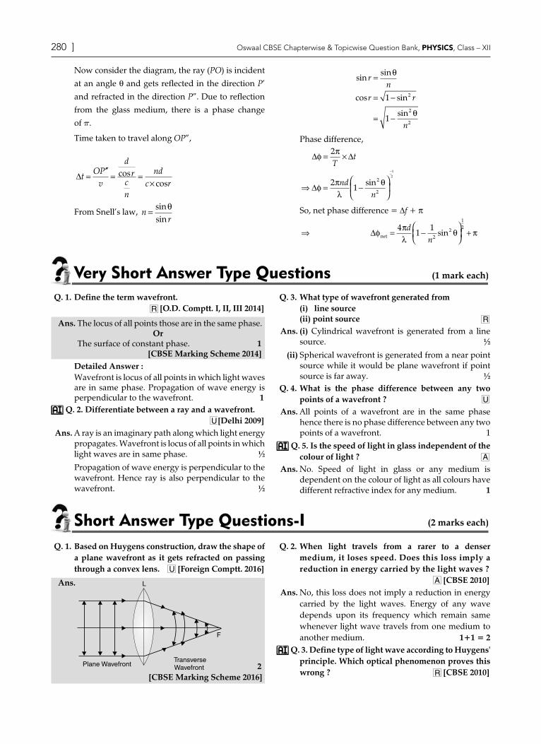
Q. 1. Based on Huygens construction, draw the shape of a plane wavefront as it gets refracted on passing through a convex lens. U [Foreign Comptt. 2016]
Ans.
2[CBSE Marking Scheme 2016]
Q. 2. When light travels from a rarer to a denser medium, it loses speed. Does this loss imply a reduction in energy carried by the light waves ?
A [CBSE 2010]Ans. No, this loss does not imply a reduction in energy
carried by the light waves. Energy of any wave depends upon its frequency which remain same whenever light wave travels from one medium to another medium. 1+1 = 2
Q. 3. Define type of light wave according to Huygens' principle. Which optical phenomenon proves this wrong ? R [CBSE 2010]

https://aktecheasy.blogspot.com
280 ] Oswaal CBSE Chapterwise & Topicwise Question Bank, PHYSICS, Class – XII Wave optics [ 281
Ans. According to Huygens' principle, light is a longitudinal wave. Polarisation proves that light is not a longitudinal wave, it is a transverse wave.
1+1 = 2 Q. 4. Define secondary wavelets and how can we
construct new wavefront with them ? R
Ans. According to the Huygen’s principle, every particle
of the medium situated on the wavefront acts as a new source of light wave from which new similar waves originate. These waves are called secondary wavelets. 1The envelop of the secondary wavelets in the forward direction at any instant gives the new wavefront at that instant. 1
Short Answer Type Questions-II (3 marks each)
Q. 1. (i) Define wavefront. Use Huygens' principle to verify the laws of refraction.
(ii) In a single slit diffraction experiment, the width of the slit is made double of the original width. How does this affect the size and intensity of the central diffraction band ? Explain.
(iii) When a tiny circular obstacle is placed in the path of light from a distant source, a bright spot is seen at the centre of obstacle. Explain why ?
R [Delhi, OD 2018]Ans. (i) Try yourself, Similar to Q. 1, Very Short Answer
Type Questions. ½For Verification : Please see the Revision Notes, 'Refraction of plane wave by Huygens Principle.' ½
(ii) Angular width of the central fringe = 2D
aλ
where,
a is the width of slit. Hence if the width of the slit is
made double, then fringe width becomes half.
The intensity of central fringe becomes four times.
This is because area of central diffraction band
would become (1/4)th. ½+½ = 1
(iii) This is because of the diffraction. The diffraction of
waves from the edges of circular obstacle interfere
constructively at the centre of the shadow. It results
the formation of bright spot at the centre of the
obstacle. ½+½ = 1
Note for the Students (ii) & (iii) parts of this question are from Topic-2
Kindly refer its revision notes.
Commonly Made Errors Some of the errors made by the students were :
(1) Correct diagrams were not drawn.(2) The arrows were not marked.(3) Angle 'i' and 'r' were not marked correctly.(4) Wavefronts were not drawn/marked.
Q. 2. (i) Define the term wavefront. State Huygen's principle.
(ii) Consider a plane wavefront incident on a thin convex lens. Draw a proper diagram to show how the incident wavefront traverses through the lens and after refraction focuses on the focal point of the lens, giving the shape of the emergent wave front. R
Ans. (i) Try yourself similar to Q. 1, Very Short Answer Type Questions. 1Huygens' Principle : Each point of the wavefront is the source of a secondary disturbance and the wavelets emanating from these points spread out in all directions. These travel with the same velocity as that of the original wavefront. ½
(ii) The shape and position of the wavefront, after time ‘t’, is given by the tangential envelope to the secondary wavelets. ½
½ + ½[CBSE Marking Scheme 2017]
Commonly Made Errors (i) Many students couldn't define wavefront.
(ii) Many students couldn't write all points of Huygens' principle.
Q. 3. Define wavefront. Use Huygen’s principle to verify the laws of refraction.
U [OD I 2018]
Ans. Try yourself, Similar to Q. 1, Very Short Answer Type Questions 1For Verification, Please see the Revision Notes, 'Refraction of plane wave by Huygens' Principle.' 2
Q. 4. (i) Compare Maxwell’s electromagnetic theory with Huygens wave theory of light.
(ii) Define incident angle of a light wave. R
Ans. (i) Both theories treat light as a wave in nature. However by electromagnetic theory light does not need any medium to propagate while by Huygen's, wave theory a medium is must. That is why he assumed a hypothetical medium ‘ether’ through which light wave travels in vacuum. 2
(ii) Angle between incident wavefront with the interface is called the incident angle of light wave. 1

https://aktecheasy.blogspot.com
282 ] Oswaal CBSE Chapterwise & Topicwise Question Bank, PHYSICS, Class – XII Wave optics [ 283
Long Answer Type Questions (5 marks each)
Q. 1. (i) Define a wavefront. How is it different from a ray ? R
(ii) Depict the shape of a wavefront in each of the following cases :(a) Light diverging from point source.(b) Light emerging out of a convex lens when a
point source is placed at its focus.(c) Using Huygens construction of secondary
wavelets, draw a diagram showing the passage of a plane wavefront from a rarer into a denser medium. [OD I, II, III 2015]
Ans. (i) Try yourself similar to Q. 1, Very Short Answer Type Question. 1Difference from a ray : The ray, at each point of a wavefront, is
normal to the wavefront at that point. The ray indicates the direction of propagation
of wave while the wavefront is the surface of constant phase. (any one) 1
The shape of the wavefront, in the three cases, are as shown :
(ii) (a)
1
(b)
1
[CBSE Marking Scheme 2015]
Q. 2. Use Huygens' principle to explain the formation of diffraction pattern due to a single slit illuminated by a monochromatic source of light. When the width of the slit is made double the original width, how would this affect the size and intensity of the central diffraction band ?
1
R [Delhi 2012]
Ans. Explanation : As per Huygens' Principle, net effect at any point = Sum total of contribution of all wavelets with proper phase difference. 1
OSa
S1
S2
½At the central point (O) the contribution from each half in SS1 is in phase with that from the corresponding part in SS2. Hence, O is a maxima. 1From the figure,
a S
S1
S2
O
M
N
½At the point M where S2M – S1M = l/2Phase difference between each wavelet from SS1 and corresponding wavelet from SS2 = l/2
Hence, M would be a minima.All such points (path difference = nl/2) are also minima.Similarly, all points, for which path difference = (2n + 1)l/2, are maxima but with decreasing intensity. 1Half angular width of central maxima = l/a\ The size of central maxima will be reduced to half and intensity of central maxima will be four times if slit is made double the original width. 1 [CBSE Marking Scheme 2012]
Q. 3. (i) State Huygens’ principle. Using it, construct a ray diagram for a plane wavefront getting incident on a denser medium.
(ii) Use Huygens’ principle to prove the laws of reflection of light. U
Ans. (i) Huygens principle :In a wavefront every particle acts as a new source of disturbance which are known as wavelet that travel in every directions with velocity of wave.The forward (tangential) envelope of all these wavelets at any time gives new wavefront. 1

https://aktecheasy.blogspot.com
282 ] Oswaal CBSE Chapterwise & Topicwise Question Bank, PHYSICS, Class – XII Wave optics [ 283
Incident wavefront
A'
v1
P
Medium 1
Medium 2
v <v2 1
A
E
i
i
r
r
1
C P'
B
Refracted
wavefront
t
1(ii)
Incident
wavefront
Refracted
wavefront
A
B
C
E
M Ni r
iv
AB = incident wavefrontEC = reflected wavefrontÐi = angle between incident wavefront AB and the interface AC.Ðr = angle between reflected wavefront EC and the interface AC. 1If disturbance at A is reflected from the interface AC then disturbance at B and disturbance at A both travel in same medium and they will have travelled equal distances in same medium in time t. Where tis the time in which disturbance from B reaches at C. Now AE = BC (distance travelled in same medium in same time) DAEC @ DABC Ði = Ðr
This is law of reflection. 1
TopiC-2Superposition of light waves (interference and Diffraction)
Revision Notes
~
¾ According to superposition principle, “At a particular point in the medium, the resultant displacement produced by a number of waves is the vector sum of the displacements produced by each of the waves”.It means if individual displacement produced at a point by two coherent waves at any instant is given by
y1 = acos wt and y2 = acos wt. Then resultant displacement at that point will be
y = y1 + y2 = 2acos wt. Hence the total intensity at that point will be :
I = 4I0 where, I0 µ a2; maximum intensity due to one wave.
Interference¾ Constructive Interference : If two waves are propagating such that crest and trough of both waves would reaching
at a point in the same instant then we say there is constructive interference of two waves at that point and the resultant amplitude of the wave is the sum of individual amplitudes. (We can generalize this to superposition of more than two waves) a = a1 + a2
¾ Destructive Interference : If two waves are propagating such that crest of one wave and trough of other wave reaching at a point in same instant then we say there is destructive interference of two waves at that point. The resultant amplitude of the wave is the difference of individual amplitudes. (We can generalize this to superposition of more than two waves) a = a1 a2
¾ Two independent sources can never be coherent. We may create two coherent sources by deriving them from one source. Condition for constructive Interference¾ Waves would be coherent in nature. Coherent wave means they should have equal frequency and constant phase
difference (0, 2p, --- 2np) with each other at any time interval t.Path difference between waves at this phase difference = 0 , l, -----nl, Here, n = 0, 1, 2, 3
a a aa a aa a
I a
I a
r
r
r
= += ==
∝
=
1 2
1 2
2
2
4
ifthen
∵ 2
Condition for destructive interference¾ Waves would be coherent in nature. The phase diff. of the waves should be odd multiples of p, i.e., 0, p, .... (2n – 1)p

https://aktecheasy.blogspot.com
284 ] Oswaal CBSE Chapterwise & Topicwise Question Bank, PHYSICS, Class – XII Wave optics [ 285
¾ Path difference between waves at this phase difference = λ λ λ2
32
2 12
, ,( )n − , Here, n = 1, 2, 3, 4....
a a aa aa
I aI
r
r
r
= −==
∝=
1 2
1 2
0
0
ifthen
∵ 2
Constructive Interference
=
Destructive Interference
=+
a
a
Young’s Experiment G
P
D
G'
Z
S1
S2
O
x
yz
x
S
¾ At “O” we would get central maxima. Here path difference (S2P – S1P) = 0
¾ At “P”, which is at “x” height from “O” path difference ( )S P S PxdD2 1− =
¾ Condition for P is a bright spotxdD
n
xnDdn
=
=
0 2, , ........λ λ λ
λth bright
where, n is number of bright fringes after central fringe.¾ Condition for P is a dark spot
xdD
n
xn D
dn
= − − − +
= +
032
2 12
2 12
, ( )
( )
λ λ
λth dark
Here, n is the number of dark fringes after central fringe.
¾ Width of the bright fringe (wB) = xnB – x(n – 1)B =
Ddλ
¾ Width of the dark fringe (wD) = xnD – x(n – 1)D =
Ddλ
¾ Width of the central fringe (wC) = Ddλ
¾ Hence wB = wD = wC Diffraction
It is defined as the bending of light around the corners of an obstacle or aperture into the region where we should expect shadow of the obstacle.
From S
LM1MM2N
¸
¸
¸To C
To P
Q

https://aktecheasy.blogspot.com
284 ] Oswaal CBSE Chapterwise & Topicwise Question Bank, PHYSICS, Class – XII Wave optics [ 285
If width of the opening = aq is the angle of elevation of point P from principal axis.Path difference between ray from L and ray from N = LQ = asin q
for first maxima
a
a
sin θ λ
θ λ=
= (\ sin q @ q) sin q <<< 1
It is observed that when path difference = l, 2l . .... (2n – 1)l then P is a dark point.
When = asin q = 32
2 12
λ λ, .
()n +
then P is a bright point.
Elevation angle for first bright fringe θ λ1
32D a
=
¾ Height of first dark fringe xDaD1
32
= λ
¾ Elevation angle for first dark fringe θλ
1D a=
¾ Width of the bright fringe = Daλ
¾ Width of the dark fringe = Daλ
¾ Width of the central fringe = 2D
aλ
¾ There is no gain or loss of energy in interference or diffraction, which is consistent with the principle of conservation of energy. Energy only redistributes in these phenomena.
Know the Formulae¾ Condition for constructive interference for coherent waves constant phase difference(0, 2p, --- 2np) Path difference = 0, l ...... nl
¾ Condition for destructive interference for coherent waves phase difference(0, p, --- (2n – 1)p) with each other at any time interval t.
Path difference = λ2
, -----(2n – 1)λ2
¾ In Interference Pattern
Width of the bright fringe = Ddλ
Width of the dark fringe = Ddλ
Width of the central fringe = Ddλ
(All fringe have equal fringe width) ¾ In Diffraction Pattern
If angle of elevation of any point P on screen = λa
Condition that P would be dark point when path difference = l, 2l .... (2n – 1)l
Condition that P would be bright point when path difference = 32
2 12
λ λ, ....( )n +
Width of the bright fringe = Daλ
Width of the dark fringe = Daλ
Width of the central fringe = 2D
aλ
Height of first bright fringe x1B = 32λDa

https://aktecheasy.blogspot.com
286 ] Oswaal CBSE Chapterwise & Topicwise Question Bank, PHYSICS, Class – XII Wave optics [ 287
objective Type Questions (1 mark each)
Q. 1. Consider sunlight incident on a slit of width 104 Å. The image seen through the slit shall(a) be a fine sharp slit white in colour at the centre.(b) a bright slit white at the centre diffusing to
zero intensities at the edges.(c) a bright slit white at the centre diffusing to
regions of different colours.(d) only be a diffused slit white in colour.
[NCERT Exemplar]Ans. Correct option : (a)
Explanation : Given that, width of slit 104 Å=10,000 Å. Wavelength of visible light varies from 4,000 Å to 8,000 Å. As the width of slit 10,000 Å is comparable to that of wavelength of visible light, i.e., 8,000 Å. Hence the diffraction occurs with maxima at the centre. So at the centre all colours appear, i.e., white colour appears at the centre.
Q. 2. In a Young’s double-slit experiment, the source is white light. One of the holes is covered by a red filter and another by a blue filter. In this case,(a) there shall be alternate interference patterns of
red and blue.(b) there shall be an interference pattern for red
distinct from that for blue.(c) there shall be no interference fringes.(d) there shall be an interference pattern for red
mixing with one for blue.[NCERT Exemplar]
Ans. Correct option : (c)Explanation : For sustained interference, the source must be coherent and should emit the light of same frequency.In this problem, one hole is covered with red and other with blue, which has different frequency, so no interference takes place.
Very Short Answer Type Questions (1 mark each)
Q. 1. Define the term ‘coherent sources’ which are required to produce interference pattern in Young’s double slit experiment.
R [Delhi Comptt. I, II, III 2014]
Ans. Two monochromatic sources, which produce light waves, having a constant phase difference, are known as coherent sources. 1 [CBSE Marking Scheme 2014]
Q. 2. In what way is diffraction from a single slit related to the interference pattern in a double slit experiment ? R [O.D. Comptt. I, II, III, 2013]
Ans. Relation between diffraction from a single slit to the interference pattern in a double slit experiment :(i) If slit width in interference pattern is reduced
to the size of wavelength of light used; the diffraction will also takes place along with interference. ½
(ii) The diffraction pattern is itself due to the interference of wavelength belonging to same but different order of spectrum. ½
Q. 3. Draw a graph showing the intensity distribution of fringes due to diffraction at single slit.
R [CBSE Comptt. 2018]
Ans.
1 [CBSE Marking Scheme 2018]
Q. 4. How does the angular separation between fringes in single-slit diffraction experiment change when the distance of separation between the slit and screen is doubled ? [O.D. I, II, III, 2012]
Ans. No change. [CBSE Marking Scheme 2012] 1
Short Answer Type Questions-I (2 marks each)
Q. 1. Draw the intensity pattern for single slit diffraction and double slit interference. Hence, state two differences between interference and diffraction patterns.
U [OD, Foreign 2017]
Ans.
I
I
max
3� 2� 1� 0 1� 2� 3�Path Difference
½

https://aktecheasy.blogspot.com
286 ] Oswaal CBSE Chapterwise & Topicwise Question Bank, PHYSICS, Class – XII Wave optics [ 287
½
Differences :
Interference Diffraction
All maxima have equal intensity
Maxima have different (rapidly decreasing) intensities
All fringes have equal width
Different (changing) width
Superposition of two wavefronts
Superposition of wavelets from the same wavefront
½+½(Any two)
[CBSE Marking Scheme 2017]
Commonly Made Error (i) Some students do not know the correct difference
between interference of light and diffraction of light.
Detailed Answer :Intensity Pattern :
½+½
Difference between Interference and Diffraction :
Interference Diffraction
Fringe width is constant. Fringe width varies.
Fringes are obtained with the coherent light coming from two slits.
Fringes are obtained with the monochromatic light coming from single slit.
It is superposition of waves.
It is superposition of many waves.
It depends upon the distance between two openings.
It depends upon the aperture of single slit opening.
Many fringes are visible. Fewer fringes are visible.
All fringes are of same brightness.
Central fringe has maximum brightness, then it reduces gradually.
(Any two) ½ + ½
Q. 2. Find the intensity at a point on a screen in Young’s double slit experiment where the interfering waves have a path difference of (i) l/6, and (ii) l/2.
A [Foreign 2017]
Ans. Phase difference = 2πλ
× Path difference
Path difference = λ6
Þ Phase difference = π3
½
Path difference λ2
Þ Phase difference = p ½
I = 4I0cos2 φ2
(i) I1 = 434
30 0I I× = ½
(ii) I2 = 4I0 × 0 = 0 ½ [CBSE Marking Scheme 2017]
Detailed Answer :Phase difference between interfering waves
f = 2πλ
× path difference
(i) Path difference = λ6
\ Phase difference = 2
6 3π
λλ π× =
I = 420
2I cosφ
= 460
2I cosπ
= 434
30 0I I× =
(ii) Path difference = λ2
\ Phase difference, f = 2
2π
λλ π× =
I = 420
2I cosφ
= 42
002I cos
π =
Q. 3. Find the intensity at a point on a screen in Young’s double slit experiment where the interfering waves of equal intensity have a path difference of (i) l/4, and (ii) l/3.
A [Foreign 2017]
Ans. Try yourself similar to Q. 2 SAQ-I
Q. 4. A narrow slit is illuminated by a parallel beam of monochromatic light of wavelength l equals to 6000 Å and the angular width of the central maxima in the resulting diffraction pattern is measured. When the slit is next illuminated by light of wavelength l’, the angular width decreases by 30%. Calculate the value of the wavelength l’.
[SQP 2018-19]

https://aktecheasy.blogspot.com
288 ] Oswaal CBSE Chapterwise & Topicwise Question Bank, PHYSICS, Class – XII Wave optics [ 289
Ans. Angular width 2q = 2l/d ½Given, l = 6000 Å ½In case of new wavelength (assumed l' here), angular width decreases by 30% ½
= 100 30
1002
−
θ
= 0.70 (2q)
2λ 'd
= 0.70 × (2l/d)
\ l' = 4200 Å ½ [CBSE Marking Scheme 2018]
Q. 5. Laser light of wavelength 640 nm incident on a pair of slits produces an interference pattern in which the bright fringes are separated by 7.2 mm. Calculate the wavelength of another source of light which produces interference fringes separated by 8.1 mm using same arrangement. Also find the minimum value of the order (n) of bright fringe of shorter wavelength which coincides with that of the longer wavelength. A [O.D. Comptt. I, II, III 2012]
Ans. Fringe width in interference pattern
b = Ddλ
...(i)
According to the question when l = 640 nm then b = 7.2 mm. Putting these values in the relation (i)
7.2 × 10–3 = D
d× × −640 10 9
Dd
=7 2 10640 10
7 2640 10
3
9 6. .×
×=
×
−
− − ½
Now with another monochromatic light l’, the fringe width b’ = 8.1 mm. Hence
8.1 × 10–3 = D
d× λ '
Putting the value of Dd
8.1 × 10–3 = 7 2
640 10 6.
× − × l’
l’ = 640 8 1 10
7 2
9× × −..
= 720 nm ½Condition for minimum value of the order (n) of bright fringe of shorter wavelength which coincides with that of the longer wavelength
n Dd1 λ =
n Dd2 λ '
nn
1
2=
λλ
'
nn
1
2 =
720 10
640 10
9
9××
−
−
nn
1
2 =
98
1
Answering Tips All quantities must be brought to SI system before
substituting them in formula.
Q. 6. A beam of light consisting of two wavelengths 800 nm and 600 nm is used to obtain the interference fringes in a Young’s double slit experiment on a screen placed 1.4 m away. If the two slits are separated by 0.28 mm, calculate the least distance from the central bright maxima where the bright fringes of the two wavelengths coincide.
A [O.D. I, II, III 2012]
Ans. The two bright fringes will coincide when ½ ml1 = (m + 1)l2 ½ m × 800 × 10–9 = (m + 1) × 600 × 10–9
\ m = 3
Xm = mD
dλ1 ½
Xm = 3 1 4 800 10
0 28 10
9
3× × ×
×
−
−..
m
Xm = 12× 10–3 m ½ [CBSE Marking Scheme 2012]
Commonly Made Error Many students couldn't understand this problem. The formula used by a number of students was
incorrect.
Q. 7. Name the phenomenon which is responsible for bending of light around sharp corners of an obstacle. Under what conditions does this phenomenon take place ? Give one application of this phenomenon in everyday life.
R [SQP 2014]
Ans. Diffraction. Diffraction Condition : The size of the obstacle sharpness should be comparable to the wavelength of the light falling. 1 + ½Application : The finite resolution of our eye. ½ [CBSE Marking Scheme 2014]
Q. 8. Write the distinguishing features between a diffraction pattern due to a single slit and the interference fringes produced in Young’s double slit experiment. R [OD Comptt. I, II, III 2013]
Ans. Diffraction due to a Single Slit :(i) It is produced due to different parts of same
wavefront.(ii) Central fringe is twice as wide as other fringes.
(iii) Intensity of fringes decreases as we go to successive maxima away from the centre.
(iv) At an angle λa
, first minima is obtained. 1
Interference Fringe due to Young’s Double Slit :(i) It is produced due to two different wavefronts.
(ii) Fringe width is of same size. (iii) Fringes have same intensity.
(iv) At an angle λa
, maxima is obtained. 1
Q. 9. A parallel beam of light of 500 nm falls on a narrow slit and the resulting diffraction pattern is observed on a screen 1 m away. It is observed that the first minima is at a distance of 2.5 mm from the centre of the screen. Calculate the width of the slit. A [O.D. I, II, III 2013]

https://aktecheasy.blogspot.com
288 ] Oswaal CBSE Chapterwise & Topicwise Question Bank, PHYSICS, Class – XII Wave optics [ 289
Ans. The distance of the 1st minima from the centre of the screen is,
x1 dark =
Dλa
where, D = distance of slit from screen, l = wavelength of the light, a = width of the slit.
According to question, D = 1 ml = 500 nm
height of first minima = 2.5 mm 1
2.5 × 10–3 = 1 500 10 9× × −
aÞ a = 2 × 10– 4 m = 0.2 mm
a = 0.2 mm. 1
Commonly Made Errors Number of candidates used incorrect formula. Some of the students did not know the correct
meaning of the symbols i.e., 'D' and 'd', hence they interchanged them.
Some students did not convert 'nm' to m as well as 'mm' to m.
Q. 10. Yellow light (l = 6000 Å) illuminates a single slit of width 1 × 10⁻⁴ m. Calculate : (i) the distance between the two dark lines on either side of the
central maxima, when the diffraction pattern is viewed on a screen kept 1.5 m away from the slit, (ii) the angular spread of the first diffraction minima. A [O.D. Comptt. I, II, III 2012]
Ans. Separation between two dark bands on each side of central bright fringe = width of bright fringe ,We know width of the central fringe
=
2Da
λ
where, D = distance of slit from screen, l = wavelength of the light, a = width of the slit. ½According to question,
Width of central fringe = 1 5 2 6000 10
1 10
10
4. × × ×
×
−
− m
So the distance between the two dark lines on either side of the central maxima = 18 mm ½Angular spread of the first diffraction minima
=
λa
= 6000 10
1 10
10
4×
×
−
−m
m
= 6 × 10⁻³ rad 1
Short Answer Type Questions-II (3 marks each)
Q. 1. Give reasons :(i) When monochromatic light is incident on a surface
separating two media, the reflected and refracted light both have the same frequency as the incident frequency.
(ii) When light travels from a rarer to a denser medium, the speed decreases. Does this decrease in speed imply a reduction in the energy carried by the wave ?
(iii) In the wave picture of light, intensity of light is determined by the square of the amplitude of the wave. What determines the intensity in the photon picture of light ? U [OD 2016]
Ans. (i) Reflection and refraction arise through interaction of incident light with atomic constituents of matter which vibrate with the same frequency as that of the incident light. Hence frequency remains unchanged.
(ii) No. [Energy carried by a wave depends on the amplitude of the wave, not on the speed of wave propagation].
(iii) For a given frequency, intensity of light in the photon picture is determined by the number of photon incident normally on a crossing an unit area per unit time. 1+1+1 = 3
[CBSE Marking Scheme 2016]
Q. 2. (a) If one of the two identical slits producing interference in Young’s experiment is covered with glass, so that the light intensity passing
through it is reduced to 50%, find the ratio of the maximum and minimum intensity of the fringe in the interference pattern.
(b) What kind of fringes do you expect to observe if white light is used instead of monochromatic light ? [OD 2017, 2019]
Ans. (a) Finding the (modified) ratio of the maximum and minimum intensities 2(b) Fringes obtained with white light. 1
(a) After the introduction of the glass sheet (say, on the second slit),
we have II2
1 = 50 % = 1
2½
\ Ratio of the amplitudes,aa
2
1 =
12
12
= ½
Hence IImax
min=
a aa a
1 2
1 2
2+−
½
= 1
12
112
2
+
−
=2 12 1
2+−
½

https://aktecheasy.blogspot.com
290 ] Oswaal CBSE Chapterwise & Topicwise Question Bank, PHYSICS, Class – XII Wave optics [ 291
(b) The central fringe remains white.No clear fringe pattern is seen after a few (coloured) fringes on either side of the central fringe. 1[Note : For part (a) of this question, The student may
(i) Just draw the diagram for the Young's double slit experiment.Or
(ii) Just state that the introduction of the glass sheet would introduce an additional phase difference and the position of the central fringe would shift. For all such answers, the student may be awarded the full (2) marks for this part of the question.]
[CBSE Marking Scheme 2018]
Q. 3. Write two points to distinguish between interference and diffraction fringes.
(ii) In a Young’s double slit experiment, fringes are obtained on a screen placed at a certain distance away from the slits. If the screen is moved by 5 cm towards the slits, the fringe width changes by 30 µm. Given that the slits are 1 mm apart, calculate the wavelength of the light used.
U [Comptt. 2018]
Ans. (a) Two points of difference ½+½(b) Formula ½ Calculation of wavelength 1½
(a) Any two points of difference
Interference Diffraction
Fringes are equally spaced.
Fringes are not equally spaced.
Intensity is same for all maxima.
Intensity falls as we go to successive maxima away from the centre.
Superposition of two waves originating from two narrow slits.
Superposition of a con-tinuous family of waves originating from each point on a single slit.
Maxima along an an-gle l/a for two narrow slits separated by a distance a.
Minima at an angle of l/a for a single slit of width a.
½+½
(b) Let D be the distance of the screen from the plane of the slits.We have
Fringe width, b = λDd
½
In the first case
b = λDd
or bd = lD ...(i) ½
In the second case
(b – 30 × 10–6) = λ( . )D
d− 0 05
or (b – 30 × 10–6)d = l(D – 0.05) ...(ii) ½Subtracting (ii) from (i) we get 30 × 10–6 × d = l × 0.05
\ l = 30 10 10
5 10
6 3
2× ×
×
− −
− m
\ l = 6 × 10⁻⁷ m = 600 nm ½[CBSE Marking Scheme 2018]
Q. 4. A monochromatic light of wavelength l is incident normally on a narrow slit of width ‘a’ to produce a diffraction pattern on the screen placed at a distance D from the slit. With the help of a relevant diagram, deduce the conditions for maxima and minima on the screen. Use these conditions to show that angular width of central maxima is twice the angular width of secondary maxima. U [Foreign II 2017]
Ans.
From S
LM1MM2N
¸
¸
¸To C
To P
Q
½
The path difference
NP – LP = NQ
= asin q @ aq
as q <<<1 \ sin q » q ½
By dividing the slit into an appropriate number of parts, we find the point P for which
(i) q = naλ
are points of minima. ½
(ii) q = na
+
12
λ are points of maxima ½
Angular width of central maxima,
q = q1 – q–1 = λ λa a
− −
q2 =
2λa
½
Angular width of secondary maxima = q2 – q1
= 2λ λ λa a a
− =
= 12
× Angular width of central maxima ½
[CBSE Marking Scheme 2017]
Q. 5. (i) In Young’s double slit experiment, two slits are 1 mm apart and the screen is placed 1 m away from the slits. Calculate the fringe width when light of wave length 500 nm is used ?

https://aktecheasy.blogspot.com
290 ] Oswaal CBSE Chapterwise & Topicwise Question Bank, PHYSICS, Class – XII Wave optics [ 291
(ii) What should be the width of each slit in order to obtain 10 maxima of the double slit pattern within the central maxima of the single slit pattern ?
U [OD 2016]
Ans. (i) b = λDd
½
= 500 10 1
10
9
3× ×−
−
½
= 0.5 mm or 5 × 10⁻⁴ m ½
(ii) b0 = 2
10λα
βD = ½
a =
2 500 10 110 5 10
9
4× × ×
× ×
−
−
½
a = 2 × 10⁻⁴ m or 0.2 mm ½[CBSE Marking Scheme 2016]
Q. 6. Consider a two slit interference arrangement (shown in figure) such that the distance of the screen from the slits is half the distance between the slits. Obtain the value of D in terms of l such that the first minima on the screen fall at a distance D from the centre O. U [SQP 2016]
Ans.
S1
Source
S C
T1
S2
P
O
T2
Screen
OP=
CO=D
S C=S C=
x
1 2 2
d
T2P = D + x, T1 P = D – x ½
S1P = [( ) ( ) ]S T PT1 12
12 +
½ = [D2 + (D – x)2]1/2 ½ S2P = [D2 + (D + x)2]1/2 ½
Minima will occur when = [D2 + (D + x)2]1/2
– [D2 + (D – x)2]1/2
=λ2
½
If x = D
(D2 +4D2)1/2 – (D2)1/2 = λ2
(5D2)1/2 – (D2)1/2 =
λ2
D( )5 1− =
λ2
\ D = λ
2 5 1( )- ½
[CBSE Marking Scheme 2016]
Q. 7. Explain by drawing a suitable diagram that the interference pattern in a double slit is actually a superposition of single slit diffraction from each slit.Write two basic features which distinguish
the interference pattern from those seen in a coherently illuminated single slit. U [Delhi 2015]
Ans. The diagram, given here, shows several fringes, due to double slit interference, ‘contained’ in a broad diffraction peak. When the separation between the slits is large compared to their width, the diffraction pattern becomes very flat and we observe the two slit interference pattern. 1
I0
0 �
Principal Maxima
Two basic features :(i) The interference pattern has a number of equally
spaced bright and dark bands while diffraction pattern has a central bright maxima which is twice as wide as the other maxima. 1
(ii) Interference pattern is the superposition of two waves originating from two narrow slits. The diffraction pattern is a superposition of a continuous family of waves originating from each point on a single slit.
(iii) For a single slit of width ‘a’ the first null of
diffraction pattern occurs at an angle ofλa
. At the
same angle of l/a , we get a maxima for two narrow slits separated by a distance a. (Any two) 1
Q. 8. (i) Two monochromatic waves emanating from two coherent sources have the displacements represented by y1 = acos wt and y2 = acos (wt + f),where f is the phase difference between the two displacements. Show that the resultant intensity at a point due to their superposition is given by I = 4I0cos2 f/2, where I0 = a2.
(ii) Hence obtain the conditions for constructive and destructive interferences. A [OD Comptt. 2014]
Ans. (i) The resultant displacement is given by y = y1 + y2 = acos wt + acos (wt + f) ½ = acos wt (1 + cos f) – asin wtsin fPut Rcos q = a(1 + cos f) Rsin q = asin f ½\ R2 = a2(1 + cos2 f + 2cos f) + a2sin2 f ½
= 2a2(1 + cos f) = 4a2cos2
φ2
\ I = R2 = 4a2cos2 φ2
= 4I0cos2 φ2
½
(ii) For constructive interference,
cos
φ2
= ±1 or φ2
= np or f = 2np ½
For destructive interference,
cos
φ2
= 0 or φ2
= (2n + 1)π2
or f = (2n + 1)p
[CBSE Marking Scheme 2014] ½

https://aktecheasy.blogspot.com
292 ] Oswaal CBSE Chapterwise & Topicwise Question Bank, PHYSICS, Class – XII Wave optics [ 293
Q. 9. Answer the following questions :(i) In a double slit experiment using light of
wavelength 600 nm, the angular width of the fringe formed on a distant screen is 0.1°. Find the spacing between the two slits.
(ii) Light of wavelength 5000 Å propagating in air gets partly reflected from the surface of water. How will the wavelengths and frequencies of the reflected and refracted light be affected ?
A [Delhi I, II, III 2015]
Ans. Finding the spacing between two slits 1Effect on wavelength and frequency of reflected and refracted width light. 1+1
(i) Angular width of fringes : ½
q = λd
where, d = separation between two slits
Here q = 0·1° = 0·1 × π
180radian
\ d = 600 10 1800 1
9× ××
−
· πm
= 3·43 × 10–4 m = 0·34 mm ½
(ii) For Reflected light :Wavelength remains same ½Frequency remains same ½For Refracted light :Wavelength decreases ½Frequency remains same ½ [CBSE Marking Scheme 2015]
Detailed Answer :(b)
we know that frequency of light is same in all mediaThus,
f =vλ
=3 0 10
5000 10
8
10· ×
× −
= 0.6 × 10+15
= 0.6 × 10¹⁵ Hz
If wavelength in air is l1 & that in water is l2.µµ
1
2=
vv
2
1 =
λλ
2
1
l2 = λ µµ1
1
2
l2 = 5000 1
2
µµ
A°
Wavelength of refracted ray decreases by a factor
of µµ
1
2
while wavelength of reflected ray may
remains same.
Long Answer Type Questions (5 marks each)
Q. 1. (i) Explain the two features to distinguish between the interference pattern in Young’s double slit experiment with the diffraction pattern obtained due to single slit.
(ii) A monochromatic light of wavelength 500 nm is incident normally on a single slit of width 0.2 mm to produce a diffraction pattern. Find the angular width of the central maximum obtained on the screen.Estimate the number of fringes obtained in Young’s double slit experiment with fringe width 0.5 mm, which can be accommodated within the region of total angular spread of the central maximum due to single slit. U [Delhi I, II 2017]
Ans. (i) Try yourself, Similar to Q. 1, Short Answer Type Questions-I 1
(ii) Angular width of central maximum
w = 2λa
1
= 2 500 10
0 2 10
9
3× ×
×
−
−.radian 1
= 5 × 10⁻³ radian
Now, b = λDd
1
Linear width of central maxima in the diffraction pattern
b' = 2λD
dLet ‘n‘ be the number of interference fringes which can be accommodated in the central maxima. 1\ n × b = b’
n = 2λ
λD
ddD
×
n = 2[Award the last ½ mark if the student writes the answer as 2 (taking d = a), or just attempts] ½
[CBSE Marking Scheme 2017]
Q. 2. In Young’s double slit experiment, deduce the condition for (a) constructive, and (b) destructive interference at a point on the screen. Draw a graph showing variation of intensity in the interference pattern against position ‘x’ on the screen.

https://aktecheasy.blogspot.com
292 ] Oswaal CBSE Chapterwise & Topicwise Question Bank, PHYSICS, Class – XII Wave optics [ 293
(ii) Compare the interference pattern observed in Young’s double slit experiment with single slit diffraction pattern, pointing out three distinguishing features. U [Delhi 2016]
Ans. (i)
S1
S2 D
G'
OZ
x
zy
x
P
d
G
½
From figure, Path difference = (S2P – S1P)
(S2P)2 – (S1P)2 = D xd
D xd2
22
2
2 2+ +
− + −
(S2P + S1P)(S2P – S1P) = 2xd
Þ S2P – S1P =
2
2 1
xdS P S P( )+
For x, d << D
S2P – S1P = 22xdD
xdD
= ½
For constructive interference, S2P – S1P = nl, n = 0, 1, 2. ....
Þ xdD
= nl ½
x = n D
dλ
\ Position of the nth bright fringe on screen :
Þ xdD
= nl
Þ x =n D
dλ
½
For destructive interference
S2P – S1P = 2 12
n +( ) λ
n = 0, 1, 2, ...
Þ xdD
= 2 12
n +( ) λ
Þ x = 2 12
nDd
+( ) λ½
½
(ii) (a) The interference pattern has number of equally spaced bright and dark bands, while in the diffraction pattern the width of the central maximum is twice the width of other maxima. ½
(b) In Interference all bright fringes are of equal intensity, whereas in the diffraction pattern the intensity falls as order of maxima increases. ½
(c) In Interference pattern, maxima occurs at an angle λa
, where, a is the slit width, whereas in diffraction
pattern, at the same angle i.e., at λa
first minima
occurs. (Here ‘a‘ is the size of the slit) 1(Any other distinguishing feature)
[CBSE Marking Scheme 2016]
Q. 3. (a) There are two sets of apparatus of Young’s double slit experiment. In set A, the phase difference between the two waves emanating from the slits does not change with time, whereas in set B, the phase difference between the two waves from the slits changes rapidly with time. What difference will be observed in the pattern obtained on the screen in the two set ups?
(b) Deduce the expression for the resultant intensity in both the above mentioned set ups (A and B), assuming that the waves emanating from the two slits have the same amplitude a and same wavelength l. U [SQP 2018-19]
Ans. (a) Set A : Stable interference pattern, the positions of maxima and minima do not change with time. 1Set B : Positions of maxima and minima will change rapidly with time and an average uniform intensity distribution will be observed on the screen. 1
(b) Expression for intensity of stable interference pattern in set-A 2If the displacement produced by slit S1 is y1 = acos wtthen, the displacement produced by S2 would be y2 = acos (wt + f)and the resultant displacement will be given by y = y1 + y2 = a[cos wt + cos (wt + f)] = 2acos (f/2)cos (wt + f/2)The amplitude of the resultant displacement is 2acos (f/2) and therefore the intensity at that point will be I = 4I0cos2 (f/2) f = 0\ I = 4I0In set B, the intensity will be given by the average intensity <I> = 4I0 < cos2 (f/2)> 1 I = 2I0
[CBSE Marking Scheme 2018-19]
Q. 4. (i) State the essential conditions for diffraction of light.
(ii) Explain diffraction of light due to a narrow single slit and the formation of pattern of fringes on the screen.

https://aktecheasy.blogspot.com
294 ] Oswaal CBSE Chapterwise & Topicwise Question Bank, PHYSICS, Class – XII Wave optics [ 295
(iii) Find the relation for width of central maxima in terms of wavelength ‘l’, width of slit ‘a’, and separation between slit and screen ‘D’.
(iv) If the width of the slit is made double the original width, how does it affect the size and intensity of the central band ? U [Foreign 2016]
Ans. (i) Size of slit/aperture must be smaller than of the order of wavelength of light. 1
(ii)
1
Single slit diffraction is explained by treating different parts of the wavefront at the slit as sources of secondary wavelets. ½At the central point C on the screen, q is zero. All path differences are zero and hence all the parts of the slit contribute in phase and give maximum intensity at C.
At any other point P, the path difference between two edges of the slit is NP – LP = NQ. = asin q » aq sin q is smallAny point P, is direction q, is a location of minima if aq = nlThis can be explained by dividing the slit into even number of parts. The path difference between waves from successive parts is 180° out of phase and hence cancel each leading to a minima. ½Any point P, in direction Q, is a location of maxima
if aq = n +
12
λ
This can be explained by dividing the slit into odd number of parts. The contributions from successive parts cancel in pairs because of 180° phase difference. The unpaired part produces intensity at P, leading to a maxima.
(iii) If q is the direction of first minima, then aq = l
Þ q = λa
Angular width of central maxima = 2q
= 2λα ½
Linear width of central maxima,
b = 2λD
a= 2q × D ½
(iv) If 'a' is doubled, b becomes half ½Intensity becomes 4 times. ½
[CBSE Marking Scheme 2016]
Q. 5. (a) Define a wavefront. Using Huygens’ principle, verify the laws of reflection at a plane surface.
(b) In a single slit diffraction experiment, the width of the slit is made double the original width. How does this affect the size and intensity of the central diffraction band ? Explain.
(c) When a tiny circular obstacle is placed in the path of light from a distant source, a bright spot is seen at the centre of the obstacle. Explain why.
[Delhi & OD, 2018]
Ans. (a) Definition of wavefront ½ Verification of laws of reflection 2
(b) Explanation of the effect on the size and intensity of central maxima 1+ 1
(c) Explanation of the bright spot in the shadow of the obstacle ½
(a) The wavefront may be defined as a surface of constant phase. ½[Alternatively : The wave front is the locii of all points that are in the same phase]
1
Incident
wavefront
Refrected
wavefront
A
B
C
E
M Ni r
i
Let speed of the wave in the medium be 'v'Let the time taken by the wave front, to advance from point B to point C be 't' ½Hence BC = v tLet CE represent the reflected wave frontDistance AE = v t = BC
Δ AEC and Δ ABC are congruentÐ BAC = Ð ECA ½
Þ Ð i = Ð r ½(b) Size of central maxima reduces to half, ½
(\ Size of central maxima = 22λ
αD
)
Intensity increases. ½This is because the amount of light, entering the slit, has increased and the area, over which it falls, decreases. ½(Also accept if the student just writes that the intensity becomes four fold)
(c) This is because of diffraction of light. [Alternatively : Light gets diffracted by the tiny circular obstacle and reaches the centre of the shadow of the obstacle.] ½[Alternatively : There is a maxima, at the centre of the obstacle, in the diffraction pattern produced by it.]
[CBSE Marking Scheme 2018]
Q. 6. (i) Derive an expression for path difference in Young’s double slit experiment and obtain the condition for constructive and destructive interference at a point on the screen.
(ii) The intensity at the central maxima in Young’s double slit experiment is I0. Find out the intensity at a point where the path difference is l/6 , l/4 and l/3. U [OD North 2016]

https://aktecheasy.blogspot.com
294 ] Oswaal CBSE Chapterwise & Topicwise Question Bank, PHYSICS, Class – XII Wave optics [ 295
Ans. (i) Try yourself, Similar to Q. 2 (i) LAT Questions.(ii) Try yourself, Similar to Q. 2 SAT Questions-I
Q. 7. (i) Using Huygens construction of secondary wavelets explain how a diffraction pattern is obtained on a screen due to a narrow slit on which a monochromatic beam of light is incident normally.
(ii) Show that the angular width of first diffraction fringe is half that of the central fringe.
(iii) Explain why the maxima at q = n+12
λa
become
weaker and weaker with increasing n. U [Delhi I, II, III 2015]
Ans. (i)
1
We can regard the total contributions of the wavefront LN at some point P on the screen, as the resultant effect of the superposition of its wavelets like LM, MM2, M2N. These have to be superposed taking into account their proper phase differences. We therefore, get maxima and minima, i.e., a diffraction pattern, on the screen. 1
(ii)
O
D2
D1
D1'
D2'
a
λ/a
λ/a
λ/aλ/a
½
Conditions for first minima on the screen asin q = l
Þ q = λa
½
\ Angular width of the central fringe on the screen (from figure)
= 2q = 2λa
½
Angular width of first diffraction fringe (From fig)
= λ
a½
For first diffraction, angular width of the fringe is half that of central fringe.
(iii) Maxima becomes weaker and weaker with increasing n. This is because the effective part of the wavefront, contributing to the maxima becomes smaller and smaller, with increasing n. 1
[CBSE Marking Scheme 2015]
Q. 8. When a parallel beam of monochromatic source of light of wavelength l is incident on a single slit of width a, show how the diffraction pattern is formed at the screen by the interference of the wavelets from the slit.Show that, besides the central maxima at q = 0, secondary maxima are observed at
q = n
a+
12
λ
and the minima at θ λ= na
.
Why do secondary maxima get weaker in intensity with increasing n ? A
Ans. (i)
½
The diffraction pattern formed can be understood by adding the contributions from the different wavelets of the incident wavefront, with their proper phase differences. 1For the central point, we imagine the slit to be divided into two equal halves. The contribution of corresponding wavelets, in the two halves, are in phase with each other. Hence we get a maxima at the central point. The entire incident wavefront contributes to this maxima. ½
All other points, for which q = na
+
12
λ, get a
net non zero contribution from all the wavelets. Hence all such points are at the points of maxima.
Points for which q = naλ
, the net contribution,
from all the wavelets, is zero. Hence these points are point of minima. ½We thus get a diffraction pattern on the screen, made up of points of maxima and minima. ½
1
Secondary maxima keep on getting weaker in intensity, with increasing n. This is because, at the
(i) First secondary maxima, the net contribution
is only from (effectively) 13
rdof the incident
wavefront on the slit.

https://aktecheasy.blogspot.com
296 ] Oswaal CBSE Chapterwise & Topicwise Question Bank, PHYSICS, Class – XII Wave optics [ 297
(ii) Second secondary maxima, the net contribution is only from (effectively) 1/5th of the incident wavefront on the slit and so on. 1
[CBSE Marking Scheme 2015]
Q. 9. (i) In Young’s double slit experiment, describe briefly how bright and dark fringes are obtained on the screen kept in front of a double slit. Hence obtain the expression for the fringe width.
(ii) The ratio of the intensities at minima to the maxima in the Young’s double slit experiment is 9 : 25. Find the ratio of the width of the slits.
U [O.D. I, II, III 2014]
Ans. (i) Try yourself similar to Q. 2 (i) LAT Questions. 3½Now, fringe width, b = separation between two successive maxima (or two successive minima) = xn – xn – 1
\ b = λDd
½
(ii) We have IImax
min =
( )( )a aa a
1 22
1 22
+-
=259
\ a aa a
1 2
1 2
+-
= 53
Þaa
1
2 =
41
½
\ww
1
2 =
II
1
2 =
( )( )
12
22
aa
=161
½
[CBSE Marking Scheme 2014]
Q. 10. (i) Write three characteristic features to distinguish between the interference fringes in Young’s double slit experiment and the diffraction pattern obtained due to a narrow single slit.
(ii) A parallel beam of light of wavelength 500 nm falls on a narrow slit and the resulting diffraction pattern is observed on a screen 1 m away. It is observed that the first minima is at distance of 2.5 mm away from the centre. Find the width of the slit. A [Foreign 2014]
Ans. (i) Try yourself, similar to Q. 1 Short Answer Type Questions -I 3
(ii) yn =n D
dλ
½
Þ d = n Dyn
λ
\ d =1 500 10 1
2 5 10
9
3× × ×
×
-
-.m ½
d = 2 × 10⁻⁴ m (= 0.2 mm) 1 [CBSE Marking Scheme 2014]
Q. 11. (i) Describe briefly how a diffraction pattern is obtained on a screen due to a single narrow slit illuminated by a monochromatic source of light.
Hence obtain the conditions for the angular width of secondary maxima and secondary minima.
(ii) Two wavelengths of sodium light of 590 nm and 596 nm are used in turn to study the diffraction taking place at a single slit of aperture 2 × 10⁻⁶ m. The distance between the slit and the screen is 1.5 m. Calculate the separation between the positions of first maxima of the diffraction pattern obtained in the two cases. [OD I, II, III 2014]
Ans. (i)
1The path difference (NP – LP), between the two edges of the slit, is given byNP – LP = NQ = asin q » aq ½
L
a
Q
90°
We, therefore, get maxima and minima, at different points of the screen, depending on the path difference between the contributions from the wavelets, emanating from different points of the slit. This results in a diffraction pattern on the screen. ½The path difference between two points M1 and M2in the slit plane, separated by a distance y, is yq. ½At the central point, C, on the screen, q is zero.All parts of the slit contribute in phase. Hence C is a maxima.
At all points where q = na
+
12
λ, we get
(secondary) maxima of varying intensity.This is because of the non-zero contribution of a (decreasing) part of the slit at these points.
At all points where, q =naλ
, we get minima. ½
This is because of a net (almost) zero contribution of the whole slit at these points.
(ii) Angular width of the secondary maxima
= 2(2n + 1)
λa
\ Linear width = [(2n + 1)λa
]D 1

https://aktecheasy.blogspot.com
296 ] Oswaal CBSE Chapterwise & Topicwise Question Bank, PHYSICS, Class – XII Wave optics [ 297
\ Linear separation, between the first maxima of the
two wavelengths, on the screen, is 3 2 1( )λ λ-
a × D
\ Separation =3 596 590 10
2 10
9
6( )- -
-×
×× 1.5 m
= 13.5 × 10⁻³ m (= 13.5 mm) 1 [CBSE Marking Scheme 2014]
Q. 12. When a plane wave front, of light, of wavelength l, is incident on a narrow slit, an intensity distribution pattern, of the form shown is observed on a screen, suitably kept behind the slit. Name the phenomenon observed.
(i) Obtain the conditions for the formation of central maxima and secondary maxima and the minima.
(ii) Why is there significant fall in intensity of the secondary maxima compared to the central maxima, where as in double slit experiment all the bright fringes are of the same intensity ?
(iii) When the width of the slit is made double the original width, how is the size of the central band affected ? U
Ans. The phenomenon observed is diffraction. (i) At the cental maxima : The contributions due to
the secondary wavelets, from all parts of the wave front (at the slit), arrive in phase at the central maxima q = 0At the secondary maxima :It is only the contributions from (nearly) 1/3 (or 1/5, or 1/7,...) of the secondary maxima. These occur at points for which
q @ na
+
12
λ(n = 0, 1, 2, 3, ...) 1
At the minima :The contribution, from ‘corresponding pairs’, of the sub-parts of the incident wavefront, cancel each other and the net contribution, at the location of the minima, is zero. The minima occur at points
for which, q = naλ (n = 1, 2, 3, ...) 1
[Note : Award these (1 + 1 + 1) marks if the student draws the diagram and writes the conditions, for q, for the three cases.] 1
(ii) There is a significant fall in intensity at the secondary maxima because the intensity there, isonly due to the contribution of (nearly)(1/3 or 1/5 or 1 / 7 , .) of the incident wavefronts. 1
(iii) The size of the central maxima would get halved when width of the slit is doubled.
1[CBSE Marking Scheme 2016]
Q. 13. (i) (a) ‘Two independent monochromatic sources of light cannot produce a sustained interference pattern’. Give reason. (b) Light waves each of amplitude “a” and frequency
“w”, emanating from two coherent light sources superimpose at a point. If the displacements due to these waves are given by y1 = acos wt and y2 = acos (wt + f), where f is the phase difference between the two, obtain the expression for the resultant intensity at the point.
(ii) In Young’s double slit experiment, using monochromatic light of wavelength l, the intensity of light at a point on the screen where path difference is l, is K units. Find out the intensity of light at a point where path difference is l/3.
[Delhi I, II, III 2014 ]
Ans. (i) Try yourself similar to Q. 7 SATQ-II(ii) A path difference of l, corresponds to a phase
difference of 2p. ½
\ The intensity, I = 4a2 Þ a2 =I4
½
A path difference of
λ3 , corresponds to a phase
difference of 23π
. ½
\ Intensity = 4a2cos2 f/2
= 4 × a2 × cos2
2 32
π /
= 4 ×I4
×12
2
=
I4
½
[CBSE Marking Scheme 2014]
TopiC-3Resolving power of optical instruments and polarisation of Light
Revision Notes¾ Resolving Power of Optical Instruments : The ability of an optical instrument to separate small or closely adjacent
images.

https://aktecheasy.blogspot.com
298 ] Oswaal CBSE Chapterwise & Topicwise Question Bank, PHYSICS, Class – XII Wave optics [ 299
¾ Border line resolving is the required minimum angle q between two objects so that they may be resolved.
Border case
�
¾ Rayleigh criteria for border line resolving If opening is circular (which in case of most optical instruments), Rayleigh criteria of border line resolving is
Dq = 1 22. λ
aDd
=
¾ Resolving Power of Microscope
¾ RP = 1
limit of resolution
¾ Limit of resolution of microscope dmin = 1 222
.sin
λβ
And Pd
∝ 1
min(the minimum distance it may resolve, the more powerful is the microscope). Hence we may
reduce the value of l by filling the liquid of refractive index n around the objective lens. In this case the medium between the object and the objective lens is not air but a medium of refractive index n.
dmin = 1 22
2.sin
λβn
¾ Resolving Power of Telescope
∆θ λmin
..= 1 22
a radian
Hence to differentiate minimum angular resolution, aperture ‘a‘ of the objective lens should be as large as possible.
RP = a1 22. λ
¾ Fresnel’s distance limit of ray optics
Za=
2
λ
where, a is the size of aperture.Doppler’s effect
When there is relative motion between source of light and observer, the frequency as apparent to observer is different and there is change, according to the following relation.
∆νν
= −vc
relative
where, n = original frequency Dn = change in frequency vrelative = relative velocity. It is considered to be positive when source is moving away from the observer.If there is redshift in doppler effect then source is moving away and if there is blue shift in doppler effect then source is moving towards observer.
Polarisation ¾ In an unpolarized wave, the displacement will be randomly changing with time though it will always be
perpendicular to the direction of propagation.

https://aktecheasy.blogspot.com
298 ] Oswaal CBSE Chapterwise & Topicwise Question Bank, PHYSICS, Class – XII Wave optics [ 299
¾ Hence in unpolarized light wave, vibrations of electric fields are in more than one direction. Polarized light waves are light waves in which the vibrations occur in a single plane.
¾ The process of transforming unpolarized light into polarized light is known as polarisation.¾ Light is unpolarized by nature but it may be converted into fully or partial polarized light¾ The light having oscillation only in one plane is called polarised or plane polarised.¾ The plane perpendicular to the plane of oscillation is called plane of polarisation.¾ Light can be polarised by transmitting through certain crystals such as tourmaline or polaroids.¾ Polaroids are thin films of ultramicroscopic, crystals of quinine iodo sulphate with their optical axes parallel to
each other.¾ Polaroids allow the light oscillations parallel to the transmission axis to pass through them.¾ If an unpolarised light is incident on a polaroid, the transmitted light is plane polarised as shown below :
Unpolarised light Polarised light
Here, the vertical oscillations are transmitted because the transmission axis is also vertical. The horizontal oscillations are not transmitted. That is why, on the right hand side there are no dots at the intersection of lines.
¾ When polaroids are used to convert unpolarised light into polarised they are known as polarisers.¾ When polaroids are used to detect polarised light, they are known as analyser.¾ If the transmission axes of the polariser and analyser are parallel, then whole of the polarised light passes through
the analyser.¾ If the transmission axis of the analyser is perpendicular to that of polariser, then no light passes through the
analyser. Such polariser and analyser are said to be crossed.
Polarised light
no light
Unpolarised
light
¾ Malus’ law : It states about the intensity of a polarised light when it is altered to pass through a polariser at an angle q. According to this law “ If I0 be the intensity of the polarised light incident on the analyser and q be the angle between the transmission axes of the polariser and analyser, then the intensity of the light transmitted through the analyser is given by I = I0cos2 q.”
Percentage of polarisation =I II Imax min
max min
−+
× 100
¾ Polarisation by reflection : When unpolarised light is incident on the boundary between two transparent media such that reflected wave is perpendicular to the refracted wave, then the reflected wave is a totally polarised wave. The angle of incidence in this case is called Brewster’s angle and is denoted by iB. If refractive index of second medium is m then
m = sinsin
ir
m = sin
sin( )i
iB
B90 −
m = sincos
itan
iiB
BB=
This is known as Brewster’s law.
Incident Reflected
MEDIUM
Refracted
AIR
B

https://aktecheasy.blogspot.com
300 ] Oswaal CBSE Chapterwise & Topicwise Question Bank, PHYSICS, Class – XII Wave optics [ 301
¾ Polarisation by scattering : When scattered light coming to the observer such that source is at 90°, then scattered light coming to observer is polarised.
Incident Sunlight(Unpolarised)
Scattered Light(Polarised)
To Observer
¾ Applications of Polarisation :¾ Polaroids are used to reduce the intensity in window pane, sunglasses etc.¾ Polaroids are also used in photographic cameras and 3D movie cameras. ¾ Used in making holograms.¾ Polarisation proves that light is transverse wave.¾ Chemical analysis of molecules.
Know the Formulae ¾ Resolving Power of Microscope
RP = Pn= 21 22
sin.
βλ
¾ Resolving Power of Telescope
∆θ λmin
.= 1 22a
¾ Fresnel’s distance limit of ray optics
Za=
2
λ¾ Polarisation Percentage to polarisation is given by
I II Imax min
max min
−+
×100
Brewster’s law m = taniB
objective Type Question (1 mark)
Q. 1. Figure shows a standard two-slit arrangement with slits S1, S2. P1, P2 are the two minima points on either side of P shows in Figure. At P2 on the screen, there is a hole and behind P2 is a second screen, 2-slit arrangement with slits S3 and S4 and a second screen behind them.
S1
S
S2
Screen
P1
P
P2
S3
S4 Second
Screen
(a) There would be no interference pattern on the second screen but it would be lighted.
(b) The second screen would be totally dark.
(c) There would be a single bright point on the second screen.
(d) There would be a regular two slit pattern on the second screen. [NCERT Exemplar]
Ans. Correct options : (d)
Explanation : As P2 is minima due to two wave fronts in opposite phase coming from, two slits S1 and S2, but there is wavefronts from S1, S2. So P2 will act as a source of secondary wavelets. Wavefront starting from P2 reaches at S3 and S4 slits which will again act as two monochromatic or coherent sources and will form pattern on second screen.

https://aktecheasy.blogspot.com
300 ] Oswaal CBSE Chapterwise & Topicwise Question Bank, PHYSICS, Class – XII Wave optics [ 301
Very Short Answer Type Questions (1 mark each)
Q. 1. Name the phenomenon which proves transverse wave nature of light. Give two uses of the devices whose functioning is based on this phenomenon.
R [SQP 2014]
Ans. Polarisation,Two uses : Polaroids can be used in sunglasses, window panes, photographic cameras and 3D movie cameras. (Any two) ½+½ [CBSE Marking Scheme 2014]
Q. 2. Two polaroid A and B are parallel. How be a third polaroid C placed between A and B so that the intensity of the emergent light be (i) zero (ii) maximum ? A
Ans. (i) C should be perpendicular to polaroids A and B. ½ (ii) C should also be parallel to polaroids A and B. ½
Q. 3. How does resolving power of a compound microscope change, when (i) refractive index of the medium between the object and the objective
lens increases; and (ii) wavelength of the radiation used is increased ? R [CBSE - 2012, 2014]
Ans. Resolving power of a compound microscope
RP = Pn= 21 22
sin.
βλ
Hence,(i) resolving power increases when refractive index of
the medium between the object and the objective lens increases. ½
(ii) resolving power decreases when wavelength of the radiation used is increased. ½
Q. 4. Which of the following waves can be polarised (i) heat waves, (ii) sound waves. Give reason in support your answer. A&E [OD I, II, III 2013]
Ans. Heat waves, as they are transverse / electromagnetic in nature. 1
[CBSE Marking Scheme 2013]
Short Answer Type Questions-I (2 marks each)
Q. 1. How is linearly polarised light obtained by the process of scattering of light ? Find the Brewster's angle for air-glass interface, when the refractive index of glass = 1.5.
R [OD II 2017]
Ans. When unpolarised light gets scattered by molecules, the scattered light has only one of its two components in it. (Also accept diagrammatic representation ) ½
Incident Sunlight(Unpolarised)
Scattered Light(Polarised)
To Observer
½
We have, m = tan IB\ tan IB = 1.5 ½\ IB = tan–1 1.5 = 56.3° ½ [CBSE Marking Scheme 2017]
Q. 2. Unpolarised light is passed through a polaroid P1. When this polarised beam passes through another polaroid P2 and if the pass axis of P2 makes angle qwith the pass axis of P1, then write the expression for the polarised beam passing through P2. Draw a plot showing the variation of intensity when q varies from 0 to 2p. U [OD 2017]
Ans. Intensity is I0 2
2cos θ (if I0 is the intensity of
unpolarised light.) (Award ½ mark if the student
writes the expression as I0cos2 q) 1
I
� [CBSE Marking Scheme 2017]
Q. 3. State Brewster’s law.The value of Brewster's angle for a transparent medium is different for light of different colours. Give reason. R [Delhi 2016, 2015]
Ans. When unpolarised light is incident on the surface two media, the reflected light gets (completely) polarized only when the reflected light and refracted light become perpendicular to each other. 1If the student draws the diagram, as shown, and writes iB as the polarizing angle, award this 1 mark. If the student just writes m = tan iB, award half mark only.

https://aktecheasy.blogspot.com
302 ] Oswaal CBSE Chapterwise & Topicwise Question Bank, PHYSICS, Class – XII Wave optics [ 303
iB
90°1
2
The refractive index of denser medium, with respect to rarer medium, is given by m = tan iB ½Since Refractive index (m) of a transparent medium is different for different colours, hence Brewster's angle is different for different colours. ½ [CBSE Marking Scheme 2016]
Q. 4. Distinguish between polarized and unpolarized light. Does the intensity of polarized light emitted by a polaroid depend on its orientation ? Explain briefly.The vibrations in a beam of polarized light make an angle of 60° with the axis of the polaroid sheet. What percentage of light is transmitted through the sheet ? R [Foreign 2016]
Ans. If the direction of vibration of electric field vector/plane of vibration of electric field vector, does not change with time, the light is polarized. ½Whereas, if the direction of vibration of electric field vector / plane of vibration of electric field vector changes randomly in very short intervals of time / with time, the light is unpolarised. ½Alternatively,
Direction of
Propagation
Direction of
Propagation
Polarized Light
Unpolarized Light
Yes, it depends upon orientation of Polaroid because electric field vibrations, those are not in the direction of axis of Polaroid, are absorbed. Hence, intensity changes. ½Alternatively, I = I0cos2 qq = angle between vibration in light and axis of polaroid sheet)
I = II
02 060cos
4° =
Þ II0
× 100 = 14
100 25× = % ½
[CBSE Marking Scheme 2016]
Q. 5. Figure shows a system of two polarizing sheets in the path of initially unpolarized light. The polarizing direction of first sheet is parallel to x-axis and that of second sheet is 60° clockwise from x-axis. Calculate what fraction of intensity of light emerges from the system. R [SQP 2016]
Ans.
I1
Y
XI0
60°
I2
I1 = I02
I2 = I1cos2 60°
I2 = I04
2
[CBSE Marking Scheme, 2016]Detailed Answer :
As the axis of first polaroid is parallel to x-axis all the light passes through it polarised and passes the second polaroid is at an angle 60° with the incident light.\ By Malus' law
I2 = I1cos2 f
= 12
I0cos2 60°
= 12
× I04
= I08
Q. 6. Find an expression for intensity of transmitted
light when a polaroid sheet is rotated between
two crossed polaroids. In which position of the
polaroid sheet will the transmitted intensity be
maximum ? R [Delhi I, II, III 2015]
Ans. Let the rotating polaroid sheet makes an angle qwith the first polaroid.\ Angle with the other polaroid will be (90 – q) 1
P1 P
3 P2
1
II
B
2
90–

https://aktecheasy.blogspot.com
302 ] Oswaal CBSE Chapterwise & Topicwise Question Bank, PHYSICS, Class – XII Wave optics [ 303
Applying Malus’ law between P1 and P3 I3 = I1cos2 qBetween P3 and P2
I2 = I3cos2 π θ2
−
I2 = (I1 cos2q) cos2 (π2
– q)
Þ I2 = I1
4 sin2 2q =
I0 2
82sin θ ½
\ Transmitted intensity will be maximum when
q =
π4
½
[CBSE Marking Scheme 2015]
[Topper's Answer, 2015]
Short Answer Type Questions-II (3 marks each)
Q. 1. (a) Define resolving power of a telescope. Write the factors on which it depends.
(b) A telescope resolves whereas a microscope magnifies. Justify the statement.
[SQP 2018-19]
Ans. (a) Resolving power of a telescope is the reciprocal of the smallest angular separation between the two objects which can be just distinctly seen.
½+½ Factors : diameter of the objective, wavelength of the incident light. ½+½
(b) A telescope produces image of far objects nearer
to our eye. Objects which are not resolved at
far distance, can be resolved by telescope. A
microscope, on the other hand magnifies objects
nearer to us and produces their large images. 1
[CBSE Marking Scheme 2018]
Commonly Made Error Students sometimes do not label the graph or
labelled incorrectly.

https://aktecheasy.blogspot.com
304 ] Oswaal CBSE Chapterwise & Topicwise Question Bank, PHYSICS, Class – XII Wave optics [ 305
Q. 2. (i) State law of Malus.(ii) Draw a graph showing the variation of intensity (I)
of polarized light transmitted by an analyser with angle (q) between polarizer and analyser.
(iii) What is the value of refractive index of a medium of polarizing angle 60° ?
R [Delhi I, II, III 2016]
Ans. (i) When the pass axis of a polaroid makes an angle q with the plane of polarisation of polarised light of intensity I0 incident on it, then the intensity of the transmitted emergent light is given by I = I0cos2 q 1
(ii)
q/2p p 3p/2 2p
I
1
(iii) m = tan ib ½ = tan .60 3 1 7° = = ½ [CBSE Marking Scheme 2016]
Commonly Made Error Sometimes students did not mention the direction
of propagation of light.
Q. 3. (i) Distinguish between unpolarised and linearly polarised light.
(ii) What does a polaroid consist of ? How does it produce a linearly polarised light ?
(iii) Explain briefly how sunlight is polarised by scattering through atmospheric particles.
U [Foreign 2014]
Ans. (i) In a beam of unpolarized light, the vibrations of light vectors are in all directions in a plane perpendicular to direction of propagation. In polarised light, these vibrations are only along one direction. 1
(ii) A polaroid consists of a long chain of molecules aligned in a particular direction. It polarises light as it allows only one component of light (electric vectors parallel to the pass-axis) to pass through it, while the other components are absorbed. ½ + ½
(iii) The observer receives scattered light corresponding to only one of the two sets of accelerated charges, i.e., electrons oscillating perpendicular to the direction of propagation. 1 [CBSE Marking Scheme 2014]
Q. 4. (i) Good quality sun-glasses made of polaroids are preferred over ordinary coloured glasses. Justify your answer.
(ii) Two polaroids P1 and P2 are placed in crossed positions. A third polaroid P3 is kept between P1 and P2 such that pass axis of P3 is parallel to that of P1. How would the intensity of light (I2) transmitted through P2 vary as P3 is rotated ? Draw a plot of intensity ‘I2’ vs. the angle ‘q’, between pass axes of P1 and P3. U [Delhi I, II, III 2015]
Ans. (i) Polaroid sunglasses are preferred because they can be much more effective than coloured sunglasses in cutting off the harmful (UV) rays of the sun. 1
(ii) Let q be the angle between the pass axis of P1 and P3. The angle between the pass axis of P3 and P2
would then beπ
θ2
-
. ½
P1
P2
P3
I1
I3
I2
By Malus's law, I3 = I1cos2 q
and I2 = I3cos2π
θ2
-
= I3sin2 q ½
\ I2 = I1cos2 qsin2 q = I1
224
( )sin θ ½
The plot of I2 vs. q, therefore, has the form shown below :
½Q. 5. (i) Using the phenomenon of polarisation, show
how transverse nature of light can be demonstrated.(ii) Two polaroids P1 and P2 are placed with their pass-
axes perpendicular to each other. Unpolarised light of intensity I0 is incident on P1. A third polaroid P3is kept in between P1 and P2 such that its pass-axis makes an angle of 30° with that of P1. Determine the intensity of light transmitted through P1, P2
and P3. U [O.D. I, II, III 2014]
Ans. (i)
1Light from the sodium lamp passing through the single polaroid sheet (P1) does not show any variation in intensity when this sheet is rotated. However, if the light, transmitted by P1, is made to pass through another polaroid sheet (P2) the light intensity, coming out of P2, varies from a maximum to zero, and again to maximum, when P2 is rotated. ½These observations are consistent only with the transverse nature of light waves.

https://aktecheasy.blogspot.com
304 ] Oswaal CBSE Chapterwise & Topicwise Question Bank, PHYSICS, Class – XII Wave optics [ 305
(ii) Intensity of light transmitted through P1
I1 = I02
Intensity of light transmitted through P3
I3 = I02
× cos2 30° ½
= 38
0I
Intensity of light transmitted through P2 I2 = I3 × cos2 (90° – 30°)
= 38
I0 cos2 60° ½
I2 =
332
I0 ½
[CBSE Marking Scheme 2014]
Q. 6. (i) Unpolarised light of intensity I0 passes through two polaroids P1 and P2 such that pass-axis of P2makes an angle q with the pass-axis of P1. Plot a graph showing the variation of intensity of light transmitted through P2 as the angle q varies from zero to 180°.
(ii) A third polaroid P3 is placed between P1 and P2
with pass-axis of P3 making an angle b with that of P1. If I1, I2 and I3 represent the intensities of light transmitted by P1, P2 and P3, determine the values of angle q and b for which I1 = I2 = I3.
U [OD Comptt. I, II, III 2014]
Ans. (i) Try yourself similar Q. 3 SATQ-II. 1(ii) I1 = Light transmitted by P1
I3 = Light transmitted by P3 = I1cos2 b I2 = Light transmitted by P2 = I3cos2 (q – b) ½ Alternatively, (Award mark to student who indicates correct value of I1, I2 and I3 by making a diagram)\ I2 = I3 I1cos2 b. cos2 (q – b) = I1 cos2 b q = b ½Also, I1 = I2 I1 = I1cos2 qor cos2 q = 1\ q = 0° or p ½Therefore b = 0° or p ½ [CBSE Marking Scheme 2014]
Q. 7. Two polaroids, P1 and P2, are ‘set-up’ so that their ‘pass-axes’ are ‘crossed’ with respect to each other. A third polaroid, P3, is now introduced between these two so that its ‘pass-axis’ makes an angle qwith ‘pass-axis’ of P1.A beam of unpolarised light, of intensity I, is incident on P1. If the intensity of light, that gets transmitted through this combination of three
polaroids, is I’, find the ratioII'
when q equals :
(i) 30°, (ii) 45°. A [Delhi Comptt., 2016]
Ans.
P3
P1
P2
I
I1
(90°– )�
�
I'
Intensity of unpolarised light is given as I,
½
It becomes I2
on passing through polaroid P1
\ Using law of Malus, for the intensity passing through P3 ½
I1 =
I2
cos2 q
This intensity I1 is incident on P2 ½Hence using law of Malus for Polaroid P2 I’ = I1cos2 (90° – q)
= I
2cos2 q[cos2 (90° – q)]
= I
8(2cos qsin q)2 ½
= I
8(sin 2q)2 ½
(i) When q = 30°
Then I’ = I8
(sin 60°)2
Þ II'
= 332
(ii) When q = 45°
Þ II' =
18
½
[CBSE Marking Scheme 2016]
Commonly Made Error Many students used a final long and tedius method
to obtain final Intensity.
Q. 8. (a) When an unpolarized light of intensity I0 is passed through a polaroid, what is the intensity of the linearly polarized light ? Does it depend on the orientation of the polaroid ? Explain your answer.
(b) A plane polarized beam of light is passed through a polaroid. Show graphically the variation of the intensity of the transmitted light with angle of rotation of the polaroid in complete one rotation.
[CBSE Comptt. 2018]
Ans. (a) Intensity of linearly polarized light ½ Dependence on orientation ½ Explanation 1
(b) Graphical representation 1(a) The intensity of the linearly polarized light would
I0
2. ½
No; it does not depend on the orientation. ½

https://aktecheasy.blogspot.com
306 ] Oswaal CBSE Chapterwise & Topicwise Question Bank, PHYSICS, Class – XII Wave optics [ 307
Explanation : The polaroid will let the component of the unpolarized light, parallel to its pass axis, to pass through it irrespective of its orientation. 1
(b) We have I = I0cos2 q\ The graph is as shown below 1
[CBSE Marking Scheme 2018]
Long Answer Type Questions (5 marks each)
Q. 1. (a) The two polaroids, in a given set up, are kept ‘crossed’ with respect to each other. A third polaroid, now put in between these two polaroids, can be rotated. Find an expression for the dependence of the intensity of light I, transmitted by the system, on the angle between the pass axes of first and the third polaroid. Draw a graph showing the dependence of I on q.
(b) When an unpolarized light is incident on a plane glass surface, find the expression for the angle of incidence so that the reflected and refracted light rays are perpendicular to each other. What is the state of polarisation, of reflected and refracted light, under this condition? [SQP 2018/19]
Ans. (a) Try yourself Similar to Q. 5 (ii) SATQ-II 2
q
I
90 180 270 360
Intensity
1
(b) Expression for incident angle :
µπ
= =−
sinsin
sinsin( / )
B B
Bri
i2 1
=
sincos
tanii
iB
BB=
Nature of polarisation :Reflected light : Linearly polarised ½Refracted light : Partially polarised ½ [CBSE Marking Scheme 2018]
Q. 2. (i) Distinguish between unpolarised and linearly polarised light. (ii) How does one get a linearly polarised light with the help of a polaroid ?
(ii) A narrow beam of unpolarized light of intensity I0
is incident on a polaroid P1. The light transmitted by it is then incident on a second polaroid P2 with its pass axis making angle of 60° relative to the pass axis of P1. Find the intensity of light transmitted by P2. A [Delhi I, II 2017]
Ans. (i) In an unpolarized light, the oscillations, of the electric field, are in random directions. For a polarized light, the oscillations are aligned along one particular direction. 1Alternatively, Polarized light can be distinguished, from unpolarized light, when it is allowed to pass through a polaroid. Unpolarized light can show change in its intensity, on passing through a Polaroid; intensity remains same in case of unpolarized light. 1When unpolarized light wave is incident on a polaroid, then the electric vector along the direction of its aligned molecules, get absorbed; the electric vector, oscillating along a direction perpendicular to the aligned molecules, pass through. This light is called linearly polarized light. 1
(ii) According to Malus’s Law I = I0cos2 q
\ I1 =I0
2
cos2 q
where, I0 is the intensity of unpolarized light. 1 q = 60°
I2 = I0 2
260cos °
= I02
212
×
= I0
8 1
[CBSE Marking Scheme 2017]
Q. 3. (i) Why does unpolarized light from a source show a variation in intensity when viewed through a polaroid which is rotated ? Show with the help of diagram how unpolarized light from sun gets linearly polarised by scattering ?
(ii) Three identical polaroid sheet P1, P2 and P3 are oriented so that the pass axes of P2 and P3 are inclined at the angle of 60° and 90° respectively with the pass axis of P1 . A monochromatic source S of unpolarized light of intensity I0 is kept in front of polaroid sheet P1 as shown in figure. Determine the intensities of light as observed by the observer at O , when the polaroid P3 is rotated with respect to P2 at angle q =30° and 60°. [OD 2016]

https://aktecheasy.blogspot.com
306 ] Oswaal CBSE Chapterwise & Topicwise Question Bank, PHYSICS, Class – XII Wave optics [ 307
s o
P1
P2
P3
Ans. (i) As per Malus’ law,Transmitted intensity I = I0cos2 q ½\ The transmitted intensity will show a variation as per cos2 q. ½[Note : If the student writes that “unpolarized light will not show any variation in intensity, when viewed through a polaroid, which is rotated” award this ½ mark ]
Incident Sunlight(Unpolarised)
Scattered Light(Polarised)
To Observer 1The electric field, of the incident wave, makes the electrons of the air molecules, acquire both components of motion (perpendicular as well as parallel). ½Charges accelerating parallel to perpendicular component, do not radiate energy towards the observer. Hence the radiation, scattered towards observer gets linearly polarised. ½
(ii) Try yourself similar to Q. 8 SATQ-II 2[CBSE Marking Scheme 2016]
Q. 4. (i) Distinguish between linearly polarised and unpolarized light.
(ii) Show that the light waves are transverse in nature.(iii) Why does light from a clear blue portion of the
sky show a rise and fall of intensity when viewed through a polaroid which is rotated ? Explain by drawing the necessary diagram.
U [Delhi Comptt. I, II, III 2014]
Ans. (i) A light wave, in which the electric vector oscillates in all possible directions is known as unpolarized light. ½If the oscillations of the electric vectors are restricted to only one direction, in a plane perpendicular to the direction of propagation, the corresponding light is known as linearly polarised light. ½
(ii)
No light
Linearlypolarised light
90°
P2
1
Unpolarized light passing through the polaroid P1
gets linearly polarized. ½[As the electric field vector components parallel to the pass-axis of P1 are transmitted, whereas the others are blocked.]When this polarised light is incident on the Polaroid P2, kept crossed with respect to P1, then these components also get blocked and no light is transmitted beyond P2. ½
(iii) It is due to the scattering of light by the molecules of earth’s atmosphere.
Incident Sunlight(Unpolarised)
Scattered Light(Polarised)
To Observer 1Under the influence of the electric field of the incident (unpolarized) wave, the electrons in the molecules acquire components of motion in both these directions. The charges, accelerating parallel to the double arrows, do not radiate energy towards the observer since their acceleration has no transverse component. The radiation scattered by the molecule is therefore represented by dots, i.e., it is polarised perpendicular to plane of figure. 1 [CBSE Marking Scheme 2014]
Q. 5. (i) How does one demonstrate, using a suitable diagram, that unpolarized light when passed through a polaroid gets polarised ?
(ii) A beam of unpolarized light is incident on a glass-air interface. Show, using a suitable ray diagram, that light reflected from the interface is totally polarised, when m = tan iB, where m is the refractive index of glass with respect to air and iB is the Brewster’s angle. U [Delhi I, II, III 2014]
Ans. (i)
Unpolarised light Polaroid Plane polarisedlight 1
The components of electric vector associated with light wave, along the direction of aligned molecules of a polaroid, get absorbed. As a result after passing through it, the components perpendicular to the direction of aligned molecules will be obtained in the form of plane polarised light. 1

https://aktecheasy.blogspot.com
308 ] Oswaal CBSE Chapterwise & Topicwise Question Bank, PHYSICS, Class – XII Wave optics [ PB
(ii) Try yourself similar to Q. 2 SATQ-II [CBSE Marking Scheme 2014]
Q. 4. (i) How does an unpolarised light incident on a polaroid get polarised ?Describe briefly, with the help of a necessary diagram, the polarisation of light by reflection from a transparent medium.
(ii) Two polaroids ‘A’ and ‘B’ are kept in crossed position. How should a third polaroid ‘C’ be placed between them so that the intensity of polarised light transmitted by polaroid B reduces to 1/8th of the intensity of unpolarised light incident on A ?
[OD I, II, III 2012]
Ans. (i) When an unpolarised light falls on a polaroid, it lets only those of its electric vectors that are oscillating along a direction perpendicular to its aligned molecules to pass through it. The incident light thus gets linearly polarised. 1Alternatively,
1
1Whenever an unpolarised light is incident on a transparent surface, the reflected light gets completely polarised when the reflected and refracted light are perpendicular to each other. 1
(ii) Let q be the angle between the pass-axis of A and C. Intensity of light passing through A = I0/2Intensity of light passing through B = (I0/2)cos2 qIntensity of light passing through C = (I0/2)cos2 q[cos2 (90° – q)] ½
½
ÞI0
2×
sin2 24
θ =
I0
8(Given) ½
\ sin 2q = 1 2q = 90°The third polaroid is placed at q = 45°. ½ [CBSE Marking Scheme, 2012]
oswaal learning toolsFor Suggested Online Videos
Visit : https://qrgo.page.link/LR9x5
Or Scan the Code
Visit : https://qrgo.page.link/F1rV6
Or Scan the Code
Visit : https://qrgo.page.link/oRPgp
Or Scan the Code


![CHEMISTRY (19] - SelfStudys](https://static.fdokumen.com/doc/165x107/631f631785e2495e15105a6d/chemistry-19-selfstudys.jpg)