OPTICS - Boris FX
723
User Guide OPTICS
-
Upload
khangminh22 -
Category
Documents
-
view
0 -
download
0
Transcript of OPTICS - Boris FX

User GuideOPTICS

• • • •••
About this Guide 2 • • • •••
ABOUT THIS GUIDE
This User Guide is a reference for Optics. You can read from start to finish or jump around as you please. This guide is available in Acrobat PDF format.
CopyrightNo part of this document may be reproduced or transmitted in any form or by any means, electronic or mechanical, including photocopying and recording, for any purpose without the express written consent of Boris FX.
Copyright © Boris FX, LLC. 2022. All Rights Reserved
February 15, 2022
About UsFounded in 1995, Boris FX is a leading developer of VFX, compositing, titling, video editing, and workflow tools for broadcast, post-production, and film professionals. Boris FX products have grown to serve over a million artists worldwide. The company’s success lies in its ability to tightly integrate and leverage technologies through strong partnerships with Adobe, Apple, Avid, Blackmagic Design, Autodesk, FilmLight, Grass Valley, Magix, SGO, and other leading developers of video editing software. In 2014, Boris FX acquired Imagineer Systems, the Academy Award-winning developer of Mocha planar tracking software. In 2016, Boris FX acquired GenArts, the developer of Sapphire, the gold standard plug-in package for high-end visual effects. In 2019, Boris FX acquired Digital Film Tools, developers of award winning software for visual effects artists, video editors and photographers.

Optics User Guide
• • • •••
Table of Contents 3 • • • •••
TABLE OF CONTENTS
About this Guide.............................................................................. 2Table of Contents............................................................................. 3Features ............................................................................................ 11
Filters and Categories .................................................................. 12Features ....................................................................................... 14
Installation........................................................................................ 16Standalone ................................................................................... 16Photo Plug-ins .............................................................................. 16
Uninstalling ...................................................................................... 18Licensing .......................................................................................... 19
Nodelocked Licenses ................................................................... 19Tutorials............................................................................................ 26
Optics Workflow ........................................................................... 26Loading An Image ........................................................................ 27Applying a Single Filter................................................................. 28Visualizing The Final Render ....................................................... 32Rendering..................................................................................... 33Working With Camera RAW Files ................................................ 34Applying Multiple Filters ............................................................... 36Editing Multiple Filters .................................................................. 37Applying Multiple Layer Blend Modes .......................................... 39Drag and Drop Layers, Filters and Masks.................................... 40Viewing Individual Layers............................................................. 44Comparing Layers ........................................................................ 44Tagging and Sorting Favorite Presets.......................................... 48Creating Presets........................................................................... 49Creating Variations....................................................................... 51Working With Masks..................................................................... 53Applying a Gradient Mask to a Layer ........................................... 57Applying a Selection Mask to a Layer .......................................... 59

Optics User Guide
• • • •••
Table of Contents 4 • • • •••
Applying a Path Mask to a Layer.................................................. 63Applying a Snap Mask to a Layer................................................. 65Applying a EZ Mask to a Layer .................................................... 70Applying a Paint Mask to a Layer................................................. 80Applying Multiple Masks to a Layer.............................................. 81Setups .......................................................................................... 83Batch Processing ......................................................................... 84
User Interface ................................................................................... 88Viewer .......................................................................................... 89Filters............................................................................................ 98Presets ......................................................................................... 100Parameters................................................................................... 104Variations ..................................................................................... 106Layers........................................................................................... 109Toolbar ......................................................................................... 119Batch ............................................................................................ 126Data Windows .............................................................................. 129Windows and Adjustments ........................................................... 130Pull-down Menus.......................................................................... 136
Filters ................................................................................................ 147Filter Categories ........................................................................... 147Common Filter Controls ............................................................... 149Ambient Light ............................................................................... 160S_Aurora ...................................................................................... 161Auto Adjust ................................................................................... 165S_Autopaint.................................................................................. 167S_Beauty...................................................................................... 169Beauty Studio ............................................................................... 174Black and White ........................................................................... 179S_BleachBypass .......................................................................... 181Blur ............................................................................................... 184

Optics User Guide
• • • •••
Table of Contents 5 • • • •••
S_BlurChannels ........................................................................... 185S_BlurChroma.............................................................................. 188S_BlurDirectional.......................................................................... 190S_BlurMotion................................................................................ 193Borders......................................................................................... 197S_Brush........................................................................................ 199S_Cartoon .................................................................................... 203S_CartoonPaint ............................................................................ 206S_Caustics ................................................................................... 209Center Spot .................................................................................. 212S_Channel Switcher..................................................................... 214Chromatic Aberration ................................................................... 217S_Clouds...................................................................................... 219S_CloudsColorSmooth................................................................. 222S_CloudsMultColor ...................................................................... 225S_CloudsPerspective ................................................................... 228Color............................................................................................. 231Color Correct ................................................................................ 232Color Gradient .............................................................................. 237Color Infrared ............................................................................... 239Color Shadow............................................................................... 240Color Spot .................................................................................... 242Colorize Gradient ......................................................................... 244Cross Processing ......................................................................... 246S_Crosshatch............................................................................... 249Curves .......................................................................................... 254Day for Night ................................................................................ 257DeBand ........................................................................................ 259DeBlock ........................................................................................ 260DeFog........................................................................................... 261DeFringe....................................................................................... 263

Optics User Guide
• • • •••
Table of Contents 6 • • • •••
DeNoise........................................................................................ 265Depth of Field ............................................................................... 266Detail ............................................................................................ 268Develop ........................................................................................ 270Diffusion ....................................................................................... 273S_DigitalDamage ......................................................................... 275S_DogVision................................................................................. 279Double Fog................................................................................... 281Dual Gradient ............................................................................... 284S_DuoTone .................................................................................. 286S_EdgeAwareBlur ........................................................................ 288S_EdgeRays ................................................................................ 290S_EmbossDistort.......................................................................... 295S_EmbossGlass........................................................................... 298S_EmbossShiny ........................................................................... 301Enhancing .................................................................................... 303S_Etching ..................................................................................... 305Eye Light ...................................................................................... 308S_FilmDamage............................................................................. 310S_FilmEffect ................................................................................. 317Film Stocks................................................................................... 325Flag / Dot...................................................................................... 331Flashing........................................................................................ 332Fluorescent................................................................................... 334S_FlysEyeCircles ......................................................................... 335S_FlysEyeHex.............................................................................. 338S_FlysEyeRect............................................................................. 341Fog ............................................................................................... 344S_FreeLens.................................................................................. 346Frost ............................................................................................. 355Gels .............................................................................................. 357

Optics User Guide
• • • •••
Table of Contents 7 • • • •••
S_Glint.......................................................................................... 359S_GlintRainbow............................................................................ 363S_Glow......................................................................................... 367S_GlowDarks ............................................................................... 371S_GlowEdges............................................................................... 374S_GlowRings................................................................................ 378Grain............................................................................................. 382S_Grunge ..................................................................................... 385S_HalfTone .................................................................................. 392S_HalfToneColor.......................................................................... 394S_HalfToneRings ......................................................................... 396Halo .............................................................................................. 398Harris Shutter ............................................................................... 400Haze / Sky .................................................................................... 402High Contrast ............................................................................... 404S_Hotspots................................................................................... 405Ice Halos ...................................................................................... 407S_InfiniteZoom ............................................................................. 410Infrared ......................................................................................... 413S_Kaleido ..................................................................................... 415S_KaleidoPolar............................................................................. 418S_KaleidoRadial........................................................................... 420Kelvin............................................................................................ 423Key Light ...................................................................................... 425S_LaserBeam............................................................................... 427Lens Distortion ............................................................................. 431S_LensFlare ................................................................................. 434Levels ........................................................................................... 444Light.............................................................................................. 446S_LightLeak ................................................................................. 452Looks............................................................................................ 456

Optics User Guide
• • • •••
Table of Contents 8 • • • •••
Low Contrast ................................................................................ 459S_Luna ......................................................................................... 460Match............................................................................................ 465Mist............................................................................................... 467S_MuzzleFlash............................................................................. 471ND Gradient ................................................................................. 476Net................................................................................................ 478S_NightSky................................................................................... 480Night Vision .................................................................................. 487Overexpose .................................................................................. 489Ozone........................................................................................... 490Paint ............................................................................................. 495S_ParallaxStrips........................................................................... 502Particle Illusion ............................................................................. 505Pastel ........................................................................................... 510Pencil............................................................................................ 511Photographic ................................................................................ 512Pin Warp....................................................................................... 514Polarizer ....................................................................................... 517S_PseudoColor ............................................................................ 520S_QuadTone ................................................................................ 522S_RackDefocus............................................................................ 524Radial Exposure ........................................................................... 528Radial Tint .................................................................................... 529Rainbow ....................................................................................... 532S_Rays......................................................................................... 535Reflector ....................................................................................... 539ReLight ......................................................................................... 541S_RomanTile................................................................................ 544Selective Color Correct ................................................................ 547Selective Saturation ..................................................................... 554

Optics User Guide
• • • •••
Table of Contents 9 • • • •••
Sepia ............................................................................................ 556Shadows/Highlights...................................................................... 558Sharpen........................................................................................ 560Silk................................................................................................ 561Skin Tone ..................................................................................... 563Soft Light ...................................................................................... 565S_Sparkles ................................................................................... 567S_SparklesColor .......................................................................... 570Split Field...................................................................................... 573Split Tone ..................................................................................... 575S_SpotLight.................................................................................. 577Star............................................................................................... 581S_Streaks..................................................................................... 583Sunset .......................................................................................... 587Texture ......................................................................................... 589S_TextureFolded.......................................................................... 591S_TextureTiles ............................................................................. 594S_Threshold ................................................................................. 598Tint ............................................................................................... 600Tone Adjust .................................................................................. 603S_TriTone..................................................................................... 604S_TVDamage............................................................................... 606S_UltraGlow ................................................................................. 613S_UltraZap ................................................................................... 620S_Vignette.................................................................................... 629S_VintageColor2Strip................................................................... 632S_VintageColor3Strip................................................................... 635S_WarpChroma............................................................................ 637S_WarpFishEye ........................................................................... 641S_WarpMagnify............................................................................ 643S_WarpPolar ................................................................................ 646

Optics User Guide
• • • •••
Table of Contents 10 • • • •••
S_WarpPuddle ............................................................................. 649S_WarpPuff .................................................................................. 652S_WarpTransform........................................................................ 654S_WarpWaves2 ........................................................................... 657X-Ray ........................................................................................... 659S_Zap........................................................................................... 661S_ZapFrom .................................................................................. 667S_ZapTo....................................................................................... 673
Masks................................................................................................ 678Controls ........................................................................................ 678Gradient Mask .............................................................................. 682Spot Mask .................................................................................... 685Path Mask .................................................................................... 687Snap Mask ................................................................................... 690EZ Mask ....................................................................................... 699Selection Mask ............................................................................. 707Paint Mask.................................................................................... 713
Blend Modes..................................................................................... 715 Keyboard Shortcuts........................................................................ 719

Optics User Guide
• • • •••
11 • • • •••
FEATURES
Optics is the definitive digital toolbox meant to simulate optical camera filters, specialized lenses, film stocks and grain, lens flares, optical lab processes, color correction as well as natural light and photographic effects.
Optics provides you with everything you will need to enhance your photos using a staggering amount of filter presets. Any filter can be limited to a portion of the image using sophisticated but simple to use masking controls. A layering system to apply multiple filters as well as the Standalone’s batch processing system rounds out Optics’ set of tools.

Optics User Guide
• • • •••
Filters and Categories 12 • • • •••
Filters and CategoriesOptics is comprised of the following filters, categorized by function: Color, Diffusion/Blurs, Film Lab, Grads/Tints, Image, Lens, Light, Render and Stylize.
ColorAuto Adjust, Black and White, S_ChannelSwitcher, Color, Color Correct, Curves, Develop, Enhancing, Fluorescent, Haze, High Contrast, S_HotSpots, Kelvin, Levels, Low Contrast, Match, Ozone, Polarizer, Selective Color Correct, Selective Saturation, Shadows/Highlights, Sky, S_Threshold, Tone Adjust.
Diffusion/BlursS_Beauty, Beauty Studio, Blur, S_BlurChannels, S_BlurChroma, S_BlurDirectional, S_BlurMotion, Center Spot, Depth of Field, Diffusion, Double Fog, S_EdgeAwareBlur, Fog, S_FreeLens, Frost, Halo, Mist, Net, S_RackDefocus, Silk, Split Field
Film LabS_BleachBypass, Cross Processing, S_FilmDamage, S_FilmEffect, Film Stocks, Flashing, Grain, Looks, S_VintageColor2Strip, S_VintageColor3Strip
Grads/TintsColor Gradient, Color Spot, Colorize Gradient, Dual Gradient, S_DuoTone, Gels, ND Gradient, Photographic, S_QuadTone, Radial Tint, Sepia, Skin Tone, Split Tone, Sunset, Tint, S_TriTone
ImageDeBand, DeBlock, DeFog, DeNoise, Detail, Paint, Sharpen, S_WarpTransform
Lens/DistortChromatic Aberration, DeFringe, S_EmbossDistort, S_EmbossGlass, S_EmbossShiny, Lens Distortion, Radial Exposure, S_Vignette, Warp Fish Eye, Warp Magnify, Warp Polar, S_WarpPuddle, S_WarpPuff, S_WarpWaves2

Optics User Guide
• • • •••
Filters and Categories 13 • • • •••
LightAmbient Light, S_Aurora, Dot, S_EdgeRays, Eye Light, Flag, S_Glint, S_Glint Rainbow, S_Glow, S_Glow Darks, S_Glow Edges, S_GlowRings, Ice Halos, Key Light, Lens Flare, S_Lens Flare, Light, S_Light Leak, Overexpose, Rainbow, S_Rays, Reflector, ReLight, Soft Light, S_Sparkles, S_SparklesColor, S_SpotLight, Star, S_Streaks, S_Ultra Glow
Particle IllusionComplete, Sampler, Abstract, Background, Dust-Fog, Emitters-2020, Emitters-2020.5, Emitters-2021, Emitters-2021.5, Emitters-2022, Explosions, Fire, Fireworks, HUD-UI, Magic, Misc, Nature, Sci-Fi, Smoke, Snow, Space, Sparkles, Trails, Tunnels, Water
RenderS_Caustics, S_Clouds, S_CloudsColor mooth, S_CloudsMultColor, S_CloudsPerspective, S_Grunge, S_LaserBeam, S_Luna, S_MuzzleFlash, S_NightSky, S_TextureFolded, S_TextureTiles, S_Ultra Zap, S_Zap, S_Zap From, S_Zap To
StylizeS_Autopaint, Borders, S_Brush, S_Cartoon, S_CartoonPaint, Color Infrared, Color Shadow, S_Crosshatch, Day for Night, S_DigitalDamage, S_Dog Vision, S_Etching, S_FlysEyeCircles,S_FlysEyesHex, S_FlysEyeRect, S_HalfTone, S_HalfToneColor, S_HalfToneRings, Harris Shutter, S_Infinite Zoom, Infrared, S_Kaleido, S_KaleidoPolar, S_KaleidoRadial, Night Vision, S_ParallaxStrips, Pastel, Pencil, S_PseudoColor, S_RomanTile, Texture, S_TVDamage, S_WarpChroma, X-Ray
Note: Filters that contain a S_ prefix come from the Emmy award winning Boris FX Sapphire filter set. Visit Boris FX Sapphire Filters for more information.

Optics User Guide
• • • •••
Features 14 • • • •••
FeaturesGeneral
• Simulation of optical glass camera filters, specialized lenses, film stocks, lens flares, optical lab processes, grain, exacting color correction as well as natural light and photographic effects
• 174 individual filters
• 85 curated, Emmy award winning Boris FX Sapphire filters let you create stunning organic looks unmatched by any host native filters
• Photorealistic particle effects such as fire, fireworks, explosions, sparks, smoke, fog, dust, water, clouds, rain, snow, trails, sci-fi elements and heads up displays
• Pin Warper that distorts specific image areas using pins and protects other areas using tacks
• Thousands of customizable presets
• Paint using Black/White, Blur, Clone, Color, Eraser, Mosaic, Red-Eye, Repair and Scatter brushes
• Layering system for multiple filter application
• Variation generator for effect parameters
• Non-destructive Crop, Rotate and Scale*
• Batch processing*
Film Stocks & Looks• 294 different color and black and white still photographic film stocks, motion
picture films stocks and historical photographic processes
• 153 color grading presets from Academy Award nominated movies including 2001 A Space Odyssey, Apocalypse Now, Blade Runner, Back to the Future, Frankenstein, Gone with the Wind, King Kong, Saving Private Ryan and Titanic
• 159 stylized color and black and white looks
Lighting• 126 optical lens flare presets
• Create stunning and realistic volumetric light ray effects
• 27 stylized light leaks
• Gobo library for lighting effects includes 801 gobos categorized into Abstract, Doors, Elements, Foliage, Snowflakes, Textures and Windows groups

Optics User Guide
• • • •••
Features 15 • • • •••
• 193 different lighting gels to colorize your images
*Standalone only features.
Renders• Enhance your photos with textures, cloud, sky, and lightning effects
• Generate a noise texture that recreates the look of clouds to enhance or replace skies
• A starfield generator renders stars accurately down to date, time, and location
• Create photorealistic renderings of the moon that feature accurate lunar cycles
Stylize• Build color grades, damage looks, and other high-quality treatments
• FilmDamage - Give your video a nostalgic archival film look by adding many different damage elements
• TVDamage - Give your video a retro television look by applying a variety of transmission issues
• DigitalDamage - Add a glitchy, digital transmission error look to your videos.
Masking• Sophisticated but easy to use masking tools• Gestural stroke based masking• Gradient, Spot, Path, Snap, EZ Mask, Selection and Paint mask types• Combine multiple masks using blend modes
Architecture• Color management using ICC profiles*
• Exchangeable Image File Format (Exif)*
• Camera RAW, TIFF, JPEG as well as Kodak Cineon and DPX file formats*
• Mac Retina Display Support
• 8, 16, 32 bit image processing
• Multi-processor acceleration
• GPU acceleration
*Standalone only features.
Optics User Guide
• • • •••
Installation 16 • • • •••
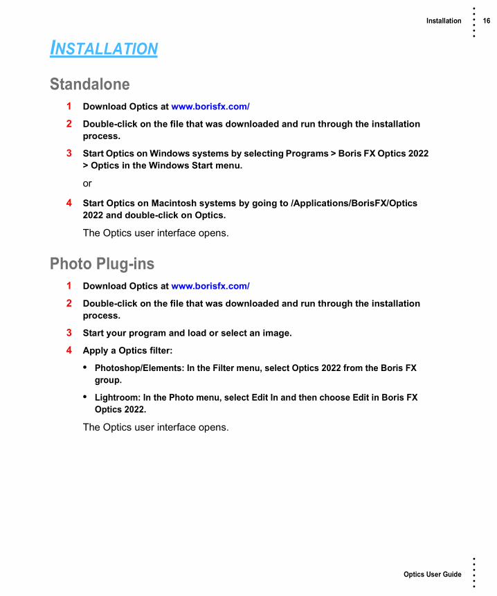
INSTALLATION
Standalone1 Download Optics at www.borisfx.com/
2 Double-click on the file that was downloaded and run through the installation process.
3 Start Optics on Windows systems by selecting Programs > Boris FX Optics 2022 > Optics in the Windows Start menu.
or
4 Start Optics on Macintosh systems by going to /Applications/BorisFX/Optics 2022 and double-click on Optics.
The Optics user interface opens.
Photo Plug-ins1 Download Optics at www.borisfx.com/
2 Double-click on the file that was downloaded and run through the installation process.
3 Start your program and load or select an image.
4 Apply a Optics filter:
• Photoshop/Elements: In the Filter menu, select Optics 2022 from the Boris FX group.
• Lightroom: In the Photo menu, select Edit In and then choose Edit in Boris FX Optics 2022.
The Optics user interface opens.

Optics User Guide
• • • •••
Installation 17 • • • •••
Adding Optics to Lightroom as an External EditorIf Lightroom is found during the installation of Optics, Optics will automatically be added as an external editor. If for some reason Optics does not show up as an external editor, you can manually add Optics as an external editor by following the steps below.
1 Open the Preferences in Lightroom.
2 Click the External Editing tab.
3 In the Additional External Editor section, select TIFF for File Format, sRGB for Color Space, 8 or 16 bits/component for Bit Depth, set the desired Resolution, and choose None for Compression.
Note: Optics is only compatible with TIFF files (8 or 16-bit, with no compression).
4 Click on Choose to select an application. Navigate to the location of Optics.
• On Windows, the default installation location for Optics will be: C:\Program Files\BorisFX\Optics 2022
• On Macintosh, the default installation location for Optics will be: /Macintosh HD/Applications/BorisFX/Optics 2022
5 Select the Optics file and click Choose.
6 Under the Preset drop-down menu, select Save Current Settings as New Preset… and name the preset Boris FX Optics 2022.
Optics can now be easily accessed under the Photo menu as a preset external editor.

Optics User Guide
• • • •••
Uninstalling 18 • • • •••
UNINSTALLING
WindowsFrom the Windows Start Menu, select Programs > Boris FX Optics > Uninstall Optics.
MacintoshGo to /Applications/BorisFX/Optics and double-click on Uninstall Optics.

Optics User Guide
• • • •••
Licensing 19 • • • •••
LICENSING
Nodelocked LicensesWhen you purchase your license, you will be emailed a serial number.
Internet ActivationWhen your machine is connected to the Internet, you can activate directly in a few simple steps.
1 Make sure you are connected to the Internet.
2 Start the Optics standalone or apply the Optics plugin.
3 Select Activate nodelock license in the License window and click OK.
The Boris FX License Tool will load.
4 Choose Activate your license now and press Next.

Optics User Guide
• • • •••
Licensing 20 • • • •••
5 Paste the serial number into the Activation Key field and click Next.
If the activation is successful, details will appear on the next page.
6 Select Finish.
Your license is now installed.
Offline ActivationIf your machine is not connected to the Internet or you are behind a firewall, use the Activate your license manually option.
1 Start the Optics standalone or apply an Optics plugin.

Optics User Guide
• • • •••
Licensing 21 • • • •••
2 Select Activate nodelock license from the License window and click OK.
The Boris FX License Tool will load.
3 Choose Activate your license manually using another computer’s web browser and press Next.

Optics User Guide
• • • •••
Licensing 22 • • • •••
4 You will be provided with file fields to load a key file.
5 Download and save the key file that you received from your license email from a computer that has an Internet connection.
6 Transfer the key file to your offline machine you are going to activate via a flash/thumb drive or a shared network.
7 Select the location of the key file in the first field.
8 Pick a location for the request file (which will be created) in the second field.
9 Copy the request file (.req) to a machine with an Internet connection.
10 Upload it to http://activation.borisfx.com/offline-activation.php.
11 Save the activation file it returns (via download or email), and copy that back to the offline machine.

Optics User Guide
• • • •••
Licensing 23 • • • •••
12 Enter its location into to the license tool and click Next.
Your license is now installed.
Internet DeactivationOnce Optics has been activated, you can access the deactivate option.
1 Make sure you are connected to the Internet.
2 Start the Optics standalone or apply the Optics plugin and select License from the Help menu.
The Boris FX License Tool loads.
3 Choose Deactivate your license now and press Next.
Optics deactivates.

Optics User Guide
• • • •••
Licensing 24 • • • •••
License Troubleshooting1 It is important that your Optics software matches your activation code, so check
your purchase order to make sure everything matches up version wise. It may be that you don’t have the correct version of Optics installed from our download section. This is especially important for legacy software.
2 Check to make sure you are not restricted to using certain ports due to a firewall or other admin permissions. When in doubt, temporarily turn your firewalls off for the duration of the installation and then turn them back on when you are done.
3 Troubleshoot your machine; try uninstalling all your Optics software, restarting your machine, and installing the software again from scratch, and make sure you follow installation directions off our website exactly. It sounds redundant, but sometimes it’s a great way to figure out what is going on inside your machine.
4 If all else fails, our support team is happy to help you figure this out. Please contact support.

Optics User Guide
• • • •••
Licensing 25 • • • •••
Request A TrialRequest a limited, unrestricted trial license.
1 Select Request a trial and click OK.
2 Click OK and you will be directed to a contact form.
3 Request a node-locked trial license of Optics.

Optics User Guide
• • • •••
Optics Workflow 26 • • • •••
TUTORIALS
Optics Workflow1 Open an image.
2 Apply Optics if using the plug-in.
3 Choose a filter category.
4 Select a filter.
5 Try out the various filter presets.
6 Adjust the filter parameters to your liking.
7 Use masks to limit where the filter is applied.
8 Add additional layers and filters.
9 Render
• Standalone: Save the image.
• Plug-in: Click the Apply button.

Optics User Guide
• • • •••
Loading An Image 27 • • • •••
Loading An ImageThe Optics standalone supports loading Camera RAW, JPEG, PNG, TIFF as well as Kodak® Cineon and DPX file formats used in motion picture and television production.
For more information on working with Camera Raw images, go to the Working With Camera RAW Files tutorial.
1 Start the Optics Standalone and open a JPEG, PNG or TIFF image using File > Open.
or
2 In Photoshop or Lightroom, apply Optics.
• Photoshop/Elements: In the Filter menu, select Optics from the Boris FX group.
• Lightroom: In the Photo menu, select Edit In and then choose Edit in Boris FX Optics.
The image appears in the Viewer and thumbnails (small images) are created for all of the effects in the current category of the Filters window.

Optics User Guide
• • • •••
Applying a Single Filter 28 • • • •••
Applying a Single Filter1 Click on the Film Lab category in the Filters window and select the Looks filter.
Presets for the filter are generated in the Presets window and the default preset is applied to the image in the Viewer.
Note: Some filters have multiple preset groups for more convenient organization.
2 In the Presets window, choose a new preset group from the pop-up menu to see a different set of filter presets.

Optics User Guide
• • • •••
Applying a Single Filter 29 • • • •••
3 Click on the different presets to try them out.
The image in the Viewer is updated as each preset is clicked.

Optics User Guide
• • • •••
Applying a Single Filter 30 • • • •••
4 Adjust the parameters to your liking.
Adjusting the parameters will update and change the image in the Viewer. You can also set the opacity of the filter using the Layer Opacity control in the Layers window.
5 Drag left or right on Layer Opacity’s numeric field to adjust the value.

Optics User Guide
• • • •••
Applying a Single Filter 31 • • • •••
In addition to opacity, Layers can be combined with the layer below using a variety of Blend modes.
Go to Blend Modes for explanations of the various modes.

Optics User Guide
• • • •••
Visualizing The Final Render 32 • • • •••
Visualizing The Final RenderBy default, the Viewer is set to a size smaller than full resolution resulting in snappy interactive editing, but will not represent the final render for some filters. These filters include: S_BleachBypass, S_Brush, Chromatic Aberration, DeNoise, Detail, S_EdgeRays, S_Etching, S_FilmDamage, S_FilmEffect, Film Stocks, Frost, Grain, Key Light, Looks, S_NightSky, Night Vision, S_RomanTile, Silk, S_VintageColor2Strip, S_VintageColor3Strip, S_ZapFrom and S_ZapTo.
To see an accurate representation of what the above filters will look like when rendered, set the Viewer > Preview Resolution to Full and the Zoom to 100%.
1 Change the Viewer > Preview Resolution to Full.
Note: The Viewer may take some time to update at full resolution.
2 Press the 1 keyboard shortcut to set the Viewer Zoom to 100%.
You are now viewing an accurate representation of what the filter will look when rendered.
3 When done viewing at Full resolution, set the Viewer > Preview Resolution back to 2K for optimal interactive performance.

Optics User Guide
• • • •••
Rendering 33 • • • •••
Rendering1 Standalone: Save the image by selecting File > Save and choose JPEG, PNG or
TIFF as the file format.
When saving to the TIFF file format, you can optionally save the Optics setup (filter, layer and mask information) along with the final file. If you then open up the saved TIFF file, you are able modify the filter, layer and mask information.
2 Plug-in: Click the Apply button at the bottom right of the user interface.
The next time you apply Optics in Photoshop, your previous Optics setup consisting of filters, layers and masks will all be displayed and can be modified. For the Optics setup information to be remembered in Lightroom, you need to use “Edit Copy with Lightroom Adjustments” and render the result. If you then apply Optics to the newly rendered version and use “Edit Original”, your previous Optics setup will also be displayed and can be modified. This behavior in Lightroom can be disabled via the Save setup with image preference.

Optics User Guide
• • • •••
Working With Camera RAW Files 34 • • • •••
Working With Camera RAW FilesOptics supports loading the most popular Camera RAW files.
Note: Loading Camera RAW images is handled by the host application when using the plug-in.
1 Open a Camera RAW file using File > Open.
The image appears in the Viewer and a Develop filter is automatically applied in the Layers window as the first layer.
Note: The Develop layer can’t be deleted.
2 To edit the camera RAW settings for the image, double-click on the bottom, Develop layer’s image thumbnail.
You are now viewing and editing the Develop layer. The layer that you are editing is considered the active layer. You can tell which layer is active by the green outline around its image thumbnail in the Layers window.
3 In the Parameters window, adjust the Develop parameters to your liking.

Optics User Guide
• • • •••
Working With Camera RAW Files 35 • • • •••
Adjusting the parameters will update and change the image in the Viewer. The initial Develop filter applied to the RAW image can’t be masked and affects the entire image. However, you can add additional layers, apply Develop filters from the Color tab and selectively mask them--all topics covered in tutorials to follow.
4 To add a filter, double-click the top, Current layer’s image thumbnail and select a filter and then a preset.

Optics User Guide
• • • •••
Applying Multiple Filters 36 • • • •••
Applying Multiple Filters1 Select a filter and choose a preset.
2 Adjust the filter parameters if you’d like.
To add another filter, a new layer has to be added.
3 Click the Add Layer icon at the top left of the Layers window or press Ctrl/Cmd+L.
The first filter drops down one position in the Layers window and is added as a layer. Multiple filters can be added in this manner.
Note: You can also use Add Layer even if no filter is applied. This way Layer Blend Modes can be used to create effects between layers.

Optics User Guide
• • • •••
Editing Multiple Filters 37 • • • •••
Editing Multiple FiltersWhen multiple filters have been applied, you have the choice of viewing and editing one layer at a time or viewing one layer while editing another.
By default, the Viewer and Parameters window display the image and controls for the top most layer. The layer displayed in the Viewer is controlled with the View/Compare icon
while the controls shown in the Parameters and Presets window are displayed with the Edit icon.
Both of these icons are located in the Layers window to the left of each layer’s image thumbnail.
View and Edit One Layer at a Time1 Apply a couple of filters to your image and add them as layers.
2 To simultaneously view and edit a different layer, double-click on its image thumbnail.
The View/Compare and Edit icons automatically activate for the new layer, while the Viewer, Parameters and Presets windows update to display the new layer’s image and effect controls.
3 Use the effect controls in the Parameters window to edit the new layer.

Optics User Guide
• • • •••
Editing Multiple Filters 38 • • • •••
View One Layer while Editing AnotherThere are many instances where it is very useful to view one layer while editing another.
1 Double-click on the top most layer’s image thumbnail.
You are now viewing and editing the top layer. The layer that you are editing is considered the active layer and this is visually indicated by the layer’s green outline.
2 Change the active layer by clicking on a lower layer’s Edit icon.
3 Adjust the effect controls in the Parameters window or choose a new preset in the Presets window.
You are now Viewing the top layer while editing a layer below.

Optics User Guide
• • • •••
Applying Multiple Layer Blend Modes 39 • • • •••
Applying Multiple Layer Blend ModesInstead of adding filters to a layer, you can use only the Layer Blend Mode to create an effect.
1 On the Current layer where no filter has been applied, select a Layer Blend Mode.
Go to Blend Modes for explanations of the various modes.
2 To add another Layer Blend Mode, click the Add Layer icon at the top left of the Layers window.
The first layer drops down one position in the Layers window and a new layer is added.
3 Select a different Layer Blend Mode for the new layer.
Multiple Layer Blend Mode’s can be added in this manner.

Optics User Guide
• • • •••
Drag and Drop Layers, Filters and Masks 40 • • • •••
Drag and Drop Layers, Filters and MasksDrag and Drop Layers
The ordering of layers can be changed by dragging and dropping them to a new location.
1 Apply a filter and create a mask.
Go to the Masking Tutorials to see how to create a mask.
2 Click the Add Layer icon and add a second filter and mask.
3 An entire layer can be moved to a new location by clicking and dragging on the gray area above or below the layer’s name and then releasing the mouse in the new location.
When the mouse button is released, the layer is moved to the new location.
Before After

Optics User Guide
• • • •••
Drag and Drop Layers, Filters and Masks 41 • • • •••
Drag and Drop Filters And MasksReplacing Filters and MasksDragging and dropping a filter or mask in the middle of an existing filter or mask replaces it.
1 Choose a layer that has a filter applied to it.
2 Click the layer’s image thumbnail that you want to copy, drag it over the image thumbnail that you want to replace, and release the mouse when a red outline appears and the cursor changes to a + sign.
When the mouse button is released, the destination filter is replaced with the source filter.
3 Click a mask, drag it over the mask you want to replace and when a red outline appears along with a + cursor, release the mouse.
When the mouse button is released, the destination mask is replaced with the source mask.
Before After
Before After

Optics User Guide
• • • •••
Drag and Drop Layers, Filters and Masks 42 • • • •••
Moving MasksWithin a layer, the order of masks can be changed.
1 Click a mask, drag it between two other masks or to the edge of the last mask and when a red vertical bar appears along with an arrow icon, release the mouse.
The mask is moved to the new location.
Before
After

Optics User Guide
• • • •••
Drag and Drop Layers, Filters and Masks 43 • • • •••
Copying and Inserting MasksDragging and dropping a mask to an open area of a layer or between masks on another layer copies/inserts it.
1 Click a mask, drag it to an open area of a layer or between masks on another layer and when a + cursor appears, release the mouse to copy/insert it.
The mask is copied to the new location.
Before
After

Optics User Guide
• • • •••
Viewing Individual Layers 44 • • • •••
Viewing Individual Layers1 Apply a couple of filters to your image and add them as layers.
2 Click on an image thumbnail in the Layers window to display that layer in the Viewer.
3 When you are finished, click on the top layer’s image thumbnail.
Comparing LayersOptics can compare layers using Side-by-Side, Vertical Split, Horizontal Split, A/B or Snapshot comparison modes. By default, the current filter and original image are selected for comparison.
The View/Compare icon in the Layers window changes which layers are used in the comparison.
1 Apply a filter and make sure it is affecting the image in some way.
2 Click on the Side-by-Side Comparison icon.
Click

Optics User Guide
• • • •••
Comparing Layers 45 • • • •••
Horizontal images are stacked vertically and vertical images are placed side by side.

Optics User Guide
• • • •••
Comparing Layers 46 • • • •••
3 Click the Vertical Split Comparison mode icon.
You can now compare the images using a vertical split.
4 Move your cursor into the image area over the split line and when the cursor changes to a double-arrow, click and drag to move the split.
Depending on the filter used, the split line may not be obvious, so triangular sashes on the outside of the image help you find it. If you drag the sash all the way around, it will swap directions.
5 Enable the A/B Comparison icon and then click the Show Other View icon that appears to cycle the current filter with the original image.
6 When done, press the A/B Comparison icon to turn it off.

Optics User Guide
• • • •••
Comparing Layers 47 • • • •••
7 Press the Snapshot icon.
Once clicked, a snapshot of the image in the Viewer is taken as well as the layer’s mask, if there is one.
8 Press the View Snapshot icon that appears.
View Snapshot allows you to now use the various comparison modes to compare the snapshot to other layers or different filter settings.
9 Turn off View Snapshot when done.

Optics User Guide
• • • •••
Tagging and Sorting Favorite Presets 48 • • • •••
Tagging and Sorting Favorite PresetsPresets can be tagged as a Favorite allowing them to be sorted separately in the Presets window as well as in the Favorites tab of the Filters window.
1 Apply a filter with presets.
2 Tag a preset as a Favorite by selecting the preset and pressing the Toggle Favorite icon located at the top right of the Presets window.
Presets tagged as a favorite display a yellow star at the top right of the preset.
3 To sort the Presets window by Favorites, select Favorites in the Presets pop-up menu.

Optics User Guide
• • • •••
Creating Presets 49 • • • •••
Creating Presets1 Select a filter and choose a preset.
2 In the Parameters window, adjust the filter parameters to your liking.
3 To create a new preset based on the current parameter settings, click the Create Custom Preset icon located at the top right of the Parameters window.

Optics User Guide
• • • •••
Creating Presets 50 • • • •••
4 When the New Preset window opens, enter the desired information and press OK to create the preset.
5 In the Presets window, you will see the newly created custom preset.

Optics User Guide
• • • •••
Creating Variations 51 • • • •••
Creating VariationsVariations based on either one or two parameters can be created and are displayed as thumbnails in a window below the Parameters and Presets window.
1 Apply a filter.
2 Click on a parameter name in the Parameters window.
Variable parameters are Ranges, Toggles, and Colors.

Optics User Guide
• • • •••
Creating Variations 52 • • • •••
When you select a parameter, the Variations appear and you'll see the variations being generated on that parameter.
3 Click on a second parameter and it will generate variations between the two.
The first parameter you click on will be the dominant parameter - it'll go across the top of the Variations tab. So, you can get different results depending on the order you select the parameters.
4 Click on a selected parameter to toggle it back off again.
Note: You can only have one or two parameters selected at a time. If you click on a third parameter, the last parameter you clicked on will deselect itself. If you deselect both of the parameters or switch effects, the Variations window will disappear because the variations are no longer being generated.
Variations are generated based on the current effect parameters. So, you can pick some parameters for your variation, then go back to the Presets window and pick a different Preset, and the variations will regenerate.
See Variations for more information.

Optics User Guide
• • • •••
Working With Masks 53 • • • •••
Working With MasksMasks allow you to limit the effect of a filter by revealing it only in white areas of the mask. White is on, black is off and gray areas in between represent a level of transparency.
The following mask types can be applied to a layer: Gradient, Spot, Path, Snap, EZ Mask, Selection and Paint by clicking the Add Mask icon in the Layers window.
Import MasksMasks are imported into the Original Layer in Optics. The mask can then be copied for use on other layers.
PhotoshopThe Photoshop layer mask is transferred to Optics.
1 If you are using a file with transparency, convert it to a layer mask by either dragging and dropping the layer thumbnail onto the Add Layer Mask icon or select Layer > Layer Mask > From Transparency.
2 Apply Optics.
3 Select No when prompted with “Apply previous filters/masks?”
Lightroom• Apply Optics to a PNG or TIFF file with alpha/transparency.
Standalone• Load a PNG or TIFF file with alpha/transparency.
4 To view the imported mask, select the Original layer and press the A key.

Optics User Guide
• • • •••
Working With Masks 54 • • • •••
Export Masks and Generated AlphaMasksMasks are exported along with the image and filters using a layer’s Export Masks icon visible to the right of the layer’s masks.
1 If you are using Photoshop, create a Layer Mask before applying Optics.
2 Add a filter and at least one mask.
3 Enable the Export Masks icon for the layer.
4 To view the masks to be exported, select the layer whose Export Masks icon is enabled and press the M key. Press the M key again to view the image.
Please note that Optics generates and renders EZ Masks at the current Preview Resolution unless a higher resolution is selected. This means that if you create a mask at any size other than full, it will be scaled up to the original image size when rendered, thus reducing quality.
5 If you want to export a full resolution EZ Mask, change the Preview Resolution to Full and regenerate the mask when prompted.
Note: You can now go back to the lower resolution for performance reasons since the mask is now generated at full size.
6 Export the masks by clicking Apply in Photoshop/Lightroom or saving from the Standalone. Requirements for mask export:
• Photoshop: A layer mask is present.
• Lightroom: Export to a PNG or TIFF file.
• Standalone: Save to a PNG or TIFF file.
The masks are exported as alpha/transparency.
Note: The masks will not be exported if a layer mask is not present in Photoshop or you don’t save/export to a PNG or TIFF file in the Standalone or Lightroom.
Optics User Guide
• • • •••
Working With Masks 55 • • • •••
Generated AlphaSome filters that generate elements like S_LensFlare and S_Rays add values to the alpha channel which can be exported along with the image and filters.
Images With Transparency1 Load an image with transparency.
2 For Photoshop users, select Layer > Layer Mask > From Transparency, select the layer’s image thumbnail and apply Optics.
3 Apply S_LensFlare and choose a preset.
4 To view the alpha channel, press the A key and you will see that the generated element is also added to the existing alpha channel. Press the A key again to view the image.
5 Leave the Export Masks icon enabled on the original layer.
6 Export the modified alpha along with the image and filters by clicking Apply in Photoshop/Lightroom or saving from the Standalone. Requirements for mask export:
• Photoshop: A layer mask is present.
• Lightroom: Export to a PNG or TIFF file.
• Standalone: Save to a PNG or TIFF file.
The modified alpha channel is exported as alpha/transparency.
Note: The modified alpha channel will not be exported if a layer mask is not present in Photoshop or you don’t save/export to a PNG or TIFF file in the Standalone or Lightroom.

Optics User Guide
• • • •••
Working With Masks 56 • • • •••
Generated Elements and Alpha OnlyAfter positioning the generated filter elements over the background image, you can render only these elements along with their alpha channel values for further manipulation in Photoshop.
1 If you are using Photoshop, create a Layer Mask before applying Optics.
2 Apply S_LensFlare and choose a preset.
3 Set the Combine mode to Flare Only.
The majority of filters that generate an element have a Combine mode that renders only the element.
4 To view the alpha channel, press the A key and you will see that the generated element is also added to the existing alpha channel. Press the A key again to view the image.
If you have multiple generated elements, the S_ChannelSwitcher filter can be used to set the RGBA channels of the Original layer to black. This would be faster than setting the Combine mode to render each element only.
5 Add a S_ChannelSwitcher filter to a new layer, select the RGBA Black preset and then move the layer directly above the Original layer.
6 Leave the Export Masks icon enabled on the original layer.
7 Export the modified alpha along with the generated filter elements by clicking Apply in Photoshop/Lightroom or saving from the Standalone. Requirements for mask export:
• Photoshop: A layer mask is present.
• Lightroom: Export to a PNG or TIFF file.
• Standalone: Save to a PNG or TIFF file.
The modified alpha channel is exported as alpha/transparency.
Note: The modified alpha channel will not be exported if a layer mask is not present in Photoshop or you don’t save/export to a PNG or TIFF file in the Standalone or Lightroom.

Optics User Guide
• • • •••
Applying a Gradient Mask to a Layer 57 • • • •••
Applying a Gradient Mask to a LayerA Gradient mask creates a linear top to bottom or left to right gradient and is adjusted using the four points around the corners of the image as well as controls in the Toolbar.
1 Select a filter and preset that changes the image in an obvious way.
2 For instance, select the Grads/Tints > Tint filter.
3 Click the Add Mask icon in the Layers window and choose Gradient.
When the mask is applied to your layer, a couple of things happen. First, a mask thumbnail appears to the right of the image thumbnail. Second, the filter that was applied to the image is now limited to the white areas of the mask. Third, controls are added to the Toolbar as well as the Viewer depending upon the type of mask selected.
Photo by Joshua Earle on Unsplash

Optics User Guide
• • • •••
Applying a Gradient Mask to a Layer 58 • • • •••
4 Use the on-screen controls to adjust the gradient.
• Corner-Pin: Drag on the corner points of the image.
• Position: Drag the center point.
• Size: Drag the top/bottom mid-points.
• Rotate: Drag the right center circle.
The direction, size and angle of the gradient can also be adjusted using the controls in the Toolbar.
See Gradient Mask for more information.
Optics User Guide
• • • •••
Applying a Selection Mask to a Layer 59 • • • •••
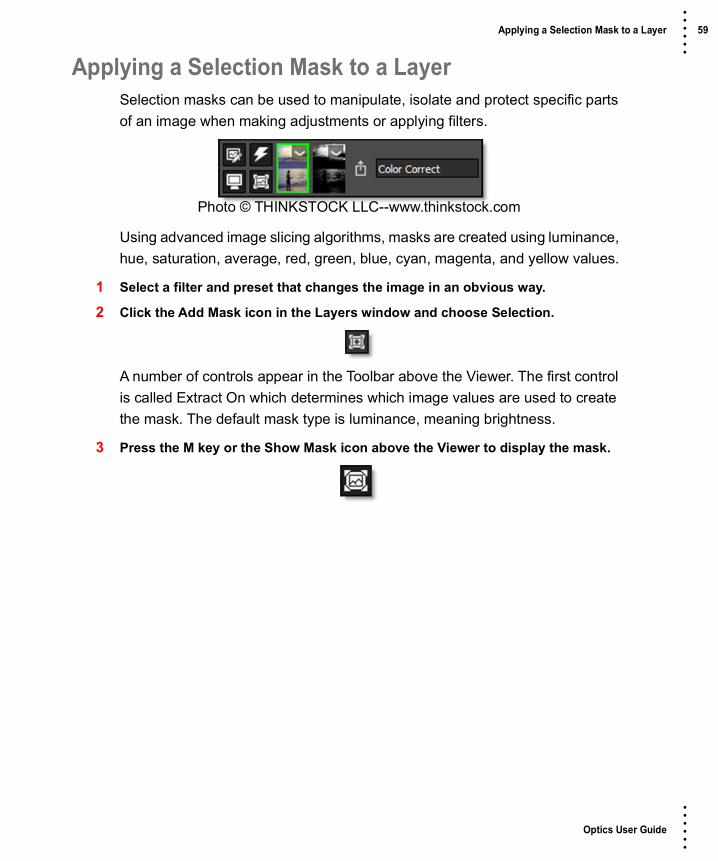
Applying a Selection Mask to a LayerSelection masks can be used to manipulate, isolate and protect specific parts of an image when making adjustments or applying filters.
Using advanced image slicing algorithms, masks are created using luminance, hue, saturation, average, red, green, blue, cyan, magenta, and yellow values.
1 Select a filter and preset that changes the image in an obvious way.
2 Click the Add Mask icon in the Layers window and choose Selection.
A number of controls appear in the Toolbar above the Viewer. The first control is called Extract On which determines which image values are used to create the mask. The default mask type is luminance, meaning brightness.
3 Press the M key or the Show Mask icon above the Viewer to display the mask.
Photo © THINKSTOCK LLC--www.thinkstock.com

Optics User Guide
• • • •••
Applying a Selection Mask to a Layer 60 • • • •••
Position and Range ControlsThe Position and Range parameters are key to isolating specific image values.
1 Set the Position parameter by dragging the numeric field to the right of its icon in the Toolbar.
Using the Luminance extraction method, a higher Position value shows more white values from the original image as white values in the mask. A lower Position value shows more black values from the original image as white values in the mask.
Once you’ve selected the Position, you can then add or subtract the Range of values to be included in the mask.
2 Adjust the Range parameter by dragging the numeric field to the right of its icon.
Position 0, Range 25 Position 100, Range 25Original

Optics User Guide
• • • •••
Applying a Selection Mask to a Layer 61 • • • •••
A higher Range value includes more white values in the mask while a lower Range value includes less values in the mask.
In addition to using the slider controls in the Toolbar, the Position, Range and Radius parameters can be set using on-screen controls. Click on the image to place the on-screen control which consists of a center point and a solid circle. The Position value is set by the location of the center point, while the Range is set by sizing the circle. The larger the circle, the larger the range.
Position 100, Range 25 Position 100, Range 75Original
Range
Position

Optics User Guide
• • • •••
Applying a Selection Mask to a Layer 62 • • • •••
3 Change the Radius parameter by dragging the numeric field to the right of its icon.
When the Radius control is increased, a soft, circular mask is created to limit the selection. If the on-screen controls are used, the Radius is represented as a dashed circle.
In this case, the Radius allows me to isolate the clouds from the water.4 You may want to adjust Black Clip to add more values to the black part of the
mask and adjust White Clip to add more values to the white part of the mask.5 If needed, Shrink/Grow can be used to make the mask smaller or larger and the
Blur controls can soften the mask.6 Press the M key to display the full color image in the Viewer.
See Selection Mask for more information.
Radius
Optics User Guide
• • • •••
Applying a Path Mask to a Layer 63 • • • •••
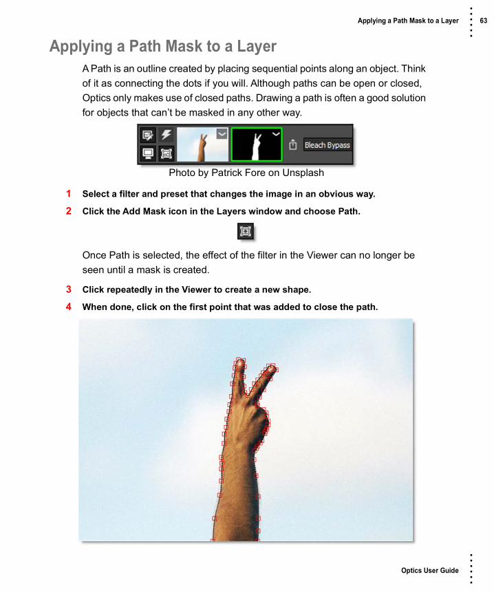
Applying a Path Mask to a LayerA Path is an outline created by placing sequential points along an object. Think of it as connecting the dots if you will. Although paths can be open or closed, Optics only makes use of closed paths. Drawing a path is often a good solution for objects that can’t be masked in any other way.
1 Select a filter and preset that changes the image in an obvious way.
2 Click the Add Mask icon in the Layers window and choose Path.
Once Path is selected, the effect of the filter in the Viewer can no longer be seen until a mask is created.
3 Click repeatedly in the Viewer to create a new shape.
4 When done, click on the first point that was added to close the path.
Photo by Patrick Fore on Unsplash

Optics User Guide
• • • •••
Applying a Path Mask to a Layer 64 • • • •••
The filter now appears only in the area contained within the path. To change the shape of the path, move the controls points.
5 Click on one point to select it or click and drag a box around a group of points.
6 Click and drag on one of the selected points to move them.
If needed, you can add new points by Alt+clicking on the path between two points. Points are deleted by selecting them and hitting the Delete key.
7 Create as many paths as you’d like.
When paths overlap, a hole in the mask occurs.
See Path Mask for more information.

Optics User Guide
• • • •••
Applying a Snap Mask to a Layer 65 • • • •••
Applying a Snap Mask to a LayerThe Snap masking tool provides instant visual feedback by snapping an editable curve to an object's boundary even if it has vague or low contrast edges. This is made possible by utilizing unique graph-cutting and segmentation algorithms.
1 Select a filter and preset that changes the image in an obvious way.
2 Click the Add Mask icon in the Layers window and choose Snap.
FG Mark
Boundary BG Mark
BG Mark
Photo © THINKSTOCK LLC--www.thinkstock.com

Optics User Guide
• • • •••
Applying a Snap Mask to a Layer 66 • • • •••
Once Snap is selected, the effect of the filter in the Viewer can no longer be seen until a mask is created.
3 Define the area to be isolated by drawing a foreground line with the left mouse button.
The Mark Foreground icon is selected by default when you apply a Snap mask and that is why you can just start drawing with the left mouse button.
4 Define background areas by drawing lines with the right mouse button.

Optics User Guide
• • • •••
Applying a Snap Mask to a Layer 67 • • • •••
5 Alternatively, you could select the Mark Background icon and draw with the left mouse button.
As soon as the first background line is drawn, Snap calculates a boundary curve that is displayed as a black and white dashed line around the object.
6 Draw additional foreground and background lines as needed until the object that you’d like to isolate is roughly surrounded by a boundary.

Optics User Guide
• • • •••
Applying a Snap Mask to a Layer 68 • • • •••
Where the boundary doesn’t correctly follow the edge of your object, refine the boundary by using either the Edit Points or Override Edge icons in the Toolbar. When either of these tools is selected, the boundary created in the object marking step is converted into editable polygons and you will see a noticeable refinement in the boundary.
7 Click the Edit Points icon in the Toolbar and drag a point to adjust the shape of the polygon.
and / or
Before After

Optics User Guide
• • • •••
Applying a Snap Mask to a Layer 69 • • • •••
8 Click the Override Edge icon in the Toolbar and draw a mark along the edge of your object where the boundary doesn’t correctly follow the edge.
9 When happy with the boundary you have created, click the Convert Curve to a Path icon in the Toolbar to apply it to the layer and convert it to an editable path.
A slider pops up to control the amount of points to be included in the path.
10 Drag the slider to reduce the number of path points or just click it to accept the current setting.
By default, Edit Points is selected after the path is created so that you can view and edit the points.
11 To create a new boundary, select the Mark Foreground icon and repeat the above steps.
When boundaries overlap, a hole in the mask is created.
See Snap Mask for more information.
Before After
Photo © THINKSTOCK LLC--www.thinkstock.com

Optics User Guide
• • • •••
Applying a EZ Mask to a Layer 70 • • • •••
Applying a EZ Mask to a LayerEZ Mask is an easy to use interactive image masking tool capable of isolating almost any object in an image--even if you are dealing with fine hair detail, smoke, or reflections.
To work this magic, EZ Mask iteratively estimates the transparency value for every pixel in the image, based on a small sample of foreground (what you want to isolate) and background pixels marked by simple strokes on the image. Results show that compared with previous approaches, our method is more efficient and requires minimal effort to extract high quality masks for foregrounds with significant semi-transparent regions.
Stroke Trimap TutorialEZ Mask creates masks by using a trimap--a pre-segmented image consisting of three regions of foreground (what you want to isolate), background and unknown. Partial opacity values are then computed only for pixels inside the unknown region. Two trimap methods can be used: Stroke and Filled. This tutorial will use the Stroke method.
Our trimaps can be relatively sparse consisting of individual foreground and background brush strokes. All pixels left unmarked will be treated as unknown. After processing, if any fine foreground details are missing from the mask, the Unknown brush can be used in these areas to help recover lost detail.
User Input Mask

Optics User Guide
• • • •••
Applying a EZ Mask to a Layer 71 • • • •••
1 Select a filter and preset that changes the image in an obvious way.
2 Click the Add Mask icon in the Layers window and choose EZ Mask.
Note: Once EZ Mask is selected, the effect of the filter in the Viewer can no longer be seen until a mask is created.
A good stroke technique is to draw an inner outline around the object you are extracting using the Paint Foreground brush and an outer outline using the Paint Background brush.
3 Define the area to be cutout by drawing foreground lines with the left mouse button. You can quickly draw straight lines if you click with the left mouse button, press Shift and then click in a different location. If you keep Shift depressed while clicking, you will create interconnected straight lines.
The Paint Foreground brush is selected by default when you enter EZ Mask and that is why you can just start drawing with the left mouse button.
The strokes should be near the boundary of the foreground, but not right up against the edge. Strokes that are closer to the boundary will dominate the creation of the mask. Also, if the foreground has varying colors, the strokes should cover these colors.
Note: The general rule is don’t put different stroke types too close together unless you need to.
4 Define background areas by drawing with the right mouse button.
or

Optics User Guide
• • • •••
Applying a EZ Mask to a Layer 72 • • • •••
5 Alternatively, you could select the Paint Background brush and draw with the left mouse button.
If the background has varying colors, the strokes should cover these colors.
Warning: If you only provide a few sparse strokes, a Stroke trimap will take longer to process than a filled trimap.
6 Click the Generate Mask icon or press the Enter key.
Good Stroke Example Bad Stroke Example

Optics User Guide
• • • •••
Applying a EZ Mask to a Layer 73 • • • •••
Once EZ Mask is done processing, the mask will be shown in the mask thumbnail of the Layers window.
7 Press the M key to view the Mask in the Viewer.
In the Mask, white is foreground, black is background and any gray areas in between represent a level of transparency. If the mask is not acceptable after processing, add a few strokes near the region where the mask is not accurate.
Note: To quickly toggle off the display of your strokes, click on the layer’s image thumbnail. Click the mask thumbnail to re-display the strokes.
8 If you see gray areas in the foreground object that should be completely white, make additional foreground marks in those areas.
9 If you see gray areas in the background that should be completely black, make additional background marks.
When drawing a stroke trimap, certain foreground details may be missing after the mask is generated. Using the Paint Missing brush in these areas can sometimes help recover lost detail.
10 Press the M key again to view the full color image.

Optics User Guide
• • • •••
Applying a EZ Mask to a Layer 74 • • • •••
11 If any fine foreground details are missing from the mask, click on the Paint Missing brush and draw over them with the left mouse button as illustrated by the purple strokes in the dog’s hair.
The purple colored strokes represent the missing areas.
12 Click the Generate Mask icon or the Enter key again to see how any new foreground, background and unknown strokes affect the mask.
See EZ Mask for more information.

Optics User Guide
• • • •••
Applying a EZ Mask to a Layer 75 • • • •••
Filled Trimap TutorialEZ Mask creates masks by using a trimap--a pre-segmented image consisting of three regions of foreground (what you want to isolate), background and unknown. Partial opacity values are then computed only for pixels inside the unknown region. Two trimap methods can be used: Stroke and Filled. This tutorial will use the Filled method.
Foreground and background brush strokes are used to mark definite foreground and background pixels while the Unknown brush is used to mark unknown, or mixed regions. Using this method, the entire image is painted/filled with one of the three brushes.
1 Select a filter and preset that changes the image in an obvious way.
2 Click the Add Mask icon in the Layers window and choose EZ Mask.
Note: Once EZ Mask is selected, the effect of the filter in the Viewer can no longer be seen until a mask is created.
When drawing a filled trimap, the best method is to draw the unknown areas first. Unknown areas are typically areas where the foreground is transitioning to the background. In the image below, the hairy edges of the Alpaca would be considered unknown areas.
Foreground Filled Trimap

Optics User Guide
• • • •••
Applying a EZ Mask to a Layer 76 • • • •••
3 Define unknown areas by selecting the Paint Unknown brush and drawing around the edges of the foreground with the left mouse button. You can quickly draw straight lines if you click with the left mouse button, press Shift and then click in a different location. If you keep Shift depressed while clicking, you will create interconnected straight lines.
Include as little solid foreground areas as possible, but be sure to draw over all of the unknown regions. Ideally, the unknown region in the trimap should only cover transparent pixels whose actual values are not completely foreground or background. In other words, the unknown region in the trimap should be as thin as possible to achieve the best masking result.

Optics User Guide
• • • •••
Applying a EZ Mask to a Layer 77 • • • •••
4 Define the area to be cutout by selecting the Paint Foreground brush and the Fill tool.
Using the current brush, the Fill tool fills a region defined by a brush stroke or the edges of the screen.
5 Click inside the area defined by the blue, unknown brush.
The area inside of the blue, unknown boundary automatically fills in with the green foreground brush. Using the Fill tool is much easier than drawing the entire area by hand.
6 Define background areas by using the Paint Background brush and the Fill tool. Since the Fill tool is already enabled, you don’t need to select it again.
7 Click on the background outside of the area defined by the blue, unknown brush.

Optics User Guide
• • • •••
Applying a EZ Mask to a Layer 78 • • • •••
The background area automatically fills in with the red background brush.
8 Click the Generate Mask icon or press the Enter key.
Once EZ Mask is done processing, the mask will be shown in the mask thumbnail.
9 Press the M key to view the Mask in the Viewer.

Optics User Guide
• • • •••
Applying a EZ Mask to a Layer 79 • • • •••
In the Mask, white is foreground, black is background and any gray areas in between represent a level of transparency.
Note: To quickly toggle off the display of your strokes, click on the layer’s image thumbnail. Click the mask thumbnail to re-display the strokes.
10 If you see gray areas in the foreground object that should be completely white, make additional foreground marks in those areas.
11 If you see gray areas in the background that should be completely black, make additional background marks.
12 If there are areas that should be marked as unknown, make additional marks with the Paint Unknown brush.
13 Click the Generate Mask icon or Enter key again to see how any new foreground, background and unknown strokes affect the mask.
14 Press the M key again to view the full color image.
See EZ Mask for more information.

Optics User Guide
• • • •••
Applying a Paint Mask to a Layer 80 • • • •••
Applying a Paint Mask to a LayerOrganic masks are created using a paint brush.
1 Select a filter and preset that changes the image in an obvious way.
2 Click the Add Mask icon in the Layers window and choose Paint.
Once the Paint mask is selected, the effect of the filter in the Viewer can no longer be seen until a paint stroke is made.
3 Change the brush size by clicking and dragging on the Brush Size number field.
or
4 Resize the brush in the Viewer by holding Ctrl/Cmd and dragging in or out.
The Brush Softness and Opacity can also be adjusted by clicking their respective number fields in the Toolbar.
5 Using the left mouse button, click and drag a portion of the Viewer.
The filter appears only in the area of the paint stroke.
6 To quickly erase a portion of the painted mask, paint with the right mouse button. Alternatively, select a O Brush Opacity and paint with the left mouse button.
Painting with a brush intensity that is a level of gray will apply the filter proportionate to that brush intensity. White areas in the mask apply the filter at full intensity while black areas show no filter.
See Paint Mask for more information.
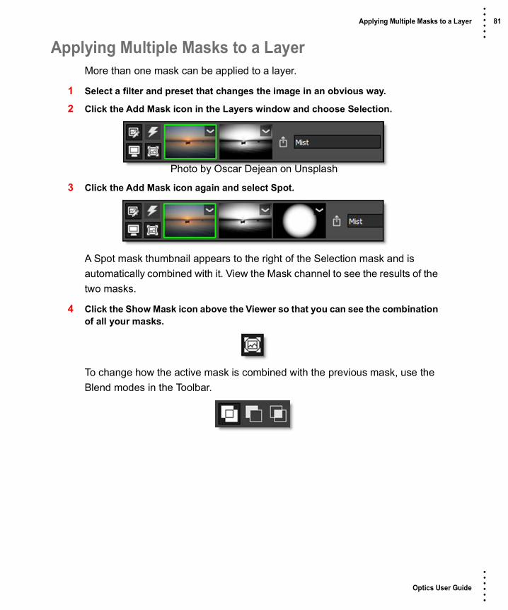
Optics User Guide
• • • •••
Applying Multiple Masks to a Layer 81 • • • •••
Applying Multiple Masks to a LayerMore than one mask can be applied to a layer.
1 Select a filter and preset that changes the image in an obvious way.
2 Click the Add Mask icon in the Layers window and choose Selection.
3 Click the Add Mask icon again and select Spot.
A Spot mask thumbnail appears to the right of the Selection mask and is automatically combined with it. View the Mask channel to see the results of the two masks.
4 Click the Show Mask icon above the Viewer so that you can see the combination of all your masks.
To change how the active mask is combined with the previous mask, use the Blend modes in the Toolbar.
Photo by Oscar Dejean on Unsplash

Optics User Guide
• • • •••
Applying Multiple Masks to a Layer 82 • • • •••
5 Select the Multiply blend mode to see how it affects the way the masks are combined.
6 Click the M shortcut key to switch the Viewer to display the full color image.
When you have multiple masks, the mask with the green outline around it is considered the active mask and it’s controls are displayed in the Toolbar.
To change the active mask, simply click on the thumbnail of another mask.

Optics User Guide
• • • •••
Setups 83 • • • •••
SetupsA Setup takes a snapshot of the filters and parameter settings applied to your image. Setups can be saved and loaded and are independent of the image they were originally applied to.
1 Select a filter, choose a preset and make some parameter adjustments.
2 Add additional filters if you like by clicking the Add Layer icon at the top of the Layers Window and then selecting another filter.
3 Select File > Save Setup.
4 When the file browser opens, enter a name and click Save.
You can now apply this setup to a different image using File > Open Setup.

Optics User Guide
• • • •••
Batch Processing 84 • • • •••
Batch ProcessingBatch processes multiple files using the current setup or a previously saved setup.
Note: Batch Processing is only available in the standalone.
1 Open an image using File > Open.
2 Select a filter and choose a preset.
3 Add additional filters if you like by clicking the Add Layer icon at the top of the Layers Window and then selecting another filter.
4 Select File > Batch.
A window pops up stating, “The current image must be closed before the batch is processed. Add to batch, close or cancel?”
5 Click Close to proceed to Batch without adding the current image.

Optics User Guide
• • • •••
Batch Processing 85 • • • •••
The Batch window opens.
6 Press the Add Image to Batch icon.

Optics User Guide
• • • •••
Batch Processing 86 • • • •••
When the file browser opens, select one or more files and click open. The files are then added to the Batch window.
The next step in the Batch process is to select a Setup to be applied to all of your images. A Setup takes a snapshot of the filters and masks applied to your image in the Layers window. Setups can be saved and loaded and are independent of the image they were originally applied to. By default, the Setup parameter is set to Current, for the current setup.
7 Leave the Setup parameter set at Current so your current Layers window setup can be applied to the batched files.
8 Set your file format for the newly created output files.
When saving to the TIFF file format, you can optionally save the Optics setup (filter, layer and mask information) along with the final file. If you then open up the saved TIFF file, you are able modify the filter, layer and mask information.
9 To save the Optics setup along with the file, choose the TIFF file format, click Options and enable Save Setup with image.
In addition, if you activate and set the Resizing options, the entire list of files will be resized.
10 Click Process.

Optics User Guide
• • • •••
Batch Processing 87 • • • •••
11 When the Save browser opens, choose a folder or create a new one for the new images that will be created and click OK.
See Batch for more information.

Optics User Guide
• • • •••
88 • • • •••
USER INTERFACE
Optics is comprised of 5 main components: Viewer, Filters, Presets, Parameters, and Layers.
Layers Viewer
Filters
Parameters
Presets

Optics User Guide
• • • •••
Viewer 89 • • • •••
ViewerThe Viewer is where images are viewed, edited and manipulated.
Preview ChannelView the individual Red, Green, Blue or Alpha channels as a gray scale image. In addition to selecting this icon, you can use the R, G, B, A, Shift-A keyboard shortcuts to toggle the red channel, green channel, blue channel, alpha channel, and alpha overlay on and off.

Optics User Guide
• • • •••
Viewer 90 • • • •••
Viewer PreviewWhen an alpha channel is present, the Viewer has a variety of display options.
Preview Over BlackThe image appears in areas of the alpha channel over a black background.
Preview Over GrayThe image appears in areas of the alpha channel over a gray background.
Preview Over WhiteThe image appears in areas of the alpha channel over a white background.
Preview Over CheckerboardThe image appears in areas of the alpha channel over a checkerboard background.
RGB StraightShows the entire image regardless of the alpha channel.
Show MaskCycles the display between the full color image and the Mask channel.
Zoom and PanZoom LevelSets the zoom level as a percentage.
Zoom to 100% (1)Sets the Zoom level to 100%.

Optics User Guide
• • • •••
Viewer 91 • • • •••
Zoom to Fit (F)Fits the entire image inside the Viewer.
ZoomClick to zoom the image in, Alt+click to zoom out or drag select a square region in the Viewer to zoom in on that area.
PanClick and drag to pan the image left, right, up and down.
Space Bar+drag also pans the image.
See the Viewer Keyboard Shortcuts for more zooming and panning options.
Preview ResolutionDefines the default working resolution. However, when your image is saved, Optics always processes at full size.
By default, the Viewer is set to a size smaller than full resolution resulting in snappy interactive editing, but will not represent the final render for some filters. These filters include: S_BleachBypass, S_Brush, Chromatic Aberration, DeNoise, Detail, S_EdgeRays, S_Etching, S_FilmDamage, S_FilmEffect, Film Stocks, Frost, Grain, Key Light, Looks, S_NightSky, Night Vision, S_RomanTile, Silk, S_VintageColor2Strip, S_VintageColor3Strip, S_ZapFrom and S_ZapTo.

Optics User Guide
• • • •••
Viewer 92 • • • •••
To see an accurate representation of what the above filters will look like when rendered, set the Viewer > Preview Resolution to Full and the Zoom to 100%.
Note: The default Preview Resolution is set in Preferences.
1KOptics works at a maximum resolution of 1024 x 1024 pixels.
2KOptics works at a maximum resolution of 2048 x 2048 pixels.
4KOptics works at a maximum resolution of 4096 x 4096 pixels.
8KOptics works at a maximum resolution of 8192 x 8192 pixels.
FullOptics works at full resolution.
Note: Large Preview Resolutions take much longer to process when making parameter adjustments.
CompareCompares images using Side-by-Side, Vertical Split, Horizontal Split, A/B or Snapshot comparison modes. By default, the current filter and original image are selected for comparison. Choose one of the comparison modes using the icons above the Viewer.
The View/Compare icon in the Layers window determines which layers are used in the comparison.

Optics User Guide
• • • •••
Viewer 93 • • • •••
Side-by-Side ComparisonCompares images side by side in the Viewer.

Optics User Guide
• • • •••
Viewer 94 • • • •••
Vertical Split ComparisonCompares images using a vertical split. Move your cursor into the image area over the split line and when the cursor changes to a double-arrow, click and drag to move the split. Depending on the filter used, the split line may not be obvious, so triangular sashes on the outside of the image help you find it. If you drag the sash all the way around, it will swap directions.

Optics User Guide
• • • •••
Viewer 95 • • • •••
Horizontal Split ComparisonCompares images using a horizontal split. Move your cursor into the image area over the split line and when the cursor changes to a double-arrow, click and drag to move the split. Depending on the filter used, the split line may not be obvious, so triangular sashes on the outside of the image help you find it. If you drag the sash all the way around, it will swap directions.
A/B ComparisonWhen the A/B Comparison button is selected,
a Show Other View icon is enabled. Clicking it cycles through the images.

Optics User Guide
• • • •••
Viewer 96 • • • •••
SnapshotWhen the Snapshot icon is enabled, a snapshot of the image in the Viewer is taken as well as the layer’s mask, if there is one.
A View Snapshot icon then appears and allows the use of the various comparison modes to compare the snapshot to the other layers or different filter settings.
Overlay (0)Toggles the display of overlays which are point, lines, or shapes that Optics superimposes over the image. 0, the number zero, toggles the overlay.
Histogram (H)A histogram is a specialized graph that plots the number of pixels at each color intensity level. It is very useful in seeing how an image’s pixels are distributed.

Optics User Guide
• • • •••
Viewer 97 • • • •••
Viewer Keyboard ShortcutsShortcut Action
R, G, B, A Toggles the red, green, blue and alpha channels on and off
Shift-A Superimposes the alpha channel over the image
Middle-mouse drag Pans the image
Space Bar+drag Pans the image
I Zooms the image in
O Zooms the image out
Zoom icon+click Zooms the image in
Zoom icon+Alt+click Zooms the image out
Zoom icon+Drag a square Zooms into the defined area
Scroll wheel over image Zooms the image in and out
Middle-mouse double click Fits the image to the window
F Fits the image to the window
1 Sets the Zoom level to 100%
M Cycles the display between the color image and the Mask channel
0 Toggles the display of overlays which are point, lines, or shapes
H Opens the Histogram window

Optics User Guide
• • • •••
Filters 98 • • • •••
FiltersThe Filters window at the bottom of the screen is categorized by filter function and displays a thumbnail for each filter. The following filter categories are listed: Color, Diffusion/Blurs, Film Lab, Grads/Tints, Image, Lens/Distort, Light, Render and Stylize.
You can find detailed information on each filter later in this guide.
SearchTo search for filters in the Filters window, click the Search icon at the top left of the Filters window.

Optics User Guide
• • • •••
Filters 99 • • • •••
Enter text into the search field and related filters will appear.
Disable the Search icon when done to return to the normal Filters window view.
Note: With the mouse in the Filters window, you can press the Enter key to enter search mode, and the Esc key to leave it.
Wrap FiltersCertain filter categories have a lot of filters and depending on the size of the window, there may be a horizontal scroll bar so that you can navigate to any filter not currently shown on the screen. To change to a vertical scroll bar, click the Wrap Filters icon at the far right of the Filters window.

Optics User Guide
• • • •••
Presets 100 • • • •••
PresetsThe Presets window allows you to select from a set of pre-defined presets. Presets are available for most filters so that you can easily click through the various choices.

Optics User Guide
• • • •••
Presets 101 • • • •••
Most filters contain multiple preset groups which are selectable at the top of the window.
Clicking once on a preset modifies the image in the Viewer. As you click on different presets, the image in the Viewer will update. This allows you to quickly try out several different presets.
Once you have found a preset that you like, click on the Add Layer icon at the top left of the Layers window to add the filter as a layer. Additional filters can then be added.
Note: Double-clicking on a thumbnail in the Presets window automatically adds the filter to the image in the Viewer as well as a layer in the Layers window.

Optics User Guide
• • • •••
Presets 102 • • • •••
Preset SearchingPresets can be searched for by entering text in the search field located at the top of the Presets window. The pattern remains in effect when you switch filters, but it will clear automatically when you switch layers in the Layers window or apply a preset. Clear the search text to return the Presets window to it’s normal state.
To search for a preset:1 Select a filter, for instance Grads/Tints > Gels.
2 In the Presets window search field, type red.
All presets with red in the name are shown.
3 In the search field, type sun|blue.
Any preset with sun or blue in the name is shown.
FavoritesPresets can be tagged as a Favorite allowing them to be sorted separately in the Presets window as well as in the Favorites tab of the Filters window.
You can tag a preset as a Favorite by selecting the preset and pressing the Toggle Favorite icon located at the top right of the Presets window.

Optics User Guide
• • • •••
Presets 103 • • • •••
Presets tagged as a favorite display a yellow star at the top right of the preset.
To sort the Presets window by Favorites, select Favorites in the Presets pop-up menu.
Presets Options MenuThe Presets options menu is located at the top right of the Presets window and can also be opened by right-clicking on a preset.
Set Default PresetSets the Default preset. The default preset is the one that is applied to the image when a filter is selected and the one shown in the Filters window.
Rename Custom PresetRenames the selected custom preset.
Delete Custom PresetDeletes the selected custom preset.
Open Custom Preset LocationOpens the custom preset location folder.

Optics User Guide
• • • •••
Parameters 104 • • • •••
ParametersThe Parameters window allows you to adjust a filter’s parameters which will in turn update and change the image in the Viewer.
Slider controls can be adjusted in the following ways:
• Clicking and dragging on the number field.
• Clicking on the number field, typing in the desired value and hitting Enter.
• Adjust with finer precision by pressing Ctrl/Cmd while dragging the number field.
• Hovering over a numeric field, the Up/Down Arrow keys change the value by 1 unit, Shift+Up/Down Arrow moves by 10 units and Ctrl/Cmd+Up/Down Arrow advances by 0.1 unit.
• Hovering over a numeric field and using Alt+mouse wheel. Use Alt+Shift for a 10x larger change. Use Alt+Ctrl/Cmd for 10x smaller change.
Pop-up menus can be adjusted in the following ways:
• Click on the pop-up menu and make a selection.

Optics User Guide
• • • •••
Parameters 105 • • • •••
• Hover the cursor over a pop-up menu and use the mouse scroll wheel to change the selection.
Create Custom PresetCreates a custom preset in the Presets window based on the current parameter settings.
To create a new preset, click the Create Custom Preset icon and when the New Preset window opens, enter the desired information and press OK to create the preset.
The newly created custom preset will appear in the Presets window as well as the Custom tab in the Filters window.
Reset to DefaultsResets all of the parameters for the currently selected preset to the built-in defaults.

Optics User Guide
• • • •••
Variations 106 • • • •••
VariationsVariations based on either one or two parameters can be created and are displayed as thumbnails in a window below the Parameters window.
To display the Variations window and create variations, pick a filter and click on a parameter name in the Parameters window.

Optics User Guide
• • • •••
Variations 107 • • • •••
Ranges, Toggles, and Color parameters are available for creating variations. When you select a parameter, the Variations window appears and you'll see the variations being generated on that parameter. Click on a second parameter and it will generate variations between the two.
The first parameter you click on will be the dominant parameter - it'll go across the top of the Variations tab. So, you can get different results depending on the order you select the parameters. Click on a selected parameter to toggle it back off again.
Note: You can only have one or two parameters selected at a time. If you click on a third parameter, the last parameter you clicked on will deselect itself. If you deselect both of the parameters or switch effects, the Variations window will disappear because the variations are no longer being generated.
Variations are generated based on the current effect parameters. So, you can pick some parameters for your variation, then go back to the Presets window and pick a different Preset, and the variations will regenerate.
Variation ControlsMaximum Number of VariationsSets the number of variations.
Parameter Value SpreadDetermines the difference from one variation to another.

Optics User Guide
• • • •••
Variations 108 • • • •••
Auto GenerateVariations are constantly being generated every time you select a parameter or click on a variation thumbnail.
GenerateWhen Auto Generate is off, you must click the Generate icon to update the variations after new parameters are selected.

Optics User Guide
• • • •••
Layers 109 • • • •••
LayersThe Layers window shows all filters that have been applied to your image. The most recently applied filter is at the top of the stack, while the earlier applications are at the bottom. When you click on a thumbnail, the Viewer displays that layer.
Layer ControlsLayer NameDisplays the Layer name. Just type in this field to rename the layer.
Layer OpacitySets the Layer’s opacity.
Layer Blend ModeLayers can be combined with the layer below using a variety of Blend modes.
The following layer blend modes are available: Normal, Darken, Multiply, Color Burn, Linear Burn, Darker Color, Lighten, Screen, Color Dodge, Linear Dodge (Add), Lighter Color, Overlay, Soft Light, Hard Light, Vivid Light, Linear Light, Pin Light, Difference, Exclusion, Subtract, Hue, Saturation, and Color.
Go to Blend Modes for explanations of the various modes.

Optics User Guide
• • • •••
Layers 110 • • • •••
Add Layer (Ctrl/Cmd+L)When a filter has been selected, pressing Add Layer applies the current filter to the image and creates a new layer.
Add Layer can also be used even if no filter is applied. This way Layer Blend Modes can be used to create effects between layers.
Add MaskAdds a Mask to the current layer. Masks can be used to limit where a filter is applied to an image and are displayed to the right of the filter thumbnail.
See Masks for more information.
EditClicking the Edit icon for a particular layer makes it active. Once active, you can adjust the filter settings or replace the current filter with a different one.
View/CompareThe View/Compare icon indicates which layer is shown in the Viewer and when enabled for multiple layers, the Viewer’s Side-by-Side, Vertical Split, Horizontal Split or A/B Comparison viewing modes become active. See the Compare section of the Viewer for more information.
Optics User Guide
• • • •••
Layers 111 • • • •••
Clicking on the image thumbnail in the Layers window automatically activates the View/Compare icon only for that layer and displays it in the Viewer.
Enable Filter (D)Enables/Disables the filter. A red X appears on the image thumbnail when disabled.
Enable Mask (Shift+D)Enables/Disables all masks. A red X appears on the mask thumbnails when disabled.
Masks are used to limit where a filter is applied and are displayed to the right of the image thumbnail.
Export MasksMasks are exported using a layer’s Export Masks icon visible to the right of the layer’s masks.
EZ Mask generates and renders masks at the current Preview Resolution unless a higher resolution is selected. This means that if you create a mask at any size other than full, it will be scaled up to the original image size when rendered, thus reducing quality. To export a high resolution mask, change the Preview Resolution to Full and regenerate the mask when prompted. You can then go back to the lower resolution since the mask was generated at full size.
Click

Optics User Guide
• • • •••
Layers 112 • • • •••
Requirements for mask export:• Photoshop: A layer mask is present.
• Lightroom: Exporting to PNG or TIFF files.
• Standalone: Saving to PNG or TIFF files.
To view the masks to be exported, select the layer whose Export Masks icon is enabled and press the M key.
Note: The masks will not be exported if a layer mask is not present in Photoshop or you don’t save/export to a PNG or TIFF file in the Standalone or Lightroom.
Layer Shortcuts
Shortcut Action
Ctrl/Cmd+L Adds a new layer
D Toggle enable filter state
Shift+D Toggle enable mask state

Optics User Guide
• • • •••
Layers 113 • • • •••
Using Layers, Filters and MasksContext MenusLayersClick on the layer’s image thumbnail context menu to choose from a list of layer and mask actions.
MasksClick on the layer’s mask thumbnail context menu to choose from a list of mask actions.
Adding Layers• Click the Add Layer icon at the top left of the Layers window.
• Press the Ctrl/Cmd+L shortcut key.
• Double-click on a thumbnail in the Presets window.
• Right-click on the layer’s image thumbnail and select Add layer.
• Click on the layer’s image thumbnail context menu and select Add Layer.
Duplicating Layers / MasksLayers• Select Edit > Duplicate.
• Right-click on the layer’s image thumbnail and select Duplicate Layer.
• Click on the layer’s image thumbnail context menu and select Duplicate Layer.

Optics User Guide
• • • •••
Layers 114 • • • •••
Masks• Right-click one of the layer’s mask thumbnails and select Duplicate Mask.
Disable Filters / MasksFilters and masks can be disabled. Once disabled, a red X appears over the thumbnail.
FiltersClick the Enable Filter icon or press D to disable the filter.
MasksAll MasksClick the Enable Mask icon or press Shift+D to disable all of the layer’s masks.
Single MaskClick one of the layer’s mask thumbnail context menus and deselect Enabled to disable that mask.
Replacing FiltersDouble-click on the layer’s image thumbnail to make it the active layer or click the Edit icon. Once active, you can replace the current filter with a different one.
Note: You can tell visually which layer is active by the active layer’s green outline.
Deleting Filters• Double-click on the layer’s image thumbnail and hit the Delete key.
• Right-click on the layer’s image thumbnail and select Delete Filter.
• Click on the layer’s image thumbnail context menu and select Delete Filter.
Deleting Masks• Double-click on the layer’s mask thumbnail and hit the Delete key.

Optics User Guide
• • • •••
Layers 115 • • • •••
• Right-click one of the layer’s mask thumbnails and select Delete Mask to delete that mask or Delete Masks to delete all masks for the selected layer.
• Click one of the layer’s mask thumbnail context menus and select Delete Mask to delete that mask or Delete Masks to delete all masks for the selected layer.
Deleting Layers• Right-click on the layer’s image thumbnail and select Delete Layer. Delete Layer
is only available when a layer has been added in the Layers window.
• Click on the layer’s image thumbnail context menu and select Delete Layer.
Drag and Drop LayersThe ordering of layers can be changed by dragging and dropping them to a new location.
Click and drag on the gray area above or below the layer’s name and then release the mouse in the new location.
When the mouse button is released, the layer is moved to the new location.
Before After

Optics User Guide
• • • •••
Layers 116 • • • •••
Drag and Drop Filters and MasksReplacing FiltersFilters from one layer can replace another layer using drag and drop.
Click the layer’s image thumbnail that you want to copy, drag it over the image thumbnail that you want to replace, and release the mouse when a red outline appears and the cursor changes to a + sign.
When the mouse button is released, the destination filter is replaced with the source filter.
Replacing MasksMasks can be replaced using drag and drop.
Click a mask, drag it over the mask you want to replace and when a red outline appears along with a + cursor, release the mouse.
When the mouse button is released, the destination mask is replaced with the source mask.
Before After
Before After

Optics User Guide
• • • •••
Layers 117 • • • •••
Moving MasksWithin a layer, the order of masks can be changed.
Click a mask, drag it between two other masks or to the edge of the last mask and when a red vertical bar appears along with an arrow icon, release the mouse.
The mask is moved to the new location.
Before
After
Optics User Guide
• • • •••
Layers 118 • • • •••
Copying and Inserting MasksMasks can be copied/inserted using drag and drop.
Click a mask, drag it to an open area of a layer or between masks on another layer and when a + cursor appears, release the mouse to copy/insert it.
The mask is copied to the new location.
Before
After

Optics User Guide
• • • •••
Toolbar 119 • • • •••
ToolbarPlug-in
The plug-in Toolbar has Apply, Cancel and Reset buttons at the bottom right of the user interface.
ApplyThe values of the parameter adjustments in the Optics user interface are transferred to your host application.
CancelCloses without making any changes.
ResetResets Optics back to the original image with nothing applied to it.

Optics User Guide
• • • •••
Toolbar 120 • • • •••
StandaloneThe standalone Toolbar contains Reset All, Crop, and Rotate tools. When a tool is selected, its controls appear to the right of the Toolbar.
Reset All (Ctrl/Cmd+R)Resets Optics back to the original image with nothing applied to it.
Crop and RotateNon-destructive cropping and rotation is possible within Optics.
Crop and Rotate Notes1 When the Crop and Rotate tools are selected, only the original image can be
seen. All filter and mask processing is deactivated until the tool is deselected.
2 Crop and Rotate should be used before filter and mask applications as some of these operations are dependent upon the image size.
3 The Crop and Rotate tools are non-destructive and you can reset their settings by re-selecting the Crop or Rotate tool and hitting the Reset icon to the right of the numeric fields.

Optics User Guide
• • • •••
Toolbar 121 • • • •••
CropCrops the image.
When the Crop tool is selected, a white outline appears around the image and a set of icons appear above the Viewer in the Toolbar.
You can move the Crop in the following ways:
Shortcut Action
Drag on one of the vertical boundaries Crops horizontally
Drag on one of the horizontal boundaries Crops vertically
Drag bounding box corner Scales the Crop
Drag inside the bounding box Moves the Crop

Optics User Guide
• • • •••
Toolbar 122 • • • •••
Final Image SizeThere are four Final Image Size numeric entry fields: Left, Top, Width and Height. Together, they determine the position and size of the crop.
ResetResets the crop.
FinishApplies the crop to the image and exits the Crop tool.
CancelExits the Crop tool without applying any changes.
Optics User Guide
• • • •••
Toolbar 123 • • • •••
RotateRotates the image.
Once the Rotate tool is selected, a set of icons and controls appear above the Viewer in the Toolbar.
You can use the icons to rotate the image, but can also directly rotate by:
• Clicking and dragging outside of the image area in the direction that you would like to rotate.

Optics User Guide
• • • •••
Toolbar 124 • • • •••
• Clicking and dragging along a diagonal portion of the image that you would like to straighten. As you click and drag, a line is drawn. When you release the mouse button, the image is straightened.
Rotate to 0 DegreesRotates the image to 0 degrees.
Rotate 90 DegreesRotates the image 90 Degrees.
Rotate 180 DegreesRotates the image 180 Degrees.

Optics User Guide
• • • •••
Toolbar 125 • • • •••
Rotate 270 DegreesRotates the image 270 Degrees.
Rotation AngleRotates the image.
ResetResets the image to a 0 Degree angle.
FinishApplies the rotation to the image and exits the Rotate tool.
CancelExits the Rotate tool without applying any changes.

Optics User Guide
• • • •••
Batch 126 • • • •••
BatchBatch Processing (Ctrl/Cmd+B)
Batch processes multiple files using the current setup or a previously saved setup.
Note: Batch Processing is only available in the standalone.
Add Image to BatchAdd a list of files to be processed in the Batch window.
Remove SelectionRemoves selected images.

Optics User Guide
• • • •••
Batch 127 • • • •••
SetupsFilters are applied to the files in the batch list by using a Setup. A Setup takes a snapshot of the filters and masks applied to your image in the Layers window. Setups can be saved and loaded and are independent of the image they were originally applied to. A filter Setup can be saved using the File > Save Setup menu item prior to entering the Batch window. Select either a Setup from the Setup list or load one from disk using the Load Setup File icon.
Setup ListShows the five most recently used Setups.
Load Setup FileLoads a setup from disk.
FormatSelects the file format and file format options for the saved files.
Bits/ChannelOriginalProcesses and saves the image in it’s original bit depth.
8 Bits/ChannelProcesses and saves the image in 8 bits per channel.
16 Bits/ChannelProcesses and saves the image in 16 bits per channel. Even if your original image is 8 Bits/Channel, you may want to change to the 16 bit setting. 16 bit processing takes longer to render, but will remove banding artifacts associated with 8 bit processing.

Optics User Guide
• • • •••
Batch 128 • • • •••
ResizingUse resizing to adjust the pixel dimensions, document size and resolution of the batched images.
See the Resize controls to see how resizing works.
CancelCancels the Batch process.
ProcessStarts the Batch process.
Go to the Batch Tutorial to see how it works.

Optics User Guide
• • • •••
Data Windows 129 • • • •••
Data WindowsExif
Optics loads and saves Exif data for all image formats that support it. Exif stands for Exchangeable Image File Format and is a specification for the image file format used by digital cameras. Exif data is embedded within the image file as metadata.
DescriptionThe Description tab has user definable text fields where you can enter information that can be saved with the image. You can enter a Document Title, Author, Copyright, Description and Comment.
Camera DataThe Camera Data tab includes the following information: Camera Make, Camera Model, Date/Time, Shutter Speed, Exposure Program, Aperture, ISO Speed Ratings, Focal Length, Flash Activity, Metering Mode, Macro Mode, Quality, Image Width, Image Height and White Balance.
AdvancedThe Advanced tab lists a comprehensive list of Exif tags spit out by the camera.
MetadataThe Metadata window contains preset related information.
NameThe name of the preset.
VersionThe version of the preset.
AuthorThe preset’s author.
TagsTags assigned to the preset.
DescriptionDescriptive information regarding the preset.

Optics User Guide
• • • •••
Windows and Adjustments 130 • • • •••
Windows and AdjustmentsThe Optics Interface contains multiple windows. Windows can be closed, torn off to be a floating window, or moved to a new location.The upper right portion of the window has two icons: Maximize and Close.
Opening and Closing Windows:• Double-click on a window’s title bar to make it a floating window.
• A floating window can be re-docked by double-clicking it’s title bar.
• Click the Close (X) icon to close a window.
• Once a window has been closed, it can be reopened by selecting it from the Window menu.
Maximize Close

Optics User Guide
• • • •••
Windows and Adjustments 131 • • • •••
Moving Windows:• Click and drag a window’s title bar and place it in a new location. This moves all
of the tabs docked in the window as one unit.
• Click and drag a tab and place it in a new location. This moves only the single tab.
• If you drop the window in the center of an existing window, a tab will be created so that both windows will share the same space.
Title Bar

Optics User Guide
• • • •••
Windows and Adjustments 132 • • • •••
SashesBy clicking and dragging the sashes, dividing lines between areas of the screen, you can customize the Optics Interface.
Tool TipsHovering the cursor over an icon will pop up a tool tip that displays its function.
Optics User Guide
• • • •••
Windows and Adjustments 133 • • • •••
Value Field LengthYou can resize the Value field by clicking and dragging the dividing line between Parameter and Value at the top of the Parameters window. This is useful if the Parameter names are getting cut off.
Parameter GroupsParameter groups in the Parameters window can be expanded and collapsed using the angle bracket icons located to the left of the group.
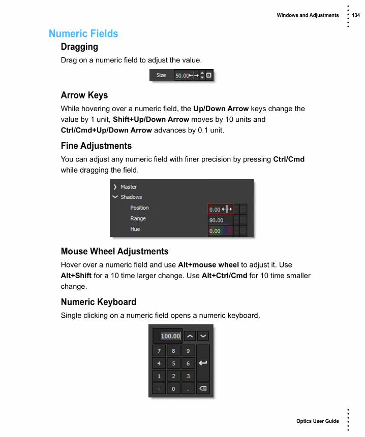
Optics User Guide
• • • •••
Windows and Adjustments 134 • • • •••
Numeric FieldsDraggingDrag on a numeric field to adjust the value.
Arrow KeysWhile hovering over a numeric field, the Up/Down Arrow keys change the value by 1 unit, Shift+Up/Down Arrow moves by 10 units and Ctrl/Cmd+Up/Down Arrow advances by 0.1 unit.
Fine AdjustmentsYou can adjust any numeric field with finer precision by pressing Ctrl/Cmd while dragging the field.
Mouse Wheel AdjustmentsHover over a numeric field and use Alt+mouse wheel to adjust it. Use Alt+Shift for a 10 time larger change. Use Alt+Ctrl/Cmd for 10 time smaller change.
Numeric KeyboardSingle clicking on a numeric field opens a numeric keyboard.

Optics User Guide
• • • •••
Windows and Adjustments 135 • • • •••
Spin Box
Spin boxes change values according to the following key strokes:
• Click = change by 1 pixel.
• Shift+click = change by 10 pixels.
• Ctrl/Cmd+click = change by 0.1 pixel.
Reset IconIndividual parameters as well as parameter groups can be reset to their default settings using the Reset icon.
Image InfoLocated at the bottom-right of the Optics Interface, the Image Info displays the image size and bit depth.

Optics User Guide
• • • •••
Pull-down Menus 136 • • • •••
Pull-down MenusStandalone only menu items are marked with an asterisk.
FileOpen*Opens an image from your computer’s hard drive. Camera RAW, TIFF, JPEG as well as Kodak® Cineon and DPX file formats used in motion picture and television production can all be used in Optics.
Note: Images can also be loaded by dragging a file from a browser window and dropping it into the Viewer.
Close*Closes the image.
Recent Files*The last five recently opened or saved files can be selected and opened here.
Save*Saves the image in JPEG, PNG, or TIFF file formats.
When saving to the TIFF file format, you can optionally save the Optics setup (filter, layer and mask information) along with the final file. If you then open up the saved TIFF file, you are able modify the filter, layer and mask information.
Save As*Saves the image as a new file.
Save OptionsWhen using Save or Save As, once the file format and name are entered, the Save Options window opens that contains settings for the file format. The controls within this window will vary depending upon the file type.
Embed ICC ProfileThe Embed ICC Profile option is enabled by default and embeds the current profile.

Optics User Guide
• • • •••
Pull-down Menus 137 • • • •••
Save with Resize*Resizes the image while saving. You can adjust the pixel dimensions, document size and resolution of an image.
Enable ResizingActivates resizing.
Pixel DimensionsSets the size of the image in terms of percent or pixels.
WidthSets the width of the image.
HeightSets the height of the image.
Unit of MeasurePercentUses percent as the unit of measure for the image dimensions.
PixelsUses pixels as the unit of measure for the image dimensions.

Optics User Guide
• • • •••
Pull-down Menus 138 • • • •••
Document SizeIf your image is ultimately targeted for print, it is useful to specify image size in terms of the printed dimensions and image resolution. Referred to as the document size, these two measurements determine the total pixel count and therefore the file size of the image.
WidthSets the width of the image.
HeightSets the height of the image.
ResolutionSets the resolution of the document.
pixels/inchUses pixels/inch as the unit of measure for the resolution.
pixels/cmUses pixels/centimeters as the unit of measure for the resolution.
Unit of MeasureinchesUses inches as the unit of measure.
cmUses centimeters as the unit of measure.
mmUses millimeters as the unit of measure.
pointsUses points as the unit of measure.
picasUses picas as the unit of measure.
Constrain ProportionsConstrain Proportions maintains the aspect ratio of the image. This parameter automatically changes the height as you change the width, and vice versa.

Optics User Guide
• • • •••
Pull-down Menus 139 • • • •••
SetupsA Setup takes a snapshot of the filters and masks applied to your image in the Layers window. Setups can be saved and loaded and are independent of the image they were originally applied to. In addition, a Setup can be used to batch process a series of files in the Standalone.
Open SetupOpens a previously saved Setup.
Save SetupTakes a snapshot of all filters and masks applied to your image in the Layers window and saves it as a Setup file. This Setup file can later be loaded to the same or a different image.
Recent SetupsThe last five recently opened or saved Setups can be selected and opened here.
Batch*Batch processes multiple files using the current setup or a previously saved Setup.
See Batch for more information.
Print*Prints the current image and filter Setup.

Optics User Guide
• • • •••
Pull-down Menus 140 • • • •••
PreferencesPreferences allow you to customize default settings.
Thumbnail SizeYou can select whether the Optics Interface uses either a small or large thumbnail size. Medium thumbnails are the default.
SmallSmall thumbnails are used in the Optics Interface.
MediumMedium thumbnails are used in the Optics Interface.
LargeLarge thumbnails are used in the Optics Interface.
Live ThumbnailsDetermines whether or not the Sapphire filters use live or pre-generated thumbnails.
Preview ResolutionDefines the default working resolution. However, when your image is saved, Optics always processes at full size.
1KOptics works at a maximum resolution of 1024 x 1024 pixels.
2KOptics works at a maximum resolution of 2048 x 2048 pixels.
4KOptics works at a maximum resolution of 4096 x 4096 pixels.
8KOptics works at a maximum resolution of 8192 x 8192 pixels.
FullOptics works at full resolution.
Note: Large Preview Resolutions take much longer to process when making parameter adjustments.

Optics User Guide
• • • •••
Pull-down Menus 141 • • • •••
Preview ScalingPointUses a lower quality scaling method when displaying the image in the Viewer. Point is more accurate when applying filters such as grain and sharpen, but when zooming in, the image will display “chunky” artifacts.
BicubicUses a smooth scaling method when displaying the image in the Viewer. Bicubic can mask the effect of grain and sharpen filters because of its inherent smoothing, but doesn’t suffer from the Point methods chunkiness when zooming in.
GPU RenderingEnables or disables GPU rendering.
DownsamplingAt large preview sizes, interaction may slow down when adjusting filter parameters. To maintain fast processing during adjustments, you can enable Downsampling.
AdaptiveAutomatically downsamples the image if required.
2:1Automatically downsamples the image by a factor of 2.
4:1Automatically downsamples the image by a factor of 4.
8:1Automatically downsamples the image by a factor of 8.
DPX Interpretation*Interpretation detects and sets whether DPX files are Logarithmic or Linear. Sometimes the program used to create the DPX files writes the wrong header information into the file causing Optics to think it is Logarithmic when it is Linear and vice versa. The controls below allow you to explicitly set whether or not the file is Logarithmic or Linear. Setting this preference will take effect the next time you load a file.

Optics User Guide
• • • •••
Pull-down Menus 142 • • • •••
AutoAutomatically figures out whether the DPX file is Logarithmic or Linear.
LogManually sets the DPX file to Logarithmic.
LinManually sets the DPX file to Linear.
Save Format*Preselects the file type save format.
AutoWhen saving, the image’s original file type is selected as the save format.
JPGJPG is automatically selected when saving.
PNGPNG is automatically selected when saving.
TIFFTIFF is automatically selected when saving.
Effect DurationSets the duration of the timeline in the Particle Illusion user interface.
Cache EntriesSets the number of cached Particle Illusion and S_LensFlare instances. 10 per filter is the default. Higher numbers result in more memory usage.
Parameter GroupsDefaultThe open/close state of parameter groups is set according to the default state specified by the filter.
CollapsedCollapses all parameter groups.
ExpandedExpands all parameter groups.

Optics User Guide
• • • •••
Pull-down Menus 143 • • • •••
Font SizeSets the font size.
Save Setup With ImageLightroomLightroom will retrieve the Optics setup information consisting of filters, layers and masks when the Save Setup With Image preference is enabled. To do this, you need to use “Edit Copy with Lightroom Adjustments” and render the result. If you then apply Optics to the newly rendered version and use “Edit Original”, your previous Optics setup will be shown and can be modified.
PhotoshopBy default, Photoshop remembers your previous Optics setup consisting of filters, layers and masks and when you reapply Optics, they can all be modified.
Record Anonymous Usage StatisticsWhen enabled, anonymous usage statistics are recorded and transmitted to Boris FX.
EditUndo/RedoUndo or redo operations.
Undo/Redo HistoryUndo/Redo has a history, so you can jump to any item in the history by picking it from the menu.
DeleteDeletes the selected filter.
WindowThe Optics user interface is broken up into individual windows which can be opened or closed by selecting or deselecting them from the View menu. The following windows can be opened or closed:
Color WheelsOpen or closes the Color Correct Wheels window.

Optics User Guide
• • • •••
Pull-down Menus 144 • • • •••
ConsoleDisplays diagnostic information.
Copy to ClipboardCopies the contents of the Console to the Clipboard.
OptionsOpenGLDisplays the OpenGL version information.
Rendering StatisticsDisplays rendering times.
ExifOpens or closes the Exif window. See Exif for more information.
FiltersOpens or closes the Filters window. See Filters for more information.
HistogramOpens or closes the Histogram window. See Histogram for more information.
LayersOpens or closes the Layers window. See Layers for more information.
MetadataOpens or closes the Metadata window which contains preset related information. See Metadata for more information.
ParametersOpens or closes the Parameters window. See Parameters for more information.
PresetsOpens or closes the Presets window. See Presets for more information.
VariationsOpens or closes the Variations window. See Variations for more information.

Optics User Guide
• • • •••
Pull-down Menus 145 • • • •••
ViewerOpens or closes the Viewer. See the Viewer for more information.
ResetResets the window layout the next time Optics is started. This is useful if you have tweaked your windows beyond recognition.
WorkspaceThere are 3 preset workspaces that automatically arrange the interface windows into different configurations. Optics workspaces can be selected, saved or deleted. The current workspace displays a checkbox next to it in the menu.
DefaultThe interface is set to the default Optics workspace where the majority of windows are visible.
EditThe Edit Layout shows the Viewer, Presets and Parameters windows.
ViewThe View Layout shows only the Viewer.
NewCreates a new workspace.
DeleteDeletes the current workspace.
Reset AllResets all workspaces to the defaults.
ExportExports the current workspaces.
ImportImports saved workspaces.

Optics User Guide
• • • •••
Pull-down Menus 146 • • • •••
Workspace Shortcuts
HelpUser GuideOpens the Optics User Guide.
Help Shortcuts
AboutShows the Optics version.
LicenseOpens the Deactivation Options window which has two choices: Internet Deactivate (Recommended) and Advanced Options.
Shortcut Action
F2 Selects the Default workspace
F3 Selects the Edit workspace
F4 Selects the View workspace
Shortcut Action
F1 Opens the Optics User Guide

Optics User Guide
• • • •••
Filter Categories 147 • • • •••
FILTERS
Filter CategoriesThe Filters are categorized by filter function: Color, Diffusion/Blurs, Film Lab, Grads/Tints, Image, Lens, Light, Render and Stylize.
ColorAuto Adjust, Black and White, S_ChannelSwitcher, Color, Color Correct, Curves, Develop, Enhancing, Fluorescent, Haze, High Contrast, S_HotSpots, Kelvin, Levels, Low Contrast, Match, Ozone, Polarizer, Selective Color Correct, Selective Saturation, Shadows/Highlights, Sky, S_Threshold, Tone Adjust.
Diffusion/BlursS_Beauty, Beauty Studio, Blur, S_BlurChannels, S_BlurChroma, S_BlurDirectional, S_BlurMotion, Center Spot, Depth of Field, Diffusion, Double Fog, S_EdgeAwareBlur, Fog, S_FreeLens, Frost, Halo, Mist, Net, S_RackDefocus, Silk, Split Field
Film LabS_BleachBypass, Cross Processing, S_FilmDamage, S_FilmEffect, Film Stocks, Flashing, Grain, Looks, S_VintageColor2Strip, S_VintageColor3Strip
Grads/TintsColor Gradient, Color Spot, Colorize Gradient, Dual Gradient, S_DuoTone, Gels, ND Gradient, Photographic, S_QuadTone, Radial Tint, Sepia, Skin Tone, Split Tone, Sunset, Tint, S_TriTone
ImageDeBand, DeBlock, DeFog, DeNoise, Detail, Paint, Sharpen, S_WarpTransform
Lens/DistortChromatic Aberration, DeFringe, S_EmbossDistort, S_EmbossGlass, S_EmbossShiny, Lens Distortion, Pin Warp, Radial Exposure, S_Vignette, Warp Fish Eye, Warp Magnify, Warp Polar, S_WarpPuddle, S_WarpPuff, S_WarpWaves2

Optics User Guide
• • • •••
Filter Categories 148 • • • •••
LightAmbient Light, S_Aurora, Dot, S_EdgeRays, Eye Light, Flag, S_Glint, S_Glint Rainbow, S_Glow, S_Glow Darks, S_Glow Edges, S_GlowRings, Ice Halos, Key Light, Lens Flare, S_Lens Flare, Light, S_Light Leak, Overexpose, Rainbow, S_Rays, Reflector, ReLight, Soft Light, S_Sparkles, S_SparklesColor, S_SpotLight, Star, S_Streaks, S_Ultra Glow
Particle IllusionComplete, Sampler, Abstract, Background, Dust-Fog, Emitters-2020, Emitters-2020.5, Emitters-2021, Emitters-2021.5, Emitters-2022, Explosions, Fire, Fireworks, HUD-UI, Magic, Misc, Nature, Sci-Fi, Smoke, Snow, Space, Sparkles, Trails, Tunnels, Water
RenderS_Caustics, S_Clouds, S_CloudsColor mooth, S_CloudsMultColor, S_CloudsPerspective, S_Grunge, S_LaserBeam, S_Luna, S_MuzzleFlash, S_NightSky, S_TextureFolded, S_TextureTiles, S_Ultra Zap, S_Zap, S_Zap From, S_Zap To
StylizeS_Autopaint, Borders, S_Brush, S_Cartoon, S_CartoonPaint, Color Infrared, Color Shadow, S_Crosshatch, Day for Night, S_DigitalDamage, S_Dog Vision, S_Etching, S_FlysEyeCircles,S_FlysEyesHex, S_FlysEyeRect, S_HalfTone, S_HalfToneColor, S_HalfToneRings, Harris Shutter, S_Infinite Zoom, Infrared, S_Kaleido, S_KaleidoPolar, S_KaleidoRadial, Night Vision, S_ParallaxStrips, Pastel, Pencil, S_PseudoColor, S_RomanTile, Texture, S_TVDamage, S_WarpChroma, X-Ray

Optics User Guide
• • • •••
Common Filter Controls 149 • • • •••
Common Filter ControlsThere are a number of common filter controls that appear in Optics. For simplicity they are listed here.
BlurHorizontalThe image is blurred by a quality blur along the X-axis.
VerticalThe image is blurred by a quality blur along the Y-axis.
GangThe horizontal and vertical slider values can be ganged together. When ganged, moving the slider affects both values.
Black and WhiteSelects the type of black and white filter to be applied to your color image.
NormalConverts the color image to a monochrome image.
RedSimulates a red filter in black and white photography.
GreenSimulates a green filter in black and white photography.
BlueSimulates a blue filter in black and white photography.
YellowSimulates a yellow filter in black and white photography.
OrangeSimulates an orange filter in black and white photography.

Optics User Guide
• • • •••
Common Filter Controls 150 • • • •••
GradGrad is the gradient transition area between the filtered image and the original. Its direction, corners, size and angle can be adjusted.
On-Screen ControlsCorner PinThere are four points around the corners of the image. By clicking and dragging any of the four points, the perspective of the gradient is adjusted.
Upper-LeftControls the X and Y position of the Upper Left Point.
Upper-RightControls the X and Y position of the Upper Right Point.
Lower-RightControls the X and Y position of the Lower Right Point.
Photo by Joshua Earle on Unsplash
Position Rotate
Corner Pin Corner Pin
Corner PinCorner Pin
Scale
Scale

Optics User Guide
• • • •••
Common Filter Controls 151 • • • •••
Lower-LeftControls the X and Y position of the Lower Left Point.
PositionDrag the center point.
ScaleDrag the top/bottom mid-points.
RotateDrag the right center circle.
ControlsEnableTurns the gradient on and off.
ND BrightnessDarkens the colored portion of the gradient.
TypeControls the direction of the gradient.
Top-to-bottomThe direction of the gradient is from top to bottom.
Bottom-to-topThe direction of the gradient is from bottom to top.
Left-to-rightThe direction of the gradient is from left to right.
Right-to-leftThe direction of the gradient is from right to left.
Horizontal StripHorizontal strip gradient.
Vertical StripVertical strip gradient.
Gradient SizeThe size of the gradient.
Gradient AngleThe angle of the gradient.

Optics User Guide
• • • •••
Common Filter Controls 152 • • • •••
MatteIn some of the filters, a matte is generated to create the desired effect. The Matte controls consist of Position, Range and Blur parameters, and they work the same in all of the filters. The white areas of the matte are the areas that will be affected by the filter, while the black areas remain unaffected. The matte is extracted based on luminance, in most cases, and is created using the Position and Range parameters.
PositionSelects the values to be included in the matte. A higher Position value shows more white values from the original image as white values in the matte. A lower Position value shows more black values from the original image as white values in the matte.Position 0, Range 25 Position 100, Range 25Original
Photo © THINKSTOCK LLC--www.thinkstock.com

Optics User Guide
• • • •••
Common Filter Controls 153 • • • •••
RangeControls the range of values to be used for the matte. Once you’ve selected the “Position”, you can then add or subtract the “Range” of values to be included in the matte. A higher Range value includes more white values in the matte while a lower Range value includes less values in the matte.
BlurThe matte is blurred by a quality blur.
Position 100, Range 25 Position 100, Range 75Original

Optics User Guide
• • • •••
Common Filter Controls 154 • • • •••
SpotA spot in the form of a radial gradient is used to limit the effect of the filter.
On-Screen Controls
ControlsPositionThe position of the spot.
AspectThe aspect ratio of the spot.
RadiusThe un-blurred radius of the spot.
Falloff RadiusThe blurred edge radius.
FalloffMoves the falloff towards the spot center point.
InvertInverts the spot.
Falloff RadiusRadius
Position

Optics User Guide
• • • •••
Common Filter Controls 155 • • • •••
TemperatureColorSets the color through the use of a standard color picker.
OpacitySets the opacity of the warming or cooling.
Preserve HighlightsPreserves the white areas of the image.
Exposure CompensationExposure Compensation adds back the brightness loss as a result of the warming or cooling.

Optics User Guide
• • • •••
Common Filter Controls 156 • • • •••
TransformTransform your image using Position, Scale, Rotation, Corner-Pin, Shear and Crop controls.
On-Screen Controls
ControlsCropTopCrops the image from the top down.
BottomCrops the image from the bottom up.
Left Crops the image from left to right.
RightCrops the image from right to left.
Position
Scale
RotateScale X
Scale YCorner Pin Corner Pin
Corner PinCorner Pin
Optics User Guide
• • • •••
Common Filter Controls 157 • • • •••
Corner PinThe Corner Pin controls change perspective.
Upper-LeftControls the X and Y position of the Upper Left Point.
Upper-RightControls the X and Y position of the Upper Right Point.
Lower-RightControls the X and Y position of the Lower Right Point.
Lower-LeftControls the X and Y position of the Lower Left Point.
PositionPosition XThe horizontal position.
Position YThe vertical position.
ScaleScale XThe horizontal scale.
Scale YThe vertical scale.
Gang ScaleThe Scale X and Scale Y values can be ganged together.
RotateIn addition to the standard position and scale controls, you can rotate. Positive values rotate clockwise and negative values rotate counter-clockwise.
ShearShear XSkews left and right.
Shear YSkews up and down.

Optics User Guide
• • • •••
Common Filter Controls 158 • • • •••
AnchorAnchor XDefines the point on the X axis around which position, rotation, scaling or shearing takes place.
Anchor YDefines the point on the Y axis around which position, rotation, scaling or shearing takes place.
FilterChooses the filtering method when transforming the image. Mitchell is the default.
TriangleThe Triangle filter is not the highest quality, but fine for scaled images.
QuadraticQuadratic is like triangle, but more blur with fewer artifacts. It offers a good compromise between speed and quality.
CubicCubic is the default filter in Photoshop. It produces better results with continuous tone images, but is slower than Quadratic. If the image contains fine details, the result may be blurrier than desired.
Catmull-RomThis produces good results with continuous tone images which are scaled down, producing sharp results with fine detailed images.
GaussianGaussian lacks in sharpness, but is good with ringing and aliasing.
MitchellA good balance between sharpness and ringing, Mitchell is a good choice when scaling up.
SincKeeps small details when scaling down with good aliasing.

Optics User Guide
• • • •••
Common Filter Controls 159 • • • •••
ViewChooses what to view. The choices in this menu will change depending on the filter.

Optics User Guide
• • • •••
Ambient Light 160 • • • •••
Ambient LightDescription
Ambient creates light without a defined source and contributes to the overall brightness of a scene without casting shadows.
CategoryLight.
ControlsPresetsTo select a preset, pick one from the Presets window.
BrightnessSets the intensity of the light.
GelsPhotographers, cinematographers and lighting designers use colored filters or gels in front of lights. Whatever mood you wish to create, we have the colors needed to achieve the effect. Select one of the Gels presets from the pop-up menu.
ColorSets the color of the light through the use of a standard color picker.
Before After
Photo by Ryan Lum on Unsplash
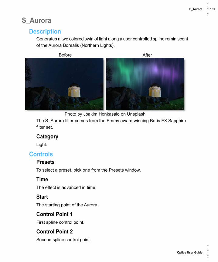
Optics User Guide
• • • •••
S_Aurora 161 • • • •••
S_AuroraDescription
Generates a two colored swirl of light along a user controlled spline reminiscent of the Aurora Borealis (Northern Lights).
The S_Aurora filter comes from the Emmy award winning Boris FX Sapphire filter set.
CategoryLight.
ControlsPresetsTo select a preset, pick one from the Presets window.
TimeThe effect is advanced in time.
StartThe starting point of the Aurora.
Control Point 1First spline control point.
Control Point 2Second spline control point.
Before After
Photo by Joakim Honkasalo on Unsplash

Optics User Guide
• • • •••
S_Aurora 162 • • • •••
Control Point 3Third spline control point.
Control Point 4Fourth spline control point.
Start ColorSets the color at the starting control point.
End ColorSets the color at the ending control point.
Color PhaseAdjusts the phase of the gradient between Start Color and End Color.
Stroke SizeInfluences the width of the Aurora along the spline. This parameter controls the size of the underlying color gradient before it's distorted.
BrightnessScales the brightness of the Aurora.
SoftnessThe amount of blur applied to the Aurora. Set to 0 to get a colored point cloud.
Softness Rel YThe relative vertical amount of softness.
SwirlingSwirl ComplexitySpecifies how many layers should be rendered in the Aurora. The more layers rendered, the more complex pattern generated along the spline.
Swirl MagnitudeThe magnitude or amplitude of the swirls along the spline. Setting this to 0 will render a color gradient along the spline.

Optics User Guide
• • • •••
S_Aurora 163 • • • •••
Magnitude Rel YThe relative vertical magnitude of the swirls.
Swirl FrequencyThe frequency of the swirls along the spline.
Frequency Rel YThe relative vertical frequency along the spline.
LightingLight BrightnessLights a circular area of the Aurora. Set to 0 to disable the light. Increase value to increase the intensity of the light.
Light ColorThe color of the light.
Ambient LightThe level of illumination outside the light.
Light RadiusDistance from the center of the light to the edge of the brightest section.
Light SoftnessHow quickly the edge of the light should taper off of to darkness.
SeedUsed to initialize the random number generator. The actual seed value is not significant, but different seeds produce different results and the same value should give a repeatable result.
Bg BrightnessScales the brightness of the image.
CombineDetermines how the Aurora is combined with the source image.
ScreenThe Aurora is blended with the source using a screen operation.

Optics User Guide
• • • •••
S_Aurora 164 • • • •••
AddThe Aurora is added to the source.
Aurora OnlyRenders the Aurora with no source.
Show SplineEnables/disables the on-screen control for adjusting the Start parameter.
Show Light PosEnables/disables the on-screen control for adjusting the Light Pos parameter.

Optics User Guide
• • • •••
Auto Adjust 165 • • • •••
Auto AdjustDescription
Automatically adjusts the image using Auto Color, Auto Contrast and Auto Levels processes.
CategoryColor.
ControlsPresetsTo select a preset, pick one from the Presets window.
TypeSelects from one of the three automatic adjustment processes.
Auto ColorAuto Color adjusts the contrast and color of an image and is good for neutralizing color casts.
Auto ContrastAuto Contrast automatically adjusts image contrast.
Auto LevelsAuto Levels automatically adjusts the white point and black point in an image. Since each color channel is adjusted individually, it may remove or introduce color casts.
Before After
Photo by Tadas Mikuckis on Unsplash

Optics User Guide
• • • •••
Auto Adjust 166 • • • •••
OpacitySets the amount of auto adjustment.

Optics User Guide
• • • •••
S_Autopaint 167 • • • •••
S_AutopaintDescription
Generates a paint-brushed version of the image.
The S_Autopaint filter comes from the Emmy award winning Boris FX Sapphire filter set.
CategoryStylize.
ControlsPresetsTo select a preset, pick one from the Presets window.
StyleSelects the style of brush strokes.
Van GoghThe stroke directions align with the edges found within the image.
Hairy PaintThe strokes are perpendicular to the edges within the image.
PointalizeThe strokes are cellular pointy shapes with no direction.
Before After
Photo by Boris Smokrovic on Unsplash

Optics User Guide
• • • •••
S_Autopaint 168 • • • •••
FrequencyThe density of brush strokes in the frame. Increase for smaller strokes.
Stroke LengthDetermines the length of the brush strokes along the directions of edges in the image. If this is negative, you can switch from VanGogh to HairyPaint styles and vice versa.
Stroke AlignIncrease to smooth out the directions of the strokes so nearby strokes are more parallel.
Smooth ColorsBlurs the source by this amount before generating the brush strokes. Increase to cause the colors of nearby strokes to be more consistent.
SeedUsed to initialize the random number generator. The actual seed value is not significant, but different seeds produce different results and the same value should give a repeatable result.
SharpenThe amount of post-process sharpening applied.
Sharpen WidthThe width at which to apply the post-process sharpening filter, relative to the stroke sizes. Higher values affect wider areas from the edges, lower values only affect areas near sharp edges.
Mix With SourceInterpolates between the result (0) and the original source (1).

Optics User Guide
• • • •••
S_Beauty 169 • • • •••
S_BeautyDescription
Applies smoothing, color correction, soft focus, and glow to skin regions.
The S_Beauty filter comes from the Emmy award winning Boris FX Sapphire filter set.
CategoryDiffusion/Blurs.
ControlsPresetsTo select a preset, pick one from the Presets window.
Skin DetectionEnable Skin DetectionGenerates and internal mask of skin regions based on Skin Color, Luma and Chroma Range, etc.
Skin ColorRepresentative skin color to use during detection.
Luma RangeDifference in luma from Skin Color to consider skin.
Before After
Photo by Andrey Zvyagintsev on Unsplash
Optics User Guide
• • • •••
S_Beauty 170 • • • •••
Chroma RangeDifference in chroma from Skin Color to consider skin.
Rel OrangeRelative amount of orange in Chroma Range. The orange axis is along the human skin tone line common to all the human races, and is also known as the I-line in vectorscope terminology. Reducing this parameter can help eliminate blond or red hair (and similar highlights in other hair colors), some red/orange/yellow sports uniforms, warm backgrounds, etc. from the skin mask.
Rel PurpleRelative amount of purple in Chroma Range. The purple axis is perpendicular to the orange axis, and is thus most un-skin-like. In most cases, this parameter can be made smaller to eliminate lips, eyes, clothing, and jewelry from the skin mask. Increase this parameter to add purple and green shades to the skin detect mask, for example eye shadow, bad lighting, or alien skin tones (i.e. non-human).
Range SoftnessControls the softness of the skin detection mask. A value of one means only pixels that exactly match Skin Color will produce a mask value of one with each other pixel's mask value being proportional to its distance from Skin Color. A value of zero means a hard mask where all pixels within the luma/chroma range of the Skin Color will produce a mask value of one.
Clip WhiteSkin detection mask values greater than this value will be set to one.
Clip BlackSkin detection mask values less than this value will be set to zero.
Post BlurBlur the skin detection mask by this amount.
ShowSelects the type of output.

Optics User Guide
• • • •••
S_Beauty 171 • • • •••
FinalShow the final output.
Skin Detect MaskShow the mask generated by the internal skin detector.
SkinShow result of applying skin detection mask to source.
Show Color HelperDisplay an interactive overlay to help set Skin Color, Chroma Range, Rel Orange, and Rel Purple. The overlay shows all possible colors that match the brightness (luma) of the Skin Color parameter. Orange is in the upper left corner, and purple is in the upper right (this orientation is similar to a traditional broadcast vectorscope). Colors matching the skin detection algorithm are highlighted. Changing Skin Color will move the highlighted region, adjusting Chroma Range changes the size of the highlighted region, and adjusting Rel Orange/Purple stretches the region along the diagonals of the square.
Suppress BackgroundSuppress BGOnly apply Beauty to the region specified by Face Center and related parameters.
Face CenterCenter position of face region when Suppress BG is enabled.
Face SoftnessMakes the face region softer when Suppress BG is enabled. This will provide a smoother transition from the face region to the background, but also possibly reduce the strength of Beauty in the face region.
Face RadiusSize of face region when Suppress BG is enabled.
Face Rel HeightRelative height of face region when Suppress BG is enabled.
Optics User Guide
• • • •••
S_Beauty 172 • • • •••
Face RotateRotation of face region when Suppress BG is enabled.
Show Face WidgetDisplay an interactive overlay to assist in placing and sizing the face region.
Pore SizeFeatures smaller than this size (pores, etc.) will be preserved even when blurring.
Blur AmountScales the width of the blur.
Edge ThresholdColor regions separate by an edge larger than this value will not blur into each other.
Soften ShadowsPositive values reduce the appearance of shadows, while negative values make shadows more pronounced. Reducing shadows can make the subject look younger, while darkening shadows will make them look older.
Shadow ThreshDark regions less than this value will be enhanced/reduced by Soften Shadows.
Reduce ShineDarken bright, shiny areas. The darkening process can lead to a lack of color, and if so, use Shine Saturation to bring back a natural skin tone in the affected region.
Shine SaturationScales the color saturation in bright regions. Useful for adding a natural skin tone to shiny areas that required darkening.
Shine ThreshRegions brighter than this value will be affected by Reduce Shine.

Optics User Guide
• • • •••
S_Beauty 173 • • • •••
Color CorrectHue ShiftShifts the hue of the source colors, in revolutions from red to green to blue to red.
SaturationScales the color saturation of the result. Increase for more intense colors. Set to 0 for monochrome. You can also invert the chroma of the result by making this negative.
BrightnessScales the brightness of the result.
TintScales the result by this color, thus tinting the lighter regions.
Soft FocusScales the width of the soft focus blur.
Glow BrightnessScales the brightness of the skin glow.
Glow DetailsGlow ColorScales the color the skin glow.
Glow ThresholdGlows are generated from locations in the skin regions that are brighter than this value. A value of 0.9 causes glows at only the brightest spots. A value of 0 causes glows for every non-black area.
Glow WidthScales the skin glow distance.
Mix With SourceInterpolates between the blurred result (0) and the original source (1). 0.1 can give a nice misty effect since it mixes only a little of the source in.

Optics User Guide
• • • •••
Beauty Studio 174 • • • •••
Beauty StudioDescription
In the age of cameras equipped with ultra sharp lenses and highly sensitive sensors, we’re seeing more detail than ever before in images on screen. Akin to digital make-up and filters, Beauty Studio was designed to automate the process of eliminating wrinkles, pores and other undesirable blemishes from facial skin tones.
The Beauty Studio filter comes from the Boris FX Continuum filter set.
CategoryDiffusion/Blurs.
Using Beauty StudioThere are two stages to using Beauty Studio: 1) building a matte to isolate the skin tone and 2) smoothing the skin tone. Pay close attention when generating the matte as a poor matte will yield an unnatural image. Ideally, the matte should exclude areas such as eyes, hair, and lips to ensure that the smoothing operation does not introduce unwanted changes in these regions. To generate a good matte, it is helpful to display the Matte in the View menu.
Matte CreationThe Color A and Color B parameters in the Matte group should be used to select typical colors toward the mid-range of the skin tones. Avoid selecting skin tones at the extreme light/dark ranges. Instead, choose a pair of
Before After
Photo by Alexander Krivitskiy on Unsplash

Optics User Guide
• • • •••
Beauty Studio 175 • • • •••
representative colors from regions that are typical of the overall or average skin tones. Then, adjust the Hue, Saturation, and Softness controls as necessary to refine the matte.
SmoothingOnce the matte is refined, set the smoothing by adjusting how much is applied at each detail level. Natural looking results are generally obtained by using small amounts of smoothing for the smallest detail levels. This ensures that very fine skin details, such as pores or fine hairs, will be partially preserved to avoid an overly smoothed, plastic or airbrushed result. Higher smoothing amounts for the larger detail levels is generally recommended as way to smooth wider blemishes, color blotches, and unwanted highlights. The ideal smoothing settings will vary from image to image depending on the type and size blemishes in the image.
ControlsPresetsTo select a preset, pick one from the Preset pop-up window.
SmoothingDetermines the amount of smoothing.
Master AmountThis is the main smoothing controller. Settings between 100 and 200 will overdrive the smoothing effect on all active smoothing levels.
Smallest DetailsAffects only the smallest details in the image using a 1×1 pixel array.
Small DetailsAffects a pixel array twice the size of the smallest pixels.
Medium DetailsAffects a pixel array twice the size of the small pixels.
Large DetailsAffects a pixel array twice the size of the medium pixels.

Optics User Guide
• • • •••
Beauty Studio 176 • • • •••
Largest DetailsAffects a pixel array twice the size of the large pixels.
QualityFastFaster processing, but lower quality.
PreciseHigher quality, but slower processing.
Detail LevelsDetermines the number of detail levels to be smoothed in the image. A value of 1 means only fine detail is smoothed, while a setting of 5 smooths the image over 5 independently controllable levels of detail.
Preserve ContrastPrevents loss of contrast in the result. Higher values preserve more contrast.
Detail ScaleModifies the size of the pixel arrays used for smoothing. Depending on the image, this can be used to reduce unwanted shine in skin tones.
MatteColorSelect typical colors toward the mid-range of the skin tones. Avoid selecting skin tones at the extreme light/dark ranges. Instead, choose a pair of representative colors from regions that are typical of the overall or average skin tones.
Color AChoose a primary skin tone color for the matte.
Color BChoose a secondary skin tone color for the matte.
Hue SoftnessExpands or contracts the hue values of the selected colors.
Saturation SoftnessExpands or contracts the saturation values of the selected colors.

Optics User Guide
• • • •••
Beauty Studio 177 • • • •••
Luma SoftnessExpands or contracts the luma values of the selected colors.
Black ClipMakes black areas of the matte blacker.
White ClipMakes white areas of the matte whiter.
GammaAdjusts the matte gamma.
ChokeShrinks the matte.
BlurBlurs the matte.
Invert MatteInverts the matte.
Color CorrectGo to the Color Correct filter to see how the Color Correct controls work.
GlowEnableEnables the glow.
Use MatteLimits the glow to the skin-tone matte.
BlendDetermines the blend mode to be used to create the glow.
AddGlow is added to the image.
ScreenGlow is combined with the image using a Screen blend mode. This looks kind of like the Add blend mode, but highlights are retained.

Optics User Guide
• • • •••
Beauty Studio 178 • • • •••
BrightnessSets the brightness of the glow.
ColorSets the glow color. The Color parameter sets the color of the glow through the use of a standard color picker. The default color is white.
BlurSets the softness of the glow.
ThresholdSets the pixel values that are affected by the glow--a setting of 0 will apply a glow to the entire image, while a setting of 100 will not apply any glow at all.

Optics User Guide
• • • •••
Black and White 179 • • • •••
Black and WhiteDescription
Black and White converts color images to black and white simulating the look of Black and White photographic filters.
CategoryColor.
ControlsPresetsTo select a preset, pick one from the Presets window.
FilterThe Filter pop-up selects the type of black and white filter to be applied to your color image. Go to the Black and White section of Common Filter Controls to see how the Black and White controls work.
BrightnessAdjusts the brightness of the image. Positive values brighten, negative values darken.
ContrastAdjusts the contrast of the image. Positive values increase contrast, negative values decrease contrast.
Before After
Photo by Anthony Delanoix on Unsplash

Optics User Guide
• • • •••
Black and White 180 • • • •••
GammaAdjusts the gamma of the image. The gamma adjustment leaves the white and black points the same and only modifies the values in-between. Positive values lighten the midtones, negative values darken the midtones.
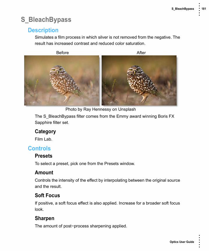
Optics User Guide
• • • •••
S_BleachBypass 181 • • • •••
S_BleachBypassDescription
Simulates a film process in which silver is not removed from the negative. The result has increased contrast and reduced color saturation.
The S_BleachBypass filter comes from the Emmy award winning Boris FX Sapphire filter set.
CategoryFilm Lab.
ControlsPresetsTo select a preset, pick one from the Presets window.
AmountControls the intensity of the effect by interpolating between the original source and the result.
Soft FocusIf positive, a soft focus effect is also applied. Increase for a broader soft focus look.
SharpenThe amount of post−process sharpening applied.
Before After
Photo by Ray Hennessy on Unsplash

Optics User Guide
• • • •••
S_BleachBypass 182 • • • •••
SaturationScales the color saturation. Increase for more intense colors. Set to 0 for monochrome.
Scale LightsScales the result by this value. Increase for a brighter result.
Offset DarksAdds this gray value to the darker regions of the result. This can be negative to increase contrast.
Grain AmpScales the amplitude of the film grain that is added to the result. Set this to 0 to disable all grain.
Grain ParametersGrain Amp RedScales the red grain amplitude.
Grain Amp GreenScales the green grain amplitude.
Grain Amp BlueScales the blue grain amplitude. Note that grain is added and subtracted from the image, so for example, increasing Grain Amp Blue will amplify both the blue and yellow speckles.
Grain Amp DarksThe relative amount of grain applied to the darkest regions of the image, per channel. This defaults to less than 1 because dark areas usually have less grain than midtones.
Grain Amp BrightsThe relative amount of grain applied to the brightest regions of the image, per channel. This defaults to zero because bright areas usually have less grain than midtones. Note that highly saturated colors can be affected by both Grain Amp Darks and Grain Amp Brights because they are dark in some color channels and bright in others.
Optics User Guide
• • • •••
S_BleachBypass 183 • • • •••
Grain BlurThe grain is smoothed by this amount. Increase for coarser grain.
Grain Blur RedThe relative blur amount for the red grain.
Grain Blur GreenThe relative blur amount for the green grain.
Grain Blur BlueThe relative blur amount for the blue grain.
Grain MonoWhen enabled, the same grain pattern is used for the red, green, and blue channels. To make truly monochrome grain you should also set Grain Amp Red/Green/Blue equal to each other, make sure Midtone Pos Red/Green/Blue are equal, and if GrainBlur is positive also set Grain Blur Red/Green/Blue to be equal.
Grain SeedInitializes the random number generator for the grain generation. The actual seed value is not significant, but different seeds produce different grain patterns and the same value should give a repeatable pattern.
Scale ColorsScales the color of the result.

Optics User Guide
• • • •••
Blur 184 • • • •••
BlurDescription
Blurs the image with individual horizontal and vertical controls. It’s fast, high quality and blurs outside the frame which removes the dark inward bleeding edges of most blurs.
CategoryDiffusion/Blurs.
ControlsBlurHorizontalThe image is blurred by a fast, quality blur along the X-axis.
VerticalThe image is blurred by a fast, quality blur along the Y-axis.
GangThe horizontal and vertical slider values can be ganged together. When ganged, moving the slider affects both values.
Before After
Photo by Michal Grosicki on Unsplash
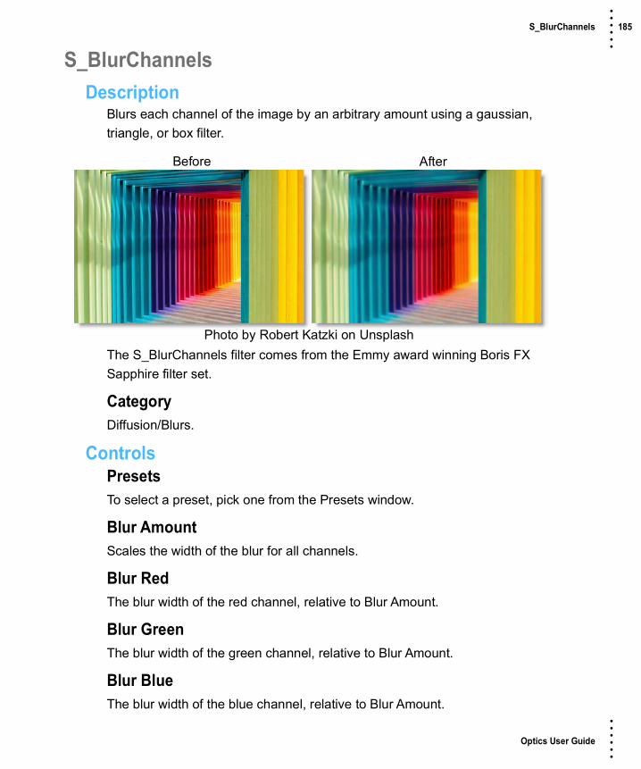
Optics User Guide
• • • •••
S_BlurChannels 185 • • • •••
S_BlurChannelsDescription
Blurs each channel of the image by an arbitrary amount using a gaussian, triangle, or box filter.
The S_BlurChannels filter comes from the Emmy award winning Boris FX Sapphire filter set.
CategoryDiffusion/Blurs.
ControlsPresetsTo select a preset, pick one from the Presets window.
Blur AmountScales the width of the blur for all channels.
Blur RedThe blur width of the red channel, relative to Blur Amount.
Blur GreenThe blur width of the green channel, relative to Blur Amount.
Blur BlueThe blur width of the blue channel, relative to Blur Amount.
Before After
Photo by Robert Katzki on Unsplash

Optics User Guide
• • • •••
S_BlurChannels 186 • • • •••
Blur AlphaThe blur width of the alpha channel, relative to Blur Amount.
Blur RelThe relative horizontal and vertical blur widths. Set Blur Rel X to 0 for a vertical-only blur, or set Blur Rel Y to 0 for a horizontal-only blur.
BrightnessBrightnessScales the brightness of the result.
Scale RedScales the blurred red channel.
Scale GreenScales the blurred green channel.
Scale BlueScales the blurred blue channel.
Scale AlphaScales the blurred alpha channel.
OffsetOffset DarksAdds this gray value to the darker regions of the result. This can be negative to increase contrast.
Offset RedAdds this value to the red channel of the result.
Offset GreenAdds this value to the green channel of the result.
Offset BlueAdds this value to the blue channel of the result.
Offset AlphaAdds this value to the alpha channel of the result.

Optics User Guide
• • • •••
S_BlurChannels 187 • • • •••
Mix With SourceInterpolates between the blurred result (0) and the original source (1). 0.1 can give a nice misty effect since it mixes only a little of the source in.
FilterThe type of convolution filter to blur with.
BoxUses a rectangular shaped filter.
TriangleSmoother, uses a pyramid shaped filter.
GaussSmoothest, uses a gaussian shaped filter.
SubpixelEnables blurring by subpixel amounts. Use this for smoother animation of any of the blur amount parameters.
Soft BordersIf enabled, transparent borders are added to the image before processing. This allows the result to include soft edges beyond the original image size. When off, the effect only occurs within the frame and the result will retain an edge at the borders.
Show Blur AmountEnables/disables the on-screen control for adjusting the blur amount parameters.

Optics User Guide
• • • •••
S_BlurChroma 188 • • • •••
S_BlurChromaDescription
Separates the source into luminance and chrominance components, blurs the chrominance and/or the luminance independently, and recombines them.
The S_BlurChroma filter comes from the Emmy award winning Boris FX Sapphire filter set.
CategoryDiffusion/Blurs.
ControlsPresetsTo select a preset, pick one from the Presets window.
Blur ChromaThe amount to blur the chrominance.
Blur LuminanceThe amount to blur the luminance.
Blur RelThe relative horizontal and vertical blur widths. Set Blur Rel X to 0 for a vertical−only blur, or set Blur Rel Y to 0 for a horizontal−only blur.
Before After
Photo by Denise Chan on Unsplash

Optics User Guide
• • • •••
S_BlurChroma 189 • • • •••
Scale ChromaScales the chrominance by this amount. Increase for more intense colors, decrease for muted colors.
Scale LuminanceScales the brightness of the result.
Offset ResultAdds this gray value to the result (or subtracts if negative). 0 has no effect, .5 is middle gray, and 1 is white.
Mix With SourceInterpolates between the blurred result (0) and the original source (1). 0.1 can give a nice misty effect since it mixes only a little of the source in.
FilterThe type of convolution filter to blur with.
BoxUses a rectangular shaped filter.
TriangleSmoother, uses a pyramid shaped filter.
GaussSmoothest, uses a gaussian shaped filter.
SubpixelEnables blurring by subpixel amounts.
Show Blur ChromaEnables/disables the on-screen control for adjusting the Blur Chroma parameter.
Show Blur LuminanceEnables/disables the on-screen control for adjusting the Blur Luminance parameter.

Optics User Guide
• • • •••
S_BlurDirectional 190 • • • •••
S_BlurDirectionalDescription
Blurs the image in a given direction using a gaussian, triangle, or box filter.
The S_BlurDirectional filter comes from the Emmy award winning Boris FX Sapphire filter set.
CategoryDiffusion/Blurs.
ControlsPresetsTo select a preset, pick one from the Presets window.
Blur AmountScales the width of the blur.
AngleThe direction of the blur. An angle of 0 produces a horizontal blur and an angle of 90 produces a vertical blur.
ShiftShifts the image in the direction of the blur. A negative shift amount shifts the image in the opposite direction.
Before After
Photo by Jan Kopriva on Unsplash

Optics User Guide
• • • •••
S_BlurDirectional 191 • • • •••
BiasVaries the weight of the pixels along the path of the blur which gives the appearance of trails or streaks in a single direction. A value of 0.5 weights all pixels evenly. A value of 1 causes the weight to increase toward the direction of the blur while a value of 0 has the opposite effect.
Blur RGBBlur RedThe blur width of the red channel relative to Blur Amount.
Blur GreenThe blur width of the green channel relative to Blur Amount.
Blur BlueThe blur width of the blue channel relative to Blur Amount.
Shift RGBShift RedAdditional amount to shift the red color channel.
Shift GreenAdditional amount to shift the green color channel.
Shift BlueAdditional amount to shift the blue color channel.
BrightnessScales the brightness of the result.
Offset DarksAdds this gray value to the darker regions of the result. This can be negative to increase contrast.
Mix With SourceInterpolates between the blurred result (0) and the original source (1). 0.1 can give a nice misty effect since it mixes only a little of the source in.

Optics User Guide
• • • •••
S_BlurDirectional 192 • • • •••
FilterThe type of convolution filter to blur with.
BoxUses a rectangular shaped filter.
TriangleSmoother, uses a pyramid shaped filter.
GaussSmoothest, uses a gaussian shaped filter.
Edge ModeDetermines the behavior when accessing areas outside the source image.
TransparentAreas outside the source image are treated as transparent, which can produce transparency around the edges of the image. Select this for fastest rendering.
RepeatRepeats the last pixel outside the border of the image.
ReflectReflects the image outside the border.
Soft BordersIf enabled, transparent borders are added to the image before processing. This allows the result to include soft edges beyond the original image size. When off, the effect only occurs within the frame and the result will retain an edge at the borders.
Show Blur AmountEnables/disables the on-screen control for adjusting the blur amount parameters.
Show AngleEnables/disables the on-screen control for adjusting the Angle parameter.

Optics User Guide
• • • •••
S_BlurMotion 193 • • • •••
S_BlurMotionDescription
Performs a motion blur between the specified From and To transformations. This can be used to perform radial zoom blurs, rotate blurs, directional blurs, or any combination of these.
The S_BlurMotion filter comes from the Emmy award winning Boris FX Sapphire filter set.
CategoryDiffusion/Blurs.
ControlsPresetsTo select a preset, pick one from the Presets window.
ModeSelects between a color or black and white result.
Blur ColorBlurs all color channels.
Blur MonoCreates a black and white image and then blurs the result.
Before After
Photo by Jaromir Kavan on Unsplash
Optics User Guide
• • • •••
S_BlurMotion 194 • • • •••
CenterThe center of rotation and zooming. The shift values should be zero for this parameter to make sense.
From Z DistThe 'distance' of the From transformation. This zooms about the Center location when Shift is 0. Increase to zoom out, decrease to zoom in.
From RotateThe rotation angle of the From transformation, in degrees, about the center.
From ShiftThe horizontal and vertical translations of the From transformation. This can be used for directional motion. If it is nonzero the center location becomes less meaningful.
To Z DistThe 'distance' of the To transformation. Increase to zoom out, or decrease to zoom in.
To RotateThe rotation angle of the To transformation, in degrees, about the center. Note that if the From and To Rotate angles are very different, the interpolation between them will become less accurate.
To ShiftThe horizontal and vertical translations of the To transformation. This can be used for directional motion. If it is nonzero, the center location becomes less meaningful.
Exposure BiasDetermines the variable amount of exposure along the path between the From and To transformations. A value of 0 causes more exposure at the From end, 0.5 causes equal exposure along the path, and 1 causes more exposure at the To end. If you have bright spots on a dark background, a 0 value would cause the processed spots to be brighter at the From end and dark at the To end, and a 1 value would cause the opposite.

Optics User Guide
• • • •••
S_BlurMotion 195 • • • •••
BrightnessScales the brightness of the result.
WrapDetermines the method for accessing outside the borders of the source image.
NoGives black beyond the borders.
TileRepeats a copy of the image.
ReflectRepeats a mirrored copy. Edges are often less visible with this method.
Blur ResSelects the resolution factor for the motion blur. This is similar to the general 'Res' factor parameter, but does a better job of averaging down to lower resolution and interpolating back up to the result. Higher resolutions give better quality, lower resolutions give faster processing.
FullFull resolution is used.
HalfThe motion blurring is performed at half resolution.
QuarterThe motion blurring is performed at quarter resolution.
SubpixelIf enabled, uses a better quality, but slightly slower method for performing the blur.
Crop InputThese 4 parameters, Crop Top, Crop Bottom, Crop Left, and Crop Right, allow selecting a rectangular subsection of the image to be processed. If the Wrap parameters are set to "No", the exposed borders will be transparent. If the

Optics User Guide
• • • •••
S_BlurMotion 196 • • • •••
Wrap is "Tile" or "Reflect", the source image is wrapped on the new cropped borders to fill the frame. This can make it easier to avoid artifacts due to distorting an image with bad edges.
Show CenterEnables/disables the on-screen control for adjusting the Center parameter.
Show From TransfmEnables/disables the on-screen control for adjusting the From Z Dist and From Rotate parameters.
Show To TransformEnables/disables the on-screen control for adjusting the To Z Dist and To Rotate parameters.
Show From ShiftEnables/disables the on-screen control for adjusting the Center parameter.
Show To ShiftEnables/disables the on-screen control for adjusting the Center parameter.

Optics User Guide
• • • •••
Borders 197 • • • •••
BordersDescription
Select from a variety of different pre-made borders or create your own.
CategoryStylize.
ControlsPresetsTo select a preset, pick one from the Presets window.
BorderTypeChoose from 11 different borders or Custom to create variable colored, softened borders.
OrientationThe orientation of border.
O degreesThe default orientation of the border.
90 degreesRotates the border 90 degrees.
Before After
Photo by Tradd Harter on Unsplash

Optics User Guide
• • • •••
Borders 198 • • • •••
180 degreesRotates the border 180 degrees.
270 degreesRotates the border 270 degrees.
InvertInverts the color of the border.
Note: Orientation and Invert are only used for the pre-made Border’s 1-11.
SizeThe size of the border.
ColorThe border color.
SoftnessThe softness of the border.
RoughnessThe roughness of the border.
RandomizeRandomizes the roughness of the border.
TransformTransform the border using Scale and Rotate controls. Go to the Transform section of Common Filter Controls to see how the Transform Controls work.

Optics User Guide
• • • •••
S_Brush 199 • • • •••
S_BrushDescription
Simulates the look of an oil painting or a chalk drawing by layering brush strokes of different sizes and directions. This effect can be used with one of the following brushes: felt tip, splat, water color, stipple, pencil, pastel, sponge, splodge, round, or cubes.
The S_Brush filter comes from the Emmy award winning Boris FX Sapphire filter set.
CategoryStylize.
ControlsPresetsTo select a preset, pick one from the Presets window.
StyleBrush OilSimulates the look of an oil painting by layering brush strokes of different sizes and directions.
Brush ChalkSimulates the look of a chalk drawing by layering brush strokes of different sizes and directions.
Before After
Photo by Nomad Bikers on Unsplash

Optics User Guide
• • • •••
S_Brush 200 • • • •••
ShapeThe shape of the brush.
Match To StyleUse the brush shape that matches the current paint style. Round matches to Oil and Sponge matches to Chalk.
Felt TipAn opaque, triangular shape.
SplatA shape of sparsely packed fine dots.
Water ColorA coarse, blobby shape.
StippleA soft, rectangular shape with holes.
PencilA long, thin shape.
PastelA long, funnel shape, like a comet.
Sponge A very coarse, rectangular shape.
SplodgeA soft, misty, rectangular shape.
RoundA soft oval shape with coarse trails, like a jellyfish.
CubesA square shape.
Max SizeSets the maximum brush size. No brushes will be larger than this size.

Optics User Guide
• • • •••
S_Brush 201 • • • •••
Size RangeScales the range of the brush sizes measured from the maximum brush size.
AngleRotates the orientation of the brushes.
Vary AngleRandomly rotates the brushes up to this amount in one direction.
Contour AlignmentInterpolates between the brush stroke direction being fully aligned to the angle parameter (0) and the contours of the original source (1). Vary angle offsets of the stroke in both directions from this interpolated direction.
LayersThe number of layers to paint.
DensitySets the overall density of brush strokes per layer.
Rel X DensityScales the density of brush strokes in the X−direction.
Rel Y DensityScales the density of brush strokes in the Y−direction.
Vary PositionShifts the brush positions randomly in all directions. A value of zero places all the brushes on a regular grid.
RoughnessScales the intensity of the highlights on the paint, similar to increasing the thickness of paint.
IntensityScales the saturation of the brush opacity, growing the perimeter of the brush.

Optics User Guide
• • • •••
S_Brush 202 • • • •••
DeteriorationScales the shadows created by roughness, similar to cracking or peeling paint.
Smooth ColorsBlurs the source to smooth the color palette and help reduce some brush stroke jitter.
Use Source ColorInterpolates between the paint color parameter (0) and the original source color (1).
Paint ColorThe paint color to use.
Bg OpacityScales the opacity of the background before combining with the brushes. If 0, the result will contain only the brush image over alpha.
SeedUsed to initialize the random number generator. The actual seed value is not significant, but different seeds produce different results and the same value should give a repeatable result.
Crop To Source AlphaCrops the effect to the boundary of the source alpha.
Soft BordersIf enabled, transparent borders are added to the image before processing. This allows the result to include soft edges beyond the original image size. When off, the effect only occurs within the frame and the result will retain an edge at the borders.

Optics User Guide
• • • •••
S_Cartoon 203 • • • •••
S_CartoonDescription
Generates a cartoon look. Finds the edges in the image and draws new outlines for those edges. Smooths the colors of the areas between the edges, and optionally posterizes the colors into fewer color values.
The S_Cartoon filter comes from the Emmy award winning Boris FX Sapphire filter set.
CategoryStylize.
ControlsPresetsTo select a preset, pick one from the Presets window.
Edge WidthThe width of the outlined edges. Increase for thicker outlines.
Edge StrengthScales the strength of the outlined edges by this amount. Increase for heavier edges.
Before After
Photo by Nong Vangh on Unsplash

Optics User Guide
• • • •••
S_Cartoon 204 • • • •••
Edge ThresholdSubtracts this value from outline image. Increase to remove unwanted noise and minor edges.
Edge ColorOutline the edges of the clip in this color.
Suppress Small EdgesIncrease this value to remove smaller edges while keeping the larger edges.
Edge SharpenAmount to sharpen the outlines. Increase this value for sharper sides to the edges.
SmoothThe amount to blur the colors in the non−edge regions.
PosterizePosterize AmountIf positive, generates a posterized look by limiting the number of colors in the result. Increase this for fewer and larger regions of solid colors. Decrease for more colors and more steps between colors.
Posterize SmoothAmount to smooth the edges between color regions when posterizing. Increase this value to reduce aliasing between the colored areas. If set to 1, the areas will be completely smoothed together and no posterize effect will occur.
Posterize PhaseAmount to shift color boundaries when posterizing. Adjust this to fine−tune the location of the edges between the color regions. A phase of 1 is equivalent to 0.
Color CorrectSaturation.Scales the color saturation. Increase for more intense colors. Set to 0 for monochrome.

Optics User Guide
• • • •••
S_Cartoon 205 • • • •••
Scale LightsScales the result by this value. Increase for a brighter result.
Tint LightsScales the result by this color, thus tinting the lighter regions.
Tint DarksAdds this color to the darker regions of the source.
Offset DarksAdds this gray value to the darker regions of the source. This can be negative to increase contrast.
Mix With SourceInterpolates between the result (0) and the original source (1).

Optics User Guide
• • • •••
S_CartoonPaint 206 • • • •••
S_CartoonPaintDescription
Auto-generates a version of the image with a cartoon paint-brushed look. Finds the edges in the image and draws new outlines for those edges. Replaces the colors of the areas between the edges with paint brush shapes.
The S_CartoonPaint filter comes from the Emmy award winning Boris FX Sapphire filter set.
CategoryStylize.
ControlsPresetsTo select a preset, pick one from the Presets window.
Edge WidthThe width of the outlined edges. Increase for thicker outlines.
Edge StrengthScales the strength of the outlined edges by this amount. Increase for heavier edges.
Before After
Photo by Nong Vangh on Unsplash

Optics User Guide
• • • •••
S_CartoonPaint 207 • • • •••
Edge ThresholdSubtracts this value from outline image. Increase to remove unwanted noise and minor edges.
Edge ColorOutline the edges of the clip in this color.
Suppress Small EdgesIncrease this value to remove smaller edges while keeping the larger edges.
Edge SharpenAmount to sharpen the outlines. Increase this value for sharper sides to the edges.
PaintFrequencyThe density of brush strokes in the frame. Increase for smaller strokes.
Stroke LengthDetermines the length of the brush strokes along the directions of edges in the image. If this is negative, you can switch from VanGogh to HairyPaint styles and vice versa.
Stroke AlignIncrease to smooth out the directions of the strokes so nearby strokes are more parallel.
Smooth ColorsBlurs the source by this amount before generating the brush strokes. Increase to cause the colors of nearby strokes to be more consistent.
SeedUsed to initialize the random number generator. The actual seed value is not significant, but different seeds produce different results and the same value should give a repeatable result.

Optics User Guide
• • • •••
S_CartoonPaint 208 • • • •••
PosterizePosterize AmountIf positive, generates a posterized look by limiting the number of colors in the result. Increase this for fewer and larger regions of solid colors. Decrease for more colors and more steps between colors.
Posterize SmoothAmount to smooth the edges between color regions when posterizing. Increase this value to reduce aliasing between the colored areas. If set to 1, the areas will be completely smoothed together and no posterize effect will occur.
Posterize PhaseAmount to shift color boundaries when posterizing. Adjust this to fine−tune the location of the edges between the color regions. A phase of 1 is equivalent to 0.
Color CorrectSaturation.Scales the color saturation. Increase for more intense colors. Set to 0 for monochrome.
Scale LightsScales the result by this value. Increase for a brighter result.
Tint LightsScales the result by this color, thus tinting the lighter regions.
Tint DarksAdds this color to the darker regions of the source.
Offset DarksAdds this gray value to the darker regions of the source. This can be negative to increase contrast.
Mix With SourceInterpolates between the result (0) and the original source (1).
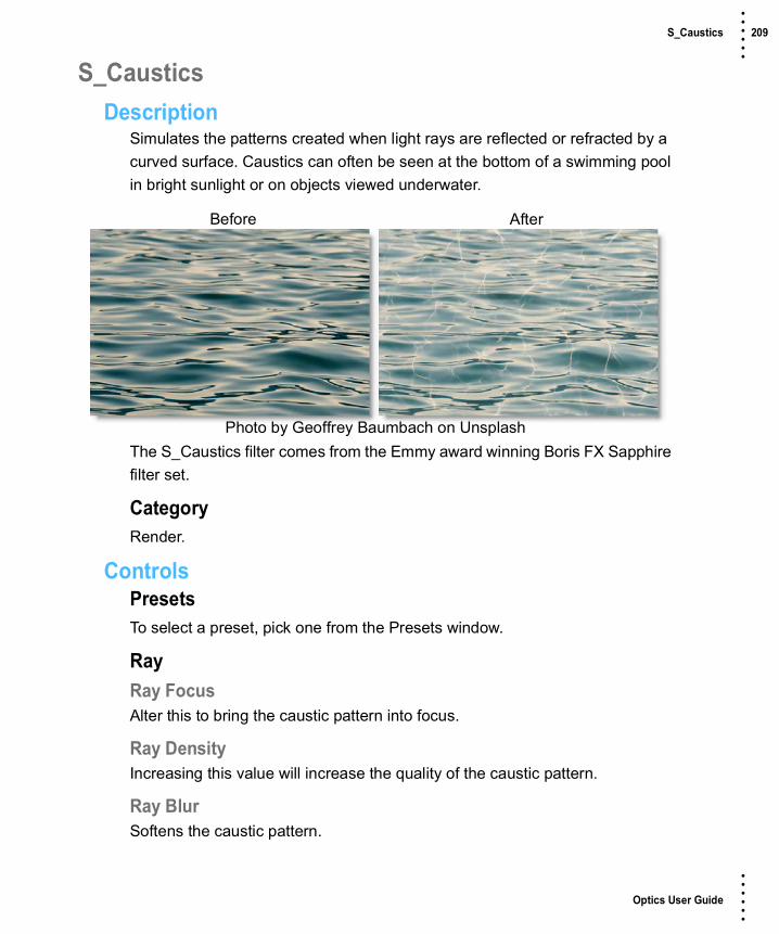
Optics User Guide
• • • •••
S_Caustics 209 • • • •••
S_CausticsDescription
Simulates the patterns created when light rays are reflected or refracted by a curved surface. Caustics can often be seen at the bottom of a swimming pool in bright sunlight or on objects viewed underwater.
The S_Caustics filter comes from the Emmy award winning Boris FX Sapphire filter set.
CategoryRender.
ControlsPresetsTo select a preset, pick one from the Presets window.
RayRay FocusAlter this to bring the caustic pattern into focus.
Ray DensityIncreasing this value will increase the quality of the caustic pattern.
Ray BlurSoftens the caustic pattern.
Before After
Photo by Geoffrey Baumbach on Unsplash

Optics User Guide
• • • •••
S_Caustics 210 • • • •••
CausticFrequencyThe frequency of the caustic pattern. Increase for more and smaller elements, or decrease for fewer and larger.
ComplexityThe complexity of the caustic pattern. Increase for more high frequency components within the caustic pattern.
ShiftTranslation of the caustic pattern.
SeedUsed to initialize the random number generator. The actual seed value is not significant, but different seeds produce different results and the same value should give a repeatable result.
ColorsBrightnessScales the brightness of Color1. Increase for more contrast.
Color1The color of the brighter parts of the texture. The colors of the result are determined by an interpolation between Color0 and Color1.
Color0The color of the darker parts of the texture.
Offset0Adds this value to color0. Decrease to a negative value for more contrast.
Bg BrightnessScales the brightness of the image.
Bg CombineDetermines how the texture is combined with the Background.
Caustic OnlyRenders only the caustic texture with no Background.

Optics User Guide
• • • •••
S_Caustics 211 • • • •••
MultThe texture is multiplied by the Background.
AddThe texture is added to the Background.
ScreenThe texture is blended with the Background using a screen operation.
DifferenceThe result is the difference between the texture and Background.
OverlayThe texture is combined with the Background using an overlay function.
Show ShiftEnables/disables the on-screen control for adjusting the Shift parameter.

Optics User Guide
• • • •••
Center Spot 212 • • • •••
Center SpotDescription
Center SpotDiffuses and blurs distracting backgrounds while keeping a center spot in focus. The center spot can be moved, sized and the amount of blur can be controlled.
Warm Center SpotCombines the benefits of Center Spot with a warming filter making it ideal for portraits and skintones.
CategoryDiffusion/Blurs.
Before After
Photo by Samuel Scrimshaw on Unsplash
Before After
Photo by Samuel Scrimshaw on Unsplash

Optics User Guide
• • • •••
Center Spot 213 • • • •••
ControlsPresetsTo select a preset, pick one from the Presets window. If you would like to view presets from a different category, use the pop-up menu at the top left of the Presets window.
BlurSets how much the image is blurred.
SpotA spot in the form of a radial gradient is used to control where blur is added to the image. Go to the Spot section of Common Filter Controls to see how the Spot controls work.
TemperatureApplies a warming filter to the image. Go to the Temperature section of Common Filter Controls to see how the Temperature controls work.

Optics User Guide
• • • •••
S_Channel Switcher 214 • • • •••
S_Channel SwitcherDescription
Reorders the RGB channels of the image. Allows mapping any source channel into any output channel, with scaling and offset for each output channel.
The S_ChannelSwitcher filter comes from the Emmy award winning Boris FX Sapphire filter set.
CategoryColor.
ControlsPresetsTo select a preset, pick one from the Presets window.
Red <−Selects which channel of the source to use as the output red channel.
RedUse the red input channel as the source for this output channel.
GreenUse the green input channel as the source for this output channel.
BlueUse the blue input channel as the source for this output channel.
Before After
Photo by Jeremy Bishop on Unsplash

Optics User Guide
• • • •••
S_Channel Switcher 215 • • • •••
LumaUse the input luminance as the source for this output channel.
1Use a constant 1 value (fully on) as the source for this output channel.
0Use a constant 0 value (fully off) as the source for this output channel.
Green <−Selects which channel of the source to use as the output green channel.
Blue <−Selects which channel of the source to use as the output blue channel.
Alpha <−Selects which channel of the source to use as the output alpha channel.
Scale Lights RedScales the brightness of the output red channel by this amount.
Scale Lights GreenScales the brightness of the output green channel by this amount.
Scale Lights BlueScales the brightness of the output blue channel by this amount.
Scale Lights AlphaScales the brightness of the output alpha channel by this amount.
Offset Darks RedAdds this value to the darker regions of the red output channel. This can be negative to increase contrast.
Offset Darks GreenAdds this value to the darker regions of the green output channel. This can be negative to increase contrast.

Optics User Guide
• • • •••
S_Channel Switcher 216 • • • •••
Offset Darks BlueAdds this value to the darker regions of the blue output channel. This can be negative to increase contrast.
Offset Darks AlphaAdds this value to the darker regions of the alpha output channel. This can be negative to increase contrast.
Mix With SourceInterpolates between the result (0) and the original source (1).

Optics User Guide
• • • •••
Chromatic Aberration 217 • • • •••
Chromatic AberrationDescription
Chromatic aberration is caused by a lens having a different refractive index for different wavelengths of light and is seen as fringes of color around the edges of the image. This fringing is removed by un-distorting the individual color channels.
There are some new types of color fringes that are not chromatic aberration. These effects might be visible as purple or blue fringes and are visible around overexposed areas in most cases. If the following conditions apply, your image most likely has true chromatic aberration as opposed to color fringing caused by sensor overloading:
• Corners should show most color fringes whereas the center should show none.
• Color fringes should be not only at the edges of overexposed areas but at lower contrast edges, too.
• Color fringes should be of complementary color (red-cyan, green/magenta, and blue-yellow) on opposite sides of a dark or bright area.
Before After
Photo by Joel Filipe on Unsplash
Optics User Guide
• • • •••
Chromatic Aberration 218 • • • •••
• Color fringes should be in all corners with the same direction and pointing out from the center.
Note: Chromatic Aberration must be applied as the first layer (bottom of the layer stack) when multiple layers are used. Otherwise, all filters below will not be rendered.
CategoryLens.
ControlsRed/Cyan, Green/Magenta, Blue/YellowUse the appropriate color group to remove the chromatic aberration. For instance, if you see red/cyan fringing, use the Red/Cyan group. Start by adjusting the Distortion parameter.
DistortionPulls the corners of the image in or out. Negative values pull the corners of the image inward while positive values pull the corners of the image outward.
Anamorphic SqueezeAnamorphic Squeeze corrects for the squeeze found in anamorphic motion picture lenses.
Curvature X and YCurvature X and Y correct for non-radial, asymmetric distortions found in anamorphic motion picture lenses.
Note: Anamorphic Squeeze and Curvature X and Y only work once the Distortion parameter has been adjusted.
Center X and YDetermines the center point for the distortion.

Optics User Guide
• • • •••
S_Clouds 219 • • • •••
S_CloudsDescription
Generates a procedural noise texture.
The S_Clouds filter comes from the Emmy award winning Boris FX Sapphire filter set.
CategoryRender.
ControlsPresetsTo select a preset, pick one from the Presets window.
TimeThe effect is advanced in time.
FrequencyThe spatial frequency of the clouds. Increase to zoom out, decrease to zoom in. Very high values of Frequency are clamped internally so the grain size is no smaller than a few pixels.
Frequency Rel XThe relative horizontal frequency of the texture. Increase to stretch it vertically or decrease to stretch it horizontally.
Before After
Photo by Jerry Zhang on Unsplash

Optics User Guide
• • • •••
S_Clouds 220 • • • •••
OctavesThe number of summed layers of noise. Each octave is twice the frequency and half the amplitude of the previous. A single octave creates a smooth texture. Adding octaves makes the result approach a fractal (1/f) noise texture.
SeedUsed to initialize the random number generator. The actual seed value is not significant, but different seeds produce different results and the same value should give a repeatable result.
Shift Start X & YTranslation offset of the texture. Since the texture is procedurally generated, it can be shifted with no repeating units or seams occurring.
Brightness1Scales the brightness of Color1. Increase for more contrast.
Color1The color of the brighter parts of the texture. The colors of the result are determined by an interpolation between Color0 and Color1.
Color0The color of the darker parts of the texture.
Offset0Adds this value to color0. Decrease to a negative value for more contrast.
Bg BrightnessThe image brightness is scaled by this value before being combined with the clouds.
CombineDetermines how the texture is combined with the Background.
Clouds OnlyRenders only the clouds texture with no Background.

Optics User Guide
• • • •••
S_Clouds 221 • • • •••
MultThe texture is multiplied by the Background.
AddThe texture is added to the Background.
ScreenThe texture is blended with the Background using a screen operation.
DifferenceThe result is the difference between the texture and Background.
OverlayThe texture is combined with the Background using an overlay function.
Show Shift StartEnables/disables the on-screen control for adjusting the Shift Start parameter.

Optics User Guide
• • • •••
S_CloudsColorSmooth 222 • • • •••
S_CloudsColorSmoothDescription
Generates a full color clouds texture. The procedural noise texture is independently generated for each of the red, green, and blue output channels.
The S_CloudsColorSmooth filter comes from the Emmy award winning Boris FX Sapphire filter set.
CategoryRender.
ControlsPresetsTo select a preset, pick one from the Presets window.
TimeThe effect is advanced in time.
FrequencyThe spatial frequency of the clouds. Increase to zoom out, decrease to zoom in. Very high values of Frequency are clamped internally so the grain size is no smaller than a few pixels.
Before After
Photo by Jerry Zhang on Unsplash

Optics User Guide
• • • •••
S_CloudsColorSmooth 223 • • • •••
Frequency Rel XThe relative horizontal frequency of the texture. Increase to stretch it vertically or decrease to stretch it horizontally.
OctavesThe number of summed layers of noise. Each octave is twice the frequency and half the amplitude of the previous. A single octave creates a smooth texture. Adding octaves makes the result approach a fractal (1/f) noise texture.
SeedUsed to initialize the random number generator. The actual seed value is not significant, but different seeds produce different results and the same value should give a repeatable result.
Shift Start X & YTranslation offset of the texture. Since the texture is procedurally generated, it can be shifted with no repeating units or seams occurring.
BrightnessScales the brightness of the result.
Scale ColorsScales the color of the result. For example, if it is yellow [1 1 0], the blue of the result will be 0.
SaturationScales the color saturation. Increase for more intense colors. Set to 0 for monochrome.
OffsetAdds this gray value to the result or subtracts if negative. 0 has no effect, .5 is middle gray, and 1 is white.
Bg BrightnessThe image brightness is scaled by this value before being combined with the clouds.
Optics User Guide
• • • •••
S_CloudsColorSmooth 224 • • • •••
CombineDetermines how the texture is combined with the Background.
Clouds OnlyRenders only the clouds texture with no Background.
MultThe texture is multiplied by the Background.
AddThe texture is added to the Background.
ScreenThe texture is blended with the Background using a screen operation.
DifferenceThe result is the difference between the texture and Background.
OverlayThe texture is combined with the Background using an overlay function.
Show Shift StartEnables/disables the on-screen control for adjusting the Shift Start parameter.

Optics User Guide
• • • •••
S_CloudsMultColor 225 • • • •••
S_CloudsMultColorDescription
Generates a procedural noise texture like Clouds and tints the colors using an additional color noise texture.
The S_CloudsMultColor filter comes from the Emmy award winning Boris FX Sapphire filter set.
CategoryRender.
ControlsPresetsTo select a preset, pick one from the Presets window.
TimeThe effect is advanced in time.
FrequencyThe spatial frequency of the clouds. Increase to zoom out, decrease to zoom in. Very high values of Frequency are clamped internally so the grain size is no smaller than a few pixels.
Before After
Photo by Jerry Zhang on Unsplash

Optics User Guide
• • • •••
S_CloudsMultColor 226 • • • •••
Frequency Rel XThe relative horizontal frequency of the texture. Increase to stretch it vertically or decrease to stretch it horizontally.
OctavesThe number of summed layers of noise. Each octave is twice the frequency and half the amplitude of the previous. A single octave creates a smooth texture. Adding octaves makes the result approach a fractal (1/f) noise texture.
SeedUsed to initialize the random number generator. The actual seed value is not significant, but different seeds produce different results and the same value should give a repeatable result.
Color AmountThe amplitude of the color tinting.
Color FreqThe frequency of the colors. Increase for finer color variation, decrease for softer color changes.
Color Freq RelxThe relative horizontal frequency of the colors. Increase to stretch vertically, decrease to stretch horizontally.
Color OctavesThe number of octaves of color noise to include. Each octave is twice the frequency and half the amplitude of the previous.
Color SeedThe random number generator seed to use for the color noise. The actual seed value is not significant, but different values produce different results.
Shift Start X & YTranslation offset of the texture. Since the texture is procedurally generated, it can be shifted with no repeating units or seams occurring.

Optics User Guide
• • • •••
S_CloudsMultColor 227 • • • •••
BrightnessScales the brightness of the result.
ColorScales the color of the result.
Color Noise ColorScales the color of the noise used for tinting.
OffsetAdds this gray value to the result or subtracts if negative. 0 has no effect, .5 is middle gray, and 1 is white.
Bg BrightnessThe image brightness is scaled by this value before being combined with the clouds.
CombineDetermines how the texture is combined with the Background.
Clouds OnlyRenders only the clouds texture with no Background.
MultThe texture is multiplied by the Background.
AddThe texture is added to the Background.
ScreenThe texture is blended with the Background using a screen operation.
DifferenceThe result is the difference between the texture and Background.
OverlayThe texture is combined with the Background using an overlay function.
Show Shift StartEnables/disables the on-screen control for adjusting the Shift Start parameter.

Optics User Guide
• • • •••
S_CloudsPerspective 228 • • • •••
S_CloudsPerspectiveDescription
Generates a procedural noise texture transformed onto a 3D plane with perspective.
The S_CloudsPerspective filter comes from the Emmy award winning Boris FX Sapphire filter set.
CategoryRender.
ControlsPresetsTo select a preset, pick one from the Presets window.
TimeThe effect is advanced in time.
FrequencyThe spatial frequency of the clouds. Increase to zoom out, decrease to zoom in. Very high values of Frequency are clamped internally so the grain size is no smaller than a few pixels.
Before After
Photo by Jerry Zhang on Unsplash

Optics User Guide
• • • •••
S_CloudsPerspective 229 • • • •••
Frequency Rel XThe relative horizontal frequency of the texture. Increase to stretch it vertically or decrease to stretch it horizontally.
OctavesThe number of summed layers of noise. Each octave is twice the frequency and half the amplitude of the previous. A single octave creates a smooth texture. Adding octaves makes the result approach a fractal (1/f) noise texture.
SeedUsed to initialize the random number generator. The actual seed value is not significant, but different seeds produce different results and the same value should give a repeatable result.
Z DistScales the distance of the image. Values greater than 1 move it farther away and make it smaller. Values less then 1 move the image closer and enlarge it.
LatitudePositive latitude tilts the image down and negative tilts it up. Keep latitude in the range of around −35 to 35 degrees to avoid aliasing towards the horizon.
SwingRotation of the image in degrees in its initial frame.
RollTilts the result from side to side in counterclockwise degrees.
Tele Lens WidthThe amount of lens telescoping. Increase to zoom in with less perspective, decrease for a wider viewing angle with more perspective.
Shift Start X & YTranslation offset of the texture. Since the texture is procedurally generated, it can be shifted with no repeating units or seams occurring.

Optics User Guide
• • • •••
S_CloudsPerspective 230 • • • •••
Brightness1Scales the brightness of Color1. Increase for more contrast.
Color1The color of the brighter parts of the texture. The colors of the result are determined by an interpolation between Color0 and Color1.
Color0The color of the darker parts of the texture.
Offset0Adds this value to color0. Decrease to a negative value for more contrast.
Bg BrightnessThe image brightness is scaled by this value before being combined with the clouds.
CombineDetermines how the texture is combined with the Background.
Clouds OnlyRenders only the clouds texture with no Background.
MultThe texture is multiplied by the Background.
AddThe texture is added to the Background.
ScreenThe texture is blended with the Background using a screen operation.
DifferenceThe result is the difference between the texture and Background.
OverlayThe texture is combined with the Background using an overlay function.
Show Shift StartEnables/disables the on-screen control for adjusting the Shift Start parameter.
Optics User Guide
• • • •••
Color 231 • • • •••
ColorDescription
Generates a solid field of color.
CategoryColor.
ControlsColorThe color can be set through the use of a standard color picker.

Optics User Guide
• • • •••
Color Correct 232 • • • •••
Color CorrectDescription
Color Correct manipulates hue, saturation, brightness, contrast, gamma, temperature, cyan/magenta, red, green and blue values of the overall image and separately in user definable shadow, midtone and highlight areas. In addition to traditional slider controls, a visual Color Wheels interface can be used to make adjustments.
CategoryColor.
Master, Shadows, Midtones, HighlightsAll of the color correctors can adjust an image by using it’s master, shadows, midtones and highlight groups. The master settings affect the entire image while adjusting parameters within the shadows, midtones and highlights will only affect those specific areas.
If you are unsure about what values are included in the shadows, midtones and highlights, you can use the View pop-up menu. It will allow you to view the shadows, midtones and highlights as a black and white matte. The white areas are the areas that will be adjusted by that particular group. For instance, if you see white areas while viewing the midtones, then midtone color adjustments will affect only those white areas. If you want to change the default areas defined by the shadows, midtones and highlights, you would use the Position and Range sliders.
Original Shadows Midtones Highlights

Optics User Guide
• • • •••
Color Correct 233 • • • •••
PositionThe Position slider pinpoints the values to be considered as shadows, midtones, or highlights. A low Position value uses the darkest image values, while a high Position value uses the brightest.
RangeIncreases or decreases the range of values considered as shadows, midtones or highlights. A low Range value indicates a narrow range of values, while a high Range value indicates a large range of values.
Go to the Matte section of Common Filter Controls to see how the Position and Range controls work.
Color CorrectPresetsTo select a preset, pick one from the Presets window.
HueRotates the hue of the image.
SaturationAdjusts the saturation of the image. Positive values saturate, negative values desaturate.
BrightnessAdjusts the brightness of the image. Positive values brighten, negative values darken.
ContrastAdjusts the contrast of the image. Positive values increase contrast, negative values decrease contrast.
Gamma Adjusts the gamma of the image. The gamma adjustment leaves the white and black points the same and only modifies the values in-between. Positive values lighten the midtones, negative values darken the midtones.

Optics User Guide
• • • •••
Color Correct 234 • • • •••
TemperatureSets the color of the image to be either warmer or cooler. Dragging the slider to the right makes the image cooler (bluer) and dragging the slider to the left makes the image warmer (redder).
Cyan/MagentaAdds either Cyan or Magenta to the image. Dragging the slider to the right makes the image more magenta and dragging the slider to the left makes the image more cyan.
RedAdds or subtracts red from the image.
GreenAdds or subtracts green from the image.
BlueAdds or subtracts blue from the image.
FlashingThe Flash parameters mix a color into the image through the use of a standard color picker. The default color is white. What in the world is this for? It is a great way to add atmosphere to an element. Flash comes from the film term “flashing”, which describes the optical process of lowering the contrast of an image by flashing it with light.
Flash Amount Sets the opacity of the Flash Color.
Flash ColorThe Flash Color can be set through the use of a standard color picker.
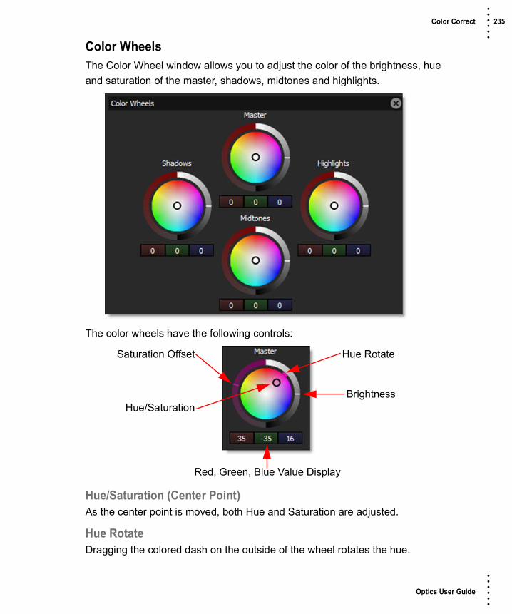
Optics User Guide
• • • •••
Color Correct 235 • • • •••
Color WheelsThe Color Wheel window allows you to adjust the color of the brightness, hue and saturation of the master, shadows, midtones and highlights.
The color wheels have the following controls:
Hue/Saturation (Center Point)As the center point is moved, both Hue and Saturation are adjusted.
Hue RotateDragging the colored dash on the outside of the wheel rotates the hue.
Saturation Offset
BrightnessHue/Saturation
Hue Rotate
Red, Green, Blue Value Display

Optics User Guide
• • • •••
Color Correct 236 • • • •••
SaturationIncreases or decreases the selected color’s saturation.
BrightnessAdjusts the brightness.
Note: The Hue and Saturation adjustments are achieved by simultaneously changing the Red, Green and Blue parameters in the respective group: Master, Shadows, Midtones, or Highlights. The current Red, Green and Blue values are displayed below the Color Wheel.
ResetDouble-click on a color wheel to reset it. Alternatively, right-clicking on any color wheel will open a context menu that contains Reset > All, Shadows, Midtones, and Highlights options.

Optics User Guide
• • • •••
Color Gradient 237 • • • •••
Color GradientDescription
Color Gradient colors and or darkens only a portion of the image giving you the ability to simulate any Color Gradient filter. Presets for your favorite color gradient filters are provided as well as the ability to create custom colors. There is a graduated transition for a smooth color blend between the colored/darkened portion and the original image. Color Gradient is especially useful for changing and enhancing the color of the sky.
CategoryGrads/Tints.
FiltersPresetsTo select a preset, pick one from the Presets window.
ColorThe Color parameter sets the color of the grad through the use of a standard color picker.
OpacitySets the opacity of the color filter.
Preserve HighlightsPreserves the white areas of the image.
Before After
Photo by Joshua Earle on Unsplash

Optics User Guide
• • • •••
Color Gradient 238 • • • •••
Exposure CompensationExposure Compensation adds back the brightness loss as a result of the filter application.
GradGrad is the transition area that goes from the tinted image to the original image. Its direction, corners and size can be adjusted. Go to the Grad section of Common Filter Controls to see how the Grad controls work.

Optics User Guide
• • • •••
Color Infrared 239 • • • •••
Color InfraredDescription
Color Infrared simulates infrared filters used in conjunction with infrared sensitive film or sensors to produce very interesting false-color images with a dreamlike or sometimes lurid appearance.
CategoryStylize.
ControlsPresetsTo select a preset, pick one from the Presets window.
MagentaAdjusts the amount of magenta.
BlueAdjusts the amount of blue.
HueAdjusts the hue in any non-blue areas.
ContrastAdjusts the contrast of the image.
Before After
Photo by Karsten Wurth on Unsplash

Optics User Guide
• • • •••
Color Shadow 240 • • • •••
Color ShadowDescription
Creates a high contrast image overlayed with a gradient.
CategoryStylize.
ControlsPresetsTo select a preset, pick one from the Presets window.
ThresholdSets the amount of image detail.
InvertChanges whether the gradient is in the background or foreground.
Background ColorSets the color of the background. Select the desired color using the color picker.
Before After
Photo by Emre Karatas on Unsplash

Optics User Guide
• • • •••
Color Shadow 241 • • • •••
Color 1Sets the color for the top half of the image. Select the desired color using the color picker.
Color 2Sets the color for the bottom half of the image. Select the desired color using the color picker.
Grad Grad is the transition area between the two colors. Its direction, corners and size can be adjusted. Go to the Grad section of Common Filter Controls to see how the Grad controls work.

Optics User Guide
• • • •••
Color Spot 242 • • • •••
Color SpotDescription
Tints the image using presets for common photographic filters except for a center spot which retains normal color. The center spot can be moved, sized and the amount of blur can be controlled.
CategoryGrads/Tints.
ControlsPresetsTo select a preset, pick one from the Presets window.
ColorColorThe Color parameter sets the color through the use of a standard color picker.
OpacitySets the opacity of the color filter.
Preserve HighlightsPreserves the white areas of the image.
Exposure CompensationExposure Compensation adds back the brightness loss as a result of the filter application.
Before After
Photo by Bill Williams on Unsplash

Optics User Guide
• • • •••
Color Spot 243 • • • •••
SpotA spot in the form of a radial gradient is used to control where color is added to the image. Go to the Spot section of Common Filter Controls to see how the Spot controls work.

Optics User Guide
• • • •••
Colorize Gradient 244 • • • •••
Colorize GradientDescription
Using multiple colors, Colorize Gradient colorizes the image according to the image’s brightness values.
CategoryGrads/Tints.
ControlsPresetsTo select a preset, pick one from the Presets window.
OpacitySets the overall opacity of the colorization.
ShadowsEnableDetermines whether or not the color contributes to the gradient.
ColorPicks the color that the image will be colorized with. Select the desired color using the color picker.
Before After
Photo by David Marcu on Unsplash

Optics User Guide
• • • •••
Colorize Gradient 245 • • • •••
PositionDetermines where the colorization is applied to the image. By default, Shadows are set to 0, which is the shadow areas. A value of 50 would be the midtones, while 100 would be highlights.
MidtonesThe Midtones controls are the same as the controls for the Shadows, except by default, the colorization is applied to the midtones of the image.
HighlightsThe Highlights controls are the same as the controls for the Shadows, except by default, the colorization is applied to the highlights of the image.
GradYou can optionally use a gradient that limits where the filter is applied. Grad is the transition area that goes from the colorized image to the original image. Its direction, corners and size can be adjusted. Go to the Grad section of Common Filter Controls to see how the Grad controls work.

Optics User Guide
• • • •••
Cross Processing 246 • • • •••
Cross ProcessingDescription
Cross-processing is a photographic technique where print film (C41) is processed in the set of chemicals usually used to process slide film (E6) or vice versa. The final result yields images with oddly skewed colors and increased contrast and saturation..
CategoryFilm Lab.
ControlsPresetsTo select a preset, pick one from the Presets window.
AmountSets the amount of the selected preset.
Before After
Photo by Jesse Collins on Unsplash

Optics User Guide
• • • •••
Cross Processing 247 • • • •••
Curves
RGBAdjusts the RGB values and has the effect of brightening or darkening the image.
RedAdjusts the red values in the image.
GreenAdjusts the green values in the image.
BlueAdjusts the blue values in the image.
Selecting Curves• Select RGB, Red, Green or Blue from the Curve Type pop-up menu.
Adjust Black
Adjust White
Adjust Gray
Curve Type

Optics User Guide
• • • •••
Cross Processing 248 • • • •••
• Click directly on an existing curve in the graph to select it.
Adding and Deleting Points:• Click directly on the curve to add a new point. Up to five points can be added.
• Points can be deleted by clicking and dragging a point to the edge of the graph.
Adjusting Points:• Moving a point in the bottom portion of the curve adjusts the shadows.
• Moving a point in the center of the curve adjusts the midtones.
• Moving a point in the top portion of the curve adjusts the highlights.
• Moving the curve upward or downward lightens or darkens the image. The steeper sections of the curve represent areas of higher contrast; flatter sections represent areas of lower contrast.
• To darken highlights, move a point near the top of the curve downward. Moving a point either down or to the right maps the input value to a lower output value, and the image darkens.
• To lighten the shadows, move a point near the bottom of the curve upward. Moving a point either up or to the left maps a lower input value to a higher output value, and the image lightens.
SlidersRGBGlobally adjusts the RGB curve.
RedGlobally adjusts the Red curve.
GreenGlobally adjusts the Green curve.
BlueGlobally adjusts the Blue curve.

Optics User Guide
• • • •••
S_Crosshatch 249 • • • •••
S_CrosshatchDescription
Simulates a pen-sketch crosshatched look using overlapping strokes. The source is divided into four bands based on luma; each band from dark to light gets a different pattern of strokes.
The S_Crosshatch filter comes from the Emmy award winning Boris FX Sapphire filter set.
CategoryStylize.
ControlsPresetsTo select a preset, pick one from the Presets window.
ModeSelects pencil or chalk modes.
CrosshatchPencilSimulates dark pencil or pen strokes on white paper.
CrosshatchChalkSimulates white chalk strokes on dark paper.
Before After
Photo by Jeremy Bishop on Unsplash

Optics User Guide
• • • •••
S_Crosshatch 250 • • • •••
Stroke StyleStroke FrequencyIncrease for smaller, finer strokes; decrease for broader strokes.
Stroke LengthAverage length of the strokes, compared to their width.
Stroke StrengthOverall size and strength; decrease for fewer, smaller strokes. At 0, strokes will vanish. Increase for bolder, more overlapping strokes. At 1, there will be strokes everywhere, so you won't see the stroke pattern.
Stroke SoftnessSoftness of the edges of each stroke. Decrease for hard edged pen strokes; increase for a softer chalk like look.
Stroke AngleAngle of the strokes in degrees; zero makes strokes horizontal and vertical.
Threshold DarksThe darkest areas get double overlapping strokes (or pure black in chalk mode). Source areas with luma darker than this threshold are considered in the darkest band and get those double strokes. Increasing this, or any threshold, will darken the overall result since more of the image will fall into the darkest band.
Threshold MidsMidtones are divided into darker−mids and brighter−mids. This threshold sets the luma value that separates those two bands. The darker mids get darker and denser strokes.
Threshold BrightsThe brightest areas get the lightest strokes--normally just white, unless you are in chalk mode. Areas brighter than this threshold are considered brights.
Thresholds AddAdds or subtracts from all the thresholds. Increase to darken the overall result or decrease to lighten the overall result.

Optics User Guide
• • • •••
S_Crosshatch 251 • • • •••
Mix ThresholdSoftens the borders between the dark/mid/light luma bands.
Stroke ColorsStrokes Use SourceIncrease to use more of the source color to color the strokes. 0 means use the stroke color, while 1 means use the color of the underlying image. In between strokes, the background color shows through. If you have Back Style set to Source, the strokes will disappear when set to 1.
Stroke ColorThe color to use for the strokes. In Pencil mode, this defaults to black. In Chalk mode, it defaults to white.
Posterize AmountPosterizes the source, giving a more cartoony look with areas of solid color. This only has an effect when using the source to colorize the strokes or when using the source as the background.
Posterize SmoothWhen posterizing, smooth the edges of the solid−color areas. This avoids aliasing and usually looks better.
Posterize PhaseAdjusts the phase of the posterization. Use this to position the areas of flat color and avoid edges in the middle of areas you'd like to keep flat.
EdgesEdge StrengthAdds cartoon like edges to the look.
Edge WidthAdjusts the width of the edge strokes. Increasing this value also softens the edges.
Edge ThresholdIncrease to remove minor, insignificant edge strokes, giving a bolder look.

Optics User Guide
• • • •••
S_Crosshatch 252 • • • •••
Edge ColorSets the color for the edge strokes.
Suppress Small EdgesIncrease to suppress small, minor edges.
Edge SharpenSharpens the edge strokes.
Background ColorBack StyleWhat to use as the background, underneath the pen strokes.
SourceUse the source as the background. This gives a much more colorful look, as if the strokes are drawn over the original clip. You may want to adjust Stroke Color when using this.
Solid ColorUse the specified Solid Color background.
Solid ColorThe color to use for the background when in Solid Color mode.
Pre Blur BgBlur the source before using it as background or to color the strokes. This can help reduce sparkling due to a noisy or grainy source.
Use Source AlphaAt 1, the effect appears only in the white areas of the alpha channel. At 0, the effect appears everywhere in the frame.
Color CorrectSaturationIncrease or decrease the overall saturation of the output.
Scale LightsScales the brightness of the result by this amount.

Optics User Guide
• • • •••
S_Crosshatch 253 • • • •••
Offset DarksAdd a gray value to the darker regions of the source. This can be negative to increase contrast.
Tint LightsScales the result by this color, thus tinting the lighter regions.
Tint DarksAdds this color to the darker regions of the result.
Mix With SourceInterpolates between the result (when set to 0) and the original source (when set to 1). 0.7 can give a nice effect by blending some of the source in with the strokes.
SeedInitialize the random number generator for the strokes. Different values produce different random stroke patterns.

Optics User Guide
• • • •••
Curves 254 • • • •••
CurvesDescription
Curves adjusts the entire tonal range of an image by changing the shape of RGB, Red, Green or Blue curves. Curve points can be adjusted throughout the range of shadows to highlights.
CategoryColor.
ControlsAmountSets the amount of the selected preset.
Before After
Photo by Annie Spratt on Unsplash

Optics User Guide
• • • •••
Curves 255 • • • •••
Curves
RGBAdjusts the RGB values and has the effect of brightening or darkening the image.
RedAdjusts the red values in the image.
GreenAdjusts the green values in the image.
BlueAdjusts the blue values in the image.
Selecting Curves• Select RGB, Red, Green or Blue from the Curve Type pop-up menu.
Adjust Black
Adjust White
Adjust Gray
Curve Type

Optics User Guide
• • • •••
Curves 256 • • • •••
• Click directly on an existing curve in the graph to select it.
Adding and Deleting Points:• Click directly on the curve to add a new point. Up to five points can be added.
• Points can be deleted by clicking and dragging a point to the edge of the graph.
Adjusting Points:• Moving a point in the bottom portion of the curve adjusts the shadows.
• Moving a point in the center of the curve adjusts the midtones.
• Moving a point in the top portion of the curve adjusts the highlights.
• Moving the curve upward or downward lightens or darkens the image. The steeper sections of the curve represent areas of higher contrast; flatter sections represent areas of lower contrast.
• To darken highlights, move a point near the top of the curve downward. Moving a point either down or to the right maps the input value to a lower output value, and the image darkens.
• To lighten the shadows, move a point near the bottom of the curve upward. Moving a point either up or to the left maps a lower input value to a higher output value, and the image lightens.
SlidersRGBGlobally adjusts the RGB curve.
RedGlobally adjusts the Red curve.
GreenGlobally adjusts the Green curve.
BlueGlobally adjusts the Blue curve.

Optics User Guide
• • • •••
Day for Night 257 • • • •••
Day for NightDescription
Day for Night simulates a technique used for shooting exteriors in daylight made to look like they were photographed at night. Typically, it involves underexposing by two to two-and-a-half stops and using a filter to provide a tint, that is often a lavender-blue, as it mimics twilight and appears to emulate the mood of moonlight.
CategoryStylize.
ControlsPresetsTo select a preset, pick one from the Presets window.
DiffusionBlurSets how much the image is diffused.
OpacitySets the amount of diffusion mixed into the original image. The higher the setting, the more the image is blurred.
Before After
Photo by Daniel Bowman on Unsplash

Optics User Guide
• • • •••
Day for Night 258 • • • •••
MoonlightColorThe Color parameter sets the color of the moonlight through the use of a standard color picker. The default color is blue.
OpacitySets the opacity of the moonlight color.
Preserve HighlightsPreserves the white areas of the image.
Exposure CompensationExposure Compensation adds back the brightness loss as a result of the color application.
Color CorrectGo to the Color Correct filter to see how the Color Correct controls work.

Optics User Guide
• • • •••
DeBand 259 • • • •••
DeBandDescription
DeBand removes banding artifacts from an image by smoothing pixels in banded areas while retaining detail.
CategoryImage.
ControlsPresetsTo select a preset, pick one from the Presets window.
AmountSets the amount of debanding.
Before After
Photo by Frantzou Fleurine on Unsplash

Optics User Guide
• • • •••
DeBlock 260 • • • •••
DeBlockDescription
Blocking artifacts created as a result of high compression factors can be removed with the DeBlock filter.
CategoryImage.
ControlsThere are no controls for the DeBlock filter since it automatically finds blocks and removes them.
Before After
Photo by Nolan Issac on Unsplash

Optics User Guide
• • • •••
DeFog 261 • • • •••
DeFogDescription
Using advanced deweathering algorithms, Defog restores clear day contrasts and colors of a scene taken in bad weather such as fog and mist. It is also successful in removing the effects of optical Fog and Diffusion filters.
CategoryStylize.
ControlsPresetsTo select a preset, pick one from the Presets window.
DefogColorThe Color parameter sets the color of the fog to be removed through the use of a standard color picker. The default color is white.
Vanishing PointA vanishing point along the direction of increasing distance in the image is used to remove fog. By default, the vanishing point is set to the center of the screen. Essentially, the fog is removed in a radial pattern emanating from the vanishing point. So at the default center position, fog is removed in a circular pattern with a greater amount of fog being removed from the center while falling off at the
Before After
Photo by Matt Hoffman on Unsplash

Optics User Guide
• • • •••
DeFog 262 • • • •••
edges. For instance, if your fog moves in the direction of top right to bottom left, set your vanishing point towards the top right corner and the fog removal will be more intense at the upper right and fall off at the bottom left. However, in most cases, the vanishing point can be left in the center of the screen and you will obtain acceptable results.
There is an on-screen control in the center of the image. By clicking and dragging the on-screen control or sliders, the position of the vanishing point can be adjusted.
DefogSets the amount of fog to be removed from the scene.
Min DepthControls how much fog is removed from the darker areas of the image.
Max DepthControls how much fog is removed from the brighter areas of the image.
Color CorrectGo to the Color Correct filter to see how the Color Correct controls work.

Optics User Guide
• • • •••
DeFringe 263 • • • •••
DeFringeDescription
Purple or blue fringing around overexposed areas is a result of sensor overloading in video as well as digital still cameras. DeFringe isolates and removes the various types of color fringing.
CategoryLens.
ControlsPresetsTo select a preset, pick one from the Presets window.
RedRedAdjusts the saturation of red values in areas defined by the Position and Range controls. Positive values saturate, negative values desaturate.
PositionA matte is generated to isolate red fringing. The areas that are white in the red matte are the areas that will be defringed. Moving the Position slider will change the hue that is used for the red matte.
Before After

Optics User Guide
• • • •••
DeFringe 264 • • • •••
RangeIncreases or decreases the range of values considered as red fringing. A low Range value indicates a narrow range of values, while a high Range value indicates a large range of values.
Go to the Matte section of Common Filter Controls to see how the Position and Range controls work.
Green, Blue, Cyan, Magenta, and YellowThe Green, Blue, Cyan, Magenta and Yellow groups work in a similar fashion to the Red group.

Optics User Guide
• • • •••
DeNoise 265 • • • •••
DeNoiseDescription
Removes film grain and noise.
CategoryImage.
ControlsPresetsTo select a preset, pick one from the Presets window.
AmountSets the amount of denoising.
Before After
Photo by Brady Bellini on Unsplash

Optics User Guide
• • • •••
Depth of Field 266 • • • •••
Depth of FieldDescription
Depth of Field can be added to a scene by isolating and blurring only a portion of the image. The amount of blurring is directly proportionate to the luminance of the matte settings, a gradient or an input image.
CategoryDiffusion/Blurs.
ControlsPresetsTo select a preset, pick one from the Presets window.
DepthSelects the source for the selective blur effect.
MatteUse a matte for the depth source.
GradUse a gradient for the depth source.
InputUse an image as the depth source. This is useful for 3D programs which render out depth mattes.
Before After
Photo by Ethan Robertson on Unsplash

Optics User Guide
• • • •••
Depth of Field 267 • • • •••
To use an image as the depth source:• Change Depth > Depth to Input.
• Click the Depth > Input > Browse button.
• Select a file.
BlurSets how much the image is blurred.
Grad Depth of Field can optionally use a gradient that limits where the filter is applied. Grad is the transition area that goes from the blurred portion to the original image. Its direction, corners and size can be adjusted. Go to the Grad section of Common Filter Controls to see how the Grad controls work.
MatteA matte can be used to create the depth of field effect. Go to the Matte section of Common Filter Controls to see how the Matte controls work.

Optics User Guide
• • • •••
Detail 268 • • • •••
DetailDescription
Detail presents a new technique for performing selective sharpening, detail enhancement and edge aware smoothing. Our approach decomposes the image into three detail layers: Coarse, medium and fine. Each of the detail layers can be manipulated separately in various ways, for instance, sharpening or smoothing. Add to that sophisticated, but easy to use masking and you have quick isolation of image features for selective filtering.
CategoryImage.
Smooth Sharpen
Photo by Chris Lawton on Unsplash
Before

Optics User Guide
• • • •••
Detail 269 • • • •••
ControlsPresetsTo select a preset, pick one from the Presets window.
CoarseAdjusts the Coarse detail layer. Increasing the value sharpens while decreasing the value smooths.
MediumAdjusts the medium detail layer. Increasing the value sharpens while decreasing the value smooths.
FineAdjusts the fine detail layer. Increasing the value sharpens while decreasing the value smooths.
GangThe Coarse, Medium and Fine slider values can be ganged together so that they all move simultaneously. This will generate an overall sharpening effect if the sliders are increased and an overall smoothing effect if decreased.
MatteA matte can be used to limit the detail effect. Wherever there is white in the matte is where the detail adjustment will occur. Go to the Matte parameters to see how they work.
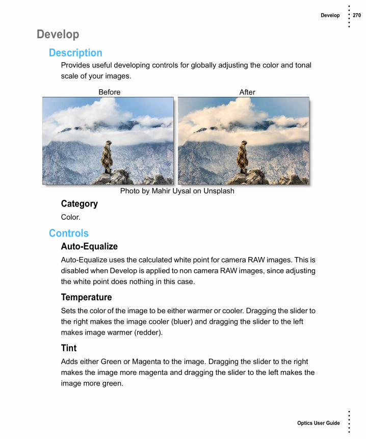
Optics User Guide
• • • •••
Develop 270 • • • •••
DevelopDescription
Provides useful developing controls for globally adjusting the color and tonal scale of your images.
CategoryColor.
ControlsAuto-EqualizeAuto-Equalize uses the calculated white point for camera RAW images. This is disabled when Develop is applied to non camera RAW images, since adjusting the white point does nothing in this case.
TemperatureSets the color of the image to be either warmer or cooler. Dragging the slider to the right makes the image cooler (bluer) and dragging the slider to the left makes image warmer (redder).
TintAdds either Green or Magenta to the image. Dragging the slider to the right makes the image more magenta and dragging the slider to the left makes the image more green.
Before After
Photo by Mahir Uysal on Unsplash

Optics User Guide
• • • •••
Develop 271 • • • •••
ExposureSets the overall image brightness, with a greater effect in the high values. Adjust the slider until the image looks good and the whites are at the right level. Use Recovery to bring highlight values down. Exposure values are in increments equivalent to f-stops. An adjustment of +1.00 is similar to increasing the aperture 1 stop. Similarly, an adjustment of –1.00 is similar to reducing the aperture 1 stop.
RecoveryReduces the tones of extreme highlights and attempts to recover highlight detail lost because of overexposure.
Fill LightLightens shadows to reveal more detail while maintaining blacks. Take care not to over apply the setting and reveal image noise.
BlacksSpecifies which image values map to black. Moving the slider to the right increases the areas that become black, sometimes creating the impression of increased image contrast. The greatest effect is in the shadows, with much less change in the midtones and highlights.
BrightnessAdjusts image brightness, mainly affecting midtones. Set the overall tonal scale by setting Exposure, Recovery, and Blacks. Then set the overall image brightness. Large brightness adjustments can affect shadow or highlight clipping, so you may want to readjust the Exposure, Recovery, or Blacks slider after adjusting brightness.
ContrastIncreases or decreases image contrast, mainly affecting midtones. When you increase contrast, the middle-to-dark image areas become darker, and the middle-to-light image areas become lighter. The image tones are inversely affected as you decrease contrast.

Optics User Guide
• • • •••
Develop 272 • • • •••
VibranceAdjusts the saturation so that clipping is minimized as colors approach full saturation, changing the saturation of all lower-saturated colors with less effect on the higher-saturated colors. Vibrance also prevents skin tones from becoming over saturated.
SaturationAdjusts the saturation of all image colors equally.

Optics User Guide
• • • •••
Diffusion 273 • • • •••
DiffusionDescription
Diffusion creates atmosphere by reducing contrast while creating a glow around highlights or shadows using an extensive texture library.
CategoryDiffusion/Blurs.
ControlsPresetsTo select a preset, pick one from the Presets window.
DiffusionBlendDetermines the blend mode to be used to create the diffusion effect.
AddThe diffusion is added to your image.
ScreenThe diffusion is combined with the image using a Screen blend mode. This looks kind of like the Add blend mode, but highlights are retained.
BrightnessSets the intensity of the diffusion.
Before After
Photo by Marina Vitale on Unsplash

Optics User Guide
• • • •••
Diffusion 274 • • • •••
BlurSets the softness of the diffusion.
ColorThe Color parameter sets the color of the diffusion through the use of a standard color picker. The default color is white.
Color CorrectGo to the Color Correct filter to see how the Color Correct controls work.
TextureTextureSelects the texture which will be used to add diffusion to the image.
BlendTextures can be used as the source of the diffusion as well as combined with a matte using a variety of Blend modes. Go to Blend Modes for explanations of the various modes.
I like the Multiply blend mode for combining textures with the matte because it only puts the texture within the areas of the generated matte.
TransformTransform the texture using Position, Scale, Rotate, Corner-Pin, Shear and Crop controls. Go to the Transform section of Common Filter Controls to see how the Transform Controls work.
MatteA matte can be used to create the diffusion effect. Go to the Matte section of Common Filter Controls to see how the Matte controls work.

Optics User Guide
• • • •••
S_DigitalDamage 275 • • • •••
S_DigitalDamageDescription
Simulates bad digital TV transmission with many options, including freeze-frames, shifting and flowing blocks, various kinds of blocky noise, and pixelization. Can give looks similar to MPEG stream errors, digital dropouts, and satellite feed data corruption.
The S_DigitalDamage filter comes from the Emmy award winning Boris FX Sapphire filter set.
CategoryStylize.
ControlsPresetsTo select a preset, pick one from the Presets window.
TimeThe effect is advanced in time.
IntensityOverall intensity of the damage.
Damage SizeTurn up to increase the average size of the damaged areas.
Before After
Photo by Jonathan Roger on Unsplash

Optics User Guide
• • • •••
S_DigitalDamage 276 • • • •••
Damage Size Rel XTurn up to elongate the damage areas horizontally. This doesn't stretch the image, just changes the aspect ratio of the damage areas and noise patterns.
SeedUsed to initialize the random number generator. The actual seed value is not significant, but different seeds produce different results and the same value should give a repeatable result.
FreezeEnable freeze−frame damage.
Freeze DetailsFreeze ThresholdDecrease for more frozen areas on each frame.
Freeze SaturationBoost the saturation of frozen areas for a more damaged look.
Freeze QualityReduce to give the frozen areas a JPEG−quantized look.
Freeze ErrsAdds JPEG quantization errors to the frozen areas.
Brights NoiseEnable noise that appears in the bright areas of the image.
Brights Noise DetailsBrights ThresholdAreas brighter than this will be subject to brights noise.
Brights Band ThresholdThis damage type occurs in bands. Increase this parameter to make more damage bands, and thus increase the amount of overall damage.

Optics User Guide
• • • •••
S_DigitalDamage 277 • • • •••
Brights Band FreqControls the average height of the damage bands. Decrease for larger bands, increase for shorter, finer bands.
PixelateEnable pixelation damage.
Pixelate DetailsPixelate FrequencyControls the size of the blocky pixels. Increase for more, smaller pixels. Decrease for fewer, larger pixels.
Pixelate HoldControls how the pixelate damaged areas move. Increase to make the damaged areas stay in one place over more frames. Decrease to make it more random.
Pixelate ThresholdDecrease for more overall pixelation per frame. Increase for less.
Pixelate OverdrivePixelate damage can invert and distort the damaged area. Increase this parameter to make it look more damaged.
Block NoiseEnable blocky−noise damage. This is commonly seen with bad satellite TV transmission. Bands and blocks of noise overlay and interact with the source footage.
Block Noise DetailsBlocks IntensityIncrease the intensity of the block damage.
Blocks ThresholdDecrease for more overall damage per frame or increase for less.
Blocks SoftnessThis parameter softens the damage pattern as it's increased.

Optics User Guide
• • • •••
S_DigitalDamage 278 • • • •••
Blocks ChromaIncrease to overdrive the chroma of the block noise and make it look more damaged.
InvertEnable image−inverting damage that inverts and recolors bands of the image.
Invert DetailsInvert ThresholdDecrease for more overall damage per frame or increase for less.
Invert DarkenIncrease to darken the inverted areas more which makes them stand out more and look more damaged.
Invert Pattern FreqControls the spatial frequency of the invert damage pattern. Increase to make the inverted area pattern finer or decrease for larger areas of damage.

Optics User Guide
• • • •••
S_DogVision 279 • • • •••
S_DogVisionDescription
Generates a dual color-channel version of the image, as might be perceived by the limited color vision system of dogs. Humans have three color receptors (for red, green, and blue) while dogs have only two receptors (for yellow and blue).
The S_DogVision filter comes from the Emmy award winning Boris FX Sapphire filter set.
CategoryStylize.
ControlsPresetsTo select a preset, pick one from the Presets window.
ChannelsSelects which two complementary color channels to use.
Yellow−BlueThe result is made using yellow and blue.
Cyan−RedThe result is made using cyan and red.
Before After
Photo by Rodion Kutsaev on Unsplash

Optics User Guide
• • • •••
S_DogVision 280 • • • •••
Magenta−GreenThe result is made using magenta and purple.
Rotate ChannelsAllows hue shifting the two color channels selected above.
Note: When this is non−zero, the channels may no longer match the name selected.
Blur Channel1Smooths the first color channel by this amount.
Blur Channel2Smooths the second color channel by this amount.
Mix OriginalInterpolates between the 2−color result and the original source. Set this to 1 for the original, or use negative values to exaggerate the dog vision effect.
BrightnessScales the brightness of the result.
Offset DarksAdds a gray value to the darker regions of the result. This can be negative to increase contrast.
SaturationScales the color saturation. Increase for more intense colors. Set to 0 for monochrome.
Weight Source RGBWeight Source RScales the red of the image before processing.
Weight Source GScales the green of the image before processing.
Weight Source BScales the blue of the image before processing.

Optics User Guide
• • • •••
Double Fog 281 • • • •••
Double FogDescription
The Double Fog filter creates a soft, misty atmosphere over the image by first applying fog using a vanishing point along the direction of increasing distance in the image. Then, a second pass blooms image highlights.
CategoryDiffusion/Blurs.
ControlsPresetsTo select a preset, pick one from the Presets window.
FogColorThe Color parameter sets the color of the fog to be added through the use of a standard color picker. The default color is white.
Vanishing PointA vanishing point along the direction of increasing distance in the image is used to add fog. By default, the vanishing point is set to the center of the screen. Essentially, the fog is added in a radial pattern emanating from the vanishing point. So at the default center position, fog is added in a circular pattern with a greater amount of fog being added in the center while falling off at the edges. For instance, if you would like your fog to move in the direction of top right to
Before After
Photo by Martin Knize on Unsplash

Optics User Guide
• • • •••
Double Fog 282 • • • •••
bottom left, set your vanishing point towards the top right corner and the fog will be more intense at the upper right and fall off at the bottom left. However, in most cases, the vanishing point can be left in the center of the screen and you will obtain acceptable results.
There is an on-screen control in the center of the image. By clicking and dragging the on-screen control or sliders, the position of the vanishing point can be adjusted.
FogSets the amount of fog to be added to the scene.
Min DepthControls how much fog is added in the darker areas of the image.
Max DepthControls how much fog is added in the brighter areas of the image.
GlowThe Glow controls are used to add additional atmosphere and are useful in adding glow to highlights. By default, a wide matte of highlights are glowed in the image and blended with the Screen blend mode. This works well for adding additional fog. To add glow around highlights such as light sources, it is best to set the Blend mode to Add and lower the Matte > Range parameter to limit the areas of glow to only include the light sources.
BlendDetermines the blend mode to be used to create the glow effect.
AddThe glow is added to your image.
ScreenThe glow is combined with the image using a Screen blend mode. This looks kind of like the Add blend mode, but highlights are retained.
BrightnessSets the intensity of the glow.

Optics User Guide
• • • •••
Double Fog 283 • • • •••
BlurSets the softness of the glow.
ColorThe Color parameter sets the color of the glow through the use of a standard color picker. The default color is white.
MatteA matte is used to create the glow effect. Go to the Matte section of Common Filter Controls to see how the Matte controls work.

Optics User Guide
• • • •••
Dual Gradient 284 • • • •••
Dual GradientDescription
Dual Gradient applies two photographic filters to the image which are blended together with a gradient. Presets for your favorite Color Gradient filters are provided as well as the ability to create custom colors.
CategoryGrads/Tints.
ControlsPresetsTo select a preset, pick one from the Presets window.
Color 1Sets the color for the top half of the image. Select the desired color using the color picker or choose a filter preset.
PresetsSelect one of the filters from the pop-up menu.
ColorThe Color parameter sets the color of the grad through the use of a standard color picker.
Before After
Photo by Heather Emond on Unsplash

Optics User Guide
• • • •••
Dual Gradient 285 • • • •••
OpacitySets the opacity of the color filter.
Color 2The Color 2 controls are the same as the controls for Color 1 except it is applied to the bottom half of the image.
Preserve HighlightsPreserves the white areas of the image.
Exposure CompensationExposure Compensation adds back the brightness loss as a result of the filter application.
Grad Grad is the transition area between the two tints. Its direction, corners and size can be adjusted. Go to the Grad section of Common Filter Controls to see how the Grad controls work.

Optics User Guide
• • • •••
S_DuoTone 286 • • • •••
S_DuoToneDescription
Performs an interpolation between two specified colors using the brightness of the image.
The S_DuoTone filter comes from the Emmy award winning Boris FX Sapphire filter set.
CategoryGrads/Tints.
ControlsPresetsTo select a preset, pick one from the Presets window.
Color1The color to use at the brighter source regions.
Color0The color to use at the darker source regions.
InvertIf enabled, the resulting texture colors are inverted. This is similar to swapping Color0 and Color1.
Before After
Photo by Juli Kosolapova on Unsplash

Optics User Guide
• • • •••
S_DuoTone 287 • • • •••
ThresholdThe source brightness value to use as the mid−point of the color interpolation. This is often a middle gray around 0.5.
SoftnessThe source brightness distance over which to perform the Color0 to Color1 interpolation. Decrease for sharper transitions between the two colors.
Mix With SourceInterpolates between the result (0) and the original source (1).

Optics User Guide
• • • •••
S_EdgeAwareBlur 288 • • • •••
S_EdgeAwareBlurDescription
Blur regions of similar color while preserving edges between regions of different colors.
The S_EdgeAwareBlur filter comes from the Emmy award winning Boris FX Sapphire filter set.
CategoryDiffusion/Blurs.
ControlsPresetsTo select a preset, pick one from the Presets window.
Blur AmountScales the width of the blur.
Blur Rel X & YThe relative horizontal and vertical blur widths. Set Blur Rel X to 0 for a vertical only blur, or set Blur Rel Y to 0 for a horizontal only blur.
Edge ThresholdColor regions separate by an edge larger than this value will not blur into each other.
Before After
Photo by Hans Veth on Unsplash

Optics User Guide
• • • •••
S_EdgeAwareBlur 289 • • • •••
Edge SmoothBlur the Edge Source by this amount before calculating edge strength.
Blur TypeDetermines the style of blur effect.
Sharp EdgesReinforces strong edges, producing a watercolor or cartoon like effect.
Soft EdgesDoesn't emphasize edges, producing a more natural blur effect.
Softer EdgeBlurs pixels near edges a little, producing a soft focus like effect.
FilterThe type of convolution filter to blur with.
BoxUses a rectangular shaped filter.
TriangleSmoother, uses a pyramid shaped filter.
GaussSmoothest, uses a gaussian shaped filter.
SmoothRepeatedly applies a gaussian filter to eliminate artifacts from edges.
SubpixelEnables blurring by subpixel amounts. Only effects the Sharp Edges blur type.
Show Blur AmountEnables/disables the on-screen control for adjusting the blur amount parameters.

Optics User Guide
• • • •••
S_EdgeRays 290 • • • •••
S_EdgeRaysDescription
Generates beams of light emitting from the edge details in the image.
The S_EdgeRays filter comes from the Emmy award winning Boris FX Sapphire filter set.
CategoryLight.
ControlsPresetsTo select a preset, pick one from the Presets window.
CenterThe location from which the rays beam outwards.
Rays LengthThe length of the rays. A length of 1 gives rays that continue forever, although they may still fade out as they go. To make the rays look longer, you can also increase the Bias Outer Bright parameter. If Rays Length is negative, the rays can beam inwards instead of outwards. Please note that processing times increase for longer rays.
Before After
Photo by Logan Weaver on Unsplash
Optics User Guide
• • • •••
S_EdgeRays 291 • • • •••
Length RedThe relative length of the red channel of the rays. Adjust this, along with Length Green and Length Blue, to create color fringing effects.
Length GreenThe relative length of the green channel of the rays.
Length BlueThe relative length of the blue channel of the rays.
Reverse RaysExtend rays inward as well as outward. The length of the reversed rays is controlled by Rays Length as well as this parameter.
Rays BrightnessScales the brightness of the ray beams.
Blur RaysBlurs the rays.
Blur Rays Rel X & YThe relative horizontal and vertical blur widths applied to the rays.
Rays ColorScales the color of the ray beams.
Enable Dark RaysAllow rays to darken the source as well as brighten it. If enabled, a dark Rays Color will cause rays to darken the source. A bright Rays Color will brighten the source as usual.
Bias Outer BrightDetermines the variable amount of brightness along the rays. This is normally near 0 so the rays fade away at their outer ends, 0.5 causes equal brightness along the rays, and 1 causes maximum brightness at the ends.

Optics User Guide
• • • •••
S_EdgeRays 292 • • • •••
Rays ResSelects the resolution factor for the rays. Higher resolutions give sharper rays, lower resolutions give smoother rays and faster processing. This 'Res' factor only affects the rays: the background is still combined with the rays at full resolution.
FullFull resolution is used.
HalfThe rays are calculated at half resolution.
QuarterThe rays are calculated at quarter resolution.
ShowSelects between output options.
ResultOutputs the rays over the Background.
EdgesOutputs only the edge image. This can useful during the adjustment of the edge or shimmer parameters.
RaysOutputs the rays on a black background.
Edge ThicknessThe thickness of the edges which generate the rays.
Edge BrightnessScales the brightness of the edges which generate the rays.
Edge SubpixelEnables subpixel Edge Thickness amounts. Turn this on if you want finer control of small values.

Optics User Guide
• • • •••
S_EdgeRays 293 • • • •••
ShimmerShimmer AmpModulates the ray source image with this amount of noise texture to give the rays a shimmering look.
Shimmer FreqThe frequency of the shimmer texture. Increase for a finer grained shimmer effect or decrease for a larger, softer shimmer. This has no effect unless Shimmer Amp is positive.
Shimmer SeedUsed to initialize the random number generator for the shimmer texture. The actual seed value is not significant, but different seeds produce different results and the same value should give a repeatable result.
Shimmer Shift X & YTranslation of the shimmer texture. This has no effect unless Shimmer Amp is positive.
AtmosphereAtmosphere AmpAtmosphere gives the effect of rays shining through a dusty atmosphere and picking up light or getting shadowed. This parameter adjusts the amount, or amplitude, of the atmospheric effect. A value of 0 creates smooth rays while higher values give a more dusty look.
Atmosphere FreqControls the spatial frequency of the atmospheric noise. Turn this up higher to get finer details or turn down for broader overall variation.
Atmosphere DetailControls the amount of fine detail in the atmosphere simulation. Decrease to get smoother atmosphere or increase for a more crunchy, grainy look.

Optics User Guide
• • • •••
S_EdgeRays 294 • • • •••
Rays From AlphaThe rays are generated from the alpha channel instead of the RGB channels. In this case, the rays will not use color from the image and will typically be brighter. Values between 0 and 100 interpolate between using the RGB and the alpha.
Rays Under SourceSet to 1 to composite the image over the rays.
Source OpacityScales the opacity of the image when combined with the rays. This does not affect the generation of the rays themselves.
Show CenterEnables/disables the on-screen control for adjusting the Center and Rays Length parameters.

Optics User Guide
• • • •••
S_EmbossDistort 295 • • • •••
S_EmbossDistortDescription
Embosses and warps the image using the Bumps input as a relief map and also distorts the result using the Bumps as a lens image.
The S_EmbossDistort filter comes from the Emmy award winning Boris FX Sapphire filter set.
CategoryLens/Distort.
ControlsPresetsTo select a preset, pick one from the Presets window.
BumpsThe bump map and lens source for the emboss.
Light DirThe direction of the light source. Surface shading is calculated using light from this direction shining onto the Bumps input.
BrightnessSets the brightness.
Before After
Photo by Benjamin Voros on Unsplash

Optics User Guide
• • • •••
S_EmbossDistort 296 • • • •••
Light ColorThe color of the light source creating the embossed result.
Bumps ScaleScales the amplitude of the bump map.
Bumps ThresholdLimits the emboss effect.
Bumps SmoothSmooths the emboss effect.
Subpixel SmoothIf enabled, the amount of pre−smoothing of the Bumps input is performed with subpixel accuracy.
Note: Subpixel Smooth has no effect unless Bumps Smooth is positive.
Hilight BrightnessThe brightness of the specular highlights.
Hilight SizeThe size of the specular highlights.
Distort AmountThe amount of lens warping distortion. A negative value inverts the distortion direction.
FilterIf enabled, the image is adaptively filtered when it is resampled. This produces a better quality result in small warped areas.
Wrap X & YDetermines the method for accessing outside the borders of the image.
NoRenders black beyond the borders.

Optics User Guide
• • • •••
S_EmbossDistort 297 • • • •••
TileRepeats a copy of the image.
ReflectRepeats a mirrored copy. Edges are often less visible with this method.
Crop InputThese 4 parameters, Crop Top, Crop Bottom, Crop Left, and Crop Right, allow selecting a rectangular subsection of the image to be processed. If the Wrap parameters are set to No, the exposed borders will be transparent. If the Wrap is Tile or Reflect, the image is wrapped on the new cropped borders to fill the frame. This can make it easier to avoid artifacts due to distorting an image with bad edges.
Show Light DirEnables/disables the on-screen control for adjusting the Light Dir parameter.

Optics User Guide
• • • •••
S_EmbossGlass 298 • • • •••
S_EmbossGlassDescription
The image is embossed and warped using the Bumps input as a relief map and lens image. A chrominance distortion is also performed, separating the spectrum for a prismatic look.
The S_EmbossGlass filter comes from the Emmy award winning Boris FX Sapphire filter set.
CategoryLens/Distort.
ControlsPresetsTo select a preset, pick one from the Presets window.
BumpsThe bump map and lens source for the emboss.
Light DirThe direction of the light source. Surface shading is calculated using light from this direction shining onto the Bumps input.
BrightnessSets the brightness.
Before After
Photo by Benjamin Voros on Unsplash

Optics User Guide
• • • •••
S_EmbossGlass 299 • • • •••
Light ColorThe color of the light source creating the embossed result.
Bumps ScaleScales the amplitude of the bump map.
Bumps ThresholdLimits the emboss effect.
Bumps SmoothSmooths the emboss effect.
Subpixel SmoothIf enabled, the amount of pre−smoothing of the Bumps input is performed with subpixel accuracy.
Note: Subpixel Smooth has no effect unless Bumps Smooth is positive.
Hilight BrightnessThe brightness of the specular highlights.
Hilight SizeThe size of the specular highlights.
Distort AmountThe amount of lens warping distortion. A negative value inverts the distortion direction.
FilterIf enabled, the image is adaptively filtered when it is resampled. This produces a better quality result in small warped areas.
Wrap X & YDetermines the method for accessing outside the borders of the image.
NoRenders black beyond the borders.

Optics User Guide
• • • •••
S_EmbossGlass 300 • • • •••
TileRepeats a copy of the image.
ReflectRepeats a mirrored copy. Edges are often less visible with this method.
Warp RedThe amount of lens distortion for the red end of the spectrum. Make negative to invert the direction of the red distortions.
Warp BlueThe amount of lens distortion for the blue end of the spectrum. Make negative to invert the direction of the blue distortions.
StepsThe number of color samples along the spectrum. More steps give a smoother result, but require more time to process.
Crop InputThese 4 parameters, Crop Top, Crop Bottom, Crop Left, and Crop Right, allow selecting a rectangular subsection of the image to be processed. If the Wrap parameters are set to No, the exposed borders will be transparent. If the Wrap is Tile or Reflect, the image is wrapped on the new cropped borders to fill the frame. This can make it easier to avoid artifacts due to distorting an image with bad edges.
Show Light DirEnables/disables the on-screen control for adjusting the Light Dir parameter.
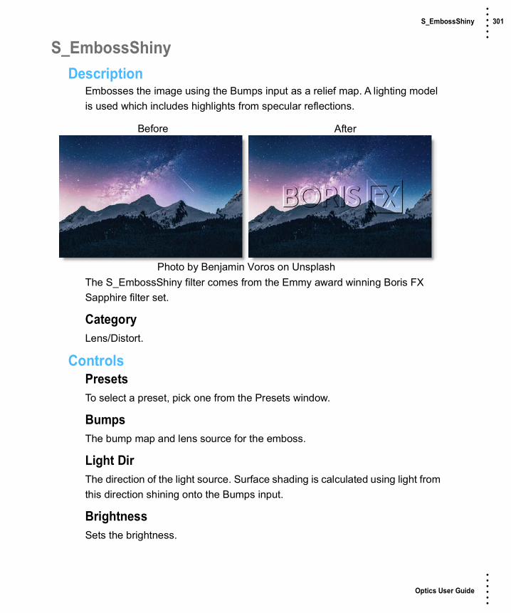
Optics User Guide
• • • •••
S_EmbossShiny 301 • • • •••
S_EmbossShinyDescription
Embosses the image using the Bumps input as a relief map. A lighting model is used which includes highlights from specular reflections.
The S_EmbossShiny filter comes from the Emmy award winning Boris FX Sapphire filter set.
CategoryLens/Distort.
ControlsPresetsTo select a preset, pick one from the Presets window.
BumpsThe bump map and lens source for the emboss.
Light DirThe direction of the light source. Surface shading is calculated using light from this direction shining onto the Bumps input.
BrightnessSets the brightness.
Before After
Photo by Benjamin Voros on Unsplash

Optics User Guide
• • • •••
S_EmbossShiny 302 • • • •••
Light ColorThe color of the light source creating the embossed result.
Bumps ScaleScales the amplitude of the bump map.
Bumps ThresholdLimits the emboss effect.
Bumps SmoothSmooths the emboss effect.
Subpixel SmoothIf enabled, the amount of pre−smoothing of the Bumps input is performed with subpixel accuracy.
Note: Subpixel Smooth has no effect unless Bumps Smooth is positive.
Hilight BrightnessThe brightness of the specular highlights.
Hilight SizeThe size of the specular highlights.
Show Light DirEnables/disables the on-screen control for adjusting the Light Dir parameter.

Optics User Guide
• • • •••
Enhancing 303 • • • •••
EnhancingDescription
Selectively enhance any color to make it pop with little to no effect on other colors.
CategoryColor.
ControlsPresetsTo select a preset, pick one from the Presets window.
EnhancingAdjusts the saturation of red, green or blue hues.
MattePresetsA matte is created based on the hue of the image to create the enhancement effect. Select from Red, Green or Blue preset hue mattes from the pop-up menu or use the Hue eyedropper to pick a color off of the screen.
HueWhen adjusting the Hue parameter, you are selecting the hue of the image which will be enhanced.
Before After
Photo by Phil Coffman on Unsplash

Optics User Guide
• • • •••
Enhancing 304 • • • •••
RangeIncreases or decreases the range of values in the hue matte. A low Range value indicates a narrow range of values. A high Range value indicates a large range of values included in the matte.
BlurSets the softness of the matte by using a fast, quality blur.
Go to the Matte parameters to see how they work.

Optics User Guide
• • • •••
S_Etching 305 • • • •••
S_EtchingDescription
Generates a version of the image using two sets of black and white lines of varying thickness to give an etching or lithograph look.
The S_Etching filter comes from the Emmy award winning Boris FX Sapphire filter set.
CategoryStylize.
ControlsPresetsTo select a preset, pick one from the Presets window.
Lines FrequencyThe frequency of the etched lines. Increase for a finer line pattern or decrease for fewer lines.
Lines1 FrequencyScales the frequency of the first set of etched lines. Increase for a finer line pattern or decrease for fewer lines.
Lines2 FrequencyScales the frequency of the second set of etched lines.
Before After
Photo by Tobias Keller on Unsplash

Optics User Guide
• • • •••
S_Etching 306 • • • •••
Lines AngleRotation of the etched lines pattern in counterclockwise degrees.
Lines1 AngleThe relative angle of the first set of etched lines in counterclockwise degrees.
Lines2 AngleThe relative angle of the second set of etched lines in counterclockwise degrees.
Lines Shift X & YShifts the pattern of lines. This location will also be the center of rotation when the line angle parameters are adjusted.
Lines SharpnessThe sharpness of the etched lines. Decrease for softer edges.
Lines Add WidthIncrease for thicker lines.
Smooth SourceIf positive, the source is blurred by this amount before the etching is applied.
Color1The brighter color of the lines pattern.
Color0The darker color of the lines pattern.
Wave FrequencyThe frequency of the waviness of the etched lines. Increase for more waves.
Warp AmpThe amount the output is warped using the source brightness.
Warp SmoothThe smoothness of the warping. This has no effect if Warp Amp is 0.

Optics User Guide
• • • •••
S_Etching 307 • • • •••
Edges ScaleAdjusts the amount of source edges to be included in the result. If positive, edges in the source image are found and added to the etching pattern.
Edges ThresholdDetermines which edges are included in the result. Increase to remove minor edges and speckles. This has no effect unless Edges Scale is positive.
Edges WidthThe width of the edges added to the result. Increase for wider edges. This has no effect unless Edges Scale is positive.
Edges SharpnessIncrease for sharper edges or decrease for softer edges. This has no effect unless Edges Scale is positive.
Show Lines ShiftEnables/disables the on-screen control for adjusting the Lines Shift parameter.

Optics User Guide
• • • •••
Eye Light 308 • • • •••
Eye LightDescription
Creates a targeted light to be placed around a person's eyes.
CategoryLight.
ControlsLightBlendDetermines the blend mode to be used to add the light.
AddThe light is added to your image.
ScreenThe light is combined with the image using a Screen blend mode. This looks kind of like the Add blend mode, but highlights are retained.
BrightnessSets the intensity of the light.
BlurSets the softness of the light.
Before After
Photo by Sebastian Unrau on Unsplash

Optics User Guide
• • • •••
Eye Light 309 • • • •••
GelsPhotographers, cinematographers and lighting designers use colored filters or gels in front of lights. Whatever mood you wish to create, we have the colors needed to achieve the effect. Select one of the Gels presets from the pop-up menu.
ColorSets the color of the light through the use of a standard color picker.
ShadowBrightnessSets the intensity of the shadows. The Brightness parameter will darken only those areas that are not being brightened by the Light settings.
TransformTransform the eye light pattern using Scale and Rotate controls. Go to the Transform section of Common Filter Controls to see how the Transform Controls work.

Optics User Guide
• • • •••
S_FilmDamage 310 • • • •••
S_FilmDamageDescription
Simulates damaged film with many options, including dust, hairs, stains, scratches, flicker, and shake.
The S_FilmDamage filter comes from the Emmy award winning Boris FX Sapphire filter set.
CategoryFilm Lab.
ControlsPresetsTo select a preset, pick one from the Presets window.
TimeThe effect is advanced in time.
Grain AmpScales the amplitude of the film grain that is added to the result. Set this to 0 to disable all grain.
Grain DetailsGrain Amp RedScales the red grain amplitude.
Before After
Photo by Nic Co UK on Unsplash

Optics User Guide
• • • •••
S_FilmDamage 311 • • • •••
Grain Amp GreenScales the green grain amplitude.
Grain Amp Blue.Scales the blue grain amplitude. Note that grain is added and subtracted from the image, so for example, increasing Grain Amp Blue will amplify both the blue and yellow speckles.
Grain Amp DarksThe relative amount of grain applied to the darkest regions of the image per channel. This defaults to less than 1 because dark areas usually have less grain than midtones.
Grain Amp BrightsThe relative amount of grain applied to the brightest regions of the image per channel. This defaults to 0 because bright areas usually have less grain than midtones. Note that highly saturated colors can be affected by both Grain Amp Darks and Grain Amp Brights because they are dark in some color channels and bright in others.
Grain BlurThe grain is smoothed by this amount. Increase for coarser grain.
Grain Blur RedThe relative blur amount for the red grain.
Grain Blur GreenThe relative blur amount for the green grain.
Grain Blur BlueThe relative blur amount for the blue grain.
Grain MonoWhen enabled, the same grain pattern is used for the red, green, and blue channels.

Optics User Guide
• • • •••
S_FilmDamage 312 • • • •••
Color CorrectSaturationScales the color saturation. Increase for more intense colors. Set to 0 for monochrome.
Scale LightsScales the result by this gray value. Increase for a brighter result.
Offset DarksAdds a gray value to the darker regions of the source. This can be negative to increase contrast.
Tint LightsScales the result by this color, thus tinting the lighter regions.
Tint DarksAdds this color to the darker regions of the source.
Stain DensityThe number of stains.
Stains DetailsStain PrintRelative density of stains on the print.
Stain NegativeRelative density of stains on the negative.
Stain SizeScales the width and height of stains.
Vary Stain SizeAmount to vary the size from one stain to the next.
Stain OpacityScales the opacity of the stains.
Vary Stain OpacityAmount to vary opacity from one stain to the next.

Optics User Guide
• • • •••
S_FilmDamage 313 • • • •••
Vary Stain BrightnessAmount to vary brightness from one stain to the next.
Vary Stain ColorAmount of additional, random color variation for each stain. If this parameter is greater than zero, stain colors can vary outside the range defined by Stain Color1 and Stain Color2.
Stain Color1Beginning of the range of colors for stains.
Stain Color2End of the range of colors for stains. Each stain will have a random color between Stain Color1 and Stain Color2.
Dust DensityThe number of dust elements.
Dust DetailsDust On PrintRelative density of dust on the print.
Dust On NegativeRelative density of dust on the negative.
Dust SizeScales the width and height of dust.
Vary Dust SizeAmount to vary the size from one piece of dust to the next.
Dust OpacityScales the opacity of the dust.
Vary Dust OpacityAmount to vary opacity from one piece of dust to the next.
Vary Dust BrightnessAmount to vary brightness from one piece of dust to the next.

Optics User Guide
• • • •••
S_FilmDamage 314 • • • •••
Vary Dust ColorAmount of additional, random color variation for each piece of dust. If this parameter is greater than zero, dust colors can vary outside the range defined by Dust Color1 and Dust Color2.
Dust Color1Beginning of the range of colors for dust.
Dust Color2End of the range of colors for dust. Each piece of dust will have a random color between Dust Color1 and Dust Color2.
HairsThe number of hairs.
Hair DetailsHair Wiggle AmpControls the amount of random movement and stretching that each hair exhibits.
Hair OpacityScales the opacity of the hairs.
Hair SizeScales the width and height of the hairs.
Vary Hair SizeAmount to vary the size from one hair to the next.
Hair ColorThe color of the hairs.
ScratchesThe number of scratches.
Scratches DetailsBlack ScratchesNumber of black scratches, relative to the Scratches parameter value.

Optics User Guide
• • • •••
S_FilmDamage 315 • • • •••
White ScratchesNumber of white scratches, relative to the Scratches parameter value.
Black Scratch LengthThe length of the black scratches.
White Scratch LengthThe length of the white scratches.
Scratch WidthWidth of the average scratch, in approximate NTSC−sized pixels.
Vary Scratches WidthIf this is 0, all the scratches will be the same width. Increase to let each scratch have its own width.
Scratches TaperControls the pointiness of the ends of each scratch. A larger value makes a longer taper on each end.
Scratch OpacityMaximum opacity of the scratches. Setting this to 0 will fade the scratches out.
Scratch RoughnessAmount to roughen the edges of each scratch to simulate the random character of a real scratch.
Scratch Rough FreqSets the frequency of the roughness on the scratch edges.
GapsLike real analog scratches, the dust particle creating the scratch sometimes rolls around and the scratch skips. This controls how much that happens.
Gaps FreqThe frequency of the scratch gaps.
Scratch Area CenterThe center coordinate of the area of the screen covered by the scratches. 0 is in the middle of the screen, −1 is the left edge, and 1 is the right edge.

Optics User Guide
• • • •••
S_FilmDamage 316 • • • •••
Scratch Area WidthThe width of the area of the screen covered by scratches. 1 means the scratches cover the full screen area. To produce scratches only in one strip, adjust the Scratch Area Width smaller.
Vignette DarknessVignetting is darkening of the image towards the corners and sides of the image. This parameter controls how much the outer corners of the screen should be darkened or vignetted. 0 produces no vignetting, while a value of 1 creates maximum darkening.
Vignette DetailsVignette RadiusDistance from the center to apply the vignette.
Vignette Edge SoftnessThe width of the vignette's soft edge. Larger values give softer, less visible edges.
Vignette Rel HeightControls the aspect ratio of the vignette ellipse. This should normally be set to the aspect ratio of the image.
SeedUsed to initialize the random number generator. The actual seed value is not significant, but different seeds produce different results and the same value should give a repeatable result.

Optics User Guide
• • • •••
S_FilmEffect 317 • • • •••
S_FilmEffectDescription
Provides a physically accurate model of film exposure and processing to make your digital imahe look like it was shot on particular film stocks. It can perform color correction for specific film types, add film grain, and apply glow or soft focus effects.
The S_FilmEffect filter comes from the Emmy award winning Boris FX Sapphire filter set.
CategoryFilm Lab.
ControlsPresetsTo select a preset, pick one from the Presets window.
Neg FilmSelects the negative film stock.
NoneIgnore any effect of negative film. This is not normally useful unless you also select None in the Print film parameter to disable both.
Kodak 5245Eastman EXR 50D, low speed, daylight balanced, very fine grain.
Before After
Photo by Brandon Mowinkel on Unsplash

Optics User Guide
• • • •••
S_FilmEffect 318 • • • •••
Kodak 5246Kodak VISION 250D, higher contrast, medium speed, daylight balanced, fine grain.
Kodak 5248Eastman EXR 100T, medium speed, tungsten light balanced, very fine grain.
Kodak 5274Kodak VISION 200T, medium speed, tungsten light balanced, fine grain.
Kodak 5277Kodak VISION 320T, lower contrast, medium speed, tungsten light balanced, medium−fine grain.
Kodak 5279Kodak VISION 500T, high speed, tungsten light balanced, somewhat grainy.
Kodak 5284Kodak VISION Expression 500T, lower contrast, high speed, tungsten light balanced, medium grain.
Kodak 5289Kodak VISION 800T, very fast, tungsten light balanced, grainy.
Kodak 5293Eastman EXR 200T, reduced contrast, tungsten light balanced, medium grain.
Kodak 5298Eastman EXR 500T, high speed, tungsten light balanced, grainy.
K SFX200TSpecial effects film, medium grain.
Kodak 5217Kodak Vision2 200T, tungsten light balanced, fine grain.
Kodak 5218Kodak Vision2 500T, tungsten light balanced, fine grain.
Optics User Guide
• • • •••
S_FilmEffect 319 • • • •••
Print FilmSelects the print film stock.
NoneIgnore any effect of the print film. This causes the negative to be output directly. If the Negative Film parameter is also set to None, the color correction and grain are disabled.
Kodak 2383Kodak VISION Color Print Film, rich blacks.
Kodak 2393Kodak VISION Premier Color Print Film, rich blacks, some grain.
Kodak 2395Kodak VISION Color Teleprint Film, low contrast.
Kodak 5386Eastman EXR Color Print Film (discontinued by Kodak, replaced by 2383).
Kodak 5285 RevEktachrome 100D Reversal film, daylight balanced, high contrast and grainy. Note that the negative film is ignored when using reversal film.
Kodak 7270 RevKodachrome 40 Movie Film, tungsten balanced reversal film, high contrast and somewhat grainy. Note that the negative film is ignored when using reversal film.
Blur InputThe image is smoothed by this amount. This can be used to remove noise or compression artifacts before processing.

Optics User Guide
• • • •••
S_FilmEffect 320 • • • •••
Color CorrectScale CCScales the amount of color correction performed due to the film types, gamma values, and exposure values. Set to 0 to disable color correction. If you increase this above 1, it exaggerates the color correction, which normally increases the contrast.
Input GammaThe gamma that your original image was shot for. For video, this is normally 2.2; for synthetic computer graphics, it may be less.
Output GammaThe intended viewing gamma of the output.
Neg ExposureAdjusts the simulated exposure of the negative film in stops. Increase for overexposed and brighter.
Print ExposureAdjusts the simulated exposure of the print film in stops. Increase for overexposed and darker.
Print Lights RedAdjusts the red exposure of the print film in printer light points. 1 light point is 1/12 stop. Increase to overexpose red and give a more cyan result.
Print Lights GreenAdjusts the green exposure of the print film in printer light points. 1 light point is 1/12 stop. Increase to overexpose green and give a more magenta result.
Print Lights BlueAdjusts the blue exposure of the print film in printer light points. 1 light point is 1/12 stop. Increase to overexpose blue and give a more yellow result.
Scale BrightsScales the bright areas of the final result after the other color correction, glow, and grain are applied. This parameter is not affected by Scale CC.

Optics User Guide
• • • •••
S_FilmEffect 321 • • • •••
Offset DarksAdds a gray value to the darker regions of the final result after the other color correction, glow, and grain are applied. This can be negative to increase contrast. This parameter is not affected by Scale CC.
GlowGlow BrightnessIf positive, the image is combined with a blurred version of itself to give a glowing look. Increase for a brighter glow.
Glow Soft FocusIf positive, the image is mixed with a blurred version of itself to give a soft focus look. The effect of this parameter is similar to Glow Brightness, but this does not brighten the overall result. Increase this to mix in more of the blurred version and less of the original. If this is 1 and Glow Brightness is 0, you will get only the blurred version.
Glow WidthThe width of the blur used by the glow and/or soft focus.
Glow Width RedThe relative glow width for the red channel.
Glow Width GreenThe relative glow width for the green channel.
Glow Width BlueThe relative glow width for the blue channel.
Grain AmpScales the amplitude of the film grain that is added to the result. Set this to 0 to disable all grain.
Grain DetailsGrain Amp RedScales the red grain amplitude.
Optics User Guide
• • • •••
S_FilmEffect 322 • • • •••
Grain Amp GreenScales the green grain amplitude.
Grain Amp Blue.Scales the blue grain amplitude. Note that grain is added and subtracted from the image, so for example, increasing Grain Amp Blue will amplify both the blue and yellow speckles.
Grain Amp DarksThe relative amount of grain applied to the darkest regions of the image per channel. This defaults to less than 1 because dark areas usually have less grain than midtones.
Grain Amp BrightsThe relative amount of grain applied to the brightest regions of the image per channel. This defaults to 0 because bright areas usually have less grain than midtones. Note that highly saturated colors can be affected by both Grain Amp Darks and Grain Amp Brights because they are dark in some color channels and bright in others.
Midtone Pos RedThe position of the midtones in the red channel that will normally receive the maximum amount of grain. The red grain amplitude is interpolated from Grain Amp Darks at black, up to 1 at this midtone position, then down to Grain Amp Brights at white. This whole curve is then scaled by the Grain Amp Red parameter.
Midtone Pos GreenThe position of the midtones in the green channel that will normally receive the maximum amount of grain. The green grain amplitude is interpolated from Grain Amp Darks at black, up to 1 at this midtone position, then down to Grain Amp Brights at white. This whole curve is then scaled by the Grain Amp Green parameter.

Optics User Guide
• • • •••
S_FilmEffect 323 • • • •••
Midtone Pos BlueThe position of the midtones in the blue channel that will normally receive the maximum amount of grain. The blue grain amplitude is interpolated from Grain Amp Darks at black, up to 1 at this midtone position, then down to Grain Amp Brights at white. This whole curve is then scaled by the Grain Amp Blue parameter.
Grain BlurThe grain is smoothed by this amount. Increase for coarser grain.
Grain Blur RedThe relative blur amount for the red grain.
Grain Blur GreenThe relative blur amount for the green grain.
Grain Blur BlueThe relative blur amount for the blue grain.
Grain MonoWhen enabled, the same grain pattern is used for the red, green, and blue channels. To make truly monochrome grain you should also set Grain Amp Red/Green/Blue equal to each other, make sure Midtone Pos Red/Green/Blue are equal, and if GrainBlur is positiv,e then also set Grain Blur Red/Green/Blue to be equal.
Vignette DarknessVignetting is darkening of the image towards the corners and sides of the image. This parameter controls how much the outer corners of the screen should be darkened or vignetted. 0 produces no vignetting, while a value of 1 creates maximum darkening.
Vignette DetailsVignette RadiusDistance from the center to apply the vignette.

Optics User Guide
• • • •••
S_FilmEffect 324 • • • •••
Vignette Edge SoftnessThe width of the vignette's soft edge. Larger values give softer, less visible edges.
Vignette Rel HeightControls the aspect ratio of the vignette ellipse. This should normally be set to the aspect ratio of the image.

Optics User Guide
• • • •••
Film Stocks 325 • • • •••
Film StocksDescription
Film Stocks is a unique filter that simulates 294 different color and black and white still photographic film stocks, motion picture films stocks and historical photographic processes.
CategoryFilm Lab.
ControlsPresetsTo select a preset, pick one from the Presets window. If you would like to view presets from a different category, use the pop-up menu at the top left of the Presets window.
AmountSets the amount of the selected preset.
Black and WhiteRed, Green and Blue controls allow you to determine the contribution of each color channel in the black and white conversion.
EnableEnables the Black and White conversion.
Before After
Photo by Teresa Kluge on Unsplash

Optics User Guide
• • • •••
Film Stocks 326 • • • •••
RedSets the amount of the red channel that contributes to the black and white conversion.
GreenSets the amount of the green channel that contributes to the black and white conversion.
BlueSets the amount of the blue channel that contributes to the black and white conversion.
Film ResponseTo mimic the characteristics of a particular film stock, a combination of settings for the RGB channels have been set.
CurvesYou can use Curves to adjust the entire tonal range of an image by changing the shape of the curve in the Curves adjustment. The Curves adjustment lets you adjust points throughout the tonal range of an image (from shadows to highlights).
Note: Curves are only available in the Optics Interface.
Adjust Black
Adjust White
Adjust Gray
Curve Type
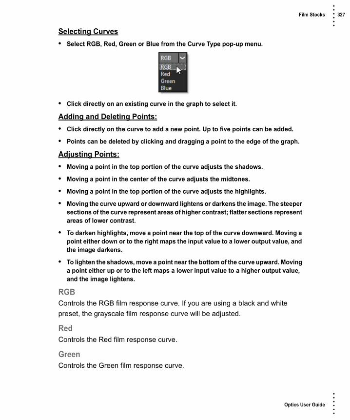
Optics User Guide
• • • •••
Film Stocks 327 • • • •••
Selecting Curves• Select RGB, Red, Green or Blue from the Curve Type pop-up menu.
• Click directly on an existing curve in the graph to select it.
Adding and Deleting Points:• Click directly on the curve to add a new point. Up to five points can be added.
• Points can be deleted by clicking and dragging a point to the edge of the graph.
Adjusting Points:• Moving a point in the top portion of the curve adjusts the shadows.
• Moving a point in the center of the curve adjusts the midtones.
• Moving a point in the top portion of the curve adjusts the highlights.
• Moving the curve upward or downward lightens or darkens the image. The steeper sections of the curve represent areas of higher contrast; flatter sections represent areas of lower contrast.
• To darken highlights, move a point near the top of the curve downward. Moving a point either down or to the right maps the input value to a lower output value, and the image darkens.
• To lighten the shadows, move a point near the bottom of the curve upward. Moving a point either up or to the left maps a lower input value to a higher output value, and the image lightens.
RGBControls the RGB film response curve. If you are using a black and white preset, the grayscale film response curve will be adjusted.
RedControls the Red film response curve.
GreenControls the Green film response curve.

Optics User Guide
• • • •••
Film Stocks 328 • • • •••
BlueControls the Blue film response curve.
Color CorrectGo to the Color Correct filter to see how the Color Correct controls work.
FilterAdds a color filter to the image.
PresetsSelect one of the filters from the pop-up menu.
ColorSets the color through the use of a standard color picker.
OpacitySets the opacity of the color filter.
HighlightsPreserves the white areas of the image.
SharpenAmountDetermines how much contrast is added at the edges.
RadiusControls the size of the edges you wish to sharpen.
ThresholdThe threshold setting is used to sharpen more pronounced edges, while leaving more subtle edges untouched. Low values sharpen more image areas while higher threshold values sharpen less.
DiffusionBlendDetermines the blend mode to be used to create the diffusion/glow effect.
AddThe diffusion/glow is added to your image.

Optics User Guide
• • • •••
Film Stocks 329 • • • •••
NormalThe diffusion is mixed with the original image. In this mode, the Amount slider only shows changes up to a value of 100.
ScreenThe diffusion/glow is combined with the image using a Screen blend mode. This looks kind of like the Add blend mode, but highlights are retained.
AmountSets the amount of diffusion.
BlurSets the softness of the image.
ColorThe Color parameter sets the color of the diffusion/glow through the use of a standard color picker or eyedropper. The default color is white.
PositionWhen using the Add and Screen blend modes, Position selects the values used to create the glow effect. A higher Position value uses the brightest image values to create the glow. A lower Position value uses the darkest image values to create the glow.
RangeWhen using the Add and Screen blend modes, Range controls the range of values to be used for the glow. Once you’ve selected the “Position”, you can then add or subtract the “Range” of values to be used in the glow source. A higher Range value includes more values in the glow source while a lower Range value includes less values.
VignetteA vignette is a popular photographic effect where the photo gradually fades into a color.
ColorThe Color parameter sets the color of the vignette through the use of a standard color picker. The default color is black.

Optics User Guide
• • • •••
Film Stocks 330 • • • •••
OpacitySets the opacity of the colored vignette. For defocused vignettes, you may want to turn down the Opacity so you can see the defocused effect.
BlurSets the softness of the image in the area of the vignette.
RoundnessSets the roundness of the vignette. The vignette can either be circular or square or anywhere in between.
SizeSets the size of the vignette.
Aspect RatioChanges the aspect ratio of the vignette. A value of -100 would be wider, and 100 would be taller.
RotationRotates the vignette.
DistortionDistorts the edge of the vignette.
Distortion SizeSets the size of the distortion.
RandomizeRandomizes the distortion.
SoftnessThe Softness parameters control the softness of the vignette edge.
GrainGrain simulates film grain with control of the size, softness and intensity. In addition, a Film Response parameter controls where you will see grain in the image. Go to the Grain filter to see how it works.

Optics User Guide
• • • •••
Flag / Dot 331 • • • •••
Flag / DotDescription
Flags and Dots are rectangular and circular lighting control devices used to create shadow areas on a motion picture or photographic set. This concept has been extended to digital so that areas of the image can be selectively darkened.
CategoryLight.
ControlsFlag / DotBrightnessSets the intensity of the flag or dot.
BlurSets the softness of the flag or dot.
TransformTransform the flag or dot shape using Scale and Rotate controls. Go to the Transform section of Common Filter Controls to see how the Transform Controls work.
Before After
Photo by Marcelo Matarazzo on Unsplash

Optics User Guide
• • • •••
Flashing 332 • • • •••
FlashingDescription
Flashing allows you to use photographic filters to lower the contrast of your shadows or highlights. The motion picture lab can expose a small amount of light to the film at various stages of the developing and printing process. For example, Negative plus Dupe Negative flashing lifts blacks, while Print plus Master Positive flashing softens whites.
CategoryFilm Lab.
ControlsPresetsTo select a preset, pick one from the Presets window.
ShadowsBrightnessRaises the brightness of the shadows using either the Shadow > Color or Shadow > Presets.
PresetsSelect one of the filters from the pop-up menu.
ColorThe Color parameter sets the color of the flashing through the use of a standard color picker.
Before After
Photo by Stainless Images on Unsplash

Optics User Guide
• • • •••
Flashing 333 • • • •••
PositionSelects the shadow values to be adjusted.
RangeControls the range of values to be used for the shadows. A higher Range value considers more values as shadows.
HighlightsBrightnessLowers the brightness of the highlights using either the Highlights > Color or Highlights > Presets.
PresetsSelect one of the filters from the pop-up menu.
ColorThe Color parameter sets the color of the flashing through the use of a standard color picker.
PositionSelects the highlight values to be adjusted.
RangeControls the range of values to be used for the highlights. A higher Range value considers more values as highlights.
Go to the Matte section of Common Filter Controls to see how the Position and Range controls work.

Optics User Guide
• • • •••
Fluorescent 334 • • • •••
FluorescentDescription
Removes the green cast caused by fluorescent bulbs.
CategoryColor.
ControlsPresetsTo select a preset, pick one from the Presets window.
TemperatureRemoves the greenish tone caused by photographing under fluorescent lights.
Before After
Photo by Jens Lindner on Unsplash

Optics User Guide
• • • •••
S_FlysEyeCircles 335 • • • •••
S_FlysEyeCirclesDescription
Breaks the image into circle shaped tiles and transforms the image within each shape to create a fly's eye view effect.
The S_FlysEyeCircles filter comes from the Emmy award winning Boris FX Sapphire filter set.
CategoryStylize.
ControlsPresetsTo select a preset, pick one from the Presets window.
Tile FrequencyThe frequency of the tile pattern. Increase for more smaller tiles.
Tile Rel HeightThe relative height of the tile shapes. Increase for taller tiles.
Tile Shift X & YTranslates the tile pattern.
Circle OverlapDetermines the method used to combine the overlapping regions of the circles.
Before After
Photo by JR Korpa on Unsplash
Optics User Guide
• • • •••
S_FlysEyeCircles 336 • • • •••
AveUses a weighted average across the overlapping region for a smooth transition.
ScreenUses a screen operation.
MaxUses the lighter.
MinUses the darker.
MultUses a multiply operation.
Circle RadiusThe radius of the circles relative to each other. If this is less than 1, you will get empty spaces between the circles. The color of these empty spaces will be either transparent, black, or white depending on the Combine mode.
Edge SoftnessThe softness of the edges of the circles. If this is increased, it may also be necessary to lower the Circle Radius to avoid rectangular artifacts where the soft edges overlap.
Inside ZdistDetermines the zoom factor of the image inside each tile. Values greater than 1 zoom out, values less than 1 zoom in. If this is 1, Inside Rotate is 0, and Overall Zdist is 1, the result should be the same as the original image.
Inside RotateThe rotation angle of the image inside each tile, in degrees.
Overall ZdistCreates an overall zooming effect by making each tile look toward or away from the image center. Decrease to zoom in or increase to zoom out. When 0, all tiles should contain identical images.

Optics User Guide
• • • •••
S_FlysEyeCircles 337 • • • •••
WrapDetermines the method for accessing outside the borders of the source image.
NoGives black beyond the borders.
TileRepeats a copy of the image.
ReflectRepeats a mirrored copy. Edges are often less visible with this method.
FilterIf enabled, the Source image is resampled using pixel averaging. This removes aliasing and gives a higher quality result especially when Inside Zdist is large. It may not be necessary if your original image is smooth or Inside Zdist is small.
Crop InputThese 4 parameters, Crop Top, Crop Bottom, Crop Left, and Crop Right, allow selecting a rectangular subsection of the image to be processed. If the Wrap parameters are set to "No", the exposed borders will be transparent. If the Wrap is "Tile" or "Reflect", the source image is wrapped on the new cropped borders to fill the frame. This can make it easier to avoid artifacts due to distorting an image with bad edges.
Show Tile FreqEnables/disables the on-screen control for adjusting the Tile Frequency parameter.
Show Tile ShiftEnables/disables the on-screen control for adjusting the Tile Shift parameter.
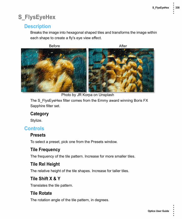
Optics User Guide
• • • •••
S_FlysEyeHex 338 • • • •••
S_FlysEyeHexDescription
Breaks the image into hexagonal shaped tiles and transforms the image within each shape to create a fly's eye view effect.
The S_FlysEyeHex filter comes from the Emmy award winning Boris FX Sapphire filter set.
CategoryStylize.
ControlsPresetsTo select a preset, pick one from the Presets window.
Tile FrequencyThe frequency of the tile pattern. Increase for more smaller tiles.
Tile Rel HeightThe relative height of the tile shapes. Increase for taller tiles.
Tile Shift X & YTranslates the tile pattern.
Tile RotateThe rotation angle of the tile pattern, in degrees.
Before After
Photo by JR Korpa on Unsplash

Optics User Guide
• • • •••
S_FlysEyeHex 339 • • • •••
Edge SoftnessThe softness of the edges of the circles. If this is increased, it may also be necessary to lower the Circle Radius to avoid rectangular artifacts where the soft edges overlap.
Inside ZdistDetermines the zoom factor of the image inside each tile. Values greater than 1 zoom out, values less than 1 zoom in. If this is 1, Inside Rotate is 0, and Overall Zdist is 1, the result should be the same as the original image.
Inside RotateThe rotation angle of the image inside each tile, in degrees.
Overall ZdistCreates an overall zooming effect by making each tile look toward or away from the image center. Decrease to zoom in or increase to zoom out. When 0, all tiles should contain identical images.
WrapDetermines the method for accessing outside the borders of the source image.
NoGives black beyond the borders.
TileRepeats a copy of the image.
ReflectRepeats a mirrored copy. Edges are often less visible with this method.
FilterIf enabled, the Source image is resampled using pixel averaging. This removes aliasing and gives a higher quality result especially when Inside Zdist is large. It may not be necessary if your original image is smooth or Inside Zdist is small.

Optics User Guide
• • • •••
S_FlysEyeHex 340 • • • •••
Crop InputThese 4 parameters, Crop Top, Crop Bottom, Crop Left, and Crop Right, allow selecting a rectangular subsection of the image to be processed. If the Wrap parameters are set to "No", the exposed borders will be transparent. If the Wrap is "Tile" or "Reflect", the source image is wrapped on the new cropped borders to fill the frame. This can make it easier to avoid artifacts due to distorting an image with bad edges.
Show Tile FreqEnables/disables the on-screen control for adjusting the Tile Frequency parameter.
Show Tile ShiftEnables/disables the on-screen control for adjusting the Tile Shift parameter.

Optics User Guide
• • • •••
S_FlysEyeRect 341 • • • •••
S_FlysEyeRectDescription
Breaks the image into rectangular shaped tiles and transforms the image within each shape to create a fly's eye view effect.
The S_FlysEyeRect filter comes from the Emmy award winning Boris FX Sapphire filter set.
CategoryStylize.
ControlsPresetsTo select a preset, pick one from the Presets window.
Tile FrequencyThe frequency of the tile pattern. Increase for more smaller tiles.
Tile Rel HeightThe relative height of the tile shapes. Increase for taller tiles.
Tile Shift X & YTranslates the tile pattern.
Before After
Photo by JR Korpa on Unsplash

Optics User Guide
• • • •••
S_FlysEyeRect 342 • • • •••
Inside ZdistDetermines the zoom factor of the image inside each tile. Values greater than 1 zoom out, values less than 1 zoom in. If this is 1, Inside Rotate is 0, and Overall Zdist is 1, the result should be the same as the original image.
Inside RotateThe rotation angle of the image inside each tile, in degrees.
Overall ZdistCreates an overall zooming effect by making each tile look toward or away from the image center. Decrease to zoom in or increase to zoom out. When 0, all tiles should contain identical images.
WrapDetermines the method for accessing outside the borders of the source image.
NoGives black beyond the borders.
TileRepeats a copy of the image.
ReflectRepeats a mirrored copy. Edges are often less visible with this method.
FilterIf enabled, the Source image is resampled using pixel averaging. This removes aliasing and gives a higher quality result especially when Inside Zdist is large. It may not be necessary if your original image is smooth or Inside Zdist is small.
Crop InputThese 4 parameters, Crop Top, Crop Bottom, Crop Left, and Crop Right, allow selecting a rectangular subsection of the image to be processed. If the Wrap parameters are set to "No", the exposed borders will be transparent. If the Wrap is "Tile" or "Reflect", the source image is wrapped on the new cropped borders to fill the frame. This can make it easier to avoid artifacts due to distorting an image with bad edges.

Optics User Guide
• • • •••
S_FlysEyeRect 343 • • • •••
Show Tile FreqEnables/disables the on-screen control for adjusting the Tile Frequency parameter.
Show Tile ShiftEnables/disables the on-screen control for adjusting the Tile Shift parameter.

Optics User Guide
• • • •••
Fog 344 • • • •••
FogDescription
The Fog filter creates a soft, misty atmosphere over the image and glows highlights.
CategoryDiffusion/Blurs.
ControlsPresetsTo select a preset, pick one from the Presets window.
FogBlendDetermines the blend mode to be used to create the fog effect.
AddThe fog is added to your image.
ScreenThe fog is combined with the image using a Screen blend mode. This looks kind of like the Add blend mode, but highlights are retained.
BrightnessSets the intensity of the fog.
Before After
Photo by Alex Klopcic on Unsplash

Optics User Guide
• • • •••
Fog 345 • • • •••
BlurSets the softness of the fog.
ColorThe Color parameter sets the color of the fog through the use of a standard color picker. The default color is white.
MatteA matte is used to create the fog effect. Go to the Matte section of Common Filter Controls to see how the Matte controls work.

Optics User Guide
• • • •••
S_FreeLens 346 • • • •••
S_FreeLensDescription
Generates a distorted, defocused and light leaked version of the image to simulate the in-camera technique of holding a detached lens in front of the camera and moving it to create focus and light effects.
The S_FreeLens filter comes from the Emmy award winning Boris FX Sapphire filter set.
CategoryDiffusion/Blurs.
ControlsPresetsTo select a preset, pick one from the Presets window.
ShiftOffsets the lens horizontally or vertically. Note that the image moves opposite to the lens motion.
Lens ManipulationTilt XRotates the lens left or right about a vertical axis.
Before After
Photo by Lee Blanchflower on Unsplash

Optics User Guide
• • • •••
S_FreeLens 347 • • • •••
Tilt YRotates the lens up or down about a horizontal axis. You can use Tilt X and Tilt Y together to rotate about an arbitrary diagonal axis.
DistanceMoves the lens away from or toward the camera.
Rotate HighlightsRotates the lens about the line of sight. In a real lens, this would rotate the iris, so the rotation is perceived as a rotation of any defocus highlights in the image.
Perspective AmountControls the amount of lens telescoping while applying Tilt X and Tilt Y. Increase for more 3D perspective.
Wrap X & YDetermines the method for accessing outside the borders of the source images.
NoGives black beyond the borders.
TileRepeats a copy of the image.
ReflectRepeats a mirrored copy. Edges are often less visible with this method.
FilterIf enabled, the image is adaptively filtered when it is resampled. This gives a better quality result when parts of the image are warped smaller.
DefocusDefocus WidthScales the overall amount of defocus blur and highlights.
Chroma DistortAdds some chromatic aberration around the edges of the image. Red and blue wavelengths of light refract differently in real lenses, producing fringes of color where the rays strike the lens at oblique angles.

Optics User Guide
• • • •••
S_FreeLens 348 • • • •••
Rel HeightThe relative height of the iris shape. If it is not 1, circles become ellipses, etc.
ShowSelects the type of output.
ResultShows the final output.
DepthMapShows the depth map generated for the current lens position and orientation.
Highlight ShapeDetermines the shape of the simulated camera iris.
CircleRound.
3 sidesTriangle.
4 sidesSquare.
5 sidesPentagon.
6 sidesHexagon.
7 sidesSeven sided polygon.
8 sidesEight sided polygon.
9 sidesNine sided polygon.
10 sidesTen sided polygon.

Optics User Guide
• • • •••
S_FreeLens 349 • • • •••
11 sidesEleven sided polygon.
12 sidesTwelve sided polygon.
Highlight RoundnessModifies the shape of the simulated camera iris. A value of 1 produces a circle, while 0 creates a flat−sided polygon with a number of sides defined by the Shape parameter. Less than 0 causes the sides to squeeze inward producing a star shape, while a value greater than 1 causes the corners to squeeze inward, creating a flowery shape. This has no effect if the Shape is set to Circle.
Boost HighlightsThe amount to increase the luma of the highlights in the image. Increase this parameter to blow out the highlights without affecting the darks or midtones.
Highlight ThresholdThe minimum luma value for highlights. Pixels brighter than this will be brightened according to the Boost Highlights parameter.
DistortionEnables distortion.
Distortion DetailsLink Distortion To LensControls whether distortion is adjusted by the lens or set manually.
Distortion AmountDistorts the image radially for barrel or pincushion.
Scale WidthScales the distortion in the horizontal direction.
Scale HeightScales the distortion in the vertical direction.
Light LeakEnables light leak.

Optics User Guide
• • • •••
S_FreeLens 350 • • • •••
Light Leak DetailsLink Leak To LensControls whether light leak is adjusted by the lens or set manually.
Leak IntensityScales the intensity of the light leak elements.
Leak Rel HeightControls the aspect ratio of the light leak elements.
Leak SizeScales the width and height of the light leak elements.
Vary SizeAmount to vary the size from one light leak element to the next.
Leak RoundnessRounds the corners of the light leak element.
SidesControls how many edges there are for each light leak element.
CopiesControls how many light leak elements there are.
SpreadControls how far apart the light leak elements are.
Outer ColorControls the color at the outer edge of each light leak element.
Mid ColorControls the color midway from the center to the outer edge of each light leak element.
Center ColorControls the color at the center of each light leak element.

Optics User Guide
• • • •••
S_FreeLens 351 • • • •••
MidpointMoves the location of the Mid Color between the center and outer of each light leak element. Set to 0 to place the Mid Color at the center or 1 to place it at the edge.
SoftnessBlurs the color gradient of each light leak element. Increase for a smoother gradient or decrease for sharper bands of color.
Glow BrightnessScales the brightness of the glow which is applied to the entire image after combining the light leak with the background.
Glow WidthThe width of the glow. Increase for a softer glow and decrease for a sharper, brighter glow.
Glow ThresholdParts of the image that are brighter than this value get glowed.
VignetteEnables vignette.
Vignette DetailsLink Vig To LensControls whether vignette is adjusted by the lens or set manually.
Vig IntensityThe opacity of the vignette.
Vig SquarenessDetermines how square the vignette shape is. Set to 1 for a square or rectangle shape. Set to 0 for a circle or ellipse. Values in between give rectangles with rounded corners by varying amounts.
Vig RadiusDistance from the center to apply the vignette.

Optics User Guide
• • • •••
S_FreeLens 352 • • • •••
Vig Rel HeightThe relative height of the iris shape. If it is not 1, circles become ellipses, etc.
Vig Rel WidthThe relative horizontal size of the vignette shape. Increase for a wider shape or decrease for a taller one.
Vig RotateRotates the iris shape.
Vig Edge SoftnessThe width of the vignette's soft edge. Larger values create softer, less visible edges.
Vig Smooth CurveIf 0, a linear gradient is used across the screen in the soft edge area. Increase this value to use a smoother S shaped curve for interpolation which can reduce the visual perception of the gradient's start and end locations.
Vig ColorThe color of the vignette.
Vig Blur AmountBlurs the borders of the image in addition to darkening them.
Vig Blur InsideIf checked, the center (undarkened) area of the image is blurred instead of the border.
Vig Source BrightnessScales the brightness of the image. To see only the vignette, set this to zero.
Vig CombineDetermines how the vignette is combined with the Source.
CompositeComposites the vignette over the image.

Optics User Guide
• • • •••
S_FreeLens 353 • • • •••
MultThe vignette color is multiplied by the image. If the Color is not black, this will selectively colorize the vignette area.
AddThe vignette color is added to the image. This will have no effect if the vignette color is black.
ScreenThe vignette color is combined with the image using a screen operation. This will have no effect if the vignette color is black.
Subtract InvThe inverse of the vignette color is subtracted from the image. Inverse means white for black, yellow for blue, and so on. This mode looks similar to Mult, but a bit more severe. It crushes the blacks, but retains highlights. This will have no effect if the vignette color is white.
Vignette OnlyShows the vignette pattern without the image. The output will be white where the amount of vignetting is greatest, for example, where the image would be darkened completely.
Vignette Only InvShows the inverted vignette pattern without the image. The output will be white where there is no vignetting, for example, where the image would not be darkened at all.
Show DistanceEnables/disables the on-screen control for adjusting the Shift parameter.
Show Tilt XEnables/disables the on-screen control for adjusting the Shift parameter.
Show Focal Point OffsetEnables/disables the on-screen control for adjusting the Focal Point Offset parameter.

Optics User Guide
• • • •••
S_FreeLens 354 • • • •••
Show Light Leak HotspotEnables/disables the on-screen control for adjusting the Light Leak Hotspot parameter.
Show Light Leak PivotEnables/disables the on-screen control for adjusting the Light Leak Pivot parameter.
Show Vig CenterEnables/disables the on-screen control for adjusting the Vig Center parameter.

Optics User Guide
• • • •••
Frost 355 • • • •••
FrostDescription
FrostFrost glows highlights and reduces contrast while softening facial blemishes and wrinkles.
Black FrostBlack Frost offers all the benefits of the Frost filter in a more subtle form. This filter subtly controls highlights, reduces contrast and provides a harder look than the Frost filter, while suppressing facial blemishes and wrinkles.
CategoryDiffusion/Blurs.
Before After
Photo by Alexandru Zdrobau on Unsplash
Before After
Photo by Alexandru Zdrobau on Unsplash

Optics User Guide
• • • •••
Frost 356 • • • •••
ControlsPresetsTo select a preset, pick one from the Presets window. If you would like to view presets from a different category, use the pop-up menu at the top left of the Presets window.
DetailSmoothingFine image details, such as facial wrinkles and blemishes, are minimized using edge aware smoothing.
MistThe Mist controls add a mild glow to image highlights.
BlendDetermines the blend mode to be used to create the mist effect.
AddThe mist is added to your image.
ScreenThe mist is combined with the image using a Screen blend mode. This looks kind of like the Add blend mode, but highlights are retained.
BrightnessSets the intensity of the mist.
BlurSets the softness of the mist.
ColorSets the color of the mist.
Color CorrectGo to the Color Correct filter to see how the Color Correct controls work.
MatteA matte is used to create the mist effect. Go to the Matte section of Common Filter Controls to see how the Matte controls work.

Optics User Guide
• • • •••
Gels 357 • • • •••
GelsDescription
Photographers, cinematographers and lighting designers use colored filters or gels in front of lights. Whatever mood you wish to create, we have the colors needed to achieve the effect.
CategoryGrads/Tints.
ControlsPresetsTo select a gel, pick one from the Presets window. If you would like to view presets from a different category, use the pop-up menu at the top left of the Presets window.
ColorColorThe Color parameter sets the color through the use of a standard color picker.
OpacitySets the opacity of the color filter.
Preserve HighlightsPreserves the white areas of the image.
Before After
Photo by Jacob Sapp on Unsplash

Optics User Guide
• • • •••
Gels 358 • • • •••
Exposure CompensationExposure Compensation adds back the brightness loss as a result of the gel application.
Grad Gels can optionally use a gradient that limits where the filter is applied. Grad is the transition area between the colored portion and the original image. Its direction, corners and size can be adjusted. Go to the Grad section of Common Filter Controls to see how the Grad controls work.

Optics User Guide
• • • •••
S_Glint 359 • • • •••
S_GlintDescription
Generates star shaped glints at locations where the image is brighter than the threshold.
The S_Glint filter comes from the Emmy award winning Boris FX Sapphire filter set.
CategoryLight.
ControlsPresetsTo select a preset, pick one from the Presets window.
BrightnessScales the brightness of all the glints.
Brightness DetailsScale ColorsScales the color of the glints.
Brightness XScales the brightness of the horizontal glint rays.
Before After
Photo by Nicola Fioravanti on Unsplash

Optics User Guide
• • • •••
S_Glint 360 • • • •••
Brightness YScales the brightness of the vertical glint rays.
Brightness Diag1Scales the brightness of the diagonal rays from top right to bottom left.
Brightness Diag2Scales the brightness of the diagonal rays from top left to bottom right.
ThresholdGlints are generated from locations in the image that are brighter than this value. A value of .9 causes glints at only the brightest spots. A value of 0 causes glints for every non−black area.
Threshold Add ColorThis can be used to raise the threshold on a specific color and thereby reduce the glints generated on areas of the image containing that color.
Threshold BlurIncrease to smooth out the areas creating glints. This can be used to eliminate glints generated from small speckles or to simply soften the glints. Increasing this may put more highlights below the threshold and darken the resulting glints, but you can decrease the Threshold parameter to compensate.
SizeScales the length of all glint rays. Note that a 0 glint size still enhances the bright areas. Set the brightness parameter to 0 if you want to pass the image through unchanged.
Size DetailsSize XScales the length of the horizontal glint rays.
Size YScales the length of the vertical glint rays.
Size Diag1Scales the length of the diagonal rays from top right to bottom left.
Optics User Guide
• • • •••
S_Glint 361 • • • •••
Size Diag2Scales the length of the diagonal rays from top left to bottom right.
Size RedScales the length of the red component of the rays. If the red, green, and blue sizes are equal, the glints will be uniform in color and will match the color of the image. If they are not equal, the glint colors can vary along the lengths of the rays.
Size GreenScales the length of the green component of the rays.
Size BlueScales the length of the blue component of the rays.
Blur GlintThe glints are blurred by this amount before being combined with the background.
Hue ShiftShifts the hue of the glint, in revolutions from red to green to blue to red.
Glint From AlphaThe glint is generated from the alpha channel instead of the RGB channels. In this case, the glint will not use color from the image and will typically be brighter. Values between 0 and 100 interpolate between using the RGB and the alpha.
Glint Under SourceSet to 1 to composite the image over the glints.
Source OpacityScales the opacity of the image when combined with the glints. This does not affect the generation of the glints themselves.

Optics User Guide
• • • •••
S_Glint 362 • • • •••
Expand BordersIf enabled, transparent borders are added to the image before processing. This allows the result to include soft edges beyond the original image size. When off, the effect only occurs within the frame and the result will retain an edge at the borders.
Show SizeEnables/disables the on-screen control for adjusting the size parameters.

Optics User Guide
• • • •••
S_GlintRainbow 363 • • • •••
S_GlintRainbowDescription
Generates star shaped rainbow colored glints at locations where the image is brighter than the threshold.
The S_GlintRainbow comes from the Emmy award winning Boris FX Sapphire filter set.
CategoryLight.
ControlsPresetsTo select a preset, pick one from the Presets window.
BrightnessScales the brightness of all the glints.
Brightness DetailsScale ColorsScales the color of the glints.
Brightness XScales the brightness of the horizontal glint rays.
Before After
Photo by Nicola Fioravanti on Unsplash

Optics User Guide
• • • •••
S_GlintRainbow 364 • • • •••
Brightness YScales the brightness of the vertical glint rays.
Brightness Diag1Scales the brightness of the diagonal rays from top right to bottom left.
Brightness Diag2Scales the brightness of the diagonal rays from top left to bottom right.
ThresholdGlints are generated from locations in the image that are brighter than this value. A value of .9 causes glints at only the brightest spots. A value of 0 causes glints for every non−black area.
Threshold Add ColorThis can be used to raise the threshold on a specific color and thereby reduce the glints generated on areas of the image containing that color.
Threshold BlurIncrease to smooth out the areas creating glints. This can be used to eliminate glints generated from small speckles or to simply soften the glints. Increasing this may put more highlights below the threshold and darken the resulting glints, but you can decrease the Threshold parameter to compensate.
SizeScales the length of all glint rays. Note that a 0 glint size still enhances the bright areas. Set the brightness parameter to 0 if you want to pass the image through unchanged.
Size DetailsSize XScales the length of the horizontal glint rays.
Size YScales the length of the vertical glint rays.
Size Diag1Scales the length of the diagonal rays from top right to bottom left.

Optics User Guide
• • • •••
S_GlintRainbow 365 • • • •••
Size Diag2Scales the length of the diagonal rays from top left to bottom right.
Shift OutShifts the glint rays outwards from their source highlights by this amount relative to the glint size.
Shift RedShifts the red component of the glints in or out relative to the blue. The green is centered between blue and red for a complete spectrum.
Shift BlueShifts the blue component of the glints in or out relative to the red and green. This can be used with Shift Red to adjust the range of hues in the glints.
Blur GlintThe glints are blurred by this amount before being combined with the background.
Hue ShiftShifts the hue of the glint, in revolutions from red to green to blue to red.
Glint From AlphaThe glint is generated from the alpha channel instead of the RGB channels. In this case, the glint will not use color from the image and will typically be brighter. Values between 0 and 100 interpolate between using the RGB and the alpha.
Glint Under SourceSet to 1 to composite the image over the glints.
Source OpacityScales the opacity of the image when combined with the glints. This does not affect the generation of the glints themselves.

Optics User Guide
• • • •••
S_GlintRainbow 366 • • • •••
Expand BordersIf enabled, transparent borders are added to the image before processing. This allows the result to include soft edges beyond the original image size. When off, the effect only occurs within the frame and the result will retain an edge at the borders.
Show SizeEnables/disables the on-screen control for adjusting the size parameters.

Optics User Guide
• • • •••
S_Glow 367 • • • •••
S_GlowDescription
Generates glowing light from areas of the image that are brighter than the given threshold.
The S_Glow filter comes from the Emmy award winning Boris FX Sapphire filter set.
CategoryLight.
ControlsPresetsTo select a preset, pick one from the Presets window.
BrightnessScales the brightness of all the glows.
ColorScales the color of the glows.
ThresholdGlows are generated from locations in the image that are brighter than this value. A value of 0.9 causes glows at only the brightest spots. A value of 0 causes glows for every non−black area.
Before After
Photo by Johannes Plenio on Unsplash

Optics User Guide
• • • •••
S_Glow 368 • • • •••
Threshold Add ColorThis can be used to raise the threshold on a specific color and thereby reduce the glows generated on areas of the source clip containing that color.
Glow WidthScales the glow distance. Note that a 0 glow width still enhances the bright areas. Set the brightness parameter to 0 if you want to pass the original image through unchanged.
Width XScales the horizontal glow width. Set to 0 for vertical only.
Width YScales the vertical glow width. Set to 0 for horizontal only.
Width RedScales the red glow width. If the red, green, and blue widths are equal, the glows will match the color of the image. If they are not equal, the glows will vary in color with distance.
Width GreenScales the green glow width.
Width BlueScales the blue glow width.
SubpixelEnables glowing by subpixel widths.
ShowSelects the type of output.
ResultShows the final result of combining the glow and image.
ThresholdShows the thresholded image that is used to generate the glow.

Optics User Guide
• • • •••
S_Glow 369 • • • •••
Glow From AlphaThe glow is generated from the alpha channel instead of the RGB channels. In this case, the glow will not use color from the image and will typically be brighter. Values between 0 and 100 interpolate between using the RGB and the alpha.
Glow Under SourceSet to 1 to composite the image over the glows.
Light BackgroundIncrease this to give a look of the glow casting light onto the background image. To see this more clearly, you can also lower the Scale Background parameter or raise the Brightness parameter.
Source OpacityScales the opacity of the image when combined with the glows. This does not affect the generation of the glows themselves.
CombineDetermines how the glow is combined with the image. This parameter has no effect if Light Background is set to 1.
MultThe image is multiplied by the glow.
AddThe glow is added to the image.
ScreenThe glow is blended with the image using a screen operation.
DifferenceThe result is the difference between the glow and the image.
OverlayThe glow is combined with the image using an overlay function.

Optics User Guide
• • • •••
S_Glow 370 • • • •••
Edge ModeDetermines the behavior when accessing areas outside the image.
TransparentAreas outside the image are treated as transparent, which can produce transparency around the edges of the image. Select this for fastest rendering.
ReflectReflects the image outside the border.
Expand BordersIf enabled, transparent borders are added to the image before processing. This allows the result to include soft edges beyond the original image size. When off, the effect only occurs within the frame and the result will retain an edge at the borders.
AtmosphereAtmosphere AmpAtmosphere gives the effect of the glow shining through a dusty atmosphere and picking up light or getting shadowed. This parameter adjusts the amount, or amplitude, of the atmospheric effect. 0 gives a smooth glow, higher values give more dusty look.
Atmosphere FreqControls the spatial frequency of the atmospheric noise. Turn this up higher to get finer details, turn down for broader overall variation.
Atmosphere DetailControls the amount of fine detail in the atmosphere simulation. Decrease to get smoother atmosphere, increase for a more crunchy or grainy look.
Atmosphere SeedUsed to initialize the random number generator for the atmospheric noise. The actual seed value is not significant, but different seeds produce different results and the same value should give a repeatable result.
Show Glow WidthEnables/disables the on-screen control for adjusting the Glow.
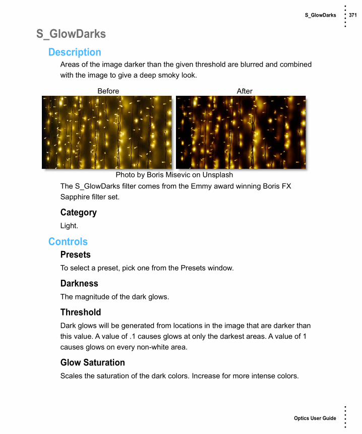
Optics User Guide
• • • •••
S_GlowDarks 371 • • • •••
S_GlowDarksDescription
Areas of the image darker than the given threshold are blurred and combined with the image to give a deep smoky look.
The S_GlowDarks filter comes from the Emmy award winning Boris FX Sapphire filter set.
CategoryLight.
ControlsPresetsTo select a preset, pick one from the Presets window.
DarknessThe magnitude of the dark glows.
ThresholdDark glows will be generated from locations in the image that are darker than this value. A value of .1 causes glows at only the darkest areas. A value of 1 causes glows on every non-white area.
Glow SaturationScales the saturation of the dark colors. Increase for more intense colors.
Before After
Photo by Boris Misevic on Unsplash
Optics User Guide
• • • •••
S_GlowDarks 372 • • • •••
Glow WidthScales the glow distance. Note that a 0 glow width still affects the dark areas. Set the darkness parameter to 0 if you want to pass the original image through unchanged.
Width XScales the horizontal glow width. Set to 0 for vertical only.
Width YScales the vertical glow width. Set to 0 for horizontal only.
SubpixelEnables glowing by subpixel widths.
ShowSelects the type of output.
ResultShows the final result of combining the glow and image.
DarksOutputs the dark areas of the image which will generate the glow. Colors are inverted, so darks will appear bright and vice versa.
Glow From AlphaThe glow is generated from the alpha channel instead of the RGB channels. In this case, the glow will not use color from the image and will typically be brighter. Values between 0 and 100 interpolate between using the RGB and the alpha.
Glow Under SourceSet to 1 to composite the image over the glows.
Source OpacityScales the opacity of the image when combined with the glows. This does not affect the generation of the glows themselves.
Optics User Guide
• • • •••
S_GlowDarks 373 • • • •••
AtmosphereAtmosphere AmpAtmosphere gives the effect of the glow shining through a dusty atmosphere and picking up light or getting shadowed. This parameter adjusts the amount, or amplitude, of the atmospheric effect. 0 gives a smooth glow, higher values give more dusty look.
Atmosphere FreqControls the spatial frequency of the atmospheric noise. Turn this up higher to get finer details, turn down for broader overall variation.
Atmosphere DetailControls the amount of fine detail in the atmosphere simulation. Decrease to get smoother atmosphere, increase for a more crunchy or grainy look.
Atmosphere SeedUsed to initialize the random number generator for the atmospheric noise. The actual seed value is not significant, but different seeds produce different results and the same value should give a repeatable result.
Show Glow WidthEnables/disables the on-screen control for adjusting the Glow.

Optics User Guide
• • • •••
S_GlowEdges 374 • • • •••
S_GlowEdgesDescription
Creates glowing light from the edges of the image. This differs from the default Glow in that small or thin objects generate as much glow around their edges as large objects.
The S_GlowEdges filter comes from the Emmy award winning Boris FX Sapphire filter set.
CategoryLight.
ControlsPresetsTo select a preset, pick one from the Presets window.
Glow BrightnessControls the overall glow brightness.
ColorScales the color of the glows.
Before After
Photo by Claudio Schwarz on Unsplash

Optics User Guide
• • • •••
S_GlowEdges 375 • • • •••
Glow WidthScales the glow distance. Note that a 0 glow width still enhances the bright areas. Set the brightness parameter to 0 if you want to pass the original image through unchanged.
Width XScales the horizontal glow width. Set to 0 for vertical only.
Width YScales the vertical glow width. Set to 0 for horizontal only.
Width RedScales the red glow width. If the red, green, and blue widths are equal, the glows will match the color of the image. If they are not equal, the glows will vary in color with distance.
Width GreenScales the green glow width.
Width BlueScales the blue glow width.
SubpixelEnables glowing by subpixel widths.
Edges SmoothDetermines the width of the extracted edges which generate the glows.
Edges BrightnessScales the brightness of the edges before the glows are applied.
Edges ThresholdIncrease to remove glows on the less sharp edges.
ShowSelects the type of output.
Optics User Guide
• • • •••
S_GlowEdges 376 • • • •••
ResultShows the final result of combining the glow and image.
EdgesThe edge image only is output, before any glows are applied. This can be helpful while adjusting the various edge parameters.
Glow From AlphaThe glow is generated from the alpha channel instead of the RGB channels. In this case, the glow will not use color from the image and will typically be brighter. Values between 0 and 100 interpolate between using the RGB and the alpha.
Glow Under SourceSet to 1 to composite the image over the glows.
Light BackgroundIncrease this to give a look of the glow casting light onto the background image. To see this more clearly, you can also lower the Scale Background parameter or raise the Brightness parameter.
Source OpacityScales the opacity of the image when combined with the glows. This does not affect the generation of the glows themselves.
CombineDetermines how the glow is combined with the image. This parameter has no effect if Light Background is set to 1.
MultThe image is multiplied by the glow.
AddThe glow is added to the image.
ScreenThe glow is blended with the image using a screen operation.

Optics User Guide
• • • •••
S_GlowEdges 377 • • • •••
DifferenceThe result is the difference between the glow and the image.
OverlayThe glow is combined with the image using an overlay function.
Expand BordersIf enabled, transparent borders are added to the image before processing. This allows the result to include soft edges beyond the original image size. When off, the effect only occurs within the frame and the result will retain an edge at the borders.
Show Glow WidthEnables/disables the on-screen control for adjusting the Glow.

Optics User Guide
• • • •••
S_GlowRings 378 • • • •••
S_GlowRingsDescription
Generates glows of colored rings around the areas of the image that are brighter than the given threshold.
The S_GlowRings filter comes from the Emmy award winning Boris FX Sapphire filter set.
CategoryLight.
ControlsPresetsTo select a preset, pick one from the Presets window.
BrightnessScales the brightness of all the glows.
ColorScales the color of the glows.
ThresholdGlows are generated from locations in the image that are brighter than this value. A value of 0.9 causes glows at only the brightest spots. A value of 0 causes glows for every non−black area.
Before After
Photo by Joe Hu on Unsplash

Optics User Guide
• • • •••
S_GlowRings 379 • • • •••
Threshold Add ColorThis can be used to raise the threshold on a specific color and thereby reduce the glows generated on areas of the image containing that color.
Glow WidthScales the glow distance. Note that a 0 glow width still enhances the bright areas.
Width XScales the horizontal glow width. Set to 0 for vertical only.
Width YScales the vertical glow width. Set to 0 for horizontal only.
Width RedScales the red glow width. If the red, green, and blue widths are equal, the glows will match the color of the image. If they are not equal, the glows will vary in color with distance.
Width GreenScales the green glow width.
Width BlueScales the blue glow width.
SubpixelEnables glowing by subpixel widths.
Thickness RedScales the thickness of the red region.
Thickness GreenScales the thickness of the green region.
Thickness BlueScales the thickness of the blue region.

Optics User Guide
• • • •••
S_GlowRings 380 • • • •••
ShowSelects the type of output.
ResultShows the final result of combining the glow and image.
ThresholdShows the thresholded image that is used to generate the glow.
Glow From AlphaThe glow is generated from the alpha channel instead of the RGB channels. In this case, the glow will not use color from the image and will typically be brighter. Values between 0 and 100 interpolate between using the RGB and the alpha.
Glow Under SourceSet to 1 to composite the image over the glows.
Source OpacityScales the opacity of the image when combined with the glows. This does not affect the generation of the glows themselves.
CombineDetermines how the glow is combined with the image.
MultThe image is multiplied by the glow.
AddThe glow is added to the image.
ScreenThe glow is blended with the image using a screen operation.
DifferenceThe result is the difference between the glow and the image.
OverlayThe glow is combined with the image using an overlay function.

Optics User Guide
• • • •••
S_GlowRings 381 • • • •••
Expand BordersIf enabled, transparent borders are added to the input image before processing. This allows the result to include soft edges beyond the original image size. When off, the effect only occurs within the frame and the result will retain an edge at the borders.
Show Glow WidthTurns on or off the on-screen control for adjusting the Glow Width parameter.
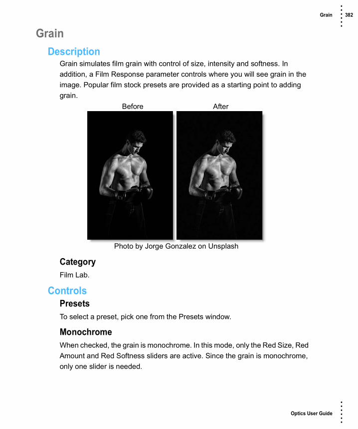
Optics User Guide
• • • •••
Grain 382 • • • •••
GrainDescription
Grain simulates film grain with control of size, intensity and softness. In addition, a Film Response parameter controls where you will see grain in the image. Popular film stock presets are provided as a starting point to adding grain.
CategoryFilm Lab.
ControlsPresetsTo select a preset, pick one from the Presets window.
MonochromeWhen checked, the grain is monochrome. In this mode, only the Red Size, Red Amount and Red Softness sliders are active. Since the grain is monochrome, only one slider is needed.
Before After
Photo by Jorge Gonzalez on Unsplash

Optics User Guide
• • • •••
Grain 383 • • • •••
SizeThe Size parameter controls the size of the grain. The larger the Size setting, the larger the grain will be.
AmountThe Amount parameters set the red, green and blue intensities of the grain. Film stocks generally have varying amounts of red, green and blue intensities with the blue intensity generally higher than the rest. If you turn the red, green and blue amount sliders to a value of 0, the grain will disappear.
Red AmountControls the intensity of the red grain.
Green AmountControls the intensity of the green grain.
Blue AmountControls the intensity of the blue grain.
SoftnessThe Softness parameter controls the softness of the grain. Normally, only minor softness adjustments are necessary, usually between a value of 0-1.
Film ResponseThe Film Response parameter allows the adjustment of where you will see grain in the image. In most cases, film grain is apparent over the entire image except the brightest whites with the black areas being the most affected.
PositionThe Position slider defines the portions of the image where grain will be added. A low Position value places grain in the darkest image values, while a high Position value places grain in the brightest areas.
RangeIncreases or decreases the area where grain is added to the image based on the value of the Position slider. A low Range value indicates a narrow range of values, while a high Range value indicates a large range of values.

Optics User Guide
• • • •••
Grain 384 • • • •••
MinimumSets the minimum level of grain that is always added to the image.
Note: A Position value of 0 and a Range of 80 is typical of standard film, with grain applied to the entire range except the brightest whites with black being the most affected.

Optics User Guide
• • • •••
S_Grunge 385 • • • •••
S_GrungeDescription
Simulates many different kinds of grunge including dirt, stains, flecks, grime, scratches, and paint. Up to three different kinds of grunge can be combined.
The S_Grunge filter comes from the Emmy award winning Boris FX Sapphire filter set.
CategoryRender.
ControlsPresetsTo select a preset, pick one from the Presets window.
Stamp DensityThe overall number of stamps over the frame. Increase for more stamps, decrease for fewer.
Stamp SizeScales the overall size of the grunge stamps.
Stamp OpacityThe overall opacity of the grunge stamps.
Before After
Photo by Frankie Cordoba on Unsplash

Optics User Guide
• • • •••
S_Grunge 386 • • • •••
Stamp BrightnessControls the brightness of the grunge stamps.
Stamp CenterThe overall position of the center of the grunge stamps.
SeedUsed to initialize the random number generator for the stamp positioning, size, and variation. The actual seed value is not significant, but different seeds produce different results and the same value should give a repeatable result.
Frame AmountControls the brightness of the grunge inside the frame or border. If Frame Amount is set to anything other than 0, Grunge will create a picture frame border of grunge around the frame center. At a Frame Amount of 1, stamps inside the frame are completely invisible and at a Frame Amount of 0, there is no frame.
Frame DetailsFrame SoftnessThe width of the frame's soft edge. Larger values give the grunge frame a softness as the grunge brightness fades on the edges.
Frame RadiusDistance from the center to apply the grunge frame.
Frame Rel HeightThe relative vertical size of the frame shape. Increase for a taller shape, decrease for a wider one.
Invert FrameIf enabled, shows the grunge in the center of the frame instead of at the edge of the frame.
Stamp1-3The style of grunge to apply. Up to three styles may be selected.

Optics User Guide
• • • •••
S_Grunge 387 • • • •••
NoneNo grunge.
PlasterLarge low detail grunge simulating plaster.
Garage FloorLarge speckled grunge reminiscent of pavement.
SpecklesGroups of small, similar sized, dots of grunge similar to paint spray.
Paint SprayGroups of small and medium splashes of paint similar to speckles.
Paint SplattersLong splashes of paint.
Hairline CracksLong, narrow, wiggly cracks with no branches.
Tile CracksLong, straight jagged cracks.
Pavement CracksVery branchy cracks with very varied widths.
HairsCurly and straight hairs of varying sizes.
ScratchesStraight scratches biased towards the diagonals.
FrostPatches of frost.
Glass CracksPatches of webbed glass cracks.
CloudsPuffs of clouds similar to smoke and watercolor drops.

Optics User Guide
• • • •••
S_Grunge 388 • • • •••
SmokeWhisps of smoke, similar to clouds and watercolor drops.
SplotchesPaint splotches with lots of streaks of paint spreading outward.
CorrosionPatches of rust like damage.
Watercolor DropsLow detail splashes of grunge similar to clouds and smoke.
DustSmall particles of grunge varying in shape similar to flecks.
StainsCoffee and water stains.
FlecksSmall to medium particles of grunge varying in shape and size similar to dust.
Stampt1-3 DetailsStamp1-3 Rel DensityScales the density for the specific stamp collection.
Stamp1-3 Color1Beginning of the range of colors for the stamp collection.
Stamp1-3 Color2End of the range of colors for the stamp collection. Each piece of grunge will have a random color between Stamp Color1 and Stamp Color2.
Stamp1-3 Rel BrightnessScales the brightness for the specific stamp collection.
Stamp1-3 Rel OpacityScales the opacity for the specific stamp collection.
Stamp1-3 Rel SizeScales the size for the specific stamp collection.

Optics User Guide
• • • •••
S_Grunge 389 • • • •••
Vary Stamp1-3 BrightnessAmount to vary the brightness from one piece of grunge to the next.
Vary Stamp1-3 OpacityAmount to vary the opacity from one piece of grunge to the next.
Vary Stamp1-3 SizeAmount to vary the size from one piece of grunge to the next.
EmbossEmboss Bumps ScaleScales the amplitude of the bumps.
Emboss Light AngleAdjusts the angle of light for the emboss.
Emboss Smooth.Smooths the small details of the image so they don't get embossed as strongly as the big features. Set to 0 to emboss all details. Increase to smooth out more details.
Emboss ThresholdAny grunge brighter than the threshold will be a bump and any grunge darker than the threshold will be a pit.
Blur GrungeBlur GrungeBlurs the grunge. Increase for more blur. Doesn't affect the image.
Blur Grunge Rel X & YScales the width of the blur.
CombineDetermines how the grunge is combined with the image.
Grunge OnlyThe grunge image with no background.

Optics User Guide
• • • •••
S_Grunge 390 • • • •••
CompComposites the grunge image over the original image.
MultThis can be used as an intersection operation on two images. White is the identity for Multiply, where one image contains white, the other is not affected, so the result only contains white where both inputs are white.
AddAdds the grunge image to the original image.
ScreenPerforms a blend function which can help prevent overly bright results.
DifferenceSimilar to Subtract, but the absolute value of the result is used, which tends to give more resulting colors in bounds. This can be used to select the regions of two images where one or the other is white, but not both.
SubtractSubtracts the grunge image from the original image.
OverlayCombines grunge and original image using an overlay function.
Hard LightSimilar to overlay but with grunge and the original image swapped.
Soft LightDarkens or lightens the original image depending on the grunge image.
Color DodgeBrightens the original image depending on the grunge image.
Color BurnDarkens the original image depending on the grunge image.
DarkenThe minimum of the grunge image and the original image. This can also be used as an intersection operation with slightly different results than Multiply.

Optics User Guide
• • • •••
S_Grunge 391 • • • •••
LightenThe maximum of the grunge image and the original image. This can also be used as a union operation with slightly different results than Screen.
ExclusionSimilar to Difference but with smoother results.
Linear DodgeAdds the grunge image to the original image and clamps the result at white.
Linear BurnAdds the grunge image to the original image but offsets to make the result darker. Similar to multiply in that combining with white provides no change and combining with black results in black.
Linear LightPerforms a linear burn or linear dodge depending on if the grunge image is more or less than 50 percent gray.
Scale BackgroundScales the brightness of the background before combining with the grunges. If 0, the result will contain only the grunge image over black.
Show Emboss Light AngleEnables/disables the on-screen control for adjusting the Emboss Light Angle parameter.
Show Frame RadiusEnables/disables the on-screen control for adjusting the Frame Radius parameter.
Show Frame CenterEnables/disables the on-screen control for adjusting the Frame Center parameter.

Optics User Guide
• • • •••
S_HalfTone 392 • • • •••
S_HalfToneDescription
Generates a halftone version of the image using a black and white pattern of dots.
The S_HalfTone filter comes from the Emmy award winning Boris FX Sapphire filter set.
CategoryStylize.
ControlsPresetsTo select a preset, pick one from the Presets window.
DotsSelects the dots' color model.
BlackDark dots are used on a bright background.
WhiteBright dots are used on a dark background.
Before After
Photo by Igor Ovsyannykov on Unsplash

Optics User Guide
• • • •••
S_HalfTone 393 • • • •••
Dots FrequencyThe frequency of the dots pattern. Increase for finer dots, decrease for larger dots.
Dots AngleThe angle of the overall dots pattern in counterclockwise degrees.
Dots Rel WidthThe relative width of the dots. Increase for wider dots, decrease for taller ones.
Dots SharpnessScales the sharpness of the edges of the dots.
Dots LightenIncrease to lighten the resulting dot pattern.
Smooth SourceIf positive, the source is blurred by this amount before the halftone is applied. This can be used to remove some detail in the dots and make them more consistently round.
Color1The bright color to use for the dots pattern.
Color0The dark color to use for the dots pattern.
Dots Shift X & YThe horizontal and vertical translation of the dots pattern.
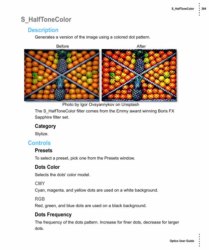
Optics User Guide
• • • •••
S_HalfToneColor 394 • • • •••
S_HalfToneColorDescription
Generates a version of the image using a colored dot pattern.
The S_HalfToneColor filter comes from the Emmy award winning Boris FX Sapphire filter set.
CategoryStylize.
ControlsPresetsTo select a preset, pick one from the Presets window.
Dots ColorSelects the dots' color model.
CMYCyan, magenta, and yellow dots are used on a white background.
RGBRed, green, and blue dots are used on a black background.
Dots FrequencyThe frequency of the dots pattern. Increase for finer dots, decrease for larger dots.
Before After
Photo by Igor Ovsyannykov on Unsplash

Optics User Guide
• • • •••
S_HalfToneColor 395 • • • •••
Dots AngleThe angle of the overall dots pattern in counterclockwise degrees.
Dots Rel WidthThe relative width of the dots. Increase for wider dots, decrease for taller ones.
Dots SharpnessScales the sharpness of the edges of the dots.
Dots LightenIncrease to lighten the resulting dot pattern.
Smooth SourceIf positive, the source is blurred by this amount before the halftone is applied. This can be used to remove some detail in the dots and make them more consistently round.
SaturationScales the color saturation. Increase for more intense colors. Set to 0 for monochrome.
Dots Shift X & YThe horizontal and vertical translation of the dots pattern.
Dots Shift RGBDots Shift X & YThe horizontal and vertical translation of the dots pattern.
Shift Red X & YThe translation of the red color channel.
Shift Green X & YThe translation of the green color channel.
Shift Blue X & YThe translation of the blue color channel.

Optics User Guide
• • • •••
S_HalfToneRings 396 • • • •••
S_HalfToneRingsDescription
Generates a duotone version of the image using a repeating pattern of concentric rings.
The S_HalfToneRings filter comes from the Emmy award winning Boris FX Sapphire filter set.
CategoryStylize.
ControlsPresetsTo select a preset, pick one from the Presets window.
Rings FrequencyThe frequency of the overall rings pattern. Increase for smaller rings, decrease for larger rings.
Rings AngleThe angle of the overall rings pattern in counterclockwise degrees.
Rings Rel WidthThe relative width of the rings. Increase for wider rings, decrease for taller ones.
Before After
Photo by Igor Ovsyannykov on Unsplash

Optics User Guide
• • • •••
S_HalfToneRings 397 • • • •••
Rings SharpnessScales the sharpness of the edges of the rings.
Rings LightenIncrease to lighten the resulting rings pattern.
Ring NumberDetermines the number of concentric rings in each tile of the repeating pattern.
Ring PhaseShifts the rings in or out within each tile of the pattern.
Rings Shift X & YThe horizontal and vertical translation of the overall rings pattern.
Smooth SourceIf positive, the image is blurred by this amount before the halftone is applied. This can be used to remove some detail in the dots and make them more consistently round.
Color1The bright color to use for the dots pattern.
Color0The dark color to use for the dots pattern.

Optics User Guide
• • • •••
Halo 398 • • • •••
HaloDescription
HaloHalo glows highlights, reduces contrast and softens facial imperfections while retaining image clarity.
Warm HaloCombines all of the benefits of Halo with a warming filter.
CategoryDiffusion/Blurs.
Before After
Photo by Alexandru Zdrobau on Unsplash
Before After
Photo by Alexandru Zdrobau on Unsplash
Optics User Guide
• • • •••
Halo 399 • • • •••
ControlsPresetsTo select a preset, pick one from the Presets window. If you would like to view presets from a different category, use the pop-up menu at the top left of the Presets window.
HaloBlurSets the softness of the image.
OpacitySets the amount of diffusion mixed into the original image. The higher the setting, the more the image is blurred.
MistThe Mist controls add a mild glow to image highlights.
BlendDetermines the blend mode to be used to create the mist effect.
AddThe mist is added to your image.
ScreenThe mist is combined with the image using a Screen blend mode. This looks kind of like the Add blend mode, but highlights are retained.
BrightnessSets the intensity of the mist.
BlurSets the softness of the mist.
ColorSets the color of the mist.
Color CorrectGo to the Color Correct filter to see how the Color Correct controls work.
MatteA matte is used to create the mist effect. Go to the Matte section of Common Filter Controls to see how the Matte controls work.

Optics User Guide
• • • •••
Harris Shutter 400 • • • •••
Harris ShutterDescription
Invented by Robert S. “Bob” Harris of Kodak, the Harris Shutter was originally a strip device with three color filters used for making color photographs with the different primary color layers exposed in separate time intervals in succession. The same frame of film was re-exposed through red, green and blue filters in turn, while keeping the camera steady.
Our digital version of the Harris Shutter can use separate images for the red, green and blue channels or offset the individual channels of a sequence in time. Offsetting the channels creates a rainbow of color around any object that moves within the frame. Some good candidates for subjects include waterfalls, clouds blowing over a landscape or people walking across a busy street.
CategoryStylize.
ControlsRed / Green / BlueSourceSets the source image to be used as the Red, Green and Blue channels. If an image is not assigned using Source, the original image’s color channel will be used.
Note: Only JPEG, PNG and TIFF files can be loaded.
Before After

Optics User Guide
• • • •••
Harris Shutter 401 • • • •••
AmountControls how much of the Red, Green or Blue image is contributed to the composite image.

Optics User Guide
• • • •••
Haze / Sky 402 • • • •••
Haze / SkyDescription
HazeReduces excessive blue by absorbing UV light and eliminates haze which tends to wash out color and image clarity.
SkyReduces UV light, haze and is pink tinted for added warmth and better colors. It is especially useful for images shot in outdoor open shade and on overcast days
CategoryColor.
Before After
Photo by Thomas Kelley on Unsplash
Before After
Photo by Thomas Kelley on Unsplash

Optics User Guide
• • • •••
Haze / Sky 403 • • • •••
ControlsPresetsTo select a preset, pick one from the Presets window.
HazeSets the amount of haze to be removed from the scene.
TemperatureSets the color of the image to be either warmer or cooler. Dragging the slider to the right makes the image cooler (bluer) and dragging the slider to the left makes the image warmer (redder).
Cyan/MagentaAdds either Cyan or Magenta to the image. Dragging the slider to the right makes the image more magenta and dragging the slider to the left makes the image more cyan.
Note: Cyan/Magenta is only included in the Sky filter.

Optics User Guide
• • • •••
High Contrast 404 • • • •••
High ContrastDescription
Creates an extreme high contrast image.
CategoryColor.
ControlsPresetsTo select a preset, pick one from the Presets window.
ContrastSets the amount of contrast to be applied to the scene.
AmountSets the mix amount between the original and filtered version.
Before After
Photo by Alex Ronsdorf on Unsplash

Optics User Guide
• • • •••
S_Hotspots 405 • • • •••
S_HotspotsDescription
Generates a hotspot image containing areas of the image brighter than a given threshold.
The S_Hotspots filter comes from the Emmy award winning Boris FX Sapphire filter set.
CategoryColor.
ControlsPresetsTo select a preset, pick one from the Presets window.
Blur InputAllows smaller spots to be smoothed away before the hotspots are determined.
ThresholdInclude hotspots at any image areas that are brighter than this value.
Threshold Add ColorThis can be used to raise the threshold on a specific color and thereby reduce the hotspots generated on areas of the image containing that color.
Before After
Photo by Josh Hild on Unsplash

Optics User Guide
• • • •••
S_Hotspots 406 • • • •••
SaturationScales the color saturation. Increase for more intense colors. Set to 0 for monochrome.
BrightnessScales the brightness of the result.

Optics User Guide
• • • •••
Ice Halos 407 • • • •••
Ice HalosDescription
Ice halos are created when small ice crystals in the atmosphere generate halos by reflecting and refracting light. Most notably, circles form around the sun or moon as well as rare occurrences when the entire sky is painted with a web of arcing halos.
CategoryLight.
ControlsPresetsTo select a preset, pick one from the Presets window.
LightBlendDetermines the blend mode to be used to add the ice halo.
AddThe ice halo is added to your image.
ScreenThe ice halo is combined with the image using a Screen blend mode. This looks kind of like the Add blend mode, but highlights are retained.
BrightnessSets the intensity of the ice halo.
Before After
Photo by Ales Krivec on Unsplash

Optics User Guide
• • • •••
Ice Halos 408 • • • •••
DisplacementDisplaces the ice halo by the luminance values of the image. This “fakes” the effect of the ice halo wrapping over objects in the image.
BlurSets the softness of the ice halo.
HaloBlendThe ice halo can be added to the entire image or limited to a matte.
Halo OnlyThe ice halo is added to the entire image.
MatteThe ice halo is added only in areas of the matte.
Sun AltitudeSelects the appropriate ice halo pattern based on the sun’s altitude.
PositionThe ice halo position can be adjusted by clicking and dragging the on-screen control or sliders.
ScaleScale XThe horizontal scale of the ice halo.
Scale YThe vertical scale of the ice halo.
Gang ScaleThe Scale X and Scale Y slider values can be ganged together.

Optics User Guide
• • • •••
Ice Halos 409 • • • •••
MatteA matte can be used to limit where the ice halo will be placed. Wherever there is white in the matte is where the ice halo will be added. Go to the Matte parameters to see how they work.
Note: To use a matte to limit where the ice halo will be added, Halo > Blend must be set to Matte.
AlphaHalo Under SourceComposites the image over the ice halos.

Optics User Guide
• • • •••
S_InfiniteZoom 410 • • • •••
S_InfiniteZoomDescription
Zooms into endlessly repeating copies of an image reminiscent of M.C. Escher drawings.
The S_InfiniteZoom filter comes from the Emmy award winning Boris FX Sapphire filter set.
CategoryStylize.
ControlsPresetsTo select a preset, pick one from the Presets window.
Shrink Per LevelHow much to shrink each smaller copy compared to the previous larger copy. .8 means each level will be .8 times as big as the previous, so small values here mean the copies are much smaller at each level. Large values give closer spacing between levels.
ZoomOverall zoom of the image.
Before After
Photo by Goh Rhy Yan on Unsplash

Optics User Guide
• • • •••
S_InfiniteZoom 411 • • • •••
Zoom CenterCenter point of the infinite zoom.
TwistAmount of twist between levels. Increase or decrease to get spiral zooms. In No Spiral mode, this is in units of 30 degrees per unit of twist. In the spiral modes, it's nonlinear, so it’s best to adjust by eye.
Spiral StrandsWhen set to No Spiral, the effect makes direct copies of the image at each level, although they still may be twisted depending on Twist. With the other spiral options, it warps each copy of the image so each level joins seamlessly to the next level in an ever decreasing spiral.
No SpiralThe image isn't warped to provide a continuous spiral. This is good for picture frames.
1 ClockwiseWarps the image to create one continuous spiral strand in a clockwise direction.
1 CounterclockwiseWarps the image to create one continuous spiral strand in a counterclockwise direction.
2 ClockwiseWarps the image to create two continuous spiral strands in a clockwise direction.
2 CounterclockwiseWarps the image to create two continuous spiral strands in a counterclockwise direction.
RotateOverall rotation of the result image.

Optics User Guide
• • • •••
S_InfiniteZoom 412 • • • •••
Shift X & YOverall shift of the result image.
Show Zoom CenterEnables/disables the on-screen control for adjusting the Zoom Center parameter.

Optics User Guide
• • • •••
Infrared 413 • • • •••
InfraredDescription
Infrared simulates infrared filters used in conjunction with infrared sensitive film or sensors to produce very interesting black and white images with glow in highlight areas.
CategoryStylize.
ControlsPresetsTo select a preset, pick one from the Presets window.
Black and WhiteSelects the type of black and white filter to be applied to your color image. Go to the Black and White section of Common Filter Controls to see how the Black and White controls work.
MistBlendDetermines the blend mode to be used to create the glow effect.
AddThe glow is added to your image.
Before After
Photo by Fab Lentz on Unsplash
Optics User Guide
• • • •••
Infrared 414 • • • •••
ScreenThe glow is combined with the image using a Screen blend mode. This looks kind of like the Add blend mode, but highlights are retained.
BrightnessSets the intensity of the glow.
BlurSets the softness of the glow.
Color CorrectGo to the Color Correct filter to see how the Color Correct controls work.
MatteA matte is used to create the glow effect. Go to the Matte section of Common Filter Controls to see how the Matte controls work.
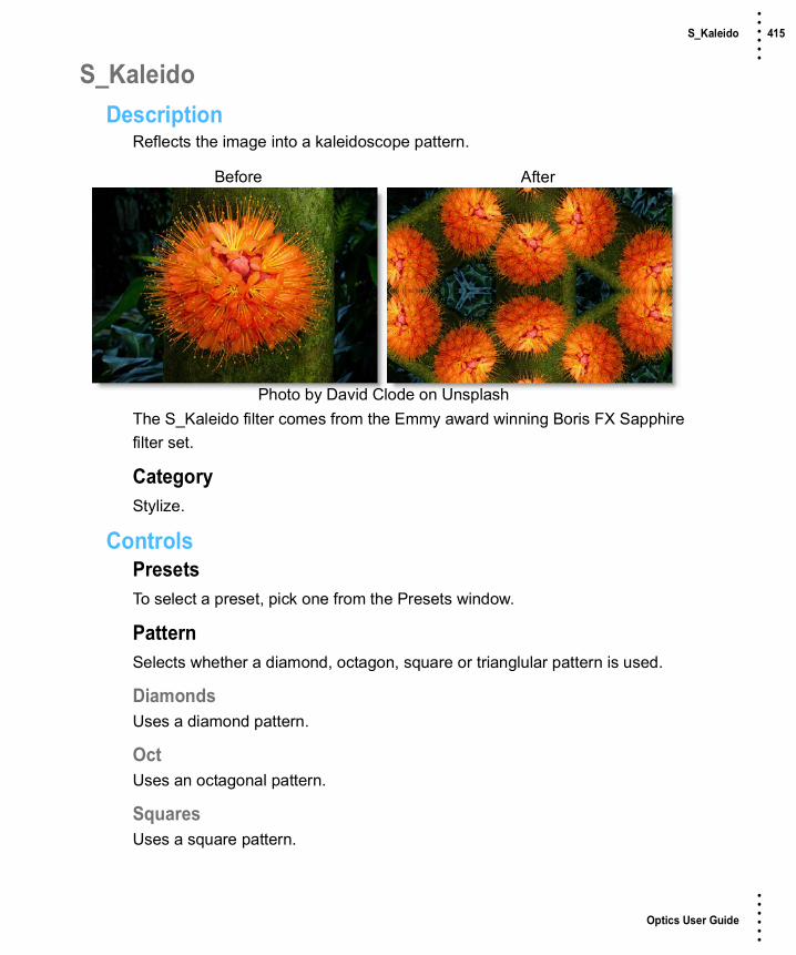
Optics User Guide
• • • •••
S_Kaleido 415 • • • •••
S_KaleidoDescription
Reflects the image into a kaleidoscope pattern.
The S_Kaleido filter comes from the Emmy award winning Boris FX Sapphire filter set.
CategoryStylize.
ControlsPresetsTo select a preset, pick one from the Presets window.
PatternSelects whether a diamond, octagon, square or trianglular pattern is used.
DiamondsUses a diamond pattern.
OctUses an octagonal pattern.
SquaresUses a square pattern.
Before After
Photo by David Clode on Unsplash

Optics User Guide
• • • •••
S_Kaleido 416 • • • •••
TrianglesUses a triangular pattern.
CenterCenter location of the kaleidoscoped image.
Z DistScales the distance of the entire result in or out from the Center. Increase to zoom out, decrease to zoom in.
RotateRotates the kaleidoscope's reflection pattern about the Center by this many counterclockwise degrees.
Inside Shift X & YTranslates the image inside the kaleidoscope before it is reflected.
Inside Z DistZooms the image in or out inside the kaleidoscope before it is reflected.
Inside RotateRotates the image inside the kaleidoscope before it is reflected.
Kaleido AmountAdjusts the overall amount of distortion applied to the image. Set this to 0 to leave the image unchanged or to 1 for a normal kaleidoscope pattern.
Wrap X & YDetermines the method for accessing outside the borders of the image. This is used only if the image inside the kaleidoscope is not contained within the shape of mirrors.
NoCreates black beyond the borders.
TileRepeats a copy of the image.

Optics User Guide
• • • •••
S_Kaleido 417 • • • •••
ReflectRepeats a mirrored copy. Edges are often less visible with this method.
FilterIf enabled, the image is resampled using pixel averaging. This removes aliasing and gives a higher quality result, although it may not be necessary if your image is smooth with no sharp edges or high frequencies.
Crop InputThese 4 parameters, Crop Top, Crop Bottom, Crop Left, and Crop Right, allow selecting a rectangular subsection of the image to be processed. If the Wrap parameters are set to "No" the exposed borders will be transparent. If the Wrap is "Tile" or "Reflect", the image is wrapped on the new cropped borders to fill the frame. This can make it easier to avoid artifacts due to distorting an image with bad edges.
Show CenterEnables/disables the on-screen control for adjusting the Center parameter.

Optics User Guide
• • • •••
S_KaleidoPolar 418 • • • •••
S_KaleidoPolarDescription
Warps the image around in a disk shape and reflects radially as if viewed through a reflecting cylinder resulting in a kaleidoscope pattern.
The S_KaleidoPolar filter comes from the Emmy award winning Boris FX Sapphire filter set.
CategoryStylize.
ControlsPresetsTo select a preset, pick one from the Presets window.
CenterCenter location of the kaleidoscoped image.
Z DistScales the distance of the entire result in or out from the Center. Increase to zoom out, decrease to zoom in.
RotateRotates the kaleidoscope's reflection pattern about the Center by this many counterclockwise degrees.
Before After
Photo by David Clode on Unsplash

Optics User Guide
• • • •••
S_KaleidoPolar 419 • • • •••
Stretch X & YScales the horizontal or vertical size of the result.
Inside Shift YShifts the image up by this amount before it is reflected. This causes the resulting pattern of images to radiate outward from the center.
Angle RepeatsThe number of copies of the image to wrap around. This should be an even integer to avoid a seam where the first copy connects to the last.
Kaleido AmountAdjusts the overall amount of distortion applied to the image. Set this to 0 to leave the image unchanged or to 1 for a normal kaleidoscope pattern.
FilterIf enabled, the image is resampled using pixel averaging. This removes aliasing and gives a higher quality result, although it may not be necessary if your image is smooth with no sharp edges or high frequencies.
Crop InputThese 4 parameters, Crop Top, Crop Bottom, Crop Left, and Crop Right, allow selecting a rectangular subsection of the image to be processed. If the Wrap parameters are set to "No" the exposed borders will be transparent. If the Wrap is "Tile" or "Reflect", the image is wrapped on the new cropped borders to fill the frame. This can make it easier to avoid artifacts due to distorting an image with bad edges.
Show CenterEnables/disables the on-screen control for adjusting the Center parameter.

Optics User Guide
• • • •••
S_KaleidoRadial 420 • • • •••
S_KaleidoRadialDescription
Simulates a traditional 2 or 3 mirror kaleidoscope. You see a pie-slice shaped piece of the image through the angle between the mirrors, and mirror-reflected copies of it in the rest of the image.
The S_KaleidoRadial filter comes from the Emmy award winning Boris FX Sapphire filter set.
CategoryStylize.
ControlsPresetsTo select a preset, pick one from the Presets window.
CenterCenter location of the kaleidoscoped image.
Z DistScales the distance of the entire result in or out from the Center. Increase to zoom out, decrease to zoom in.
Before After
Photo by David Clode on Unsplash
Optics User Guide
• • • •••
S_KaleidoRadial 421 • • • •••
SlicesSets how many slices the image will be broken up into. Each slice corresponds to the area between the mirrors in a traditional kaleidoscope. Turn this up to get a more abstract look, and down to get fewer, wider slices. Fractional numbers here will get you one fractional slice. For a fully symmetrical look, use integers like 3, 4, 5, and so on.
RotateRotates the whole pattern about the Center by this many degrees.
Rotate KaleidoRotates the kaleidoscope itself without rotating the image under or inside it.
Rotate InsideRotates the image under the kaleidoscope about the Center, much like rotating the object box at the end of a traditional kaleidoscope.
Kaleido AmountAdjusts the overall amount of distortion applied to the image. Set this to 0 to leave the image unchanged or to 1 for a normal kaleidoscope pattern.
WrapDetermines the method for accessing outside the borders of the image. This is used only if the image inside the kaleidoscope is not contained within the shape of mirrors.
NoCreates black beyond the borders.
TileRepeats a copy of the image.
FilterIf enabled, the image is resampled using pixel averaging. This removes aliasing and gives a higher quality result, although it may not be necessary if your image is smooth with no sharp edges or high frequencies.

Optics User Guide
• • • •••
S_KaleidoRadial 422 • • • •••
Show CenterEnables/disables the on-screen control for adjusting the Center parameter.

Optics User Guide
• • • •••
Kelvin 423 • • • •••
KelvinDescription
Degrees Kelvin is the standard unit of measure for color temperature which is a way to characterize the spectral properties of a light source. Low color temperature implies warmer (redder) light, while high color temperature implies a colder (bluer) light. Presets for a number of different light sources and conditions are provided in degrees Kelvin.
CategoryColor.
ControlsPresetsTo select a preset, pick one from the Presets window.
Color TemperatureThe Color Temperature of the image is determined by the difference of the Destination and Source Kelvin parameters. For instance, if your Source Kelvin is 3200 degrees Kelvin and you adjust the Destination Kelvin to 6500 degrees, your image would turn blue. This is the same as using tungsten indoor film meant to be used with lighting balanced for 3200 degrees Kelvin outside in daylight which is 6500 degrees Kelvin.
Destination KelvinSets the destination color temperature of the image in degrees Kelvin.
Before After
Photo by Christiane Nuetzel on Unsplash

Optics User Guide
• • • •••
Kelvin 424 • • • •••
Source KelvinSets the source color temperature of the image in degrees Kelvin.
OpacitySets the opacity of the color temperature adjustment.
Preserve HighlightsPreserves the white areas of the image.
Exposure CompensationExposure Compensation adds back the brightness loss as a result of the color temperature application.
Grad Kelvin can optionally use a gradient that limits where the filter is applied. Grad is the transition area between the colored portion and the original image. Its direction, corners and size can be adjusted. Go to the Grad section of Common Filter Controls to see how the Grad controls work.
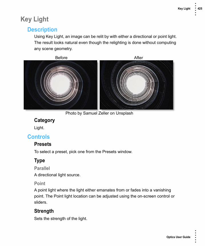
Optics User Guide
• • • •••
Key Light 425 • • • •••
Key LightDescription
Using Key Light, an image can be relit by with either a directional or point light. The result looks natural even though the relighting is done without computing any scene geometry.
CategoryLight.
ControlsPresetsTo select a preset, pick one from the Presets window.
TypeParallelA directional light source.
PointA point light where the light either emanates from or fades into a vanishing point. The Point light location can be adjusted using the on-screen control or sliders.
StrengthSets the strength of the light.
Before After
Photo by Samuel Zeller on Unsplash

Optics User Guide
• • • •••
Key Light 426 • • • •••
AngleUsed in conjunction with Parallel, Angle sets the direction of the light source.
InvertUsed in conjunction with Point, Invert determines whether the light source emanates from or fades into a vanishing point.

Optics User Guide
• • • •••
S_LaserBeam 427 • • • •••
S_LaserBeamDescription
Simulates the beam from a science fiction style laser blaster.
The S_LaserBeam filter comes from the Emmy award winning Boris FX Sapphire filter set.
CategoryRender.
ControlsPresetsTo select a preset, pick one from the Presets window.
TimeThe effect is advanced in time.
StartStart of the beam.
StopEnd of the beam.
Shift X & YMoves the Start and Stop points shifting the whole beam to a different location.
Before After
Photo by Donald Giannatti on Unsplash

Optics User Guide
• • • •••
S_LaserBeam 428 • • • •••
PositionWhere the drawn beam segment should appear along the beam trajectory. At values between 0 and 1, the beam segment will appear along the beam trajectory.
Note: Nothing will be drawn at Position values of 0 or 1.
LengthLength of the drawn beam segment.
WidthWidth of the drawn beam segment.
Core ColorColor at the center of the beam.
Edge ColorColor at the edge of the beam.
Color BalanceAdjusts the balance between the core and edge colors.
BrightnessBrightness of the beam.
SoftnessSoftness of the texturing in the beam.
Fade BackFades out the brightness of the back half of the beam. Setting this to 1 will fade to black at the very back of the beam. Higher values will fade out more quickly.
Fade FrontFades out the brightness of the front half of the beam. Setting this to 1 will fade to black at the very front of the beam. Higher values will fade out more quickly.
Laser ShapeThe shape of the drawn segment of the beam.
Optics User Guide
• • • •••
S_LaserBeam 429 • • • •••
SmoothThe segment is drawn with a circular profile.
SpearThe segment is drawn as a symmetrical shape with sharpened ends.
ForwardThe segment is drawn as an asymmetrical shape with the leading end wider than the trailing end.
BackwardThe segment is drawn as an asymmetrical shape with the trailing end wider than the leading end.
PerspectiveThe strength of the perspective effect. At 0, there is no effect. Positive values move the bolt nearer to the target than it otherwise would be at a given beam position, while negative values move it nearer to the source.
BreakupAs this increases, the drawn beam segment become more and more ragged.
SmoothOverall smoothing applied to the beam segment.
AtmosphereAtmosphere AmpAtmosphere gives the effect of the laser shining through a dusty atmosphere and picking up light or getting shadowed. This parameter adjusts the amount, or amplitude of the atmospheric effect. 0 gives a smooth beam while higher values give a more dusty look.
Atmosphere FreqControls the spatial frequency of the atmospheric noise. Turn this up higher to get finer details or turn down for broader overall variation.

Optics User Guide
• • • •••
S_LaserBeam 430 • • • •••
Atmosphere DetailControls the amount of fine detail in the atmosphere simulation. Decrease to get smoother atmosphere or increase for a more crunchy, grainy look.
Atmosphere SeedUsed to initialize the random number generator for the atmospheric noise. The actual seed value is not significant, but different seeds produce different results and the same value should give a repeatable result.
CombineDetermines how the beam image is combined with the background.
ScreenBlends the beam with the image which can help prevent overly bright results.
AddAdd the beam image to the image.
Beam OnlyShows the beam over a transparent black background.
Show StartEnables/disables the on-screen control for adjusting the Start parameter.
Show StopEnables/disables the on-screen control for adjusting the Stop parameter.
Show ShiftEnables/disables the on-screen control for adjusting the Shift parameter.

Optics User Guide
• • • •••
Lens Distortion 431 • • • •••
Lens DistortionDescription
Lens Distortion corrects for pin-cushioning and barrel distortion of camera lenses. It is also useful for creating the look of a wide angle lens.
CategoryLens.
Note: Lens Distortion must be applied as the first layer (bottom of the layer stack) when multiple layers are used. Otherwise, all filters below will not be rendered.
Before After
Photo by Vincent Guth on Unsplash

Optics User Guide
• • • •••
Lens Distortion 432 • • • •••
ControlsDistortionPulls the corners of the image in or out. Negative values pull the corners of the image outward while positive values pull the corners of the image inward.
Anamorphic SqueezeAnamorphic Squeeze corrects for the squeeze found in anamorphic motion picture lenses.
Curvature X and YCurvature X and Y correct for non-radial, asymmetric distortions found in anamorphic motion picture lenses.
Note: Anamorphic Squeeze and Curvature X and Y only work once the Distortion parameter has been moved.
Barrel Distortion Pin Cushion Distortion
Original
Optics User Guide
• • • •••
Lens Distortion 433 • • • •••
CenterDetermines the center point for the distortion. There is an on-screen control in the center of the image. By clicking and dragging the on-screen control or sliders, the Center can be adjusted.

Optics User Guide
• • • •••
S_LensFlare 434 • • • •••
S_LensFlareDescription
Renders a lens flare image over the image, aligning various flare elements between the hotspot and pivot locations.
The S_LensFlare filter comes from the Emmy award winning Boris FX Sapphire filter set.
CategoryLight.
ControlsPresetsTo select a preset, pick one from the Presets window.
Edit LensOpens the Flare Designer where you can select Lens Flare presets and modify their elements.
See the Flare Designer for more information.
Scale WidthsScales the sizes of all the flare elements.
Rel HeightsScales the vertical dimension of all the flare elements, making them elliptical instead of circular.
Before After
Photo by Andrey Grinkevich on Unsplash

Optics User Guide
• • • •••
S_LensFlare 435 • • • •••
Blur FlareIf positive, the flare image is blurred by this amount before being combined with the image.
HotspotThe location of the brightest spot in the flare.
PivotThe elements of the flare will be in a line between the Hotspot and the Pivot locations.
BrightnessScales the brightness of all the flare elements.
ColorScales the color of all flare elements.
GammaIncreasing gamma brightens the flare and especially boosts the darker elements.
SaturationScales the color saturation of the flare elements. Increase for more intense colors. Set to 0 for a monochrome lens flare.
Hue ShiftShifts the hue of the flare in revolutions from red to green to blue to red.
RaysRays BrightnessScales the brightness of the ray elements only.
Rays RotateRotates the ray elements of the lens flare, if any, in counterclockwise degrees.
Rays Num ScaleIncreases or decreases the number of rays.

Optics User Guide
• • • •••
S_LensFlare 436 • • • •••
Rays LengthAdjusts the length of the rays without changing their thickness or changing the size of the other flare elements.
Rays ThicknessAdjusts the thickness of the individual rays within the flare.
HotspotHotspot BrightScales the brightness of the hotspot elements only.
Hotspot ColorScales the color of the hotspot elements only.
OtherOther BrightnessScales the brightness of all flare elements that are not at the hotspot location.
Other ColorScales the color of all flare elements that are not at the hotspot location.
Other WidthScales the width of all flare elements that are not at the hotspot location.
AtmosphereAtmosphere AmpAtmosphere gives the effect of the flare shining through a dusty atmosphere and picking up light or getting shadowed. This parameter adjusts the amount, or amplitude of the atmospheric effect. 0 creates a smoother flare while higher values provide a more dirty look.
Atmosphere FreqControls the spatial frequency of the atmospheric noise. Turn this up higher to get finer details or turn down for broader overall variation.
Atmosphere DetailControls the amount of fine detail in the atmosphere simulation. Decrease to get smoother atmosphere or increase for a more crunchy, grainy look.
Optics User Guide
• • • •••
S_LensFlare 437 • • • •••
Atmosphere SeedUsed to initialize the random number generator for the atmospheric noise. The actual seed value is not significant, but different seeds produce different results and the same value should give a repeatable result.
Bg BrightnessScales the brightness of the image before combining with the flare. If 0, the result will contain only the flare image over black.
CombineDetermines how the flare is combined with the image.
ScreenPerforms a blend function which can help prevent overly bright results.
AddAdds the flare to the image.
Flare OnlyRenders only the flare with no background.
Tint Bg WhitesIf this is enabled, the chroma of the flare is added only after the result is clamped to the maximum brightness. This allows the color of the flare image to still be visible even over bright white backgrounds. For the majority of images, there will be no observable difference.
Edge TriggersEdge WidthCreates a trigger zone at the edge of the screen which affects the brightness and size of the flare. This parameter controls the width of the zone. Setting it to zero will disable Edge Triggers.

Optics User Guide
• • • •••
S_LensFlare 438 • • • •••
Edge FalloffControls the speed with which the intensity of the trigger decreases when moving away from the edge. A value of 1 results in a linear ramp. Values greater than one result in a steeper initial drop which gradually levels out. Values less than one result in a slope that starts gradually and gets steeper at the end.
Shift OutShifts the trigger zone outward from the edge of the screen, placing the peak off−screen. Negative values will shift the trigger zone inward toward the center of the image.
One WayIf this box is checked, the trigger will stay at maximum intensity when the Hotspot moves off−screen instead of ramping back down as it moves farther from the edge.
Edge Scale BrightnessScales the Brightness by this amount when the trigger is at peak intensity. For example, a value of 3 will cause the flare to ramp up to 3 times its normal brightness as it passes through the trigger zone. If less than 1, the trigger will dim the flare instead of brightening it.
Edge Scale WidthsScales the width of the flare by this amount when the trigger is at peak intensity. For example, a value of 3 will cause the flare to expand to 3 times its normal size as it passes through the trigger zone. If less than 1, the trigger will shrink the flare instead of growing it.
Show Edge ZonesOverlays the output with a grayscale image which shows the location intensity of the Edge Triggers.
Optics User Guide
• • • •••
S_LensFlare 439 • • • •••
Center TriggersCenter RadiusCreates a trigger zone centered on the Pivot which affects the brightness and size of the flare. This parameter controls the radius of the zone. Setting it to zero will disable Center Triggers.
Center FalloffControls the speed with which the intensity of the trigger decreases when moving away from the edge. A value of 1 results in a linear ramp. Values greater than one result in a steeper initial drop which gradually levels out. Values less than one result in a slope that starts gradually and gets steeper at the end.
Center Scale BrightnessScales the Brightness by this amount when the trigger is at peak intensity. For example, a value of 3 will cause the flare to ramp up to 3 times its normal brightness as it passes through the trigger zone. If less than 1, the trigger will dim the flare instead of brightening it.
Center Scale WidthsScales the width of the flare by this amount when the trigger is at peak intensity. For example, a value of 3 will cause the flare to expand to 3 times its normal size as it passes through the trigger zone. If less than 1, the trigger will shrink the flare instead of growing it.
Show Center ZoneOverlays the output with a grayscale image which shows the location intensity of the Center Trigger.
Show Scale WidthsEnables/disables the on-screen control for adjusting the Scale Widths and Rel Heights parameters.
Show HotspotEnables/disables the on-screen control for adjusting the Hotspot parameter.

Optics User Guide
• • • •••
S_LensFlare 440 • • • •••
Show PivotEnables/disables the on-screen control for adjusting the Pivot parameter.
Flare DesignerThe Flare Designer lets you completely customize a lens flare. You can add or remove elements, copy them, customize how each element looks, and even how it reacts to the center or edge of the image. You can also interactively move the flare around to see how it will look as it moves.
All the windows of the Flare Designer are movable, so you can adjust the user interface itself to suit your work flow. The main windows are the Viewer, where you see the flare you're working on, the Elements window which lists all the elements of the flare, and the Properties window, which lets you adjust the properties of the currently selected element or elements. There's also a toolbar of element templates at the top.
Note: Clicking Edit Lens opens the Flare Designer.
ViewerThe Viewer displays the lens flare over the background or over black. Click and drag to move the flare around, adjust the gamma, or solo only selected elements. If you change the Preview Mode pop-up menu to Use Plug-in Settings, the Flare Designer imports the Lens Flare settings from Optics.

Optics User Guide
• • • •••
S_LensFlare 441 • • • •••
ElementsThe Elements window shows you all the elements as thumbnails. If you hover over them, an overlay shows where they are in the Viewer. If you click on an element to select it, it flashes brighter in the Viewer to help you find it. Clicking Identify in the Properties window also flashes the element.
Add ElementsTo add new elements, click an element template in the top toolbar. You can then rename the element, move it in the list by dragging and dropping, or hide it by unchecking the checkbox.
Delete ElementsTo delete an element, select it and press Delete. There is full undo, so feel free to experiment.
Duplicate ElementsDuplicate an element using standard copy/paste operations. You can then adjust the copy's parameters in the Properties window.
Advanced Element TypeThe Advanced Element Type has a number of controls and is very customizable, but it's recommended for advanced users only.
The standard element types get you most of the same looks with simpler parameters. Along with all the standard element types, you can import your own images to use as elements. Click the Add Texture icon to import an image file.
The image data will become part of the flare, so a reference to the original file is not needed.

Optics User Guide
• • • •••
S_LensFlare 442 • • • •••
To combine two flares into one, or add many elements at once, you can import another flare into your current flare. This will add all the other flare's elements to your current flare. You can also replace the current flare with a new one.
• To import and add to your flare, click the Insert button or File > Insert Lens.
• To import and replace, use the Load button or use File > Open Lens.
PropertiesThe Properties window is where you adjust all the details of a single element or multiple elements together. Use Shift+click or Ctrl/Cmd+click to select multiple elements.
Numeric FieldsDrag in the number field to increase or decrease the value. You can also click in the number field and type any value you want.
Color ControlsColor controls are just a swatch of color. Click to bring up a standard color picker.
GradientSome elements have a special gradient control.
The stops are below the color swatch. You can drag them left and right to move them. Drag down to delete. Click in the color gradient to add a stop. Ctrl/Cmd+drag to stretch neighboring colors and Shift+drag to push neighboring colors. The triangles above the color gradient allow you to control the interpolation of the colors between stops.
Common ParametersDifferent element types will have various parameters you can adjust, but you will find common ones below.

Optics User Guide
• • • •••
S_LensFlare 443 • • • •••
PositionThe Position is where the element occurs along the line between the hotspot and pivot point. Position 1 is at the hotspot while 0 is at the pivot. Note that you don't have to stay in that range. You can use any value you like. Bigger than 1 will be past the hotspot, and less than zero will look like a reflection because it's on the other side of the pivot point.
RotateRotates the element in degrees.
SizeHow big the image is.
Rel Width / Rel HeightUse these to squash and stretch.
ResetThere's a Reset icon to the right of each parameter group as well as at the bottom of the Properties window to reset the current element(s) to default settings.

Optics User Guide
• • • •••
Levels 444 • • • •••
LevelsDescription
Levels is an image adjustment tool which can move and stretch the brightness levels of an image histogram. It has the power to adjust brightness, contrast, and tonal range by specifying the location of complete black, complete white, and midtones in a histogram.
CategoryColor.
Before After
Photo by Mohamed Nohassi on Unsplash

Optics User Guide
• • • •••
Levels 445 • • • •••
Since every photo's histogram is unique, there is no single way to adjust the levels for all your photos. A proper understanding of how to adjust the levels of an image histogram will help you better represent tones in the final image.
Input LevelsThe outer two Input Levels sliders map the black point and white point to the settings of the Output sliders. By default, the Output sliders are at level 0, where the pixels are black, and level 100, where the pixels are white. With the Output sliders in the default positions, moving the black Input slider maps the pixel value to level 0 and moving the white Input slider maps the pixel value to level 100. The remaining levels are redistributed between levels 0 and 100. This redistribution increases the tonal range of the image, in effect increasing the overall contrast of the image.
Note: When shadows are clipped, the pixels are black, with no detail. When highlights are clipped, the pixels are white, with no detail.
The middle Input slider adjusts the gamma in the image. It moves the midtone and changes the intensity values of the middle range of gray tones without dramatically altering the highlights and shadows.
Output LevelsThe Output Levels decrease the contrast of the image.
A. Shadows B. Midtones C. Highlights
A B C

Optics User Guide
• • • •••
Light 446 • • • •••
LightDescription
Light can be added to a scene where none existed before just as if you were adding light at the time of shooting. Realistic lighting and shadow is introduced using digital versions of lighting gobos.
Gobos (patterns) are widely used by designers in theatre, film, photography and television to create atmosphere, project scenery, and generally enhance the visual impact of their lighting. Normally used in front of lights during photography, these same exact gobos can be applied digitally to the entire image or inside a matte.
CategoryLight.
Before After
Photo by Julia Komarova on Unsplash

Optics User Guide
• • • •••
Light 447 • • • •••
PresetsTo select a gobo, pick one from the Presets window. If you would like to view gobos from a different category, use the pop-up menu at the top left of the Presets window.
LightBlendDetermines the blend mode to be used to add the light.
AddThe light is added to your image.
ScreenThe light is combined with the image using a Screen blend mode. This looks kind of like the Add blend mode, but highlights are retained.
SubtractThe light is subtracted from your image creating shadow instead of light.
BrightnessSets the intensity of the light.

Optics User Guide
• • • •••
Light 448 • • • •••
DisplacementDisplaces the gobo by the luminance values of the image. This “fakes” the effect of light wrapping over objects in the image.
BlurSets the softness of the light.
GelsPhotographers, cinematographers and lighting designers use colored filters or gels in front of lights. Whatever mood you wish to create, we have the colors needed to achieve the effect. Select one of the Gels presets from the pop-up menu.
ColorSets the color of the light through the use of a standard color picker.
ShadowBrightnessSets the intensity of the shadows. The Brightness parameter will darken only those areas that are not being affected by the Light settings.
Displaced Gobo

Optics User Guide
• • • •••
Light 449 • • • •••
GobosThe gobos are organized into various categories including: Abstract, Doors, Elements, Foliage, Glass, Snowflakes, Textures and Windows groups.
GoboClicking the Gobo > Browse button allows you to load your own image as the light source.
To use your own image as a light source:• Select Gobo > Gobo > Browse.
• When the file browser opens, navigate to your image and select it.
BlendThe gobo can be added to a matte using a variety of Blend modes. Go to Blend Modes for explanations of the various modes.

Optics User Guide
• • • •••
Light 450 • • • •••
I like the Multiply blend mode for combining gobos with the matte because it only puts the gobo within the areas of the matte.
OpacitySets the opacity of the gobo.
BlurSets the softness of the gobo.
TransformTransform your gobo using Position, Scale, Rotate, Corner-Pin, Shear and Crop controls. Go to the Transform section of Common Filter Controls to see how the Transform Controls work.
Matte GoboMultiply

Optics User Guide
• • • •••
Light 451 • • • •••
MatteA matte can be used to create areas of light or limit where gobos will be added. Wherever there is white in the matte is where the light will be added. When using the Light and Gobo filters, it is usually helpful to blur the matte. Go to the Matte parameters to see how they work.
Note: To use a matte to create light, Gobo > Blend must be set to something other than Gobo Only for the Matte controls to be active.
Matte

Optics User Guide
• • • •••
S_LightLeak 452 • • • •••
S_LightLeakDescription
Renders abstract patterns of color that simulate light leaking through gaps in a camera body. The light leak consists of three distinct elements which can be adjusted individually.
The S_LightLeak filter comes from the Emmy award winning Boris FX Sapphire filter set.
CategoryLight.
ControlsPresetsTo select a preset, pick one from the Presets window.
Scale LightsScales the light leak by this value. Increase for a brighter result.
Offset DarksAdds this gray value to the darker regions of the result. This can be negative to increase contrast.
ColorThe overall color of the light leak.
Before After
Photo by Nika Akin on Unsplash

Optics User Guide
• • • •••
S_LightLeak 453 • • • •••
Hue ShiftShifts the hue of the light leak in revolutions from red to green to blue to red.
SaturationScales the color saturation of the light leak. Increase for more intense colors. Set to 0 for a monochrome light leak.
GammaIncreasing Gamma brightens the light leak and especially boosts the darker areas.
Shift X & YShifts the position of all elements.
SeedUsed to initialize the random number generator. The actual seed value is not significant, but different seeds produce different results and the same value should give a repeatable result.
Bg BrightnessScales the brightness of the image before combining it with the light leak. If 0, the result will contain only the light leak image over black.
CombineDetermines how the light leak is combined with the image.
ScreenThe light leak is blended with the image using a function that helps prevent overly bright results.
AddThe light leak is added to the image.
Leaks OnlyThe light leak is shown on its own with no background.

Optics User Guide
• • • •••
S_LightLeak 454 • • • •••
GlowGlow BrightnessScales the brightness of the glow which is applied to the entire image after combining the light leak with the background.
Glow WidthThe width of the glow. Increase for a softer glow and decrease for a sharper, brighter glow.
Glow ThresholdParts of the image that are brighter than this value get glowed.
Element1-3 EnableTurns these elements on and off.
Element1-3Size1-3Adjusts the size.
Rel Height1-3Scales the vertical dimension making it elliptical instead of circular.
Brightness1-3Scales the brightness.
Angle1-3The angle of this element's path across the screen. The element moves along a line at this angle, passing through the center position at the midpoint of the image.
Outer Color1-3The color at the outer edge.
Mid Color1-3The color at the midpoint, between the Outer and Center Colors. The exact location depends on the Midpoint parameter.
Center Color1-3The color at the center.

Optics User Guide
• • • •••
S_LightLeak 455 • • • •••
Midpoint1-3Moves the location of the Mid Color between the center and outer edge of the element. Set to 0 to place the Mid Color at the center, or 1 to place it at the edge.
Softness1-3Blurs the color gradient. Increase for a smoother gradient or decrease for sharper bands of color.
Noise Amp1-3The amount of noise applied.
Noise Freq1-3The frequency of the noise applied. Increase for smaller blobs or decrease for larger ones.
Noise Freq Rel Y1-3The relative vertical frequency of the noise pattern. Increase to flatten the noise or decrease to stretch it out vertically.
Noise Detail1-3Controls the amount of fine detail in the noise simulation. Decrease to get smoother noise or increase for a more crunchy, grainy look.

Optics User Guide
• • • •••
Looks 456 • • • •••
LooksDescription
Looks is a unique filter meant to simulate a variety of color and black and white photographic/film looks, diffusion and color grad camera filters, lighting gels, film stocks and optical lab processes. By selecting from the available presets, parameters in the various modules are automatically set to achieve a variety of different effects.
CategoryFilm Lab.
ControlsThe Looks filters are made up of Color Correct, Diffusion, Color Gradient, Gels, Lab, Grain and Post Color Correct groups. Together, they simulate a variety of photographic and film looks. By selecting from the available presets, parameters in the various groups are automatically set to achieve a variety of different effects.
PresetsTo select a preset, pick one from the Presets window. If you would like to view presets from a different category, use the pop-up menu at the top left of the Presets window.
Before After
Photo by Mickey O'neil on Unsplash

Optics User Guide
• • • •••
Looks 457 • • • •••
Color CorrectColor Correct manipulates the Black and White, Hue, Saturation, Brightness, Contrast, Gamma, Red, Green and Blue values of the image. Go to the Color Correct filter to see how it works.
DiffusionDiffusion creates atmosphere by reducing contrast while creating a glow around highlights or shadows. It simulates diffusion and fog filters as well as glows. Go to the Diffusion section of the Film Stocks filter to see how it works.
Color GradientColor Gradient colors and or darkens only a portion of the image giving you the ability to simulate any Color Gradient filter. Presets for your favorite color gradient filters are provided as well as the ability to create custom colors. There is a graduated transition for a smooth color blend between the colored/darkened portion and the original image. Color Gradient is especially useful for changing and enhancing the color of the sky. Go to the Color Gradient filter to see how it works.
GelsPhotographers, cinematographers and lighting designers use colored filters or gels in front of lights. Whatever mood you wish to create, we have the colors needed to achieve the effect. Go to the Gels filter to see how it works.
LabThe Lab group simulates a variety of different optical lab processes including Bleach Bypass, Cross Processing, Flashing and Overexposure. Go to the Bleach Bypass filter, Cross Processing filter, Flashing and the Overexpose filter to see how they work.
GrainGrain simulates film grain with individual control of red, green, and blue grain size, softness and intensity. In addition, a Film Response parameter controls where you will see grain in the image. Go to the Grain filter to see how it works.

Optics User Guide
• • • •••
Looks 458 • • • •••
Post Color CorrectPost Color Correct gives you further color correction after all other operations have been processed. This is often helpful as some of the operations affect the brightness, contrast and color of the image. In addition, Temperature controls allow you to make the scene warmer or cooler, and cyan or magenta. Go to the Color Correct filter to see how it works.

Optics User Guide
• • • •••
Low Contrast 459 • • • •••
Low ContrastDescription
Low Contrast spreads highlights into darker areas, lowers contrast and keeps bright areas bright.
CategoryColor.
ControlsPresetsTo select a preset, pick one from the Presets window.
ContrastLight BrightnessSets the intensity of the light that is spread into darker areas.
Light SpreadSets how far light is spread from bright areas to darker areas.
Shadow BrightnessAdjusts the brightness of the shadow areas.
MatteA matte is used to create the light spread effect. Go to the Matte section of Common Filter Controls to see how the Matte controls work.
Before After
Photo by Len Dela Cruz on Unsplash

Optics User Guide
• • • •••
S_Luna 460 • • • •••
S_LunaDescription
Renders the Earth's Moon. You can adjust phase, color, and add atmospheric effects.
The S_Luna filter comes from the Emmy award winning Boris FX Sapphire filter set.
CategoryRender.
ControlsPresetsTo select a preset, pick one from the Presets window.
ModeSelects how the moon's phase is chosen. You can adjust it directly in Luna mode, or select LunaDate mode to choose a date and time and the effect will use the proper phase for that date.
LunaSelect this mode to adjust the moon phase manually.
LunaDateSelect this mode to have the effect compute the phase from the given date and time.
Before After
Photo by Noah Silliman on Unsplash

Optics User Guide
• • • •••
S_Luna 461 • • • •••
CenterCenter point of the moon.
SizeSize of the moon.
Lunar PhasePhase of the moon in degrees; 0 is new, 90 is first quarter, 180 is full, and 270 is last quarter. Only available in Luna mode.
Note: The Year, Month, Day, Hour, Minute, and GMT Offset parameters are only available in LunaDate mode.
YearYear to use when computing the phase.
MonthMonth to use when computing the phase.
DayDay to use when computing the phase.
HourHour to use when computing the phase.
MinuteMinute to use when computing the phase.
GMT OffsetGMT offset to use when computing the phase. For instance, −5 is Eastern Standard Time while −8 is Pacific Standard Time.
RotationRotation of the moon image in degrees.
BumpinessThe moon has craters that catch and reflect light. This parameter can be used to adjust how bumpy those craters look. 0 is completely smooth, 1 is very rough, and .3 is physically realistic on a clear night.

Optics User Guide
• • • •••
S_Luna 462 • • • •••
ContrastAdjusts the contrast of the moon. Values toward 0 brighten the dark areas.
BrightnessScales the brightness of the result.
ColorScales the color of the result. For example, if it is yellow [1 1 0], the blue of the result will be 0.
Earth GlowAdds earth−glow which you often see near sunset when the moon is crescent. The sun's light reflects off the earth and some of that reflected light illuminates even the dark part of the moon. This gives an especially nice look during a lunar eclipse.
GammaSets the overall gamma of the moon image. Good for reducing contrast in a different way from the contrast parameter.
Sky ColorIf you want to make a complete sky image with the moon and a colored sky, you can put the moon in a blue sky by setting Sky Color to blue. This will also tint the moon toward the sky color.
GlowGlow BrightnessAdds some glow to the moon. You can see this often in real life when there's some haze or light clouds.
ThresholdThreshold for the glow. Only parts of the moon brighter than this threshold will glow.
Glow SizeSize of the moon glow. Larger values create a more diffuse glow.

Optics User Guide
• • • •••
S_Luna 463 • • • •••
HaloHalo BrightnessWith certain kinds of high, diffuse clouds, you can sometimes see a subtle rainbow halo around the moon. Increase this parameter to see that halo.
Halo Rel SizeSets the size of the halo relative to the moon. A value of 1 would be the same size as the moon while 2 is twice as large.
Color FringingIncreases or decreases the amount of color fringing in the moon halo. Fringing separates the colors into a rainbow.
Inner SoftnessSets the softness or spread of the inside of the halo closest to the moon.
Outer SoftnessSets the softness or spread of the outside of the halo farthest from the moon.
Halo SaturationSets the overall saturation of the moon halo. Increase for a more graphic look.
Halo TintTints the halo toward this color.
AtmosphereAtmosphere AmpThe Atmosphere parameters add a little noise to the glow and halo for a more realistic look. Atmosphere Amp controls the amount of atmospheric noise.
Atmosphere FreqControls the frequency of the atmospheric noise.
Atmosphere TurbulenceControls the turbulence (amount of detail) in the atmospheric noise.
Atmosphere SeedSets the seed of the atmospheric noise.

Optics User Guide
• • • •••
S_Luna 464 • • • •••
CombineCombines the moon with the image using various blend modes.
Moon OnlyRenders only the moon including its glow and halo.
OverlayUses an Overlay blend mode to composite the moon over the image.
AddAdds the moon to the background.
ScreenScreens the moon with the background. Nice for daytime shots.
MaxWhere the moon is brighter than the background, show it. This can be useful for daytime shots with clouds. Where the clouds are brighter than the moon, they'll obscure it.
Transparent ShadowComposite only the lit part of the moon over the background leaving the dark part transparent. This is not physically realistic, since the dark part of the moon obscures the sky and stars behind it, but it can be used for graphic effect.
Bg BrightnessScales the brightness of the image before combining with the moon. If 0, the result will contain only the moon over black.
Show SizeEnables/disables the on-screen control for adjusting the Center parameter.
Show CenterEnables/disables the on-screen control for adjusting the Center parameter.

Optics User Guide
• • • •••
Match 465 • • • •••
MatchDescription
Matches the brightness and color from one image and applies it to another.
CategoryColor.
ControlsSourceSelects a source image to be matched. Click the Browse button to select an image.
BrightnessSets the amount of the brightness match.
ColorSets the amount of the color match.
Source Target After
Source/After: Photo by Paula Borowska on UnsplashTarget: Photo by Saud Sarosh on Unsplash

Optics User Guide
• • • •••
Match 466 • • • •••
Matching Clips:1 Apply the Match filter to a target image.
2 Select the source image to be matched with the Source selector.
The color and brightness of the source image are analyzed and applied to your target image.
3 Adjust the Color and Brightness parameters to your liking.

Optics User Guide
• • • •••
Mist 467 • • • •••
MistDescription
MistCreates atmosphere by reducing contrast while creating a glow around highlights.
Warm MistSame as Mist but combined with a warming filter.
Before After
Photo by Christopher Campbell on Unsplash
Before After
Photo by Christopher Campbell on Unsplash

Optics User Guide
• • • •••
Mist 468 • • • •••
Cool MistSame as Mist but combined with a cooling filter.
Black MistA more subtle version of Mist, the Black Mist filter creates atmosphere by reducing contrast, but with minimal glow around highlights.
Before After
Photo by Christopher Campbell on Unsplash
Before After
Photo by Christopher Campbell on Unsplash

Optics User Guide
• • • •••
Mist 469 • • • •••
Warm Black MistSame as Black Mist but combined with a warming filter.
CategoryDiffusion/Blurs.
ControlsPresetsTo select a preset, pick one from the Presets window.
MistThe Mist controls add a mild glow to image highlights.
BlendDetermines the blend mode to be used to create the glow effect.
AddThe glow is added to your image.
ScreenThe glow is combined with the image using a Screen blend mode. This looks kind of like the Add blend mode, but highlights are retained.
BrightnessSets the intensity of the glow.
Before After
Photo by Christopher Campbell on Unsplash

Optics User Guide
• • • •••
Mist 470 • • • •••
BlurSets the softness of the glow.
ColorSets the color of the glow.
Color CorrectGo to the Color Correct filter to see how the Color Correct controls work.
MatteA matte is used to create the mist effect. Go to the Matte section of Common Filter Controls to see how the Matte controls work.
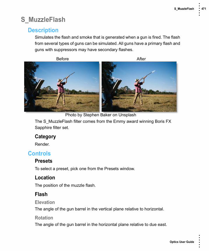
Optics User Guide
• • • •••
S_MuzzleFlash 471 • • • •••
S_MuzzleFlashDescription
Simulates the flash and smoke that is generated when a gun is fired. The flash from several types of guns can be simulated. All guns have a primary flash and guns with suppressors may have secondary flashes.
The S_MuzzleFlash filter comes from the Emmy award winning Boris FX Sapphire filter set.
CategoryRender.
ControlsPresetsTo select a preset, pick one from the Presets window.
LocationThe position of the muzzle flash.
FlashElevationThe angle of the gun barrel in the vertical plane relative to horizontal.
RotationThe angle of the gun barrel in the horizontal plane relative to due east.
Before After
Photo by Stephen Baker on Unsplash

Optics User Guide
• • • •••
S_MuzzleFlash 472 • • • •••
RadiusThe overall size of the gun blast.
BrightnessThe overall brightness of the flash.
Shift OutThe muzzle flash will be drawn this far from the end of the gun barrel.
GunThe type of gun being fired.
AK47AK47 assault rifle.
BerettaBeretta pistol.
Colt45Colt 45 revolver.
M16M16 assault rifle.
12GaugeShotgun.
VariantVariations on the muzzle flash pattern.
OneFirst variation.
TwoSecond variation.
ThreeThird variation.
RandomRandomly pick one of the variations each time a shot is fired.

Optics User Guide
• • • •••
S_MuzzleFlash 473 • • • •••
SeedRandom number seed. Many aspects of the muzzle flash appearance depend on the seed. To get a different result for a given set of control values, try changing this seed value.
OctavesIncreasing this increases the detail in the smoke.
BlurHow much blur is to be applied to the muzzle flash.
Mid DensityHow dense the muzzle flash should be at half its radius.
Mid ColorThe color of the muzzle flash at half its radius.
CombineDetermines how the muzzle flash is combined with the image.
ScreenThe muzzle flash is blended with the image using a Screen operation.
AddThe muzzle flash is added to the image.
MuzzleFlash OnlyRenders only the muzzle flash.
PrimaryPrimary LengthLength of the primary flash. This is always aligned with the gun barrel and is present in all guns.
Primary WidthWidth of the primary flash.
Primary BrightnessOverall density and brightness of the primary flash.

Optics User Guide
• • • •••
S_MuzzleFlash 474 • • • •••
Primary PuffHow puffy (as opposed to smooth) the primary flash should appear.
Primary DetailHow much detail should appear in the primary flash.
SecondariesSecondary NumberThe amount of secondary flashes that should be generated for those guns that have secondary flashes. These flashes appear from holes in the suppressor and only guns with suppressors have them. The flashes appear at an angle in the vertical plane with respect to the gun barrel direction. This control specifies how many holes there are in the suppressor. The holes are assumed to be evenly distributed around the circumference of the suppressor.
Secondary AngleThe angle the secondary flashes make in the vertical plane with respect to the gun barrel.
Secondary LengthThe length of the secondary flashes.
Secondary WidthThe width of the secondary flashes.
Secondary BrightnessThe overall density and brightness of the secondary flashes.
Secondary PuffHow puffy (as opposed to smooth) the secondary flashes should appear.
Secondary DetailHow much detail should appear in the secondary flashes.
GlowGlow ColorThe color of an overall glow around the bright parts of the muzzle flash.

Optics User Guide
• • • •••
S_MuzzleFlash 475 • • • •••
Glow BrightThe brightness of an overall glow around the muzzle flash.
Glow WidthThe size of an overall glow around the muzzle flash.
Glow ThresholdMuzzle flash intensities above this threshold will glow.
Show MuzzleFlashEnables/disables the on-screen control for adjusting the Location parameter.

Optics User Guide
• • • •••
ND Gradient 476 • • • •••
ND GradientDescription
ND (Neutral Density) Gradient darkens only a portion of the image using a graduated transition between the darkened portion and the original image. It selectively adjusts brightness without affecting color balance. The most likely use for ND Gradient would be to balance the difference between the sky and ground in a landscape.
CategoryGrads/Tints.
ControlsPresetsTo select a preset, pick one from the Presets window.
F-StopPresetsSelect one of the ND Gradient presets from the pop-up menu.
ExposureDarkens the image using F-Stops as the unit of measure.
Preserve HighlightsPreserves the white areas of the image.
Before After
Photo by Sam Ferrara on Unsplash

Optics User Guide
• • • •••
ND Gradient 477 • • • •••
GradGrad is the transition area between the darkened portion and the original image. Its direction, corners and size can be adjusted. Go to the Grad section of Common Filter Controls to see how the Grad controls work.

Optics User Guide
• • • •••
Net 478 • • • •••
NetDescription
Since the 1930’s, cinematographers have used net filters, consisting of a net mesh, to create flawless skin by removing facial imperfections like wrinkles and blemishes.
NetSoftens and minimizes facial imperfections while retaining image clarity. Great for portraits and people photography.
Warm NetCombines all of the benefits of Net with a warming filter.
Before After
Photo by Rachael Crowe on Unsplash
Before After
Photo by Rachael Crowe on Unsplash

Optics User Guide
• • • •••
Net 479 • • • •••
CategoryDiffusion/Blurs.
PresetsTo select a preset, pick one from the Presets window. If you would like to view presets from a different category, use the pop-up menu at the top left of the Presets window.
BlurSets the softness of the image.
OpacitySets the amount of diffusion mixed into the original image. The higher the setting, the more the image is blurred.
Color CorrectGo to the Color Correct filter to see how the Color Correct controls work.

Optics User Guide
• • • •••
S_NightSky 480 • • • •••
S_NightSkyDescription
Generates a realistic starry night sky as viewed from a major city or a specified longitude and latitude. The stars are generated using a star database so that major constellations are visible where expected.
The S_NightSky filter comes from the Emmy award winning Boris FX Sapphire filter set.
CategoryRender.
ControlsPresetsTo select a preset, pick one from the Presets window.
ModeControls how the location is determined.
Night SkyLocation is set by adjusting Latitude, Longitude, and GMT Offset parameters.
Night Sky LocationsLocation is set by choosing a city from the Location list.
Before After
Photo by Benjamin Child on Unsplash

Optics User Guide
• • • •••
S_NightSky 481 • • • •••
LatitudeLatitude for specifying the location of the camera.
LongitudeLongitude for specifying location of the camera.
GMT OffsetNumber of hours the specified time is offset from Coordinated Universal Time (UTC) or Greenwich Mean Time (GMT).
LocationSpecifies which city to use to determine position on the Earth's surface. Available cities are scattered around each of the continents.
Note: The Location parameter is only visible in Night Sky Locations mode.
AnchorageAnchorage, Alaska, United States, North America.
AstanaAstana, Kazakhstan, Asia.
BeijingBeijing, China, Asia.
BostonBoston, Massachusetts, United States, North America.
CairoCairo, Egypt, Africa.
CaracasCaracas, Venezuela, South America.
ChicagoChicago, Illinois, United States, North America.
Hong KongHong Kong, China, Asia.

Optics User Guide
• • • •••
S_NightSky 482 • • • •••
IstanbulIstanbul, Turkey, Asia/Europe.
JohannesburgJohannesburg, South Africa, Africa.
LagosLagos, Nigeria, Africa.
LimaLima, Peru, South America.
LondonLongon, England, Europe.
Los AngelesLos Angeles, California, United States, North America.
MadridMadrid, Spain, Europe.
Mexico CityMexico City, Mexico, North America.
MoscowMoscow, Russia, Europe.
MumbaiMumbai, India, Asia.
NairobiNairobi, Kenya, Africa.
New York CityNew York City, New York, United States, North America.
NuukNuuk, Greenland, North America.
PerthPerth, Australia, Australia.

Optics User Guide
• • • •••
S_NightSky 483 • • • •••
Punta ArenasPunta Arenas, Chile, South America.
Rio de JaneiroRio de Janeiro, Brazil, South America.
Central SiberiaSiberia, Russia, Europe.
StockholmStockholm, Sweden, Europe.
SydneySydney, Australia, Australia.
TokyoTokyo, Japan, Asia.
VancouverVancouver, Canada, North America.
YellowknifeYellowknife, Canada, North America.
WarsawWarsaw, Poland, Europe.
Star SizeThe size of stars in pixels.
Star BrightnessThe overall brightness of the stars.
AltitudeCamera rotation up and down. An altitude of 0 points out towards the horizon. 90 degrees points straight up. 180 looks backwards and upside down.
AzimuthCamera rotation left and right. An azimuth of zero points North and positive values rotate East (right).

Optics User Guide
• • • •••
S_NightSky 484 • • • •••
Field Of ViewCamera field of view.
TimeYearWhich year to use to look up star locations.
MonthWhich month to use to look up star locations.
DayWhich day of the month to use to look up star locations.
HourThe hour of the day to use to look up star locations. This should be specified in military (24 hour) format.
MinuteThe minute to use to look up star locations. Animate this parameter if you want to animate the stars over a period of real world time.
Magnitude LimitThis controls which stars are currently visible based on their apparent magnitude.
Brighter stars have smaller magnitudes and dimmer stars have larger magnitudes, opposite from what you might think. The brightest stars in the sky have magnitude 0 or even −1. With the naked eye you can see stars up to magnitude 5 or 6, but a backyard telescope can see much fainter stars, up to 12 or more.
The larger Magnitude Limit, the more stars visible on screen. Increasing this parameter will add stars dimmer than the currently visible ones.
Vary Size By MagMake brighter stars larger and dimmer stars smaller so that brighter stars appear brighter and smaller stars appear dimmer. A value of 0 will make all stars the same size, while a value of 1 will approximate the apparent size

Optics User Guide
• • • •••
S_NightSky 485 • • • •••
differences naturally occurring in the sky. Magnitude 0 stars will remain the same size regardless of the value of this parameter. Negative magnitude stars (very bright stars) will grow with an increased parameter value. Positive magnitude stars (dim stars) will shrink with an increased parameter value.
Star SaturationScales the color saturation of the star. Set to 0 for all white stars. Increase for more intense colors.
GlareGlare BrightnessThe overall brightness of the glares.
Glare SizeScales the size of the glares.
Rel HeightScales the vertical dimension of the glares making them elliptical instead of circular.
Glare ColorScales the color of the glares.
Glare RotateRotates the ray elements of the glares, if any, in degrees.
Rays LengthAdjusts the length of the rays without changing their thickness.
Glare Star MagSpecify which stars should be glared based on magnitude. Stars brighter than this (i.e. lower magnitude) will get glares.
StreaksStreak LengthLength of streaks or rays radiating out from the brightest stars.
Streak BrightnessBrightness of streaks radiating out from the brightest stars.

Optics User Guide
• • • •••
S_NightSky 486 • • • •••
Streak NumberNumber of streaks radiating out from the brightest stars.
Streak RotationRotation of the streaks emanating from the stars. A 0 value means that the first streak will be vertical from the star if Streak Symmetry is set to 1.
Streak SymmetryHow symmetrically the rays are drawn. This affects both spacing and length.
Streak Star MagSpecify which stars should have streaks based on magnitude. Stars brighter than this (i.e. lower magnitude) will get streaks.
Bg BrightnessScales the brightness of the image.
CombineDetermines how the stars are combined with the image.
Stars OnlyRenders only the stars.
MultThe stars are multiplied by the image.
AddThe stars are added to the image.
ScreenThe stars are blended with the image using a s Screen operation.
DifferenceThe result is the difference between the stars and image.
OverlayThe stars are combined with the image using an Overlay function.
SeedUsed to initialize the random number generator. The actual seed value is not significant, but different seeds produce different results and the same value should give a repeatable result.

Optics User Guide
• • • •••
Night Vision 487 • • • •••
Night VisionDescription
The Night Vision filter creates the effect of a Night Vision lens--that green, glowy, grainy look.
CategoryStylize.
ControlsPresetsTo select a preset, pick one from the Presets window.
Black and WhiteSelects the type of black and white filter to be applied to your color image. Go to the Black and White section of Common Filter Controls to see how the Black and White controls work.
TintColorSets the color that the image will be tinted with. The color is preset to a night vision green, but feel free change it by using the color picker.
OpacitySets the opacity of the tint color.
Before After
Photo by Thomas Shellberg on Unsplash

Optics User Guide
• • • •••
Night Vision 488 • • • •••
GlowBlendDetermines the blend mode to be used to create the glow effect.
AddThe glow is added to your image.
ScreenThe glow is combined with the image using a Screen blend mode. This looks kind of like the Add blend mode, but highlights are retained.
BrightnessSets the intensity of the glow.
BlurSets the softness of the glow.
Additional ControlsGrainGrain SizeControls the size of the grain.
Grain AmountControls the intensity of the grain.
Color CorrectGo to the Color Correct filter to see how the Color Correct controls work.
MatteA matte is used to create the glow effect. Go to the Matte section of Common Filter Controls to see how the Matte controls work.

Optics User Guide
• • • •••
Overexpose 489 • • • •••
OverexposeDescription
Overexpose simulates the overexposure that occurs when a film camera is stopped.
CategoryLight.
ControlsPresetsTo select a preset, pick one from the Presets window.
AmountControls the amount of overexposure.
IntensitySets the intensity of the overexposure.
BlurSets the softness of the overexposure.
Before After
Photo by Mads Schmidt on Unsplash

Optics User Guide
• • • •••
Ozone 490 • • • •••
OzoneDescription
Ozone allows you to manipulate the color of an image with incredible flexibility and accuracy.
Inspired by Ansel Adams’ Zone System for still photography, we have created “The Digital Zone System”. Just what is the Digital Zone System? The world around us contains an infinite palette of colors, tones and brightness. To reproduce this vast range of brightness, the Digital Zone System takes the spectrum of image values and divides them into 11 discrete zones using proprietary image slicing algorithms.
Zones can be created using luminance, hue, saturation, average, red, green, blue, cyan, magenta, and yellow values. Look at how the image below is divided into hue zones.
Before After
Photo by Annie Spratt on Unsplash
Zone 0 Zone 1 Zone 2 Zone 3 Zone 4 Zone 5 Zone 6 Zone 7 Zone 8 Zone 9 Zone 10

Optics User Guide
• • • •••
Ozone 491 • • • •••
With Ozone, the color values of each zone can be independently adjusted until you’ve painted a new picture. Your adjustments occur on a zone by zone basis, but you view the result of all color corrections simultaneously.
CategoryColor.
ControlsZoneSelects one of the 11 zones. Once you click in the Zone selector, you can use the left and right arrow keys to cycle through the zones.
Extract OnThe Extract On pop-up menu allows you to specify the image values to be used for dividing the image into the 11 individual zones.
LuminanceZones are created using the image’s luminance values.
HueZones are created using the image’s hue. When adjusting the Position parameter, you are selecting different hues.
SaturationZones are created using the image’s saturation values.
AverageZones are created based on the average of the image’s RGB values.
RedZones are created using the image’s red values.
GreenZones are created using the image’s green values.
BlueZones are created using the image’s blue values.

Optics User Guide
• • • •••
Ozone 492 • • • •••
CyanZones are created using the image’s cyan values.
MagentaZones are created using the image’s magenta values.
YellowZones are created using the image’s yellow values.
Zone ControlsWhen using Luminance as the method for slicing up the image, the Position and Range sliders are preset so that each zone is twice as bright as the previous zone, proceeding from black towards white.
Pure black is defined as Zone 0, Zone 5 as middle gray and pure white as Zone 10. By using the View menu, you can look at the zone which is helpful in determining the portions of the image you are going to adjust. The values shown as white in the selected zone are the areas of the image that will be modified by the color adjustments. Alternatively, at the bottom of the Parameter window is a small image thumbnail of the selected zone.
PositionThe Position value pinpoints the color values to be used in the selected zone. This value has been preset according to the Digital Zone System, but can be changed if you choose. If the zones are created using Luminance, a high Position value shows the brightest image values as white values in the zone. A low Position value shows the darkest image values as white values in the zone.
RangeThe Range value increases or decreases the range of values in the selected zone. This value has been preset according to the Digital Zone System, but can be changed if you want.
Zone 0 Zone 1 Zone 2 Zone 3 Zone 4 Zone 5 Zone 6 Zone 7 Zone 8 Zone 9 Zone 10

Optics User Guide
• • • •••
Ozone 493 • • • •••
Go to the Matte section of Common Filter Controls to see how the Position and Range controls work.
HueRotates the hue of the zone.
SaturationAdjusts the saturation of the zone. Positive values saturate, negative values desaturate.
BrightnessAdjusts the brightness of the zone. Positive values brighten, negative values darken.
ContrastAdjusts the contrast of the zone. Positive values increase contrast, negative values decrease contrast.
Gamma Adjusts the gamma of the zone. The gamma adjustment leaves the white and black points the same and only modifies the values in-between. Positive values lighten the midtones, negative values darken the midtones.
RedAdds or subtracts red from the zone.
GreenAdds or subtracts green from the zone.
BlueAdds or subtracts blue from the zone.
TemperatureSets the color temperature of the zone. Dragging the slider to the right makes the image cooler (bluer) and dragging the slider to the left makes the image warmer (redder).

Optics User Guide
• • • •••
Ozone 494 • • • •••
Cyan/MagentaAdds either Cyan or Magenta to the zone. Dragging the slider to the right makes the image more magenta and dragging the slider to the left makes the image more cyan.
Zone ThumbnailAt the bottom of the Parameter window is a thumbnail of the selected zone to help you see which areas of the image will be adjusted.
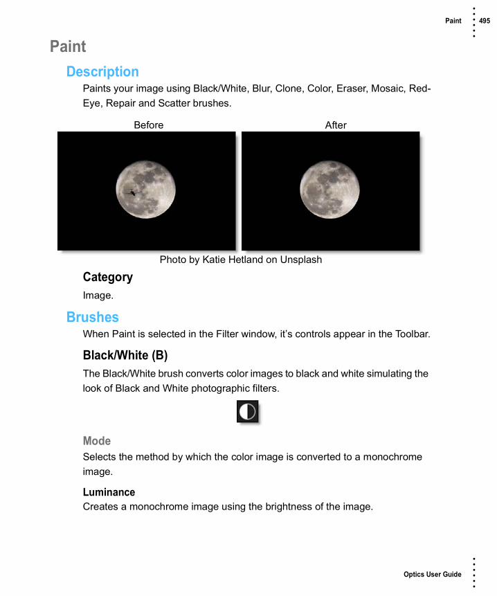
Optics User Guide
• • • •••
Paint 495 • • • •••
PaintDescription
Paints your image using Black/White, Blur, Clone, Color, Eraser, Mosaic, Red-Eye, Repair and Scatter brushes.
CategoryImage.
BrushesWhen Paint is selected in the Filter window, it’s controls appear in the Toolbar.
Black/White (B)The Black/White brush converts color images to black and white simulating the look of Black and White photographic filters.
ModeSelects the method by which the color image is converted to a monochrome image.
LuminanceCreates a monochrome image using the brightness of the image.
Before After
Photo by Katie Hetland on Unsplash

Optics User Guide
• • • •••
Paint 496 • • • •••
AverageCreates a monochrome image using the average of the red, green and blue channels.
RedSimulates a red filter in black and white photography.
GreenSimulates a green filter in black and white photography.
BlueSimulates a blue filter in black and white photography.
YellowSimulates a yellow filter in black and white photography.
OrangeSimulates a orange filter in black and white photography.
Blur (Shift+B)Blurs the image.
AmountSets the amount of blur to be applied.
Clone (C)Paints the image using another part of the image.
Using the Clone brush:1 Select the Clone brush in the Toolbar.
2 Press and hold down the Shift key.
3 Click, drag and release to set the clone offset.
The first click sets the clone source and where you drag and release is the clone destination.

Optics User Guide
• • • •••
Paint 497 • • • •••
4 Use your pen and tablet or mouse to paint with the Clone brush.
To quickly reset the clone offset:• Press shift and without moving the cursor, click your mouse or tap your pen on
the screen once.
The clone offset is quickly reset.
Nudging the Clone SourceThe Clone source can be nudged using the Arrow keys. One press of the Arrow key moves the Clone source 1 pixel. Using the Shift key in conjunction with the Arrow keys moves the Clone source 10 pixels.
Color (Shift+C)Paints the image with the current color.
ColorDisplays the currently selected color. Clicking on the Color icon opens a standard color picker.
EyedropperColors can be picked off of the screen using the eyedropper icon.
ModeSelects how color is applied to the image.
NormalThe current color is added to the image.
TintThe current color is used to tint the image by replacing hue and saturation.
HueThe current color is used to tint the image by only replacing hue.

Optics User Guide
• • • •••
Paint 498 • • • •••
LightenPixels darker than the paint color are replaced, and pixels lighter than the paint color do not change.
DarkenPixels lighter than the paint color are replaced, and pixels darker than the paint color do not change.
Eraser (E)Erases previously painted brush strokes.
Painting with the right-mouse button automatically paints with the Eraser brush.
Mosaic (Shift+M)Divides the picture up into square tiles.
SizeControls the size of the square tiles. A small size value will create many square tiles.
Red-Eye (R)Removes red-eye.
To remove red-eye:1 Select the Red-Eye brush in the Toolbar.

Optics User Guide
• • • •••
Paint 499 • • • •••
2 Use Ctrl(Win) or Cmd(Mac) and drag in or out to size the brush to roughly match the size of the red pupil.
3 Paint in the area of the red pupil being careful not to paint on any skin areas.
Repair (Shift+R)Paints the image with the color level sampled at the beginning of each stroke.
Scatter (S)Scatters pixels in a random fashion.
RadiusSets the amount of scattering.
Brush SettingsCustomize your brush using the following settings:

Optics User Guide
• • • •••
Paint 500 • • • •••
ProfileThe profile setting controls the shape of the brush.
CircleThe brush profile is set to a circular shape.
SquareThe brush profile is set to a square shape.
SizeSets the size of the brush.
To set the brush size:1 Click and drag on the Brush Size number field.
or
2 Click on the Brush Size number field, enter a value and hit Enter.
or
3 Resize the brush in the Viewer by holding Ctrl/Cmd and dragging in or out.
SoftnessSets the brush softness.
To set the brush softness:1 Click and drag on the Brush Softness number field.
or
2 Click on the Brush Softness number field, enter a value and hit Enter.

Optics User Guide
• • • •••
Paint 501 • • • •••
OpacitySets the brush opacity.
To set the brush opacity:1 Click and drag on the Brush Opacity number field.
or
2 Click on the Brush Opacity number field, enter a value and hit Enter.
Paint Keyboard ShortcutsShortcut Action
B Selects the Black/White brush
Shift+B Selects the Blur brush
C Selects the Clone brush
Shift+C Selects the Color brush
E Selects the Eraser brush
Shift+M Selects the Mosaic brush
R Selects the Red-Eye brush
Shift+R Selects the Repair brush
S Selects the Scatter brush
Ctrl/Cmd+drag Sizes the brush
[ ] Sizes the brush
Shift with clone brush Sets the clone offset
Shift+click or tap Resets the clone offset
Arrow keys Moves the Clone source by 1 pixel
Shift+Arrow keys Moves the Clone source by 10 pixels
Hold down Arrow keys Moves the Clone source continuously
Right-mouse drag Paints with the Eraser brush

Optics User Guide
• • • •••
S_ParallaxStrips 502 • • • •••
S_ParallaxStripsDescription
Applies a collection of 3d refracting glass strips to break up the image, while the image is shifted within each strip.
The S_ParallaxStrips filter comes from the Emmy award winning Boris FX Sapphire filter set.
CategoryStylize.
ControlsPresetsTo select a preset, pick one from the Presets window.
Manual AmountControls the strength of the effect.
Ensure Full CoverageAdjusts the number of strips to the minimum needed to fully cover the frame.
N StripsNumber of strips.
Before After
Photo by Alex Simon on Unsplash

Optics User Guide
• • • •••
S_ParallaxStrips 503 • • • •••
SizeSize of the strips.
Rel HeightHeight of the strips relative to their width. Increase to make the strips taller.
Size Vary X & YIncrease to make each strip randomly larger or smaller.
AngleAngle of the strips with 0 being horizontal. The strips move along their angle, and also shift the image along the same angle.
DepthMake the front most strips larger so it appears they're in front, simulating a 3d look.
Shift AmountSets how much the image shifts, or refracts, within each strip. Shifting is always along the major axis of the strip.
Shift VaryIncrease to make the amount of shift in each strip more random.
All Strips Shift X & YMove all strips around on the screen.
Z DistZoom in or out on the image before applying the parallax strips.
ShowShow the effect result, or the strips themselves, which is useful during effect setup.
ResultShow the result of the effect.

Optics User Guide
• • • •••
S_ParallaxStrips 504 • • • •••
Strips Over SourceShow each strip as a gray rectangle with brightness set by depth. Uncovered areas display the original image.
Strips Over BlackShow each strip as a gray rectangle with brightness set by depth. Uncovered areas display as black.
WrapDetermines the method for accessing outside the borders of the image.
NoProduces black beyond the borders.
TileRepeats a copy of the image.
ReflectRepeats a mirrored copy. Edges are often less visible with this method.
SeedUsed to initialize the random number generator. The actual seed value is not significant, but different seeds produce different results and the same value should give a repeatable result.

Optics User Guide
• • • •••
Particle Illusion 505 • • • •••
Particle IllusionDescription
Particle Illusion is an easy-to-use, powerful, particle generator that creates photorealistic particle effects such as fire, fireworks, explosions, sparks, smoke, fog, dust, water, clouds, rain, snow, trails, sci-fi elements and heads up displays.
CategoryParticle Illusion. This category contains the following preset groups: Complete, Sampler, Abstract, Background, Dust-Fog, Emitters-2020, Emitters-2020.5, Emitters-2021, Emitters-2021.5, Emitters-2022, Explosions, Fire, Fireworks, HUD-UI, Magic, Misc, Nature, Sci-Fi, Smoke, Snow, Space, Sparkles, Trails, Tunnels, Water
ControlsPresetsTo select a preset, pick one from the Presets window.
Launch Particle IllusionComprehensive editing of particles takes place in the Particle Illusion user interface. However, you can select particle presets directly in Optics and use the subset of parameters below to perform common tasks without entering Particle Illusion.
Before After
Photo by William Farlow on Unsplash

Optics User Guide
• • • •••
Particle Illusion 506 • • • •••
For more information on Particle Illusion, see the Particle Illusion User Guide
Note: There are only three libraries installed in the Particle Illusion interface by default: the Sampler library, the Emitters_202X library of new emitters for this release and an editable Custom library. To get the full set of additional emitter libraries, select Download Emitters from the Help menu.
CompositeComposite StyleParticle Illusion can be applied using a variety of Blend modes.
Direct (Classic)Composites the particles directly over the source image.
OpacityThe opacity of the particles.
Tint ColorSets the tint color.
Tint StrengthSets the tint strength.
Alpha + Apply ModeProvides a wide variety of Blend modes to add particles to the source image.
OpacityThe opacity of the particles.
Apply ModeSelects the Blend modes used to add particles to the source image.
Apply MixThe opacity of the Blend mode.
BrightnessSets the brightness.
ContrastSets the contrast.
GammaSets the gamma.

Optics User Guide
• • • •••
Particle Illusion 507 • • • •••
Tint ColorSets the tint color.
Tint StrengthSets the tint strength.
Apply GradeCompositionApplies the brightness, contrast and gamma adjustments to the entire composition.
Particles OnlyApplies the brightness, contrast and gamma adjustments to just the particles.
TransformsDetermines how transforms are applied.
NoneNo transforms are applied.
WorldTransforms the camera position.
EmitterTransforms the emitter position.
World + EmitterTransforms both camera and emitter positions simultaneously.
World TransformWorld CenterThe horizontal and vertical position of the particles when Transform is set to World or World + Emitter.
Master ScaleScales the particles.
Scale XThe horizontal scale amount.

Optics User Guide
• • • •••
Particle Illusion 508 • • • •••
Scale YThe vertical scale amount.
RotateRotates the particles.
Emitter OffsetThe horizontal and vertical position of the particles when Transform is set to Emitter or World + Emitter.
Particle PropertiesEdit select native Particle Illusion parameters without having to open the PI interface.
Frames to PreloadSets the number of frames that the emitter will run before the first frame in the particle sequence, allowing it to have many particles visible at the start instead of starting from zero particles.
LifeThe particle lifetime.
NumberThe number of particles.
SizeThe size of the particles.
VelocityThe speed of the particles.
WeightThe weight of particles.
SpinThe rotation of the particles.
Motion RandomnessThe randomness of the particle motion.

Optics User Guide
• • • •••
Particle Illusion 509 • • • •••
ZoomZooms the particles in or out.
Random SeedRandomizes the particles. Changing this value by any amount will result in a different pattern of particles and is the easiest way to get a new version of the effect.
Motion BlurWhen enabled, particles are drawn with motion blur. This enhances realism, especially for fast-moving particles.
PI SettingsThe Motion blur settings form the Particle Illusion interface are used.
Force OnForces motion blur on.
Force OffForces motion blur off.
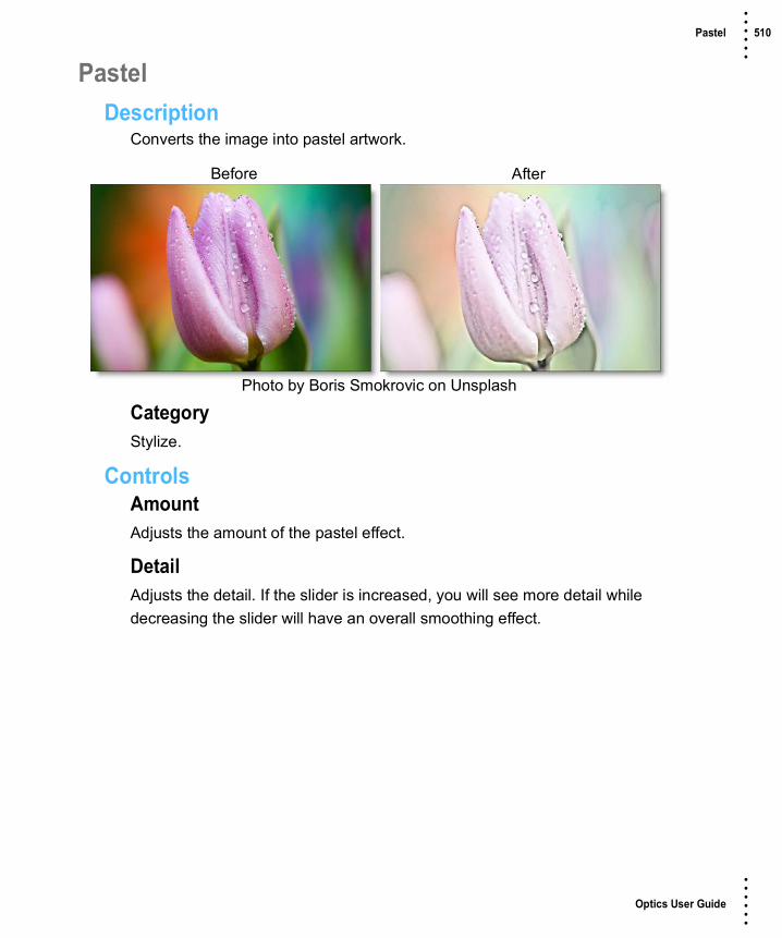
Optics User Guide
• • • •••
Pastel 510 • • • •••
PastelDescription
Converts the image into pastel artwork.
CategoryStylize.
ControlsAmountAdjusts the amount of the pastel effect.
DetailAdjusts the detail. If the slider is increased, you will see more detail while decreasing the slider will have an overall smoothing effect.
Before After
Photo by Boris Smokrovic on Unsplash

Optics User Guide
• • • •••
Pencil 511 • • • •••
PencilDescription
Pencil converts your image to a pencil sketch.
CategoryStylize.
ControlsPresetsTo select a preset, pick one from the Presets window.
AmountSets the intensity of the pencil effect.
ColorThe Color parameter sets the color of the pencil effect through the use of a standard color picker.
BackgroundMixes in the original image.
Before After
Photo by Ludde Lorentz on Unsplash

Optics User Guide
• • • •••
Photographic 512 • • • •••
PhotographicDescription
The most complete line of Kodak® filters for photographic uses is available in the form of gelatin films and are known as Wratten® Gelatin Filters. Our Photographic filter is a digital equivalent of the Wratten set and were created using the spectral transmission curves for each optical filter. The Color Conversion, Light Balancing and Color Compensating preset groups are subsets of the Photographic filters.
PhotographicDigital versions of the complete line of Kodak® Wratten® Gelatin Filters.
Color ConversionColor Conversion filters correct for significant differences in color temperature between your light source and recording media.
Light BalancingLight Balancing filters correct for minor differences in color temperature between your light source and recording media.
Color CompensatingColor Compensating filters control color by attenuating specific parts of the spectrum. They can be used to make changes in color balance or compensate for deficiencies in the image’s spectral quality.
Before After
Photo by Paul Morris on Unsplash

Optics User Guide
• • • •••
Photographic 513 • • • •••
CategoryGrads/Tints.
ControlsPresetsTo select a preset, pick one from the Presets window. If you would like to view presets from a different category, use the pop-up menu at the top left of the Presets window.
ColorColorThe Color parameter sets the color of the filter through the use of a standard color picker.
OpacitySets the opacity of the color filter.
Preserve HighlightsPreserves the white areas of the image.
Exposure CompensationExposure Compensation adds back the brightness loss as a result of the filter application.
Grad These filters can optionally use a gradient that limits where the filter is applied. Grad is the transition area between the colored portion and the original image. Its direction, corners and size can be adjusted. Go to the Grad section of Common Filter Controls to see how the Grad controls work.

Optics User Guide
• • • •••
Pin Warp 514 • • • •••
Pin WarpDescription
Pin Warp warps specific image areas using pins, while leaving other areas untouched using tacks. Adjustments can range from subtle nip and tucks to something more obvious like repositioning an arm or leg.
CategoryLens/Distort.
ControlsPinsA total of 20 pins can be added to an image. Pins have a source (green circle) and target (red circle). The farther the target is dragged from the source, the more the image warps.
Creating Pins• Click+drag on the image and the next disabled pin number is automatically set
and enabled.
or
• Click the pin number’s Enable checkbox and the pin Source and Target points appear in the center of the screen.
Before
Photo by Tim Easley on Unsplash
After

Optics User Guide
• • • •••
Pin Warp 515 • • • •••
TacksTacks are used to constrain the warp. A tack is just a pin with the same source and target position.
Creating Tacks:• Click+release on the image and the next disabled pin number is automatically set
and enabled.
EnableEnables the pin. Once enabled, the pin Source and Target points appear in the center of the screen.
Source X/YThe source (start) pin point.
Target X/YThe target (end) pin point.
StrengthThe strength of the warp effect. Decreasing the Strength virtually moves the target toward the source position without having to move the target.
Source
Target
Tack

Optics User Guide
• • • •••
Pin Warp 516 • • • •••
RadiusDetermines the area to be warped. Drag the Radius to adjust it or Shift+drag to adjust all pin radii at once.
Pin Warp Keyboard Shortcuts
Shortcut Action
Click+drag on image Creates a pin
Click+release on image Creates a tack
Click+drag pin source or target Moves the pin source or target
Shift+drag pin source or target Moves both the pin source and target
Shift+drag pin radius Adjusts all pin radii
Hover over Pin Displays the pin number

Optics User Guide
• • • •••
Polarizer 517 • • • •••
PolarizerDescription
PolarizerThe greatest use of polarizing filters is to achieve a darkened, deep blue sky. Our digital version of the Polarizer is designed to do just that. Through the use of a matte and an adjustable gradient, the color of the sky can be adjusted.
Warm PolarizerCombines the benefits of the Polarizer with a warming filter making it ideal for portraits and scenics.
CategoryColor.
Before After
Photo by Takahiro Sakamoto on Unsplash
Before After
Photo by Takahiro Sakamoto on Unsplash

Optics User Guide
• • • •••
Polarizer 518 • • • •••
ControlsPresetsTo select a preset, pick one from the Presets window. If you would like to view presets from a different category, use the pop-up menu at the top left of the Presets window.
SkyColor Correct controls are provided to adjust the sky.
HueRotates the hue of the sky.
SaturationAdjusts the saturation of the sky. Positive values saturate, negative values desaturate.
BrightnessAdjusts the brightness of the sky. Positive values brighten, negative values darken.
ContrastAdjusts the contrast of the sky. Positive values increase contrast, negative values decrease contrast.
Gamma Adjusts the gamma of the sky. The gamma adjustment leaves the white and black points the same and only modifies the values in-between. Positive values lighten the midtones, negative values darken the midtones.
RedAdds or subtracts red from the sky.
GreenAdds or subtracts green from the sky.
BlueAdds or subtracts blue from the sky.

Optics User Guide
• • • •••
Polarizer 519 • • • •••
TemperatureSets the color temperature of the sky. Dragging the slider to the right makes the sky cooler (bluer) and dragging the slider to the left makes the sky warmer (redder).
TemperatureApplies a warming filter to the image. Go to the Temperature section of Common Filter Controls to see how the Temperature controls work.
GradThe Polarizer can optionally use a gradient that limits where the filter is applied. For instance, if the polarization is affecting areas other than the sky, enable the Grad and adjust it to limit the areas of polarization. Go to the Grad section of Common Filter Controls to see how the Grad controls work.
MatteHueThe Polarizer isolates the sky using a matte based on a blue hue. Use the Hue eyedropper to select the exact color of the sky if you are not seeing enough polarization.
RangeIncreases or decreases the range of values in the hue matte. A low Range value indicates a narrow range of values. A high Range value indicates a large range of values included in the matte.
BlurSets the softness of the matte by using a quality blur.
Go to the Matte parameters to see how they work.
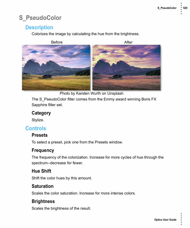
Optics User Guide
• • • •••
S_PseudoColor 520 • • • •••
S_PseudoColorDescription
Colorizes the image by calculating the hue from the brightness.
The S_PseudoColor filter comes from the Emmy award winning Boris FX Sapphire filter set.
CategoryStylize.
ControlsPresetsTo select a preset, pick one from the Presets window.
FrequencyThe frequency of the colorization. Increase for more cycles of hue through the spectrum--decrease for fewer.
Hue ShiftShift the color hues by this amount.
SaturationScales the color saturation. Increase for more intense colors.
BrightnessScales the brightness of the result.
Before After
Photo by Karsten Wurth on Unsplash

Optics User Guide
• • • •••
S_PseudoColor 521 • • • •••
Scale By SourceThe brightness of the output is scaled down by the original image brightness as this is increased to 1.
Scale By Src AmpThis amplifies the effect of Scale By Source, so if it is increased above 1, the middle grays can still retain their full brightness. It has no effect unless Scale By Source is positive.
Mix With SourceInterpolates between the result (0) and the original image (1).

Optics User Guide
• • • •••
S_QuadTone 522 • • • •••
S_QuadToneDescription
Performs an interpolation between four specified colors using the brightness of the image.
The S_QuadTone filter comes from the Emmy award winning Boris FX Sapphire filter set.
CategoryGrads/Tints.
ControlsPresetsTo select a preset, pick one from the Presets window.
Color3The color to use at the brighter image regions.
Color2The color to use at the light gray image regions.
Color1The color to use at the dark gray image regions.
Color0The color to use at the darker image regions.
Before After
Photo by Sergey Pesterev on Unsplash

Optics User Guide
• • • •••
S_QuadTone 523 • • • •••
SoftnessThe softness of the interpolation between the three colors. Use lower values for sharper contours between more solid regions of color.
Softness 23Scales the softness of the interpolation between Color2 and Color3.
Softness 12Scales the softness of the interpolation between Color1 and Color2.
Softness 01Scales the softness of the interpolation between Color0 and Color1.
Color3 At BrightThe image brightness value to replace with Color3.
Color2 At BrightThe image brightness value to replace with Color2. This value should normally be in-between the Color1 and Color3 At Bright values.
Color1 At BrightThe image brightness value to replace with Color1. This value should normally be in-between the Color0 and Color2 At Bright values.
Color0 At BrightThe image brightness value to replace with Color0.
Mix With SourceInterpolates between the result (0) and the original source (1).

Optics User Guide
• • • •••
S_RackDefocus 524 • • • •••
S_RackDefocusDescription
Generates a defocused version of the image using a 'circle of confusion' convolution. This effect is often preferable to a gaussian blur for simulating a real defocused camera lens, because bright spots can be defocused into clean shapes instead of being smoothed away.
The S_RackDefocus filter comes from the Emmy award winning Boris FX Sapphire filter set.
CategoryDiffusion/Blurs.
ControlsPresetsTo select a preset, pick one from the Presets window.
Defocus WidthThe width of the defocus.
Rel HeightThe relative height of the iris shape. If it is not 1, circles become ellipses, etc.
Before After
Photo by Gian D on Unsplash

Optics User Guide
• • • •••
S_RackDefocus 525 • • • •••
LensShapeDetermines the shape of the simulated camera iris.
CircleRound.
3 - 12 sides3 to 12 sided shapes.
Show ShapeShow the iris shape instead of the defocused image.
RoundnessModifies the shape of the simulated camera iris. A value of 1 produces a circle while 0 produces a flat−sided polygon with a number of sides defined by the Shape parameter. Less than 0 causes the sides to squeeze inward creating a star shape, while a value greater than 1 causes the corners to squeeze inward, generating a flowery shape. Roundness has no effect if Shape is set to Circle.
RotateRotates the iris shape.
BokehSoftens the outer edge of the iris shape, which creates a softer look to the defocused highlights. A negative value darkens the center of the iris shape, producing a ring−like defocus shape.
Lens NoiseIncrease to add noise to the iris shape, dirtying up the defocus. Can make the result more realistic. Turn up past 1 for a more stylistic result.
Noise FreqThe frequency of the added noise. Ignored if Lens Noise is zero.
Noise Freq Rel XThe relative horizontal frequency of the added iris noise. Increase to stretch it vertically or decrease to stretch it horizontally.
Optics User Guide
• • • •••
S_RackDefocus 526 • • • •••
Noise SeedThe seed value for the added noise.
Gauss BlurIf positive, a gaussian blur is applied which smooths out the edges of the shapes. This might also darken the highlights because Gamma is not considered in the gaussian blur.
Use GammaValues above 1 cause highlights in the image to retain their brightness after the defocus is applied.
Boost Highlights.The amount to increase the luma of the highlights in the image. Increase this parameter to blow out the highlights without affecting the darks or midtones.
Hilight ThresholdThe minimum luma value for highlights. Pixels brighter than this will be brightened according to the Boost Highlights parameter.
Chroma DistortAdds some chromatic aberration around the edges of the image. Red and blue wavelengths of light refract differently in real lenses, producing fringes of color where the rays strike the lens at oblique angles.
Color FringingColor Fringing produces rings of color around every object in the image by varying the focal distance for each color channel. It generates a different style of chromatic aberration from Chroma Distort because it's not just in the image corners.
BrightnessScales the brightness of the result.
Offset DarksAdds a gray value to the darker regions of the result. This can be negative to increase contrast.

Optics User Guide
• • • •••
S_RackDefocus 527 • • • •••
Mix With SourceInterpolates between the defocused result and the original image.
Edge ModeDetermines the behavior when accessing areas outside the image.
TransparentAreas outside the image are treated as transparent, which can produce transparency around the edges. Select this option for fastest rendering.
RepeatRepeats the last pixel outside the border of the image.
ReflectReflects the image outside the border.
Soft BordersIf enabled, transparent borders are added to the image before processing. This allows the result to include soft edges beyond the original image size. When off, the effect only occurs within the frame and the result will retain an edge at the borders.
Show Defocus WidthEnables/disables the on-screen control for adjusting the Defocus Width parameter.

Optics User Guide
• • • •••
Radial Exposure 528 • • • •••
Radial ExposureDescription
Lightens and/or darkens the center or edges of an image to correct lens vignetting.
CategoryLens.
ControlsExposureEdgesLightens or darkens the edges of the image.
CenterLightens or darkens the center of the image.
SpotA radial gradient is used to lighten or darken the edges or center of the image. Go to the Spot section of Common Filter Controls to see how the Spot controls work.
Before After
Photo by Joshua Earle on Unsplash

Optics User Guide
• • • •••
Radial Tint 529 • • • •••
Radial TintDescription
Tints the image using multi-color, radially graduated filters.
CategoryGrads/Tints.
ControlsPresetsTo select a preset, pick one from the Presets window.
Tint ModeSelects how color is applied to the image.
NormalTints the image while retaining highlights.
TintThe image is tinted by replacing hue and saturation.
HueThe image is tinted by only replacing hue.
LightenPixels darker than the color are replaced, and pixels lighter than the color do not change.
Before After
Photo by Jason Wong on Unsplash

Optics User Guide
• • • •••
Radial Tint 530 • • • •••
DarkenPixels lighter than the color are replaced, and pixels darker than the color do not change.
Color 1Sets the color for the top left quadrant of the image.
ColorSets the color through the use of a standard color picker.
OpacitySets the opacity of the color.
Color 2The Color 2 controls are the same as the controls for Color 1 except it is applied to the top right quadrant of the image.
Color 3The Color 3 controls are the same as the controls for Color 1 except it is applied to the bottom right quadrant of the image.
Color 4The Color 4controls are the same as the controls for Color 1 except it is applied to the bottom left quadrant of the image.
Radial GradSets the position, rotation and aspect ratio of the radial gradient.
PositionThere is an on-screen control in the center of the image. By clicking and dragging the on-screen control or sliders, the position of the grad can be adjusted.
SizeThe size of the grad.
RotationThe rotation of the grad.

Optics User Guide
• • • •••
Radial Tint 531 • • • •••
AspectThe aspect ratio of the grad.
HighlightsPreserve HighlightsPreserves the white areas of the image.
Exposure CompensationExposure Compensation adds back the brightness loss as a result of the filter application.
SpotA spot in the form of a radial gradient can optionally be used to control where color is added to the image. Go to the Spot section of Common Filter Controls to see how the Spot controls work.

Optics User Guide
• • • •••
Rainbow 532 • • • •••
RainbowDescription
Recreates arced rainbows of spectral colors, usually identified as red, orange, yellow, green, blue, indigo, and violet, that appear in the sky as a result of the refractive dispersion of sunlight in drops of rain or mist.
CategoryLight.
ControlsLightBlendDetermines the blend mode to be used to add the rainbow.
AddThe rainbow is combined with the image using an Add blend mode.
ScreenThe rainbow is combined with the image using a Screen blend mode. This looks kind of like the Add blend mode, but highlights are retained.
NormalThe rainbow is added to the image using a normal composite function.
AmountSets the intensity of the rainbow.
Before After
Photo by Jeremy Bishop on Unsplash

Optics User Guide
• • • •••
Rainbow 533 • • • •••
DisplacementDisplaces the rainbow by the luminance values of the image. This “fakes” the effect of the rainbow wrapping over objects in the image.
BlurSets the softness of the rainbow.
RainbowBlendThe rainbow can be added to the entire image or limited to a matte.
Rainbow OnlyThe rainbow is added to the entire image.
MatteThe rainbow is added only in areas of the matte.
PositionThe rainbow position can be adjusted by clicking and dragging the on-screen control or sliders.
RadiusThe size of the rainbow.
AspectSets the aspect ratio of the rainbow. Positive values stretch the rainbow horizontally and negative values stretch it vertically.
ThicknessSets the thickness of the rainbow’s bands.
CropOffsetThe rainbow is cropped based on the Offset value. The higher the value, the more rainbow you see. A value of -100 shows no rainbow at all while 100 displays a complete 360 degree rainbow.
AngleSets the angle of the crop.

Optics User Guide
• • • •••
Rainbow 534 • • • •••
SoftnessSets the softness of the crop’s edge.
MatteA matte can be used to limit where the rainbow will be placed. Wherever there is white in the matte is where the rainbow will be added. Go to the Matte parameters to see how they work.
Note: To use a matte to limit where the rainbow will be added, Rainbow > Blend must be set to Matte.
AlphaRainbow Under SourceComposites the image over the rainbow.

Optics User Guide
• • • •••
S_Rays 535 • • • •••
S_RaysDescription
Generates beams of light emitting from the bright areas of the image.
The S_Rays filter comes from the Emmy award winning Boris FX Sapphire filter set.
CategoryLight.
ControlsPresetsTo select a preset, pick one from the Presets window.
ModeSelects between light and dark rays.
Light RaysGenerates beams of light emitting from the bright areas of the source.
Dark RaysGenerates beams of darkness emitting from the dark areas of the source.
CenterThe location from which the rays beam outwards.
Before After
Photo by Filipe Dos Santos Mendes on Unsplash

Optics User Guide
• • • •••
S_Rays 536 • • • •••
Rays LengthThe length of the rays. A length of 1 gives rays that continue forever, although they may still fade out as they go. To make the rays look longer, you can also increase the Bias Outer Bright parameter. If Rays Length is negative, the rays can beam inwards instead of outwards. Please note that processing times increase for longer rays.
Length RedThe relative length of the red channel of the rays. Adjust this, along with Length Green and Length Blue, to create color fringing effects.
Length GreenThe relative length of the green channel of the rays.
Length BlueThe relative length of the blue channel of the rays.
Reverse RaysExtend rays inward as well as outward. The length of the reversed rays is controlled by Rays Length as well as this parameter.
Rays BrightnessScales the brightness of the ray beams.
Blur RaysBlurs the rays.
Blur Rays Rel X & YThe relative horizontal and vertical blur widths applied to the rays.
Rays ColorScales the color of the ray beams.
Bias Outer BrightDetermines the variable amount of brightness along the rays. This is normally near 0 so the rays fade away at their outer ends, 0.5 causes equal brightness along the rays, and 1 causes maximum brightness at the ends.

Optics User Guide
• • • •••
S_Rays 537 • • • •••
Rays ResSelects the resolution factor for the rays. Higher resolutions give sharper rays, lower resolutions give smoother rays and faster processing. This 'Res' factor only affects the rays: the background is still combined with the rays at full resolution.
FullFull resolution is used.
HalfThe rays are calculated at half resolution.
QuarterThe rays are calculated at quarter resolution.
ThresholdRays are generated from locations in the image that are brighter than this value. A value of .9 creates rays at only the brightest spots, while a value of 0 creates rays for every non−black area.
Threshold Add ColorThis can be used to raise the threshold on a specific color and thereby reduce the rays generated on areas of the image containing that color.
ShimmerShimmer AmpModulates the ray source image with this amount of noise texture to give the rays a shimmering look.
Shimmer FreqThe frequency of the shimmer texture. Increase for a finer grained shimmer effect or decrease for a larger, softer shimmer. This has no effect unless Shimmer Amp is positive.
Shimmer SeedUsed to initialize the random number generator for the shimmer texture. The actual seed value is not significant, but different seeds produce different results and the same value should give a repeatable result.

Optics User Guide
• • • •••
S_Rays 538 • • • •••
Shimmer Shift X & YTranslation of the shimmer texture. This has no effect unless Shimmer Amp is positive.
AtmosphereAtmosphere AmpAtmosphere gives the effect of rays shining through a dusty atmosphere and picking up light or getting shadowed. This parameter adjusts the amount, or amplitude, of the atmospheric effect. A value of 0 creates smooth rays while higher values give a more dusty look.
Atmosphere FreqControls the spatial frequency of the atmospheric noise. Turn this up higher to get finer details or turn down for broader overall variation.
Atmosphere DetailControls the amount of fine detail in the atmosphere simulation. Decrease to get smoother atmosphere or increase for a more crunchy, grainy look.
Rays From AlphaThe rays are generated from the alpha channel instead of the RGB channels. In this case, the rays will not use color from the image and will typically be brighter. Values between 0 and 100 interpolate between using the RGB and the alpha.
Rays Under SourceSet to 1 to composite the image over the rays.
Source OpacityScales the opacity of the image when combined with the rays. This does not affect the generation of the rays themselves.
Use Source ChromaIf this is 1, the chroma of the image affects the chroma of the resulting rays. If it is 0, only the brightness of the image affects the brightness of the rays and the rendering speed should also be faster. Values between 0 and 1 interpolate between these two options.
Show CenterEnables/disables the on-screen control for adjusting the Center and Rays Length parameters.

Optics User Guide
• • • •••
Reflector 539 • • • •••
ReflectorDescription
One of the oldest and still most popular means of lighting an exterior set is by taking a reflective surface and redirecting sunlight or artificial light exactly where it is needed. Unfortunately, it is nearly impossible for actors to keep their eyes open when looking into a reflector, resulting in squinting eyes. Our silver and gold reflectors allow you to add white or gold light into shadow areas without the squinting.
CategoryLight.
ControlsPresetsTo select a preset, pick one from the Presets window. If you would like to view presets from a different category, use the pop-up menu at the top left of the Presets window.
BrightnessSets the intensity of the reflector.
Before After
Photo by Alexandre Chambon on Unsplash

Optics User Guide
• • • •••
Reflector 540 • • • •••
ColorThe Color parameter sets the color of the reflector through the use of a standard color picker. The default color is gold for Gold Reflector and white for Silver Reflector.
PositionSelects the shadow values that will be adjusted with the Brightness slider.
RangeControls the range of shadow values that will be adjusted with the Brightness slider.
Go to the Matte section of Common Filter Controls to see how the Position and Range controls work.

Optics User Guide
• • • •••
ReLight 541 • • • •••
ReLightDescription
Light can be added to a scene where none existed before. A complete set of light source controls allow you to adjust the light just as you would at the time of shooting.
CategoryLight.
LightBlendDetermines the blend mode to be used to add the light.
AddThe light is added to your image.
ScreenThe light is combined with the image using a Screen blend mode. This looks kind of like the Add blend mode, but highlights are retained.
Before After
Photo by Blake Lisk on Unsplash

Optics User Guide
• • • •••
ReLight 542 • • • •••
BrightnessSets the intensity of the light.
DisplacementDisplaces the light source by the luminance values of the image. This “fakes” the effect of light wrapping over objects in the image.
BlurSets the softness of the light.
GelsPhotographers, cinematographers and lighting designers use colored filters or gels in front of lights. Whatever mood you wish to create, we have the colors needed to achieve the effect. Select one of the Gels presets from the pop-up menu.
ColorSets the color of the light through the use of a standard color picker.
Light SourceBlendThe light source can be added to the matte using a variety of Blend modes. Go to Blend Modes for explanations of the various modes.
I like the Multiply blend mode for combining the light source with the matte because it only puts the light source within the areas of the matte.
OpacitySets the opacity of the light source.
AspectThe aspect ratio of the light source.
RadiusThe un-blurred radius of the light source.
Falloff RadiusThe blurred edge radius.

Optics User Guide
• • • •••
ReLight 543 • • • •••
FalloffMoves the falloff towards the light centerpoint.
InvertInverts the light source.
TransformTransform your light pattern using Position, Scale, Rotate, Corner-Pin, Shear and Crop controls. Go to the Transform section of Common Filter Controls to see how the Transform Controls work.
MatteA matte can be used to limit the area of added light. Wherever there is white in the matte is where the light will be added. When using ReLight, it is usually helpful to blur the matte. Go to the Matte parameters to see how they work.
Note: Light Source > Blend must be set to something other than Shape Only for the Matte controls to be active.

Optics User Guide
• • • •••
S_RomanTile 544 • • • •••
S_RomanTileDescription
Generates a mosaic pattern.
The S_RomanTile filter comes from the Emmy award winning Boris FX Sapphire filter set.
CategoryStylize.
ControlsPresetsTo select a preset, pick one from the Presets window.
Tile SizeThe width of an individual tile.
Tile ShapeDetermines the shape of the tiles.
SquareFour-sided tiles.
HexagonSix-sided tiles.
Before After
Photo by Peyne Francois on Unsplash

Optics User Guide
• • • •••
S_RomanTile 545 • • • •••
Vary ShapeControls the variation of the tile shape. Set to 0 for regularly shaped tiles. Set to 1 for randomly shaped tiles.
Tile Edge SharpnessHow sharp to make the 3d lighting roll off on the edge of the tile. Set to 1 for a very sharp tile edge. Set to a lower number for a softer, more curved tile.
Tile Texture FreqControls the coarseness of the tile’s bumpy texture.
Tile RoughnessThe height of the bumpy texture on the tiles.
Tile HeightThe strength of the lighting on the edge of the tiles.
Tile OpacityThe opacity of the tiles. Set to 0 to show the image. Set to 1 to show only the tile.
Cracked TilesHow likely a tile is to crack along edges in the image. Set to 0 to get no cracked tiles. Set to 1 to see tiles with detectable edges crack. At .5 only tiles with strong edges will crack. Tiles with a very slow gradient will never crack.
Smooth ColorsControl the variation in the color palette. Increase to make only very sharp image edges change tile colors.
Edge AttractHow strongly the corners of the tiles should attract to the edges in the image.
GroutGrout ColorThe color of the grout between the tiles.

Optics User Guide
• • • •••
S_RomanTile 546 • • • •••
Grout WidthThe width of the grout between the tiles as a percentage of the tile size.
Grout Texture FreqControls the coarseness of the grout’s bumpy texture.
Grout RoughnessThe height of the bumpy texture in the grout.
Grout OpacityThe opacity of the grout between the tiles. Set to 0 to show the image. Set to 1 to show only the grout.
LightLight BrightnessThe tiles are lit with a 3d point light source. This parameter sets the brightness of that light. Set to 0 to disable the light. Increase this value to increase the intensity of the light.
Light ColorThe color of the light.
Light ZThe height of the light source.
Bg BrightnessScales the brightness of the image before combining it with the tiles. If 0, the result will contain only the tile image over black.
SeedUsed to initialize the random number generator. The actual seed value is not significant, but different seeds produce different results and the same value should give a repeatable result.
Show Light PositionEnables/disables the on-screen control for adjusting the Light Position parameter.

Optics User Guide
• • • •••
Selective Color Correct 547 • • • •••
Selective Color CorrectDescription
Colors can be selectively isolated through the use of a matte and adjusted using hue, saturation, brightness, gamma, contrast, temperature, cyan/magenta, red, green, and blue controls.
CategoryColor.
Color CorrectCertain parts of the image are isolated by the creation of a matte. Whatever is shown as white in the matte can be adjusted by the color controls below.
HueRotates the hue of the image.
SaturationAdjusts the saturation of the image. Positive values saturate, negative values desaturate.
BrightnessAdjusts the brightness of the image. Positive values brighten, negative values darken.
Before After
Photo by Pietro De Grandi on Unsplash

Optics User Guide
• • • •••
Selective Color Correct 548 • • • •••
ContrastAdjusts the contrast of the image. Positive values increase contrast, negative values decrease contrast.
Gamma Adjusts the gamma of the image. The gamma adjustment leaves the white and black points the same and only modifies the values in-between. Positive values lighten the midtones, negative values darken the midtones.
TemperatureSets the color of the image to be either warmer or cooler. Dragging the slider to the right makes the image cooler (bluer) and dragging the slider to the left makes the image warmer (redder).
Cyan/MagentaAdds either Cyan or Magenta to the image. Dragging the slider to the right makes the image more magenta and dragging the slider to the left makes the image more cyan.
RedAdds or subtracts red from the image.
GreenAdds or subtracts green from the image.
BlueAdds or subtracts blue from the image.
TemperatureSets the color temperature of the image. Dragging the slider to the right makes the image cooler (bluer) and dragging the slider to the left makes the image warmer (redder).

Optics User Guide
• • • •••
Selective Color Correct 549 • • • •••
MatteA matte is created to isolate areas to be color corrected. Using advanced image slicing algorithms, mattes are created using luminance, hue, saturation, average, red, green, blue, cyan, magenta, and yellow values.
Extract OnExtract On selects the type of matte. Select whichever type isolates the desired values.
A matte is created based on one of the following:
LuminanceA matte is created based on the luminance of the image.
HueA matte is created based on the hue of the image. When adjusting the Position parameter, you are selecting different hues.
Before After
Matte
Hue Matte

Optics User Guide
• • • •••
Selective Color Correct 550 • • • •••
SaturationA matte is created based on the saturation of the image.
AverageA matte is created based on the average of the image’s RGB values.
RedA matte is created based on the image’s red values.
GreenA matte is created based on the image’s green values.
BlueA matte is created based on the image’s blue values.
CyanA matte is created based on the image’s cyan values.
MagentaA matte is created based on the image’s magenta values.
YellowA matte is created based on the image’s yellow values.
PositionThe Position value pinpoints the color values to be used in the matte. For a luminance matte, a Position value of 100 would make a white matte of the highlights and a value of 0 would make a white matte of the shadows. In the flower image below, look at how the matte varies for different Position values in a red extraction. When the Position is at a value of 100, the red flowers are shown as white in the matte.
Position=100, Range=25

Optics User Guide
• • • •••
Selective Color Correct 551 • • • •••
When the Position is moved to 50, the red flowers turn black.
RangeIncreases or decreases the range of values in the matte. A low Range value indicates a narrow range of values. A high Range value indicates a large range of values included in the matte.
Black ClipBlacks in the matte are made blacker by increasing the value of the slider. As the slider value increases, more values are clipped to black. This is helpful for getting rid of unwanted gray areas in what should be the black part of the matte.
Position=50, Range=25
Position=100, Range=50
Matte with No Black Clip Black Clip=50

Optics User Guide
• • • •••
Selective Color Correct 552 • • • •••
White ClipWhites in the matte are made whiter by increasing the value of the slider. As the slider value increases, more values are clipped to white. This is helpful for getting rid of unwanted gray areas in what should be the white part of the matte.
Shrink/GrowShrinks or grows the matte. Negative values shrink and positive values grow the matte.
Matte with No White Clip White Clip=50
Original
Shrink=-2 Grow=1.5

Optics User Guide
• • • •••
Selective Color Correct 553 • • • •••
BlurBlurs the matte.
Invert• Off
Does nothing to the matte.
• On
Inverts the luminance values of the matte.
No Blur Blur=10
Invert Off Invert On

Optics User Guide
• • • •••
Selective Saturation 554 • • • •••
Selective SaturationDescription
The saturation of the image can be adjusted independently in the shadows, midtones and highlights.
CategoryColor.
ControlsPresetsTo select a preset, pick one from the Presets window.
ShadowsSaturationAdjusts the saturation of the image in the shadows. Positive values saturate, negative values desaturate.
PositionSelects the shadow values to be adjusted.
RangeControls the range of values to be used for the shadows. A higher Range value considers more values as shadows.
Before After
Photo by Oswaldo Martinez on Unsplash

Optics User Guide
• • • •••
Selective Saturation 555 • • • •••
MidtonesSaturationAdjusts the saturation of the image in the midtones. Positive values saturate, negative values desaturate.
PositionSelects the midtones values to be adjusted.
RangeControls the range of values to be used for the midtones. A higher Range value considers more values as midtones.
HighlightsSaturationAdjusts the saturation of the image in the highlights. Positive values saturate, negative values desaturate.
PositionSelects the highlight values to be adjusted.
RangeControls the range of values to be used for the highlights. A higher Range value considers more values as highlights.
Go to the Matte section of Common Filter Controls to see how the Position and Range controls work.

Optics User Guide
• • • •••
Sepia 556 • • • •••
SepiaDescription
SepiaCreates a warm brown tone for that nostalgic feeling.
CategoryGrads/Tints.
ControlsPresetsTo select a preset, pick one from the Presets window.
ColorAmountDetermines the intensity of the color added to the image.
OpacitySets the opacity of the filter.
Preserve HighlightsPreserves the white areas of the image.
Exposure CompensationExposure Compensation adds back the brightness loss as a result of the filter application.
Before After
Photo by Andrew Neel on Unsplash

Optics User Guide
• • • •••
Sepia 557 • • • •••
Grad Sepia can optionally use a gradient that limits where the filter is applied. Grad is the transition area between the colored portion and the original image. Its direction, corners and size can be adjusted. Go to the Grad section of Common Filter Controls to see how the Grad controls work.

Optics User Guide
• • • •••
Shadows/Highlights 558 • • • •••
Shadows/HighlightsDescription
Shadows/Highlights lowers contrast evenly throughout the image by brightening shadow areas and darkening highlights. It is useful for correcting dark foreground subjects due to strong backlighting as well as highlights that are slightly washed out.
CategoryColor.
ControlsPresetsTo select a preset, pick one from the Presets window.
ShadowsShadowsRaises the brightness of the shadows.
PositionSelects the shadow values to be adjusted.
RangeControls the range of values to be used for the shadows. A higher Range value considers more values as shadows.
Before After
Photo by Jonatan Pie on Unsplash

Optics User Guide
• • • •••
Shadows/Highlights 559 • • • •••
HighlightsHighlightsLowers the brightness of the highlights.
PositionSelects the highlight values to be adjusted.
RangeControls the range of values to be used for the highlights. A higher Range value considers more values as highlights.
Go to the Matte section of Common Filter Controls to see how the Position and Range controls work.

Optics User Guide
• • • •••
Sharpen 560 • • • •••
SharpenDescription
Enhances the sharpness or focus by selectively increasing the contrast between adjacent pixels along edges in an image.
CategoryImage.
ControlsPresetsTo select a preset, pick one from the Presets window.
AmountDetermines how much contrast is added at the edges.
RadiusControls the size of the edges you wish to sharpen.
ThresholdThe threshold setting is used to sharpen more pronounced edges, while leaving more subtle edges untouched. Low values sharpen more image areas while higher threshold values sharpen less.
Before After
Photo by Corentin Marzin on Unsplash

Optics User Guide
• • • •••
Silk 561 • • • •••
SilkDescription
SilkSilk softens wrinkles, blemishes and fine detail to produce smooth skin textures while retaining detail in coarse features such as the eyes, nose and mouth.
Warm SilkWarm Silk offers all the benefits of the Silk filter while adding a diffuse warm tint to the shadows.
CategoryDiffusion/Blurs.
Before After
Photo by Joe Gardner on Unsplash
Before After
Photo by Joe Gardner on Unsplash

Optics User Guide
• • • •••
Silk 562 • • • •••
ControlsPresetsTo select a preset, pick one from the Presets window. If you would like to view presets from a different category, use the pop-up menu at the top left of the Presets window.
DetailSmoothingFine image details, such as facial wrinkles and blemishes, are minimized using edge aware smoothing.
Color CorrectGo to the Color Correct filter to see how the Color Correct controls work.
MatteA matte can be used to limit the smoothing effect. Wherever there is white in the matte is where the smoothing will occur. Go to the Matte parameters to see how they work.

Optics User Guide
• • • •••
Skin Tone 563 • • • •••
Skin ToneDescription
A set of colorization filters to enhance skin tones.
CategoryGrads/Tints.
ControlsPresetsTo select a preset, pick one from the Presets window.
ColorColorThe Color parameter sets the color through the use of a standard color picker.
OpacitySets the opacity of the color filter.
Preserve HighlightsPreserves the white areas of the image.
Before After
Photo by Roksolana Zasiadko on Unsplash
Optics User Guide
• • • •••
Skin Tone 564 • • • •••
Exposure CompensationExposure Compensation adds back the brightness loss as a result of the filter application.
Grad The Skin Tone filters can optionally use a gradient that limits where the filter is applied. Grad is the transition area between the colored portion and the original image. Its direction, corners and size can be adjusted. Go to the Grad section of Common Filter Controls to see how the Grad controls work.

Optics User Guide
• • • •••
Soft Light 565 • • • •••
Soft LightDescription
Provides soft, digitally diffused and virtually shadowless light.
CategoryLight.
ControlsPresetsTo select a preset, pick one from the Presets window.
BlendDetermines the blend mode to be used to add the light.
AddThe light is added to your image.
ScreenThe light is combined with the image using a Screen blend mode. This looks kind of like the Add blend mode, but highlights are retained.
BrightnessSets the intensity of the light.
BlurSets the softness of the light.
Before After
Photo by Chris Abney on Unsplash

Optics User Guide
• • • •••
Soft Light 566 • • • •••
GelsPhotographers, cinematographers and lighting designers use colored filters or gels in front of lights. Whatever mood you wish to create, we have the colors needed to achieve the effect. Select one of the Gels presets from the pop-up menu.
ColorSets the color of the light through the use of a standard color picker.

Optics User Guide
• • • •••
S_Sparkles 567 • • • •••
S_SparklesDescription
Generates a field of sparkling glint effects.
The S_Sparkles filter comes from the Emmy award winning Boris FX Sapphire filter set.
CategoryLight.
ControlsPresetsTo select a preset, pick one from the Presets window.
FrequencyThe frequency of the sparkles. Increase to zoom out or decrease to zoom in.
DensityIncrease to add more sparkles.
SeedUsed to initialize the random number generator. The actual seed value is not significant, but different seeds produce different results and the same value should give a repeatable result.
Before After
Photo by Rhett Wesley on Unsplash

Optics User Guide
• • • •••
S_Sparkles 568 • • • •••
BrightnessScales the brightness of all the sparkles.
Brightness DetailsColorScales the color of all the sparkles.
Brightness XScales the brightness of the horizontal glint rays.
Brightness YScales the brightness of the vertical glint rays.
Brightness Diag1Scales the brightness of the diagonal rays from top right to bottom left.
Brightness Diag2Scales the brightness of the diagonal rays from top left to bottom right.
SizeScales the length of all the glint rays.
Size DetailsSize XScales the length of the horizontal glint rays.
Size YScales the length of the vertical glint rays.
Size Diag1Scales the length of the diagonal rays from top right to bottom left.
Size Diag2Scales the length of the diagonal rays from top left to bottom right.
Size RedScales the length of the red component of the rays. If the red, green, and blue sizes are equal the sparkles will be monochrome.

Optics User Guide
• • • •••
S_Sparkles 569 • • • •••
Size GreenScales the length of the green component of the rays.
Size BlueScales the length of the blue component of the rays.
Shift Start X & YTranslation offset of the result.
Bg BrightnessScales the brightness of the image before combining with the sparkles. If 0, the result will contain only the sparkles over black.
Show SizeEnables/disables the on-screen control for adjusting the size parameters.
Show Shift StartEnables/disables the on-screen control for adjusting the Shift Start parameter.

Optics User Guide
• • • •••
S_SparklesColor 570 • • • •••
S_SparklesColorDescription
Generates a field of sparkling glint effects with varying colors.
The S_SparklesColor filter comes from the Emmy award winning Boris FX Sapphire filter set.
CategoryLight.
ControlsPresetsTo select a preset, pick one from the Presets window.
FrequencyThe frequency of the sparkles. Increase to zoom out or decrease to zoom in.
DensityIncrease to add more sparkles.
SeedUsed to initialize the random number generator. The actual seed value is not significant, but different seeds produce different results and the same value should give a repeatable result.
Before After
Photo by Rhett Wesley on Unsplash

Optics User Guide
• • • •••
S_SparklesColor 571 • • • •••
BrightnessScales the brightness of all the sparkles.
Brightness DetailsColorScales the color of all the sparkles.
Color VariationScales the saturation of the sparkles. Increase for more intense colors or decrease for more subtle colors.
Brightness XScales the brightness of the horizontal glint rays.
Brightness YScales the brightness of the vertical glint rays.
Brightness Diag1Scales the brightness of the diagonal rays from top right to bottom left.
Brightness Diag2Scales the brightness of the diagonal rays from top left to bottom right.
SizeScales the length of all the glint rays.
Size DetailsSize XScales the length of the horizontal glint rays.
Size YScales the length of the vertical glint rays.
Size Diag1Scales the length of the diagonal rays from top right to bottom left.
Size Diag2Scales the length of the diagonal rays from top left to bottom right.

Optics User Guide
• • • •••
S_SparklesColor 572 • • • •••
Size RedScales the length of the red component of the rays. If the red, green, and blue sizes are equal the sparkles will be monochrome.
Size GreenScales the length of the green component of the rays.
Size BlueScales the length of the blue component of the rays.
Shift Start X & YTranslation offset of the result.
Bg BrightnessScales the brightness of the image before combining with the sparkles. If 0, the result will contain only the sparkles over black.
Show SizeEnables/disables the on-screen control for adjusting the size parameters.
Show Shift StartEnables/disables the on-screen control for adjusting the Shift Start parameter.

Optics User Guide
• • • •••
Split Field 573 • • • •••
Split FieldDescription
Split Field splits the image with a line that can be positioned, rotated and blurred. On one side of the line, the image is blurred and on the other, it is in focus.
CategoryDiffusion/Blurs.
ControlsPresetsTo select a preset, pick one from the Presets window.
BlurSets the softness of the split portion of the image.
SplitThe Split controls manipulate the position, rotation and blur of the split line.
PositionThere is an on-screen control in the center of the image. By clicking and dragging the on-screen control or sliders, the position of the split line can be adjusted.
Before After
Photo by Anthony Cantin on Unsplash

Optics User Guide
• • • •••
Split Field 574 • • • •••
RotateRotates the split line.
BlurBlurs the split line using a quality blur.

Optics User Guide
• • • •••
Split Tone 575 • • • •••
Split ToneDescription
Shadows, midtones and highlights can be individually tinted with the Split tone filter.
CategoryGrads/Tints.
ControlsShadowsOpacitySet the opacity of the tint color.
ColorThe Color parameter sets the color of the shadow tint through the use of a standard color picker.
PositionSelects the shadow values to be adjusted.
RangeControls the range of values to be used for the shadows. A higher Range value considers more values as shadows.
Before After
Photo by Aaron Burden on Unsplash

Optics User Guide
• • • •••
Split Tone 576 • • • •••
MidtonesOpacitySet the opacity of the tint color.
ColorThe Color parameter sets the color of the midtone tint through the use of a standard color picker.
PositionSelects the midtone values to be adjusted.
RangeControls the range of values to be used for the midtones. A higher Range value considers more values as midtones.
HighlightsOpacitySet the opacity of the tint color.
ColorThe Color parameter sets the color of the highlight tint through the use of a standard color picker.
PositionSelects the highlight values to be adjusted.
RangeControls the range of values to be used for the highlights. A higher Range value considers more values as highlights.
Go to the Matte section of Common Filter Controls to see how the Position and Range controls work.
Preserve HighlightsPreserves the white areas of the image.
Exposure CompensationExposure Compensation adds back the brightness loss as a result of the tinting.

Optics User Guide
• • • •••
S_SpotLight 577 • • • •••
S_SpotLightDescription
Lights the input clip using one or two spotlights. For each enabled light, the intersection of a 3D light cone with the image plane is calculated using the given light source position, aim location, and beam angle. Ambient light can also be applied to affect the entire image evenly. A wide variety of lighting shapes can be produced.
The S_SpotLight filter comes from the Emmy award winning Boris FX Sapphire filter set.
CategoryLight.
ControlsPresetsTo select a preset, pick one from the Presets window.
Light1-2Light1-2 EnableTurns the spotlight on or off.
Light1-2 BrightScales the brightness of the spotlight. This value can be made negative for a dark spotlight effect.
Before After
Photo by Steve Barker on Unsplash

Optics User Guide
• • • •••
S_SpotLight 578 • • • •••
Light1-2 ColorDetermines the color of the spotlight.
Light1-2 ZThe distance of the light source from the image plane. Decreasing this brings the light source closer to the surface and causes the direction of the beam to be more parallel to the surface which can stretch the spot into an ellipse or hyperbola shape.
Light1-2The position of this light source.
Spread Angle1-2The spread angle of the spotlight beam in degrees. Larger values open up the beam for a larger spot.
Softness1-2.Determines the amount of penumbra or the softness of the spotlight edges relative to the Spread Angle. Lower values make crisp edged shapes while higher values make softer shapes.
Falloff Power1-2Determines how much the spotlight brightness fades with distance. A value of 0 causes no fading, 1 fades the light as distance increases, and 2 fades it faster with distance. A value of 2 is correct for a physically realistic point light.
Ambient BrightThe amount of ambient light included in the entire frame. This allows parts of the image outside of the spotlights to still be visible.
Ambient ColorDetermines the color of the ambient light.
All LightsAll Lights BrightScales the brightness of all the spotlights together.

Optics User Guide
• • • •••
S_SpotLight 579 • • • •••
All Lights ColorScales the color of all the spotlights together.
All Aims Shift X & YAdds this amount to all lights Aim parameters. This can be used to easily make all lights aim at the same location.
All Shift X & YShifts the entire spotlight pattern without changing their shapes by adding this amount to all light and aim positions.
CombineDetermines how the light is combined with the image.
Lights OnlyRenders only the light.
MultThe light is multiplied by the image. This is the effect that a real light would typically have.
AddThe light is added to the image.
ScreenThe light is blended with the image using a Screen operation.
OverlayThe light is combined with the image using an Overlay function.
Show Light1Enables/disables the on-screen control for adjusting the Light1 parameter.
Show Aim1Enables/disables the on-screen control for adjusting the Aim1 parameter.
Show Light2Enables/disables the on-screen control for adjusting the Light2 parameter.

Optics User Guide
• • • •••
S_SpotLight 580 • • • •••
Show Aim2Enables/disables the on-screen control for adjusting the Aim2 parameter.
Show All Aims ShiftEnables/disables the on-screen control for adjusting the All Aims Shift parameter.

Optics User Guide
• • • •••
Star 581 • • • •••
StarDescription
User definable multi-point star patterns are generated on highlights in the image.
CategoryLight.
ControlsPresetsTo select a preset, pick one from the Presets window.
StarThe Star settings control the various qualities of the generated star patterns.
BlendDetermines the blend mode to be used when adding the stars.
AddThe stars are added to your image.
ScreenThe stars are combined with the image using a Screen blend mode. This looks kind of like the Add blend mode, but highlights are retained.
Before After
Photo by Pawel Bukowski on Unsplash

Optics User Guide
• • • •••
Star 582 • • • •••
BrightnessDetermines the brightness of the stars.
SpokesControls the number of star spokes.
SizeSets the star size.
AngleRotates the stars.
ColorSets the star color.
MatteA matte is used to create the star effect. Go to the Matte section of Common Filter Controls to see how the Matte controls work.

Optics User Guide
• • • •••
S_Streaks 583 • • • •••
S_StreaksDescription
Motion blurs the bright areas of the image into streaks defined by From and To locations. This can be used to create an extended film exposure effect or simulate soft beams of light.
The S_Streaks filter comes from the Emmy award winning Boris FX Sapphire filter set.
CategoryLight.
ControlsPresetsTo select a preset, pick one from the Presets window.
Streaks BrightnessScales the brightness of the streaks.
Exposure BiasDetermines the variable amount of exposure along the path between the From and To transformations. A value of 0 creates more exposure at the From end, .5 causes equal exposure along the path, and 1.0 generates more exposure at the To end. If you have bright spots on a dark background, a 0 value would cause the processed spots to be brighter at the From end and dark at the To end, and a 1 value would cause the opposite.
Before After
Photo by Anton Darius on Unsplash

Optics User Guide
• • • •••
S_Streaks 584 • • • •••
ThresholdStreaks are generated from locations in the image that are brighter than this value. A value of .9 creates streaks at only the brightest spots. A value of 0 generates streaks for every non−black area.
Threshold Add ColorThis can be used to raise the threshold on a specific color and thereby reduce the streaks generated on areas of the source clip containing that color.
CenterThe center of rotation and zooming. The shift values should be zero for this parameter to make sense.
From Z DistThe distance of the From transformation. This zooms about the Center location when Shift is 0. Increase to zoom out or decrease to zoom in.
From RotateThe rotation angle of the From transformation, in degrees, about the center.
From Shift X & YThe horizontal and vertical translations of the From transformation. This can be used for directional motion. If it is non−zero, the center location becomes less meaningful.
To Z DistThe 'distance' of the To transformation. Increase to zoom out or decrease to zoom in.
To RotateThe rotation angle of the To transformation, in degrees, about the center. Note that if the From and To Rotate angles are very different, the interpolation between them will become less accurate.

Optics User Guide
• • • •••
S_Streaks 585 • • • •••
To Shift X & YThe horizontal and vertical translations of the To transformation. This can be used for directional motion. If it is non−zero, the center location becomes less meaningful.
Mix Source DarksThe dark non−streaked components of the Source are scaled by this amount and added to the result. This allows combining the streaked and non−streaked versions of the image.
Mix Source BrightsThe original bright components of the image that were used to generate the streaks are scaled by this amount and added to the result. This allows combining some non−streaked bright areas of the image with the output.
Result BrightnessScales the brightness of the result.
CombineDetermines how the streaks are combined with the image.
AddAdds the streaks to the image.
ScreenPerforms a blend function which can help prevent overly bright results.
WrapDetermines the method for accessing outside the borders of the image.
NoProduces black beyond the borders.
TileRepeats a copy of the image.
ReflectRepeats a mirrored copy. Edges are often less visible with this method.

Optics User Guide
• • • •••
S_Streaks 586 • • • •••
Streaks ResSelects the resolution factor for the streaks. This is similar to the general 'Res' factor parameter, but it only affects the streaks. The original mixed with the streaks remains at full resolution. Higher resolutions have better quality while lower resolutions provide faster processing.
FullFull resolution is used.
HalfThe streaks are calculated at half resolution.
QuarterThe streaks are calculated at quarter resolution.
SubpixelIf enabled, uses a better quality but slightly slower method for rendering the streaks.
Show CenterEnables/disables the on-screen control for adjusting the Center parameter.
Show From TransfmEnables/disables the on-screen control for adjusting the From Z Dist and From Rotate parameters.
Show To TransformEnables/disables the on-screen control for adjusting the To Z Dist and To Rotate parameters.
Show From ShiftEnables/disables the on-screen control for adjusting the From Shift parameter.
Show To ShiftEnables/disables the on-screen control for adjusting the To Shift parameter.

Optics User Guide
• • • •••
Sunset 587 • • • •••
SunsetDescription
Sunset applies three photographic filters to the image which are blended together with a gradient. Presets for your favorite Color Gradient filters are provided as well as the ability to create custom colors.
CategoryGrads/Tints.
ControlsPresetsTo select a preset, pick one from the Presets window.
Color 1Sets the color for the top third of the image. Select the desired color using the color picker or choose a filter preset.
PresetsSelect one of the filters from the pop-up menu.
ColorThe Color parameter sets the color of the grad through the use of a standard color picker.
Before After
Photo by Mark Harpur on Unsplash

Optics User Guide
• • • •••
Sunset 588 • • • •••
OpacitySets the opacity of the color filter.
Color 2The Color 2 controls are the same as the controls for Color 1 except it is applied to the middle third of the image.
Color 3The Color 3 controls are the same as the controls for Color 1 except it is applied to the bottom third of the image.
HighlightsPreserve HighlightsPreserves the white areas of the image.
Exposure CompensationExposure Compensation adds back the brightness loss as a result of the filter application.
Grad Grad is the combination of the three blended tints. Its direction, corners and size can be adjusted.Go to the Grad section of Common Filter Controls to see how the Grad controls work.

Optics User Guide
• • • •••
Texture 589 • • • •••
TextureDescription
Applies textures to an image for a stylized look.
CategoryStylize.
ControlsPresetsTo select a preset, pick one from the Presets window.
AmountSets the amount of texture applied to the image.
ComplexityGenerates a more detailed, repetitive texture.
RandomizeRandomizes the texture.
Before After
Photo by Luke Braswell on Unsplash

Optics User Guide
• • • •••
Texture 590 • • • •••
TransformTransform the texture using Position, Scale, Rotate, Corner-Pin, Shear and Crop controls. Go to the Transform section of Common Filter Controls to see how the Transform Controls work.

Optics User Guide
• • • •••
S_TextureFolded 591 • • • •••
S_TextureFoldedDescription
Creates an abstract texture resembling folded cloth or liquid.
The S_TextureFolded filter comes from the Emmy award winning Boris FX Sapphire filter set.
CategoryRender.
ControlsPresetsTo select a preset, pick one from the Presets window.
FrequencyThe spatial frequency of the texture.
Frequency Rel XThe relative horizontal frequency of the texture. Increase to stretch it vertically or decrease to stretch it horizontally.
OctavesThe number of summed layers of noise. Each octave is twice the frequency and half the amplitude of the previous. A single octave creates a smooth texture. Adding octaves makes the result approach a fractal (1/f) noise texture.

Optics User Guide
• • • •••
S_TextureFolded 592 • • • •••
SeedUsed to initialize the random number generator. The actual seed value is not significant, but different seeds produce different results and the same value should give a repeatable result.
Fold AmpThe angle of the folding distortions.
Fold FreqThe frequency of the noise used for the folding distortions.
Fold OctavesThe number of noise octaves to use for the folding distortions.
Shift X & YTranslation offset of the texture. Since the texture is procedurally generated, it can be shifted with no repeating units or seams occurring.
Fold Start X & YThe offset of the folding effect.
Brightness1Scales the brightness of Color1. Increase for more contrast.
Color1The color of the brighter parts of the texture. The colors of the result are determined by an interpolation between Color0 and Color1.
Color0The color of the darker parts of the texture.
Offset0Adds this value to Color0. Decrease to a negative value for more contrast.Bg BrightnessScales the brightness of the image.

Optics User Guide
• • • •••
S_TextureFolded 593 • • • •••
CombineDetermines how the texture is combined with the source image.
Texture OnlyRenders only the texture with no Background.
MultThe texture is multiplied by the Background.
AddThe texture is added to the Background.
ScreenThe texture is blended with the Background using a screen operation.
DifferenceThe result is the difference between the texture and Background.
OverlayThe texture is combined with the Background using an overlay function.
Show ShiftEnables/disables the on-screen control for adjusting the Shift parameter.

Optics User Guide
• • • •••
S_TextureTiles 594 • • • •••
S_TextureTilesDescription
TextureTiles draws a repeating pattern of tiles. The shapes can be hexagons, triangles, diamonds, stars, or variations on those, depending on the Morph parameters.
The S_TextureTiles filter comes from the Emmy award winning Boris FX Sapphire filter set.
CategoryRender.
ControlsPresetsTo select a preset, pick one from the Presets window.
SizeThe size of each tile within its cell.
FrequencyThe spatial frequency of the tile pattern. Increase for many smaller tiles or decrease for fewer large tiles.
AngleRotates the pattern around the center point.

Optics User Guide
• • • •••
S_TextureTiles 595 • • • •••
Rel WidthSquashes or stretches the pattern.
Rel Wid Pre RotSquashes or stretches the pattern before rotating using Angle.
Shift X & YShifts the pattern and also sets the center point for rotation, Morph Radial, and Size Radial.
MorphMorph ShapesChanges the shapes of the tiles smoothly between hexagons, triangles, diamonds and stars.
Morph Grad AddChange the shape morphing across the image so the left side has one shape and the right side another.
Morph Grad AngleAngle of the morph gradient. If Morph Grad Add is zero, this has no effect.
Morph RadialMorph the shapes radially away from the center point. The shapes will be hexagons in the center smoothly becoming different toward the edges of the image.
Size Grad AddChange the shape size differently across the image.
Size Grad AngleAngle of the size gradient. If Size Grad Add is zero, this has no effect.
Size RadialChange the shape size according to the distance from the center point. Increase to make shapes smaller at the screen edge.

Optics User Guide
• • • •••
S_TextureTiles 596 • • • •••
Edge SoftnessSoftens the edges of each tile. If Softness Red/Green/Blue are not one, color fringing is produced around the edges of the tiles.
Edge Softness RGBSoftness RedRelative softness of the red channel To remove color fringing around tile edges, set Softness Red/Green/Blue to one.
Softness GreenRelative softness of the green channel To remove color fringing around tile edges, set Softness Red/Green/Blue to one.
Softness BlueRelative softness of the blue channel To remove color fringing around tile edges, set Softness Red/Green/Blue to one.
InvertInvert the pattern, swapping dark and bright areas.
Brightness1Scales the brightness of Color1. Increase for more contrast.
Color1The color of the brighter parts of the pattern. The colors of the result are determined by an interpolation between Color0 and Color1.
Color0The color of the darker parts of the pattern.
Offset0Adds this value to Color0. Decrease to a negative value for more contrast.
Bg BrightnessScales the brightness of the image.
CombineDetermines how the pattern is combined with the source image.

Optics User Guide
• • • •••
S_TextureTiles 597 • • • •••
Texture OnlyRenders only the pattern with no Background.
MultThe pattern is multiplied by the Background.
AddThe pattern is added to the Background.
ScreenThe pattern is blended with the Background using a screen operation.
DifferenceThe result is the difference between the pattern and Background.
OverlayThe pattern is combined with the Background using an overlay function.
Show FrequencyEnables/disables the on-screen control for adjusting the Frequency parameter.
Show ShiftEnables/disables the on-screen control for adjusting the Shift parameter.

Optics User Guide
• • • •••
S_Threshold 598 • • • •••
S_ThresholdDescription
Sets the color channels of the image to full on or full off using a given softness and threshold. This can be used to increase the contrast of each color channel independently.
The S_Threshold filter comes from the Emmy award winning Boris FX Sapphire filter set.
CategoryColor.
ControlsPresetsTo select a preset, pick one from the Presets window.
ThresholdThe source brightness value to use as the midpoint of the thresholding. This is often a middle gray around .5.
Threshold Add ColorRaises the thresholds on each color channel using this color. It has no effect when black.
SoftnessThe softness of the transition between full off and on. Increase for smoother transitions or decrease for sharper ones.
Before After
Photo by Andrey Grinkevich on Unsplash

Optics User Guide
• • • •••
S_Threshold 599 • • • •••
Soft Rel RedThe relative softness of the red thresholding.
Soft Rel GreenThe relative softness of the green thresholding.
Soft Rel BlueThe relative softness of the blue thresholding.
SaturationScales the color saturation. Increase for more intense colors. Set to 0 for monochrome.

Optics User Guide
• • • •••
Tint 600 • • • •••
TintDescription
Tints the entire image with a selected color using a variety of colorization modes.
CategoryGrads/Tints.
ControlsPresetsTo select a preset, pick one from the Presets window. If you would like to view presets from a different category, use the pop-up menu at the top left of the Presets window.
Black and WhiteEnableConverts the image to Black and White.
Before After
Photo by Joshua Medway on Unsplash

Optics User Guide
• • • •••
Tint 601 • • • •••
FilterThe Filter pop-up selects the type of black and white filter to be applied to your color image. Go to the Black and White section of Common Filter Controls to see how the Black and White controls work.
BrightnessAdjusts the brightness of the image. Positive values brighten, negative values darken.
ContrastAdjusts the contrast of the image. Positive values increase contrast, negative values decrease contrast.
Gamma Adjusts the gamma of the image. The gamma adjustment leaves the white and black points the same and only modifies the values in-between. Positive values lighten the midtones, negative values darken the midtones.
TintColorSets the color that the image will be colorized with. Select the desired color using the color picker.
OpacitySets the opacity of the color.
ModeSelects how color is applied to the image.
NormalTints the image while retaining highlights.
TintThe image is tinted by replacing hue and saturation.
HueThe image is tinted by only replacing hue.

Optics User Guide
• • • •••
Tint 602 • • • •••
LightenPixels darker than the color are replaced, and pixels lighter than the color do not change.
DarkenPixels lighter than the color are replaced, and pixels darker than the color do not change.
GradTint can optionally use a gradient that limits where the filter is applied. Grad is the transition area that goes from the tinted image to the original image. Its direction, corners and size can be adjusted. Go to the Grad section of Common Filter Controls to see how the Grad controls work.

Optics User Guide
• • • •••
Tone Adjust 603 • • • •••
Tone AdjustDescription
Tone Adjust approximates the appearance of high dynamic range images by adjusting the tonal values. Specifically, detail is recovered from the darker portions of the images and can optionally be denoised.
CategoryColor
ControlsAmountLightens shadows to reveal more detail. Take care not to over apply this setting and reveal image noise.
DeNoiseRemoves film grain and noise in the shadow areas.
PositionSelects the shadow values to be adjusted.
RangeControls the range of values to be used for the shadows. A higher Range value considers more values as shadows.
Before After
Photo by Sebastian Pichler on Unsplash

Optics User Guide
• • • •••
S_TriTone 604 • • • •••
S_TriToneDescription
Performs an interpolation between three specified colors using the brightness of the image.
The S_TriTone filter comes from the Emmy award winning Boris FX Sapphire filter set.
CategoryGrads/Tints.
ControlsPresetsTo select a preset, pick one from the Presets window.
Color2The color to use at the brighter image regions.
Color1The color to use at the midtone image regions.
Color0The color to use at the darker image regions.
Before After
Photo by Simon Berger on Unsplash

Optics User Guide
• • • •••
S_TriTone 605 • • • •••
SoftnessThe softness of the interpolation between the three colors. Use lower values for sharper contours between more solid regions of color.
Softness 12Scales the softness of the interpolation between Color1 and Color2.
Softness 01Scales the softness of the interpolation between Color0 and Color1.
Color2 At BrightThe image brightness value to replace with Color2.
Color1 At BrightThe image brightness value to replace with Color1. This value should normally be in between the other two.
Color0 At BrightThe image brightness value to replace with Color0.
Mix With SourceInterpolates between the result (0) and the original source (1).

Optics User Guide
• • • •••
S_TVDamage 606 • • • •••
S_TVDamageDescription
Simulates a TV with transmission and reception problems, VCR issues, and TV hardware difficulties. Simulates static, interference, ghosting, horizontal and vertical hold, hum bars, color stripes, visible scanlines, VCR fast-forward, dropouts, vignetting, orthicon, and fisheye.
The S-TV Damage filter comes from the Emmy award winning Boris FX Sapphire filter set.
CategoryStylize.
ControlsPresetsTo select a preset, pick one from the Presets window.
TimeThe effect is advanced in time.
ModeTypes of TV damage to simulate.
TVDamage ColorSimulates color TV damage.
Before After
Photo by Annie Spratt on Unsplash

Optics User Guide
• • • •••
S_TVDamage 607 • • • •••
TVDamage MonoSimulates black & white TV damage.
Reception MasterMaster control for all reception oriented artifacts: static, interference, ghosting, horizontal and vertical hold, hum bars, and color stripes. Set to 0 to get perfect reception, for example, 0 of each of the above artifacts.
Interference AmpSimulates interference from nearby electrical devices such as electric motors, cordless phones, etc. The look is a pattern of semi−regularly spaced random color dots.
Ghost AmpGhosts are copies of the image that result from multi-path distortion between the transmitter and the TV.
Horizontal HoldThis causes the image to shift horizontally in a semi−random way, simulating a TV with a bad horizontal hold circuit or a signal not strong enough to engage the horizontal hold.
Vertical HoldThis causes the image to shift vertically in a rolling motion and is normally caused by a weak signal preventing the TV from locking on.
Bars BrightnessPower line hum and other TV problems can cause rolling light and dark bars to crawl up the screen. This can also be caused by failure to synchronize a video camera to the TV output.
Color Stripes AmplitudeAnother common form of interference caused by phase shifts in the chroma signal.
Fast Forward AmountGenerates a VCR fast forward look with torn bars across the screen.

Optics User Guide
• • • •••
S_TVDamage 608 • • • •••
Tape Dropout BrightnessGenerates VCR dropouts.
Vignette DarknessVignetting is darkening of the image towards the corners and sides of the image.
StaticStatic AmplitudeScales the brightness of the static noise.
Static DensityDensity of the static. Turn up to get more static pixels or turn down to get only occasional static pixels.
Interference DetailsInterference FrequencyInterference frequency. The look is very sensitive to this parameter. Fractional values like 0.3 or 1.23 look better than integers.
Ghosting DetailsNum GhostsThe number of ghost images. Some may be to the left of the image, but most will be to the right. Some will be positive and some negative (inverted).
Negative GhostsThe fraction of the ghosts that are negative (inverted).
SpacingThe fraction of the image width over which ghost images are spread out.
Vary PositionControls the regularity of the ghost image spacing. Set to 0 for regularly spaced ghosts or set to 1 for random positioning.
ShiftShifts the ghost images to the left or right without shifting the main image.

Optics User Guide
• • • •••
S_TVDamage 609 • • • •••
BlurBlurs the ghost images without blurring the main image or any other artifacts.
Horiz. Hold DetailsH FrequencyVertical frequency of the horizontal hold waves.
H OctavesOctaves for the horizontal hold waves. Increase for spikier look or decrease for smoother waves.
Border WidthA TV signal has a black border outside the displayed area. This becomes visible when the horizontal hold isn't working. This parameter controls the width of that black border. On the other side of the border, you see another copy of the image.
Vert. Hold DetailsV FrequencyThe frequency of vertical hold.
Border HeightLike Border Width, this controls the vertical border between frames that becomes visible when vertical hold is not locked. Some static and closed captioning and timecode information will typically be visible in this border.
Border DataBrightness of the dots and lines that appear in the vertical blanking interval specified by Border Width.
Bars DetailsBar SharpnessSharpens or smooths the top and bottom edges of the main bars. Set to 0 for no main bars and you will only see the smaller bars.
Bar FrequencyThe frequency of the bars. Turn up for more thinner bars or turn down for fewer fat bars.

Optics User Guide
• • • •••
S_TVDamage 610 • • • •••
Bar1 WidthFraction of the main bar that is light and the rest is dark.
Bar2 Rel FrequencyControls the frequency of the smaller bars.
Bar2 SharpnessSharpens or smooths the top and bottom edges of the smaller bars. Set to 0 for no small bars and you will only see the main bars.
Stripe DetailsColor Frequency.Spatial frequency of the color stripes.
Color AngleAngle of the stripes.
Fast Forward DetailsFF Band FrequencyHow many fast forward bands to create.
FF Band ShiftShifts the fast forward bands up or down.
FF Band HeightThe height of each fast forward band.
Dropout DetailsDropout LengthThe average length of each dropout scanline.
Dropout Gap LengthThe average length of the gaps between the dropouts.
Dropout Y FreqThe dropouts appear on random scanlines according to a noise function with this frequency. Decrease to get a few large bands of dropouts or increase to get lots of small bands.
Optics User Guide
• • • •••
S_TVDamage 611 • • • •••
Dropout Y ThresholdIncrease to cover more of the screen with dropouts or decrease to cover less of it. If you don't see any dropouts at all on some frames, increase this parameter.
Vignette DetailsVignette RadiusDistance from the center where the vignetting starts.
Vignette Edge SoftnessThe width of the vignette's soft edge. Larger values give softer, less visible edges.
Vignette Rel HeightControls the aspect ratio of the vignette ellipse.
ScanlinesScanlinesCreates visible scanlines in the image. Increase to get more intense scanlines or set to 0 for no scanlines.
Scanlines Rel FreqRelative frequency of the TV scanlines. Increase to get more scanlines or decrease to get fewer large scanlines. Note that the number of scanlines is also controlled by the TV Pixels parameter.
OrthiconOrthiconDarkens the clip at areas around parts of the source clip that are brighter than the given threshold to simulate a 1950s orthicon TV camera look. Most useful in black & white mode.
ThresholdDarkening will occur around locations in the source clip that are brighter than this value. A value of .9 causes dark glows from only the brightest spots. A value of 0 causes glows for every non−black area.

Optics User Guide
• • • •••
S_TVDamage 612 • • • •••
Darks WidthScales the dark glow distance.
Color CorrectHue ShiftShift the color hues by this amount.
SaturationScales the color saturation. Increase for more intense colors. Set to 0 for monochrome.
Scale LightsScales the result by this gray value. Increase for a brighter result.
Offset DarksAdds this gray value to the darker regions of the result. This can be negative to increase contrast.
Tint LightsScales the result by this color thus tinting the lighter regions.
Tint DarksAdds this color to the darker regions of the result. Set this to a dark red−orange color for a negative film effect look.
Fish EyeExpands the center of the source clip as if viewed through a fish eye lens. This gives an old time slightly rounded TV look.
Tv PixelsThe number of TV pixels across the screen. Controls the size of the static, interference, scanlines, and dropouts. Lower this to simulate a lower resolution TV.
SeedUsed to initialize the random number generator. The actual seed value is not significant, but different seeds produce different results and the same value should give a repeatable result.

Optics User Guide
• • • •••
S_UltraGlow 613 • • • •••
S_UltraGlowDescription
Generates a variety of glowing light from bright areas of the image utilizing a primary as well as secondary, after glow.
The S_UltraGlow filter comes from the Emmy award winning Boris FX Sapphire filter set.
CategoryLight.
ControlsPresetsTo select a preset, pick one from the Presets win\dow.
Primary GlowBrightnessScales the brightness of all the glows.
ColorScales the color of the glows.
ThresholdGlows are generated from locations in the image that are brighter than this value. A value of 0.9 produces glows at only the brightest spots, while a value of 0 produces glows for every non−black area.
Before After
Photo by Jarin Domingue on Unsplash

Optics User Guide
• • • •••
S_UltraGlow 614 • • • •••
Threshold Add ColorThis can be used to raise the threshold on a specific color and thereby reduce the glows generated on areas of the source clip containing that color.
Glow WidthScales the glow distance. Note that a 0 glow width still enhances the bright areas. Set the brightness parameter to 0 if you want to pass the original image through unchanged.
Glow FalloffBoost or cut the distance that the glow extends.
Glow BiasAmount to grow the outskirts of the thresholded result, or shrink if negative.
Width XScales the horizontal glow width. Set to 0 for vertical only.
Width YScales the vertical glow width. Set to 0 for horizontal only.
Width RedScales the red glow width. If the red, green, and blue widths are equal, the glows will match the color of the image. If they are not equal, the glows will vary in color with distance.
Width GreenScales the green glow width.
Width BlueScales the blue glow width.
SubpixelEnables glowing by subpixel widths.
ShowSelects the type of output.
ResultShows the final result of combining the glow and image.

Optics User Guide
• • • •••
S_UltraGlow 615 • • • •••
ThresholdShows the thresholded image that is used to generate the glow.
After GlowAfter Glow WidthScales the glow distance of the secondary glow.
After Glow ColorScales the color of the secondary glow.
After Glow Stretch XScales the horizontal secondary glow width.
After Glow Stretch YScales the vertical secondary glow width.
Horizontal StreaksScales the appearance of narrow trails in the horizontal direction.
Vertical StreaksScales the appearance of narrow trails in the vertical direction.
EdgesEdge DetectEnables edge detection.
Edge CombineDetermines how the detected edges are combined with the image.
ScreenDetected edges are blended with the image using a screen operation.
AddDetected edges are added to the image.
Edges OnlyThe image is replaced with only the detected edges.
Edge SmoothIncrease for thicker and smoother edges.

Optics User Guide
• • • •••
S_UltraGlow 616 • • • •••
Edge ModeDetermines the behavior when accessing areas outside the image.
TransparentAreas outside the image are treated as transparent which can produce transparency around the edges of the image. Select this for fastest rendering.
ReflectReflects the image outside the border.
AtmosphereAtmosphere gives the effect of the glow shining through a dusty atmosphere and picking up light or getting shadowed.
AtmosphereEnables/disables the atmosphere layer.
Atmosphere AmpAdjusts the amount, or amplitude, of the atmospheric effect. 0 gives a smooth glow, higher values give more dusty look.
Atmosphere FreqControls the spatial frequency of the atmospheric noise. Turn this up to get finer details or turn down for broader overall variation.
Atmosphere DetailControls the amount of fine detail in the atmosphere simulation. Decrease to get smoother atmosphere or increase for a more crunchy or grainy look.
Atmosphere LightsScales the highlights. Increase for a more intense result.
Atmosphere DarksScales the blacks. Increase for a more subtle result.
Atmosphere SeedUsed to initialize the random number generator for the atmospheric noise. The actual seed value is not significant, but different seeds produce different results and the same value should give a repeatable result.

Optics User Guide
• • • •••
S_UltraGlow 617 • • • •••
Apply Pre-GlowCombines the atmosphere with the image prior to any glows.
HighlightsHighlightsEnables highlights using an electrical plasma texture.
Highlights FreqThe spatial frequency of the highlights. Increase to zoom out or decrease to zoom in.
Highlights Freq Rel XThe relative horizontal frequency of the highlights. Increase to stretch vertically or decrease to stretch horizontally.
Highlights OctavesThe number of octaves of highlights to include. Each octave is twice the frequency and half the amplitude of the previous.
Highlights Grad XDetermines the amplitude and direction of a gradient which orients the highlights. Increasing X makes them more vertical.
Highlights Grad YDetermines the amplitude and direction of a gradient which orients the highlights. Increasing Y makes them more horizontal.
Highlights LayersThe number of layers of highlights. Increase for a more striped effect.
Highlights ThresholdDetermines the thickness of the highlights. Increase for thinner lines or decrease for thicker and brighter ones.
Highlights BrightnessScales the brightness of the highlights.
Highlights LightsScales the highlights. Increase for a more intense result.

Optics User Guide
• • • •••
S_UltraGlow 618 • • • •••
Highlights DarksScales the blacks. Increase for a more subtle result.
Highlights BlurSoften the edges of the highlights.
CompositeCombineDetermines how the glow is combined with the image. This parameter has no effect if Light Background is set to 1.
MultThe image is multiplied by the glow.
AddThe glow is added to the image.
ScreenThe glow is blended with the image using a screen operation.
DifferenceThe result is the difference between the glow and the image.
OverlayThe glow is combined with the image using an overlay function.
Glow From AlphaGenerate glows from the alpha channel instead of the RGB channels. In this case, the glows will not pick up color from the image and will typically be brighter. Values between 0 and 1 interpolate between using the RGB and the alpha.
Glow Under SourceComposites the image over the glows.
Light BackgroundIncrease this to give a look of the glow casting light onto the background image. To see this more clearly, you can lower the Scale Background parameter or raise the Brightness parameter.

Optics User Guide
• • • •••
S_UltraGlow 619 • • • •••
Source OpacityScales the opacity of the image when combined with the glows. This does not affect the generation of the glows themselves.
Expand BordersIf enabled, transparent borders are added to the image before processing. This allows the result to include soft edges beyond the original image size. When off, the effect only occurs within the frame and the result will retain an edge at the borders.
Show Glow WidthEnables/disables the on-screen control for adjusting the Glow.

Optics User Guide
• • • •••
S_UltraZap 620 • • • •••
S_UltraZapDescription
Generates lightning bolts along a spline and renders them over a background with added UltraGlow options.
The S_UltraZap filter comes from the Emmy award winning Boris FX Sapphire filter set.
CategoryRender.
ControlsPresetsTo select a preset, pick one from the Presets window.
TimeThe effect is advanced in time.
Control PointsStart PointThe starting point of the bolts.
Point 1 EnableEnables Point 1.
Before After
Photo by Brandon Morgan on Unsplash

Optics User Guide
• • • •••
S_UltraZap 621 • • • •••
Control Point 1First control point.
Point 2 EnableEnables Point 2.
Control Point 2Second control point.
Point 3 EnableEnables Point 3.
Control Point 3Third control point.
Point 4 EnableEnables Point 4.
Control Point 4Fourth control point.
End PointThe end point of the bolts
Bolt StructureBoltsThe number of lightning bolts to draw between the Start and End location.
Bolt WidthThe width of the lightning bolts.
Bolt LengthThe length of the lightning bolts. If less than 1, the bolts will not be drawn all the way from start to end.
Wrinkle AmpScales the amount of wrinkles in the bolts. Decrease for straighter, smoother bolts or increase for more kinky bolts.
Optics User Guide
• • • •••
S_UltraZap 622 • • • •••
Curve AmpSimilar to Wrinkle Amp but affects the general path of the bolt. If decreased, the bolt will stay closer to the line between the Start and End points. If increased, it can wander further away from this line. This differs from the Wrinkle Amp parameter in that it can be used to make straighter bolts while still keeping the wrinkles at the detailed level.
Taper StartDetermines how pointed the start of the bolts are. If 0, the entire bolt will have equal width. If 1, the bolts will thin out along their entire length for a pointed end. If it is .5, the bolts will start thin and grow to the width parameter at the center of the bolt.
Taper EndDetermines how pointed the end of the bolts are. If 0, the entire bolt will have equal width. If 1, the bolts will thin out along their entire length for a pointed end. If it is .5, the bolts will start thinning out halfway between the start and end points.
Feather BoltAdd softness to the bolt before glowing.
Zap Edge BlurOnly blur the edges of the zap. This is useful if there is noise on the zap.
Zap BrightnessScales the brightness of the lightning bolts.
Start ColorThe color at the start of the main bolt.
End ColorThe color at the tip of the main bolt.
Vary Bolt HueThis varies the start and end color between multiple bolts. This does not change the color along a single bolt.

Optics User Guide
• • • •••
S_UltraZap 623 • • • •••
Vary WidthThe amount of random variation in the width of the bolts along their lengths.
Vary EndpointOffsets the End location by a random amount within a circle of this radius. If Bolts is greater than 1, this can be useful to spread out the different End points. For example, you can create multiple radiating bolts by increasing this radius and placing the End point near the Start point.
Random SeedUsed to initialize the random number generator. The actual seed value is not significant, but different seeds produce different random lightning bolts and the same value should give a repeatable result.
Bolt AnimationStart OffsetThe offset from the start point of where bolts are drawn.
Bolt NoiseApplies a noise pattern to the bolt before the glow.
Bolt Noise FreqThe frequency of the bolt noise.
Bolt BranchinessBranches OnlyHides the core bolt and only shows the branches.
BranchinessScales the number of additional bolts that branch from the main bolt. Set this to 0 for basic bolts with no extra branches.
Branch AngleThe maximum angle of the random branches relative to the bolt they are branching off of. If this is 0, the branches will be more lined up with the main bolt. With larger values, the branches will be more perpendicular to the main bolt.

Optics User Guide
• • • •••
S_UltraZap 624 • • • •••
Branch LengthThe scaled length of the branches relative to the distance between the Start and End points.
Branch ColorThe color at the tips of the branches.
Vary Branch HueVaries the end color between multiple branches.
Branch StyleSpecifies how the branch width should be calculated.
Width Uses DistBranch width is calculated based on how far along the bolt the branch splits off.
Width Uses Bolt WidthBranch width is calculated based on how wide the bolt is at the point where the branch splits off.
Branch WidthWidth of branches relative to the main bolt.
Secondary Bolt StructureSecondary BoltsThe number of lightning bolts to draw between the Start and End location.
Secondary Bolt WidthThe width of the lightning bolts.
Secondary LengthThe length of the lightning bolts. If less than 1, the bolts will not be drawn all the way from start to end.
Secondary Wrinkle AmpScales the amount of wrinkles in the bolts. Decrease for straighter, smoother bolts or increase for more kinky bolts.

Optics User Guide
• • • •••
S_UltraZap 625 • • • •••
Secondary Curve AmpSimilar to Wrinkle Amp but affects the general path of the bolt. If decreased, the bolt will stay closer to the line between the Start and End points. If increased, it can wander further away from this line. This differs from the Wrinkle Amp parameter in that it can be used to make straighter bolts while still keeping the wrinkles at the detailed level.
Secondary Taper StartDetermines how pointed the start of the bolts are. If 0, the entire bolt will have equal width. If 1, the bolts will thin out along their entire length for a pointed end. If it is .5, the bolts will start thin and grow to the width parameter at the center of the bolt.
Secondary Taper EndDetermines how pointed the end of the bolts are. If 0, the entire bolt will have equal width. If 1, the bolts will thin out along their entire length for a pointed end. If it is .5, the bolts will start thinning out halfway between the start and end points.
Secondary BrightnessScales the brightness of the lightning bolts.
Secondary Start ColorThe color at the start of the main bolt.
Secondary End ColorThe color at the tip of the main bolt.
Secondary Vary Bolt HueThis varies the start and end color between multiple bolts. This does not change the color along a single bolt.
Secondary Vary WidthThe amount of random variation in the width of the bolts along their lengths.
Optics User Guide
• • • •••
S_UltraZap 626 • • • •••
Secondary Vary EndpointOffsets the End location by a random amount within a circle of this radius. If Bolts is greater than 1, this can be useful to spread out the different End points. For example, you can create multiple radiating bolts by increasing this radius and placing the End point near the Start point.
Secondary SeedUsed to initialize the random number generator. The actual seed value is not significant, but different seeds produce different random lightning bolts and the same value should give a repeatable result.
Secondary Bolt AnimationSecondary Start OffsetThe offset from the start point of where bolts are drawn.
Secondary Bolt BranchinessSecondary BranchinessScales the number of additional bolts that branch from the bolt. Set this to 0 for basic bolts with no extra branches.
Secondary Branch AngleThe maximum angle of the random branches relative to the bolt they are branching off of. If this is 0, the branches will be more lined up with the main bolt. With larger values, the branches will be more perpendicular to the main bolt.
Secondary Branch WidthWidth of branches relative to the bolt.
Secondary Branch LengthThe scaled length of the branches relative to the distance between the Start and End points.
Secondary Branch ColorThe color at the tips of the branches.
Secondary Vary Branch HueVaries the end color between multiple branches.

Optics User Guide
• • • •••
S_UltraZap 627 • • • •••
Ultra GlowGlow BrightnessScales the brightness of the lightning glow.
Glow ThresholdThreshold for what colors are glowed from the zap.
Glow ColorScales the color of the lightning glow.
Glow WidthThe width of the lightning glow.
Glow Width RedThe relative red width of the glow.
Glow Width GreenThe relative green width of the glow.
Glow Width BlueThe relative blue width of the glow.
Glow FalloffBoost or cut the distance that the glow extends.
Glow BiasAmount to grow the outskirts of the thresholded result, or shrink if negative.
After Glow WidthScales the glow distance of the secondary glow.
After Glow ColorScales the color of the secondary glow.
Glow HighlightsEnables highlights using an electrical plasma texture.
Glow Highlights FreqThe spatial frequency of the highlights. Increase to zoom out or decrease to zoom in.
Optics User Guide
• • • •••
S_UltraZap 628 • • • •••
Glow AtmosphereEnables/disables the atmosphere layer.
Glow Atmosphere AmpAdjusts the amount, or amplitude, of the atmospheric effect. 0 gives a smooth glow, higher values give more dusty look.
Glow Atmosphere FreqControls the spatial frequency of the atmospheric noise. Turn this up to get finer details or turn down for broader overall variation.
CompositeCombineDetermines how the lightning and glow are combined with the image.
ScreenPerforms a blend function which can help prevent overly bright results.
AddAdds the lightning to the image. This gives brighter glows over light backgrounds.
Zap OnlyRenders the lightning over black.
Bg BrightnessScales the brightness of the image before combining with the lightning. If 0, the result will contain only the lightning over black.
Show SplineEnables/disables the on-screen control for displaying the spline.

Optics User Guide
• • • •••
S_Vignette 629 • • • •••
S_VignetteDescription
Darkens the border areas of the image to create a vignette effect.
The S_Vignette filter comes from the Emmy award winning Boris FX Sapphire filter set.
CategoryLens.
ControlsPresetsTo select a preset, pick one from the Presets window.
CenterThe center location of the vignette effect.
SquarenessDetermines how square the vignette shape is. Set to 1 for a square or rectangle shape. Set to 0 for a circle or ellipse. Values in between give rectangles with rounded corners by varying amounts.
RadiusDistance from the center to apply the vignette.
Before After
Photo by Atul Vinayak on Unsplash
Optics User Guide
• • • •••
S_Vignette 630 • • • •••
Rel HeightThe relative vertical size of the vignette shape. Increase for a taller shape or decrease for a wider one.
Rel WidthThe relative horizontal size of the vignette shape. Increase for a wider shape or decrease for a taller one.
RotateRotation in degrees of the vignette shape. Note that rotation will have no effect if Squareness is 0 and Rel Width and Rel Height are equal.
Edge SoftnessThe width of the vignette's soft edge. Larger values give softer, less visible edges.
Smooth CurveIf 0, a linear gradient is used across the screen in the soft edge area. Increase this value to use a smoother 'S' shaped curve for interpolation which can reduce the visual perception of the gradient's start and end locations.
ColorThe color of the vignette.
OpacityThe opacity of the vignette.
Blur AmountBlurs the borders of the image in addition to darkening them.
Blur InsideIf checked, the center (undarkened) area of the image is blurred instead of the border.
Source BrightnessScales the brightness of the source clip. To see only the vignette, set this to zero.

Optics User Guide
• • • •••
S_Vignette 631 • • • •••
CombineDetermines how the vignette is combined with the image.
CompositeComposites the vignette over the image.
MultThe vignette color is multiplied by the image. If the Color is not black, this will selectively colorize the vignette area.
AddThe vignette color is added to the image. This will have no effect if the vignette color is black.
ScreenThe vignette color is combined with the image using a Screen operation. This will have no effect if the vignette color is black.
Subtract InvThe inverse of the vignette color is subtracted from the image. Inverse means white for black, yellow for blue, and so on. This mode looks similar to Mult, but is a bit more severe. It crushes the blacks and retains the highlights. This will have no effect if the vignette color is white.
Vignette OnlyShows the vignette pattern without the image. The output will be white where the amount of vignetting is greatest, in other words, where the image would be darkened completely.
Vignette Only InvShows the inverted vignette pattern without the image. The output will be white where there is no vignetting, in other words, where the source clip would not be darkened at all.
Show RadiusEnables/disables the on-screen control for adjusting the Radius parameter.
Show RotateEnables/disables the on-screen control for adjusting the Rotate parameter.
Show CenterEnables/disables the on-screen control for adjusting the Center parameter.

Optics User Guide
• • • •••
S_VintageColor2Strip 632 • • • •••
S_VintageColor2StripDescription
Simulates the old color 2-strip film process from the 1920s. The scene is exposed twice through red and green filters onto alternating frames of a monochrome film strip. Then, the red print is dyed with a red dye and the green print is dyed cyan. Those two strips are cemented together back to back to form the final print. The result contains mostly red and green colors with some synthetic blue from the blue components of the dyes. This effect simulates the two filter colors and the two dye colors as well as adding grain and color correction.
The S_VintageColor2Strip filter comes from the Emmy award winning Boris FX Sapphire filter set.
CategoryFilm Lab.
ControlsPresetsTo select a preset, pick one from the Presets window.
AmountAmount of the effect to use. Set to 0 to get the original image. Increase beyond to oversaturate.
Red FilterThe color of the red filter.
Before After
Photo by Frances Gunn on Unsplash

Optics User Guide
• • • •••
S_VintageColor2Strip 633 • • • •••
Bluegreen FilterThe color of the green filter.
Red DyeThe dye color for the red strip.
Cyan DyeThe dye color for the cyan strip. Adjust slightly greener for a warmer look.
BrightnessScales the brightness of the result.
SaturationScales the color saturation. Increase for more intense colors. Set to 0 for monochrome.
Offset DarksAdds a gray value to the darker regions of the result. This can be negative to increase contrast.
Grain AmpScales the amplitude of the film grain that is added to the result. Set this to 0 to disable all grain.
Grain BlurThe grain is smoothed by this amount. Increase for coarser grain.
ShowShows either the final result or any of various intermediate parts of the process.
ResultShows the final result.
Red StripShows the red−filtered source as monochrome as it would be on the real film.

Optics User Guide
• • • •••
S_VintageColor2Strip 634 • • • •••
BlueGreen StripShows the blue−green−filtered source as monochrome as it would be on the real film.
Red DyeShows the red−dyed red strip.
Cyan DyeShows the cyan−dyed green strip.

Optics User Guide
• • • •••
S_VintageColor3Strip 635 • • • •••
S_VintageColor3StripDescription
Simulates the color 3-strip film process from 1935 through 1955. Three-strip color was a subtractive process which exposed three separate film strips through color filters which were then applied complementary color dyes to the print according to the density of the original records. This process was used for many films such as The Wizard Of Oz, Fantasia, and Gone With The Wind.
Modern color film has much broader color filtering in the emulsion layers, so this effect simulates the narrower filters and sharper colored dyes of the era which gave it its characteristic vibrancy. This effect also allows adding grain and color correction.
The S_VintageColor3Strip filter comes from the Emmy award winning Boris FX Sapphire filter set.
CategoryFilm Lab.
ControlsPresetsTo select a preset, pick one from the Presets window.
AmountAmount of the effect to use. Set to 0 to get the original image. Increase beyond to oversaturate.
Before After
Photo by Frances Gunn on Unsplash

Optics User Guide
• • • •••
S_VintageColor3Strip 636 • • • •••
Key Layer DensityFrom 1932 up to about 1945, the blank print started with a 50 percent black and white duplicate of the green original record. This increased apparent sharpness and improved contrast. Set this to .5 for a historically accurate key layer, but it will decrease the overall brightness. After 1945, the key layer was no longer needed due to improvements in the process.
BrightnessScales the brightness of the result.
TintTints the image towards the given color.
SaturationScales the color saturation. Increase for more intense colors. Set to 0 for monochrome.
Offset DarksAdds a gray value to the darker regions of the result. This can be negative to increase contrast.
Grain AmpScales the amplitude of the film grain that is added to the result. Set this to 0 to disable all grain.
Grain BlurThe grain is smoothed by this amount. Increase for coarser grain.
ShowShows either the final result or any of various intermediate parts of the process.
ResultShows the final result.
Pure ColorsShows an RGB mask containing only the pure colors in the image.
Complementary MasksShows a mask of the complementary colors used to apply the dyes to the final print.
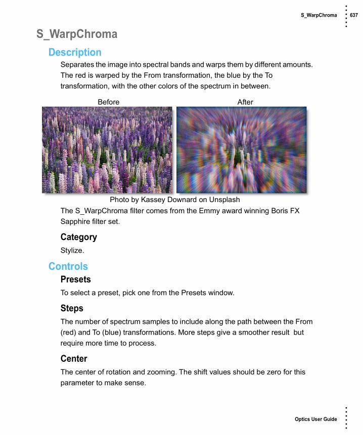
Optics User Guide
• • • •••
S_WarpChroma 637 • • • •••
S_WarpChromaDescription
Separates the image into spectral bands and warps them by different amounts. The red is warped by the From transformation, the blue by the To transformation, with the other colors of the spectrum in between.
The S_WarpChroma filter comes from the Emmy award winning Boris FX Sapphire filter set.
CategoryStylize.
ControlsPresetsTo select a preset, pick one from the Presets window.
StepsThe number of spectrum samples to include along the path between the From (red) and To (blue) transformations. More steps give a smoother result but require more time to process.
CenterThe center of rotation and zooming. The shift values should be zero for this parameter to make sense.
Before After
Photo by Kassey Downard on Unsplash

Optics User Guide
• • • •••
S_WarpChroma 638 • • • •••
From Z DistThe distance of the From transformation. This zooms about the Center location when Shift is 0. Increase to zoom out or decrease to zoom in.
From RotateThe rotation angle of the From transformation, in degrees, about the center.
From Shift X & YThe horizontal and vertical translations of the From transformation. This can be used for directional motion. If it is non−zero, the center location becomes less meaningful.
To Z DistThe distance of the To transformation. Increase to zoom out or decrease to zoom in.
To RotateThe rotation angle of the To transformation, in degrees, about the center. Note that if the From and To Rotate angles are very different, the interpolation between them will become less accurate.
To Shift X & YThe horizontal and vertical translations of the To transformation. This can be used for directional motion. If it is non−zero, the center location becomes less meaningful.
Warp AmountAdjusts the overall amount of warping by scaling the From and To transformations. Setting this to zero disables both transforms and leaves the image unchanged.
BrightnessScales the brightness of the result.
Color1The color at the From transformation.

Optics User Guide
• • • •••
S_WarpChroma 639 • • • •••
Color2The color midway between the From and To transformations.
Color3The color at the To transformation.
White BalanceWhen enabled, the three colors are adjusted internally so they sum to white. In this case, the colors of unwarped regions are not affected and the average color of the result remains the same.
Wrap X & YDetermines the method for accessing outside the borders of the image.
NoRenders black beyond the borders.
TileRepeats a copy of the image.
ReflectRepeats a mirrored copy. Edges are often less visible with this method.
FilterIf enabled, the image is adaptively filtered when it is resampled. This gives a better quality result when parts of the image are warped smaller.
Crop InputThese 4 parameters, Crop Top, Crop Bottom, Crop Left, and Crop Right, allow selecting a rectangular subsection of the image to be processed. If the Wrap parameters are set to No, the exposed borders will be transparent. If the Wrap is Tile or Reflect, the image is wrapped on the new cropped borders to fill the frame. This can make it easier to avoid artifacts due to distorting an image with bad edges.
Show CenterEnables/disables the on-screen control for adjusting the Center parameter.

Optics User Guide
• • • •••
S_WarpChroma 640 • • • •••
Show From TransfmEnables/disables the on-screen control for adjusting the From Z Dist and From Rotate parameters.
Show To TransformEnables/disables the on-screen control for adjusting the To Z Dist and To Rotate parameters.
Show From ShiftEnables/disables the on-screen control for adjusting the From Shift parameter.
Show To ShiftEnables/disables the on-screen control for adjusting the To Shift parameter.

Optics User Guide
• • • •••
S_WarpFishEye 641 • • • •••
S_WarpFishEyeDescription
Expands the center of the image as if viewed through a fish eye lens.
The S_WarpFishEye filter comes from the Emmy award winning Boris FX Sapphire filter set.
CategoryLens.
ControlsPresetsTo select a preset, pick one from the Presets window.
AmountThe amplitude of the fish eye warping. Set this to a negative value with a large Z Dist for some wacky bug eye distortions.
CenterThe center of the fish-eye warping function.
Z DistScales the distance of the image. Values greater than 1 move it farther away and make it smaller. Values less than 1 move the image closer and enlarge it. Zooming in slightly can sometimes be used to hide edge artifacts.
Before After
Photo by Pascal Meier on Unsplash

Optics User Guide
• • • •••
S_WarpFishEye 642 • • • •••
RotateRotates the result about the center location by this many counterclockwise degrees.
Shift Orig X & YTranslates the source image before the fish eye warping is applied.
Wrap X & YDetermines the method for accessing outside the borders of the image.
NoRenders black beyond the borders.
TileRepeats a copy of the image.
ReflectRepeats a mirrored copy. Edges are often less visible with this method.
FilterIf enabled, the image is adaptively filtered when it is resampled. This gives a better quality result when parts of the image are warped smaller.
Crop InputThese 4 parameters, Crop Top, Crop Bottom, Crop Left, and Crop Right, allow selecting a rectangular subsection of the image to be processed. If the Wrap parameters are set to No, the exposed borders will be transparent. If the Wrap is Tile or Reflect, the image is wrapped on the new cropped borders to fill the frame. This can make it easier to avoid artifacts due to distorting an image with bad edges.
Show CenterEnables/disables the on-screen control for adjusting the Center parameter.

Optics User Guide
• • • •••
S_WarpMagnify 643 • • • •••
S_WarpMagnifyDescription
Magnifies an elliptical region of the image to create a glass lens refraction effect.
The S_WarpMagnify filter comes from the Emmy award winning Boris FX Sapphire filter set.
CategoryLens.
ControlsPresetsTo select a preset, pick one from the Presets window.
Magnify AmountAmount to scale the image within the magnified region. Use values below 1 to shrink the image instead within the lens.
Magnify Rel X & YThe relative horizontal and vertical magnification.
Lens CenterThe center of the lens shape.
Before After
Photo by David Monjeh on Unsplash

Optics User Guide
• • • •••
S_WarpMagnify 644 • • • •••
Lens RadiusRadius of the inner part of the lens. Within this region, the image is scaled by the full magnify amount.
Lens Edge WidthThe width of the lens edge, as a fraction of the inner radius. In the edge area of the lens, magnification tapers off from the full magnify amount to no magnification.
Lens Rel HeightThe relative vertical size of the lens. Increase for a taller ellipse or decrease for a wider one.
Lens Rel WidthThe relative horizontal size of the lens. Increase for a wider ellipse or decrease for a taller one.
Lens RotateRotation in degrees of the lens. Note that rotation will have no effect when Rel Width and Rel Height are equal and the shape is a perfect circle.
Lens Edge ShapeDetermines the curve of the magnification amount within the edge of the lens. If set to 0, magnification tapers off linearly. If set to 1, magnification tapers off in a smoother curve which can reduce the visual perception of the border of the lens. Other values interpolate between the two.
Wrap X & YDetermines the method for accessing outside the borders of the image.
NoRenders black beyond the borders.
TileRepeats a copy of the image.
ReflectRepeats a mirrored copy. Edges are often less visible with this method.

Optics User Guide
• • • •••
S_WarpMagnify 645 • • • •••
FilterIf enabled, the image is adaptively filtered when it is resampled. This gives a better quality result when parts of the image are warped smaller.
Crop InputThese 4 parameters, Crop Top, Crop Bottom, Crop Left, and Crop Right, allow selecting a rectangular subsection of the image to be processed. If the Wrap parameters are set to No, the exposed borders will be transparent. If the Wrap is Tile or Reflect, the image is wrapped on the new cropped borders to fill the frame. This can make it easier to avoid artifacts due to distorting an image with bad edges.
Show Edge WidthEnables/disables the on-screen control for adjusting the Lens Edge Width parameter.
Show Lens RadiusEnables/disables the on-screen control for adjusting the Lens Radius parameter.
Show Lens RotateEnables/disables the on-screen control for adjusting the Lens Rotate parameter.
Show Lens CenterEnables/disables the on-screen control for adjusting the Lens Center parameter.

Optics User Guide
• • • •••
S_WarpPolar 646 • • • •••
S_WarpPolarDescription
Warps the image into a rounded disk shape.
The S_WarpPolar filter comes from the Emmy award winning Boris FX Sapphire filter set.
CategoryLens.
ControlsPresetsTo select a preset, pick one from the Presets window.
AngleRotation of the result in counterclockwise degrees.
Angle RepeatsThe number of copies of the image to wrap around. This should be an integer to avoid a seam where the first copy connects to the last.
CenterThe center of the disk.
Stretch X & YScales the horizontal or vertical size of the disk shape.
Before After
Photo by Michal Dzierza on Unsplash

Optics User Guide
• • • •••
S_WarpPolar 647 • • • •••
Inner RadiusThe distance from the center where the bottom edge of the image is mapped.
Outer RadiusThe distance from the center where the top edge of the image is mapped.
Wrap X & YDetermines the method for accessing outside the borders of the image.
NoRenders black beyond the borders.
TileRepeats a copy of the image.
ReflectRepeats a mirrored copy. Edges are often less visible with this method.
FilterIf enabled, the image is adaptively filtered when it is resampled. This gives a better quality result when parts of the image are warped smaller.
Crop InputThese 4 parameters, Crop Top, Crop Bottom, Crop Left, and Crop Right, allow selecting a rectangular subsection of the image to be processed. If the Wrap parameters are set to No, the exposed borders will be transparent. If the Wrap is Tile or Reflect, the image is wrapped on the new cropped borders to fill the frame. This can make it easier to avoid artifacts due to distorting an image with bad edges.
Show AngleEnables/disables the on-screen control for adjusting the Angle parameter.
Show CenterEnables/disables the on-screen control for adjusting the Center parameter.

Optics User Guide
• • • •••
S_WarpPolar 648 • • • •••
Show Inner RadiusEnables/disables the on-screen control for adjusting the Inner Radius parameter.
Show Outer RadiusEnables/disables the on-screen control for adjusting the Outer Radius parameter.

Optics User Guide
• • • •••
S_WarpPuddle 649 • • • •••
S_WarpPuddleDescription
Warps the image using a pattern of concentric waves.
The S_WarpPuddle filter comes from the Emmy award winning Boris FX Sapphire filter set.
CategoryLens/Distort.
ControlsPresetsTo select a preset, pick one from the Presets window.
AmplitudeThe amount of distortion.
FrequencyThe frequency of the waves. Increase for more waves or decrease for fewer.
Rel HeightThe relative height of the concentric wave pattern.
Rotate PuddleRotates the puddle pattern by this many counter−clockwise degrees after the Rel Height stretching has been applied. This has no effect when Rel Height is 1.
Before After
Photo by Marc Olivier Jodoin on Unsplash Jarin Domingue on Unsplash

Optics User Guide
• • • •••
S_WarpPuddle 650 • • • •••
Center X & YThe center of the puddle.
Phase StartThe phase shift of the waves.
Inner RadiusThe distance from the puddle center where the wave distortion is phased in. No waves are generated inside this radius.
Inner SoftnessThe width of the region at the Inner Radius over which the wave distortion is phased in.
Outer RadiusThe distance from the puddle center where the wave distortion is phased out. No waves are generated outside this radius.
Outer SoftnessThe width of the region at the Outer Radius over which the wave distortion is phased out.
Z DistScales the distance of the image. Values greater than 1 move it farther away and make it smaller. Values less than 1 move the image closer and enlarge it. Zooming in slightly can sometimes be used to hide edge artifacts.
Wrap X & YDetermines the method for accessing outside the borders of the image.
NoRenders black beyond the borders.
TileRepeats a copy of the image.
ReflectRepeats a mirrored copy. Edges are often less visible with this method.

Optics User Guide
• • • •••
S_WarpPuddle 651 • • • •••
FilterIf enabled, the image is adaptively filtered when it is resampled. This gives a better quality result when parts of the image are warped smaller.
Crop InputThese 4 parameters, Crop Top, Crop Bottom, Crop Left, and Crop Right, allow selecting a rectangular subsection of the image to be processed. If the Wrap parameters are set to No, the exposed borders will be transparent. If the Wrap is Tile or Reflect, the image is wrapped on the new cropped borders to fill the frame. This can make it easier to avoid artifacts due to distorting an image with bad edges.
Show FrequencyEnables/disables the on-screen control for adjusting the Frequency parameter.
Show Inner RadiusEnables/disables the on-screen control for adjusting the Inner Radius. The value of the Inner Radius parameter must first be positive for this on-screen control to be visible.
Show Outer RadiusEnables/disables the on-screen control for adjusting the Rel Height parameter.
Show CenterEnables/disables the on-screen control for adjusting the Center parameter.
Show Rotate PuddleEnables/disables the on-screen control for adjusting the Rotate Puddle parameter.

Optics User Guide
• • • •••
S_WarpPuff 652 • • • •••
S_WarpPuffDescription
Warps the image based on its gradient. By default, brighter areas are puffed out and darker areas are shrunk.
The S_WarpPuff filter comes from the Emmy award winning Boris FX Sapphire filter set.
CategoryLens/Distort.
ControlsPresetsTo select a preset, pick one from the Presets window.
DirectionDetermines the areas of the image to be puffed.
PuffExpands brighter areas and shrinks darker ones.
ShrivelShrinks brighter areas and expands darker ones.
Before After
Photo by Sasha Freemind on Unsplash Jarin Domingue on Unsplash

Optics User Guide
• • • •••
S_WarpPuff 653 • • • •••
AmountSets the amount of distortion. This can also be negative to turn puffs into shrivels and vice-versa.
SmoothnessBlurs the image by this amount before determining the warp directions and amounts.
Rotate Warp DirRotates the direction of the warping. This can cause areas of similar brightness to be twisted instead of just expanded or shrunk.
Wrap X & YDetermines the method for accessing outside the borders of the image.
NoRenders black beyond the borders.
TileRepeats a copy of the image.
ReflectRepeats a mirrored copy. Edges are often less visible with this method.
FilterIf enabled, the image is adaptively filtered when it is resampled. This gives a better quality result when parts of the image are warped smaller.
Crop InputThese 4 parameters, Crop Top, Crop Bottom, Crop Left, and Crop Right, allow selecting a rectangular subsection of the image to be processed. If the Wrap parameters are set to No, the exposed borders will be transparent. If the Wrap is Tile or Reflect, the image is wrapped on the new cropped borders to fill the frame. This can make it easier to avoid artifacts due to distorting an image with bad edges.

Optics User Guide
• • • •••
S_WarpTransform 654 • • • •••
S_WarpTransformDescription
Warps the image by a combination of linear transformations including scale, shear, zoom, rotation, and translation.
The S_WarpTransform filter comes from the Emmy award winning Boris FX Sapphire filter set.
CategoryImage.
ControlsPresetsTo select a preset, pick one from the Presets window.
Scale X & YScales the relative horizontal or vertical size of the image.
Shift X & YTranslates the image.
Before After
Photo by Christopher Burns on Unsplash

Optics User Guide
• • • •••
S_WarpTransform 655 • • • •••
Z DistScales the distance of the image. Values greater than 1 move it farther away and make it smaller. Values less then 1 move the image closer and enlarge it. Note that Scale X and Y also scale the size of the image, but in an inverse way and on each axis.
RotateRotates the image by the specified angle in degrees.
SwivelRotates the image left or right in 3D about the vertical axis.
TiltRotates the image up or down in 3D about the horizontal axis. You can use Swivel and Tilt together to rotate about arbitrary diagonal axes.
Perspective AmountControls the amount of lens telescoping while applying Swivel and Tilt. Increase for more 3D perspective.
Shear X & YShears the image horizontally or vertically.
Wrap X & YDetermines the method for accessing outside the borders of the image.
NoCreates black beyond the borders.
TileRepeats a copy of the image.
ReflectRepeats a mirrored copy. Edges are often less visible with this method.
FilterIf enabled, the image is adaptively filtered when it is resampled. This gives a better quality result when parts of the image are warped smaller.

Optics User Guide
• • • •••
S_WarpTransform 656 • • • •••
Crop Input ParametersThese 4 parameters: Crop Top, Crop Bottom, Crop Left, and Crop Right select a rectangular subsection of the image. If the Wrap parameters are set to No, the exposed borders will be transparent. If the Wrap is set to Tile or Reflect, the image is wrapped on the newly cropped borders to fill the frame. This can make it easier to avoid artifacts due to distorting an image with bad edges.
Show ShiftEnables/disables the on-screen control for adjusting the Shift parameter.

Optics User Guide
• • • •••
S_WarpWaves2 657 • • • •••
S_WarpWaves2Description
Warps the image using two sets of overlapping wave patterns.
The S_WarpWaves2 filter comes from the Emmy award winning Boris FX Sapphire filter set.
CategoryLens/Distort.
ControlsPresetsTo select a preset, pick one from the Presets window.
A Waves / B WavesAmplitudeThe amount of distortion.
FrequencyThe frequency of the waves. Increase for more waves or decrease for fewer.
AngleThe rotation angle of the wave pattern in degrees.
Before After
Photo by Jarin Domingue on Unsplash Jarin Domingue on Unsplash

Optics User Guide
• • • •••
S_WarpWaves2 658 • • • •••
Displace AngleThe warping direction in degrees relative to the angle of the waves. 0 produces compression-expansion waves, while 90 creates side to side waves.
Phase StartThe phase shift of the waves.
Z DistScales the distance of the image. Values greater than 1 move it farther away and make it smaller. Values less than 1 move the image closer and enlarge it. Zooming in slightly can sometimes be used to hide edge artifacts.
Wrap X & YDetermines the method for accessing outside the borders of the image.
NoRenders black beyond the borders.
TileRepeats a copy of the image.
ReflectRepeats a mirrored copy. Edges are often less visible with this method.
FilterIf enabled, the image is adaptively filtered when it is resampled. This gives a better quality result when parts of the image are warped smaller.
Crop InputThese 4 parameters, Crop Top, Crop Bottom, Crop Left, and Crop Right, allow selecting a rectangular subsection of the image to be processed. If the Wrap parameters are set to No, the exposed borders will be transparent. If the Wrap is Tile or Reflect, the image is wrapped on the new cropped borders to fill the frame. This can make it easier to avoid artifacts due to distorting an image with bad edges.

Optics User Guide
• • • •••
X-Ray 659 • • • •••
X-RayDescription
Simulates the look of X-Ray images.
CategoryStylize.
ControlsPresetsTo select a preset, pick one from the Presets window.
Black and WhiteFilterThe Filter pop-up selects the type of black and white filter to be applied to your color image. Go to the Black and White section of Common Filter Controls to see how the Black and White controls work.
BrightnessAdjusts the brightness of the image. Positive values brighten, negative values darken.
ContrastAdjusts the contrast of the image. Positive values increase contrast, negative values decrease contrast.
Before After
Photo by Clem Onojeghuo on Unsplash

Optics User Guide
• • • •••
X-Ray 660 • • • •••
Gamma Adjusts the gamma of the image. The gamma adjustment leaves the white and black points the same and only modifies the values in-between. Positive values lighten the midtones, negative values darken the midtones.
ColorOpacitySets the opacity of the color.
ColorThe Color parameter sets the color of the x-ray through the use of a standard color picker and defaults to blue.
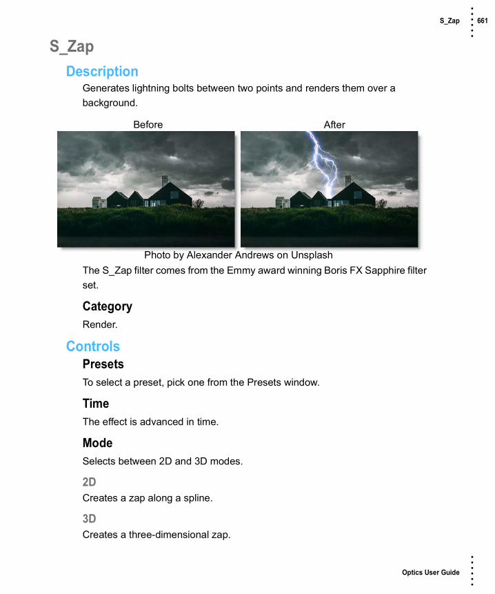
Optics User Guide
• • • •••
S_Zap 661 • • • •••
S_ZapDescription
Generates lightning bolts between two points and renders them over a background.
The S_Zap filter comes from the Emmy award winning Boris FX Sapphire filter set.
CategoryRender.
ControlsPresetsTo select a preset, pick one from the Presets window.
TimeThe effect is advanced in time.
ModeSelects between 2D and 3D modes.
2DCreates a zap along a spline.
3DCreates a three-dimensional zap.
Before After
Photo by Alexander Andrews on Unsplash

Optics User Guide
• • • •••
S_Zap 662 • • • •••
BoltsThe number of lightning bolts to draw between the Start and End location.
Start PointThe starting point of the bolts.
Point 1 EnableEnables Point 1.
Control Point 1First control point.
Point 2 EnableEnables Point 2.
Control Point 2Second control point.
Point 3 EnableEnables Point 3.
Control Point 3Third control point.
Point 4 EnableEnables Point 4.
Control Point 4Fourth control point.
End PointThe end point of the bolts
Vary EndpointOffsets the End location by a random amount within a circle of this radius. If Bolts is greater than 1, this can be useful to spread out the different End points. For example, you can create multiple radiating bolts by increasing this radius and placing the End point near the Start point.

Optics User Guide
• • • •••
S_Zap 663 • • • •••
Bolt WidthThe width of the lightning bolts.
Vary WidthThe amount of random variation in the width of the bolts along their lengths.
End PointinessDetermines how pointed the end of the bolts are. If 0, the entire bolt will have equal width. If 1, the bolts will thin out along their entire length for a pointed end. If it is .5, the bolts will start thinning out half way between the start and end points.
Motion/ShapeRand SeedUsed to initialize the random number generator. The actual seed value is not significant, but different seeds produce different random lightning bolts and the same value should give a repeatable result.
Wrinkle AmpScales the amount of wrinkles in the bolts. Decrease for straighter, smoother bolts or increase for more kinky bolts.
Curve AmpSimilar to Wrinkle Amp but affects the general path of the bolt. If decreased, the bolt will stay closer to the line between the Start and End points. If increased, it can wander further away from this line. This differs from the Wrinkle Amp parameter in that it can be used to make straighter bolts while still keeping the wrinkles at the detailed level.
BranchesBranchinessScales the number of additional bolts that branch from the main bolt. Set this to 0 for basic bolts with no extra branches.

Optics User Guide
• • • •••
S_Zap 664 • • • •••
Branch AngleThe maximum angle of the random branches relative to the bolt they are branching off of. If this is 0, the branches will be more lined up with the main bolt. With larger values, the branches will be more perpendicular to the main bolt.
Branch LengthThe scaled length of the branches relative to the distance between the Start and End points.
Glow BrightScales the brightness of the glow applied to the lightning.
Glow ColorThe color of the glow applied to the lightning.
Glow WidthGlow WidthThe width of the glow applied to the lightning.
Glow Width RedThe relative red width of the glow.
Glow Width GrnThe relative green width of the glow.
Glow Width BlueThe relative blue width of the glow.
Zap BrightScales the brightness of the lightning bolts.
Zap ColorThe color of the lightning. If you want to keep the lightning bolt itself bright white, you can still affect the perceived color by adjusting the Glow Color instead.

Optics User Guide
• • • •••
S_Zap 665 • • • •••
Start OffsetThe offset from the start point to begin drawing the bolts. This can be useful for animating a lightning strike.
LengthThe length of the bolts beginning at Start Offset. If less than 1, the bolts will not be drawn all the way from start to end.
Bg BrightnessScales the brightness of the image before combining with the lightning. If 0, the result will contain only the lightning over black.
CombineDetermines how the lightning and glow are combined with the image.
ScreenPerforms a blend function which can help prevent overly bright results.
AddAdds the lightning to the image. This gives brighter glows over light backgrounds.
Zap OnlyRenders the lightning over black.
AtmosphereAtmosphere AmpAtmosphere gives the effect of the lightning shining through a dusty atmosphere and picking up light or getting shadowed. This parameter adjusts the amount, or amplitude of the atmospheric effect. 0 creates smoother lightning while higher values provide a more dirty look.
Atmosphere FreqControls the spatial frequency of the atmospheric noise. Turn this up higher to get finer details or turn down for broader overall variation.

Optics User Guide
• • • •••
S_Zap 666 • • • •••
Atmosphere DetailControls the amount of fine detail in the atmosphere simulation. Decrease to get smoother atmosphere or increase for a more crunchy, grainy look.
Atmosphere SeedUsed to initialize the random number generator for the atmospheric noise. The actual seed value is not significant, but different seeds produce different results and the same value should give a repeatable result.
3D ParametersShowSelects what the effect will output.
ResultShows the normal lightning result over the background.
ZBufferShows a depth map of the lightning which can be used for compositing or to control other effects.
Swivel ZapRotates the lightning left or right about a vertical axis.
Tilt ZapRotates the lightning up or down about a horizontal axis. You can use Swivel and Tilt together to rotate about arbitrary diagonal axes.
Camera ZoomZooms in or out on the lightning.
Glow FadeFades out the glow on more distant parts of the lightning.
Show SplineEnables/disables the on-screen control for displaying the spline.
Show Vary EndpointEnables/disables the on-screen control for adjusting the Vary Endpoint parameter.

Optics User Guide
• • • •••
S_ZapFrom 667 • • • •••
S_ZapFromDescription
Generates multiple lightning bolts outwards from the edges of objects.
The S_ZapFrom filter comes from the Emmy award winning Boris FX Sapphire filter set.
CategoryRender.
ControlsPresetsTo select a preset, pick one from the Presets window.
TimeThe effect is advanced in time.
Surface BoltsThe number of points along the edges to generate lightning bolts from.
Before After
Photo by Zoltan Tasi on Unsplash

Optics User Guide
• • • •••
S_ZapFrom 668 • • • •••
ThresholdThe value used to determine the edge locations. Objects darker than this value are ignored. On smooth objects, larger threshold values move the edges inwards to make smaller bolts, while smaller values move the edges outwards. You can use the Show Edges option to view the edge image directly while adjusting this parameter.
Blur FromObjBlurs the image before finding the edges. This can help remove noise and reduce the number of separate bolts. You can use the Show Edges option to view the edge image directly while adjusting this parameter.
FromObj UseDetermines which channels are used.
LumaThe luminance of the RGB channels is used.
AlphaThe Alpha channel is used.
ShowSelects the output option.
ResultShows the normal lightning result over the image.
EdgesShows the edge image. This can be useful to view while adjusting the Threshold and Blur From.
Max LengthScales the length of the bolts.
Vary LengthThe amount to randomly vary the length of each bolt. A value of 0 makes all bolt lengths equal to Max Length, and a value of 1 makes bolt lengths between zero and Max Length.

Optics User Guide
• • • •••
S_ZapFrom 669 • • • •••
Vary SpacingThe amount to randomly vary the starting point of each bolt along the edges. A value of 0 makes the bolts regularly spaced while a value of 1 make the bolts randomly spaced.
Bolt WidthThe width of the lightning bolts.
Vary WidthThe amount of random variation in the width of the bolts along their lengths.
End PointinessDetermines how pointed the end of the bolts are. If 0, the entire bolt will have equal width. If 1, the bolts will thin out along their entire length for a pointed end. If it is .5, the bolts will start thinning out half way between the start and end points.
Rand SeedUsed to initialize the random number generator. The actual seed value is not significant, but different seeds produce different random lightning bolts and the same value should give a repeatable result.
Wrinkle AmpScales the amount of wrinkles in the bolts. Decrease for straighter, smoother bolts or increase for more kinky bolts.
Curve AmpSimilar to Wrinkle Amp but affects the general path of the bolt. If decreased, the bolt will stay closer to the line between the Start and End points. If increased, it can wander further away from this line. This differs from the Wrinkle Amp parameter in that it can be used to make straighter bolts while still keeping the wrinkles at the detailed level.
BranchinessScales the number of additional bolts that branch from the main bolt. Set this to 0 for basic bolts with no extra branches.

Optics User Guide
• • • •••
S_ZapFrom 670 • • • •••
Branch AngleThe maximum angle of the random branches relative to the bolt they are branching off of. If this is 0, the branches will be more lined up with the main bolt. With larger values, the branches will be more perpendicular to the main bolt.
Branch LengthThe scaled length of the branches relative to the distance between the Start and End points.
Glow BrightScales the brightness of the glow applied to the lightning.
Glow ColorThe color of the glow applied to the lightning.
Glow WidthGlow WidthThe width of the glow applied to the lightning.
Glow Width RedThe relative red width of the glow.
Glow Width GrnThe relative green width of the glow.
Glow Width BlueThe relative blue width of the glow.
Zap BrightScales the brightness of the lightning bolts.
Zap ColorThe color of the lightning. If you want to keep the lightning bolt itself bright white, you can still affect the perceived color by adjusting the Glow Color instead.

Optics User Guide
• • • •••
S_ZapFrom 671 • • • •••
Start OffsetThe offset from the start point to begin drawing the bolts. This can be useful for animating a lightning strike.
LengthThe length of the bolts beginning at Start Offset. If less than 1, the bolts will not be drawn all the way from start to end.
Bg BrightnessScales the brightness of the image before combining with the lightning. If 0, the result will contain only the lightning over black.
CombineDetermines how the lightning and glow are combined with the image.
ScreenPerforms a blend function which can help prevent overly bright results.
AddAdds the lightning to the image. This gives brighter glows over light backgrounds.
Zap OnlyRenders the lightning over black.
AtmosphereAtmosphere AmpAtmosphere gives the effect of the lightning shining through a dusty atmosphere and picking up light or getting shadowed. This parameter adjusts the amount, or amplitude of the atmospheric effect. 0 creates smoother lightning while higher values provide a more dirty look.
Atmosphere FreqControls the spatial frequency of the atmospheric noise. Turn this up higher to get finer details or turn down for broader overall variation.
Atmosphere DetailControls the amount of fine detail in the atmosphere simulation. Decrease to get smoother atmosphere or increase for a more crunchy, grainy look

Optics User Guide
• • • •••
S_ZapFrom 672 • • • •••
Atmosphere SeedUsed to initialize the random number generator for the atmospheric noise. The actual seed value is not significant, but different seeds produce different results and the same value should give a repeatable result.

Optics User Guide
• • • •••
S_ZapTo 673 • • • •••
S_ZapToDescription
Generates a forked lightning bolt from a given point to the edges of objects.
The S_ZapTo filter comes from the Emmy award winning Boris FX Sapphire filter set.
CategoryRender.
ControlsPresetsTo select a preset, pick one from the Presets window.
TimeThe effect is advanced in time.
Surface PointsThe number of points along the edges to connect the lightning to.
BoltsThe number of independent forked lightning bolts to draw, each connecting the Start position with the edge points.
Before After
Photo by Milan Sonigra on Unsplash

Optics User Guide
• • • •••
S_ZapTo 674 • • • •••
StartThe starting position of the lightning.
Max DistThe maximum distance of surface points from the Start position. Edges outside this distance are ignored.
ThresholdThe value used to determine the edge locations. Objects darker than this value are ignored. On smooth objects, larger threshold values move the edges inwards to make smaller bolts, while smaller values move the edges outwards. You can use the Show Edges option to view the edge image directly while adjusting this parameter.
Blur ToObjBlurs the image before finding the edges. This can help remove noise and reduce the number of separate bolts. You can use the Show Edges option to view the edge image directly while adjusting this parameter.
ShowSelects the output option.
ResultShows the normal lightning result over the image.
EdgesShows the edge image. This can be useful to view while adjusting the Threshold and Blur From.
Bolt WidthThe width of the lightning bolts.
Vary WidthThe amount of random variation in the width of the bolts along their lengths.

Optics User Guide
• • • •••
S_ZapTo 675 • • • •••
End PointinessDetermines how pointed the end of the bolts are. If 0, the entire bolt will have equal width. If 1, the bolts will thin out along their entire length for a pointed end. If it is .5, the bolts will start thinning out half way between the start and end points.
Rand SeedUsed to initialize the random number generator. The actual seed value is not significant, but different seeds produce different random lightning bolts and the same value should give a repeatable result.
Wrinkle AmpScales the amount of wrinkles in the bolts. Decrease for straighter, smoother bolts or increase for more kinky bolts.
BranchinessScales the number of additional bolts that branch from the main bolt. Set this to 0 for basic bolts with no extra branches.
Branch AngleThe maximum angle of the random branches relative to the bolt they are branching off of. If this is 0, the branches will be more lined up with the main bolt. With larger values, the branches will be more perpendicular to the main bolt.
Branch LengthThe scaled length of the branches relative to the distance between the Start and End points.
Glow BrightScales the brightness of the glow applied to the lightning.
Glow ColorThe color of the glow applied to the lightning.

Optics User Guide
• • • •••
S_ZapTo 676 • • • •••
Glow WidthGlow WidthThe width of the glow applied to the lightning.
Glow Width RedThe relative red width of the glow.
Glow Width GrnThe relative green width of the glow.
Glow Width BlueThe relative blue width of the glow.
Zap BrightScales the brightness of the lightning bolts.
Zap ColorThe color of the lightning. If you want to keep the lightning bolt itself bright white, you can still affect the perceived color by adjusting the Glow Color instead.
Start OffsetThe offset from the start point to begin drawing the bolts. This can be useful for animating a lightning strike.
LengthThe length of the bolts beginning at Start Offset. If less than 1, the bolts will not be drawn all the way from start to end.
Bg BrightnessScales the brightness of the image before combining with the lightning. If 0, the result will contain only the lightning over black.
CombineDetermines how the lightning and glow are combined with the image.
ScreenPerforms a blend function which can help prevent overly bright results.

Optics User Guide
• • • •••
S_ZapTo 677 • • • •••
AddAdds the lightning to the image. This gives brighter glows over light backgrounds.
Zap OnlyRenders the lightning over black.
AtmosphereAtmosphere AmpAtmosphere gives the effect of the lightning shining through a dusty atmosphere and picking up light or getting shadowed. This parameter adjusts the amount, or amplitude of the atmospheric effect. 0 creates smoother lightning while higher values provide a more dirty look.
Atmosphere FreqControls the spatial frequency of the atmospheric noise. Turn this up higher to get finer details or turn down for broader overall variation.
Atmosphere DetailControls the amount of fine detail in the atmosphere simulation. Decrease to get smoother atmosphere or increase for a more crunchy, grainy look.
Atmosphere SeedUsed to initialize the random number generator for the atmospheric noise. The actual seed value is not significant, but different seeds produce different results and the same value should give a repeatable result.
Show StartEnables/disables the on-screen control for adjusting the Start parameter.

Optics User Guide
• • • •••
Controls 678 • • • •••
MASKS
Masks allow you to limit the effect of a filter by revealing it only in white areas of the mask. White is on, black is off and gray areas in between represent a level of transparency.
Masks are displayed to the right of the image thumbnail in the Layers window and utilize a combination of on-screen and toolbar controls.
ControlsAdd Mask
Using the Add Mask icon in the Layers window, one of seven mask types can be applied to a layer: Gradient, Spot, Path, Snap, EZ Mask, Selection and Paint. Masks can be used to limit where a filter is applied to an image and are displayed to the right of the layer’s image thumbnail in the Layers window.
When a mask is added, its controls appear to the right of the Toolbar.
Photo by Joshua Earle on Unsplash

Optics User Guide
• • • •••
Controls 679 • • • •••
Mask Blend ModeThe Blend mode controls how the current mask is combined with the previous mask and is only active when more than one mask has been applied.
NormalNormal blends masks based on each mask’s transparency.
SubtractThe pixels of one mask are subtracted from another mask.
MultiplyProduces a result where there is a union of pixels from two masks.
Invert MaskInverts the current mask.
Mask OpacitySets the opacity of the current mask.
Mask BlurSets the blur level of the EZ Mask, Path, Selection and Snap masks.

Optics User Guide
• • • •••
Controls 680 • • • •••
Inner BlurThe mask is blurred inward from the edge of the mask.
Centered BlurThe blur is centered on the edge of the mask, equally blurring inward and outward.
Outer BlurThe mask is blurred outward from the edge of the mask.
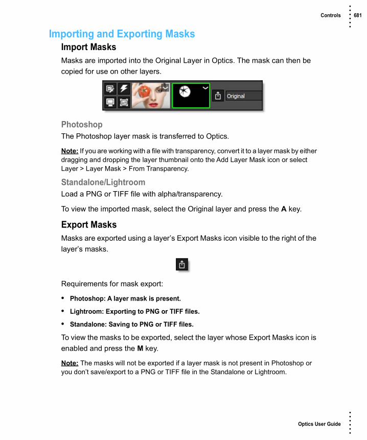
Optics User Guide
• • • •••
Controls 681 • • • •••
Importing and Exporting MasksImport MasksMasks are imported into the Original Layer in Optics. The mask can then be copied for use on other layers.
PhotoshopThe Photoshop layer mask is transferred to Optics.
Note: If you are working with a file with transparency, convert it to a layer mask by either dragging and dropping the layer thumbnail onto the Add Layer Mask icon or select Layer > Layer Mask > From Transparency.
Standalone/LightroomLoad a PNG or TIFF file with alpha/transparency.
To view the imported mask, select the Original layer and press the A key.
Export MasksMasks are exported using a layer’s Export Masks icon visible to the right of the layer’s masks.
Requirements for mask export:
• Photoshop: A layer mask is present.
• Lightroom: Exporting to PNG or TIFF files.
• Standalone: Saving to PNG or TIFF files.
To view the masks to be exported, select the layer whose Export Masks icon is enabled and press the M key.
Note: The masks will not be exported if a layer mask is not present in Photoshop or you don’t save/export to a PNG or TIFF file in the Standalone or Lightroom.

Optics User Guide
• • • •••
Gradient Mask 682 • • • •••
Gradient MaskCreates a linear top to bottom or left to right gradient and is adjusted using the four points around the corners of the image as well as controls in the Toolbar.
Go to the Gradient Mask Tutorial to see how it works.
The Gradient Mask consists of a combination of on-screen and toolbar controls. Its direction, corners, size and angle can be adjusted.
Photo by Joshua Earle on Unsplash

Optics User Guide
• • • •••
Gradient Mask 683 • • • •••
On-Screen ControlsCorner-PinDrag on the corner points of the image.
PositionDrag the center point.
SizeDrag the top/bottom mid-points.
RotateDrag the right center circle.
Toolbar ControlsTop-to-bottomThe direction of the gradient is from top to bottom.
Bottom-to-topThe direction of the gradient is from bottom to top.
Left-to-rightThe direction of the gradient is from left to right.
Right-to-leftThe direction of the gradient is from right to left.

Optics User Guide
• • • •••
Gradient Mask 684 • • • •••
Gradient SizeThe size of the gradient.
Gradient AngleThe angle of the gradient.

Optics User Guide
• • • •••
Spot Mask 685 • • • •••
Spot MaskCreates a circular spot mask and is adjusted using the two circular on-screen controls as well as parameters in the Toolbar.
Spot Mask consists of a combination of on-screen and toolbar controls.
On-Screen ControlsRadiusThe un-blurred radius of the spot is controlled using the inner on-screen circle.
Falloff RadiusThe blurred edge radius is controlled using the outer on-screen circle.
Photo by Ariel Lustre on Unsplash

Optics User Guide
• • • •••
Spot Mask 686 • • • •••
Toolbar ControlsAspect RatioThe aspect ratio of the spot.
FalloffMoves the falloff towards the spot centerpoint.

Optics User Guide
• • • •••
Path Mask 687 • • • •••
Path MaskA Path is an outline created by placing sequential points along an object. Think of it as connecting the dots if you will. Although paths can be open or closed, Optics only makes use of closed paths. Drawing a path is often a good solution for objects that can’t be masked in any other way.
Go to the Path Mask Tutorial to see how it works.
Create a PathCreate a path by clicking on the image in the Viewer. With each click of the mouse, a point is created. When done, click on the first point that was added to close the shape.
Note: If shapes overlap, a hole in the path is created.
Photo by Patrick Fore on Unsplash

Optics User Guide
• • • •••
Path Mask 688 • • • •••
Closing Open PathsIf you neglect to close a path and would later like to close it, select one of the end points and then select the other end point. The path will then close.
Selecting PointsIndividual or multiple points can be selected. Once selected, various point editing operations are available.
Point Selecting Shortcuts
Point EditingSignificant modification to the path is made possible by point editing controls available through pop-up menus or keyboard shortcuts.
Point Editing Shortcuts
Shortcut Action
Click a point Selects one point
Click and drag over multiple points Selects multiple points
Ctrl+click on a point Toggles the selection on or off
Shift+click a point Adds the point to the current selection
Shortcut Action
Alt+click on a path Inserts a new point along the path
Delete key Delete all selected points
Click and drag selected points All selected points move
Click and drag an unselected point Moves one point
Alt+click+drag on a point Opens a slider to adjust the point’s tension. Left of center forces the path to curve through the point (Cardinal spline). The center position creates a corner point while the right position moves the curve towards the center of the path (B-Spline). If multiple points have been selected, they will all be set to the same tension.
Alt+click+drag+Shift on a point Snaps the point tension to Cardinal, Corner or B-Spline positions

Optics User Guide
• • • •••
Path Mask 689 • • • •••
Point Editing Pop-up MenuRight-click over a path point or set of path points to open the Point pop-up menu.
Show Control PointsIt is sometimes helpful to turn off the display of path points to see the accuracy of your path. When turned off, you can still adjust the hidden points by click+dragging on the path and the nearest point will be adjusted.
Menu Option Action
Cardinal Creates a path that passes smoothly through each point
Corner Creates a corner point
B-Spline Creates a path that is determined by the surrounding points

Optics User Guide
• • • •••
Snap Mask 690 • • • •••
Snap MaskSnap is an easy to use interactive image masking tool. Snap provides instant visual feedback by snapping an editable curve to an object's boundary even if it has vague or low contrast edges.
Go to the Snap Mask Tutorial to see how it works.
Snap consists of a combination of on-screen and toolbar controls.
Photo © THINKSTOCK LLC--www.thinkstock.com

Optics User Guide
• • • •••
Snap Mask 691 • • • •••
WorkflowUsing a coarse to fine editing approach, an area of the image is selected by first marking the object and then refining the boundary. Object marking occurs at a coarse level, which roughly defines an object by marking a few lines. Next, boundary editing works at a finer scale by either clicking and dragging polygon points to edit the object boundary or drawing a stroke along the object’s edge.

Optics User Guide
• • • •••
Snap Mask 692 • • • •••
Object MarkingInstead of tracing the boundary of an object, Snap uses lines and curves to define the object.
FG Mark
Boundary BG Mark
BG Mark

Optics User Guide
• • • •••
Snap Mask 693 • • • •••
Mark ForegroundClick the Mark Foreground icon and draw lines to mark the foreground area--the region to be isolated. With each click and drag of the mouse, a green line is drawn.
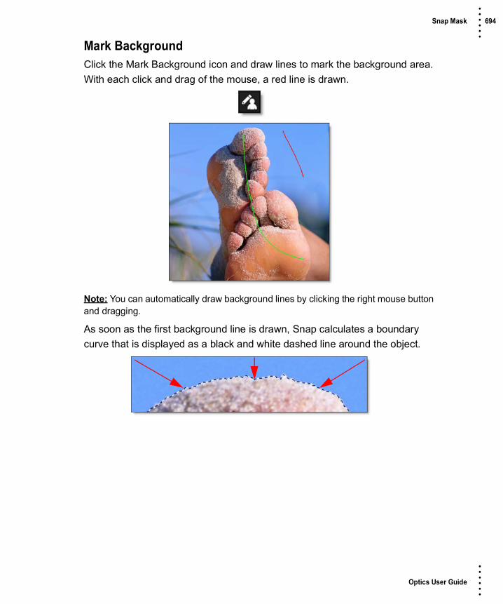
Optics User Guide
• • • •••
Snap Mask 694 • • • •••
Mark BackgroundClick the Mark Background icon and draw lines to mark the background area. With each click and drag of the mouse, a red line is drawn.
Note: You can automatically draw background lines by clicking the right mouse button and dragging.
As soon as the first background line is drawn, Snap calculates a boundary curve that is displayed as a black and white dashed line around the object.

Optics User Guide
• • • •••
Snap Mask 695 • • • •••
Add additional FG and BG lines as needed so that your object is surrounded by the boundary. Don't be concerned at this point if the boundary is not exactly following your object. The curve can be refined further using the boundary editing tools.
Boundary EditingEven though object marking does a pretty good job of creating an accurate boundary, there can still be some errors, especially around vague or low contrast edges. To remedy these errors, there are simple polygon point editing tools to refine the object's boundary. Two tools are provided for polygon editing: Edit Points and Override Edge. When either of these tools is selected, the boundary created in the object marking step is converted into editable polygons and you will see a noticeable refinement in the boundary.

Optics User Guide
• • • •••
Snap Mask 696 • • • •••
Edit PointsClick the Edit Points icon and drag points to adjust the shape of the polygon.
Compared with a simple polygon where you need to modify many points, Snap uses far fewer points to define the object shape. You should see variation in the boundary even though there are no points directly over the variations.
Note: The Edit Points icon can also be used to display and edit control points after the boundary is converted to a path.
Point Editing Shortcuts
Override Edge Click the Override Edge icon and draw a stroke along the edge of your object where the boundary doesn’t correctly follow the edge.
Before After
Shortcut Action
Alt+click between two points Add points
Hover over point+Delete Delete points
Alt+drag a point Uses magnetism to snap a point to an object’s boundary

Optics User Guide
• • • •••
Snap Mask 697 • • • •••
Once a stroke has been drawn, Snap optimizes the object boundary. The optimized boundary automatically snaps to the object boundary even though the polygon points may not be on it.
An entire segment of the polygon is replaced by drawing a single stroke and is much easier than dragging individual points.
Clear Foreground / Background MarksClears all foreground ad background marks.
Before Mark
After

Optics User Guide
• • • •••
Snap Mask 698 • • • •••
Convert Curve to a PathWhen happy with the boundary you have created, click the Convert Curve to a Path icon to apply it to the layer and convert it to an editable path. Additional boundaries can be created and applied to the layer. When boundaries overlap, a hole in the mask is created.
Show Control PointsIt is sometimes helpful to turn off the display of path points to see the accuracy of your path. When turned off, you can still adjust the hidden points by click+dragging on the path and the nearest point will be adjusted.

Optics User Guide
• • • •••
EZ Mask 699 • • • •••
EZ MaskEZ Mask is an easy to use interactive image masking tool capable of isolating almost any object in an image--even if you are dealing with fine hair detail, smoke, or reflections.
To work this magic, EZ Mask iteratively estimates the transparency value for every pixel in the image, based on a small sample of foreground (what you want to isolate) and background pixels marked by simple strokes on the image.
Results show that compared with previous approaches, our method is more efficient and requires minimal effort to extract high quality masks for foregrounds with significant semi-transparent regions.
Go to the EZ Mask Tutorial to see how it works.
EZ Mask consists of a combination of on-screen and toolbar controls.
Mask CreationTrimapsEZ Mask creates masks by using a trimap--a pre-segmented image consisting of three regions of foreground (what you want to isolate), background and unknown. Partial opacity values are then computed only for pixels inside the
User Input Mask

Optics User Guide
• • • •••
EZ Mask 700 • • • •••
unknown region. Two trimap methods can be used: Stroke and Filled. When creating masks, start with the Stroke method and move on to the Filled method if the results are not satisfying.
StrokeUnlike previous approaches, our trimaps can be relatively sparse consisting of individual foreground and background brush strokes. All pixels left unmarked will be treated as unknown. After processing, if any fine foreground details are missing from the mask, the Unknown brush can be used in these areas to help recover lost detail.
Stroke trimaps require little user input, but when color ambiguity exists between the foreground and background, a Filled trimap may create a more accurate mask. In addition, Stroke trimaps will also take longer to render as they require an extra calculation step.
Stroke Trimap Creation Tips & Tricks• Make sure you place enough foreground and background strokes. A good stroke
technique is to draw an inner outline around the object you are extracting using the Paint Foreground brush and an outer outline using the Paint Background brush.
• The strokes should be near the boundary of the object, but not right up against the edge.
• Strokes that are closer to the boundary will dominate the creation of the mask.
• If the foreground or background has varying colors, the strokes should cover these colors.
Strokes Mask

Optics User Guide
• • • •••
EZ Mask 701 • • • •••
• After processing the mask, if you see gray areas in the foreground object that should be completely white, make additional foreground marks in those areas.
• If you see gray mask areas in the background that should be completely black, make additional background marks.
• If any fine foreground details are missing from the mask, click on the Unknown brush and draw over them with the left mouse button. This instructs EZ Mask to pay special attention to these areas and will help recover lost detail.
• The general rule is don’t put different stroke types too close together unless you need to.
Warning: If you only provide a few sparse strokes, a Stroke trimap will take longer to process than a filled trimap.
FilledForeground and background brush strokes are used to mark definite foreground and background pixels while the Unknown brush is used to mark unknown, or mixed regions. Using this method, the entire image is painted/filled with one of the three brushes.
Good Stroke Example Bad Stroke Example
Filled Mask

Optics User Guide
• • • •••
EZ Mask 702 • • • •••
Filled trimaps process faster than Stroke trimaps and can result in extracting a more accurate mask, most notably when color ambiguity exists between the foreground and background. However, they can be tedious to create and tend to fail for images with large portions of semi-transparent foreground where the trimap is difficult to create manually.
Filled Trimap Creation Tips & Tricks• First, define unknown areas by selecting the Paint Unknown brush and drawing
around the edges of the foreground (what you want to isolate) with the left mouse button. Include as little solid foreground areas as possible.
• Ideally, the unknown region in the trimap should only cover transparent pixels whose actual values are not completely foreground or background. In other words, the unknown region in the trimap should be as thin as possible to achieve the best masking result.
• Next, fill in the solid foreground area by selecting the Paint Foreground brush and the Fill tool. Click inside the area defined by the blue, Unknown brush. The foreground area automatically fills in with the green foreground color.
• Last, mark background areas by using the Paint Background brush and the Fill tool. Since the Fill tool is already enabled, you don’t need to select it again. Click outside of the area defined by the blue, Unknown brush. The background area automatically fills in with the red background color.
Note: Large foreground objects take longer to process than small ones.
BrushesPaint ForegroundClick the Paint Foreground icon and draw to mark the foreground area--the region to be isolated. With each click and drag of the mouse, a green line is drawn.
Note: If you click with the left mouse button, press Shift and then click in a different location, a straight line is drawn. This will work with any brush type. If you keep Shift depressed while clicking, you will create interconnected straight lines. This is very useful when using a mouse.

Optics User Guide
• • • •••
EZ Mask 703 • • • •••
Paint BackgroundClick the Paint Background icon and draw to mark the background area. With each click and drag of the mouse, a red line is drawn.
Note: You can quickly create background strokes without selecting the Paint Background brush by painting with the right-mouse button. This temporarily draws with the Paint Background brush and when the right-mouse button is released, the previously selected brush becomes active.
Paint UnknownClick the Paint Unknown icon and draw to mark the unknown area. With each click and drag of the mouse, a blue line is drawn.
When drawing a stroke trimap, certain foreground details may be missing after the mask is generated. Using the Paint Unknown brush in these areas can sometimes help recover lost detail.
Paint MissingThe Paint Missing brush is used to mark missing foreground areas--fine details such as strands of hair that may be missing after the mask is generated. Using the Paint Missing brush in these areas can sometimes help recover lost detail. With each click and drag of the mouse, a purple line is drawn.
Note: The Paint Missing brush has a Sensitivity parameter located in Settings (Wrench icon) > Process Options. It’s preset value will work for most images. However, the higher the value, the more details are brought out.
EraserErases existing brush strokes.

Optics User Guide
• • • •••
EZ Mask 704 • • • •••
FillUsing the current brush, the Fill tool fills a region defined by a brush stroke or the edges of the screen.
Brush ParametersSizeSets the size of the brush.
To set the brush size:1 Click and drag on the Brush Size number field.
or
2 Click on the Brush Size number field, enter a value and hit Enter.
or
3 Resize the brush in the Viewer by holding Ctrl/Cmd and dragging in or out.
Paint Overlay OpacitySets the opacity of the foreground, background and unknown brush strokes.
To set the paint overlay opacity:1 Click and drag on the Paint Overlay Opacity number field.
or
2 Click on the Paint Overlay Opacity number field, enter a value and hit Enter.
SettingsVarious EZ Mask preferences can be set by clicking the Settings icon.

Optics User Guide
• • • •••
EZ Mask 705 • • • •••
Foreground ColorSets the color of the Paint Foreground brush.
Background ColorSets the color of the Paint Background brush.
Unknown ColorSets the color of the Paint Unknown brush.
Missing ColorSets the color of the Paint Missing brush.
Process OptionsDeartifactBlurry artifacts can be generated while attempting to extract objects that have drop shadows, similar colors to the background or out of focus edges. Deartifact can be used to limit these artifacts.
DeartifactTurns deartifact on or off.
AmountSets the amount of deartifacting.
Missing BrushSensitivitySets the sensitivity of the Missing Brush. The higher the value, the more details are brought out.
ResetClears all brush strokes.

Optics User Guide
• • • •••
EZ Mask 706 • • • •••
Mask Processing (Enter)Generate MaskGenerates the mask. Click this after creating either foreground and background strokes or a filled trimap. You can use the Enter key to trigger the mask processing.

Optics User Guide
• • • •••
Selection Mask 707 • • • •••
Selection MaskSelection masks, also known as mattes, can be used to manipulate, isolate and protect specific parts of an image when making adjustments or applying filters.
Using advanced image slicing algorithms, masks are created using luminance, hue, saturation, average, red, green, blue, cyan, magenta, and yellow values.
Go to the Selection Mask Tutorial to see how it works.
The Selection Mask consists of a combination of on-screen and toolbar controls.
Extract OnExtract On selects the type of mask. Select whichever type isolates the desired values.
Original Mask
Hue Mask

Optics User Guide
• • • •••
Selection Mask 708 • • • •••
A mask is created based on one of the following:
LuminanceA mask is created based on the luminance of the image.
HueA mask is created based on the hue of the image. When adjusting the Position parameter, you are selecting different hues.
SaturationA mask is created based on the saturation of the image.
AverageA mask is created based on the average of the image’s RGB values.
RedA mask is created based on the image’s red values.
GreenA mask is created based on the image’s green values.
BlueA mask is created based on the image’s blue values.
CyanA mask is created based on the image’s cyan values.
MagentaA mask is created based on the image’s magenta values.
YellowA mask is created based on the image’s yellow values.
PositionThe Position value pinpoints the color values to be used in the mask. For a luminance mask, a Position value of 100 would make a white mask of the highlights and a value of 0 would make a white mask of the shadows. In our

Optics User Guide
• • • •••
Selection Mask 709 • • • •••
flower image, look at how the mask varies for different Position values in a red extraction. When the Position is at a value of 100, the red flowers are shown as white in the mask.
When the Position is moved to 50, the red flowers turn black.
Position=100, Range=25
Position=50, Range=25

Optics User Guide
• • • •••
Selection Mask 710 • • • •••
RangeIncreases or decreases the range of values in the mask. A low Range value indicates a narrow range of values. A high Range value indicates a large range of values included in the mask.
RadiusWhen the Radius control is increased, a soft, circular mask is created to limit the mask.
On-Screen ControlsWhen using the Selection Mask, the Position, Range and Radius parameters can be set using on-screen controls. Click on the image to place the on-screen control which consists of a center point and a solid circle. The Position value is
Position=100, Range=50
Radius=50

Optics User Guide
• • • •••
Selection Mask 711 • • • •••
set by the location of the center point, while the Range is set by sizing the circle. The larger the circle, the larger the range. If Radius is used, a dashed circle will also appear.
Black ClipBlacks in the mask are made blacker by increasing this value. As the value increases, more values are clipped to black. This is helpful for getting rid of unwanted gray areas in what should be the black part of the mask.
Radius
Range
Position
Mask with No Black Clip Black Clip=50

Optics User Guide
• • • •••
Selection Mask 712 • • • •••
White ClipWhites in the mask are made whiter by increasing this value. As the value increases, more values are clipped to white. This is helpful for getting rid of unwanted gray areas in what should be the white part of the mask.
Mask with No White Clip White Clip=50

Optics User Guide
• • • •••
Paint Mask 713 • • • •••
Paint MaskOrganic masks are created using a paint brush and the filter appears only in the area of the paint stroke.
Go to the Paint Mask Tutorial to see how it works.
Paint Mask consists of a combination of on-screen brushes and toolbar controls.
Note: If you have a large area that needs to be masked out, it may be more efficient to first use the Path Mask since Paint’s brush size does not exceed 500 pixels.
Brush SizeSets the size of the brush.
To set the brush size:1 Click and drag on the Brush Size number field.
or
2 Click on the Brush Size number field, enter a value and hit Enter.
or
3 Resize the brush in the Viewer by holding Ctrl/Cmd and dragging in or out.

Optics User Guide
• • • •••
Paint Mask 714 • • • •••
Brush SoftnessSets the brush softness.
To set the brush softness:1 Click and drag on the Brush Softness number field.
or
2 Click on the Brush Softness number field, enter a value and hit Enter.
Brush OpacitySets the brush opacity. Painting with the right-mouse button automatically paints with O opacity or black.
To set the brush opacity:1 Click and drag on the Brush Opacity number field.
or
Click on the Brush Opacity number field, enter a value and hit Enter.

Optics User Guide
• • • •••
Blend Modes 715 • • • •••
BLEND MODES
Blend modes are used to combine images in a variety of different ways.
NormalEdits each pixel to make it the result color. This is the default mode. Changing the opacity results in a mix between two layers.
DarkenLooks at the color information in each channel and selects the base or blend color—whichever is darker—as the result color. Pixels lighter than the blend color are replaced, and pixels darker than the blend color do not change.
MultiplyLooks at the color information in each channel and multiplies the base color by the blend color. The result color is always a darker color. Multiplying any color with black produces black. Multiplying any color with white leaves the color unchanged.
Color BurnLooks at the color information in each channel and darkens the base color to reflect the blend color by increasing the contrast between the two. Blending with white produces no change.
Linear BurnLooks at the color information in each channel and darkens the base color to reflect the blend color by decreasing the brightness. Blending with white produces no change.
Darker ColorCompares the total of all channel values for the blend and base color and displays the lower value color. Darker Color does not produce a third color, which can result from the Darken blend, because it chooses the lowest channel values from both the base and the blend color to create the result color.

Optics User Guide
• • • •••
Blend Modes 716 • • • •••
LightenLooks at the color information in each channel and selects the base or blend color—whichever is lighter—as the result color. Pixels darker than the blend color are replaced, and pixels lighter than the blend color do not change.
AddThe pixels of one image are added to another image
ScreenLooks at each images color information and multiplies the inverse of the two images. This looks kind of like the Add blend mode, but highlights are retained.
Color DodgeLooks at the color information in each channel and brightens the base color to reflect the blend color by decreasing contrast between the two. Blending with black produces no change.
Linear Dodge (Add)Looks at the color information in each channel and brightens the base color to reflect the blend color by increasing the brightness. Blending with black produces no change.
Lighter ColorCompares the total of all channel values for the blend and base color and displays the higher value color. Lighter Color does not produce a third color, which can result from the Lighten blend, because it chooses the highest channel values from both the base and blend color to create the result color.
OverlayMultiplies or screens the colors, depending on the base color. Patterns or colors overlay the existing pixels while preserving the highlights and shadows of the base color. The base color is not replaced, but mixed with the blend color to reflect the lightness or darkness of the original color.

Optics User Guide
• • • •••
Blend Modes 717 • • • •••
Soft LightDarkens or lightens the colors, depending on the blend color. The effect is similar to shining a diffused spotlight on the image. If the blend color (light source) is lighter than 50% gray, the image is lightened as if it were dodged. If the blend color is darker than 50% gray, the image is darkened as if it were burned in.
Hard LightMultiplies or screens the colors, depending on the blend color. The effect is similar to shining a harsh spotlight on the image. If the blend color (light source) is lighter than 50% gray, the image is lightened, as if it were screened. This is useful for adding highlights to an image. If the blend color is darker than 50% gray, the image is darkened, as if it were multiplied. This is useful for adding shadows to an image.
Vivid LightBurns or dodges the colors by increasing or decreasing the contrast, depending on the blend color. If the blend color (light source) is lighter than 50% gray, the image is lightened by decreasing the contrast. If the blend color is darker than 50% gray, the image is darkened by increasing the contrast.
Linear LightBurns or dodges the colors by decreasing or increasing the brightness, depending on the blend color. If the blend color (light source) is lighter than 50% gray, the image is lightened by increasing the brightness. If the blend color is darker than 50% gray, the image is darkened by decreasing the brightness.
Pin LightReplaces the colors, depending on the blend color. If the blend color (light source) is lighter than 50% gray, pixels darker than the blend color are replaced, and pixels lighter than the blend color do not change. If the blend color is darker than 50% gray, pixels lighter than the blend color are replaced, and pixels darker than the blend color do not change. This is useful for adding special effects to an image.

Optics User Guide
• • • •••
Blend Modes 718 • • • •••
DifferenceLooks at the color information in each channel and subtracts either the blend color from the base color or the base color from the blend color, depending on which has the greater brightness value. Blending with white inverts the base color values; blending with black produces no change.
ExclusionCreates an effect similar to but lower in contrast than the Difference mode. Blending with white inverts the base color values. Blending with black produces no change.
SubtractLooks at the color information in each channel and subtracts the blend color from the base color. In 8 and 16-bit images, any resulting negative values are clipped to zero.
HueCreates a result color with the luminance and saturation of the base color and the hue of the blend color.
SaturationCreates a result color with the luminance and hue of the base color and the saturation of the blend color.
ColorCreates a result color with the luminance of the base color and the hue and saturation of the blend color. This preserves the gray levels in the image and is useful for coloring monochrome images and for tinting color images.

Optics User Guide
• • • •••
Keyboard Shortcuts 719 • • • •••
KEYBOARD SHORTCUTS
Crop
EZ Mask
General
Gradient Mask On-Screen Controls
Help
Shortcut Action
Drag on one of the vertical boundaries Crops horizontally
Drag on one of the horizontal boundaries Crops vertically
Drag bounding box corner Scales the Crop
Drag inside the bounding box Moves the Crop
Shortcut Action
Enter Processes the mask
Shortcut Action
Ctrl/Cmd+R Resets everything
Shortcut Action
Drag points on corners of the image Corner-pins the gradient
Drag center point Moves the gradient
Drag top/bottom mid-point Sets the gradient size
Drag right center circle Rotates the gradient
Shortcut Action
F1 Opens the Optics User Guide

Optics User Guide
• • • •••
Keyboard Shortcuts 720 • • • •••
Layer
Paint Keyboard
Shortcut Action
Ctrl/Cmd+L Adds a new layer
D Toggle enable filter state
Shift+D Toggle enable mask state
Shortcut Action
B Selects the Black/White brush
Shift+B Selects the Blur brush
C Selects the Clone brush
Shift+C Selects the Color brush
E Selects the Eraser brush
Shift+M Selects the Mosaic brush
R Selects the Red-Eye brush
Shift+R Selects the Repair brush
S Selects the Scatter brush
Ctrl/Cmd+drag Sizes the brush
[ ] Sizes the brush
Shift with clone brush Sets the clone offset
Shift+click or tap Resets the clone offset
Arrow keys Moves the Clone source by 1 pixel
Shift+Arrow keys Moves the Clone source by 10 pixels
Hold down Arrow keys Moves the Clone source continuously
Right-mouse drag Paints with the Eraser brush

Optics User Guide
• • • •••
Keyboard Shortcuts 721 • • • •••
Parameter Editing
Path Mask Point Selecting
Path Mask Point Editing
Shortcut Action
Up/Down Arrow Moves the value by 1 unit
Shift+Up/Down Arrow Moves the value by 10 units
Ctrl/Cmd+Up/Down Arrow Moves the value by one tenth of a unit
Alt+mouse wheel over numeric field Adjusts parameter
Alt+Shift+mouse wheel over numeric field 10x larger change than Alt
Alt+Ctrl/Cmd+mouse wheel over numeric field 10x smaller change than Alt
Shortcut Action
Click a point Selects one point
Click and drag over multiple points Selects multiple points
Ctrl+click on a point Toggles the matte on or off
Shift+click a point Adds the point to the current matte
Shortcut Action
Alt+click on a path Inserts a new point along the path
Delete key Delete all selected points
Click and drag selected points All selected points move
Click and drag an unselected point Moves one point
Alt+click+drag on a point Opens a slider to adjust the point’s tension. Left of center forces the path to curve through the point (Cardinal spline). The center position creates a corner point while the right position moves the curve towards the center of the path (B-Spline). If multiple points have been selected, they will all be set to the same tension.
Alt+click+drag+Shift on a point Snaps the point tension to Cardinal, Corner or B-Spline positions

Optics User Guide
• • • •••
Keyboard Shortcuts 722 • • • •••
Path Mask Point Editing Pop-up Menu
Pin Warp Keyboard Shortcuts
Snap Mask Point Editing
Menu Option Action
Cardinal Creates a path that passes smoothly through each point
Corner Creates a corner point
B-Spline Creates a path that is determined by the surrounding points
Shortcut Action
Click+drag on image Creates a pin
Click+release on image Creates a tack
Click+drag pin source or target Moves the pin source or target
Shift+drag pin source or target Moves both the pin source and target
Shift+drag pin radius Adjusts all pin radii
Hover over Pin Displays the pin number
Shortcut Action
Alt+click between two points Add points
Hover over point+Delete Delete points
Alt+drag a point Uses magnetism to snap a point to an object’s boundary

Optics User Guide
• • • •••
Keyboard Shortcuts 723 • • • •••
Viewer Keyboard Shortcuts
Workspace Shortcuts
Shortcut Action
R, G, B, A Toggles the red, green, blue and alpha channels on and off
Shift-A Superimposes the alpha channel over the image
Middle-mouse drag Pans the image
Space Bar+drag Pans the image
I Zooms the image in
O Zooms the image out
Zoom icon+click Zooms the image in
Zoom icon+Alt+click Zooms the image out
Zoom icon+Drag a square Zooms into the defined area
Scroll wheel over image Zooms the image in and out
Middle-mouse double click Fits the image to the window
F Fits the image to the window
1 Sets the Zoom level to 100%
M Cycles the display between the color image and the Mask channel
0 Toggles the display of overlays which are point, lines, or shapes
H Opens the Histogram window
Shortcut Action
F2 Selects the Default workspace
F3 Selects the Edit workspace
F4 Selects the View workspace