Graviton Metal Distortion - Aion FX
11
GRAVITON METAL DISTORTION 1 PROJECT NAME GRAVITON BASED ON EFFECT TYPE PROJECT SUMMARY DOCUMENT VERSION BOSS ® HM-2 Heavy Metal A unique distortion effect favored by extreme metal guitarists for its characteristic “buzzsaw” sound. It also works very well as a versatile high-gain effect in other styles of music. Metal Distortion 1.1.0 (2019-08-06) BUILD DIFFICULTY Intermediate Actual size is 2.3” x 2.42” (main board) and 1.78” x 0.86” (bypass board).
-
Upload
khangminh22 -
Category
Documents
-
view
0 -
download
0
Transcript of Graviton Metal Distortion - Aion FX

GRAVITON METAL DISTORTION 1
PROJECT NAME
GRAVITONBASED ON
EFFECT TYPE
PROJECT SUMMARY
DOCUMENT VERSION
BOSS® HM-2 Heavy Metal
A unique distortion effect favored by extreme metal guitarists for its characteristic “buzzsaw” sound. It also works very well as a versatile high-gain effect in other styles of music.
Metal Distortion 1.1.0 (2019-08-06)
BUILD DIFFICULTYIntermediate
Actual size is 2.3” x 2.42” (main board) and 1.78” x 0.86” (bypass board).
GRAVITON METAL DISTORTION 2
TABLE OF CONTENTS
1 Project Overview 8 Drill Template
2 Introduction & Usage 9 Enclosure Layout
3-5 Parts List 10 Wiring Diagram
6 Build Notes 11 Licensing
7 Schematic 11 Document Revisions
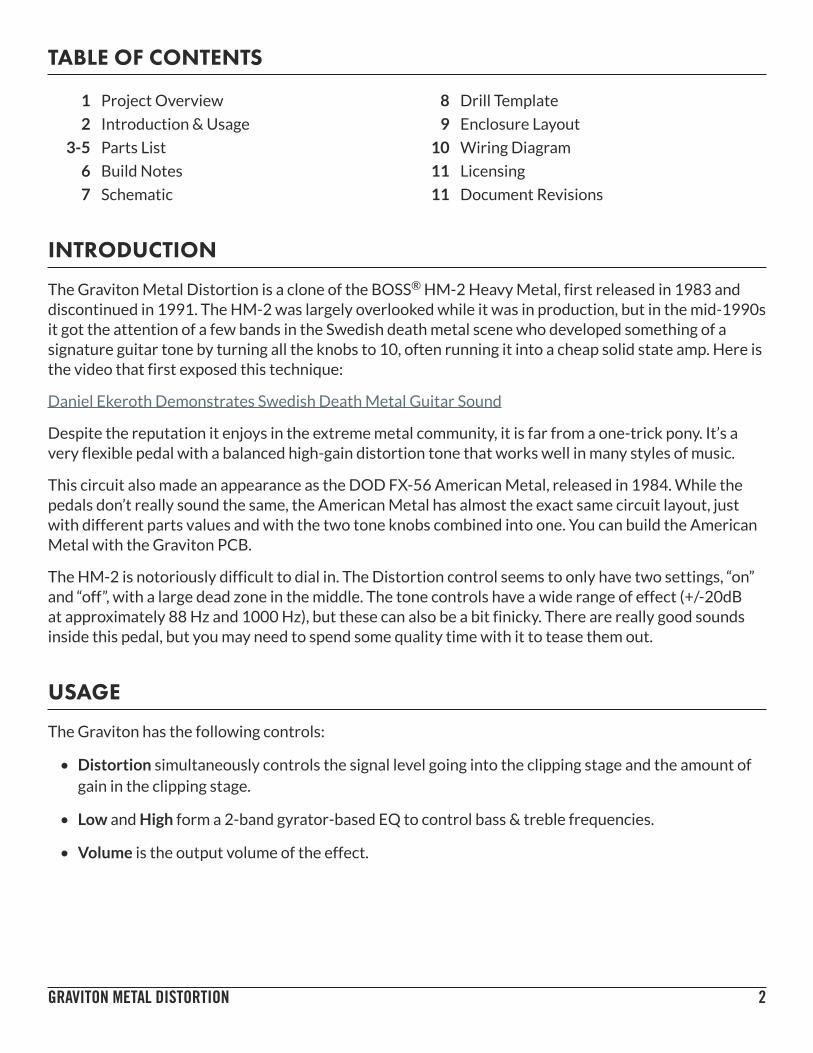
INTRODUCTION
The Graviton Metal Distortion is a clone of the BOSS® HM-2 Heavy Metal, first released in 1983 and discontinued in 1991. The HM-2 was largely overlooked while it was in production, but in the mid-1990s it got the attention of a few bands in the Swedish death metal scene who developed something of a signature guitar tone by turning all the knobs to 10, often running it into a cheap solid state amp. Here is the video that first exposed this technique:
Daniel Ekeroth Demonstrates Swedish Death Metal Guitar Sound
Despite the reputation it enjoys in the extreme metal community, it is far from a one-trick pony. It’s a very flexible pedal with a balanced high-gain distortion tone that works well in many styles of music.
This circuit also made an appearance as the DOD FX-56 American Metal, released in 1984. While the pedals don’t really sound the same, the American Metal has almost the exact same circuit layout, just with different parts values and with the two tone knobs combined into one. You can build the American Metal with the Graviton PCB.
The HM-2 is notoriously difficult to dial in. The Distortion control seems to only have two settings, “on” and “off”, with a large dead zone in the middle. The tone controls have a wide range of effect (+/-20dB at approximately 88 Hz and 1000 Hz), but these can also be a bit finicky. There are really good sounds inside this pedal, but you may need to spend some quality time with it to tease them out.
USAGE
The Graviton has the following controls:
• Distortion simultaneously controls the signal level going into the clipping stage and the amount of gain in the clipping stage.
• Low and High form a 2-band gyrator-based EQ to control bass & treble frequencies.
• Volume is the output volume of the effect.

GRAVITON METAL DISTORTION 3
PARTS LIST
This parts list is also available in a spreadsheet format which can be imported directly into Mouser for easy parts ordering. Mouser doesn’t carry all the parts (most notably potentiometers) so the second tab lists all the non-Mouser parts as well as sources for each.
View parts list spreadsheet →
PART VALUE TYPE NOTESR1 10k Metal film resistor, 1/4W
R2 1M Metal film resistor, 1/4W
R3 10k Metal film resistor, 1/4W
R4 22k Metal film resistor, 1/4W
R5 100k Metal film resistor, 1/4W
R6 470k Metal film resistor, 1/4W
R7 10k Metal film resistor, 1/4W
R8 22R Metal film resistor, 1/4W
R9 150R Metal film resistor, 1/4W
R10 22k Metal film resistor, 1/4W
R11 100k Metal film resistor, 1/4W
R12 470k Metal film resistor, 1/4W
R13 120R Metal film resistor, 1/4W
R14 1k Metal film resistor, 1/4W
R15 10k Metal film resistor, 1/4W
R16 68k Metal film resistor, 1/4W
R17 220k Metal film resistor, 1/4W
R18 47k Metal film resistor, 1/4W
R19 10k Metal film resistor, 1/4W
R20 10k Metal film resistor, 1/4W
R21 68k Metal film resistor, 1/4W
R22 3k3 Metal film resistor, 1/4W
R23 3k3 Metal film resistor, 1/4W
R24 10k Metal film resistor, 1/4W
R25 100k Metal film resistor, 1/4W
R26 330R Metal film resistor, 1/4W
R27 82k Metal film resistor, 1/4W
R28 330R Metal film resistor, 1/4W
R29 100k Metal film resistor, 1/4W
R30 330R Metal film resistor, 1/4W

GRAVITON METAL DISTORTION 4
PARTS LIST, CONT.PART VALUE TYPE NOTESR31 10k Metal film resistor, 1/4W
R32 10k Metal film resistor, 1/4W
R33 470k Metal film resistor, 1/4W
R34 10k Metal film resistor, 1/4W
R35 1k Metal film resistor, 1/4W
R36 100k Metal film resistor, 1/4W
RPD 2M2 Metal film resistor, 1/4W Input pulldown resistor. Can be as low as 1M.
LEDR 4k7 Metal film resistor, 1/4W LED current-limiting resistor. Adjust value to change LED brightness.
C1 47n Film capacitor, 7.2 x 2.5mm
C2 47n Film capacitor, 7.2 x 2.5mm
C3 100pF MLCC capacitor, NP0/C0G
C4 47uF Electrolytic capacitor, 5mm
C5 10uF Electrolytic capacitor, 5mm
C6 47n Film capacitor, 7.2 x 2.5mm
C7 100pF MLCC capacitor, NP0/C0G
C8 100pF MLCC capacitor, NP0/C0G
C9 47n Film capacitor, 7.2 x 2.5mm
C10 1uF Film capacitor, 7.2 x 3.5mm
C11 1n Film capacitor, 7.2 x 2.5mm
C12 1uF Film capacitor, 7.2 x 3.5mm
C13 470pF MLCC capacitor, NP0/C0G
C14 10uF Electrolytic capacitor, 5mm
C15 1.5uF Film capacitor, 7.2 x 4.5mm
C16 68n Film capacitor, 7.2 x 2.5mm
C17 150n Film capacitor, 7.2 x 2.5mm
C18 6n8 Film capacitor, 7.2 x 2.5mm
C19 100n Film capacitor, 7.2 x 2.5mm
C20 4n7 Film capacitor, 7.2 x 2.5mm
C21 47n Film capacitor, 7.2 x 2.5mm
C22 1uF Film capacitor, 7.2 x 3.5mm
C23 100uF Electrolytic capacitor, 6.3mm Power supply filter capacitor.
C24 47uF Electrolytic capacitor, 5mm Voltage reference filter capacitor.
C25 100n MLCC capacitor, X7R Power supply filter capacitor.

GRAVITON METAL DISTORTION 5
PARTS LIST, CONT.PART VALUE TYPE NOTESD1 1N5817 Schottky diode, DO-41 Polarity protection diode with low voltage drop (~0.2V).
D2 1N914 Fast-switching diode, DO-35
D3 1N914 Fast-switching diode, DO-35
D4 1N914 Fast-switching diode, DO-35
D5 BAT46 Schottky diode, DO-35 The HM-2 uses Ge diodes here, but Schottky is a better modern replacement. They only set the gate threshold and do not affect tone.D6 BAT46 Schottky diode, DO-35
D8 1N914 Fast-switching diode, DO-35
D9 1N914 Fast-switching diode, DO-35
Q1 2N5457 JFET, N-channel, TO-92 The HM-2 uses 2SK30A-Y (a Japanese equivalent).
Q2 2N5088 BJT transistor, NPN, TO-92 The HM-2 uses 2SC2240-GR (a Japanese equivalent).
Q3 2N5087 BJT transistor, PNP, TO-92 The HM-2 uses 2SA970-GR (a Japanese equivalent).
Q4 2N5088 BJT transistor, NPN, TO-92 The HM-2 uses 2SC732TM-GR (a Japanese equivalent).
IC1 JRC4558D Operational amplifier, DIP8
IC2 JRC4558D Operational amplifier, DIP8
IC3 JRC4558D Operational amplifier, DIP8
IC1-S DIP-8 socket IC socket, DIP-8
IC2-S DIP-8 socket IC socket, DIP-8
IC3-S DIP-8 socket IC socket, DIP-8
LED 5mm LED, 5mm Adjust LEDR resistor to set brightness depending on the LED used.
VOL 10kA Potentiometer, 16mm right-angle Audio (log) taper.
DIST 250kA Potentiometer, 16mm right-angle Audio (log) taper. The HM-2 uses D-taper which is similar to A.
HIGH 10kA Potentiometer, 16mm right-angle Audio (log) taper. The HM-2 uses G-taper which is similar to A.
LOW 10kA Potentiometer, 16mm right-angle Audio (log) taper. The HM-2 uses G-taper which is similar to A.
IN 1/4" mono 1/4" phone jack, closed frame Switchcraft 111X or equivalent. Open-frame types can be used instead, but the top side drill template is different. See drill template for details.OUT 1/4" mono 1/4" phone jack, closed frame
DC 2.1mm DC jack, 2.1mm panel mount Mouser 163-4302-E or equivalent.
FSW 3PDT 3PDT stomp switch
ENC 125B Enclosure, die-cast aluminum Can also use a Hammond 1590N1.

GRAVITON METAL DISTORTION 6
BUILD NOTES
The “midrange” control modification
Many people who have looked at the schematic of the HM-2 have noticed that there are three distinct EQ poles (technically op-amp gyrators), but two of them are tied together to make the High control. As a result, a common modification is to split out this EQ pole into its own knob, which is mistakenly called a midrange knob because it controls a slightly lower frequency than the high control. People see this and begin to think they’ve uncovered some super-secret control that had to be hidden because it was just too brutal or something.
While the Graviton project does support splitting out this 3rd EQ pole into its own control, I’m going to try to dissuade you from it. The reason is that the two EQ poles are centered very closely together around 1kHz and 1.2kHz, and they overlap in such a way as to form a single filter that is just broader than normal. By breaking out control over 1k but leaving 1.2k intact, you end up with a really weird notch effect that isn’t very useful, while also changing the core tone characteristics of the HM-2.
With that said, getting to the point: To use the midrange pot, you will need to cut a trace on the PCB. On the back of the PCB, between lugs 1 & 2 of the “High” pot, you’ll see two diagonal marks:
If you cut the trace at exactly this spot, taking care to avoid all surrounding traces, you can solder a 10kA pot to the “MID” pads in the middle. I recommend using an Alpha right-angle 9mm pot as shown to the right, but with the side mounting pins clipped off.
Adjusting the EQ filters
If you want to experiment and don’t care about maintaining the stock HM-2 tone, you can turn this filter into a truly useful midrange control. By changing some part values in the “mid” EQ pole, you can lower the gyrator frequency into something that would be worth splitting out.
For instance, if you put it down into the 720Hz range, you’d have control over the classic Tube Screamer mid frequency, which also happens to be right between the 86 Hz frequency of the Low knob and the 1.2k frequency of the High knob. To do this, you’d change R27 to 100k and C18 to 10n.
For further experimentation, I recommend using AMZ’s Bandpass EQ calculator.
Bypassing the output buffer
The output of the HM-2 is already well-buffered, but there is a second transistor-based buffer added to the end to support the JFET switching. To be as true to the original as possible, this second buffer has been included in the Graviton even though the JFET switching is omitted. Jumper pads are provided in the upper-right corner of the PCB to bypass this last buffer if desired. If you do use the jumper, you can omit C21, C22, R33, R34, R35, and Q4.

SCHEMATIC
GRAVITON METAL DISTORTION 7
CUT TRACE FOR MID POT
GND
2M2
1N5817
100uF
GND
250k
D
10kA10
kG
10kG
10kB
2N545710k
1M
47n
10k
10k
GND
VBVA
47uF
GND
VA
VB
47n
10k
GND
22k
100k
470k
GND
2N5088
100pF
10k
22R
GND
47uF
GND
150R
47n
22k
100k
2N5087
470k
120R
10k
100pF
GND
GND
1k
VA
68k
VA
JRC4558
JRC4558
220k47k
100pF
1N914
47n
1uF
10k
1N34A
1N34A 10k
1N91
4
1N91
4
GND
1n
GND
1uF
VB
68k
JRC4558JRC4558JRC4558
JRC4558
VA
3k3
3k3
470pF
10k
GND1.5uF
330R
68n
100k
VB
150n
330R
6n8
82k
VB
100n
4n7 330R10
0kVB
47n 47
0k
VB
2N5088
VA
10k
1k
GND
1uF
100k
GND
GND
VA VA
GND GND
+9V
100n
10uF
10uF
RPD
D1
C23
IN
OUT
DIST
ORTI
ON12
3
VOLU
ME
12
3
LOW
12
3
HIGH
12
3
MID
12
3
Q1R1
R2
C1
R31
R32
C24
C2
R3
R4
R5R6
Q2
C3
R7R8
C4
R9
C6 R10
R11
Q3
R12
R13
R15C7
R14
R16
2
31
IC1A
6
57
IC1B
R17R18
C8
D2
D3D4
C9
C10
R19
D5
D6
R20
D8 D9
C11
C12
R21
84
2
31
IC2A
6
57
IC2B
2
31
IC3A
6
57
IC3B
84
84
R22
R23
C13
R24
C15
R26
C16
R25
C17
R28
C18
R27
C19
C20R3
0R29
C21 R3
3
Q4
R34
R35 C22
R36
C25
C5
C14
GND

GRAVITON METAL DISTORTION 8
DRILL TEMPLATE
Cut out this drill template, fold the edges and tape it to the enclosure. Before drilling, it’s recommended to first use a center punch for each of the holes to help guide the drill bit.
Ensure that this template is printed at 100% or “Actual Size”. You can double-check this by measuring the scale on the printed page.
Top jack layout assumes the use of closed-frame jacks like the Switchcraft 111X. If you’d rather use open-frame jacks, please refer to the Open-Frame Jack Drill Template for the top side.
LED hole drill size assumes the use of a 5mm LED bezel, available from several parts suppliers. Adjust size accordingly if using something different, such as a 3mm bezel, a plastic bezel, or just a plain LED.
0 1 2
CM
0 1
INCH
ø3/8” ø1/2”
0.38
5”
0.625” 0.625”
x: -0.65, y: +1.71 x: +0.65, y: +1.71ø9/32” ø9/32”
x: -0.65, y: +0.41ø9/32”
x: +0.65, y: +0.41ø9/32”
x: 0, y: -1.775ø15/32”
x: -0.775, y: -1.775ø5/16”
CENTER (0,0)
ø3/8”
125B
OUT
VOLUME DISTORTION
LOW HIGH
FOOTSWITCHLED
DC IN

GRAVITON METAL DISTORTION 9
ENCLOSURE LAYOUT
Enclosure is shown without jacks. See next page for jack layout and wiring.
125B
GRAVITON METAL DISTORTION 10
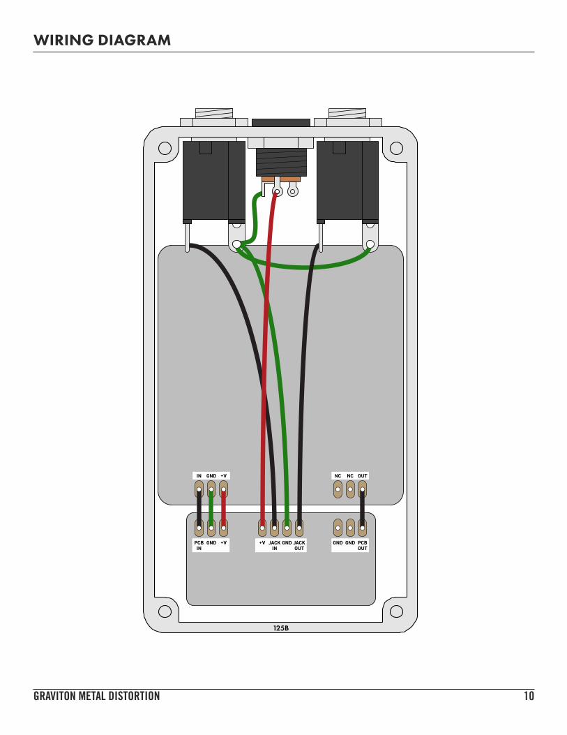
WIRING DIAGRAM
125B
IN +VGND NC NC OUT
PCBIN
GND +V +V JACK GND JACKOUTIN
GND GND PCBOUT

GRAVITON METAL DISTORTION 11
LICENSE & USAGE
No direct support is offered for these projects beyond the provided documentation. It’s assumed that you have at least some experience building pedals before starting one of these. Replacements and refunds cannot be offered unless it can be shown that the circuit or documentation are in error.
All of these circuits have been tested in good faith in their base configurations. However, not all the modifications or variations have necessarily been tested. These are offered only as suggestions based on the experience and opinions of others.
DOCUMENT REVISIONS
1.1.0 (2019-08-06) Added C25 (100n ceramic capacitor) for extra power filtering to make it consistent with other Aion FX PCBs. Slight layout tweak to move the D1 polarity-protection diode to the footswitch PCB.
1.0.0 (2018-07-04) Initial release