Wave Optics - SelfStudys
67
Wave Optics 1761 Newton's Corpuscular Theory (1) Newton thought that light is made up of tiny, light and elastic particles called corpuscles which are emitted by a luminous body. (2) The corpuscles travel with speed equal to the speed of light in all directions in straight lines. (3) The corpuscles carry energy with them. When they strike retina of the eye, they produce sensation of vision. (4) The corpuscles of different colour are of different sizes (red corpuscles larger than blue corpuscles). (5) The corpuscular theory explains that light carry energy and momentum, light travels in a straight line, Propagation of light in vacuum, Laws of reflection and refraction (6) The corpuscular theory fails to explain interference, diffraction and polarization. (7) A major prediction of the corpuscular theory is that the speed of light in a denser medium is more than the speed of light in a rarer medium. The truth is that the speed of the light is smaller in a denser medium. Therefore, the Newton's corpuscular theory is wrong. Huygen's Wave Theory (1) Wave theory of light was given by Christian Huygen. According to this, a luminous body is a source of disturbance in a hypothetical medium ether. This medium pervades all space. (2) It is assumed to be transparent and having zero inertia. The disturbance from the source is propagated in the form of waves through the space. (3) The waves carry energy and momentum. Huygen assumed that the waves were longitudinal. Further when polarization was discovered, then to explain it, light waves were, assumed to be transverse in nature by Fresnel. (4) This theory explains successfully, the phenomenon of interference and diffraction apart from other properties of light. (5) The Huygen's theory fails to explain photo-electric effect, Compton's effect etc. (6) The wave theory introduces the concept of wavefront. Wavefront (1) Suggested by Huygens (2) The locus of all particles in a medium, vibrating in the same phase is called Wave Front (WF) (3) The direction of propagation of light (ray of light) is perpendicular to the WF. (4) Every point on the given wave front acts as a source of new disturbance called secondary wavelets which travel in all directions with the velocity of light in the medium. (5) A surface touching these secondary wavelets tangentially in the forward direction at any instant gives the new wave front at that instant. This is called secondary wave front Table 30.1 : Different types of wavefront Type of wavefront Intensity Amplitude Spherical 2 1 r I r A 1 Point source Light ray Spherical WF Primary wave front Secondary wave front Secondary wavelets Point source Fig. 30.1 Wave Optics Chapter 30
-
Upload
khangminh22 -
Category
Documents
-
view
5 -
download
0
Transcript of Wave Optics - SelfStudys
Wave Optics 1761
Newton's Corpuscular Theory
(1) Newton thought that light is made up of tiny, light and elastic
particles called corpuscles which are emitted by a luminous body.
(2) The corpuscles travel with speed equal to the speed of light in all
directions in straight lines.
(3) The corpuscles carry energy with them. When they strike retina of
the eye, they produce sensation of vision.
(4) The corpuscles of different colour are of different sizes (red
corpuscles larger than blue corpuscles).
(5) The corpuscular theory explains that light carry energy and
momentum, light travels in a straight line, Propagation of light in
vacuum, Laws of reflection and refraction
(6) The corpuscular theory fails to explain interference,
diffraction and polarization.
(7) A major prediction of the corpuscular theory is that the speed of
light in a denser medium is more than the speed of light in a rarer medium.
The truth is that the speed of the light is smaller in a denser medium.
Therefore, the Newton's corpuscular theory is wrong.
Huygen's Wave Theory
(1) Wave theory of light was given by Christian Huygen. According to
this, a luminous body is a source of disturbance in a hypothetical medium
ether. This medium pervades all space.
(2) It is assumed to be transparent and having zero inertia. The
disturbance from the source is propagated in the form of waves through the
space.
(3) The waves carry energy and momentum. Huygen assumed that the
waves were longitudinal. Further when polarization was discovered, then to
explain it, light waves were, assumed to be transverse in nature by Fresnel.
(4) This theory explains successfully, the phenomenon of interference
and diffraction apart from other properties of light.
(5) The Huygen's theory fails to explain photo-electric effect,
Compton's effect etc.
(6) The wave theory introduces the concept of wavefront.
Wavefront
(1) Suggested by Huygens
(2) The locus of all particles in a medium, vibrating in the same phase
is called Wave Front (WF)
(3) The direction of propagation of light (ray of light) is perpendicular
to the WF.
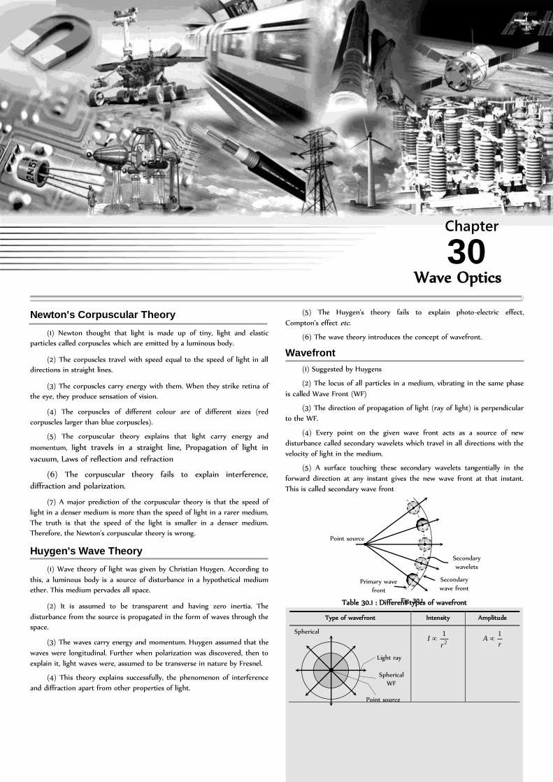
(4) Every point on the given wave front acts as a source of new
disturbance called secondary wavelets which travel in all directions with the
velocity of light in the medium.
(5) A surface touching these secondary wavelets tangentially in the
forward direction at any instant gives the new wave front at that instant.
This is called secondary wave front
Table 30.1 : Different types of wavefront
Type of wavefront Intensity Amplitude
Spherical
2
1
rI
rA
1
Point source
Light ray
Spherical
WF
Primary wave
front
Secondary
wave front
Secondary
wavelets
Point source
Fig. 30.1
Wave Optics
Chapter
30

1762 Wave Optics
Cylindrical
rI
1
rA
1
Plane
0rI 0rA
Reflection and Refraction of Wavefront
Reflection
BC = AD
and i = r
Refraction
1
2
2
1
sin
sin
r
i
v
v
AD
BC
Super Position of Waves
When two or more than two waves superimpose over each other at a
common particle of the medium then the resultant displacement (y) of the
particle is equal to the vector sum of the displacements (y1
and y2
) produced
by individual waves. i.e. 21 yyy
Important Terms
(1) Phase : The argument of sine or cosine in the expression for
displacement of a wave is defined as the phase. For displacement y = a sin
t ; term t = phase or instantaneous phase.
(2) Phase difference () : The difference between the phases of two
waves at a point is called phase difference i.e. if tay sin11 and
)(sin22 tay so phase difference =
(3) Path difference () : The difference in path length’s of two waves
meeting at a point is called path difference between the waves at that point.
Also
2
(4) Time difference (T.D.) : Time difference between the waves
meeting at a point is
2
TT.D.
Resultant Amplitude and Intensity
Let us consider two waves that have the same frequency but have a
certain fixed (constant) phase difference between them. Their super position
shown below
Let the two waves are
tay sin11 and )(sin22 tay
where 21 ,aa Individual amplitudes,
= Phase difference between the waves at an instant when they are
meeting a point.
(1) Resultant amplitude : The resultant wave can be written as y = A
sin ( t + )
where A = resultant amplitude φaaaa cos2 2122
21
(2) Resultant intensity : As we know intensity (Amplitude)2
222
211 , kaIkaI and 2kAI (k is a proportionality
constant). Resultant intensity cos2 2121 IIIII
For two identical source 021 III cos2 0000 IIIII
2cos4 2
0
I [1 + cos
2cos2 2 ]
Coherence
The phase relationship between two light waves can very from time to
time and from point to point in space. The property of definite phase relationship is called coherence.
(1) Temporal coherence : In a light source a light wave (photon) is
produced when an excited atom goes to the ground state and emits light.
(i) The duration of this transition is about 10–9 to 10–10 sec. Thus the
emitted wave remains sinusoidal for this much time. This time is known as
coherence time (c
).
(ii) Definite phase relationship is maintained for a length ccL
called coherence length. For neon = 6328 Å, c
10–10 sec and L = 0.03 m.
For cadmium = 6438 Å, c
= 10–9 sec and L = 0.3 m
For Laser c
= 10–5 sec and L = 3 km
Cylindrical
WF
Line source
Light ray
Plane
WF
Light rays
r
C
r
D
A
B
i i
Fig. 30.3
1
2
Resultant Resultant 1
2
(A) (B)
Fig. 30.4
t
y
1
2
Resultant
Fig. 30.5
Fig. 30.2
B D
i i r r
C A

Wave Optics 1763
(iii) The spectral lines width is related to coherence length L and
coherence time c
. cc
2
or L
2
(2) Spatial coherence : Two points in space are said to be spatially coherence if the waves reaching there maintains a constant phase difference
Points P and Q are at the same distance from S, they will always be
having the same phase. Points P and 'P will be spatially coherent if the
distance between P and 'P is much less than the coherence length i.e.
ccPP '
(3) Methods of obtaining coherent sources : Two coherent sources are produced from a single source of light by two methods (i) By division of
wavefront and (ii) By division of amplitude
(i) Division of wave front : The wave front emitted by a narrow source is divided in two parts by reflection, refraction or diffraction.
The coherent sources so obtained are imaginary. There produced in Fresnel's biprism, Llyod's mirror Youngs' double slit etc.
(ii) Division of amplitude : In this arrangement light wave is partly
reflected (50%) and partly transmitted (50%) to produced two light rays.
The amplitude of wave emitted by an extend source of light is divided in
two parts by partial reflection and partial refraction.
The coherent sources obtained are real and are obtained in Newton's
rings, Michelson's interferrometer, colours in thin films.
Interference of Light
When two waves of exactly same frequency (coming from two
coherent sources) travels in a medium, in
the same direction simultaneously then due
to their superposition, at some points
intensity of light is maximum while at some
other points intensity is minimum. This
phenomenon is called Interference of light. It is of following two types
(1) Constructive interference : When the waves meets a point with
same phase, constructive interference is obtained at that point (i.e.
maximum light)
(i) Phase difference between the waves at the point of observation
no 2or0
(ii) Path difference between the waves at the point of observation
n (i.e. even multiple of /2)
(iii) Resultant amplitude at the point of observation will be maximum
Amax
= a1
+ a2
If 0max021 2aAaaa
(iv) Resultant intensity at the point of observation will be maximum
2121max 2 IIIII 221 II
If 0max021 4 IIIII
(2) Destructive interference : When the wave meets a point with opposite phase, destructive interference is obtained at that point (i.e. minimum light)
(i) Phase difference ;)12(or180 no n = 1, 2, .....
or ;)12( n .....2,1,0n
(ii) Path difference 2
)12(
n (i.e. odd multiple of /2)
(iii) Resultant amplitude at the point of observation will be minimum
21min aaA
If 0min21 Aaa
(iv) Resultant intensity at the point of observation will be minimum
2121min 2 IIIII 221 II
If 0min021 IIII
(3) Super position of waves of random phase difference : When two
waves (or more waves) having random phase difference between them
super impose, then no interference pattern is produced. Then the resultant
intensity is just the sum of the two intensities. 21 III
Young's Double Slit Experiment (YDSE)
Monochromatic light (single wavelength) falls on two narrow slits S1
and S2
which are very close together acts as two coherent sources, when
waves coming from two coherent sources ),( 21 SS superimposes on each
other, an interference pattern is obtained on the screen. In YDSE alternate
bright and dark bands obtained on the screen. These bands are called
Fringes.
Reflection
coating M1
S L
Tw
o w
aves
super
impos
e
M2
Fig. 30.8
S
S1
S2
Fig. 30.7
Central bright fringe
(or Central maxima)
S
S1
S2
d
D
Screen
4 Dark
1 Dark
2 Dark
3 Dark
4 Dark
3 Dark
2 Dark
1 Dark
1 Bright
2 Bright
3 Bright
1 Bright
2 Bright
3 Bright
d = Distance between slits D = Distance between slits and screen
= Wavelength of monochromatic light
emitted from source
Fig. 30.6
Monochromatic
source of light
P
P '
Q
1764 Wave Optics
(1) Central fringe is always bright, because at central position
o0 or 0
(2) The fringe pattern obtained due to a slit is more bright than that
due to a point.
(3) If the slit widths are unequal, the minima will not be complete
dark. For very large width uniform illumination occurs.
(4) If one slit is illuminated with red light and the other slit is
illuminated with blue light, no interference pattern is observed on the
screen.
(5) If the two coherent sources consist of object and it’s reflected
image, the central fringe is dark instead of bright one.
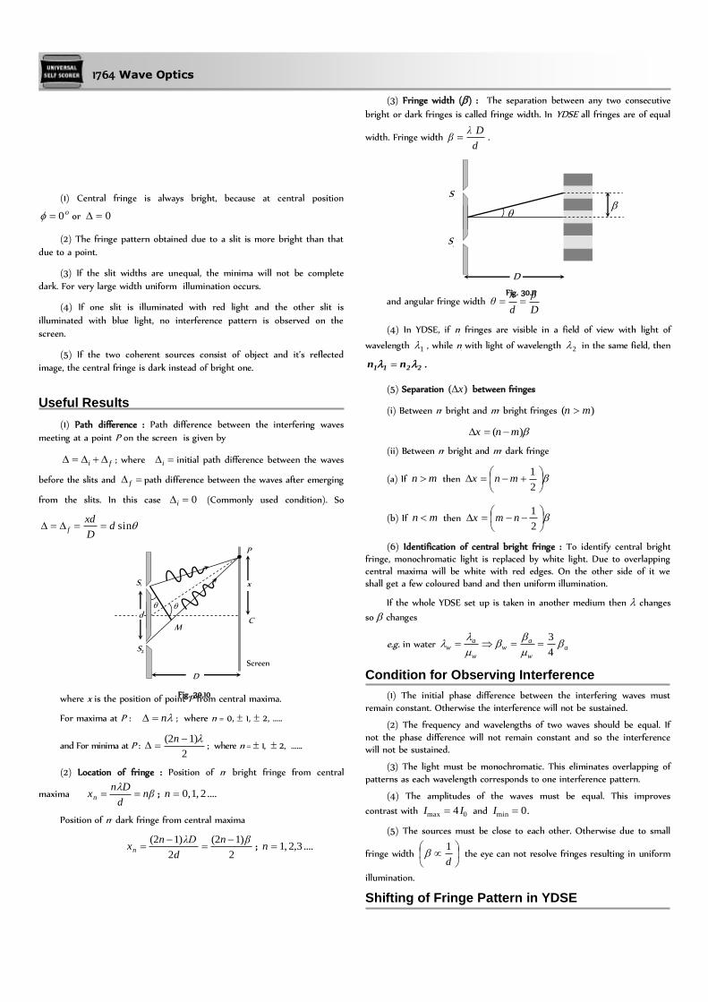
Useful Results
(1) Path difference : Path difference between the interfering waves
meeting at a point P on the screen is given by
fi ; where i initial path difference between the waves
before the slits and f path difference between the waves after emerging
from the slits. In this case 0i (Commonly used condition). So
sindD
xdf
where x is the position of point P from central maxima.
For maxima at P : n ; where n = 0, 1, 2, …..
and For minima at P : 2
)12(
n; where n = 1, 2, …...
(2) Location of fringe : Position of nth bright fringe from central
maxima nβd
Dnxn
; ....2,1,0n
Position of nth dark fringe from central maxima
2
)12(
2
)12( βn
d
λDnxn
; ....3,2,1n
(3) Fringe width () : The separation between any two consecutive
bright or dark fringes is called fringe width. In YDSE all fringes are of equal
width. Fringe width d
Dλβ .
and angular fringe width D
β
d
λθ
(4) In YDSE, if n1
fringes are visible in a field of view with light of
wavelength 1 , while n1
with light of wavelength 2 in the same field, then
2211 nn .
(5) Separation )( x between fringes
(i) Between nth bright and mth bright fringes )( mn
)( mnx
(ii) Between nth bright and mth dark fringe
(a) If mn then
2
1mnx
(b) If mn then
2
1nmx
(6) Identification of central bright fringe : To identify central bright fringe, monochromatic light is replaced by white light. Due to overlapping central maxima will be white with red edges. On the other side of it we shall get a few coloured band and then uniform illumination.
If the whole YDSE set up is taken in another medium then changes
so changes
e.g. in water a
w
aw
w
aw
4
3
Condition for Observing Interference
(1) The initial phase difference between the interfering waves must
remain constant. Otherwise the interference will not be sustained.
(2) The frequency and wavelengths of two waves should be equal. If
not the phase difference will not remain constant and so the interference will not be sustained.
(3) The light must be monochromatic. This eliminates overlapping of
patterns as each wavelength corresponds to one interference pattern.
(4) The amplitudes of the waves must be equal. This improves
contrast with 0max 4 II and .0min I
(5) The sources must be close to each other. Otherwise due to small
fringe width
d
1 the eye can not resolve fringes resulting in uniform
illumination.
Shifting of Fringe Pattern in YDSE
S1
S2
d
Screen
D
C
M
x
P
Fig. 30.10
S1
S2
D
Fig. 30.11

Wave Optics 1765
If a transparent thin film of mica or glass is put in the path of one of
the waves, then the whole fringe pattern gets shifted towards the slit in
front of which glass plate is placed.
(1) ttd
D)1()1(shift Fringe
(2) Additional path difference t)1(
(3) If shift is equivalent to n fringes then
tn
)1( or
)1(
nt
(4) Shift is independent of the order of fringe (i.e. shift of zero order maxima = shift of nth order maxima.
(5) Shift is independent of wavelength.
Fringe Visibility (V)
With the help of visibility, knowledge about coherence, fringe contrast
an interference pattern is obtained.
)(2
21
21
minmax
minmax
II
II
II
IIV
If 0min I , 1V (maximum) i.e.,
fringe visibility will be best.
Also if 1,0max VI and If 0,minmax VII
Missing Wavelength in Front of One Slit in YDSE
Suppose P is a point of observation infront of slit S1
as shown
Missing wavelength at P
D1)n(2
d 2
By putting ....3,2,1n
Missing wavelengths are
....5
,3
,222
D
d
D
d
D
d
Interference in Thin
Films
Interference effects are commonly observed in thin films when their
thickness is comparable to wavelength of incident light (If it is too thin as
compared to wavelength of light it appears dark and if it is too thick, this
will result in uniform illumination
of film). Thin layer of oil on water
surface and soap bubbles shows
various colours in white light due
to interference of waves reflected
from the two surfaces of the film.
In thin films interference takes place between the waves reflected from
it’s two surfaces and waves refracted through it.
(1) Interference in reflected light : Condition of constructive interference (maximum intensity)
2)12(cos2
nrt .
For normal incidence r = 0 so 2
)12(2 nt
Condition of destructive interference (minimum intensity)
2)2(cos2
nrt . For normal incidence nt 2
(2) Interference in refracted light : Condition of constructive interference (maximum intensity)
2)2(cos2
nrt . For normal incidence nt 2
Condition of destructive interference (minimum intensity)
2)12(cos2
nrt
For normal incidence 2
)12(2
nt
Lloyd's Mirror
A plane glass plate (acting as a mirror) is illuminated at almost
grazing incidence by a light from a slit S1
. A virtual image S2
of S1
is formed
closed to S1
by reflection and these two act as coherent sources. The
expression giving the fringe width is the same as for the double slit, but the
fringe system differs in one important respect.
The path difference S2
P – S1
P is a whole number of wavelengths, the
fringe at P is dark not bright. This is due to 180o phase change which occurs
when light is reflected from a denser medium. At grazing incidence a fringe
is formed at O, where the geometrical path difference between the direct
and reflected waves is zero and it follows that it will be dark rather than
bright.
Thus, whenever there exists a phase difference of a between the two
interfering beams of light, conditions of maximas and minimas are
interchanged, i.e., nx (for minimum intensity)
and 2/)12( nx (for maximum intensity)
Fresnel's Biprims
S1
S2
d
Screen
D
t
C
Fig. 30.12
Refracted rays
Reflected rays
t
r
r
i
Fig. 30.15
Oil
Air
Water
Oil film on water surface
Fig. 30.14
S1
S2
d
D
Central
position
P
Fig. 30.13
S1
P
S2
d O
Fig. 30.16

1766 Wave Optics
(1) It is an optical device of producing interference of light Fresnel's
biprism is made by joining base to base two thin prism of very small angle
(2) Acute angle of prism is about 1/2o and obtuse angle of prism is about 179o.
(3) When a monochromatic light source is kept in front of biprism
two coherent virtual source S1
and S2
are produced.
(4) Interference fringes are found on the screen placed behind the
biprism interference fringes are formed in the limited region which can be
observed with the help eye piece.
(5) Fringe width is measured by a micrometer attached to the eye
piece. Fringes are of equal width and its value is d
D
(6) Let the separation between S1
and S2
be d and the distance of slits and the screen from the biprism be a and b respectively i.e. D = (a + b). If
angle of prism is and refractive index is then )1(2 ad
)(
])1(2[
ba
a
)1(2
)(
a
ba
(7) If a convex lens is mounted between the biprism and eye piece.
There will be two positions of lens when the sharp images of coherent sources will be observed in the eyepiece. The separation of the images in
the two positions are measured. Let these be d1
and d2
then 21ddd
)(
21
ba
dd
D
d
.
Newton's Rings
(1) If we place a plano-convex lens on a plane glass surface, a thin film
of air is formed between the curved surface of the lens and plane glass
plate.
(2) If we allow monochomatic light to fall normally on the surface of
lens, then circular interference fringes of radius r can be seen in the
reflected light. This circular fringes are called Newton rings.
(3) The central fringe is a dark spot then there are alternate bright and dark fringes (Ring shape).
(4) Radius of nth dark ring Rrm –~
n = 0, 1, 2, ....., R = Radius of convex surface
(5) Radius of nth bright ring Rnrn
2
1
(6) If a liquid of ref index is introduced between the lens and glass
plate, the radii of dark ring would be
Rnrn
(7) Newton's ring arrangement is used of determining the wavelength
of monochromatic light. For this the diameter of nth dark ring (Dn
) and (n +
p)th dark ring (Dn + p
) are measured then
RpnD pn )(42)( and RnDn 42
pR
DD npn
4
22
Doppler's Effect of Light
The phenomenon of apparent change in frequency (or wavelength) of
the light due to relative motion between the source of light and the
observer is called Doppler’s effect.
If actual frequency, ' Apparent frequency, v = speed of
source w.r.t stationary observer, c = speed of light
(1) Source of light moves towards the stationary observer : When a
light source is moving towards an observer with a relative velocity v then
the apparent frequency (') is greater than the actual frequency () of
light. Thus apparent wavelength (') is lesser the actual wavelength ().
)/1(
)/1('
cv
cv
and
)/1(
)/1('
cv
cv
For v << c :
(i) Apparent frequency
c
v1 and
(ii) Apparent wavelength
c
v1
(iii) Doppler’s shift : Apparent wavelength < actual wavelength,
So spectrum of the radiation from the source of light shifts towards the violet end of spectrum. This is called violet shift
Doppler’s shift c
v. Δ
(iv) The fraction decrease in wavelength c
v
(2) Source of light moves away from the stationary observer : In this
case ' < and ' >
)/1(
)/1('
cv
cv
and
)/1(
)/1('
cv
cv
For v << c :
(i) Apparent frequency
c
v1 and
S
S2
S1
d
Slit
Screen
(Eyepiece) a b
D = a + b
Central bright
Biprism
Fig. 30.17
d
r
R
Incident light
22rR
Air film
Fig. 30.18

Wave Optics 1767
(ii) Apparent wavelength
c
v1
(iii) Doppler’s shift : Apparent wavelength > actual wavelength,
So spectrum of the radiation from the source of light shifts towards the red end of spectrum. This is called red shift
Doppler’s shift c
v. Δ
(iv) The fractional increase in wavelength c
v
.
(3) Doppler broadening : For a gas in a discharge tube, atoms are
moving randomly in all directions. When spectrum of light emitted from
these atoms is analyzed, then due to Doppler effect (because some atoms
are moving towards detector, some atoms are moving away from detector),
the frequency of a spectral line is not observed as having one value, but is
spread over a range
c
v ,
c
v
This broadens the spectral line by an amount (2). It is called
Doppler broadening. The Doppler broadening is proportional to v, which in
turn is proportional to ,T where T is the temperature in Kelvin.
(4) Radar : Radar is a system for locating distant object by means of
reflected radio waves, usually of microwave frequencies. Radar is used for
navigation and guidance of aircraft, ships etc.,.
Radar employs the Doppler effect to distinguish between stationary
and moving targets. The change in frequency between transmitted and
received waves is measured. If v is the velocity of the approaching target,
then the change in frequency is
c
v2 . (The factor of 2 arises due to refection of waves). For a
receding target c
v2 . (The minus sign indicates decrease in
frequency).
(5) Applications of Doppler effect
(i) Determination of speed of moving bodies (aeroplane, submarine
etc) in RADAR and SONAR.
(ii) Determination of the velocities of stars and galaxies by spectral
shift.
(iii) Determination of rotational motion of sun.
(iv) Explanation of width of spectral lines.
(v) Tracking of satellites.
(vi) In medical sciences in echo cardiogram, sonography etc.
Diffraction of Light
The phenomenon of diffraction was first discovered by Girmaldi. It’s
experimental study was done by Newton's and young. The theoretical
explanation was first given by Fresnel’s.
(1) The phenomenon of bending of light around the corners of an
obstacle/aperture of the size of the wave length of light is called diffraction.
(2) The phenomenon resulting from the superposition of secondary
wavelets originating from different parts of the same wave front is define as
diffraction of light.
(3) Diffraction is the characteristic of all types of waves.
(4) Greater the wave length of wave higher will be it’s degree of
diffraction.
Types of Diffraction
(1) Fresnel diffraction : If either source or screen or both are at finite
distance from the diffracting device (obstacle or aperture), the diffraction is
called Fresnel type.
Common examples : Diffraction at a straight edge, narrow wire or
small opaque disc etc.
(2) Fraunhofer diffraction : In this case both source and screen are
effectively at infinite distance from the diffracting device.
Common examples : Diffraction at single slit, double slit and
diffraction grating.
Diffraction at Single Slit (Fraunhoffer Diffraction)
Suppose a plane wave front is incident on a slit AB (of width b). Each
and every part of the expose part of the plane wave front (i.e. every part of
the slit) acts as a source of secondary wavelets spreading in all directions.
The diffraction is obtained on a screen placed at a large distance. (In
practice, this condition is achieved by placing the screen at the focal plane
of a converging lens placed just after the slit).
(B) Size of the slit is comparable to wavelength
b
D
O
b>
Non-uniform intensity
distribution
I
Dark
Dark
Dark
Dark
(A) Size of the slit is very large compared to wavelength
b
D
O
b>>
Uniform intensity
distribution
P
O
A
b
Slit
Screen
Source at
Fig. 30.21
Slit
S
Source
Screen
Fig. 30.20

1768 Wave Optics
(1) The diffraction pattern consists of a central bright fringe (central maxima) surrounded by dark and bright lines (called secondary minima and maxima).
(2) At point O on the screen, the central maxima is obtained. The wavelets originating from points A and B meets in the same phase at this point, hence at O, intensity is maximum.
(3) Secondary minima : For obtaining nth secondary minima at P on the
screen, path difference between the diffracted waves nb sin
(i) Angular position of nth secondary minima b
n sin
(ii) Distance of nth secondary minima from central maxima
b
fn
b
DnDxn
. ; where D = Distance between slit and
screen. f D = Focal length of converging lens.
(4) Secondary maxima : For nth secondary maxima at P on the screen.
Path difference 2
)12(sin
nb ; where n = 1, 2, 3 .....
(i) Angular position of nth secondary maxima
b
n
2
)12(sin
(ii) Distance of nth secondary maxima from central maxima
b
fn
b
DnDxn
2
)12(
2
)12(.
(5) Central maxima : The central maxima lies between the first minima
on both sides.
(i) The Angular width d central maxima = b
22
(ii) Linear width of central maxima b
ffDx
2222
(6) Intensity distribution : If the intensity of the central maxima is I0
then the intensity of the first and second secondary maxima are found to be
22
0I and 61
0I . Thus diffraction fringes are of unequal width and unequal
intensities.
(i) The mathematical expression for in intensity distribution on the
screen is given by
I =
2sin
oI where is just a convenient connection between the
angle that locates a point on the viewing screening and light intensity I.
= Phase difference between the top and bottom ray from the slit
width b.
Also
sin
2
1 b
(ii) As the slit width increases (relative to wavelength) the width of the
control diffraction maxima decreases; that is, the light undergoes less flaring
by the slit. The secondary maxima also decreases in width (and becomes
weaker).
(iii) If b , the secondary maxima due to the slit disappear; we
then no longer have single slit diffraction.
(iv) When the slit width is reduced by a factor of 2, the amplitude of
the wave at the centre of the screen is reduced by a factor of 2, so the
intensity at the centre is reduced by a factor of 4.
Diffraction Gratings
One of the most useful tools in the study of light and of objects that
emit and absorbs light is the diffraction grating.
(1) this device consists parallel slits of equal width and equal spacing
called rulings, perhaps as many as several thousand per mm.
(2) The separation (d) between rulings is called grating spacing. (If N-
rulings occupy a total width , then N
d
)
(3) For light ray emerging from each slit at an angle , there is a path
difference d sin, between each ray the one directly above. The d is called
the grating element
d = a + e
where a = width of the slit
e = opaque part
x
D f
Central
maxima
First minima
First minima
x
Fig. 30.23
d a
e
Fig. 30.26
0 – 300 – 150 0 150 300
I
I0
4
I0
mrad
Fig. 30.25
I0
b
2
b
b
b
3
b
2
b
3
O
First
minimum Second
minimum
Central
maximum
I0/22 I0/61
Secondary maxima
Second First
(d +n/2)
(d +/2)
P d
A
D
C
B
O
1
2
3
I
II
III
IV
Fig. 30.27

Wave Optics 1769
(4) The condition for formation of bright fringe is d sin = n, where
n = 0, 1, 2, .... is called the order of diffraction.
Fresnel’s Half Period Zone (HPZ)
According to Fresnel’s the entire wave front can be divided into a large
number of parts of zones which are known as Fresnel’s half period zones
(HPZ’s).
The resultant effect at any point on screen is due to the combined
effect of all the secondary waves from the various zones.
Suppose ABCD is a plane wave front. We desire to find it’s effect at
point P consider a sphere of radius
2
d with centre at P, then this
sphere will cut the wave front in a circle (circle 1). This circular zone is called Fresnel’s first (I) HPZ.
A sphere of radius
22
b with centre at P will cut the wave front
in circle 2, the annular region between circle 2 and circle 1 is called second
(II) HPZ.
The peripheral area enclosed between the nth circle and th)1( n circle
is defined as nth HPZ.
(1) Radius of HPZ : For nth HPZ, it is given by
nn rndr
(2) Area of HPZ : Area of nth HPZ is given by
An
= Area of nth circle – Area of th)1( n circle
= drr nn )( 21
2
(3) Mean distance of the observation point P from n th HPZ :
4
)12(
2
1
n
brr
d nnn
(4) Phase difference between the HPZ : phase difference between the
wavelets originating from two consecutive HPZ’s and reaching the point P is (or
path difference is ,2
time difference is
2
T).
The phase difference between any two even or old number HPZ is 2.
(5) Amplitude of HPZ : The amplitude of light at point P due to nth
HPZ is )cos1( n
n
nn
d
AR ; where A
n
= Area of nth HPZ, dn
= Mean
distance of nth HPZ
)cos1( n = Obliquity factor.
On increasing the value of n, the value of Rn
gradually goes on
decreasing i.e. nn RRRRRR 14321 ............
(6) Resultant Amplitude : The wavelets from two consecutive HPZ’s
meets in opposite phase at P.
Hence Resultant amplitude at P
nRRRRRR -1n4321 )1.........(
When n , then ,01 nn RR therefore 2
1RR
i.e. For large number of HPZ, the amplitude of light at point P due to
whole wave front is half the amplitude due to first HPZ.
The ratio of amplitudes due to consecutive HPZ’s is constant and is
less than 1
kR
R
R
R
R
R
R
R
R
R
n
n 1
2
2
3
3
4
4
5
1
........ (where k < 1)
(7) Resultant Intensity : Intensity (amplitude)2
For ,n 44
121 IR
I
i.e. the resultant intensity due to whole wave front is th4
1 the
intensity due to first HPZ.
Diffraction Due to a Circular Disc
When a disc is placed in the path of a light beam, then diffraction
pattern is formed on the screen.
(1) At the centre of the circular shadow of disc, there occurs a bright
spot. This spot is called Fresnel’s spot or Poisson’s spot.
(2) The intensity of bright spot decreases, when the size of the disc is increased or when the screen is moved towards the disc.
(3) Circular alternate bright and dark fringes are formed around the bright spot with fringe width in decreasing order.
P d O
n
n
rn
Fig. 30.28 S
Disc
Screen
Diffraction
fringes
Fig. 30.29

1770 Wave Optics
(4) Let r be the radius of the disc, d is the distance between screen
and the disc and is the wavelength of light used.
If n HPZ are covered by disc then
d
rnrnd
22
(5) If the disc obstruct only first HPZ, the resultant amplitude at the
central point 2
......... 232
RRRR .
So intensity is 4
22kR
which is slightly less than the intensity 4
21Rk
due to whole wave front, when no obstacle is placed.
(6) The intensity at bright spot is given by
2
1
2
nR
kI
where n = Number of obstructed HPZ’s
Diffraction Due to a Circular Aperture
When a circular aperture is placed in the path of a light beam, then
following diffraction pattern is formed on the screen.
(1) If only one HPZ is allowed by the aperture then the resultant
amplitude at P would be 1R which is twice the value of amplitude for the
unobstructed wave front. The intensity would there fore be 4Io
, where I0
represents the intensity at point P, due to unobstructed wave front.
(2) If the first two HPZ’s are permitted by aperture than the resultant
intensity at the centre point P will be very small (as )021 RR . In this
case the diffraction pattern consist of a bright circle of light with a dark
spot.
(3) In general if number of HPZ’s (n) passing through aperture is odd,
then the central point will be bright and if n is even, central point will be
dark.
(4) The central bright disc is known as Airy’s disc.
(5) In the non axial region bright and dark diffraction rings are
obtained. The intensity of bright diffraction rings gradually goes on
decreasing whereas that of dark diffraction goes on increasing.
(6) The first dark ring obtained around the central bright disc is
known as Airy’s ring.
Zone Plate
It is a diffracting device used to experimentally demonstrate the
diffraction effect.
(1) It is formed on a glass plate by drawing a number of concentric
circles on it whose radii are in the ratio of
nrei .............3:2:1
For some specific distance from this plate the circles coincides with
the HPZ’s of the Fresnel’s theory. (Alternate zones are made opaque).
(2) Positive zone plate : When odd zones are kept transparent to the light and even zones are made opaque, then it is called positive zone plate.
The resultant amplitude due to this zone plate in
2.......... 1
531
RRRRR
Thus, intensity of light tremendously increases.
(3) Negative zone plate : when even zones are kept transparent to light and odd zones are made opaque, then it is called negative zone plate.
The resultant amplitude due to this zone plate is
2.......... 1
642
RRRRR
(4) Zone plate behaves like a convex lens. For a plane wave front the image of source is formed at distance d i.e. d is equal to the principle focal length or first focal
length
2
1
rdf
(5) Multiple focii of zone plate are given by )12(
2
p
rfp where p
= 1, 2, 3,......... represents the order of focii
(6) If the radius of nth circle on zone plate is nr then in terms of nr .
Principal focal length n
rf n
2
1
Other focal length np
rf np
)12(
2
(7) If a is the distance of the source
from the zone plate then the distance b
of the point where maximum intensity is
observes is given by 2
11
nr
n
ba
Polarisation of Light
Light propagates as transverse EM waves. The magnitude of electric field
is much larger as compared to magnitude of magnetic field. We generally
prefer to describe light as electric field oscillations.
(1) Unpolarised light : In ordinary light (light from sun, bulb etc.) the
electric field vectors are distributed in all directions in a light is called
unpolarised light. The oscillation of propagation of light wave. This resolved
into horizontal and vertical component.
(A) n=1, r2=b bright centre
(B) n=2, r2=2b dark centre
(C) n=3, r2=3b
bright centre
Fig. 30.31
Zone plate
O P S a b
Fig. 30.34
Fig. 30.33
Fig. 30.32
Vertical oscillation
Horizontal oscillation Direction of
propagation
Fig. 30.35
Fig. 30.30
Circular
aperture Screen
Airy's ring
Centre bright or
dark
Airy's disc P
S

Wave Optics 1771
(2) Polarised light : The phenomenon of limiting the vibrating of electric field vector in one direction in a plane perpendicular to the direction of propagation of light wave is called polarization of light.
(i) The plane in which oscillation occurs in the polarised light is called plane of oscillation.
(ii) The plane perpendicular to the plane of oscillation is called plane of polarisation.
(iii) Light can be polarised by transmitting through certain crystals
such as tourmaline or polaroids.
(3) Polaroids : It is a device used to produce the plane polarised light.
It is based on the principle of selective absorption and is more effective than the tourmaline crystal. or
It is a thin film of ultramicroscopic crystals of quinine idosulphate
with their optic axis parallel to each other.
(i) Polaroids allow the light oscillations parallel to the transmission axis
pass through them.
(ii) The crystal or polaroid on which unpolarised light is incident is
called polariser. Crystal or polaroid on which polarised light is incident is
called analyser.
(4) Malus law : This law states that the intensity of the polarised light
transmitted through the analyser varies as the square of the cosine of the
angle between the plane of transmission of the analyser and the plane of the
polariser.
(i) 20 cosII and 22
02 cosAA cos0AA
If o0 , 0II , 0AA , If o90 , 0I , 0A
(ii) If iI Intensity of unpolarised light.
So 2
0iII i.e. if an unpolarised light is converted into plane
polarised light (say by passing it through a Polaroid or a Nicol-prism), its
intensity becomes half. and 2cos2
iII
Methods of Producing Polarised Light
(1) Polarisation by reflection : Brewster discovered that when a beam
of unpolarised light is reflected from a transparent medium (refractive index
=), the reflected light is completely plane polarised at a certain angle of
incidence (called the angle of polarisation p ).
From fig. it is clear that P
+ r
= 90o
Also p tan Brewster’s law
(i) For i < P
or i > P
Both reflected and refracted rays becomes partially polarised
(ii) For glass ,57 oP for water o
P 53
(2) By Dichroism : Some crystals such as tourmaline and sheets of
iodosulphate of quinine have the property of strongly absorbing the light
with vibrations perpendicular to a specific direction (called transmission
axis) transmitting the light with vibrations parallel to it. This selective
absorption of light is called dichroism.
(3) By double refraction : In certain crystals, like calcite, quartz and
tourmaline etc, incident unpolarized light splits up into two light beams of
equal intensities with
perpendicular
polarization.
(i) One of the ray
is ordinary ray (O-ray)
(A) Transmission axes of the polariser and analyser are parallel to each other, so
whole of the polarised light passes through analyser
Polarised
light
Polarised light
Polarizer
Analyzer
Unpolarized light
Detector
Transmission axes
Unpolarized light Polarizer
Projection of
transmitted E field
Detector
Transmission axis
Fig. 30.36
P P
Unpolarised light
Plane polarised
reflected light
Partial polarised
refracted light
r
90o
Fig. 30.39
(B) Transmission axis of the analyser is perpendicular to the polariser, hence no
light passes through the analyser
Polarised
light
No light
Polarizer
Analyzer
Unpolarized light
Detector
Transmission axes
Fig. 30.37
Intensity = I0 Amplitude = A0
Polarizer
Unpolarized light
Transmission axes Analyzer
Intensity = I Amplitude = A
Fig. 30.38
E-ray
O-ray Calicte
Unpolarized
light
Fig. 30.40

1772 Wave Optics
it obey's the Snell's law. Another ray's extra ordinary ray (E-ray) it doesn't
obey's the Snell's law.
(ii) Along a particular direction (fixed in the crystal, the two velocities
(velocity of O-ray vo
and velocity of E-ray ve
) are equal; this direction is
known as the optic axis of the crystal (crystal's known as uniaxial crystal).
Optic axis is a direction and not any line in crystal.
(iii) In the direction, perpendicular to the optic axis for negative
crystal (calcite) ve
> vo
and e
< o
.
For positive crystal ve
< vo
, e
> o
.
(4) Nicol prism : Nicol prism is made up of calcite crystal and in it E-
ray is isolated from O-ray
through total internal
reflection of O-ray at
canada balsam layer and
then absorbing it at the
blackened surface as
shown in fig.
The refractive index
for the O-ray is more that
for the E-ray. The
refractive index of Canada balsam lies between the refractive indices of
calcite for the O-ray and E-ray
(5) By Scattering : It is found that scattered light in directions
perpendicular to the direction of incident light is completely plane polarised
while transmitted light is unpolarised. Light in all other directions is
partially polarised.
(6) Optical activity and specific rotation : When plane polarised light
passes through certain substances, the plane of polarisation of the light is
rotated about the direction of propagation of light through a certain angle.
This phenomenon is called optical activity or optical rotation and the
substances optically active.
If the optically active substance rotates the plane of polarisation clockwise (looking against the direction of light), it is said to be dextro-rotatory or right-handed. However, if the substance rotates the plane of polarisation anti-clockwise, it is called laevo-rotatory or left-handed.
The optical activity of a substance is related to the asymmetry of the molecule or crystal as a whole, e.g., a solution of cane-sugar is dextro-rotatory due to asymmetrical molecular structure while crystals of quartz are dextro or laevo-rotatory due to structural asymmetry which vanishes when quartz is fused.
Optical activity of a substance is measured with help of polarimeter in terms of 'specific rotation' which is defined as the rotation produced by a solution of length 10 cm (1 dm) and of unit concentration (i.e. 1 g/cc) for a
given wavelength of light at a given temperature. i.e. CLCto
][
where is the rotation in length L at concentration C.
(7) Applications and uses of polarisation
(i) By determining the polarising angle and using Brewster's law, i.e.
= tanP
, refractive index of dark transparent substance can be determined.
(ii) It is used to reduce glare.
(iii) In calculators and watches, numbers and letters are formed by liquid crystals through polarisation of light called liquid crystal display (LCD).
(iv) In CD player polarised laser beam acts as needle for producing sound from compact disc which is an encoded digital format.
(v) It has also been used in recording and reproducing three-dimensional pictures.
(vi) Polarisation of scattered sunlight is used for navigation in solar-compass in polar regions.
(vii) Polarised light is used in optical stress analysis known as 'photoelasticity'.
(viii) Polarisation is also used to study asymmetries in molecules and crystals through the phenomenon of 'optical activity'.
(ix) A polarised light is used to study surface of nucleic acids (DNA, RNA)
Electromagnetic Waves
A changing electric field produces a changing magnetic field and vice versa which gives rise to a transverse wave known as electromagnetic wave. The time varying electric and magnetic field are mutually perpendicular to each other and also perpendicular to the direction of propagation of this wave.
The electric vector is responsible for the optical effects of an EM wave
and is called the light vector.
(1) E and B always oscillates in phase.
(2) E and B are such that BE is always in the direction of
propagation of wave.
(3) The EM wave propagating in the positive x-direction may be
represented by
E = Ey
= E0
sin (kx – t)
B = Bz
= B0
sin (kx – t)
where E (or Ey
), B (or Bz
) are the instantaneous values of the fields, E0
,
B0
are amplitude of the fields and K = angular wave number
2 .
Maxwell's Contribution
dextro-
rotatory
Laevo-rotatory
Polarimeter
Substance
Polariser Analyser
Unpolarised
light
Polarised
light
Fig. 30.42
B
c
E
Fig. 30.43
E-ray
O-ray Unpolarized
light
Blackened surface
Canada balsam layer
Fig. 30.41
Fig. 30.44
B
E
– Y
X
Wave propagation
Wave propagation
B E
Wave Optics 1773
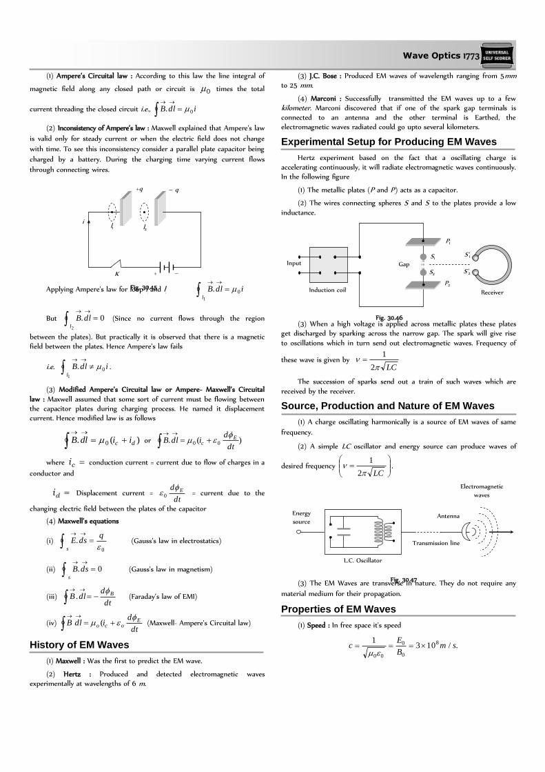
(1) Ampere’s Circuital law : According to this law the line integral of
magnetic field along any closed path or circuit is 0 times the total
current threading the closed circuit i.e., idlB 0.
(2) Inconsistency of Ampere’s law : Maxwell explained that Ampere's law
is valid only for steady current or when the electric field does not change
with time. To see this inconsistency consider a parallel plate capacitor being
charged by a battery. During the charging time varying current flows
through connecting wires.
Applying Ampere's law for loop l1
and l2
idlBl
0.1
But 0.2
dlBl
(Since no current flows through the region
between the plates). But practically it is observed that there is a magnetic field between the plates. Hence Ampere's law fails
i.e. idlBl
0.1
.
(3) Modified Ampere’s Circuital law or Ampere- Maxwell’s Circuital
law : Maxwell assumed that some sort of current must be flowing between the capacitor plates during charging process. He named it displacement current. Hence modified law is as follows
)(. 0 dc iidlB
or )(. 00dt
didlB Ec
where ci conduction current = current due to flow of charges in a
conductor and
di Displacement current = dt
d E 0 = current due to the
changing electric field between the plates of the capacitor
(4) Maxwell’s equations
(i) 0
.
qdsE
s
(Gauss’s law in electrostatics)
(ii) 0.
dsBs
(Gauss's law in magnetism)
(iii) dt
ddlB B
. (Faraday’s law of EMI)
(iv) dt
didlB E
oco
( (Maxwell- Ampere's Circuital law)
History of EM Waves
(1) Maxwell : Was the first to predict the EM wave.
(2) Hertz : Produced and detected electromagnetic waves experimentally at wavelengths of 6 m.
(3) J.C. Bose : Produced EM waves of wavelength ranging from 5mm to 25 mm.
(4) Marconi : Successfully transmitted the EM waves up to a few kilometer. Marconi discovered that if one of the spark gap terminals is connected to an antenna and the other terminal is Earthed, the electromagnetic waves radiated could go upto several kilometers.
Experimental Setup for Producing EM Waves
Hertz experiment based on the fact that a oscillating charge is accelerating continuously, it will radiate electromagnetic waves continuously. In the following figure
(1) The metallic plates (P1
and P2
) acts as a capacitor.
(2) The wires connecting spheres S1
and S2
to the plates provide a low
inductance.
(3) When a high voltage is applied across metallic plates these plates get discharged by sparking across the narrow gap. The spark will give rise
to oscillations which in turn send out electromagnetic waves. Frequency of
these wave is given by LC
2
1
The succession of sparks send out a train of such waves which are
received by the receiver.
Source, Production and Nature of EM Waves
(1) A charge oscillating harmonically is a source of EM waves of same
frequency.
(2) A simple LC oscillator and energy source can produce waves of
desired frequency
LC
2
1.
(3) The EM Waves are transverse in nature. They do not require any
material medium for their propagation.
Properties of EM Waves
(1) Speed : In free space it's speed
./1031 8
0
0
00
smB
Ec
i l1 l2
+q – q
K + –
Fig. 30.45
S1
S2
Input
Induction coil
Gap
P1
P2
S'1
S'2
Receiver
Fig. 30.46
Fig. 30.47
Energy
source
L.C. Oscillator
Transmission line
Antenna
Electromagnetic
waves

1774 Wave Optics
In medium
1v ; where 0 Absolute permeability,
0
=
Absolute permittivity.
(2) Energy : The energy in an EM waves is divided equally between the electric and magnetic fields.
Energy density of electric field 20
2
1Eue , Energy density of
magnetic field 0
2
2
1
BuB
The total energy per unit volume is me uuu 0
22
02
1
2
1
BE .
Also 200
2
1Euav
0
20
2
B
(3) Intensity (I) : The energy crossing per unit area per unit time,
perpendicular to the direction of propagation of EM wave is called intensity.
i.e. Time area Surface
Volumedensity energyTotal
Time area Surface
energy EMTotal
I
..2
1
2
12
0
202
00m
W attc
BcEcuI av
(4) Momentum : EM waves also carries momentum, if a portion of
EM wave of energy u propagating with speed c, then linear momentum
)( Speed
)( Energy
c
u
If wave incident on a completely absorbing surface then momentum
delivered c
up . If wave incident on a totally reflecting surface then
momentum delivered c
up
2 .
(5) Poynting vector ).(S
: In EM waves, the rate of flow of energy
crossing a unit area is described by the Poynting vector.
(i) It's unit is 2/ mWatt and )()(1
02 BEcBES
o
.
(ii) Because in EM waves E and B are perpendicular to each other,
the magnitude of S is C
EEBBES o
2
00
90sin1
||
.
(iii) The direction of S does not oscillate but it's magnitude varies
between zero and a maximum
0
00max
BES each quarter of a period.
(iv) Average value of poynting vector is given by
0
202
0000
0 22
1
2
1
cBcEBES
The direction of the poynting vector S at any point gives the wave's
direction of travel and direction of energy transport the point.
(6) Radiation pressure : Is the momentum imparted per second pre
unit area. On which the light falls.
For a perfectly reflecting surface c
SPr
2 ; S = Poynting vector; c =
Speed of light
For a perfectly absorbing surface .c
SPa
(7) Wave impedance (Z) : The medium offers hindrance to the
propagation of wave. Such hindrance is called wave impedance and it is
given by 0
0
r
rZ
For vacuum or free space .6.3760
0
Z
EM Spectrum
The whole orderly range of frequencies/wavelengths of the EM waves
is known as the EM spectrum.
Table 30.2 : Uses of EM spectrum
Radiation Uses
-rays Gives informations on nuclear structure,
medical treatment etc.
X-rays Medical diagnosis and treatment study of
crystal structure, industrial radiograph.
UV- rays Preserve food, sterilizing the surgical
instruments, detecting the invisible writings,
finger prints etc.
Visible light To see objects
Infrared rays To treat, muscular strain for taking
photography during the fog, haze etc.
Micro wave and radio wave In radar and telecommunication.
Earth's Atmosphere
The gaseous envelope surrounding the earth is called it's atmosphere.
The atmosphere contains 78% ,2N 21% 2O , and traces of other gases
(like helium, krypton, 2CO etc.)
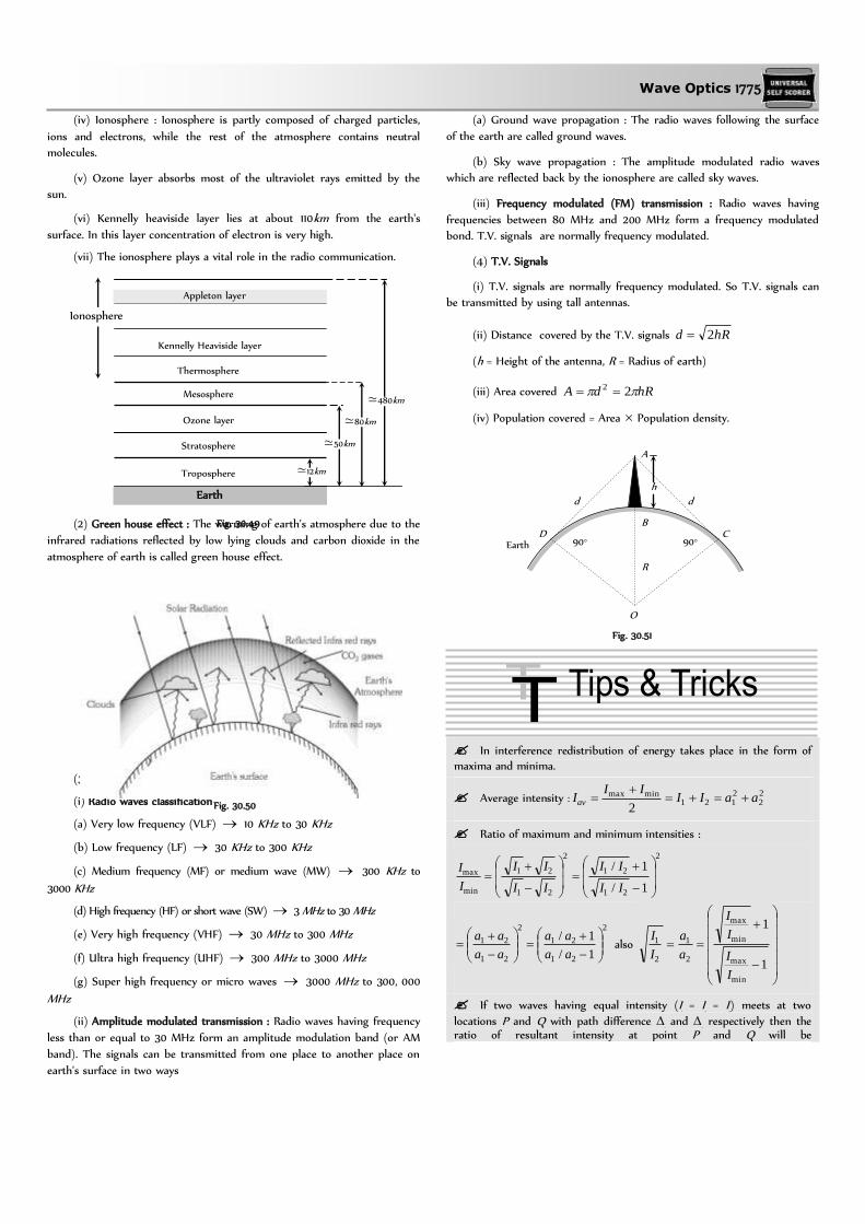
(1) Division of earth's atmosphere : Earth atmosphere has been divided
into regions as shown.
(i) Troposphere : In this region, the temperature decreases with height
from 290 K to 220 K.
(ii) Stratosphere : The temperature of stratosphere varies from 220 K
to 200 K.
(iii) Mesosphere : In this region, the temperature falls to 180 K.
Fig. 30.48
Wave Optics 1775
(iv) Ionosphere : Ionosphere is partly composed of charged particles,
ions and electrons, while the rest of the atmosphere contains neutral
molecules.
(v) Ozone layer absorbs most of the ultraviolet rays emitted by the
sun.
(vi) Kennelly heaviside layer lies at about 110km from the earth's
surface. In this layer concentration of electron is very high.
(vii) The ionosphere plays a vital role in the radio communication.
(2) Green house effect : The warming of earth's atmosphere due to the
infrared radiations reflected by low lying clouds and carbon dioxide in the
atmosphere of earth is called green house effect.
(3) Role of earth's atmosphere in propagation of radio waves
(i) Radio waves classification
(a) Very low frequency (VLF) 10 KHz to 30 KHz
(b) Low frequency (LF) 30 KHz to 300 KHz
(c) Medium frequency (MF) or medium wave (MW) 300 KHz to
3000 KHz
(d) High frequency (HF) or short wave (SW) 3 MHz to 30 MHz
(e) Very high frequency (VHF) 30 MHz to 300 MHz
(f) Ultra high frequency (UHF) 300 MHz to 3000 MHz
(g) Super high frequency or micro waves 3000 MHz to 300, 000
MHz
(ii) Amplitude modulated transmission : Radio waves having frequency
less than or equal to 30 MHz form an amplitude modulation band (or AM
band). The signals can be transmitted from one place to another place on
earth's surface in two ways
(a) Ground wave propagation : The radio waves following the surface
of the earth are called ground waves.
(b) Sky wave propagation : The amplitude modulated radio waves
which are reflected back by the ionosphere are called sky waves.
(iii) Frequency modulated (FM) transmission : Radio waves having
frequencies between 80 MHz and 200 MHz form a frequency modulated
bond. T.V. signals are normally frequency modulated.
(4) T.V. Signals
(i) T.V. signals are normally frequency modulated. So T.V. signals can
be transmitted by using tall antennas.
(ii) Distance covered by the T.V. signals hRd 2
(h = Height of the antenna, R = Radius of earth)
(iii) Area covered hRdA 22
(iv) Population covered = Area Population density.
In interference redistribution of energy takes place in the form of
maxima and minima.
Average intensity : 22
2121
minmax
2aaII
IIIav
Ratio of maximum and minimum intensities :
2
21
21
2
21
21
min
max
1/
1/
II
II
II
II
I
I
2
21
21
2
21
21
1/
1/
aa
aa
aa
aa also
1
1
min
max
min
max
2
1
2
1
I
I
I
I
a
a
I
I
If two waves having equal intensity (I1
= I2
= I0
) meets at two
locations P and Q with path difference 1
and 2
respectively then the ratio of resultant intensity at point P and Q will be
Fig. 30.50
Appleton layer
Kennelly Heaviside layer
Thermosphere
Mesosphere
Ozone layer
Stratosphere
Troposphere ≃12km
≃50km
≃80km
≃480km
Earth
Ionosphere
Fig. 30.49
Fig. 30.51
h
d d
D C Earth 90° 90°
R
O
B
A

1776 Wave Optics
22
12
22
12
cos
cos
2cos
2cos
Q
P
I
I
The angular thickness of fringe width is defined as dD
,
which is independent of the screen distance D.
Central maxima means the maxima formed with zero optical path difference. It may be formed anywhere on the screen.
All the wavelengths produce their central maxima at the same position.
The wave with smaller wavelength from its maxima before the wave with longer wavelength.
The first maxima of violet colour is closest and that for the red colour is farthest.
Fringes with blue light are thicker than those for red light.
In an interference pattern, whatever energy disappears at the minimum, appears at the maximum.
In YDSE, the nth maxima always comes before the nth minima.
In YDSE, the ratio min
max
I
I is maximum when both the sources have
same intensity.
For two interfering waves if initial phase difference between them
is 0
and phase difference due to path difference between them is '. Then total phase difference will be
2' 0 .
Sometimes maximm number of maximas or minimas are asked in the question which can be obtained on the screen. For this we use the
fact that value of sin (or cos ) can't be greater than 1. For example in the first case when the slits are vertical
d
n sin (for maximum intensity)
sin ≯1 d
n≯ 1 or n ≯
d
Suppose in some question d/ comes out say 4.6, then total number of maximuas on the screen will be 9. Corresponding to
3,2,1,0 n and 4.
Shape of wave front
If rays are parallel, wave front is plane. If rays are converging wave front is spherical of decreasing radius. If rays are diverging wave front is spherical of increasing radius.
Most efficient antennas are those which have a size comparable to
the wavelength of the of electromagnetic wave they emit or receive.
A substance (like calcite quartz) which exhibits different properties in different direction is called an anisotopic substance.
Wave front

1778 Wave Optics
Wave Nature and Interference of Light
1. By corpuscular theory of light, the phenomenon which can be explained is
(a) Refraction (b) Interference
(c) Diffraction (d) Polarisation
2. According to corpuscular theory of light, the different colours of light are due to
(a) Different electromagnetic waves
(b) Different force of attraction among the corpuscles
(c) Different size of the corpuscles
(d) None of the above
3. Huygen's conception of secondary waves [CPMT 1975]
(a) Allow us to find the focal length of a thick lens
(b) Is a geometrical method to find a wavefront
(c) Is used to determine the velocity of light
(d) Is used to explain polarisation
4. The idea of the quantum nature of light has emerged in an attempt to explain [CPMT 1990]
(a) Interference
(b) Diffraction
(c) Radiation spectrum of a black body
(d) Polarisation
5. Two coherent sources of light can be obtained by
[MH CET 2001]
(a) Two different lamps
(b) Two different lamps but of the same power
(c) Two different lamps of same power and having the same colour
(d) None of the above
6. By Huygen's wave theory of light, we cannot explain the phenomenon of
[CPMT 1989; AFMC 1993, 99; MP PET 1995, 2003;
RPMT 2003; BCECE 2003; Pb PMT 2004]
(a) Interference (b) Diffraction
(c) Photoelectric effect (d) Polarisation
7. The phenomenon of interference is shown by
[MNR 1994; MP PMT 1997; AIIMS 1999, 2000;
JIPMER 2000; UPSEAT 1994, 2000]
(a) Longitudinal mechanical waves only
(b) Transverse mechanical waves only
(c) Electromagnetic waves only
(d) All the above types of waves
8. Two coherent monochromatic light beams of intensities I and 4I are
superposed. The maximum and minimum possible intensities in the
resulting beam are
[IIT-JEE 1988; RPMT 1995; AIIMS 1997; MP PMT 1997;
MP PET 1999; BHU 2002; KCET 2000, 05]
(a) 5I and I (b) 5I and 3I
(c) 9I and I (d) 9I and 3I
9. Light appears to travel in straight lines since [RPMT 1997;
CPMT 1987, 89, 90, 2001; AIIMS 1998, 2002;
KCET 2002; BHU 2002; DCE 2003]
(a) It is not absorbed by the atmosphere
(b) It is reflected by the atmosphere
(c) Its wavelength is very small
(d) Its velocity is very large
10. The idea of secondary wavelets for the propagation of a wave was
first given by [Orissa PMT 2004]
(a) Newton (b) Huygen
(c) Maxwell (d) Fresnel
11. By a monochromatic wave, we mean [AFMC 1995]
(a) A single ray
(b) A single ray of a single colour
(c) Wave having a single wavelength
(d) Many rays of a single colour
12. The similarity between the sound waves and light waves is
[KCET 1994]
(a) Both are electromagnetic waves
(b) Both are longitudinal waves
(c) Both have the same speed in a medium
(d) They can produce interference
13. The ratio of intensities of two waves is 9 : 1. They are producing
interference. The ratio of maximum and minimum intensities will be [MNR 1987
MP PET 1999; AMU (Engg.) 1999; AIIMS 2000]
(a) 10 : 8 (b) 9 : 1
(c) 4 : 1 (d) 2 : 1
14. A wave can transmit ...... from one place to another
[CPMT 1984]
(a) Energy (b) Amplitude
(c) Wavelength (d) Matter
15. If the ratio of intensities of two waves is 1 : 25, then the ratio of
their amplitudes will be [CPMT 1984]
(a) 1 : 25 (b) 5 : 1
(c) 26 : 24 (d) 1 : 5
16. Two identical light sources S1
and S2
emit light of same wavelength .
These light rays will exhibit interference if
[MP PMT 1993]
(a) Their phase differences remain constant
(b) Their phases are distributed randomly
(c) Their light intensities remain constant
(d) Their light intensities change randomly
17. Wave nature of light follows because [MP PMT 1993]
(a) Light rays travel in a straight line
(b) Light exhibits the phenomena of reflection and refraction
(c) Light exhibits the phenomenon of interference

Wave Optics 1779
(d) Light causes the phenomenon of photoelectric effect
18. If L is the coherence length and c the velocity of light, the coherent time is [MP PMT 1996]
(a) cL (b) c
L
(c) L
c (d)
Lc
1
19. If the amplitude ratio of two sources producing interference is 3 : 5, the ratio of intensities at maxima and minima is
[MP PMT 1996]
(a) 25 : 16 (b) 5 : 3
(c) 16 : 1 (d) 25 : 9
20. Colours of thin films result from
[CPMT 1972, 83, 96; RPMT 1997; DCE 2002; AIIMS 2005]
or
On a rainy day, a small oil film on water show brilliant colours. This is due to [MP PET 2004]
(a) Dispersion of light (b) Interference of light
(c) Absorption of light (d) Scattering of light
21. For constructive interference to take place between two
monochromatic light waves of wavelength , the path difference
should be [MNR 1992; UPSEAT 2001]
(a) 4
)12(
n (b) 2
)12(
n
(c) n (d) 2
)12(
n
22. Two sources of waves are called coherent if
[NCERT 1984; MNR 1995; RPMT 1996, 97;
CPMT 1997; UPSEAT 1995, 2000; Orissa JEE 2002; RPET 2003; MP PMT 1996, 2004]
(a) Both have the same amplitude of vibrations
(b) Both produce waves of the same wavelength
(c) Both produce waves of the same wavelength having constant phase difference
(d) Both produce waves having the same velocity
23. Soap bubble appears coloured due to the phenomenon of
[AFMC 1995, 97; RPET 1997;
CBSE PMT 1999; Pb PET 2001]
(a) Interference (b) Diffraction
(c) Dispersion (d) Reflection
24. Which of the following statements indicates that light waves are
transverse [MP PMT 1995; AFMC 1996]
(a) Light waves can travel in vacuum
(b) Light waves show interference
(c) Light waves can be polarized
(d) Light waves can be diffracted
25. If two light waves having same frequency have intensity ratio 4 : 1
and they interfere, the ratio of maximum to minimum intensity in
the pattern will be
[BHU 1995; MP PMT 1995; DPMT 1999; CPMT 2003]
(a) 9 : 1 (b) 3 : 1
(c) 25 : 9 (d) 16 : 25
26. Evidence for the wave nature of light cannot be obtained from [MP PET 1996]
(a) Reflection (b) Doppler effect
(c) Interference (d) Diffraction
27. Two light sources are said to be coherent if they are obtained from [MP PET 1996]
(a) Two independent point sources emitting light of the same
wavelength
(b) A single point source
(c) A wide source
(d) Two ordinary bulbs emitting light of different wavelengths
28. Wavelength of light of frequency 100Hz [CBSE PMT 1999]
(a) m6102 (b) m6103
(c) m6104 (d) m6105
29. Two waves having intensity in the ratio 25 : 4 produce interference.
The ratio of the maximum to the minimum intensity is [CPMT 1999]
(a) 5 : 2 (b) 7 : 3
(c) 49 : 9 (d) 9 : 49
30. Wavefront means [RPMT 1997, 98]
(a) All particles in it have same phase
(b) All particles have opposite phase of vibrations
(c) Few particles are in same phase, rest are in opposite phase
(d) None of these
31. Wavefront of a wave has direction with wave motion
[RPMT 1997]
(a) Parallel (b) Perpendicular
(c) Opposite (d) At an angle of
32. Which one of the following phenomena is not explained by Huygen's
construction of wavefront [CBSE PMT 1992]
(a) Refraction (b) Reflection
(c) Diffraction (d) Origin of spectra
33. Interference was observed in interference chamber when air was
present, now the chamber is evacuated and if the same light is used,
a careful observer will see
[CBSE PMT 1993; DPMT 2000; BHU 2002]
(a) No interference
(b) Interference with bright bands
(c) Interference with dark bands
(d) Interference in which width of the fringe will be slightly
increased
34. The ratio of intensities of two waves are given by 4 : 1. The ratio of the amplitudes of the two waves is
[CBSE PMT 1993]
(a) 2 : 1 (b) 1 : 2
(c) 4 : 1 (d) 1 : 4
35. For the sustained interference of light, the necessary condition is
that the two sources should
[DPMT 1996; RPMT 1998, 2003]
(a) Have constant phase difference

1780 Wave Optics
(b) Be narrow
(c) Be close to each other
(d) Of same amplitude
36. If the ratio of amplitude of two waves is 4 : 3, then the ratio of maximum and minimum intensity is [AFMC 1997]
(a) 16 : 18 (b) 18 : 16
(c) 49 : 1 (d) 94 : 1
37. Which of the following is conserved when light waves interfere [MNR 1998]
(a) Intensity (b) Energy
(c) Amplitude (d) Momentum
38. Intensity of light depends upon [RPMT 1999]
(a) Velocity (b) Wavelength
(c) Amplitude (d) Frequency
39. Ray diverging from a point source from a wave front that is
[RPET 2000]
(a) Cylindrical (b) Spherical
(c) Plane (d) Cubical
40. Ratio of amplitude of interfering waves is 3 : 4. Now ratio of their intensities will be [RPET 2000]
(a) 9
16 (b) 49 : 1
(c) 16
9 (d) None of these
41. Two coherent sources have intensity in the ratio of 1
100. Ratio of
(intensity) max/(intensity) min is [RPET 2000]
(a) 100
1 (b)
10
1
(c) 1
10 (d)
2
3
42. If two waves represented by ty sin41 and
3sin32
ty interfere at a point, the amplitude of the
resulting wave will be about [MP PMT 2000]
(a) 7 (b) 6
(c) 5 (d) 3.5
43. The two waves represented by y1
= a sin(t) and )cos(2 tby
have a phase difference of [MP PMT 2000]
(a) 0 (b) 2
(c) (d) 4
44. In a wave, the path difference corresponding to a phase difference of
is [MP PET 2000]
(a)
2 (b)
(c)
2 (d)
45. Two coherent sources of intensities, I1
and I2
produce an interference pattern. The maximum intensity in the interference pattern will be[UPSEAT 2001; MP PET 2001]
(a) I1
+ I2
(b) 22
21 II
(c) (I1
+ I2
)2 (d) 221 )( II
46. Newton postulated his corpuscular theory on the basis of
[UPSEAT 2001; KCET 2001]
(a) Newton’s rings
(b) Colours of thin films
(c) Rectilinear propagation of light
(d) Dispersion of white light
47. The dual nature of light is exhibited by
[KCET 1999; AIIMS 2001; BHU 2001;
MH CET 2003; BCECE 2004]
(a) Photoelectric effect
(b) Refraction and interference
(c) Diffraction and reflection
(d) Diffraction and photoelectric effect
48. Two beams of light having intensities I and 4I interfere to produce a
fringe pattern on a screen. The phase difference between the beams
is 2
at point A and at point B. Then the difference between the
resultant intensities at A and B is
[IIT JEE (Screening) 2001]
(a) 2I (b) 4I
(c) 5I (d) 7I
49. Coherent sources are those sources for which [RPET 2001]
(a) Phase difference remain constant
(b) Frequency remains constant
(c) Both phase difference and frequency remains constant
(d) None of these
50. Wave nature of light is verified by [RPET 2001]
(a) Interference (b) Photoelectric effect
(c) Reflection (d) Refraction
51. Two waves are represented by the equations tay sin1 and
.cos2 tay The first wave [MP PMT 2001]
(a) Leads the second by
(b) Lags the second by
(c) Leads the second by 2
(d) Lags the second by 2
52. Light waves producing interference have their amplitudes in the
ratio 3 : 2. The intensity ratio of maximum and minimum of
interference fringes is [EAMCET 2001]
(a) 36 : 1 (b) 9 : 4
(c) 25 : 1 (d) 6 : 4
53. Laser beams are used to measure long distance because
[DCE 2001]
(a) They are monochromatic
(b) They are highly polarised
(c) They are coherent

Wave Optics 1781
(d) They have high degree of parallelism
54. Two coherent sources of different intensities send waves which
interfere. The ratio of maximum intensity to the minimum intensity
is 25. The intensities of the sources are in the ratio [UPSEAT 2002]
(a) 25 : 1 (b) 5 : 1
(c) 9 : 4 (d) 25 : 16
55. The frequency of light ray having the wavelength 3000 Å is
[DPMT 2002]
(a) 9 1013 cycles/sec (b) 1015 cycles/sec
(c) 90 cycles/sec (d) 3000 cycles/sec
56. Two waves have their amplitudes in the ratio 1 : 9. The maximum and minimum intensities when they interfere are in the ratio [KCET 2002]
(a) 16
25 (b)
26
16
(c) 9
1 (d)
1
9
57. Huygen’s principle of secondary wavelets may be used to
[KCET 2002]
(a) Find the velocity of light in vacuum
(b) Explain the particle behaviour of light
(c) Find the new position of the wavefront
(d) Explain photoelectric effect
58. What is the path difference of destructive interference
[AIIMS 2002]
(a) n (b) )1( n
(c) 2
)1( n (d)
2
)12( n
59. If an interference pattern have maximum and minimum intensities in 36 : 1 ratio then what will be the ratio of amplitudes [AFMC 2002]
(a) 5 : 7 (b) 7 : 4
(c) 4 : 7 (d) 7 : 5
60. Intensities of the two waves of light are I and 4I. The maximum
intensity of the resultant wave after superposition is [MP PET 2002]
(a) 5 I (b) 9 I
(c) 16 I (d) 25 I
61. As a result of interference of two coherent sources of light, energy is [MP PMT 2002; KCET 2003]
(a) Increased
(b) Redistributed and the distribution does not vary with time
(c) Decreased
(c) Redistributed and the distribution changes with time
62. To demonstrate the phenomenon of interference, we require two sources which emit radiation [AIEEE 2003]
(a) Of the same frequency and having a define phase relationship
(b) Of nearly the same frequency
(c) Of the same frequency
(d) Of different wavelengths
63. When a beam of light is used to determine the position of an object,
the maximum accuracy is achieved if the light is
[AIIMS 2003]
(a) Polarised (b) Of longer wavelength
(c) Of shorter wavelength (d) Of high intensity
64. If the distance between a point source and screen is doubled, then
intensity of light on the screen will become
[RPET 1997; RPMT 1999]
(a) Four times (b) Double
(c) Half (d) One-fourth
65. Huygen wave theory allows us to know [AFMC 2004]
(a) The wavelength of the wave
(b) The velocity of the wave
(c) The amplitude of the wave
(d) The propagation of wave fronts
66. The wave theory of light was given by
[J & K CET 2004; KCET 2005]
(a) Maxwell (b) Planck
(c) Huygen (d) Young
67. The phase difference between incident wave and reflected wave is
180° when light ray [RPMT 1998, 2001]
(a) Enters into glass from air
(b) Enters into air from glass
(c) Enters into glass from diamond
(d) Enters into water from glass
68. Which of the following phenomena can explain quantum nature of
light [RPMT 2001]
(a) Photoelectric effect (b) Interference
(c) Diffraction (d) Polarisation
69. Which of the following is not a property of light
[AFMC 2005]
(a) It requires a material medium for propagation
(b) It can travel through vacuum
(c) It involves transportation of energy
(d) It has finite speed
70. What causes changes in the colours of the soap or oil films for the given beam of light [AFMC 2005]
(a) Angle of incidence (b) Angle of reflection
(c) Thickness of film (d) None of these
71. Select the right option in the following [KCET 2005]
(a) Christian Huygens a contemporary of Newton established the wave theory of light by assuming that light waves were
transverse
(b) Maxwell provided the compelling theoretical evidence that light is transverse wave
(c) Thomas Young experimentally proved the wave behaviour of light and Huygens assumption
(d) All the statements give above, correctly answers the question ‚what is light‛
72. Two waves of intensity I undergo Interference. The maximum intensity obtained is [BHU 2005]
(a) I / 2 (b) I
(c) 2I (d) 4I

1782 Wave Optics
Young’s Double Slit Experiment
1. Young's experiment establishes that
[CPMT 1972; MP PET 1994, 98; MP PMT 1998]
(a) Light consists of waves
(b) Light consists of particles
(c) Light consists of neither particles nor waves
(d) Light consists of both particles and waves
2. In the interference pattern, energy is
(a) Created at the position of maxima
(b) Destroyed at the position of minima
(c) Conserved but is redistributed
(d) None of the above
3. Monochromatic green light of wavelength m7105 illuminates a
pair of slits 1 mm apart. The separation of bright lines on the interference pattern formed on a screen 2 m away is [CPMT 1971; DPMT 1999]
(a) 0.25 mm (b) 0.1 mm
(c) 1.0 mm (d) 0.01 mm
4. In Young's double slit experiment, if the slit widths are in the ratio 1 : 9, then the ratio of the intensity at minima to that at maxima will
be [MP PET 1987]
(a) 1 (b) 1/9
(c) 1/4 (d) 1/3
5. In Young's double slit interference experiment, the slit separation is
made 3 fold. The fringe width becomes
[CPMT 1982, 89]
(a) 1/3 times (b) 1/9 times
(c) 3 times (d) 9 times
6. In a certain double slit experimental arrangement interference
fringes of width 1.0 mm each are observed when light of wavelength
5000 Å is used. Keeping the set up unaltered, if the source is
replaced by another source of wavelength 6000 Å, the fringe width
will be [CPMT 1988]
(a) 0.5 mm (b) 1.0 mm
(c) 1.2 mm (d) 1.5 mm
7. Two coherent light sources S1
and S2
(= 6000 Å) are 1mm apart
from each other. The screen is placed at a distance of 25 cm from
the sources. The width of the fringes on the screen should be [CPMT 1990]
(a) 0.015 cm (b) 0.025 cm
(c) 0.010 cm (d) 0.030 cm
8. The figure shows a double slit experiment P and Q are the slits. The
path lengths PX and QX are n and )2( n respectively, where
n is a whole number and is the wavelength. Taking the central
fringe as zero, what is formed at X
(a) First bright
(b) First dark
(c) Second bright
(d) Second dark
9. In Young's double slit experiment, if one of the slit is closed fully,
then in the interference pattern
(a) A bright slit will be observed, no interference pattern will exist
(b) The bright fringes will become more bright
(c) The bright fringes will become fainter
(d) None of the above
10. In Young's double slit experiment, a glass plate is placed before a slit
which absorbs half the intensity of light. Under this case
(a) The brightness of fringes decreases
(b) The fringe width decreases
(c) No fringes will be observed
(d) The bright fringes become fainter and the dark fringes have finite light intensity
11. In Young's experiment, the distance between the slits is reduced to half and the distance between the slit and screen is doubled, then
the fringe width
[IIT 1981; MP PMT 1994; RPMT 1997; KCET 2000;
CPMT 2003; AMU (Engg.) 2000; DPMT 2003;
UPSEAT 2000, 04; Kerala PMT 2004]
(a) Will not change (b) Will become half
(c) Will be doubled (d) Will become four times
12. The maximum intensity of fringes in Young's experiment is I. If one of the slit is closed, then the intensity at that place becomes I
o
. Which of the following relation is true ?
[NCERT 1982; MP PMT 1994, 99; BHU 1998;
RPMT 1996; RPET 1999; AMU (Engg.) 1999]
(a) I = Io
(b) I = 2Io
(c) I = 4Io
(d) There is no relation between I and Io
13. In the Young's double slit experiment, the ratio of intensities of
bright and dark fringes is 9. This means that [IIT 1982]
(a) The intensities of individual sources are 5 and 4 units respectively
(b) The intensities of individual sources are 4 and 1 units
respectively
(c) The ratio of their amplitudes is 3
(d) The ratio of their amplitudes is 2
14. An oil flowing on water seems coloured due to interference. For observing this effect, the approximate thickness of the oil film should be
[DPET 1987; JIPMER 1997; RPMT 2002, 04]
(a) 100 Å (b) 10000 Å
(c) 1 mm (d) 1 cm
15. The Young's experiment is performed with the lights of blue ( =
4360 Å) and green colour ( = 5460 Å), If the distance of the 4th
fringe from the centre is x, then [CPMT 1987]
(a) x (Blue) = x (Green) (b) x (Blue)> x (Green)
(c) x (Blue) < x (Green) (d) 4360
5460
)(
)(
Greenx
Bluex
16. In the Young's double slit experiment, the spacing between two slits is 0.1 mm. If the screen is kept at a distance of 1.0 m from the slits and the wavelength of light is 5000 Å, then the fringe width is [MP PMT 1993; RPET 1996]
(a) 1.0 cm (b) 1.5 cm
(c) 0.5 cm (d) 2.0 cm
17. In Young's double slit experiment, if L is the distance between the
slits and the screen upon which interference pattern is observed, x is
n
(n+2) P
Q
X
Wave Optics 1783
the average distance between the adjacent fringes and d being the slit separation. The wavelength of light is given by [MP PET 1993]
(a) L
xd (b)
d
xL
(c) x
Ld (d)
Ldx
1
18. In a Young's double slit experiment, the central point on the screen is [MP PMT 1996]
(a) Bright (b) Dark
(c) First bright and then dark (d) First dark and then bright
19. In a Young's double slit experiment, the fringe width is found to be 0.4 mm. If the whole apparatus is immersed in water of refractive
index 4/3 without disturbing the geometrical arrangement, the new fringe width will be
[CBSE PMT 1990]
(a) 0.30 mm (b) 0.40 mm
(c) 0.53 mm (d) 450 micron
20. Young's experiment is performed in air and then performed in water, the fringe width [CPMT 1990; MP PMT 1994;
RPMT 1997; Kerala PMT 2004]
(a) Will remain same (b) Will decrease
(c) Will increase (d) Will be infinite
21. In double slits experiment, for light of which colour the fringe width will be minimum [MP PMT 1994]
(a) Violet (b) Red
(c) Green (d) Yellow
22. In Young's experiment, light of wavelength 4000 Å is used to
produce bright fringes of width 0.6 mm, at a distance of 2 meters. If
the whole apparatus is dipped in a liquid of refractive index 1.5, then
fringe width will be [MP PMT 1994]
(a) 0.2 mm (b) 0.3 mm
(c) 0.4 mm (d) 1.2 mm
23. In Young's double slit experiment, the phase difference between the
light waves reaching third bright fringe from the central fringe will
be ( =6000 Å ) [MP PMT 1994]
(a) Zero (b) 2
(c) 4 (d) 6
24. In Young's double slit experiment, if the widths of the slits are in the
ratio 4 : 9, the ratio of the intensity at maxima to the intensity at
minima will be [Manipal MEE 1995]
(a) 169 : 25 (b) 81 : 16
(c) 25 : 1 (d) 9 : 4
25. In Young's double slit experiment when wavelength used is 6000 Å
and the screen is 40 cm from the slits, the fringes are 0.012 cm
wide. What is the distance between the slits
[MP PMT 1995; Pb PET 2002]
(a) 0.024 cm (b) 2.4 cm
(c) 0.24 cm (d) 0.2 cm
26. In two separate set - ups of the Young's double slit experiment,
fringes of equal width are observed when lights of wavelengths in
the ratio 1 : 2 are used. If the ratio of the slit separation in the two
cases is 2 : 1, the ratio of the distances between the plane of the slits
and the screen in the two set - ups is [KCET 1996]
(a) 4 : 1 (b) 1 : 1
(c) 1 : 4 (d) 2 : 1
27. In an interference experiment, the spacing between successive
maxima or minima is [MP PET 1996]
(a) D
d (b)
d
D
(c)
dD (d)
D
d
4
(Where the symbols have their usual meanings)
28. If yellow light in the Young's double slit experiment is replaced by
red light, the fringe width will [MP PMT 1996]
(a) Decrease
(b) Remain unaffected
(c) Increase
(d) First increase and then decrease
29. In Young's double slit experiment, the fringe width is m4101 if
the distance between the slit and screen is doubled and the distance between the two slit is reduced to half and wavelength is changed
from m7104.6 to m7100.4 , the value of new fringe width will be
(a) m41015.0 (b) m4100.2
(c) m41025.1 (d) m4105.2
30. In Young's experiment, one slit is covered with a blue filter and the
other (slit) with a yellow filter. Then the interference pattern [MP PET 1997]
(a) Will be blue (b) Will be yellow
(c) Will be green (d) Will not be formed
31. Two sources give interference pattern which is observed on a screen,
D distance apart from the sources. The fringe width is 2w. If the
distance D is now doubled, the fringe width will [MP PET 1997]
(a) Become w/2 (b) Remain the same
(c) Become w (d) Become 4w
32. In double slit experiment, the angular width of the fringes is 0.20 o
for the sodium light ( =5890 Å). In order to increase the angular
width of the fringes by 10%, the necessary change in the wavelength
is [MP PMT 1997]
(a) Increase of 589 Å (b) Decrease of 589 Å
(c) Increase of 6479 Å (d) Zero
33. In a biprism experiment, by using light of wavelength 5000 Å, 5 mm
wide fringes are obtained on a screen 1.0 m away from the coherent
sources. The separation between the two coherent sources is [MP PMT/PET 1998]
(a) 1.0 mm (b) 0.1 mm
(c) 0.05 mm (d) 0.01 mm
34. The slits in a Young's double slit experiment have equal widths and
the source is placed symmetrically relative to the slits. The intensity
1784 Wave Optics
at the central fringes is I0
. If one of the slits is closed, the intensity at
this point will be
[MP PMT 1999; Orissa JEE 2004; Kerala PET 2005]
(a) I0
(b) I0
/ 4
(c) I0
/ 2 (d) 4I0
35. A thin mica sheet of thickness m6102 and refractive index
)5.1( is introduced in the path of the first wave. The
wavelength of the wave used is 5000 Å. The central bright
maximum will shift [CPMT 1999]
(a) 2 fringes upward (b) 2 fringes downward
(c) 10 fringes upward (d) None of these
36. In a Young's double slit experiment, the fringe width will remain
same, if (D = distance between screen and plane of slits, d =
separation between two slits and = wavelength of light used) [Bihar MEE 1995]
(a) Both and D are doubled
(b) Both d and D are doubled
(c) D is doubled but d is halved
(d) is doubled but d is halved
37. In Young's double slit experiment, the slits are 0.5 mm apart and
interference pattern is observed on a screen placed at a distance of 1.0 m from the plane containing the slits. If wavelength of the incident light is 6000 Å, then the separation between the third bright fringe and the central maxima is [AMU 1995]
(a) 4.0 mm (b) 3.5 mm
(c) 3.0 mm (d) 2.5 mm
38. In Young's double slit experiment, 62 fringes are seen in visible region for sodium light of wavelength 5893 Å. If violet light of wavelength 4358 Å is used in place of sodium light, then number of fringes seen will be [RPET 1997]
(a) 54 (b) 64
(c) 74 (d) 84
39. In Young's double slit experiment, angular width of fringes is 0.20o for sodium light of wavelength 5890 Å. If complete system is dipped in water, then angular width of fringes becomes [RPET 1997]
(a) 0.11o (b) 0.15o
(c) 0.22o (d) 0.30o
40. In Young's double slit experiment, the distance between the slits is 1 mm and that between slit and screen is 1 meter and 10th fringe is 5 mm away from the central bright fringe, then wavelength of light used will be [RPMT 1997]
(a) 5000 Å (b) 6000 Å
(c) 7000 Å (d) 8000 Å
41. In Young's double slit experiment, carried out with light of
wavelength = 5000 Å, the distance between the slits is 0.2 mm
and the screen is at 200 cm from the slits. The central maximum is at x =0. The third maximum (taking the central maximum as zeroth
maximum) will be at x equal to
[CBSE PMT 1992; MH CET 2002]
(a) 1.67 cm (b) 1.5 cm
(c) 0.5 cm (d) 5.0 cm
42. In a Young's experiment, two coherent sources are placed 0.90 mm apart and the fringes are observed one metre away. If it produces
the second dark fringe at a distance of 1 mm from the central fringe, the wavelength of monochromatic light used would be
[CBSE PMT 1992; KCET 2004]
(a) cm41060 (b) cm41010
(c) cm51010 (d) cm5106
43. In Young's double slit experiment, the distance between the two
slits is 0.1 mm and the wavelength of light used is m7104 . If the width of the fringe on the screen is 4 mm, the distance between screen and slit is
[Bihar CMEET 1995]
(a) 0.1 mm (b) 1 cm
(c) 0.1 cm (d) 1 m
44. In Young's double slit experiment, the distance between sources is 1
mm and distance between the screen and source is 1 m. If the fringe
width on the screen is 0.06 cm, then = [CPMT 1996]
(a) 6000 Å (b) 4000 Å
(c) 1200 Å (d) 2400 Å
45. In Young's double slit experiment, a mica slit of thickness t and
refractive index is introduced in the ray from the first source S1
.
By how much distance the fringes pattern will be displaced [RPMT 1996, 97; JIPMER 2000; RPMT 2003]
(a) tD
d)1( (b) t
d
D)1(
(c) D
d
)1( (d) )1(
d
D
46. In Young's double slit experiment using sodium light ( = 5898 Å),
92 fringes are seen. If given colour ( = 5461 Å) is used, how many
fringes will be seen
[CPMT 1989; RPET 1996; JIPMER 2001, 02]
(a) 62 (b) 67
(c) 85 (d) 99
47. If a torch is used in place of monochromatic light in Young’s
experiment what will happens
[MH CET 1999; KCET 1999]
(a) Fringe will appear for a moment then it will disappear
(b) Fringes will occur as from monochromatic light
(c) Only bright fringes will appear
(d) No fringes will appear
48. When a thin metal plate is placed in the path of one of the
interfering beams of light [KCET 1999]
(a) Fringe width increases (b) Fringes disappear
(c) Fringes become brighter (d) Fringes becomes blurred
49. In Young’s experiment, the distance between slits is 0.28 mm and distance
between slits and screen is 1.4 m. Distance between central bright
fringe and third bright fringe is 0.9 cm. What is the wavelength of
used light [KCET 1999]
(a) 5000 Å (b) 6000 Å
(c) 7000 Å (d) 9000 Å
Wave Optics 1785
50. Two parallel slits 0.6 mm apart are illuminated by light source of wavelength 6000 Å. The distance between two consecutive dark fringes on a screen 1 m away from the slits is [JIPMER 1999]
(a) 1 mm (b) 0.01 mm
(c) 0.1 m (d) 10 m
51. In young’s double slit experiment with a source of light of wavelength 6320Å, the first maxima will occur when
[Roorkee 1999]
(a) Path difference is 9480 Å
(b) Phase difference is 2 radian
(c) Path difference is 6320 Å
(d) Phase difference is radian
52. If a transparent medium of refractive index = 1.5 and thickness t =
2.5 10–5 m is inserted in front of one of the slits of Young’s Double Slit experiment, how much will be the shift in the interference pattern? The distance between the slits is 0.5 mm and that between slits and screen is 100 cm [AIIMS 1999]
(a) 5 cm (b) 2.5 cm
(c) 0.25 cm (d) 0.1 cm
53. In Young’s experiment, monochromatic light is used to illuminate the two slits A and B. Interference fringes are observed on a screen placed in front of the slits. Now if a thin glass plate is placed normally in the path of the beam coming from the slit
[UPSEAT 1993, 2000; AIIMS 1999, 2004]
(a) The fringes will disappear
(b) The fringe width will increase
(c) The fringe width will increase
(d) There will be no change in the fringe width but the pattern shifts
54. The fringe width in Young’s double slit experiment increases when [MP PMT 2000]
(a) Wavelength increases
(b) Distance between the slits increases
(c) Distance between the source and screen decreases
(d) The width of the slits increases
55. In a double slit experiment, instead of taking slits of equal widths, one slit is made twice as wide as the other. Then in the interference pattern [IIT-JEE (Screening) 2000]
(a) The intensities of both the maxima and the minima increase
(b) The intensity of maxima increases and the minima has zero intensity
(c) The intensity of maxima decreases and that of the minima increases
(d) The intensity of maxima decreases and the minima has zero intensity
56. Two slits, 4 mm apart, are illuminated by light of wavelength 6000 Å. What will be the fringe width on a screen placed 2m from the slits [MP PET 2000]
(a) 0.12 mm (b) 0.3 mm
(c) 3.0 mm (d) 4.0 mm
57. In the Young’s double slit experiment, for which colour the fringe width is least [UPSEAT 2001, MP PET 2001]
(a) Red (b) Green
(c) Blue (d) Yellow
58. In a Young’s double slit experiment, the separation of the two slits is doubled. To keep the same spacing of fringes, the distance D of the screen from the slits should be made
[MNR 1998; AMU (Engg.) 2001]
(a) 2
D (b)
2
D
(c) 2D (d) 4D
59. Young’s double slit experiment is performed with light of wavelength 550 nm. The separation between the slits is 1.10 mm and screen is placed at distance of 1 m. What is the distance between the consecutive bright or dark fringes
[Pb. PMT 2000]
(a) 1.5 mm (b) 1.0 mm
(c) 0.5 mm (d) None of these
60. In Young’s experiment, the ratio of maximum to minimum intensities of the fringe system is 4 : 1. The amplitudes of the coherent sources are in the ratio
[RPMT 1996; MP PET 2000; RPET 2001; MP PMT 2001]
(a) 4 : 1 (b) 3 : 1
(c) 2 : 1 (d) 1 : 1
61. An interference pattern was made by using red light. If the red light changes with blue light, the fringes will become
[BHU 2001]
(a) Wider (b) Narrower
(c) Fainter (d) Brighter
62. If a white light is used in Young’s double slit experiments then a
very large number of coloured fringes can be seen
[KCET 2001]
(a) With first order violet fringes being closer to the central white fringes
(b) First order red fringes being closer to the central white fringes
(c) With a central white fringe
(d) With a central black fringe
63. In a Young’s double slit experiment, 12 fringes are observed to be
formed in a certain segment of the screen when light of wavelength 600 nm is used. If the wavelength of light is changed to 400 nm, number of fringes observed in the same segment of the screen is given by [IIT-JEE (Screening) 2001]
(a) 12 (b) 18
(c) 24 (d) 30
64. In the Young’s double slit experiment with sodium light. The slits are 0.589 m a part. The angular separation of the third maximum
from the central maximum will be (given = 589 mm) [Pb. PMT 2002]
(a) )1033.0(sin 81 (b) )1033.0(sin 61
(c) )103(sin 81 (d) )103(sin 61
65. In Young’s double slit experiment, the distance between the two slits is made half, then the fringe width will become
[RPMT 1999; BHU 2002]
(a) Half (b) Double
(c) One fourth (d) Unchanged
66. In Young’s double slit experiment, the central bright fringe can be identified [KCET 2002]
(a) By using white light instead of monochromatic light
(b) As it is narrower than other bright fringes
(c) As it is wider than other bright fringes
A
B
C
1786 Wave Optics
(d) As it has a greater intensity than the other bright fringes
67. In Young’s double slit experiment, the wavelength of the light used is doubled and distance between two slits is half of initial distance, the resultant fringe width becomes
[AIEEE 2002]
(a) 2 times (b) 3 times
(c) 4 times (d) 1/2 times
68. In a Young’s double slit experiment, the source illuminating the slits is changed from blue to violet. The width of the fringes [KCET 2002]
(a) Increases (b) Decreases
(c) Becomes unequal (d) Remains constant
69. In Young’s double slit experiment, the intensity of light coming from the first slit is double the intensity from the second slit. The ratio of the maximum intensity to the minimum intensity on the interference fringe pattern observed is [KCET 2002]
(a) 34 (b) 40
(c) 25 (d) 38
70. If the sodium light in Young’s double slit experiment is replaced by red light, the fringe width will [MP PMT 2002]
(a) Decrease
(b) Increase
(c) Remain unaffected
(d) First increase, then decrease
71. In Young’s double slit experiment the wavelength of light was changed from 7000 Å to 3500 Å. While doubling the separation between the slits which of the following is not true for this experiment [Orissa JEE 2002]
(a) The width of the fringes changes
(b) The colour of bright fringes changes
(c) The separation between successive bright fringes changes
(d) The separation between successive dark fringes remains unchanged
72. When a thin transparent plate of thickness t and refractive index
is placed in the path of one of the two interfering waves of light,
then the path difference changes by
[MP PMT 2002]
(a) ( + 1)t (b) ( – 1)t
(c) t
)1( (d)
t
)1(
73. In Young’s double-slit experiment, an interference pattern is
obtained on a screen by a light of wavelength 6000 Å, coming from
the coherent sources S1
and S2
. At certain point P on the screen third
dark fringe is formed. Then the path difference S1
P – S2
P in microns
is [EAMCET 2003]
(a) 0.75 (b) 1.5
(c) 3.0 (d) 4.5
74. In a Young’s double slit experiment, the slit separation is 1 mm and
the screen is 1 m from the slit. For a monochromatic light of
wavelength 500 nm, the distance of 3rd minima from the central
maxima is [Orissa JEE 2003]
(a) 0.50 mm (b) 1.25 mm
(c) 1.50 mm (d) 1.75 mm
75. In Young’s double-slit experiment the fringe width is . If entire
arrangement is placed in a liquid of refractive index n, the fringe
width becomes [KCET 2003]
(a) 1n
(b) n
(c) n
(d)
1n
76. In an interference experiment, third bright fringe is obtained at a
point on the screen with a light of 700 nm. What should be the
wavelength of the light source in order to obtain 5th bright fringe at
the same point [KCET 2003]
(a) 500 nm (b) 630 nm
(c) 750 nm (d) 420 nm
77. If the separation between slits in Young’s double slit experiment is
reduced to ,3
1rd the fringe width becomes n times. The value of n
is [MP PET 2003]
(a) 3 (b) 3
1
(c) 9 (d) 9
1
78. A double slit experiment is performed with light of wavelength 500
nm. A thin film of thickness 2 m and refractive index 1.5 is
introduced in the path of the upper beam. The location of the
central maximum will
[AIIMS 2003]
(a) Remain unshifted
(b) Shift downward by nearly two fringes
(c) Shift upward by nearly two fringes
(d) Shift downward by 10 fringes
79. The two slits at a distance of 1 mm are illuminated by the light of
wavelength m7105.6 . The interference fringes are observed on
a screen placed at a distance of 1m. The distance between third dark
fringe and fifth bright fringe will be [NCERT 1982; MP PET 1995; BVP 2003]
(a) 0.65 mm (b) 1.63 mm
(c) 3.25 mm (d) 4.88 mm
80. In a Young’s double-slit experiment the fringe width is 0.2 mm. If
the wavelength of light used is increased by 10% and the separation
between the slits is also increased by 10%, the fringe width will be [MP PMT 2004]
(a) 0.20 mm (b) 0.401 mm
(c) 0.242 mm (d) 0.165 mm
81. Two coherent sources of intensity ratio 1 : 4 produce an interference
pattern. The fringe visibility will be
[J & K CET 2004]
(a) 1 (b) 0.8
(c) 0.4 (d) 0.6
82. In Young’s double slit experiment the amplitudes of two sources are
3a and a respectively. The ratio of intensities of bright and dark
fringes will be [J & K CET 2004]
(a) 3 : 1 (b) 4 : 1
(c) 2 : 1 (d) 9 : 1
83. In Young’s double slit experiment, distance between two sources is
0.1 mm. The distance of screen from the sources is 20 cm.
Wavelength of light used is 5460 Å. Then angular position of the
first dark fringe is [DCE 2002]
(a) 0.08° (b) 0.16°

Wave Optics 1787
(c) 0.20° (d) 0.313°
84. In a Young’s double slit experiment, the slit separation is 0.2 cm, the
distance between the screen and slit is 1m. Wavelength of the light
used is 5000 Å. The distance between two consecutive dark fringes
(in mm) is
[DCE 2004]
(a) 0.25 (b) 0.26
(c) 0.27 (d) 0.28
85. A light of wavelength 5890 Å falls normally on a thin air film. The
minimum thickness of the film such that the film appears dark in reflected light [Pb. PMT 2003]
(a) m710945.2 (b) m710945.3
(c) m71095.4 (d) m710945.1
86. In Young’s double slit experiment, a minimum is obtained when the phase difference of super imposing waves is
[MH CET 2004]
(a) Zero (b) )12( n
(c) n (d) )1( n
87. In Fresnel’s biprism )5.1( experiment the distance between
source and biprism is 0.3 m and that between biprism and screen is 0.7m and angle of prism is 1°. The fringe width with light of wavelength 6000 Å will be
[RPMT 2002]
(a) 3 cm (b) 0.011 cm
(c) 2 cm (d) 4 cm
88. In Young double slit experiment, when two light waves form third minimum, they have [RPMT 2003]
(a) Phase difference of 3 (b) Phase difference of 2
5
(c) Path difference of 3 (d) Path difference of 2
5
89. In Fresnel’s biprism experiment, on increasing the prism angle,
fringe width will [RPMT 2003]
(a) Increase
(b) Decrease
(c) Remain unchanged
(d) Depend on the position of object
90. If prism angle ,54.1,1 distance between screen and
prism ,7.0)( mb distance between prism and source
nmma 180,3.0 then in Fresnal biprism find the value of
(fringe width) [RPMT 2002]
(a) m410 (b) mm310
(c) m410 (d) m310
91. If Fresnel’s biprism experiment as held in water inspite of air, then
what will be the effect on fringe width [RPMT 1997, 98]
(a) Decrease (b) Increase
(c) No effect (d) None of these
92. What is the effect on Fresnel’s biprism experiment when the use of
white light is made [RPMT 1998]
(a) Fringe are affected
(b) Diffraction pattern is spread more
(c) Central fringe is white and all are coloured
(d) None of these
93. What happens to the fringe pattern when the Young’s double slit
experiment is performed in water instead or air then fringe width [AFMC 2005]
(a) Shrinks (b) Disappear
(c) Unchanged (d) Enlarged
94. In Young’s doubled slit experiment, the separation between the slit
and the screen increases. The fringe width
[BCECE 2005]
(a) Increases (b) Decreases (c) Remains unchanged (d) None of these
95. In Young’s double slit experiment, the aperture screen distance is
2m. The fringe width is 1 mm. Light of 600 nm is used. If a thin
plate of glass ( = 1.5) of thickness 0.06 mm is placed over one of
the slits, then there will be a lateral displacement of the fringes by [BCECE 2005]
(a) 0 cm (b) 5 cm
(c) 10 cm (d) 15 cm
96. In which of the following is the interference due to the division of
wave front [UPSEAT 2005]
(a) Young's double slit experiment
(b) Fresnel's biprism experiment
(c) Lloyd's mirror experiment
(d) Demonstration colours of thin film
97. Two slits are separated by a distance of 0.5 mm and illuminated
with light of 6000 Å. If the screen is placed 2.5 m from the
slits. The distance of the third bright image from the centre will be [CPMT 2005]
(a) 1.5 mm (b) 3 mm
(c) 6 mm (d) 9 mm
Doppler’s Effect of Light
1. The observed wavelength of light coming from a distant galaxy is
found to be increased by 0.5% as compared with that coming from
a terrestrial source. The galaxy is
[MP PMT 1993, 2003]
(a) Stationary with respect to the earth
(b) Approaching the earth with velocity of light
(c) Receding from the earth with the velocity of light
(d) Receding from the earth with a velocity equal to
sm /105.1 6
2. A star producing light of wavelength 6000 Å moves away from the
earth with a speed of 5 km/sec. Due to Doppler effect the shift in
wavelength will be sec)/103( 8 mc
[MP PMT 1990]
(a) 0.1 Å (b) 0.05 Å
(c) 0.2 Å (d) 1 Å

1788 Wave Optics
3. If the shift of wavelength of light emitted by a star is towards violet,
then this shows that star is
[RPET 1996; RPMT 1999]
(a) Stationary
(b) Moving towards earth
(c) Moving away from earth
(d) Information is incomplete
4. Assuming that universe is expanding, if the spectrum of light coming
from a star which is going away from earth is tested, then in the
wavelength of light
(a) There will be no change
(b) The spectrum will move to infrared region
(c) The spectrum will seems to shift to ultraviolet side
(d) None of the above
5. Doppler's effect in sound in addition to relative velocity between
source and observer, also depends while source and observer or both
are moving. Doppler effect in light depend only on the relative
velocity of source and observer. The reason of this is [MP PET/PMT 1988]
(a) Einstein mass - energy relation
(b) Einstein theory of relativity
(c) Photoelectric effect
(d) None of these
6. A rocket is moving away from the earth at a speed of
sm /106 7 . The rocket has blue light in it. What will be the
wavelength of light recorded by an observer on the earth
(wavelength of blue light = 4600 Å)
(a) 4600 Å (b) 5520 Å
(c) 3680 Å (d) 3920 Å
7. A spectral line = 5000 Å in the light coming from a distant star is
observed as a 5200 Å. What will be recession velocity of the star
(a) sec/1015.1 7 cm (b) sec/1015.1 7 m
(c) sec/1015.1 7 km (d) 1.15 km/sec
8. The apparent wavelength of the light from a star moving away from
the earth is 0.01% more than its real wavelength. Then the velocity
of star is [CPMT 1979]
(a) 60 km/sec (b) 15 km/sec
(c) 150 km/sec (d) 30 km/sec
9. A star emits light of 5500 Å wavelength. Its appears blue to an
observer on the earth, it means [DPMT 2002]
(a) Star is going away from the earth
(b) Star is stationary
(c) Star is coming towards earth
(d) None of the above
10. The velocity of light emitted by a source S observed by an observer
O, who is at rest with respect to S is c. If the observer moves
towards S with velocity v, the velocity of light as observed will be [NCERT 1980]
(a) c + v (b) vc
(c) c (d) 2
2
1c
v
11. In the context of Doppler effect in light, the term ‘red shift’ signifies [MP PET 1994]
(a) Decrease in frequency
(b) Increase in frequency
(c) Decrease in intensity
(d) Increase in intensity
12. The sun is rotating about its own axis. The spectral lines emitted
from the two ends of its equator, for an observer on the earth, will
show [MP PMT 1994]
(a) Shift towards red end
(b) Shift towards violet end
(c) Shift towards red end by one line and towards violet end by
other
(d) No shift
13. A star is moving away from the earth with a velocity of 100 km/s. If
the velocity of light is sm /103 8 then the shift of its spectral
line of wavelength 5700 Å due to Doppler's effect will be [MP PMT 1994]
(a) 0.63 Å (b) 1.90 Å
(c) 3.80 Å (d) 5.70 Å
14. If a source of light is moving away from a stationary observer, then
the frequency of light wave appears to change because of [AFMC 1995]
(a) Doppler's effect
(b) Interference
(c) Diffraction
(d) None of these
15. A star emitting radiation at a wavelength of 5000 Å is approaching
earth with a velocity of sm /105.1 6 . The change in wavelength
of the radiation as received on the earth, is [CBSE PMT 1995]
(a) 25 Å (b) Zero
(c) 100 Å (d) 2.5 Å
16. A star emitting light of wavelength 5896 Å is moving away from the
earth with a speed of 3600 km / sec. The wavelength of light
observed on earth will
[MP PET 1995, 2002]
(a) Decrease by 5825.25 Å
(b) Increase by 5966.75 Å
(c) Decrease by 70.75 Å
(d) Increase by 70.75 Å
( sec/103 8 mc is the speed of light)
17. A star moves away from earth at speed 0.8 c while emitting light of
frequency Hz14106 . What frequency will be observed on the
earth (in units of 1014 Hz) (c = speed of light) [MP PMT 1995]
(a) 0.24 (b) 1.2
(c) 30 (d) 3.3
18. A light source approaches the observer with velocity 0.8 c. The
doppler shift for the light of wavelength 5500 Å is
[MP PET 1996]

Wave Optics 1789
(a) 4400 Å (b) 1833 Å
(c) 3167 Å (d) 7333 Å
19. Light coming from a star is observed to have a wavelength of 3737
Å, while its real wavelength is 3700 Å. The speed of the star relative
to the earth is [Speed of light sm /103 8 ]
[MP PET 1997]
(a) sm /103 5 (b) sm /103 6
(c) sm /107.3 7 (d) sm /107.3 6
20. In the spectrum of light of a luminous heavenly body the wavelength
of a spectral line is measured to be 4747 Å while actual wavelength
of the line is 4700 Å. The relative velocity of the heavenly body with
respect to earth will be (velocity of light is sm /103 8 ) [MP PMT/PET 1998]
(a) sm /103 5 moving towards the earth
(b) sm /103 5 moving away from the earth
(c) sm /103 6 moving towards the earth
(d) sm /103 6 moving away from the earth
21. The wavelength of light observed on the earth, from a moving star is
found to decrease by 0.05%. Relative to the earth the star is [MP PMT/PET 1998]
(a) Moving away with a velocity of sm /105.1 5
(b) Coming closer with a velocity of sm /105.1 5
(c) Moving away with a velocity of sm /105.1 4
(d) Coming closer with a velocity of sm /105.1 4
22. A star is going away from the earth. An observer on the earth will
see the wavelength of light coming from the star
[MP PMT 1999]
(a) Decreased
(b) Increased
(c) Neither decreased nor increased
(d) Decreased or increased depending upon the velocity of the star
23. A star is moving towards the earth with a speed of 6105.4 m/s.
If the true wavelength of a certain line in the spectrum received
from the star is 5890 Å, its apparent wavelength will be about
]/103[ 8 smc [MP PMT 1999]
(a) 5890 Å (b) 5978 Å
(c) 5802 Å (d) 5896 Å
24. Due to Doppler's effect, the shift in wavelength observed is 0.1 Å for
a star producing wavelength 6000 Å. Velocity of recession of the
star will be
(a) 2.5 km/s (d) 10 km/s
(c) 5 km/s (d) 20 km/s
25. A rocket is going away from the earth at a speed of 10 6 m/s If the
wavelength of the light wave emitted by it be 5700 Å, what will be
its Doppler's shift [RPMT 1996]
(a) 200 Å (b) 19 Å
(c) 20 Å (d) 0.2 Å
26. A rocket is going away from the earth at a speed 0.2c, where c =
speed of light. It emits a signal of frequency Hz7104 . What will
be the frequency observed by an observer on the earth [RPMT 1996]
(a) Hz6104 (b) Hz7102.3
(c) Hz6103 (d) Hz7105
27. If a star is moving towards the earth, then the lines are shifted
towards [AIIMS 1997]
(a) Red (b) Infrared
(c) Blue (d) Green
28. When the wavelength of light coming from a distant star is
measured it is found shifted towards red. Then the conclusion is [JIPMER 1999]
(a) The star is approaching the observer
(b) The star recedes away from earth
(c) There is gravitational effect on the light
(d) The star remains stationary
29. A heavenly body is receding from earth such that the fractional
change in is 1, then its velocity is [DCE 2000]
(a) C (b) 5
3C
(c) 5
C (d)
5
2C
30. The 6563 Å line emitted by hydrogen atom in a star is found to be
red shifted by 5 Å. The speed with which the star is receding from
the earth is [Pb. PMT 2002]
(a) 17.29 109 m/s (b) 4.29 107 m/s
(c) 3.39 105 m/s (d) 2.29 105 m/s
31. Three observers A, B and C measure the speed of light coming from
a source to be Av , Bv and Cv . The observer A moves towards the
source, the observer C moves away from the source with the same
speed. The observer B stays stationary. the surrounding space is
vacuum every where. Then [KCET 2002]
(a) CBA vvv (b) CBA vvv
(c) CBA vvv (d) CBA vvv
32. Light from the constellation Virgo is observed to increase in
wavelength by 0.4%. With respect to Earth the constellation is [MP PET 2003]
(a) Moving away with velocity 1.2 106 m/s
(b) Coming closer with velocity 1.2 106 m/s
(c) Moving away with velocity 4 106 m/s
(d) Coming closer with velocity 4 106 m/s
33. It is believed that the universe is expanding and hence the distant
stars are receding from us. Light from such a star will show [CPMT 2005]
(a) Shift in frequency towards longer wavelengths
(b) Shift in frequency towards shorter wavelength
(c) No shift in frequency but a decrease in intensity
(d) A shift in frequency sometimes towards longer and sometimes towards shorter wavelengths

1790 Wave Optics
Diffraction of Light
1. A slit of width a is illuminated by white light. For red light ( =
6500 Å), the first minima is obtained at o30 . Then the value
of a will be [MP PMT 1987; CPMT 2002]
(a) 3250 Å (b) mm4105.6
(c) 1.24 microns (d) cm4106.2
2. The light of wavelength 6328 Å is incident on a slit of width 0.2
mm perpendicularly, the angular width of central maxima will be [MP PMT 1987; Pb. PMT 2002]
(a) o36.0 (b) o18.0
(c) o72.0 (d) o09.0
3. The bending of beam of light around corners of obstacles is called [NCERT 1990; AFMC 1995; RPET 1997;
RPMT 1997; CPMT 1999; JIPMER 2000]
(a) Reflection (b) Diffraction
(c) Refraction (d) Interference
4. The penetration of light into the region of geometrical shadow is
called [CPMT 1999; JIPMER 2000]
(a) Polarisation (b) Interference
(c) Diffraction (d) Refraction
5. A slit of size 0.15 cm is placed at 2.1 m from a screen. On
illuminated it by a light of wavelength 5 10–5 cm. The width of
central maxima will be [RPMT 1999]
(a) 70 mm (b) 0.14 mm
(c) 1.4 mm (d) 0.14 cm
6. A diffraction is obtained by using a beam of red light. What will happen if the red light is replaced by the blue light
[KCET 2000; BHU 2001]
(a) Bands will narrower and crowd full together
(b) Bands become broader and further apart
(c) No change will take place
(d) Bands disappear
7. What will be the angle of diffracting for the first minimum due to Fraunhoffer diffraction with sources of light of wave length 550 nm and slit of width 0.55 mm [Pb. PMT 2001]
(a) 0.001 rad (b) 0.01 rad
(c) 1 rad (d) 0.1 rad
8. Angular width () of central maximum of a diffraction pattern on a single slit does not depend upon
[DCE 2000; 01]
(a) Distance between slit and source
(b) Wavelength of light used
(c) Width of the slit
(d) Frequency of light used
9. A single slit of width 0.20 mm is illuminated with light of
wavelength 500 nm. The observing screen is placed 80 cm from the
slit. The width of the central bright fringe will be
[AMU (Med.) 2002]
(a) 1 mm (b) 2 mm
(c) 4 mm (d) 5 mm
10. Yellow light is used in single slit diffraction experiment with slit
width 0.6 mm. If yellow light is replaced by X-rays then the pattern
will reveal
[IIT-JEE (Screening) 1999; MP PMT 2002; KCET 2003]
(a) That the central maxima is narrower
(b) No diffraction pattern
(c) More number of fringes
(d) Less number of fringes
11. Which statement is correct for a zone plate and a lens
[RPMT 2002]
(a) Zone plate has multi focii whereas lens has one
(b) Zone plate has one focus whereas lens has multiple focii
(c) Both are correct
(d) Zone plate has one focus whereas a lens has infinite
12. In Fresnel diffraction, if the distance between the disc and the screen is decreased, the intensity of central bright spot will [RPMT 2002]
(a) Increase (b) Decrease
(c) Remain constant (d) None of these
13. A plane wavefront )106( 7 m falls on a slit mm4.0 wide.
A convex lens of focal length m8.0 placed behind the slit focusses
the light on a screen. What is the linear diameter of second maximum [RPMT 2001]
(a) mm6 (b) mm12
(c) mm3 (d) mm9
14. A zone plate of focal length ,60 cm behaves as a convex lens, If
wavelength of incident light is ,6000 Å then radius of first half
period zone will be [RPMT 2001]
(a) .1036 8 m (b) .106 8 m
(c) .106 8 m (d) .106 4 m
15. Radius of central zone of circular zone plate is .3.2 mm
Wavelength of incident light is .5893 Å Source is at a distance of
.6 m Then the distance of first image will be
[RPMT 2001]
(a) m9 (b) m12
(c) m24 (d) m36
16. Red light is generally used to observe diffraction pattern from single slit. If blue light is used instead of red light, then diffraction pattern
[RPMT 2001; BCECE 2005; CPMT 2005]
(a) Will be more clear (b) Will contract
(c) Will expanded (d) Will not be visualized
17. In the experiment of diffraction at a single slit, if the slit width is decreased, the width of the central maximum
[KCET 2001]
(a) Increases in both Fresnel and Fraunhofer diffraction
(b) Decreases both in Fresnal and Fraunhofer diffraction
(c) Increases in Fresnel diffraction but decreases in Fraunhofer diffraction
(d) Decreases in Fresnel diffraction but increases is Fraunofer diffraction.
18. Conditions of diffraction is [RPET 2001]
(a) 1
a (b) 1
a

Wave Optics 1791
(c) 1
a (d) None of these
19. Light of wavelength nm3.589 is incident normally on the slit of
width .1.0 mm What will be the angular width of the central
diffraction maximum at a distance of m1 from the slit [BHU (Med.) 1999]
(a) 68.0 (b) 02.1
(c) 34.0 (d) None of these
20. The phenomenon of diffraction of light was discovered by
[KCET 2000]
(a) Hygens (b) Newton
(c) Fresnel (d) Grimaldi
21. The radius r of half period zone is proportional to
[RPMT 1998, 2002]
(a) n (b) n
1
(c) 2n (d) n
1
22. In a diffraction pattern by a wire, on increasing diameter of wire, fringe width [RPMT 1998]
(a) Decreases
(b) Increases
(c) Remains unchanged
(d) Increasing or decreasing will depend on wavelength
23. What will be the angular width of central maxima in Fraunhoffer
diffraction when light of wavelength Å6000 is used and slit width
is .1012 5 cm [RPMT 2004]
(a) 2 rad (b) 3 rad
(c) 1 rad (d) 8 rad
24. When a compact disc is illuminated by a source of white light. Coloured 'lanes' are observed. This is due to
[DCE 2003; AIIMS 2004]
(a) Dispersion (b) Diffraction
(c) Interference (d) Refraction
25. The diffraction effect can be observed in [J & K CET 2004]
(a) Only sound waves
(b) Only light waves
(c) Only ultrasonic waves
(d) Sound as well as light waves
26. If we observe the single slit Fraunhofer diffraction with wavelength
and slit width e, the width of the central maxima is 2. On
decreasing the slit width for the same
[UPSEAT 2004]
(a) increases
(b) remains unchanged
(c) decreases
(d) increases or decreases depending on the intensity of light
27. When light is incident on a diffraction grating the zero order principal maximum will be [KCET 2004]
(a) One of the component colours
(b) Absent
(c) Spectrum of the colours
(d) White
28. A beam of light of wavelength 600 nm from a distant source falls on a single slit 1 mm wide and the resulting diffraction pattern is observed on a screen 2 m away. The distance between the first dark fringes on either side of the central bright fringe is [IIT-JEE 1994; KCET 2004]
(a) 1.2 mm (b) 1.2 cm
(c) 2.4 cm (d) 2.4 mm
29. In order to see diffraction the thickness of the film is
[J&K CEE 2001]
(a) 100 Å (b) 10,000 Å
(c) 1 mm (d) 1 cm
30. Diffraction effects are easier to notice in the case of sound waves than in the case of light waves because
[RPET 1978; KCET 1994, 2000]
(a) Sound waves are longitudinal
(b) Sound is perceived by the ear
(c) Sound waves are mechanical waves
(d) Sound waves are of longer wavelength
31. Direction of the first secondary maximum in the Fraunhofer diffraction pattern at a single slit is given by (a is the width of the slit) [KCET 1999]
(a) 2
sin
a (b) 2
3cos
a
(c) sina (d) 2
3sin
a
32. A parallel monochromatic beam of light is incident normally on a
narrow slit. A diffraction pattern is formed on a screen placed perpendicular to the direction of incident beam. At the first maximum of the diffraction pattern the phase difference between the rays coming from the edges of the slit is [IIT–JEE 1995, 98]
(a) 0 (b) 2
(c) (d) 2
33. Diffraction and interference of light suggest
[CPMT 1995; RPMT 1998]
(a) Nature of light is electro-magnetic
(b) Wave nature
(c) Nature is quantum
(d) Nature of light is transverse
34. A light wave is incident normally over a slit of width
cm51024 . The angular position of second dark fringe from the
central maxima is 30o. What is the wavelength of light [RPET 1995]
(a) 6000 Å (b) 5000 Å
(c) 3000 Å (d) 1500 Å
35. A parallel beam of monochromatic light of wavelength 5000 Å is
incident normally on a single narrow slit of width 0.001 mm. The
light is focused by a convex lens on a screen placed on the focal
plane. The first minimum will be formed for the angle of diffraction
equal to [CBSE PMT 1993]
(a) 0o (b) 15o
(c) 30o (d) 60o

1792 Wave Optics
36. The condition for observing Fraunhofer diffraction from a single slit
is that the light wavefront incident on the slit should be [MP PMT 1987]
(a) Spherical (b) Cylindrical
(c) Plane (d) Elliptical
37. To observe diffraction the size of an obstacle [CPMT 1982]
(a) Should be of the same order as wavelength
(b) Should be much larger than the wavelength
(c) Have no relation to wavelength
(d) Should be exactly 2
38. In the far field diffraction pattern of a single slit under
polychromatic illumination, the first minimum with the wavelength
1 is found to be coincident with the third maximum at 2 . So
(a) 21 3.03 (b) 213
(c) 21 5.3 (d) 21 33.0
39. Light of wavelength = 5000 Å falls normally on a narrow slit. A
screen placed at a distance of 1 m from the slit and perpendicular to
the direction of light. The first minima of the diffraction pattern is
situated at 5 mm from the centre of central maximum. The width of
the slit is
(a) 0.1 mm (b) 1.0 mm
(c) 0.5 mm (d) 0.2 mm
40. The width of the nth HPZ will be
(a) nb (b) ]1[ nnb
(c) )1( nn (d) ]1[ nn
b
41. A single slit of width a is illuminated by violet light of wavelength
400 nm and the width of the diffraction pattern is measured as y.
When half of the slit width is covered and illuminated by yellow
light of wavelength 600 nm, the width of the diffraction pattern is [KCET 2005]
(a) The pattern vanishes and the width is zero
(b) y / 3
(c) 3y
(d) None of these
Polarization of Light
1. A polariser is used to [CPMT 1999]
(a) Reduce intensity of light
(b) Produce polarised light
(c) Increase intensity of light
(d) Produce unpolarised light
2. Light waves can be polarised as they are
[CBSE PMT 1993; KCET 1994;
AFMC 1997; J & K CET 2002; CPMT 2005]
(a) Transverse (b) Of high frequency
(c) Longitudinal (d) Reflected
3. Through which character we can distinguish the light waves from sound waves [CBSE PMT 1990; RPET 2000, 02]
(a) Interference (b) Refraction
(c) Polarisation (d) Reflection
4. The angle of polarisation for any medium is 60o, what will be critical angle for this [UPSEAT 1999]
(a) 3sin 1 (b) 3tan 1
(c) 3cos 1 (d) 3
1sin 1
5. The angle of incidence at which reflected light is totally polarized for reflection from air to glass (refraction index n) is [AIEEE 2004; UPSEAT 2005]
(a) )(sin 1 n (b)
n
1sin 1
(c)
n
1tan 1 (d) )(tan 1 n
6. Which of following can not be polarised [Kerala PMT 2001]
(a) Radio waves (b) Ultraviolet rays
(c) Infrared rays (d) Ultrasonic waves
7. A polaroid is placed at 45o to an incoming light of intensity 0I . Now
the intensity of light passing through polaroid after polarisation would be [CPMT 1995]
(a) 0I (b) 2/0I
(c) 4/0I (d) Zero
8. Plane polarised light is passed through a polaroid. On viewing through the polaroid we find that when the polariod is given one complete rotation about the direction of the light, one of the following is observed [MNR 1993]
(a) The intensity of light gradually decreases to zero and remains at zero
(b) The intensity of light gradually increases to a maximum and remains at maximum
(c) There is no change in intensity
(d) The intensity of light is twice maximum and twice zero
9. Out of the following statements which is not correct
[CPMT 1991]
(a) When unpolarised light passes through a Nicol's prism, the emergent light is elliptically polarised
(b) Nicol's prism works on the principle of double refraction and total internal reflection
(c) Nicol's prism can be used to produce and analyse polarised light
(d) Calcite and Quartz are both doubly refracting crystals
10. A ray of light is incident on the surface of a glass plate at an angle
of incidence equal to Brewster's angle . If represents the
refractive index of glass with respect to air, then the angle between
reflected and refracted rays is
[CPMT 1989]
(a) 90 (b) )cos(sin 1
(c) 90o (d) )/(sinsin90 1 o
11. Figure represents a glass plate placed vertically on a horizontal table
with a beam of unpolarised light falling on its surface at the
polarising angle of 57o with the normal. The electric vector in the
reflected light on screen S will vibrate with respect to the plane of
incidence in a
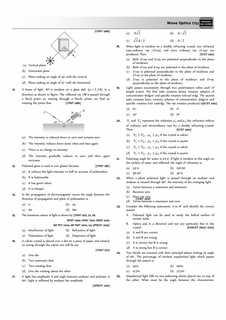
Wave Optics 1793
[CPMT 1988]
(a) Vertical plane
(b) Horizontal plane
(c) Plane making an angle of 45o with the vertical
(d) Plane making an angle of 57o with the horizontal
12. A beam of light AO is incident on a glass slab )54.1( in a
direction as shown in figure. The reflected ray OB is passed through
a Nicol prism on viewing through a Nicole prism, we find on
rotating the prism that [CPMT 1986]
(a) The intensity is reduced down to zero and remains zero
(b) The intensity reduces down some what and rises again
(c) There is no change in intensity
(d) The intensity gradually reduces to zero and then again
increases
13. Polarised glass is used in sun glasses because [CPMT 1981]
(a) It reduces the light intensity to half an account of polarisation
(b) It is fashionable
(c) It has good colour
(d) It is cheaper
14. In the propagation of electromagnetic waves the angle between the
direction of propagation and plane of polarisation is [CPMT 1978]
(a) 0o (b) 45o
(c) 90o (d) 180o
15. The transverse nature of light is shown by [CPMT 1972, 74, 78;
RPMT 1999; AFMC 2001; AIEEE 2002;
MP PET 2004; MP PMT 2000, 04; UPSEAT 2005]
(a) Interference of light (b) Refraction of light
(c) Polarisation of light (d) Dispersion of light
16. A calcite crystal is placed over a dot on a piece of paper and rotated, on seeing through the calcite one will be see
[CPMT 1971]
(a) One dot
(b) Two stationary dots
(c) Two rotating dots
(d) One dot rotating about the other
17. A light has amplitude A and angle between analyser and polariser is 60°. Light is reflected by analyser has amplitude
[UPSEAT 2001]
(a) 2A (b) 2/A
(c) 2/3 A (d) 2/A
18. When light is incident on a doubly refracting crystal, two refracted rays-ordinary ray (O-ray) and extra ordinary ray (E-ray) are produced. Then [KCET 2001]
(a) Both O-ray and E-ray are polarised perpendicular to the plane of incidence
(b) Both O-ray and E-ray are polarised in the plane of incidence
(c) E-ray is polarised perpendicular to the plane of incidence and O-ray in the plane of incidence
(d) E-ray is polarised in the plane of incidence and O-ray perpendicular to the plane of incidence
19. Light passes successively through two polarimeters tubes each of length 0.29m. The first tube contains dextro rotatory solution of concentration 60kgm–3 and specific rotation 0.01rad m2kg–1. The second tube contains laevo rotatory solution of concentration 30kg/m3 and specific rotation 0.02 radm2kg–1. The net rotation produced is[KCET 2002]
(a) 15° (b) 0°
(c) 20° (d) 10°
20. oV and EV represent the velocities, o and E the refractive indices
of ordinary and extraordinary rays for a doubly refracting crystal. Then [KCET 2002]
(a) EoEo VV , if the crystal is calcite
(b) EoEo VV , if the crystal is quartz
(c) EoEo VV , if the crystal is calcite
(d) EoEo VV , if the crystal is quartz
21. Polarising angle for water is 53°4'. If light is incident at this angle on
the surface of water and reflected, the angle of refraction is [TNPCEE 2002]
(a) 53°4' (b) 126°56'
(c) 36°56' (d) 30°4'
22. When a plane polarised light is passed through an analyser and
analyser is rotated through 90º, the intensity of the emerging light [TNPCEE 2002]
(a) Varies between a maximum and minimum
(b) Becomes zero
(c) Does not vary
(d) Varies between a maximum and zero
23. Consider the following statements A to B and identify the correct answer
A. Polarised light can be used to study the helical surface of nucleic acids.
B. Optics axis is a direction and not any particular line in the crystal [EAMCET (Med.) 2003]
(a) A and B are correct
(b) A and B are wrong
(c) A is correct but B is wrong
(d) A is wrong but B is correct
24. Two Nicols are oriented with their principal planes making an angle of 60°. The percentage of incident unpolarized light which passes through the system is
(a) 50% (b) 100%
(c) 12.5% (d) 37.5%
25. Unpolarized light falls on two polarizing sheets placed one on top of the other. What must be the angle between the characteristic
57° 57° S
A N B
33° 33°
O

1794 Wave Optics
directions of the sheets if the intensity of the final transmitted light is one-third the maximum intensity of the first transmitted beam
(a) 75° (b) 55°
(c) 35° (d) 15°
26. Unpolarized light of intensity 32Wm–2 passes through three polarizers such that transmission axes of the first and second polarizer makes and angle 30° with each other and the transmission axis of the last polarizer is crossed with that of the first. The intensity of final emerging light will be
(a) 32 Wm–2 (b) 3 Wm–2
(c) 8 Wm–2 (d) 4 Wm–2
27. In the visible region of the spectrum the rotation of the place of
polarization is given by 2
b
a . The optical rotation produced
by a particular material is found to be 30° per mm at 5000 Å
and 50° per mm at Å4000 . The value of constant a will be
(a) 9
50 per mm (b)
9
50 per mm
(c) 50
9 per mm (d)
50
9 per mm
28. When an unpolarized light of intensity 0I is incident on a
polarizing sheet, the intensity of the light which does not get
transmitted is [AIEEE 2005]
(a) Zero (b) 0I
(c) 02
1I (c) 0
4
1I
29. Refractive index of material is equal to tangent of polarising angle. It
is called [AFMC 2005]
(a) Brewster’s law (b) Lambert’s law
(c) Malus’s law (d) Bragg’s law
30. In case of linearly polarized light, the magnitude of the electric field
vector: [AIIMS 2005]
(a) Does not change with time
(b) Varies periodically with time
(c) Increases and decreases linearly with time
(d) Is parallel to the direction of propagation
31. When unpolarised light beam is incident from air onto glass (n = 1.5)
at the polarising angle [KCET 2005]
(a) Reflected beam is polarised 100 percent
(b) Reflected and refracted beams are partially polarised
(c) The reason for (a) is that almost all the light is reflected
(d) All of the above
32. An optically active compound [DCE 2005]
(a) Rotates the plane polarised light
(b) Changing the direction of polarised light
(c) Do not allow plane polarised light to pass through
(d) None of the above
33. When the angle of incidence on a material is 60°, the reflected light
is completely polarized. The velocity of the refracted ray inside the
material is (in ms–1)
[Kerala PMT 2005]
(a) 8103 (b) 8102
3
(c) 8103 (d) 8105.0
34. Two polaroids are placed in the path of unpolarized beam of
intensity 0I such that no light is emitted from the second polaroid.
If a third polaroid whose polarization axis makes an angle with the
polarization axis of first polaroid, is placed between these polaroids then the intensity of light emerging from the last polaroid will be [UPSEAT 2005]
(a) 2sin8
20
I (b) 2sin
4
20
I
(c) 40 cos2
I (d) 4
0 cosI
35. For the study of the helical structure of nucleic acids, the property of electromagnetic radiation generally used is
[EAMCET 2005]
(a) Reflection (b) Interference
(c) Diffraction (d) Polarization
EM Waves
1. Which of the following statement is wrong [NCERT 1976]
(a) Infrared photon has more energy than the photon of visible light
(b) Photographic plates are sensitive to ultraviolet rays
(c) Photographic plates can be made sensitive to infrared rays
(d) Infrared rays are invisible but can cast shadows like visible light rays
2. Pick out the longest wavelength from the following types of
radiations [CBSE PMT 1990]
(a) Blue light (b) -rays
(c) X-rays (d) Red light
3. Wave which cannot travel in vacuum is [MP PMT 1994]
(a) X-rays (b) Infrasonic
(c) Ultraviolet (d) Radiowaves
4. Light is an electromagnetic wave. Its speed in vacuum is given by
the expression
[CBSE PMT 1993; MP PMT 1994; RPMT 1999;
MP PET 2001; Kerala PET 2001; AIIMS 2002]
(a) oo (b) o
o
(c) o
o
(d)
oo
1
5. The range of wavelength of the visible light is
[MP PMT 2000; MP PET 2002]
(a) 10 Å to 100 Å (b) 4,000 Å to 8,000 Å
(c) 8,000 Å to 10,000 Å (d) 10,000 Å to 15,000 Å
6. Which radiation in sunlight, causes heating effect
[AFMC 2001]
(a) Ultraviolet (b) Infrared
(c) Visible light (d) All of these
7. Which of the following represents an infrared wavelength
Wave Optics 1795
[CPMT 1975; MP PET/PMT 1988]
(a) 410 cm (b) 510 cm
(c) 610 cm (d) 710 cm
8. The wavelength of light visible to eye is of the order of
[CPMT 1982, 84]
(a) m210 (b) 1010 m
(c) 1 m (d) 7106 m
9. The speed of electromagnetic wave in vacuum depends upon the source of radiation [Kerala PMT 2004]
(a) Increases as we move from -rays to radio waves
(b) Decreases as we move from -rays to radio waves
(c) Is same for all of them
(d) None of these
10. Which of the following radiations has the least wavelength
[AIEEE 2003]
(a) -rays (b) -rays
(c) -rays (d) X-rays
11. The maximum distance upto which TV transmission from a TV tower of height h can be received is proportional to
[AIIMS 2003]
(a) 2/1h (b) h
(c) h (d) 2h
12. Which of the following are not electromagnetic waves
[AIEEE 2002; CBSE PMT 2003]
(a) Cosmic rays (b) Gamma rays
(c) -rays (d) X-rays
13. Ozone is found in [DPMT 2002]
(a) Stratosphere (b) Ionosphere
(c) Mesosphere (d) Troposphere
14. The electromagnetic waves travel with a velocity
[J & K CET 2002]
(a) Equal to velocity of sound
(b) Equal to velocity of light
(c) Less than velocity of light
(d) None of these
15. The ozone layer absorbs [Kerala PET 2002]
(a) Infrared radiations (b) Ultraviolet radiations
(c) X-rays (d) -rays
16. Electromagnetic radiation of highest frequency is
[Kerala PMT 2002]
(a) Infrared radiations (b) Visible radiation
(c) Radio waves (d) -rays
17. Which of the following shows green house effect
[CBSE PMT 2002]
(a) Ultraviolet rays (b) Infrared rays
(c) X-rays (d) None of these
18. Which of the following waves have the maximum wavelength [AFMC 2002]
(a) X-rays (b) I.R. rays
(c) UV rays (d) Radio waves
19. Electromagnetic waves are transverse in nature is evident by
[AIEEE 2002]
(a) Polarization (b) Interference
(c) Reflection (d) Diffraction
20. If E and B are the electric and magnetic field vectors of E.M. waves then the direction of propagation of E.M. wave is along the direction of
[CBSE PMT 1992, 2002; DCE 2002, 05]
(a) E (b) B
(c) BE (d) None of these
21. Biological importance of Ozone layer is [CBSE PMT 2001]
(a) It stops ultraviolet rays
(b) Ozone rays reduce green house effect
(c) Ozone layer reflects radio waves
(d) Ozone layer controls 22 / HO radio in atmosphere
22. What is ozone hole [AFMC 2001]
(a) Hole in the ozone layer
(b) Formation of ozone layer
(c) Thinning of ozone layer in troposphere
(d) Reduction in ozone thickness in stratosphere
23. Which rays are not the portion of electromagnetic spectrum
[Haryana CEET 2000]
(a) X-rays (b) Microwaves
(c) -rays (d) Radio waves
24. Radio wave diffract around building although light waves do not.
The reason is that radio waves [AMU 2000]
(a) Travel with speed larger than c
(b) Have much larger wavelength than light
(c) Carry news
(d) Are not electromagnetic waves
25. The frequencies of X-rays, -rays and ultraviolet rays are respectively
a, b and c. Then [CBSE PMT 2000]
(a) a < b, b > c (b) a > b, b > c
(c) a > b, b < c (d) a < b, b < c
26. Radio waves and visible light in vacuum have [KCET 2000]
(a) Same velocity but different wavelength
(b) Continuous emission spectrum
(c) Band absorption spectrum
(d) Line emission spectrum
27. Energy stored in electromagnetic oscillations is in the form of
[Haryana CEET 2000; AFMC 1994]
(a) Electrical energy (b) Magnetic energy
(c) Both (a) and (b) (d) None of these
28. Heat radiations propagate with the speed of [AMU 2000]
(a) -rays (b) -rays
(c) Light waves (d) Sound waves

1796 Wave Optics
29. If a source is transmitting electromagnetic wave of frequency 6102.8 Hz, then wavelength of the electromagnetic waves
transmitted from the source will be [DPMT 1999]
(a) 36.6 m (b) 40.5 m
(c) 42.3 m (d) 50.9 m
30. In an apparatus, the electric field was found to oscillate with an amplitude of 18 V/m. The magnitude of the oscillating magnetic field will be [Pb. PMT 1999]
(a) 6104 T (b) 8106 T
(c) 9109 T (d) 111011 T
31. According to Maxwell’s hypothesis, a changing electric field gives rise to [AIIMS 1998]
(a) An e.m.f. (b) Electric current
(c) Magnetic field (d) Pressure radiant
32. In an electromagnetic wave, the electric and magnetising fields are 1100 mV and 1265.0 mA . The maximum energy flow is [Pb. PMT 1997, 98]
(a) 2/5.26 mW (b) 2/5.36 mW
(c) 2/7.46 mW (d) 2/765 mW
33. The 21 cm radio wave emitted by hydrogen in interstellar space is
due to the interaction called the hyperfine interaction is atomic hydrogen. the energy of the emitted wave is nearly [CBSE PMT 1998]
(a) 1710 Joule (b) 1 Joule
(c) 8107 Joule (d) 2410 Joule
34. TV waves have a wavelength range of 1-10 meter. Their frequency
range in MHz is [KCET 1998]
(a) 30-300 (b) 3-30
(c) 300-3000 (d) 3-3000
35. Maxwell’s equations describe the fundamental laws of
[CPMT 1996]
(a) Electricity only (b) Magnetism only
(c) Mechanics only (d) Both (a) and (b)
36. The oscillating electric and magnetic vectors of an electromagnetic
wave are oriented along [CBSE PMT 1994]
(a) The same direction but differ in phase by 90°
(b) The same direction and are in phase
(c) Mutually perpendicular directions and are in phase
(d) Mutually perpendicular directions and differ in phase by 90°
37. In which one of the following regions of the electromagnetic spectrum will the vibrational motion of molecules give rise to
absorption [SCRA 1994]
(a) Ultraviolet (b) Microwaves
(c) Infrared (d) Radio waves
38. An electromagnetic wave travels along z-axis. Which of the following
pairs of space and time varying fields would generate such a wave [CBSE PMT 1994]
(a) yx BE , (b) xy BE ,
(c) xz BE , (d) zy BE ,
39. Which of the following rays has the maximum frequency
[CBSE PMT 1994]
(a) Gamma rays (b) Blue light
(c) Infrared rays (d) Ultraviolet rays
40. A signal emitted by an antenna from a certain point can be received
at another point of the surface in the form of
[CPMT 1993]
(a) Sky wave (b) Ground wave
(c) Sea wave (d) Both (a) and (b)
41. Approximate height of ozone layer above the ground is
[CBSE PMT 1991]
(a) 60 to 70 km (b) 59 km to 80 km
(c) 70 km to 100 km (d) 100 km to 200 km
42. The electromagnetic waves do not transport [Pb. PET 1991]
(a) Energy (b) Charge
(c) Momentum (d) Information
43. A plane electromagnetic wave is incident on a material surface. If the
wave delivers momentum p and energy E, then
(a) p = 0, E = 0 (b) p 0, E 0
(c) p 0, E = 0 (d) p = 0, E 0
44. An electromagnetic wave, going through vacuum is described by
)sin(0 tkxEE . Which of the following is independent of
wavelength
(a) k (b)
(c) k/ (d) k
45. An electromagnetic wave going through vacuum is described by
)sin(0 tkxEE ; )sin(0 tkxBB . Which of the
following equation is true
(a) 00 BkE (b) kBE 00
(c) kBE 00 (d) None of these
46. An LC resonant circuit contains a 400 pF capacitor and a 100 H
inductor. It is set into oscillation coupled to an antenna. The
wavelength of the radiated electromagnetic waves is
(a) 377 mm (b) 377 metre
(c) 377 cm (d) 3.77 cm
47. A radio receiver antenna that is 2 m long is oriented along the direction of the electromagnetic wave and receives a signal of
intensity 216 /105 mW . The maximum instantaneous potential difference across the two ends of the antenna is
(a) 1.23 V (b) 1.23 mV
(c) 1.23 V (d) 12.3 mV
48. Television signals broadcast from the moon can be received on the
earth while the TV broadcast from Delhi cannot be received at
places about 100 km distant from Delhi. This is because
(a) There is no atmosphere around the moon
(b) Of strong gravity effect on TV signals
(c) TV signals travel straight and cannot follow the curvature of
the earth
Wave Optics 1797
(d) There is atmosphere around the earth
49. A TV tower has a height of 100 m. The average population density
around the tower is 1000 per km2. The radius of the earth is
6104.6 m. the population covered by the tower is
(a) 6102 (b) 6103
(c) 6104 (d) 6106
50. The wavelength 21 cm emitted by atomic hydrogen in interstellar
space belongs to
(a) Radio waves (b) Infrared waves
(c) Microwaves (d) -rays
51. Which scientist experimentally proved the existence of electromagnetic waves [AFMC 2004]
(a) Sir J.C. Bose (b) Maxwell
(c) Marconi (d) Hertz
52. An electromagnetic wave of frequency MHz0.3 passes from
vacuum into a dielectric medium with permitivity 0.4 . Then [AIEEE 2004]
(a) Wavelength is doubled and the frequency remains unchanged
(b) Wavelength is doubled and frequency becomes half
(c) Wavelength is halved and frequency remains unchanged
(d) Wavelength and frequency both remain unchanged
53. Frequency of a wave is .106 15 Hz The wave is
[Orissa PMT 2004]
(a) Radiowave (b) Microwave
(c) X-ray (d) None of these
54. The region of the atmosphere above troposphere is known as [BCECE 2004]
(a) Lithosphere (b) Uppersphere
(c) Ionosphere (d) Stratosphere
55. Which of the following electromagnetic waves have minimum frequency [Pb PET 2000]
(a) Microwaves (b) Audible waves
(c) Ultrasonic waves (d) Radiowaves
56. Which one of the following have minimum wavelength
[Pb PET 2001]
(a) Ultraviolet rays (b) Cosmic rays
(c) X-rays (d) rays
57. Radiations of intensity 2/5.0 mW are striking a metal plate. The
pressure on the plate is [DCE 2004]
(a) 28 /10166.0 mN (b) 28 /10332.0 mN
(c) 28 /10111.0 mN (d) 28 /10083.0 mN
58. Electromagnetic waves travel in a medium which has relative permeability 1.3 and relative permittivity 2.14. Then the speed of the electromagnetic wave in the medium will be [MH CET 2003]
(a) sm /106.13 6 (b) sm /108.1 2
(c) sm /106.3 8 (d) sm /108.1 8
59. The intensity of gamma radiation from a given source is I. On
passing through 36 mm of lead, it is reduced to 8
I. The thickness
of lead which will reduce the intensity to 2
I will be
[AIEEE 2005]
(a) 18 mm (b) 12 mm
(c) 6 mm (d) 9 mm
60. If rv , and m represent the wavelength of visible light x-rays
and microwaves respectively, then [CBSE PMT 2005]
(a) vxm (b) ymv
(c) vvm (d) mxv
61. For skywave propagation of a 10 MHz signal, what should be the minimum electron density in ionosphere
[AFMC 2005]
(a) 312102.1~ m (b) 3610~ m
(c) 31410~ m (d) 32210~ m
62. The pressure exerted by an electromagnetic wave of intensity I (watts/m2) on a nonreflecting surface is [c is the velocity of light] [AFMC 2005]
(a) Ic (b) 2Ic
(c) cI / (d) 2/ cI
63. Infrared radiation was discovered in 1800 by
[KCET 2005]
(a) William Wollaston (b) William Herschel
(c) Wilhelm Roentgen (d) Thomas Young
64. Which of the following is electromagnetic wave
[BCECE 2005]
(a) X-rays and light waves
(b) Cosmic rays and sound waves
(c) Beta rays and sound waves
(d) Alpha rays and sound waves
65. Which one of the following is not electromagnetic in nature
[Kerala PMT 2005]
(a) X-rays (b) Gamma rays
(c) Cathode rays (d) Infrared rays
66. Light wave is travelling along y-direction. If the corresponding E
vector at any time is along the x-axis, the direction of B
vector at
that time is along [UPSEAT 2005]
(a) y-axis
(b) x-axis
(c) + z-axis
(d) – z axis
67. If c is the speed of electromagnetic waves in vacuum, its speed in a
medium of dielectric constant K and relative permeability r is [Kerala PET 2005]
(a) K
v
r
1 (b) Kcv r
(c) K
cv
r (d)
C
Kv
r
x
y
z

1798 Wave Optics
1. A ray of light of intensity I is incident on a parallel glass-slab at a
point A as shown in fig. It undergoes partial reflection and
refraction. At each reflection 25% of incident energy is reflected. The
rays AB and A'B' undergo interference. The ratio minmax / II is [IIT 1990]
(a) 4 : 1 (b) 8 : 1
(c) 7 : 1 (d) 49 : 1
2. A thin slice is cut out of a glass cylinder along a plane parallel to its
axis. The slice is placed on a flat glass plate as shown. The observed
interference fringes from this combination shall be [IIT-JEE (Screening)1999]
(a) Straight
(b) Circular
(c) Equally spaced
(d) Having fringe spacing which increases as we go outwards
3. In the adjacent diagram, CP represents a wavefront and AO & BP,
the corresponding two rays. Find the condition on for constructive
interference at P between the ray BP and reflected ray OP [IIT-JEE (Screening) 2003]
(a) cos = 3/2d
(b) cos = /4d
(c) sec – cos = /d
(d) sec – cos = 4/d
4. In Young's double slit experiment, if monochromatic light is replaced by white light
[AIIMS 2001; Kerala PET 2000; KCET 2004]
(a) All bright fringes become white
(b) All bright fringes have colours between violet and red
(c) Only the central fringe is white, all other fringes are coloured
(d) No fringes are observed
5. In Young's double slit experiment, if the two slits are illuminated with separate sources, no interference pattern is observed because
(a) There will be no constant phase difference between the two
waves
(b) The wavelengths are not equal
(c) The amplitudes are not equal
(d) None of the above
6. In Young's double slit experiment, white light is used. The separation between the slits is b. The screen is at a distance d (d>> b) from the slits. Some wavelengths are missing exactly in front of one slit. These wavelengths are
[IIT 1984; AIIMS 1995]
(a) d
b 2
(b) d
b 22
(c) d
b
3
2
(d) d
b
3
2 2
7. In a Young's double slit experiment the source S and the two slits A and B are vertical with slit A above slit B. The fringes are observed on a vertical screen K. The optical path length from S to B is increased very slightly (by introducing a transparent material of higher refractive index) and the optical path length from S to A is
not changed, as a result the fringe system on K moves [NCERT 1984]
(a) Vertically downwards slightly
(b) Vertically upwards slightly
(c) Horizontally, slightly to the left
(d) Horizontally, slightly to the right
8. In an interference arrangement similar to Young's double slit
experiment, the slits S1
and S2
are illuminated with coherent
microwave sources each of frequency 106 Hz. The sources are
synchronized to have zero phase difference. The slits are separated
by distance d = 150 m. The intensity I )( is measured as a function
of , where is defined as shown. If I0
is maximum intensity, then
)(I for o900 is given by [IIT 1995]
(a) 0)( II for o0
(b) 2/)( 0II for o30
(c) 4/)( 0II for o90
(d) )(I is constant for all values of
9. In the Young's double slit experiment, if the phase difference
between the two waves interfering at a point is , the intensity at that point can be expressed by the expression
[MP PET 1998; MP PMT 2003]
(a) 222 cosBAI (b) cosB
AI
(c) 2
cos
BAI (d) cosBAI
Where A and B depend upon the amplitudes of the two waves.
10. Figure here shows P and Q as two equally intense coherent sources emitting radiations of wavelength 20 m. The separation PQ is 5.0 m and phase of P is ahead of the phase of Q by 90o. A, B and C are three distant points of observation equidistant from the mid-point of PQ. The intensity of radiations at A, B, C will bear the ratio
[NSEP 1994]
(a) 0 : 1 : 4
(b) 4 : 1 : 0
(c) 0 : 1 : 2
(d) 2 : 1 : 0
11. In Young's double slit experiment, the intensity on the screen at a
point where path difference is is K. What will be the intensity at
the point where path difference is 4/
[RPET 1996]
(a) 4
K (b)
2
K
(c) K (d) Zero
I
A
B B
A
C
d/2
d/2
S1
S2
C
P Q
A
B
C
Q R
P
B
A
d
O

Wave Optics 1799
12. When one of the slits of Young’s experiment is covered with a transparent sheet of thickness 4.8 mm, the central fringe shifts to a position originally occupied by the 30 th bright fringe. What should be the thickness of the sheet if the central fringe has to shift to the position occupied by 20th bright fringe [KCET 2002]
(a) 3.8 mm (b) 1.6 mm
(c) 7.6 mm (d) 3.2 mm
13. In the ideal double-slit experiment, when a glass-plate (refractive
index 1.5) of thickness t is introduced in the path of one of the
interfering beams (wavelength ), the intensity at the position where
the central maximum occurred previously remains unchanged. The
minimum thickness of the glass-plate is [IIT-JEE (Screening) 2002]
(a) 2 (b) 3
2
(c) 3
(d)
14. The time period of rotation of the sun is 25 days and its radius is
m8107 . The Doppler shift for the light of wavelength 6000 Å
emitted from the surface of the sun will be [MP PMT 1994]
(a) 0.04 Å (b) 0.40 Å
(c) 4.00 Å (d) 40.0 Å
15. In hydrogen spectrum the wavelength of H line is 656 nm
whereas in the spectrum of a distant galaxy, H line wavelength is
706 nm. Estimated speed of the galaxy with respect to earth is[IIT-JEE 1999; UPSEAT 2003]
(a) sm /102 8 (b) sm /102 7
(c) sm /102 6 (d) sm /102 5
16. A rocket is going towards moon with a speed v. The astronaut in the
rocket sends signals of frequency towards the moon and receives
them back on reflection from the moon. What will be the frequency
of the signal received by the astronaut (Take v<<c) [RPMT 1996; DPMT 2000]
(a) vc
c
(b)
vc
c
2
(c) c
v2 (d)
v
c2
17. The periodic time of rotation of a certain star is 22 days and its
radius is 7 108 metres. If the wavelength of light emitted by its
surface be 4320 Å, the Doppler shift will be (1 day = 86400 sec) [MP PET 2001]
(a) 0.033 Å (b) 0.33 Å
(c) 3.3 Å (d) 33 Å
18. In a two slit experiment with monochromatic light fringes are
obtained on a screen placed at some distance from the sits. If the
screen is moved by m2105 towards the slits, the change in
fringe width is m5103 . If separation between the slits is
m310 , the wavelength of light used is
[Roorkee 1992]
(a) 6000 Å (b) 5000 Å
(c) 3000 Å (d) 4500 Å
19. In the figure is shown Young’s double slit experiment. Q is the
position of the first bright fringe on the right side of O. P is the 11th
fringe on the other side, as measured from Q. If the wavelength of
the light used is m10106000 , then BS1 will be equal to [CPMT 1986, 92]
(a) m6106
(b) m6106.6
(c) m710138.3
(d) m710144.3
20. In Young’s double slit experiment, the two slits act as coherent
sources of equal amplitude A and wavelength . In another
experiment with the same set up the two slits are of equal
amplitude A and wavelength but are incoherent. The ratio of the
intensity of light at the mid-point of the screen in the first case to
that in the second case is
[IIT-JEE 1986; RPMT 2002]
(a) 1 : 2 (b) 2 : 1
(c) 4 : 1 (d) 1 : 1
21. Four light waves are represented by
(i) y = a1
sin t (ii) )sin(2 tay
(iii) tay 2sin1 (iv) )(2sin2 tay
Interference fringes may be observed due to superposition of
(a) (i) and (ii) (b) (i) and (iii)
(c) (ii) and (iv) (d) (iii) and (iv)
22. In Young's double slit experiment the y-coordinates of central
maxima and 10th maxima are 2 cm and 5 cm respectively. When the
YDSE apparatus is immersed in a liquid of refractive index 1.5 the
corresponding y-coordinates will be
(a) 2 cm, 7.5 cm
(b) 3 cm, 6 cm
(c) 2 cm, 4 cm
(d) 4/3 cm, 10/3 cm
23. The maximum intensity in Young's double slit experiment is I0
. Distance
between the slits is d = 5 , where is the wavelength of
monochromatic light used in the experiment. What will be the intensity
of light in front of one of the slits on a screen at a distance dD 10
(a) 2
0I (b) 04
3I
(c) I0
(d) 4
0I
24. A monochromatic beam of light falls on YDSE apparatus at some
angle (say ) as shown in figure. A thin sheet of glass is inserted in
front of the lower slit S2
. The central bright fringe (path difference =
0) will be obtained
(a) At O
(b) Above O
(c) Below O
S1
S2
O
Q
P Slit
B
S2
S1
O

1800 Wave Optics
(d) Anywhere depending on angle , thickness of plate t and
refractive index of glass
25. In Young's double slit experiment how many maximas can be obtained on a screen (including the central maximum) on both sides
of the central fringe if Å2000 and Åd 7000
(a) 12 (b) 7
(c) 18 (d) 4
26. In a Young's double slit experiment, the slits are 2 mm apart and are
illuminated with a mixture of two wavelength nm7500 and
nm900 . The minimum distance from the common central
bright fringe on a screen 2m from the slits where a bright fringe
from one interference pattern coincides with a bright fringe from
the other is
(a) 1.5 mm (b) 3 mm
(c) 4.5 mm (d) 6 mm
27. A flake of glass (refractive index 1.5) is placed over one of the
openings of a double slit apparatus. The interference pattern
displaces itself through seven successive maxima towards the side
where the flake is placed. if wavelength of the diffracted light is
nm600 , then the thickness of the flake is
(a) 2100 nm (b) 4200 nm
(c) 8400 nm (d) None of these
28. Two ideal slits S1
and S2
are at a distance d apart, and illuminated by
light of wavelength passing through an ideal source slit S placed
on the line through S2
as shown. The distance between the planes of
slits and the source slit is D. A screen is held at a distance D from
the plane of the slits. The minimum value of d for which there is
darkness at O is
(a) 2
3 D
(b) D
(c) 2
D
(d) D3
29. In a double slit arrangement fringes are produced using light of
wavelength 4800 Å. One slit is covered by a thin plate of glass of
refractive index 1.4 and the other with another glass plate of same
thickness but of refractive index 1.7. By doing so the central bright
shifts to original fifth bright fringe from centre. Thickness of glass
plate is
(a) 8 m (b) 6 m
(c) 4 m (d) 10 m
30. Two point sources X and Y emit waves of same frequency and speed
but Y lags in phase behind X by 2l radian. If there is a maximum in
direction D the distance XO using n as an integer is given by
(a) )(2
ln
(b) )( ln
(c) )(2
ln
(d) )( ln
31. A beam with wavelength falls on a stack of partially reflecting
planes with separation d. The angle that the beam should make
with the planes so that the beams reflected from successive planes
may interfere constructively is (where n =1, 2, ……)
(a)
d
n1sin
(b)
d
n1tan
(c)
d
n
2sin 1
(d)
d
n
2cos 1
32. Two coherent sources separated by distance d are radiating in phase
having wavelength . A detector moves in a big circle around the two sources in the plane of the two sources. The angular position of n = 4 interference maxima is given as
(a) d
n1sin
(b) d
4cos 1
(c) 4
tan 1 d
(d) d4
cos 1
33. Two coherent sources S1
and S2
are separated by a distance four
times the wavelength of the source. The sources lie along y axis whereas a detector moves along + x axis. Leaving the origin and far off points the number of points where maxima are observed is
(a) 2 (b) 3
(c) 4 (d) 5
34. A circular disc is placed in front of a narrow source. When the point
of observation is at a distance of 1 meter from the disc, then the disc
covers first HPZ. The intensity at this point is I0
. The intensity at a
point distance 25 cm from the disc will be
(a) 01 531.0 II (b) 01 053.0 II
(c) 01 53II (d) 01 03.5 II
35. A wavefront presents one, two and three HPZ at points A, B and C
respectively. If the ratio of consecutive amplitudes of HPZ is 4 : 3,
then the ratio of resultant intensities at these point will be
(a) 169 : 16 : 256 (b) 256 : 16 : 169
(c) 256 : 16 : 196 (d) 256 : 196 : 16
36. A circular disc is placed in front of a narrow source. When the point
of observation is 2 m from the disc, then it covers first HPZ. The
intensity at this point is I. When the point of observation is 25 cm
from the disc then intensity will be
(a) IR
R2
2
6
(b) I
R
R2
2
7
(c) IR
R2
2
8
(d) I
R
R2
2
9
S2
S1
S O
D D
O
X
Y
D
d
d
S1 S2

Wave Optics 1801
37. In a single slit diffraction of light of wavelength by a slit of width
e, the size of the central maximum on a screen at a distance b is
(a) eb 2 (b) e
b2
(c) ee
b
2 (d) e
e
b
2
38. Angular width of central maxima in the Fraunhoffer diffraction
pattern of a slit is measured. The slit is illuminated by light of
wavelength 6000 Å. When the slit is illuminated by light of another
wavelength, the angular width decreases by 30%. The wavelength of
this light will be
(a) 6000 Å (b) 4200 Å
(c) 3000 Å (d) 1800 Å
39. In a single slit diffraction experiment first minimum for red light
(660 nm) coincides with first maximum of some other wavelength
'. The value of ' is
(a) 4400 Å (b) 6600 Å
(c) 2000 Å (d) 3500 Å
40. The ratio of intensities of consecutive maxima in the diffraction
pattern due to a single slit is
(a) 1 : 4 : 9 (b) 1 : 2 : 3
(c) 22 25
4:
9
4:1
(d)
22
9:
1:1
41. Light is incident normally on a diffraction grating through which the first order diffraction is seen at 32o. The second order diffraction will be seen at
(a) 48o
(b) 64o
(c) 80o
(d) There is no second order diffraction in this case
42. White light may be considered to be a mixture of waves with ranging between 3900 Å and 7800 Å. An oil film of thickness 10,000
Å is examined normally by reflected light. If = 1.4, then the film appears bright for
(a) 4308 Å, 5091 Å, 6222 Å
(b) 4000 Å, 5091 Å, 5600 Å
(c) 4667 Å, 6222 Å, 7000 Å
(d) 4000 Å, 4667 Å, 5600 Å, 7000Å
43. Among the two interfering monochromatic sources A and B; A is ahead of B in phase by 66°. If the observation be taken from point
P, such that PB – PA = /4. Then the phase difference between the waves from A and B reaching P is
(a) 156° (b) 140°
(c) 136° (d) 126°
44. The ratio of the intensity at the centre of a bright fringe to the intensity at a point one-quarter of the distance between two fringe from the centre is
(a) 2 (b) 1/2
(c) 4 (d) 16
45. A parallel plate capacitor of plate separation 2 mm is connected in an electric circuit having source voltage 400 V. if the plate area is
60 cm2, then the value of displacement current for sec10 6 will be
(a) 1.062 amp (b) 210062.1 amp
(c) 310062.1 amp (d) 410062.1 amp
46. A long straight wire of resistance R, radius a and length l carries a constant current I. The Poynting vector for the wire will be
(a) al
IR
2 (b)
al
IR2
(c) al
RI2
(d) al
RI
2
2
47. In an electromagnetic wave, the amplitude of electric field is 1 V/m.
the frequency of wave is Hz14105 . The wave is propagating
along z-axis. The average energy density of electric field, in Joule/m3, will be
(a) 11101.1 (b) 12102.2
(c) 13103.3 (d) 14104.4
48. A laser beam can be focussed on an area equal to the square of its wavelength A He-Ne laser radiates energy at the rate of 1mW and its wavelength is 632.8 nm. The intensity of focussed beam will be
(a) 213 /105.1 mW (b) 29 /105.2 mW
(c) 217 /105.3 mW (d) None of these
49. A lamp emits monochromatic green light uniformly in all directions. The lamp is 3% efficient in converting electrical power to electromagnetic waves and consumes 100W of power. The amplitude
of the electric field associated with the electromagnetic radiation at a distance of 10m from the lamp will be
(a) 1.34 V/m (b) 2.68 V/m
(c) 5.36 V/m (d) 9.37 V/m
50. A point source of electromagnetic radiation has an average power output of 800 W. The maximum value of electric field at a distance 4.0 m from the source is
(a) 64.7 V/m (b) 57.8 V/m
(c) 56.72 V/m (d) 54.77 V/m
51. A wave is propagating in a medium of electric dielectric constant 2
and relative magnetic permeability 50. The wave impedance of such a medium is
(a) 5 (b) 376.6
(c) 1883 (d) 3776
52. A plane electromagnetic wave of wave intensity 6 W/m2 strikes a small mirror area 40 cm2, held perpendicular to the approaching wave. The momentum transferred by the wave to the mirror each second will be
(a) 27 /104.6 smkg (b) 28 /108.4 smkg
(c) 29 /102.3 smkg (d) 210 /106.1 smkg
53. Specific rotation of sugar solution is 0.01 SI units. 200 3kgm of
impure sugar solution is taken in a polarimeter tube of length 0.25m and an optical rotation of 0.4rad is observed. The percentage of purity of sugar is the sample is
[KCET 2004]
(a) 80% (b) 89%
(c) 11% (d) 20%
54. A 20 cm length of a certain solution causes right-handed rotation of
38°. A 30cm length of another solution causes left-handed rotation

1802 Wave Optics
of 24°. The optical rotation caused by 30cm length of a mixture of
the above solutions in the volume ratio 1 : 2 is [KCET 2001]
(a) Left handed rotation of 14°
(b) Right handed rotation of 14°
(c) Left handed rotation of 3°
(d) Right handed rotation of 3°
55. A beam of natural light falls on a system of 6 polaroids, which are
arranged in succession such that each polaroid is turned through
30° with respect to the preceding one. The percentage of incident
intensity that passes through the system will be
(a) 100% (b) 50%
(c) 30% (d) 12%
56. A beam of plane polarized light falls normally on a polarizer of cross
sectional area 24103 m . Flux of energy of incident ray in 10–3 W. The polarizer rotates with an angular frequency of 31.4 rad/sec. The energy of light passing through the polarizer per revolution will be
(a) 10–4 Joule (b) 10–3 Joule
(c) 10–2 Joule (d) 10–1 Joule
57. In a YDSE bi-chromatic light of wavelengths 400 nm and 560 nm are used. The distance between the slits is 0.1 mm and the distance between the plane of the slits and the screen is 1m. The minimum distance between two successive regions of complete darkness is
[IIT JEE (Screening) 2004]
(a) 4 mm (b) 5.6 mm
(c) 14 mm (d) 28 mm
58. The maximum number of possible interference maxima for slit-
separation equal to twice the wavelength in Young’s double-slit experiment is [AIEEE 2004]
(a) Infinite (b) Five
(c) Three (d) Zero
59. The k line of singly ionised calcium has a wavelength of 393.3 nm as
measured on earth. In the spectrum of one of the observed galaxies, this spectral line is located at 401.8 nm. The speed with which the galaxy is moving away from us, will be [Pb. PET 2003]
(a) 6480 km/s (b) 3240 km/s
(c) 4240 km/sec (d) None of these
60. A Young's double slit experiment uses a monochromatic source. The shape of the interference fringes formed on a screen is [AIEEE 2005]
(a) Straight line (b) Parabola
(c) Hyperbola (d) Circle
61. If 0I is the intensity of the principal maximum in the single slit
diffraction pattern, then what will be its intensity when the slit width is doubled [AIEEE 2005]
(a) 0I (b) 2
0
(c) 02I (d) 04 I
62. In Young's double slit experiment intensity at a point is (1/4) of the maximum intensity. Angular position of this point is
[IIT-JEE (Screening) 2005]
(a) sin-1(/d) (b) sin-1(/2d)
(c) sin-1(/3d) (d) sin-1(/4d)
63. A beam of electron is used in an YDSE experiment. The slit width is d. When the velocity of electron is increased, then
[IIT-JEE (Screening) 2005]
(a) No interference is observed
(b) Fringe width increases
(c) Fringe width decreases
(d) Fringe width remains same
1806 Wave Optics
Read the assertion and reason carefully to mark the correct
option out of the options given below:
(a) If both assertion and reason are true and the reason is
the correct explanation of the assertion.
(b) If both assertion and reason are true but reason is not the
correct explanation of the assertion.
(c) If assertion is true but reason is false.
(d) If the assertion and reason both are false.
(e) If assertion is false but reason is true.
1. Assertion : When a light wave travels from a rarer to a
denser medium, it loses speed. The
reduction in speed imply a reduction in
energy carried by the light wave.
Reason : The energy of a wave is proportional to
velocity of wave.
2. Assertion : A narrow pulse of light is sent through a
medium. The pulse will retain its shape as
it travels through the medium.
Reason : A narrow pulse is made of harmonic waves
with a large range of wavelengths.
3. Assertion : No interference pattern is detected when
two coherent sources are infinitely close to
each other.
Reason : The fringe width is inversely proportional to
the distance between the two slits.
4. Assertion : Newton’s rings are formed in the reflected
system. When the space between the lens
and the glass plate is filled with a liquid of
refractive index greater than that of glass,
the central spot of the pattern is dark.
Reason : The reflection is Newton’s ring cases will be
from a denser to a rarer medium and the
two interfering rays are reflected under
similar conditions. [AIIMS 1998]
5. Assertion : The film which appears bright in reflected
system will appear dark in the transmitted
light and vice-versa.
Reason : The conditions for film to appear bright or
dark in reflected light are just reverse to
those in the transmitted light.
6. Assertion : For best contrast between maxima and
minima in the interference pattern of
Young’s double slit experiment, the
intensity of light emerging out of the two
slits should be equal.
Reason : The intensity of interference pattern is
proportional to square of amplitude.
7. Assertion : In Young’s double slit experiment, the
fringes become indistinct if one of the slits
is covered with cellophane paper.
Reason : The cellophane paper decrease the
wavelength of light.
8. Assertion : The unpolarised light and polarised light
can be distinguished from each other by
using polaroid.
Reason : A polaroid is capable of producing plane
polarised beams of light.
9. Assertion : Nicol prism is used to produce and analyse
plane polarised light.
Reason : Nicol prism reduces the intensity of light to
zero.
10. Assertion : In everyday life the Doppler’s effect is
observed readily for sound waves than light
waves.
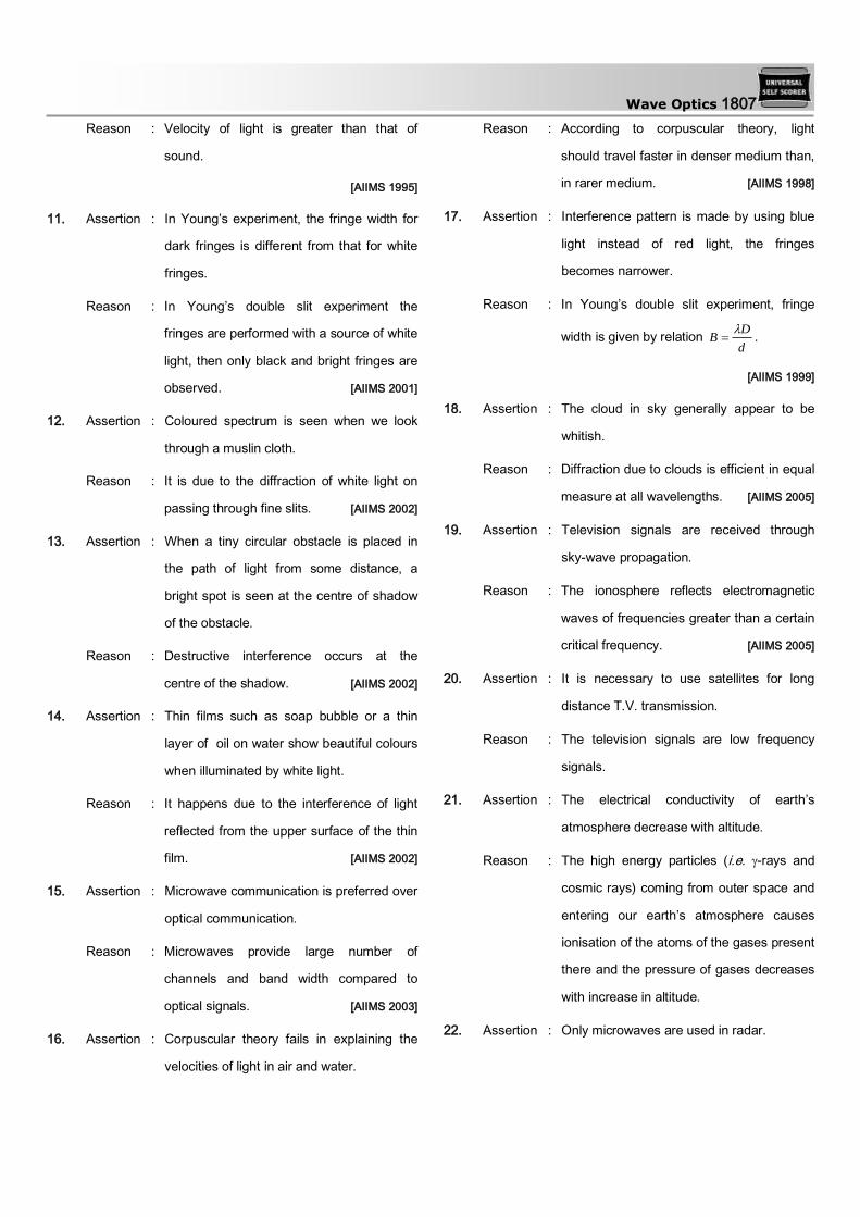
Wave Optics 1807
Reason : Velocity of light is greater than that of
sound.
[AIIMS 1995]
11. Assertion : In Young’s experiment, the fringe width for
dark fringes is different from that for white
fringes.
Reason : In Young’s double slit experiment the
fringes are performed with a source of white
light, then only black and bright fringes are
observed. [AIIMS 2001]
12. Assertion : Coloured spectrum is seen when we look
through a muslin cloth.
Reason : It is due to the diffraction of white light on
passing through fine slits. [AIIMS 2002]
13. Assertion : When a tiny circular obstacle is placed in
the path of light from some distance, a
bright spot is seen at the centre of shadow
of the obstacle.
Reason : Destructive interference occurs at the
centre of the shadow. [AIIMS 2002]
14. Assertion : Thin films such as soap bubble or a thin
layer of oil on water show beautiful colours
when illuminated by white light.
Reason : It happens due to the interference of light
reflected from the upper surface of the thin
film. [AIIMS 2002]
15. Assertion : Microwave communication is preferred over
optical communication.
Reason : Microwaves provide large number of
channels and band width compared to
optical signals. [AIIMS 2003]
16. Assertion : Corpuscular theory fails in explaining the
velocities of light in air and water.
Reason : According to corpuscular theory, light
should travel faster in denser medium than,
in rarer medium. [AIIMS 1998]
17. Assertion : Interference pattern is made by using blue
light instead of red light, the fringes
becomes narrower.
Reason : In Young’s double slit experiment, fringe
width is given by relation d
DB
.
[AIIMS 1999]
18. Assertion : The cloud in sky generally appear to be
whitish.
Reason : Diffraction due to clouds is efficient in equal
measure at all wavelengths. [AIIMS 2005]
19. Assertion : Television signals are received through
sky-wave propagation.
Reason : The ionosphere reflects electromagnetic
waves of frequencies greater than a certain
critical frequency. [AIIMS 2005]
20. Assertion : It is necessary to use satellites for long
distance T.V. transmission.
Reason : The television signals are low frequency
signals.
21. Assertion : The electrical conductivity of earth’s
atmosphere decrease with altitude.
Reason : The high energy particles (i.e. -rays and
cosmic rays) coming from outer space and
entering our earth’s atmosphere causes
ionisation of the atoms of the gases present
there and the pressure of gases decreases
with increase in altitude.
22. Assertion : Only microwaves are used in radar.

1808 Wave Optics
Reason : Because microwaves have very small
wavelength.
23. Assertion : In Hertz experiment, the electric vector of
radiation produced by the source gap is
parallel to the gap.
Reason : Production of sparks between the detector
gap is maximum when it is placed
perpendicular to the source gap.
24. Assertion : For cooking in a microwave oven, food is
always kept in metal containers.
Reason : The energy of microwave is easily
transferred to the food in metal container.
25. Assertion : X-ray astronomy is possible only from
satellites orbiting the earth.
Reason : Efficiency of X-rays telescope is large as
compared to any other telescope.
26. Assertion : Short wave bands are used for
transmission of ratio waves to a large
distance
Reason : Short waves are reflected by ionosphere
[AIIMS 1994]
27. Assertion : Ultraviolet radiation are of higher frequency
waves are dangerous to human being.
Reason : Ultraviolet radiation are absorbed by the
atmosphere [AIIMS 1995]
28. Assertion : Environmental damage has increased the
amount of ozone in the atmosphere.
Reason : Increase of ozone increases the amount of
ultraviolet radiation on earth. [AIIMS 1996]
29. Assertion : Radio waves can be polarised.
Reason : Sound waves in air are longitudinal in
nature.
[AIIMS 1998]
30. Assertion : The earth without atmosphere would be
inhospitably cold.
Reason : All heat would escape in the absence of
atmosphere. [AIIMS 2002]
Wave Nature and Interference of Light
1 a 2 c 3 b 4 c 5 d
6 c 7 d 8 c 9 c 10 b
11 a 12 d 13 c 14 a 15 d
16 a 17 c 18 b 19 c 20 b
21 c 22 c 23 a 24 c 25 a
26 a 27 b 28 b 29 c 30 a
31 b 32 d 33 d 34 a 35 a
36 c 37 b 38 c 39 b 40 c
41 d 42 b 43 b 44 c 45 d
46 c 47 d 48 b 49 c 50 a
51 d 52 c 53 d 54 c 55 b
56 a 57 c 58 d 59 d 60 b
61 b 62 a 63 c 64 d 65 d
66 c 67 a 68 a 69 a 70 c
71 b 72 d
Young's Double Slit Experiment
1 a 2 c 3 c 4 c 5 a
6 c 7 a 8 c 9 a 10 d
11 d 12 c 13 bd 14 b 15 c
16 c 17 a 18 a 19 a 20 b
21 a 22 c 23 d 24 c 25 d
26 a 27 b 28 c 29 d 30 d
31 d 32 a 33 b 34 b 35 a
36 b 37 b 38 d 39 b 40 a
41 b 42 d 43 d 44 a 45 b
46 d 47 d 48 b 49 b 50 a
51 bc 52 b 53 d 54 a 55 a

Wave Optics 1809
56 b 57 c 58 c 59 c 60 b
61 b 62 c 63 b 64 d 65 b
66 a 67 c 68 b 69 a 70 b
71 d 72 b 73 b 74 b 75 c
76 d 77 a 78 c 79 b 80 a
81 b 82 b 83 d 84 a 85 a
86 b 87 b 88 d 89 b 90 a
91 a 92 c 93 a 94 a 95 b
96 b 97 d
Doppler's Effect of Light
1 d 2 a 3 b 4 b 5 b
6 b 7 b 8 d 9 c 10 c
11 a 12 c 13 b 14 a 15 a
16 d 17 b 18 c 19 b 20 d
21 b 22 b 23 c 24 c 25 b
26 b 27 c 28 b 29 a 30 d
31 c 32 a 33 a
Diffraction of Light
1 c 2 a 3 b 4 c 5 c
6 a 7 a 8 a 9 c 10 b
11 a 12 b 13 a 14 d 15 a
16 b 17 a 18 a 19 a 20 d
21 a 22 a 23 c 24 b 25 d
26 a 27 d 28 d 29 b 30 d
31 d 32 d 33 b 34 a 35 c
36 c 37 a 38 c 39 a 40 b
41 c
Polarisation of Light
1 b 2 a 3 c 4 d 5 d
6 d 7 b 8 d 9 a 10 c
11 a 12 d 13 a 14 a 15 c
16 d 17 d 18 d 19 b 20 c
21 c 22 d 23 a 24 c 25 b
26 b 27 b 28 c 29 a 30 b
31 a 32 a 33 c 34 a 35 d
EM Waves
1 a 2 d 3 b 4 d 5 b
6 b 7 a 8 d 9 c 10 a
11 a 12 c 13 a 14 b 15 b
16 d 17 b 18 d 19 a 20 c
21 a 22 d 23 c 24 b 25 a
26 a 27 c 28 c 29 a 30 b
31 c 32 a 33 d 34 a 35 d
36 c 37 b 38 a 39 a 40 d
41 a 42 b 43 b 44 c 45 a
46 b 47 a 48 c 49 c 50 a
51 c 52 c 53 d 54 d 55 b
56 b 57 a 58 d 59 b 60 c
61 a 62 c 63 b 64 a 65 c
66 d 67 c
Critical Thinking Questions
1 d 2 a 3 b 4 c 5 a
6 ac 7 a 8 ab 9 d 10 d
11 b 12 d 13 a 14 a 15 b
16 b 17 a 18 a 19 a 20 b
21 ad 22 c 23 a 24 d 25 b
26 c 27 c 28 c 29 a 30 b
31 c 32 b 33 b 34 a 35 b
36 d 37 c 38 b 39 a 40 c
41 d 42 a 43 a 44 a 45 b
46 d 47 b 48 b 49 a 50 d
51 c 52 d 53 a 54 d 55 d
56 a 57 d 58 b 59 a 60 c
61 d 62 c 63 b
Assertion and Reason
1 d 2 e 3 b 4 a 5 a
6 b 7 c 8 a 9 c 10 b
11 d 12 a 13 c 14 c 15 a
16 a 17 a 18 c 19 d 20 c
21 e 22 a 23 c 24 d 25 c
26 b 27 b 28 d 29 b 30 a
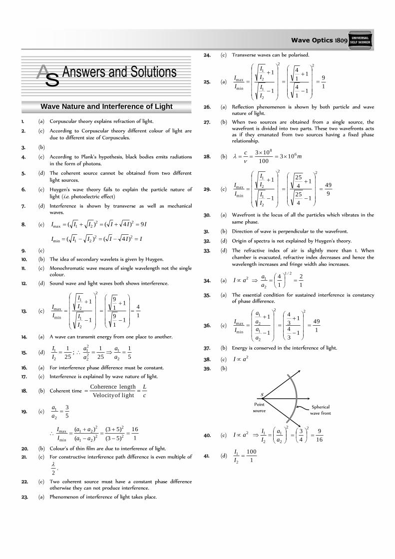
Wave Optics 1809
Wave Nature and Interference of Light
1. (a) Corpuscular theory explains refraction of light.
2. (c) According to Corpuscular theory different colour of light are due to different size of Corpuscules.
3. (b)
4. (c) According to Plank’s hypothesis, black bodies emits radiations in the form of photons.
5. (d) The coherent source cannot be obtained from two different
light sources.
6. (c) Huygen's wave theory fails to explain the particle nature of
light (i.e. photoelectric effect)
7. (d) Interference is shown by transverse as well as mechanical waves.
8. (c) IIIIII 9)4()( 2221max
IIIIII 2221min )4()(
9. (c)
10. (b) The idea of secondary wavelets is given by Huygen.
11. (c) Monochromatic wave means of single wavelength not the single colour.
12. (d) Sound wave and light waves both shows interference.
13. (c) 1
4
11
9
11
9
1
1
2
2
1
2
1
min
max
I
I
I
I
I
I
14. (a) A wave can transmit energy from one place to another.
15. (d) 5
1
25
1;
25
1
2
1
22
21
2
1 a
a
a
a
I
I
16. (a) For interference phase difference must be constant.
17. (c) Interference is explained by wave nature of light.
18. (b) Coherent time c
L
lightofVelocity
lengthCoherence
19. (c) 5
3
2
1 a
a
1
16
)53(
)53(
)(
)(2
2
221
221
min
max
aa
aa
I
I
20. (b) Colour’s of thin film are due to interference of light.
21. (c) For constructive interference path difference is even multiple of
2
.
22. (c) Two coherent source must have a constant phase difference otherwise they can not produce interference.
23. (a) Phenomenon of interference of light takes place.
24. (c) Transverse waves can be polarised.
25. (a) 1
9
11
4
11
4
1
1
22
2
1
2
1
min
max
I
I
I
I
I
I
26. (a) Reflection phenomenon is shown by both particle and wave nature of light.
27. (b) When two sources are obtained from a single source, the wavefront is divided into two parts. These two wavefronts acts as if they emanated from two sources having a fixed phase relationship.
28. (b) mc 6
8
103100
103
29. (c) 9
49
14
25
14
25
1
1
22
2
1
2
1
min
max
I
I
I
I
I
I
30. (a) Wavefront is the locus of all the particles which vibrates in the
same phase.
31. (b) Direction of wave is perpendicular to the wavefront.
32. (d) Origin of spectra is not explained by Huygen's theory.
33. (d) The refractive index of air is slightly more than 1. When chamber is evacuated, refractive index decreases and hence the wavelength increases and fringe width also increases.
34. (a) 2aI 1
2
1
42/1
2
1
a
a
35. (a) The essential condition for sustained interference is constancy of phase difference.
36. (c) 1
49
13
4
13
4
1
122
2
1
2
1
min
max
a
a
a
a
I
I
37. (b) Energy is conserved in the interference of light.
38. (c) 2aI
39. (b)
40. (c) 2aI
2
2
1
2
1
a
a
I
I
16
9
4
32
41. (d) 1
100
2
1 I
I
Spherical
wave front
Point
source
S

1810 Wave Optics
Now 2
3
81
121
1100
1100
1
1 2
2
2
1
2
1
min
max
I
I
I
I
I
I
42. (b) 3,4,3/ 21 aa
So, 6cos.2 2122
21 AaaaaA
43. (b) ,sin1 tay and
2sincos2
tbtby
So phase difference 2/
44. (c) For 2 phase difference Path difference is
For phase difference Path difference is
2
45. (d) Resultant intensity cos2 2121 IIIIIR
For maximum ,RI o0
2212121 2 IIIIIIIR
46. (c) Newton first law of motion states that every particle travels in a straight line with a constant velocity unless disturbed by an external force. So the corpuscles travels in straight lines.
47. (d) Diffraction shows the wave nature of light and photoelectric effect shows particle nature of light.
48. (b) At point A, resultant intensity
;521 IIIIA and at point B
IIIIIIIB 45cos2 2121
IIB 9 so .4 III AB
49. (c)
50. (a) Photoelectric effect varifies particle nature of light. Reflection
and refraction varifies both particle nature and wave nature of light.
51. (d)
2sincos,sin 21
tataytay
52. (c) 1
25
1
1
2
2
1
2
1
min
max
a
a
a
a
I
I
53. (d) Laser beams are perfectly parallel. So that they are very narrow
and can travel a long distance without spreading. This is the feature of laser while they are monochromatic and coherent these are characteristics only.
54. (c) 4
9
1
1
2
1
2
2
1
2
1
min
max
I
I
I
I
I
I
I
I
55. (b) 15
10
8
10103000
103
ccycles/sec
56. (a) .16
25
4
5
19
1
19
1
1
1 2
22
2
1
2
1
min
max
a
a
a
a
I
I
57. (c)
58. (d) For destructive interference path difference is odd multiple of
.2
59. (d) 6
1
1
21
21
2
2
1
2
1
min
max
aa
aa
a
a
a
a
I
I
5:71
2 a
a
60. (b) 2121max 2 IIIII
So, IIIIII 94.24max
61. (b) In interference energy is redistribution.
62. (a) For interference frequency must be same and phase difference must be constant.
63. (c) When a beam of light is used to determine the position of an object, the maximum accuracy is achieved if the light is of shorter wavelength, because
Wavelength
1 Accuracy
64. (d) Intensity 2(Distance)
1
65. (d) Huygen’s theory explains propagation of wavefront.
66. (c) Wave theory of light is given by Huygen.
67. (a) When light reflect from denser surface phase change of occurs.
68. (a) Photoelectric effect explain the quantum nature of light while interference, diffraction and polarization explain the wave nature of light.
69. (a) Light is electromagnetic in nature it does not require any material medium for its propagation.
70. (c) For viewing interference in oil films or soap bubble, thickness of film is of the order of wavelength of light.
71. (b)
72. (d) For maximum intensity 0
cos2 2121 IIIII IIIII 40cos2
Young's Double Slit Experiment
1. (a)
2. (c) In interference of light the energy is transferred from the region of destructive interference to the region of constructive interference. The average energy being always equal to the sum of the energies of the interfering waves. Thus the phenomenon of interference is in complete agreement with the law of conservation of energy.
Wave Optics 1811
3. (c) mmmmd
D0.110
10
2105 3
3
7
.
4. (c) Slit width ratio = 1 : 9
Since slit width ratio is the ratio of intensity and intensity (amplitude)2
9:1: 21 II
3:1:9:1: 2122
21 aaaa
4
1)(,)(
max
min221min
221max
I
IaaIaaI
5. (a) d
1 If d becomes thrice, then become becomes
3
1
times.
6. (c) 2
1
2
1
or
6000
50000.1
2
or mm2.15000
60002 .
7. (a) 3
210
10
1025106000
cmm 015.01015.010150000 39 .
8. (c) For brightness, path difference 2 n
So second is bright.
9. (a) If one of slit is closed then interference fringes are not formed on the screen but a fringe pattern is observed due to diffraction from slit.
10. (d)
11. (d) d
D If D becomes twice and d becomes half so
becomes four times.
12. (c) Suppose slit width’s are equal, so they produces waves of equal
intensity say .I Resultant intensity at any point
2cos4 IIR where is the phase difference between
the waves at the point of observation.
For maximum intensity IIIo 40 max …(i)
If one of slit is closed, Resultant intensity at the same point will
be I only i.e. OII …(ii)
Comparing equation (i) and (ii) we get
OII 4
13. (b, d) 39921
21
2
21
21
min
max
aa
aa
aa
aa
I
I
.213
13
2
1
2
1
a
a
a
a Therefore 1:4: 21 II
14. (b)
15. (c) Distance of nth bright fringe
nn yeid
Dny ..
5460
4360
)Green(
(Blue)
2
1
2
1 x
x
x
x
n
n
x (Green) > x (Blue).
16. (c) cmmmd
D5.0105
101.0
1105000 3
3
10
.
17. (a) We know that fringe width d
D
L
xd
d
Lx
18. (a) In the normal adjustment of young’s, double slit experiment, path difference between the waves at central location is always zero, so maxima is obtained at central position.
19. (a)
Bd
D;
mm3.0'3/4
4.0'
.
20. (b)
1
,
21. (a) v , minimum.
22. (c) mm4.05.1
6.0airmedium
.
23. (d) 6322,3 nn
24. (c) Slit width ratio ;9:4 hence 9:4: 21 II
3
2
9
4
2
1
22
21
a
a
a
a
1
25
)(
)(2
21
221
min
max
aa
aa
I
I
25. (d) d
D
Dd .2.0
10012.0
)1040(1060002
210
cm
26. (a) As
1
2
2
1
2
1
2
1
d
d
D
D
d
D
1
4
2
1
2
11
2
1
2
1
D
D
D
D
27. (b)
28. (c) Fringe width
d
D)(
As ,yellowred hence fringe width will increase.
29. (d) d
D
211
122
1
2
dD
dD
m4
2 105.2 .
30. (d) For interference, of both the waves must be same.
31. (d) D
32. (a)
;d
can be increased by increasing , so here has to
be increased by 10%
i.e., % Increase Å5895890100
10
33. (b) mmmD
d 1.010105
1051 4
3
7
.
34. (b) If intensity of each wave is I, then initially at central position
.4 IIo when one of the slit is covered then intensity at
central position will be I only i.e., 4
oI .
35. (a) Shift
2102)5.1(
)105000()1( 6
10
t
i.e., 2 fringes upwards.

1812 Wave Optics
36. (b) d
D
37. (b) Separation thn bright fringe and central maxima is
d
Dnx n
So, .5.3105.0
110600033
10
3 mmx
38. (d) 2211 nn 4358589362 2 n .842 n
39. (b) Angular fringe width
d
w
aw
So w
air
w 15.0
3
4
20.0
40. (a) By using d
Dnxn
m7
3
3 105)101(
110)105(
Å5000
41. (b) Distance of third maxima from central maxima is
3
210
102.0
)10200(10500033
d
Dx
.5.1 cm
42. (d) Distance of thn dark fringe from central fringe
d
Dnxn
2
)12(
d
D
d
Dx
2
3
2
)122(2
cm5
3
3 106109.02
13101
43. (d) mDD
d
D1
101.0
104)104(
3
73
44. (a) 3
2
101
1)1006.0(
d
D Å6000
45. (b)
46. (d) )( 2211 nn 995461
5898
921
1
1
2
2
1 nn
n
n
47. (d) If we use torch light in place of monochromatic light then overlapping of fringe pattern take place. Hence no fringe will appear.
48. (b)
49. (b) Position of 3rd bright fringe d
Dx
33
ÅD
dx6000
4.13
)1028.0()109.0(
3
323
50. (a) Distance between two consecutive
Dark fringes 3
10
106.0
1106000
d
D
.1101 3 mmm
51. (b, c) For maxima, path difference n
So for n =1, Å6320
52. (b) Shift in the fringe pattern d
Dtx
.)1(
.5.2105.0
10100105.2)15.1(3
25
cm
53. (d) In the presence of thin glass plate, the fringe pattern shifts, but no change in fringe width.
54. (a)
d
D
55. (a) In interference between waves of equal amplitudes a, the minimum intensity is zero and the maximum intensity is proportional to 4a2. For waves of unequal amplitudes a and A(A >a), the minimum intensity is non zero and the maximum intensity is proportional to (a + A)2, which is greater than 4a2.
56. (b) mmmd
D3.0103
104
2106000 4
3
10
57. (c)
58. (c) d
D
59. (c) Distance between consecutive bright fringes or dark
fringes
mmd
D5.060500
101.1
110550 6
3
9
60. (b) 1
3
1
4
1
1
2
1
2
2
1
2
2
1
min
max
a
a
a
a
a
a
I
I
61. (b)
d
D
62. (c)
63. (b) 18400
60012
2
122211
1nnnn
64. (d) Using relation, d
nnd
sinsin
For n = 3, 589.0
1058933sin
9
d
6103 or )103(sin 61
65. (b) d
1
66. (a) When white light is used, central fringe will be white with red
edges, and on either side of it, we shall get few coloured bands
and then uniform illumination.
67. (c) d
68. (b)
69. (a) ;3412
12
1
1 2
2
2
1
2
1
min
max
I
I
I
I
I
I (given I
1
= 2I2
)
70. (b) B

Wave Optics 1813
71. (d) d
72. (b)
73. (b) For dark fringe at P
2/)12(21 nPSPS
Here n =3 and = 6000
So, micronÅ 5.1150002
60005
2
5
74. (b) Distance of nth minima from central bright fringe
d
Dnxn
2
)12(
For n=3 i.e. 3rd minima
3
9
31012
110500)132(
x
.25.11025.12
105005 36
mmm
75. (c) d
D and
1
76. (d) nmnn 42057003 222211
77. (a) d
as
3
dd so 3 3 n
78. (c) If shift is equal to n fringes width, then
210500
1
10500
102)15.1()1( 3
9
6
tn
Since a thin film is introduced in upper beam. So shift will be upward.
79. (b) Distance between thn Bright fringe and thm dark fringe
)( mn
3
7
101
1105.6
2
135
2
1
mnx
= mm63.1
80. (a) d
D ; If and d both increase by 10%, there will be no
change in fringe width )( .
81. (b) kII
I 1
2
1
4
1 and kI 42
Fringe visibility 8.0)4(
42
)(
2
21
21
kk
kk
II
IIV
82. (b) 1
4
3
322
21
21
min
max
aa
aa
aa
aa
I
I
83. (d) Angular position of first dark fringe
180
101.0
1054603
10
d (in degree)
= 0.313°
84. (a) Distance between two consecutive dark fringes d
D
25.0102.0
11050002
10
mm.
85. (a) If thin film appears dark
2t cos r = n for normal incidence or 0
2 t = n
2
nt
2min t =
12
105890 10
m710945.2 .
86. (b) In case of destructive interference (minima) phase difference is odd multiple of .
87. (b)
)1(2
)(
a
ba
where a = distance between source and biprism = 0.3 m
b = distance between biprism and screen = 0.7 m.
= Angle of prism = 1°, = 1.5, = 6000 10–10 m
Hence,
)180
1()15.1(3.02
106)7.03.0( 7
o
= 1.14 10–4 m = 0.0114 cm.
88. (d) For minima, path difference 2
)12(
n
For third minima 2
5
2)132(3
n
89. (b) Fringe width )( Angle prism
1)(
90. (a) By using
1801)154.1(3.02
10180)7.03.0(
)1(2
)( 9
a
ba
= m410
91. (a) aw so aw
92. (c) With white light, the rays reaching the centre has zero path
difference. So we get white fringe at the centre and coloured near the central fringe.
93. (a) w
airwater
94. (a) d
D
95. (b) Lateral displacement of fringes = t)1(
3
9
3
1006.0)15.1(10600
101
m
20
1 .5 cm
96. (b)
97. (d) Distance of the nth bright fringe from the centred
Dnxn
.9109105.0
5.21060003 3
3
10
3 mmmx
Doppler's Effect of Light
1. (d) ,c
v
Now
100
5.0
100
5.0
smcv /105.1103100
5.0
100
5.0 68
1814 Wave Optics
Increase in indicates that the star is receding.
2. (a) Doppler’s shift is given by
Åc
v1.0
103
600050008
3. (b) Shifting towards ultraviolet region shows that Apparent wavelength decreased. Therefore the source is moving towards the earth.
4. (b) Due to expansion of universe, the star will go away from the earth thereby increasing the observed wavelength. Therefore the spectrum will shift to the infrared region.
5. (b) With reference to this theory the velocity of the observer is neglected w.r.t. the light velocity.
6. (b) 2.0103
1068
7
c
v
Å552046002.12.1'2.0'
7. (b) Å20050005200
Now 5000
200103
''
8
cv
c
v
sec/1015.1sec/102.1 77 mm
8. (d) 100
01.0)'(
c
ccv
c
v
sec/30/103 4 kmsm
9. (c) Blue radiations have the wavelength around 4600o
A . It shows that apparent wavelength is smaller than the real wavelength. It means that the star is proceeding towards earth.
10. (c)
11. (a)
12. (c)
13. (b) Åc
v90.1
103
101005700
8
3
14. (a) According to Doppler’s effect, wherever there is a relative motion between source and observer, the frequency observed is different from that given out by source.
15. (a) Åc
v255000
103
105.1.
8
6
16. (d)
c
Å75.705896103
1036008
3
So the increased wavelength of light is observed.
17. (b) Observed frequency
c
v1'
Hzc
c 1414 102.18.0
1106'
18. (c) According to Doppler's principle cv
cv
/1
/1'
for v = c
3.18338.01
)8.01(5500'
Shift = 5500 – 1833.3 = 3167 Å
19. (b) c
v
smvv
/103103
3700)37003737( 6
8
20. (d) 4700
10347. 8
cv
c
vs
s
sm /103 6 away from earth
21. (b) 8103100
05.0
v
c
v
v = 1.5 105 m/s
(Since wavelength is decreasing, so star coming closer)
22. (b)
23. (c)
8
6
103
105.4158901'
c
v 5802Å
24. (c) skmskmcvc
v/5/103
6000
1.0 5
25. (b) c
v
Å19
103
1057003
6
26. (b) Hzc
c
c
v 77 102.32.0
11041'
27. (c) When the source and observer approach each other, apparent frequency increases and hence wavelength decreases.
28. (b)
29. (a) cvc
v
c
v
1
30. (d) cvc
v.
58 1029.2)103(6563
5 m/sec
31. (c)
32. (a) Using cvc
v
68 102.1103004.0 v m/sec
33. (a)
Diffraction of Light
1. (c) For first minima a
or
a
6106500 8
a (As 30o = 6
radian)
24.11024.1 4 cm microns
2. (a) The angular half width of the central maxima is given by
a
sin
3
10
102.0
106328
rad
3
10
102.0
80106328degree = 0.18o
Total width of central maxima o36.02
3. (b)
4. (c) It is caused due to turning of light around corners.
5. (c) Width of central maxima d
D2
mmm 4.1104.11015.0
1051.22 3
2
7

Wave Optics 1815
6. (a) Band width ,
blue
< red
, hence for blue light the diffraction bands becomes narrower and crowded together.
7. (a) Using ,sin nd for n =1
radd
001.0101055.0
10550sin 3
3
9
8. (a) For single slit diffraction pattern sind ( d slit width)
Angular width =
d
1sin22
It is independent of D i.e. distance between screen and slit
9. (c) Width of central bright fringe.
3
29
1020.0
10801050022
d
D.4104 3 mmm
10. (b) Diffraction is obtained when the slit width is of the order of
wavelength of EM waves (or light). Here wavelength of X-rays
(1-100 Å) is very-very lesser than slit width (0.6 mm). Therefore
no diffraction pattern will be observed.
11. (a) Multiple focii of zone plate given by )12(
2
p
rf np , where
......3,2,1p
12. (b) dnA
And = constant
dn
1 n(
number of blocked )HPZ on decreasing ,d n increases,
hence intensity decreases.
13. (a) For secondary maxima 2
5sin
d
2
5
)(.
fD
xdd
mmmd
fx 6106
104
108.0552 3
4
7
14. (d) By using )12(
2
p
rfp
For first HPZ 101060006.0 pfr
.106 4 m
15. (a) .9105893
)103.2(10
232
1 mr
f
16. (b) RedBlue . Therefore fringe pattern will contract because
fringe width
17. (a)
18. (a) For diffraction size of the obstacle must be of the order of
wavelength of wave ..ei a
19. (a) Angular width of central maxima
d
2 rad
3
9
101.0
103.5892
68.0
1800117.0
20. (d)
21. (a) nrndr nn
22. (a) d
D. w here D = distance of screen from wire, d =
diameter of wire
23. (c) Angular width .1101012
1060002225
10
radd
24. (b) 25. (d)
26. (a) d
22 (where d = slit width)
As d decreases, increases.
27. (d) 28. (d) Distance between the first dark fringes on either side of central
maxima = width of central maxima = d
D2=
3
9
101
2106002
= 2.4 mm.
29. (b) Thickness of the film must be of the order of wavelength of light falling on film (i.e. visible light)
30. (d)
31. (d) For nth secondary maxima path difference
2)12(sin
nd 2
3sin
a
32. (d) The phase difference )( between the wavelets from the top
edge and the bottom edge of the slit is )sin(2
d
where d is the slit width. The first minima of the diffraction
pattern occurs at d
sin so
2
2
dd
33. (b)
34. (a) For second dark fringe 2sin d
230sin101024 25
Åm 6000106 7
35. (c) For the first minima sind
d
sin
o3010001.0
105000sin
3
101
36. (c)
37. (a)
38. (c) Position of first minima = position of third maxima i.e.,
21
21 5.32
1321
d
D
d
D
39. (a) Position of nth minima d
Dnxn
d
11050001105
103
mmmd 1.010 4 .
40. (b) Width of nth HPZ 1 nnn rrB
nbrn , bnrn )1(1
])1([)1( nnbbnnbBn
41. (c) In single slit experiment,
Width of central maxima (y) = dD /2
yyd
d
d
dy
y3'
4002/
600
'
''
.
Polarisation of Light

1816 Wave Optics
1. (b) Polariser produced prolarised light.
2. (a) Only transverse waves can be polarised.
3. (c) Polarisation is not shown by sound waves.
4. (d) By using 360tantan p ,
also
3
1sin
1sin 11 CC
5. (d) = tanP
P
= tan–1 n
6. (d) Ultrasonic waves are longitudinal waves.
7. (b) 20 cosII = I
0
cos2 45 2
0I
8. (d)
9. (a) It magnitude of light vector varies periodically during it's rotation, the tip of vector traces an ellipse and light is said to
be elliptically polarised. This is not in nicol prism.
10. (c) At polarizing angle, the reflected and refracted rays are mutually perpendicular to each other.
11. (a) When unpolarised light is made incident at polarising angle, the reflected light is plane polarised in a direction perpendicular to the plane of incidence.
Therefore E in reflected light will vibrate in vertical plane
with respect to plane of incidence.
12. (d) In the arrangement shown, the unpolarised light is incident at polarising angle of 90° – 33° = 57°. The reflected light is thus
plane polarised light. When plane polarised light is passed
through Nicol prism (a polariser or analyser), the intensity
gradually reduces to zero and finally increases.
13. (a)
14. (a) A plane which contains E and the propagation direction is called the plane of polarization.
15. (c)
16. (d) Light suffers double refraction through calcite.
17. (d) The amplitude will be 2/60cos AA o
18. (d)
19. (b) Rotation produced = Slc
Net rotation produced r
= 1
– 2
= l (S1
c1
– S2
c2
)
= 0.29 [0.01 60 – 0.02 30] = 0
20. (c) In double refraction light rays always splits into two rays (O-
ray & E-ray). O-ray has same velocity in all direction but E-ray
has different velocity in different direction.
For calcite e
< 0
ve
> v0
For quartz e
> 0
v0
> ve
21. (c) 90rP or r = 90o – P
= 90° – 53°4' = 36°56'.
22. (d)
23. (a)
24. (c) Intensity of polarized light from first polarizer 502
100
5.124
5060cos50 2 I
25. (b) 6
cos2
' 2 III or
3
1cos = 55º
26. (b) Angle between P1
and P2
= 30° (given)
Angle between P2
and P3
= = 90° – 30° = 60°
The intensity of light transmitted by P1
is
2
01 16
2
32
2 m
WII
According to Malus law the intensity of light transmitted by P2
is 2
2
212 12
2
31630cos
m
WII
Similarly intensity of light transmitted by P3
is
2
2
2223 3
2
11260cos12cos
m
WII
27. (b) 2
b
a
2)5000(30
ba and
2)4000(50
ba
Solving for a, we get mmpera9
50
28. (c) If an unpolarised light is converted into plane polarised light by passing through a polaroid, it's intensity becomes half.
29. (a)
30. (b) The magnitude of electric field vector varies periodically with time because it is the form of electromagnetic wave.
31. (a) According to Brewster’s law, when a beam of ordinary light (i.e. unpolarised) is reflected from a transparent medium (like glass), the reflected light is completely plane polarised at certain angle of incidence called the angle of polarisation.
32. (a) When the plane-polarised light passes through certain substance, the plane of polarisation of the light is rotated about the direction of propagation of light through a certain angle.
33. (c) From Brewster's law pitan 360tan v
c
88
1033
103
3
cv m/sec.
34. (a) No light is emitted from the second polaroid, so 1P and 2P
are perpendicular to each other
90°–
P3
P2 P1
2032
m
WI
P1 P2 P3
30°
I1 I2 I3
Wave Optics 1817
Let the initial intensity of light is 0I . So Intensity of light after
transmission from first polaroid = 2
0I .
Intensity of light emitted from 3P 201 cos
2
II
Intensity of light transmitted from last polaroid i.e. from
)90(cos212 oIP = 220 sin.cos
2
I
8
0I2)cossin2( = 2sin
8
20I .
35. (d)
EM Waves
1. (a)
2. (d) rayXBluedRe
3. (b) Infrasonic waves are mechanical waves.
4. (d) 2
212
07
0
-1085.8,104
C
mN
so .1031 8
00sec
meterc
5. (b) Wavelength of visible spectrum is 3900 Å – 7800 Å.
6. (b) Infrared causes heating effect.
7. (a)
8. (d)
9. (c) Speed of EM waves in vacuum =
00
1
=constant
10. (a) .raysraysraysxrays
11. (a) Distance covered by T.V. signals = hR2
maximum distance h1/2
12. (c) -rays are beams of fast electrons.
13. (a)
14. (b) Velocity of EM waves = sm/1031 8
00
=velocity of light
15. (b) Ozone layer absorbs most of the UV rays emitted by sun.
16. (d) wavesRadioInfraredradiation visible rays
17. (b) Infrared radiations reflected by low lying clouds and keeps the earth warm.
18. (d) raysXRaysJraysUVRadiowaves
19. (a) Polarization is shown by only transverse waves.
20. (c) EM waves travels with perpendicular to E and B. Which are
also perpendicular to each other BEv
21. (a)
22. (d) Ozone hole is depletion of ozone layer in stratosphere because of gases like CFC’S etc.
23. (c)
24. (b)
25. (a) raysUVraysXrays
26. (a) In vacuum velocity of all EM waves are same but their wavelengths are different.
27. (c)
28. (c)
29. (a) mc
5.36102.8
1036
8
30. (b) Tc
EB
B
Ec 8
8106
103
18
.
31. (c) According to the Maxwell’s EM theory, the EM waves propagation contains electric and magnetic field vibration in mutually perpendicular direction. Thus the changing of electric field give rise to magnetic field.
32. (a) Here ,/1000 mVE ./265.00 mAB
Maximum rate of energy flow S = 00 BE
= 2
5.26265.100m
W
33. (d) 2
834
1021
103106.6
hcE = J2424 101094.0
34. (a) 1
108
1
v
Cv
= MHzHz 300103 8
and 10
103 8
2
v = MHzHz 30103 7
35. (d)
36. (c) E
and B
are mutually perpendicular to each other and are in phase i.e. they become zero and minimum at the same place and at the same time.
37. (b) Molecular spectra due to vibrational motion lie in the microwave region of EM-spectrum. Due to Kirchhoff’s law in spectroscopy the same will be absorbed.
38. (a) xE and yB would generate a plane EM wave travelling in z-
direction. E
, B
and k
form a right handed system k
is
along z-axis. As kji ˆˆˆ
kCjBiE yxˆˆˆ i.e. E is along x-axis and B is along y-axis.
39. (a) rays Infraredlight Bluerays- UVrays
40. (d) Ground wave and sky wave both are amplitude modulated wave and the amplitude modulated signal is transmitted by a
transmitting antenna and received by the receiving antenna at a distance place.
41. (a)
42. (b) EM waves transport energy, momentum and information but not charge. EM waves are uncharged
43. (b) EM waves carry momentum and hence can exert pressure on
surfaces. They also transfer energy to the surface so 0p
and 0E .
44. (c) The angular wave number ;2
k where is the wave
length. The angular frequency is .2w
The ratio c
k 11
2
/2
= constant
45. (a) .0
0 CB
E also
2k and 2
These relation gives 00 BKE
46. (b) LC
2
1 and
C

1818 Wave Optics
47. (a) 200
2
1CEI
m
V
C
IE 6
16
0
0 1061.085.8
10522
Also d
VE 0
0 VdEV 23.121061.0 600
48. (c)
49. (c) Population covered = 2hR Population density
= 2 100 6.4 106 23)10(
1000= 4 106
50. (a)
51. (c)
52. (c) Refractive index 00
Here is not specified so we can consider = 0
then refractive index 20
Speed and wavelength of wave becomes half and frequency remain unchanged.
53. (d)
54. (d)
55. (b)
56. (b)
57. (a) Intensity or power per unit area of the radiations fvP
28
8/10166.0
103
5.0mN
v
Pf
58. (d) secmc
v
rr
/108.114.23.1
103 88
59. (b) xeII ' '
log1
I
Ix e
(where I = original intensity, I'
= changed intensity)
8/log
136
I
Ie
= 2log
3e
....(i)
2/log
1
I
Ix e
2log
1e
.....(ii)
From equation (i) and (ii), mmx 12 .
60. (c) xvm
61. (a) If maximum electron density of the ionosphere is Nmax
per m3
then the critical frequency fc
is given by .)(9 2/1maxNfc
2/16 )(9101 N N = 1.2 1012 m–3
62. (c)
63. (b)
64. (a)
65. (c)
66. (d) Direction of wave propagation is given by BE .
67. (c) Speed of light of vacuum 00
1
c and in another medium
1v
Kv
cr
00
K
cv
r
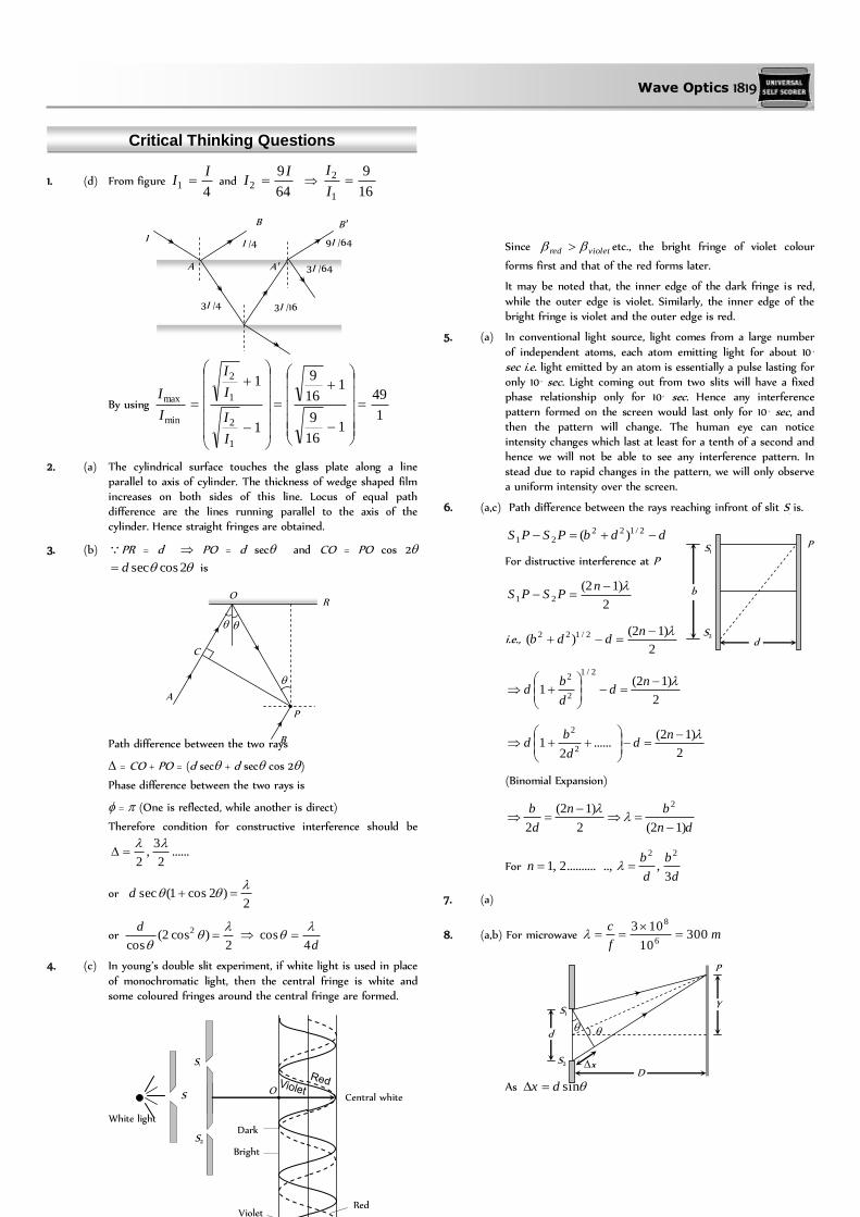
Wave Optics 1819
Critical Thinking Questions
1. (d) From figure 4
1
II and
64
92
II
16
9
1
2 I
I
By using 1
49
116
9
116
9
1
1
1
2
1
2
min
max
I
I
I
I
I
I
2. (a) The cylindrical surface touches the glass plate along a line parallel to axis of cylinder. The thickness of wedge shaped film increases on both sides of this line. Locus of equal path difference are the lines running parallel to the axis of the cylinder. Hence straight fringes are obtained.
3. (b) PR = d PO = d sec and CO = PO cos 2
2cossecd is
Path difference between the two rays
= CO + PO = (d sec + d sec cos 2)
Phase difference between the two rays is
= (One is reflected, while another is direct)
Therefore condition for constructive interference should be
......2
3,
2
or 2
)2cos1(sec
d
or 2
)cos2(cos
2
d
d4cos
4. (c) In young’s double slit experiment, if white light is used in place
of monochromatic light, then the central fringe is white and some coloured fringes around the central fringe are formed.
Since violetred etc., the bright fringe of violet colour
forms first and that of the red forms later.
It may be noted that, the inner edge of the dark fringe is red,
while the outer edge is violet. Similarly, the inner edge of the bright fringe is violet and the outer edge is red.
5. (a) In conventional light source, light comes from a large number
of independent atoms, each atom emitting light for about 10 –9 sec i.e. light emitted by an atom is essentially a pulse lasting for only 10–9 sec. Light coming out from two slits will have a fixed phase relationship only for 10-9 sec. Hence any interference pattern formed on the screen would last only for 10–9 sec, and then the pattern will change. The human eye can notice intensity changes which last at least for a tenth of a second and hence we will not be able to see any interference pattern. In stead due to rapid changes in the pattern, we will only observe a uniform intensity over the screen.
6. (a,c) Path difference between the rays reaching infront of slit S1
is.
ddbPSPS 2/12221 )(
For distructive interference at P
2
)12(21
nPSPS
i.e., 2
)12()( 2/122
n
ddb
2
)12(1
2/1
2
2
nd
d
bd
2
)12(......
21
2
2
nd
d
bd
(Binomial Expansion)
dn
bn
d
b
)12(2
)12(
2
2
For d
b
d
bn
3,..,..........2,1
22
7. (a)
8. (a,b) For microwave mf
c300
10
1036
8
As sindx
I I /4
3I /4 3I /16
3I /64
9I /64
A
B B
A
b
S1
S2 d
P
S1
S2
d
D
x
Y
P
Central white
Red Violet
Dark
Bright
O
S1
S2
S
White light
C
R
P
B
A
O
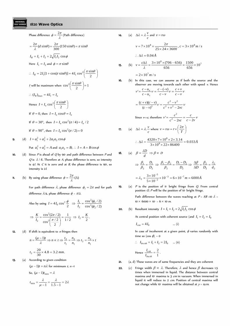
1820 Wave Optics
Phase difference
2 (Path difference)
sin)sin150(
300
2)sin(
2 d
cos2 2121 IIIIIR
Here 21 II and sin
2
sincos4)]sincos(1[2 2
11
IIIR
IR
will be maximum when 12
sincos2
oR III 1max 4)(
Hence
2
sincos2
oII
If ,0 then oo III cos
If ,30 then 2/)4/(cos2oo III
If ,90o then 0)2/(cos2 oII
9. (d) cos2 2122
21 aaaaI
Put Aaa 22
21 and cos;21 BAIBaa
10. (d) Since P is ahead of Q by 90o and path difference between P and
Q is .4/ Therefore at A, phase difference is zero, so intensity
is 4I. At C it is zero and at B, the phase difference is 90o, so
intensity is 2I.
11. (b) By using phase difference )(2
For path difference , phase difference 21 and for path
difference /4, phase difference 2
= /2.
Also by using 2
cos4 20
II
)2/(cos
)2/(cos
22
12
2
1
I
I
2/1
1
2
2/cos
)2/2(cos
2
2
2
I
K .
22
KI
12. (d) If shift is equivalent to n fringes then
tn
nt
n
n
t
ttn
tn
1
22
1
2
1
2)1(
.2.38.430
202 mmt
13. (a) According to given condition
nt )1( for minimum t, n =1
So, min)1( t
2
15.11min
t
14. (a) c
v and rv
smcv /103,36002425
2107 88
Å04.0
15. (b) 78
10656
1500
656
)656706(103
cv
sm /102 7
16. (b) In this case, we can assume as if both the source and the observer are moving towards each other with speed v. Hence
vc
vc
vc
vc
uc
uc
s
o
)('
vcvc
vc
vc
vcvc
2)(
))((22
22
2
Since v<<c, therefore vc
c
vcc
c
22'
2
2
17. (a) c
v. where
Trrv
2
Å033.08640022103
14.3210743208
8
18. (a) d
D D
2
1
2
1
D
D
2
21
2
21
D
DD
2
2
2
2
dDD
Åm 600010610105
103 73
2
5
2
19. (a) P is the position of 11th bright fringe from Q. From central position O, P will be the position of 10th bright fringe.
Path difference between the waves reaching at P = S1
B =10 =
10 6000 10–10 = 6 10–6m.
20. (b) Resultant intensity cos2 2121 IIIII
At central position with coherent source (and 021 III
04 IIcon ... (i)
In case of incoherent at a given point, varies randomly with
time so (cos )av
= 0
021 2IIII cohIn ... (ii)
Hence 1
2
Incoh
coh
I
I.
21. (a, d) These waves are of same frequencies and they are coherent
22. (c) Fringe width . Therefore, and hence decreases 1.5
times when immersed in liquid. The distance between central maxima and 10th maxima is 3 cm in vacuum. When immersed in liquid it will reduce to 2 cm. Position of central maxima will not change while 10th maxima will be obtained at y = 4cm.
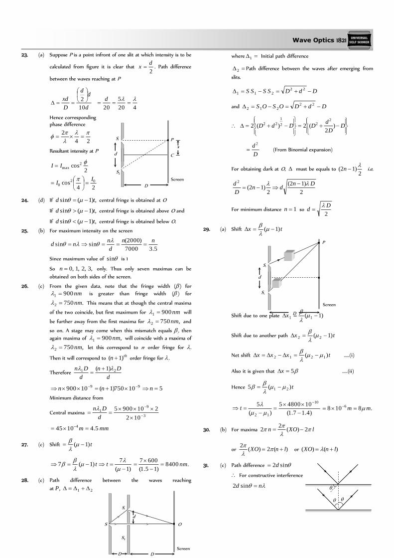
Wave Optics 1821
23. (a) Suppose P is a point infront of one slit at which intensity is to be
calculated from figure it is clear that 2
dx . Path difference
between the waves reaching at P
d
dd
D
xd
10
2
420
5
20
d
Hence corresponding phase difference
24
2
Resultant intensity at P
2cos2
max
II
24cos 02
0
II
24. (d) If ,)1(sin td central fringe is obtained at O
If ,)1(sin td central fringe is obtained above O and
If ,)1(sin td central fringe is obtained below O.
25. (b) For maximum intensity on the screen
5.37000
)2000(sinsin
nn
d
nnd
Since maximum value of sin is 1
So ,3,2,1,0n only. Thus only seven maximas can be
obtained on both sides of the screen.
26. (c) From the given data, note that the fringe width (1
) for
nm9001 is greater than fringe width (2
) for
.7502 nm This means that at though the central maxima
of the two coincide, but first maximum for nm9001 will
be further away from the first maxima for ,7502 nm and
so on. A stage may come when this mismatch equals 2
, then
again maxima of ,9001 nm will coincide with a maxima of
,7502 nm let this correspond to nth order fringe for 1
.
Then it will correspond to thn )1( order fringe for 2
.
Therefore d
Dn
d
Dn 21 )1(
510750)1(10900 99 nnn
Minimum distance from
Central maxima 3
91
102
2109005
d
Dn
mmm 5.41045 4
27. (c) Shift t)1(
)1(
7)1(7
tt .8400
)15.1(
6007nm
28. (c) Path difference between the waves reaching
at ,P 21
where 1 Initial path difference
2 Path difference between the waves after emerging from
slits.
DdDSSSS 22211
and DdDOSOS 22212
D
D
dDDdD )
2(2)(2
222
1
22
D
d 2
(From Binomial expansion)
For obtaining dark at O, must be equals to 2
)12(
n i.e.
2
)12(
2)12(
2 Dndn
D
d
For minimum distance 1n so 2
Dd
29. (a) Shift tx )1(
Shift due to one plate )1( 11
x
Shift due to another path tx )1( 22
Net shift txxx )( 1212
…..(i)
Also it is given that 5x …..(ii)
Hence t)(5 21
)4.17.1(
1048005
)(
5 10
12
t .8108 6 mm
30. (b) For maxima lXOn
2)(
22
or )(2)(2
lnXO
or )()( lnXO
31. (c) Path difference sin2d
For constructive interference
nd sin2
S1
S2
d
Screen
D
P
S1
S2
d
Screen
D
C
P
x
S1
S2
d
Screen
D
O S
D

1822 Wave Optics
d
n
2sin 1
32. (b) Here path difference at a point P on the circle is given by
cosdx ….. (i)
For maxima at P
nx ….. (ii)
From equation (i) and (ii)
dd
ndn
4coscoscos 11
33. (b) From ,21 DSS
22
221
21 )()()( DSSSDS
22
221
21 )()()( DSSSPDPS
Here PS 1 is the path difference n for maximum
intensity.
222 )()4()( nn xxn
or
n
nx n
2
16 222
Then
5.7
2
16 22
1
x
3
4
416 22
2
x
6
7
6
916 22
3
x
04 x .
Number of points for maxima becomes 3.
34. (a) 4
222
0
RRI
Number of HPZ covered by the disc at cmb 25
2211 bnbn
425.0
11
2
112
b
bnn
Hence the intensity at this point is
2
2
2
2
3
3
4
4
5
2
52
22
R
R
R
R
R
R
R
RRI
or 6]9.0[1
01 531.0 II
Hence the correct answer will be (a).
35. (b) 21RIA
164
311)(
21
2
21
2
1
221
221
RR
R
RRRRIB
2321 )( RRRIC
2
1
3
1
221 1
R
R
R
RR
2
1
2
2
3
1
221 1
R
R
R
R
R
RR
2
21
4
3
4
3
4
31
R 2
121
2
256
169
16
13RR
169:16:256256
169:
16::: 2
1
212
1 RR
RIII CBA
36. (d) 4
22R
I given 2211 bnbn 252001 2 n
HPZn 82
2
9
2
RI
2
2
2
2
3
3
4
4
5
5
6
6
7
7
8
8
9
R
R
R
R
R
R
R
R
R
R
R
R
R
R
R
R
IR
R2
2
9
37. (c) The direction in which the first minima occurs is (say).
Then sine or e or, e
sin(
when small)
Width of the central maximum ee
beb
.22
38. (b) Angular width
d
2
Å42006000
100
70 2
22
1
2
1
39. (a) In a single slit diffraction experiment, position of minima is
given by nd sin
So for first minima of red
d
R 1sin
and as first maxima is midway between first and second
minima, for wavelength ,
d S1 S2
P
b
e
P
S1
S2
xn 4
xn
y
x D

Wave Optics 1823
its position will be
dd
2
3sin
2
2sin
According to given condition sinsin
R3
2 so nm4406600
3
2 Å4400
40. (c) ,sin
2
0
II where
2
For thn secondary maxima
2
12sin
nd
2
12sin
2
nd
2
0
2
0
2
)12(
2
12
2
12sin
n
I
n
n
II
So 0202021025
4:
9
4::: IIIIII
22 25
4:
9
4:1
41. (d) For a grating nde n sin)(
where )( de grating element
)(sin
de
nn
For ,1n
32sin)(
sin 1de
This is more than 0.5. Now 2sin will be more than ,5.02
which is not possible.
42. (a) The film appears bright when the path difference
)cos2( rt is equal to odd multiple of 2
i.e. 2/)12(cos2 nrt where .....3,2,1n
)12(
cos4
n
rt
Ånn )12(
56000
)12(
0cos10000,104.14 10
Å56000 ,18666 Å ,8000 Å ,6222 Å ,5091 Å
,4308 Å .3733 Å
The wavelength which are not within specified range are to be
refracted.
43. (a) Total phase difference
= Initial phase difference + Phase difference due to path
x
36066
4
36066
1569066
44. (a) 2
cos4 20
II
At central position 01 4 II ……(i)
Since the phase difference between two successive fringes is
,2 the phase difference between two points separated by a
distance equal to one quarter of the distance between the two,
successive fringes is equal to 24
1)2(
radian
02
02 22
2cos4 III
……(ii)
Using (i) and (ii), 22
4
0
0
2
1 I
I
I
I
45. (b) ..000t
A
d
V
t
EA
dt
dI ED
amp2
63
412
10602.11010
10604001085.8
46. (d) Electric field l
iR
l
VE (R = Resistance of wire)
Magnetic field at the surface of wire a
iB
2
0 (a = radius of
wire)
Hence poynting vector, directed radially inward is given by
al
Ri
a
i
l
iREBS
22.
20
00
47. (b) Average energy density of electric field is given by
200
2
00
20
4
1
22
1
2
1E
EEue
./102.2)1(1085.84
1 312212 mJ
48. (b) Area through which the energy of beam passes
2137 104)10328.6( m
29
13
3
/105.2104
10mW
A
PI
49. (a) 2
200
42
1
R
PcESav
CR
PE
020
2
812 1031085.810014.32
3
= 1.34 V/m
50. (d) Intensity of EM wave is given by
cEcvR
PI av 2
002 2
1.
4
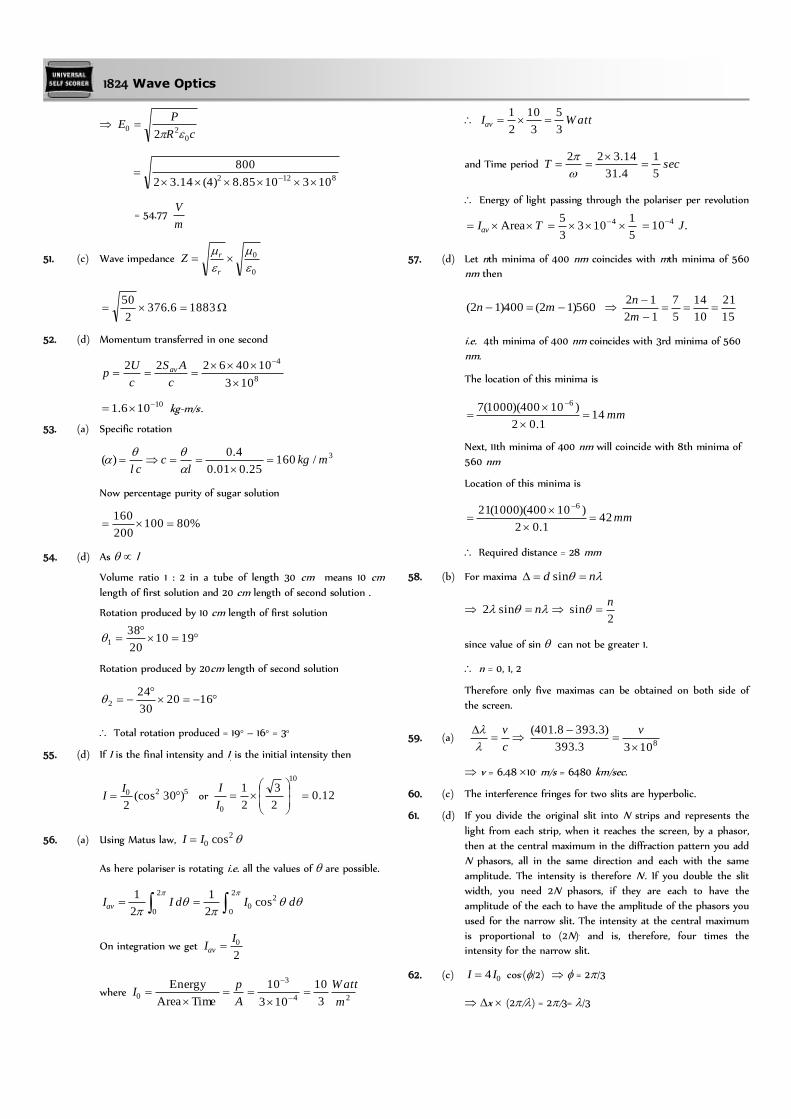
1824 Wave Optics
cR
PE
020
2
8122 1031085.8)4(14.32
800
= 54.77 m
V
51. (c) Wave impedance 0
0
r
rZ
18836.3762
50
52. (d) Momentum transferred in one second
8
4
103
10406222
c
AS
c
Up av
10106.1 kg-m/s2.
53. (a) Specific rotation
3/16025.001.0
4.0)( mkg
lc
cl
Now percentage purity of sugar solution
%80100200
160
54. (d) As l
Volume ratio 1 : 2 in a tube of length 30 cm means 10 cm
length of first solution and 20 cm length of second solution .
Rotation produced by 10 cm length of first solution
191020
381
Rotation produced by 20cm length of second solution
162030
242
Total rotation produced = 19° – 16° = 3°
55. (d) If I is the final intensity and I0
is the initial intensity then
520 )30(cos2
I
I or 12.02
3
2
110
0
I
I
56. (a) Using Matus law, 20 cosII
As here polariser is rotating i.e. all the values of are possible.
2
0
20
2
0cos
2
1
2
1dIdIIav
On integration we get 2
0IIav
where 24
3
03
10
103
10
Time Area
Energy
m
Watt
A
pI
W attIav3
5
3
10
2
1
and Time period secT5
1
4.31
14.322
Energy of light passing through the polariser per revolution
TIav Area5
1103
3
5 4 .10 4 J
57. (d) Let nth minima of 400 nm coincides with mth minima of 560
nm then
560)12(400)12( mn 15
21
10
14
5
7
12
12
m
n
i.e. 4th minima of 400 nm coincides with 3rd minima of 560
nm.
The location of this minima is
mm141.02
)10400)(1000(7 6
Next, 11th minima of 400 nm will coincide with 8th minima of
560 nm
Location of this minima is
mm421.02
)10400)(1000(21 6
Required distance = 28 mm
58. (b) For maxima nd sin
nsin2 2
sinn
since value of sin can not be greater 1.
n = 0, 1, 2
Therefore only five maximas can be obtained on both side of
the screen.
59. (a) c
v
81033.393
)3.3938.401(
v
v = 6.48 106 m/s = 6480 km/sec.
60. (c) The interference fringes for two slits are hyperbolic.
61. (d) If you divide the original slit into N strips and represents the
light from each strip, when it reaches the screen, by a phasor,
then at the central maximum in the diffraction pattern you add
N phasors, all in the same direction and each with the same
amplitude. The intensity is therefore N2. If you double the slit
width, you need 2N phasors, if they are each to have the
amplitude of the each to have the amplitude of the phasors you
used for the narrow slit. The intensity at the central maximum
is proportional to (2N)2 and is, therefore, four times the
intensity for the narrow slit.
62. (c) 04 II cos2(/2) = 2/3
x (2/) = 2/3= /3

Wave Optics 1825
sin = x/d sin = /3d
63. (b) Momentum of the electron will increase. So the wavelength (
= h/p)of electrons will decrease and fringe width decreases as
Assertion and Reason
1. (d) When a light wave travel from a rarer to a denser medium it loses speed, but energy carried by the wave does not depend on its speed. Instead, it depends on the amplitude of wave.
2. (e) A narrow pulse is made of harmonic waves with a large range of wavelength. As speed of propagation is different for different wavelengths, the pulse cannot retain its shape while travelling through the medium.
3. (b) When d is negligibly small, fringe width which is
proportional to d/1 may become too large. Even a single fringe may occupy the whole screen. Hence the pattern cannot be detected.
4. (a) The central spot of Newton’s rings is dark when the medium between plano convex lens and plane glass is rarer than the medium of lens and glass. The central spot is dark because the phase change of is introduced between the rays reflected from surfaces of denser to rarer and rarer to denser media.
5. (a) For reflected system of the film, the maxima or constructive
interference is 2
)12(cos2
nrµt while the maxima for
transmitted system of film is given by equation
nrµt cos2
where t is thickness of the film and r is angle of reflection.
From these two equations we can see that condition for maxima in reflected system and transmitted system are just opposite.
6. (b) When intensity of light emerging from two slits is equal, the intensity at minima,
,02
min ba III or absolute dark.
It provides a better contrast.
7. (c) When one of slits is covered with cellophane paper, the
intensity of light emerging from the slit is decreased (because this medium is translucent). Now the two interfering beam have different intensities or amplitudes. Hence intensity at minima will not be zero and fringes will become indistinct.
8. (a) When a polaroid is rotated in the path of unpolarised light, the intensity of light transmitted from polaroid remains undiminished (because unpolarised light contains waves vibrating in all possible planes with equal probability). However, when the polaroid is rotated in path of plane polarised light, its intensity will vary from maximum (when the vibrations of the plane polarised light are parallel to the axis of the polaroid) to minimum (when the direction of the vibrations becomes perpendicular to the axis of the crystal). Thus using polaroid we can easily verify that whether the light is polarised or not.
9. (c) The nicol prism is made of calcite crystal. When light is passed through calcite crystal, it breaks up into two rays (i) the ordinary ray which has its electric vector perpendicular to the principal section of the crystal and (ii) the extra ordinary ray which has its electric vector parallel to the principal section. The nicol prism is made in such a way that it eliminates one of the two rays by total internal reflection, thus produces plane
polarised light. It is generally found that the ordinary ray is eliminated and only the extra ordinary ray is transmitted through the prism. The nicol prism consists of two calcite crystal cut at – 68° with its principal axis joined by a glue called Canada balsam.
10. (b) Doppler’s effect is observed readily in sound wave due to larger wavelengths. The same is not the case with light due to shorter wavelength in every day life.
11. (d) In Young’s experiments fringe width for dark and white fringes are same while in Young’s double slit experiment when a white light as a source is used, the central fringe is white around which few coloured fringes are observed on either side.
12. (a) It is quite clear that the coloured spectrum is seen due to diffraction of white light on passing through fine slits made by fine threads in the muslin cloth.
13. (c) As the waves diffracted from the edges of circular obstacle, placed in the path of light interfere constructively at the centre of the shadow resulting in the formation of a bright spot.
14. (c) The beautiful colours are seen on account of interference of light reflected from the upper and the lower surfaces of the thin films.
15. (a) Microwave communication is preferred over optical communication because microwaves provide large number of channels and wider band width compared to optical signals as information carrying capacity is directly proportional to band width. So, wider the band width, greater the information carrying capacity.
16. (a)
17. (a) d
D
18. (c) The clouds consists of dust particles and water droplets. Their size is very large as compared to the wavelength of the incident light from the sun. So there is very little scattering of light. Hence the light which we receive through the clouds has all the colours of light. As a result of this, we receive almost white light. Therefore, the cloud are generally white.
19. (d) In sky wave propagation, the radio waves having frequency range 2 MHz to 30 MHz are reflected back by the ionosphere. Radio waves having frequency nearly greater than 30 MHz penetrates the inosphere and is not reflected back by the ionosphere. The TV signal having frequency greater than 30 MHz therefore cannot be propagated through sky wave propagation.
In case of sky wave propagation, critical frequency is defined as the highest frequency is returned to the earth by the considered layer of the ionosphere after having sent straight to it. Above this frequency, a wave will penetrate the inosphere and is not reflected by it.
20. (c) The television signals being of high frequency are not reflected by the ionosphere. So the T.V. signals are broadcasted by tall
antenna to get large coverage, but for transmission over large distance satellites are needed. That is way, satellites are used for long distance T.V. transmission.
21. (e) We know, with increase in altitude, the atmospheric pressure
decreases. The high energy particles (i.e. -rays and cosmic
rays) coming from outer space and entering out earth’s
E-ray
O-ray Unpolarized
light
Blackened surface
Canada balsam layer
Polarised light
1826 Wave Optics
atmosphere cause ionisation of the atoms of the gases present there. The ionising power of these radiation decreases rapidly as they approach to earth, due to increase in number of collisions with the gas atoms. It is due to this reason the electrical conductivity of earth’s atmosphere increase with
altitude.
22. (a) In a radar, a beam signal is needed in particular direction
which is possible if wavelength of wave is very small. Since the wavelength of microwaves is a few millimeter, hence they are used in radar.
23. (c) Hertz experimentally observed that the production of spark
between the detector gap is maximum when it is placed parallel to source gap. This means that the electric vector of radiation produced by the source gap is parallel to the two gaps i.e., in the direction perpendicular to the direction of propagation of
the radiation.
24. (d) The atoms of the metallic container are set into forced
vibrations by the microwaves. Hence, energy of the microwaves is not efficiently transferred to the metallic container. Hence food in metallic containers cannot be cooked in microwave oven. Normally in microwave oven the energy of waves is transferred to the kinetic energy of the molecules. This raises the temperature of any food.
25. (c) The earth’s atmosphere is transparent to visible light and radio waves, but absorbs X-rays. Therefore X-rays telescope cannot be
used on earth surface.
26. (b) Short wave (wavelength 30 km to 30 cm). These waves are
used for radio transmission and for general communication purpose to a longer distance from ionosphere.
27. (b) The wavelength of these waves ranges between 4000 Å to 100
Å that is smaller wavelength and higher frequency. They are absorbed by atmosphere and convert oxygen into ozone. They cause skin diseases and they are harmful to eye and cause permanent blindness.
28. (d) Ozone layer in the stratosphere helps in protecting life of
organism from ultraviolet radiation on earth. Ozone layer is depleted due to of several factors like use of chlorofluoro carbon (CFC) which is the cause of environmental damages.
29. (b) Radio waves can be polarised becomes they are transverse in
nature. Sound waves in air are longitudinal in nature.
30. (a) In the absence of atmosphere, all the heat will escape from earth’s surface which will make earth in hospitably cold.
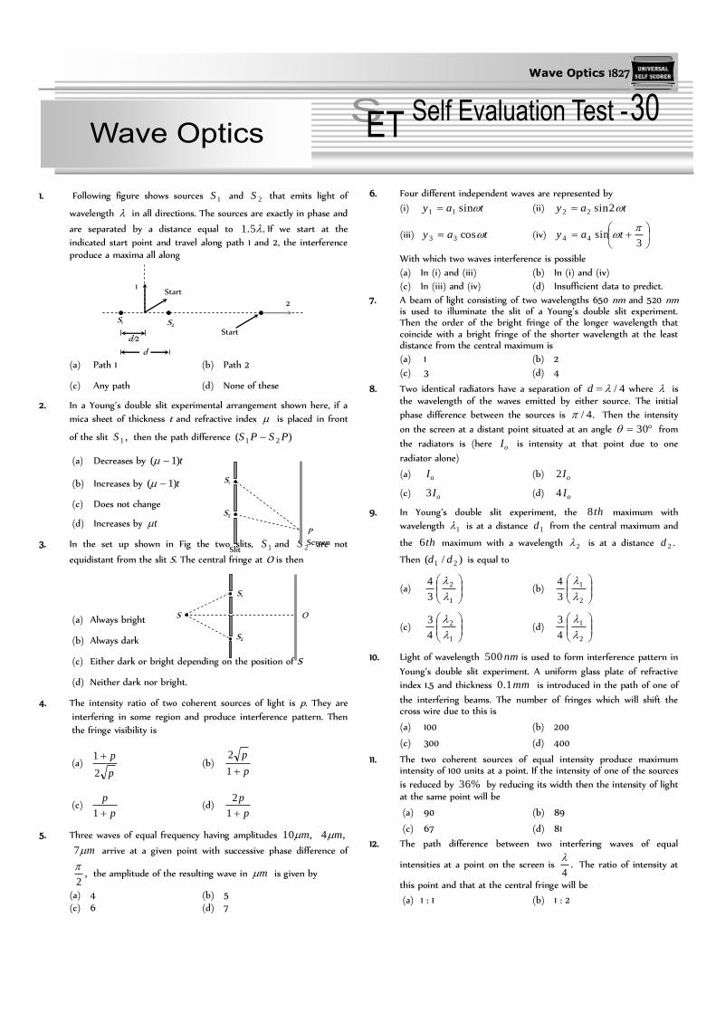
Wave Optics 1827
1. Following figure shows sources 1S and 2S that emits light of
wavelength in all directions. The sources are exactly in phase and
are separated by a distance equal to .5.1 If we start at the
indicated start point and travel along path 1 and 2, the interference produce a maxima all along
(a) Path 1 (b) Path 2
(c) Any path (d) None of these
2. In a Young’s double slit experimental arrangement shown here, if a
mica sheet of thickness t and refractive index is placed in front
of the slit ,1S then the path difference )( 21 PSPS
(a) Decreases by t)1(
(b) Increases by t)1(
(c) Does not change
(d) Increases by t
3. In the set up shown in Fig the two slits, 1S and 2S are not
equidistant from the slit S. The central fringe at O is then
(a) Always bright
(b) Always dark
(c) Either dark or bright depending on the position of S
(d) Neither dark nor bright.
4. The intensity ratio of two coherent sources of light is p. They are
interfering in some region and produce interference pattern. Then
the fringe visibility is
(a) p
p
2
1 (b)
p
p
1
2
(c) p
p
1 (d)
p
p
1
2
5. Three waves of equal frequency having amplitudes ,10 m ,4 m
m7 arrive at a given point with successive phase difference of
,2
the amplitude of the resulting wave in m is given by
(a) 4 (b) 5
(c) 6 (d) 7
6. Four different independent waves are represented by
(i) tay sin11 (ii) tay 2sin22
(iii) tay cos33 (iv)
3sin44
tay
With which two waves interference is possible
(a) In (i) and (iii) (b) In (i) and (iv)
(c) In (iii) and (iv) (d) Insufficient data to predict.
7. A beam of light consisting of two wavelengths 650 nm and 520 nm is used to illuminate the slit of a Young’s double slit experiment. Then the order of the bright fringe of the longer wavelength that coincide with a bright fringe of the shorter wavelength at the least distance from the central maximum is
(a) 1 (b) 2
(c) 3 (d) 4
8. Two identical radiators have a separation of 4/d where is the wavelength of the waves emitted by either source. The initial
phase difference between the sources is .4/ Then the intensity
on the screen at a distant point situated at an angle 30 from
the radiators is (here oI is intensity at that point due to one
radiator alone)
(a) oI (b) oI2
(c) oI3 (d) oI4
9. In Young’s double slit experiment, the th8 maximum with
wavelength 1 is at a distance 1d from the central maximum and
the th6 maximum with a wavelength 2 is at a distance .2d
Then )/( 21 dd is equal to
(a)
1
2
3
4
(b)
2
1
3
4
(c)
1
2
4
3
(d)
2
1
4
3
10. Light of wavelength nm500 is used to form interference pattern in
Young’s double slit experiment. A uniform glass plate of refractive
index 1.5 and thickness mm1.0 is introduced in the path of one of
the interfering beams. The number of fringes which will shift the cross wire due to this is
(a) 100 (b) 200
(c) 300 (d) 400
11. The two coherent sources of equal intensity produce maximum intensity of 100 units at a point. If the intensity of one of the sources
is reduced by %36 by reducing its width then the intensity of light at the same point will be
(a) 90 (b) 89
(c) 67 (d) 81
12. The path difference between two interfering waves of equal
intensities at a point on the screen is .4
The ratio of intensity at
this point and that at the central fringe will be
(a) 1 : 1 (b) 1 : 2
S2
S1
Slit
Screen
P
S2
S1
O S
S1 S2
1
2
Start
Start
d/2
d

1828 Wave Optics
(c) 2 : 1 (d) 1 : 4
13. In a Young’s double slit experiment, oI is the intensity at the
central maximum and is the fringe width. The intensity at a
point P distant x from the centre will be
(a)
xIo cos (b)
xIo
2cos4
(c)
xIo
2cos (d)
xIo 2cos4
14. In a Fresnel’s diffraction arrangement, the screen is at a distance of 2 meter from a circular aperture. It is found that for light of
wavelengths 1 and ,2 the radius of th4 zone for 1 coincides
with the radius of 5th zone for .2 Then the ratio 21 : is
(a) 5/4 (b) 4/5
(c) 4/5 (d) 5/4
15. If n represents the order of a half period zone, the area of this zone
is approximately proportional to mn where m is equal to
(a) Zero (b) Half
(c) One (d) Two
16. A screen is placed cm50 from a single slit, which is illuminated
with Å6000 light. If distance between the first and third minima
in the diffraction pattern is ,3 mm the width of the slit is
(a) mm1.0 (b) mm2.0
(c) mm3.0 (d) mm4.0
17. In Young’s double slit experiment, the fringes are displaced by a distance x when a glass plate of one refractive index 1.5 is introduced in the path of one of the beams. When this plate in replaced by another plate of the same thickness, the shift of fringes is
.)2/3( x The refractive index of the second plate is
(a) 1.75 (b) 1.50
(c) 1.25 (d) 1.00
18. Two waves of equal amplitude and frequency interfere each other. The ratio of intensity when the two waves arrive in phase to that
when they arrive 90 out of phase is
(a) 1 : 1 (b) 2 : 1
(c) 2 : 1 (d) 4 : 1
19. In Young’s double slit experiment, we get 60 fringes in the field of
view of monochromatic light of wavelength Å4000 . If we use
monochromatic light of wavelength ,6000Å then the number of
fringes obtained in the same field of view is
(a) 60 (b) 90
(c) 40 (d) 1.5
20. A parallel plate capacitor with plate are A and seperation between
the plates d, is charged by a constant current i, consider a plane
surface of area A/2 parallel to the plates and drawn symmetrically
between the plates, the displacement current through this area, will
be.
(a) i (b) 2
i
(c) 4
i (d) None of these
21. The figure here gives the electric field of an EM wave at a certain
point and a certain instant. The wave is transporting energy in the
negative z direction. What is the direction of the magnetic field of
the wave at that point and instant
(a) Towards + X direction
(b) Towards – X direction
(c) Towards + Z direction
(d) Towards – Z direction
22. The figure shows four pairs of polarizing sheets, seen face-on. Each
pair is mounted in the path of initially unpolarized light. The
polarizing direction of each sheet (indicated by the dashed line) is
referenced to either a horizontal x-axis or a vertical y axis. Rank the
pair according to the fraction of the initial intensity that they pass,
greatest first
(a) (i) > (ii) > (iii) > (iv) (b) (i) > (iv) > (ii) > (iii)
(c) (i) > (iii) > (ii) > (iv) (d) (iv) > (iii) > (ii) > (i)
23. An astronaut floating freely in space decides to use his flash light as
a rocket. He shines a 10 watt light beam in a fixed direction so that
he acquires momentum in the opposite direction. If his mass is 80
kg, how long must he need to reach a velocity of 1 ms–1
(a) 9 sec (b) 2.4 103 sec
(c) 2.4 106 sec (d) 2.4 109 sec
1. (a) At any point along the path 1, path difference between the waves is 0.
Hence maxima is obtained all along the path 1.
At any point along the path 2, path difference is 1.5 which is
odd multiple of ,2
so minima is obtained all along the path
2.
2. (b) Path difference at P PStPS 21 ))1((
X
Y
Z
E
(SET -30)
60o
60o 60o 60o
30o
30o
30o
30o
(i) (ii) (iii) (iv)

Wave Optics 1829
tPSPS )1()( 21
3. (c) If path difference = (SS1
+ S1
O) – (SS2
+ S2
O) = n n = 0, 1, 2,
3, .... the central fringe at O is a bright fringe and if the path
difference
2
1n , n = 1, 2, 3, ..... the central bright
fringe will be a dark fringe.
4. (b) )(
2 Visibility
21
21
minmax
minmax
II
II
II
IIV
)1(
2
1
/2
2
1
21
P
P
I
I
II
5. (b) The amplitudes of the waves are
a1
= 10 m, a2
= 4 m and a3
= 7m
and the phase difference between 1st and 2nd wave is 2
and that
between 2nd and 3rd wave is .2
Therefore, phase difference
between 1st and 3rd is . Combining 1st with 3rd, their resultant
amplitude is given by
cos2 3123
21
21 aaaaA
or 14049100cos7102710 221 A
m39 in the direction of first.
Now combining this with 2nd wave we have, the resultant amplitude
2cos2 21
22
21
2 aAaAA
or mA o 516990cos43243 22
6. (d) Since the sources are independent, interference will not occur unless they are coherent (such as laser beams etc). So, insufficient data to predict.
7. (d) 21 )1( nn
d
Dn
d
Dn
1919 10520)1(10650
n = 4
8. (b) The intensity at a point on screen is given by
)2/(cos4 20 II
where is the phase difference. In this problem arises (i)
due to initial phase difference of /4 and (ii) due to path
difference for the observation point situated at .30o Thus
244)30(sin
4.
2
4)sin(
2
4
d
Thus 42
and 0
20 2)4/(cos4 III
9. (b) Position of nth maxima from central maxima is given by
d
Dnxn
nxn
2
1
2
1
22
11
2
1
3
4
6
8
n
n
d
d
10. (a) The number of fringes shifting is decided by the extra path difference produced by introducing the glass plate. The extra
path difference is ( – 1) t = n
or 93 10500101.0)15.1( n
n = 100
11. (d) Intensity of each source unitI 254
1000
If the intensity of one of the source is reduced by 36% then
unitI 251 and )(16100
3625252 unitI
Hence resultant intensity at the same point will be
unitIIIII 811625216252 2121
12. (b) By using
20
20 cos4
2cos4 III
2
2
1
)0(cos
4.
cos
cos
cos
2
2
22
12
2
1
I
I
13. (c) Path difference at point D
xdP
Phase difference at point
x
D
xdP
22
10 4 II , intensity at point P
xI
xIIII
2cos12
2cos2 1111
xI 20 cos
14. (c) It is given that 14 4 br and 25 5 br
are equal. Therefore 21 54 bb
or 21 54 bb
or .4
5
2
1
15. (a) Area of half period zone is independent of order of zone. Therefore, m is equal to zero in nm.
16. (b) Position of nth minima d
Dnyn
S2
S1
P

1830 Wave Optics
d
D
d
Dyy
2)13()( 13
d
5.01060002103
103
mmmd 2.0102.0 3
17. (b) Fringe shift is given by
tx
)1(
For first plate,
tx
)1( 1
For second plate
tx
)1(
2
3 2
2
3
1
1
1
2
2
3
15.1
12
75.12
18. (c) Resultant intensity )2/(cos4 20 II
1
2
)2/90(cos
0cos
)2/(cos
)2/(cos2
2
22
12
2
1
I
I
19. (c) 2211 nn 6000400060 2 n n2
= 40
20. (b) Suppose the charge on the capacitor at time t is Q, the electric
field between the plates of the capacitor is .0 A
QE
The
flux through the area considered is 00 22
.
QA
A
QE
The displacement current
.22
1
0
00
i
dt
dQ
dt
di Ed
21. (a) The direction of EM wave is given by the direction of .BE
22. (b) Final intensity of light is given by Brewster's law
;cos20 II where = Angle between transmission axes of
polariser and analyser.
(i) (ii) (iii) (iv)
Hence decreasing order of intensity is (i) > (iv) > (ii) > (iii)
23. (d) Let it take t sec for astronaut to acquire a velocity of 1 ms– 1.
Then energy of photons = 10 t
Momentum C
t10 = 80 1
sect 98
104.210
103180
***
60o
60o 60o 60o
30o
30o
30o
30o