
Fiber Optics Handbook - World Radio History
48
-
Upload
khangminh22 -
Category
Documents
-
view
3 -
download
0
Transcript of Fiber Optics Handbook - World Radio History
THE MAGAZINE OF BROADBAND TECHNOLOGY / SEPTEMBER 1990
tor
A special supplement of CED magazine
oe
Fiber Optics Handbook

•
Panasonic Built.
From The Inside Out.
Every time you install a Panasonic® CATV converter, you're assured of uncompromised quality and performance.
Because Panasonic CATV converters are designed and
manufactured by its parent company, Matsushita Electric. Which means each CATV converter is Panasonic built. From the
inside out.
Take the Panasonic TZ-PC140/170 Series. Employing the latest in manufacturing technology, Panasonic converters are built to
exceptionally high quality standards. It's the quality your subscribers have grown to expect from Panasonic. And that will help avoid costly service calls.
And to provide today's subscribers with the sophistication
they associate with all Panasonic video products, the TZ-PC140/170 Series provides features like BTSC stereo
compatibility, skip-scan tuning and remote volume control (170 Series), to name a few.
Panasonic CATV converters. Built for you and your subscribers the way all converters should be. From the inside out.
Panasonic Video Communications
For more information call: Northeast 609-589-3063 Midwest 513-530-9216 Southeast 404-925-6845 West 415-947-0147
l'or Information via FAX RESPONSE call 1-800-876-2299, code number 008.
Reader Service Number 1
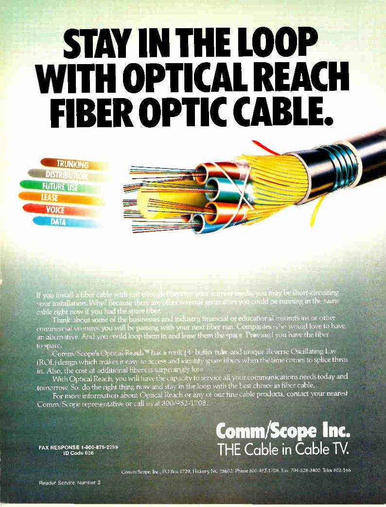
STAY I THE LOOP WITH OPTICAL REAC FIBER OPTIC CABLE.
1
411111L.
If you install a fiber cable wit your installation. Why? Because t ere cable right now if you had the spare fiber.
Think about some of the businesses and industry, financial or educational institutions or other commercial ventures you will be passing with your next fiber run. Companies who would love to have an alternative. And you could loop them in and lease them the space. Provided you have the fiber to spare.
Comm/Scope's Optical Reach Te has a multiple buffer tube and unique Reverse Oscillating Lay (ROL) design which makes it easy to access and identify spare fibers when the time comes to splice them in. Also, the cost of additional fibers is surprisingly low
With Optical Reach, you will have the capacity to service all your communications needs today and tomorrow So, do the right thing now and stay in the loop with the best choice in fiber cable.
For more information about Optical Reach or any of our fine cable products, contact your nearest Comm/Scope representative or call us at 800/9824708.
FAX RESPONSE 1-800-876-2299 ID Code 026
Reader Service Number 2
u *lay • s ort-circuiting 'rcïit could :be running in the same
Comm/Scope Inc. THE Cable in Cable W.
Comm/Scope, Inc., PO Box 1729, Hickory NC 28602. Phone 800-982-1708. Fax: 704-328-3400. Telex 802-166
EMIL IN PERSPECTIVE
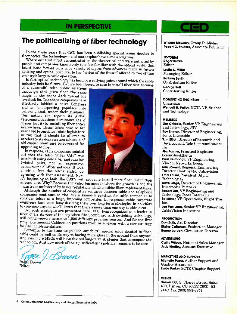
The politicalizing of fiber technology
In the three years that CED has been publishing special issues devoted to fiber optics, the technology—and marketplacehave come a long way. Where our first effort concentrated on the theoretical and were authored by
people and companies known only to a few familiar with the optical world, this latest issue focuses on a wide variety of topics, from advances made in fusion splicing and optical couplers, to the "vision of the future" offered by two of this country's largest cable operators.
In fact, optical technology has become a rallying point around which the cable industry bets its future. Cable's been forced to race to install fiber first because of a successful telco public relations campaign that gives fiber the same magic as the beans Jack traded his livestock for. Telephone companies have effectively lobbied a naive Congress and an unsuspecting populace into believing that, under their guidance, this nation can regain its global telecommunications dominance (as if it ever lost it) by installing fiber optics everywhere. These telcos have so far managed to convince a state legislature or two that it should be allowed to accelerate its depreciation schedule of old copper plant and be rewarded for upgrading to fiber.
In response, cable companies pointed out that the telco "Fiber City" was best built using both fiber and coax (or twisted pair), not an expensive, cumbersome all-fiber network. It took a while, but the telcos ended up agreeing with that assessment. Now it's beginning to look like CATV will probably install more fiber faster than anyone else. Why? Because the video business is where the growth is and the industry is unfettered by heavy regulation, which inhibits fiber implementation. Although the number of cooperative ventures between cable and telephone
companies continues to rise, it's a kneejerk reaction for cable companies to consider telcos as a huge, imposing competitor. In response, cable corporate engineers have been busy devising their own long-term strategies in an effort to convince anyone who'll listen that there's more than one way to skin a cat. Two such strategies are presented here. ATC, long recognized as a leader in
fiber, offers its view of the day when fiber, combined with switching technology, will bring viewers access to 1,000 different program sources. And for the first time, Continental Cablevision positions itself as a leader with a new strategy for fiber implementation.
Certainly, by the time we publish our fourth special issue devoted to fiber, cable could be well on its way to having more glass in the ground than anyone. And ever more MSOs will have devised long-term strategies that encompass the technology. Just how much of their justification is political remains to be seen.
R,o r Bro Editor
411111=1,
William McGorry, Group Publisher Robert C. Stuehrk, Associate Publisher
EDITQMAL Roger Brown Editor
Leslie A. Miller Managing Editor Kathryn Berlin Contributing Editor George Sell Contributing Editor
CONSULTING ENGINEERS Chairman Wendell H. Bailey, NCTA VP, Science and Technology
MEMBERS Jim Chlddbc, Senior VP, Engineering and Technology, ATC Roy Ehman, Director of Engineering, Jones Intercable Tom Elliot, Director of Research and Development, lile-Communications Inc. Jim Farmer, Principal Engineer, Scientific-Atlanta Paul Heimbach, VP Engineering, Viacom Networks Group Tom Jokerst, Regional Engineering Director, Continental Cablevision Fred Kaiser, President, Alpha Technologies Dave Large, Director of Engineering, Intermedia Partners Robert Luff, VP Engineering and Technology, Jones Intercable Ed Milner, VP Operations, Flight 'frac Inc. Joe Van Loan, Senior VP Engineering, CableVision Industries
PRODUCTION Don Ruth, Art Director Elaine Callahan, Production Manager Renee Jordan, Circulation Director
ADVERTISING Cathy Wilson, National Sales Manager Judy Medley, Account Executive
MARKETING AND SUPPORT Michelle Pazar, Author Support and Quality Assurance Linda Parker, SCTE Chapter Support
OFFICE
Denver 600 S. Cherry Street, Suite 400, Denver, CO 80222 (303) 93-7449. Fax (303) 393-6654.
6 Communications Engineering and Design September 1990
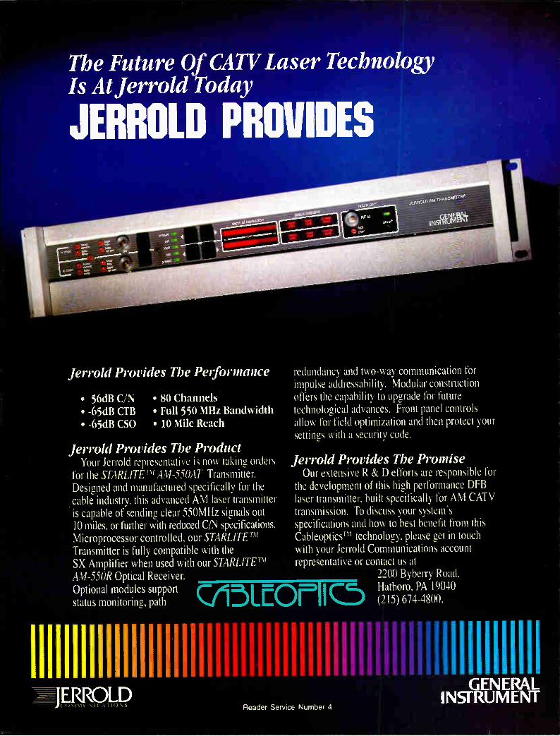
The Future Of CATV Laser Technology Is At Jerrold Today
JERROLD PROVIDES
Jerrold Provides The Performance
• 56dB C/N • -65dB dB • -65dB CSO
• 80 Channels • Full 550 MHz Bandwidth • 10 Mile Reach
Jerrold Provides The Product Your Jerrold representative is now taking orders
for the STARLITErm AM-550AT Transmitter. Designed and manufactured specifically for the cable industry, this advanced AM laser transmitter is capable of sending clear 550MHz signals out 10 miles, or further with reduced C/N specifications. Microprocessor controlled, our STARLITE TM Transmitter is fully compatible with the SX Amplifier when used with our STARLITE AM-550R Optical Receiver. Optional modules support status monitoring, path
redundancy and two-way communication for impulse addressability. Modular construction offers the capability to upgrade for future technological advances. Front panel controls allow for field optimization and then protect your settings with a security code.
Jerrold Provides The Promise Our extensive R & D efforts are responsible for
the development of this high performance DFB laser transmitter, built specifically for AM CATV transmission. To discuss your system's specifications and how to best benefit from this CableopticsTM technology, please get in touch with your Jerrold Communications account representative or contact us at
2200 Byberry Road,
CA5LcOrlIC5 Hatboro, PA 19040 (215) 674-4800.
IIIIIIIIIIIIIIIII.IIIIIIIII.I1IIIiIIIIIIIIIILIII1I.IiIIIIIIIIIII JERROLD INSURUMENT
Reader Service Number 4

The evolution of cable television delivery systems A strategic plan for Continental Cablevision of New England
Ats we enter he decade of the '90s, the
cable television industry is entering a critical era of increased oversight and threat of compe-tition. Cable's success during this pivotal time will largely revolve around its ability to respond to the complex array of issues that now confronts it. From a technological standpoint, the advent of fiber optics has pro-vided the key to ensuring cable's position as the pro-vider of broad-band services to the home. As the various
applications for fiber in the CATV landscape are examined, one must first understand the limitations of the current system architectures and explore ways to strategically deploy fiber in a way that will counteract these limitations. Architectural limitations include the number of failure points between any one subscriber and the headend, and the ever escalating costs to maintain the cable plant. The common denominator is electri-
cal current. More than 50 percent of system outages can be directly corre-lated to power surges, outages, brown-outs, etc. Figure 1 illustrates that power consumption in the cable plant
By Kevin M. Casey, director of engineering, Continental Cablevision of New England
Continental Cablevision of New England
5 -
4.5 -
4 -
3.5 -
2.5 -
1.5 -
0.5 -
FIBER MILEAGE DEPLOYMENT
o
1987 1988 1989 1990 1991 1992 1993
Power Consumption Costs Per Plant Mile 300 MHz 400 MHz 450 MHz 550 MHz 550 MHz 550 MHz
P.S. Costs / Mile $102.00 $114.00 $168.00 $366.00 $366.00 $193.00
P. Supplies / Mile 0.17 0.19 0.28 0.61 0.61 0.32
Homes / Mile 120 88 87 255 87 23
Cost / Passing $0.85 $1.30 $1.93 $1.44 $4.21 $8.39
F gure 1
increases dramatically as bandwidth increases. This not only impacts the reliability of the system, but places additional burden on operating ex-penses as well. As headends are con-solidated and bandwidth expanded, the result will be longer cascades that may require feedforward technology in or-der to meet performance requirements.
Fiber usage a decade ago
The extent of fiber deployment in the cable system architecture of the '80s was largely restricted to supertrunking and limited trunking applications. This was attributed to the high cost and
limited avail-ability of fiber and optoelec-tronics. Prior to 1988, frequency modulation, which was the transmission medium used almost exclu-sively with fiber, did not require highly linear optical sources in order to meet EIA RS-250-B medium haul specifications for video transport. However, the eco-nomics of FM at $4,000 to $7,500 per channel limited the applications in which fiber was a viable alter-native to microwave or supertrunking.
Notwithstand-ing the economic barriers, the key to widespread deployment of fiber is the reduction of signal processing components required under
the FM scheme. For example, a 450 MHz 60-channel FM system would require more than 200 active headend components before final combining. To further complicate matters, group de-lay, inherent with video scrambling in the FM format, required signal scram-bling to be performed at each hub site.
In 1988, the advent of the distributed feedback laser (DFB) for CATV appli-cations provided direct modulation of AM broadband signals and the elimi-nation of signal processing components required under the FM approach. Sub-sequently, several MSOs have deployed this technology with flawless operation to date. This has established vast
8 Communications Engineering and Design September 1990
market potential for vendors and sup-pliers, who have accelerated research and development efforts to produce low cost, high performance AM optoelec-tronics. These recent developments have now altered the economic and technical outlook for widespread deployment in the CATV architecture. The opportuni-ties that this technology now offers in improving the quality, reliability and capability of the cable plant are un-equaled.
Three-phase fiber plan
The events of the past two years have helped shape our engineering strategy into the year 2000. Continen-tal Cable of New England has estab-lished a three-phase plan that it be-lieves will provide for increased fiber deployment into the distribution sys-tem, and ultimately to the tap, by the end of the century. The plan is evolu-tionary in that it maintains the techni-cal and economic integrity that is essential to our long-term success.
Architectural development. Phase one of Continental's engineering strat-egy is the deployment of topology architectures designed to push fiber deeper into the system at an economi-cally viable cost. The ATC "backbone" or Jones "CAN" systems are two such examples of the 1989-1990 generation of fiber deployment. Under these architectures, fiber nodes
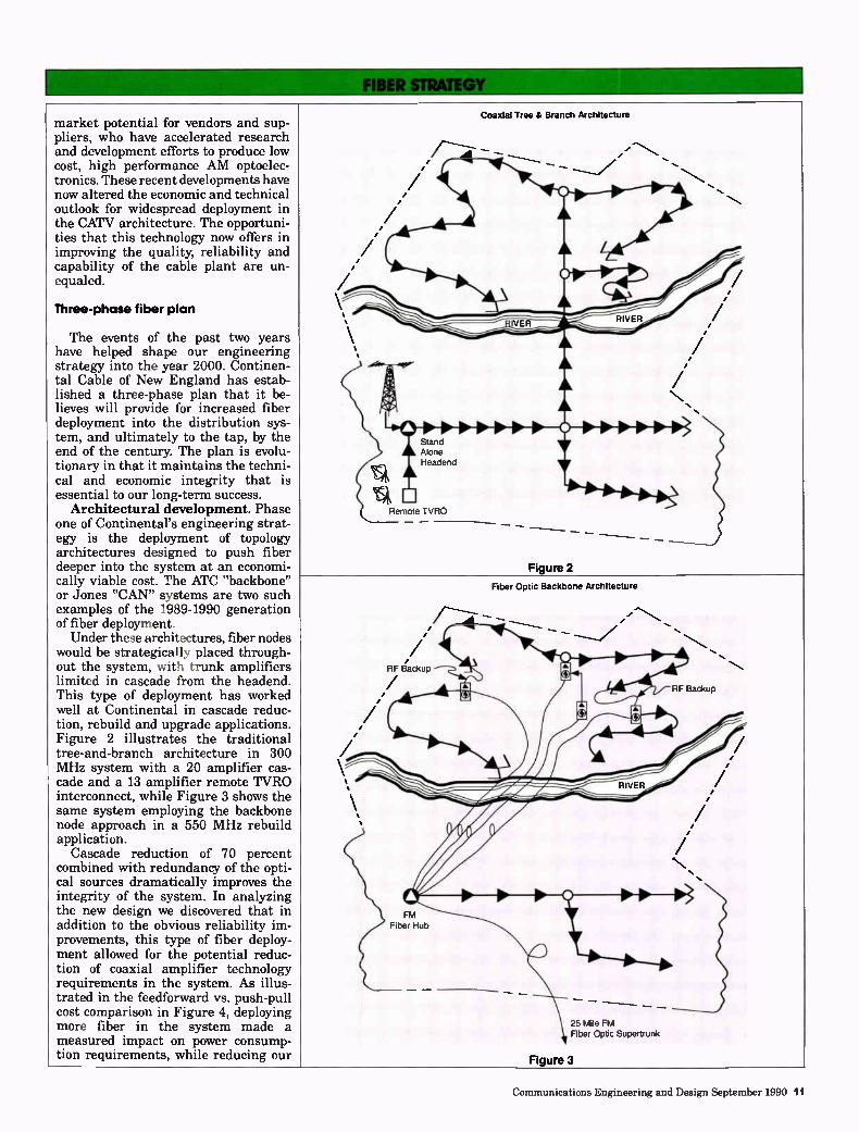
would be strategically placed through-out the system, with trunk amplifiers limited in cascade from the headend. This type of deployment has worked well at Continental in cascade reduc-tion, rebuild and upgrade applications. Figure 2 illustrates the traditional tree-and-branch architecture in 300 MHz system with a 20 amplifier cas-cade and a 13 amplifier remote TVRO interconnect, while Figure 3 shows the same system employing the backbone node approach in a 550 MHz rebuild application.
Cascade reduction of 70 percent combined with redundancy of the opti-cal sources dramatically improves the integrity of the system. In analyzing the new design we discovered that in addition to the obvious reliability im-provements, this type of fiber deploy-ment allowed for the potential reduc-tion of coaxial amplifier technology requirements in the system. As illus-trated in the feedforward vs. push-pull cost comparison in Figure 4, deploying more fiber in the system made a measured impact on power consump-tion requirements, while reducing our
Coaxial Tree & Branch Architecture
Figure 2
Remote TVRO
RF Backup
FM Fiber Hub
Fiber Optic Backbone Architecture
25 Mile FM Fiber Optic Supertrunk
RF Backup
N..
Figure 3
Communications Engineering and Design September 1990 11
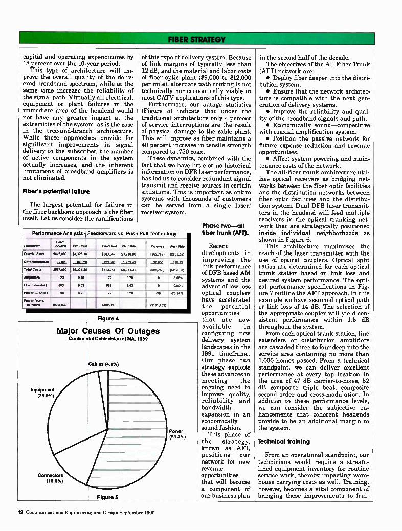
capital and operating expenditures by 18 percent over the 10-year period.
This type of architecture will im-prove the overall quality of the deliv-ered broadband spectrum, while at the same time increase the reliability of the signal path. Virtually all electrical, equipment or plant failures in the immediate area of the headend would not have any greater impact at the extremities of the system, as is the case in the tree-and-branch architecture. While these approaches provide for significant improvements in signal delivery to the subscriber, the number of active components in the system actually increases, and the inherent limitations of broadband amplifiers is not eliminated.
Fiber's potential failure
The largest potential for failure in the fiber backbone approach is the fiber itself. Let us consider the ramifications
of this type of delivery system. Because of link margins of typically less than 12 dB, and the material and labor costs of fiber optic plant ($9,000 to $12,000 per mile), alternate path routing is not technically nor economically viable in most CATV applications of this type.
Furthermore, our outage statistics (Figure 5) indicate that under the traditional architecture only 4 percent of service interruptions are the result of physical damage to the cable plant. This will improve as fiber maintains a 40 percent increase in tensile strength compared to .750 coax.
These dynamics, combined with the fact that we have little or no historical information on DFB laser performance, has led us to consider redundant signal transmit and receive sources in certain situations. This is important as entire systems with thousands of customers can be served from a single laser/ receiver system.
Performance Analysis - Feedforward vs. Push Pull Technology
Parameter Feed
' Forward Per / Mile
$4,328.16 H
Push Pull Per/Mlle : Variance Per/Mile
($609.25) Coaxial Elect. _ ____ : $445,800
• _
$383,047 $3,718.90
1.252.42
. ($62,758)
Optoelectronles 1 UM __II= 125.9911 AL4011 _3222
Total Costs
Amplifiers
L: $537,800
72
$5221.36 0 $512,047 64,971.32 , ($25,753)
o
($250.03)
0.00% 0.70 II 72 0.70
Line Extenders 683 6.63 683 6.63 o 0.00%
Power Supplies se 0.95 72 0.70 -26 -25.24%
Power Costs-10 Years $568,000 $432000 ll ($181,753)
Figure 4
Major Cause 01 Outages Continental Cablevision of MA, 1989
Cables (4.1%)
Equipment
(25.9%)
Connectors
(16.6%)
Figure 5
Power
(53 4%)
Phase two—all fiber trunk (AFT).
Recent developments in improving the link performance of DFB based AM systems and the advent of low loss optical couplers have accelerated the potential opportunities that are now available in configuring new delivery system landscapes in the 1991 timeframe. Our phase two strategy exploits these advances in meeting the ongoing need to improve quality, reliability and bandwidth expansion in an economically sound fashion.
This phase of the strategy, known as AFT, positions our network for new revenue opportunities that will become a component of our business plan
in the second half of the decade. The objectives of the All Fiber Trunk
(AFT) network are: • Deploy fiber deeper into the distri-
bution system. • Ensure that the network architec-
ture is compatible with the next gen-eration of delivery systems. • Improve the reliability and qual-
ity of the broadband signals and path. • Economically sound—competitive
with coaxial amplification system. • Position the passive network for
future expense reduction and revenue opportunities. • Affect system powering and main-
tenance costs of the network. The all-fiber trunk architecture util-
izes optical receivers as bridging net-works between the fiber optic facilities and the distribution networks between fiber optic facilities and the distribu-tion system. Dual DFB laser transmit-ters in the headend will feed multiple receivers in the optical trunking net-work that are strategically positioned inside individual neighborhoods as shown in Figure 6.
This architecture maximizes the reach of the laser transmitter with the use of optical couplers. Optical split ratios are determined for each optical trunk station based on link loss and desired system performance. The opti-cal performance specifications in Fig-ure 7 outline the AFT approach. In this example we have assumed optical path or link loss of 14 dB. The selection of the appropriate coupler will yield con-sistent performance within 1.5 dB throughout the system. From each optical trunk station, line
extenders or distribution amplifiers are cascaded three to four deep into the service area containing no more than 1,000 homes passed. From a technical standpoint, we can deliver excellent performance at every tap location in the area of 47 dB carrier-to-noise, 52 dB composite triple beat, composite second order and cross-modulation. In addition to these performance levels, we can consider the subjective en-hancements that coherent headends provide to be an additional margin to the system.
Technical training
From an operational standpoint, our technicians would require a stream-lined equipment inventory for routine service work, thereby impacting ware-house carrying costs as well. 'framing, however, becomes a vital component of bringing these improvements to frui-
12 Communications Engineering and Design September 1990
OPTICAL SOLUTIONS THAT OPTIMIZE PERFORMANCE. Magnavox has a line of sophisticated fiber optic prod-ucts, including transmitters, couplers and receivers, that work in unison with your RF equipment to bring cost-effective fiber optic quality to your coaxial sys-tem. The result is a system with higher subscriber satisfaction and plenty of room to grow.
AM fiber optic products are currently available in rack mount and strand mount configurations.
By upgrading with fiber optics you boost system capacity, reliability, quality and profits. By using Magnavox you get a quality system designed by fiber optic professionals.
So, bring your cable system into the 21st century with the Magnavox Fiber Optic System. Call your Magnavox representative to find out more.
MAGNAVOX cav SYSTEMS, INC. 100 Fairgrounds Drive, Manlius, NY 13104 (315) 682-9105 Fax: (315) 682-9006 Call 1-800-448-5171 (In NY State 1-800-522-7464)
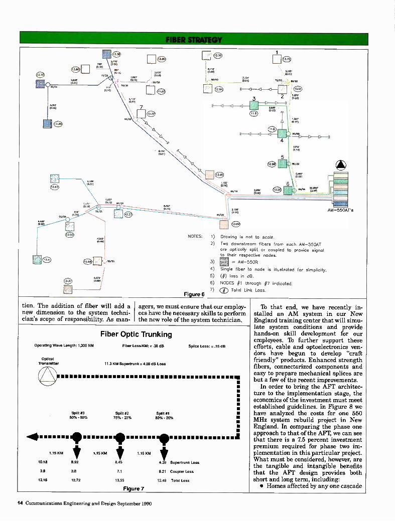
NOTES: 1) Drawing is not to scale.
2) Two downstream fibers from each AM-550A1 are optically split or coupled to provide signal to their respective nodes.
./50
6.079. i (We)
Figure 6
3) = AM-550R
4) Single fiber to node is illustrated for simplicity.
5) (#) loss in dB.
6) NODES #1 through #7 indicated.
7) (1) Total Link Loss.
tion. The addition of fiber will add a new dimension to the system techni-cian's scope of responsibility. As man-
agers, we must ensure that our employ-ees have the necessary skills to perform the new role of the system technician.
Operating Wave Length .300 NM
Optical
Transmitter
Fiber Optic Trunking
Fiber Loss KM = 38 dB Splice Loss: ..15 dB
11.3 KM Supertrunk = 4.28 dB Loss
izaaaamaaamaamaaamaaaaaaaaaaaaa awl
Split #3 Split 82 • 50% - 50% 75'. - Split al 80.° - 2(71° •
•
• •
-4•1110•••••••••••••••1101••••••••11p•••••••••ammul
1.15 KM t 1 15 KM 1.15 KM t
10.18 8.92 6.45 4.28 Supertrunk Loss
3.8 3.8 7.1
13.18 12.72 13.55
Figure 7
8.21 Coupler Loss
12.49 Total Loss
'lb that end, we have recently in-stalled an AM system in our New England training center that will simu-late system conditions and provide hands-on skill development for our employees. 'Ib further support these efforts, cable and optoelectronics ven-dors have begun to develop "craft friendly" products. Enhanced strength fibers, connectorized components and easy to prepare mechanical splices are but a few of the recent improvements.
In order to bring the AFT architec-ture to the implementation stage, the economics of the investment must meet established guidelines. In Figure 8 we have analyzed the costs for one 550 MHz system rebuild project in New England. In comparing the phase one approach to that of the AFT, we can see that there is a 7.5 percent investment premium required for phase two im-plementation in this particular project. What must be considered, however, are the tangible and intangible benefits that the AFT design provides both short and long term, including: • Homes affected by any one cascade
14 Communications Engineering and Design September 1990
Will you be ready for the big picture? Someday soon, a few demanding subscribers
will pull up a chair, turn on their HDTV, and put your system to the test.
With C-COR's new fiber optics and extended bandwidth products, you'll pass with high resolution colors. If the demand is for more channels, we'll make sure you're ready Data and video services? Just ask.
C-COR's outstanding quality and highly respected service? All included.
Even better, it's all available now. Just write C-COR, 60 Decibel Road, State College, PA 16801. Or call toll free 1-800-233-2267. In PA, 1-800-356-5090.
Whether you're planning for the big picture, or upgrading for a better one, we're ready when you are.
CCCII) ELECTRONICS INC '.'re Out To Give You
The Best Reception In The Industry.
Reader Service Number 6

went from 4,000 to less than 300. • System performance was consis-
tent within 1.5 dB throughout the entire system. • Passive fiber architecture provides
for future technology enhancements without major plant expense. • Addition of 1.5 GHz bandwidth
Summary Of key Cost Components
Of Total Investment
Hybrid Conventional
Alt Fiber
Reception Facilities 242,047 242,047
Coaxial Facilities 3,176,110 2,563,428
Fiber Optic Facilities
Aerial $ Per Mile
223,457
$14,470
1,034,298
$15,243
U.G. S Per Mile $37,308 $39,272
Figure 8
capability into neighborhoods. • 28 percent reduction in active
components in the cable plant. • Inventory requirements for elec-
tronics are reduced. • Long-term revenue opportunities
in areas other than CATV transport. • Investment in fiber plant can be
expected to maintain five times the average life cycle of the coax plant. • Power consumption costs are re-
duced by 21 percent which recoups 3.4 percent of the 7.5 percent investment premium over the 10-year franchise period. • Strategic value of the network in
offering advanced services to the com-mercial market.
This positions the cable network to provide for a passive fiber path back to the headend for every 300 to 1,000
Fiber Feeder System Grade Contours
\
Grade "B"\
Grade 'A
Grade contours represent a theoretical distance limit by which optical light sources may be split multiple times from a single source and deliver acceptable optical input signals to the receiver at each tap location. At each tap location, the light source is converted to RF energy to provide + 15 dBmv to +20 dBmv at the subscriber port.
Figure 9
subscribers. This quasi-star configura-tion positions the network for future business opportunities that are traffic limiting, or require extensive band-width requirements. Why not video-on-demand on a per
neighborhood basis? Or segmented pro-gramming to targeted demographic groups? With the infrastructure in place, systems, headends and offices can be interconnected to transport billing system data (MIS), voice and fax between offices. Additionally, remote commercial insertion becomes a dis-tinct possibility. These are several network overlay options that are now available with fiber. Once accomplished in the 1991 to 1997 timeframe, we are positioned for phase three of our fiber deployment strategy. Phase three—fiber optic distribu-
tion. Phase three of our strategic plans looks beyond the configurations previ-ously discussed, taking the fiber trunk-ing one step further into the feed portion of the distribution system, specifically the tap. Our "Fiber Optic Distribution Net-
work" architecture will be designed to: • Provide the capability of deliver-
ing advanced television signals to the subscriber's TV set. • Improve the reliability of the sys-
tem by eliminating the tree-and-branch architecture that limits the potential failure points or active com-ponents between the headend and the subscriber. • Reduce controllable operating costs
in the areas of plant maintenance and installation, while at the same time affect our dependance on power con-sumption. • Deliver signals in a highly secure
manner in such a way that enables the subscriber to utilize his video equip-ment, i.e. cable-ready sets or VCRs. • Affect signal leakage and ingress
potential that is inherent in today's coaxial systems. • Provide for two-way transmission
so as to anticipate future interactive revenue opportunities such as impulse pay-per-view, data transmission and voice. • Incorporate flexibility in design
so as to facilitate deployment of future technological developments. The Fiber Optic Distribution concept
utilizes several of the current tree-and-branch topology characteristics in that the broadband spectrum cascades from the headend out to the furthest point in the system. Unlike the tree-and-branch approach, however, the system is broken up into "grade contours,"
16 Communications Engineering and Design September 1990
It's Not Always This Easy To See The Power And Reach That Legends Are Made Of.
Sometimes It Takes
A Closer Look.
Fiber to bridger (FTB) among your goals? Meet "FLAMETHROWER", newest member of Texscan's PATHMAKER PLUS + Opto/RF family. Features include a high performance, low noise, dual or single LASER LINK detector, and a high-powered RF distribution amplifier. Typical FTB system performance is nothing short of, impressive.* "Node-to-node" RF REACH> 3.0 km. Subscriber tap performance: CTB > 53 db, CSO > 53 db, C/N > 50 db Make sure your goals are in REACH.
*10 db optical loss budget, 77 channels, .625 inch coax, with up to 4 ports and 3 LE' TePATHkAAKEsRS IN CTECHNàLOGnY
Id
-
CONTACT YOUR LOCAL REP OR CALL ..
IWO-351-2345
Reader Service Number 7
bled mode for securing each outlet. For two-way applications, an LED or laser operating in
the reverse direction on the same fiber in the tap unit via wave division multiplexing (WDM) allows for interactivity of data, voice and video back to the headend. The fiber distribution network approach is unique in that it provides for each tap to have interaction directly with the headend as opposed to being connected through a series of active components. The only active components in the network are the optical transmitters in the headend, the tap at the pole, and in some cases, optical repeaters. The advantages of the architecture include: • System reliability is increased dramatically, as the
number of failure points in the system are reduced between the headend and the subscriber. • Reliance on electricity and its associated cost is virtually
eliminated from the system. • Capacity for advanced television delivery to the
subscriber's set is maintained. • Operating expenses are impacted by the lower installation,
service and maintenance requirements that would be realized in the fiber system. • Signal leakage would be eliminated in the distribution
system and CLI would not be a consideration as the only RF signals transmitted in the system would be transmitted through the drop cable at levels below the 38.75 dBmV threshold for signal leakage. • Disconnects and reconnects can be performed remotely
from the office. • Output level selectivity provides for the capability to
anticipate and affect levels for long drops or span drops where less than four subscribers are fed from a single tap. This also enhances signal security on additional outlets. • Bi-directional capability is built in to the system
without additional plant costs. • System architecture is conducive to delivering voice and
data transmission in the future. • The network is completely transparent; there is no need
for tilted system operation or equalization of the spectrum at higher frequencies.
In addition to the technical advantages of this concept, there is potential for significant cost reductions in the area of manpower required to maintain such a system. Consider the following parameters that would be affected under the Fiber Optic Distribution concept:
Installation (average cable system). Reconnects represent 25 percent of the total work performed.
Should moves or non-pay disconnects be able to be reconnected without major rework at the pole, the manpower requirements for reconnects could drop that to seven percent of the total workload.
Disconnects represent 17 percent of the total work performed. Conservative estimates show that 80 percent of this work could be performed remotely. This would reduce the disconnect workload by 14 percent, or three percent of the total workload. Changes of service represent 13 percent of the total work
performed. The elimination of traps, converters and remotes could reduce the workload by two percent in this area to 11 percent.
Service. Service related problems such as converters, customer
education, power problems and distribution problems represent 78 percent of the total service department's activity. Under
20 Communications Engineering and Design September 1990
111011111,'
Some suppliers could call Next time, try MIDWES Need construction material? Now? No problem. We've got it. Pedestals. Hard hats. Screw anchors. Tool bags. Connectors. Sizing tools. Strand lashers. Coring tools. Gloves. Ground rods. Heat shrink. Safety cones. Lashing wire. Nuts. Bolts. And more!
Corporate Office Charleston, WV
304 343-8874
Central Region Lafayette, IN 800 382-7526
Outside IN 800 428-7596 Clarksb
Out
less about your construction material needs. CATV. The supplier who gives a dam. All from quality manufacturers and ready to ship nationwide.
For quick service, call any of our offices today. Just tell 'em the Beav sent you.
1 800 MID-CATV
Eastern Region WV 304 624-5459 WV 800 532-2288
Northeastern Region Pottstown, PA 215 970-0200
Outside PA 800 458-4524
Southern Region Ocala, FL 800 433-4720 Outside FL 800 433-3765
Southwestern Region Dallas, TX 214 340-1515 Outside TX 800 421-4334
MIDWEST
CATV More than supplies. Solutions.
Reader Service Number 9
Western Region Denver, CO 800 232-9378 Phoenix, AZ 800 782-4566
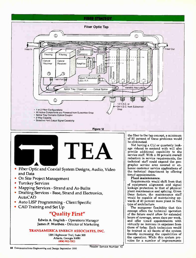
Fiber Optic Tap
(0 %
Fiber In
Filtering Filtering
Optical Optical Receiver Receiver
Test Port
.,..- t i ...." RF Splice Container
j Combiner ....., ••-- . -,
/ ---4—? 1, 7. f..--- ..----
.— .5 Amplifier • •--- .." ,_, '--. 1, •---- aY • .g.- .., it),
Return Transmitter LED / F.P.
z 15 -0 -o <
."'"/
111 • -̀-s, I , ,
Splice Tray / Organizer Optical Splitter Variable Attenuators
11.1111."
• 1 or 2 Fiber Configurations • All Active Components are Powered from Subscriber Drop • Splice Tray Contains Optical Coupler • 2-Way Capable • Selective Port Output Signal Capability
Figure 12
12 V.A.C. or 24 V.D.C. from Subscriber Drop
Fiber Out
TEA • Fiber Optic and Coaxial System Designs, Audio, Video and Data
• On Site Project Management • Turnkey Services • Mapping Services - Strand and As-Builts • Drafting Services - Base, Strand and Electronics, AutoCAD
• Auto LISP Programming - Client Specific • CAD Training and Set Up
"Quality First" Edwin A. English - Operations Manager
James P. Worthen - Director of Marketing
TRANSAMERICA ENERGY ASSOCIATES, INC.
1301 Hightower Trail, Suite 300 Atlanta, Georgia 30050
(404) 992-7003
the fiber to the tap concept, a minimum of 50 percent of these problems would be eliminated.
Not having a CLI or quarterly leak-age rideout to contend with will also provide additional capability to the service staff. With a 39 percent overall reduction in service requirements, the technical staff could expand the geo-graphic service area covered or en-hance customer service applications of the technical department by offering timed appointments.
Plant maintenance. Requirements would shift from that
of equipment alignment and signal leakage protection to that of physical plant maintenance and splicing. Given these factors, the maintenance staff would be capable of maintaining up-wards of 40 percent more plant in this type of architecture. The manpower flexibility that this
concept offers the technical operation of the future could allow for extended hours of coverage, seven days per week, and offer timed appointments with virtually no increase in expenses from those of today. Each technician would be trained in all facets of the system thereby increasing the capabilities of the operation. While this system pro-vides for a number of improvements
22 Communications Engineering and Design September 1990 Reader Service Number 10

4111111111111UnlifAr7if.ril..
Historical Cable Cost Comparison fiber to the tap concept as the consumer interface would no longer limit the use of cable-ready sets. • Technical personnel will require
broader types of training in the area of fiber optics. Test equipment would consist of a fusion splicer, optical power meter, signal level meter and test set. The developments in fiber optics in
just the past 12 months further height-ened our expectations of fiber to the tap. Consider the performance im-provements that suppliers have incor-porated into their products. Doubling the link capability without affecting performance while reducing costs is a signficant improvement. For the fu-ture, we see a continued reduction in the cost of fiber optic components and cable as deployment increases through the 1990s.
In comparing fiber and coax cable costs in Figure 13, we can see the cost curve for fiber has dropped by over 50 percent, while the coaxial costs have increased by 42 percent during that same period. Note that coax relies heavily on raw materials, while fiber relies on an endless supply of sand. As shown in Figure 14, optical transmis-sion systems have realized an even greater reduction in the cost per deliv-
1.5
1.4. u, 1.2.
1.1 g 1.0.
7 0.9. P 0.8' E
A 0.7 ,
, ..---- r 00 ? 05
OA .
0.3« 0.2 .
0
t.'li
i
• ' ,1 .;
r ,.
. ,
.
1. .- ,,
1
z
l'
d ,,,,,:,
, l'
1984 1985 1986 1987 1988 1989 1990 Coaxial 8 Fiber
Figure 13
over current deployed technologies, there are several areas of this technol- ogy which should be considered: • Maintenance and operation of the system requires more exacting infor- mation than in the coaxial architec- ture. This includes database informa-
tion as well as the administration of the fibers within the network, • Additional outlet revenues could
be negatively impacted by moving the security controls to the tap as opposed to the outlet. • Remote revenue is affected in the
WHERE THE FIBER STOPS... WE START
LA SERIES DISTRIBUTION AMPLIFIERS
LA 5000 SERIES FEATURES Automatic Level Control Selectable Equalizers & slope Bandwidth No Plug-In Pads or Equalizers Required High Efficiency Switching Supply External Matched Test Points Universal Entry Ports
Input and Interstage Controls
The Triple Crown LA Series distribution amplifiers offer performance, features and flexibility unavailable from most competitive products. Our wide range of push-pull and power doubling models can be configured to exactly meet your needs.
TRIPLE CROWN' ELECTRONICS t":! •
4560 Fieldgate Drive, Mississauga. Ontario Canada L4W 3W6 Tel: 1 (416) 629-1111 Fax: 1 (416) 629-1115
Reader Service Number 11 Communications Engineering and Design September 1990 23
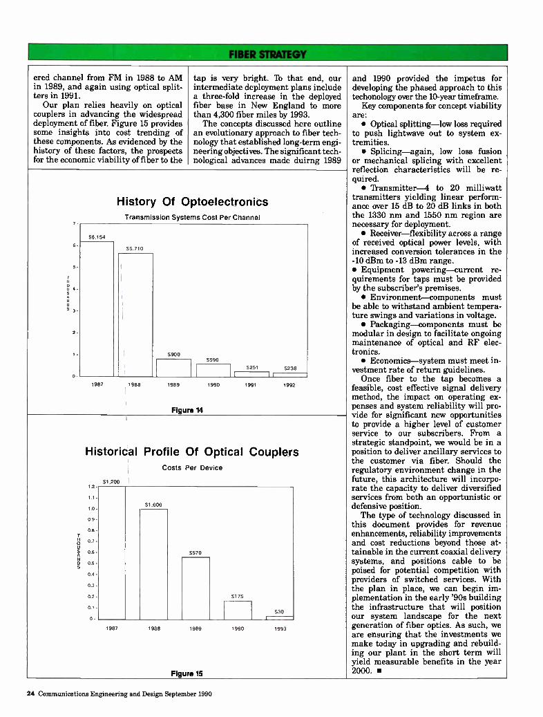
ered channel from FM in 1988 to AM in 1989, and again using optical split-ters in 1991. Our plan relies heavily on optical
couplers in advancing the widespread deployment of fiber. Figure 15 provides some insights into cost trending of these components. As evidenced by the history of these factors, the prospects for the economic viability of fiber to the
tap is very bright. lb that end, our intermediate deployment plans include a three-fold increase in the deployed fiber base in New England to more than 4,300 fiber miles by 1993. The concepts discussed here outline
an evolutionary approach to fiber tech-nology that established long-term engi-neering objectives. The significant tech-nological advances made duirng 1989
7
6
5-
2
s
History Of Optoelectronics Transmission Systems Cost Per Channel
56.154
1987 1988
S900
1989
S590
Figure 14
1990
5251 5238
I
1991 1992
o u A N
Historical Profile Of Optical Couplers
1.2
1.1 -
1.0 •
0.9 -
0.8 -
0.7 -
0.6 -
0.5 -0.4 •
0.3
0.2 •
0.1 -
-
Costs Per Device
51.200
SI 000
5570
S175
530
1987 1988 1589
Figure 15
1990 1993
and 1990 provided the impetus for developing the phased approach to this techonology over the 10-year timeframe.
Key components for concept viability are: • Optical splitting—low loss required
to push lightwave out to system ex-tremities. • Splicing—again, low loss fusion
or mechanical splicing with excellent reflection characteristics will be re-quired. • Transmitter-4 to 20 milliwatt
transmitters yielding linear perform-ance over 15 dB to 20 dB links in both the 1330 nm and 1550 nm region are necessary for deployment. • Receiver—flexibility across a range
of received optical power levels, with increased conversion tolerances in the -10 dBm to -13 dBm range. • Equipment powering—current re-quirements for taps must be provided by the subscriber's premises. • Environment—components must
be able to withstand ambient tempera-ture swings and variations in voltage. • Packaging—components must be
modular in design to facilitate ongoing maintenance of optical and RF elec-tronics. • Economics—system must meet in-
vestment rate of return guidelines. Once fiber to the tap becomes a
feasible, cost effective signal delivery method, the impact on operating ex-penses and system reliability will pro-vide for significant new opportunities to provide a higher level of customer service to our subscribers. From a strategic standpoint, we would be in a position to deliver ancillary services to the customer via fiber. Should the regulatory environment change in the future, this architecture will incorpo-rate the capacity to deliver diversified services from both an opportunistic or defensive position. The type of technology discussed in
this document provides for revenue enhancements, reliability improvements and cost reductions beyond those at-tainable in the current coaxial delivery systems, and positions cable to be poised for potential competition with providers of switched services. With the plan in place, we can begin im-plementation in the early '90s building the infrastructure that will position our system landscape for the next generation of fiber optics. As such, we are ensuring that the investments we make today in upgrading and rebuild-ing our plant in the short term will yield measurable benefits in the year 2000. •
24 Communications Engineering and Design September 1990
CableVision. No ones been more farsighted in designing fiber optic cable than Siecor. As a result, our cable design is virtually the same today as it was nearly ten years ago. In the same time span, many of our competitors have redesigned their cables two and three times or more. And guess what? Their cables now look amazingly like ours.
One reason our design hasn't changed—and the reason it's so widely imitated—is simple. We anticipated the craftsman's most important needs.
In doing so, we introduced stranded loose tube design which groups fibers in tubes. This way, it provides the best protection during stripping and splicing. And makes fibers easy to identify and manage.
Furthermore, we designed a cable that's friendly to fiber—protecting it from environmental stress. And finally, we allowed for changing fiber optic technology Our cable carries multimode or single mode signals at any transmission rate. It transmits at all wavelengths. And it accommodates the use of evolving splicing techniques.
The fact is, no better cable has come along in the last ten years. And no cable can prepare your system better for the future.
So talk to the company with the vision to see what's ahead in fiber optics. Call 704/327-5998. Or write Siecor Corporation, Literature Department (CO) TV-1,489 Siecor Park. Hickory NC 28603-0489. SIECOR
Reader Service Number 12

1' ,
\
1 i /
\
/
I / /
% \
\
. I ‘
\\ ‘
1 /
: .
i • t
'1.
•••••••••••••••
auffsiimummiummo.m.m..u.mbe...
"47
gierse
1
•:„:04;lee
.••
••:04.
• •
.
• •
e •
•
da.
eirefflboode de
, +11•041«11111•.•••••• our • «II
•
• •••••••• •
•01111111M11••••
•••••••••«a»
•111111•11111•111••••••••••••••• • ••• dew •
• • 11.8.•fflalyalle
•
•
• \,
••••%esi,
-
•••• • ••
•
11_

CAM's evolution to a switched network ATC's vision of 1,000 channels starts with fiber in the trunks
uch has een writ-ten and
speculated about what a cable system will look like 10 or 20 years from now. Outside of agreement that these networks will have to offer more channels of quality video and allow viewers to select events to be watched at their command, most visions of the future seem to lack a coherent, thought-ful methodology that should be followed to arrive at the goal.
Recently, Jim Chiddix, senior vice president of engineering and technology at American Iblevision and Communications (ATC), started a lot of people thinking when he made mention of a 1,000-channel cable television system. The questions in people's minds could almost be heard: How could a headend offer 1,000 choices? Would viewers ever use that many channels? What about electronics— could there ever be enough capacity to pass that much spectrum? It seemed Chiddix's idea was mere wishful thinking.
Headend
Supertrunks, Remote Earth Stations and Hub Sites
Trunk Network
Distribution Network
i
Drop and House Wiring
Plant Investment (%) 5 1 19 55 20
Plant Mileage (%) - 1 14 40 45
Embedded Costs/Sub ($)
17 4 50 194 70
Signal-to-Noise Ratio Contribution (dB)
48 58 47 53 45
The clear need for switching
But, indeed, Chiddix's thinking wasn't mere folly. But it does require an abandonment of today's coaxial tree-and-branch architecture in favor of one that consists of fiber throughout the trunks and switches in the headend to control a large number of video offerings.
Unlike the plans laid out by the nation's telephone companies, ATC's
Table 1
approach relies on an orderly evolution that requires capital outlay only when it makes good business sense—a key consideration in times of increasing
'Strategically, we
need to be able to
evolve to a network
where people can
watch anything they
want to watch.'
competition. A review of a cable system's network
architecture reveals that only a small
fraction of the physical plant, in terms of mileage and capital investment, is dedicated to the trunk, yet it is this portion of the system which largely limits video performance and channel capacity. According to figures supplied by ATC, the trunk portion of the network accounts for roughly 19 percent of the investment made in the plant, and just 14 percent of its mileage (see Table 1). This compares to 55 percent and 40 percent, respectively, for the distribution plant.
Coax in the trunk raises S/N
The presence of coaxial cable in the trunk is also a "weak link" in the chain of signal transmission. According to ATC's numbers, the trunk contributes 47 dB of signal-to-noise, compared to significantly higher numbers in the distribution plant.
However, as Chiddix points out, coax's strengths include its ability to
Communications Engineering and Design September 1990 27
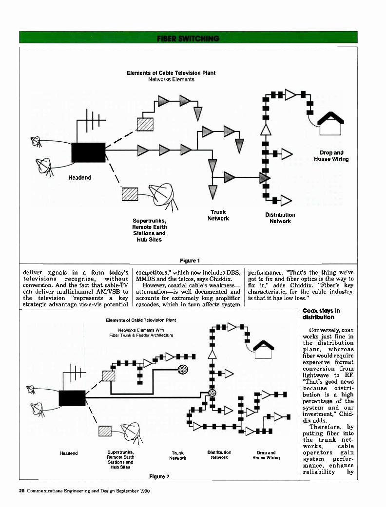
Elements of Cable Television Plant Networks Elements
Headend
Supertrunks, Remote Earth Stations and Hub Sites
Figure 1
Trunk Network
Distribution Network
Drop and House Wiring
deliver signals in a form today's televisions recognize, without conversion. And the fact that cable-TV can deliver multichannel AM/VSB to the television "represents a key strategic advantage vis-a-vis potential
competitors," which now includes DBS, MMDS and the telcos, says Chiddix.
However, coaxial cable's weakness— attenuation—is well documented and accounts for extremely long amplifier cascades, which in turn affects system
performance. "That's the thing we've got to fix and fiber optics is the way to fix it," adds Chiddix. "Fiber's key characteristic, for the cable industry, is that it has low loss."
Headend
Elements of Cable Television Plant
Networks Elements With Fiber Trunk & Feeder Architecture
Figure 2
Supertrunks, Remote Earth Stations and Hub Sites
Distribution Network
Drop and House Wiring
Trunk Network
Coax stays in distribution
Conversely, coax works just fine in the distribution plant, whereas fiber would require expensive format conversion from lightwave to RF. "That's good news because distri-bution is a high percentage of the system and our investment," Chid-dix adds.
Therefore, by putting fiber into the trunk net-works, cable operators gain system perfor-mance, enhance reliability by
28 Communications Engineering and Design September 1990
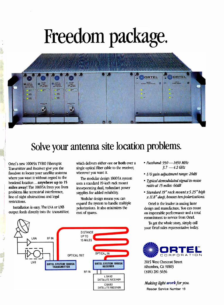
Freedom package.
Solve your antenna site location problems.
Ortei's new 10005A TYRO Fiberoptic Transmitter and Receiver give you the freedom to locate your satellite antenna where you want it without regard to the headend location.., anywhere up to 15 miles away! The 10005A frees you from problems like terrestrial interference, line-of-sight obstructions and legal restrictions.
Installation is easy. The LNA or LNB output feeds directly into the transmitter,
LNA RF IN
[NB ORTEL SYSTEM 10005A
TRANSMITTER
which delivers either one or both over a single optical fiber cable to the receiver, wherever you want it.
The modular design 10005A system uses a standard 19-inch rack mount incorporating dual, redundant power supplies for added reliability.
Modular design means you can expand the system to handle multiple polarizations. It also minimizes the cost of spares.
DISTANCE
UP TO
15 MILES
4
OPTICAL OUT OPTIGA,. IN
ORIEL SYSTEM 10005A RECEIVER
REIN 1 1
BAND SATELLITE RECEIVER
C BAND SATELLITE RECEIVER
• Passbare 950 —1450 MHz 3.7 —4.2 GHz
• I/O gain adjustment range: 20dB
• Typical demodulated signal-to-noise ratio at 15 miles: 60dB
• Standard 19" rack mount x 5.25" high x 11.8" deep, houses two polarizations.
Ortel is the leader in analog laser design and manufacture. You can count on impeccable performance and a total commitment to service from Ortel.
To get the whole story, simply call your Ortel sales representative today.
41 '-dek-mORTEL coRpoRATIoN
2015 West Chestnut Street Alhambra, CA 91803 (818) 281-3636
Making light work for you.
Reader Service Number 19

reliable, long-term investment. If prop-erly designed, manufactured and in-stalled, a fiber optic cable will not couple strain to the optical fibers under the loading parameters normally en-countered in a given region. This will enable the stable attenuation perform-ance of the fiber over the 20 to 40 year expected cable life. The state-of-the-art of fiber optic cable is such that, once installed, system upgrades (for the foreseeable future) should only occur electronically. A stable single-mode fiber is capable of very low attenuation and carrying in excess of 1,000 chan-nels based on current bandwidth re-quirements. A substandard fiber optic cable can
cause fiber strain which will degrade its life and can cause increased attenu-ation. Increased fiber attenuation may limit system performance and could create the need for early electronic upgrade by making the system opera-tion substandard. Also, as the lasers begin to age and experience drift toward 1300 nm and below, or the more sensitive region of 1550 nm and above (if that wavelength is employed) the apparent degradation of the system will accelerate. Such a scenario is also capable of occurring on an intermittent basis if a substandard cable develops "hot spots" where attenuation fluctu-ates based on temperature cycling or increased loading conditions. Over the past 10 to 15 years, volume
users of fiber optics in industries out-side cable television have written, revised and continue to update stan-dards and test procedures for fiber optic cable. Their number one stated reason for the effort is to ensure a high degree of reliability. The basis for their exper-tise comes from the estimated 6 million homes of optical fiber deployed in the U.S. since 1981. Only about 60,000 to 65,000 thousand miles have been replaced. The CATV industry has installed
approximately 100,000 miles of optical fiber. The growth in the last three years has accounted for the vast major-ity of this cable and places the industry in a position of increased future de-pendence on the reliability of the technology. Cable systems can save considerable time and effort regarding the evaluation of fiber optic cable by drawing on the accumulated knowledge of prior users in other industries. Some of the more well known docu-
ments addressing fiber optic cable standards area as follows: • Bellcore TR-TSY-000020 Titled:
Generic Requirements for Optical Fi-
ber and Optical Fiber Cable • REA PE-90 Titled: REA Specifica-
tions for Ibtally Filled Fiber Optic Cable • EIA 472 Titled: Generic Specifica-
tions for Fiber Optic Cables. The most widely referenced of the
three is probably the series of fiber optic test procedures from the Electron-ic Industries Assocation (EIA). The EIA is in the process of updating and revising its specifications. The basic standards and test proce-
dures currently followed in the indus-try can be broken into two categories: optical fiber and optical fiber cable. The system engineer must first establish a baseline requirement for the optical fiber that will meet or exceed the application. Once that is determined, cable parameters must be established. It is important to note that the adage
"fiber is fiber" is true only when comparing one manufacturer's fiber to itself and the fiber is of a specific grade. Once an optical fiber is incorporated into a cable design, material compati-bility, mechanical efforts and environ-ment may all impact the fiber's per-formance throughout its lifetime. When evaluating optical fiber, cer-
tain routine optical and geometrical requirements can be evaluated and specified to qualify a product prior to cabling. Because of the effects of cable design and manufacturing, parameters such as maximum attenuation need to be specified for the end product. A few examples of requirements and
test procedures routinely encountered for optical fiber are as follows: • Attenuation measurements will
be made in accordance with EIA-455-61, OTDR Measurement or EIA-455-
Optical Test Parameter Procedures
7. Mode Field EIA-455-164 Diameter EIA-455-165 (MFD) EIA-455-166
EIA-455-167 EIA-455-174
Typical Requirement
8.7 gm < MFD < 9.5 gm ± 8% (Measured at 1300 nm)
8. Concentricity EIA-455-45A Core to cladding Error EIA-455-176 offset < 1.0 gm
9. Cladding Diameter EIA-455-176
EIA-455-45A 125.0 gm ± 2.0 gm
10. Cladding EIA-455-45A < 2% Non-circularity EIA-455-176
11. Coating EIA-455-55A 250 gm nominal Diameter EIA-455-173
12. Fiber Tensile Proof Test
13. Coating Strippability
EIA-455-31A 0.35 GN/m2 (50 kpsi)
EIA-455-178 procedure.
Easily stripped with commercial-ly available mechanical strip-ping tools. < 13.4 N of force to remove 30 mm of 250 gm diameter coating.
Comments
In a single-mode fiber, light travels slightly into the cladding region. Controlling MFDs helps to provide compatibility between single-mode brands and minimizes splicing mismatch.
Ensures light carry-ing portion of fiber is centered to allow proper splicing and connectorization.
Industry standard. Critical for low loss mechanical splicing and connectorization.
Industry standard. Critical for low loss mechanical splicing and connectorization.
Typical 250 ± 15 gm.
Test 100% of fibers to assure long term physical reliability.
Important aspect for field installations.
42 Communications Engineering and Design September 1990
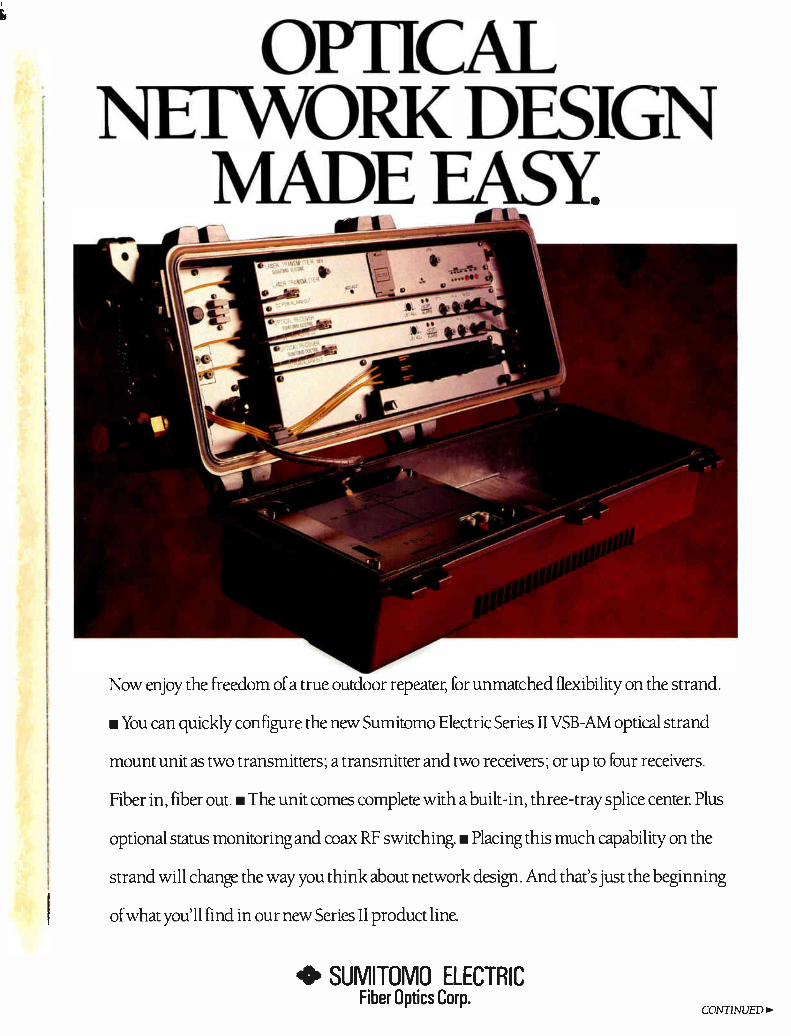
OPTICAL NETWORK DESIGN
MADE EASY.
Now enjoy the freedom of a true outdoor repeater, for unmatched flexibility on the strand.
• You can quickly configure the new Sumitomo Electric Series II VSB-AM optical strand
mount unit as two transmitters; a transmitter and two receivers; or up to four receivers.
Fiber in, fiber out. • The unit comes complete with a built-in, three-tray splice center. Plus
optional status monitoring and coax RF switching • Placing this much capability on the
strand will change the way you think about network design. And that's just the beginning
of what you'll find in our new Series II product line.
• SUMITOMO ELECTRIC Fiber Optics Corp.
CONTINUED>

Rack Vp Major Advantages From Sumitomo Electric
Optical transmitters and receivers are not created equal. Sumitomo Electric has long been a leading designer and manufacturer of VSB-AM optical transmission equipment. One result is our new-generation Series II. It's transparently compatible with coax cable TV systems of up to 550 MHz, with built-in advantages like those shown here.
Uniform Specs Save Management Headaches Anyone can give you best-of-the-bunch "hero" lasers that squeeze out an extra dB or so. But what happens when you face real-world maintenance, repair and replacement needs? Sumitomo Electric offers a saner approach: lasers that meet uniformly high performance specifications in every unit we make. Result: you get consistent high performance, plus components that are interchangeable throughout the network. Which makes for low-cost spare stocking — and makes managing the entire system a lot easier.
QUICK-CHANGE MODULES CUT DOWNTIME
If the need ever arises, you can swap out a subsystem to put your unit back on line in seconds. Everything's plugged or connectorized. The pull-handles help speed removal and replacement.
FACTORY SETTINGS MINIMIZE ADJUSTMENTS
All test points are accessed on the clearly labelled front panel. Inside, you set only the transmitter's depth of modulation and the receiver's RF level. Everything else is factory-set for optimum performance.
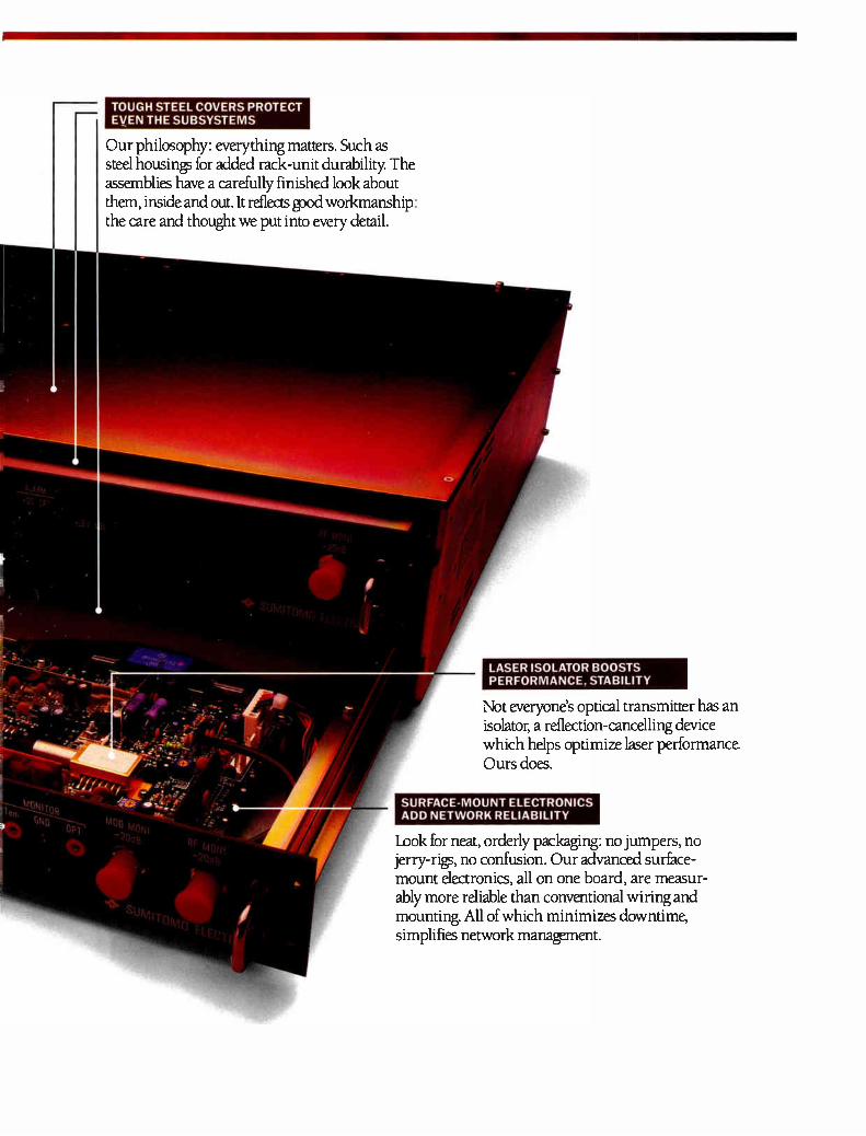
TOUGH STEEL COVERS PROTECT EVEN THE SUBSYSTEMS
Our philosophy: everything matters. Such as steel housings for added rack-unit durability The assemblies have a carefully finished look about them, inside and out. It reflects good workmanship: the care and thought we put into every detail.
LASER ISOLATOR BOOSTS PERFORMANCE, STABILITY
Not everyone's optical transmitter has an isolator, a reflection-cancelling device which helps optimize laser performance Ours does.
SURFACE-MOUNT ELECTRONICS ADD NETWORK RELIABILITY
Look for neat, orderly packaging: no jumpers, no jerry-rigs, no confusion. Our advanced surface-mount electronics, all on one board, are measur-ably more reliable than conventional wiring and mounting. All of which minimizes downtime, simplifies network manawment.
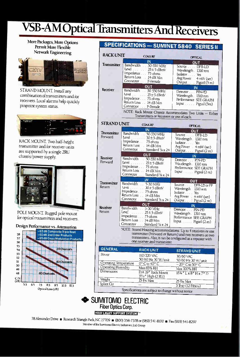
VS13 -AM Optical Transmitters And Receivers More Packages, More Options
Permit More flexible Network Engineering
q11\\ :=1), STRAND MOUNT. Install any combination of transmitters and/or receivers. Local alarms help quickly pinpoint system status.
RACK MOUNT. Two half-height transmitter and/or receiver units are supported by a single 2RU chassis/power supply.
POLE MOUNT. Rugged pole mount for optical transmitters and receivers.
Design Performance vs. Attenuation
58
57
56 55
54 53
52 51
50 49
48
C/N (dB)
-65 dB Composite Triple Beat -60 dB 2nd Order Products -65 dB Cross Modulation Products
niqUIMMOMM
:1911/E=11 111 .«,"1.111111111
11111.1\.7...111 :11111MIMMIll
IIIIflhIIhN 5.5 63 7.5 85 9.5 103 115
Optical Loss (dB)
RACK UNIT
Transmitter
Receiver
COAX RF OPTICAL
IN Bandwidth .. 50-550 MHz Level 25±5 dBmV Impedence . . 75 ohms Return Loss 14 dB Min Connector . . F-Female
Bandwidth .. 50-550 MHz Level 25+5 dBmV Impedence . . 75 ohms Return Loss 14 dB Min Connector . . F-Female
OUT Source . . . . DFB-LD Wavelength. 1310 nm Isolator . . . . Yes Avg Power . 4 mW (set) Ou ut. . .. • il (5 m)
IN Detector . . PIN-PD Wavelength 1310 nm Performance SEE GRAPH Input Pigtail (5m)
NOTE: Rack Mount Chassis Accommodates Two Units — Either Transmitters or Receivers or one of each.
STRAND UNIT
Transmitter Forward
Receiver Forward
Transmitter Return
Receiver Return
COAX RF OPTICAL
Bandwidth .. 50-550 MHz Level 30± 5 dBmV Impedence . . 75 ohms Return Loss 14 dB Min Connector . . Standard 5/8 x 24
OUT Bandwidth .. 50-550 MHz Level 25+5 dBmV Impedence 75 ohms Return Loss 14 dB Min Connector . Standard 5/8 x 24
IN Bandwidth .. 5-30 MHz Level 30+ 5 dBmV Impedence . . 75 ohms Return Loss 14 dB Min Connector . . Standard 5/8x 24
Bandwidth .. 5-30 MHz Level 25+5 dBmV Impedence. 75 ohms Return Loss 14 dB Min Connector . Standard Y8 X 24
OUT Source . . . . DFB-LD Wavelength 1310 nm Isolator . . . Yes Avg Power . 4 mW (set) Ou ut. Pi il (2 m)
IN Detector . . . PIN-PD Wavelength 1310 nm Performance SEE GRAPH Input Pigtail (2 m)
OUT Source . . .. DFB-LD or FP Wavelength. 1310 nm Isolator . . . Yes Avg Power . mW (set) Out ut. . .1 Pigtail (2 m)
IN Detector . . . PIN-PD Wavelength 1310 nm Performance SEE GRAPH Input Pigtail (2 m)
NOTE: Strand Housing accommodations: Up to 4 receivers or one transmitter (Forward or Return) and two receivers or two transmitters. Also, it can be configured as a repeater with one receiver and transmitter.
GENERAL RACK UNIT STRAND UNIT Power 110/220 VAC
50/60 Hz 30 W/unit 30/60 VAC 50/60 Hz 30 W/unit
Operating Temperature 0° C to 40° C —20° C to 50°C Operating Humidity Max 85% RH Max 100% RH Dimensions EIA 19" Rack Mount
.39/to' High (2 RU) 183/4" Lx 8" H x 7" D
Weight 25 lbs Max 25 lbs Max Splice Ctr
- — 3 Tray (12 Fibers)
peci ications are subject to change without notice.
lib SUMITOMO ELECTRIC Fiber Optics Corp.
YOUR LIGHT SUPPORT SYSTEM
78 Alexander Drive Research Triangle Park, NC 27709 o (800) 358-7378 or (919) 541-8100 Fax (919) 541-8297 Member of the Sumitomo Electric Industries, Ltd. Group
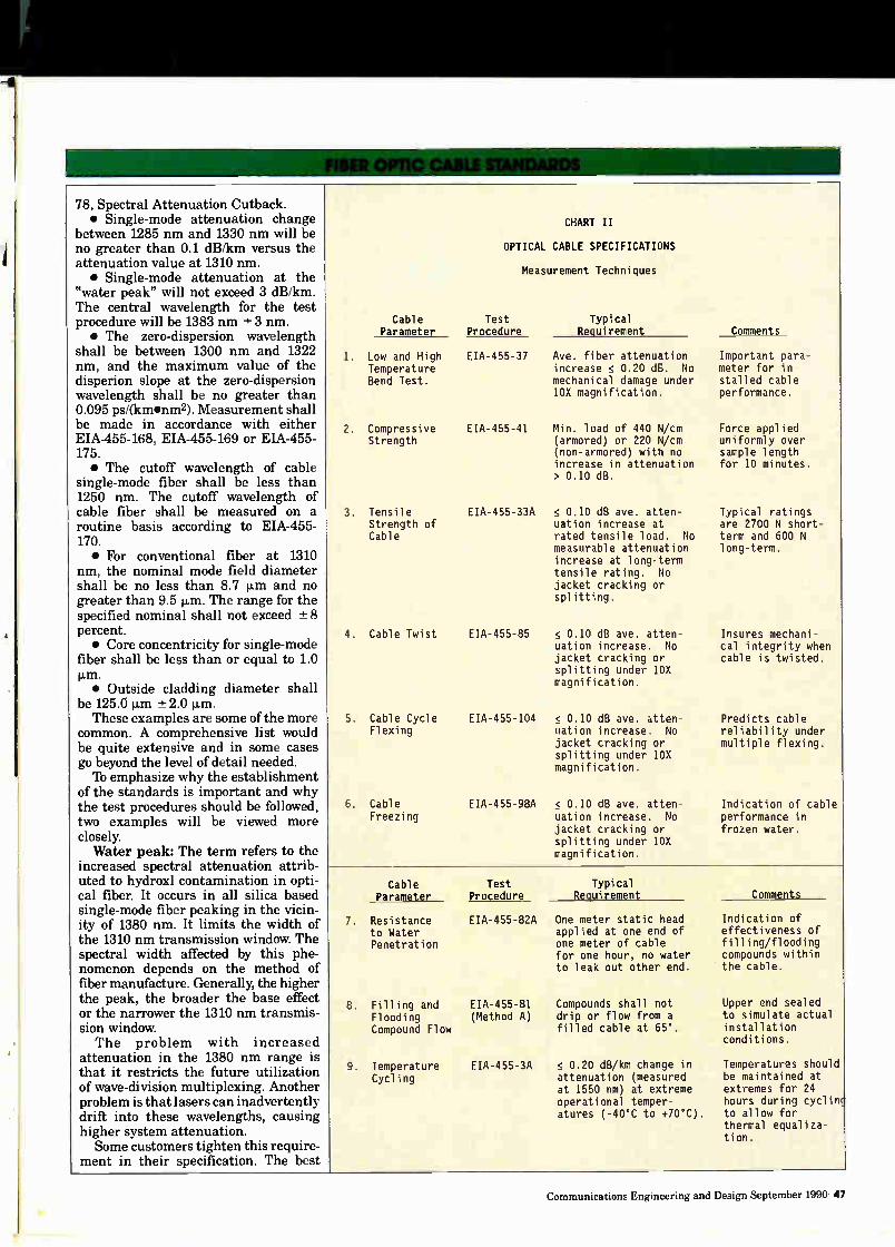
78, Spectral Attenuation Cutback. • Single-mode attenuation change
between 1285 nm and 1330 nm will be no greater than 0.1 dB/km versus the attenuation value at 1310 nm. • Single-mode attenuation at the
"water peak" will not exceed 3 dB/km. The central wavelength for the test procedure will be 1383 nm ± 3 nm. • The zero-dispersion wavelength
shall be between 1300 nm and 1322 nm, and the maximum value of the disperion slope at the zero-dispersion wavelength shall be no greater than 0.095 ps/(km•nm2). Measurement shall be made in accordance with either EIA-455-168, EIA-455-169 or EIA-455-175. • The cutoff wavelength of cable
single-mode fiber shall be less than 1250 nm. The cutoff wavelength of cable fiber shall be measured on a routine basis according to EIA-455-170. • For conventional fiber at 1310
nm, the nominal mode field diameter shall be no less than 8.7 p.m and no greater than 9.5 p.m. The range for the specified nominal shall not exceed -± 8 percent. • Core concentricity for single-mode
fiber shall be less than or equal to 1.0 p.m. • Outside cladding diameter shall
be 125.0 p.m ±2.0 p.m. These examples are some of the more
common. A comprehensive list would be quite extensive and in some cases go beyond the level of detail needed. ID emphasize why the establishment
of the standards is important and why the test procedures should be followed, two examples will be viewed more closely. Water peak: The term refers to the
increased spectral attenuation attrib uted to hydroxl contamination in opti-cal fiber. It occurs in all silica based single-mode fiber peaking in the vicin-ity of 1380 nm. It limits the width of the 1310 nm transmission window. The spectral width affected by this phe-nomenon depends on the method of fiber manufacture. Generally, the higher the peak, the broader the base effect or the narrower the 1310 nm transmis-sion window. The problem with increased
attenuation in the 1380 nm range is that it restricts the future utilization of wave-division multiplexing. Another problem is that lasers can inadvertently drift into these wavelengths, causing higher system attenuation. Some customers tighten this require-
ment in their specification. The best
1.
Cable Parameter
Low and High Temperature Bend Test.
2. Compressive Strength
3. Tensile Strength of Cable
4. Cable Twist
5. Cable Cycle Flexing
6. Cable Freezing
CHART II
OPTICAL CABLE SPECIFICATIONS
Measurement Techniques
Test Procedure
EIA-455-37
EIA-455-41
Typical Requirement
Ave. fiber attenuation increase < 0.20 dB. No mechanical damage under 10X magnification.
Min. load of 440 N/cm (armored) or 220 N/cm (non-armored) with no increase in attenuation > 0.10 dB.
EIA-455-33A < 0.10 dB ave. atten-uation increase at rated tensile load. No measurable attenuation increase at long-term tensile rating. No jacket cracking or splitting.
EIA-455-85 < 0.10 dB ave. atten-uation increase. No jacket cracking or splitting under 10X magnification.
EIA-455-104 < 0.10 dB ave. atten-uation increase No jacket cracking or splitting under 10X magnification.
EIA-455-98A < 0.10 dB ave. atten-uation increase. No jacket cracking or splitting under 10X magnification.
Comments
Important para-meter for in-stalled cable performance.
Force applied uniformly over sample length for 10 minutes.
Typical ratings are 2700 N short-term and 600 N long-term.
Insures mechani-cal integrity when cable is twisted.
Predicts cable reliability under multiple flexing.
Indication of cable performance in frozen water.
Cable Parameter
7. Resistance to Water Penetration
Test Procedure
Typical Requirement
EIA-455-82A One meter static head applied at one end of one meter of cable for one hour, no water to leak out other end.
8. Filling and EIA-455-81 Flooding (Method A) Compound Flow
9. Temperature Cycling
EIA-455-3A
Compounds shall not drip or flow from a filled cable at 65°.
< 0.20 dB/km change in attenuation (measured at 1550 nm) at extreme operational temper-atures (-40°C to +70°C).
Comments
Indication of effectiveness of filling/flooding compounds within the cable.
Upper end sealed to simulate actual installation conditions.
Temperatures should be maintained at extremes for 24 hours during cyclinç to allow for thermal equaliza-tion.
Communications Engineering and Design September 1990 47

procedures. The duration of the test is such that it can be passed by incorpora-ting various materials such as swel-lable tape or powders into the cable. This allows the cable to pass the test but is a short term block which will allow the compound to flow after saturation. This is where the "spirit" of the test rather than the letter becomes important. In general, you can assume manufacturers that recommend cable blocking kits for open ends have problems with cable flow.
Lightning damage susceptibility. Dam-age from lightning is always an issue when the cable contains metallic com-ponents. The obvious problem is fiber damage from electrical arcs. Specifica-tions have typically addressed buried applications because the vast majority of aerial fiber optic cable deployed outside the CATV industry has been non-armored and primarily dielectric. The concern in the CATV industry regarding rodent damage to aerial cables has prompted a number of operators to specify armored cables for
their systems. In these cases, a light-ning specification is very applicable.
'Ib ensure high reliability, it is recommended the system operators specify a 205 kA rating for cable lightning resistance. This is based on the fact that 95 percent of lightning strikes are 105 kA or less. Some companies specify higher values for their own reliability requirements. The limit of the Bellcore test is 200 kA. There are manufacturers that have standard product capable of meeting the 200 kA limit.
This snapshot of reasons for, and examples of, standards and procedures should provide a broad enough picture to generate interest regarding the in-corporation of currently available pro-jects. At the same time, the task of reviewing, comparing, adding to, and deleting from the currently available documents would be a tedious one. Some system engineers may have the time and desire to undertake such a study. For most, it would probably be easer for the basic groundwork to be
Optical Cable Specification
Optical Performance Specification
Attenuation @ 1310 nm Attenuation @ 1550 nm Attenuation Discontinuity Max @ 1310/1550 nm Attenuation @ Water Peak (1383 ± 3 nm) Mode Field Diameter (matched clad) Mode Field Diameter (depressed clad) Dispersion Zero Crossing Dispersion Max @ 1310 ± 20 nm Dispersion Max @ 1550 nm Bending Loss @ 1550 nm Fiber Proof Test Cladding Diameter Concentricity Error (core/cladding offset) Cladding Non-Circularity Coating Diameter Fiber Coating Color Code
Cable Performance Specification
Temperature Range Cutoff Wavelength Min. Bending Radius (dynamic) Min. Bending Radius (static) Pulling Tension Polymetric Sheath Material
Sheath Thickness (nominal) Continuous Length (no factory splices) Length Markings Resistance to Lightning
0.35 dB/km max/fiber 0.25 dB/km max/fiber
0.1 dB <2.1 dB/km
9.5 ± 0.5 8.8 ± 0.5
1311.5 ± 10 nm 2.6 ps/(nm x km) 17.5 ps/(nm x km) ElA RS-455-62
50 kpsi 125.0 ± 2.0 p.m
1.0 p.m 2.0%
250 ± 15 1.1,m Bellcore or REA Standard
-40 to +70 C 1250 nm
15 x Outside Diameter 10 x Outside Diameter
600 lbs. Black Medium or High Density Polyethlyene
1.4 mm Up to 12 km Every Meter
Bellcore TR-TSY-000020 Issue #4 EIA FOTP 181 Draft (Task Group FO-6-7-8) 15 p.S Rise Time 40-60
Decay Time. Peak Current Resistance 105kA,
provided and to allow for revisions as deemed necessary by experience and improved technology.
In an attempt to meet the require-ments of most systems for fiber optic cable, two charts accompany this text. The first addresses optical fiber. The second addresses optical fiber cable. Following the charts is a "ready to use" Optical Cable Specification. Sev-eral manufacturers may exceed the requirements in some categories with standard product, and customers may opt to tighten specific requirements as they see fit. The purpose of the charts is not to set the highest possible standards (which may eliminate manu-facturers with satisfactory product), but to establish a minimum for the protection of the cable operators and the reputable manufacturers that serve the CATV industry. The Cable Specifi-cation reflects actual requirements for high grade applications (e.g. AM sys-tems). Again, some manufacturers may exceed this specification. A final point in support of standards
they help to reduce cost by allowing manufacturers to perfect basic processes and become more efficient. Also, standards ensure compatibility between different manufacturers' products, providing the system operator with competitive bidding and reduced inventory. Cable operators have already benefited in this way from the standards established in other industries. The need for minimum standards
and common test procedures for fiber optics has been validated over the past 10 to 15 years in other industries. The same need holds true for cable televi-sion. By incorporating the information provided by previous specifications and the basic specifications offered in this paper, system operators should save themselves valuable time and energy associated with climbing the learning curve of a "new" technology. •
References Bellcore TR-20: "General Require-
ments for Optical Fibers and Optical Fiber Cable", Bellcore Customer Serv-ice, 60 New England Ave., Room 1B252, Piscataway, NJ 08854-4196 REA PE-90: "REA Sepecifications
for Ibtally Filled Fiber Optic Cable," Telecommunications Staff Division, Ru-ral Electrification Administration, Wash-ington D.C. 20250
EIA-472: "General Specifications for Fiber Optic Cables," Telecommuni-cation Industries Association, Engi-neering Dept., 2001 Eye St. N.W., Washington, D.C, 20006
50 Communications Engineering and Design September 1990
•
1111%.,
4V_J ti
As Good As New And SAVE $1,000.°° WESTEC Your AML Support System
"CPR for AML"
I WESTEC COMMUNICATIONS 14405 N. Scottsdale Road, Scottsdale, Arizona 85.254
(602) 948-4484 Microwave Service (800) 666-4441 FAX (602) 998-8701 Reader Service Number 21

Specifying AM fiber system performance
This paper discusses the methodology for specifying noise and distortio performance of AM fiber optic links
The relative merits of live video vs unmodulated carrier measurement tech niques are compared, and both theo retical and experimental data are pre sented to correlate the two methods Also, the relationship between AM fiber system specifications, amplifier specifications and end-of-line perform-ance is considered. Various perform-ance tradeoffs are examined, and ex-tensive analysis is presented to demon-strate the range of specifications that is appropriate for AM fiber systems.
Determining the reference frame
Over the past year, there has been a great deal of discussion with regard to the performance of AM fiber optic systems. Great effort has been under-taken to maximize the performance of DFB laser-based systems, and several alternative approaches have been and continue to be investigated. In order to compare the relative merits of the various options which are available, it is first necessary to establish a common frame of reference on which to base the comparison.
This reference frame consists of the methodology for measuring the video performance of a given system, and a common data set with which to express and compare that performance. The standard data set, which has been in use for a number of years in the cable industry and is defined in the "NCTA Measurements on Cable iblevision Sys-tems," is the carrier-to-noise ratio, the composite triple beat and the composite second order. Each of these measure-ments describes the relative quality of a transmitted video signal in terms of a standard reference point. While there is general agreement
regarding the data to be measured and the procedure to follow, there are two contrasting views as to the correct signal source to be used for measure-ment: modulated video or unmodulated
By John A. Mattson, marketing manger, transmission systems division, Scientific-Atlanta
CW carriers. Both alternatives are n included in the NCTA Recommended
Practices, and each has its proponents. • The modulated video carrier method - involves the measurement of the modu-
lated output of a headend. The advan-tage of this method is that it is relatively simple to set up and execute the measurements, without requiring any additional equipment other than a spectrum analyzer, a variable attenu-ator and bandpass filters. Also, the measurements are made on the same signal that is transmitted to the cable system subscribers. The disadvantage of using modu-
lated video carriers is that the peak level of the carrier varies continuously over time. This is particularly significant because the composite triple beat and composite second order measurements are taken at the peak carrier level. In addition, the modulated carrier level peaks at approximately 75 percent of the maximum carrier level, except for the brief sync pulse intervals on each carrier when the level reaches 100 percent. As the t number of carriers used in the composite i signal increases, the likelihood of the o sync pulses occurring simultaneously decreases, and thus the probability of ever reaching the 100 percent composite s level also decreases. Using unmodulated carriers as the
signal source eliminates this problem, because the carriers am operated at 100 percent levels continuously. Thus, ti the advantage of the unmodulated d carrier method is that it yields a n consistent, repeatable measurement. o The disadvantage of the unmodu- n
lated carrier method is that it requires vs either the use of a matrix multi- fo channel generator, or the removal of sy video modulation in a headend. The la first alternative necessitates having CT an expensive piece of test equipment, va and the second means turning service me off for a period of time.
For specifying AM fiber system can performance, the unmodulated carrier method is preferred. It has the distinct Reg advantage of being both accurate and repeatable, which are the critical attributes for a measurement standard. pe It is also the standard method for las
specifying amplifiers, since ultimately fiber and amplifier performance must be considered together. The impractical nature of using unmodulated carriers in field testing situations is of no concern in this context. Rather, what is important for field usage is to establish correlation factors which will allow modulated video measurements to be referenced to the unmodulated carrier standard.
CW-to-modulation correlation
Recently published theoretical and experimental results indicate that cor-relation factors for CTB and CSO can be established with some certainty. A theoretical model employing computer simulation indicates a CW-to-modula-tion improvement factor of 12.3 dB for CTB and 8.2 dB for CSO Reported experimental data ranges from 10.0 dB to 12.8 dB for CTB, and from 6.0 dB to 7.8 dB for CSO. As expected, carrier-to-noise ratios remain constant using either method. Thus, even using he minimum im provement we can nfer CTB and CSO correlation factors f 10 dB and 6 dB, respectively. The implications of these factors can
be significant in evaluating AM fiber ystem performance. A system speci-ied using CW carriers for a CNR of 51 dB, CTB of 65 dB and CSO of 62 dB would, if measured using modulated . .
54 Communications Engineering and Design September 1990
, yield performance specifica-ons of 51 dB CNR, 75 dB CTB and 68 B CSO. This would afford the opportu-ity to increase the laser drive level in rder to maximize measured carrier-to-oise performance, by trading off CNR . CTB in a 2:1 ratio, and trading CNR r CSO in a 1:1 ratio. Thus, the same stem could be measured, using modu-ted carriers, with 56 dB CNR, 65 dB B, and 63 CSO. In other words, by
rying the laser drive level to equalize asured distortions, a 5 dB CNR
W-to-modulation improvement factor be derived.
aired AM fiber performance
For the purpose of this analysis, the rformance needed at the end of the t tap will be assumed to be 45 dB
Real-World Leadership
© 1990 AT&T
In the real world, how you build a fiber optic system is as critical as the fiber you build it with. AT&T has over 10 years of experience in developing end-to-end systems. We've installed 30,000 miles of cable —and produced 3 million miles of fiber—in more shapes and coatings than most suppli-ers dream of. Utilizing the expertise of AT&T Bell Laboratories, our fiber provides excellent resistance to bending and environmental attack. On top of that, AT&T leads the industry in the calibre of its technical assistance and engineering and field support. And what a real world of difference that can make in your development of superior fiber optic systems. AT&T ..Real-World Leadership, at the speed of light.
Fiber Optic Systems from Am'
Reader Service Number 23
___AT&T ..-- Network Systems

CNR and 53 dB CTB and CSO. Because amplifiers are specified for discrete second order (DSO), a 7 dB correction factor will be used to convert CSO to DSO. For example, a fiber system's
Fiber vs. end-of-line performance
The data in Figure 1 shows the trade-offs that are possible between fiber and amplifier performance. De-
Figure 1
Required AM Fiber Performance Specifications End-of-line objective: 45 dB CNR, 53 dB CTB, 53 dB CSO
Feed Forward Line Trunk Bridger Extender
Cascade Technology Technology CNR CTB CSO
8 PHD PP 47.0 ---- 55.0 8 PHD PHD 47.0 65.0 54.5 8 PT PP 47.0 67.0 54.5 8 PT PHD 47.0 60.0 54.0
15 PHD PP 50.0 ---- 55.0 15 PHD PHD 50.0 68.0 54.5 15 PT PP 50.0 70.0 54.5 15 PT PHD 50.0 62.0 54.0
20 PHD PP 53.0 ---- 55.0 20 PHD PHD 53.0 71.0 54.5 20 PT PP 53.0 75.0 54.5 20 PT PHD 53.0 63.0 54.0
Legend PP = Push-Pull PHD = Parallel Hybrid PT = Advanced Parallel Hybrid
CSO specification of 62 dB was converted to 69 dB DSO, and an end-of-line DSO of 63 dB was converted to 56 dB CSO. Throughout the analysis, a 450 MHz
bandwidth has been used. In order to investigate the effect of various AM fiber performance levels on end-of-line performance, the length of the post-fiber trunk cascade and the trunk, bridger and line extender amplifier technology have been varied. In all cases one bridger and two line exten-ders were used. Trunk, bridger and line extender output levels were held con-stant at 36, 48 and 45 dBmV, respec-tively. Trunk cascades of 8, 15 and 20 were tested. The reference case for amplifier
technologies was established as feedfor-ward trunks and parallel hybrid bridg-ers and line extenders. The analysis was also conducted using "PT" bridg-ers (advanced parallel hybrid) and push-pull line extenders. Every possi-ble combination of these five amplifier technologies was tried at each of the three trunk cascade lengths. (Ampli-fier specifications are given in the Appendix.)
pending on the amplifier technology used and the length of the trunk
cascade, required fiber CNR to achieve 45 dB end-of-line CNR may vary from 47 dB to 53 dB. Required fiber CTB varies from 60 dB to 68 dB, with the exception that it is not possible to achieve the end-of-line objective of 53 dB CTB using parallel hybrid bridgers and push-pull line extenders. The re-quired fiber CSO falls in a narrow range from 54 dB to 55 dB.
This data indicates that CTB is by far the more critical of the distortion specifications. This is not surprising, because CTB dominates in amplifier distortion analysis as well. In the range of performance normally expected for composite second order distortions in cable systems, CSO is not a factor in the end-of-line calculations. As might be expected, improvement
in the CTB performance of the ampli-fier cascade leads to signficant reduc-tions in the required fiber CTB per-formance. The amplifier CTB can be upgraded both by reducing the length of the trunk cascade, and by upgrading the technology used for the bridger and line extenders. The biggest gain in CTB performance is achieved by up-grading from push-pull to parallel hybrid line extenders. Using PT bridg-ers leads to significant improvement as well, particularly as the cascade is lengthened.
Testing performance specs
As a result of this analysis, the
Figure 2
End-of-Line Impact of AM Fiber Performance Improvements
CNR Variation
Fiber System CNR: 49.0 50.0 51.0 52.0 53.0 54.0 55.0 56.0 57.0
End-of-Line CNR
8 amp cascade: 46.1 46.6 47.0 47.4 47.7 48.0 48.2 48.4 48.6 15 amp cascade: 44.8 45.2 45.5 45.7 46.0 46.1 46.3 46.4 46.5 20 amp cascade: 44.1 44.4 44.7 44.9 45.0 45.2 45.3 45.4 45.5
CTV Variation
Fiber System CTB: 63.0 64.0 65.0 66.0 67.0 68.0 69.0 70.0 71.0
End-of-Line CTB
8 amp cascade: 52.4 52.7 53.0 53.2 53.4 53.6 53.8 54.0 54.1 15 amp cascade: 51.9 52.1 52.4 52.6 52.8 53.0 53.2 53.3 53.5 20 amp cascade: 51.5 51.8 52.0 52.2 52.4 52.6 52.7 52.9 53.0
CSO Variation
Fiber System CSO: 54.0 55.0 56.0 57.0 58.0 59.0 60.0 61.0 62.0
End-of-Line CSO 8 amp cascade: 52.8 53.6 54.3 54.9 55.5 56.0 56.5 56.9 57.3 15 amp cascade: 52.8 53.5 54.2 54.8 55.4 55.9 56.4 56.8 57.2 20 amp cascade: 52.8 53.5 54.2 54.8 55.4 55.9 56.3 56.7 57.1
Note: Feedforward trunks, 1 parallel hybrid bridger and 2 parallel hybrid line extenders used in all cases.
56 Communications Engineering and Design September 1990

appropriate range of performance re- proved by about 0.5 dB in each redue- fiber technology; the required CNR was quired of AM fiber systems to achieve tion in the cascade, and the CSO also within the range of existing AM the stated end-of-line performance ob- performance is essentially unchanged. fiber technology The required CTB jectives has been established. Next, the effect of increasing the performance Conclusions
performance varied over a wide range, and in some cases it exceeded the limit
specifications of the AM fiber system of generally available AM fiber equip-was investigated. The appropriate specifications for ment. However, by carefully selecting
For this portion of the analysis, the measurement of the performance of the amplifier technology and the trunk reference specifications were set at 49 AM fiber systems are carrier-to-noise cascade length, the CTB performance dB carrier-to-noise, 63 dB CTB and 54 ratio, composite triple beat and corn- needed from the fiber system can be set dB CSO. Each was increased upward posite second order. In order to make at easily achievable levels. in 1 dB increments. The results are these measurements, either modulated Increasing the performance of an shown in Figure 2. It is apparent from or unmodulated CW carriers may be AM fiber system has limited effect on the data in Figure 2 that in the range used as the signal source. The um- the end-of-line performance, particu-of performance being investigated, each modulated carrier is preferred because tarty as the trunk cascade length decibel of improvement in fiber system it is consistent and repeatable. increases. With a cascade of 15 trunk CNR yields a corresponding end-of-line Nevertheless, the modulated carrier amplifiers, it would take anywhere improvement of 0.2 dB to 0.3 dB. method is in widespread use, and it is from 4 dB to 6 dB improvement in fiber Likewise, for each decibel of CTB much more practical to carry out in a CNR or CTB to realize a 1 dB improve-improvement in the fiber system, 0.2 dI3 was realized at the last tap, and the
cable system. Therefore, correlation factors to convert from one method to
ment at the last tap. On the other hand, much larger improvements are attain-
corresponding CSO increase was 0.4 the other are needed. While theoretical able by upgrading the bridger and/or dB to 0.5 dB. calculations suggest factors of 12 dB for line extender technology, as well as by The data in Figure 2 also indicates CTB and 8 dB for CSO, experimental reducing the trunk cascade.
the effect of changing the length of the results tend to indicate that the some- The results of this analysis indicate cascade. Reducing the cascade from 20 what smaller figures of 10 dB for CTB that the range of performance required to 15 accounts for about a 0.7 to 1.0 and 6 dB for CSO are appropriate. If to meet reasonable end-of-line objec-improvement in CNR, with an addi- the system is optimized for CNR, a 5 tives is attainable with existing AM tional 1.3 dB to 2.1 dB improvement dB conversion factor should be used. fiber technology. Achieving the desired by reducing the cascade from 15 to In all cases, the CSO required was cost and performance targets for a eight. The CTB performance is im- well within the range of available AM given system design depends on the
OUTDOOR Aluminum / Stainless Enclosures
Custom - Modified - Catalogued Standards Nema 3R, 12, 4, 4X
Total Protection: Environment - Vandal - Liability Hennessy's catalog line of enclosures are constructed of .125" thick 5052 series Marine Grade aluminum for maximum strength and corrosion resistance. Hennessy's expertise in the fabrication of aluminum and stainless steel enclosures carries over into our custom
capabilities. Hennessy offers top quality workmanship and quick response for those who have custom needs from project to project or for those OEM customers who want to showcase their products in a uniquely designed but functional enclosure.
Applications: • fiber optics, RF equipment • metering, electric, gas • telemetry/SCADA
• telecommunications • motor/pump controls • timers, lighting controls
Detailed Catalog and Specifications Available.
Hennessy Products, Inc. Progress and Industrial Rd./P.O. Box 509, Chambersburg, PA 17201
800-950-7146 Fax: 717-264-1634 Reader Service Number 24
Communications Engineering and Design September 1990 57

Equipment:
Noise Figure (dB):
Distortion Reference:
CTB Rating (dB):
DSO Rating (dB):
Operational Tilt:
Level Control:
Channel Capacity:
Amplifier Input (dBmV):
Operational Gain:
Amplifier Output (dBmV):
Appendix
Amplifier Specifications
Parallel Feed Parallel Push-Pull Hybrid
Forward Hybrid PT Line Line Trunk Bridger Bridger Extender Extender
10.0 7.5 9.0 9.0 9.0
33.0 46.0 46.0 46.0 46.0
-99.0 -66.0 -73.0 -62.0 -67.0
-92.0 -70.0 -73.0 -70.0 -73.0
3.0 7.0 7.0 7.0 7.0
AGC N/A N/A thermal thermal
62 62 62 62 62
10.0 16.0 16.0 13.0 14.0
26.0 32.0 32.0 32.0 31.0
36.0 48.0 48.0 45.0 45.0
specific requirements and operating parameters, but the existing AM and amplifier technology provides the tools to reach the goal. •
References
McEwen, Doug; Slater, Norm; Strauss, Ibm; and Pidgeon, Rezin. "Distortion Characteristics of Inte-grated Fiber, AML and Cable Ampli-fier Systems," CCTA Convention Pa-pers, 1990.
Williamson, Louis. "Laboratory vs. Field Measurement of AM Optical Links-Reconciling the Differences," SCTE Fiber Optics Papers, 1990.
Slater, Norm; McEwen, Doug. "Lim-ited Non-Linear Distortions in 400 + MHz Systems," CCTA Convention Pa-pers, 1984.
Arnold, Bert. "Composite 'friple Beat Measurements," NCTA Conven-tion Papers, 1975.
Pike, Dan. "The Measure and Per-ceptibility of Composite Triple Beat," NCTA Convention Papers, 1979. NCTA Recommended Practices for
Measurements on Cable Television Sys-tems, National Cable Television Asso-ciation, First Edition, 1983.
he message is dea
The future of fiber optics and computer networking is at FiberTour/ComputerNet'90
October 24-26, 1990 World Trade Center
Boston
Discover new technologies and applications of fiber optics and computer networks at the largest national marketing event of its kind!
Plan to attend FiberTour/ComputerNet'90. For attendance/program information or details on exhibiting, call (800) 873-1177 ext. 500.
Conference topics include: Fiber optic applications...Fiber to the subscriber, CAW, broadband ISDN, SONET technology, video transmission, coherent communications, integrated optics Networking options...Advanced future networks, FDDI, ISDN, LANs, wide and metropolitan area networks, fiber networking Networking management strategies...051 standards, LAN management, interoperability, private network options, network management perspectives Fiber installation...Approaches and standards, outside plant, splicing, connectors, test and measurement
Sponsored by the American EledronlcsAssodation Reader Service Number 25
58 Communications Engineering and Design September 1990
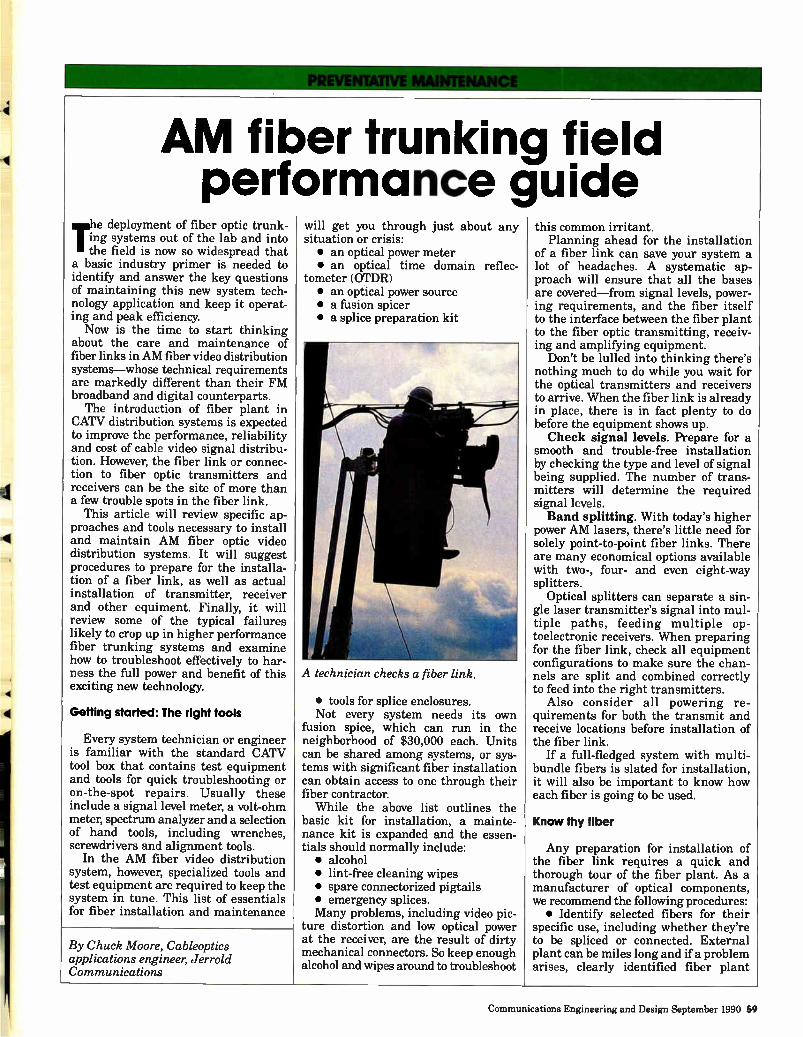
AM fib perf
rte deployment of fiber optic trunk-ing systems out of the lab and into he field is now so widespread that
a basic industry primer is needed to identify and answer the key questions of maintaining this new system tech-nology application and keep it operat-ing and peak efficiency. Now is the time to start thinking
about the care and maintenance of fiber links in AM fiber video distribution systems—whose technical requirements are markedly different than their FM broadband and digital counterparts. The introduction of fiber plant in
CATV distribution systems is expected to improve the performance, reliability and cost of cable video signal distribu-tion. However, the fiber link or connec-tion to fiber optic transmitters and receivers can be the site of more than a few trouble spots in the fiber link.
This article will review specific ap-proaches and tools necessary to install and maintain AM fiber optic video distribution systems. It will suggest procedures to prepare for the installa-tion of a fiber link, as well as actual installation of transmitter, receiver and other equiment. Finally, it will review some of the typical failures likely to crop up in higher performance fiber trunking systems and examine how to troubleshoot effectively to har-ness the full power and benefit of this exciting new technology.
Getting started: The right tools
Every system technician or engineer is familiar with the standard CATV tool box that contains test equipment and tools for quick troubleshooting or on-the-spot repairs. Usually these include a signal level meter, a volt-ohm meter, spectrum analyzer and a selection of hand tools, including wrenches, screwdrivers and alignment tools.
In the AM fiber video distribution system, however, specialized tools and test equipment are required to keep the system in tune. This list of essentials for fiber installation and maintenance
er trunkin ormance g
By Chuck Moore, Cableoptics applications engineer, Jerrold Communications
will get you through just about any situation or crisis: • an optical power meter • an optical time domain reflec-
tometer (OTDR) • an optical power source • a fusion spicer • a splice preparation kit
A technician checks a fiber link.
• tools for splice enclosures. Not every system needs its own
fusion spice, which can run in the neighborhood of $30,000 each. Units can be shared among systems, or sys-tems with significant fiber installation can obtain access to one through their fiber contractor. While the above list outlines the
basic kit for installation, a mainte-nance kit is expanded and the essen-tials should normally include: • alcohol • lint-free cleaning wipes • spare connectorized pigtails • emergency splices. Many problems, including video pic-
ture distortion and low optical power at the receiver, are the result of dirty mechanical connectors. So keep enough alcohol and wipes around to troubleshoot
g field uide
this common irritant. Planning ahead for the installation
of a fiber link can save your system a lot of headaches. A systematic ap-proach will ensure that all the bases are covered—from signal levels, power-ing requirements, and the fiber itself to the interface between the fiber plant to the fiber optic transmitting, receiv-ing and amplifying equipment.
Don't be lulled into thinking there's nothing much to do while you wait for the optical transmitters and receivers to arrive. When the fiber link is already in place, there is in fact plenty to do before the equipment shows up. Check signal levels. Prepare for a
smooth and trouble-free installation by checking the type and level of signal being supplied. The number of trans-mitters will determine the required signal levels. Band splitting. With today's higher
power AM lasers, there's little need for solely point-to-point fiber links. There are many economical options available with two-, four- and even eight-way splitters.
Optical splitters can separate a sin-gle laser transmitter's signal into mul-tiple paths, feeding multiple op-toelectronic receivers. When preparing for the fiber link, check all equipment configurations to make sure the chan-nels are split and combined correctly to feed into the right transmitters.
Also consider all powering re-quirements for both the transmit and receive locations before installation of the fiber link.
If a full-fledged system with multi-bundle fibers is slated for installation, it will also be important to know how each fiber is going to be used.
Know thy fiber
Any preparation for installation of the fiber link requires a quick and thorough tour of the fiber plant. As a manufacturer of optical components, we recommend the following procedures: • Identify selected fibers for their
specific use, including whether they're to be spliced or connected. External plant can be miles long and if a problem arises, clearly identified fiber plant
Communications Engineering and Design September 1990 59
OPTICAL SOCIETY Of AMERICA
will help facilitate problem solving. • Know and verify the continuity
and loss measurement of all identified fiber. Use an OTDR to measure any light loss along the fiber. Most systems involved in rolling out fiber plant should have access to this diagnostic device. The OTDR reads the amount of light being reflected back through the fiber and allows evaluation of the state of the fiber based on this light reading, especially measurement of signal loss
across the fiber. • Use power meters to measure loss
at connector sites and at the bare fiber adaptor.
Flber to equipment Interface
The equipment has arrived: What's next? Prepare the environment for a seamless interface of fiber plant to all fiber optic equipment.
Identify the location for all transmit
IEEE COMMUNICATIONS SOCIETY JOINS OFC' *NETWORKS AND SWITCHLNG PROGRAM ADDED!
OPTICAL FIBER COMMUNICATION CONFERENCE
OFC"91 FDDI • ISDN • LAN • MAN • CATV • SENSORS • FIBERS & CABLES
DEVICES • COMPONENTS • SYSTEMS
February 17-22,1991
San Diego Convention Center • San Diego, California
Come to San Diego in February and see why OFC® is considered the "Premiere Fiber Optic Gathering."
TECHNICAL PROGRAM
OFC°, the major North American conference on optical fiber communications technologies, offers the most up-to-date information and training from the basics to the very latest in research, develop-ment, applications including components and systems. The technical program will consist of con-tributed and invited presentations reporting leading edge research, development in components and fiber systems technologies. OFC° '91 will feature a series of one-hour tutorials and three-hour short courses for in-depth instruction in a variety of optical fiber communication disciplines.
TOPICS INCLUDE II Fiber Optic Systems for Telecommunica-
tions, Including CATV ▪ Metropolitan Area, Local Area and Multiser-
vice Networks ▪ New Applications for Fiber Optic Technology ▪ Network Architectures and Protocols al Semiconductor Sources and Detectors
▪ PhotoniciElectronic Switching Architec-tures; Fast Packet Switching
• Optoelectronic and Integrated Optics Devices and Components
▪ Fiber, Cables and Glass Technologies ▪ Optical Fiber Amplifiers
EXHIBITS /IntODUCT PRFSENTATIONS
* The world's foremost fiber optics exhibit-200 companies displaying products and ser-vices for research, development and applications
* The latest in components, devices and systems
*Product presentations provide specifics on new and important fiber optic develop-ments
Cosponsored by IEEE Communications Society IEEE Lasers & Electro-Optics Society Optical Society of America
For exhibit information contact: Exhibits Department Opti•cal Society of America (202) 416-1950 FAX 202-416-6140
Reader Service Number 30 60 Communications Engineering and Design September 1990
and receive equipment—whether in-door or outdoor. Know which splicing techniques you'll use and where you'll employ them, giving weight more to-ward return loss than insertion loss. Placement and type of mechanical connectm should eso be considered. The risks in using mechanical splices,
even in the case of good splices in terms of insertion loss, point to excessive reflection. While data seems to indicate that the new generation a mechnical splices offer performance close to fusion splicing, environmental factm from temperature and weather loss could result in deteriorated splice return loss from the time of original installation. Recommended is the use of fusion
splicing, primarily because of excellent return loss and insertion loss of typically 0.05 dB per splice or better. An all fusion-spliced fiber link is
ideal for AM CATV performance, but this isn't always possible. The real challenge is achievement of acceptable insertion loss and minimization of reflection risk.
In terms of connectors, proper clean-ing of the fiber ends for each connect or re-connect is essential for a number of reasons, but primarily because dirt and fingerprints cause reflections and dampen AM fiber performance, par-ticularly at the transmitter connection.
Ready, set, Im tall
Ensuring proper installation of all the equipment that will interface to the fiber plant is a several step process. For installation of transmitters, power them up and test all vital signs and outputs to make sure they are fully functional. Check volge test points. If there
are test points for the transmitter unit, use measurement equipment to test them. Check for: • laser Mas • laser temperature • cooler current • optical power • any indication of laser fault. Apply signals to the transmitter.
The next step in the process of install-ing the optical transmitter is to apply signal to the unit. You'll need t,o attach both RF and fiber optic cables to check and measure: • RF test points • FtF drive-level indicators • make any adjustments to the proper
levels. Check transmitter power output.
Here, simply use a power meter to examine the power outputs of the unit.

All output levels should be recorded for later reference. The installation of receiver units
follows much the same procedure as the transmittter, except that testing is directed to measuring the quality of the light transmitted to the receiver. • Check the voltage
supply • Check the optical
power at the end of the fiber by using a connector on the power meter and using a bare fiber adapter on the power meter if the receiver is to undergo fusion splicing.
If the power is low or nonexistent, refer to the common troubleshooting techniques mentioned shortly. If the power is correct, adjust the unit to its proper output level. Consider adjusting the padding as necessary and making adjustments to the level control as needed.
Fiber troubleshooting
There are a number of common recurring failures in the fiber link that require troubleshooting. Generally, most problems are external to the equipment itself and point to things that went wrong in the installation and testing process, such as broken fibers, poorly adjusted or dirty connectors or laser/receiver
Reader Service Number 27
problems. In order to avoid Murphy's Law—
where anything than can go wrong,
Fiber test facility.
will go wrong—it is worthwhile to be prepared to handle any and all of the common problems that arise. After all, forewarned is forearmed.
No optical power at the receiver location. Problems in this area point to a number of things that can go
wrong, including: • broken fibers • defective connectors • transmitters that are
defective or not powered. Low optical power at the
receiver. It's important to measure optical power at the receiver to ensure an adequate level of output from the receiver. As a general rule, keep in mind that a 1 dB increase in optical loss is likely to decrease the receiver output by 2 dB. While the causes of low
power at the receive site are numerous, they typically include one or more of the following: • defective or dirty
connectors • pinched fiber • inaccurate measurement
of the fiber link • inaccurate measurement
with OTDR • improper configuration of
optical splitters, such as the legs interchanged.
Connectors can be a real problem if not dealt with consistently. Any time a connector is opened up, clean it. Dirty or defective connectors cause excessive loss in the
fiber path and physical impairment of the picture quality. Inadequate signal level at the
receiver location. As more and more
C-COR and COMLUX have joined forces to develop and produce all-digital fiber optic systems with price, features and performance
for a perfect fit in your cable television plant.
Watch for the next generation of digital fiber products in the near future.
WE'RE OUT TO GIVE YOU THE BEST RECEPTION IN THE INDUSTRY.
ceorl 60 Decibel Road / State College, PA 16801 2461 / 800-233-2267 / 800-356-5090 (in PA)
ELECTRONICS 814-238-INC
Communications Engineering and Design September 1990 61

Preventative maintenance is a growing concern in fiber optic technology.
optical transmitters are loaded into the headend, the signal level requirements will become more and more of a con-cern. Consult the equipment specifica-tions to make sure that the correct level of the signal is being provided to the operating units. When there are insuf-ficient signal levels, there also won't be enough power to generate adequate signal to the receive location. This is typically caused by: • improperly adjusted transmitter/
receiver
• excessive fiber loss • defective transmitter/receiver. Once the transmitter is supplied
with correct operating levels, make all necessary adjustments. 'fransmitters must be adjusted to their normal oper-ating point, an important factor in driving the laser to achieve its desired performance.
Unit adjustment can be preset by the manufacturer or is done by the users. Only when ideal transmitter operating levels are verified can you go on to
Ad Index Reader Service # Page #
AT&T 23 55 AM. Electronics 25 Anixter Cable TV 29 72 Augat Communications Group 15 33 C-COR Electronics 6, 27 15, 61 Catel Iblecommunications 8 19 Comm/Scope Inc 2 3 Corning 22 52-53 Ditel 17 38 Expo 60 Fotec 18 39 General Inst./Jerrold (Dist.) 4, 16 7, 36-37 Gould 20 49 Hennessy 24 57 Magnavox CATV 5 13 Midwest CATV 9 20-21 National Cable Iblevision Institute . .13 29 Optical Fiber Comm. Conf. 30 60 Ortel Corp 19 41 Panasonic 1 2 Power Guard 28 71 Reliable Electric 14 31
62 Communications Engineering and Design September 1990
adjust the receiver for its desired output performance.
Distortion in the video picture. Distortion is normally caused by: • distortion in signals applied to the
transmitter • poorly adjusted transmitter or re-
ceiver • fiber that is defective, broken or
barely touching • mechanical connectors that are
loose or dirty • excessive channel load on the
fiber. In one system, field engineers found
that mechanical connectors caused a significant amount of reflection, detect-able using an OTDR. The recommended solution is to replace mechanical con-nectors with fusion splicing.
In the best of all possible worlds, nothing goes wrong with the installa-tion of the fiber link. But in the real world, you need to keep a high-technology, high-performance AM fi-ber video distribution system running. The emerging world of fiber optics means that new tools and techniques must be added to the system technician and engineer's care and maintenance repertoire. By following some of the procedures
discussed here, and understanding how to apply common sense troubleshooting to problems in the fiber link, the true elegance, power, efficiency and com-patibility of AM fiber optic distribution systems will continue to shine through for years to come. •
Reader Service #
58 Scientific-Atlanta 3 Siecor Corp 12 Sumitomo Elec. Fiber Optics Transamerica Energy Assoc. (TEA) . 11 lbxscan 10 Triple Crown 11 Westec 21
MX RESPONSE-1-800-876-2299
Advertiser's ID Code
Page #
5 25
43-46 22
17 23 51
Page # Augat Communications Group . .016 33 Anixter 017 72 Comm/Scope Inc 026 3 General Instrument/Jerrold 019 7,36-37 Magnavox 020 13 Midwest CATV 007 20-21 Panasonic 008 2 Power Guard 028 ......71 Scientific-Atlanta 025 5
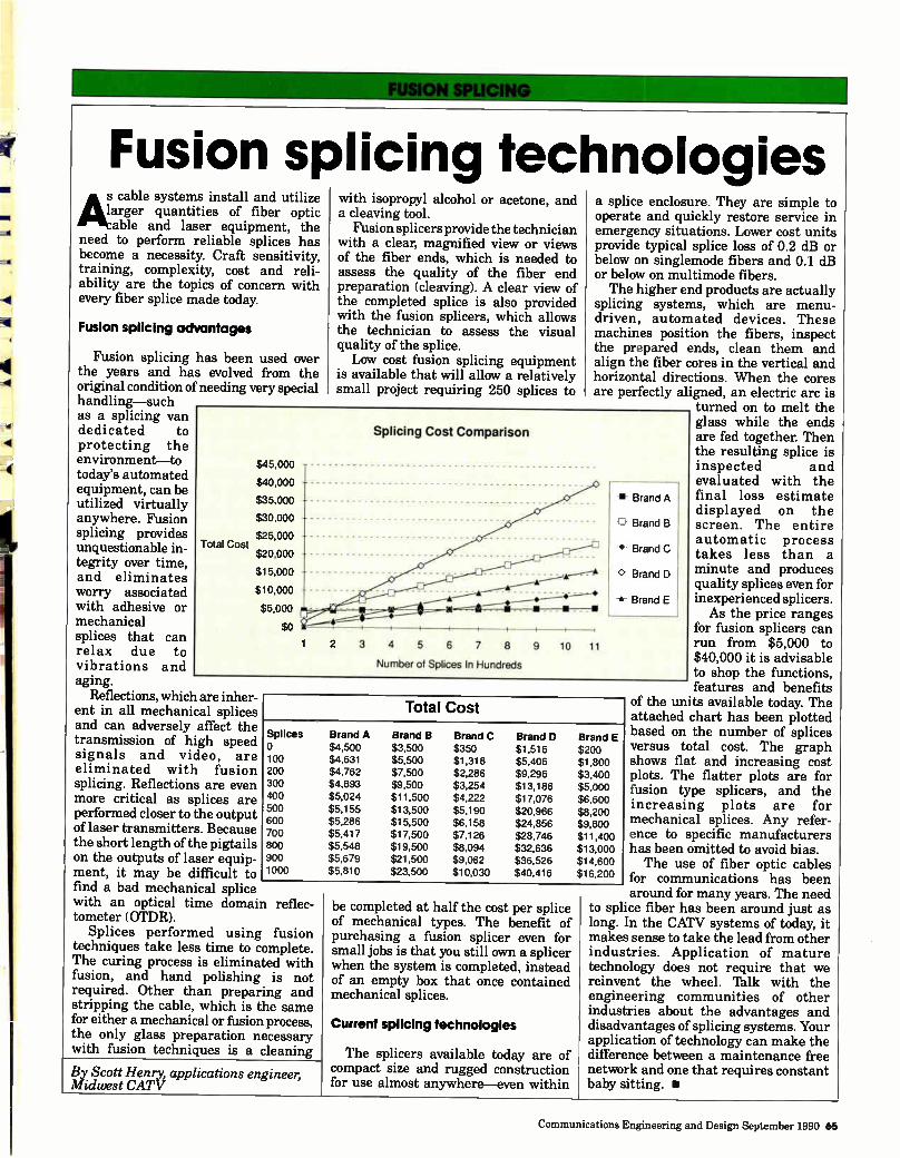
Fusion splicing technologies cable systems install and utilize
quantities of fiber optic able and laser equipment, the
need to perform reliable splices has become a necessity. Craft sensitivity, training, complexity, cost and reli-ability are the topics of concern with every fiber splice made today.
Fusion splicing advantages
Fusion splicing has been used over the years and has evolved from the original condition of needing very special handling-such as a splicing van dedicated to protecting the environment-to today's automated equipment, can be utilized virtually anywhere. Fusion splicing provides unquestionable in-tegrity over time, and eliminates worry associated with adhesive or mechanical splices that can relax due to vibrations and aging.
Reflections, which are inher-ent in all mechanical splices and can adversely affect the transmission of high speed signals and video, are eliminated with fusion splicing. Reflections are even more critical as splices are performed closer to the output of laser transmitters. Because the short length of the pigtails on the outputs of laser equip-ment, it may be difficult to find a bad mechanical splice with an optical time domain reflec-tometer (OTDR).
Splices performed using fusion techniques take less time to complete. The curing process is eliminated with fusion, and hand polishing is not required. Other than preparing and stripping the cable, which is the same for either a mechanical or fusion process, the only glass preparation necessary with fusion techniques is a cleaning
By Scott Henry, applications engineer, Midwest CATV
with isopropyl alcohol or acetone, and a cleaving tool.
Fusion splicers provide the technician with a clear, magnified view or views of the fiber ends, which is needed to assess the quality of the fiber end preparation (cleaving). A clear view of the completed splice is also provided with the fusion splicers, which allows the technician to assess the visual quality of the splice. Low cost fusion splicing equipment
is available that will allow a relatively small project requiring 250 splices to
a splice enclosure. They are simple to operate and quickly restore service in emergency situations. Lower cost units provide typical splice loss of 0.2 dB or below on singlemode fibers and 0.1 dB or below on multimode fibers. The higher end products are actually
splicing systems, which are menu-driven, automated devices. These machines position the fibers, inspect the prepared ends, clean them and align the fiber cores in the vertical and horizontal directions. When the cores are perfectly aligned, an electric arc is
turned on to melt the glass while the ends are fed together. Then the resulting splice is inspected and
evaluated with the final loss estimate displayed on the screen. The entire automatic process takes less than a minute and produces quality splices even for inexperienced splicers. As the price ranges
for fusion splicers can run from $5,000 to $40,000 it is advisable to shop the functions, features and benefits
of the units available today. The attached chart has been plotted based on the number of splices versus total cost. The graph shows flat and increasing cost plots. The flatter plots are for fusion type splicers, and the increasing plots are for mechanical splices. Any refer-ence to specific manufacturers has been omitted to avoid bias. The use of fiber optic cables
for communications has been around for many years. The need
to splice fiber has been around just as long. In the CATV systems of today, it makes sense to take the lead from other industries. Application of mature technology does not require that we reinvent the wheel. 'Balk with the engineering communities of other industries about the advantages and disadvantages of splicing systems. Your application of technology can make the difference between a maintenance free network and one that requires constant baby sitting. •
$45,000
$40,000
$35,000
$30,000
$25,000
$20,000
$15,000
$10,000
$5,000
$0
Splicing Cost Comparison
2 3 4 5 6 7 8 9
Number of Splices In Hundreds
-=3
10 11
-w- Brand A
G Brand B
-•- Brand C
Brand D
-s- Brand E
Total Cost
Splices o 100 200 300 400 500 600 700 800 900 1000
Brand A Brand B Brand C Brand D Brand E $4,500 $3,500 $350 $1,516 $200 $4,631 $5,500 $1,318 $5,406 $1,800 $4,762 $7,500 $2,286 $9,296 $3,400 $4,893 $9,500 $3,254 $13,186 $5,000 $5,024 $11,500 $4,222 $17,076 $6,600 $5,155 $13,500 $5,190 $20,966 $8,200 $5,286 $15,500 $6,158 $24,856 $9,800 $5,417 $17,500 $7,126 $28,746 $11,400 $5,548 $19,500 $8,094 $32,636 $13,000 $5,679 $21,500 $9,062 $36,526 $14,600 $5,810 $23,500 $10,030 $40,416 $16,200
Total Cost
be completed at half the cost per splice of mechanical types. The benefit of purchasing a fusion splicer even for small jobs is that you still own a splicer when the system is completed, instead of an empty box that once contained mechanical splices.
Current splicing technologies
The splicers available today are of compact size and rugged construction for use almost anywhere-even within
Communications Engineering and Design September 1990 65

The following companies have paid a fee to have their listing appear in the Fiber Optic Callbook
Cable
AT&T 911111,
-"•1111•1111"'
AT&T (303) 740-6102 FAX (303) 694-3977 8101 E. Prentice Ave., Suite 210 Englewood, CO 80111 PERSONNEL: Tim Gropp, National Sales Manager: CATV; Ron Causey, Account Executive: CATV DESCRIPTION: AT&T is a manufacturer of optical fiber, optical fiber cable, and lightwave transmission systems for cable TV. AT&T also supplies turnkey installation services. Anixter Cable TV is the sole supplier of AT&T products.
BELDEN COOPER INDUSTRIES
Belden Wire and Cable. .(317) 983-5200 FAX (317) 93-5294 2200 US 27 South Richmond, IN 47374 PERSONNEL: Phil Dunn, CATV Sales Manager; Phil Pennington, Regional CATV Manager DESCRIPTION: Belden offers a complete line of armored and non-armored fiber optic Super'frunk cables in two styles. Belden offers multi-fiber per tube and a bundled fiber optic cable. Both styles are offered in fiber counts from 6-72 fibers. Belden also offers a turnkey package from design to installation from a network of authorized systems integrators.
Comm/Scope,Inc. THE Cable in Cable TV
Comm/Scope, Inc. (704) 324-2200 WATS (National) (800) 982-1708 WATS (State) (800) 222-6808 FAX (704) 328-3400 1375 Lenoir Rhyne Blvd., P O. Box 1729 Hickory, NC 28603 PERSONNEL: Paul Wilson, Lynn Sigmon DESCRIPTION: Supplier of high quality Optical Reach r fiber optic cables employing depressed clad fibers in buffered tubes. Optical Reach is available in many constructions and fiber counts.
ADVERTISEMENT
CORNING
Corning Incorporated . . .(607) 974-4411 Teiecomm. Prods. Dim FAX (607) 974-7522 MP-R0-03 Corning, NY 14831 PERSONNEL: Scott Esty, Cable TV Market Development Manager; Bill Willson, Sales Manager, Coupler Products DESCRIPTION: Corning Incorporated manufactures a full line of optical fiber and components to meet today's demanding cable TV applications. Products include: Corning Fiber—Titan's' single-mode fiber, SMF/DS" single-mode dispersion-shifted fiber—and Corning Couplers, both multimode and single-mode tree, star, tap and WDM couplers.
SIECOR Siecor Corp. (704) 327-5554 FAX (704) 327-5973 489 Siecor Park Hickory, NC 28603-0489 PERSONNEL: Sandy Lyons, 704-327-5806; David Johnson, 704-327-5895 DESCRIPTION: Siecor manufactures a variety of fiber optic cable designs for aerial, direct buried, duct installations. Loose tube design is rugged, easy to handle and provides superior environmental protection. Modularity simplifies fiber drop-off and mid-span access. Also supplies splicers, testers, training, services.
Electro Optics
..-•-•••••••111.
AT&T "••111M1M.'
AT&T (303) 740-6102 FAX (303) 694-3977 8101 E. Prentice Ave., Suite 210 Englewood, CO 80111 PERSONNEL: Tim Gropp, National Sales Manager: CATV; Ron Causey, Account Executive: CATV. DESCRIPTION: AT&T is a manufacturer of optical fiber, optical fiber cable, and lightwave transmission systems for cable TV. AT&T also supplies turnkey installation services. Anixter Cable TV is the sole supplier of AT&T products.
66 Communications Engineering and Design September 1990
ALS`e AMERICAN LIGHTWAVE
SYSTEMS, INC.
American LIghtwaye . . .(203) 265-8802 Systems, Inc. FAX (203) 265-8746 358 Hall Ave. Wallingford, CT 06492-1149 PERSONNEL: John Holobinko, VP/ Marketing & Sales; Rod Andersen, Regional CATV Sales Manager DESCRIPTION: ALS LiteAMp" AM fiber optic and FN6000" FM fiber optic systems are designed for easy installation by normal CATV personnel without special optical training, yet they feature high performance and no periodic maintenance adjustments. ALS systems are completely modular. LiteAMp is available in strand, pole, pedestal and rack mounts. FN6000 and LiteAMp offer advanced features not found on competitive systems, based on ALS' 12 years of CATV fiber experience, more than twice any other vendor.
Amoco Laser Company
Amoco Laser Co (708) 961-8400 FAX (708) 369-4299 1251 Frontenac Rd. Naperville, IL 60563 PERSONNEL: Juan M. Cerda; Scott L. Miller DESCRIPTION: Leading manufacturer of diode-pumped, solid-state microlaser for fiber optic communications industry. These microlasers are intended for use in high-power-budget, externally modulated CATV applications for either headend or distribution links. Amoco Laser offers standard products up to 175 mW with isolators and fiber optic pigtails.
B TECHNOLOGIES
BT&D Technologies . . . .(302) 479-0300 FAX (800) 545-4306 2 Righter Pkwy. Delaware Corporate Center, Ste. 200 Wilmington, DE 19803 PERSONNEL: William G. Morrel, Prod. Mkt. Mgr. Passive Components; Kenneth Miller, Sales Engineer DESCRIPTION: BT&D is a volume manufacturer of fiberoptic components for use in SONET/SDH, FDDI, CATV, and
ADVERTISEMENT
Local Loop applications. Products range from ELEDS, lasers and PIN detectors to integrated function modules, passive couplers, splitters, switches and advanced products. BT&D's Subscriber Loop Coupler can be used in a variety of applications.
ELECTRONICS INC C-COR Electronics, Inc. . .(814) 238-2461 WATS (800) 233-2267 FAX (814) 238-4065 60 Decibel Rd. State College, PA 16801 PERSONNEL: John Hastings, Director of Sales; Dick lbylor, National Sales Manager-CATV DESCRIPTION: C-COR's products include digital and AM fiber optics, a variety of amplifiers, status monitoring, modems, passives, and power supplies. Our professional services include System Design, Field Engineering Assistance, lbchnicalUaining, Equipment Repair, a 48-hour Emergency Repair Service and a 24-hour Hotline.
CORNING Corning Incorporated . . .(607) 974-4411 Telecomm. Prods. Div. FAX (607) 974-7522 MP-R0-03 Corning, NY 14831 PERSONNEL: Scott Esty, Cable TV Market Development Manager; Bill Willson, Sales Manager, Coupler Products DESCRIPTION: Corning Incorporated manufactures a full line of optical fiber and components to meet today's demanding cable TV applications. Products include: Corning" Fiber—Titan' single-mode fiber, SMF/DS" single-mode dispersion-shifted fiber—and Corning' Couplers, both multimode and single-mode tree, star, tap and VVDM couplers.
Cil5LEOrlICS Jerrold Communications .(215) 674-4800 General Instrument WATS (National) (800) 523-6678 WATS (State) (800) 562-6965 FAX (215) 672-5130 2200 Byberry Rd. Hatboro, PA 19040 PERSONNEL: David Robinson, Director of Cableoptics; Geoff Roman, VP of Marketing DESCRIPTION: Designer/Manufacturer of
the industry's most comprehensive line of electronic and fiber optic broadband communications equipment. Jerrold Starlite Cableoptics" equipment supports both FM supertrunk and AM backbone distribution applications. The company's RF distribution and headend gear provide a complete opto-electronic product line for cable TV and LAN systems.
MAGNAVOX rfwamrionwirm CATV SYSTEMS CO.
Magnavox CATV Systems .(800) 448-5171 WATS (State) (800) 522-7464 FAX (315) 682-9006 100 Fairgrounds Drive Manlius, NY 13104 PERSONNEL: John Caezza, Product Manager; Rick Haube, Fiber Optic Product Specialist DESCRIPTION: Manufacturer of video and data transmission systems, FM video transmission systems to include FM modulators/demodulators, laser diode transmitters, and optical receivers. AM fiber optic transmission systems to include rack mounted transmitters and rack or strand mounted receivers. Also a supplier of Amplitude modulated headend equipment.
NORTHERN TELECOM
Northern Telecom (404) 661-5000 FAX (404) 395-5000 One Ravinia Drive Atlanta, GA 30346 PERSONNEL: Tim Grimsley, Area Sales Manager; John Park, Area Sales Manager DESCRIPTION: Northern Telecom Limited is a leading global supplier of fully digital telecommunications switching systems. The Optical Cable Division develops, manufactures and markets a complete line of fiber optic products including splicing and jointing, test products and optical connectors. Our line of optical cable and outside plant products is fully complementary to Northern Telecom's FiberWorld family. (A supplier to CATV.)
O PTICALCABLECORPORATION
Optical Cable Corp.. . . (800) 622-7711 FAX (703) 265-0724 PO Box 11967 Roanoke, VA 24022-1967 PERSONNEL: Luke J. Huybrechts, VP,
Sales; Robert Kopstein, President DESCRIPTION: Optical Cable Corporation manufactures a complete line of fiber optic cable products for video, voice, data communications and local area networks applications. The tight buffered cable design is easily terminated and suitable for inside building and outside plant environments as well as aerial, burial and duct environments. A-series jumper cables, B-series breakout cables, D-series trunking cables, military tactical field, plenum and riser cables. All cables are manufactured with communication grade fibers. Sales are made to end-users, OEMs, installers, contractors and through distribution.
ORCHARD COMMUNICATIONS
Orchard Comm., Inc. . . .(203) 284-1680 WATS (National) (800) 523-7893 FAX (203) 269-2964 101 N. Plains Industrial Rd Wallingford, CT 06492 PERSONNEL: Dean Bogert, Director of Systems Engineering; Ronald Jones, VP of Sales, NJ office 609-596-9222 DESCRIPTION: Orchard manufactures a full range of fiberoptic AM-VSB, FM, and digital video transmission systems. AM systems use DFB lasers, or external modulation for high output power. Interfaces for FM and digital systems include baseband video/audio, monaural or BTSC audio, 45.75 MHz IF, or composite video with 4.5 MHz audio.
o ORTEL CORPORATION
Ortel Corp. (818) 281-3636 FAX (818) 281-8231 2015 W. Chestnut St. Alhambra, CA 91803 PERSONNEL: Larry Stark, Director of Marketing; Bill Moore, Director of Sales DESCRIPTION: Ortel manufactures fiber optic components for AM CATV transmission and for satellite TVRO antenna remoting.
1111POWER GUARD Power Guard Inc (800) 288-1507 FAX (205) 742-0058 506 Walker St., PO Box 2796 Opelika, AL 36801 PERSONNEL: Jerry Schultz, Presidet; Mike Springer, VP of Sales
Communications Engineering and Design September 1990 67
DESCRIPTION: Power Guard manufactures the revolutionary and versatile new Power Cast" which is the first power supply designed for strand, pole, or pedestal mounting. The Power Cast" is available in 3, 6, 9, 12, and 15 amp models; for optimum powering of fiber/coaxial plant. Power Guard also manufactures a complete line of standby and non-standby power supplies to meet virtually any CATV requirement.
Scientific Atlanta
Scientific-Atlanta (800) 722-2009 FAX (404) 925-5445 PO Box 105027 Atlanta, GA 30348 PERSONNEL: John Mattson; Godfrey Pinto DESCRIPTION: Scientific-Atlanta's FOCUS AM Fiber Optic System provides unmatched perormance combined with maximum reliability. The system consists of the model 6450 OptoelectronicUansmitter and the model 6901 Optoelectronic Bridging Amplifier, each of which can be custom-configured for optimal performance in a variety of applications.
Texscan Texscan Corp. (915) 594-3555 WATS (800) 351-2345 FAX (915) 591-6984 10841 Pellicano Dr. El Paso, TX 79935 . PERSONNEL: William H. Lambert, Chairman, President, CEO; George L. Fletcher, Senior V.P. Corporate Marketing DESCRIPTION: Manufacturer of a broad line of distribution electonics, fiber optic systems, character generators, commercial insertion equipment. lbxscan's Flamethrower Systems, offer new architecture for CATV's future. Flamethrower Optical Bridging Systems feature unique bridger architecture allowing lower RF active counts (and cost) with greater reliability and performance, less mechanical system interfaces with 2 or 4 output versions. Unequalled RF output performance for additional savings in RF and optical active devices for lower construction, maintenance and operational costs. The right RF technology to do the job.
Test Equipment
ADVANTEST Advantest America, Inc.. (708) 634-2552 FAX (708) 634-2610
ADVERTISEMENT
300 Knightsbridge Parkway Lincolnshire, IL 60069 PERSONNEL: Atlee Jacobson, Sales Support Eng.-Midwest; Joe Diamond, Regional Sales Manager-East DESCRIPTION: Q8460-High resolution OTDR. Provides accurate fault detection at distance ranges of 15, 50, and 100Km.The unique reflective mode locates reflected faults. R3361 series spectrum analyzers come with either 2.6 or 3.6 GHz capability and with an internal tracking generator. Its dB display dynamic range puts high and low signals on screen simultaneously. R4131 is a 3.5 GHz spectrum analyzer with numerous advanced digital functions at a low cost.
Anritsu Anritsu America, Inc.. . . .(201) 337-1111 WATS (National) (800) 255-7234 FAX (201) 337-1033 15 Thornton Rd. Oakland, NJ 07436 PERSONNEL: Chuck Smith, Director of Sales & Marketing; Hugh Felger, Marketing Manager DESCRIPTION: Fiber optic instrumentation including OTDR's, light sources and power meters. RF and microwave products including spectrum analyzers, EMI receivers, synthesizers, power meters and network analyzers.
Lij__s/ CALAN, Inc. (717) 828-2356 WATS (National) (800) 544-3392 FAX (717) 828-2472 1776 Independence Drive Route 739 Ding-mans Ferry, PA 18328 PERSONNEL: Edward McDonald, Major Accounts; Ian Jones, Product Manager DESCRIPTION: CALAN, Inc. manufacturers top of the line Integrated Sweep/Spectrum Analyzer Systems. The System combines the function of a Non-Interfering System Sweep and Spectrum Analyzer in one portable, battery operated unit. The CALAN Sweep System has been successfully field tested on several fiber systems. Sweeping over fiber is a proven reality with the CALAN System. The System is fully compatible with both CATV and Broadband Data Networks. CALAN also offers rugged Fiber Optic Power Meters and Sources for measuring optical power and component or system loss.
68 Communications Engineering and Design September 1990
Electro-Opt,cal Engtneering
EXFO E.O. Eng. Inc (418) 683-0211 FAX (418) 683-2170 352 St-Sacrement Ave. Quebec City, QC GIN 3Y2 PERSONNEL: Andrew Benn; Vedrana Stojahac DESCRIPTION: EXFO manufactures a complete range of fiberoptic test equipment for CATV, LAN, or long haul testing and is the best known for Quality, Innovation and Customer Support. These products include optical power meters, attenuation test sets at 1 or 2 wavelengths, LED/LASER light sources, talk sets, variable attenuators, visual fault locators, variable back reflectors, back reflection test sets, etc. Product range include low-cost hand-held to top performance laboratory units which are available in over 30 countries around the world.
HEWLETT PACKARD
Hewlett-Packard Co.. . . (707) 794-3569 Signal Analysis Div. FAX (707) 794-4620 1212 Valley House Dr., 2LR-J Rohnert Park, CA 94928 PERSONNEL: Julie Bickford, Division Marcom Manager DESCRIPTION: Quality Analyzers Dedicated to Cable Iblevision: Keep your CATV system operating and customers satisfied with HP CATV test equipment. For headend and trunk RF measurements, the HP 8590B/91A operate from 9kHz to 1.8 GHz. For microwave-link testing, the HP 8592B/93A extend coverage to 22 GHz. And for lightwave, the HP 83810A signal analyzer covers from 1,200 to 1,600 nm and bandwidths from 9 kHz to 22 GHz. Consult your local telephone directory for the HP sales office nearest you.
YQRK YORK TECHNOLOGY, INC.
York Technology Inc.. . . (818) 955-8927 FAX (818) 955-9728 210 N. Glenoaks Blvd., Suite C Burbank, CA 91502 PERSONNEL: Brent Ware, VP; Paul Walker, Sales Mgr. DESCRIPTION: S18 Chromatic Dispersion: Fast-typical scan of 120 nm in 10 nm increments accomplished in less than

ADVERTISEMENT
15 seconds, including curve fit (500 m to 75 km). Direct measurement of fiber length, with millimeter resolution. Direct measurement ofchromatic dispersion, lambda-zero, and slope. Direct measurement of group delay characteristic. Strain measurements to cabled fibers. Up to 5 sources. S25 Spectral Attenuation: Fast measurement-2 minutes; Excellent repeatability-0.003dB RMS; Wavelength range 350 to 5500 nm; Singlemode and multimode; Easy fiber handling; Auto-sequencing; HP/IBM PC controlled; Cutback or stored technique; Mode Field Diameter using the VAFF technique measures from 750 nm-175 nm, 0.5 NA optics.
Accessories
'.1•1111MI
AT&T AT&T (303) 740-6102 FAX (303) 694-3977 8101 E. Prentice Ave., Suite 210 Englewood, CO 80111 PERSONNEL: Tim Gropp, National Sales Manager: CATV; Ron Causey, Account Executive: CATV DESCRIPTION: AT&T is a manufacturer of optical fiber, optical fiber cable, and lightwave transmission systems for cable TV. AT&T also supplies turnkey installation services. Anixter Cable TV is the sole supplier of AT&T products.
AUGAT AUGAT COMMUNICATIONS GROUP INC.
Augat Comm. Group . . .(206) 932-8428 FAX (206) 938-8850 2414 SW Andover St. Seattle, WA 98106 PERSONNEL: Bill Jensen, Dir. of Sales Fiberoptics; Amy Amrhein, Fiberoptic Product Manager DESCRIPTION. The fiberoptics product line of the Augat Communications Group offers the following: SMT, SMA and biconic connectors; SMT, SMA and termination kits. Gauging tools; heat curing ovens; tools and accessories; modems and mux interfaces; cable assemblies; fiberoptic patch panels; Augat/Cinch fiber optic wiring system.
ceo irk° ELECTRONICS INC
C-COR Electronics, Inc. . .(814) 238-2461 WATS (800) 233-2267
FAX (814) 238-4065 60 Decibel Rd. State College, PA 16801 PERSONNEL: John Hastings, Director of Sales; Dick Taylor, National Sales Manager-CATV DESCRIPTION: C-COR's products include digital and AM fiber optics, a variety of amplifiers, status monitoring, modems, passives, and power supplies. Our professional services include System Design, Field Engineering Assistance, Technical Equipment Repair, a 48-hour Emergency Reapir Service and a 24-hour Hotline.
CORNING Corning Incorporated . . .(607) 974-4411 Telecomm. Prods. Div. FAX (607) 974-7522 MP-R0-03 Corning, NY 14831 PERSONNEL: Scott Esty, Cable TV Market Development Manager; Bill Willson, Sales Manager, Coupler Products DESCRIPTION: Corning Incorporated manufactures a full line of optical fiber and components to meet today's demanding cable TV applications. Products include: Corning r Fiber—Titan'. single-mode fiber, SMF/DS single-mode dispersion-shifted fiber—and Corning' Couplers, both multimode and single-mode tree, star, tap and WDM couplers.
Enclosures
KU flp.0 Es Hennessy Products, Inc.. (800) 950-7146 FAX (717) 264-1634 910 Progress Rd., PO Box 509 Chambersburg, PA 17201 PERSONNEL: Patrick Hennessy, Sales Manager; Bruce Ritchey, Vice President, Sales DESCRIPTION: Hennessy designs and manufactures quality aluminum and stainless enclosures/cabinets ideal for fiber optic equipment and other electronics and electrical equipment that requires protection. Catalog available.
RELIANCE'S!! comm/rEc mQ
Reliance Comm/Tee.. . .(708) 455-8010 Reliable Electric
FAX (708) 451-5516 11333 Addison Franklin Park, IL 60131 PERSONNEL: Cloyd Poll, Fiber Optics Products; Frank Priebe, CATV Products DESCRIPTION: Fiber optic accessory items, connectors, cables splice organizers, distribution enclosures for indoor and outdoor applications, buried and aerial terminal and splice enclosures, headend distribution equipment, fiber optic pedestals.
Construction
\Mania
-"ERB la'
AT&T
AT&T (303) 740-6102 FAX (303) 694-3977 8101 E. Prentice Ave., Suite 210 Englewood, CO 80111 PERSONNEL: Tim Gropp, National Sales Manager: CATV; Ron Causey, Account Executive: CATV DESCRIPTION: AT&T is a manufacturer of optical fiber, optical fiber cable, and lightwave transmission systems for cable TV. AT&T also supplies turnkey installation services. Anixter Cable TV is the sole supplier of AT&T products.
Cable Services Company Inc.
Cable Services Co. Inc.. .(717) 323-8518 FAX (717) 322-5373 2113 Marydale Ave. Williamsport, PA 17701 PERSONNEL: George A. Ferguson, VP, Sales; John M. Roskowski, VP, Construction DESCRIPTION: Aerial and underground cable TV construction turnkey and fiber optic installation.
Cablemasters Corp. Lf1 .A AAA
Ow Nome Soy t 11 All
Cablemasters Corp.. . . .(814) 838-8713 FAX (814) 838-8713 PO Box 219 Lake City, PA 16423 PERSONNEL: Bernie Czarnecki; Gary Morris DESCRIPTION: Cablemasters Corp. provides high quality aerial and underground coax and fiber optic construction services.
Communications Engineering and Design September 1990 69
ADVERTISEMENT
We Budd The Best
Channel Comm. (414) 565-3378 (414) 565-2911 (414) 565-2106 FAX
5430 Highway 42 Sheboygan, WI 53083 PERSONNEL: Jeff Ebersole, President; David Huff, Engineering Manager DESCRIPTION: Complete engineering and construction services offered, including strand mapping, as builts, design, CAD or manual drafting, construction, fiber installation, activation, sweep and balance, engineering assessments, residential and multi-dwelling unit installations.
EATS_ Dltel, Inc (704) 328-5640 FAX (704) 324-4738 PO Box 3386 Hickory, NC 28603 PERSONNEL: Tom Isaacs, Operations; Dare Johnston, Administration DESCRIPTION: Serving the northeast and sunbelt, Ditel provides quality installation of fiberoptic systems, both buried and aerial. Systems may be surveyed and designed on either a turnkey or labor only basis. Ditel also provides professional seminar training for your personnel. A complete line of accessory products for fiber is available.
NaCom NaCom (614) 895-1313 WATS (National) (800) 669-8765 WATS (California) . . . . 4800) 767-6772 1900 E. Dublin-Granville Rd., #100A Columbus, OH 43229 PERSONNEL: Leslie Lotte, VP-Operations, Western Region; Bob Gemignani, VP-Mktg. & Corporate Develop. DESCRIPTION: Full service communication contractor experienced in all aspects of fiber optic cable constructioin for CATV and LAN industries. We also provide strand mapping etc.
con struc tion
Schenck Construction . . .(206) 867-9694 15042 NE 95th, PO Box 3159 Redmond, WA 98073-3159
PERSONNEL: Edward A. Schenck, President; Bud Longnecker, VP/Aerial DESCRIPTION: Aerial and underground cable TV construction: turnkey, and fiber optic installation.
TEA Transamerica Energy . . .(404) 992-7003 Associates, Inc. (TEA) FAX . . ........ . . .(404) 992-8432 1301 Hightower 'frail, Ste. 300 Atlanta, GA 30350 PERSONNEL: Edwin A. English, Operations Manager;James P. Worthen, Director of Marketing DESCRIPTION: Specializing in field engineering, fiber optic and RF broadband design, and computerized drafting, a principal part of TEA's business is cable layout for cable TV and telephone companies. Keeping in mind the ever growing demand for TV and phone services at the personal and business level, it becomes obvious that speed, quality, and competitive prices can quickly determine the level of success.
Suppliers/Dist./Reps
ELECTRONICS INC
C-COR Electronics, Inc. . .(814) 238-2461 WATS (800) 233-2267 FAX (814) 238-4065 60 Decibel Rd. State College, PA 16801 PERSONNEL: John Hastings, Director of Sales; Dick Taylor, National Sales Manager-CATV DESCRIPTION: C-COR's products include digital and AM fiber optics, a variety of amplifiers, status monitoring, modems, passives, and power supplies. Our professional services include System Design, Field Engineering Assistance, Technical Training, Equipment Repair, a 48-hour Emergency Reapir Service and a 24-hour Hotline.
..P Cable Services Company Inc
Cable Services Co., Inc.. .(800) 233-8452 WATS (State) (800) 332-8545 FAX (717) 322-5373 2113 Marydale Ave. Williamsport, PA 17701 PERSONNEL: Sales Department DESCRIPTION: Suppliers of cable, distribution, splicing, tools and hardware for CATV fiber optic systems.
Your Link with Fiberoptics
Fibedron Corp (213) 690-0670 FAX (213) 697-5360 450 E. Commercial Way La Habra, CA 90631 PERSONNEL: Marlene Spiegel, President; Henry Cohen, Vice President DESCRIPTION: As a leading fiber optics distributor, Fibertron offers the widest array of quality oriented products from leading manufacturers like AT&T, AMP, 3M, Amphenol, Augat, Belden, BICC, Chromatic Technologies, Clauss, PSI, Pyramid, Reliance, Siecor, Tektronix, and more. In addition, we offer custom cable assemblies, including: pigtail, tactical, hybrid and multi fiber; patchcords and custom cable putups; plus, specialized customer support, consultation and training.
ic Jerry Conn Assoc., Inc. . .(717) 263-8258 WATS (National) (800) 233-7600 WATS (State) (800) 692-7370 FAX (717) 263-1547 130 Industrial Dr., PO Box 444 Chambersburg, PA 17201 PERSONNEL: Mike Harpster; John Miller DESCRIPTION: Manufacturers' Representative for Cate!, manufacturer of FM and AM fiber optic transmission equipment including franshub FM VSB/ AM and the high performance franshub III VSB/AM fiber optic systems. Also representative for Fitel General, manufacturer of single mode and multimode cable. Product line includes loose tube, PowerGuide and tight buffer constructions.
MIDWEST
CATV More than supplies. Solutions.
Midwest CATV (303) 799-4343 WATS (National) (800) 232-9378 FAX (303) 643-4797 94 Inverness Terrace East, Suite 310 Englewood, CO 80112. PERSONNEL: Christopher Sophinos, President; Bill Dancy, Sales Engineer DESCRIPTION: Midwest CATV is a full-line fiber optics supplier. Fiber is available to your needs from Belden, Comm/Scope or Times Fiber. Electronics are available from Olson Electronics and the Jerrold Division of General Instrument. Accessories for installation are also available from numerous manufacturers, including our own fiber optic splice pedestal. Call our offices for fast service.
70 Communications Engineering and Design September 1990

4« It's such a simple idea: construct a
power supply with fewer internal parts so there's less to go wrong. Heat sink its transformer into a cast aluminum hous-ing for maximum heat dissipation. Make it adaptable to power configurations around the world. Protect the electronics with a weather-proof seal. And engineer the entire unit so that it mounts easily on a pole, a pedestal, and even the strand.
But the simplest ideas are often the most revolutionary. And that's the idea behind the new Power Cast- power supply.
Make Your System Right From The Start.
Jerry Schultz and our Power Guard en-gineers spent five years designing, plan-ning, and testing the Power Cast. They wanted to make sure it had all the fea-tures you demand—no matter where in the world your system may be.
For instance, the placement of your power supply is very important because of local costs, regulations, controls, and specifications.
Anticipating these problems, we made the Power Cast so you can mount it any-where. Whether that's on a pole. In a pedestal. And even on the strand itself. So it's the ideal power supply solution for off-premise addressability. And the
POWER CAST Patent Pending
Power Cast is light enough so that it weighs less than most trunk amps. Plus it's the first power supply specifically designed with fiber optics in mind.
The Sky's The Limit Once You Have The Power Cast. TM
The Power Cast is available in various power configurations to meet your country's specifications.
All models feature: • strand/pole/pedestal mounting • cool, quiet operation • fiber optic compatibility • input/output surge protection • 90% - 93% efficiency rating • time delay
We also offer an anodized model for underground and coastal environments So order your Power Cast evaluation
unit today. You'll see how the Power Cast power supply keeps on hanging in therc giving you performance you can count on anywhere in the world.
International Distributors, Let's Talk.
Power Guard is the fastest growing manufacturer of power supplies for CATV. To help us grow internationally, we are
seeking foreign distributors. If you are interested in representing an aggressive, quality manufacturer, please contact us.
B' POWER GUARD 801 Fox Trail PO. Box 2796 Opelika, AL 36801 USA
Ph: 800-288-1507 205-742-0050
FAX: 205-742-0058
Reader Service Number 28

"Outstanding performance with no surprises
Anbcter's Laser Link was the best choice for Augusta:"
"We've activated 24 Laser Links in Augusta GA, with 1,200 miles of LXE Lightguide cable. Laser Link's design flexibility helped the CAN (Cable Area Network) concept become a reality herefor more than 40,000 satisfied Jones
subscribers.
Anixter gave us outstanding peerm-ance throughout the entire project, with no surprises. Their engineering support and project management ex-pertise were invaluable, and each phase of the upgrade has proceeded like clockwork
Laser Link was definitely the right choice for Augusta, and we plan to use it in more fiber upgrades."
Bob Luff Group Vice President, Technology
Jones Intercable
ANDOTIEL CPA IILF TV
1-800-FIBER-ME CORPORATE OFFICES, ANIXTER CABLE TV, 4711 Golf Road, Skokie, IL 60076, (708) 677-2600
C11990 Anixler Cable TV
Reader Service Number 29