Influence of transonic inducer design on the performance of ...
Upload
khangminh22Category
view
0download
0
Aohan Wang, Kohsuke Kawabata, Hirotsugu Kawashima, and Hiromasa Goto* POLYMER, 54(15), 3821-3827 (2013)
1
Synthesis of a pyrimidine-based new chiral inducer for construction of cholesteric liquid crystal electrolyte solution and its electrochemical polymerization, and stimulated emission like interference Aohan Wang, Kohsuke Kawabata, Hirotsugu Kawashima, and Hiromasa Goto* Division of Materials Science, Faculty of Pure and Applied Sciences, University of Tsukuba, Tsukuba, Ibaraki 305-8573, Japan *Correspondence to H. Goto, e-mail: [email protected] Abstract Pyrimidine-based chiral compounds were successfully synthesized via Mitsunobu reaction. The chiral molecules with rigid molecular shape can function as chiral inducers (chiral dopant) to prepare cholesteric liquid crystal (CLC) electrolyte solutions. We carried out electrochemical polymerization in the CLC electrolyte solution thus prepared with the chiral inducer. The polymerization in the CLC afforded chiroptically active polymer films. The synthesis of the pyrimidine-based chiral inducer, electrochemical polymerization, and observation of a surface image of the polymer were carried out. It is noted that the polymer shows laser diffraction in the visible range due to a periodic pattern produced by imprinting of structural chirality of the CLC electrolyte solution. The laser diffraction patterns are multiple circles, implying occurrence of stimulated emission via periodic patterns of the cholesteric order. Keywords: chiral inducer, laser diffraction, pyrimidine, structural chirality 1. Introduction
Liquid crystals (LCs) have both crystal order and fluidity similar to liquids[1-10]. Nematic LCs have especially low viscosity. They can be used as a reaction solvent because of good solvation properties[11,12]. In this case, the addition of non-LC compounds to LC materials destroys its liquid crystallinity, resulting in a transformation into isotropic liquid or solid, whereas the addition of a small amount of optically active molecules to non-chiroptically active nematic LC produces cholesteric liquid crystal (CLC) with helical aggregation structure[13,14].
CLC is a twisted nematic phase of liquid crystal in which the directors are rotated progressively to form a helical structure [15-17]. The helical aggregation of rod-like

Aohan Wang, Kohsuke Kawabata, Hirotsugu Kawashima, and Hiromasa Goto* POLYMER, 54(15), 3821-3827 (2013)
2
molecules in cholesteric LC results in periodicity and the three-dimensional (3D) molecular arrangement produces structural chirality.
The additives to the nematic LC are referred to as chiral inducers (chiral dopants). Chiral inducers require 1) good solubility in nematic LCs,2) chiral molecular structure for the induction of cholesteric phase, and 3) compatibility with nematic LC to maintain liquid crystallinity after the addition of the inducer into matrix nematic LCs.
To prepare a compound which covers these requirement as chiral inducers, we introduced a chiral moiety into the terminal of a rigid molecule having fluorine atom. A rigid chiral mesogenic molecule can be expected to function as a chiral inducer because of rigid molecular shape (indicative of good compatibility in nematic LC consisting of rigid molecules), good chiral induction property with the aid of polar fluorine atom directed perpendicular to the molecular axis, and compatibility with nematic LC.
Electrochemical polymerization has been carried out to prepare -conjugated polymers with electro-activity [18-21]. Electrochemical polymerization in CLC is possible by using indium-tin-oxide (ITO) coated sandwich polymerization method [22,23]. In the present study, the pyrimidine-type chiral compounds are employed as a mesogen for the construction of CLC from nematic LC. Then, electrochemical polymerization in the CLC containing a monomer, electrolyte, and chiral inducer was carried out. The synthesis of the pyrimidine-based chiral inducers, the preparation of CLC electrolyte solution, its electrochemical polymerization, surface observation, and measurements of optical properties are reported in this study.
2. Experimental 2.1. Synthesis of chiral inducers
Pyrimidine derivatives having chiral center in its terminal alkyl group, 2-(2-fluoro-4-undecyloxy-phenyl)-5-[4-(1-methyl-heptyloxy)-phenyl]-pyrimidine with R or S configuration, abbreviated as R- or S-UFP*, were synthesized (Scheme1). 4-[2-(2-Fluoro-4-undecyloxy-phenyl)-pyrimidin-5-yl]-phenol (UFP-OH) and (R)- or (S)-octanol were coupled using diethyl azodicarboxylate (DEAD) and triphenyl phosphine (TPP) in tetrahydrofuran (THF) solution for 24 h in argon atmosphere at room temperature, according to the Mitsunobu reaction. After the reaction, the solvent was evaporated. The crude product was purified by column chromatography (silica gel, CH2Cl2) followed by recrystallization from ethanol to afford the target material as a white solid.
Scheme 1.
Aohan Wang, Kohsuke Kawabata, Hirotsugu Kawashima, and Hiromasa Goto* POLYMER, 54(15), 3821-3827 (2013)
3
The absolute configuration of the chiral center is inverted during this SN2 reaction, according to the Mitsunobu inversion. The chemical structure of the inducers was confirmed by1H NMR (Fig.1). The proton at the chiral center showed a sextet signal at around 5 ppm, confirming the chiral fraction was introduced into the mesogen. 19F NMR of S-UPF showed a signal at 113 ppm against tetrafluorotoluene as an internal standard, confirming that this molecule contained a fluorine atom. The UV-vis optical absorption spectroscopy confirmed that the inducers showed max at 303 nm due to π-π* transition of the aromatic rings of the mesogen.
Figure 1
3. Results and discussion 3.1. Liquid crystallinity of the chiral inducers The chiral inducers show thermotropic liquid crystallinity. Figure 2displays dynamic scanning calorimetry (DSC) curves of S-UFP* (10 ºC /min)during heating and cooling process (10ºC /min). S-UFP* showed two exothermic peaks corresponding to phase transition from chiral crystal (Cr*) to cholesteric phase (Ch*) (Cr*-Ch*) and Ch* to isotropic phase (Iso*) (Ch*-Iso*), while the cooling process displayed three endothermic troughs. These signals correspond to phase transition of Iso*-Ch*, Ch*-smectic C (Ch*-SmC*), and SmC*- Cr*. In the temperature range of the Ch* phase, typical Grandjean texture of CLC was observed (Figure 3(a). Also, a fingerprint texture of the CLC was observable depending on the surface contact state to the substrate: rubbing process on the substrate allows appearance of a fingerprint texture. Green colored Schlieren texture typical of the SmC* phase was observed during the cooling process (Figure 3(b)). Both of them are chiral LC phases, indicating that the inducers are chiral and have good compatibility with rigid nematic molecules. Molecular orientation in the Ch* and SmC* is shown in Figure 3(c,d). Both chiral LC phases have a helical axis, while the directions of the molecular orientation are different. It should be noted that the Ch* phase was not layered, while the SmC* had a layered structure.
Figure 3
3.2. Helical direction of the inducers
Helical direction of the inducers was determined using a miscibility test by observing boundaries between the inducer and cholesteryl oleyl carbonate as a standard
Aohan Wang, Kohsuke Kawabata, Hirotsugu Kawashima, and Hiromasa Goto* POLYMER, 54(15), 3821-3827 (2013)
4
CLC material having an anticlockwise helical direction. When both compared compounds have opposite directions, the helicity could be unwound, resulting in a Schlieren texture of the nematic phase. Therefore, the miscibility test between opposite helical directions of the sample and the standard CLC materials showed a nematic phase boundary between the two compounds.
(R)-UFP*(R-configuration at the chiral center) showed no boundary with cholesteryl oleyl carbonate because of the anticlockwise helical direction. On the other hand, (S)-UFP*(S-configuration at the chiral center) showed a boundary against cholesteryl oleyl carbonate because of its clockwise direction. These results indicated that(R)-UFP* is a left-handed helical structure and (S)-UFP* shows right-handed helicity, indicating that the chiral inducers with opposite helical directions were successfully synthesized by the Mitsunobu reaction. 3.2.1 Helical twisting power Helical twisting power of the chiral inducer was estimated by the Cano-wedge method. First, the chiral inducers were mixed with nematic LC (n-hexyl cyanobiphenyl, 6CB). The mixture was injected into the Cano-wedge cell. The helical pitch of the cholesteric LC was visually observed under the polarizing optical microscope by measuring Grandjean lines (Figure 4), and the helical twisting powers () were calculated by the following equation:
= (p‧c)1. The line width according to this equation corresponds to the helical half-pitch. The β values were 0.48 for (R)-UFP* and 0.47 for (S)-UFP* (p = helical pitch, c = conc), respectively.
Figure 4 3.2.2. Electrochemical polymerization in CLC
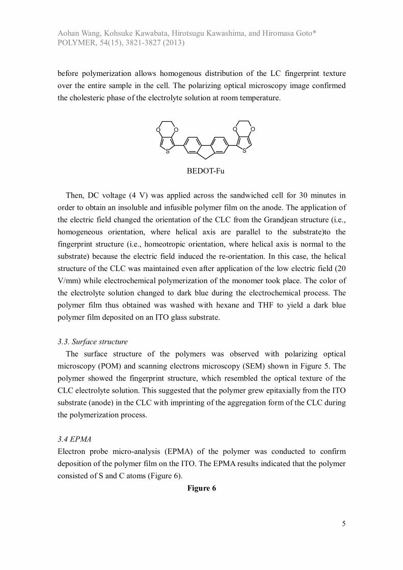
Electrolyte solution containing 6CB, the chiral inducer, monomer (BEDOT-Fu (EDOT-fluorene-EDOT), EDOT = ethylenedioxythiophene), and tetrabutylammonium perchlorate (TBAP) was injected between two transparent ITO glass substrates sandwiched by a 0.20mm-thick Teflon sheet. The molecular structure of the monomer (BEDOT-Fu) is indicated as follows. The synthesis of the BEDOT-Fu was carried out according to the previously reported method [24].The electrolyte solution was heated up to ~80°C to completely dissolve the supporting salt, monomer, and chiral inducer in the 6CB, and cooled down to room temperature(21°C). The injection process produces orientation of LC in the cell. This heating process after completion of the LC injection
Aohan Wang, Kohsuke Kawabata, Hirotsugu Kawashima, and Hiromasa Goto* POLYMER, 54(15), 3821-3827 (2013)
5
before polymerization allows homogenous distribution of the LC fingerprint texture over the entire sample in the cell. The polarizing optical microscopy image confirmed the cholesteric phase of the electrolyte solution at room temperature.
OO
S
OO
S
BEDOT-Fu
Then, DC voltage (4 V) was applied across the sandwiched cell for 30 minutes in order to obtain an insoluble and infusible polymer film on the anode. The application of the electric field changed the orientation of the CLC from the Grandjean structure (i.e., homogeneous orientation, where helical axis are parallel to the substrate)to the fingerprint structure (i.e., homeotropic orientation, where helical axis is normal to the substrate) because the electric field induced the re-orientation. In this case, the helical structure of the CLC was maintained even after application of the low electric field (20 V/mm) while electrochemical polymerization of the monomer took place. The color of the electrolyte solution changed to dark blue during the electrochemical process. The polymer film thus obtained was washed with hexane and THF to yield a dark blue polymer film deposited on an ITO glass substrate. 3.3. Surface structure
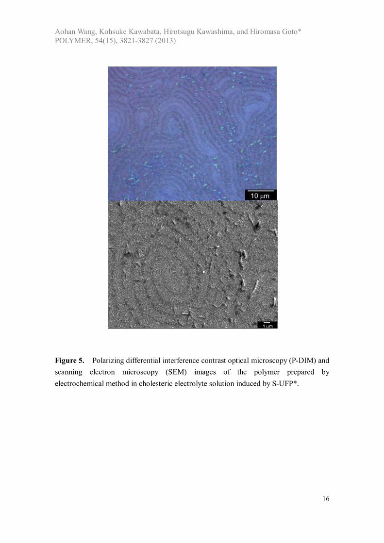
The surface structure of the polymers was observed with polarizing optical microscopy (POM) and scanning electrons microscopy (SEM) shown in Figure 5. The polymer showed the fingerprint structure, which resembled the optical texture of the CLC electrolyte solution. This suggested that the polymer grew epitaxially from the ITO substrate (anode) in the CLC with imprinting of the aggregation form of the CLC during the polymerization process. 3.4 EPMA Electron probe micro-analysis (EPMA) of the polymer was conducted to confirm deposition of the polymer film on the ITO. The EPMA results indicated that the polymer consisted of S and C atoms (Figure 6).
Figure 6
Aohan Wang, Kohsuke Kawabata, Hirotsugu Kawashima, and Hiromasa Goto* POLYMER, 54(15), 3821-3827 (2013)
6
3.5. Electrochemical properties The electrochemical measurements of the polymer film were carried out by cyclic voltammetry. The polymer film was examined at scan rates of 10, 20, 60, 80, 100 mV/s in a monomer-free 0.1 M TBAP/acetonitrile solution. The polymer showed signals at 0.33 V and 0.75 V in the oxidation process, and 0.66 V and 0.23 V in the reduction process, respectively, as shown in Figure 7. This result suggested that an electrochemical two-electron reaction occurred during the redox process. The good electrochemical switching indicated that the polymer adhered well to the electrode.
Figure 7
3.6. UV-vis
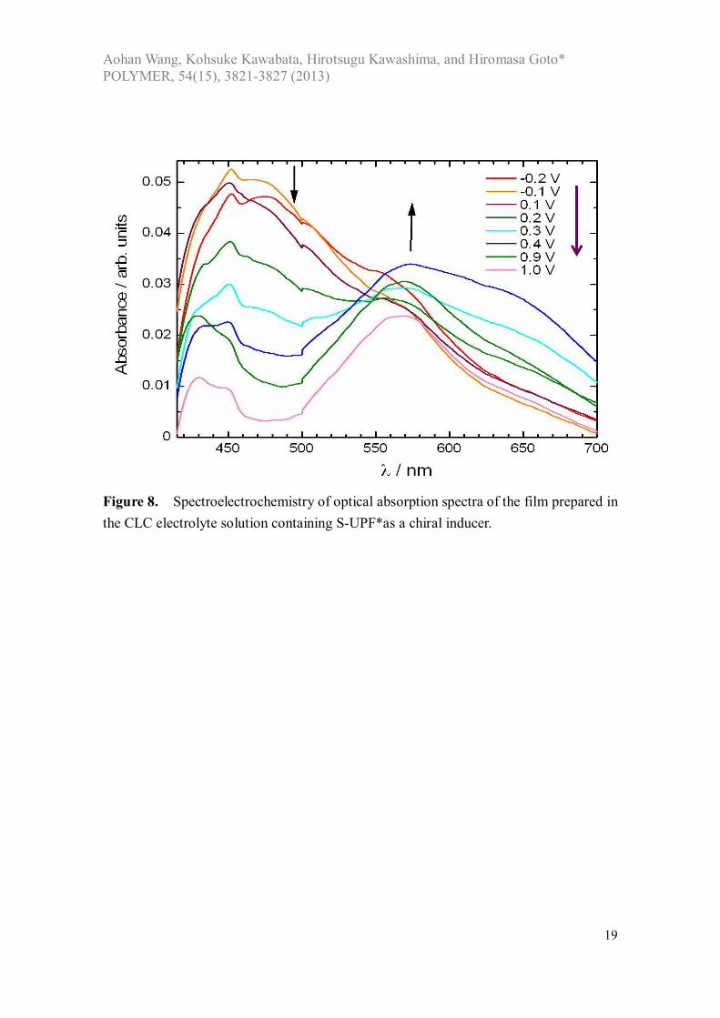
UV-vis optical absorption spectra showed characteristic absorption bands of π-π* transition at short wavelengths (470 nm), as shown in Fig.8. The absorption band at long wavelengths (~570 nm) can be due to generation of polarons (radical cations) in the electrochemical oxidation process. The absorption band at 470 nm decreased accompanied by the appearance of the doping band. Note that the macroscopic fingerprint texture has no relation to electronic transition of the polymer.
Figure 8. 3.7. ORD Asymmetric materials show optical rotation. The plane of the polarization of linearly polarized light is rotated in chiral media. This is one of the most interesting physical properties of chiroptically active thin films. Figure 9 shows optical rotatory dispersion (ORD) for the polymer film at 0.3 V vs. Ag/Ag+. This result indicated that the polymer thus prepared in the CLC was optically active even though the polymer had no chiral centers. This can be due to the fact that the polymer forms a helical structure with structural chirality produced by the electrochemical polymerization in the CLC. The helical structure of the polymer is similar to the helical aggregation structure of the CLC. The polymer imprints the 3-D helical structure of the CLC electrolyte solution in the polymerization process. Therefore, the polymer displayed liquid crystal-like helical aggregation high-ordered structure. The CLC electrolyte solution separated from the polymer during a phase separation process [25], yielding pure polymer film with chiroptical activity.
Figure 9

Aohan Wang, Kohsuke Kawabata, Hirotsugu Kawashima, and Hiromasa Goto* POLYMER, 54(15), 3821-3827 (2013)
7
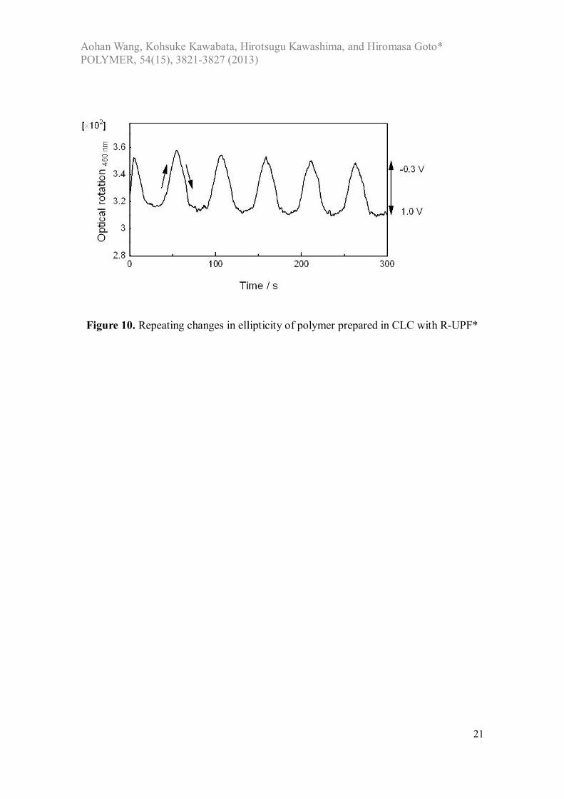
3.8. Repeating redox properties The electro-switching behavior of polymer was examined through observation of changes in the ORD spectra upon repeated changes in applied voltage (Figure 10). Electrochemical repeating voltage scans displayed a repeatable change in optical rotation of the polymer. This result confirmed that the polymer had chiroptical properties. Furthermore, the chiroptical activity could be repeatedly controlled through application of the external electric field.
Figure 10.
3.9. Laser diffraction The polymer showed a diffraction pattern upon irradiation of visible light due to periodic structure of the polymer produced by transcription of structural chiral order of the CLC electrolyte solution. Figure 11 shows laser diffraction pattern obtained upon the irradiation of red laser light. The diffraction occurred with reflected light and transmitted light (Figure 11a). Concentric circle pattern involved the first-order and second-order diffraction with fine several multiplex circles. The first order (m = 1) and second order (m = 2) diffractions were due to the periodic pattern of the fingerprint texture (Figure 11b). The fingerprint lines correspond to helical half-pitch of the helical aggregation structure derived from the CLC electrolyte solution. Fine concentric lines may come from occurrence of multiplex diffraction by the periodicity of fingerprint lines (inter-main chain periodicity) or diffraction of intra-main chain periodicity. The intermolecular helical structure of the polymer provided clear first-order and second-order diffraction, and the periodicity of the intra-helical structure (twisting of individual main chain) may also function as a diffraction grating for producing multiplex circular diffraction pattern. Furthermore, the fine strips may be derived from stimulated emission produced by periodic structure of cholesteric order of the polymer.
These results demonstrate that the polymer film prepared in this study had diffraction properties due to the periodic dielectric microstructure. The grating function was random due to the random alignment of stripes comprising the fingerprint texture.
Figure 11.
4. Conclusions
Pyrimidine mesogen core-based chiroptically active chiral inducers were synthesized for the production of a CLC electrolyte solution. The electrochemical

Aohan Wang, Kohsuke Kawabata, Hirotsugu Kawashima, and Hiromasa Goto* POLYMER, 54(15), 3821-3827 (2013)
8
polymerization afforded chiroptically active polymer films. This result demonstrated that the chirality of the chiral inducer is transferred to resultant polymer via induction of a cholesteric phase of a matrix LC. In other words, chiral amplification via induction of cholesteric phase with structural chirality occurred in the electrochemical polymerization. The highly ordered microstructure was produced by transcription from the three-dimensional helical continuum of the CLC environment.
Performance of the chiral induction depends on molecular shape, affinity, and chirality of the chiral inducers. The development of new chiral inducers opens further possibilities for chiral LC materials. Acknowledgements This research was supported by Japan Society for the Promotion of Science (JSPS), Grant-in-Aid for Scientific Research, 22550161. The pyrimidine based LC precursor materials were generously donated by Midori Chemical (Midori Kagaku), Japan. Techniques The UV-vis absorption spectra were obtained using a Hitachi U-2000 spectrophotometer, and circular dichroism and optical rotation measurements were performed using a Jasco J-720 spectrometer with an ORDE-307W ORD unit. Experimental Optical texture observations were carried out using a Nikon ECLIPS LV-100 high resolution polarizing microscope. The morphology of the polymer film was studied by scanning electron microscopy (SEM) using Hitachi S-5500 microscope. Optical absorption spectra of the polymers were measured using a Jasco V-640 spectrometer equipped with a quartz cell. ORD measurements were performed with a Jasco J-720spectrometerequipped with ORD unit. Cyclic voltammetry (CV) was measured with μAuto Lab III potentiostat (the Netherlands) at various scan rates between 1.0 V and 1.0 V vs. Ag/Ag+ reference electrode. Custom-made function generator and temperature control stage were used for electrochemical polymerization.
Chemicals 4-[2-(2-Fluoro-4-undecyloxy-phenyl)-pyrimidin-5-yl]-phenol (UFP-OH) (Midori Chemical), DEAD (TCI, Japan), and TPP (TCI, Japan) were used without purification. THF was distilled prior to use.

Aohan Wang, Kohsuke Kawabata, Hirotsugu Kawashima, and Hiromasa Goto* POLYMER, 54(15), 3821-3827 (2013)
9
(R)-2-(2-fluoro-4-undecyloxy-phenyl)-5-[4-(1-methyl-heptyloxy)-phenyl]-pyrimidine (R-UFP*) Quantity used. 4-[2-(2-Fluoro-4-undecyloxy-phenyl)-pyrimidin-5-yl]-phenol (UFP-OH, 0.801 g, 1.84 mmol). (S)-octanol (0.2447 g 1.88 mmol). DEAD (40% in toluene, 0.864 mL, 1.83 mmol).TPP (0.501 g, 1.93 mmol). Y = 35.3% (0.355 g, 0.65 mmol). (S)-2-(2-fluoro-4-undecyloxy-phenyl)-5-[4-(1-methyl-heptyloxy)-phenyl]-pyrimidine (S-UFP*) Quantity used. 4-[2-(2-Fluoro-4-undecyloxy-phenyl)-pyrimidin-5-yl]-phenol (UFP-OH) 0.804 g, 1.84 mmol. (R)-octanol (0.252 g, 1.94 mmol). DEAD (40% in toluene, 0.864 mL, 1.83 mmol).TPP (0.493 g, 1.90 mmol).0.501 g, 1.93 mmol). Y = 46.2% (0.465 g, 0.85 mmol). References [1] Dierking I, Textures of Liquid Crystals, 2003 WILEY-VCH. [2] Goto H, Akagi K. Angew Chem Int Ed 2005;44:4322. [3] Link DR, Natale G, Shao R, Maclennan JE, Clark NA, Korblova E, Walba DM. Science 1997;278:1924. [4] Martin PC, Parodi O, Pershan PS. Phys Rev A: Atomic Molecular Opt Phys 1972;6:2401. [5] Pelta J, Duran D, Doucet J, Livolant F. Biophys Jour 1996;71:48. [6] Moore JS, Stupp SI. Macromolecules 1987;20:282. [7] Gin DL, Pecinovsky CS, Bara JE, Kerr RL. Struct Bond 2008;128:181. [8] Savage JR, Caggioni M, Spicer PT, Cohen I. Soft Matter 2010;6:592. [9] Sergeyev S, Pisula W, Geerts YH. Chem Soc Rev 2007;36:1902. [10] Freiser MI, Phys Rev Lett 1970;24:1041. [11] Ewbank PC, Nuding G, Suenaga H, McCullough RD, Shinkai S. Tetrahedron Lett
2001;42:155. [12] Goto H, Togashi F, Tsujimoto A, Ohta R, Kawabata K. Liq Cryst 2008;35:847. [13] Kawabata K, Goto H, Polym Chem 2010;1:1606. [14] Goto H. J Mater Chem 2009;19:4914. [15] Yokoyama Y, Sagisaka T. Chem Lett 1997;8:687. [16] Held GA, Kosbar LL, Dierking I, Lowe AC, Grinstein G, Lee V, Miller RD. Phys
Rev Lett 1997;79:3443. [17] Goto H. Macromolecules 2007;40:1377.
Aohan Wang, Kohsuke Kawabata, Hirotsugu Kawashima, and Hiromasa Goto* POLYMER, 54(15), 3821-3827 (2013)
10
[18] Goto H. Adv Funct Mater 2009;9:1335. [19] Borole DD, Kapadi UR, Mahulikar PP, undiwale DG. Des Mono Polym 2004;7:
337. [20] Turac E, Varol R, Ak M, Sahmetlioglu E, Toppare L. Des Mono Polym
2008;11:309. [21] Beaujuge PM, Ellinger S, Reynolds JR. Nat Mater 2008;7:795. [22] Goto H. J Polym Sci Part A: Polym Chem 2012;50:622. [23] Goto H, Kawabata K. Polym Chem 2011;2:1098. [24] Kawabata K, Goto H. Chem Lett 2009;38:706. [25] Kihara H, Miura T, Kishi R. Macromol Rapid Commun 2004;25:445.

Aohan Wang, Kohsuke Kawabata, Hirotsugu Kawashima, and Hiromasa Goto* POLYMER, 54(15), 3821-3827 (2013)
11
N
NOH
F
O, DEAD, TPP
CH
CH3
HO C6H13
N
NO
F
OC11H23C11H23
*
*
* = stereogenic center, (R) or (S)
THFUFP-OH R-UFPor S-UFP R = 46.2%
S = 35.3%
Scheme 1. Synthesis of chiral inducers

Aohan Wang, Kohsuke Kawabata, Hirotsugu Kawashima, and Hiromasa Goto* POLYMER, 54(15), 3821-3827 (2013)
12
Figure 1 1H-NMR analysis result of R-UFP*
CHCl3

Aohan Wang, Kohsuke Kawabata, Hirotsugu Kawashima, and Hiromasa Goto* POLYMER, 54(15), 3821-3827 (2013)
13
40 60 80 100 120
Heating
CoolingSmC*Ch*
Ch*
Iso*
Iso*
Temperature / Co
End
o.
Exo
.
Figure 2. Differential scanning calorimetry (DSC) curves of S-UFP* (scan rate = 10 ºC/min) (a) (b)

Aohan Wang, Kohsuke Kawabata, Hirotsugu Kawashima, and Hiromasa Goto* POLYMER, 54(15), 3821-3827 (2013)
14
Figure 3. (a,b): Polarizing optical microscopy images of S-UFP*. (a): Oily streaks texture of cholesteric phase (Ch*) at 83 C. (b) Schlieren texture of chiral smectic C phase (SmC*) at 61 C. (c,d): Molecular orientation in liquid crystal phase. (c): Ch* phase. (d): SmC* phase.
Cholesteric phase Chiral smectic C (SmC*) phase
(c)z
(d)
Cooling
Phase transition
Helical axis Helical axis
Laye
r stru
ctur
e

Aohan Wang, Kohsuke Kawabata, Hirotsugu Kawashima, and Hiromasa Goto* POLYMER, 54(15), 3821-3827 (2013)
15
Figure 4. Polarizing optical microscopy images of the chiral inducer S-UFP* in Cano’s wedge cell
Aohan Wang, Kohsuke Kawabata, Hirotsugu Kawashima, and Hiromasa Goto* POLYMER, 54(15), 3821-3827 (2013)
16
Figure 5. Polarizing differential interference contrast optical microscopy (P-DIM) and scanning electron microscopy (SEM) images of the polymer prepared by electrochemical method in cholesteric electrolyte solution induced by S-UFP*.

Aohan Wang, Kohsuke Kawabata, Hirotsugu Kawashima, and Hiromasa Goto* POLYMER, 54(15), 3821-3827 (2013)
17
Figure 6. Electron probe micro analyzer (EPMA) measurements results for polymer. (a) Scanning electron microscopy (SEM) image. (b) Distribution of sulfur atom image. (c) Distribution of carbon atom image.

Aohan Wang, Kohsuke Kawabata, Hirotsugu Kawashima, and Hiromasa Goto* POLYMER, 54(15), 3821-3827 (2013)
18
Figure 7. CV measurements of the film prepared in CLC electrolyte containing S-UFP* at several scan rates.
Aohan Wang, Kohsuke Kawabata, Hirotsugu Kawashima, and Hiromasa Goto* POLYMER, 54(15), 3821-3827 (2013)
19
Figure 8. Spectroelectrochemistry of optical absorption spectra of the film prepared in the CLC electrolyte solution containing S-UPF*as a chiral inducer.

Aohan Wang, Kohsuke Kawabata, Hirotsugu Kawashima, and Hiromasa Goto* POLYMER, 54(15), 3821-3827 (2013)
20
Figure 9. ORD spectra of the film prepared from CLC electrolyte electrolyte containing S-UPF*as a chiral inducer.
Aohan Wang, Kohsuke Kawabata, Hirotsugu Kawashima, and Hiromasa Goto* POLYMER, 54(15), 3821-3827 (2013)
21
Figure 10. Repeating changes in ellipticity of polymer prepared in CLC with R-UPF*

Aohan Wang, Kohsuke Kawabata, Hirotsugu Kawashima, and Hiromasa Goto* POLYMER, 54(15), 3821-3827 (2013)
22
Figure 11. Laser diffraction patterns of polymer prepared in CLC with S-UPF*. (a) Schematic illustration of laser diffraction. (b) Diffraction and stimulated emission like interference pattern upon incident of red laser.
(a)
Incidence of LASER
Reflection with diffraction
Transmission with diffraction
Copyright © 2022 FDOKUMEN