
Synchronous Pipeline Design in Action Systems
24
Synchronous Pipeline Design in Action Systems Tiberiu Seceleanu Juha Plosila Turku Centre for Computer Science TUCS Technical Reports No 403, March 2002
Transcript of Synchronous Pipeline Design in Action Systems

Synchronous Pipeline Design inAction Systems
Tiberiu SeceleanuJuha Plosila
Turku Centre for Computer Science
TUCS Technical Reports
No 403, March 2002


Synchronous Pipeline Design inAction Systems
Tiberiu SeceleanuJuha Plosila
University of Turku, Dep. of Applied Physics,Lab. of Electronics and Information Technology,FIN-20014 Turku, Finland,email: ftiberiu.seceleanu,[email protected]
Turku Centre for Computer ScienceTUCS Technical Report No 403March 2002
ISBN 952-12-0821-XISSN 1239-1891

Abstract
The action systems formalism has recently been applied to the area of asynchron-ous and synchronous VLSI design. In this paper, we study formal aspects of syn-chronous pipelining. We show how the framework of synchronous action systemscan be used to derive a pipelined structure from a non-pipelined specification in acorrectness-preserving manner.

1 Introduction
Pipelining is a very common technique used in digital systems design in orderto increase parallelism. It has an important impact on the rate at which data isproduced and consumed, a pipelined version allowing a higher speed than thenon-pipelined version of the same circuit [8]. For example, in microprocessors,the execution of an instruction is divided into several subtasks each of which con-stitutes a stage of the instruction pipeline. In addition, complex arithmetic oper-ations, such as multiplications, divisions, or combinations of different arithmeticcomputations, are often implemented using pipelining in order to obtain high op-eration speeds. Furthermore, if a computation task is split into sufficiently simplesubtasks, the supply voltage of the circuit can be reduced, still maintaining therequired clock frequency. Hence, pipelining can be utilized in low-power designas well [4, 13]. In our descriptions, pipelining will be reflected in transforminga synchronous system into another synchronous system, with a larger number of(simpler) actions and an equivalent behavior with respect to input or output vari-ables.
Formal methods of concurrent programming become increasingly importantin design of complex VLSI systems. In our earlier work, we have shown how theaction systems formalism [1] can be applied in design of both self-timed [9] andsynchronous circuits [10, 11]. In this paper, we continue our work on synchron-ous modeling by focusing on the formal aspects of clocked pipelining. The actionscomposing a synchronous action system are high-level representations of circuitfunctionality. One single action may actually map on a very complex hardwareimplementation, in terms of the time required to perform. Therefore, the deviceshould operate on a large clock period, situation which, often, does not represent asolution. Thus, a further splitting of the execution of the initial action becomes ne-cessary, reflected further in a pipelined realization of the digital device. Here, wepresent a stepwise procedure by which a non-pipelined synchronous action sys-tem specification is transformed into a pipelined form, in a correctness-preservingmanner.
2 Synchronous action systems
The action systems formalism is based on an extended version of Dijkstra’s lan-guage of guarded commands [6]. This language includes assignment, sequentialcomposition, conditional choice, and iteration.
1

Actions. An action A is defined (for example) by
A ::= x := x0:Q (nondeterministic assignment)j boolean expression ! B (guarded action)j A1 [] A2 (nondeterministic choice)j A1; A2 (sequential composition)j A1 � A2 (simultaneous assignment)
where B, A1, A2 are actions, and Q is a boolean relation which determines thevalue(s) x0 assigned to the (list of) variable(s) x. For example: Q b= x0 = x + y,where y is another variable. The variables updated by a certain action A composethe write set of the corresponding action, and it is denoted by wA. Similarly, thevariables that are only accessed but not modified in value by the action, composethe set of read variables, denoted rA.
Actions are considered atomic, which means that whenever an action is se-lected for execution, it will be completed without interference. They are definedusing weakest precondition predicate transformers [6]. We have for instance that:
wp(x := x0:Q; P ) b= (8x0:Q) P [x0=x])
where the notation P [x0=x] indicates a substitution operation, i.e., the predicateP [x0=x] is obtained from P by replacing every occurrence of x with x0. Thisnotation can be applied to the actions and action systems as well.
The guard gA of an action A is defined by gA b= :wp(A; false). An actionis said to be enabled when its guard is true, disabled otherwise. If the guard isinvariantly true, the action is always enabled. For clarity, we often distinguishactions by using angular brackets ‘<’ and ‘>’.
Synchronous action systems. An action system is a collection of actions per-forming on a list of global (g) and local (l) variables. A synchronous action system[10] contains a synchronous composition of actions (‘r’). It has the form
sys A (g) :: j[ var l; init g; l := g0; l0; do A1 r A2 od ]j
The synchronous composition operator ‘r’ between the actions Ai - always en-abled non-deterministic assignments - creates a two-phase action, where the sim-ultaneous composition of the read parts RAi
of the actions is sequenced in a non-atomic manner with the simultaneous composition of the write parts WAi
of theseactions, or:
A1 r A2 b= < :p! (RA1�RA2
); p := true > (1)
[] < p! (WA1�WA2
); p := false >
2

Here the local boolean variable p, which sequences the read and write phases,is an abstraction of the clock signal. The operator ‘r’ hides also the (lists of)intermediate variables ui assigned by the read parts RAi
and read by the write partsWAi
. Assuming that the actions Ai perform the non-deterministic assignmentsvi := v0i:Qi, the read and write parts are defined as follows:
RAib= ui := u0i:(gAi ) Qi[u
0
i=v0
i]) ^ (:gAi ) u0i = vi); i = 1; 2;
WAib= vi := ui
Further, notice that the synchronous composition of actions is always enabled: iteither performs an update according to the predicate Q or a false update - pre-serving the value of the output variable(s).
Hardware aspects. The hardware representation of a synchronous (two-phase)is represented by a set of registers (D flip-flops), each associated with one of thewrite variables of the action, and the corresponding combinational logic. Thecombinational logic is specified, under all input situations, by the predicate Q.
Synchronous composition of action systems. Two synchronous action systemsA1 andA2 can be composed using the operator ‘r’. The compositionA1 r A2 isdefined to be a synchronous action system which is composed of the actions of theconstituent systems. This system merges the global variables of the componentsAi keeping the local variables distinct.
Refinement of action systems. Actions and action systems are intended to bedeveloped in a stepwise manner within the refinement calculus [2]. We say that anabstract action A is (correctly) refined by the concrete action C, denoted A � C,if the condition wp(A; P )) wp(C; P ) holds for any predicate P .
Refinement of synchronous action systems is mainly based on the theory oftrace refinement [3]. A trace, or a sequence of values of the global variables,represents an observable behavior of a system. An abstract action system A issaid to be (trace) refined by the concrete system C, denoted A v C, if the tracesof A and C are equivalent. Notice that, in a trace, several successive equivalentstates are considered as a single one.
Design of synchronous action systems. The design of synchronous action sys-tems [11] is based on correctly deriving synchronous representations from asyn-chronous action systems. An asynchronous system interacts with its environmentvia an asynchronous communication (handshake) channel, which is composed oftwo boolean variables [7], denoted req and ack (request, acknowledge), and data
3

variables. The values of the data variables are transferred from the system to itsenvironment, or vice versa. The handshake variable req is updated by the mas-ter system which is the active party of communication requesting tasks from theserver system which is the passive party of communication. The variable ack isupdated by the server whenever it has completed a task requested by the mas-ter. Furthermore, the master only reads ack, and the server only reads req. Inour approach, the synchronous system is the server component of an asynchron-ous description and a system that models the environment acts as the master. Weexpress this by means of prioritized composition: Env == Sync:
acknowledge
data
one transact ion
request
Figure 1: The four phase handshake.
We build our design flow on the four-phase signaling protocol [5] (Figure 1).Thus, the master system sets the request line and it holds it until the server systemreplies by setting up the “acknowledge” variable. Then the request is released and,in response, the server resets the acknowledgment line. Notice that a single datais processed in one transaction, and not a block of data (a sequence of incomingdata samples).
In order to perform the translation from an asynchronous to a synchronousrepresentation, the system under analysis has to comply with a set of synchron-ization requirements [11]. Of interest to our present study is the requirement: itis possible to transform a sequence (for instance A1; : : : ;An) into a simultaneousassignment (A1 ? : : : ? An), and from here, into a two-phase action, if actions inthe sequence do not read what other actions, positioned earlier in the sequence,have just updated. Also, notice that the process preserves the existence of thecommunication variables req and ack in the synchronous description.
3 Non-Pipelined vs. Pipelined Systems
Let us analyze the synchronous implementation of the action system
4
sys A (g) ::
j[ var l; init l; g := l0; g0;
do A r B od]j
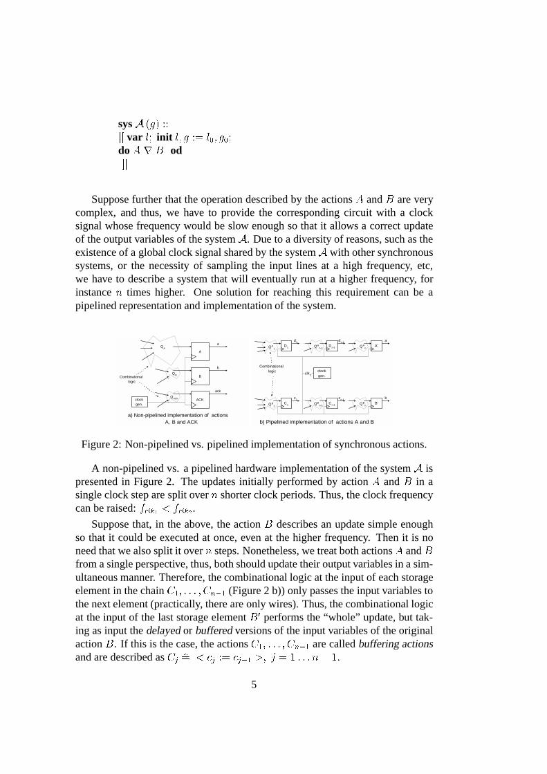
Suppose further that the operation described by the actions A and B are verycomplex, and thus, we have to provide the corresponding circuit with a clocksignal whose frequency would be slow enough so that it allows a correct updateof the output variables of the system A. Due to a diversity of reasons, such as theexistence of a global clock signal shared by the system A with other synchronoussystems, or the necessity of sampling the input lines at a high frequency, etc,we have to describe a system that will eventually run at a higher frequency, forinstance n times higher. One solution for reaching this requirement can be apipelined representation and implementation of the system.
a) Non-pipelined implementation of actionsA, B and ACK
clockgen.
Combinationallogic
A
aQA
B
b
QB
ACK
ack
QACK
b) Pipelined implementation of actions A and B
clockgen.
Combinationallogic
C1QB1
Cn-1QBn-1
c1 cn-1
B'QBn
b
D1QA1
Dn-1QAn-1
d1 dn-1
A'QAn
a
clk2
Figure 2: Non-pipelined vs. pipelined implementation of synchronous actions.
A non-pipelined vs. a pipelined hardware implementation of the system A ispresented in Figure 2. The updates initially performed by action A and B in asingle clock step are split over n shorter clock periods. Thus, the clock frequencycan be raised: fclk1 < fclk2 .
Suppose that, in the above, the action B describes an update simple enoughso that it could be executed at once, even at the higher frequency. Then it is noneed that we also split it over n steps. Nonetheless, we treat both actions A and Bfrom a single perspective, thus, both should update their output variables in a sim-ultaneous manner. Therefore, the combinational logic at the input of each storageelement in the chain C1; : : : ; Cn�1 (Figure 2 b)) only passes the input variables tothe next element (practically, there are only wires). Thus, the combinational logicat the input of the last storage element B0 performs the “whole” update, but tak-ing as input the delayed or buffered versions of the input variables of the originalaction B. If this is the case, the actions C1; : : : ; Cn�1 are called buffering actionsand are described as Cj b= < cj := cj�1 >; j = 1 : : : n� 1:
5

4 Pipelined Synchronous Action Systems
In the following, we first introduce notions and procedures that will help us de-velop a method of transforming a synchronous action system from a non-pipelinedinto a pipelined format. We continue by describing the actual procedure of obtain-ing a pipelined synchronous action system, followed by an illustrative example.
4.1 Local variable introduction
In this section, we adapt the local variable introduction rule presented in [2] to ourspecific purposes. Consider the action system:
sys A (g) ::
j[ var l; init g; l := g0; l0;
do A od]j
where A b= < a := a0:Qa >; a 2 g.We introduce a new local variable b, updated as specified by the predicate Qb
of action B :
B b= < b := b0:Qb >
At the system level we have
A v A1;l0 b= l [ fbg;sys A1
(g) ::
j[ var l0; init g; l0 := g0; l0
0;
do A;B od]j
If the variable a does not appear free in Qb, that is, if action B does not readthe updated variable a, then we can transform the sequence A;B of the abovesystem A1 into A ? B :
A;B � A ? B;
A1 v A2;
sys A2(g) ::
j[ var l0; init g; l0 := g0; l0
0;
do A ? B od]j
Hence, we can directly introduce new variables by either extending a simul-taneous assignment (in the case this already existed), or by creating it, as in the
6

situation of systemA2. Notice also that A is not supposed to be the only action ofthe initial system A: Thus, A can be part of a more complex construct within themain loop of the system.
Next, we extend the local variable introduction technique, now in the contextof a synchronous system. Consider
sys Sync (g) ::j[ var l; init g; l := g0; l0;
do A r B od]j;A b= < a := a0:Qa >;
B b= < b := b0:Qb >
At the choice level, we have
sys Sync (g) ::j[ var l; p; uA; uB; init g; l; p; uA; uB := g0; l0; false; a; b;
do < :p! RA ? RB; p := true >
[] < p! WA ? WB; p := false >
od]jRA b= < ua := u0a:Qa[u
0
a=a0] >;
RB b= < ub := u0b:Qb[u0
b=b0] >;
WA b= < a := ua >;WB b= < b := ub >
We intend to introduce a new local variable c. The action C is updating thenew variable and is executed synchronously with the other actions, A and B.Thus, we also need an intermediate variable (uC) for the two-phase modellingof C. We apply twice the previously discussed results, for the introduction ofthe intermediate variable uc and the variable c, respectively. We then have thefollowing system description:
Sync v Sync1;sys Sync1 (g) ::j[ var l; p; c; uA; uB; uC;
init g; l; p; c; uA; uB; uC := g0; l0; false; c0; a; b; c0;
do < :p! RA ? RB ? RC ; p := true >[] < p! WA ? WB ?WC ; p := false >
od]j;RC b= < uc := u0c:Qc[u
0
c=c0] >;
WC b= < c := uc >
7

Using the definition of a two phase action (1), we further represent the systemas
sys Sync1 (g) ::j[ var l; c; init g; l := g0; l0; c0;
do A r B r C od]j
4.2 Elimination of a local variable
Elimination of a local variable can often help simplifying the description of asystem. Related to hardware implementation issues, this can be viewed also asa reduction in signal lines and area of the device. We intend to apply the rulesof eliminating local variables [2] to a synchronous composition of actions. Thus,we need to check only one of the requirements: the variable to be eliminatedappears solely in assignments to itself, or, in other words, it is a ghost variable.If this happens, then we can eliminate the variable from the synchronous system,together with the action that updates it.
4.3 Pipelining procedure
Let us consider now a synchronous action system, A, together with the environ-ment, Env. We have the composition Env == A and sys A contains the actionACK that updates the acknowledge signal ack :
sys A (req; ack : bool; x; y; a; b : data) ::
j[ var l; init l; x; : : : ; b := l0; x0; : : : ; b0; req; ack := false
do A r B r ACK od (1)
]j;
where
A b= < a := a0:QA >; QA b= (req ) Qa) ^ (:req ) a0 = a);B b= < b := b0:QB >; QB b= (req ) Qb) ^ (:req ) b0 = b);
ACK b= < ack := ack0:QK >; QK b= (req ) ack0 = true)^(:req ) ack0 = false)
Let us now assume that the direct circuit implementation of the actions A andB of the systemA is estimated to be so complex that it cannot be operated with thespecified clock frequency. Then the computations of A and B have to be dividedinto n (n > 1) phases each of which is simple enough to be executed in one clockcycle. A set of n � 1 new local variables is introduced for every action we split,in order to store the results of each phase. The combinational logic that updates
8

the variable ack is a very simple construct. Consequently, the update is possibleto be completed in a single clock step. Therefore, the update on the variable ackis only delayed but not split over n stages.
For simplicity, in the description of systemA, we consider that rA = x; wA =
a; rB = y; wB = b. Naturally, rACK = req and wACK = ack. Thus, thepredicate QA is a relation on a0 and x, etc.
Pre-analysis step. Intuitively, the first step in dividing the actionA into n pipelinedactions is to transform it locally into the atomic n-element sequence:
A � A0;
A0b= A0; : : : ;An�1;
Aj b= < aj := a0j:Qja >; j = 0; : : : ; n� 1; an�1 = a
The above refinement requires that
(Q0
a ^Q1
a[a0
0=a0] ^ � � � ^Qn�1
a [a0n�2=an�2]) � QA
Each action of the sequence A0 reads the values of the variables updated by theprevious action in the sequence. Thus, it is not possible to obtain a synchronousrepresentation of the action A0 (for instance A0 r : : : r An�1), as the composingactions breach the mentioned synchronization requirement (section 2). However,this study is necessary as it indicates what the relations Qj
a; j = 0 : : : n�1 are (inother words, it shows how to split the execution of action A). They will be usedin the following steps, when we describe the transformation of the system A intoan equivalent pipelined system. Observe that a similar procedure is to be appliedto action B, too.Step 1. Buffering. We start the transformation of the action system (1) by intro-ducing 3 � (n � 1) variables, (n � 1) of which will help us obtain the pipelinedversion of each action in the system. Consequently, we also have 3 � (n� 1) newactions. Initially we only modify the original actions so that they have as input thenew local variables, instead of the initial global variables. We have:
sys A1(req; ack : bool; x; y; a; b : data) ::
j[ var l; a0; : : : ; an�2; b0; : : : ; bn�2; req0; : : : ; reqn�2;
init l; x; : : : ; b := l0; x0; : : : ; b0;
req; ack; req0; : : : ; reqn�2 := false;
a0; b0; : : : ; an�2; bn�2 := a00 ; b00 ; : : : ; an�20; bn�20
;
do A0 r A0 : : :r An�2
rB0 r B0 : : :r Bn�2
rACK 0 r ACK0 : : :r ACKn�2
od]j;
9
where
A0b= A[an�2; reqn�2=x; req];
B0b= B[bn�2; reqn�2=y; req];
ACK 0b= ACK[reqn�2=req]
and the new (buffering) actions are
A0 b= < a0 := x >;
B0 b= < b0 := y >;
ACK0 b= < req0 := req >;
Sj b= < sj := sj�1 >;
s 2 fa; b; reqg; S 2 fA;B;ACKg; j = 1 : : : n� 2
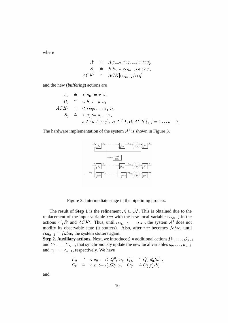
The hardware implementation of the system A1 is shown in Figure 3.
clockgen.
req
clk
A0
xAn-2
x0 xn-2
A'a
QA
B0
yBn-2
y0 yn-2
B'b
QB
ACK 0QKACK n-2
req 0 req n-2
ACK'
ack
Figure 3: Intermediate stage in the pipelining process.
The result of Step 1 is the refinement A v A1: This is obtained due to thereplacement of the input variable req with the new local variable reqn�2 in theactions A0; B0 and ACK 0. Thus, until reqn�2 = true; the system A1 does notmodify its observable state (it stutters). Also, after req becomes false, untilreqn�2 = false, the system stutters again.Step 2. Auxiliary actions. Next, we introduce 2�n additional actionsD0; : : : ; Dn�1
and C0; : : : ; Cn�1, that synchronously update the new local variables d0; : : : ; dn�1
and c0; : : : ; cn�1, respectively. We have
D0 b= < d0 := d00:Q0
D >; Q0
D b= Q0
a[d0
0=a0
0];
C0 b= < c0 := c00:Q0
C >; Q0
C b= Q0
b [c0
0=b0
0]
and
10

For j = 0 : : : n � 1; the actions Dj and Cj update the corresponding outputvariables as specified by the predicates selected in the pre-processing step:
Dj b= < dj := d0j:QjD >;
QjD b= (reqj�1 ) Qj
a[d0
j=a0
j]) ^ (:reqj�1 ) d0j = dj);
Cj b= < cj := c0j:QjC >;
QjC b= (reqj�1 ) Qj
b[c0
j=b0
j]) ^ (:reqj�1 ) c0j = cj)
At the system level we have, based on the results of section 4.1, sys A1 vsys A2; where A2 is described as
sys A2(req; ack : bool; x; y; a; b : data) ::
j[ var l; a0; b0; req0; d0; c0 : : : ; an�2; bn�2; reqn�2; dn�1; cn�1;
init l; x; : : : ; b := l0; x0; : : : ; b0;
req; ack; req0; : : : ; reqn�2 := false;
a0; b0 : : : ; an�2; bn�2 := a00 ; b00 : : : ; an�20; bn�20
;
d0; c0 : : : ; dn�2; cn�2 := d00; c00 : : : ; dn�20; cn�20
;
do A0 r A0 : : :r An�2 rB0 r B0 : : :r Bn�2
rACK 0 r ACK0 : : :r ACKn�2
r C0 : : :r Cn�1 r D0 : : :r Dn�1
od]j
Step 3. Removal of auxiliary variables. The final description. Next, noticethat
req ^ reqn�2 ) (Qn�1
D [a=dn�1] � QA[an�2; reqn�2=x; req])
^ (Qn�1
C [b=bn�1] � QB[bn�2; reqn�2=y; req])
The interpretation of the above relation is as follows. The update on variablea; either according to QA, or to Qn�1
D , leads to the same result. Therefore, we canwrite
A0 � A00; A00b= Dn�1[a=dn�1];
B0 � B00; B00b= Cn�1[b=cn�1]
From the above relations, it follows further that the variables an�2; bn�2 be-came ghost variables. Thus, we can safely eliminate them from the system de-scription, together with the actions that update them. We repeat this procedure forthe variables aj; bj (j = n�3 : : : 0) and for the corresponding actions. Eventuallywe come to the system:
11

A2 v A3;
sys A3(req; ack : bool; x; y; a; b : data) ::
j[ var l; req0; d0; c0 : : : ; reqn�2; dn�1; cn�1;
init l; x; : : : ; b := l0; x0; : : : ; b0;
req; ack; req0; : : : ; reqn�2 := false;d0; c0 : : : ; dn�2; cn�2 := d00 ; c00 : : : ; dn�20
; cn�20;
do A00 r B00
r D0 : : :r Dn�2 r C0 : : :r Cn�2
rACK 0 r ACK0 : : :r ACKn�2
od]j
The implementation of the system A3 is shown in Figure 4.
clockgen.
Combinationallogic
req
D0reqx
Dn-2
d0 dn-2
A''QA[dn-2,req n-2/x,req]
a
clk2
C0req
QC0 Cn-2
QCn-2
c0
B''b
ACK 0QKACK n-2
req 0 req n-2
ACK'
ack
y
QD0 QD
n-2
QB[cn-2,req n-2/y,req]
cn-2
Figure 4: The system A3 in hardware.
Comments. The above procedure helps only towards obtaining a pipelined de-scription of a certain synchronous action system. This mainly means that theimplementation of the specific system can operate at higher frequencies. As thecommunication protocol is preserved, there is no change in the way the system isobserved by the other systems. This indicates, for instance, that we cannot, yet,take advantage of the pipeline representation, for processing block data input. Inorder to get improved results with respect to the throughput of the whole design,the systems that interact with the just pipelined system have to be modified ac-cordingly. This further step is dependent on the particular device that we want todescribe and implement, it implies a modification of the communication protocol,and it is subject of forthcoming studies.
The buffering of the action ACK is important not only because the outputsof the system have to be simultaneously updated. The intermediate variablesreqj; j = 0 : : : n � 2, delayed copies of req, help us in controlling the phaseof the operation and provide a way to obtain a correct transition into the pipelinedversion.
12

5 Example
In this section we present a simple exemplification of obtaining a pipelined versionof a synchronous system. We only show the straightforward way to follow. Thisis, of course, based on the detailed analysis described in the previous section.
Consider the synchronous system
sys Sync (req; ack : bool; a; b : integer) ::
j[ init a; b := 1; 0; req; ack := false;
A r B r ACK
]j
where:
A =< a := a0:QA >; QA = (req ) a0 = (a+ 2) � 4 + 4)
^ (:req ) a0 = a);B =< b := b0:QB >; QB = (req ) b0 = b + 1)
^ (:req ) b0 = b);ACK =< ack := ack0:QK >; QK = (req ) ack0 = true)
^ (:req ) ack0 = false)
For the purpose of exemplification, let us consider that the execution ofA takesa longer time than the execution of B (depending on the width of the bit repres-entation of a and b, this might even be true, but not in a dramatic manner). Forinstance, suppose we want a four times higher operating frequency, than the onethat would allow the operations described by action A to complete. Consequently,we have to split the execution of action A into four stages (n = 4). We considerthat the implementation of action B is not that complex, hence, it is possible toperform with the new, faster frequency.
The pre-process analysis gives us the following sequence:
A0= A0;A1;A2;A3;
A0 b= < a0 := a00:Q0
a >; Q0
a b= (a00= a+ 2);
A1 b= < a1 := a01:Q1
a >; Q1
a b= (a01= a0 � 2);
A2 b= < a2 := a00:Q2
a >; Q2
a b= (a02= a1 � 2);
A3 b= < a3 := a03:Q3
a >; Q3
a b= (a03= a2 + 4)
From here we can directly obtain the pipelined version of the system Sync as:
13

sys SyncP (req; ack : bool; a; b : integer) ::
j[ var d0; d1; d2; b0; : : : ; req2;init a; b := 1; 0; req; ack; req0; req1; req2 := false;
d0; : : : ; b3 := d00; : : : ; b30 ;do A00 rD0 r D1 r D2
r B0 r B0 r B1 r B2
r ACK 0 r ACK0 r ACK1 r ACK2
od]j;
where
A00b= < a = a0:((req2 ) a0 = d2 + 4) ^ (:req2 ) a0 = d2 >;
B0b= < b := b0:((req2 ! b0 = b2 + 1) ^ (:req2 ) b0 = b)) >;
ACK 0b= < ack := ack0:((req2 ) ack := true)
^ (:req2 ) ack := false)) >
and
D0 = < d0 := d00:Q0
D >; Q0
D = (req ) d00= a + 2) ^ (:req ) d0
0= d0);
D1 = < d1 := d01:Q1
D >; Q1
D = (req0 ) d01= d0 � 2) ^ (:req0 ) d0
1= d1);
D2 = < d2 := d02:Q2
D >; Q2
D = (req1 ) d02= d1 � 2) ^ (:req1 ) d0
2= d2)
The actions Bj; ACKj j = 0 : : : 2 are buffering actions as described in previousparagraphs.
The hardware implementation of the system SyncP is shown in Figure 5.
clockgen.
Combinationallogic
req
D0req
d0 := a + 2 D2req
d2 := d 1 * 2
d0 d2
A''req
a := d 2 + 4
a
clk2
C1b0 := b Cn-1req
b2 := b 1
b1 b2
B''req
b := b 2+ 1
b
ACK 0ack :=reqACK n-2
ack 0 ack 2
ACK'
ack
Figure 5: Pipeline example.
6 Synchronous Systems
In this section we shortly take into consideration a possible representation of theenvironment as a synchronous system, too. Thus, the composition that we ana-lyze is Env r Sync. Suppose that we still have, from earlier design stages, a
14
communication channel shared by the two systems. The system Sync operates asspecified in previous sections, or it may operate on a gated clock basis [12].
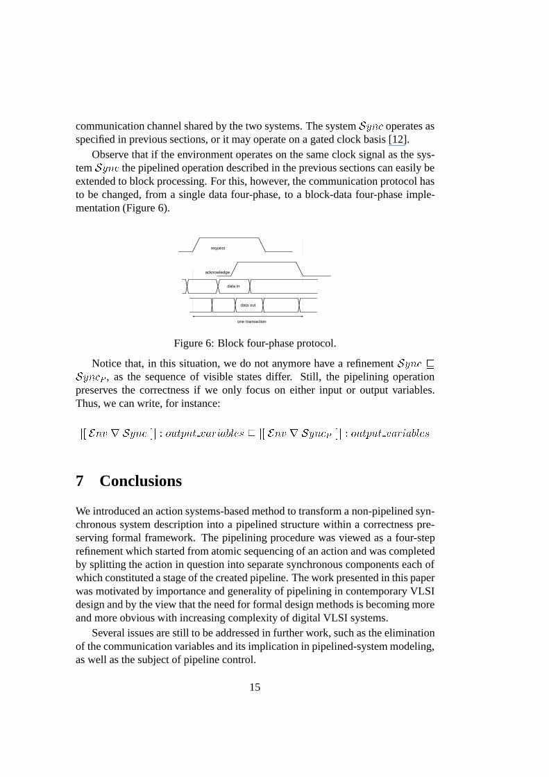
Observe that if the environment operates on the same clock signal as the sys-tem Sync the pipelined operation described in the previous sections can easily beextended to block processing. For this, however, the communication protocol hasto be changed, from a single data four-phase, to a block-data four-phase imple-mentation (Figure 6).
acknowledge
data in
one transaction
request
data out
Figure 6: Block four-phase protocol.
Notice that, in this situation, we do not anymore have a refinement Sync vSyncP , as the sequence of visible states differ. Still, the pipelining operationpreserves the correctness if we only focus on either input or output variables.Thus, we can write, for instance:
j[ Env r Sync ]j : output variables v j[ Env r SyncP ]j : output variables
7 Conclusions
We introduced an action systems-based method to transform a non-pipelined syn-chronous system description into a pipelined structure within a correctness pre-serving formal framework. The pipelining procedure was viewed as a four-steprefinement which started from atomic sequencing of an action and was completedby splitting the action in question into separate synchronous components each ofwhich constituted a stage of the created pipeline. The work presented in this paperwas motivated by importance and generality of pipelining in contemporary VLSIdesign and by the view that the need for formal design methods is becoming moreand more obvious with increasing complexity of digital VLSI systems.
Several issues are still to be addressed in further work, such as the eliminationof the communication variables and its implication in pipelined-system modeling,as well as the subject of pipeline control.
15

References
[1] R. J. R. Back and K. Sere. Stepwise refinement of action systems. StructuredProgramming, 12:17-30,1991.
[2] R. J. R. Back and J. von Wright. Refinement calculus: A Systematic Intro-duction. Springer-Verlag. April 1998.
[3] R. J. R. Back and J. von Wright. Trace refinement of action systems. InB. Jonsson and J. Parrow, editors, CONCUR’94: Concurrency Theory, 5thInternational Conference, Uppsala, Sweden, August 1994, volume 836 ofLecture Notes in Computer Science. Springer–Verlag, 1994.
[4] W. Dally and J. Poulton. Digital Systems Engineering. Cambridge UniversityPress, 1998.
[5] A. Davis and S. M. Nowick. Asynchronous circuit design: motivation, back-ground and methods. In G. Birtwistle and A. Davis, editors, AsynchronousDigital Circuit Design, pages 1-49. Springer, 1995.
[6] E. W. Dijkstra. A Discipline of Programming. Prentice-Hall International,1976.
[7] J. C. Ebergen, J. Segers, I. Benko. Parallel Program and Asynchronous Cir-cuit Design. Asynchronous Digital Circuit Design, Graham Birtwistle and AlDavis (eds.), Springer, 1995.
[8] G. De Micheli. Synthesis and Optimization of Digital Circuits. McGraw-HillInternational Editions, 1994.
[9] J. Plosila. Self-Timed Circuit Design - The Action Systems Approach. Ph.D.Thesis, University of Turku, Dept of Applied Physics, Turku, Finland, 1999.
[10] J. Plosila and T. Seceleanu. Modeling synchronous action systems. In Proc.of the 17
th NORCHIP Conference, Oslo, Norway, pages 242-248. November1999.
[11] J. Plosila, T. Seceleanu. Design of Synchronous Action Systems. The 12th
International Conference on VLSI Design, Goa, India, 1999. In Proceedingsof The 13
th International Conference on VLSI Design, January 2000, pages578-583.
16

[12] T. Seceleanu, J. Plosila. Formal Representation of Gated Clock Designs.In Proceedings of The 13
th Annual IEEE International ASIC / SOC Confer-ence Systems-On-Chip in the Internet Age, Washington DC, USA, September2000, pages 352-356.
[13] J. M. Rabaey. Digital Integrated Circuits - A Design Perspective. Prentice-Hall International, 1996.
17


Turku Centre for Computer ScienceLemminkaisenkatu 14FIN-20520 TurkuFinland
http://www.tucs.fi
University of Turku� Department of Information Technology� Department of Mathematical Sciences
Abo Akademi University� Department of Computer Science� Institute for Advanced Management Systems Research
Turku School of Economics and Business Administration� Institute of Information Systems Science