Surface plasmon polaritons in generalized slab heterostructures with negative permittivity and...
11
Surface plasmon polaritons in generalized slab heterostructures with negative permittivity and permeability Kosmas L. Tsakmakidis, Christian Hermann, Andreas Klaedtke, Cécile Jamois, and Ortwin Hess Advanced Technology Institute, School of Electronics and Physical Sciences, University of Surrey, Guildford, GU2 7XH, United Kingdom Received 6 September 2005; revised manuscript received 2 December 2005; published 9 February 2006 We present a detailed analytical study of surface plasmon polaritons SPPs in generalized asymmetric slab waveguides with a core of negative permittivity and permeability. Profiting from the duality principle, we confine ourselves to the analysis of p-polarized TM SPP eigenmodes, which also occur in thin metallic films. It is shown that the left-handed LH structures considered here support a richer variety of SPPs when compared to their metallic counterparts. Depending on the refractive index distribution, the permittivity of each medium and the thickness of the core, a total of 30 solutions to the involved characteristic equation are identified in a unified manner and classified systematically. In order to identify conclusively all SPPs, we follow an analytical methodology based directly on the solution constraints inherent in the associated transcen- dental equation. This treatment reveals striking features of the formed SPP eigenmodes, such as the existence of “supermodes” when no SPP is supported at one of the slab interfaces. Moreover, our study reveals the opening of gaps in the SPP dispersion diagrams, occurrence of monomodal propagation for specific choices of the material parameters, presence of SPPs with no cutoff thickness and coexistence of three eigenmodes, with double mode-degeneracy points occurring twice. The eigenmodes with negative energy flux that give rise to negative group velocity are identified via a closed-form expression for the time-averaged power flow P in the guide. For each eigenmode, we examine the variation of P with the reduced slab thickness and discuss key features of the effective index geometric dispersion diagram, most of which are unique to the generalized structures studied herein. DOI: 10.1103/PhysRevB.73.085104 PACS numbers: 41.20.Jb, 42.82.Et, 78.20.Ci I. INTRODUCTION Structures exhibiting negative permittivity and permeabil- ity were first analyzed around 40 years ago by Veselago. 1 He coined for their description the term “left-handed LH ma- terials” to stress that the electric field E, the magnetic field H, and the wave vector k of a monochromatic plane wave inside such materials form a left-handed triplet. Veselago hy- pothesized that a material of this kind could exist without contradicting any of the fundamental laws of physics and he showed that it would posses striking electromagnetic proper- ties, such as inverse Doppler shift, antiparallel phase and group velocities, backward power flow, and negative refrac- tion. Critical issues, such as the actual occurrence of negative refraction 2 and the possibility to enhance the evanescent waves, 3,4 have been elucidated lately in a series of theoretical, 5 numerical, 6 and experimental 7 investigations. How to construct these metamaterials was not known un- til recently due to the absence of naturally occurring or arti- ficial materials with negative magnetic permeability. Practi- cal suggestions of how LH media could be realized experimentally were first given in a series of works by Pen- dry et al., 8 who also predicted theoretically that these media could be used for the creation of a “perfect lens.” After these insights, the physical construction of a composite LH struc- ture has been demonstrated by Shelby et al., 9 and the possi- bility of achieving subwavelength resolution of an object with the same structures has been shown with further experiments. 10 The perfect-lens action mentioned before relies critically on the amplification of an object’s near field in a surface wave SW-like manner inside a LH slab. Due to momentum mismatch, radiative waves cannot couple directly to the formed SWs or surface polaritons at the interfaces of the slab with positive-index media. Pendry, however, showed that the near field of an object, which describes its finest features and decays exponentially away form the source evanescent, can couple to an exponentially increasing field inside the LH slab that decays similarly on the other side. The whole field pattern resembles that of a surface polariton, although the proof of its existence for the particular sym- metrical structure considered by Pendry was not given in Ref. 3, as well as in other more detailed analyses. 11 Generalizations of these studies were investigations of asymmetric LH slab configurations for lensing, 12 sensoring and directional coupling 13 applications. In both cases, the role of the coupled surface polaritons at the two interfaces of the slab waveguide was shown to be of crucial importance. For the first class of applications, the asymmetry helped to improve the limit imposed on the image resolution by the losses of the core. For the second class it improved the am- plification of the evanescent waves in the device-working region, leading to enhanced performance. It is the purpose of this paper to identify and classify all surface plasmon 14 polariton SPP eigenmodes supported by generalized asymmetric slab heterostructures. To this end, a rigorous analytical study is pursued that proves that a total of 30 solutions to the involved characteristic equation giving the SPP eigenmodes can exist for all choices of the refractive index distribution, constitutive parameters and , and the thickness of the core. Such an approach is essential, 15 par- ticularly for the investigation of asymmetric slab configura- PHYSICAL REVIEW B 73, 085104 2006 1098-0121/2006/738/08510411/$23.00 ©2006 The American Physical Society 085104-1
-
Upload
independent -
Category
Documents
-
view
5 -
download
0
Transcript of Surface plasmon polaritons in generalized slab heterostructures with negative permittivity and...

Surface plasmon polaritons in generalized slab heterostructures with negative permittivityand permeability
Kosmas L. Tsakmakidis, Christian Hermann, Andreas Klaedtke, Cécile Jamois, and Ortwin HessAdvanced Technology Institute, School of Electronics and Physical Sciences, University of Surrey, Guildford, GU2 7XH, United Kingdom
�Received 6 September 2005; revised manuscript received 2 December 2005; published 9 February 2006�
We present a detailed analytical study of surface plasmon polaritons �SPPs� in generalized asymmetric slabwaveguides with a core of negative permittivity and permeability. Profiting from the duality principle, weconfine ourselves to the analysis of p-polarized �TM� SPP eigenmodes, which also occur in thin metallic films.It is shown that the left-handed �LH� structures considered here support a richer variety of SPPs whencompared to their metallic counterparts. Depending on the refractive index distribution, the permittivity of eachmedium and the thickness of the core, a total of 30 solutions to the involved characteristic equation areidentified in a unified manner and classified systematically. In order to identify conclusively all SPPs, wefollow an analytical methodology based directly on the solution constraints inherent in the associated transcen-dental equation. This treatment reveals striking features of the formed SPP eigenmodes, such as the existenceof “supermodes” when no SPP is supported at one of the slab interfaces. Moreover, our study reveals theopening of gaps in the SPP dispersion diagrams, occurrence of monomodal propagation for specific choices ofthe material parameters, presence of SPPs with no cutoff thickness and coexistence of three eigenmodes, withdouble mode-degeneracy points occurring twice. The eigenmodes with negative energy flux that give rise tonegative group velocity are identified via a closed-form expression for the time-averaged power flow P in theguide. For each eigenmode, we examine the variation of P with the reduced slab thickness and discuss keyfeatures of the effective index geometric dispersion diagram, most of which are unique to the generalizedstructures studied herein.
DOI: 10.1103/PhysRevB.73.085104 PACS number�s�: 41.20.Jb, 42.82.Et, 78.20.Ci
I. INTRODUCTION
Structures exhibiting negative permittivity and permeabil-ity were first analyzed around 40 years ago by Veselago.1 Hecoined for their description the term “left-handed �LH� ma-terials” to stress that the electric field E, the magnetic fieldH, and the wave vector k of a monochromatic plane waveinside such materials form a left-handed triplet. Veselago hy-pothesized that a material of this kind could exist withoutcontradicting any of the fundamental laws of physics and heshowed that it would posses striking electromagnetic proper-ties, such as inverse Doppler shift, antiparallel phase andgroup velocities, backward power flow, and negative refrac-tion. Critical issues, such as the actual occurrence of negativerefraction2 and the possibility to enhance the evanescentwaves,3,4 have been elucidated lately in a series oftheoretical,5 numerical,6 and experimental7 investigations.
How to construct these metamaterials was not known un-til recently due to the absence of naturally occurring or arti-ficial materials with negative magnetic permeability. Practi-cal suggestions of how LH media could be realizedexperimentally were first given in a series of works by Pen-dry et al.,8 who also predicted theoretically that these mediacould be used for the creation of a “perfect lens.” After theseinsights, the physical construction of a composite LH struc-ture has been demonstrated by Shelby et al.,9 and the possi-bility of achieving subwavelength resolution of an objectwith the same structures has been shown with furtherexperiments.10
The perfect-lens action mentioned before relies criticallyon the amplification of an object’s near field in a surface
wave �SW�-like manner inside a LH slab. Due to momentummismatch, radiative waves cannot couple directly to theformed SWs �or surface polaritons� at the interfaces of theslab with positive-index media. Pendry, however, showedthat the near field of an object, which describes its finestfeatures and decays exponentially away form the source�evanescent�, can couple to an exponentially increasing fieldinside the LH slab that decays similarly on the other side.The whole field pattern resembles that of a surface polariton,although the proof of its existence for the particular sym-metrical structure considered by Pendry was not given inRef. 3, as well as in other more detailed analyses.11
Generalizations of these studies were investigations ofasymmetric LH slab configurations for lensing,12 sensoringand directional coupling13 applications. In both cases, therole of the coupled surface polaritons at the two interfaces ofthe slab waveguide was shown to be of crucial importance.For the first class of applications, the asymmetry helped toimprove the limit imposed on the image resolution by thelosses of the core. For the second class it improved the am-plification of the evanescent waves in the device-workingregion, leading to enhanced performance.
It is the purpose of this paper to identify and classify allsurface plasmon14 polariton �SPP� eigenmodes supported bygeneralized asymmetric slab heterostructures. To this end, arigorous analytical study is pursued that proves that a total of30 solutions to the involved characteristic equation givingthe SPP eigenmodes can exist for all choices of the refractiveindex distribution, constitutive parameters � and �, and thethickness of the core. Such an approach is essential,15 par-ticularly for the investigation of asymmetric slab configura-
PHYSICAL REVIEW B 73, 085104 �2006�
1098-0121/2006/73�8�/085104�11�/$23.00 ©2006 The American Physical Society085104-1

tions, because the graphical methodologies that have beenproposed in the past for the modal analysis of LHwaveguides12 did not reveal all SPP eigenmodes. A suitablymodified form of the associated transcendental equation, de-rived from macroscopic electrodynamics using the well-known boundary conditions for the tangential electric andmagnetic-field components, obviates this limitation and al-lows an analytical, unified treatment. We will confine our-selves to the discussion of the geometric dispersion �SPPeffective index versus reduced slab thickness� since negativematerial parameters occur near resonances; hence, all experi-mental realizations of LH materials considered thus far werefor narrowbands. In addition, all transmission �lensing�analyses of LH slab heterostructures, as well as investiga-tions of asymmetric LH �Ref. 13� and metallic15,16 films inthe past, involved mainly monochromatic waves. All the im-portant modal features, such as the number and classificationof modes, number and kind of cutoffs, field enhancement,phase reversal, and possible double mode-degeneracy occur-rence, can be derived in a clear and conclusive way follow-ing this methodology.
The organization of the paper is the following. Section IIwill make some introductory remarks regarding SPP wavesat a single interface between a right-handed �RH� and a LHmaterial. Emphasis is given on the conditions for the exis-tence of such waves, as these are used later when the effectsof retardation are taken into account. Section III is devoted tothe discussion of the SPP eigenmodes supported by an asym-metric slab waveguide with a negative refractive index core.Following a macroscopic analysis, the LH waveguide istreated as a boundary value problem. Special solutions of thescalar wave equation are sought, subject to boundary condi-tions, to obtain the characteristic equation of the SPP eigen-modes. From the restrictions inherent in this equation, whichdepend on the refractive index distribution, we identify allsupported SPP eigenmodes and classify them as forward orbackward propagating via a closed-form expression for thetotal power flow P in the guide. Finally, Sec. IV summarizesthe paper presenting the main conclusions of the presentstudy.
II. SURFACE PLASMON POLARITONS AT A PLANELH/RH INTERFACE
The negative permittivity and permeability of a left-handed medium �LHM� allows the existence of surfacewaves �SWs�, also called surface polaritons �SPs�, at the in-terface with a right-handed medium �RHM�.17 In order toinvestigate these solutions and derive the conditions for theirexistence, we consider the geometry illustrated in Fig. 1.Here both media are considered to be semi-infinite,homogeneous11 and isotropic.18 Medium 1 has negative rela-tive permittivity �r1=−�r1p�0 and permeability �r1=−�r1p�0, whereas in medium 2 we assume �r2�0 and �r2�0.The coordinate axes are chosen so that the z axis is directedalong the SP propagation and the x axis is perpendicular tothe media interface.
In what follows, we will examine p-polarized �TM� SPwaves that exist due to the change in the sign of the permit-
tivities. Analogous results can be obtained for s-polarized�TE� waves, following a dual analysis. The following rela-tions describe the field components tangential to the interfaceof the media �in SI units�:
d2Hy
dx2 + ��r�rk02 − �2�Hy = 0, �1a�
Ez = −j
��
�Hy
�x. �1b�
Inside the LH medium, Eq. �1a� becomes
d2Hy
dx2 − ��2 − �r1p�r1pk02�Hy = 0 �2�
where � is the longitudinal propagation constant of the SPwave. Assuming �2�max��r1p�r1pk0
2 ,�r2�r2k02�, the Hy-field
component in medium 1 will be of the form Hy =Ae�x, where
�=��2−�r1p�r1pk02 and A is an arbitrary constant. For a
bound wave to be supported by the interface, we seek Hysolutions that decay exponentially as x→ ±�. Therefore, weseek a solution for medium 2 of the form Hy =Ce−x. Bydirect substitution of this expression into the scalar waveequation for Hy in Eq. �1a� we obtain =��2−�r2�r2k0
2.Applying the boundary conditions associated with the tan-
gential Hy and Ez fields at x=0, yields a characteristic oreigenvalue equation for the formed SP at the plane interfacethat allows us to determine the conditions for its existence. Interms of the eigenmode’s effective index neff=� /k0, theaforementioned equation takes the form
neff = ��r1p�r2��r1p�r2 − �r2�r1p��r2
2 − �r1p2 �1/2
. �3�
FIG. 1. Isolated interface between a left-handed material �LHM�and a right-handed material �RHM�. The change in sign of the per-mittivity allows a p-polarized surface polariton �SP� to exist at thisinterface.
TSAKMAKIDIS et al. PHYSICAL REVIEW B 73, 085104 �2006�
085104-2

It is convenient for the subsequent discussions to rewriteEq. �3� using the ratios of the permittivities, �=�r2 /�r1p, andpermeabilities, �=�r2 /�r1p, of the two media17
neff = �n1����� − ���
2 − 1�1/2
. �4�
Since � is a positive quantity, we conclude from Eq. �4�that an SP at a LH/RH interface can only exist if
�� � 1 and � � �� �5a�
or
�� � 1 and � � �� . �5b�
Before closing this section, we wish to emphasize thatthese restrictions concern uncoupled �“unretarded”� SPsexisting at isolated LH/RH interfaces. We demonstrate inSec. III that an SP eigenmode violating these constraints mayexist if the interface that supports it, is brought sufficientlyclose to another LH/RH interface creating a “supermode,”which is not obliged to obey the two different cases inEq. �5�.
III. SURFACE PLASMON POLARITONS IN ASYMMETRICLH SLAB WAVEGUIDES
In the following we study surface plasmon polaritonspropagating along a homogeneous isotropic slab of negativepermittivity and permeability bounded by two different me-dia with positive refractive indices, as illustrated in Fig. 2.The SPP eigenmodes in the slab waveguide will be travellingalong the z direction. There is no variation in the guide ge-ometry in the z direction and by symmetry no variation in thefield distributions in the y direction. The thickness of the slabis 2� and in all the subsequent discussions we assume, with-out loss of generality, that n2�n3.
In the analysis of planar dielectric waveguides,19 the so-lution ansatz to the master equation is a monochromaticplane wave of frequency � with a functional expression thatcan be symbolically written as
��x,z,t� = �x�e−j�zej�t, �6�
where � represents an electric or magnetic field component, describes its amplitude in the x axis, and � is the longitu-
dinal component of the wave vector k in the slab. For TMSPPs, where the three existing field components are given byEq. �1�, we are seeking Hy-solutions in the three media, ofthe form
Hy�x� = Ae3x, x � 0
B cosh��x� + C sinh��x� , 0 � x � 2�
De−�x−2��2, x � 2� , �7�
with �=��2−�r1p�r1pk02, 2=��2−�r2�r2k0
2, and 3
=��2−�r3�r3k02, as in Sec. II. Similarly to the single inter-
face case we require neff�max��n1� ,n2 ,n3�, from which wemake the ansatz to Eq. �7�. By matching the tangential com-ponents at x=0 and x=2�, we find
B = A , �8a�
C = −�r1p
�r3
3
�A , �8b�
D = �cosh�2��� −�r1p
�r3
3
�sinh�2����A , �8c�
and the following SPP characteristic equation is obtained:
tanh�2��� =�r1p���r32 + �r23��r2�r3�2 + �r1p
2 23
. �9�
As in classical fiber theory,19 it is advantageous to intro-duce the following reduced, dimensionless, modal param-eters:
U = �� = �k0�neff
2 − �r1p�r1p, �10a�
W2 = �2 = �k0�neff
2 − �r2�r2, �10b�
W3 = �3 = �k0�neff
2 − �r3�r3. �10c�
With these definitions, Eq. �9� takes the form
tanh�2U� =�r1pU��r3W2 + �r2W3��r2�r3U2 + �r1p
2 W2W3
. �11�
In order to determine the power propagation direction, wecalculate the time-averaged power flow in the slab hetero-structure, obtained by the integral over the guide’s cross sec-tion of the z component of the complex Poynting vector �Sz�
P = �−�
�
Sz dx =1
2�
−�
�
Re�E � H*�z dx . �12�
For p-polarized SPP eigenmodes, Sz is given by
Sz =1
2Hy
*Ex =�
2��0�i�Hy�2 �i = 1,2,3� . �13�
From Eqs. �7�–�9�, we find the power Pi confined in eachregion to be
P3 = � A2
4��0 1
�r1p
�
��3, �14a�
FIG. 2. Schematic representation of the asymmetric left-handedslab heterostructure. The core is a medium with negative refractiveindex n1 and thickness 2�. Also shown is a possible field pattern ofa supported SP and the direction of the longitudinal propagationconstant �.
SURFACE PLASMON POLARITONS IN GENERALIZED… PHYSICAL REVIEW B 73, 085104 �2006�
085104-3

P1 = − � A2
4��0 �
�r1p
��2�2 − 3
2
��2�2 �2� +
�2
�2�2 − 2
2 +��3
��2�2 − 3
2� ,
�14b�
P2 = � A2
4��0 �
�r1p�2
�2
��2
��2�2 − 3
2
�2�2 − 2
2 , �14c�
where ��=�r3 /�r1p and �=�r2 /�r1p. From Eq. �14� we canderive a closed-form expression for the total power Ptot=�i=1
3 Pi in terms of the dimensionless parameters defined inEq. �10� and the reduced slab thickness �k0
Ptot = � A2
4��0 W3
2 − ��2U2
��2U2
�U2 + �r1p�r1p��k0�2�1/2
�r1p
��2 +�
W2
U2 − W22
W22 − �
2U2 +��
W3
U2 − W32
W32 − �3
2U2� . �15�
The central task at this point is the determination of thesolutions to Eq. �11�. Their existence is identified followingan analytical methodology. In what follows, we discuss thefeatures and dependence of these solutions on the thicknessof the inner layer, for the various cases of the refractiveindex distribution. A brief summary of the results for eachcase is found in Tables I–III.
A. Case I: �n1��n2�n3
For this case, we start by defining the following twoV-parameters:
V2��k0� = �W22 − U2�1/2 = �k0��r1p�r1p − �r2�r2�1/2,
�16a�
V3��k0� = �W32 − U2�1/2 = �k0��r1p�r1p − �r3�r3�1/2,
�16b�
where it is seen that the usual notation of the V numberfound in fiber theory19 has been properly modified to accom-modate the changes in the refractive index distribution andthat both parameters are functions of �k0. We also introducethe following ratios:
b�neff� =U
V2= � �neff/n1�2 − 1
1 − ���1/2
, �17�
t =V3
V2= �1 − ����
1 − �� 1/2
, �18�
obeying the restrictions b�0 and t�1, where �=�r2 /�r1pand ��=�r3 /�r1p. Note that similar ratios to b and t areutilized in the analysis of conventional slab waveguides todenote the “normalized guide index” and the “asymmetrymeasure,” respectively,20 and that b is a function of the SPPeigenmode’s effective index.
For the explicit acquisition of the dispersion diagrams andthe derivation of the analytical restrictions inherent inEq. �11�, a common strategy is to produce an inverted ver-sion of the associated characteristic equation.15,20 First, wenote from Eqs. �16� and �17� that U=bV2, W2=V2�b2+1�1/2
and W3=V2�b2+ t2�1/2. With these observations, Eq. �11� canbe rewritten in the form
V2 =1
4bln� �X + 1��Y + 1�
�X − 1��Y − 1�� , �19�
where X�b�=��b / �b2+ t2�1/2 and Y�b�=�b / �b2+1�1/2. SinceV2, given in Eq. �16a�, is a real number, we immediately seethat Eq. �19� only has solutions, when the argument of thelogarithm is positive, i.e., for
TABLE I. Summary of the discussion for the case �n1��n2�n3.
���1, ��1 ���1, ��1 ���1, ��1 ���1, ��1
���� ���
First: forward,2 cutoffs
First: backward,low cutoff
First: forward,2 cutoffs
First: forward,2 cutoffs
First: forward,upper cutoff
Second: backward,low cutoff
Second: backward,no cutoff
Second: backward,low cutoff
Second: backward,low cutoff
Third: backward,no cutoff
TABLE II. Summary of the discussion for the case n2�n3� �n1�.
���1, ��1 ���1, ��1 ���1, ��1 ���1, ��1
��� ���� ��� �����−��2� / �1−��
2�
First: forward,2 cutoffs
First: forward,low cutoff
First: forward,low cutoff
First: forward,low cutoff
First: forward,low cutoff
First: forward,no cutoff
Second: backward,upper cutoff
Second: forward,no cutoff
Second: forward,no cutoff
TSAKMAKIDIS et al. PHYSICAL REVIEW B 73, 085104 �2006�
085104-4

�X � 1 and Y � 1� , �20a�
or:
�0 � X � 1 and 0 � Y � 1� . �20b�
We now examine, in detail, the consequences of theserestrictions on X�b� and Y�b�, based on which the existingSPP eigenmodes are rigorously identified. In particular, wederive analytically the allowable range of values that b,hence the eigenmodes’ effective index, can take. In pursuingthis analysis, we find that it is necessary to distinguish be-tween the following four situations that describe the possiblevariations in the permittivity distribution. In all four of them,it is implied that ��������1 from the initial assumption�n1��n2�n3.
The first situation occurs for ����1 and ��1�. When����, inspection of Eq. �20� results in the allowable valuesfor b; that is 0�b�b1 or b�b2, where
b1 = � 1
�2 − 1
1/2
, �21�
and
b2 = � 1 − ����
���2 − 1��1 − ����1/2
. �22�
The corresponding geometric dispersion diagram is shown inFig. 3�a�, and the variation of the normalized power P= Ptot / ��P1�+ �P2�+ �P3�� �Ref. 11� with the reduced slab thick-ness for each solution is given in Fig. 3�b�. Three SPP eigen-modes exist in this case. The first has a lower cutoff and anupper one at b=0, is forward propagating, having positivetotal power P, and the field intensity has a node in the coreregion. It should be noted that modes with oscillating fieldinside the core can also exist in high-index guiding LHstructures.11 Therefore, all SPP cutoff points correspondingto b=0 are not necessarily “real” cutoffs where no electro-magnetic mode �SPP or oscillatory� can exist any more, but atransition point from SPP mode to oscillatory mode. It isworth pointing out that for all SPPs considered in case I thiscontinuous transformation is into the first oscillating mode.
At the lower cutoff point, the previous SPP solution de-generates into the second eigenmode. This SPP has a lowcutoff and no upper cutoff and is backward propagating, hav-ing negative energy velocity and, since the dielectric mediaare nonabsorbing, negative group velocity, as well.21 After a
finite gap, a third eigenmode appears, which has no cutoffand is also backward propagating having negative P for ev-ery core thickness. The corresponding fields have no node inthe core region.
It is interesting to discuss the behavior of these solutionsin the extreme cases of b→b1 and b→b2. First, by letting bbecome equal to b1, we recover asymptotically Eq. �4�,which is the SPP characteristic equation at the 1-2 mediainterface. Such result is expected, since from Eqs. �16a� and�19� and from Fig. 3�a� we note that for b→b1 ,�k0→�,hence the two slab interfaces decouple and the SPP at anisolated interface should be recovered. For a relatively largevalue of �k0, the result of plotting this SPP eigenmode isshown in the middle left inset of Fig. 3�a�, reflecting theprevious conclusions. Then, assuming that b=b2, we obtain
neff,3 = �n1������� − �����
2 − 1�1/2
, �23�
and the SPP eigenmode at the 1-3 interface is recoveredasymptotically, shown in the top inset.
When ����, it proves necessary to examine the inter-vals that to which the ratio � belongs. If ���, where �= ���,1����,2�� ���1�� and �,1 ,�,2 are the two rootsof the polynomial
���� = �1 − ������2 + ����
2 − 1�� − ��1 − �����
+ ���2 − 1�� , �24�
it is b1�b2, and we see from Fig. 3�c� that two eigenmodesexist, both of which are backward propagating. The first SPPhas only a lower cutoff at b=0 and, contrary to the previouscase, it concentrates asymptotically at the 1-3 interface whileexhibiting a phase reversal. The second �upper� SPP showsno cutoff, has positive Hy-field component throughout theslab and concentrates at the 1-2 media interface for largecore thickness. For ����, where ��= ������,1�� ��
��,2��� ���1��, we have b1�b2 and the results of theanalysis hold the same as in the case ����, apart from thedisappearance of the first SPP eigenmode that was forwardpropagating.
The second situation occurs for ����1 and ��1�. Fromthe conditions in Eq. �20�, we find that b ranges from 0 to b2and the corresponding dispersion diagram is illustrated inFig. 3�e�. In this case two eigenmodes are shown to exist; forboth, the Hy component has a node in the core region. Thefirst has a low cutoff and an upper one occurring at b=0, and
TABLE III. Summary of the discussion for the case n2� �n1��n3.
���1, ��1 ���1, ��1 ���1, ��1
��� ���2−����� / ���
2−1� ��� ���2−����� / ���
2−1� ��� ���� ��� ���2−����� / ���
2−1�
First: backward,no cutoff
First: forward,2 cutoffs
First: backward,low cutoff
First: forward,low cutoff
First: forward,2 cutoffs
First: forward,no cutoff
Second: backward,upper cutoff
Second: forward,low cutoff
Second: backward,low cutoff
Second: backward,2 cutoffs
Third: forward,low cutoff
SURFACE PLASMON POLARITONS IN GENERALIZED… PHYSICAL REVIEW B 73, 085104 �2006�
085104-5

is forward propagating. The second SPP has only a low cut-off and it concentrates asymptotically at the 1-3 interface. Asin all the encountered cases that contain degeneracy, the totalpower P at this point equals zero, corresponding to zero
group velocity. Waves with this feature are of great practicalinterest for optical communication and data storageapplications.22 It should be noted that, for the particular val-ues of the permittivity and permeability ratios shown in
FIG. 3. Variation of an SP eigenmode’s effective index neff and normalized power P with the reduced slab thickness �k0 in a generalizedLH slab waveguide �case I: �n1��n2�n3, as indicated by the shaded background�. In all cases it is assumed that �r=2, �r=1.2. �a�, �b� neff
and P variation for ��=1.1, ��=0.5, �=1.15, �=0.6. �c�, �d� Variations for ��=1.8, ��=0.5, �=1.55, �=0.6. �e�, �f� Variations for��=1.1, ��=0.5, �=0.95, �=0.8. �g�, �h� Variations for ��=0.8, ��=0.2, �=1.05, �=0.2. �i�, �j� Variations for ��=0.8, ��=1, �
=0.9, �=1.1.
TSAKMAKIDIS et al. PHYSICAL REVIEW B 73, 085104 �2006�
085104-6

Fig. 3�e�, the 1-2 single interface does not support an SPPbecause the constraints in Eq. �5� are violated. However, thecoupled SPPs at the interfaces of the slab overcome this limi-tation, creating the two new SPP “supermodes” for relativelylarge slab thickness.
In the third case, which exists for ����1 and ��1�, it isfound that the range of values for b is between 0 and b1. Thevariation of the eigenmodes’ effective index and power withthe reduced guide thickness is shown in Figs. 3�g� and 3�h�.The conclusions for the supported SPPs are similar withthose in the previous case, with the difference that the second�upper� eigenmode concentrates asymptotically at the 1-2 in-terface while taking negative values. In this case also, it isthe 1-3 interface that violates the SPP existence conditionsand, if isolated, would not support a bound wave.
The final situation occurs for ����1 and ��1�. In thiscase there are no additional restrictions on b other than b�0. From Figs. 3�i� and 3�j� we see that only one SPP eigen-mode exists, which is forward propagating with only ahigher cutoff at b=0 and has opposite sign at the two inter-faces of the slab.
B. Case II: n2�n3� �n1�
For the refractive index distribution considered here, weuse the following definitions for the V numbers:
V2��k0� = �U2 − W22�1/2 = �k0��r2�r2 − �r1p�r1p�1/2,
�25a�
V3��k0� = �U2 − W32�1/2 = �k0��r3�r3 − �r1p�r1p�1/2,
�25b�
with ��������1 used throughout the following analy-sis. Then, the previously introduced b and t parameters takethe form
b�neff� =U
V2= � �neff/n1�2 − 1
�� − 1�1/2
, �26�
t =V3
V2= ����� − 1
�� − 1 1/2
, �27�
obeying the restrictions b�1 and t�1. The general form ofEq. �19� and the solution conditions of Eq. �20� remain thesame, but now we have W2=V2�b2−1�1/2, W3=V2�b2− t2�1/2,X�b�=��b / �b2− t2�1/2 and Y�b�=�b / �b2−1�1/2. By lettingX�b� and Y�b� fulfill these conditions, we again find that fourdistinct situations arise depending on the permittivity profile.
The first situation occurs for ����1 and ��1�, and doesnot contain further restrictions on b. The eigenmodes’ effec-tive index and P dispersion diagrams are shown in Figs. 4�a�and 4�b�. We see that two SPPs exist; both have no node inthe middle layer. The first, which is forward propagating, hasa lower cutoff at b=1 and also an upper cutoff point, whereit degenerates into the second eigenmode. The second SPPhas only a high cutoff and is backward propagating havingnegative total power P.
The second situation occurs for ����1 and ��1�, and itcan be shown that b is in the range 1�b�b1, where now
b1 = � 1
1 − �2 1/2
. �28�
In this case, a single SPP eigenmode is shown to exist, hav-ing only a low cutoff at b=1. This SPP is forward propagat-ing and concentrates at the 1-2 media interface for large corethickness, as illustrated in the inset of Fig. 4�c�. This result isalso verified by letting b=b1, where we obtain the SPP char-acteristic Eq. �4�.
The third case exists for ����1 and ��1�, and it isfound that b ranges from 1 to b2, where now
b2 = � ���� − 1
�1 − ��2���� − 1��1/2
, �29�
with the constraint ��� �����−��2� / �1−��
2�. The variationof the effective index and total power with the reduced guidethickness are shown in Figs. 4�e� and 4�f�. The conclusionsare similar with the previous case, with the difference thatthe supported SPP concentrates asymptotically at the 1-3 in-terface. For the values of � and � shown in Fig. 4�e�, theisolated 1-2 interface would not support an SPP.
The final situation occurs for ����1 and ��1�. If��� �����−��
2� / �1−��2�, it proves necessary to examine
the intervals that the ratio � belongs to. When ���, with�= ������,1�� ����,2��� �0���1�� and �,1 ,�,2 be-ing the two roots of the polynomial
���� = ����� − 1��2 + ��1 − ��
2�� − ��1 − ��2�
+ ����� − 1�� , �30�
it is b1�b2, and we see from Fig. 4�g� that two eigenmodesexist, both of which are forward propagating. The first SPPhas only a low cutoff at b=1 and concentrates asymptoticallyat the 1-3 interface; the corresponding field intensity has nonode in the core region. The second SPP has no cutoff, ex-hibits phase reversal and concentrates at the 1-2 media inter-face for large core thickness. For ����, where ��= ���,1
����,2�� �0���1��, we have b1�b2 and again twoSPP eigenmodes are shown to exist in Figs. 4�i� and 4�j�. Thefirst has positive Hy-field amplitude across the slab. Com-pared to the previous two eigenmodes, the cutoff character-istics remain the same, but the order of the interfaces towhich these SPPs concentrate is reversed. Finally, if ��
� �����−��2� / �1−��
2�, the constraint b�b1 becomes manda-tory. The dispersion diagrams for this case are shown inFigs. 4�k� and 4�l�. We see that a single SPP exists, whichshows no cutoff, exhibits phase reversal, concentratesasymptotically at the 1-2 interface and has positive totalpower for all core thicknesses.
C. Case III: n2� �n1��n3
To reflect the refractive index distribution consideredhere, the two V numbers are defined as
V2��k0� = �U2 − W22�1/2 = �k0��r2�r2 − �r1p�r1p�1/2,
�31a�
SURFACE PLASMON POLARITONS IN GENERALIZED… PHYSICAL REVIEW B 73, 085104 �2006�
085104-7

FIG. 4. Variation of an SP eigenmode’s effective index neff and normalized power P with the reduced slab thickness �k0 in a generalizedLH slab waveguide �case II: n2�n3� �n1�, as indicated by the shaded background�. In all cases, it is assumed that �r=2, �r=1.2. �a�, �b� neff
and P variation for ��=1.7, ��=1.1, �=1.8, �=1.2. �c�, �d� Variations for ��=1.2, ��=0.9, �=0.8, �=1.6. �e�, �f� Variations for ��
=0.9, ��=1.2, �=1.1, �=1.1. �g�, �h� Variations for ��=0.7, ��=1.6, �=0.71, �=1.7. �i�, �j� Variations for ��=0.7, ��=2.7, �
=0.4, �=5.8. �k�, �l� Variations for ��=0.7, ��=2.7, �=0.85, �=3.5.
TSAKMAKIDIS et al. PHYSICAL REVIEW B 73, 085104 �2006�
085104-8

V3��k0� = �W32 − U2�1/2 = �k0��r1p�r1p − �r3�r3�1/2,
�31b�
with ���1����� used in the remaining analysis. Ac-cordingly, the b and t ratios take the form
b�neff� =U
V2= � �neff/n1�2 − 1
�� − 1�1/2
, �32�
t =V3
V2= �1 − ����
�� − 1 1/2
, �33�
obeying the restrictions b�1 and t�0. Once more, the gen-eral form of Eq. �19� and the solution conditions of Eq. �20�remain the same, but now W2=V2�b2−1�1/2, W3=V2�b2
+ t2�1/2, X�b�=��b / �b2+ t2�1/2 and Y�b�=�b / �b2−1�1/2. Byletting X�b� and Y�b� fulfill the aforesaid conditions, the fol-lowing four distinct situations arise depending on the permit-tivity profile.
The first situation occurs for ����1 and ��1�. If ��
� ���2−����� / ���
2−1�, the allowable range of values for b isb�b2, where
b2 = � 1 − ����
��� − 1����2 − 1��1/2
. �34�
We see from Figs. 5�a� and 5�b� that a single eigenmodeexists, which is backward propagating and has no cutoff. Forlarge core thickness, the SPP characteristic equation at the1-3 interface is recovered. The other interface would not sup-port a SPP, if isolated. In the case ��� ���
2−����� / ���2
−1�, it is seen from Figs. 5�c� and 5�d� that two SPP eigen-modes can exist; both have no node in the inner layer. Thefirst one, which is forward propagating, has a low cutoffpoint at b=1 and a high cutoff, where it degenerates into thesecond SPP. This eigenmode is backward propagating havingonly an upper cutoff.
The second situation is described by ����1 and ��1�.For ��� ���
2−����� / ���2−1�, it proves necessary to exam-
ine the intervals that the ratio � belong to. When ���,with �= ������,1�� ����,2��� �0���1�� and�,1 , �,2 being the two roots of the polynomial
���� = �1 − ������2 + ����
2 − 1�� − ��1 − ��2�
+ �1 − ������ , �35�
it is b1�b2, where
b1 = � 1
1 − �2 1/2
, �36�
and it can be shown that b is in the range b2�b�b1. Thecorresponding dispersion diagrams are illustrated inFigs. 5�e� and 5�f�. We see that two nodeless eigenmodesexist. The first one has only a low cutoff, is backward propa-gating and concentrates asymptotically at the 1-3 interface.The second SPP has only a low cutoff, is forward propagat-ing and concentrates at the 1-2 interface for relatively largecore thicknesses. For ����, where ��= ���,1��
��,2�� �0���1��, it is b1�b2 and again two SPP eigen-
modes are shown to exist in Figs. 5�g� and 5�h�. Compared tothe previous two eigenmodes, the cutoff characteristics andthe classification remain the same, but the order of the inter-faces to which these SPPs concentrate is reversed. Also, bothSPPs now exhibit phase reversal. For ��� ���
2
−����� / ���2−1�, we have 1�b�b1 and the dispersion dia-
grams are shown in Figs. 5�i� and 5�j�. In this case, threedistinct solutions of Eq. �11� are found; the Hy-field intensityfor all of them has no node in the core region. The first one,which corresponds to positive total power P, has a low cutoffpoint at b=1 and an upper cutoff, where it degenerates intothe second SPP. This eigenmode has also a lower and ahigher cutoff, but is backward propagating. The third branchshows only a low cutoff, corresponds to positive P and,asymptotically, degenerates into the isolated 1-2 interfacesolution. This situation is the only one where two doublemode-degeneracy points occur.
In the third situation, which occurs for ����1 and �
�1�, there are no solutions to Eq. �19� for any b�1; hence,the slab waveguide does not support SPPs.
The final situation occurs for ����1 and ��1� and thecorresponding dispersion diagrams are shown in Figs. 5�k�and 5�l�. From the solution constraints of Eq. �20�, we findthat b�b1. A single SPP exists, which does not have cutoff,is forward propagating, exhibits phase reversal and concen-trates asymptotically at the 1-2 media interface. It should benoted that, for the chosen values of �� and ��, the isolated1-3 interface does not support an SPP.
IV. CONCLUSIONS
We have presented a systematic investigation of all solu-tions of the involved characteristic equation giving thep-polarized surface plasmon polariton eigenmodes in gener-alized slab waveguides, comprised of a negative refractiveindex core that is bounded by two different positive-indexmedia. Following an analytical methodology, all SPPs areclassified as forward or backward propagating, depending onthe sign of the associated power flow. Contrary to the case ofthin metallic films surrounded by two different dielectrics,where the SPPs depend solely on the permittivity distribu-tion, we have shown analytically that, for the correspondingleft-handed structures considered here, the refractive indexdistribution must also be included in the analysis.
In particular, if the absolute value of the core refractiveindex is greater than those of the surrounding dielectrics, weidentified ten TM SPP eigenmodes; six of these solutions arebackward propagating. Nine solutions existed if the core in-dex has the smallest absolute value; one of these SPPs hasantiparallel phase and group velocities. In the final case,where the core index value is between those of the claddings,11 SPP eigenmodes were identified; five of these solutionshave backward power flow in relation to the direction of thephase velocity. The total number of 30 SPP eigenmodes,which is significantly higher than the six SPPs that wererecognized in similar metallic film geometries,15 is a directresult of the presence of negative magnetic permeability inthe LH structures that provides additional degrees of free-dom in the definition of the V numbers.
SURFACE PLASMON POLARITONS IN GENERALIZED… PHYSICAL REVIEW B 73, 085104 �2006�
085104-9
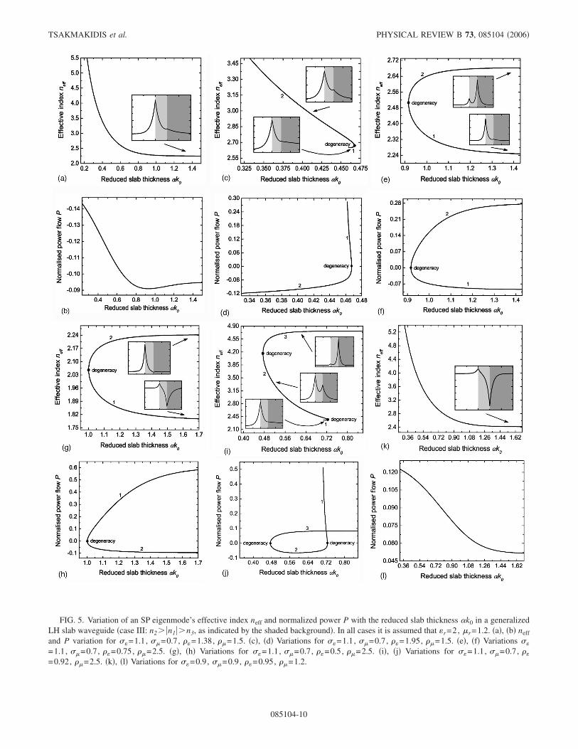
FIG. 5. Variation of an SP eigenmode’s effective index neff and normalized power P with the reduced slab thickness �k0 in a generalizedLH slab waveguide �case III: n2� �n1��n3, as indicated by the shaded background�. In all cases it is assumed that �r=2, �r=1.2. �a�, �b� neff
and P variation for ��=1.1, ��=0.7, �=1.38, �=1.5. �c�, �d� Variations for ��=1.1, ��=0.7, �=1.95, �=1.5. �e�, �f� Variations ��
=1.1, ��=0.7, �=0.75, �=2.5. �g�, �h� Variations for ��=1.1, ��=0.7, �=0.5, �=2.5. �i�, �j� Variations for ��=1.1, ��=0.7, �
=0.92, �=2.5. �k�, �l� Variations for ��=0.9, ��=0.9, �=0.95, �=1.2.
TSAKMAKIDIS et al. PHYSICAL REVIEW B 73, 085104 �2006�
085104-10
The analytical treatment revealed features not observedbefore, such as the occurrence of “supermodes” in the caseof a violation of the isolated interface condition, strong fieldenhancement and opening of gaps in the geometric disper-sion diagrams owing to the asymmetry, and coexistence ofthree eigenmodes with double mode-degeneracy points oc-curring twice. We also demonstrated that the group velocityof the investigated slow waves could be decreased down to
zero or become negative, by adjusting suitably the thicknessof the core.
ACKNOWLEDGMENT
This work is partially supported by the Engineering andPhysical Sciences Research Council �EPSRC�, U.K.
1 V. G. Veselago, Sov. Phys. Usp. 10, 509 �1968�; V. G. Veselago,in Proceedings of the First Taormina Research Conference onthe Structure of Matter, Pergamon, 1972, edited by E. Bursteinand F. De Martini �Pergamon Press, New York, 1974�, p. 5.
2 P. M. Valanju, R. M. Walser, and A. P. Valanju, Phys. Rev. Lett.88, 187401 �2002�.
3 J. B. Pendry, Phys. Rev. Lett. 85, 3966 �2000�.4 N. Garcia and M. Nieto-Vesperinas, Phys. Rev. Lett. 88, 207403
�2002�.5 D. R. Smith, D. Schurig, and J. B. Pendry, Appl. Phys. Lett. 81,
2713 �2002�; D. R. Smith, D. Schurig, M. Rosenbluth, S.Schultz, S. A. Ramakrishna, and J. B. Pendry, ibid. 82, 1506�2003�.
6 S. A. Cummer, Appl. Phys. Lett. 82, 2008 �2003�; W. T. Lu, J. B.Sokoloff, and S. Sridhar, Phys. Rev. E 69, 026604 �2004�.
7 C. G. Parazzoli, R. B. Greegor, K. Li, B. E. C. Koltenbah, and M.Tanielian, Phys. Rev. Lett. 90, 107401 �2003�; A. A. Houck, J.B. Brock, and I. L. Chuang, ibid. 90, 137401 �2003�.
8 J. B. Pendry, A. J. Holden, W. J. Stewart, and I. Youngs, Phys.Rev. Lett. 76, 4773 �1996�; J. B. Pendry, A. J. Holden, D. J.Robbins, and W. J. Stewart, J. Phys.: Condens. Matter 10, 4785�1998�; J. B. Pendry, A. J. Holden, D. J. Robbins, and W. J.Stewart, IEEE Trans. Microwave Theory Tech. 47, 2075 �1999�.
9 R. A. Shelby, D. R. Smith, and S. Shultz, Science 292, 77 �2001�.10 A. N. Lagarkov and V. N. Kissel, Phys. Rev. Lett. 92, 077401
�2004�.
11 I. V. Shadrivov, A. A. Sukhorukov, and Y. S. Kivshar, Phys. Rev.E 67, 057602 �2003�.
12 S. A. Ramakrishna, J. B. Pendry, D. Schurig, D. R. Smith, and S.Schultz, J. Mod. Opt. 49, 1747 �2002�; B.-I. Wu, T. M. Grze-gorczyk, Y. Zhang, and J. A. Kong, J. Appl. Phys. 93, 9386�2003�; Y. He, Z. Cao, Q. Shen, Opt. Commun. 245, 125 �2005�.
13 D.-K. Qing and G. Chen, Appl. Phys. Lett. 84, 669 �2004�.14 We include the term “plasmon” in the naming of the investigated
surface polaritons, to denote that the dielectric constant �(�) andthe magnetic permeability �(�) of the LH material are describedmacroscopically by a plasma dispersion law, as explained inRef. 9.
15 B. Prade, J. Y. Vinet, and A. Mysyrowicz, Phys. Rev. B 44,13556 �1991�.
16 J. J. Burke, G. I. Stegeman, and T. Tamir, Phys. Rev. B 33, 5186�1986�.
17 I. V. Shadrivov, A. A. Sukhorukov, Y. S. Kivshar, A. A. Zharov,A. D. Boardman, and P. Egan, Phys. Rev. E 69, 016617 �2004�.
18 R. A. Shelby, D. R. Smith, S. C. Nemat Nasser, and S. Shultz,Appl. Phys. Lett. 78, 489 �2001�.
19 A. Snyder and J. D. Love, Optical Waveguide Theory �Chapmanand Hall, New York, 1983�.
20 H. Kogelnic and V. Ramaswamy, Appl. Opt. 13, 1857 �1974�.21 R. Loudon, J. Phys. A 3, 233 �1970�; R. Ruppin, Phys. Lett. A
299, 309 �2002�.22 M. F. Yanik and S. Fan, Phys. Rev. Lett. 92, 083901 �2004�.
SURFACE PLASMON POLARITONS IN GENERALIZED… PHYSICAL REVIEW B 73, 085104 �2006�
085104-11