Impedance bandwidth improvement of compact low permittivity RDRA using parasitic conducting metallic...
6
29 th NATIONAL RADIO SCIENCE CONFERENCE (NRSC 2012) April 10-12, 2012, Faculty of Engineering/ Cairo University, Egypt B7. Impedance Bandwidth Improvement of Compact Low Permittivity RDRA Using Parasitic Conducting Metallic Strip Ehab K. I. Hamad 1 and Hany A. Atallah 2 1 Electrical Engineering Department, Aswan Faculty of Engineering, South Valley University, Aswan 81542, Egypt, [email protected] 2 Electrical Engineering Department, Qena Faculty of Engineering, South Valley University, Qena 83523, Egypt, [email protected] ABSTRACT In this paper, a compact broadband, low profile rectangular dielectric resonator antenna (RDRA) is presented. The RDRA is fed with a modified stepped microstrip feed to ensure efficient coupling between the RDR and feeder. Impedance improvement and broadband operation is achieved by loading the RDR with conducting metallic strip of suitable width, which results in a new resonance closes to the antenna operating frequency. The performance of the proposed antenna has been significantly improved and leads to a wider operating bandwidth (up to 22 %). Parametric investigations for different geometrical parameters have been carried out. The frequency characteristics and radiation performance of the proposed antenna are successfully optimized with numerical experimentation techniques and experimentally verified. Measurements and simulation results based on a 3D full- wave EM simulator are in excellent agreement. Keywords: Broadband, Dielectric resonator antenna, Loading strip, Stepped microstrip. I. INTRODUCTION In recent years, the demand for wideband antennas for wireless mobile communications has led to the development of antennas that are low profile and small in size. In the last two decades, microstrip patch antennas [1] and DRAs [2]–[6] have been extensively investigated as suitable antennas for wireless communication applications. The DRA offers attractive features such as low ohmic loss, low profile, small size, wide impedance bandwidth as compared to the microstrip antenna. The DRA can be used at millimeter frequency bands and is compatible with existing excitation methods such as coaxial probe, microstrip transmission line, coplanar waveguide feed or aperture coupling. DRAs are available in basic shapes such as rectangular, cylindrical, spherical and hemispherical geometries. RDRAs offer more design flexibility since two of the three of its dimensions can be varied independently for a fixed resonant frequency and known dielectric constant of the material [7]. Hence, the RDRAs for the current investigations is chosen. Feeding mechanisms that are generally used for DRAs include using microstrip lines [8], coaxial probes [9], coplanar waveguide feeds [10] and aperture coupling [11]. Coupling techniques that have appeared in the literature [7]–[11] require high of the permittivity (usually greater than 10) to ensure efficient coupling. Even though high permittivity results in a small DRA, it also narrows the bandwidth. If efficient coupling for relatively low-permittivity, low profile DRAs can be realized, much wider bandwidth can be obtained. Furthermore, inexpensive widely available microwave substrates can be used to make the DRA, rather than commonly used DRAs using high permittivity ceramic resonators. This is precisely the focus of this research. In this paper, a novel, simple, and efficient coupling technique of low permittivity, low profile DRAs, resulting in very broadband performance is presented. Techniques published in the literature for high dielectric constant DRAs include two or more stacked DRAs [12], coplanar parasitic DRAs [13], and inclusion of air gaps inside DRAs [14]. Such techniques require additional DRA elements increasing the size of the overall antenna or involve a more complicated geometry. The bandwidth of DRA can also be extended by attaching additional parasitic elements to incur another resonance. In this paper, a metallic strip is attached to the top of a DR to incur additional resonance close to that of the DRA resonance. The inductance of the metallic strip and the capacitance between the strip and the ground plane form an LC tank circuit [15] which can be coupled to the DR resonant mode to exhibit a wider bandwidth. Also, the impedance bandwidth of DRA can be further increased by modifying their feeding structures. In this paper a stepped microstrip feed is used to ensure an efficient coupling. The paper first introduces an optimized RDRA, its EM simulated and measured S-parameters then the simulations and measurements of the single metallic loading strip RDRA. 57 978-1-4673-1887-7/12/$31.00 ©2012 IEEE
Transcript of Impedance bandwidth improvement of compact low permittivity RDRA using parasitic conducting metallic...

29th NATIONAL RADIO SCIENCE CONFERENCE
(NRSC 2012) April 10-12, 2012, Faculty of Engineering/ Cairo University, Egypt
B7. Impedance Bandwidth Improvement of Compact Low Permittivity
RDRA Using Parasitic Conducting Metallic Strip
Ehab K. I. Hamad1 and Hany A. Atallah
2
1Electrical Engineering Department, Aswan Faculty of Engineering,
South Valley University, Aswan 81542, Egypt, [email protected] 2Electrical Engineering Department, Qena Faculty of Engineering,
South Valley University, Qena 83523, Egypt, [email protected]
ABSTRACT
In this paper, a compact broadband, low profile rectangular dielectric resonator antenna (RDRA) is presented.
The RDRA is fed with a modified stepped microstrip feed to ensure efficient coupling between the RDR and
feeder. Impedance improvement and broadband operation is achieved by loading the RDR with conducting
metallic strip of suitable width, which results in a new resonance closes to the antenna operating frequency. The
performance of the proposed antenna has been significantly improved and leads to a wider operating bandwidth
(up to 22 %). Parametric investigations for different geometrical parameters have been carried out. The frequency
characteristics and radiation performance of the proposed antenna are successfully optimized with numerical
experimentation techniques and experimentally verified. Measurements and simulation results based on a 3D full-
wave EM simulator are in excellent agreement.
Keywords: Broadband, Dielectric resonator antenna, Loading strip, Stepped microstrip.
I. INTRODUCTION
In recent years, the demand for wideband antennas for wireless mobile communications has led to the
development of antennas that are low profile and small in size. In the last two decades, microstrip patch antennas
[1] and DRAs [2]–[6] have been extensively investigated as suitable antennas for wireless communication
applications. The DRA offers attractive features such as low ohmic loss, low profile, small size, wide impedance
bandwidth as compared to the microstrip antenna. The DRA can be used at millimeter frequency bands and is
compatible with existing excitation methods such as coaxial probe, microstrip transmission line, coplanar
waveguide feed or aperture coupling. DRAs are available in basic shapes such as rectangular, cylindrical,
spherical and hemispherical geometries. RDRAs offer more design flexibility since two of the three of its
dimensions can be varied independently for a fixed resonant frequency and known dielectric constant of the
material [7]. Hence, the RDRAs for the current investigations is chosen. Feeding mechanisms that are generally
used for DRAs include using microstrip lines [8], coaxial probes [9], coplanar waveguide feeds [10] and aperture
coupling [11]. Coupling techniques that have appeared in the literature [7]–[11] require high of the permittivity
(usually greater than 10) to ensure efficient coupling. Even though high permittivity results in a small DRA, it also
narrows the bandwidth. If efficient coupling for relatively low-permittivity, low profile DRAs can be realized,
much wider bandwidth can be obtained. Furthermore, inexpensive widely available microwave substrates can be
used to make the DRA, rather than commonly used DRAs using high permittivity ceramic resonators. This is
precisely the focus of this research. In this paper, a novel, simple, and efficient coupling technique of low
permittivity, low profile DRAs, resulting in very broadband performance is presented. Techniques published in
the literature for high dielectric constant DRAs include two or more stacked DRAs [12], coplanar parasitic DRAs
[13], and inclusion of air gaps inside DRAs [14]. Such techniques require additional DRA elements increasing the
size of the overall antenna or involve a more complicated geometry. The bandwidth of DRA can also be extended
by attaching additional parasitic elements to incur another resonance. In this paper, a metallic strip is attached to
the top of a DR to incur additional resonance close to that of the DRA resonance. The inductance of the metallic
strip and the capacitance between the strip and the ground plane form an LC tank circuit [15] which can be
coupled to the DR resonant mode to exhibit a wider bandwidth. Also, the impedance bandwidth of DRA can be
further increased by modifying their feeding structures. In this paper a stepped microstrip feed is used to ensure an
efficient coupling. The paper first introduces an optimized RDRA, its EM simulated and measured S-parameters
then the simulations and measurements of the single metallic loading strip RDRA.
57978-1-4673-1887-7/12/$31.00 ©2012 IEEE

29th NATIONAL RADIO SCIENCE CONFERENCE
(NRSC 2012) April 10-12, 2012, Faculty of Engineering/ Cairo University, Egypt
II. RECTANGULAR DIELECTRIC RESONATOR ANTENNA
Usually more resonant modes are observed in a RDRA compared to its cylindrical version over a normalized
frequency range. In fact this feature can be used to enhance the bandwidth of the RDRA if adjacent resonant
modes have similar radiation patterns. For example, a truncated tetrahedron DRA [16] for wideband applications
has recently been realized using this concept. Figure 1 shows the geometry of a stepped microstrip feed RDRA.
The wide strip in essence provides the necessary impedance matching. The feeding stepped strip is placed in the
middle under the DRA. The proposed geometry of the low profile DRA is fed with a stepped microstrip line
whereas the feeding microstrip has length L1 and width W1 which ensures a 50 Ω characteristic impedance. The
optimizations of the designed antenna are achieved through simulations using a commercial 3D full-wave analysis
software package Ansoft HFSS [17]. The feed microstrip line has a 50 Ω characteristic impedance whereas the
width and length of the stepped section are W2 = 3 mm and L2 = 10.5 mm, respectively as shown in Fig. 1. The
dielectric constants for both the DRA and the feed substrate are chosen to be the same. Figure 1 shows the
schematic diagram and the photograph of the designed antenna by stepped microstrip with dimensions W = 10
mm, L = 10 mm, and H = 2.5 mm. A Rogers RT/Duroid 3010 substrate with the thickness t of 1.27 mm and a
dielectric constant εr of 10.2 is used in this study. The TE111 mode of the resonator is excited. In this mode the
resonator radiates like a magnetic dipole. The resonance frequency of the TE111 mode of this antenna can be
determined using the following equations:
(1)
(2)
where
and
By solving these equations for kz and ko, the resonant frequency can be obtained from:
(3)
where fo = 8.76 GHz theoretically while the simulated value is 9.15 GHz with percentage error of 4 %. As the
DR permittivity increased the resonant frequency decreased, which results in a high quality factor. As a result the
antenna bandwidth is reduced so a low permittivity substrate is used to overcome such problem. It should be
noticed that for electrically small antennas there is a trade-off between the size, bandwidth and efficiency.
Figure 1(d) demonstrates the simulated S-parameters of the optimized antenna versus frequency. The HFSS
simulated results show that the relative bandwidth achieved with optimal parameters is about 13 % ranging from
8.4 to 9.6 GHz. The measured and simulated results are shown in Fig. 1(d). A good agreement is indicated. A 10
dB return loss bandwidth of 9 % (8.8 – 9.6 GHz) with a centre frequency fo of 9.2 GHz is obtained experimentally.
The difference between the computed and measured central frequencies is only 0.5 % (50 MHz). The fractional
bandwidth of 9 % represents a very good result for this antenna construction. Figure 2 shows the antenna’s
parameters simulation results of the optimized stepped microstrip feed RDRA with gain up to 5.8 dB, efficiency
up to 89.7 %, and directivity up to 6.34 dB.
.
L1
L2
L
WW1
W2
Stepped Microstrip
Low Profile DRA
Microstrip Line
H
t
Microstrip LineLow Profile DRA
Substrate
Ground Plane
(a) Stepped microstrip feed RDRA (top view) (b) Stepped microstrip feed RDRA (side view)
58
29th NATIONAL RADIO SCIENCE CONFERENCE
(NRSC 2012) April 10-12, 2012, Faculty of Engineering/ Cairo University, Egypt
-35
-30
-25
-20
-15
-10
-5
0
7.66 8.33 9 9.67 10.34
Simulated S11(dB) Measured S11(dB)
IS1
1I(
dB
)
Frequency(GHz)
(c) Photograph of the fabricated RDRA (d) Simulated and measured |S11| using HP8510C
Fig. 1: Stepped microstrip feed RDRA, measured and simulated |S11| parameters
-150
-100
-50
0
50
100
150
200
250
7.5 8 8.5 9 9.5 10 10.5 11
BC
Co
mp
ute
d In
put
Imp
eda
nce
(oh
m)
Frequency(GHz)
(a) Computed input impedance versus frequency,
Real and …. Imaginary parts) ــــــ(
(b) Antenna gain radiation pattern at 9.2 GHz
(E-plane, …. H-plane ـــــ)
Fig. 2: Optimized RDRA parameters results
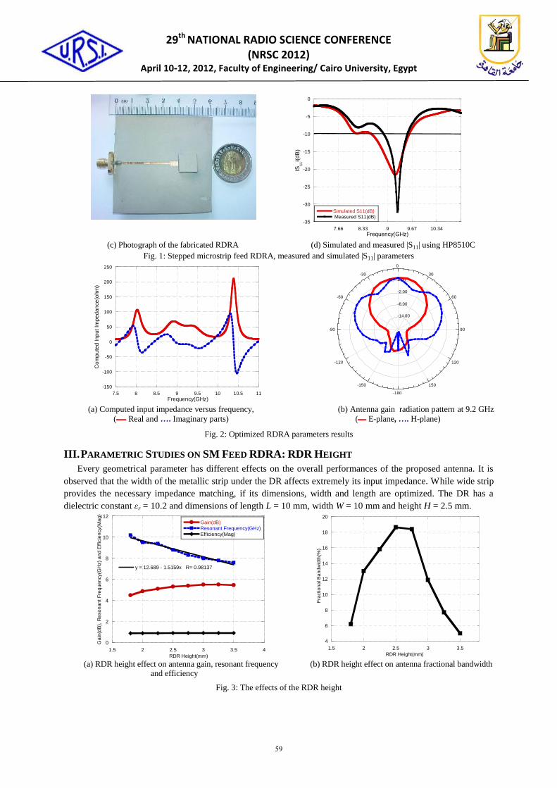
III. PARAMETRIC STUDIES ON SM FEED RDRA: RDR HEIGHT
Every geometrical parameter has different effects on the overall performances of the proposed antenna. It is
observed that the width of the metallic strip under the DR affects extremely its input impedance. While wide strip
provides the necessary impedance matching, if its dimensions, width and length are optimized. The DR has a
dielectric constant εr = 10.2 and dimensions of length L = 10 mm, width W = 10 mm and height H = 2.5 mm.
0
2
4
6
8
10
12
1.5 2 2.5 3 3.5 4
Gain(dB)Resonant Frequency(GHz)Efficiency(Mag)
y = 12.689 - 1.5159x R= 0.98137
Gain
(dB
), R
eso
na
nt
Fre
qu
en
cy(G
Hz)
an
d E
ffic
ien
cy(M
ag
)
RDR Height(mm)
4
6
8
10
12
14
16
18
20
1.5 2 2.5 3 3.5
Bandwidth(%)
Fra
ctio
na
l B
an
dw
idth
(%)
RDR Height(mm) (a) RDR height effect on antenna gain, resonant frequency
and efficiency (b) RDR height effect on antenna fractional bandwidth
Fig. 3: The effects of the RDR height
-14.00
-8.00
-2.00
4.00
90
60
30
0
-30
-60
-90
-120
-150
-180
150
120
Ansoft Corporation ref enhanced dra 9 ghzRadiation Pattern 1
Curve Info
dB(GainTotal)
Setup1 : Sw eep1
dB(GainTotal)_1
Setup1 : Sw eep1
59

29th NATIONAL RADIO SCIENCE CONFERENCE
(NRSC 2012) April 10-12, 2012, Faculty of Engineering/ Cairo University, Egypt
In Fig. 3, the antenna parameters are depicted as a function of the RDR height as a parameter. From this
Figure, it is clear that the height of the RDR affects fairly the resonant frequency which decreases as the RDR
height increases. Using numerical analysis techniques, the curve is fitted with least squares straight line
approximation, the following equation is obtained:
(4)
where fr is the resonant frequency in GHz, H is the RDR height in mm with a correlation coefficient of
0.98137 was estimated using MathCAD, the other antenna parameters should be optimized.
IV. PROPOSED SINGLE METALLIC STRIP SM RDRA
Figure 4 shows the schematic diagram of the proposed low profile RDRA fed with a stepped microstrip line
and loaded with metallic strip. With intensive EM simulations, the antenna is designed and optimized using a
commercial 3D full-wave analysis software package. The metallic strip over the RDR affects significantly its gain
and bandwidth. A metal strip on the RDR disturbs the shield current and it can change the effective inductance
and capacitance of the DRA. A narrow stepped microstrip width resulted in a high input impedance, much higher
than 50 Ω, whereas a wide strip lowered the input impedance of the DRA; hence the proposed geometry. The
wide strip in essence provides the necessary impedance matching, if other dimensions like width and length are
optimized. The DRA is built on Rogers RT/Duroid 3010 substrate with thickness of t = 1.27 mm and dielectric
constant εr of 10.2. The antenna length L = 10 mm, width W = 10 mm and height H = 2.5 mm. The feed microstrip
line has a 50 Ω characteristic impedance whereas the width and length of the stepped section are W2 and L2,
respectively as shown in Fig. 4. The metallic strip width on the RDR is SW = 2 mm. The dielectric constants of
substrate for both the RDR and the feed line are chosen to be the same. As shown in Fig. 4, the proposed
configuration produced an impedance bandwidth better than 19.6 % using numerical experimentation technique.
A metallic strip on the RDR disturbs the shield current and it can change the effective inductance and capacitance
of the DRA.
L1
L2
L
WW1
W2
Metallic Strip
Stepped Microstrip
SW
Low Profile DRA
Microstrip Line
(a) Proposed single metallic strip RDRA (top view) (b) Photograph of the fabricated single metallic strip DRA
-50
-40
-30
-20
-10
0
8 8.5 9 9.5 10 10.5 11 11.5 12
Simulated S11(dB)
Measured S11(dB)
IS11
I(dB
)
Frequency(GHz)
(c) Simulated and measured |S11| Using HP8510C
Fig. 4: Proposed single metallic strip RDRA and results
60

29th NATIONAL RADIO SCIENCE CONFERENCE
(NRSC 2012) April 10-12, 2012, Faculty of Engineering/ Cairo University, Egypt
-40
-20
0
20
40
60
80
9 9.5 10 10.5 11 11.5
BC
Com
pute
d In
put I
mpe
danc
e(oh
m)
Frequency(GHz)
(a) Computed input impedance versus frequency,
Real and …. Imaginary parts) ــــــ(
(b) Antenna gain radiation pattern at 9.5 GHz
(E-plane, …. H-plane ـــــ)
Fig. 5: Optimized single metallic strip rectangular DRA parameters results
Figure 5 illustrates the antenna simulation results of the optimized broadband single metallic strip RDRA
which produces a bandwidth up to 19.6 % (1.8 GHz) from 9.15 to 10.95 GHz suitable for wideband wireless
communication applications at X-band with gain improvement up to 6.18 dB, efficiency up to 87.5 %, and
directivity up to 6.78 dB.
4
4.5
5
5.5
6
6.5
7
7.5
9 9.5 10 10.5 11
Gain(dB)Directivity(dB)
Gai
n (d
B)
and
Dir
ectiv
ity (
dB)
Frequency (GHz) 0
5
10
15
20
25
0 1 2 3 4 5 6
Bandwidth(%)Gain(dB)Directivity(dB)
Fra
ctio
na
l Ba
nd
wid
th(%
), G
ain
(dB
) a
nd
Dire
ctiv
ity(d
B)
Metallic Strip Width(mm)
Fig. 6: The single metallic strip RDRA gain and dirctivity Fig. 7: Effects of the metallic strip width on gain,
fractional bandwidth and directivity
It is obvious from Fig. 4 that both simulated and measured S-parameters are in good agreement within the
frequency band. A 10 dB return loss bandwidth of 22 % (9.2 – 11.25 GHz) with a centre frequency fo = 10.1 GHz
is obtained. The difference between the computed and measured central frequencies is only about 1 % (100 MHz).
The fractional bandwidth of 22 % represents a very good result for this antenna construction. Figure 6
demonstrates the results of the antenna gain and directivity of the proposed antenna versus frequency in the
operating frequency band. The proposed antenna offers a peak gain of ~6.7 dB, a peak directivity of ~7.4 dB and
an average gain of ~5.7 dB over the interesting frequency band.
V. PARAMETRIC STUDY ON SINGLE METALLIC STRIP SM RDRA: STRIP WIDTH
To increase the bandwidth; a rectangular metallic layer is placed over the RDR. After several optimization tests,
a metallic layer of 10 mm by 2 mm size is the bets to get the most largest bandwidth. The optimal value obtained
for the antenna bandwidth is 19.6 %. Figure 7 shows that gain and directivity of the antenna nearly remains
unchanged; while the bandwidth significantly increased as strip width decreased.
VI. CONCLUSION
In this paper, a design of a novel broadband RDRA has been presented. It is fabricated and measured for the
validation purposes. In this design, a large bandwidth has been obtained by adding a metallic strip above the RDR and
stepped microstrip for enhancement of the matching, bandwidth, and gain of the proposed antenna. Parametric
-14.00
-8.00
-2.00
4.00
90
60
30
0
-30
-60
-90
-120
-150
-180
150
120
Ansoft Corporation singl m ptch 11.5ghzRadiation Pattern 1
Curve Info
dB(GainTotal)
Setup1 : Sw eep1
dB(GainTotal)_1
Setup1 : Sw eep1
61

29th NATIONAL RADIO SCIENCE CONFERENCE
(NRSC 2012) April 10-12, 2012, Faculty of Engineering/ Cairo University, Egypt
investigations for different geometrical variables have also been carried out . The obtained results show that the proposed
antenna can produce a bandwidth of 22 %. The radiation patterns are stable over the whole operating frequency range.
With this feature, the proposed antennas are suitable for broadband wireless systems at X-band frequency range.
ACKNOWLEDGMENT
The authors would like to thank the National Research College, Cairo, Egypt, Microstrip Department team for their co-operation in fabrication process. Great thanks also should go to the Military Technical College, EE Department, Cairo, Egypt for providing access to testing facilities and measurements.
REFERENCES
[1] A. Khidre, K. F. Lee, F. Yang, and A. Elsherbeni, “Wideband Circularly Polarized E-Shaped Patch Antenna for
Wireless Applications,” IEEE Antennas and Propagation Magazine, vol. 52, no. 5, pp. 219-229, October 2010.
[2] K. M. Luk and K. W. Leung, Dielectric Resonator Antennas, Research Studies Press Ltd Press, Baldock,
Herfordshire, UK, 2002.
[3] G. D. Makwana and K. J. Vinoy, “Design of a Compact Rectangular Dielectric Resonator Antenna at 2.4 GHz,”
Progress In Electromagnetics Research C, vol. 11, pp. 69-79, 2009.
[4] S. Sreekantan, Y. K. Ling, and Z. A. Ahmad, “Simulation and Experimental Investigators on Rectangular, Circular
and Cylindrical DRA,” Progress In Electromagnetics Research C, vol. 7, pp. 151–166, 2009.
[5] M. Saed and R. Yadla, "Microstrip-Fed Low Profile and Compact Dielectric Resonator Antennas," Progress in
Electromagnetics Research, PIER 56, pp. 151–162, 2006.
[6] Hany A. Atallah and Ehab K. I. Hamad, “Broadband Low Profile and Compact RDRA Loaded with Metallic Strips
for Wideband Applications,” Journal of Engineering Sciences, Faculty of Engineering, Assiut University, vol. 38,
no. 6, pp. 1469-1483, Nov. 2010.
[7] Mohsen Khalily, Mohamad Kamal Abdul Rahim, and Ahmed A. Kishk, “Bandwidth Enhancment and Radiation
characterstics Improvement of Dielectric Resonator Antenna,” IEEE Antennas and Wireless Propagation Letters,
vol. 10, pp. 393-395, 2011.
[8] R. A. Kranenburg and S. A. Long, “Microstrip Transmission Line Excitation of Dielectric Resonator Antennas,”
Electronics Letters, vol. 24, no. 18, pp. 1156–1157, September 1988.
[9] Hany A. Atallah and Ehab K. I. Hamad, “ Radiation Pattern Improvement of RDRA Using LHM Flat Lens
Composed of CSRR, ” IEEE–APS Middle East Conference on Antennas and Propagation, Cairo, Egypt, 2010.
[10] M. S. Al Salameh, Yahia M. M. Antar, and Guy Seguin, “Coplanar Waveguide Fed Slot Coupled Rectangular
Dielectric Resonator Antenna,” IEEE Transaction on Antennas and Propagation, vol. 50, no. 10, Oct. 2002.
[11] R. Chair, S. Lung S. Yang, A. A. Kishk, K. F. Lee, and K. M. Luk, “Aperture Fed Wideband Circularly Polarized
Rectangular Stair Shaped Dielectric Resonator Antenna,” IEEE Transactions on Antennas and Propagation, vol.
54, no. 4, April 2006.
[12] Y. F. Ruan, Y. X. Guo, and X. Q. Shi1, “Wideband Dielectric Resonator Antenna,” Microwave and Optical
Technology Letters, vol. 48, no. 2, February 2006.
[13] R. N. Simons and R. Q. Lee, “Effect of Parasitic Dielectric Resonators on CPW /Aperture Coupled Dielectric
Resonator Antennas,” IEEE Proceedings-H, vol. 140, no. 5, October 1993.
[14] A. Petosa, N. Simons, R. Siushansian, A. Ittipiboon, and M. Cuhaci, “Design and Analysis of Multisegment
Dielectric Resonator Antennas,” IEEE Trans. on Antennas and Propagation, vol. 48, no. 5, May 2000.
[15] Ehab K. I. Hamad, Amr M. E. Safwat, and Abbas S. Omar, “Controlled Capacitance and Inductance Behavior of L-
Shaped Defected Ground Structure for Coplanar Waveguide,” IEE Proceedings - Microwaves, Antennas and
Propagation, vol. 152, no. 5, pp. 299-304, October 2005.
[16] A. A. Kishk, “Tetrahedron and Triangular Dielectric Resonator with wideband Performance,” IEEE Antennas and
Propagation International Symposium, vol. 4, pp. 462-465, June 2002.
[17] Ansoft Corporation, HFSS, http://www.ansoft.com/products/hf/hfss /
62