Surface PIV measurements on shallow compound channel flows: Coherent flow structur es, horizontal...
6
-1- Surface-PIV measurements on shallow compound channel flows: Coherent flow structures, horizontal mixing and dispersion Andreas C. Rummel 1,2 , Simone Sartini 2 , Alessandro Stocchino 2 , Alessandra Piatella 3 and Maurizio Brocchini 3 1 Institute for Hydromechanics, University of Karlsruhe (TH), 76133 Karlsruhe, Germany, email:[email protected] 2 Department of Civil and Environmental Engineering, University of Genova, 16145 Genova, Italy 3 Institute of Hydraulics and Road Infrastructures, Polytechnic University of Marche, 60131 Ancona, Italy Abstract: An experimental investigation based on PIV analysis of free surface velocities forms the basis for the following analyses of specific features of macrovortices in compound channels. Dynamical properties are seen to strongly depend on the input discharge (low-discharge, intermediate-discharge and high- discharge conditions). The maximum streamwise mean velocity component increases with both discharge/downstream location and the bell-type crossflow profile of the mean streamwise velocity, typical of the low/intermediate discharges, becomes non-monotonic at high discharges (need of new types of self-similar solutions). The mean shear at the transition region decreases with increasing discharge. This leads to the reduction of macrovortex generation at the transition region and a simultaneous increase at the lateral walls. The size of macrovortices in the transition region is closely related to the channel geometry and the shear layer width is found to be almost constant. Keywords: Compound Channel, Macrovortices, Shear Layer. Introduction A great variety of natural water streams and artificial channels can be classified as ‘compound channels’ since their cross-stream section can be assumed to be characterized by a main central channel and shallow flood plains. We define flows of these streams as predominantly horizontal since their horizontal dimensions greatly exceed the vertical dimension [JIRKA 2004]. Although in bounded shear flows the three-dimensional turbulent eddy size is, typically, limited to the shortest dimension (in this case, the water depth), large-scale, two-dimensional coherent structures with length scales greater than the water depth are observed in a wide range of shallow shear flows [SOKOLOFSKY 2004]. The flow velocity in the flood plains is lower than in the main channel, due to the water shallowness and to the high bed roughness (e.g. presence of vegetation). Thus shearing occurs at the interface between the main channel and the floodplains (‘transition region’ hereinafter) which may lead to various flow patterns most of which characterized by large-scale vortical structures with vertical axes (macrovortices). Such turbulent structures are liable of the transfer of momentum and mass from the main channel to the flood plains.
-
Upload
independent -
Category
Documents
-
view
1 -
download
0
Transcript of Surface PIV measurements on shallow compound channel flows: Coherent flow structur es, horizontal...
- 1 -
Surface-PIV measurements on shallow compound channel flows:Coherent flow structures, horizontal mixing and dispersion
Andreas C. Rummel1,2, Simone Sartini2, Alessandro Stocchino2,Alessandra Piatella3 and Maurizio Brocchini3
1Institute for Hydromechanics, University of Karlsruhe (TH), 76133 Karlsruhe,Germany, email:[email protected] of Civil and Environmental Engineering, University of Genova, 16145Genova, Italy3Institute of Hydraulics and Road Infrastructures, Polytechnic University of Marche,60131 Ancona, Italy
Abstract: An experimental investigation based on PIV analysis of free surfacevelocities forms the basis for the following analyses of specific features ofmacrovortices in compound channels. Dynamical properties are seen to stronglydepend on the input discharge (low-discharge, intermediate-discharge and high-discharge conditions). The maximum streamwise mean velocity componentincreases with both discharge/downstream location and the bell-type crossflowprofile of the mean streamwise velocity, typical of the low/intermediate discharges,becomes non-monotonic at high discharges (need of new types of self-similarsolutions). The mean shear at the transition region decreases with increasingdischarge. This leads to the reduction of macrovortex generation at the transitionregion and a simultaneous increase at the lateral walls. The size of macrovortices inthe transition region is closely related to the channel geometry and the shear layerwidth is found to be almost constant.Keywords: Compound Channel, Macrovortices, Shear Layer.
Introduction
A great variety of natural water streams and artificial channels can be classified as‘compound channels’ since their cross-stream section can be assumed to becharacterized by a main central channel and shallow flood plains. We define flows ofthese streams as predominantly horizontal since their horizontal dimensions greatlyexceed the vertical dimension [JIRKA 2004]. Although in bounded shear flows thethree-dimensional turbulent eddy size is, typically, limited to the shortest dimension(in this case, the water depth), large-scale, two-dimensional coherent structures withlength scales greater than the water depth are observed in a wide range of shallowshear flows [SOKOLOFSKY 2004]. The flow velocity in the flood plains is lower than in the main channel, due to thewater shallowness and to the high bed roughness (e.g. presence of vegetation). Thusshearing occurs at the interface between the main channel and the floodplains(‘transition region’ hereinafter) which may lead to various flow patterns most ofwhich characterized by large-scale vortical structures with vertical axes(macrovortices). Such turbulent structures are liable of the transfer of momentum andmass from the main channel to the flood plains.

- 2 -
The present contribution focuses on the description of the dynamics undergone bymacrovortices in a compound channel as part of the overall flow evolution. Morespecifically we intend to clarify validity and ambiguities concerned with use of shearlayer approach as the most suited to represent the flow at hand. Further, the resultshere described will be used as the basis for a theoretical analysis.
Experimental Setup and Data processing
The experiments have been carried out in the laboratory of the EnvironmentalEngineering Department of the University of Genova, Italy using a pre-existingflume. The flume is about L = 20m long and has a width of W = 0.6m, thetrapezoidal cross-section with a main channel (mc) and two lateral flat floodplains (fp)can be seen in figure 1. The cross-section has been subdivided in three sections, eachof them have nearly the same width 0.2mcW m= , 0.19fpW m= . Great care has been
dedicated to obtain a perfectly-horizontal channel. The compound channel, includingthe lateral vertical walls, is made by sheets of polyvinyl chloride (PVC) 1cm thick(Manning roughness n = 0.009 s−1m1/3).Following the main parameters of the experiments: The depth Reynolds numbercalculated for the main channel to be in the range of ,22000 Re 74000h mc< < and for
the flood plain to be in the range of ,2500 Re 37500h fp< < , which means that we
have fully turbulent conditions. The Froude number is found to approximately rangebetween 0.6 0.7ccFr = − and the bed friction is 32.9 2.0 10fc −= − ⋅ . Three
measurement sections have been selected along the flume respectively located at(2,5,7)x m= downstream of the inlet section.
The ratio between characteristic horizontal (H) and vertical (V) length scales is in therange of 4 20H V< < . This means that the flow can be regarded as intermediate-to-shallow. On these grounds, though fully recognizing the role of secondary flows (e.g.[TOMINAGA 1989]), we proceed to an analysis based on the description of thedynamics evolving at the water surface and take this as a good representation of thedynamics of the shallow flows.
figure 1: left panel: view from the outflow section of the flume at DICAT. Right panel: sketch ofthe cross section of the compound channel flume. All dimensions are in cm.
Measurements of two-dimensional flow fields on the free surface have been obtainedusing a PIV system in continuous, single-exposure mode. A digital camera (model:

- 3 -
IDT xS3) with NIKON lens (f=50mm) has been used to record 2000 frames with100Hz acquisition frequency. The area of interest for the flow measurements hasdimensions of about (0.6×0.6) m2 and (1024×1024) pixel2. The illumination has beenprovided by three white light incandescent lamps of 1000 Watts each and we usedwhite plastic particles with a mean diameter of 300 µm as tracer. Images wereanalysed using the software provided by IDT and each interrogation window hadphysical dimensions of 15.0mm×15.0mm.The two-dimensional velocity vector outputs of the PIV analysis have beenelaborated to extract the main features of the flow under investigation. In particular,we performed an ensemble average on the velocity fields and, then, spatial averagesalong the longitudinal direction to extract velocity crossflow profiles for eachsection, see figure 2.A specific analysis to identify and to track vortical structures has also been carriedout. As vortex identification technique we employed the method based on theevaluation of the swirling strength: The swirling strength, defined as the positiveimaginary eigenvalue of the local velocity gradients tensor, is large where there is astrong rotation of the flow, i.e. a vortex [ADRIAN 2000]. In two dimensions, thevelocity gradient tensor is only a 2 × 2 tensor, which has either two real eigenvalues( 1,2
rλ ) or a pair of complex conjugate eigenvalues ( cr ciλ λ± ). Hence, a vortex core is
identified by a region where 0ciλ > . The resulting contour maps of the swirlingstrength have been used to study the evolution of the macrovortices. With an object-tracking algorithm applied to the contour maps of ciλ (see figure 3) macrovorticesare recognized as a single entity, with geometrical characteristics related to theintensity of ciλ . Following the above procedure, we could infer the position of the
centroid centroidX of the vortex, the area occupied by the vortex Ω , the radius of the
area-equivalent circle eqR , and other geometrical characteristics of interest, e.g. the
eccentricity ε of the vortices and the maximum radius maxR , the inclination angle θwith respect to the mean flow direction x . When required, the analysis has beenrefined to separate vortices generated in the transition region −0.2m≤y≤0.2m(transition region vortices) and at the wall boundary layers y<−0.2m and y>0.2m(wall vortices).
figure 2: transversal velocity profiles for different downstream positions x = (7,5,2) m anddischarges Q = (3.3,5.0,8.0,10.2,15.7,22.0) l/s.

- 4 -
Probability Density Functions (PDFs) have been obtained by normalizing theoccurrence of the vortices with the total number of vortices per experiment. The totalnumber of vortices used for the analysis is in the range of 200 and 400 perexperiment with an average and overall (i.e. without distinguishing transitionvortices from wall vortices) shedding frequency increasing with the input dischargefrom 1.0Hz to 2.1Hz.
Mean Flow and Macrovortices
One of the main characteristics of a compound channel flow is the difference invelocity between the main-channel flow and the floodplain flow. Such difference isessentially driven by the bottom friction which, being inversely proportional to theflow depth, more effectively slows down the floodplain streams than that flowing inthe deeper main channel. Inspection of figure 2 well illustrates the mean velocityreduction occurring over the floodplains, the growth of the mean velocity with boththe flow discharge Q and the downstream distance x.Other features are also evident. For example, the reduction of the transversal shear atfixed x and the near-wall sudden velocity decay because of the no-slip condition atthe lateral walls and the non-monotonic profiles observed at the most downstreamsection x = 7m for flow rates higher than Q = 10.2l/s. While the former suggests aprogressive reduction with both x and Q of vortex generation at the transition regionbalanced by an increasing generation at the lateral boundaries, the latter clearlyindicates that a self-similar solution, if any is possible, has to be sought with a shapemore complicated than that given by the usual hyperbolic functions.Since it is well recognized that the maximum shear intensity at the transition regionis the most important parameter governing the flow, we investigate its role throughinspection of figure 4. The left panel clearly illustrates the reduction in flow shearingat the transition region with increasing flow intensity. This is also reflected in thereduction of macrovortices generation at the transition region and a simultaneousincrease at the lateral walls (see figure 5 and next section).
y [−]
x[−
]
Q = 3.3 l/s, swirling strength, t= 20
−3 −2 −1 0 1 2 3
0
1
2
3
4
5
0.06
0.08
0.1
0.12
0.14
0.16
0.18
0.2
0.22
0.24
y [−]
x[−
]
Q = 12.9 l/s, swirling strength, t= 32
−3 −2 −1 0 1 2 3
0
1
2
3
4
5
0.06
0.08
0.1
0.12
0.14
0.16
0.18
0.2
0.22
0.24
figure 3: swirling strength and velocity fluctuations distribution of sample ensemble-averagedflow fields at x=7m for a low discharge Q=3.3l/s (left panel) and a high discharge Q=12.9l/s(right panel) case. Velocity fields are derived from a space-time decomposition of theinstantaneous velocity field and different colors correspond to the magnitude of the swirlingstrength.
- 5 -
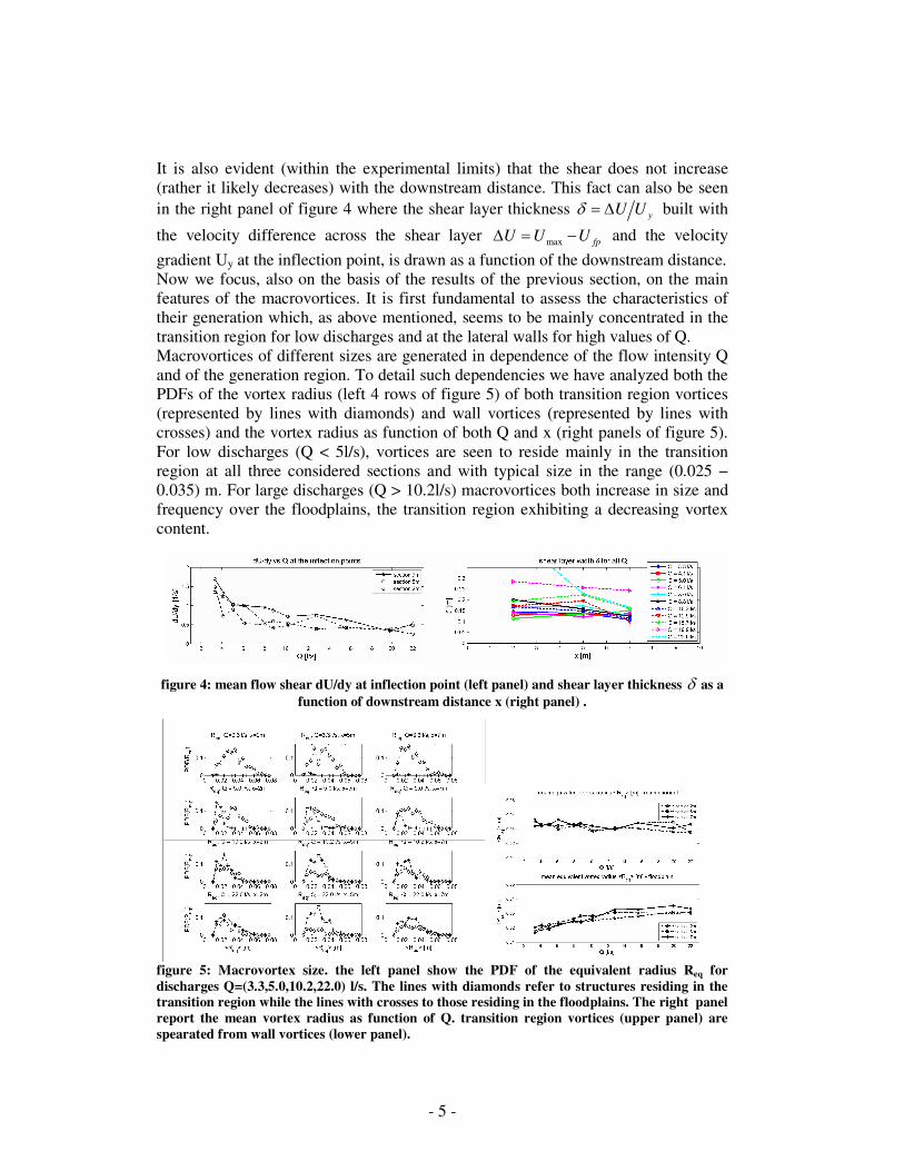
It is also evident (within the experimental limits) that the shear does not increase(rather it likely decreases) with the downstream distance. This fact can also be seenin the right panel of figure 4 where the shear layer thickness yU Uδ = ∆ built with
the velocity difference across the shear layer max fpU U U∆ = − and the velocity
gradient Uy at the inflection point, is drawn as a function of the downstream distance.Now we focus, also on the basis of the results of the previous section, on the mainfeatures of the macrovortices. It is first fundamental to assess the characteristics oftheir generation which, as above mentioned, seems to be mainly concentrated in thetransition region for low discharges and at the lateral walls for high values of Q.Macrovortices of different sizes are generated in dependence of the flow intensity Qand of the generation region. To detail such dependencies we have analyzed both thePDFs of the vortex radius (left 4 rows of figure 5) of both transition region vortices(represented by lines with diamonds) and wall vortices (represented by lines withcrosses) and the vortex radius as function of both Q and x (right panels of figure 5).For low discharges (Q < 5l/s), vortices are seen to reside mainly in the transitionregion at all three considered sections and with typical size in the range (0.025 −0.035) m. For large discharges (Q > 10.2l/s) macrovortices both increase in size andfrequency over the floodplains, the transition region exhibiting a decreasing vortexcontent.
figure 4: mean flow shear dU/dy at inflection point (left panel) and shear layer thickness δ as afunction of downstream distance x (right panel) .
figure 5: Macrovortex size. the left panel show the PDF of the equivalent radius Req fordischarges Q=(3.3,5.0,10.2,22.0) l/s. The lines with diamonds refer to structures residing in thetransition region while the lines with crosses to those residing in the floodplains. The right panelreport the mean vortex radius as function of Q. transition region vortices (upper panel) arespearated from wall vortices (lower panel).
- 6 -
The fundamental result is, however, reported in the right panels of the figure: themean vortex radius, weakly-decreasing in size for Q < 10.2l/s, is always in the range0.020m≤ Req ≤ 0.037m, which well compares with the transversal size of thetransition region (0.05m), for all values of x.
Conclusions
A detailed and extensive experimental investigation based on PIV analysis of freesurface velocities has been made to reveal the fundamental features of the flowcharacterizing a straight compound channel from the inception to fully-developedconditions. Specific focus was on the evolution of the transition region shear layerwhich is mainly dominated by macrovortices and pointing out similarities/differenceswith a true free shallow shear flow. The main findings of this work can besummarized as follows:• the maximum streamwise mean velocity component increases (approximatelylinearly) with Q and x, while the bell-type crossflow profile of U, typical of thelow/intermediate discharges, becomes non-monotonic at high discharges (hence theneed of new types of self-similar solutions). The mean shear at the transition regiondecreases with increasing Q and leads the reduction of macrovortex generation at thetransition region and a simultaneous increase at the lateral walls;• the macrovortices radii range between 0.025m and 0.035m, i.e. clearly scaling withthe crossflow extension of the transition region;• the global dynamics of a straight compound channel cannot be entirely explainedby a shear layer approach i.e. the flow largely differs from that obtained by themeeting of three parallel streams of different velocity (fast stream in the mainchannel and two slow streams at the floodplains). The compound channel topographyand boundaries force a non-monotonic velocity profile, a shear layer thicknessweakly decreasing downstream, macrovortices generated at the transition and at thelateral wall with size almost independent of the streamwise coordinate.All the above suggests that more analyses should be devoted to the understanding of
the global flow in a compound channel in addition to ongoing studies of localfeatures.
Acknowledgements
A.C.R. was supported by a European Union EST-020228 FLUBIO grant during hisstay in Genova.
References
R.J. Adrian, K.T. Christensen, and Z.C. Liu, Analysis and interpretation ofinstantaneous turbulent velocity fields, Expts. in Fluids 29, 275-290 (2000).
G.H. Jirka and W.S.J. Uijttewaal, Shallow Flows: a definition, Shallow Flows, 1-13(Balkema, Leiden, NL, 2004).
S.A. Socolofksy and G.H. Jirka, Large-Scale Flow Structures and stability in shallowflows, J. Environ. Eng. Sci. 3, 451-462 (2004).
A. Tominaga and I. Nezu and K. Ezaki and H. Nakagawa, Turbulent structurein straight open channel flows, J. Hydr. Res. 27(1), 149-173 (1989).