supply, technological and environmental scenarios to 2030
79
DIRECTORATE-GENERAL FOR RESEARCH WORKING PAPER ALTERNATIVE AUTOMOTIVE FUELS - SUPPLY, TECHNOLOGICAL AND ENVIRONMENTAL SCENARIOS TO 2030 Scientific and Technological Options Assessment Series __________STOA 121 EN __________
-
Upload
khangminh22 -
Category
Documents
-
view
0 -
download
0
Transcript of supply, technological and environmental scenarios to 2030

DIRECTORATE-GENERAL FOR RESEARCH
WORKING PAPER
ALTERNATIVE AUTOMOTIVE FUELS -
SUPPLY, TECHNOLOGICAL
AND ENVIRONMENTAL
SCENARIOS TO 2030
Scientific and Technological Options Assessment Series
__________STOA 121 EN __________

ALTERNATIVE AUTOMOTIVE FUELS
PE 338.699 2

ALTERNATIVE AUTOMOTIVE FUELS
PE 338.699 3
DIRECTORATE-GENERAL FOR RESEARCH
WORKING PAPER
ALTERNATIVE AUTOMOTIVE FUELS -
SUPPLY, TECHNOLOGICAL
AND ENVIRONMENTAL
SCENARIOS TO 2030
Scientific and Technological Options Assessment Series
__________STOA 121 EN __________ 12-2003

ALTERNATIVE AUTOMOTIVE FUELS
PE 338.699 4
This study was requested by the European Parliament's Committee on Industry,
External Trade, Research and Energy within the STOA Workplan 2002.
This paper is published in English only.
Authors: Tobias KAMPET
Andreas JAHN
Henning NIEMEYER of MVV Consultants and Engineers GmbH, Berlin,
Germany
Responsible Official: Peter PALINKAS
Directorate-General for Internal Policies of the Union
Directorate A - Economic and Scientific Policy Tel: ++35 (0)2 4300 22920 Fax: ++35 (0)2 4300 20016
E-mail: [email protected]
Manuscript completed in December 2003.
The opinions expressed in this document are the sole responsibility of the author and do not necessarily represent the official position of the European Parliament.
Reproduction and translation for non-commercial purposes are authorised,
provided the source is acknowledged and the publisher is given prior notice and sent a copy.
© European Communities, 2003
Printed in Luxembourg

ALTERNATIVE AUTOMOTIVE FUELS
PE 338.699 5
Table of Contents
Table of Contents .......................................................................................................5
Options brief.......................................................................................................................9
Executive summary.....................................................................................................11
I. Technological options (alternative fuel choices and propulsion
technologies)...............................................................................................................15
1 Alternative motor fuels .....................................................................................15
1.1 Natural gas ......................................................................................................15
1.2 Bio-fuels..........................................................................................................18
1.3 Hydrogen.........................................................................................................20
1.4 Liquefied petroleum gas (LPG) ......................................................................28
1.5 Other alternative motor fuels ..........................................................................28
2 Alternative propulsion technologies.................................................................28
2.1 Fuel cells .........................................................................................................29
2.2 Hydrogen Combustion ....................................................................................32
2.3 Other propulsion technologies ........................................................................32
3 Current research activities in the alternative fuels and automotive
technologies ........................................................................................................33
3.1 Fuel cells .........................................................................................................33
3.2 Syn-fuels (synthetic fuels) ..............................................................................36
3.3 Hydrogen.........................................................................................................38
II. Scenarios for sustainable automotive propulsion with a long-term
perspective to 2030 ....................................................................................................47
1 Development of the scenarios ...........................................................................49
1.1 Scarcity of resources .......................................................................................50
1.2 Availability of new technologies ....................................................................51
1.3 Social and personal priorities..........................................................................51
2 Scenario “Dynamics as usual”..........................................................................52
2.1 Social priorities focus on the environment .....................................................52
2.2 Established technologies proliferate ...............................................................52
ALTERNATIVE AUTOMOTIVE FUELS
PE 338.699 6
2.3 Dash for gas ....................................................................................................53
2.4 Boom and bust for renewable energy sources ................................................53
2.5 Outlook: the situation after 2030 according to the scenario “Dynamics
as usual” ..........................................................................................................54
2.6 Milestones of this scenario..............................................................................55
3 Scenario “Spirit of the coming age”.................................................................55
3.1 Breaking paradigms and observing limits.......................................................56
3.2 Cost reduction for fuel cells ............................................................................57
3.3 Technology convergence ................................................................................58
3.4 The development in China and India ..............................................................59
3.5 Oil phases out and renewables increase slowly ..............................................59
3.6 Outlook: the situation after 2030 according to the scenario “Spirit of
the coming age” ..............................................................................................60
3.7 Milestones of this scenario..............................................................................60
4 Assessment of the scenarios ..............................................................................60
4.1 Comparison and evaluation.............................................................................60
4.2 Representation of the current situation and future changes in the technology / fuel matrix ..................................................................................61
5 Conclusive analysis of key factors requiring EU actions.......................................65
6 Identification of relevant action fields according to the scenarios ................65
6.1 Natural gas as a “bridge fuel” .........................................................................65
6.2 Increasing importance of renewable energy technologies ..............................65
6.3 Clear tendency towards decentralised heat and power systems......................66
7 Targets for EU policy ........................................................................................66
7.1 Legally binding targets of the Kyoto Protocol................................................66
7.2 Voluntary self-commitments of the European Union relevant to the
topic.................................................................................................................66
III. Policy recommendations...........................................................................................69
1 EU action plan to support the improved market penetration of
biofuels ................................................................................................................69
2 EU action to support natural gas vehicles .......................................................70
3 Further support for hydrogen and fuel cell research.....................................70

ALTERNATIVE AUTOMOTIVE FUELS
PE 338.699 7
Bibliography.....................................................................................................................73
LIST OF FIGURES.........................................................................................................77
Abbreviations used ..........................................................................................................79

ALTERNATIVE AUTOMOTIVE FUELS
PE 338.699 8
Acknowledgement
This study was carried out on behalf and with the support of the European Parliament, DG for Research, Division for Industry, Research, Energy, Environment and STOA programme. The report has been prepared by Tobias
Kampet, Andreas Jahn and Henning Niemeyer of MVV Consultants and
Engineers GmbH. The consultants are particularly grateful to Dr. Peter Palinkas who supported the work at the European Parliament.
Berlin, December 2003

ALTERNATIVE AUTOMOTIVE FUELS
PE 338.699 9
Options brief
The consumption of energy and the direction of its further development has always depended on the choices made by consumers, producers, governments and
societies. The selection was made according to the criteria costs, quality, reliability, security, convenience and social impacts. Governments have a key role in establishing the framework within which this can take place.
The broad pattern of different fuels and propulsion technologies which currently
exists will persist also in the future. However, not all technological options will have relevant shares in the market, some will exist in niche applications only. These niches can be technological niches which are widely spread over the world
(such as current battery-powered electrical propulsion), or specific regional niches
relevant to the specific characteristics of a region (as can currently be found on some islands).
In future as in the present, the major role in transport will be played by a relatively
small number of fuels and technologies. This study will focus on these fuels and
technologies, it touches only very briefly or does not explicitly mention other existing, but not as relevant fuels and technologies.
The technological development of fuels and propulsion technologies cannot be
seen as being isolated for the European Union (whether it be EU-15 or EU-25.) The worldwide flows of energy, economic globalisation and the political aim of a
free worldwide trade tightly weave the EU’s (energy) economy with the global
economy. The future development of emerging economies like China or India will influence the scarcity of primary energy and fuels and, thus, influence worldwide trends. Therefore, the important changes outside the EU must be considered. The
study presented takes this into account and opens its considerations to a wider
framework.
Demographics, urbanisation, incomes, market liberalisation and energy demand are all important factors for the future development of the energy system, but are
not likely to be the central driving forces in its evolution. However, it will be the limited availability of energy sources and, in particular, the potential mineral oil
scarcity in the second quarter of the century (and its portents), followed by natural
gas later, which will form the system. The key question for all scenarios for the future fuel choices and automobile propulsion technologies is:
“In the long term perspective, what will take the place of mineral oil products?”
• Will a lethargic evolutionary development until 2030 bring only modest changes like biofuels in advanced internal combustion engines into the market?
• Or will new technologies be available in time? Will there be (the beginning
of) a change towards new technologies and new fuels in the next three decades? Will the technologies be available and affordable in time to meet the
needs, first of all of climate protection?
Last, but not least, what will the social and personal priorities be which shape
the future energy system?

ALTERNATIVE AUTOMOTIVE FUELS
PE 338.699 10
The world is entering a particular innovative period with a number of options for sustainable energy development which has never existed before. Two whole new
generations of cars, not yet built today, will be scraped in 2030.1 The effects of
future (geo)political developments on the global energy flows and markets are unknown today. In this context, it is a very ambitious aim to point out today who will be the winners in 30 years2 from the competing different technologies.
In order to come to an output which is most useful to the overall objective of this
study (i.e. the development of a list of policy recommendations for the European
Commission), this study concentrates, for the generation of the scenarios, on the analysis and description of the potential driving forces of future development
which may create the need for action for the policymakers. It looks more closely at the acting forces and the set crews, and focuses less on the exact number of status variables (such as the precise number of different types of vehicles, etc.). It
differs in this way from the approach used in many other forecasts which produce a great amount of statistical data describing a potential future.
1 See footnote 47.
2 Three decades are a long period for the development of energy sources and automotive
technologies. 30 years ago, in 1983, there was no mineral oil and natural gas production in the
North Sea and the imports of natural gas from the Soviet Union into the EU had started just
some years ago. The gasoline in the EU was leaded, thus, no catalytic converter technology
could be applied. Combustion engines with electronic fuel injection were limited to a small
number of vehicles, mainly sport cars. The first VW Golf was produced in 1984.

ALTERNATIVE AUTOMOTIVE FUELS
PE 338.699 11
Executive summary
The outcome of the study “Alternative automotive fuels – supply, technological
and environmental scenarios to 2030” is as follows:
• The framework definition of existing and technological options with future potential for fuels and propulsion technologies (see Chapters I.1 to I.3),
• The development of two divergent scenarios for the future advancement of automotive fuels up to 2030, showing the range of possible options (see Chapter II) and
• The development of a number of policy options and recommendations for achieving a sustainable automotive propulsion in the European Union.
In this context, demographics, urbanisation, income, market liberalisation and
energy demand are all important factors for the future development of the energy
system. However, they are not likely to be the central driving forces in its evolution. On the other hand, it is the limited availability of energy sources and, in particular, the potential scarcity of mineral oil in the second quarter of the
century (and related portents), followed by natural gas at a later stage, which will
shape the system. The key question for all future fuel choice scenarios and automobile propulsion technologies is therefore:
“In the long-term perspective, what will take the place of mineral oil
products?”
• Will a lethargic evolutionary development until 2030 bring only modest changes into the market, such as biofuels in advanced internal combustion engines?
• Will new technologies be available in time? Will there be (the beginning of) a change towards new technologies and new fuels in the next three decades? Will the technologies be available and affordable in time to meet the needs,
first of all, of climate protection?
• Last, but not least, what will the social and personal priorities be which shape the future energy system?
Based on information provided by Shell International, two scenarios have been
described, which are embedded in a forecast for the global energy market until
2050 which includes all consumer sectors and their interactions.
The scenario “Dynamics as usual”
In the scenario “Dynamics as usual”, a more evolutionary development of fuel
markets is earmarked by resource scarcity, environmental and security concerns,
rival emerging technologies and competing societal priorities. Qualities such as a “clean”, “secure” and “sustainable” energy supply – that is to say dynamics as usual are highly valued. However, interests are conflicting, leading to high
competition between suppliers and a wide range of new technologies maturing in
parallel (and, thus, in competition). It is the transition to a sustainable, but increasingly diverse and complex energy system.

ALTERNATIVE AUTOMOTIVE FUELS
PE 338.699 12
To sum up this scenario, one can say that the different phases of “Dynamics as usual” will be reached in the following years:
Around 2005 • Proliferation of internal combustion engines and hybrid
vehicles
Around 2010 • “Dash for gas”
• Renewables pump priming
Around 2015 • Oil price shock triggers resource expansion
Around 2020 • EU/OECD renewables stall at 20% of electricity supply
• Gas security concerns emerge
Around 2030 • New nuclear stalls
• Next generation of renewable energy technologies (RET)
emerges
After 2030 • Oil scarcity drives biofuels expansion (BTL)
Scenario “Spirit of the coming age”
While the scenario “Dynamics as usual” assumes that the public are driving the energy choices and shaping an evolutionary development, the contrasting scenario
“Spirit of the coming age” describes a more revolutionary development, pushed
on mainly by the choices of pro-active consumers. This pace of development requires a willingness to experiment and takes into account the risk of failures. A
technological revolution is set off by the fuel cell. The spirit that will be driving this development can be characterised by the following statement from Geoffrey Ballard, founder of Ballard Fuel Cells:
“The internal combustion engine will go the way of the horse. It will be a
curiosity to my grandchildren.”
According to the scenario “Spirit of the coming age”, the following phases will be reached:
Around 2005 • First stationary and vehicular fuel cells, high consumer
interest
Around 2010 • Gas resource outlook expands
• Fuel cell fuel distribution innovations
• Renewables limited to niches
Around 2015 • Convergence around fuel cells for transport
• Gas network backbone
Around 2020 • Unconventional oil and gas expand in India and China
• Fuel cells reach 25% of sales in OECD
Around 2030 • Solid H2 storage transition
• Renewable energy sources (RES) pulled by H2 demand
After 2030 • H2 infrastructure expansion

ALTERNATIVE AUTOMOTIVE FUELS
PE 338.699 13
Conclusive analysis of key factors requiring EU actions
The relevant action fields are identified by two approaches:
• The first approach is the evaluation of the two scenarios (see Chapter II.6). The scenarios describe two different future developments in the automotive fuel and propulsion market. However, despite the different assumptions on which
they are based, they do have a number of common features such as: - natural gas being the most important “bridge fuel” until 2030 and - the increasing importance of renewable energy sources after 2030.
- another very likely trend is towards decentralised heat and power systems and, to some extent, an interconnection between automobile engines and
heat and power grids, e.g. the automobile engine serving as the main
capacity or back-up capacity for the grids through docking stations. A European Union sustainable policy in the field of automotive fuels and innovative propulsion technologies must provide an adequate framework to
allow and support the more advanced developments. • Further areas which require activity are defined through the legally binding
targets accepted by the European Union (i.e. the Kyoto Protocol) or voluntary
self-commitments such as the White Paper Targets for Renewable Energy Development and for Biofuel as well as the target for alternative fuels by 2020. Relevant action fields are identified from the gap between the quantified
targets agreed and the current trend forecast for the respective target year (see
Chapter II.7).
Policy recommendations
The above targets set for the European Commission for 2010 and 2020 will most
likely not be achieved without massive intervention by the European Commission.
The actions proposed to support the achievement of these objectives are a combination of:
• extensive R&D programs as well as programs for dissemination and promotion (e.g. to support the technological development of fuel cells and hydrogen
technologies),
• support to a relatively small project which will allow an improved EU-wide co-
ordination of different factors necessary for the market-breakthrough of natural
gas as an automotive fuel,
• legislative actions and a change of existing market price mechanisms (e.g. to
internalise externalities in energy costs in order to remove existing market
distortions which hinder biofuels or tax reductions for natural gas as an automotive fuel to support faster market penetration).
The overall policy targets recommended support the faster market penetration of biofuels (see Chapter III.1) and natural gas vehicles (see Chapter III.2) and
strongly support hydrogen and fuel cell research (see Chapter III.3).
In general, RES must be ranked according to their relevance in achieving policy goals and targets and in attaining a sustainable policy for automotive propulsion. With the duty to develop new and renewable energies as it is stated in the article

ALTERNATIVE AUTOMOTIVE FUELS
PE 338.699 14
on energy in the final draft for the constitution of the European Union, there is a “formal” obligation to support the market penetration of bio-fuels and the hydrogen and fuel cell research in the European Union.
The development of innovative technologies like hydrogen technology fuel cell
technology leads to important opportunities for the creation of employment in an innovative and future-oriented field. Therefore, the European Union and its Member States should not only provide the setting for the application of these
new technologies, but should actively support the development and application of
these innovative technologies within the EU in order to ensure that an important part of future world-wide employment potential can be allocated to EU Member
States.
ALTERNATIVE AUTOMOTIVE FUELS
PE 338.699 15
I. Technological options (alternative fuel choices and propulsion technologies)
The most commonly used automotive technologies on a global scale are internal combustion engines by Otto and Diesel. Consequently, the two most widely used
motor fuels are diesel and gasoline refined from mineral oil, whose different qualities exist around the world.
On this basis, “alternative fuels” can be defined as all existing fuels which are not diesel and gasoline produced from mineral oils. Alternative propulsion
technologies however, are all propulsion technologies besides Otto and Diesel engines.
1 Alternative motor fuels
1.1 Natural gas
Natural gas consists of 90% methane (CH4) and, depending on the origin gas fields, a mixture of other gases such as ethane (C2H6), propane (C3H8), carbon
dioxide (CO2) or hydrogen (H2). As a fuel, natural gas has two major advantages when compared to petroleum products:
• The range of its availability is estimated to be distinctly longer than for crude
oil and
• The relationship of hydrogen / carbon is, with 23% for natural gas, much more favourable than for crude oil, meaning that during combustion, less carbon dioxide is emitted than when using petroleum products.
There are two technologies for the direct use of natural gas (CNG and LNG) and a
third technology which is used in the transformation of natural gas into a liquid fuel (GTL).
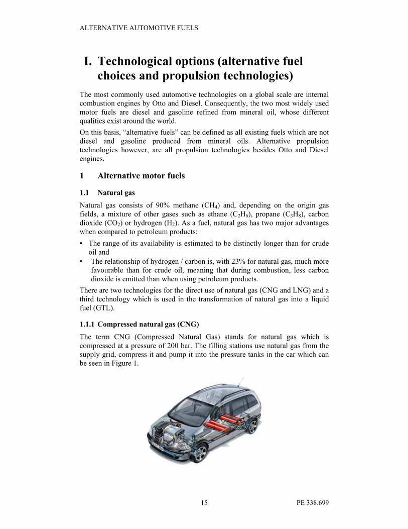
1.1.1 Compressed natural gas (CNG)
The term CNG (Compressed Natural Gas) stands for natural gas which is compressed at a pressure of 200 bar. The filling stations use natural gas from the supply grid, compress it and pump it into the pressure tanks in the car which can
be seen in Figure 1.

ALTERNATIVE AUTOMOTIVE FUELS
PE 338.699 16
Figure 1: The Opel Zafira 1,6 CNG3. The four CNG tanks can clearly be seen.
The use of natural gas as a fuel requires engines which work according to the Otto
principle.4 Therefore, for cars running on natural gas, Otto engines are used, which are optimised for the use of natural gas. The adaptation can be done:
• exclusively for natural gas without the possibility of using gasoline
(monovalent vehicles) or
• for gasoline and natural gas (bivalent vehicles). Switching from one fuel to the other can be done by the driver at the dashboard or automatically if one of the
fuels is running out. However, diesel engines are required in natural gas fuelled trucks and buses, which are adapted to the Otto principle exclusively
in the monovalent modus.
CNG has a lower energy content per litre than gasoline or diesel. This initially can
be seen through the lower range of CNG vehicles compared to gasoline or diesel-fuelled vehicles. However, conventional gasoline tanks still exist in bivalent vehicles (in contrary to monovalent vehicles). Thus, the range of the bivalent
vehicles is clearly increased.
In some cars, the CNG tank is put into the boot. At the same time, a number of mono- and bivalent CNG cars exist in which the tank is integrated in the bottom of the vehicle (see Figure 2), without loss of boot space. For buses and trucks
requiring greater fuel storage the tanks are put onto the vehicle’s roof.
Figure 2: The steel tanks for CNG integrated in the bottom of the vehicle, outside
the crumple zone. View from the bottom (Example Opel Zafira 1,6
CNG5).
The advantages of CNG fuel fall mainly into the environmental category (less CO2 and other pollutant emissions) and the protection of the mineral oil reserves.
3 Source: http://opel-osv.de.
4 However, the development of natural gas-fuelled Diesel engine has started (Statement of Dr.
Jürgen Lenz,Ruhrgas AG, Essen, on the European Forum “Sustainable Mobility in Europe –
with CNG into the Future” on September 18, 2003, on the IAA, Frankfurt/M.
5 Source: http://opel-osv.de.
ALTERNATIVE AUTOMOTIVE FUELS
PE 338.699 17
1.1.2 Liquefied natural gas (LNG)
LNG is not a specific automotive fuel, but a favourable form in which natural gas can be transported. LNG is liquefied natural gas transported and stored at –165° C
and at a pressure slightly above atmospheric. In the condensed liquefied form, natural gas can be transported very efficiently, e.g. in trucks or railway wagons. Once it arrives at its destination, LNG can be transformed into gaseous CNG.
Thus, LNG can enable a natural gas supply of installation without connection to the natural gas grid.
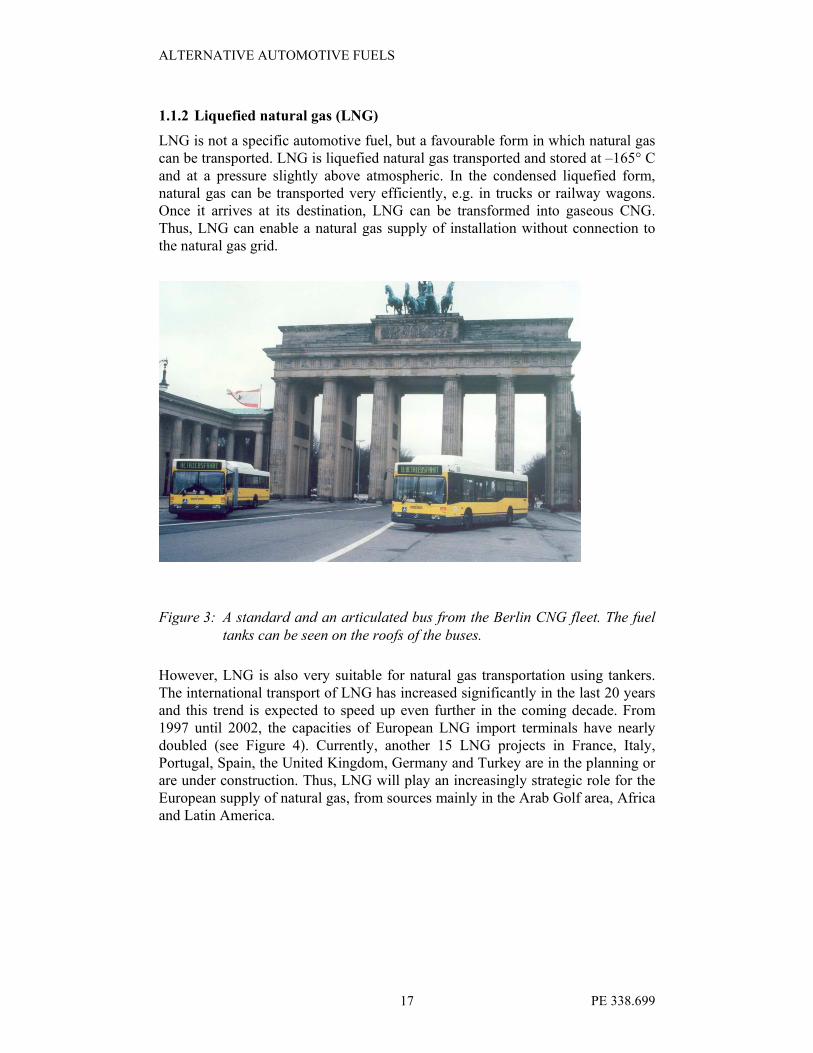
Figure 3: A standard and an articulated bus from the Berlin CNG fleet. The fuel
tanks can be seen on the roofs of the buses.
However, LNG is also very suitable for natural gas transportation using tankers.
The international transport of LNG has increased significantly in the last 20 years and this trend is expected to speed up even further in the coming decade. From
1997 until 2002, the capacities of European LNG import terminals have nearly
doubled (see Figure 4). Currently, another 15 LNG projects in France, Italy, Portugal, Spain, the United Kingdom, Germany and Turkey are in the planning or are under construction. Thus, LNG will play an increasingly strategic role for the
European supply of natural gas, from sources mainly in the Arab Golf area, Africa and Latin America.

ALTERNATIVE AUTOMOTIVE FUELS
PE 338.699 18
LNG import terminals in Europe
Capacity in mio m³ 1997 2002
Belgium 155 260
France 300 510
Greece 0 75
Italy 59 100
Spain 215 560
Turkey 155 255
United Kingdom 31 0
Total 915 1760
Figure 4: The capacity of LNG import terminals in Europe6
However, the extreme temperature of –165° C for LNG requires an excellent resistance to cracking from those materials with which it comes into contact. Furthermore, the heat transfer from the environment into LNG through the
insulation material, leads to a continuous evaporation of the liquefied gas into the gaseous phase (boil-off). This gaseous natural gas is often brought into the atmosphere through “open rack” evaporators which have a strong effect on
climate change: 1 kg of natural gas (i.e. methane) has a climate change potential which is 32 times higher than 1 kg of carbon dioxide.
1.1.3 Gas-to-liquids (GTL)
The development of gas-to-liquid fuels (GTL) is only in its infancy. Details of this process are given in chapter 3.2.2 “Current research activities in the alternative fuels and automotive technologies”.
1.2 Bio-fuels
1.2.1 Biodiesel (RME) 7
Biodiesel is produced by mechanically extracting natural vegetable oils from seeds, such as rape, and reacting the oil with methanol in the presence of a sodium
or potassium hydroxide catalyst. Valuable by-products are produced during the production including straw (which can be used as a fuel), oilseed cake (a protein rich animal feed) and glycerol used in the production of soap and as a
pharmaceutical medium. The production of biodiesel, such as rape methyl ester, is still done on a small scale and does not presently enjoy the economies of scale available to the production and distribution of diesel.
6 Source : DIW, 2003, p. 566.
7 http://www.biodiesel.co.uk.

ALTERNATIVE AUTOMOTIVE FUELS
PE 338.699 19
Emissions of greenhouse gases (g/km)
Diese
l
Biodiese
l
Extraction 15.84 Fertiliser production 15
Transport 2.74 Fertiliser application 10
Refining 13.63 Agricultural machinery*
25
Distribution 0.95 Oil production 3
Vehicle operation
245 Processing -straw** 1
Processing-gas 17
Transport 5
Vehicle operation 0
Total 278.1
6 Total (straw
processing) 59
Total (gas
processing) 75
* assume mineral diesel oil used ** emissions of straw include those from transporting straw
Figure 5: Emission of greenhouse gases from diesel and bio-diesel8
Unlike diesel, RME, otherwise known as FAME (fatty acid methyl ester), aside
from contaminants, does not contain sulphur and should not give rise to SOx emissions. The carbon dioxide emissions produced when the fuel is used are a
product of photosynthesis occurring in the previous year. One would expect net tailgate emissions of carbon dioxide and SOx (aside from contaminants) to be zero. Carbon dioxide and SOx will however be emitted elsewhere in the life cycle
(Figure 5).
Life cycle emissions of greenhouse gases from biodiesel are 24% those of diesel when processing is fired by straw and 30% those of diesel when gas is used to fire the processing. The difference between greenhouse gas emissions arises chiefly as
a result of emissions neutrality during the actual running of the vehicle (vehicle
operation). Biodiesel has a major advantage over fossil diesel concerning
greenhouse gas emissions. 9
8 http://www.biodiesel.co.uk.
9 http://www.biodiesel.co.uk.

ALTERNATIVE AUTOMOTIVE FUELS
PE 338.699 20
1.2.2 Biomass-to-liquid (BTL)
The development of biomass-to-liquid fuels is only in the beginning phase. Thus, the details are given in Chapter 3.2.1 “Current research activities in the alternative
fuels and automotive technologies”.
1.2.3 Other biofuels
Biomass can be used as an automotive fuel through a number of different
processes and products, e.g. as bio-ethanol, bio-methanol, biogas or through the
gasification of wood and other biomass.
As these biofuels cover only niches or regionally limited markets (e.g. ethanol in Brazil) and will have a limited importance on the world market, they will not be
considered in any further detail in this report.
1.3 Hydrogen10
1.3.1 Hydrogen sources and methods of production
Hydrogen is abundant in our world in its chemically bound form. Energy is needed in order to isolate it in its elementary form from its sources. The main
sources are water, hydrocarbons and coal.
In 1988 the annual world hydrogen production was 5 x 10¹¹ Nm3 (Appl, 1997).
This includes hydrogen produced on purpose and hydrogen received as a by-product. In 1988, the sources of hydrogen, by decreasing order of importance, were
• natural gas (48% of world production),
• oil (30% of world production),
• coal (18%), and
• electrolysis (4%).
The electrolytic hydrogen was mainly derived as a by-product of chlorine-alkali
electrolysis (Appl, 1997).
Hydrogen is often economically recovered from the hydrogen-rich off-gases of
other processes, especially in refineries. The purge gases from ammonia, methanol, ethylene and ethylene oxide plants also contain fair amounts of
hydrogen. Three technologies are available for hydrogen recovery from off-gases, namely Pressure Swing Adsorption, Membrane separation and Cryogenic separation (Appl, 1997).
For capacities above 1000 Nm3/h, the production of hydrogen from hydrocarbons
in dedicated plants is generally preferred. The main production processes are steam reforming and partial oxidation.
(a) Steam reforming
Catalytic steam reforming is the main industrial route for hydrogen production. It is based on the endothermic reaction of hydrocarbons with steam to form carbon monoxide and hydrogen. Natural gas is the most important feedstock, but
10 Source: Zoulias, 2003.

ALTERNATIVE AUTOMOTIVE FUELS
PE 338.699 21
propane, butane, liquefied petroleum gas and some naphtha fractions are also used (Ullmann’s, 1989). In the shift conversion steps (high- and low-temperature), the carbon monoxide reacts with excess water to form carbon dioxide and hydrogen,
releasing heat.
According to the long-established process sequence, carbon dioxide was subsequently removed by a scrubbing process and hydrogen was purified by methanation to 95-98%, containing mainly methane and a small amount of
nitrogen (Appl, 1997).
The Pressure Swing Adsorption (PSA) technology, which was first introduced by Union Carbide 30 years ago, has actually been adopted in most new steam reforming plants. In the PSA system, hydrogen of very high purity (>99.9%) is
separated from the shift-converted gas by adsorption on molecular sieves, replacing the low temperature shift conversion, carbon dioxide removal and
methanation process steps (Appl, 1997).
(b) Partial oxidation There are two commercial processes for hydrogen production by partial oxidation, namely the Texaco Synthesis Gas Generation Process and the Shell Gasification
Process. Partial oxidation is a very versatile process, because it can use any hydrocarbon feedstock from natural gas to very heavy residues, such as asphalt. It may become particularly attractive in the future, as a means of converting
products of low value, which are difficult to deal with for environmental reasons (Appl, 1997).
The raw gas must generally be purified, because heavy feedstock can easily contain as much as 7.5% sulphur, which is mainly converted to hydrogen
sulphide. Hydrogen sulphide is generally removed in a Rectisol process, using chilled methanol as an absorbent (Appl, 1997). The oxidation reactions of the hydrocarbon feedstock take place almost simultaneously with the water gas
reaction, the CO shift conversion and the methane formation or decomposition reaction, at a temperature of 1250-1500°C and a pressure of 3-12 MPa (Ullmann’s, 1989).
(c) Coal gasification Almost all types of coal can be gasified to produce hydrogen. There are several
commercial gasification processes, but the highest yield in the primary
gasification step is achieved, if pulverized coal is gasified with oxygen at high temperatures. Most of these processes are interesting from a technological rather than from an economical point of view. At high gasification pressure, the yield of
hydrogen is slightly reduced, but the economics are improved. Therefore, modern
gasification processes are operated at minimum 2 MPa, and the hydrogen yield may be improved by a slight increase in temperature (Ullmann’s, 1989).
(d) Electrolysis In the electrolysis process, electrical energy is supplied, in order to split a water
molecule to its constituents, hydrogen and oxygen, according to the reaction:
H2O → H2 + ½ O2

ALTERNATIVE AUTOMOTIVE FUELS
PE 338.699 22
The electrolytic hydrogen produced is very pure and contains only small amounts of oxygen and water vapour.
Depending on the technology, size and condition of the electrolysis plant, the
energy requirement for the production of 1 Nm3 of H2 ranges between 4 and 6
kWh.
The high electrical energy requirement for water electrolysis is mainly due to the high over-potential of oxygen evolution. The energy requirement decreases as the temperature of water electrolysis increases.
(e) Other methods There are several other methods possible for the production of hydrogen. The decomposition of ammonia is the reverse of the ammonia synthesis and it is
favoured at high temperatures and low pressures. The decomposition of methanol
is also favoured at high temperatures and low pressures, and it is generally carried out at 300-450°C and 7-30 bar over a copper-nickel or zinc-chromate catalyst
(Appl, 1997). Hydrogen may also be produced by thermochemical, photochemical, photocatalytical, photoelectrochemical, or photobiological processes.
1.3.2 Hydrogen storage
There are three main ways to store hydrogen:
• as a compressed gas,
• as a liquid and
• in the form of metal hydrides.
Carbon based materials are another hydrogen storage possibility, but they are currently in the early stage of development (see Chapter 3.3.2).
(a) Compressed gas
Compressed hydrogen is one of the simplest forms of hydrogen storage (Haland A, 2000). The only equipment required is a compressor and a pressure vessel (Schwarz et al, 1993), but the main problem with this technology is the low
storage density (shown in Figure 6) which depends on the storage pressure. Higher storage pressure result in higher capital and operating costs (Garret DE,
1989). Low-pressure spherical tanks can hold as much as 1,300 kg of hydrogen at
12-16 bar (Hart D, 1997).

ALTERNATIVE AUTOMOTIVE FUELS
PE 338.699 23
Figure 6: Comparison of fuel energy densities (Source: Zoulias et al., 2003)
Thiokol propulsion (Haland A, 2000) developed a composite wrapped tank
prototype with ~12% hydrogen by weight at 345 bar, 300 K, with a safety factor 2.25, which demonstrates the feasibility of using compressed hydrogen gas for
vehicular operation. The use of hydrogen as a vehicular fuel will require a safe
and cost-effective means of on-board storage. This physical storage may be accomplished in the form of compressed gas. To achieve a vehicle range comparable to a vehicle running on gasoline will require storing gaseous
hydrogen at pressures of 350 bar and higher. High-strength composite materials
will be necessary in order to minimize weight and maximize stored mass. In 1998, Lincoln Composites, a Division of Advanced Technical Products, began testing
and delivery of the first all-composite high-pressure tanks for storage of hydrogen on fuel cell vehicles (Tiller et al, 2002).
Many of the challenges relating to the future of hydrogen as a vehicular fuel
source are the same or similar to those as for natural gas. Hydrogen storage on an
automobile is an even more complex problem than was the storage of natural gas. Natural gas is stored at 200 to 250 bar. Since the energy density of hydrogen gas is so low, much higher pressures are being considered. To store enough hydrogen
gas to provide an acceptable vehicular range will require pressures of
approximately 350 bar to 700 bar. These high storage pressures depend on the use of high strength composite materials such as carbon fibre.
Most of the concern for hydrogen compatibility of pressure vessel materials is
centred on hydrogen embrittlement issues. Hydrogen embrittlement is a problem for materials that develop a "homogeneous crystalline lattice" for strength. The
effects of hydrogen on the material properties of a crystalline material are based
on the interactions of the solute hydrogen (molecular or atom) or hydrogen-based chemical products at the grain boundaries of the molecular lattice. The hydrogen/hydrogen products affect the dislocation energies at the grain
boundaries (micro level), which in turn, affect ductility, reduction of area and
tensile strengths (macro level) of the material.
0
10
20
30
40
50
60
70
80
90
100
Relative Energy Density
Gas CNG 25 MPa H2 35 MPa

ALTERNATIVE AUTOMOTIVE FUELS
PE 338.699 24
The three materials with the widest use for hydrogen storage are:
• Carbon/Epoxy Laminate. The question of hydrogen embrittlement is simply not appropriate for composite materials. Composite materials do not develop homogeneous structures. The mechanics of fibre-reinforced materials are
based on a highly anisotropic material condition. Grain boundaries, edge dislocation energies, and other crystal phenomena simply do not exist in
composite materials. Understanding the fundamental structure of filament
wound composite helps to focus on what is important to the response of fibre-reinforced material in a hydrogen environment. The molecular hydrogen, at worst case, can dissociate in the presence of water to form mild acid solutions.
It can easily be shown that carbon fibre is inert to acid solutions. In the
laboratory, determination of fibre content of a laminate is done by removing resin from the composite sample with extremely strong, heated acid solutions.
These solutions digest the resin compounds to leave only the carbon fibre. In addition, testing of carbon-reinforced tanks in accordance with the NGV2 acid environment test has demonstrated that the carbon fibre is unaffected.
• HDPE Liner. The hydrogen compatibility of high-density polyethylene is well documented by many years of successful applications in hydrogen environments. These applications range from 30 years of natural gas pipeline
service (significant percentage of hydrogen) to hydrogen gas service in the
chemical industries.
• Aluminium End Bosses. The use of aluminium materials in hydrogen service
is also well documented in numerous aerospace programs. NASA recognises
the use of aluminium in hydrogen systems in their safety manual (NASA, 1996): aluminium is one of the few metals with only minimal susceptibility to
hydrogen attack. Aluminium shows little effect in hydrogen environments, because aluminium hydrides cannot be formed during the production and service of aluminium. In addition, aluminium oxides cannot be reduced by
hydrogen, even at the melting point of aluminium. This exceptional chemical
stability, coupled with a very low solubility of hydrogen within the aluminium material crystalline matrix prevents hydrogen interactions at the boundaries of
the aluminium metal grains thus retaining the aluminium’s intended material response. This has been confirmed in material testing done by
Walter/Chandler (1968) in which notched aluminium bars tested in 690 bar
hydrogen suffered no loss of strength or reduction of ductility.
(b) Liquid hydrogen A major concern in liquid hydrogen storage is minimizing hydrogen losses from
liquid boil-off. Because liquid hydrogen is stored as a cryogenic liquid, which is
at its boiling point, any heat transfer to the liquid causes some hydrogen to evaporate. The source of this heat can be mixing or pumping energy, radiant
heating, convection heating or conduction heating. Any evaporation will result in a net loss in system efficiency, because work went into liquefying the hydrogen, but there will be an even greater loss if the hydrogen is released into the
atmosphere instead of being recovered. An important step to prevent boil-off is to use insulated cryogenic containers, which are designed to minimize conductive, convective, and radiant heat transfer from the outer container wall to the liquid

ALTERNATIVE AUTOMOTIVE FUELS
PE 338.699 25
(Wade AA, 1998). All cryogenic containers have a double-wall construction and the space between the walls is evacuated to nearly eliminate heat transfer from convection and conduction. To prevent radiant heat transfer, multiple layers (30-
100) of reflective, low-emittance heat shielding (usually aluminized plastic Mylar) are put between the inner and outer walls of the vessel. A cheaper alternative to Mylar film is perlite (colloidal silica) placed between the vessel walls
(Timmerhaus C, 1989). Some large storage vessels have an additional outer wall with the space filled with liquid nitrogen. This reduces heat transfer by lowering
the temperature difference driving the heat transfer (Huston EL, 1984).
Most liquid hydrogen tanks are spherical, because this shape has the lowest
surface area for heat transfer per unit volume (Michel et al, 1998). As the diameter of the tank increases, the volume increases faster than the surface area, so a large tank will have proportionally less heat transfer area than a small tank, reducing
boil-off. Cylindrical tanks are sometimes used because they are easier and cheaper to construct than spherical tanks and their volume-to-surface area ratio is almost the same (Timmerhaus C, 1989).
Liquid hydrogen storage vessels at customer sites typically have a capacity of 110
to 5,300 kg (Huston EL, 1984, Taylor et al, 1986, Das LM, 1996). NASA has the
largest spherical tank in the world with a capacity of 228,000 kg of liquid hydrogen (Taylor et al, 1986, Das LM, 1996). Hydrogen liquefaction plants
normally have about 115,000 kg of storage onsite. Single tanks can be constructed to hold as much as 900,000 kg of hydrogen.
Figure 7: Storage efficiency of hydrogen storage systems (Source: Zoulias et al.,
2003)
Even with careful insulation, some hydrogen will evaporate. This hydrogen gas can be vented, allowed to build up pressure in the vessel, or captured and returned to the liquefaction process. If the liquid hydrogen is stored in a pressure vessel,

ALTERNATIVE AUTOMOTIVE FUELS
PE 338.699 26
the gas can be left to build up gradually until it reaches the design pressure, then some of the gas must be vented (Michel et al, 1998). Another option if the hydrogen is stored on the same site where it is liquefied is to pull the hydrogen
gas out of the liquid hydrogen vessel and re-liquefy it. This way no hydrogen is lost, and because the hydrogen gas is still cold, it is easier to compress. For mobile hydrogen storage use, tanks need above all to be light and small. In Figure 7
different storage systems for liquefied hydrogen are compared on the basis of their storage densities in terms of the volume and weight of the respective storage
vessels.
Compared with the classical storage of compressed gas in metal cylinders, higher
storage densities are reached, for example by composite vessels or with metal hydrides (Kesten et al, 1995). However, only the storage of hydrogen as a liquid results in the highest storage densities, in both volumetric and gravimetric terms
(Michel et al, 1998). On a weight basis, liquid hydrogen represents the highest energy density in a chemical fuel. It is mainly for this reason that liquid hydrogen has found such a widespread application as a principal fuel in the space programs.
However, in view of the liquefaction temperature of about 20 K, there occurs a significant energy penalty for the liquefaction process. It has been estimated that
the process of liquefaction needs an energy level equivalent to approximately 30%
of the combustion energy of the hydrogen that is liquefied (Das LM, 1996).
A modern mobile LH2 tank basically consists of (Figure 8):
a) The inner and outer vessel with a high-grade super-insulation between them,
b) Connections for filling, withdrawal and pressure relief valves and
c) The liquid level sensor and the pressurization device.
Figure 8: Mobile liquid hydrogen storage tank11
11 Source: Zoulias et al., 2003.

ALTERNATIVE AUTOMOTIVE FUELS
PE 338.699 27
Liquid hydrogen is kept at a temperature level of about 20 K. The storage system needs perfect insulation, which is presently available as rigid, closed cell porous material. This is often considered a better mode of storage than compressed gas.
However, there occurs a hydrogen loss of about 2% per day due to evaporation. Utilisation of hydrogen in the liquid stage in various areas of applications is a well known technology.
(c) Metal hydrides The science and technology of reversible metal hydrides, in other words, the
hydriding and dehydriding (H/D) of metals (M) by both direct dissociative
chemisorption of H2 gas (1) and electrochemical (2) splitting of H2O are very simple (Sandrock G, 1999):
xMHHx
M ↔+ 22
(1)
−− +↔++ OHx
MHex
OHx
M x222
2 (2)
For practical purposes metal-hydrides are intermetallic compounds, which when exposed to hydrogen gas at certain temperatures and pressures, absorb large quantities of hydrogen gas forming hydride compounds (Da Costa et al, 2002). The formed hydrides can then, under certain temperatures and pressures, desorb the stored hydrogen. Hydrogen is absorbed interstitially in the metal lattice expanding the parent compound in the atomic and macroscopic level. Such metal-hydrides can expand as much as 30% causing the decrepitation of the original ingots into fine powders. Metal-hydrides are inherently safer than compressed gas or liquid hydrogen and have a higher volumetric hydrogen storage capacity. Some hydrides can actually store hydrogen in densities twice as much of that of the liquid hydrogen (0.07 g/cm3).
Stationary storage usually implies bulk storage and the use of large amounts of alloy. Therefore, in such a case, low alloy cost tends to be an important factor. On the other hand vehicular storage tends to require a high hydrogen weight percentage. In fact, most existing hydrides fall far short of what is desired in this property, as shall be described below. Both kinds of storage desire easy activation to minimise container pressure and temperature requirements for the one-time activation. In both cases, good resistance to gaseous impurities is desirable in case impure H2 is used or the inevitable accidental introduction of air occurs. In both cases, Pressure-Composition-Temperature (PCT) properties should be roughly in the ambient temperature and pressure area so that waste heat from the environment or vehicle engine (or fuel cell) can be used for endothermic H2 desorption. Kinetics are somewhat less important because of the relatively slow cycling of storage tanks.
In order to capitalise on practical applications of reversible hydrides, it is required to combine strong hydride forming elements A with weak hydriding elements B to form alloys (especially intermetallic compounds) that have the desired intermediate thermodynamic affinities for hydrogen. A classic and well-known

ALTERNATIVE AUTOMOTIVE FUELS
PE 338.699 28
example is the combination of La with Ni to form the intermetallic compound LaNi5. This extraordinary ability to “interpolate” between the extremes of elemental hydriding behaviour has led to the modern world of reversible hydrides
and the applications associated with this.
There are several types of intermetallic compounds, the most common of which are: AB5, AB2, AB, A2B alloys. There are also other intermetallic compounds, such as AB3, A2B7, A6B23, A2B17, A3B, which are currently under development for use in the storage of hydrogen. New directions for hydriding materials include amorphous and nanocrystalline alloys, quasi-crystalline alloys, transition and non-transition metal complexes and carbon.
Chemical hydride (LiH, NaH, CaH2) slurries (in light mineral oil) are used as hydrogen carriers and storage media (Breault et al, 1998). The slurry protects the hydride from an anticipated conduct with moisture in the air and makes the hydride pumpable. Hydrogen gas is produced by a chemical Hydride/water reaction. The main advantage of the method is high hydrogen storage capacity (up to 25 wt% in LiH). The main disadvantage is that the system is not refillable, and it is difficult to extract the hydrogen.
1.4 Liquefied petroleum gas (LPG)
Liquefied petroleum gas (LPG) is a mixture of light hydrocarbons (C3 and C4), mainly propane, propene, butane and butene. Under atmospheric conditions, it is gaseous, but under slightly higher pressure, it becomes liquid. In this state, it can easily be transported and stored as it requires only a 260th of the initial volume.
LPG is won from the mineral oil refining processes and as a by-product from the extraction of mineral oil and natural gas.
The applications of LNG are manifold. In the transportation sector, it fuels four million vehicles of which about half are in Europe.12 It is also often used for sideloaders.
1.5 Other alternative motor fuels
There are a number of other alternative motor fuels. These fuels, however, are expected to exist in regional niche markets, and will have a limited role in European road transportation and therefore will not be treated in more detail within this report. 13
2 Alternative propulsion technologies
There are a great number of other propulsion technologies besides those combustion engines which operate according to Otto and Diesel principles. Those which are expected to play a dominant role in future markets will be described In the following chapters.
There is also the possibility of combining different propulsion technologies in one vehicle (hybrid vehicles). An example of this is the combination of a conventional
12 http://www.propan.de
13 Repsol YPF, 2003.

ALTERNATIVE AUTOMOTIVE FUELS
PE 338.699 29
internal combustion engine, a generator and an electric, battery-powered drive, e.g. for more environmentally-friendly propulsion in inner cities.
For decades, the development of hybrid technologies has seen a number of technological breakthroughs, however, it is unlikely that any of the hybrid technologies currently on offer will lead to a market breakthrough or even obtain a major market share in the near future, as long as a suitable “single” technology is available. Hybrid technologies are more complex, more expensive and often less energy-efficient than single technologies: the more extensive the technology, the more voluminous and heavier.
This report will therefore not deal with hybrid technologies any further.
2.1 Fuel cells14
2.1.1 Technology overview
The basic physical principle behind a fuel cell can be characterised simply as a “reverse electrolysis”. Whereas hydrogen and oxygen are produced along with electricity through the electrolysis of water, a fuel cell produces power with the “cold burning” of both these gases in a reverse process. This is made possible by letting the two gases react separately in the different compartments (the electrodes) of the fuel cell. As a result hydrogen and oxygen cannot directly react with each other, which would lead to an explosion, but are forced to release their energy in a “tamed” reaction whilst being separated from one another. The products of this reaction are electricity and, when pure hydrogen is used for fuel, water vapour. The two “reaction chambers” of the fuel cell are called the cathode, which is supplied with oxygen or air, and the anode, which is fed with fuel gas. Both are separated by a gas-tight, ion-conducting layer, hence the name: electrolyte.
source: www.initiative-brennstoffzelle.de
Figure 9: Basic design of a proton exchanging fuel cell15
14 European Commission, 2003.

ALTERNATIVE AUTOMOTIVE FUELS
PE 338.699 30
At the anode, the entering fuel gas (mostly H2) is catalytically separated into a positive proton (H+) and an electron. On the cathode side, the oxygen (mostly from air) can react with the electron from the anode side. Both reactions are
thermodynamically favoured and are exothermic – meaning they occur without external energy input. Depending on the material of the electrolyte, either the negatively charged oxygen containing ion from the cathode side or the positively charged hydrogen ion (proton) from the anode side can travel through.
The electron itself has to pass through the electrical circuit to power an external load. After the ion has passed through the membrane it binds with its counter-ion to form a water molecule. At this point, most of its available energy has been already harnessed by the “travelling” of the electron through the load and only the remaining small amount of energy associated with the ions is released without the effects of a hydrogen / oxygen reaction.
A fuel cell (also called a stack) is a modular technology (compared to an internal combustion engine) and is a relatively simple structured unit consisting of the electrolyte which can be either liquid or solid, the porous anode and cathode electrodes, the bipolar plates and one endplate at each side forming the stack. Basically, every type of fuel cell is built out of these four components. This modular design with many single elements is necessary to obtain the high internal surface area that is required to reach a high enough outputs. Also, the voltage from a single cell is too low for standard operational uses and consequently several cells have to be put together.
Figure 10: Fuel cell stack with one element separately drawn (Example: Proton
exchange membrane fuel cell PEMFC)
15 Here the electrolyte is depicted as being porous, but fuel cell electrolytes are actually made of
non-porous materials (otherwise the gases themselves could pass through). This illustrates
how the proton travels in the fuel cell.

ALTERNATIVE AUTOMOTIVE FUELS
PE 338.699 31
2.1.2 Efficiency
Apart from the environmental benefits derived from a reduction in exhaust emissions, a high level of efficiency is the other technological advantage of fuel
cells over other conventional heat engine powered generation such as the internal combustion engine or the gas turbine. As chemically bound energy is directly transformed into electricity in one step, without having to first convert it into heat (hence the name heat engine) and then mechanical energy, other thermodynamic laws apply. When the temperature rises, the voltage drops and consequently the efficiency decreases with the process temperature. This is defined as the usable energy (either mechanical or electrical) divided by the amount of chemical energy put into the process. The heat engine has a characteristic contrary to this. Below the theoretical and currently attainable efficiencies of both processes are shown.
0%
20%
40%
60%
80%
100%
0 200 400 600 800 1000 1200 1400 1600
temperature [°C]
efficiencyel %
fuel cellheat engine(carnot process)
today's efficiencies
heat engine
today's
efficiencies
fuel cell
fuel cell
Figure 11: Theoretical and achieved efficiencies of fuel cells and heat engines
depending on the operation temperature
It is important to stress that there is a big difference between the theoretical efficiency, which is only limited by the laws of physics and which define the maximum attainable, and the “real” efficiencies which are possible today. Even after a century of continuous technological advancement, the heat engine is “stuck” at about 55-60%, which is the ultimate maximum efficiency which can be reached with current state-of-the-art LPC gas turbine combined cycles, whose turbine efficiency itself is 40% maximum. The internal combustion engine has efficiencies of 25% (gas engine) and 35% (diesel engine) with substantial efficiency losses in half load modes where fuel cells are operating best.
Fuel cells, far from being as optimised as heat engines, can easily reach 40-50% efficiency over a wide range of temperatures. The fact that they are a long way from the 80-90% which is theoretically possible is caused by the discrepancy between the pure laws of physic and the electrochemical reaction velocity which

ALTERNATIVE AUTOMOTIVE FUELS
PE 338.699 32
is quite slow at low temperatures and reduces the efficiency of the whole process. The higher the reaction temperature, the closer one gets to the theoretically possible. Also, for a fuel cell there are no losses caused by friction, which occur
when the chemical energy is transformed to mechanical and then to electrical energy as is the case for heat engines.
2.1.3 Environmental aspects
Because of the so-called “cold” combustion at low temperatures the amount of emissions of nitro oxides is almost non-existent. Also CO emission is very low, due to the low tolerance of the catalyst (of low temperature fuel cells) for CO and the danger of poisoning it. CO2 is formed when fuel gases other than hydrogen are used. Other fuels like natural gas (mainly CH4), methanol or gasoline can be either directly fed into a suitable fuel cell (high temperature fuel cells) or after
conversion to H2 in a reformer. In both cases CO2 is formed, the amount of which corresponds with the carbon content of the fuel (lowest carbon content: CH4, highest: gasoline) and the overall net efficiency of the electricity generation. SO2 which is poisonous for the catalyst is also not emitted due to the imperative non-existence of sulphur in the fuel.
2.2 Hydrogen Combustion16
Catalytic burners use a coating of a catalyst to ‘burn’ a fuel chemically. There are two basic concepts, the catalytic heater and the hybrid system. The fuel, which in this case is pure hydrogen, is fed onto the catalytic surface and reacts with oxygen
in the air and produces heat. Water vapour is also produced, and this may result in unacceptable rises in humidity levels for certain applications. Catalytic burners are self starting, therefore when hydrogen is fed to the catalyst the reaction starts and heat is generated with an ‘invisible flame’. This should be no problem for most applications. The range of temperatures that can be produced by a catalytic burner is much wider than those produced by a conventional flame and can be controlled much more finely.
Hydrogen can be burnt in a standard internal combustion engine with marginal modification, but only with a performance penalty for vehicular applications. If it is burnt in a dedicated hydrogen engine, the performance may be better than that
of a comparable gasoline engine. The important differences between a hydrogen and a gasoline burning engine are due to the very high flammability of hydrogen in air. Not only does it require less energy to ignite, it also burns over a much wider range of mixtures and more quickly. This requires some modifications to the engine (Hart D, 1997).
2.3 Other propulsion technologies
There is a great number of other propulsion technologies existing which are continuously developed and improved in terms of technical reliability, energy efficiency, economic viability, environmental performance or other
16 Zoulias et al., 2003.

ALTERNATIVE AUTOMOTIVE FUELS
PE 338.699 33
characteristics.17 Despite the continuous efforts for improvement, it is expected that these technologies will not cover major market shares in the future, but will be exist only in niche markets. For this reason, the authors decided to refrain from
an in-depth description of these propulsion technologies and concentrate on the most promising technologies.
3 Current research activities in the alternative fuels and
automotive technologies18
3.1 Fuel cells19
It is estimated that in 2002 about 4000 medium and large scale fuel cell devices were in operation world wide20. About half of all these systems are operated in the US and Canada with major companies such as Ballard and UTC Fuel Cells being the market leaders. The other half is roughly divided between Japan and Europe, each with about a quarter. About 150 fuel cell powered vehicles have been produced (cumulative) to date21 (2002/2003) with the first fuel cell powered vehicles being tested in the early 90s.
source: www.fuelcelltoday.com
Figure 12: Cumulative numbers of fuel cell units world wide
17 An example for this is the continuous development over decades of the Wankel Rotary
Combustion Engine by Mazda or the continuous development of electric wheel drives.
Pure (i.e. battery-supplied) electric drives will not be considered any further due to their limited
range, the required filling time and other relative disadvantages of energy storage (when
compared to other fuels). Energy recovery systems such as the feeding of electricity won from
braking into battery storages or the fly wheel are not considered further.
18 Please refer also to Chapter 0.
19 European Commission, 2003.
20 Source: fuel cell today, 2003.
21 www.hyweb.de
ALTERNATIVE AUTOMOTIVE FUELS
PE 338.699 34
Today the PEMFC (proton exchange membrane fuel cell) is the most promising and common fuel cell concept for integration into vehicles like cars or buses. Also the DMFC (direct methanol fuel cell) is seen to have potential to be introduced for
vehicle propulsion but to date is less technologically advanced than the PEMFC. Whereas methanol and also gasoline are thought to be the fuels of choice in the coming years due to the absence of a hydrogen distribution and filling infrastructure, most fuel cell cars and buses today run on compressed (CGH2) or liquefied (LH2) hydrogen. The technology for onboard conversion of fossil, carbon containing fuels is under intense development and car makers like GM are investigating this fuel option.
3.1.1 Cars
Currently, no fuel cell powered car is available on a commercial scale or has even
been introduced into the market. Many car manufacturers are developing propulsion concepts with fuel cells mainly through modifications of existing standard models (Daimler-Chrysler: A-class; VW: Bora; Opel/GM: Zaphira22; Ford: Focus; Toyota: FineS). To reduce the investment costs for research and development which can be in the order of several hundred million to a billion Euros, strategic partnerships are made among car manufacturers and other partners interested in fuel cell technology (oil industry, governments, etc.).
Most car concepts being developed for market introduction in the near to medium future (Ford Focus, Opel Zafira, Mercedes Benz F-Cell) integrate the fuel cell system and tanks into the car floor partly for space reasons and partly for safety considerations (protection of pressurised hydrogen storage tanks in the case of a road accident). Engine outputs range from about 25 to 75 kW for continuous operation with most at about 40-55 kW. Efficiency is about 35-40% depending on the fuel cell concept and the chosen fuel (hydrogen / methanol). Today, nearly all fuel cell cars are concept cars or prototypes which will probably not reach a series
status but are useful as test vehicles for (among other reasons) optimising mobile fuel cell application.
22 Der Tagesspiegel, 5 July 2003.

ALTERNATIVE AUTOMOTIVE FUELS
PE 338.699 35
Figure 13: The fuel cell car “Hy-wire”, a concept car from General Motors23
3.1.2 Light duty vehicles
Daimler-Chrysler has equipped one light duty vehicle with a fuel cell based propulsion system. It is integrated into a MB Sprinter chassis and is currently
being tested under real driving conditions.
3.1.3 Buses
Buses were one of the first vehicles to be demonstrated to run successfully with fuel cells. Several fuel cell related projects have incorporated fuel cell driven buses. Due to the fact that on the whole, entire fleets of buses are operated from one central bus station, the problem of refilling with an unconventional fuel (e.g. LH2, CGH2, CNG, LNG etc…) which is not readily available at normal filling stations can be easily solved. Investment in a special filling station for hydrogen (up to one million Euro) can be economically feasible if enough fleet vehicles are
running on the cheaper fuel.
Daimler Chrysler has modified its inner city Citaro bus to run with a 120 kW PEM fuel cell and will sell 30 buses within the framework of the CUTE project in Europe.
23 Source: Der Tagesspiegel, 5 July 2003.

ALTERNATIVE AUTOMOTIVE FUELS
PE 338.699 36
3.2 Syn-fuels (synthetic fuels)
3.2.1 BTL: methanol, syn-diesel and gasoline
The current production of synthetic fuels from biomass provides promising research for the improvement in efficiency of the so-called “bio-diesel” fuel.
Bio-diesel (and bio-fuels in general) is often considered to be CO2-neutral as its combustion process emits only as much carbon dioxide as that which the plants used have absorbed from the atmosphere when growing. Furthermore, bio-fuels
are renewable and their use reduces the dependence on oil imports.
Conventional bio-diesel, in terms of chemistry, is “rape methyl ester” (RME). Its production does not use the whole rape plant, but only the rape oil made from the seeds. This means that an important part of the energy contained in the plant remains unused or is used only in by-products.
Furthermore, the agricultural production of the plants is linked to the consumption of fossil fuels (fertilizer) and, thus, to further CO2 emissions as this is released during the transport and production of the bio-fuels. It can be said that bio-diesel and bio-ethanol have a better CO2 balance that fossil fuels, however their production is not CO2-neutral.
Furthermore, the areas used for the production of rape or other energy crops are limited as their production is partially in competition with edible food production: It is estimated that up to 12 to 17% of agricultural surfaces in Europe can be used for energy plants without affecting food production.24
Last, but not least, farmers can grow the plants only in an alternating fashion to avoid soil exhaustion. This, along with the fact that there is a low exploitation rate of energy contained in plants for the production bio-fuels, means that their contribution towards the entire fuel market is limited.
A typical syn-diesel production process is the one developed jointly by DaimlerChrysler, Volkswagen and Choren Industries. This process can use a large variety of different types of biomass as raw material: wood chips from wood rests from industry or forestry, waste wood, meat and bone meal, dried sewage sludge or the dried organic fraction of household waste.
In the first step of the process, the biomass is heated to between 400 and 600 °C
and smouldered. The products from this process are bio-coke (which is similar to charcoal) and a gas containing tar (see Figure 14).
24 DaimlerChrysler, 2003, p. 20.

ALTERNATIVE AUTOMOTIVE FUELS
PE 338.699 37
Figure 14: The raw product won from synthesis gas and containing tar in the left
glass and the fuel won from distillation processes in the right glass
(Source: DaimlerChrysler, 2003)
In a second step, this gas is burned at temperatures of 1300 to 1500 °C and thus the tar and other long hydrocarbons are decomposed into carbon monoxide, hydrogen, vapour and carbon dioxide.
This gas is then brought into contact with the bio-coke. The result of the chemical reaction is a tar-free gas (see Figure 14). After cleaning, the so-won synthesis gas can be the basis for the production of different, extremely clean fuels, e.g.
methanol, syn-diesel or gasoline depending on the chemical processes applied. Each fuel can thus be designed in accordance to the characteristics required.
The fuels are sulphur-free and contain only paraffines (linear hydrocarbons). Due to its purity, it is expected that the emission of particulates from syn-diesel will only be half of the those from conventional diesel. First results from tests are expected in Autumn 2003.
Another asset of this technology is the high efficiency of 50% which is considered to be higher than any other technology used in fuel production from renewable energy sources.25 However, the efficiency of the process depends on the sufficient presence of hydrogen, which must be added from external sources, as the production of hydrogen from this process is not sufficient.
In a future step, it is planned to substitute fossil fuels by wind power for the production of electricity needed for the electrolysis of hydrogen. Solar energy is also used in two different forms: for the production of biomass and for the production of hydrogen.
25 DaimlerChrysler, 2003, p. 21.

ALTERNATIVE AUTOMOTIVE FUELS
PE 338.699 38
It is expected that in 20 years, BTL fuels will cover 10 to 15% of the total fuel demand26.
3.2.2 Gas-to-liquid (GTL)
Natural gas is used today as a direct fuel, e.g. as CNG or LNG. This direct use requires an additional filling infrastructure and bulky fuel tanks in the vehicles. Both disadvantages are avoided if the natural gas is not used itself, but is transformed into a liquid fuel which can then be transported, distributed and consumed in the already existing infrastructure. Today, the most frequent GTL fuel is diesel.
The first plants for the production of GTL fuel have been constructed, e.g. two plants in Bolivia. 27 The 25 Volkswagen Golf is fuelled with GTL fuel from Shell within the framework of a test which started in May 2003 in Berlin28.
The advantages of GTL are:
• Energy from natural gas, which is a by-product of crude oil production and is often burned off, can be used.
• No additional infrastructure or changes in the vehicles are necessary.
• GTL fuel can be mixed with conventional fuels (e.g. with Diesel from fossil production) without any changes to the engine.
• The reserves of natural gas are expected to last longer than those of mineral oil. • As the GTL fuel is the product of a chemical transformation and refining
process, possibilities exist for the design of a fuel with excellent qualities, allowing progresses in efficiency and in the development of the burning engine and, thus, a reduction in environmental impairment.
However, the use of remote gas for the production of synthetic diesel induces
higher energy losses and higher green house gas emissions than the direct use as LNG or CNG. From the environmental perspective, the GTL option is counterproductive.
3.2.3 Biomethane
From the same chemical process which is used for the production of GTL (i.e. Fischer-Tropsch synthesis), bio-methane can be produced. However, as this development is at its beginning, a substantial demand for R&D can be seen. However, an efficient gasification process for producing bio-methane in large quantities becomes available, the estimated potential for biogas / biomethane is
significant higher than the potential for liquid biofuels.29
3.3 Hydrogen
Currently the most promising use for hydrogen energy is as a CO2 emission-free
and non-polluting transport fuel. There are a number of major projects around the
26 DaimlerChrysler, 2003, p. 25.
27 Repsol YPF, 2003.
28 http://www.shell.com.
29 Wuppertal Institute for Climate Environment Energy, 2003, p. 22.

ALTERNATIVE AUTOMOTIVE FUELS
PE 338.699 39
world designed to develop the use of hydrogen produced using fossil fuels to power fuel cell vehicles. For example, the EU funded European collaborative Clean Urban Transport in Europe (CUTE) project30, which includes BP among its
partners, is aiming to provide three hydrogen powered buses to each of ten European cities by the third or fourth quarter of 2003. Major projects to explore fuel cell technology are also underway in Japan, Canada and the United
States.31, 32
3.3.1 Hydrogen production
Hydrogen can be produced by different technologies such as hydrocarbon
reforming, nuclear or solar electrolysis or biomass conversion. Natural gas steam reforming is currently by far the cheapest process, even if when carbon dioxide sequestration is required.33
There are also a number of pilot projects in Europe designed to explore the use
of hydrogen produced from renewables in transport. These range from small scale regionally-funded demonstration projects such as hydrogen transport for the Gaia Energy Centre at Delabole in Cornwall, UK, which is currently under
discussion; to larger scale transport projects such as USHER (Urban Integrated
Solar to Hydrogen Realisation) and ECTOS (Ecological City Transport System) as well as projects that form part of the Campaign for Take-Off, an
ambitious plan which relies on renewables to make the Swedish Island of Gotland completely sustainable in energy by 2025.34
(a) Hydrogen from renewable energy sources Water electrolysis is the best way to produce hydrogen without causing pollution. Nevertheless, when fossil fuels are used as the primary source of electricity, the problem of environmental pollution remains unsolved. Therefore, electricity provided from renewable energy sources is essential for the production of emission-free hydrogen.
Aeolic energy usage cost for the production of hydrogen is nowadays 15-20$/GJ, but a fall in this cost is expected in the near future. The cost of hydrogen production from solar energy is rather high, approximately 100$/GJ. Therefore, hydrogen production from photovoltaics is rarely used in demonstration projects for hydrogen as a motor fuel. 35
A) Photovoltaics:
A major aim of the USHER project is to demonstrate the feasibility of using electricity generated from photovoltaic (PV) systems to power electrolysers to produce hydrogen to power fuel cell buses. Project members include
30 See also Chapter I.3.1.3.
31 See, for example, www.fuel-celltoday.com.
32 Morgan, 2003.
33 Shell International, 2001, p. 51.
34 Morgan, 2003.
35 Zoulias et al., 2003.

ALTERNATIVE AUTOMOTIVE FUELS
PE 338.699 40
- BP Solar, - the UK bus operating company, Stagecoach, - electrolyser manufacturer, Hydrogen Systems,
- the industrial gases company, Linde AGA, - the engineering consultancy, Whitby Bird and Partners, - Cambridge University Estates, - Cambridge University Engineering, - the Municipality of Gotland, - the Gotland Energy Agency and - ISLENET, a broad grouping of island communities for renewables dissemination. Funding for this 5 million Euro project comes from the European Commission, national governments and the partners themselves. The USHER project is based in two sites: Cambridge in the UK, and Gotlands Kommun in Sweden. In Gotland, 2500 m² of PV cells will be used to run electrolysers to produce the hydrogen to run fuel cell buses in the world heritage city of Visby. In Cambridge, 3500 m2 of PV cells - the largest single array in the UK — producing around 300 kWp will be installed on the roof of a colonnade in a new science park being built at the University, but located outside of the city centre. Transport to the science park will be provided by a fuel cell bus fuelled by hydrogen obtained by electrolysis using electricity from the photovoltaic cells. The Cambridge system will produce 30 m3 of hydrogen per hour from a 144 kW electrolyser. The hydrogen on the bus will be stored at high pressure, to
ensure the bus has a useful range and hydrogen for refuelling will be stored in a container at the science park site. The Cambridge buses were due to begin operation in the third quarter of 2003, however funding problems mean that completion may be delayed for a year. Nevertheless, when completed, the USHER demonstration project will enable an assessment to be made of the benefit of PV hydrogen generation as opposed to grid connection, in terms of cost, energy savings, emissions avoided, safety, technical feasibility, public acceptance and practicality. It will also help to demonstrate the use of hydrogen as a means of overcoming the intermittancy problems associated with PV electricity generation. 36,37
36 Morgan, 2003.
37 For more information please refer to www.europeanislands.net.

ALTERNATIVE AUTOMOTIVE FUELS
PE 338.699 41
Figure 15: The Usher project in Cambridge. The Cambridge system will produce
30 m³ of hydrogen per hour from a 144 kW electrolyser38
B) Wind-energy:
Over the last years, wind power has established itself as an economic, grid-connected electricity generating technology. Electricity production from wind energy converters is not steady, thus a storage medium for the energy is needed. Hydrogen produced via water electrolysis could be used as such a storage medium in the near future. Respective research projects are currently carried out at the University of Quebec at Trois-Rivieres, in Canada or in the Complex Laboratory of Alternative Energy at the Technical University of Applied Sciences in Stralsund, Germany.39 The Gaia Energy Centre is an environmentally focussed tourist attraction that has already contributed significantly to the regeneration of the local
community in east Cornwall. The aim of the Gaia project is to take
advantage of electricity generated from the nearby Delabole Wind farm — the UK's first commercial wind farm, which was opened in 1991 — to
electrolyse water to produce hydrogen and oxygen gas. The hydrogen will be used to fuel two hydrogen buses to provide public transport links in the
surrounding rural area. The buses will be powered by combustion engines
designed to run on hydrogen. As well as providing pollution-free transportation and a sustainable transport fuel, the project will also demonstrate one solution to the problem of intermittancy associated with
38 Picture taken out of: Morgan, 2003. Picture: Element Energy, a subsidiary of Whitby Bird and
Partners.
39 For details please refer to Menzl F., 2001, or Zoulias et al., 2003.

ALTERNATIVE AUTOMOTIVE FUELS
PE 338.699 42
wind turbine electricity. The project partners also hope it will generate further interest in the region and ensure that future growth in tourism is more sustainable. 40
C) Ocean Energy: The cost of producing hydrogen via water electrolysis is directly related to the cost of producing the electric power and hence directly tied to the electric generation method. To make hydrogen production more attractive, a less expensive source of electric power is needed. The oceans contain a huge amount of energy in the form of wind waves and swells crossing its surface. Examples for the variety of different research activities on ocean energy-electrolysis are: Aqua Magnetics Inc. has developed a reciprocating generator that directly converts the energy in ocean swells to electric power. The reciprocating generator can be used to supply all of the energy needed for the generation of hydrogen from the ocean. The size of the ocean swells is not constant and hence the electric power produced will not be constant, however, fluctuations in the energy is not a concern for this process (Woodbridge, 1996). At a rate of eight Space Shuttle launches per year, The Kennedy Space Centre consumes approximately 18.9 million l of liquid hydrogen. A pilot plant was proposed by Woodbridge (1996), which will utilise the energy in the ocean swells off the coast of the Kennedy Space Centre to create hydrogen via electrolysis. The cost of electric power will be reduced by approximately 40% through this method; the cost of the hydrogen created at
the Kennedy Space Centre will be less than purchasing hydrogen on the open market where power costs are significantly higher. The pilot plant will create 3,785,000 l of liquid hydrogen per year. This volume of hydrogen production will require a sea-water inlet flow of approximately 300 l/h. This inlet flow rate is relatively small. The inlet water will be desalinated by distillation or reverse osmosis prior to the electrolysis. The hydrogen produced was proposed to be stored as compressed gas to avoid losses due to boil-off. Whenever needed the hydrogen will be cooled to cryogenic temperatures and piped directly to the launch-site storage tanks. In Figure 16 a block diagram of the combined ocean swell energy (OSWEC) – electrolysis process for low cost hydrogen generation is demonstrated. The ocean energy system converts the energy in the ocean swells to electric power, which is distributed to the different functions of the overall hydrogen generation process. This figure also illustrates an added plus from using sea water, in that other useful chemicals can be obtained
from the salt brine.
40 Morgan, 2003.

ALTERNATIVE AUTOMOTIVE FUELS
PE 338.699 43
Figure 16: Block diagram of the combined ocean energy electrolysis
hydrogen generation process41
The OSWEC system of the proposed pilot plant consists of twelve reciprocating generators located approximately 2 km off the launch site in the Atlantic Ocean. The electric power will be brought to shore via submerged cables to the electrolysis plant. An advantage of this system is that it can be easily scaled-up to supply all of the hydrogen and oxygen required for launch operations at the Kennedy Space Centre and the Cape Canaveral Air Force Station, with the addition of more generators and electrolysis cells. Approximately 100 reciprocating generators would be required to provide the electric power for producing all of the liquid hydrogen required for launch operations at the Kennedy Space Centre (Woodbridge, 1996). Sea Power & Associates has developed the Wave Rider technology that consists of a series of lightweight concrete floats that would sit one to two miles off shore. Floats are connected to a hydraulic pump that extends about 18 m down to the ocean floor. The up-and-down motion of the waves creates pressure that drives the hydraulic pump, which then drives turbines to generate electric power. Sea Power's first target market is Hawaii and the islands of the Pacific Ocean, where the relatively high costs of generating electricity from imported fossil fuels provide an opportunity for immediate profitable operations and positive cash flow. They claim their system could be cost-competitive with diesel, which now costs 18 to 25 cents/kWh
(Locke, 2001).42
D) Combined renewable energy sources:
At the end of the 20th century, Iceland, a country which (despite its abundant geothermal and hydro power resources) produces more greenhouse gas emissions per capita than any other, set itself the goal of creating the world's
41 Source : Zoulias et al., 2003.
42 Zoulias et al., 2003.

ALTERNATIVE AUTOMOTIVE FUELS
PE 338.699 44
first hydrogen economy based on renewables. The ECTOS project, launched in March 2001, is billed as the first step in Iceland's transition to a hydrogen-based economy. Project members include both local Icelandic as
well as foreign and international companies, such as DaimlerChrysler; Shell Hydrogen and Norsk Hydro. The project objective is to demonstrate how a hydrogen economy based on renewables might work by using 3 fuel cell buses (or 4% of Reykjavik's total bus fleet) as part of the public transportation system in Reykjavik. The hydrogen will be produced from water by electrolysis, in a process powered by Iceland's abundant geothermal and hydro-power resources, then compressed and stored at a purpose-built fuelling station, where the fuel cell buses will refuel. A conference on the theme of Making Hydrogen Available to the Public, was held in Iceland at the end of April 2003 to celebrate the opening of the filling station.43
The island of Gotland has considerable potential for the development of
wind, solar and biomass sources, and in 1996 published an Eco-Programme that identified the municipality's goal "to become an ecologically sustainable society within the course of a generation." The
solar powered production of hydrogen in the USHER project is just one
part of an ambitious scheme to use renewables to make the island of Gotland completely self sufficient in terms of energy. The island's energy
plan also includes development of energy resources from biomass, wind power and solar energy, as well as introducing energy efficiency measures to reduce overall energy consumption. 44
(b) Other processes Recently, Prof. Kiyoshi Ohtsuka, of the Tokyo Institute of Technology, claimed that he has developed a process that decomposes methane completely, with no CO2 by-product. The process takes place at or below 500° C and atmospheric pressure. Methane is decomposed over a silica-supported nickel catalyst to H2 and carbon, which is recovered as a marketable fine powder. The product gas, which contains approximately 40% H2, is passed through metal oxides as Fe2O3 and In2O3 and the hydrogen reduces the oxides to metal, producing water. The metal is subsequently reoxidised with steam at about 300° C and pure H2 is obtained
(Chementator, 2000).
Very recently, Bockris (2002) proposed a method for electrolyzing sea water: by solar evaporation, sea water could be concentrated to approximately 5 M NaCl (brine), then it would be electrolysed with the anode potentiostated in order to evolve bromine instead of chlorine. Limiting current problems could be avoided by increasing greatly the area of the anode with respect to the cathode. The liquid bromine produced would be supplied to the market whenever possible, and the rest would be rejected into the sea.
43 More information can be found under www.newenergy.is/ectos.
44 Morgan, 2003.

ALTERNATIVE AUTOMOTIVE FUELS
PE 338.699 45
3.3.2 Hydrogen storage45
There are four options for the storage of hydrogen:
• Solid hydrogen, if commercialised, would provide superior convenience, safety and (possibly) costs. The market breakthrough is expect at least in a decade.
• For further research, liquid hydrogen has generally been rejected as impractical and uneconomic because of concerns about boil-off, filling and safety. A typical storage regime requires a pressure of 20 bar and a temperature of – 200° C. Furthermore, the liquefaction for storage and the re-gasification before use produce energy losses of up to 30%.
• Gaseous hydrogen is already used and currently a number of research projects focus on the improved storage of gaseous hydrogen (see the following Chapters).
• On board reforming is preferred by automakers. Methanol is easy to reform, but there are concerns about toxicity and the need to build a new infrastructure for the distribution of the new transition fuel. Gasoline is easier to distribute, but faces performance and cost disadvantages and requires a cleaner fuel.
However, the costs are unlikely to be the determining factor. The winner will be determined by the strength of consumer interest in fuel cell vehicles and his weighting and choosing conveniences.46
(a) Metal hydride
The conventional form of storing hydrogen is by pressurising it in tanks at ambient temperature. As one gram of hydrogen occupies 11 litre volume, extreme pressures of 500 bar or more are necessary to produce a suitable energy density.
These pressures, however, face security problems.
The storage by metal hydride is considered to be more promising: hydrogen gas is increasingly compressed in the presence of a host metal (e.g. iron / titanium, magnesium / nickel or magnesium / titanium). When the hydrogen goes into its solid phase, it forms a hydride with the metal: the host metal is “loaded” with hydrogen.
To release the hydrogen from the host metal, temperatures up to 350° C are needed which have limited the application of metal hydrides as a hydrogen source in vehicles up to now. However, research activities are ongoing in order to find alloys with improved qualities like higher absorb / desorb rates at more normal temperatures and pressures or the ability to run many loading / unloading cycles without degradation.
(b) Carbon-based materials
Low-temperature adsorption of hydrogen (at 150 K) on activated carbon has a
storage capacity of about 4 wt% (Sapru C, 1998). The storage capacity is related to the porosity and surface properties of the carbon bed. While the potential for
45 Zoulias et al., 2003.
46 Shell International, 2001, p. 51.

ALTERNATIVE AUTOMOTIVE FUELS
PE 338.699 46
gravimetric density is high the volumetric density is very low. Low adsorption temperatures dictate the use of insulated containers, and the boil-off calls for pressurized containers. These are significant drawbacks of this storage technology
(Wang et al, 1999).
Fullerenes and nanotubes are single or multiple atomic layers of graphite wrapped together into very stable balls or tube molecules respectively. Fullerenes or mixed Fullerenes (MF) and some related organic hydrides can absorb up to 7 wt% of hydrogen and release it under suitable conditions (Wang et al, 1999). For example, there is 7.7 wt% of hydrogen stored in C60H60.
The Carbon Single-Wall Nanotubes (SWNTs) are elongated micropores of molecular dimensions (diameter approximately 1.2 nm). It has been shown (Dillon et al, 1996) that hydrogen could be adsorbed at temperatures above 12 °C on arc-generated soot containing nanotubes. Materials that are composed predominantly of SWNTs may prove to be the ideal adsorbent for ambient temperature storage of hydrogen. However, experiments and simulations with pure SWNT ropes indicate that the pure material requires low temperature (80 K) and high pressure (40-120 bar) to stabilize a significant amount of hydrogen.
(c) Glass microspheres
Glass microspheres are small, hollow spheres 25 - 500 microns in diameter constructed of a glass that becomes permeable to hydrogen when heated to 200 - 400°C. Hydrogen gas enters the microspheres and becomes trapped when they are cooled to room temperature. The hydrogen can then be recovered by reheating the microspheres (Schwarz J, 1994). Beds of glass microspheres can store pressurized hydrogen at 14% mass fraction and 10 kg H2/m
3 storage densities when the spheres are pressurized to 248.2 bar.
Storage through glass microspheres is a promising technology for small-scale storage of gaseous hydrogen for vehicular applications. In an automobile,
hydrogen diffusion through the walls of the microsphere can be achieved by heating to a temperature level of 200 - 300°C in a high-pressure hydrogen environment. The diffusion coefficient gets reduced to a large extent because of the effects of cooling and thus hydrogen becomes effectively encapsulated within the microspheres. Thus each microsphere functionally behaves like a miniature high-pressure storage vessel. Microspheres offer the potential for low material cost, as far as automotive application is concerned. However, there are some problems which must be addressed before any large-scale implementation is carried out. The microspheres require high levels of pressure compressors and charging vessels. Since it is a high-pressure gaseous storage system, it suffers from the intrinsic problem of poor volumetric storage density of gaseous hydrogen. On a comparative scale, it has been found that the glass microspheres could at best store only a fraction of the hydrogen in a given volume that can be stored either in liquid hydrogen storage system or in hydrides. It has been observed that some times the glass microspheres leak slowly even at room
temperature. Therefore it is essential to evaluate and optimize the glass composition to be used in microspheres to rule out any possible leakage for the sake of safety.

ALTERNATIVE AUTOMOTIVE FUELS
PE 338.699 47
II. Scenarios for sustainable automotive
propulsion with a long-term perspective to
2030
The consumption of motor fuels has always depended on the choices made by consumers, producers, governments and societies. Selection was made according to criteria such as costs, quality, reliability, security, convenience and social impact. Recent technological advances, e.g. in material technologies, allow for the use of new automotive fuels and propulsion technologies which did not exist a decade before. Never has the variety of choice between propulsion technologies and / or fuels been as big as it is today. This is one of the reasons for the wide range of alternative scenarios which describe the potential future of automotive propulsion technologies.
The two scenarios on sustainable automotive propulsion in this study are based on the results of the publication “Energy Needs, Choices and Possibilities – Scenarios to 2050” published by Shell International. The authors of this report are aware that among all the scenarios existing, the two selected are “(thought)-provoking”. The other main reasons for this choice are:
• The study published by Shell International (different to many others) does not focus mainly on the description of status variables (like the number of cars of a certain type), but bases all its work (and observes continuously) on the three driving forces for the global energy system in the future: the scarcity of resources, the availability of technologies and social priorities. (The different development, impact and timing of these forces determine the distinctions between the two scenarios.) This more dynamic approach fits better into the
work oriented towards the development of policy options and recommendations for an action plan, as stipulated as the main objective in the TOR for this study, as it considers the driving forces and does not only deliver a photo shot of the situation in 2030.
• Not all scenarios available fall into the range to the year 2030. Medium- and short-term scenarios describe the development up to 2020, 2015 or 2010. However, the description of the transport sector in 20 years or later is difficult as the transport sector might be one of the most dynamic sectors with regards to changes in the form of energy sources used.47 Thus, the use of a description of the situation in 2030 which is in harmony with a scenario to 2050 is more useful for the long-term objectives of this study.
• During the work, there were discussions between the authors of this study if the output of a study on one of the international mineral oil trusts could be used as a reliable enough basis for the work within this study. The conclusions from these discussions are that, at first, the Shell study uses input from a great
47 One of the reasons is the relatively short life cycle of the “infrastructure”: In OECD countries,
the average car lasts 13 years. This means that until 2030 the whole automobile fleet will have
completely been exchanged two times. A forecast on the technologies used in the automobile
industry however, bears uncertainties.

ALTERNATIVE AUTOMOTIVE FUELS
PE 338.699 48
variety of information sources like the United Nations or the OECD. Secondly and generally speaking, all scenarios are estimations on unknown future developments and thus are not free from the (also unconscious) influence of
the interests of respective individuals. Furthermore, one must keep in mind that Shell is a major energy supplier, not only for gasoline and diesel supply for automotive propulsion, but also for the other energy consumer sectors as well as for other energy sources like photovoltaics. These scenarios provide additional information from practical experience and an “inside view” of one of the key players in the energy sector. This know-how has been used by other international institutions, e.g. for developing scenarios for the Intergovernmental Panel on Climate Change (IPCC) or the World Business Council for Sustainable Development.48
• A scenario embedded in a forecast for the global energy market until 2050 that includes all consumer sectors and their interactions, provides a broader, more solid and more secure basis for information than a scenario designed to be exclusively limited to the description of the future of the transport sector.
• As elaborated above, the two scenarios selected are (thought)-provoking which is considered to be a useful starting element for the development of an action-oriented and engaged action plan for policy makers.
The two scenarios describe
• a continuous progress shifting between fossil fuels and from fossil fuels towards CO2-free energies forms such as renewable energy sources (and, possibly, nuclear energy) and
• the development of a hydrogen economy, supported by the development of fuel cells, advanced hydrocarbon technologies and carbon dioxide sequestration.
At a first look, the scenarios seem to be both relatively advanced. However, two aspects must be considered in this context:
• First of all, it must be seen that the automobile market is very dynamic: From now until 2030, two generations of automobiles will be scrapped. Automobiles have a much shorter sequence of generations (13 years in OECD countries, see footnote 47) than other infrastructure, e.g. in the building sector with life cycles of 50 to 100 years.
• For the future development of propulsion technologies and automotive fuels, the fuel cell and the hydrogen economy are considered by many engineers to be one realistic option in the next 30 to 100 years. The change towards a hydrogen economy means that a whole hydrogen infrastructure (for hydrogen production, transport, distribution and fuelling) must be built up. Such an investment can be economical and reasonable for the investors (and can be attractive for the consumers) only if a certain “critical mass” is exceeded: only a high spatial density of consumption makes the development of the infrastructure economical, and a widespread, but dense supply grid (i.e. fuelling stations) makes the technology attractive to the consumers. To achieve
such a situation, different, but overlaying favourable developments must
48 Shell International, 2001, p.6.
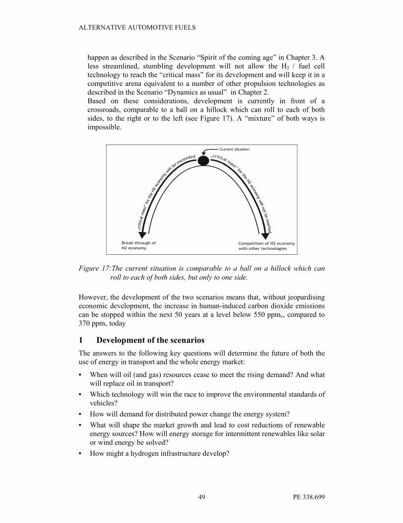
ALTERNATIVE AUTOMOTIVE FUELS
PE 338.699 49
happen as described in the Scenario “Spirit of the coming age” in Chapter 3. A less streamlined, stumbling development will not allow the H2 / fuel cell technology to reach the “critical mass” for its development and will keep it in a
competitive arena equivalent to a number of other propulsion technologies as described in the Scenario “Dynamics as usual” in Chapter 2. Based on these considerations, development is currently in front of a crossroads, comparable to a ball on a hillock which can roll to each of both sides, to the right or to the left (see Figure 17). A “mixture” of both ways is impossible.
Current situation
„critical mass“ for the H
2 economy w
ill not b
e re
ached
Competition of H2 economy
with other technologies
Break-through of
H2 economy
„critical mass“ for the H2 economy will
be exceede
d
Figure 17:The current situation is comparable to a ball on a hillock which can
roll to each of both sides, but only to one side.
However, the development of the two scenarios means that, without jeopardising economic development, the increase in human-induced carbon dioxide emissions can be stopped within the next 50 years at a level below 550 ppmv, compared to 370 ppmv today.
1 Development of the scenarios
The answers to the following key questions will determine the future of both the use of energy in transport and the whole energy market:
• When will oil (and gas) resources cease to meet the rising demand? And what will replace oil in transport?
• Which technology will win the race to improve the environmental standards of vehicles?
• How will demand for distributed power change the energy system?
• What will shape the market growth and lead to cost reductions of renewable energy sources? How will energy storage for intermittent renewables like solar or wind energy be solved?
• How might a hydrogen infrastructure develop?

ALTERNATIVE AUTOMOTIVE FUELS
PE 338.699 50
• How will emerging economies like China and India balance rapidly growing energy needs with rising import dependence and environmental effects?
• Where will social and personal priorities lie and how will these affect energy choices?49
In fact, there are three driving forces for the future global energy system (including transport): the scarcity of resources, the availability of technologies and social priorities.
1.1 Scarcity of resources50
Energy resource scarcity will happen if resources are limited or the costs for new production capacities are too high. This will not happen on the global level, but for some regions and / or some fuels:
The world mineral oil production is not expected to increase further. However, a scarcity of oil supply is very unlikely before 2025, due to the exploitation of unconventional sources and natural gas liquids. If the measures already known to increase the energy efficiency of vehicles are broadly implemented, the mineral oil supply is expected to be sufficient until 2040.
The technology improvements and progresses will counterbalance the increasing costs of depletion for the next decade, leading to costs of US$ 20 per barrel.
The costs for biofuels and gas to liquids will both fall below US$ 20 per barrel oil equivalent in the next two decades, thus influencing the oil price.
The uncertainty of gas resources is important after 2025. AT this time, a 3% annual growth seems possible. Scarcity can occur in 2025 or later, depending on the timely development of infrastructure to transport remote gas economically (see Figure 18).
Figure 18: The ultimately recoverable conventional gas resource is highly
uncertain. Estimates range from 15,000 EJ51 to 20,000 EJ.
49 Shell International, 2001.
50 Shell International, 2001.
51 EJ: Exajoule: 1018 Joule.
ALTERNATIVE AUTOMOTIVE FUELS
PE 338.699 51
Unconventional gas resources might add another 13,000 EJ. Source:
Shell International, 2001.
Coal will not become scarce until 2030 as its resources are limited to a few countries and will be increasingly distant from markets. Probably the costs for the exploitation and use of coal will affect its competitiveness.
Nuclear energy expansion has stalled in OECD countries, not only because of safety concerns but also because new nuclear power is uncompetitive. The liberalisation of electricity and gas markets means that this is unlikely to change over the next two decades.
Renewable energy sources can meet all requirements for energy even if competing with food and leisure for land use. However, the extensive use of wind and solar energy requires new forms of energy storage. The costs for wind and photovoltaic energy have fallen dramatically in the last two decades. However, this is also true for conventional energy.
1.2 Availability of new technologies
The two new technologies with the greatest potential for changing the energy economy are
• solar photovoltaic which produces electricity from an abundant and widely distributed energy and
• hydrogen fuel cells which offer high performance and clean final energy from a variety of fuels. 52
Fuel cells need a new fuelling infrastructure while photovoltaics require a new form of energy storage and a significant cost reduction.
The key questions for the availability of the new technologies are: Will they overcome the currently existing technical / technological hurdles in time? And will they provide enough benefits to the consumers (beside environmental advantages) to buy them and, thus, to trigger widespread implementation?
1.3 Social and personal priorities
The choices of fuels are ultimately social choices. The attitudes of governments and the public towards energy security or self-sufficiency will, for example, influence the penetration of natural gas into Asian and European markets. They can also be the driving force in the governments supply of renewable energy.
Another parameter influencing the energy system are personal priorities, e.g. for values, the environment or lifestyles. Affordability is not the main constraint in the EU or other OECD countries. If there is a desire for changes, much will depend on which technologies and fuels are available. Timing and timely action make the difference between evolutionary or revolutionary solutions to problems like climate change.
52 Shell International, 2001, p. 22ff.

ALTERNATIVE AUTOMOTIVE FUELS
PE 338.699 52
2 Scenario “Dynamics as usual”53
In the scenario “Dynamics as usual”, the development of fuel markets is earmarked by resource scarcity, environmental and security concerns, rival emerging technologies and competing societal priorities. The values of high esteem are qualities such as a “clean”, “secure” and “sustainable” energy supply – that is to say dynamics as usual.
However, interests are conflicting, leading to high competition between suppliers and a wide range of new technologies maturing in parallel (and, thus, in
competition). It is the transition to a sustainable, but increasingly diverse and complex energy system.
The driving forces and main developments of the scenario are the following:
2.1 Social priorities focus on the environment
This scenario describes the rapid economic growth of major developing countries (like China) with an exploding demand for transportation. As a contrast, little additional energy is needed to support EU/OECD Countries’ economic growth and resulting needs. In all markets, the technology progresses allow for important productivity gains, reducing the specific input from energy and material.
Many intangible factors determine the success of fuels and propulsion technologies. In the industrialised world, where consumers take a secure and affordable energy supply for granted, one factor for the ageing population is the focus on health and the environment. Environmental standards have been tightened. Companies look for a competitive advantage by developing and marketing clean fuels. As energy prices are a relatively small cost factor, a “premium” is paid for clean fuels in rich countries. In emerging economies, the rapidly growing number of middle class citizens increasingly demand action to reduce environmental problems from low quality fuels and a rapidly growing number of inefficient vehicles.
2.2 Established technologies proliferate
Concerns about the security of the fuel supply will stimulate a greater move towards energy efficiency. This provides a longer life for existing propulsion technologies, particularly the internal combustion engine. Developments have brought a range of advanced internal combustion and hybrid engines, with fuel consumption having been reduced to a third when compared to today’s performances. They cost less than vehicles with alternative propulsion technologies. Fuel cell vehicles will first be introduced in 2005, but fuelling inconvenience and consumer indifference limit their use.
Between 2010 and 2015, the spread of super-efficient vehicles keep the prices for mineral oil and its products low. However, this trend will be overcompensated by increasing fuel consumption from the growing demand for transport and heating fuels in developing countries. Thus, the mineral oil demand grows slowly, but
53 Shell International, 2001.

ALTERNATIVE AUTOMOTIVE FUELS
PE 338.699 53
steadily for the next 25 years, thus spurring advances in mineral oil recovery techniques.
2.3 Dash for gas
The general fuel trend at the beginning of this century is towards natural gas. New power plant capacities are using combined-cycle gas turbines (CCGT) wherever gas is available. China initiates major gas import projects to substitute coal. Pan-Asian and Latin American gas grids will emerge shortly after 2010. Significant LNG trade will stimulate consumption and increase gas competitiveness.
Traditional oil exporters such as Iran, Mexico or Indonesia will develop gas exports to reduce budget deficits. Natural gas is seen as another source of revenue rather than competition for mineral oil. Middle East producers may join in to avoid being shut out of the markets.
On the global energy market, natural gas will overtake coal by 2010 and by 2020 it is challenging mineral oil as the dominant source of primary energy. However, uncertainty about the availability of long-term resources and fear for political disruption in supplying countries start to limit the expansion. The market liberalisation has also reduced the buyers’ interest in long-term contracts. Tough
competition has kept the natural gas and electricity prices low, affecting the development of major cross-border pipelines.
2.4 Boom and bust for renewable energy sources
In the first two decades of the century, renewable energy grows rapidly in OECD countries, within the framework of existing electricity grids and strong government support. Deregulated markets provide opportunities for branded green energy which cover up to 10% of the demand. Prices for electricity from renewable energy fall (and consumer interests in it grow) as the average sizes of wind energy converters increase and mighty PV production capacities are built up.
Governments support renewable energy technologies with a view to improve health concerns, climate change and supply security. Renewables grow by 10% p.a., wind and PV up to over 20% p.a. By 2020, a variety of renewable energy sources supply a fifth of electricity production requirements in some OECD markets and nearly a tenth of the global primary energy.54
Then, the growth stalls. The willingness of the (rural) population to accept renewable energy projects decreases as the size of the installations increases and their spatial concentration becomes more and more dense. Renewable energy plants must go more and more to remote locations which drives up the costs. It becomes increasingly difficult to get approval for the development of major renewable energy projects.
Stagnant electricity demand in EU countries limit the possibilities for expansion. Although the public supports renewables, most are unwilling to pay higher prices. Despite significant cost improvements, PV stays in niche markets. With little
54 Shell International, 2001, p. 36.
ALTERNATIVE AUTOMOTIVE FUELS
PE 338.699 54
progress in energy storage and the concerns about the reliability of the electricity grids, the further growth of wind and PV are blocked.
Renewable energy sources expand in developing countries from 2010, stimulated by European activities. China and India push the development of wind power. They furthermore support hydropower and nuclear energy to maintain energy diversity. The energy use of waste and biomass is expected to provide rural energy, although this opportunity diminishes as rural income rise.
However, renewables do not fully compete with conventional low cost
alternatives. With the stagnating demand, renewable equipment prices collapse and producers go bankrupt. New investments stagnate.
2.5 Outlook: the situation after 2030 according to the scenario “Dynamics
as usual”
After 2025, when renewables stagnate and the concerns about the gas supply security grow, it is uncertain how the energy market will develop. Potential options are crash programmes to commercialise new nuclear energies or the breakthrough of biofuels or solar energy storage. Improvements in energy efficiency allow for gains in time.
The energy system has become a diverse and complex mix of fuels and technologies. This is true for the energy system as a whole, but also specifically for the transportation sector. No technology / fuel combination is obvious as the dominant source of future energy supply, while increasingly stringent environmental standards start to exhaust the capacity of “classic” technologies to meet them.
As mineral oil becomes scarce around 2040, advances in biotechnology plus the dramatically improved energy efficiency of vehicles bring a relatively smooth transition to liquid biofuels (BTL) and low cost modifications of the existing transport infrastructure. Biomass plantations, previously developed for power supply, are converted to transport fuel supply. Technological advances will allow renewable energy sources to contribute a third to the world’s primary energy demand by 2050.55
55 Shell International, 2001, p. 40.

ALTERNATIVE AUTOMOTIVE FUELS
PE 338.699 55
2.6 Milestones of this scenario
To sum up this scenario, the different phases of “Dynamics as usual” will be reached in the following years:
Around 2005 • Internal combustion engines and hybrid vehicles proliferate
Around 2010 • “dash for gas”
• renewables pump priming
Around 2015 • Oil price shock triggers resource expansion
Around 2020 • EU/OECD renewables stall at 20% of electricity supply
• gas security concerns emerge
Around 2030 • New nuclear stalls
• next generation of renewable energy technologies emerges
After 2030 • Oil scarcity drives biofuels expansion (BTL)
Figure 19: Milestones of the scenario “Dynamics as usual”56
3 Scenario “Spirit of the coming age”57
While the scenario “Dynamics as usual” assumes that the citizens are driving the energy choices and shaping an evolutionary development, the scenario “Spirit of the coming age” describes a more revolutionary development, pushed mainly by the choices of the consumers. This pace of development requires the willingness to experiment and takes into account the risk of failures. A technology revolution is set off by the fuel cell. The spirit that will be driving this development can be characterised by the following statement from Geoffrey Ballard, founder of Ballard Fuel cells: “The internal combustion engine will go the way of the horse. It will be a curiosity to my grandchildren.”58
56 Source : Shell International, 2001, p. 41.
57 Shell International, 2001.
58 Shell International, 2001, p. 48.

ALTERNATIVE AUTOMOTIVE FUELS
PE 338.699 56
Figure 20: In the „roaring twenties“, a new engine technology, together with
an energy-dense fuel, revolutionized the transport sector and,
within less than 3 decades, it phased out the horse as “propulsion
technology”. Photo taken in Berlin, Pariser Platz, around 1925.
In fact, according to this scenario the development can be compared to the situation in the early 20th century, when a new engine technology, together with a portable and energy-dense fuel, revolutionised the transport sector (Figure 20). This development started with fuel in a box, sold at local hardware stores, adequate for limited travel along the few paved roads. The availability of the respective energy resources, the readiness of the technology and the social priorities drove the development up to today’s fuelling infrastructure which, nowadays, constitutes both a valuable infrastructure as well as a barrier to change.
The scenario “Spirit of the coming age” describes the following phases and developments:
3.1 Breaking paradigms and observing limits
The automobile industry knows that fuel cell vehicles fit the mood of today because they are cleaner, quieter and offer high performance. One of the major constraints for their market penetration is the fuelling infrastructure. Automobile manufacturers prefer methanol or direct hydrogen for fuel cells. However, the oil industry does not want to cover the costs and bear the commercial risks.59
The reaction of the automobile industry is to develop a new “fuel in a box” for fuel cell vehicles, using progresses made through small scale applications like fuel cell powered computers or cell phones. A “six pack” of fuel (12 litres) is sufficient for 400 km. Fuel boxes can be delivered directly to the consumer or can be distributed like soft drinks through multiple distribution channels like
59 Shell International, 2001, p. 46.

ALTERNATIVE AUTOMOTIVE FUELS
PE 338.699 57
supermarkets or dispensing machines. This is particularly interesting for developing countries with limited fuelling infrastructure and constraints on urban space. In rural areas of these countries where consumers can afford only a
relatively small amount of fuel in one time, the boxed fuels will replace LPG bottles, kerosene and traditional lamps and cookers.
Consumers can get their fuel anywhere and anytime.60
The fuel is made from mineral oil, natural gas or biomass (see Figure 21). Sealing it in a box overcomes health and security concerns.
Figure 21: DaimlerChrysler’s and Volkswagen’s view on the evolution of
future fuels61
3.2 Cost reduction for fuel cells
The fuel cell market penetration starts with stationary applications in businesses that are willing to pay a premium price for the image gained from using innovative technologies or simply for a highly reliable electricity supply without voltage fluctuations or outages. This demand helps to reduce the costs below 500
60 This break of a distribution paradigm can be compared to the “revolution” through the Sony
Walkman 20 years ago when it broke the paradigm that music has to come from a source
plugged into a wall.
61 Source: Heinrich, 2003.
hydrogen emission and CO2 free Based on renew. En.
Synthetic fuels (BTL) Low emissions, low CO2
emissions Based on biomass
Synthetic fuels (GTL), Low emissions Based on natural gas
Clean convent. Fuels sulphur-free, no aromatics based on crude oil
Conventional fuels Containing sulphur and aromatics
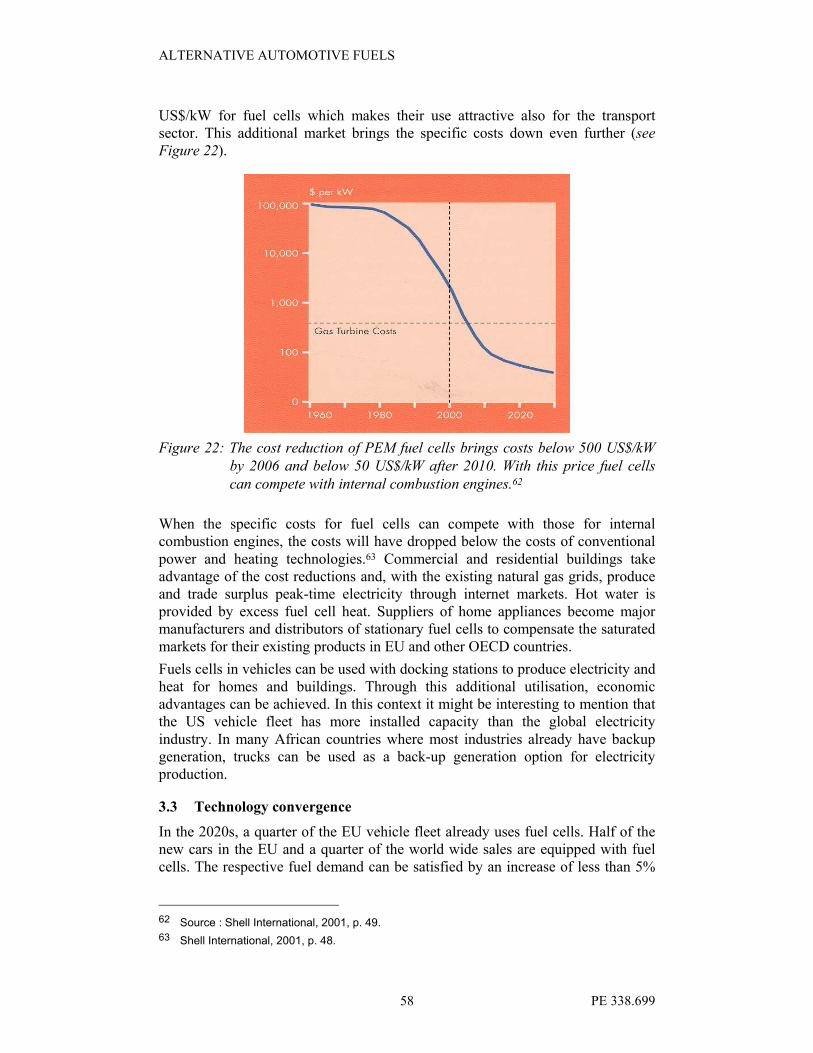
ALTERNATIVE AUTOMOTIVE FUELS
PE 338.699 58
US$/kW for fuel cells which makes their use attractive also for the transport sector. This additional market brings the specific costs down even further (see Figure 22).
Figure 22: The cost reduction of PEM fuel cells brings costs below 500 US$/kW
by 2006 and below 50 US$/kW after 2010. With this price fuel cells
can compete with internal combustion engines.62
When the specific costs for fuel cells can compete with those for internal combustion engines, the costs will have dropped below the costs of conventional
power and heating technologies.63 Commercial and residential buildings take advantage of the cost reductions and, with the existing natural gas grids, produce and trade surplus peak-time electricity through internet markets. Hot water is provided by excess fuel cell heat. Suppliers of home appliances become major manufacturers and distributors of stationary fuel cells to compensate the saturated markets for their existing products in EU and other OECD countries.
Fuels cells in vehicles can be used with docking stations to produce electricity and heat for homes and buildings. Through this additional utilisation, economic advantages can be achieved. In this context it might be interesting to mention that the US vehicle fleet has more installed capacity than the global electricity
industry. In many African countries where most industries already have backup generation, trucks can be used as a back-up generation option for electricity production.
3.3 Technology convergence
In the 2020s, a quarter of the EU vehicle fleet already uses fuel cells. Half of the new cars in the EU and a quarter of the world wide sales are equipped with fuel cells. The respective fuel demand can be satisfied by an increase of less than 5%
62 Source : Shell International, 2001, p. 49.
63 Shell International, 2001, p. 48.

ALTERNATIVE AUTOMOTIVE FUELS
PE 338.699 59
in natural gas production. The global automobile industry rapidly consolidates around this new trend.
The technical progress in transport and electricity generation are solving mutual problems as fuel cell technology and hydrogen electrolysis are mirror images of the same technology / chemical reaction. All benefit from the advantages in material technologies: carbon nano-tubes are widely used by 2025 because of their high strength, supporting the development of carbon nano-fibres as the ultimate hydrogen storage medium. However, the alternative development is the eventual transition from liquid to solid hydrogen.
3.4 The development in China and India
In the 2020s, China and its huge and still growing vehicle fleet faces an extreme dependence on oil imports. Unease about the sufficiency of regional gas resources and the dependence from gas imports, means the Chinese energy economy is pushed towards the indigenous coal reserves. This, however, creates environmental and logistical problems. Land scarcity limits the biofuel opportunities. India faces the same problems.
The growing global demand for gas and hydrogen supports (and is supported by)
the development of low cost in-situ extraction of methane and hydrogen from coal and oil shales. Carbon dioxide sequestration is feasible. These advanced hydrocarbon developments build on established infrastructure and technologies and will be financed and managed by the existing fuel suppliers. They will be used in China, together with indigenous technologies, to extract methane and hydrogen directly from the coal mines, allowing for the transport of energy in pipelines instead of in thousands of trains.
Once the fuel cells take off in the EU and other OECD countries, China starts to develop a transport and power system around cost effective fuel cells fuelled by indigenous methane and hydrogen.
3.5 Oil phases out and renewables increase slowly
The advantages offered by the new technology push the transition to hydrogen before oil becomes scarce. The higher the demand for fuel cells, the less consumers will need and buy for mineral oil products. As a result, these products are cheap enough to be used for heat and electricity generation in some developing countries, but this development does not compensate the declining transport market.
Renewable energy sources grow steadily, but slowly until 2025. Green energy reaches 5% only in some regions. However, in a first phase, the sales of photovoltaics to rural communities in developing countries grows fast as there is a willingness to pay for the convenience of electricity supply and for the connection to the outside world via television. However, as the desires and needs increase, they exceed what a photovoltaic island solution can offer. The result is a switch to fuel cells.
Government support helps renewable energy technologies early in the century, but the price prevents them to from substituting existing sources. This is especially

ALTERNATIVE AUTOMOTIVE FUELS
PE 338.699 60
true for the EU with excess power capacities. Competition drives down the electricity prices and although renewable energy technologies increase their competitiveness, they cannot close the gap.
3.6 Outlook: the situation after 2030 according to the scenario “Spirit of
the coming age”
After 2030, a new infrastructure will be developed: The growing use of fuel cells as heat and power sources creates a rapidly expanding demand for hydrogen. It is widely produced from coal, oil and gas fields, with carbon dioxide extracted and sequestered cheaply in situ. The carbon dioxide sequestration reaches 0,3 billion tonnes carbon p.a. in 2025 and 2.3 billion tonnes carbon p.a. in 2050. This corresponds to a fifth of emissions.
By 2030, large scale renewable and nuclear energy installations for the production of hydrogen by hydrolysis become attractive. Renewable energy starts to expand rapidly after 2030.
Hydrogen is transported in gas grids until the growing demand justifies hydrogen pipelines. This is the beginning of the hydrogen economy.
3.7 Milestones of this scenario
According to the scenario “Spirit of the coming age”, the following phases will be reached:
Around 2005 • First stationary and vehicular fuel cells, high consumer
interest
Around 2010 • Gas resource outlook expands
• Fuel cell fuel distribution innovations
• Renewables limited to niches
Around 2015 • Convergence around fuel cells for transport
• Gas network backbone
Around 2020 • Unconventional oil and gas expand in India and China
• Fuel cells reach 25% of sales in OECD
Around 2030 • Solid H2 storage transition
• renewable energy sources pulled by H2 demand
After 2030 • H2 infrastructure expansion
Figure 23: Milestones of the scenario “Spirit of the coming age”64
4 Assessment of the scenarios
4.1 Comparison and evaluation65
The two scenarios described in the Chapters 2 and 3 describe different paths towards a more sustainable energy system. However, despite the differing
64 Source : Shell International, 2001, p. 57.
65 Shell International, 2001, p. 58.

ALTERNATIVE AUTOMOTIVE FUELS
PE 338.699 61
assumptions they are based on and the different results to which they lead, they have a number of common features:
• In both scenarios, natural gas has an important role as a “bridge fuel” for the next two decades. In this period, natural gas increases supply security as it reduces the very high dependence on mineral oil products.
• When new propulsion technologies enter the vehicle market, the mineral oil market is disrupted.
• In the energy markets, there is a clear tendency towards decentralised heat and power systems for economic and social reasons. This can also have implications on the diffusion of technologies used in vehicles (see Chapter 3.2).
• Renewable energy technologies and energy storage technologies will be further developed with regard to their efficiency, economic factors and the extent of their use.
• It is difficult to identify the winning technology/-ies in 20 years time as this sector is very dynamic and highly innovative.
Nevertheless, the key differences between the two scenarios are those assumptions on the timing of available new technologies, the availability of
different energy forms and the social and personal priorities (like health, security, the environment and sustainability, convenience, aesthetics and the openness to change).
After 2030, the paths described in the two scenarios could converge, for instance, with hydrogen as the preferred energy carrier and energy storage medium. At this time, the world energy system will have been through its toughest test: meeting the huge energy demand of the vast majority of the world’s population as they pass through industrialisation and seek to improve the quality of their lives (including increased mobility).
Over the next two to three decades however, technology, economics and personal choice will determine the direction.
4.2 Representation of the current situation and future changes in the
technology / fuel matrix
In Error! Reference source not found., a summary of the changes from the
present status towards the situations in the two scenarios is visualised in a technology / fuel matrix:
Each combination of a propulsion technology and the respective fuel, which is presently relevant or is estimated to become relevant in the future, is shown as a cell of the matrix. The propulsion technologies are given in the rows, the fuels in the columns. The conventional technologies and fuels are located in the upper left area of the matrix. The more advanced technologies and fuels are listed respectively in more detail at the bottom or on the right hand side of the matrix.
For improved clarity, the number of fuels and technologies listed has been limited to 10 to 15 per axis. Besides those listed, a number of other fuels and technologies exist but are less relevant.

ALTERNATIVE AUTOMOTIVE FUELS
PE 338.699 62
At present, the three most relevant combinations of fuel / propulsion technology are the use of fossil gasoline, fossil diesel and fossil LPG burned in conventional internal combustion engines. The respective cells of the matrix are filled with
black dots.

Innovative fuels�
Traditional Other fossil Natural gas Biofuel Hydrogen Other
Technology
Fuel
Gasoline Diesel LPG Methane CNG LNG GTL RME BTL Biomethanol bioethanol biogas Other
Otto ●� ●� �
Traditional Diesel ●� � �
PEM � � �
DMFC
AFC
PAFC
MCFC
Fuel cell
SOFC
Hydrogen
combustion
Other
●: One of the current predominant combinations of fuel and propulsion technology
� One of the predominant combinations of fuel and propulsion technology in 2030 according to the scenario
“Dynamics as usual”. The area covered in the matrix is marked by the blue ellipse.
� One of predominant combinations of fuel and propulsion technology in 2030 according to the scenario “Spirit of the
coming ages”. The area covered in the matrix is marked by the red ellipse.
Figure 24:The main changes from the current status towards the situations given by the two scenarios “Dynamics as usual” and “Spirit of the coming
ages” summarised in a technology / fuel matrix. For details please refer to the text.

According to the scenario “Dynamics as usual”, a smooth and slow transition towards natural gas and liquid biofuels (RME and BTL) as main fuels will be achieved by 2030 (see cells marked by squares in the matrix). However, fossil fuel
will still play a certain role. Its range reaches 2030 due to the use of super efficient cars in the preceding decades.
The diversification of fuels, as suggested by this scenario, can be seen from the wider ellipse which is stretched round more cells in the matrix representing the relevant propulsion technologies and fuels which are bordered by the blue ellipse.
According to the scenario “Spirit of the coming ages” the change will be much more far-reaching (which can also be seen in the matrix): future technology development and application converge on the fuel cell, with PME being the most likely candidate (Proton Exchange Membrane Fuel cell´). The main fuels will be hydrogen and fuels from biomass (see the cells marked by stars in the matrix). Where available, methane will be used.

ALTERNATIVE AUTOMOTIVE FUELS
PE 338.699 65
5 Conclusive analysis of key factors requiring EU actions
The automotive fuel sector is facing a future development which clearly needs action. This can be seen in the following figures gathered from different sources which illustrate the future problems:
• Today, there are 800 million operational vehicles world-wide. This number is expected to double in the coming 10 to 15 years.
• In the EU, 250 billion Euros are spent each year on fuels and cars.66
• In the EU, the transport sector is 98% dependent on oil, 70% of which is imported.
• Mineral oil consumption is expected to increase by 50% in the next 20 to 25 years.
• In the coming 20 years, mineral oil is expected to become scarce and expensive.
• The transport sector is responsible for 28% of CO2 emissions, the main greenhouse gas. 84% of CO2 emissions from transport arise from road traffic.67
In Chapter 4 of this report, two scenarios for the development of the automotive fuel market are described which reflect two development extremes: a further continuation with the same driving forces (i.e. “business as usual”) and a revolutionary development (“spirit of the coming ages”).
The key factors and areas which require action can be identified on the one hand from the outcome of these scenarios. On the other hand, these actions are defined on a wider scale through the obligations the European Union has accepted to fulfil.
6 Identification of relevant action fields according to the scenarios
The two scenarios given in the Chapters 2 and 3 describe two different (and divergent) future developments. However, despite the different assumptions they are based on, they have a number of common features:
6.1 Natural gas as a “bridge fuel”
In both scenarios, natural gas has an important role as a “bridge fuel” over the next two
decades. Over this period, it increases supply security by reducing the very high dependence on mineral oil products.
6.2 Increasing importance of renewable energy technologies
Renewable energy technologies and energy storage technologies will have to be further developed with regard to efficiency, economic factors and the extent of their use. In the future, they will play an increasingly important role in both the overall energy market and the market for automotive fuels: It is expected that by the year 2030, renewable energy technologies will have emerged and will be a major energy source in satisfying the hydrogen demand (scenario “Spirit of the coming ages”). According to the scenario
“Dynamics as usual”, the use of biofuels (BTL) will expand due to the scarcity of oil and thus, in the long-term perspective, biofuels will be a future substitute for mineral oil products in the automotive fuel sector.
66 Statement of Mr Jorgen Henningsen, DG TREN, on the European Forum “Sustainable Mobility in
Europe – with CNG into the Future” on September 18, 2003, on the IAA, Frankfurt/M.
67 European Commission, 2001.

ALTERNATIVE AUTOMOTIVE FUELS
PE 338.699 66
6.3 Clear tendency towards decentralised heat and power systems
There is a clear tendency towards decentralised heat and power systems in energy markets for economic and social reasons. This can also have implications on the
diffusion of technologies used in vehicles: Examples given in Chapter 3.2 show that in the future, a fuel cell installed in an automobile will also be able to be used in a docking station for heat and power systems, at least as a back-up system in developing countries.
7 Targets for EU policy
Beside general objectives like security of energy supply and ensuring people’s mobility, there are a number of quantitative targets for EU policy. However, when considering them, a differentiation must be made between:
• on one hand, the legally binding targets which must be achieved according to signed international agreements and
• on the other, voluntary self-commitments made by the European Union.
7.1 Legally binding targets of the Kyoto Protocol
The European Commission has adopted the quantified targets of the Kyoto Protocol for the reduction of carbon dioxide emissions. This treaty foresees an 8% reduction of carbon dioxide emissions for the whole of the EU-15 by 2010 compared to figures from 1990. This overall target has been translated into different objectives for each of the Member States.
As the current Kyoto Protocol is only the first step towards an international agreement to put a halt to global warming, it is expected that the current Kyoto Protocol with its 2010 horizon will be continued by a “post Kyoto Protocol” with more ambitious targets for the reduction of greenhouse gases such as carbon dioxide.
7.2 Voluntary self-commitments of the European Union relevant to the topic
The time horizon of this study reaches 2030 and beyond. However, the objectives set for the European Union comprise targets of 2010 or 2020. In this context, the most important targets are laid down in the EU’s “White Paper”.
7.2.1 The White Paper target for renewable energy development
In 1997 the European Commission presented a communication, the so-called White Paper for a Community Strategy and Action Plan “Energy for the Future: Renewable Sources of Energy” (hereinafter referred to as White Paper). It states the concrete indicative target of doubling the share of RES in the European Union from 5.3 per cent of gross inland energy consumption in 1995 to 12 (11.5) per cent in 2010.
However, for the topic of this study, the target pertaining to the stronger use of biofuels is more important:
7.2.2 The White Paper target for biofuels
The White Paper stated that specific measures are needed in order to help “increase the market share for liquid biofuels from the current 0.3 per cent to a significantly higher percentage, in collaboration with member states.” The quantity has been estimated at 18
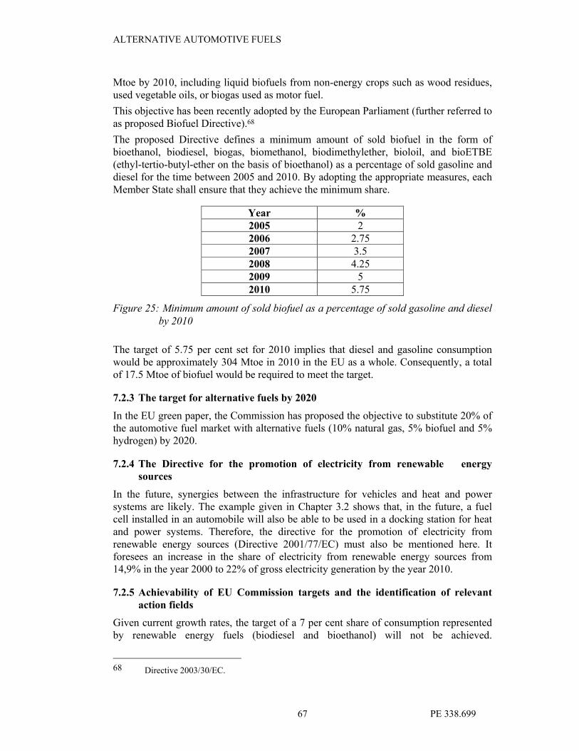
ALTERNATIVE AUTOMOTIVE FUELS
PE 338.699 67
Mtoe by 2010, including liquid biofuels from non-energy crops such as wood residues, used vegetable oils, or biogas used as motor fuel.
This objective has been recently adopted by the European Parliament (further referred to as proposed Biofuel Directive).68
The proposed Directive defines a minimum amount of sold biofuel in the form of bioethanol, biodiesel, biogas, biomethanol, biodimethylether, bioloil, and bioETBE (ethyl-tertio-butyl-ether on the basis of bioethanol) as a percentage of sold gasoline and diesel for the time between 2005 and 2010. By adopting the appropriate measures, each
Member State shall ensure that they achieve the minimum share.
Year %
2005 2
2006 2.75
2007 3.5
2008 4.25
2009 5
2010 5.75
Figure 25: Minimum amount of sold biofuel as a percentage of sold gasoline and diesel
by 2010
The target of 5.75 per cent set for 2010 implies that diesel and gasoline consumption would be approximately 304 Mtoe in 2010 in the EU as a whole. Consequently, a total of 17.5 Mtoe of biofuel would be required to meet the target.
7.2.3 The target for alternative fuels by 2020
In the EU green paper, the Commission has proposed the objective to substitute 20% of the automotive fuel market with alternative fuels (10% natural gas, 5% biofuel and 5% hydrogen) by 2020.
7.2.4 The Directive for the promotion of electricity from renewable energy
sources
In the future, synergies between the infrastructure for vehicles and heat and power systems are likely. The example given in Chapter 3.2 shows that, in the future, a fuel cell installed in an automobile will also be able to be used in a docking station for heat and power systems. Therefore, the directive for the promotion of electricity from renewable energy sources (Directive 2001/77/EC) must also be mentioned here. It foresees an increase in the share of electricity from renewable energy sources from 14,9% in the year 2000 to 22% of gross electricity generation by the year 2010.
7.2.5 Achievability of EU Commission targets and the identification of relevant
action fields
Given current growth rates, the target of a 7 per cent share of consumption represented by renewable energy fuels (biodiesel and bioethanol) will not be achieved.
68 Directive 2003/30/EC.

ALTERNATIVE AUTOMOTIVE FUELS
PE 338.699 68
EurObserv’ER estimates that 11.7 million tons are practical.69 However, the target for 2010 has been set at 17 million tons. Consequently, the forecasted level represents 69 per cent of the target figure only. According to the draft, a total of 17.5.Mtoe of biofuels
must be sold in the European Union.
As things stand now, only 62.5 per cent of the biomass targets will be achieved on a weighted average base. Due to the large weight carried by biomass within the overall renewables market, this will not be without consequence to the aggregate renewable target achievability. Due to the central role biomass is to play in achieving 2010 targets, massive further action appears to be needed.
69 MVV Consultants & Engineers GmbH, 2002, Chapter 4.

ALTERNATIVE AUTOMOTIVE FUELS
PE 338.699 69
III. Policy recommendations Based on the outcomes of the previous chapters in this report, a number of recommendations for guidelines towards an EU action plan can be developed, of which the following are the most important:
1 EU action plan to support the improved market penetration of
biofuels
The technical potential of renewable energy sources in the European Union is
hypothetically large enough to ensure achievement of the White Paper’s indicative quantitative targets.70 As a matter of fact, the present technical potential is at least twice as much as the 12 per cent target of EU primary energy consumption set for the year 2010. In Germany, only 3% of available biomass is currently used in the energy market.71
Biomass represents the most pertinent source in terms of incremental growth potential and, thus, any progress made in achieving the 2010 target figure will be overwhelmingly contingent on whether biomass can make essential headway far beyond present-day trends.
However, an EU action plan to support the improved market penetration of biofuels into the automotive fuel market would simultaneously support the following objectives:
• A contribution towards the achievement of the policy objectives
• of the Kyoto Protocol,
• of the White Paper Target for Renewable Energy Development (12% in 2010 see Chapter II.7.2.1),
• of the biofuel directive (see Chapter II.7.2.2),
• for alternative fuels until 2020 (see Chapter II.7.2.3) and, last but not least,
• of the article on new and renewable energy included in the final draft of the constitution of the European Union.
• The two different scenarios described in the Chapters 3 and 4 of this report assume that around 2030, biomass will be of great importance on the worldwide automotive fuel market, whether as raw material for the production of biofuels (BTL) or as primary energy for the production of “green hydrogen”72.
The main barrier for the comparably slow progress of biomass / biofuels into the automotive fuel market is that fuel market prices do not take account of the various externalities, notably those linked with conventional air pollution and global warming. A subsequent recommendation therefore is to remove existing market distortions through internalising externalities into existing energy market price mechanisms.
For both, the policy for automotive fuels and the general energy policy, it is of utmost importance not to lose sight of the big relevance of renewable energy sources and to set the right priorities and policy signals. Contrary to what is conventional wisdom, RES
70 For details please refer to Chapter II.7.2.
71 Neue Energie, map “Biogasnutzung in Deutschland, 31. 7.2002“.
72 “Green hydrogen” uses renewable energy sources as primary energy while “black hydrogen” is using
fossil fuels as primary energy.

ALTERNATIVE AUTOMOTIVE FUELS
PE 338.699 70
must be ranked according to their relevance in achieving policy goals and targets and in attaining a sustainable policy for automotive propulsion.
2 EU action to support natural gas vehicles
The outcome of the previous chapters shows that natural gas has an important role as a “bridge fuel” over the next two decades. In this period, it increases supply security by reducing the very high dependence on mineral oil products. In the automotive fuel sectors, this means an improved introduction of natural-gas fuelled vehicles.
The market introduction of natural-gas fuelled vehicles is relatively advanced, but it has not yet reached a stage of market breakthrough. Market penetration is pushed by natural-gas fuelled vehicle fleets which are fuelled by a limited number of fuelling stations (e.g. buses of urban public transport). The market penetration for fleets of private vehicles in the EU has not yet been achieved.
Over the last 15 years, the European Commission has already supported the market introduction of natural-gas fuelled vehicles (e.g. through the THERMIE demonstration projects), however, for a market breakthrough, a final shove should be made in order to overcome the chicken/egg problem from which the EU-wide market breakthrough is still suffering. For this to happen, the appropriate co-ordination of the four success factors required for the introduction of natural gas must be implemented. These are:
• professional marketing,
• a dense network of fuelling stations,
• a competitive price, because for private consumers, the investment cost is often more relevant to the decision of purchase than the total cost of operation and
• a sufficient fleet to justify investments into the fuelling infrastructure.
For the introduction of a new technology (e.g. natural gas engines), the attitude and technical skills of local vehicle dealers are decisive.
One suggestion is that an international organisation such as the European Union should take over the task of developing a framework for co-ordinating the efforts of different actors towards the market breakthrough of natural gas vehicles in the European private vehicle market.
This motion requires a relatively small input, but has an important strategic value. It could be delivered through a project within the STEER program under the current Intelligent Energy for Europe program which is valid until 2006.
An additional incentive to the vehicle market to buy natural gas vehicles and, thus, to allow the European Union to reach the targets described in Chapter II.7 of this report is clearly a tax reduction on natural gas as an automotive fuel. The taxation of fuels, however, lies in the hands of national governments and finance ministries. It contributes an important share towards the national tax income. With the current difficult financial situation of public administrations within the European Union, it will be difficult to achieve a tax reduction for natural gas as an automotive fuel.
3 Further support for hydrogen and fuel cell research
In Chapter II.2 of this report, the development of the automotive fuel market is described assuming that the future market’s driving forces will be similar to those currently in place (“business as usual”). It is clear that this scenario will lead to an
ALTERNATIVE AUTOMOTIVE FUELS
PE 338.699 71
increasingly diverse and complex energy system, but will not allow hydrogen fuel to play the expected major role in the year 2030 as is indicated by many experts in this field.
If, by 2030, the European Community should come to the beginning of the “age of the hydrogen economy”, future development as described in the scenario “Spirit of the coming ages” in Chapter II.3, must take place. For the automotive fuel sector, this means concentrating efforts on the implementation of hydrogen fuel cells. It is expected that technical progress in transport and electricity generation will solve mutual problems as fuel cell technology and hydrogen electrolysis are mirror images of the same technology / chemical reaction.
Within hydrogen research, advantages are necessary mainly in material technologies: development of high strength carbon nano-tubes and support to the development of carbon nano-fibres as the ultimate hydrogen storage medium. However, the alternative development is the eventual transition from liquid to solid hydrogen.
Nonetheless, support should be granted until a market share of 2% is reached. When this milestone is achieved,
• the technology is mature enough, will further penetrate the market without additional assistance and, thereby, will justify the public support budget spent or
• the technology will not be able to enter further into the market without additional
support which means that is not viable and does not deserve additional support.
Based on lessons learned from the introduction of natural gas vehicles, the following four points should be simultaneously and adequately observed in order to ensure a smooth and rapid introduction of hydrogen fuel cells:
• Professional marketing of the product,
• A dense network of fuelling stations or suitable alternatives,73
• Favourable economic / competitive price of the product for the private customer 74 and
• A sufficient fleet to justify the investments into the fuelling infrastructure.
Finally, it should be noted that, for the introduction of a new technology such as fuel cells or any other hydrogen engine technology, the attitude and the technical skills of local vehicle dealers is decisive with regard to the speed of market penetration.
As the support for hydrogen and fuel cell research requires large financial contributions, support programmes can be carried out in co-operation with foreign governments or international institutions. This is in contrast to the automobile industry where research and development projects require huge financial resources which are frequently provided by bi- or multilateral international co-operation projects in order to split the burden.75
73 See Chapter II.3.1.
74 However, it must be seen that in private consumer markets, the investment cost is often more relevant
for the decision of purchase than the total cost of operation.
75 In 2003 the US Government pledged 1.8 Mio US$ for hydrogen research. Possibilities for harmonised
guidelines and a co-operation in research and development investments in hydrogen and hydrogen
vehicle/fuel cell technology were discussed between the European Commission President, Mr Prodi,

ALTERNATIVE AUTOMOTIVE FUELS
PE 338.699 72
National R&D and dissemination programs in this field should be co-ordinated both, between national governments (e.g. the current French-German initiatives concerning big European investment projects) and/or between governments and the industry.
However, within this context, the list of key elements identified by the “Hydrogen Energy and Fuel Cells: A Vision of our Future” report should be kept in mind. This report was produced by a high-ranking group consisting of experts from industrial and research institutions. This group was established in 2002 with the support of the Commissioner for Transport and Energy, Mrs Loyola de Palacio and the Commissioner for Research Mr Philippe Busquin.76
The list of five key elements necessary for starting the transition from fossil fuels to a hydrogen-based economy are as follows:
• Support for the political framework,
• A strategic research agenda,
• A strategy for implementation,
• A European roadmap for hydrogen and fuel cell technology, and
• A European partnership for hydrogen and fuel cell technology.
However, in conclusion, the development of hydrogen technology and, more importantly of fuel cell technology, will lead to bigger opportunities for the creation of employment in an innovative and future-oriented field.77 Therefore, the European Union
and its Member States should not only provide the setting for the application of this new technology, but should actively support the development and application of innovative technologies within the EU in order to ensure that an important part of the future world-wide employment potential can be allocated to the EU Member States. Along with the duty to develop new and renewable energies as stated in the article on energy in the final draft of the constitution of the European Union, there is a “formal” obligation to support hydrogen and fuel cell research in the European Union.
the EU Energy and Transport Commissioner Mrs Loyola de Palacio and the US Secretary of Energy,
Mr Spencer Abraham during his visit to Brussels on 16th and 17
th June 2003. (ENGVA, 2003, p. 4.)
76 See Cordis, 2003, p. 224.
77 Please refer to: European Commission: Effects of the implementation of fuel cells on labour markets
and working conditions. A study of the CUTE project. Brussels, 2003.

ALTERNATIVE AUTOMOTIVE FUELS
PE 338.699 73
Bibliography
“Hydrogen from methane with no CO2 byproduct”, Chementator, Chem. Eng., December, 2000, p. 17.
Adamson K.A., and Pearson P., Hydrogen and methanol: a comparison of safety, economics, efficiencies and emissions, J. Power Sources 86, 2000, pp. 548-555.
Agbossou K., Chahine R., Hamelin J., Laurencelle F., Anouar A., St-Arnaud J.-M., Bose T.K., Renewable energy systems based on hydrogen for remote applications, Journal of Power Sources 96, 2001, pp. 168-172.
Appl M., Modern Production Technologies, Part 4. Hydrogen, Ed. A. More, Nitrogen, CRU Publishing Ltd., 1997.
Bockris J.O’M., The origin of ideas on a Hydrogen Economy and its solution to the decay of the environment, Int. J. Hydrogen Energy, 27, 2002, pp. 731-740.
Breault RW et al, Hydrogen Transition/Storage with a metal Hydride/ Organic Slurry, Proceedings of the 1998, U.S. DOE Hydrogen Program review, NREL/CP-570-25315, Vol II April 28-30, 1998 Alexandria, Virginia USA.
„Kommission begrüßt Forderung nach einer stragischen Forschungsagenda für die Wasserstoffwirtschaft“, Cordis Focus, Brussels, 2003.
DaCosta D.H., Golben M. and Tragna D.C., Metal Hydride Systems for the Hydrogen
Planet, Proceedings of the 14th World Hydrogen Energy Conference, eds. R. D. Venter and T. K. Bose, Canada, June 9-13, 2002.
DaimlerChrysler: Hightechreport 1/2003. Stuttgart, 2003
Das L.M., On-Board Hydrogen Storage Systems for Automotive Application, Int. Journal of Hydrogen Energy, Vol. 21, No. 9, 1996, pp. 789-800,.
“Feasibility of developing wave power as a renewable energy resource for Hawaii”, Department of Business Economic Development and Tourism (DBEDT) Report, Honoloulu, Hawaii, 2001.
Dillon A.C., Jones K.M., and Heben M.J., Carbon nanotube materials for hydrogen storage, 1996, Department of Energy/National Renewable Energy Laboratory (DOE/NREL) hydrogen program review, Proceedings.
DIW: Wochenbericht Nr. 36-37/2003, 70. Jg / 4.September 2003.
Dutton A.G., Bleijs J.A.M., Dienhart H., Falchetta M., Hug W., Prischich D., and Rudell A.J. 2000, Experience in the design, sizing, economics, and implementation of autonomous wind-powered hydrogen production systems, Int. J. Hydrogen Energy 25, pp.705-722.
ENGVA (European Natural Gas Vehicle Association): ENGVA News Issue 6, June 2003.
“Energy for the Future: Renewable Sources of Energy”, European Commission: White Paper for a Community Strategy and Action Plan, Brussels, 1997
European Commission: CUTE - Clean Urban Transport for Europe: A fuel cell bus project in 9 European cities. Brussels, 2002a.

ALTERNATIVE AUTOMOTIVE FUELS
PE 338.699 74
European Commission: Effects of the implementation of fuel cells on labour markets and working conditions. A study of the CUTE project. Brussels, 2003.
European Commission / LDK Consultants: European Developments in Natural Gas Technologies. Maxibrochure within the hydrocarbon s series. Athens, Brussels, 2000.
European Commission: European transport policy for 2010 : Time to Decide. Presentation in Berlin, September 2001.
European Commission, Proposed Biofuel Directive, Brussels, 2001a
European Commission: EU Energy and transport figures. Statistical pocketbook 2002. Belgium, 2002.
Garret D.E., Chemical Engineering Economics, New York, 1989: Von Nostrand Reinhold.
Haland A., High-Pressure Conformable Hydrogen Storage for Fuel Cell Vehicles, Proceedings of the 2000, U.S. DOE Hydrogen Program review, NREL/CP-570-28890, May 9-11, 2000, San Ramon California USA.
Hart D., Hydrogen Power: The Commercial Future of the Ultimate Fuel, London, UK: Financial Times Energy Publishing, 1997.
Heinrich, Dr. Hartmut: Synthetic Fuels – Volkswagen’s Fuel Strategy, Presentation on the 3rd Annual World GTL Summit, London, 22nd May 2003
Hirschenhofer J.H., Stauffer D.B., Engleman R.R., and Klett M.G., Fuel Cell Handbook, 4 th Edition, prepared for the U.S. Department of Energy under contract no. DE-AC21-94MC31166, November 1998, p.4-5.
Huston E.L., Liquid and Solid Storage of Hydrogen, Proceedings of the 5th World Hydrogen Energy Conference. Vol. 3; July 15-20, 1984, Toronto, Canada.
InnoTec Systemanalyse GmbH / Berlin Senate / BVG et al: The Natural Gas Bus Project Berlin. With the support of the European Commission within the THERMIE Programme. Berlin / Brussels, without year (a)
InnoTec Systemanalyse GmbH / Fast: Compressed Natural Gas as a Fuel in Private Cars and Small Freight Vehicles. With the support of the European Commission within the THERMIE Programme. Berlin / Milan / Brussels, without year (b)
InnoTec Systemanalyse GmbH / Fast: The Use of Compressed Natural Gas as a Fuel in Urban Buses. With the support of the European Commission within the THERMIE Programme. Berlin / Brussels, without year.
Kesten M. and Meyer G., Offene und gelöste Probleme bei Wasserstofftransport und Speicherung. Presentation at BAM, Berlin, 13 December 1995.
Kolhe M., Agbossou K., Kelouwani S., Anouar A., Fournier M., Hamelin J., and Bose T.K., Long-term performance of stand-alone renewable Energy system for hydrogen production, WHEC 2002 – 14th World Hydrogen Energy Conference, Montreal, 9-13 June, 2002.
Lehmann J., Luschtinetz T., Menzl F., The wind-hydrogen-fuel cell chain, WHEC 2002 - 14th World Hydrogen Energy Conference, Montreal, Canada, June 9-13, 2002.

ALTERNATIVE AUTOMOTIVE FUELS
PE 338.699 75
Locke M., Oceans of Energy Await Harnessing, Berkeley Startup Seeks Funding for Plan to Replace Diesel Engines with Wave Power, Associated Press article in The San Francisco Chronicle, June 17, 2001, http://www.sfgate.com/cgi-bin/article.cgi?f=/c/a/2001/06/17/MN101195.DTL.
Menzl F., Wenske M., Lehmann J., Windmill-electrolyser-system for a hydrogen based energy supply, in Wissenschaftliche Schriftenreihe Fachhochschule Stralsund, Nummer 2: Regenerative Energien.
Michel F. et al, On Board Equipment For Liquid Hydrogen Vehicles, Int. Journal of Hydrogen Energy, Vol. 23, No. 3, 1998, pp. 191-199.
Momirlan M., Veziroglu T., Recent directions of world hydrogen production, Renewable and Sustainable Energy Reviews, 3, 1999, pp. 219-231.
Morgan N., Renewable hydrogen – just around the corner? In: Refocus, the international renewable energy magazine, Elsevier Advanced technologies Ltd. May/June 2003.
MVV Consultants & Engineers GmbH: Production Capacity of Renewable Energies in the European Union. Study Report for the European Parliament. Berlin / Brussels / Mannheim, 2002.
MVV InnoTec GmbH / Stichting European Natural Gas Vehicles Association (ENGVA) : Natural Gas Vehicles for European Cities – NGV Europe. With the support of the European Commission, Directorate-General Energy and Transport. Berlin / Amsterdam / Brussels 2000.
MVV InnoTec GmbH / Stichting European Natural Gas Vehicles Association (ENGVA) : The Natural Gas Vehicles Equipment Guide. With the support of the European Commission, Directorate-General Energy and Transport. Berlin / Amsterdam / Brussels 2000a.
MVV InnoTec GmbH / Stichting European Natural Gas Vehicles Association (ENGVA) et al.: The Decision Makers Guide for Natural Gas Vehicles. With the support of the European Commission, Directorate-General Energy and Transport. Berlin / Amsterdam / Stockholm/Köln, Brussels 2000b.
NASA Glenn Safety Manual, Chapter 6, Hydrogen Propellant, Revision Data, 10/96.
Neue Energie: Magazin für erneuerbare Energien: Flower Power im Tank. 10/2003. Osnabrück, 2003.
Prater KB, Polymer electrolyte fuel cells: a review of recent developments, J. Power Sources, 51, 1994, p. 133.
Ramachandran R., Menon R.K., An overview of industrial uses of hydrogen, Int. J. Hydrogen Energy, 23(7) , 1998, pp. 593-598.
Repsol YPF: GTL Technological Project at Repsol YPF. Presentation of Dr. J. Delgado at the World GTL Summit, London, 21 – 22 May 2003.
Sandrock G., A panoramic overview of hydrogen storage alloys from a gas reaction point of view, J. Alloys and Comp, 1999, pp. 293-295, 877-888.
Sapru C. et al, Develop Improved Metal Hydride Technology for the storage of
Hydrogen, Final Report, December 4, 1998, DOE/GO/10145-T1.

ALTERNATIVE AUTOMOTIVE FUELS
PE 338.699 76
Schucan T., IEA Hydrogen Implementing Agreement Task 11: Integrated systems-Final Report of subtask A: Case studies of integrated hydrogen energy systems, 1998, p. 5-102, 117-145.
Schwarz J., Activated Carbon-Based Hydrogen Storage Systems, in the Proceedings of the 1994 DOE / NREL Hydrogen Program Review, pp 149-164, Livermore, CA, Apr 18-21, 1994.
Schwarz J.A., Amonkwah K.A.G., Hydrogen Storage Systems. Washington, DC: U.S. Geological Survey, 1993.
Sea Power & Associates. 2001. Brochure.
Shell International: Energy Needs, Choices and Possibilities – Scenarios to 2050. London, 2001.
Shell International: Scenarios: An Explorer’s Guide. London, 2003.
Stoll R.E., von Linde F., Hydrogen – what are the costs?, Hydrocarbon Processing, December, 2000, pp. 42-46.
Suban M., Tusek J., Uran M., Use of hydrogen in welding engineering in former times and today, J. Materials Processing Technology, 119, 2001, pp. 193-198.
Taylor J.B., Alderson J.E.A., Kalyanam K.M., Lyle A.B., Phillips L.A., A Technical and Economic Assessment of Methods for the Storage of Large Quantities of Hydrogen, International Journal of Hydrogen Energy. (11:1); 1986, pp. 5-22.
Tiller et. al., Development of an all-composite tank for high pressure hydrogen storage. 14th World Hydrogen Energy Conference, June 9-13, 2002 Canada.
Timmerhaus C., Flynn T.M., Cryogenic Engineering. New York: Plenum Press, 1989.
Ullmann’s Encyclopedia of Industrial Chemistry, Hydrogen, Vol. A13, pp. 297-442, 1989.
Wade A.A., Cost of Storing and Transporting Hydrogen, November 1998, NREL/TP-570-25106.
Walter R.J. and Chandler W.T., Effect of High Pressure Hydrogen on Metals, ASM Technical Report Nl. D8-14.2, Presented at the 1968 Materials Engineering Exposition & Congress, 14-17 October 1968, Detroit, Michigan.
Wuppertal Institute for Climate Environment Energy: Energy system aspects of natural gas as an alternative fuel in transport. Wuppertal, 2003.
Zoulias, Dr. M., et al : An overview of hydrogen technologies. Produced by the Centre for Renewable Energy Sources (CRES), Division of renewable energy sources, within the EC project “Development of Components of Environmentally Compatible System for Economics Progress in Arctic Coastal Areas Based on the Use of Regional Renewable Resources“ within EC’s INCO programme for International Scientific Cooperation 1998-2002. Athens, 2003.

ALTERNATIVE AUTOMOTIVE FUELS
PE 338.699 77
LIST OF FIGURES
Fig. 1: The Opel Zafira 1,6 CNG The four CNG tanks can clearly be seen. 1
Fig. 2: The steel tanks for CNG integrated in the bottom of the vehicle, outside
the crumple zone. View from the bottom 2
Fig. 3: A standard and an articulated bus from the Berlin CNG fleet. The fuel
tanks can be seen on the roofs of the buses 3
Fig. 4: The capacity of LNG import terminals in Europe 3
Fig. 5: Emission of greenhouse gases from diesel and bio-diesel 4
Fig. 6: Comparison of fuel energy densities 8
Fig. 7: Storage efficiency of hydrogen storage systems 10
Fig. 8: Mobile liquid hydrogen storage tank 11
Fig. 9: Basic design of a proton exchanging fuel cell 14
Fig.10: Fuel cell stack with one element separately drawn (Example: Proton
exchange membrane fuel cell PEMFC) 15
Fig. 11: Theoretical and achieved efficiencies of fuel cells and heat engines
depending on the operation temperature 16
Fig. 12: Cumulative numbers of fuel cell units world wide 18
Fig. 13: The fuel cell car “Hy-wire”, a concept car from General Motors 19
Fig. 14: The raw product won from synthesis gas and containing tar in the left
glass and the fuel won from distillation processes in the right glass
(Source: DaimlerChrysler, 2003) 21
Fig. 15: The Usher project in Cambridge. The Cambridge system will produce
30 m³ of hydrogen per hour from a 144 kW electrolyser 25
Fig. 16: Block diagram of the combined ocean energy electrolysis hydrogen
generation process 26
Fig. 17: Block The current situation is comparable to a ball on a hillock which
can roll to each of both sides, but only to one side. 33
Fig. 18: The ultimately recoverable conventional gas resource is highly
uncertain. Estimates range from 15,000 EJ to 20,000 EJ.
Unconventional gas resources might add another 13,000 EJ. Source:
Shell International, 2001. 34
Fig. 19: Milestones of the scenario “Dynamics as usual" 38

ALTERNATIVE AUTOMOTIVE FUELS
PE 338.699 78
Page
Fig. 20: In the „roaring twenties“, a new engine technology, together with an
energy-dense fuel, revolutionized the transport sector and, within less
than 3 decades, it phased out the horse as “propulsion technology”.
Photo taken in Berlin, Pariser Platz, around 1925. 39
Fig. 21: DaimlerChrysler’s and Volkswagen’s view on the evolution of future
fuel 41
Fig. 22: The cost reduction of PEM fuel cells brings costs below 500 US$/kW
by 2006 and below 50 US$/kW after 2010. With this price fuel cells
can compete with internal combustion engine 41
Fig. 23: Milestones of the scenario “Spirit of the coming age" 43
Fig. 24: The main changes from the current status towards the situations given
by the two scenarios “Dynamics as usual” and “Spirit of the coming
ages” summarised in a technology / fuel matrix. For details please refer
to the text. 45
Fig. 26: Minimum amount of sold biofuel as a percentage of sold gasoline and
diesel by 2010 49

ALTERNATIVE AUTOMOTIVE FUELS
PE 338.699 79
Abbreviations used
AFC Alkaline FC BTL biomass-to-fuel CH2 compressed hydrogen CGH2 compressed gaseous hydrogen CNG compressed natural gas DM(FC) Direct methanol FC FC fuel cell GTL gas-to-fuel H2 hydrogen LH2 liquefied hydrogen LNG Liquefied natural gas LPG liquefied petroleum gas MCFC Molten carbonate FC NG natural gas PAFC Phosphoric acid FC PEM(FC) Proton exchange membrane FC RES renewable energy sources RET renewable energy technologies RME rape methyl ester SOFC Solid oxide FC