SunATM 3.0 Installation and User's Guide - Oracle Help Center
140
901 San Antonio Road Palo Alto, CA 94303-4900 USA 650 960-1300 fax 650 969-9131 A Sun Microsystems, Inc. Business SunATM ™ 3.0 Installation and User’s Guide Part No.: 805-0331-10 Revision A, November 1997 Sun Microsystems Computer Company
-
Upload
khangminh22 -
Category
Documents
-
view
4 -
download
0
Transcript of SunATM 3.0 Installation and User's Guide - Oracle Help Center

901 San Antonio RoadPalo Alto, CA 94303-4900 USA650 960-1300 fax 650 969-9131
A Sun Microsystems, Inc. Business
SunATM™ 3.0 Installation and
User’s Guide
Part No.: 805-0331-10Revision A, November 1997
Sun Microsystems Computer Company

Copyright 1997 Sun Microsystems, Inc., 901 San Antonio Road • Palo Alto, CA 94303 USA. All rights reserved.
This product or document is protected by copyright and distributed under licenses restricting its use, copying, distribution, and decompilation.
No part of this product or document may be reproduced in any form by any means without prior written authorization of Sun and its licensors,
if any. Third-party software, including font technology, is copyrighted and licensed from Sun suppliers.
Parts of the product may be derived from Berkeley BSD systems, licensed from the University of California. UNIX is a registered trademark in
the U.S. and other countries, exclusively licensed through X/Open Company, Ltd.
Sun, Sun Microsystems, the Sun logo, AnswerBook, SunDocs, SunATM, SunVTS, OpenBoot, Ultra, Ultra Enterprise, SunSolve, SunNet
Manager, and Solaris are trademarks, registered trademarks, or service marks of Sun Microsystems, Inc. in the U.S. and other countries. All
SPARC trademarks are used under license and are trademarks or registered trademarks of SPARC International, Inc. in the U.S. and other
countries. Products bearing SPARC trademarks are based upon an architecture developed by Sun Microsystems, Inc.
The OPEN LOOK and Sun™ Graphical User Interface was developed by Sun Microsystems, Inc. for its users and licensees. Sun acknowledges
the pioneering efforts of Xerox in researching and developing the concept of visual or graphical user interfaces for the computer industry. Sun
holds a non-exclusive license from Xerox to the Xerox Graphical User Interface, which license also covers Sun’s licensees who implement OPEN
LOOK GUIs and otherwise comply with Sun’s written license agreements.
RESTRICTED RIGHTS: Use, duplication, or disclosure by the U.S. Government is subject to restrictions of FAR 52.227-14(g)(2)(6/87) and
FAR 52.227-19(6/87), or DFAR 252.227-7015(b)(6/95) and DFAR 227.7202-3(a).
DOCUMENTATION IS PROVIDED “AS IS” AND ALL EXPRESS OR IMPLIED CONDITIONS, REPRESENTATIONS AND WARRANTIES,
INCLUDING ANY IMPLIED WARRANTY OF MERCHANTABILITY, FITNESS FOR A PARTICULAR PURPOSE OR NON-
INFRINGEMENT, ARE DISCLAIMED, EXCEPT TO THE EXTENT THAT SUCH DISCLAIMERS ARE HELD TO BE LEGALLY INVALID.
Copyright 1997 Sun Microsystems, Inc., 901 San Antonio Road • Palo Alto, CA 94303 Etats-Unis. Tous droits réservés.
Ce produit ou document est protégé par un copyright et distribué avec des licences qui en restreignent l’utilisation, la copie, la distribution, et la
décompilation. Aucune partie de ce produit ou document ne peut être reproduite sous aucune forme, par quelque moyen que ce soit, sans
l’autorisation préalable et écrite de Sun et de ses bailleurs de licence, s’il y en a. Le logiciel détenu par des tiers, et qui comprend la technologie
relative aux polices de caractères, est protégé par un copyright et licencié par des fournisseurs de Sun.
Des parties de ce produit pourront être dérivées des systèmes Berkeley BSD licenciés par l’Université de Californie. UNIX est une marque
déposée aux Etats-Unis et dans d’autres pays et licenciée exclusivement par X/Open Company, Ltd.
Sun, Sun Microsystems, le logo Sun, AnswerBook, SunDocs, SunATM, SunVTS, OpenBoot, Ultra, Ultra Enterprise, SunSolve, SunNet Manager,
et Solaris sont des marques de fabrique ou des marques déposées, ou marques de service, de Sun Microsystems, Inc. aux Etats-Unis et dans
d’autres pays. Toutes les marques SPARC sont utilisées sous licence et sont des marques de fabrique ou des marques déposées de SPARC
International, Inc. aux Etats-Unis et dans d’autres pays. Les produits portant les marques SPARC sont basés sur une architecture développée
par Sun Microsystems, Inc.
L’interface d’utilisation graphique OPEN LOOK et Sun™ a été développée par Sun Microsystems, Inc. pour ses utilisateurs et licenciés. Sun
reconnaît les efforts de pionniers de Xerox pour la recherche et le développement du concept des interfaces d’utilisation visuelle ou graphique
pour l’industrie de l’informatique. Sun détient une licence non exclusive de Xerox sur l’interface d’utilisation graphique Xerox, cette licence
couvrant également les licenciés de Sun qui mettent en place l’interface d’utilisation graphique OPEN LOOK et qui en outre se conforment aux
licences écrites de Sun.
CETTE PUBLICATION EST FOURNIE "EN L’ETAT" ET AUCUNE GARANTIE, EXPRESSE OU IMPLICITE, N’EST ACCORDEE, Y
COMPRIS DES GARANTIES CONCERNANT LA VALEUR MARCHANDE, L’APTITUDE DE LA PUBLICATION A REPONDRE A UNE
UTILISATION PARTICULIERE, OU LE FAIT QU’ELLE NE SOIT PAS CONTREFAISANTE DE PRODUIT DE TIERS. CE DENI DE
GARANTIE NE S’APPLIQUERAIT PAS, DANS LA MESURE OU IL SERAIT TENU JURIDIQUEMENT NUL ET NON AVENU.

Regulatory Compliance Statements
Your Sun product is marked to indicate its compliance class:
• Federal Communications Commission (FCC) — USA
• Department of Communications (DOC) — Canada
• Voluntary Control Council for Interference (VCCI) — Japan
Please read the appropriate section that corresponds to the marking on your Sun product before attempting to install the product.
FCC Class A Notice
This device complies with Part 15 of the FCC Rules. Operation is subject to the following two conditions:
1. This device may not cause harmful interference.
2. This device must accept any interference received, including interference that may cause undesired operation.
Note: This equipment has been tested and found to comply with the limits for a Class A digital device, pursuant to Part 15 of the FCC
Rules. These limits are designed to provide reasonable protection against harmful interference when the equipment is operated in a
commercial environment. This equipment generates, uses and can radiate radio frequency energy and, if not installed and used in
accordance with the instruction manual, may cause harmful interference to radio communications. Operation of this equipment in a
residential area is likely to cause harmful interference in which case the user will be required to correct the interference at his own
expense.
Shielded Cables: Connections between the workstation and peripherals must be made using shielded cables in order to maintain
compliance with FCC radio frequency emission limits. Networking connections can be made using unshielded twisted-pair (UTP)
cables.
Modifications: Any modifications made to this device that are not approved by Sun Microsystems, Inc. may void the authority
granted to the user by the FCC to operate this equipment.
FCC Class B Notice
This device complies with Part 15 of the FCC Rules. Operation is subject to the following two conditions:
1. This device may not cause harmful interference.
2. This device must accept any interference received, including interference that may cause undesired operation.
Note: This equipment has been tested and found to comply with the limits for a Class B digital device, pursuant to Part 15 of the FCC
Rules. These limits are designed to provide reasonable protection against harmful interference in a residential installation. This
equipment generates, uses and can radiate radio frequency energy and, if not installed and used in accordance with the instructions,
may cause harmful interference to radio communications. However, there is no guarantee that interference will not occur in a
particular installation. If this equipment does cause harmful interference to radio or television reception, which can be determined by
turning the equipment off and on, the user is encouraged to try to correct the interference by one or more of the following measures:
• Reorient or relocate the receiving antenna.
• Increase the separation between the equipment and receiver.
• Connect the equipment into an outlet on a circuit different from that to which the receiver is connected.
• Consult the dealer or an experienced radio/television technician for help.
Shielded Cables: Connections between the workstation and peripherals must be made using shielded cables in order to maintain
compliance with FCC radio frequency emission limits. Networking connections can be made using unshielded twisted pair (UTP)
cables.
Modifications: Any modifications made to this device that are not approved by Sun Microsystems, Inc. may void the authority
granted to the user by the FCC to operate this equipment.
iii

DOC Class A Notice - Avis DOC, Classe A
This Class A digital apparatus meets all requirements of the Canadian Interference-Causing Equipment Regulations.
Cet appareil numérique de la classe A respecte toutes les exigences du Règlement sur le matériel brouilleur du Canada.
DOC Class B Notice - Avis DOC, Classe B
This Class B digital apparatus meets all requirements of the Canadian Interference-Causing Equipment Regulations.
Cet appareil numérique de la classe B respecte toutes les exigences du Règlement sur le matériel brouilleur du Canada.
iv SunATM 3.0 Installation and User’s Guide • November 1997

Contents
1. Introducing the SunATM Adapters 1-1
1.1 SunATM/P 155 Adapters 1-1
1.1.1 Features 1-2
1.1.2 Hardware Requirements 1-3
1.1.3 Software Requirements 1-3
1.2 SunATM/P 622 MMF 3.0 Adapter 1-4
1.2.1 Features 1-4
1.2.2 Hardware Requirements 1-5
1.2.3 Software Requirements 1-5
2. Installing the SunATM Adapters 2-1
2.1 Installing the SunATM Adapters 2-1
2.2 Verifying the Installation 2-2
2.3 SunATM Adapter Wiring Configuration 2-3
2.3.1 SunATM/P 155 MMF 3.0 Adapter Wiring Configuration 2-3
2.3.2 SunATM/P 155 UTP 3.0 Adapter Wiring Configuration 2-4
2.3.3 SunATM/P 622 MMF 3.0 Adapter Wiring Configuration 2-5
3. Installing the SunATM Software 3-1
3.1 Installing the SunATM Software 3-1
3.1.1 Adding the Software Packages Using pkgadd 3-1
Contents v

3.1.2 Using the pkgadd Utility 3-3
3.1.3 Checking the Package Installation Using pkgchk 3-4
3.1.4 Checking the Package Installation Using pkginfo 3-4
3.1.5 Removing the Software Packages Using pkgrm 3-4
3.2 Rebooting the System and Examining Network Interfaces 3-5
4. Configuring the SunATM Interface 4-1
4.1 New Features in the SunATM Software 4-1
4.1.1 Support for UNI and ILMI 4.0 4-1
4.1.2 Automatic LECS Address Detection 4-1
4.2 Using the atmadmin Configuration Program 4-2
4.2.1 Starting the atmadmin Configuration Program 4-2
4.2.2 atmadmin Main Menu 4-3
4.2.3 atmadmin and the SunATM Configuration Files in the /etcdirectory 4-5
4.3 atmadmin Parameter Groups 4-6
4.3.1 Physical Layer Parameter Group 4-8
4.3.2 Signalling Parameter Group 4-9
4.3.3 ILMI Parameter Group 4-10
4.3.4 Classical IP Parameter Group 4-10
4.3.5 LAN Emulation Parameter Group 4-14
5. Editing SunATM Configuration Files 5-1
5.1 Editing the /etc/atmconfig File 5-2
5.1.1 Changing the Framing Interface in the
/etc/atmconfig File 5-3
5.1.2 Using Dynamic Host Configuration Protocol (DHCP) on an ATM
LAN Emulation Interface 5-3
5.1.3 Example of an /etc/atmconfig File 5-4
5.2 Configuring a Classical Internet Protocol Interface 5-4
5.2.1 Editing the /etc/aarconfig File 5-5
5.2.2 Using Variables in the /etc/aarconfig File 5-8
vi SunATM 3.0 Installation and User’s Guide • November 1997
5.2.3 Sample Classical IP Configurations 5-11
5.3 Configuring a LAN Emulation Interface 5-13
5.3.1 Editing the /etc/laneconfig File 5-14
5.3.2 Using Variables in the /etc/laneconfig File 5-17
5.3.3 Sample LAN Emulation Configurations 5-18
5.4 Supporting Logical Interfaces 5-18
5.5 Supporting Multiple Emulated LANS on a Single Interface 5-21
6. Classical IP and LAN Emulation Protocols 6-1
6.1 ATM Addresses and Address Registration 6-2
6.1.1 ATM Address Registration Daemon (ILMID) 6-2
6.2 Classical Internet Protocol 6-3
6.2.1 ATM Address Resolution 6-3
6.2.2 ATM ARP Address Resolution Tables 6-4
6.3 LAN Emulation 6-5
6.3.1 LAN Emulation Services 6-6
6.3.2 Resolving an IP Address to an ATM Connection 6-7
6.3.3 LAN Emulation Connections 6-8
6.4 ATM and SNMP 6-8
6.4.1 SNMP and Solaris 6-9
A. Wiring Scheme and Pin Descriptions A-1
A.1 Designation T568B A-1
A.2 Back-To-Back Cross Over Cable A-2
B. SunATM Adapters Specifications B-1
B.1 SunATM/P 155 Adapters Specifications B-1
B.1.1 Physical Dimensions B-1
B.1.2 Performance Specifications B-2
B.1.3 Power Specifications B-2
B.1.4 Environmental Specifications B-2
Contents vii

B.2 SunATM/P 622 MMF 3.0 Adapter Specifications B-3
B.2.1 Physical Dimensions B-3
B.2.2 Performance Specifications B-3
B.2.3 Power Specifications B-3
B.2.4 Environmental Specifications B-4
C. Troubleshooting and Error Messages C-1
C.1 Troubleshooting While Starting a SunATM Interface C-1
C.1.1 Generic Configuration C-2
C.1.2 Classical IP Configuration C-3
C.1.3 LAN Emulation Configuration C-6
C.2 Error Messages C-9
C.2.1 Error Messages from S00sunatm C-9
C.2.2 Error Messages from aarsetup and lanesetup C-12
C.2.3 Error Messages from the Kernel Drivers C-15
D. Managing SunATM Interfaces with SNMP D-1
D.1 Installing the SunATM SNMP Software D-1
D.2 Setting Up the Management Console D-2
D.3 Setting Up Agent Systems D-3
E. Application Programmers’ Interface E-1
E.1 Using the SunATM API with the q93b and the ATM Device Drivers E-2
E.1.1 Establishing a Connection to the q93b Driver E-2
E.1.2 Setting up an ATM Connection Over a Switched Virtual Circuit
(SVC) E-3
E.1.3 Connecting, Sending, and Receiving Data with the ATM Device
Driver E-7
F. Running Diagnostic Tests F-1
F.1 SunVTS Validation and Test Suite F-1
F.1.1 ATM Adapter Test (atmtest ) F-1
F.2 Using the OpenBoot PROM Selftest F-5
viii SunATM 3.0 Installation and User’s Guide • November 1997

Glossary Glossary-1
Contents ix

x SunATM 3.0 Installation and User’s Guide • November 1997

Figures
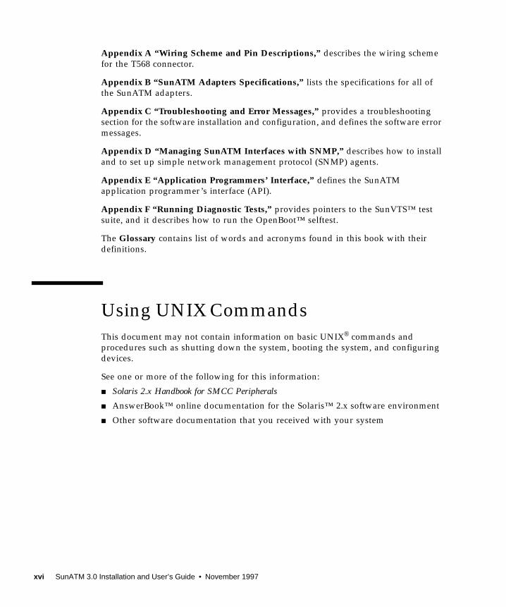
FIGURE 1-1 SunATM/P 155 MMF 3.0 Adapter 1-2
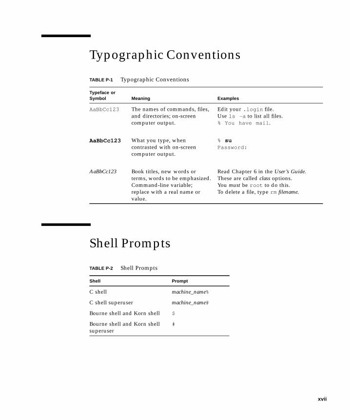
FIGURE 1-2 SunATM/P 155 UTP 3.0 Adapter 1-2
FIGURE 1-3 SunATM/P 622 MMF 3.0 Adapter 1-4
FIGURE 2-1 SunATM/P 155 MMF 3.0 Adapter Backplate 2-3
FIGURE 2-2 SunATM/P 155 UTP 3.0 Adapter Backplate 2-4
FIGURE 2-3 SunATM/P 622 MMF 3.0 Adapter Backplate 2-5
FIGURE 4-1 atmadmin Main Menu 4-3
FIGURE 4-2 System Parameter Group Menu 4-4
FIGURE 4-3 Interface Configuration Menu 4-5
FIGURE 4-4 Physical Layer Parameter Menu 4-8
FIGURE 4-5 Signalling Parameter Menu 4-9
FIGURE 4-6 ILMI Parameter Menu 4-10
FIGURE 4-7 Classical IP Parameter Menu for an ARP Client 4-11
FIGURE 4-8 LAN Emulation Parameter Menu 4-15
FIGURE 4-9 LAN Emulation Per-Instance Parameters Menu 4-16
FIGURE 5-1 Example /etc/atmconfig File 5-4
FIGURE 6-1 ATM Address Fields 6-2
FIGURE 6-2 Using atmsnmpd as a Forwarding Agent 6-9
FIGURE A-1 Designation T568B A-1
xi

FIGURE A-2 UTP Back-to-Back Cross Over Cable Diagram A-2
FIGURE E-1 ATM Signalling E-2
FIGURE E-2 Message Format E-4
FIGURE E-3 Normal Call Setup and Tear Down E-10
xii SunATM 3.0 Installation and User’s Guide • November 1997

Tables
TABLE 4-1 Basic Navigational Commands in atmadmin 4-3
TABLE 4-2 Configurable Parameters in the SunATM Software 4-6
TABLE 4-3 Predefined SunATM Variables 4-13
TABLE 5-1 /etc/atmconfig Field Descriptions 5-2
TABLE 5-2 /etc/aarconfig Entry Descriptions 5-6
TABLE 5-3 /etc/aarconfig Flag Descriptions 5-6
TABLE 5-4 /etc/aarconfig File Flag Options 5-7
TABLE 5-5 Predefined SunATM Variables 5-9
TABLE 5-6 /etc/laneconfig Entry Descriptions 5-14
TABLE 5-7 /etc/laneconfig Flag Descriptions 5-15
TABLE 5-8 laneconfig File Flag Options 5-16
TABLE 5-9 Predefined SunATM Variables 5-17
TABLE 6-1 LAN Emulation Connections 6-8
TABLE B-1 SunATM/P 155 Adapters Physical Dimensions B-1
TABLE B-2 SunATM/P 155 Adapters Performance Specifications B-2
TABLE B-3 SunATM/P 155 Adapters Power Specifications B-2
TABLE B-4 SunATM/P 155 Adapters Environmental Specifications B-2
TABLE B-5 SunATM/P 622 MMF 3.0 Adapter Physical Dimensions B-3
TABLE B-6 SunATM/P 622 MMF 3.0 Adapter Performance Specifications B-3
TABLE B-7 SunATM/P 622 MMF 3.0 Adapter Power Specifications B-3
xiii

TABLE B-8 SunATM/P 622 MMF 3.0 Adapter Environmental Specifications B-4
TABLE E-1 Messages Between the User and the q93b Driver E-3
TABLE E-2 Fields in the M_PROTO mblock E-4
TABLE E-3 qcc Functions E-5
TABLE E-4 atm_util Function Overview E-7
TABLE F-1 atmtest Command Line Syntax F-2
xiv SunATM 3.0 Installation and User’s Guide • November 1997
Preface
The SunATM™ 3.0 Installation and User’s Guide provides installation instructions for
the SunATM adapters supported by the SunATM 3.0 software. This manual also
describes how to install and configure the SunATM software.
These instructions are designed for a system administrator with experienced
installing similar hardware and software.
How This Book Is Organized
Chapter 1 “Introducing the SunATM Adapters,” introduces the features of the
SunATM adapters.
Chapter 2 “Installing the SunATM Adapters,” defines how to install the SunATM
PCI adapters into your system.
Chapter 3 “Installing the SunATM Software,” describes how to install the SunATM
software packages using the pkgadd utility.
Chapter 4 “Configuring the SunATM Interface,” describes some of the new features
in the SunATM software and how to configure the software using the atmadminconfiguration program.
Chapter 5 “Editing SunATM Configuration Files,” shows how you can edit the
SunATM configuration files to best suit your network.
Chapter 6 “Classical IP and LAN Emulation Protocols,” provides background
information about the Classical Internet Protocol (IP) and the local area network
(LAN) emulation protocol, which enables IP traffic to run over asynchronous
transfer mode (ATM) interfaces.
Preface xv
Appendix A “Wiring Scheme and Pin Descriptions,” describes the wiring scheme
for the T568 connector.
Appendix B “SunATM Adapters Specifications,” lists the specifications for all of
the SunATM adapters.
Appendix C “Troubleshooting and Error Messages,” provides a troubleshooting
section for the software installation and configuration, and defines the software error
messages.
Appendix D “Managing SunATM Interfaces with SNMP,” describes how to install
and to set up simple network management protocol (SNMP) agents.
Appendix E “Application Programmers’ Interface,” defines the SunATM
application programmer’s interface (API).
Appendix F “Running Diagnostic Tests,” provides pointers to the SunVTS™ test
suite, and it describes how to run the OpenBoot™ selftest.
The Glossary contains list of words and acronyms found in this book with their
definitions.
Using UNIX Commands
This document may not contain information on basic UNIX® commands and
procedures such as shutting down the system, booting the system, and configuring
devices.
See one or more of the following for this information:
■ Solaris 2.x Handbook for SMCC Peripherals
■ AnswerBook™ online documentation for the Solaris™ 2.x software environment
■ Other software documentation that you received with your system
xvi SunATM 3.0 Installation and User’s Guide • November 1997
Typographic Conventions
Shell Prompts
TABLE P-1 Typographic Conventions
Typeface orSymbol Meaning Examples
AaBbCc123 The names of commands, files,
and directories; on-screen
computer output.
Edit your .login file.
Use ls -a to list all files.
% You have mail .
AaBbCc123 What you type, when
contrasted with on-screen
computer output.
% suPassword:
AaBbCc123 Book titles, new words or
terms, words to be emphasized.
Command-line variable;
replace with a real name or
value.
Read Chapter 6 in the User’s Guide.
These are called class options.
You must be root to do this.
To delete a file, type rm filename.
TABLE P-2 Shell Prompts
Shell Prompt
C shell machine_name%
C shell superuser machine_name#
Bourne shell and Korn shell $
Bourne shell and Korn shell
superuser
#
xvii
Ordering Sun Documents
SunDocsSM is a distribution program for Sun Microsystems technical documentation.
Contact SunExpress for easy ordering and quick delivery. You can find a listing of
available Sun documentation on the World Wide Web.
Sun Welcomes Your Comments
We are interested in improving our documentation and welcome your comments
and suggestions.
You can email or fax your comments to us. Please include the part number of your
document in the subject line of your email or fax message.
■ Email: [email protected]
■ Fax: SMCC Document Feedback
1-650-786-6443
TABLE P-3 SunExpress Contact Information
Country Telephone Fax
Belgium 02-720-09-09 02-725-88-50
Canada 1-800-873-7869 1-800-944-0661
France 0800-90-61-57 0800-90-61-58
Germany 01-30-81-61-91 01-30-81-61-92
Holland 06-022-34-45 06-022-34-46
Japan 0120-33-9096 0120-33-9097
Luxembourg 32-2-720-09-09 32-2-725-88-50
Sweden 020-79-57-26 020-79-57-27
Switzerland 0800-55-19-26 0800-55-19-27
United Kingdom 0800-89-88-88 0800-89-88-87
United States 1-800-873-7869 1-800-944-0661
World Wide Web: http://www.sun.com/sunexpress/
xviii SunATM 3.0 Installation and User’s Guide • November 1997

CHAPTER 1
Introducing the SunATM Adapters
This chapter introduces the SunATM adapters supported by the SunATM 3.0
software. These adapters include:
■ SunATM/P 155 MMF 3.0
■ SunATM/P 155 UTP 3.0
■ SunATM/P 622 MMF 3.0
The features, hardware requirements, and software requirements of these adapters
are described in the following sections.
1.1 SunATM/P 155 AdaptersThe SunATM/P 155 MMF 3.0 adapter and the SunATM/P 155 UTP 3.0 adapter are
seven-inch PCI adapters that conform to the specifications of the Asynchronous
Transfer Mode (ATM) Forum. The adapters offer 155 Mbps network bandwidth over
either multimode fiber optic cable or Category 5 unshielded twisted pair (UTP)
copper wire.
The SunATM 155 adapters are designed for operation in systems that run under the
Solaris environment, revision 2.5.1 Hardware 4/97 or later. An on-board FCode
PROM provides the configuration support that identifies the SunATM 155 adapters
to the system.
Note – For instructions on how to install the adapters, see Chapter 2 “Installing theSunATM Adapters.”
1-1
FIGURE 1-1 SunATM/P 155 MMF 3.0 Adapter
FIGURE 1-2 SunATM/P 155 UTP 3.0 Adapter
1.1.1 Features
The highlights of the SunATM 155 adapters include:
■ Supports 155-Mbps operation over:
■ 62.5/125 µ multimode fiber (SunATM/P 155 MMF 3.0) or
■ UTP Category 5 wire conforming with the TIA/EIA-568-A standard
(SunATM/P 155 UTP 3.0)
■ Integrates PCI/SAR (segmentation and reassembly) ASIC implemented in
standard CMOS
1-2 SunATM 3.0 Installation and User’s Guide • November 1997

■ SAR function aligned with ATM Forum specified and International
Telecommunications Union - Telecommunication Sector (ITU-TS) approved ATM
Adaptation Layer (AAL) 5
■ Supports 32- and 64-bit bus master interface
■ Supports both 33 MHz and 66 MHz clock speeds
■ Supports the SONET/SDH (Synchronous Optical NETwork/Synchronous Digital
Hierarchy) physical layer framing structure
■ Supports up to 126 simultaneous transmit channels and up to 1024 simultaneous
open receive channels
■ Is compatible with relevant emerging standards (including existing ATM Forum
baseline specifications and ITU-TS)
1.1.2 Hardware Requirements
To connect the SunATM 155 adapters to an ATM switch or another adapter, you
need the following cables:
■ SunATM/P 155 MMF 3.0 Adapter—Multimode fiber cable with an SC connector
■ SunATM/P 155 UTP 3.0 Adapter—Category 5 UTP with a RJ-45 connector
Refer to the manual supplied with the ATM switch for specific instructions about
cable connections.
1.1.3 Software Requirements
The SunATM 3.0 CD-ROM that shipped with the PCI adapter contains the requireddriver software that must be installed in order to connect a SunATM 155 adapter to
a network.
The SunATM 3.0 software is supported on systems running under the Solaris
environment, revision 2.5.1 Hardware 4/97 or later.
Note – Before installing the SunATM 3.0 software packages, you must first install
the SunATM adapter into the system.
Chapter 1 Introducing the SunATM Adapters 1-3
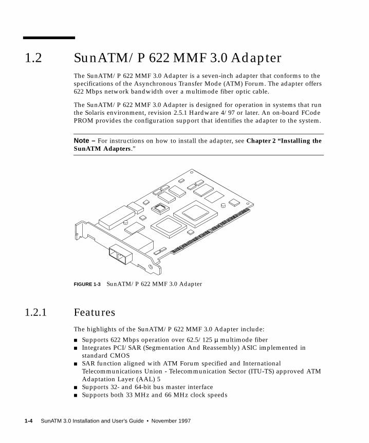
1.2 SunATM/P 622 MMF 3.0 AdapterThe SunATM/P 622 MMF 3.0 Adapter is a seven-inch adapter that conforms to the
specifications of the Asynchronous Transfer Mode (ATM) Forum. The adapter offers
622 Mbps network bandwidth over a multimode fiber optic cable.
The SunATM/P 622 MMF 3.0 Adapter is designed for operation in systems that run
the Solaris environment, revision 2.5.1 Hardware 4/97 or later. An on-board FCode
PROM provides the configuration support that identifies the adapter to the system.
Note – For instructions on how to install the adapter, see Chapter 2 “Installing theSunATM Adapters.”
FIGURE 1-3 SunATM/P 622 MMF 3.0 Adapter
1.2.1 Features
The highlights of the SunATM/P 622 MMF 3.0 Adapter include:
■ Supports 622 Mbps operation over 62.5/125 µ multimode fiber
■ Integrates PCI/SAR (Segmentation And Reassembly) ASIC implemented in
standard CMOS
■ SAR function aligned with ATM Forum specified and International
Telecommunications Union - Telecommunication Sector (ITU-TS) approved ATM
Adaptation Layer (AAL) 5
■ Supports 32- and 64-bit bus master interface
■ Supports both 33 MHz and 66 MHz clock speeds
1-4 SunATM 3.0 Installation and User’s Guide • November 1997
■ Supports SONET/SDH (Synchronous Optical NETwork/Synchronous Digital
Hierarchy) physical layer framing structure
■ Supports up to 126 simultaneous transmit channels and up to 1024 simultaneous
open receive channels
■ Is compatible with relevant emerging standards (including existing ATM Forum
baseline specifications and ITU-TS)
1.2.2 Hardware Requirements
To connect the SunATM/P 622 MMF 3.0 adapter to an ATM switch or another
adapter, you will need a multimode fiber cable with an SC connector.
Refer to the manual supplied with the ATM switch for the specific instructions about
cable connections.
1.2.3 Software Requirements
The SunATM 3.0 CD-ROM that shipped with the adapter contains the required driver
software that must be installed in order to connect a SunATM adapter to a network.
The SunATM 3.0 software is supported on systems running the Solaris environment,
revision 2.5.1 Hardware 4/97 or later.
Note – Before installing the SunATM 3.0 software packages, you must first install
the SunATM adapter into the system.
Chapter 1 Introducing the SunATM Adapters 1-5

1-6 SunATM 3.0 Installation and User’s Guide • November 1997
CHAPTER 2
Installing the SunATM Adapters
This chapter describes how to install the following three SunATM adapters:
■ SunATM/P 155 MMF 3.0 Adapter
■ SunATM/P 155 UTP 3.0 Adapter
■ SunATM/P 622 MMF 3.0 Adapter
Refer to your system’s service and installation manuals for additional information
about installing PCI adapters.
Note – Before installing the SunATM 3.0 software packages, you must first install
the SunATM adapter into the system.
2.1 Installing the SunATM Adapters
Note – Refer to your system installation or service manual for detailed instructions
for the following tasks.
1. Power off your system and open the system unit.
2. Attach the adhesive copper strip of the wrist strap to the metal casing of thepower supply. Wrap the other end twice around your wrist, with the adhesive sideagainst your skin.
3. Holding the PCI adapter by the edges, unpack and place it on an antistaticsurface.
2-1

Note – The SunATM-155/MMF PCI adapter and the SunATM-622/MMF PCI
adapter are both shipped with a rubber plug that keeps the SC connector free of
dust. Remove this plug before installing the adapter into the system.
4. Remove the PCI filler panel from the slot in which you want to insert theSunATM PCI adapter.
5. Holding the PCI adapter by the edges, align the adapter edge connector with thePCI slot. Slide the adapter face plate into the small slot at the end of the PCIopening.
Note – The SunATM PCI adapters support both the 33 MHz and the 66 MHz PCI
slots. Refer to your system’s service manual for the location of these slots.
6. Applying even pressure at both corners of the adapter, push the PCI adapter untilit is firmly seated in the slot.
Caution – Do not use excessive force when installing the adapter into the PCI slot.
You may damage the adapter’s PCI connector. If the adapter does not seat properly
when you apply even pressure, remove the adapter and carefully reinstall it.
7. Detach the wrist strap and close the system unit.
2.2 Verifying the InstallationAfter you have installed the SunATM adapter, but before you boot your system,
perform the following tasks to verify the installation. Refer to the Solaris 2.xHandbook for SMCC Peripherals manual or your Solaris documentation for the
detailed instructions.
1. Power on the system, and when the banner appears, press the Stop-A keys tointerrupt the boot process and to get to the ok prompt.
2. Use the show-devs command to list the system devices.
2-2 SunATM 3.0 Installation and User’s Guide • November 1997
You should see a line in the list of devices, similar to the example below, specific to
the SunATM adapter. The SunATM adapters are identified by the device name ma.
The SUNW,ma@1entry identifies that the SunATM adapter is seated in PCI slot 1.
Note – If you do not see the madevice listed, check that the adapter is properly
seated and, if necessary, reinstall the adapter.
3. Perform a reconfiguration boot on the system.
Refer to the Solaris 2.x Peripheral’s Handbook for more information about performing
reconfiguration boots on Solaris systems.
2.3 SunATM Adapter Wiring Configuration
2.3.1 SunATM/P 155 MMF 3.0 Adapter Wiring
Configuration
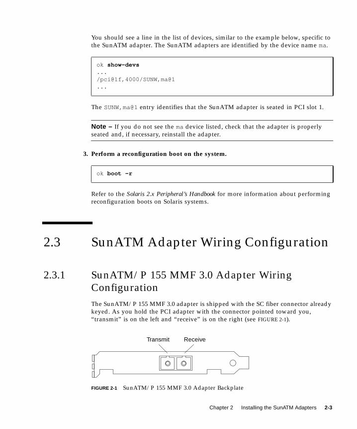
The SunATM/P 155 MMF 3.0 adapter is shipped with the SC fiber connector already
keyed. As you hold the PCI adapter with the connector pointed toward you,
“transmit” is on the left and “receive” is on the right (see FIGURE 2-1).
FIGURE 2-1 SunATM/P 155 MMF 3.0 Adapter Backplate
ok show-devs.../pci@1f,4000/SUNW,ma@1...
ok boot -r
Transmit Receive
Chapter 2 Installing the SunATM Adapters 2-3
To connect the SunATM/P 155 MMF 3.0 adapter to the network:
● Connect one end of the multimode fiber cable into the fiber receptacle on theadapter and connect the other end to an ATM switch.
Note – The adapters can also work in back-to-back mode without a switch.
Refer to the installation or users manual supplied with the hardware interface for
additional information.
After connecting the adapter to the ATM switch, install the SunATM 3.0 software as
described in Chapter 3 “Installing the SunATM Software.”
2.3.2 SunATM/P 155 UTP 3.0 Adapter Wiring
Configuration
The SunATM/P 155 UTP 3.0 adapter is shipped with the RJ-45 connector already
keyed for “transmit” (Pair 2, pins 1 and 2) and “receive” (Pair 4, pins 7 and 8) in
accordance with the EIA/TIA (T568B) wiring scheme (see Appendix A “WiringScheme and Pin Descriptions”).
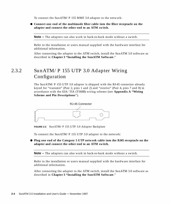
FIGURE 2-2 SunATM/P 155 UTP 3.0 Adapter Backplate
To connect the SunATM/P 155 UTP 3.0 adapter to the network:
● Plug one end of the Category 5 UTP network cable into the RJ45 receptacle on theadapter and connect the other end to an ATM switch.
Note – The adapters can also work in back-to-back mode without a switch.
Refer to the installation or users manual supplied with the hardware interface for
additional information.
After connecting the adapter to the ATM switch, install the SunATM 3.0 software as
described in Chapter 3 “Installing the SunATM Software.”
RJ-45 Connector
2-4 SunATM 3.0 Installation and User’s Guide • November 1997
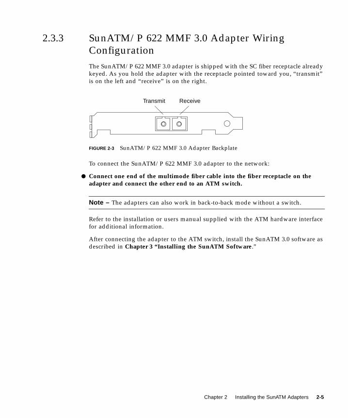
2.3.3 SunATM/P 622 MMF 3.0 Adapter Wiring
Configuration
The SunATM/P 622 MMF 3.0 adapter is shipped with the SC fiber receptacle already
keyed. As you hold the adapter with the receptacle pointed toward you, “transmit”
is on the left and “receive” is on the right.
FIGURE 2-3 SunATM/P 622 MMF 3.0 Adapter Backplate
To connect the SunATM/P 622 MMF 3.0 adapter to the network:
● Connect one end of the multimode fiber cable into the fiber receptacle on theadapter and connect the other end to an ATM switch.
Note – The adapters can also work in back-to-back mode without a switch.
Refer to the installation or users manual supplied with the ATM hardware interface
for additional information.
After connecting the adapter to the ATM switch, install the SunATM 3.0 software as
described in Chapter 3 “Installing the SunATM Software.”
Transmit Receive
Chapter 2 Installing the SunATM Adapters 2-5

2-6 SunATM 3.0 Installation and User’s Guide • November 1997
CHAPTER 3
Installing the SunATM Software
Before installing and configuring the SunATM software, you must first install the
adapter into the system. See Chapter 2 “Installing the SunATM Adapters,” for
more information.
After you have installed the SunATM software, but before you reboot your system,
you need to configure the SunATM software. See Chapter 4 “Configuring theSunATM Interface,” for instructions on how to use the atmadmin configuration
program.
3.1 Installing the SunATM Software
3.1.1 Adding the Software Packages Using pkgadd
1. Become superuser (root).
2. Insert the SunATM CD-ROM into the CD-ROM drive connected to your system.
■ If your system is running the volume management software, it should
automatically mount the CD on this directory: /cdrom/sunatm_3_0
■ If your system is not running the volume management software, type the
following to mount the CD-ROM:
# mkdir -p /cdrom/sunatm_3_0# mount -F hsfs -o ro /dev/dsk/c0t6d0s2 /cdrom/sunatm_3_0
3-1
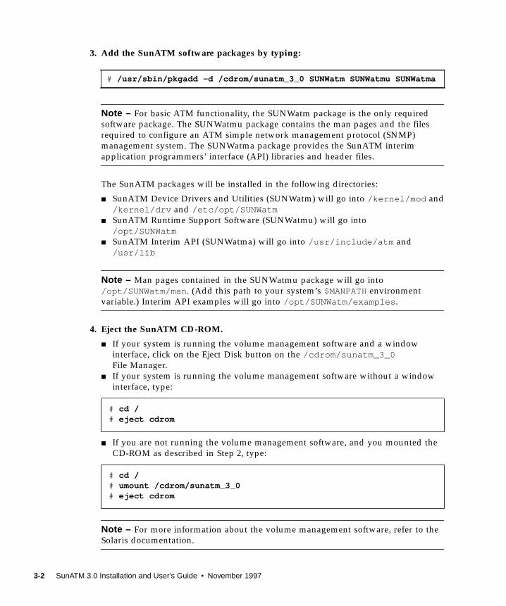
3. Add the SunATM software packages by typing:
Note – For basic ATM functionality, the SUNWatm package is the only required
software package. The SUNWatmu package contains the man pages and the files
required to configure an ATM simple network management protocol (SNMP)
management system. The SUNWatma package provides the SunATM interim
application programmers’ interface (API) libraries and header files.
The SunATM packages will be installed in the following directories:
■ SunATM Device Drivers and Utilities (SUNWatm) will go into /kernel/mod and
/kernel/drv and /etc/opt/SUNWatm■ SunATM Runtime Support Software (SUNWatmu) will go into
/opt/SUNWatm■ SunATM Interim API (SUNWatma) will go into /usr/include/atm and
/usr/lib
Note – Man pages contained in the SUNWatmu package will go into
/opt/SUNWatm/man . (Add this path to your system’s $MANPATHenvironment
variable.) Interim API examples will go into /opt/SUNWatm/examples .
4. Eject the SunATM CD-ROM.
■ If your system is running the volume management software and a window
interface, click on the Eject Disk button on the /cdrom/sunatm_3_0File Manager.
■ If your system is running the volume management software without a window
interface, type:
■ If you are not running the volume management software, and you mounted the
CD-ROM as described in Step 2, type:
Note – For more information about the volume management software, refer to the
Solaris documentation.
# /usr/sbin/pkgadd -d /cdrom/sunatm_3_0 SUNWatm SUNWatmu SUNWatma
# cd /# eject cdrom
# cd /# umount /cdrom/sunatm_3_0# eject cdrom
3-2 SunATM 3.0 Installation and User’s Guide • November 1997
5. Configure your SunATM interface(s).
You must complete the network configuration of your SunATM interface before you
can use the interface. An interactive program,
/etc/opt/SUNWatm/bin/atmadmin , is included with the SunATM software, and
it can be used to configure your SunATM interfaces. See Chapter 4 “Configuring theSunATM Interface,” for instructions on how to use the atmadmin configuration
program.
Caution – You must configure the SunATM software before rebooting your system.
6. Perform a reconfiguration boot on your system, and check the network.
See Section 3.2 “Rebooting the System and Examining Network Interfaces,” for more
information.
3.1.2 Using the pkgadd Utility
When the device on which the package resides is not specified, pkgadd checks the
default spool directory (/var/spool/pkg ). If the package is not there, installation
fails. The -d option enables you to specify a different spool directory, and the name
specified after -d must be a full pathname to a device or directory (as shown in
Section 3.1.1 “Adding the Software Packages Using pkgadd”).
When pkgadd encounters a problem, information about the problem is displayed
along with the following prompt:
You should respond with either yes , no , or quit . If more than one package has
been specified, no stops the installation of the package being installed but informs
pkgadd to continue with installation of the other packages. quit tells pkgadd to
stop installation of all packages.
Note – For more information about the pkgadd utility, refer to the pkgadd(1M)man page.
Do you want to continue with this installation?
Chapter 3 Installing the SunATM Software 3-3
3.1.3 Checking the Package Installation Using pkgchk
Once the package is installed, you can use the pkgchk command to see if the
installation was complete:
Multiple packages can be specified at the command line by separating the package
names with a space. If no package identifier is specified, the entire contents of the
machine are checked.
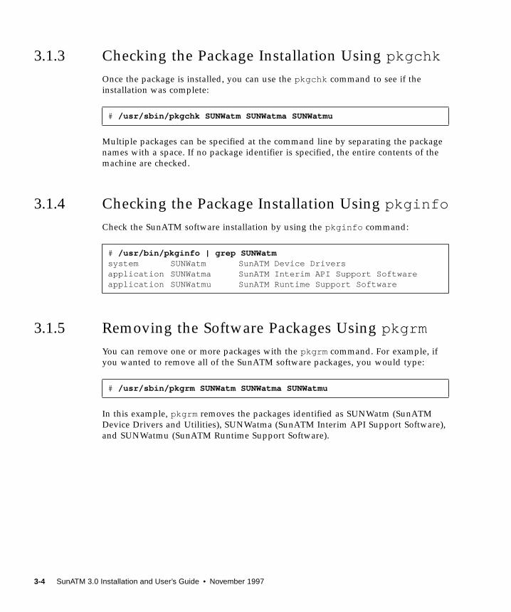
3.1.4 Checking the Package Installation Using pkginfo
Check the SunATM software installation by using the pkginfo command:
3.1.5 Removing the Software Packages Using pkgrm
You can remove one or more packages with the pkgrm command. For example, if
you wanted to remove all of the SunATM software packages, you would type:
In this example, pkgrm removes the packages identified as SUNWatm (SunATM
Device Drivers and Utilities), SUNWatma (SunATM Interim API Support Software),
and SUNWatmu (SunATM Runtime Support Software).
# /usr/sbin/pkgchk SUNWatm SUNWatma SUNWatmu
# /usr/bin/pkginfo | grep SUNWatmsystem SUNWatm SunATM Device Driversapplication SUNWatma SunATM Interim API Support Softwareapplication SUNWatmu SunATM Runtime Support Software
# /usr/sbin/pkgrm SUNWatm SUNWatma SUNWatmu
3-4 SunATM 3.0 Installation and User’s Guide • November 1997
3.2 Rebooting the System and ExaminingNetwork InterfacesAfter you have installed and configured the SunATM software, you need to
shutdown and reboot your system.
1. Shutdown your system.
2. At the ok prompt, perform a reconfiguration boot on your system using theboot -rv command.
The -r option is required by the Solaris software environment when installing new
hardware. Use the -v option to display the boot messages, so you can see that the
SunATM adapters are recognized correctly.
Note – On Solaris 2.x systems, use boot -r whenever the physical configuration of
the system is changed. Refer to the boot(1M) man page for more information.
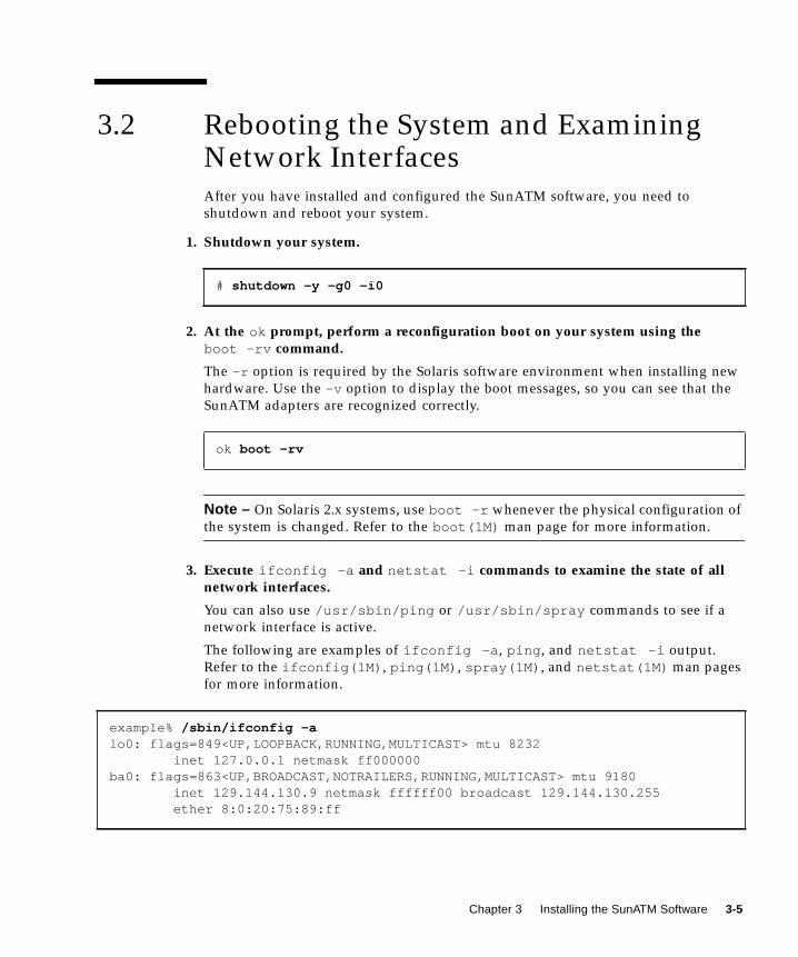
3. Execute ifconfig -a and netstat -i commands to examine the state of allnetwork interfaces.
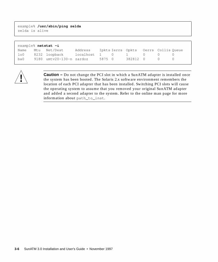
You can also use /usr/sbin/ping or /usr/sbin/spray commands to see if a
network interface is active.
The following are examples of ifconfig -a , ping , and netstat -i output.
Refer to the ifconfig(1M) , ping(1M) , spray(1M) , and netstat(1M) man pages
for more information.
# shutdown -y -g0 -i0
ok boot -rv
example% /sbin/ifconfig -alo0: flags=849<UP,LOOPBACK,RUNNING,MULTICAST> mtu 8232 inet 127.0.0.1 netmask ff000000ba0: flags=863<UP,BROADCAST,NOTRAILERS,RUNNING,MULTICAST> mtu 9180 inet 129.144.130.9 netmask ffffff00 broadcast 129.144.130.255 ether 8:0:20:75:89:ff
Chapter 3 Installing the SunATM Software 3-5
Caution – Do not change the PCI slot in which a SunATM adapter is installed once
the system has been booted. The Solaris 2.x software environment remembers the
location of each PCI adapter that has been installed. Switching PCI slots will cause
the operating system to assume that you removed your original SunATM adapter
and added a second adapter to the system. Refer to the online man page for more
information about path_to_inst .
example% /usr/sbin/ping zeldazelda is alive
example% netstat -iName Mtu Net/Dest Address Ipkts Ierrs Opkts Oerrs Collis Queuelo0 8232 loopback localhost 1 0 1 0 0 0ba0 9180 umtv20-130-n zardoz 5875 0 382812 0 0 0
3-6 SunATM 3.0 Installation and User’s Guide • November 1997
CHAPTER 4
Configuring the SunATM Interface
This chapter describes the new features in the SunATM software and how to
configure the software using the atmadmin configuration program.
4.1 New Features in the SunATM SoftwareBesides supporting the new SunATM PCI adapters, the SunATM software contains
several new features in addition to performance improvements. This section
provides a brief overview of these new features.
4.1.1 Support for UNI and ILMI 4.0
The ATM Forum recently published new revisions of its User Network Interface
(UNI) and Integrated Local Management Interface (ILMI) specifications. Both of
these are supported in the SunATM 3.0 software.
4.1.2 Automatic LECS Address Detection
Some LAN Emulation environments include LAN emulation configuration servers
(LECS), which do not use the ATM Forum-defined well-known address. Beginning
with the SunATM 3.0 release, the SunATM software will automatically attempt to
learn the LECS address via ILMI. If it is unable to find the address via ILMI, it will
default to the well-known address. The user may still override both of these
methods by entering an LECS address in the LAN Emulation configuration file.
4-1

4.2 Using the atmadmin ConfigurationProgramThe SunATM configuration program, atmadmin , is an interactive command-line
interface. The program contains a hierarchy of menus, which divide the
configuration into seven main parameter groups: system, physical layer, signalling,
ILMI, Classical IP, and LAN Emulation. All but the system parameter group are
specific to individual SunATM interfaces, so you must configure the parameters in
these groups separately for each interface.
If you prefer, you can enter and change the SunATM configuration information by
editing the SunATM configuration files directly. See Chapter 5 “Editing SunATMConfiguration Files,” for a description of the configuration files’ contents and
formats.
Note – See the Glossary for descriptions of the ATM and SunATM terms used in
this chapter. Chapter 5 “Editing SunATM Configuration Files,” and Chapter 6“Classical IP and LAN Emulation Protocols,” also provide more information about
ATM protocols and the SunATM implementation of these protocols.
4.2.1 Starting the atmadmin Configuration Program
The atmadmin program is installed with the SUNWatm software package in the
/etc/opt/SUNWatm/bin directory. The program must be run as superuser (root),
and it has no command-line options. It can be run in any local or remote shell on the
SunATM system.
# /etc/opt/SUNWatm/bin/atmadmin
4-2 SunATM 3.0 Installation and User’s Guide • November 1997
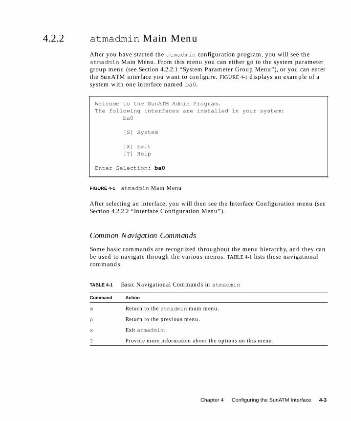
4.2.2 atmadmin Main Menu
After you have started the atmadmin configuration program, you will see the
atmadmin Main Menu. From this menu you can either go to the system parameter
group menu (see Section 4.2.2.1 “System Parameter Group Menu”), or you can enter
the SunATM interface you want to configure. FIGURE 4-1 displays an example of a
system with one interface named ba0 .
FIGURE 4-1 atmadmin Main Menu
After selecting an interface, you will then see the Interface Configuration menu (see
Section 4.2.2.2 “Interface Configuration Menu”).
Common Navigation Commands
Some basic commands are recognized throughout the menu hierarchy, and they can
be used to navigate through the various menus. TABLE 4-1 lists these navigational
commands.
Welcome to the SunATM Admin Program.The following interfaces are installed in your system: ba0
[S] System
[X] Exit [?] Help
Enter Selection: ba0
TABLE 4-1 Basic Navigational Commands in atmadmin
Command Action
m Return to the atmadmin main menu.
p Return to the previous menu.
x Exit atmadmin .
? Provide more information about the options on this menu.
Chapter 4 Configuring the SunATM Interface 4-3
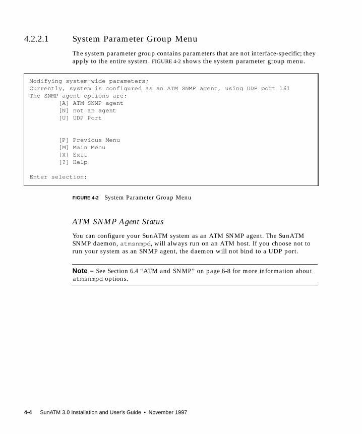
4.2.2.1 System Parameter Group Menu
The system parameter group contains parameters that are not interface-specific; they
apply to the entire system. FIGURE 4-2 shows the system parameter group menu.
FIGURE 4-2 System Parameter Group Menu
ATM SNMP Agent Status
You can configure your SunATM system as an ATM SNMP agent. The SunATM
SNMP daemon, atmsnmpd , will always run on an ATM host. If you choose not to
run your system as an SNMP agent, the daemon will not bind to a UDP port.
Note – See Section 6.4 “ATM and SNMP” on page 6-8 for more information about
atmsnmpd options.
Modifying system-wide parameters;Currently, system is configured as an ATM SNMP agent, using UDP port 161The SNMP agent options are: [A] ATM SNMP agent [N] not an agent [U] UDP Port
[P] Previous Menu [M] Main Menu [X] Exit [?] Help
Enter selection:
4-4 SunATM 3.0 Installation and User’s Guide • November 1997

4.2.2.2 Interface Configuration Menu
Once you have selected a SunATM interface, you will see the atmadmin Interface
Configuration menu (FIGURE 4-3). From this menu you will be able to proceed to the
interface parameter group submenus, which are described in Section 4.3 “atmadmin
Parameter Groups.” Within these submenus, you can change the SunATM interface
configuration parameters.
FIGURE 4-3 Interface Configuration Menu
4.2.3 atmadmin and the SunATM Configuration Files
in the /etc directory
The atmadmin program will first attempt to read the current configuration
information from the /etc/atmconfig , /etc/aarconfig , and
/etc/laneconfig files. If no configuration information is found, or if the files do
not exist, the default values listed in TABLE 4-2 will be applied to the installed
interfaces.
Caution – When saving configuration information, atmadmin will overwrite the
existing SunATM configuration files in the /etc directory. Therefore, any comments
or other changes you manually made to the files will be lost.
Modifying ba0 [Y] Physical Layer [U] UNI Signalling [I] ILMI Address Registration [C] Classical IP [L] LAN Emulation
[P] Previous Menu [M] Main Menu [X] Exit [?] Help
Enter selection:
Chapter 4 Configuring the SunATM Interface 4-5

4.3 atmadmin Parameter GroupsThe atmadmin configuration program contains a series of menus where you can
input or alter the configuration of specific SunATM software parameters. These
menus, or parameter groups, are described in the following sections in this chapter:
■ Physical Layer Parameter Group—page 4-8
■ Signalling Parameter Group—page 4-9
■ ILMI Parameter Group—page 4-10
■ Classical IP Parameter Group—page 4-10
■ LAN Emulation Parameter Group—page 4-14
TABLE 4-2 summarizes the configurable parameters in each parameter group.
Although the parameter list appears rather lengthy, you will only need to use the
default values for most standard configurations. The large number of parameters
provide the flexibility to support a wide variety of special case configurations, and to
enable interoperability with a broad a range of equipment from other vendors.
Note – In most cases, you will only need to configure the parameters which do not
have default values.
TABLE 4-2 Configurable Parameters in the SunATM Software
Group Parameters Possible Values Default Values Required?
System SNMP Agent Status agent or
not_agentnot_agent Yes
SNMP Agent UDP
port
1 <= n <= 65535 161 or 1000 For SNMP Agent
Physical Layer Framing Interface SONET or SDH SONET Yes
Signalling UNI Version 3.0, 3.1, 4.0 or none No default Yes
ILMI Use ILMI Yes or no Yes Yes
Classical IP Hostname/
IP Address
Valid hostname and
IP address
No default For Classical IP
Interface Type Client, Server, or
Standalone
No default For Classical IP
Local ATM Address Valid ATM address $myaddress For Classical IP
Clients or
Servers
4-6 SunATM 3.0 Installation and User’s Guide • November 1997

ARP Server Valid ATM address $localswitch_server For Classical IP
Clients
PVC 32 <= n < 1024 32 For Classical IP
Standalones
Destination
hostname and
IP address
Valid hostname and
IP address
No default For Classical IP
Standalones
LAN
Emulation
Instance Number 0 <= n <= 999 No default For LAN
Emulation
Per-Instance
Parameters
Hostname/
IP Address
Valid hostname and
IP address
No default For IP over LAN
Emulation
Local ATM Address Valid ATM address $myaddress For LAN
Emulation
LECS Indicator no_lecs , or
lecs_presentlecs_present For LAN
Emulation
LECS ATM Address Valid ATM address The well-known LECS
address
For LAN
Emulation,
lecs_present
LES ATM Address Valid ATM address No default For LAN
Emulation,
no_lecs
Emulated LAN
Name
Character string No default For additional
instance on a
physical interface
Additional
IP Address
Yes or no No For LAN
Emulation
Per-Additional
IP Address
Logical Unit
Number
1 <= n <=81911 None For LAN
Emulation,
additional IP
Hostname/
IP Address
Valid hostname and
IP address
No default For LAN
Emulation,
additional IP
1 Some versions of the Solaris operating system support a maximum configuration of 256 logical unit numbers per interface.Beginning with the Solaris 2.6 operating system, support for up to 8192 logical units per interface is available. (However, the defaultlimit is still set to 256 units per instance.) See Section “Additional IP Addresses” on page 4-18 for more information.
TABLE 4-2 Configurable Parameters in the SunATM Software (Continued)
Group Parameters Possible Values Default Values Required?
Chapter 4 Configuring the SunATM Interface 4-7
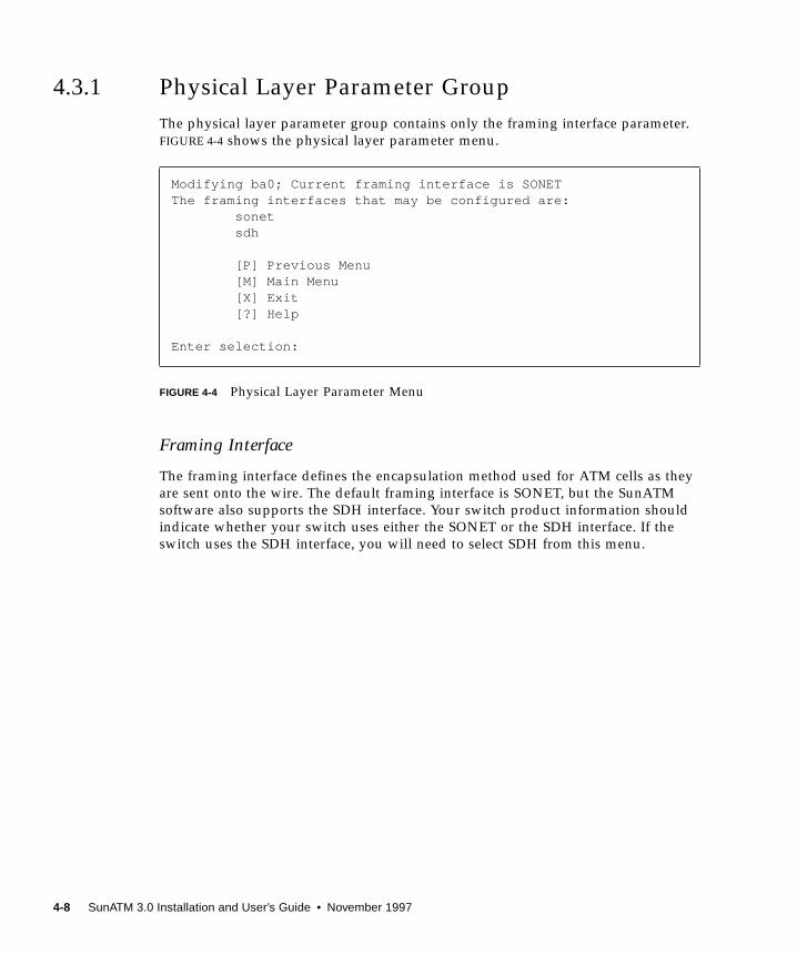
4.3.1 Physical Layer Parameter Group
The physical layer parameter group contains only the framing interface parameter.
FIGURE 4-4 shows the physical layer parameter menu.
FIGURE 4-4 Physical Layer Parameter Menu
Framing Interface
The framing interface defines the encapsulation method used for ATM cells as they
are sent onto the wire. The default framing interface is SONET, but the SunATM
software also supports the SDH interface. Your switch product information should
indicate whether your switch uses either the SONET or the SDH interface. If the
switch uses the SDH interface, you will need to select SDH from this menu.
Modifying ba0; Current framing interface is SONETThe framing interfaces that may be configured are: sonet sdh
[P] Previous Menu [M] Main Menu [X] Exit [?] Help
Enter selection:
4-8 SunATM 3.0 Installation and User’s Guide • November 1997
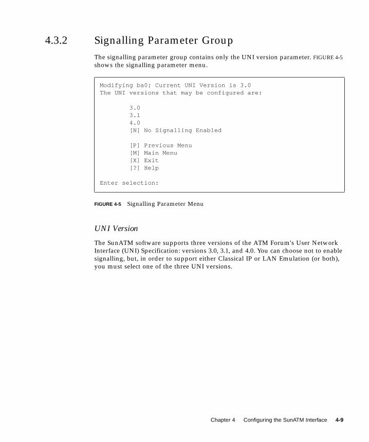
4.3.2 Signalling Parameter Group
The signalling parameter group contains only the UNI version parameter. FIGURE 4-5
shows the signalling parameter menu.
FIGURE 4-5 Signalling Parameter Menu
UNI Version
The SunATM software supports three versions of the ATM Forum's User Network
Interface (UNI) Specification: versions 3.0, 3.1, and 4.0. You can choose not to enable
signalling, but, in order to support either Classical IP or LAN Emulation (or both),
you must select one of the three UNI versions.
Modifying ba0; Current UNI Version is 3.0The UNI versions that may be configured are:
3.0 3.1 4.0 [N] No Signalling Enabled
[P] Previous Menu [M] Main Menu [X] Exit [?] Help
Enter selection:
Chapter 4 Configuring the SunATM Interface 4-9
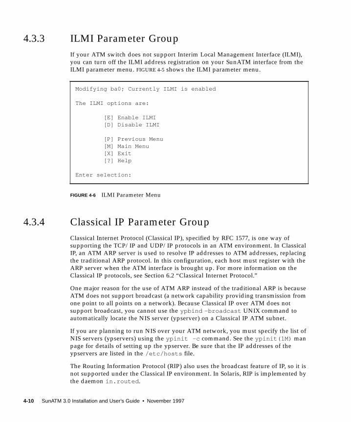
4.3.3 ILMI Parameter Group
If your ATM switch does not support Interim Local Management Interface (ILMI),
you can turn off the ILMI address registration on your SunATM interface from the
ILMI parameter menu. FIGURE 4-5 shows the ILMI parameter menu.
FIGURE 4-6 ILMI Parameter Menu
4.3.4 Classical IP Parameter Group
Classical Internet Protocol (Classical IP), specified by RFC 1577, is one way of
supporting the TCP/IP and UDP/IP protocols in an ATM environment. In Classical
IP, an ATM ARP server is used to resolve IP addresses to ATM addresses, replacing
the traditional ARP protocol. In this configuration, each host must register with the
ARP server when the ATM interface is brought up. For more information on the
Classical IP protocols, see Section 6.2 “Classical Internet Protocol.”
One major reason for the use of ATM ARP instead of the traditional ARP is because
ATM does not support broadcast (a network capability providing transmission from
one point to all points on a network). Because Classical IP over ATM does not
support broadcast, you cannot use the ypbind -broadcast UNIX command to
automatically locate the NIS server (ypserver) on a Classical IP ATM subnet.
If you are planning to run NIS over your ATM network, you must specify the list of
NIS servers (ypservers) using the ypinit -c command. See the ypinit(1M) man
page for details of setting up the ypserver. Be sure that the IP addresses of the
ypservers are listed in the /etc/hosts file.
The Routing Information Protocol (RIP) also uses the broadcast feature of IP, so it is
not supported under the Classical IP environment. In Solaris, RIP is implemented by
the daemon in.routed .
Modifying ba0; Currently ILMI is enabled
The ILMI options are:
[E] Enable ILMI [D] Disable ILMI
[P] Previous Menu [M] Main Menu [X] Exit [?] Help
Enter selection:
4-10 SunATM 3.0 Installation and User’s Guide • November 1997
If you are using Classical IP, you must explicitly add the routes to the routers in the
ATM subnet. You can also specify one router as the default router to provide
connectivity outside of the ATM subnet. See the route(1M) man page for
information on using the route command to add specific router entries and to add
a default router.
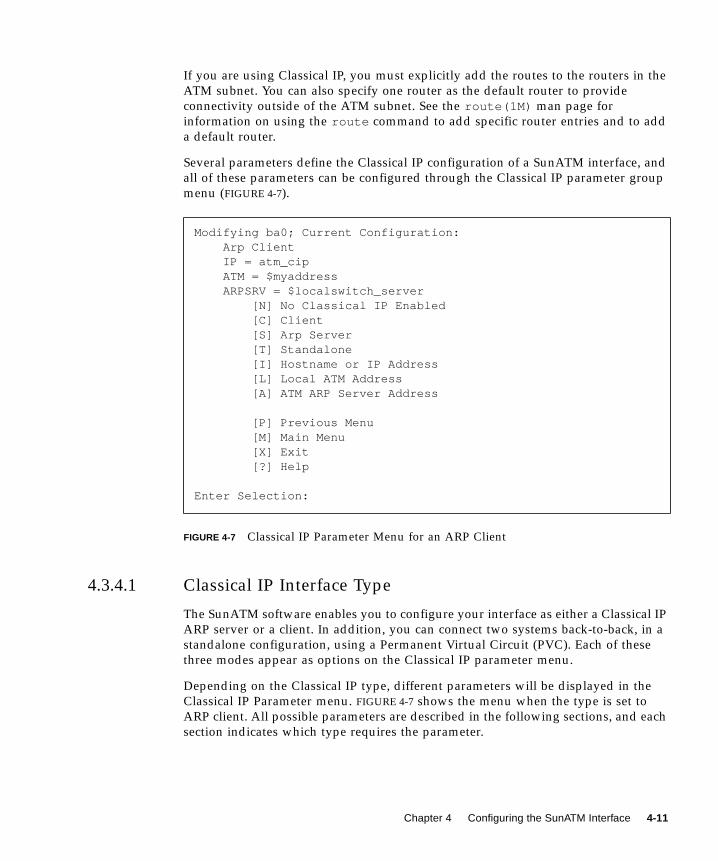
Several parameters define the Classical IP configuration of a SunATM interface, and
all of these parameters can be configured through the Classical IP parameter group
menu (FIGURE 4-7).
FIGURE 4-7 Classical IP Parameter Menu for an ARP Client
4.3.4.1 Classical IP Interface Type
The SunATM software enables you to configure your interface as either a Classical IP
ARP server or a client. In addition, you can connect two systems back-to-back, in a
standalone configuration, using a Permanent Virtual Circuit (PVC). Each of these
three modes appear as options on the Classical IP parameter menu.
Depending on the Classical IP type, different parameters will be displayed in the
Classical IP Parameter menu. FIGURE 4-7 shows the menu when the type is set to
ARP client. All possible parameters are described in the following sections, and each
section indicates which type requires the parameter.
Modifying ba0; Current Configuration: Arp Client IP = atm_cip ATM = $myaddress ARPSRV = $localswitch_server [N] No Classical IP Enabled [C] Client [S] Arp Server [T] Standalone [I] Hostname or IP Address [L] Local ATM Address [A] ATM ARP Server Address
[P] Previous Menu [M] Main Menu [X] Exit [?] Help
Enter Selection:
Chapter 4 Configuring the SunATM Interface 4-11
4.3.4.2 Hostname and IP Address
Regardless of the Classical IP Interface Type, an IP address and hostname must be
assigned to the interface. If you enter a hostname that appears in the /etc/hostsfile (or if NIS is enabled and the hostname is resolvable over NIS), you will not be
prompted to enter an IP address. Instead, the resolution will be performed
automatically. If the hostname cannot be resolved, you will be prompted to enter an
IP address. If you must enter an IP address, or if the address is only available
through NIS, the SunATM software will update the /etc/hosts file.
A valid hostname must be no more than 80 characters in length. A valid IP address
must be a dot-separated set of four decimal numbers in the range of 0 to 255 (for
example, 149.144.130.9 ).
4.3.4.3 Local ATM Address
The local ATM address is the 20-byte ATM address associated with this Classical IP
instance. You must assign an ATM address to each Classical IP client and server, but
you do not need to assign an ATM address on standalone (back-to-back)
configurations. The following section describes ATM address formats and some of
the SunATM software defined address variables.
ATM Address Formats and Variables
ATM addresses, like Network Service Access Point (NSAP) addresses, are 20 octets
long, with each octet made up of one or two hexadecimal digits. The ATM address is
divided into three fields: the End System Identifier field, Selector field, and the
Network Prefix field. The End System Identifier (ESI) field is a unique six octet
value, which can be the IEEE hardware MAC address conventionally associated with
every network interface. The Selector field is one octet long. The 13 octets that make
up the rest of the ATM address are called the Network Prefix. This field should be
derived from the ATM switch fabric to which the interface is connected. Every ATM
switch fabric is configured with a 13 octet prefix.
4-12 SunATM 3.0 Installation and User’s Guide • November 1997
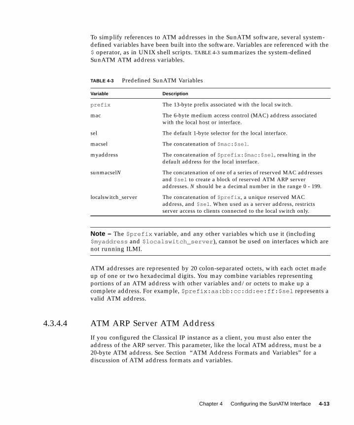
To simplify references to ATM addresses in the SunATM software, several system-
defined variables have been built into the software. Variables are referenced with the
$ operator, as in UNIX shell scripts. TABLE 4-3 summarizes the system-defined
SunATM ATM address variables.
Note – The $prefix variable, and any other variables which use it (including
$myaddress and $localswitch_server ), cannot be used on interfaces which are
not running ILMI.
ATM addresses are represented by 20 colon-separated octets, with each octet made
up of one or two hexadecimal digits. You may combine variables representing
portions of an ATM address with other variables and/or octets to make up a
complete address. For example, $prefix:aa:bb:cc:dd:ee:ff:$sel represents a
valid ATM address.
4.3.4.4 ATM ARP Server ATM Address
If you configured the Classical IP instance as a client, you must also enter the
address of the ARP server. This parameter, like the local ATM address, must be a
20-byte ATM address. See Section “ATM Address Formats and Variables” for a
discussion of ATM address formats and variables.
TABLE 4-3 Predefined SunATM Variables
Variable Description
prefix The 13-byte prefix associated with the local switch.
mac The 6-byte medium access control (MAC) address associated
with the local host or interface.
sel The default 1-byte selector for the local interface.
macsel The concatenation of $mac:$sel .
myaddress The concatenation of $prefix:$mac:$sel , resulting in the
default address for the local interface.
sunmacselN The concatenation of one of a series of reserved MAC addresses
and $sel to create a block of reserved ATM ARP server
addresses. N should be a decimal number in the range 0 - 199.
localswitch_server The concatenation of $prefix , a unique reserved MAC
address, and $sel . When used as a server address, restricts
server access to clients connected to the local switch only.
Chapter 4 Configuring the SunATM Interface 4-13
4.3.4.5 Permanent Virtual Circuit
The Permanent Virtual Circuit parameter applies only to standalone configurations.
It identifies the permanent virtual circuit (PVC) which will be used to communicate
between the two systems connected back-to-back. Both systems must use the same
PVC value. The PVC parameter must be a decimal integer between 32 and 1024.
4.3.5 LAN Emulation Parameter Group
LAN Emulation, standardized by the ATM Forum’s LAN Emulation 1.0
specification, is another way of providing TCP/IP and UDP/IP support over an
ATM interface. Address resolution information is provided by a series of LAN
Emulation services. When a LAN Emulation interface is brought up it must register
with these LAN Emulation services (known as “joining the LAN”). This registration
process and the address resolution process are described in Section 6.3 “LAN
Emulation” on page 6-5.
Unlike Classical IP, the LAN Emulation protocol provides a broadcast service to the
upper layer protocols. Therefore, the multicast and RIP limitations described in
Section 4.3.4 “Classical IP Parameter Group,” do not affect LAN Emulation
interfaces.
The SunATM software enables a single ATM interface to join up to sixteen emulated
local area networks (ELANs), provided that this action is allowed by the switch and
LAN Emulation (LANE) services. Each ELAN joined will be represented by a unique
lane instance (for example. lane0 or lane1 ).
4-14 SunATM 3.0 Installation and User’s Guide • November 1997
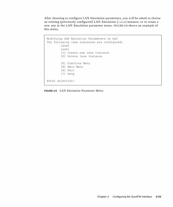
After choosing to configure LAN Emulation parameters, you will be asked to choose
an existing (previously configured) LAN Emulation (lane ) instance, or to create a
new one in the LAN Emulation parameter menu. FIGURE 4-8 shows an example of
this menu.
FIGURE 4-8 LAN Emulation Parameter Menu
Modifying LAN Emulation Parameters on ba0The following lane instances are configured: lane0 lane1 [C] Create new lane instance [D] Delete lane instance
[P] Previous Menu [M] Main Menu [X] Exit [?] Help
Enter selection:
Chapter 4 Configuring the SunATM Interface 4-15
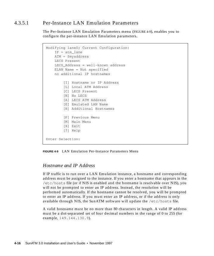
4.3.5.1 Per-Instance LAN Emulation Parameters
The Per-Instance LAN Emulation Parameters menu (FIGURE 4-9), enables you to
configure the per-instance LAN Emulation parameters.
FIGURE 4-9 LAN Emulation Per-Instance Parameters Menu
Hostname and IP Address
If IP traffic is to run over a LAN Emulation instance, a hostname and corresponding
address must be assigned to the instance. If you enter a hostname that appears in the
/etc/hosts file (or if NIS is enabled and the hostname is resolvable over NIS), you
will not be prompted to enter an IP address. Instead, the resolution will be
performed automatically. If the hostname cannot be resolved, you will be prompted
to enter an IP address. If you must enter an IP address, or if the address is only
available through NIS, the SunATM software will update the /etc/hosts file.
A valid hostname must be no more than 80 characters in length. A valid IP address
must be a dot-separated set of four decimal numbers in the range of 0 to 255 (for
example, 149.144.130.9 ).
Modifying lane0; Current Configuration: IP = atm_lane ATM = $myaddress LECS Present LECS_Address = well-known address ELAN Name = Not specified no additional IP hostnames
[I] Hostname or IP Address [L] Local ATM Address [C] LECS Present [N] No LECS [A] LECS ATM Address [E] Emulated LAN Name [H] Additional Hostnames
[P] Previous Menu [M] Main Menu [X] Exit [?] Help
Enter Selection:
4-16 SunATM 3.0 Installation and User’s Guide • November 1997

Local ATM Address
The local ATM address is the 20-byte ATM address associated with this LAN
Emulation instance. See Section “ATM Address Formats and Variables” for more
information about ATM address formats and variables.
Each lane instance must be assigned a unique ATM address. Each SunATM 3.0
board has been assigned 16 unique MAC addresses; if you use the variable
$myaddress for each lane instance, the SunATM software will automatically
distribute those MAC addresses to the lane instances associated with each physical
interface.
LECS Indicator
Most LAN Emulation Services include a LAN Emulation Configuration Server
(LECS) which is the first server contacted when bringing up a LAN Emulation client.
The LECS will provide the ATM address of the LAN Emulation Server (LES), as well
as other configuration information about the emulated LAN. However, some LAN
Emulation services do not include a LECS, and the LES must be contacted directly.
With the LECS Indicator parameter, you can specify which service should be
contacted first in your configuration. The possible values for this parameter are
displayed as individual options on the LAN Emulation per-instance parameters
menu.
Note – If the value of this parameter is no_LECS, a value must be given for the LES
ATM Address parameter.
LECS ATM Address
The ATM Forum specifies a “well-known” ATM address for the LECS. The SunATM
software uses this address to contact the LECS. If your LECS uses a different ATM
address, you should specify it in this parameter. If applicable, any of the ATM
address variables described in Section “ATM Address Formats and Variables”
($prefix in particular), can be used.
LES ATM Address
This parameter is required if the value of the LECS Indicator parameter is no_LECS.
There is no “well-known” address for the LES, so an ATM address must be specified
for the LES since there is not a LECS present to provide one. This parameter is a
Chapter 4 Configuring the SunATM Interface 4-17

standard ATM address. If any of the SunATM ATM address variables such as
$prefix , described in Section “ATM Address Formats and Variables,” are
applicable, they can be used.
Emulated LAN Name
If multiple Emulated LANs (ELANs) are present, you can enter a character string in
the Emulated LAN Name parameter. The LAN Emulation client can use this
parameter to indicate to the LAN Emulation services which ELAN it wishes to join.
By default, if a SunATM LAN Emulation client does not specify an ELAN name, it
tells the services to assign it to the default (or only) ELAN.
Note – If you have multiple LAN Emulation instances configured on a physical
interface, only one instance may join the default (unspecified) ELAN. You must
specify an ELAN name for all other instances.
Additional IP Addresses
The SunATM software supports logical interfaces in the SunATM LAN Emulation
environment. Logical interfaces enable you to assign multiple IP addresses to a
single LAN Emulation interface. A logical interface name consists of three parts: the
device name (in the case of SunATM LAN Emulation, lane ); the instance number,
which corresponds to the lane instance number; and the logical unit number, which
distinguishes the logical interfaces on a single lane instance. The format of a LAN
Emulation logical interface name is lane N:X, where N is the instance number and Xis the logical unit number (for example, lane0:2 ).
The SunATM software will associate each logical interface with a unique hostname
and IP address. All logical interfaces on a given physical interface will be associated
with the same ATM and MAC addresses.
The hostname displayed in the LAN Emulation per-instance parameters menu
corresponds to the logical unit 0. The additional hostnames parameter will indicate
if any additional hostnames are assigned to the instance. Additional hostnames may
be modified and/or created by selecting this parameter. You must enter or modify
each additional hostname in the same manner as other hostname and IP address
pairs (see Section “ATM Address Formats and Variables” on page 4-12 for more
details), and you must associate it with a logical unit number between 1 and 8191.
Note – Although atmadmin will enable you to configure logical unit numbers up to
8191, not all Solaris releases support this maximum configuration.
4-18 SunATM 3.0 Installation and User’s Guide • November 1997
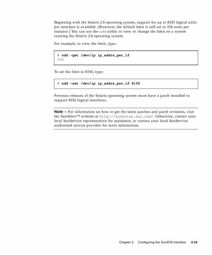
Beginning with the Solaris 2.6 operating system, support for up to 8192 logical units
per interface is available. (However, the default limit is still set to 256 units per
instance.) You can use the ndd utility to view or change the limit on a system
running the Solaris 2.6 operating system.
For example, to view the limit, type:
To set the limit to 8192, type:
Previous releases of the Solaris operating system must have a patch installed to
support 8192 logical interfaces.
Note – For information on how to get the latest patches and patch revisions, visit
the SunSolve™ website at http://sunsolve.sun.com/ . Otherwise, contact your
local SunService representative for assistance, or contact your local SunService
authorized service provider for more information.
# ndd -get /dev/ip ip_addrs_per_if256
# ndd -set /dev/ip ip_addrs_per_if 8192
Chapter 4 Configuring the SunATM Interface 4-19

4-20 SunATM 3.0 Installation and User’s Guide • November 1997
CHAPTER 5
Editing SunATM ConfigurationFiles
This chapter describes how you can configure your SunATM interfaces by editing
the configuration files.
You are not required to edit these configuration files by hand. You can use the
atmadmin configuration program, described in Section 4.2 “Using the atmadmin
Configuration Program,” to configure the SunATM files. From the program’s
command-line interface, you can change most of the SunATM parameters, with the
only exception being the access list security feature described in Section 5.2
“Configuring a Classical Internet Protocol Interface” and Section 5.3 “Configuring a
LAN Emulation Interface.”
Caution – When saving configuration information, atmadmin will overwrite the
existing SunATM configuration files in the /etc directory. Therefore, any comments
or other changes you manually made to the files will be lost.
5-1
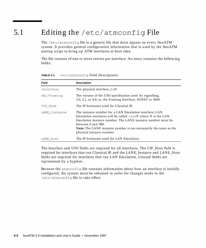
5.1 Editing the /etc/atmconfig FileThe /etc/atmconfig file is a generic file that must appear on every SunATM
system. It provides general configuration information that is used by the SunATM
startup script to bring up ATM interfaces at boot time.
The file consists of one or more entries per interface. An entry contains the following
fields:
The Interface and UNI fields are required for all interfaces. The CIP_Host field is
required for interfaces that run Classical IP, and the LANE_Instance and LANE_Host
fields are required for interfaces that run LAN Emulation. Unused fields are
represented by a hyphen.
Because the atmconfig file contains information about how an interface is initially
configured, the system must be rebooted in order for changes made in the
/etc/atmconfig file to take effect.
TABLE 5-1 /etc/atmconfig Field Descriptions
Field Description
Interface The physical interface, baN.
UNI/Framing The version of the UNI specification used for signalling,
3.0, 3.1, or 4.0; or, the Framing Interface, SONET or SDH.
CIP_Host The IP hostname used for Classical IP.
LANE_Instance The instance number for a LAN Emulation interface; LAN
Emulation interfaces will be called lane N where N is the LAN
Emulation instance number. The LANE instance number must be
between 0 and 999.
Note: The LANE instance number is not necessarily the same as the
physical instance number.
LANE_Host The IP hostname used for LAN Emulation
5-2 SunATM 3.0 Installation and User’s Guide • November 1997
5.1.1 Changing the Framing Interface in the
/etc/atmconfig File
The framing interface defines the encapsulation method used for ATM cells as they
are sent onto the wire. The default framing interface is SONET, but the SunATM
software also supports the SDH interface. Your switch product information should
indicate whether your switch uses either the SONET or the SDH interface.
Previous versions of the SunATM software allowed a framing interface to be chosen
for the entire system (the selection was made by setting a variable in the
/etc/system file). In the SunATM software, the system variable can still be used to
enable backwards compatibility, but the preferred method is to select the framing
interface per-interface, with an entry in the /etc/atmconfig file. Entries in
/etc/atmconfig will override a variable set in /etc/system for a particular
interface. If there is no value in either /etc/system or /etc/atmconfig , the
default framing interface is SONET.
Framing entries in /etc/atmconfig should appear on individual lines, with two
fields. The first field indicates the interface, baN, where N is the instance number
(for example: ba0 ). The second is either SDHor SONET, depending on the desired
setting. See FIGURE 5-1 for an example of selecting SDH in an /etc/atmconfig file.
5.1.2 Using Dynamic Host Configuration Protocol
(DHCP) on an ATM LAN Emulation Interface
DHCP, as specified in RFC 1541, provides a mechanism for IP hosts to dynamically
learn their configuration information from a server on startup. Support for DHCP
clients is a new feature in Solaris 2.6, and it is available to SunATM 3.0 LAN
Emulation interfaces that are running in a Solaris 2.6 environment. An ATM
interface is designated for DHCP configuration by using the keyword +dhcp as the
hostname in the /etc/atmconfig file entry. A DHCP interface may be designated
the primary DHCP interface with the keyword hostname +primarydhcp .
Note – DHCP is not supported on Classical IP interfaces, because it requires
broadcast capability.
Chapter 5 Editing SunATM Configuration Files 5-3

5.1.3 Example of an /etc/atmconfig File
FIGURE 5-1 shows an atmconfig file creating this configuration:
■ A LAN Emulation interface lane0 , supporting UNI 3.1, and using DHCP for
configuration on the ba0 interface.
■ An interface that supports both Classical IP and LAN Emulation on ba1 , using
UNI 4.0. The LAN Emulation interface name is lane1 .
■ A Classical IP interface, supporting UNI 3.0, on ba2 , which uses the SDH framing
interface.
FIGURE 5-1 Example /etc/atmconfig File
5.2 Configuring a Classical Internet ProtocolInterfaceClassical Internet Protocol (Classical IP), specified by RFC 1577, is one way of
supporting the TCP/IP and UDP/IP protocols in an ATM environment. In Classical
IP, an ATM ARP server is used to resolve IP addresses to ATM addresses, replacing
the traditional ARP protocol. In this configuration each host must register with the
ARP server when the ATM interface is brought up. For more information on the
Classical IP protocols, see Section 6.2 “Classical Internet Protocol.”
One major reason for the use of ATM ARP instead of the traditional ARP is because
ATM does not support broadcast (a network capability providing transmission from
one point to all points on a network). Because Classical IP over ATM does not
support broadcast, you cannot use the ypbind UNIX command with the
-broadcast option to automatically locate the NIS server (ypserver) on a Classical
IP ATM subnet.
If you are planning to run NIS over your ATM network, you must specify the list of
NIS servers (ypservers) using the ypinit -c command. See the ypinit(1M) man
page for details of setting up the ypserver. Be sure that the IP addresses of the
ypservers are listed in the /etc/hosts file.
#Interface UNI/Framing CIP_Host LANE_Instance LANE_Host#-------------------------------------------------------------- ba0 3.1 - 0 +dhcp ba1 4.0 atm1 1 atm2 ba2 3.0 atm3 - - ba2 SDH
5-4 SunATM 3.0 Installation and User’s Guide • November 1997
The Routing Information Protocol (RIP) also uses the broadcast feature of IP, so it is
not supported under the Classical IP environment. In Solaris, RIP is implemented by
the daemon in.routed .
If you are using Classical IP, you must explicitly add the routes to the routers in the
ATM subnet. You may also specify one router as the default router to provide
connectivity outside of the ATM subnet. See the route(1M) man page for
information on using the route command to add specific router entries and to add
a default router.
5.2.1 Editing the /etc/aarconfig File
The /etc/aarconfig file is a generic file that must appear on every SunATM
system which is supporting Classical IP interfaces. It enables you to specify IP to
ATM address translation, permanent virtual circuits (PVCs) to destinations, and
specify the address of the ATM ARP server. The environment allows for a mix of
PVCs and switched virtual circuits (SVCs).
Every node, or client, will have both an IP address and either an ATM address or a
virtual circuit identifier (VCI). See Section 6.2.1 “ATM Address Resolution,” for ATM
addressing scheme information.
Note – Although SunATM supports PVC connections to a server for ARP traffic,
RFC 1577 does not specify this case. For interoperability with other implementations,
connections to the server should use SVCs.
Note – In order for two hosts to communicate over PVCs, corresponding PVC
connections must also be established in the ATM switch fabric.
Each time the /etc/aarconfig file is modified, you must run the ATM ARP setup
program (aarsetup ). aarsetup is in the /etc/opt/SUNWatm/bin directory.
Each /etc/aarconfig entry follows this format:
Interface Hostname ATM Address VCI Flag
Chapter 5 Editing SunATM Configuration Files 5-5

These fields are describe in TABLE 5-2. Any unused field is denoted by a hyphen.
TABLE 5-2 /etc/aarconfig Entry Descriptions
Field Description
Interface This field is for the name of the ATM interface, baN.
Hostname This field is for either an IP address in “dot” notation or the name of a
host that should be locally available unless a non-ATM network
connection also exists.
ATM Address This field consists of 20 octets, with each octet represented by a one- or
two-digit hexadecimal number and separated by colons.
VCI The VCI field is a positive decimal integer.
Flag This field identifies the type of this entry. For a complete description of
this flags, see TABLE 5-3.
TABLE 5-3 /etc/aarconfig Flag Descriptions
Flag Description
l Represents the ATM address of the local interface on ARP clients or systems not
using an ARP server for ATM address resolution, and can be used to assign an
ATM address to the host. Hostname should not appear; ATM Address should be
provided if and only if SVCs are used. If an s entry is provided to use an ARP
server (see below), ATM Address must be provided (a server is meaningful only
in an SVC environment). See TABLE 5-4.
L Represents the ATM address of the local interface on an ARP server. Hostnameshould not appear; ATM Address is required. See TABLE 5-4.
s Specifies a connection to the ATM ARP server. Either ATM Address or VCI (in
the case of a PVC connection) should appear, but not both. Hostname should not
appear. The s entry is required on all clients that need to communicate with the
server for ATM address resolution. See TABLE 5-4.
t Represents an IP to ATM address/VCI entry. aarsetup adds these entries into
the local table. Any t entries on the server must contain ATM Address and may
also contain VCI if PVC communication between the server and client is desired.
In addition, there are some cases when a t entry may be useful on an ARP client
system. If a client wants to communicate with another system over PVCs, the
PVC to be used is provided in a t entry containing VCI; or if a client wishes to
cache frequently used addresses to avoid frequent ARP requests, a t entry
containing ATM Address may be provided. See TABLE 5-4.
5-6 SunATM 3.0 Installation and User’s Guide • November 1997

TABLE 5-4 describes the required, optional, and illegal fields for each flag type.
Note – Entries in the aarconfig file must be grouped in a designated order: the
local (l or L) entry must be first, the table (t) entries next, and then the server (s)
entries. Other flags may appear in any order. Also, the ordering need only be
maintained among entries for each physical interface; for example, all of the ba0entries may appear first, and then all of the ba1 entries, and so forth.
Note: If you are using a naming service such as NIS, NIS+, or DNS you must
provide the IP hostname to the address resolution for the hosts included in tentries, either by using the IP address in the Hostname field of the
t entry, or by adding an entry to the local /etc/hosts file.
a Represents an address that may have access to this host. If no a entries appear in
the aarconfig file, access to the host is unrestricted. Including a entries allows
access to be restricted to known hosts. As an alternative to listing individual
addresses, the ATM address field may contain a prefix, followed by the
wildcard $anymacsel , which matches any 7-byte ESI/Selector combination
following the given prefix. This allows access by any host connected to the
switch specified by the given prefix. Hostname and VCI should not appear; ATMAddress is required. See TABLE 5-4.
m Notifies the system that the entire ATM address, including the network prefix,
must be configured manually on this interface. If your interface is connected to
a switch that does not support ILMI, you must include this option in your
/etc/aarconfig or /etc/laneconfig file. Note that the variables
$myaddress , $prefix and $localswitch_server (which use the switch
prefix obtained from the switch via ILMI) may not be used if ILMI is not
running.
TABLE 5-4 /etc/aarconfig File Flag Options
Interface Host ATM Address VCI Flags
required illegal SVC only illegal l local information
required illegal required illegal L local information on server
required illegal required illegal a access list entry
required required or1 or1 t permanent table entry
required illegal xor2 xor2 s server address/PVC
required illegal illegal illegal m manual address registration
1or – Means one or the other required, but using both is also legal.2xor – Means one or the other required, but both are illegal.
TABLE 5-3 /etc/aarconfig Flag Descriptions
Flag Description
Chapter 5 Editing SunATM Configuration Files 5-7
5.2.2 Using Variables in the /etc/aarconfig File
Because the prefix portion of an ATM address specifies the ATM switch, a number of
hosts specified in an aarconfig file may have ATM addresses which share the same
prefix. To simplify setting up the aarconfig file, you can define variables that
contain part of an ATM address.
A variable's name is an identifier consisting of a collection of no more than 32 letters,
digits, and underscores. The value associated with the variable is denoted by a
dollar sign followed immediately by the variable name.
Note – Variables may only be used in the ATM address field. They may not be used
in any of the other fields in an entry.
Multiple variables can be concatenated to represent a single ATM address
expression. A colon must be used to concatenate the variables. Thus, if one variable,
v1, is set to 11:22 and another variable, v2, is set to 33:44 , the sequence $v1:$v2represents 11:22:33:44 . Hexadecimal numbers may also be included with
variables in the expression. The expression 45:$v1:$v2 would have the value
45:11:22:33:44 .
Variables are defined in the aarconfig file according to the following format:
set VARIABLE = EXPRESSION
where VARIABLE is the name of a variable and EXPRESSION is an expression
concatenating one or two-digit hexadecimal numbers and/or the values of variables
that have been previously defined. The equal sign is optional, but the variable and
expression must be separated either by white space (spaces or tabs), an equal sign,
or both.
Several predefined variables are built into the SunATM software. These variables are
summarized in TABLE 5-5.
5-8 SunATM 3.0 Installation and User’s Guide • November 1997
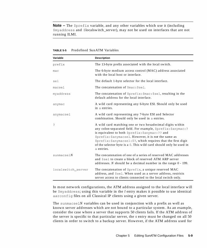
Note – The $prefix variable, and any other variables which use it (including
$myaddress and $localswitch_server), may not be used on interfaces that are not
running ILMI.
In most network configurations, the ATM address assigned to the local interface will
be $myaddress ; using this variable in the l entry makes it possible to use identical
aarconfig files on all Classical IP clients using a given server.
The sunmacsel N variables can be used in conjunction with a prefix as well as
known server addresses which are not bound to a particular system. As an example,
consider the case where a server that supports 50 clients fails. If the ATM address of
the server is specific to that particular server, the s entry must be changed on all 50
clients in order to switch to a backup server. However, if the ATM address used for
TABLE 5-5 Predefined SunATM Variables
Variable Description
prefix The 13-byte prefix associated with the local switch.
mac The 6-byte medium access control (MAC) address associated
with the local host or interface.
sel The default 1-byte selector for the local interface.
macsel The concatenation of $mac:$sel .
myaddress The concatenation of $prefix:$mac:$sel , resulting in the
default address for the local interface.
anymac A wild card representing any 6-byte ESI. Should only be used
in a entries.
anymacsel A wild card representing any 7-byte ESI and Selector
combination. Should only be used in a entries.
? A wild card matching one or two hexadecimal digits within
any colon-separated field. For example, $prefix:$anymac:?is equivalent to both $prefix:$anymac:?? and
$prefix:$anymacsel . However, it is not the same as
$prefix:$anymacsel:0? , which requires that the first digit
of the selector byte is a 0. This wild card should only be used in
a entries.
sunmacsel N The concatenation of one of a series of reserved MAC addresses
and $sel to create a block of reserved ATM ARP server
addresses. N should be a decimal number in the range 0 - 199.
localswitch_server The concatenation of $prefix , a unique reserved MAC
address, and $sel . When used as a server address, restricts
server access to clients connected to the local switch only.
Chapter 5 Editing SunATM Configuration Files 5-9
that server is $prefix:$sunmacsel3 , this address is not only guaranteed to be
unique, since it uses reserved medium access control (MAC) addresses, it is also
possible to simply assign that address to the backup server on the same switch by
creating a new L entry in its aarconfig file, and bring up a new server with no
changes to the clients.
Note – The sunmacsel N variables do not include a prefix since a client and server
may be on different switches and thus have different local prefix values.
In the case of a single-switch network, localswitch_server can be used as a
well-known server address. Not only does it include the prefix associated with the
local switch with a unique MAC address and appropriate Selector, it also restricts
server access to clients on the local switch. Thus any host with a network prefix
other than that of the local switch will be refused a connection to the ARP server if
the ARP server's address is $localswitch_server .
Several rules apply to the use of variables in the aarconfig file:
1. Two variables cannot follow each other in an expression without an intervening
colon. Thus $v1:$v2 is legal while $v1$v2 is not.
2. Fields in each line in the aarconfig file are separated by white space. Therefore
variables should not be separated from the rest of an ATM address with
whitespace. For example, $v1: $v2 is illegal.
3. Once a variable is defined by a set command, it may not be redefined later in the
aarconfig file.
4. The reserved variable names cannot be set. These names include prefix , mac,
sel , macsel , myaddress , anymac , anymacsel , sunmacsel N (where N is a
number between 0 and 199), and localswitch_server .
Note – The ESI portion of localswitch_server and the sunmacsel N variables
are a reserved MAC address. The hexadecimal values of the reserved addresses are:
localswitch_server 08:00:20:75:48:08sunmacsel N base 08:00:20:75:48:10
To calculate the ESI portion for a sunmacsel N address, simply add the value of N(converted to a hexadecimal number) to the sunmacsel N base address. For
example, the ESI portion of sunmacsel20 would be
08:00:20:75:48:10 + 0x14 = 08:00:20:75:48:24.
5-10 SunATM 3.0 Installation and User’s Guide • November 1997
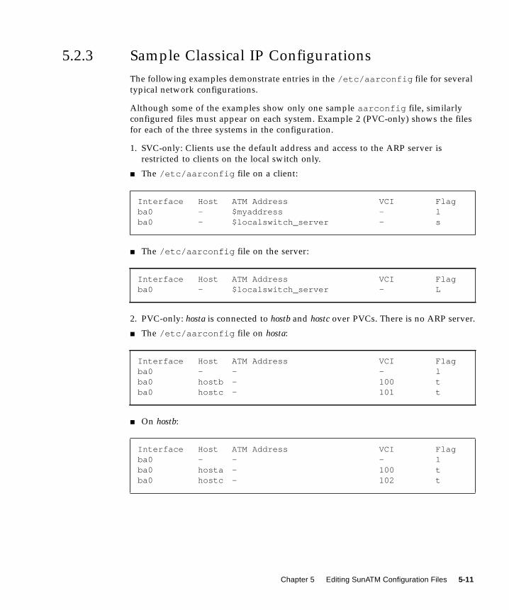
5.2.3 Sample Classical IP Configurations
The following examples demonstrate entries in the /etc/aarconfig file for several
typical network configurations.
Although some of the examples show only one sample aarconfig file, similarly
configured files must appear on each system. Example 2 (PVC-only) shows the files
for each of the three systems in the configuration.
1. SVC-only: Clients use the default address and access to the ARP server is
restricted to clients on the local switch only.
■ The /etc/aarconfig file on a client:
■ The /etc/aarconfig file on the server:
2. PVC-only: hosta is connected to hostb and hostc over PVCs. There is no ARP server.
■ The /etc/aarconfig file on hosta:
■ On hostb:
Interface Host ATM Address VCI Flagba0 - $myaddress - lba0 - $localswitch_server - s
Interface Host ATM Address VCI Flagba0 - $localswitch_server - L
Interface Host ATM Address VCI Flagba0 - - - lba0 hostb - 100 tba0 hostc - 101 t
Interface Host ATM Address VCI Flagba0 - - - lba0 hosta - 100 tba0 hostc - 102 t
Chapter 5 Editing SunATM Configuration Files 5-11

■ On hostc:
3. SVC-only: hosta uses SVCs to connect to hostb and hostc. All hosts are connected to
the same switch; there is no ARP server.
4. PVC/SVC mix: hosta uses a SVC to connect to hostb, and a PVC to connect to
hostc. hostb is not on the local switch; there is no ARP server.
5. ARP server: Hosts are connected to an ATM ARP server that resolves addresses.
Access is restricted to the local switch subnet and one additional switch subnet.
■ The /etc/aarconfig file on hosta:
■ The /etc/aarconfig file on the server:
Interface Host ATM Address VCI Flagba0 - - - lba0 hosta - 101 tba0 hostb - 102 t
Interface Host ATM Address VCI Flagba0 - $myaddress - lba0 hostb $prefix:08:00:20:d5:08:a8:00 - tba0 hostc $prefix:08:00:20:21:20:c3:00 - t
Interface Host ATM Address VCI Flagba0 - $myaddress - lba0 hostb 45:00:00:00:00:00:00:00:0f:00:00:00:00::08:00:20:d5:08:a8:00 - tba0 hostc - 100 t
Interface Host ATM Address VCI Flagba0 - $myaddress - lba0 - $prefix:$sunmacsel0 - s
Interface Host ATM Address VCI Flagba0 - $prefix:$sunmacsel0 - Lba0 - $prefix:$anymacsel - aba0 - 45:00:00:00:00:00:00:00:0f:00:00:00:00:$anymacsel - a
5-12 SunATM 3.0 Installation and User’s Guide • November 1997
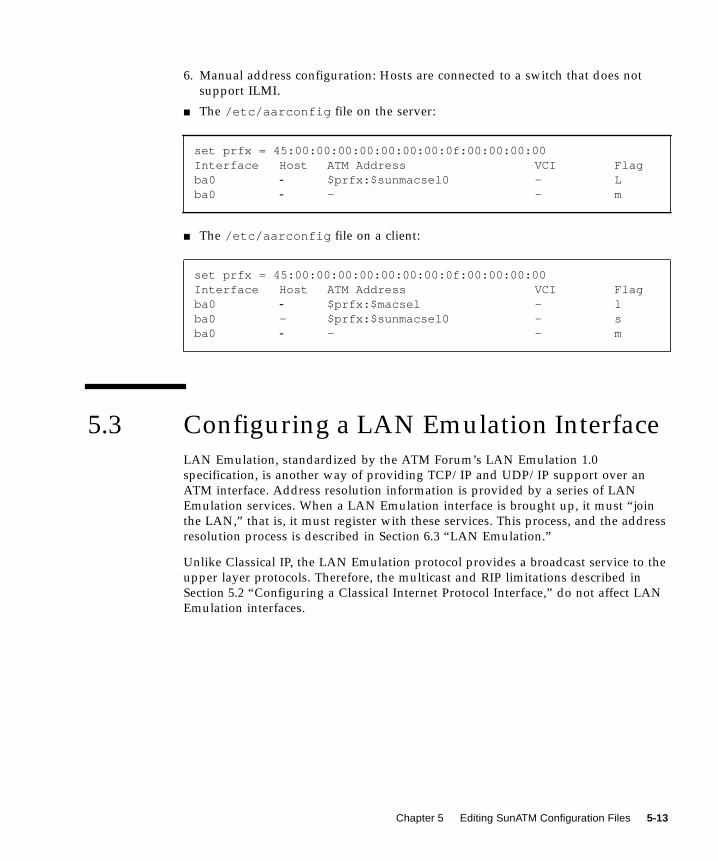
6. Manual address configuration: Hosts are connected to a switch that does not
support ILMI.
■ The /etc/aarconfig file on the server:
■ The /etc/aarconfig file on a client:
5.3 Configuring a LAN Emulation InterfaceLAN Emulation, standardized by the ATM Forum’s LAN Emulation 1.0
specification, is another way of providing TCP/IP and UDP/IP support over an
ATM interface. Address resolution information is provided by a series of LAN
Emulation services. When a LAN Emulation interface is brought up, it must “join
the LAN,” that is, it must register with these services. This process, and the address
resolution process is described in Section 6.3 “LAN Emulation.”
Unlike Classical IP, the LAN Emulation protocol provides a broadcast service to the
upper layer protocols. Therefore, the multicast and RIP limitations described in
Section 5.2 “Configuring a Classical Internet Protocol Interface,” do not affect LAN
Emulation interfaces.
set prfx = 45:00:00:00:00:00:00:00:0f:00:00:00:00Interface Host ATM Address VCI Flagba0 - $prfx:$sunmacsel0 - Lba0 - - - m
set prfx = 45:00:00:00:00:00:00:00:0f:00:00:00:00Interface Host ATM Address VCI Flagba0 - $prfx:$macsel - lba0 - $prfx:$sunmacsel0 - sba0 - - - m
Chapter 5 Editing SunATM Configuration Files 5-13
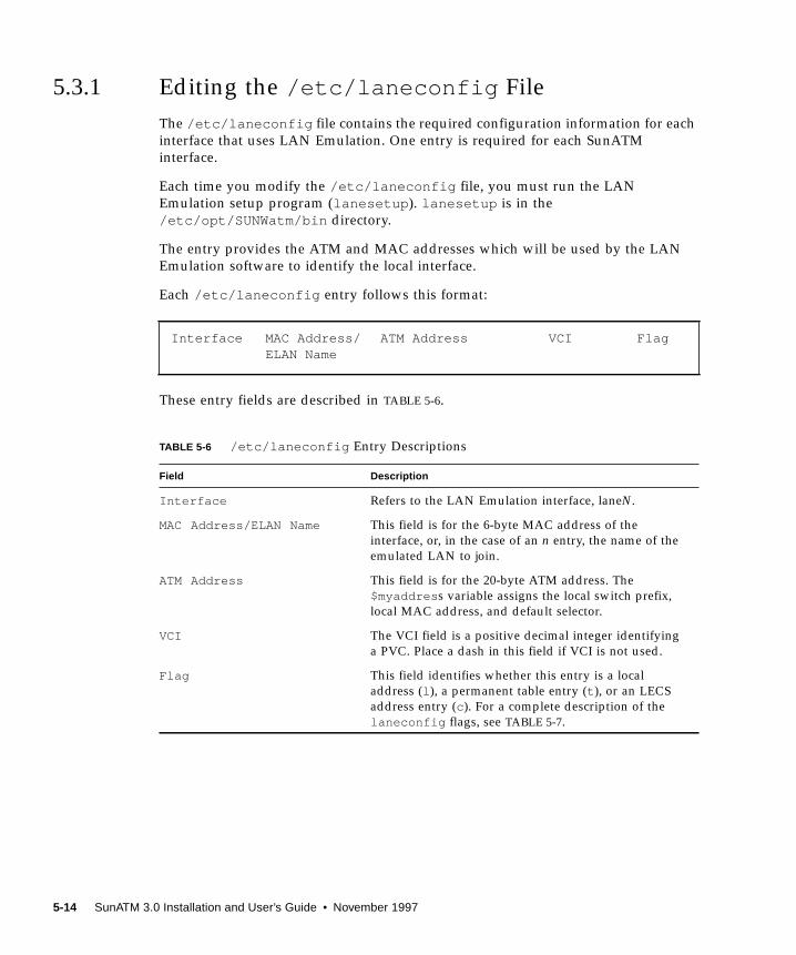
5.3.1 Editing the /etc/laneconfig File
The /etc/laneconfig file contains the required configuration information for each
interface that uses LAN Emulation. One entry is required for each SunATM
interface.
Each time you modify the /etc/laneconfig file, you must run the LAN
Emulation setup program (lanesetup ). lanesetup is in the
/etc/opt/SUNWatm/bin directory.
The entry provides the ATM and MAC addresses which will be used by the LAN
Emulation software to identify the local interface.
Each /etc/laneconfig entry follows this format:
These entry fields are described in TABLE 5-6.
Interface MAC Address/ ATM Address VCI FlagELAN Name
TABLE 5-6 /etc/laneconfig Entry Descriptions
Field Description
Interface Refers to the LAN Emulation interface, laneN.
MAC Address/ELAN Name This field is for the 6-byte MAC address of the
interface, or, in the case of an n entry, the name of the
emulated LAN to join.
ATM Address This field is for the 20-byte ATM address. The
$myaddres s variable assigns the local switch prefix,
local MAC address, and default selector.
VCI The VCI field is a positive decimal integer identifying
a PVC. Place a dash in this field if VCI is not used.
Flag This field identifies whether this entry is a local
address (l ), a permanent table entry (t ), or an LECS
address entry (c ). For a complete description of the
laneconfig flags, see TABLE 5-7.
5-14 SunATM 3.0 Installation and User’s Guide • November 1997
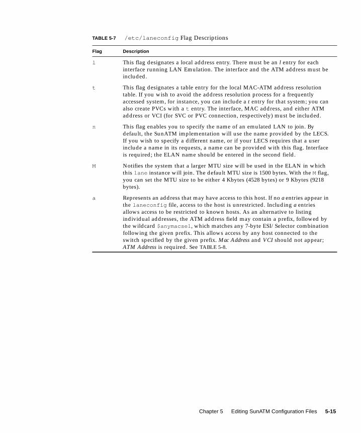
TABLE 5-7 /etc/laneconfig Flag Descriptions
Flag Description
l This flag designates a local address entry. There must be an l entry for each
interface running LAN Emulation. The interface and the ATM address must be
included.
t This flag designates a table entry for the local MAC-ATM address resolution
table. If you wish to avoid the address resolution process for a frequently
accessed system, for instance, you can include a t entry for that system; you can
also create PVCs with a t entry. The interface, MAC address, and either ATM
address or VCI (for SVC or PVC connection, respectively) must be included.
n This flag enables you to specify the name of an emulated LAN to join. By
default, the SunATM implementation will use the name provided by the LECS.
If you wish to specify a different name, or if your LECS requires that a user
include a name in its requests, a name can be provided with this flag. Interface
is required; the ELAN name should be entered in the second field.
M Notifies the system that a larger MTU size will be used in the ELAN in which
this lane instance will join. The default MTU size is 1500 bytes. With the Mflag,
you can set the MTU size to be either 4 Kbytes (4528 bytes) or 9 Kbytes (9218
bytes).
a Represents an address that may have access to this host. If no a entries appear in
the laneconfig file, access to the host is unrestricted. Including a entries
allows access to be restricted to known hosts. As an alternative to listing
individual addresses, the ATM address field may contain a prefix, followed by
the wildcard $anymacsel , which matches any 7-byte ESI/Selector combination
following the given prefix. This allows access by any host connected to the
switch specified by the given prefix. Mac Address and VCI should not appear;
ATM Address is required. See TABLE 5-8.
Chapter 5 Editing SunATM Configuration Files 5-15

TABLE 5-8 describes the required, optional, and illegal fields for each flag type.
Note – Designate unused fields in the /etc/laneconfig file with a hyphen.
c This flag allows an alternate LECS address to be specified. By default, the
SunATM software uses the well-known address specified in the LAN Emulation
standard. If, however, your LECS has a different address, or you wish to connect
to the LECS over a PVC, you can provide the alternate ATM address or VCI in a
c entry. If you wish to make a PVC connection, the VCI must be 17, as required
by the LAN Emulation standard. The interface and ATM address or VCI must
be included.
s This flag specifies the LES address or VCI, and instructs the system to contact
the LES directly, and to use default subnet configuration information. This flag
should be used if your subnet does not have an LECS. Without this entry, the
system first connects to the LECS, which provides the LES address and
configuration information.
m Notifies the system that the entire ATM address, including the network prefix,
must be configured manually on this interface. If your interface is connected to
a switch that does not support ILMI, you must include this option in your
/etc/aarconfig or /etc/laneconfig file. Note that the variables
$myaddress , $prefix and $localswitch_server (which use the switch
prefix obtained from the switch via ILMI) may not be used if ILMI is not
running.
TABLE 5-8 laneconfig File Flag Options
Interface MAC Address/ELAN Name ATM Address VCI Flag
required illegal required illegal l
required required xor1 xor1 t
required Emulated LAN name illegal illegal n
required MTU Size in bytes (1500, 4528, or 9218) illegal illegal M
required illegal required illegal a
required illegal xor1 xor c
required illegal xor1 xor s
required illegal illegal illegal m
1xor means that you can use either the ATM Address field or the VCI field, but not both.
TABLE 5-7 /etc/laneconfig Flag Descriptions (Continued)
Flag Description
5-16 SunATM 3.0 Installation and User’s Guide • November 1997
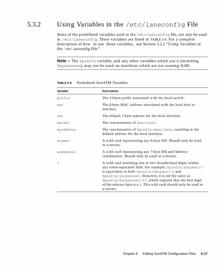
5.3.2 Using Variables in the /etc/laneconfig File
Some of the predefined variables used in the /etc/aarconfig file, can also be used
in /etc/laneconfig . These variables are listed in TABLE 5-9. For a complete
description of how to use these variables, see Section 5.2.2 “Using Variables in
the /etc/aarconfig File.”
Note – The $prefix variable, and any other variables which use it (including
$myaddress ), may not be used on interfaces which are not running ILMI.
TABLE 5-9 Predefined SunATM Variables
Variable Description
prefix The 13-byte prefix associated with the local switch.
mac The 6-byte MAC address associated with the local host or
interface.
sel The default 1-byte selector for the local interface.
macsel The concatenation of $mac:$sel .
myaddress The concatenation of $prefix:$mac:$sel , resulting in the
default address for the local interface.
anymac A wild card representing any 6-byte ESI. Should only be used
in a entries.
anymacsel A wild card representing any 7-byte ESI and Selector
combination. Should only be used in a entries.
? A wild card matching one or two hexadecimal digits within
any colon-separated field. For example, $prefix:$anymac:?is equivalent to both $prefix:$anymac:?? and
$prefix:$anymacsel . However, it is not the same as
$prefix:$anymacsel:0? , which requires that the first digit
of the selector byte is a 0. This wild card should only be used in
a entries.
Chapter 5 Editing SunATM Configuration Files 5-17
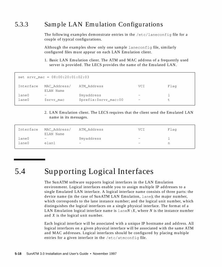
5.3.3 Sample LAN Emulation Configurations
The following examples demonstrate entries in the /etc/laneconfig file for a
couple of typical configurations.
Although the examples show only one sample laneconfig file, similarly
configured files must appear on each LAN Emulation client.
1. Basic LAN Emulation client. The ATM and MAC address of a frequently used
server is provided. The LECS provides the name of the Emulated LAN.
2. LAN Emulation client. The LECS requires that the client send the Emulated LAN
name in its messages.
5.4 Supporting Logical InterfacesThe SunATM software supports logical interfaces in the LAN Emulation
environment. Logical interfaces enable you to assign multiple IP addresses to a
single Emulated LAN interface. A logical interface name consists of three parts: the
device name (in the case of SunATM LAN Emulation, lane ); the major number,
which corresponds to the lane instance number; and the logical unit number, which
distinguishes the logical interfaces on a single physical interface. The format of a
LAN Emulation logical interface name is lane N: X, where N is the instance number
and X is the logical unit number.
Each logical interface will be associated with a unique IP hostname and address. All
logical interfaces on a given physical interface will be associated with the same ATM
and MAC addresses. Logical interfaces should be configured by placing multiple
entries for a given interface in the /etc/atmconfig file.
set srvr_mac = 08:00:20:01:02:03
Interface MAC_Address/ ATM_Address VCI FlagELAN Name
lane0 - $myaddress - llane0 $srvr_mac $prefix:$srvr_mac:00 - t
Interface MAC_Address/ ATM_Address VCI FlagELAN Name
lane0 - $myaddress - llane0 elan1 - - n
5-18 SunATM 3.0 Installation and User’s Guide • November 1997

The following rules and notes should be considered when using logical interfaces
with the SunATM software:
■ Only one signalling protocol (for example, UNI 3.0, 3.1, or 4.0) is supported per
interface, and must appear in the first entry for that interface.
■ Only one Classical IP hostname may be assigned to an interface; it may appear in
any entry in any order in /etc/atmconfig .
■ The first lane N entry on an interface must be for lane N:0 , or simply lane N.
lane N and lane N:0 are identical and interchangeable.
■ IP limits the number of logical interfaces on a physical interface to either 256 or
8192, depending on your operating system. (Solaris releases prior to 2.6 support a
maximum of 256 units. However, beginning with the Solaris 2.6 operating system,
8192 units are supported.)
In the Solaris 2.6 environment, the default limit of logical unit number is still set to
256 units per instance. You can use the ndd utility to view or change the limit on a
system running the Solaris 2.6 operating system.
For example, to view the limit, type:
To set the limit to 8192, type:
Note – Previous releases of the Solaris operating system must have a patch installed
to support 8192 logical interfaces. For information on how to get the latest patches
and patch revisions, visit the SunSolve website at http://sunsolve.sun.com/ .
Otherwise, contact your local SunService representative for assistance, or contact
your local SunService authorized service provider for more information.
The following example shows the atmconfig and laneconfig files and the
ifconfig -a output for a system with one physical interface, ba0 . That interface
runs both Classical IP and LAN Emulation under UNI 3.1, and has 3 different IP
addresses. The IP hostnames, cip0 , atm0 , atm1 , and atm2 , should be configured
appropriately in /etc/hosts .
# ndd -get /dev/ip ip_addrs_per_if256
# ndd -set /dev/ip ip_addrs_per_if 8192
Chapter 5 Editing SunATM Configuration Files 5-19

The example /etc/atmconfig file:
The corresponding example /etc/laneconfig file:
The resulting ifconfig -a output:
Interface UNI CIP Hostname LANE Instance LANE Hostnameba0 3.1 cip0 0 atm0ba0 - - 0:1 atm1ba0 - - 0:2 atm2
Interface MAC Address/ ATM Address VCI FlagELAN Name
lane0 - $myaddress -l
lo0: flags=849<UP,LOOPBACK,RUNNING,MULTICAST> mtu 8232inet 127.0.0.1 netmask ff000000
ba0: flags=863<UP,BROADCAST,NOTRAILERS,RUNNING,MULTICAST> mtu 9180inet 192.29.235.36 netmask ffffff00 broadcast 192.29.235.255ether 8:0:20:7a:37:af
lane0: flags=863<UP,BROADCAST,NOTRAILERS,RUNNING,MULTICAST> mtu 1500inet 192.29.240.36 netmask ffffff00 broadcast 192.29.240.255ether 8:0:20:7a:37:af
lane0:1: flags=863<UP,BROADCAST,NOTRAILERS,RUNNING,MULTICAST> mtu 1500inet 192.29.241.36 netmask ffffff00 broadcast 192.29.241.255
lane0:2: flags=863<UP,BROADCAST,NOTRAILERS,RUNNING,MULTICAST> mtu 1500inet 192.29.242.36 netmask ffffff00 broadcast 192.29.242.255
5-20 SunATM 3.0 Installation and User’s Guide • November 1997

5.5 Supporting Multiple Emulated LANS ona Single InterfaceThe SunATM software enables a single ATM interface to join up to sixteen emulated
local area networks (ELANs), provided that this is allowed by the switch and LAN
Emulation (LANE) services. Each ELAN joined will be represented by a unique
lane instance (e.g. lane0 or lane1 ).
The joining of multiple ELANs is configured by placing multiple entries in the
/etc/atmconfig and /etc/laneconfig files. Each lane instance will have a
unique IP hostname and address, ATM address, and MAC address associated with
it. In addition, an ELAN name should be assigned to the instance if any ELAN other
than the default is to be joined. This information, with the exception of the MAC
address, which is retrieved from the board itself, should be provided in the
/etc/atmconfig and /etc/laneconfig configuration files.
Note – Only one signalling protocol (for example. UNI 3.0, 3.1, or 4.0) and one
Classical IP instance are supported per physical interface. The UNI version must be
specified in the first /etc/atmconfig entry for a given interface; the Classical IP
instance may be specified in any entry.
The following example shows the /etc/atmconfig and /etc/laneconfig files
and the ifconfig -a output for a system with one SunATM interface, ba0 . The
interface is using UNI 3.0 for signalling, and is not running Classical IP. It will join
four emulated LANs: the default, elan1 , elan2 , and elan3 .
The example /etc/atmconfig file:
Interface UNI CIP Hostname LANE Instance LANE Hostnameba0 3.0 - 0 atm0ba0 - - 1 atm1ba0 - - 2 atm2ba0 - - 3 atm3
Chapter 5 Editing SunATM Configuration Files 5-21
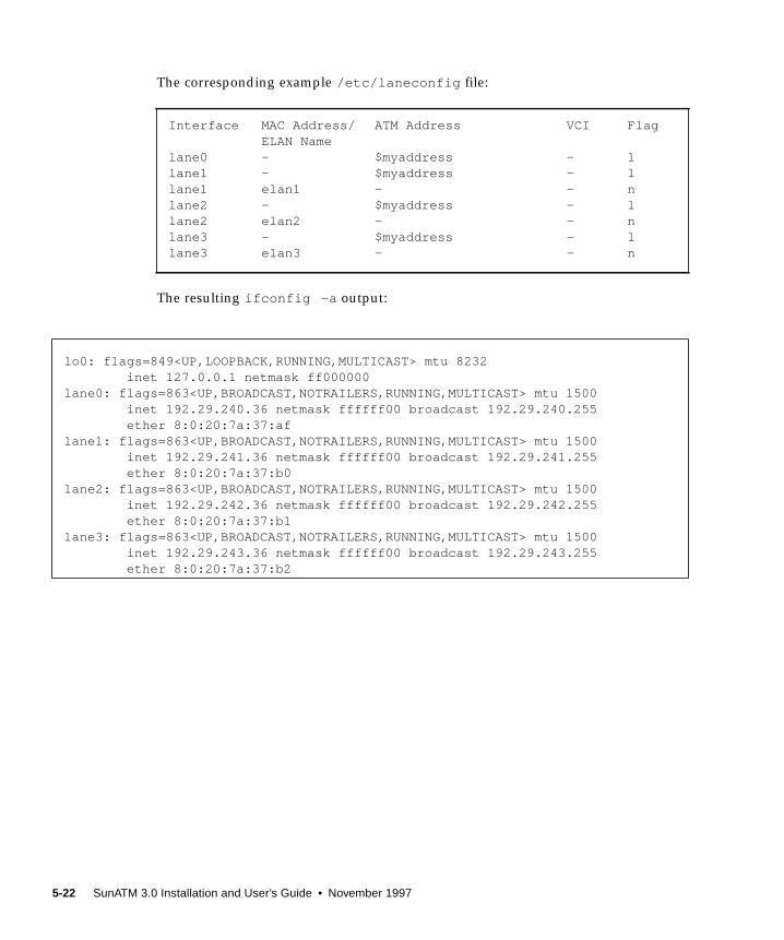
The corresponding example /etc/laneconfig file:
The resulting ifconfig -a output:
Interface MAC Address/ ATM Address VCI FlagELAN Name
lane0 - $myaddress - llane1 - $myaddress - llane1 elan1 - - nlane2 - $myaddress - llane2 elan2 - - nlane3 - $myaddress - llane3 elan3 - - n
lo0: flags=849<UP,LOOPBACK,RUNNING,MULTICAST> mtu 8232 inet 127.0.0.1 netmask ff000000lane0: flags=863<UP,BROADCAST,NOTRAILERS,RUNNING,MULTICAST> mtu 1500 inet 192.29.240.36 netmask ffffff00 broadcast 192.29.240.255 ether 8:0:20:7a:37:aflane1: flags=863<UP,BROADCAST,NOTRAILERS,RUNNING,MULTICAST> mtu 1500 inet 192.29.241.36 netmask ffffff00 broadcast 192.29.241.255 ether 8:0:20:7a:37:b0lane2: flags=863<UP,BROADCAST,NOTRAILERS,RUNNING,MULTICAST> mtu 1500 inet 192.29.242.36 netmask ffffff00 broadcast 192.29.242.255 ether 8:0:20:7a:37:b1lane3: flags=863<UP,BROADCAST,NOTRAILERS,RUNNING,MULTICAST> mtu 1500 inet 192.29.243.36 netmask ffffff00 broadcast 192.29.243.255 ether 8:0:20:7a:37:b2
5-22 SunATM 3.0 Installation and User’s Guide • November 1997

CHAPTER 6
Classical IP and LAN EmulationProtocols
ATM is a connection-oriented network protocol, which means that a connection
must be established between two communicating entities before data transfer can
begin. IP is inherently connectionless. The implementation on the host must
therefore reconcile the differences in these two paradigms.
There are two standardized, commonly used ways of doing this: Classical IP,
standardized in RFC 1577, and LAN Emulation standardized in the LAN Emulation
1.0 specification from the ATM Forum. The SunATM architecture supports both of
these methods. Some of the key ideas of these two methods are discussed in later
sections of this chapter.
Both methods enable IP to run transparently over the ATM interface. Thus IP itself
sees the ATM interface just as it sees any traditional network interface. Every
SunATM interface has a subnet IP address. During the process of startup of an ATM
interface, appropriate modules and drivers are plumbed. All the TCP/IP and
UDP/IP applications run without modifications over these modules, and all the
utilities associated with the network interfaces also run without modification and
display similar results (for example, netstat and ifconfig utilities), with one
exception. Because of the different plumbing of the ATM modules, the plumb and
unplumb options of ifconfig will not work on ATM interfaces; the
atmplumb(1M) command must be used instead. IP treats the ATM interface as a
subnet, choosing the interface used to send a packet out based on the IP address of
the destination and on the IP address and netmask of the interface itself.
The transparency to IP is enabled in different ways in Classical IP and LAN
Emulation. Those differences will be discussed in later sections of this chapter.
SunATM signalling conforms to the UNI specification of the ATM Forum. Versions
3.0, 3.1, and 4.0 of that specification are supported. This signalling, called Q.2931,
runs on top of Q.SAAL and uses VC 5 for signalling as specified in the Forum
specification.
6-1
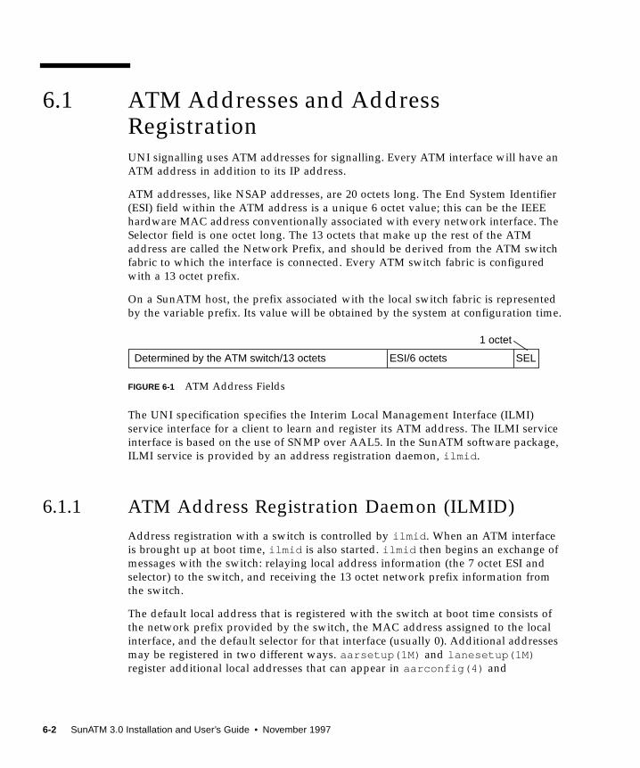
6.1 ATM Addresses and AddressRegistrationUNI signalling uses ATM addresses for signalling. Every ATM interface will have an
ATM address in addition to its IP address.
ATM addresses, like NSAP addresses, are 20 octets long. The End System Identifier
(ESI) field within the ATM address is a unique 6 octet value; this can be the IEEE
hardware MAC address conventionally associated with every network interface. The
Selector field is one octet long. The 13 octets that make up the rest of the ATM
address are called the Network Prefix, and should be derived from the ATM switch
fabric to which the interface is connected. Every ATM switch fabric is configured
with a 13 octet prefix.
On a SunATM host, the prefix associated with the local switch fabric is represented
by the variable prefix. Its value will be obtained by the system at configuration time.
FIGURE 6-1 ATM Address Fields
The UNI specification specifies the Interim Local Management Interface (ILMI)
service interface for a client to learn and register its ATM address. The ILMI service
interface is based on the use of SNMP over AAL5. In the SunATM software package,
ILMI service is provided by an address registration daemon, ilmid .
6.1.1 ATM Address Registration Daemon (ILMID)
Address registration with a switch is controlled by ilmid . When an ATM interface
is brought up at boot time, ilmid is also started. ilmid then begins an exchange of
messages with the switch: relaying local address information (the 7 octet ESI and
selector) to the switch, and receiving the 13 octet network prefix information from
the switch.
The default local address that is registered with the switch at boot time consists of
the network prefix provided by the switch, the MAC address assigned to the local
interface, and the default selector for that interface (usually 0). Additional addresses
may be registered in two different ways. aarsetup(1M) and lanesetup(1M)register additional local addresses that can appear in aarconfig(4) and
Determined by the ATM switch/13 octets ESI/6 octets SEL
1 octet
6-2 SunATM 3.0 Installation and User’s Guide • November 1997

laneconfig(4) , respectively. There is also a user program, atmreg(1M) , that can
be used to register addresses, to deregister addresses, and to check the status of any
address.
6.2 Classical Internet ProtocolThe major task required for ATM to work transparently under IP is resolving an IP
address to an ATM address and establishing the connection to that destination.
Classical IP does this via a database of IP/ATM address pairs that is either provided
by an ATM ARP server which is accessible to all hosts on the subnet, or maintained
locally in each host.
6.2.1 ATM Address Resolution
Traditional TCP/IP and UDP/IP applications use IP addresses for communicating to
a destination. In order for these applications to run as before, there is a need to
resolve these IP addresses into ATM addresses. The ATM address is then used in
signalling to establish an ATM connection to the destination. An ATM connection in
turn is represented by a VPI/VCI. The host must use this returned VPI/VCI to send
packets to the destination representing the ATM connection.
ATM address resolution, also called ATM ARP, follows RFC 1577, the classic draft
that describes the ATM ARP process.
RFC 1577 is based upon the existence of an ATM ARP server on every subnet. Every
client of the subnet communicates with the ATM ARP server to derive an ATM
address of the destination from the IP address of the destination. The ATM ARP
server holds the IP to ATM address information for all hosts in the ATM subnet.
In addition to supporting dynamic address resolution, as specified in RFC 1577, the
SunATM Classical IP software also allows static IP to ATM address databases to be
used. This is accomplished through the use of t entries in the /etc/aarconfig file
(see Section 5.2 “Configuring a Classical Internet Protocol Interface” for more
information). This mechanism allows frequently used address pairs to be statically
configured, while the RFC 1577 dynamic resolution mechanism is available for other
addresses.
Chapter 6 Classical IP and LAN Emulation Protocols 6-3
6.2.2 ATM ARP Address Resolution Tables
Depending on the aarconfig file, the Classical IP software will run as either a
server or a client. As a server, the Classical IP software is responsible for handling
ATM ARP requests originating from its clients. An ATM server has to be configured
for each subnet. The ATM ARP server code conforms to RFC 1577: clients send ATM
ARP requests to the server to resolve a destination IP address to an ATM address.
The server then replies to ATM ARP requests by sending an ATM ARP response. If
the server does not have the IP to ATM address entry, then it replies with NAK.
The file /etc/aarconfig is also used by the ATM ARP server. All the IP to ATM
address entries specified in the file will be entered into a kernel resident table by the
ATM ARP setup program, aarsetup . Additional entries in the kernel table will be
added dynamically using the inverse ARP process. When a client connects to the
server, the server will send an inverse ARP request back to the client to obtain the
client’s IP address. When a response is received, an entry will be created for that
client. The Classical IP software will also respond to client ARP requests. The
software looks up a kernel IP to ATM address entry and responds to an ATM ARP
request with either an ATM ARP reply or ATM ARP NAK (if there is no entry in the
table). Note that an ATM ARP client uses the virtual channel (VC) specified in the
/etc/aarconfig file to communicate with the server; or, if an ATM address is
specified, it establishes an switched virtual circuit (SVC) connection to communicate
with the server.
While dynamic entries in the ARP server’s table make network administration less
complex, it also creates a security problem. Any host may register with the ARP
server and, therefore, gain access to the subnet. To resolve this issue, a list of hosts or
networks can optionally be provided with a entries in the server’s /etc/aarconfigfile. If no a entries appear, any host will be allowed to connect to the server. If any aentries exist, only those hosts whose addresses match those specified will be allowed
to connect.
Although the a entry requires a complete ATM address, multiple addresses can be
referenced in a single entry using the provided wildcards. See Section 5.2.2 “Using
Variables in the /etc/aarconfig File,” for more information about this feature.
The advantage to having an ATM ARP server in the subnet is that it represents a
known source for all address resolutions. It is the only host which a client must
know about to have IP addresses resolved to ATM connections, and it allows for
access control in the ATM network.
When the /etc/aarconfig file has been modified on a system, it is necessary to
rerun aarsetup .
6-4 SunATM 3.0 Installation and User’s Guide • November 1997
Note – For better caching, all clients have the option of adding to their
configuration file the IP to ATM address information for other clients.
This can benefit clients who communicate frequently because it eliminates having to
go through the ATM ARP server for IP to ATM address resolution.
If a host has multiple SunATM cards, the host may be a server for one IP subnet and
a client for another. This is handled transparently by aarsetup .
6.3 LAN EmulationAs described in previous sections, Classical IP provides its own (IP to ATM) address
resolution mechanism which corresponds to and replaces ARP, thus allowing IP-
based applications to run transparently over ATM. A shortcoming of Classical IP,
and a primary reason it must replace the traditional ARP, is that it does not support
broadcast messages.
Because ATM is a connection-oriented protocol (unlike Ethernet), implementing
broadcast is much more difficult. The only host that receives a message is the host to
which the message is addressed, and a call must be established to that host before
the message can be sent.
Local area network (LAN) Emulation, as standardized by the ATM Forum, provides
mechanisms to send broadcast messages in an ATM environment. Given this
capability, LAN Emulation is also able to work transparently with ARP, as well as IP.
IP and ARP can send broadcast messages over the ATM interface, and thus resolve
IP addresses to MAC addresses; messages are then sent to the LAN Emulation
driver, which has its own address resolution protocol (similar to that of Classical IP)
to resolve the medium access control (MAC) address to an ATM address and
connection.
The SunATM software implements the client side of the LAN Emulation standard. In
order to use LAN Emulation in an environment, several LAN Emulation services
must also exist in the emulated LAN. These services, called the LAN Emulation
Configuration Server (LECS), the LAN Emulation Server (LES), and the Broadcast
and Unknown Address Server (BUS), are generally provided in an ATM switch. An
overview of the functions of these servers is provided in the following sections.
Chapter 6 Classical IP and LAN Emulation Protocols 6-5

6.3.1 LAN Emulation Services
6.3.1.1 LAN Emulation Configuration Server
This server is contacted first by a host interface when the host is brought up on the
emulated LAN. Its address is generally a well-known address specified by the LAN
Emulation standard which is coded into the host software; thus no input from the
user is required to establish this connection. When contacted by a host wishing to
join its emulated LAN, the LECS replies with configuration parameters for the
emulated LAN, as well as the address of the LES.
6.3.1.2 LAN Emulation Server
The second step in joining an emulated LAN is to make a connection to the LAN
Emulation Server. After receiving the LES address from the LECS, a host will
establish a connection to the LES. The LES may add the host to a point-to-multipoint
call which is maintained by the LES with connections to every host in the emulated
LAN. This point-to-multipoint connection, if created by the LES, sends control
information to each host on the emulated LAN.
The LES acts as the ATM ARP server. Since IP and ARP work with MAC addresses,
an additional address resolution step is required to convert a MAC address to the
corresponding ATM address, which makes a connection to the target host; this
resolution step is provided by the LES.
6.3.1.3 Broadcast and Unknown Address Server
The final step in joining an emulated LAN is to make a connection to the BUS. The
ATM address of the BUS is obtained by sending a LAN Emulation ARP request to
the LES for the broadcast address. Once established, this connection is used to send
broadcast messages to the BUS, which will add the client to a point-to-multipoint
call including all hosts on the emulated LAN. Thus when a broadcast message (such
as an IP ARP request) is received by the LAN Emulation host from its upper layers,
it sends that message to the BUS, which forwards it to all hosts in the emulated
LAN. Just as in the case of Ethernet, the correct host responds to the sender, and
thus the IP address is resolved to a MAC address.
6-6 SunATM 3.0 Installation and User’s Guide • November 1997
6.3.2 Resolving an IP Address to an ATM Connection
The entire process from the time IP sends a message addressed to an IP address to
the arrival of that message at the appropriate destination was implied in the above
descriptions of the LAN Emulation servers. To demonstrate how those pieces work
together during the actual transmission of a message, the process is described below,
assuming that none of the needed addresses have been previously resolved and
cached. The two hosts involved are referred to as the source (the system who wishes
to send a message) and the target (the system to which the message is addressed).
1. IP has a message to transmit and only knows the IP address of the target system.
It first sends a message to ARP to resolve the IP address to a MAC address.
2. ARP creates a broadcast request for the MAC address corresponding to the given
IP address, which it sends to the LAN Emulation driver.
3. The LAN Emulation driver recognizes that this message has a broadcast address
and sends it to the BUS, which forwards the message to every host on the
emulated LAN.
4. The message is received on each host and sent up to ARP by the LAN Emulation
driver.
5. On the target, ARP recognizes the IP address as its own and sends a response
with its MAC address (addressed to the source’s MAC address) down to the LAN
Emulation driver.
6. The LAN Emulation driver sends an LAN Emulation (LE) address resolution
protocol (ARP) request to the LES to resolve the source’s MAC address to its ATM
address.
7. The LES responds with the requested ATM address, and the target host sets up an
ATM connection to the source host, over which it sends the IP ARP response.
8. The LAN Emulation driver on the source receives the IP ARP response message
and sends it up to ARP. ARP then inserts the MAC address into the original
message and sends it back down to the LAN Emulation driver.
9. The LAN Emulation driver then must send an LE ARP request to the LES to
resolve the MAC address in the message from ARP to an ATM address. When it
receives an LE ARP response, it then sees that it has a connection to that address
(established by the target to return the IP ARP response), and sends the original
IP message to the target over that connection.
Chapter 6 Classical IP and LAN Emulation Protocols 6-7
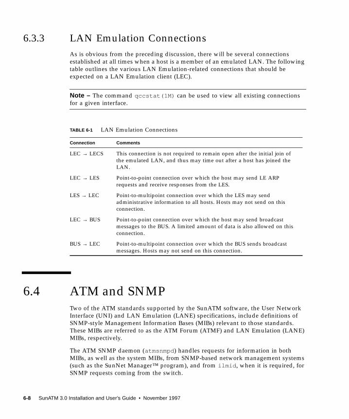
6.3.3 LAN Emulation Connections
As is obvious from the preceding discussion, there will be several connections
established at all times when a host is a member of an emulated LAN. The following
table outlines the various LAN Emulation-related connections that should be
expected on a LAN Emulation client (LEC).
Note – The command qccstat(1M) can be used to view all existing connections
for a given interface.
6.4 ATM and SNMPTwo of the ATM standards supported by the SunATM software, the User Network
Interface (UNI) and LAN Emulation (LANE) specifications, include definitions of
SNMP-style Management Information Bases (MIBs) relevant to those standards.
These MIBs are referred to as the ATM Forum (ATMF) and LAN Emulation (LANE)
MIBs, respectively.
The ATM SNMP daemon (atmsnmpd ) handles requests for information in both
MIBs, as well as the system MIBs, from SNMP-based network management systems
(such as the SunNet Manager™ program), and from ilmid , when it is required, for
SNMP requests coming from the switch.
TABLE 6-1 LAN Emulation Connections
Connection Comments
LEC → LECS This connection is not required to remain open after the initial join of
the emulated LAN, and thus may time out after a host has joined the
LAN.
LEC → LES Point-to-point connection over which the host may send LE ARP
requests and receive responses from the LES.
LES → LEC Point-to-multipoint connection over which the LES may send
administrative information to all hosts. Hosts may not send on this
connection.
LEC → BUS Point-to-point connection over which the host may send broadcast
messages to the BUS. A limited amount of data is also allowed on this
connection.
BUS → LEC Point-to-multipoint connection over which the BUS sends broadcast
messages. Hosts may not send on this connection.
6-8 SunATM 3.0 Installation and User’s Guide • November 1997
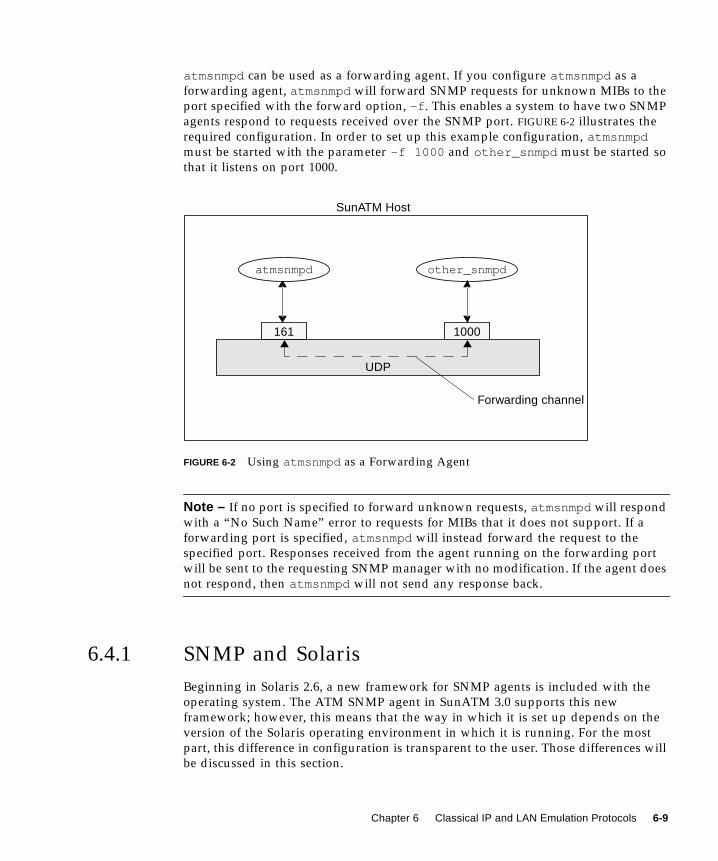
atmsnmpd can be used as a forwarding agent. If you configure atmsnmpd as a
forwarding agent, atmsnmpd will forward SNMP requests for unknown MIBs to the
port specified with the forward option, -f . This enables a system to have two SNMP
agents respond to requests received over the SNMP port. FIGURE 6-2 illustrates the
required configuration. In order to set up this example configuration, atmsnmpdmust be started with the parameter -f 1000 and other_snmpd must be started so
that it listens on port 1000.
FIGURE 6-2 Using atmsnmpd as a Forwarding Agent
Note – If no port is specified to forward unknown requests, atmsnmpd will respond
with a “No Such Name” error to requests for MIBs that it does not support. If a
forwarding port is specified, atmsnmpd will instead forward the request to the
specified port. Responses received from the agent running on the forwarding port
will be sent to the requesting SNMP manager with no modification. If the agent does
not respond, then atmsnmpd will not send any response back.
6.4.1 SNMP and Solaris
Beginning in Solaris 2.6, a new framework for SNMP agents is included with the
operating system. The ATM SNMP agent in SunATM 3.0 supports this new
framework; however, this means that the way in which it is set up depends on the
version of the Solaris operating environment in which it is running. For the most
part, this difference in configuration is transparent to the user. Those differences will
be discussed in this section.
other_snmpd
1000161
SunATM Host
Forwarding channel
UDP
atmsnmpd
Chapter 6 Classical IP and LAN Emulation Protocols 6-9
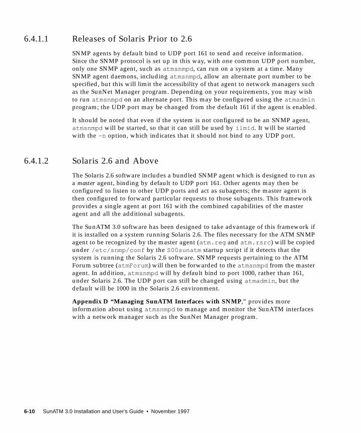
6.4.1.1 Releases of Solaris Prior to 2.6
SNMP agents by default bind to UDP port 161 to send and receive information.
Since the SNMP protocol is set up in this way, with one common UDP port number,
only one SNMP agent, such as atmsnmpd , can run on a system at a time. Many
SNMP agent daemons, including atmsnmpd , allow an alternate port number to be
specified, but this will limit the accessibility of that agent to network managers such
as the SunNet Manager program. Depending on your requirements, you may wish
to run atmsnmpd on an alternate port. This may be configured using the atmadminprogram; the UDP port may be changed from the default 161 if the agent is enabled.
It should be noted that even if the system is not configured to be an SNMP agent,
atmsnmpd will be started, so that it can still be used by ilmid . It will be started
with the -n option, which indicates that it should not bind to any UDP port.
6.4.1.2 Solaris 2.6 and Above
The Solaris 2.6 software includes a bundled SNMP agent which is designed to run as
a master agent, binding by default to UDP port 161. Other agents may then be
configured to listen to other UDP ports and act as subagents; the master agent is
then configured to forward particular requests to those subagents. This framework
provides a single agent at port 161 with the combined capabilities of the master
agent and all the additional subagents.
The SunATM 3.0 software has been designed to take advantage of this framework if
it is installed on a system running Solaris 2.6. The files necessary for the ATM SNMP
agent to be recognized by the master agent (atm.reg and atm.rsrc ) will be copied
under /etc/snmp/conf by the S00sunatm startup script if it detects that the
system is running the Solaris 2.6 software. SNMP requests pertaining to the ATM
Forum subtree (atmForum ) will then be forwarded to the atmsnmpd from the master
agent. In addition, atmsnmpd will by default bind to port 1000, rather than 161,
under Solaris 2.6. The UDP port can still be changed using atmadmin , but the
default will be 1000 in the Solaris 2.6 environment.
Appendix D “Managing SunATM Interfaces with SNMP,” provides more
information about using atmsnmpd to manage and monitor the SunATM interfaces
with a network manager such as the SunNet Manager program.
6-10 SunATM 3.0 Installation and User’s Guide • November 1997

APPENDIX A
Wiring Scheme and Pin Descriptions
A.1 Designation T568B
FIGURE A-1 Designation T568B
1 2 3 4 5 6 7 8
Pair 2,Pins 1 and 2
Pair 4,Pins 7 and 8
1 2 3 4 5 6 7 8
Transmit Receive
Pin 1 = +Pin 2 = –
Pin 7 = +Pin 8 = –
A-1
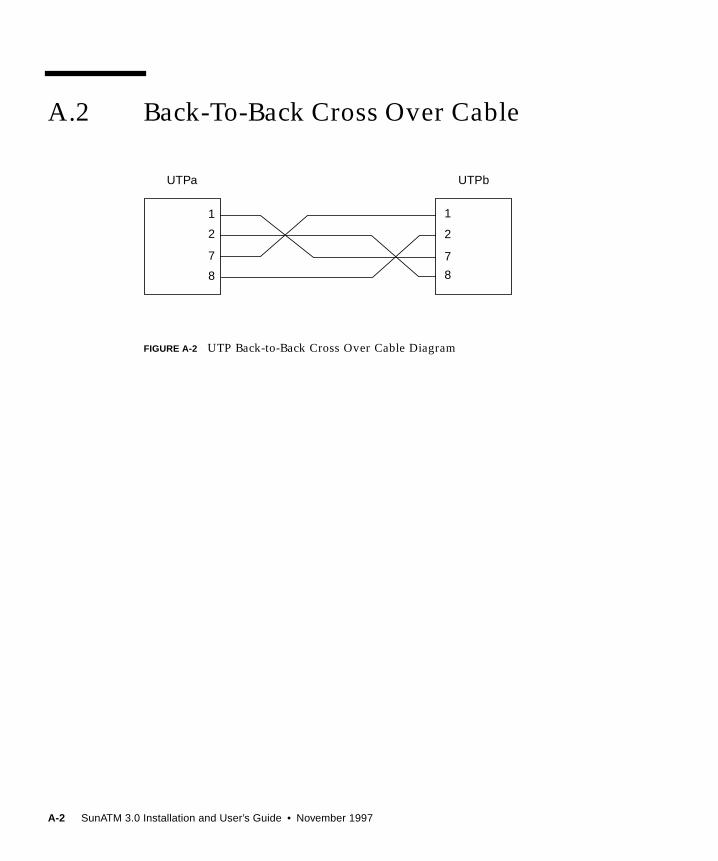
A.2 Back-To-Back Cross Over Cable
FIGURE A-2 UTP Back-to-Back Cross Over Cable Diagram
UTPa
1
2
7
8
UTPb
1
2
7
8
A-2 SunATM 3.0 Installation and User’s Guide • November 1997

APPENDIX B
SunATM Adapters Specifications
B.1 SunATM/P 155 Adapters Specifications
B.1.1 Physical Dimensions
TABLE B-1 SunATM/P 155 Adapters Physical Dimensions
Dimension Measurement
Length 6.875 in. (17.46 cm)
Width 4.125 in. (10.48 cm)
B-1
B.1.2 Performance Specifications
B.1.3 Power Specifications
B.1.4 Environmental Specifications
TABLE B-2 SunATM/P 155 Adapters Performance Specifications
Feature Specification
PCI Clock 33 MHz min., 66 MHz max.
Maximum Burst Transfer Rate 200 Mbytes/sec (approximately)
Steady State Transfer Rate 14 Mbytes/sec
PCI Bus Modes Master/Slave
TABLE B-3 SunATM/P 155 Adapters Power Specifications
Specification Measurement
Power Dissipation 11 Watt max.
Voltage Tolerance +/- 5%
Ripple ≤ 100 mV
Operational Current 2.2 Amps
TABLE B-4 SunATM/P 155 Adapters Environmental Specifications
Condition Operating Specification Storage Specification
Temperature 0 to 70°C (+32 to +131°F) -25 to 70°C (-25 to +131°F)
Relative Humidity 5 to 85% non-condensing 0 to 95% non-condensing
(40°C, wet bulb temperature) 40°C /hour
Altitude -1000 to +15,000 ft. -1000 to +50,000 ft.
Shock 5g, 1/2 sine wave, 11 msec 30g, 1/2 sine wave, 11 msec
Vibration, pk to pk displacement 0.005 in. max. (5 to 32 Hz) 0.1 in. max (5 to 17 Hz)
Vibration, peak acceleration 0.25g (5 to 500 Hz) 1.0g (5 to 500 Hz)
(Sweep Rate = 1 octave/min.) (Sweep Rate = 1 octave/min.)
B-2 SunATM 3.0 Installation and User’s Guide • November 1997

B.2 SunATM/P 622 MMF 3.0 AdapterSpecifications
B.2.1 Physical Dimensions
B.2.2 Performance Specifications
B.2.3 Power Specifications
TABLE B-5 SunATM/P 622 MMF 3.0 Adapter Physical Dimensions
Dimension Measurement
Length 6.875 in. (17.46 cm)
Width 4.125 in. (10.48 cm)
TABLE B-6 SunATM/P 622 MMF 3.0 Adapter Performance Specifications
Feature Specification
PCI Clock 33 MHz min., 66 MHz max.
Maximum Burst Transfer Rate 200 Mbytes/sec (approximately)
Steady State Transfer Rate 56 Mbytes/sec
PCI Bus Modes Master/Slave
TABLE B-7 SunATM/P 622 MMF 3.0 Adapter Power Specifications
Specification Measurement
Power Dissipation 14.7 Watt max.
Voltage Tolerance +/- 5%
Ripple ≤ 100 mV
Operational Current 2.94 Amps
Appendix B SunATM Adapters Specifications B-3
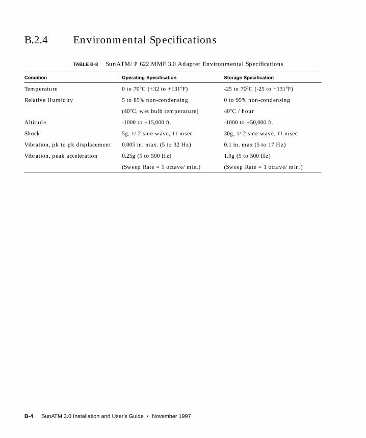
B.2.4 Environmental Specifications
TABLE B-8 SunATM/P 622 MMF 3.0 Adapter Environmental Specifications
Condition Operating Specification Storage Specification
Temperature 0 to 70°C (+32 to +131°F) -25 to 70°C (-25 to +131°F)
Relative Humidity 5 to 85% non-condensing 0 to 95% non-condensing
(40°C, wet bulb temperature) 40°C /hour
Altitude -1000 to +15,000 ft. -1000 to +50,000 ft.
Shock 5g, 1/2 sine wave, 11 msec 30g, 1/2 sine wave, 11 msec
Vibration, pk to pk displacement 0.005 in. max. (5 to 32 Hz) 0.1 in. max (5 to 17 Hz)
Vibration, peak acceleration 0.25g (5 to 500 Hz) 1.0g (5 to 500 Hz)
(Sweep Rate = 1 octave/min.) (Sweep Rate = 1 octave/min.)
B-4 SunATM 3.0 Installation and User’s Guide • November 1997
APPENDIX C
TroubleshootingandErrorMessages
C.1 Troubleshooting While Starting aSunATM InterfaceThere are many steps involved in making an interface active on an ATM network.
Once you have configured the interface properly, these steps should be transparent
to you. However, problems in your configuration may cause a failure at any number
of points along the way. This section contains checks that you can make to determine
where in the process your system failed, and what you can do to remedy the
situation. If you continue to experience problems, information gathered from these
checks will help your service provider diagnose the problem.
This troubleshooting section is divided into three subsections:
Section Description
Section C.1.1, “Generic Configuration” Refers to all SunATM configurations,
regardless of the IP support type
involved, if any.
Section C.1.2, “Classical IP Configuration” Refers only to interfaces configured to
support Classical IP.
Section C.1.3, “LAN Emulation Configuration” Refers to interfaces configured to support
LAN Emulation.
C-1

C.1.1 Generic Configuration
This section describes the troubleshooting procedures for common SunATM
configuration problems.
■ Make sure that there is an entry for the interface in the /etc/atmconfig file.
Configuration of a SunATM interface begins during the system boot process.
Configuration will be attempted for all interfaces listed in the /etc/atmconfigfile. For information about the format of this file, see Section 5.1, “Editing the /
etc/atmconfig File,” and the atmconfig(4) man page.
■ Check to see if any error messages were printed during the boot process.
If there were error messages, see Section C.2, “Error Messages,” for more
information.
■ Verify the link state using the qccstat(1M) command.
This command will indicate the signalling status of your interface. The link state
should be DL_ACTIVE. If it is not, your interface is not communicating properly
with your switch.
If your SunATM interface is not communicating with your switch:
1. Make sure that your switch and interface are both configured to run the same
version of UNI signalling.
The SunATM software supports UNI versions 3.0, 3.1, and 4.0. The UNI version is
set per-interface in the /etc/atmconfig file. See Section 5.1, “Editing the /etc/
atmconfig File,” for more information.
2. Verify that your interface is physically connected to the switch, and that the
switch sees the physical connection (most switches have a physical link LED for
each port).
If your interface is a multimode fiber interface, one possible cause for a bad
physical connection is that transmit and receive are swapped. “transmit” on your
interface should be connected to “receive” on the switch, and “receive” on your
interface to “transmit” on the switch. There is generally writing on one of the
cables in a transmit-receive pair so that the two cables are distinct.
■ Verify that an address has been registered with the switch.
The qccstat(1M) command also lists all addresses registered to the interface
with the switch. See Section 6.1, “ATM Addresses and Address Registration,” for
more information about address registration. If there are no addresses registered,
the ilmid daemon on your system is not communicating properly with the
switch.
C-2 SunATM 3.0 Installation and User’s Guide • November 1997
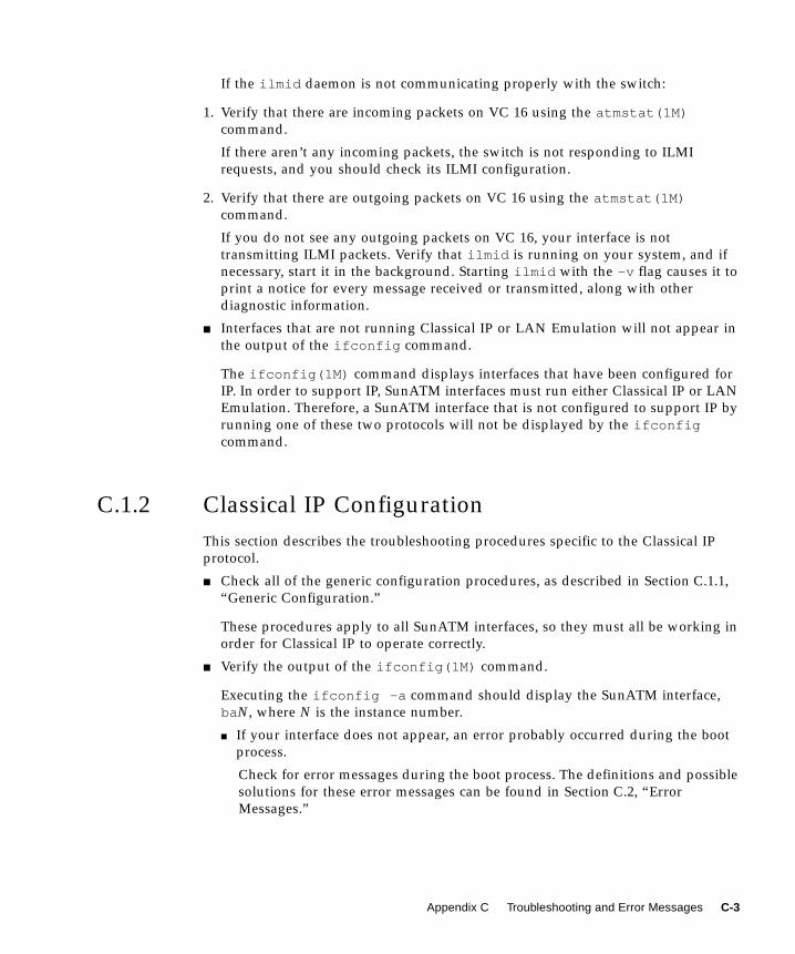
If the ilmid daemon is not communicating properly with the switch:
1. Verify that there are incoming packets on VC 16 using the atmstat(1M)command.
If there aren’t any incoming packets, the switch is not responding to ILMI
requests, and you should check its ILMI configuration.
2. Verify that there are outgoing packets on VC 16 using the atmstat(1M)command.
If you do not see any outgoing packets on VC 16, your interface is not
transmitting ILMI packets. Verify that ilmid is running on your system, and if
necessary, start it in the background. Starting ilmid with the -v flag causes it to
print a notice for every message received or transmitted, along with other
diagnostic information.
■ Interfaces that are not running Classical IP or LAN Emulation will not appear in
the output of the ifconfig command.
The ifconfig(1M) command displays interfaces that have been configured for
IP. In order to support IP, SunATM interfaces must run either Classical IP or LAN
Emulation. Therefore, a SunATM interface that is not configured to support IP by
running one of these two protocols will not be displayed by the ifconfigcommand.
C.1.2 Classical IP Configuration
This section describes the troubleshooting procedures specific to the Classical IP
protocol.
■ Check all of the generic configuration procedures, as described in Section C.1.1,
“Generic Configuration.”
These procedures apply to all SunATM interfaces, so they must all be working in
order for Classical IP to operate correctly.
■ Verify the output of the ifconfig(1M) command.
Executing the ifconfig -a command should display the SunATM interface,
baN, where N is the instance number.
■ If your interface does not appear, an error probably occurred during the boot
process.
Check for error messages during the boot process. The definitions and possible
solutions for these error messages can be found in Section C.2, “Error
Messages.”
Appendix C Troubleshooting and Error Messages C-3
■ If your interface appears, but has incorrect information, verify the SunATM
software’s configuration files.
The information given to the ifconfig command comes from the
/etc/atmconfig and /etc/aarconfig files. Check the entries in these files
that apply to this interface and verify the interface’s configuration. For
descriptions of the file formats, see Section 5.1, “Editing the /etc/atmconfig
File,” and Section 5.3.1, “Editing the /etc/laneconfig File,” or see the
atmconfig(4) and aarconfig(4) man pages.
■ Check the setup_state with the aarstat(1M) command.
This command will provide information about the Classical IP status on your
interface. The setup_state refers to the completion of the aarsetup program.
■ If the setup_state is setup-started:
This indicates that the aarsetup program has not completed; it may be
delayed by slow switch responses, or failed attempts to register ATM addresses
in the /etc/aarconfig file. Make sure that the local address given for your
interface in the /etc/aarconfig file is unique to this switch. Using the
$myaddress variable and the reserved server addresses is a good way to
guarantee that all addresses are unique. After making any changes to the
/etc/aarconfig file, run the aarsetup program again.
■ If the setup_state is not setup-started or setup-finished:
Verify that the addresses and interfaces in the /etc/aarconfig file are valid,
and run the aarsetup program again. If you see any error messages, see
Section C.2, “Error Messages,” for more information.
■ Verify the interface_state using the aarstat(1M) command.
The interface_state is either up or down, and reflects the link state given in
the output of the qccstat command. If the link state is DL_ACTIVE, the
interface_state is up; otherwise the interface_ state is down. If the
aarstat command indicates that the interface_state is down, try the
suggestions for a link state that is not DL_ACTIVE given in Section C.1.1,
“Generic Configuration.”
■ Make sure Classical IP is configured correctly.
The aarstat(1M) command output lists several parameters for Classical IP. The
arpcsmode field lists whether Classical IP is running as a client, a server, or
stand-alone (a client with no server configured). Verify that this is configured
correctly. If it is not, check your /etc/aarconfig file entries.
■ If the system is a Classical IP client, verify the server connection.
On systems running in client mode, the aarstat command also provides
information about the server. Verify the server address, and that the
server_state is connected.
C-4 SunATM 3.0 Installation and User’s Guide • November 1997
■ If the server_state is no-connection or connecting:
The system is likely having a problem establishing a connection to the server.
Verify that the server address is correct, and that there is a system on the network
which has registered that address. The server and applicable switch ports must
also be configured to support UNI signalling, also called Q.2931 or Q.93b.
■ Verify that addresses are resolved and connections are made with the ping(1M)command.
Once you have two systems configured and running (for example, client1 and
client2 ), they should be able to ping each other using the ping command. On
client1 , type: ping client2 . You should receive the response, after a small
delay, client2 is alive .
If the ping command is not successful:
1. Check to see that the ARP requests are being sent to the server.
Find the server_vci in the output of the aarstat command. Then run the
atmstat command and verify that there are outgoing packets on that VC. If not,
make sure that your interface is up and configured properly.
2. Make sure that you are receiving ARP responses from the server.
In the atmstat command output, check the output packets for the server VC
(found in the aarstat command information). If none are being received, your
server is not responding to the ARP requests from the client. If it is a SunATM
server, verify its Classical IP status with the suggestions described in this section.
Also, verify that the system is up and running as a server.
3. Make sure the address is resolved correctly.
Run the atmarp command for the system you are trying to ping , and verify that
its IP address has been resolved to the correct ATM address. If not, make sure that
the remote system is registering the correct address with the ATM ARP server. If
the address has not been resolved at all, make sure that the remote system has a
connection to the server.
4. Verify that a connection has been established between the two systems.
The output of the qccstat command lists the source and destination addresses
of all open connections. You should have at least one connection to the server, and
you should also see a connection to the remote host you are trying to ping. If not,
make sure both interfaces are up and registered with the switch, and that both
interfaces and the switch are running UNI signalling (Q.2931 or Q.93b).
5. Check for IP problems.
If the address has been resolved correctly, and a connection has been established
between the two systems, but they still cannot ping, the problem is likely outside
the scope of ATM.
Appendix C Troubleshooting and Error Messages C-5

C.1.3 LAN Emulation Configuration
This section describes the troubleshooting procedures specific to the LAN Emulation
protocol.
■ Check all of the generic configuration procedures, as described in Section C.1.1,
“Generic Configuration.”
These procedures apply to all SunATM interfaces, so they must all be working in
order for LAN Emulation to operate correctly.
■ Verify the output of the ifconfig(1M) command.
Executing the ifconfig -a command should display the SunATM LAN
Emulation interface, lane N, where N is the instance number.
■ If your interface does not appear, an error probably occurred during the boot
process.
Check for error messages during the boot process. The descriptions and
possible solutions of these error messages can be found in Section C.2, “Error
Messages.”
■ If your interface is displayed, but has incorrect information, verify the SunATM
configuration files.
The information given to the ifconfig command comes from the
/etc/atmconfig and /etc/laneconfig files. Check the entries in these
files that apply to the lane N interface and verify their configuration. For
descriptions of the file formats, see Section 5.1, “Editing the /etc/atmconfig
File” and Section 5.3.1, “Editing the /etc/laneconfig File,” or see the
atmconfig(4) and laneconfig(4) man pages.
■ Check the setup_state with the lanestat(1M) command.
This command will provide information about the LAN Emulation status on your
interface. The setup_state refers to the completion of the lanesetup program.
■ If the setup_state is setup-started:
This indicates that the lanesetup program has not completed. It may have
been delayed by slow switch responses, or it may have failed to register ATM
addresses listed in the /etc/laneconfig file. Make sure that the local
address given for your interface in the /etc/laneconfig file is unique to this
switch. Using the variable $myaddress for all systems is a good way to
guarantee that all addresses are unique. After making any changes to the
/etc/laneconfig file, run the lanesetup program again.
■ If the setup_state is not setup-started or setup-finished:
Verify that the addresses and interfaces in the /etc/laneconfig file are
valid, and rerun the lanesetup program. If you see any error messages, check
their meanings in Section C.2, “Error Messages.”
C-6 SunATM 3.0 Installation and User’s Guide • November 1997
■ Verify that a connection has been made to the LAN Emulation server (LES).
A LAN Emulation client must establish and maintain a connection to the LES. In
most cases, the LES will also establish and maintain a second connection to the
client. Find the LES address in the output of the lanestat command, and then
look for connections with that address as the destination or source in the output
of the qccstat command.
Check the points in the following order if you do not see any connections with
that address.
1. If you have an LAN Emulation configuration server (LECS):
Make sure that the correct address is configured for the LECS. By default, the
ATM Forum well-known address will be used by the SunATM software. If your
LECS uses a different address, you should enter the alternate address in the
/etc/laneconfig file. See Section 5.3.1, “Editing the /etc/laneconfig File,” for
information on editing /etc/laneconfig . You can check the address currently
being used in the output of the lanestat command.
2. If you do not have an LECS:
One of the LECS functions is to provide the LES address, so if you do not have an
LECS, you must provide this address. You can add this address by adding an
entry in to the /etc/laneconfig file. See Section 5.3.1, “Editing the /etc/
laneconfig File.” You can check the LES address currently being used by viewing
the output of the lanestat command.
3. Verify that the LECS, if present, and LES are configured properly.
■ Verify that a connection has been made to the BUS.
In addition to the LES connection(s), a LAN Emulation client must also establish
and maintain a connection to the BUS, and the BUS will typically establish and
maintain a second connection to the client. You can find the BUS ATM address in
the output of the lanestat command. You can then verify that there is a
connection with that address as the destination, and probably a second with that
address as source, in the output of the qccstat command. If there are no
connections, verify that the BUS is configured properly.
■ Verify that the host has joined the Emulated LAN.
The lanestate field in the output of the lanestat command should indicate
that the client is in the active state.
If your system is not able to join the emulated LAN, there may be a problem with
the way in which your LAN Emulation Services are configured. If the Emulated
LAN uses an MTU size larger than 9 Kbytes, the SunATM host will not join
(9 Kbytes is the largest MTU size supported by the SunATM product). If the host
is not able to join, an error message will be printed with an explanation.
Appendix C Troubleshooting and Error Messages C-7

■ Verify that addresses are resolved and connections are made with the pingcommand.
Once you have two systems configured and running (for example, client1 and
client2 ), they should be able to ping each other using the ping command. On
client1 , type: ping client2 . You should receive the response, after a small
delay, client2 is alive .
If the ping command is not successful:
1. Check that the hostname or IP address is resolved to a MAC address.
LAN Emulation requires two address resolution steps to make a call. The first is
to resolve an IP address to a MAC address. From the perspective of IP and ARP,
this works exactly like it does on an Ethernet interface; using the arp command,
you can verify that this resolution has been made correctly. If it has not, verify the
connections to the BUS, and make sure data is being transmitted and received on
the connection(s) to the BUS by finding the VC in the output of the qccstatcommand, and by looking at the statistics for that VC in the atmstat command
output.
2. Check that the MAC address has been resolved to an ATM address.
This is the second address resolution step, and is accomplished by the LAN
Emulation software and communication with the LES. You can use the lanearpcommand to verify that the MAC addresses have been properly resolved to ATM
addresses. If they have not been resolved, verify the connections to the LES, and
make sure data is being transmitted and received on the connection(s) to the LES
by finding the VC in the output of the qccstat command, and by looking at the
statistics for that VC in the atmstat command output.
3. Verify that a connection has been established between the two systems.
The output of the qccstat command lists the source and destination addresses
of all open connections. There you should see a connection to the remote host you
are trying to ping. If not, make sure both interfaces are up and registered with the
switch, and that both interfaces and the switch are running UNI signalling
(Q.2931 or Q.93b).
4. Check for IP problems.
If the address has been resolved correctly, and a connection has been established
between the two systems, but they still cannot ping each other, the problem is
likely outside the scope of ATM.
C-8 SunATM 3.0 Installation and User’s Guide • November 1997

C.2 Error MessagesThis section includes a list of some of the most common error messages you might
see while configuring and bringing up your SunATM interface. For each message,
there is a brief explanation of the problem and a possible solution.
C.2.1 Error Messages from S00sunatm
Cannot find ATM utilities in /etc/opt/SUNWatm/bin;exiting S00sunatm.
The SunATM utility directory /etc/opt/SUNWatm/bin does not exist. Make
sure that the SUNWatm package installation completed successfully (see
Section 3.1.4, “Checking the Package Installation Using pkginfo,” for more
information). If necessary, the package may need to be re-installed.
Cannot find atmconfig file in /etc; exiting S00sunatm.
The /etc/atmconfig file provides configuration information to the S00sunatmscript so that it can bring up the SunATM interfaces during system boot. If the
/etc/atmconfig file is not present, S00sunatm will print this warning message
and exit. The /etc/atmconfig file is installed with the SUNWatmpackage as
/etc/atmconfig.template ; if you choose autoconfiguration or if no previous
/etc/atmconfig file exists, pkgadd will copy this template file to
/etc/atmconfig . If a previous /etc/atmconfig file exists, it will not be
overwritten. See Section 5.1, “Editing the /etc/atmconfig File,” for more
information on this file.
warning: can't plumb <device>; no UNI version provided
The first entry in /etc/atmconfig for a physical interface must include a UNI
value in the second field.
warning: can't plumb <uni version> on <device>; <uni version>already plumbed
This message is printed when an entry is encountered which attempts to plumb a
signalling version on an interface which has already been plumbed with a
different signalling version. The script will ignore the new UNI version and
continue processing the entry and the remaining entries in the file.
Appendix C Troubleshooting and Error Messages C-9
warning: can't plumb <lane instance>: too many lane instanceson <device>
A physical interface will support up to n lane instances, where n is the number of
MAC addresses on the board (or 1 if the board has no MAC address). The number
of MAC addresses on a board may be checked using the count option to the
atmgetmac(1m) command. If an entry is encountered which attempts to plumb
more LANE instances than allowed, this message will be printed; processing will
continue with the next entry in the file.
warning: can't plumb signalling on <device>warning: can't plumb classical IP interface <device>warning: can't plumb <lane instance> on <device>
An error occurred when the script attempted to run atmplumb(1m) , either to
plumb signalling, Classical IP, or LAN Emulation on an interface, with
information specified in the /etc/atmconfig file. The atmplumb program will
generally print out an error message indicating why it failed; use that information
to check your values in the /etc/atmconfig entry for the device. The script will
proceed to read and process the remaining entries in the /etc/atmconfig file,
although further entries for the failed interface will not be processed correctly.
warning: invalid interface <lane instance>
The minor number provided in a logical interface name was not in the range
0 - 255. The script will proceed without attempting to configure the invalid lane
device.
warning: only one classical ip hostname is allowed on <device>
An additional entry was found containing a Classical IP hostname after an initial
Classical IP hostname was already plumbed for the device. Multiple Classical IP
instances are not supported on a single physical interface. The script will ignore
additional Classical IP information for a physical interface.
warning: <laneN> entry must appear before <laneN:X> entry
When using logical interface names, the first entry in /etc/atmconfig file must
always be either lane N or lane N:0 , which are equivalent. All entries that
appear before the lane N or lane N:0 entry will be ignored.
Please install <SUNWatm>
A required software package is not installed on the system. Install the package,
and reboot the system.
warning: extra fields for <device> will be ignored
There were additional fields in the /etc/atmconfig entry for the given device
name. The script will proceed, ignoring the additional fields.
C-10 SunATM 3.0 Installation and User’s Guide • November 1997
warning: duplicate entry <lane device>
There were multiple entries in the /etc/atmconfig file using the same LAN
Emulation instance number. This is not a fatal error; the script will continue to
run. However, only the first entry for each LAN Emulation instance number will
be configured for LAN Emulation.
warning: not enough fields to configure <device>
The /etc/atmconfig entry for the given device did not have all the required
fields. You must edit the /etc/atmconfig file (see Section 5.1, “Editing the /
etc/atmconfig File”), filling in all the appropriate information, and reboot the
system. Empty fields should be indicated with a hyphen (- ).
warning: ifconfig failed for classical IP interface <device>warning: ifconfig failed for <lane instance>
An error occurred when the script attempted to run the ifconfig command for
the specified interface. You should see error messages printed by the ifconfigprogram indicating why it failed; use that information to check your values in
/etc/atmconfig . In particular, verify that the hostname you provide in
/etc/atmconfig appears in the /etc/hosts file on your system.
warning: invalid lane instance (<lane instance>) for <device>
The lane instance number provided in /etc/atmconfig was not in the range 0
to 999. The script will proceed without attempting to configure the invalid lane
instance.
warning: aarsetup failed; could not configure classical IPinterfaceswarning: lanesetup failed; could not configure LAN Emulationinterfaces
Either the LAN Emulation or the Classical IP startup script failed and exited with
an error value. Check the error messages that were printed by the aarsetup or
lanesetup programs, and verify the values you have entered in
/etc/aarconfig and/or /etc/laneconfig files.
Appendix C Troubleshooting and Error Messages C-11
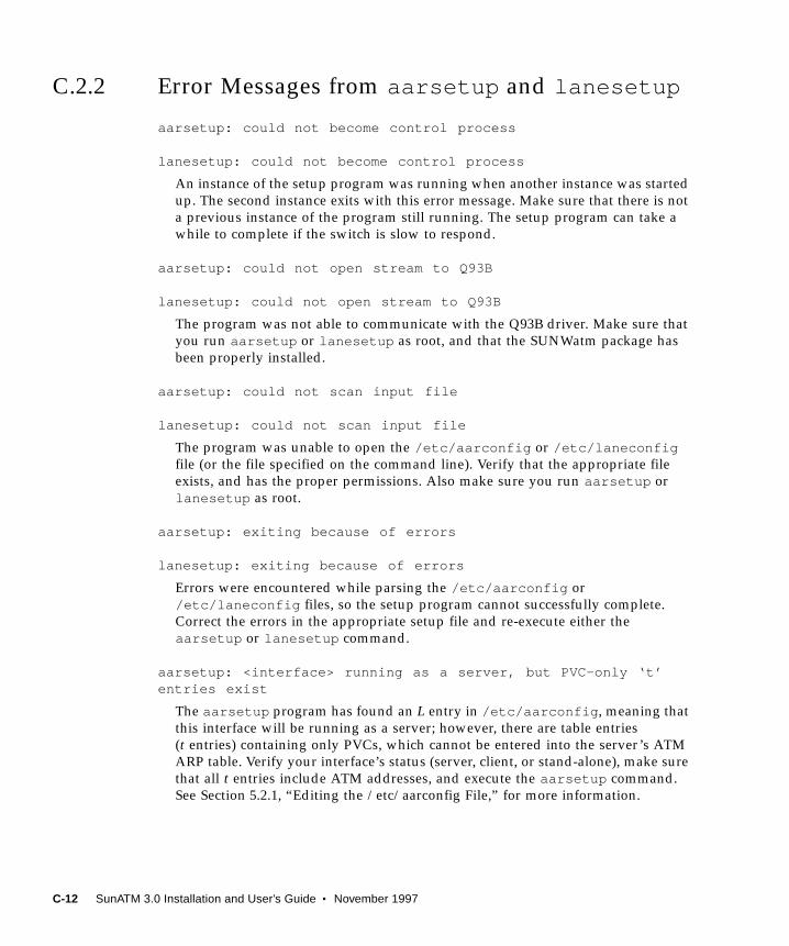
C.2.2 Error Messages from aarsetup and lanesetup
aarsetup: could not become control process
lanesetup: could not become control process
An instance of the setup program was running when another instance was started
up. The second instance exits with this error message. Make sure that there is not
a previous instance of the program still running. The setup program can take a
while to complete if the switch is slow to respond.
aarsetup: could not open stream to Q93B
lanesetup: could not open stream to Q93B
The program was not able to communicate with the Q93B driver. Make sure that
you run aarsetup or lanesetup as root, and that the SUNWatm package has
been properly installed.
aarsetup: could not scan input file
lanesetup: could not scan input file
The program was unable to open the /etc/aarconfig or /etc/laneconfigfile (or the file specified on the command line). Verify that the appropriate file
exists, and has the proper permissions. Also make sure you run aarsetup or
lanesetup as root.
aarsetup: exiting because of errors
lanesetup: exiting because of errors
Errors were encountered while parsing the /etc/aarconfig or
/etc/laneconfig files, so the setup program cannot successfully complete.
Correct the errors in the appropriate setup file and re-execute either the
aarsetup or lanesetup command.
aarsetup: <interface> running as a server, but PVC-only ‘t’entries exist
The aarsetup program has found an L entry in /etc/aarconfig , meaning that
this interface will be running as a server; however, there are table entries
(t entries) containing only PVCs, which cannot be entered into the server’s ATM
ARP table. Verify your interface’s status (server, client, or stand-alone), make sure
that all t entries include ATM addresses, and execute the aarsetup command.
See Section 5.2.1, “Editing the /etc/aarconfig File,” for more information.
C-12 SunATM 3.0 Installation and User’s Guide • November 1997
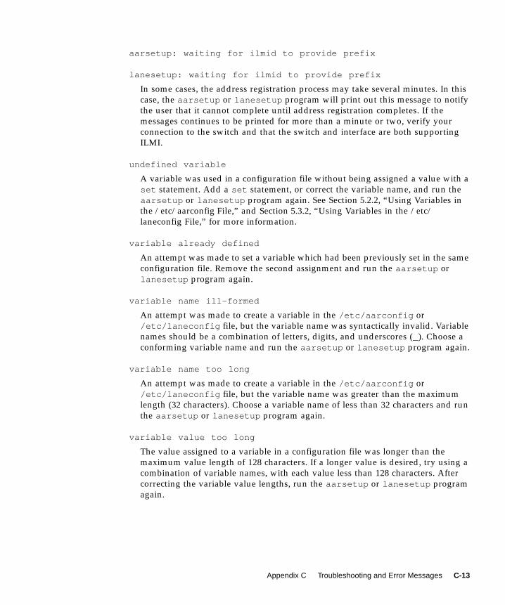
aarsetup: waiting for ilmid to provide prefix
lanesetup: waiting for ilmid to provide prefix
In some cases, the address registration process may take several minutes. In this
case, the aarsetup or lanesetup program will print out this message to notify
the user that it cannot complete until address registration completes. If the
messages continues to be printed for more than a minute or two, verify your
connection to the switch and that the switch and interface are both supporting
ILMI.
undefined variable
A variable was used in a configuration file without being assigned a value with a
set statement. Add a set statement, or correct the variable name, and run the
aarsetup or lanesetup program again. See Section 5.2.2, “Using Variables in
the /etc/aarconfig File,” and Section 5.3.2, “Using Variables in the /etc/
laneconfig File,” for more information.
variable already defined
An attempt was made to set a variable which had been previously set in the same
configuration file. Remove the second assignment and run the aarsetup or
lanesetup program again.
variable name ill-formed
An attempt was made to create a variable in the /etc/aarconfig or
/etc/laneconfig file, but the variable name was syntactically invalid. Variable
names should be a combination of letters, digits, and underscores (_). Choose a
conforming variable name and run the aarsetup or lanesetup program again.
variable name too long
An attempt was made to create a variable in the /etc/aarconfig or
/etc/laneconfig file, but the variable name was greater than the maximum
length (32 characters). Choose a variable name of less than 32 characters and run
the aarsetup or lanesetup program again.
variable value too long
The value assigned to a variable in a configuration file was longer than the
maximum value length of 128 characters. If a longer value is desired, try using a
combination of variable names, with each value less than 128 characters. After
correcting the variable value lengths, run the aarsetup or lanesetup program
again.
Appendix C Troubleshooting and Error Messages C-13
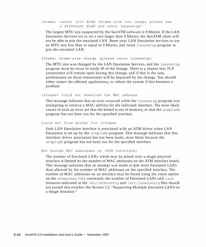
ifname: cannot join ELAN (frame size too large; please usea different ELAN and rerun lanesetup)
The largest MTU size supported by the SunATM software is 9 Kbytes. If the LAN
Emulation Services try to set a size larger than 9 Kbytes, the SunATM client will
not be able to join the emulated LAN. Reset your LAN Emulation services to use
an MTU size less than or equal to 9 Kbytes, and rerun lanesetup program to
join the emulated LAN.
ifname: frame-size change (please rerun lanesetup)
The MTU size was changed by the LAN Emulation Services, and the lanesetupprogram must be rerun to notify IP of the change. There is a chance that TCP
connections will remain open during this change, and if that is the case,
performance on those connections will be impacted by the change. You should
either restart the affected applications, or reboot the system if this becomes a
problem.
<ifname> could not download the MAC address
This message indicates that an error occurred while the lanesetup program was
attempting to retrieve a MAC address for the indicated interface. The most likely
causes of such an error are that the kernel is out of memory, or that the atmplumbprogram has not been run for the specified interface.
Could not find driver for <ifname>
Each LAN Emulation interface is associated with an ATM driver when LAN
Emulation is set up by the atmplumb program. This message indicates that this
interface/driver association has not been made, most likely because the
atmplumb program has not been run for the specified interface.
Not enough MAC addresses on <ATM interface>
The number of Emulated LANs which may be joined over a single physical
interface is limited by the number of MAC addresses on the ATM interface board.
This message indicates that an attempt was made to join more Emulated LANs
than allowed by the number of MAC addresses on the specified interface. The
number of MAC addresses on an interface may be found using the count option
on the atmgetmac(1M) command; the number of Emulated LANs and laneinstances indicated in the /etc/atmconfig and /etc/laneconfig files should
not exceed this number. See Section 5.5, “Supporting Multiple Emulated LANS on
a Single Interface.”
C-14 SunATM 3.0 Installation and User’s Guide • November 1997
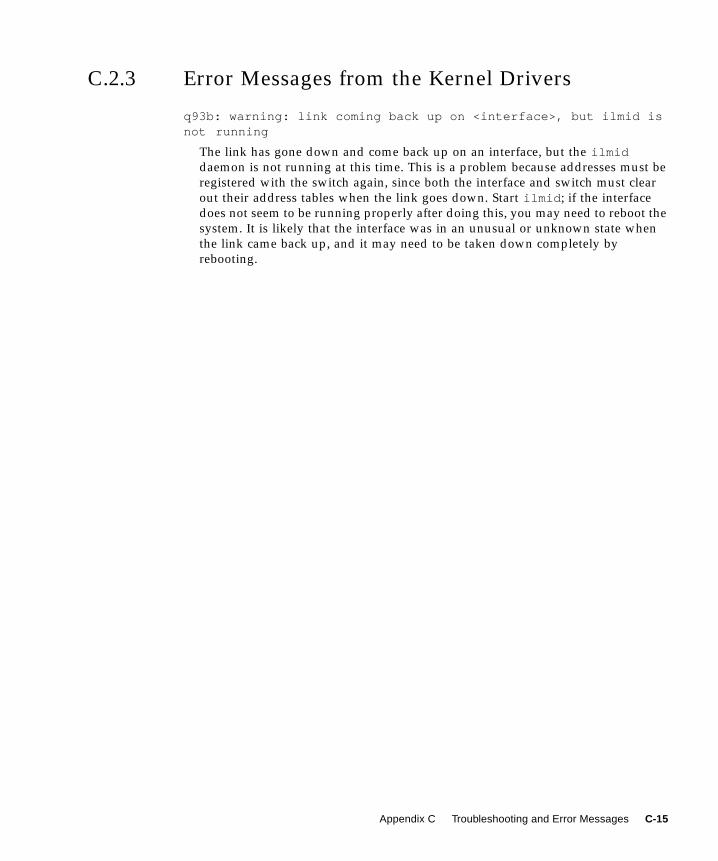
C.2.3 Error Messages from the Kernel Drivers
q93b: warning: link coming back up on <interface>, but ilmid isnot running
The link has gone down and come back up on an interface, but the ilmiddaemon is not running at this time. This is a problem because addresses must be
registered with the switch again, since both the interface and switch must clear
out their address tables when the link goes down. Start ilmid ; if the interface
does not seem to be running properly after doing this, you may need to reboot the
system. It is likely that the interface was in an unusual or unknown state when
the link came back up, and it may need to be taken down completely by
rebooting.
Appendix C Troubleshooting and Error Messages C-15

C-16 SunATM 3.0 Installation and User’s Guide • November 1997
APPENDIX D
ManagingSunATMInterfaceswith
SNMP
The SunATM software package provides an SNMP (Simple Network Management
Protocol) agent which supports the ATM UNI and LAN Emulation Management
Information Bases (MIBs) defined in the User Network Interface and LAN
Emulation Specifications. This agent will provide information to a network
management system, such as the SunNet Manager system.
Note – The SNMP agent is discussed in Section 6.4, “ATM and SNMP.” This
appendix describes how you can configure the SunNet Manager’s SNMP
management console to include ATM.
D.1 Installing the SunATM SNMP SoftwareThe SunATM SNMP software is made up of three parts: the SunATM SNMP
daemon, atmsnmpd , the SNMP management console configuration files, and the
agent configuration files. The management configuration files, which are installed in
the /opt/SUNWatm/snmp directory, are part of the SUNWatmu package. The ATM
SNMP daemon and its configuration files, which are part of the SUNWatm package,
are installed in the /etc/opt/SUNWatm/bin and the /etc/opt/SUNWatm/snmpdirectories, respectively.
D-1
D.2 Setting Up the Management ConsoleThe schema and oid files containing the required ATM MIB definitions for SunNet
Manager are installed in /opt/SUNWatm/snmp . In addition, the MIB files in abstract
syntax notation (ASN.1) format are included if you are running a network manager
that does not use schema files. Refer to the documentation for your network
manager for information on how to generate the appropriate configuration files from
the MIB files provided.
To configure your SunNet Manager console system to recognize SunATM agents:
1. Start the snm console program and save your management database.
This can be done using File -> Save -> Management database from the snm console
menus.
2. Copy the SunATM schema and oid files which were installed on the SunATMhosts to the schema directory on the manager.
The files, atmf.mib.schema , lane.mib.schema , atmf.mib.oid , and
lane.mib.oid , are installed in the /opt/SUNWatm/snmp directory on SunATM
hosts. They should be copied to the /opt/SUNWconn/snm/agents directory on the
management system.
3. Build the object identifier database to include the SunATM object identifiers.
Do this by executing the following command on the management console system:
4. Start the snm console program with the -i flag:
5. Load your management database using File -> Load -> Management databasefrom the menus.
The SunATM MIBs, atmf.mib and lane.mib , should now be available when you
create or update a component.
Note – For further information on using SunNet Manager to monitor snmp agents,
refer to the SunNet Manager documentation.
# /opt/SUNWconn/bin/build_oid /opt/SUNWconn/snm/agents
# snm -i
D-2 SunATM 3.0 Installation and User’s Guide • November 1997

D.3 Setting Up Agent SystemsTo configure a SunATM host system to run as an SNMP agent:
● Select the System Parameters option on the atmadmin main menu.
From this option, you will be given the choice of setting your system to run as a
SNMP agent or not (see Section 4.2, “Using the atmadmin Configuration Program,”
for more information about the atmadmin configuration program).
Note – This option applies to the entire system, and not for each SunATM interface.
Whether the system is running as an agent or not, the daemon must be running,
since it communicates with other parts of the SunATM software. If the system is
configured to run as an ATM SNMP agent, the daemon will bind to the default UDP
port (see Section 6.4, “ATM and SNMP” for more information). If the system is not
configured as an agent, the agent will not bind to this port, and it will not respond to
requests from network management software.
The default community values for the SunATM agent are public for read and private
for write. If you wish to change these values, they should be changed in the
/etc/opt/SUNWatm/snmp/agent.cnf file. This file contains SNMP agent
configuration information, and you can customize these values as needed. The
atmsnmpd daemon must be restarted after any changes to any of its configuration
files, including the agent.cnf file.
Appendix D Managing SunATM Interfaces with SNMP D-3

D-4 SunATM 3.0 Installation and User’s Guide • November 1997
APPENDIX E
ApplicationProgrammers’ Interface
The Application Programmers’ Interface (API) that is provided with this software
release is an interim API to be used until the ATM Forum standardizes an API.
Note – Be aware that since this is an interim API, it can be changed at any time.
Note – For historical reasons, Q.93B and Q.2931 are used interchangeably.
The signalling API, called Q.2931 Call Control (qcc), consists of two sets of similar
functions: one for applications running in the kernel, and one for applications
running in user space. Each set provides functions to build and parse Q.2931
signalling messages, which are required to set up and tear down connections.
One additional function is provided to assist applications in establishing appropriate
connections to the q93b driver. q_ioc_bind associates a service access point (SAP)
with the specified connection to the q93b driver. The SAP is used by the driver to
direct incoming messages to applications.
An additional set of functions is provided to facilitate communication with the ATM
device driver (the ba driver in SunATM software). These functions are referred to
collectively as the atm_util functions.
For examples of user applications that use the SunATM API, see the sample
programs installed in /opt/SUNWatm/examples .
E-1
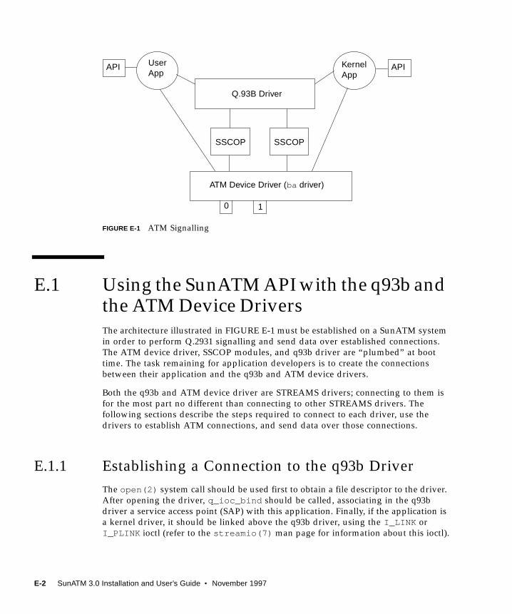
FIGURE E-1 ATM Signalling
E.1 Using the SunATM API with the q93b andthe ATM Device DriversThe architecture illustrated in FIGURE E-1 must be established on a SunATM system
in order to perform Q.2931 signalling and send data over established connections.
The ATM device driver, SSCOP modules, and q93b driver are “plumbed” at boot
time. The task remaining for application developers is to create the connections
between their application and the q93b and ATM device drivers.
Both the q93b and ATM device driver are STREAMS drivers; connecting to them is
for the most part no different than connecting to other STREAMS drivers. The
following sections describe the steps required to connect to each driver, use the
drivers to establish ATM connections, and send data over those connections.
E.1.1 Establishing a Connection to the q93b Driver
The open(2) system call should be used first to obtain a file descriptor to the driver.
After opening the driver, q_ioc_bind should be called, associating in the q93b
driver a service access point (SAP) with this application. Finally, if the application is
a kernel driver, it should be linked above the q93b driver, using the I_LINK or
I_PLINK ioctl (refer to the streamio(7) man page for information about this ioctl).
10
KernelApp
APIAPI
SSCOP SSCOP
Q.93B Driver
ATM Device Driver (ba driver)
UserApp
E-2 SunATM 3.0 Installation and User’s Guide • November 1997
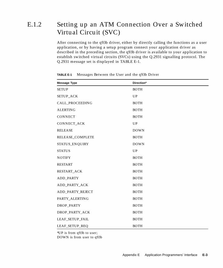
E.1.2 Setting up an ATM Connection Over a Switched
Virtual Circuit (SVC)
After connecting to the q93b driver, either by directly calling the functions as a user
application, or by having a setup program connect your application driver as
described in the preceding section, the q93b driver is available to your application to
establish switched virtual circuits (SVCs) using the Q.2931 signalling protocol. The
Q.2931 message set is displayed in TABLE E-1.
TABLE E-1 Messages Between the User and the q93b Driver
Message Type Direction*
SETUP BOTH
SETUP_ACK UP
CALL_PROCEEDING BOTH
ALERTING BOTH
CONNECT BOTH
CONNECT_ACK UP
RELEASE DOWN
RELEASE_COMPLETE BOTH
STATUS_ENQUIRY DOWN
STATUS UP
NOTIFY BOTH
RESTART BOTH
RESTART_ACK BOTH
ADD_PARTY BOTH
ADD_PARTY_ACK BOTH
ADD_PARTY_REJECT BOTH
PARTY_ALERTING BOTH
DROP_PARTY BOTH
DROP_PARTY_ACK BOTH
LEAF_SETUP_FAIL BOTH
LEAF_SETUP_REQ BOTH
*UP is from q93b to user;
DOWN is from user to q93b
Appendix E Application Programmers’ Interface E-3
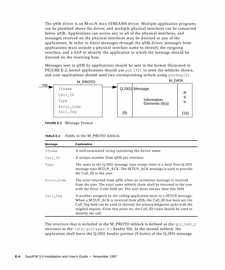
The q93b driver is an M-to-N mux STREAMS driver. Multiple application programs
can be plumbed above the driver, and multiple physical interfaces can be connected
below q93b. Applications can access any or all of the physical interfaces, and
messages received on the physical interfaces may be directed to any of the
applications. In order to direct messages through the q93b driver, messages from
applications must include a physical interface name to identify the outgoing
interface, and a SAP to identify the application to which the message should be
directed on the receiving host.
Messages sent to q93b by applications should be sent in the format illustrated in
FIGURE E-2; kernel applications should use put(9f) to send the mblocks shown,
and user applications should send two corresponding strbufs using putmsg(2) .
FIGURE E-2 Message Format
The structure that is included in the M_PROTO mblock is defined as the qcc_hdr_tstructure in the <atm/qcctypes.h> header file. In the second mblock, the
application shall leave the Q.2931 header portion (9 bytes) of the Q.2931 message
TABLE E-2 Fields in the M_PROTO mblock
Message Explanation
Ifname A null-terminated string containing the device name
Call_ID A unique number from q93b per interface.
Type The same as the Q.2931 message type except there is a local Non-Q.2931
message type SETUP_ACK. The SETUP_ACK message is used to provide
the Call_ID to the user.
Error_Code The error returned from q93b when an erroneous message is received
from the user. The exact same mblock chain shall be returned to the user
with the Error_Code field set. The user must always clear this field
Call_Tag A number assigned by the calling application layer to a SETUP message.
When a SETUP_ACK is received from q93b, the Call_ID has been set; the
Call_Tag field can be used to identify the acknowledgment (ack) with the
original request. From that point on, the Call_ID value should be used to
identify the call.
Ifname
Call_ID
Type
Error_Code
M_PROTO M_DATAmp
Q.2931 Message
(9) (16)
InformationElements (IEs)
Call_Tag
RSV
E-4 SunATM 3.0 Installation and User’s Guide • November 1997
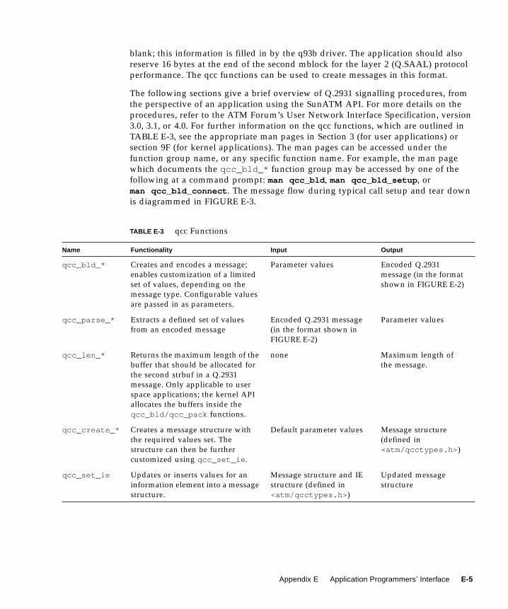
blank; this information is filled in by the q93b driver. The application should also
reserve 16 bytes at the end of the second mblock for the layer 2 (Q.SAAL) protocol
performance. The qcc functions can be used to create messages in this format.
The following sections give a brief overview of Q.2931 signalling procedures, from
the perspective of an application using the SunATM API. For more details on the
procedures, refer to the ATM Forum’s User Network Interface Specification, version
3.0, 3.1, or 4.0. For further information on the qcc functions, which are outlined in
TABLE E-3, see the appropriate man pages in Section 3 (for user applications) or
section 9F (for kernel applications). The man pages can be accessed under the
function group name, or any specific function name. For example, the man page
which documents the qcc_bld_* function group may be accessed by one of the
following at a command prompt: man qcc_bld , man qcc_bld_setup , or
man qcc_bld_connect . The message flow during typical call setup and tear down
is diagrammed in FIGURE E-3.
TABLE E-3 qcc Functions
Name Functionality Input Output
qcc_bld_* Creates and encodes a message;
enables customization of a limited
set of values, depending on the
message type. Configurable values
are passed in as parameters.
Parameter values Encoded Q.2931
message (in the format
shown in FIGURE E-2)
qcc_parse_* Extracts a defined set of values
from an encoded message
Encoded Q.2931 message
(in the format shown in
FIGURE E-2)
Parameter values
qcc_len_* Returns the maximum length of the
buffer that should be allocated for
the second strbuf in a Q.2931
message. Only applicable to user
space applications; the kernel API
allocates the buffers inside the
qcc_bld/qcc_pack functions.
none Maximum length of
the message.
qcc_create_* Creates a message structure with
the required values set. The
structure can then be further
customized using qcc_set_ie .
Default parameter values Message structure
(defined in
<atm/qcctypes.h> )
qcc_set_ie Updates or inserts values for an
information element into a message
structure.
Message structure and IE
structure (defined in
<atm/qcctypes.h> )
Updated message
structure
Appendix E Application Programmers’ Interface E-5

E.1.2.1 Call Setup
When the user decides to make a call, the user sends a SETUP message down to
q93b and waits for a SETUP_ACK from q93b. The SETUP message should include a
Broadband Higher Layer Information (BHLI) information element which contains a
four-octet SAP identified as User Specific Information. The SAP is used to identify
the application to which the message should be directed by q93b on the receiving
host. After receiving a SETUP_ACK with a 0 error field, the user waits for either a
CALL_PROCEEDING, ALERTING, CONNECT, or RELEASE_COMPLETE message
from q93b (all other messages are ignored by q93b). After the CONNECT message is
received, the user can use the virtual channel.
When the user receives a SETUP message from q93b, the user responds with either a
CALL_PROCEEDING, ALERTING, CONNECT, or RELEASE_COMPLETE message
to q93b. After the CONNECT_ACK message is received, the user can use the virtual
channel.
E.1.2.2 Release Procedure
To clear an active call or a call in progress, the user should send a RELEASE message
down to q93b and wait for a RELEASE_COMPLETE from q93b. Any time the user
receives a RELEASE_COMPLETE message from q93b, the user releases the virtual
channel if the call is active or in progress.
q93b never sends a RELEASE message to the user; it will always send a
RELEASE_COMPLETE. The user only sends the RELEASE_COMPLETE message
when rejecting a call in response to a SETUP message from q93b. At any other time,
to reject or tear down a call, the user sends a RELEASE message to q93b.
qcc_pack_* Takes a message structure and
encodes it into an actual Q.2931
message, consisting of the two
mblks (or strbufs) illustrated in
FIGURE E-2.
Message structure (defined
in <atm/qcctypes.h> )
Encoded Q.2931
message (in the format
shown in FIGURE E-2)
qcc_unpack_* The reverse of qcc_pack_* : takes
an encoded message and decodes
the data into a message structure.
Encoded Q.2931 message
(in the format shown in
FIGURE E-2)
Message structure
(defined in
<atm/qcctypes.h> )
qcc_get_ie Extracts a single information
element structure from a message
structure.
Message structure and
empty IE structure (defined
in <atm/qcctypes.h> )
Updated IE structure
TABLE E-3 qcc Functions (Continued)
Name Functionality Input Output
E-6 SunATM 3.0 Installation and User’s Guide • November 1997
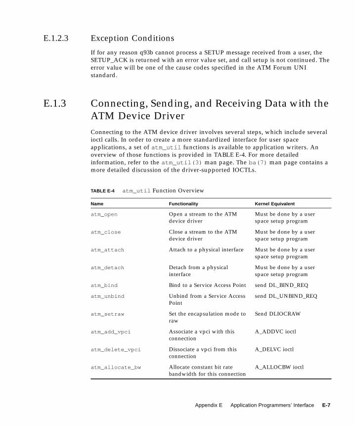
E.1.2.3 Exception Conditions
If for any reason q93b cannot process a SETUP message received from a user, the
SETUP_ACK is returned with an error value set, and call setup is not continued. The
error value will be one of the cause codes specified in the ATM Forum UNI
standard.
E.1.3 Connecting, Sending, and Receiving Data with the
ATM Device Driver
Connecting to the ATM device driver involves several steps, which include several
ioctl calls. In order to create a more standardized interface for user space
applications, a set of atm_util functions is available to application writers. An
overview of those functions is provided in TABLE E-4. For more detailed
information, refer to the atm_util(3) man page. The ba(7) man page contains a
more detailed discussion of the driver-supported IOCTLs.
TABLE E-4 atm_util Function Overview
Name Functionality Kernel Equivalent
atm_open Open a stream to the ATM
device driver
Must be done by a user
space setup program
atm_close Close a stream to the ATM
device driver
Must be done by a user
space setup program
atm_attach Attach to a physical interface Must be done by a user
space setup program
atm_detach Detach from a physical
interface
Must be done by a user
space setup program
atm_bind Bind to a Service Access Point send DL_BIND_REQ
atm_unbind Unbind from a Service Access
Point
send DL_UNBIND_REQ
atm_setraw Set the encapsulation mode to
raw
Send DLIOCRAW
atm_add_vpci Associate a vpci with this
connection
A_ADDVC ioctl
atm_delete_vpci Dissociate a vpci from this
connection
A_DELVC ioctl
atm_allocate_bw Allocate constant bit rate
bandwidth for this connection
A_ALLOCBW ioctl
Appendix E Application Programmers’ Interface E-7
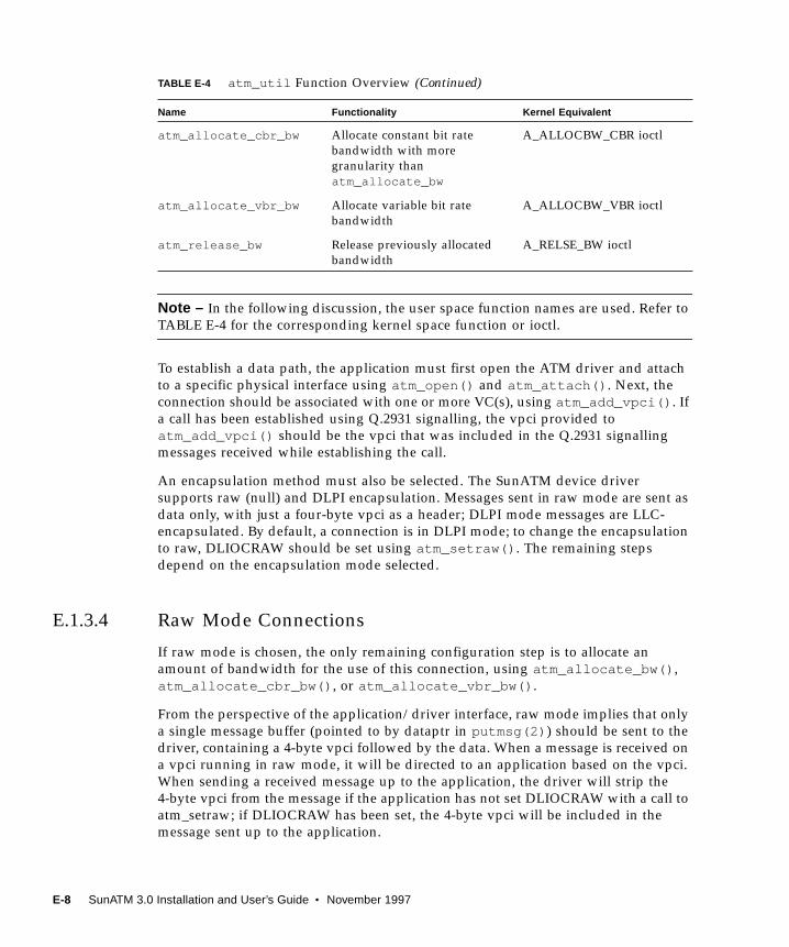
Note – In the following discussion, the user space function names are used. Refer to
TABLE E-4 for the corresponding kernel space function or ioctl.
To establish a data path, the application must first open the ATM driver and attach
to a specific physical interface using atm_open() and atm_attach() . Next, the
connection should be associated with one or more VC(s), using atm_add_vpci() . If
a call has been established using Q.2931 signalling, the vpci provided to
atm_add_vpci() should be the vpci that was included in the Q.2931 signalling
messages received while establishing the call.
An encapsulation method must also be selected. The SunATM device driver
supports raw (null) and DLPI encapsulation. Messages sent in raw mode are sent as
data only, with just a four-byte vpci as a header; DLPI mode messages are LLC-
encapsulated. By default, a connection is in DLPI mode; to change the encapsulation
to raw, DLIOCRAW should be set using atm_setraw() . The remaining steps
depend on the encapsulation mode selected.
E.1.3.4 Raw Mode Connections
If raw mode is chosen, the only remaining configuration step is to allocate an
amount of bandwidth for the use of this connection, using atm_allocate_bw() ,
atm_allocate_cbr_bw() , or atm_allocate_vbr_bw() .
From the perspective of the application/driver interface, raw mode implies that only
a single message buffer (pointed to by dataptr in putmsg(2) ) should be sent to the
driver, containing a 4-byte vpci followed by the data. When a message is received on
a vpci running in raw mode, it will be directed to an application based on the vpci.
When sending a received message up to the application, the driver will strip the
4-byte vpci from the message if the application has not set DLIOCRAW with a call to
atm_setraw; if DLIOCRAW has been set, the 4-byte vpci will be included in the
message sent up to the application.
atm_allocate_cbr_bw Allocate constant bit rate
bandwidth with more
granularity than
atm_allocate_bw
A_ALLOCBW_CBR ioctl
atm_allocate_vbr_bw Allocate variable bit rate
bandwidth
A_ALLOCBW_VBR ioctl
atm_release_bw Release previously allocated
bandwidth
A_RELSE_BW ioctl
TABLE E-4 atm_util Function Overview (Continued)
Name Functionality Kernel Equivalent
E-8 SunATM 3.0 Installation and User’s Guide • November 1997
E.1.3.5 DLPI Encapsulated Connections
If DLPI mode is chosen, a SAP must be associated with the connection using
atm_bind() . Optionally, a specific amount of bandwidth may be allocated for the
connection using atm_allocate_bw() , atm_allocate_cbr_bw() , or
atm_allocate_vbr_bw() . If bandwidth is not explicitly allocated, IP’s bandwidth
(which includes all available unallocated bandwidth) will be shared by the
connection.
DLPI mode implies that two message buffers will be sent to the driver. The first,
pointed to by ctlptr in putmsg(3) , contains the dlpi message type, which is
dl_unitdata_req for transmit and dl_unitdata_ind for receive. The vpci is
included in this buffer as well; the format for the buffer is defined in the header file
<sys/dlpi.h> . The second buffer, pointed to by dataptr in putmsg(3) , contains
the data. When the driver receives the two buffers from the application, it will
remove the first buffer, add a LLC header containing the SAP which has been bound
to this stream to the data buffer, and transmit it. On receive, the LLC header is
stripped, the control buffer is added with the DLPI header, and the two buffers are
sent up to the application indicated by the SAP in the LLC header.
Appendix E Application Programmers’ Interface E-9
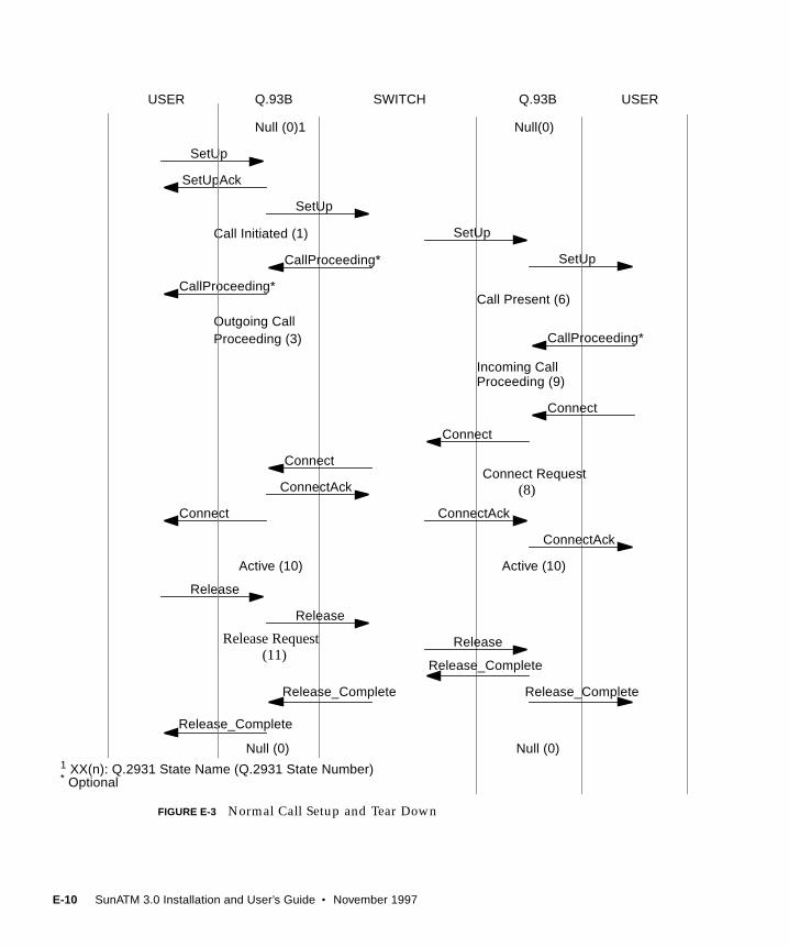
FIGURE E-3 Normal Call Setup and Tear Down
SetUp
USER Q.93B SWITCH Q.93B USER
SetUpAck
SetUp
Null (0)1 Null(0)
Call Initiated (1)
Call Present (6)
CallProceeding*
CallProceeding*
Outgoing Call
Incoming CallProceeding (9)
Connect
Connect
Connect Request(8)
Active (10) Active (10)
Release
Release_Complete
Release_Complete
Release Request(11)
Null (0) Null (0)
SetUp
SetUp
Connect
Connect
ConnectAck
ConnectAck
Release
Release
Release_Complete
Release_Complete
ConnectAck
CallProceeding*
Proceeding (3)
1 XX(n): Q.2931 State Name (Q.2931 State Number)* Optional
E-10 SunATM 3.0 Installation and User’s Guide • November 1997
APPENDIX F
RunningDiagnosticTests
F.1 SunVTS Validation and Test SuiteThe SunVTS Validation and Test Suite, version 2.1 and above, contains two
diagnostic tests that you can use to verify the SunATM adapters. The nettestdiagnostic test checks all the network interfaces on a system, including the SunATM
adapter. The atmtest diagnostic test checks the functionality of the SunATM
adapter itself.
In order to use the nettest or atmtest diagnostics, you must have the SunVTS
Validation and Test Suite installed on your system. Refer to the Solaris
documentation for instructions on how to install the SunVTS software on your
system.
Note – You must have Classical IP up and running on an interface for the nettestto work. The atmtest does not require a network to test the adapter.
Refer to the SunVTS User’s Guide for more information on how to use the SunVTS
graphical user interface and how to run the nettest diagnostic.
F.1.1 ATM Adapter Test (atmtest )
This atmtest verifies the functionality of the SunATM adapters. It runs in either
external or internal loopback mode. In order to run atmtest in external loopback
mode, you need a loopback connector, the SunATM adapter and the SunATM device
driver (which is part of the SunATM software). You do not need a loopback
connector to test the adapter in internal loopback mode.
F-1

The atmtest uses DLPI RAW mode to talk to the device driver. It establishes a
virtual circuit (VC) to send message, receive the message, and compare the sent and
received messages. If the test finds that the messages do not match, or if the message
is out of sequence, the atmtest will display an error message indicating that an
error occurred.
The data sent out is generated by a random number generator, and put into a data
buffer. Each time the message sent out is selected from a different starting point of
the data buffer, so that no two consecutive messages sent out will be the same.
The atmtest can set up more than one virtual circuit to test. The test is More
stressful if more VC are used. The atmtest automatically selects the VC number
which is unique during the test. Each atmtest instance creates two virtual circuits
by default.
F.1.1.1 atmtest Test Modes
The atmtest can only be run in off-line mode. It is assumed that the host is not on
the network while it is testing in loopback mode.
F.1.1.2 atmtest Command Line Syntax
TABLE F-1 describes the command line options of the atmtest .
/opt/SUNWvts/bin/atmtest standard_arguments -o dev= device,tpkts= n,nv= n,ml= n,bw= n,opkts= n,sd,sl,nc,ns,vcf= n
TABLE F-1 atmtest Command Line Syntax
Argument Explanation
standard_arguments The command line arguments that are common to all SunVTS
tests. Refer to the SunVTS User’s Guide for a descriptions of these
arguments.
dev= device Specify the device name to be tested (for example, ba0 ).
tpkts= n The number of packets to loopback (n can be 1 through
2147483647).
nv= num_vc Number of simultaneous VCs to be tested.
ml= max_len Maximum length of random packets.
bw=bandwidth Bandwidth in Mbps of a VC.
F-2 SunATM 3.0 Installation and User’s Guide • November 1997
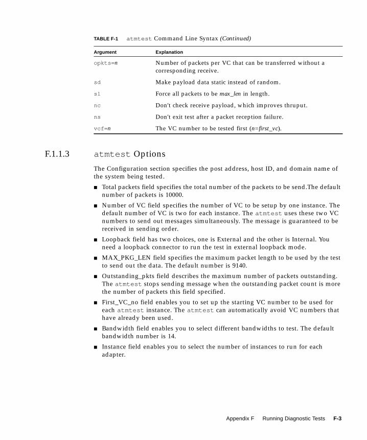
F.1.1.3 atmtest Options
The Configuration section specifies the post address, host ID, and domain name of
the system being tested.
■ Total packets field specifies the total number of the packets to be send.The default
number of packets is 10000.
■ Number of VC field specifies the number of VC to be setup by one instance. The
default number of VC is two for each instance. The atmtest uses these two VC
numbers to send out messages simultaneously. The message is guaranteed to be
received in sending order.
■ Loopback field has two choices, one is External and the other is Internal. You
need a loopback connector to run the test in external loopback mode.
■ MAX_PKG_LEN field specifies the maximum packet length to be used by the test
to send out the data. The default number is 9140.
■ Outstanding_pkts field describes the maximum number of packets outstanding.
The atmtest stops sending message when the outstanding packet count is more
the number of packets this field specified.
■ First_VC_no field enables you to set up the starting VC number to be used for
each atmtest instance. The atmtest can automatically avoid VC numbers that
have already been used.
■ Bandwidth field enables you to select different bandwidths to test. The default
bandwidth number is 14.
■ Instance field enables you to select the number of instances to run for each
adapter.
opkts= n Number of packets per VC that can be transferred without a
corresponding receive.
sd Make payload data static instead of random.
sl Force all packets to be max_len in length.
nc Don't check receive payload, which improves thruput.
ns Don't exit test after a packet reception failure.
vcf= n The VC number to be tested first (n=first_vc).
TABLE F-1 atmtest Command Line Syntax (Continued)
Argument Explanation
Appendix F Running Diagnostic Tests F-3
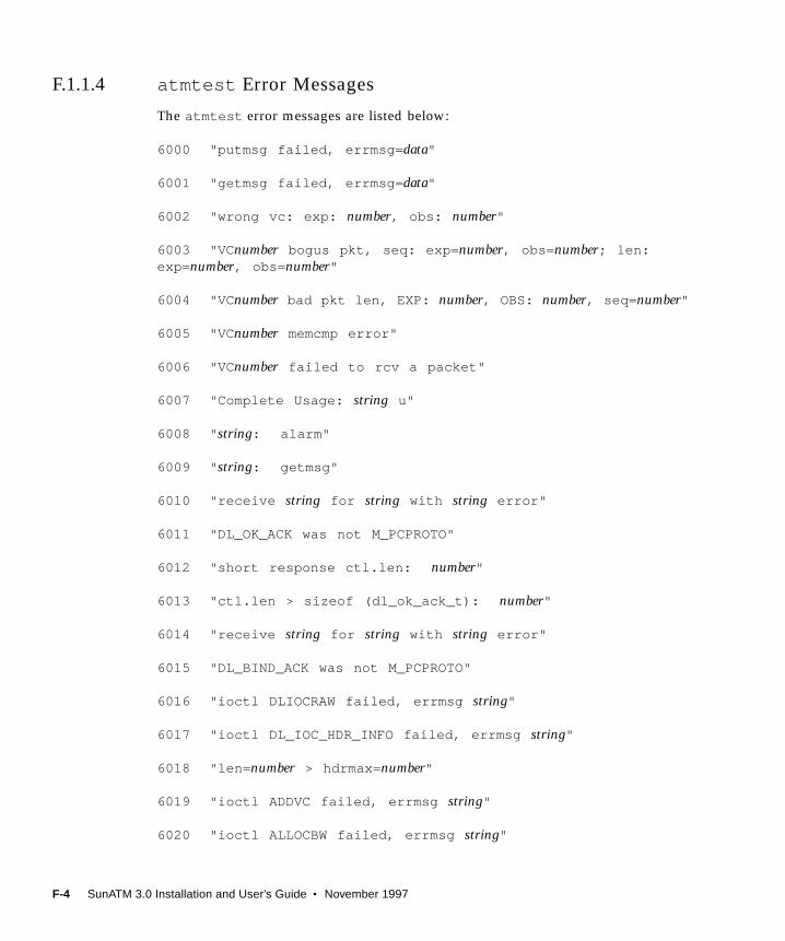
F.1.1.4 atmtest Error Messages
The atmtest error messages are listed below:
6000 "putmsg failed, errmsg= data"
6001 "getmsg failed, errmsg= data"
6002 "wrong vc: exp: number, obs: number"
6003 "VC number bogus pkt, seq: exp= number, obs= number; len:exp= number, obs= number"
6004 "VC number bad pkt len, EXP: number, OBS: number, seq= number"
6005 "VC number memcmp error"
6006 "VC number failed to rcv a packet"
6007 "Complete Usage: string u"
6008 " string: alarm"
6009 " string: getmsg"
6010 "receive string for string with string error"
6011 "DL_OK_ACK was not M_PCPROTO"
6012 "short response ctl.len: number"
6013 "ctl.len > sizeof (dl_ok_ack_t): number"
6014 "receive string for string with string error"
6015 "DL_BIND_ACK was not M_PCPROTO"
6016 "ioctl DLIOCRAW failed, errmsg string"
6017 "ioctl DL_IOC_HDR_INFO failed, errmsg string"
6018 "len= number > hdrmax= number"
6019 "ioctl ADDVC failed, errmsg string"
6020 "ioctl ALLOCBW failed, errmsg string"
F-4 SunATM 3.0 Installation and User’s Guide • November 1997

8000 "open failed, errmsg= string"
8001 "sa_add_vpci failed, errmsg= string"
8002 "sa_allocatebw failed, errmsg= string"
F.2 Using the OpenBoot PROM SelftestThe SunATM adapter’s selftest verifies correct operation of the adapter. The selftest
consists of a suite of tests that reside in the FCode PROM on the adapter. The code is
written in Forth programming language and can only be run under OpenBoot
PROM (OBP) version 3.x or later.
The SunATM adapter’s selftest does not automatically run after power on or reset,
but you can use selftest any time you want to determine the status of the hardware.
Note – Selftest does not require connection to the network. The selftest will test the
internal loopback up to the Saturn User Network Interface (SUNI) ASIC.
Running the SunATM PCI Adapter’s Selftest
1. If the system is set up to boot automatically, press key combination Stop(L1)-A tostop it from booting after the following banner is displayed:
4-slot Ultra Enterprise 3000, No KeyboardOpenBoot 3.2.3, 64 MB memory installed, Serial #7715685.Ethernet address 8:0:20:75:bb:65, Host ID: 8075bb65.
ok
Appendix F Running Diagnostic Tests F-5
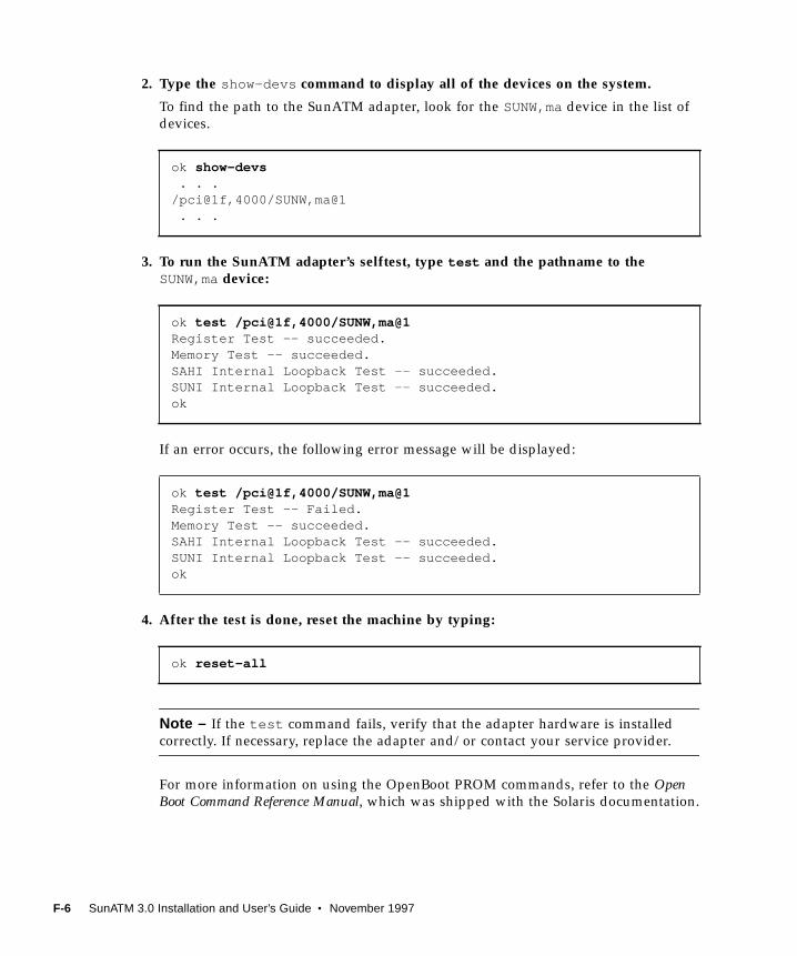
2. Type the show-devs command to display all of the devices on the system.
To find the path to the SunATM adapter, look for the SUNW,madevice in the list of
devices.
3. To run the SunATM adapter’s selftest, type test and the pathname to theSUNW,madevice:
If an error occurs, the following error message will be displayed:
4. After the test is done, reset the machine by typing:
Note – If the test command fails, verify that the adapter hardware is installed
correctly. If necessary, replace the adapter and/or contact your service provider.
For more information on using the OpenBoot PROM commands, refer to the OpenBoot Command Reference Manual, which was shipped with the Solaris documentation.
ok show-devs . . ./pci@1f,4000/SUNW,ma@1 . . .
ok test /pci@1f,4000/SUNW,ma@1Register Test -- succeeded.Memory Test -- succeeded.SAHI Internal Loopback Test -- succeeded.SUNI Internal Loopback Test -- succeeded.ok
ok test /pci@1f,4000/SUNW,ma@1Register Test -- Failed.Memory Test -- succeeded.SAHI Internal Loopback Test -- succeeded.SUNI Internal Loopback Test -- succeeded.ok
ok reset-all
F-6 SunATM 3.0 Installation and User’s Guide • November 1997
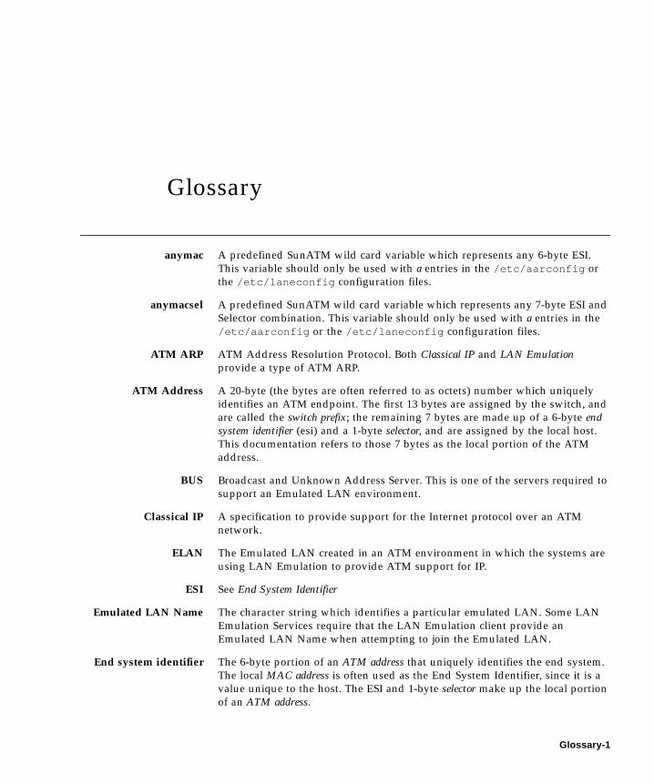
Glossary
anymac A predefined SunATM wild card variable which represents any 6-byte ESI.
This variable should only be used with a entries in the /etc/aarconfig or
the /etc/laneconfig configuration files.
anymacsel A predefined SunATM wild card variable which represents any 7-byte ESI and
Selector combination. This variable should only be used with a entries in the
/etc/aarconfig or the /etc/laneconfig configuration files.
ATM ARP ATM Address Resolution Protocol. Both Classical IP and LAN Emulationprovide a type of ATM ARP.
ATM Address A 20-byte (the bytes are often referred to as octets) number which uniquely
identifies an ATM endpoint. The first 13 bytes are assigned by the switch, and
are called the switch prefix; the remaining 7 bytes are made up of a 6-byte endsystem identifier (esi) and a 1-byte selector, and are assigned by the local host.
This documentation refers to those 7 bytes as the local portion of the ATM
address.
BUS Broadcast and Unknown Address Server. This is one of the servers required to
support an Emulated LAN environment.
Classical IP A specification to provide support for the Internet protocol over an ATM
network.
ELAN The Emulated LAN created in an ATM environment in which the systems are
using LAN Emulation to provide ATM support for IP.
ESI See End System Identifier
Emulated LAN Name The character string which identifies a particular emulated LAN. Some LAN
Emulation Services require that the LAN Emulation client provide an
Emulated LAN Name when attempting to join the Emulated LAN.
End system identifier The 6-byte portion of an ATM address that uniquely identifies the end system.
The local MAC address is often used as the End System Identifier, since it is a
value unique to the host. The ESI and 1-byte selector make up the local portion
of an ATM address.
Glossary-1
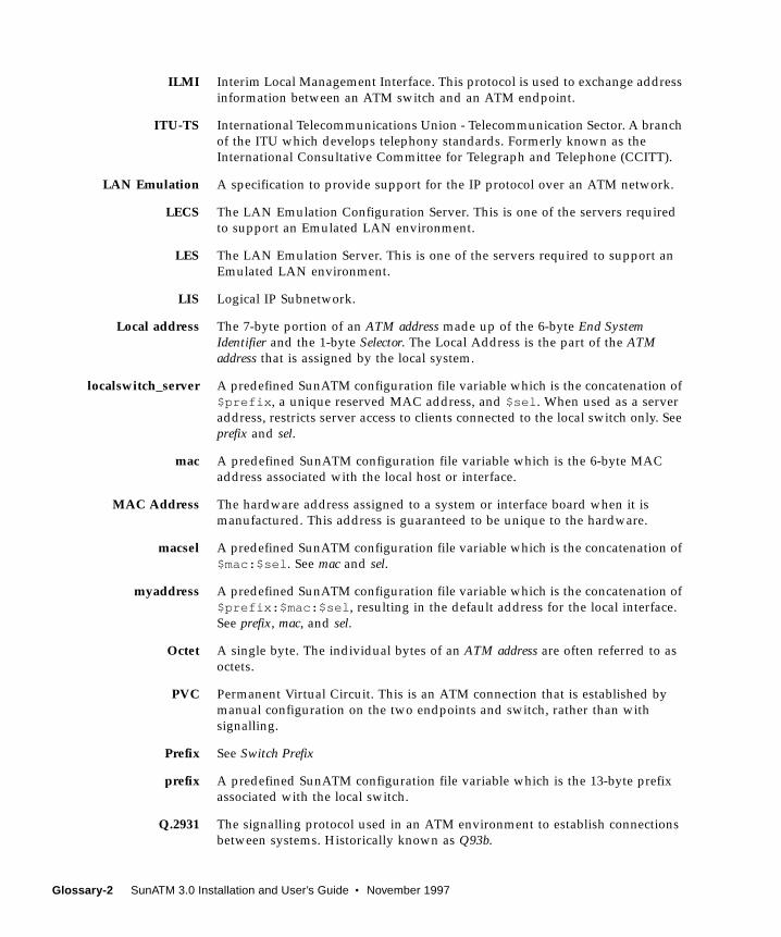
ILMI Interim Local Management Interface. This protocol is used to exchange address
information between an ATM switch and an ATM endpoint.
ITU-TS International Telecommunications Union - Telecommunication Sector. A branch
of the ITU which develops telephony standards. Formerly known as the
International Consultative Committee for Telegraph and Telephone (CCITT).
LAN Emulation A specification to provide support for the IP protocol over an ATM network.
LECS The LAN Emulation Configuration Server. This is one of the servers required
to support an Emulated LAN environment.
LES The LAN Emulation Server. This is one of the servers required to support an
Emulated LAN environment.
LIS Logical IP Subnetwork.
Local address The 7-byte portion of an ATM address made up of the 6-byte End SystemIdentifier and the 1-byte Selector. The Local Address is the part of the ATMaddress that is assigned by the local system.
localswitch_server A predefined SunATM configuration file variable which is the concatenation of
$prefix , a unique reserved MAC address, and $sel . When used as a server
address, restricts server access to clients connected to the local switch only. See
prefix and sel.
mac A predefined SunATM configuration file variable which is the 6-byte MAC
address associated with the local host or interface.
MAC Address The hardware address assigned to a system or interface board when it is
manufactured. This address is guaranteed to be unique to the hardware.
macsel A predefined SunATM configuration file variable which is the concatenation of
$mac:$sel . See mac and sel.
myaddress A predefined SunATM configuration file variable which is the concatenation of
$prefix:$mac:$sel , resulting in the default address for the local interface.
See prefix, mac, and sel.
Octet A single byte. The individual bytes of an ATM address are often referred to as
octets.
PVC Permanent Virtual Circuit. This is an ATM connection that is established by
manual configuration on the two endpoints and switch, rather than with
signalling.
Prefix See Switch Prefix
prefix A predefined SunATM configuration file variable which is the 13-byte prefix
associated with the local switch.
Q.2931 The signalling protocol used in an ATM environment to establish connections
between systems. Historically known as Q93b.
Glossary-2 SunATM 3.0 Installation and User’s Guide • November 1997
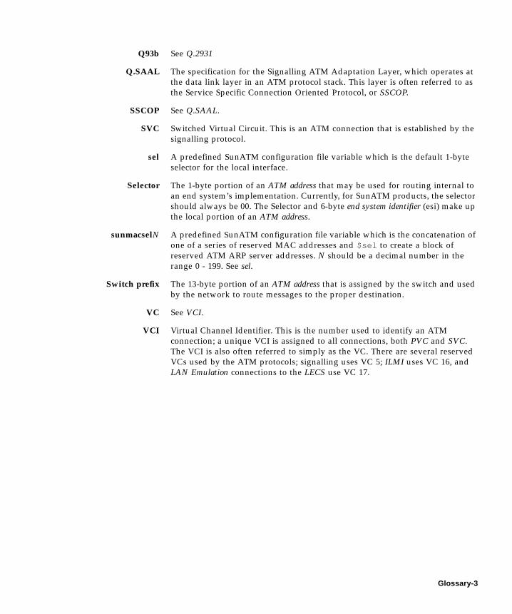
Q93b See Q.2931
Q.SAAL The specification for the Signalling ATM Adaptation Layer, which operates at
the data link layer in an ATM protocol stack. This layer is often referred to as
the Service Specific Connection Oriented Protocol, or SSCOP.
SSCOP See Q.SAAL.
SVC Switched Virtual Circuit. This is an ATM connection that is established by the
signalling protocol.
sel A predefined SunATM configuration file variable which is the default 1-byte
selector for the local interface.
Selector The 1-byte portion of an ATM address that may be used for routing internal to
an end system’s implementation. Currently, for SunATM products, the selector
should always be 00. The Selector and 6-byte end system identifier (esi) make up
the local portion of an ATM address.
sunmacselN A predefined SunATM configuration file variable which is the concatenation of
one of a series of reserved MAC addresses and $sel to create a block of
reserved ATM ARP server addresses. N should be a decimal number in the
range 0 - 199. See sel.
Switch prefix The 13-byte portion of an ATM address that is assigned by the switch and used
by the network to route messages to the proper destination.
VC See VCI.
VCI Virtual Channel Identifier. This is the number used to identify an ATM
connection; a unique VCI is assigned to all connections, both PVC and SVC.
The VCI is also often referred to simply as the VC. There are several reserved
VCs used by the ATM protocols; signalling uses VC 5; ILMI uses VC 16, and
LAN Emulation connections to the LECS use VC 17.
Glossary-3

Glossary-4 SunATM 3.0 Installation and User’s Guide • November 1997
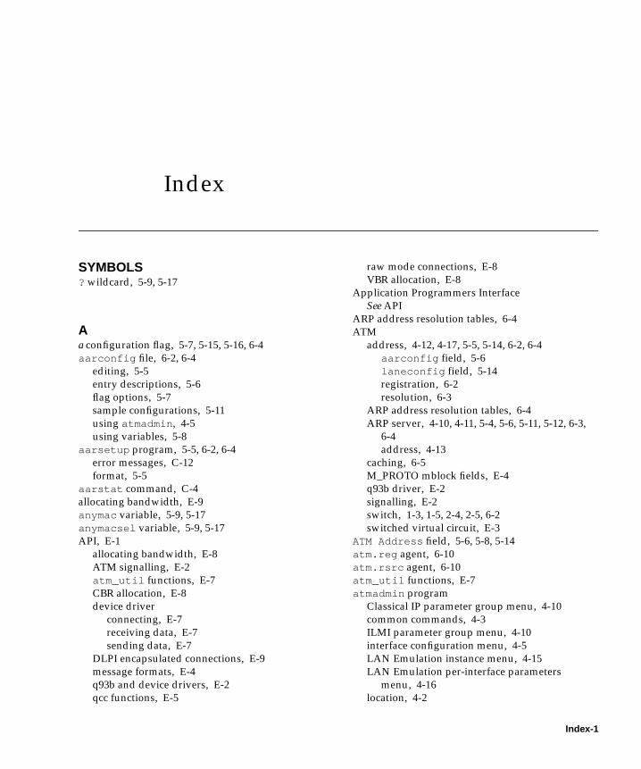
Index
SYMBOLS? wildcard, 5-9, 5-17
Aa configuration flag, 5-7, 5-15, 5-16, 6-4
aarconfig file, 6-2, 6-4
editing, 5-5
entry descriptions, 5-6
flag options, 5-7
sample configurations, 5-11
using atmadmin , 4-5
using variables, 5-8
aarsetup program, 5-5, 6-2, 6-4
error messages, C-12
format, 5-5
aarstat command, C-4
allocating bandwidth, E-9
anymac variable, 5-9, 5-17
anymacsel variable, 5-9, 5-17
API, E-1
allocating bandwidth, E-8
ATM signalling, E-2
atm_util functions, E-7
CBR allocation, E-8
device driver
connecting, E-7
receiving data, E-7
sending data, E-7
DLPI encapsulated connections, E-9
message formats, E-4
q93b and device drivers, E-2
qcc functions, E-5
raw mode connections, E-8
VBR allocation, E-8
Application Programmers Interface
See API
ARP address resolution tables, 6-4
ATM
address, 4-12, 4-17, 5-5, 5-14, 6-2, 6-4
aarconfig field, 5-6
laneconfig field, 5-14
registration, 6-2
resolution, 6-3
ARP address resolution tables, 6-4
ARP server, 4-10, 4-11, 5-4, 5-6, 5-11, 5-12, 6-3,
6-4
address, 4-13
caching, 6-5
M_PROTO mblock fields, E-4
q93b driver, E-2
signalling, E-2
switch, 1-3, 1-5, 2-4, 2-5, 6-2
switched virtual circuit, E-3
ATM Address field, 5-6, 5-8, 5-14
atm.reg agent, 6-10
atm.rsrc agent, 6-10
atm_util functions, E-7
atmadmin program
Classical IP parameter group menu, 4-10
common commands, 4-3
ILMI parameter group menu, 4-10
interface configuration menu, 4-5
LAN Emulation instance menu, 4-15
LAN Emulation per-interface parameters
menu, 4-16
location, 4-2
Index-1
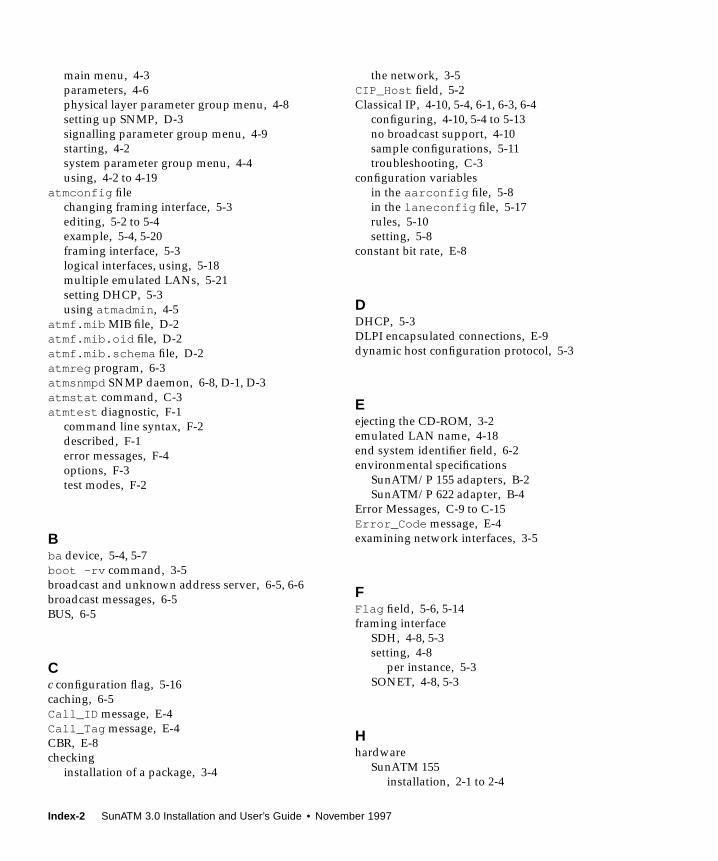
main menu, 4-3
parameters, 4-6
physical layer parameter group menu, 4-8
setting up SNMP, D-3
signalling parameter group menu, 4-9
starting, 4-2
system parameter group menu, 4-4
using, 4-2 to 4-19
atmconfig file
changing framing interface, 5-3
editing, 5-2 to 5-4
example, 5-4, 5-20
framing interface, 5-3
logical interfaces, using, 5-18
multiple emulated LANs, 5-21
setting DHCP, 5-3
using atmadmin , 4-5
atmf.mib MIB file, D-2
atmf.mib.oid file, D-2
atmf.mib.schema file, D-2
atmreg program, 6-3
atmsnmpd SNMP daemon, 6-8, D-1, D-3
atmstat command, C-3
atmtest diagnostic, F-1
command line syntax, F-2
described, F-1
error messages, F-4
options, F-3
test modes, F-2
Bba device, 5-4, 5-7
boot -rv command, 3-5
broadcast and unknown address server, 6-5, 6-6
broadcast messages, 6-5
BUS, 6-5
Cc configuration flag, 5-16
caching, 6-5
Call_ID message, E-4
Call_Tag message, E-4
CBR, E-8
checking
installation of a package, 3-4
the network, 3-5
CIP_Host field, 5-2
Classical IP, 4-10, 5-4, 6-1, 6-3, 6-4
configuring, 4-10, 5-4 to 5-13
no broadcast support, 4-10
sample configurations, 5-11
troubleshooting, C-3
configuration variables
in the aarconfig file, 5-8
in the laneconfig file, 5-17
rules, 5-10
setting, 5-8
constant bit rate, E-8
DDHCP, 5-3
DLPI encapsulated connections, E-9
dynamic host configuration protocol, 5-3
Eejecting the CD-ROM, 3-2
emulated LAN name, 4-18
end system identifier field, 6-2
environmental specifications
SunATM/P 155 adapters, B-2
SunATM/P 622 adapter, B-4
Error Messages, C-9 to C-15
Error_Code message, E-4
examining network interfaces, 3-5
FFlag field, 5-6, 5-14
framing interface
SDH, 4-8, 5-3
setting, 4-8
per instance, 5-3
SONET, 4-8, 5-3
Hhardware
SunATM 155
installation, 2-1 to 2-4
Index-2 SunATM 3.0 Installation and User’s Guide • November 1997
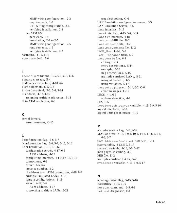
MMF wiring configuration, 2-3
requirements, 1-3
UTP wiring configuration, 2-4
verifying installation, 2-2
SunATM 622
hardware, 1-5
installation, 2-1 to 2-5
MMF wiring configuration, 2-5
requirements, 1-5
verifying installation, 2-2
hostname, 4-12, 4-16
Hostname field, 5-6
Iifconfig command, 3-5, 6-1, C-3, C-6
Ifname message, E-4
ILMI service interface, 4-10, 6-2
ilmid daemon, 6-2, C-3
Interface field, 5-2, 5-6, 5-14
IP address, 4-12, 4-16
assigning multiple addresses, 5-18
IP to ATM resolution, 6-3
Kkernel drivers,
error messages, C-15
LL configuration flag, 5-6, 5-7
l configuration flag, 5-6, 5-7, 5-15, 5-16
LAN Emulation, 5-13, 6-1, 6-5
configuration server, 4-17, 6-6
ATM address, 4-17
configuring interface, 4-14 to 4-18, 5-13
connections, 6-8
driver, 6-5, 6-7
instance number, 5-2
IP address to an ATM connection, 4-18, 6-7
multiple Emulated LANs, 4-18
sample configurations, 5-18
server, 4-17, 6-6
ATM address, 4-17
supporting multiple LANs, 5-21
troubleshooting, C-6
LAN Emulation configuration server, 6-5
LAN Emulation Server, 6-5
lane interface, 5-18
lane # interface, 4-15, 5-4, 5-14
lane#:# interface, 4-18
lane.mib MIB file, D-2
lane.mib.oid file, D-2
lane.mib.schema file, D-2
LANE_Host field, 5-2
LANE_Instance field, 5-2
laneconfig file, 6-3
editing, 5-14
entry descriptions, 5-14
example, 5-20
flag descriptions, 5-15
multiple emulated LANs, 5-21
using atmadmin , 4-5
using variables, 5-17
lanesetup program, 5-14, 6-2, C-6
error messages, C-12
LECS, 4-1, 6-5
address detection, 4-1
LES, 6-5
localswitch_server variable, 4-13, 5-9, 5-10
logical interfaces, 5-18
logical units per interface, 4-19
Mm configuration flag, 5-7, 5-16
MAC address, 4-13, 5-9, 5-10, 5-14, 5-17, 6-2, 6-5,
6-6, 6-7
MAC Address/Emulated LAN field, 5-14
mac variable, 4-13, 5-9, 5-17
macsel variable, 4-13, 5-9, 5-17
man pages, installing, 3-2
MIB file, D-2
multiple emulated LANs, 5-21
myaddress variable, 4-13, 5-9, 5-17
Nn configuration flag, 5-15, 5-16
ndd utility, 4-19, 5-19
netstat command, 3-5, 6-1
nettest diagnostic, F-1
Index-3
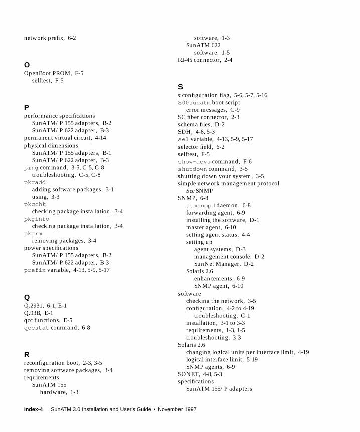
network prefix, 6-2
OOpenBoot PROM, F-5
selftest, F-5
Pperformance specifications
SunATM/P 155 adapters, B-2
SunATM/P 622 adapter, B-3
permanent virtual circuit, 4-14
physical dimensions
SunATM/P 155 adapters, B-1
SunATM/P 622 adapter, B-3
ping command, 3-5, C-5, C-8
troubleshooting, C-5, C-8
pkgaddadding software packages, 3-1
using, 3-3
pkgchkchecking package installation, 3-4
pkginfochecking package installation, 3-4
pkgrmremoving packages, 3-4
power specifications
SunATM/P 155 adapters, B-2
SunATM/P 622 adapter, B-3
prefix variable, 4-13, 5-9, 5-17
QQ.2931, 6-1, E-1
Q.93B, E-1
qcc functions, E-5
qccstat command, 6-8
Rreconfiguration boot, 2-3, 3-5
removing software packages, 3-4
requirements
SunATM 155
hardware, 1-3
software, 1-3
SunATM 622
software, 1-5
RJ-45 connector, 2-4
Ss configuration flag, 5-6, 5-7, 5-16
S00sunatm boot script
error messages, C-9
SC fiber connector, 2-3
schema files, D-2
SDH, 4-8, 5-3
sel variable, 4-13, 5-9, 5-17
selector field, 6-2
selftest, F-5
show-devs command, F-6
shutdown command, 3-5
shutting down your system, 3-5
simple network management protocol
See SNMP
SNMP, 6-8
atmsnmpd daemon, 6-8
forwarding agent, 6-9
installing the software, D-1
master agent, 6-10
setting agent status, 4-4
setting up
agent systems, D-3
management console, D-2
SunNet Manager, D-2
Solaris 2.6
enhancements, 6-9
SNMP agent, 6-10
software
checking the network, 3-5
configuration, 4-2 to 4-19
troubleshooting, C-1
installation, 3-1 to 3-3
requirements, 1-3, 1-5
troubleshooting, 3-3
Solaris 2.6
changing logical units per interface limit, 4-19
logical interface limit, 5-19
SNMP agents, 6-9
SONET, 4-8, 5-3
specifications
SunATM 155/P adapters
Index-4 SunATM 3.0 Installation and User’s Guide • November 1997

environmental specifications, B-2
performance specifications, B-2
physical dimensions, B-1
power specifications, B-2
SunATM 622/P adapter
environmental specifications, B-4
performance specifications, B-3
physical dimensions, B-3
power specifications, B-3
spray command, 3-5
SunATM software
CD-ROM
ejecting, 3-2
mounting, 3-1
checking the network, 3-5
configuration, 4-2 to 4-19
troubleshooting, C-1
variables, 4-13, 5-9
device drivers package, 3-2
installation, 3-1 to 3-3
interim API support package, 3-2
LECS address detection, 4-1
new features, 4-1
predefined variables, 5-17
requirements, 1-3
runtime support package, 3-2
SunATM/P 155 MMF adapter
backplate, 2-3
hardware requirements, 1-3
highlights, 1-2
illustrated, 1-2
introduction, 1-1
software requirements, 1-3
specifications, B-1
SunATM/P 155 UTP adapter
backplate, 2-4
hardware requirements, 1-3
highlights, 1-2
illustrated, 1-2
introduction, 1-1
software requirements, 1-3
specifications, B-1
SunATM/P 622 MMF adapter
backplate, 2-5
hardware requirements, 1-5
highlights, 1-4
illustrated, 1-4
introduction, 1-4
software requirements, 1-5
specifications, B-3
sunmacsel N variable, 4-13, 5-9
SunNet Manager, 6-8
using, D-1
SunVTS Validation and Test Suite, F-1
atmtest diagnostic, F-1
nettest diagnostic, F-1
SUNW,ma device, 2-3, F-6
SUNWatm
device drivers package, 3-2
SUNWatma
interim API support package, 3-2
SUNWatmu
man pages, 3-2
runtime support package, 3-2
Tt configuration flag, 5-6, 5-7, 5-15, 5-16
T568B pin designation, A-1
test command, F-6
troubleshooting, C-1 to C-8
software installation, 3-3
Type message, E-4
UUNI Framing field, 5-2
UNI specification, 5-2, 6-1
4.0 support, 4-1
selecting version, 4-9
user network interface, 4-1, 4-9
UTP cross over cable, A-2
Vvariable bit rate bandwidth, E-8
VBR, E-8
VCI field, 5-6, 5-14
virtual circuit identifier, 4-14, 5-5
Wwiring configuration
SunATM/P 155 MMF adapter, 2-3
SunATM/P 155 UTP adapter, 2-4
Index-5
SunATM/P 622 MMF adapter, 2-5
Yypinit command, 4-10
Index-6 SunATM 3.0 Installation and User’s Guide • November 1997