StorageTek - Oracle Help Center
224
StorageTek Expert Performance Reporter (ExPR) MVS User’s Guide Version 1 Release 1 PN: 112193701
-
Upload
khangminh22 -
Category
Documents
-
view
0 -
download
0
Transcript of StorageTek - Oracle Help Center

StorageTek
Expert
Performance
Reporter
(ExPR)
MVS User’s Guide
Version 1 Release 1
PN: 112193701

ExPR MVS User’s Guide2
Information contained in this publication is subject to change.In the event of changes, the publication will be revised.Comments concerning the contents of this manual should bedirected to the following address:
Storage Technology CorporationSoftware Information DevelopmentSoftware Engineering Department2270 South 88th StreetLouisville, CO 80028-5209
StorageTek® and Nearline® are registered trademarks of StorageTechnology Corporation.
Expert Performance Reporter (ExPR)™ is a trademark of StorageTechnology Corporation.
IBM® is a registered trademark of International Business MachinesCorp.
MVS/XA™ and MVS/ESA™ and VTAM™ are trademarks ofInternational Business Machines Corp.
CA-1™ and CA-TLMS™ are trademarks of Computer AssociatesInternational Inc.
If this software is used by the Government, use, duplication, ordisclosure by the Government is subject to restrictions as set forth insubparagraph (c)(1)(ii) of the Rights in Technical Data andComputer Software clause of DFARS 252.7-7013.
Copyright © 1996 by
Storage Technology Corporation
All Rights Reserved

Contents 3
Contents
Preface ----------------------------------------------------------------------------------------------- 9
Overview ------------------------------------------------------------------------------------------ 9
Optional Windows Help System --------------------------------------------------------------- 9
Audience ------------------------------------------------------------------------------------------ 9
Organization------------------------------------------------------------------------------------ 10
Related Documentation ----------------------------------------------------------------------- 11
Conventions------------------------------------------------------------------------------------- 12
StorageTek Support---------------------------------------------------------------------------- 12
Chapter 1: Introduction ----------------------------------------------------------------------- 13
Overview ---------------------------------------------------------------------------------------- 13
What ExPR Does------------------------------------------------------------------------------- 13
How ExPR Works------------------------------------------------------------------------------ 13
ExPR Mainframe Databases------------------------------------------------------------------ 14
ExPR PC Databases---------------------------------------------------------------------------- 15
ExPR Data Flow-------------------------------------------------------------------------------- 15
ExPR Reporting Features --------------------------------------------------------------------- 17
Report Granularity----------------------------------------------------------------------------- 17
Exception Processing-------------------------------------------------------------------------- 17
Jobname and Dataset Workload Groups---------------------------------------------------- 19
Tape Catalog Processing---------------------------------------------------------------------- 19
Mainframe Performance Reports ------------------------------------------------------------ 21
Graphical Reports------------------------------------------------------------------------------ 22

ExPR MVS User’s Guide4
User-Customizable Reports------------------------------------------------------------------- 22
Chapter 2: Installation and Customization ------------------------------------------------ 25
Overview ---------------------------------------------------------------------------------------- 25
Skills Required --------------------------------------------------------------------------------- 26
Control Statements----------------------------------------------------------------------------- 26
Configuration Task Summary---------------------------------------------------------------- 27
IMPORTANT: Copy Your SAMPLIB First!---------------------------------------------- 31
Task 1: Review Data Collection Procedures----------------------------------------------- 31Data Collection Sources-------------------------------------------------------------------- 31Review SYS1.PARMLIB Member SMFPRMnn --------------------------------------- 34SMF Housekeeping Procedures ----------------------------------------------------------- 34
Task 2: Space Planning ---------------------------------------------------------------------- 35ExPR Datasets ------------------------------------------------------------------------------- 35DATABASE --------------------------------------------------------------------------------- 36FTEXTR-------------------------------------------------------------------------------------- 42FTCNTL-------------------------------------------------------------------------------------- 42CONFIG-------------------------------------------------------------------------------------- 42CDSCONF ----------------------------------------------------------------------------------- 42PGMIDATA --------------------------------------------------------------------------------- 43EXPORT ------------------------------------------------------------------------------------- 43TMCHIST------------------------------------------------------------------------------------ 43TLMSRPT ----------------------------------------------------------------------------------- 44Temporary SYSDA Work Files----------------------------------------------------------- 45
Task 3: Review Hardware and Software Prerequisites----------------------------------- 46
Task 4: Define ExPR Datasets and Tailor EXPRPROC Procedure -------------------- 46Data Collection and Parameter Files ----------------------------------------------------- 47
Task 5: Define the ExPR Database(s) ------------------------------------------------------ 48Database Overview-------------------------------------------------------------------------- 49Database File Structure--------------------------------------------------------------------- 49
Task 6: Initialize the ExPR Database ------------------------------------------------------ 50
Task 7: Review ExPR Parameters and Configuration Options ------------------------- 51

Contents 5
Determining Whether to Use the Automatic Config Generator ---------------------- 52How the Automatic Config Generator Works------------------------------------------- 53Determining Channel Path Group Requirements -------------------------------------- 53Determining Device-Type Requirements ------------------------------------------------ 54
Task 8: Define Nearline Configuration to ExPR ----------------------------------------- 56Using the ExPR Automatic Config Generation Feature ------------------------------- 57Entering CONFIG Data Manually-------------------------------------------------------- 59
Task 9: Install the ExPR Started Task ----------------------------------------------------- 61Started Task Overview --------------------------------------------------------------------- 61Started Task Parameters ------------------------------------------------------------------- 62
Task 10: Specify HSC SMF Number to ExPR -------------------------------------------- 64
Task 11: Define the Control Dataset to ExPR--------------------------------------------- 65
Task 12: Create the ExPR CONFIG Dataset ---------------------------------------------- 65
Task 13: Installation Verification----------------------------------------------------------- 67
Chapter 3: Managing the ExPR Database------------------------------------------------- 69
Overview ---------------------------------------------------------------------------------------- 69
Input Data Review ----------------------------------------------------------------------------- 69
Database Processes----------------------------------------------------------------------------- 72
SYSIN Examples------------------------------------------------------------------------------- 74Example 1: Select HSC SMF Records Only and Update the Database ------------- 75Example 2: Select PGMI Data and Update the Database----------------------------- 76Example 3: Select MVS SYSLOG Data and Update the Database ----------------- 78JES3 Support -------------------------------------------------------------------------------- 79RECFM Support ---------------------------------------------------------------------------- 80Example 4: Select Tape Catalog Data and Update the Database-------------------- 81Example 5: Converting an ExPR 1.0 Database ---------------------------------------- 82
Multiple Database Support ------------------------------------------------------------------- 84
Consolidate the Database --------------------------------------------------------------------- 84
Reorganizing the Database ------------------------------------------------------------------- 85

ExPR MVS User’s Guide6
Chapter 4: Exception Processing and Reports-------------------------------------------- 87
Overview ---------------------------------------------------------------------------------------- 87
Process Description ---------------------------------------------------------------------------- 87
Exception Types-------------------------------------------------------------------------------- 88
Defining Threshold Values for Your Site -------------------------------------------------- 89
Threshold Values ------------------------------------------------------------------------------ 89
Exception Report Generation----------------------------------------------------------------- 91
Threshold Exceptions Report----------------------------------------------------------------- 93
SMF Exception Event Report ---------------------------------------------------------------- 95
Chapter 5: Jobname Workload Groups---------------------------------------------------- 99
Overview ---------------------------------------------------------------------------------------- 99
Defining Jobname Workload Groups ------------------------------------------------------- 99
Jobname Workload Group Reports --------------------------------------------------------- 101
Chapter 6: Tape Catalog Processing and Reports -------------------------------------- 103
Overview --------------------------------------------------------------------------------------- 103
Supported Environments--------------------------------------------------------------------- 104
How ExPR Tape Processing Works -------------------------------------------------------- 104
What Information Is Generated------------------------------------------------------------- 106
Defining Tape Catalog Processing for Your Site----------------------------------------- 107
Defining Age Bands -------------------------------------------------------------------------- 108
Tape Utilization and Capacity Estimation------------------------------------------------- 109
Defining Tape Ranges------------------------------------------------------------------------ 110Defining Tape Ranges Based on Length------------------------------------------------ 110Defining Tape Ranges Based on Redwood Capacity---------------------------------- 112Defining Tape Ranges to EXCLUDE from Processing------------------------------- 113
Defining Dataset Workload Groups -------------------------------------------------------- 114

Contents 7
Special Considerations for the TMCHIST File ------------------------------------------- 117
Processing Tape Catalog Data -------------------------------------------------------------- 118Example 1: Process Tape Catalog and Update Database and History Files------- 119Example 2: Process Tape Catalog Without Updating Database and History Files119Example 3: Process Tape Catalog Including All Volumes-------------------------- 120
Generating Tape Catalog Reports ---------------------------------------------------------- 121
TAPECAT Update Processing Aging and Utilization Summary ---------------------- 122
TAPECAT Nearline Volume Details Report---------------------------------------------- 125
TAPECAT Nearline Volume Summary Report ------------------------------------------ 128
TAPECAT Tape Catalog History Reports------------------------------------------------- 131
CA-TLMS Considerations------------------------------------------------------------------- 133
Running Without a Tape Catalog----------------------------------------------------------- 134
Chapter 7: Mainframe Performance Reports-------------------------------------------- 135
Overview --------------------------------------------------------------------------------------- 135
Generating Reports --------------------------------------------------------------------------- 135
Printing SYSOUT Information ------------------------------------------------------------- 137
Order of SELECT Statement Processing -------------------------------------------------- 139
MOUNTS Report ----------------------------------------------------------------------------- 140
MOUNTS-DETAIL Report------------------------------------------------------------------ 142
UTILIZATION Report ----------------------------------------------------------------------- 144
CONTENTS Report -------------------------------------------------------------------------- 146
CU-BUSY Report ----------------------------------------------------------------------------- 148
PATH-BUSY Report ------------------------------------------------------------------------- 150
TAPE-ERRORS Report ---------------------------------------------------------------------- 151
ALLOC-REC Report ------------------------------------------------------------------------- 153
DEMAND-ENTERS Report----------------------------------------------------------------- 156

ExPR MVS User’s Guide8
Chapter 8: File Transfer --------------------------------------------------------------------- 157
Overview --------------------------------------------------------------------------------------- 157
Process Description --------------------------------------------------------------------------- 157
Selecting the Extraction Period ------------------------------------------------------------- 159
Transferring Extracted Data to a PC ------------------------------------------------------- 160
File Transfer Recovery Procedures --------------------------------------------------------- 160
Chapter 9: ExPR API ------------------------------------------------------------------------- 161
Overview --------------------------------------------------------------------------------------- 161
Using the API---------------------------------------------------------------------------------- 161
Appendix A: CONFIG Parameters -------------------------------------------------------- 165
Appendix B: SYSIN Parameters------------------------------------------------------------ 177
Appendix C: Messages------------------------------------------------------------------------ 189
Appendix D: Database and TMCHIST Layout------------------------------------------ 209
Appendix E: ExPR Version 1 Release 1 Modifications--------------------------------- 223
Index----------------------------------------------------------------------------------------------- 227

Preface 9
Preface
Overview
This document describes how to install, configure, and usethe MVS component of the StorageTek Expert PerformanceReporter (ExPR) software product.
Optional Windows Help System
Reference information in this MVS User’s Guide is alsoavailable as a Windows-based Help system on the PC. Thehelp system includes help for CONFIG and SYSIN statementsyntax and ExPR error messages.
The ExPR MVS Help system can be accessed from the ExPRPC main window or from the ExPR PC Help system.
Audience
The audience for this document includes MVS systemprogrammers and capacity planners who will install,configure, and use the ExPR MVS component, as well asStorageTek support personnel who support ExPR customersin these efforts.

ExPR MVS User’s Guide10
Organization
This document is organized as follows:
• Chapter 1, Introduction, describes the ExPR softwareproduct, including what ExPR does and how it works.
• Chapter 2, Installation and Customization, describes a setof sequential tasks to configure the ExPR system for yoursite after the initial SMP/E installation is completed.
• Chapter 3, Managing the ExPR Database, describes thedatabase update process and also how to verify andconsolidate the database.
• Chapter 4, Exception Processing and Reports, describeshow to configure and use the exception processingfeature of ExPR to define exception thresholds andgenerate mainframe tabular exception reports.
• Chapter 5, Jobname Workload Groups, describes how toconfigure and use the jobname workload groups featuresof ExPR to logically map Nearline activity by specifiedjobnames for use in ExPR reports.
• Chapter 6, Tape Catalog Processing and Reports,describes how to configure and use the tape catalogprocessing feature of ExPR to collect information fromyour site’s tape catalog system and generate tapecartridge-based reports. This chapter also describes howto use the dataset workload group feature in conjunctionwith tape catalog processing to logically map tapecartridge activity by specified datasets for use in ExPRreports.

Preface 11
• Chapter 7, Mainframe Performance Reports, describeshow to generate and interpret mainframe tabularperformance reports.
• Chapter 8, File Transfer, describes the process ofextracting data from the mainframe database andtransferring it to a PC for further processing in the ExPRPC environment.
• Chapter 9, API, describes the ExPR ApplicationProgramming Interface (API) and how it is used to createcustomized mainframe tabular reports.
• Appendix A, CONFIG Parameters, lists and describesExPR configuration (CONFIG DD) parameterstatements.
• Appendix B, SYSIN Parameters, lists and describes ExPRruntime (SYSIN DD) parameter statements.
• Appendix C, Messages, lists messages that are generatedby ExPR and provides possible solutions to problems thatare indicated by these messages.
• Appendix D, Database Layout, provides supplementaltechnical information about the ExPR mainframedatabase.
• Appendix E, ExPR Version 1 Release 1 Modifications,describes modifications and enhancements to ExPR thatare introduced in this release of the product.
Related Documentation
• ExPR MVS Installation Notes - describes how to SMP/Einstall the ExPR MVS software on the MVS host system.

ExPR MVS User’s Guide12
• ExPR PC User’s Guide - describes the ExPR softwareproduct, including instructions for installing the softwarein the Windows environment, building and maintainingthe PC database of downloaded information, andselecting reports for graphical display.
• IBM System Management Facility (GC28-1628-nn),describes the SMF record collection process.
Conventions
The following conventions are used in this document:
• Parameter keywords are shown in boldface type
• Variable information you enter is shown in italics
• A bar ( | ) separates mutually exclusive choices incommand strings
• Parentheses and single quotation marks must be enteredas shown in command strings
StorageTek Support
To report problems and receive support from StorageTekSoftware Support Representatives (SSRs), refer to theseparate document, How to Request Help or Software
Enhancements.

Chapter 1: Introduction 13
Chapter 1
Introduction
Overview
This chapter describes the StorageTek ExPR softwareproduct, including what ExPR does and how it works.
What ExPR Does
ExPR collects performance data and generates reports aboutStorageTek Nearline Automated Cartridge System (ACS)status and performance. ExPR reports are available in tabularformat in the MVS mainframe environment and in graphicalor tabular format in the PC Windows environment.
How ExPR Works
ExPR software is packaged as two unique software systems,ExPR MVS and ExPR PC:
• ExPR MVS, which resides on an MVS host system,builds and maintains a database of historical performancedata that it collects from the Nearline system, from theMVS operating system, and optionally from the site’s

ExPR MVS User’s Guide14
tape management system. Tabular performance andexception reports are generated directly from thisdatabase for display in the MVS environment. For ExPRMVS, all processes are controlled by a batch taskinterface. ExPR MVS is described in this document.
• ExPR PC, which resides on one or more PCs, is aWindows application that manages user-customizedsubsets of the mainframe database on the PC. Data thatis transferred from the mainframe database can bequeried and displayed in graphical or tabularperformance, exception, and quick summary reports.Data can also be ported to a Microsoft Excel-compatiblespreadsheet and other external applications for furtherprocessing. ExPR PC is described in the ExPR PC
User’s Guide.
ExPR Mainframe Databases
ExPR MVS collects information relating to Nearlineperformance and inputs it to an ExPR mainframe database.This process is controlled by user-specified parameters.
The ExPR mainframe database is a VSAM KSDS file. Datacan be stored as a single database or as multiple databases(one for each ACS, in multiple ACS configurations, etc.),depending on the size and complexity of the installation andits reporting requirements.
A single database can be maintained containing data relatedto all ACS environments, or multiple databases can bemaintained to reflect the reporting needs of various groupswithin the organization. Databases can be defined for each

Chapter 1: Introduction 15
individual ACS or a logical group of ACSs determined byapplication, host system attachment, or geographic location.
Data from more than one MVS system can also be input to asingle ExPR database. This is useful where multiple MVSsystems share a single Nearline ACS environment.
The ExPR database update and maintenance process isdescribed in chapter 3, Managing the ExPR Database.
ExPR PC Databases
A subset of the mainframe database is maintained as arelational database (or databases) on each PC where ExPR PCsoftware is installed. For each PC user, a batch job process isexecuted at user-specified intervals on the mainframe,requesting that selected data be extracted to the mainframeextract file for transfer to the PC. Once transferred, the PCuser inputs the file to the PC database. Graphicalperformance reports are generated from this database. TheExPR PC database is described in the ExPR PC User's Guide.
ExPR Data Flow
Figure 1-1 provides a simplified overview of how data flowsthrough the ExPR system. Information is collected fromvarious sources (PGMI, tape catalog, SMF, RMF, MVSSYSLOG, etc.) and input to the ExPR mainframe database.Collected data can then be processed for mainframe tabularreports or transferred to a PC for graphical display and/orporting to a Microsoft Excel-compatible spreadsheet andother external applications.

ExPR MVS User’s Guide16
_______________________________________________________________________
_______________________________________________________________________
Figure 1-1: ExPR Data Flow

Chapter 1: Introduction 17
ExPR Reporting Features
Reports can be generated to track the capacity, utilization,and performance of Nearline configurations ranging from asingle LSM to complex multi-ACS environments utilizingmixed transport types.
The following types of reports are available:
• Tabular performance, exception analysis, and tapecatalog reports (host and PC)
• Graphical performance, exception analysis, and tapecatalog reports (PC)
• User-customizable tabular reports through the suppliedAPI (host)
Report Granularity
ExPR provides mechanisms for isolating precise data in yourreports. Reports can include data for all or specific MVSsystems, ACSs, LSMs, and device types. Information can bedisplayed on the mainframe as hourly detail and dailysummary formats. If greater granularity is required, the PCcomponent supports dynamic summarization in hourly, daily,weekly, monthly, quarterly, or yearly formats.
Exception Processing
ExPR exception processing monitors user-specified exceptionthresholds, which represent the point at which an event isconsidered to be an exception, and generates a report when

ExPR MVS User’s Guide18
thresholds have been exceeded, such as when the number ofmounts or mount response time exceeds the specified value.
Thresholds can be set for scratch mounts, non-scratchmounts, scratch mount response time, non-scratch mountresponse time, enters, ejects, passthroughs, control unit load,number of drives in use, available scratch, available free cells,and maximum allocation recovery time.
Exception reports may be run in tabular hardcopy format onthe mainframe. Input is user report requests that are run as abatch job process against exception data in the mainframedatabase.
Mainframe exception reports include:
• The THRESHOLD EXCEPTIONS report, whichcompares the thresholds you have defined against thedatabase records over a selected period of time andhighlights those fields which exceed a threshold.
• The SMF EXCEPTION EVENT report, which comparesthe thresholds defined for mount response time with themount events as they were recorded.
Graphical or tabular exception reports can also be generatedon the PC. These reports can be run against the mainframethresholds or against user-specified local thresholds.
Exception processing is described in chapter 4, Exception
Processing and Reports. PC exception reports are describedin the ExPR PC User’s Guide.

Chapter 1: Introduction 19
Jobname and Dataset Workload Groups
Site-specified jobname and dataset workload groups providemechanisms for logically mapping activity from specifiedjobnames or datasets into groups against which reports can begenerated, increasing the ExPR reporting capability byfurther defining Nearline activities within your organization.
• Jobname workload groups map Nearline activity fromspecified jobnames into logical groups, typically definingactivities generated by specific departments or functions.Jobname workload groups are described in chapter 5,Jobname Workload Groups.
• Dataset workload groups, used in conjunction with ExPRtape catalog processing, logically map the contents of alibrary based on dataset names, typically defining criticalapplications or system components. Dataset workloadgroups are described in chapter 6, Tape Catalog
Processing and Reports.
Note: Jobname workload groups and dataset workloadgroups are completely separate ExPR features; there is nodirect correlation between the reports that are generated byeither type of workload group.
Tape Catalog Processing
Tape catalog processing is an optional ExPR feature thatprovides a comprehensive set of snapshot and historicalcomparison reports relating to the age and utilization ofcartridges in the library. You can feed your entire tapecatalog into ExPR or allow ExPR to filter only Nearlineentries. Mixed media and transport device types are

ExPR MVS User’s Guide20
supported. Output is in a tabular hardcopy format on themainframe and in a graphical or tabular format on the PC.
Mainframe tape catalog reports include the following:
• The tape processing update Aging report lists, for eachLSM and for each user-defined dataset workload group,the number of cartridges within user-specified age bandsand their average ages, the number of cartridgescontaining multi-volume datasets, and the number ofcartridges containing multiple datasets.
• The tape processing update Utilization report lists, foreach LSM and for each user-defined dataset workloadgroup, the number of cartridges within each tapeutilization percentage band.
• The Volume Details report lists, for each volume, theprimary dataset name (or optionally all dataset names),volume sequence, number of megabytes, ACS/LSMlocation, number of datasets, estimated utilizationpercentage, last-reference date, number of accesses,device type and cartridge length, scratch status, and thename, file sequence, block count, block size, record size,and record format of each dataset.
• The Volume Summary report provides tape catalogvolume contents information summarized for each ACS,each LSM, each dataset workload group, each devicetype, each media type, and each defined tape length.
• The Tape Catalog History report provides comparativeactivity analysis between two tape catalog images bylisting volumes that have changed status.

Chapter 1: Introduction 21
The tape catalog feature is described in chapter 6, Tape
Catalog Processing and Reports.
Mainframe Performance Reports
Mainframe performance reports are run as a batch job processagainst the mainframe database. Output is in a tabularhardcopy format. Each report presents data sorted by hour fora specified date range on all or selected ACSs and LSMs.
Mainframe performance reports include the following:
• The MOUNTS report lists the number of Nearlinemounts, average mount time, and maximum mount time.Separate tallies are reported for scratch and non-scratchvolumes. Total global (including non-Nearline) mountsare also reported separately.
• The MOUNTS-DETAIL report provides a breakdown ofthe mount response time components for both scratch andnon-scratch mounts.
• The CONTENTS report lists cartridge movements(enter/eject count and number of passthroughs) andcontents information (scratch count, free cells, totalcells).
• The UTILIZATION report lists the percentage of timethe robotics system was in use and the percentage of timethat drives were concurrently in use.
• The CU-BUSY report produces control unit information,including the number of drives with a disconnect timeexceeding the user-defined threshold.

ExPR MVS User’s Guide22
• The PATH-BUSY report produces information aboutuser-defined channel group utilization.
• The TAPE-ERRORS report provide listings of thenumber of temporary and permanent read/write errorsthat occur. The report also provides an audit trail ofwhich drive and volume the media errors occurred on.
• The ALLOC-REC report provides information aboutallocation recovery tasks on JES2 systems, including thenumber of events and the delay times.
• The DEMAND-ENTERS report provides informationabout demand enters that occurred during the reportingperiod.
These reports are described in chapter 7, Mainframe
Performance Reports.
Graphical Reports
Graphical performance and exception reports are generatedon the PC using data that is extracted from the mainframedatabase and transferred to the PC. Data that is used forgenerating graphical reports can also be displayed in tabularformat on the PC. These reports are described in the ExPR
PC User’s Guide. The process of transferring data from themainframe is described in chapter 8, File Transfer to PC.
User-Customizable Reports
The supplied ExPR Application Programming Interface (API)provides a mechanism for writing custom reports against the

Chapter 1: Introduction 23
ExPR mainframe database. These reports can be developedby your technical staff. The API is described in chapter 9,ExPR API.

Chapter 2: Installation and Customization 25
Chapter 2
Installation and Customization
Overview
This chapter describes the sequential tasks you will performafter the basic SMP/E software installation is complete. TheSMP/E software installation process is described in theseparate document, ExPR MVS Installation Notes.
IMPORTANT
The ExPR installation and customization process includes theestablishment of a started task in your MVS startupparameters. Depending on your site rules, you may need toschedule this procedure in advance with your systemadministrator.
Before you install the software, you should review thischapter to become familiar with ExPR site planning issuesand system configuration processes to assess their impact atyour site.

ExPR MVS User’s Guide26
MVS tailoring may be required to define how ExPR fits intoyour mainframe environment. Specifically, changes toSYS1.PARMLIB and SYS1.PROCLIB may be required toreflect site parameters and how ExPR interacts with otherproducts in your MVS operating environment.
Skills Required
The person who installs and configures ExPR should haveexperience with the following:
• JCL
• SMF/RMF post-processing
• MVS SYSLOG external writer
• SYS1.PARMLIB members
• VSAM
• SMP/E
• IBM Utilities
Control Statements
Two types of control statements, CONFIG and SYSIN, areused to configure and operate the ExPR MVS software.These statements can be interchanged (i.e., a CONFIGstatement could be specified in the SYSIN jobstream).However, the following rules have been applied to the sampledecks supplied with the product:
• CONFIG statements are used for static settings, such asdefining the Nearline configuration
• SYSIN statements are used for day-to-day requests, suchas generating reports

Chapter 2: Installation and Customization 27
Information that is specific to your installation, such as MVShost names and ACS, LSM, and tape drive device IDs, can becollected automatically by ExPR from the HSC control dataset(CDS) and input to the configuration process by the ExPRautomatic Config generator feature. However, ExPR cannotautomatically collect all site data (for example, device types,channel paths, LSM types, and optional ACS and LSMnames), so some manual entry is required even when theautomatic Config generation feature is used.
When interpreting parameters, ExPR looks first to theCDSCOPY dataset to see if automatically generated data isavailable, then to the CONFIG dataset, and finally to theSYSIN dataset.
The automatic Config generator feature is described in moredetail in Task 7: Review ExPR Parameters and
Configuration Options in this chapter. At that point in theinstallation process, you will make a decision to use the ExPRautomatic Config generator feature or input all site-specificinformation manually.
CONFIG and SYSIN control statements are describedcontextually throughout this user guide and individually inappendix A, CONFIG Statements and appendix B, SYSIN
Statements. Sample control cards are also providedthroughout to assist you in the ExPR configuration process.
Configuration Task Summary
The ExPR MVS configuration process is organized as a seriesof sequential tasks you will perform.

ExPR MVS User’s Guide28
• The initial tasks provide you with technical informationabout ExPR and help you make site planning decisions.
• The remaining tasks involve copying sample controlcards from the supplied SAMPLIB, customizing themwhere appropriate to substitute site-specific data, andinserting them in your batch jobstream. The ExPRautomatic Config generator feature may be used toautomatically supply some of this data.
Note: The configuration tasks described in this chapter willbuild a basic functional system for your MVS environment.Additional customization is required if you wish toimplement optional features, including exception processing,jobname workload groups, and tape catalog processing.These features are described in chapters 4, 5, and 6respectively.
The table below summarizes the tasks you will perform toconfigure the MVS portion of the ExPR software for your site.
ExPR Configuration Task Summary
Task Description
Task 1: Review Data Collection Procedures This task provides a necessary technicalintroduction to the types of data ExPR will collect,and reviews several housekeeping issues thatshould be considered when inserting the ExPRdata collection process into your MVS batchjobstream.
Task 2: Space Planning This task helps you determine the probable DASDrequirements at your site for ExPR datasets andthe ExPR database.

Chapter 2: Installation and Customization 29
Task 3: Review Hardware and SoftwarePrerequisites
This task helps you ensure that all requiredhardware and software components are in placebefore you start configuring ExPR.
Task 4: Define ExPR Datasets and Tailorthe EXPRPROC Procedure
This task allocates the datasets that are requiredby ExPR and initializes the PGMI collection file.In this task, you will customize sample controlcards with site data you calculated in Task 2,
Space Planning. You will also customize thestandard EXPRPROC procedure and place it in anMVS PROCLIB.
Task 5: Define ExPR Database(s) This task helps you determine if a single ormultiple ExPR databases are suitable for yoursite’s reporting requirements, and then defines thedatabase or databases. In this task, you willcustomize sample control cards with site data anddatabase information you calculated in Task 2,
Space Planning.
Task 6: Initialize the ExPR Database This task initializes the database(s) that weredefined in the previous task. In this task, you willrun the sample initialize on the database(s) thatwere defined in Task 5, Define the ExPR
Database(s).
Task 7: Review ExPR Parameters andConfiguration Options
This task reviews the @-prefixed SAMPLIBmembers and the CONFIG and SYSIN parameter-generation options you will use to establish ExPRfunctions for your site.
This task also helps you determine whether to usethe ExPR automatic Config generator feature orinput site-specific information manually.

ExPR MVS User’s Guide30
Task 8: Define the Nearline Configurationto ExPR
This task identifies your Nearline configuration toExPR, including ACSs and LSMs, tape drivedevices and device types, and channel paths andchannel path groups.
Task 9: Install the ExPR Started Task This task defines the ExPR PGMI started task andestablishes it in your MVS jobstream. In this task,you will copy sample control cards to yourselected PROCLIB library and customize them todefine started task runtime parameters for yoursite.
Task 10: Specify HSC SMF Number toExPR
This task identifies the HSC SMF number for yoursite to ExPR. In this task, you will customizesample control cards with the HSC SMF numberfor your site.
Task 11: Define the Control Dataset toExPR
This task identifies the name of the HSC ControlDataset (CDS) that ExPR is to reference. In thistask, you will customize sample control cards withthe HSC CDS name that ExPR is to reference.
Task 12: Create the ExPR CONFIG Dataset This task copies the customized sample controlcards from previous tasks into the live CONFIGdataset. In this task, you will customizeparameters provided in the sample control cardsto copy your edited SAMPLIB entries into the liveCONFIG dataset.
Task 13: Installation Verification This task tests the basic functionality of thecompleted ExPR installation to ensure that allrequired processes have been satisfactorilyperformed.

Chapter 2: Installation and Customization 31
IMPORTANT: Copy Your SAMPLIB First!
It is highly recommended that you make a copy of the ExPRSAMPLIB files and retain a clean master copy of the files asthey were installed from the distribution tape. This way, ifyour initial tailoring efforts do not produce the desired results,you will still have a clean copy of the SAMPLIB filesavailable.
Task 1: Review Data Collection Procedures
This task provides a necessary technical introduction to thetypes of data ExPR will collect, and reviews severalhousekeeping issues that should be considered when insertingthe ExPR data collection process into your MVS batchjobstream.
Data Collection Sources
ExPR collects data relating to Nearline performance from thefollowing sources:
• MVS SMF records
• MVS RMF records
• HSC SMF records
• MVS system log (console output)
• HSC PGMI records (started task)
• HSC CDS (started task)
• Tape catalog data (optional process)

ExPR MVS User’s Guide32
MVS SMF Processing
ExPR uses standard MVS SMF type 21 records to extractexternal tape statistics and media error information. Inputdatasets containing the SMF records are identified in the JCL,with ExPR parameters providing controls for date range.
MVS RMF Processing
RMF records are used to identify 4400 channel and controlunit activity and SSCH (start subchannel) counts.Configuration information provided during installation iscross-referenced to identify the specific 4400 components.Record types 73 and 74 are used. Input datasets containingthe RMF records are identified in the JCL, with ExPRparameters providing controls for date range andconfiguration information.
HSC SMF Processing
The HSC User SMF record provides the primary input sourcefor ExPR. Data is classified by ACS, LSM, device type, andby user-defined jobname workload groups. Subtype 4 andsubtype 7 records are used. The input dataset containingHSC SMF records is identified in the JCL, with ExPRparameters providing controls for date range, SMF number,and workload group identification.
MVS System Log
Some events that are useful in diagnosing performanceproblems in a Nearline environment are not available throughSMF-based reporting. An example of this is JES allocationrecovery. ExPR uses the external writer SYSLOG file

Chapter 2: Installation and Customization 33
generated by MVS from console messages for thisinformation.
HSC PGMI Processing
The HSC Programmatic Interface (PGMI) is referencedthrough the EXPR started task that reads the HSC CDS,issues regular PGMI calls to the HSC, and directs its output toa collection file for input to the ExPR database. Collecteddata includes cell count statistics, which are not availablethrough HSC SMF records.
Tape Catalog/HSC CDS Processing
Selected fields may be extracted from your CA-1 or TLMStape catalog. This catalog is first cross-referenced with theHSC CDS, which contains an inventory of cartridges residingin the library. (Optionally, you may specify that the entiretape catalog be read without cross-reference against theCDS.)
Processing would normally take place on a daily “snapshot”basis to minimize the overhead of reading both the CDS andtape catalog. However, the ExPR database structure wouldallow you to record the tape catalog aging and utilization dataon a more frequent basis if required.
Direct reads of the CDS are also undertaken through theExPR started task to extract scratch status information.
Tape catalog processing is optional. If you do not wish tocollect tape catalog data (or if this release of ExPR does notsupport your tape catalog system), ExPR can be used withoutcollecting these records.

ExPR MVS User’s Guide34
Review SYS1.PARMLIB Member SMFPRMnn
A general review of SMF record collection is recommended.You should look at member SMFPRMnn in SYS1.PARMLIBand refer to the IBM SMF manual, System Management
Facility (GC28-1628-nn).
The MVS SMF, HSC SMF, and MVS RMF record typesdescribed above are all derived from the MVS SMF. RMFrecords are in fact SMF records in the range 70 through 79,and the HSC data is written to a user-defined SMF record.
The HSC SMF is usually assigned 255. However, this maynot be the case and should be verified with the appropriatesystems programmer.
The following SMF record types and subtypes are required byExPR:
• SMF type 21
• RMF type 73
• RMF type 74
• SMF user record for HSC
SMF Housekeeping Procedures
Current housekeeping procedures should be examined toidentify the best place and time to run the ExPR datacollection and update procedures.
SMF, RMF, and the HSC SMF records are collected by MVSinto a single system file named SYS1.MANx. This file willfill up on a regular basis and be automatically switched to thenext file in sequence. Procedures will be established fordownloading these files on a regular basis before the sequence

Chapter 2: Installation and Customization 35
of fil es are all full. If the files are all full, data collectionceases.
The recommended approach is to extract the required recordtypes using an IBM supplied SMF utilit y called IFASMFDP.Information can be found in the IBM document System
Management Facility (GC28-1628-nn). In most installationssimilar processing takes place for other products. Wherepossible, ExPR processing should be integrated at thisprocessing point to avoid reading the main SMF/RMFcollection file unnecessaril y.
Note: The installation download procedure usually moves thedata to a daily GDG file which in turn will be moved into aweekly and then monthly GDG cycle. Theoretically, thisentire system-wide file could be input to ExPR and only therequired record types would be selected for processing by theproduct. However, this is very ineff icient and would normallyinvolve a huge number of cartridge mounts.
Task 2: Space Planning
This task helps you determine the probable DASDrequirements at your site for ExPR datasets, including theExPR database. These requirements are in addition to targetand distribution libraries already allocated during the basicSMP/E installation.
ExPR Datasets
The following files are created by ExPR MVS:
• DATABASE (ExPR mainframe database file)
• FTEXTR (File transfer extract fil e)

ExPR MVS User’s Guide36
• FTCNTL (File transfer control file)
• CONFIG (ExPR parameter file)
• CDSCONF (Generated configuration statements fromCDS)
• PGMIDATA (Collection file for PGMI data)
• EXPORT (Consolidation file for exported (old) records)
• TMCHIST (CDS/tape catalog volume history file)
• TLMSRPT (report file for CA-TLMS installations only)
Additionally, a number of temporary files are allocated duringvarious update processes. These are allocated to SYSDA; it isassumed that sufficient temporary DASD is available.
DASD space estimates for ExPR files are described in thesections below. Estimates are based on 3390 device types.
DATABASE
DASD requirements for the ExPR mainframe database ordatabases depend on the size of the Nearline system beingreported on and other factors. The calculations below can beused to estimate ExPR mainframe database size requirements.Refer also to appendix D, Database Layout, for additionalinformation about the contents of each record type.
Note: A cylinder of 3380 will hold approximately 700K ofExPR database, and a 3390 cylinder will hold approximately800K. If, at this point, you are uncertain about how muchdata you will collect, you could use the supplied modeldefined in SAMPLIB member DBDEF without changing theallocation size.

Chapter 2: Installation and Customization 37
Database Size Calculation Worksheet
RECORD TYPE 0 HSC SMF Hourly Mount Statistics
(# hours)* x (# LSMs) x (1 + # of workload groups) x (record size)**
______ x _____ x ________ x 145 = ________
RECORD TYPE 1 Hourly Control Unit Activity
(# hours)* x (# LSMs) x (record size)**
________ x ________ x 66 = ________
RECORD TYPE 2 Hourly Tape Error Statistics
(# hours)* x (record size)**
________ x 64 = ________
RECORD TYPE 3 Hourly Global Mounts
(# hours)* x (record size)**
________ x 24 = ________
* The period of time collected data will be kept in the database (i.e., six months is4368 hours, one month is 720 hours).
** These record sizes include the 16-byte VSAM key at the start of each record.

ExPR MVS User’s Guide38
RECORD TYPE 4 LSM Volume Aging Statistics
(#days)* x (#LSMs) x (record size)**
________ x ________ x 84 = ________
RECORD TYPE 5 Dataset Group Utilization Statistics
(#days)* x (#dataset workload groups) x (record size)**
________ x ________ x 68 = ________
RECORD TYPE 6 Dataset Group Aging Statistics
(#days)* x (#dataset workload groups) x (record size)**
________ x ________ x 68 = ________
RECORD TYPE 7 LSM Volume Utilization Statistics
(#days)* x (#LSMs) x (record size)**
________ x ________ x 84 = ________
* The period of time collected data will be kept in the database (i.e., six months is182 days, one month is 30 days).
** These record sizes include the 16-byte VSAM key at the start of each record.

Chapter 2: Installation and Customization 39
RECORD TYPE 8 Hourly Scratch and Free Cell Statistics
(#hours)* x (#LSMs) x (record size)**
________ x ________ x 48 = ________
RECORD TYPE 9 Hourly Channel Group Statistics
(#hours)* x (#groups) x (record size)**
_______ x ______ x 24 = __________
RECORD TYPE 10 Hourly Allocation Recovery Per ACS/LSM
(#hours)* x (#LSMs) x (record size)**
_______ x ______ x 56 = ___________
RECORD TYPE 11 Tape Error Event Detail
(#days)* x (estimated tape errors per day) x (record size)**
_______ x ______ x 59 = ___________
* The period of time collected data will be kept in the database (i.e., six months is4368 hours, one month is 720 hours, six months is 182 days, one month is 30 days).
** These record sizes include the 16-byte VSAM key at the start of each record.

ExPR MVS User’s Guide40
RECORD TYPE 12 Demand Enter Event Detail
(#days)* x (estimated demand enters per day) x (record size)**
_______ x ______ x 39 = ___________
RECORD TYPE 13 Hourly Allocation Recovery For Non-ACS Devices
(#hours)* x (#LSMs) x (record size)**
_______ x ______ x 56 = ___________
* The period of time collected data will be kept in the database (i.e., six months is 4368hours, one month is 720 hours, six months is 182 days, one month is 30 days).
** These record sizes include the 16-byte VSAM key at the start of each record.

Chapter 2: Installation and Customization 41
Total of Database Record Calculations
RECORD TYPE 0: ________
RECORD TYPE 1: ________
RECORD TYPE 2: ________
RECORD TYPE 3: ________
RECORD TYPE 4: ________
RECORD TYPE 5: ________
RECORD TYPE 6: ________
RECORD TYPE 7: ________
RECORD TYPE 8: ________
RECORD TYPE 9: ________
RECORD TYPE 10: ________
RECORD TYPE 11: ________
RECORD TYPE 12: ________
RECORD TYPE 13: ________
======================
Sum of Calculations for All Database Record Types: ____________

ExPR MVS User’s Guide42
FTEXTR
The FTEXTR file contains information that is extracted fromthe ExPR database and formatted for user file transfer to aPC. The size of the file is dependent on the period of data tobe extracted and the size of the database.
This file is formatted as a comma-separated ASCII file, andas such may be up to 50% larger than the correspondingdatabase segment where its information is extracted from.
The FTEXTR file can be deleted between extract runs ifnecessary due to DASD space considerations. However,successful updating of the PC database should be verified firstif extract files are to be deleted.
FTCNTL
The FTCNTL file contains file transfer control information,specifically the last-extract date stamp. This file requiresminimal DASD; estimate one track.
CONFIG
The CONFIG file contains configuration parameters ExPRrequires to perform database build and update procedures,and to collect appropriate run data. This file requiresminimal DASD; estimate two tracks.
CDSCONF
This file is required by the automatic configuration-generation routines. Allocate at least five tracks for this file ifyou are using the automatic configuration feature.

Chapter 2: Installation and Customization 43
PGMIDATA
The PGMIDATA file contains PGMI data collected by theExPR started task. The size of the file depends on thenumber of days between database updates (up to themaximum number of days set by the ExPR oldest recordparameter MAXAGE). Estimate two tracks per day foraverage-to-medium-size sites with up to five LSMs.
EXPORT
The EXPORT dataset is used to hold old database recordsthat are not required for immediate access and can thereforebe archived in some manner. The format of this dataset is:
• DSORG PS
• RECFM VB
• LRECL 500
• BLKSIZE 504 or greater
The EXPORT file can be imported back into the ExPR KSDSdatabase with the IDCAMS REPRO command. The size ofthe dataset can only be determined by knowing how manyrecords are to be exported.
TMCHIST
This file is created each time you run the TAPECATUPDATE function. It contains information on each volumein the CDS/tape catalog. Task 4 in this chapter defines aGDG for TMCHIST.

ExPR MVS User’s Guide44
TLMSRPT
This file is only required by CA-TLMS installations. It is anFBA/133-byte file. You should block this dataset with themaximum one-half track blocksize. As a guide to sizing thisfile, a 380-page TLMS report requires 90 tracks (3390) whenone-half track blocking is used.
Total ExPR DASD Requirement
DATABASE: _____________
FTEXTR: _____________
FTCNTL: _____________
CONFIG: _____________
CDSCONF: _____________
PGMIDATA: _____________
EXPORT: _____________
TMCHIST _____________
TLMSRPT: _____________
Total ExPR DASD Space Requirement: _____________

Chapter 2: Installation and Customization 45
Temporary SYSDA Work Files
The EXPRPROC member includes work DDs for four pairs oftemporary files which are used by the TAPECAT functionand its called sorts. Larger installations may need to increasethe space allocation for these files, which should always beblocked at the maximum half-track capacity for your DASDtype. CDSTEMP and CDSTEMPX are also used as workfilesby other ExPR functions.
The table below describes the characteristics and usage ofthese files. Records-per-track are for 3380/3390, assumingmaximum half-track blocking.
Temporary SYSDA Work FilesFile Type / Size Description Records-per-Track
CDSTEMPCDSTEMPX
FB 40 bytes One record per volume definedin the HSC CDS.
1200 (3380) 1400 (3390)
TMCTEMPTMCTEMPX
VBS 167 bytes.LRECL must be32756.
One record per volume in thetape catalog, plus 57 bytes persecondary dataset in the tapecatalog.
210 (3380) 250 (3390)
TMCDSNTMCDSNX
FB 170 bytes One record per secondarydataset in the tape catalog.
270 (3380) 320 (3390)
TMCVOLTMCVOLX
FB 340 bytes One record per volume in thetape catalog.
136 (3380) 163 (3390)
TMCHISTX FB 110 bytes One record per dataset matchedbetween the tape catalog and theHSC CDS. Used in conjunctionwith the TMCHIST GDG file.
416 (3380) 510 (3390)

ExPR MVS User’s Guide46
Task 3: Review Hardware and Software Prerequisites
This task helps you ensure that all required hardware andsoftware components are in place before you start configuringExPR.
Generally, the hardware prerequisites for the MVScomponent of ExPR are very basic. The software must run onan MVS/XA or MVS/ESA system. The MVS system doesnot necessarily need to be the system with the Nearlineconfiguration attached, except for the PGMI task, which mustrun on the HSC-resident system. Additionally, automaticConfig would require read access to the CDS dataset. Allother hardware conditions are satisfied by the presence of aNearline configuration.
Required software for the MVS environment includes theMVS operating system, StorageTek Host SoftwareComponent (HSC) software, a SORT product, RMF, andoptionally a tape management system. Refer to the separatedocument ExPR MVS Installation Notes for a list of thesupported or required versions of these products for thisrelease of ExPR.
Task 4: Define ExPR Datasets and Tailor EXPRPROC
Procedure
This task allocates the datasets that are required by ExPR andinitializes the PGMI collection file. In this task, you willcustomize sample control cards with site data you calculatedin Task 2, Space Planning.

Chapter 2: Installation and Customization 47
Data Collection and Parameter Files
ExPR requires the following data collection and parameterfiles:
• File transfer extract dataset
• File transfer control dataset
• CONFIG dataset
• PGMI collection file (VSAM KSDS)
• ExPR consolidation EXPORT file
• TMCHIST pattern DSCB (for non-SMS installationsonly)
• TMCHIST GDG definition (IDCAMS)
• Optional TLMSRPT file for CA-TLMS users
• Optional CDSCONF automatic Config generation file

ExPR MVS User’s Guide48
ACTION:
⇒ Refer to Task 2: Space Planning in this chapter todetermine appropriate sizes for ExPR datasets.
⇒ Allocate required datasets using SAMPLIB memberDSNDEF. Non-SMS installations must be sure thatTMCHIST pattern DSCB is allocated to the correctcatalog volume. SMS installations must remove this DDstatement.
⇒ Initialize the PGMI collection file, also using DSNDEF.
⇒ CA-TLMS users must amend DSNDEF to allocate theTLMSRPT file.
⇒ Tailor SAMPLIB member EXPRPROC with your datasetnames; catalog to your MVS PROCLIB for subsequentuse by EXPRJOB. Be sure that the correct HSC steplib isincluded, and be sure to include the CAPS commandwhen tailoring SAMPLIB members.
Note: Generally, from this point on, you will be using thetailored procedure EXPRPROC and the supplied jobEXPRJOB when running the ExPR batch functions. Thesewill be used in conjunction with the various SAMPLIBmembers.
Task 5: Define the ExPR Database(s)
This task helps you determine if a single or multiple ExPRdatabases are suitable for your site’s reporting requirements,and then defines the database or databases. In this task, youwill customize sample control cards with site data you

Chapter 2: Installation and Customization 49
calculated in Task 2, Space Planning. You will also providedatabase names in this task.
Database Overview
A single ExPR mainframe database can be maintained thatcontains data relating to all ACS environments, or multiplemainframe databases can be defined. How you define theExPR MVS database for your site depends on a number offactors, including the size of the Nearline configuration andthe number of geographic locations involved. As a generalrule, if in doubt, create a single database. This is especiallytrue for small to medium installations with five or fewerLSMs.
For larger installations, it may be desirable to establish aunique database for each individual ACS, or for a logicalgroup of ACSs determined by application, host systemattachment, or geographic location. In multi-siteinstallations, the logistics of updating the ExPR database maybe streamlined by establishing a database for each site.Similarly, if different ACSs in the organization have uniquedynamics and it is appropriate to create separate CONFIGfiles to uniquely handle ExPR features such as exceptionprocessing, separate databases should be established.
Database File Structure
The ExPR database is a VSAM KSDS file. It contains anumber of different record types; see appendix D, Database
Layout for specifics. Duplicate data handling and update ofexisting records are supported.

ExPR MVS User’s Guide50
ACTION:
⇒ Refer to Task 2: Space Planning in this chapter todetermine the appropriate size for the ExPR mainframedatabase(s).
⇒ Define the database(s) using SAMPLIB member DBDEF.
⇒ Be sure to include the CAPS command when tailoringSAMPLIB members.
Task 6: Initialize the ExPR Database
This task initializes the database(s) that were defined in theprevious task. In this task, you will run the sample initializewith database name(s) that were supplied in Task 5, Define
the ExPR Database(s).
The mainframe database must be initialized as a VSAMKSDS file before data collection can begin.
ACTION:
⇒ Initialize the database using SAMPLIB membersDBINIT and EXPRJOB.
⇒ Refer to appendix B, SYSIN Parameters for informationabout runtime parameters in the SAMPLIB.
⇒ Be sure to include the CAPS command when tailoringSAMPLIB members.
Note: You must add the DD DUMMY for EXPR.CONFIG,as noted in DBINIT. Remove it after the initialize function.

Chapter 2: Installation and Customization 51
Task 7: Review ExPR Parameters and Configuration
Options
The ExPR environment and configuration are established foryour site using the SAMPLIB members that are prefixed“@”. The "@" SAMPLIB members contain parameters thatwill be built into the ExPR CONFIG file. These membersand their functions are described in the table below.
"@" SAMPLIB Member Description@CONFIG Defines hardware specification@HSC Defines SMF number@PGMI Defines started task controls@CDS Defines HSC CDS and DDname
parameters@THRSHLD Defines exception threshold
values @MAP Defines jobname workload groups@TAPCAT Defines tape processing controls@DSMAP Defines dataset workload groups
Note: Some of the site configuration information in@CONFIG and @HSC can be supplied automatically byExPR from the HSC CDS if the automatic Config generatorfeature is used. This feature is described below.
Before proceeding with the remaining tasks in this chapter,you should determine if you will use the ExPR automaticConfig generator feature or input your site data manually.You should also review the "@" SAMPLIB members tobecome familiar with their contents. Examples of fullycompleted configurations are in SAMPLIB membersCONFSMPA (for automatically generated configurations)and CONFSMPM (for manually generated configurations).

ExPR MVS User’s Guide52
You should also review the following appendixes in thisguide:
• Appendix A, CONFIG Parameters. Configurationparameters that are fixed values (or unlikely to change ona run-to-run basis) are specified by the CONFIG DDdataset.
• Appendix B, SYSIN Parameters. Runtime parametersthat are specific to each job are specified by the SYSINDD dataset.
Note: It is important to understand that ExPR does notexecute from the SAMPLIB library, and that only thoseparameters copied to the CONFIG file or automaticallygenerated by ExPR will become effective.
Determining Whether to Use the Automatic Config Generator
There are two available methods for building the ExPRCONFIG dataset, manually or with assistance from the ExPRautomatic Config generator feature.
The automatic Config generator feature, which is activated bydefault, collects your site’s hardware configurationinformation from the HSC CDS and inputs it to the CONFIGprocess. However, not all site data can be collectedautomatically, so smaller sites (with five or fewer LSMs) mayin fact find it more efficient to just enter the data manuallyusing ExPR CONFIG parameter statements.
Data that is automatically collected is written to theCDSCONF dataset. When ExPR interprets parameters, itlooks first to the CDSCONF dataset and then to the CONFIGdataset and finally to the SYSIN DD.

Chapter 2: Installation and Customization 53
How the Automatic Config Generator Works
The automatic Config generator feature is invokedautomatically by ExPR when any ExPR function is run. Nouser command specification is required.
This function is controlled by JCL in EXPRPROC:
• If the CDSCONF DD statement is present, the automaticCONFIG statements will be written and used when ExPRlooks for CONFIG parameters.
• If the CDSCONF DD statement is commented out, noautomatic Config statements can be written. ExPR willnot return an error for this condition. It will look insteadto the CONFIG dataset for site configuration data.
Input to the automatic Config function is from the HSC CDSthat is specified in the CDSCOPY DD statement, also foundin EXPRPROC. This can be either the live CDS or a copyyou have made. Remember that ExPR will look at this fileand attempt to update the CDSCONF file every time it runs(this represents a very low overhead) so this should be the liveCDS dataset if you want all changes to your CDS to beimmediately reflected in ExPR reporting. If you wish tocontrol when CDS changes are seen in ExPR reports (this canbe important in maintaining consistency for historicalreporting), then use a copy of the CDS.
Determining Channel Path Group Requirements
ExPR reports provide information about channel path activityrelated to your Nearline configuration. To use this featureeffectively, you need to map your channel paths into logicalgroups that reflect how they are organized in your

ExPR MVS User’s Guide54
configuration. Each channel path group may contain one ormore channel paths (and/or a range of channel paths) whoseactivity should be reported on as a single unit. These groupsare defined to ExPR with the CONFIG DD statementCHPATH in the next task.
Determining Device-Type Requirements
During SMF/RMF processing, ExPR will collect mountcounts, mount times, mount robotics breakdown, and driveutilization statistics on a per LSM, per hour basis. Alldevices attached to a given LSM will be accounted for in asingle hourly record.
Until recently, this has been adequate for most customers.However, it is now possible to have mixed devices on a singleLSM (4480/4490 and 9490). Your site may wish to analyzethe performance and utilization of the newer faster devicesseparately from the main device pool. SD-3 Redwood devicesand HSC 2.0.1 further raises the importance of device-typereporting and maximization of your hardware investment.
ExPR addresses this requirement with the following featuresand control statements:
• DEVICE-TYPE DEFAULT allows you to define themajority device type across all LSMs.
• DEVICE TYPE assigns a device type to a specific deviceon a single MVS host.
• APPEND DEVICE TYPE adds a device type to apreviously defined device (i.e., from Auto-Config).

Chapter 2: Installation and Customization 55
• REPORT-OPTIONS causes the MOUNTS, MOUNTS-DETAIL, and UTILIZATION reports to print summarylines for individual device types.
If you have a single device type in your configuration, or ifyou do not wish to break down the device-type statistics, thenit is not necessary to specify any of the above parameters.
If you choose to use device-type analysis, it is important tounderstand the order of processing:
1. At the commencement of ExPR control statementprocessing, the default device type is set to NONE.
2. A DEVICE-TYPE DEFAULT statement, whenencountered, will set the new default device type for allMVS systems, until another DEVICE-TYPE DEFAULTstatement is processed.
3. When a DEVICE statement without a TYPE parameter isprocessed, it will receive the current DEVICE-TYPEDEFAULT setting.
4. When all AUTO-Config, CONFIG, and SYSINstatements have been processed, the final DEVICE-TYPE DEFAULT setting will be applied to all devices inall MVS systems that do not have a specific device typeassigned by DEVICE TYPE.
5. An APPEND DEVICE TYPE statement will alwaysover-ride any previous setting for a specific device.
6. A summary of the final device-type settings will beprinted if PARM='OPTIONS(+A)' is specified on theExPR EXEC statement.

ExPR MVS User’s Guide56
Large users of mixed device types may choose to take a copyof the generated CDSCONF auto-Config file and add thedevice-type values to it. This could then be merged into theCONFIG file, and the automatic Config feature could bedisabled by removing DD CDSCONF. In thesecircumstances, you must remember to reactivate automaticConfig if the Nearline configuration is amended.
Task 8: Define Nearline Configuration to ExPR
This task identifies your Nearline configuration to ExPR.Instructions are included here for performing this task withthe automatic Config generator feature or entering the datamanually.
ExPR requires the following information about your site:
• For each MVS host system, the host system identifier
• For each ACS, the decimal ACS identifier found in HSCSMF records, and optionally the ACS text name toappear in report headings
• For each LSM in each ACS, the decimal LSM identifierand optionally the LSM type (4400, Wolfcreek, etc.) andthe LSM text name to appear in report headings
• For each LSM in each ACS, the hexadecimal deviceaddress for each tape drive and its device type
• Channel path IDs and channel path group definitions tologically group channel path IDs for reporting purposes.

Chapter 2: Installation and Customization 57
Using the ExPR Automatic Co nfig Ge neratio n Feature
Note: Skip this subtask if you intend to enter site informationmanually.
When the automatic Config generation feature is invoked (thedefault), ExPR will automatically collect the following sitedata from the HSC CDS and input it to the CDSCONFdataset:
• The HSC SMF record type number
• The MVS host system identifier for each host
• The ACS identifier for each ACS
• The LSM identifier for each LSM
• The device address for each tape drive
The following site data cannot be collected automatically andtherefore must still be entered manually in the CONFIG DDdataset:
• The channel path ID and optional channel path group foreach channel path
• The optional LSM type (4400, Wolfcreek, etc.) for eachLSM
• The optional ACS, LSM, and customer names thatappear in report headings
• The device type (4480, Redwood, etc.) for each tape drive
The optional customer name, ACS name, ACS type, andLSM name appear in report headers for ease of identification;

ExPR MVS User’s Guide58
these optional parameters are not used by ExPR for any directprocessing.
Parameters that identify device types, channel paths, companyname, and ACS/LSM names are shown in the table below.
Site Data CONFIG DD StatementsChannel Paths CHPATH ID(xx-xx) GROUP(nnn) SYSID(mvshost)Company Name CUSTOMER NAME(‘text’)ACS Names APPEND ACS ID(aaa) NAME(‘ text’)LSM Names APPEND LSM ID(aaa ll) NAME(‘ text’) TYPE(‘t’)Device Types DEVICE-TYPE DEFAULT(tttt)Tape Drives APPEND DEVICE ID(dddd) LSM(aaa ll)
TYPE(tttt) SYSID(mvshost)
SAMPLIB member @CONFIG contains sample control cardsfor each of these functions. You must comment out thosestatements that do not apply to your installation.
Chapter 2: Installation and Customization 59
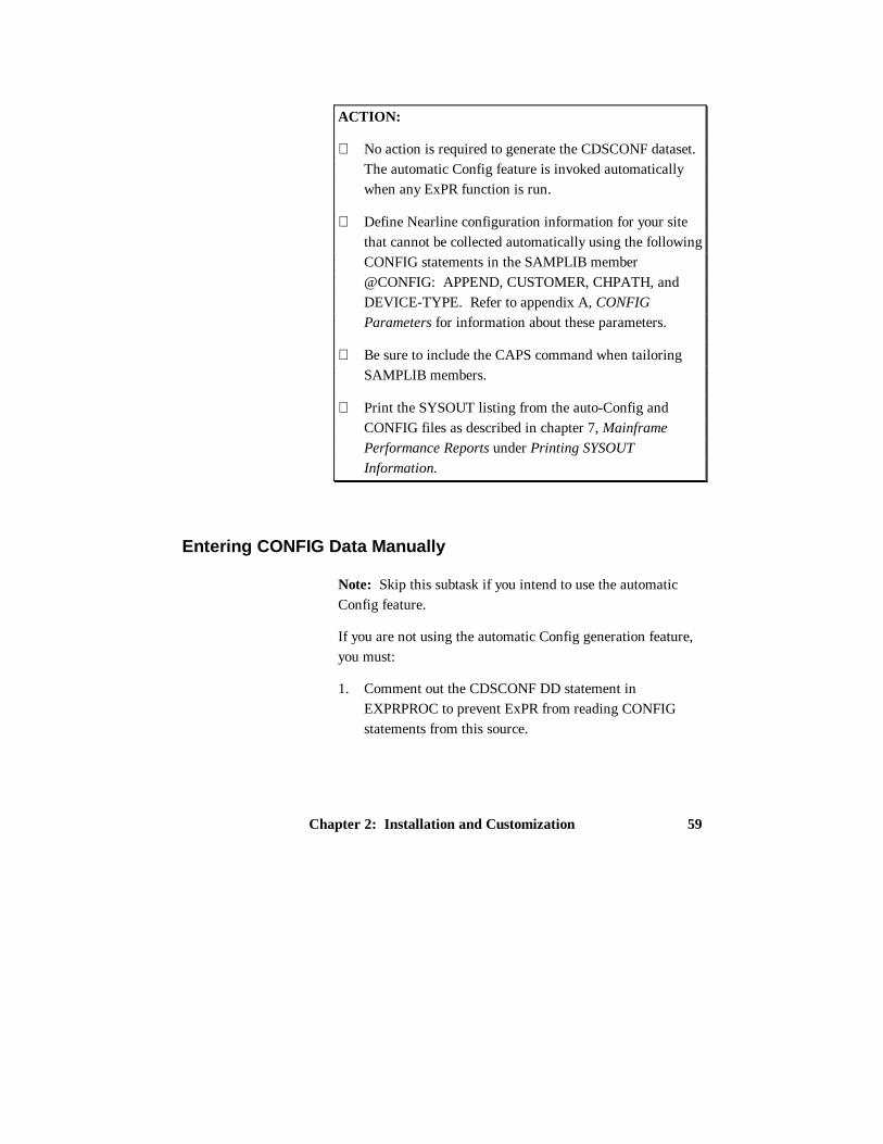
ACTION:
⇒ No action is required to generate the CDSCONF dataset.The automatic Config feature is invoked automaticallywhen any ExPR function is run.
⇒ Define Nearline configuration information for your sitethat cannot be collected automatically using the followingCONFIG statements in the SAMPLIB member@CONFIG: APPEND, CUSTOMER, CHPATH, andDEVICE-TYPE. Refer to appendix A, CONFIG
Parameters for information about these parameters.
⇒ Be sure to include the CAPS command when tailoringSAMPLIB members.
⇒ Print the SYSOUT listing from the auto-Config andCONFIG files as described in chapter 7, Mainframe
Performance Reports under Printing SYSOUT
Information.
Entering CONFIG Data Manually
Note: Skip this subtask if you intend to use the automaticConfig feature.
If you are not using the automatic Config generation feature,you must:
1. Comment out the CDSCONF DD statement inEXPRPROC to prevent ExPR from reading CONFIGstatements from this source.

ExPR MVS User’s Guide60
2. Customize sample control cards in SAMPLIB member@CONFIG with site data about your installation’sconfiguration.
Parameters that identify each MVS host, ACS, LSM, tapedrive device, and channel path, as shown in the table below.
Site Data CONFIG DD StatementsMVS Hosts HOST SYSID(mvshost)ACSs ACS ID(aaa) NAME(‘ text’)LSMs LSM ID(aaa ll) NAME(‘ text’) TYPE(‘t’)Tape Drives DEVICE ID(dddd) LSM(aaa ll) TYPE (tttt)
SYSID(mvshost)Device Types DEVICE-TYPE DEFAULT(tttt)Channel Paths CHPATH ID(xx-xx) GROUP(nnn) SYSID(mvshost)Company Name CUSTOMER NAME(‘text’)
SAMPLIB member @CONFIG contains sample control cardsfor each of these functions.

Chapter 2: Installation and Customization 61
ACTION:
⇒ Comment out the CDSCONF DD statement inEXPRPROC to prevent ExPR from reading CONFIGstatements from this source.
⇒ Define Nearline configuration information for your siteto ExPR using SAMPLIB member @CONFIG.
⇒ Refer to appendix A, CONFIG Parameters forinformation about the CONFIG dataset parameters.
⇒ Be sure to include the CAPS command when tailoringSAMPLIB members.
⇒ Print the SYSOUT listing from CONFIG DD, asdescribed in chapter 7, Mainframe Performance Reports.
Task 9: Install the ExPR Started Task
This task defines the EXPRPGMI started task and establishesit in your MVS startup parameters. In this task, you will copysample control cards to your selected PROCLIB library andcustomize them to define started task runtime parameters foryour site.
Started Task Overview
The EXPRPGMI started task is required to collect data forscratch count and free cell information on an hourly basis.This task is required because these statistics are not provided

ExPR MVS User’s Guide62
in the HSC SMF record. The started task, EXPRPGMI, isincluded in the ExPR SAMPLIB.
EXPRPGMI issues regular PGMI calls to the HSC and alsoreads the HSC CDS. Output is then written to a collectionfile, EXPR.PGMIDATA, which is subsequently input to thedatabase update process as a separate step. The size of thecollection file is controlled by applying an age limit to thedata contained in it.
Housekeeping procedures are performed automatically by thestarted task to maintain the collection file at the correct size.Record keys are checked for age each time the task is startedand also after database update processing.
Started Task Parameters
The started task is run from the SYS1.PROCLIB library (or asite-specified concatenated PROCLIB). Optionally, it can bestarted automatically at IPL by a start command inSYS1.PARMLIB member IEACMDnn (for example,‘COM=START EXPRPGMI’).
The CONFIG statement PGMI defines the frequency thatPGMI calls are made and the age of the data that is retainedin the collection file:
• PGMI call frequency: An EVENT parameter controlsthe rate at which records are generated by ExPR (everyminute, every 15 minutes, or every hour).

Chapter 2: Installation and Customization 63
• Age specification: The started task checks records in thecollection file against the age parameter (MAXAGE) anddeletes outdated records. Thus, the age limit shouldcover the longest period between database update runs(seven days is recommended). This ensures that recordsare retained in the collection file long enough to beincluded in the database update process without requiringexcess DASD allocation.
Data that is written to EXPR.PGMIDATA is selected andinput for database update processing by a single process.
Notes:
1. The EXPR.PGMIDATA collection dataset referenced byDDname PGMIDATA must be defined and initializedprior to running the started task. This process wasdescribed in Task 4: Define ExPR Datasets and Tailor
EXPRPROC Procedure in this chapter.
2. The EXPRPGMI started task references HSC moduleSLSXCAL. You must ensure that the HSC load librarywhere this module resides is either included in the linklist or is specified on the STEPLIB DD statement for theEXPRPGMI started task.
3. The SLSXCAL module must be the same version/releaseas the executing HSC started task.

ExPR MVS User’s Guide64
ACTION:
⇒ Copy the started task EXPRPGMI from SAMPLIB toyour selected PROCLIB library.
⇒ Establish started task parameters for your site usingSAMPLIB member @PGMI.
⇒ Refer to appendix A, CONFIG Parameters forinformation about CONFIG dataset parameters, and toappendix B, SYSIN Parameters for information aboutruntime parameters.
⇒ Be sure to include the CAPS command when tailoringSAMPLIB members.
Task 10: Specify HSC SMF Number to ExPR
This task identifies the HSC SMF number for your site toExPR. In this task, you will customize sample control cardswith the HSC SMF number for your site.
Note: If you are using the ExPR automatic configurationgenerator feature, the HSC SMF number is suppliedautomatically and you do not need to perform this task.However, you must comment out the statement in SAMPLIBmember @HSC.
The HSC SMF number is usually assigned 255. However, itis a site-variable number and thus should be verified with theappropriate systems programmer.

Chapter 2: Installation and Customization 65
ACTION:
⇒ Define the HSC SMF number to ExPR for your site usingSAMPLIB member @HSC.
⇒ Be sure to include the CAPS command when tailoringSAMPLIB members.
Task 11: Define the Control Dataset to ExPR
This task identifies the DDname of the HSC Control Dataset(CDS) that ExPR is to reference. In this task, you willcustomize sample control cards by specifying the DDnamethat points to the CDS. Typically, this would be one of thethree images of the CDS supported by HSC. ExPR's defaultvalue is the primary image, CDSPRIM, which wouldnormally point to the primary CDS dataset.
ACTION:
⇒ Define the Control Dataset (CDS) to be referenced byExPR using SAMPLIB member @CDS.
⇒ Be sure to include the CAPS command when tailoringSAMPLIB members.
Task 12: Create the ExPR CONFIG Dataset
This task copies the customized sample configuration optionsfrom previous tasks into the live CONFIG dataset. In thistask, you will customize parameters provided in the samplecontrol cards to copy your edited SAMPLIB entries into thelive CONFIG dataset. This task is essential for a successful

ExPR MVS User’s Guide66
installation. ExPR does not execute from the SAMPLIBlibrary, so only those parameters copied to the CONFIG file(or generated automatically by ExPR) will become effective.
Note: Before you perform this task, you may want to first setup the optional exception processing, jobname workloadgroup, and tape catalog processing features described inchapters 4, 5, and 6 respectively. It does not matter when orif you set up those optional features, but if you do, you mustreturn to this task to copy any SAMPLIB members youcustomize into the live CONFIG dataset. There are fourSAMPLIB members relating to these optional features -@DSMAP, @MAP, @TAPCAT and @THRSHLD. Thesample statements are commented out, so it is not necessaryto edit these members if you do not wish to utilize theassociated features of ExPR.
ACTION:
⇒ Create the CONFIG dataset for your site using SAMPLIBmember CONFIG.
⇒ Be sure to include the CAPS command when tailoringSAMPLIB members.
Note: Examples of fully completed configurations can befound in SAMPLIB members CONFSMPA (for automaticallygenerated configurations) and CONFSMPM (for manuallygenerated configurations).

Chapter 2: Installation and Customization 67
Task 13: Installation Verification
At this point, the basic ExPR system is installed andconfigured for use in the MVS environment at your site. Thebest way to test and verify your installation is to update thedatabase with your site data and begin generating mainframetabular reports.
ACTION:
⇒ Build the database using SAMPLIB memberSMFUPDAT. Refer to chapter 3, Managing the ExPR
Database for more information about the database updateprocess.
⇒ Generate mainframe performance reports usingSAMPLIB members MFREPS and EXPRJOB. Refer tochapter 7, Mainframe Performance Reports for moreinformation about the mainframe reporting process.
⇒ Be sure to include the CAPS command when tailoringSAMPLIB members.
⇒ Refer to chapters 4, 5, and 6 respectively for informationabout configuring the optional exception processing,jobname workload groups, and tape catalog processingfeatures.

Chapter 3: Managing the ExPR Database 69
Chapter 3
Managing the ExPR Database
Overview
This chapter describes required steps for selecting data toupdate the database with, various database processes, andmaintenance procedures required to maintain the ExPRdatabase, including verification and consolidation. Examplesare included for reference.
Note: Before proceeding with this chapter, be sure you havesuccessfully completed all tasks in chapter 2, Installation and
Customization.
Input Data Review
ExPR allows data input from a number of MVS and HSCsources. These are:
• SMF type 21 (tape error statistics)
• RMF (Nearline channel and CU statistics and SSCHcounts)
• HSC SMF (Nearline activity)
• PGMI (Nearline cell information)

ExPR MVS User’s Guide70
• CDS (scratch and free cell statistics)
• Tape Catalog (tape usage statistics)
• MVS SYSLOG (console messages for allocation recoveryanalysis)
Not all data sources follow the same selection path. Figure 3-1 below illustrates the various update paths that are taken bydifferent data sources.
• SMF type data requires pre-selection and sorting
• PGMI and CDS data is first written to an intermediatecollection file
• Tape Catalog data is updated directly to the ExPRdatabase
• MVS SYSLOG data is updated directly to the ExPRdatabase

Chapter 3: Managing the ExPR Database 71
_______________________________________________________________________
_______________________________________________________________________
Figure 3-1: ExPR Data Update Paths

ExPR MVS User’s Guide72
Database Processes
The database should be updated as part of the samehousekeeping procedure as SMF, RMF, and HSC SMFprocessing. The database update process can be selectivewith ExPR parameters providing controls for the record typesto be input. Update (new date ranges) and replace (overwriteexisting records) processing are supported.
Each of the ExPR SYSIN parameters that relate to databaseprocessing are described below. The syntax for theseparameters is described in appendix B, SYSIN Parameters.
Note: If you are processing data that is more than 30 daysold, you must include a PERIOD FROM/TO range; thedefault is from 30 days previous to the current date if a periodis not specified.
SELECT
SELECT defines filtering criteria for the SMF record typesto be extracted from the general SMF housekeeping filemaintained by the installation. SELECT subparametersinclude HSC, SMF21, and RMF. This parameter should beused when not all SMF type records handled by ExPR arerequired. The SELECT command must precede theSMFSELECT function.
PERFORM SMFSELECT
Extracts the required ExPR SMF record types (subject to anySELECT filtering criteria) and writes them to a sequentialfile for input to the SORT utility.

Chapter 3: Managing the ExPR Database 73
PERFORM SMFUPDATE
Updates the ExPR VSAM database file with the sortedoutput from SMFSELECT processing.
PERFORM PGMIUPDATE
Updates the ExPR database with data records that are heldin the collection file that is written to by the PGMI startedtask processes.
PERFORM SYSLOGUPDATE
Update the ExPR database with console message records fromthe MVS SYSLOG. Selective message numbers are scannedand the date and timestamp associated with each message isused to build a record containing the number of allocationrecovery events and the duration of each event.
PERFORM TAPECAT
Performs tape catalog processing and updates the ExPRdatabase with information extracted from the tape catalogand CDS. This information relates to tape ages andutilization within the ACS. Tape catalog processing isdetailed in chapter 6, Tape Catalog Processing and Reports.
PERFORM CONVERTDB
Allows users of ExPR 1.0 to convert their existing databasefor use with ExPR 1.1. Major database structure changeshave occurred in ExPR 1.1; consequently, it is not possibleto run the ExPR 1.1 software against the older database.

ExPR MVS User’s Guide74
ACTION:
⇒ Update the database using SAMPLIB membersSMFUPDAT, PGMIUPDT, SYSLOG, and TAPECAT1or TAPECATT.
⇒ Refer to appendix B, SYSIN Parameters for informationabout runtime parameters that appear in the SAMPLIB.
⇒ Refer to chapter 6, Tape Catalog Processing and
Reports, for more detail about the TAPECAT function.
⇒ Be sure to include the CAPS command when tailoringSAMPLIB members.
SYSIN Examples
The following examples illustrate how SYSIN parametersdescribed above are used to update the database.

Chapter 3: Managing the ExPR Database 75
Example 1: Select HSC SMF Records Only and Update the
Database
PERIOD FROM(yyyyddd) TO(yyyyddd) ; INPUT DDNAME(INDATA1 INDATA2) ; SELECT TYPE(HSC) SYSID(mvshost); PERFORM SMFSELECT ;
--- SORT step goes here ---
PERIOD FROM(yyyyddd) TO(yyyyddd) ; INPUT DDNAME(SORTDAT) ; PERFORM SMFUPDATE ;
Note: If all SMF data is required, do not specify a SELECTstatement. If SMF data from a specific system is required,specify SELECT SYSID without the TYPE(HSC) parameter.
The SMFUPDATE function can be replaced by theSMFREPORT function if you want to analyze SMF data forexception events without updating the ExPR database. Seechapter 4, Exception Processing and Reports for furtherdetails and a sample of the SMF Exception Events report.
All SMF type data needs to be sorted before being input to thedatabase update process. If this is done already at yourinstallation, the sort steps provided in the control cardexamples found in the ExPR SAMPLIB can be omitted. Inthe above example of SYSIN streams, a sort step would beperformed between SMFSELECT and SMFUPDATEprocessing.

ExPR MVS User’s Guide76
Example 2: Select PGMI Data and Update the Database
PERIOD FROM(yyyyddd) TO(yyyyddd) ;PERFORMPGMIUPDATE ;
Data that is collected by the EXPRPGMI started task iswritten to the PGMIDATA collection file. The database isthen updated with this collected data by the SYSIN parameterPERFORM PGMIUPDATE.
A report is generated automatically by this process. Thereport (titled “Update Database from STC Records”) displaystotals for records read and records added to the database bythe PGMIUPDATE process. Additionally, hourly averagesare printed for total cells, free cells, scratches, and cleaningcartridges.
The report shown below is generated during PGMIUPDATEprocessing.

Chapter 3: Managing the ExPR Database 77
--------------------------------------------------------------------------------------------------------------------------------------------------------------------------------------------1995.353 S T O R A G E T E K E X P R 1 . 1 XYZ COMPANY PAGE 1 17:03:11 UPDATE DATABASE FROM STC RECORDS ------------------------------------------------------------- NO OF - - A V E R A G E S - - INTER TOTAL FREE SCRAT CLEAN DATE HOUR SYS ACSLSM VALS CELLS CELLS CHES CARTS --------------------------------------------------------------------------------------------- 1994.340 01.00 CPUA 000 00 7 5800 256 384 8 1994.340 01.00 CPUA 000 01 7 5800 256 384 8 1994.340 01.00 CPUA 000 02 7 5800 256 384 8 1994.340 12.00 CPUA 000 00 4 5800 256 384 8 1994.340 12.00 CPUA 000 01 4 5800 256 384 8 1994.340 12.00 CPUA 000 02 4 5800 256 384 8 1994.340 13.00 CPUA 000 00 4 5800 304 640 8 1994.340 13.00 CPUA 000 01 4 5800 304 640 8 1994.340 13.00 CPUA 000 02 4 5800 304 640 8 1994.340 14.00 CPUA 000 00 4 5800 243 291 6 1994.340 14.00 CPUA 000 01 4 5800 243 291 6 1994.340 14.00 CPUA 000 02 4 5800 243 291 6 1994.340 15.00 CPUA 000 00 4 5800 273 801 6 1994.340 15.00 CPUA 000 01 4 5800 273 801 6 1994.340 15.00 CPUA 000 02 4 5800 273 801 6 1994.340 16.00 CPUA 000 00 4 5800 200 255 6 1994.340 16.00 CPUA 000 01 4 5800 200 255 6 1994.340 16.00 CPUA 000 02 4 5800 200 255 6 1994.340 17.00 CPUA 000 00 4 5800 153 528 6 1994.340 17.00 CPUA 000 01 4 5800 153 528 6 1994.340 17.00 CPUA 000 02 4 5800 153 528 6 1994.341 16.00 CPUA 000 00 3 0 0 242 9 1994.341 16.00 CPUA 000 01 3 0 60 306 8 1994.341 16.00 CPUA 000 02 3 0 170 332 4 1994.341 17.00 CPUA 000 00 4 0 0 242 9 1994.341 17.00 CPUA 000 01 3 0 60 306 8 1994.341 17.00 CPUA 000 02 3 0 170 332 4 1994.341 18.00 CPUA 000 00 12 0 0 242 9 1994.341 18.00 CPUA 000 01 12 0 60 306 8 1994.341 18.00 CPUA 000 02 12 0 170 332 4 1994.342 10.00 CPUA 000 00 3 0 0 242 9 1994.342 10.00 CPUA 000 01 3 0 60 306 8 1994.342 10.00 CPUA 000 02 3 0 170 332 4 1994.342 11.00 CPUA 000 00 60 0 0 242 9 1994.342 11.00 CPUA 000 01 60 0 60 306 8 1994.342 11.00 CPUA 000 02 60 0 170 332 4 1994.342 12.00 CPUA 000 02 18 0 170 332 4 1994.342 12.00 CPUA 000 01 18 0 60 306 8 1994.342 12.00 CPUA 000 00 18 0 0 242 9
COLLECTION FILE INPUT: RECORDS READ.................................511DATABASE OUTPUT ANALYSIS: RECORDS ADDED..................................0 RECORDS REPLACED.........................39 UPDATE FROM STC DATA COMPLETED--------------------------------------------------------------------------------------------------------------------------------------------------------------------------------------------

ExPR MVS User’s Guide78
Example 3: Select MVS SYSLOG Data and Update the
Database
The SYSLOGUPDATE control statement below is for a JES2system. JES3 users should refer to the next page for a JES3example.
//EXPR.SYSLOG DD DISP=SHR,DSN=user.syslog//EXPR.SYSIN DD * PERFORM SYSLOGUPDATE ;/*
PERFORM SYSLOGUPDATE selects SYSLOG data andupdates the database. The SYSLOG input is located byDDNAME SYSLOG. This is a fixed value and should not bechanged. Also, there is no PERIOD card required with thisfunction; the full XWTR dataset will be processed by ExPR.
The SYSLOGUPDATE process writes hourly summaryrecords to the database for each LSM and additionally for allnon-Nearline activity (manual tape devices and other devicetypes which invoked MVS allocation recovery). Allocationrecovery is a single-thread function of MVS. It is thereforeimportant to understand how much throughput delay isattributable to it.
The report shown below is generated duringSYSLOGUPDATE processing.

Chapter 3: Managing the ExPR Database 79
-------------------------------------------------------------------------------------------------------------------------------------------------------------------------------------------- 1994.340 S T O R A G E T E K E X P R 1 . 1 XYZ COMPANY PAGE 1 17:52:29-------------------------------------------------------------------------------------------------------------------------------------------------------------------------------------------- MVS ALLOCATION/RECOVERY UPDATE/REPORT FOR SYSTEM CPUA DATE RANGE: 1993001 TO 1995365-------------------------------------------------------------------------------------------------------------------------------------------------------------------------------------------- JESJOBNO JOBNAME STEPNAME DDNAME VOLSER DATE STRTTIME END-TIME DURATION UNIT ACS LSM ------- COMMENTS ----
JOB01121 CPF002 DFDSS TAPE PRIVAT 1994.341 10.31.44 10.31.56 00:00:12 393 000 01 JOB01127 CPF001 DFDSS TAPE PRIVAT 1994.341 10.34.39 10.34.44 00:00:05 394 000 01 JOB01163 N51T001A S1 SYSUT1 PP2V3C 1994.341 10.40.32 10.41.04 00:00:32 393 000 01 JOB01129 CPF001 DFDSS TAPE PRIVAT 1994.341 10.47.42 10.48.24 00:00:42 395 000 01 JOB00895 SMFSAVT INIT TAPEUNIT SCRTCH 1994.341 10.50.01 10.50.12 00:00:11 394 000 01 JOB02862 B30REST S010 INDD1 BRM006 1994.341 11.03.55 11.06.01 00:02:06 394 000 01 JOB02521 B30T005S EXPR INDATA1 OTS403 1994.341 11.07.49 11.08.14 00:00:25 OPERATOR REPLIED CANCEL JOB02863 B30REST S010 INDD1 BRM007 1994.341 11.25.56 11.29.35 00:03:39 394 000 01 JOB03451 CPF002 DFDSS TAPE PRIVAT 1994.341 11.30.23 11.32.01 00:01:38 391 000 00 JOB02591 B30T005S EXPR INDATA1 OTS403 1994.341 11.32.11 11.32.50 00:00:39 392 000 00 JOB01638 CPF002 DFDSS TAPE PRIVAT 1994.341 12.17.27 12.17.35 00:00:08 395 000 01 JOB01373 CPFRS1 DFDSS TAPE PRIVAT 1994.341 13.02.47 13.02.53 00:00:06 397 000 02 JOB02197 B30T005C GENER SYSUT1 CMF001 1994.341 13.49.59 13.51.06 00:01:07 393 000 01 JOB03041 B30COPY S1 IN PA0001 1994.341 14.23.18 14.28.53 00:05:35 OPERATOR REPLIED WAIT JOB05143 CPF001 DFDSS TAPE PRIVAT 1994.341 14.29.10 14.29.17 00:00:07 392 000 00 JOB05145 CPFRS1 DFDSS TAPE PRIVAT 1994.341 14.29.27 14.29.32 00:00:05 393 000 01 JOB03041 B30COPY S1 IN PA0001 1994.341 14.28.53 14.41.58 00:13:05 396 000 02 MOUNT SERVICED AFTER WAIT .
--------------------------------------------------------------------------------------------------------------------------------------------------------------------------------------------
JES3 Support
The SYSLOGUPDATE example above is for a JES2 system.JES3 users should specify the following control statement:
//EXPR.SYSLOG DD DISP=SHR,DSN=user.syslog//EXPR.SYSIN DD *
PERFORM SYSLOGUPDATE JES3(x=yyyy ...) ;/*
The additional parameter JES3 lists the system-ids to beextracted from the GLOBAL JES3 console file. In the aboveexample, for each system, x represents the message originprefix in the JES3 complex and yyyy represents the

ExPR MVS User’s Guide80
MVS/JES3 system-id associated with each system (normallythe SMF-id). For example, if “1” is the message prefix for“SY1X” and “2” is the message prefix for “SY2X”, youwould code 1=SY1X 2=SY2X.
When multiple JES3 systems are specified, a separateallocation recovery report is generated for each system. TheJES3 console file is read via the DDname SYSLOG, the sameas for JES2. It is not possible to mix JES2 and JES3SYSLOGUPDATE functions in a single execution of ExPR.
In addition to MVS allocation/recovery, ExPR will also reporton JES3 mount setup processing as recorded by messagesIAT5210 and IAT5918.
RECFM Support
Although the SYSLOGUPDATE function was designed toread the output file from the IBM external writer, it isrecognized that many installations use other utilities orpackages to manage SYSLOG output. These utilities may notproduce a VBA/VBM file like the external writer.
If your SYSLOG file is not VBA/VBM, you can specify theRECFM parameter on the SYSLOGUPDATE statement, asshown below. Valid RECFMs are VBA, VBM, FBA, FBM,FB, and VB. (The external write record format for JES2 isVBA; for JES3 it is VB.)
//EXPR.SYSLOG DD DISP=SHR,DSN=user.syslog//EXPR.SYSIN DD *
PERFORM SYSLOGUPDATE JES3(x=yyyy ...) RECFM(valid recfm) ;/*

Chapter 3: Managing the ExPR Database 81
Example 4: Select Tape Catalog Data and Update the
Database
CDS DDNAME(CDS) ; PERFORM TAPECAT OPTION(UPDATE) SYSID(mvshost);
PERFORM TAPECAT OPTION(UPDATE) updates thedatabase using tape catalog information if the tape catalogprocessing feature has been implemented for your site withthe @TAPCAT SAMPLIB member. Tape catalog processingand the generated reports are described in chapter 6, Tape
Catalog Processing and Reports.
UPDATE scans the CDS and tape catalog, calculates age andutilization statistics, updates the database file, creates the tapecatalog history file, and generates basic age and usagesummary reports. Examples of the control cards to run thistask are in SAMPLIB members TAPECAT1 for CA-1 andTAPECATT for CA-TLMS.
Due to the potential overhead caused by reading both theCDS and tape catalog, it is recommended that this task onlybe run once per day. This level of recording should beadequate for the reports generated from this source.However, the ExPR data key structure would permit therecording of tape catalog information on a more frequentbasis if required.
Additionally, this task should be run at the same time eachday to avoid data being distorted by any workload variations,such as enter/eject activity.

ExPR MVS User’s Guide82
When running TAPECAT UPDATE to create a TMCHISTfile (the default option), be sure to un-comment theTMCHIST DD in EXPRJOB. Do not un-comment this DDfor other ExPR functions or when using option NOHIST; youwill create empty generations of TMCHIST files.
Example 5: Converting an ExPR 1.0 Database
//EXPR.OLDDB DD DISP=SHR,DSN=unloaded.EXPR10.database //EXPR.SYSIN DD * PERFORM CONVERTDB SYSID(mvshost) ; /*
PERFORM CONVERTDB will read an unloaded sequentialcopy of the ExPR 1.0 database and write the data directly intothe new ExPR 1.1 database. The input file is located byDDNAME OLDDB and should have been previously createdusing the IDCAMS REPRO function as follows:
//DATABASE DD DISP=SHR,DSN=EXPR10.database //UNLOAD DD DISP=SHR,DSN=unloaded.EXPR10.database, DCB=(LRECL=500,BLKSIZE=nnn,RECFM=VB) //SYSIN DD * REPRO INFILE(DATABASE) OUTFILE(UNLOAD) /*
ExPR 1.0 data can be loaded into a newly defined (andinitialized) 1.1 database or it can be merged into an existingdatabase with newer 1.1 records. Once converted, there is nodifferentiation of 1.0 and 1.1 data.

Chapter 3: Managing the ExPR Database 83
When converting the 1.0 database, the SYSID(mvshost)parameter must be specified. If you have several 1.0databases, each representing a different MVS host, theconversion process of unloading and running CONVERTDBcan be repeated. Each time, you would change the SYSIDparameter, thereby loading all systems into a single ExPR 1.1database.
The CONVERTDB process produces a small report of recordsread and written. Due to the database structure changes, theinput and output record counts do not always correlate one-to-one:
• Record types 0, 3, 4, 5, 6, 7 ,8, and 9 are processed on aone-to-one basis.
• Record type 2 was previously created one per hour, perLSM; however in ExPR 1.1, this is now one per hour forthe entire system.
• Record type 1 is not converted at all.
Record type 1 data can be reproduced by running theSMFSELECT/SMFUPDATE process against your old RMFdata. This should be run with a SELECT TYPE(RMF)statement.
Note: An alternative to database conversion would be tomaintain the previous release of the mainframe and PCcomponents of ExPR. When the new release has collectedsufficient data (for example, two or three months), you couldthen purge the old product and data.

ExPR MVS User’s Guide84
Multiple Database Support
More than one ExPR database can be maintained. To updatea second database, the DATABASE DD statement must pointto the appropriate database, and the SELECT statement mustidentify those systems and ACSs to be input to this database.
Consolidate the Database
The database consolidation procedure allows you to controlthe size of your mainframe database by moving date ranges ofrecords from the database to an external export fil e createdthrough JCL or TSO faciliti es. The export fil e is a variableblocked QSAM file with a maximum record length of 500bytes. It can be deleted or archived following the databaseconsolidation.
Two functions are supported, EXPORT and PURGE:
• EXPORT copies database periods to the QSAM file
• PURGE deletes the selected periods from the database
EXPORT and PURGE appear as PERFORM options in theSYSIN runtime parameters. EXPORT and PURGE can beused alone or in combination. When used in combination,PURGE is not executed if the EXPORT command fails.

Chapter 3: Managing the ExPR Database 85
ACTI ON:
⇒ Consolidate the database using SAMPLIB memberDBCON.
⇒ Refer to appendix B, SYSIN Parameters for informationabout runtime parameters that appear in the SAMPLIB.
⇒ Be sure to include the CAPS command when tailoringSAMPLIB members.
Reorganizing the Database
At some point, you may wish to reorganize your ExPRdatabase, particularly in larger installations, because ofCI/CA splits and secondary extent allocations. This can beachieved with the ExPR EXPORT command and IDCAMSDELETE/DEFINE and REPRO.
The ExPR EXPORT file is a standard VB file which could bereloaded to the main database at any time. When using ExPREXPORT as part of a database reorganization, be sure tospecify a PERIOD FROM/TO that ensures all data is exportedbefore the DELETE/DEFINE, such as PERIODFROM(1990000) TO(1999365).

Chapter 4: Exception Processing and Reports 87
Chapter 4
Exception Processing and Reports
Overview
This chapter describes the ExPR exception processing feature andthe exception-based reports that can be generated in themainframe environment.
Process Description
ExPR exception processing monitors user-specified exceptionthresholds, which represent the point at which an event isconsidered to be an exception. Exception processing generates areport when thresholds have been exceeded, such as when thenumber of mounts or mount response time exceeds the specifiedvalue.
Thresholds can be set for scratch mounts, non-scratch mounts,scratch mount response time, non-scratch mount response time,enters, ejects, passthroughs, control unit load, number of drives inuse, available scratch, available free cells, and maximumallocation recovery time.
Exception reports are produced in tabular hardcopy format on themainframe. These reports include an event report that lists allSMF exception events and a summary report that provides hourly

ExPR MVS User’s Guide88
threshold exception totals by exception type. Graphical or tabularexception reports can also be generated on the PC. These reportscan be run against the mainframe thresholds or against user-specified local thresholds.
Data collected from HSC SMF records and MVS SMF/RMFrecords is eligible for SMF exception processing. Processing ofexceptions takes place automatically during the SYSINPERFORM SMFUPDATE database update operation or ondemand when the SYSIN PERFORM SMFREPORT parameter isspecified in the control cards.
Eligible fields are checked against the user-defined thresholds todetermine if an exception event has been triggered. If so, anexception event is printed for subsequent review and analysis.
The Threshold Exceptions report reads the ExPR database andprints an hourly summary of the collected data. The currentthreshold settings are also listed. Database fields exceeding thosethresholds are highlighted to draw your attention to them.
Exception Types
All exception values are specified at the LSM level. There aretwo exception types:
• EVENT: Where an individual event triggers the exception,such as mount time
• INTERVAL: Where the number of events over a recordedperiod triggers the exception, such as mounts
Default values can apply to event exceptions until some analysishas been done on the reports generated by ExPR. For intervalexceptions, some knowledge of activity volume is required. If youare unsure of what these values should be, specify a high value to

Chapter 4: Exception Processing and Reports 89
avoid excessive exception recording until further analysis of realdata has been completed.
Note: As a general rule, avoid frequent adjustment of exceptionvalues. The database exception records provide historicalperspectives on exceptions and are based on the percentage oftotal records exceeding the threshold. Therefore, this figure willbe distorted if the original threshold is not consistent.
Defining Threshold Values for Your Site
Exception threshold values are defined for your site bycustomizing sample control cards in the SAMPLIB library.Exception thresholds should be set at a level where you areprepared to take some follow-up action when they are exceeded.This may, for example, be a service level that your installation hasimplemented.
If there are no service levels in place at your site, then thethreshold should be set at a level where you would wish to spendtime performing further analysis to identify the reason behind thethreshold being exceeded. If thresholds are set too low, there is adanger they will be ignored since this event will become or seemto be the norm. Also, in larger installations, the volume ofexceptions being generated could become unmanageable.
Threshold Values
Exception threshold values are set with the CONFIG controlstatement THRESHOLD. Subparameters for this statement arelisted in the table below.

ExPR MVS User’s Guide90
Threshold Name DescriptionSCRMOUNTCOUNT Scratch mount countSCRMOUNTTIME Scratch mount time in secondsNONSCRMOUNTCOUNT Non-scratch mount countNONSCRMOUNTTIME Non-scratch mount time in secondsENTERS Enter countEJECTS Eject countPASSTHRUS Passthrough countDRIVESINUSE Number of drives in use within an LSMCULOAD Control unit load percentage thresholdAVAILSCRATCH Minimum number of available scratch cartridgesAVAILCELLS Minimum number of available free cellsMAXALLOCREC Maximum time in seconds for an allocation
recovery to be serviced
ACTION:
⇒ Define exception thresholds for your site using SAMPLIBmember @THRSHLD.
⇒ Refer to appendix A, CONFIG Parameters for informationabout the THRESHOLDS configuration parameter.
⇒ Be sure to include the CAPS command when tailoringSAMPLIB members.
⇒ Add the customized SAMPLIB member to the CONFIGdataset using SAMPLIB member CONFIG. ExPR does notexecute from the SAMPLIB library, so only those parameterscopied to the CONFIG file or automatically generated byExPR will become effective.

Chapter 4: Exception Processing and Reports 91
Exception Report Generation
Tabular hardcopy reports are generated against the exceptionscreated by exception processing. These reports and how to usethem are described below.
Two mainframe exception reports are generated; the SMFException Event report and the Threshold Exceptions report.These reports are shown in the samples on the following pages.
In addition, exceptions for allocation recovery and percentdisconnect for tape devices are shown on the ALLOC-REC andCU-BUSY reports. These reports are described in chapter 7,Mainframe Performance Reports.
The Thresholds Exception Summary report is generated by thefollowing SYSIN statement:
• PERFORM REPORT NAME(THRESHOLDS)
The SMF Exception Event report is generated automatically aspart of the SMFUPDATE function, or by the SMFREPORTfunction:
• PERFORM SMFUPDATE reads the SMF data, updates theExPR mainframe database, and produces the SMF ExceptionEvent report as a part of the normal database updateoperation.
• PERFORM SMFREPORT reads the SMF data and prints theSMF Exception Event report without updating the database.

ExPR MVS User’s Guide92
ACTION:
⇒ Generate the Threshold Exceptions report using SAMPLIBmember EXCPREP.
⇒ To run the SMF Exceptions Event report (SMFREPORT),refer to SAMPLIB member SMFUPDAT. Also refer toSYSIN Examples in chapter 3, Managing the ExPR Database.
⇒ Refer to appendix B, SYSIN Parameters for information aboutruntime parameters that appear in the SAMPLIB.
⇒ Be sure to include the CAPS command when tailoringSAMPLIB members.
Note: You can also produce exception reports in a graphical ortabular format on a PC, and each ExPR PC user can set localexception thresholds to override the mainframe defaults. Refer tothe ExPR PC User’s Guide for information about PC-basedexception reports.

Chapter 4: Exception Processing and Reports 93
Threshold Exceptions Report--------------------------------------------------------------------------------------------------------------------------------------------------------------------------------------------------------- 1994.340 S T O R A G E T E K E X P R 1 . 1 XYZ COMPANY PAGE 1 17:52:29--------------------------------------------------------------------------------------------------------------------------------------------------------------------------------------------------------- THRESHOLD EXCEPTIONS REPORT FOR SYSTEM CPUA DATE RANGE: 1993001 TO 1995365 ACS: 000 NEARLINE ACS 000 LSM: 02 NEARLINE LSM 000 02--------------------------------------------------------------------------------------------------------------------------------------------------------------------------------------------------------- MNT CNT MNT CNT MNT TIME MNT TIME MAX USED AVAILABLE AVAILABLE MAX ALLOC THRESHOLD SCRATCH NON-SCR SCRATCH NON-SCR ENTERS EJECTS PASSTHRUS DRIVES SCRATCHES CELLS RECOVERY VALUES ===> ( 45) ( 55) ( 50) ( 60) ( 25) ( 30) ( 35) ( 6) ( 200) ( 200) ( 300) DATE HOUR 1994340 6 4 2 17 20 0 0 0 => 16 <= 384 256 7 17 3 26 34 0 0 0 => 16 <= 384 256 8 8 3 23 18 0 0 2 => 16 <= 384 256 9 15 11 18 25 0 0 1 => 16 <= 384 256 10 15 8 21 22 0 0 1 => 16 <= 384 256 11 9 10 17 39 0 0 6 => 16 <= 384 256 12 0 1 0 17 0 0 0 => 16 <= 384 256 17 0 1 0 17 0 0 0 => 16 <= 528 => 153 <= 1994341 6 9 3 28 30 0 => 131 <= 2 => 16 <= 528 => 153 <= 7 7 4 26 38 0 7 1 => 16 <= 528 => 153 <= 8 11 0 21 0 0 0 0 => 16 <= 528 => 153 <= 9 11 1 27 28 0 0 1 => 16 <= 528 => 153 <= 10 8 3 24 34 0 0 1 => 16 <= 528 => 153 <= 11 6 8 38 38 0 0 4 => 16 <= 528 => 153 <= 12 12 5 28 35 0 0 4 => 16 <= 528 => 153 <= 13 10 6 33 20 0 0 0 => 16 <= 528 => 153 <= 14 5 11 22 18 21 0 0 => 16 <= 528 => 153 <= 15 4 7 33 27 0 0 3 => 16 <= 528 => 153 <= 16 4 5 30 30 0 0 2 => 16 <= 332 => 170 <= 17 3 3 32 58 0 0 1 => 16 <= 332 => 170 <= 18 3 3 => 51 <= 28 0 0 0 => 16 <= 332 => 170 <= 19 15 1 32 19 0 0 1 => 16 <= 332 => 170 <= 20 15 4 33 30 0 0 1 => 16 <= 332 => 170 <= 21 15 4 35 30 0 0 1 => 16 <= 332 => 170 <= 22 14 1 34 17 0 0 4 => 16 <= 332 => 170 <= 23 16 0 27 0 0 0 1 => 16 <= 332 => 170 <= 1994342 0 19 1 23 58 0 0 0 => 16 <= 332 => 170 <= 1 8 3 38 35 0 0 3 => 16 <= 332 => 170 <= . . .---------------------------------------------------------------------------------------------------------------------------------------------------------------------------------------------------------
The Threshold Exceptions report is run against the ExPRmainframe database. It compares the thresholds you havespecified against the database records over a selected period oftime. The report highlights those fields that exceed the threshold,providing you with information to use as a starting point whenperforming detailed analysis on any problem areas.

ExPR MVS User’s Guide94
Reports are generated per-LSM and show only hours where atleast one field has exceeded its threshold.
If a threshold is exceeded, all the other fields for that hour aredisplayed even if they are within threshold. This enables a basicanalysis of related data to be completed.
If data is not present, the field is filled with blanks.
Where exceptions are present, they are highlighted with => and<= characters on either side of the field.
Beneath each exception field heading, the exception thresholdspecified in the CONFIG file is displayed.

Chapter 4: Exception Processing and Reports 95
SMF Exception Event Report----------------------------------------------------------------------------------------------------------------------------------------------------------------------------------------------------1995.353 S T O R A G E T E K E X P R 1 . 1 XYZ COMPANY PAGE 9 17:13:08 SMF UPDATE - SMF EXCEPTION EVENTS ----------------------------------------------------------
DATE TIME SYS DRIVE TYPE ACS LSM EVENT OBSERVATION THRESHOLD VARIATION --------------------------------------------------------------------------------------------------------------------------------------------------------------------------------------------------- 1994.341 13:01:40 CPUA 0C25 4490 000 02 UNEXPECTED DISMOUNT 1994.341 13:01:46 CPUA 0C09 9490 000 00 UNEXPECTED DISMOUNT 1994.341 13:06:59 CPUA 0C00 4490 000 02 UNEXPECTED MOUNT 1994.341 13:07:58 CPUA 0C0A 9490 000 00 UNEXPECTED DISMOUNT 1994.341 13:09:03 CPUA 0C0B 9490 000 00 NON-SCRATCH MOUNT 76 60 126% ------> 1994.341 13:28:49 CPUA 0C02 9490 000 01 NON-SCRATCH MOUNT 67 60 111% -----> 1994.341 13:30:34 CPUA 0C09 9490 000 00 NON-SCRATCH MOUNT 70 60 116% -----> 1994.341 13:33:43 CPUA 02B0 000 02 DEMAND ENTER - VOLSER=030471 JOB=MAINT13C 1994.341 13:33:43 CPUA 02B0 000 02 NON-SCRATCH MOUNT 103 60 171% --------> 1994.341 13:36:12 CPUA 02B0 000 02 DEMAND ENTER - VOLSER=030470 JOB=MAINT13C 1994.341 13:38:15 CPUA 0C27 9490 000 02 SCRATCH MOUNT 63 50 126% ------> 1994.341 13:45:03 CPUA 0C00 4490 000 01 HIGH CU DISCONNECT 92% 80% +12% 1994.341 13:46:29 CPUA 0C0B 9490 000 01 DRIVESINUSE EXCEEDED 7 6 116% -----> 1994.341 13:59:59 CPUA 000 01 EXCESSIVE SCR MOUNTS 40 20 200% ---------> 1994.341 14:02:31 CPUA 0C2A 4480 000 01 NON-SCRATCH MOUNT 80 60 133% ------> 1994.341 14:30:03 CPUA 0C2A 4480 000 01 HIGH CU DISCONNECT 81% 80% + 1% 1994.341 14:45:04 CPUA 0C25 4490 000 02 HIGH CU DISCONNECT 96% 80% +16% 1994.341 14:47:47 CPUA 0C00 4490 000 01 DEMAND ENTER - VOLSER=104045 JOB=PRDACNTS 1994.341 14:47:53 CPUA 0C01 4490 000 01 DEMAND ENTER - VOLSER=102890 JOB=PRDACNTS 1994.341 14:48:01 CPUA 0C02 9490 000 01 DEMAND ENTER - VOLSER=102914 JOB=PRDACNTS 1994.341 14:48:13 CPUA 0C03 9490 000 01 DEMAND ENTER - VOLSER=102916 JOB=PRDACNTS 1994.341 14:48:23 CPUA 0C00 4490 000 01 DEMAND ENTER - VOLSER=102635 JOB=PRDACNTS 1994.341 14:48:35 CPUA 0C01 4490 000 01 DEMAND ENTER - VOLSER=107178 JOB=PRDACNTS 1994.341 14:48:36 CPUA 0C02 9490 000 01 DEMAND ENTER - VOLSER=102645 JOB=PRDACNTS 1994.341 14:48:41 CPUA 0C03 9490 000 01 DEMAND ENTER - VOLSER=000006 JOB=PRDACNTS 1994.341 14:50:24 CPUA 0C27 9490 000 02 PERM I/O ERROR VOLSER=013539 1994.341 14:51:34 CPUA 0C00 4490 000 01 PERM I/O ERROR VOLSER=013539 1994.341 14:52:45 CPUA 0C02 9490 000 01 NON-SCRATCH MOUNT 69 60 115% -----> 1994.341 14:52:54 CPUA 0C0B 9490 000 00 DRIVESINUSE EXCEEDED 7 6 116% -----> 1994.341 14:55:23 CPUA 0C02 9490 000 01 PERM I/O ERROR VOLSER=017003 1994.341 14:59:17 CPUA 0C22 4490 000 00 SCRATCH MOUNT 54 50 108% -----> 1994.341 14:59:50 CPUA 0C2A 4480 000 01 SCRATCH MOUNT 67 50 134% ------>
----------------------------------------------------------------------------------------------------------------------------------------------------------------------------------------------------
The SMF Exception Event report is generated automatically byPERFORM SMFUPDATE during database update processing,and on demand by PERFORM SMFREPORT. The reportcompares the threshold defined for mount response time forscratch and non-scratch volumes with the mount events as theywere recorded. No summarization of this data has taken place, soreporting is at the lowest possible level.
Possible exceptions from SMF data are listed below:

ExPR MVS User’s Guide96
Exception Description
SCRATCH MOUNT Scratch mount time exceeded the threshold.
NON-SCRATCH MOUNT Non-scratch mount time exceeded the threshold.
EXCESSIVE SCR MOUNTS The scratch mount count threshold has been exceeded forthis LSM/hour.
EXCESSIVE NSC MOUNTS The non-scratch mount count threshold has been exceededfor this LSM/hour.
UNEXPECTED MOUNT A mount occurred for an already mounted drive.
UNEXPECTED DISMOUNT A dismount occurred for an already free drive.
DRIVESINUSE EXCEEDED The number of active drives was exceeded for this LSM.
HIGH CU DISCONNECT The tape control disconnect time exceeded the threshold.
PERM I/O ERROR VOL=xxxxxx The identified volume had a permanent read or write error.
TEMP I/O ERROR VOL=xxxxxx The identified volume had a temporary read or write error.
DEMAND ENTER -VOL=xxxxxx JOB=xxxxxx
A mount was issued against a Nearline drive for a volumethat was not in the library. The operator had to load thecartridge into a CAP to satisfy the mount.
HSC COUNTER OVERFLOW An HSC LMU statistics counter has overflowed and beenreset to zero by ExPR. This prevents distortion of mount-time breakdown values.
An unexpected dismount can occur at the start of the SMF data ifthe corresponding mount preceded the start of the SMF file.

Chapter 4: Exception Processing and Reports 97
A returned RC=4 from the report indicates a possible break inSMF recording, resulting in a mount-mount sequence with nointervening dismount, or a dismount with no preceding mount. Ifthis occurs, check that SMF input data is complete andcontinuous.
A returned RC=8 from any ExPR report request indicates that thedatabase did not contain records to match your selection criteria(date range, system, or ACS/LSM ids).
Note: The SMFREPORT/SMFUPDATE functions will returnRC=8 if the input file is not in ascending date/time sequence.Ensure that the SMFSELECT and SORT steps are run correctly.

Chapter 5: Jobname Workload Groups 99
Chapter 5
Jobname Workload Groups
Overview
This chapter describes the optional jobname workload groupsfeature. Jobname workload groups map Nearline activityfrom specified jobnames into logical groups, typicallydefining activities generated by specific departments orfunctions. Reports can be generated for these groups,increasing the ExPR reporting capability by further definingNearline activities within your organization.
Defining Jobname Workload Groups
A workload group can comprise one or more jobnames.Groups are specified by including one or more jobnamesunder a user-selected group name. Masks and wildcardcharacters are used to select a range of jobnames for a group.
The following masks can be used when constructing ExPRjobname workload groups:

ExPR MVS User’s Guide100
? or % Represents a wildcard character, one for one. Blanks are notallowed.
* Represents a wild prefix or suffix (0-8 characters). Can beused as either the prefix or suffix, or both.
For example:
JT100* Any job starting JT100.
J*100ABC Jobs such as JT100ABC or JD100ABC
J????ABC Jobs starting with J and ending with ABC, with anyalphanumeric characters in positions 2-5.
Workload groups are defined with the CONFIG controlstatement MAP. Identifying names can be defined forjobname workload groups with the CONFIG controlstatement WORKLOAD.
Note: Jobname workload groups will significantly increasethe size of the ExPR database, so some thought is required atspecification time. Refer to Task 2: Space Planning inchapter 2, Installation and Customization Tasks.

Chapter 5: Jobname Workload Groups 101
ACTION:
⇒ Define jobname workload groups for your site usingSAMPLIB member @MAP.
⇒ Refer to appendix A, CONFIG Parameters forinformation about the MAP and WORKLOADconfiguration parameters.
⇒ Be sure to include the CAPS command when tailoringSAMPLIB members.
⇒ Add the customized SAMPLIB member to the CONFIGdataset using SAMPLIB member CONFIG. ExPR doesnot execute from the SAMPLIB library, so only thoseparameters copied to the CONFIG file or automaticallygenerated by ExPR will become effective.
Jobname Workload Group Reports
Jobname workload group reporting is available primarilythrough the ExPR PC component. Reports for mount countsand mount response time can be generated by jobnameworkload group in that environment. Refer to the ExPR PC
User's Guide for information about these reports. Themainframe REPORT NAME(MOUNTS) report canoptionally print jobname workload group information whenREPORT-OPTIONS(WORKLOADS) is specified.

Chapter 6: Tape Catalog Processing and Reports 103
Chapter 6
Tape Catalog Processing and Reports
Overview
This chapter describes the optional ExPR tape catalog processingfunction. If you use this function, ExPR will process your tapecatalog as an input source to the database update process that takesplace on the mainframe. Database records are written that can belater reported against as mainframe tabular reports (or as PCgraphical reports when the file is transferred to the ExPR PCcomponent).
Tape catalog processing makes another level of Nearline reportingavailable to you. Other input sources look at how the varioushardware components are performing and identify processing trendsand potential bottlenecks. With tape catalog database records, youcan also account for who is occupying the slots within each libraryand also how efficiently the tape is being used. Additionally, you canproduce historical comparisons of your tape catalog's contents.
Note: Important tailoring steps are required to use this feature ofExPR. Tailoring steps you must complete are described in thischapter; syntax for these steps is described in appendix A, CONFIG
Parameters.

ExPR MVS User’s Guide104
Supported Environments
ExPR currently supports the CA-1 and CA-TLMS tape managementsystems. Tape catalog users with products other than CA-1 or CA-TLMS can also write an interface to the ExPR Custom TapeManagement Interface (CTMI) architecture. Contact your supportrepresentative for technical specifications.
It is still possible to use the tape processing facilities of ExPR even ifyour installation does not have a tape management catalog, or ifExPR does not support your tape management system. Refer to“Running Without a Tape Catalog” at the end of this chapter.
Note: CA-TLMS users should refer to the end of this chapter foradditional considerations about setting up ExPR tape catalogprocessing for use with CA-TLMS.
How ExPR Tape Processing Works
ExPR requires two input sources to build its tape catalog-relateddatabase fields:
• Installation Tape Catalog
• HSC Control Dataset
ExPR reads the control dataset (CDS) and builds a list of cartridgevolumes in the libraries. This list is referenced against the tapecatalog and the appropriate fields are extracted. Optionally,information about all cartridge volumes in the tape catalog can beextracted.
ExPR tape catalog processing analyzes the collected data andgenerates two summary reports automatically. These reports analyzetape aging and utilization statistics at the ACS/LSM and dataset

Chapter 6: Tape Catalog Processing and Reports 105
workload group level. Depending on the submitted SYSIN controlstatements, ExPR also writes database records types 4, 5, 6, and 7 toits mainframe database (see appendix D, Database Layout forinformation about individual record types) and writes one record pervolume to a TMCHIST history file. This file is a GDG datasetcreated each time the tape processing update function is run, allowingcomparative analysis on a day-to-day basis with the tape processinghistory reports.
Unlike the other ExPR data sources, the tape catalog needs to be readonly once a day under normal circumstances. This is to reduce theoverhead of processing such a large file, and also because the profileof information contained within the tape catalog should not typicallychange significantly during each 24-hour cycle. If this is not the caseat your installation, you can run this process more frequently and getExPR to write additional database records.
Figure 6-1 illustrates how ExPR processes tape catalog-based input.
_____________________________________________________________________________
____________________________________________________________________________
Figure 6-1: Tape Processing Data Flow

ExPR MVS User’s Guide106
What Information Is Generated
Tape processing gives access to information that you can use todetermine which users or applications are using the Nearline librariesand how efficiently they are using them. ExPR has a number ofunique analysis features to help isolate tape catalog usage and trends,including:
• Dataset workload group analysis
• Tape utilization estimation analysis
• User-specified age band analysis
• Comparative historical analysis
• Media type analysis
These analysis features are reflected in tape catalog reports that aregenerated at the mainframe in a tabular hardcopy format. Thefollowing types of mainframe tape catalog reports are available:
• The tape update Aging summary report lists, for each LSM andfor each user-defined dataset workload group, the number ofcartridges within user-specified age bands and their averageages, the number of cartridges containing multi-volume datasets,and the number of cartridges containing multiple datasets.
• The tape update Utilization report lists, for each LSM and foreach user-defined dataset workload group, the number ofcartridges within each tape utilization percentage band.
• The Volume Details report lists, for each volume, the volumesequence, number of megabytes, ACS/LSM location, number ofdatasets, estimated utilization percentage, last-reference date,number of accesses, device type and cartridge length, scratch

Chapter 6: Tape Catalog Processing and Reports 107
status, and the name, file sequence, block count, block size,record size, and record format of each dataset.
• The Volume Summary report provides tape catalog volumecontents information summarized for each ACS, each LSM, eachdataset workload group, each device type, each media type, andeach defined tape length.
• The Tape Catalog History report provides comparative activityanalysis between two tape catalog images by listing volumes thathave changed status.
Defining Tape Catalog Processing for Your Site
This task provides information about specifying the CONFIGparameters ExPR will require to understand what tape managementsystem is in place at your installation and what runtime options youwish to apply.
Tape catalog processing is established with the @TAPCAT memberof the ExPR SAMPLIB. This member contains three statements:
• TMS tells ExPR which of its tape management modules to calland which DD statement identifies the tape catalog. Thesupplied EXPRPROC procedure requires a DDname of TMC(the default).
• AGEBANDS specify a series of two to four numeric values, eachof which represents a number of days. These are in a range, lowto high, and are used to provide a distribution report of how oldthe cartridges are in the libraries.
• TAPEDEF defines ranges of cartridges based on length,Redwood capacity, or desired exclusion from tape catalogprocessing.

ExPR MVS User’s Guide108
ACTION:
⇒ Define tape catalog processing for your site using SAMPLIBmember @TAPCAT. Refer to the sections below for additionalinformation about using the AGEBANDS and TAPEDEFconfiguration statements.
⇒ Refer to appendix A, CONFIG Parameters for syntaxinformation about the TMS, AGEBANDS, and TAPEDEFconfiguration statements.
⇒ Be sure to include the CAPS command when tailoringSAMPLIB members.
⇒ CA-TLMS Users: Tailor SAMPLIB member TLMS53 orTLMS54 as appropriate and run.
⇒ Add the customized SAMPLIB member to the CONFIG datasetusing SAMPLIB member CONFIG. ExPR does not execute from
the SAMPLIB library, so only those parameters copied to theCONFIG file or automatically generated by ExPR will becomeeffective.
Defining Age Bands
Age bands are used to classify last-referenced date information intoconcise groupings that show the distribution of data across a datasetworkload group, LSM, or entire ACS. They are specified in theExPR CONFIG file with the AGEBANDS control statement.
You can specify up to four age bands on the AGEBANDS command.For example, AGEBANDS(365 183 91 31) would summarize theACS-resident cartridges into age groupings of up to one month, three

Chapter 6: Tape Catalog Processing and Reports 109
months, six months, and one year since last beingreferenced/accessed by the host system. A fifth “catchall” band willaccount for cartridges older than the oldest ageband.
Tape Utilization and Capacity Estimation
The ExPR tape utilization feature provides an estimation of thelength of tape that has been used for groups of cartridges, defined bydataset workload groups, or for an LSM. It should be stressed thatthis is an estimation tool only and many variable factors exist thatcan affect the accuracy of the information recorded.
ExPR makes utilization estimates based on cartridge tape lengths andcapacities (either default lengths or lengths you specify in theCONFIG dataset with the TAPEDEF control statement).
If you require very precise information, it is recommended that youbenchmark this feature against known cartridge capacities and dataprofiles before making any external processing decisions. ExPRtakes into account factors such as HSM, variable and unblocked files,IDRC, hardware type, and tape lengths. However, in some cases,these rules are applied at a global level. For example, the IDRCcompression ratio for 3480- and 3490-type devices is fixed at 2:1against non-IDRC devices.
The percentage utilization calculation is not a measurement ofblocking efficiency.
ExPR will also calculate the amount of data written to a tape inmegabytes. Once again, the device type, recording technique, andlength of tape is taken into account. An average blocksize iscalculated from catalog information about all datasets on a givenvolume. This average blocksize and the number of blocks is used todetermine if a volume’s theoretical capacity has been exceeded. If

ExPR MVS User’s Guide110
the megabytes value exceeds 80 percent of the theoretical capacity,the volume’s capacity will be capped. This reduces distortion causedby incorrectly stating cartridge lengths or, for multi-volume files,excessively large block counts stored in the tape catalog. MessageXPR0097W will advise you how many volumes have been capped.
Defining Tape Ranges
Ranges of tape cartridges can be defined by volser number using theCONFIG TAPEDEF control statement. Ranges are typically definedbased on length, Redwood capacity, or desired exclusion from tapecatalog processing. Each of these uses is described in this section.
Defining Tape Ranges Based on Length
Since cartridges are usually purchased in blocks of volser numbers, itshould be possible to match ranges of volsers to a given tape length.By supplying this information to ExPR, you can increase the accuracyof tape utilization estimates in ExPR tape catalog reports.
Generally, cartridges come in four lengths - 550, 685, 800, and 1100feet. Manufacturers have each produced variations in cartridgelengths, particularly in the 550 foot "standard length" range (i.e.,541/548/565/575). It is strongly recommended that all "standardlength" cartridges be grouped together under a common lengthclassification of 550 feet.
The sample CONFIG TAPEDEF control statements coded belowwould define two ranges of volsers with a unique tape length for eachrange:

Chapter 6: Tape Catalog Processing and Reports 111
TAPEDEF LOVOL(000000) HIVOL(010000) LENGTH(550) ;TAPEDEF LOVOL(010001) HIVOL(015000) LENGTH(1100) ;
In this example, volsers 000000-010000 are defined as 550 feet inlength and volsers 010001-015000 are defined as 1100 feet. Duringtape catalog processing, the volser will be used to determine thelength of each cartridge. This value will be used with the tapecatalog device type density value to estimate the capacity andpercentage utilization of the cartridge.
Alternatively, if you are not particularly interested in the volumeutilization statistics, you can define a standard length for each type ofcartridge. The sample CONFIG TAPEDEF control statement codedbelow would define standard lengths for all 3480 and 3490cartridges:
TAPEDEF CART3480(550) CART3490(1100) ;
In this example, all 3480 cartridges are defined as 550 feet and all3490 cartridges are defined as 1100 feet. During tape catalogprocessing, the cartridge type will be used to determine the length ofeach cartridge. This value will be used with the tape catalog devicetype density value to estimate the capacity and percentage utilizationof the cartridge. The estimation provided by this general assessmentof cartridge lengths will be somewhat less accurate than in theprevious example where cartridge lengths were more preciselydefined.
You can define as many TAPEDEF ranges as you wish, there is nolimit. The default 3480/3490 length is assumed for volumes that arenot covered by a specific range.

ExPR MVS User’s Guide112
Defining Tape Ranges Based on Redwood Capacity
HSC 2.0.1 introduces support for the helical scan Redwood devicesand three capacities of cartridges, 10Gb, 25Gb and 50Gb. ExPRsupports Redwood through the VARMEDIA flag in the DVAR CDSrecords. The following VARMEDIA values are supported:
VARMEDIA Value DescriptionX’00’ or C’1’ Tape is 3480/3490 type. Use TAPEDEF definitions to determine
capacity and length.C’A’ Redwood 10Gb cartridgeC’B’ Redwood 25Gb cartridgeC’C’ Redwood 50Gb cartridgeC’E’ 3490E extended length cartridge (1100 ft.). This takes precedence
over any TAPEDEF range that may include this cartridge.
If the CDS DVAR record returns a VARMEDIA value of A,B,C or E,then that device/media type takes precedence over TAPEDEFdefinitions. However, if you inadvertently define a range of3480/3490 type cartridges as Redwood, then the TAPEDEF definitionwill take precedence.
Under normal circumstances you should not need to define ranges ofRedwood cartridges, though you may wish to for purposes of clarityand documentation. The sample CONFIG TAPEDEF controlstatements coded below would define ranges of volsers for each typeof Redwood cartridge:
TAPEDEF LOVOL(100000) HIVOL(100499) OPTION(RW10) ;TAPEDEF LOVOL(100500) HIVOL(100999) OPTION(RW25) ;TAPEDEF LOVOL(101000) HIVOL(101499) OPTION(RW50) ;

Chapter 6: Tape Catalog Processing and Reports 113
One example of how you might use this feature is to define a range of3490 cartridges as Redwood cartridges, sort them by dataset, andanalyze the results to help determine the impact Redwood devicetypes might have on your library capacities and utilization. If you setup a scenario like this, be sure to include the NODBUP and NOHISToptions in the PERFORM TAPECAT OPTION(UPDATE) controlcard so as to not store these "what if" results in your database andhistory files.
Defining Tape Ranges to EXCLUDE from Processing
ExPR also allows the exclusion of a range or ranges of tape cartridgesfrom tape catalog processing. This option is intended for sites withmultiple MVS systems and sites that want to analyze a subset of thecomplete ACS tape catalog.
An example of excluding a range of tapes in a multiple sharedMVS/ACS could be a situation where an ACS holds volumes000000-010000 and 100000-106000, with the first range beingproduction cartridges in a production MVS system and tape catalog,and the second range belonging to a test/development MVS onanother LPAR/CPU with its own tape catalog. TAPECAT UPDATEprocessing on the production system would issue 6000 occurrences ofthe XPR0080W NOT IN TAPE CATALOG message. This could beprevented by the following TAPEDEF statement:
TAPEDEF LOVOL(100000) HIVOL(106000) OPTION(EXCLUDE) ;
This example would exclude volsers 100000-106000 from tapecatalog processing. The exclusion filter is applied to recordsretrieved from the tape catalog and also to those retrieved from theHSC CDS.

ExPR MVS User’s Guide114
Another example of how the EXCLUDE option could be used is togenerate snapshot statistics of a subset of the tape catalog. Thissubset could be defined by the following TAPEDEF statement:
TAPEDEF LOVOL(050000) HIVOL(999999) OPTION(EXCLUDE) ;
This example would exclude volsers 050000-999999 from tapecatalog processing, effectively creating a subset of the tape catalogcomposed of cartridges that were not excluded. Such ad-hoc statisticscould be generated with the following TAPECAT statement:
PERFORM TAPECAT OPTION(UPDATE NOHIST NODBUP) ;
This example would process all but the excluded data and would alsopreclude ExPR from updating the history and database files with theresults of this processing.
Refer to appendix B, SYSIN Parameters for more information aboutthe TAPECAT control statement and the options that are used in thisexample.
Defining Dataset Workload Groups
Dataset workload groups, used in conjunction with ExPR tape catalogprocessing, provide a mechanism for logically mapping the contentsof a library to particular systems or applications based on datasetnames. A workload group typically defines a critical application orsystem component, such as HSM. While optional, these workloadgroups can greatly enhance the level of detail of your Nearlinereporting. A dataset workload group records statistics for cartridges

Chapter 6: Tape Catalog Processing and Reports 115
whose primary dataset name matches a set of masks defined by you inthe ExPR CONFIG file.
If dataset workload groups are to be used, you can define one or manygroups to allow ExPR to report at an appropriate level of detail.However, unless clearly defined naming standards or existingworkload specifications are in place at your site, you should notdefine overly complex groups.
Note: Cartridges may appear in more than one dataset workloadgroup. A duplicate entry report is automatically generated that listscartridge volumes that are in more than one group.
Dataset workload groups are specified by including one or moredatasets under a user-selected group name. The mask that defines thegroup includes dataset qualifiers and wildcard characters. The rulesand syntax for specifying workload groups are detailed below.
The following masks can be used when constructing ExPR datasetworkload groups:
? or % Represents a wildcard character, one for one. Blanks are notallowed.
* Represents a single node wild prefix or suffix (1-8 characters).Can be used as either the prefix or suffix, or both.
** Represents a wild single or multiple node up to 21 characters long.Can be used as a prefix or suffix (but not both) or on its own.
For example:
*.PROD? SYS1.PROD1, SYS1.PROD2, and IPO1.PROD3but notACCOUNTS.DATA.PROD4 or IP01.SYSTEM.PROD3
SYS1.**.TEST SYS1.LINKLIB.TEST and SYS1.LINKLIB.MVS1.TESTbut notSYS2.LINKLIB.TEST or SYS1.LINKLIB.MVS1.PROD3

ExPR MVS User’s Guide116
SYS1.BACKUP.* SYS1.BACKUP.DAILY and SYS1.BACKUP.WEEKLYbut notSYS1.BACKUP.DAILY.MONDAY or SYS2.BACKUP.WEEKLY
SYS2.BACKUP.** SYS2.BACKUP.DAILY and SYS2.BACKUP.DAILY.MONDAYbut notSYS1.BACKUP.DAILY or SYS2.DAILY.MONDAY
Dataset workload groups are defined and mapped by the CONFIGcontrol statements DSGROUP and DSMAP. DSGROUP defines thegroup and DSMAP maps datasets to the group. The CLASSsubparameter in each statement links them together.
Using the previous examples, four unique dataset workload groupscould be established with the following CONFIG control statements:
DSGROUP CLASS(1) NAME('ALLPRODX') ; DSMAP CLASS(1) DSN(*.PROD?) ACS(0) ; DSGROUP CLASS(2) NAME('S1ALLTEST') ; DSMAP CLASS(2) DSN(SYS1.**.TEST) ACS(0) ; DSGROUP CLASS(3) NAME('S1BACKUP') ; DSMAP CLASS(3) DSN(SYS1.BACKUP.*) ACS(0) ; DSGROUP CLASS(4) NAME('S2BAKALL') ; DSMAP CLASS(4) DSN(SYS2.BACKUP.**) ACS(0) ;
If you have not previously classified applications that use theNearline system in a way that can be easily mapped to dataset names,it is recommended that you begin by specifying some simple andfairly broad groups (for example, HSM or other archive/backupworkloads). Care should be taken when specifying complex masks toensure that a dataset only qualifies for its intended group or groups.

Chapter 6: Tape Catalog Processing and Reports 117
ACTION:
⇒ Define and map dataset workload groups for your site usingSAMPLIB member @DSMAP.
⇒ Refer to appendix A, CONFIG Parameters for information aboutthe DSMAP and DSGROUP configuration parameters.
⇒ Be sure to include the CAPS command when tailoringSAMPLIB members.
⇒ Add the customized SAMPLIB member to the CONFIG datasetusing SAMPLIB member CONFIG. ExPR does not execute from
the SAMPLIB library, so only those parameters copied to theCONFIG file or automatically generated by ExPR will becomeeffective.
Special Considerations for the TMCHIST File
During installation and customization of ExPR in chapter 2,SAMPLIB member DSNDEF created a generation data group for theTAPECAT TMCHIST file. This file holds a record per volume inthe CDS (and optionally the tape catalog) and is a snapshot of thetape library at the time the TAPECAT UPDATE function is run.
The optional TMCHIST DD statement in EXPRJOB should only beset to create generation (+1) when running the TAPECAT UPDATEfunction; otherwise you will create empty generations of TMCHISTwhenever you run EXPRJOB.
If the TAPECAT reporting options REPORT or SUMMARY arerequested in the same run as UPDATE, they will read the newlycreated (+1) generation. However, when running TAPECATREPORT or SUMMARY standalone, the TMCHIST DD shouldspecify (0) or a previous generation (-1, -2, etc.).

ExPR MVS User’s Guide118
The TAPECAT HISTORY function requires two generations ofTMCHIST for comparison purposes. These are read via DDstatements TMCHIST1 and TMCHIST2 and should always specifyprevious generations (0, -1, -2, etc.).
Note: If your installation wishes to read the TMCHIST file for yourown processing requirements, SAMPLIB member EXPRHISTcontains an assembler record layout. Appendix D, Database and
TMCHIST Layouts, also describes the TMCHIST record.
Processing Tape Catalog Data
Tape catalog processing is controlled and initiated by mainframebatch tasks that scan the CDS and tape catalog, calculate age andutilization statistics, update the database file, create the history file,generate basic age and usage summary reports, and produce optionalreports. Sample SYSIN decks are provided below.
Note: If you use CA-TLMS as your tape management system, referto the section CA-TLMS Considerations at the end of this chapter.
ACTION:
⇒ Refer to appendix B, SYSIN Parameters for information aboutthe PERFORM TAPECAT runtime parameters.
⇒ Review SAMPLIB members TAPECAT1 and TAPECATT forexamples of PERFORM TAPECAT.

Chapter 6: Tape Catalog Processing and Reports 119
Example 1: Process Tape Catalog and Update Database and
History Files
This example will read the CDS and tape catalog, calculate tapeutilization estimations, and calculate age statistics based on last-reference date and data profile, such as stacked and multi-volumestatistics. The database file is updated and the history file is createdin this example, and two basic age and usage summary reports aregenerated listing each ACS/LSM or dataset group that was processed(ExPR messages XPR0091I and XPR0092I).
//SYSINDD * PERFORM TAPECAT OPTION(UPDATE) SYSID(mvshost) ;
Do not forget to un-comment the TMCHIST DD in EXPRJOB forTAPECAT UPDATE.
Note: The SYSID parameter is required; an error message will beissued if it is omitted. In a multi-MVS shared tape catalog/CDSenvironment, you should specify the system-id of the main system.The TAPECAT database records are written to the database with theSYSID value in the record key.
Example 2: Process Tape Catalog Without Updating Database and
History Files
This example will perform all of the calculations and generate thetwo summary reports as in the previous example, but will not updatethe database file and will not create the history file. This example isuseful for generating snapshot statistics for subsets of the tape catalogwhen the CONFIG statement TAPEDEF EXCLUDE is specified, as

ExPR MVS User’s Guide120
was previously described in this chapter in the section Defining Tape
Ranges to EXCLUDE from Processing.
//SYSIN DD * PERFORM TAPECAT OPTION(UPDATE NOHIST NODBUP) SYSID(mvshost) ;
When using option NOHIST, you should not un-comment theTMCHIST DD in EXPRJOB. Doing so will create an emptygeneration of the TMCHIST file.
Example 3: Process Tape Catalog Including All Volumes
By default, ExPR processes just those volumes in the tape catalog thatare listed in the HSC CDS. However, the SYSIN control statementTAPECAT OPTION includes a subparameter option, FULLCAT,which includes all volumes in the tape management catalog for ExPRtape catalog processing. Use of this subparameter does not affect thecalculation of age and utilization data for the ACSs, LSMs, anddataset workload groups. However, it will cause additional records tobe written to the history file for subsequent comparison, sorting, andreporting (unless NOHIST is also specified).
//SYSIN DD * PERFORM TAPECAT OPTION(UPDATE FULLCAT) SYSID(mvshost) ;
Do not forget to un-comment the TMCHIST DD in EXPRJOB forTAPECAT UPDATE.

Chapter 6: Tape Catalog Processing and Reports 121
Generating Tape Catalog Reports
Tape catalog reports are produced by the following batch processes:
• TAPECAT OPTION(UPDATE) produces the tape updateprocessing Aging and Utilization reports as part of the ExPRtape catalog processing function.
• TAPECAT OPTION(REPORT BYxxxx) produces the NearlineVolume Detail report.
• TAPECAT OPTION(SUMMARY) produces the NearlineVolume Summary report.
• TAPECAT OPTION(HISTORY) produces the Historycomparison report.
Each of these reports is described on the following pages.

ExPR MVS User’s Guide122
TAPECAT Update Processing Aging and Utilization
Summary-----------------------------------------------------------------------------------------------------------------------------------------------------------------------------------------------------------
1994.340 S T O R A G E T E K E X P R 1 . 1 XYZ COMPANY PAGE 1 17:32:20 TAPE CATALOG PROCESSING FOR SYSTEM CPUA----------------------------------------------------------------------------------------------------------------------------------------------------------------------------------------------------------- XPR0709I HSC / SLSXCAL LEVEL IS 2.0.0 XPR0080W Volser ABS001 not in Tape Catalog XPR0080W Volser FAT001 not in Tape Catalog XPR0087W VOLUME 000020 DSN=IDMS.LIBRARY.WEEKLY.BACKUP.G0321V00 SELECTED IN DATASET-GROUP 1 AND 1026 XPR0087W VOLUME 000105 DSN=TEST.OLAS.IBCATB.BACKUP.G0079V00 SELECTED IN DATASET-GROUP 1 AND 2 XPR0082W Volser 004954: Catalog says Scratch, CDS says not XPR0080W Volser 999995 not in Tape Catalog
-----------------------------------------------------------------------------------------------------------------------------------------------------------------------------------------------------------1994.340 S T O R A G E T E K E X P R 1 . 1 XYZ COMPANY PAGE 1 17:32:20 TAPE CATALOG PROCESSING FOR SYSTEM CPUA-----------------------------------------------------------------------------------------------------------------------------------------------------------------------------------------------------------XPR0092I OLDEST # MULTI # MULTI (9999- 457 DAYS) ( 456- 366 DAYS) ( 365- 275 DAYS) ( 274- 184 DAYS) ( 183- 1 DAYS)ACS LSM IN DAYS VOLUMES FILES (# VOLS/AVG AGE)(# VOLS/AVG AGE)(# VOLS/AVG AGE)(# VOLS/AVG AGE)(# VOLS/AVG AGE) 0 0 322 1393 1147 0 0 0 0 26 304 51 216 5409 5 0 1 314 1123 998 0 0 0 0 19 299 75 212 5265 5 0 2 315 1317 1049 0 0 0 0 42 305 103 216 5264 5
XPR0092I DATA- OLDEST # MULTI # MULTI (9999- 457 DAYS) ( 456- 366 DAYS) ( 365- 275 DAYS) ( 274- 184 DAYS) ( 183- 1 DAYS)ACS LSM GROUP IN DAYS VOLUMES FILES (# VOLS/AVG AGE)(# VOLS/AVG AGE)(# VOLS/AVG AGE)(# VOLS/AVG AGE)(# VOLS/AVG AGE) ALL 1 290 3705 3037 0 0 0 0 0 21 285 136 227 7429 4 0 1 2 32 38 39 0 0 0 0 0 0 0 0 106 3 ALL ALL 1026 290 618 132 0 0 0 0 12 290 12 260 779 0 0 2 1027 0 8 6 0 0 0 0 0 0 0 0 10 0 0 ALL 1028 0 0 0 0 0 0 0 0 0 0 0 10 0 0 ALL 1029 0 0 0 0 0 0 0 0 0 0 0 10 0
XPR0091I TOTAL UTILIZED AVERAGE - - - - - - - - PERCENTAGE UTILIZED BANDS (NO OF VOLUMES) - - - - - - - - -ACS LSM VOLUMES VOLUMES % UTIL 00-10% 11-20% 21-30% 31-40% 41-50% 51-60% 61-70% 71-80% 81-90% 91-100% 0 0 5728 4141 41 1189 317 679 577 130 62 40 13 15 1119 0 1 5665 3666 38 1142 321 591 501 108 55 28 19 5 896 0 2 5741 3853 40 1241 328 466 532 123 59 19 12 13 1060
XPR0091I DATA- TOTAL UTILIZED AVERAGE - - - - - - - - PERCENTAGE UTILIZED BANDS (NO OF VOLUMES) - - - - - - - - -ACS LSM GROUP VOLUMES VOLUMES % UTIL 00-10% 11-20% 21-30% 31-40% 41-50% 51-60% 61-70% 71-80% 81-90% 91-100% 0 ALL 1 7586 7586 44 3099 747 449 143 88 64 11 6 17 2962 0 1 2 106 106 34 39 29 2 3 2 4 0 0 2 25 ALL ALL 1026 803 803 75 128 15 26 34 16 11 1 3 12 557 0 2 1027 10 10 45 3 3 0 0 0 0 0 0 0 4 0 ALL 1028 10 10 10 7 0 3 0 0 0 0 0 0 0 0 ALL 1029 10 10 10 7 0 3 0 0 0 0 0 0 0
XPR0093W AT LEAST ONE LSM OR DATASET-GROUP HAS NO VOLUMES XPR0094I 4910 CDS VOLUMES NOT IN TAPE CATALOG XPR0095I 3 VOLUMES HAVE A CONFLICTING SCRATCH STATUS XPR0097W 254 VOLUMES HAVE HAD THEIR MEGA-BYTES CAPACITY CAPPED
-----------------------------------------------------------------------------------------------------------------------------------------------------------------------------------------------------------

Chapter 6: Tape Catalog Processing and Reports 123
The tape update processing Aging and Utilization summary reportsare generated automatically by the ExPR tape catalog processingfunction TAPECAT OPTION(UPDATE). Processing anomaliesbetween the tape catalog and CDS are also printed as XPR messageswith these reports.
• The Aging summary report (XPR0092I) lists, for each LSM andagain for each user-defined dataset workload group, the numberof non-scratch cartridges within user-specified age bands andtheir average ages, the number of cartridges containing multi-volume datasets, and the number of cartridges containingmultiple datasets.
• The Utilization summary report (XPR0091I) lists, for each LSMand again for each user-defined dataset workload group, thenumber of non-scratch cartridges within each tape utilizationpercentage band.
Fields in these reports are as follows:
• ACS: The ACS being reported.
• LSM: The LSM being reported.
• DSGRP: The dataset workload group being reported.
• OLDEST IN DAYS: The highest number of days since the last-reference date, i.e., the oldest tape within the LSM or datasetworkload group.
• # MULTI VOLUMES: The number of multi-volume cartridges(more than one cartridge per file) held within the LSM or datasetworkload group.
• # MULTI FILES: The number of multi-file cartridges (morethan one file per cartridge) held within the LSM or datasetworkload group.

ExPR MVS User’s Guide124
• # VOLS/AVG AGE (1st occurrence): The number of non-scratch cartridges (#VOLS) that are older than the highest ageband and the average number of days since their last-referencedate (AVG AGE) within the LSM or dataset workload group.The age band range (in days) is printed above the occurrence.
• # VOLS/AVG AGE (2nd through 5th occurrences): For eachage band, the number of non-scratch cartridges (# VOLS) thatare within the specified age band and the average number of dayssince their last reference (AVG AGE). The age band range (indays) is printed above each occurrence.
• UTILIZED VOLUMES: The total number of entries for whichutilization calculations have been performed. For LSM, this isthe number of non-scratch cartridges matched in the tape catalogand HSC CDS. For dataset workload groups, this is the numberof cartridges in the group.
• AVERAGE % UTIL: The LSM or group average of how muchof the cartridges were utilized, expressed as a percentage of thelength.
• xx-xx%: A series of percentage utilization bands showing thenumber of cartridges in each band.

Chapter 6: Tape Catalog Processing and Reports 125
TAPECAT Nearline Volume Details Report-----------------------------------------------------------------------------------------------------------------------------------------------------------------------------------------------------------
1994.340 S T O R A G E T E K E X P R 1 . 1 XYZ COMPANY PAGE 1 17:43:41 NEARLINE VOLUME DETAILS REPORT (AS AT 1994.340 17:32:20) -------------------------------------------------------- SORTED BY - VOLUME SERIAL NO --------------------------------------------------------
VOLUME VOL DS PER MEGA- LAST REF/ ACS USAGE DEVICE- SCRA FIL BLOCK BLOCK REC SERIAL --------------- DATASET NAME --------------- SEQ NS CNT BYTES USED DATE LSM COUNT TYPE/MEDIA TCH SEQ COUNT SIZE LRECL FM
000002 HSM.HMIGTAPE.DATASET 1 1 47 646 1995100 000 01 100 3490I 1100 1 41369 16384 16384 F 000003 HSM.HMIGTAPE.DATASET 1 1 28 395 1995120 000 00 394 3490I 1100 1 25299 16384 16384 F 000004 HSM.HMIGTAPE.DATASET 1 1 37 513 1995110 000 01 301 3490I 1100 1 32812 16384 16384 F 000005 HSM.HMIGTAPE.DATASET 1 1 35 491 1995123 000 00 630 3490I 1100 1 31415 16384 16384 F 000010 PROD.IB.IBCA.IC1.DTH3DDA.DTH3 6 5 100 778 1995090 000 02 535 3490I 1100 1 43482 32760 28014 VBS 000014 HSM.BACKTAPE.DATASET 1 1 31 434 1995089 000 02 246 3490I 1100 1 27761 16384 16384 F 000017 PROD.OB.RPDS.BACKUP.G4631V00 1 3 0 0 1995111 000 02 345 3490I 1100 1 0 32720 80 FB 000018 PROD.IB.IBCA.IC1.DTPOLDA 8 6 100 804 1995083 000 02 242 3490I 1100 1 44973 32760 28014 VBS 000019 PROD.IB.IBCA.IC1.DTACDDA 1 3 100 886 1995101 000 02 389 3490I 1100 1 2776 32760 28014 VBS 000020 IDMS.LIBRARY.WEEKLY.BACKUP 1 1 7 102 1995090 000 00 300 3490I 1100 1 6551 0 0 UN 000021 PROD.GO.GLP.DGLPP001.SGLPP01 1 20 11 210 1995101 000 02 269 3490I 1100 1 1 28672 4096 FB 000030 HSM.HMIGTAPE.DATASET 1 1 30 417 1995112 000 01 423 3490I 1100 1 26685 16384 16384 F 000033 PROD.PU.PU001.G1405V00 1 1 2 50 1995080 000 01 375 3490I 1100 1 1588 32760 32756 VBS 000034 PROD.HK.DB2E.SYSDDF.IMAGE 1 16 2 38 1995108 000 01 212 3490I 1100 1 1 28672 4096 FB 000035 HSM.BACKTAPE.DATASET 1 1 31 427 1995047 000 02 236 3490I 1100 1 27339 16384 16384 F 000036 HSM.HMIGTAPE.DATASET 1 1 37 509 1995123 000 00 419 3490I 1100 1 32545 16384 16384 F 000038 HSM.BACKTAPE.DATASET 1 1 38 523 1994159 000 02 424 3490I 1100 1 33486 16384 16384 F 000044 XYZ.SAR.SARTAPE.T0012447 1 1 0 0 1995099 000 00 391 3490I 1100 1 0 0 0 UN 000047 PROD.OB.OB001.G0594V00 1 1 10 202 1995123 000 00 225 3490I 1100 1 6495 32640 128 FB 000048 PROD.IB.IBCA.IC1.DTRNDDA 9 2 100 198 1995083 000 02 127 3490I 1100 1 2962 32760 28014 VBS 000049 HSM.HMIGTAPE.DATASET 1 1 32 448 1995123 000 01 399 3490I 1100 1 28659 16384 16384 F 000050 HSM.HMIGTAPE.DATASET 1 1 28 391 1995123 000 00 245 3490I 1100 1 25030 16384 16384 F 000051 PROD.VSAM.STATS.BACKUP 1 1 1 36 1995123 000 01 517 3490I 1100 1 1158 32760 32756 VBS 000052 HSM.BACKTAPE.DATASET 1 1 31 437 1995037 000 00 267 3490I 1100 1 27966 16384 16384 F 000059 PROD.OG.DEPUBDA.IC1.G0087V00 1 5 100 1202 1995116 000 00 424 3490I 1100 1 1 32760 4105 VBS 000062 HSM.HMIGTAPE.DATASET 1 1 36 501 1995123 000 00 725 3490I 1100 1 32086 16384 16384 F 000068 HSM.HMIGTAPE.DATASET 1 1 28 395 1995120 000 00 397 3490I 1100 1 25293 16384 16384 F 000069 PROD.IB.IBCA.IC1.DTH3DDA 5 1 100 827 1995106 000 01 119 3490I 1100 1 46250 32760 28014 VBS 000071 PROD.PR.PR301.PRE.BATCH 1 1 7 134 1995115 000 00 209 3490I 1100 1 4295 32760 32756 VBS 000072 HSM.HMIGTAPE.DATASET 1 1 30 418 1995116 000 01 270 3490I 1100 1 26731 16384 16384 F
-----------------------------------------------------------------------------------------------------------------------------------------------------------------------------------------------------------
The Nearline Volume Details report lists, for each volume, theprimary dataset name (or optionally all primary and secondarydataset names), volume sequence, number of datasets, percent used,number of megabytes, last reference date, ACS/LSM location,number of accesses, device type and cartridge length, scratch status,

ExPR MVS User’s Guide126
and the file sequence, block count, block size, record size, and recordformat of each listed dataset.
This report is produced by the SYSIN control statement PERFORMTAPECAT OPTION(REPORT BYxxxx). Refer to appendix B,SYSIN Parameters for syntax information and additional reportingoptions.
Fields in this report are as follows:
• VOLUME SERIAL: The volser of the volume cartridge.
• DATASET NAME: The primary dataset name on the volume(and optionally all secondary datasets).
• VOL SEQ: The volume sequence within a multi-volume stack.
• DSNS: The number of datasets on the volume.
• PER CNT: The approximate percentage used of the volume.This is a percentage of the length of the cartridge that has beencovered with data blocks and inter-block gaps.
• MEGA-BYTES: The approximate amount of data written to thevolume. A “+” symbol beside this value indicates that thecapacity has been capped.
• LAST REF/USED DATE: The last date the volume was lastaccessed.
• ACS LSM: The location of the volume within the Nearlinelibrary.
• USAGE COUNT: The number of times the volume has beenaccessed.

Chapter 6: Tape Catalog Processing and Reports 127
• DEVICE-TYPE/MEDIA: The creating device type and cartridgelength. 3480I/3490I indicates that IDRC/ICRC compression wasactive for this cartridge.
• SCRATCH: The volume's scratch status. Blank indicates thatthe cartridge is not in scratch status. YES indicates the cartridgeis a scratch. ??? indicates that message XPR0081W orXPR0082W was issued for this cartridge.
• FIL SEQ: The file sequence on a multi-file cartridge.
• BLOCK COUNT: The block count of the dataset.
• BLOCK SIZE: The block size of the dataset.
• LRECL: The record size of the dataset.
• RECFM: The record format of the dataset.

ExPR MVS User’s Guide128
TAPECAT Nearline Volume Summary Report-----------------------------------------------------------------------------------------------------------------------------------------------------------------------------------------------------------
1994.340 S T O R A G E T E K E X P R 1 . 1 XYZ COMPANY PAGE 1 17:47:17
NEARLINE VOLUME SUMMARY REPORT (AS AT 1994.340 17:32:20) ----------------------------------------------------------
PART 1 - VOLUME AGING AND TOTALS-----------------------------------------------------------
DATA- DEVICE- TOTAL IN-USE SCRA- UTILIZED NOT IN MULTI MULTI OLDEST AVG AVG HIGH CAPPED TOTAL MAX ACS LSM GROUP TYPE/MEDIA VOLUMES VOLUMES TCHES VOLUMES CATALOG VOLUMES FILES DAYS DAYS MEGS MEGS VOLUMES DSNS DSNS
000 00 ALL MEDIA 3134 2892 242 1547 1403 33 50 322 9 462 2275 3 2062 84 000 00 3480 1405 1345 60 0 1403 0 0 322 10 127 219 1 2 1 000 00 3480 0550 1405 1345 60 0 1403 0 0 322 10 127 219 1 2 1 000 00 3490 38 35 3 35 0 0 35 0 0 293 387 0 73 2 000 00 3490 1100 38 35 3 35 0 0 35 0 0 293 387 0 73 2 000 00 3490IDRC 1691 1512 179 1512 0 33 15 315 8 466 2275 2 1987 84 000 00 3490I 1100 1691 1512 179 1512 0 33 15 315 8 466 2275 2 1987 84 000 00 1 ALL MEDIA 2568 2568 0 2568 0 1339 1097 279 7 527 2257 84 19016 181 000 00 1 3480 9 9 0 9 0 8 0 161 45 64 157 0 9 1 000 00 1 3480 0550 9 9 0 9 0 8 0 161 45 64 157 0 9 1 000 00 1 3490IDRC 2559 2559 0 2559 0 1331 1097 279 7 529 2257 84 19007 181 000 00 1 3490I 1100 2559 2559 0 2559 0 1331 1097 279 7 529 2257 84 19007 181 000 00 1026 ALL MEDIA 23 23 0 23 0 21 0 0 0 744 934 0 23 1 000 00 1026 3490IDRC 23 23 0 23 0 21 0 0 0 744 934 0 23 1 000 00 1026 3490I 1100 23 23 0 23 0 21 0 0 0 744 934 0 23 1 . . .-----------------------------------------------------------------------------------------------------------------------------------------------------------------------------------------------------------1994.340 S T O R A G E T E K E X P R 1 . 1 XYZ COMPANY PAGE 7 17:47:17 NEARLINE VOLUME SUMMARY REPORT (AS AT 1994.340 17:32:20) ----------------------------------------------------------
PART 2 - VOLUME UTILIZATION ----------------------------------------------------------
DATA- DEVICE- TOTAL UTILIZED AVG% ACS LSM GROUP TYPE/MEDIA VOLUMES VOLUMES UTIL 00-10% 11-20% 21-30% 31-40% 41-50% 51-60% 61-70% 71-80% 81-90% 91-100%
000 00 ALL MEDIA 3134 1547 30 193 80 527 532 92 45 32 10 6 30 000 00 3480 1405 0 0 0 0 0 0 0 0 0 0 0 0 000 00 3480 0550 1405 0 0 0 0 0 0 0 0 0 0 0 0 000 00 3490 38 35 40 2 3 3 3 24 0 0 0 0 0 000 00 3490 1100 38 35 40 2 3 3 3 24 0 0 0 0 0 000 00 3490IDRC 1691 1512 30 191 77 524 529 68 45 32 10 6 30 000 00 3490I 1100 1691 1512 30 191 77 524 529 68 45 32 10 6 30 000 00 1 ALL MEDIA 2568 2568 47 992 237 150 45 38 17 8 3 9 1069 000 00 1 3480 9 9 88 0 0 1 0 0 0 0 1 0 7 000 00 1 3480 0550 9 9 88 0 0 1 0 0 0 0 1 0 7 000 00 1 3490IDRC 2559 2559 47 992 237 149 45 38 17 8 2 9 1062 000 00 1 3490I 1100 2559 2559 47 992 237 149 45 38 17 8 2 9 1062 000 00 1026 ALL MEDIA 23 23 88 2 0 1 0 0 0 0 0 0 20 000 00 1026 3490IDRC 23 23 88 2 0 1 0 0 0 0 0 0 20 . . .-----------------------------------------------------------------------------------------------------------------------------------------------------------------------------------------------------------

Chapter 6: Tape Catalog Processing and Reports 129
The Nearline Volume summary report provides tape catalog volumecontents information summarized for each ACS, each LSM, eachdataset workload group, each device type, each media type, and eachdefined tape length.
This report is produced by the SYSIN control statement PERFORMTAPECAT OPTION(SUMMARY). Refer to appendix B, SYSIN
Parameters for syntax information and additional reporting options.
The report is presented in two parts (due to page width constraints),volume aging and totals, and volume utilization.
Fields in this report are as follows:
• ACS: The ACS being reported.
• LSM: The LSM being reported.
• DATA-GROUP: The dataset workload group being reported.
• DEVICE-TYPE/MEDIA: The device type and cartridge lengthbeing reported.
• TOTAL VOLUMES: The total of all volumes resident withinthis LSM.
• IN-USE VOLUMES: The volumes not in scratch status.
• SCRATCHES: The volumes available as scratches
• UTILIZED VOLUMES: The volumes for which a utilizationcalculation was performed.
• NOT IN CATALOG: The number of volumes that were not inthe tape catalog.
• MULTI-VOLUMES: The volumes that are part of a multi-volume stack.

ExPR MVS User’s Guide130
• MULTI-FILES: The volumes with more than one dataset.
• OLDEST DAYS: The number of days since the oldest volumewas last referenced.
• AVG DAYS: The average number of days since these volumeswere last referenced.
• AVG MEGS: The average megabytes of data on these volumes.
• HIGH MEGS: The highest number of megabytes on any volume.
• CAPPED VOLUMES: The number of volumes to whichmessage XPR0097W applied.
• TOTAL DSNS: The total of all primary and secondary datasets.
• MAX DSNS: The maximum number of datasets on any volume.
• AVG % UTIL: The average percentage utilization forUTILIZED VOLUMES.
• 00-10 / 91-100%: The ten percentage bands showing the spreadof cartridge utilization.

Chapter 6: Tape Catalog Processing and Reports 131
TAPECAT Tape Catalog History Reports
The Nearline and tape catalog history report provides comparativeactivity analysis between two tape catalog images by listing volumesthat have changed status and summarizing activity with the libraryand tape catalog.
The HISTORY report reads two generations of the TMCHIST GDG,as shown below.
//STEPABC EXEC EXPRPROC //EXPR.TMCHIST1 DD DSN=user.name.SPR110.TMCHIST(-1), // DISP=SHR,DCB=(BUFNO=20) //EXPR.TMCHIST2 DD DSN=user.name.SPR110.TMCHIST(0), // DISP=SHR,DCB=(BUFNO=20) //EXPR.SYSIN DD * PERFORM TAPECAT OPTION(HISTORY) ;
Note: Always ensure TMCHIST1 points at the older dataset.
The HISTORY report lists those volumes that have changed statusbetween the two runs of TAPECAT UPDATE that generated theTMCHIST files. These changes can be:
• a volume being added to the TMC or deleted from the TMC
• a volume being entered into the Nearline library or ejected fromthe Nearline library
• a volume becoming a scratch or non-scratch
• a volume recording mode/density changing (18/36 track)
Additionally, history file comparison statistics are listed at the end ofthe report.

ExPR MVS User’s Guide132
-----------------------------------------------------------------------------------------------------------------------------------------------------------------------------------------------------------
1996.015 S T O R A G E T E K E X P R 1 . 1 XYZ COMPANY PAGE 1 11:14:33 NEARLINE VOLUME HISTORY REPORT ------------------------------------------------------- (1ST FILE CREATED: 1996.011 AT 08:02:12 2ND FILE CREATED: 1996.012 AT 08:03:24)
VOLUME CDS/ACS TMC CHANGED BECOME BECOME VOLUME SERIAL STATUS STATUS DENSITY SCRTCH NONSCR RE-USED-----------------------------------------------------------------------------------------------------------------------------------------
000001 YES YES YES 000002 ENTERED YES YES YES 000005 YES YES YES 000006 EJECTED YES YES YES 000008 YES YES YES YES 000010 YES YES YES 000011 EJECTED DELETED 000014 DELETED 000016 DELETED 000017 ENTERED YES YES YES YES 000019 ENTERED YES YES YES YES 000020 YES YES YES 000021 ENTERED ADDED 000023 EJECTED YES YES YES 000025 ADDED 000027 ENTERED ADDED
HISTORY FILE COMPARISON STATISTICS : VOLUMES ENTERED...................................................... 70 VOLUMES EJECTED....................................................... 12 VOLUMES MOVED BETWEEN ACS/LSM'S............... 356 VOLUMES ADDED TO THE TMC................................. 50 VOLUMES DELETED FROM THE TMC...................... 11 VOLUMES WITH CHANGED DENSITY/MODE........ 22 VOLUMES THAT HAVE BECOME SCRATCH........... 514 VOLUMES THAT HAVE BECOME NON-SCRATCH. 558 VOLUMES THAT HAVE BEEN RE-USED.................... 14
VOLUMES THAT HAVE BEEN READ AS INPUT...... 381 TOTAL NO OF INPUT OPENS........................................ 435
TMCHIST1 VOLUMES READ......................................... 45935 TMCHIST1 VOLUMES IN LIBRARY............................. 15993 TMCHIST1 SCRATCHES IN LIBRARY........................ 1265 TMCHIST1 VOLUMES IN TMC...................................... 41250 TMCHIST2 VOLUMES READ......................................... 45993 TMCHIST2 VOLUMES IN LIBRARY............................. 16051 TMCHIST2 SCRATCHES IN LIBRARY......................... 1228 TMCHIST2 VOLUMES IN TMC...................................... 41289
-----------------------------------------------------------------------------------------------------------------------------------------------------------------------------------------------------------

Chapter 6: Tape Catalog Processing and Reports 133
CA-TLMS Considerations
Installations that use the CA-TLMS tape management system mustrun an extra job before the ExPR TAPECAT UPDATE function.This job is a TLMS report run, as documented in the ExPRSAMPLIB members TLMS53 and TLMS54. Users of CA-TLMS 5.3 (or earlier) must use job TLMS53 and users of CA-TLMS 5.4 (or later) must run job TLMS54. This is due todifferences in the TLMS018 user report definitions.
The ExPR/TLMS interface module does not directly read the tapecatalog (as with CA-1), but extracts the required informationfrom TLMS reports. These reports are read from the TLMSRPTdataset by the TLMS interface module. SAMPLIB memberTAPECATT is an example of running the TAPECAT functionfor CA-TLMS installations.
It is recommended that the TLMS report step be run immediatelybefore the ExPR TAPECAT UPDATE function. This will ensurethat the tape catalog and CDS are in synchronization.

ExPR MVS User’s Guide134
Running Without a Tape Catalog
If a tape catalog is not available to ExPR, limited information can beextracted from the CDS alone. This will include volume agingstatistics only, and the TMCHIST file will be empty. To operatewithout a tape catalog, specify the following TMS statement in theCONFIG file.
TMS MODNAME(IEFBR14) PARM(EXPRFORM) ;

Chapter 7: Mainframe Performance Reports 135
Chapter 7
Mainframe Performance Reports
Overview
This chapter describes mainframe tabular performance reports that areproduced by ExPR.
Note: You can also generate performance reports in a graphical formaton a PC with ExPR. Graphical reports are described in the ExPR PC
User’s Guide.
Generating Reports
Mainframe performance reports are generated by running user reportrequests and selection parameters against the ExPR mainframedatabase as a batch task. ExPR mainframe performance reports areformatted as tabular hardcopy output.
Mainframe performance reports provide a simple and quick mechanismfor report generation without the need for advanced graphics facilities.If more sophisticated reporting is required, use the ExPR PC graphicalreports. If more flexible mainframe reports are required, refer to theExPR API, which is described in chapter 9, ExPR API.

ExPR MVS User’s Guide136
The procedure for generating mainframe reports can be considered intwo parts: specifying selection criteria and running the batch task tobuild the report. Report availability is subject to the raw data beingmade available to ExPR during update processing.
Mainframe performance reports include the following:
• The MOUNTS report lists the number of Nearline mounts, averagemount time, and maximum mount time. Separate tallies arereported for scratch and non-scratch volumes. Total global(including non-Nearline) mounts are also reported separately.
• The MOUNTS-DETAIL report provides a breakdown of the mountresponse time components for both scratch and non-scratchmounts.
• The CONTENTS report lists cartridge movements (enter/ejectcount and number of passthroughs) and contents information(scratch count, free cells, total cells).
• The UTILIZATION report lists the percentage of time the roboticssystem was in use and the percentage of time that drives wereconcurrently in use.
• The CU-BUSY report produces control unit information, includingthe number of drives with a disconnect time exceeding the user-defined threshold.
• The PATH-BUSY report produces information about user-definedchannel group utilization.
• The TAPE-ERRORS report provides listings of the number oftemporary and permanent read/write errors that occurred. Thereport also provides an audit trail of which drive and volume themedia errors occurred on.

Chapter 7: Mainframe Performance Reports 137
• The ALLOC-REC report provides information about allocationrecovery tasks on JES2 systems, including the number of eventsand the delay times.
• The DEMAND-ENTERS report provides information aboutdemand enters that occurred during the reporting period.
Report samples and information field summaries follow in this chapter.Mainframe performance reports are generated by the SYSIN controlstatement PERFORM REPORT NAME(reportname).
ACTION:
⇒ Generate mainframe performance reports using SAMPLIBmember MFREPS.
⇒ Refer to appendix B, SYSIN Parameters for information aboutruntime parameters that appear in the SAMPLIB.
Printing SYSOUT Information
By default, the SYSIN controls that were used to generate performancereports are printed with the report. Three other SYSOUT listings arenot printed automatically; these are the Configuration listing, the traceAnalysis listing, and auto-CONFIG Generated statements listing.These listings can be produced along with or in place of the SYSINcontrols listing with the OPTIONS control card.
The OPTIONS control card has the following syntax:
+ Prefix to include an output type - Prefix to exclude an output type S Runtime statements (from SYSIN DD) C Configuration statements (from CONFIG DD) G Generated statements (from CDSCOPY DD) A Analysis report (trace use only)

ExPR MVS User’s Guide138
The default settings for these parameters includes SYSIN but excludesConfiguration , Generated, and Analysis listing. If this is acceptable, itis not necessary to code the PARM statement.
For example, the default
//STEPn EXEC PGM=EXPRPROC,PARM=‘OPTIONS(+S-CGA)’
lists just SYSIN runtime statements, while the coded statement
//STEPn EXEC PGM=EXPRPROC,PARM=‘OPTIONS(-S+CGA)’
would list everything except the SYSIN statements.

Chapter 7: Mainframe Performance Reports 139
Order of SELECT Statement Processing
ExPR processes the complete generated AUTO-CONFIG, CONFIG,and SYSIN files before acting on any update or report requests.
The reports are then generated in the same order as the PERFORMREPORT statements, but will be produced subject to the final status ofthe SELECT SYSID criteria.
Thus, the following example would result in three reports for systemCPUA:
SELECT SYSID(MVSA) ; PERFORM REPORT NAME(MOUNTS) ; PERFORM REPORT NAME(CU-BUSY) ; SELECT SYSID(CPUA) ; PERFORM REPORT NAME(ALLOC-REC) ; /*
Selection by ACS/LSM-ids is cumulative, however. All requestedreports will process all selected ACS/LSM-ids regardless of the order ofSELECT and REPORT statements.
A returned RC=8 from any ExPR report request indicates that thedatabase did not contain records to match your selection criteria.

ExPR MVS User’s Guide140
MOUNTS Report---------------------------------------------------------------------------------------------------------------------------------------------------------------------------------------------------------------
1994.340 S T O R A G E T E K E X P R 1 . 1 XYZ COMPANY PAGE 1 17:52:29 -------------------------------------------------------------------------------------------------------------------------------------------------------------------------------------------------------------- MOUNTS REPORT FOR SYSTEM CPUA DATE RANGE: 1993001 TO 1995365 ACS: 000 NEARLINE ACS 000 LSM: 02 NEARLINE LSM 000 02 --------------------------------------------------------------------------------------------------------------------------------------------------------------------------------------------------------------
---PERIOD--- DEVICE-TYPE/ ------------------------------------NEARLINE MOUNTS---------------------------------------- ---GLOBAL MOUNTS--DATE HOUR WORKLOAD NUMBER OF MOUNTS AVERAGE MOUNT TIME MAXIMUM MOUNT TIME NUMBER OF MOUNTS SCRATCH | NON-SCR SCRATCH | NON-SCR SCRATCH | NON-SCR SCRATCH | NON-SCR
1994341 00 NO DATA | | | | 01 " | | | | 02 " | | | | 03 " | | | | 04 " | | | | 05 " | | | | 06 ALL DEVICES 9 | 3 28 | 30 60 | 41 9 | 7 07 ALL DEVICES 7 | 4 26 | 38 36 | 51 20 | 8 08 ALL DEVICES 11 | 0 21 | 0 32 | 0 21 | 15 09 ALL DEVICES 11 | 1 27 | 28 61 | 28 14 | 47 10 ALL DEVICES 8 | 3 24 | 34 40 | 42 15 | 69 11 ALL DEVICES 6 | 8 38 | 38 80 | 80 7 | 52 12 ALL DEVICES 12 | 5 28 | 35 41 | 48 7 | 40 13 ALL DEVICES 10 | 6 33 | 20 63 | 39 12 | 46 14 ALL DEVICES 5 | 11 22 | 18 46 | 23 3 | 31 15 ALL DEVICES 4 | 7 33 | 27 38 | 59 8 | 65 16 ALL DEVICES 4 | 5 30 | 30 36 | 41 7 | 67 17 ALL DEVICES 3 | 3 32 | 58 33 | 86 8 | 39 18 ALL DEVICES 3 | 3 51 | 28 75 | 34 38 | 34 19 ALL DEVICES 15 | 1 32 | 19 54 | 19 7 | 7 20 ALL DEVICES 15 | 4 33 | 30 81 | 45 39 | 6 21 ALL DEVICES 15 | 4 35 | 30 72 | 46 20 | 6 22 ALL DEVICES 14 | 1 34 | 17 70 | 17 24 | 7 23 ALL DEVICES 16 | 0 27 | 0 42 | 0 7 | 5
---------------------------------------------------------------------------------------------------------------------------------------------------------------------------------------------------------------
The MOUNTS report is generated per-LSM and shows one day of dataper page. The report title section shows the ACS/LSM being reportedon, with any user annotation from the CONFIG file and the user-selected date range.
This report is produced by the SYSIN control statement PERFORMREPORT NAME(MOUNTS). Refer to appendix B, SYSIN Parameters
for syntax information.

Chapter 7: Mainframe Performance Reports 141
The MOUNTS report provides the following types of information:
• Nearline Mounts: Mount event statistics within the Nearlineenvironment, including the number of mounts, the average mounttime (in seconds), and the highest recorded time to mount avolume over the interval. Each report is further categorized byscratch and non-scratch volumes.
• Global Mounts: Mount events (including those outside theNearline environment), showing the number of scratch and non-scratch mounts for this MVS system.
Mounts that exceed the user-defined thresholds are listed individuallyon the reports generated by SMFUPDATE or SMFREPORT.
The MOUNTS report can produce additional summary lines forindividual device-types and user-defined workload groups. Thisfacility is controlled by the REPORT-OPTIONS statement. Refer toappendix B, SYSIN Parameters for syntax information.
Note: It is possible that the Nearline scratch and non-scratch mountcounts may exceed the global system mounts for a given hour. This isdue to the different data sources used by ExPR. The Nearline countsare derived from HSC SMF records (written at the time of the mountevent), whereas the global values are extracted from SMF 21 dismountrecords and HSC SMF records.

ExPR MVS User’s Guide142
MOUNTS-DETAIL Report---------------------------------------------------------------------------------------------------------------------------------------------------------------------------------------------------------------1995.353 S T O R A G E T E K E X P R 1 . 1 XYZ COMPANY PAGE 1 17:04:49--------------------------------------------------------------------------------------------------------------------------------------------------------------------------------------------------------------- MOUNTS-DETAIL REPORT FOR SYSTEM CPUA DATE RANGE: 1994340 TO 1994342 ACS: 000 NEARLINE ACS 000 LSM: 02 NEARLINE LSM 000 02--------------------------------------------------------------------------------------------------------------------------------------------------------------------------------------------------------------- <------------ SCRATCH MOUNT BREAKDOWN DETAILS ------------><--------- NON-SCRATCH MOUNT BREAKDOWN DETAILS -------> DEVICE-TYPE/ NO AVG TOTL HSC DRIVE DEST DEST OTHR OTHR PTHR PTHR NO AVG TOTL HSC DRIVE DEST DEST OTHR OTHR PTHRPTHR DATE HOUR WORKLOAD MNTS TIME TIME Q WAIT ROB ROBQ ROB ROBQ ROB ROBQ MNTS TIME TIME Q WAI T ROB ROBQ ROB ROBQ ROB ROBQ
1994341 00 NO DATA 01 " 02 " 03 " 04 " 05 " 06 ALL DEVICES 9 28 252 86 78 81 7 0 0 0 0 3 30 90 32 27 27 4 0 0 0 0 07 ALL DEVICES 7 26 182 62 59 59 2 0 0 0 0 4 38 152 75 34 34 0 4 3 2 0 08 ALL DEVICES 11 21 231 30 93 108 0 0 0 0 0 0 0 0 0 0 0 0 0 0 0 0 09 ALL DEVICES 11 27 297 109 94 94 0 0 0 0 0 1 28 28 13 8 7 0 0 0 0 0 10 ALL DEVICES 8 24 192 45 76 71 0 0 0 0 0 3 34 102 49 25 28 0 0 0 0 0 11 ALL DEVICES 6 38 228 123 50 55 0 0 0 0 0 8 38 304 99 75 82 0 31 5 11 1 12 ALL DEVICES 12 28 336 90 105 124 17 0 0 0 0 5 35 175 80 42 45 8 0 0 0 0 13 ALL DEVICES 10 33 330 137 85 103 5 0 0 0 0 8 34 272 129 65 59 19 0 0 0 0 14 ALL DEVICES 5 22 110 23 42 37 8 0 0 0 0 11 18 198 10 93 95 0 0 0 0 0 15 ALL DEVICES 4 33 132 63 34 35 0 0 0 0 0 7 27 189 35 59 71 0 12 11 1 0 16 ALL DEVICES 4 30 120 54 34 32 0 0 0 0 0 5 30 150 59 42 49 0 0 0 0 0 17 ALL DEVICES 3 32 96 50 25 21 0 0 0 0 0 3 58 174 120 25 29 0 0 0 0 0 18 ALL DEVICES 3 51 153 94 25 34 0 0 0 0 0 3 28 84 38 25 21 0 0 0 0 0 19 ALL DEVICES 15 32 480 184 130 138 28 0 0 0 0 1 19 19 1 8 10 0 0 0 0 0 20 ALL DEVICES 15 33 495 208 127 160 0 0 0 0 0 4 30 120 43 34 34 9 0 0 0 0 21 ALL DEVICES 15 35 525 264 127 121 13 0 0 0 0 4 30 120 36 34 36 0 12 0 2 0 22 ALL DEVICES 14 34 476 242 119 112 3 0 0 0 0 1 17 17 1 8 8 0 0 0 0 0 23 ALL DEVICES 16 27 432 105 137 147 43 0 0 0 0 0 0 0 0 0 0 0 0 0 0 0
---------------------------------------------------------------------------------------------------------------------------------------------------------------------------------------------------------------
The MOUNTS-DETAIL report provides a breakdown of the statisticsproduced in the MOUNTS report, particularly the components thatmake up the total response time of a Nearline mount request.
This report is produced by the SYSIN control statement PERFORMREPORT NAME(MOUNTS-DETAIL). Refer to appendix B, SYSIN
Parameters for syntax information.
The report is in two sections, scratch and non-scratch. For eachsection, the MOUNTS-DETAIL report provides the following types ofinformation on an hourly basis:
• The number of mounts requested.

Chapter 7: Mainframe Performance Reports 143
• The average time in seconds to service a mount.
• The total time in seconds spent servicing mounts.
• HSC queue time: The time spent while HSC processed otherevents.
• Drive Wait: The duration of tape drive threading/loading.
• Dest Robotics: The time the robotics arm was busy/moving.
• Dest Robotics Queue: The time awaiting the robotics arm tobecome free.
• Other Robotics: The time robotics arm in the adjacent LSM wasbusy.
• Other Robotics Queue: The time awaiting the robotics arm in theadjacent LSM.
• Passthru Robotics: The time cartridges were traveling betweenLSMs.
• Passthru Robotics Queue: The time awaiting the passthrough portto become free.
Destination Robotics refers to the robotics arm of the LSM that isattached to the allocated drive.
Other Robotics refers to the robotics activities of all other LSMsinvolved in moving the cartridge from its cell to the destination LSM.
The MOUNTS-DETAIL report can produce additional summary linesfor individual device-types. This facility is controlled by the REPORT-OPTIONS statement. Refer to appendix B, SYSIN Parameters forsyntax information.

ExPR MVS User’s Guide144
UTILIZATION Report
--------------------------------------------------------------------------------------------------------------------------------------------------------------------------------------------------------------- 1994.340 S T O R A G E T E K E X P R 1 . 1 XYZ COMPANY PAGE 1 17:52:29 -------------------------------------------------------------------------------------------------------------------------------------------------------------------------------------------------------------- UTILIZATION MOUNTS REPORT FOR SYSTEM CPUA DATE RANGE: 1993001 TO 1995365 ACS: 000 NEARLINE ACS 000 LSM: 02 NEARLINE LSM 000 02 --------------------------------------------------------------------------------------------------------------------------------------------------------------------------------------------------------------
DATE HOUR DEVICE-TYPE/ DRIVE DRIVE ROBOTICS -------- PERCENTAGE OF TIME DRIVES WERE IN USE ------------- THRESHOLD WORKLOAD UTIL% UTIL% UTIL % (---------------------- NO OF IN USE DRIVES -----------------------------------) DRIVESINUSE(06) SCR NON-SCR (00 01 02 03 04 05 06 07 08 09 10 11 12 13 14 15 16)
1994341 00 NO DATA 01 " 02 " 03 " 04 " 05 " 06 ALL DEVICES 68 19 38 0 1 6 24 69 0 0 0 0 0 0 0 0 0 0 0 0 07 ALL DEVICES 71 22 6 0 0 7 7 86 0 0 0 0 0 0 0 0 0 0 0 0 08 ALL DEVICES 70 0 3 0 1 36 40 23 0 0 0 0 0 0 0 0 0 0 0 0 09 ALL DEVICES 95 2 5 0 0 0 8 92 0 0 0 0 0 0 0 0 0 0 0 0 10 ALL DEVICES 84 11 6 0 0 1 12 87 0 0 0 0 0 0 0 0 0 0 0 0 11 ALL DEVICES 44 37 7 0 2 15 32 51 0 0 0 0 0 0 0 0 0 0 0 0 12 ALL DEVICES 60 22 9 0 1 20 23 56 0 0 0 0 0 0 0 0 0 0 0 0 13 ALL DEVICES 37 10 9 0 41 30 25 4 0 0 0 0 0 0 0 0 0 0 0 0 14 ALL DEVICES 18 15 8 18 47 22 10 3 0 0 0 0 0 0 0 0 0 0 0 0 15 ALL DEVICES 23 13 7 1 59 30 10 0 0 0 0 0 0 0 0 0 0 0 0 0 16 ALL DEVICES 24 17 4 0 29 71 0 0 0 0 0 0 0 0 0 0 0 0 0 0 17 ALL DEVICES 24 24 4 0 4 96 0 0 0 0 0 0 0 0 0 0 0 0 0 0 18 ALL DEVICES 20 11 6 15 39 46 0 0 0 0 0 0 0 0 0 0 0 0 0 0 19 ALL DEVICES 55 2 12 3 23 8 66 0 0 0 0 0 0 0 0 0 0 0 0 0 20 ALL DEVICES 72 7 9 0 0 10 58 32 0 0 0 0 0 0 0 0 0 0 0 0 21 ALL DEVICES 79 11 9 0 0 1 30 69 0 0 0 0 0 0 0 0 0 0 0 0 22 ALL DEVICES 88 3 11 0 0 6 13 81 0 0 0 0 0 0 0 0 0 0 0 0 23 ALL DEVICES 85 0 7 0 4 8 24 64 0 0 0 0 0 0 0 0 0 0 0 0
---------------------------------------------------------------------------------------------------------------------------------------------------------------------------------------------------------------
The UTILIZATION report is generated per-LSM and shows one day ofdata per page. The report title section shows the ACS/LSM beingreported on, with any user annotation from the CONFIG file and theuser-selected date range.
This report is produced by the SYSIN control statement PERFORMREPORT NAME(UTILIZATION). Refer to appendix B, SYSIN
Parameters for syntax information.

Chapter 7: Mainframe Performance Reports 145
The UTILIZATION report provides the following types of information:
Drive Util%: A percentage breakdown between scratch and non-scratch volumes mounted on the drives.
Robotics: The percentage of time over an interval the robotics arm wasperforming some kind of action.
Drives in Use: The percentage of time a number of drives wereconcurrently in use.
*EXCEEDED*: This messages is printed in the right-most columnwhen the user-defined threshold DRIVESINUSE is exceeded.
The UTILIZATION report can produce additional summary lines forindividual device-types. This facility is controlled by the REPORT-OPTIONS statement. Refer to appendix B, SYSIN Parameters forsyntax information.

ExPR MVS User’s Guide146
CONTENTS Report
---------------------------------------------------------------------------------------------------------------------------------------------------------------------------------------------------------------
1994.340 S T O R A G E T E K E X P R 1 . 1 XYZ COMPANY PAGE 1 17:52:29 -------------------------------------------------------------------------------------------------------------------------------------------------------------------------------------------------------------- CONTENTS REPORT FOR SYSTEM CPUA DATE RANGE: 1993001 TO 1995365 ACS: 000 NEARLINE ACS 000 LSM: 02 NEARLINE LSM 000 02 -----------------------------------------------------------------------------------------------------------------------------------------------------------------------------------------------------------------PERIOD--- -------CARTRIDGE MOVEMENTS----------- -------------------------LIBRARY CONTENTS--------------------DATE HOUR DEMAND SCRATCH COUNTS --FREE CELLS--- TOTAL CELLS PASSTHRUS EJECTS ENTERS ENTERS MIN AVG MAX MIN AVG MAX
1994341 00 NO DATA 01 " 02 " 03 " 04 " 05 " 06 PARTIAL 2 0 131 3 07 " 1 0 7 0 08 " 0 0 0 0 09 " 1 0 0 0 10 " 1 0 0 0 11 " 4 0 0 0 12 " 4 0 0 0 13 " 0 0 0 0 14 " 0 21 0 0 15 " 3 0 0 0 16 2 0 0 0 332 332 332 170 170 170 5400 17 1 0 0 0 332 332 332 170 170 170 5400 18 0 0 0 0 332 332 332 170 170 170 5400 19 PARTIAL 1 0 0 0 20 " 1 0 0 0 21 " 1 0 0 0 22 " 4 0 0 0 23 " 1 0 0 0
---------------------------------------------------------------------------------------------------------------------------------------------------------------------------------------------------------------
The CONTENTS report is generated per-LSM and shows one day ofdata per page. The report title section shows the ACS/LSM reportedon, with any user annotation from the CONFIG file and the user-selected date range.
This report is produced by the SYSIN control statement PERFORMREPORT NAME(CONTENTS). Refer to appendix B, SYSIN
Parameters for syntax information.

Chapter 7: Mainframe Performance Reports 147
The CONTENTS report provides the following types of information:
• Cartridge Movements: Statistics on the movement of cartridges in,out, and around LSMs, including enters, ejects, and passthroughs.
• Library Contents: LSM cell information, including scratch count,free cells, and total cells.

ExPR MVS User’s Guide148
CU-BUSY Report--------------------------------------------------------------------------------------------------------------------------------------------------------------------------------------------------------------- 1995.353 S T O R A G E T E K E X P R 1 . 1 XYZ COMPANY PAGE 1 17:06:18 -------------------------------------------------------------------------------------------------------------------------------------------------------------------------------------------------------------- CONTROL UNIT BUSY REPORT FOR SYSTEM CPUA DATE RANGE: 1994340 TO 1994342 CONTROL UNIT: 0C00 (LCU# 54) DEVICES: 0C00 THRU 0C0F --------------------------------------------------------------------------------------------------------------------------------------------------------------------------------------------------------------ACS+LSM ====> 00001 00001 00001 00001 00000 00000 00000 00000 DEVICE-TYPE ====> DEVICE-ADDR ====> -CU- 0C00 0C01 0C02 0C03 0C04 0C05 0C06 0C07 0C08 0C09 0C0A 0C0B 0C0C 0C0D 0C0E 0C0F TOTAL <------------------------------ CONTROL UNIT AND INDIVIDUAL DEVICE PERCENTAGE DISCONNECTED ------------------------------------>THRESHOLDDATE HOUR SSCHS AV HI AV HI AV HI AV HI AV HI AV HI AV HI AV HI AV HI AV HI AV HI AV HI AV HI AV HI AV HI AV HI AV HI CULOAD(80)
1994341 00 NO DATA 01 " 02 " 03 " 04 " 05 " 06 295508 43 94 60 74 30 39 49 61 47 73 0 0 0 0 0 0 0 0 87 94 24 31 35 44 44 49 0 0 0 0 0 0 0 0 *EXCEEDED* 07 394380 44 85 68 77 46 51 81 85 47 85 0 0 0 0 0 0 0 0 41 50 37 49 39 47 57 59 0 0 0 0 0 0 0 0 *EXCEEDED* 08 223900 35 81 54 62 45 48 27 81 27 81 0 0 0 0 0 0 0 0 28 62 21 33 34 35 30 47 0 0 0 0 0 0 0 0 *EXCEEDED* 09 138741 18 67 12 60 52 55 1 1 1 1 0 0 0 0 0 0 0 0 39 61 6 58 4 55 39 67 0 0 0 0 0 0 0 0 10 186768 33 67 7 26 61 66 48 67 48 67 0 0 0 0 0 0 0 0 51 60 21 35 31 62 24 63 0 0 0 0 0 0 0 0 11 219755 26 66 22 56 58 59 25 66 25 66 0 0 0 0 0 0 0 0 9 40 0 0 28 40 29 37 0 0 0 0 0 0 0 0 12 302194 14 79 19 79 44 58 1 3 1 3 0 0 0 0 0 0 0 0 8 26 59 59 16 20 21 34 0 0 0 0 0 0 0 0 13 55157 17 95 26 92 60 62 6 69 6 69 0 0 0 0 0 0 0 0 35 49 30 95 5 58 57 63 0 0 0 0 0 0 0 0 *EXCEEDED*
14 31351 19 66 23 66 15 54 28 60 28 60 0 0 0 0 0 0 0 0 4 58 57 62 3 57 29 59 0 0 0 0 0 0 0 0 15 51265 24 70 4 36 3 11 51 58 51 58 0 0 0 0 0 0 0 0 41 55 52 57 14 70 23 63 0 0 0 0 0 0 0 0 16 24142 40 77 51 77 0 0 54 61 54 61 0 0 0 0 0 0 0 0 0 0 34 62 63 64 20 58 0 0 0 0 0 0 0 0 17 27082 23 85 40 85 0 0 5 12 5 12 0 0 0 0 0 0 0 0 0 0 15 57 10 54 9 58 0 0 0 0 0 0 0 0 *EXCEEDED* 18 110018 22 85 75 85 0 0 57 64 0 0 0 0 0 0 0 0 0 0 0 0 8 79 28 53 12 20 0 0 0 0 0 0 0 0 *EXCEEDED* 19 151389 51 91 76 85 0 0 86 91 30 40 0 0 0 0 0 0 0 0 86 86 41 57 30 86 50 67 0 0 0 0 0 0 0 0 *EXCEEDED* 20 309177 51 85 72 84 48 56 60 85 29 38 0 0 0 0 0 0 0 0 48 56 0 0 0 0 61 74 0 0 0 0 0 0 0 0 *EXCEEDED* 21 170785 54 92 71 75 39 56 76 92 57 88 0 0 0 0 0 0 0 0 39 56 0 0 48 66 70 78 0 0 0 0 0 0 0 0 *EXCEEDED* 22 186034 43 91 58 71 23 31 83 91 73 78 0 0 0 0 0 0 0 0 23 31 0 0 48 74 60 75 0 0 0 0 0 0 0 0 *EXCEEDED* 23 153333 20 44 0 0 0 0 33 44 26 33 0 0 0 0 0 0 0 0 0 0 0 0 10 23 8 11 0 0 0 0 0 0 0 0
---------------------------------------------------------------------------------------------------------------------------------------------------------------------------------------------------------------
The CU-BUSY report is generated for each tape control unit defined inthe ExPR configuration. The headings identify the address of eachcontrol unit and its logical control unit number (LCU) from the systemIOCP/IOCDS.
This report is produced by the SYSIN control statement PERFORMREPORT NAME(CU-BUSY). Refer to appendix B, SYSIN Parameters
for syntax information.
The CU-BUSY report provides the following types of information:

Chapter 7: Mainframe Performance Reports 149
• Total SSCHs: The total start subchannel commands (physicalSIOs) to devices attached to this control unit.
• CU Average: The average percentage of disconnected time for thiscontrol unit.
• CU Highest: The highest percentage of disconnected time of anydevice attached to this control unit.
• Device Average: The average percentage of disconnected time foreach device attached (0-F).
• Device Highest: The highest percentage of disconnected time foreach device attached (0-F).
• CULOAD Threshold: The user-defined control unit loadingthreshold. *EXCEEDED* is printed to indicate that this value hasbeen surpassed. (Excessive control unit busy is also listed as anexception in the SMFUPDATE report.)
The percentage disconnect time is collected by RMF on a per-devicebasis. Disconnected time is defined as the time spent by the devicewaiting to transfer data across the already busy control unit interface.
Note: When the devices are 9490 or SD-3 (Timberline or Redwood),each device actually has its own integrated control unit. In this case,you should treat each pair of device columns within the CU-BUSYreport as an individual control unit. The SSCH count will be for alldevices/control units. When you review the data on the PC, you shouldalso select the “device-specific” option.

ExPR MVS User’s Guide150
PATH-BUSY Report---------------------------------------------------------------------------------------------------------------------------------------------------------------------------------------------------------------1995.353 S T O R A G E T E K E X P R 1 . 1 XYZ COMPANY PAGE 1 17:06:18 -------------------------------------------------------------------------------------------------------------------------------------------------------------------------------------------------------------- CHANNEL PATH GROUP BUSY REPORT FOR SYSTEM CPUA DATE RANGE: 1994340 TO 1994342 -------------------------------------------------------------------------------------------------------------------------------------------------------------------------------------------------------------- CPG CPG CPG CPG CPG CPG CPG CPG CPG CPG CPG CPG CPG CPG CPG CPG CPG CPG CPG CPG CPG CPG CPG CPG 0 1 2 DATE HOUR % % % % % % % % % % % % % % % % % % % % % % % % 1994341 00 NO DATA 01 " 02 " 03 " 04 " 05 " 06 6 2 4 07 6 2 5 08 6 2 5 09 6 2 5 10 6 2 5 11 6 2 5 12 6 2 5 13 6 2 4 14 6 2 4 15 6 2 4 16 6 2 4 17 6 2 4 18 6 2 4 19 6 2 4 20 6 2 4 21 6 2 4 22 6 2 4 23 6 2 4
--------------------------------------------------------------------------------------------------------------------------------------------------------------------------------------------------------------
The PATH-BUSY report produces information about user-definedchannel group utilization. This report is produced by the SYSINcontrol statement PERFORM REPORT NAME(PATH-BUSY). Referto appendix B, SYSIN Parameters for syntax information.
The report is generated as one page per day for each system defined.Up to 30 user-defined channel path groups are listed across the page.The user-defined group numbers (0-255) are inserted in the columnheadings. The percentage busy time is printed under each definedgroup. This percentage is derived by totaling all RMF samples for allchannels in a specific group and all RMF busy samples within thegroup.

Chapter 7: Mainframe Performance Reports 151
TAPE-ERRORS Report
--------------------------------------------------------------------------------------------------------------------------------------------------------------------------------------------------------------- 1994.340 S T O R A G E T E K E X P R 1 . 1 XYZ COMPANY PAGE 1 17:52:29--------------------------------------------------------------------------------------------------------------------------------------------------------------------------------------------------------------- GLOBAL SUMMARY OF TAPE ERRORS FOR SYSTEM CPUA DATE RANGE: 1993001 TO 1995365-------------------------------------------------------------------------------------------------------------------------------------------------------------------------------------------- <---TOTALS FOR ACS VOLUMES AND DRIVES---> <-TOTALS FOR NON-ACS VOLUMES AND DRIVES-> <PERM ERRORS> <TEMP ERRORS> <NO OF VOLS> <PERM ERRORS> <TEMP ERRORS> <NO OF VOLS> -DATE- HOUR SYSTEM READ WRITE READ WRITE PERM TEMP READ WRITE READ WRITE PERM TEMP
1994.341 22.00 CPUA 0 2 0 0 2 0 0 0 0 0 0 0 1994.342 00.00 CPUA 1 0 0 1 0 0 0 0 0 0 0 0 . .--------------------------------------------------------------------------------------------------------------------------------------------------------------------------------------------------------------- 1994.340 S T O R A G E T E K E X P R 1 . 1 XYZ COMPANY PAGE 1 17:52:29--------------------------------------------------------------------------------------------------------------------------------------------------------------------------------------------------------------- GLOBAL DETAILS OF TAPE ERRORS FOR SYSTEM CPUA DATE RANGE: 1993001 TO 1995365--------------------------------------------------------------------------------------------------------------------------------------------------------------------------------------------------------------- UNIT VOLUME < PERM ERRORS > < TEMP ERRORS > NO OF <DATA TRANSFERRED> -DATE- HOUR SYSTEM ACS LSM ADDR SERIAL READ WRITE READ WRITE SSCH'S READ WRITTEN
1994.341 22.00 CPUA 000 02 0C27 013539 0 1 0 0 1207 12K 965M 1994.341 22.00 CPUA 000 01 0C00 013539 0 1 0 0 191 4K 28M 1994.342 00.00 CPUA 000 01 0C02 017003 0 1 0 0 275 268K 35M . .---------------------------------------------------------------------------------------------------------------------------------------------------------------------------------------------------------------
TAPE-ERRORS reports provide summary and detail listings of thenumber of temporary and permanent read/write errors that occur; thedetail report also provides an audit trail of which tape drive andcartridge volume the media errors occurred on.
The reports are produced by the SYSIN control statement PERFORMREPORT NAME(TAPE-ERRORS). Refer to appendix B, SYSIN
Parameters for syntax information.
The Global Summary report has two sections, one for Nearline volumesand devices and another for non-Nearline volumes and devices. Thefollowing information is listed for each section:
• The number of permanent read errors recorded.

ExPR MVS User’s Guide152
• The number of permanent write errors recorded.
• The number of temporary read errors recorded.
• The number of temporary write errors recorded.
• The number of volumes that had permanent errors.
• The number of volumes that had temporary errors.
The Global Details report lists one record per drive/volume that hadI/O errors associated with it. For each drive/volume, the followinginformation is printed:
• The ACS and LSM that owned the drive (these are blank for non-Nearline devices).
• The device address of the unit involved.
• The volser of the cartridge.
• Counts of permanent/temporary read and write errors.
• The SSCH count (number of physical I/Os to the volume).
• The quantity of data read and written to the volume.
The SSCH count taken with the data transferred can give a ratio oferrors to I/O activity. For example, one temporary error on a volume of800Mb with 20,000 physical I/Os is not as important as a permanenterror while writing tape labels.
Note: Tape errors are also listed as exceptions by the SMFUPDATEand SMFREPORT functions.

Chapter 7: Mainframe Performance Reports 153
ALLOC-REC Report--------------------------------------------------------------------------------------------------------------------------------------------------------------------------------------------------------------- 1994.340 S T O R A G E T E K E X P R 1 . 1 XYZ COMPANY PAGE 1 17:52:29--------------------------------------------------------------------------------------------------------------------------------------------------------------------------------------------------------------- MVS ALLOCATION RECOVERY SUMMARY FOR SYSTEM CPUA DATE RANGE: 1993001 TO 1995365--------------------------------------------------------------------------------------------------------------------------------------------------------------------------------------------------------------- <------------- ACS/LSM SPECIFIC -------------------------> <---------------- GLOBAL/COMPLETE SYSTEM ---------------- NO OF TOTAL LONGEST NO OF LONGEST NO OF NO OF HIGHEST TIME ANY TIME ANY OPERATOR OPERATOR OPERATOR WAITS WAIT CANCEL WAIT NO WAITS WAIT WAS REPLY WAS -DATE- HOUR SYSTEM ACS LSM REPLIES REPLY TIME REPLY SERVICED SERVICED REPLIES REPLIES PENDING PENDING PENDING
1994.341 11.00 CPUA 000 02 0 00.00.00 00.00.00 1 00.08.23 1994.341 13.00 CPUA 000 02 1 00.00.06 00.00.06 00.01.12 1994.341 14.00 CPUA 000 02 1 00.00.03 00.00.03 1 00.13.05 1 1 00.13.05 00.05.55 1994.341 15.00 CPUA 000 02 1 00.00.06 00.00.06 1 00.01.00 1994.341 16.00 CPUA 000 02 0 00.00.00 00.00.00 1 00.00.37 1994.341 17.00 CPUA 000 02 0 00.00.00 00.00.00 1 00.00.52 1994.342 14.00 CPUA 000 02 1 00.00.07 00.00.07 00.00.07 1994.342 18.00 CPUA 000 02 0 00.00.00 00.00.00 1 00.04.05 1994.343 10.00 CPUA 000 02 0 00.00.00 00.00.00 1 00.00.07 1994.343 14.00 CPUA 000 02 0 00.00.00 00.00.00 1 00.00.19 1994.344 10.00 CPUA 000 02 1 00.02.12 00.02.12 1 1 00.21.32 00.02.12 1994.344 11.00 CPUA 000 02 0 00.00.00 00.00.00 3 00.01.02 1994.344 12.00 CPUA 000 02 0 00.00.00 00.00.00 3 00.00.51 1994.344 13.00 CPUA 000 02 1 00.00.16 00.00.16 00.00.16 . . .---------------------------------------------------------------------------------------------------------------------------------------------------------------------------------------------------------------
The ALLOC-REC allocation recovery summary report is a per-systemper-LSM report of data collected from the SYSLOGUPDATE function.The report only prints those hours with non-zero data recorded.
Information is also produced for non-Nearline mounts that involvedallocation recovery; these manual tape drives are listed with a blankACS/LSM-id.
This report is produced by the SYSIN control statement PERFORMREPORT NAME(ALLOC-REC). Refer to appendix B, SYSIN
Parameters for syntax information.
Note: A second report, the MVS Allocation Recovery Update report, isgenerated automatically during SYSLOGUPDATE processing. Thatreport was previously described in chapter 3, Managing the ExPR
Database.

ExPR MVS User’s Guide154
The ALLOC-REC report contains two sections. The first relates to thespecific LSM and the second is for the whole MVS system and containsglobal information.
The first part of the report provides the following types of information:
• The date, hour, system-id, and ACS/LSM-id.
• Operator reply measurements, including the number of replies thatallocated devices on this LSM, the total time spent awaiting areply, and the longest operator reply.
• System throughput measurements, including the number ofoutstanding WAITs serviced and the longest WAIT serviced bydevices attached to each LSM.
These reply and wait times are recorded in the hour in which the eventcompleted. They can therefore exceed one hour and may have beenoutstanding for many hours previously.
The second part of each line relates to global system-widemeasurements, including:
• The number of CANCEL replies given by the operator.
• The number of WAIT replies given by the operator.
• The highest number of WAITs outstanding at any time (i.e.between the operator replying WAIT and the system allocating adrive and issuing a mount message).
• The time any WAIT or any REPLY was outstanding.
These last two measurements will never exceed one hour. Outstandingevents that span several hours will have the time spread across thosehours. These fields can be plotted on the ExPR PC component as ameasure of operator and system performance.

Chapter 7: Mainframe Performance Reports 155
When an operator replies WAIT or CANCEL to an allocation recovery,there is no associated LSM. Therefore, the operator reply times forWAIT and CANCEL are recorded in the non-Nearline portion of thereport.
Whenever an operator reply or a WAITed mount exceeded the user-defined MAXALLOCREC threshold, this is noted in the rightmostcolumn of the report by the *EXCEEDED* message.

ExPR MVS User’s Guide156
DEMAND-ENTERS Report---------------------------------------------------------------------------------------------------------------------------------------------------------------------------------------------------------------1995.353 S T O R A G E T E K E X P R 1 . 1 XYZ COMPANY PAGE 1 17:06:18 GLOBAL DETAILS OF DEMAND ENTERS FOR SYSTEM CPUA DATE RANGE: 1994340 TO 1994342 -------------------------------------------------------------------------------------------------------------------------------------------------------------------------------------------------------------- UNIT VOLUME--DATE-- HOUR SYSTEM ACS LSM ADDR SERIAL JOBNAME
1994.341 13.00 CPUA 000 02 02B0 030471 MAINT13C 1994.341 13.00 CPUA 000 02 02B0 030470 MAINT13C 1994.341 14.00 CPUA 000 01 0C00 104045 PRDACNTS 1994.341 14.00 CPUA 000 01 0C01 102890 PRDACNTS 1994.341 14.00 CPUA 000 01 0C02 102914 PRDACNTS 1994.341 14.00 CPUA 000 01 0C03 102916 PRDACNTS 1994.341 14.00 CPUA 000 01 0C00 102635 PRDACNTS 1994.341 14.00 CPUA 000 01 0C01 107178 PRDACNTS 1994.341 14.00 CPUA 000 01 0C02 102645 PRDACNTS 1994.341 14.00 CPUA 000 01 0C03 000006 PRDACNTS
--------------------------------------------------------------------------------------------------------------------------------------------------------------------------------------------------------------
The DEMAND-ENTERS report lists any demand enters that occurredduring the reporting period.
This report is produced by the SYSIN control statement PERFORMREPORT NAME(DEMAND-ENTERS). Refer to appendix B, SYSIN
Parameters for syntax information.
The DEMAND-ENTERS report provides the following types ofinformation:
• The date and hour in which the demand enter occurred.
• The MVS system, ACS, LSM, and drive involved in the demand enter.
• The volser and jobname that requested the mount.
Demand enters should ideally be rare events and are therefore alsolisted as exceptions in the SMFUPDATE report. The same mount mayalso be listed as a mount-time threshold exception due to the manualintervention required.

Chapter 8: File Transfer 157
Chapter 8
File Transfer
Overview
This chapter describes the process of transferring user-extracted data from the ExPR MVS environment to a PC, andthe administration that is required for each PC user.
Process Description
User data extraction processing extracts selected records fromthe mainframe database and formats them to be readable bythe ExPR PC component. Records are selected based on dateand written to a comma-separated ASCII file that is formattedfor file transfer processing to a PC.
Each ExPR user can define their own criteria for selectingrecords without impacting other users of the system. Controlof this process is achieved by using a unique extract datasetfor each user or group (DDname EXTRACT) and similarly aunique dataset which contains a single record with a lastextract date stamp (DDname LASTEXTR).
The LASTEXTR dataset, referenced through the user’s JCL,determines where subsequent database extracts for that user

ExPR MVS User’s Guide158
should begin. Use of the last-extract flag is optional; userscan manually override the value by editing the dataset. If thisfile is not specified, default processing will extract thecomplete database file.
Note: ExPR maintains multiple last-extract flags. These areunique to particular users and can avoid multiple mainframedatabases having to be maintained if a significantly differentview or frequency of update is required by different PC users.
• Each user maintains a control and extract file unique tothem. These are identified and specified by the user inthe JCL. ExPR will use the file associated with thecorresponding DD name. These are as follows:
• LASTEXTR: Last extract date specification
RECFM=FB, LRECL=80, BLKSIZE=80, DSORG=PS
• EXTRACT: Extract file containing extracted databaserecords
RECFM=VB,LRECL=500,BLKSIZE=504 (or greater -normally half-track)
The LASTEXTR dataset is updated automatically by theextract processing when the EXTRACT statement is set asOPTION(FLAG).
The file transfer dataset is sized to match the largest periodbetween file transfer executions. Each update to this file is areplace operation and includes all data with a date higherthan the last-update flag.
Some consideration is required to control the specification ofuser control and extract datasets. In particular, a defaultExPR processing option is recommended with additional user

Chapter 8: File Transfer 159
datasets only being used where the default option does notsatisfy the requested data profile.
Selecting the Extraction Period
The table below shows how the FROM subparameter of theSYSIN parameter PERIOD is used to control data extractionfor individual users. This parameter appears in the controlcard for each user. (Complete syntax for ExPR SYSINparameters is described in appendix B, SYSIN Parameters.)
PERIOD Subparameter Description
FROM(yyyyddd) Extracts data from thespecified date to the present
FROM(yyyyddd) TO(yyyyddd) Extracts data from thespecified range of dates
FROM(LASTEXTRACT) Extracts data from the lastextraction date to thepresent
Note: The SAMPLIB supplied with ExPR suggests usingFROM(yyyyddd). This is to set up the initial extraction ofdata. Subsequently, you will probably want to change eachuser's JCL to LASTEXTRACT.

ExPR MVS User’s Guide160
ACTION:
⇒ Define user file transfer processing on the mainframeusing SAMPLIB member FTEXTR.
⇒ Refer to appendix B, SYSIN Parameters for informationabout runtime parameters that appear in the SAMPLIB.
Transferring Extracted Data to a PC
File transfer operations are initiated from the PC. Files thatare transferred from ExPR MVS to a PC are used as the inputsource to a PC database build process. This database iscontrolled and queried by the ExPR PC component to buildgraphical reports.
Note: The actual mainframe-to-PC file transfer process isexternal to ExPR. There are no specification requirementsfor this software; you can use the file transfer product youhave in place to transfer extracted data to a PC.
File Transfer Recovery Procedures
Within the file transfer processing cycle, there is a possibilityfor the extract file to be deleted or overwritten at themainframe before a successful update has been completed onthe PC. This situation can be easily rectified by two methods:the “user.name.LASTEXTR” dataset can be manually editedwith a different date and time value or an explicit date can bespecified for the extract criteria.

Chapter 9: ExPR API 161
Chapter 9
ExPR API
Overview
This chapter provides information about developingcustomized mainframe reporting applications using the ExPRApplication Programming Interface (API).
Using the API
ExPR mainframe reports have been developed to cover mostcommon user information needs. However, it is understoodthat these reports may not adequately cover all requirementsfor all users. The ExPR API has been developed to assist youin developing reporting formats that meet your specifications.
The ExPR API provides consistent access to all databasefields for user-written modules that create customizedmainframe reports. The advantage of using the API forcustomized report development is that it provides a consistentdevelopment format that will remain valid across releases ofthe product even if the database format changes.
Specifically, the API provides the user module with aninterface containing values which may be useful in creating a

ExPR MVS User’s Guide162
report, and also the addresses of routines that it may call toperform certain functions (such as getting database records orwriting report lines).
The user module to be called is defined to ExPR as follows:
PERFORM REPORT MODNAME(usermod) ;
or
PERFORM REPORT MODNAME (usermod) GROUP ;
The presence or absence of the GROUP parameter influencesthe API as follows:
If GROUP is specified, the user module is only presented withrecords for a single LSM as it calls for database records.When it returns control to ExPR, it will have seen onlyrecords for a single LSM. ExPR will then invoke the usermodule again for the next LSM, and so on until all LSMshave been processed.
If GROUP is not specified, the database records are returnedin their natural sequence on the database, so any giveninterval records for each LSM are in turn returned to thecaller.
ExPR cannot know which is the appropriate method to use, soit is the user’s responsibility to ensure that the GROUPparameter is correctly coded.

Chapter 9: ExPR API 163
You should be aware that not all ExPR database records arekeyed by ACS/LSM-id (for example, demand enters, tapeerrors, and global allocation recovery records). The ExPRAPI will always pass such records across regardless of thespecification of the GROUP parameter or the SELECTstatement, such as SELECT LSM(001 02). A system-basedSELECT statement will however cause only those records forthat system to be passed to the user module, such as SELECTSYSID(CPUA).
You must also be aware that device-type and workload-specific type-0 records will be passed across to your reportmodule, in addition to the global record per LSM/per hour.
All record types are subject to filtering against the PERIODFROM/TO criteria.
The following record types are not keyed by ACS/LSM-id andwill always be passed across:
Type 01 - Control unit and device activity
Type 02 - Global tape volume error counters
Type 03 - Global tape mount counters
Type 05 - Tape dataset group utilization information
Type 06 - Tape dataset group aging information
Type 09 - Channel path group data
Type 11 - Tape error detail event
Type 12 - Demand enter detail event
Type 13 - Allocation recovery global statistics

ExPR MVS User’s Guide164
The ExPR database assembler DSECT, in SAMPLIB memberEXPRDB, gives details of the key values used for each recordtype.
ACTION:
⇒ For examples of how to code the API and the conventionsused, refer to SAMPLIB members APIDEMO,EXPRAPI, and EXPRDB.
⇒ Refer to appendix B, SYSIN Parameters for informationabout runtime parameters that appear in the SAMPLIB.

Appendix A: CONFIG Parameters 165
Appendix A
CONFIG Parameters
This appendix lists CONFIG DD parameters for ExPR.These parameters are used for relatively static informationthat will be common to all ExPR jobs, such as hardware andsoftware specifications.
Note: CONFIG parameters can also be specified in theSYSIN and vice versa.
The following conventions are used in the tables below:
• Parameter keywords are shown in boldface type
• Parentheses and single quotation marks must be enteredas shown
• Variable information you enter is shown in italics
• A bar (|) separates mutually exclusive choices
Note: A semicolon (;) delimiter is required at the end of eachparameter statement. For example:
ACS ID(001) NAME(‘acsnew’) ;
LSM ID(001 01) NAME(‘lsmwolf’) TYPE(‘3’) ;

ExPR MVS User’s Guide166
CONFIG DD Statements
Hardware Configuration Parameters Description
HOST
SYSID(mvshost) ;
HOST defines an MVS hostsystem to ExPR.
SYSID identifies the MVS hostsystem name (1-4 characters).
Note: All HOST statements mustappear before any ACS or LSMstatements in the ExPR CONFIGfile.
ACS
ID(aaa)
NAME('text') ;
ACS defines an ACS to ExPR.
ID identifies a decimal identifier(000-255) that identifies the ACS.This identifier is part of the sitehardware configuration data.
NAME defines an optional user-defined textual identifier (1-60characters) for the ACS.
LSM
ID(aaa ll)
LSM defines an LSM to ExPR.
ID identifies a decimal identifierthat is the associated ACSnumber (000-255) in the firstthree positions, a space, and theindividual LSM number (0-15) inthe last two positions. Thesenumbers in combination identify

Appendix A: CONFIG Parameters 167
NAME('text')
TYPE('t') ;
the LSM.
NAME defines an optional user-defined textual identifier (1-60characters) for the LSM.
TYPE identifies the Nearlinesystem, where 1=4400,2=Powderhorn, 3=Wolfcreek,4=Timberwolf, and5=unspecified. This value is notused by ExPR processing atpresent; however, you may wishto specify it for documentationpurposes.
DEVICE
ID(dddd)
LSM(aaa ll)
TYPE(device-code)
SYSID(mvshost) ;
DEVICE defines Nearline tapedrive devices to ExPR.
ID identifies the device address inthe hex format 0000-FFFF.
LSM identifies the numericalLSM identifier that identifieswhere the device is located.
TYPE optionally specifies adevice-type code (as documentedunder the DEVICE-TYPEstatement).
SYSID identifies the MVS hostsystem associated with the device.
DEVICE-TYPE DEVICE-TYPE specifies optionaldevice-type codes that cause theExPR SMFUPDATE function togenerate overall statistics for all

ExPR MVS User’s Guide168
DEFAULT(device-code) ;
devices per LSM, andadditionally statistics for eachdevice-type subgroup.
The values listed below are validfor the DEVICE-TYPE andDEVICE statements:
NONE - no specific device-typeassigned (the default)
4480 - the device is an 18-track4480 (3480-compatible)
4490 - the device is a 36-track4490 (3490-compatible)
9490 - 36-track 9490 Silverton(3490-compatible)
SD-3 - the device is a RedwoodHelical Scan device
APPEND
[ACS ID(aaa) NAME(‘ text’) |
LSM ID(aaa ll) NAME(‘ text’) TYPE(‘ t’ ) |
DEVICE ID(ccuu) LSM(aaa ll) TYPE(device code) SYSID(mvshost)] ;
APPEND allows you to identifyACS and LSM site names anddevice types to appear in reportheaders for automaticallygenerated configurations.
APPEND DEVICE permitsaddition of a device-type code asdocumented under the DEVICE-TYPE statement.
CUSTOMER NAME('text') ; CUSTOMER allows you toidentify your company or sitename to appear in report headers.

Appendix A: CONFIG Parameters 169
CHPATH
ID(xx-xx)
GROUP(nnn)
SYSID(mvshost) ;
CHPATH allows you to logicallygroup channel path IDsassociated with the Nearlineconfiguration.
ID identifies a single channelpath ID (xx) or a range of paths(xx-xx) specified in the hexformat 00-FF.
GROUP is the common reportingidentifier (decimal) for thechannel paths specified by the IDparameter.
Note: Multiple statements withthe same GROUP value aresupported if you wish to includemultiple IDs (such as 10, 20, 30,35-40) in a single group.
SYSID identifies the MVS hostsystem associated with thechannel path.
Software Configuration Parameters Description
HSC
SMFTYPE(nnn) ;
HSC defines site-specific HSCcharacteristics to ExPR.
SMFTYPE identifies the HSCSMF record type (default 255).

ExPR MVS User’s Guide170
Dataset Usage Parameters Description
CDS
DDNAME(ddddddd) ;
CDS allows variation of the DDname for the CDS dataset. Thedefault is CDSPRIM.
DDNAME defines the variation.
Tape Catalog Processing Parameters Description
DSGROUP
CLASS(nnnnn)
NAME(‘cccccccc’) ;
DSGROUP defines a datasetworkload group and gives ameaningful name to it.
CLASS defines a unique datasetidentifier (1-32767) for thedataset workload group.
NAME is a user-defined name toassociate with this dataset classidentifier.
DSMAP
CLASS(nnnnn)
DSN(dataset_name_mask)
DSMAP maps a dataset nameread from the tape catalog to adataset class identifier. MultipleDSMAP statements can associatemany dataset name masks into asingle DSGROUP.
CLASS identifies the datasetclass (1-32767) that correspondsto the DSGROUP CLASSparameter.
DSN defines the dataset ordataset mask to include in the

Appendix A: CONFIG Parameters 171
ACS(aaa)
LSM(ll ) ;
work group.
ACS identifies an ACS to limitthe workload group matching.
LSM identifies an LSM to limitthe workload group matching.
AGEBANDS(nnn nnn nnn nnn) ; AGEBANDS provides a list of upto four values, representing anumber of days, used in tapecatalog reporting of cartridge agedistribution. These values aresorted into descending order.
TMS
MODNAME(extrnlmod)
DDNAME(ddddddd)
PARM(xxxxxxxxxx) ;
TMS identifies the externalmodule that will read the tapecatalog and return selectedinformation.
MODNAME identifies theexternal module. You must usethe ExPR-supplied modules forTAPECAT processing. Thedefault is XPRCA1X, for CA-1.CA-TLMS users should specifyMODNAME(XPRTLMX). Ifyour installation does not have atape management catalog, specifyMODNAME(IEFBR14).
DDNAME identifies the DD filefrom which the tape catalog willbe read. The default is TMC.
PARM specifies up to 50 bytes ofdata that will be passed to the“Clemson-type” interface module

ExPR MVS User’s Guide172
specified by MODNAME. ForExPR TAPECAT processing, youmust specifyPARM(EXPRFORM).
TAPEDEF CART3480(nnnn) CART3490(nnnn) ;
-------------------------------------------------------------TAPEDEF LOVOL(volser) HIVOL(volser)LENGTH(nnnn) [OPTION([EXCLUDE | RW10 |RW25 | RW50])] ;
TAPEDEF defines the tape lengthin feet for all 3480 or 3490cartridges, or for a range ofcartridges. It can also be used toidentify ranges of Redwoodcartridges by capacity, and todefine ranges of cartridges toexclude from tape catalogprocessing.
CART3480 and CART3490define standard tape lengths infeet for all 3480 and 3490cartridges. Either or both can bespecified in a single TAPEDEFstatement. The tape length(nnnn) can be any value between1 and 2000 feet. The defaultvalue is 550 feet.
Note: CART3480 andCART3490 are standalonesubparameters; that is, they arenot allowed in the sameTAPEDEF statement withsubparameters listed below thatdefine ranges of cartridges.-----------------------------------------LOVOL identifies the lowest-numbered volser to include in therange.
HIVOL identifies the highest-

Appendix A: CONFIG Parameters 173
numbered volser to include in therange.
LENGTH identifies the tapelength in feet for volsers in thedefined range, where (nnnn) isany value between 1 and 2000feet. LENGTH is ignored ifOPTION is specified.
OPTION(EXCLUDE) indicatesthe defined range is to beexcluded from tape catalogprocessing.
OPTION(RW10) indicates thedefined range is composed ofRedwood 10Gb cartridges.
OPTION(RW25) indicates thedefined range is composed ofRedwood 25Gb cartridges.
OPTION(RW50) indicates thedefined range is composed ofRedwood 50Gb cartridges.
Started Task Parameters Description
PGMI
MODNAME(extrnlmod)
PGMI defines the HSC PGMI asthe started task.
MODNAME defines an externalmodule to be loaded and thencalled periodically at intervalsindicated by the EVENTSoperand. The default is a built-in

ExPR MVS User’s Guide174
EVENTS(n)
MAXAGE(aaa) ;
function, so the operand isoptional. (For normal processing,this parameter is not required.)
EVENTS defines intervals forcalling the external moduledefined in MODNAME. May beset to H, Q, or M, indicatingevery hour (H), every quarterhour (Q), or every minute (M)respectively. Default is Q.
MAXAGE defines the oldest datato be retained on the collectionfile to which the started taskwrites, as a number of days in therange 0-999.
Job Workload Class Parameters Description
MAP
JOB(cccccccc)
WORKLOAD(a) ;
MAP maps jobnames to workloadgroups. Multiple MAP statementscan associate many jobnamemasks into a single workloadgroup.
JOB defines a mask to be matchedagainst a job name, including wildcards (‘*’ and ‘?’).
WORKLOAD specifies theassociated workload group as asingle alphanumeric character (A-Z or 0-9).

Appendix A: CONFIG Parameters 175
WORKLOAD
ID(a)
NAME(xxxxxxxx) ;
WORKLOAD complements theMAP statement to provide adescriptive name for the workloadgroup.
ID identifies the workload groupbeing named (corresponding tothe WORKLOAD subparameterin MAP (A-Z or 0-9).
NAME is a description to identifythose jobs that are associated withthis workload group.
Exception Threshold Parameters Description
THRESHOLD
SCRMOUNTTIME(sss)
NONSCRMOUNTTIME(sss)
SCRMOUNTCOUNT(nnnn)
NONSCRMOUNTCOUNT(nnnn)
THRESHOLD sets exceptionthreshold values to be used byExPR exception processing.Threshold values can be definedfor the following:
SCRMOUNTTIME = number ofseconds to mount scratch volumes
NONSCRMOUNTTIME =number of seconds to mount non-scratch volumes
SCRMOUNTCOUNT = numberof scratch mounts per LSM hour
NONSCRMOUNTCOUNT =number of non-scratch mountsper LSM hour

ExPR MVS User’s Guide176
ENTERS(nnnn)
EJECTS(nnnn)
PASSTHRUS(nnnn)
CULOAD(nnn)
AVAILSCRATCH(nnnn)
AVAILCELLS(nnnn)
MAXALLOCREC(ssss)
DRIVESINUSE(nn)
ENTERS = number of enters perLSM hour
EJECTS = number of ejects perLSM hour
PASSTHRUS = number ofpassthroughs per LSM hour
CULOAD = control unitpercentage disconnectedthreshold
AVAILSCRATCH = minimumnumber of available scratchcartridges
AVAILCELLS = minimumnumber of available cells
MAXALLOCREC = maximumtime in seconds for an allocationrecovery to be serviced
DRIVESINUSE = the number ofdrives in use per LSM at any time

Appendix B: SYSIN Parameters 177
Appendix B
SYSIN Parameters
This appendix lists SYSIN DD parameters for ExPR. Theseparameters are used for information that is specific to eachjob, and indicate the function to be performed within thatexecution of ExPR.
Note: SYSIN parameters can also be specified in theCONFIG and vice versa.
The following conventions are used in the tables below:
• Parameter keywords are shown in boldface type
• Parentheses and single quotation marks must be enteredas shown
• Variable information you enter is shown in italics
• A bar (|) separates mutually exclusive choices
Note: A semicolon (;) delimiter is required at the end of eachparameter statement. For example:
PERIOD FROM(LASTEXTRACT);
PERFORM EXTRACT;

ExPR MVS User’s Guide178
SYSIN DD Statements
Input SMF Source Parameters Description
INPUT
DDNAME(dd1 dd2 ... ddN) ;
INPUT allows SMF data inputfrom multiple DD names.
DDNAME identifies the DDnames to accept input from.
Record Selection Parameters Description
PERIOD
FROM(yyyyddd) TO(yyyyddd) ;
FROM(LASTEXTRACT) ;
PERIOD selects inclusive daterange to process; if not specified,the default is from 30 daysprevious to the current date.
FROM and TO define the range,in the format “yearday” (whereJanuary 1, 1995 is 1995001).The default is 30 days previous tothe current date.
FROM(LASTEXTRACT)indicates that the value is to beobtained from the LASTEXTRdataset.
SELECT
ACS(aaa)
LSM(aaa ll)
SELECT selects a subset of thedata in the date range.
ACS indicates all LSMs in theidentified ACS are selected forreport generation.
LSM indicates just the identified

Appendix B: SYSIN Parameters 179
TYPE(HSC SMF21 RMF) ;
SYSID(mvshost)
LSM is selected for reportgeneration.
TYPE is meaningful only if theinput source is SMF data, andallows selective processing of asubset of the SMF input.
The optional parameter SYSIDidentifies the MVS host system tobe selected for either generalreport generation or SMF inputfiltering during SMFREPORT orSMFUPDATE processing. Onlyone system-id can be selected;generic selection is not supported.If SYSID is not specified, thendata for all systems that havebeen defined by a HOSTstatement will be selected.
Report Detail Request Parameters Description
REPORT-OPTIONS (DEVICE-TYPESWORKLOADS) ;
REPORT-OPTIONS controls thelevel of detail reporting generatedby the MOUNTS, MOUNTS-DETAIL, and UTILIZATIONreports.
DEVICE-TYPES requests that inaddition to the general ALLDEVICES summary line, asummary is also printed for eachdevice-type within an LSM.
WORKLOADS only applies to

ExPR MVS User’s Guide180
the MOUNTS report; it requests asummary line for each user-defined workload group.
Action Request Parameters Description
PERFORM
CONVERTDB SYSID(mvshost) ;
INITIALIZE ;
SMFSELECT ;
SMFUPDATE DUPKEY(option) ;
PGMIUPDATE ;
PERFORM specifies an action tobe performed in this execution ofExPR and is followed by anaction request (e.g., PERFORMINITIALIZE ;).
CONVERTDB converts ExPRdatabase files from previoussoftware versions to the currentsoftware version’s format. TheSYSID parameter is required.
INITIALIZE initializes a newly-defined database.
SMFSELECT selects SMFrecords from input dataset(s) andwrites them to SMFOUT readyfor sorting.
SMFUPDATE selects SMFrecords from a sorted inputdataset, creates database records,and produces an Exception Eventreport.
DUPKEY option is IGNORE,REPLACE, or CANCEL. Thedefault is REPLACE.
PGMIUPDATE selects recordsfrom the PGMIDATA dataset

Appendix B: SYSIN Parameters 181
EXTRACT OPTION(FLAG|NOFLAG);
PGMI ;
EXPORT ;
PURGE ;
SYSLOGUPDATE [JES3(x=yyyy ...)] [RECFM(valid recfm)] ;
written by the ExPR started taskand creates database records.
EXTRACT extracts data from theExPR database for transfer to PC.
OPTION indicates whether thelast extract value flag is to beupdated, either FLAG orNOFLAG. The default isNOFLAG.
PGMI performs started taskprocessing (periodic datacollection from CDS and HSCPGMI).
EXPORT selects data from theExPR database and writes to aQSAM dataset for archiving.
PURGE removes the selectedrange of records from the ExPRdatabase.
SYSLOGUPDATE requestsallocation/recovery analysis of theJES console log.
JES3 defines those systems in aJES3 complex that are to beextracted. For each system, xrepresents the message originprefix and yyyy represents theassociated MVS system-id(normally the SMF-id) . Do notspecify the JES3 parameter if youare processing JES2 console logs.

ExPR MVS User’s Guide182
RECFM - this optional parameteris valid for JES2 or JES3installations. The IBM externalwriter produces a VBA file ofJES2 SYSLOG messages and VBfor JES3 messages. However,many sites use other utilities tomanage their SYSLOG, and theseutilities may not produce theirfiles in VBA format. The validRECFMs are VBA, VBM, FBA,FBM, FB, and VB. The default isVBA/VBM.
Report Request Action Parameters Description
PERFORM
------------------------------------------------------------- SMFREPORT ;
-------------------------------------------------------------REPORT NAME(predefrep|extrnlmod){GROUP|NOGROUP} ;
PERFORM specifies an action tobe performed in this execution ofExPR and is followed by anaction request (e.g., PERFORMSMFREPORT ;).
-----------------------------------------SMFREPORT selects SMFrecords from a sorted inputdataset and produces anException Event report, the sameas SMFUPDATE, but does notcreate database records.
-----------------------------------------REPORT generates ExPRmainframe reports. Reporting isperformed through an API toallow local extension of the

Appendix B: SYSIN Parameters 183
For example:
PERFORM REPORT NAME(MOUNTS) ;
reporting facilities.
NAME identifies the reportsource, either predefined or froman external module.
predefreport represents one of thefollowing values:
MOUNTS - produce the mountsreport
CONTENTS - produce thecontents report
UTILIZATION - produce theutilization report
MOUNTS-DETAIL - produce themounts detail report
ALLOC-REC - produce theallocation recovery report
TAPE-ERRORS - produce thetape errors reports
THRESHOLDS - produce thethreshold exceptions report
CU-BUSY - produce the controlunit busy report
PATH-BUSY - produce thechannel group utilization report
DEMAND-ENTERS - producethe demand errors report

ExPR MVS User’s Guide184
extrnlmod represents a loadmodule to which ExPR links, andthat module obtains data andwrites the report by calling backthrough the API.
GROUP indicates that the reportis ‘per LSM’ and only records fora single LSM should be passedduring each link. It is optionaland is not needed for thepredefined reports.
NOGROUP is the default foruser-written reports using theAPI. If specified, all records foran ACS will be passed in a singleinvocation of the report module,the opposite of GROUP.
Tape Catalog Action RequestParameters
Description
PERFORM TAPECAT OPTION(subparameter) PERFORM requests an action tobe performed.
TAPECAT indicates the tapecatalog function.
OPTION(subparameter)identifies the TAPECAT functionto perform, either UPDATE,REPORT, SUMMARY, orHISTORY. Only one of thesefour options may be specified ineach TAPECAT control

Appendix B: SYSIN Parameters 185
TAPECAT OPTION(subparameter) strings arelisted below:
-------------------------------------------------------------
(UPDATE [NOHIST FULLCAT NODBUP])SYSID(mvshost)
For example:
PERFORM TAPECAT OPTION(UPDATE NOHIST)SYSID(MVS1) ;
SYSID(mvshost)
statement. OPTION must beimmediately followed by one ofthe four keywords, which is set inparentheses.
-----------------------------------------
UPDATE reads the HSC CDSand tape catalog. All volumes inthe tape catalog that are also inthe HSC CDS are processed. Thedatabase file is updated and thehistory file is created. Summaryaging and utilization reports areproduced.
NOHIST - This UPDATE optionperforms tape catalog processingbut does not create the historyfile.
NODBUP - This UPDATE optionperforms tape catalog processingbut does not update the database.
FULLCAT - This UPDATEoption processes all volumes inthe tape catalog in addition tovolumes found in the HSC CDS(i.e., non-ACS volumes areincluded).
SYSID identifies the MVS hostsystem associated with the tapecatalog. This parameter isrequired for UPDATE processing.In a multi-MVS/shared system,the main system-id should be

ExPR MVS User’s Guide186
-------------------------------------------------------------
(REPORT [ALLDSNS FULLCAT] BYxxxx...)
For example:
PERFORM TAPECAT OPTION(REPORT BYDSN) ;
Note: Multiple BYxxxx options can be specifiedon a single statement to generate multiple reports.
specified.
-----------------------------------------
REPORT produces the NearlineVolume Details report from thehistory file created by UPDATEprocessing. The required BYxxxxparameter specifies the sortingsequence.
A summary line is printed foreach primary dataset that waswritten from the HSC CDS andtape catalog, sorted into theappropriate sequence.
ALLDSNS - This REPORToption prints a summary line forall primary and secondarydatasets. The default is primaryonly.
FULLCAT - This REPORToption prints a summary line forall non-ACS volumes (but only ifFULLCAT was also specified asan UPDATE option at the timethe history file was created).
BYxxxx - This required REPORTparameter specifies the sortingsequence(s) for the report:
BYVOL - by volser, file sequence
BYDSN - by dataset name,volume sequence

Appendix B: SYSIN Parameters 187
BYREF - by reference date,dataset name
BYUTIL - by percentage/Mb,dataset name
BYUSES - by use count,reference date
BYMEGS - by Mb, dataset name
BYACS - by ACS/LSM,volser/file sequence
BYMEDIA - by media type,volser/file sequence
TAPECAT SUMMARY AND HISTORYREPORTS
Description
PERFORM TAPECAT OPTION(SUMMARY) ; SUMMARY produces theNearline Volume Summary reportfrom the history file created byTAPECAT UPDATE processing.
Volume statistics and utilizationestimates are summarized foreach ACS, LSM, datasetworkload group, and media type(device type and cart length).
Statistics are also summarizedseparately for non-ACS volumesif FULLCAT was specifiedduring the UPDATE processingthat created the history file.

ExPR MVS User’s Guide188
-------------------------------------------------------------
PERFORM TAPECAT OPTION(HISTORY) ;
-----------------------------------------
HISTORY produces comparisonreports for two history files,listing volumes that have changedstatus and a summary of activitywithin the Nearline library andtape catalog.

Appendix C: Messages 189
Appendix C
Messages
Overview
This appendix lists error, warning, and informationalmessages that may be generated by ExPR.
Message Format
ExPR messages are identified by an eight-character messageidentifier in the format XPRnnnn%, where:
XPR Identifies the message as an ExPR message
nnnn The message number
% Indicates if the message is for an error (E), a warning (W), or is for informational (I) purposes
ExPR Messages
Messages are listed below in numerical sequence. Whereappropriate, information is included to help you determinewhy the message was produced and steps you should take tocorrect the problem.

ExPR MVS User’s Guide190
Message ID Description
XPR0001I Error opening SYSIN
This informational message indicates SYSIN is eithermissing or not pointing to a valid dataset (QSAM, 80bytes fixed). Check the console log for moreinformation.
XPR0002I Error opening CONFIG
This informational message indicates CONFIG iseither missing or not pointing to a valid dataset(QSAM, 80 bytes fixed). Check the console log formore information.
XPR0003E Unclosed quotes
This error message indicates a syntax error inCONFIG or SYSIN parameters. Quotation marksmust be entered as shown in the parameter tables.Check appendix A and B for correct syntax.
XPR0004E Unmatched parenthesis
This error message indicates a syntax error inCONFIG or SYSIN parameters. Parentheses must beentered as shown in the parameter tables. Checkappendix A and B for correct syntax.
XPR0005E No Delimiter (*/) on Final Statement
This error message indicates a syntax error inCONFIG or SYSIN parameters. A */ delimiter isrequired after each block of comments(/*...comments...*/).
XPR0006E No delimiter (semicolon) on final statement
This error message indicates a syntax error in

Appendix C: Messages 191
CONFIG or SYSIN parameters. A semicolondelimiter is required after each keyword statement.Check appendix A and B for correct syntax.
XPR0007I Parameter File Processing Completed Successfully.
This informational message indicates that ExPR hasread and validated all CONFIG and SYSIN controlstatements, and no errors were found. Requestedfunctions are then performed.
XPR0008E Parameter file processing ended, errors detected
This error message indicates a syntax error inCONFIG or SYSIN parameters. This message isissued with another message that indicates a probablecause. Check appendix A and B for correct syntax.
XPR0009I Last Statement Processed was __ / Parameter __ -Statement no __
This informational message is a supplementarydiagnostic message to assist in determining whichExPR AUTO-CONFIG, CONFIG, or SYSINstatement is in error. The statement number value isthe sequence number of the erroneous statementwithin the complete AUTO-CONFIG, CONFIG,SYSIN sequence (excluding comment statements).
XPR0010E Parameter __ unrecognized
This error message indicates a syntax error inCONFIG or SYSIN parameters, possibly a missingsemicolon delimiter at the end of the previousstatement. Check appendix A and B for correctsyntax.
XPR0011E Expecting keyword before __
This error message indicates a syntax error inCONFIG or SYSIN parameters, possibly an openparenthesis with no preceding keyword caused by amisplaced semicolon delimiter, or by a missing

ExPR MVS User’s Guide192
keyword subparameter. Check appendix A and B forcorrect syntax.
XPR0012E Too many parameters specified
The INPUT DD( ....,....,....) command has too manyDDnames specified for SMF input data. Checkappendix B for correct syntax.
XPR0013E __ does not accept value operands
This error message indicates a syntax error inCONFIG or SYSIN parameters, possibly a missingkeyword or a misplaced parenthetical entry. Checkappendix A and B for correct syntax.
XPR0014E Expected numeric value, found __
This error message indicates a syntax error inCONFIG or SYSIN parameters, where a numericvalue was expected but a non-numeric value wasfound. Check appendix A and B for correct syntax.
XPR0015E Cannot process numeric value, __ too large
This error message indicates a syntax error inCONFIG or SYSIN parameters, where more than theallowable number of digits were entered. Checkappendix A and B for correct syntax.
XPR0016E ACS __ invalid, outside range 0-255
This error message indicates a syntax error inCONFIG or SYSIN parameters, where an invalid ACSid was entered. Check appendix A and B for correctsyntax.
XPR0017E Expected date as yyyyddd, found __
This error message indicates a syntax error in SYSINparameters, where a date was entered that was not inthe expected format. Check appendix B for correctsyntax.
XPR0018E Value __ is beyond the valid range / Invalid - the valid

Appendix C: Messages 193
syntax is __
This error message indicates a value error in aCONFIG or SYSIN statement. This is normally anumeric value which has been specified as too low ortoo high. The acceptable syntax of thestatement/parameter is also listed. Check appendix Aor B for further clarification.
XPR0020E Device addr __ invalid, outside range 0000-FFFF
This error message indicates a syntax error inCONFIG parameters, where an invalid device addresswas entered. Check appendix A for correct syntax.
XPR0021E Channel path __ invalid, outside range 00-FF
This error message indicates a syntax error inCONFIG parameters, where an invalid channel pathwas entered. Check appendix A for correct syntax.
XPR0022E Incomplete parameter set for this statement
This error message indicates a syntax error inCONFIG or SYSIN parameters, where an incompleteset of the required or minimum parameters wasspecified. Check appendix A and B for correct syntax.
XPR0023E Open error on SMFOUT
This error message indicates SMFOUT is eithermissing or not pointing at a valid dataset. Check theconsole log for more information.
XPR0024E Error on SMFOUT, record __, length __
This error message indicates a write error occurredwhile processing SMFOUT. Check the spaceallocation for the SMFOUT dataset.
XPR0025E Dataset mask format error: __
This error message identifies an invalid datasetworkload group mask specification. Refer to chapter 6

ExPR MVS User’s Guide194
for valid mask formats.
The valid error codes are:
4 - illegal character in DSN8 - a DSN node was >8 or zero characters12 - DSN ends in a period/full-stop or has trailingnon-blanks16 - Multiple wildcards (**) specified
XPR0026E Open error on __
This error message indicates the named DCB isinvalid, which usually means the DDNAME is spelledincorrectly or allocated to the wrong dataset. Checkthe console log for more information.
XPR0027E Max age __ invalid, outside range 1-999
This error message indicates the PGMI MAXAGEvalue is outside the absolute range. Enter a validnumber.
XPR0028E No report name specified
This error message indicates a PERFORM REPORTparameter is missing either the NAME subparameteror a report name to generate. Check appendix B forcorrect syntax.
XPR0029E Workload mask format error in __: __
This error message identifies an invalid workloadmask. Refer to chapter 4 for valid mask formats.
XPR0030E Internal Tables Full - Too Many Statements orParameters
This error message indicates that, during userstatement processing, the total of all AUTO-CONFIG,CONFIG, and SYSIN statements (excluding commentstatements) has caused the internal tables to fill up.Review the quantity of input statements and remove

Appendix C: Messages 195
any defunct system definitions or devices that nolonger exist. It may be necessary to copy the AUTO-CONFIG file (CDSCONF) into your CONFIG file andedit it to reduce the size. You can then deactivateAUTO-CONFIG by removing the CDSCONF DDstatement.
XPR0031E Database initialization SHOWCB failed
This error message indicates an internal VSAM filehandling error occurred during database initialization.Contact Customer Services.
XPR0032E Database initialization failed: missing DD statement
This error message indicates a VSAM file open erroroccurred during database initialization. Check for thecorrect DDNAME.
XPR0033E Database initialization failed: open error
This error message indicates database initializationfailed because the database initialization module couldnot open the file. Check the console log for moreinformation.
XPR0034E Database initialization failed: not a KSDS
This error message indicates the database initializationfailed because the DDNAME does not point to a validdataset. Check the console log for more information.
XPR0035E Database initialization failed: close error
This error message indicates database initializationfailed because the database initialization module couldnot close the database correctly. Check the console logfor more information.
XPR0036E Database initialization failed: Open Error
This error message indicates that the second open ofthe database has failed. Check the console log formore information.

ExPR MVS User’s Guide196
XPR0037E Database initialization MODCB failed
This error message indicates an internal error occurredduring database initialization. Contact CustomerServices.
XPR0038E Database initialization failed: database not empty
This error message indicates the database initializationfailed because the database has already beeninitialized.
XPR0039E Database initialization failed: couldn’t write controlrecord
This error message indicates an internal error occurredduring database initialization. Check that the VSAMdefinition is consistent with ExPR requirements (i.e.,not below minimum record length, etc.).
XPR0040I Database Initialized Successfully.
This information message indicates the requestedPERFORM INITIALIZE function has completedsuccessfully.
XPR0041E Database initialization ERASE failed
This error message indicates an internal error occurredduring database initialization. Contact CustomerServices.
XPR0042E Database initialization GET failed
This error message indicates an internal error occurredduring database initialization. Check that the VSAMdefinition is consistent with ExPR requirements (i.e.,not below minimum record length, etc.).
XPR0043E GETMAIN Error - Insufficient Storage - EnsureREGION=4M or Greater - Abend S0C1 Follows
This error message indicates the ExPR storagemanagement module has received a non-zero return

Appendix C: Messages 197
code from a GETMAIN request. This is probably dueto insufficient region size. Increase the region sizeand retry the job. An abend S0C1 is forcedimmediately after this message for the purpose ofdebugging. R7 contains the required storage lengthand R8 contains the R15 return code from theGETMAIN macro. A value of hex ‘ABC’ in R8indicates an internal ExPR GETMAIN request error.
XPR0044E FREEMAIN Error Code nn - Abend S0C1 Follows
This error message indicates the ExPR storagemanagement module has detected an error whileprocessing a FREEMAIN request. The possible errorcodes are:
01 - the leading storage eye-catcher has beencorrupted - part 1.02 - the leading storage eye-catcher has beencorrupted - part 2.03 - the storage area trailer area has beenoverwritten.04 - the FREEMAIN macro gave a non-zero returncode.
An Abend S0C1 is forced immediately after thismessage for the purpose of debugging. R6 points atthe area to be freed, R7 contains the length of the area,and R8 contains the R15 return code from theFREEMAIN macro.
XPR0050E Input SMF records out of sequence __ follows __
This error message indicates that records were notupdated in ascending sequence during databaseupdate. Be sure to include the select and sort steps inyour JCL for updating the database with SMF records,as described in chapter 2.
XPR0051E Error on EXTRACT, record __ length __ invalid

ExPR MVS User’s Guide198
This error message indicates an internal error occurredwhile writing extract records. Contact CustomerServices.
XPR0053E Error opening EXTRACT
This error message indicates that the EXTRACTdataset is missing, which usually means theDDNAME or dataset type is incorrect. Check theconsole log for more information.
XPR0060E Couldn’t load external module __
This error message indicates a syntax error in SYSINparameters, where the named predefined report orexternal module is invalid or spelled incorrectly.Refer to appendix B for correct syntax.
XPR0071E Error writing to __ R15=__
This error message indicates an unrecoverable errorwas detected while trying to write to the database.Check the console log for more information.
XPR0072E Duplicate key encountered, DUPKEY(CANCEL)specified
This error message indicates that, during databaseupdate, when CANCEL was specified, a duplicate keywas encountered. This could be caused by an attemptto update the wrong database or if the update wasbeing re-run.
XPR0073E Duplicate key encountered, get-for-update failed
This error message indicates an internal VSAM erroroccurred. Call Customer Services.
XPR0074E Duplicate key encountered, replace failed
This error message indicates an internal VSAM erroroccurred. Call Customer Services.
XPR0075E Input records out of sequence ___ follows ___

Appendix C: Messages 199
During the PGMIUPDATE function, ExPR found thatthe records in the PGMIDATA file were not inascending date/time sequence. As PGMIDATA is aKSDS file, this should not occur. Run IDCAMSVERIFY against PGMIDATA and retry thePGMIUPDATE function.
XPR0076E CDS relative record __ id was not __
This error message indicates an internal error causedby an unexpected response from the CDS or possiblyby a record format version incompatibility. CallCustomer Services.
XPR0077E Process aborted due to foregoing error
This error message indicates another error caused theprocess to stop. A separate error message will begenerated for that error.
XPR0078E Process aborted due to error in sort
This error message indicates that an internal sortprocess failed. Check the console log for moreinformation.
XPR0079W No Tape Catalog data exists
This warning message indicates that an attempt wasmade to read tape catalog data but no data was found.This is possibly caused by an empty tape catalog.
XPR0080W Volser __ not in Tape Catalog
This warning message indicates that the CDS knowsof the named cartridge but the tape catalog does not.This message indicates a possible HSCsynchronization problem.
XPR0081W Volser __: CDS says Scratch, Catalog says not
This warning message indicates that the CDS knowsthe named cartridge as a scratch volume but the tape

ExPR MVS User’s Guide200
catalog does not. This message indicates a possibleHSC synchronization problem.
XPR0082W Volser __: Catalog says Scratch, CDS says not
This warning message indicates that the CDS knowsthe named cartridge as a non-scratch volume but thetape catalog does not. This message indicates apossible HSC synchronization problem.
XPR0083W Volser __ in transit or location unknown
This warning message indicates that the CDS has arecord indicating the named cartridge exists but doesnot know its location. This message indicates apossible HSC synchronization problem.
XPR0084W Volser __ location invalid - LSM __, __
This warning message indicates that the CDS has arecord indicating the named cartridge’s location butthe LSM does not exist. This message indicates apossible HSC synchronization problem.
XPR0085E Cleaning Cartridge Prefix record absent from CDS
This error message indicates that the CDS does notcontain a record which indicates a cleaning cartridgeprefix, possibly caused by an invalid CDS.
XPR0086E Volser __: Problem with DSNAME - Reason __
This error message indicates an internal error causedby a dataset name on the named cartridge that does notmatch dataset group masks. Refer to chapter 6 forvalid mask formats.
Valid reason codes are:
8 - invalid DSN node length >8 or zero12 - position 44 of DSN was a period/full-stop.
This will occur against CA-TLMS “crash-protected”

Appendix C: Messages 201
tapes and other special status volumes within CA-1and CA-TLMS.
XPR0087W Volume __ DSN=___ Selected in dataset group __ and__
This warning message indicates that dataset group andmap criteria have selected the named volume in morethan one dataset workload group. You should beaware of this when comparing or combining theresults from dataset workload group output.
XPR0091I This message is a heading for the utilization summaryproduced by the TAPECAT UPDATE function. Eachline printed represents an LSM silo or a dataset group.
XPR0092I This message is a heading for the aging summaryproduced by the TAPECAT UPDATE function. Eachline printed represents an LSM silo or a dataset group.
XPR0093W At Least One LSM or dataset group has No Volumes
During the preceding XPR0091/XPR0092 summary,an LSM silo or dataset group had no volumesmatched/selected against it. For a dataset group, thiscould merely be an error in the dataset name masks. Ifan LSM has no volumes/cartridges, this would requirefurther investigation.
XPR0094I ______ CDS Volumes Not in Tape Catalog
This is a total of message XPR0080 occurrences.XPR0095I ______ Volumes Have a Conflicting Scratch Status
This is a total of the occurrences of messagesXPR0081 and XPR0082.
XPR0096E ‘PARM (EXPRFORM)’ required for ExPR TapeCatalog Interface Module
For ExPR TAPECAT processing, you must specifyTMS PARM(EXPRFORM).
XPR0097W ___ Volumes have had their Megabytes CapacityCapped.

ExPR MVS User’s Guide202
This warning message is a count of volumes where thetape catalog values exceed 80% of the theoreticalmaximum. These volumes have a plus symbol printedagainst the megabytes column of the Volume Detailsreport. During ExPR TAPECAT UPDATEprocessing, the tape catalog information is used tocalculate how much data is stored on a cartridge. Thisis compared against a theoretical maximum capacitybased on recording technique and cartridge length.
XPR0098E Invalid Record Type Returned by External TMCInterface Module
This error message indicates the external “Clemson”module, as defined by TMS MODNAME(....)PARM(EXPRFORM), has failed to pass back anextended format record for TAPECAT UPDATEprocessing. Currently only ExPR-supplied modulessupport the extended format and parameterPARM(EXPRFORM). If this message occurs with anExPR-supplied module, call Customer Services.
XPR0100W DSN Count Mismatch: Volume ____ says ____ DSNS- ____ DSNS Found
The XPRCA1X CA-1 catalog interface module hasdetected a discrepancy in the catalog. The DSNBrecord count in a volumes base record does not matchthe number of DSNBs found for that volume. Thismay be due to in-flight activity while the TAPECATfunction was running.
XPR0101E ERROR-VOL ______, DSNB ______ Requested,DSNB ______ RETRIEVED
During CA-1 catalog processing, the XPRCA1Xmodule has attempted to retrieve a DSNB associatedwith the stated volume. However, a different DSNBwas passed back by the DA logic module. This couldbe an error in XPRCA1X or a corruption of the

Appendix C: Messages 203
catalog pointers.XPR0103E Tape Catalog Does Not Have Exactly Three Control
Records
The first three records of the CA-1 catalog are controlrecords with the identifiers TMSCTL#1, 2 & 3.XPRCA1X has failed to find these and cannot processthe catalog. The catalog may be corrupted.
XPR0104E Called Sort of Tape Catalog Failed
XPRCA1X invokes the SORT utility to sort tapecatalog DSNBs and optionally the volume baserecords. One of these sorts has filed. Review theSYSPRINT/SYSOUT to determine the reason for thefailure. Each sort has a unique identifier - DSNS orVOLS.
XPR0105I Catalog Volumes Out of Sequence - Sort will beCalled
While retrieving the CA-1 catalog volume baserecords, XPRCA1X has detected that they are not inascending order - this is not an error. This will occurif your installation has non-numeric volume serialnumbers and uses the CA-1 exits TMSUXOE andTMSUXOU.
XPR0106W Unowned/Orphaned DSNB Found: VOL=______DSN = dataset name _______
The XPRCA1X CA-1 interface has found a DSNBrecord for which there is no matching volume baserecord. This may be due to in-flight activity while theTAPECAT function was running, alternatively theremay be a corruption of the tape catalog.
XPR0107I XPRCA1X Run Stats - ____ Vols, ____DSNBS, ____DA READS
XPRCA1X has completed processing and is returningcontrol to the main ExPR module. The statistics

ExPR MVS User’s Guide204
represent the number of base volume records andsecondary dataset DSNBs read from the catalog. TheDA READ count is associated with the processing ofthe multi-file/multi-volume tape stacks.
XPR0108W Volume ___ has ___ Datasets - Truncated at ___
This warning message indicates that ExPR has notbeen able to collect all secondary dataset informationon the named volume because the volume has moresecondary datasets than can be accommodated in a32756-byte record. MVS restricts the maximum VBrecord length to 32756 bytes, so ExPR truncates therecord at 572 datasets. The dataset count for thevolume will include the additional secondary datasets;however, they will not be included in the calculationsof percentage used and megabytes. The extra datasetswill also not be written to the TMCHIST file forsubsequent reporting by the TAPECATOPTION(REPORT ALLDSNS) function.
XPR0120I TLMS Control: ___ TLMS report options ___
The CA-TLMS interface XPRTLMX will print severalof these informational messages to show the controlcards used for the TLMS003 and TLMS018 reports -this is for audit trail purposes.
XPR0121E Input Report is not Recognizable TLMS Format -Reason =
XPRTLMX has detected an error in theprocessing/extraction from the TLMS report file. Thereason can be:
(01) - unable to find the TLMS001 control page.
(02) - unable to find the CA-DYNAM/TLMS eye-catcher and level/service indicators.
(03) - the reports date format is not MM/DD/YY or

Appendix C: Messages 205
DD/MM/YY.
(04) - while processing the TLMS003 report adiscrepancy was discovered - this is probablyinsufficient columns of data.
(05) - while processing the TLMS018 report adiscrepancy was discovered - this is probablyinsufficient columns of data. Check that theTLMS018 control card was correctly specified.
(06) - no records were extracted from the TLMS003and TLMS018 reports.
XPR0124E Called Sort of TLMS Catalog Volumes Failed
The called SORT from XPRTLMX gave a non-zeroreturn-code. Review the SYSPRINT/SYSOUT todetermine the reason for the failure.
XPR0127I XPRTLMX Run Stats - ___ Scratches, ____ ActiveVolumes, _____ Datasets, ____ Crash-ProtectedVolumes
XPRTLMX has completed processing and is returningcontrol to the main EXPR module. These controlcounters are self-explanatory.
XPR0700I variable text
This message number is used to prefix messagespassed to EXPR by external tape catalog interfaces,such as Clemson.
XPR0701E I/O Error: <SYNAD DATA>
This error message indicates an I/O error whilereading or writing a file. Check that you have enoughspace allocated for the file and that the DDname iscorrect.. If the problem is not due to the above, callCustomer Services.
XPR702E CDS Relative Record ___________ ID was not

ExPR MVS User’s Guide206
________
This error message indicates an inconsistency wasfound while reading the CDS for record type, possiblycaused by an invalid CDS.
XPR0703E Error Loading SLSXCAL
This error message indicates an interface problemwhile attempting to load the HSC interface. Checkthat HSC is active.
XPR0704E Return Code R15=__________ From ProgrammaticInterface
This error message indicates an invalid return codefrom HSC. Check that HSC is active.
XPR0705E Return Code SLXCMDRC=___ From ProgrammaticInterface
This error message indicates an invalid return codefrom HSC. Check that HSC is active
XPR0706E Inconsistent Data Returned From ProgrammaticInterface
This error message indicates that HSC may not beproperly installed.
XPR0707E Programmatic Interface Response Conflicts WithControl Dataset
This error message indicates that the CDS andprogrammatic interface do not agree about the numberof LSMs in the ACS. Check that the CDS is valid andthat has not been updated since the PGMI was started.
XPR0708E Unable to Open DDNAME ________
This error message indicates an error occurred whileopening a DCB dataset, possibly caused by a missingDDname. Check the console log for more

Appendix C: Messages 207
information.XPR0709I HSC /SLSXCAL Level is v.r.m. (assumed as default)
The ExPR PGMI interface module has determined thelevel of HSC installed by scanning the SLSXCALmodule. If the additional text ASSUMED ASDEFAULT appears, the level of HSC could not bedetermined and 1.2 is assumed.
XPR0710E XPRQAC1 Incorrectly Invoked
This error message indicates a logic error in the EXPRPGMI interface routines. No configuration orACS/LSM information has been extracted from theCDS or PGMI.

Appendix D: Database Layout 209
Appendix D
Database and TMCHIST Layout
The ExPR mainframe database is a VSAM KSDS file. It has a 16-byte key,which should be added to the length of each record.
EXPR DATABASE KEY SECTIONFIELD LENGTH DESCRIPTION
DBDATE 4 Date - YYYYDDD
DBHOUR 1 HOUR - x’00’ - x’17’
DBSYS 4 MVS SYSTEM-ID
DBACS 1 ACS Number
DBLSM 1 LSM Number
DBDRVTYP 1 Device-Type
-------- 1 reserved
DBRECTYP 1 Record Type
DBWKLOAD 1 Workload ID
DBMINUTE 1 Minutes of Hour.
TOTAL 16

ExPR MVS User’s Guide210
RECORD TYPE 0: HSC SMF HOURLY MOUNT STATISTICSFIELD LENGTH DESCRIPTION
DBMCSC 4 Mount count scratch
DBMCNS 4 Mount count non scratch
DBMCNJ 4 Mount count non-job mounts
DBMTSC 4 Mount time scratch
DBMTNS 4 Mount time non scratch
DBMTSCM 4 Maximum mount time scratch
DBMTNSM 4 Maximum mount time non scratch
DBDUSC 4 Drive utilization scratch
DBDUNS 4 Drive utilization non scratch
DBDENTER 4 Demand enters count
DBENTER 4 Enters count
DBEJECT 4 Ejects count
DBPTHRU 4 Passthroughs count
DBROBOT 4 Robotics utilization
DBDWT 4 Drive wait time - scratch
DBDRO 4 Destination robotics time - scratch
DBDRQ 4 Destination robotics queue time -scratch
DBORO 4 Other robotics time - scratch
DBORQ 4 Other robotics queue time - scratch

Appendix D: Database Layout 211
DBPRO 4 Passthrough robotics time - scratch
DBPRQ 4 Passthrough robotics queue time -scratch
DBDWTNS 4 Drive wait time - non-scratch
DBDRONS 4 Destination robotics time - non-scratch
DBDRQNS 4 Destination robotics queue time - non-scratch
DBORONS 4 Other robotics time - non-scratch
DBORQNS 4 Other robotics queue time - non-scratch
DBPRONS 4 Passthrough robotics time - non-scratch
DBPRQNS 4 Passthrough robotics queue time - non-scratch
DBCMPX 17 Concurrent drive array (0-16 in-use)
TOTAL 129 (excluding key area length)
RECORD TYPE 1: HOURLY CONTROL UNIT ACTIVITYFIELD LENGTH DESCRIPTION
DB1SSCH 4 Total SSCHs thru CU
DB1CUB 4 CU busy time
DB1LCU 4 Logical CU number
DB1TABL 0 Table of 17x2 two-byte entries
DB1CUAV 1 CU - Average % disconnected
DB1CUH1 1 CU - Highest % disconnected
DB1DVAV 1 Device xx0 - Average % disconnected

ExPR MVS User’s Guide212
DB1DVH1 1 Device xx0 - Highest % disconnected
1 Device xx1 - Average % disconnected
1 Device xx1 - Highest % disconnected
28 Devices xx2-xxF Avg and High %disconnected
DB1ADRT 4 Base address of CU x ‘ccuu’ (incharacter)
TOTAL 50 (excluding key area length)
RECORD TYPE 2: HOURLY TAPE ERROR STATISTICSFIELD LENGTH DESCRIPTION
DB2PREA 4 Number of permanent read errors - ACS
DB2PWEA 4 Number of permanent write errors - ACS
DB2TREA 4 Number of temporary read errors - ACS
DB2TWEA 4 Number of temporary write errors - ACS
DB2PNOA 4 Number of volumes with perm errors -ACS
DB2TNOA 4 Number of volumes with temp errors -ACS
DB2PREN 4 Number of permanent read errors - non-ACS
DB2PWEN 4 Number of permanent write errors - non-ACS
DB2TREN 4 Number of temporary read errors - non-ACS
DB2TWEN 4 Number of temporary write errors - non-ACS
DB2PNON 4 Number of volumes with perm errors -non-ACS

Appendix D: Database Layout 213
DB2PTNON 4 Number of volumes with temp errors -non-ACS
TOTAL 48 (excluding key area length)
RECORD TYPE 3: HOURLY GLOBAL MOUNTSFIELD LENGTH DESCRIPTION
DBGMNTS 4 Global scratch mounts
DBGMNTN 4 Global non-scratch mounts
TOTAL 8 (excluding key area length)
RECORD TYPE 4: LSM VOLUME AGING STATISTICSFIELD LENGTH DESCRIPTION
DB4NCEL 4 Total number of cells
DB4NFRE 4 Number of free cells
DB4NCLN 4 Number of cleaning cartridges
DB4NSCR 4 Number of scratch tapes
DB4OLDS 4 Longest days since last mount
DB4MVOL 4 Number of volumes multi volume
DB4MDS 4 Number of volumes multi dataset
DB4BNDS 0 Array of age band data x 5
DB4NVOL 4 Band x - number of volumes
DB4AGET 4 Band x - sum of ages of volumes

ExPR MVS User’s Guide214
----- 4 Band A - number of volumes
----- 4 Band A - sum of ages of volumes
----- 4 Band B - number of volumes
----- 4 Band B - sum of ages of volumes
----- 4 Band C - number of volumes
----- 4 Band C - sum of ages of volumes
----- 4 Band D - number of volumes
----- 4 Band D - sum of ages of volumes
TOTAL 68 (excluding key area length)
RECORD TYPE 5: DATASET GROUP UTILIZATION STATISTICSFIELD LENGTH DESCRIPTION
DB5TTAPE 4 Total # of tapes
DB5AVGPC 4 Average % utilization
DB5T010 4 Total tapes in range 00 - 10%
DB5T020 4 Total tapes in range 11 - 20%
DB5T030 4 Total tapes in range 21 - 30%
DB5T040 4 Total tapes in range 31 - 40%
DB5T050 4 Total tapes in range 41 - 50%
DB5T060 4 Total tapes in range 51 - 60%
DB5T070 4 Total tapes in range 61 - 70%
DB5T080 4 Total tapes in range 71 - 80%

Appendix D: Database Layout 215
DB5T090 4 Total tapes in range 81 - 90%
DB5T100 4 Total tapes in range 91 - 100%
---- 4 Spare/unused
TOTAL 52 (excluding key area length)
RECORD TYPE 6: DATASET GROUP AGING STATISTICSFIELD LENGTH DESCRIPTION
DB6OLDS 4 Longest days since last mount
DB6MVOL 4 Number of multi-volume volumes
DB6MDS 4 Number of multi-dataset volumes
DB6BNDS 0 Array of age band data x 5
DB6NVOL 4 Band x - Number of volumes
DB6AGET 4 Band x - Sum of ages of volumes
----- 4 Band A - number of volumes
----- 4 Band A - sum of ages of volumes
----- 4 Band B - number of volumes
----- 4 Band B - sum of ages of volumes
----- 4 Band C - number of volumes
----- 4 Band C - sum of ages of volumes
----- 4 Band D - number of volumes
----- 4 Band D - sum of ages of volumes
TOTAL 52 (excluding key area length)

ExPR MVS User’s Guide216
RECORD TYPE 7: LSM VOLUME UTILIZATION STATISTICSFIELD LENGTH DESCRIPTION
DB7TTAPE 4 Total # of tapes
DB7AVGPC 4 Average % utilization
DB7T010 4 Total tapes in range 00 - 10%
DB7T020 4 Total tapes in range 11 - 20%
DB7T030 4 Total tapes in range 21 - 30%
DB7T040 4 Total tapes in range 31 - 40%
DB7T050 4 Total tapes in range 41 - 50%
DB7T060 4 Total tapes in range 51 - 60%
DB7T070 4 Total tapes in range 61 - 70%
DB7T080 4 Total tapes in range 71 - 80%
DB7T090 4 Total tapes in range 81 - 90%
DB7T100 4 Total tapes in range 91 - 100%
---- 20 Spare/Unused
TOTAL 68 (excluding key area length)
RECORD TYPE 8: HOURLY AVERAGE SCRATCH & FREE CELLSTATISTICSFIELD LENGTH DESCRIPTION
DB8NCEL 4 Number of cells
DB8NFRELO 4 Minimum free cells

Appendix D: Database Layout 217
DB8NFRE 4 Average free cells
DB8NFREHI 4 Maximum free cells
DB8NSCRLO 4 Minimum available scratch
DB8NSCR 4 Average available scratch
DB8NSCRHI 4 Maximum available scratch
DB8NCLN 4 Number of cleaning cartridges
TOTAL 32 (excluding key area length)
RECORD TYPE 9: HOURLY CHANNEL GROUP STATISTICSFIELD LENGTH DESCRIPTION
DBCHGBSY 4 Channel group busy samples
DBCHGSMP 4 Total channel path samples
TOTAL 8 (excluding key area length)

ExPR MVS User’s Guide218
RECORD TYPE 10: HOURLY ALLOCATION RECOVERY PERACS/LSMFIELD LENGTH DESCRIPTION
DB10TOT 4 Total operator reply time (in seconds)
DB10REP 4 Total number of operator replies
DB10LNG 4 Longest operator reply (in seconds)
DB10SVCD 4 Number of WAITs serviced this hour
DB10SVCL 4 Longest WAIT serviced (in seconds)
DB10WAIT 4 Global - number of WAIT replies
DB10NCAN 4 Global - number of CANCEL replies
DB10HIWT 4 Global - highest number of outstandingWAITs
DB10ANYW 4 Global - time with any WAIT outstanding(in seconds)
DB10ANYR 4 Global - time with any reply outstanding(in seconds)
TOTAL 40 (excluding key area length)
RECORD TYPE 11: TAPE ERROR EVENT DETAILFIELD LENGTH DESCRIPTION
DB11PRD 4 Permanent read error count
DB11TRD 4 Temporary read error count
DB11PWR 4 Permanent write error count
DB11TWR 4 Temporary write error count
DB11SSCH 4 Physical I/O count (start subchannel)

Appendix D: Database Layout 219
DB114KRD 4 Multiples of 4K read from device
DB114KWR 4 Multiples of 4K written to device
DB11ACS 3 ACS number (in character)
DB11LSM 2 LSM number (in character)
DB11VOL 6 Volume serial number
DB11CUU 4 Device address (in character)
TOTAL 43 (excluding key area length)
RECORD TYPE 12: DEMAND ENTER EVENT DETAILFIELD LENGTH DESCRIPTION
DB12ACS 3 ACS number (in character)
DB12LSM 2 LSM number (in character)
DB12VOL 6 Volume serial number
DB12CUU 4 Device address (in character)
DB12JOB 8 Jobname
TOTAL 23 (excluding key area length)
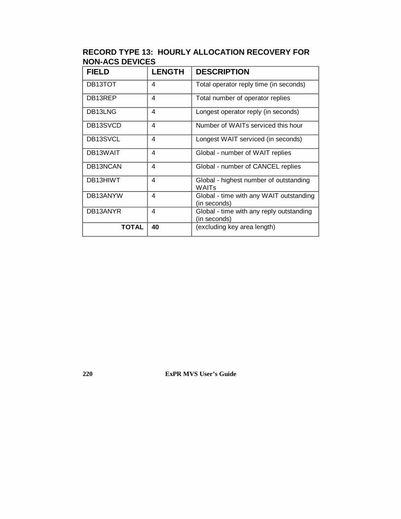
ExPR MVS User’s Guide220
RECORD TYPE 13: HOURLY ALLOCATION RECOVERY FORNON-ACS DEVICESFIELD LENGTH DESCRIPTION
DB13TOT 4 Total operator reply time (in seconds)
DB13REP 4 Total number of operator replies
DB13LNG 4 Longest operator reply (in seconds)
DB13SVCD 4 Number of WAITs serviced this hour
DB13SVCL 4 Longest WAIT serviced (in seconds)
DB13WAIT 4 Global - number of WAIT replies
DB13NCAN 4 Global - number of CANCEL replies
DB13HIWT 4 Global - highest number of outstandingWAITs
DB13ANYW 4 Global - time with any WAIT outstanding(in seconds)
DB13ANYR 4 Global - time with any reply outstanding(in seconds)
TOTAL 40 (excluding key area length)

Appendix D: Database Layout 221
TMCHIST: CDS/TMC VOLUME AND DATASET HISTORYRECORDFIELD LENGTH TYPE DESCRIPTION
ORF_USE 4 Binary Volume usage count
ORF_BLKS 4 Binary File block size
ORF_BLKC 4 Binary File block count
ORF_LREC 4 Binary File record length
ORF_VSEQ 2 Binary Volume sequence withinmulti-volume set
ORF_DSNS 2 Binary Volume number of DSN=
ORF_VOL 6 Char Volume serial
ORF_FSEQ 2 Binary File sequence within volume
ORF_ACS 3 Char ACS location of volume
ORF_LSM 2 Char LSM location of volume
ORF_DSN 44 Char File dataset name
ORF_REF 12 Char Volume last use/referencedate
ORF_UTIL 3 Char Volume percentage utilized
ORF_MEGS 5 Char Volume megabytes capacity
ORF_MEGX 1 Char + = megabytes capacitycapped
ORF_SCR 1 Char Volume scratch status
ORF_RECF 3 Char File record format
ORF_DEN 1 Char Volume creation device-typedensity
ORF_CLEN 2 Binary Volume cat length

ExPR MVS User’s Guide222
ORF_AGE 2 Binary Volume age since lastuse/reference
ORF_DSG 2 Binary Primary dataset groupnumber
ORF_MVOL 1 Char Y = Part of multi-volume sets
TOTAL 110
A TMCHIST record exists for each primary and secondarydataset on a volume. SAMPLIB member EXPRHISTcontains an assembler layout.

Appendix E: ExPR 1.1 Modifications 223
Appendix E
ExPR Version 1 Release 1 Modifications
ExPR Version 1 Release 1 introduces the following new orrevised functions:
Automate ExPR CONFIG Update Procedure - Providesautomatic collection of site data from the HSC controldataset, eliminating the need for manually specifying deviceaddresses and IDs for each ACS, LSM, and device during theinstallation and configuration process. Additionally,subsequent changes to the configuration are automaticallyrecognized by ExPR.
Tape Catalog Processing Enhancements - Extends tapecatalog reporting by providing cartridge access reporting,summary reporting by device type or length, tape rangespecification with length/include/exclude options, Redwoodsupport, extended SORT key options, splitting of update andreporting functions to allow report generating withoutaffecting the status of the database, and historicalcomparisons of volumes.
Allocation Recovery Analysis - Extends mount analysis tofully account for mount delays caused by insufficient drives oroperator performance.

ExPR MVS User’s Guide224
Mount Breakdown Report - Extends mount analysis toprovide a detailed breakdown of mount time components,including delay time.
Mount Analysis by Drive Type - Extends mount analysis todifferentiate between device types for mount count and mountresponse time.
PC Tabular Reporting - Extends PC graphical reportingoptions to display the numeric values behind the graphicalpresentation.
PC Multiple Print Option - Extends PC graphical reportingoptions to print either the current graph or all displayedgraphs.
PC “Save As” Option - extends PC graphical reportingoptions to save either the current graph or all displayedgraphs.
PC Database Purge - Allows records beyond a certain age tobe purged from the PC database.
PC Utility Functions Grouping - Combines database utilityfunctions (repair, compress, purge, scan, etc.) under a singleicon.
Dynamic Summarization of PC Database - Extends PCgraphical reporting options to include hourly, daily, weekly,monthly, quarterly, and yearly summary options.
Microsoft Excel Interface - Extends PC graphical reportingoptions to include copying graph data into an Excel-compatible spreadsheet through the clipboard feature.
Channel and Control Unit Reporting Enhancements -Extends control unit reports to include control unit saturation

Appendix E: ExPR 1.1 Modifications 225
and subsystem loading, and extends channel reporting withthe PATH-BUSY report.
Tape Error Detail Report - Extends media error reportingto include the volser and drive associated with each mediaerror, providing an audit trail of bad volumes or drives.
Demand Enter Detail Report - Extends the current enterand eject counts to highlight enters required to immediatelyservice a mount request. An audit trail report additionallygives details of the volumes and jobs involved.
Multiple CPU Support - Extends MVS system-levelreporting by grouping data by SMF ID to facilitate reportingof ACS/LSM utilization by individual MVS system in ashared environment, providing a base for future Sysplex datacollection.
Exception Reporting Enhancements - Extends exceptionreporting to include RMF-based channel and control unitdata, JES2 and JES3 allocation recovery, and available freecell and scratch information.
Database Verification and Scan Report Modifications -These reports are reformatted to reflect changes in databaselayout.
Database Conversion Facility - Enables ExPR 1.0installations to convert existing databases at the host and PClevel.

ExPR MVS User’s Guide226

Index 227
Index
—A—ACS CONFIG Statement, 166ACS Identifier, 56AGEBANDS CONFIG Statement, 171Aging and Utilization Summary, 122ALLOC-REC Report, 153API, 161APPEND CONFIG Statement, 168Application Programming Interface, 161Audience, 9Automatic CONFIG Generator
Determining Whether to Use, 52How it Works, 53Manual Entry, 59Using the Feature, 57
—C—CA-TLMS Considerations, 133CDS CONFIG Statement, 170CDSCONF, 42Channel Path Group Requirements, 53Channel Path Groups, 56CHPATH CONFIG Statement, 169CONFIG, 42CONFIG Parameters, 165CONFIG Dataset, 65CONFIG DD Statements, 166CONFIG, Entering Manually, 59Configuration Task Summary, 27Configuration, Nearline, 56
Consolidate the Database, 84Contents Report, 146Control Dataset, 65Control Statements, 26Convert ExPR Database Example, 82CONVERTDB, 73Create the ExPR CONFIG Dataset, 65CU-BUSY Report, 148CUSTOMER CONFIG Statement, 168Customization, 25
—D—Data Collection and Parameter Files, 47Data Collection Procedures, 31Data Collection Sources, 31Data Flow, 15Database
consolidate, 84initialize, 50input data, 69layout, 209multiple, 84processes, 72Reorganizing, 85
DATABASE, 36define, 48managing, 69overview, 14
Database Conversion Example, 82Database Conversion to 1.1, 73Database File Structure, 49Database Overview, 49Database Processes, 72

ExPR MVS User’s Guide228
Database Size Calculation Worksheet, 37Database Update Examples, 74Databases, 15Dataset Workload Groups, 19, 114Datasets, 35, 46Define ExPR Datasets, 46Define Nearline Configuration to ExPR, 56Define the Control Dataset to ExPR, 65Define the ExPR Database(s), 48Defining Age Bands, 108Defining Threshold Values, 89DEMAND-ENTERS Report, 156Device Address, 56DEVICE CONFIG Statement, 167DEVICE-TYPE CONFIG Statement, 167Device-Type Requirements, 54DSGROUP CONFIG Statement, 170DSMAP CONFIG Statement, 170
—E—Entering CONFIG Data Manually, 59Exception Processing, 17, 87Exception Report Generation, 91Exception Reports, 87Exception Types, 88EXPORT, 43ExPR Application Programming Interface
(API), 161ExPR CONFIG Dataset, 65ExPR Data Flow, 15ExPR Database(s), 48ExPR Datasets, 35, 46ExPR Mainframe Databases, 14ExPR Messages, 189ExPR Parameter Generation, 51ExPR PC Databases, 15ExPR Reporting Features, 17ExPR Started Task, 61ExPR Version 1 Release 1 Modifications,
223EXPRPROC Procedure, 46Extraction Period for File Transfer, 159
—F—File Transfer, 157File Transfer Extraction Period, 159File Transfer Recovery Procedures, 160FTCNTL, 42FTEXTR, 42
—G—Generating Exception Reports, 91Generating Performance Reports, 135Generating Tape Catalog Reports, 121Graphical Reports, 22
—H—Hardware Prerequisites, 46History Reports, 131HOST CONFIG Statement, 166Housekeeping Procedures, 34How ExPR Tape Processing Works, 104How ExPR Works, 13HSC CONFIG Statement, 169HSC PGMI Processing, 33HSC SMF Number, 64HSC SMF Processing, 32
—I—Initialize the ExPR Database, 50Input Data, 69INPUT SYSIN Statement, 178Install the ExPR Started Task, 61Installation, 25Installation Verification, 67Introduction, 13
—J—JES3 Support, 79Jobname Workload Group Reports, 101Jobname Workload Groups, 19, 99

Index 229
—L—LSM CONFIG Statement, 166
—M—Mainframe Databases, 14Mainframe Performance Reports, 21, 135Managing ExPR Databases, 69MAP CONFIG Statement, 174Messages, 189Mounts Report, 140MOUNTS-DETAIL Report, 142Multiple Database Support, 84MVS RMF Processing, 32MVS SMF Processing, 32MVS System Log, 32
—N—Nearline Configuration, 56
—O—Order of SELECT Statement Processing,
139
—P—Parameter Files, 47Parameter Generation, 51PATH-BUSY Report, 150PC Databases, 15PC File Transfer, 157PERFORM CONVERTDB, 73PERFORM PGMIUPDATE, 73PERFORM SMFSELECT, 72PERFORM SMFUPDATE, 73PERFORM SYSIN Statement, 180, 182PERFORM SYSLOGUPDATE, 73PERFORM TAPECAT, 73Performance Reports, 21, 135PERIOD SYSIN Statement, 178
PGMI CONFIG Statement, 173PGMIDATA, 43Printing SYSOUT Information, 137Processing Tape Catalog Data, 118
—R—RECFM Support, 80Record Types, 209Recovery Procedures, File Transfer, 160Redwood Support, 112Related Documentation, 11Reorganizing the Database, 85Report Granularity, 17Reporting Features, 17REPORT-OPTIONS SYSIN Statement, 179Reports, 21
Exception, 17generating, 135Graphical, 22performance, 135User customizable, 22
Required skills, 26Review Data Collection Procedures, 31Review ExPR Parameter Generation, 51Review SYS1.PARMLIB, 34Running Without a Tape Catalog, 134
—S—SELECT, 72Select HSC SMF Records Example, 75Select MVS SYSLOG Data Example, 78Select PGMI Data Example, 76SELECT Statement Processing Order, 139SELECT SYSIN Statement, 178Select Tape Catalog Data Example, 81Skills required, 26SMF Exception Event Report, 95SMF Housekeeping Procedures, 34Software Prerequisites, 46Space Planning, 35Specify HSC SMF Number to ExPR, 64

ExPR MVS User’s Guide230
Started Task, 61Started Task Parameters, 62StorageTek Support, 12SYS1.PARMLIB, 34SYSDA Work Files, 45SYSIN DD Statements, 178SYSIN Examples, 74SYSIN Parameters, 177SYSOUT Information, 137
—T—Tailor EXPRPROC Procedure, 46Tape Capacity Estimation, 109Tape Catalog History Reports, 131Tape Catalog Processing, 19, 103Tape Catalog Processing, Defining, 107Tape Catalog Reports, 103Tape Catalog Reports, Generating, 121Tape Catalog Supported Environments, 104Tape Catalog, Processing Data, 118Tape Catalog, Running Without, 134Tape Catalog/HSC CDS Processing, 33Tape Processing, Defining Age Bands, 108Tape Processing, How it Works, 104Tape Processing, What Information Is
Generated, 106Tape Range Definitions, 110Tape Ranges Based on Length, 110Tape Ranges Based on Redwood Capacity,
112Tape Ranges to EXCLUDE from
Processing, 113Tape Utilization Estimation, 109TAPECAT Nearline Volume Details
Report, 125TAPECAT Nearline Volume Summary
Report, 128TAPECAT Tape Catalog History Reports,
131TAPECAT Update Processing Aging and
Utilization Summary Report, 122
TAPEDEF CONFIG Statement, 172TAPE-ERRORS Report, 151Task Summary, 27Temporary SYSDA Work Files, 45THRESHOLD CONFIG Statement, 175Threshold Exceptions Report, 93Threshold Values, Defining, 89TLMSRPT, 44TMCHIST, 43TMCHIST File, Special Considerations,
117TMCHIST Record Layout, 221TMS CONFIG Statement, 171Transfer Files to PC, 157Transferring Extracted Data to a PC, 160
—U—Update Database Examples, 74Update Processing Aging and Utilization
Summary, 122User-Customizable Reports, 22Utilization Report, 144Utilization Summary, 122
—V—Verify Installation, 67Version Modifications, 223Volume Details Report, 125Volume Summary Report, 128
—W—What ExPR Does, 13Windows Help System, 9Work Files, 45WORKLOAD CONFIG Statement, 175Workload Groups, 19
Dataset, 114Jobname, 99