
Submillimeter Accuracy of InSAR Time Series: Experimental Validation
12
1142 IEEE TRANSACTIONS ON GEOSCIENCE AND REMOTE SENSING, VOL. 45, NO. 5, MAY 2007 Submillimeter Accuracy of InSAR Time Series: Experimental Validation Alessandro Ferretti, Member, IEEE, Giuliano Savio, Riccardo Barzaghi, Alessandra Borghi, Sergio Musazzi, Fabrizio Novali, Claudio Prati, and Fabio Rocca Abstract—This paper presents the results of a blind experiment that is performed using two pairs of dihedral reflectors. The aim of the experiment was to demonstrate that interferometric synthetic aperture radar (InSAR) measurements can indeed allow a displacement time series estimation with submillimeter accuracy (both in horizontal and vertical directions), provided that the data are properly processed and the impact of in situ as well as atmospheric effects is minimized. One pair of dihedral reflectors was moved a few millimeters between SAR acquisitions, in the vertical and east–west (EW) directions, and the ground truth was compared with the InSAR data. The experiment was designed to allow a multiplatform and multigeometry analysis, i.e., each re- flector was carefully pointed in order to be visible in both Envisat and Radarsat acquisitions. Moreover, two pairs of reflectors were used to allow the combination of data gathered along ascending and descending orbits. The standard deviation of the error is 0.75 mm in the vertical direction and 0.58 mm in the horizontal (EW) direction. GPS data were also collected during this experiment in order to cross-check the SAR results. Index Terms—Artificial reflector, global positioning system (GPS), interferometric synthetic aperture radar (InSAR), perma- nent scatterer (PS). I. I NTRODUCTION A S WELL known, temporal and geometric decorrelation represents the most important limiting factor in synthetic aperture radar interferometry (InSAR) [1]. Due to this fact, analyses of low coherence areas (e.g., forested and vegetated areas) with conventional InSAR methodologies cannot be per- formed successfully. Even the application of advanced InSAR algorithms, such as the permanent scatterer (PS) technique [2], may prove to be ineffective wherever the density of stable radar targets (i.e., the PS) is extremely low. In order to overcome this limitation, the usage of artificial reflectors can be very promising. Basically, an artificial reflector is an object that exhibits a high radar cross section (RCS)—or, at least, a good signal-to-clutter ratio (SCR)—stable in time. This feature allows one to carry out the interferometric mea- surements with a high signal-to-noise ratio (SNR). Apart from their deployment in low coherence areas to create measurement points, artificial reflectors have already been used Manuscript received July 18, 2006; revised November 28, 2006. This work was supported by the public fund for the Italian Electric System. A. Ferretti, G. Savio, and F. Novali are with the Tele-Rilevamento Europa, 20149 Milan, Italy (e-mail: [email protected]). R. Barzaghi and A. Borghi are with the DIIAR, Politecnico di Milano, 20133 Milan, Italy. S. Musazzi is with the CESI Ricerca, 20134 Milan, Italy. C. Prati and F. Rocca are with the Dipartimento di Elettronica ed Infor- mazione, Politecnico di Milano, 20133 Milan, Italy. Digital Object Identifier 10.1109/TGRS.2007.894440 in previous works to assess the accuracy of the InSAR mea- surements [3]–[7]. However, usually, the experiment focused on the detection and/or the measurement of just one component of the displacement vector affecting the phase center of an artificial radar target, typically a corner reflector. In fact, since InSAR data measure range variations (i.e., the component of the displacement vector along the satellite line of sight—LOS), the full 3-D displacement vector can be recovered using three or more independent InSAR datasets corresponding to noncopla- nar acquisition geometries, unless additional assumptions on the motion can be exploited. To the authors’ knowledge, so far, a blind experiment to assess the accuracy of both vertical and horizontal components of the displacement vector using two acquisition geometries has not been performed yet. In this paper, we will discuss the results achieved in a new field test with artificial reflectors. The main goal of this project was to demonstrate that the InSAR data can indeed allow the measurement of displacement time series with submillimeter accuracy (both in horizontal and vertical directions) once the radar acquisitions are properly processed and the impact of in situ as well as atmospheric effects is minimized. As an addi- tional result, the possibility of using properly oriented dihedral reflectors to create high RCS targets in urban areas for two different satellite radar sensors, characterized by different orbits and antenna squint angles, was confirmed. Preliminary results were presented during the ESA-FRINGE Workshop by Frascati [8]. Here, all SAR data have been reprocessed, achieving better results. Although not specifically designed for GPS-InSAR compar- ison, the experimental setup was used to measure the vertical displacement of the mobile reflectors using two GPS antennas, creating another dataset to cross-check the results. This paper is organized as follows: first, the design phase of the experiment is briefly summarized in Section II. Then, a description of the technical and mechanical details of the artifi- cial reflectors is reported (Section III). The subsequent section presents the deployment procedure and how the test area was identified based on amplitude data (Section IV). In Section V, the experimental results are reported, while in Sections VI and VII, the results are discussed and conclusions are drawn. II. EXPERIMENTAL SETUP In order to assess the accuracy of satellite InSAR measure- ments in both vertical and horizontal directions, an experiment involving two pairs of artificial reflectors has been set up. Each pair of reflectors is composed of two radar targets mounted on a 0196-2892/$25.00 © 2007 IEEE
-
Upload
independent -
Category
Documents
-
view
0 -
download
0
Transcript of Submillimeter Accuracy of InSAR Time Series: Experimental Validation
1142 IEEE TRANSACTIONS ON GEOSCIENCE AND REMOTE SENSING, VOL. 45, NO. 5, MAY 2007
Submillimeter Accuracy of InSAR Time Series:Experimental Validation
Alessandro Ferretti, Member, IEEE, Giuliano Savio, Riccardo Barzaghi, Alessandra Borghi,Sergio Musazzi, Fabrizio Novali, Claudio Prati, and Fabio Rocca
Abstract—This paper presents the results of a blind experimentthat is performed using two pairs of dihedral reflectors. Theaim of the experiment was to demonstrate that interferometricsynthetic aperture radar (InSAR) measurements can indeed allowa displacement time series estimation with submillimeter accuracy(both in horizontal and vertical directions), provided that thedata are properly processed and the impact of in situ as well asatmospheric effects is minimized. One pair of dihedral reflectorswas moved a few millimeters between SAR acquisitions, in thevertical and east–west (EW) directions, and the ground truth wascompared with the InSAR data. The experiment was designed toallow a multiplatform and multigeometry analysis, i.e., each re-flector was carefully pointed in order to be visible in both Envisatand Radarsat acquisitions. Moreover, two pairs of reflectors wereused to allow the combination of data gathered along ascendingand descending orbits. The standard deviation of the error is 0.75mm in the vertical direction and 0.58 mm in the horizontal (EW)direction. GPS data were also collected during this experiment inorder to cross-check the SAR results.
Index Terms—Artificial reflector, global positioning system(GPS), interferometric synthetic aperture radar (InSAR), perma-nent scatterer (PS).
I. INTRODUCTION
A S WELL known, temporal and geometric decorrelationrepresents the most important limiting factor in synthetic
aperture radar interferometry (InSAR) [1]. Due to this fact,analyses of low coherence areas (e.g., forested and vegetatedareas) with conventional InSAR methodologies cannot be per-formed successfully. Even the application of advanced InSARalgorithms, such as the permanent scatterer (PS) technique [2],may prove to be ineffective wherever the density of stable radartargets (i.e., the PS) is extremely low.
In order to overcome this limitation, the usage of artificialreflectors can be very promising. Basically, an artificial reflectoris an object that exhibits a high radar cross section (RCS)—or,at least, a good signal-to-clutter ratio (SCR)—stable in time.This feature allows one to carry out the interferometric mea-surements with a high signal-to-noise ratio (SNR).
Apart from their deployment in low coherence areas to createmeasurement points, artificial reflectors have already been used
Manuscript received July 18, 2006; revised November 28, 2006. This workwas supported by the public fund for the Italian Electric System.
A. Ferretti, G. Savio, and F. Novali are with the Tele-Rilevamento Europa,20149 Milan, Italy (e-mail: [email protected]).
R. Barzaghi and A. Borghi are with the DIIAR, Politecnico di Milano, 20133Milan, Italy.
S. Musazzi is with the CESI Ricerca, 20134 Milan, Italy.C. Prati and F. Rocca are with the Dipartimento di Elettronica ed Infor-
mazione, Politecnico di Milano, 20133 Milan, Italy.Digital Object Identifier 10.1109/TGRS.2007.894440
in previous works to assess the accuracy of the InSAR mea-surements [3]–[7]. However, usually, the experiment focusedon the detection and/or the measurement of just one componentof the displacement vector affecting the phase center of anartificial radar target, typically a corner reflector. In fact, sinceInSAR data measure range variations (i.e., the component ofthe displacement vector along the satellite line of sight—LOS),the full 3-D displacement vector can be recovered using three ormore independent InSAR datasets corresponding to noncopla-nar acquisition geometries, unless additional assumptions onthe motion can be exploited. To the authors’ knowledge, so far,a blind experiment to assess the accuracy of both vertical andhorizontal components of the displacement vector using twoacquisition geometries has not been performed yet.
In this paper, we will discuss the results achieved in a newfield test with artificial reflectors. The main goal of this projectwas to demonstrate that the InSAR data can indeed allow themeasurement of displacement time series with submillimeteraccuracy (both in horizontal and vertical directions) once theradar acquisitions are properly processed and the impact ofin situ as well as atmospheric effects is minimized. As an addi-tional result, the possibility of using properly oriented dihedralreflectors to create high RCS targets in urban areas for twodifferent satellite radar sensors, characterized by different orbitsand antenna squint angles, was confirmed. Preliminary resultswere presented during the ESA-FRINGE Workshop by Frascati[8]. Here, all SAR data have been reprocessed, achieving betterresults.
Although not specifically designed for GPS-InSAR compar-ison, the experimental setup was used to measure the verticaldisplacement of the mobile reflectors using two GPS antennas,creating another dataset to cross-check the results.
This paper is organized as follows: first, the design phaseof the experiment is briefly summarized in Section II. Then, adescription of the technical and mechanical details of the artifi-cial reflectors is reported (Section III). The subsequent sectionpresents the deployment procedure and how the test area wasidentified based on amplitude data (Section IV). In Section V,the experimental results are reported, while in Sections VI andVII, the results are discussed and conclusions are drawn.
II. EXPERIMENTAL SETUP
In order to assess the accuracy of satellite InSAR measure-ments in both vertical and horizontal directions, an experimentinvolving two pairs of artificial reflectors has been set up. Eachpair of reflectors is composed of two radar targets mounted on a
0196-2892/$25.00 © 2007 IEEE

FERRETTI et al.: SUBMILLIMETER ACCURACY OF InSAR TIME SERIES: EXPERIMENTAL VALIDATION 1143
TABLE IRCSs OF THE MOST COMMON ARTIFICIAL REFLECTORS
common metallic basement: one is visible along ascending or-bits of the satellite and the other one is visible along descendingorbits. One pair is fixed and used as a reference point. The otherpair is installed on a platform that can be shifted horizontallyand vertically with submillimetric accuracy.
In principle, the use of four independent datasets acquired bytwo different sensors (i.e., Envisat and Radarsat) along ascend-ing and descending orbits would allow the recovery of the full3-D displacement vector affecting the radar target. However,due to the limited number of scenes that could be acquiredduring the duration of the experiment (about ten months) andthe unfavorable SNR achievable in the north–south direction[9], [10], it was decided to limit the displacement of the movingreflectors to the east–west (EW) and vertical components only.
The type of artificial reflector to be used in the experimentwas designed to maximize the RCS and the SCR of the targetto allow accurate phase measurements while keeping the weightand the overall dimensions as small as possible. The latterconstraints are required to guarantee a high mechanical stabilityand a positioning accuracy of the mobile reflectors better than1 mm. Moreover, the selected reflectors had to be visible in bothEnvisat and Radarsat acquisitions, both platforms having radarsensors operating at C-band.
As far as the first point is concerned, the reflector should becharacterized by a reflectivity much higher than the surroundingscatterers. In fact, the reflector has to be easy to identify inthe radar image, and its SCR, i.e., the ratio between the RCSof the reflector and that of the background scenario, shouldguarantee a low dispersion of the phase values. For high SCRvalues, the relationship between SCR, phase noise (σφ), and thedispersion of the displacement measurements along the satelliteLOS (σLOS) can be approximated as follows [4]:
σLOS =λ
4 · π · σφ ≈ λ
4 · π ·√
12 · SCR
. (1)
A design requirement on the SCR of 100 (i.e., 20 dB) thencorresponds to a dispersion of the displacement measurementsin LOS direction of about 0.3 mm at C-band. Since the areaavailable for the experiment was an urban area in Milano (Italy),high SCR values can be achieved only with RCS values ofseveral thousand square meters.
Apart from the SCR, the other major requirement of theexperiment concerns the multiplatform visibility. Table I sum-marizes the main features of the most common reflectors used
in radar experiments, namely, flat plate, dihedral [11]–[14],square, and triangular trihedral. Flat plates cannot be used forthe experiment since they are visible for one satellite sensoronly (either Envisat or Radarsat). In fact, the two radar systems,although both operating at C-band and quite similar for band-width and pulse repetition frequency, are characterized by verydifferent Doppler centroid (Dc) values, corresponding to differ-ent antenna squint angles (Appendix), at least at midlatitudes.Due to the different Dc values of the target in the two radarsystems (no yaw-steering correction is available in Radarsat),by properly pointing a flat reflector with a physical dimensionof 1 m2 for Envisat acquisitions, its RCS in Radarsat imageswould experience a loss of about 17 dB with respect to thenominal value reported in Table I, making it impossible to havea high SCR in an urban environment.
By comparing the maximum theoretical RCS with the cor-responding overall dimensions of the reflectors, it was decidedto use a set of dihedral reflectors properly pointed toward bothsatellite platforms, as discussed in Section IV.
Even if dihedral provides an excellent radar target for thepurpose of polarimetric calibration [15]–[17], its applicationin the InSAR experiment is not so common. Indeed, cornerreflectors, having less demanding requirements, are generallydeployed. Because of the mechanical stability and the accuracyof the imposed shifts to the reflectors must be better than afraction of millimeter for this validation exercise, both the sizeand the weight of the structure to be tracked by the systemshould be kept limited. As a consequence, the dihedral has beenpreferred to the more cumbersome structure of the trihedral.Moreover, a by-product of the experiment would have been thevalidation of the pointing procedure (described in Section IV)based on nominal satellite ephemeredes.
Although not specifically designed for a GPS-InSAR com-parison, the experimental setup was completed by two GPSpoints for differential measurements. The first antenna has beenfixed to the mobile platform. Unfortunately, the shape of thebasement turned out to be unfavorable to create a measurementpoint integral with the mobile reflectors, and the GPS antennacould measure only the vertical displacements of the dihedrals.The second antenna was placed 50 m apart from the first oneon an area supposed stable. The baseline vector between thesetwo points can then be estimated with high accuracy; in fact,most of the biases affecting the GPS signal are strongly reducedfor such a short baseline when processing a double differencecarrier phase.
III. DIHEDRAL DESIGN
As already discussed in the previous section, two pairs ofdihedral reflectors were designed and manufactured for theexperiment: one fixed and one “mobile.” The latter was se-quentially displaced by an operator both in the horizontal andvertical directions.
The mobile reflectors’ assembly [Fig. 1(a)] is made by twometallic frames (manufactured by means of 45 × 45 and 45 ×90 mm2 square/rectangular section standard section aluminumbars). The lower frame, which is robust enough to supportthe whole reflector structure, is steady and equipped with

1144 IEEE TRANSACTIONS ON GEOSCIENCE AND REMOTE SENSING, VOL. 45, NO. 5, MAY 2007
Fig. 1. (a) Mobile reflectors assembly and (b) schematic of a dihedral reflector.
Fig. 2. Mobile reflectors’ assembly. The (a) vertical and (b) horizontal translation mechanism.
four protrusive legs (to increase the stability) provided with fas-tening holes for ground fixation. The upper frame is the mobileone. Vertical displacements of this frame can be generated bymeans of four screw jacks (50-mm travel range; 0.1-mm screwpitch) positioned between the two frames. To get a uniform ver-tical displacement, the four jacks are simultaneously driven (viaconnecting bars) by acting on a unique driving crank [Fig. 2(a)].Bolted to the upper frame, there are two linear translation unitsutilized for the horizontal displacements [Fig. 2(b)]. The precisein-plane translation of a mobile platform is provided in eachunit by four ball screw assemblies driven by means of screwjacks similar to the previously described ones (50-mm travelrange; 0.2-mm screw pitch). As for the vertical translationmechanism, the two jacks are simultaneously driven by meansof a unique crank.
The dihedral reflectors are mounted upon the two slidingplatforms by means of a robust clamping system. Each reflector
is made by two square aluminum plates (1 × 1 m wide;2 mm thick), orthogonally mounted on a rigid supporting frame(made by 45 × 45 mm2 standard section aluminum bars). Themaximum RCS is then 7.845 m2 at 5.3 GHz. The clampingmechanism has been designed so that rotations of the reflectorsaround both the vertical and horizontal axes can be performedaccurately during the preliminary alignment phase.
By means of multiple measurements carried out on themobile platform, it was estimated that the mechanical errors(taking into account also the thermal dilation effects) wereabout 0.3 mm. This high accuracy value is required in orderto allow a submillimeter comparison with the InSAR data.
The steady reflectors’ assembly is quite similar to the mobileone, but with a simpler mechanical structure. It is, in fact,composed of a single supporting frame where a couple ofdihedral reflectors (identical to those utilized in the mobileunit) is rigidly clamped. Apart from the reflector’s clamping

FERRETTI et al.: SUBMILLIMETER ACCURACY OF InSAR TIME SERIES: EXPERIMENTAL VALIDATION 1145
mechanism (used to properly point the device), no other movingparts are present in the structure.
IV. DIHEDRAL DEPLOYMENT
The deployment procedure mainly consists of two steps:1) identification of the proper locations for the artificial reflec-tors; and 2) pointing of the dihedrals.
The selection of the best site is carried out by taking intoaccount the three basic requirements.
1) The reflectors should be installed in a protected area un-der control of the validation team for the whole durationof the campaign (almost one year).
2) The SCR should be high enough in all acquisitions so thatthe theoretical precision of LOS displacement measure-ments would be better than 1 mm.
3) The reflectors should be not too far apart, so that the im-pact of atmospheric effects can be considered negligible.
Radar amplitude images acquired before the deployment ofthe artificial reflectors can be used successfully to select suit-able areas for the experiment. According to logistic constraints,as explained in [8], the area selected for the experiment was aflat roof of a building. The two stations are about 50 m apart,making the impact of the atmospheric effects on the phasevalues extremely weak [18]. Indeed, one of the most significanterror terms affecting the InSAR measurements is due to theso-called “atmospheric phase screen.” Having deployed thereflectors very close to each other, this phase disturbance wasalmost canceled when performing the double phase difference(as explained in Section V).
It was realized, however, that the best configuration couldnot meet all the requirements on σLOS, since one of the fourreflectors would experience unfavorable SCR values for one ac-quisition geometry, at least based on the clutter power estimatedfrom the available radar images. Real data analysis partiallyconfirmed this fact, as it will be discussed in Section V.
After the selection of the best areas for the deployment ofthe reflectors, each dihedral is properly orientated in order tomaximize its RCS in all acquisition geometries. As well known,the RCS decreases if the LOS of the radar sensor is not alongthe symmetry axis of the reflector [11]. Dihedral reflectors arethen very sensitive to pointing errors in the azimuth direction.
Since each reflector should be visible in both Envisat andRadarsat acquisitions, an ad hoc deployment procedure has tobe adopted. In detail, the following steps are required.
1) For each dihedral, the direction of “maximum illumina-tion” for each radar sensor is computed, i.e., we evalu-ate the relative position of the satellite with respect tothe reflector when the radar illuminates the target withmaximum power.
2) Let Lrsat and Lenvi be the maximum illumination unitvector of the reflector for Radarsat and Envisat, respec-tively; Lrsat and Lenvi depend on the effective squintangles of the radar antenna estimated from the nominalDc values (Appendix).
3) Compute the vector cross product: PERP = Lrsat ×Lenvi.
TABLE IIDATASET RADARSAT ASCENDING (STANDARD BEAM S3)
4) Align the dihedral backbone along the PERP direction.5) Rotate the reflector around PERP so that it points (i.e.,
it exhibits maximum RCS) toward the direction definedby the bisector vector BIS of the two radar illuminationdirections: BIS = Lrsat + Lenvi [as shown in Fig. 1(b)].
From an operational point of view, taking into account thewhole pointing procedure and the instruments used, it was esti-mated that pointing errors were lower than 0.5◦ correspondingto a loss of less than 1200 m2 in RCS with respect to thenominal (maximum) value, namely, 7.845 m2. Of course, anyvariation in the Dc with respect to the nominal value impactson the RCS exhibited by the reflector. While this factor isalmost negligible in Envisat acquisitions (Dc values are verylow and almost identical), for Radarsat, a further loss of 100 m2
maximum in RCS should be taken into account (Appendix).
V. EXPERIMENTAL RESULTS
The processing was performed using four different datasetsacquired over Milano from October 2004 to July 2005: ascend-ing Radarsat Standard Beam S3 (Table II), descending RadarsatStandard Beam S3 (Table III), ascending Envisat Image ModeS2 (Table IV), and descending Envisat Image Mode S2(Table V).
The experiment was “blind,” i.e., the processing team wasnot aware of the actual displacements affecting the mobile tar-get. However, the maximum differential shift, in both horizontaland vertical directions, was carefully selected so that no phaseunwrapping error should be expected in the time series of rangevariations in any InSAR dataset.
1146 IEEE TRANSACTIONS ON GEOSCIENCE AND REMOTE SENSING, VOL. 45, NO. 5, MAY 2007
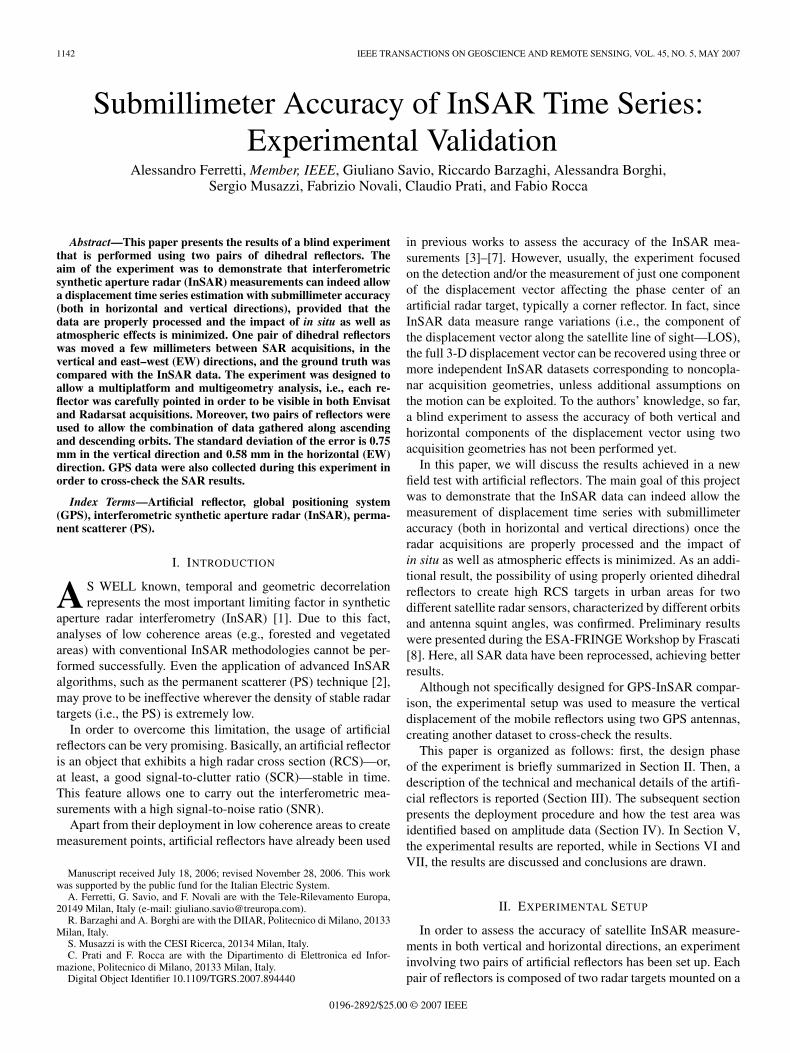
TABLE IIIDATASET RADARSAT DESCENDING (STANDARD BEAM S3)
TABLE IVDATASET ENVISAT ASCENDING (TRACK 487—FRAME 909)
Each dataset was processed independently. First, all imageshave been oversampled both in range and azimuth directions,and coregistered with respect to a reference image or master.Then, the differential interferograms have been generated, aswell as the time series of the amplitude returns. Finally, the LOSdisplacement time series has been extracted, and the EW andvertical components have been estimated.
A. Amplitude Analysis
As already mentioned in the previous section, the time seriesanalysis of the amplitude values of the image pixels correspond-
TABLE VDATASET ENVISAT DESCENDING (TRACK 208—FRAME 2691)
TABLE VIESTIMATED DISPERSION OF LOS DISPLACEMENT FROM SCR ASI VALUES
ing to the locations of the reflectors allows an estimation ofthe SCR value, assuming stationary clutter conditions. Oper-ationally, the clutter power can be computed as the mean of theintensity values corresponding to those images (at least sevenimages for all datasets) acquired before the deployment of thedihedrals, whereas the other samples are used to extract themean reflector backscattered signal.
Table VI summarizes the estimated SCR values for the refer-ence and mobile dihedrals for all acquisition geometries. Threeout of four reflectors exhibit an estimated SCR value higherthan 10 dB, allowing precise (σLOS < 1 mm) displacementestimates (1), at least theoretically. One is characterized by arather poor SCR (< 6 dB), as was already foreseen during thedesign phase of the experiment.
Apart from the ratio of the signal intensity before and afterthe deployment of the reflector, the expected phase noise can beestimated by computing the dispersion index of the amplitudevalues relative to the time series of each reflector. The amplitudestability index (ASI) is a simple statistical parameter alreadyused successfully in the PS technique for the identification ofthe so-called “PS candidates,” and it is defined as the ratio of themean (mA) and the standard deviation (σA) of the amplitudedata returns [2].

FERRETTI et al.: SUBMILLIMETER ACCURACY OF InSAR TIME SERIES: EXPERIMENTAL VALIDATION 1147
Fig. 3. LOS displacement estimation using differential phase observations atthe reflector locations.
The difference between the SCR and the ASI values is relatedto the methodology adopted to estimate the noise level. Inthe former, the clutter power is estimated by using the radarimages acquired before the experiment (with no reflector) andby supposing a certain RCS for the artificial reflector to beinstalled. In other words, the estimated SCR value assumesthat the superposition of the effects holds and the installationof the artificial reflector will not produce any interaction orshadowing effect with the background clutter of the resolutioncell where it will be deployed. Thus, the computed SCR is an“expected SCR.”
On the contrary, the ASI value is a measurement of the actualSCR (better to say, the SNR: taking into account both the clutterand the noise level of both the sensor and the processing). TheASI value, of course, could be estimated only after the reflectordeployment and after the acquisition of some SAR data. Thehigher the number of data available, the better the accuracy ofthe estimation.
For high SNR [2], the following relation holds:
σLOS =λ
4 · π · σφ ≈ λ
4 · π · 1ASI
=λ
4 · π · σA
mA. (2)
In Table VI, the ASI values of the four reflectors as wellas the estimated dispersion of the LOS displacement measure-ments are reported for Radarsat acquisitions. In fact, the numberof Envisat data available after the installation of the reflectorswas not enough to get a reasonable estimation of the ASI values.
It should be noted that, in general, both approaches for theestimation of the phase dispersion based on the amplitudedata give a worse SNR for images acquired by Radarsat alongascending orbits. However, the ASI is higher than expected, atleast based on the analysis of the images after the deploymentof the reflectors.
As a matter of fact, the precision of the InSAR measurementsturned out to be comparable with the accuracy expected fromthe ASI values, taking into account the contribution expectedfrom unavoidable in situ mechanical effects and spurious at-mospheric components, as well as processing artifacts, as it willbe discussed in Section VI.
B. LOS Measurements
As shown in Fig. 3, the LOS displacement correspondingto the ith acquisition is computed through a phase difference
Fig. 4. LOS displacements retrieved by Radarsat data in comparison with theprojection of the true values components along the corresponding radar sight.(a) Descending data. (b) Ascending data.
between the reference reflector (suffix REF) and the mobile one(suffix MOB):
∆ϕi =(ϕi
MOB − ϕiREF
) − (ϕM
MOB − ϕMREF
)(3)
where the superscript M indicates the master acquisition (i.e.,the temporal reference) and i is the slave image under study.
Since the position of the reflectors was known with submeteraccuracy, owing to the GPS measurements carried out at thebeginning of the experiment, all phase components related tothe positions of the radar targets were easily compensated for,allowing a rather straightforward extraction of the motion com-ponents. In fact, owing to the closest distance (e.g., about 50 m)separating the reflectors and the spatial behavior (e.g., low pass)of the tropospheric and ionospheric phase components, theimpact of the atmospheric effects could be reasonably neglectedby the double phase difference.
Figs. 4 and 5 show the retrieved LOS displacements forRadarsat and Envisat data (ascending and descending orbits),as well as the ground truth data obtained from the horizontaland vertical displacement values imposed on the mobile sta-tion by the validation team, projected into the satellite LOS.Maximum errors and standard deviation values are reported inTables VII–X.
C. Estimation of Horizontal and Vertical Components
In order to properly combine the LOS estimations derivedfrom different acquisition geometries at different times, we re-ferred to the known scheduled shifts of the reflectors, as shownin Table XI. The ascending and descending LOS measurements

1148 IEEE TRANSACTIONS ON GEOSCIENCE AND REMOTE SENSING, VOL. 45, NO. 5, MAY 2007
Fig. 5. LOS displacements retrieved by Envisat data in comparison with theprojection of the true values components along the corresponding radar sight.(a) Descending data. (b) Ascending data.
TABLE VIILOS DISPLACEMENTS RETRIEVED BY RADARSAT ASCENDING DATA IN
COMPARISON WITH THE PROJECTION OF THE TRUE VALUES OF THE
DISPLACEMENT COMPONENTS ALONG THE CORRESPONDING RADAR LOS
TABLE VIIILOS DISPLACEMENTS RETRIEVED BY RADARSAT DESCENDING DATA IN
COMPARISON WITH THE PROJECTION OF THE TRUE VALUES OF THE
DISPLACEMENT COMPONENTS ALONG THE CORRESPONDING RADAR LOS
TABLE IXLOS DISPLACEMENTS RETRIEVED BY ENVISAT ASCENDING DATA IN
COMPARISON WITH THE PROJECTION OF THE TRUE VALUES OF THE
DISPLACEMENT COMPONENTS ALONG THE CORRESPONDING RADAR LOS
TABLE XLOS DISPLACEMENTS RETRIEVED BY ENVISAT DESCENDING DATA IN
COMPARISON WITH THE PROJECTION OF THE TRUE VALUES OF THE
DISPLACEMENT COMPONENTS ALONG THE CORRESPONDING RADAR LOS
TABLE XISCHEDULED MOVEMENTS AND SAR IMAGES ACQUIRED
DURING THE EXPERIMENT
can be related to the components of the displacement vectoraccording to the following equations:
[νASCE
νDESCE
]=
[aASCEUD aASCE
EW
aDESCEUD aDESCE
EW
] [xUD
xEW
]
v =A · x (4)
where v is the vector of the estimated displacements alongthe two LOSs, A is the matrix of the up–down (UD) andEW components of the sensitivity vectors (i.e., the unit vectorsrelated to the satellite LOS), and x is the unknown componentsof the displacement vector. Equations in (4) are derived sup-posing that the north–south component is null, as discussed inthe Introduction. Since the matrix A is nonsingular, the exactanalytical solution can be easily computed.
Unfortunately, the low number of Envisat scenes acquiredduring the experiment (due to conflicts in the acquisition plan-ning over the test area) did not allow us to apply a multiplatformapproach, where Envisat and Radarsat data are jointly usedto recover the displacement vector. As a consequence, theestimation of the horizontal and vertical components of thedisplacement vector has been performed using the Radarsatdata only.

FERRETTI et al.: SUBMILLIMETER ACCURACY OF InSAR TIME SERIES: EXPERIMENTAL VALIDATION 1149
Fig. 6. Comparison between the DInSAR displacement time series and theground truth data. A blue triangle corresponds to a DInSAR displacementand a purple square to a ground truth data. (a) EW displacement component.(b) UD displacement component.
TABLE XIIDISPLACEMENTS RETRIEVED BY COMBINING RADARSAT ASCENDING
AND DESCENDING DATA IN COMPARISON WITH GROUND TRUTH VALUES
In Fig. 6, the time series of the horizontal and vertical com-ponents estimated from the Radarsat dataset is reported. Thestandard deviation of the estimated displacements is 0.75 and0.58 mm for vertical and horizontal components, respectively(Table XII). These numbers are the most important achievementof this project. They show that under favorable conditions andhigh SNR, submillimetric precision of the estimated displace-ment values can be achieved using satellite radar observation.
D. GPS Data Analysis
GPS data were collected at the beginning and at the end ofthe temporal window of SAR acquisitions, i.e., from October2004 to July 2005. These data have been observed over sessionslasting, in most of the cases, more than 24 h. Data processing
TABLE XIIIDISPLACEMENTS RETRIEVED BY GPS DATA IN COMPARISON
WITH THE GROUND TRUTH VALUES
Fig. 7. GPS displacement estimations compared with ground truth data. (UDdirection).
has been based on computing the double difference carrierphase using the Bernese 5.0 scientific software [19], whichallows for the highest quality standard.
The quasi-iono free strategy for ambiguity fixing has beenadopted, and CODE ionospheric parameters have been consid-ered to reduce the ionospheric perturbation in L1 and L2 carrierphase observables. The tropospheric zenith path delay hasbeen modeled by the Dry-Neill model, estimating one hourlyparameter in the Wet-Neill mapping function. Horizontal gra-dient parameters have also been estimated. The coordinateshave been computed using the iono-free observable, weightingthe observations with the elevation-dependent function cos2(z)(z is the satellite zenith angle).
The coordinates of the two points have been estimated inthe IGb00 reference frame [20] by using three IGS permanentstations (WTZR, GRAZ, ZIMM) and precise IGS ephemerides.
Then, (N, E, U) coordinates were computed with respect toa local cartesian reference frame having its origin in point B(i.e., the “reference antenna”). The local coordinate variationshave been referred to the estimates of October 18th, which ishence our starting position. The estimated GPS variations arelisted in Table XIII.
As already mentioned, the position of the GPS antenna wassuch that only the vertical displacements of the reflectors couldbe recorded and compared with ground truth. Indeed, the GPSestimates, as reported in Fig. 7, are close to the experimentalvariations. A t-Student test (at the significance level α = 5%)proves that these estimates are statistically coherent with thoseimposed during the experiment.

1150 IEEE TRANSACTIONS ON GEOSCIENCE AND REMOTE SENSING, VOL. 45, NO. 5, MAY 2007
VI. DISCUSSION
As stated in (3), LOS displacements are evaluated by a phasedifference. Thus, assuming the uncorrelated noise components,it follows that
σ2∆ϕi =
(σ2
MOB,i + σ2REF,i
)+
(σ2
MOB,M + σ2REF,M
). (5)
The phase dispersion of each InSAR measurement is then thesum of four contributions: two depend on the ith acquisition,whereas the others are related to the reference image. Due tothis fact, each LOS measurement is affected by a systematicerror (i.e., a bias) that is caused by the noise superimposed tothe master acquisition.
Using (5) and the dispersion of the LOS measurementsestimated from the ASI values (Table VI), it is possible toestimate the a priori covariance matrix CD of the input data:
CD =[
σ2LOS,ASCE 0
0 σ2LOS,DESCE
]=
[0.712 0
0 0.412
].
(6)
In order to retrieve the expected accuracy of the vertical andEW displacements, we can compute the a posteriori covariancematrix CM. By substituting the Radarsat sensitivity vectorsinto the A matrix and taking into account the matrix CD,it results that
CM =[ATC−1
D A]−1
=[
0.502 −0.15−0.15 0.712
]. (7)
According to (6), the vertical component is resolved better thanthe EW. In detail, the theoretical standard deviation for theUD direction is 0.50 mm, whereas for the EW component,it is 0.71 mm.
It is interesting to compare the expected values with thosecomputed by the experimental data. According to the experi-mental results, the standard deviation for the UD component is0.75 mm, and it is 0.58 mm along the EW direction. Such a highaccuracy level for both horizontal and vertical displacementsof a time series (not a single measurement) of the InSAR dataturns out to be comparable with the accuracy of the mechanicaldevice used for the ground truth (about 0.3 mm as stated inSection III).
GPS data demonstrated that under ideal conditions and usinga state-of-the-art software, the GPS can achieve a millimetricaccuracy also in the vertical direction.
VII. CONCLUSION
Compared to other experiments involving artificial reflectors,the experiment reported in this paper presents some new inter-esting features.
First of all, in order to carry out a validation experimentwith submillimeter accuracy, we were somewhat “forced” touse the dihedral reflector. In fact, both the weight and thedimension of the structure to be tracked represent main practicaldesign requirements to guarantee high mechanical stability and
accurate positioning systems (e.g., the ground-truth data shouldbe collected with submillimeter accuracy too). Even if the useof dihedral reflector made the experiment more challengingfrom the technical point of view, the final results show anunprecedented precision.
A new pointing procedure that allows dihedral reflectors tobe visible from two different satellite platforms (i.e., Envisatand Radarsat) was developed and successfully tested. It wasfound that it was possible to accomplish a multiplatform analy-sis using the same radar target. Unfortunately, the low numberof Envisat scenes acquired during the experiment did not allowthe completion of this analysis.
Nevertheless, for the first time, the possibility of combiningmultigeometry (e.g., ascending and descending orbits) SARacquisitions in order to retrieve a 2-D displacement time serieswith submillimeter accuracy has been demonstrated. In moredetail, the accuracy for the vertical movement results equal to0.75 mm, whereas for the EW component, it is 0.58 mm. Theretrieved U-D dispersion results were slightly lower than thetheoretical value, while the E-W component is resolved betterthan expected.
Such a high accuracy was a consequence of the following.
1) Significant time and resources devoted to the design,the planning, the implementation, the control, and theperformance of the experiment.
2) The mobile structure and the mechanism for imposingthe displacement were carefully designed, manufactured,assembled, and operated.
3) All in situ effects were minimized by properly selectingthe site and preventing any natural or anthropogenicinterferences.
4) The impact of atmospheric effects was minimized byconsidering two reflectors less than 50 m apart: this iswell below the correlation length of tropospheric andionospheric components. Indeed, one of the most signif-icant error terms affecting the InSAR measurements isdue to the so-called “atmospheric phase screen.” Havingdeployed the reflectors very close to each other, this phasedisturbance was almost canceled by the double phasedifference.
5) GPS data have been used to properly remove the topo-graphic phase components.
6) SAR data processing has been performed using state-of-the-art software procedures developed internally.
Another interesting result has been derived by the amplitudeand the phase analysis of each deployed reflectors: usually,amplitude data are neglected in InSAR validation exercise. Itis the first time that both amplitude and phase informationgathered during the duration of the experiment exhibit sucha good agreement. Moreover, the computed ASI index valuesprovide an extremely powerful cross-check of the reliability ofthe achieved results.
It should be pointed out that this experiment was just onestep toward a full validation of the PS approach using artificialreflectors. In fact, although we have demonstrated that precisedisplacement measurements can be carried out on radar targetsnot affected by phase decorrelation phenomena, the procedure

FERRETTI et al.: SUBMILLIMETER ACCURACY OF InSAR TIME SERIES: EXPERIMENTAL VALIDATION 1151
related to the estimation and removal of the atmospheric phasescreen superimposed on each radar acquisition was not val-idated, due to the short distance between the two reflectors.Future research efforts should be devoted to this importanttopic, although a good agreement between PS and continuousGPS data has already been reported in [21] and [22].
In the future, the combination of GPS and InSAR technologywill provide a powerful tool for imaging land deformation.GPS data can provide an absolute calibration for PS data[23], high temporal resolution to detect abrupt changes, highvelocity accuracy in three dimensions, and calibration of SARmeasurements to remove low-frequency components due toionospheric effects and orbital fringes. PS interferometry pro-vides a remarkable spatial coverage compared to the GPS, andnew SAR sensors will increase significantly the number of SARimages gathered over a certain area. Urban areas are particularlyamenable to PSInSAR analysis. The joint combination of bothRadarsat and ESA SAR images acquired along both ascendingand descending orbits could provide more than 2000 PS/km2
over most of the cities, making the monitoring of individualbuildings feasible. If the density of GPS stations is high enough,the vertical components of the local velocity field can beestimated using single-geometry SAR datasets by removing thecontribution of the GPS-derived horizontal velocity field fromthe InSAR range change rates [24]. For sure, the identificationof synergistic strategies for the combination of both GPS andPS data will be the subject of future developments.
APPENDIX
The RCS of a dihedral reflector depends on its dimensionsand orientation. Theoretically, the relationship between RCSand these angles can be determined only by using very accuratemodel for backscattering [13]. Nevertheless, a closed-form for-mula for the RCS of a perfectly conducting dihedral at arbitraryaspect angles can be found in [11] and [12]. The latter formulais valid for incident angles close to the symmetry axis of thereflector, and it is then applicable to the experiment under study.According to [12], the RCS is proportional to the followingfunction:
RCS ∝(
sin(X)X
)2
(A1)
where
X =2 · πλ
· L · cos(θ) · sin(φ) (A2)
and L is the dihedrals’ edge length.Because the dihedral orientation was performed using a GPS
compass and electronic leveling, the positioning could contain“man-induced” errors. For example, considering a positionaccuracy of 0.5◦, it results from (A2) that the RCS loss for adihedral with 1 × 1 m surfaces is 1177 m2. As is well known,the Dc value of a SAR acquisition affects the direction ofthe illuminating wave. As a consequence, it is interesting to
investigate the effect of this parameter on the RCS of a radartarget shaped as a dihedral. The Doppler frequency fD is relatedto the squint angle ϕsquint by the relationship
fD =2 · νsat
λ· sin(ϕsquint) (A3)
where νsat is the velocity of the satellite platform. Consideringa Doppler frequency variation ∆fD of 600 Hz (the maximumfrequency difference exhibited by all the processed scenes isequal to 583 Hz), the pointing error ∆ϕsquint with respect tothe reference φ angle is given by
∆ϕsquint =∣∣∣∣ϕsquint − arcsin
(λ · (fD + ∆fD)
2 · νsat
)∣∣∣∣ . (A4)
The worst case presents a maximum angle error of 0.14◦ thatcorresponds to an RCS loss lower than 100 m2. To conclude, alimited Doppler frequency variation has a negligible impact onthe dihedral RCS value.
Therefore, the main source of RCS loss for dihedral reflectorsis represented by orientation errors. Deployment of dihedralreflectors then requires very accurate pointing procedures aswell as a good knowledge of the satellite acquisition geometry.
ACKNOWLEDGMENT
The authors would like to thank A. Fumagalli for his supportin SAR data processing.
REFERENCES
[1] P. A. Rosen et al., “Synthetic aperture radar interferometry,” Proc. IEEE,vol. 88, no. 3, pp. 333–382, Mar. 2000.
[2] A. Ferretti, C. Prati, and F. Rocca, “Permanent scatterers in SAR inter-ferometry,” IEEE Trans. Geosci. Remote Sens., vol. 39, no. 1, pp. 8–20,Jan. 2001.
[3] C. Prati, F. Rocca, and A. Monti Guarnieri, “SAR interferometry ex-periments with ERS-1,” in Proc. 1st ERS-1 Symp.—Space Service OurEnvironment, Cannes, France, Nov. 4–8, 1992, pp. 211–218. ESA SP-359.
[4] G. Ketelaar, P. Marinkovic, and R. Hanssen, “Validation of point scattererphase statistics in multi-pass InSAR,” in Proc. CEOS SAR Workshop,Ulm, Germany, May 27–28, 2004.
[5] P. Marinkovic, G. Ketelaar, and R. Hanssen, “A controlled Envisat/ERSpermanent scatterer experiment, implications of corner reflector monitor-ing,” in Proc. CEOS SAR Workshop, Ulm, Germany, May 27–28, 2004.
[6] Y. Xia, H. Kaufmann, and X. Guo, “Differential SAR interferometry usingcorner reflectors,” in Proc. Int. Geosci. and Remote Sens. Symp., Toronto,ON, Canada, Jun. 24–28, 2002, pp. 1243–1246.
[7] L. Timmen, Y. Xia, C. Reigber, R. Hartmann, T. Fiksel, W. Winzer, andJ. Knoch-Weber, “Monitoring of small motions in mining areas by SARinterferometry,” in Proc. Fringe, 1996.
[8] G. Savio, A. Ferretti, F. Novali, S. Musazzi, C. Prati, and F. Rocca,“PSInSAR validation by means of a blind experiment using dihedralreflectors,” in Proc. FRINGE Workshop, 2005. ESA SP-610.
[9] F. Rocca, “3D motion recovery from multiangle and/or left right interfer-ometry,” in Proc. Fringe, 2003.
[10] S. Sircar, C. Randell, D. Power, J. Youden, and E. Gill, “Measuring 3-Dground movement by differential interferometry: Technique and valida-tion,” in Proc. IEEE NECEC, St. John’s, NF, Canada, 2003.
[11] E. F. Knott, “RCS reduction of dihedral corners,” IEEE Trans. AntennasPropag., vol. AP-25, no. 3, pp. 406–409, May 1977.
[12] S.-Y. Wang and S.-K. Lee, “A compact RCS formula for a dihedral cor-ner reflector at arbitrary aspect angles,” IEEE Trans. Antennas Propag.,vol. 46, no. 7, pp. 1112–1113, Jul. 1998.
[13] K. Hayashi, R. Sato, Y. Yamaguchi, and H. Yamada, “Polarimetric scatter-ing analysis for a finite dihedral corner reflector,” IEICE Trans. Commun.,vol. E89-B, no. 1, pp. 191–195, Jan. 2006.
1152 IEEE TRANSACTIONS ON GEOSCIENCE AND REMOTE SENSING, VOL. 45, NO. 5, MAY 2007
[14] P. Corona, A. De Bonitatubus, G. Ferrara, and C. Gennarelli, “A veryaccurate model for backscattering by right angled dihedral corners,” inProc. IEEE Antenna and Propag. Soc. Int. Symp., May 1990, vol. 4,pp. 1734–1737.
[15] C. J. Bradley, P. J. Collins, J. Fortuny-Guasch, M. L. Hastriter, G. Nesti,A. J. Terzuoli, Jr., and K. S. Wilson, “An investigation of bistatic cal-ibration objects,” IEEE Trans. Geosci. Remote Sens., vol. 43, no. 10,pp. 2177–2184, Oct. 2005.
[16] R. Z. Schneider, K. Papathanassiou, I. Hajnsek, and A. Moreira, “Coher-ent scatterers in urban areas: Characterisation and information extraction,”in Proc. Fringe, 2005.
[17] M. Satake, T. Umehara, A. Nadai, H. Maeno, S. Uratsuka, T. Matsuoka,and H. Honma, “Development of polarization selective corner reflectorsand its experiment for calibration of airborne polarimetric synthetic aper-ture radar,” in Proc. IGARSS, 2001, pp. 417–419.
[18] R. Hanssen, Radar Interferometry: Data Interpretation and ErrorAnalysis. Norwell, MA: Kluwer, 2001.
[19] U. Hungenobler, R. Dach, and P. Fridez, Bernese GPS Software. Berne,Switzerland: Univ. Berne, 2004. Version 5.0.
[20] J. Ray, D. Dong, and Z. Altamimi, “IGS reference frames: Status andfuture improvements,” GPS Solut., vol. 8, no. 4, pp. 251–266, Dec. 2004.
[21] C. Colesanti, A. Ferretti, C. Prati, and F. Rocca, “Monitoring landslidesand tectonic motions with the permanent scatterers technique,” Eng.Geol., vol. 68, no. 1/2, pp. 3–14, 2003.
[22] A. Ferretti, C. Colesanti, C. Prati, and F. Rocca, “Comparing GPS, opticallevelling and permanent scatterers,” in Proc. IGARSS, Sydney, Australia,Jul. 9–13, 2001, vol. 6, pp. 2622–2624.
[23] T. H. Dixon, F. Amelung, A. Ferretti, F. Novali, F. Rocca, R. Dokkas,G. Sella, S. W. Kim, S. Wdowinski, and D. Whitman, “Subsidence andflooding in New Orleans,” Nature, vol. 441, no. 7093, pp. 587–588,Jun. 1, 2006.
[24] R. Bürgmann, G. E. Hilley, A. Ferretti, and F. Novali, “Resolving verticaltectonics in the San Francisco Bay Area from permanent scatterer InSARand GPS analysis,” Geology, vol. 34, no. 3, pp. 221–224, Mar. 2006.
Alessandro Ferretti (M’03) was born in Milano,Italy, on January 27, 1968. He received the Laureadegree in electrical engineering (cum laude) fromPolitecnico di Milano (POLIMI), Milan, Italy, in1993, the “Master” degree in information technol-ogy (cum laude) from CEFRIEL, Milan, where hewas working on digital signal processing, and thePh.D. degree in electrical engineering from POLIMI,in 1997.
In May 1994, he was with the POLIMI radar groupworking on SAR interferometry and digital elevation
model reconstruction. After devoting most of his research efforts on multitem-poral SAR data stacks, he developed, together with Prof. Rocca and Prof. Prati,what is now called the “Permanent Scatterer Technique,” a technology patentedin 1999 that can overcome most of the difficulties encountered in conventionalSAR interferometry. In March 2000, he founded, together with Prof. Rocca,Prof. Prati, and Politecnico di Milano, the company “Tele-Rilevamento Europa”(TRE), where he is currently the Managing Director. He has been involved inmany projects financed by the European Space Agency and was the promoter,in 2003, of the first interferometric archive of Radarsat data on a national level.His research interest include radar data processing, optimization algorithms,differential interferometry, and use of remote sensing information for civilprotection applications.
Giuliano Savio was born in Bozzolo, Italy, onJune 16, 1975. He received the Laurea degree intelecommunication engineering from Politecnico diMilano (POLIMI), Milan, Italy, in 2000.
From 2001 to 2002, he was a Researcher withCEFRIEL, Milan, where he worked in the AdvancedMobile and Wireline Transmission System unit. Dur-ing this period, he was involved in the radio accessnetwork optimization procedures for GSM mobilenetworks. Since July 2002, he has been with Tele-Rilevamento Europa (TRE), Milan, where he is cur-
rently working on PSInSAR processing. His main research interests includenonlinear displacement estimation algorithms and artificial radar reflectordevelopment.
Riccardo Barzaghi was born in Milano, Italy, onDecember 14, 1958. He received the Laurea degreein physics from Università degli Studi di Milano,Milano, in 1982, and the Ph.D. degree in geodesyand surveying sciences from Politecnico di Milano(POLIMI), Milano, in 1987.
In 1990, he was with the Department of GeomaticEngineering. In 2001, he was the Italian NationalScientific Coordinator of an INGV-GNDT projectwhich aimed at estimating the deformation style andstate of stress of the Calabrian Arc area. Since 2003,
he has been a Full Professor of geodesy and geomatics at POLIMI. His researchinterests are mainly in stochastic methods in geodesy for approximating theEarth gravity potential and in GPS for deformation monitoring.
Prof. Barzaghi is a Fellow of the International Association of Geodesy (IAG)and Director of the International Geoid Service, an official IAG Service.
Alessandra Borghi was born in Bologna, Italy, onJune 10, 1971. She received the Laurea degree inphysics from Università degli Studi di Bologna,Bologna, Italy, in 1995, and the Ph.D. degree ingeodesy and surveying sciences from Politecnico diMilano (POLIMI), Milan, Italy, in 1999.
Since 2000, she has been a Fellow in the Depart-ment of Geomatic Engineering. Her research inter-ests are mainly in stochastic methods in geodesy forapproximating the Earth gravity potential and in GPSfor deformation monitoring.
Sergio Musazzi received the degree in physics fromthe University of Milan, Milan, Italy, in 1978.
He is a Researcher at CESI Ricerca (formerlyCISE), Milan. He has worked in different areas ofapplied optics and remote monitoring techniques.His main research interests in optics include specklemetrology, optical interferometry, light scattering forparticle sizing, and spectroscopic techniques. In thefield of remote monitoring, his activity has mainlybeen concerned with the applications of SAR inter-ferometry for landslides monitoring and the stability
analysis of industrial structures and with the study of processing techniques forthe analysis of high-resolution spaceborne imagery.
Fabrizio Novali received the Laurea degree (summacum laude) in electronic engineering from Politec-nico di Milano (POLIMI), Milan, Italy, in 2000,where he was studying the techniques to estimateand remove atmospheric artifacts in differential SARinterferometry.
He joined Tele-Rilevamento Europa, Milan,working on the permanent scatterers technique anddevoting his activity to the development and im-plementation of algorithms and software. His mainresearch interests are the retrieval of atmospheric
phase contributions and of time-nonuniform deformation effects in multi-imageSAR interferometry exploiting the PS approach.

FERRETTI et al.: SUBMILLIMETER ACCURACY OF InSAR TIME SERIES: EXPERIMENTAL VALIDATION 1153
Claudio Prati was born in Milan, Italy, on March20, 1958. He received the Laurea degree in electronicengineering and the Ph.D. degree from the Politec-nico di Milano (POLIMI), Milan, in 1983 and 1987,respectively.
He is currently a Full Professor of telecom-munications in the Dipartimento di Elettronica edInformazione, POLIMI. He is a Cofounder of Tele-Rilevamento Europa, which is an RS spin-off com-pany of POLIMI. He has published more than 100papers on SAR data processing and interferometry.
He is the holder of four patents on SAR image processing.Prof. Prati was the recipient of two prizes from the IEEE Geoscience and
Remote Sensing Society (IGARSS’89 and IGARSS’99).
Fabio Rocca received the Dottore in IngegneriaElettronica in 1962.
He was a Department Chair from 1975 to 1978; aVisiting Professor at Stanford University, Stanford,CA, from 1978 to 1988; and a Commissioned’Ateneo from 1980 to 1993. He is currently aProfessor of digital signal processing in the Diparti-mento di Elettronica ed Informazione, Politecnico diMilano, Milan, Italy. He is also a Cofounder of twosmall technological companies, i.e., TelerilevamentoEuropa and Aresys, which are spin-off companies of
Politecnico di Milano. His research includes digital signal processing for tele-vision bandwidth compression, emission tomography, seismic data processing,and SAR. He has served in the editorial committees of the Journal of SeismicExploration and Oil & Gas Science and Technology.
Prof. Rocca was the President of OGS Trieste from 1982 to 1983 and a PastPresident of the European Association of Exploration Geophysicists. He wasan Honorary Member of the Society of Exploration Geophysicists (SEG) in1989 and the European Association of Geoscientists and Engineers in 1998.He was the Coordinator of the first EEC research program in geosciences anda member of the Scientific Council of IN-OGS and of the SAR AdvisoryGroup of the European Space Agency. He was the recipient of the HUSPIAward in 1979, the Best Paper Award from IGARSS in 1989 and 1999; theSchlumberger Award in 1990; the Italgas Award for Telecommunications in1995; the Special SEG Commendation Award in 1998; the Eduard RheinFoundation Technology Award in 1999; Doctor Honoris Causa in Geophysicsfrom the Institut Polytechnique de Lorraine, Vandoeuvre, France, in 2001; andthe Best Paper Award from EUSAR in 2004.