Consistency, precision, and accuracy of optical and ...
11
Georgia State University Georgia State University ScholarWorks @ Georgia State University ScholarWorks @ Georgia State University Kinesiology Faculty Publications Department of Kinesiology and Health 2007 Consistency, precision, and accuracy of optical and Consistency, precision, and accuracy of optical and electromagnetic shape-capturing systems for digital electromagnetic shape-capturing systems for digital measurement of residual-limb anthropometrics of persons with measurement of residual-limb anthropometrics of persons with transtibial amputation transtibial amputation Mark Geil Georgia State University, [email protected] Follow this and additional works at: https://scholarworks.gsu.edu/kin_health_facpub Part of the Kinesiology Commons Recommended Citation Recommended Citation Geil MD. Consistency, precision, and accuracy of optical and electromagnetic shape-capturing systems for digital measurement of residual-limb anthropometrics of persons with transtibial amputation. Journal of Rehabilitation Research and Development. 44(4), 515-524, 2007. This Article is brought to you for free and open access by the Department of Kinesiology and Health at ScholarWorks @ Georgia State University. It has been accepted for inclusion in Kinesiology Faculty Publications by an authorized administrator of ScholarWorks @ Georgia State University. For more information, please contact [email protected].
-
Upload
khangminh22 -
Category
Documents
-
view
6 -
download
0
Transcript of Consistency, precision, and accuracy of optical and ...
Georgia State University Georgia State University
ScholarWorks @ Georgia State University ScholarWorks @ Georgia State University
Kinesiology Faculty Publications Department of Kinesiology and Health
2007
Consistency, precision, and accuracy of optical and Consistency, precision, and accuracy of optical and
electromagnetic shape-capturing systems for digital electromagnetic shape-capturing systems for digital
measurement of residual-limb anthropometrics of persons with measurement of residual-limb anthropometrics of persons with
transtibial amputation transtibial amputation
Mark Geil Georgia State University, [email protected]
Follow this and additional works at: https://scholarworks.gsu.edu/kin_health_facpub
Part of the Kinesiology Commons
Recommended Citation Recommended Citation Geil MD. Consistency, precision, and accuracy of optical and electromagnetic shape-capturing systems for digital measurement of residual-limb anthropometrics of persons with transtibial amputation. Journal of Rehabilitation Research and Development. 44(4), 515-524, 2007.
This Article is brought to you for free and open access by the Department of Kinesiology and Health at ScholarWorks @ Georgia State University. It has been accepted for inclusion in Kinesiology Faculty Publications by an authorized administrator of ScholarWorks @ Georgia State University. For more information, please contact [email protected].

515
JRRDJRRD Volume 44, Number 4, 2007
Pages 515–524
Journal of Rehabil itation Research & Development
Consistency, precision, and accuracy of optical and electromagnetic shape-capturing systems for digital measurement of residual-limb anthropometrics of persons with transtibial amputation
Mark D. Geil, PhDDepartment of Kinesiology and Health, Georgia State University, Atlanta, GA
Abstract—Computer-aided design (CAD) and computer-aidedmanufacturing systems have been adapted for specific use inprosthetics, providing practitioners with a means to digitallycapture the shape of a patient’s limb, modify the socket modelusing software, and automatically manufacture either a positivemodel to be used in the fabrication of a socket or the socketitself. The digital shape captured is a three-dimensional (3-D)model from which standard anthropometric measures can beeasily obtained. This study recorded six common anthropomet-ric dimensions from CAD shape files of three foam positivemodels of the residual limbs of persons with transtibial amputa-tions. Two systems were used to obtain 3-D models of the resid-ual limb, a noncontact optical system and a contact-basedelectromagnetic field system, and both experienced practitionersand prosthetics students conducted measurements. Measure-ments were consistent; the mean range (difference of maximumand minimum) across all measurements was 0.96 cm. Both sys-tems provided similar results, and both groups used the systemsconsistently. Students were slightly more consistent than practi-tioners but not to a clinically significant degree. Results alsocompared favorably with traditional measurement, with differ-ences versus hand measurements about 5 mm. These resultssuggest the routine use of digital shape capture for collection ofpatient volume information.
Key words: amputee, anthropometry, CAD, computer-aideddesign, digitization, measurement, outcomes, prosthetics, reha-bilitation, residual limb.
INTRODUCTION
The traditional and most widely used technique formanufacturing prosthetic sockets involves the prosthetistfirst making a negative cast of the residual limb and thenfilling the cast with plaster to form a positive mold of theresidual limb. After the prosthetist makes structural modi-fications to the positive mold, which generally involvephysical carving of the mold through incremental shav-ing, a socket is made over the plaster model. While such aclassical socket manufacturing process is effective underthe guidance of skilled prosthetists, problems with thisprocess include variable accuracy and reliability betweenprosthetists, increased patient time and discomfort, andinaccurate manual structural modifications. These pitfallsmay in turn lead to decreased patient satisfaction and ele-vated costs.
Abbreviations: 3-D = three-dimensional, AP = anterior-posterior, CAD = computer-aided design, CAM = computer-aided manufacturing, LED = light-emitting diode, ML =medial-lateral, MPT = midpatellar tendon, SD = standarddeviation, TD = total difference.Address all correspondence to Mark D. Geil, PhD; Biome-chanics Laboratory, Department of Kinesiology andHealth, Georgia State University, PO Box 3975, Atlanta,GA 30302-3975; 404-413-8379; fax: 404-651-4814.Email: [email protected]: 10.1682/JRRD.2006.08.0088

516
JRRD, Volume 44, Number 4, 2007
The introduction of computer-aided design (CAD)and computer-aided manufacturing (CAM) systems intothe prosthetics and orthotics community presented clini-cians, technicians, and patients with numerous potentialadvantages over traditional techniques. Several CAD/CAM systems are now available and used in prostheticsclinics throughout the United States [1]. These systemsdiffer in their capabilities, but CAD/CAM in the contextof socket design generally involves scanning of the resid-ual limb to produce a digital image [2]. Following digiti-zation, the limb model is modified in software and datafrom the modified limb are sent to an automatic carverthat replicates the residual limb, typically using a foammaterial. The foam model, analogous to the positive plas-ter model of traditional methods, then serves as a tem-plate for socket production [3].
One of the most profound innovations of CAD tech-nology is that the prosthetist can modify the digitized limbin software rather than by sanding, filing, or filling a plas-ter mold, which can be inaccurate and time-consumingprocesses, particularly in the hands of unskilled techni-cians. With the CAD system, however, precise modifica-tions and revisions can be made literally with the click of acomputer mouse, and the results of these “virtual” modifi-cations can be observed and measured in software beforethe final positive mold is actually fabricated. In addition,common modifications, such as indentation at the midpa-tellar tendon (MPT) site, can be stored and simply appliedto digitizations of future patients [4].
In addition to quick and accurate modification ofdigitized residual limbs, an important advantage of CAD/CAM is rapid production of the positive mold. The timerequired to digitize a residual limb has been reported tobe several minutes [1], and newer digitizing methodolo-gies allow for scanning in seconds. In addition, fabrica-tion of the sockets from digital data with an automatedcarver system is rapid (15–30 minutes) and accurate.Decreased time to manufacture means that the total timefor the prosthesis fitting process is decreased, whichleads to two immediate benefits. First, the medical teamrequires less time and resources. Second, given that“optimal” limb design varies by patient, being able toproduce quick positive molds and easily modify thosemolds allows the prosthetist to produce several uniquebiomechanical designs per patient visit [5], increasing thelikelihood of providing a sound and comfortable designfor the patient.
Other advantages of CAD/CAM in socket manufac-ture include its ease of integration with central fabricationsites [3], which is particularly relevant to developingcountries [6], and its low cost. The inexpensive materialsand quick production time suggest that CAD/CAM pre-sents a cost-effective alternative to plaster techniques.More globally, CAD/CAM presents a method for manu-facturing inexpensive, reliable sockets in developingcountries, as has been demonstrated in the Prosthetics Out-reach Foundation’s clinic in Hanoi, Vietnam [7]. Finally,for the academic community, structural data obtained fromdigitization can be stored and used for more sophisticatedstructural analyses. For example, limb geometry datacould be used in computational models of biomechanicalforces translated from the residual limb via the socket toother prosthetic limb components during physical activity.Thus, using data from a digitized residual limb to calculatean “ideal” socket design may be possible in the future.
While CAD/CAM techniques offer numerous novelapplications and advantages over older techniques, quan-titative studies evaluating accuracy, reliability, and cost-effectiveness relative to existing methods are lacking.Previous studies have evaluated the precision and reli-ability of various digital shape-capture systems to makevolume measurements of both simple geometric shapesand residual-limb models [8–9]. However, these studiesdid not evaluate more clinically relevant measurements,such as anterior-posterior (AP) diameter and circumfer-ence measurements at the MPT. In addition, the hypothe-sized enhanced accuracy and reliability of CAD/CAMtechniques versus traditional measurement and fabrica-tion techniques have not been directly demonstrated.Inter- and intraprosthetist accuracy and reliability regard-ing each step of the residual-limb measurement andsocket manufacture processes have been quantified fortraditional systems, such as tape measures and calipers[10], but not for CAD/CAM methods. Such determina-tions are important for evaluation of CAD/CAM as along-term cost-effective strategy for clinical use and mayreveal which specific steps of the entire socket manufac-turing process can be aided by the newer CAD/CAMtechnology. Furthermore, establishment of the accuracy,precision, and consistency of digital shape-capture toolsin the measurement of standard anthropometrics maydemonstrate an underutilized value of digital technolo-gies in clinical practice [11], particularly environments inwhich the collection of outcome measures is increasinglyprevalent [12].

517
GEIL. Digital shape-capturing systems for limb measurement
This investigation used transtibial unmodified foamresidual-limb positive models (1) to evaluate the accuracyand reliability of the digital shape-capture component of twocommercially available CAD systems (Tracer OMEGA andT-Ring II; Ohio Willow Wood, Mount Sterling, Ohio) com-pared with previously recorded and published anthropomet-rics from standard measurement tools (standard tapemeasure, force gauge tape measure, anthropometer, VAPC,and Ritz Stick) [10] and (2) to quantify several clinicallyimportant residual-limb measurement parameters.
METHODS
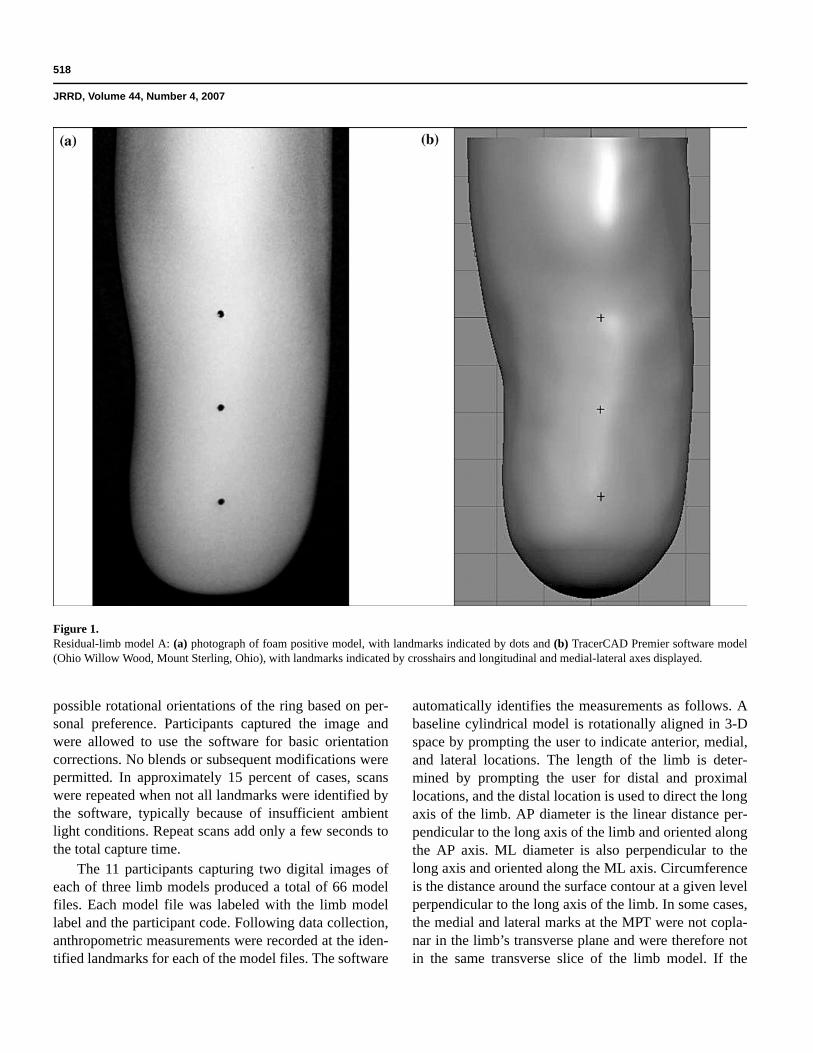
Digital shape capture was conducted for three foampositive models (labeled “A,” “B,” and “C”) of the resid-ual limbs of persons with transtibial amputation. Thesemodels were identical to those used in Geil [10], whichenabled comparison of digitized data with traditional cali-per and tape measure data. Each model was mounted on apolyvinylchloride shaft and covered with two Cool Blue(LTWT lightweight 6 × 3 × 12 in.) prosthetic socks (SPSby Knit-Rite, Alpharetta, Georgia) and a white 6 mmAlpha Uniform C-Liner (Ohio Willow Wood, Mount Ster-ling, Ohio) suitable for use with the T-Ring II (Figure 1).The socks and liner allowed for some compression, mim-icking soft tissue. Unbeknownst to the study participants,models A and C were identical, which enabled within-subject repeatability assessment. Because this studyassessed instrument accuracy and consistency and instru-ment use, as opposed to anatomical knowledge and palpa-tion technique, anatomical landmarks were identified withsmall black dots (identifiable by the T-Ring II) on theAlpha liner covering each model. The following locationswere identified: MPT, medial and lateral marks at the mid-patella line, 2 in. distal to the MPT on the anterior aspect,and 4 in. distal to the MPT on the anterior aspect. TheMPT mark was used for the AP, length, and circumfer-ence measurements; the medial and lateral marks wereused for the medial-lateral (ML) measurement; and themarks 2 and 4 in. distal to the MPT were used for addi-tional circumference measurements.
Each model was secured in a vise, and participantswere asked to digitize the shape of each model using thedigital shape-capture devices from two different CADsystems: the Tracer OMEGA system and the T-Ring IIsystem, which are both manufactured by Ohio WillowWood (Mount Sterling, Ohio) and operate off the same
software platform (TracerCAD Premier v. 8.0.2; OhioWillow Wood, Mount Sterling, Ohio).
The Tracer OMEGA system is a contact scanner thatidentifies the three-dimensional (3-D) position and orien-tation of a small “pen” in a magnetic field. The operatordefines the shape of the model by placing the pen in con-tact with the model and tracing the entire surface area. Theresulting shape of the model is therefore sensitive to thepressure applied by the operator while tracing. The T-RingII system is a noncontact optical scanner. A ring contain-ing four optical cameras and four light-emitting diode(LED) arrays is held perpendicular to the long axis of thelimb. The LED arrays project parallel lines onto a whiteliner covering the limb. Changes in spacing between thelines that correspond to out-of-plane contours of the limbshape are recorded by the cameras and the 3-D shape isreconstructed. The software automatically detects theblack dots placed over the landmarks and identifies theselocations on the digital model (Figure 1). Data captureoccurs in less than 1 second and involves no contact withthe overall surface of the limb. Consequently, the T-RingII system is not sensitive to operator scanning techniquebut is sensitive to the orientation at which the device isheld with respect to the limb.
Participants were recruited from two populations:practitioners and students. Practitioners were certified inprosthetics or orthotics by the American Board for Certifi-cation in Orthotics, Prosthetics & Pedorthics and hadcompleted the Ohio Willow Wood training course for andhad experience using the two CAD systems. Studentswere first- or second-year students in the Georgia Instituteof Technology Master of Science program in Prostheticsand Orthotics; all had completed a semester-long coursein CAD/CAM that included the Ohio Willow Wood train-ing course for both CAD systems in this study but had nopractical or clinical experience using the systems.
Four practitioners and seven students completed thestudy. Each provided informed consent prior to participa-tion, and the Georgia State Institutional Review Boardapproved the study. Digitization type and model orderwere randomized for each participant. Each participantwas given specific instructions for each digital shape-capture system. For the contact scanner, participantswere instructed to trace the model, use the pen for largeblends following tracing, and identify the aforementionedlandmarks following a custom Tracer sequence. No addi-tional modifications were permitted. For the optical scan-ner, participants were permitted to use either of two
518
JRRD, Volume 44, Number 4, 2007
possible rotational orientations of the ring based on per-sonal preference. Participants captured the image andwere allowed to use the software for basic orientationcorrections. No blends or subsequent modifications werepermitted. In approximately 15 percent of cases, scanswere repeated when not all landmarks were identified bythe software, typically because of insufficient ambientlight conditions. Repeat scans add only a few seconds tothe total capture time.
The 11 participants capturing two digital images ofeach of three limb models produced a total of 66 modelfiles. Each model file was labeled with the limb modellabel and the participant code. Following data collection,anthropometric measurements were recorded at the iden-tified landmarks for each of the model files. The software
automatically identifies the measurements as follows. Abaseline cylindrical model is rotationally aligned in 3-Dspace by prompting the user to indicate anterior, medial,and lateral locations. The length of the limb is deter-mined by prompting the user for distal and proximallocations, and the distal location is used to direct the longaxis of the limb. AP diameter is the linear distance per-pendicular to the long axis of the limb and oriented alongthe AP axis. ML diameter is also perpendicular to thelong axis and oriented along the ML axis. Circumferenceis the distance around the surface contour at a given levelperpendicular to the long axis of the limb. In some cases,the medial and lateral marks at the MPT were not copla-nar in the limb’s transverse plane and were therefore notin the same transverse slice of the limb model. If the
Figure 1.Residual-limb model A: (a) photograph of foam positive model, with landmarks indicated by dots and (b) TracerCAD Premier software model(Ohio Willow Wood, Mount Sterling, Ohio), with landmarks indicated by crosshairs and longitudinal and medial-lateral axes displayed.

519
GEIL. Digital shape-capturing systems for limb measurement
circumferences at each landmark were consequentlyunequal, the average of the two circumferences wasrecorded. In no case did the difference between the twocircumferences exceed 4.0 mm (mean ± standard deviation[SD] difference 0.18 ± 0.08 mm).
Linear AP distance and length were recorded at thelevel of the MPT landmark. ML distances were recordedat the medial and lateral marks. Circumferences wererecorded at the level of the MPT and at 2 and 4 in. distal.
Data were analyzed to address several specificquestions: • How precise and consistent were measurements by
different participants at a given site? • Which group (students vs practitioners) was more
consistent? • Did the two systems (optical vs contact) produce simi-
larly accurate and precise results? • How did the accuracy of results of digitally captured
shape measurement compare with “gold standard”analog data?An overall measure of consistency at each measure-
ment site was obtained by assessment of the range ofresults (maximum minus minimum) and the SD at eachmeasurement site across all participants and systems. Theanalysis assessed the general usefulness of anthropometricdata as obtained by digital capture systems in the contextof clinical significance. After an exploratory statisticsmodule (SPSS 11.0.1, Chicago, Illinois) generated meanand SD values and screened the data for outliers, data werecompared by subject group (students vs practitioners). Inaddition, each measurer’s error in the repeated measure-ments of identical models A and C was calculated as theabsolute value of the difference between A and C measure-ments. The mean error and maximum error were deter-mined for each participant. A similar comparison wasmade between systems and across participants. Consis-tency between the two digital capture systems was calcu-lated as the absolute value of the difference in eachparticipant’s measurement using the contact system modeland the optical system model.
These absolute values were added for each measure-ment location (m), providing a total difference (TD)(optical vs contact) for each participant (Equation):
Finally, results were directly compared to previouslypublished data from a study that used analog hand tools
[10]. For assessment of accuracy, the results were com-pared with previous data on the same models and land-marks. These data identified accurate linear measurementsusing a GPM anthropometer (SiberHegner, Zurich, Swit-zerland), which is often used to record body segmentparameters in a gait analysis laboratory, and circumfer-ence measurements Spring Tape (Tech-Med model 4414,Tech-Med Services, Inc; Hauppauge, New York). Thisflexible tape measure incorporates a spring on the endwith a mark identifying a standard amount of tension.
RESULTS
Prior to analysis of groups and tools, measurementresults were averaged across all participants and both digi-tal capture systems. The mean, SD, and range wererecorded for each model and measurement (Table). Allmeasurement sites produced consistent measurements. Thelargest range recorded across the 11 participants and twomeasurement systems was 1.70 cm, at the length measure-ment. This maximum range was the difference betweenthe Model C lengths (MPT to distal end) of 20.01 cm and18.40 cm measured by different practitioners both usingthe contact scanner. The mean range across all measure-ments was 0.96 cm.
Group consistency was assessed, first, by a compari-son of the SD and range values and, second, by a compari-son of each group’s ability to consistently measureidentical models A and C. Across all models, studentswere more consistent than practitioners, as assessed byboth range (students showed a smaller range in 67% ofmeasurements) and SD (students showed a smaller SD in56% of measurements). Differences were slight, however.For example, the sum of student ranges across all meas-urements and all models was 13.00 cm compared with13.35 cm for practitioners. Comparison of model A versusC error revealed sources of inconsistency (Figure 2).Practitioners showed a larger average error in the lengthmeasurement than did the students, while other sitesshowed very similar errors. In the model A versus C com-parison, students’ models showed more consistency in alllinear measures, while practitioners’ models showed moreconsistency in all circumferential measures.
Two digital shape-capture systems were used in thestudy: an optical system (T-Ring II) and a contact scanner(Tracer OMEGA). Just as group results were consistent,results between systems, measured as the TD (opticalvs contact) for each participant (Equation), were also
TD mcontact moptical– .m 1=m 6=
∑=

520
JRRD, Volume 44, Number 4, 2007
consistent. The single largest overall TD was 3.75 cm,representing an average error of 6.2 mm when divided bythe six measures. The largest actual system difference fora single measure was 1.50 cm, when a practitionerrecorded a length of 18.50 cm for model C using the opti-cal system and 20.00 cm using the contact system.
Model A versus C error was also used to assess sys-tem differences. Both systems were largely accurate inreplicating similar measurements for the identical models(Figure 3). Neither system consistently overestimated orunderestimated the linear differences, though errors weregreatest for circumferential measures taken from opti-cally captured models. Despite this trend, none of theerrors observed could be considered clinically signifi-cant, especially because the entire range of the y-axis inFigure 3 is 1 cm.
A final analysis compared the digital results to previ-ously published anthropometrics collected with hand tools[10]. Again, results were quite similar. When results foreach measurement from each study were averaged acrossall subjects (Figure 4), differences between average datafrom the present study and average data using the goldstandard hand tools (anthropometer and spring-loaded
Table.Mean ± standard deviation (SD) and range (difference of maximum andminimum) for three positive foam models (A, B, and C) and differentmeasurement locations across systems and participant populations. Alldata shown in centimeters.Measurement
Location A B C
APMean ± SD 13.41 ± 0.45 10.97 ± 0.15 13.40 ± 0.19Range 1.40 0.50 0.70
LengthMean ± SD 18.90 ± 0.36 14.60 ± 0.37 19.09 ± 0.40Range 1.50 1.40 1.70
MLMean ± SD 13.28 ± 0.17 11.62 ± 0.11 13.29 ± 0.12Range 0.70 0.45 0.40
Circ MPTMean ± SD 40.51 ± 0.17 33.90 ± 0.22 41.15 ± 0.25Range 0.70 0.70 0.80
Circ +2Mean ± SD 40.02 ± 0.22 32.34 ± 0.22 40.66 ± 0.26Range 0.90 1.00 1.00
Circ +4Mean ± SD 39.19 ± 0.25 31.00 ± 0.31 39.92 ± 0.33Range 1.00 1.20 1.20
AP = anterior-posterior distance at midpatellar tendon, Length = linear dis-tance from midpatellar tendon (MPT) to distal end, ML = average of medial-lateral distances at medial and lateral landmarks at MPT level; Circ MPT = cir-cumference (circ) at level of MPT, Circ +2 = circ 2 in. distal to MPT, Circ +4 =circ 4 in. distal to MPT.
Figure 2.Measurement error between identical models A and C by location andacross both digital shape-capture systems. Shown as absolute value ofmean distance or circumference (circ) on model A minus mean distanceor circ on model C for all students and practitioners at each measurementlocation. AP = anterior-posterior, Circ +2 = circ 2 in. distal to midpatellartendon (MPT), Circ +4 = circ 4 in. distal to MPT, Length = lineardistance from MPT to distal end, ML = medial-lateral.
Figure 3.Measurement error between identical models A and C by location andacross participants. Shown as absolute value of mean distance orcircumference (circ) on model A minus mean distance or circ on model Cfor each measurement system (T-Ring II scanner [Optical] vs TracerOMEGA magnetic field-based scanner [Contact], both by Ohio WillowWood, Mount Sterling, Ohio) at each measurement location. AP =anterior-posterior, Circ +2 = circ 2 in. distal to midpatellar tendon (MPT),Circ +4 = circ 4 in. distal to MPT, Length = linear distance from MPT todistal end, ML = medial-lateral.

521
GEIL. Digital shape-capturing systems for limb measurement
Figure 4.Average measurement by location across all students and practitioners in current study using T-Ring II scanner (Optical) and Tracer OMEGAmagnetic field-based scanner (Contact) vs multiple students and practitioners measuring same three models using standard calipers or tape measures(Hand Tool). Data presented for (a) model A, (b) model B, and (c) model C (identical to A). AP = anterior-posterior, Circ = circumference, Circ +2 =circ 2 in. distal to midpatellar tendon (MPT), Circ +4 = circ 4 in. distal to MPT, Length = linear distance from MPT to distal end, ML = medial-lateral.

522
JRRD, Volume 44, Number 4, 2007
tape measure) were approximately 0.5 cm. The largestdifferences between digital and hand tools were found incircumferential measures.
DISCUSSION
This study investigated the use of digital shape-capture methods to record standard anthropometrics ofmodels of the residual limbs of persons with transtibialamputation. The study compared the consistency of twoCAD systems and their use by two populations of measur-ers. If the systems can be established as accurate and con-sistent, and the results they produce compare favorablywith similar measurements with conventional hand tools,practitioners may wish to consider routinely using digitalshape-capture systems for anthropometric measurement.
The study was limited in its scope. Only two digitalshape-capture systems were considered. The study didnot test the full capability of CAD systems to capture andalso modify a model. Some participants in the studynoted that, in practice, they would normally modify theirmodels substantially more than was allowed in this study.An additional limitation was that mean and SD valueswere affected by the difference in sample size for eachgroup (seven vs four). This limitation would have been ofgreater concern had larger differences been noted in anyof the measures. Finally, the study should be recognizedas a cross-section of measurements that does not considerthe consistency of measurements done by the same per-son over a span of months or years, a scenario with par-ticular clinical relevance.
Measurement results were consistent across systemsand participant groups. An ensemble average measure-ment range of <1 cm (0.96 cm) is clinically acceptable,particularly considering that the measure is across two dif-ferent digital shape-capture systems and two very differentparticipant populations. Differences were present betweengroups, but no result suggested clinically significant differ-ences in consistency or measurement error between thestudents and practitioners. This result implies that a base-line level of training is all that is required to produce con-sistent and accurate anthropometric measurements withdigital shape capture. This result does not imply that expe-rience does not factor in the proper use of CAD/CAM sys-tems for the design and fabrication of a prosthetic socket.The present experiment was designed to assess the utilityof CAD systems in the collection of anthropometric mod-
els; consequently, modifications (which are essential to thesocket design process) were excluded from the protocol.Clinical experience almost certainly plays a larger role inmodel modification than in proper digital shape capture.
Some technological differences could explain whylength was the most inconsistently measured location. CADsystems start with a uniform model upon which scannerdata either add or delete volume in slices. A challengingscenario for shape digitization occurs when the modelrequires a closed end in a plane perpendicular to the longaxis of the cylinder. Such is the case with residual-limbmodels and prosthetic sockets, suggesting that end effectsmay produce less consistent results for length measures notbecause of the location of the MPT landmark but rather thelocation of the distal end along the model’s long axis.
Though the systems used in this study share the samemodeling software, their physical and mechanical uses arequite different and help explain the model A versus C errorbetween systems (Figure 3). The fact that the optical scan-ner must be held perpendicular to the long axis of the resid-ual limb implies that errors may occur if that angle varies.The results of this study revealed that circumferential meas-urements were more variable with the optical system, sug-gesting that these measures may be more sensitive to errorsin perpendicularity. Figure 5 demonstrates that a relativelysmall 5° error produces a “perpendicular” diameter that islonger than the true diameter. Linear distances are subjectto this error only if the tilt occurs in the same plane, but cir-cumferences are affected by any radial tilt. The 5° tiltshown in Figure 5 produces only 0.76 percent error indiameter (twice the inverse of the cosine of 5°), but largertilt angles produce larger errors. Practitioners using opticalscanners for circumferential measurements should pay par-ticular attention to the perpendicularity of the scannerwhen measuring.
Digitally captured data were surprisingly similar tomeasurements with conventional hand tools. This resultsuggests that, at least for linear and circumferential shapemeasures at distinct landmarks, measures obtained byeither digital system in comparison with analog measure-ment with hand tools have no clinically significant differ-ences. Slightly larger differences did occur between thedigital systems and the hand tools in the circumferencemeasurements, which is somewhat surprising. One wouldexpect the tension developed in a tape measure to reduceresults compared with the surface circumference recordedby the digital systems. However, the hand-measured cir-cumferences were consistently larger (Figure 4).

523
GEIL. Digital shape-capturing systems for limb measurement
One should note that digital systems are used differ-ently than conventional tools. In this case, the digital sys-tems collected far more information more efficiently. Theoptical capture system used in this study records data inless than 1 second. Most participants completed the con-tact scanner data collection in 1.5 to 3.0 minutes per scan.A brief amount of time is associated with labeling land-marks and obtaining the anthropometrics, but this steprequires only a few mouse clicks. Hand measurement ofanthropometrics takes as long or longer than either digitalcapture system, and the digital systems provide far moredata since the complete 3-D model is recorded, not justthe six anthropometric measures.
Most practitioners assume that CAD/CAM systems inprosthetics are to be used only for designing and fabricat-ing a prosthetic socket. The study results suggest an addi-tional use for the digital shape-capture component of thesystems. Recording data related to the shape of eachpatient’s residual limb, including standard anthropometricmeasures, can be accomplished accurately, consistently,
and efficiently with digital shape capture, even if thesocket is subsequently produced by conventional means.
CONCLUSIONS
Anthropometric measurements taken from digitallycaptured models were accurate and consistent. The opti-cal and contact scanners tested produced similar resultsfor the same measurement, and both students and practi-tioners were able to use the devices consistently. Resultswere also similar to those obtained from hand calipersand tape measures. Digital shape capture may be effi-ciently used to record residual limb anthropometrics and3-D shape information.
ACKNOWLEDGMENTS
I extend thanks to the participants in the study and toMatthew Tate, PhD, Emory University, for assistance inpreparation of the manuscript.
This material is the result of work supported withresources and the use of facilities at the Department ofKinesiology and Health, Georgia State University, Atlanta,Georgia.
The author has declared that no competing interestsexist.
REFERENCES
1. Houston VL, Burgess EM, Childress DS, Lehneis HR,Mason CP, Garbarini MA, LaBlanc KP, Boone DA, ChanRB, Harlan JH, Brncick MD. Automated fabrication ofmobility aids (AFMA): Below-knee CAD/CAM testingand evaluation program results. J Rehabil Res Dev. 1992;29(4):78–124. [PMID: 1432729]
2. Boone DA, Burgess EM. Automated fabrication of mobilityaids: Clinical demonstration of the UCL computer-aidedsocket design system. J Prosthet Orthot. 1989;1(3):187–90.
3. Smith DG, Burgess EM. The use of CAD/CAM technologyin prosthetics and orthotics—Current clinical models and aview to the future. J Rehabil Res Dev. 2001;38(3):327–34.[PMID: 11440264]
4. Boone DA, Harlan JS, Burgess EM. Automated fabricationof mobility aids: Review of the AFMA process and VA/Seattle ShapeMaker software design. J Rehabil Res Dev.1994;31(1):42–49. [PMID: 8035359]
5. Murdoch G. Editorial. Prosthet Orthot Int. 1985;9(1):1–2.
Figure 5.Effect of optical scanner tilt on diameter and therefore circumference.Tilt of 5° from proper position (perpendicular to long axis of limb)causes overestimation of diameter (by 0.76%).
524
JRRD, Volume 44, Number 4, 2007
6. Boone DA, Urban ND, Smith DG, Burgess EM, MathewsDE, Coleman KL. Use of CAD/CAM for prosthetic ser-vices in the developing world. Proceedings of the 9thWorld Congress of the International Society for Prostheticsand Orthotics; 1998 Jun 30–Jul 3; Amsterdam, the Nether-lands. Copenhagen (Denmark): ISPO; 1998. p. 74–76.
7. Smith DG, Boone DA, Harlan JS, Forsgren SM, BurgessEM. Automated prosthetics fabrication in the developingworld: The experimental prosthetics center in Hanoi, Viet-nam. Orthopaedic J. 1993;2:49–60.
8. Lilja M, Oberg T. Volumetric determinations with CAD/CAM in prosthetics and orthotics: Errors of measurement.J Rehabil Res Dev. 1995;32(2):141–48. [PMID: 7562654]
9. Johansson S, Oberg T. Accuracy and precision of volumet-ric determinations using two commercial CAD systems for
prosthetics: A technical note. J Rehabil Res Dev. 1998;35(1):27–33. [PMID: 9505250]
10. Geil MD. Consistency and accuracy of measurement oflower-limb amputee anthropometrics. J Rehabil Res Dev.2005;42(2):131–40. [PMID: 15944877]
11. Lunsford TR. Clinical research. J Prosthet Orthot. 1993;5(4):101–4.
12. Convery P, Buis AW, Wilkie R, Sockalingam S, Blair A,McHugh B. Measurement of the consistency of patellar-tendon-bearing cast rectification. Prosthet Orthot Int. 2003;27(3):207–13. [PMID: 14727701]
Submitted for publication August 8, 2006. Accepted inrevised form March 29, 2007.