Sub-Cell® GT Agarose Gel Electrophoresis Systems ...
26
Sub-Cell ® GT Agarose Gel Electrophoresis Systems Instruction Manual Catalog Numbers 170-4401 to 170-4406 170-4481 to 170-4486 For technical support call your local Bio-Rad office or in the U.S. call 1-800-4BIORAD (1-800-424-6723)
-
Upload
khangminh22 -
Category
Documents
-
view
0 -
download
0
Transcript of Sub-Cell® GT Agarose Gel Electrophoresis Systems ...
Sub-Cell® GTAgarose Gel
ElectrophoresisSystems
Instruction Manual
Catalog Numbers170-4401 to 170-4406170-4481 to 170-4486
For technical support call your local Bio-Rad office or in the U.S. call 1-800-4BIORAD (1-800-424-6723)
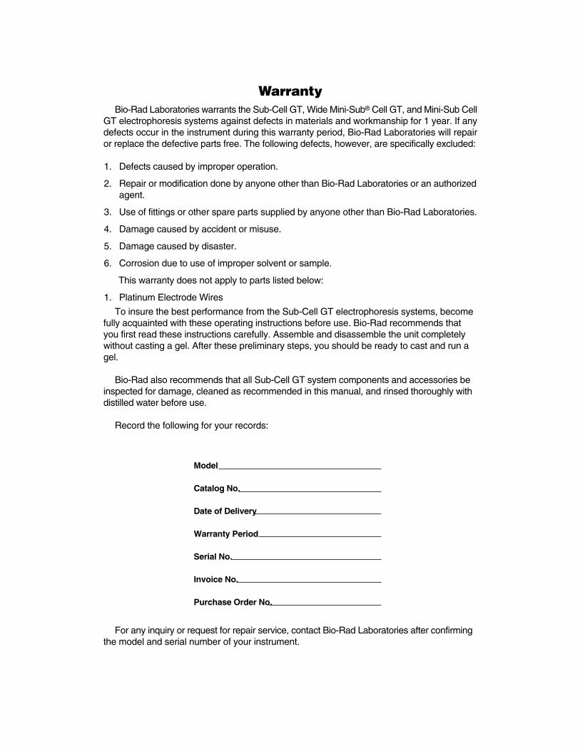
WarrantyBio-Rad Laboratories warrants the Sub-Cell GT, Wide Mini-Sub® Cell GT, and Mini-Sub Cell
GT electrophoresis systems against defects in materials and workmanship for 1 year. If anydefects occur in the instrument during this warranty period, Bio-Rad Laboratories will repairor replace the defective parts free. The following defects, however, are specifically excluded:
1. Defects caused by improper operation.
2. Repair or modification done by anyone other than Bio-Rad Laboratories or an authorizedagent.
3. Use of fittings or other spare parts supplied by anyone other than Bio-Rad Laboratories.
4. Damage caused by accident or misuse.
5. Damage caused by disaster.
6. Corrosion due to use of improper solvent or sample.
This warranty does not apply to parts listed below:
1. Platinum Electrode Wires
To insure the best performance from the Sub-Cell GT electrophoresis systems, becomefully acquainted with these operating instructions before use. Bio-Rad recommends thatyou first read these instructions carefully. Assemble and disassemble the unit completelywithout casting a gel. After these preliminary steps, you should be ready to cast and run agel.
Bio-Rad also recommends that all Sub-Cell GT system components and accessories beinspected for damage, cleaned as recommended in this manual, and rinsed thoroughly withdistilled water before use.
Record the following for your records:
For any inquiry or request for repair service, contact Bio-Rad Laboratories after confirmingthe model and serial number of your instrument.
Model
Catalog No.
Date of Delivery
Warranty Period
Serial No.
Invoice No.
Purchase Order No.
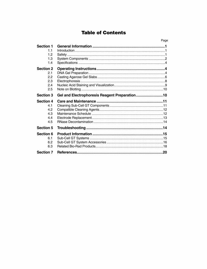
Table of ContentsPage
Section 1 General Information ......................................................................11.1 Introduction................................................................................................11.2 Safety ........................................................................................................11.3 System Components .................................................................................21.4 Specifications ............................................................................................4
Section 2 Operating Instructions..................................................................42.1 DNA Gel Preparation .................................................................................42.2 Casting Agarose Gel Slabs........................................................................62.3 Electrophoresis..........................................................................................82.4 Nucleic Acid Staining and Visualization......................................................92.5 Note on Blotting .......................................................................................10
Section 3 Gel and Electrophoresis Reagent Preparation..........................10
Section 4 Care and Maintenance ................................................................114.1 Cleaning Sub-Cell GT Components .........................................................114.2 Compatible Cleaning Agents....................................................................124.3 Maintenance Schedule ............................................................................124.4 Electrode Replacement............................................................................134.5 RNase Decontamination ..........................................................................14
Section 5 Troubleshooting ..........................................................................14
Section 6 Product Information ....................................................................156.1 Sub-Cell GT Systems ..............................................................................156.2 Sub-Cell GT System Accessories ............................................................166.3 Related Bio-Rad Products........................................................................18
Section 7 References...................................................................................20

1
Section 1General Information
1.1 IntroductionThe Sub-Cell® GT instruments (basic Sub-Cell® GT cell, Wide Mini-Sub® Cell GT, and Mini-Sub
Cell® GT) comprise a comprehensive and flexible gel electrophoresis system that effectivelyseparates nucleic acids using submerged agarose gels. Submarine agarose gels are easy tocast and readily dissipate heat. These gels allow sample underlaying and prevent electrical fielddiscontinuities caused by wicks or sample well dehydration. Agarose gels are ideal for the separationof DNA restriction digestions, polymerase chain reaction (PCR*)-amplified fragments, and genomicDNA and RNA prior to Southern or northern blotting. If operated correctly, agarose gel submarineelectrophoresis can effectively separate nucleic acids from 20 base pairs to 20 kilobase pairs inlength.
The Sub-Cell GT systems are designed for years of reproducible and rigorous use.These rugged systems incorporate many features that make casting and running agarosegels simple and efficient. The gel caster provides tape-free gel casting in trays. Gels canalso be cast in the GT bases using specially designed casting gates. Replaceable electrodecassettes provide a simple way to replace electrode wires. A comprehensive assortment ofbase and tray sizes, including a variety of preparative, analytical, and multichannel pipetcompatible combs, makes these systems ideal for any agarose gel application.
Note: This manual contains instructions for the Sub-Cell GT electrophoresis systemsonly. Prior to the release of the Sub-Cell GT systems, Bio-Rad supplied similar agarose gelelectrophoresis cells: the original Sub-Cell DNA electrophoresis cell, Wide Mini-Sub cell, andMini-Sub cell systems. This manual does not provide information on these earlier versions.Contact your local Bio-Rad representative for information concerning the original Sub-Cellsystems.
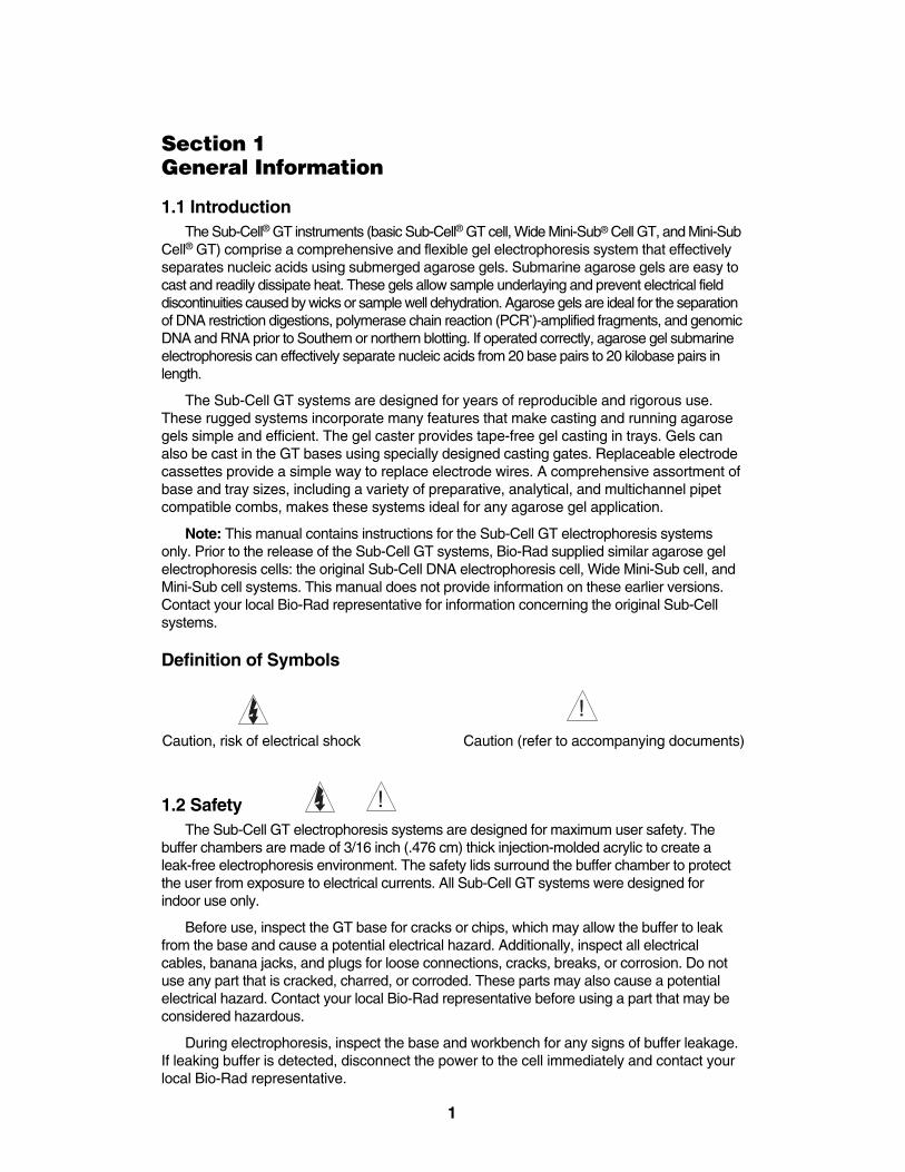
Definition of Symbols
Caution, risk of electrical shock Caution (refer to accompanying documents)
1.2 SafetyThe Sub-Cell GT electrophoresis systems are designed for maximum user safety. The
buffer chambers are made of 3/16 inch (.476 cm) thick injection-molded acrylic to create aleak-free electrophoresis environment. The safety lids surround the buffer chamber to protectthe user from exposure to electrical currents. All Sub-Cell GT systems were designed forindoor use only.
Before use, inspect the GT base for cracks or chips, which may allow the buffer to leakfrom the base and cause a potential electrical hazard. Additionally, inspect all electricalcables, banana jacks, and plugs for loose connections, cracks, breaks, or corrosion. Do notuse any part that is cracked, charred, or corroded. These parts may also cause a potentialelectrical hazard. Contact your local Bio-Rad representative before using a part that may beconsidered hazardous.
During electrophoresis, inspect the base and workbench for any signs of buffer leakage.If leaking buffer is detected, disconnect the power to the cell immediately and contact yourlocal Bio-Rad representative.
!
!!
!
!!
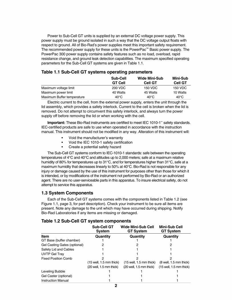
Power to Sub-Cell GT units is supplied by an external DC voltage power supply. Thispower supply must be ground isolated in such a way that the DC voltage output floats withrespect to ground. All of Bio-Rad’s power supplies meet this important safety requirement.The recommended power supply for these units is the PowerPac™ Basic power supply. ThePowerPac 300 power supply contains safety features such as no load, overload, rapid resistance change, and ground leak detection capabilities. The maximum specified operatingparameters for the Sub-Cell GT systems are given in Table 1.1.
Table 1.1 Sub-Cell GT systems operating parametersSub-Cell Wide Mini-Sub Mini-Sub GT Cell Cell GT Cell GT
Maximum voltage limit 200 VDC 150 VDC 150 VDCMaximum power limit 40 Watts 45 Watts 10 WattsMaximum Buffer temperature 40°C 40°C 40°C
Electric current to the cell, from the external power supply, enters the unit through thelid assembly, which provides a safety interlock. Current to the cell is broken when the lid isremoved. Do not attempt to circumvent this safety interlock, and always turn the powersupply off before removing the lid or when working with the cell.
Important: These Bio-Rad instruments are certified to meet IEC 1010-1** safety standards.IEC-certified products are safe to use when operated in accordance with the instructionmanual. This instrument should not be modified in any way. Alteration of this instrument will:
• Void the manufacturer’s warranty• Void the IEC 1010-1 safety certification• Create a potential safety hazard
The Sub-Cell GT systems conform to IEC-1010-1 standards: safe between the operatingtemperatures of 4°C and 40°C and altitudes up to 2,000 meters; safe at a maximum relativehumidity of 80% for temperatures up to 31°C, and for temperatures higher than 31°C, safe at amaximum humidity that decreases linearly to 50% at 40°C. Bio-Rad is not responsible for anyinjury or damage caused by the use of this instrument for purposes other than those for which itis intended, or by modifications of the instrument not performed by Bio-Rad or an authorizedagent. There are no user-serviceable parts in this apparatus. To insure electrical safety, do notattempt to service this apparatus.
1.3 System ComponentsEach of the Sub-Cell GT systems comes with the components listed in Table 1.2 (see
Figure 1.1, page 3, for part description). Check your instrument to be sure all items are present. Note any damage to the unit which may have occurred during shipping. Notify Bio-Rad Laboratories if any items are missing or damaged.
Table 1.2 Sub-Cell GT system componentsSub-Cell GT Wide Mini-Sub Cell Mini-Sub Cell
System GT System GT SystemItem Quantity Quantity QuantityGT Base (buffer chamber) 1 1 1Gel Casting Gates (optional) 2 2 2Safety Lid and Cables 1 1 1UVTP Gel Tray 1 1 1Fixed Position Comb 2 2 2
(15 well, 1.5 mm thick) (15 well, 1.5 mm thick) (8 well, 1.5 mm thick)(20 well, 1.5 mm thick) (20 well, 1.5 mm thick) (15 well, 1.5 mm thick)
Leveling Bubble 1 1 1Gel Caster (optional) 1 1 1Instruction Manual 1 1 1
2
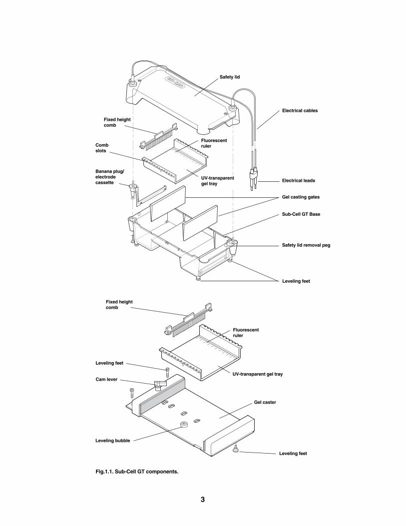
Fig.1.1. Sub-Cell GT components.
3
Safety lid
Electrical cables
Electrical leads
Gel casting gates
Fixed heightcomb
Sub-Cell GT Base
Safety lid removal peg
Leveling feet
Combslots
Banana plug/electrode cassette
UV-transparentgel tray
Fluorescent ruler
Fixed height comb
Leveling feet
Leveling feet
UV-transparent gel tray
Gel caster
Cam lever
Fluorescent ruler
Leveling bubble

1.4 Specifications
Sub-Cell GT Wide Mini-Sub Cell Mini-Sub Cell System GT System GT System
GT base footprint (L x W x H) 42 x 20 x 10 cm 26 x 20 x 7.5 cm 26 x 12 x 6.5 cmGT base buffer volume✝ 1,500–2,000 ml 650–900 ml 265–320 mlGT base gel size 15 x 15 cm 15 x 7 cm 7 x 7 cmGel tray sizes 15 x 10 cm 15 x 7 cm 7 x 7 cm
15 x 15 cm 15 x 10 cm 7 x 10 cm15 x 20 cm15 x 25 cm
ConstructionGT base Molded clear plasticGel casting gates AluminumSafety lid Molded clear plasticBanana plug/electrode cassette Molded polycarbonate Banana plugs Gold-plated brass, 4.4 cm lengthElectrodes Platinum, 0.25 mm diameterElectrical cables Dual, 20 AWG, tinned copper wire cable
Flame-retardant polyurethane insulation jacketElectrical leads Nickel silverGel tray UV-transparent acrylic plastic (UVTP)Combs Molded plastic and machined acrylicGel casting device Polycarbonate
0.64 cm silicon foam
Section 2Operating InstructionsNote: See Section 3, Gel and Electrophoresis Reagent Preparation, for information on thepreparation of RNA gels. See References 1 and 2 for more information on DNA and RNAelectrophoresis.
2.1 DNA Gel PreparationDNA agarose gels can be used to separate and visualize DNA of various sizes. Before
casting an agarose gel, consult Table 2.1, page 5, to determine the appropriate percentagarose gel to use, based on the size of DNA to be separated.
Procedure
1. Determine the amount of agarose (grams) required to make the desired agarose gelconcentration and volume. Use Tables 2.1 and 2.2, page 5, as a guide for agarose concentration and gel volume requirements.
Example: For a 1% agarose gel, add 1 gram of agarose to 100 ml of 1x electrophoresis buffer.
4
✝ GT base buffer volumes will vary depending on the size and thickness of the gel used.
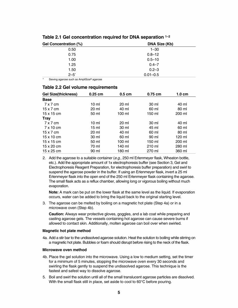
Table 2.1 Gel concentration required for DNA separation 1–2
Gel Concentration (%) DNA Size (Kb)0.50 1–300.75 0.8–121.00 0.5–101.25 0.4–71.50 0.2–32–5* 0.01–0.5
* Sieving agarose such as AmpliSize® agarose
Table 2.2 Gel volume requirementsGel Size(thickness) 0.25 cm 0.5 cm 0.75 cm 1.0 cmBase7 x 7 cm 10 ml 20 ml 30 ml 40 ml
15 x 7 cm 20 ml 40 ml 60 ml 80 ml15 x 15 cm 50 ml 100 ml 150 ml 200 mlTray7 x 7 cm 10 ml 20 ml 30 ml 40 ml7 x 10 cm 15 ml 30 ml 45 ml 60 ml
15 x 7 cm 20 ml 40 ml 60 ml 80 ml15 x 10 cm 30 ml 60 ml 90 ml 120 ml15 x 15 cm 50 ml 100 ml 150 ml 200 ml15 x 20 cm 70 ml 140 ml 210 ml 280 ml15 x 25 cm 90 ml 180 ml 270 ml 360 ml
2. Add the agarose to a suitable container (e.g., 250 ml Erlenmeyer flask, Wheaton bottle,etc.). Add the appropriate amount of 1x electrophoresis buffer (see Section 3, Gel andElectrophoresis Reagent Preparation, for electrophoresis buffer preparation) and swirl tosuspend the agarose powder in the buffer. If using an Erlenmeyer flask, invert a 25 mlErlenmeyer flask into the open end of the 250 ml Erlenmeyer flask containing the agarose.The small flask acts as a reflux chamber, allowing long or vigorous boiling without muchevaporation.
Note: A mark can be put on the lower flask at the same level as the liquid. If evaporationoccurs, water can be added to bring the liquid back to the original starting level.
3. The agarose can be melted by boiling on a magnetic hot plate (Step 4a) or in amicrowave oven (Step 4b).
Caution: Always wear protective gloves, goggles, and a lab coat while preparing andcasting agarose gels. The vessels containing hot agarose can cause severe burns ifallowed to contact skin. Additionally, molten agarose can boil over when swirled.
Magnetic hot plate method
4a. Add a stir bar to the undissolved agarose solution. Heat the solution to boiling while stirring ona magnetic hot plate. Bubbles or foam should disrupt before rising to the neck of the flask.
Microwave oven method
4b. Place the gel solution into the microwave. Using a low to medium setting, set the timerfor a minimum of 5 minutes, stopping the microwave oven every 30 seconds andswirling the flask gently to suspend the undissolved agarose. This technique is thefastest and safest way to dissolve agarose.
5. Boil and swirl the solution until all of the small translucent agarose particles are dissolved.With the small flask still in place, set aside to cool to 60°C before pouring.
5
2.2 Casting Agarose Gel SlabsThere are several ways to cast agarose submarine gels using the Sub-Cell GT systems.
Gels may be cast with or without a UV-transparent plastic (UVTP) tray directly on the stageof the Sub-Cell GT bases using the gel casting gates. Gels may also be cast on the removableUVTP trays with the aid of the gel caster or with standard laboratory tape.
Casting gels on the Sub-Cell GT base
1. Level the Sub-Cell GT base using the leveling bubble provided.
2. Slide the gel casting gates into the slots at opposite ends of the GT base.
3. Place the comb(s) into the appropriate slot(s) of the base so that the sample wells are nearthe cathode (black). DNA samples will migrate toward the anode (red) during electrophoresis.
4. Prepare the desired concentration and amount of agarose in 1x electrophoresis buffer(see Section 2.1). When the agarose solution has cooled to 50–60°C pour the moltenagarose between the gates.
Warning: Hot agarose (>60°C) may cause the plastic in the cell to warp or craze andwill decrease the lifetime of the Sub-Cell base. Warping may also result in sample wellsof uneven depth.
5. Allow 20–40 minutes for the gel to solidify at room temperature.
6. Carefully remove the comb from the solidified gel. Remove the gel casting gates.
7. Submerge the gel beneath 2 to 6 mm of 1x electrophoresis buffer (see Section 3, Geland Electrophoresis Reagent Preparation). Use greater depth overlay (more buffer)with increasing voltages to avoid pH and heat effects.
Casting gels on the base stage with the UVTP tray
1. Level the cell using the leveling bubble provided.
2. Place the UVTP tray on the GT base.
Note: The Mini-Sub Cell GT requires the 7 x 7 cm UVTP tray for casting in the GT base.The Wide-Mini-Sub Cell GT requires the 15 x 7 cm UVTP tray and the Sub-Cell GT system requires the 15 x 15 cm UVTP tray for casting in the GT base.
3. Slide the gel casting gates into the slots at opposite ends of the GT base stage. Insurethat the gates are evenly seated in the slots and the gates uniformly contact all edges ofthe UVTP tray. The weight of the gates provides a tight seal to prevent any leakage problems during gel casting.
4. Place the comb(s) into the appropriate slot(s) of the trays so that the sample wells are nearthe cathode (black). DNA samples will migrate toward the anode (red) during electrophoresis.
5. Prepare the desired concentration and amount of agarose in 1x electrophoresis buffer(see Section 2.1). When the agarose solution has cooled to 50–60°C, pour the moltenagarose between the gates.
Warning: Hot agarose (>60°C) may cause the tray to warp or craze and will decreasethe lifetime of the tray. Warping may also result in sample wells of uneven depth.
6. Allow 20–40 minutes for the gel to solidify at room temperature.
7. Carefully remove the comb from the solidified gel. Remove the gel casting gates.
8. Submerge the gel beneath 2 to 6 mm of 1x electrophoresis buffer (see Section 3, Geland Electrophoresis Reagent Preparation). Use greater depth overlay (more buffer)with increasing voltages to prevent pH and heat effects.
6
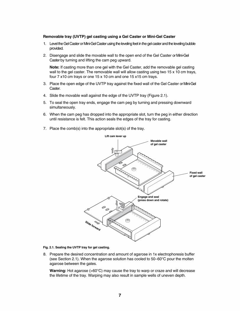
Removable tray (UVTP) gel casting using a Gel Caster or Mini-Gel Caster
1. Level the Gel Caster or Mini-Gel Caster using the leveling feet in the gel caster and the leveling bubbleprovided.
2. Disengage and slide the movable wall to the open end of the Gel Caster or Mini-GelCaster by turning and lifting the cam peg upward.
Note: If casting more than one gel with the Gel Caster, add the removable gel castingwall to the gel caster. The removable wall will allow casting using two 15 x 10 cm trays,four 7 x10 cm trays or one 15 x 10 cm and one 15 x15 cm trays.
3. Place the open edge of the UVTP tray against the fixed wall of the Gel Caster or Mini-GelCaster.
4. Slide the movable wall against the edge of the UVTP tray (Figure 2.1).
5. To seal the open tray ends, engage the cam peg by turning and pressing downwardsimultaneously.
6. When the cam peg has dropped into the appropriate slot, turn the peg in either directionuntil resistance is felt. This action seals the edges of the tray for casting.
7. Place the comb(s) into the appropriate slot(s) of the tray.
Fig. 2.1. Sealing the UVTP tray for gel casting.
8. Prepare the desired concentration and amount of agarose in 1x electrophoresis buffer(see Section 2.1). When the agarose solution has cooled to 50–60°C pour the moltenagarose between the gates.
Warning: Hot agarose (>60°C) may cause the tray to warp or craze and will decreasethe lifetime of the tray. Warping may also result in sample wells of uneven depth.
7
Movable wall of gel caster
Fixed wall of gel caster
Engage and seal (press down and rotate)
Slide forward
Lift cam lever up
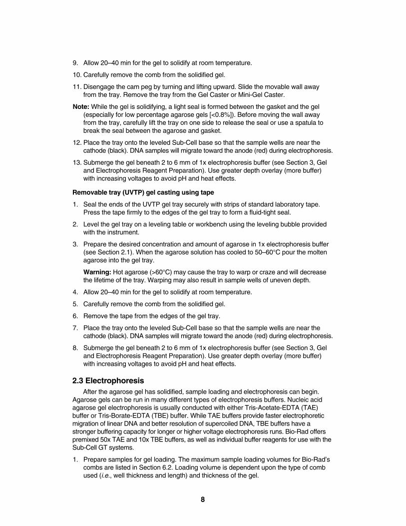
9. Allow 20–40 min for the gel to solidify at room temperature.
10. Carefully remove the comb from the solidified gel.
11. Disengage the cam peg by turning and lifting upward. Slide the movable wall awayfrom the tray. Remove the tray from the Gel Caster or Mini-Gel Caster.
Note: While the gel is solidifying, a light seal is formed between the gasket and the gel(especially for low percentage agarose gels [<0.8%]). Before moving the wall awayfrom the tray, carefully lift the tray on one side to release the seal or use a spatula tobreak the seal between the agarose and gasket.
12. Place the tray onto the leveled Sub-Cell base so that the sample wells are near thecathode (black). DNA samples will migrate toward the anode (red) during electrophoresis.
13. Submerge the gel beneath 2 to 6 mm of 1x electrophoresis buffer (see Section 3, Geland Electrophoresis Reagent Preparation). Use greater depth overlay (more buffer)with increasing voltages to avoid pH and heat effects.
Removable tray (UVTP) gel casting using tape
1. Seal the ends of the UVTP gel tray securely with strips of standard laboratory tape.Press the tape firmly to the edges of the gel tray to form a fluid-tight seal.
2. Level the gel tray on a leveling table or workbench using the leveling bubble providedwith the instrument.
3. Prepare the desired concentration and amount of agarose in 1x electrophoresis buffer(see Section 2.1). When the agarose solution has cooled to 50–60°C pour the moltenagarose into the gel tray.
Warning: Hot agarose (>60°C) may cause the tray to warp or craze and will decreasethe lifetime of the tray. Warping may also result in sample wells of uneven depth.
4. Allow 20–40 min for the gel to solidify at room temperature.
5. Carefully remove the comb from the solidified gel.
6. Remove the tape from the edges of the gel tray.
7. Place the tray onto the leveled Sub-Cell base so that the sample wells are near thecathode (black). DNA samples will migrate toward the anode (red) during electrophoresis.
8. Submerge the gel beneath 2 to 6 mm of 1x electrophoresis buffer (see Section 3, Geland Electrophoresis Reagent Preparation). Use greater depth overlay (more buffer)with increasing voltages to avoid pH and heat effects.
2.3 ElectrophoresisAfter the agarose gel has solidified, sample loading and electrophoresis can begin.
Agarose gels can be run in many different types of electrophoresis buffers. Nucleic acidagarose gel electrophoresis is usually conducted with either Tris-Acetate-EDTA (TAE)buffer or Tris-Borate-EDTA (TBE) buffer. While TAE buffers provide faster electrophoreticmigration of linear DNA and better resolution of supercoiled DNA, TBE buffers have astronger buffering capacity for longer or higher voltage electrophoresis runs. Bio-Rad offerspremixed 50x TAE and 10x TBE buffers, as well as individual buffer reagents for use with theSub-Cell GT systems.
1. Prepare samples for gel loading. The maximum sample loading volumes for Bio-Rad’scombs are listed in Section 6.2. Loading volume is dependent upon the type of combused (i.e., well thickness and length) and thickness of the gel.
8
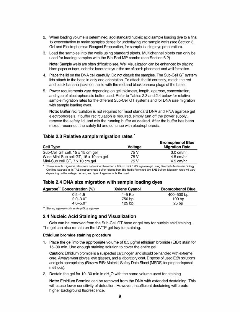
2. When loading volume is determined, add standard nucleic acid sample loading dye to a final1x concentration to make samples dense for underlaying into sample wells (see Section 3,Gel and Electrophoresis Reagent Preparation, for sample loading dye preparation).
3. Load the samples into the wells using standard pipets. Multichannel pipets can only beused for loading samples with the Bio-Rad MP combs (see Section 6.2).
Note: Sample wells are often difficult to see. Well visualization can be enhanced by placingblack paper or tape under the base or trays in the are of comb placement and well formation.
4. Place the lid on the DNA cell carefully. Do not disturb the samples. The Sub-Cell GT systemlids attach to the base in only one orientation. To attach the lid correctly, match the redand black banana jacks on the lid with the red and black banana plugs of the base.
5. Power requirements vary depending on gel thickness, length, agarose, concentration,and type of electrophoresis buffer used. Refer to Tables 2.3 and 2.4 below for relativesample migration rates for the different Sub-Cell GT systems and for DNA size migrationwith sample loading dyes.
Note: Buffer recirculation is not required for most standard DNA and RNA agarose gelelectrophoresis. If buffer recirculation is required, simply turn off the power supply,remove the safety lid, and mix the running buffer as desired. After the buffer has beenmixed, reconnect the safety lid and continue with electrophoresis.
Table 2.3 Relative sample migration rates *
Bromophenol Blue Cell Type Voltage Migration RateSub-Cell GT cell, 15 x 15 cm gel 75 V 3.0 cm/hrWide Mini-Sub cell GT, 15 x 10 cm gel 75 V 4.5 cm/hrMini-Sub cell GT, 7 x 10 cm gel 75 V 4.5 cm/hr* These sample migration rates were determined based on a 0.5 cm thick 1.0% agarose gel using Bio-Rad’s Molecular Biology
Certified Agarose in 1x TAE electrophoresis buffer (diluted from Bio-Rad’s Premixed 50x TAE Buffer). Migration rates will varydepending on the voltage, current, and type of agarose or buffer used.
Table 2.4 DNA size migration with sample loading dyesAgarose** Concentration (%) Xylene Cyanol Bromophenol Blue
0.5–1.5 4–5 Kb 400–500 bp2.0–3.0** 750 bp 100 bp4.0–5.0** 125 bp 25 bp
** Sieving agarose such as AmpliSize agarose.
2.4 Nucleic Acid Staining and VisualizationGels can be removed from the Sub-Cell GT base or gel tray for nucleic acid staining.
The gel can also remain on the UVTP gel tray for staining.
Ethidium bromide staining procedure
1. Place the gel into the appropriate volume of 0.5 µg/ml ethidium bromide (EtBr) stain for15–30 min. Use enough staining solution to cover the entire gel.
Caution: Ethidium bromide is a suspected carcinogen and should be handled with extremecare. Always wear gloves, eye glasses, and a laboratory coat. Dispose of used EtBr solutionsand gels appropriately (Review EtBr Material Safety Data Sheet [MSDS] for proper disposalmethods).
2. Destain the gel for 10–30 min in dH2O with the same volume used for staining.
Note: Ethidium Bromide can be removed from the DNA with extended destaining. Thiswill cause lower sensitivity of detection. However, insufficient destaining will createhigher background fluorescence.
9
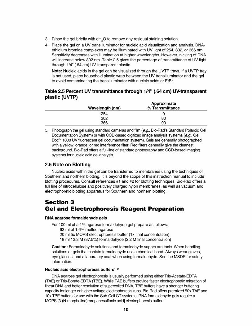
3. Rinse the gel briefly with dH2O to remove any residual staining solution.
4. Place the gel on a UV transilluminator for nucleic acid visualization and analysis. DNA-ethidium bromide complexes may be illuminated with UV light of 254, 302, or 366 nm.Sensitivity decreases with illumination at higher wavelengths. However, nicking of DNAwill increase below 302 nm. Table 2.5 gives the percentage of transmittance of UV lightthrough 1/4” (.64 cm) UV-transparent plastic.
Note: Nucleic acids in the gel can be visualized through the UVTP trays. If a UVTP trayis not used, place household plastic wrap between the UV transilluminator and the gelto avoid contaminating the transilluminator with nucleic acids or EtBr.
Table 2.5 Percent UV transmittance through 1/4” (.64 cm) UV-transparentplastic (UVTP)
ApproximateWavelength (nm) % Transmittance
254 0302 80366 90
5. Photograph the gel using standard cameras and film (e.g., Bio-Rad’s Standard Polaroid GelDocumentation System) or with CCD-based digitized image analysis systems (e.g., GelDoc™ 1000 UV fluorescent gel documentation system). Gels are generally photographedwith a yellow, orange, or red interference filter. Red filters generally give the cleanest background. Bio-Rad offers a full-line of standard photography and CCD-based imagingsystems for nucleic acid gel analysis.
2.5 Note on BlottingNucleic acids within the gel can be transferred to membranes using the techniques of
Southern and northern blotting. It is beyond the scope of this instruction manual to includeblotting procedures. Consult references #1 and #2 for blotting techniques. Bio-Rad offers afull line of nitrocellulose and positively charged nylon membranes, as well as vacuum and electrophoretic blotting apparatus for Southern and northern blotting.
Section 3Gel and Electrophoresis Reagent PreparationRNA agarose formaldehyde gels
For 100 ml of a 1% agarose formaldehyde gel prepare as follows:62 ml of 1.6% melted agarose20 ml 5x MOPS electrophoresis buffer (1x final concentration)18 ml 12.3 M (37.5%) formaldehyde (2.2 M final concentration)
Caution: Formaldehyde solutions and formaldehyde vapors are toxic. When handlingsolutions or gels that contain formaldehyde use a chemical hood. Always wear gloves,eye glasses, and a laboratory coat when using formaldehyde. See the MSDS for safetyinformation.
Nucleic acid electrophoresis buffers1–2
DNA agarose gel electrophoresis is usually performed using either Tris-Acetate-EDTA(TAE) or Tris-Borate-EDTA (TBE). While TAE buffers provide faster electrophoretic migration oflinear DNA and better resolution of supercoiled DNA, TBE buffers have a stronger bufferingcapacity for longer or higher voltage electrophoresis runs. Bio-Rad offers premixed 50x TAE and10x TBE buffers for use with the Sub-Cell GT systems. RNA formaldehyde gels require aMOPS [3-(N-morpholino)-propanesulfonic acid] electrophoresis buffer.
10
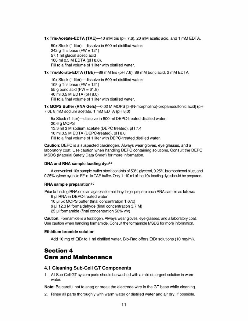
1x Tris-Acetate-EDTA (TAE)—40 mM tris (pH 7.6), 20 mM acetic acid, and 1 mM EDTA.
50x Stock (1 liter)—dissolve in 600 ml distilled water:242 g Tris base (FW = 121)57.1 ml glacial acetic acid100 ml 0.5 M EDTA (pH 8.0).Fill to a final volume of 1 liter with distilled water.
1x Tris-Borate-EDTA (TBE)—89 mM tris (pH 7.6), 89 mM boric acid, 2 mM EDTA
10x Stock (1 liter)—dissolve in 600 ml distilled water:108 g Tris base (FW = 121)55 g boric acid (FW = 61.8)40 ml 0.5 M EDTA (pH 8.0)Fill to a final volume of 1 liter with distilled water.
1x MOPS Buffer (RNA Gels)—0.02 M MOPS [3-(N-morpholino)-propanesulfonic acid] (pH7.0), 8 mM sodium acetate, 1 mM EDTA (pH 8.0)
5x Stock (1 liter)—dissolve in 600 ml DEPC-treated distilled water:20.6 g MOPS 13.3 ml 3 M sodium acetate (DEPC treated), pH 7.410 ml 0.5 M EDTA (DEPC-treated), pH 8.0Fill to a final volume of 1 liter with DEPC-treated distilled water.
Caution: DEPC is a suspected carcinogen. Always wear gloves, eye glasses, and a laboratory coat. Use caution when handling DEPC containing solutions. Consult the DEPCMSDS (Material Safety Data Sheet) for more information.
DNA and RNA sample loading dye1-2
A convenient 10x sample buffer stock consists of 50% glycerol, 0.25% bromophenol blue, and0.25% xylene cyanole FF in 1x TAE buffer. Only 1–10 ml of the 10x loading dye should be prepared.
RNA sample preparation1-2
Prior to loading RNA onto an agarose formaldehyde gel prepare each RNA sample as follows:6 µl RNA in DEPC-treated water10 µl 5x MOPS buffer (final concentration 1.67x)9 µl 12.3 M formaldehyde (final concentration 3.7 M)25 µl formamide (final concentration 50% v/v)
Caution: Formamide is a teratogen. Always wear gloves, eye glasses, and a laboratory coat.Use caution when handling formamide. Consult the formamide MSDS for more information.
Ethidium bromide solution
Add 10 mg of EtBr to 1 ml distilled water. Bio-Rad offers EtBr solutions (10 mg/ml).
Section 4Care and Maintenance
4.1 Cleaning Sub-Cell GT Components1. All Sub-Cell GT system parts should be washed with a mild detergent solution in warm
water.
Note: Be careful not to snag or break the electrode wire in the GT base while cleaning.
2. Rinse all parts thoroughly with warm water or distilled water and air dry, if possible.
11
4.2 Compatible Cleaning AgentsChemically compatible cleaners must be used to insure long life of parts. These include:
• Aqueous solutions of soaps and mild detergents:Bio-Rad Cleaning Concentrate (catalog number 161-0722)Dishwashing liquid
• Organic solvents:HexaneAliphatic hydrocarbons
Do not leave plastic parts to soak in detergents more than 30 minutes. A short detergentrinse typically is all that is required.
Caution: Do not use the following chemicals to clean Sub-Cell GT parts. Exposure to thesechemicals may cause the plastic parts to crack, craze, etch, or warp.
• Chlorinated hydrocarbonsCarbon tetrachlorideChloroform
• Aromatic hydrocarbonsBenzenePhenolTolueneMethyl ethyl ketoneAcetone
• AlcoholsMethanolEthanolIsopropyl alcohol
Do not use abrasive or highly alkaline cleaners on Sub-Cell GT parts.
Do not expose Sub-Cell GT parts to temperatures >60°C. Do not sterilize Sub-Cell GTparts by autoclaving or dry heat.
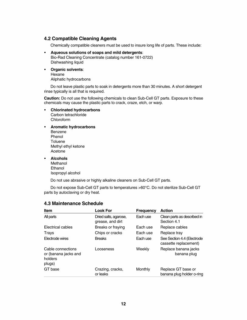
4.3 Maintenance ScheduleItem Look For Frequency Action
All parts Dried salts, agarose, Each use Clean parts as described ingrease, and dirt Section 4.1
Electrical cables Breaks or fraying Each use Replace cablesTrays Chips or cracks Each use Replace trayElectrode wires Breaks Each use See Section 4.4 (Electrode
cassette replacement)Cable connections Looseness Weekly Replace banana jacksor (banana jacks and banana plugholdersplugs)GT base Crazing, cracks, Monthly Replace GT base or
or leaks banana plug holder o-ring
12
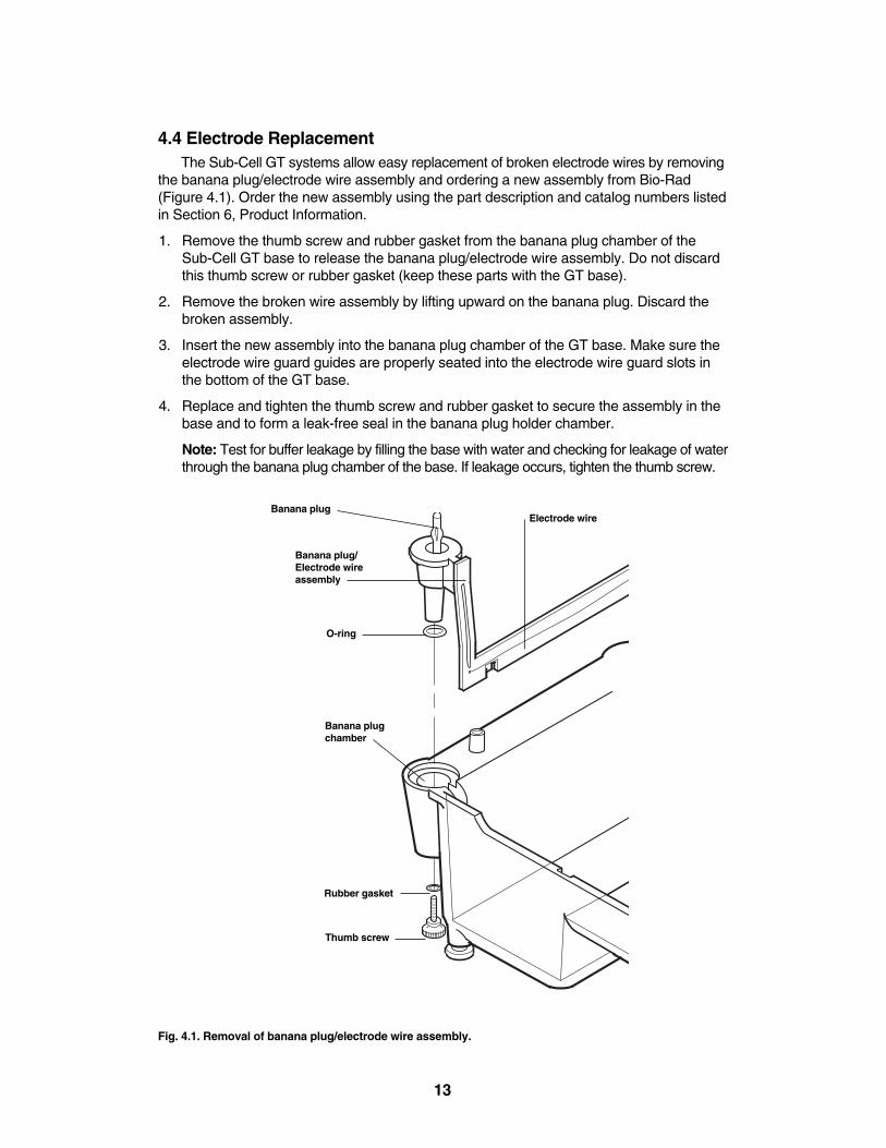
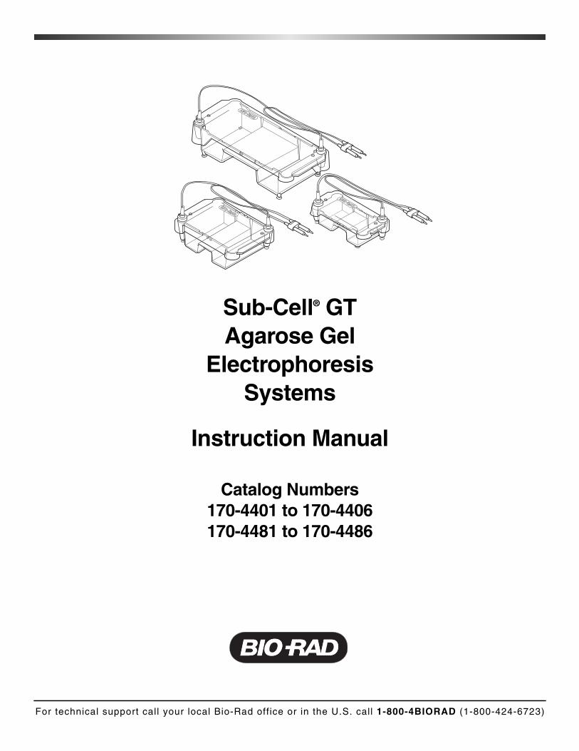
4.4 Electrode ReplacementThe Sub-Cell GT systems allow easy replacement of broken electrode wires by removing
the banana plug/electrode wire assembly and ordering a new assembly from Bio-Rad(Figure 4.1). Order the new assembly using the part description and catalog numbers listedin Section 6, Product Information.
1. Remove the thumb screw and rubber gasket from the banana plug chamber of theSub-Cell GT base to release the banana plug/electrode wire assembly. Do not discardthis thumb screw or rubber gasket (keep these parts with the GT base).
2. Remove the broken wire assembly by lifting upward on the banana plug. Discard thebroken assembly.
3. Insert the new assembly into the banana plug chamber of the GT base. Make sure theelectrode wire guard guides are properly seated into the electrode wire guard slots inthe bottom of the GT base.
4. Replace and tighten the thumb screw and rubber gasket to secure the assembly in thebase and to form a leak-free seal in the banana plug holder chamber.
Note: Test for buffer leakage by filling the base with water and checking for leakage of waterthrough the banana plug chamber of the base. If leakage occurs, tighten the thumb screw.
Fig. 4.1. Removal of banana plug/electrode wire assembly.
Banana plug
O-ring
Electrode wire
Banana plug/Electrode wireassembly
Banana plugchamber
Thumb screw
Rubber gasket
13
4.5 RNase DecontaminationSub-Cell GT parts can be cleaned with a mild detergent and treated for 10 minutes with
3% hydrogen peroxide (H2O2), and then rinsed with 0.1% DEPC- (diethyl pyrocarbonate)treated distilled water, to eliminate RNases prior to using the Sub-Cell GT systems for RNAgels.1-2 Consult references #'s1–2 for other suggestions regarding the use of DEPC inRNase decontamination.
Caution: DEPC is a suspected carcinogen. Always wear gloves, eye glasses, and a laboratory coat. Use caution when handling DEPC-containing solutions. Consult the DEPCMSDS for more information.
Do not attempt to decontaminate RNase from Sub-Cell GT parts using extreme dry heat.
Note: Several commercial products are available for eliminating RNase contamination.RNaseZAP® (Ambion) is a safe, simple, and effective method that if used properly does notcraze or fog the Sub-Cell GT parts. See manufacturer’s instructions for proper use.
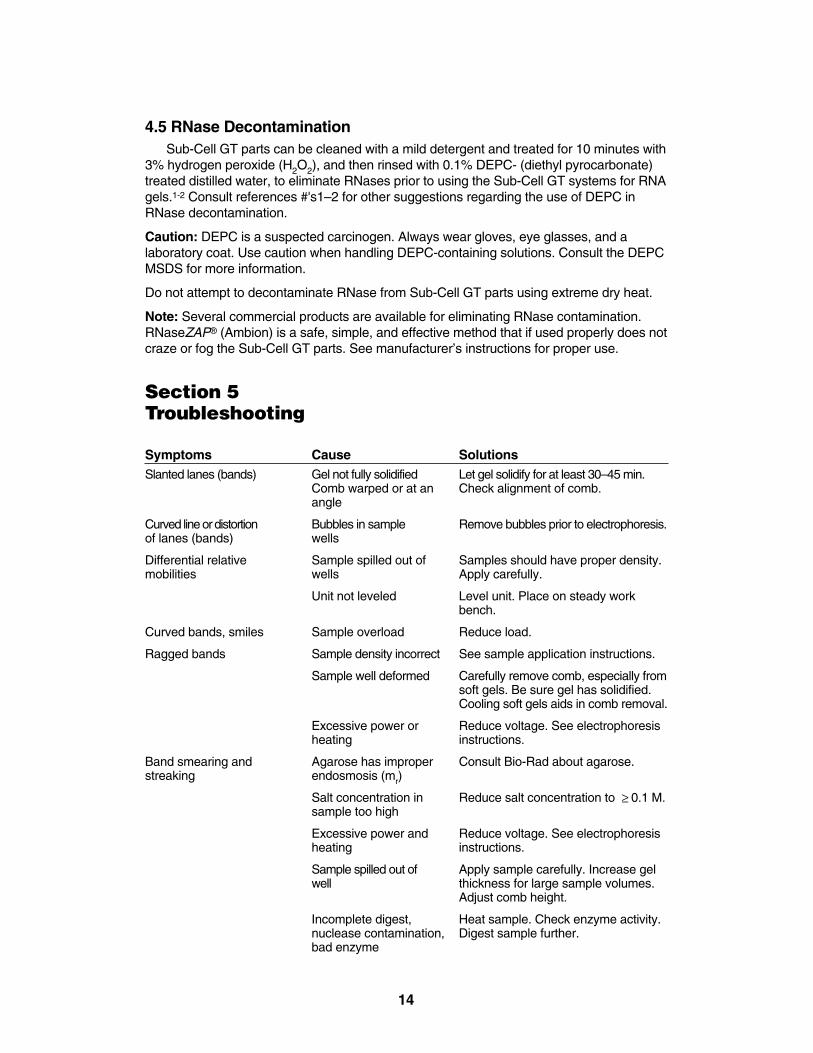
Section 5Troubleshooting
Symptoms Cause SolutionsSlanted lanes (bands) Gel not fully solidified Let gel solidify for at least 30–45 min.
Comb warped or at an Check alignment of comb.angle
Curved line or distortion Bubbles in sample Remove bubbles prior to electrophoresis.of lanes (bands) wells
Differential relative Sample spilled out of Samples should have proper density. mobilities wells Apply carefully.
Unit not leveled Level unit. Place on steady work bench.
Curved bands, smiles Sample overload Reduce load.
Ragged bands Sample density incorrect See sample application instructions.
Sample well deformed Carefully remove comb, especially fromsoft gels. Be sure gel has solidified. Cooling soft gels aids in comb removal.
Excessive power or Reduce voltage. See electrophoresis heating instructions.
Band smearing and Agarose has improper Consult Bio-Rad about agarose.streaking endosmosis (mr)
Salt concentration in Reduce salt concentration to 0.1 M.sample too high
Excessive power and Reduce voltage. See electrophoresis heating instructions.
Sample spilled out of Apply sample carefully. Increase gel well thickness for large sample volumes.
Adjust comb height.
Incomplete digest, Heat sample. Check enzyme activity. nuclease contamination, Digest sample further.bad enzyme
£
14
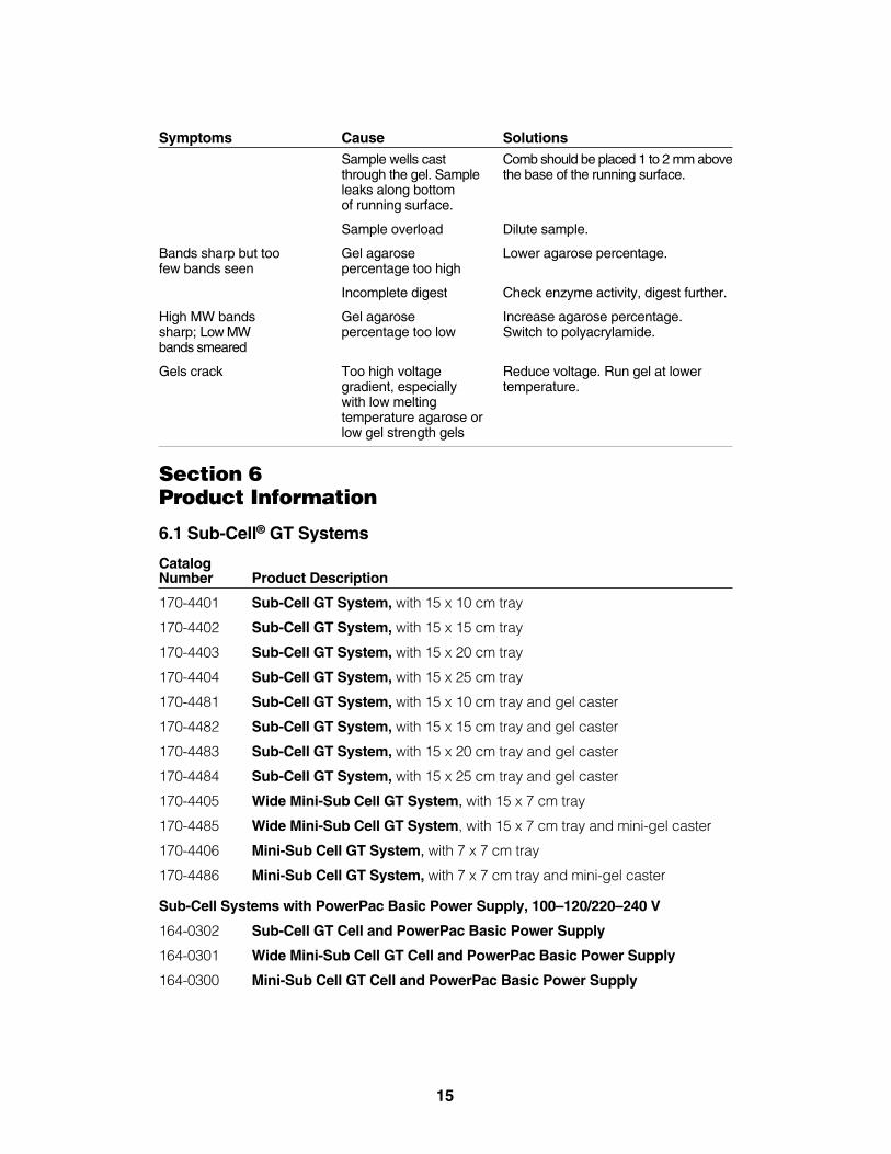
Symptoms Cause SolutionsSample wells cast Comb should be placed 1 to 2 mm abovethrough the gel. Sample the base of the running surface.leaks along bottom of running surface.
Sample overload Dilute sample.
Bands sharp but too Gel agarose Lower agarose percentage.few bands seen percentage too high
Incomplete digest Check enzyme activity, digest further.
High MW bands Gel agarose Increase agarose percentage.sharp; Low MW percentage too low Switch to polyacrylamide.bands smeared
Gels crack Too high voltage Reduce voltage. Run gel at lower gradient, especially temperature.with low melting temperature agarose orlow gel strength gels
Section 6Product Information
6.1 Sub-Cell® GT Systems
Catalog Number Product Description
170-4401 Sub-Cell GT System, with 15 x 10 cm tray
170-4402 Sub-Cell GT System, with 15 x 15 cm tray
170-4403 Sub-Cell GT System, with 15 x 20 cm tray
170-4404 Sub-Cell GT System, with 15 x 25 cm tray
170-4481 Sub-Cell GT System, with 15 x 10 cm tray and gel caster
170-4482 Sub-Cell GT System, with 15 x 15 cm tray and gel caster
170-4483 Sub-Cell GT System, with 15 x 20 cm tray and gel caster
170-4484 Sub-Cell GT System, with 15 x 25 cm tray and gel caster
170-4405 Wide Mini-Sub Cell GT System, with 15 x 7 cm tray
170-4485 Wide Mini-Sub Cell GT System, with 15 x 7 cm tray and mini-gel caster
170-4406 Mini-Sub Cell GT System, with 7 x 7 cm tray
170-4486 Mini-Sub Cell GT System, with 7 x 7 cm tray and mini-gel caster
Sub-Cell Systems with PowerPac Basic Power Supply, 100–120/220–240 V
164-0302 Sub-Cell GT Cell and PowerPac Basic Power Supply
164-0301 Wide Mini-Sub Cell GT Cell and PowerPac Basic Power Supply
164-0300 Mini-Sub Cell GT Cell and PowerPac Basic Power Supply
15
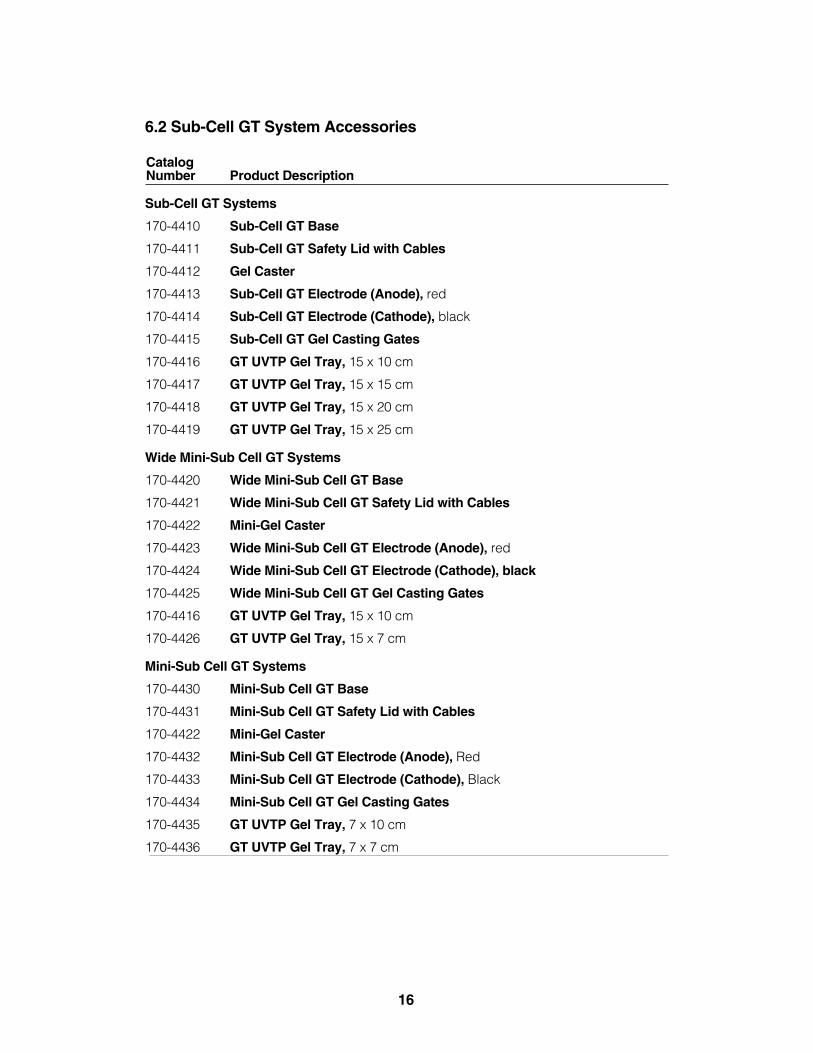
6.2 Sub-Cell GT System Accessories
Catalog Number Product Description
Sub-Cell GT Systems
170-4410 Sub-Cell GT Base
170-4411 Sub-Cell GT Safety Lid with Cables
170-4412 Gel Caster
170-4413 Sub-Cell GT Electrode (Anode), red
170-4414 Sub-Cell GT Electrode (Cathode), black
170-4415 Sub-Cell GT Gel Casting Gates
170-4416 GT UVTP Gel Tray, 15 x 10 cm
170-4417 GT UVTP Gel Tray, 15 x 15 cm
170-4418 GT UVTP Gel Tray, 15 x 20 cm
170-4419 GT UVTP Gel Tray, 15 x 25 cm
Wide Mini-Sub Cell GT Systems
170-4420 Wide Mini-Sub Cell GT Base
170-4421 Wide Mini-Sub Cell GT Safety Lid with Cables
170-4422 Mini-Gel Caster
170-4423 Wide Mini-Sub Cell GT Electrode (Anode), red
170-4424 Wide Mini-Sub Cell GT Electrode (Cathode), black
170-4425 Wide Mini-Sub Cell GT Gel Casting Gates
170-4416 GT UVTP Gel Tray, 15 x 10 cm
170-4426 GT UVTP Gel Tray, 15 x 7 cm
Mini-Sub Cell GT Systems
170-4430 Mini-Sub Cell GT Base
170-4431 Mini-Sub Cell GT Safety Lid with Cables
170-4422 Mini-Gel Caster
170-4432 Mini-Sub Cell GT Electrode (Anode), Red
170-4433 Mini-Sub Cell GT Electrode (Cathode), Black
170-4434 Mini-Sub Cell GT Gel Casting Gates
170-4435 GT UVTP Gel Tray, 7 x 10 cm
170-4436 GT UVTP Gel Tray, 7 x 7 cm
16
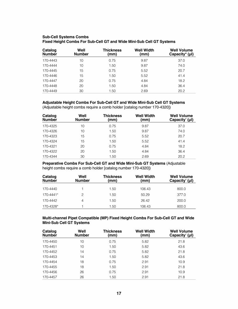
Sub-Cell Systems CombsFixed Height Combs For Sub-Cell GT and Wide Mini-Sub Cell GT Systems
Catalog Well Thickness Well Width Well VolumeNumber Number (mm) (mm) Capacity* (µl)
170-4443 10 0.75 9.87 37.0170-4444 10 1.50 9.87 74.0170-4445 15 0.75 5.52 20.7170-4446 15 1.50 5.52 41.4170-4447 20 0.75 4.84 18.2170-4448 20 1.50 4.84 36.4170-4449 30 1.50 2.69 20.2
Adjustable Height Combs For Sub-Cell GT and Wide Mini-Sub Cell GT Systems(Adjustable height combs require a comb holder [catalog number 170-4320])
Catalog Well Thickness Well Width Well VolumeNumber Number (mm) (mm) Capacity* (µl)
170-4325 10 0.75 9.87 37.0170-4326 10 1.50 9.87 74.0170-4323 15 0.75 5.52 20.7170-4324 15 1.50 5.52 41.4170-4321 20 0.75 4.84 18.2170-4322 20 1.50 4.84 36.4170-4344 30 1.50 2.69 20.2
Preparative Combs For Sub-Cell GT and Wide Mini-Sub GT Systems (Adjustableheight combs require a comb holder [catalog number 170-4320])
Catalog Well Thickness Well Width Well VolumeNumber Number (mm) (mm) Capacity* (µl)
170-4440 1 1.50 106.43 800.0
170-4441* 2 1.50 50.29 377.0
170-4442 4 1.50 26.42 200.0
170-4328* 1 1.50 106.43 800.0
Multi-channel Pipet Compatible (MP) Fixed Height Combs For Sub-Cell GT and WideMini-Sub Cell GT Systems
Catalog Well Thickness Well Width Well VolumeNumber Number (mm) (mm) Capacity* (µl)
170-4450 10 0.75 5.82 21.8170-4451 10 1.50 5.82 43.6170-4452 14 0.75 5.82 21.8170-4453 14 1.50 5.82 43.6170-4454 18 0.75 2.91 10.9170-4455 18 1.50 2.91 21.8170-4456 26 0.75 2.91 10.9170-4457 26 1.50 2.91 21.8
17
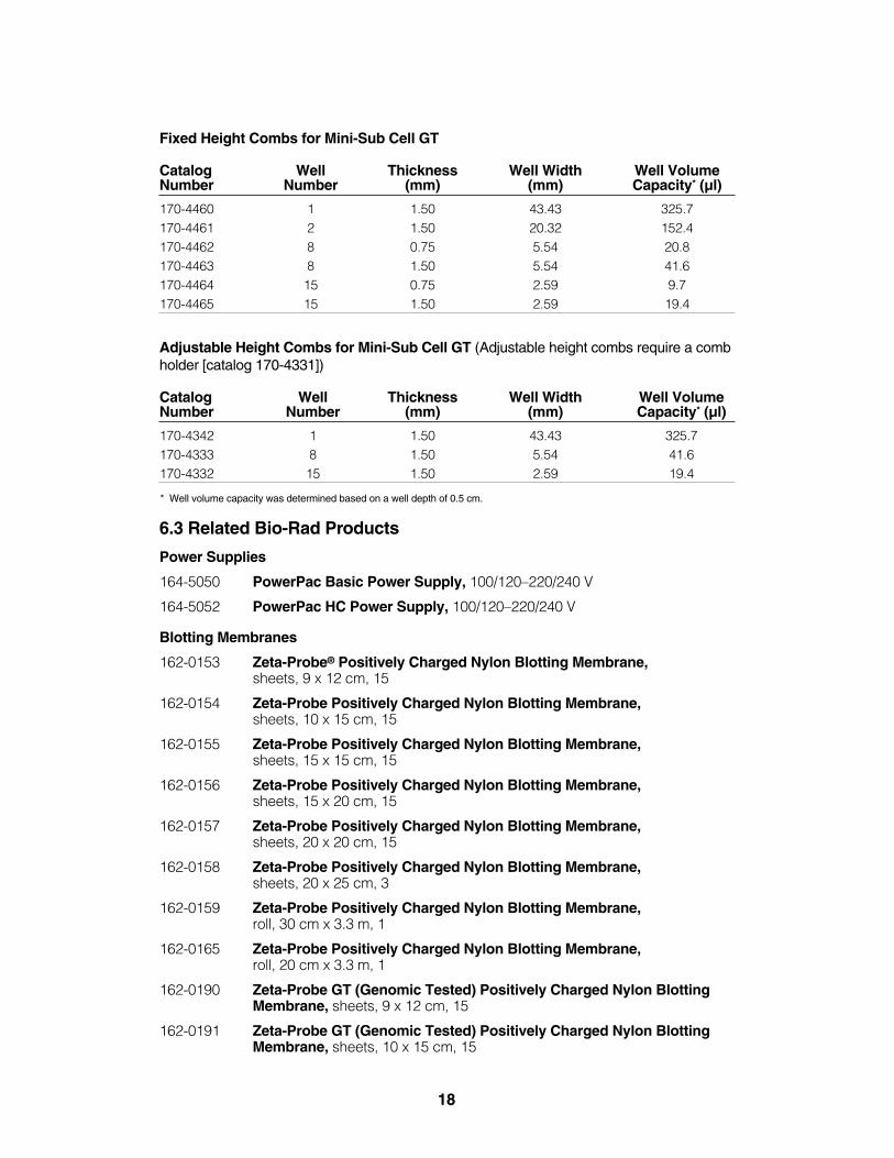
Fixed Height Combs for Mini-Sub Cell GT
Catalog Well Thickness Well Width Well VolumeNumber Number (mm) (mm) Capacity* (µl)
170-4460 1 1.50 43.43 325.7170-4461 2 1.50 20.32 152.4170-4462 8 0.75 5.54 20.8170-4463 8 1.50 5.54 41.6170-4464 15 0.75 2.59 9.7170-4465 15 1.50 2.59 19.4
Adjustable Height Combs for Mini-Sub Cell GT (Adjustable height combs require a combholder [catalog 170-4331])
Catalog Well Thickness Well Width Well VolumeNumber Number (mm) (mm) Capacity* (µl)
170-4342 1 1.50 43.43 325.7170-4333 8 1.50 5.54 41.6170-4332 15 1.50 2.59 19.4
* Well volume capacity was determined based on a well depth of 0.5 cm.
6.3 Related Bio-Rad Products
Power Supplies
164-5050 PowerPac Basic Power Supply, 100/120–220/240 V
164-5052 PowerPac HC Power Supply, 100/120–220/240 V
Blotting Membranes
162-0153 Zeta-Probe® Positively Charged Nylon Blotting Membrane, sheets, 9 x 12 cm, 15
162-0154 Zeta-Probe Positively Charged Nylon Blotting Membrane,sheets, 10 x 15 cm, 15
162-0155 Zeta-Probe Positively Charged Nylon Blotting Membrane,sheets, 15 x 15 cm, 15
162-0156 Zeta-Probe Positively Charged Nylon Blotting Membrane,sheets, 15 x 20 cm, 15
162-0157 Zeta-Probe Positively Charged Nylon Blotting Membrane,sheets, 20 x 20 cm, 15
162-0158 Zeta-Probe Positively Charged Nylon Blotting Membrane,sheets, 20 x 25 cm, 3
162-0159 Zeta-Probe Positively Charged Nylon Blotting Membrane,roll, 30 cm x 3.3 m, 1
162-0165 Zeta-Probe Positively Charged Nylon Blotting Membrane,roll, 20 cm x 3.3 m, 1
162-0190 Zeta-Probe GT (Genomic Tested) Positively Charged Nylon BlottingMembrane, sheets, 9 x 12 cm, 15
162-0191 Zeta-Probe GT (Genomic Tested) Positively Charged Nylon BlottingMembrane, sheets, 10 x 15 cm, 15
18
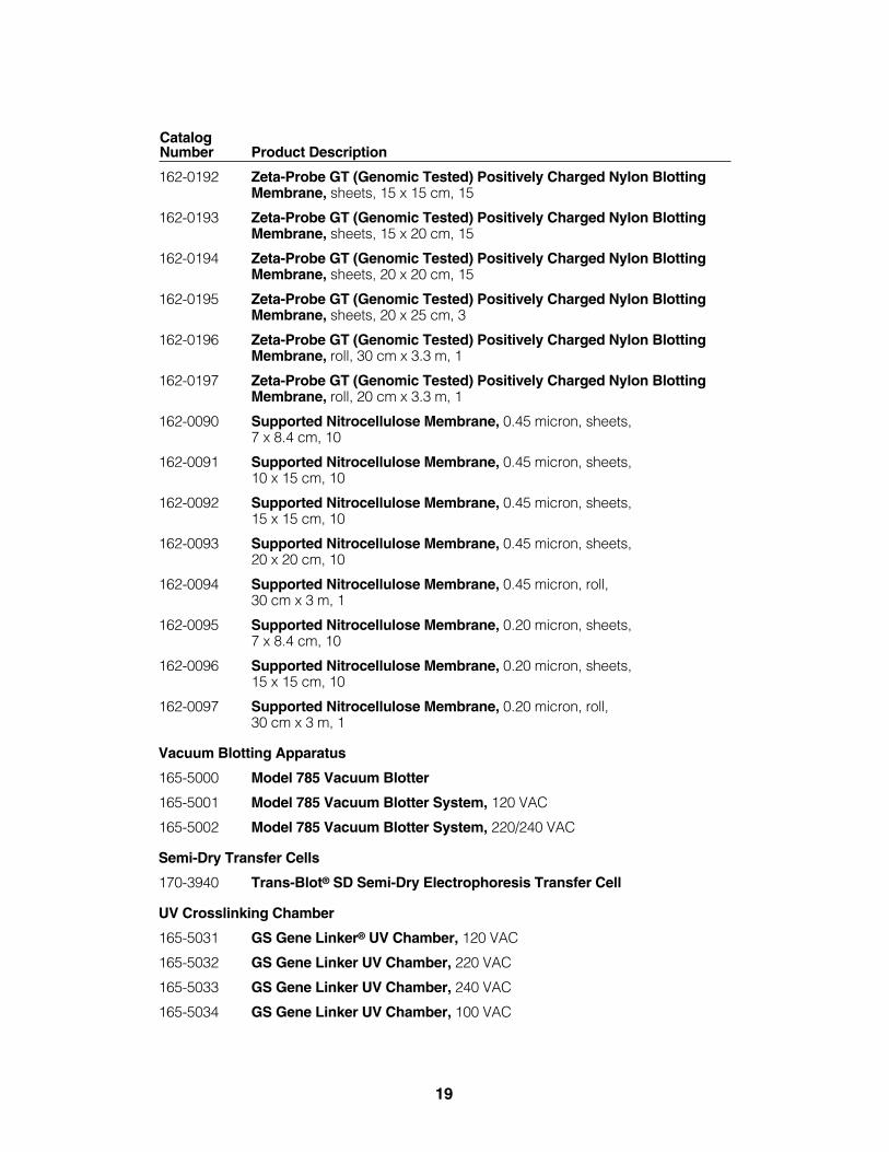
Catalog Number Product Description
162-0192 Zeta-Probe GT (Genomic Tested) Positively Charged Nylon BlottingMembrane, sheets, 15 x 15 cm, 15
162-0193 Zeta-Probe GT (Genomic Tested) Positively Charged Nylon BlottingMembrane, sheets, 15 x 20 cm, 15
162-0194 Zeta-Probe GT (Genomic Tested) Positively Charged Nylon BlottingMembrane, sheets, 20 x 20 cm, 15
162-0195 Zeta-Probe GT (Genomic Tested) Positively Charged Nylon BlottingMembrane, sheets, 20 x 25 cm, 3
162-0196 Zeta-Probe GT (Genomic Tested) Positively Charged Nylon BlottingMembrane, roll, 30 cm x 3.3 m, 1
162-0197 Zeta-Probe GT (Genomic Tested) Positively Charged Nylon BlottingMembrane, roll, 20 cm x 3.3 m, 1
162-0090 Supported Nitrocellulose Membrane, 0.45 micron, sheets, 7 x 8.4 cm, 10
162-0091 Supported Nitrocellulose Membrane, 0.45 micron, sheets, 10 x 15 cm, 10
162-0092 Supported Nitrocellulose Membrane, 0.45 micron, sheets, 15 x 15 cm, 10
162-0093 Supported Nitrocellulose Membrane, 0.45 micron, sheets, 20 x 20 cm, 10
162-0094 Supported Nitrocellulose Membrane, 0.45 micron, roll, 30 cm x 3 m, 1
162-0095 Supported Nitrocellulose Membrane, 0.20 micron, sheets, 7 x 8.4 cm, 10
162-0096 Supported Nitrocellulose Membrane, 0.20 micron, sheets, 15 x 15 cm, 10
162-0097 Supported Nitrocellulose Membrane, 0.20 micron, roll, 30 cm x 3 m, 1
Vacuum Blotting Apparatus
165-5000 Model 785 Vacuum Blotter
165-5001 Model 785 Vacuum Blotter System, 120 VAC
165-5002 Model 785 Vacuum Blotter System, 220/240 VAC
Semi-Dry Transfer Cells
170-3940 Trans-Blot® SD Semi-Dry Electrophoresis Transfer Cell
UV Crosslinking Chamber
165-5031 GS Gene Linker® UV Chamber, 120 VAC
165-5032 GS Gene Linker UV Chamber, 220 VAC
165-5033 GS Gene Linker UV Chamber, 240 VAC
165-5034 GS Gene Linker UV Chamber, 100 VAC
19
Catalog Number Product Description
Gel Reagents and Standards
162-0019 Low Melt Preparative Grade Agarose, 100 g
170-8200 AmpliSize DNA Size Standard, 50-2,000 bp
161-0404 Bromophenol Blue, 10 g
161-0423 Xylene Cyanole FF, 25 g
161-0433 Ethidium Bromide Solution, 10 ml, 10 mg/ml
Electrophoresis Buffers
161-0733 10x Tris/Boric Acid/EDTA (TBE), 1 l
161-0743 50x Tris/Acetic Acid/EDTA (TAE), 1 l
161-0719 Tris, 1 kg
DNA Gel Image Analysis and Documentation Systems
170-8170 Molecular Imager Gel Doc XR System-PC
170-8171 Molecular Imager Gel Doc XR System-MAC
Section 7References1. Sambrook, Fritsch, and Maniatis, Molecular Cloning, A Laboratory Manual, Second
Edition, Cold Spring Harbor Laboratory Press, 1989.
2. Current Protocols in Molecular Biology, Greene Publishing Associates and Wiley-Interscience, 1989.
Additional Reading
3. Kopchick, J. J., Cullen, B. R. and Stacey, D. W., Anal. Biochem., 115, 419 (1981).
4. Southern, E., Methods in Enzymol., 68, 152 (1979).
5. The Bio-Rad Silver Stain - Bulletin 1089, Bio-Rad Laboratories, Hercules, CA.
6. Bittner, M., Kupferer, P. and Morris, C .F., Anal. Biochem., 102, 459 (1980).
7. Bio-Rad Trans-Blot Cell Operation Instructions, Bulletin 1082, Bio-Rad Laboratories,Hercules, CA.
8. Winberg, G. and Hammarskjold, M. L., Nucleic Acids Res., 8, 253 (1980).
9. Jytatekadze, T. V., Axelrod, V. D., Gorbulev, V. G., Belzhelarskaya, S. N. andVartikyan, R. M., Anal. Biochem., 100, 129 (1979).
10. Dretzen, G., Bellard, M., Sassone-Corsi, P. and Chambon, P., Anal. Biochem., 112,295 (1981).
* The Polymerase Chain Reaction (PCR) process is covered by patents owned by Hoffmann-LaRoche. Use of the PCR processrequires a license.
** IEC 1010-1 is an internationally accepted electrical safety standard for laboratory instruments.
20


Life ScienceGroup
07-1013 0108 Sig 1207Bulletin 5694 US/EG Rev A
Bio-Rad Laboratories, Inc.
Web site www.bio-rad.com USA 800 4BIORAD Australia 61 02 9914 2800 Austria 01 877 89 01 Belgium 09 385 55 11 Brazil 55 21 3237 9400 Canada 905 364 3435 China 86 21 6426 0808 Czech Republic 420 241 430 532 Denmark 44 52 10 00 Finland 09 804 22 00 France 01 47 95 69 65 Germany 089 318 84 0 Greece 30 210 777 4396 Hong Kong 852 2789 3300 Hungary 36 1 455 8800 India 91 124 4029300 Israel 03 963 6050 Italy 39 02 216091 Japan 03 6361 7000 Korea 82 2 3473 4460 Mexico 52 555 488 7670 The Netherlands 0318 540666 New Zealand 0508 805 500 Norway 23 38 41 30 Poland 48 22 331 99 99 Portugal 351 21 472 7700 Russia 7 495 721 14 04 Singapore 65 6415 3188 South Africa 27 861 246 723 Spain 34 91 590 5200 Sweden 08 555 12700 Switzerland 061 717 95 55 Taiwan 886 2 2578 7189 United Kingdom 020 8328 2000
M1704400 Rev B