Study of Stress Levels in Various Materials in Total Knee Replacements Under Static Condition
60
i STUDY OF STRESS LEVELS IN VARIOUS MATERIALS IN TOTAL KNEE REPLACEMENT UNDER STATIC CONDITION A PROJECT REPORT Submitted by SHREYAS HARSHA [REG.NO - 1021110129] Under the guidance of DR. RAMESH KANDADAI (Visiting Professor, Department of Mechanical Engineering) in partial fulfillment for the award of the degree of BACHELORS IN TECHNOLOGY in MECHANICAL ENGINEERING of FACULTY OF ENGINEERING & TECHNOLOGY
Transcript of Study of Stress Levels in Various Materials in Total Knee Replacements Under Static Condition
i
STUDY OF STRESS LEVELS IN VARIOUS
MATERIALS IN TOTAL KNEE REPLACEMENT UNDER
STATIC CONDITION
A PROJECT REPORTSubmitted by
SHREYAS HARSHA [REG.NO - 1021110129]
Under the guidance of
DR. RAMESH KANDADAI(Visiting Professor, Department of Mechanical Engineering)
in partial fulfillment for the award of the degreeof
BACHELORS IN TECHNOLOGYin
MECHANICAL ENGINEERING
of
FACULTY OF ENGINEERING & TECHNOLOGY

ii
S.R.M. Nagar, Kattankulathur, Kancheepuram District
APRIL 2015

i
ABSTRACT
With the increase in the number of people being
affected by Osteroarthritis, Rheumatoid Arthritis, and
other knee complication, Total Knee Replacement (TKR)
has emerged as one of the best solution for mobility
and to reduce the pain, stiffness etc, among people.
In TKR the affected portion of the Femur is fitted
with a metallic implant while the Tibia is fitted with
a implant made of a Polymer. The knee joint is
considered to be the most complex joint in the human
body. Accordingly the material utilized for knee
implant assumes an exceptionally important part for
survival of knee prosthesis. These implant materials
must meet the physical, mechanical and biological
necessary to serve its purpose. The materials that are
utilized incorporate Metals, Composites, Ceramics and
Polymers. Of these materials Co-Cr Alloy, Titanium
alloys, Stainless Steel, Zirconia and Tantalum are

ii
used for Femur and Ultra High Molecular Weight
Polyethylene (UHMWPE) for Tibia. The aim of this
project is to prepare a 3D model of the Knee
prosthesis and calculate the Stress, Contact and
Deformation for the various bio-materials used in the
TKR components. The 3D Modelling of knee prosthesis
was made using SolidWorks, while the pre-processing
was done using HYPERMESH and the FEA software ABAQUS
CAE was used as a solver for the contact pressure,
deformation on the knee. The aim is to find out by FEM
analysis results, for the various bio-materials under
static condition and find out the best materials for
the purpose of the Knee Implant.
iii
TABLE OF CONTENTS
CHAPTER TITLE PAGE NO.
BONAFIDE CERTIFICATE i
ABSTRACT ii
TABLE OF CONTENTS iii
LIST OF TABLES vi
LIST OF FIGURES vii
1. LITERATURE SURVEY 1
1.1 KNEE JOINT 1
1.2 FAILURE OF TKR 2
1.3 JOINT LOADING 2
1.4 MATERIALS 4
1.4.1 TITANIUM ALLOY 4
1.4.2 COBALT CHROMIUM ALLOY 5
1.4.3 STAINLESS STEEL 5
iv
1.4.4 ZIRCONIUM CERAMICS 5
1.4.5 POROUS TANTALUM 6
v
CHAPTER TITLE PAGE NO.
1.4.6 UHMWPE 6
1.5 PROBLEM STATEMENT 7
2. KNEE IMPLANT AND ITS MODELLING 8
2.1 KNEE IMPLANT 8
2.2 MODELLING OF KNEE IMPLANT 9
2.2.1 CAD MODELLING 9
2.2.2 FEM ANALYSIS 12
2.2.2.1 MESHING 12
2.2.2.2 CONTACT INTERFACE 13
2.2.2.3 MATERIAL PROPERTIES 14
2.2.2.4 BOUNDARY CONDITION 15
2.2.2.5 OUTPUT BLOCK 16
2.3 ANALYSIS 16
3. FINITE ELEMENT METHOD RESULTS 17

vi
3.1 VON-MISES STRESS 17
3.2 STRAIN/ DEFORMATION 20
CHAPTER TITLE PAGE NO.
3.3 YOUNGS MODULUS 22
4 RESULT AND CONCLUSION 25
5 BIBILOGRAPHY 29

vii
LIST OF TABLES
TABLE NAME PAGE
1 MATERIAL PROPERTIES 14
2 MINIMUM AND MAXIMUM STRESS
IN PROSTHESIS MADE OF DIFFERENT 19
MATERIAL (MPa)
3 STAIN COMPARISON OF PROSTHESIS
MADE OF 5 DIFFERENT MATEIRAL 22
4 TABLE FOR EVALUATION OF AHP 25
5 SCORING TABLE FOR
OSSEOINTERGRATION 26
viii
6 SCORING TABLE FOR COEFFICIENT
OF FRICTION 27
7 ANALYTIC HIERARCHY PROCESS TABLE 28
LIST OF FIGURES
FIGURE NAME PAGE
1 MEDIAL VIEW OF THE RIGHT KNEE 1
2 REPRESENTATION OF TOTAL KNEE
REPLACEMENT 3
3 MOBILE BEARING PROSTHESIS 9
4 FIXED BEARING PROSTHESIS 9
5 2D MODEL OF FEMUR IMPLANT 10

ix
6 2D MODEL OF TIBIA IMPLANT 10
7 3D MODEL OF FEMUR IMPLANT USING
SOLIDWORKS 2014 11
8 3D MODEL OF TIBIAL IMPLANT USING
SOLIDWORKS 11
9 ASSEMBLED MODEL OF THE KNEE IMPLANT 12
10 MESHED MODEL OF KNEE PROSTHESIS 14
11 MASKED VIEW OF SOLID MODEL 14
12 BOUNDARY CONDITION OF SOLID MODEL 15
13 CONTOUR PLOT OF VON-MISES FOR ZIRCONIA
(JUMPING) 17
14 CONTOUR PLOT OF VON-MISES FOR
Ti6Al4V(JUMPING) 17

x
15 CONTOUR PLOT OF VON-MISES FOR POROUS
TANTALUM (JUMPING) 18
16 CONTOUR PLOT OF VON-MISES FOR Co-Cr
ALLOY (JUMPING) 18
17 CONTOUR PLOT OF VON-MISES FOR
316L SS (JUMPING) 18
18 STRESS LEVEL COMPARISON FOR THE THREE
LOADING CASE SCENARIO 20
19 CONTOUR PLOT OF STRAIN FOR 316L SS 20
(JUMPING)
FIGURE NAME PAGE
20 CONTOUR PLOT OF STRAIN FOR
Co-Cr ALLOY (JUMPING) 21
21 CONTOUR PLOT OF STRAIN FOR
POROUS TANTALUM (JUMPING) 21

xi
22 CONTOUR PLOT OF STRAIN FOR Ti6Al4V
(JUMPING) 21
23 CONTOUR PLOT OF STRAIN FOR ZIRCONIA
(JUMPING). 21
24 STRESS- STRAIN GRAPH OF 316L SS
OBTAINED FROM ABAQUS 23
25 316L SS SPECIMEN BEFORE TENSILE TEST 23
26 TENSILE TEST SPECIMEN DIAGRAM 23
27 FAILED SPECIMEN AFTER TESNSILE TEST 24
28 STRESS - STRAIN% GRAPH FROM UTM 24

1
CHAPTER 1
LITERATURE SURVEY
1.1 - KNEE JOINT
The knee joint joins the thigh with the leg and consists
of two articulations: one between the femur and tibia, and
one between the femur and patella. It is the largest joint in
the human body. The knee is a pivotal condylar joint, which
permits flexion and extension as well as a slight internal
and external rotation. The knee is a hinge type synovial
joint, which is composed of three functional compartments:
the femoro-patellar articulation, consisting of the patella,
or "kneecap", and the patellar groove on the front of
the femur through which it slides; and the medial and lateral
femoro-tibial articulations linking the femur, or thigh bone,
with the tibia, the main bone of the lower leg. The joint is
bathed in synovial fluid which is contained inside
the synovial membrane called the joint capsule.

2
Fig. 1 - Medial View of Right Knee
The knee consists of three more or less independent
articulations: one between each sphere-like condyle of
the femur and a corresponding but more planar condylar
surface of the tibia, with interposed menisci, and a
third between the patella and the patellar groove of
the femur. None of the pairs of bearing surfaces is
exactly congruent, which results in a combination of
rolling and gliding motions determined by the
restraints of a complex network of ligaments, capsular
structures, and the contours of the bones themselves.
This intricate arrangement of anatomic
interrelationships allows the knee six degrees of
freedom of motion: three rotations and three
translations. The translations are anteroposterior (5
to 10 mm), compression–distraction (2 to 5 mm), and
mediolateral (1 to 2 mm). These motions are limited by
the ligaments, capsul, The rotations are flexion–
extension, varus–valgus, and internal–external
rotation, and in general they are much more extensive
than the translations. Normal flexion and extension of
the knee is variable, ranging from 0° to 15° of
hyperextension to 130° to 150° of flexion. Internal and
external rotation ranges from little or no motion in
full extension to 20° to 30° with the knee flexed.[11]
1.2 - FAILURE OF TKR
Arthritis is a disorder that results in the
inflammation of one or more joints. There are over 100
3
different types of arthritis. The most common type,
osteoarthritis, is due to trauma to the joint, infection of
the joint, or age. Other forms of arthritis are- rheumatoid
arthritis, psoriatic arthritis, and other related autoimmune
diseases. Osteoarthritis (OA) and rheumatoid arthritis (RA)
largely affect joints present in the fingers, shoulders,
elbows and also specifically the knee joint. Osteoarthritis
ranks as the 4th leading cause of the Years Lived with
Disability (YLDs).
Joint replacement represents an appealing means to relieve
the pain and increase the mobility of arthritic patients.
Nearly 200,000 Total Knee Replacements (TKR) are implanted
annually in the United States. Most TKR designs incorporate a
polished metallic femoral component, usually made from a
cobalt- chrome alloy or Titanium Aluminum alloy in contact
with a tibial bearing made from Ultra- High Molecular Weight
Polyethylene (UHMWPE). Femoral component are also made up of
Zirconium Oxide, Stainless Steel, pure Titanium and pure
Tantalum in certain cases. The loading conditions in knee
joints are cyclic in nature, and they vary with the flexion
and extension angle. Owing to inertia forces during the human
gait, loads of more than 2-3 times body weight can be
supported by the knee during a typical walk cycle and other
research has shown that loads can exceed 8 times body weight
in many cases. These loads cause high contact pressures in
the concentrated contact between the metallic femoral
component and the UHMWPE tibial bearing. Therefore, after
implantation the non conforming TKR bearings are subjected to

4
many cycles of high contact stress during oscillatory
rolling/sliding contact. Although many implanted knee
prostheses have withstood 10 or even 20 years of activity
without substantial surface damage many other tibial bearings
of TKR have shown evidence of significant wear and contact
fatigue damage, requiring early replacement (5 years after
implantation). The replacement procedures are costly and can
have serious health consequences.[12][13][14][16]
1.3 - JOINT LOADING
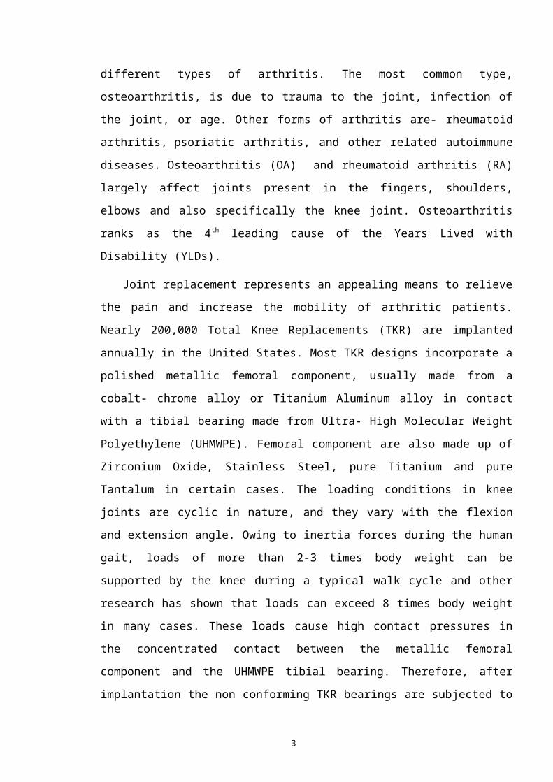
It has been estimated that femoro-patellar contact forces
can range from 300 to 2000 N during normal walking. This
translates to a compressive stress of 2-4 MPa on the contact
surface. When considering joint loading on the knee, it is
important to note that load on the knee joint is rarely
constant for an extending period of time. Proper loading
analysis must consider spatial dimensions, position of the
joint, and muscle groups most active in loading activity. The
walk cycle is broken into four phases: stance, swing, heel
strike, and toe off. For most of the walk cycle, one leg is
in swing phase and one is in stance. The leg in stance phase
is weight bearing and in contact with the ground. [1] The
walking cycle becomes more complex when considering the five
separate motions involved: pelvic rotation, pelvic tilt, knee
flexion, ankle flexion, and toe flexion. These five motions
result in a center of gravity path that oscillates left to
right and up and down creating a figure 8 motion.
5
Fig.2
-
Representation of Total Knee Replacement
Maximum load on the knee occurs during the heel strike and
just before toe off phases of the walk cycle, where it
reaches about 1500 N. [2] Sliding velocity in the knee varies
with load and increases as load on the knee decreases. Forces
in the knee are highly dependent on the position of the
tibia, as a 1-degree change in angle moves the knee by 10mm.
Joint force can be calculated with 2-D or 3-D analysis and
static or dynamic analysis of horizontal force balance,
vertical force balance, and moment balance in the joint. [2] A
real time experiment performed on knee shows, 1.5 - 1.8 times
the body weight being transmitted on the tibial part of the
knee.
1.4 - MATERIALS
1.4.1 - TITANIUM ALLOY

6
Titanium alloys are metals that contain a mixture of
Titanium and other chemical elements like Vanadium, Aluminum,
Niobium, Iron and oxygen. Such alloys have very high tensile
strength and toughness. They are light in weight, have
excellent corrosion resistance and the ability to withstand
extreme temperatures. This makes the alloys most suitable for
aircraft, spacecrafts, medical devices, sports cars etc.
Although pure titanium has acceptable mechanical properties
and has been used for orthopedic implants, for most
applications titanium is alloyed with small amounts of
aluminum and vanadium, typically 6% and 4% respectively by
weight. Grade 5, also knows as Ti6Al4V is most commonly used
alloy. It has a chemical composition of 6% aluminum,
4%vanadium, 0.25% Iron and 0.2 % oxygen, while the rest is
Titanium. This grade of Titanium alloy has an excellent
combination of strength, corrosion resistance, weld and
fabricability. Ti6Al4V is used in application up to 400
degrees Celsius. It has a density of 4430 kg/m3, Young's
Modulus of 115 GPa and Poission’s ratio of 0.342. Ti6Al7Nb was
developed as a bio-medical replacement of Ti6Al4V because
Ti6Al4V contains vanadium, an element that has demonstrated
cytrotxic outcomes when isolated. Ti6Al7Nb contains 6%
Aluminum and 7% Niobium.[28][29]
1.4.2 - COBALT-CHROMIUM ALLOY
Cobalt-Chromium also known as Cobalt-Chrome is a metallic
alloy made up up Cobalt and Chromium. Because of its high
strength, it is extensively used in gas turbines, Orthopedic
7
and Dental implants. Co-Cr alloys show high resistance to
corrosion due to the spontaneous formation of a protective
passive film composed of Cr2O3. Because of its bio-compartable
property, it finds wide application in Bio-medical industry.
Good Mechanical properties that are similar to stainless
steel are a result of multi-phase structure which increases
the hardness of the alloy. Co-Cr alloys are most commonly
used to make artificial joints including knee and hip joints
due to high wear-resistance and bio-compatibility.[18][19]Co-Cr
alloys tend to be corrosion resistance, which reduces
complication with the surrounding tissues when implanted, and
chemically inert that they minimize the possibility of
irritation, allergic reaction, and immune response. Co-Cr
alloy has also been widely used in the manufacture of stent
and other surgical implants as Co-Cr alloy demonstrates
excellent bio-compatibility with blood and soft tissues as
well. The alloy composition used in orthopedic implants is
described in industry standard ASTM-F75: cobalt with 27 to
30% chromium, 5 to 7% molybdenum, and limits on other
important elements such as manganese and silicon, less than
1%, iron, less than 0.75%, nickel, less than 0.5%, and
carbon, nitrogen, tungsten, phosphrous, sulphur and boron[20]
[23][24]
1.4.3 - STAINLESS STEEL
Stainless steel, also know as inox steel is a steel alloy
with a minimum of 10.5% chromium content by mass. Low-carbon
versions, for example 316L or 304L, are used to avoid

8
corrosion problems caused by welding. Grade 316L is preferred
where biocompatibility is required such as body implants and
piercings. The "L" means that the carbon content of the
alloy is below 0.03%, which reduces the sensitization effect
caused by the high temperatures involved in welding. Grade
316 is the standard molybdenum-bearing grade, second in
importance to 304 amongst the austenitic stainless steels.
The molybdenum gives 316 better overall corrosion resistant
properties than Grade 304, particularly higher resistance to
pitting and crevice corrosion in chloride environments. The
austenitic structure also gives these grades excellent
toughness, even down to cryogenic temperatures. Compared to
chromium-nickel austenitic stainless steels, 316L stainless
steel offers higher creep, stress to rupture and tensile
strength at elevated temperatures.[17]
1.4.4 - ZIRCONIUM CERAMICS
Yttria-stabilized zirconia (YSZ) is a ceramic in which the
crystal structure of zirconium dioxide is made stable at room
temperature by an addition of yttrium oxide. These oxides are
commonly called "zirconia" (ZrO2) and "yttria" (Y2O3).
Yttria-stabilized zirconia (YSZ) is a form of Zirconiumceramic that is most commonly used as bio-materials in human
body as implants. These materials are used extensively for
the purpose of Dental implants as Crowns and as Hip and Knee
9
implants. Zirconia is best known among ceramics as being both
hard and fracture-tough at room temperature. [26]Additionally,
its fine grain size enables excellent surface finishes and
the ability to hold a sharp edge. Althought it retains many
properties including corrosion resistance at extremely high
temperature, Zirconia does exhibit structural change that can
limit its use at high temperatures of about 500 degree
Celsius. Zirconia is tough because it has a teragonal
structure that precipitates a stress induced phase
transformation near an advancing crack tip. [27][30][31]
1.4.5 - POROUS TANTALUM
With the advancements in the field of Material Science and
Bio-Materials, Porous Tantalum has come into the picture as
an alternative metal for primary and revision Total Knee
Arthroplasty, because of its several unique properties.
Tantalum is a transition metal, which in its bulk nature
shows excellent biocompatibility. It is safe to use it in
vivo as Porous Tantalum finds its application in pacemaker
electrodes, cranioplasty plates, and radiopaque markers.
Porous Tantalum as a orthopedic implant maintain a high
columetric porosity (70%-80%), low modulus of elasticity,
making it a good fit for biologic fixation. Because of its
low modulus of elasticity, it allows a more physiologic load
transfer and relative preservation of bone stock. Although
porous tantalum is in its early stages of evolution, the
initial clinical data and studies support of its use as an

10
alternative to traditional orthopedic implant materials.[25][32]
[33]
1.4.6 - UHMWPE
Ultra high molecular weight polyethylene is a subset of
the thermosplastic polyethylene. Also known as high modulus
polyethylene, it has extremely long chains, with a molecular
mass usually between 2 and 6 million atomic mass unit. [10]The
longer chain serves to transfer load more effectively to the
polymer backbone by strengthening intermolecular
interactions. This results in a very tough material, with the
highest impact strength of any thermoplastic presently made.
UHMWPE is odorless, tasteless, and nontoxic.[11 It is highly
resistant to corrosive chemicals except oxidizing acids; has
extremely low moisture absorption and a very low coefficient
of friction; is self-lubricating; and is highly resistant
to abrasion, in some forms being 15 times more resistant to
abrasion than carbon steel. Its coefficient of friction is
significantly lower than that of nylon and acetal, and is
comparable to that of PTFE but UHMWPE has better abrasion
resistance than PTFE. [12]
1.5 - PROBLEM STATEMENT
The aim of this project is to find out the Stress, Strain
and Deformation for the various materials that are used as
femoral implants in Total Knee Arthroplasty using Finite
Element Analysis (FEA). Also taking into consideration other
11
factors such as Density and Osseointergration, to find the
material that is best suited as a femoral implant, when
UHMWPE is taken as the material for Tibia. In order to find
the best material for femoral implant, a Multi- Criteria
Decision Making procedure known as Analytic Hierarchy Process
(AHP) is used.
The analytic hierarchy process (AHP) is a structured
technique developed by Thomas. L. Saaty in 1970 for
organizing and analyzing complex decisions. This process is
generally used to make group decision making and is used
around the world in large scale for a variety of decision
situations, in the field of government, business, industry,
health care, shipbuilding, education etc. In this process,
rather than suggesting the “Correct” decision, it helps the
decision makers to find that alternative that best suits
their goal. It provides a comprehensive and rational
framework for structuring a decision problem, for
representing and quantifying its elements, for relating those
elements to overall goals and for evaluating alternative
solutions.[21][22]
Users of the AHP, first dissect their decision problem
into a sub-problems that are easier to comprehend. This way
each of the sub-problems can be analyzed independently. The
elements of this sub-problems can relate to any aspect of the
decision problem, carefully measured or roughly estimated,
well or poorly understood- anything at all that applies to
the decision at hand.
12
CHAPTER 2
KNEE IMPLANT AND ITS M
2.1 KNEE IMPLANT
The earliest Total Knee Arthroplasty can be dated back to
1860, when a German surgeon by the name Themistocles Gluck
implanted the first artificial knee. It was based on the
principle of Hinge Joint and was made up of Ivory. In 1960s
John Charnley’s cemented metal on polyethylene total hip
arthroplasty inspired the development of the modern total
knee replacement.
With improvement in the field of Biomechanics, cruciate
and collateral ligaments began to be preserved intact, which
helped in maintaining the stability of unlinked femoral and
tibial components. Throughout the 1970s and 1980s incremental
improvement in component material, geometry and fixation
continued. The early efforts of McKeever and Eliott to
develop a Unicompartmental Knee Arthroplasty was being
pursued even in the 80s. However because the unicompartmental
procedure replaces only the diseased part of the joint with
more natural kinematics , the indications for its use are
more limited.
In the modern Total Knee Arthroplasty, the affected
portion of the knee are precision cut by the surgeon using

13
special cutting instruments, for the implant to fit on the
knee properly. Then the implants are fixed on to the knee
either using bone cement (polymethylmethacrylate) or by means
of screws. In most of the cases the Posterior Cruciate
Ligament (PCL) are removed along with the Anterior Cruciate
Ligament (ACL), while in some cases the the PCL is retained
with provision in the knee implants to accommodate the PCL,
to give better stability to the knee. The latter model is
more appropriate for patients who have a strong and healthy
PCL, and it needs no external support.
The other variation the knee implant provides is Fixed
Bearing Prosthesis and Mobile Bearing Prosthesis. In fixed
bearing prosthesis , the polyethylene of the tibial component
is attached firmly to the metal implant beneath. The femoral
component then rolls over the tibial component which acts as
a cushioned surface. While the other model namely Mobile
bearing prosthesis consists of the polyethylene of tibia
rotating over the metallic implant beneath it. Compared with
fixed-bearing designs, mobile-bearing knee implants require
more support from soft tissues, such as the ligaments
surrounding the knee. [1]
Fig.3- Mobile
Bearing Prosthesis
Fig.4- Fixed Bearing
Prosthesis

14
In the late 1980’s and early 1990’s, there have been tests
performed to introduce all polymer implant. Polyethylene was
used as the femur and Polyacetal was used as the tibial
plate. Though it showed significant reduction in the wear (up
to 20% improvement), issues of load bearing capacity were
reported among few patients. This accounts to the low load
bearing capacity of the Polymers. Similarly an all metal
implant may also face problems in terms of the excessive
wear, when a metal slides over another metal. For this
reason, a combination of metal and polymer is used. The
femoral head made up of metal acts as a load bearer, thereby
transmitting the load to the tibia efficiently,and the
Polymeric Tibia act as a lubricating part. The Polymer
(generally UHMWPE) used in the tibia also acts as a shock
absorber. This excellent combination helps in the functioning
of the artificial knee.[15]
2.2 - MODELLING OF KNEE IMPLANT
2.2.1 - CAD MODELLING
The geometry of the knee implant has a significant
influence in the performance of the implant. Thus it is
necessary to model the implant according to the standard
procedure. The 2D model of the knee implant can be made using
CT scan of the knee and with the help of MIMICS software. For
the purpose of this project, the 2D model of the knee implant
was referred from the research paper “Finite Element M and
15
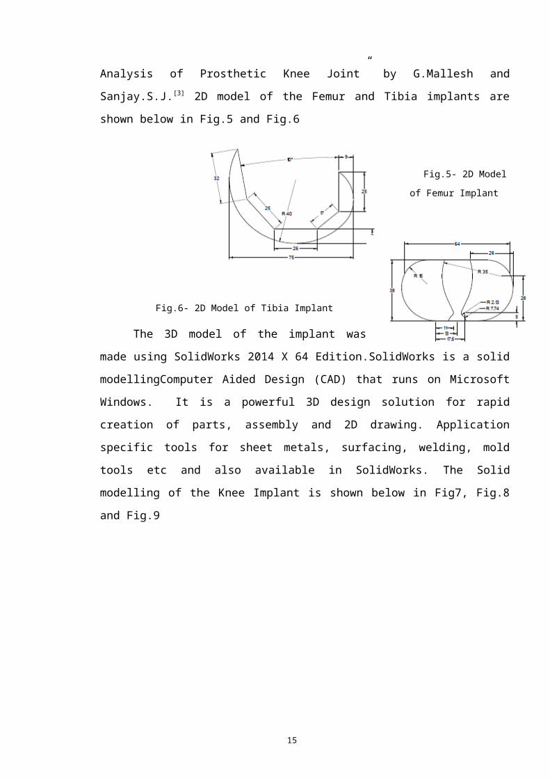
Analysis of Prosthetic Knee Joint” by G.Mallesh and
Sanjay.S.J.[3] 2D model of the Femur and Tibia implants are
shown below in Fig.5 and Fig.6
Fig.5- 2D Model
of Femur Implant
Fig.6- 2D Model of Tibia Implant
The 3D model of the implant was
made using SolidWorks 2014 X 64 Edition.SolidWorks is a solid
modellingComputer Aided Design (CAD) that runs on Microsoft
Windows. It is a powerful 3D design solution for rapid
creation of parts, assembly and 2D drawing. Application
specific tools for sheet metals, surfacing, welding, mold
tools etc and also available in SolidWorks. The Solid
modelling of the Knee Implant is shown below in Fig7, Fig.8
and Fig.9

16
Fig.7- 3D Model of Femur Implant using SolidWorks 2014
17
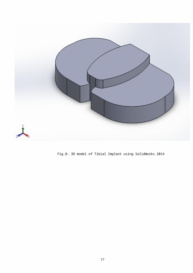
Fig.8- 3D model of Tibial Implant using SolidWorks 2014

18
Fig.9- Assembled model of the Knee Implant
2.2.2 - FEMANALYSIS
Finite Element Method (FEM) analysis of the prosthetic
joint for various bio-materials of the femur was performed
partly in HYPERMESH and partly in ABAQUS. The meshing,
defining interfaces and boundary conditions of the model was
performed on Hypermesh.[4][5][6]
19
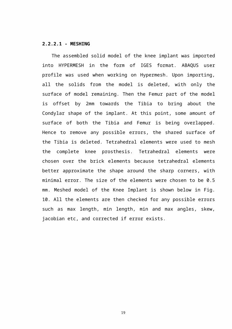
2.2.2.1 - MESHING
The assembled solid model of the knee implant was imported
into HYPERMESH in the form of IGES format. ABAQUS user
profile was used when working on Hypermesh. Upon importing,
all the solids from the model is deleted, with only the
surface of model remaining. Then the Femur part of the model
is offset by 2mm towards the Tibia to bring about the
Condylar shape of the implant. At this point, some amount of
surface of both the Tibia and Femur is being overlapped.
Hence to remove any possible errors, the shared surface of
the Tibia is deleted. Tetrahedral elements were used to mesh
the complete knee prosthesis. Tetrahedral elements were
chosen over the brick elements because tetrahedral elements
better approximate the shape around the sharp corners, with
minimal error. The size of the elements were chosen to be 0.5
mm. Meshed model of the Knee Implant is shown below in Fig.
10. All the elements are then checked for any possible errors
such as max length, min length, min and max angles, skew,
jacobian etc, and corrected if error exists.
20
Fig.10- Meshed model of Knee Prosthesis
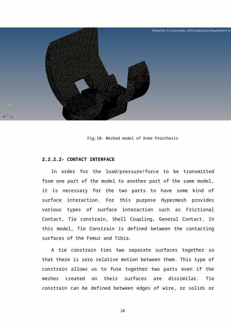
2.2.2.2- CONTACT INTERFACE
In order for the load/pressure/force to be transmitted
from one part of the model to another part of the same model,
it is necessary for the two parts to have some kind of
surface interaction. For this purpose Hypermesh provides
various types of surface interaction such as Frictional
Contact, Tie constrain, Shell Coupling, General Contact. In
this model, Tie Constrain is defined between the contacting
surfaces of the Femur and Tibia.
A tie constrain ties two separate surfaces together so
that there is zero relative motion between them. This type of
constrain allows us to fuse together two parts even if the
meshes created on their surfaces are dissimilar. Tie
constrain can be defined between edges of wire, or solids or
21
between faces or shells.
Fig.11- Masked view of Solid Model
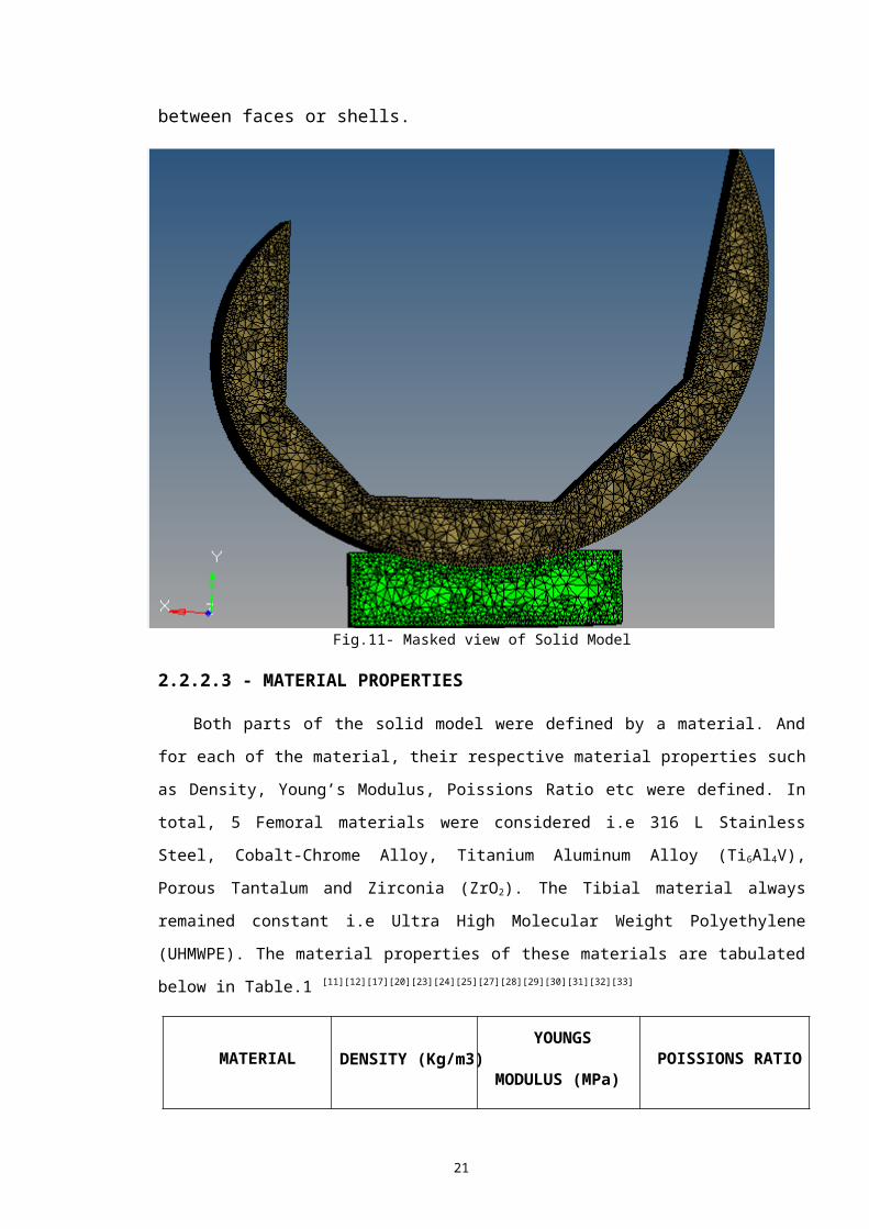
2.2.2.3 - MATERIAL PROPERTIES
Both parts of the solid model were defined by a material. And
for each of the material, their respective material properties such
as Density, Young’s Modulus, Poissions Ratio etc were defined. In
total, 5 Femoral materials were considered i.e 316 L Stainless
Steel, Cobalt-Chrome Alloy, Titanium Aluminum Alloy (Ti6Al4V),
Porous Tantalum and Zirconia (ZrO2). The Tibial material always
remained constant i.e Ultra High Molecular Weight Polyethylene
(UHMWPE). The material properties of these materials are tabulated
below in Table.1 [11][12][17][20][23][24][25][27][28][29][30][31][32][33]
MATERIAL DENSITY (Kg/m3) YOUNGS
MODULUS (MPa) POISSIONS RATIO

22
316L SS 8000 1.97E+5 0.3
Co-Cr Alloy 8300 2.3E+5 0.3
Ti6Al4V 4430 1.15E+5 0.342
Porous Tantalum 16700 1.86E+5 0.34
Zirconia 6040 2.1E+5 0.3
UHMWPE 930 6.9E+3 0.29
TABLE.1 MATERIAL PROPERTIES
2.2.2.4 - BOUNDARY CONDITION
Load on the model is applied in the form of force.
According to ISO 14243-1, an axial compressive load is one
which acts while standing and thus needs to be applied on the
model. Also according to 14243-1, maximum load should be
applied for testing of the knee implant. In this study, 3
loading case scenario are considered i.e Walking ( 2.84 X
Body weight), Running (5.5 X Body Weight), Jumping (9 X Body
Weight). Thus the load being applied on each knee while
Walking, Running and Jumping are 994N, 1925N and 3150N
respectively considering a person of 70Kg weight. The Tibial
part of the prosthesis was constrained of all degrees of
freedom (DOF) from the bottom surface.[10]
The Tibial portion is constrained of all degrees of
freedom by creating a “Load Collector” in the name of
CONSTRAINS. By selecting “CONSTRAINTS” option available in
“ANALYSIS”, all elements of the bottom surface of the Tibia

23
are selected and the constraints are created in all the 6
DOF. Similarly another “Load Collector” is created in the
name of LOAD. The load is applied on the flat surface of the
Femoral implant that is parallel to the Tibial surface. A
Master node was created and all the nodes of the flat surface
of femur (on which load is to be acted) is connected to the
master node by means of rigid links. To apply the load,
“FORCES” option is selected from “ANALYSIS”, following which
the master node is selected on which the force is to be
acted. Then the magnitude of the forces is specified along
with direction of force.
Fig.12- Boundary Condition of Solid Model

24
2.2.2.5 - OUTPUT BLOCK
In order to obtain and view results, it is necessary to
define the OUTPUT BLOCK. Output Block is an option in
Hypermesh that requests for the output of the analysis for
either some or all the entities in the model. In order to
define the Output block, two Output blocks are created, one
each for Tibia and Femur. For each of this, “Node Output (to
obtain the results of displacements)” and “ Element Output
(to obtain the results of Stress and Strain)” are selected.
In the Element Output, the required outputs are selected for
eg. ‘S’, ‘SINV’, ‘E’ and similarly in the Node Output, ‘U’ is
selected. This way all the required outputs are selected
which would be displayed upon the completion of the analysis.
2.2.3 - ANALYSIS
Once the meshing, interface conditions, boundary
conditions, material properties and output block have been
defined, the model is exported as Solverdeck in Abaqus File
Format (.inp). Upon importing the model is run in ABAQUS, by
opening the command window and giving the following command “
ABAQUS ANALYSIS JOB= “FILE NAME” INT ”. Once the analysis has
been completed, the results can be viewed using .odb file.

25
CHAPTER - 3
FINITE ELEMENT METHOD RESULTS
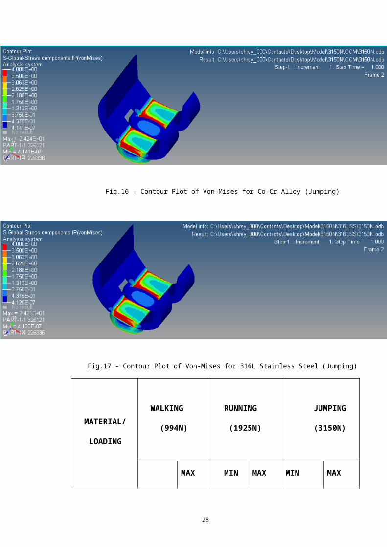
3.1 - VON-MISES STRESS

26
Stress is the force per unit area that some particles in a
body exert on adjacent particles. In prosthesis such as the
knee, lower the value of stress better is the prosthesis.
The following 5 figures shows the Contour Plot of Von-
Mises Stress for the five different materials that were used
as femoral implants. The scenario considered for loading was
Jumping with a load of 3150N.
Fig.13 - Contour Plot of Von-Mises for Zirconia (Jumping)

27
Fig.14 - Contour Plot of Von-Mises for Ti6Al4V (Jumping)
Fig.15 - Contour Plot of Von-Mises for Porous Tantalum (Jumping)
28
Fig.16 - Contour Plot of Von-Mises for Co-Cr Alloy (Jumping)
Fig.17 - Contour Plot of Von-Mises for 316L Stainless Steel (Jumping)
MATERIAL/
LOADING
WALKING
(994N)
RUNNING
(1925N)
JUMPING
(3150N)
MAX MIN MAX MIN MAX
29
MIN
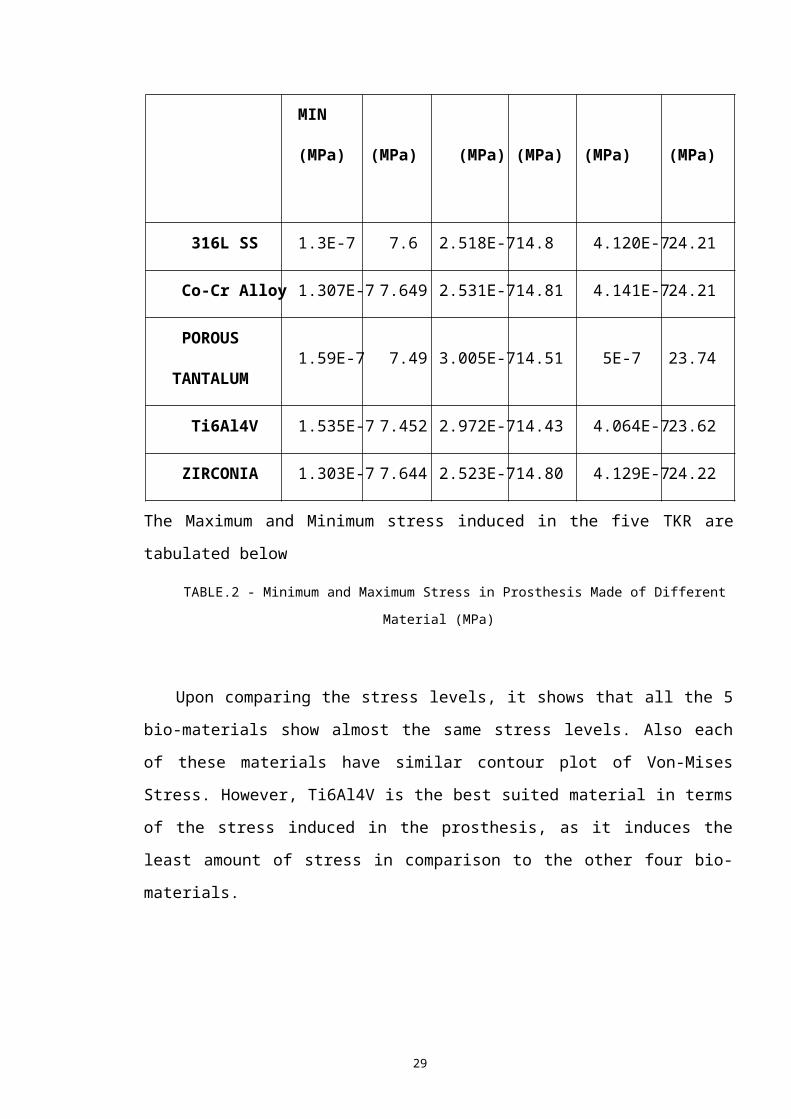
(MPa) (MPa) (MPa) (MPa) (MPa) (MPa)
316L SS 1.3E-7 7.6 2.518E-714.8 4.120E-724.21
Co-Cr Alloy 1.307E-7 7.649 2.531E-714.81 4.141E-724.21
POROUS
TANTALUM 1.59E-7 7.49 3.005E-714.51 5E-7 23.74
Ti6Al4V 1.535E-7 7.452 2.972E-714.43 4.064E-723.62
ZIRCONIA 1.303E-7 7.644 2.523E-714.80 4.129E-724.22
The Maximum and Minimum stress induced in the five TKR are
tabulated below
TABLE.2 - Minimum and Maximum Stress in Prosthesis Made of Different
Material (MPa)
Upon comparing the stress levels, it shows that all the 5
bio-materials show almost the same stress levels. Also each
of these materials have similar contour plot of Von-Mises
Stress. However, Ti6Al4V is the best suited material in terms
of the stress induced in the prosthesis, as it induces the
least amount of stress in comparison to the other four bio-
materials.
30
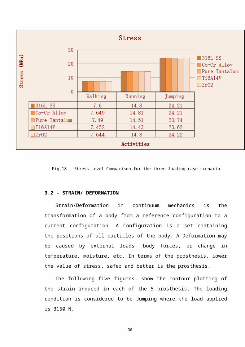
Fig.18 - Stress Level Comparison for the three loading case scenario
3.2 - STRAIN/ DEFORMATION
Strain/Deformation in continuum mechanics is the
transformation of a body from a reference configuration to a
current configuration. A Configuration is a set containing
the positions of all particles of the body. A Deformation may
be caused by external loads, body forces, or change in
temperature, moisture, etc. In terms of the prosthesis, lower
the value of stress, safer and better is the prosthesis.
The following five figures, show the contour plotting of
the strain induced in each of the 5 prosthesis. The loading
condition is considered to be Jumping where the load applied
is 3150 N.

31
Fig.19 - Contour Plot of Strain for 316L Stainless Steel (Jumping)
Fig.20 - Contour Plot of Strain for Co-Cr Alloy (Jumping)
32
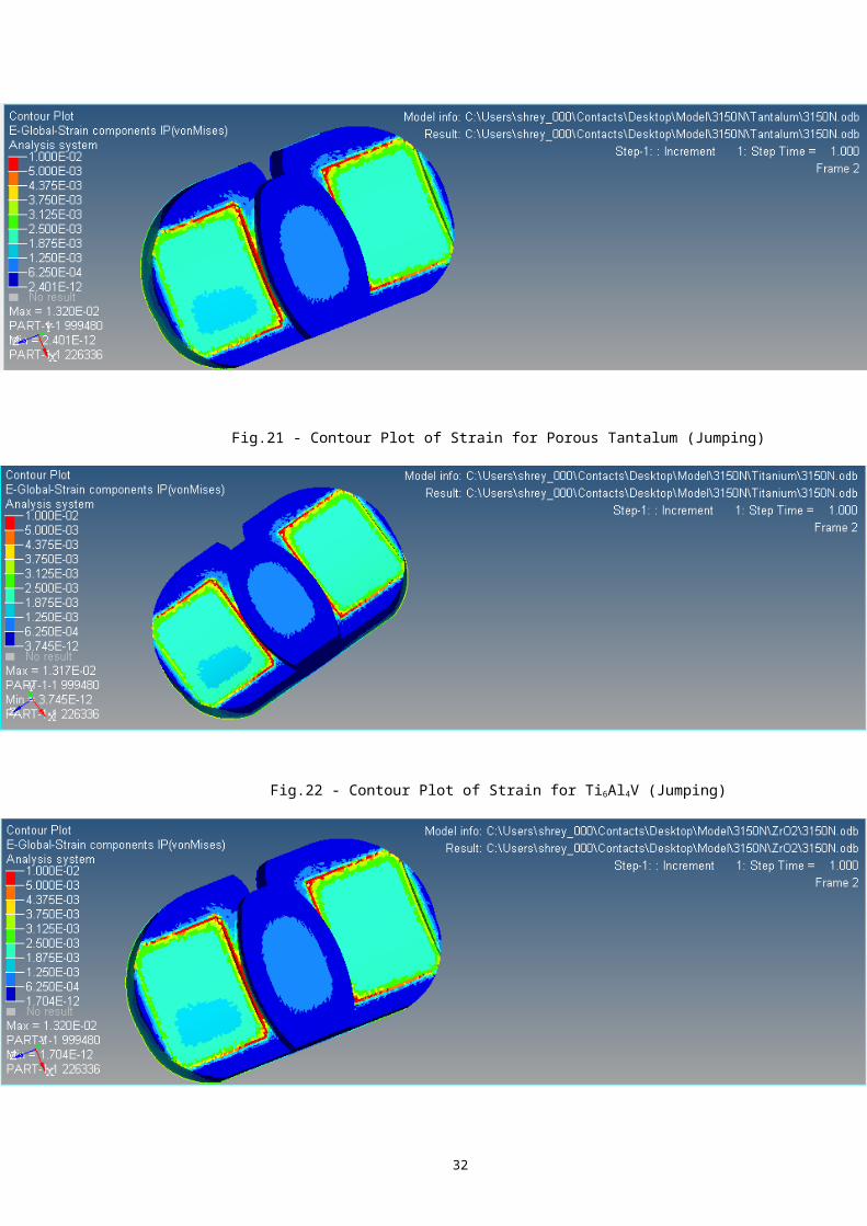
Fig.21 - Contour Plot of Strain for Porous Tantalum (Jumping)
Fig.22 - Contour Plot of Strain for Ti6Al4V (Jumping)

33
Fig.23- Contour Plot of Strain for Zirconia (Jumping)
MATERIAL/LOADING CONDITIONWALKING RUNNING JUMPING
316L SS 0.000416 0.0008066 0.001320
Co-Cr Alloy 0.000416 0.0008059 0.001320
Porous Tantalum 0.000416 0.0008064 0.001320
Ti6Al4V 0.0004156 0.0008050 0.001317
Zirconia 0.0004166 0.0008067 0.001320
TABLE.3 - STRAIN COMPARISON OF PROSTHESIS MADE OF 5 DIFFERENT
MATEIRAL
Upon comparison of the five different materials used in
the femoral insert of the knee prosthesis, the maximum
variation in strain levels is about 0.000016. As this value
is too small, the variation in the strain level is assumed to
be negligible.
3.3 - YOUNGS MODULUS
Young's modulus, also known as the tensile
modulus or elastic modulus, is a measure of the stiffness of
an elastic material. It is defined as the ratio of
the stress (force per unit area) along an axis to
the strain (ratio of deformation over initial length) along
that axis in the range of stress in which Hooke's law holds.
The unit of measurement is the same as that of Pressure (MPa

34
or N/mm2)
In order to validate the results obtained from ABAQUS, the
Youngs Modulus of 316L SS was calculated by plotting the
Stress-Strain graph from the values obtained from ABAQUS
. Thus obtained value of the Young’s Modulus was compared
with the value that was obtained by performing Tensile Test
on a specimen of 316L SS using a Universal Testing Machine
(UTM).
The Stress Strain graph obtained from ABAQUS is shown
below in Fig.24
Fig.24
- Stress
Strain
graph of
316L SS
obtained
from ABAQUS
The
Youngs
Modulus
thus
obtained of Stress-Strain through ABAQUS was 2.26 X 10⁵ MPa.
35
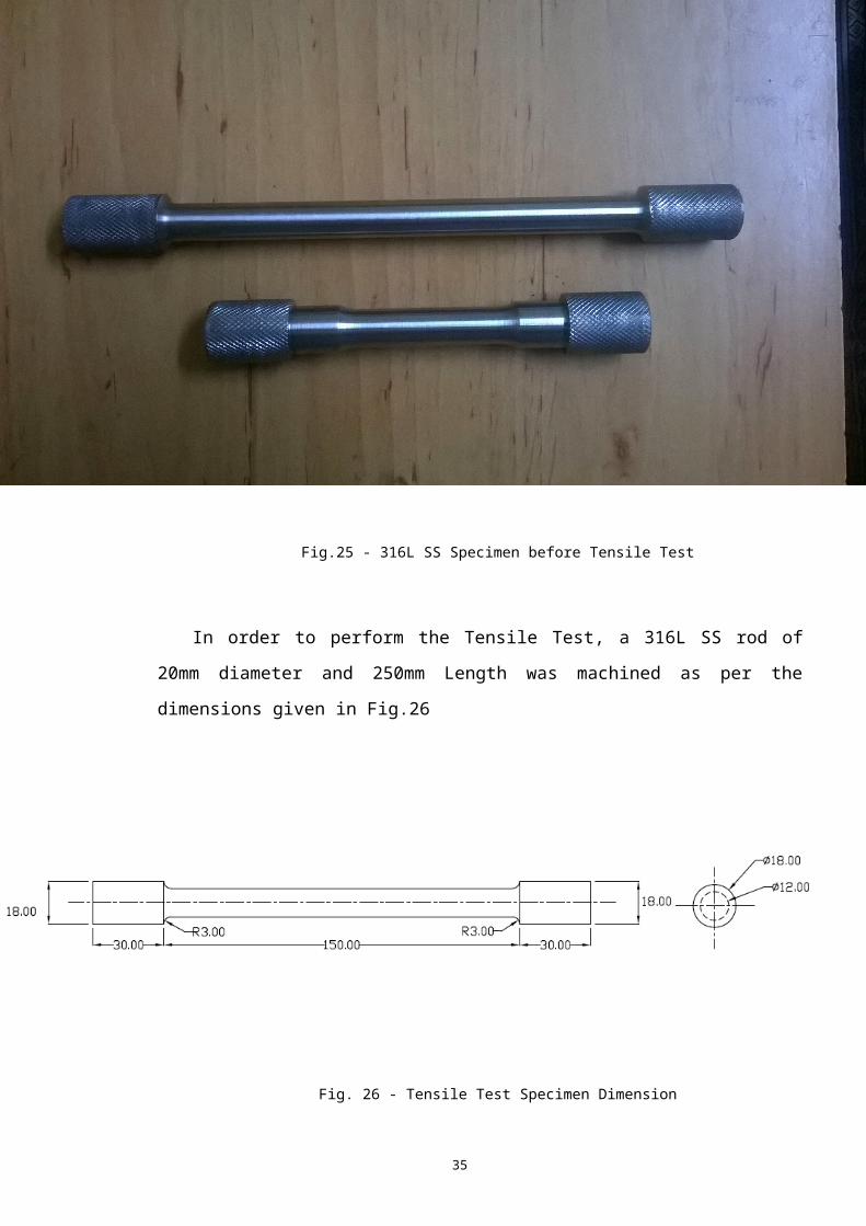
Fig.25 - 316L SS Specimen before Tensile Test
In order to perform the Tensile Test, a 316L SS rod of
20mm diameter and 250mm Length was machined as per the
dimensions given in Fig.26
Fig. 26 - Tensile Test Specimen Dimension
36
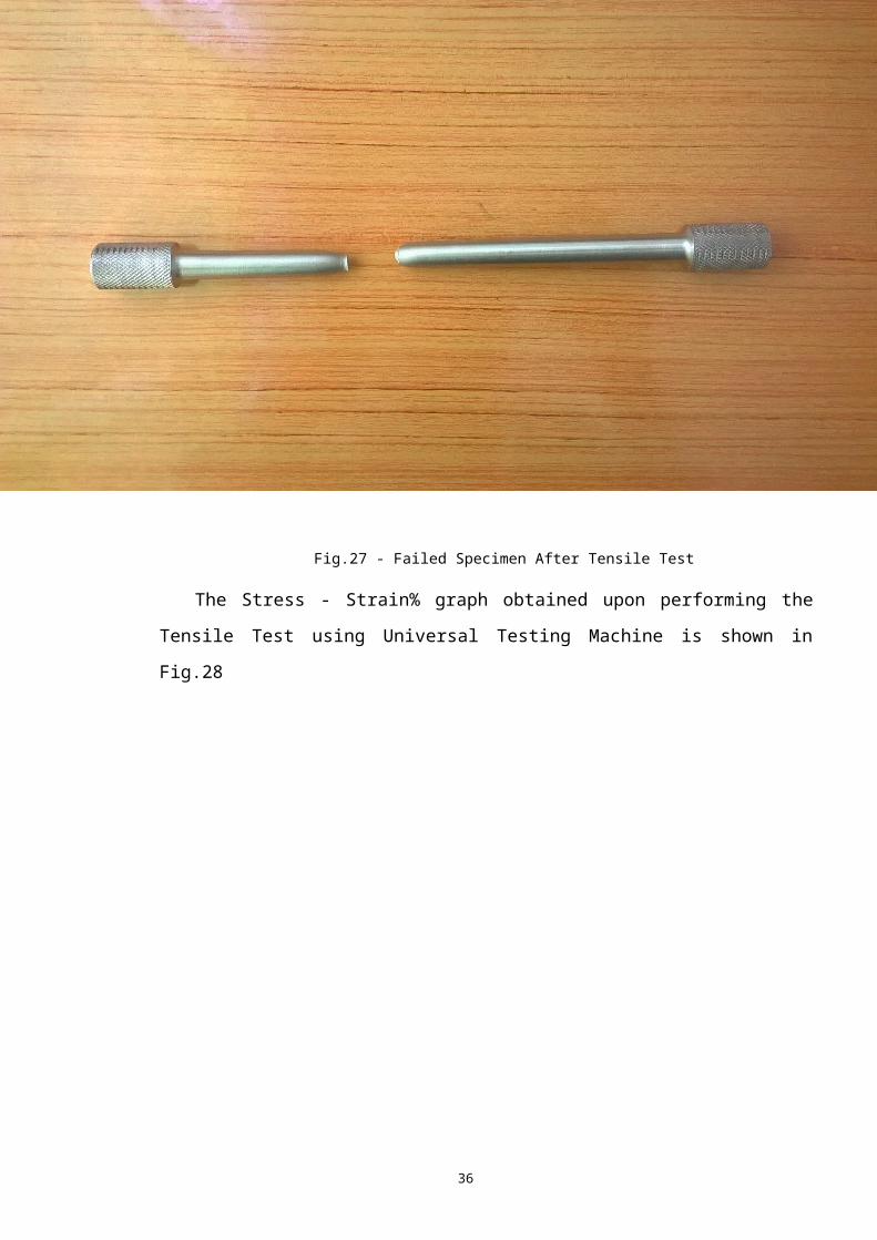
Fig.27 - Failed Specimen After Tensile Test
The Stress - Strain% graph obtained upon performing the
Tensile Test using Universal Testing Machine is shown in
Fig.28

37
Fig.28 - Stress-Strain% graph from UTM
The Young’s Modulus thus obtained from the Tensile Test
performed using UTM is 1.014 X10⁴ MPa.
Possible source of errors while performing Tensile Test
are :
Alignment Error
Improper Calibration of Elongation Measuring Instrument in
UTM
38
CHAPTER - 4
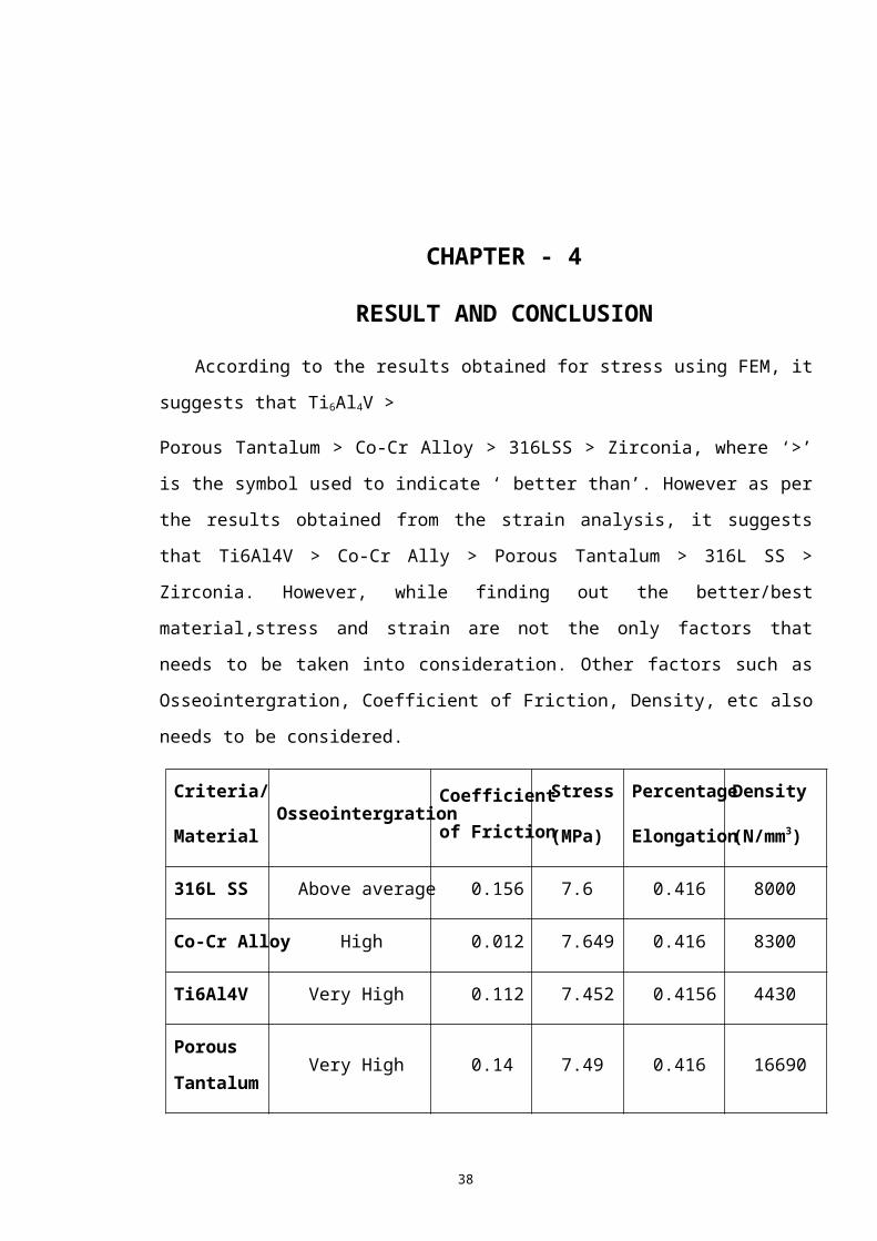
RESULT AND CONCLUSION
According to the results obtained for stress using FEM, it
suggests that Ti6Al4V >
Porous Tantalum > Co-Cr Alloy > 316LSS > Zirconia, where ‘>’
is the symbol used to indicate ‘ better than’. However as per
the results obtained from the strain analysis, it suggests
that Ti6Al4V > Co-Cr Ally > Porous Tantalum > 316L SS >
Zirconia. However, while finding out the better/best
material,stress and strain are not the only factors that
needs to be taken into consideration. Other factors such as
Osseointergration, Coefficient of Friction, Density, etc also
needs to be considered.
Criteria/
MaterialOsseointergration
Coefficient
of Friction
Stress
(MPa)
Percentage
Elongation
Density
(N/mm3)
316L SS Above average 0.156 7.6 0.416 8000
Co-Cr Alloy High 0.012 7.649 0.416 8300
Ti6Al4V Very High 0.112 7.452 0.4156 4430
Porous
Tantalum Very High 0.14 7.49 0.416 16690

39
Zirconia Extremely High 0.082 7.644 0.416 6040
While considering multiple factors and multiple
alternatives, the task of choosing the best material becomes
tedious. To solve such a problem, the use of Multi Criteria
Decision Making (MCDM) process is made. Of the available
methods under MCDM, Analytic Hierarchy Method (AHP) is used
to solve the problem of determining the best material from
five options available. To start of with this method, firstly
a tabular column is made listing all the alternative and
criteria. Following this, the tabular column is filled with
appropriate data. The filled tabular column is shown below in
Table 4.[11][12][17][20][23][24][25][28][29][30][31][32][33][34][35][36][37]
TABLE.4 - Table for evaluation of AHP
After filling up of all the required data in the table, the
following steps are to be followed:
I. Each of the five criteria are assigned weight-age. The
criteria that holds the most importance, is given the
highest weight-age, while the least weight-age is given
to the criteria that holds the least importance of all
the criteria.
II. Each of the alternative are relatively ranked or
given a relative score for each of the five criteria. (
The ranking/score is given on the basis that the most
suitable material in a particular criteria is given the
lowest score/value) Scoring tables of Osseointergration
and Coefficient of Friction is given below in Table 5 and
Table 6

40
III. The AAHP for each of the material is calculated my
multiplying the weight-age of each criteria and its
respective score/rank.
The calculation is performed as shown below:
AAHP(316L SS) =(5*0.3) + (4*0.15) + (3*0.15) + (2*0.2)
+ (3*0.2) = 3.55
AAHP(Co-Cr Alloy) = (3.75*0.3) + (1*0.15) + (5*0.15) +
(2*0.2) + (2*0.2) = 2.825
AAHP(Ti6Al4V) = (2.5*0.3) + (4*0.15) + (1*0.15) + (1*0.20)
+ (5*0.2) = 2.7
AAHP(Porous Tantalum) = (2.5*0.3) + (4*0.15) + (2*0.15) +
(2*0.2) + (1*0.2) = 2.25
AAHP(Zirconia) = (1.25*0.3) + (3*0.15) + (4*0.15) +
(2*0.2) + (4*0.2) = 2.5875
OSSEOINTERGRATION
Extremely High 1.25
Very High 2.5
High 3.75
Above Average 5
Average 6.25
Low 7.5
Very Low 8.75
Extremely Low 10
41
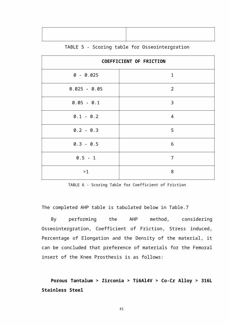
TABLE 5 - Scoring table for Osseointergration
COEFFICIENT OF FRICTION
0 - 0.025 1
0.025 - 0.05 2
0.05 - 0.1 3
0.1 - 0.2 4
0.2 - 0.3 5
0.3 - 0.5 6
0.5 - 1 7
>1 8
TABLE 6 - Scoring Table for Coefficient of Friction
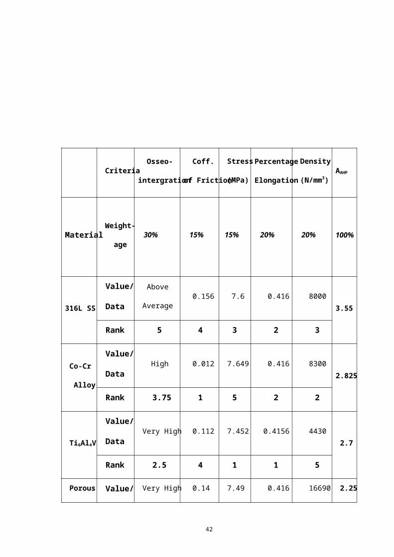
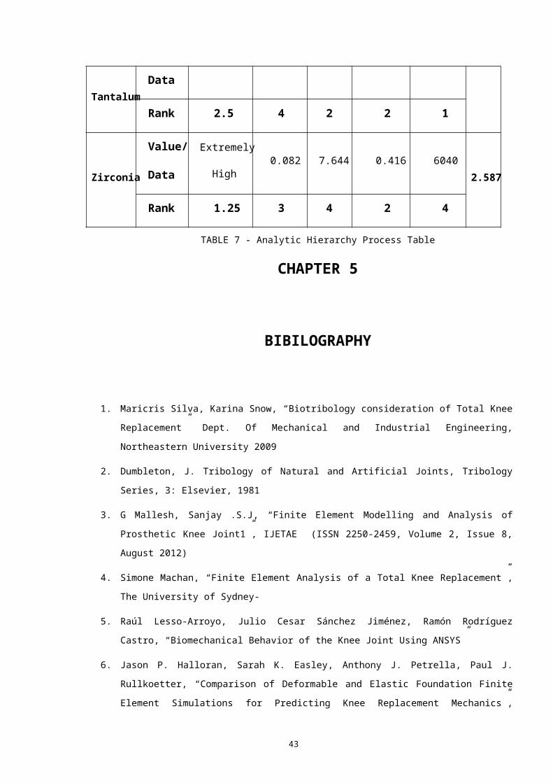
The completed AHP table is tabulated below in Table.7
By performing the AHP method, considering
Osseointergration, Coefficient of Friction, Stress induced,
Percentage of Elongation and the Density of the material, it
can be concluded that preference of materials for the Femoral
insert of the Knee Prosthesis is as follows:
Porous Tantalum > Zirconia > Ti6Al4V > Co-Cr Alloy > 316L
Stainless Steel
42
Criteria Osseo-
intergration
Coff.
of Friction
Stress
(MPa)
Percentage
Elongation
Density
(N/mm3)AAHP
Material Weight-
age 30% 15% 15% 20% 20% 100%
316L SS
Value/
Data
Above
Average 0.156 7.6 0.416 8000
3.55
Rank 5 4 3 2 3
Co-Cr
Alloy
Value/
Data High 0.012 7.649 0.416 8300
2.825
Rank 3.75 1 5 2 2
Ti6Al4V
Value/
Data Very High 0.112 7.452 0.4156 4430
2.7
Rank 2.5 4 1 1 5
Porous Value/ Very High 0.14 7.49 0.416 16690 2.25
43
Tantalum Data
Rank 2.5 4 2 2 1
Zirconia
Value/
Data
Extremely
High 0.082 7.644 0.416 6040
2.587
Rank 1.25 3 4 2 4
TABLE 7 - Analytic Hierarchy Process Table
CHAPTER 5
BIBILOGRAPHY
1. Maricris Silva, Karina Snow, “Biotribology consideration of Total Knee
Replacement” Dept. Of Mechanical and Industrial Engineering,
Northeastern University 2009
2. Dumbleton, J. Tribology of Natural and Artificial Joints, Tribology
Series, 3: Elsevier, 1981
3. G Mallesh, Sanjay .S.J, “Finite Element Modelling and Analysis of
Prosthetic Knee Joint1”, IJETAE (ISSN 2250-2459, Volume 2, Issue 8,
August 2012)
4. Simone Machan, “Finite Element Analysis of a Total Knee Replacement”,
The University of Sydney-
5. Raúl Lesso-Arroyo, Julio Cesar Sánchez Jiménez, Ramón Rodríguez
Castro, “Biomechanical Behavior of the Knee Joint Using ANSYS”
6. Jason P. Halloran, Sarah K. Easley, Anthony J. Petrella, Paul J.
Rullkoetter, “Comparison of Deformable and Elastic Foundation Finite
Element Simulations for Predicting Knee Replacement Mechanics”,

44
Journal of Biomechanical Engineering, OCTOBER 2005, Vol. 127 / 813
7. Wong, D.W.S.; Camirand, W.M.; Pavlath, A.E.; Krochta, J.M.; Baldwin,
E.A. and Nisperos-Carriedo, M.O. (eds.) (1994) "Development of edible
coatings for minimally processed fruits and vegetables" pp. 65–88
in Edible coatings and films to improve food quality, Technomic Publishing Company,
Lancaster, PA. ISBN 1566761131
8. Tong, Jin; Ma, Yunhai; Arnell, R.D.; Ren, Luquan (2006). "Free
abrasive wear behavior of UHMWPE composites filled with stonite
fibers". Composites Part A: Applied Science and Manufacturing 37:
38. doiwolla:10.1016/j.compositesa.2005.05.023
9. Budinski, Kenneth G. (1997). "Resistance to particle abrasion of
selected plastics". Wear. 203–204: 302. doi:10.1016/S0043-
1648(96)07346-2
10. W. Brent Edwards, Jason C. Gillette, Joshua M. Thomas, Timothy R.
Derrick, “Internal femoral forces and moments during running:
Implications for stress fracture development”, Clinical Biomechanics,
23 (2008) 1269–1278
11. Daniel J.Schneck, Joseph D.Bronzino “Biomechanics: Principles and
Application” , CRC Press
12. Claire L Brockett, Louise M Jennings, John Fisher, “Wear of knee
prostheses”, Dovepress, Orthopedic Research and Reviews 2012:4 19–26
13. Blunn GW, Joshi AB, Minns RJ, et al. “Wear in retrieved condylar knee
arthroplasties: A comparison of wear in different designs of 280
retrieved condylar knee prostheses.” J Arthroplasty. 1997;12(3):281–
290
14. Fisher J, Dowson D, Hamdzah H, Lee HL. , “The effect of sliding
velocity on the friction and wear of UMWPE for use in total artificial
joints”, Wear. 1994;175(1–2):219–225.
15. Kurtz SM. “The clinical performance of UHMWPE in knee replacements.”,
In: UHMWPE Biomaterials handbook. 2nd ed. Boston, MA: Academic Press;
2009
45
16. Dumbleton JH, Manley MT, Edidin AA. “ A literature review of the
association between wear rate and osteolysis in total hip
arthroplasty.” J Arthroplasty. 2002;17(5):649–661.
17. Stainless Steel Composition was collected from
http://www.brownmac.com/products/stainlesssteel-
plate/Stainless-Steel-316-and-316l.aspx
18. Stephen M. Howell, MD, Stacey J. Howell, and Maury L. Hull “Assessment
of the Radii of the Medial and Lateral Femoral Condyles in Varus and
Valgus Knees with Osteoarthritis” J Bone Joint Surg Am. 2010;92:98-104
19. Maricris Silva and Karina Snow, “ Biotribology consideration of Total
Knee Replacement”
20. M. A. Kumbhalkar, Umesh Nawghare, Rupesh Ghode, Yogesh Deshmukh,
Bhushan Armarkar, “Modelling and Finite Element Analysis of Knee
Prosthesis with and without Implant”, Universal Journal of
Computational Mathematics 1(2): 56-66, 2013
21. Dr. Rainer Haas , Dr. Oliver Meixner, “An Illustrated Guide to the
ANALYTIC HIERARCHY PROCESS”
22. Rozann Whitaker, “Validation examples of the Analytic Hierarchy
Process and Analytic Network Process” , Mathematical and Computer
Modelling, Colume 46, Issues 7-8, October 2007, Pages 840-859
23. Hyslop, D. J. S.; Abdelkader, A. M.; Cox, A.; Fray, D. J.
Electrochemical Synthesis of a Biomedically Important Co-Cr Alloy. Acta
Materialia. 2010, 58, 3124-3130
24. Kereiakes, D. J.; Cox, D. A.; Hermiller, J. B.; Midei, M. G.;
Usefulness of a Cobalt Chromium Coronary Stent Alloy. The Amer. J.
Cardi. 2003, 92, 463-466
25. Biomimetic Porous Titanium Scaffolds for Orthopedic and Dental
Applications, Alireza Nouri, Peter D. Hodgson and Cui’e Wen (Institute
for Technology Research and Innovation, Deakin University, Australia)
26. Modenese, L., Phillips, A. T. M. and Bull, A. M. J., “ An open source
lower limb model: Hip joint validation.” Journal of Biomechanics 44,
46
2185-2193
27. Geraldes D. M., and Phillips A. T. M. (2014), A comparative study of
orthotropic and isotropic bone
adaptation in the femur, International Journal for Numerical Methods
in Biomedical Engineering, 30, pages 873-889.
28. Material Properties of Titanium Alloy was
http://asm.matweb.com/search/SpecificMaterial.asp?MTP641
29. Material Properties of Titanium Alloy was taken from
http://www.azom.com/article.aspx?
ArticleID=1547
30. R. Stevens, 1986. Introduction to Zirconia. Magnesium Elektron
Publication No 113
31. Material Properites of ZrO2 were taken from
http://www.ceramtec.in/ceramic-materials/zirconium-oxide/
32. Levine B1, Sporer S, Della Valle CJ, Jacobs JJ, Paprosky W, “Porous
tantalum in reconstructive surgery of the knee: a review”.J Knee
Surg. 2007 Jul;20(3):185-94.
33. Levine B1, Sporer S, Della Valle CJ, Jacobs JJ, Paprosky
W.Applications of porous tantalum in total hip arthroplasty..J Knee
Surg. 2006 Nov;14(12):646-55.
34. Rita Depprich Holger ,Zipprich Michelle Ommerborn, Christian
Naujoks, Hans-Peter Wiesmann, Sirichai Kiattavorncharoen, Hans-Christoph
Laue, Ulrich Meyer, Norbert R Kübler and Jörg Handschel,
“Osseointegration of zirconia implants compared with titanium: an in
vivo study”doi:10.1186/1746-160X-4-30
35. Ali Parsapour, Saied Nouri Khorasani, Mohammad Hossein Fathi,
“Corrosion Behavior and Biocompatibility of Hydroxyapatite Coating on
H2SO4 Passivated 316L SS for Human Body Implant”DOI: 10.1007/s40195-
012-0212-3

47
36. Jin Whan Lee, Hai Bo Wen,Do-Gyoon Kim, Sarandeep S. Huja, Paul G.
Fairbanks, Boon Ching Tee, Peter E. Larsen, Kelly S. Kreuter, “Stability
and Osseointegration of Tantalum-based Porous Implants in a Canine
Model”
37. Mavrogenis AF1, Papagelopoulos PJ, Babis GC, “Osseointegration of
cobalt-chrome alloy implants.” DOI 2011;21(4):349-58