
Dynamic force feedback in a virtual knee palpation
13
ELSEVIER Artificial Intelligence in Medicine 6 (1994) 321-333 Artificial Intelligence in Medicine Dynamic force feedback in a virtual knee palpation Noshir A. Langrana*, Grigore Burdea, Kenneth Lange, Daniel Gomez, Sonal Deshpande Rutgers - The State University of New Jersey, CAIP Center, CORE Bldg., P.O.Box 1390, Piscataway. NJ 08855- 1390, USA Received December 1993; revised February 1994 Abstract A virtual model of a knee joint with muscles, ligaments and bones has been developed. This model includes realistic 3-D surface deformation and tissue stiffnesses. Tissue and bone deformation (palpation) produces real time force feedback to the user hand wearing a DataGlove and Rutgers Master. Collision detection algorithms determine when and where the virtual hand palpates the surface model. This user interaction with the muscles and bones of a human knee model may be used as a training and planning tool for knee surgery. Key words: Virtual Reality; Force feedback; Biomechanics; Object model; Knee joint; Muscles; Bones; Compliance; Simulation 1. Introduction Surgeons planning a delicate surgical procedure practice it over and over again, making cuts, and retracting organs in different ways until the best approach has been found. Computer-assisted surgery has been investigated for many years [1,13]. For example, the simulation of total joint replacement surgery using computer algorithms and robotics is used to identify the optimum standard artificial joint replacement for an individual patient [22]. This simulation has helped improve * Corresponding author. Full address: Rutgers University, CORE Bldg, CAIP Center, Room 721, Frelinghuysen Road, POBox 1390, Piscataway, New Jersey 088551390, USA. Email: langrana@ caip.rutgers.edu 0933-3657/94/$07.00 0 1994 Elsevier Science B.V. Ah rights reserved SSDI 0933-3657(94)00010-P
-
Upload
independent -
Category
Documents
-
view
3 -
download
0
Transcript of Dynamic force feedback in a virtual knee palpation
ELSEVIER Artificial Intelligence in Medicine 6 (1994) 321-333
Artificial Intelligence in Medicine
Dynamic force feedback in a virtual knee palpation
Noshir A. Langrana*, Grigore Burdea, Kenneth Lange, Daniel Gomez, Sonal Deshpande
Rutgers - The State University of New Jersey, CAIP Center, CORE Bldg., P.O.Box 1390, Piscataway.
NJ 08855- 1390, USA
Received December 1993; revised February 1994
Abstract
A virtual model of a knee joint with muscles, ligaments and bones has been developed. This model includes realistic 3-D surface deformation and tissue stiffnesses. Tissue and bone deformation (palpation) produces real time force feedback to the user hand wearing a DataGlove and Rutgers Master. Collision detection algorithms determine when and where the virtual hand palpates the surface model. This user interaction with the muscles and bones of a human knee model may be used as a training and planning tool for knee surgery.
Key words: Virtual Reality; Force feedback; Biomechanics; Object model; Knee joint; Muscles; Bones; Compliance; Simulation
1. Introduction
Surgeons planning a delicate surgical procedure practice it over and over again, making cuts, and retracting organs in different ways until the best approach has been found. Computer-assisted surgery has been investigated for many years [1,13]. For example, the simulation of total joint replacement surgery using computer algorithms and robotics is used to identify the optimum standard artificial joint replacement for an individual patient [22]. This simulation has helped improve
* Corresponding author. Full address: Rutgers University, CORE Bldg, CAIP Center, Room 721,
Frelinghuysen Road, POBox 1390, Piscataway, New Jersey 088551390, USA. Email: langrana@
caip.rutgers.edu
0933-3657/94/$07.00 0 1994 Elsevier Science B.V. Ah rights reserved
SSDI 0933-3657(94)00010-P

322 N.A. Langrana et al. /Artificial Intelligence in Medicine 6 (1994) 321-333
results and reduce complications of surgery. Computers are also being used to aid in the design and manufacture of custom artificial joint replacements where large bony deformities prevent the use of standard artificial joints.
The recent development of Virtual Reality (VR) hardware and software, to- gether with increased computational power, has made it feasible to develop applications for training surgeons. Virtual Reality interactions can be described as human immersion in computer simulated environments. Key to immersion realism are real-time, multi-sensorial interactions with the simulated world. Real-time VR graphics rendering requires high-end graphics workstations, while multi-sensorial immersion needs specialized devices for each of the human senses. Along this line, over the past three years, our group has developed a portable force feedback master hardware and software environment [2-4,6].
The use of VR in surgery will affect a number of distinct activities such as teaching students human anatomy and pathology, surgical procedure training for new surgeons, surgical planning of complex procedures, presenting navigational and informational aids during surgery, and predicting the outcomes of surgical procedures [ 191.
One area in which 3-D interactive displays are making significant head-way is in minimally invasive surgery. Small incisions are made in the body through which an endoscope, a light source and surgical tools are inserted. By minimizing the amount of tissue that is cut, this type of surgery reduces the trauma done to the patient during surgery and results in a faster recovery. One problem with these new techniques is that the surgeon has had to work with a 2-D display and the image obtained from the endoscope lacks essential depth cues, whereas the operative procedures take place in three dimensional space. Using spatial displays, one might be able to provide a surgeon with that missing dimension. Work is being done on various 3-D endoscopes, including one based on a lens system with two optical canals [23]. These types of tools would allow safer movements inside neurological and other delicate structures by providing the much needed depth cues afforded by stereoscopic images.
It is envisioned that someday surgeons will be able to practice rare or high-risk surgical procedures on an ‘electronic cadaver’. Many labs are working towards the creation of this virtual patient. Rosen and his colleagues at the MIT Media Lab [5,14,151 are trying to develop a digital model of patient skin and skeletal muscle for surgical simulation systems. A model of the skeletal muscle using finite element methods has been developed that can simulate the non-linear characteristics of a real muscle. The current system offers an interface in which the surgeon can use whole hand input devices and HMDs to view and manipulate the virtual patient. However, the realism of the simulation suffers from a lack of force or tactile feedback.
Early virtual surgical simulators were developed by military surgeon Richard Satava, using Virtual Reality hardware and software from VPL Research. He developed a colecystectomy trainer with stomach, pancreas, liver, biliary tree and gallbladder. A few surgical instruments have also been created, but currently these simulators have also not incorporated force feedback or tactile sensation [19,20].

N.A. Langrana et al. /Artificial Intelligence in Medicine 6 (1994) 321-333 323
To help surgeons gain expertise in minimally invasive procedures Hon and colleagues [9] are building realistic simulators that can monitor and evaluate ‘practice’ performances. These simulators combine ‘videographics’ and endoscopic instruments with force feedback. These latter sensing and tactile interfaces are implemented inside a mannequin, and sensors relay the geometric position of the scopes and instruments within the simulated ‘anatomy’. These systems present and manipulate images in real time, reacting with the students eyes and hands. Early versions relied upon interactive video frame retrieval for the visual display compo- nent, while current versions use both video texture mapping and interactive graphical models of the tissue of interest.
An integrated system, which combines computer-based medical imaging and CAD/CAM technology for preoperative planning with robotics for femoral prepa- ration during cementless total hip replacement surgery has been developed. The image guided robot developed substantially improves a surgeon’s ability to create a cavity that is precisely shaped and oriented for any commercially available femoral component [ 111.
Researchers at Human Interface Technology Lab (University of Washington) are working on a simulation of opthalmic surgery using a combination of video display and detection of instrument collision with spatial virtual objects [26]. At the same time SRI is developing telepresence technology configured for remote laparoscopic surgery with force feedback [8].
2. Force feedback in VR
Touch feedback and force feedback are intermixed in the technical literature but they are not the same [21]. Touch feedback gives the user the geometry and roughness of the virtual surfaces as well as some information about virtual object compliance. Unfortunately it cannot produce rigidity of motion, so that remote real (or virtual) instruments can damage the manipulated objects, or themselves. Force feedback provides information on the compliance of the grasped objects, but can also produce rigidity of motion (for large feedback forces). Force feedback is, however, more difficult to realize, due to larger actuators and limited surface available to place these actuators close to the hand [2]. It is therefore necessary to develop new tools that are more compact, easy to maintain, safe, and inexpensive. Lower costs and portability would then afford their large-scale use in VR training. These new tools should have both force and touch feedback on one common master and should preserve the hand’s freedom of motion in the way flexion sensing gloves do.
The Rutgers Master [3] uses pneumatic micro actuators and proportional regulators, which return about 4N per fingertip at lo-20 Hz. The force feedback structure was designed for four fingers and a DataGloveTM. The feed-back struc- ture is very light (about 50 grams), resulting in reduced operator fatigue. Attach- ment of the feedback structure to the glove has been accomplished with VelcroTM strips which adapt to varying hand sizes.

324 N.A. Langrana et al. /Artificial Intelligence in Medicine 6 (1994) 321-333
Force Feedback
Force Feedback
Fig. 1. The Rutgers Master.
The general configuration of the Rutgers Master is illustrated in Fig. 1. The feedback actuators are controlled by analog proportional pressure regulators (PPR) that are housed in a master interface. These regulators control air pressure to the actuators in the palm of the user’s hand. The interface has its own power supply and main air pressure indicator, as well as separate LED displays for each output channel. These LEDs indicate the level of feedback forces on each of the fingers and provide an additional cue to the user and to other persons watching the simulation.
The step response for each force feedback actuator is such that the transient ripple and overshoot are small enough not to be noticed by the user. A rise time of 14 ms is caused by static friction in the pneumatic cylinder and the inertia of the pressure regulator valve. The static friction is also responsible for the steady-state error of 4% of the total force of about 4N/actuator. The relaxing time of 62 ms presents a bottleneck for the actuator bandwidth (of 8-10 Hz). This delay is a result of the slow rate by which air is released from the air line, since mufflers are installed to reduce noise.
To demonstrate the usefulness of the system a simulation with virtual elastic balls was developed. Compliance of the virtual objects was programmable so that users could feel the difference between a yellow ‘hard’ ball and pink ‘soft’ ball. Initial human factors studies done on 10 subjects (five male and five female) showed that force feedback using the Rutgers Master reduced the task average error rate by 50%. The learning time required by the subjects for a given task was also reduced by 50% when compared to learning time with only visual feedback [I61.
The above tests were performed using an older HP-9000 workstation at a graphics refresh rate of (only) 6 frames/second. This slow refresh rate raised concerns regarding the validity of the cross-modality human factors tests. Subse- quent tests were recently done using a high-end HP-755CRX workstation with a

N.A. Langrana et al. /Artificial Intelligence in Medicine 6 (1994) 321-333
ETHERNET
I ;~Gl~GTO
CONVERTER c
I ~$@&DBACK c
RGB RS232 I
I I
1 Trackball
Force Feedback Actuators.
USER INTERFACE
325
Fig. 2. Distributed simulation architecture.
graphics refresh rate of 28 fps [17]. These studies confirmed the 50% reduction in error rates obtained previously.
3. Virtual knee joint simulation
Geometry data for a complete knee joint [24] was acquired from Viewpoint Datalabs. It includes the proximal end of tibia/fibula, the distal end of the femur, and all major muscles and ligaments. These data were used to create a complete smooth shaded virtual knee joint from inner layer of skin to bones with 13,494 vertices and 13,532 polygons. The static database model was transformed into a dynamic hierarchical structure and rendered using the HP Starbase library [12]. The model was modified to allow deformation (and reformation), as well as viewing perspective change with a 6D trackball.
Current research is focused on integrating force feedback to increase realism of surface deformation in the knee joint. At this early stage our system provides a simplistic one finger ‘feel’ (palpation) of tissue compliance.
3.1. Distributed simulation environment
The Rutgers virtual reality system configuration is illustrated in Fig. 2. A loosely coupled, client-server architecture allows distribution of the computational load
326 N.A. Langrana et al. /Artificial Intelligence in Medicine 6 (1994) 321-333
for the simulation across two workstations. A SUN4/380 is dedicated to force feedback via the Rutgers Master, while an HP755CRX workstation is dedicated to reading the DataGlove (with its attached Polhemus position and orientation tracker) and trackball data, object interaction modeling and graphics rendering.
The main loop of the simulation resides on the HP workstation to which the DataGlove electronic unit and the trackball are connected. The glove’s driver reads sensor data and converts it into hand orientation and position based on user calibration [lo, 181. These data are then used to update the state of various objects in the simulation, taking into account object collisions, grasping and deformation, as well as determining the size of contact forces. The user may use the trackball to change perspective on the virtual scene. The trackball driver processes raw data into viewpoint transformations which are used to manipulate a virtual camera.
Update information on virtual force due to hand-object interaction is sent to the Sun4 for display via an ethernet connection. The force data sent by the HP are encoded in four int s (4 bytes each), one per finger. The integer values are then scaled and type casted to floats in the range of 0 to 10. The floating point values are sent to the D/A drivers to be output to the Rutgers Master interface.
Three types of objects can be found in our experimental virtual world: the virtual hand, the virtual knee (segmented into bones, ligaments and muscles) and the room walls. An ‘ X ’ shadow mark is drawn on the virtual floor under the hand to provide a visual cue for depth perception. The objects are programmed into a display list data structure using the Starbase graphics library [12] with double buffering and Gouraud shading 171 with one light source. More light sources can, of course, be added but would increase the rendering time.
The virtual hand has the same kinematics as the human hand, i.e. four degrees of freedom per finger. The DataGlove does not measure the distal joint angles for the index, middle, ring or small fingers. Therefore, in order to provide more natural-looking virtual hand animation, a coupling formula was applied to deter- mine expected distal joint angles based on the angle of the middle joint [3].
3.1.1 Collision detection Collision detection represents the first phase in the knee palpation process. The
knee model is in a fixed location in the virtual world, while the hand model is moving. Collision occurs whenever a fingertip touches a knee bone or muscle surface. It is therefore necessary to first determine the position of the fingertips in world coordinates. Homogeneous transformation matrices are used which relate fingertip coordinates to the Polhemus sensor position and to the world frame (attached to the Polhemus transmitter).
To decrease the number of real time calculations in both the collision detection and deformation algorithms, a special data structure was developed to store the geometry of the knee model. The data structure is a dynamically allocated array of pointers to segment structures. Each segment structure contains data describing a virtual object (an enclosed set of polygons such as a muscle or bone).
For graphical rendering, each segment contains dynamically allocated lists of vertex and polygon structures. For collision detection, each segment structure

N.A. Langrana et al. /Artificial Intelligence in Medicine 6 (1994) 321-333 327
contains the coordinates of the geometric centroid of that segment along with the distance of the farthest vertex from the centroid. Each segment structure contains a dynamically allocated list of group structures. Each group structure contains the same sort of collision detection information as the segment structure about a group of adjacent vertices. Vertex structures which are stored at the segment level contain position coordinates and labels of the groups to which each vertex belongs. Polygon structures contain the labels of the vertices which define them. The collision detection is based on a modified ‘bounding box’ approach. Due to the irregular nature of the knee shape, a rectangular bounding box is not sufficient. We therefore use a number of spherical ‘boxes’ with varying radius. The sphere radius and position are user settable. A wire frame rendering of a group of bounding spheres is shown in Fig. 3.
During runtime, each possible contact point is computed and compared with the precalculated maximum distance from the centroid of each segment to determine whether or not it could be in contact with that segment. If the contact point is inside a sphere radius, then it is checked against the precalculated maximum distance from the centroid of each group. If a contact point is found to be inside the maximum distance or ‘sphere of contact’ of a group, then that group label is passed to the collision detection routine. In this way, the number of calculations necessary to determine a collision is significantly reduced. After only a few calculations, large portions of the model can be eliminated from the contact problem, thus reducing the number of real time calculations.
The contact point is then passed to the collision detection routine along with a list of groups with which it could be in contact. The list of groups is ranked according to how far the contact point has penetrated each group’s ‘sphere of influence’. The contact point is compared with each vertex in each group of possible contact by calculating the angle between the point of contact and the vertex about the centroid of the group. The number of real time calculations for this step is reduced by storing the vertex positions in spherical coordinates relative to the centroid of the group to which each vertex belongs. (The spatial coordinates of each vertex have to be calculated only once in the beginning and again only when a particular segment is deformed). From these calculations, the three vertices closest in angle to the point of contact are chosen.
Once the three vertices closest to the possible point of contact are chosen, the point of contact is compared with the plane made by the three vertices. If the point of contact is on the same side of the plane as the centroid of the group, then there is contact and the penetration distance (the distance between the point of contact and the plane) is passed to the deformation and force feedback routines. If the point is on the other side of the plane, then there is no contact with that group and the algorithm goes on to the next group of possible contact. (Note that the segment must be modeled such that all of the group centroids are inside of the segment).
To illustrate the contact detection algorithm, the polygons in the segment shown in Fig. 3 are shaded according to the groups with which they are associated. (This is approximate, since polygons may be defined by vertices belonging to different groups). The dark lines in Fig. 3 represent the ‘spheres of influence’ of each group.

328 N.A. Langrana et al. /Artificial Intelligence in Medicine 6 (1994) 321-333
Fig. 3. Interaction with model: Collision detection.
The three dark spheres near the tip of the finger in Fig. 3 represent the three vertices closest to the point of possible contact at the fingertip.
Once a contact is confirmed, the penetration distance is used to determine the force feedback which is then sent to the Sun4 for output via the Rutgers Master. Each segment has a specified maximum penetration distance and maximum force. Segments representing soft objects such as muscles or ligaments have large maximum penetration distances and small maximum forces whereas segments representing hard objects such as bones have very smal1 maximum penetration distances and large maximum forces. The force feedback is proportional to the penetration (I-Iooke’s Law, F; = kdx,, where i is the finger number). In this way,
N.A. Langrana et al. /Artificial Intelligence in Medicine 6 (1994) 321-333 329
Distance from Zero detlectiou
point of entry d, distance do
C t4
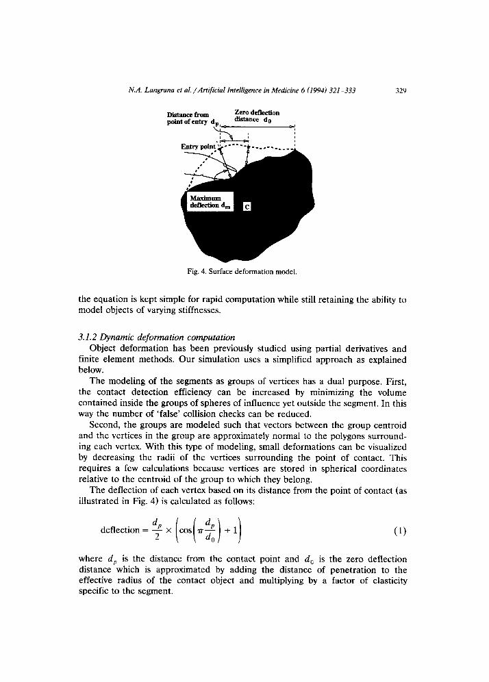
Fig. 4. Surface deformation model.
the equation is kept simple for rapid computation while still retaining the ability to model objects of varying stiffnesses.
3.1.2 Dynamic deformation computation Object deformation has been previously studied using partial derivatives and
finite element methods. Our simulation uses a simplified approach as explained below.
The modeling of the segments as groups of vertices has a dual purpose. First, the contact detection efficiency can be increased by minimizing the volume contained inside the groups of spheres of influence yet outside the segment. In this way the number of ‘false’ collision checks can be reduced.
Second, the groups are modeled such that vectors between the group centroid and the vertices in the group are approximately normal to the polygons surround- ing each vertex. With this type of modeling, small deformations can be visualized by decreasing the radii of the vertices surrounding the point of contact. This requires a few calculations because vertices are stored in spherical coordinates relative to the centroid of the group to which they belong.
The deflection of each vertex based on its distance from the point of contact (as illustrated in Fig. 4) is calculated as follows:
deflection=%X(cos(?r:)+I) (1)
where d, is the distance from the contact point and d, is the zero deflection distance which is approximated by adding the distance of penetration to the effective radius of the contact object and multiplying by a factor of elasticity specific to the segment.
330 N.A. Langrana et al. /Artificial Intelligence in Medicine 6 (1994) 321-333
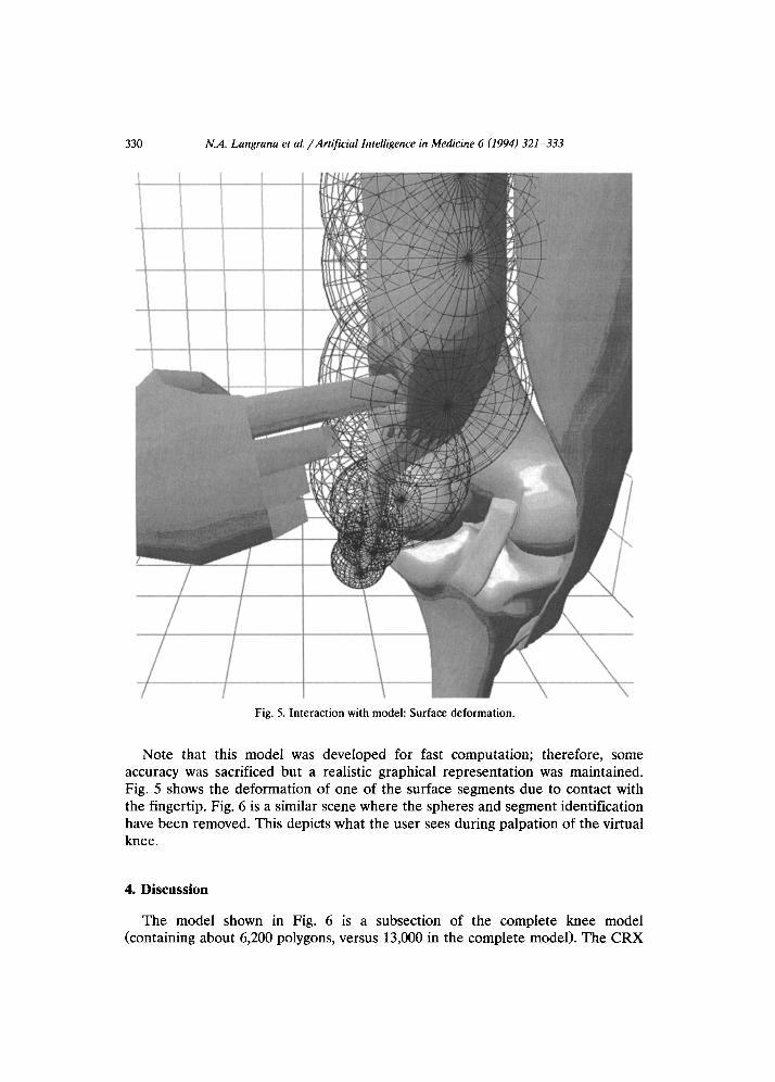
Fig. 5. Interaction with model: Surface deformation.
Note that this model was deveIoped for fast computation; therefore, some accuracy was sacrificed but a realistic graphical representation was maintained. Fig. 5 shows the deformation of one of the surface segments due to contact with the fingertip. Fig. 6 is a similar scene where the spheres and segment identification have been removed. This depicts what the user sees during palpation of the virtual knee.
4. Discussion
The model shown in Fig. 6 is a subsection of the complete knee model (containing about 6,200 polygons, versus 13,000 in the complete model). The CRX

N.A. Langrana et al. /Artificial Intelligence in Medicine 6 (1994) 321-333 331
Fig. 6. Interaction with model: Hand touching a virtual muscle.
graphics acceleration yields a rendering rate of 150,000 Gauraud shaded poly- gons/ second. Therefore the simulation should display about 24 frames/ second for the model shown in Fig. 6. The simulation bandwidth has been measured at only 5 frames/second when no contact exists between the hand and the knee. This rate drops to 3 frames/second when the model is deformed.
The fact that object deformation reduces the refresh rate is explained by the increase in the computational load for modelling shape and force data. The large discrepancy between the graphics potential and actual refresh rates shows that the renderer receives data at rates somewhat lower than its ability to display them. This also suggests a possible overloading of the HP main CPU which is in charge of physical modelling and communication. Smooth simulation interaction requires

332 N.A. Langrana et al. /Artificial Intelligence in Medicine 6 (1994) 321-333
a graphics rate of at least 14 frames/second and a force bandwidth of about lo-12I-Iz. Thus it is necessary to improve the simulation in several ways: (1) Distribute the computation and communication loads. The DataGlove reading
and fingertip calculation could be easily done by the SUN4 workstation. The reading of the trackball should also be delegated to a different workstation instead of the HP graphics computer.
(2) Contact and deformation calculations should be optimized. The above slow rates have been obtained using ‘first generation’ code.
(3) The knee model can be simplified and model management techniques imple- mented. We may use dual resolution display or acquire a lower polygon count model.
The computational methodology of ‘feel’ or palpation of muscles and ligaments is general purpose in nature. It uses dynamic hierarchial structure of body segments and therefore palpation can be performed on any other virtual body part.
5. Conclusions and future work
The work presented here is in an initial ‘proof of concept’ stage. Code and model optimization are necessary in order to increase the simulation bandwidth. Further speedup may be obtained by distributing the computational load to other machines in order to offload as much as possible the HP graphics workstation. Only after these steps are implemented can human factors tests be performed to identify potential benefits to students or surgeons.
Further research is aimed at doing complex multi-finger manipulation and deformation, as well as displaying images in stereo, rather than the current monoscopic view.
A parallel project is aimed at improving the force feedback system. We are developing a second-generation master called ‘Rutgers Master II’ that has im- proved sensing and reduced static friction. The second-generation master elimi- nates the need for a DataGlove by integrating position sensors within the force feedback structure.
Acknowledgements
The research reported here was supported by the CAIP Center, Rutgers University, with funds provided by the New Jersey Commission on Science and Technology and by CAIP’s industrial members and by a special purpose grant from the AT&T Foundation.
References
[l] P.J. Brooks, P.S. Walker and R.D. Scott, Tibia1 component fixation in deficient tibia1 bone stock,
Clin. Orthop. Related Res. (1984) 302-308.

N.A. Langrana et al. /Artificial Intelligence in Medicine 6 (1994) 321-333 333
[2] G. Burdea and N. Langrana, Virtual force feedback - Lessons, challenges and future applications. Robotics and Mechatronics 5(2) (1992) 78-182.
[3] G. Burdea, J. Zhuang, E. Roskos, D. Silver and N. Langrana, A portable dextrous master with force feedback, Presence: Teleoperators and Virtual Environments l(1) (1992) 18-28.
[4] G. Burdea and P. Coiffet, La Realite Virtuelle (Hermes Publishers, Paris, 1993) (in French). [5] D. Chen, Pump it up: Computer animation of a biomechanically based model of muscle using
FEM, Ph.D. thesis, MIT, Boston, 1992. [6] D. Gomez, G. Burdea, N. Langrana and E. Roskos, Second-generation Rutgers Force Feedback
Master, Pro. VR Systems’93 Conf., New York City (1993). [7] H. Gouraud, Continuous shading of curved surfaces, IEEE Trans. Comput. c-20(6) (1971) 623-629. [8] P. Green et al., Telepresence: Advanced teleoperator technology for minimally invasive surgery,
Proc. Medicine Meets virtual Reality I, San Diego, CA (1992). [9] D. Hon, Tactile and visual simulation: A realistic endoscopy experience, Proc. Medicine Meets
Virtual Reality I, San Diego, CA (1992). [lo] J. Hong and X. Tan, Teleoperating the Utah/MIT hand with a VPL Dataglove I. Dataglove
calibration, IEEE Conf. on Robotics and Automation (1988) 12. [ll] P.A. Howard., Image-directed robotic surgery, Proc. Medicine Meets Virtual Reality I, San Diego,
CA (1992). [12] Hewlett-Packard, Starbase Display List Programmers Manual, 1st edition (Jan. 1991). [13] R.W. Mann, Computer-aided surgery, RESNA 8th Annual Con& (1985). [14] S. Pieper, CAPS: Computer-aided plastic surgery, Ph.D. thesis, MIT, Boston, 1992. [15] S. Pieper, D. Chen, D. Scott, M. McKenna, D. Zeltzer and J. Rosen, Surgical simulation: From
computer-aided design to computer-aided surgery, Proc. Imagina 1992 (1992). [16] P. Richard, G. Burdea and P. Coiffet, Performances humaines dans des taches impliquant des
objets virtuels avec retour d’effort, Interface to Real and Virtual Worlds Conf , Montpelier, France (1993) 229-238.
[17] P. Richard, G. Burdea D. Gomez, N. Langrana and P. Coiffet, Human Interaction in a Virtual World with Force Feedback: Testing and Evaluation, Rutgers University, CAIP Technical Report, 1993.
[18] E. Roskos and J. Zhuang, Real-time software for the VPL Dataglove, Rutgers University, CAIP Technical Report, 1990.
[19] R.M. Satava, Virtual reality surgical simulator: The first step, Proc. Medicine Meets Virtual Reality I, San Diego, CA (1992).
[20] R.M. Satava, Surgery 2001: A technologic framework for the future, Proc. Medicine Meets Virtual Reality I, San Diego, CA (1992).
[21] K. Shimoga, A survey of perceptual feedback issues in dexterous telemanipulation : Part I. Finger force feedback, Proc. IEEE Virtual Reality Annual Int. Symp. Seattle, WA (1993) 263-270.
[22] R. Taylor, S. Lavallee, G. Burdea and R. Moesges, eds., Computer Integrated Surgery, (MIT Press, Boston, to appear 1994).
[23] U. Volker, 3-D Endoscopy in neurosurgery, Proc. Medicine Meets Virtual Reality I, San Diego, CA (1992).
[24] Viewpoint Datalabs, Orem, Utah. [25] VPL Research, Datagloue Model 2 Operating Manual (VPL, Redwood City, CA, 1987). [26] S. Weghorst, Inclusive computing in medicine, Proc. Medicine Meets Vktual Reality I, San Diego,
CA (1992).