Feedback IT version
52
SJTU Zhou Lingling 1 Chapter 6 Feedback Amplifiers
Transcript of Feedback IT version
SJTU Zhou Lingling 1
Chapter 6
Feedback Amplifiers
SJTU Zhou Lingling 2
Outline
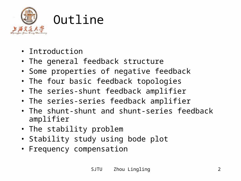
• Introduction• The general feedback structure• Some properties of negative feedback• The four basic feedback topologies• The series-shunt feedback amplifier• The series-series feedback amplifier• The shunt-shunt and shunt-series feedback amplifier
• The stability problem• Stability study using bode plot• Frequency compensation
SJTU Zhou Lingling 3
Introduction
• It’s impossible to think of electronic circuits without some forms of feedback.
• Negative feedback Desensitize the gain Reduce nonlinear distortion Reduce the effect of noise Control the input and output impedance Extend the bandwidth of the amplifier
• The basic idea of negative feedback is to trade off gain for other desirable properties.
• Positive feedback will cause the amplifier oscillation.
SJTU Zhou Lingling 4
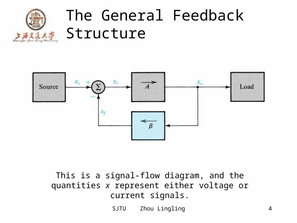
The General Feedback Structure
This is a signal-flow diagram, and the quantities x represent either voltage or
current signals.
SJTU Zhou Lingling 5
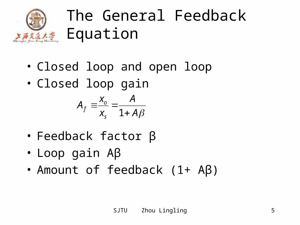
The General Feedback Equation
• Closed loop and open loop• Closed loop gain
• Feedback factor β• Loop gain Aβ• Amount of feedback (1+ Aβ)
AA
xxA
s
of
1
SJTU Zhou Lingling 6
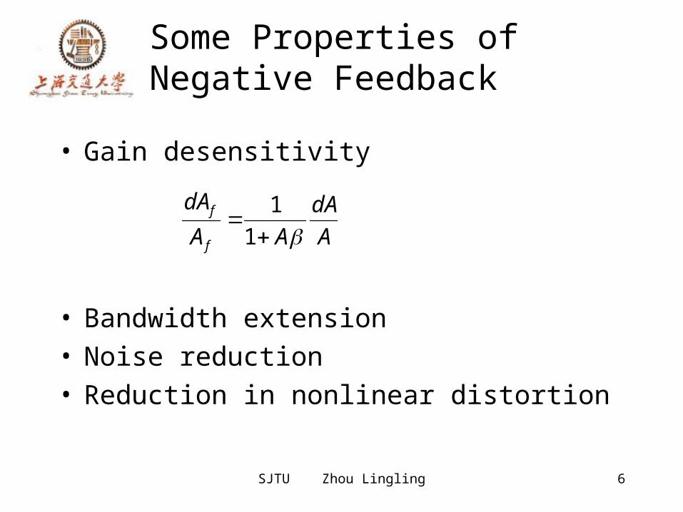
Some Properties of Negative Feedback
• Gain desensitivity
• Bandwidth extension• Noise reduction• Reduction in nonlinear distortion
AdA
AAdA
f
f
1
1
SJTU Zhou Lingling 7
The Four Basic Feedback Topologies
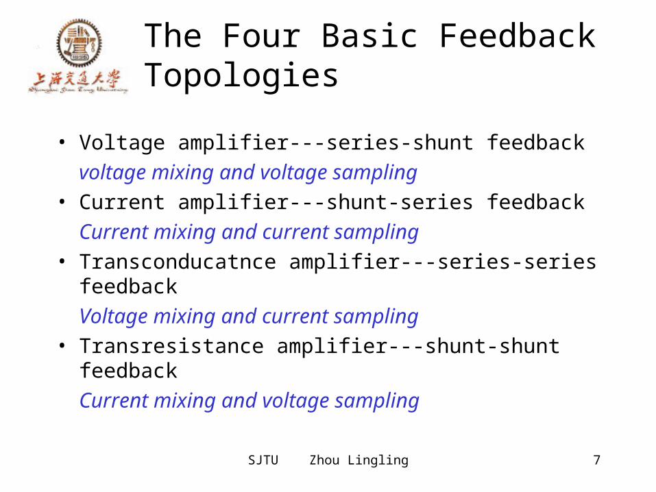
• Voltage amplifier---series-shunt feedbackvoltage mixing and voltage sampling
• Current amplifier---shunt-series feedbackCurrent mixing and current sampling
• Transconducatnce amplifier---series-series feedbackVoltage mixing and current sampling
• Transresistance amplifier---shunt-shunt feedbackCurrent mixing and voltage sampling
SJTU Zhou Lingling 8
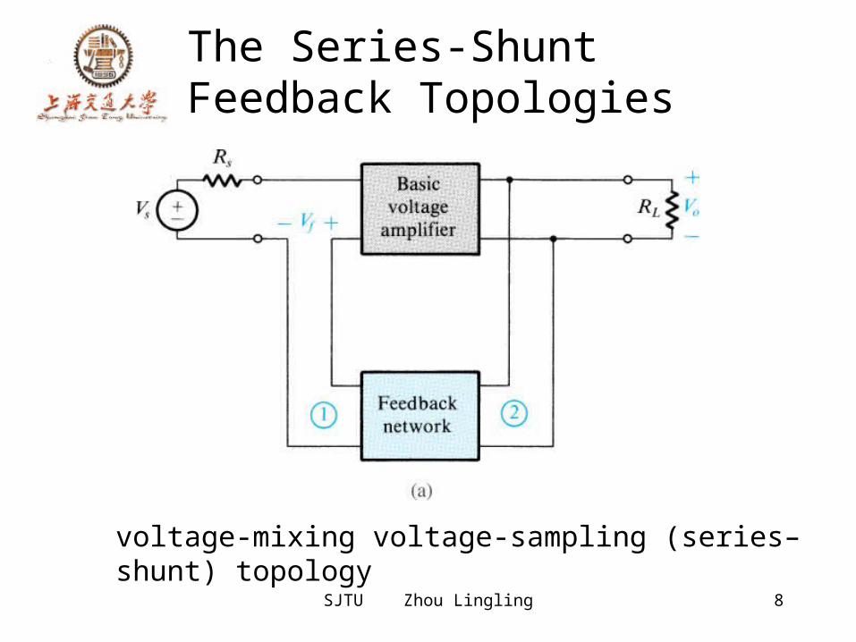
The Series-Shunt Feedback Topologies
voltage-mixing voltage-sampling (series–shunt) topology
SJTU Zhou Lingling 9
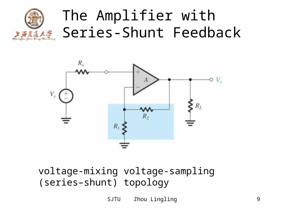
The Amplifier with Series-Shunt Feedback
voltage-mixing voltage-sampling (series–shunt) topology
SJTU Zhou Lingling 10
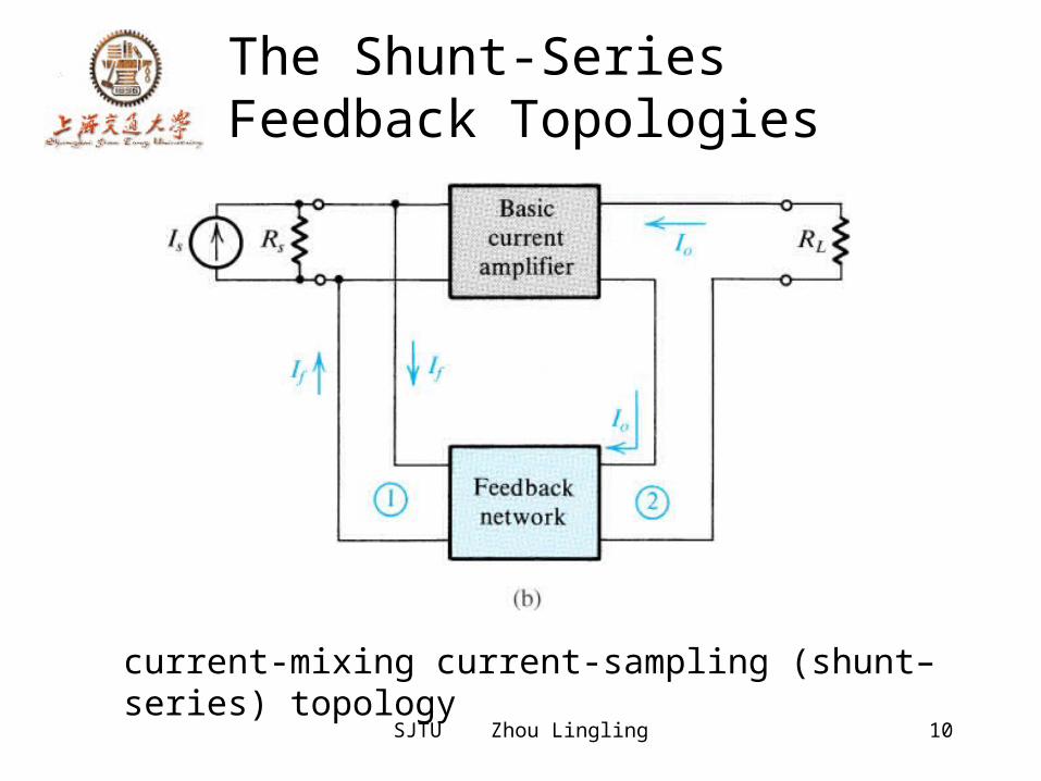
The Shunt-Series Feedback Topologies
current-mixing current-sampling (shunt–series) topology
SJTU Zhou Lingling 11
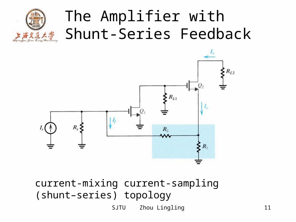
The Amplifier with Shunt-Series Feedback
current-mixing current-sampling (shunt–series) topology
SJTU Zhou Lingling 12
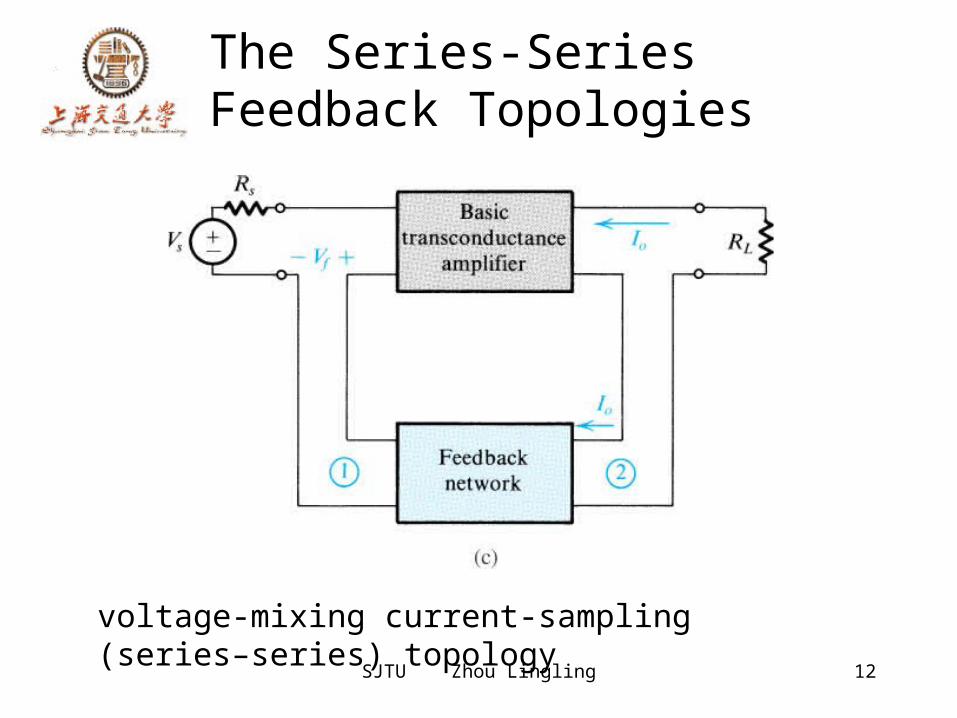
The Series-Series Feedback Topologies
voltage-mixing current-sampling (series–series) topology
SJTU Zhou Lingling 13
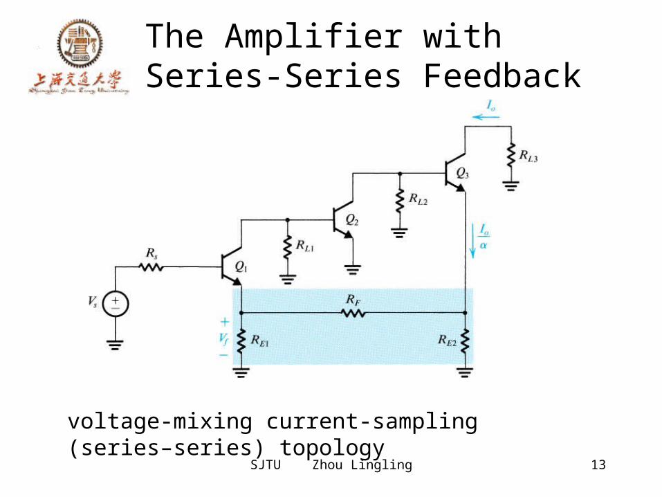
The Amplifier with Series-Series Feedback
voltage-mixing current-sampling (series–series) topology
SJTU Zhou Lingling 14
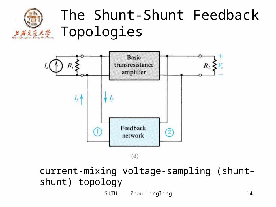
The Shunt-Shunt Feedback Topologies
current-mixing voltage-sampling (shunt–shunt) topology
SJTU Zhou Lingling 15
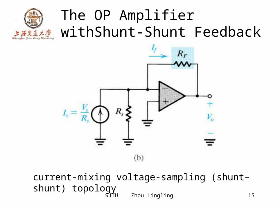
The OP Amplifier withShunt-Shunt Feedback
current-mixing voltage-sampling (shunt–shunt) topology
SJTU Zhou Lingling 16
The Series-Shunt Feedback Amplifier
• The ideal situation• The practical situation• summary
SJTU Zhou Lingling 17
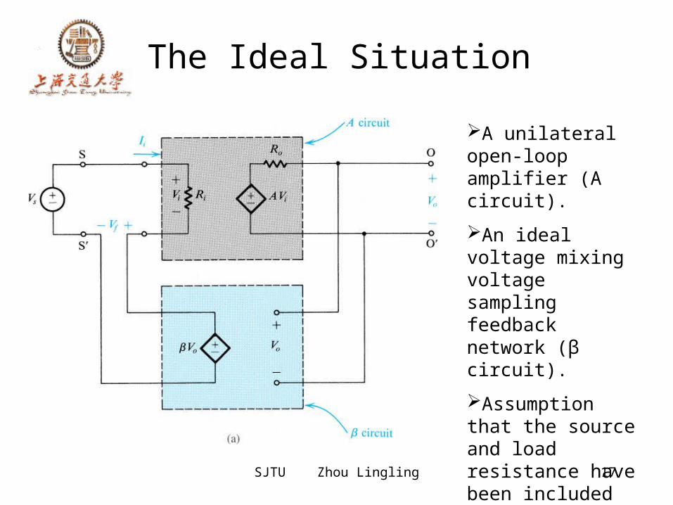
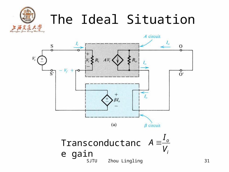
The Ideal Situation
A unilateral open-loop amplifier (A circuit).An ideal voltage mixing voltage sampling feedback network (β circuit).Assumption that the source and load resistance have been included inside the A circuit.
SJTU Zhou Lingling 18
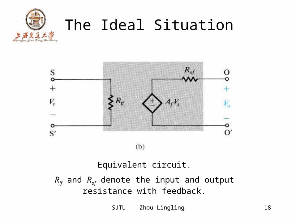
The Ideal Situation
Equivalent circuit.Rif and Rof denote the input and output
resistance with feedback.
SJTU Zhou Lingling 19
Input and Output Resistance with Feedback
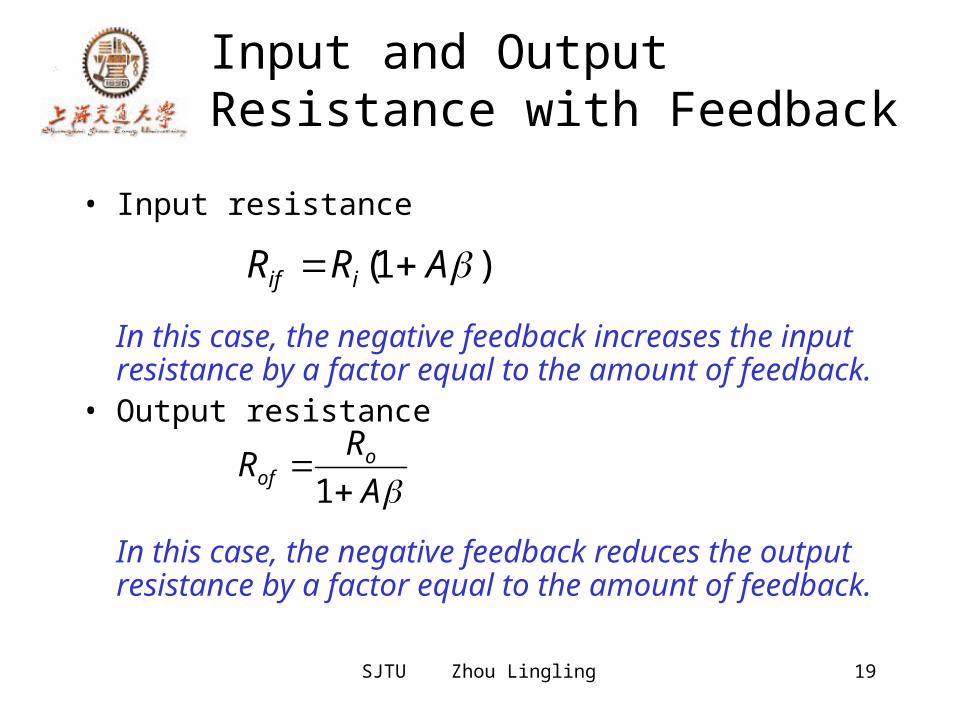
• Input resistance
In this case, the negative feedback increases the input resistance by a factor equal to the amount of feedback.
• Output resistance
In this case, the negative feedback reduces the output resistance by a factor equal to the amount of feedback.
)1( ARR iif
ARR o
of 1
SJTU Zhou Lingling 20
The Practical Situation
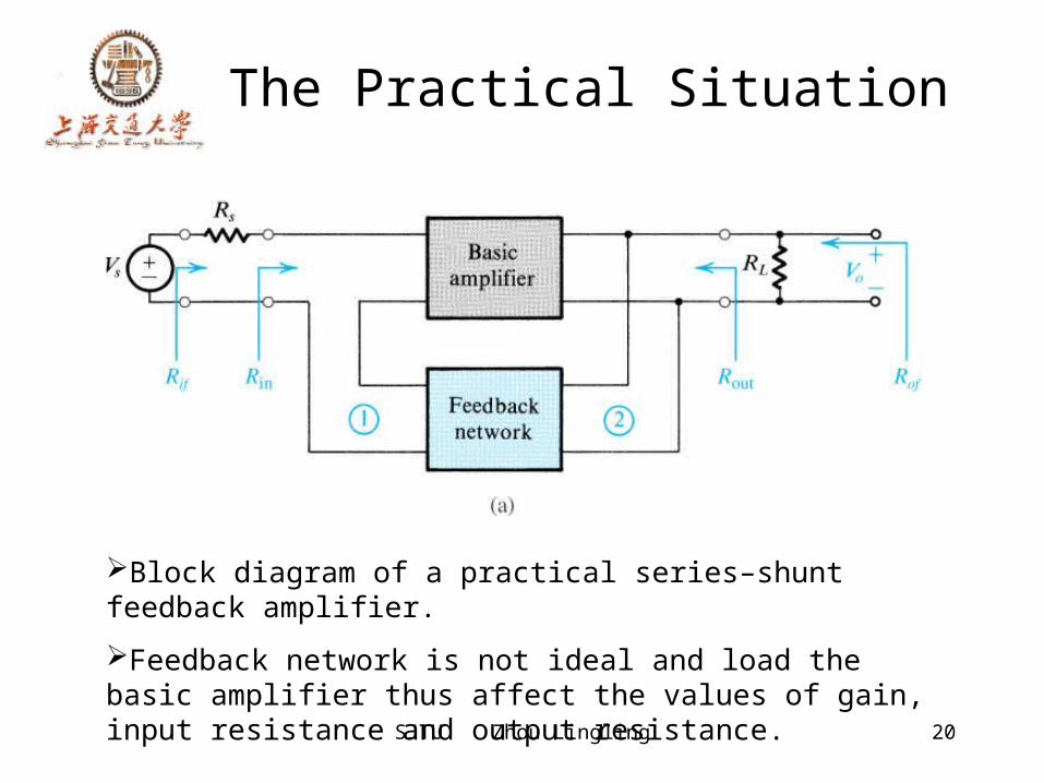
Block diagram of a practical series–shunt feedback amplifier. Feedback network is not ideal and load the basic amplifier thus affect the values of gain, input resistance and output resistance.
SJTU Zhou Lingling 21
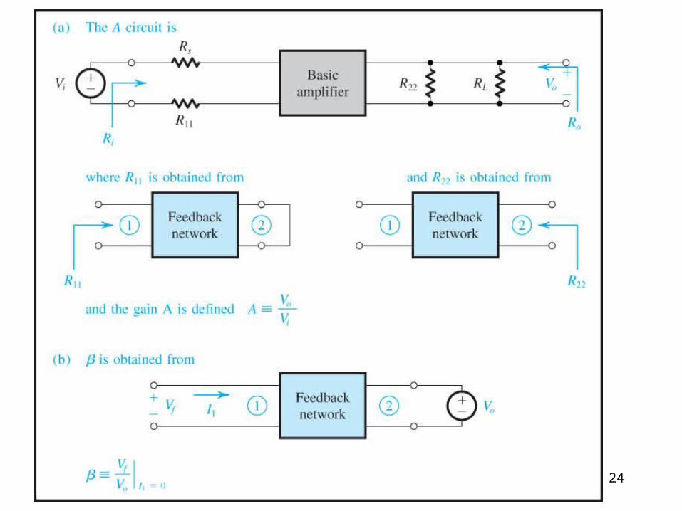
The Practical Situation
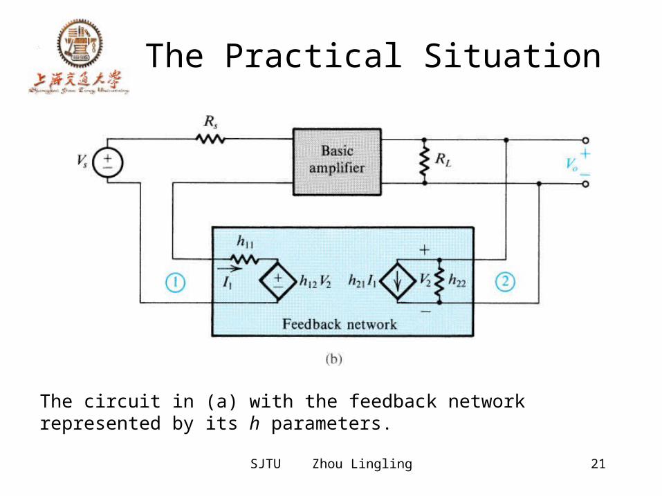
The circuit in (a) with the feedback network represented by its h parameters.
SJTU Zhou Lingling 22
The Practical Situation
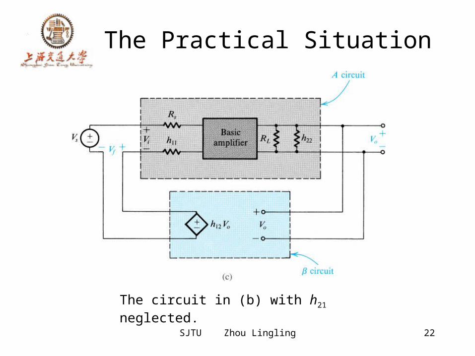
The circuit in (b) with h21 neglected.
SJTU Zhou Lingling 23
The Practical Situation
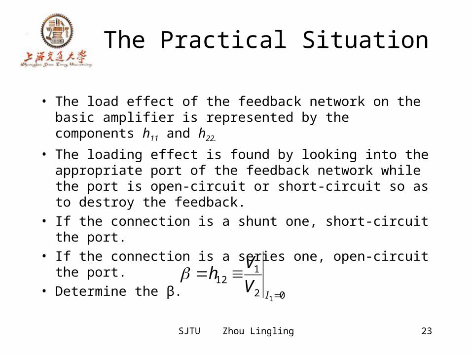
• The load effect of the feedback network on the basic amplifier is represented by the components h11 and h22.
• The loading effect is found by looking into the appropriate port of the feedback network while the port is open-circuit or short-circuit so as to destroy the feedback.
• If the connection is a shunt one, short-circuit the port.
• If the connection is a series one, open-circuit the port.
• Determine the β. 02
112
1
IV
Vh
24
SJTU Zhou Lingling 25
Summary
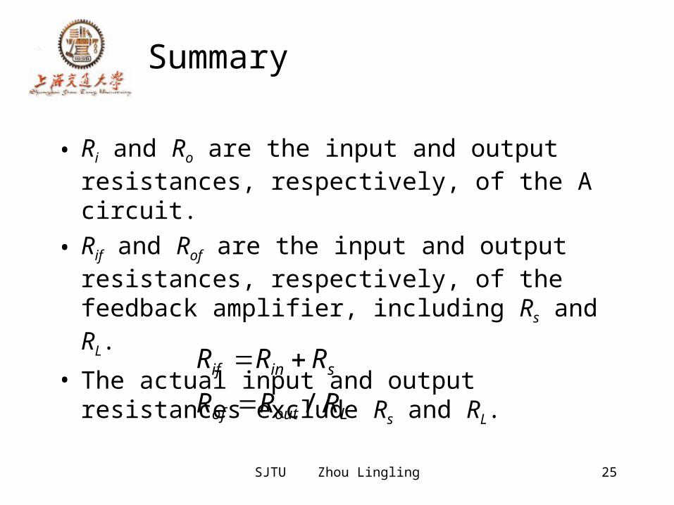
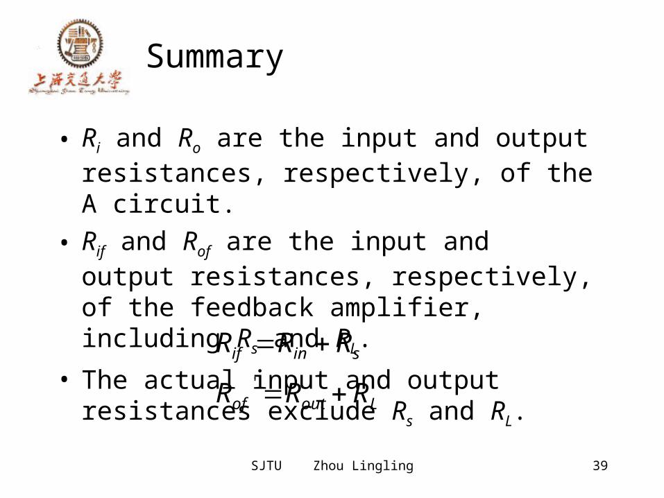
• Ri and Ro are the input and output resistances, respectively, of the A circuit.
• Rif and Rof are the input and output resistances, respectively, of the feedback amplifier, including Rs and RL.
• The actual input and output resistances exclude Rs and RL.Loutof
sinif
RRRRRR//
26
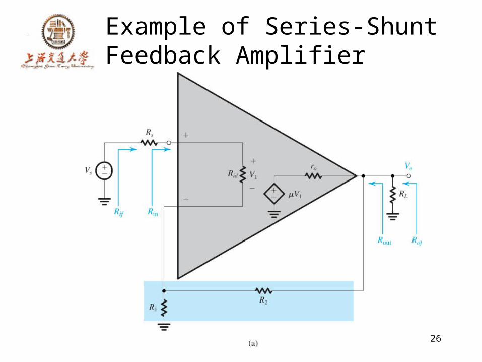
Example of Series-Shunt Feedback Amplifier
SJTU Zhou Lingling 27
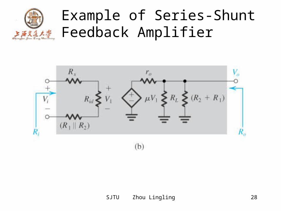
Example of Series-Shunt Feedback Amplifier
• Op amplifier connected in noninverting configuration with the open-loop gain μ, Rid and ro
• Find expression for A, β, the closed-loop gain Vo/Vi , the input resistance Rin and the output resistance Rout
• Find numerical values
SJTU Zhou Lingling 28
Example of Series-Shunt Feedback Amplifier
SJTU Zhou Lingling 29
Example of Series-Shunt Feedback Amplifier
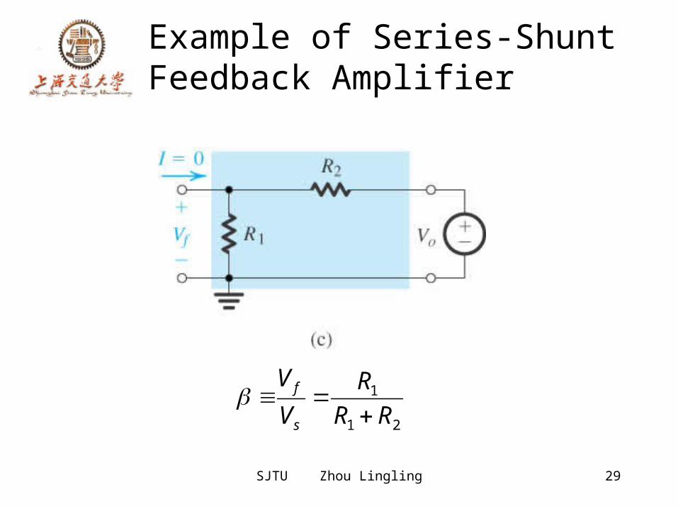
21
1RR
RVV
s
f
SJTU Zhou Lingling 30
The Series-Series Feedback Amplifier
• The ideal situation• The practical situation• summary
SJTU Zhou Lingling 31
The Ideal Situation
Transconductance gain i
o
VIA
SJTU Zhou Lingling 32
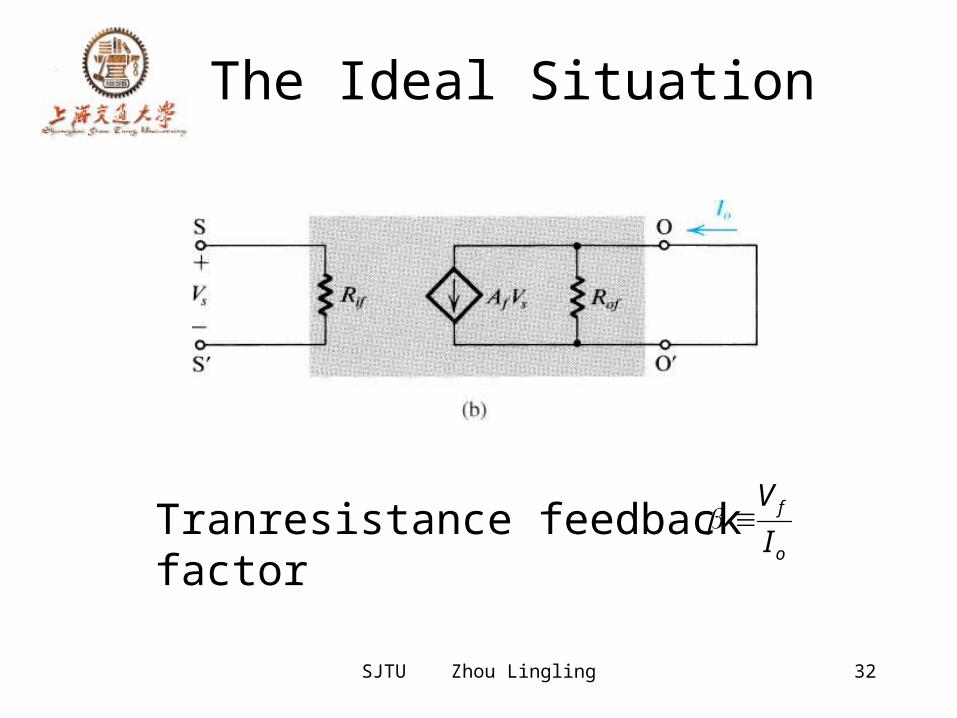
The Ideal Situation
o
f
IV
Tranresistance feedback factor
SJTU Zhou Lingling 33
Input and Output Resistance with Feedback
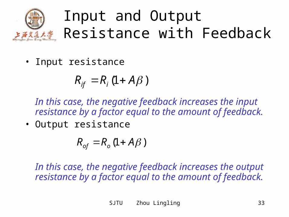
• Input resistance
In this case, the negative feedback increases the input resistance by a factor equal to the amount of feedback.
• Output resistance
In this case, the negative feedback increases the output resistance by a factor equal to the amount of feedback.
)1( ARR iif
)1( ARR oof
SJTU Zhou Lingling 34
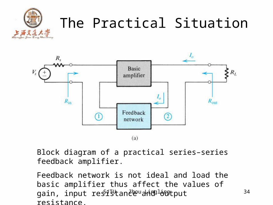
The Practical Situation
Block diagram of a practical series–series feedback amplifier. Feedback network is not ideal and load the basic amplifier thus affect the values of gain, input resistance and output resistance.
SJTU Zhou Lingling 35
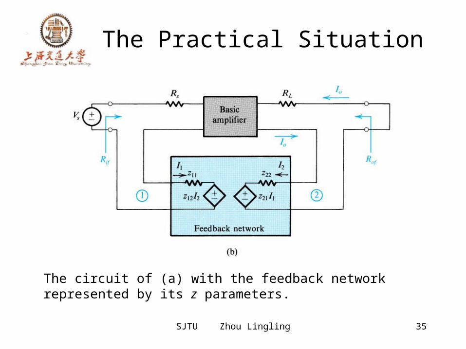
The Practical Situation
The circuit of (a) with the feedback network represented by its z parameters.
SJTU Zhou Lingling 36
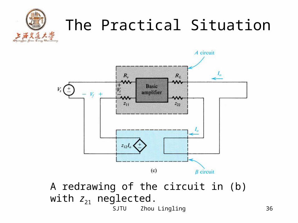
The Practical Situation
A redrawing of the circuit in (b) with z21 neglected.
SJTU Zhou Lingling 37
The Practical Situation
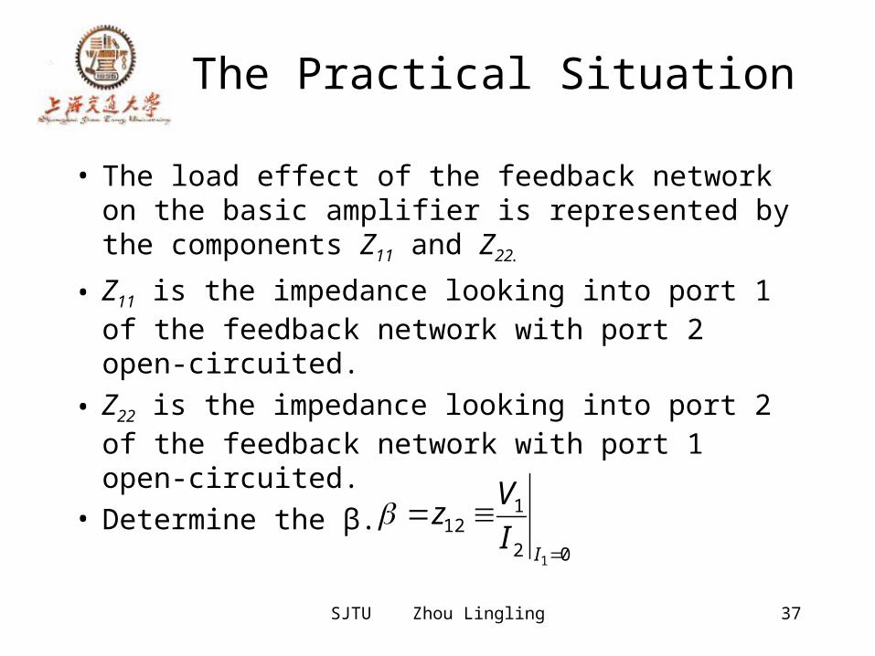
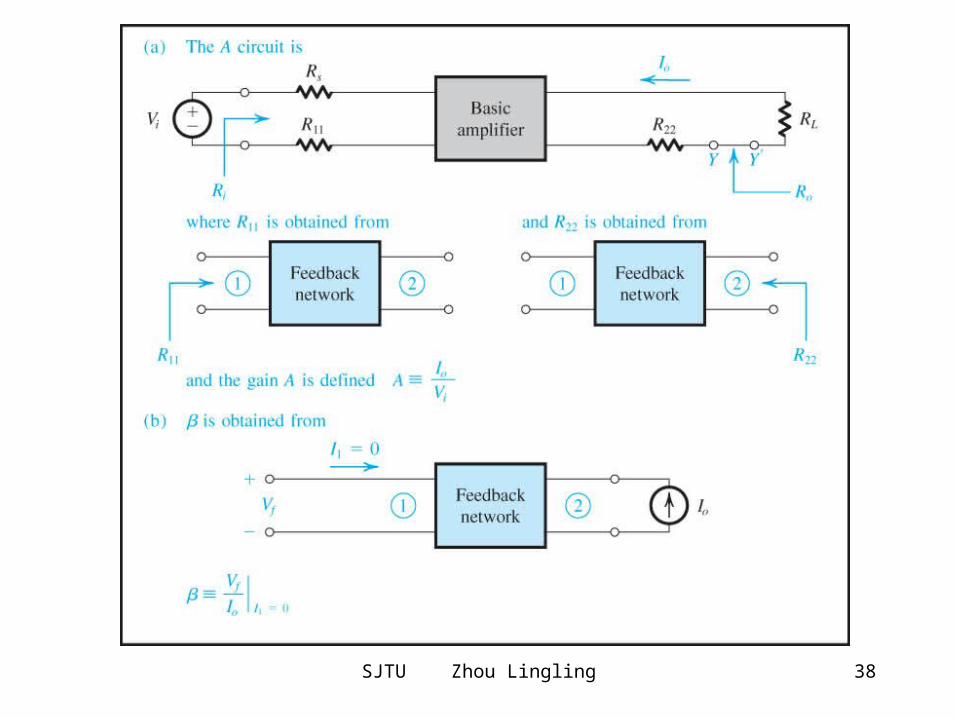
• The load effect of the feedback network on the basic amplifier is represented by the components Z11 and Z22.
• Z11 is the impedance looking into port 1 of the feedback network with port 2 open-circuited.
• Z22 is the impedance looking into port 2 of the feedback network with port 1 open-circuited.
• Determine the β.02
112
1
II
Vz
SJTU Zhou Lingling 38
SJTU Zhou Lingling 39
Summary
• Ri and Ro are the input and output resistances, respectively, of the A circuit.
• Rif and Rof are the input and output resistances, respectively, of the feedback amplifier, including Rs and RL.
• The actual input and output resistances exclude Rs and RL.Loutof
sinif
RRR
RRR
'
SJTU Zhou Lingling 40
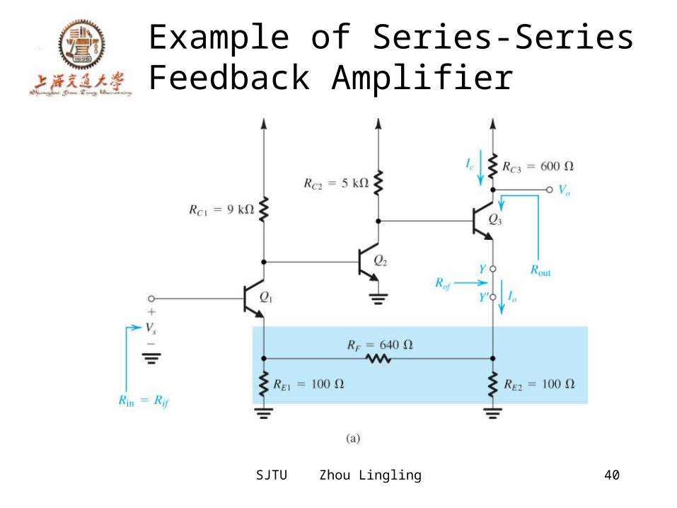
Example of Series-Series Feedback Amplifier
SJTU Zhou Lingling 41
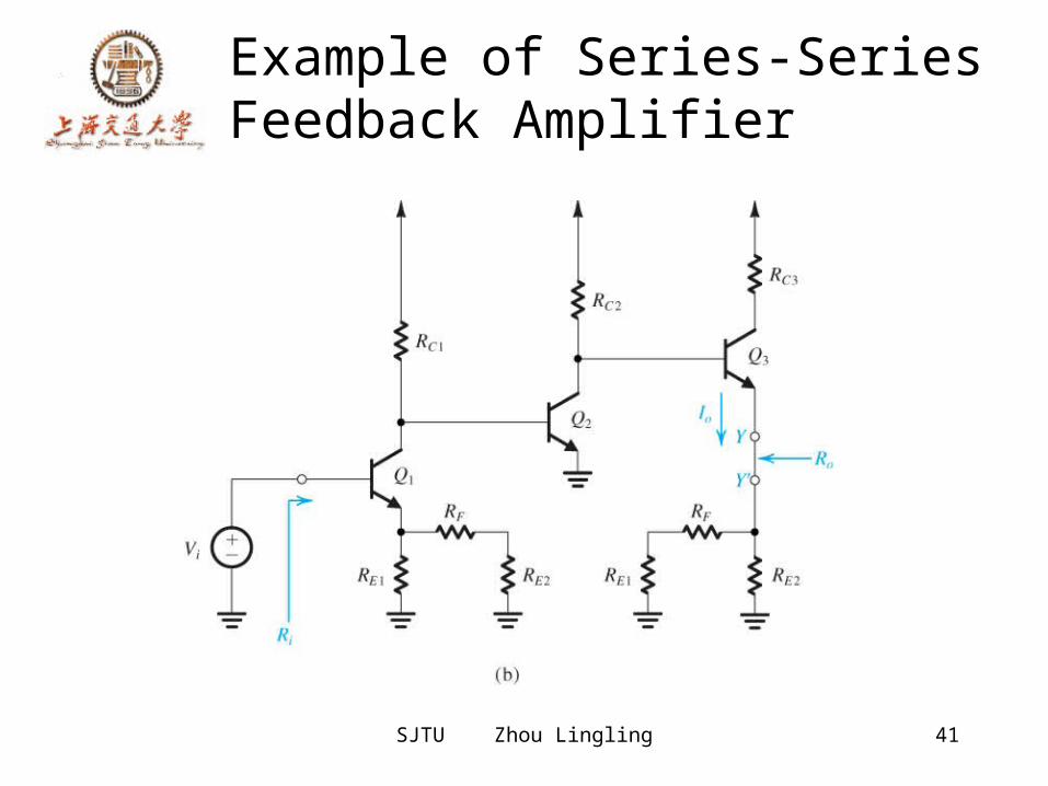
Example of Series-Series Feedback Amplifier
SJTU Zhou Lingling 42
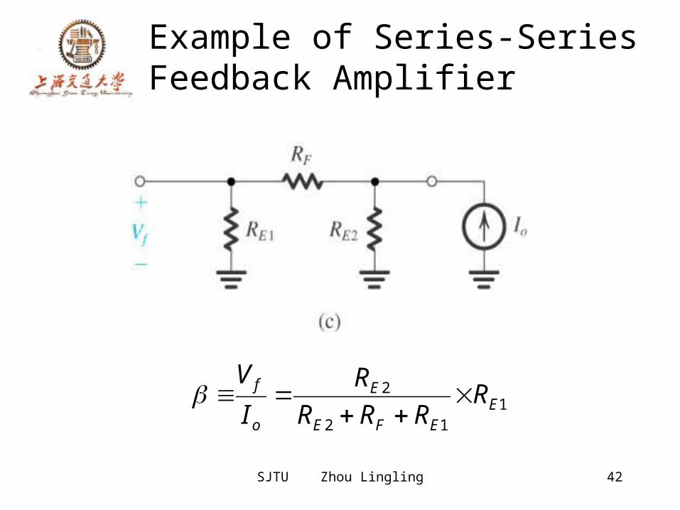
Example of Series-Series Feedback Amplifier
112
2E
EFE
E
o
f RRRR
RIV
SJTU Zhou Lingling 43
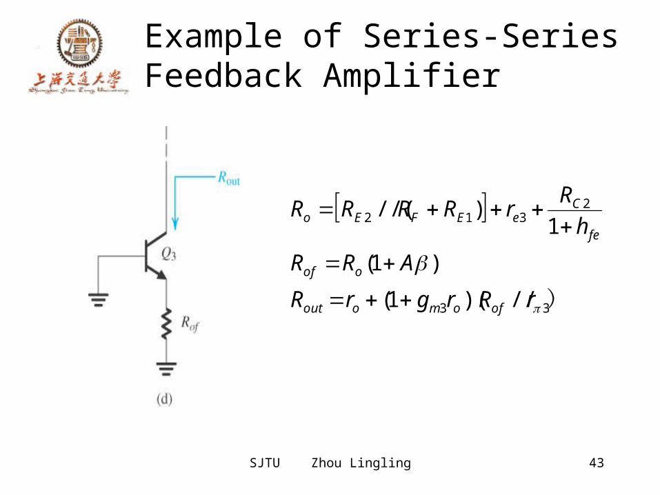
Example of Series-Series Feedback Amplifier
)33
2312
//)(1()1(
1)//(
rRrgrRARR
hRrRRRR
ofomoout
oof
fe
CeEFEo
SJTU Zhou Lingling 44
The Shunt-Shunt and Shunt-Series Feedback Amplifiers
• Study by yourselves• Important notes:
Closed-loop gainFeedback factorLoad effectSummary example
SJTU Zhou Lingling 45
The Stability Problem • Closed-loop transfer function is similar to the one of the middle band gain.
• The condition for negative feedback to oscillate
• Any right-half-plane poles results in instability. Amplifier with a single-pole is unconditionally stable. Amplifier with two-pole is also unconditionally stable. Amplifier with more than two poles has the possibility to be unstable.
• Stability study using bode plot
1)()()( jjAjL
SJTU Zhou Lingling 46
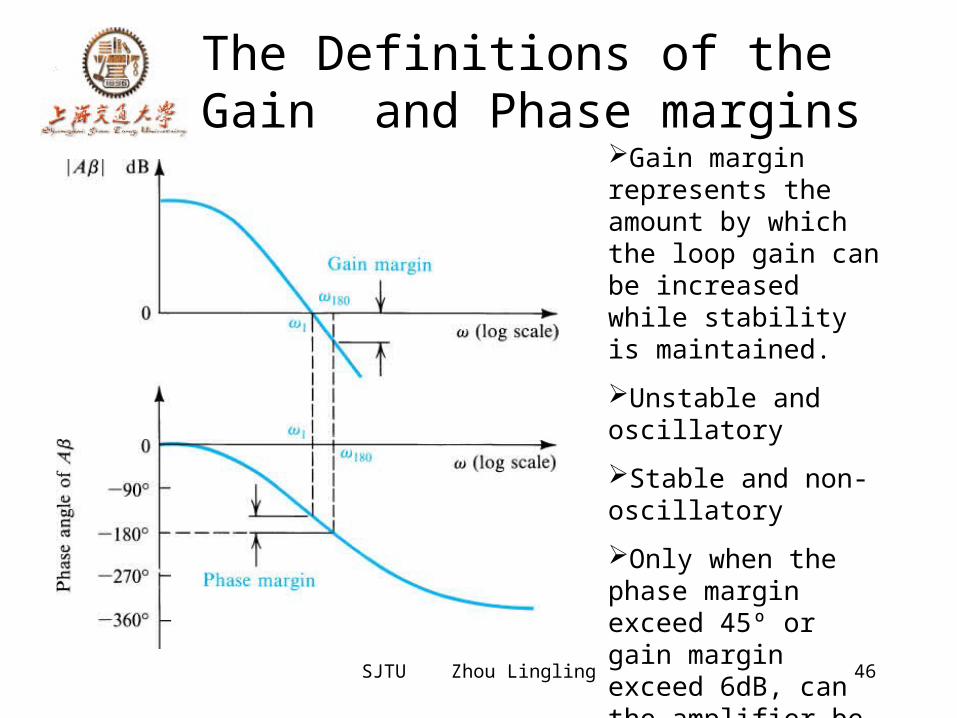
The Definitions of the Gain and Phase margins
Gain margin represents the amount by which the loop gain can be increased while stability is maintained.Unstable and oscillatoryStable and non-oscillatory Only when the phase margin exceed 45º or gain margin exceed 6dB, can the amplifier be stable.
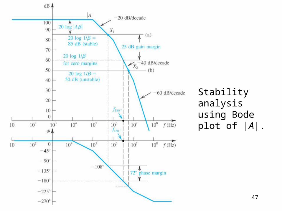
47
Stability analysis using Bode plot of |A|.
SJTU Zhou Lingling 48
Stability Analysis Using Bode Plot of |A|
• Gain margin and phase margin• The horizontal line of inverse of feedback factor in dB.
• A rule of thumb:The closed-loop amplifier will be stable if the 20log(1/β) line intersects the 20log|A| curve at a point on the –20dB/decade segment.
• The general rule states:At the intersection of 20log[1/ | β (jω)| ] and 20log |A(jω)| the difference of slopes should not exceed 20dB/decade.
SJTU Zhou Lingling 49
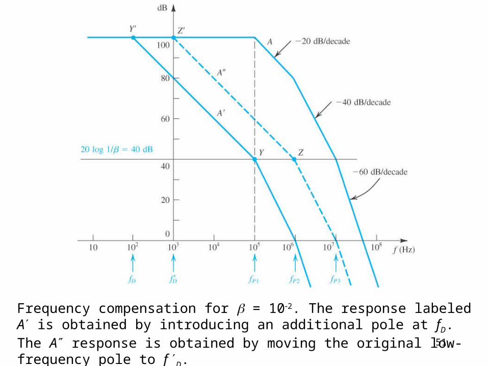
Frequency Compensation• The purpose is to modifying the open-loop transfer function of an amplifier having three or more poles so that the closed-loop amplifier is stable for any desired value of closed-loop gain.
• Theory of frequency compensation is the enlarge the –20dB/decade line.
• Implementation Capacitance Cc added Miller compensation and pole splitting
50
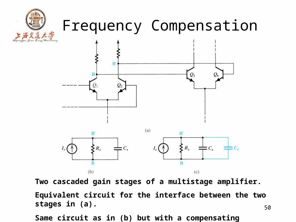
Frequency Compensation
Two cascaded gain stages of a multistage amplifier. Equivalent circuit for the interface between the two stages in (a). Same circuit as in (b) but with a compensating capacitor CC added.
51
Frequency compensation for = 102. The response labeled A is obtained by introducing an additional pole at fD. The A response is obtained by moving the original low-frequency pole to f D.
SJTU Zhou Lingling 52
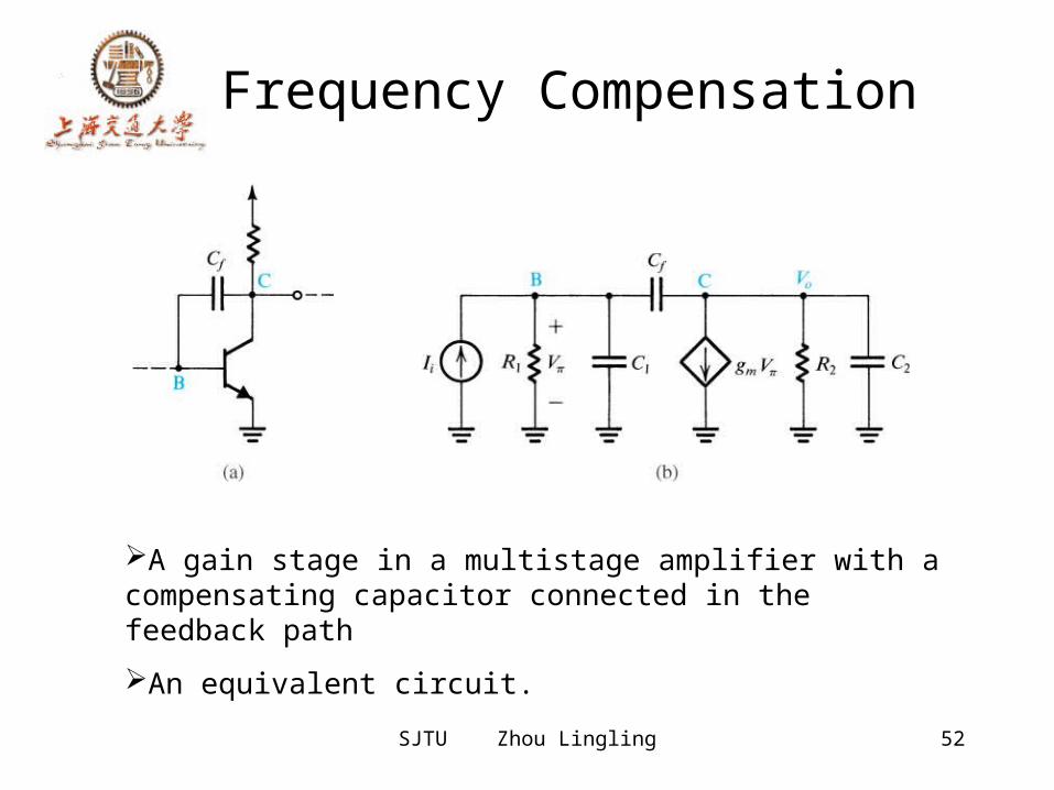
Frequency Compensation
A gain stage in a multistage amplifier with a compensating capacitor connected in the feedback pathAn equivalent circuit.