WEB VERSION - Leviton
20
Modbus TM Flex I/O Module Cat. No. A8332 Installation and Operation Manual DI-004-A8332-00B WEB VERSION
-
Upload
khangminh22 -
Category
Documents
-
view
3 -
download
0
Transcript of WEB VERSION - Leviton

ModbusTM Flex I/O ModuleCat. No. A8332
Installation and Operation Manual
DI-004-A8332-00B
WE
B V
ER
SIO
N
TABLE OF CONTENTS
1 Product Application Limitation ............................................................................32 Features and Specifications ................................................................................43 Installation Checklist .............................................................................................5 3.1 Required Components .......................................................................................5 3.2 Configuration Software Required .......................................................................54 Hardware Installation ............................................................................................65 Dip Switch Configuration ......................................................................................86 Operation ................................................................................................................97 Troubleshooting ..................................................................................................108 Modbus Registers ...............................................................................................12 8.1 Modbus Functions ...........................................................................................12 8.2 Modbus Register Listing ..................................................................................159 Mechanical Drawings ..........................................................................................1810 Warranty and Contact Information....................................................................19
WE
B V
ER
SIO
N

• Leviton products are not intended for use in critical applications such as nuclear facilities, human implantable devices or life support. Leviton is not liable, in whole or in part, for any claims or damages arising from such uses.
• Leviton strongly believes in continuous improvement, therefore we must reserve the right to change specifications and product offerings without notice. Where possible, we will substitute products with equivalent functionality when necessary.
NOTICE
This product is not intended for life safety applications.
Do not install this product in hazardous or classified locations.
The installer is responsible for conformance to all applicable codes.
3
1 PRODUCT APPLICATION LIMITATION
WE
B V
ER
SIO
N

4
2 FEATURES AND SPECIFICATIONS
The A8332 is designed to read a variety of industry standard analog and pulse sensor devices and communicate the data values back to a Modbus master system using RS485. Applications include data acquisition systems reading gas/water/electric meters or analog sensors such as temperature, humidity, pressure, and flow.
Processor Arm7, field upgradeable firmware.LED 8 input status LEDs (red), 2 Modbus TX/RX (yellow), 1 power/alive status. (green)Protocols Modbus/RTUPower Supply 24VDC, 400 mA3, required (not included) The unit is to be sourced by a Class 2 power supply
with the following output: 24VDC, 400 mA minimum but not to exceed 8ASerial Port1 RS485 two wire, 19200 or 9600 baud. 8NIInputs1 8 flex I/O inputs with multiple modes: voltage, current, resistance, pulse and status. Voltage mode: 0-10VDC (min/max/average/instantaneous data) accuracy: +- 0.25% of full scale at 20ºc Current mode: 4-20 mA (min/max/average/instantaneous data) accuracy: +- 0.25% of full scale at 20oC Resistance mode: 100 ohms to 100k. Accuracy: 1001 – 1k1 +/- 1% of 1k1 at 20oC 1k1 – 10k1 +/- 1% of 10k1 at 20oC 10k1 – 47.5k1 +/- 1% of 47.5k1 at 20oC 47.5k1 – 100k1 +/- 1% of 100k1 at 20oC 100k1 – 10m1 accuracy unrated.
Pulse mode: intended for use with dry contact outputs. (consumption/rate/runtime/status) Standard and KYZ modes for form A and C relay outputs Input terminal supplies 5V at 5 mA sense voltage to detect contact closures. Maximum rate: 10Hz, minimum pulse width 50ms. Adjustable contact closure threshold: 1001 to 5 k1 , broken wire sense above 10k1 optional. Pulse count and runtime values are stored in non-volatile memory.
Outputs1: 2 optically isolated outputs Type: opto-fet, dry contacts. Rating: 30VDC, 150 mA max.
Isolation2: Pulse outputs are isolated to 1500VDC from main board. RS485 port is
isolated to 1500VDC from the main board. Power input, RS232, and analog/pulse inputs and are non-isolated.
Environmental Pollution Degree 2, altitude up to 2000m. For indoor use. Outdoor use requires appropriate enclosure. The A8332 must be mounted inside a NEMA rated electrical enclosure for safety and isolation
requirements. North America: Indoor, temperature -30oC - +70oC, 0 - 95% humidity, non-condensing3
EMC FCC CFR 47 Part 15, Class A EN 61000, EN 61326Size 4.13 in x 3.39 in x 1.18 in (105 mm x 86 mm x 30 mm)Mass 3.7 oz (105 g)
1 Inputs are intended for low voltage Class 2 or equivalent outputs.
2 If the product is used in a manner not specified by the manufacture, the protection provided by the equipment may be impaired.
3 Power consumption listed does not include power consumed by attached sensor devices. The combined current draw requirements of all 8 input sensors should not exceed 200 mA.
4 Devices manufactured before Feb 1, 2010 are rated to 0 - 50oc, and are not UL recognized.
WE
B V
ER
SIO
N
3 INSTALLATION CHECKLIST
5
3.1 Required Components
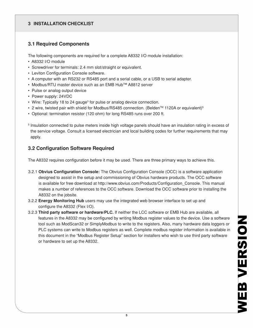
The following components are required for a complete A8332 I/O module installation:• A8332 I/O module• Screwdriver for terminals: 2.4 mm slot/straight or equivalent.• Leviton Configuration Console software.• A computer with an RS232 or RS485 port and a serial cable, or a USB to serial adapter.• Modbus/RTU master device such as an EMB Hub™ A8812 server• Pulse or analog output device• Power supply: 24VDC• Wire: Typically 18 to 24 gauge3 for pulse or analog device connection.• 2 wire, twisted pair with shield for Modbus/RS485 connection. (BeldenTM 1120A or equivalent)5
• Optional: termination resistor (120 ohm) for long RS485 runs over 200 ft.
5 Insulation connected to pulse meters inside high voltage panels should have an insulation rating in excess of the service voltage. Consult a licensed electrician and local building codes for further requirements that may apply.
3.2 Configuration Software Required
The A8332 requires configuration before it may be used. There are three primary ways to achieve this.
3.2.1 Obvius Configuration Console: The Obvius Configuration Console (OCC) is a software application designed to assist in the setup and commissioning of Obvius hardware products. The OCC software is available for free download at http://www.obvius.com/Products/Configuration_Console. This manual makes a number of references to the OCC software. Download the OCC software prior to installing the A8332 on the jobsite.
3.2.2 Energy Monitoring Hub users may use the integrated web browser interface to set up and configure the A8332 (Flex I/O).
3.2.3 Third party software or hardware/PLC. If neither the LCC software or EMB Hub are available, all features in the A8332 may be configured by writing Modbus register values to the device. Use a software tool such as ModScan32 or SimplyModbus to write to the registers. Also, many hardware data loggers or PLC systems can write to Modbus registers as well. Complete modbus register information is available in this document in the “Modbus Register Setup” section for installers who wish to use third party software or hardware to set up the A8332.
WE
B V
ER
SIO
N
4 HARDWARE INSTALLATION
4.1 Hardware Installation
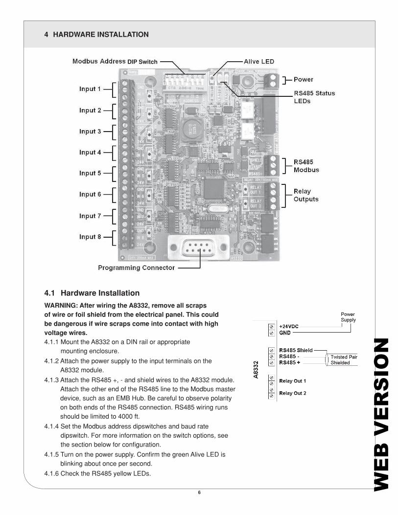
WARNING: After wiring the A8332, remove all scrapsof wire or foil shield from the electrical panel. This couldbe dangerous if wire scraps come into contact with highvoltage wires.4.1.1 Mount the A8332 on a DIN rail or appropriate
mounting enclosure.4.1.2 Attach the power supply to the input terminals on the
A8332 module.4.1.3 Attach the RS485 +, - and shield wires to the A8332 module.
Attach the other end of the RS485 line to the Modbus master device, such as an EMB Hub. Be careful to observe polarity on both ends of the RS485 connection. RS485 wiring runs should be limited to 4000 ft.
4.1.4 Set the Modbus address dipswitches and baud rate dipswitch. For more information on the switch options, see the section below for configuration.
4.1.5 Turn on the power supply. Confirm the green Alive LED is blinking about once per second.
4.1.6 Check the RS485 yellow LEDs.
6
DIP Switch
WE
B V
ER
SIO
N
4 HARDWARE INSTALLATION
- If the A8332 receives any Modbus traffic on the RS485 port, the yellow RX led should blink.- If the A8332 receives a Modbus query that is addressed to it specifically, the yellow TX LED should blink and
it will respond to the query.If you are using an EMB Hub Data Acquisition Server, the A8332 should appear in the Modbus device list after about 2 minutes at the Modbus address set in step 4.1.4. Click on the device and select “Configure” to give the A8332 a logical name. This will allow the EMB Hub to begin logging data for the device. If you are using the Leviton Configuration Console, enter the Modbus address from step 4.1.4 in the scan range field and click scan. The A8332 should appear in the device list with that Modbus address.
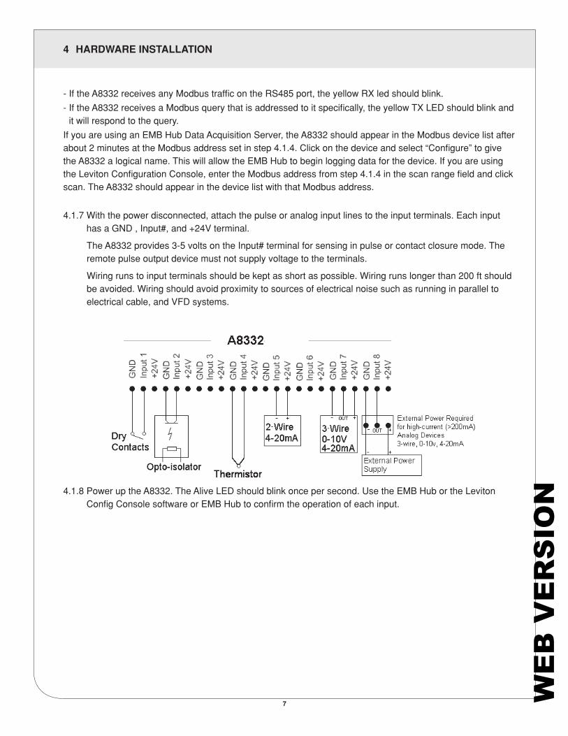
4.1.7 With the power disconnected, attach the pulse or analog input lines to the input terminals. Each input has a GND , Input#, and +24V terminal.
The A8332 provides 3-5 volts on the Input# terminal for sensing in pulse or contact closure mode. The remote pulse output device must not supply voltage to the terminals.
Wiring runs to input terminals should be kept as short as possible. Wiring runs longer than 200 ft should be avoided. Wiring should avoid proximity to sources of electrical noise such as running in parallel to electrical cable, and VFD systems.
4.1.8 Power up the A8332. The Alive LED should blink once per second. Use the EMB Hub or the Leviton Config Console software or EMB Hub to confirm the operation of each input.
7 WE
B V
ER
SIO
N
8
5 DIP SWITCH CONFIGURATION
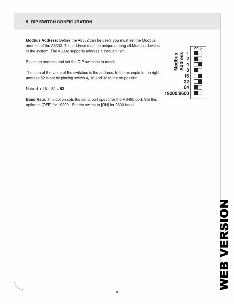
Modbus Address: Before the A8332 can be used, you must set the Modbus address of the A8332. This address must be unique among all Modbus devices in the system. The A8332 supports address 1 through 127.
Select an address and set the DIP switches to match.
The sum of the value of the switches is the address. In the example to the right, address 52 is set by placing switch 4, 16 and 32 to the on position.
Note: 4 + 16 + 32 = 52
Baud Rate: This option sets the serial port speed for the RS485 port. Set this option to [OFF] for 19200. Set the switch to [ON] for 9600 baud.
Mo
db
us
Ad
dre
ss
19200/9600
on
643216
8421
WE
B V
ER
SIO
N

6 OPERATION
9
The device will power up and be ready in a few seconds. The LEDs will blink in the following manner:
• The green “Alive” LED should start to blink approximately once per second.• The yellow RS485 TX and RX LEDs will blink for local Modbus activity.• For each input, you MUST configure the input mode register [40065 – 40072]. The mode register sets
up the input for 4-20mA, 0-10V, pulse, or resistance type sensors. The default mode is “unconfigured”. The following methods can be used to configure each input. (Choose one of the methods below)
- Use the EMB Hub device configuration page, select configure point. Pick the appropriate mode from the dropdown list. Also, you will need to configure each pulse input with a Name, Engineering Unit, and Multiplier.
- Using the Obvius Config Console software, select the A8332 from the list, and choose the input mode from the dropdown list. Be sure to click the “Save” button at the bottom of the page.
- If neither the EMB Hub or the LCC software are available, you can use any Modbus register writing software or hardware, such as ModScan32, or a PLC. Select the input mode register and write the appropraite value to that register. For a complete list of registers, and allowed mode values, review the Modbus Register Listing section toward the end of this manual.
• After configuring the input mode, the red input status LEDs will show information for each input depending on the configured mode of the input. Input status LEDs are adjacent to the corresponding input screw terminals.
- For inputs configured for pulse, pulse-kyz, and status, the LED will turn on when the contact is closed.
- For 4-20mA, 0-10V modes, the LED will show off-scale-high by blinking fast (2x second). - For 4-20mA and Resistance mode, the LED will show a broken wire alarm
with a blink-blink-off pattern. - For unconfigured inputs, the LED will be off.
WE
B V
ER
SIO
N
7 TROUBLESHOOTING
10
7.1 Pulse count input troubleshooting:
Verify the pulse output meter is connected to the GND and IN# terminals of the A8332, not the +24V terminal.
Use the LCC software or EMB Hub configuration page. Verify the specific input mode is set to Pulse, Pulse-kyz, or Status.
Check the input LED for the specific input that is not working. The LED should blink when the pulse meter closes the contact output. If the LED is not blinking, try bridging the input terminals with a short piece of wire to confirm the LED comes on. Note: if the input LED lights up when you bridge the input terminals, the problem is likely with the meter, and/or the wiring to the meter.
If the LED is always on, you may have a short in the wires leading to the pulse output meter. Try removing the wires from the A8332 input to confirm the LED turns off. If so, repeat the test with the wires attached at the A8332, and disconnected at the pulse output meter.
Try bridging the terminals at the other end of the pulse wiring run. This will confirm there are no breaks in the wire.
Verify the pulse output device is operating.
Disconnect the A8332 input and use a hand held digital meter and measure resistance of the pulse output device. Verify that the pulse output device is operational and the contact closure reads less than 1000 ohms when closed. For high resistance pulse devices such as intrinsic barriers, the “contact closure threshold” register may need to be configured to a larger value. The default is 1k however up to 2.5k is allowed. If using the LCC software or the EMB Hub data acquisition server, use the advanced configuration page of the A8332 in the Modbus/device list to set this option.
7.2 Analog 4-20mA input troubleshooting:
Verify the analog output sensor is connected to the proper terminals. For a 2 wire 4-20 mA sensor, this is typically the +24 and IN# terminals of the A8332.
Use the LCC software or EMB Hub configuration page. Verify the specific input mode is set to 4-20 mA mode.
Check the input LED for the specific input that is not working. The LED should be off for normal operation. If the sensor reads below 4mA, the LED will show a blink-blink-off pattern. If the sensor is reading above 20 mA, the LED will blink in a fast (2 Hz) pattern.
Use the LCC software to view the mA output reading for the channel.
Use a hand-held meter. Select the DC mA reading mode of the meter and wire the meter in series with the sensor output, and the A8332 input terminal. Typically, the Red/+ meter probe connects to the sensor output wire, and the Black/- meter probe connects to the IN# terminal of the A8332. Verify the mA reading on your meter matches the LCC software reading.
WE
B V
ER
SIO
N

7 TROUBLESHOOTING
11
7.3 Analog 0-10V input troubleshooting:
Verify the analog output sensor is connected to the proper terminals. For a self-powered 2 wire 0-10V sensor, this is typically the GND and IN# terminals of the A8332. For a 3-wire device that uses power supplied by the A8332, all three input wires (GND, IN# and +24V) will be used.
Use the LCC software or EMB Hub configuration page. Verify the specific input mode is set to 0-10V mode.
Check the input LED for the specific input that is not working. The LED should be off for normal operation. If the sensor is reading above 10V, the LED will blink in a fast (2Hz) pattern.
Use the LCC software to view the voltage output reading for the channel.
Use a hand-held meter. Select the DC Volts reading mode of the meter and wire the meter in parallel with the sensor output; this will use the Red/+ meter probe on the IN# terminal and the Black/- meter probe on the GND terminal. Verify the voltage reading on your meter matches the LCC software reading.
WE
B V
ER
SIO
N
8 MODBUS REGISTERS
12
8.1 Modbus Functions
8.1.1 Modbus Functions: The A8332 responds to the following Modbus/RTU functions: • function 0x11 Report slave ID. • function 0x03 read holding registers (multiple) • function 0x06 preset single register All Modbus registers are read-only unless otherwise noted. Registers listed as “NV” are options that are stored in non-volatile memory and will be preserved when power is removed from the device.
8.1.2 Input Modes: Each of the 8 inputs has several different modes (4-20 mA, 0-10V, pulse, etc) The following sections list the purpose of each of the Modbus registers depending on the selected mode.
8.1.3 Mode Register value: The value of the mode register (40065 - 40072) controls the mode of the input (volts, pulse, etc). Users may write to the mode register, and it will be stored in non-volatile memory. Note however that the preferred operation is to use the LCC tool or the A8812 EMB Hub web page interface to configure the input mode.
0 = unconfigured (return 0xFFFF for all registers associated with this input). 1 = reserved.2 = Analog current mode, 4-20mA range. 3 = voltage mode, 0-10V range.4 = resistance mode, as ohms measured. 0-10mohm range.5 = contact closure mode, reports closure count and dutycycle. 6 = pulse counter input. (standard) counts contact closures only. 7 = pulse counter input. (KYZ mode) counts closure and open.
8.1.4 Pulse Mode: Count: the number of pulses counted on the input port. In standard mode, the pulse is counted on the closure of the contact. If the KYZ option is enabled, both the closure and opening of the pulse are counted. The maximum pulse rate to be able to count is 10 Hz. Expect pulse width to be minimum of 20ms. The pulse count starts at zero (factory default) and always increments as pulses are counted. Rollover at 2^32 (approx 4.3 billion). Count is stored in non-volatile memory. The pulse count cannot be reset to zero.
Rate-inst: This register reports the instantaneous rate of pulses received on the input, calculated based on the time the last N pulses were received. For example, if the pulse rate is 2 Hz, and N is 5, then 5 pulses will be received in 10 seconds, and the rate-inst value will return 10. N is user selectable from 2 to 20. Note: as the value of rate-inst increases, the pulse rate it represents decreases. thus, a value of 20(seconds) represents a pulse rate that is 1/2 of a 10s value. If the pulse rate is very fast such that rate-inst < N the value of rate-inst will be unusable due to the granularity of the measurement. This should be handled as off-scale-high by the Modbus master system. To properly handle this situation, reconfigure the pulse output meter with a slower pulse rate using a larger multiplier. The rate-inst register will report 65535 when off-scale-low. When reading large values from rate-inst, it is advisable to handle numbers as off-scale-low when the number of seconds exceeds the data logging interval.
WE
B V
ER
SIO
N
8 MODBUS REGISTERS
13
Rate-min: The minimum rate value as measured in rate-inst. Note: the minimum rate is actually the largest count of seconds seen in rate-inst.Rate-max: The maximum rate value as measured in rate-inst. Note: the maximum rate is actually the smallest count of seconds seen in rate-inst.
* Clear min/max (register 41021): The Modbus registers for rate-inst, rate-min and rate-max may be cleared by writing to a Modbus register. It is assumed that these three fields will be cleared at the beginning of each new logging period by the Modbus master device. In pulse mode, clearing the inst register does not clear the pulse count history. The fields for inst/min/max will be valid after only one pulse value is received.
* Average rate: (not an A8332 datapoint) The EMB Hub will compute an average rate for the pulse count input. The calculation will be performed at the end of each logging cycle by subtracting the count at the start and end of the interval and dividing by the interval length. (DV/DT). This will provide the average rate over the log interval. If the unit of measure is power related, (kwh, kvarh, kvah, etc) the average rate will be called “demand” as it is the effective block demand value for the input. Because the rate value is not a Modbus register, Modbus master devices must use the “count” register and compute the average rate value.
8.1.5 Status Mode: Count: the number of pulses counted on the input port. In standard mode, the pulse is counted on the closure of the contact. If the KYZ option is enabled, both the closure and opening of the pulse are counted. The maximum pulse rate to be able to count is 10 Hz. Expect pulse width to be minimum of 20ms.
On-time: the cumulative number of seconds the contacts have been closed. The pulse count starts at zero (factory default) and always increments as pulses are counted. Rollover at 2^32 (over 130 years). Count is stored in non-volatile memory. This value has 1 second granularity, rounding is performed by sampling the input once per second and accumulating 1 second if the contact is closed at that time. For practical applications, the pulse width should be a minimum of 1 second.
Dutycycle: The ratio of time the contact is closed vs open. For example, if the contact is closed for 10 seconds and open for 30, the duty cycle register will report 25%. The register value returned must be divided by 1000 to convert it to a percentage with three decimal places.
Status: returns 1 if the contact is presently closed, 0 if the contact is presently open.
* Clear min/max (register 41021): the only value cleared in status mode is the duty cycle field. The data logger will clear this field at the beginning of each log period. The duty cycle register will be used to calculate the duty cycle for one log period only.
WE
B V
ER
SIO
N
8 MODBUS REGISTERS
14
8.1.6 Voltage Mode, Current Mode, Resistance Mode: (all 3 modes are the same unless otherwise noted)
Instantaneous: The instantaneous reading will report the present status of the input, represented in ohms, mA, or volts. The value uses a short-term average of the last 16 A/D converter readings to compute the value of this register. In voltage and current mode, the instantaneous value is calculated several times per second. In resistance mode, the value is calculated at least every two seconds. 0xFFFFFFFF will report an off-scale-high condition, or any other invalid data.
Average: This register reports the longer-term average of the input. Each time a short-term average is calculated with all-new samples, the value is added to the cumulative average. This value should be reset using the clear min/max register at least once per hour. If not cleared, it will eventually start a moving average after memory storage is exceeded. The EMB Hub will clear this register at the start of each data logging period.
min: the minimum value seen in the instantaneous register.max: the maximum value seen in the instantaneous register.
* Multipliers: The register value for inst, average, min, and max must be divided by 1000 to convert the number to mA and Volts. Volts mode reports 0 to 10.000 V. Current mode reports 0 to 20.000 mA. In resistor mode value is reported in ohms and no division is required. Note: in current mode, the broken-wire register 40074 is set when the input goes below 4 mA, however the current value reading will still be shown in the data register. Modbus master systems should typically discard readings below 4 mA as broken-wire/invalid when reading a 4-20 mA sensor.
* Clear min/max (register 41021): This register clears the values for average, min, and max. The historical accumulation of samples for the average field will be cleared, and average, min, max will be set to the present instantaneous value after the next instantaneous value is recalculated.
WE
B V
ER
SIO
N
8 MODBUS REGISTERS
15
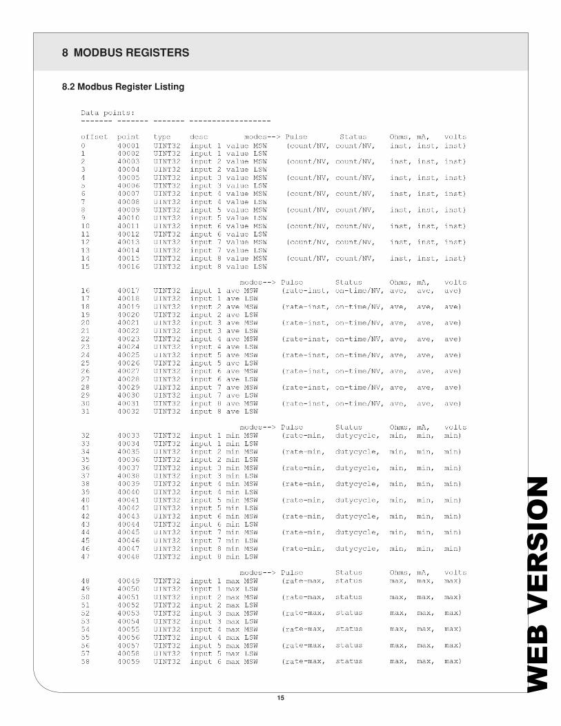
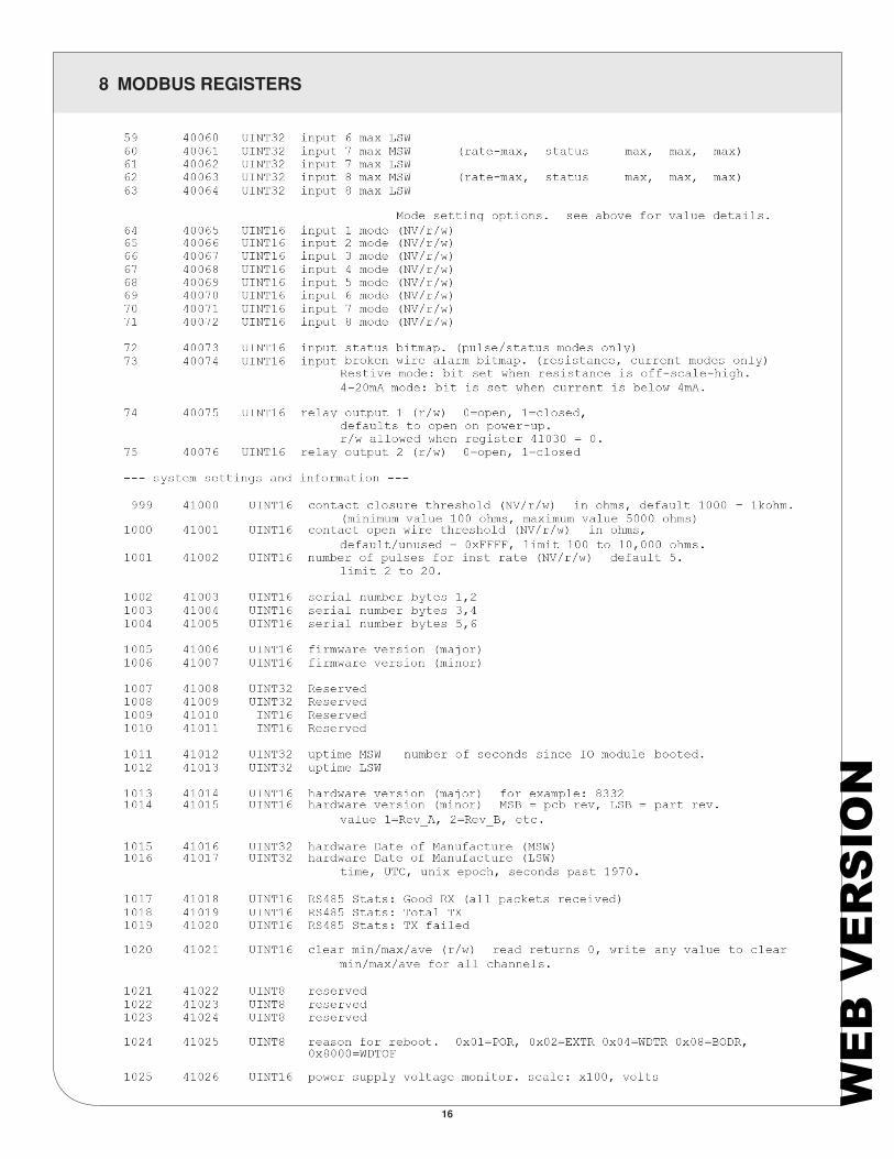
8.2 Modbus Register Listing
WE
B V
ER
SIO
N
8 MODBUS REGISTERS
16
WE
B V
ER
SIO
N
8 MODBUS REGISTERS
17
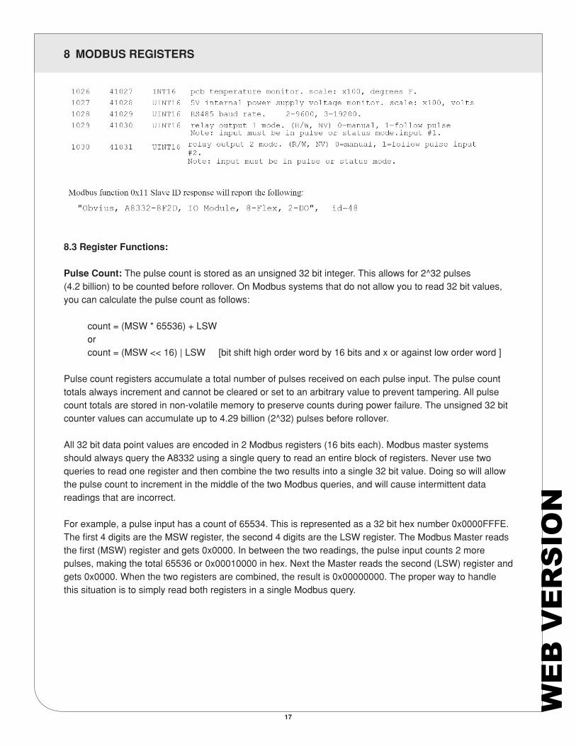
8.3 Register Functions:
Pulse Count: The pulse count is stored as an unsigned 32 bit integer. This allows for 2^32 pulses (4.2 billion) to be counted before rollover. On Modbus systems that do not allow you to read 32 bit values, you can calculate the pulse count as follows:
count = (MSW * 65536) + LSW or count = (MSW << 16) | LSW [bit shift high order word by 16 bits and x or against low order word ]
Pulse count registers accumulate a total number of pulses received on each pulse input. The pulse count totals always increment and cannot be cleared or set to an arbitrary value to prevent tampering. All pulse count totals are stored in non-volatile memory to preserve counts during power failure. The unsigned 32 bit counter values can accumulate up to 4.29 billion (2^32) pulses before rollover.
All 32 bit data point values are encoded in 2 Modbus registers (16 bits each). Modbus master systems should always query the A8332 using a single query to read an entire block of registers. Never use two queries to read one register and then combine the two results into a single 32 bit value. Doing so will allow the pulse count to increment in the middle of the two Modbus queries, and will cause intermittent data readings that are incorrect.
For example, a pulse input has a count of 65534. This is represented as a 32 bit hex number 0x0000FFFE. The first 4 digits are the MSW register, the second 4 digits are the LSW register. The Modbus Master reads the first (MSW) register and gets 0x0000. In between the two readings, the pulse input counts 2 more pulses, making the total 65536 or 0x00010000 in hex. Next the Master reads the second (LSW) register and gets 0x0000. When the two registers are combined, the result is 0x00000000. The proper way to handle this situation is to simply read both registers in a single Modbus query.
WE
B V
ER
SIO
N
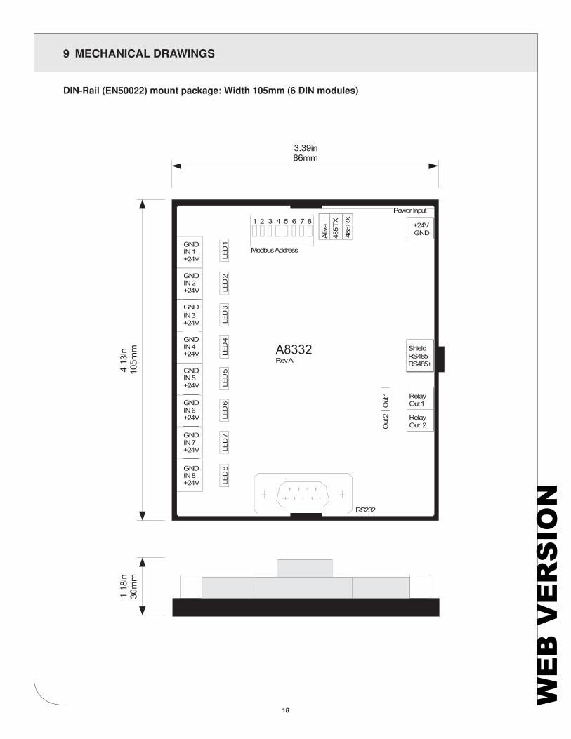
9 MECHANICAL DRAWINGS
18
DIN-Rail (EN50022) mount package: Width 105mm (6 DIN modules)
3.39in 86mm
Aliv
e 48
5 TX
485 R
X
LED
3
LED
4
LED
5
LED
6
LED
7
LED
8
1.18
in
30m
m
4.13
in
105m
m
Out
2
Out
1
LED
1
LED
2
WE
B V
ER
SIO
N

10 WARRANTY AND CONTACT INFORMATION
19
FOR CANADA ONLY
For warranty information and/or product returns, residents of Canada should contact Leviton in writing at Leviton Manufacturing of Canada ULC to the attention of the Quality Assurance Department, 165 Hymus Blvd, Pointe-Claire (Quebec), Canada H9R 1E9 or by telephone at 1 800 405-5320.
For Technical Assistance Call: 1-800-824-3005 (USA Only) or 1-800-405-5320 (Canada Only) www.leviton.com
LIMITED 5 YEAR WARRANTY AND EXCLUSIONSLeviton warrants to the original consumer purchaser and not for the benefit of anyone else that this product at the time of its sale by Leviton is free of defects in materials and workmanship under normal and proper use for five years from the purchase date. Leviton’s only obligation is to correct such defects by repair or replacement, at its option. For details visit www.leviton.com or call 1-800-824-3005. This warranty excludes and there is disclaimed liability for labor for removal of this product or reinstallation. This warranty is void if this product is installed improperly or in an improper environment, overloaded, misused, opened, abused, or altered in any manner, or is not used under normal operating conditions or not in accordance with any labels or instructions. There are no other or implied warranties of any kind, including merchantability and fitness for a particular purpose, but if any implied warranty is required by the applicable jurisdiction, the duration of any such implied warranty, including merchantability and fitness for a particular purpose, is limited to five years. Leviton is not liable for incidental, indirect, special, or consequential damages, including without limitation, damage to, or loss of use of, any equipment, lost sales or profits or delay or failure to perform this warranty obligation. The remedies provided herein are the exclusive remedies under this warranty, whether based on contract, tort or otherwise.
FCC STATEMENT:
This equipment has been tested and found to comply with the limits for a Class A digital device, pursuant to part 15 of the FCC Rules. These limits are designed to provide reasonable protection against harmful interference when the equipment is operated in a commercial environment. This equipment generates, uses, and can radiate radio frequency energy and, if not installed and used in accordance with the instruction manual, may cause harmful interference to radio communications. Operation of this equipment in a residential area is likely to cause harmful interference in which case the user will be required to correct the interference at his own expense.
Any changes or modifications not expressly approved by Leviton Manufacturing Co., could void the user’s authority to operate the equipment
TRADEMARK DISCLAIMER:
Use herein of third party trademarks, service marks, trade names, brand names and/or product names are for informational purposes only, are/may be the trademarks of their respective owners; such use is not meant to imply affiliation, sponsorship, or endorsement. EMB Hub is a trademark of Leviton Manufacturing Co., Inc. Modbus is a U.S. registered trademark of Schneider Electric USA, Inc. Belden is a trademark of Belden, Inc.
FCC SUPPLIERS DECLARATION OF CONFORMITY:
Model A8332 manufactured by Obvius Holdings, LLC, 20497 SW Teton Avenue, Tualatin, OR 97062, www.obvius.com. This device complies with part 15 of the FCC Rules. Operation is subject to the following two conditions: (1) This device may not cause harmful interference, and (2) this device must accept any interference received, including interference that may cause undesired operation.
IC STATEMENT:
This device complies with Industry Canada license-exempt RSS standard(s). Operation is subject to the following two conditions: (1) this device may not cause interference, and (2) this device must accept any interference, including interference that may cause undesired operation of the device.
Leviton Manufacturing Co., Inc.
201 North Service Road, Melville, NY 11747
Visit Leviton’s Web site at www.leviton.com
© 2021 Leviton Manufacturing Co., Inc. All rights reserved.
Specifications and price subject to change at any time without notice.
WE
B V
ER
SIO
N

WE
B V
ER
SIO
N