A Bioinspired 10 DOF Wearable Powered Arm Exoskeleton for Rehabilitation
Upload
independentCategory
view
2download
0
http://ijr.sagepub.com
Research The International Journal of Robotics
DOI: 10.1177/0278364907084261 2008; 27; 233 The International Journal of Robotics Research
Abhishek Gupta, Marcia K. O'Malley, Volkan Patoglu and Charles Burgar Rehabilitation and Training
A Force Feedback Wrist Exoskeleton forRiceWrist:Design, Control and Performance of
http://ijr.sagepub.com/cgi/content/abstract/27/2/233 The online version of this article can be found at:
Published by:
http://www.sagepublications.com
On behalf of:
Multimedia Archives
can be found at:The International Journal of Robotics Research Additional services and information for
http://ijr.sagepub.com/cgi/alerts Email Alerts:
http://ijr.sagepub.com/subscriptions Subscriptions:
http://www.sagepub.com/journalsReprints.navReprints:
http://www.sagepub.co.uk/journalsPermissions.navPermissions:
http://ijr.sagepub.com/cgi/content/refs/27/2/233 Citations
at RICE UNIV on April 14, 2009 http://ijr.sagepub.comDownloaded from
Abhishek GuptaMarcia K. O’MalleyDepartment of Mechanical Engineering and Materials ScienceRice University, Houston, TX 77005, USA{abhi,omalleym}@rice.edu
Volkan PatogluFaculty of Engineering and Natural SciencesSabanc� UniversityTuzla, �Istanbul 34956, [email protected]
Charles Burgar, MDCTVHCS, Temple, TX 76504, [email protected]
Design, Control andPerformance ofRiceWrist: A ForceFeedback WristExoskeleton forRehabilitation andTraining
Abstract
This paper presents the design, control and performance of a highfidelity four degree-of-freedom wrist exoskeleton robot, RiceWrist,for training and rehabilitation. The RiceWrist is intended to providekinesthetic feedback during the training of motor skills or rehabilita-tion of reaching movements. Motivation for such applications is basedon findings that show robot-assisted physical therapy aids in the re-habilitation process following neurological injuries. The exoskeletondevice accommodates forearm supination and pronation, wrist flexionand extension and radial and ulnar deviation in a compact parallelmechanism design with low friction, zero backlash and high stiffness.As compared to other exoskeleton devices, the RiceWrist allows easymeasurement of human joint angles and independent kinesthetic feed-back to individual human joints. In this paper, joint-space as well astask-space position controllers and an impedance-based force con-troller for the device are presented. The kinematic performance of thedevice is characterized in terms of its workspace, singularities, ma-nipulability, backlash and backdrivability. The dynamic performanceof RiceWrist is characterized in terms of motor torque output, jointfriction, step responses, behavior under closed loop set-point and tra-jectory tracking control and display of virtual walls. The device issingularity-free, encompasses most of the natural workspace of thehuman joints and exhibits low friction, zero-backlash and high ma-nipulability, which are kinematic properties that characterize a high-quality impedance display device. In addition, the device displays
The International Journal of Robotics ResearchVol. 27, No. 2, February 2008, pp. 233–251DOI: 10.1177/0278364907084261c�SAGE Publications 2008 Los Angeles, London, New Delhi and SingaporeFigures 2, 9–28 appear in color online: http://ijr.sagepub.com
fast, accurate response under position control that matches humanactuation bandwidth and the capability to display sufficiently hardcontact with little coupling between controlled degrees-of-freedom.
KEY WORDS—rehabilitation robotics, medical robots andsystems, mechanism design, haptics and haptic interfaces,physical human-robot interaction
1. Introduction
The ability to interact mechanically with virtual objectsthrough incorporation of haptic feedback allows users to ma-nipulate objects in the simulated or remote environment withease when compared to a purely visual display. Added advan-tages of haptic simulators include increased repeatability, scal-ability, safety and control over environmental conditions. It isalso possible to simulate additional physical forces, which mayor may not be part of a natural environment, in order to conveyinformation to the user. This makes a haptic display suitablefor a variety of applications such as remote operation in haz-ardous environments, simulators for surgical training (Basdo-gan et al. 2001� Feygin et al. 2002� Carignan and Akin 2003)and rehabilitation research (Todorov et al. 1997� Prisco et al.1998� Jack et al. 2001� Sveistrup 2004). Physical therapy uti-lizing the resistance offered to a user’s motion during haptic in-teraction can be used for rehabilitation of impaired arm move-ments in patients. Furthermore, research has shown that aug-mented feedback presented in virtual environments acceleratesthe learning of motor tasks (Todorov et al. 1997).
In 2003, 700 000 persons in the United States suffered acerebral vascular accident (CVA) or stroke, with the total num-
233
at RICE UNIV on April 14, 2009 http://ijr.sagepub.comDownloaded from
234 THE INTERNATIONAL JOURNAL OF ROBOTICS RESEARCH / February 2008
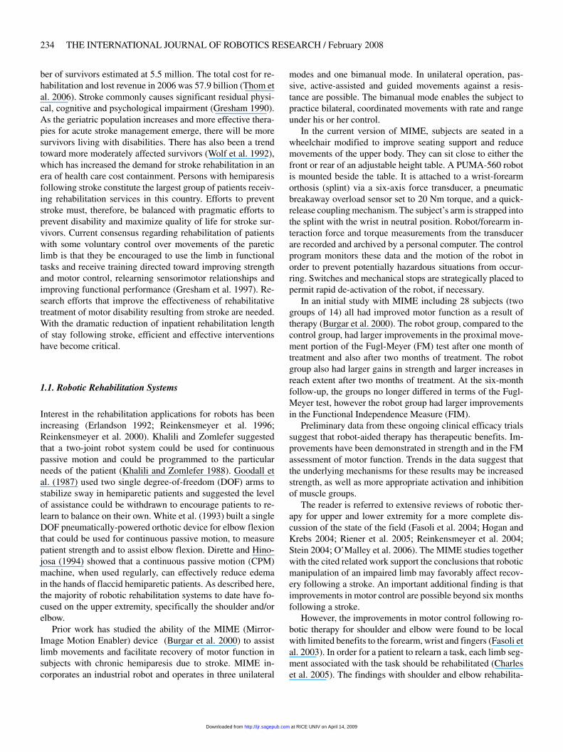
ber of survivors estimated at 5.5 million. The total cost for re-habilitation and lost revenue in 2006 was 57�9 billion (Thom etal. 2006). Stroke commonly causes significant residual physi-cal, cognitive and psychological impairment (Gresham 1990).As the geriatric population increases and more effective thera-pies for acute stroke management emerge, there will be moresurvivors living with disabilities. There has also been a trendtoward more moderately affected survivors (Wolf et al. 1992),which has increased the demand for stroke rehabilitation in anera of health care cost containment. Persons with hemiparesisfollowing stroke constitute the largest group of patients receiv-ing rehabilitation services in this country. Efforts to preventstroke must, therefore, be balanced with pragmatic efforts toprevent disability and maximize quality of life for stroke sur-vivors. Current consensus regarding rehabilitation of patientswith some voluntary control over movements of the pareticlimb is that they be encouraged to use the limb in functionaltasks and receive training directed toward improving strengthand motor control, relearning sensorimotor relationships andimproving functional performance (Gresham et al. 1997). Re-search efforts that improve the effectiveness of rehabilitativetreatment of motor disability resulting from stroke are needed.With the dramatic reduction of inpatient rehabilitation lengthof stay following stroke, efficient and effective interventionshave become critical.
1.1. Robotic Rehabilitation Systems
Interest in the rehabilitation applications for robots has beenincreasing (Erlandson 1992� Reinkensmeyer et al. 1996�Reinkensmeyer et al. 2000). Khalili and Zomlefer suggestedthat a two-joint robot system could be used for continuouspassive motion and could be programmed to the particularneeds of the patient (Khalili and Zomlefer 1988). Goodall etal. (1987) used two single degree-of-freedom (DOF) arms tostabilize sway in hemiparetic patients and suggested the levelof assistance could be withdrawn to encourage patients to re-learn to balance on their own. White et al. (1993) built a singleDOF pneumatically-powered orthotic device for elbow flexionthat could be used for continuous passive motion, to measurepatient strength and to assist elbow flexion. Dirette and Hino-josa (1994) showed that a continuous passive motion (CPM)machine, when used regularly, can effectively reduce edemain the hands of flaccid hemiparetic patients. As described here,the majority of robotic rehabilitation systems to date have fo-cused on the upper extremity, specifically the shoulder and/orelbow.
Prior work has studied the ability of the MIME (Mirror-Image Motion Enabler) device (Burgar et al. 2000) to assistlimb movements and facilitate recovery of motor function insubjects with chronic hemiparesis due to stroke. MIME in-corporates an industrial robot and operates in three unilateral
modes and one bimanual mode. In unilateral operation, pas-sive, active-assisted and guided movements against a resis-tance are possible. The bimanual mode enables the subject topractice bilateral, coordinated movements with rate and rangeunder his or her control.
In the current version of MIME, subjects are seated in awheelchair modified to improve seating support and reducemovements of the upper body. They can sit close to either thefront or rear of an adjustable height table. A PUMA-560 robotis mounted beside the table. It is attached to a wrist-forearmorthosis (splint) via a six-axis force transducer, a pneumaticbreakaway overload sensor set to 20 Nm torque, and a quick-release coupling mechanism. The subject’s arm is strapped intothe splint with the wrist in neutral position. Robot/forearm in-teraction force and torque measurements from the transducerare recorded and archived by a personal computer. The controlprogram monitors these data and the motion of the robot inorder to prevent potentially hazardous situations from occur-ring. Switches and mechanical stops are strategically placed topermit rapid de-activation of the robot, if necessary.
In an initial study with MIME including 28 subjects (twogroups of 14) all had improved motor function as a result oftherapy (Burgar et al. 2000). The robot group, compared to thecontrol group, had larger improvements in the proximal move-ment portion of the Fugl-Meyer (FM) test after one month oftreatment and also after two months of treatment. The robotgroup also had larger gains in strength and larger increases inreach extent after two months of treatment. At the six-monthfollow-up, the groups no longer differed in terms of the Fugl-Meyer test, however the robot group had larger improvementsin the Functional Independence Measure (FIM).
Preliminary data from these ongoing clinical efficacy trialssuggest that robot-aided therapy has therapeutic benefits. Im-provements have been demonstrated in strength and in the FMassessment of motor function. Trends in the data suggest thatthe underlying mechanisms for these results may be increasedstrength, as well as more appropriate activation and inhibitionof muscle groups.
The reader is referred to extensive reviews of robotic ther-apy for upper and lower extremity for a more complete dis-cussion of the state of the field (Fasoli et al. 2004� Hogan andKrebs 2004� Riener et al. 2005� Reinkensmeyer et al. 2004�Stein 2004� O’Malley et al. 2006). The MIME studies togetherwith the cited related work support the conclusions that roboticmanipulation of an impaired limb may favorably affect recov-ery following a stroke. An important additional finding is thatimprovements in motor control are possible beyond six monthsfollowing a stroke.
However, the improvements in motor control following ro-botic therapy for shoulder and elbow were found to be localwith limited benefits to the forearm, wrist and fingers (Fasoli etal. 2003). In order for a patient to relearn a task, each limb seg-ment associated with the task should be rehabilitated (Charleset al. 2005). The findings with shoulder and elbow rehabilita-
at RICE UNIV on April 14, 2009 http://ijr.sagepub.comDownloaded from
Gupta, O’Malley, Patoglu, and Burgar / A Force Feedback Wrist Exoskeleton for Rehabilitation and Training 235
tion motivate the extension of robotic-assisted rehabilitationdistally for the upper extremity, so that forearm pronation-supination, wrist flexion-extension, radial-ulnar deviation andultimately digital manipulation are enabled. Several deviceshave been presented in the literature to achieve at least a sub-set of these movements. For example, Charles et al. (2005)have developed an extension of the MIT-MANUS system toprovide three rotational degrees-of-freedom for wrist rehabil-itation. Hesse et al. (2003) have also extended the utility oftheir arm trainer to include wrist motion. In order to improvethe applicability of the MIME system for full arm rehabilita-tion post stroke, the authors have developed the RiceWrist, amodification of the MAHI exoskeleton (Gupta and O’Malley2006� Sledd and O’Malley 2006), which interfaces with MIMEand provides a variety of interaction modes for the therapist toselect for the patient.
2. Design of the RiceWrist
The RiceWrist is an electrically actuated forearm and wristhaptic exoskeleton device that has been designed for rehabili-tation applications. The kinematic design of the RiceWrist al-lows for the reproduction of most of the natural human wristand forearm workspace, force isotropy and high torque out-put levels required during robot-aided training and/or rehabil-itation. Another important feature of the design is the align-ment of the axes of rotation of human joints with the con-trolled degrees-of-freedom of the exoskeleton. The problem ofmeasurement of arm position is thus reduced to the solutionof the exoskeleton kinematics, with no further transformationsrequired. This makes it possible to actuate the robot to con-trol feedback to a specific human joint, for example to con-strain the forearm rotation during wrist rehabilitation, withoutaffecting other joints.
Robot-aided rehabilitation typically requires the use ofvirtual force fields for guidance or active assistance. TheRiceWrist has high force output bandwidth, low backlash, low-friction, high backdrivability, high structural stiffness and asingularity free workspace, features characteristic of a highfidelity haptic interface. The forward and inverse kinematicsof the robot can be solved uniquely at each point, thus makingthe measurement of arm position and force feedback to indi-vidual arm joints possible at high update rates.
The RiceWrist design extends from prior work by someof the authors. A thorough discussion of specific design con-siderations for the original MAHI exoskeleton and how eachwas addressed can be found in O’Malley (2006). The re-design of the MAHI exoskeleton, discussed by Sledd andO’Malley (2006), successfully addresses the limitations of theoriginal device design. This paper discusses the design of theRiceWrist, and presents joint-space as well as task-space po-sition controllers and an impedance-based force controller forthe device.
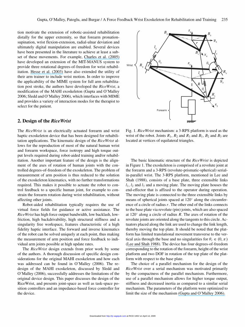
Fig. 1. RiceWrist mechanism: a 3-RPS platform is used as thewrist of the robot. Joints R1, R2 and R3 and B1, B2 and B3 arelocated at vertices of equilateral triangles.
The basic kinematic structure of the RiceWrist is depictedin Figure 1. The exoskeleton is comprised of a revolute joint atthe forearm and a 3-RPS (revolute-prismatic-spherical) serial-in-parallel wrist. The 3-RPS platform, mentioned in Lee andShah (1988), consists of a base plate, three extensible linksl1, l2 and l3 and a moving plate. The moving plate houses theend-effector that is affixed to the operator during operation.The moving plate is connected to the three extensible links bymeans of spherical joints spaced at 120� along the circumfer-ence of a circle of radius r . The other end of the links connectsto the base plate via revolute (pin) joints, which are also spacedat 120� along a circle of radius R. The axes of rotation of therevolute joints are oriented along the tangents to this circle. Ac-tuators placed along the link are used to change the link length,thereby moving the top plate. It should be noted that the plat-form has limited translational movement transverse to the ver-tical axis through the base and no singularities for � i � �0� ��(Lee and Shah 1988). The device has four degrees-of-freedomcorresponding to the rotation of the forearm, height of the wristplatform and two DOF in rotation of the top plate of the plat-form with respect to the base plate.
The choice of a parallel mechanism for the design of theRiceWrist over a serial mechanism was motivated primarilyby the compactness of the parallel mechanism. Furthermore,use of a parallel mechanism allows for higher torque output,stiffness and decreased inertia as compared to a similar serialmechanism. The parameters of the platform were optimized tolimit the size of the mechanism (Gupta and O’Malley 2006).
at RICE UNIV on April 14, 2009 http://ijr.sagepub.comDownloaded from
236 THE INTERNATIONAL JOURNAL OF ROBOTICS RESEARCH / February 2008
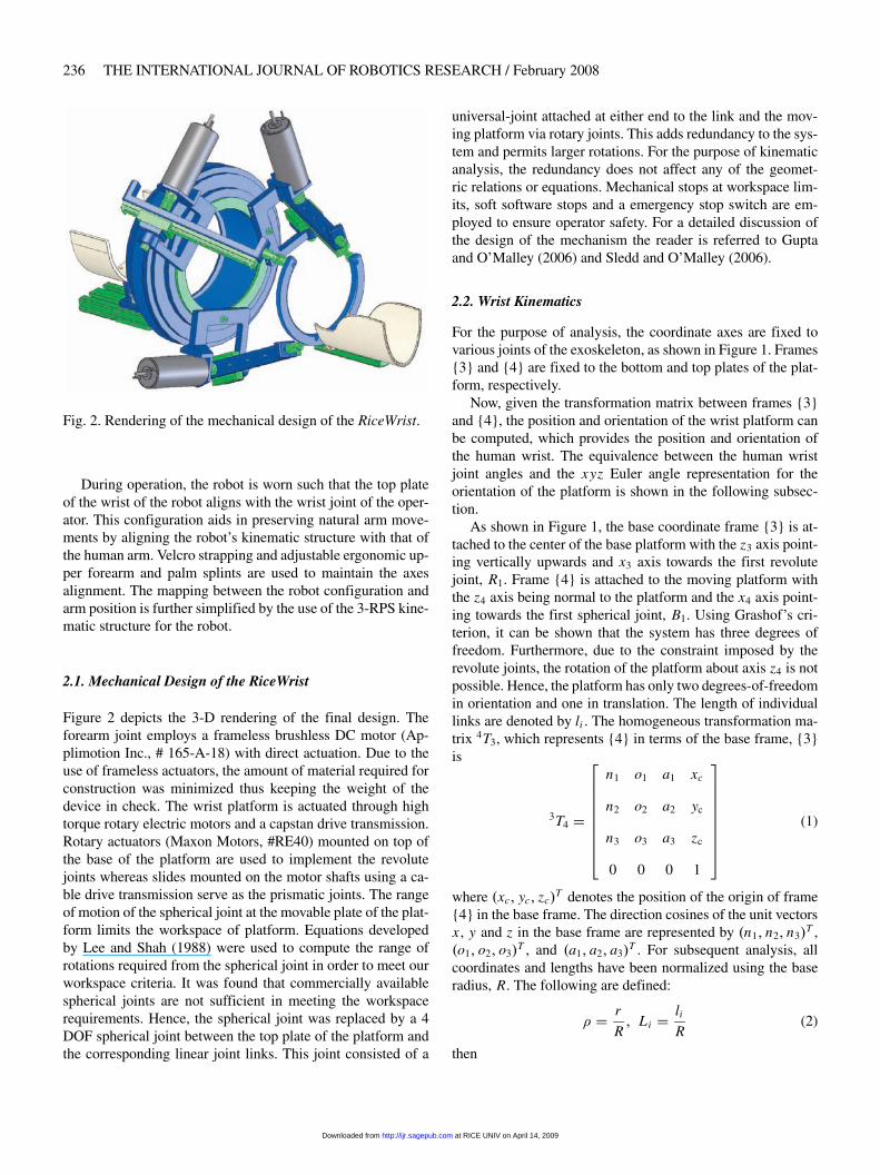
Fig. 2. Rendering of the mechanical design of the RiceWrist.
During operation, the robot is worn such that the top plateof the wrist of the robot aligns with the wrist joint of the oper-ator. This configuration aids in preserving natural arm move-ments by aligning the robot’s kinematic structure with that ofthe human arm. Velcro strapping and adjustable ergonomic up-per forearm and palm splints are used to maintain the axesalignment. The mapping between the robot configuration andarm position is further simplified by the use of the 3-RPS kine-matic structure for the robot.
2.1. Mechanical Design of the RiceWrist
Figure 2 depicts the 3-D rendering of the final design. Theforearm joint employs a frameless brushless DC motor (Ap-plimotion Inc., # 165-A-18) with direct actuation. Due to theuse of frameless actuators, the amount of material required forconstruction was minimized thus keeping the weight of thedevice in check. The wrist platform is actuated through hightorque rotary electric motors and a capstan drive transmission.Rotary actuators (Maxon Motors, #RE40) mounted on top ofthe base of the platform are used to implement the revolutejoints whereas slides mounted on the motor shafts using a ca-ble drive transmission serve as the prismatic joints. The rangeof motion of the spherical joint at the movable plate of the plat-form limits the workspace of platform. Equations developedby Lee and Shah (1988) were used to compute the range ofrotations required from the spherical joint in order to meet ourworkspace criteria. It was found that commercially availablespherical joints are not sufficient in meeting the workspacerequirements. Hence, the spherical joint was replaced by a 4DOF spherical joint between the top plate of the platform andthe corresponding linear joint links. This joint consisted of a
universal-joint attached at either end to the link and the mov-ing platform via rotary joints. This adds redundancy to the sys-tem and permits larger rotations. For the purpose of kinematicanalysis, the redundancy does not affect any of the geomet-ric relations or equations. Mechanical stops at workspace lim-its, soft software stops and a emergency stop switch are em-ployed to ensure operator safety. For a detailed discussion ofthe design of the mechanism the reader is referred to Guptaand O’Malley (2006) and Sledd and O’Malley (2006).
2.2. Wrist Kinematics
For the purpose of analysis, the coordinate axes are fixed tovarious joints of the exoskeleton, as shown in Figure 1. Frames{3} and {4} are fixed to the bottom and top plates of the plat-form, respectively.
Now, given the transformation matrix between frames {3}and {4}, the position and orientation of the wrist platform canbe computed, which provides the position and orientation ofthe human wrist. The equivalence between the human wristjoint angles and the xyz Euler angle representation for theorientation of the platform is shown in the following subsec-tion.
As shown in Figure 1, the base coordinate frame {3} is at-tached to the center of the base platform with the z3 axis point-ing vertically upwards and x3 axis towards the first revolutejoint, R1. Frame {4} is attached to the moving platform withthe z4 axis being normal to the platform and the x4 axis point-ing towards the first spherical joint, B1. Using Grashof’s cri-terion, it can be shown that the system has three degrees offreedom. Furthermore, due to the constraint imposed by therevolute joints, the rotation of the platform about axis z4 is notpossible. Hence, the platform has only two degrees-of-freedomin orientation and one in translation. The length of individuallinks are denoted by li . The homogeneous transformation ma-trix 4T3, which represents {4} in terms of the base frame, {3}is
3T4 �
���������
n1 o1 a1 xc
n2 o2 a2 yc
n3 o3 a3 zc
0 0 0 1
���������
(1)
where �xc� yc� zc�T denotes the position of the origin of frame
{4} in the base frame. The direction cosines of the unit vectorsx , y and z in the base frame are represented by �n1� n2� n3�
T ,�o1� o2� o3�
T , and �a1� a2� a3�T . For subsequent analysis, all
coordinates and lengths have been normalized using the baseradius, R. The following are defined:
� � r
R� Li � li
R(2)
then
at RICE UNIV on April 14, 2009 http://ijr.sagepub.comDownloaded from
Gupta, O’Malley, Patoglu, and Burgar / A Force Feedback Wrist Exoskeleton for Rehabilitation and Training 237
Xc � xc
R� Yc � yc
R� Zc � zc
R� (3)
2.2.1. Forward Kinematics
The forward kinematics for the platform involves solving si-multaneous equations for the position and orientation of themovable platform in terms of the given link lengths. The factthat the manipulator is essentially a structure for fixed lengthshas been used to derive these equations. If � i is the angle be-tween link Ri Bi and the base, then the coordinates of the spher-ical joints with respect to the base frame are
3 B1 �
�����
1� L1 cos �1
0
L1 sin��1�
����� �
3 B2 �
��������
�1
2�1� L2 cos �2�
�3
2�1� L2 cos �2�
L2 sin��2�
���������
3 B3 �
��������
�1
2�1� L3 cos �3�
��3
2�1� L3 cos �3�
L3 sin��3�
��������� (4)
The distance between any two spherical joints,�
3 r , can beused to implicitly relate � i to Li . This leads to three constraintequations given as
L21 � L2
2 � 3� 3�2 � L1L2 cos �1 cos �2
� 2L1L2 sin �1 sin �2 � 3L1 cos �1 � 3L2 cos �2 � 0�(5)
L23 � L2
2 � 3� 3�2 � L3L2 cos �3 cos �2
� 2L3L2 sin �3 sin �2 � 3L3 cos �3 � 3L2 cos �2 � 0�(6)
L21 � L2
3 � 3� 3�2 � L1L3 cos �1 cos �3
� 2L1L3 sin �1 sin �3 � 3L1 cos �1 � 3L3 cos �3 � 0�(7)
Multiple solutions of �1, �2 and �3 for a given set of linklengths are possible. A further mathematical constraint
0� � � i � 180�
ensures uniqueness. In other words, position zc for the plat-form must always be positive, i.e. the moving platform should
always move on one side of the base platform: a physical con-straint. With this constraint, equations (5)–(7) can be solvednumerically for � i .
As the spherical joints are placed at the vertices of an equi-lateral triangle, the Cartesian position of the origin of the mov-ing frame {4}, which is the centroid of the triangle, can becalculated.
The Cartesian position of the spherical joints can be ex-pressed as �
� 4 Bi
1
�� � 4T3
�� 3 Bi
1
�� � (8)
Equations (8) and (4) can be solved to determine the vec-tors n, o and a and hence the orientation of the platform. Oncethe transformation matrix T is known, the orientation of theplatform in terms of xyz-Euler angles, , and � , can be de-termined using
� sin�1�n3�� � atan2
� �o3
cos���
a3
cos��
��
� � atan2
� �n2
cos���
n1
cos��
��
It should be noted that if � �90�, and � become in-determinate. In addition, the top plate of the platform cannotrotate about z4 and hence � � 0 in general. For a detailed dis-cussion of forward kinematics, refer to Gupta and O’Malley(2006).
2.2.2. Inverse Kinematics
As the moving platform has three degrees-of-freedom, its po-sition can be defined in terms of the first two xyz-Euler angles, and , and one Cartesian coordinate, Zc. As the links R1 B1,R2 B2 and R3 B3 are constrained by the revolute joints to movein the planes y � 0� y � ��3 and y � �
3x , respectively,using equation (8) we have
n2� � Yc � 0� Xc � �
n1 � o2�
Now, � � 0 as the top plate of the platform cannot rotateabout z4. Hence, Xc, Yc and � can be easily solved. The orien-tation and position of the top plate can then be used to computethe transformation matrix T and determine the Cartesian posi-tions Bi using equation (8). The actuator position is then trivialto calculate as the length of link Ri Bi .
2.2.3. Measurement of Human Wrist Joint Angles
A simplified kinematic model of the human lower arm and thewrist is shown in Figure 3. Notice that axes x4 of the plat-
at RICE UNIV on April 14, 2009 http://ijr.sagepub.comDownloaded from
238 THE INTERNATIONAL JOURNAL OF ROBOTICS RESEARCH / February 2008
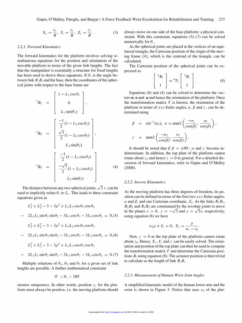
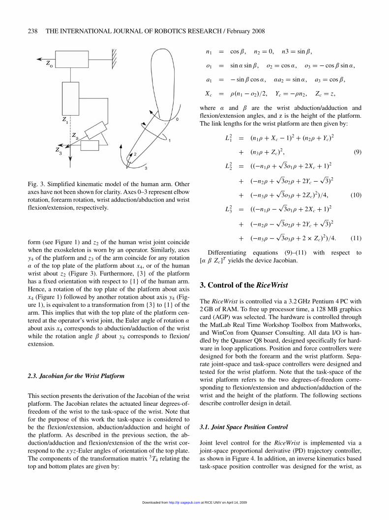
Fig. 3. Simplified kinematic model of the human arm. Otheraxes have not been shown for clarity. Axes 0–3 represent elbowrotation, forearm rotation, wrist adduction/abduction and wristflexion/extension, respectively.
form (see Figure 1) and z2 of the human wrist joint coincidewhen the exoskeleton is worn by an operator. Similarly, axesy4 of the platform and z3 of the arm coincide for any rotation of the top plate of the platform about x4, or of the humanwrist about z2 (Figure 3). Furthermore, {3} of the platformhas a fixed orientation with respect to {1} of the human arm.Hence, a rotation of the top plate of the platform about axisx4 (Figure 1) followed by another rotation about axis y4 (Fig-ure 1), is equivalent to a transformation from {3} to {1} of thearm. This implies that with the top plate of the platform cen-tered at the operator’s wrist joint, the Euler angle of rotation about axis x4 corresponds to abduction/adduction of the wristwhile the rotation angle about y4 corresponds to flexion/extension.
2.3. Jacobian for the Wrist Platform
This section presents the derivation of the Jacobian of the wristplatform. The Jacobian relates the actuated linear degrees-of-freedom of the wrist to the task-space of the wrist. Note thatfor the purpose of this work the task-space is considered tobe the flexion/extension, abduction/adduction and height ofthe platform. As described in the previous section, the ab-duction/adduction and flexion/extension of the the wrist cor-respond to the xyz-Euler angles of orientation of the top plate.The components of the transformation matrix 3T4 relating thetop and bottom plates are given by:
n1 � cos� n2 � 0� n3 � sin�
o1 � sin sin� o2 � cos� o3 � � cos sin�
a1 � � sin cos� a2 � sin� a3 � cos�
Xc � ��n1 � o2��2� Yc � ��n2� Zc � z�
where and are the wrist abduction/adduction andflexion/extension angles, and z is the height of the platform.The link lengths for the wrist platform are then given by:
L21 � �n1� � Xc � 1�2 � �n2� � Yc�
2
� �n3� � Zc�2� (9)
L22 � ���n1� �
�3o1� � 2Xc � 1�2
� ��n2� ��
3o2� � 2Yc ��
3�2
� ��n3� ��
3o3� � 2Zc�2��4� (10)
L23 � ���n1� �
�3o1� � 2Xc � 1�2
� ��n2� ��
3o2� � 2Yc ��
3�2
� ��n3� ��
3o3� � 2 Zc�2��4� (11)
Differentiating equations (9)–(11) with respect to[ Zc]T yields the device Jacobian.
3. Control of the RiceWrist
The RiceWrist is controlled via a 3.2 GHz Pentium 4 PC with2 GB of RAM. To free up processor time, a 128 MB graphicscard (AGP) was selected. The hardware is controlled throughthe MatLab Real Time Workshop Toolbox from Mathworks,and WinCon from Quanser Consulting. All data I/O is han-dled by the Quanser Q8 board, designed specifically for hard-ware in loop applications. Position and force controllers weredesigned for both the forearm and the wrist platform. Sepa-rate joint-space and task-space controllers were designed andtested for the wrist platform. Note that the task-space of thewrist platform refers to the two degrees-of-freedom corre-sponding to flexion/extension and abduction/adduction of thewrist and the height of the platform. The following sectionsdescribe controller design in detail.
3.1. Joint Space Position Control
Joint level control for the RiceWrist is implemented via ajoint-space proportional derivative (PD) trajectory controller,as shown in Figure 4. In addition, an inverse kinematics basedtask-space position controller was designed for the wrist, as
at RICE UNIV on April 14, 2009 http://ijr.sagepub.comDownloaded from
Gupta, O’Malley, Patoglu, and Burgar / A Force Feedback Wrist Exoskeleton for Rehabilitation and Training 239
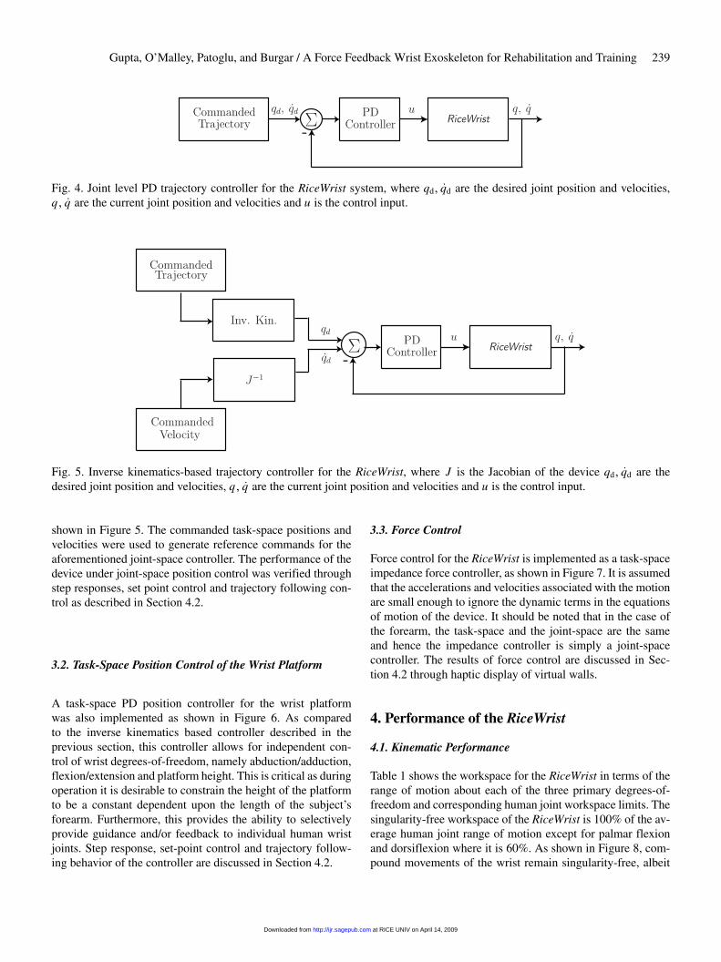
Fig. 4. Joint level PD trajectory controller for the RiceWrist system, where qd� qd are the desired joint position and velocities,q� q are the current joint position and velocities and u is the control input.
Fig. 5. Inverse kinematics-based trajectory controller for the RiceWrist, where J is the Jacobian of the device qd� qd are thedesired joint position and velocities, q� q are the current joint position and velocities and u is the control input.
shown in Figure 5. The commanded task-space positions andvelocities were used to generate reference commands for theaforementioned joint-space controller. The performance of thedevice under joint-space position control was verified throughstep responses, set point control and trajectory following con-trol as described in Section 4.2.
3.2. Task-Space Position Control of the Wrist Platform
A task-space PD position controller for the wrist platformwas also implemented as shown in Figure 6. As comparedto the inverse kinematics based controller described in theprevious section, this controller allows for independent con-trol of wrist degrees-of-freedom, namely abduction/adduction,flexion/extension and platform height. This is critical as duringoperation it is desirable to constrain the height of the platformto be a constant dependent upon the length of the subject’sforearm. Furthermore, this provides the ability to selectivelyprovide guidance and/or feedback to individual human wristjoints. Step response, set-point control and trajectory follow-ing behavior of the controller are discussed in Section 4.2.
3.3. Force Control
Force control for the RiceWrist is implemented as a task-spaceimpedance force controller, as shown in Figure 7. It is assumedthat the accelerations and velocities associated with the motionare small enough to ignore the dynamic terms in the equationsof motion of the device. It should be noted that in the case ofthe forearm, the task-space and the joint-space are the sameand hence the impedance controller is simply a joint-spacecontroller. The results of force control are discussed in Sec-tion 4.2 through haptic display of virtual walls.
4. Performance of the RiceWrist
4.1. Kinematic Performance
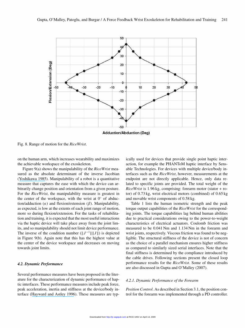
Table 1 shows the workspace for the RiceWrist in terms of therange of motion about each of the three primary degrees-of-freedom and corresponding human joint workspace limits. Thesingularity-free workspace of the RiceWrist is 100% of the av-erage human joint range of motion except for palmar flexionand dorsiflexion where it is 60%. As shown in Figure 8, com-pound movements of the wrist remain singularity-free, albeit
at RICE UNIV on April 14, 2009 http://ijr.sagepub.comDownloaded from
240 THE INTERNATIONAL JOURNAL OF ROBOTICS RESEARCH / February 2008
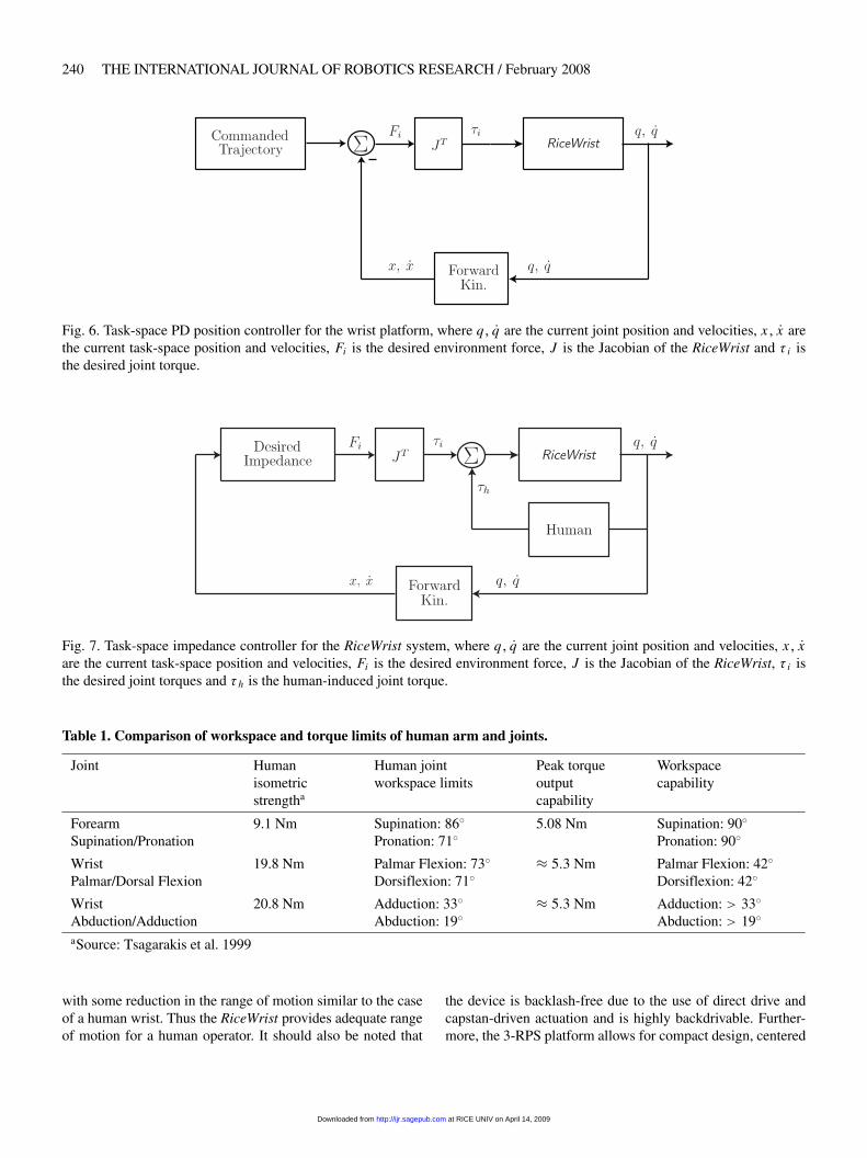
Fig. 6. Task-space PD position controller for the wrist platform, where q� q are the current joint position and velocities, x� x arethe current task-space position and velocities, Fi is the desired environment force, J is the Jacobian of the RiceWrist and i isthe desired joint torque.
Fig. 7. Task-space impedance controller for the RiceWrist system, where q� q are the current joint position and velocities, x� xare the current task-space position and velocities, Fi is the desired environment force, J is the Jacobian of the RiceWrist, i isthe desired joint torques and h is the human-induced joint torque.
Table 1. Comparison of workspace and torque limits of human arm and joints.
Joint Humanisometricstrengtha
Human jointworkspace limits
Peak torqueoutputcapability
Workspacecapability
ForearmSupination/Pronation
9.1 Nm Supination: 86�Pronation: 71�
5.08 Nm Supination: 90�Pronation: 90�
WristPalmar/Dorsal Flexion
19.8 Nm Palmar Flexion: 73�Dorsiflexion: 71�
� 5�3 Nm Palmar Flexion: 42�Dorsiflexion: 42�
WristAbduction/Adduction
20.8 Nm Adduction: 33�Abduction: 19�
� 5�3 Nm Adduction: � 33�Abduction: � 19�
aSource: Tsagarakis et al. 1999
with some reduction in the range of motion similar to the caseof a human wrist. Thus the RiceWrist provides adequate rangeof motion for a human operator. It should also be noted that
the device is backlash-free due to the use of direct drive andcapstan-driven actuation and is highly backdrivable. Further-more, the 3-RPS platform allows for compact design, centered
at RICE UNIV on April 14, 2009 http://ijr.sagepub.comDownloaded from
Gupta, O’Malley, Patoglu, and Burgar / A Force Feedback Wrist Exoskeleton for Rehabilitation and Training 241
Fig. 8. Range of motion for the RiceWrist.
on the human arm, which increases wearability and maximizesthe achievable workspace of the exoskeleton.
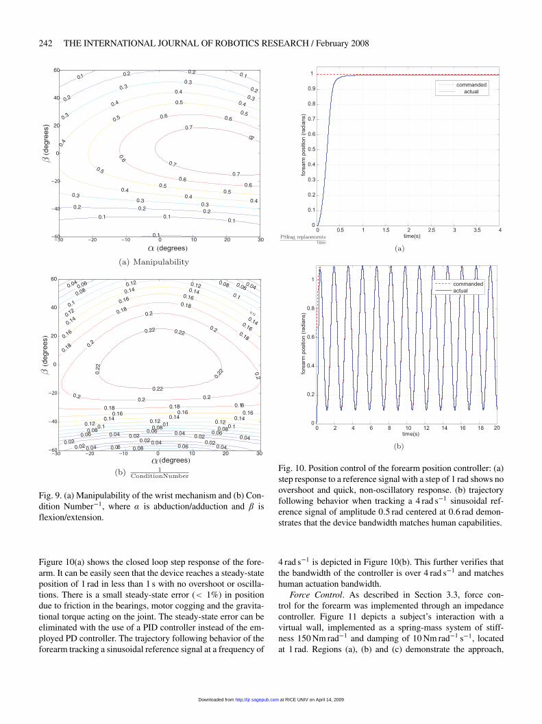
Figure 9(a) shows the manipulability of the RiceWrist mea-sured as the absolute determinant of the inverse Jacobian(Yoshikawa 1985). Manipulability of a robot is a quantitativemeasure that captures the ease with which the device can ar-bitrarily change position and orientation from a given posture.For the RiceWrist, the manipulability measure is greatest inthe center of the workspace, with the wrist at 0� of abduc-tion/adduction () and flexion/extension (). Manipulability,as expected, is low at the extents of each joint range of motion,more so during flexion/extension. For the tasks of rehabilita-tion and training, it is expected that the most useful interactionsvia the haptic device will take place away from the joint lim-its, and so manipulability should not limit device performance.The inverse of the condition number (�J�1��J�) is depictedin Figure 9(b). Again note that this has the highest value atthe center of the device workspace and decreases on movingtowards joint limits.
4.2. Dynamic Performance
Several performance measures have been proposed in the liter-ature for the characterization of dynamic performance of hap-tic interfaces. These performance measures include peak force,peak acceleration, inertia and stiffness at the device/body in-terface (Hayward and Astley 1996). These measures are typ-
ically used for devices that provide single point haptic inter-action, for example the PHANToM haptic interface by Sens-able Technologies. For devices with multiple device/body in-terfaces such as the RiceWrist, however, measurements at theendpoint are not directly applicable. Hence, only data re-lated to specific joints are provided. The total weight of theRiceWrist is 1�96 kg, comprising: forearm motor (stator + ro-tor) of 0�73 kg, wrist electrical motors (combined) of 0�65 kgand movable wrist components of 0�58 kg.
Table 1 lists the human isometric strength and the peaktorque output capabilities of the RiceWrist for the correspond-ing joints. The torque capabilities lag behind human abilitiesdue to practical considerations owing to the power-to-weightcharacteristics of electrical actuators. Coulomb friction wasmeasured to be 0�041 Nm and 1�134 Nm in the forearm andwrist joints, respectively. Viscous friction was found to be neg-ligible. The structural stiffness of the device is not of concernas the choice of a parallel mechanism ensures higher stiffnessas compared to similarly sized serial interfaces. Note that thefinal stiffness is determined by the compliance introduced bythe cable drives. Following sections present the closed loopperformance results for the RiceWrist. Some of these resultsare also discussed in Gupta and O’Malley (2007).
4.2.1. Dynamic Performance of the Forearm
Position Control. As described in Section 3.1, the position con-trol for the forearm was implemented through a PD controller.
at RICE UNIV on April 14, 2009 http://ijr.sagepub.comDownloaded from
242 THE INTERNATIONAL JOURNAL OF ROBOTICS RESEARCH / February 2008
Fig. 9. (a) Manipulability of the wrist mechanism and (b) Con-dition Number�1, where is abduction/adduction and isflexion/extension.
Figure 10(a) shows the closed loop step response of the fore-arm. It can be easily seen that the device reaches a steady-stateposition of 1 rad in less than 1 s with no overshoot or oscilla-tions. There is a small steady-state error (� 1%) in positiondue to friction in the bearings, motor cogging and the gravita-tional torque acting on the joint. The steady-state error can beeliminated with the use of a PID controller instead of the em-ployed PD controller. The trajectory following behavior of theforearm tracking a sinusoidal reference signal at a frequency of
Fig. 10. Position control of the forearm position controller: (a)step response to a reference signal with a step of 1 rad shows noovershoot and quick, non-oscillatory response. (b) trajectoryfollowing behavior when tracking a 4 rad s�1 sinusoidal ref-erence signal of amplitude 0�5 rad centered at 0�6 rad demon-strates that the device bandwidth matches human capabilities.
4 rad s�1 is depicted in Figure 10(b). This further verifies thatthe bandwidth of the controller is over 4 rad s�1 and matcheshuman actuation bandwidth.
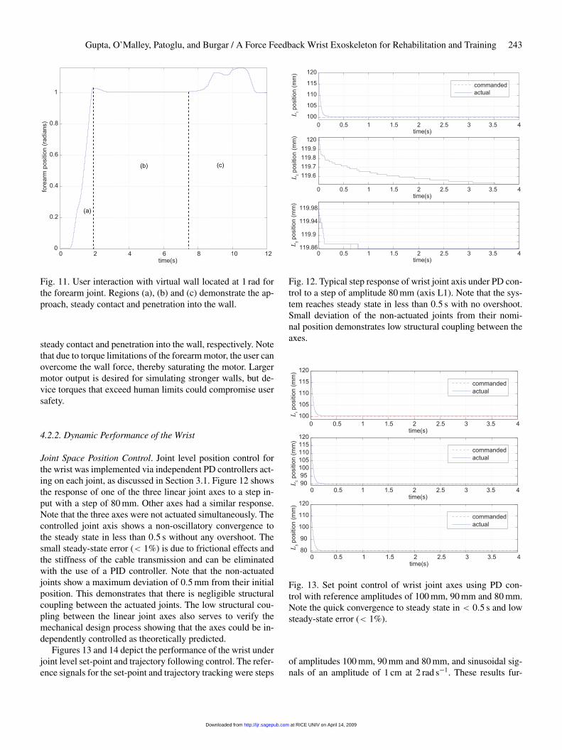
Force Control. As described in Section 3.3, force con-trol for the forearm was implemented through an impedancecontroller. Figure 11 depicts a subject’s interaction with avirtual wall, implemented as a spring-mass system of stiff-ness 150 Nm rad�1 and damping of 10 Nm rad�1 s�1, locatedat 1 rad. Regions (a), (b) and (c) demonstrate the approach,
at RICE UNIV on April 14, 2009 http://ijr.sagepub.comDownloaded from
Gupta, O’Malley, Patoglu, and Burgar / A Force Feedback Wrist Exoskeleton for Rehabilitation and Training 243
Fig. 11. User interaction with virtual wall located at 1 rad forthe forearm joint. Regions (a), (b) and (c) demonstrate the ap-proach, steady contact and penetration into the wall.
steady contact and penetration into the wall, respectively. Notethat due to torque limitations of the forearm motor, the user canovercome the wall force, thereby saturating the motor. Largermotor output is desired for simulating stronger walls, but de-vice torques that exceed human limits could compromise usersafety.
4.2.2. Dynamic Performance of the Wrist
Joint Space Position Control. Joint level position control forthe wrist was implemented via independent PD controllers act-ing on each joint, as discussed in Section 3.1. Figure 12 showsthe response of one of the three linear joint axes to a step in-put with a step of 80 mm. Other axes had a similar response.Note that the three axes were not actuated simultaneously. Thecontrolled joint axis shows a non-oscillatory convergence tothe steady state in less than 0�5 s without any overshoot. Thesmall steady-state error (� 1%) is due to frictional effects andthe stiffness of the cable transmission and can be eliminatedwith the use of a PID controller. Note that the non-actuatedjoints show a maximum deviation of 0�5 mm from their initialposition. This demonstrates that there is negligible structuralcoupling between the actuated joints. The low structural cou-pling between the linear joint axes also serves to verify themechanical design process showing that the axes could be in-dependently controlled as theoretically predicted.
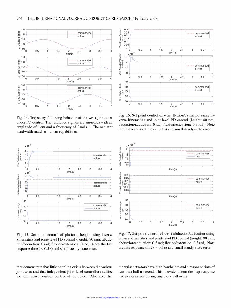
Figures 13 and 14 depict the performance of the wrist underjoint level set-point and trajectory following control. The refer-ence signals for the set-point and trajectory tracking were steps
Fig. 12. Typical step response of wrist joint axis under PD con-trol to a step of amplitude 80 mm (axis L1). Note that the sys-tem reaches steady state in less than 0�5 s with no overshoot.Small deviation of the non-actuated joints from their nomi-nal position demonstrates low structural coupling between theaxes.
Fig. 13. Set point control of wrist joint axes using PD con-trol with reference amplitudes of 100 mm, 90 mm and 80 mm.Note the quick convergence to steady state in � 0�5 s and lowsteady-state error (� 1%).
of amplitudes 100 mm, 90 mm and 80 mm, and sinusoidal sig-nals of an amplitude of 1 cm at 2 rad s�1. These results fur-
at RICE UNIV on April 14, 2009 http://ijr.sagepub.comDownloaded from
244 THE INTERNATIONAL JOURNAL OF ROBOTICS RESEARCH / February 2008
Fig. 14. Trajectory following behavior of the wrist joint axesunder PD control. The reference signals are sinusoids with anamplitude of 1 cm and a frequency of 2 rad s�1. The actuatorbandwidth matches human capabilities.
Fig. 15. Set point control of platform height using inversekinematics and joint-level PD control (height: 80 mm� abduc-tion/adduction: 0 rad� flexion/extension: 0 rad). Note the fastresponse time (� 0�5 s) and small steady-state error.
ther demonstrate that little coupling exists between the variousjoint axes and that independent joint-level controllers sufficefor joint space position control of the device. Also note that
Fig. 16. Set point control of wrist flexion/extension using in-verse kinematics and joint-level PD control (height: 80 mm�abduction/adduction: 0 rad� flexion/extension: 0�3 rad). Notethe fast response time (� 0�5 s) and small steady-state error.
Fig. 17. Set point control of wrist abduction/adduction usinginverse kinematics and joint-level PD control (height: 80 mm�abduction/adduction: 0�3 rad� flexion/extension: 0�3 rad). Notethe fast response time (� 0�5 s) and small steady-state error.
the wrist actuators have high bandwidth and a response time ofless than half a second. This is evident from the step responseand performance during trajectory following.
at RICE UNIV on April 14, 2009 http://ijr.sagepub.comDownloaded from
Gupta, O’Malley, Patoglu, and Burgar / A Force Feedback Wrist Exoskeleton for Rehabilitation and Training 245
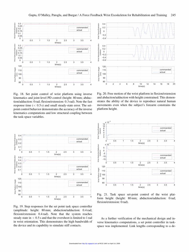
Fig. 18. Set point control of wrist platform using inversekinematics and joint-level PD control (height: 80 mm� abduc-tion/adduction: 0 rad� flexion/extension: 0�3 rad). Note the fastresponse time (� 0�5 s) and small steady-state error. The set-point control behavior demonstrates the accuracy of the inversekinematics computations and low structural coupling betweenthe task-space variables.
Fig. 19. Step responses for the set point task space controller(amplitude: height: 80 mm� abduction/adduction: 0�4 rad�flexion/extension: 0�4 rad). Note that the system reachessteady state in� 0�5 s and that the overshoot is limited to 1 radin wrist orientation. This demonstrates the high bandwidth ofthe device and its capability to simulate stiff contacts.
Fig. 20. Free motion of the wrist platform in flexion/extensionand abduction/adduction with height constrained. This demon-strates the ability of the device to reproduce natural humanmovements even when the subject’s forearm constrains theplatform height.
Fig. 21. Task space set-point control of the wrist plat-form height (height: 80 mm� abduction/adduction: 0 rad�flexion/extension: 0 rad).
As a further verification of the mechanical design and in-verse kinematics computations, a set point controller in task-space was implemented. Link lengths corresponding to a de-
at RICE UNIV on April 14, 2009 http://ijr.sagepub.comDownloaded from
246 THE INTERNATIONAL JOURNAL OF ROBOTICS RESEARCH / February 2008
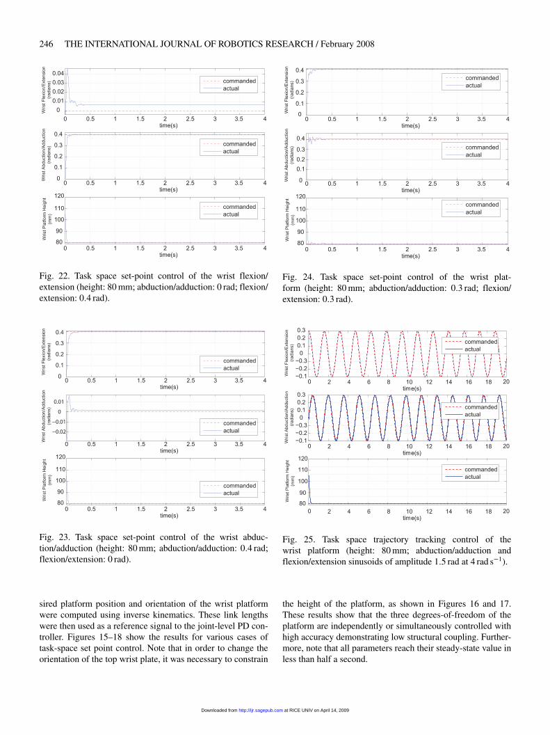
Fig. 22. Task space set-point control of the wrist flexion/extension (height: 80 mm� abduction/adduction: 0 rad� flexion/extension: 0�4 rad).
Fig. 23. Task space set-point control of the wrist abduc-tion/adduction (height: 80 mm� abduction/adduction: 0�4 rad�flexion/extension: 0 rad).
sired platform position and orientation of the wrist platformwere computed using inverse kinematics. These link lengthswere then used as a reference signal to the joint-level PD con-troller. Figures 15–18 show the results for various cases oftask-space set point control. Note that in order to change theorientation of the top wrist plate, it was necessary to constrain
Fig. 24. Task space set-point control of the wrist plat-form (height: 80 mm� abduction/adduction: 0�3 rad� flexion/extension: 0�3 rad).
Fig. 25. Task space trajectory tracking control of thewrist platform (height: 80 mm� abduction/adduction andflexion/extension sinusoids of amplitude 1�5 rad at 4 rad s�1).
the height of the platform, as shown in Figures 16 and 17.These results show that the three degrees-of-freedom of theplatform are independently or simultaneously controlled withhigh accuracy demonstrating low structural coupling. Further-more, note that all parameters reach their steady-state value inless than half a second.
at RICE UNIV on April 14, 2009 http://ijr.sagepub.comDownloaded from
Gupta, O’Malley, Patoglu, and Burgar / A Force Feedback Wrist Exoskeleton for Rehabilitation and Training 247
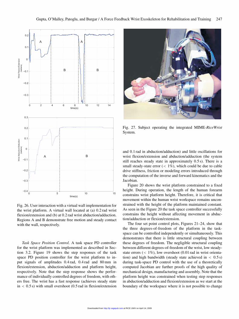
Fig. 26. User interaction with a virtual wall implementation forthe wrist platform. A virtual wall located at (a) 0�2 rad wristflexion/extension and (b) at 0�2 rad wrist abduction/adduction.Regions A and B demonstrate free motion and steady contactwith the wall, respectively.
Task Space Position Control. A task space PD controllerfor the wrist platform was implemented as described in Sec-tion 3.2. Figure 19 shows the step responses of the taskspace PD position controller for the wrist platform to in-put signals of amplitudes 0�4 rad, 0�4 rad and 80 mm inflexion/extension, abduction/adduction and platform height,respectively. Note that the step response shows the perfor-mance of individually controlled degrees of freedom, with oth-ers free. The wrist has a fast response (achieves steady statein � 0�5 s) with small overshoot (0�5 rad in flexion/extension
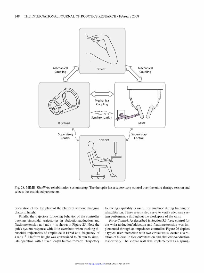
Fig. 27. Subject operating the integrated MIME-RiceWristSystem.
and 0�1 rad in abduction/adduction) and little oscillations forwrist flexion/extension and abduction/adduction (the systemstill reaches steady state in approximately 0�5 s). There is asmall steady-state error (� 1%), which could be due to cabledrive stiffness, friction or modeling errors introduced throughthe computation of the inverse and forward kinematics and theJacobian.
Figure 20 shows the wrist platform constrained to a fixedheight. During operation, the length of the human forearmconstrains wrist platform height. Therefore, it is critical thatmovement within the human wrist workspace remains uncon-strained with the height of the platform maintained constant.As seen in the Figure 20 the task space controller successfullyconstrains the height without affecting movement in abduc-tion/adduction or flexion/extension.
The four set point control plots, Figures 21–24, show thatthe three degrees-of-freedom of the platform in the task-space can be controlled independently or simultaneously. Thisdemonstrates that there is little structural coupling betweenthese degrees of freedom. The negligible structural couplingbetween different degrees-of-freedom of the wrist, low steady-state errors (� 1%), low overshoot (0�01 rad in wrist orienta-tion) and high bandwidth (steady state achieved in � 0�5 s)during task-space PD control with the use of a theoreticallycomputed Jacobian are further proofs of the high quality ofmechanical design, manufacturing and assembly. Note that theplatform height was constrained when testing step responsesin abduction/adduction and flexion/extension as we start at theboundary of the workspace where it is not possible to change
at RICE UNIV on April 14, 2009 http://ijr.sagepub.comDownloaded from
248 THE INTERNATIONAL JOURNAL OF ROBOTICS RESEARCH / February 2008
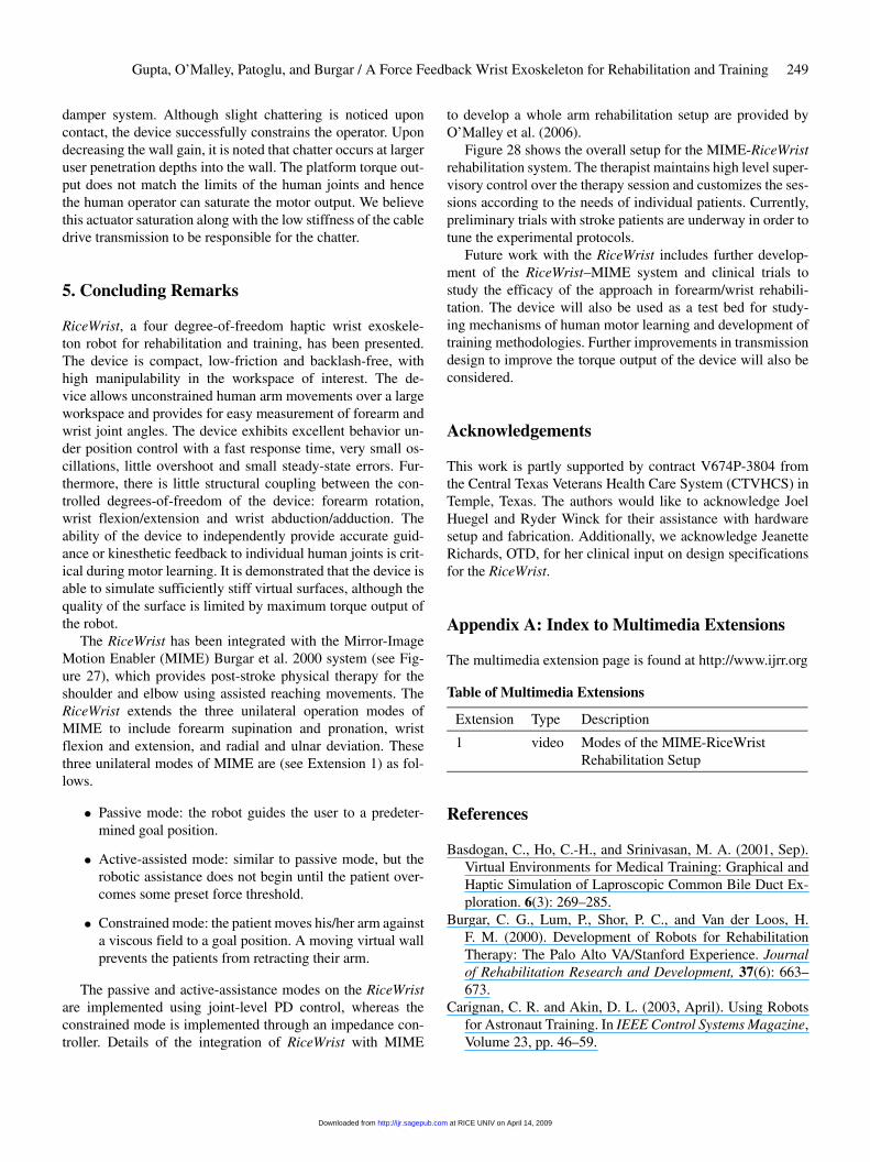
Fig. 28. MIME–RiceWrist rehabilitation system setup. The therapist has a supervisory control over the entire therapy session andselects the associated parameters.
orientation of the top plate of the platform without changingplatform height.
Finally, the trajectory following behavior of the controllertracking sinusoidal trajectories in abduction/adduction andflexion/extension at 4 rad s�1 is shown in Figure 25. Note thequick system response with little overshoot when tracking si-nusoidal trajectories of amplitude 0�15 rad at a frequency of4 rad s�1. Platform height was constrained to 80 mm to simu-late operation with a fixed length human forearm. Trajectory
following capability is useful for guidance during training orrehabilitation. These results also serve to verify adequate sys-tem performance throughout the workspace of the wrist.
Force Control. As described in Section 3.3 force control forthe wrist abduction/adduction and flexion/extension was im-plemented through an impedance controller. Figure 26 depictsa typical user interaction with two virtual walls located at a ro-tation of 0�2 rad in flexion/extension and abduction/adductionrespectively. The virtual wall was implemented as a spring-
at RICE UNIV on April 14, 2009 http://ijr.sagepub.comDownloaded from
Gupta, O’Malley, Patoglu, and Burgar / A Force Feedback Wrist Exoskeleton for Rehabilitation and Training 249
damper system. Although slight chattering is noticed uponcontact, the device successfully constrains the operator. Upondecreasing the wall gain, it is noted that chatter occurs at largeruser penetration depths into the wall. The platform torque out-put does not match the limits of the human joints and hencethe human operator can saturate the motor output. We believethis actuator saturation along with the low stiffness of the cabledrive transmission to be responsible for the chatter.
5. Concluding Remarks
RiceWrist, a four degree-of-freedom haptic wrist exoskele-ton robot for rehabilitation and training, has been presented.The device is compact, low-friction and backlash-free, withhigh manipulability in the workspace of interest. The de-vice allows unconstrained human arm movements over a largeworkspace and provides for easy measurement of forearm andwrist joint angles. The device exhibits excellent behavior un-der position control with a fast response time, very small os-cillations, little overshoot and small steady-state errors. Fur-thermore, there is little structural coupling between the con-trolled degrees-of-freedom of the device: forearm rotation,wrist flexion/extension and wrist abduction/adduction. Theability of the device to independently provide accurate guid-ance or kinesthetic feedback to individual human joints is crit-ical during motor learning. It is demonstrated that the device isable to simulate sufficiently stiff virtual surfaces, although thequality of the surface is limited by maximum torque output ofthe robot.
The RiceWrist has been integrated with the Mirror-ImageMotion Enabler (MIME) Burgar et al. 2000 system (see Fig-ure 27), which provides post-stroke physical therapy for theshoulder and elbow using assisted reaching movements. TheRiceWrist extends the three unilateral operation modes ofMIME to include forearm supination and pronation, wristflexion and extension, and radial and ulnar deviation. Thesethree unilateral modes of MIME are (see Extension 1) as fol-lows.
Passive mode: the robot guides the user to a predeter-mined goal position.
Active-assisted mode: similar to passive mode, but therobotic assistance does not begin until the patient over-comes some preset force threshold.
Constrained mode: the patient moves his/her arm againsta viscous field to a goal position. A moving virtual wallprevents the patients from retracting their arm.
The passive and active-assistance modes on the RiceWristare implemented using joint-level PD control, whereas theconstrained mode is implemented through an impedance con-troller. Details of the integration of RiceWrist with MIME
to develop a whole arm rehabilitation setup are provided byO’Malley et al. (2006).
Figure 28 shows the overall setup for the MIME-RiceWristrehabilitation system. The therapist maintains high level super-visory control over the therapy session and customizes the ses-sions according to the needs of individual patients. Currently,preliminary trials with stroke patients are underway in order totune the experimental protocols.
Future work with the RiceWrist includes further develop-ment of the RiceWrist–MIME system and clinical trials tostudy the efficacy of the approach in forearm/wrist rehabili-tation. The device will also be used as a test bed for study-ing mechanisms of human motor learning and development oftraining methodologies. Further improvements in transmissiondesign to improve the torque output of the device will also beconsidered.
Acknowledgements
This work is partly supported by contract V674P-3804 fromthe Central Texas Veterans Health Care System (CTVHCS) inTemple, Texas. The authors would like to acknowledge JoelHuegel and Ryder Winck for their assistance with hardwaresetup and fabrication. Additionally, we acknowledge JeanetteRichards, OTD, for her clinical input on design specificationsfor the RiceWrist.
Appendix A: Index to Multimedia Extensions
The multimedia extension page is found at http://www.ijrr.org
Table of Multimedia Extensions
Extension Type Description
1 video Modes of the MIME-RiceWristRehabilitation Setup
References
Basdogan, C., Ho, C.-H., and Srinivasan, M. A. (2001, Sep).Virtual Environments for Medical Training: Graphical andHaptic Simulation of Laproscopic Common Bile Duct Ex-ploration. 6(3): 269–285.
Burgar, C. G., Lum, P., Shor, P. C., and Van der Loos, H.F. M. (2000). Development of Robots for RehabilitationTherapy: The Palo Alto VA/Stanford Experience. Journalof Rehabilitation Research and Development, 37(6): 663–673.
Carignan, C. R. and Akin, D. L. (2003, April). Using Robotsfor Astronaut Training. In IEEE Control Systems Magazine,Volume 23, pp. 46–59.
at RICE UNIV on April 14, 2009 http://ijr.sagepub.comDownloaded from
250 THE INTERNATIONAL JOURNAL OF ROBOTICS RESEARCH / February 2008
Charles, S. K., Krebs, H. I., Volpe, B. T., Lynch, D., andHogan, N. (2005). Wrist Rehabilitation Following Stroke:Initial Clinical Results. In International Conference on Re-habilitation Robotics, pp. 13–16.
Dirette, D. and Hinojosa, J. (1994). Effects of ContinuousPassive Motion on the Edematous Hands of Two Personswith Flaccid Hemiplegia. American Journal of Occupa-tional Therapy, 48(5): 403–409.
Erlandson, R. F. (1992). Applications of Robotic/MechatronicSystems in Special Education, Rehabilitation Therapy.IEEE Transactions on Rehabilition Engineering, 3(1): 22–34.
Fasoli, S., Krebs, H. I., Stein, J., Frontera, W. R., and Hogan,N. (2003). Effects of robotic therapy on motor impairmentand recovery in chronic stroke. Archives of Physical Medi-cine and Rehabilitation, 84: 477–482.
Fasoli, S. E., Krebs, H. I., and Hogan, N. (2004). Robotic Tech-nology and Stroke Rehabilitation. Topics in Stroke Rehabil-itation, 11: 11–19.
Feygin, D., Keehner, M., and Tendick, R. (2002, March). Hap-tic Guidance: Experimental Evaluation of a Haptic TrainingMethod for a Perceptual Motor Skill. In International Sym-posium on Haptic Interfaces for Virtual Environment andTeleoperator Systems, pp. 40–47.
Goodall, R. M., Pratt, D. J., Rogers, C. T., and Murray-Leslie,C. M. (1987). Enhancing Postural Stability in Hemi-PlegicsUsing Externally Applied Forces. International Journal ofRehabilitation Research, 10(4): 132–140.
Gresham, G. E., Alexander, D., Bishop, D. S., Giuliani, C.,Goldberg, G., Holland, A., Kelly-Hayes, M., Linn, R. T.,Roth, E. J., Stason, W. B., and Trombly, C. A. (1997). Re-habilitation. Stroke, 28(7): 1522–1526.
Gresham, G. H. (1990, Sep). Past Achievements and New Di-rections in Stroke Outcome Research. Stroke, 21 (9 Suppl).
Gupta, A. and O’Malley, M. K. (2006). Design of a haptic armexoskeleton for training and rehabilitation. IEEE/ASMETransactions on Mechatronics, 11(3): 280–289.
Gupta, A. and O’Malley, M. K. (2007). Robotic Exoskeletonsfor Upper Extremity Rehabilitation. In Rehabilitations Ro-botics, Sachi S. Kommu (Ed.) I-Tech Education and Pub-lishing, Vienna, Austria, pp. 371–396.
Hayward, V. and Astley, O. (1996). Performance measures forhaptic interfaces. In Robotics Research: The 7th Interna-tional Symposium. Springer Verlag.
Hesse, S., Schulte-Tigges, G., Konrad, M., Bardeleben, A.,and Werner, C. (2003). Robot Assisted Arm Trainer for thePassive and Active Practice of Bilateral Forearm and WristMovements in Hemiparetic Subjects. Archives of PhysicalMedicine and Rehabilitation, 84(6): 915–920.
Hogan, N. and Krebs, H. I. (2004). Interactive Robots for Neu-rorehabilitation. Restorative Neurology and Neuroscience,22: 349–358.
Jack, D., Boian, R., Merians, A. S., Tremaine, M., Burdea, G.C., Adamovich, S. V., Recce, M., and Poizner, H. (2001,
Sep). Virtual Reality Enhanced Stroke Rehabilitation. IEEETransactions on Neural Systems and Rehabilitation Engi-neering, 9(3): 308–318.
Khalili, D. and Zomlefer, M. (1988). An Intelligent RoboticSystem for Rehabilitation of Joints and Estimation of BodySegment Parameters. IEEE Transactions on BiomedicalEngineering, 35(2): 138–146.
Lee, K. M. and Shah, D. K. (1988, June). Kinematic Analysisof a Three Degrees-of-Freedom in-Parallel Actuated Ma-nipulator. IEEE Journal of Robotics and Automation, 4(3):354–360.
O’Malley, M. K., Ro, T., and Levin, H. S. (2006). Assess-ing and Inducing Neuroplasticity with TMS and Robot-ics. Archives of PMR, Special Issue on Neuroplasticity andNeuroimaging in Acquired Brain Injury: Measurements,Concepts, and Applications, 87(12): 59–66.
O’Malley, M. K., Sledd, A., Gupta, A., Patoglu, V., Huegel, J.,and Burgar, C. (2006, Nov). The RiceWrist: A distal upperextremity rehabilitation robot for stroke therapy. In ASMEInternational Mechanical Engineering Congress and Expo-sition.
Prisco, G. M., Avizzano, C. A., Calcara, M., Ciancio, S., Pinna,S., and Bergamasco, M. (1998, May). A Virtual Environ-ment with Haptic Feedback for the Treatment of MotorDexterity Disabilities. In IEEE International Conference onRobotics and Automation, Volume 4, pp. 3721–3726.
Reinkensmeyer, D. J., Dewald, J. P. A., and Rymer, W. Z.(1996). Robotic Devices for Physical Rehabilitation ofStroke Patients: Fundamental Requirements, Target Ther-apeutic Techniques, and Preliminary Designs. Technologyand Disability, 5: 205–215.
Reinkensmeyer, D. J., Emken, J. L., and Cramer, S. C. (2004).Robotics, Motor Learning and Neurologic Recovery. An-nual Reviews in Biomedical Engineering, 6: 497–525.
Reinkensmeyer, D. J., Takahashi, C. D., Timoszyk, W. K.,Reinkensmeyer, A. N., and Kahn, L. E. (2000). Design ofRobot Assistance for Arm Movement Therapy FollowingStroke. Advanced Robotics, 14(7): 625–637.
Riener, R., Nef, T., and Colombo, G. (2005). Robot-AidedNeurorehabilitation of the Upper Extremeties. Medical andBiological Engineering and Computing, 43: 2–10.
Sledd, A. and O’Malley, M. K. (2006). Performance Enhance-ment of a Haptic Arm Exoskeleton. In International Sym-posium on Haptic Interfaces for Virtual Environment andTeleoperator Systems, pp. 375–381.
Stein, J. (2004). Motor Recovery Strategies after Stroke. Top-ics in Stroke Rehabiliation, 11: 12– 22.
Sveistrup, H. (2004). Motor Rehabilitation using Virtual Real-ity. Journal of NeuroEngineering and Rehabilitation, 1(10).
Thom, T., Haase, N., Rosamond, W., Howard, V. J., Rums-feld, J., Manolio, T., Zheng, Z.-J., Flegal, K., O’Donnell,C., Kittner, S., Lloyd-Jones, D., Goff, Jr, D. C., Hong, Y.,Adams, R., Friday, G., Furie, K., Gorelick, P., Kissela, B.,Marler, J., Meigs, J., Roger, V., Sidney, S., Sorlie, P., Stein-
at RICE UNIV on April 14, 2009 http://ijr.sagepub.comDownloaded from
Gupta, O’Malley, Patoglu, and Burgar / A Force Feedback Wrist Exoskeleton for Rehabilitation and Training 251
berger, J., Wasserthiel-Smoller, S., Wilson, M., and Wolf, P.(2006). Heart disease and stroke american heart associationsubcommittee. Circulation, 113: e85–e151.
Todorov, E., Shadmehr, R., and Bizzi, E. (1997). AugmentedFeedback Presented in a Virtual Environment AcceleratesLearning of a Dif�cult Motor Task. Journal of Motor Be-havior, 29(2): 147–158.
Tsagarakis, N., Caldwell, D. G., and Medrano-Cerda, G.(1999, Sep.). A 7DOF Pneumatic Muscle Actuator Pow-ered Exoskeleton. In International Workshop on Robot andHuman Interaction, pp. 327–333.
White, C. J., Scneider, A. M., and Brogan Jr., W. K. (1993).Robotic Orthosis for Stroke Patient Rehabilitation. In IEEEInternational Conference on Engineering and Medical Bi-ology, pp. 1272–1273.
Wolf, P. A., D’Agostino, R. B., O’Neal, M. A., Sytkowski, P.,Kase, C. S., Belanger, A. J., and Kannel, W. B. (1992). Sec-ular Trends in Stroke Incidence and Mortality: The Fram-ingham Study. Stroke, 23: 1551–1555.
Yoshikawa, T. (1985). Manipulability of Robotic Mechanisms.International Journal of Robotics Research, 4(2): 3–9.
at RICE UNIV on April 14, 2009 http://ijr.sagepub.comDownloaded from
Copyright © 2022 FDOKUMEN