Study of cyclic hot corrosion of nanostructured Cr/Co–Al coatings on superalloy
9
Materials Chemistry and Physics 126 (2011) 253–261 Contents lists available at ScienceDirect Materials Chemistry and Physics journal homepage: www.elsevier.com/locate/matchemphys Study of cyclic hot corrosion of nanostructured Cr/Co–Al coatings on superalloy Atikur Rahman a,b , Vipin Chawla b , R. Jayaganthan a,∗ , Ramesh Chandra b , R. Ambardar c a Department of Metallurgical and Materials Engineering, Indian Institute of Technology Roorkee, Roorkee 247667, India b Institute Instrumentation Centre, Indian Institute of Technology Roorkee, Roorkee 247667, India c Department of Metallurgical Engineering, National Institute of Technology Hazratbal, Srinagar 190006, India article info Article history: Received 22 March 2010 Received in revised form 25 October 2010 Accepted 17 November 2010 Keywords: Coatings Atomic force microscopy Thermo gravimetric analysis Corrosion abstract Nanostructured Cr/Co–Al coatings were deposited on Superni-718 substrate by DC/RF magnetron sput- tering in the present work. Hot corrosion studies were conducted on bare substrate and the Cr/Co–Al coated Superni-718 after exposure to a molten salt environment of Na 2 SO 4 –60%V 2 O 5 at 900 ◦ C under cyclic conditions. The weight change measurements were made to calculate the cyclic hot corrosion kinetics of the coatings at 900 ◦ C. The microstructural features of the as deposited coatings were charac- terized by FE-SEM, AFM and XRD. It was observed that the corrosion rate of Cr/Co–Al coated superalloy is lower than that of the uncoated superalloy due to the formation of continuous, dense, adherent and pro- tective oxide scale over the surface of the coatings. The protective oxide scales are basically the thin layer of Cr 2 O 3 , Al 2 O 3 , and CoCr 2 O 4 which has formed over the Cr/Co–Al coated superalloy substrate exposed to molten salt environment at temperature, 900 ◦ C. © 2010 Elsevier B.V. All rights reserved. 1. Introduction The superalloy coatings based on MCrAlY (M = Ni, Co, or Fe) exhibit good protection against high temperature oxidation and hot corrosion due to the formation of dense and adherent alumina and chromia scales [1,2]. Hence, about seventy five percent of hot section components in industrial and aircraft engines are coated with MCrAlY coatings [3,4]. It is well known that the Al content in MCrAlY coating is vital for the protection because the selective oxidation of Al occurs only when its concentration is sufficient in the coating [5]. Besides, the life time of MCrAlY coatings depends greatly on the extent of Al depletion occurring from the repeated spallation/formation of the alumina scale and interdiffusion with the substrate. Also, a high Al content in MCrAlY coating is essen- tial for enhancing the performance and extending the service life of structural components. However, the direct increase of the Al content in the coating is hard to be accomplished due to the reduc- tion of mechanical properties and deterioration of machinability. Nanostructured Ni–Al and Cr/Al coatings deposited on superalloy by magnetron sputtering showed an improved high temperature oxidation resistance in air at 900 ◦ C as compared to bare super- alloy as reported in the literature [6,7]. Since nanosized grain possesses high density of grain boundaries, it provides the more favorable sites of diffusion for the easier formation of protective ∗ Corresponding author at: Indian Institute of Technology Roorkee, Metallurgical and Materials Engg & Centre of Nanotechnology, Uttarakhand 247667, India. Tel.: +91 1332 285869; fax: +91 1332 285243. E-mail address: [email protected] (R. Jayaganthan). scales. Although hot corrosion of microcrystalline coatings is well studied [8], the hot corrosion of nanostructured Cr/Co–Al coatings on Ni-based super alloy substrate is scarce in the literature. There- fore, the present work has been focused to study the hot corrosion of nanostructured Cr/Co–Al coatings deposited on Superni-718 and bare Superni-718 to assess the performance of coated superalloy. A small amount of Al and Cr in nanostructured Cr/Co–Al coatings is adequate to form protective Al 2 O 3 and Cr 2 O 3 scales in order to combat type I and type II hot corrosion. Hence, the coatings were designed as the outer layer consisting of rich Co and Al, and so that it can form the intermetallic ˇ-CoAl phases, which has high melt- ing point (1640 ◦ C) as evident from CoAl binary phase diagram. This coating could be beneficial for providing hot corrosion resistance at very high temperature (>1000 ◦ C) in the actual service applications, especially in gas turbines for combating type I hot corrosion, and Cr intermediate layer to prevent type II hot corrosion. The Cr reacts with sodium vanadate and forms sodium chromate (melting point 884 ◦ C), which could stop further dissolution of Cr 2 O 3 scale. Hence, it can behave as smart coatings due to the storage “pools” of outer Al and intermediate Cr, during service life. The substrate temperature of 250 ◦ C, 350 ◦ C and 450 ◦ C were chosen during deposition of Cr/Co–Al coatings. The micro structural features of the as deposited Cr/Co–Al coatings were characterized by FE-SEM/EDS and AFM. XRD was used to identify the formation of different phases in the Cr/Co–Al coatings. The weight change measurements were made to study the kinetics of hot corro- sion of Cr/Co–Al coatings as well as bare superalloy substrate in molten salt environment at 900 ◦ C. The morphology of corroded products of coatings and bare superalloy substrate was charac- terized by FE-SEM/EDS and XRD. The mechanisms contributing to 0254-0584/$ – see front matter © 2010 Elsevier B.V. All rights reserved. doi:10.1016/j.matchemphys.2010.11.030
-
Upload
independent -
Category
Documents
-
view
1 -
download
0
Transcript of Study of cyclic hot corrosion of nanostructured Cr/Co–Al coatings on superalloy

S
Aa
b
c
a
ARRA
KCATC
1
ehaswiotgsttoctNboapf
aT
0d
Materials Chemistry and Physics 126 (2011) 253–261
Contents lists available at ScienceDirect
Materials Chemistry and Physics
journa l homepage: www.e lsev ier .com/ locate /matchemphys
tudy of cyclic hot corrosion of nanostructured Cr/Co–Al coatings on superalloy
tikur Rahmana,b, Vipin Chawlab, R. Jayaganthana,∗, Ramesh Chandrab, R. Ambardarc
Department of Metallurgical and Materials Engineering, Indian Institute of Technology Roorkee, Roorkee 247667, IndiaInstitute Instrumentation Centre, Indian Institute of Technology Roorkee, Roorkee 247667, IndiaDepartment of Metallurgical Engineering, National Institute of Technology Hazratbal, Srinagar 190006, India
r t i c l e i n f o
rticle history:eceived 22 March 2010eceived in revised form 25 October 2010ccepted 17 November 2010
a b s t r a c t
Nanostructured Cr/Co–Al coatings were deposited on Superni-718 substrate by DC/RF magnetron sput-tering in the present work. Hot corrosion studies were conducted on bare substrate and the Cr/Co–Alcoated Superni-718 after exposure to a molten salt environment of Na2SO4–60%V2O5 at 900 ◦C under
eywords:oatingstomic force microscopyhermo gravimetric analysis
cyclic conditions. The weight change measurements were made to calculate the cyclic hot corrosionkinetics of the coatings at 900 ◦C. The microstructural features of the as deposited coatings were charac-terized by FE-SEM, AFM and XRD. It was observed that the corrosion rate of Cr/Co–Al coated superalloy islower than that of the uncoated superalloy due to the formation of continuous, dense, adherent and pro-tective oxide scale over the surface of the coatings. The protective oxide scales are basically the thin layer
2O4 wnt at
orrosion of Cr2O3, Al2O3, and CoCrto molten salt environme
. Introduction
The superalloy coatings based on MCrAlY (M = Ni, Co, or Fe)xhibit good protection against high temperature oxidation andot corrosion due to the formation of dense and adherent aluminand chromia scales [1,2]. Hence, about seventy five percent of hotection components in industrial and aircraft engines are coatedith MCrAlY coatings [3,4]. It is well known that the Al content
n MCrAlY coating is vital for the protection because the selectivexidation of Al occurs only when its concentration is sufficient inhe coating [5]. Besides, the life time of MCrAlY coatings dependsreatly on the extent of Al depletion occurring from the repeatedpallation/formation of the alumina scale and interdiffusion withhe substrate. Also, a high Al content in MCrAlY coating is essen-ial for enhancing the performance and extending the service lifef structural components. However, the direct increase of the Alontent in the coating is hard to be accomplished due to the reduc-ion of mechanical properties and deterioration of machinability.anostructured Ni–Al and Cr/Al coatings deposited on superalloyy magnetron sputtering showed an improved high temperature
xidation resistance in air at 900 ◦C as compared to bare super-lloy as reported in the literature [6,7]. Since nanosized grainossesses high density of grain boundaries, it provides the moreavorable sites of diffusion for the easier formation of protective∗ Corresponding author at: Indian Institute of Technology Roorkee, Metallurgicalnd Materials Engg & Centre of Nanotechnology, Uttarakhand 247667, India.el.: +91 1332 285869; fax: +91 1332 285243.
E-mail address: [email protected] (R. Jayaganthan).
254-0584/$ – see front matter © 2010 Elsevier B.V. All rights reserved.oi:10.1016/j.matchemphys.2010.11.030
hich has formed over the Cr/Co–Al coated superalloy substrate exposedtemperature, 900 ◦C.
© 2010 Elsevier B.V. All rights reserved.
scales. Although hot corrosion of microcrystalline coatings is wellstudied [8], the hot corrosion of nanostructured Cr/Co–Al coatingson Ni-based super alloy substrate is scarce in the literature. There-fore, the present work has been focused to study the hot corrosionof nanostructured Cr/Co–Al coatings deposited on Superni-718 andbare Superni-718 to assess the performance of coated superalloy.A small amount of Al and Cr in nanostructured Cr/Co–Al coatingsis adequate to form protective Al2O3 and Cr2O3 scales in order tocombat type I and type II hot corrosion. Hence, the coatings weredesigned as the outer layer consisting of rich Co and Al, and so thatit can form the intermetallic ˇ-CoAl phases, which has high melt-ing point (1640 ◦C) as evident from CoAl binary phase diagram. Thiscoating could be beneficial for providing hot corrosion resistance atvery high temperature (>1000 ◦C) in the actual service applications,especially in gas turbines for combating type I hot corrosion, andCr intermediate layer to prevent type II hot corrosion. The Cr reactswith sodium vanadate and forms sodium chromate (melting point884 ◦C), which could stop further dissolution of Cr2O3 scale. Hence,it can behave as smart coatings due to the storage “pools” of outerAl and intermediate Cr, during service life.
The substrate temperature of 250 ◦C, 350 ◦C and 450 ◦C werechosen during deposition of Cr/Co–Al coatings. The micro structuralfeatures of the as deposited Cr/Co–Al coatings were characterizedby FE-SEM/EDS and AFM. XRD was used to identify the formationof different phases in the Cr/Co–Al coatings. The weight change
measurements were made to study the kinetics of hot corro-sion of Cr/Co–Al coatings as well as bare superalloy substrate inmolten salt environment at 900 ◦C. The morphology of corrodedproducts of coatings and bare superalloy substrate was charac-terized by FE-SEM/EDS and XRD. The mechanisms contributing to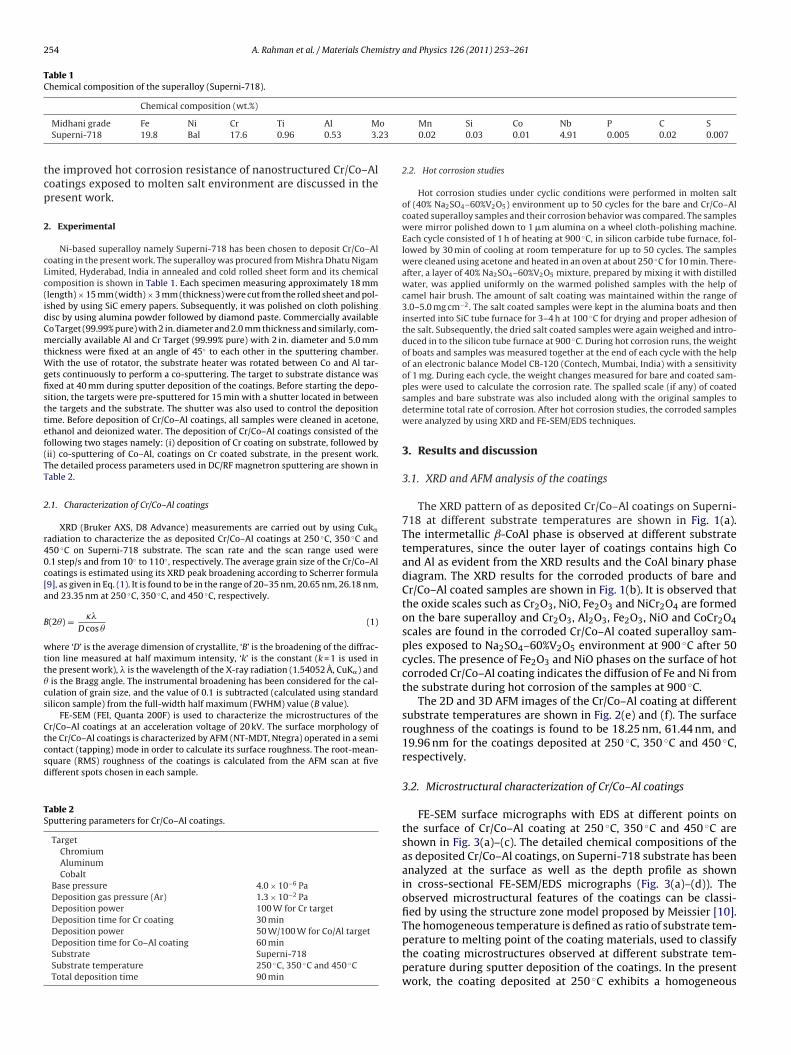
254 A. Rahman et al. / Materials Chemistry and Physics 126 (2011) 253–261
Table 1Chemical composition of the superalloy (Superni-718).
o23
tcp
2
cLc(idCmtWgfisttef(TT
2
r40c[a
B
wtt�cs
Ctcsd
TS
Chemical composition (wt.%)
Midhani grade Fe Ni Cr Ti Al MSuperni-718 19.8 Bal 17.6 0.96 0.53 3.
he improved hot corrosion resistance of nanostructured Cr/Co–Aloatings exposed to molten salt environment are discussed in theresent work.
. Experimental
Ni-based superalloy namely Superni-718 has been chosen to deposit Cr/Co–Aloating in the present work. The superalloy was procured from Mishra Dhatu Nigamimited, Hyderabad, India in annealed and cold rolled sheet form and its chemicalomposition is shown in Table 1. Each specimen measuring approximately 18 mmlength) × 15 mm (width) × 3 mm (thickness) were cut from the rolled sheet and pol-shed by using SiC emery papers. Subsequently, it was polished on cloth polishingisc by using alumina powder followed by diamond paste. Commercially availableo Target (99.99% pure) with 2 in. diameter and 2.0 mm thickness and similarly, com-ercially available Al and Cr Target (99.99% pure) with 2 in. diameter and 5.0 mm
hickness were fixed at an angle of 45◦ to each other in the sputtering chamber.ith the use of rotator, the substrate heater was rotated between Co and Al tar-
ets continuously to perform a co-sputtering. The target to substrate distance wasxed at 40 mm during sputter deposition of the coatings. Before starting the depo-ition, the targets were pre-sputtered for 15 min with a shutter located in betweenhe targets and the substrate. The shutter was also used to control the depositionime. Before deposition of Cr/Co–Al coatings, all samples were cleaned in acetone,thanol and deionized water. The deposition of Cr/Co–Al coatings consisted of theollowing two stages namely: (i) deposition of Cr coating on substrate, followed byii) co-sputtering of Co–Al, coatings on Cr coated substrate, in the present work.he detailed process parameters used in DC/RF magnetron sputtering are shown inable 2.
.1. Characterization of Cr/Co–Al coatings
XRD (Bruker AXS, D8 Advance) measurements are carried out by using Cuk�
adiation to characterize the as deposited Cr/Co–Al coatings at 250 ◦C, 350 ◦C and50 ◦C on Superni-718 substrate. The scan rate and the scan range used were.1 step/s and from 10◦ to 110◦ , respectively. The average grain size of the Cr/Co–Aloatings is estimated using its XRD peak broadening according to Scherrer formula9], as given in Eq. (1). It is found to be in the range of 20–35 nm, 20.65 nm, 26.18 nm,nd 23.35 nm at 250 ◦C, 350 ◦C, and 450 ◦C, respectively.
(2�) = ��
D cos �(1)
here ‘D’ is the average dimension of crystallite, ‘B’ is the broadening of the diffrac-ion line measured at half maximum intensity, ‘k’ is the constant (k = 1 is used inhe present work), � is the wavelength of the X-ray radiation (1.54052 A, CuK�) andis the Bragg angle. The instrumental broadening has been considered for the cal-
ulation of grain size, and the value of 0.1 is subtracted (calculated using standardilicon sample) from the full-width half maximum (FWHM) value (B value).
FE-SEM (FEI, Quanta 200F) is used to characterize the microstructures of the
r/Co–Al coatings at an acceleration voltage of 20 kV. The surface morphology ofhe Cr/Co–Al coatings is characterized by AFM (NT-MDT, Ntegra) operated in a semiontact (tapping) mode in order to calculate its surface roughness. The root-mean-quare (RMS) roughness of the coatings is calculated from the AFM scan at fiveifferent spots chosen in each sample.able 2puttering parameters for Cr/Co–Al coatings.
TargetChromiumAluminumCobalt
Base pressure 4.0 × 10⁻⁶ PaDeposition gas pressure (Ar) 1.3 × 10⁻² PaDeposition power 100 W for Cr targetDeposition time for Cr coating 30 minDeposition power 50 W/100 W for Co/Al targetDeposition time for Co–Al coating 60 minSubstrate Superni-718Substrate temperature 250 ◦C, 350 ◦C and 450 ◦CTotal deposition time 90 min
Mn Si Co Nb P C S0.02 0.03 0.01 4.91 0.005 0.02 0.007
2.2. Hot corrosion studies
Hot corrosion studies under cyclic conditions were performed in molten saltof (40% Na2SO4–60%V2O5) environment up to 50 cycles for the bare and Cr/Co–Alcoated superalloy samples and their corrosion behavior was compared. The sampleswere mirror polished down to 1 �m alumina on a wheel cloth-polishing machine.Each cycle consisted of 1 h of heating at 900 ◦C, in silicon carbide tube furnace, fol-lowed by 30 min of cooling at room temperature for up to 50 cycles. The sampleswere cleaned using acetone and heated in an oven at about 250 ◦C for 10 min. There-after, a layer of 40% Na2SO4–60%V2O5 mixture, prepared by mixing it with distilledwater, was applied uniformly on the warmed polished samples with the help ofcamel hair brush. The amount of salt coating was maintained within the range of3.0–5.0 mg cm−2. The salt coated samples were kept in the alumina boats and theninserted into SiC tube furnace for 3–4 h at 100 ◦C for drying and proper adhesion ofthe salt. Subsequently, the dried salt coated samples were again weighed and intro-duced in to the silicon tube furnace at 900 ◦C. During hot corrosion runs, the weightof boats and samples was measured together at the end of each cycle with the helpof an electronic balance Model CB-120 (Contech, Mumbai, India) with a sensitivityof 1 mg. During each cycle, the weight changes measured for bare and coated sam-ples were used to calculate the corrosion rate. The spalled scale (if any) of coatedsamples and bare substrate was also included along with the original samples todetermine total rate of corrosion. After hot corrosion studies, the corroded sampleswere analyzed by using XRD and FE-SEM/EDS techniques.
3. Results and discussion
3.1. XRD and AFM analysis of the coatings
The XRD pattern of as deposited Cr/Co–Al coatings on Superni-718 at different substrate temperatures are shown in Fig. 1(a).The intermetallic ˇ-CoAl phase is observed at different substratetemperatures, since the outer layer of coatings contains high Coand Al as evident from the XRD results and the CoAl binary phasediagram. The XRD results for the corroded products of bare andCr/Co–Al coated samples are shown in Fig. 1(b). It is observed thatthe oxide scales such as Cr2O3, NiO, Fe2O3 and NiCr2O4 are formedon the bare superalloy and Cr2O3, Al2O3, Fe2O3, NiO and CoCr2O4scales are found in the corroded Cr/Co–Al coated superalloy sam-ples exposed to Na2SO4–60%V2O5 environment at 900 ◦C after 50cycles. The presence of Fe2O3 and NiO phases on the surface of hotcorroded Cr/Co–Al coating indicates the diffusion of Fe and Ni fromthe substrate during hot corrosion of the samples at 900 ◦C.
The 2D and 3D AFM images of the Cr/Co–Al coating at differentsubstrate temperatures are shown in Fig. 2(e) and (f). The surfaceroughness of the coatings is found to be 18.25 nm, 61.44 nm, and19.96 nm for the coatings deposited at 250 ◦C, 350 ◦C and 450 ◦C,respectively.
3.2. Microstructural characterization of Cr/Co–Al coatings
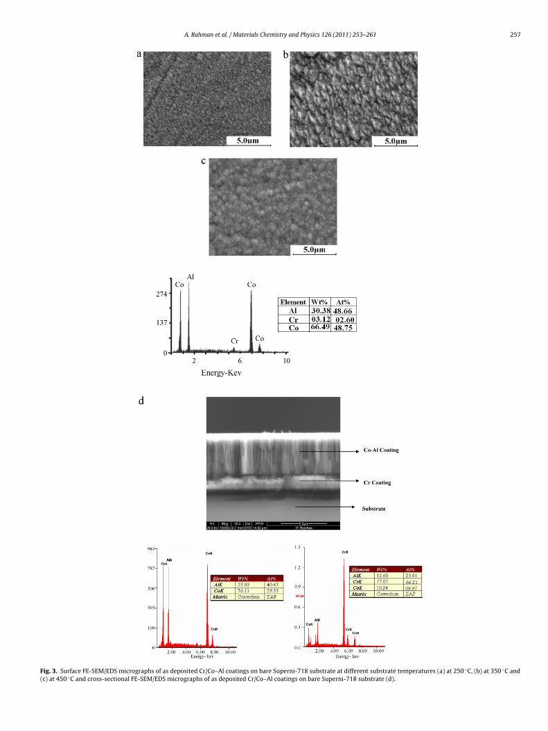
FE-SEM surface micrographs with EDS at different points onthe surface of Cr/Co–Al coating at 250 ◦C, 350 ◦C and 450 ◦C areshown in Fig. 3(a)–(c). The detailed chemical compositions of theas deposited Cr/Co–Al coatings, on Superni-718 substrate has beenanalyzed at the surface as well as the depth profile as shownin cross-sectional FE-SEM/EDS micrographs (Fig. 3(a)–(d)). Theobserved microstructural features of the coatings can be classi-fied by using the structure zone model proposed by Meissier [10].
The homogeneous temperature is defined as ratio of substrate tem-perature to melting point of the coating materials, used to classifythe coating microstructures observed at different substrate tem-perature during sputter deposition of the coatings. In the presentwork, the coating deposited at 250 ◦C exhibits a homogeneous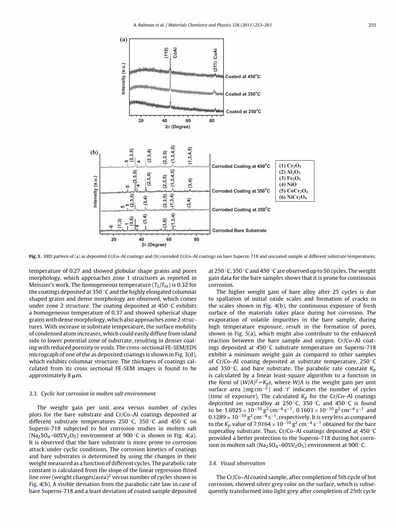
A. Rahman et al. / Materials Chemistry and Physics 126 (2011) 253–261 255
20 40 60 80
Coated at 250oC
Coated at 350oC
Co
Al
Co
Al
(211
)
Coated at 450oC
Inte
nsi
ty (
a.u
.)2θ (Degree)
(110
)
(a)
(b)
0
Corroded Coating at 250OC
Corroded Coating at 350OC(1
,3,4
,5)
(2,3
,5)
(1,3
,4,5
)
(2,3
,4)
4(2,3
,5)
5
(3,4
)
(2,3
,5)
(1,3
,4,5
)
4(2
,3,5
)
5 (2,3
,4)
(3,4
)
(1,3
,4)
(2,3
,5)
(3,4
)
(2,3
,5)
5 5
(1,3
,4)
(3,6
)
(3,4
)
4(3,6
)1
(1,3
)
6
Corroded Coating at 450OC
Corroded Bare Substrate
Inte
nsi
ty (
a.u
.)
(1) Cr2O3
(2) Al2O3
(3) Fe2O3
(4) NiO (5) CoCr2O4
(6) NiCr2O4
F coati
tmMtsuagtosimwca
3
pdS(IaawclFb
20 40 60 82θ (Degree)
ig. 1. XRD pattern of (a) as deposited Cr/Co–Al coatings and (b) corroded Cr/Co–Al
emperature of 0.27 and showed globular shape grains and poresorphology, which approaches zone 1 structures as reported ineissier’s work. The homogeneous temperature (TS/Tm) is 0.32 for
he coatings deposited at 350 ◦C and the highly elongated columnarhaped grains and dense morphology are observed, which comesnder zone 2 structure. The coating deposited at 450 ◦C exhibitshomogeneous temperature of 0.37 and showed spherical shape
rains with dense morphology, which also approaches zone 2 struc-ures. With increase in substrate temperature, the surface mobilityf condensed atom increases, which could easily diffuse from islandide to lower potential zone of substrate, resulting in denser coat-ng with reduced porosity or voids. The cross-sectional FE-SEM/EDS
icrograph of one of the as deposited coatings is shown in Fig. 3(d),hich exhibits columnar structure. The thickness of coatings cal-
ulated from its cross sectional FE-SEM images is found to bepproximately 8 �m.
.3. Cyclic hot corrosion in molten salt environment
The weight gain per unit area versus number of cycleslots for the bare substrate and Cr/Co–Al coatings deposited atifferent substrate temperatures 250 ◦C, 350 ◦C and 450 ◦C onuperni-718 subjected to hot corrosion studies in molten saltNa2SO4–60%V2O5) environment at 900 ◦C is shown in Fig. 4(a).t is observed that the bare substrate is more prone to corrosionttack under cyclic conditions. The corrosion kinetics of coatingsnd bare substrates is determined by using the changes in their
eight measured as a function of different cycles. The parabolic rateonstant is calculated from the slope of the linear regression fittedine over (weight changes/area)2 versus number of cycles shown inig. 4(b). A visible deviation from the parabolic rate law in case ofare Superni-718 and a least deviation of coated sample deposited
ngs on bare Superni-718 and uncoated sample at different substrate temperatures.
at 250 ◦C, 350 ◦C and 450 ◦C are observed up to 50 cycles. The weightgain data for the bare samples shows that it is prone for continuouscorrosion.
The higher weight gain of bare alloy after 25 cycles is dueto spallation of initial oxide scales and formation of cracks inthe scales shown in Fig. 4(b), the continuous exposure of freshsurface of the materials takes place during hot corrosion. Theevaporation of volatile impurities in the bare sample, duringhigh temperature exposure, result in the formation of pores,shown in Fig. 5(a), which might also contribute to the enhancedreaction between the bare sample and oxygen. Cr/Co–Al coat-ings deposited at 450 ◦C substrate temperature on Superni-718exhibit a minimum weight gain as compared to other samplesof Cr/Co–Al coating deposited at substrate temperature, 250 ◦Cand 350 ◦C, and bare substrate. The parabolic rate constant Kp
is calculated by a linear least-square algorithm to a function inthe form of (W/A)2 = Kpt, where W/A is the weight gain per unitsurface area (mg cm−2) and ‘t’ indicates the number of cycles(time of exposure). The calculated Kp for the Cr/Co–Al coatingsdeposited on superalloy at 250 ◦C, 350 ◦C, and 450 ◦C is foundto be 1.6925 × 10⁻¹⁰ g2 cm−4 s−1, 0.1603 × 10⁻¹⁰ g2 cm−4 s−1 and0.1289 × 10−10 g2 cm−4 s−1, respectively. It is very less as comparedto the Kp value of 7.9164 × 10⁻¹⁰ g2 cm−4 s−1 obtained for the baresuperalloy substrate. Thus, Cr/Co–Al coatings deposited at 450 ◦Cprovided a better protection to the Superni-718 during hot corro-sion in molten salt (Na2SO4–60%V2O5) environment at 900 ◦C.
3.4. Visual observation
The Cr/Co–Al coated sample, after completion of 5th cycle of hotcorrosion, showed silver grey color on the surface, which is subse-quently transformed into light grey after completion of 25th cycle

256 A. Rahman et al. / Materials Chemistry and Physics 126 (2011) 253–261
F at diff(
oeqctm
ig. 2. AFM 2D and 3D images of Cr/Co–Al coatings on bare Superni-718 substratef) at 450 ◦C.
f hot corrosion at 900 ◦C. The bare superalloy after 5th cycle of
xposure to molten salt environment exhibits grey color, subse-uently, it is transformed into light grey with brown patches afterompletion of 25th cycle. The appearance of different color overhe samples indicates the formation of different oxide scale on theaterials.
erent substrate temperatures (a) and (b) at 250 ◦C, (c) and (d) at 350 ◦C and (e) and
3.5. Surface scale analysis
FE-SEM micrographs along with its corresponding EDS results atthe selected points of interest of corroded bare substrate, Superni-718, are shown in Fig. 5(a) and (b). The scale formed on bareSuperni-718 is porous and the cracks are formed as shown in
A. Rahman et al. / Materials Chemistry and Physics 126 (2011) 253–261 257
Fig. 3. Surface FE-SEM/EDS micrographs of as deposited Cr/Co–Al coatings on bare Superni-718 substrate at different substrate temperatures (a) at 250 ◦C, (b) at 350 ◦C and(c) at 450 ◦C and cross-sectional FE-SEM/EDS micrographs of as deposited Cr/Co–Al coatings on bare Superni-718 substrate (d).
258 A. Rahman et al. / Materials Chemistry and Physics 126 (2011) 253–261
0 10 20 30 40 50
0
4
8
12
Wei
gh
t V
aria
tio
n/A
rea(
mg
m/c
m)
Number of Cycles
Bare Substrate
Cr/Co-Al Coating at 250 C
Cr/Co-Al Coating at 350 C
Cr/Co-Al Coating at 450 C
a
0 15 30 45
0
40
80
120
160
200
(Wei
gh
t V
aria
tio
n/A
rea)
(mg
m/c
m)
Number of Cycles
Bare Substrate
Cr/Co-Al Coating at 250 C
Cr/Co-Al Coating at 350 C
Cr/Co-Al Coating at 450 C
b
Fra
Ftiaeirtpt
3
snsdr(
Fs
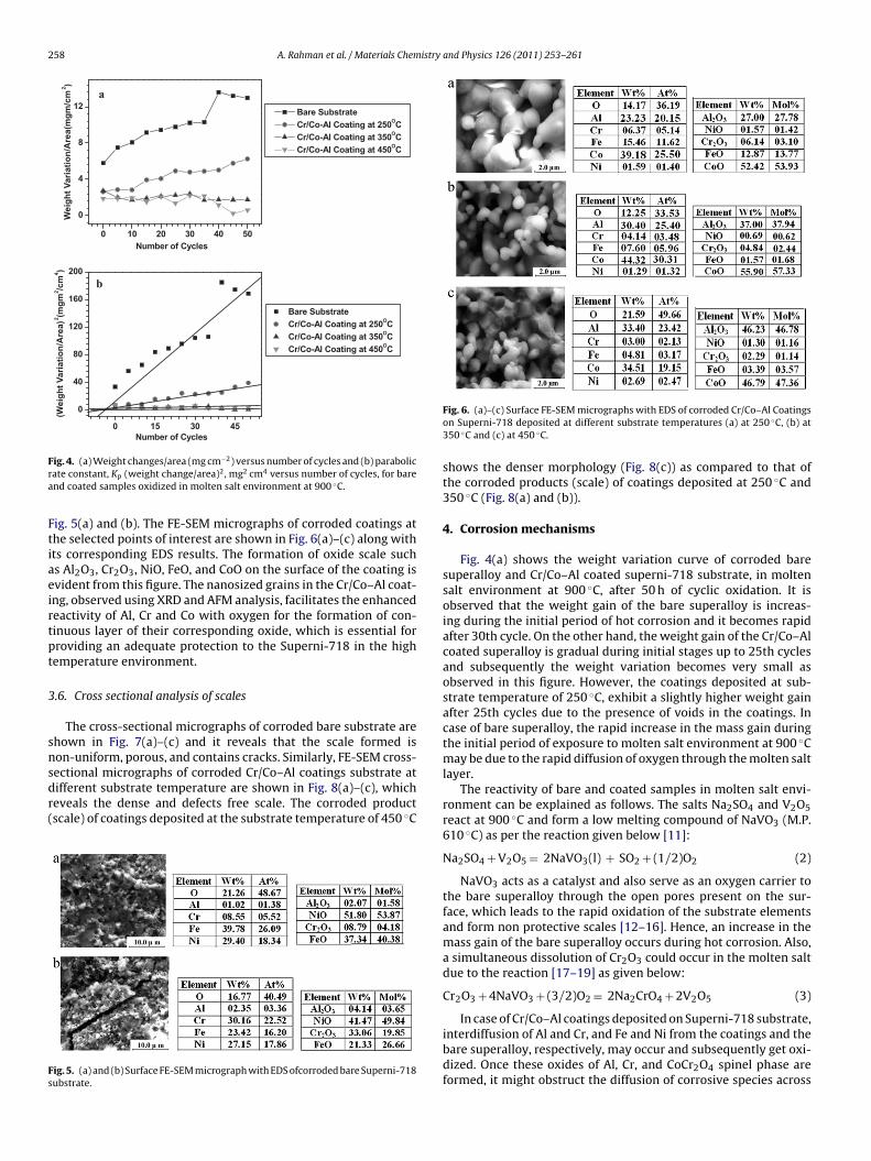
ig. 4. (a) Weight changes/area (mg cm−2) versus number of cycles and (b) parabolicate constant, Kp (weight change/area)2, mg2 cm4 versus number of cycles, for barend coated samples oxidized in molten salt environment at 900 ◦C.
ig. 5(a) and (b). The FE-SEM micrographs of corroded coatings athe selected points of interest are shown in Fig. 6(a)–(c) along withts corresponding EDS results. The formation of oxide scale suchs Al2O3, Cr2O3, NiO, FeO, and CoO on the surface of the coating isvident from this figure. The nanosized grains in the Cr/Co–Al coat-ng, observed using XRD and AFM analysis, facilitates the enhancedeactivity of Al, Cr and Co with oxygen for the formation of con-inuous layer of their corresponding oxide, which is essential forroviding an adequate protection to the Superni-718 in the highemperature environment.
.6. Cross sectional analysis of scales
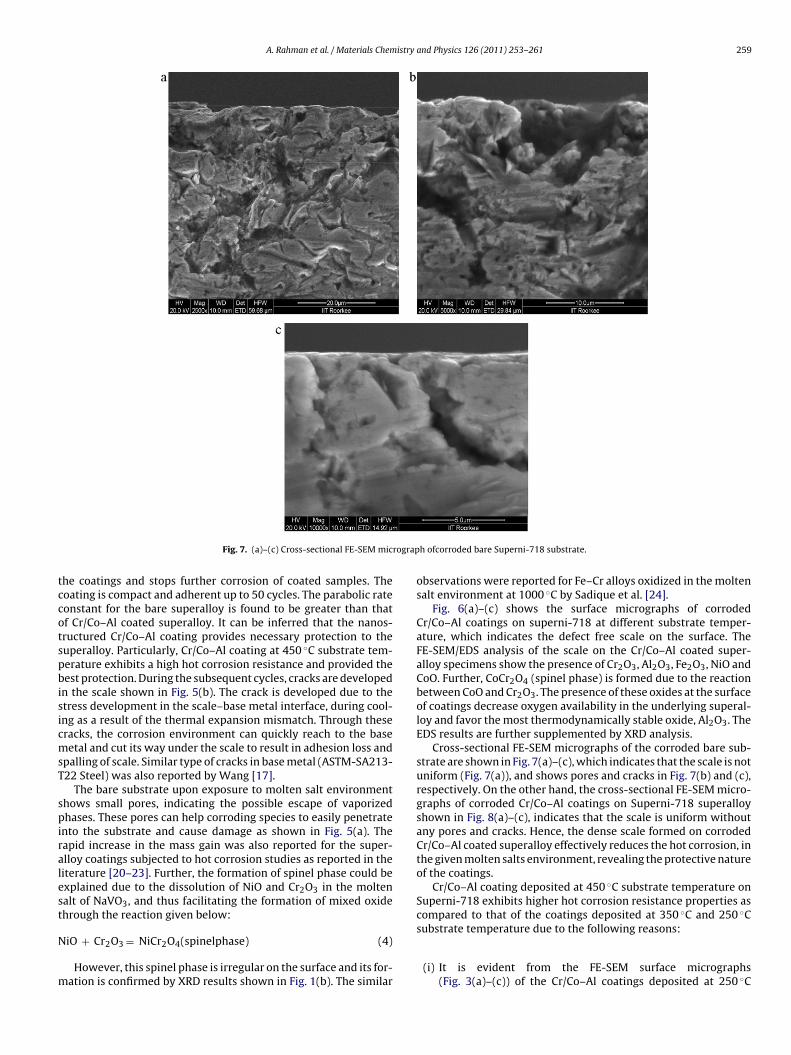
The cross-sectional micrographs of corroded bare substrate arehown in Fig. 7(a)–(c) and it reveals that the scale formed ison-uniform, porous, and contains cracks. Similarly, FE-SEM cross-
ectional micrographs of corroded Cr/Co–Al coatings substrate atifferent substrate temperature are shown in Fig. 8(a)–(c), whicheveals the dense and defects free scale. The corroded productscale) of coatings deposited at the substrate temperature of 450 ◦Cig. 5. (a) and (b) Surface FE-SEM micrograph with EDS ofcorroded bare Superni-718ubstrate.
Fig. 6. (a)–(c) Surface FE-SEM micrographs with EDS of corroded Cr/Co–Al Coatingson Superni-718 deposited at different substrate temperatures (a) at 250 ◦C, (b) at350 ◦C and (c) at 450 ◦C.
shows the denser morphology (Fig. 8(c)) as compared to that ofthe corroded products (scale) of coatings deposited at 250 ◦C and350 ◦C (Fig. 8(a) and (b)).
4. Corrosion mechanisms
Fig. 4(a) shows the weight variation curve of corroded baresuperalloy and Cr/Co–Al coated superni-718 substrate, in moltensalt environment at 900 ◦C, after 50 h of cyclic oxidation. It isobserved that the weight gain of the bare superalloy is increas-ing during the initial period of hot corrosion and it becomes rapidafter 30th cycle. On the other hand, the weight gain of the Cr/Co–Alcoated superalloy is gradual during initial stages up to 25th cyclesand subsequently the weight variation becomes very small asobserved in this figure. However, the coatings deposited at sub-strate temperature of 250 ◦C, exhibit a slightly higher weight gainafter 25th cycles due to the presence of voids in the coatings. Incase of bare superalloy, the rapid increase in the mass gain duringthe initial period of exposure to molten salt environment at 900 ◦Cmay be due to the rapid diffusion of oxygen through the molten saltlayer.
The reactivity of bare and coated samples in molten salt envi-ronment can be explained as follows. The salts Na2SO4 and V2O5react at 900 ◦C and form a low melting compound of NaVO3 (M.P.610 ◦C) as per the reaction given below [11]:
Na2SO4 + V2O5 = 2NaVO3(l) + SO2 + (1/2)O2 (2)
NaVO3 acts as a catalyst and also serve as an oxygen carrier tothe bare superalloy through the open pores present on the sur-face, which leads to the rapid oxidation of the substrate elementsand form non protective scales [12–16]. Hence, an increase in themass gain of the bare superalloy occurs during hot corrosion. Also,a simultaneous dissolution of Cr2O3 could occur in the molten saltdue to the reaction [17–19] as given below:
Cr2O3 + 4NaVO3 + (3/2)O2 = 2Na2CrO4 + 2V2O5 (3)
In case of Cr/Co–Al coatings deposited on Superni-718 substrate,interdiffusion of Al and Cr, and Fe and Ni from the coatings and thebare superalloy, respectively, may occur and subsequently get oxi-dized. Once these oxides of Al, Cr, and CoCr2O4 spinel phase areformed, it might obstruct the diffusion of corrosive species across
A. Rahman et al. / Materials Chemistry and Physics 126 (2011) 253–261 259
rograp
tccotspbisicmsT
spiralest
N
m
Fig. 7. (a)–(c) Cross-sectional FE-SEM mic
he coatings and stops further corrosion of coated samples. Theoating is compact and adherent up to 50 cycles. The parabolic rateonstant for the bare superalloy is found to be greater than thatf Cr/Co–Al coated superalloy. It can be inferred that the nanos-ructured Cr/Co–Al coating provides necessary protection to theuperalloy. Particularly, Cr/Co–Al coating at 450 ◦C substrate tem-erature exhibits a high hot corrosion resistance and provided theest protection. During the subsequent cycles, cracks are developed
n the scale shown in Fig. 5(b). The crack is developed due to thetress development in the scale–base metal interface, during cool-ng as a result of the thermal expansion mismatch. Through theseracks, the corrosion environment can quickly reach to the baseetal and cut its way under the scale to result in adhesion loss and
palling of scale. Similar type of cracks in base metal (ASTM-SA213-22 Steel) was also reported by Wang [17].
The bare substrate upon exposure to molten salt environmenthows small pores, indicating the possible escape of vaporizedhases. These pores can help corroding species to easily penetrate
nto the substrate and cause damage as shown in Fig. 5(a). Theapid increase in the mass gain was also reported for the super-lloy coatings subjected to hot corrosion studies as reported in theiterature [20–23]. Further, the formation of spinel phase could bexplained due to the dissolution of NiO and Cr2O3 in the moltenalt of NaVO3, and thus facilitating the formation of mixed oxidehrough the reaction given below:
iO + Cr2O3 = NiCr2O4(spinelphase) (4)
However, this spinel phase is irregular on the surface and its for-ation is confirmed by XRD results shown in Fig. 1(b). The similar
h ofcorroded bare Superni-718 substrate.
observations were reported for Fe–Cr alloys oxidized in the moltensalt environment at 1000 ◦C by Sadique et al. [24].
Fig. 6(a)–(c) shows the surface micrographs of corrodedCr/Co–Al coatings on superni-718 at different substrate temper-ature, which indicates the defect free scale on the surface. TheFE-SEM/EDS analysis of the scale on the Cr/Co–Al coated super-alloy specimens show the presence of Cr2O3, Al2O3, Fe2O3, NiO andCoO. Further, CoCr2O4 (spinel phase) is formed due to the reactionbetween CoO and Cr2O3. The presence of these oxides at the surfaceof coatings decrease oxygen availability in the underlying superal-loy and favor the most thermodynamically stable oxide, Al2O3. TheEDS results are further supplemented by XRD analysis.
Cross-sectional FE-SEM micrographs of the corroded bare sub-strate are shown in Fig. 7(a)–(c), which indicates that the scale is notuniform (Fig. 7(a)), and shows pores and cracks in Fig. 7(b) and (c),respectively. On the other hand, the cross-sectional FE-SEM micro-graphs of corroded Cr/Co–Al coatings on Superni-718 superalloyshown in Fig. 8(a)–(c), indicates that the scale is uniform withoutany pores and cracks. Hence, the dense scale formed on corrodedCr/Co–Al coated superalloy effectively reduces the hot corrosion, inthe given molten salts environment, revealing the protective natureof the coatings.
Cr/Co–Al coating deposited at 450 ◦C substrate temperature onSuperni-718 exhibits higher hot corrosion resistance properties ascompared to that of the coatings deposited at 350 ◦C and 250 ◦C
substrate temperature due to the following reasons:(i) It is evident from the FE-SEM surface micrographs(Fig. 3(a)–(c)) of the Cr/Co–Al coatings deposited at 250 ◦C

260 A. Rahman et al. / Materials Chemistry and Physics 126 (2011) 253–261
F on Supa
(
altamc
ig. 8. (a)–(c) Cross-sectional FE-SEM Micrographs of corroded Cr/Co–Al Coatingsnd (c) at 450 ◦C.
and 350 ◦C that the coatings exhibit globular and layered typemorphology but the spherical morphology is observed forthe coatings deposited at 450 ◦C. Similarly, cross-sectionalmicrograph of as deposited Cr/Co–Al coatings shows a denseand columnar structure of the coatings. It may be mentionedthat the diffusivity of atoms such as Al, Cr, and Co in thecoatings through columnar structure is fast, which results inthe formation of dense and defect free scale as confirmed bysurface as well as cross-sectional FE-SEM micrograph shownin Figs. 6(c) and 8(c). Therefore, the coatings deposited atsubstrate temperature of 450 ◦C show Al-rich and Co-richoxide scale indicated in Fig. 6(c), which inhibits the movementof anion as well as cations.
(ii) The fine grain size, 20–35 nm, and a sufficient amount of Al inthe coatings, leads to its selective oxidation. It enables to repairthe alumina scale rapidly during fluxing.
iii) The surface EDS analysis of oxide scale of coatings depositedat 450 ◦C substrate temperature contains higher Al2O3 content(46.23 wt.%) as compared to the coatings deposited at 250 ◦C(27.00 wt.%) and 350 ◦C substrate temperature (37.00 wt.%) asshown in Fig. 6(a)–(c), which is sufficient to inhibit the oxygenand suppress the internal oxidation.
In brief, the nanostructured Cr/Co–Al coating is designed in suchway that aluminum rich outer layer and chromium rich internal
ayer are effectively utilized to combat hot corrosion. The resistanceo hot corrosion fluxing of the Cr/Co–Al coating is greatly enhancedt the cost of sacrificing its beneficial element (especially the alu-inum), while the bare substrate Superni-718 exhibits poor hot
orrosion resistance in molten salt of (Na2SO4–60%V2O5) environ-
erni-718 deposited at different substrate temperatures (a) at 250 ◦C, (b) at 350 ◦C
ment at 900 ◦C, due to the shortage of aluminum reservoir. In otherwords, a coating with an insufficient amount of aluminum reservoircannot survive for a longer duration in chemically aggressive envi-ronments at high temperature [25–27]. The low corrosion rate ofnanostructured Cr/Co–Al coatings observed in the present work isin accordance with the results of nanocrystalline NiCrAlY coatingsreported in the literature [28].
5. Conclusion
Cyclic hot corrosion of nanostructured Cr/Co–Al coat-ings on the superalloy substrate exposed to molten salt of(40%Na2SO4–60%V2O5) environment at 900 ◦C has been investi-gated in the present work. The hot corrosion kinetics of Cr/Co–Alcoatings has been compared with that of the bare Superni-718 andfound that the parabolic rate constant is very less for the former,which is due to the formation of continuous, nonporous, adherentand protective oxide scale over the surface of the coating. Thecontinuous mass gain of Superni-718 is due to the spallation ofinitial oxide scales, renewal of fresh surface of the materials, andthe pores resulting from the evaporation of volatile impurities inthe alloy at high temperature. The XRD analysis of the corrodedproducts of the Cr/Co–Al coatings indicated the formation ofprotective oxide scale such as Cr2O3, Al2O3, Fe2O3, CoCr2O4 andNiO. The morphological features of the corroded coatings and bare
samples were characterized by FE-SEM and it was evident that thescales formed on the surface of coatings are adherent and very lessspallation has occurred as compared to bare samples.Cr/Co–Al coatings, deposited at 450 ◦C, showed a lower corro-sion rate as compared to that of the coatings deposited at 250 ◦C
istry
a(onaw
A
N
R
[[[[[[[[[
[[
[[
[
A. Rahman et al. / Materials Chem
nd 350 ◦C. It is due to the denser morphology, nanosized grains20–35 nm) of the coatings, and spherical and equiaxed grain sizef scales/oxides with higher amount of alumina (46.23 wt.%). Theanostructured coatings have improved their oxidation resistances well as the scale-metal adherence as observed in the presentork.
cknowledgment
One of the authors, Dr. R. Jayaganthan would like to thank CSIR,ew Delhi, India for their financial support to this work.
eferences
[1] D.P. Whittle, in: D. Coutsouradis, P. Felix, H. Fischmeister, L. Habraken, Y. Lin-blon, M.O. Speidel (Eds.), High Temperature Alloys for Gas Turbines, AppliedScience Publishers Ltd., London, 1978, pp. 209–224.
[2] F. Wang, X. Tian, Q. Li, L. Li, X. Peng, Thin Solid Films 516 (2008) 5740–5747.[3] S. Geng, F. Wang, S. Zhang, Surf. Coat. Technol. 167 (2003) 212–216.[4] D.P. Whittle, J. Stringer, Philos. Trans. R. Soc., Lond. Ser. A 295 (1980) 309–329.[5] C.S. Giggins, F.S. Pettit, Trans. Metall. Soc. AIME 245 (1969) 2495–2507.[6] A. Rahman, R. Jayaganthan, S. Prakash, V. Chawla, R. Chandra, J. Alloys Compd.
472 (2009) 478–483.
[
[[[[
and Physics 126 (2011) 253–261 261
[7] A. Rahman, R. Jayaganthan, S. Prakash, V. Chawla, R. Chandra, Surf. Eng. (2008),in press, doi:10.1179/026708408x339064.
[8] L. Hanyi, W. Fuhui, B. Linxiang, Mater. Sci. Eng. A 123 (1990) 123–128.[9] D. Zou, D. Yan, L. Xiao, Y. Dong, Surf. Coat. Technol. 202 (2008) 1928–1934.10] R. Messier, A.P. Giri, R.A. Roy, J. Vac. Sci. Technol. A 2 (1984) 500–503.11] G.A. Kotla, I.F. Hewaidy, N.S. Felix, Thermochem. Acta 4 (1972) 151–164.12] N.S. Bornstein, M.A. DeCrescente, Metall. Trans. 2 (1971) 2875–2883.13] N.S. Bornstein, M.A. DeCrescente, Metall. Trans. 4 (1973) 1799–1811.14] J.A. Goebel, F.S. Pettit, G.W. Gowar, Metall. Trans. 4 (1973) 261–279.15] D.K. Gupta, R.A. Rapp, J. Electrochem. Soc. 127 (1980) 2194–2202.16] Y.S. Zhang, R.A. Rapp, J. Electrochem. Soc. 132 (1985) 2498–2501.17] D. Wang, Surf. Coat. Technol. 36 (1988) 49–60.18] G.R. Heath, P. Heimgarther, G. Irons, R. Miller, S. Gustafsson, Mater. Sci. Forum
251–254 (1997) 809–816.19] M. Seiersten, P. Kofstad, High Temp. Tech. 5 (30) (1987) 115–122.20] T.S. Sidhu, S. Prakash, R.D. Agrawala, Surf. Coat. Technol. 201 (2006)
792–800.21] H. Singh, D. Puri, S. Prakash, Surf. Coat. Technol. 192 (2005) 27–38.22] S.N. Tiwari, S. Prakash, A Symposium on Localized Corrosion and Environmental
Cracking (SOLCEC), Kalpakkam, India, 1997, C-33.23] A. Ul-Hamid, Mater. Chem. Phys. 80 (2003) 135–142.
24] S.E. Sadique, A.H. Mollah, M.S. Islam, M.M. Ali, M.H.H. Megat, S. Basri, Oxid. Met.54 (5–6) (2000) 385–400.25] R.A. Rapp, Corros. Sci. 44 (2002) 209–221.26] Y.S. Hwang, R.A. Rapp, J. Electrochem. Soc. 137 (1990) 1276–1284.27] R.A. Rapp, Whitney Award Lecture, Corrosion-NACE 42, 1986, p. 568.28] X. Ren, F. Wang, Surf. Coat. Technol. 201 (2006) 30–37.