
Synthesis and Evaluation of Luminescent Tracers and Hapten ...
Upload
khangminh22Category
view
1download
0
materials
Review
Aluminate-Based Nanostructured Luminescent Materials:Design of Processing and Functional Properties
Rocío Estefanía Rojas-Hernandez 1,* , Fernando Rubio-Marcos 2,3 , José Francisco Fernandez 2
and Irina Hussainova 1
�����������������
Citation: Rojas-Hernandez, R.E.;
Rubio-Marcos, F.; Fernandez, J.F.;
Hussainova, I. Aluminate-Based
Nanostructured Luminescent
Materials: Design of Processing and
Functional Properties. Materials 2021,
14, 4591. https://doi.org/10.3390/
ma14164591
Academic Editor: Dirk Poelman
Received: 2 July 2021
Accepted: 10 August 2021
Published: 16 August 2021
Publisher’s Note: MDPI stays neutral
with regard to jurisdictional claims in
published maps and institutional affil-
iations.
Copyright: © 2021 by the authors.
Licensee MDPI, Basel, Switzerland.
This article is an open access article
distributed under the terms and
conditions of the Creative Commons
Attribution (CC BY) license (https://
creativecommons.org/licenses/by/
4.0/).
1 Department of Mechanical and Industrial Engineering, Tallinn University of Technology, Ehitajate 5,19180 Tallinn, Estonia; [email protected]
2 Electroceramic Department, Instituto de Cerámica y Vidrio, CSIC, Kelsen 5, 28049 Madrid, Spain;[email protected] (F.R.-M.); [email protected] (J.F.F.)
3 Escuela Politécnica Superior, Universidad Antonio de Nebrija, C/Pirineos, 55, 28040 Madrid, Spain* Correspondence: [email protected]
Abstract: Interest in luminescent materials has been continuously growing for several decades,looking for the development of new systems with optimized optical properties. Nowadays, researchhas been focused on the development of materials that satisfy specific market requirements inoptoelectronics, radioelectronics, aerospace, bio-sensing, pigment applications, etc. Despite the factthat several efforts have made in the synthesis of organic luminescent materials, their poor stabilityunder light exposure limits their use. Hence, luminescent materials based on inorganic phosphorsare considered a mature topic. Within this subject, glass, glass-ceramics and ceramics have had greattechnological relevance, depending on the final applications. Supposing that luminescent materialsare able to withstand high temperatures, have a high strength and, simultaneously, possess highstability, ceramics may be considered promising candidates to demonstrate required performance. Inan ongoing effort to find a suitable synthesis method for their processing, some routes to developnanostructured luminescent materials are addressed in this review paper. Several ceramic familiesthat show luminescence have been intensively studied in the last few decades. Here, we demonstratethe synthesis of particles based on aluminate using the methods of sol-gel or molten salts and theproduction of thin films using screen printing assisted by a molten salt flux. The goal of this reviewis to identify potential methods to tailor the micro-nanostructure and to tune both the emission andexcitation properties, focusing on emerging strategies that can be easily transferred to an industrialscale. Major challenges, opportunities, and directions of future research are specified.
Keywords: ceramic luminescent materials; nanostructure; screen printing; molten salts; NIR emission;down-conversion; nanofibers; sol-gel
1. Introduction
Recently, a large number of inorganic, organic, or inorganic-organic luminescent hy-brid materials have been extensively explored for optical, opto-electronical, and biologicalapplications. Nowadays, a wide variety of luminescent materials are represented in theforms of glass, glass-ceramics, and ceramics. Here, we are focusing on luminescent materi-als composed of an inorganic matrix, usually known as a host, and activators or dopants,which are included in the matrix to act as an emitter or a trap. In general, the dopants arerare earth elements, and, to a lesser extent, transition metals, such as V3+, Cu2+, Mn2+, Ti4+,Sn2+, Co2+, Bi3+ or Pb2+ [1]. Despite the increasing demand for rare earth-free luminescentmaterials, the efficiency is still quite low [2].
Glasses are quite versatile and are mainly used for lasers, optical fibers and amplifiersdue to their high optical transparency. Usually, a low phonon matrix is selected to get ridof non-radiative relaxation. Glass phosphors’ shortcomings are related to their inefficientperformance as compared to crystalline counterparts [3]. Moreover, as bulk active materials,
Materials 2021, 14, 4591. https://doi.org/10.3390/ma14164591 https://www.mdpi.com/journal/materials

Materials 2021, 14, 4591 2 of 18
their manufacturing is economical and less tedious, providing the freedom to obtaindifferent shapes, sizes, and homogeneity, avoiding optical losses.
On the other hand, glass-ceramics are constituted by crystallites that are uniformlydispersed or embedded into an amorphous glass matrix. Their optical properties aremodulated by the nature of the crystallites that can be either on the micron or nano scale,the glass matrix and the interfaces between the constituents [4,5]. The refractive index andmorphological differences between the crystal and glass components are considered asthe main reasons for scattering losses. This encourages the scientific community to closelymatch the refractive index of the crystalline phase to the glass-matrix one. Design andfabrication methods are challenging tasks. Despite significant advances in the theoreticalunderstanding of glass structures [6], predictive methods are still far from maturity.
Not only should the optical properties of luminescent materials be improved, thematerials themselves should fulfil other requirements, such as having a suitable hardness,fracture toughness, and high temperature stability. For this reason, research in polycrys-talline ceramic materials has been growing in parallel with the development of glass-basedmaterials. Luminescent materials that withstand high temperatures, harsh chemical en-vironments, electromagnetic fields, and radiation are highly demanded. These requestshave led to the study of ceramic luminescent materials, which have customized spectralproperties and decay kinetics.
In general, luminescent materials, as well as ceramics, have been mostly manufactur-ing in a powder form. For specific applications, luminescent particles are incorporated toform thick or thin films. However, efficient emission of light is limited due to the strongabsorption and scattering of the particles. This, alongside the drawbacks regarding ther-mal stability and aging degradation of the particles embedded in a polymer matrix, havedirectly led to the development of films, where the volume effect greatly increases theluminescent properties.
Several fabrication methods have been adapted to synthesize ceramic luminescentmaterials based on conventional approaches, such as solid-state methods and, to a lesserextent, others routes, such as the precipitation method, a sol-gel route [7,8], hydrothermalsynthesis [9], laser synthesis [10], and combustion synthesis [11–14]. Sol-gel derivedpowders usually accept higher contents of dopants due to their solubility and achievea better dispersion in the matrix compared to other synthesis methods, in which thequenching concentrations are lower.
Generally, ceramic luminescent materials can be classified based on their chemicalcompositions. Within the oxide family, Al2O3 has mainly been studied due to its highperformance within engineering ceramics. Specifically, the α-alumina phase has beenselected due to its stability and wide availability. Both undoped and doped aluminacompounds show luminescence. Undoped alumina represents a high potential for usein dosimeters [15] due to the high concentration of oxygen vacancies, which producesF-centers and the photo and cathodoluminescence in the UV region derived from the F-centers. Regarding doped alumina, Cr-doped Al2O3 powders have been the most studied;the luminescence response has been found to be similar to ruby crystal, giving a frameworkto replace single crystals by employing polycrystalline alumina with a reduced cost andwith a greater versatility of shapes and dimensions [16].
Garnets are also well-known as a host family for optical applications; these com-pounds are based on the combination of a rare earth oxide and a metal oxide, the mostrepresentative materials of this group are Y3Al5O12 (YAG) and Y3Ga5O12 (YGG). YAGmay be doped with Eu [17], Ce [18], or Nd [19,20] to enhance performance. It is importantto highlight that Nd-YAG is one of the most important laser crystals for generating a1.06-µm NIR emission. The primary reason for the interest in aluminate-based luminescentmaterials is its efficient luminescence response compared to other families, such as oxides.The undistorted and distorted structures formed by rings of AlO4 tetrahedra and AlO6octahedra provide lattice conditions for the ease incorporation of activators that providethe luminescence properties to the end product. In addition, some inherent defects, such
Materials 2021, 14, 4591 3 of 18
as vacancies and structure inversion contributing to the creation of anti-site defects, giveadded value into their luminescence response.
Another remarkable family of luminescent materials is the sulfides. Among them,calcium sulfides (CaS) doped with Eu2+, Tm3+, and Ce+, or with Bi3+, show emission inred and blue lights [21,22]. Sulfide development has been in parallel with that of LEDs;the first white LEDs were based on a blue LED joined with a sulfide phosphor. However,sulfides are sensitive to moisture and thermal quenching. For this reason, the research onaluminate-based phosphors has gained enormous attention. Generally speaking, metalaluminates doped with RE demonstrate a suitable luminescence performance due to theintrinsic properties of spinel or trydimite structures. This is the case for the alkaline earthaluminate MAl2O4 (where M = Ca, Sr, Ba) and also alkaline earth hexa-aluminates relatedto magnetoplumbite and β-alumina.
Until now, the number of types of phosphors has increased significantly, and thereare new modified hosts and dopants from transitions metals and rare earths that open upa chart of phosphors. Depending on the emission, excitation, and end-product response,a huge list of appropriate phosphors for each field is already available. In this review,some phosphors based on alkaline earth aluminates and metal aluminates are reported.Our work is focused on materials that display luminescence and persistence luminescence.Mostly, RE have been used as activators, achieving emissions in the visible and NIR ranges.
Taking into consideration the current phosphor market, there are still some limitationsthat hinder their use in practical applications. In the case of phosphors in a powdered form,commercial phosphor particles in the micron size range, which have been mainly producedusing conventional solid-state reaction processes, have shortcomings related to their ag-glomeration and irregular shapes and sizes. Nano-scale phosphors could be a promisingalternative due to the confinement effects; however, their low stability, together with com-plex synthesis routes, restrict their use. As luminescence is affected by the morphology andsize of particles, many efforts have been made to synthesize well-defined morphologiesand sizes. To solve the problem of agglomeration, hydrothermal, microemulsion andsol-gel methods have been successfully exploited; small particles at low temperatures canbe synthesized, but the formation of a single phase should be optimized [23]. Therefore,combining improvements in efficiency and stability of phosphors is still required; thescientific community is looking for new strategies to provide a framework for the designof the next generation of phosphors based on nano-architectures, increasing performanceand, at the same time, wavelength tunability.
2. Designing Strategies for Aluminates-Based Luminescent Materials
Luminescent nanostructured materials have drawn the interest of the scientific com-munity due to their optical and chemical properties, which show better a response incomparison with their bulk counterparts. Their design size, morphology, and phasecontent have led to a surge of new synthesis methods. Chemical routes, such as hydrother-mal, co-precipitation, micro emulsion, solvothermal, combustion, sol-gel methods, andmicrowave-assisted reactions, are usually used to produce nanomaterials, and are des-ignated as bottom-up approaches. Ceramic powders with ultrafine grains and sphericalmorphologies are commonly obtained via microemulsion, in which the growth of particlesis limited by micelles. Solvo-thermal or microwave assisted bottom-up processes allow tocontrol the size of phosphor particles through surfactant or chelating agents. Nevertheless,the complicated fabrication procedures limit the practical applications of these nanomate-rial solutions, which do not require sophisticated processing in order to have easy scale-up.Through the use of top-down approaches, such as high- or low-energy milling processes,nanophosphors can also be produced. However, the milling process deteriorates opticalproperties due to the large numbers of defects on the surface and the lower crystallinity ofthe obtained non-spherical phosphors.
Materials 2021, 14, 4591 4 of 18
2.1. Luminescent Materials by Molten Salts Assisted Process
Looking for a synthesis method that can meet all requirements, a molten salts strategyhas been used for the synthesis of nanostructured luminescent materials to be transferredto an industrial level. Not many phosphors have been obtained using a molten salt-assistedroute. The first works on phosphors made using molten salts date to the last decade;Lei et al. [24] obtained sphere-like and rod-like Gd2MoO6:Eu3+ phosphors dependingthe used flux (NaCl or KCl). The same authors obtained a red phosphor based onZnWO4:Eu3+ [25] using LiNO3, NaNO3, and KNO3 as a flux. Y2O3:Eu, Bi was synthesizedfor the first time by Wu et al. [26]; the red emitter had an octahedral morphology that wasobtained using a KNO3–NaNO3 eutectic mixture. Cerium-activated Y3-xCexAl5O12 wasfirst synthesized using molten salts with NaNO2-KNO2 and NaCl-KCl [27]; the morphol-ogy could be tuned from spherical-like to cubic shaped using different salts. Moreover,YAG doped with cerium non-aggregated particles with a spherical morphology were ob-tained using mixtures of Na2SO4-BaF2 as the molten salt [28]. The salt ratios modulatedthe diameter of the spherical particles, which shows peak emission at 535 nm [28]. Otherquasi-spherical Y2O3:Eu3+ particles were obtained using Na2CO3, S, and NaCl salts. Theparticles synthesized with molten salts allowed to improve the luminescence intensityby 30% in comparison with particles obtained without salts [29]. Recently, red-emittingMgAl2O4:Mn4+ single-crystal phosphors have been produced using LiCl as a moltenflux [30].
The idea behind molten salt synthesis is to promote mass transfer and transport usinga liquid media at the synthesis temperature. The nature of the salt greatly effects thechemical reactivity of the precursor used; depending on the composition a relatively lowmelting point can be achieved. Generally, nitrates, hydroxides, chlorides, and sulfatesare employed; individual ionic salts or their corresponding eutectic mixtures are selected,and the advantage of mixtures are that they endow a low melting point and usuallya reduced viscosity. The morphology, size, and nature of the precursors used governthe growth process of a template formation, a dissolution-precipitation process, or amixture of both. When both reactants are soluble in salt, the dissolution-precipitationmechanism controls the growth. On the contrary, if one of the reactants is less soluble thatthe other, the dissolution-diffusion mechanism (known as a template formation or templategrowth) occurs; the soluble reactant is dissolved in the initial stage and then diffusesonto the surface of the less-soluble precursor. Figure 1 shows the morphology of twoaluminates, magnesium and strontium aluminate phosphor materials prepared by moltensalts employing two different nanosized, alpha (α-Al2O3) and gamma (γ-Al2O3), aluminasand MgO and SrCO3 particles in the micron range. Here, the dissolution-precipitationtends to dominate the growth mechanism. As the aluminates formed tend to retain theoriginal nano γ or α-Al2O3 shape, the authors suggested the occurrence of a mix mechanism(dissolution–diffusion–precipitation process), governed by the dissolution-precipitationprocess. When γ-Al2O3 is used, Mg2+ or Sr2+ diffusion around the nano γ-Al2O3 is higherin comparison to the alpha phase, and the end aluminate is notably large. Raw α-Al2O3promotes template mechanism preserving the size of the precursor of the alpha aluminamore, while the raw γ-Al2O3 stimulates the dissolution-precipitation process. Despitethere the fact that there is a mixing mechanism in both cases, the prevailing mechanismdefines the end size of the aluminate.
The synthesis of magnesium aluminate MgAl2O4:Mn4+ was done using ionic salts,such as LiCl, NaCl, and KCl. As the melting point of LiCl is low, this salt was the one thataccelerated synthesis, avoiding residual MgO. On the other hand, SrAl2O4:Eu, Dy wassynthesized using a NaCl-KCl eutectic mixture that has a melting point around 659 ◦C,which is lower than the individual ionic salts, with melting points at 903 and 954 ◦C forNaCl and KCl, respectively. To the best of our knowledge, our research group was the firstto develop persistent phosphors using the molten salts route [31].

Materials 2021, 14, 4591 5 of 18Materials 2021, 14, x FOR PEER REVIEW 5 of 19
Figure 1. SEM micrographs of MgAl2O4:Mn phosphors heated at 950 °C for 6 h in 90N2-10H2 atmos-
phere using (a) nano α-Al2O3 and (b) nano γ-Al2O3. Reprinted with permission from [30]. Copyright
2020, American Chemical Society Publishing. FE-SEM micrographs of powders based on SrAl2O4:Eu,
Dy heated at 1000 °C for 2 h in 90N2-10H2 atmosphere, employing a salt/SrAl2O4 molar ratio of 3:1
using (c) nano α-Al2O3 and (d) nano γ-Al2O3.
The synthesis of magnesium aluminate MgAl2O4:Mn4+ was done using ionic salts,
such as LiCl, NaCl, and KCl. As the melting point of LiCl is low, this salt was the one that
accelerated synthesis, avoiding residual MgO. On the other hand, SrAl2O4:Eu,Dy was syn-
thesized using a NaCl-KCl eutectic mixture that has a melting point around 659 °C, which
is lower than the individual ionic salts, with melting points at 903 and 954 °C for NaCl
and KCl, respectively. To the best of our knowledge, our research group was the first to
develop persistent phosphors using the molten salts route [31].
In our previous works [31–33], the correlation of the amount of salt and photolumi-
nescence intensity was studied thoroughly. In the case of employing SrAl2O4:Eu, Dy as
precursor of nano α-Al2O3, an increase in the emission intensity was observed when the
salt/SrAl2O4 molar ratio increased from 1:1, 3:1, to 5:1. The emission increment is attributed
to the different percentages of monoclinic and hexagonal polymorphs, using different salt
ratios (Figure 2a). A similar behavior has been observed when YAG: Ce was synthesized
using NaCl-KCl (Figure 2b), it was found that the emission intensity showed a rising ten-
dency as the ratio of salt increased to 4:1; using a higher salts ratio, such as 5:1, the intensity
decreased slightly [34].
a. c.
b. d.
Figure 1. SEM micrographs of MgAl2O4:Mn phosphors heated at 950 ◦C for 6 h in 90N2-10H2
atmosphere using (a) nano α-Al2O3 and (b) nano γ-Al2O3. Reprinted with permission from [30].Copyright 2020, American Chemical Society Publishing. FE-SEM micrographs of powders based onSrAl2O4:Eu, Dy heated at 1000 ◦C for 2 h in 90N2-10H2 atmosphere, employing a salt/SrAl2O4 molarratio of 3:1 using (c) nano α-Al2O3 and (d) nano γ-Al2O3.
In our previous works [31–33], the correlation of the amount of salt and photolu-minescence intensity was studied thoroughly. In the case of employing SrAl2O4:Eu, Dyas precursor of nano α-Al2O3, an increase in the emission intensity was observed whenthe salt/SrAl2O4 molar ratio increased from 1:1, 3:1, to 5:1. The emission increment isattributed to the different percentages of monoclinic and hexagonal polymorphs, usingdifferent salt ratios (Figure 2a). A similar behavior has been observed when YAG: Ce wassynthesized using NaCl-KCl (Figure 2b), it was found that the emission intensity showed arising tendency as the ratio of salt increased to 4:1; using a higher salts ratio, such as 5:1,the intensity decreased slightly [34].
It is fundamental to emphasize that one of the requirements for the selected salt isrelated to its easy elimination, either through evaporation during synthesis or by washingin a further step. In most cases, during synthesis, the salt is eliminated because theused temperature usually exceeds the melting point. In case of mixtures of salts, highertemperatures should be used due to the possible vaporization of individual salts. Somegrains of individual salts can remain unreacted in the mixture, so leftovers or excess ofsalts interact well with the phosphor material. If the temperatures of the process do notpromote the evaporation of the salts, a washing step is required. In principle, almost allsalts can be eliminated by washing out with water or other polar solvents [35]; nevertheless,some phosphors are not resistant or their luminescence response decreases by exposureto water. This shortcoming can be overcome by washing with other media. Here, bothapproaches are addressed; the phosphors based on strontium aluminate were shed withglycerin and those based on yttrium aluminate with water. Figure 3 shows the dropin luminescence when a washing cycle is performed for phosphors based on strontiumaluminate, employing a salt ratio of 5:1 (eutectic mixture NaCl-KCl).
Materials 2021, 14, 4591 6 of 18Materials 2021, 14, x FOR PEER REVIEW 6 of 19
Figure 2. (a) Photoluminescence emission spectra as a function of the salt/SrAl2O4 molar ratio of 1:1, 3:1, and 5:1 of
SrAl2O4:Eu, Dy phosphor synthesized at 900 °C. (b) Emission spectra of Ce3+ doped yttrium aluminum garnet using salt-
to-reactant molar ratios of 4:1 and 5:1. Reprinted with permission from [34]. Copyright 2019, IOP Publishing, Ltd.
It is fundamental to emphasize that one of the requirements for the selected salt is
related to its easy elimination, either through evaporation during synthesis or by washing
in a further step. In most cases, during synthesis, the salt is eliminated because the used
temperature usually exceeds the melting point. In case of mixtures of salts, higher tem-
peratures should be used due to the possible vaporization of individual salts. Some grains
of individual salts can remain unreacted in the mixture, so leftovers or excess of salts in-
teract well with the phosphor material. If the temperatures of the process do not promote
the evaporation of the salts, a washing step is required. In principle, almost all salts can
be eliminated by washing out with water or other polar solvents [35]; nevertheless, some
phosphors are not resistant or their luminescence response decreases by exposure to wa-
ter. This shortcoming can be overcome by washing with other media. Here, both ap-
proaches are addressed; the phosphors based on strontium aluminate were shed with
glycerin and those based on yttrium aluminate with water. Figure 3 shows the drop in
luminescence when a washing cycle is performed for phosphors based on strontium alu-
minate, employing a salt ratio of 5:1 (eutectic mixture NaCl-KCl).
Figure 2. (a) Photoluminescence emission spectra as a function of the salt/SrAl2O4 molar ratio of 1:1, 3:1, and 5:1 ofSrAl2O4:Eu, Dy phosphor synthesized at 900 ◦C. (b) Emission spectra of Ce3+ doped yttrium aluminum garnet usingsalt-to-reactant molar ratios of 4:1 and 5:1. Reprinted with permission from [34]. Copyright 2019, IOP Publishing, Ltd.
Materials 2021, 14, x FOR PEER REVIEW 7 of 19
Figure 3. (a) Photoluminescence emission spectra as a function of the salt/SrAl2O4 molar ratio of 1:1, 3:1 and 5:1 of
SrAl2O4:Eu, Dy phosphor synthesized at 1000 °C before and after washing. (b) The emission spectra of Dydoped yttrium
aluminum garnet using different Dy concentrations, after washing 12 times. Reprinted with permission from [36]. Copy-
right 2019, John Wiley and Sons.
The washing step was carried out using glycerin, avoiding a hydrolysis reaction, due
to the sensitivity of strontium aluminates to water. For salt ratios of 3:1 and 1:1, the wash-
ing step can be skipped because there is no salt remaining in the end product. Figure 3b
shows the emission of Y3-xDyxAl5O12 (x = 0.05, 0.10, 0.15, 0.20, and 0.25) phosphors, em-
ploying NaCl-KCl molten salt (ratio of the initial reagents and the NaCl–KCl mixture: 1:4).
The YAG:Dy phosphor was fired at 1100 °C and washed with deionized water at least 12
times [36]. Both washing approaches were successfully applied, suggesting that the re-
moval of the remaining salts was not an issue with the use of this synthesis route.
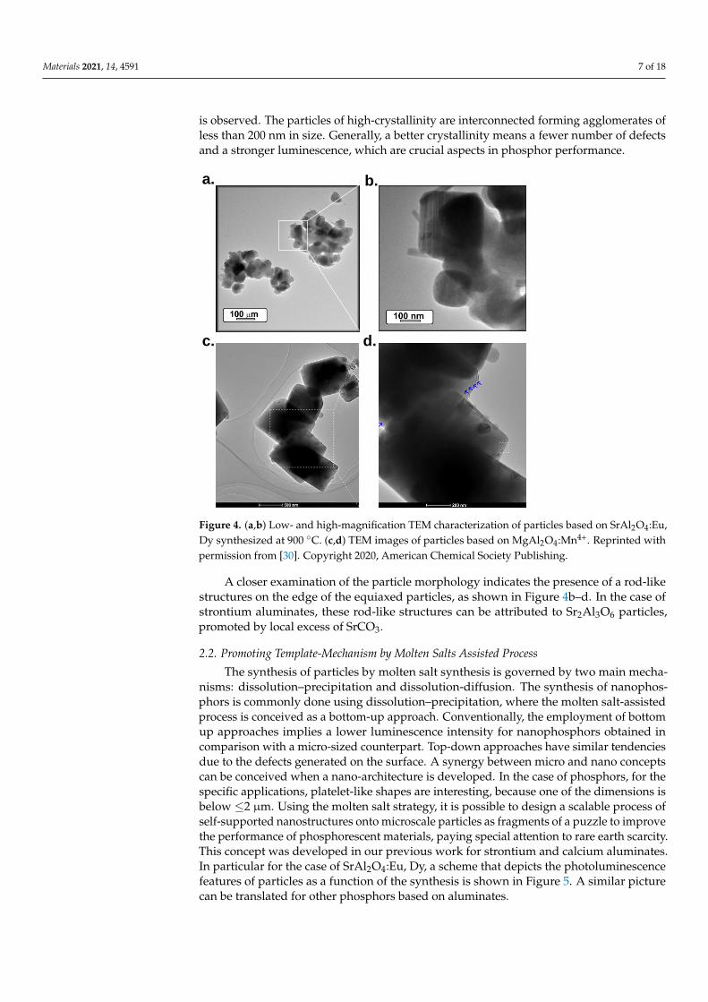
In addition, the molten salts approach provides conditions to obtain particles with a
high crystallinity, smooth surface, and texturation. Figure 4a–d exhibits TEM images of
zinc aluminate and magnesium aluminate particles; in both cases a semi-rectangular
shape is observed. The particles of high-crystallinity are interconnected forming agglom-
erates of less than 200 nm in size. Generally, a better crystallinity means a fewer number
of defects and a stronger luminescence, which are crucial aspects in phosphor perfor-
mance.
a. b.
450 500 550 600 650 700
(nm)
1000ºC 5 : 1 WASHED
Inte
nsity (
arb
.un
its)
1000ºC 5 : 1
1000ºC 3 : 1
EXC
= 380nm
1000ºC 1 : 1
Figure 3. (a) Photoluminescence emission spectra as a function of the salt/SrAl2O4 molar ratio of 1:1, 3:1 and 5:1 ofSrAl2O4:Eu, Dy phosphor synthesized at 1000 ◦C before and after washing. (b) The emission spectra of Dydoped yttriumaluminum garnet using different Dy concentrations, after washing 12 times. Reprinted with permission from [36]. Copyright2019, John Wiley and Sons.
The washing step was carried out using glycerin, avoiding a hydrolysis reaction,due to the sensitivity of strontium aluminates to water. For salt ratios of 3:1 and 1:1,the washing step can be skipped because there is no salt remaining in the end product.Figure 3b shows the emission of Y3-xDyxAl5O12 (x = 0.05, 0.10, 0.15, 0.20, and 0.25) phos-phors, employing NaCl-KCl molten salt (ratio of the initial reagents and the NaCl–KClmixture: 1:4). The YAG:Dy phosphor was fired at 1100 ◦C and washed with deionizedwater at least 12 times [36]. Both washing approaches were successfully applied, suggestingthat the removal of the remaining salts was not an issue with the use of this synthesis route.
In addition, the molten salts approach provides conditions to obtain particles with ahigh crystallinity, smooth surface, and texturation. Figure 4a–d exhibits TEM images ofzinc aluminate and magnesium aluminate particles; in both cases a semi-rectangular shape
Materials 2021, 14, 4591 7 of 18
is observed. The particles of high-crystallinity are interconnected forming agglomerates ofless than 200 nm in size. Generally, a better crystallinity means a fewer number of defectsand a stronger luminescence, which are crucial aspects in phosphor performance.
Materials 2021, 14, x FOR PEER REVIEW 8 of 19
Figure 4. (a,b) Low- and high-magnification TEM characterization of particles based on SrAl2O4:Eu,
Dy synthesized at 900 °C. (c,d) TEM images of particles based on MgAl2O4:Mn4+. Reprinted with
permission from [30]. Copyright 2020, American Chemical Society Publishing.
A closer examination of the particle morphology indicates the presence of a rod-like
structures on the edge of the equiaxed particles, as shown in Figure 4b–d. In the case of
strontium aluminates, these rod-like structures can be attributed to Sr2Al3O6 particles, pro-
moted by local excess of SrCO3.
2.2. Promoting Template-Mechanism by Molten Salts Assisted Process
The synthesis of particles by molten salt synthesis is governed by two main mecha-
nisms: dissolution–precipitation and dissolution-diffusion. The synthesis of nanophos-
phors is commonly done using dissolution–precipitation, where the molten salt-assisted
process is conceived as a bottom-up approach. Conventionally, the employment of bottom
up approaches implies a lower luminescence intensity for nanophosphors obtained in
comparison with a micro-sized counterpart. Top-down approaches have similar tenden-
cies due to the defects generated on the surface. A synergy between micro and nano con-
cepts can be conceived when a nano-architecture is developed. In the case of phosphors,
for the specific applications, platelet-like shapes are interesting, because one of the dimen-
sions is below ≤2 µm. Using the molten salt strategy, it is possible to design a scalable
process of self-supported nanostructures onto microscale particles as fragments of a puz-
zle to improve the performance of phosphorescent materials, paying special attention to
rare earth scarcity. This concept was developed in our previous work for strontium and
calcium aluminates. In particular for the case of SrAl2O4:Eu, Dy, a scheme that depicts the
photoluminescence features of particles as a function of the synthesis is shown in Figure
5. A similar picture can be translated for other phosphors based on aluminates.
a. b.
c. d.
Figure 4. (a,b) Low- and high-magnification TEM characterization of particles based on SrAl2O4:Eu,Dy synthesized at 900 ◦C. (c,d) TEM images of particles based on MgAl2O4:Mn4+. Reprinted withpermission from [30]. Copyright 2020, American Chemical Society Publishing.
A closer examination of the particle morphology indicates the presence of a rod-likestructures on the edge of the equiaxed particles, as shown in Figure 4b–d. In the case ofstrontium aluminates, these rod-like structures can be attributed to Sr2Al3O6 particles,promoted by local excess of SrCO3.
2.2. Promoting Template-Mechanism by Molten Salts Assisted Process
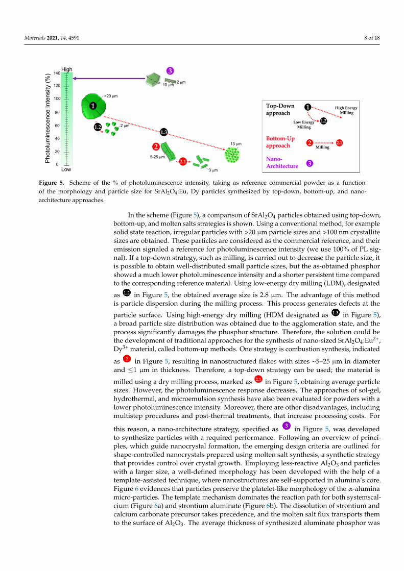
The synthesis of particles by molten salt synthesis is governed by two main mecha-nisms: dissolution–precipitation and dissolution-diffusion. The synthesis of nanophos-phors is commonly done using dissolution–precipitation, where the molten salt-assistedprocess is conceived as a bottom-up approach. Conventionally, the employment of bottomup approaches implies a lower luminescence intensity for nanophosphors obtained incomparison with a micro-sized counterpart. Top-down approaches have similar tendenciesdue to the defects generated on the surface. A synergy between micro and nano conceptscan be conceived when a nano-architecture is developed. In the case of phosphors, for thespecific applications, platelet-like shapes are interesting, because one of the dimensions isbelow ≤2 µm. Using the molten salt strategy, it is possible to design a scalable process ofself-supported nanostructures onto microscale particles as fragments of a puzzle to improvethe performance of phosphorescent materials, paying special attention to rare earth scarcity.This concept was developed in our previous work for strontium and calcium aluminates.In particular for the case of SrAl2O4:Eu, Dy, a scheme that depicts the photoluminescencefeatures of particles as a function of the synthesis is shown in Figure 5. A similar picturecan be translated for other phosphors based on aluminates.
Materials 2021, 14, 4591 8 of 18Materials 2021, 14, x FOR PEER REVIEW 9 of 19
Figure 5. Scheme of the % of photoluminescence intensity, taking as reference commercial powder as a function of the
morphology and particle size for SrAl2O4 :Eu, Dy particles synthesized by top-down, bottom-up, and nano-architecture
approaches.
In the scheme (Figure 5), a comparison of SrAl2O4 particles obtained using top-down,
bottom-up, and molten salts strategies is shown. Using a conventional method, for exam-
ple solid state reaction, irregular particles with >20 μm particle sizes and >100 nm crystal-
lite sizes are obtained. These particles are considered as the commercial reference, and
their emission signaled a reference for photoluminescence intensity (we use 100% of PL
signal). If a top-down strategy, such as milling, is carried out to decrease the particle size,
it is possible to obtain well-distributed small particle sizes, but the as-obtained phosphor
showed a much lower photoluminescence intensity and a shorter persistent time com-
pared to the corresponding reference material. Using low-energy dry milling (LDM), des-
ignated as in Figure 5, the obtained average size is 2.8 μm. The advantage of this
method is particle dispersion during the milling process. This process generates defects at
the particle surface. Using high-energy dry milling (HDM designated as in Figure 5),
a broad particle size distribution was obtained due to the agglomeration state, and the
process significantly damages the phosphor structure. Therefore, the solution could be the
development of traditional approaches for the synthesis of nano-sized SrAl2O4:Eu2+, Dy3+
material, called bottom-up methods. One strategy is combustion synthesis, indicated as
in Figure 5, resulting in nanostructured flakes with sizes ~5–25 μm in diameter and ≤1
μm in thickness. Therefore, a top-down strategy can be used; the material is milled using
a dry milling process, marked as in Figure 5, obtaining average particle sizes. How-
ever, the photoluminescence response decreases. The approaches of sol-gel, hydrother-
mal, and microemulsion synthesis have also been evaluated for powders with a lower
photoluminescence intensity. Moreover, there are other disadvantages, including multi-
step procedures and post-thermal treatments, that increase processing costs. For this rea-
son, a nano-architecture strategy, specified as in Figure 5, was developed to synthe-
size particles with a required performance. Following an overview of principles, which
guide nanocrystal formation, the emerging design criteria are outlined for shape-con-
trolled nanocrystals prepared using molten salt synthesis, a synthetic strategy that pro-
vides control over crystal growth. Employing less-reactive Al2O3 and particles with a
larger size, a well-defined morphology has been developed with the help of a template-
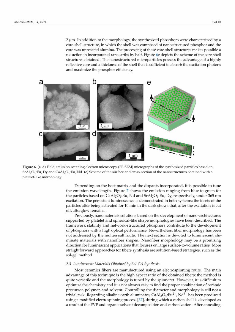
assisted technique, where nanostructures are self-supported in alumina’s core. Figure 6
evidences that particles preserve the platelet-like morphology of the α-alumina micro-
particles. The template mechanism dominates the reaction path for both systemscalcium
(Figure 6a) and strontium aluminate (Figure 6b). The dissolution of strontium and calcium
2.1
Figure 5. Scheme of the % of photoluminescence intensity, taking as reference commercial powder as a functionof the morphology and particle size for SrAl2O4:Eu, Dy particles synthesized by top-down, bottom-up, and nano-architecture approaches.
In the scheme (Figure 5), a comparison of SrAl2O4 particles obtained using top-down,bottom-up, and molten salts strategies is shown. Using a conventional method, for examplesolid state reaction, irregular particles with >20 µm particle sizes and >100 nm crystallitesizes are obtained. These particles are considered as the commercial reference, and theiremission signaled a reference for photoluminescence intensity (we use 100% of PL sig-nal). If a top-down strategy, such as milling, is carried out to decrease the particle size, itis possible to obtain well-distributed small particle sizes, but the as-obtained phosphorshowed a much lower photoluminescence intensity and a shorter persistent time comparedto the corresponding reference material. Using low-energy dry milling (LDM), designated
as
Materials 2021, 14, x FOR PEER REVIEW 9 of 19
Figure 5. Scheme of the % of photoluminescence intensity, taking as reference commercial powder as a function of the
morphology and particle size for SrAl2O4 :Eu, Dy particles synthesized by top-down, bottom-up, and nano-architecture
approaches.
In the scheme (Figure 5), a comparison of SrAl2O4 particles obtained using top-down,
bottom-up, and molten salts strategies is shown. Using a conventional method, for exam-
ple solid state reaction, irregular particles with >20 μm particle sizes and >100 nm crystal-
lite sizes are obtained. These particles are considered as the commercial reference, and
their emission signaled a reference for photoluminescence intensity (we use 100% of PL
signal). If a top-down strategy, such as milling, is carried out to decrease the particle size,
it is possible to obtain well-distributed small particle sizes, but the as-obtained phosphor
showed a much lower photoluminescence intensity and a shorter persistent time com-
pared to the corresponding reference material. Using low-energy dry milling (LDM), des-
ignated as in Figure 5, the obtained average size is 2.8 μm. The advantage of this
method is particle dispersion during the milling process. This process generates defects at
the particle surface. Using high-energy dry milling (HDM designated as in Figure 5),
a broad particle size distribution was obtained due to the agglomeration state, and the
process significantly damages the phosphor structure. Therefore, the solution could be the
development of traditional approaches for the synthesis of nano-sized SrAl2O4:Eu2+, Dy3+
material, called bottom-up methods. One strategy is combustion synthesis, indicated as
in Figure 5, resulting in nanostructured flakes with sizes ~5–25 μm in diameter and ≤1
μm in thickness. Therefore, a top-down strategy can be used; the material is milled using
a dry milling process, marked as in Figure 5, obtaining average particle sizes. How-
ever, the photoluminescence response decreases. The approaches of sol-gel, hydrother-
mal, and microemulsion synthesis have also been evaluated for powders with a lower
photoluminescence intensity. Moreover, there are other disadvantages, including multi-
step procedures and post-thermal treatments, that increase processing costs. For this rea-
son, a nano-architecture strategy, specified as in Figure 5, was developed to synthe-
size particles with a required performance. Following an overview of principles, which
guide nanocrystal formation, the emerging design criteria are outlined for shape-con-
trolled nanocrystals prepared using molten salt synthesis, a synthetic strategy that pro-
vides control over crystal growth. Employing less-reactive Al2O3 and particles with a
larger size, a well-defined morphology has been developed with the help of a template-
assisted technique, where nanostructures are self-supported in alumina’s core. Figure 6
evidences that particles preserve the platelet-like morphology of the α-alumina micro-
particles. The template mechanism dominates the reaction path for both systemscalcium
(Figure 6a) and strontium aluminate (Figure 6b). The dissolution of strontium and calcium
2.1
in Figure 5, the obtained average size is 2.8 µm. The advantage of this methodis particle dispersion during the milling process. This process generates defects at the
particle surface. Using high-energy dry milling (HDM designated as
Materials 2021, 14, x FOR PEER REVIEW 9 of 19
Figure 5. Scheme of the % of photoluminescence intensity, taking as reference commercial powder as a function of the
morphology and particle size for SrAl2O4 :Eu, Dy particles synthesized by top-down, bottom-up, and nano-architecture
approaches.
In the scheme (Figure 5), a comparison of SrAl2O4 particles obtained using top-down,
bottom-up, and molten salts strategies is shown. Using a conventional method, for exam-
ple solid state reaction, irregular particles with >20 μm particle sizes and >100 nm crystal-
lite sizes are obtained. These particles are considered as the commercial reference, and
their emission signaled a reference for photoluminescence intensity (we use 100% of PL
signal). If a top-down strategy, such as milling, is carried out to decrease the particle size,
it is possible to obtain well-distributed small particle sizes, but the as-obtained phosphor
showed a much lower photoluminescence intensity and a shorter persistent time com-
pared to the corresponding reference material. Using low-energy dry milling (LDM), des-
ignated as in Figure 5, the obtained average size is 2.8 μm. The advantage of this
method is particle dispersion during the milling process. This process generates defects at
the particle surface. Using high-energy dry milling (HDM designated as in Figure 5),
a broad particle size distribution was obtained due to the agglomeration state, and the
process significantly damages the phosphor structure. Therefore, the solution could be the
development of traditional approaches for the synthesis of nano-sized SrAl2O4:Eu2+, Dy3+
material, called bottom-up methods. One strategy is combustion synthesis, indicated as
in Figure 5, resulting in nanostructured flakes with sizes ~5–25 μm in diameter and ≤1
μm in thickness. Therefore, a top-down strategy can be used; the material is milled using
a dry milling process, marked as in Figure 5, obtaining average particle sizes. How-
ever, the photoluminescence response decreases. The approaches of sol-gel, hydrother-
mal, and microemulsion synthesis have also been evaluated for powders with a lower
photoluminescence intensity. Moreover, there are other disadvantages, including multi-
step procedures and post-thermal treatments, that increase processing costs. For this rea-
son, a nano-architecture strategy, specified as in Figure 5, was developed to synthe-
size particles with a required performance. Following an overview of principles, which
guide nanocrystal formation, the emerging design criteria are outlined for shape-con-
trolled nanocrystals prepared using molten salt synthesis, a synthetic strategy that pro-
vides control over crystal growth. Employing less-reactive Al2O3 and particles with a
larger size, a well-defined morphology has been developed with the help of a template-
assisted technique, where nanostructures are self-supported in alumina’s core. Figure 6
evidences that particles preserve the platelet-like morphology of the α-alumina micro-
particles. The template mechanism dominates the reaction path for both systemscalcium
(Figure 6a) and strontium aluminate (Figure 6b). The dissolution of strontium and calcium
2.1
in Figure 5),a broad particle size distribution was obtained due to the agglomeration state, and theprocess significantly damages the phosphor structure. Therefore, the solution could bethe development of traditional approaches for the synthesis of nano-sized SrAl2O4:Eu2+,Dy3+ material, called bottom-up methods. One strategy is combustion synthesis, indicated
as
Materials 2021, 14, x FOR PEER REVIEW 9 of 19
Figure 5. Scheme of the % of photoluminescence intensity, taking as reference commercial powder as a function of the
morphology and particle size for SrAl2O4 :Eu, Dy particles synthesized by top-down, bottom-up, and nano-architecture
approaches.
In the scheme (Figure 5), a comparison of SrAl2O4 particles obtained using top-down,
bottom-up, and molten salts strategies is shown. Using a conventional method, for exam-
ple solid state reaction, irregular particles with >20 μm particle sizes and >100 nm crystal-
lite sizes are obtained. These particles are considered as the commercial reference, and
their emission signaled a reference for photoluminescence intensity (we use 100% of PL
signal). If a top-down strategy, such as milling, is carried out to decrease the particle size,
it is possible to obtain well-distributed small particle sizes, but the as-obtained phosphor
showed a much lower photoluminescence intensity and a shorter persistent time com-
pared to the corresponding reference material. Using low-energy dry milling (LDM), des-
ignated as in Figure 5, the obtained average size is 2.8 μm. The advantage of this
method is particle dispersion during the milling process. This process generates defects at
the particle surface. Using high-energy dry milling (HDM designated as in Figure 5),
a broad particle size distribution was obtained due to the agglomeration state, and the
process significantly damages the phosphor structure. Therefore, the solution could be the
development of traditional approaches for the synthesis of nano-sized SrAl2O4:Eu2+, Dy3+
material, called bottom-up methods. One strategy is combustion synthesis, indicated as
in Figure 5, resulting in nanostructured flakes with sizes ~5–25 μm in diameter and ≤1
μm in thickness. Therefore, a top-down strategy can be used; the material is milled using
a dry milling process, marked as in Figure 5, obtaining average particle sizes. How-
ever, the photoluminescence response decreases. The approaches of sol-gel, hydrother-
mal, and microemulsion synthesis have also been evaluated for powders with a lower
photoluminescence intensity. Moreover, there are other disadvantages, including multi-
step procedures and post-thermal treatments, that increase processing costs. For this rea-
son, a nano-architecture strategy, specified as in Figure 5, was developed to synthe-
size particles with a required performance. Following an overview of principles, which
guide nanocrystal formation, the emerging design criteria are outlined for shape-con-
trolled nanocrystals prepared using molten salt synthesis, a synthetic strategy that pro-
vides control over crystal growth. Employing less-reactive Al2O3 and particles with a
larger size, a well-defined morphology has been developed with the help of a template-
assisted technique, where nanostructures are self-supported in alumina’s core. Figure 6
evidences that particles preserve the platelet-like morphology of the α-alumina micro-
particles. The template mechanism dominates the reaction path for both systemscalcium
(Figure 6a) and strontium aluminate (Figure 6b). The dissolution of strontium and calcium
2.1
in Figure 5, resulting in nanostructured flakes with sizes ~5–25 µm in diameterand ≤1 µm in thickness. Therefore, a top-down strategy can be used; the material is
milled using a dry milling process, marked as
Materials 2021, 14, x FOR PEER REVIEW 9 of 19
Figure 5. Scheme of the % of photoluminescence intensity, taking as reference commercial powder as a function of the
morphology and particle size for SrAl2O4 :Eu, Dy particles synthesized by top-down, bottom-up, and nano-architecture
approaches.
In the scheme (Figure 5), a comparison of SrAl2O4 particles obtained using top-down,
bottom-up, and molten salts strategies is shown. Using a conventional method, for exam-
ple solid state reaction, irregular particles with >20 μm particle sizes and >100 nm crystal-
lite sizes are obtained. These particles are considered as the commercial reference, and
their emission signaled a reference for photoluminescence intensity (we use 100% of PL
signal). If a top-down strategy, such as milling, is carried out to decrease the particle size,
it is possible to obtain well-distributed small particle sizes, but the as-obtained phosphor
showed a much lower photoluminescence intensity and a shorter persistent time com-
pared to the corresponding reference material. Using low-energy dry milling (LDM), des-
ignated as in Figure 5, the obtained average size is 2.8 μm. The advantage of this
method is particle dispersion during the milling process. This process generates defects at
the particle surface. Using high-energy dry milling (HDM designated as in Figure 5),
a broad particle size distribution was obtained due to the agglomeration state, and the
process significantly damages the phosphor structure. Therefore, the solution could be the
development of traditional approaches for the synthesis of nano-sized SrAl2O4:Eu2+, Dy3+
material, called bottom-up methods. One strategy is combustion synthesis, indicated as
in Figure 5, resulting in nanostructured flakes with sizes ~5–25 μm in diameter and ≤1
μm in thickness. Therefore, a top-down strategy can be used; the material is milled using
a dry milling process, marked as in Figure 5, obtaining average particle sizes. How-
ever, the photoluminescence response decreases. The approaches of sol-gel, hydrother-
mal, and microemulsion synthesis have also been evaluated for powders with a lower
photoluminescence intensity. Moreover, there are other disadvantages, including multi-
step procedures and post-thermal treatments, that increase processing costs. For this rea-
son, a nano-architecture strategy, specified as in Figure 5, was developed to synthe-
size particles with a required performance. Following an overview of principles, which
guide nanocrystal formation, the emerging design criteria are outlined for shape-con-
trolled nanocrystals prepared using molten salt synthesis, a synthetic strategy that pro-
vides control over crystal growth. Employing less-reactive Al2O3 and particles with a
larger size, a well-defined morphology has been developed with the help of a template-
assisted technique, where nanostructures are self-supported in alumina’s core. Figure 6
evidences that particles preserve the platelet-like morphology of the α-alumina micro-
particles. The template mechanism dominates the reaction path for both systemscalcium
(Figure 6a) and strontium aluminate (Figure 6b). The dissolution of strontium and calcium
2.1 in Figure 5, obtaining average particlesizes. However, the photoluminescence response decreases. The approaches of sol-gel,hydrothermal, and microemulsion synthesis have also been evaluated for powders with alower photoluminescence intensity. Moreover, there are other disadvantages, includingmultistep procedures and post-thermal treatments, that increase processing costs. For
this reason, a nano-architecture strategy, specified as
Materials 2021, 14, x FOR PEER REVIEW 9 of 19
Figure 5. Scheme of the % of photoluminescence intensity, taking as reference commercial powder as a function of the
morphology and particle size for SrAl2O4 :Eu, Dy particles synthesized by top-down, bottom-up, and nano-architecture
approaches.
In the scheme (Figure 5), a comparison of SrAl2O4 particles obtained using top-down,
bottom-up, and molten salts strategies is shown. Using a conventional method, for exam-
ple solid state reaction, irregular particles with >20 μm particle sizes and >100 nm crystal-
lite sizes are obtained. These particles are considered as the commercial reference, and
their emission signaled a reference for photoluminescence intensity (we use 100% of PL
signal). If a top-down strategy, such as milling, is carried out to decrease the particle size,
it is possible to obtain well-distributed small particle sizes, but the as-obtained phosphor
showed a much lower photoluminescence intensity and a shorter persistent time com-
pared to the corresponding reference material. Using low-energy dry milling (LDM), des-
ignated as in Figure 5, the obtained average size is 2.8 μm. The advantage of this
method is particle dispersion during the milling process. This process generates defects at
the particle surface. Using high-energy dry milling (HDM designated as in Figure 5),
a broad particle size distribution was obtained due to the agglomeration state, and the
process significantly damages the phosphor structure. Therefore, the solution could be the
development of traditional approaches for the synthesis of nano-sized SrAl2O4:Eu2+, Dy3+
material, called bottom-up methods. One strategy is combustion synthesis, indicated as
in Figure 5, resulting in nanostructured flakes with sizes ~5–25 μm in diameter and ≤1
μm in thickness. Therefore, a top-down strategy can be used; the material is milled using
a dry milling process, marked as in Figure 5, obtaining average particle sizes. How-
ever, the photoluminescence response decreases. The approaches of sol-gel, hydrother-
mal, and microemulsion synthesis have also been evaluated for powders with a lower
photoluminescence intensity. Moreover, there are other disadvantages, including multi-
step procedures and post-thermal treatments, that increase processing costs. For this rea-
son, a nano-architecture strategy, specified as in Figure 5, was developed to synthe-
size particles with a required performance. Following an overview of principles, which
guide nanocrystal formation, the emerging design criteria are outlined for shape-con-
trolled nanocrystals prepared using molten salt synthesis, a synthetic strategy that pro-
vides control over crystal growth. Employing less-reactive Al2O3 and particles with a
larger size, a well-defined morphology has been developed with the help of a template-
assisted technique, where nanostructures are self-supported in alumina’s core. Figure 6
evidences that particles preserve the platelet-like morphology of the α-alumina micro-
particles. The template mechanism dominates the reaction path for both systemscalcium
(Figure 6a) and strontium aluminate (Figure 6b). The dissolution of strontium and calcium
2.1
in Figure 5, was developedto synthesize particles with a required performance. Following an overview of princi-ples, which guide nanocrystal formation, the emerging design criteria are outlined forshape-controlled nanocrystals prepared using molten salt synthesis, a synthetic strategythat provides control over crystal growth. Employing less-reactive Al2O3 and particleswith a larger size, a well-defined morphology has been developed with the help of atemplate-assisted technique, where nanostructures are self-supported in alumina’s core.Figure 6 evidences that particles preserve the platelet-like morphology of the α-aluminamicro-particles. The template mechanism dominates the reaction path for both systemscal-cium (Figure 6a) and strontium aluminate (Figure 6b). The dissolution of strontium andcalcium carbonate precursor takes precedence, and the molten salt flux transports themto the surface of Al2O3. The average thickness of synthesized aluminate phosphor was
Materials 2021, 14, 4591 9 of 18
2 µm. In addition to the morphology, the synthesized phosphors were characterized by acore-shell structure, in which the shell was composed of nanostructured phosphor and thecore was unreacted alumina. The processing of these core-shell structures makes possible areduction in incorporated rare earths by half. Figure 6e depicts the scheme of the core-shellstructures obtained. The nanostructured microparticles possess the advantage of a highlyreflective core and a thickness of the shell that is sufficient to absorb the excitation photonsand maximize the phosphor efficiency.
Materials 2021, 14, x FOR PEER REVIEW 10 of 19
carbonate precursor takes precedence, and the molten salt flux transports them to the sur-
face of Al2O3. The average thickness of synthesized aluminate phosphor was 2 µm. In ad-
dition to the morphology, the synthesized phosphors were characterized by a core-shell
structure, in which the shell was composed of nanostructured phosphor and the core was
unreacted alumina. The processing of these core-shell structures makes possible a reduc-
tion in incorporated rare earths by half. Figure 6e depicts the scheme of the core-shell
structures obtained. The nanostructured microparticles possess the advantage of a highly
reflective core and a thickness of the shell that is sufficient to absorb the excitation photons
and maximize the phosphor efficiency.
Figure 6. (a–d) Field-emission scanning electron microscopy (FE-SEM) micrographs of the synthesized particles based on
SrAl2O4:Eu, Dy and CaAl2O4:Eu, Nd. (e) Scheme of the surface and cross-section of the nanostructures obtained with a
platelet-like morphology.
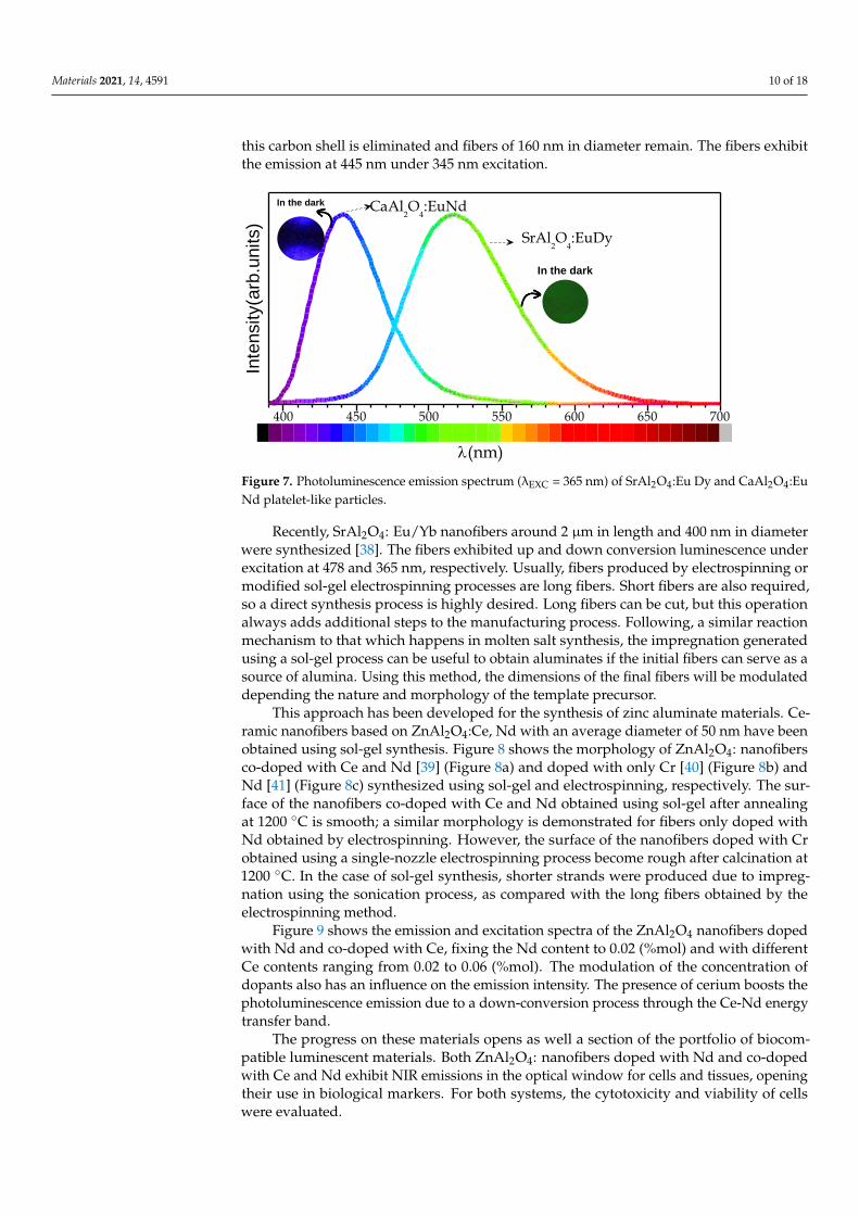
Depending on the host matrix and the dopants incorporated, it is possible to tune the
emission wavelength. Figure 7 shows the emission ranging from blue to green for the par-
ticles based on CaAl2O4:Eu, Nd and SrAl2O4:Eu, Dy, respectively, under 365 nm excitation.
The persistent luminescence is demonstrated in both systems; the insets of the particles
after being activated for 10 min in the dark shows that, after the excitation is cut off, after-
glow remains.
400 450 500 550 600 650 700
CaAl2O4:EuNd
380.0390.5401.1411.6422.2432.7443.2453.8464.3474.9485.4495.9506.5517.0527.6538.1548.6559.2569.7580.3590.8601.4611.9622.4633.0643.5654.1664.6675.1685.7696.2706.8717.3727.8738.4748.9759.5770.0
Inte
nsity(a
rb.u
nits)
(nm)
SrAl2O4:EuDy
In the dark
In the dark
Figure 6. (a–d) Field-emission scanning electron microscopy (FE-SEM) micrographs of the synthesized particles based onSrAl2O4:Eu, Dy and CaAl2O4:Eu, Nd. (e) Scheme of the surface and cross-section of the nanostructures obtained with aplatelet-like morphology.
Depending on the host matrix and the dopants incorporated, it is possible to tunethe emission wavelength. Figure 7 shows the emission ranging from blue to green forthe particles based on CaAl2O4:Eu, Nd and SrAl2O4:Eu, Dy, respectively, under 365 nmexcitation. The persistent luminescence is demonstrated in both systems; the insets of theparticles after being activated for 10 min in the dark shows that, after the excitation is cutoff, afterglow remains.
Previously, nanomaterials solutions based on the development of nano-architecturessupported by platelet and spherical-like shape morphologies have been described. Theframework stability and network-structured phosphors contribute to the developmentof phosphors with a high optical performance. Nevertheless, fiber morphology has beennot addressed by the molten salt route. The next section is devoted to luminescent alu-minate materials with nanofiber shapes. Nanofiber morphology may be a promisingdirection for luminescent applications that focuses on large surface-to-volume ratios. Morestraightforward approaches for fibers synthesis are solution-based strategies, such as thesol-gel method.
2.3. Luminescent Materials Obtained by Sol-Gel Synthesis
Most ceramics fibers are manufactured using an electrospinning route. The mainadvantage of this technique is the high aspect ratio of the obtained fibers; the method isquite versatile and the morphology is tuned by the spinneret. However, it is difficult tooptimize the chemistry and it is not always easy to find the proper combination of ceramicprecursor, polymer, and solvent. Controlling the diameter and morphology is still not atrivial task. Regarding alkaline earth aluminates, CaAl2O4:Eu2+, Nd3+ has been producedusing a modified electrospinning process [37], during which a carbon shell is developed asa result of the PVP and organic solvent decomposition and carbonization. After annealing,
Materials 2021, 14, 4591 10 of 18
this carbon shell is eliminated and fibers of 160 nm in diameter remain. The fibers exhibitthe emission at 445 nm under 345 nm excitation.
Materials 2021, 14, x FOR PEER REVIEW 10 of 19
carbonate precursor takes precedence, and the molten salt flux transports them to the sur-
face of Al2O3. The average thickness of synthesized aluminate phosphor was 2 µm. In ad-
dition to the morphology, the synthesized phosphors were characterized by a core-shell
structure, in which the shell was composed of nanostructured phosphor and the core was
unreacted alumina. The processing of these core-shell structures makes possible a reduc-
tion in incorporated rare earths by half. Figure 6e depicts the scheme of the core-shell
structures obtained. The nanostructured microparticles possess the advantage of a highly
reflective core and a thickness of the shell that is sufficient to absorb the excitation photons
and maximize the phosphor efficiency.
Figure 6. (a–d) Field-emission scanning electron microscopy (FE-SEM) micrographs of the synthesized particles based on
SrAl2O4:Eu, Dy and CaAl2O4:Eu, Nd. (e) Scheme of the surface and cross-section of the nanostructures obtained with a
platelet-like morphology.
Depending on the host matrix and the dopants incorporated, it is possible to tune the
emission wavelength. Figure 7 shows the emission ranging from blue to green for the par-
ticles based on CaAl2O4:Eu, Nd and SrAl2O4:Eu, Dy, respectively, under 365 nm excitation.
The persistent luminescence is demonstrated in both systems; the insets of the particles
after being activated for 10 min in the dark shows that, after the excitation is cut off, after-
glow remains.
400 450 500 550 600 650 700
CaAl2O4:EuNd
380.0390.5401.1411.6422.2432.7443.2453.8464.3474.9485.4495.9506.5517.0527.6538.1548.6559.2569.7580.3590.8601.4611.9622.4633.0643.5654.1664.6675.1685.7696.2706.8717.3727.8738.4748.9759.5770.0
Inte
nsity(a
rb.u
nits)
(nm)
SrAl2O4:EuDy
In the dark
In the dark
Figure 7. Photoluminescence emission spectrum (λEXC = 365 nm) of SrAl2O4:Eu Dy and CaAl2O4:EuNd platelet-like particles.
Recently, SrAl2O4: Eu/Yb nanofibers around 2 µm in length and 400 nm in diameterwere synthesized [38]. The fibers exhibited up and down conversion luminescence underexcitation at 478 and 365 nm, respectively. Usually, fibers produced by electrospinning ormodified sol-gel electrospinning processes are long fibers. Short fibers are also required,so a direct synthesis process is highly desired. Long fibers can be cut, but this operationalways adds additional steps to the manufacturing process. Following, a similar reactionmechanism to that which happens in molten salt synthesis, the impregnation generatedusing a sol-gel process can be useful to obtain aluminates if the initial fibers can serve as asource of alumina. Using this method, the dimensions of the final fibers will be modulateddepending the nature and morphology of the template precursor.
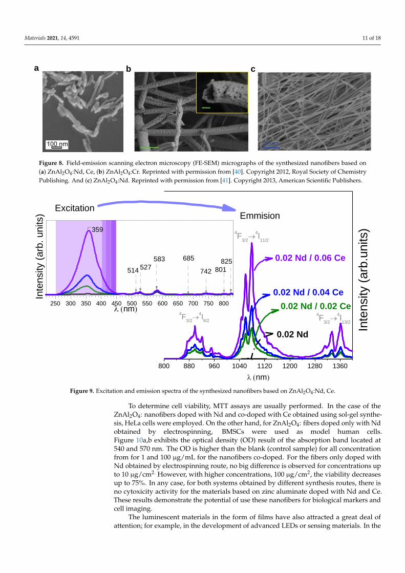
This approach has been developed for the synthesis of zinc aluminate materials. Ce-ramic nanofibers based on ZnAl2O4:Ce, Nd with an average diameter of 50 nm have beenobtained using sol-gel synthesis. Figure 8 shows the morphology of ZnAl2O4: nanofibersco-doped with Ce and Nd [39] (Figure 8a) and doped with only Cr [40] (Figure 8b) andNd [41] (Figure 8c) synthesized using sol-gel and electrospinning, respectively. The sur-face of the nanofibers co-doped with Ce and Nd obtained using sol-gel after annealingat 1200 ◦C is smooth; a similar morphology is demonstrated for fibers only doped withNd obtained by electrospinning. However, the surface of the nanofibers doped with Crobtained using a single-nozzle electrospinning process become rough after calcination at1200 ◦C. In the case of sol-gel synthesis, shorter strands were produced due to impreg-nation using the sonication process, as compared with the long fibers obtained by theelectrospinning method.
Figure 9 shows the emission and excitation spectra of the ZnAl2O4 nanofibers dopedwith Nd and co-doped with Ce, fixing the Nd content to 0.02 (%mol) and with differentCe contents ranging from 0.02 to 0.06 (%mol). The modulation of the concentration ofdopants also has an influence on the emission intensity. The presence of cerium boosts thephotoluminescence emission due to a down-conversion process through the Ce-Nd energytransfer band.
The progress on these materials opens as well a section of the portfolio of biocom-patible luminescent materials. Both ZnAl2O4: nanofibers doped with Nd and co-dopedwith Ce and Nd exhibit NIR emissions in the optical window for cells and tissues, openingtheir use in biological markers. For both systems, the cytotoxicity and viability of cellswere evaluated.
Materials 2021, 14, 4591 11 of 18Materials 2021, 14, x FOR PEER REVIEW 12 of 19
Figure 8. Field-emission scanning electron microscopy (FE-SEM) micrographs of the synthesized nanofibers based on (a)
ZnAl2O4:Nd, Ce, (b) ZnAl2O4:CrReprinted with permission from [40]. Copyright 2012, Royal Society of Chemistry Pub-
lishing., and (c) ZnAl2O4:Nd. Reprinted with permission from [41]. Copyright 2013, American Scientific Publishers.
Figure 9 shows the emission and excitation spectra of the ZnAl2O4 nanofibers doped
with Nd and co-doped with Ce, fixing the Nd content to 0.02 (%mol) and with different
Ce contents ranging from 0.02 to 0.06 (%mol). The modulation of the concentration of do-
pants also has an influence on the emission intensity. The presence of cerium boosts the
photoluminescence emission due to a down-conversion process through the Ce-Nd en-
ergy transfer band.
Figure 9. Excitation and emission spectra of the synthesized nanofibers based on ZnAl2O4:Nd, Ce.
The progress on these materials opens as well a section of the portfolio of biocompat-
ible luminescent materials. Both ZnAl2O4: nanofibers doped with Nd and co-doped with
Ce and Nd exhibit NIR emissions in the optical window for cells and tissues, opening their
use in biological markers. For both systems, the cytotoxicity and viability of cells were
evaluated.
a b c
800 880 960 1040 1120 1200 1280 1360
250 300 350 400 450 500 550 600 650 700 750 800
Inte
nsity (
arb
. units)
(nm)
359
825
801742
685583
527514
In
tensity (
arb
.units)
0.02 Nd / 0.06 Ce
0.02 Nd
0.02 Nd / 0.04 Ce
0.02 Nd / 0.02 Ce4F
3/2
4I13/2
4F
3/2
4I11/2
(nm)
4F
3/2
4I9/2
ExcitationEmmision
Figure 8. Field-emission scanning electron microscopy (FE-SEM) micrographs of the synthesized nanofibers based on(a) ZnAl2O4:Nd, Ce, (b) ZnAl2O4:Cr. Reprinted with permission from [40]. Copyright 2012, Royal Society of ChemistryPublishing. And (c) ZnAl2O4:Nd. Reprinted with permission from [41]. Copyright 2013, American Scientific Publishers.
Materials 2021, 14, x FOR PEER REVIEW 12 of 19
Figure 8. Field-emission scanning electron microscopy (FE-SEM) micrographs of the synthesized nanofibers based on (a)
ZnAl2O4:Nd, Ce, (b) ZnAl2O4:CrReprinted with permission from [40]. Copyright 2012, Royal Society of Chemistry Pub-
lishing., and (c) ZnAl2O4:Nd. Reprinted with permission from [41]. Copyright 2013, American Scientific Publishers.
Figure 9 shows the emission and excitation spectra of the ZnAl2O4 nanofibers doped
with Nd and co-doped with Ce, fixing the Nd content to 0.02 (%mol) and with different
Ce contents ranging from 0.02 to 0.06 (%mol). The modulation of the concentration of do-
pants also has an influence on the emission intensity. The presence of cerium boosts the
photoluminescence emission due to a down-conversion process through the Ce-Nd en-
ergy transfer band.
Figure 9. Excitation and emission spectra of the synthesized nanofibers based on ZnAl2O4:Nd, Ce.
The progress on these materials opens as well a section of the portfolio of biocompat-
ible luminescent materials. Both ZnAl2O4: nanofibers doped with Nd and co-doped with
Ce and Nd exhibit NIR emissions in the optical window for cells and tissues, opening their
use in biological markers. For both systems, the cytotoxicity and viability of cells were
evaluated.
a b c
800 880 960 1040 1120 1200 1280 1360
250 300 350 400 450 500 550 600 650 700 750 800
Inte
nsity (
arb
. units)
(nm)
359
825
801742
685583
527514
In
tensity (
arb
.units)
0.02 Nd / 0.06 Ce
0.02 Nd
0.02 Nd / 0.04 Ce
0.02 Nd / 0.02 Ce4F
3/2
4I13/2
4F
3/2
4I11/2
(nm)
4F
3/2
4I9/2
ExcitationEmmision
Figure 9. Excitation and emission spectra of the synthesized nanofibers based on ZnAl2O4:Nd, Ce.
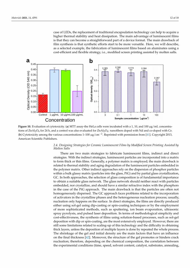
To determine cell viability, MTT assays are usually performed. In the case of theZnAl2O4: nanofibers doped with Nd and co-doped with Ce obtained using sol-gel synthe-sis, HeLa cells were employed. On the other hand, for ZnAl2O4: fibers doped only with Ndobtained by electrospinning, BMSCs were used as model human cells.Figure 10a,b exhibits the optical density (OD) result of the absorption band located at540 and 570 nm. The OD is higher than the blank (control sample) for all concentrationfrom for 1 and 100 µg/mL for the nanofibers co-doped. For the fibers only doped withNd obtained by electrospinning route, no big difference is observed for concentrations upto 10 µg/cm2. However, with higher concentrations, 100 µg/cm2, the viability decreasesup to 75%. In any case, for both systems obtained by different synthesis routes, there isno cytoxicity activity for the materials based on zinc aluminate doped with Nd and Ce.These results demonstrate the potential of use these nanofibers for biological markers andcell imaging.
The luminescent materials in the form of films have also attracted a great deal ofattention; for example, in the development of advanced LEDs or sensing materials. In the
Materials 2021, 14, 4591 12 of 18
case of LEDs, the replacement of traditional encapsulation technology can help to acquire ahigher thermal stability and heat dissipation. The main advantage of luminescent filmsis that they can become a straightforward part of a device format. The main drawback offilm synthesis is that synthetic efforts start to be more versatile. Here, we will describe,as a selected example, the fabrication of luminescent films based on aluminates using acost-efficient and flexible strategy, i.e., modified screen printing assisted by molten salts.
Materials 2021, 14, x FOR PEER REVIEW 13 of 19
To determine cell viability, MTT assays are usually performed. In the case of the
ZnAl2O4: nanofibers doped with Nd and co-doped with Ce obtained using sol-gel synthe-
sis, HeLa cells were employed. On the other hand, for ZnAl2O4: fibers doped only with
Nd obtained by electrospinning, BMSCs were used as model human cells. Figure 10a,b
exhibits the optical density (OD) result of the absorption band located at 540 and 570 nm.
The OD is higher than the blank (control sample) for all concentration from for 1 and 100
µg/mL for the nanofibers co-doped. For the fibers only doped with Nd obtained by elec-
trospinning route, no big difference is observed for concentrations up to 10 µg/cm2. How-
ever, with higher concentrations, 100 µg/cm2, the viability decreases up to 75%. In any
case, for both systems obtained by different synthesis routes, there is no cytoxicity activity
for the materials based on zinc aluminate doped with Nd and Ce. These results demon-
strate the potential of use these nanofibers for biological markers and cell imaging.
Figure 10. Evaluation of cytotoxicity. (a) MTT assay-the HeLa cells were incubated with a 1, 10, and 100 µg/mL concentra-
tions of ZnAl2O4 for 24 h, and a control was also evaluated for ZnAl2O4: nanofibers doped with Nd and co-doped with Ce.
(b) Cytotoxicity among the various concentrations 1–100 µg/cm-2. Reprinted with permission from [41].Copyright 2013,
American Scientific Publishers.
The luminescent materials in the form of films have also attracted a great deal of at-
tention; for example, in the development of advanced LEDs or sensing materials. In the
case of LEDs, the replacement of traditional encapsulation technology can help to acquire
a higher thermal stability and heat dissipation. The main advantage of luminescent films
is that they can become a straightforward part of a device format. The main drawback of
film synthesis is that synthetic efforts start to be more versatile. Here, we will describe, as
a selected example, the fabrication of luminescent films based on aluminates using a cost-
efficient and flexible strategy, i.e., modified screen printing assisted by molten salts.
2.4. Designing Strategies for Ceramic Luminescent Films by Modified Screen Printing Assisted
by Molten Salts
There are two main strategies to fabricate luminescent films, indirect and direct strat-
egies. With the indirect strategies, luminescent particles are incorporated into a matrix to
form thick or thin films. Generally, a polymer matrix is employed; the main drawback is
related to thermal stability and aging degradation of the luminescent particles embedded
in the polymer matrix. Other indirect approaches rely on the dispersion of phosphor par-
ticles within a bulk glassy matrix (particles into the glass, PiG) and by partial glass crys-
tallization, GC. In both approaches, the selection of glass composition is of fundamental
importance to obtain a suitable glass network. The glass network should neither react with
Control 1 µg/mL 10 µg/mL100 µg/mL0.00
0.05
0.10
0.15
0.20
0.25
0.30
0.35
0.40
0.45
Op
tica
l D
en
sity (
OD
54
0 n
m)
Concentration
a b
Figure 10. Evaluation of cytotoxicity. (a) MTT assay-the HeLa cells were incubated with a 1, 10, and 100 µg/mL concentra-tions of ZnAl2O4 for 24 h, and a control was also evaluated for ZnAl2O4: nanofibers doped with Nd and co-doped with Ce.(b) Cytotoxicity among the various concentrations 1–100 µg/cm−2. Reprinted with permission from [41]. Copyright 2013,American Scientific Publishers.
2.4. Designing Strategies for Ceramic Luminescent Films by Modified Screen Printing Assisted byMolten Salts
There are two main strategies to fabricate luminescent films, indirect and directstrategies. With the indirect strategies, luminescent particles are incorporated into a matrixto form thick or thin films. Generally, a polymer matrix is employed; the main drawback isrelated to thermal stability and aging degradation of the luminescent particles embedded inthe polymer matrix. Other indirect approaches rely on the dispersion of phosphor particleswithin a bulk glassy matrix (particles into the glass, PiG) and by partial glass crystallization,GC. In both approaches, the selection of glass composition is of fundamental importanceto obtain a suitable glass network. The glass network should neither react with particlesembedded, nor crystallize, and should have a similar refractive index with the phosphorsin the case of the PiG approach. The main drawback is that the particles are often nothomogeneously dispersed. The GC approach faces problems related to the incorporationof activators in the crystalline phases and the heterogeneous nucleation process; usually,nucleation only happens on the surface. In direct strategies, the films are directly producedeither using sol-gel using dip-casting or spin-coating techniques or by the employmentof more sophisticated methods, such as sputtering, ion beam evaporation, ultrasonicspray pyrolysis, and pulsed laser deposition. In terms of methodological simplicity andcost-effectiveness, the synthesis of films using solution-based processes, such as sol-geldeposition with dip or spin-coating, are the most extensively employed. However, there arestill some limitations related to scaling-up of this technology and the difficulty in obtainingthick layers, unless the deposition of multiple layers is done by repeated the whole process.The shrinkage of the gel and initial density are the main factors that have an influenceon the final thickness [42]. Moreover, the structure of the gel promotes or hinders cracknucleation; therefore, depending on the chemical composition, the correlation betweenthe experimental conditions (time, speed, solvent content, catalyst, substrates, annealing,
Materials 2021, 14, 4591 13 of 18
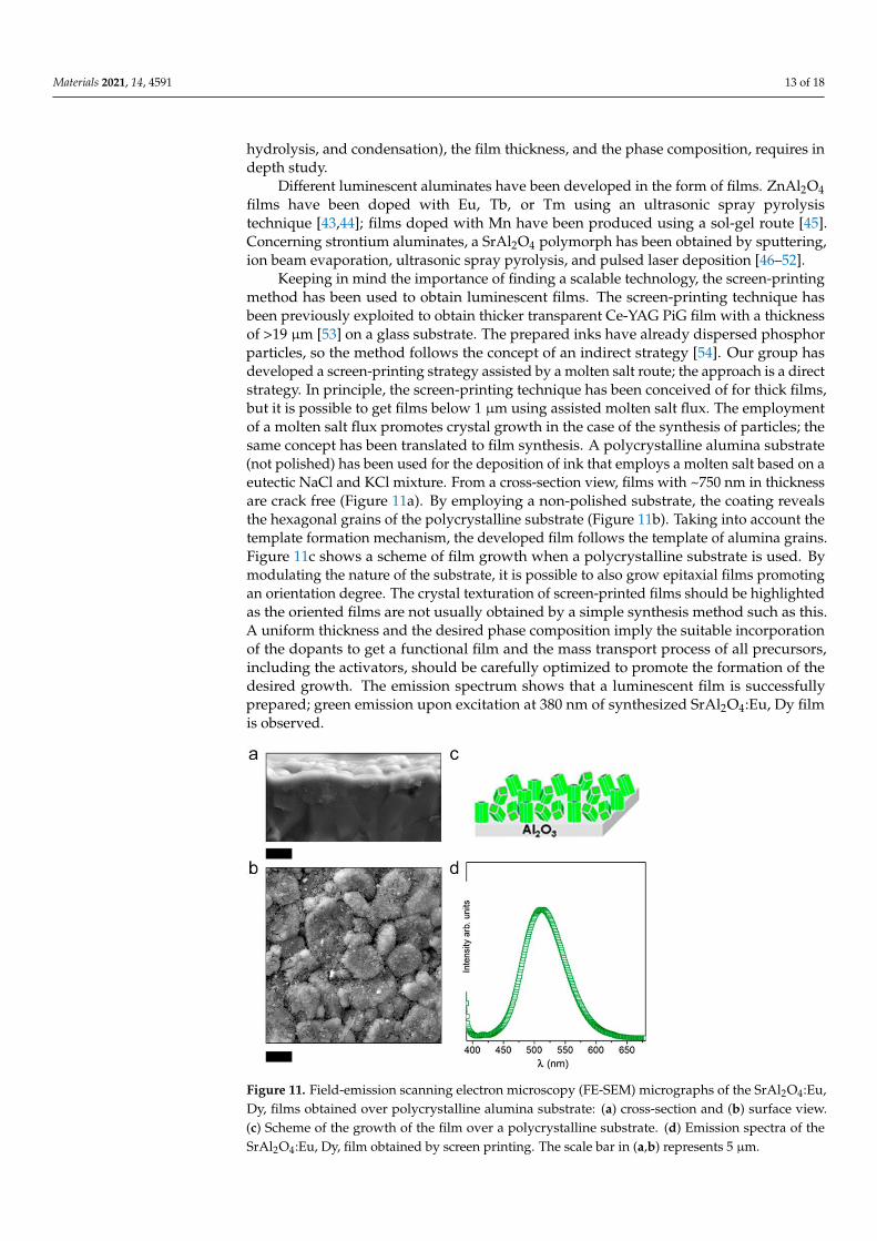
hydrolysis, and condensation), the film thickness, and the phase composition, requires indepth study.
Different luminescent aluminates have been developed in the form of films. ZnAl2O4films have been doped with Eu, Tb, or Tm using an ultrasonic spray pyrolysistechnique [43,44]; films doped with Mn have been produced using a sol-gel route [45].Concerning strontium aluminates, a SrAl2O4 polymorph has been obtained by sputtering,ion beam evaporation, ultrasonic spray pyrolysis, and pulsed laser deposition [46–52].
Keeping in mind the importance of finding a scalable technology, the screen-printingmethod has been used to obtain luminescent films. The screen-printing technique hasbeen previously exploited to obtain thicker transparent Ce-YAG PiG film with a thicknessof >19 µm [53] on a glass substrate. The prepared inks have already dispersed phosphorparticles, so the method follows the concept of an indirect strategy [54]. Our group hasdeveloped a screen-printing strategy assisted by a molten salt route; the approach is a directstrategy. In principle, the screen-printing technique has been conceived of for thick films,but it is possible to get films below 1 µm using assisted molten salt flux. The employmentof a molten salt flux promotes crystal growth in the case of the synthesis of particles; thesame concept has been translated to film synthesis. A polycrystalline alumina substrate(not polished) has been used for the deposition of ink that employs a molten salt based on aeutectic NaCl and KCl mixture. From a cross-section view, films with ~750 nm in thicknessare crack free (Figure 11a). By employing a non-polished substrate, the coating revealsthe hexagonal grains of the polycrystalline substrate (Figure 11b). Taking into account thetemplate formation mechanism, the developed film follows the template of alumina grains.Figure 11c shows a scheme of film growth when a polycrystalline substrate is used. Bymodulating the nature of the substrate, it is possible to also grow epitaxial films promotingan orientation degree. The crystal texturation of screen-printed films should be highlightedas the oriented films are not usually obtained by a simple synthesis method such as this.A uniform thickness and the desired phase composition imply the suitable incorporationof the dopants to get a functional film and the mass transport process of all precursors,including the activators, should be carefully optimized to promote the formation of thedesired growth. The emission spectrum shows that a luminescent film is successfullyprepared; green emission upon excitation at 380 nm of synthesized SrAl2O4:Eu, Dy filmis observed.
Materials 2021, 14, x FOR PEER REVIEW 15 of 19
Figure 11. Field-emission scanning electron microscopy (FE-SEM) micrographs of the SrAl2O4: Eu,
Dy, films obtained over polycrystalline alumina substrate: (a) cross-section and (b) surface view. (c)
Scheme of the growth of the film over a polycrystalline substrate. (d) Emission spectra of the
SrAl2O4: Eu, Dy, film obtained by screen printing. The scale bar in (a,b) represents 5 µm.
The optimized screen-printing method assisted by molten salts, which was devel-
oped by our group, can be adapted to other aluminates to produce other active materials
for other emission and excitation ranges.
3. Perspectives and Applications
The main challenge for the luminescent materials research community is to develop
strategies that consider further up-scaling and cost-effective production of materials in
both powder and film forms. The proposed approaches based on sol-gel and molten salt
synthesis exhibit enormous flexibility for different system production. These methodolo-
gies are proven to produce materials at the industrial scale for other systems and, thus,
anticipate the scalability for nanostructured inorganic phosphors. The ability to tailor en-
gineering nanostructures and at the same time tuning both the emission and the excitation
ranges represents a key point for the development of devices for application in printable
optoelectronics, energy storage, sensor technology, as well as products in medicine. The
development of mass production processes will open new application in cost-efficient ap-
plications for common usage; for example, in signage, textile and printing areas. Moreo-
ver, incorporation of the luminescent materials into additive manufacturing will open
new possibilities beyond aesthetic or design applications.
The use of rare earth (RE) as activators of phosphors represents a relevant limitation.
Rare earths are critical materials due to their scarcity, environmental impact and cost. The
high demand for RE in functional applications will imply a foreseeable increase for the
next few years that will depend on the availability of their supply also conditioned by
geopolitical evolution and international trade agreements. The forecast implies an in-
crease in the cost of raw materials that will restrict certain applications. On the one hand,
the use of strategies to reduce the use of rare earths by inorganic phosphors is an incentive
for researchers. In this sense, nanostructured coatings have shown an increase in the effi-
ciency of the systems that must be enhanced. The recovery of rare earths from industrial
waste is a necessary aspect to be addressed in the coming years in order to maximize the
use of scarce resources on planet earth. Given that the circular economy approach will be
essential in the coming years for industrial product development, the entry of rare earths
Figure 11. Field-emission scanning electron microscopy (FE-SEM) micrographs of the SrAl2O4:Eu,Dy, films obtained over polycrystalline alumina substrate: (a) cross-section and (b) surface view.(c) Scheme of the growth of the film over a polycrystalline substrate. (d) Emission spectra of theSrAl2O4:Eu, Dy, film obtained by screen printing. The scale bar in (a,b) represents 5 µm.

Materials 2021, 14, 4591 14 of 18
The optimized screen-printing method assisted by molten salts, which was developedby our group, can be adapted to other aluminates to produce other active materials forother emission and excitation ranges.
3. Perspectives and Applications
The main challenge for the luminescent materials research community is to developstrategies that consider further up-scaling and cost-effective production of materials inboth powder and film forms. The proposed approaches based on sol-gel and molten saltsynthesis exhibit enormous flexibility for different system production. These methodolo-gies are proven to produce materials at the industrial scale for other systems and, thus,anticipate the scalability for nanostructured inorganic phosphors. The ability to tailor engi-neering nanostructures and at the same time tuning both the emission and the excitationranges represents a key point for the development of devices for application in printableoptoelectronics, energy storage, sensor technology, as well as products in medicine. Thedevelopment of mass production processes will open new application in cost-efficient ap-plications for common usage; for example, in signage, textile and printing areas. Moreover,incorporation of the luminescent materials into additive manufacturing will open newpossibilities beyond aesthetic or design applications.
The use of rare earth (RE) as activators of phosphors represents a relevant limitation.Rare earths are critical materials due to their scarcity, environmental impact and cost. Thehigh demand for RE in functional applications will imply a foreseeable increase for thenext few years that will depend on the availability of their supply also conditioned bygeopolitical evolution and international trade agreements. The forecast implies an increasein the cost of raw materials that will restrict certain applications. On the one hand, theuse of strategies to reduce the use of rare earths by inorganic phosphors is an incentive forresearchers. In this sense, nanostructured coatings have shown an increase in the efficiencyof the systems that must be enhanced. The recovery of rare earths from industrial wasteis a necessary aspect to be addressed in the coming years in order to maximize the useof scarce resources on planet earth. Given that the circular economy approach will beessential in the coming years for industrial product development, the entry of rare earthsinto circular economy processes requires commendable efforts. The strong dependence ofthe response of rare earths with minority elements and impurities must be addressed inorder to achieve new, more robust and tolerant formulations, aspects that result far fromobvious for materials with an optical response. Last but not least, the development ofinorganic materials with luminescent properties without rare earths is an emerging fieldthat requires a strong investment in the coming years. Some recent examples in dual micro-nanostructure glass-ceramic feldspar nanocrystals having aluminate tetrahedra in theirstructure that present a relevant luminescent efficiency without rare-earth activators [55,56].However, there is still a need to increase its tuning capacity for broadcasts.
Concerning the application of inorganic phosphor as optical probes in biomaging andbiosensing, the luminescent powders are more convenient for the efficient penetrationcell ability for in vivo and in vitro studies. Nevertheless, the luminescent particles canbe functionalized for targeting specific tumor or diseases and furtherly incorporatedin an adequate fluid. Despite, the stability should be verified and the regulation andstandardization needs further steps, the incorporation of phosphors in powder form is stilla solution for multiple bio and lightning applications.
Nowadays, material that can have isotropic lighting characteristics and high mechan-ical properties is highly desired [57]. Ceramics coatings in the form of films can solvethese requests due to the strong mechanical performance combined with an enhancedoptical response. In addition, the stability increases the lifetime of the final product ascompared to the polymer hybrid composites. The development of transparent films witha controllable photon release is of a great interest for anti-counterfeiting technology andenergy storage applications from the VUV to NIR range [58]. In addition, the technologycan be applied for not persistent materials, as well. A field that is still under construction
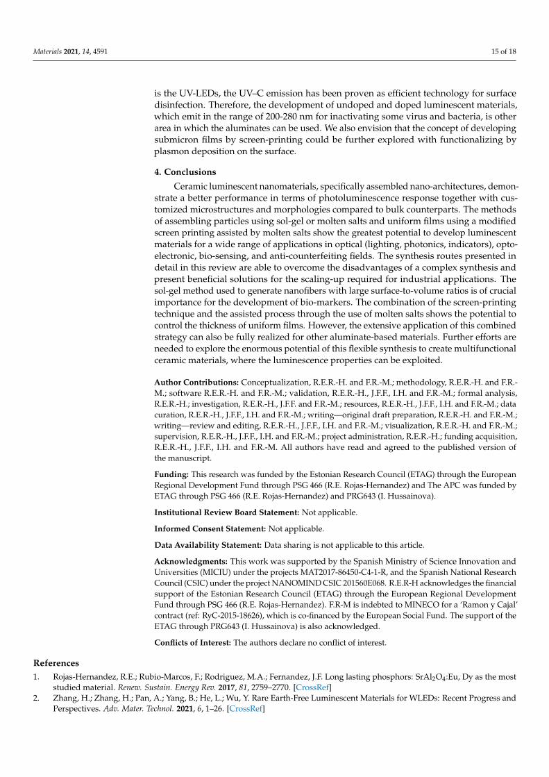
Materials 2021, 14, 4591 15 of 18
is the UV-LEDs, the UV–C emission has been proven as efficient technology for surfacedisinfection. Therefore, the development of undoped and doped luminescent materials,which emit in the range of 200-280 nm for inactivating some virus and bacteria, is otherarea in which the aluminates can be used. We also envision that the concept of developingsubmicron films by screen-printing could be further explored with functionalizing byplasmon deposition on the surface.
4. Conclusions
Ceramic luminescent nanomaterials, specifically assembled nano-architectures, demon-strate a better performance in terms of photoluminescence response together with cus-tomized microstructures and morphologies compared to bulk counterparts. The methodsof assembling particles using sol-gel or molten salts and uniform films using a modifiedscreen printing assisted by molten salts show the greatest potential to develop luminescentmaterials for a wide range of applications in optical (lighting, photonics, indicators), opto-electronic, bio-sensing, and anti-counterfeiting fields. The synthesis routes presented indetail in this review are able to overcome the disadvantages of a complex synthesis andpresent beneficial solutions for the scaling-up required for industrial applications. Thesol-gel method used to generate nanofibers with large surface-to-volume ratios is of crucialimportance for the development of bio-markers. The combination of the screen-printingtechnique and the assisted process through the use of molten salts shows the potential tocontrol the thickness of uniform films. However, the extensive application of this combinedstrategy can also be fully realized for other aluminate-based materials. Further efforts areneeded to explore the enormous potential of this flexible synthesis to create multifunctionalceramic materials, where the luminescence properties can be exploited.
Author Contributions: Conceptualization, R.E.R.-H. and F.R.-M.; methodology, R.E.R.-H. and F.R.-M.; software R.E.R.-H. and F.R.-M.; validation, R.E.R.-H., J.F.F., I.H. and F.R.-M.; formal analysis,R.E.R.-H.; investigation, R.E.R.-H., J.F.F. and F.R.-M.; resources, R.E.R.-H., J.F.F., I.H. and F.R.-M.; datacuration, R.E.R.-H., J.F.F., I.H. and F.R.-M.; writing—original draft preparation, R.E.R.-H. and F.R.-M.;writing—review and editing, R.E.R.-H., J.F.F., I.H. and F.R.-M.; visualization, R.E.R.-H. and F.R.-M.;supervision, R.E.R.-H., J.F.F., I.H. and F.R.-M.; project administration, R.E.R.-H.; funding acquisition,R.E.R.-H., J.F.F., I.H. and F.R.-M. All authors have read and agreed to the published version ofthe manuscript.
Funding: This research was funded by the Estonian Research Council (ETAG) through the EuropeanRegional Development Fund through PSG 466 (R.E. Rojas-Hernandez) and The APC was funded byETAG through PSG 466 (R.E. Rojas-Hernandez) and PRG643 (I. Hussainova).
Institutional Review Board Statement: Not applicable.
Informed Consent Statement: Not applicable.
Data Availability Statement: Data sharing is not applicable to this article.
Acknowledgments: This work was supported by the Spanish Ministry of Science Innovation andUniversities (MICIU) under the projects MAT2017-86450-C4-1-R, and the Spanish National ResearchCouncil (CSIC) under the project NANOMIND CSIC 201560E068. R.E.R-H acknowledges the financialsupport of the Estonian Research Council (ETAG) through the European Regional DevelopmentFund through PSG 466 (R.E. Rojas-Hernandez). F.R-M is indebted to MINECO for a ‘Ramon y Cajal’contract (ref: RyC-2015-18626), which is co-financed by the European Social Fund. The support of theETAG through PRG643 (I. Hussainova) is also acknowledged.
Conflicts of Interest: The authors declare no conflict of interest.
References1. Rojas-Hernandez, R.E.; Rubio-Marcos, F.; Rodriguez, M.A.; Fernandez, J.F. Long lasting phosphors: SrAl2O4:Eu, Dy as the most
studied material. Renew. Sustain. Energy Rev. 2017, 81, 2759–2770. [CrossRef]2. Zhang, H.; Zhang, H.; Pan, A.; Yang, B.; He, L.; Wu, Y. Rare Earth-Free Luminescent Materials for WLEDs: Recent Progress and
Perspectives. Adv. Mater. Technol. 2021, 6, 1–26. [CrossRef]
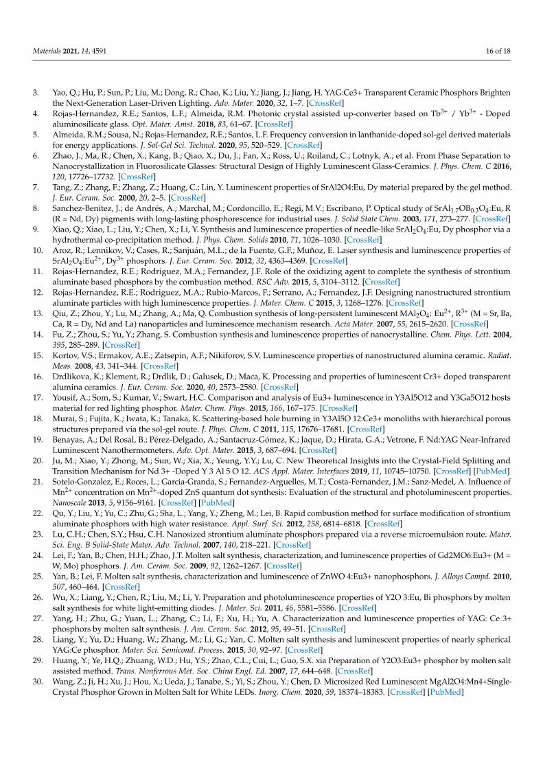
Materials 2021, 14, 4591 16 of 18
3. Yao, Q.; Hu, P.; Sun, P.; Liu, M.; Dong, R.; Chao, K.; Liu, Y.; Jiang, J.; Jiang, H. YAG:Ce3+ Transparent Ceramic Phosphors Brightenthe Next-Generation Laser-Driven Lighting. Adv. Mater. 2020, 32, 1–7. [CrossRef]
4. Rojas-Hernandez, R.E.; Santos, L.F.; Almeida, R.M. Photonic crystal assisted up-converter based on Tb3+ / Yb3+ - Dopedaluminosilicate glass. Opt. Mater. Amst. 2018, 83, 61–67. [CrossRef]
5. Almeida, R.M.; Sousa, N.; Rojas-Hernandez, R.E.; Santos, L.F. Frequency conversion in lanthanide-doped sol-gel derived materialsfor energy applications. J. Sol-Gel Sci. Technol. 2020, 95, 520–529. [CrossRef]
6. Zhao, J.; Ma, R.; Chen, X.; Kang, B.; Qiao, X.; Du, J.; Fan, X.; Ross, U.; Roiland, C.; Lotnyk, A.; et al. From Phase Separation toNanocrystallization in Fluorosilicate Glasses: Structural Design of Highly Luminescent Glass-Ceramics. J. Phys. Chem. C 2016,120, 17726–17732. [CrossRef]
7. Tang, Z.; Zhang, F.; Zhang, Z.; Huang, C.; Lin, Y. Luminescent properties of SrAl2O4:Eu, Dy material prepared by the gel method.J. Eur. Ceram. Soc. 2000, 20, 2–5. [CrossRef]
8. Sanchez-Benitez, J.; de Andrés, A.; Marchal, M.; Cordoncillo, E.; Regi, M.V.; Escribano, P. Optical study of SrAl1.7OB0.3O4:Eu, R(R = Nd, Dy) pigments with long-lasting phosphorescence for industrial uses. J. Solid State Chem. 2003, 171, 273–277. [CrossRef]
9. Xiao, Q.; Xiao, L.; Liu, Y.; Chen, X.; Li, Y. Synthesis and luminescence properties of needle-like SrAl2O4:Eu, Dy phosphor via ahydrothermal co-precipitation method. J. Phys. Chem. Solids 2010, 71, 1026–1030. [CrossRef]
10. Aroz, R.; Lennikov, V.; Cases, R.; Sanjuán, M.L.; de la Fuente, G.F.; Muñoz, E. Laser synthesis and luminescence properties ofSrAl2O4:Eu2+, Dy3+ phosphors. J. Eur. Ceram. Soc. 2012, 32, 4363–4369. [CrossRef]
11. Rojas-Hernandez, R.E.; Rodriguez, M.A.; Fernandez, J.F. Role of the oxidizing agent to complete the synthesis of strontiumaluminate based phosphors by the combustion method. RSC Adv. 2015, 5, 3104–3112. [CrossRef]
12. Rojas-Hernandez, R.E.; Rodriguez, M.A.; Rubio-Marcos, F.; Serrano, A.; Fernandez, J.F. Designing nanostructured strontiumaluminate particles with high luminescence properties. J. Mater. Chem. C 2015, 3, 1268–1276. [CrossRef]
13. Qiu, Z.; Zhou, Y.; Lu, M.; Zhang, A.; Ma, Q. Combustion synthesis of long-persistent luminescent MAl2O4: Eu2+, R3+ (M = Sr, Ba,Ca, R = Dy, Nd and La) nanoparticles and luminescence mechanism research. Acta Mater. 2007, 55, 2615–2620. [CrossRef]
14. Fu, Z.; Zhou, S.; Yu, Y.; Zhang, S. Combustion synthesis and luminescence properties of nanocrystalline. Chem. Phys. Lett. 2004,395, 285–289. [CrossRef]
15. Kortov, V.S.; Ermakov, A.E.; Zatsepin, A.F.; Nikiforov, S.V. Luminescence properties of nanostructured alumina ceramic. Radiat.Meas. 2008, 43, 341–344. [CrossRef]
16. Drdlikova, K.; Klement, R.; Drdlik, D.; Galusek, D.; Maca, K. Processing and properties of luminescent Cr3+ doped transparentalumina ceramics. J. Eur. Ceram. Soc. 2020, 40, 2573–2580. [CrossRef]
17. Yousif, A.; Som, S.; Kumar, V.; Swart, H.C. Comparison and analysis of Eu3+ luminescence in Y3Al5O12 and Y3Ga5O12 hostsmaterial for red lighting phosphor. Mater. Chem. Phys. 2015, 166, 167–175. [CrossRef]
18. Murai, S.; Fujita, K.; Iwata, K.; Tanaka, K. Scattering-based hole burning in Y3Al5O 12:Ce3+ monoliths with hierarchical porousstructures prepared via the sol-gel route. J. Phys. Chem. C 2011, 115, 17676–17681. [CrossRef]
19. Benayas, A.; Del Rosal, B.; Pérez-Delgado, A.; Santacruz-Gómez, K.; Jaque, D.; Hirata, G.A.; Vetrone, F. Nd:YAG Near-InfraredLuminescent Nanothermometers. Adv. Opt. Mater. 2015, 3, 687–694. [CrossRef]
20. Ju, M.; Xiao, Y.; Zhong, M.; Sun, W.; Xia, X.; Yeung, Y.Y.; Lu, C. New Theoretical Insights into the Crystal-Field Splitting andTransition Mechanism for Nd 3+ -Doped Y 3 Al 5 O 12. ACS Appl. Mater. Interfaces 2019, 11, 10745–10750. [CrossRef] [PubMed]
21. Sotelo-Gonzalez, E.; Roces, L.; Garcia-Granda, S.; Fernandez-Arguelles, M.T.; Costa-Fernandez, J.M.; Sanz-Medel, A. Influence ofMn2+ concentration on Mn2+-doped ZnS quantum dot synthesis: Evaluation of the structural and photoluminescent properties.Nanoscale 2013, 5, 9156–9161. [CrossRef] [PubMed]
22. Qu, Y.; Liu, Y.; Yu, C.; Zhu, G.; Sha, L.; Yang, Y.; Zheng, M.; Lei, B. Rapid combustion method for surface modification of strontiumaluminate phosphors with high water resistance. Appl. Surf. Sci. 2012, 258, 6814–6818. [CrossRef]
23. Lu, C.H.; Chen, S.Y.; Hsu, C.H. Nanosized strontium aluminate phosphors prepared via a reverse microemulsion route. Mater.Sci. Eng. B Solid-State Mater. Adv. Technol. 2007, 140, 218–221. [CrossRef]
24. Lei, F.; Yan, B.; Chen, H.H.; Zhao, J.T. Molten salt synthesis, characterization, and luminescence properties of Gd2MO6:Eu3+ (M =W, Mo) phosphors. J. Am. Ceram. Soc. 2009, 92, 1262–1267. [CrossRef]
25. Yan, B.; Lei, F. Molten salt synthesis, characterization and luminescence of ZnWO 4:Eu3+ nanophosphors. J. Alloys Compd. 2010,507, 460–464. [CrossRef]
26. Wu, X.; Liang, Y.; Chen, R.; Liu, M.; Li, Y. Preparation and photoluminescence properties of Y2O 3:Eu, Bi phosphors by moltensalt synthesis for white light-emitting diodes. J. Mater. Sci. 2011, 46, 5581–5586. [CrossRef]
27. Yang, H.; Zhu, G.; Yuan, L.; Zhang, C.; Li, F.; Xu, H.; Yu, A. Characterization and luminescence properties of YAG: Ce 3+phosphors by molten salt synthesis. J. Am. Ceram. Soc. 2012, 95, 49–51. [CrossRef]
28. Liang, Y.; Yu, D.; Huang, W.; Zhang, M.; Li, G.; Yan, C. Molten salt synthesis and luminescent properties of nearly sphericalYAG:Ce phosphor. Mater. Sci. Semicond. Process. 2015, 30, 92–97. [CrossRef]
29. Huang, Y.; Ye, H.Q.; Zhuang, W.D.; Hu, Y.S.; Zhao, C.L.; Cui, L.; Guo, S.X. xia Preparation of Y2O3:Eu3+ phosphor by molten saltassisted method. Trans. Nonferrous Met. Soc. China Engl. Ed. 2007, 17, 644–648. [CrossRef]
30. Wang, Z.; Ji, H.; Xu, J.; Hou, X.; Ueda, J.; Tanabe, S.; Yi, S.; Zhou, Y.; Chen, D. Microsized Red Luminescent MgAl2O4:Mn4+Single-Crystal Phosphor Grown in Molten Salt for White LEDs. Inorg. Chem. 2020, 59, 18374–18383. [CrossRef] [PubMed]
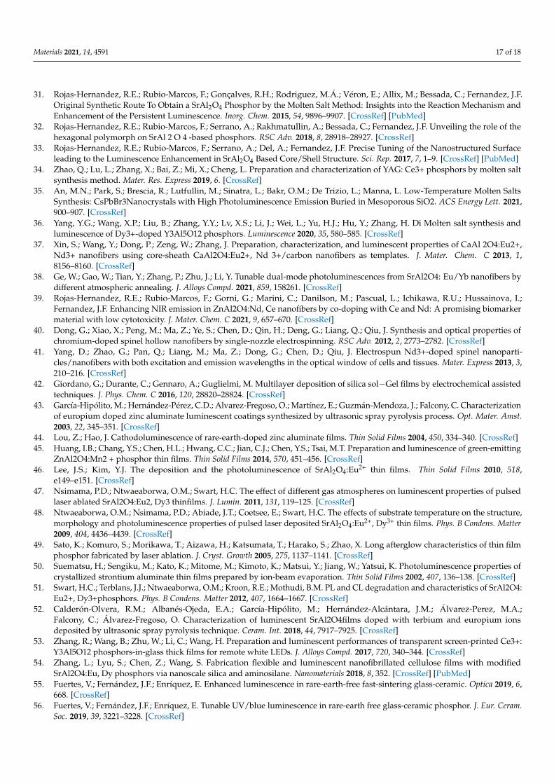
Materials 2021, 14, 4591 17 of 18
31. Rojas-Hernandez, R.E.; Rubio-Marcos, F.; Gonçalves, R.H.; Rodriguez, M.Á.; Véron, E.; Allix, M.; Bessada, C.; Fernandez, J.F.Original Synthetic Route To Obtain a SrAl2O4 Phosphor by the Molten Salt Method: Insights into the Reaction Mechanism andEnhancement of the Persistent Luminescence. Inorg. Chem. 2015, 54, 9896–9907. [CrossRef] [PubMed]
32. Rojas-Hernandez, R.E.; Rubio-Marcos, F.; Serrano, A.; Rakhmatullin, A.; Bessada, C.; Fernandez, J.F. Unveiling the role of thehexagonal polymorph on SrAl 2 O 4 -based phosphors. RSC Adv. 2018, 8, 28918–28927. [CrossRef]
33. Rojas-Hernandez, R.E.; Rubio-Marcos, F.; Serrano, A.; Del, A.; Fernandez, J.F. Precise Tuning of the Nanostructured Surfaceleading to the Luminescence Enhancement in SrAl2O4 Based Core/Shell Structure. Sci. Rep. 2017, 7, 1–9. [CrossRef] [PubMed]
34. Zhao, Q.; Lu, L.; Zhang, X.; Bai, Z.; Mi, X.; Cheng, L. Preparation and characterization of YAG: Ce3+ phosphors by molten saltsynthesis method. Mater. Res. Express 2019, 6. [CrossRef]
35. An, M.N.; Park, S.; Brescia, R.; Lutfullin, M.; Sinatra, L.; Bakr, O.M.; De Trizio, L.; Manna, L. Low-Temperature Molten SaltsSynthesis: CsPbBr3Nanocrystals with High Photoluminescence Emission Buried in Mesoporous SiO2. ACS Energy Lett. 2021,900–907. [CrossRef]
36. Yang, Y.G.; Wang, X.P.; Liu, B.; Zhang, Y.Y.; Lv, X.S.; Li, J.; Wei, L.; Yu, H.J.; Hu, Y.; Zhang, H. Di Molten salt synthesis andluminescence of Dy3+-doped Y3Al5O12 phosphors. Luminescence 2020, 35, 580–585. [CrossRef]
37. Xin, S.; Wang, Y.; Dong, P.; Zeng, W.; Zhang, J. Preparation, characterization, and luminescent properties of CaAl 2O4:Eu2+,Nd3+ nanofibers using core-sheath CaAl2O4:Eu2+, Nd 3+/carbon nanofibers as templates. J. Mater. Chem. C 2013, 1,8156–8160. [CrossRef]
38. Ge, W.; Gao, W.; Tian, Y.; Zhang, P.; Zhu, J.; Li, Y. Tunable dual-mode photoluminescences from SrAl2O4: Eu/Yb nanofibers bydifferent atmospheric annealing. J. Alloys Compd. 2021, 859, 158261. [CrossRef]
39. Rojas-Hernandez, R.E.; Rubio-Marcos, F.; Gorni, G.; Marini, C.; Danilson, M.; Pascual, L.; Ichikawa, R.U.; Hussainova, I.;Fernandez, J.F. Enhancing NIR emission in ZnAl2O4:Nd, Ce nanofibers by co-doping with Ce and Nd: A promising biomarkermaterial with low cytotoxicity. J. Mater. Chem. C 2021, 9, 657–670. [CrossRef]
40. Dong, G.; Xiao, X.; Peng, M.; Ma, Z.; Ye, S.; Chen, D.; Qin, H.; Deng, G.; Liang, Q.; Qiu, J. Synthesis and optical properties ofchromium-doped spinel hollow nanofibers by single-nozzle electrospinning. RSC Adv. 2012, 2, 2773–2782. [CrossRef]
41. Yang, D.; Zhao, G.; Pan, Q.; Liang, M.; Ma, Z.; Dong, G.; Chen, D.; Qiu, J. Electrospun Nd3+-doped spinel nanoparti-cles/nanofibers with both excitation and emission wavelengths in the optical window of cells and tissues. Mater. Express 2013, 3,210–216. [CrossRef]
42. Giordano, G.; Durante, C.; Gennaro, A.; Guglielmi, M. Multilayer deposition of silica sol−Gel films by electrochemical assistedtechniques. J. Phys. Chem. C 2016, 120, 28820–28824. [CrossRef]
43. García-Hipólito, M.; Hernández-Pérez, C.D.; Alvarez-Fregoso, O.; Martínez, E.; Guzmán-Mendoza, J.; Falcony, C. Characterizationof europium doped zinc aluminate luminescent coatings synthesized by ultrasonic spray pyrolysis process. Opt. Mater. Amst.2003, 22, 345–351. [CrossRef]
44. Lou, Z.; Hao, J. Cathodoluminescence of rare-earth-doped zinc aluminate films. Thin Solid Films 2004, 450, 334–340. [CrossRef]45. Huang, I.B.; Chang, Y.S.; Chen, H.L.; Hwang, C.C.; Jian, C.J.; Chen, Y.S.; Tsai, M.T. Preparation and luminescence of green-emitting
ZnAl2O4:Mn2 + phosphor thin films. Thin Solid Films 2014, 570, 451–456. [CrossRef]46. Lee, J.S.; Kim, Y.J. The deposition and the photoluminescence of SrAl2O4:Eu2+ thin films. Thin Solid Films 2010, 518,
e149–e151. [CrossRef]47. Nsimama, P.D.; Ntwaeaborwa, O.M.; Swart, H.C. The effect of different gas atmospheres on luminescent properties of pulsed
laser ablated SrAl2O4:Eu2, Dy3 thinfilms. J. Lumin. 2011, 131, 119–125. [CrossRef]48. Ntwaeaborwa, O.M.; Nsimama, P.D.; Abiade, J.T.; Coetsee, E.; Swart, H.C. The effects of substrate temperature on the structure,
morphology and photoluminescence properties of pulsed laser deposited SrAl2O4:Eu2+, Dy3+ thin films. Phys. B Condens. Matter2009, 404, 4436–4439. [CrossRef]
49. Sato, K.; Komuro, S.; Morikawa, T.; Aizawa, H.; Katsumata, T.; Harako, S.; Zhao, X. Long afterglow characteristics of thin filmphosphor fabricated by laser ablation. J. Cryst. Growth 2005, 275, 1137–1141. [CrossRef]
50. Suematsu, H.; Sengiku, M.; Kato, K.; Mitome, M.; Kimoto, K.; Matsui, Y.; Jiang, W.; Yatsui, K. Photoluminescence properties ofcrystallized strontium aluminate thin films prepared by ion-beam evaporation. Thin Solid Films 2002, 407, 136–138. [CrossRef]
51. Swart, H.C.; Terblans, J.J.; Ntwaeaborwa, O.M.; Kroon, R.E.; Mothudi, B.M. PL and CL degradation and characteristics of SrAl2O4:Eu2+, Dy3+phosphors. Phys. B Condens. Matter 2012, 407, 1664–1667. [CrossRef]
52. Calderón-Olvera, R.M.; Albanés-Ojeda, E.A.; García-Hipólito, M.; Hernández-Alcántara, J.M.; Álvarez-Perez, M.A.;Falcony, C.; Álvarez-Fregoso, O. Characterization of luminescent SrAl2O4films doped with terbium and europium ionsdeposited by ultrasonic spray pyrolysis technique. Ceram. Int. 2018, 44, 7917–7925. [CrossRef]
53. Zhang, R.; Wang, B.; Zhu, W.; Li, C.; Wang, H. Preparation and luminescent performances of transparent screen-printed Ce3+:Y3Al5O12 phosphors-in-glass thick films for remote white LEDs. J. Alloys Compd. 2017, 720, 340–344. [CrossRef]
54. Zhang, L.; Lyu, S.; Chen, Z.; Wang, S. Fabrication flexible and luminescent nanofibrillated cellulose films with modifiedSrAl2O4:Eu, Dy phosphors via nanoscale silica and aminosilane. Nanomaterials 2018, 8, 352. [CrossRef] [PubMed]
55. Fuertes, V.; Fernández, J.F.; Enríquez, E. Enhanced luminescence in rare-earth-free fast-sintering glass-ceramic. Optica 2019, 6,668. [CrossRef]
56. Fuertes, V.; Fernández, J.F.; Enríquez, E. Tunable UV/blue luminescence in rare-earth free glass-ceramic phosphor. J. Eur. Ceram.Soc. 2019, 39, 3221–3228. [CrossRef]

Materials 2021, 14, 4591 18 of 18
57. Fu, Q.; Burgert, I.; Tu, K.; Goldhahn, C.; Keplinger, T.; Adobes-Vidal, M.; Sorieul, M. Luminescent and hydrophobic wood films asoptical lighting materials. ACS Nano 2020, 14, 13775–13783. [CrossRef] [PubMed]
58. Arroyo, E.; Medrán, B.; Castaing, V.; Lozano, G.; Ocaña, M.; Becerro, A.I. Persistent luminescence of transparentZnGa2O4:Cr3+thin films from colloidal nanoparticles of tunable size. J. Mater. Chem. C 2021, 9, 4474–4485. [CrossRef]
Copyright © 2022 FDOKUMEN