Microstructure of an experimental Ni base superalloy under various casting conditions
9
This article appeared in a journal published by Elsevier. The attached copy is furnished to the author for internal non-commercial research and education use, including for instruction at the authors institution and sharing with colleagues. Other uses, including reproduction and distribution, or selling or licensing copies, or posting to personal, institutional or third party websites are prohibited. In most cases authors are permitted to post their version of the article (e.g. in Word or Tex form) to their personal website or institutional repository. Authors requiring further information regarding Elsevier’s archiving and manuscript policies are encouraged to visit: http://www.elsevier.com/copyright
-
Upload
independent -
Category
Documents
-
view
0 -
download
0
Transcript of Microstructure of an experimental Ni base superalloy under various casting conditions
This article appeared in a journal published by Elsevier. The attachedcopy is furnished to the author for internal non-commercial researchand education use, including for instruction at the authors institution
and sharing with colleagues.
Other uses, including reproduction and distribution, or selling orlicensing copies, or posting to personal, institutional or third party
websites are prohibited.
In most cases authors are permitted to post their version of thearticle (e.g. in Word or Tex form) to their personal website orinstitutional repository. Authors requiring further information
regarding Elsevier’s archiving and manuscript policies areencouraged to visit:
http://www.elsevier.com/copyright
Author's personal copy
Materials Science and Engineering A 527 (2010) 7793–7800
Contents lists available at ScienceDirect
Materials Science and Engineering A
journa l homepage: www.e lsev ier .com/ locate /msea
Microstructure of an experimental Ni base superalloy undervarious casting conditions
N. El-Bagourya,b,∗, A. Nofala
a Casting Technology Lab., Central Metallurgical Research and Development Institute (CMRDI), P.O. Box 87 Helwan, Cairo, Egyptb Chemistry Department, Faculty of Science, TAIF University, P.O. Box 888, El-Haweyah, El-Taif, Saudi Arabia
a r t i c l e i n f o
Article history:Received 10 June 2010Received in revised form 17 August 2010Accepted 18 August 2010
Keywords:Polycrystalline Ni base superalloyCastingMelt superheatSolidification cooling rateMicrostructure� and � phases
a b s t r a c t
The effect of casting parameters such as melt superheat and solidification rate on the microstructureof an experimental Ni-based superalloy made by vacuum melting and investment casting methods wasinvestigated. The results show that the as cast microstructure of this alloy consists of dendritic � matrix,interdendritic �/�′, �′ phase, MC carbides and minor phases in interdendritic regions. DSC analyses inaddition to SEM and EDS proved that the nodular phase found in minor phases is � phase, while the �phase was found to solidify in two forms; as plate-like and blocky shape. The volume fraction (Vf) of � and� phases increases as the melt superheat increases and the solidification cooling rate decreases. Addi-tionally, the Vf of interdendritic �/�′ increases with higher solidification rate and lower melt superheat.It was found that higher melt superheating temperature enlarges the size of the primary � dendrites;however the higher solidification rate diminishes it.
© 2010 Elsevier B.V. All rights reserved.
1. Introduction
The Ni base superalloys such as IN738LC and GTD111 weredeveloped by General Electric for use in manufacturing of the firststage blades of powerful gas turbines (over 125 MW). The bladeswork at critical conditions of creep, corrosion, and fatigue for morethan 70,000 h. The alloy contains refractory elements such as Mo,W, Ta, Cr and Co to prevent local hot corrosion [1–3].
In spite of the important role of most of Ni base superalloys inthe high temperature performance, limited data on microstructureand material characterization are reported, therefore a completedescription of the effect of casting parameters on the Ni base alloysis required [4,5–7].
Ni base superalloy is known to have a multiphase microstruc-ture consisting of a solid solution strengthened austenitic nickel �matrix, bimodal �′ precipitate, �/�′ interdendritic, carbides and asmall amount of deleterious phases such as: �, �, � and laves [8–11].In some cases, minor phases like � phase and � phase, which usu-ally form due to solid state transformation in superalloys, may format the end of solidification owing to the influence of composition.
∗ Corresponding author at: Casting Technology Lab., Central MetallurgicalResearch and Development Institute (CMRDI), P.O. Box 87 Helwan, Cairo, Egypt.Tel.: +966 596264584; fax: +966 27242296.
E-mail addresses: [email protected], nader [email protected](N. El-Bagoury).
The � phase has a hexagonal close-packed (hcp) structure and hasthe basic stoichiometry of Ni3Ti, while � phase has a tetragonaltopologically close-packed (TCP) structure. Both � and � phases aregenerally considered as deleterious minor phases by alloy design-ers as they usually pose negative impact on superalloys’ mechanicalproperties. Previous studies are focused on analyzing the precipi-tation mechanism of � and � phases in solid state in superalloys.� phase may form either during casting or thermo exposure pro-cess in nickel based superalloys. Bouse has reported that � phaseor platelet phases formed in the as cast microstructure of alloyscontaining high percentages of Ti, such as IN792Hf, IN939, GTD111and IN6203 [12]. Other studies also reported the occurrence of �phase at the periphery of the �/�′ interdendritic zones [13–15].Recently, the � phase formed by MC carbide decomposition duringheat treatment or thermo exposure is gaining researchers’ interests[16,17]. However, quite a few studies have been made to char-acterize the formation of � phase during both solidification andsubsequent heat treatment processes. � phase generally precipitatefrom � phase in solid state and seriously degrades the mechani-cal properties of superalloys due to its plate-like morphology andhigh content of refractory alloy containing [18]. Moreover, a recentstudy declared that � phase can act as nucleating sites for other TCPphases, such as � or P phases [19].
Most investigations of Ni base alloys are focused on the heattreatment processes [20–23]. Few are concerned on the effect ofcasting and solidification processes on microstructure of this groupof alloys. Casting and solidification variables such as superheating
0921-5093/$ – see front matter © 2010 Elsevier B.V. All rights reserved.doi:10.1016/j.msea.2010.08.050
Author's personal copy
7794 N. El-Bagoury, A. Nofal / Materials Science and Engineering A 527 (2010) 7793–7800
Table 1Chemical composition of as cast Ni base superalloys, mass %.
Alloy Elements
C Cr Mo W Ti Co Al Nb Ta Ni
IN738LC scrap 0.13 15.01 1.97 2.81 3.63 7.67 4.52 1.07 1.27 Bal.As cast (L) 0.47 16.97 2.39 4.27 5.74 10.37 1.41 0.12 1.93 Bal.As cast (H) 0.54 16.95 2.45 4.36 5.88 10.48 1.49 0.10 1.86 Bal.
treatment and cooling rate have marked influences on phases andits volume fractions, refinement of structure as well as segregationand portion of alloying elements.
In the present study, melt superheat and cooling rate effectson solidification and microstructural evolutions in Ni base super-alloy have been investigated. As almost no studies have reportedthe formation of � phase during casting in addition to the con-troversial issue about the precipitation of � phase either duringsolidification or heat treatment processes, a detailed characteriza-tion of these phases in the microstructure of Ni base superalloy willprovide better knowledge and understanding about the formationof these phases.
2. Experimental procedures
The IN738LC alloy used in this work was received as turbineblade scrap supplied from a gas turbine power plant. Table 1 showsthe chemical composition of as-received IN738LC scrap. This scrapwas double melted and cast under vacuum, using an inductionvacuum furnace. In the second melt some amounts of alloying ele-ments such as Ti, Co, Ta, W were added to adjust the chemicalcomposition, then a third melting was made to ensure melting andhomogenous distribution of all alloying elements in the heat. Heats
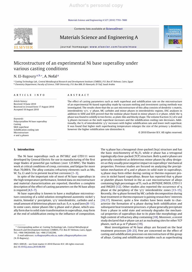
Fig. 1. Ceramic mold used in the investment casting of Ni base superalloy.
were made by melting 10 kg of turbine blade scrap. Pouring wascarried out into an investment casting ceramic mold (Fig. 1). Thismold was preheated to 1000 ◦C before the pouring process.
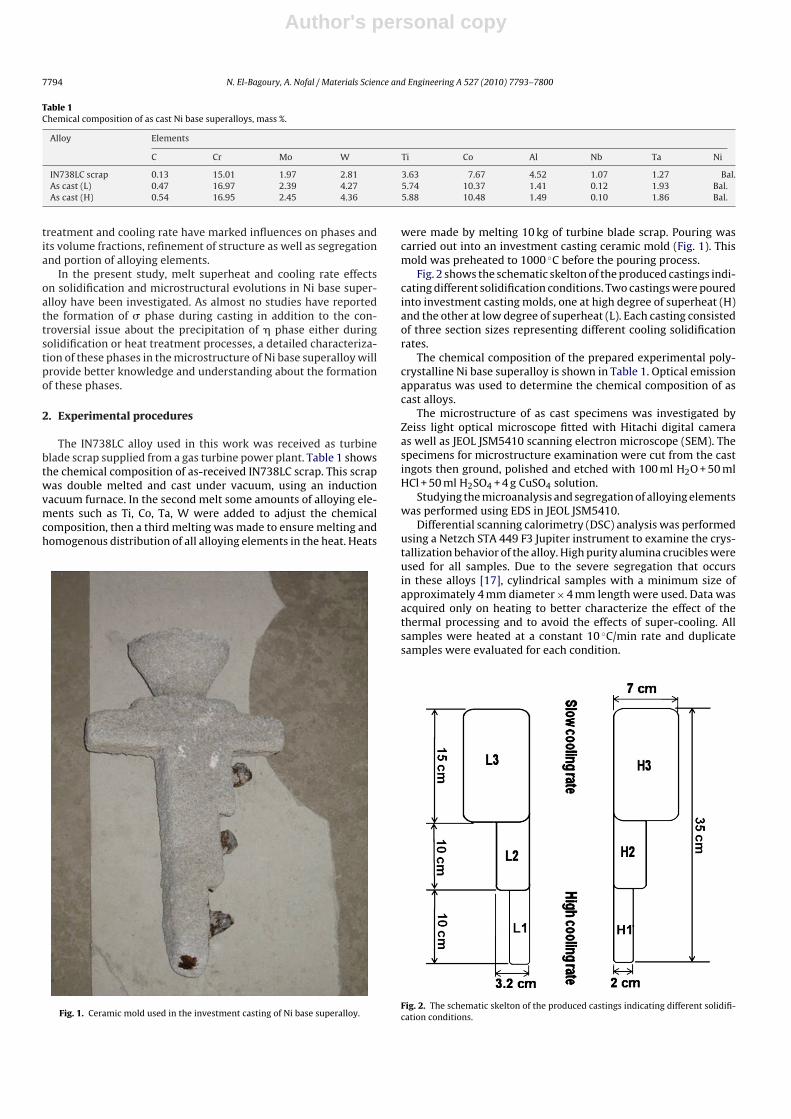
Fig. 2 shows the schematic skelton of the produced castings indi-cating different solidification conditions. Two castings were pouredinto investment casting molds, one at high degree of superheat (H)and the other at low degree of superheat (L). Each casting consistedof three section sizes representing different cooling solidificationrates.
The chemical composition of the prepared experimental poly-crystalline Ni base superalloy is shown in Table 1. Optical emissionapparatus was used to determine the chemical composition of ascast alloys.
The microstructure of as cast specimens was investigated byZeiss light optical microscope fitted with Hitachi digital cameraas well as JEOL JSM5410 scanning electron microscope (SEM). Thespecimens for microstructure examination were cut from the castingots then ground, polished and etched with 100 ml H2O + 50 mlHCl + 50 ml H2SO4 + 4 g CuSO4 solution.
Studying the microanalysis and segregation of alloying elementswas performed using EDS in JEOL JSM5410.
Differential scanning calorimetry (DSC) analysis was performedusing a Netzch STA 449 F3 Jupiter instrument to examine the crys-tallization behavior of the alloy. High purity alumina crucibles wereused for all samples. Due to the severe segregation that occursin these alloys [17], cylindrical samples with a minimum size ofapproximately 4 mm diameter × 4 mm length were used. Data wasacquired only on heating to better characterize the effect of thethermal processing and to avoid the effects of super-cooling. Allsamples were heated at a constant 10 ◦C/min rate and duplicatesamples were evaluated for each condition.
Fig. 2. The schematic skelton of the produced castings indicating different solidifi-cation conditions.
Author's personal copy
N. El-Bagoury, A. Nofal / Materials Science and Engineering A 527 (2010) 7793–7800 7795
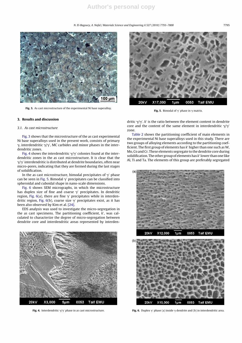
Fig. 3. As cast microstructure of the experimental Ni base superalloy.
3. Results and discussion
3.1. As cast microstructure
Fig. 3 shows that the microstructure of the as cast experimentalNi base superalloys used in the present work, consists of primary�, interdendritic �/�′, MC carbides and minor phases in the inter-dendritic zones.
Fig. 4 shows the interdendritic �/�′ colonies found at the inter-dendritic zones in the as cast microstructure. It is clear that the�/�′ interdendritic is distributed at dendrite boundaries, often nearmicro-pores, indicating that they are formed during the last stagesof solidification.
In the as cast microstructure, bimodal precipitates of �′ phasecan be seen in Fig. 5. Bimodal �′ precipitates can be classified intospheroidal and cuboidal shape in nano-scale dimensions.
Fig. 6 shows SEM micrographs, in which the microstructurehas duplex size of fine and coarse �′ precipitates. In dendriticregion, Fig. 6(a), there are fine �′ precipitates while in interden-dritic region, Fig. 6(b), coarse size �′ precipitates exist, as it hasbeen also observed by Kim et al. [24].
EDS analysis was used to investigate the micro-segregation inthe as cast specimens. The partitioning coefficient, k′, was cal-culated to characterize the degree of micro-segregation betweendendrite core and interdendritic areas represented by interden-
Fig. 4. Interdendritic �/�′ phase in as cast microstructure.
Fig. 5. Bimodal of �′ phase in � matrix.
dritic �/�′. k′ is the ratio between the element content in dendritecore and the content of the same element in interdendritic �/�′
zone.Table 2 shows the partitioning coefficient of main elements in
the experimental Ni base superalloys used in this study. There aretwo groups of alloying elements according to the partitioning coef-ficient. The first group of elements has k′ higher than one such as W,Mo, Co and Cr. These elements segregate to the dendrite core duringsolidification. The other group of elements has k′ lower than one likeAl, Ti and Ta. The elements of this group are preferably segregated
Fig. 6. Duplex �′ phase (a) inside � dendrite and (b) in interdendritic area.
Author's personal copy
7796 N. El-Bagoury, A. Nofal / Materials Science and Engineering A 527 (2010) 7793–7800
Table 2Partition coefficient of major elements in cast Ni base superalloys.
Part. coeff. Elements
Al Ti Cr Co Mo Ta W Ni
k′ in as cast L1 0.95 0.50 1.24 1.21 1.16 0.52 1.65 1.013k′ in as cast H1 0.81 0.53 1.09 1.15 1.26 0.57 1.78 0.997
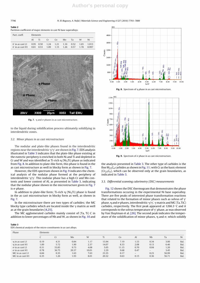
Fig. 7. � and � phases in as cast microstructure.
to the liquid during solidification process ultimately solidifying ininterdendritic zones.
3.2. Minor phases in as cast microstructure
The nodular and plate-like phases found in the interdendriticregions near the interdendritic �/�′ are shown in Fig. 7. EDS analysisillustrated in Table 3 indicates that the plate-like phase existing atthe eutectic periphery is enriched in both Ni and Ti and depleted inCr and W and was identified as Ti-rich � (Ni3Ti) phase as indicatedfrom Fig. 8. In addition to plate-like form, this phase is found in theas cast microstructure as well in blocky form as shown in Fig. 7.
However, the EDS spectrum shown in Fig. 9 indicates the chem-ical analysis of the nodular phase formed at the periphery ofinterdendritic �/�′. This nodular phase has a high Cr and Mo con-tents and lower content of Al, as presented in Table 3, indicatingthat the nodular phase shown in the microstructure given in Fig. 7is � phase.
In addition to plate-like form; Ti-rich � (Ni3Ti) phase is foundin the as cast microstructure in blocky form as well, as shown inFig. 7.
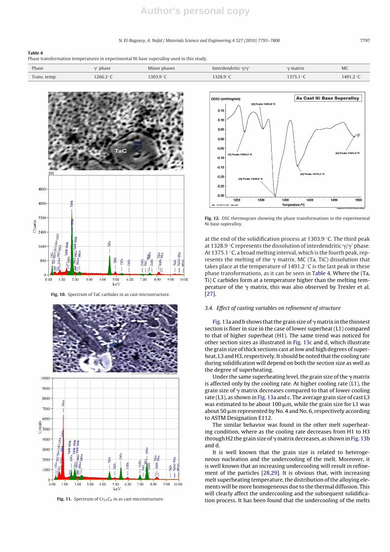
In the microstructure there are two types of carbides; the MCblocky type carbides which are located inside the � matrix as wellas at the grain boundaries [4,25].
The MC agglomerated carbides mainly consist of (Ta, Ti) C inaddition to lower percentages of Nb and W, as shown in Fig. 10 and
Fig. 8. Spectrum of � phase in as cast microstructure.
Fig. 9. Spectrum of � phase in as cast microstructure.
the analysis presented in Table 3. The other type of carbides is thefine M23C6 carbides as shown in Fig. 11; with Cr as the basic element(Cr23C6), which can be observed only at the grain boundaries, asindicated in Table 3.
3.3. Differential scanning calorimetry (DSC) measurements
Fig. 12 shows the DSC thermogram that demonstrates the phasetransformations occuring in the experimental Ni base superalloy.There are five peaks of interested phase transformation reactionsthat related to the formation of minor phases such as solvus of �′
phase, � and � phases, interdendritic �/�′, � matrix and MC (Ta, TiC)carbides, respectively. The first peak appeared at 1266.3 ◦C and itcorresponds to the solvus temperature of �′ phase, as was observedby Van Sluytman et al. [26]. The second peak indicates the temper-ature of the solidification of minor phases, � and �, which solidify
Table 3EDS chemical analysis of the micro-constituents in as cast alloys.
Phase Elements
C Cr Mo W Ti Co Al Nb Ta Ni
� in as cast L1 0.19 4.31 0.84 1.17 15.94 7.19 1.53 0.34 3.00 Bal.� in as cast H1 1.89 5.72 1.90 2.37 14.07 8.33 2.08 0.13 6.46 Bal.� in as cast L1 0.31 33.85 9.73 4.68 5.05 11.15 0.70 0.04 1.20 Bal.� in as cast H1 0.78 36.75 20.37 10.01 2.29 9.68 0.47 – 3.45 Bal.MC in as cast L1 6.84 0.35 1.63 7.63 23.35 0.17 – 0.23 56.99 Bal.MC in as cast H1 6.35 1.26 1.93 8.01 20.32 0.63 0.15 0.36 56.71 Bal.
Author's personal copy
N. El-Bagoury, A. Nofal / Materials Science and Engineering A 527 (2010) 7793–7800 7797
Table 4Phase transformation temperatures in experimental Ni base superalloy used in this study.
Phase �′ phase Minor phases Interdendritic �/�′ � matrix MC
Trans. temp. 1266.3 ◦C 1303.9 ◦C 1328.9 ◦C 1375.1 ◦C 1491.2 ◦C
Fig. 10. Spectrum of TaC carbides in as cast microstructure.
Fig. 11. Spectrum of Cr23C6 in as cast microstructure.
Fig. 12. DSC thermogram showing the phase transformations in the experimentalNi base superalloy.
at the end of the solidification process at 1303.9 ◦C. The third peakat 1328.9 ◦C represents the dissolution of interdendritic �/�′ phase.At 1375.1 ◦C, a broad melting interval, which is the fourth peak, rep-resents the melting of the � matrix. MC (Ta, TiC) dissolution thattakes place at the temperature of 1491.2 ◦C is the last peak in thesephase transformations, as it can be seen in Table 4. Where the (Ta,Ti) C carbides form at a temperature higher than the melting tem-perature of the � matrix, this was also observed by Trexler et al.[27].
3.4. Effect of casting variables on refinement of structure
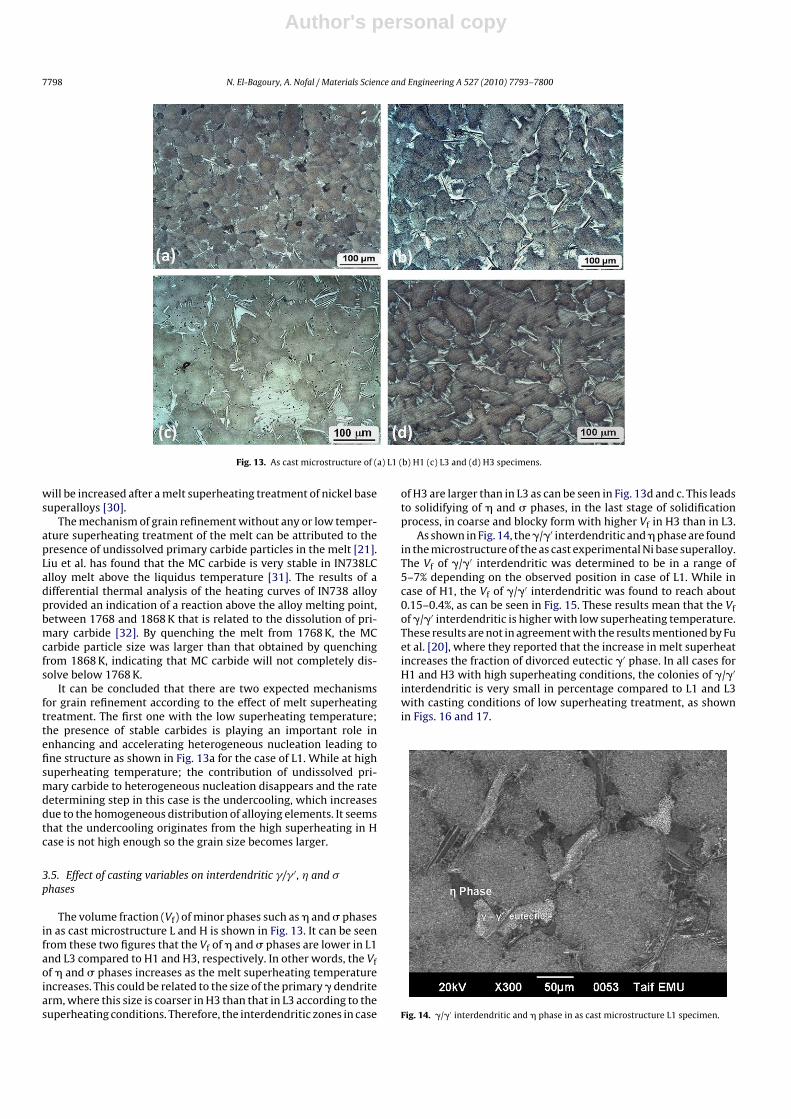
Fig. 13a and b shows that the grain size of � matrix in the thinnestsection is finer in size in the case of lower superheat (L1) comparedto that of higher superheat (H1). The same trend was noticed forother section sizes as illustrated in Fig. 13c and d, which illustratethe grain size of thick sections cast at low and high degrees of super-heat, L3 and H3, respectively. It should be noted that the cooling rateduring solidification will depend on both the section size as well asthe degree of superheating.
Under the same superheating level, the grain size of the � matrixis affected only by the cooling rate. At higher cooling rate (L1), thegrain size of � matrix decreases compared to that of lower coolingrate (L3), as shown in Fig. 13a and c. The average grain size of cast L3was estimated to be about 100 �m, while the grain size for L1 wasabout 50 �m represented by No. 4 and No. 6, respectively accordingto ASTM Designation E112.
The similar behavior was found in the other melt superheat-ing condition, where as the cooling rate decreases from H1 to H3through H2 the grain size of � matrix decreases, as shown in Fig. 13band d.
It is well known that the grain size is related to heteroge-neous nucleation and the undercooling of the melt. Moreover, itis well known that an increasing undercooling will result in refine-ment of the particles [28,29]. It is obvious that, with increasingmelt superheating temperature, the distribution of the alloying ele-ments will be more homogeneous due to the thermal diffusion. Thiswill clearly affect the undercooling and the subsequent solidifica-tion process. It has been found that the undercooling of the melts
Author's personal copy
7798 N. El-Bagoury, A. Nofal / Materials Science and Engineering A 527 (2010) 7793–7800
Fig. 13. As cast microstructure of (a) L1 (b) H1 (c) L3 and (d) H3 specimens.
will be increased after a melt superheating treatment of nickel basesuperalloys [30].
The mechanism of grain refinement without any or low temper-ature superheating treatment of the melt can be attributed to thepresence of undissolved primary carbide particles in the melt [21].Liu et al. has found that the MC carbide is very stable in IN738LCalloy melt above the liquidus temperature [31]. The results of adifferential thermal analysis of the heating curves of IN738 alloyprovided an indication of a reaction above the alloy melting point,between 1768 and 1868 K that is related to the dissolution of pri-mary carbide [32]. By quenching the melt from 1768 K, the MCcarbide particle size was larger than that obtained by quenchingfrom 1868 K, indicating that MC carbide will not completely dis-solve below 1768 K.
It can be concluded that there are two expected mechanismsfor grain refinement according to the effect of melt superheatingtreatment. The first one with the low superheating temperature;the presence of stable carbides is playing an important role inenhancing and accelerating heterogeneous nucleation leading tofine structure as shown in Fig. 13a for the case of L1. While at highsuperheating temperature; the contribution of undissolved pri-mary carbide to heterogeneous nucleation disappears and the ratedetermining step in this case is the undercooling, which increasesdue to the homogeneous distribution of alloying elements. It seemsthat the undercooling originates from the high superheating in Hcase is not high enough so the grain size becomes larger.
3.5. Effect of casting variables on interdendritic �/� ′, � and �phases
The volume fraction (Vf) of minor phases such as � and � phasesin as cast microstructure L and H is shown in Fig. 13. It can be seenfrom these two figures that the Vf of � and � phases are lower in L1and L3 compared to H1 and H3, respectively. In other words, the Vfof � and � phases increases as the melt superheating temperatureincreases. This could be related to the size of the primary � dendritearm, where this size is coarser in H3 than that in L3 according to thesuperheating conditions. Therefore, the interdendritic zones in case
of H3 are larger than in L3 as can be seen in Fig. 13d and c. This leadsto solidifying of � and � phases, in the last stage of solidificationprocess, in coarse and blocky form with higher Vf in H3 than in L3.
As shown in Fig. 14, the �/�′ interdendritic and � phase are foundin the microstructure of the as cast experimental Ni base superalloy.The Vf of �/�′ interdendritic was determined to be in a range of5–7% depending on the observed position in case of L1. While incase of H1, the Vf of �/�′ interdendritic was found to reach about0.15–0.4%, as can be seen in Fig. 15. These results mean that the Vfof �/�′ interdendritic is higher with low superheating temperature.These results are not in agreement with the results mentioned by Fuet al. [20], where they reported that the increase in melt superheatincreases the fraction of divorced eutectic �′ phase. In all cases forH1 and H3 with high superheating conditions, the colonies of �/�′
interdendritic is very small in percentage compared to L1 and L3with casting conditions of low superheating treatment, as shownin Figs. 16 and 17.
Fig. 14. �/�′ interdendritic and � phase in as cast microstructure L1 specimen.
Author's personal copy
N. El-Bagoury, A. Nofal / Materials Science and Engineering A 527 (2010) 7793–7800 7799
Fig. 15. �/�′ interdendritic phase in as cast microstructure H1 specimen.
Fig. 16. �/�′ interdendritic and � phases in as cast microstructure L2 specimen.
Fig. 17. �/�′ interdendritic phase in as cast microstructure H2 specimen.
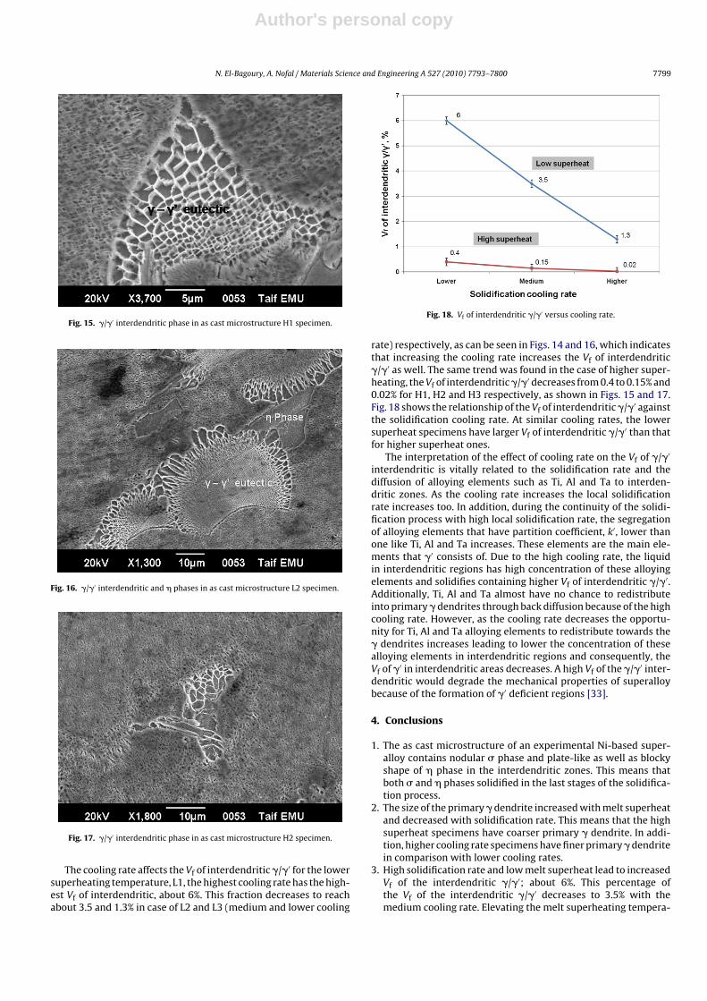
The cooling rate affects the Vf of interdendritic �/�′ for the lowersuperheating temperature, L1, the highest cooling rate has the high-est Vf of interdendritic, about 6%. This fraction decreases to reachabout 3.5 and 1.3% in case of L2 and L3 (medium and lower cooling
Fig. 18. Vf of interdendritic �/�′ versus cooling rate.
rate) respectively, as can be seen in Figs. 14 and 16, which indicatesthat increasing the cooling rate increases the Vf of interdendritic�/�′ as well. The same trend was found in the case of higher super-heating, the Vf of interdendritic �/�′ decreases from 0.4 to 0.15% and0.02% for H1, H2 and H3 respectively, as shown in Figs. 15 and 17.Fig. 18 shows the relationship of the Vf of interdendritic �/�′ againstthe solidification cooling rate. At similar cooling rates, the lowersuperheat specimens have larger Vf of interdendritic �/�′ than thatfor higher superheat ones.
The interpretation of the effect of cooling rate on the Vf of �/�′
interdendritic is vitally related to the solidification rate and thediffusion of alloying elements such as Ti, Al and Ta to interden-dritic zones. As the cooling rate increases the local solidificationrate increases too. In addition, during the continuity of the solidi-fication process with high local solidification rate, the segregationof alloying elements that have partition coefficient, k′, lower thanone like Ti, Al and Ta increases. These elements are the main ele-ments that �′ consists of. Due to the high cooling rate, the liquidin interdendritic regions has high concentration of these alloyingelements and solidifies containing higher Vf of interdendritic �/�′.Additionally, Ti, Al and Ta almost have no chance to redistributeinto primary � dendrites through back diffusion because of the highcooling rate. However, as the cooling rate decreases the opportu-nity for Ti, Al and Ta alloying elements to redistribute towards the� dendrites increases leading to lower the concentration of thesealloying elements in interdendritic regions and consequently, theVf of �′ in interdendritic areas decreases. A high Vf of the �/�′ inter-dendritic would degrade the mechanical properties of superalloybecause of the formation of �′ deficient regions [33].
4. Conclusions
1. The as cast microstructure of an experimental Ni-based super-alloy contains nodular � phase and plate-like as well as blockyshape of � phase in the interdendritic zones. This means thatboth � and � phases solidified in the last stages of the solidifica-tion process.
2. The size of the primary � dendrite increased with melt superheatand decreased with solidification rate. This means that the highsuperheat specimens have coarser primary � dendrite. In addi-tion, higher cooling rate specimens have finer primary � dendritein comparison with lower cooling rates.
3. High solidification rate and low melt superheat lead to increasedVf of the interdendritic �/�′; about 6%. This percentage ofthe Vf of the interdendritic �/�′ decreases to 3.5% with themedium cooling rate. Elevating the melt superheating tempera-
Author's personal copy
7800 N. El-Bagoury, A. Nofal / Materials Science and Engineering A 527 (2010) 7793–7800
ture diminishes the Vf of the interdendritic �/�′ from 6 to about0.4% with higher cooling rate.
4. The Vf of � and � phases in the interdendritic regions was foundto increase as the melt superheat increased, in case of high super-heat specimens than low superheat ones and the solidificationcooling rate decreased for example in higher cooling rate speci-mens compared to lowered cooling rate ones.
References
[1] B.G. Choi, I.S. Kim, D.H. Kim, C. Jo, Mater. Sci. Eng. A 478 (2008) 329.[2] S.A. Sajjadi, S. Nategh, R.I.L. Guthrie, Mater. Sci. Eng. A 325 (2002) 484.[3] C.T. Liua, J. Ma, X.F. Sun, J. Alloys Compd. 491 (2010) 522.[4] F. Long, Y.S. Yoo, C.Y. Jo, S.M. Seo, Y.S. Song, T. Jin, Z.Q. Hu, Mater. Sci. Eng. A 527
(2009) 361.[5] S.A. SAjjadi, S.M. Zebarjad, R.I.L. Guthrie, M. Isac, Mater. Process. Technol. 175
(2006) 376.[6] M. Pouranvari, A. Ekrami, A.H. Kokabi, Alloys Compd. 461 (2008) 641.[7] A. Jacques, F. Diologent, P. Caron, P. Bastie, Mater. Sci. Eng. A 483–484 (2008)
568.[8] R.A. Kupkovits, D.J. Smith, R.W. Neu, Procedia Eng. 2 (2010) 687.[9] M. Pouranvari, A. Ekrami, A.H. Kokabi, Mater. Sci. Eng. A 490 (2008) 229.
[10] H. Xuebing, K. Yan, Z. Huihua, Z. Yun, H. Zhuangqi, Mater. Lett. 36 (1998) 210.[11] Z. Chu, J. Yu, X. Sun, H. Guan, Z. Hu, Mater. Sci. Eng. A 527 (2010) 3010.[12] G.K. Bouse, in: R.D. Kissinger, D.J. Deye, D.L. Anton, A.D. Cetel, M.V. Nathal,
T.M. Pollock (Eds.), Superalloys, The Minerals, Metals and Materials Society,Warrendale, PA, USA, 1996, p. 163.
[13] W.R. Sun, J.H. Lee, S.M. Seo, S.J. Choe, Z.Q. Hu, Mater. Sci. Technol. 15 (1999)1221.
[14] B.G. Choi, I.S. Kim, D.H. Kim, C.Y. Jo, Mater. Sci. Eng. A 478 (2008) 329.[15] S.M. Seo, I.S. Kim, J.H. Lee, C.Y. Jo, H. Miyahara, K. Ogi, Metall. Mater. Trans. A
38 (2007) 883.[16] G. Lvov, V.I. Levit, M.J. Kaufman, Metall. Mater. Trans. A 35A (2004) 1669.[17] X.Z. Qin, J.T. Gou, C. Yuan, C.L. Chen, H.Q. Ye, Metall. Mater. Trans. A 38A (2007)
3014.[18] C.T. Sims, W.C. Hagel (Eds.), Superalloys II, John Wiley Sons, 1987.[19] C.M.F. Rae, R.C. Reed, Acta Mater. 49 (2001) 4113.[20] W. Fu, Z. Jun-tao, W. Xian-hui, F. Zhi-kang, Trans. Nonferrous Met. Soc. China
19 (2009) 19.[21] N. El-Bagoury, M. Waly, A. Nofal, Mater. Sci. Eng. A 487 (2008) 152.[22] E. Balikci, A. Raman, R.A. Mirshams, Metall. Mater. Trans. A 28A (1997) 1993.[23] Y. Zhu, S. Zhang, J. Zhang, Z.Q. Hu, X. Xie, C. Shi, in: S.D. Antolovich, R.W. Stus-
rud, R.A. MacKay, D.L. Anton, T. Khan, R.D. Kissinger, D.L. Klarstrom (Eds.),Superalloys, TMS, Warrendale, PA, 1992, pp. 54–145.
[24] M.T. Kim, S.Y. Chang, J.B. Won, Mater. Sci. Eng. A 441 (2006) 126.[25] F. Long, Y.S. Yoo, C.Y. Jo, S.M. Seo, H.W. Jeong, Y.S. Song, T. Jin, Z.Q. Hu, J. Alloys
Compd. 478 (2009) 181.[26] J.S. Van Sluytman, A. La Fontaine, J.M. Cairney, T.M. Pollock, Acta Mater. 58
(2010) 1952.[27] M.D. Trexler, B.C. Church, T.H. Sanders, Scripta Mater. 55 (6 September) (2006)
561.[28] V.E. Kysunko, A.I. Novokhatsky, A.I. Potoreelov, Foundry Production 11 (1986)
10.[29] X.F. Bian, J.J. Ma, Z.L. Ma, Chin. J. Mech. Eng. 5 (1992) 176.[30] F.S. Yin, X.F. Sun, J.G. Li, H.R. Guan, Z.Q. Huna, Scripta Mater. 48 (2003) 425.[31] L. Liu, B.L. Zhen, A. Banerji, W. Reif, F. Sommer, Scripta Metall. 30 (1994)
593–598.[32] G.K. Bouse, J.R. Mihalisin, Superalloys, Supercomposites and Superceramics,
Academic Press, Boston, 1989, p. 125.[33] G.E. Fuchs, Mater. Sci. Eng. A 300 (2001) 52.