
STRU C T U~~~: - Defense Technical Information Center
161
STRU C T U~~~: Reproduced From Best Available Copy V ~A r 1923 119441
-
Upload
khangminh22 -
Category
Documents
-
view
4 -
download
0
Transcript of STRU C T U~~~: - Defense Technical Information Center

STRU C T U~~~:
Reproduced FromBest Available Copy V ~A r
1923
119441

The SHIP STRUCTURE COMMITTEE Is constituted to prosecute a resesch program to limprove the hull structures of ships and othermarin structures by an extension of knowledge pertaining to design. materials. and methods of construction.
RLADM A E. Meom. USCO (Chairman)Chief, Office of Marine SO*t. Securityaid niternerial Protection
U. S. Coaet Guard
Mr. Thomas H. Pearce Mr. H. T. Haller Dr. Donald UuMarine Reseparch and Development Associate Admininstrator for Ship- Senior Vice President
Coordinator buidding and Ship Operations American Bureau of ShippingTransportation Development Center Marlitme hminuiltreffonTransport Canada
Mr. Alexander Malshoff Mr. Thomme W. Alan Mr. Warren NethercoleDirector, Structural Integrity Enthsrn Queeor (N Head. Hydronautics Section
Subgroup (SEA 05P) M11y e~ Command Defence Research Establishment-AllanticNava ea Sy=m Command
EXECUTI'rED~EIR OTRQmOFI TECHNICALWCAL8EE8E ENTAfWE
CDR Stephen E. Sharpe, USCG Mr. Wiliam J. SiskierkaShi Structure Committee SEA 05P4U. S. Coast Guard Naval Sea Systems Command
SHI -TRCTRE SUDCOMMfl
The SHIP STRUCTUJRE SUBCOMMITTEE acts for the Ship Structur Committe on technical matters by providig technicalcoordination for determirnating the goals and objectives of the program and by evaluating and interpreting the re=l in terms ofstructural des*gn construction, and operation.
AMERICAN BUREAU OF SHIPPIN NAVAL SEA SYSTEMS COMMAND TASOTCND
Mr. Stephen G. Arntson (Chairman) Mr. W. Thomas Packard Mr. John GrinsteadMr. John F. Conlon Mr. Charles L NUN Mr. Ian BaylyMr. Phillip G. Rynn Mr. Edward K(adala Mr. David L StocksMr. William Hanzelek Mr. Allen H. Enose Mr. Peter Tkmonin
MILTAY SAUIECOMANDMRTIEA U. S. COAST GUARD
Mr. Robert E. Van Jones Mr. Frederick Selbold CAPT G. D. MarshMr. Rickard A. Anderson Mr. Norman 0. Hammer CAPT W. E. Colburni, Jr.Mr. Michael W. Toumna Mr. Chao H. Lini Mr. Rubin SchuinbergMr. Jeffrey E. Beach Dr. Walter M. Madlean Mr. H. Paul Cojeen
Dr.Nall PowLCOR D. OrIeglDr. RogerHonghaMr. John Porter
U. S. COAST GULARD ACADEM IMUEQ D OFSINE
LCOR Bruce R. Mustaln Dr. Roer Sleisk
U. S. MERCHANT MARINE ACADEM
Dr. C. B. 10m CMITT~EEJONMARINE STRUL7JR1ES
U. S. NAVAL ACADEMJ Mr. Peter K. Palermo
Dr. Ramnswar Bhattacharyya WELDING ESEABCGH QQUNQ
GANADA&CFATE MEBJ INERALS AND Dr. Martin PragerENEGYTECNOOG~;SAMERICAN IRON AND STEEL INSTfli
Dr. Wiliam R. Tyson Mr. Alexander D. Wilson
MAIN E INOFFICE OF NAVAL REERH
Dr. William Sandberg Dr. YapD. S.. Rajapaske

Member Agencies: CAddress C~orrespondience to:Amrnedw 8weoi Executive Director
Deftice Ressch Estabhhmerd SWp Structwu Comm"te2100 Seond Stree S.W.
Nealwfre~h~~u =hi US. Coestan Du.C. 20G0-&4M'""WWW Canada Structure !a*tO. D.C. 20 -OO,
Unte Sa Committee F(M 20227-4677
An Interagency Advisory Commlttee SSC-372SR-1347
7 April, 1994
MAINTENANCE OF MARINE STRUCTURES;A STATE OF THE ART SUMMARY
This research provides an overview of the current state of the artof maintaining marine structures as documented by Ship StructureCommittee reports over the past decades. This report is intendedto feed into the development of future research planning throughthe development of a baseline. Each chapter directly relates toone of the National Academy of Science's Marine Structure ResearchRecommendations for FY 1993 topics. In addition to the hard copyreport a database was developed to aid researchers in their reviewof SSC reports in the future. A copy of the database on a 3 1/2"computer disk is available from the Executive Director at the aboveaddress for the near term. This project was completed under theMaritime Administration's National Maritime Enhancement Instituteprogram at the University of California, Berkeley.
A. E. HENNRear Admiral, U. S. Coast Guard
Chairman, Ship Structure Committee
1o0esýýon For
RNTIS I
Avll*llt C jil
A )l

Technical Report Documoetetoeu Pae
1. *e.ite, Nm. 2. Govornment Accession No. 3. Roepieint'a Cataleg No.
SZC--372. "B94-121951
4. Title end Subtitle S. Newp.,, De.
Maintenance of Marine Structures; May 1993
A State of the Art Summary 6. Perlorng Orgaeiseatei CodeDTMA
A o 11I. Pe f ,rmsn O geonis en ion R et5 O, Ne.
Bea, R. G., Hutchison, S. C. DTMA91-92-CA-200096
9. Perforating Orgiseul• o Houe .o d Address 10. Work Unit N. . (TRAIS)Department of Naval Architecture and Offshore Eng.University of California at Berkeley 11. CnrctorGntNo.202 Naval Architecture Bldg. SR-,1347Berkeley CA, 94720 13. Type of Repeo and Period Covered
12. Sppsoring Agency Neon end AddressDOT/Maritime Administration Final Report May 92-Office of Acquisition, MAR-382 May 93400 Seventh Street, SW., Room 7310 14. Sponsoring Agency CodeWashington D.C. 20590 G-M
15. Supplementary Not*$
Sponsored by the Ship Structure Committee and its Member Agencies
16. Abstrcut
This document is the final research report for Mlarad sponsored resEarchcontract SR-1347. The intent of the research was to provide an overviewof the current state of the art of specific areas in the field of shipmaintenance through the exclusive review of pertinent Ship StructuresCommittee (SSC) reports. The topics discussed in the report include;reliability based design, welding, mechanical fastening technicues, fatigue,structural fractures,instrumentation, vibration, corrosion, inspectionnon-destructive-testing, (NDT), and instrumentation. The topics are inaccordance with the National Academy's recommended research topics for93-94 fiscalyear in th( ship structures field. In addition to the researchreport, a database was developed to aid researchers in finding SSC reportsof interest to their specific topics. The database is written in Microsoft
Foxpro for Windows, which must be resident on the users' PC in order to usethe database. An operator's manual and floppy,(3.5" 1.44MByte), disk issupplied with the report in the end matter.
17. Key Words 18. Dis ltribuin ste' temmnt
Review Distribution unlimited, available from:
Database National Technical Information ServiceMaintenance U.S. Department of CommerceExisting Ships Springfield, VA 22151
19. eoueety Closest. 41 *is optW) 23. Soevity Cloosall. (of this pole) 21. Nm. of Pages j2. Pries
Unclassified Unclassified 160
Foem DOT P 170.7 03-M) .epwoduetien of eompeoted pgeo oubl oed
1.ii

1,,11 I ii 111 2 Um, I
Iii I ai I ja-"
1+ ". 1.. oil 1.1 11'11 1,0ll 1 P" ,,.il 11 1"161 ,1,, 1111,1 if, I. "'T'II 111l "r' i ai 1 -"1[
I
3 S I
li l e i iii I1 I It It £4
Jil
1111 I I 1 Ili 11.. 1
iv
Ill iI!~t
II
111 """" I1111l "iIII l i l ., II+ .. :!

Table of Contents
List of Tables . ............................................................ x
List of Figures ............................................................ xii
1.0.0 Introduction .......................................................... I
11.0.0 Design . ............................................................. 511.1.0 Durability . ..................................................... 511.2.0 Design for Maintenance and Repair ................................... 611.3.0 Probability Based Design Methodology ................................ 9
111.0.0 Steel Structure Assembly: Welding ....................................... 13111.1.0 W eld Techniques .............................................. 13111.2.0 Delayed Cracking ............................................... 21
IV.0.0 Structural Assembly: Fastenings ......................................... 29IV.1.0 Mechanical Fastening Considerations ................................ 31IV.2.0 Fastener Types and Applications ................................... 32IV.3.0 Riveting . .................................................... 33IV.4.0 Cold expansion sleeve system ..................................... 36IV.5.0 Explosive Bonding .............................................. 36IV.6.0 Adhesive Bonding ............................................. 36
V.0.0 Vibration Control and Attenuation ........................................ 39V.1.0 Background .......... ......................................... 41V.2.0 Subsystem Considerations ......................................... 44V.3.0 Substructure Vibration . ........................................... 47V.4.0 Criteria for Acceptable Levels of Vibration ............................. 48V.5.0 Vibration Evaluation and Corrective Action ............................ 49V.6.0 General Approach .............................................. 51
VI.0.0 Fatigue . ........................................................... 53VI.1.0 Discussion . ................................................... 54VI.Z0 Fracture Controls .............................................. 54VI.3.0 Allowable Stresses in Fatigue Design ................................. 57VI.4.0 Fatigue Life . .................................................. 58VI.5.0 Munse Fatigue Design Procedure (MFDP) ............................ 61VI.6.0 Alternate Approach .............................................. 63VI.7.0 Initiation Life Model ............................................. 64
VII.0.0 Structural Fractures ................................................... 71VII.1.0 Fracture Initiation ............................................. 72VI1.2.0 Fracture Prevention . ............................................ 72V11.3.0 Crack Arresters ................................................ 73VII.4.0 Flaws . ...................................................... 75
V

VII.5.0 Brittle Fracture ............................................... 78
VIII.0,0 Corrosion Considerations .............................................. 83VIII.1.0 Corrosion Control Factors ........................................ 83VIII.2.0 Cathodic Protection ........................................... 84VIII.3.0 Adhesive Coatings: General ....................................... 87V111.4.0 Full Scantlings . ............................................... 90VIII.5.0 Corrosion Rate Prediction; Polarization Rate Methods ................... 91VIII.6.0 Statistical Rate Prediction Methods ................................. 92
IX.0.0 Corrosion Survey Methodology ........................................... 97IX.1.0 Survey Results . ................................................ 97IX.2.0 Corrosion Data Utilization ......................................... 98IX.3.0 Corrosion Surveys ............................................. 101IX.4.0 Corrosion Locations ............................................ 101
X.0.0 Inspections ......................................................... 103X.1.0 Design Checks ................................................ 103X.2.0 Construction Phase ............................................. 108X.3.0 Inspection Archiving ............................................ 110X.4.0 In Service Inspection Program ...................................... 110X.5.0 Survey Results ................................................ 111
X .0.0 Non Destructive Testing ............................................... 113XI.1.0 Purpose ..................................................... 113XI.2.0 Scope . ...................................................... 113XI.3.0 Personnel Qualification .......................................... 114XI.4.0 Methods of Non Destructive Testing ................................. 115XI.5.0 Specialized Non Destructive Testing ................................. 119XI.6.0 Underwater Testing ............................................. 120
XII.0.0 Instrumentation ..................................................... 124XII.1.0 Data Types .................................................. 125XII.2.0 Measuring Equipment .......................................... 126
XIII.0.0 SSC Database System ............................................... 132XIII.1.0 Data Format ................................................ 132XIII.2.0 Database Usage .............................................. 132
XIV.0.0 Conclusions ...................................................... 134
SSC Database, SSCDBASE, User's Guide .......................................... I1.0 Introduction .. ..................................................... I2.0 Database Contents ................................................. H3.0 Program Loading ................................................. In4.0 Database Layout . ................................................. IV5.0 Database Operation ............................................... VII
vi

XV.O.O References .......................................................... X
vii

List of Tables
Table I Summary of Delayed Crack Locations and Detection ......................... 22
Table II Mechanical Fastening Advantages ....................................... 29
Table III Fastener Selection Considerations ...................................... 30
Table IV Detrimental Effects of Vibration ...................................... 42
Table V Brittle Fracture Prevention Checkpoints ................................... 78
Table VI Practical Galvanic Series ............................................ 92
Table VII Instrumentation System Cabling ....................................... 129
ix

list of Figures
Figure 1 Comparison of Traditional Minimum Scantlings Vessel with "Maintenance-Free"
D esign . . ........................................................... 6
Figure 2 Degradation and Repair Curves .......................................... 8
Figure 3 Fillet weld failure planes .............................................. 15
Figure 4 Favorable vs. Unfavorable Fillet Weld Profiles ............................. 19
Figure 5 Locations of Delayed Cracks Around Fillet and Butt Welds .................... 23
Figure 6 Steel Crystalline Transformation/ Cooldown Curves ......................... 26
Figure 7 Riveted Lap Joint ................................................... 34
Figure 8 Dynamic Amplification vs. Frequency as a Function of Damping Ratio ........... 40
Figure 9 Spring-Mass-Damper Model .......................................... 41
Figure 10 Response of SDOF Oscillator With Various Degrees of Damping ............... 42
Figure 11 Modem vs. Traditional Merchant Ship Stern Configurations ................... 47
Figure 12 Schematic Representation of Crack Growth in Steels ........................ 61
Figure 13 Stress-Strain Curve for Metal .......................................... 65
Figure 14 Crack Arrest Schemes ............................................... 73
Figure 15 Crack Arrester Locations Around Hull Section ............................ 75
Figure 16 Fracture Mode Identification Sketch ..................................... 77
Figure 17 K, for various cracks, stress/flaw size/toughness curves ........................ 80
Figure 18 Brittle Fracture Transition Curves ..................................... 81
Figure 19 Weld Joint Geometry Sketch ........................................ 116
Figure 20 Instrumentation Block Representation ................................... 128
Figure 21 Foxpro icon in windows environment ..................................... I
Figure 22 Foxpro main program screen ........................................... II
xi

Figure 23 SSCDBASE program selection window ................................. IV
Figure 24 SSCDBASE Main Screen ............................................ V
Figure 25 Additional Keyword Input Screen ..................................... VI
Figure 26 Abstract Viewing Window .......................................... VII
Figure 27 Search criterium pull-down .......................................... VIII
xii

1.0.0 Introduction
Ships have been relied upon to transport goods in bulk from their source to marketplace for
over 2000 years. Routine long distance transport of bulk materials began in the 17th century with, the
oriental spice trade. The 'east indiamen' undertook voyages taking years and covering thousands of
miles between Europe and the Orient. Ships had to be built to withstand the rigors of the long
voyages, have enough cargo capar*v to make the trips profitable and have space enough to
accommodate crews large enough to operate the vessels.
The construction of early vessels was an art, with hull fo- .s and rigs developed through years
of experience and personal taste rather than through any standardized guidelines. The relatively small
size of the vessels allowed shipwrights to construct a vessel near almost any large body of water, often
relying on plans that at times existed only in the mind of the yard master. As a result, the tracking of
vessel construction was nearly impossible. Yards often appeared, built only a small number of vessels
and disappeared, leaving no record of the details of a vessels construction. However as a result of
crude construction methods and small size, these vessels tended to be heavily built with success
determined by the speed/cost/deadweight abilities rather than by the more than adequate strength of the
vessel. The loss of these sailing merchantmen was nearly always a result of grounding, loss of
stability or foundering at sea rather than due to catastrophic structural failure. Since the vessels were
heavily built with initial strength far in excess of that required to perform their missions, the condition
of older ships could vary widely as a result of varied levels (if any) of maintenance which the vessels
had experienced.
The formation of classification societies was in part a response to the accountability problems
involved with the multitude of small vessels available to carry freight. To a merchant, the soundness
of one [olderl vessel was difficult to evaluate. Without an objective expert opinion, that evaluation
was often wrong. The loss of goods shipped on ill fated, inferior quality, poorly maintained vessels

cost the merchant and underwriters dearly. With the performance of fitness for purpose surveys of
vessels by classification societies, risk was minimized through classification of ships with respect to
age and apparent seaworthiness. This ranking of vessels helping to determine the risk to financiers
and underwriters of speculative ventures involving the sponsoring of vessels on long perilous voyages.
The safety of crews also improved due to the new interest of shipowners in getting their vessels
favorably classified.
With the application of steam power to ships in the mid 19th Century, ships could be built to
serve on any route regardless of season and wind direction. For the first time, a vessel could be
driven at high speed into head seas imposing loads on hulls heretofore unexperienced by sailing
vessels which were limited to running before or abeam of the wind and prevailing seas. Due to the
increases in power available from superheated steam, larger vessels could be built which experienced
even greater stresses.
With 'production line' type ship building first seen during world war II, welded steel
construction came into wide spread use. It expedited construction and was less prone to plate
"springing" under impacts as were riveted hulls. The welded hull was considered to be stronger,
lighter and more resilient than it's riveted predecessor. There were problems though, with cricks
propagating unchecked through welded structures. Many cases of brittle fracture were reported on
Liberty type ships and T-1 tankers. Perhaps the most notorious case of catastrophic brittle fracture
was the dockside breakup of the S.S. Schenectady in the winter of 1943. Improvements in steels,
welding methods and inspection techniques since then have greatly improved the resistance of ships to
such catastrophic failures. However, they still do occur on a disturbingly frequent basis. Since the
cost of failure including the loss of freight revenue, shipyard costs, salvage costs and clean-up costs is
high, it is important that every effort is made to ensure that the most diligent and technically
sophisticated efforts would be utilized in order to assure the structural integrity of the ship.
2

Since 1946 the Ship Structure Committee has addressed critical problems such as brittle
fracture and has sponsored research to improve structural design, construction, maintenance and repair.
Three hundred and sixty five separate reports have been published to date. The content of these
reports range from the highly technical to practical guidelines for personnel directly involved in
shipyard/shipping operations.
The purpose of this report is to provide a state of the art summary and overview of completed
research related to ship maintenance. The report is based principally on the work of the SSC and
focuses on technological areas of greatest concern to ship operators. While it is intended to be as
qualitative as possible, quantitative analysis was necessary in certain areas in order to properly address
the concepts.
In addition to this report, a database of SSC report abstracts has been compiled to allow rapid
access to all of the reports through a key word search format. Through information availability, this
database will further facilitate new technology application within the maritime community.
The topics discussed in this report are based on the key technology and subject areas currently
in use by the SSC for research planning. These areas include reliability based design, structural
assembly, vibration, fatigue, fracture control, corrosion, inspection, non destructive testing, and
structural instrumentation. The report emphasizes the application of technology to the maintenance of
ships.
3

This Page Intentionally Left Blank
4

11.0.0 Design
Since existing ship maintenance is the focus of this report, design considerations are of limited
concern. However, maintenance difficulties and expenses are related to earlier design decisions.
Therefore, some design philosophy background is needed to understand maintenance practices and
problems.
11.1.0 Durability
Traditionally ships have been designed to meet a minimum allowable scantlings requirement
with some additional margin to allow for uncertainties in the somewhat crude analysis tools available
to designers. With the advent of more sophisticated design tools and intensified competition in
bidding for ship building contracts, the margin between the minimum scantling requirements and the
as built scantlings have become quite small.
The method used in shipbuilding to achieve a minimum weight structure is the use of highly
stiffened thin plate for weight and cost savings. This design philosophy has led to highly fracture
prone, complex, hard to inspect and repair structures I1l. The use of heavier plating with lighter
stiffening members would result in a more robust, easier to construct and less corrosion prone
structure. Increased steel weight does result in a ship more costly to operate: however the cost of
maintenance is drastically reduced by the structure's tolerance for corrosion without approaching any
minimum scantling limit. As shown in Figure 1 curve A, a poorly maintained 'lightly' built vessel
will incur quite high maintenance costs as it ages. Because of the small margin between the ship's 'a,
built' and minimum scantlings, it will reach a minimum scantling limit several times throughout it's
life. At each occurance, the ship would require extensive and costly repair. Curve B illustrates the
same lightly built but better maintained vessel which incurs lower repair costs than A, but will still
needs some structural replacement during it's lifetime. Curve C, which represents the heavily built
lightly stiffened ship, can corrode throughout it's entire life without reaching a minimum scantling
5

gee AUMMITI"CE ]ran VUSIL
7RADMTONALVElS]D,
&oenewal ofOaig o afn /n es
DOL Urcaln Wgs eve EOL(Steel Renewal Required)
Figure 1 Comparison of Traditional Minimum Scantlings Vessel with "Maintenance-Free" Design.
limit.
Both the initial cost and lifetime maintenance costs and lifetime maintenance costs of the
vessel are related to the margin between the ship's as-built and minimum scantlings. This suggests
that higher initial steel expenditures may result in a cheaper ship in the long run. In practice the ideal
ship would fall somewhere between the three alternatives presented in Figure 1. The decision is
dependent upon a number of economic factors that the owner must weigh.
11.2.0 Design for Maintenance and Repair
The primary motivation for the efficient planning and execution of maintenance in a
commercial setting is to minimize the net long term cost to the operator. As seen in Figure 1, curve
B, poor maintenance practices, (coatings, cathodic protection renewal, and repair quality) could result
6

in the need for repeated and expensive steel renewals. The design of details and sub assemblies can
have a significant effect on the minimizing of these costs by ensuring that attempts are made during
the initial, (or with respect to the intent of this report, the remedial), design stages to observe the
following guidelines;
"o Care must be taken in the selection of materials with mechanical properties which aresuitable for the types and magnitudes of stresses expected.
"o Welding methods for specific locations must be clearly specified, [Chapter II].
"o Designers must consider a structure's damage tolerance and long term durability.
"o Care must be taken to ensure corrosion resistance, avoid water traps, provide drainage paths,and minimize hidden surfaces, (difficult to coat and inspect), provide for ease of access to,and mounting points for cathodic protection [Chapter VII.
o Design for constructability; inspectability [Chapter IX], (Can NDT equipment reach thecritical welds?), and repairs, (If a failure does occur, how will the detail be removed? Ifit cannot be removed has extra care been taken in it's design?), consider the use ofmechanical fastening techniques, [Chapter 11] in critical hard to reach areas to minimizewelding and in place inspection problems.
The "design for durability" requirement noted above, has definite bearing on the maintenance
of existing vessels. When a detail fails, a determination must be made as to whether the failure was a
result of bad design or, as is more often the case, poor construction. If the cause was poor
construction, the detail is merely removed and replaced, although with a higher level of scrutiny.
If the cause was poor design, then a revised design must be developed having a higher level of
robustness than that of the previous failed detail. A direct analogy can be drawn to curve B, Figure 1;
if a detail is well repaired and re-protected, (coated), it will degrade slowly with the rest of the
structure as does the repair in Figure 1, curve B. However, if a repair is poorly planned, the detail
will most likely fail again, necessitating the repetition of the repair process. In some cases, repairs are
made which not only have the original faulty characteristics, but new ones introduced by an even
poorer quality repair process which can lead to even more serious consequences 12]. This process is
7

Normal 2Drradaatx Poorly EnedRpiRCafv
D
i e B c Good u epair
TiDe
Figure 2 Degradation and Repair Curves
illustrated in Figure 2, where through normal wear and tear, the structure degrades until some repair is
necessary, (curve B). If the initial quality of construction is poor, the structure degrades at a higher
rate as shown by curve A. This condition necessitates earlier than expected repairs, however if the
quality is very poor, or unexpected high loadings are encountered,the detail may fail completely as
shown by curve A'. If the complete failure (fracture) occurs, A' shows the strength effectively going
to zero, with the load picked up by parallel members, possibly overloading them also. In either case,
insufficient design work, faulty construction and lax inspection can all lead to early repair costs. Once
repair is needed, a properly designed and executed repair should bring the strength back up to it's
intended design level, (curve E), with a subsequent normal rate of degradation. Curve C indicates a
poorly designed repair, which will fail early regardless of the quality of the installation. Conversely
8

curve D indicates a well designed, poorly executed repair which will also degrade rapidly as in the
case of curve A.
113.0 Probability Based Design Methodology
Historically, structures have been designed to withstand the product of a specified set of
loading conditions with a factor of safety. Historically, the magnitude of the factor of safety has been
subjectively determined. It has been based on the accumulation of experience with similar structures.
The goal of a probability based design is the clear definition of the minimum margin required between
the structure's maximum expected loading and it's strength, given failure consequences and
uncertainties. The procedure involved in the probabilistic approach accepts the fact that there is no
absolute assurance of safety for any structure. There is an expected level of structural performance, or
likelihood of survival, which is defined by subjecting the structure to a probabilistic set of loads with
performance described in terms of probability. The advantage of using probability based design
methods is that a large data bank of previous designs is not required, only a combination of
distributions for strength and loadings are needed to define a probability of failure. This approach is
particularly advantageous when the design of a new type of structure is being contemplated given that
no historical data is available from which to extrapolate the new design.
The calculated required margin is ideally a weighted balance between overbuilding to
withstand uncertain loads in an uncertain structure, and a cost based consequence of failure factor.
The classical methodology used in probability based design is quite elegant in it's elementary form.
However the rational quantification of variables needed to complete the process can be quite difficult.
As a result, this quantification of variables is one of the areas where a majority of current research is
presently being concentrated [31. The challenges facing the designer are the definition of failure, an
acceptable probability of failure, the estimation of uncertainties and the selection of the applicable
distribution models to use in the calculations.
9

11.3.1 Economics Based Approach
This approach enables the designer to optimize the combination of initial capacity, durability,
and inspection/maintenance/repair program, in terms of the total life cycle cost utility of the structure.
This utility being defined as the minimum possible expected net cost over the lifetime of the structure.
The total cost is defined as shown in Eq (1),
ct=Co +÷c, + cc (1)
where; C,=Initial Construction CostC,=Failure Costq=Inspection CostCm=Structural Maintenance costsCR=Structural Repair costs
Assuming continuous discounting, each of the C's can be expressed as shown in Eq (2);
a.OCX=E cj' e-'r (2)1.0
Where;Cx-=Cost typeC1=Specific costs at t=T.r =Assumed average discount rateT,=Time at which expense is incurred
II.3.1.a Uncertainties
Of course not being able to see into the future, all of the above quantities are uncertain.
Which means that we must assign a best guess probability to each, expressed in terms of a probability
E[C] -, CZ P ()ft0
P and an expected value E, as shown in Eq (3). With the likelihoods, (Probabilities P's), associated
with each of thecost variables estimated on the basis of analysis, data or experience.
10

II.3.1.b Probability of Failure
The probability of failure of the global system, PF, can be defined as the probability that the
"supply" of structural strength is exceeded by a "demand" of a set of loadings. If the ultimate capacity
of the hull structure is denoted by Ru, and the ultimate load SM, the above statement can be expressed
as in Eq (4). These two quantities are each assigned a probability distribution, the strength being
based on arithmetical combination of the constituent strength distributions, and the loading being based
Pp= P(Ru-Sm) (4)
on environmental condition forecasting. A median factor of safety is defined as the quotient of the
median ultimate strength and the median ultimate loading, which when divided by the total
uncertainty, yields a "Safety index", B, as shown in Eq (5), (for Normally distributed R and S). Where
B is defined as a proxy or normalized measure of the probability of failure. When B increases, the
likelihood of failure decreases. The probability of failure can be approximately related to B as shown
in Eq (6);
RUn-S Mn
rOrR- + 12 SM
pF-10-P (6)
A quantitative measure of the "margin", can be expressed as the quotient of the ultimate
capacity and the design loading, or the 'Reserve Strength Ratio' or RSR as shown in Eq (7).
ASR=-RSi
The RSR is used to express the overall robustness of the design, which can be directly translated into
the structure's ability to withstand loading without reaching a minimum scantlings limit.
11

An additional factor which should be considered in the design process is the level of 'residual'
or post ductile failure strength that the structure possesses. The consideration of this factor can, in
some instances, enable the designer to go with a lighter, (read: cheaper), structure that utilizes it's
non-linear plastic deformation to survive highly unlikely loading conditions on a single survival
incident basis'.
'Once again to be evaluated on a probabilistic cost analysis basis.
12

111.0.0 Steel Structure Assembly: Welding
Almost all modern steel structures are assembled using high temperature electrical arc fusion
welding techniques. The success of welding as a technique for the assemblage of steel components
has come quite far in the fifty years that it has been used for ship building. The types and methods of
welding now used are numerous varying from standard arc welding to sophisticated inert gas methods.
The most obvious advantage of joining two components with a weld is that the continuous
joint effectively unifies two components into a single member. However there are many mechanisms
which if allowed to occur, can lead to premature failure of the subassembly. The careful training of
welders, design for access by welders and perhaps most importantly, the inspection of welds, are all
critical in ensuring that a structure, once constructed, will perform to expectation.
Approximately 20 percent of the SSC reports address the subject of welding, indicating the
relative importance of this subject with respect to the integrity of ship structures.
In maintaining an existing vessel, there will be subassemblies and details that fail and need
repair or replacement. The vast majority of these failures will involve faulty welds [4]. It is thus
necessary to investigate welding problems and solutions in a survey of ship maintenance.
111.1.0 Weld Techniques
111.1.1 Fillet Welding
There are fully 60 tons of fillet weld metal in a 50,000 ton ship, all of which is highly fatigue
sensitive given it's location at points of stress redirection and between homogeneous plating.
The resistance to fatigue failure of fillet welds can be expressed as in Eq (8) [5].
13

R-RUL41-e -A)-'
where; (8)p =Emupirial regression coefficientA =Dejbrmaaion
From fatigue testing data, (pulsating tension testing), the regression coefficients shown in Eq(8) were
reduced through:
Peening by 75%Grinding by 50%
Which is to say that the resistance to fatigue is increased by utilizing the above methods to reduce
residual stresses and wnprove the weld profile respectively. Some welds made under ideal conditions
may be good welds in every sense but may be somewhat under size. Many inspectors will reject the
weld requiring that additional passes be made in order to exceed the minimum size, this is probably a
waste of time and resources, however the acceptance of slightly undersize welds places a large burden
of responsibility on the inspectors knowledge of which welds are critical in the ship's structure, and
since classification society rules can vary in their requirements for minimum weld size by up to 100%,
the minimum acceljtable weld size has yet to be agreed upon. Since many fatigue failures are initiated
from weld toes, this is an area of concern which merits further investigation. A fully plastic yield
failure criterion which requires a fully plastic zone along the weld legs as the failure criterion would
allow a less restrictive minimum weld size requirement.
The goal in the development of strength criteria for fillet welds is that of developing weld
material strength that is as near as possible to that of the attached members. This goal is aimed at
minimizing the existence of stress concentrating, high stiffness regions. In order to analyze the
strength of fillet welds, ideally the solution of different equations for each of six failure modes should
be performed, here two modes will be examined which will show the basic methodology used.
14

11I.1.1.a Longitudinal shear
In order to develop the ideal strength of the attached material through the weld throat, the
dimension of the throat should conform with the relation shown in Eq (9), with dimensions as
sketched in Figure 3. For loading along planes AA or BB, the proportions should conform to the
relations as shown in Eq (9). As long as the conditions
Intercoastal Member
Transverse Shear22.5° 0Failure PlanesX2.5
Failure Planes: BLong. Shear T
Sc D
Figure 3 Fillet weld failure planes
2 x D x Sin450 x rw=T x rW
D/t=0.707 x
Jfir,(9)
1t9*=Weld material utimate longifaknal shear strm.
T•,=Uldmawte shear stress of btercostal member.D=FUillt weld size.T=Base plate thicknes.
15

indicated in Equations (9) and (10) are satisfied, the fillet weld should develop the full shear strength
of the intercostal member.
2 x D A14 z rnc=T x ,,-fT-.354 (10)
I.1.1.b. Transverse Shear
Although the failure planes in transverse shear most often occur as shown in Figure 3,
(angularly midway between the longitudinal failure planes and the intercostal, or 22.50 from the
intercosUl), for simplicity sake the failure planes are conservatively taken to be the 450 planes,
(conservative since there is less shear area for the 450 planes than for the 22.50 planes, 0.71D vs.
0.92D respectively). Thus the criterium is identical to those stated for longitudinal shear with the
e)rception of the substitution of o.*, (the ultimate tensile stress of the intercostal),for 'r,, (the ultimate
shear stress of the intercostal). -c.,, for most weld deposition tetals is 2/3 to 3/4 of the ultimate tensile
strength of the base material, thus conservatively the ultimate shear strength can be expressed as
shown in Eq (11);
=•O0.75,*o
Due to the greater area of the transverse failure planes it can be shown that the transverse shear
strength of the fillet weld is between 1.44 and 1.56 times greater than the longitudinal strength. (This
fact is of interest to inspectors in that if loading patterns are known, the most likely points for fillet
weld failure can be quite accurately predicted, e.g. longitudinal failures in bottom longitudinal frames
is more likely than tripping if girth and primary loads are similar). Thus it is assumed that T,•=1.44
rt, where T.A is tabulated in welding handbooks as a function of the weld rod electrode series.
Comparing this to the criterium set forth by the various classification societies reveals hidden
16

conservatism by introducing bias in the direction of over-welded and consequently expensive structures
(5].
Weld size reductions are not achieved by using higher strength weld rod, since doing this
merely shifts the failure plane closer to the base metal. Using the afore mentioned relations, a narrow
band of minimum weld sizes ranging from .607 to .698 times the intercostal member thickness is
found. The more conservative figure of 0.698 is used to determine the acceptable joint efficiency. A
final expression for minimum weld size must include a corrosion margin, joint efficiency and
intercostal size as expressed in Eq (12).
D.,=0.698*%m*(T-2*C) +1.414*CWhere.D,,=Corroded w*ld size. (12)1q.,=Corroded joint efficiency
C=Corroson allowance
111.1.2 Joint Efficiency
As indicated in the previous discussion, an expression indicating joint efficiency must be
included in any expression specifying minimum joint size. The joint efficiency is a function of joint
geometry, loading mechanism and connection method, (weld method and quality), which for a properly
connected joint can range from of a low of approximately 50% to unity. In a design setting,
efficiencies for standardized joint geometries are determined from tables, which take into account the
foregoing set of variables pertinent to the design situation.
III.I.2.a Intermittent Welding
Intern.I'tent welds, when properly executed, can be just as effective as continuous welds with
the added benefit of being more economically attractive [6). In regions of the structure where
lightweight material is specified, intermittent welds are used in order to avoid excessively strong joints.
Little , "'ince is given in this area due to the obvious liability problems. Classification societies
17

usually require that specific analysis must be shown for regions where intermittent welding is to be
allowed.
111.1.3 Corrosion Allowances for Corrosion Control Systems
In regions of the vessel where approved corrosion control methods are specified, most
classification societies allow the reduction of scantlings by a corrosion allowance [see page 901. For
welds which are used in these areas, no reduction is allowed, apart from reductions due to the material
thickness of connected members. This dilemma could be eliminated by simply ignoring or reducing
the corrosion factor C by an agreed upon factor.
Many shipowners will, in order to build a conservative ship, use a corrosion control system
but not use the control system scantling reduction allowance. This is done in the belief that the extra
money spent on the material is well spent in avoiding possible future repairs, [See Figure 21, that the
material cost is a small fraction of total cost, (with respect to labor cost), and that an over built vessel
will be more able to meet schedules in a wider variety of conditions.
The cost of welding for a typical vessel is quite high given the labor intensive nature of the
job. Differences in specific welding cost, (cost per linear unit of bead), although quite small can result
in large cost differentials for the construction of an entire ship. Therefore any means available to the
designer for reducing the amount of welding necessary should be fully taken advantage of, this being
especially true given the intense competition in the ship building industry.
111.1.4 Effect of Defects on Structural Integrity
In any complex system deviations in material and assembly will be present, and as a result a
construction plan will contain tolerances in order to allow for some errors in assembly and
manufacture. The welding process is no different, with tolerances specified in order to allow the
welder some room for error in order for him to expeditiously proceed with the assigned work [7).
In order for the design engineer to specify the level of non-conformity, he must understand the
18

effect of the inclusion of defects on the structural integrity of the structure.
II.1.4.a Fatigue Effects
The ultimate strength of a structure is well understood and can be predicted using modern non-
linear plastic numerical methods. Temporal failures occurring at significantly lower stress levels are
less well understood and are the main reason for specifying maximum levels for defects in weldments.
The migration of cracks in structures almost invariably originate from defecis introduced at the time of
it's construction. The study of fracture mechanics aims to understand the mechanisms involved in the
spread of damage, enabling the designer to specify a maximum defect level which can exist with a
specified maximum probability of failure at a maximum stress level over a the lifetime of the
Smoothly ProfiledWeld Toes, Less ProneTo Cracking.
Overly Heavy WeldPasses. Sharp Angle
Between Bead andBase Metal; Prone to
Cracking.
Figure 4 Favorable vs. Unfavorable Fillet Weld Profiles
19

structure.
As shown in Figure 4, the most critical failure initiation site for a weld is the weld toe, this
point represents an abrupt change in the geometry of the structure and is a prime stress concentration
point. For this reason, smaller weld beads can actually reduce stress concentrations reducing the
probability of the initiation of a fatigue crack. Porosity defects in weldments tend to have a lesser
criticality in terms of initiating fatigue cracking, as they tend to be approximately spherical which
means no sharp discontinuities exist for crack initiation. The comparison of the stress concentration
factors, K,'s, also reinforces this statement2.
Residual stresses in welds significantly decrease their endurance. The stresses tend to be
tensile on the surface and compressive at around mid thickness in the weld, this is the reason that
peening [See page 14] and post weld heat treatment of the weld surface can increase the expected
fatigue life of the weld3.
The interaction of loads in welds tend to retard crack growth, which is usually not accounted
for in linear elastic fracture mechanics which have been shown to yield overly conservative fatigue
endurance limits. These superimposed loads are most prevalent in structures exposed to random
loading such as those experienced by marine structures. Thus the actual crack growth rate is lower
than that predicted by the linear summation of individual loading regimes at differing frequencies.
The modeling of fatigue behavior is discussed in chapter V.
2 The stress concentration for a pore in an infinite body subjected to axial tension is 2.05. The stress
concentration factor for a toe of a butt weld is 3.06 for a 1/2 inch plate with a weld toe radius of .02 inch,a height of 0.17 inch and a reinforcement width of 0.29 inch.
3 Peeni: g the weld surface counteracts the tensile stress at the surface relieving residual stresses. Theincrease of compressive residual stresses is acceptable since it can be shown that compressive residualstress in welds tends to increase the expected endurance of the weld.
20

111.2.0 Delayed Cracking
Delayed cracking of joints in welded structures is a significant problem with regard to
structural integrity. These cracks occur in the Heat Affected Zones, (HAZ's), of the welds in low
alloy and carbon steels4, and occasionally in the weld material itself. As the name implies, this type
of cracking develops over a period of time, (several hours to several days 181), after the weld has
been completed. Often the crack will not open to the surface meaning that they are hard to detect.
Delayed cracking is hard to detect and can occur in initially good looking passable welds.
Although delayed cracking is reiatively easy to prevent, compliance with the requirements necessary in
it's prevention can be difficult to assure because of the delayed nature of crack formation5 [8]
111.2.1 Description of Delayed Cracking
Delayed cracks form on a microscale near a weld joint when the necessary conditions are
present. After a sequence of certain events take place, the crack grows until it is large enough to be
seen either visually or by other means of Non Destructive Testing, (NDT). If detected, the delayed
cracked weld must be removed and re-welded in order to prevent possible catastrophic failure in
service.
Delayed cracks appear in several locations around weld joints as shown in Figure 5, and
summarized in Table I. The root and toe cracks are considered the most serious delayed crack types
since they occur nearer to the surface where bending stresses imposed on a joint are the most severe.
Toe and root cracks are also frequently associated with other types of defects such as undercutting or
4 Low strength steels such as ABS-A, ABS-B and ABS-C are not susceptible to delayed cracking, thusdelayed cracking precautions do not apply. However the majority of a ships structure is constructed ofhigh strength steels which are quite susceptible.
5 Welders may not understand the consequences of delayed cracking, which combined with the initiallyacceptable appearance of the weld, may result in their ignoring the requirements necessary to minimizethe chances of delayed crack initiation.
21

incomplete penetration. These surface defects increase the stress concentration at the vicinity of the
crack even further increasing the chance of joint failure.
Another consequence of delayed cracking is the effect it has on production scheduling and
fabrication costs. The usual procedure for inspecting the welds for delayed cracking, is to delay
inspection in order to allow time for the cracks to grow. USCG regulations [81 call for a delay of
seven days prior to inspecting welds, meaning that if delayed cracking is found, between removal of
the weld, re welding, waiting for seven more days and then reinspecting, total production time and
costs are considerably affected.
Table I Summary of Delayed Crack Locations and Detection
OTransverse weld metal cracks:Less frequently encountered, weld metals usually contain less carbon and are thus less aptto form a microstructure susceptible to cracking upon cooling.
OUnderbead cracks:Longitudinally positioned, occurring parallel to the fusion line, entirely in HAZ, does notpropagate to the surface, must be detected by Ultrasonic methods.
ORoot Cracks:Initiate at weld root and propagate into the HAZ or weld metal, if occurring in fillet welds,cannot be detected by any practical means, in butt welds detectable by Ultrasonictesting.
OToe cracks:Occur in the edge of the weld and are open to the surface, magnetic particle or dye penetrantdetectable, very 'tight' cracks not detectable by visual inspection.
111.2.2 Conditions for Occurrence of Delayed Cracking
Three conditions must be present for delayed cracking to occur in a welded joint:
OAtomic hydrogen, (H1 not H2, molecular hydrogen), must be present.OThe heat affected zone and/or weld metal must have a hardened microstructure.oThe weld joint must have significant internal stresses.
All of these conditions must be present for delayed cracking to occur. The formation or absence of
22

Dashed Lines:i
Limitof HZ 'a Transverse.... Transverse Weld Metal
Unde•HAZ "a
Root Toe
Figure 5 Locations of Delayed Cracks Around Fillet and Butt Welds
the hardened microstructure, (mainly a function of the material properties, and to a lesser extent the
cooldown rate), will determine whether or not delayed cracking will occur. The rate at which delayed
cracks develop is a function of the steel's susceptibility to delayed cracking, (micro-structure), the
amount of hydrogen present and the level of stress in the joint.
The delayed cracking susceptibility in steels is a direct function of the steel's chemical
composition, which determines the hardening characteristics when the material cools after welding.
The main alloying element that determines the steels's susceptibility is it's carbon content. In high
carbon steels, the susceptibility to delayed cracking can be minimized through the control of welding
heat input, cooling rate and other procedural factors.
Atomic hydrogen is formed in the highly ionizing gas envelope that surrounds the welding arc.
The arc breaks down any hydrogen bearing compounds present releasing atomic hydrogen 1H' that
migrates into the weld metal. Typical sources of hydrom~clude:
ODamp electrode coverings
23

OMoisture on joint surfacesODamp electrodesOOrganic covered electrodesOOrganic material present on the base metal
The elimination of moisture, the use of inert gas shielded welding techniques or submerged arc
welding, can significantly reduce the risk of delayed cracking.
Stress conditions are due to unequal shrinkage in the weld and HAZ as it cools after welding.
The magnitude of stress is a function of the joint design, plate thickness, and welding procedure.
These stresses can be controlled to a point through control of welding procedures that reduce or more
evenly distribute the amount of shrinkage.
H1.2.3 Mechanism of Delayed Cracking
Although the exact mechanism of delayed cracking is not known, several theories have been
proposed to explain what is actually happening. Over time, various theories explaining the delayed
cracking phenomenon have been accepted and subsequently rejected. The currently accepted theory is
the triaxial stress theory. The triaxial stress theory basically states that hydrogen will diffuse through
steel to regions of high triaxial stresses 181. Such regions are always present on a microscale in a
martensitic 6 microstructure [9]. If a critical stress level exists and a critical amount of hydrogen is
present in this area, a microcrack will initiate. As the crack appears, the region ahead of the crack is
subjected to increased triaxial stresses and further diffusion of hydrogen into this region occurs. The
concentration of hydrogen again builds up until it reaches a critical level for the crack to propagates a
little bit further. This process continues until the crack reaches a macro scale and it is then called a
delayed crack. The arrest of the crack, (as with any fracture), occurs when it reaches regions of
6 When steel is cooled from a molten state, it passes through a eutectoid state, meaning that the
alloying elements solidify nearly together. If a steel is cooled too rapidly, this will not occur, rather astructure called martensite will form rather than steel. This substance is very hard structure with littleductility, (a necessary property in steels).
S24

differing material properties or lower stresses, (beyond the HAZ into the base metal in this case).
From the standpoint of prevention, the theory that is in fashion has no bearing on the
procedural steps to be taken in the prevention of delayed cracking. (All of the theories agreeing on
the same initiation conditions necessary for delayed cracking to occur). Thus to prevent this
phenomenon, at least one of the three [page 22] conditions necessary must be removed from the weld
area.
111.2.3 Prevention
II1.2.3.a Microstructure
In Figure 6 below, the three designated zones indicate the type of structural changes that
occur in steel as it is heated or cooled. In addition, three cooling curves labeled I, II and III are
shown which indicate various rates of cooling and the micro-structural changes which occur. The
fastest cooling rate is shown by curve I. As the steel cools at this rate, no structural changes occur
until a temperature of about 500SF is reached, whereupon the austenite changes completely into hard
martensite, (the worst case with respect to delayed cracking). This cooling rate is representative of a
sudden water quench of the weld joint. The slowest cooling rate curve, III, passes through the
austenite to ferrite region so that all the austenite is transformed into ferrite. This curve corresponds to
the cooling rate of a pre-heated HAZ, (which is why pre-heating of the weld joint is so favorable).
Curve II corresponds to the approximate cooldown of a non pre-heated HAZ, where in cooling the
austenite is converted to bainite, ferrite and some martensite. This diagram illustrates how the use of
pre-heating a weld joint can prevent the formation of martensite, the structure necessary for the
formation of delayed cracking.
The use of higher carbon steels, (which is quite common in shipbuilding applications), will
tend to shift the upper transition curves to the right, meaning that even more pre-heating and slower
cooldowns are necessary to avoid the formation of martensite.
25

1400
1200
TE ..... .....
600
00.5 1 2 5 20 .$0 100 200 SW 1000 2000 .$(W0 100003
COOLIN. TIME(SOCW6
Figure 6 Steel Crystalline Transformation/ Cooldown Curves
llI.2.3.b Hydrogen
The minimization of the possibility of atomic hydrogen introduction of into the weld region is
perhaps the best understood, yet difficult to ensure step in the prevention of delayed cracking. The
preheating of the weld, in addition to the metallurgical benefits described in the previous paragraph,
will tend to dry the joint and burn off any foreign organic material in the vicinity. The use of
electrodes with low hydrogen contents is the next step in minimizing the chance of hydrogen
introduction. Electrodes which have the numbers 15, 16, 18, or 28 in -heir designation, (e.g. E8016 or
El l180M, ire low hydrogen electrodes. However, steps must be taken to prevent their contamination
due to their tendency to absorb moisture from the air.
ONew electrodes must be baked to drive off any moisture, (per Mfg. directions).
26

OBaked electrodes must be stored in an oven in order to prevent subsequent moisturepick-up, (250°-300°F).
OElectrodes must be handled with care to avoid moisture or organic materialcontamination.
OA supply of heated electrodes should be kept as near to the site as possible.olf a heated supply of electrodes is not available, electrodes should be used within thefollowing times:
E-70XX 4 hoursE-8OXX 2 hoursE-90XX 1 hourE-11OXX % hour
OAny electrodes exposed longer than the above should be rebaked as new electrodes.OThe above rebake should only be done ONCE, thus rebaked electrodes should be used first.OAny electrodes that become visibly contaminated should be discarded.
III.2.3.c Stresses
The stresses present in a welded joint consist of 'local' stresses and 'external' stresses. The
local stresses are caused by the welding operation itself. The base plate expands and contracts as the
heating is applied and removed. The weld metal shrinks as it cools after solidifying. Multiple passes
cause repeated heating and cooling cycles. Welding variations, (non-uniformities), mean that this
thermal cycling will not be uniform along the joint. All of these act together to create internal stresses
in the joint after the weld is completed. External sources are not related to the welding process but
will add to the internal local stresses. External sources arise due to forcing parts into alignment, the
self weight of the part(s) being welded, shrinkage from other welds, lifting and moving the welded
part, etc.
27

This Page Intentionally Left Blank
28

IV.O.O Structuial Assembly: Fastenings
The connection of many sub-assemblies, (especially those prone to damage, corrosion or rapid
wear), in marine structures is accomplished using mechanical fastening techniques. As shown in
Table II, the use of mechanical fasteners in certain situations has several important advantages over the
blanket use of welding. Which is to say that the use of mechanically fastened details should be
considered prior to assuming that all subassemblies should be affixed by welding. This being
especially true in a repair environment, where in certain situations, the welds themselves may be at the
root of the problem 1301. The redesign of problem details for assembly using mechanical fastenings
may solve problems that cause these details to fail in the first place, many of which are cited in
Table II below. For nonstructural joints, not all of the points cited in Table III are of concern.
Table II Mechanical Fastening Advantages
"o Ease of installation, most types requiring only simple hand tools and basic skill levels."o Lack of material problems in the immediate vicinity of Heat Affected Zones, (HAZ's)."o Crack arresting properties inherent to discontinuous joints."o Ease of inspection and repair."o Possible isolation of sub-structures from loads, e.g. deckhouses isolated from hull loads using
intermediate flexible jointing methods."o Ease of removal for access, inspection, repair or replacement."o Increased accuracy of detailed analysis due to problems with the modeling of stresses in welds,
(See Page 58)."o Ease of emergency re-enforcement of partially failed details.
However for structural hull plating to stiffener or bulkhead to framing joints, all the considerations
listed in Table III must be addressed when a mechanical fastening system has been chosen or
suggested, (most of the concerns listed in Table III are of concern for any joint with the exception of
tooling and hole tolerances). These points have been included in various aircraft design manuals
[101, included herein since as ship structure strength to weight ratios continue to increase, the
seemingly diverse technologies are actually beginning to converge in many ways. The main structural
29

Tabl III Fastener Selection Considerations
A) Joint Type1) Single lap2) Double lap3) Butt4) Fluid Tight5) High Load Transfer
B) Loading1) Direction2) Magnitude3) Frequency
C) Environment1) Thermal2) Corrosion3) Material Compatibility4) Material Properties
D) Structural Life Requirements1) Stress Limitations2) Fatigue Limits3) SCF's
E) Maintainability/ Repairs1) Tooling for Installation2) " " for Maintenance3) Accessibility after Assembly
F) Required Reliability LevelG) Hole Tolerances
1) Fastener Fit2) Fastener Installation3) Fastener Repair/ Replacement
concern in a highly cyclic loading environment is of course that of fatigue. The fatigue of airframes is
one of the main areas of research in the aircraft structural design field, which is years ahead of those
involved in the study of ship structures7. With the increasing use of high yield low ductility steels in
shipbuilding, designers can draw on established technologies to solve problems inherent in newer
ships. The seemingly retrogressive shift to mechanical fastenings is one of the more elegant solutions
7 The ship structure has only quite recently began to utilize high yield materials to create highlystressed relatively light-weight structures. From it's inception, out of necessity, airframe designers wereforced to create light-weight highly stressed structures. Due to the convergence of the technologies, someutilization of methods should be possible.
30

to the fatigue problem, with extensive research data available through studies carried out by the
aircraft industry. For the purposes of the ensuing discussion the advances made in the field of
airframe mechanical fastening technology will be used in the discussion of mechanical fastening of
ships. Although the scale of ship and aircraft structures differ by an order of magnitude, the
engineering principles involved are the same.
With regard to existing ships, it is proposed that many previously welded sub-assemblies could
be fastened using mechanical methods, allowing:
"o Superior Fatigue Resistance"o Pre-Fabrication"o Ease of Structural Modification"o Ease of Installation (hand tools and lifting/alignment apparatus)"o Reduction of Concerns about the Strength of Welds"o Reduction in NDT cost
IV.1.0 Mechanical Fastening Considerations
Prior to WWII nearly every ship built had been mechanically fastened in one manner or
another. The advent of welding made for rapid construction but had problems with cracking and
durability. When the aircraft industry began to fabricate aircraft from metal it also for a time utilized
welding of skins to stiffeners, however with ever increasing standards of reliability it was determined
that use of rivets or screws resulted in a structure of superior durability and fracture resistance.
One of the problems inherent in the use of mechanical fasteners is the proliferation of the
types of fasteners available. This problem has been overcome in many industries by specifying that
only select sizes, thread types, material grades, and fastener configurations be used in design work.
This eliminates the problem of vast selections of fastener types that contractors must purchase and/or
have on had for assembly, repairs or replacement. This also increases the likelihood that field repairs
can be accomplished using a smaller inventory of spares carried on board a vessel. The choice also
must be made regarding the standard to be used in fastener selection, i.e. MilSpec, SAE, DIN,
31

English, Metric, NASA... standards. The standard chosen is invariably a function of the vessel's trade
route e.g. the standard most commonly used in candidate repair/overhaul yards along the route.
IV.2.0 Fastener Types and AppHcations
Fatigue rated mechanical fasteners are available in a seemingly infinite number of
configurations for installation by unskilled to highly skilled personnel using hand tools or highly
sophisticated machinery.
Installation conditions include:
"o Interference Fits"o Net Fits"o Clearance Fits"o Taper Hole/Shank Fits
With holes being formed by:
"o Precision Drilling"o Broaching
Often holes located in highly cycled environments are cold worked, 1101, to increase fatigue resistance.
Fasteners are installed by;
"o Squeeze Operations"o Pull or Push Operation"o Slip Fitted
The fasteners are retained using;
"o Torqued Nuts"o Swaged Collars"o Fastener Deformationn
The following list includes some of the more common fastener types available for or amenable to
marine applications, together with possible applications in a ship structure.
IV.2.1 BUS Fasteners
The BUS Hi-Lok fasteners are two piece, high strength, torque controlled, threaded structural
fasteners designed for use in naval and commercial marine applications. The system consists of a high
32

strength bolt; a high torque clamping nut with a wrenching hex torque-off feature for torque control;
and a matching light weight installation tool. The system is designed to provide hole seal-off
capabilities, making it suitable for fluid boundary applications.
IV.2.2 Six Wing Fasteners
Six-Wing fasteners are available for high tensile applications. These fasteners have a
protruding torque head and are available for high tensile, shear and temperature applications. The Six-
Wing series is available in several alloys with tensile strengths of 160-240 KSI, 1101, (which has
obvious strength advantages over welded connections which are lucky to develop the strength of the
base metal). The fastener is designed for joints requiring high clamping forces, tensile strength and
fatigue resistance.
This fastener is suitable for attachment of machinery to deck mountings, and its' high torque
capability allows ease of removal should machinery or fastener replacement become necessary.
IV.2.3 Blind Fasteners
These are available in flush and protruding head designs in various alloys. A use of this type
of fastener in a flush head corrosion resistant alloy would be that of panel close out.
IV.2.4 Lock Bolts
Lockbolts come in a variety of configurations with flush and protruding heads, a variety of
alloys, and protective finishes and are used for structural joints in tension and shear. These have been
utilized in marine structures for attachment of the deckhouse to the deck via lap joints formed by the
deck house and a steel deck combing.
IV.3.0 Riveting
Rivets are available in a wide variety of alloys, heat treats, coatings and head configurations.
Rivets are available in fatigue and fluid tight ratings for structural applications, and can be installed in
33

Riveted Lap Joint
Figure 7 Riveted Lap Joint
materials varying from thin sheets to thick lap joints, (Figure 7). They do not require tight hole
tolerances, are easily installed by hand driving, machine riveting, electromagnetic riveting, or by using
portable squeeze type hand riveting tools. Marine applications can be easily seen in photos of pre-war
merchant ships which were fastened almost exclusively by rivets. Some possible applications of
riveting in modern steel vessels include;
"o Splice-Butt joints in the primary structure, similar to those used in aircraft wings"o Jumboized" modular structures could be joined using fatigue rated fasteners in pre
assembled units"o Modular internal structure could be attached using portable "squeeze" type units,
eliminating the need for continuous welding which tends to deform the shape of a structure.
The following articles discuss various material developments, tooling, and riveting techniques which
have been proven or show promise for shipboard applications.
34

IV.3.1 Nitinol
Nitinol is an alloy composed of nickel, titanium, iron and cobalt. It was developed for the
U.S. Navy as a riveting material with the ability to be formed into a configuration, chilled, reformed
and installed, regaining it's original configuration upon warming. The use of nitinol is advantageous
in that it forms a very tight fit, it loads the hole in compression resisting fatigue, and has high
strength.
IV.3.2 Drilling
Preparation for rivet installation over large areas is conventionally performed using automated
drilling techniques. The installation of rivets is semi-automatic in that rivet loading into the riveter
can be automatic using pneumatic, hydraulic or electromagnetic power sources.
IV.3.3 Electromagnetic Riveting (EMR)
This method of riveting, developed by the aerospace industry, uses electromagnetic energy to
form the rivets, [Figure 7]. The equipment is portable, relatively inexpensive, and easy to use,
allowing highly repeatable quality production. EMR when used in conjunction with production type
track drilling equipment, affords cost effective production capability for structural fastener installation
but is capable of functioning independently. The advantages of EMR include;
"o Proven performance in wing spar? production"o High installation rate capability"o Built in repeatability and quality control"o Interference profiles in thick materials not achievable with conventional riveting
processes"o Rivet head uniformity"o Low noise operation"o Minimizes operator fatigue"o Low skill requirements"o Conventional quick change dies"o Low cost
The wing spar being the central structural section (beam) in an aircraft wing which carries the loads
produced by aerodynamic, propulsive, control surface and landing gear loads.
35

0 Balanced forming forces
IV.4.0 Cold expansion sleeve system
Under applied load, each rivet or fastener hole has a region of stress concentration of 200-
300%, 1111, of that in the surrounding structure. Cold working or introducing residual compressive
stresses in the region of the holes reduces the chance of tensile fatigue cracks from initiating at the
holes through compressive pre-loading. The cold expansion sleeve system uses a cylindrical sleeve
which is placed into the hole and expanded using a mandrel which is forced through it causing
compressive plastic flow of the surrounding metal. The sleeve is removed and the fastener inserted.
The system has the following advantages;
"o It allows greater expansion of fastener holes than previous methods"o The process produces a controlled amount of cold working"o The use of a pre-lubricated sleeve reduces problems of galling and tool breakage"o All work can be accomplisheJ by one man from one side of the structure
IV.5.0 Explosive Bonding
This process was first developed for the chemical industry, which developed the method in
response to the need for a method of joining two dissimilar metals in a continuous manner. The
method has application in the joining of aluminum deckhouses to steel hulls, specifically the
fabrication of a transition joint to serve as an interface between dissimilar metals.
The process consists of placing the "clad" metal above and parallel to the base metal, placing
an explosive charge over the entire surface of the base metal and detonating it from one end. The
detonation causes a fluid flow phenomenon in the impinging metal which forms an extremely strong
bond between the two metals, stronger than the weakest metal.
IV.6.0 Adhesive Bonding
The state of the art in adhesive technology has advanced considerably in the past several
decades, principally due to efforts by the aerospace industry. Advances in polymer chemistry have
36

made possible adhesives with high strength, good environmental resistances, excellent manufacturing
characteristics and moderate costs. The bond integrity of an adhesive joint is highly dependent on the
surface preparation meaning that consistent high strength bonds in metal applications will usually
require some type of chemical-immersion pre-bond treatment. Due to it's wide variety of applications
in aircraft structures, the state of the art for bonding aluminum alloys is far more advanced than that of
other metals. The most successful bonding preparation in use for iron alloys has been the precoating
of the surfaces with a chromate primer prior to bonding.
The use of adhesive bonded subassemblies although not yet widely accepted by the maritime
co(tounity for metal applications, does show promise for future developments. The fact that direct
contact is not achieved between metals implies usefulness for the bonding of dissimilar metals. As an
alternative to welding or mechanical assembly of non-critical structural assemblies, adhesive bonding
could be used to provide the advantages of the continuous weldment with the stable non heat effected
nature of mechanical assembly. An additional side benefit of bonding is it's resistance to sonic
fatigue, or high frequency fatigue noticeable in lightweight structures in high noise areas.
37

This Page Intentionally Left Blank
38

V.0.0 Vibration Control and Attenuation
Mechanical vibration, when transmitted throughout a structure is a cause not only of
discomfort to those working or living within the structure, but a potential cause of fatigue and failure
of mechanical fasteners, welds, and other fatigue prone subassemblies[12]. Since, as noted
previously, a majority of the failures noted in modern merchant ships are of a dynamic nature, it is
very important to understand these dynamic forces which can cause dynamic type failures, (fatigue).
Since wave and impact loads are a function of hull design and operational demands, the discussion of
vibratory loads will be focused mainly on those which are mechanically generated.
The configuration of most modern vessels with bridge and accommodations well aft, in
combination with the high power propulsion plants, has served to increase crew awareness of
machinery vibrations. However this arrangement has also had the effect of placing operators far from
bow sections which experience the highest level of hydrodynamic and impact loads. The net result
being a reduced awareness of structural and hull vibration [13]. For this reason the careful
inspection of vessel characteristics in normally unmanned spaces during sea trials is of even greater
importance' with regard to early detection and correction of potentially damaging levels of structut!
vibration. The ability to detect excessive vibrations in a marine structure is very dependent on the
conditions during testing; they must be performed while the structure is in it's element, e.g. main
engines run up to service speed, normal seaway loadings, and routine heavy equipment operation.
Operation of the system in it's element is imperative in order to obtain data which may reveal a
problem.
Since the complexity of a marine system dictates the involvement of many different designers,
9 The increasing reliability and economy of structural instrumentation systems, which when combinedwith the structural damage cost and consequence of failure, makes the installation of such systemsincreasingly attractive.
39

DYNAMIC AMPLIFICATION RATIO CDAFJ vs.FORCING FREQUENCY
10
9-
8I'a
* 7
U 64.'
x* 5 - --- _
U 4
Zota=
x
0 0.3 0.6 0.9 1.2 1.5 1.8 2.1 2.4 2.7
CFREQUENCY/NATURAL FREQUENCY)
Figure 8 Dynamic Amplification vs. Frequency as a Function of Damping Ratio
each with a slightly different design objective depending on the subsystem he is working on, means
that unrelated subsystems may, (and often do), have undesirable effects when run simultaneously: e.g.
unpleasant and potentially damaging generation of beat'0 harmonics if run at slightly different load or
speeds[14, 161. Some typical vibration related problems are given in Table IV, 1141, showing the
wide variety of problems that undesired levels of vibration can cause.
In the interest of discussing only the factors that might be easily remedied, (machinery,
10 "Beat" frequencies can be generated by running two or more monochromatic sources at slightly
differing speeds producing low frequency periodic interference vibrations. This phenomenon is seen whentwo engines are run at nearly the same speed producing a low "thrumming". Since most of the equipmenton a vessel is run at or near a 50 or 60 Hertz frequency, if machinery isolation or damping is insufficient,potentially damaging mechanical vibrations can result.
40

I
Figure 9 Spring-Mass-Damper Model
appendage or mechanically induced structural vibration), the correction of vibrations induced by
hydrodynamic effects 11 will be discussed only briefly due to the complex nature of the
turbulent flow and separation effects which commonly induce these vibrations.
V.1.0 Background
Although theoretically all the machinery present on board a ship will contribute to the total
vibratory signature of the vessel, to analyze the total system response is extremely difficult and for the
most part unnecessary. Most of the vibration problems which are cited as problematic can be
considered as local in nature and can therefore be analyzed as such 114, 161. One of the most
" These vibrations including slamming and whipping of the ship are most commonly a function ofhull design and require extensive redesign to remedy.
41

Table IV Detrimental Effects of Vibration
"o Damage or non-utility of various navigation aids at certain speeds."o Cracked welds near deckhouses."o Fractures in piping, (possible deadly consequences)."o Premature wear of shock mountings."o Chemical exchange element breakdowns."o Premature bearing failures."o Excessive rudder vibration leading to loss."o Reduction gear damage."o Damage to PDE main bearings."o Ship speed reductions so as to allow tolerable levels of habitability.
Dampi ng ResponseSingle Degree of Freedom Oscillator
1.6
1.4
1.2
1 --
0.8 - _t
* ~0.6 -
4*J 0.4
0.2
10 T-0 .2
00
-0.4T
-0.6--0.98 __
-1.
-1.4 - ___ _
0 T 2T 3T
Ti me
Figure 10 Response of SDOF Oscillator With Various Degrees of Damping
common examples found in ships is the vibrations present in a propeller drive system induced by
screw-hull interaction, shafting imbalance/misalignment, or improper bearing or main engine mounts.
42

This system is modeled with the screw as the cyclic forciny function, (with frequency taken as the
product of the rotational speed and the number of blades), the shaft torsional and/or bending stiffness
as the restoring force, and the material damping properties as the mechanical damper. The boundary
conditions imposed by the cutlass, line shaft, and thrust bearings are taken as fixed or corresponding to
local hull stiffness and damping properties. In most cases the system is analyzed using a simplified
model which has as few variable boundary conditions as possible, expediting and exaggerating the
effects of changes in system parameters. For example, the effect of slightly varying the degree of
damping in the simplest possible model, (a single degree of freedom damped oscillator), can be seen in
Figure 8 to be very significant, (especially in the neighborhood of the resonant frequency where
dynamic amplification [DAF'2 ] effects become pronounced). The curves presented in Figure 8 are
plots of Eq (14), which models the behavior of a simple single degree of freedom oscillator [Figure 9]
under the influence of a periodic forcing function. Zeta is representative of the damping ratio, or the
fraction of criticai damping, (the damping level where a single excitation pulse will produce a
displacement with no oscillations [Figure 101), present in the system. This non-dimensional quantity is
based on the solution of the equation of motion for a free, (no periodical forcing function), single
degree of freedom damped oscillator [see Figure 91 as shown in Eq (13). The advantage of this
approach is uiat the quantification of damping is not necessary, only an idea of the damping relative to
the critical damping, solved for as shown in Eq (14). These equations are very powerful in that quick
estimates of the effect of various changes in the system, (mass, restoring force and damping), can be
readily understood.
12 The Dynamic Amplification Factor (DAF) is the ratio of the amplitude of motion at a specific
frequency to the static deflection amplitude, which as seen in Figure 8 can be quite high near resonantfrequencies with small damping ratios.
43

EF-Mt +Ct+Kx-O
W C C " ( 3
C-ci.-2v4R- . ,,,.,-
Dy)..mc Awlfcto Factor-1
Mr. (14)0a UP Urerht p)eqwuecy
W.)-kmawnt ftequency
C-Daapfq C CCcRt2;YM-
V.2.0 Subsystem Considerations
V.2.1 HuH Girder
The hull girder is comprised of the vessel's internal framing, bottom, side and deck plating
which collectively provides the strength necessary for satisfactory performance of the design in all
expected sea conditions. Globally, the hull responds as a "free-free" beam with vibration mode shapes
independent of any fixed nodes, which means that there are many fundamental mode shapes possible
due to the lack of mechanical restraint in any of the six domains of dynamic motion. The hull girder
is thus subject to numerous vibration related problems, e.g. premature fatigue failures, jamming of
mechanisms, etc.
The most comxwon cause of vibration in the hull girder is interaction of the propeller and hull,
where the characteristics of the vibration are primarily established by the propeller and stern
configurations. The correction of excessive vibrations due to this interaction are most easily
accomplished through modification or replacement of the existing screw(s) with screw(s) of different
44

pitch/ diameter or, most commonly, a different number of blades"3. Temporary relief from this type
of vibration is achieved by simply operating at power levels above or below the resonant peak of the
system, (although operation above the peak requires two potentially damaging transitions through the
resonant frequency, one on the up bell and one on the down).
V.2.2 Shaft Frequency Forces
First order mechanical forces associated with shaft rotational speed may result from any of the
following 1151;
"o Shaft imbalance"o Propeller imbalance"o Propeller pitch errors"o Engine imbalance"o Bent shafting"o Journal eccentricity"o Coupling misalignment
Shaft frequency forces normally occur within a low frequency range, (directly proportional to shaft
speed which is normally on the order of 100 RPM). They are of considerable concern due to the large
amplitude forces possible, (directly proportional to the vessel SHP and shaft rotational speed), exciting
significant hull modes at or near full power [151. This is of special concern on modern high power
low speed direct drive diesel applications with very high coupled driveline mass"4, which means that
the only real way of alleviating a vibration problem is to detune the system, since varying mass or
damping would require impractically large changes in the system.
V.2.3 Propeller Forces
The periodic forces induced by the blade tips passing through regions of time and space
13 The excitation frequency of the propeller-hull interface is determined by the frequency of the bladetips passing near the hull, (usually in the case of single screw ships, the 12:00 position), e.g. a six bladepropeller turning 100RPM will generate a frequency of 600 pulses per minute or 10 Hz.
"14 In a direct drive system, the rotating mass includes the pistons, connecting rods, counterweights,crank-shaft, flywheel, couplings, shafting, and the screw.
45

varying pressure fields, (as a result of the turbulent flow in proximity to the hull), cause both
longitudinal and transverse excitation forces on the shafting. This interaction transmits vibrations
principally at the shaft and higher order harmonic frequencies. Of primary importance in the
consideration of hull excitation is the first mode. Random vibrations tend to be a result of propeller
cavitation effects. Cavitation occurs when the pressure on the forward trailing edge of the screw falls
below the vapor pressure of the water, resulting in the formation of water vapor pockets. When these
vapor regions are carried away from the screw, in either a tangential or radial direction, they are
collapsed violently. The collapse of the vapor in the region of the hull plating creates distinctive
"booming" impacts, causing even further imbalance of forces on the screw, (additionally leading to
rapid deterioration or "burning" of the propeller blades due to material erosion).
Modern hull design has evolved in response to attempts to minimize the shaft frequency
excitation of the structure. The after sections of modem ships appear quite different than their
predecessors due primarily to the desire to minimize propeller induced vibratory forces by [161;
"o maximizing the distance between the propeller, hull, and rudder, (see Figure 11)."o high aspect low cavitation propeller blades,"o flow improvement schemes intended to minimize the confusion of the water flowing into the
screw.
The spade rudder has become almost universal, eliminating the traditional gudgeon shoe design
which placed a stationary hydrodynamic interference directly below the screw on older designs,
(Figure 11), introducing a secondary member into which radial blade wash collided doubling excitation
frequency on screws an odd number of blades, and increasing excitation on screws with an even
number of blades. The loss of lateral rigidity of the lower rudder has led to some vibratory problems
114, 161 due to the lack of lateral restraint at the lower end of the rudder'5, however the benefits of
15 The cantilevered spade rudder requires a much heavier rudder stock than the traditional gudgeonshoe design. Lateral vibration problems occur as a result of insufficient lateral structure supporting thisheavy strut. In some cases the entire after sections of a vessel must be modified when the stock is placewell aft in a narrow stern with soft angular stiffness.
46

the design far outweigh this disadvantage.
The use of highly skewed, high aspect ratio propellers with seven or more blades has also
moved the fundamental frequency of the propeller-hull system further away, (higher), from the low
fundamental hull frequencies, (the skewness"6 of these propellers reduce the severity of passage
through pressure gradients since the entire blade takes longer to pass, generating longer, gentler
pressure waves thus decreasing excitation).
[•Modern Hull Form Around Screw
Traditional Stern Hull Form
Figure 11 Modem vs. Traditional Merchant Ship Stem Configurations
V.3.0 Substructure Vibration
For the purpose of this discussion, substructures are defined as any structure of sufficient mass
"Skewness refers to the "sweep" of the propeller blades, or the amount by which the chord centers
lag behind that at the root as one moves from the root to the tip.
47

or capable of developing sufficient force to have dynamic characteristics of their own, which because
of direct coupling with the hull girder, can significantly influence the global vibratory characteristics of
the hull. Excessive vibration of a major substructure can be the result of transmission of forces from
the hull girder or forces generated by mounted equipment within the substructure.
Typical substructures on a vessel would include;
"o Superstructures, deckhouses"o Main deck structures, cargo handling equipment etc."o Propulsion and auxiliary machinery"o Heavy cargo
The dynamic response of deckhouses and superstructures are primarily a function of the stiffness of
the hull-deck stiffness at the joint. This type of problem usually requires an extensive testing program
to isolate problems which tend to be very expensive to repair.
V.3.1 Local structural Vibration
Local structural vibrations are usually the result of cyclic motion transmitted from the parent
structure into a local detail. These local details are normally designed based on experience with
similar details, thus receiving very little dynamic analysis during the design stage. In most cases these
local vibrations are detected during trials and easily remedied if the underlying principles are
understood. Undetected structural vibration induces dynamic stresses in the detail which in addition to
the normal operational stress can cause premature fatigue failure of the detail. For this reason it is
imperative that a thorough inspection of the structure is performed when it is placed in service to
correct excessive vibrations in detAls, ensuring that their integrity is not jeopardized by early vibration
induced fatigue.
V.4.0 Criteria for Acceptable Levels of Vibration
Several codes exist which specify "acceptable" levels of vibration, SNAME T&R code C-1,
"Code for Shipboard Vibration Measurement," and ISO 4876, "Code for the Measurement and
48

Reporting of Shipboard Vibration Data," both have similar requirements. In the absence of any other
criteria these codes can be used as a standard for the measurement and evaluation of vibration levels
aboard ship.
Vibration is considered excessive if it results in;
"o Damage of shipboard equipment"o Structural damage"o Adverse effects on passengers or crew
Normally vibration will result in personnel complaints before it reaches a level whereby structural
damage is likely to occur. This may not be the case with remote subassemblies which can experience
periodic high amplitude vibrations, not noticed by the operators, which can lead to premature failure.
Various methods using a wide variety of equipment can be used to measure and evaluate the
vibration of structures, although an experienced operators' "feel" for the structure may still be the most
revealing method of uncovering the source(s) of trouble.
V.5.0 Vibration Evaluation and Corrective Action
Once it has been established that an unsatisfactory vibration situation exists, the source of the
problem must be isolated, data on the characteristics of the vibration gathered, a model of the system
designed and tested, and f& y alternatives for repair evaluated in order to determine the most
effective method for solving the problem.
In the design of the model for use in evaluating the data and solutions, the first step is to
determine the components which comprise the model's mass(es), spring(s), damper(s) and force(s) in
the vibrating system. The number of degrees of freedom of the system must be determined in order to
evaluate the nature of the vibration, since identical structures vibrating in different directions may be
excited by completely independent phenomenon. If it is determined that the system has multiple
degrees of freedom, it may be necessary to gather extensive data in order to define the motion
adequately; (generally complicated vibration modes should be referred to consulting vibration
49
engineers due to the involved specialized methods involved in the analysis).
As mentioned, the seriousness of vibrations can most often be evaluated by an experienced
operator with a "feel" for the normal vibration of the ship. The vibration of loose gear, lightweight
panels or rails might be extremely annoying, but of little concern structurally. Bearing squeal or
rotating machinery rumbling on the other hand may be indicative of serious problems, thus in the
initial evaluation of vibrations throughout the structure, a somewhat subjective decision must be made
regarding the severity and level of criticality of detected vibrations.
V.5.1 HuH Vibration
Hull vibrations will normally be detected immediately during sea trials, excessive levels will
probably show up in the form of excessive stem vibration levels at specific speeds and headings. The
cause is invariably due to either loose or damaged structural members or screw-hull interaction.
Solution is usually accomplished by reenforcement or less preferably screw replacement.
V.5.2 Excitation
The excitation of hull vibration can be the result of poor flow into the propeller(s), creating
multiple vibration modes in the shafting and stem area. The remedies include;
"o Increasing the skewness of the propeller"o Installation of fins to direct flow into the screw"o Increased radial and axial clearances
Propeller cavitation may be the result of poor screw design or poor flow into the propeller, these
forces can damage the screw and result in high cyclic forces on the hull. The remedies include;
"o Reducing speed or maneuvering rates' 7
"o Redesign screw
1 7 Maneuvering rate being defined as the rapidity with which changes in power level are accomplished;e.g. the rate [RPM/time] that the screw is accelerated when responding to power level orders. If the ratesare reduced, the vessel will have time to respond, (speed up), as the RPM's are increased, resulting inreduced cavitation due to lack of flow to a racing propeller with low speed of advance.
50

Propeller imbalance will result in lateral vibrations of the shafting and rapid wear of the bearings, this
can be caused by a damaged or faulty screw. This condition is remedied by replacing or balancing the
Screw.
The forces imposed on the hull girder by a sea way may excite the hull through several
mechanisms. Bow slamming is the most familiar and is mainly a problem of operator sensitivity to
conditions. Initial design of the lower bow sections can minimize the severity of this phenomenon,
but for existing ships, unless extensive modifications are made, slamming is a fact of life. Hull
springing can occur on vessels with low fundamental frequencies, (vessels with low section modulli
such as great lakes bulk carriers, which consists of dynamic alternations of sag and hog profiles. The
solution to this problem again is mainly operational, that is if large amplitude springing occurs, the
operators should change heading and speed to alter the excitation, (wave encounter), frequency. In
addition, the subsequent distribution of cargo be altered in order change the vessels shear and bending
curves in order to minimize the tendency for rapid transition between hogging to sagging modes.
V.6.0 General Approach
In order to alleviate, (minimize periodic displacements), vibration problems, there are several
different options. The problem structure can be braced against vibrations, effectively tying it to a
larger structure with a higher mass and degree of stiffness. Rotating machinery can be balanced,
effectively reducing its unbalanced mass and thus the imbalance force at critical frequencies.
Structures excited by fluid forces can be detuned or redesigned so that flow separation is not as severe
or vortex shedding is spoiled. Of great interest to those seeking further guidance in this area is
[14, 161 which contains several excellent case studies of shipboard vibration problems and their
solutions.
51

This Page Intentionally Left Blank
52

VI.O.O Fatigue
Fatigue is easily the most prevalent structural failure mechanism in offshore structures. The
fatigue environment being uniquely severe due to the cyclic loads imposed by the waves continuously
encountered by a ship or any other structure at sea [17]. Although a ship may be designed to
withstand the ultimate stresses imposed by immense storm waves, (very low frequency high intensity
events), failure can and does occur due to seemingly low stresses generated by the continuous
encounter of smaller although significant ocean swells, (high frequency nominal intensity events), as
well as the routine impact loads resulting from the routine loading 8 and maneuvering of a ship.
Given that a ship has a life of 20 years and is at sea 75% of the time, assuming that the median wave
encounter period is on the order of 5 seconds, (approximate wave periodicity), the ship will have
experienced nearly 100 million loading cycles. Thus one can see that no matter how robust the
structure, with this many potential cycles imposed some work hardening and embrittlement is bound to
oCCur.
Fatigue has become an even greater concern when the increasing stress levels imposed on
modern ship details is considered. This condition arises as a result of the trend toward the use of
steels with higher yield strengths, (and consequently less ductility)t9. The use of these steels has the
advantage of increased deadweight with constant gross weight which translates into a more profitable
ship due to it's lighter structural weight, however the construction and maintenance of this lighter
weight more highly stressed structure requires an increased level of attentiveness than previous lower
stressed structures. Although yield and ultimate strength of higher strength steels are higher, the
1 A vessel undergoes routine cyclic stress due to the variance of still water bending moments during
the transfer of cargo, stores, ballast and fuel.
19 There are high strength steels with high levels of ductility, however they are quite expensive due
to the extensive heat treatment required. The decision must be made on a case by case basis usingeconomic optimization methods.
53

fatigue strength does not increase in proportion to either 1181.
VI.1.0 Discussion
Fatigue failure is most evident in the complicated geometry of the internal structural framing
of the ship. The connection of various 3 dimensional internal components and the subsequent
redirection of force vectors gives rise to stress concentrations, which can contain stresses many times
that experienced by the originating members. When the connections and details are well designed and
fabricated, these stress concentrations can be minimized, however if poorly designed and constructed
details are used cracks can develop, and if proper maintenance and repair is not carried out cracks can
grow leading to the possible failure of details and even the loss of the ship.
With regard to the maintenance of existing ships, the subject of fatigue is limited to the
detection and modification of existing, (detected), failing or failed details to minimize the chance of
future failures. Due to the complexity of a ship structure, some details are bound to experience
overload and failure. This being especially true in a new class of ship (prototype) where design
calculations are bound to be in error in some areas. Proper inspection, maintenance and repair
procedures [see Chapter I1 and operation of the ship per design specifications are the first line of
defense against these potential failures. Once a trouble spot is identified, analysis of the detail in order
to identify the cause(s) of failure followed by careful repair and documentation of the solution and
action taken is necessary2". The documentation should include a ship's machinery history log, entry
into a generic detail database and a bulletin directed to the classification society.
VI.Z0 Fracture Controls
Cracking was not a critical structural failure mode prior to the 1940's when welding became
the preferted method of connection of individual components used to construct ship structures. The
0 This is not to say that attempts should be made to analyze the problem away, but attempts should
be made to verify loading in order to design a reasonable re-enforcement scheme for the local structure.
54

discontinuous nature of riveted joints served to effectively arrest any crack propagation, (which is why
modem aircraft are riveted together vs. fusion bonding (welding) of sections),[ 101. The solution in
the past to failures has been the incorporation of large factors of safety order to reduce wnrking
stresses to a level where it was assumed that cracking would not occur. However as mentioned, the
trend towards higher yield steels and low factors of safety due to improved analysis techniques, has
resulted in relatively brittle, unforgiving structures.
Fracture control can be broken down into five basic categories [191:
"o Control of stress levels/ Redundancy"o Minimizing Stress Concentration Factors (SCFs)"o Control of welding procedures"o Inspection"o Material selection
Improvements in structural analysis methods have allowed the designer to estimate the stresses
and strains on structures given a set of loading conditions with a great deal of accuracy. The
increasing ease with which the creation and analysis of numerical structural models has given the
designer the ability to perform fully non-linear structural analysis enabling him to utilize all of the
material's reserve strength (post yield) to determine the true ultimate strength of a structure. As a
result, factors of safety have been reduced, which has subsequently resulted in higher loading levels in
the structure, creating a more fracture prone environment. One of the greatest advantages of improved
analysis techniques, (e.g. FEM), is the ability to identify regions of high stress concentration for a
multitude of loadings and prospective geometries. In order to minimize the probability of fracture
occurrence, efforts must be made to minimize the severity of these stress concentrations by either
attempting to more evenly distribute loads throughout the structure or increasing scantlings
proportionally. When this is accomplished, any existing flaws are less likely to experience overload
leading to fracture.
The introduction of flaws is unavoidable during either construction or less prevalently during
55

the life of the structure, and although essentially impossible to eliminate, quite possible to minimize.
Introduction of cracks during construction can occur due to overloading of subassemblies during fit-up
due to stresses imposed during crane operations', equipment placement, launching and innumerable
other operations which can impose uneven loading on subassemblies not designed to carry loads out of
certain orientations. There are many sources of flaws, welding imperfections (mainly), material
impurities, misalignment of joints, residual stresses from forming (welding, casting/forging), heat
treating etc. The minimizing of fracture initiation points can be accomplished during the construction
or repair phases through high quality welding and inspection, both of which tend to be influenced to a
great extent by workforce competence and workmanship. Which is to say that the welders must
consistently produce high quality welds versus welds which will probably pass if inspected22. If
surveys of structural failure in ship structures are examined, it is easy to see that poor welding is
perhaps the leading cause of fracture initiation [20].
The availability of uniformly high quality steel is quite good, the task of the designer is to
select the material whose properties are well suited for the loading and environment expected [211.
Standardized material testing techniques include the charpy V-notch test which indicates the material's
fracture toughness, Brinell and Rockwell hardness tests which indicate the material's hardness and of
course fatigue testing which although used more specifically to examine specific joint geometries, can
be used to determine the material's resistance to fatigue and work hardening.
21 This problem is most evident in the assembly of platform jackets during crane operations. The
jacket is usually constructed in flat faces lying on the ground and then lifted into a vertical position bya team of cranes. If the cranes are just slightly unbalanced, immense loads can be imposed on the tubularjoints of the truss work as it is erected resulting in fractures.
22 Workers must be made to feel that errors are expected and should be reported, in this way allpersonnel can be trained in their avoidance and all will learn from them, as opposed to the traditional,(read: American), punitive system which encourages workers to hide errors. Dr. Edwards Deming, onQuality Control.
56

VI.3.0 Allowable Stresses in Fatigue Design
The logarithmic stress vs. number of cycles curves, (SN) curves, used for the determination of
the suitability of a detail's fatigue life, are determined using the fracture mechanics approach in the
laboratory for various detail configurations and loading environments.
The American Petroleum Institutes' Guidelines for the Design of Offshore Structures•, (API-
RP 2A), defines 2 curves for any given detail, one more conservative and another which requires the
welds to be properly profiled to minimize the generation of stress risers at the weld toes. "Peening" or
literally beating on the welds with a purpose made hammer also serves to reduce residual stresses in
the welds since the residual stresses on the weld surfaces tend to be tensile in nature, (the introduction
of compression tends to neutralize the tensile residual stresses-which can reach yield stress in the
weld). The allowance for greater fatigue life in design using the profiled SN curve encourages the
designer to specify profiled welds. The SN curve selected defines an allowable stress level for a
proposed design life load history or visa versa. However the allowable fatigue loading does tend to
u, .r estimate true fatigue life due to the placement of the allowable limit 2 standard deviations of the
data below the median SN curve, thus ensuring that 97.7% of the test points lie above the allowable
stress line. If in addition to using the conservative -2o curve, a significant safety factor is included,
the design will tend to be quite unnecessarily robust and costly. In addition when the structure is
exposed to random variable amplitude loading, crack growth retardation occurs which is not accounted
for in the super-position of linear elastic discreet frequency loading regimes, which introduces further
conservatism into the analysis. Thus when considering the addition of conservatism into the design,
these facts should be kept in mind 1221.
The definition of failure should also be examined, depending on the detail's criticality, failure
2 This reference is useful in that the criticality of welds for permanent offshore structures is very high,and has resulted in some very serious research work with regard to fatigue.
57

might be defined as the complete fracture of the detail, excessive displacement of some part of the
detail, or any of innumerable other criteria. The detection probability must also be taken into account,
.g. the resistance to damage should be proportional to the difficulty of inspection [of the particular
detail 1231.
Conservatism is warranted with respect to the actual stresses experienced within the welded
joint itself due to the difficulty of measuring the stresses in a welded joint. SCF's within the joint can
vary by orders of magnitude due to geometrical stress concentrations, residual stress in the heat
affected zone and other factors such as shear lag. The FEM has difficulty in modeling thicker regions
where multiple weld passes are necessary to achieve the desired weld profile, and also where material
thickness is increased24. Therefore although very good estimates of stresses in the members up to the-
joint itself can be made, the stresses in the actual fused joint are still difficult to model accurately.
VI.4.O Fatigue Life
The fatigue life of a structure can be considered to be the finite number of cycles required to
achieve failure as defined by the assumptions for the specific empirical SN curve. The cycles are
broken up into discreet ranges (blocks) e.g. discreet wave height ranges which impose proportional
loadings in the detail. For each range, a specific number of cycles to failure is defined with a range
damage ratio equal to the quotient of the cycles experienced and the number of cycles to failure. The
overall damage ratio is as defined in Eq (15), where N=number of cycles to failure and n•=number of
cycles that the detail has experienced up to any point in time. One of the questionable assumptions in
R II
D=E n'j (15)
24 It can be shown experimentally that the allowable stress decreases by the change in thickness raised
to the -0.25 i.e. if t2=2*t1 .yi.(2) =(•)(0'*a.k~) or 84%
58

the design procedure is that the nte of damage accumulation at the Beginning Of the structure Life,
(BOL), (for a specific stress level) is identical to that at the End Of structure Life ,(EOL), even
though crack propagation is in a different phase. Justification is given by the fact that it can be shown
that after a crack initiates, it will propagate at a relatively constant rate, (assuming that the conditions
necessary for brittle fracture to occur are not satisfied; namely that material temperature does not fall
below the Nil Ductility Temperature ND7T, assuming the other conditions are satisfied, namely a
flaw and tensile stress). Thus the accumulation of damage is considered to be a linear process from
crack initiation to fracture. The fatigue life is defined as the inverse of the damage accumulation
level.
VI.4.1 Fatigue Life Prediction
The prediction of the exact number of cycles that a specific ship detail will endure, even if
assuming a constant stress amplitude, is quite difficult given the variabilities in geometry and the
complexity of loadings imposed on the detail. There have been hundreds of test programs carried out
with the aim of the determination of the fatigue characteristics of various classes of details in order to
develop design guidelines and verify fatigue design hypotheses, and as a result there is a plethora of
fatigue data available which attempts to represent SN curves for the various test specimens [17].
VI.4.1.a Miner's Rule
This approach is based upon the assumption that the structural loading and the strength of the
structure in terms of stress levels and number of cycles to failure can be quantified. The method is
derived from S-N test data and the assumption that damage accumulation is linear. Therefore the
fatigue life is assumed to be the weighted sum of the individual lives at various stress levels, S, as
given by applicable S-N curves with each being weighted by the assumed fraction of time that
' NDT (Italics) will be used as the abbreviation for Nil Ductility Temperature vs NDT for NonDestructive Testing.
59

exposure to the specific loading level occurs. The loading can be expressed as a histogram where the
ordinates are number of cycles and the abscissa is divided into stress ranges. A resulting non-
dimensional damage ratio can be expressed as shown in Eq (16) where nL depends on the number of
cycles at each stress level [19, 231.
In linear-Elastic fracture mechanics the stress field at the tip of the crack is described in terms
of stress intensity as in Eq (17) where F is a geometrical correction fP 's crack length. In all
methods for crack growth predictions, the stress intensity factor is the main independent variable
determining the rate at which the cracking progresses. That is to say that
M Ntwhere;
W&M.5~dmaeg~gr (16)
P -Musher of areu block,III-Nwmber of usrew block e block iNI-'nwaber of cycles -. Azifre
da/dn-F(K.,-K..) or the crack growth rate is some function of the range of stress applied to a flaw.
When fatigue data is plotted against stress intensity on Log-Log paper, an S shaped curve results,
(Figure 12), which is commonly divided into three distinct regions: Region I is the early non-linear
region referred to as the "threshold" region, in this region small changes in stress range produce large
changes in growth rate. Region II is the "steady state" region which is nearly linear in that changes in
stress range produce nearly linear changes in growth rate. Finally region III or the "unstable" region,
like region I is non-linear and is the region in which failure occurs. The entire curve can be modeled
Z=F.ooa [ANJSi' (17)
by Eq (18) where C and M are material dependant constants determined empirically.
60
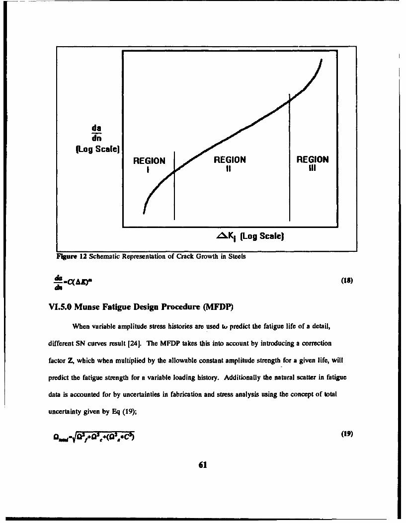
da
(Log Scale)REGION REGION REGION
,Ki (Log Scale)
FIgure 12 Schematic Representation of Crack Growth in Steels
=4(. y (18)
-aC(AZ)r
VI.5.O Munse Fatigue Design Procedure (MFDP)
When variable amplitude stress histories are used tk predict the fatigue life of a detail,
different SN curves result 1241. The MFDP takes this into account by introducing a correction
factor Z, which when multiplied by the allowable constant amplitude strength for a given life, will
predict the fatigue strength for a variable loading history. Additionally the natural scatter in fatigue
data is accounted for by uncertainties in fabrication and stress analysis using the concept of total
uncertainty given by Eq (19);
Qa,= tf+j O+(O2 'j*C2) (19)
61

Where;Q.= Uncertainty in TOTAL fatigue lifeC4- Uncertainty in fatigue data life: RMS of COV of fatigue data life about the SN regression line
and the error in the fatigue model: effects of imperfections in the linear damage accumulationassumption.
Q= Uncertainty in mean intercept of the SN regression line: in particular effects of fabricationR= Uncertainty in the mean stress range: effects of impact and errors in stress analysis and
determination.
The largest uncertainty is of course the stress range that the structure will encounter. Having estimated
the uncertainty, a reliability factor Rf is estimated after assuming appropriate distribution models and
desired level of reliability. The MFDP estimates the maximum allowable stress range DELTA SD
from the particular detail's closest matching type of weldment SN curve, the average fatigue strength
at the desired life, and finally multiplying by the random load correction and the reliability factor.
For Welds subjected to a constant amplitude stress range, the mean fatigue life N is given by
Eq (20), [241.
N.C (20)
Where C and m are empirical constants obtained from least squares analysis of SN data. Munse's
procedure uses the extended straight SN line at the stress ratio R=O as its basis and neglects effects of
mean stress, material properties and residual stress. After cycle counting, the variable load history is
plotted in a stress range histogram. Mean stress level and sequence effects are regarded as secondary
effects. Since random loadings for weld details cannot be determined exactly, the Munse procedure
uses probability distribution functions to represent the weld fatigue loading. Six distributions are
employed to represent different common variable loading histories:
"0 Beta"0 Log-normal"0 'Weibull"0 Exponential"0 Rayleigh"0 Shifted Exponential
62

It is necessary to determine which distribution or distributions provide the best fit to the loading
history. The random load factor is a function of the desired life and are tabulated in various design
guidelines. The reliability factor is given by Eq (21).
LULf( N)I-Q )UM (21)
Where;PK(N)= probability of failurefN=Total uncertaintyr =Gamma Function
50% Reliability Rf=l.0090% Reliability Rf=0.7095% Reliability Rf=0.6099% Reliability Rf=0.45
This procedure provides an accurate prediction of fatigue life and is straight forward to carry out [241.
The difficulty lies in the determination of the proper distribution and the quantification of the
uncertainties. The utilization of successful values used in similar applications is recommended with
the addition or subtraction of some additional modeling uncertainty depending on the subjective
confidence of the designer. This may be due to more or less confidence in the quality of fabrication
of the detail at hand, the materials/ assembly method, or the ease of access to the workpiece.
VI.6.0 Alternate Appreach
An alternate approach as proposed by Munse [17] is btazd on the calculation of a "design
allowable" stress range, Sd, for fatigue. This stress range is the maximum peak to peak stress range
expected at the point in question once under the most severe sea state and during the entire life of the
structure. Comparing that stress range to the allowable stress for other failure modes indicates the
controlling mode of failure. In all cases the Sd must be less than the one time maximum allowable
stress. The approach defines Sd as the product of the mean value of constant amplitude stress range
at the design life Nd, a reliability factor, Rf and a random load factor e, Eq (22). Thc value of
63

S. is found using the applicable SN curve for the expected life of the structure, (number of cycles).
S(22)
The reliability factor is meant to account for uncertainties in the fatigue data, workmanship,
fabrication, use of the equivalent stress concept, errors in load history and errors in the stress analysis.
The reliability factor is modeled assuming that Rf is a random variable with a Weibul pdf and the use
of a relationship for the P(survival) through N loading cycles. The effect of this factor is to reduce a
mean stress range to an equivalent stress range which corresponds to a designated probability of
survival greater than the 50% level of the mean stress range. The random load factor, e, is introduced
in order to make possible the use of existing constant cycle fatigue data in designing for variable
loading service conditions.
VI.7.0 Initiation Life Model
It is generally agreed that cracks will initiate at points of stress concentration, namely notches,
pores or other defects which interrupt the continuity of material 1251. This initiation mechanism
results due to the plastic deformation in the region of the initiator, due to the high stress concentration
and thus stress level well above the yield stress. This can occur with the majority of the assembly
well below yield again due to the magnification of stress at the initiation site. Cyclic loading applied
in the region of the initiating flaw will thus result in a propagating crack whose progress is directly
proportional to the lading and loading rate. The endurance of a particular detail is divided into two
distinct phases: that of crack initiation and that of propagation. The modeling of fatigue life must
therefore consist of two models, an initiation model and a propagation model.
VI.7.1 Initiation: Notch Analysis
After the occurrence of plastic deformation as described above, the stresses and strains can be
determined using the following notch analysis technique [19, 23]. An elastic stress concentration
64

Limit
Stress(I•L) lJnear-Elusic
RegionSlope=E
#lo 4ved
Post-Unloading Plastic Set S
Figure 13 Stress-Strain Curve for Metal
factor,K, which is defined as the quotient of local stress and remote stress, is determined by using
either FEM or elasticity theory. After the notch region has plastically deformed K, can no longer be
used to directly predict the local stress as the plastic stress will rise at a lesser rate and the plastic
strain at a greater rate. Instantaneous stress and strain conversion factors must be used beyond the
elastic limit due to the non-linear nature of the problem, (see Figure 13); this relation is expressed in
Eq (23). Since delta e is the quotient of the nominal stress range and the modulus of elasticity, the
65

u u)
-s~ (23)
A$-Nemin rlek raiw
expression can be given as in Eq (24). This is Neuber's rule expressing the local stress/strain behavior
at the notch root to the nominal stress and elastic stress concentration factors. Using the power law
hardening relationship; the relation in Eq (24) can be expressed as in Eq (25);
Ae.A +AP (24)
where K is the strength coefficient and n is the strain hardening exponent, finally the expression is
expressed with only the stress range as the unknown in Eq (26).
SI A GA AO~ (25)
which is solved through successive iterations for the elastic stress concentration.
Since in practice the predicted life for a notched specimen tends to be overly conservative, a
fatigue notch factor, Kj, is introduced which is used in place of K., which is defined as shown in Eq
(2")[19, 231,
Kf can be expressed in terms of K., notch tip radius, r, and a material dependant strength parameter, a
as shown in Eq (28); This important relation points out the fact that small notches are less sensitive
to fatigue and that ductile materials are less fatigue prone than strong materials, which is intuitively
correct.
66

r (27)a-(20)'.8X10-3h~h"as
r-crd * rdiW
The actual prediction of the number of cycles to crack initiation can be expressed in terms of
the above expressions when the specimen is cycled between strain limits in the Coffin-Mason Equation
given in Eq (29). By relating the strain calculated at the notch root to the strain life data,
2 4W (N
(4) o..-Mai a ~m
(5) 2N Mm.aber of rew 'u(6) C-•atigm dUftk VWOuAt(7) b-Fadw at•qe k voucxt
the number of cycles to initiate a fatigue crack at the notch can be estimated. Quantities 2,3,7 and 8
in Eq (29) above are obtained by either low cycle fatigue testing or through estimation.
VI.7.2 Propagation: Crack Growth
The second phase in the fatigue crack mechanism is that of crack growth. The growth rates
have been shown to be a function of the stress intensity at the crack tip, the ratio of the minimum
stress to the maximum stress and specific material properties as mentioned in the previous section.
The growth rate can thus be expressed as shown in Eq (30);
The stress intensity factor is determined as a function of the geometry, the stress range and the
instantaneous crack length and shape. An expression for the stress intensity factor can be expressed as
shown in Eq (31);
67

1i! AAXmdis 1-_R
*2(2wR .. S .o b (29)
SýA Z-h'M iatwLsy Jhft~rA,. amw makwW -
AK-(M MjMtmk)AS~,( )to
M.-Cmt m.ce arme (30)M,-Plaft Akkaw..
*o-Crau kakzee
AS-S&wn range
The geometrical descriptors, (M's), shown in Eq (31) must be included in order to differentiate the
infinite number of possible crack shapes, orientations and sizes. The M factor which accounts for the
front free sair1ace can be described as in Eq (32);
M,-1.0-0.12(10-• (31)
2C
where a/c is the ratio of the minor to major ellipsoidal axes. If the crack is embedded in the material,
M,=1.0. The Mt factor, accounts for plate thickness and is tabulated in mechanics of materials
handbooks in tables of stress intensity factors. The factor Mk is used to account for the stress
differential near flaw vs remote regions of the material, as above it is tabulated in handbooks. The
crack shape factor (D. is calculated as given in Eq (33);
O.-f [* (32)0 C
68

VII.O.O Structural Fractures
The prevention of fracture of rigid steel ship structures is the overwhelmingly prevalent
concern amongst those involved in the design, construction and maintenance of these structures [26].
In order to minimize the occurrence of fractures due to design, construction or accidental loading, steel
structures are constructed according to codes or optimum performance specifications. Ships are
constructed mainly in accordance with codes although some unusual designs are built to performance
standards due to lack of pertinent codes. In addition to minimum strength requirements, the use of
redundancy, "fail-safe" structural design and the use of "safe metals" are specified 127). Redundai,.
structures are designed such that multiple load paths exist at loading levels low enough such that the
additional loadings which are imposed on adjacent members due to the loss of a specified maximum
number of the original load paths, (reliability level; see Chapter 1), can be tolerated by the remaining
elements. A "fail-safe" philosophy consists of designing the structure so that failures in the structure
are physically limited to isolated sub assemblies, e.g. crack arresters and certain schemes of sub
assembly isolation. The "safe metal" approach is somewhat implicit in material specification for
modern structures, with the brittle fracture and fatigue problems being prime examples of the type of
failure mechanisms that this approach is meant to avert, (i.e. the specification of minimum ductility,
toughness, transition temperature... in addition to material strength properties).
The degree of fracture resistance of a structure is a direct result of not only the thoroughness
of the engineering analysis directed at minimizing the problem, but most importantly the level of
fabrication quality that exists once the structure is built. Implicit in this statement is quality of
qualification, inspection and material monitoring which exists during construction. The minimizing of
fracture consequence and severity when fractures do occur is one of the main functions of thorough
and routine structural inspection program. Catastrophic failures of structures due to known existing
flaws are not rare, emphasizing the importance of prompt action upon the discovery of fractures.
69

Although structural redundancy may allow the continuing operation of a vessel with substantial
fractures, unexpected or unusual loads may cause unforseen damage which can combine with existing
damage causing massive failures. In damage reports, an isolated lone crack is seen less often than
multiple seemingly random cracks emphasizing the somewhat random forms that fractures take.
VI.1.0 Fracture Initiation
The initiation of fractures observed in surveys such as that carried out in the SSC detail survey
report series, indicate that the overwhelming majority of fractures initiate in the region of assembly
flaws [28,29,301. These flaws, if located near sub assemblies where large changes in stiffness
occur, near regions of high stress, or regions with a high degree of alternating stress invariably fail
through the slow or fast migration of fractures. In addition, if high levels of residual stress due to
poor fit-up and/or poor welding method are present, the failures will occur at even lower loading
levels.
VII.2.0 Fracture Prevention
In some cases, known "hot spots" in the structure, detected during design or modification
analysis, will fail in fatigue due to scantlings designed to withstand ultimate rather than the working
loads critical in fatigue failure. A high degree of diligence must be exercised in detail design to;
"o Design details which are straight forward to assemble, mii,-*7:ing the chance of theintroduction of high levels of residual stresses due to diffi f proper fit-up.
"O Wherever possible eliminate sharp notches or other initill ints for cracks, (as in theabove, design such that these initiators are not introduc. .o the difficulty of fabricationof specified details). If drainage channels or other types o! slotting of material is necessary,(e.g. in horizontal plate elements, such as tank tops or longitudinal flanges) they should bealigned such that the axes are parallel with the orientation of expected principle stresses,(minimize the possibility of fatigue cracking).
o'Wherever failures are at all expected, (and especially in critical structures), crack arresters orinterruptions in load paths should be used to limit fractures to local assemblies, (thus limitingthe nature of damage to that of local vs. global).
o ENSURE whenever possible the specification and USE of materials with sufficient resistance
70

to expected loadings in details, (in many cases failure occurs due to the use of materialsother than those specified in plans, rendering the engineering work involved in the drawingup of those plans all but void).
"o Establish tolerances which are easily met by the expected competence level of the force toperform the work.
"o If at all possible search for data, i.e. SSC294 A Survey of in Service Structural Details 130],on performance of various designs in order to utilize past experience with existing detailtypes utilizing only configurations which have been successful.
VIL3.0 Crack Arresters
Material Property
Change
Figure 14 Crack Arrest ScheSs
Crack Arresters are the "fail safe" component in a complete fracture prevention system. In the
event that cracking does occur, the intent is that crack arresters will have been placed near enough to
one and other that the crack cannot propagate to the extent that it becomes structurally threatening.
71
)~~~~~~Mtra -Crosmmmsm ilm, ,..--

The requirements for an effective crack arrester system are 1311;
"o Proper Material, toughness, strength and compatibility with surrounding material."o Effective Geometry"o Strategic Location
The material must be able to stop a propagating crack, thus it must be much tougher than the base
metal. It has been found that an arrester toughness of approximately 4x that of the base metal is
sufficiently effective in arresting cracks.
The most common geometrical arrangement of crack arresters fall into one of the three
categories as sketched in Figure 14 including;
"o Riveted seams"o Welded strakes, (in plane arresters)"o Welded stiffeners, (out of plane arresters)
Riveted strips are less common in newer ships due to the expense and time consuming nature of
riveting. This scheme's crack arrest ability is accomplished when the crack propagates into a
discontinuity or into a rivet hole, which is commonly agreed upon as the most effective crack arrest
mechanismSI32I. Many fittings and auxiliary equipment are through bolted to the primary
structure such as water tight doors, flanges, and hatch combings, which provide these discontinuities
and holes for crack termination.
Welded in plane strakes serve to arrest cracking in two ways, they are usually of a slightly
heavier section than the adjacent primary structure, and they are of a material grade with far superior
toughness and fracture resistance to that of the primary structure. It is suggested that for most large
commercial vessels where this material is used in sheer, side shell, and deck strakes, that the strake be
at least 6 feet in width 131, 33]. For primary hull bending stresses, the most effective locations for
this material is in the two regions of highest stress, namely the main deck edge and the turn of the
"2 Emergency crack repair procedures all dictate the boring of a stopping hole at the end of cracks topreclude further growth, prior to welding. Since the hole is smooth all the way around its girth, there isnowhere for the crack to re-initiate.
72

bilge, and to resist primary shear loads, on the side shell at the approximate level of the neutral axis,
as sketched in Figure 15.
Figure 15 Crack Arrester Locations Around Hull Section
In ships with large deck openings, such as the deck hatch openings in container ships, regions
of high stress concentration of torsional and primary stresses exist in the region of the container hold
openings at the main deck level. The use of material surrounding these openings is actually a
combination of the transverse, longitudinal and riveted type reinforcements acting to minimize
cracking around the openings and combings as shown in Figure 15.
VII.4.O Flaws
From surveys, the most often cited fracture initiation flaws are [331;
o Slag Inclusions
73

"o Material cracks, (delaminations, corrosion cracking...)"o Material/Weld Porosity"o Undercutting"o Lack of Weld penetration
An all too common scenario for fractures is the initiation of a fatigue crack which grows
slowly, and, (if undetected), steadily until it reaches critical size for brittle fracture which occurs and
fails the detail when conditions are opportune for brittle fracture, (T :% NDT, tensile stress condition,
and critical flaw size) 1201. The occurrence of brittle fracture, although minimized through extensive
materials testing and improvement, does still occur in vessels operating in cold conditions, (many
fractures from surveys occur in northern latitudes in winter), seemingly emphasizing the criticality of
thorough inspections during the fall and continuously in the winter to prevent these occurrences.
VII.4.1 Indications
The most useful tools available in the study of fracture in offshore structures, are cracked
sections removed from a failed structure (Figure 16). The failure analysis of failed specimens carried
out constitutes the data which is most directly used in the definition of construction codes and
standards used by the industry. Several key checks can be quickly performed on a broken specimen to
determine [20];
"o The direction of crack propagation, and thus the general area of initiation."o The type of fracture, i.e. Fatigue, Overload, Brittle..."o The mode of fracture, i.e. Plastic, Elastic Plastic or Plane.
The indications clearly visible on a fatigue fracture sample include the following [31, 33];
o A "Clamshell" pattern visible on the crack surface, indicative of the slow sequential natureof fatigue propagation.
o Due to the slow nature of the crack propagation, corrosion may be visible on the "older"parts of the crack surface, (lower damage accumulation level).
o Extensive evidence of plastic deformation adjacent to the crack, indicative of the high stressfield around the crack root, (ridges somewhat proportional to clamshell pattern).
o Crack oriented normal to a principle stress field.
The indications clearly visible on a brittle fracture sample include [31, 33];
74

Fractured Sample Indicators
40- Chkwwuu VsIOUP an CrUiairk urfawoWvaturm alnMlatlen hint (Cawl Pnle.tlu)-e
evideace ofplastic
Fm4uwe WASSUAR ClmPsahi POtIers at aa| mrface
Figure 16 Fracture Mode Identification Sketch
"o Distinctive "Chevron" markings on the crack surface, these chevrons "pointing" in theopposite direction as crack propagation, (towards the initiation point).
"o Clean new crack, indicative of rapid propagation through the material."o Little evidence of plastic deformation."o Fracture occurrence during a period of low ambient temperature, near or below NDT.
Thus from simple visual observations, important information about the cause of fractures can
immediately27 be deduced. Subsequent laboratory testing provides material composition and exact
initiation mode, however the above visual observations can provide the majority of macroscopic fault
analysis information.
17 It is very important to inspect the fracture as soon as possible after it's discovery, with efforts madeto record all possible pertinent information, since important indications can be masked with time due tocorrosion and temporary repairs.
75

VII.5.0 Brittle Fracture
The brittle fracture failure mechanism became a significant global failure mechanism with the
advent of the all welded ship during world war II. Of the 5000 liberty and T-2 vessels constructed
during the war, by 1946 200 had experienced serious fractures and 9 had broken completely in two.
In 1947 the American Bureau of Shipping, (ABS), established chemical composition guidelines for
Table V Brittle Fracture Prevention Checkpoints
"o Service Temp, 0 C is considered to be a safe minimum temp for design purposes,however many, (most) of the failures occur at lower temperatures.
"o Residual stresses, increasing the intensity of stresses imposed by normal loading allowingthe detail to reach critical stress levels during non critical global loading conditions.
"o Design, the inclusion of sharp intersections or detail designs which are prone to weldingerrors should be avoided.
"o Welding, completeness of prep, completeness of fusion, removal of slag, proper weld rods,lack of porosity, and lack of cracking in welds.
"o Material toughness, suitable for intended operating conditions.
"o Fatigue environment, location in the structure e.g. cyclic stress environment.
ship steels requiring that they be classified not only in terms of strength but in terms of toughness and
fracture resistance. Although significant progress has been made in the field of brittle fracture
prevention, brittle fracture still occurs in modem ships. Therefore when involved in the maintenance
and repair of even quite modem ships, diligence must be exercised in order to guard against this
destructive phenomenon. The surest method is to ensure that mechanisms are present to arrest
fractures should they occur. The factors which must be considered with respect to brittle fracture are
given in Table V [341. The three most critical initiation factors for brittle fracture are toughness,
76

initiation flaw size and stress level when T s NDT'I, the above additional considerations in Table V
affecting the severity of the fracture when these critical criterium are met 1261.
The study of fracture mechanics has shown that all the above factors can be interrelated to
predict (or design against) the susceptibility of a welded structure to brittle fracture. Fracture
mechanics is based on stress analysis and thus does not depend on empirical correlations to translate
laboratory results into practical design information. Fracture mechanics is based on the fact that the
stress distribution ahead of a flaw can be characterized in terms of a single parameter K,, the stress
intensity factor [KSI/v'in]. K, is a function of the nominal stress, (a), and the flaw size, (a), which if
known at failure can provide the designer with critical flaw sizes to be guarded against in the
specification of design tolerances and geometry.
VII.5.1 Toughness Requirements
Material toughness is determined using impact tests which express the materials toughness in
terms of the energy that the material can absorb without fractures propagating from various flaw sites.
The fracture energy is plotted vs. temperature, which is varied in order to determine the transition or
Nil Ductility Temperature, NDT, as sketched in Figure 18 the general appearance of the resulting
curves are shown. The energy ordinates are divided into three regionsPlane Strain behavior refers to
fracture under elastic stresses with little or no shear-lip formation, essentially classical brittle fracture.
Plastic behavior refers to ductile failure under yielding conditions with large shear lip formation. In
between these is a transitional region or the Elastic-Plastic region, in this area traits of either or both
modes are observed.
For structures subjected to only static loadings, the static curve shown in Figure 18 should be
2 NDT; Nil Ductility Temperature, the temperature below which the material exhibits primarily brittlebehavior. Determined by conducting such tests as the Charpy V-Notch, (CVN), which test the impactresistance of notched specimens at various temperatures in order to determine their toughness andtransition temperature.
77

F_ _ __ _ AA
Kii, ~I Cr K1 .1 iiCYv{ /ar K 1.12 CV-4 ~
* (0f[al2c. •"-
re 17 K1 for various cracks, stress/flaw size/toughness curves.
used whereas for dynamically loaded structures the more restrictive impact curve should be used29.
As shown in Figure 18, the steel used to coustrct a structure should have a margin between its
expected minimum operating temperature and the transition temperature of the steel. Using a
reliability based design method to obtain the desired margin, a steel with a curve similar to steel 2
would be selected given the indicated desired performance level.
If at 0TF KID, (the critical dynamic toughness), is about 60% of the c;D, (the dynamic yield
strength), then at 32*F the ratio can be taken to be about 90%. Using the concepts of fracture
mechanics, as well as engineering experience, observations regarding the level of performance at 32*F
29 Since for a dynamic loading, such as a dropped object the applied force can be twice the object's
weight.
78

for steels and weldments that satisfy the primary toughness requirement of NDT s O°F and the
auxiliary toughness requirement that KIoldy a 0.9 at 32"F:
Plastic
Elastic-Plastic NDTEnergy Stati
absorptionPlane '. / _• matStrain -0act
Temperature
Plastic
Elastic- / Stol 1 SM&Wz steel 3Plastic
Plane T1 IT2rT
Strain
FIgure 18 Brittle Fracture Transition Curves
"o The start of the transition from brittle to ductile behavior will begin below the minimumservice temperature of 32°F. Thus at the minimum service temperature the materials willexhibit non plane-strain behavior in the presence of a crack under impact.
"o The material will experience some fibrous fracture appearance at 32*F, an indicator ofresistance to brittle fracture.
"o Although precise stress-flaw size behavior cannot be made for material exhibiting elastic-plastic behavior, critical crack size for 40KSI steel can be made as follows:
"o For Knp-0.9 ~ya and a nominal stress range of 14 KSI the critical crack size at 320F isestimated to be 8-10 inches.
"o For about 24 KSI, (one of the largest primary stress levels ever actually recorded in avessel), the critical crack size is estimated to be about 3 inches.
79

O For the worst case dynamic loading of yield point magnitude, the dynamic critical cracksize is estimated to be about ½ inch.
For plate thicknesses commonly used in commercial ships, (less than 2 inches thick), the
thickness of the plate has a second order effect on the transition temperature of the material, as
compared with the first order effects of loading rate and notch acuity. For this reason the testing of
less than full thickness samples is acceptable since changes in toughness are very small.
80

VIII.O.O Corrosion Considerations
The highly corrosive sea water environment that steel maritime structures are expected to
operate for their entire lifetimes is easily the most chemically punishing of any environment in which
large steel structures are expected to operate. The highly oxygenated salt water is highly reactive with
the iron contained in all mild steels. From the day the structural steel arrives at the shipyard to be
used in a new vessel, to the vessel's decommissioning, a continuous battle with corrosion is waged.
There are several methods of corrosion inhibition available for use in the marine environment
to retard wastage and subsequent loss of structural integrity. Since the degree of corrosion which
occurs on the outer shell, deck and super structure of a vessel is readily apparent due to it's external
nature, diligent topsides maintenance can ensure a relatively corrosion free structure in these areas.
The internal structure, on the other hand, is often inaccessible to routine inspection due to cargo or
remoteness from normal operating areas of the ship. In addition, many of the cargoes carried,
(especially in tankships / OBO carriers), can be corrosive, reactive or otherwise harmful to the
integrity of the corrosion control system. The ease with which the internal vs. external structural
components are blasted, recoated, or replaced constitute tasks with very different levels of difficulty, (
and thus cost). Thus the corrosion control systems for the internal structure of the vessel must be of a
higher level of robustness than topsides or wetted surface systems.
VIII.1.0 Corrosion Control Factors
VIII.1.1 Tank Washing
Tank washing is carried out whenever a tank is to carry a "cleaner" cargo than was previously
carried [35]. In the past tank washing was accomplished using high pressure jets of seawater to
clean sludge and debris from the tank surfaces. This practice resulted in the need to discharge
contaminated seawater overboard and had very unfavorable corrosion implications. These included;
81

"o Hydraulic erosion near washdown nozzles tended to erode the coating, (High pressures-up to200 PSI- are needed in order to reach remote areas of the tank).
"o The introduction of sea water into the tank means that there will invariably be a small layerof seawater at the bottom of the tank contributing to localized pitting. Beneath this layer ofseawater there is usually a layer of salty sludge whose salinity is further increased with eachseawater introduction.
"o When it is necessary to use hot water to cut the sludge, an even more corrosive environmentis created. The washing is beneficial in that it removes any foreign build up from installedzincs enabling them to be effective when the tank is refidled, (especially if it is to be inballast).
VIII.1.2 Crude Oil Washing (COW)
In order to alleviate some of the problems associated with the use of seawater to clean tanks
on tankships, the substitution of a petroleum solvent for seawater has been used to successfully clean
ballast tanks of sludge and waxy deposits. The elimination of water and salt from the environment
reduces the hostility of the environment during washing and eliminates the continuous introduction of
residual non strippable seawater puddles from tank bottoms. The disposal of the washing medium is
simple due to the fact that it is merely a fuel oil sprayed at elevated pressures".
VIII.2.0 Cathodic Protection
Cathodic protection provides corrosion protection through the attachment of dissimilar metals
of lesser nobility, (higher oxidation potential than the structure's metal). The resulting electrochemical
cell tends to shed the atoms of the anode, "sacrificing" itself and rather than the base metal, thus
protecting the base structure from reduction due to the shedding of it's own atoms.
The longer an anode, the higher the current it will generate, reducing the number of anodes
needed. The cross sectional area will determine the anode's useful life. Thus the sizing of anodes
must be a compromise between mechanical considerations (keeping the anodes attached, relatively out
3o Due to the spraying of oil into the tank atmosphere, an increased level diligence must be exercisedwith respect to fire hazards. The use of gas inerting methods in tanks undergoing COW is highlyrecommended.
82

of the way, and small enough so that they do not generate high drag forces if mounted externally), and
the protection required. The anode sizing for protection is a function of many variables, including
salinity, temperature and the condition of any coatings present. The current density requirements are
usually expressed in milli-Amperes per square foot or meter, the magnitude required being based on
historical data of protection levels vs. corrosion rates. Cathodic protection requirements vary greatly
from one structural region to another, with the greatest requirements in areas with large horizontal
surfaces. The simple placement of large anodes very near to one another, forming large overlapping
active regions, is to be avoided since over protection can cause coating damage.
The anodes can be attached by welding or bolting to attached pads. Although welding is
cheaper initially, the use of bolts allows much quicker and simpler replacement.
Cathodic protection provides two basic types of protection, primary and secondary. Primary
protection is that afforded by the anodes when installed on bare steel as the only corrosion inhibition
system. Using only primary control, corrosion should be limited to approximately 20% of non
protected, (bare steel), rate. Secondary control is that afforded by using cathodic protection in consort
with a coating system. In this way corrosion in areas of defects which occur in the coating system are
protected by the anodes.
The location of the anodes on the vessel requires some consideration as well, on the
submerged outer shell anodes are located in a pattern which affords minimum overlapping protection
along the entire wetted surface. The anodes are usually aligned as parallel as possible to the
streamlines along the ship's hull, minimizing drag iorce and thus the tendency for them to be sheared
off by either hydrodynamic forces or impacts with foreign objects. The placement of anodes within
the hull must be done with the levels, types and frequency of fluid types in mind. Since most tanks
are never filled completely, cathodic protection will not protect tank tops, which must be protected
through the use of coatings. The tank sides and bottoms are areas where cathodic protection is most
83

effective, especially in wing tanks where ballast is often carried [351. The tank bottoms are nearly
always covered with between a few inches to a foot of sea water no matter the cargo3 1, thus it is
quite common to see anodes mounted on tank bottoms or diagonally on bottom longitudu al webs.
In order for the anode to afford full protection, it must be fully immersed in an electrolyte,
(electrically conductive fluid), and it must be clean i.e. no paint or other coatings should be allowed to
cover the anodes. This problem is particularly important in cargo/ballast tanks where sediment and
waxy build up can form due to the presence of crude on the anodes, (this is another reason tank
washing is important before changing cargo types).
There are several metals used for cathodic protection including Aluminum (Al), Zinc (Zn) and
Magnesium (Mg). The use of Mg anodes was halted due to both their tendency to spark (due to high
driving voltage), and also a nasty tendency of producing hydrogen gas, (which have lead to
catastrophic explosive hydrogen ignitions in cargo tanks). Mg also tended to overprotect adjacent
areas causing heavy salt deposits around the anodes. Mg anodes were banned for use in cargo tanks
in 1964 by the USCG.
Although Al anodes were initially banned for use along with Mg due to theirtendency to arc
and spark when attachments failed and the anodes fell to the tank bottom, the aluminum anode has
been re allowed under the restriction that an anodes TOTAL potential energy not exceed 200 ft-lbf
above the tank bottom32. Al is again used due to several advantageous fe•atures;
o Self Cleaning: If submerged in waxy crude, not cleaned, and then submerged in seawater,the aluminum anode quickly reestablishes effectiveness.
31 This seawater tends to evaporate between tank fill/pump-down cycles, meaning that the Chloridecontent of the water concentrates, (the constituent of salt water that is responsible for most corrosionprocesses;
[Na. + Cl + H20 + Fe* ---, FeO,(rust) + HC! + Na 20],
When anodes are present the anode metal ions take the place of the iron ions, due to their higher oxidationpotential.
32 e.g. a 251b anode can be no more than 8 ft. above the tank bottom.
84

o High current density: Fewer aluminum anodes will provide the same protection as zincanodes.
The use of Zinc anodes is by far the most popular and has no restrictions placed on their installation.
VIII.3.0 Adhesive Coatings: General
Protective adhesive coatings are by far the most familiar method of corrosion control, however
there are a wide variety of corrosion inhibiting coatings available for use. The selection of the proper
system is of paramount importance with regard to long term costs. The selection of a proper system is
a function of several considerations including 1361;
"o Constituency of material in contact with the coating"o pH of fluids in contact with the surface"o Temperature""o Reactivity"o Type of metal to be coated"o Cost benefit analysis of yard time: i.e. projected high PVC3
"o Desired hardness of coating"o Environment in which the coating must set-up"o Method of application
The coating of the interior of tankships is of interest due to the highly variable nature of the
corrosion environment. A tank may contain crude, gasoline, light fuel oils, kerosene, or seawater
ballast at any given time. Of additional interest in this environment is the problem of tank washing,
where the tank is cleaned in order to take on a different cargo, enable inspection, or enter a yard
period. This operation is hard on the coating due to the hydraulic blast of the cleaning jets and the
chemical attack due to the application a cleaning medium.
Easily the most important phase in the application of any coating system is the surface
preparation. In order for the coating to properly adhere to the steel, it must be clean, dry and
corrosion free. However, as any ship yard knows, full compliance with the above conditions are
" If a cheap initial system is used, with projected frequent yard periods, the ever rising cost ofhazardous waste disposal (Sand Blasting residue, solvents anC spray application) must be kept in mindwhen one considers a cheap short life system.
85

nearly impossible in the real world given the complexity and sheer size of most ship coating jobs. In
order to come as close as possible to this goal, the most effective method of steel preparation is the
use of sand blasting followed promptly by the application of a suitable prime coat. The preparation of
any steel surface is basically as above with more or less cleaning approaching an ideal level of "white
metal". The Steel Structures Painting Council, SSPC, publishes specific guidelines in the level of
surface preparation required as a function of the type of coating to be applied, expected durability and
the environment in which the system is to operate 136]. It is usually desirable to remove all corrosion
from the surface of the steel prior to coating. This may be quite difficult in the case of in-service
ships due to heavily pitted regions or inaccessibility to sand blasting equipment, (again design for
accessibility problems). Another problem specific to tankship tanks is the waxy build up on the
surfaces due to the carriage of heavy crudes. This build up, if not properly removed, can be driven
into the metal during blasting making adhesion of the coating nearly impossible. For this reason
special care must be taken in the preparation of internal spaces where this cargo has been carried.
The environment present in the vicinity during the application and set up of the coating is also
very important. Manufacturer's specifications for humidity, temperature, ventilation and curing time
must be met in order to ensure that the expected durability of the coating is realized. All of the above
can be controlled artificially in the interior spaces, but are quite difficult to control on topsides
surfaces. Once the coating has been properly applied and cured, care must be taken if the coating is
applied to the internal surface of cargo carrying tanks to ensure that initial cargos are not detrimental
to the new coating. Manufacturers of tank coating systems will normally specify cargoes which will
aid or hider curing of newly coated tanks.
VIII3.1 Coating Types
There are two main types of coatings used in ship building, zinc based coatings and epoxy
type coatings. The zinc coatings are comprised of two categories; organic zinc coatings and inorganic
86

zinc coatings: Organic zinc coatings exhibit cathodic protection characteristics combined with epoxy
characteristics. Inorganic zinc coatings are most widely used and again provide cathodic protection.
The use of a coating with a high zinc content (-75 w/O Zn by Vol) serves to protect against high
corrosion rates in regions of insufficient coating coverage such as bubbles, light spray areas, and areas
which are completely missed during application. The coatings may be either solvent or water based
with the prime difference being the curing environment required.
Inorganic zinc coatings have a narrow pH range in which they can operate, (nominally neutral:
pH=7 +3/-2). The suitability of zinc coatings for exposure to crude is a function of the sulphur
content of the oil. Inorganic zinc coatings are tolerant of the solvent characteristics of the full range
of petroleum products, as long as the pH requirement is met. Inorganic zinc coating should not be
used for continuous sea water immersion due to it's sacrificial nature, however it is an excellent under
coating for anti-fouling and topsides paint. The presence of inert gas systems which use stack gas to
displace any formation of explosive gas mixtures in cargo tanks34, has been known to cause rapid
deterioration in zinc coatings if high levels of sulfites are present in the gas.'
Epoxy coatings can be broken down into 3 categories, amine catalyzed, polyamide catalyzed
and coal tar epoxies. Epoxy coatings attempt to prevent corrosion by creating an oxygen tight
envelope around the steel isolating it from the oxygen in the air which is necessary for the formation
of Iron oxides Fe20 3 (Rust). Epoxies are generally two part products consisting of a base and a
hardener, the hardener, or curing agent, is the amine or polyamide in the formula. Amine based
products are resistant to petroleum products and salt water while polyamide products are susceptible to
34 Required in all tankships over 70,000 DWT
35 Can be removed through the use of scrubbers
87

attack by acids and solvents, with both of the afore mentioned drying to form a hard3' glossy f'iish.
There are of course disadvantages, firstly the epoxies tend to shrink when curing, which can cause the
coating to pull away from sharp edges and corners. The second is the tendency of the formation of
pinholes which can lead to local corrosion.
Coal tar Epoxies are quite different from the aforementioned types, they are highly water
resistant but resistance to solvents is poor and cargo contamination would result from the transport of
refined products in a tank lined with coal tar epoxy. As the name implies, coal tar epoxies are dark
which implies inspection problems. One of the main reasons for the avoidance of the use of coal tar
epoxies is it's potential health hazards, it has been reported to be carcinogenic by many yards which
refuse to work with it.
V1113.2 Soft Coatings
Soft coatings are, as their name implies, semi permanent coatings which require very little
preparation to apply. The level of preparation required can involve as little as the removal of all scale
and sludge from a tank. The soft coatings are applied using several methods, they can be applied
using conventional spray techniques which require the emptying of the tank, cleaning and then
spraying. They can also be applied using the "float" method whereby the coating is poured over the
free surface of water in the tank, then the tank is ballasted up and down resulting in the coating the
sides of the tank. The "float" method requires more coating than spraying, but it can be accomplished
at sea by ship's company, and also ensures that all areas which will come into contact with the
seawater are coated.
VIII.4.O Full Scantlings
Most classification societies now allow a reduction in required scantlings if approved corrosion
3' It has been suggested that the hard finish is advantageous as it will tend to show material crackingmore readily than a 'soft' finish; facilitating more successfull crack detection during inspections.
88

control systems are utilized. The implementation of this reduced scantling requirement dictates that if
the corrosion control system should fail, it must be replaced/repaired promptly to prevent the loss of
material due to wastage. If it is not, there is a smaller window of time that unchecked corrosion can
be allowed to proceed before structural steel replacement is required by the classification society due
to the loss of minimum scantlings to wastage [see Figure 1, page 5].
Most owners opt for scantlings whi,- ' !-d the minimum allowed for a ship with no
corrosion control system, so that loss of corro;ior f-.atrol does no! imply rapid deterioration of the
structure to a point where steel replacement is necessary.
VIII.5.0 Corrosion Rate Prediction; Polarization Ratc. Methods
The term polarization as it applies to corrosion refers to the change in op•-n circuit electrode
potential as the result of the passage of current. In short, polarization is the change in a metal's
galvanic potential,(voltage drop), due to current flow from one metal to another of dissimilar potential,
(analogous to the voltage 'droop' observed in a heavily loaded DC circuit). Every corrosion process
involves a corrosion potential (e) and current (i), which are VOM 37 measurable quantities (see
Table VI). For a given corrosion process, an i/e curve can be expressed as a function of the potential
of the process where the inverse slope of the generated curve is proportional to the corrosion rate.
B B8i =ij10- - 10-=-] (33)
Eq(34) shows the generally observed form of the curve where;
i=Applied current densityit=Corrosion rate expressed as current densityB. and B. are Anodic and Cathodic, (-Q,+Q respectively) constantsP is the overpotential, (difference between the open circuit and the polarized potentials)
At low values of P the corrosion rate can be expressed as shown in Eq (35),
37 Volt-Ohm-Meter, usually able to measure voltage, resistance, and current.
89

R=A p (3)(B) (34)
At 2.303 1, (B,.3)
Where R, the slope of the generated curve of E vs. i, has units of resistance and is inversely
proportional to the corrosion rate, i.
This method is useful in describing the corrosion process but is of limited use in practical
applications since the constants which are considered as such in the derivation are in reality variables
which are notoriously unpredictable 1371.
VIII.6.0 Statistical Rate Prediction Methods
Statistical corrosion rate prediction methods have a wide degree of applicability in industrial,
commercial and laboratory applications. Statistical methods characterize the corrosion process in terms
of the end result of the process as opposed to deterministic methods which are concerned with the on
Table VI Practical Galvanic Series
Material Potential (Voltsl
Pure Magnesium(Mg) -1.75Mg Alloy -1.6Al-Zn-In -1.16Al-Zn-Hg -1.1Zn -1.1Pure Al -0.8Clean Mild Steel -0.5 to -0.8Rusty Mild Steel -0.2 to -0.5Cast Iron -0.5Pb -0.5Mild Steel in Concrete -0.2Cu,Brass,Bronze -0.2High Si Cast Iron -0.2Mill Scale on Steel -0.2Carbon, Graphite, Coke +0.3
90

going corrosion reactions involved 137). The beauty of using a statistical frame work lies in the fact
that the results of the corrosion analysis can be used directly in the system reliability formulation. For
example once a distribution for the corrosion process of a region is determined, the distribution
parameters can be combined through methods such as the algebra of normal processes to determine the
subsystem reliability index.
VIII.6.1 Corrosion Induced Strength Loss: Probabilistic Model Development
If the mode of failure considered is that of yielding during bending of the hull girder as a
"free-free" beam, it can easily be shown that the strength expression is as given in Eq(36), where:
S = F(D.tB, t,)sNS,. (35)S = 1* S, a D *(tf B + 1 tD) *S
N =deck or bottom section modulussy =tensile strengthD =section depthB =section beamAf =flange areaA� =web area
=A,/2B =equivalent thickness of one flanget. =A.J2D =equivalent thickness of one web
When corrosion occurs, tf, Af, t.., and Ak all become functions of time or; t4(t), Af(t), t,.(t), and A.(t),
as the structure corrodes. The material thickness can be considered to conform to the expression in
Eq(37);
(r) =T* -• Rl (36)
Where;T(c) =plate thickness at t= - [mm]T. =original thickness [mm]R,j =corrosion rate for period Ti' [mm/yr]
(Eq (37) assumes that the corrosion rates over the life of the structure can be subdivided into blocks of
91

different rates of corrosion each with a constant rate, however for simplicity sake a mean value can be
used for calculation of temporal performance). As a result of the constant loss of material with time
due to corrosion, the strength distribution expression in the reliability expression becomes a function of
time, and as a result, so does the system reliability. Accordingly, the probability of failure will
increase throughout the ship's life until, when it reaches a minimum scantlings limit,(as shown in
Figure 1), and repair costs become too high, the vessel is scrapped. Eq (38), (the familiar
'MVFOSM';Mean Value First Order Second Moment expression), expresses the reliability index as a
(normally distributed) function of time since the system strength distribution becomes a function of
pMMo= t) -s
t=Overa per ( separat owrhau);PmW-PivW (37)
opat
m ed kner for anpk sae.)
time. This relation shows that as the strength diminishes with time, (with increasing uncertainty due to
corrosion non-uniformity), the reliability will decrease proportionally.
Alternatively the strength at time t, can be multiplied by a corrosion rate factor, k•, (effectively
the same procedure as Eq (38)), which is also a random variable, to account for a specific reduction in
strength at a certain time in the vessel life.
Another approach is to consider the effect of corrosion which does not result in a time
dependant strength is to take the total plate thickness as the sum of the thickness required for limiting
stresses, t,, plus a thickness for corrosion allowance, t, as shown in Eq (39);
92

Lgj(O BOL)=ta + t' (38)
which, if expanded about mean plating thickness, yields the COV of the plate thickness over the
expected life of the piece as shown in Eq (40).
tt2 2 + 2 (39)
Where the lower case deltas represent the Coefficients of Variation, (COV);
&•,, =COV of plating thickness due to production tolerances=COV due to corrosion=mean thickness for corrosion condition 'i'
For most ship owners it seems that the addition of a corrosion margin in concert with a high
quality corrosion control system is considered an inexpensive method of ensuring that catastrophic
failures due to wastage, or loss of revenues due to unscheduled repairs are unlikely to occur.
93

This Page Intentionally Left Blank
94
IX.O.O Corrosion Survey Methodology
The periodic inspection of a vessels structure is necessary in order to determine fitness for
continuing service and/or the estimation of the expected time until repairs are required. Although
certain structural problems such as cracking are difficult to detect, the detection of corrosion is simple
due to its omnipresence and highly visible nature throughout the structure. The difficulty lies in the
prediction of average and specific local corrosion rates throughout the structure. Due to the ever
changing environment that the ship structure is subjected to, corrosion rates tend to be very erratic.
The tanks in a tankship may at any given time contain seawater, crude (sweet or sourp), gasoline or
light fuel oil, all of which have vastly different corrosive properties.
Inspections are performed in order to satisfy two basic requirements; those as required by a
vessels owner in order to access the condition of the ships corrosion protection systems, attain data for
estimation of corrosion rates and estimate the time remaining until repairs are required. The other type
are the inspections required by a classification society or other regulatory body to determine if the
structure (plates and shapes) requires renewal as part of the evaluation of fitness of the vessel to
conduct safe operations.
IX.1.O Survey Results
Although it is difficult to estimate corrosion rates from historical survey data, it is possible to
establish corrosion patterns throughout the structure. In specific regions of similar vessels trading on
similar routes, and of comparable age, corrosion patterns should be quite similar. The patterns of
corrosion can also be correlated to the type of coatings used. These general categories of corrosion
observed in ship structures are;
3s The terms "sweet" and "sour" crude refer to the sulfur content of the oil, "sour" crude having a highcontent of sulfur and thus a "sour" aroma. The effect on corrosion rates has to do with the tendency toform sulfur based acids when exposed to water including: H2S, HSO3, and H2S0 4, these acids havingobvious detrimental effects on any lightly protected steel in the tanks.
95

"o General corrosion, or the large scale formation of rust over a significant area;
"o Pitting corrosion, which is characterized by the localized attack of the base metal resultingin the physical pitting of the material.
"o Crevice corrosion, which occurs along paths of high water flow or along creases or welds inthe structure.
Man,, operators view pitting corrosion as the most detrimental due to the possible of loss of Wembrane
integrity and the possibility of fatigue cracks initiating from pifting sites. The most prevalent general
corrosion locations seem to be within the splash zone where seawater continually wets the area yet the
complete immersion of the area is slight. General corrosion is prevalently a surface type of corrosion
which does not pose significant structural risks unless left unchecked over a long period of time. If
this happens deep scaling can occur which can flake away leaving fresh material to corrode again
rapidly, this scenario is indicative of a major loss in material which if located in highly stressed
regions can lead to major structural failure. Pitting corrosion tends to occur in areas where water is
trapped and allowed to stand such as tank tops, side shell longitudinals, bottom shell plating and other
horizontal surfaces such as bottom longitudinal flanges.
Local loss of structural integrity in highly stressed areas maybe critical with respect to global
integrity especially when local stresses arise from primary loads. For this reason a high degree of
scrutiny must be paid to any loss of effective scantlings in the vessel's strength decks or bottom
structure which unfortunately are hot beds of corrosicn 138, 421.
IX.2.0 Corrosion Data Utilization
The accumulation of corrosion data is the primary tool available to the structural engineer in
the estimation of corrosion margins and reevaluation of older structures which have under gone
96

significant material loss to corrosion" 1381. The evaluation of corrosion margins is of use in
determining the validity of the assumptions made in the design stage, allowing the future use of
margins which are more representative of actual corrosion COV's.
Margins are specified by classification societies either as nominal constants or as functions of
new steel dimensions. ABS adds a corrosion allowance to the material thickness of the required
scantling dimensional formulae and requires hull thickness gagings and renewals based on percentage
wastage limits for the various location. The USCG wastage limits are based on an "Average" wastage
of 20 percent. Norms' wastage allowances before structural steel replacement is required range from
between 15 to 30 percent, the exact figure being a function of frame spacing, ship type, age, and the
structural component in question. In practice, the pl"'te thickness that the wastage limit is based on the
ABS rule required thickness at that location [391.
A more specific use of corrosion data with respect to general corrosion average wastage is the
reevaluation of the buckling strength of panels with in plane loading regimes.
S 2*E40
Eq (41) is the familiar, [371, expression for the critical plate buckling stress where;
t= Plate thicknessM= Poisson's ratiob= Unstiffened widthk= Plate aspect ratioE= Young's modulus or the modulus of elasticity
The significant point here is that a reduction in effective material thickness has a second order effect
on the ability of the plate to accept in plane comprCIssion loads without failing. This example
" This is a growing area of interest amongst owners of offshore systems which are nearing or havereached the end of their design lives. The re-qualification for service of older structures which areoperating in marginally favorable trade can mean high profitability for it's owners since it's value has been
depreciated and operating costs are well known.
97

emphasizes the criticality of any loss of material which is considered effective in the section modulus
calculation. Considering that bottom shell and deck plating maybe subjected to buckling loads, anu
that these areas are highly prone to material loss due to corrosion, (with the bottom plating being the
most affected)'e significant changes in the primary strength can arise due to seemingly small amounts
of material loss in these areas.
Only very rudimentary models for the prediction of the loss of strength due to pitting
corrosion exist. One of the most intuitive models uses the uniform distribution of an average pit from
inspection data to create a mesh arrangement of pits which is analyzed as a homogenous plate of
reduced thickness consistent with the mesh model's loss of material as expressed in Eq (42).
TT*Affl -= P- . Vp n.-XUX
Apiw____
TxwucjmD Reduced plate tdhicbew with win~jrm pit dlmibuton (41)Apt.= Plate areaPAMY=Avwage wa= demity of pitVM--= Avere volane of pit
Pits are also considered as cyclic stress fatigue failure initiation sites since crevices around the
pit can act as notches from which cracks can propagate, an additional important motivating factor in
'o For example a uniform 10% reduction in bottom plating will cause a 30% reduction in it'seffectiveness in the section modulus calculation due to the third order effect of the plating's thickness on
SM= " -Z
Zm.-Helig of no" azfsZI-Height Of J16 Com~ponent
I-Scon~d momient of i,, co gbonentabout it's horoal cewWoJl axs.
it's horizontal second moment. This can increase stresses and subsequently significant reductions in themargin to buckling.
98

the minimization of pitting.
IX.3.0 Corrosion Surveys
Previously three types of corrosion were mentioned, general, pitting and grooving, but in order
to be precise, there are actually eight (8) corrosion classifications that can be identified in steels.
These include;
"o General"o Galvanic"o Crevice"o Pitting/Grooving"o Intergranular"o Selective leaching"o Velocity corrosion (Erosion)"o Stress corrosion cracking
Although there are certain overlaps in the mechanisms of all of the above regimes, definite differences
do exist in each, each with specific consequences.
The gathering of corrosion data must be well planned and executed to ensure that pertinent and
useful information is obtained. This planning should include but is not limited to;
"o Determining the extent and location of inspection"o Logistical plan for minimizing time within the structure"o Detailed emergency plan, with immediate actions required committed to memory by all those
involved"o All necessary equipment located and on hand"o Peculiarities of the particular vessel reviewed with a company Naval Architect"o Instrument calibration verified
IX.4.O Corrosion Locations
A.Bottom plating: Experiences the greatest wastage as a result of sea water collection and settling.
Types of corrosion observed include;
"o General: In uncoated areas or areas where the coating has been damaged, and in areaswhere inorganic zinc has been used light general corrosion is observed.
"o Pitting and Grooving: In areas where Coal tar epoxy was used, presents a real hazardof bottom penetration.
99

o Grooving; In areas of high flow due to cutouts and between bottom longitudinals.
Heavy pitting is observed on horizontal members or geometries that catch and settlei.e. at the top of the joints between side longitudinal webs and side shell plate near theturn of the bilge.
B. Side Shells: as mentioned above, the most severe corrosion near the side shell plate is in areaswhere sea water can collect and settle. Corrosion of the side shell is usually initiated at welds andsharp edges.
C. Deckheads: General corrosion usually appears at the connections of the deck longitudinals to thedeck. The upper regions of tanks need a coating system since zincs aren't effective in the ullagespace, this is a very condusive environment for wastage should the protective system break down. Inaddition in ships which use a stack gas inerting system in their tanks HSO,'s present can formextremely corrosive acidic solutions which can rapidly degrade unprotected steel. For these reasons,the upper sections of cargo tanks need be coated with a high quality coating system resistant to harshatmospheric conditions.
D. Special Locations: In any particular vessel areas which tend to corrode rapidly will appear requiringextraordin3ry controls and attention. Many times these areas can be controlled by simply rearrangingdrainage such that the area loses any tendency to collect corrosive sea water, changing the extent ofcorrosion protection afforded the area, or reevaluating the expected life of the sub structure.
100

X.O.0 Inspections
Perhaps the most critical factor involved in the assurance that structural integrity is maintained
is the thoroughness with which a vessel is scrutinized by her crew on a routine basis, or by specialized
Inspectors during less frequent scheduled or unscheduled inspections. Although the cost of inspections
can be relatively high, that cost throughout the ship's life should be more than offset by the savings in
unscheduled major repair costs when an assembly actually fails rendering the vessel unserviceable or
in need of immediate unscheduled corrective maintenance 41 1401.
The frequency of inspection varies from semi-continuous observation of the ships' performance
by her crew to the required periodic inspections by port authorities, classification societies, and the
Coast Guard required to ensure specified reliability level over the ships' life.
X.1.0 Design Checks
The inspections carried out during the new-build or overhaul phases are critical with respect to
the expected robustness of the structure throughout it's remaining lifetime. The most optimal time for
inspection is during the process of assembling a new or repaired detail, since inspections can be
performed prior to installation of interferences such as piping, wiring and machinery. Since newly
completed structural components have experienced very little, (if any), material loss to corrosion or
fouling build up, (which would tend to mask faults in the steel or connections), [411 this is the best
time to ensure that high quality, [see section 11.2.142], assembly is achieved. In order to minimize the
corrosion damage of details throughout the vessel, the quality of the initial application of coatings over
bare steel is perhaps the most critical factor involved in the minimizing of the probability of future
4' The intent of the performance of periodic scheduled preventative maintenance is to detect andmonitor possible faults, noting them and preferably scheduling their correction foraccomplishment during a scheduled availability of the vessel.
' Regarding delays necessary in order to allow any delayed cracking of weldments ko occur.
101

repair costs due to wastage. The preparation of the steel, selection of a proper coating system, a
uniformly high quality application, and subsequent inspection of the coating coverage and quality is of
paramount importance in the production of a minimum maintenance vessel.
The fitting up of sub assemblies should be given special attention to assure dimensiond
accuracy, in order to prevent misalignment with adjacent assemblies which when forced inm -ment
will introduce un-necessary stress.[421. Many of the inspection responsibilities should, if possible,
be delegated to site supervisors in order to minimize work stoppage while waiting for inspectors to
approve minor construction completions prior to further work progression. However, certain
construction milestones should be Inspected by specifically designated personnel representing the yard,
owner or classification society in order to minimize flaws due to "tunnel vision" of on site personnel.
X.1.1 Inspection Milestones
X.1.1.a Planning
During the design, construction and acceptance phase of the vessel's life, a thorough and
detailed inspection/QC plan should be designed and approved prior to any actual progress on the
vessel's construction. Ideally, in order to minimize possible delays in the initiation of work, a
somewhat standardized inspection plan should be established which can be modified in order monitor
and assure the quality of any job undertaken by the yard, (with non applicable steps deleted from
simpler jobs or details added to larger jobs'3 ).
X.1.1.b New Construction
Although not directly related to the maintenance of existing ships, the motivation for an
inspection plan in a new-build setting has instructive value amenable to the inspection and repair of
existing vessels. The cost involved in any significant structural repair of a vessel dictates that it be
As determined by the site level III inspector, (see page 115).
102

performed as expeditiously, expertly and as permanently as possible.
An analogous concept of an iterative monitoring/inspection system is familiar to the Naval
Architect in the iterative design process used during ship design, wherein the design is modified when
it is determined that it has fallen short of minimum design requirements. When it is determined that
the design meets all the specified checkpoints, i.e. deadweight, speed, strength, constructability, cost
etc., it is carefully reviewed and either approved, or sent back to the design department for the
indicated revisions. This system is obviously different from a construction scenario in that the design
is changed to meet requirements prior to any actual physical structural work. In the yard setting, the
design is essentially complete with inspections intended to assure conformance to the design.
This design iteration/review process is of interest to those dealing with existing vessels in that
if requirements such as accessibility to welders and inspectors at any time before, during or after work
completion, are not met, it should be possible, (and indeed encouraged), that suggestions regarding
revisions of the plan be made in an expeditious manner. The attitude that if a structure can be built, it
can be inspected should not be assumed, blind spots and sealed voids are to be avoided due to their
potential as sites for undetected structural failure". The attitude that plans are to be carried out as
specified, even though there are obvious problems which will need attention later, should be
discouraged with available channels of communication open between the design office and the
shipyard.
Some of the checkpoints that should be met during the design (or refit/repair planning) phase
should include [401:
"o Degree of attention paid to accessibility to all details"o Degree of redundancy"o Care in selection, specification, and procurement of materials
"The term "Structural Failure", indicating any unplanned or potentially damaging condition presentor impending within the stress bearing framework, shell plating or ship's machinery. Which is to sayit includes anything from coating failure to plastic deformation or fracture of structural members.
103

o Quality of materials delivered (Receipt Inspection)0 Effectiveness of inspection plano Efficiency of defect initiator correction plan (thoroughness of fault analysis)O Procedure for modification of ship's plans if during construction it is found that
modifications are requiredo Conformance to Classification Ruleso Proper notification of all concerned bodieso Effect on adjacent structureso Logical definition and inclusion of uncertainties in calculations
X.1.2 Structural Analysis
During the evolution of a structural design, the loading preliminary stress analysis should
reveal areas of high stress which should, during the next design iteration, result in increases in local
scantlings. This strategic increase in local scantlings allows the acceptance of a higher local loadings
without unreasonably high stress levels. The goal being the development of similar stress levels in
areas of high loading to those experienced elsewhere in the structure45. The "Structural Integrity" of
the vessel can be expressed somewhat simplistically as a function of the distribution of materials and
of structural redundancy, or the degree of indeterminacy built into the ship I431. Both of these
factors are of particular interest when formulating the inspection plan for the vessel, since regions of
unavoidably high local stress, (where either space, weight or cost considerations preclude the use of
heavier scantlings), are usually the first areas to indicate damage accumulation, which in turn give a
good indication of the degree of loading that the ship has experienced up to the time of inspection".
The updated level of microstructural damage accumulation can then be used to update the predicted
fatigue life of the detail, indicating the need for inspection schedule modification, (updating of
45 Accordingly, in areas that are found to experience low loading levels, scantlings can be reduced.As a result, the total material weight can be kept to a minimum through lightening some and building upother strategic areas.
"46 Indicating the severity of conditions that the ship has experienced up to that time, and as a resultthe damage atcumulation level. Since the initial inspection timetable is based on an assumed loadingpattern, the vessel's actual damage level may be indicative of more or less severe loadings requiring eitherearlier or less frequent monitoring.
104

probabilistic inspection plan).
The structural redundancy increases the reliability, in that failure of the entire system is highly
unlikely as a result of the failure of a single element. However, if damage is detected in a redundant
member, adjacent load sharing members should be closely examined in order to determine if they too
have been damaged requiring either reenforcement or replacement.
When a Probabilistic design format is used, a target reliability level is specified which defines
the maximum acceptable risk level, (Probability of Failure), at which it is considered acceptable to
operate the ship. Since the strength of the ship slowly decreases with time, (due to corrosion, fatigue
damage accumulation and general wear), accordingly the reliability level also decreases. When the
reliability is determined to have reached the afore-mentioned minimum level, the ship must undergo a
structural survey, (and overhaul if required), which will allow a reevaluation of the reliability through
the reduction of uncertainty of the structural condition of the vessel [Figure 1]. This procedure
extends the life by shifting the reliability level upward, above the minimum, due to the determination
of structures actual vs. predicted level of soundness. This new reliability level will never be as high as
when the vessel was new, which means that at some point when it is determined that the cost of
overhauling an old ship to maintain it's viability as a commercial venture becomes too high it is
simply scrapped.
Of critical importance in the performance of a numerical structural analysis, is the review of
the results of involved computations. If the model, the analysis method, the imposed loads, or
mathematics are in error the value of the work is nil. In particular, the FEM which has gained
acceptance as the standard by which details are analyzed can easily be misused by the introduction of
errors in the assumption of boundary conditions, mesh size, or material properties. Thus the proper
procedure in the use of sophisticated structural analysis methods such as the FEM must include [441;
o Verification of loads
105
"o Verification of boundary condition assumptions"o Checking that geometry is correct"O Appropriateness of mesh size, (are regions of stress concentration likely to be "hidden" in a
coarse mesh?)"o Verification of material properties"o Testing the accuracy of analysis programs with benchmark problems
In summary the performance of a structural analysis consists of the adoption of a geometry,
the determination of the geometry to applied loads and the evaluation of the response with respect to
acceptable standards. This is a crucial step in the design/planning process, however without careful
scrutiny of the steps involved, a GIG0 47 loop can be easily established with possibly disastrous
results. The results of an accurate structural analysis provides a good basis for an initial in service
inspection plan, in that critically high stressed regions can be identified for routine inspections.
X.2.0 Construction Phase
X.2.1 Receipt Inspection
Prior to commencing with the cutting of plate and framing elements, and the erection of
modules, a receipt inspection of delivered materials must be carried out. The cost of receipt inspection
can be minimized by utilizing random sampling methods on specific "Lots" or "batches" of material
and statistically predicting the variability of material properties about specified nominal values. The
material should be color coded so as to minimize the incorrect use of material once it has been
accepted from the mill. Receipt inspection checkpoints should include;
"o Dimensional Accuracy"o Surface Defects"o Plate Lamination"o Grade
X.2.2 Construction/Overhaul/Modification Inspection
The inspection plan should identify as specifically as possible the frequency and scope of
47 Garbage In Garbage Out
106

inspections to be performed throughout the yard/construction period. Over inspection of construction
will slow progress and drive costs up unnecessarily, however under inspection of the process may
allow flaws to leave the yard undetected and impose unplanned repair costs on the vessel far costlier
than the correction of errors while the ship was still in the yard with equipment and yard personnel on
board4g. As mentioned previously, the self inspection philosophy should be used to the maximum
extent possible given the yard's record of quality and the size and type of vissel being built.
Specific customer needs should also be addressed in the inspection plan, as nearly all owners
will have "Pet" requirements which may seem trivial to the yard and designers, but may mean the
difference between a cordial and adversarial relationship between the two parties. If early problems
are identified and corrected expeditiously, the confidence level that the owner has in the yard will
increase, which will tend to persuade the owner to place more responsibility in the yard's hands
further expediting construction and reducing costs.
In process inspection during subassembly, assembly and erection should in particular check for
the following [38, 421:
"o Completeness of details,(Welds: Slag removal, Fusion, Complete;Structure: Correct scantlings, Correct geometry, Correct Placement; Coatings: Preparation,Coverage, Type)
"o Materials are correct"o Accuracy of fitup (all assemblies within tolerance, minimum of "jacking" of components
into place)"o Preparation: Preparation is of paramount importance with respect to any operation to be
performed, be it welding, cutting, fitting up, equipment installation or especially theapplication of the coating system.
"o Welding: Weld Type/Method/Quality"o Detail Conformity with Plans"o Proper Support for Construction Equipment"o General Workmanship"o Calibration of Cutting Equipment"O Clear definition of Datums used to align sub assemblies
(Actually this should be ensured during planning stages)
48 Very critical with regard to yard reputation, one of the intangible costs of doing business.
107

0 Application and curing of coatings per manufacturer's specifications
X.3.0 Inspection Archiving
A continuous log of inspection results should be maintained as part of the ship's record.
Results of structural inspections should be distributed to the ship's owners, the yard and the
classification society charged with classing the vessel. Of primary importance in the assurance of
structural integrity, is the prompt transmission of inspection results to the cognizant structural engineer.
When structural deficiencies are found this information is imperative in order for prompt expert advise
regarding recommended corrective action in light of the results of analysis of the failures effect on the
global structural safety.
All inspection results should be statistically analyzed in order to detect trends in the
performance of certain details and enable the design office to track the efficiency of all aspects of the
design.
X.4.0 In Service Inspection Program
At the vessel's completion of a yard period, be it post newbuild or overhaul, the inspection
plan should be reviewed and updated to reflect any changes in the vessels structure which may weaken
or strengthen it, dictating more or less frequent inspection intervals. Changes in the inspection plan
should in particular give instructions to the crew identifying critical areas to be watched and logged
during all ship's operational periods. This is an important point since, as mentioned previously, the
ship's crew is able to continuously monitor the behavior of the ship in it's element and is thus most
able to note subtle changes in it's characteristics. When the crew is unable to access a suspect area,
they are the people best suited to schedule inspection during availabilities such that ship operations are
interrupted as little as possible.
108

X.4.1 Specific Detail Inspections
X.4.1.a Longitudinal Stiffeners
Longitudinals are joined using two different joints, firstly the joint between the plating and the
stiffener is a fillet weld, and secondly the joints between stiffener sections are butt welds. Historically
the butt welds are very robust and have not been known to fail [45]. The fillet welds have been
known to fail due to the tripping of the longitudinal, (transverse shear failure, in vertical planes
adjacent to the welds-see chapter IV), and due to secondary bending of the plating structure between
transverse members, (Longitudinal shear failure arid vertical sear failure depending on the severity of
the secondary deflection).
Considering the above statements, the inspection of hull longitudinals should concentrate on
the fillet welds between the longitudinals and plating, especially if heavy plate is used such as that in
the box girders of container ships.
X.5.0 Survey Results
Although it is difficult to estimate corrosion rates from historical survey data, it is possible to
establish corrosion patterns throughout the structure. In specific regions of vessels of common type
route and age, corrosion patterns are quite similar. The nature and patterns of corrosion can also be
correlated to the type of coatings used. The typical types of corrosion observed are those of general
corrosion, or the large scale formation of rust over a significant area, pitting corrosion which is
characterized by the localized attack of the base metal resulting in the physical pitting of the material,
and thirdly, crevice corrosion which occurs along paths of high water flow, along creases, or welds in
the structure. Many operators view pitting corrosion as the most detrimental due to the possibly of the
loss of membrane integrity and possibility of fatigue cracks initiating from pitting sites.
109

This Page Intentionally Left Blank
110

XI.0.0 Non Destructive Testing
XI.1.0 Purpose
The performance of Non Destructive Testing (NDT) would not be necessary if it could be
proven that 100% of all the materials, connections, and design assumptions used in the design and
construction of a structure were flawless. Since this is not the case, it is necessary to test components
of a structure to ensure that specifications ind requirements are met. NDT is accomplished by using a
wide variety of methods and equipment ranging from simple visual checks to sophisticated high
energy particle testing of critical welds in a structure.
XI.2.0 Scope
The degree or thoroughness with which a particular subassembly is inspected is in direct
proportion to it's perceived criticality in the structure and/or the type and frequency of flaws
commonly encountered in the particular detail type 1461. The degree of confidence required of a
particular subassembly, dictates the inspection method(s) used to evaluate the detail since the cost of
inspection can be quite high when highly skilled inspection personnel are required to perform
complicated inspections, i.e. radiography.
In a welded steel structure the most critical and thus most inspected part of the structure are of
course the welds. There are literally miles of welded joints in a modem vessel, with a large
percentage being critical to the structural and watertight integrity of the vessel.
Since the emphasis of this report is directed towards maintenance of existing ships, the
inspections of interest are those p:;f-rme/j either as preventative, post abnormal loading, (collision,
storm, post-fracture etc.), or post repair. The inspections carried out on a routine basis would fall
primarily into the preventative category. This type of inspection is performed somewhat continuously
by an alert crew operating the vessel. Scheduled preventative maintenance is usually performed on
111

subsystems which are heavily loaded, inaccessible during normal operation or on assemblies which
have been recently repaired or modified in order to evaluate the performance of the repair over time.
Scheduled preventative maintenance is done in such a way that specific personnel must take
responsibility for the results of the inspections and are thus held accountable for inspection results.
Corrective maintenance inspections should be conducted in an even more formal manner than that of
preventative maintenance inspections. In this case, more documentation is required, more steps are
required, and higher authorities must be notified of the results. The procedure should include at least
three (3) separate inspections [471;
"o A pre-repair inspection should bc performed to determine the extent of damage, thecondition of surrounding components and any other conditions pertinent to necessary failureanalysis.
"o The structure should be inspected prior to actual repairs, but after all preparations havebeen completed. This condition being met by the removal of all damaged steel, all corrosionand coatings, insulation, machinery and interferences removed, and necessary materialsneeded to complete the repair present. Depending on the cause of damage, the proposedrepairs should also be approved by qualified personnel,(engineering analysis completed),prior to the actual repair being initiated, (this being absolutely necessary if the failure was asa result of normal loading resulting in the need for the addition of material to reenforce thearea).
"o Lastly a post repair inspection should be completed including all inspections necessary toverify the soundness and conformity of the repair, a verification that all the pertinentinformation has been recorded in the vessel's records, that the classification society has beennotified and approves of the repair and post repair checks, and finally that all equipment orstructure removed has been replaced and properly preserved.
XI.3.O Personnel Qualification
As in most jobs which require the completion of tasks requiring definitive levels of skill and
competence, certain personal qualification requirements must be met by NDT personnel. This in itself
is a form of preventive maintenance, ensuring that personnel performing the testing have been tested
and certified to perform according to the standards of the most recent published standards as set forth
by the ASTM [48].
There are three levels of NDT qualification for Inspectors depending on experience and
112

knowledge level [48, 49]:
O NDT level I Level I personnel are certified to perform the testing only, he is responsible toa level II or III inspector.
O NDT level II Level II personnel are also qualified to perform tests but in addition he iscertified to set up and calibrate the equipment, evaluate the test results and compare themwith established codes or specifications as set forth by the level Ill inspector.
o NDT level III A level III inspector can in addition to the above, is qualified to interpretcodes, establish techniques and design a particular set of inspections in order to satisfyparticular codes. He is responsible for supervising level II and III personnel, and ensuringthe establishment of maintenance of their proper qualification levels. Usually a shipyard willhave only one or two level III personnel responsible for all of the above, with the title ofNDT manager or head.
XI.4.O Methods of Non Destructive Testing
The focus of this chapter, as mentioned above, is the testing for the level of integrity of the
materials and welds in the structure. The inspection of the condition of steel and corrosion control
systems is discussed in chapter VII.
The goal of NDT for welded connections is the assurance that the strength of the welded
connection is as close as possible to that of the surrounding material, and more specifically that defects
which might initiate cracking are minimized [491. Specifications and checkpoints for proper weld
profiles are the main assurance of the strength of a weld and are discussed in chapter II. Thus the
main goal of weld NDT is to check for the existence of cracks which are not visible or may not be at
the weld surface. The following is a brief discussion of the basic methods of NDT for welds,
assuming that the weld beads meet the standards of the American Welding Society guidelines for the
connection in question. Several excellent guides have been published by the SSC for the interpretation
of inspection results provided by qualified NDT personnel, most notably; SSC177/213/245 [48, 49,
50, 51], which contain excellent summaries of joint types, flaws and the inspection methods used
to detect them.
113

XL4.1 Radiography
The methods used for Radiography should always conform to the latest published
guidelines of the American Society for Testing and Materials, (ASTM). All activities certified to
perform radiography should have the latest copies of the guidelines available for review and "in hand"
when radiography is being performed. In addition to the actual testing procedures, all applicable
radiological precautions must be strictly adhered to as specified by 10 CFR 20 and the cognizant
activities' local radiological controls instructions.
S~Fillet Weld
Buff Weld., ....
Figure 19 Weld Joint Geometry Sketch
Radiographic testing enables the inspector to see "inside" the interior of the weld and to check
4 Federal Guidelines for Exposure limits for Radiation and Non-Radiation workers.
114

for possible failure initiation sites. The method is quite expensive and demands very tight controls due
to the use of high energy particle emitting isotopes or powerful electromagnetic fields. For these
reasons the method is usually used to examine the most critical welds.
Radiographic inspection is accomplished by placing a radiation sensitive film cartridge on one
side of the weld, and a radiation emitting isotope source or "X-ray" generating device on the other side
of the weld. The source or machine is subsequently exposed/energized for a predetermined time,
dependant on the material thickness, generating an image of the interior of the weld on the film
cassette. This enables the inspector to determine weather flaws exist within the weld with almost
absolute certainty. SSC245 [48, 49] contains photographs of common flaws to be aware of when
examining Radiographic images of welds. The inspector should be well trained to identify any
abnormalities in the images.
XI4.2 Magnetic Particle Testing
This method is used to identify near surface or surface cracks in welds of ferro-magnetic
materials. The method involves the scattering of ferrous powder over the area to be inspected and
observing the patterns that result when a magnetic field is generated in the test specimen. Flaws are
detected by the formation of distinctive patterns on the surface indicating the existence of near-surface
or surface flaws, these patterns being formed by the migration of the particles to the location of
discontinuities attracted to the strong leakage of the magnetic fields in these areas [52].
The magnetic field is generated in the test specimen using either magnets or high current low
voltage probes " in contact with the metal. Most often a portable high voltage generator with
attached electrical probes are used due to their portability and ability to adjust output to vary the
"o The leads of an arc welding unit can be used to generate the magnetic field needed to performMagnetic Particle Testing, Ref SSCJ95 Emergency Welding Procedures for Temporary Repairs of ShipSteels.
115

magnetic field to suit the test conditions. The probes generate a magnetic field which is perpendicular
to a line between the probes, which allows the detection of flaws parallel to the line between the
prods. In order to detect longitudinal flaws, the probes are positioned along the weld bead, and for
transverse flaws the probes are positioned on either side of the bead. Electrode voltage and prod
spacing is set in accordance with approved test procedures and is as a function of the material
thickness and composition.
Some high strength low alloy steels may exhibit false flaw indications, however, unnecessary
repairs can be avoided by light exploratory grinding followed by retesting. Again this method requires
specialized equipment and personnel, so it is used only for relatively critical welds. This method is
less costly and not as technically demanding as radiography, however, it can miss deep discontinuities
in welds.
XI.4.3 Dye Penetrant Testing
This method, aside from simple unassisted visual inspections, is the easiest of the 3 commonly
used tests. It is useful for the detection of surface discontinuities only. The method uses a bright dye
which seeps into cracks and pits, making them more obvious to visual inspection. The method is
simple meaning that yard personnel can be quickly trained and qualified in it's use. Like the other
tests, the surface to be tested must be cleaned to bare metal. However, with this test, care must be
taken to avoid the inadvertent peening of the material resulting in the closure of cracks. Therefore,
chemical or high pressure water blasting is preferred for pre-test cleaning of a test specimen5s.
s' For all NDT it is preferable to clean the material in a manner which produces the smallest possibledisturbance in the base and weld metal. Therefore, better methods include; chemical, high pressurewashing (care must be taken in the use of this method as it can cause some deformation in metal), andmethods to be avoided include; needle gunning, grinding or chipping. All of which tend to highly deformthe surface of the sample.
116

XI.44 Visual Inspection
Visual inspection is by far the simplest and most easily performed mode of NDT. Usually the
welder will self inspect his work prior to calling the job complete and ready for any more extensive
testing. Common checkpoints for visual checks include bead size, bead shape, pitting, slag inclusions
etc. Visual inspections are perhaps the most subjective type of inspection available, relying heavily
on the experience and judgement of the person performing the inspection. A good welder will inspect
multi-pass welds thoroughly after the completion of each pass, since remediation of defects are most
easily accomplished if they are surface or near surface defects. The complete removal of slag between
each pass is perhaps the most important self inspection task that the welder performs.
As mentioned above, the inspection of an assembly which has been fitted up and is ready to
be welded is quite important. This step can ensure that unnecessary stresses are not introduced by
improper fit and forcing members into alignment. In addition the proper preparation of joint gaps and
condition is checked, ideally just prior to actual welding.
Assurance of conformity to minimum bead size and geometry can be accomplished using
template type gauges for quick go-nogo checks of finished welds, the welder will usually carry several
of these gauges for self inspection.
XI.5.0 Specialized Non Destructive Testing
XI.5.1 Inspection of Heavy Sections
The non destructive testing of heavy section weldments, forgings and castings demand
differing inspection techniques to detect flaws unique to these type of specimens. Thick sections have
a greater chance of flaws due to the larger amount of material present, castings and forgings in
particular are prone to flaws resulting from cooling effects [53]. Castings are also prone to
inclusions of porous point defects due to entrained gasses in the molten material. The criticality of
117

surface defects in large castings and forgings is lower since catastrophic crack migration is less likely
due to the random crystalline orientation present.
The ASTM and ABS both publish a set of standards and guidelines for testing heavy sections.
The shipyard is given a high degree of freedom in the establishment of standards for these heavy
sections due to the historical reliability of these types of sub assemblies.
XI.6.0 Underwater Testing
On occasions when it becomes necessary to examine the condition of submerged portions of a
vessel's hull, historically it has been necessary to expose the hull through dry docking or grounding in
an area with a large tidal range. In the offshore oil industry the above options are not available, which
has encouraged the development of technology for underwater inspection and repair utilizing both
manned and unmanned methods 154]. If under water repair and more specifically underwater
inspections, can be done in such a manner that underwriters and classification societies accept the
procedures as semi-permanent to permanent repairs, the large costs involved in unscheduled dry-
docking may be avoided.
XI.6.1 Techniques
Of the five methods used for non-destructive testing, (visual, magnetic particle, radiography,
ultrasonic and dye-penetrant testing), all but the dye penetrant test have been successfully used in
underwater applications.
Visual inspection can be performed using either direct reporting, photographic equipment or
video equipment For all of these methods, the visibility in the water must be good, this can be
achieved by either the continuous pumping of clean water to the site or the isolation of the site using a
boundary filled with clean water. In addition, all methods require that the region must be cleaned to
118

bare metal-. This is achieved using high pressure water jets, mechanical methods, such as needle
guns, or for small regions, manual means, such as scrapers or wire brushes. The preferred method is
the water jet, since mechanical means can slightly peen the welds which tends to mask defects.
Magnetic particle inspection is performed using the ferrous particles suspended in a slurry with
the rest of the procedure performed in the normal manner. Superior results have been obtained using
florescent particles in conjunction with ultraviolet light, providing much more apparent results. This
method is actually a more sophisticated visual inspection, since the results must be recorded as
mentioned above, e.g. directly reported, photographed or transmitted via video camera [55) to
personnel in a remote locale.
Radiographic inspection for underwater applications also requires some procedural deviations
from those carried out in a dry environment. Firstly since a radiation source and a film cassette must
be placed on opposing sides of the weld, the alignment of the source and the film cassette presents a
unique challenge. Electronic probes have been the most successful method of alignment, where one
probe is placed inside of the hull, and a diver has the other which, when moved to within a
predetermined distance, emits a signal which alerts the diver to mark the spot. Either component (the
source or film cassette), can be placed within the hull. Although, if room allows, it is preferable to
place the source inside the hull in order to maintain maximum control of radioactive materials.
Using this arrangement, the film can be attached to the outside of the hull using magnets holding a
lead backing sheet to the hull, which when complete allows the diver to leave the area. This method
gives the best results. However, it is the most costly and hazardous method.
Ultrasonic inspection is perhaps the most readily adapted method of underwater inspections.
52 The reapplication of a coating system is imperative once the inspection(s) have been completed,requiring the use of a coating system which can be applied underwater.
"- This also allows the use of a less highly qualified diver since if the source is placed outside of thehull, the diver must be qualified to have custody of the radioactive material.
119

seawater is an efficient couplant for the ultrasonic probe and the diver's mobility around the three
dimensional hull cannot be duplicated in the drydock. There are numerous battery powered portable
ultrasonic inspection devices available which only need to be sealed for underwater use. A more
efficient method would be the use of a recorder topside with the actual device connected by cable to
the diver operated probe. Again remote video equipment carried by the diver can be
monitored/recorded topside and used to direct the diver to exact locations on the hull.
120

XII.O.O Instrumentation
At some point in the development of theory which is meant to predict the behavior of a
dynamic system, the theory must be calibrated against the actual physical behavior of the system it is
meant to model. Once actual data is obtained, the theory can be modified in order to reduce bias
present in the prediction process. For marine structures, actual motions data is important due to the
larger amplitude forces and motions experienced with respect to other large structures. The vessel
motions and accelerations along with concurrent measurements of the forcing mechanisms, (Ocean
waves, wind and currents), must be recorded in order to verify design assumptions and determine if
structures should be built or modified according to revised standards [561. In addition, with the
aforementioned more highly stressed nature of modern ship structures, their instrumentation can serve
as an additional safeguard against overloading. Which is to say that in addition to the collection of
data, the system can serve as a monitoring system for the crew, thus creating an increased level of
awareness of the vessel's structural performance54.
The accurate recording of wave properties is important to oceanographers whose ultimate goal
is the accurate prediction of ocean behavior according to season and existing conditions. The ability
to accurately forecast the average and maximum severity of conditions directly affects the ultimate and
fatigue loading uncertainties and subsequently the strength and cost of structures.
The rational design of ship structures must be based on knowledge of the magnitudes and
combined effects of the loads to which the ship is subjected in service. Some of these loads arise
from locked in stresses, diurnal temperature variations, local heating or cooling, still water cargo
loading, low frequency wave bending load, slamming, and local vibratory effects. Rather than attempt
4' The provision of such information as midship bending moment, impact pressures, vibrationamplitudes... etc., will be of little use to the crew if some basic training regarding the significance andmeaning of the data is not accomplished. This can be somewhat circumvented by the provision of tablesof nominal, severe, and dangerous levels of these parameters, or simply installing alarm circuitry.
121

a simultaneous study of the effects of all of the above loads, and because of the statistical nature of
some of them, it is most convenient to investigate each type of loading in detail and then establish the
effects of combined loading.
With the ever improving level of technology with regard to instrumentation and data
processing and recording devices, the cost and complexity of instrumentation packages continues to
fall. Where once the existence of an instrumentation system on a vessel was highly unusual, and
probably the centerpiece of an expensive research project, it is now becoming an integral part of
normal ship's operational equipment. These packages, once they gain acceptance by owners and
operators, could become to the field of structural damage avoidance what radar, satellite navigation,
and computers have become to the ancient art of navigation.
XM.1.0 Data Types
The data attained from instrumentation programs carried out on seagoing structures can be
divided into two general categories, environmental and structural response data. Environmental data
consists of wave height, period and shape, wind speed, direction and variation, current (speed,
direction and temperature), and barometric pressure and variability. This data is recorded for use by
engineers in the verification of structural response to environmental conditions, and by oceanographers
as previously mentioned. Response data is measured within the structure as strains, stresses,
vibrations, displacements and accelerations. The response data is used by engineers to verify that the
structure is behaving as designed or to detect conditions that indicate possible trouble. Perhaps the
most useful application of the data is that of the verification of model accuracy and subsequent bias-"
determination as mentioned above.
-" Bias is defined as the true value of a variate divided by the calculated or predicted value of thevariate. In the event that the bias is very non-proportional or large, the model used for predictions mayneed extensive modification or complete redefinition.
122

In most instances modem recording equipment will process analog signals through a A-D
converter and store the data in digital form. The data is then easily analyzed using a digital computer
either on board or ashore.
XII.2.0 Measuring Equipment
In any structural response study it is desirable to obtain simultaneous cause and effect
information, in order to establish the proper correlation between loading and structural response. For
this reason response instrumentation packages developed for use in the marine environment, tend to
consist of a rather extensive array of triggering, detection, signal processing, and data recording
devices to comprise a system which yields valuable data. Of prime concern when selecting the
components for such a system is the robustness of the equipment. It must be corrosion resistant, it
must not interfere with normal ship's operation, it must be somewhat autonomous, since most modem
commercial vessels sail with very small crews (unless the body sponsoring a short term data gathering
program wishes to embark personnel to monitor the performance of the equipment).
XII.2.1 Triggering Devices
In order to avoid the accumulation of large masses of data of little interest to researchers, or
subject equipment to long periods of expensive unnecessary operation, triggering devices are used to
start the equipment only when certain conditions are satisfied. The onset of bow slamming is
commonly a condition for which recording equipment is automatically switched from standby to
record5' (or in an operations system, warning the crew of the slamming condition). The
environmental conditions recording instrumentation can also be used to switch the equipment from
standby to operate. (e.g. wave height, wind speed, and barometric pressure trends are all examples of
environmental).
SThis condiion is sensed by either bow displacement, acceleration, or vibration sensing equipmentwhich actually senses the slamming.
123

The operation of these triggering devices is quite simple, the signal from the signal
conditioning unit is simply fed to a bistable amplifier which is in turn used to operate an electronic
switch which places the equipment on line. The triggering mechanism may have several levels of
operation;
"o During periods of very mild conditions it may align the system such that most of theequipment is off.
"o When conditions reach a moderate loading level, the system may switch on variousequipment, placing it in a standby mode, with circuitry energized and thus "warmed up",internal calibration carried out.
"o When conditions become more severe, the system may go into a "reduced" data gatheringmode, e.g. wave height sensing on, recorder off, standby for slamming data withaccompanying indications on the bridge.
"o Fully operational, all sensors on, all recorders on indication of conditions.
XII.2.2 Detectors
The types of detectors available for measuring quantities of interest on board a ship are as
numerous as the possible quantities and ranges they are intended to measure. They range in
sophistication from simple strain gauges to complex RADAR 1571 wave height sensing equipment
consisting of many complex components which must be expertly installed, calibrated, and maintained.
The information provided by the detectors is only useful if their location has been carefully
selected to correspond to regions of high variation of parameters, (a detector intended to measure shear
load would reveal little if it is attached on the deck center-line!). Detectors must be compensated if
they are measuring quantities that are relative in nature, e.g. absolute wave height signals may be
compensated by ship motion signals, depth sounder signals, and ship trim.
Detectors should be mounted in such a way as to minimize the possibility of their interference
with normal shipboard operation. Devices such as strain gauges, accelerometers, and pressure cells are
usually mounted in locations (on the shell plating or internal framing members) where the chances of
124

interference with machinery or personnel movement is small"7 . Topside exposed detectors such as
wave height sensors and outer shell strain gauges should again be clearly marked, and preferably be
protected by an enclosing cage. The protective "cage" should be designed so as to prevent fouling of
cables, lines, or equipment with the detector. The immediate area around the det,.xtor should be
painted with warnings to attempt to instill some caution in those working nearby.
P •
Figure 20 Instrumentation B'ick Representation
XJJ.2.3 Component Connection (Cabling)
As shown in block form in Figure 20, the interconnection of the components in an
instrumentation system is not a trivial matter. All the components of an instrumentation system are
"5 These detectors should be clearly marked for inspection or repair teams, so that when accessing aspace, damage is not done to the detector, (or Inspector), due to stumbling over the detector or cabling.
125

widely dispersed throughout the vessel, are located in many differing types of environments, and
produce signals which can easily be masked by radio frequency interference emitted by various
machinery throughout the vessel.
The loss of detector signals is most often due to cabling failure, and most often in severe
conditions when the data is most informative. For these reasons the guidelines shown in Table VII
should be observed in order to ensure maximum reliability of the system.
Table VII Instrumentation System Cabling
1. CablingOShielded, thermally rated, heavily armored.OSpare cable runs to remote detectors.
2. InstallationOAIl cable terminations completed & TESTED per standard.OMinimize cable terminations.OPenetrations completed through insulated stuffing boxes.OFollow ship's cable runs, {ensure distinction between}.OMaintain clearance between machinery.Off cable must bend around plating, provide saddles.OAll cabling permanently clearly labeled, if permanent entry in ship's machinery history anddrawings.
OConnections should be made within sealed junction boxes, securely mounted to the vessel.3. Maintenance
Olf the above guidelines are adhered to, none should be required.
XII.2.4 Signal Processing Equipment
Due to the wide variety of signal types and levels supplied by the various detection
components in the system, there must be a system of signal conditioners or pre-amplifiers which
provide signal isolation, amplification, demodulation, and general conditioning. This equipment
connects one end to the coaxial shielded cabling from the detectors and at the other end provides the
signals as analyzed, displayed, and stored by the computer system. The preamplifiers are used during
the initial alignment of the system to coarsely tune the signals from the detectors, clamping the signal
levels for use by the A-D converters in the computing system.
126

XII.2.5 Computing/Display System
With the availability and ever increasing capabilities of commercially available personal
computers, this onetime costly and complex component of the instrumentation system has become it's
most reliable and easy to understand. The computing needs of a complete ship structural
instrumentation system can now be easily met by using standard high performance PC's.
127

This Page Intentionally Left Blank
128
XII.O.O SSC Database System
In addition to this report, the research project sponsors, (MARAD SR-1347), requested that a
database of SSC reports be developed for use by the maritime industry. The database code and report
data fields were programmed/entered using the commercially available FOXPRO V 2.0 database
package'. As a result, a user must have this package loaded on his IBM compatible PC in order to
utilize the SSCDBASE package. However, due to the low cost of the package it is felt that the utility
of the system is well worth the cost. An operator's manual, (Appendix I), details all the operations
possible with the system, the SSCDBASE code is provided on floppy disk as part of this report
package.
XII1.1.0 Data Format
All reports published by the SSC as SSC XXX reports have been entered into the database
with the following information included;
"o SSC report number"o General subject classification"o Author(s)"o Date of publication"o Abstract"o National Technical Information Service (NTIS) order number, (all of these reports are kept
by the NTIS on microfilm, and can be ordered in hardcopy for a nominal fee".
A utility for the entering of new reports has been incorporated into the system allowing any user to
either add commentary, pertinent references, or new SSC reports.
XIII.2.0 Database Usage
A complete users manual is included in the appendices of this report, detailing the usage of the
lThe complete package is available from;Fox Software, 143 W. South Boundary, Perrysburg, Ohio 435521As of spring 1993 the package sold for approximately $125 U.S.
" U.S. DEPARTMENT OF COMMERCE, National Technical Information Service, Springfield, VA22161, PHONE: (1-800-553-NTIS), FAX: (1-703-321-8547), TELEX: (89-9405)
129

package, it's capabilities and limitations.
130

XIV.0.0 Conclusions
In the course of reviewing SSC reports for this project, it became quite clear that a full review
of all aspects of ship maintenance would be impossible to complete in the allotted time frame. Even
the areas discussed in this report are only considered to be overviews of the currant state of the art as
defined by the related SSC reports. For a structure as complex and variable as that of a ship, it is
clear that only general conclusions and guidelines can be given to aid the ship owner/operator in his
goal of performing the best maintenance that resources allow.
The reviewers recommended that this project be continued with new efforts directed in areas
not covered or not completely covered by this report. Some suggested topics include;
"o Operational Guidelines
"* Ship handling effects on ship structures, (maneuvering effects)."* Guideline for data reporting by ship's company.* Quick reference guide for operators in the event of grounding/ stranding.
"o Guidelines* Emergency repairs.* Data archiving, maintenance system.* Detail surveys, 12731.* Numerical models of details for direct use by standardized FEM routine.* Failure correlation study, 12621, quick reference for welders to aid in their
understanding of weld flaw consequences."o Design
* Ergonomic design methods, design for accessibility during construction andsubsequent inspections.
* Probability Based Design* Further elimination of error regarding COV's for wave loading, (COV's for
large waves currently err by 10-20% [331, mans]).* Effects of vessel form on vibratory loadings; fatigue effects.* More work with regards to whipping behavior of ships [3301.* Further investigation regarding plastic behavior of metals, for use in non-linear
mechanics."o Welding
"* Intermittent vs. continuous welding guidelines."* Effect of neglecting corrosion allowances on cost and strength.
As seen by the above list, the topics which relate to ship maintenance are widely varied,
effecting the vessel's integrity in direct and indirect manners. The maintainability of a structure is a
131

function of many variables, ranging from decisions made in the early planning stages of a design to
procedures used when failures occur.
132

SSC Database, SSCDBASE, User's Guide
1.0 Introduction
This database system has been developed in response to the need for a method of rapid access
to the wealth of information that has been published by the SSC over the past 50 years. The system is
to be issued as part of the final product of the MARAD sponsored research project entitled
Maintenance of Marine Structures; a State of the Art Summary, (SR-1347)'0.
Im gANI MM
Eile Qptions Wridow Help
FoxPro Foxo Q&A
Figure 21 Foxpro icon in windows environment
The system has been designed to allow a user to access any of the 367 SSC reports issued as
of publication of this report, (May 1993), with provisions for the entry of additional SSC or outside
6 Marad Report DTMA91-92-CA-200096
I

reports as they become available.
The system runs as an application within the Microsoft Foxpro for Windows environment,
meaning that a user must obtain a copy of Foxpro for windows, (and windows in the unlikely case that
windows is not running on the user's machine). This is a reasonably priced, commercially available
program which runs well on an 80386 based PC.
File Edit D2atabase Record Lrogram Run Text Window Help
Figure 22 Foxpro main program screen
1.1 Database Contents
The database has been designed to enable the user to continue the classification, evaluation
and cross referencing begun by the authors after the completion of a workable database system. The
additional classification of the reports in terms of their contents has been accomplished through the
II

addition of keywords entered in addendum to the report abstract fields, and their entry by subject into
specific categories. These keywords are intended to facilitate the listing of reports whose abstracts
may have left out indications as to the contents of text contained in the body of a report. The
additional keywords are entered in the abstracts below a heading which appears as follows:
SMRP Commentary
All of the reports published by the SSC have been entered into the database in terms of their
apparent subjects as inferred by their titles and abstracts. The addition of commentary is limited to the
reports cited as references in the end of this report.
2.0 Installation
The application is supplied on one (1) 1.44 MByte 3.5" floppy disk, with installation
accomplished by simply copying all of the files on the supplied floppy to whatever directory the user
desires. It is suggested that the following procedure be carried out;
"o Boot computer or change to the target directory using the standard DOS CDTargetcommand; Foxpro for windows is loaded into a directory called Foxprow by default, and it isrecommended that the SSCDBASE files be loaded into a sub-directory created asC:VoxprowtSSC.
"o Copy all files from the supplied floppy by inserting it and typing COPY B:\*.* while in thetarget directory.
"o Start windows in the usual way
"o Load foxpro for windows by double clicking on the fox icon as shown in Figure 21.
3.0 Program Loading
Once the foxpro/w program has been loaded and started as described above, the screen will
appear as shown in Figure 22. The SSCDBASE program is started by clicking on the 'SSC' icon,
which will bring up the screen shown in Figure 23. The data base is now ready for use.
III

Do Pog;am Fie: Dugectoi:-
,w#cdbase.app d:Voxprow%*a#ci
ftfow'ow
tseaL p~ig Drimve:nk
dW& dos400
Figure 23 SSCDBASE program selection window
4.0 Database Layout
The SSCDBASE system is organized into two basic blocks, an upper editing block, and a
lower search block. In this section the user is taken on a tour of the main screen in order to
familiarize himself with the basic operation of all the 'buttons' in the program.
4.1 Editing Block
The editing block, starting from the upper left-hand corner down, consists of:
"o Report number block: Displays current report number of record displayed."o Title Block: Displays Title of current record."o Subject Block: Displays category of current record."o NTIS Cat #: Displays National Technical Information Service, (NTIS), catalogue number for
ordering complete reports.
IV

Fle Edit Patabasc fi[ecord f~rogramn Run Window Hielp
Figure 24 SSCDBASE Main Screen
"0 Scan Bar: Allows moving through the database by:*lop: Moves pointer to the first record in the database*Prior: Moves pointer back one record in the sequence*Next: Moves pointer forward one record in the database.*_Bottom: Moves pointer to the last record in the database.*Quit: Quits the application
"o Date: Displays the publishing date of the report."o Editing Box: Allows editing of records including:
*The addition of new records*Saving new records to the database file, (SSCDBASE.DBF)*Canceling an editorial session.*Deletion of records from the database file.
o The Keywords button allows the user to define keywords for permanent association with thecurrently displayed record, (page VI: §4.2). The popup which appears for inputting new
keywords by the user is shown in Figure 25.
V

File Edit Dt•tibs, Record Program Run Window Help
SSC Report Index
KJ iý P
Figure 25 Additional Keyword Input Screen
0 The Abstract button displays the abstract of the current record, as shown in Figure 26.
4.2 Search Block
The search block consists of a left side criteria block, and a right side results block. The
search criterium is defined in the search block by selecting on of the options displayed when the
'Search By' down arrow is clicked on. The options include:
"o SAbstract: Searches through all abstracts for keywords entered by user in the Search Bybox.
"o Subject : Searches for reports under pre arranged groups of records, e.g. corrosion, fatigue,damage etc.
"o Author: Searches for report(s) by specific authors."o Keyword: Searches for records that have been linked to particular keywords as defined in
the Keyword button in the upper right region of the main screen, (see Figure 27).
Vi
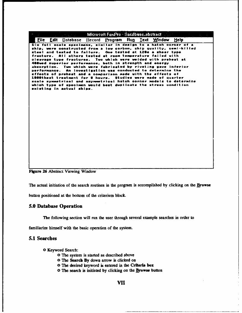
File dlt Database Record ... rogr.am Run Text Window HelpSix full scale specimens, similar in design to a hatch corner of aship, were constructed from a low carbon, ship quality, semi-killedsteel and tested to failure. One tested at l2Se a shear typefracture. All others tested at room temperature failed withcleavage type fractures. Two which were welded with preheat at4S@wed superior performance, both in strength and energyabsorption. Two which were fabricated by riveting gave Inferiorperformance. An investigation was conducted to determine theeffects of preheat and a comparison made with the effects ofllSetheat treatment for S hours. Studies were "ade of quarterscale symmetrical and asymmetrical hatch corner models to determinewhich type of specimen would best duplicate the stress conditionexisting in actual ships.
Figure 26 Abstract Viewing Window
The actual initiation of the search routines in the program is accomplished by clicking on the Browse
button positioned at the bottom of the criterium block.
5.0 Database Operation
The following section will run the user through several example searches in order to
familiarize himself with the basic operation of the system.
5.1 Searches
o Keyword Search:"o The system is started as described above"o The Search By down arrow is clicked on"o The desired keyword is entered in the Criteria box"o The search is initiated by clicking on the Browse button
VII

file Edit D)atabase 1jecord Program Run Window Help
Figure 27 Search criterium pull-down
o The records retrieved as a result of the search are displayed in the Search Resultsbox
o When a particular record is selected in the Search Results box, the details regardingthe record automatically appear above in the editing section.
o Subject Search:
o As above except Subject is selected from the Search By Pull Down
o Author Search:
o As above except Author is selected from the Search By Pull Down
o $Abstract Search:"o As above except Abstract is selected from the Search By Pull Down
6.0 Maintenance
The system has been designed so as to allow a user to continuously update the
VIII

SSCDBASE.DBF and KEYWORD.DBF database files through the editing section, all updating of the
system should be accomplished through the utilities available in the main screen. Changes to the
database file(s) are permanently accomplished upon exiting the program.
The usual backup copies of the disk should be made using the DOS Diskcopy command. The
program will be archived permanently by the Department of Naval Architecture on the University of
Californiz at Berkeley.
IX

XV.0.0 References
1. SSC-365 MARINE STRUCTURAL INTEGRITY PROGRAMS (MSIP)Bea, RGDepartment of Naval ArchitectureUniversity of California, Berkeley
2. SSC-337 (Part 1)SHIP FRACTURE MECHANISMS INVESTIGATIONStambaugh, KA, Wood, WA
3. SSC-363 UNCERTAINTIES IN STRESS ANALYSES ON MARINE STRUCTURESNikolaidis, E, Kaplan, P
4. SSC 328 FRACTURE CONTROL FOR FIXED OFFSHORE STRUCTURESBesuner, PM, Ortiz, K, Thomas, JM, Adams, SDFailure Analysis Associates
5. SSC 323 UPDATING OF FILLET WELD STRENGTH PARAMETERS FOR COMMERCIALSHIPBUILDING.Krumpen, Jr., RP, Jordan, CRNewport News Shipbuilding
6. SSC 296 REVIEW OF FILLET WELD STRENGTH PARAMETERS IN SHIPBUILDINGTsai, CL, Itoga, K, Malliris, AP, McCabe, WC Masubuchi, KMassachusetts Institute of Technology
7. SSC 273 SURVEY OF STRUCTURAL TOLERANCES IN THE UNITED STATES SHIPBUILDINGINDUSTRY.Basar, NS, Stanicy, RFRosenblatt (M) and Son, Incorporated
8. SSC262 PREVENTING DELAYED CRACKS IN SHIP WELDSMishler, HWBattelle Columbus Laboratories
9. Derucher & Korfiatis, Materials for Civil Engineers Prentice Hall, Englewood Cliffs, NJ 1988
10. SSC 260 A SURVEY OF FASTENING TECHNIQUES FOR SHIPBUILDINGYutani, N, Reynolds, TLBoeing Commercial Airplane Company
x

11. SSC 356 FATIGUE PERFORMANCE UNDER MULTIAXIAL LOADINGStambaugh, KA, Van Mater, Jr., PRColumbia Research Corporation
12. SSC 249 SHIP VIBRATION PREDICTION METHODS AND EVALUATION OF INFLUENCE OFHULL STIFFNESS VARIATION ON VIBRATORY RESPONSE.Kline, RG, Daidola, JCRosenblatt (M) and Son, Incorporated
13. SSC292 REPORT ON SHIP VIBRATION SYMPOSIUM '78Dillon, HS
14. SSC330 PRACTICAL GUIDE FOR SHIPBOARD VIBRATION CONTROL AND AITENUATIONNoonan, EF, Antonides, GP, Wood, WANKF Engineering Associates, Inc.
15. SSC281 BIBLIOGRAPHY FOR THE STUDY OF PROPELLER-INDUCED VIBRATION IN HULLSTRUCTURAL ELEMENTSBurnside, OH, Kana, DD, Reed, FESouthwest Research Institute; Littleton Research & Engineering
16. SSC-291 A DESIGN PROCEDURE FOR MINIMIZING PROPELLER-INDUCED VIBRATION INHULL STRUCTURAL ELEMENTSBurnside, OH, Kana, DD, Reed, FESouthwest Research Institute
17. SSC-318 FATIGUE CHARACTERIZATION OF FABRICATED SHIP DETAILS FOR DESIGNMunse, WH, Wilbur, TW, Tellalian, ML, Nicoll, K, Wilson, KDepartment of Civil Engineering
18. SSC-358 INFLUENCE OF PRIOR DAMAGE BY CYCLIC LOADING BELOW THE YIELDSTRENGTH ON SHIP STEELS IN MARINE ENVIRONMENTSLeis, BNBattelle, Columbus Division
19. SSC-356 FATIGUE PERFORMANCE UNDER MULTIAXIAL LOADING IN MARINESTRUCTURESStambaugh, KA, Van Mater, Jr., PRColumbia Research Corporation
Xi

20. SSC 337 SHIP FRACTURE MECHANISMS INVESTIGATIONStambaugh, KA, Wood, WAGiannotti & Associates, Inc.
21. SSC-232 STUDY OF THE FACTORS WHICH AFFECT THE ADEQUACY OF HIGH-STRENGTH,LOW-ALLOY STEEL WELDMENTS FOR CARGO SHIP HULLSNorris, EB, Pickett, AG, Wylie, RDSouthwest Research Institute
22. SSC-354 STRUCTURAL REDUNDANCY FOR CONTINUOUS AND DISCRETE SYSTEMSWalsh, WJ, Leis, BN, Yung, JYBattelle Institute
23. SSC-332 GUIDE FOR SHIP STRUCTURAL INSPECTIONBasar, NS, Jovino, VWM. Rosenblatt & Son, Inc.
24. SSC-346 FATIGUE CHARACTERIZATION OF FABRICATED SHIP DETAILS FOR DESIGN -PHASE IIPark, SK, Lawrence, FVDepartment of Civil Engineering, University of Illinois atUrbana-Champaign
25. SSC-334 STUDY TO DETERMINE THE INFLUENCE OF WELD POROSITY ON THEINTEGRITY OF MARINE STRUCTURESWalsh, WJ, Leis, BN, Yung, JYBattelle
26. SSC-307 EVALUATION OF FRACTURE CRITERIA FOR SHIP STEELS AND WELDMENTSPense, AWLehigh University
27. SSC-322 ANALYSIS AND ASSESSMENT OF MAJOR UNCERTAINTIES ASSOCIATED WITHSHIP HULL ULTIMATE FAILUREKaplan, P, Benatar, M, Bentson, J, Achtarides, TAHydromechanics, Inc.
28. SSC-266 REVIEW OF SHIP STRUCTURAL DETAILSGlasfeld, R, Jordan, D , Kerr, MJ, Zoller, DGeneral Dynamics Corporation
XIl

29. SSC-272 IN-SERVICE PERFORMANCE OF STRUCTURAL DETAILSJordan, CR Cochran, CSNewport News Shipbuilding
30. SSC-294 FURTHER SURVEY OF IN-SERVICE PERFORMANCE OF STRUCTURAL DETAILSJordan, CR, Knight, LTNewport News Shipbuilding
31. SSC-265 A STUDY OF CRACK ARRESTER SYSTEMSKanninen, M Mills, E Hahn, GT Marschall, C Broek, D Coyle, AMasubuchi, K Itoga, K
32. SSC-195 RECOMMENDED EMERGENCY WELDING PROCEDURE FOR TEMPORARYREPAIRS OF SHIP STEELSLowenberg, AL, Watson, PDSouthwest Research Institute
33. SSC-296 REVIEW OF FILLET WELD STRENGTH PARAMETERS FOR SHIPBUILDINGTsai, CL, Itoga, K, Malliris, AP, McCabe, WC Masubuchi, KMassachusetts Institute of Technology
3, 'SC-345 Part 1 ELASTIC-PLASTIC FRACTURE MECHANICS - A CRITICAL REVIEWAnuerson, TLTexas A & M Research Foundation
35. SSC-312 INVESTIGATION OF INTERNAL CORROSION AND INTERNAL CORROSIONCONTROL ALTERNATIVES IN COMMERCIAL TANKSHIPSHering, LC, Titcomb, ANNewport News Shipbuilding
36. SSC-326 LONG-TERM CORROSION FATIGUE OF WELDED MARINE STEELSBurnside, OH, Hudak, Jr. SJ, Oelkers, E, Chan, K, Dexter, RJSouthwest Research Instiute
37. SSC-348 CORROSION EXPERIENCE DATA REQUIREMENTSStambaugh, KA, Knecht, JCGiannotti & Associates, Inc.
XIll

38. SSC-332 GUIDE FOR SHIP STRUCTURAL INSPECTIONBasar, NS, Jovino, VWM. Rosenblatt & Son, Inc.
39. SSC-301 PROBABILISTIC STRUCTURAL ANALYSIS OF SHIP HULL LONGITUDINALSTRENGTHDaidola, JC, Basar, NSRosenblatt (M) and Son, Incorporated
40. SSC-136 ON VARIOUS PROBLEMS OF IMMEDIATE INTEREST TO A SHIP CLASSIFICATIONMANVedeler, GNorske Veritas
41. SSC-220 A LIMITED SURVEY OF SHIP STRUCTURAL DAMAGEHawkins, S, Levine, GH, Taggart, RTaggart (Robert), Incorporated
42. SSC-332 GUIDE FOR SHIP STRUCTURAL INSPECTIONBasar, NS, Jovino, VW
43. SSC-322 ANALYSIS AND ASSESSMENT OF MAJOR UNCERTAINTIES ASSOCIATED WITHSHIP HULL ULTIMATE FAILUREKaplan, P, Benatar, M, Benison, J, Achtarides, TA
44. SSC-313 SL-7 RESEARCH PROGRAM SUMMARY, CONCLUSIONS ANDRECOMMENDATIONSStambaugh, KA, Wood, WA
45.SSC-295 NONDESTRUCTIVE INSPECTION OF LONGITUDINAL STIFFENER BUTI' WELDS INCOMMERCIAL VESSELSYoushaw, RA
46. SSC-332 GUIDE FOR SHIP STRUCTURAL INSPECTIONBasar, NS, Jovino, VW
47. SSC-253 A GUIDE FOR THE NONDESTRUCTIVE TESTING OF NON-BUTT WELDS INCOMMERCIAL SHIPS. PART IYoushaw, RA Criscuolo, EL
XIV

48. SSC245 GUIDE FOR INTERPRETATION OF NONDESTRUCTIVE TESTS OF ORDINARY-,MEDIUM-, AND HIGH-STRENGTH, LOW-ALLOY STEEL BUTT-JOINT WELDMENTS INSHIP HULL STRUCTURESShip Structure Comnittee
49. SSC-262 PREVENTING DELAYED CRACKS IN SHIP WELDS (PART II)Mishler, HW
50. SSC-177 GUIDE FOR INTERPRETATION OF NON-DESTRUCTIVE TESTS OF WELDS IN SHIPHULL STRUCTURESShip Structure Committee
51. SSC-213 A GUIDE FOR ULTRASONIC TESTING AND EVALUATION OF WELD FLAWSYoushaw, RA
52. SSC-332 GUIDE FOR SHIP STRUCTURAL INSPECTIONBasar, NS, Jovino, VW
53. SSC-300 SUMMARY OF NONDESTRUCTIVE INSPECTION STANDARDS FOR HEAVYSECTION CASTINGS, FORGINGS, AND WELDMENTSYoushaw, RA
54. SSC-293 UNDERWATER NONDESTRUCTIVE TESTING OF SHIP HI " L WELDSYoushaw, RA, Dyer, C
55. SSC-189 THE VIDEO TAPE RECORDING OF ULTRASONIC TEST INFORMATIONYoushaw, R Dyer, CH Criscuolo, EL
56. SSC-274 DEVELOPMENT OF AN INSTRUMENTATION PACKAGE TO RECORD FULL-SCALESHIP SLAM DATABand, EGU, Euler, AJ
57. SSC-238 DESIGN AND INSTALLATION OF A SHIP RESPONSE INSTRUMENTATION SYSTEMABOARD THE SL-7 CLASS CONTAINERSHIP S.S. SEA-LAND MCLEAN (SL-7-1)Fain, RA
xv

Project Technical Committee Members
The following persons were members of the committee that represented the ShipStructure Committee to the Contractor as resident subject matter experts. As suchthey performed technical review of the initial proposals to select the contractor,advised the contractor in cognizant matters pertaining to the contract of which theagencies were aware, and performed technical review of the work in progress andedited the final report.
Mr. Frederick Seibold -Chairman U.S. Maritime Administration
Mr. John Garside American Bureau of Shipping
Mr. Zbigniew Karaszewski U. S. Coast Guard
LT Rob Holtzman U. S. Coast Guard
Mr. Richard Norris American Bureau of Shipping
Dr. Neil G. Pegg Defence Research EstablishmentAtlantic- Canada
LCDR Doug O'Reilly National Defence Headquarters-Canada
Mr. William Siekierka Naval Sea Systems Command,Contracting Officer'sTechnical Representative
Mr. Alex Stavovy National Academy of Science,Dr. Robert Sielski Marine Board Liaison
CDR Mike Parmelee U.S. Coast Guard, Executive DirectorCDR Steve Sharpe Ship Structure Committee

COMMITTEE ON MARINE STRUCTURES
Commission on Engineering and Technical Systems
National Academy of Sciences - National Research Council
The COMMITTEE ON MARINE STRUCTURES has technical cognizance over the
interagency Ship Structure Committee's research program.
Peter M. Palermo Chairman, Alexandria, VA
Subrata K. Chakrabarti, Chicago Bridge and Iron, Plainfield, IL
John Landes, University of Tennessee, Knoxville, TNBruce G. Collipp, Marine Engineering Consultant, Houston, TX
Robert G. Kline, Marine Engineering Consultant, Winona, MN
Robert G. Loewy, NAE, Rensselaer Polytechnic Institute, Troy, NYRobert Slelski, National Research Council, Washington, DCStephen E. Sharpe, Ship Structure Committee, Washington, DC
LOADS WORK GROUP
Subrata K. Chakrabarti Chairman, Chicago Bridge and Iron Company, Plainfield, ILHoward M. Bunch, University of Michigan, Ann Arbor, MI
Peter A. Gale, John J. McMullen Associates, Arlington, VA
Hsien Yun Jan, Martech Incorporated, Neshanic Station, NJJohn Niedzweckl, Texas A&M University, College Station, TX
Solomon C. S. Ylm, Oregon State University, Corvallis, OR
Maria Celia Ximenes, Chevron Shipping Co., San Francisco, CA
MATERIALS WORK GROUP
John Landes, Chairman, University of Tennessee, Knoxville, TN
William H Hartt, Florida Atlantic University, Boca Raton, FL
Horold S. Reemanyder, Bethlehem Steel Corp., Bethlehem, PA
Barbara A. Shaw, Pennsylvania State University, University Park, PA
James M. Sawhill, Jr., Newport News Shipbuilding, Newport News, VA
Bruce R. Somers, Lehigh University, Bethlehem, PAJerry G. Williams, Conoco, Inc., Ponca City, OK

SHIP STRUCTURE COMMITTEE PUBLICATIONS
SSC-354 Structural Redundancy for Discrete and Continuous Systems by P. K.Das and J. F. Garside 1990
SSC-355 Relation of Inspection Findings to Fatigue Reliability by M. Shinozuka
SSC-356 Fatigue Performance Under Multiaxial L90l by Karl A. Stambaugh,Paul R. Van Mater, Jr., and William H. Munse 1990
SSC-357 Carbon Equivalence and Weldablilty of Microalloyed Steels by C. D.Lundin, T. P. S. Gill, C. Y. P. Qlao, Y. Wang, and K. K. Kang 1990
SSC-358 Structural Behavior After Fatigu by Brian N. Leis 1987
SSC-359 Hydr"odynamic Hull Damping (Phase I) by V. Ankudinov 1987
SSC-360 Use of Fibegr ReInforced Plastic In Marine Structure by Eric Greene1990
SSC-361 Hull Strapping of Ships by Nedret S. Basar and Roderick B. Hulla 1990
SSC-362 Shipboard-Wave Height Sensor by R. Atwater 1990
SSC-363 Uncertanties in;Stres Analysison Marine Structures by E. Nikolaidisand P. Kaplan 1991
SSC-364 Inelastic Deformation of Plate Panels by Eric Jennings, Kim Grubbs,Charles Zanis, and Louis Raymond 1991
SSC-365 Marine Structural integrity Programs (MASIP) by Robert G. Bea 1992
SSC-366 Threshold Corrosion Fatigue of Welded _Shpbuldidna Steels by G. H.Reynolds and J. A. Todd 1992
SSC-367 Fatigue Technology Assessment and Strategies for Fatigue Avoidance InMarine Structures by C. C. Capanoglu. 1993
SSC-368 Probability Based Ship Design Procedures: A Demonstrationby A. Mansour, M. Lin, L Hovem, A. Thayamballl 1993
SSC-369 Reductionj of S-N Curves for Ship Structural Details by K. Stambaugh, D.Lesson, F. Lawrence, C-Y. Hou, and G. Banns 1993
SSC-370 Underwa-ter Repair Procedures for Ship Hulls (fa-tigue and Ductility ofUnderwater Wet Welds) byK rbsad C. Zanls 1993
SSC-371 Establishment of a Uniform Format for Data Reporting of StructuralMaterial Properties for Reliability Anaalys by N. Pussegoda, L Malik,and A. Dlnovltzer 1993
None Ship Structure Committee Publications - A Special Bibilorraphy