RICi fILE COY - Defense Technical Information Center
416
RICi fILE COY AGARD-CP-4 17 I,,SR RU O EOPAERSAC EEOM N W, AGR OFREC RCEDNSN.1 The Design, Development and Testing of Complex Avionics Systems DTIC ELECTE DISTRIBUTION AND AVAILABILITY D1r~UIf Ia?5 ON BACK COVER ________Un~W~ 88 4 11 307
-
Upload
khangminh22 -
Category
Documents
-
view
1 -
download
0
Transcript of RICi fILE COY - Defense Technical Information Center

RICi fILE COY
AGARD-CP-4 17
I,,SR RU O EOPAERSAC EEOM N
W,
AGR OFREC RCEDNSN.1
The Design, Development and Testingof Complex Avionics Systems
DTICELECTE
DISTRIBUTION AND AVAILABILITYD1r~UIf Ia?5 ON BACK COVER
________Un~W~ 88 4 11 307

AGARD-CP-4 17
NORTH ATLANTIC TREATY ORGANIZATION
ADVISORY GROUP FOR AEROSPACE RESEARCH AND DEVELOPMENT
(ORGANISATION DU TRAITE DE LATLANTIQUE NORD)
AGARD Conference Proceedings No.417
THE DESIGN, DEVELOPMENT AND TESTING OF COMPLEX
AVIONICS SYSTEMS
DTIC
H
Papers presented at the Avionics Panel Symposium held in Las Vegas, US.on 27 April- I May 198 7.

THE MISSION OF AGARD
According to its Charter, the mission of AGARD is to bring together the leading personalities of the NATO nations inthe fields of science and technology relating to aerospace for the following purposes:
Recommending effective ways for the member nations to use their research and development capabilities for diecommon benefit of the NATO community;
-- Providing scientific and technical advice and assistance to the Military Committee in the field of aerospace researchand development (with particular regard to its military application);
- Continuously stimulating advances in the aerospace sciences relevant to strengthening the common def,2nce posture:
- Improving the co-operation among member nations in aerospace research and development;
- Exchange of scientific and technical information;
- Providing assistance to member nations for the purpose of increasing their scientific and technical potential
- Rendering scientific and technical assistance, as reques.cd, to other NATO bodies and to member nations inconnection with research and development problems in the aerospace field.
The highest aut-ority within AGARD is the National Delegates Board consisting of officially appointed seniorrepresentatives from tach member nation. The mission of AGARD is carried out through the Panels which are comp,,scd ofexperts appointed by tise National Delegates, the Consultant and Exchange Programme and the Aerospacc ApplicationsStudies Programme. T1e results of AGARD work are reported to the member nations and the NATO Authorities throughthe AGARD series of publications of which this is one,
Participation in AGARD activities is by invitation only and i.i normally limited to citizens of the NATO nations.
The content of this publication has been reproduceddirectly from material supplied by AGARD or the authors.
Published December 1987Copyright 0 AGARD 1987
All Rights Reserved
ISBN 92-835-0437-2
tiPrinted by Specialised Printing Services Limited40 Chigwell Lane, Loughton, Essex IG 10 3 7Z
THEME
This symposium was designed to explore how today's system designer i addressing the solution to tomorrow's avionicssystems design.
As government budgets become more limited for the research, development, testing and production of military aircraftsystems, and the Warsaw Pact nations continue to produce all types of aircraft in greater numbers, the N ATn, '"r
look" at how avion;, ytem a'- ,!eX,. ,, g,, , inc avionics community has thought of avionic architecture as theintegration of a collection of "black boxes" (sensors, navigation, communication, displays, etc.) with the software allowing forthe communication between "black boxes", computers and man. Normally, the system is decomposed into manageable partswith accurately defined interfaces. By rigidly controlling this process, aerospace companies have developed excellent avionicssystems which are fully integrated into aircraft systems, but the cost is high. Cost means that the aircraft is required to performmulti-missions which often lead to performance compromises. With the advent of the VHSIC, distributed processing, artificialintelligence, sensor data fusion, etc., the technologists are blurring the clear functional allocation defined for the "black box".These factors, technology and cost, provide both an opportunity and a challenge to the system designers to design futureavionics systems whose performance degrades gracefully, is reliable, and is affordable.
Ce Symposium avait pour theme les methodes utilisces aujourd'hui par un concepteur de systeme pour trouver unesolution aux problemes posds par les systbmes avioniques de demain.
Comme les gouvemements limitent de plus en plus les budgets consacres A la recherche, au developpement, aux essais et ala production des syst~mes d'avions militaires et comme les pays du Pact de Varsovie produisent de plus en plus d'avions, lespays de lOTAN doivent reconsiderer les methodes de developpement des systbmes avioniques. D'une maniere gdnrale.l'industrie avionique considere ;'architecture d'une systbme avionique comme un ensemble de "boites noires" (dtecteiir,,navigation, communication, affichage, et...), le systeme se decompose en elements pouvant itre giris et ayant des interfacesdefinies avec precision. Par une maitrise stricte de ce processus, les societes aerospatiales ont developpe d'excellents systimesavioniques qui sont totalement integres dans les syst&mes de Iavion, mais dont le coot est eleve. Pour des raisons de coit,l'avion dolt pouvoir effecteur des missions multiples, ce qui nece~site des compromis entre les performances. Avec l'apparitiondes circuits intigres tres grande 6chelle (VESIC), de l'intelligence artificiclle, de la fusion des donnees de detecteur, etc..., lestechnologies brouillent l'image claire que l'on avait de ]'affectation fonctionnelle definie pour la boite noire. Ces facteurstechniques et economiques offrent une occasion et un defi A relever pour les concepteurs de systime; ceux-ci doivent concevoirles futurs systimes avioniques dont le cot et la fiabilite doivent tre satisfaisants et dont les performances ne doivent sedegrader que lentement.
Accession For
iSTIS GRA&1DTIC TAB f"Un winounc ed CD
Js - f _o ______, _--_-By
Distribution/
iv;niabillty Ccdet
.Avc!Ii and/ortst iSpecial
i 11iii

AVIONICS PANEL
Chairman: Dr G.H.Hunt Deputy Chairman: Dr R.W.Macl'hersonADXR (E) National Defence EstablishmentRoyal Aircraft Establishment CRAD/DS Pol3Farnborough, Hants, GU 14 6TD 10 1 Colonel By DriveUK Ottawa, Ontario. K I A 0K2
Canada
TECHNICAL PROGRAMME COMMITTEE
PROGRAMME CO-CHAIRMEN
Mr E. 'anuzzi Dr E.KutchmaDirector, Software & Computer Dir. Head, Aircraft Weapons Integr. Dept.Naval Air Development Center (Code 3 1)Warminster, PA 18974- 50(00 US Naval Weapons CenterUSA Chind Like, CA 93 55 5
USA
COMMITTEE MEMBERS
Mr R.Gu jot LTC. W.Van den BrandenAs-ions Marcel Dassault-Breguet Aviation Belgian Air Staff VDT/BDirection Gynirale Technique Section AvionicsDivision Systemes d'Armes Quartier Reine Elisabeth, Rue d'Evere I78, Quai Carnal, BP 300 1140 Bruxelles. Belgium92214 Saint Cloud Cedex. France
Mr J.WhalleyIng. L.Crovella 3Ae Aircraft GroupAeritalia SAIPA Weybridge DivisionGruppo Sistemni Avionici ed Chester Road. Woodford, Bramball.
Equipaggiatnenti Stockport. Cheshire. SK7 I QR10072 Caselle Torinese UKTorinoItaly DipI. Ing. W-..Kiny
MBB1 Dep LKE3Maj. M.Mascarenltas Postfach 80 11 60Head, Test Software Group 8(000 Miinchen 80O.G.M.A. Federal Republic of Germany2615 Alverca. Portugal
AVIONICS PANEL EXECUTIVE
Lt. Colonel M.Stratton
From Europe From the USA and CanadaAGARD-OTAN AGARD-NATO7, rue Ancelle APO New York 0977792200, Neuilly-sur-SeineFranceTel: 47.38.57.65Telex: 610176 AGARD
iv
CONTENTS
Page
THEME
AVIONICS PANEL
TECHNICAL EVALUATION REPORTby D.Schimsky viii
Reference
KEYNOTE ADDRESSby G.Clark K
SESSION I - DESIGN ASPECTS FOR FUTURE AVIONICS SYSTEMS
TECHNOLOC;Y DEVELOPMF.NT PROGRAM FOR TWENTY-FIRST CENTURY AEROSPACEVEHICLES
bv W.T.Suit and D.B.Price I
SYSTEMS FOR IHE 2 IST CENTURYby R.G.DeSipio 2
ARCHITECTURE AND ROLE OF THE -SENSOR SUBSYSTEM" IN FUTL RE AIRCRAFT " EAPONSYSTEMS
by J.A.Salmon, CJ.C.Ravat and F.J.Lork 3
RAPID PROTOTYPING OF COMPLEX AVIONIC SYSTEM ARCHITECTURESby L.Berardi, N.Giorgi, W.Mellano, A.Valente and E.Zucco 4
THE SPECIFICATION AND DESIGN OF A FUTURE MARITIME RECONNAISSANCE AIRCRAFTby J.Shepard 5
- A STRUCTURED APPROACH TO WEAPON SYSTEM DESIGNby H.,M.Malley, N.TJewell and R.A.C.Smith 6
DEVELOPMENT OF A GENERIC ARCHITECTUIEby C.Berggren 7
TEST PHILOSOPHY OF THE EHI01 INTEGRATED AVIONICby E.Galfi 8
SYSTEMS ENGINEERING TECHNIQUEby L.Karas and D.Rhodes 9
MAQUETTE DES SPECIFICATIONS FONCTIONNELLES DU LOGICIEL EMBARQUE -EXPERIENCE DU SYSTEME AVIONIQUE RAFALE
par P.Schirle 10
THE AVIONICS SOFTWARE ARCHITECTURE IMPACT ON SYSTEM ARCHITECTUREby C.D.Locke I I
Paper 12 withdrawn
A COMPARISON OF INTEGRATED AND SEPARATE SYSTEMS FOR FLIGHT CONTROL ANDNAVIGATION
by H.Buitkamp 13
DEVELOPMENT AND TESTING OF A PREDICTIVE METHODOLOGY FOR OPTIMIZATION OFMAN-MACHINE INTERFACE IN FUTURE AVIONICS SYSTEMS
by R.E.Parks 14
CREWStATION INFORMATION AND DEVELOPMENT SYSTEM (t-4BSfby M.E.Rowland and W.R.Wagoner 15

Reference
A CHANGE IN SYSTEM DESIGN EMPHASIS: FROM MACHINE TO MANby M.L.Metersky and J.L.Ryder 16
SESSION I1 - MANAGING THE FUl URE SYSTEM DESIGN PROCESS
MANAGING ADVANCED AVIONIC SYSTEM DESIGNby P.Simons 17
ERGONOMIE PSYCHOSENSORIELLE DES COCKPITS, INTERET DES SYSTEMESINFORMATIQUES INTELLIGENTS
par R.Amalberti, F.Deblon et J.P.Menu 18
ADVANCED DEVELOPMENT OF A COCKPIT AUTOMATION DESIGN SUPPORT SYSTEMby P.V.Kulwicki, J.W.McDaniel and L.M.Guadagna 19
CONCEPTION ET DEVELOPPEMENT D'UN SYSTEME AVIONIQUE ADAPTE AUX MISSIONS DESHELICOPTERES
par D.Bouheret et J.L.Roch 20
OPERATION AND PERFORMANCE OF AN INTEGRATED HELICOPTER COMMUNICATION SYSTEMby W.R.Fried 21
DESIGNING FOR DESIGN EFFECTIVENESS OF COMPLEX AVIONICS SYSTEMSby K.R.Boff 22
DESIGN FOR INTEROPERABILITY (INTERCHANGEABILITY)by G.Konomos 23
THE ELECTROMAGNETIC THREAT TO Fl TURE AVIONIC SYSTEMSby B.Audone 24
THE INTEGRATION, CHARACTERISATION AND TRIALLING OF A MODERN COMPLEXAIRBORNE RADAR
by R.R.Hogben and F.N.Morphet 25
MICROELECTRONICS, THE NEXT FIFTEEN YEARSby D.Wallace 26
SESSION III - SYSTEM DESIGN TOOLS AND INTEGRATION
EXPERIENCE IN THE INTEGRATION OF HUMAN ENGINEERING EFFORT WITH AVIONICSSYSTEMS DEVELOPMENT
by D.Beevis 27
LE TEST DE LOGICIELS AVIONIQUES COMPLEXES: UNE EXPERIENCE PRATIQUEpar M.Muenier 28
DEVELOPING SYSTEMS USING STATE-OF-THE-ART CAD/CAM TECHNOLOGYby V.Anderson and D.J.Brewer 29
INTERFACING AND INTEGRATING HARDWARE AND SOFTWARE DESIGN SYSTEMSby D.Davis 30
A LOOK TOWARD THE FUTURE OF COMPLEX AVIONICS SYSTEMS DEVELOPMENT USINGTHE USAF TEST PILOT SCHOOL'S AVIONICS SYSTEMS TEST TRAINING AIRCRAFT
by W.Broome and M.Parrag 31
SOFTWARE ENGINEERING FOR THE BRITISH AEROSPACE EXPERIMENTAL AIRCRAFTPROGRAMME (EAP)
by W.E.R.Kellaway 32
SYSTEME AVIONIQUE - METHODE DE DEVELOPPEMENT ET OUTILS INFORMATIQUESpar P.Laroche-Levy 33
vi

Reference
-- A SOFTWARE LIFE CYCLE SUPPORT ENVIRONMENTby L.Y.Bujwa, W.R.Wisehajl and F.LaMonca .34
DEVELOPMENT OF AN AIRBORNE FACILITY FOR ADVANCED AVIONICS RESEARCHbv N.van Driel 35
ATELIERS DE CONCEPTION DE SYSTEMES AVIONIQUES ET DE REALISATION DE LOGICIELSEMBARQUES
par M.Sfissa et P.Laroche-Levy 36
COHERENT FUNCTIONAL DEVELOPMENT: KEY TO SUCCESSFUL FUTURE SYSTEM INTEGRATIONby B.L.House 37
SESSION IV - CLASSIFIED
Paper 38 withdrawn
A -QUASI-CONVENTIONAL- APPROACH TO FUTURE SYSTEM DESIGN AND MANAGEMENTby P.Broaa 39*
DEVELOPPEMENT DES SYSTEMES AVIONIQUES COMPLEXES - EXPERIENCE ISSUE DESPROGRAMMES MILITAIRES FRANCAIS
par A.Courainiault 40
THE FUTURE MARITIME RECONNAISSANCE AIRCRAFT AS PART OF AN INTEGRATEDMARITIME BATiTLEFIELD SYSTEM
by D.Baldvvimon W1
*Abstract only. The ful text appears In Classified Publication CP 417 (Supplement)
vii

TECHNICAL EVALUATION REPORT ON THE 53RD SYMPOSIUM OFTHE AVIONICS PANEL OF AGARD
THE DESIGN, DEVELOPMENT, AND TESTING OFCOMPLEX AVIONICS SYSTEMS
Las Vegas, Nevada, U.S., 27 April - I May 1987
David SchinakyNaval Air Development Center
Warminster, Pennsylvania, U.S. 18974
SUMMARY
The overall quality of the papers presented at the symposium was first class, and the presentations were.on the whole, excellent. However, the relevance of the subject matter to the stated topic of a session wasweak in several cases. Although these papers addressed the primary topics in the broadest sense, theirsubject matter was often unfocused and diffused. Their primary point was usually a reiteration of howavionic system design, development, and test was accomplished on a specific project. It would have beenbetter if these papers clearly stated the problem and how it was solved. If we in theavionics community hadmore standardized ways of doing business, we would most likely face the same problems, and any discussionon their resolution would certainly draw our attention.
The symposium clearly emphasized two vital requirements in the development of avionic systems:
" Current and future avionic systems are so complex and require such a diversity of talents, expertise.and resources to design, develop, and test that a stringent, rigorous, methodical top-down approachusing the latest computer-aided techniques tiust be applied.
" Standards are needed iu. almost every area.
Without some sort of agreement and implementation of standards to impose discipline, futuresymposia will repeat the theme of this one: "Here is how I did it. now show me how you did it.- Whileexploring different approaches and sharing lessons learned are beneficial, more progress could be made by-t " -eeing to 'set h,. ,-I- .. pproac.,e "7, hnir'," etc.. and evaluatine our successes, failures, andproblems when the next symposium is convened.
THEME AND OBJECTIVES
The title of this symposium was "The Design, Development, and Testing of Complex As onicsSystems." However, this title barely does justice to the subject. In the recent past, a near revolution hasoccurred in avionic system requirements, including how they are built and, as was continuously emphasizedin the presc,.atiwns, hu)w they are operated.
The stated theme was "to explore how today's system designer is addressing the solution to tomorro- 'savionics system design." The presentations adequately addressed this theme with descriptions of curre:.and near-future efforts, all with forward-looking implications.
It was clear from the content of the presentations that all member countries, as well as the companieswithin those countries, are experiencing the same problems in designing advanced avionic systems. What istruly remarkable is the virtual unanimity in the approach to resolving the problems.
The symposium's goal was to share the experiences, successes, and pitfalls surrounding this complexsubject and to take advantage of lessons learned. Judging from the size of the audience at each session, thesession, the enthusiastic question and answer periods following each presenttion, and the variety ofexperiences discussed, the symposium may be considered a resounding success.
TECHNICAl. CONTENT
The symposium began with an opening address by VADM G. Clarke Commander of the Space andNaval Warfare (SPAWAR) Systems Command of the United States Navy. He set the tone iot tik mcetin?by strongly emphasizing the need for system designers to consider the whole system in the design processrather than the avionics portion only. According to the Admiral, the whole system includes surface ships,aircraft, submarines, space vehicles, and, most importantly, man. Admiral Clarke then described his task asCommander of SPAWAR to establish a total system architecture approach to the battle group and to do ittop-down for the first time ever. He described the process he and his staff are using and the three majorcomponents of the architecture: the tactical command system, the communication support system, and thewarfare support system.
viii

Admiral Clarke's comments were reiterated throughout the symposium. His emphasis on an orderly.
rigorous, structured top-down approach was the single most common element of virtually all presentations
Session I - Design Aspects of Future Avionic Systems
In Paper No. L.* the author describes a cooperatic planning ,.i,,it betweii the U.S. N,.onalAeronautics and Space Administration (NASA) and the Department of Defense (DOD) to conduct studiesto determine technology development requirements for the design of the next generation of spacetransportation systems. A thorough top-down hierarchical approach being used on this project is describedThis approach covers major categories such as guidance, navigation, and control; flight systemsmanagement; system integration; and modeling, communications, and man systems interfaces. Fhemultitude of research elements that must be considered provides ample justification for using a structured.rigorous approach. The paper highlights the need for significant systems as an important driving tactotWhile the paper addresses only one of five major phases of the avionic system planning process. a
systematic, classical approach is taken: Define the potential (generic) mission, define the (generic) %ehicle tosatisfy the mission, and identify the technology needed to build the vehicle The time frame for the fi-stvehicle is post-2000.
Paper No. 2 calls for standardization at various levels to help solve the problem of transitioning toda 'sarchitectures into architectures of the future without having to start from the beginning As the authorpoints out, we never start with a totally new design, but one that is almost always based upon an existingdesign. Therefore, a "bridging" or transitioning techniirie must be developed. He identifies tmorequirements to accomplish this:
" A doctrine that defines both future architectures and the intermediate 'transitional- architectures
" An interplatform interface requirements document.
The author proposes to develop a high-level architecture of the future and a standard method toidentify the components and structure of that chitectur. He also calls for some form ofstandardization orcommonality across platforms, and even across national boundaries, a siew that was expressed by man)throughout the symposium.
Paper No. 3 highlights the role of sensors in a hypothetical future aircraft and emphasizes the complexproblems facing the pilot. These aircraft will be equipped with highly capable sensors with different datarates, ranges, and accuracies that sometimes do not supply data (e.g.. because of jamming). The analysis.reduction, fusion, correlation, and tracking of these data can be accomplished in a decentralized, adaptablesystem with the aid of artificial intelligence (All, also known as the -pilot's associate."The authoi states thatthe successful developer of the future will be the one that best manages the myriad of different contractorsthat will be required to design and integrate such a system.
Papers Nos. 4 and 5 introduce advanced tools to aid the design of complex systems. Expert Consultantfor Avionic Systems Transformation Exploitation (ECATE), described in Paper No. 4, is an expert sy,cmthat aids the rapid prototyping of avionic systems. Paper No. 5 discusses the Controlled RequirementsExpression (CORE) system, which is useful in providing unambiguous functional descriptions andrepresenting dynamic interactions within and across systems. The use of sophisticated tools will bemandatory to ensure the successful exe,,'ion of current and future complex avionic system designs. Thisissue raises two questions:
* Will the ability to design more complex systems depend on the ability to design increasingly complextools?
* Can tools be used to design tools?
Work on the Experimental Aircraft Program (EAP) is the topic of Paper No. 6. The author describes
the use of the CORE tool to impose a top-down structured design approach. The use of CORE resulted inthe remarkable conclusion that after 20 flights of the aircraft in the first 18 days of flight, no system changeswere deemed necessary. Apparently, enforcing a superior, strictly followed approach can lead tooutstanding results. This raises the suspicion that many problems encountered in avionic system designprojects may be due to taking shortcuts and known high-risk paths.
Paper No. 7 best addresses the subject of the first session. This paper describes the development of ageneric architecture of the future. The author identifies the salient characte, istics of the future system, suchas distributed processing and control (not shared processing), fault tolerance leading to uninterruptedoperation, and stringent real-time performance demanding very short control loops. The paper alsodescribes a very practical, professional approach taken to these subjects and discusses the problems of real-time processing. The author also calls for some form of standardization in control/data distribution tofaelitwt limi task of system designers, in this case the Society of Automotive Engineers (SAE).
OA lat of the compiete tit i and authors of tch paper is pmeented at the end of this paper.
is
The use of special test -rigs" and predefined standard interfaces to expedite the testing of the EH-101helicopter integrated avionic suite is discussed in Paper No. 8. A "rig" is actually a complex system in itself,consisting of computers, emulators simulators, buses. etc , that allow testing to proceed without the delaysassociated with the lack of some system components. Again. initial planning and standardized interlaceshelped the system designers considerably in the latter development stages.
Paper No 9 describes the use of the formalized System Engineering Technique (SE I), which wasdeveloped to improve both the quality and productivity of system engineering tasks. The authors emphasitethat no tool, technique, or methodology will replace common sense, and that SET is not really new, but aformalization and integration of existing procedures and worksheets. The authors describe the use of threemodels:
" A functional model that outputs requirements.
" A physical model that is represented by the design.
" An operational model used for final system analysis.
These models should lead to specific quantifiable constraints and system components. This particular papergenerated much interest among the symposium attendees, as evidenced by the large number ol pertinentquestions.
As described in Paper No. 10. a rigorous, strictly adhered to methodology was responsible [or thesuccessful development of the RAFALE aircraft. Rapid prototyping of complex systems was alsobeneficial. This technique improved the quality of the functional design specifications, which, as the authorpoints out, are the cornerstones of the whole effel. Rapid prototyping was used to validate the functionalspecifications that were prepaid[ by adhering to a ngid top-down methodology. As a result of theseprocedures, a first flight was conducted six months ahead of schedule, and the number of errors in thespecifications was greatly reduced.
Paper No. II is a thoughtful presentation on the impact of software on avionic architecture. A brielreview ol avionic system development history shows that technology, as a whole, has grown exponentially.with hardware following in a very similar manner. However, software capabilities and man's ability topioduce it have, unfortunately, not followed suit. Yet, software wili be the main constraint in satisfyingfuture requirements; no alternatives are foreseen. A new model was proposed, wherein the rework requiredafter an error is found will be limited to a small step backward in time rather than the large rework loop thatis used on most of today's efforts. I he author feels that careful definition of information flows early in thedesign process is the key.
The 12th paper listed on the agenda was not presented at the symposium.
In Paper No. 13, the author compares integrated and separate systems for flight control andnavigation. The main problem is that the two subsystems have somewhat divergent characteristics. Theproblems of vibration, data processing, and increased vulnerability as a result of separating the systems arediscussed. The author concludes that the integration of flight control sensors and the inertial navigationsystem (INS) in one system is basically feasible and has been successfully implemented.
Paper No. 14 emphasizes that while new technologies provide designers with all sorts of newopportunities, they are also posing significant challenges. The sheer complexity of the proposed systemsdemands that a stringent, predictive, analytical methodology be employed. Further. the role of man in thesystem must be given the attention it is due. The author believes that man is. after all, at least as important acomponent as, for example, a radar. Man's performance in the system should be analyzed in as much detailas the system hardware. The paper describes an approach that encompasses mission functionalrequirements analysis, candidate system development and gross task analysis. critical task analysis, systemperformance analysis, and validation. Again, a rigorous, analytical top-down approach seems to be the keyto success.
In paper No. 15, the authors discuss ihe use of a formalized, structured methodology called"Crewstation Information and Development System" (CIDS). The importance of specific requirementsthat stand on their own merit is stressed, and they are used throughout CIDS. CIDS provides a quantifiedmethod for making critical design decisions, and, therefore, is suitable for partial or complete automation.As a result of using CIDS, the design can be considered optimal in accordance with the parameters andweighting factors chosen by the designers. The system provides requirements traceability, degraded modehandling, redundancy handling, and strict interface designs. A concept demon .ration of CIDS is due in thefourth quarter of 1987.
Paper No. 16, delivered by R. DeSipio, addresses the role of man in the system. The increase in raw datato the human in the system will overload him. Data must be converted into processed information beforethey are presented to the human for decision making. Even the decision-making process should beaugmented by knowledge-based systems, if he is to devote the majority of his attention to the tacticalsituation. The authors propose a reorientation of the system design process, in which the design is based
. k ( m l mm mm Il m ll - - i~mm m m m
upon decision requirements rather than hardware performance. It appears that the more complex thesystem, the harder the job for the man in the loop. Or, as one participant put it, "high technology equals high% orkload."
Session 2 - Managing the Future System Design Process
In the first paperofthe second session. Paper No. 17. the author addresses a tool that Northropusesasan aid in managing avionic system design. The Avionic System Engineering ITool (ASET) automates thecompany's structured design approach, which comprises four phases:
" Abstract requirements identilication.
" Requirements and functional decomposition.
" Functional recomposition.
" Detailed interface and bus definition.
ASET was designed to help diseminate information; be expandable, maintainab!e, fast, powerful, anduser-friendly; require only a short learning curve; produce hard copy; and handle classified data. Asovers, helming as these requirements appear, the author ,'lims that ASE1 meets them. Further. it providestraceability, modification time decreases, I 0 serification. throughput and memory analyses, and improvedsoftware designs and test.
Paper No. 18 addresses issues concerning the human in the cockpit, ergonomics. and the use of Al. Theauthors describe two experiments under way in ihe laboratory, one dealing with vision and imaging, theother with cognitive psychology and cognitive aids in cockpits. To date, databases have been produced onthe transler functions of vision and the results of peripheral vision studies. These databases have been usedil developing models of vision to aid interpretation of complex images. The process is now being used tointerpret satellite image data. This knowledge will aid pilots under stresses of acceleration and vibration andreduce the effects of hypoxia.
The objective of the second experiment, which involves cognitive psychology. is toassess the use of Al,working in concert with the pilot in real-time, to provide an analysis of the pilot's current situation. The"context detection unit" is especially interesting and appears to be a rather advanced application of At.
Paper No. 19 presents an approach to automated cockpit design with a tool called "CockpitAutomatioi Design Support System" ICADSS). The authors identify a number of deficiencies associatedwith today's way of doing business, including lack of standardization, dependence on people's uniqueabilities, manual procedures, outdated design guides, and poor change management. While the approachtaken hy these authors is similar to others described at the symposium, CADSS is uniquely tailored for andapplieo to cockpits. Competing teams are building CASS now. atd demonstrations are scheduled forMay 1988.
The fourth paper of this session, Paper No. 20, describes a system for search and rescue on a helicopter.The paper identifies the eight-leg mission used as a scenario and the three subsystems constituting thearchitecture: the display, the autopilot, navigation subsystem, and mission management subsystem. Adetailed technical explanation of the navigation and mission management subsystems revealed a complex,capable equipment suite. The Nadir Mk2 computer, for example, is a 32-bit microprogrammable systemthat can execute at a rate of I MOPS. The system was specifically designed for the type of real-timeoperations needed for this project. The development effort required 3 I) 2 years to complete (7 months fordefinition), and the first flight occurred in 18 months. Software development was performed on a VAX 785and a MICROVAX, with the aid of microprocessor emulators.
The authors describe a complex interactive relationship that exists between the systemdesigners integrators and the equipment manufacturers. High rates of information flow between the twogroups, and complementary tools aid successful interaction. This aspect of system design was not touchedupon in other papers, but it is certainly worthy of further consideration.
In Paper No. 21. the author effectively justifies the .r-ed for high levels of automation and fullyintegrated architectures with powerful central processing capability. His description of a helicoptercommunication system and the concerns faced by system designers in building the system highlight some oftoday's problems. Nap-of-the-earth communication, target data handoffs, auto reconfiguration uponfailure, and operations in the presence of intense jamming are enough to convince even the most skepticalthat ad hoc methods are grossly outdated.
Paper No. 22 focuses on one of the main problems addressed at this symposium; that is, the design ofcrew systems has typically involved little systematic consideration of human performance characteristicsand limitations. The author describes an Air Force thrust to manage design information, namely theIntegrated Perceptual Information for Designers lIPID) Project. The goal of the IPID Project is toconsolidate human performance data, present these data in useful formats, train designers in the use of the

data, and make the data accessible. Descriptions are provided on how the proiect personnel intend to meetthe goals of the IPID Project. It seems obvious that some approach, such as the one described in the paper,must be used if the more-or-less heuristic approach to design is to become more scientific.
In Paper No. 23, the author describes a projeL to produce interchangeable modules (hardware)manufactured by two different contractors. The statement of work mandated the exchange of modules ofequivalent function without any impact on software. The MIL-STD-1750A computer was produced out ofa VAMP module set. The illustrations show that two very dissimilar-looking modules are actuallreplacements for each other. At the end of the project, interoperability will be demonstrated. The authoralso declares that the biggest problem associated with using standard hardware is the software and predictedthis problem will become worse.
Paper No. 24 describes the problems electromagnetic fields cause modern electronic devices. All thecharacteristics that are inherent to modern high-technology devices, such as the change from black boxes tointegrated devices, the use of low-voltage circuitry, and the use of VHSIC-sized components, make it easierfor stray, unwanted electromagnetic fields to upset the state of the devices. The author calls for guidelines inmany areas, including grounding, bonding, filtering, shielding, electrical interfaces, etc. Further, to beuseful in practical applications, these guidelines must be specific, applications, not generic "motherhood-statements. Testing also needs improvement. In accordance with MIL-STD-461 I462A/ B, current methodsimply stand-alone equipment designs, not full systems. In addition, susceptibility criteria are not clearlydefined.
The integration and testing of an airborne radar is discussed in Paper No. 25. This paper provides someunassailable advice: An informed, fundamental, and methodical approach is needed software integration isimportant; tests must be performed on the actual radar and not only on the simulator; and an acceptancetest may be required for the sponsor. While most of the material presented is commonly accepted. some ofthe
The final paper of this session, Paper No. 26, describes expected developments in microelectronicstechnology in the next 10 to 15 years. The author points out that in the last 20 years, microelectronic deviceshave increased 200 percent in density and 20 percent in speed. The future will probably bring CMOS. lu erpower consumption, higher densities, and submicron dimension. By the year 2000,0.3-micron feature sizeswill be possible. The author also explains different kinds of IC processingand technologies and declares thatperhaps the best of two worlds might be achieved by a BIMOS technology (e.g., CMOS/ BIPOLAR). Themessage of this paper is to expect rapid advances, including some that were thought impossible just a fewyears ago, and more computer tools.
Session 3 - System Design Tools and Integration
In the first paper of the third session, Paper No. 27, the author uses convincing historical data from 10projects over the last 12 to 13 years to show that the projects that used consistent and in-depth humanengineering processes had the fewest design changes. One of the points made in this paper was voiced earlierin the symposium at least twice: Look ahead, perceive how equipment will be used in conjunction w ith thehuman being, and design functionality into the equipment.
Large-scale software development and testing are the focus of Paper No. 28. The most advanced, state-of-the-art tools, approaches, and methodologies are descrised. A typical cross-development is described.The software validation rac. provides environmental simulation, graphic output, and various operationalmodes. The author identifies a trend that can be readily perceived: Front-end tools (e.g., specification tools)will be integrated with back-end tools (e.g., test tools). A natural progression from specification tool, tosemiformal specification, to prototype, to stimuli, to test tool is foreseen. The potential for massiveautomation of the process seems obvious.
Paper No. 29 describes the use of CAD, CAM technology as it can be applied to the system designprocess.
In Paper No. 30, the author descries current design automation systems' almost total lack of ability tocapture and communicate the context within which a design is developed. He points out that currentstandardization efforts focus on syntax, do not separate "what" from "how," and use ad hoc semantics,among other faults. He describes a process called "Abstract Resource Design Methodology," which mayhave the potential to correct many of the stated deficiencies. These complaints are valid, although theimpact of the deficiencies on the concept-design-implementation process is not obvious.
Paper No. 31 describe, how the Avionics System Test Training Aircraft (ASTTA) can be beneficial inthe design process. Because designers have limited viewpoints about the operational environment andtesters generally lack avionic system test training, the resulting system can often overtax and overwhelmsystem users. A flying test bed employed early in the process can alleviate some of these problems. Theaudience tended to challenge the concept's nonreal-time operation and its less than 100-percent systemfidelity. The question of cost-effectiveness was also raised.
xii
Paper No. 32 addresses a modern, high-powered approach to software engineering used by BritishAerospace (BAE) on the Experimental Aircraft Program (EAP). Modern tools, such as CORE,PERSPECTIVE, and DASS, and capable host computers (i.e., VAXs) were used in concert with soundengineering practices (e.g., thread diagrams, automated documentation, etc.) to increase productivity andreduce errors. The author quotes figures of a five-fold increase in productivity and a five-fold reduction oferrors (from 10 to 2 errors per 1,000 LOC). Again, the author notes a trend toward true integration of toolsand methodologies.
Paper No. 33 discusses the development of a set of automated tools to aid in the design of avionicsystems, from the definition phase through the software production phase. (The tools are actually describedin some detail in Paper No. 36, which was presented immediately following this paper.) The author describesthe by-now familiar characteristics of the systems we are concerned with: highly integrated, open-ended,and safe. The major problems in designing such a system successfully (i.e., one that meets rcquirementswithin budget and on time) are cost/schedule control, communications between the different contractors.validation of the system, and management of the massive amount of documentation that is produced. Athorough description of the steps involved in the various design phases is also provided in this paper.
A software life-cycle environment being built for the Rome Air Development Center is discussed inPaper No. 34. This VAX-based, multilingual (JOVIAL, FORTRAN, Ada, COBOL). multirole, distributedfacility covers the full software life cycle. The authors point out that 32 tools will provide users with basiccapabilities in requirements definition, design, prototyping, coding, test, verification, project management,configuration management, environment management, etc. Full functional capability is scheduled forAugust 1988. The audience questioned the portability of tools developed for a virtual memory system(VMS).
Paper No. 35 describes a system to be installed in a research aircraft that comprises I I subsystems. Thesystem will be used to help solve the problems of aircraft routing caused by increased air traffic that must behandled by a constant number of airports. The author believes that new avionic systems (e.g., microwavelanding systems, Global Positioning System, electronic flight instrument systems, etc.) can help alleviate thesituation if properly used. The research aircraft will be used as a tool and should be finished by the end of1999.
Paper No. 36 is a "companion" paper to Paper No. 33, both of which were presented in the thirdsession. In this paper, the authors expand upon the avionic development system that was described in PaperNo. 33. The authors explain that this concept, developed by/ for the French avionic community, resulted inan open-ended suite of integrated tools that is useful in system design and software development. Eachparticipating contractor may add on or tailor the basic tool set to his individual requirements. The authorsdescribe a "hosting structure" tool that ties the whole system together and three other basic tools: OCS, asystem design aid; DLAO, a computer-aided software definition tool; and SAO, a graphic, detailedspecification language.
The authors also indicate that some of the tools developed have already been used on some recentFrench projects, and that the workshop concept, supported in part by the French Ministry of Defense, wassuccessful in aiding the definition of complex avionic systems, the production of better specifications, and,perhaps most significantly, the communications between the various entities involved in the effort.
A "coherent" functional development methodology is the focus of Paper No. 37. This concept wasdeveloped over ti,. past five years and is used by Rockwell Aviation. The term "coherent" identifies the needto take into account the interactions of the real system, on a time-line basis, to produce an effective,workable system. The technique and tools to develop such a system are embodied in a methodology called"Coherent Design Evaluation Simulation" (CODES), which is used to produce high-quality, real-time,man-in-the-loop simulations. The tool couples the man with avionic, vehicle, and flight control models andimposes a time-line scenario. The power, complexity, and sophistication of CODES are evident from itsstatistics: hosted on two Harris 1,200 CPUs plus ADI- 100, contains about 100K SLOC in FORTRAN, anduses an Evans and Southerland CT-6 graphics system.
The value of a device such as CODES to an aerospace manufacturer is obvious. Although the cost ishigh, it is a bargain when compared with less effective options. The deficiencies of current developmentmethods are real. Resolving them requires determination and commitment.
RECOMMENDA77ONS
Although it is difficult to determine the technical content of a proposed paper from an abstract, moreeffort should be expended to avoid duplicating the very similar nature of many papers. It must be frustratingfor a speaker scheduled late in the day to hear his/ her key points and ideas expounded upon three or fourtimes before he/she has a chance to speak.
It would also be helpful to symposium attendees if a hard copy of the transparencies used during thepresentations were made available. These transparencies often have very different content from thepublished paper and synopsize the paper very well.
imim

Since software development is a major part of the development of avionic systems, perhaps a specialconference should be dedicated solely to software tools, techniques, and environments.
The symposium included extensive discussion of tools and programs to aid development activities. Itwould have been helpful if actual examples of tool outputs were shown.
Finally, although it is admittedly not a function of AGARD, some effort to influence or even effectstandardization should be seriously considered by the executive committee.
xiv

LIST OF PAPERS AND AUTHORS
PaperNumber Title and Author
Technology Development Plan for Twenty-FirstCentury Aerospace Vehicles, W. T. Suit and D. B.Price
2 Systems for the 21st Century, R. G. DeSipio
3 Architecture and Role of the "Sensor Subsystem" inFuture Aircraft Weapon Systems, J. A. Salmon, C.J. C. Cravat, and F. J. Lork
4 Rapid Prototyping of Complex Avionic SystemArchitectures, L. Berardi, N. Giorgi, W. Mellano,E. Zucco, and A. Valente
5 The Specification and Design of a Future MaritimeReconnaissance Aircraft, J. Shepard
6 A Structured Approach to Weapon System Design,H. M. Malley, N. T. Jewell, and R. A. C. Smith
7 Development of a Generic Architecture,C. Berggren
8 Test Philosophy of the EH 101 Integrated Avionics,E. Galli
9 Systems Engineering Technique, L. Karas andD. Rhodes
10 Maquettage des Specifications Fonctionnelles duLogiciel Embarque - Experience du SystemeAvionique RAFALE, P. Schirle
II The Avionics Software Architecture Impact onSystem Architecture, C. D. Locke
12 Adherence to DOD-STD-2167 During an AdaSoftware Development Activity, B. K. Mohs andT. B. Priest Jr.
13 A Comparison of Integrated and Separate Systemsfor Right Control and Navigation, H. Buitkamp
14 Development and Testing of a PredictiveMethodology for Optimization of Man-MachineInterface in Future Avionics Systems, R. E. Parks
15 Crewstation Information and Development System(CIDS), M. E. Rowland and W. R. Wagoner
16 A Change in System Design Emphasis: FromMachine to Man, M. L. Metersky and J. L. Ryder
17 Managing Advanced Avionic System Development,P. Simons and L. J. Hansen
18 Ergonomic Psychosensorielle des Cockpits. Interetdes Systemes Informatiques Intelligents,R. Amalberti, F. Deblon, and J. P. Menu
19 Advanced Development of a Cockpit AutomationDesign Support System, P. V. Kulwicki,J. W. McDaniel, and L. M. Guadagna
Xv

PaperNumber Title and Author
20 Conception et Developpement d'Un SystemeAvionique Adapte Aux Missions des Helicopteres,D. Bouheret and J. L. Roch
21 Operation and Performance of an IntegratedHelicopter Communication System, W. I. Fried
22 Designing for Design Effectiveness of ComplexAvionics Systems, K. R. Boff
23 Design for Interchangeability, G. Konomos
24 The Electromagnetic Threat to Future AvionicSystems, B. Audone
25 The Integration, Characterization, and Trialling of aModern, Complex Airborne Radar, F. N. Morphetand R. R. Hogben
26 Microelectronics, The Next Fifteen Years,D. Wallace
27 Experience in the Integration of HumanEngineering Effort with Avionics SystemsDevelopment, D. Beevis
28 Le Test de Logiciels Avioniques Complexes:Une Experience Pratique, M. Muenier
29 Developing Systems Using State-of-the-ArtCAD/CAM Technology, V. Anderson andD. J. Brewer
30 Interfacingand Integrating Hardware and SoftwareDesign Systems, D. Davis
31 A Look Toward the Future of Complex AvionicsSystems Development Using the USAF Test PilotSchool's Avionics Systems Test Training Aircraft.W. Broome and M. Parrag
32 Software Engineering for the British AerospaceExperimental Aircraft Programme (EAP),W. E. R. Kellaway
33 Systeme Avionique - Methode de Developpementet Outils Informatiques, P. Laroche-Levy
34 A Software Life-Cycle Support Environment.L. Y. Bajwa, W. R. Wisehart, and F. LaMonica
35 Development of an Airborne Facility for AdvancedAvionics Research, N. Van Driel
36 Ateliers de Conception de Svstemes Avioniques et deRealisation de Logiciels Fmbarques, M. Slissaand P. Laroche-Levy
37 Coherent Functional Develupment: Key toSuccessful Future System Integration, B. House
xvi

K-I
KEYNOTE ADDRESSTO
53RD PANEL MEETING/SYMPOSIUMOF THE
AVIONICS PANELNATO-AGARD
Las Vegas, Nevada27 April 1987
Vice Admiral Gleawood Clark, USNCommander, Spe and Naval Warfare System Commiand
On behalf of the United States Government and the Department of Defense, I would like to welcomeyou to our country; Las Vegas, Nevada; and to the 53rd Panel Meeting/ Symposium of the NATO-AGARDAvionics Panel. It is a pleasure for me to be your keynote speaker and to address such a distinguishedgathering.
These meetings are an important element of the technology activities of NATO, giving us theopportunity to review the quality work that is under way within the allied countries of NATO. Theyofferachance, from time to time, to establish and renew the personal contact between colleagues doing similarwork. The close proximity of Nellis Air Force Base gives us the unique opportunity to see firsthand thetactical implications of our research and development work.
This group has set a very ambitious and vital task for itself when it explores how the system designerwill build tomorrow's integrated avionics systems. As a senior military officer and a former programmanager, I know we have successfully met the challenge of today's threats by developing and buildingquality systems. But, I am concerned about how we will meet the challenge of future threats, with the newtechnology and systems currently in development.
The papers to be presented here and the ensuing discussions will begin to chart a course through thisnew territory. It is easy to see that you are on target with the subjects like rapid prototyping, sensor fusion,Ada, multiaperture seekers, very high-speed integrated circuits, artificial intelligence, and genericarchitectures that are essential to the development of a new generation of systems. However, we must besensitive to the implications of the total system.
I was pleased to accept an invitation to give this keynote address because in my current job asCommander, Space and Naval Warfare Systems Command (SPAWAR), l am fully involved with this issue.The total system, in its broadest, most generic sense, involves air, land, sea, and space-based sensors. Itinvolves sea, land, and air forces working in concert asan integrated network or system. This is what I meanby the total system.
We face a potential enemy today that can field vastly superior number. Our strategy will be the use ofsuperior technology combined with the ability to network our activities. We have the capability now, asnever before possible in history, to integrate and focus our fighting forces into the ultimate total system.
For example, in a "war-at-sea" scenario, we expect some time in the near future to form a computernetwork of fleet air defense multipurpose fighter/attack aircraft, picket ships, and long-range surveillanceaircraft which can share control of long-range missiles far beyond visual range.
The degree of information sharing between nodes of the network and the degree of controllability atvarious nodes will give the system tremendous flexibility and adaptability to meet anticipated increases inenemy capability.
That is the system concept in its broadest context. What you are discussing here will form a subset ofthis total concept. The technology, the tools, the methods, the advances that will be caused by you, ladiesand gentlemen of AGARD, are vital to the overall effort. Keep your minds .o new ideas and rememberyouare in the vanguard of this integrated approach to a total systems concept.
This total systems concept is uppermost in our minds within my command, where we are plowing newground as we embark on designing the U.S. Navy's battle force as a system - more from the top downrather than the bottom up. We've never tried this before.
One might ask the questions: Why do we want to take on what is clearly a complex engineeringmanagement task? Why not keep doing what we've been doing, which has been reasonably successful? Myanswer is that we must change our way of doing business if we are to take full advantage of the technologicalexplosion, and we must cope with our adversary's application of that same technology. Technology has
K-2
significantly shrunk the battle zone, whether it is sea, land, or air. This fact alone requires us to design amuch more highly integrated battle force - one that is:
* Effective against potential threats.
* Assures us that we have functional redundancy, but only where we want it.
This requires a well system-engineered battle force.
We are already embarked on this total systems concept to which I have alluded, as a result of a majorchange in the way the Navy wants to design and acquire its battle forces of the future. This is no small task.
Heretofore, the application ofa comprehensive system engineering approach in the U.S. Navy has beenlimited almost entirely to systems no larger than individual major weapon systems, e.g., FBM , AEGIS, andaircraft systems. We have never had the organization nor the dedication to approach the design of our totalbattle force through the application of systems engineering techniques and disciplines. We have nowestablish-d that organization and signaled the intention to change our way of doing business.
I would like to talk about some of our early efforts during the past 16 months of work. Having first beentasked by the Secretary of the Navy almost two years ago to develop a process for system engineering theNavy, we were later tasked by the Vice Chief of Naval Operations to tackle battle force command andcontrol as a first and critical opportunity.
We began the job of developing a BFC2 architecture bydoing that top-down and bottom-up analysis ofNavy functions. We then aggregated these functions into loosely coupled major systems using a set of self-generated architectural principles.
We refer to these loosely coupled battle force warfare systems as (I) tactical command systems, (2)communication support systems, (3) warfare support systems, and (4) weapon systems, battle forcecommand and control consisting of the first three. Let me give you a brief description of these battle forcecommand and control "warfare systems" we have developed.
In our scheme, each of these systems would be specified by an operational requirement derived from abattle force top-level requirement. These systems would be designed as a system, budgeted as a system, andmanaged as a system. Now let me say a few words about each.
The tactical command system will be a repository of data. Its primary concern will be to theman/machine interface that supports Navy command authority. The principal objective is to enhance Navycommand and control by providing our warfare commanders, at all levels, with an accurate and consistenttactical picture while minimizing the number of independent developments.
The communication support system can be envisioned as the "Ma Bell" system for the Navy. It treats allgeneral-purpose data and voice communications, message standards, and communications processingelements as a system.
The idea is to pass from the other warfare systems the information that needs to be tiansferred to otherNavy, Department of Defense, or allied units, and let the system process that information into the correctformat for delivery.
Finally, there is the warfare support system. This sy-tem contains all wide-a-,a and force-lzvelsurveillance systems, such as space sensors, and undersea surveillance systems, along with the sea- andshore-based systems that detect and correlate all contact data.
In the past, elements of this system have been treated quite separately as either shore-based or afloat-based systems without benefit of a top.down system architectural approach which would permit rigorousapplication of tradeoff analysis and system engineering disciplines in determining the optimum constituentsof this system and defining/controlling interfaces between these constituents.
Our architecture calls for the engineering of these elements as one large system using systemengineering disciplines that have proven so useful in designing major weapon systems.
Last November, the Vice Chief of Naval Operations approved this conceptual architecture, and we arenow conducting a more detailed design definition and working to define a transition plan to this new systemdesign for the three warfare systems. In addition, we have begun work to describe an architecture for each ofthe three major warfare areas: antiair warfare, antisubmarine warfare, and antisurface warfare.
This approach represents a new way of designing, budgeting, and managing the Navy's warfaresystems.
There are many other activities that we are working on that bear on improving our ability to provide awell system-engineered battle force.

K-3
One ot the most exciting things we aredoing is an effort called the Fleet Initiatives Program. This effortis moving o,-t quickly to couple more closely the Navy material establishment with our operating forces.
We have established a supporting organization for this effort, and we are working on new fleet-prioritized ideas which employ commercial computer resources to rapidly prototype tactical commandsystems. This effort provides an opportunity for us to learn tI.c type of system that best supports Dur forcecommanders and allows us to write better specifications for development contracts. Where appropriate, itgives uur llsxt commanders an intei im capability, and it the acquisition cycle continues to lengthen, it mightbe their only capability.
This program is also working on fleet priorities that cause changes to existing military systems forexperimental woik, such as third-party targeting.
Some of these prototypes involve new technology, like the artificial intelligence work the DefenseAdvanced Research Projects Agency is funding to build the fleet command center for battle management atCINCPACFLT. All of these are exciting efforts that will be continuing.
To continue our architecture work, we are building the databases of operational and system functionsto translate top-level warfare requirements being written by offices within the Chief of Naval Operationsinto designs and engineering solutions for the appropriate weapon system.
We are also beginning to evaluate existing development option papers in the weapon systems to assurethat proposed solutions meet the direction planned for the architecture. As an example, we are rethinkingthe electronic warfare control system to allow the necessary tight coupling between hard-kill and soft-killweapons.
In the warfare system engineering work, we are coming to closure on the concept that we plan to use.This engineering work should provide more stability for our program managers. We will create warfaresystem performance specifications and warfare system control interface drawings as the mechanisms thatwill establish that stability between and among warfire systems.
I see these new thrusts in our Navyas exciting opportunities for the Navy to begin building a future thatwill sustain this country in its maritime strength and provide the President with the means to maintain ourcommitment to the free world.
I view these activities as the most challenging enterprise that the Navy has initiated in past decades.Now it is time for me to step aside and let this Panel get down to work.
Thank you for inviting me to be your speaker, and good luck in your deliberations.

I-I
WTM-FXinAT Coil A5,me1n IGI QSIR
William T. Suit a..d Douglas B. PriceNASK Langley Research CenterSpacecraft Control BranchHampton, VA 23665-5225
USA
Imwy /iODCOm
In 1985, a presidential directive initiated the National Space Transportation and Support Study whichinstructed NASA and the DOD to look at the national needs for large system architectuires, avionics, andmislon requirements to support the design of space transportation systems through the year 2010. The pur-pose of the joint NASA-DOD program resulting from the directive was to conduct studies to determin toetechnology development required for the design of the next generation of space transportation systems.These objectives are discussed in greater detail in reference 1. Much of the proposed research is missionmotivated, and vehicle operations will be the focal point for this research. In this paper, we willprimarily discuss NASA's input to the avionics technology development plan.
While contro issues are critical in the design of propulsion systems and airframes, a major task isthe development of operational simplicity leading to significantly lower costs. When discussing the nextgeneration of space transportation systems words such as "autonomous," "adaptive," and "on-line" are used.If single vehicles are to be operated more efficiently or if multiple vehicles are to be supported bylimited onboard crews and ground support staff, many operational functions will have to be handled byvehicle avionics systems.
Several examples will illustrate this point. Retargeting for new missions can currently require daysfor reprogramming, while the proposed vehicles will need the capability of retargeting in minutes. A cur-rent manned mission requires an extensive ground support network, while in the future, several manned vehi-cles could be operating at the seame time with only limited around or space station support available. Thenext generation of vehicles must, therefore, be autonomous and require only minimized outside support.
The research plan to develop the technology base required to meet the avionics needs of the 21stcentury space transportation systems was pot together by technical representatives from NASA and DOD. Itrepresents their beet estimate of the research areas necessary to expand the current technology baserequired before actual vehicle design can begin. This program will serve as a basis for research require-ments and the time necessary for their development. The plan developed has been divided into majorcategories. These are:
1. Guidance, Navigation and ontrol2. Flight Systems Management3. System Integration and Modelling4. Communications5. Man/Systems Interface
These categories will be further divided into subcategories with specific objectives. The extent to whichthis plan is implemented will determine how much of the suggested technology base will be available for thedesign of future space transportation systems.
This paper will assume full implementation and will discuss these categories and objectives withemphasis on the mission requirements they will satisfy. Since this is a long-term program that is justbeginning, few results are available. The current studies, in many cases, are extensions of existing workand are general in nature, but are directed toward GN&C algorithms and flight systems that will result inan autonomous vehicle. A test program to demonstrate the concepts developed has been proposed, and thistest program and its necessity will be discussed. A summary of the goals and potential impact of the tech-nology plan will conclude the paper.
DISCUSSION O m an c2ORIS
Initially, the current state of the art suet be established. The Space Shuttle will be consideredrepresentative of the current state of the art, and this paper will indicate improvements in the currentsystems required to meet the needs of follow-on vehicles. As the different categories are discussed, theresults of the proposed research will be related to various proposed missions and experiments.
A discussion of the research categories follows:
I. Guidance, Navigation and Control (GN&C)
GN&C technologies will be developed to achieve on-demand launch/recovery, precision rendezvous anddocking, and in-space operations without ground support. This effort includes developments required toachieve adaptive, all-weather, optimal, autonomous, fault-tolerant, anboard guidance, navigation and con-trol. Critical tanks include the development of algorithms end the associated subsystem required to sup-port autonomous GQ&C. The associated subvstenms include attitude reference ystens, flight data sensors,actuators and supporting processors.
To accomplish the GN&C objectives, seven research elements have been identified. These are: 1. GN&CSystem Modeling, 2. Algorithm Development, 3. Sensors, 4. Actuators/Control Effectors, 5. AttitudeReference Systems, 6. Supporting Processors, and 7. Ground Test Simulations.

1-2
Mission needs require that various research elements or groups of elements be accomplished. Newguidance, control and navigation algorithms must be developed to achieve the on-demand, autonomous, all-weather operation desired for the next generation of space vehicles. Improved instruments are required tosupport the algorithms developed, and them must be smart, self-checking, self-healing, and fault-tolerantto give a very reliable system. The concepts of redundancy and reliablity will have to be redefined in thenew environment, and this redefinition will also be part of the proposed research. The object of theavionics systems for future vehicles is greater reliability with reduced maintenance.
The proposed research programs to accomplish the objectives outlined above are: 1. Algorithm forAutonomous GN&C, 2. Navigation System Requirements, 3. Subsystems Development, and 4. Vehicles DynamicsModeling. Milestones for accomplihing various objectives in the research programs are shown as Table I.
TABLE I. Research Program Milestones For The Guidance, Navigation and Control Category.
YEAR 87 88 89 90 91 92 93 94 95 96
1 2 3 4 6 795 8
Milestones1. Ascent guidance/control algorithms demonstrated2. .t u . vigation algoritius demonstrated3. Rendezvous/docking guidance systems defined4. Aero-assist Orbital Transfer Vehicle (AOTV) atmospheric guidance algorithms demonstrated5. Air data sensor technology available6. Attitude reference system technology ready7. Autonomous automatic navigation system ready8. Entry control algorithms ready9. Unmanned GN&C system simulation completed
The research elements should be satisfied and the programs completed by 1996 so that final design of
various aerospace vehicles rcn begin.
2. Flight Systems Management
Flight Systems Management technology advances are sought in three major areas: 1. Automated SystemHealth Monitoring and Control, 2. Onboard Mission Planning and Retargeting, and 3. Flight operationsManagement. The system health studies will permit advanced knowledge-based systems to perform self-test/diagnostic tasks, display risk evaluations and initiate appropriate reconfigurations or other corrections.onboard mission planning/retargeting developments will allow fast reaction to changed mission requirementsor parameters. Critical aspects center on the ability to develop and check-out adaptive, fast reactivesoftware retargeting algorithms. Developed algorithms will be tested in laboratory simulations. Flightoperations management techniques will allow real-time redirection o' reconfigu-ation of subsystems. Systemtests will be conducted to demonstrate integrated technologies.
The research elements for the Flight Systems Management category are: 1. System HealthDetermination, 2. Onboard Mission Planning/Retargeting, and 3. Flight Operations Management. The healthdetermination research element dictates the development of system checks to see if hardware/software combi-nations are working properly. Simulations will he designed to establish conditions to be met by GN&C algc-rithme for nominal missions and missions with changes. This onboard mission planning and retargeting willgreatly reduce the ground support required during a mission. For manned missions, the information aboutvehicle health, retargeting or other automated mission operational functions will be displayed to the pilotin such a manner that he can react to this information and take any actions required.
The research programs proposed in the Flight Systems Management category are: 1. Autonomous FlightSystems Management, and 2. Systems Health Determination. These are general research programs, and thespecific milestones showing when results can be expected are shown as Table II.
TABLE I. Research Program Milestones For The Flight Systems Management Category.
YEAR 87 8 89 90 91 92 93 94 95 96
1 2 3 4 7 8S 6
Milestones1. Launch operations concepts defined and evaluated2. Launch operations design requirements defined and evaluated3. Launch operations algorithms developed and tasted4. Launch operations systems demonstration completed5. Complete mission concepts defined and evaluated6. Complete mission design requirements defined and evaluated7. Complete mission algorithms developed and tested8. Complete mission systems demonstration completed

1-3
3. Systems Integration and Modeling
Candidate avionics technology and subsystem architecture concepts will be explored to identifybuilding blocks for custo. configuration of autonomous, fault-tolerant avionics systems. Methodologieswill be developed for evaluating various approaches to assure synergistic benefits, optimization and systemcompatibility. Critical tasks include system concepts definition and the derivation of analytical modelsfor evaluating system performance and cost. A systems test bed is proposed to facilitate ayatp. leveltrade studies of conceptual design candidates.
The research elements for the Syste Integration and Modeling Category are: 1. Integrated SystemConcepts, 2. System Dynamics Analysis, 3. Systems Performance and Cost Modeling, and 4. Systems TestBeds. Design and testing programs will be required to seat the Systems Integration and Modelingobjectives. These will be used to assess the impact of various design philosophies for systems rangingfrom computer architectures to combinations of structures and propulsion systems. The test beds developedwill be used for on-ground certification of various design concepts. Advanced information-processing con-cepts will be required to support the programs developed. Some of the programs developed could beconverted to operational flight aids.
The research programs initiated to satisfy the Systems Integration and Modeling category are:1. Advanced Information System, 2. Aero-asist Flight Experiment Avionics Simulation, 3. DesignSpecifications, 4. Fault-tolerant Architecture, 5. System Performance Evaluation. The milestones showingthe completion targets for different portions of the research are shown as Table III.
TABLE 1i. Research Program Milestones For The System Integration And Modeling Category.
YEAR a? 88 89 gO 91 g2 93 94 95 96
1 2 3 4 5 8 9 106 7
ilestonesI. Prototype OrV/AOTV systems concepts defined2. Prototype arV/AOTV analytical models developed3. Prototype OTV/AOTV systems concepts analyzed4. Prototype OTV/AOTV systems test beds operational5. Prototype oTV/AOTV systems trades completed6. Multimission vehicle systems concepts defined7. Multimission vehicle analytical models developed8. ultimission vehicle systems concepts analyzed9. Multiission vehicle systems test beds operational10. Multimesion vehicle systems trades completed
4. Communicatione
Jam-resistant communications technology will be developed for all mission phases, with emphasis on theon-orbit and reentry blackout phases. Current comuniation technology procedures will be reviewed toidentify specific limitations and problems areas. Ongoing programs will be focused co space transportationneeds. Critical concepts and disciplines include autonomous/secure comr,.ications, adaptive multifunctionantenna systems, multiple beam formulations, and phased array semiconductor laser coemunications. Antennasystem improvements will reduce reliance on ground station support: laser comunication developments willbe applicable to on-orbit operations, especially for data collection and reporting of self-monitoringsystem studies. Laboratory component testing will be conducted to validate the technology at the componentlevel. The integrated system technology will be demonstrated in a flight test.
The research elements for the Communications category are: I. Jam Resistance, 2. Reentry Blackout,3. Antenna Design, 4. Coverage Bandwidth, 5. Data Transmission Rate/Reliability, and 6. Coding andDecoding. The communicatione system is to be designed to be operative throughout the operational range ofthe vehicle: from orbit, through in-atmosphere maneuvering, to landing. This is to be accomplishedthrough antenna design and through the use of the laser techniques required to transmit large amounts ofdata.
The research programs for the Communications category are, 1. Focused Communications/Tracking,2. Optical wavelength Division Multiplexing, and 3. Real-time Image Processing Algorithms. Themilestones giving the projected completion of portions of the research programs Are shown as Table IV.
TABLE IV. Research Program Milestones For The Communications Category.
YEAR 87 s 89 90 91 92 53 94 95 961 2 3
MilestonesI. Component technology available2. Flight test completed3. System technology available
1-4
5. Man/System Interface
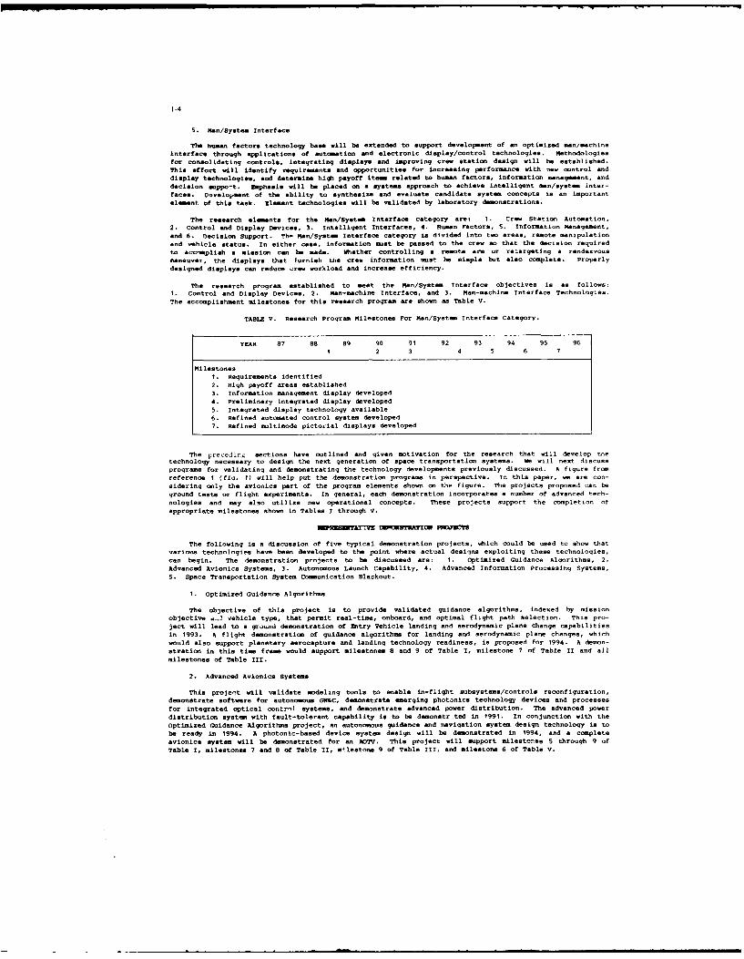
The human factors technology base will be extended to support develop.ent of an optimized man/machineinterface through applications of automation and electronic display/control technologies. Methodologiesfor consolidating controls, integrating displays and improving crew station design will he established.This effort will identify requirements and opportunities for increasing performance with new control anddisplay technologies, and determine high payoff item related to human factors, information management, anddecision support. Emphasis will be placed on a systems approach to achieve intelligent man/system inter-faces. Dveloiment of the ability to synthesize and evaluate candidate system concepts is an importantelement of this task. Element technologies will be validated by laboratory demonstrations.
The research elements for the an/System Interface category are: 1. Crew Station Automation,2. Control and Display Devices, 3. Intelligent Interfacees, 4. Human Factors, 5. Information Management,
and 6. Decision Support. Th, Han/System Interface category is divided into two areas, remote manipulationand vehicle status. In either case, information mst be passed to the crew so that the decision required
to accomplish a mission can be made. Whether controlling a remote arm or retargeting a rendezvousmaneuver, the displays that furnish the crew information mst be simple but also complete. Properlydesigned displays can reduce crew workload and increase efficiency.
The research program established to meet the Man/System Interface objectives is as follows;I. Control and Display Devices, 2. Man-machine Interface, and 3. Man-machine Interface Technologies.The accomplishment milestones for this research program are shown as Table V.
TABLE V. Research Program Milestones For Man/Syst=e Interface Category.
YEAR 87 88 89 90 91 92 93 94 95 961 2 3 4 5 6 7
Milestones1. Requirements identified2. High payoff areas established3. Information management display developed4. Preliminary integrated display developed5. Integrated display technology available6. Refined automated control system developed7. Refined multimode pictorial displays developed
The preceding sections have outlined and given motivation for the research that will develop tnetechnology necessary to design the next generation of space transportation systems. We will next discussprograms for validating and demonstrating the technology developments previously discussed. A figure fromreference I (fic. 1) will help put the demonstration programs in perspective. In this paper, we are con-sidering only the avionics part of the program elements shown on the figure. The projects proposed can beground tests or flight experiments. In general, each demonstration incorporates a number of advanced tech-nologies and may also utilize new operational concepts. These projects support the completion ofappropriate milestones shown in Tables I through V.
AT/Z DE8BESYATIOU PDJZCT
The following is a discussion of five typical demonstration projects, which could be used to show thatvarious technologies have been developed to the point where actual designs exploiting these technologies,can begin. The demonstration projects to be discussed are: 1. Optimized Guidance Algorithms, 2.Advanced Avionics Systems, 3. Autonomous Launch Capability, 4. Idvanced Information Processing Systems,5. Space Transportation System Communication Blackout.
I. Optimized Guidance Algorithms
The objective of this project is to provide validated guidance algorithms, indexed by missionobjective 4..1 vehicle type, that permit real-time, onboard, and optimal flight path selection. This pro-ject will lead to a ground demonstration of Entry Vehicle landing and aerodynamic plane change capabilitiesin 1993. A flight demonstration of guidance algorithms for landing and aerodynamic plane changes, whichwould also support planetary aerocapture and landing technology readiness, is proposed for 1994. A demon-stration in this time frame would support milestones 8 and 9 of Table I, milestone 7 of Table II and allmilestones of Table III.
2. Advanced Avionics Systems
This project will validate modeling tools to enable in-flight subsystems/controls reconfiguration,demonstrate software for autonomous GN&C, demonstrate emerging photanics technology devices and processesfor integrated optical oontrnl systems, and demonstrate advanced power distribution. The advanced powerdistribution system with fault-tolerant capability is to be demonstr ted in 1991. In conjunction with theOptimized Guidance Algorithms project, an autonomous guidance and navigation system design technology is tobe ready in 1994. A photonic-based device system design will be demonstrated in 1994, and a completeavionics system will be demonstrated for an AOTV. This project will support milestones 5 through 9 ofTable I, milestones 7 and 8 of Table I, meestone 9 of Table III, and milestone 6 of Table V.

3. Autonomous Iaunch Capability
This project will incorporate many of the results from the previous studies. Its objective is todevelop the capability for prelaunch commit-to-flight determination based on onboard simulation, check-out,
and loads prediction; and develop capability for onboard real-time retargeting, load relief, and abortdecisions. The requirements will be defined for onboard simulation, check-out, loads prediction, environ-ment measurements, and GN&C algorithm in 1991. This requirements definition relates directly to mile-
stones 1 and 2 of Table I and milestones 1 through 4 of Table II. Instruments for onboard environmentmeasurements will be available by 1994. The technology required for these instruments were shown as mile-
stone 5 of Table I. A simulation for the prelaunch and launch phases of the demonstration will be avail-
able in 1994. This development is eupported by milestone 9 of Table I and milestone 9 of Table III. Aground-based demonstration of an autonomous launch will be scheduled for 1995. The flight instrumentationand software will be developed by 1998 for a flight test on the Shuttle with parallel ground-based monitor-
ing set for 2000. This flight test could be a partial fulfillment of milestone 8 of Table II and milestone10 of Table III. The extent, to which this demonstration may verify the Man/System Interface research, has
not been defined.
4. Advanced Information Processing Systems
The objective of this demonstration project is to provide validated technology for real-time faulttolerant and distributed control systems based on A sound theoretical foundation, mature reliability andperformance toole and operating hardware based on fault-tolerant building blocks. Validation concepts for
operating system hardware and software will be established in 1989. Also, a control architecture simula-tion for an OTV and the Aero-asist Flight Experiment will be developed by 1989. Design guilelines for
hardware, software and validated performance and reliability tools will be established in 1991. Integratedreal-time fault-tolerant distributed control technology and Advanced Transportation System control archi-
tecture technology will be ready by 1992. The Information Processing demonstration will impact the three
preceding demonstration experiments.
5. Colunication Blackout
The Communication Blackout demonstration has no direct link to the other research programs or demon-stration projects, but its success will impact all missions. The objective of the demonstration is todevelop antenna design and placement methodologies and techniques to minimize or alleviate coemunicationsblackout during high-speed, high-altitude atmospheric flight. Since the blackout is a function of the ion-ization layer structure about the vehicle, the development of computational fluid dynamics (CFD) codes todescribe the ionization structure is required. Non-equilibrium CFD codes will be developed by 1989. CFDcodes will be etended to estimate leeside free electron number, density, and ionization layer structure in1990. Also, by 1990, techniques for alleviating blackout will be developed, including an experimentalapproach and instrumentation for their validation. CFD code validation for AOTV-type vehicles using Aero-assist Flight Experiment results will be available by 1993. The demonstration project relates directly to
the Oommunications research program and supports all three milestones.
The successful completion of the demonstration projects should coincide with the matuting of theresearch program to the point that the technology developed, at that time, can be considered ready t, be
incorporated into vehicle designs. Based on the technology available, decisions can be made as to which of
the final designs are most practical (fig. 1).
CONCLUDING -
In this paper, a program to meet the avionics technology needs for the design of future spacetransportation systems has been outlined. A more general discussion of the proposed research program andits potential problem areas for both NASA and DOD is given in reference 1. This discussion gives greaterdetail for specific research programs. The program is designed to meet as many technology goals as pos-
sible by 1996 so that decisions can be made as to which vehicles are feasible and which should be con-structed. The research program has bean established based on mission profiles that are common to many
vehicles. The time lines established for this research program are based on a full funding assumption andcould slip or have to be limited if this assumption is not met. As of this time, priorities have not been
set on the various programs listed.
The demonstration projects listed are only a sampling of the verification tests required to determinethat the technology is ready to be used in a vehicle design process. An examination of the research pro-gram milestones shows that other demonstrations will be required to validate the results of all the
research programs.
As pointed out, this paper describes a program that is just beginning. This is the first year inwhich significant funding of program is expected. The ingenuity of many people will be tested to make the
best use of these funds and *o ar-mnlish the program mkee.o.-e. W look forward to an interesting 10years.
1. Walberg, Gerald D.1 Gasperich, Lt. 001. Frank J. Jr.; and Scheyhing, Ernest R.: *National SpaceTransportation and Support Study/Technology Requirements and Plans,' AIAA 86-1213-CP, June 1986.

1-6
Program Demerits Projects FlgtoSystemrs
Structures/ ~ raio cssep
(.Berggren. U
AuthorsmReplyStuiesarecurenly nde wy t adres tesequetios.Resltson herecnfiuraio isue teBypctepinth
198 tiefaeado0lgtpt eeto nte18 iefae
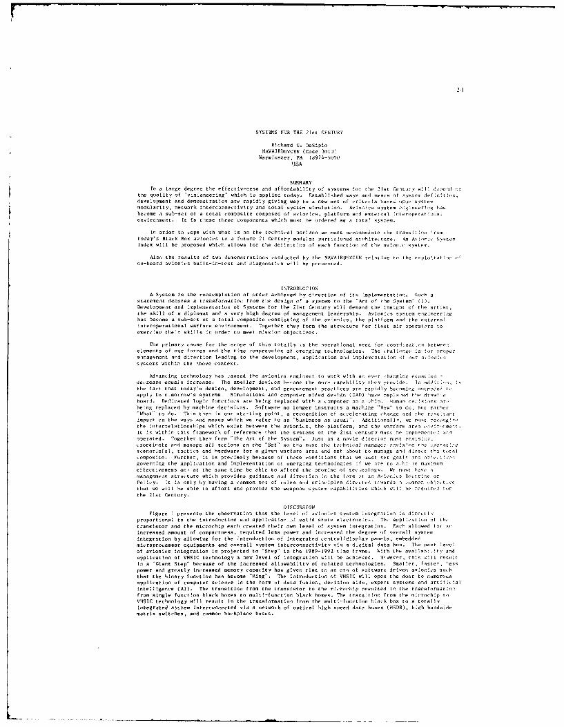
21I
SYSTEMS FOR THE 21st CENTURY
Richard G. DeSiploNAVAIRDEVCEN (Code 3013'
Warminster, PA 16974-5000
USA
SUL1MARY
To a large degree the effectiveness and affordabilty of systems for the 21st Century will dopend on
the quality of "visioneering" which is applied today. Established ways and means of system deflntion,
development and demonstration are rapidly giving way to a new set of criteria based upon systemmodularity, network interconnectivfty and total system simulation. Avionics system engineering has
become a sub-set of a total composite composed of avionics, platform and external Interoperatfonai
environment. It is these three components which must be ordered as a total system.
In order to cope with what is on the technical horfzon we must accomodate the transition from
today's Black Boo avIonIcs to a future 21 Cetu'ry modular partitioned architectore. An Anionic bysten
Index will be proposed which allows for the definition of each function of the avlonlc system.
Also the results of two demonstrations conducted by the NAVAIRDEVCEN relative to the exploitatio. ofon-board avionics built-in-test and diagnostics will be presented.
INTRODUCTIONA System is the contemplation of order achieved by dIrection of its Implementation. Such a
statement denotes a transformation from tie design of a system to the "Art of the System" (I).Development and implementation of Systems for the 21st Century will demand the insight of the artist,
the skill of a diplomat ane a very high degree of management leadership. Avionics system engineeringhas become a sub-set ot a total composite consisting of the avionics, the platform and the external
interoperational warfare environment. Together they form the structure for fleet air operators to
exercise thefr skills in order to meet mission objectives.
The primary cause for the scope of this totally is the operational need for coordinat ion between
elements of our forces and the time compression of emerging technologies. The challenge is for proper
mnagement and direction leading to the development, application and Implemeotation of our av!o,-
systems within the bove context.
Advancing technology has caused the avionics engineer to work with an ever :hanging equat ion -decrease equals Increase. The smaller devices become the more capability they provide. In add! tiesthe fact that today's design, development, and procurement practices are rapidly becoming outoded to
apply to tmorrow's systems. Simulations and computer aided design (CAD) have replaced the drawing
board. Dedicated logic functtos are being replaced with a computer on a chip. Human decIsions arc
befng replaced by machine decisiuns. Software no longer instructs a machine "How" to do, bt rather"What" to do. This then is our starting point, a recognition of accelerating change and the rosltant
impact on the ways and means which we refer to as "business as usual". AdditLonallv, we must recog,the interrelationships which exist between the avionics, the platform, and the warfare area einiromeet
It is within this framework of reference that the systems of the 21st century must he implament, a-Ioperated. Together then form "The Art of the System". lst as a movie director must enoisior,
coordinate and manage all actions on the "Set" so too most the technical manager enof lon the one at:sscenario(s), tactics and hardware for a given warfare area and set about to manage and dire,t the totalcomposite. Further, it Is precisely because of these conditions that we must set goal nod obicct esgoverning the application and Implementation of emerging technologfes if we are to oh ie maximom
effectiveness an, at the same time be able to afford the promise of tecnoloify. We m.st have amanagement structure which provides guidance and direction In the form ot an Avfocics Doctrine or
Policy. It is only by having a common set of rules and Principles dlrccted towards a common obeLtinethat we will be able to affort and provide the weapons system capabilities which will be required tot
the 21st Century.
DISCUSSIONFigure I presents the observation that the level of avionics system integration is dfrectly
proportional to the introduction and application if solid state electronoics. The applicat ion of thetransistor and the microchip each created their own level of system integration. Fach allowed for aincreased amount of compactness, required less power and increased the degree of overall system
integration by allowing for the introduction of integrated control/dlsplay panels, embeddedmicroprocessor equipments and overall system interconnecttviti via a digital data bus. The next levelof avionics Integration is projected to "Step" in the 1989-1992 time frame. With the availabifty and
application of VHSIC technology a new level of Integration will he achieved. lcwevor, this will result
In a "Giant Step" because of the increased allowabiltty of related technologies. Smaller, faster, lesspower and greatly increased memory capacity has given rise to an era of software driven avionics such
that the binary function has become "King". The introduction of VHSIC will open the door to numerous
application of computer science in the form of data fusior., decision aids, expert systems and artificialinteliigence (Al). The transition from the transistor to the microchfp resilted in the transformation
from single function black boxes to mult'-functton black boxes. The transItIon from the microchip toVHSIC technology will result in the transformation from the multl-functlon black box to a totally
Integrated aytem Interconnected via a network of optical high speed data huses (HSDB), high bandwidematrix switches, and common backplane buses.
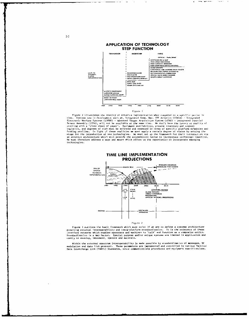
2-2
APPLICATION OF TECHNOLOGYSTEP FUNCTION
TRANSISTOR MICROCHIP I VHSIC
E C TIO D 1 A L I S . . . .1. 00 1 A F SIO
I DECIS~~ION AIDSETT! STUSA
AVIONICSIGI SATLAEPE DATA BOESSEN1.1LSO
DISCR-T1 COOPOTBEO
Figr Ix
Fngure ill S t a oS sn .a . F n Ne
'-o Wafr St SS I n
..... 2-2
][TRISTO -D ROHI I SIT.2I 1
- Sy oi s - INA - I eM0time e~snow n deelopent sch a, Inegraed Cmm. av.IF CAA. a " gr:
Sensor Assembly (lISA), will not be available at the same timse. We don't have the luxury or reality ofstarting with a "clean Hheet of paper". Equipment availability, present Inventory and supoortlogistics, and degrees of risk must be balanced and assessed in terms of specific platform schedules andfunding profiles. to light uf these realities we must apply a certain degree of visionT by sctting thestage for the introduction of new technologies. We must set up the framework for their lotroductlon viaan avinics architecture which will provide the allowability factor to incorporate technology Insertion.We must therefore address a ways snd means which offers us the opportuoity to Incorporate emergingtechnologies.
TIME LINE IMPLEMENTATIONPROJECTIONS
I RESOURCE SHADING
BLACD ROn MODULCAR PARTITI OBUEDA OR0 -1
AVIONI 'CSIMPLEMENTATION SINGLE L/TUUPLA
FUNCTION ?TFNIO
PART' I ICNIA CONMONESHARE
E NEWS GLASS COCKPIT
ARRAY ANTENNASwoPROCESSO TS
OPTICAL STNSORNJPROCESNORN
ENGINE -__ SOFTWARE
JUNTIO NOT IN.EE
Figure 2
Figure 3 outliaes the basic framework which must exist If we are to define a systems architecture
governing externoal interoperabilty and intra-platform standardization. It is the existence of these
interface networks which enables operators and machines to "talk and fnction as a composite entity.
Standardization is a key factor. Special purpose and/or ilnique system are limited in application sod
costly to develop, impiement, operate sad maintain.
Within the external spectrum interoperability is made possible by Ntandardizstion of messages, tF
modulation and data link protocol. These parameters are implemented and Controlled by Various Tactca
Dst Interrhange Link (TADIL) Standards, Voice commeunicatons procedures and equipment specifications.

2-3
The standardization of an intra-platform network was begun with the introduction and implementationof the DOD MIL-STD-1553B and its NATO equivalent STANAG-3838 bus network. MiL-STD-1553B provided asignificant step forward relative to avionics system integration. For tomorrow's systems we mustcontinue with the development and implementation of internal aircraft network standards governing highspeed data buses, wide bandwidth switch matrixes, and common backplane connectivity. These networkswill serve as the framework for a future common Navy, military, avionics architecture.
TIEROPERABIL;Ty
VIA
NETWORK CONNECTIVITY
EXTERNAL INTERNAL
SPECTRUM SPECTRUM
ELF MIL-STD-153BVF HIGH SPEED DATA BUSVtF VIDEO
LF BACKPLANE BUS
RADIO MF STANDARDIZATION SWITCH MATRIX
XF STRUCTURE -VHF VIORMATVHF PROTOCOL -
SHFMICROWAVE VHF P
INMIAVITH - - -INFRARED NJ1A-LIF
OPTICAL VISIBLE
LILIRAVIDLET
X-RPYS
GAPILA-RA'IS
Figure 3
Figure 4 illustrates avionics architectural trends based on both government and industryprojections. To be sure there are many other similar or varied versions both from within the governmentand from industry. However, they do reflect a common underlying thesis. That is, they represent amodular time shared partitioning of functions In order to group like functions into some type ofmanagable architectural structure. It is to be noted that the key ingredient which allows for theinterplay and construction of the avionics functions is the one of a common intra-platform network.This is the framework which supports the architecture.
FIio"tNCS CHIILNNEL1
INRA T
-MACHINE -
MN
Figure 4
Figure 4 presents the concept of an Avionics Channel to replace the self contained dedicatedchannels implemented by today's black box systems. The advantage of this type of architecture is thatIt allows us to define functional areas of operation which can then be described by standardelectrical/optical interface standards for networking throughout the aircraft. It is by so doing that wepartition areas into functional domains and subsequently set up boundaries which can be defined In termsof function and interface, packaging and software standards. The intrastructure I have chosen Is one ofa System Index composed of Elements (E), Cells (C), and Zones (Z), Figure 5. The basic unit of theavionics system is the Element. Elements are implemented within a structure of Cells which in turnoccupy a Zone. Such an arrangement is viewed as a means of defining, describing and locat.ng anyElement of a system simliar to having an avionics library of functions from which to choose andmanipulate in order to construct and satisfy the requirements of a particular aircraft avionics system.
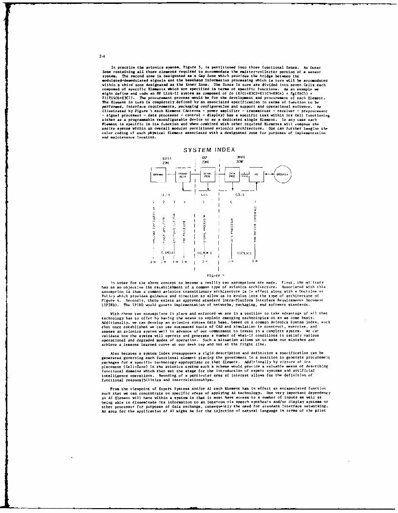
2-4
In practice the avionics system, Figure 5, is partitioned into three functional Zones. An OuterZone containing all those elements required to accommodate the emitter-collector portion of a sensorsystem. The second zone is designated as a Gap Zone which provides the bridge between themodulated-demodulated signals and the baseband information processing which is turn will be accomodatedwithin a third zone designated as the Inner Zone. The Zones in turn are divided into seven Cells eachcomposed of specific Elements which are specified in terms of specific functions. As an example wemight define and code an HF Link-Il system as composed of Zo (E7CI+E3C2+EIlC3+E9C4) + Zg(EbC5) +Zi(E14C6+E3C7). The procurement process would be for the development and procurement of each Element.The Element in turn is completely defined by an associated specification in terms of function to beperformed, interface requirements, packaging configuration and support and operational software. As
illustrated by Figure 5 each Element (Antenna - power amplifier - transmitter - receiver - preprocessor- signal processor - data processor - control - display) has a specific task within its Cell functioningeither as a programmable reconfigurable device or as a dedicated single Element. In any case each
Element is specific in its function and when combined with other required Elements will compose theentire system within an overall modular partitioned avionics architecture. One can further imagine thecolor coding of each physical Element associated with a designated zone for purposes of implementationand maintenance location.
SYSTEM INDEX
OUIER lAP INNER
ZONE I ZONE I ZONE
E[I S CELL CEL.S
1 2 3 s
i 7
E1EIMENIS ELEMENIS ELEPENIS
I IL. 1N IN IN I-N l- I-N
Figure
in order for the above concept to become a reality two assumptions are made. First, the militaryhas as an objective the establishment of a common type of avionics architecture. Associated with this
assumption is that a comson avionics transitionary architecture is in effect along with a Doctrine orPolicy which provides guidance and direction to allow us to evolve into the type of architecture of
Figure 4. Secondly, there exists an approved standard Intra-Platform Interface Requirements Document(IPIRD). The IPIRD would govern implementation of networks, packaging, and software standards.
With these two assumptions in place and enforced we are in a position to take advantage of all thattechnology has to offer by having the means to exploit emerging technologies on an as come basis.
Additionally, we can develop an avionics system data base, based on a common Avionics System Index, suchthat once established we can use automated tools of CAD and simulation to construct, exercise, and
assess an avionics system well in advance of our commitment to invest in a complete system. We canvalidate how the system will operate and generate a number of what-if conditions to satisfy various
operational and degraded modes of operation. Such a situation allows us to make our mistakes andachieve a lessons learned curve at our desk top and not at the flight line.
Also because s system index presupposes s rigid description and definition a specification can begenerated governing each functional element placing the government in a position to generate procurementpackages for a specific technology appropriate to that Element. Additionally by virture of itsplacement (Cell-Zone) in the avionics system such a scheme would provide a valuable means of describingfunctional domains which then set the stage for the introduction of expert systems and artificial
intelligence operations. Bounding of a particular area of interest allows for the definition offunctional responsibilities and interrelationships.
From the viewpoint of Expert Systems and/or Al each Element has in effect an encapsulated function
such that we can concentrate on specific areas of applying Al technology. One very important dependencyan Al Element will have within a system is that it must have access to a number of inputs as well asbeing able to disseminate its information to an intercom via speech synthesis and/or display systems orother processor for purposes of data exchange, consequently the need for standard interface networking.
An area for the application of Al might be for the injection of natural language in terms of the pilot
2-5
questioning the status and performance of his avionics and aircraft systems. In this case anaircraft/avionics At status Element would be defined in terms of what type of "input knowledge" would beacquired (from various on-board aircraft sensors and avionics equipment/system built-in-test), and whattype of output information is required. By virtue of having a set of interface standards the designerof the At Element would be in a position to access and formulate "source" data in terms of whatinformation is wanted and when it is needed. Likewise once the AI processing algorithms are executedthe information can be easily disseminated to a designated "sink". Another area of application might befor the identification and designation of an external platform detected by the aircraft's sensor suite.Additionally once identified the At system could provide the complete weapons configuration andperformance characteristics of the potential enemy platform to the pilot/crew. An Al Element programmedas an expert interpreter would be designed and implemented as a specific Element residing within thetotal system as for example ZiC6E23.
Earlier we mentioned the need for a transitional architecture which would allow us to evolve intothe projected architecture of Figure 4. A transitional architecture would be implemented within upgradeand near-term (3-7 years) platforms. The transitional architecture will allow for the ecceptance ofemerging technologies by setting the stage for their insertion as they mature and become available.There are a number of "not needed right now" provisions, although at least one could be taken advantageof in today's contemporary data bus implemented aircraft. The MIL-STD-1553B data bus controller isconfigured to operate in two additional modes (inherent in 1553B protocol), the dynamic bus control andbroadcast modes. Additionally, two data bus ports are incorporated. The first is for external accessto the avionics system under conditions of "weight on wheels" for purposes of on-the-deck and remotestation status monltoring/maintenance actions and avionice system initialization. This feature could beutilized for our contemporary data-bus configured aircraft. The second port is for the implementationof an internal 1553B to high-speed interface gateway for use at a future date. The next step is toseriously consider the MIL-STD-1773, the fiber-optic version of 15538. We should take avantage of thebenefits of a fiber-optic transmission media within planned upgrade and near-term future aircraft of thenext 3-7 years. The transition to the 1773 could be accomplished by initially performing theelectrical-to-optical conversion at the fiber-optic cable connection, not modifying each black-boxelectrical I/O. Such an approach would be cost prohibitive. Future equipments/elements wouldincorporate the optical 1773 as a basic I/O channel. Likewise, we should consider the installation of afiber-optic high-speed transmission media to accommodate a future outer and inner zone high-speed databus configuration. Once the stage is set for the insertion of future technology, we can begin to scceptfunctional elements as they become available. This process is not unlike that employed fortransformation from a totally hardwired system to a hybrid 1553A/B data bus system. Older equipmentsretained their hard-wired I/O and interfaced with 1553A/B compatible equipments via a gateway converterbox, designated as a Communication Control Set, a Switching Logic Unit or some such nomenclature. Ineither case, the gateway converter coupler is necessary. As time goes on and a standardoptical/electrical interface I/O is adapted for a 1553 and/or future outer and inner zone high-speeddata-bus system, the gateway converter will no longer be required. A second step taken for thetransition to a contemporary 1553 system was the incorporation of a growth factor within the buscontroller. This allows for the addition of a number of black boxes to be coupled directly to the busas manufacturers began to incorporate the 1553 i/o directly into a particular equipment. Today, this Isthe rule rather than the exception.
Of equal importance to the incorporation of emerging technologies is that we exploit the fullpotential of each technology. In order to illustrate what can be achieved within the bounds of today'stechnology and standard networks we shall cite two demonstrations performed by the Naval Air DevelopmentCenter (NAVAIRDEVCEN). The first was a result of a concept proposed by the NAVAIRDEVCEN in 1972 todemonstrate the merits of implementing a common aircraft multiplex data bus system within a network ofremote site service and support facilities Figure 6. In 1978 the NAVAIRDEVCEN awarded a contract forthe development of a Multiplex Data Bus Test Set similiar to the concept equipment of Figure 6. Thetest set was validated in the NAVAIRDEVCEN LAMPS MARK III and Basic Avionics System Integration Concept(BASIC) laboratories. Subsequenlty the Air Force contracted for a similar but more rompr-h-nslveequipment in 1981 from LORAL Instrumentation, San Diego, CA. With the cooperation of LORAL and theNaval Air Test Center (NAVAIRTESTCEN), PatuxentRiver, MD a demonstration of the remote site servicesupport system concept was conducted in June 1983 (2). An F-18A test aircraft stationed at theNAVAIRTESTCEN was connected to the LORAL Test Set SBA-100 equipment via the avionics 1553 internal databus. A second LORAL SBA-100 was located at the NAVAIRDEVCEN, Warminster, PA. The two terminalsinteracted via RS232 as a remote site monitor and command message injection source. An around the worldservice support system is possible with such a system.
The second demonstration combined the use of emerging speech recognition and synthesis technologywith the exploitation of the existing avionics system architecture of the Coast Guard HH-65A helicopter.An avionics System "Ask and Tell" (3) status information exchange was conducted via a device designatedas an Aircraft Speech Interviewer (ASI). The ASI was developed under a contract to NAVAIRDEVCEN byCollins Avionics Division, Cedar Rapid, IA. The ASI was connected to the HH-65A 1553 data bus forinjection of voice commands within the context of the data bus protocol and command status messagefield. Voice commands were converted to data bus words instructing selected equipments connected to thebus to execute their Built-In-Test (BIT) routines. Returning status words were received and converted tospeech via a speech synthesis module. An interesting aspect of the "Ask and Tell" demonstration was theuse of a (low skill) 13 year old operator to dramaticaly illustrate the advantages and utility which canbe obtained within the context of our existing systems. This demonstrat-on was conducted atAerospatiale Helicopter Corporation, Grand Prairee, TX in September 1982.

2-6
REMOTE SITE SERVICESUPPORT SYSTEM CONCEPTf .
FLIGHT LINE I DEPOT
a P O T S
CONCL OCSAION
Emerging technologies together with the need for coordinated operations of our Naval and alliedforces have created the need for standardized communications networks both within the aircraft avionics
system and for purposes of warfare area interoperabillty..
Avionics system engineering has become a sob-set of a more broader warfare area engineering concept.Together the avionics, the platform and the external warfare area environment make up a total compositesorb that we must envlsion the future and apply "the art of a system" in order to brIng each component
into proper perspective and utility.
In order to facilitate the incorporation of emerging technologIes on an evolutionary basis and at anaffordable price we most have an approved and established policy in the form of an Intra-Platform
Interface Requirement Document which articulates aircraft network conectvit y, packaging, software and
support standards.
Lastly w most set the stage for maturing technologIes by Incorporating a transitlonary avionicsarchitectore whIch will altow for the implementation of emerging technologies as well as theexploitation of the fall potential of each technology in terms of expanding its utility.
References:
(I) Richard C. DeSil, NAVAIRDEVCEN, Warminster, PA
The Art of Avionics Systemefense Science I Electronics, August 1986
(2) Philip J. KlassNavy Test Nw Maintenance Procedure
Aviation Week 6 Space Technology, August 1963
(3) Richard .teSiplo, NAVAIRDEVCEN Eugene fry, Collins Avionics DivisionAvionics system Plays Ask and el wth its OperatorSpeech echnology, January/tebruary 1983
afodal prc we mus havemm an appove and esabise poic in themmm form of anIt
2-7
DISCUSSION
P.Flahault, FR(1) DoesaMIL-STD-1553-2 exist?
(2) Notice 2 discusses communications means and recommends that the broadcast mode not be used. Please addressthis issue.
Author's Reply(1) No, there are no plans to issue a MIL-STD- 1553-2. The ersion issued in 1978 is the DOD (tri-service) verson of
record.
(2) Notice 2 does not "delete" the broadcast mode from the basic MIL-STD- 1553B. Currently, there is muchdiscussion within the tri-service/NATO/industry avionics community [e.g.. Society of Automotive Engineers(SAE-AE9 Subcommittee)] on the merits of the broadcast mode. To date. tc my knowledge. this mode is stillinherent in the existing MIL-STD- 1553B.
E..Manzie, CATo clarify a point regarding MIL-STD-1553B, a Notice 2 to this standard exists. This notice addresses the broadcastmode and suggests it not be used.
Author's ReplyIt is true that Notice 2 suggests the nonuse of the broadcast mode. However. the entire DOD (i.e., the Army and NavN)has not approved Notice 2; only the Air Force has suggested the nonuse of the broadcast mode.

3-I
ARCHITECTURE AND ROLE OF THE *SENSOR SUBSYSTEM" IN FUTUREAIRCRAFT WEAPON SYSTEMS
by
J.A.Salmon, Ci.C.Ravat and FJ.LorkThomson CSFiAVS168 Bid. Gabriel Pei
92240 MalakoffFrance
SUMMARY
To-day, in military aircraft systems, each external sensor (radar, ESM, electro-optical equipment, radiocommunications) is almost independent and reports directlyto the central computer.
Taking into account first the evolution of operational context in which the aircraftis involved (increasingly varied and quantitative nature of the threat) and secondthe dramatic progress in processing capabilities (growth of several orders of magni-tude in the same volume between 1980 and 1995) it appears necessary and possible tospread the "Intelligence" aspects of the weapon system in order to optimize theglobal cost-efficiency.
This distribution enables each specialist to concentrate his efforts, in order totake advantage of the ever increasing scope of knowledge associated with eachdiscipline.
When considering an individual sensor, an expert system allows pseudo real timeprocessing, taking into account simultaneously the characteristics of the environ-ment and specific mission requirements. This is the high technology province ofexperts in physics and mathematics.
When considering the whole Let 3f L;Lu.x cxprt syvtem aliows intelligent datarusion. This is once again the province of sensor technicians involving in additionoperational aspects.
In the case of the whole aircraft weapon system, expert systems allow optimal controlof the mission, taking into account the predetermined data and their updating in realtime (tactical situation assessment, aircraft status, weapnn status, mission planningman-machine interface, ...). This is within the scope of operational and missionmanagers, considering human capacities in environments of particular stress.
In this paper, the sensors subsystem is dealt with, its architecture is defined andits function in the aircraft weapon system is described.
KEYWORDS
Expert system, sensor fusion, external sensors, aircraft weapon system.
. INTRODUCTION
To-day, in military aircraft systems, each external sensor (radar, ESM, electro-optical equipment, radiocommunications) is almost independent and reports directlyto the central computer.
Taking into account first the evolution of the operational context in which theaircraft is involved (increasingly varied and quantitative nature of the threat)and second the dramatic progress in processing capabilities (growth of severalorders of magnitude in the same volume between 1980 and 1995) it appears necessaryand possible to spread the "Intelligence" aspects of the weapon system in order tooptimize the global cost-efficiency.
When considering and individual sensor, an expert system allows pseudo real timeprocessing, taking into account simultaneously the characteristics of the environ-ment and specific mission requirements.
When considering the whole set of sensors, an expert system allows intelligentdata fusion.
In the case of the whole aircraft weapon system, expert systems allows optimalcontrol of the mission, taking into account the predetermined data and theirupdating in real time (tactical situation assessment, aircraft status, weaponstatus, mission planning, man-machine interface. .. .).
In this n-per, the sensors subsystem is dealt with, its architecture is definedand its function in the aircraft weapon system is described.
3-2
2. PRED:cTABE GLOBAL ARCH:TECTURE
Many papers have aready presented various architecture wniicn COuld be propused
for future military aircraft.
Among the most significant, we nave retained the architecture proposed in treDARPA project, the P:LOT'S ASSOC:ATE :!'
'ne general diagram of the P LOT'S ASSOCIATE Is shown on figure 1.
In tris diagram, the olace-box ranieq sensor fusion is a ey elen.ent of theoperational situation assessment in real time. As a matter of fact, it is therelevance of the information issued from tri s 'black-oX' wht Cn provides thepilot with the necessary decision factors to ensure the success oi his missionand Mis own survivability. Ronald M. Yannone 2' discusses, is Mis article,the role of this 'sensc- subsystem' and its close relationship with tnL tiuticalSituation wsessment subsystem.
'nis type ot architecture seems to us to fit in very well witi- .e capabilitiessf the different "actors" involved in the design an development of an overallaircraft weapon system.
Tne various external sensors considered in future military aircraft (radar, ESM,electro-optical equipment, radiocommunications, ... ) have each their Ownspecific cnararteristics and the men in charge of these equipments must be verymignly specialised in tneir respective fields.
At the other end, the man in charge of the whole aircraft weapon system, mustbe a specialist in operatioral and mission manager problems.
To prevent overload and therefore inefficiency, the pilot can only take intoaccount synthetic information, cleared of their fluctuations, their uncertaini-ties and sometimes their contradictions.
Due to the great variety of information issued by the sensors, and their possiblecomplementarity, it appears necessary to achieve a "smart" fusion, in order toimprove them and to solve the conflicts which might occur.
The responsibility for this smart' fusion can only be assumed in an efficientway by the men who have .c -, I tc i' cal know edge- of the diffnrentsensors. They must also have a fair knowledge of operational problems in theavionics field.
It's only with this combined proficiency that they will be able to solve, forinstance, the identification conflict in which an "error" of a sensor can bedue to a kind of counter-measure from the enemy,
3. DESCRIPTION OF THE SENSOR SUBSYSTEM
At the date we are considering, i.e. the years 2000 , the external sensorsequipping a sophisticated military aircraft will be the following ones
- a radar for detection in the frontal zone (at least a cone of 120 ) with an1FF interrogator,
a passive detector of radio and radar signals (ESM) covering any dlrectio',(4 T steradians)
- a passive and active (Lidar) electro-optical system, covering any direction,
- a multifunction communication system such as the S:NTAC (French equiva'ntof JTIDS).
These "sensors" will include very sophisticated data processing, includingexpert systems, in order on one hand to optimize their own functioning in thereal environment, taking into account the initial constraints itype of Mn sslon,discretion, ... ) and on the other hand to perform a certain level of ide'ifl-cation on the detected targets (for instance, Doppler lines of aircraft e-g- nes"seen" by the radar, identification of a given terrain following radar by theE.S.M., significant loads of missiles under -n aircraft "seen" by the E.O.system, ..
3-3
A good example of this identification function is given by Thierry SCHANG in C3).
The sensors will provide two types of information
- numerical data, with a quality factor (O*,
- symbolic data, with a confidence factor (C)
Table 2 summarize the information provided by each sensor.
The essential characteristics which appear when examining those data are thefollowing ones :
- They are not simultaneous (different rate) nor are they all present (differencein detection range, for instance : ESM 200 km, Radar 100 km, E.O. 20 km in agiven situation, .. .).
- Their avalability depends on the type of sensor (ESM generally provides neither
radial velocity nor range), and on the jamming environment.
- They do not have the same accuracy.
- They are not all reliable (use of decoy by enemy).
Therefore the interest of a "smart" fusion is evident in order to improve the
accuracy and the reliability of the information (especially in presence ofcounter-measures).
The block diagram of the fusion system which could be realized is given infigure 3.
The numerical data (NUM) from each sensor will generally be provided to the systemonly after filtering or tracking in order to increase their quality.
The symbolic data (SYMB) delivered by their internal expert systems will berefreshed in quasi real time.
The overall data cnming from eat sensor enter a processor allowing theirtemporal and spatial alignment U .
The numerical data are then sent to a proximity estimator 0 in order to obtainan initial spatial correlation.
The so-defined "sets" are then sent to dn expert system which will take intoaccount symbolic data to effect an evaluation of coherence. The result could bea rejection of the proposed correlations and possibly new proposals.
The dialogue will converge on the generation of identified "tracks" G witha certain level of confidence (C). These tracks will be continuously maintainedG in order to :
-to confirm and improve,
- cancell or reject (too old or level of confidence too low),
- propose new tracks to the processor @ -
For each detected target, the "track" to be carried out will consist of thefollowing information (with their quality or confidence factor)
- Status vector X, Y, Z, 0 ,
- Range
- Radial velocity and time-to-go before direct threat (according to criteria)
- "Smart" identification (i.e. MIRAGE Ill E + weapons A, B, C, ..
- Threat data, for example :
detection probability by "his" radar,
probability of triggering "his" weapons (lock-on range, shooting range'.
These data are then sent to the tactical situation assessment Epert system.in order to enter the whole "Pilot's AssociaLe".

3-4
4. CONCLUSION
Highly decentralized and adaptable avionics systems are the only way to effecti-vely counter the ever increasing complexity of weapon system
decentralization facilitates the drawing up of module specifications andtherefore their test and validation,
flexibility, made possible by the Artificial Intelligence approach, allowsupdating of complex systems with minimum maintenance of embedded software.
A lot of work remains to be done to build a complete and efficient electronicpilot's assistant. In addition close cooperation between the different 'Expertsof the overall system is necessary
Experts on the different sensor aspects who have to provide pertinent Inform a-tion from the outside world.
Expert on sensor fusion, who must take into account sensors capabilities onone hand, and operational problems on the other hand.
Expert on overall aircraft aspects who must take into account all the miss onconstraints and the human pilot's capabilities.
The winner of the aggressive competition in the military avionic market wilicertainly be the country that will achieve both a friendly and interactivecooperation between the different companies involved in the design of thefuture systems.
5. REFERENCES
Cl) Kenneth J. STEIN - DARPA Stressing Development of Pilot's Associate SystemAW & ST April 22, 1985 p. 69-74.
C2) Ronald M. Yannone. The role of Expert System in the Advanced TacticalFighter of the 1990's 0547-3578/85 - 1985 IEEE.
(3) Thierry SCHANG - Threat Identification : an Artificial intelligenceApproach. AGARD AVP 52th Symposium.
lOCN
;.iE I- ORDFRSR
S T A P T S 1 E
EXTERNAL
RAA SENSOR I .. IKNOWN I S:IUATION //zC OM DAIA ASSESSME T
SNOSTACTCS F IH
STORE S "EPLNGSASONAT
. . - - - m NTROLSI m i

3-5
SENSORS NUMBERICAL DATA SYMBOLIC DATA
RADAR Riange, 0. , V" I y Radar cross section,
fluctuations, "profile".(A. Y Z* 0 Zengine lines.
IFF Range 9 ~Friend identification
for friend only)
ESM 9 9Radiating equipmtent type
(Range possible) (radar, radio, IFF, remote
control)
EDO. Range 95 'g v r Visual type identification
Optical signature
RADJOCOM4UNICATIONS X. Y, 0 full or partial identification
Fir. ? DATAO IS IJF BY SENSORS
7 enporal Spatial Cocerenc DaaIrc
and crrela- Eoou~io Fusi, matnntNONj 2. SYMB 2 spatial t mon tt p rt -CreatIon
--ainets y5te.) Maintena
D Q (D ti on (
FYMm 1 - SiNERA DIOSROM OF SENSOR SYSnEM

DISCUSSION
W.R.Fried, US()Will the French data systemn you mentioned be compatible wsith the US JTDS (e.g.. modulation and messane
format).
(2) Does the planned processing include automatic correlation of FSMI-derised (INTL.) target tracks and radar-derived target tracks'?
Author's Reply*I1) Yes, the Systeme d'Iden tification. dc Navigation. de Con trole de Trafie. d'Ant icoll ision. et de (ommninun icationt
(SINTAC) is fully compatible and interoperable with JTlI)S TDMA and has the same modulation and messacformats (i.e.. Link 16 TADI. J ).
(2) Yes, the slsem includes ESM tracks and radar tracks coirrelatioin.
E.(ambise. IT(1) What is the titne frame oif the implementation of I lie proiposed airchitectur.'
12) What are the hard-are requirements for processing pimer atd memory. to support the implementation.'
kuthor's Repli,AX mentiiined, "e are in a preliminary study phase. It implies tat
11)Ihc arebiteeture aill nut be implemetnted tin the necxt-generation aircraft. but (in the next 2000)) year gencratiiin
i Pr teesii piiscr and memory requirements are not yet defined. but a e estimate that theix ill be at a \cr\ hight
lc' ci ichies able i nh, "x ith the nmiost advanced VIISIC priiducts.
N d i 1 ti ipp~q[ Labilite poiur les aii de la periiidc 99 I 99I
Re.94nsc d'Autur11 J C1 cieUdeC. Sins bc~iRiiuup d'imnelligcrnee artifiCielle. Lin COiplagC radar- trrue
4-1
RAPID PROTOTYPING OF COWPLEX AVIONIC
SYSTM1 ARCHITZCTURKS
by
L. Berardi, N. Giorgi, V. Kellano, A. Valente., . Zucco
Aeritalia - Gruppo Sistemi Avionict ed Equipaggiamenti10072 Caselle (Torino) - Italy
This paper describes a design tool celled ECATE (Expert Consultant for Avionics System TransformationExploitation) developed by the Avionics System and Equipment Group of Aeritalia.
ECATE., rapidly prototyping different alternatives, helps the designer in establishing the informationflow architecture of the avionics system, that is the organization of the internal data handling. Thetool provides the user with an interface to assist him in describing the avionics from the point of viewof the data handling, and presents the results in a suitable format; it perform. consistency checks andadvices the user on possible architectural problems by means of the expert system techniques.
The paper contains also sm indications on the development environment of the tool and how it works ina consulting session. Some examples give an idea of the result that can be obtained.
Conclusion is that not only the tool is valuable for the information flow architecture design but alsoit show that the use of the knowledge engineering and the Artificial Intelligence techniques can be
effective to meet the problems arising when complex systems, not only avionics, are involved.
1. Introduction
A state-of-the-art avionics system shall be fully integrated with the other systems of the aircraftand shall take full advantage fros the features of the microelectronics, to provide the crew with the
highest mission success probability.
It means to find a real implementation for concept like distributed processing, sensor data fusion,
adaptive reconfiguration, expert pilot assistant, synthetic world displaying, now made possible by theadvancemement of the technology, specially the data processing and transmission.
But in such a system the performance increase is not simply due to the higher performances of themicrocircuits, on the contrary it derives primarly by an increase of the overall system complexity.In fact the "black box", a large unit with well defined interface and function allocation, is no morethe basis for the advanced system design but is being substituted by lower scale units, which changingcombinations provides the best adptation of the system to a changing environment.
It is difficult to establich a metric for the system complexity (ass for example ref. 1), however it
could be said that it is reflected by the amount of memory used for operational software storage, which
today is increasing to a rate at least an order of magnitude higher than the number of othermicrocircuits in an avionics system.
The increasing complexity, while can allow for dramatic improvements in terms of reduced pilot workload
and mission success probability, has also some important drawback.
It in evident that a complexity which is mainly software implies a design, development and testing
process and a management of it much more difficult than in a conventional system.Therefore some change to the way of thinking, the tools and the organization of the industry arenecessary.It is our opinion that the tools and techniques of the Artificial Intelligence can be effectively
applied not only in the system itself, but also to manage its complexity for the people who shall design
it.Scope of this paper is to illustrate an application of the rapid prototyping and expert systemtechniques to the design of the data flow organization within a complex avionics system,
2. The problem of the system architecture
The problem concerns the establishing of a correct data flow architecture, There are severalinterpretation of the term "architecture" in the avionic system design| it can be applied to thephysical structure, the topology, the software organization and so on, All these are aspect% of the amcharacteristic. the way in which the system components are organised and work together in order tocreate a system.
The architectural aspect chosen for the application described in this paper it the Information handlingwithin the avionics, i.e. the characteristics of the data flow and processing among the various systemcomponents, considered from the point of view of the information treatment,
Therefore the following definition of architecture will be uaued in the following peragraphse
4-2
Definition
System architecture is the organization of the information generation, distribution, processing and
utilization within the boundaries of the avionics system.
A pictorial view of the above definition is given in fig. 2-1.
The boundaries of the avionics system are intended to define the meaning of generation and utilization
of the information.
In other words if the boundary identifies the world outside the aircraft all information coming from it
corresponds to a generation of information for the avionics system; on the other side the data are
utilized when they are provided to the crew via a display or to the external world via an antenna.
Such an architecture is relatively easy to describe by means of few building blocks with a limited
number of peculiar characteristics; but a correct design of it has relevant influence on the overall
performance of the system, because it in usually established in the very early stages of the design and
it is difficut to be drastically changed during the development process.
Therefore it is clear that a serious error in the data flow architecture design impairs the achievementof the design objectives in terms of time, coat and performance.For that reason the architecture of the avionics system Is usually designed by highly experienced peoplewith support of the operations research tools (see ref. 2): nevertheless the work of these people is
difficult to quantify and to describe analitically, being often result of empirical knowledge andheuristics.
When the complexity grows the difficulty of the design task dramatically increases to a level that the
problem shall be partitioned into simpler problems, loosing part of the efficiency achieved by an
overall view.
An alternative that can help to still consider the problem from a global point of view keeping to a
reasonsable level the complexity managed by the designer, is to take advantage by the ArtificialIntelligence tools and techniques, prepared to describe and process complex situations with an heuristic
approach to the problem, i.e. rapid prototyping and expert systems.Rapid prototyping of a complex architecture helps to easily evaluate many alternatives while an expertsystem directs the search for the best design. A dedicated tool combining together the two techniquescan organize and manage the overall complexity of an architecture, requiring from the operator higher
level decisions only.
A tool like that sketched above, described in the following paragraphs and developed in our laboratory,
can be of effective use for the purpose and can demonstrate the advantage of the Artificial Intelligence
approach in the design of complex avionics systems.
3. Theoretical considerations
3.1. System description
The building blocks that shall be used for the construction of an object oriented data flow
architecture have characteristics that describe mainly their attitude with respect to the information
handling.
Four types of objects represent the building blocks.
1. Generators, the sensors of the system, the controls available to the crew and the interface toother systems.
2. Processors, signal processors, mainly associated with sensors and displays and data processors toelaborate information at an higher level.
3. Utilizers. displays for the crew, interfaces to other systems, emitters or weapon which stimulatethe external world.
A 4. Channels transmission means that link together all above objects when not directly interfaced
(aggregation of objects).
The table 3-1 lists an example of the typical characteristics associated to the objects.
It shall be pointed out that the characteristics may vary in relation with some peculiarities of thedescribed system.
The processors and the channels are possibly multiport devices, while equipment like a monostatic radar
may be described by a signal processor, a generator and an utilizer, that is an aggregation of objects.
Although not direct.y related to a technological solution, the objects that form a system architecturefrom the point of view of the information handling, shall nevertheless take into account thestats-of-the-art to avoid a design perfect but not feasible.

4-3
The building blocks shall be combined to form the information handling architecture corresponding to the
functional architecture to model.The architecture is characterized by some features, system descriptors which are listed in table 3-2.
Some descriptors need explanation on its definition, while the calculation methods are embedded into the
tools and will De described in para. 3.
Risk The development risk take into account how mujch each object is close to its technological limit
and how the the combination of objects influence the development.
Integration level It takes into account how good is the processing within the system. An higher
integration level is a merit.
Grwth -apa Represents the dual of the resource utilization of processors and channels.
It shall be noted that the descriptors can be computed also for a limited portion of the system, a
subsystem.
3.2. Rapid prototyping and expert system design
A rapi prototyping tool shall assist the user to convert from the functional/performance requirementsto a description that uses the object and connections illustrated in para. 3.1.
But an easy mean- to prototype many alternate design solutions is not sufficient because the knosledgebehind the architectural design is not totally convieed by analytical descriptors.
Therefore an expert system, a tool that allow to acquire, use, modify and make available a type of
knowledge which is complee, difficult to transfer, empiric, incomplete and heritage of a limited numberof people is the most appropriate supplement for the rapid prototyping tool.The expert system shall direct the search for a better architecture and provide advice on solution thatmay also not have different descriptor values but are known to guarantee an higher confidence ofsuccess.
The operational flow of an architectural design carried out by means of a ravid prototyping expert
system is skectohed in fig. 3-I.
4. The tool, ECATE
4.1. The environment
The tool, foreseen by para. 3.2 and called cCATE (Expert Consultant for Aviori u systemiransformation Exploitation), has been developed by means of KEE (Knowledge Engineering Environment, TMby Intellicorp), runing on a dedicated LISF workstation (EXFLOPER, TM by Texas Instruments).KEE is a deoolopment environment prepared for Expert System construction, it could be cot.sidered on
hybrid tool built on a range of state-of-the-Art Artificial Intel-iience techniques utilized to combinedifferent type of knowledge.
The knowledge is organized in frameunits associated to which are their peculiar characteristics, that
structure Is particularly suitable for the description of our problem because it implemets a
programming oriented to object linked by relations.Bv means of KEE it has teen implemented the foilowing:
I. The user interface
2. The collection of objects and relations that represent the system
-,. The algorithms and procedures for the descriptors computation
4. The expert knowledge
5. The knowledge handling structure.
The knowledge about the system is a(quired via a graphic interface and processed by the inferencemechanisms embedded in the KEE environment, according to the set of rules describing the expert
knowledge.
4.2. The structure
The strture of th tool carn be deoribed by means of the block dingrar hotwn in fig. 4-1.Hereafter follows a brief description of the main components of the structure.

4-4
User Interface The user interface assirts the user to represent his system in accordance with
convention of the formal description and is formed by:
a) graphic utilities using icons, representing the objects, with associated menus for
describing their characteristics.
b) indicators of the system descriptors of the terminated system.
c) menu sensitive "pushbuttons", i.e. means to activate a "method" (see below).
Methods The methods are procedures codified in LISF to execute algorithms, object interaction and
reasoning/control stategies (see table 4-I for example of methods).
Permanent data base It contains the description of the four types of .bects and their classes
It contains, moreover the expert system rule base, unmodifiable by the user.
Working area It is formed by the oits, which characteristics, called "slots", uescribe al
information about the system under development.
Inference struclur, This structure is formed by an inference engine operating on the rules.
The structure and the developnent environment allow for the maximum flexibility; to change the object
and system descriptors, inference rules or methods is extremely easy for the expert system designer.That featre is of capital importance and is used currently becase the tool shall evolve with the
knowledge available.
4.3. Consulting ECATE
The steps of u consulting session are summarized in fig. 4-2 and briefly exlalned hereafter.
Configuration Insertion The user, with assistance of the tool graphic facilities inserts theconfiguration of objects, aggregations and relations tie wants to prototype (see
for e.ople fig. 4-31.
Cispatibility .erificaton The 'ol verifies after each ifult its com[.tibility with the objectsrelated to it.
Overall Compatibility When the configuration is completo the activatir of the "terminated system"
push-bstton starts a verification of the overall urchitecture compatibility.
The res,lto f the step above can be:
I. equest for more inforation (for xmpl" se relation is ]vkng or some data are ot available)
2. Display of incompatibility warnings at system level (for example a multipoint channel of
insufficient capacity).
3. Satisfartory comptibility
Descriptors computation When the system compatibility is not violated a method is activated to compule
all system descriptors for which sufficient information is available.
Result display The results of the previous step can be displayed tsee fig. 4-Al in either the
numerical or hystogram format.
Optimization ECATE, by means of rules activated in forward chaining inference presents to
the user advices on possible architecture problems and suggested changesinvolving objects, aggregations, subsets or the overall system.
Assistance request The use can ask for assistance in optimizing the architecture, giving, if he
wish, instruction on the direction of the optimization.
Configuration change In case the user wants to follow one or more of the devices he can, by means ofa pushbutton, modify the configuration and restart the consulting.
Explanation The user can ask at any time information about the facts that have activated
the rules and generated the advices.
4-5
The tool accepts at any step not only numerical values in response to its queries but also generic
indications, like high, low etc.The consulting session car be terminated at any time and the results saved in the library.
4.4. Validation
The validation of a tool like ECATE shall answer to two kind of questions:
a) Is the tool conform to its specification?
b) Is the tool suitable for its purpose?
For the first check ECATE has been submitted for evaluation to the experts who concurred in its
development and to foreign experts, exercizing it by means of test cases.The second check is much more difficult to perform, because it is supposed to require a demonstration of
the development of different architectures, accepted or rejected by ECATE.
The validation is still in progress, but the results available, related to the first check, show a good
agreement with the predictions.Nevertheless it shall be pointed out that the high flexibility allowed by the development environment
and the tool structure stimulate a continuous refinement to adapt ECATE to new situations or to increase
its knowledge. It is in fact current practice to introduce new object descriptors, computing methods or
inference rules.Therefore also the validation is continuing to follow toe evaluation of ECATE and will not give final
results until the refinement work is completed.
5. Exmpe
5.1. A simple system
In this paragraph it is shown an example of a simple architecture to illustrate how the systemworks.Fig. 5-1 shows how the tool allows to represent the uketch of the system prepared by the designer, whilefig. 5-2 shows how the entire system architecture looks like and comprise some advices given by the
expert system.
5.2. A more complex system
A state-of-the-art system with complex architecture is shown in fig. 5-3, already in the formalized
description of ECATE.
5.3 A Future avionics system
At the moment we believe that the knowledge available on future avionics systemarchitecture, (see ref. 3), is not sufficient to effectively use ECATE.
Reason is mainly because, although enough data on sensors and processors can be found, tte knowledgelacks in the display and control area and specialy on standardized multipoint channels, switch,
backplane and high speed data bus. Insufficient is also the knowledge of the rules that regulates theoverall system functioning.Nevertheless data are gathered and trials are performed with reference to experimental data to allow the
specific ECATE knowledge to improve.
6. Conclusions
The scope of ECATE, an architectural design tool conceived and realized by Aeritalia, Avionic
Systems and Equipment Group, in twofold.First, it shall provide valuable means to design the information handling architecture of an avionics
system, that is a rapid prototyping expert system, which make available a knowledge difficult to acquire
and transfer and often heuristic.Second, it shall demonstrate the effectivenesS of the Artificial Intelligenc tools and techniques inmanaging complex design problems.
Although ECATE is still in its first stages of evolution, mainly about the inference rules and the user
interface, i% already shows a remarkably good achievement of the first objective above.
But the best result is obtained in demonstrating the second objective, because ECATE shows an excellent
flexibility in the continuous refinement of all its parts and a rapid response to the changes introduced
by the user.

4-6
The latter feature, made possible by the Knowledge Engineering Environment of development, is greatly
valuable in the architectural design, because it maxes available to the designer comparlson between
different solutions considered from different points of view and in overall.
It is our belief that toe tools and techniques of the Artificial Intelligence can be applied also ,other the other phases of the design, development, testing and ,, the management of avionics, and non
avionics, system when complex problem are implied.
The benefit given by the intrinsic flexibility of the powerful knowleddge management techniques, great!,
surpasses the initial cost of training people and acquiring tools, and results in a bettor ao, ,r
effective product.
Acknow edements
Aeritalia, Gruppo Sistemi Avionici ed Equipaggiamenti, wish to thank UNISYS, Italian branch, for thc
support they provided in the use of KEE tTM) and Esplorer (TMi.
Responsibility of what stated in this paper is nevertheless only of Aeritalia, Grupp, Sistemi Avocio
ed Equipaggiamenti.
References
b. System Complexity : Its Conception and Measurement in the Design of Engineering Systems - Ueoendra
Sahal. IEEE Transactions on Systems, Man, and Cybernetics, June 1976.
2. Critical Factors and Operational Rescarch in toatical fighter avionics systre Jeelopet -
L. Berordi 0onference Freceeding --. 343. 4d'th AVf Symposium Faper No. 29.
3. New technology impacts on future avionics architectures. - R.S. Mejzak Naval Air Developrn,
Center, <A, USA. Paper No. 10 of the i5lth AVf Symposium.

4-7
EXTERNAL WORLD
IF IF %U %
DIUPLNYU CUNTRULS *CThETINS
CREW OTHER 01 'C SYSTEM
Fig. 2-1
member memberCONNECTEDTCORICT C2ANNEL-'TYPI (local)COST CONNECTED-To-oBSECTGENERATOR-TYPE (local) COSTMINIMUM-LATENCY INORMATION-FLOW-CAPACrrY (local)PAES UJPUtr-INFoRVATIoDJ-FLOW (local)OUT PUTr- INFORM~ATION- FLOW (local) MAE- NIIMISER- oF-CONNEICrIONS (local)OVERHEAD PZNIMUMt-LATENCYREDUNDANCY NITB?RISK-FACTOR OUTPUT-INFORMATION-FLOW (local)SIGNAL-CRMrCrrY OVERHEADSIGNAL- TYPE REDUNDANCY
RISK- FACTORSIONAL-CRITCrTYSIGNAL-TYPE (local)
TYPEOF-CONNECTION (local)
member membercONrRD-TO.OBmCT CONEC TOJRCTCOCT C06rINPUT-INFORMATION.FLOW (local) INPUT-INFORMATION-FLOW (local)MINIMUM-LATENCY MAX-THROUGHPUT (local)M.T&F MEMORY (local)OVERtHEAD MinImUM- LATENCYREDUNDANCY PVITSRISK-FACTOR OUTPUT-INFORMATION-FLOW (local)SIGNAL-CRITICITY OVERHEADS=IGNA-TYPE n OR-TYPE (local)UTILIZERt-TYPE (local) RJEDUNDANCY
REQUIRED-THROUGHPUT (l10al)RISK-FACTORSIGNAL-CRITICrTYSIGNA.L-TYPETRAS~vIITRID-InDORATION-FLOW (=&Ia)
Tab. 3-1

4-8
- - -0aIW01
DESrERINETH
SESTEME
EEULUTIIEDESrRIPTORS
J DESXHN 1. -1SAT ] dCT'UESNTO ,A, IITSFIED ' "
lNLTERNIITESOLUTIONS
Fig. 3-1
Total data flow RedundancyTotal Throughput Mean time between failure
* Total memory capacity Integration levelGrowth Capability Total costLatency * Development Risk factor
* Overall efficency Max Risk factor
Tab. 3-2

mum -- , MWKNG INFERENCE
USER
Fig. 4-1
(DEF-UN TOT-COST (SYS)"Total cost computation function."(PUT.UALUE SYS 'TOTAL-COST
(SUMMA 'COST (FIND-CHILDREN 'COMPONENTS SYS)f)(8REAK-LIST (FIND-CHILDREN 'COMPONENTS 56S) 'COST 'TOTAL-COST SYS))
(DEFUN TOT-INLEREL (SYS)"System integration l ee determination.",(LET ((LIST-PROC (LIST-CONTROL (FIND-CHILD)REN 'PROCESSORS SYS) NIL)))(PUT UALUE 56S 'INTEGRATION-LEVEL
(,,(+ (SUMMA 'OUTPUT-IFORMATIO-FLOW
(LET ((RICLIST (FIND-CHILDREN 'GENERATORS SY5fl(PASSED-LIST NIL))
(LIST-GEN-CONTROL GIGLIST PASSED-LIST)))(SUMMA 'INPUT-IFORMATION-FLOW
(LET ((DIGLIST (FIND-CHILDREN 'UTILIZERS SYS))(PASSED-LIST NIL))(LIST-UTI-CONTROL BIGLIST PASSED-LIST))))
(FLOAT (+ (SUMMA 'OUTPUT-INFORMATION-FLOW LIST-PROC)(SUTMA 'INPUT-I FORMATIOMNFLOW LIST-PROC)(GETUALUE SYS 'TOTAL-DATA-FLOW))))))
Tab. 4-1

4-10
IEUNtS CONrIIIURNTIBN INPUT
OIOU Ih CDMPHTIUILZTY-CHEEK
COMPLETED CUNrisURRTIDN:CIPHTINILITY CHECK
PERrORMlENCE DETERMlINNTION* PROCEDURE
RESULT DIPLOV and/or . -- --
HISTORY DISPLNY- -
. . ... .. FURTHER CONFIGURNTION CHOICE
Fig. 4-2
Tun. of utIllmori 3stpiaj
factog. N-3
_oam aJ"IL

I Ul
Tt~p~SWEU ~a O UqaiL s ,qsfM
~~~gO aa ;wob s.70 ti. rL
ltd PM I I ml beU soo ul ItI' 0)s1 cvI ato,.5iu dft amd of IO dimmis sq
IN-rI:a, "M Besa doakatc. W~I ItS~
"t t CFNg. A 4
".tb.~ig %,c-1z.O

4-12
0.6n
__<.
h~vU" u8*b lpat. 4m p~f Fig. 5-2
'fr cc P-10, (UK w4Ih WS) .*.myIi f eaim Rsdwmy ofu" me lemcrl"T. mis
torw wo qsm kuss& a
Fig. 5-3

4-13
DISCUSSION
E.Cambise, ITIs the purpose of the ECATE system to determine the performance of an avionic system composed of building blockswith known performances. or is it to determine the performances of component building blocks to achieve the overalldesired system performance?
Author's ReplyECATE mainly addresses information processing requirements. Its intended application is th,. former, but it is al,opossible to introduce prospective performance data and assess the conscquent system performance.
P.R.Walwvn, UKCan the ECATE design tool be used to implement the decision function emphasis" approach to system architecturedesign (i.e.. the human interface requirement) outlined in Paper No. 16, A Change in System Design Emphasis: FromMachine to Man'?
Author's ReplyYes. provided a suitable model of human interface is a%,ailable. ECATE can be casilt incorporated in the s,stemdescription. The key point is to be able to sort out the rules to operate the human interface.
THE SPECIFICATION AND DESIGN OF A
FUTURE MARITIME RECONNAISSANCE AIRCRAFT
J SHEPARV
British Aerospace PLC
Civil Aircraft Division
Chester Road
Woodford
Stockport
Cheshire
UK
1. 1i;TRODUCTON
This paper addresses the problems of providing specifications for system
components of the highly integrated avionic systems of the future. The problems are
discussed in the context of the avionic systems of a Future Maritime Reconnaissance
Airc-aft (FMRA). The need and extent of the integration of the avionic systems are
discussed, as are the consequences for system definition and specification. Potentlal
techniques for addressing these problems are reviewed. These are brought together to
describe an approach which could provide the tools required. The implication of this
approach for vendors and integrators is then addressed.
2. THE GROWING NEED FOR AVIONIC SYSTEM INTEGRATION
It is not too much of a simplification to say that in Maritime Reconnaissance
aircraft there is not the same intimate relationship between airframe performance and
avionics capability as there is in a fast jet. Provided the airframe has the
capability to carry the payload required and to stay on station for the required
duration its capability as an overall weapons system is largely dependent upon the
capability of Its avi-nics and weapon systems. This is shown by the fact that the
Nimrod MR airframe has not been changed significantly over the years but its avionics
has been updated on a number of occasions. The functionality of such a system,
therefore, although not its implementation, can be considered in isolation from the
airframe in which it is installed. Furthermore it has a large number of tactical
sensors and communicatinns systems to meet the needs of different roles and the
performance required of it imposes high levels of integration with consequential
problems in the specification, design and testing cycle.
For the purposes of specification and design, the avionics and weapon systems are
broken down into major systems (Radar, Acoustics etc) each of which is then broken
down into major subsystems and so on into their physical embodiment at the LRU and
module levels.
The integration task commences at LRU level and progressively builds up to a
functional test of the overall weapon system. The size of this task is illustrated by
the fact that a system such as Nimrod has of the order of 400 avionics LRUs and 800
avionics LRU interfaces, some simple but some involving a large degree of interactions
between the subsystems. The architecture oi a typical system of this type is shown in
figure 1 and a typical specification, design and integration testing cycle is shown in
figure 2. This could take of the order of 5 - 10 years.

i-2
3. FUTURE DEVELOPMENTS
Consideration of the future threats indicates that greater performance will be
required of future avionics systems. Greater sensitivity in the sensor heads will
produce more data but it is unlikely to result in data better than that currently
available and it may well be worse. To maintain or increase mission success rates
with these quantities and qualities of data will require more sophisticated
processing, both within systems and across systems The ensuing need for a higher
level of integration will, at its most extreme, result in the kind of system
architecture shown in figure 3 where processing functions can be shared. The increase
in the number of sensor systems but reductions in the size of elements of such systems
e.g. by the use of VHSIC, could lead to elements currently specified as LRUs being
implemented as single card modules and sharing an enclosure with modules from other
systems. Even if not fully realised the flexibility offered by some of these
developments will have similar effects. For instance the moves towards general
purpose computing elements e.g. the Transputer, offer cheap, reconfigurable processing
which can be extended in a way which is functionally transparent to the software using
it, except in performance terms. The system requirement, and the software element of
it, .ay then be designed without knowledge of the hardware embodiment and hence
functional interaction between components must be explicitly specified.
These developments will pose in stark terms the type of problems faced today by
the specification and integration of 3vionic systems. These are:-
- the need to provide an unambiguous definition of the functionality of the
system and subsystem,
- a definition of the dynamic interaction of components within a system,
- a definition of the dynamic interactions of systems across their interfaces.
i. POTENTIAL TECHNIQUES TO ADDRESS THESE PROBLEMS
Almost all of the potential techniques considered have their origins In software,
where the abstract natire of the product leads to attempts to define the requirement
and deliverables as explicitly as possible.
4.! Functionality
Functionality is the main area which has been addressed. The techniques
duveloped have some combination of the following ideas
- diagrammatic -epresentation,
- unambiguous notation,
- functional decomposition,
- data modelling (for data bases),
- process modelling.

The techniques may also incorporate a set of -rocedures by which the techniques
are applied. The degree of interpretation required to implement the functionality
defined is dependent upon the precision or degree of elaboration used by the
techniques and procedure. Since many of these techniques are intended for use in
transaction processing they lack a means of temporal representation. They also range
from fairly abstract means of representation to techniques such as MASCOT which maps
ideas onto language and hence leads directly into tools such as CONTEXT which converts
MASCOT into CORAL. The type of technique required for the FMRA must provide an
unambiguous representation which can indicate temporal relationships. It must support
the specification, design and testing cycle.
4.2 Dynamic Representation of System Components
The idea of executable specifications and prototyping also has its origins in
software. The production of a functional requirement document leaves open the
question of whether the requirement, as it lies on the page of the specification, or
the initial paper design, in response to that requirement, are viable individually and
whether the design is an adequate response to the requirement. It is an attractive
idea to write the specification in software, which can be executed, and hence proved
viable, and to write a prototype Of the softwa=re design which can be proved viable in
its own right but can also be compared with the executable specification for
verification.
This is an extremely difficult task for a time dependant, highly integrated
system. The types of language commonly available do not lend themselves to the
functional modelling of the requirement and hence a fair degree of effort is reauired
to actually construct a model. Consequently the idea of the frequent change needed to
refine the requirement is daunting. The same is also true of prototyping, except the
prototype i3 invariably more detailed than the requirement hence the work involved in
the changes is the greater. The technique required for the FMRA must be capable of
adquately representing the system components of the requirement specification, the
interactions between these, and must also allow the definition of th, components and
the interactions to te changed reasonably easily. The definition thus established can
be developed by more conventional means.
4.3 Dynamic Interactions Across Interfaces
Interface design is generally agreed to be both difficult and important but
almost all the effort has been directed at providing improved or more detailed
documentation. By its nature this means of providing the interface specification is
static and defines the detail of an interface rather than indicates the way in which
the detail is to be used. It is thus open to more than one intepretation because it
is a detailed static definition of a boundary representing complex, dynamic and
time-related interactions between functions either side of the boundary.
The technique developed to represent the dynamic representation of system
components would produce the starting point for such an interfa-e definition but it
would not be detailed enough. The techniqiie required for the FMRA must not only
represent the system components on either aide of the boundary adequately but must
also be able to represent the data exchange characteristics.

5-4
5. TECHNIQUES FOR THE FMRA
5.1 Functionalitv
A system design method with which BAe has some experience is Controlled
Requirements Expression (CORE). This is a technique which produces a temporal
representation of processes with data passing between them. Each process has a
process description and each datum a definition. It uses the technique of functional
decomposition and is capable of being continued until software is produced. It is
necessary for the method selected to deal with the fact that a weapon system developed
by a Prime Contractor would consist of functions provided by Government, functions
developed by the Prime Contractor and functions defined by the Prime for a sub-
contractor.
All of these functions can be defined, to a greater or lesser degree of detail as
appropriate, using CORE. The OFF functions must be defined to a level of detail which
allows their effect on the overall weapon system and its major system be determined.
The subcontracted functions must be defined to a level of detail which allows a proper
degree of control over the subcontract. The self to self function must, of course, be
defined to a production level of detail. CORE allows the definition to be stopped on
different levels of detail and still produce an adecuate definition. The problem,
both for current and future systems, is establishing the boundaries of the system.
Figure 4A shows how a current LRU based system would be broken down in this way.
Figure 4B shows an equivalent diagram of a future system indicating that the method
can be used to produce a requirement definition for a future system. This definition
is however a static one.
5.2 Dynamic Representation of System Components
The definition of a major system, such as Radar, in CORE would produce functional
descriptions of the major blocks (see figure 5). Figure 6 shows an expansion of the
tracking block where the "track control" process description is given. This type of
description in which the process is described in the form rules relnting input data,
output data and intermediate results, is evocative of a Knowledge Based Systems using
production rules. The essence of such systems is the ease of changing the knowledge
compared to a system written in a conventional language where the knowledge is
implicit in the structure of the software. Tlting an architecture known as a Multiple
Blackboard architecture a model of the system could be built up from the processes
defined by CORE. Each major system, e.g. RADAR, could have its own blackboard upon
which the system functions, e.g. signal processing or tracking, read data intended for
Knowledge Sources (KS) e.g. track control, and write data from KS e.g. transmit track.
These blackboards are themselves the KSs for a system blackboard on which the
major systems read and write data (Figure 7). This type of approach meets the
characteristics stated. These are:
a) it is capable of adequately representing the components in CORE
b) it is capable of adequately representing the interaction in CORE
then in KBS

5-5
c) the definition of component and interaction can be changed
reasonably easily - this is an attribute of a KBS
Since the system is defined in terms of functions, boundaries can be defined
which produce (arbitrary) groupings and the interfaces between them. Such a grouping
could be GFE or subcontracted functions and changes to such functions could be
reflected throughout the model. The model is thus capable of testing the effect of
changes in the subsystem functions and the overall system regardless of the physical
boundaries of the subsystem (Figure 8).
If a great deal of detail is required in the model it will be necessary to
develop a model of the major systems, the multiple blackboard architecture lends
itself to this line of development.
5.3 Dynamic Interactions Across Interface
From the foregoing discussion it is apparent that the same general approach would
also be appropriate for interactions across interfaces. An interface definition is an
evolving definition. It starts with sparse detail and gradually is developed until it
can become so detailed that it is not fanciful to describe it as encrusted (and
virtually impossible to verify or validate). It also combines functional data on what
systems do with data on protocol and procedure; the CORE definition will provide theformer, the traditional ways of defining protocol and procedures will produce the
latter. In considering protocol and procedures it is only necessary to recall that
these are other names for rules to see that the CORE/KBS approach is appropriate both
for existing LRU-based systems and for future systems (Figures 9 and 10).
It should be noted that interface definition is required between all functional
groups whether GFE, subcontracted or in-house developed.
6. A Coherent Approach
These three types of task can come together into a coherent approach (Figure 11).
The overall system can be defined in CORE to the point at which groupings are
established. These can be modelled using the CORE/KBS approach as can the interfaces
between these groupings. After this point GFE functions are only modelled in the
detail required to support the other functions. This means in full detail for the
interface models. The CORE definition of the other functions and subsequently the
CORE/KBS models, are developed to the level of detail required to allow the definition
of subcontracted functions and their interfaces to be delivered to the subcontractor.
After this point, subcontracted functions are modelled to the level of detail required
to support the other functions and allow control of the suLoontracts to be maintained.
This involves full detail of the interface models.

5-6
7. IMPLICATIONS
The preceding discussion deals only with issues arising from the need to providean effective means of specifying and designing a highly integrated system. There isevidence that subcontractors are reluctant to accept as specifications anything otherthan conventional documentation. The existence of in-house methods; the investment intrained personnel; the flexibility afforded by the in-house decision as to how arequirement specification will be used is the asis of a design; these are all factorswhich will hinder the adoption by a Prime Contractor of a specification and designapproach which is based on handing over software models as part of a requirementspecification to be met. More particularly this approach brings In its wake thequestion of standardisation on computer, operating system and software tools. Theapproach is, in any case, fairly ambitious in its demands upon the KBS architecture(still in development) and the software tools needed to produce such models (currentlyKBS shells are special to type). Whether the approach achieves a realisation Ilargely dependent upon whether the needs of future platforms demand such highly
integrated systems.
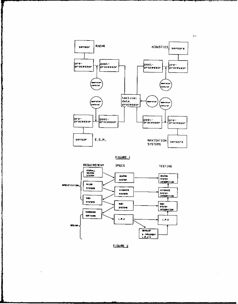
sensor RADAR ACOUSTICSI sensors
Lpe- - post- post- pre-
proe~or processor processor rcso
RE U1 C@NT SPCSTS "lN
tacttzat
data "tCan~e*4processor
pre- post- post- pre-processor -E ocessor prce Io -pocessor
S~l~f E.S.m. NAVIGATIONsesr
SYSTEM S
FIGURE 1
REOIREI"ENT SPECS TESTINGOVERALL
SIWAPON WEAP01IONSYSTEII"[ SYSTEM
WSCINICATIAN
AVI..C5 AVI01EICSSYSTEMS L TU• .
I.TEGIAT 101
54*--
SSYSTEM
HARWFIGUR 2TO
I4m m IO-WANII& IMPLEME N
SWIVA2

FFIGURE AA
1 Weapon System
S(h-ca P P
FIGURE 4A

5-9
F IGURE 5
doe YesC-od T-iptai. ~ ~ oiw daeTak aeDt
Coicr.
Process def init ionIrock Canroroi- track status, ks Ye o both plot end correlate dot. Or*v lilbe and 1 ie t dote. occurso 3 ti..vo Cw...ctml~LV
FIGURE 6
ocobo, rockin L.O.S .L.O.S
F IGURE 7

5-10
ActiveSo-oars
sensor0 L*Ckbftrd
Bta d i , , I OCP, Wising
Heads 'at Pas
slackbmd
Signst SignetType Type
I.
Id
2 "a
FIGURE 8
Svst"BILOCkboard
etaCkboard nasicatRadar Tact message
Ot "ek P,.:.,Ot eprocedwe,a ,
F I GURE 9
Active
Sensors
kb-ca d9 tac
A V.
signs
Ct
'v*
Postproces ng mps:., gooc..6, d FIr assmg
ckboardk A'Otmot pr ad--

asj F~. gaoplgg
"JO, Sub--yt.s ~ CORE
G.F.E. SUB CONTRACT
IN HOUSE
*mtvrscv a.-Le'fGc*
-Cofles CORIesS
F IGURE 1 1

6-1
A STRUCTURED APPROACH TO WEAPON SYSTEM DESIGN
by
H. M. MALLEY, N. T. JEWELL, R. A. C. SMITH
BRITISH AEROSPACE, MILITARY AIRCRAFT DIVISION,WARTON AERODROME, PRESTON,
LANCASHIRE, ENGLAND.
SUMMARY
The design requirements for future airborne weapon systems show an increasing drivetowards iqu-vio theit overall performance and flexibility whilst at the same timereducing the total weight and the resulting cost. These requirements generate theneed for much closer integration of the subsystems which make up the total weapon system.This approach to total systems integration, forces the weapon system designer to lookfor improved design techniques which are capable of coping with the complexity andhigh interdependence of the various functions involved.
This paper describes a structured approach to the design of highly integrated weaponsystems of the future. The approach was used in the successful design and developmentof the avionics system for the UK Experimental Aircraft Programme (EAP) demonstratoraircraft. Brief descriptions are given of the EAP systems, the main system designtools used, the activities carried out during the systems design process and themanagement and control procedures adopted. The paper concludes with a series of obser-vations highlighting some of the findings of the project and providing pointers tothe design of future weapon systems.
1. INTRODUCTION
ihe prime purpose of this paper is to describe a structured approach to the designof a weapon system which British Aerospace (BAe) were able to develop and prove duringthe design of the avionics system for the Experimental Aircraft Programme (EAP) demon-strator air-lift. i _L I L first flew in the United Kingdom in August, 1986.b.ief descriptions are given of the EAP systems, the main system design tools used,the activities carried out during the systems design process and the management andcontrol procedures adopted. In addition a series of observations highlighting someof the findings of the project and providing pointers to the design of future weaponsystems are given.
What is 3 structured approach? - A structured approach can be defined as a methodicalor step by step process in~olving the nr-gressive development of concepts from thestart of the design process to its completion. This contrasts greatly with the adhoc methods which have been used in the past and have been found deficient in suchareas as the lack of definition or the late discovery of design or specificationproblems leading to costly modifications. In no way does the structured approach removcthe need for engineering judgement or skill, it does however highlight the need tomake engineering decisions at the appropriate time to allow the design process toproceed.
Why a structured approach? - As technology continues to advance so the requirementsdemanded of the next generation of weapon systems also increase. This increase istwo-fold; improvement in the performance of existing requirements such as detectionranges or navigation accuracy and improvement in operational flexibility by thecombination of requirements such as air combat and clectronic counter measures intoone vehicle. In this age of the ever increasing demand for the use of new technology,it is essential that its use is kept within the bounds of what can be afforded. Inthe case of an airborne weapon system, weight is considered to be a very importantcost driver. The heavier the avionic equipment, the greater the demand it makes onthe aircraft, i.e. airframe, engines, fuel etc., which leads to a heavier, costlieraircraft. There is therefore a very strong requirement to minimise the weight of anyairborne weapon system.
In the past it was considered acceptable for individual system elements to standalone. This often led to some duplication in the provision of sensors, processorsor displays. The demands for minimising the total system weight removes any possibleduplication of the system elements and leads to a highly integrated weapon system wheresome equipments may undertake several functions. It is this coliplexity and interdepend-ence of the various functions involved which forces the weapon system designer to lookfor improved design techniques.
It was therefore considered that the following features should be embodied in theprocesses to be used for the design of the EAP avionics system:-
a step by step approach which progressively develops the design rationale andproides a capability for planning the execution of the design and formonitoring its progress.

6-2
a orecise, consistent and unambigious way of expressing system requirementsat all levels.
- a means of applying checks at different stages of the design life cycle todetect errors of specification or design in order to assure the design quality.
- an ability to demonstrate that the requirements have been met in order toprovide traceability of the requiiemets.
The above features constitute the structured approach which was adopted by BAe andwhich are discussed in more detail in this paper.
2. EAP
While EAP has been created relatively quickly, its origins go back at least tenyears. During this period, engineers at BAe worked on various studies for a new fighteraircraft incorporating twin engines, delta wings, canards and boh single and twinfins. Some of these studies were undertaken in collaboration with other Companies.In 1979 a proposal for a European Combat Fighter (ECF) was put to the British and Germangovernments jointly by BAe and Messerschmitt-Bolkow-Blohm (MBB), while in 1980 a slightlymodified design for a European Combat Aircraft (ECA) was prepared by BAe, Dassault-Breguet and MBB and put to their respective governments. Unfortunately the governmentswere unable to reach agreement on a common set of requirements.
During 1981 BAe continued its studies and defined the Pl0 project which involvedthe UK Avionics Industry in agreeing a weapon system architecture and producing equipmentspecifications. At the same time MBB were working up their TXF90 project which wasvery similar to the PII0 project. Therefore in April 1982, BAe and MBB together withAeritalia who had previously co-operated to design and build the Tornado aircraft,agreed to investigate the possibilities of producing a joint specification to meettheir individual national requirements. The resulting Agile Combat Aircraft (ACA)was unveiled in mock up fori, at the 1982 Farnborough Air Show ann the 2K government
- vo] pro",id supc-t for a dcmonstratci ai- :-af, i c,- hnu3ld oiLlown at the 1986 Farnborough Air Sow.
It was anticipated that two demonstrator aircraft based on the ACA design wouldbe built, one in Great Britain and one in Germany. During 1983 a limited systems fitwas agreed for the aircraft and due to the tight timescale of the project, equipmentspecifications were produced, put out to tender and Suppliers selected, very muchin advance of the carrying out of a detailed system design. Unfortunately as a resultof the German and Italian Governmerts decisions to withdraw at the end of 1983, workon the German aircraft did not proceed. However the chosen equipment suppliers fromthe three countries accepted BAe's invitation to conlinue with the design, build andsupply of the numerous equipments required, without charge, for the single demonstratoraircraft.
In obtaining the agreement of the UK government to provide support for the demonstratoraircraft, it was necessary to agree the objectives which would be demonstrated. Theareas chosen covered the fields of aerodynamics, structures and materials, and systemsand involved the development and demonstration of procedures necessary for the design,manufacture and test in these areas which were considered relevant to a future fighteraircraft.
This paper concentrates on the work carried out in the design and development ofthe avionics system involving the use of the MIL STD 1553B data bus and the modernelectronic cockpit which were the responsibility of the authors.
3. EAP SYSTEMS
The EAP has three major electronic systems: Flight Control System, Utilities ServicesManagement System and Avionics System, the latter comprising communications, navigationand displays and controls subsystems. A simplified system architecture is shown inFig. 1.
3.1 Flight Control System
The EAP has a full authority, digital fly by wire system to provide artificial stabilityand the necessarily complex control functions. This system is based on the JaguarActive Control Technology aircraft which was the first aircraft to use fly by wirefor flight control without mechanical back up. The system controls up to 13 surfacessimultaneously. The four identical flight control computers host the flight softwarewhich enables the pilot to fly the unstable aircraft and provides carefree manoeuvrabilityand increased agility. The computers also house software for failure management, reversionlogic and built in test. The computers receive inputs from the Zour ,lrcraft motionsensors, four attitude detectors, two air data computers and pilot inceptors and providethe outputs to the control siifaces. In addition they provide air data informationto the utilities and a',ionics systems via the two MIL STD 1553B data buses and airdate, attitude and heading to the reversionary instruments.

6-3
3.2 Utility Services Management System
While not originally claimed as a technological demonstration feature, the SAPadopted an integrated computing system for the control and management of the aircraftutility systems. The system comprises four system management processors connectedto a dual redundant MIL STD 1553B data bus, The bus control function is embedded intwo of the processors. The main utility systems which are controlled by the processorsare as follows:-
- fuel management and fuel gauging
- hydraulic system control and indication
- undcrcsriace indication and monitoring, wheel brakes
- environmental control system including cabin temperature control
- engine control and indication
- secondary power system
- LOX contents, electrical generation and battery monitoring, probe heating
The main benefits of this type of system for a high performance aircraft are a signif-icant reduction in installed weight and operating costs, and a large improvement inavailability. It also provides a simple interface to the avionics system in particularfor the cockpit electronic displays and controls, this being one of the original driversin evolving the system.
3.3 Avionics System
It was accepted that for the EAP, the avionics system would be a sub-set of the weaponsystem proposed for the ACA. This was called the 'Core System' and provides theessential features to fly a high performance aircraft namely navigation, communicationsand display and control functions. Transmission of data between the subsystems isvia a dual redundant MIL STD 1553B data bus. This greatly reduces the amount of wiringrequired in the aircraft and simplifies the development and on-aircraft testing.
The navigation subsystem comprises an inertial platform with its own self-containednavigation processor and a TACAN and radar altimeter which share the same remote terminal.
The communications subsystem comprises a standard V/UHF radio and an emergency UHFradio. The control of this equipment is through an integrated control and managementunit which also provides a voice warning facility. The latter supplements the normalaircraft warning system.
The displays and controls subsystem demonstrates several new technologies. Twoidentical wavefcrm generators form the heart of the subsystem and are each capableof driving the three multi function colour displays and the wide angle holographichead up display. They also provide the bus control and executive control functionsfor the avionics system. Mission data such as waypoints, TACAN beacons, communicationchannels etc., are inserted by the pilot via the manual data entry facility mountedon the left hand glareshield. This information together with raw control data fromthe controls mounted on the consoles, throttles, control stick and displays is processedin two identical cockpit interface units prior to being transmitted on the avionicsdata bus. A cockpit lighting controller undertakes the task of monitoring the lightsensors distributed around the cockpit and continuously regulates the power suppliedto all the displays and controls to provide optimum illumination and display contrastat all times.
4. DESIGN TOOLS
In parallel with the work being carried out on fighter aircraft studies during the70's, BAe put considerable effort into examining ways of improving the techniques usedfor designing systems and also into the newer system technologies. Two specific areaswhich showed promise and were pursued with the support of the UK government, were:
- means of improving the production of airborne software in terms of productivityand quality
- investigations into the implementation of a MIL STD 1553B databus togetherwith an all 'electronic' cockpit including the multi-moding of displays andcontrols.
The former led to the development of an approach called Semi-Automated FunctionalRequirement Analysis (SAFRA) while the latter led to the production of the Active Cockpit.Both of these tools were used to support the design of the avionics system for EAPand are described in the following paragraphs.

6-4
4.1 Semi-Automated Functional Requirecents Analysis (SAFRA)
In examining ways of improving the productivity and quality of airborne softwareit was shown that the biggest improvements would be obtained by the ability to findand eliminate errors at as early a stage as possible in the software life cycle. Thisled to the development of the approach called SAFRA which in particular addressed thelack of method, lack of visibility, lack of consistency and resolution of ambiguitiesin producing software requirements. Just as this method was applied to softwarerequirements it was shown that it could be applied to the establishing of system require-ments and was therefore also adopted for this latter purpose.
The SAFRA approach encompasses a number of methods and tools which support the variousstages of the system/software life-cycle. At the heart of SAFRA is a method calledCOntrolled Requirements Expression (CORE) which is used to produce system and softwarerequirements that are unambiguous, consistent and complete. The method is based onthe progressive decomposition of high level requirements in a logical and consistentmanner until a level is reached where the requirements are expressed in sufficientlyprecise detail to allow hardware and software design to commence.
Each level of decomposition consists of a number of logical steps, eleven in all,which when applied to a higher level requirement products the lower level componentsof the require-nt. These steps car! -LL vely summarised as information gathering,establishment of relationships and the verification of relationships. The informationderived at each level of decomposition is presented in diagrammatic form known as CORPdiagrams. These diagrams use a precise unambiguous notation which can be checked forconsistency and completeness across the whole of the systems requirement.
To assist in the production of CORE diagrams, a work station was developed whichenables diagrams to be entered at a high-resolution graphics terminal and edited asrequired. It also provides a multi-user database in which diagrams are stored anda hard copy facility using a printer-plotter. Some automatic on-line checking ofthe diagrams for consistency is undertaken as they are being entered.
By producing th- requirements in an unambiguous form in a computer database it ispossible to check the data for consistency and completeness. This was done usingPSL/PSA (Problem Statement Language/Problem Statement Analyser), which is a productof the ISDOS project of the University of Michigan, although other similar productssuch as EPOS are now available. The CORZ notation is automatically described in P5Lin a consistent manner and stored in a new database. PSA is then used to provide checkingand analysis of the database in numerous ways. When all the checks have been satisfactoril.completed at each level of decomposition, the CORE database is made read-only to allowthe next stage of the design to proceed.
4.2 Active Cockpit
As the result of its continuing development studies, BAe gained considerable exuerien-ein the operation of active cockpit facilities and demonstrated their great importancein providing information on the man-machine interface to the system design process.In effect this facility provides a means by which rapid prototyping of ideas can betested and developed with full operator inter-,nion.
The Active Cockpit consists of a wooden shell representing the actual cockpit.The displays and controls are positioned to the best information available, use beinmade of commercial items wherever possible. Initially static displays are assessedfor the development of the moding and formats. These displays are then driven dynamicallyin a representative manner together with other simulated functions such as engines,hydraulics,fuel etc., to fully exercise the cockpit displays and controls. To allowassessment under realistic flight conditions an outside world simulation system isprovided. In addition a comprehensive fault injection system is used to allow assessmentof the pilot/cockpit interface under single or multiple system failure conditions.
5. SYSTEM DESIGN ACTIVITIES
The life-cycle stages in the design and development of a typical system are illustrat'edin figure 2. These can be grouped under three main headings namely system design,system implementation and system test. As defined system design covers the stagesof activity from the establishment of the initial high level system requirement throughseveral levels of decomposition which produce the detailed requirements including hardware/'software partitioning to the production of hardware and software specifications. Systemimplementation covers the stages from the availability of specifications through tc theirrealisation in either hardware or software. System test covers the stages of testingtaitriiq with individual equipments and software modu'eu ,nd building u , i-dividual
elements to subsystems and finally integrating these to form the total system.
The following paragraphs describe in more detail the various activities undertakenduring the system design process. These activities are considered under four majorheadings: design planning, data gathering, functional analysis and partitioning.

6-5
5.1 Design Planning
Design planning focused on the production of a design route map which is illustratedin Figure 3. This route map showed how each of the design teams intended to produce
formal design documentation. Each system route map was also required to show thedependence of one design task on another so that a sensible programme could be derived.Technical details relating to the use of CORE were also included e.g. the number oflevels of design decomposition were considered and documented, and naming conventionsfor data items were included. To ensure proper interfacing and integration of themain aircraft systems, the points at which formal design reviews would be held, werealso defined. This ensured that the system design was properly integrated therebyavoiding the need for major and time consuming design revisions late in the programme.
The route map also defined a list of formal documents which were to be producedand delivered to other organisations. For example the systems design team were taskedwith providing the software team with software requirements and software specifications:the scope and depth of each of these documents were also defined.
5.2 Data Gathering
A data gathering activity occurs in any project either as a conscious or an unconsciousaction. Probably the most commonly accepted need at the start of any project is toobtain a basic design requirement for the aircraft. This is usually provided by aformal requirement from the customer such as an air staff target or requirement. Inthe case of EAP no such requirement existed and it was therefore necessary for theaircraft companies to produce a similar document. During the definition of the ACAproject, attempts had been made to establish an air vehicle specification. It wastherefore possible to modify this specification to reflect the intended standard ofthe EAP. This was then used to establish the areas of high technology to be demnnstr-'which formed the basis of the agreement with the UK govornma"- for providing sameof the funding for the project. Thus some constraints and guidelines were formallyagreed at an early stage of the project.
To complement the basic 'customer' requirement, the design teams produced a setof p-liminary systems descriptions. In effect these descriptions were based on designwhich embodied experience resulting from rig demonstrator programmes, advanced aircraftstudies, and a knowledge of the state-of-the -art in equipment and systems. They werenot validated design documents and subsequently were not maintained as formal designstatements. These descriptions were formally reviewed by the project management earlyin 1984. It is of significancethat subsequent to the issuing of the systems descriptionsno further major changes in requirements were permitted until this initial design hadbeen implemented. This meant that a relatively stable set of design objectives wereavailable.
A further stage in the data collection was the production of a set of principlesand philosohpies which would guide the subsequent detailed design. A typical examplewas to derive the concepts for displays and controls moding for ergonomic single crewoperation. Also important at this stage was the prototyping of design ideas, and inparticular the use of the active cockpit rig discussed in Section 4.2. This facilityallowed pilots and designers to assess design concepts. Because of the lead timesneeded to produce such a facility the active cockpit did not provide valid:ted designdata during the data collection phase, however all of the information to be used onthe rig was also made available to the system designers. In this way rig based revisionswere fed into formal design documents at a later stage, but in advance of the designfreeze prior to subsystem testing.
Finally an area of data collection which is either overlooked or is paradoxicallytaken to be a comprehensive statement of a design is that of pre-defined functions.On EAP several of the required functions could be obtained by the use of existing orslightly modified equipments, typically, TACA. IFF and inertial navigators. The non-standard aspects of these of these equipments was not related to the functions theyprovided but to the way in which the equipments would be interfaced. Thus by definingin CORE the functions and data requirements for these equipments, constraints wereplaced on the design. It also enabled significant pieces of the system 'puzzle' tobe put in place quickly and used to drive out other less well defined system requirements.It should be noted that this is a technique which is generally applicable. For examplethe weapons fitted to a new aircraft are rarely completely neu and hence the accuracy,functions and data requirements of many weapons will be known at the initial designstage and should therefore be us-d to drive the 6esign of the interfacing equipment.
5.3 Functional Analysis
Functional requirements analysis was the first formal design stage of EAP and usedthe CORE systems design tool. Because CORE is essentially a method for documentating,analysing and validating a design, all the preceeding informally derived data was firstentered into the system CORE design database. As an example the initial step in COREis to propose the main system functions and then to postulate their data requirements.This is formally referred to as tabular entries, and much of this data was availablefrom the previous stage of data gathering. However, because of the diagrammatic natureof CORE and the fact that the design data is electronically stored, it could bevalidated for functional completeness and consistency using the PSL/PSA tool e.g. foreach data source there must be a user.

6-6
Initial system moding was also proposed at this stage. Each function was describedin terms of its various modes or states so that the control data needed to nter/exita particular mode, and the specific data produced in that state were defined.
Space does not allow all of the separate and formal design steps associated withCORE to be discussed here, however the benefits arising from this formalism were numerous.Direct benefits included automatic checking of gross system inconsistencies, automaticproduction of interface control documents for the major systems, and a clear definitionof the bus contiol transaction table requirements. Of less importance at the functionaldesign stage but of considerable benefit later during systems testing was the abilityof the various disciplines (test, system design, and software), to quickly trace afault, isolate the cause, and correct the problem without inducing additional problemselsewhere in the system. The formalism and visibility provided by the CORE designmethod also dramatically reduced the number of errors which were detected during thefinal stages of system integration testing.
To provide sufficient detail, the design of the avionics system was completed inthree separate stages.
- The first stage was the production of a functional statement known as the systemfunctional requirement document which described the system functional requirementswithout reference to mechanisation or location and was derived from the aircraftspecification,systems descriptions and the principal and philosophy documentswhich had been produced. It also defined the information flows to and fromthe avionics system.
- The second stage involved the decomposition of the system functional requirementsto establish subsystem functional requirements. This provided more detaileddefinition of data attributes, transfer rates and interface details such asword formats. It also included the overall sequence of operation of the variousfunctions and their iteration rate. This resulted in deriving the data interfacesbetween subsystems/equipments.
- The third stage involved further decomposition of the subsystem functionalrequirements to produce the detailed hardware and software requirments.The software requirements were in fact produced in two phases. As soon asthe data interface requirements, sequence of operations and iteration rateswere available from stage two, it was possible to define the software schedulesand the overall structure of the code so that the software basic design couldproceed. The next phase was to add the details of the process algorithms.This enabled the software task to be completed by coding the algorithms whichwere in principle inserted into the basic design as process modules.
5.4 Partitioning
It is clear that at some stage there must be a transition from the purely functionaldesign requirement to an implementable system specification. For the most part thistransition was done during the second stage of the functional analysis. The main functionswere partitioned into equipments, and in the case of multiprocessor units, they wereallocated to specific processors. However, this procedure was not a simple singlestep action. The main systems were partitioned at the first stage i.e. functions whichwere to be carried out within the flight control, utilities and avionics systems weredefined. Subsequently each of the functions allocated to these systems were partitionedto appropriate subsystems. For example, avionics partitioned functions to the navigation,communication, displays and controls subsystems.
This partitioning process took account of such system technical requirements asminimising data bus load requirements and data latency and providing adequate failuremode handling. In addition project considerations such as minimum weight and the useof pre-defined equipments were also taken into account.
It was found quite acceptable in certain instances to split up functions amongstthe various equipments or processors or to combine several functions in a single equipmentor processor. The main requirement was that the design was clearly documented.
Two examples are given to illustrate the above mentioned forms of partitioning.
- The EAP avionics system included an intelligent voice warning system whichinvolved two fundamentally different disciplines, the voice audio generationand management and the logic associated with recognising a failure and associatingthis with a specific warning requirement. The waveform nenerators were in effetnatural hosts for a good deal of the system data and hence were already sourcedwith the data needed for warning generation. Conversely the communicationsmanagement system naturally provided audio generation, audio mixing, etc.Therefore the voice warning generation function was partitioned to the ommunicationsmanagement unit, and the warnings handling logic was partitioned to the waveformgenerators. This resulted in a minimal bus load, since only a few data wordswere needed to specify the required warning message and its status from thewaveform generator to the communications audio management unit.
6-7
In examining locations for the bus control, executive control, display managementand symbol generation functions, there were several possible choices. Themost obvious way was to combine the bus control and executive control functionsin a single equipment and the display management and symbol generator functionsin a separate equipment. However from analysis of databus traffic it was shownthat the databus traffic could be significantly reduced by combining all fourfunctions into a single equipment. It was also shown that by using a singleequipment significant savings in weight, volume, cabling, power and coolingwould result and finally it was established with potential suppliers that thissolution was viable. Thus a specification for a waveform generator which undertookall four functions was put out to tender.
In this specific case the main operational software which included the buscontrol transaction tables, executive control, warnings and display managementfunctions were produced by BAe while other software functions for bus controlalgorithms, symbol generation, built-in test and basic system operating moduleswere produced by the equipment supplier. This combination of software withinindividual processors was satisfactorily achieved through the use of commonsoftware standards and tools.
It must be recognised that the system design processes described here are neithersimple not has it been possible to cover all the aspects in this paper. Considerabledesign effort was provided in parallel,by equipment engineers and other disciplines.However the basic planning, the design steps and the use of the formal design methodCORE all resulted in an unambiguous set of system requirements which would not havebeen produced by conventional techniques. These enabled the design to be successfullyimplemented.
6. SYSTEM MANAGEMENT AND CONTROL
The structured design process with its pre-defined life cycle stages provided thebasis for the management and control strategy. Each life cycle stage had a specifiedstart point, purpose and resultant output. Thus as the life cycle unfolded the successfulcompletion of these outputs provided management with the necessary measure of progress
and achievement.
The management control procedures, to which all life cycle stage products were subjectedcan be summarised as follows:-
- Review
- Configuration Control
- Change Control
- Configuration Status Accounting
6.1 Review
The aim of the review process was to ensure:-
- a satisfactory completion of one stage of the life cycle before commencingthe next.
- the correct planning for successful implementation of subsequent stages.
AThe review itself comorised a technical review and a separate management review.The former checked for technical accuracy, compliance with previous stage and conformanceto standards. Since the majority ot the lifecycle products were generated in machinereadable form, automated checking procedures were used to assist in validating compliancewith previous higher level stages and proving technical accuracy.
The technical review was a formal process and all remedial actions were recordedin the form of a review report. In addition an independant qua±ity control reportwas also produced. All such products from the technical review and the reviewed itemwere passed onto the management review. This latter review rnsured that all requiredactions identified and recoid;d at t
h- technical review, were implemented in an accuracte
and timely manner and that adequate resources were avallable zo impl ,tt t-he fcll'1in,gstages.
6.2 Configuration Control
Following a successful review the items were subjected to formal configuration control.At this point the item ceased to be the property of the author and became a projectitem. All formal distribution of the system life cycle products was performed viaconfiguration control. Thus all recipients knew that the work could proceed againsta formally established and controlled baseline. Any subsequent change to such baselineswere therefore communicated to all affected parties in a controlled authorised manner.As a consequence the work of each life cycle stage was initiated against configurationcontrolled baselines from the previous stages.

6-8
Configuration control was imposed from the first product of the first stageof the life cycle and maintained throughout its entirety. Obviously as the life cycleunfolded and mote detailed design work was pursued, previous work was exposed to closescrutiny and errors were detected.
To accommodate such design iterations, for whatever reason, an effective changecontrol procedure was rigorously maintained as part of the configuration control process.
6.3 Change Control
All configuration controlled items were subjected to a rigorous change control procedure.This is particularly important in an 'integrated system' since a single change in nearea can cause changes to several processing elements elsewhere in the system. Thusbefore approval was granted, on any change, all potentially affected areas were canvassedfor their comments on the change implication including effects on system design, timescales,manpower effort and costs etc. All aspects of the change process therefore involvedthe project as a whole rather than individual areas and for this reason the changeprocess was managed by and co-ordinated by an independent configuration control group.This ensured that the correct procedures were enforced and that all relevant data wasobtained so as to make the necessary valued judgement as to whether the proposed changeshould be authorised for implementation. In certain cases formal reviews were heldif the change was in any way controversial or extensive. No changes, however small,were allowed to be implemented without formal approval via the agreed procedures.
In addition to managing the change process, the configuration control group alsomonitored and assessed the change process. Each change was uniquely identified andcategorised in order to formulate change statistics. These records provided a highlevel of visibility to management into how the project was progressing. On EAP itwas clearly evident that the adopted design approach had proved invaluable in ioentifyingthe majority of errors in the early design stages where they were most easily and cheaplycorrected, i.e. in the design paperwork rather than in the defined product. This experiencesuggests that management should expect to see a large amount of change in progressthroughout these early life ycle stages which only decreases as the systems testingstages are reached. This volume of change during the design process, whilst desirable,poses significant problems which can only be contained with the strict aherence toconfiguration control procedures and the maintenance of configuration status accounting.
6.4 Configuration Status Accounting
In a project with a large number of configuration controlled items and an even largernumber of changes in progress, the status accounting of these items becomes essential.All project participants must be kept informed on a frequent and regular basis abcutthe current status of all configuration items, i.e. their issue number and all applicableauthorised changes to that issue. This process is merely the communication of currentdesign data baselines to all parties involved in the furliherance of the systems designin accordance with those baselines. A configuration status report also communicatesprogress and achievement to project management. This report covered
- overall progress- a list of all configuration items, their issue and change status- all new items subjected to configuration control- all new issues of items indicating embodied changes- all new changes including their status- change analysis data.
7. OBSERVATIONS AND CONCLUDING REMARKS
The use of the structured design approach together with its associated tools undoubtedlycontributed to the success of the EAP in designing the avionics system to a high standardin an extremely short timescale. The following specific points are considered to beworthy of note in summarising what was learnt from this exercise and in providing pointersto the design of future weapon systems.
- The structured approach together with the application of the rigorous managementand control procedures enabled realistic programme plans to be produced and provideda high level of visibility to management in terms of progress of the design activities.The change statistics proved to be a valuable indicator of how the project expectationsand requirements were being fulfilled.
- The undertaking of a freeze of the system requirements prior to starting the functionalanalysis process and then the application of a strict configuration control procedurewhich virtually eliminated the introduction of changes to these requirements oncethe freeze had taken place were considered to be majo. factors in enabling theprogramme timescale to be met.
- The use of the structured approach brings about a significant increase in the a ountof design documentation produced, however this is greatly assisted by the use ofcomputer aided tools which reduce the labour intensive nature of this task. Thisincrease in design documentation is a significant step forward in overcoming pastdeficiencies of having insufficient information readily available. It also significantlyreduces such tasks as the production of test specifications, customer manuals etc.

- The key to the production of a high quality system design was undoubtedly the insistenceon the adherence to the very rigid control and management of the design processand the use of the automated validation tools. CORE proved to be a very powerfultool not only for design but also for fault finding due partly to the extensivedocumentation. This was found to be very versatile in assisting the engineers torapidly locate the problem area and correct it. It also enabled changes in therequirements to be introduced easily and rapidly.
- The structured approach to the total system design, places more responsibility onthe weapon system contractor who carries out the partitioning process, and thereforedetermines where and how the various functions will be carried out. How much ofthe resulting activity is undertaken by the weapon system contractor or the avionicequipment suppliers is a matter of debate. It is considered that avionics supplierswill continue to implement the specialist functions such as sensors, displays andprocessor hardware but the definition of the on-board software will become the respon-sibility of the weapon system contractor.
- As well as the tools associated with SAFRA which were used to assist in the designof BAP systems, use was also made of mainframe text processors, minicomputer wordprocessors, standard proforma and data base tools. For future projects, the extensionto a comprehensive, centralised, computerised engineering database is consideredto be highly desirable.
- In any project there is a need for effective configuration control throughout thedesign phase. On EAP this was handled by manual means supported wherever possiblewith computer aids. As the size of the project increases and the use of a centralisedengineering data base with multi-user access is established, so automated configurationcontrol tools must be available.
- It is considered that complex system requirements cannot be accurately describedin plain 'english' text. The use of tools such as CORE generate their own designlanguage and introduce a need for training not only of the system design engineersbut of all the personnel who will be associated with the project such as test engineers,support engineers and in particular managers and representatives of the Customer.
- A major difference between the structured 'top-down' approach compared to existing'bottom up' approaches, is the elapsed time before some functioning of the systemcan be seen. In the latter case it is usual for some areas of the system to becomevisible early in the programme, but in the former case the system tends to cometogether all at once, albeit on time.
In conclusion it must be admitted that there were doubts during the initial stagesof the project as to whether the structured design approach was sufficiently developedto enable us to achieve our declared objectives. In retrospect the success of theproject in achieving 35 flights in its first 30 days with no requirements for systemhanges, shows that the doubts were unfounded. In particular, the success of the structured
design approach applied to the avionics system in terms of the quality of design, thetimescale achieved and its supportability were beyond our expectations and indicatesthe way forward for the design of the more complex weapon systems of the future.
ACKNOWLEDGEMENTS
The authors wish to express their thanks to the members of the EAP System Teamsat BAe Warton and colleagues from the various Avionic Companies in Great Britain,Germany and Italy, who undertook their own part of the total systems design which ensuredthe success of the EAP. The Directors of British Aerospace are acknowledged for theirpermission to produce and publish this paper. The views expressed, however, are thoseof the authors.
This work has been carried out with the cupport of the Procurement Execut,,-. Miniztryof Defence.
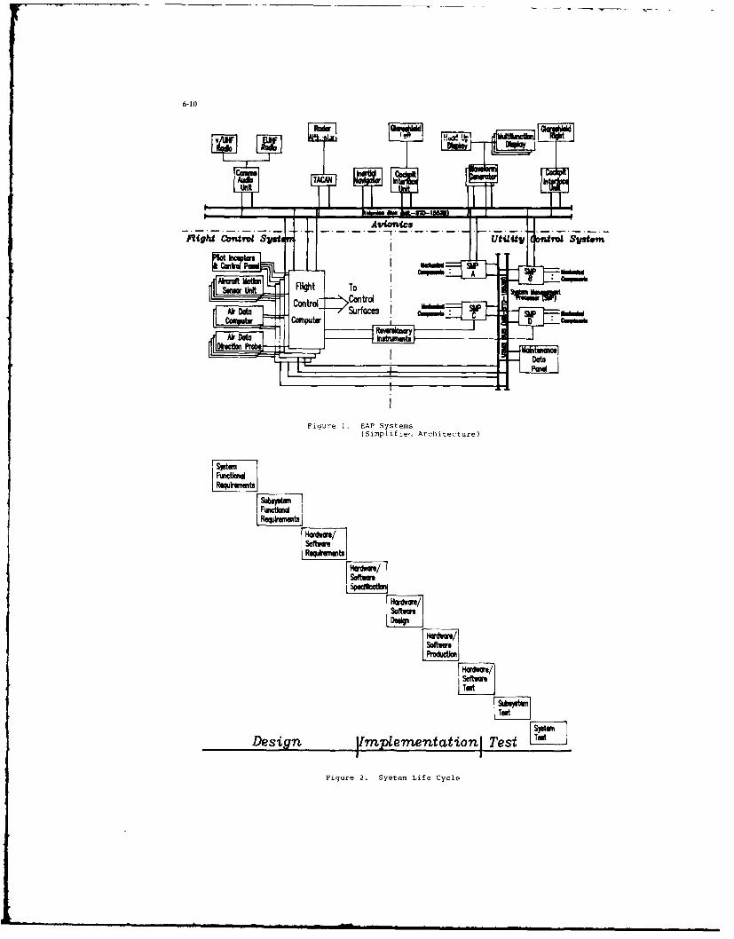
6-10
Figure1. SAPSyste"
(Siml~fe~.Archtecure
Rqkuunt baIV s aa
twowg
Moraft Motion
Sovewoe oo
Air Date
DrconPoesg mtmtatnJTs
Figure . A SystemsLf yl

6-11I
Input Activity Output
Stage 1 - rV"-Fcm o*woFKw wh t- PkCOu am - Prdmkwy Pwtrdmihg -Moor S),tg kltwfocg
Nuaphs dtc to &*IN=~tm
Stage 2 - FwfdRume- -wWFcw SubVi. Fund
- MO)wr %Stu - Pr M nbwyPUmIg - *etm hItefackitwbac to E*Ommh
- %misy Ad- kditctwe D*Itlui
Stage 3 - j~m wm ~P@$Jdanto- Sub.)lI kitwffacm - Eqi~mmt/Wocm. - Eqamwt ntkitfas
DMm
iqure 3. System Design Route map

6-12
DISCUSSION
P.Simons, USDo the software tools for this process support multiple decompositions of a functional analysis'?
Author's ReplyFigure 3 of the paper shows that hardware assignment or design occurs at the end of stage 3 of system design, after theglobal system and subsystem functions have been identified. System design is driven by mission and phase of flightrequirements. Decomposition at stage 2 (see Figure 3 of paper) identifies subsystem requirements at the attack, flightcontrol, display and control, etc., levels. This includes all mission requirements. Particular mission analysis can beperformed at this point, including the system's offensive and defensive abilities. The system's defensive abilities aregenerally compromised in the UK because of the requirement to use existing equipment provided to the aircraftconstructor by the government.
G.Bouche, GEDo you know about national or NATO activities aimed at standardization of system design tools such as CORE?
Author's ReplyWe are not aware of any national or NATO activities to standardize system design tools. Within British Aerospace.there is an intent to standardize on CORE. For EFA. the customer requires CORE/EPOS to be used throughout thedesign. This requirement is driving CORE/EPOS as a common project (EFA) design tool.

7-I
DEVELOPMENT OF A GENERIC ARCHITECTUREby
Christina BerggrenInternational Business Machines Corporation
Federal Systems DivisionMD 0906, Owego, NY 13827-1298 USA
SUMMARY
A new generation systems architecture being developed at IBM in Owego, NY, is designed to bridge the gap between todam's 1553-based systems and the fault-tolerant, totally integrated systems of ti,m's rnow This pater descrines a n--1 -,-oach to system func-tional area partitioning and the design of this generic distributed real-time architecture. The architecture incorporates ne militar%standards in development
INTRODUCTION
Next-generation avionic systems cannot be developed by traditional means. The simulation of a centralized architecture systemand the gradual replacement of the simulator with the prime system 'black boxes' during development is a discipline well suited fortoday's technology-based systems. The architecture of test beds supporting the development of future avionic systems, hovser, mustmap onto the architecture of the system being developed, both, hardware and software. A distributed fault-tolerant system with parallelexecution aqd dynamic task allocation to processors cannot be simulated by a centralized sequential architecture.
The architecture of the Advanced Systems Development Laboratory (ASDL) at IBM Owego is designed to emulate systems of thefuture on commercial hardware. Validated system designs can then be hardened with little risk.
The ASDL, presently in concept salidation phase. employs a fully distributed, data driven architecture. It is a hierarchicall% con-trolled parallel pipeline of alternating layers of self-contained Ada* tasks and a communication architecture based on next-generationmilitary standards.
The decomposition of this next-generation system required innovative approaches and a nea aay of thinking ahen the require-ments were partitioned into functional areas of manageable subparts.
FUNCTIONAL AREA PARTITIONING
The objectives used to guide partitioning of the ASDL into functional areas were reusability. flexibility, and extendibilitNApplication-unique requirements were isolated by extracting generic services applicable to all systems, and this resulted in an architec-ture partitioned into four functional areas as shown in Figure I.
The application-specific requirements aere allocated to the Simulation Models Functional Area and Data T ranslation IunctionalArea and the generic system services to the Communications Functional Area and the Execution Contro, Functonal Area.
SIMULATION MODELS I EXECUTION CONTROLAPPLICATION FUNCTIONAL AREA I FUNCTIONAL AREA O NTERRATORSOF TWARE (S I MF A )( XFA) INEFC
COMMUNICATIONS ARCHITECTURE
FUNCTIONAL AREA GENERIC SUBJECTS( COMFA ) /
DATA TRANSLATION
FUNCT IONAL AREA(DATFA)
EFFECTOR J SENSOR OROR CAPTURPD
BUS DATA BUS DATA
ENVIRONMENTAL INTERFACE
Figure 1. ASDI_ Functional Areas
*Registered Trademark of United States Department of Defense

7-2
Traditionally, system-level functional area partitioning maps onto hardware. In the ASDL. system partitioning transcends conven-tional hardware and software boundaries. Figure 2 shows the ASDL mapping of functional areas onto one hardware node in the dis-tributed architecture, Application modules and part of execution control are at the top, and layers of the communications architectureare helow.
SIMFA BRIDGEAPPLICATION APPLICATIONSOFTWARE SOFTWARE
XFA AFA
COMFA COMFA
(TOKEN TOKEN TOKENRING RING RING
STANDARD NODE BRIDGE
GATEWAY GATEWAYAPPLICATION APPLICATIONSOFTWARE SOFTWARE
XFA XFA
COMFA COMFA
ATFA DATFA,F D
MIL STD ANALOG SYNCHRO1553 DISCRETE.ETC.
GATEWAY GATEWAY
Figure 2. ASDI. Node Functional Area Mapping
SIMULATION MODELS FUNCTIONAL AREA
Mission-unique functions have been allocated to the Simulation Models Functional ,rea (SIM FA) SIMFA is a collection (itapplication-specific Ada modules, each of which accomplish one self-contained task. The software interface to these modules is stan-dardized to allow any number of modules to be merged togcther. Combinations of modules emulate entities ranging in size from smallsubsystems to large complex systems of the future.
Intermodule communication at this level in the architecture is logically independent of hardware allocation and supported b theunderlying system services. Task execution is externally initiated.
Thus, through system-level partitioning, application- or mission-specific functions were isolated. S'stem adaptation or changes arelimited to adding deleting or upgrading SIMFA modules for software.

7-3
DATA TRANSLATION FUNCTIONAL AREA
Application-unique hardware interfaces have been allocated to the Data Translation Functional Area (DAT FA). The DATFAtranslates the standard intra-ASDL digital format to from analog, synchro. discrete, or whatever the specific need may be. DATFAalso converts data to formats required for specific data buses. The first ASD. DATFA implementation is a token passing ring to 1553gateway. This gateway will allow for hybrid systems during the transition period into next-generation military architectures
The main ASDL development efforts, however, are focused on the generic subsets of the architecture: the Communications Func-tional Area and Execution Control Functional Area.
COMMUNICATIONS FUNCTIONAL AREA
The Open Systems Interconnnection Reference Model of the International Standard Organization (ISO) sas evaluated for applic-ability to the development of the ASDL communications architecture. Its seven-layer model defines the partitioning of the communica-tion services between heterogeneous end users in an open network type system.
The types of communication services required for a real-time distributed system differ significantly from those of an OSI applica-tion non-real-time system as do the requirements for the implementations. A large percentage of the data in real-time appilcattons issensor data sampled periodiically as often as sixty times per second.
To establish virtual circuits beforehand and retransmit erroneous dais for reliabilitv is neither needeu, nor desired it new data willbe available in 16 milliseconds. The processing overhead of the comatuiicmtons protocol ma. require more time than that.
The requirement for a high-speed implementation of a completel. connectionless, unacknowledged datagram service is one areawhere military divtribted real-time systems differ from traditional systems. Naturally, military systems also require the reliability of aconnection-oriented service with application-level acknowledge for mission implementation and system execution control,
The implementation of these services has different design drivers. For real-time systems, as the name implies, reducing the timerequired for a task to communicate with another is a primary design driver, thus minimizing the end-to-end delay through the system
The implementation of the ASDL communciautions architecture, however, does take advantage of the OSI philosophy and struc-ture. Partitioning the services into layers of separate entities provides flexibility that allows change. Changing or adding to a function inone layer will not ripple through the system. The impact of the change will be confined to the one entity being changed.
In order to implement efficient real-time communication services, the communication protocols of the ASDL architecture hasebeen partitioned into three layers:
" Lower Layer (I 0 Driver)
* Middle Layer (Communications Conirol)
" Upper Layer (Application Communications).
LOWER LAYER
The lower layer is the 1 0 Driver, and it includes the I 0 device or LAN (Local Area Network) hardware. The LAN technologychosen is a high-speed token passing ring. It allows for distributed control, deterministic access, and delays that are quantifiable andminimum between geographically dispersed nodes.
In the prototyping facility, the LAN used is an 80Mb s token passing ring manufactured by Proteon Inc. and employs a roundrobin type access method. The lower layer and the interface to it were designed with provisions which will make it easy to replace thelaver when hardware becomes available for the next-generation military standard token passing ring. (This new standard, defined forfault-tolerant distributed real-time systems, was developed by the SAE-AE9B* subcommittee and is presently going through the ap-pro al cycle. )
Ihe I 0 device hardware contains high-speed input and output buffers and a state-machine that controls the interface to the com-municattons media, the host computer is interfaced via the CPU internal bus.
The primary function performed by the lower layer software is to move data between the host's internal memory and the inputoutput buffers. There is little intelligence in this layer: it does not determine nemory address or type data move. It reports errors oranomalies in the lower layer or the transmission media to upper layers for action, but it does no error handling.
MIDDLE LAYER
The middle layer. Communications Control (Coin Cntl). controls all node external communications.
For incoming data. Coin Cntl analyzes the header of the packet before data is moved from the input buffer on the I 0 device.Based on the data's logical source. Coin Cntl defines memory destination for the data. The type of operation for the I 0 Driver toperform is defined in the header Message Category word and initialization tables. This can be queue algorithm, using DMA,programmed I/O. etc., to move the data to another I 0 device for gateway or bridge functions, or Coin Cnil can direct the 1 0 deviceto discard the data if it is no longer required.
For outgoing data, Coin Cntl performs the logical source to physical destination address translation and prepares the packetheader before directing the I 0 device to transmit the data. This address translation is a selltcontained entity that can easily beremoved when the MIL-STD token ring is integrated, since it supports logical addressing in the hardware.
In order to reduce the end-to-end delay. data is only moved once as it passes through .he communciations architecture, and thatmove is between host memory and the high-speed input output buffers in the I 0 device. Buffer pool techniques are used to sequen-tially pass control of access to the data from the application onto the upper layer, to the middle layer, and to the lower layer of thecommunications architecture.
*Society of Automotive Engineers Aerospace Equipment

7-4
UPPER LAYER
The upper layer, Application Communication (App Corn), controls all communications internal to a node.
Logical addressing is used throughout the system such that a task never knows where another task that it communicates with islocated physically. App Com thus has the responsibility to define whether data generated within a node is required bv another taskwithin the same node, or if control of the data is to be passed to Corn Cnl for subsequent transmission to another physical node
All task communication management has been allocated to App Com. Each task resident at a node has a correspondingcommunication management task in this layer. This App Corn task is responsible for receiving and keeping track of all data required hian application for execution. For instance, if an application requires data from one internal source and two external sources. App tonwill take access control of the data as it arrives, and when all necessary data is received, access control will he passed and theapplication task posted for execution.
As mentioned earlier, military real-time systems require two classes of communication ser%ices: a connnectionless datagram typeservice, and an application-leve acknowledged message. In the ASDL architecture, the application-lesel acknowledge is supported inApp Com. App Com's communications management includes waiting for acknowledgement to transmission ot these tipes of message,for a predetermined period of time, retry of message transmission, and alerting system services it no response is receised. App Con alsoprovides system services with logically named error messages from the other layers for initiation of programmable, user-defined errorhandling, reporting tasks.
LAYER INTERFACE
Key to the implementation of the ASDL architecture is the design of the layer interface. The structure ol the interface has beenstandardized to allow near indefinite flexibility and extendibility. Functions may be added or deleted from a layer without attectingother entities. Actu,; ,he li uaiuce and iniplementation of the layer interface permits entire layers to be added. &I icquiird, lrtadditional non-real-time services.
The layer interface is designed utilizing the OSI concept of Service Access Points (SAP). SAPs are memory pointers shared bentities which communicate with each other across a layer interface. Communications via the SAPs occur in the following mainer Anentity wishing to operate on an entity in an adjacent layer prepares a control word defining operation type and parameters required lotthe operation. A memory pointer to the control word is then loaded into the specific SAP, and CPU control is passed over the layerboundary. Fhe receiving entity reads the SAP. finds the pointer to the control word. and then decodes the control word to perform thedesired operation.
Eah , .... "-4
.tr.a. c ua' C_.I U aiid adds to the end-to-end delay of the system In the ASDI. architectureprototype, the design of the layer interface was focused on speed and resulted in a fast, efficient, and flexible implementation
In the data-driven system architecture prototype. there are two SAPs between each I 0 Driver and Coin Coil and two SAPsbetween Corn Cvil and App Com, one f-, each direction of operation. IN or OUT Figure 3 depicts the layer interfaces with associatedSAPs and operation direction. Communications occur in both directions over a SAP. Any one operation ma\ require ..Auence ofcontrol words and responses to be communicated via the SAP.
Direction of operation is defined by who operates on whom: that is. who initiates the operation For thy implementation of thedata-driven architecture, this means t- ,%: "ny given message arriving at a node sia the token passing ring, first the I 0 l)erier willoperate on Corn Cntl. then Corn Cntl operates o App Com, which in turn ma, operate on the application task For an out operotion.the sequence of operations is reversed except for the application task
By definition, only control tasks can operate on another entity: mission-specilic tasks get operated on and respond.
The ASDL interface design allows flexibility in allocation of communications architecture between main processor and I 0 pie.essor. Communication-ntensive applications may require a separate I 0 processor within the node, but or lois (o normalcommunication needs, this processing. or any layer of it. can easily be moved to the main processor
EXECUTION CONTROl. FUNCTIONAL AREA
In the ASDI. implementation, SAPs are not only nuclei of communicattins but also of control. Any operation can, al ihe int-face, be halted, resumed. or. for debug purposes, single stepped. This allows a total integration of operation management and conteolfunctions with the communications.
Operation management and control is one of the system tasks allocated to the Execution Control Fun'!!ona Area (XI ,) o! thASDL architecture. The design supports standard control access points via the SAP implementation such that all or any of the la.ersof the architecture or application tasks can individually be executed under XFA control algorithms. These algorithms can he dnam-cally changed. depending on system state. A straight mission priority data-driven task scheduling algorithm, for instance, can hereplaced with a best effort decision-based algorithm for temporarily degraded system states during fault recover when onli partialdata sets may be available for processing.
This task scheduling algorithm decision task is a subset of the overall resource management task resident in XFA. Other tighiiintegrated subsets include redundancy management and anomaly reaction
XFA contains a hierarchical control structure with some subsets resident at all nodes all the time. These subsets include local nodestates: that is, dynamically updated resource status data bases defining tasks allocated to said nodes and their communication needsand execution state, as well as any locally detected anomaly condition.
XFA tasks on the next level of the hierarchy can be resident at any node but need .nly be resident at one (or more dependent onlevel of redundancy) at any given time. The resource allocator task, for instance, queries other nodes for processing load b reading thelocal resource status data bases via a roll call before making any task configuration changes.
The system anomaly handler task is also resident in this next higher level of the XFA hierarchy A combination of periodic healthchecks from the individual nodes and anomaly reports from the local XFA anomaly handlers prosvides for automatic reconfguraton inthe event of failures.
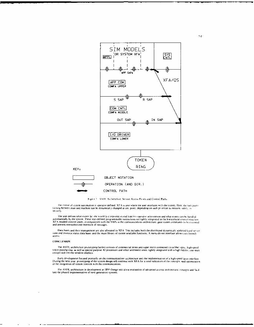
7-5
S'IM MODELS
OUT SAPSI A
I/O DRIVER
XA/OSCOaA UPPER
[OmFA MDlE
OUT SAP IN SAP
11/0 DRIVER]COMFA LOWER
TOKEN
KEYz RING
[ OBJECT NOTATION
OPERATION (AND DIR.)
40 O CONTROL PATH
Figure 3 \SDI, Architecture Service Access Points and Control Paths
Fhe extent of sNstem automation is operator defined. XFA is also shere the user interfaces with the system. Here. the task parti-tioning between man and machine can be dynamically changed at any point, depending on such prorities as mission. satet, orsecurity.
The user defines what events he she w.ould like reported in real time for operator intervention and what events can Ie handledautomatically by the system. These user-defined programmable instructions ate tightly integrated in the hierarchical control structureXFA resident control states, in conjunction with the SAPs in the communications architecture, gate system command, to he ese,iutedand prevent nonauthorized recention of messages.
Data bases and their management are also allocated to XFA. This includes both the distributed dynamically updated fused sensorstate and resource status data bases and the main library of system available functions. A menu-driven interface allos user friendlsaccess.
CONCLUSION
The ASDL architecture prs,totyping facility consists of commercial minis and super-minis connected via a fiber optic, high-speedtoken passing ring. as well as special purpose Al processors and other arithmetic units, tightly integrated w.ith a high fidelity, one-mancockpit and out-the-window displays.
Early development focused primarily on the communications architecture and the implementation of a high-speed laver interfaceDuring the next year, prototyping of the system design will continue with XFA for a total validation of the concepts, and optimirationof the integration of system controls with the communicalions.
The ASDL architecture in development at IBM Owego will allow evaluation of advanced avionic architectural concepts and fail.tate the phased implementation of next-generation systems.

TEST PILO SOPHY OF THE EHIOl INTEGRATEDI AVIONIC
byE. Galli
AGUSTA SISTEMI Sp.A.
Via Isonzo, 3321049 Tradate
VARESE - ITV
SIJISIARY
The intent of this paper is to succintly outline the philosophy employed by Agusta during the deve-lopeeec and testing of the EH101 integrated avionic naval helicopter. The paper is written following thebuilding blocks of the avionic under test (see figure below on which the avionic architecture is showy.
1. SYSTEM DESCRIPTION
The EH101 avinc system is divided into two main processing areas: the Aircraft Management System,(AMS), and the Mission Avionic System (MAS).
FIH FLGT PIL T CAI CAI
DISPLAY DISLY D SPLAY DISPLAY DISPLAY SLYSEOR
8-2
The Aircraft Management System consists of:
- Two redundant Aircraft Management Computers (AMC): i.e., one active, the other in back-up mode.
- Two Sensor Interface Units (SIU) to handle all the analogue and discret signals coming to/from thehelicopter's sensory system.
- A Control Panel (CP) that allows the pilot to select operation (automatic or manual) of the system.
- A Data Transfer Device (DTD) to do the download/upload exchange from external equipment such as
preflight data and maintenance information.
- Two Common Control Units (CCU) which permit the pilot and co-pilot to interact with the system(AMS and AS).
- Symbol Generators (SG) manage the Electronic Instrument System (SIS) programed with the formats
required for the display of navigation, flight and power systems.
- A Navigation Pack which includes Air Data Unit (ADU), Radar Altimeter (RA), Doppler velocity, Tacan.
Global Positioning System (GPS) and Inertial Reference Units (IRU).
The ANS performs management of all the basic functions of the helicopter. These basic functions include
Navigation, Maintenance, Performance computation, Communication, and the monitoring of the helicoptersystems (i.e., rotor, transmission, engine, fuel, electrical, hydraulics, etc.).
The Mission Avionic System is based on:
- Two redundant Mission Computer Units (MCU), same concep, as above: active and back-up.
- Two Common Control Units (CCU) that allow the cabin operators to interact with the system (AMS and
MAS).
- Common Waveform Units (CWU) to manage cabin ard pilot tactical situation displays and tabular infor-mation.
Sensors dedicated to perform the Antisubmarine Warfare (ASW). Antisurface Vessels (ASV) and Electronic
Warfare (EW) are subdivided into:
Underwater Sensors
Sonar subsystemMagnetic anomaly subsystems
Surface SensorsRadar subsystem
Electronic Support Measure (ESM)
Identification Systems
Interrogator Friend Foe (IFF) TransponderInterrogator Friend Fne (IFF) InterrogatorIntermediate Band Transponder
- Communication System
Data Link subsys-em
- Armament System
Weapons management subsystem
Store management subsystem
The two MCU perform al! the processing required for the mission operation, collecting, processing and
storing tactical informaticn coming from the Mission Systems. Each of the two areas (AMS and HAS) use asthe main data transmission meJium; a dual redundant MIL-STD-1553B data bus, the ANS also uses ARINC 429lines to communicate with most of the navigation sensors and the Automatic Flight Control System (AFCS).
2. TEST DESCRIPTION
In order to carry-out the entire integration and testing of the Avionic System four main phases have
been identified.
DEV!LOPMZNT
In this phase each subsystem or piece of equipment is designed and developed in accordance with the
avionic system requirements.
TEST PHASE AT SUBSYSTEM OR EQUIPMENT LEVEL
The assessment with regard to the requirements is carried out.

8-3
FIRST INTEGRATION
At this level integration of the Aircraft Management System in conducted parallel to the integrationof the Mission Avionic items. Testing of these items is contingent upon computerized structures calledRigs. The equipment under test is controlled and stimulated by these Rigs. The basic configuration of the
rigs is a host computer, a set of 15538 and ARINC 429 bus stations, subsystem simulators, input/output
stimulator. and control and display units.
FINAL OVERALL AVIONIC INTEGRATION
At this point, the Aircraft Management System and the Mission Avionic System are fused, tested, and
validated. Again such testing is made feasible by means of the Rigs. The above mentioned phases are con-
ducted to achieve the following goals:
- Minimize the number of prototype flight trials necessary to teat the integrated avionics.
- Reduce the technical risks associated with software/hardware integration.
- Accelerate the iterative loop (i.e., test/design changes/retest) using suitable test programs and
resulting data analysis.
- Deploy an efficient test battery to execute all test runs and cases required to qualify and certify
the systems.
Facilitate the integration of new subsystems, affording timely responses to experimental software
and/or hardware modifications. This feature transcends the design and development phase. It will be
active throughout the helicopter's life cycle.
Let us explore each of these phases in more detail. The Aircr.ift Management System avionic test admini-
sters four separate trials. Trials occur at each of the following levels:
Aircraft Management Computer Test
The aim of this test is the validation of the hardware architecture when put together with the basic
software under more severe ground loading conditions than those encountered during flight. Testing fo-
cuses on the following main areas of interest:
- Interface of 1553B's input/output
- Arbitration of shared random access memory
- Degradation of performance under multiprocessor interference and interactive conditions- Redundancy management.
Tools and techniques used to detect errors during testing are:
- Real time simulation- Failure mode generation in both software and hardware items- Failure analysis- Artificial stress of C.P.U. capabilities- Special test software used to establish the readiness of basic software and hardware prior phase
activity.
The A.M.C. rig Is composed of 1553B & ARINC 429 bus stations. Both bus stations are remotely controlled by
the host computer which provides them the necessary data to simulate equipment not yet available. It also
monitors and analyzes output of the AMC on the 1553B bus and ARINC 429 lines.
Sensor Interface Units Test
The purpose of this test phase is to verify the proper operation of the SIU integration with actualsensors. The SIU are programed with a select input/output polling sequence; the sequence having been per-formance verified. The input/output data exchange with the 15538 system can also be defined, programed
and verified. Testing focuses on:
- 15538 Input/Output interface- Stress incured when CPU respond to different input/output sequences and sampling rates- Real time simulation- Failure mode generation in software/hardware items- Failure analysis
- Assessing results, CPU loading, unit size and timing.

8-4
The SIU is also tested by the rig. This rig is composed in part by 1553B bus stations which emulate the
bus controller commands, monitor and analyze the SIU's data transactions on the bus. The otner compnent
of the rig is the emulator of the helicopter sensors (i.e., temperatures, pressure, loads, discrets,
frequency, etc.). Such items can also be gov-,a _outeiy my tne host computer.
Aircraft Manages-nt System Test
The aim of this test phase is to verify correct integration of the AMC & SIU (the functcon ol each
has already been tested). Major tests performed are:
- Start-up functions- Redundancy management (master/slave in case of failure- Cross channel checking function- Mqintenance data bases exchange
- Bus monitor functions.
The AMS rig is an amalgamation of the AMC & SIU rigs. It consists of the host computer, bus stations(15538 & ARINC 429), SIU, emulators (helicopter sensors & navigation suosystems), symbol generator, )h"display and common control unit. It becomes prudent at this time tc discuss the navcgat-co emulators.They are comprised by a set of single board computers linked to the host computer through an asyocron-line. Each single board computer emulates a specific navigation h,. tec s in terms of timing, pr.tc'v,failure & signal characterization. The host computer furnishes on-going, updated data derived fr heflight p1-, senaric.
Aircraft Management Test
The activities examined during this assessment are:
- Hardware/Software interfaces, functions 0 capabilities- System performances
- Verification of reversionary modes
- Collection of reliability data- Optimization of the download/upload procedure- Support of flight planning- Check system validity before flight test.
At this point the aircraft management system Cig .gle"s Prorlty to 'onotor"ng, acquiring, and aoalyzingdata. Emulation activities previously provided by the rig are no longer required as the real equpment
is now installed. A hlock description of the rig is given (see the following, on which all the eleoenticonstituting it appear with their relevant interconnections.
HOST A 429 A 429 LINES
BU5COMPUTER STATION
1553 BUS MEASURING
STATIONS 335 INITBCMEN.ASX'N
ST IMULI AMIC
SYMBOL
53 Xi2 L IrZATLN H ENERATOB
The foregoirng described the A,C Managemen t System elements or the 1:xtegrated avon-i-. Lts
attention now to the Mission Aveonic Syste-. The :onfig-rat lr. coder test in ris portior. o! tr~e prs t,
like its counterpart the AMS, follows a development cncet of e-. in-reasinw omeplexit, Lt
facilern au-e provided kspecial to-type test eAuipment for evaIoaTior of equp:xerit requiring part;,iciar
attention Ii.e., sonar, radar, armament, ESM . The rig is aio oosrst.ted .of Hoot computer, 15531 Av
stations and a 'omon wave-lore generator unit. The rig is tasked -itn providing the activities listed
below:
- Hardware/software interface integration
- System performances (bus occupancy, CPu load, data sec-rity, .tc.
- Verification of reversionary modes
- Collect reliability & maintainability data
- Optimize download/upload procedure
- Support software validation
- Verify build-in test functions
- Support flight planning.
Note, the functions as outlined in the precedng do not include data handling management of the tactical
scenario as needed by the operators. Tnis job is performed on what is known as the Mission Software De-
velopment Rig (MSDR). All aspects of operator interfaces, data routing, and the human factor are studied
on the MSDR. Off-the-shelf equipment (computer, graphic generators, CRT, compilers, data base, etc.) are
used. This avails the flexibility necessao, Tr a ready analysis of an exising set-up and i-s editing.
T is mode of operation is undertaken to prevent waste _f manpower during the on-board software develop-
sent, validation & testing phases.
The development of the two systems, Aircraft Management and Mission, is effected in two distinct environs.
Only marginally taking into consideration is the information interface of the two systems. At this point
consolidation of the two systems and their respective rigs takes place. Synchronization with regard to a
common scenario, also occurs at this juncture. Having achieved merger the rigs are referred to as tce
Overall Integration Rig. The principle activities executed at this level are:
- Validation of interfaces between the two areas
- Initialization functions
- Failure modes
- System performances
- Total system validation.
The Overall Integration Rig is subject to scrutiny similar to that of the Aizcraft Management and Mission
stage. The price uses of the Overall Integration Pig are to:
- Analyze dati captured by the assigned bus stations
- Emulate, in a dynamic situation, sny required subsystem functions
- When possible, replay excerpts from actual flights that require farther examination.
3. CONCLUSIONS
As illustrated, the testing actirity is not incumbered by external delays. Testing can be carried
on, as preliminary, by the use of emulation capabilities made available by the rigs. The EHIOI Avionic
Test Activities are in the early stae, at present, so a deep analyFis can not be conducted. However, it
,an be stated that the Agusta EHIO1 Integrated Avionic test philosophy has responded well to our needs.
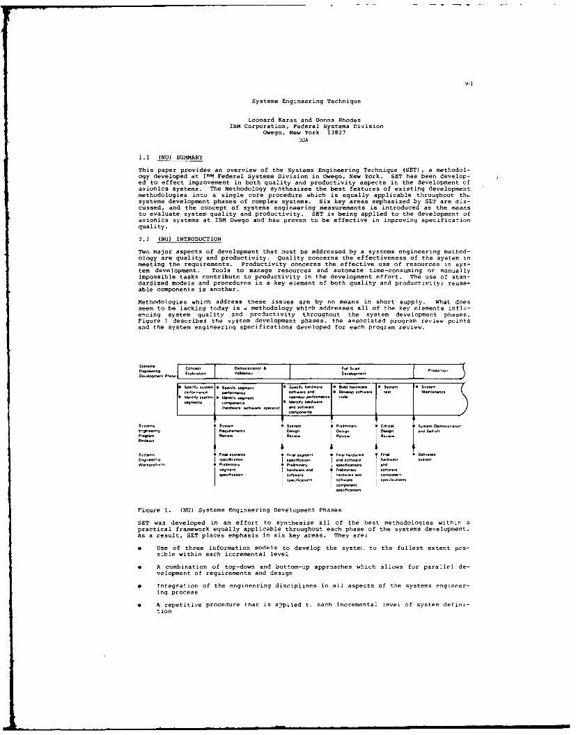
9-1
Systems Engineering Technique
Leonard Karas and Donna RhodesIBM Corporation, Federal Systems Division
Owego, New York 13827USA
1.1 (NU) SUMMARY
This paper provides an overview of the Systems Engineering Technique (SET), a methodol-ogy developed at TIM Federal Systems Division in Owego, New York. SET has been develop-ed to effect improvement in both quality and productivity aspects in the development ofavionics systems. The methodology synthesizes the best features of existing developmentmethodologies into a single core procedure which is equally applicable throughout thsystems development phases of complex systems. Six key areas emphasized by SET are dis-cussed, and the concept of systems engineering measurements is introduced as the meansto evaluate system quality and productivity. SET is being applied to the development ofavionics systems at IBM Owego and has proven to be effective in improving specificationquality.
2.1 (NU) INTRODUCTION
Two major aspects of development that must be addressed by a systems engineering method-ology are quality and productivity. Quality concerns the effectiveness of the system inmeeting the requirements. Productivity concerns the effective use of resources in sys-tem development. Tools to manage resources and automate time-consuming or manuallyimpossible tasks contribute to productivity in the development effort. The use of stan-dardized models and procedures is a key element of both quality and productivity; reuse-able components is another.
Methodologies which address these issues are by no means in short supply. What doesseem to be lacking today is a methodology which addresses all of the key elements influ-encing system quality and productivity throughout the system development phases.Figure 1 describes the system development phases, the associated program review pointsand the system engineering specifications developed for each program review.
Etaiesi ocptSmystt & FoP Scae1.dt~,Deoelopmeyy ... EaI nto edto eeomn
* Specify system * Speify segment 1 S-eily Merts.. Bu ld wdmas System 1. Systeperformance perfomence softw"et end eio sotere lest Mantena.ce
• Identfy system 0Idemtify segment o perto 1r0'm.- cd
segments ompcnents Identify ftardwstre(haedwere software. opatero) and eoftwata
Compornnt s
System, C System C System tP,Inyi l System e.one.retoySnginetng Seqnre-ents Desigy Desgn )eengn end Sl -oft
Progtam Reniaw Reviem 4 ReRiew n ReSlem
Systems C Final systems I Fnel segment * Fiel herdware e Finel DalnoeredEngineeng spacificetion T peclficer oo end softmere hanrdwea systemWorkproducts C Ptefninety C Preliminery specific-tl s end
segment hetdwae andf Prelminar sofywete'emficetion solswere hrdwe end Io npnan
speorficernyns soft.ste epeo/ticetiranssoponcate
s mcmet.
Figure 1. (NU) Systems Engineering Development Phases
SET was developed in an effort to synthesize all of the best methodologies within apractical framework equally applicable throughout each phase of the systems development.As a result, SET places emphasis in six key areas. They are:
* Use of three information models to develop the syste:. to the fullest extent pos-sible within each incremental level
* A combination of top-down and bottom-up approaches which allows for parallel de-velopment of requirements and design
* Integration of the engineering disciplines in all aspects of the systems engineer-ing process
* A repetitive procedure that is applied t- each incremental level of system defini-tion

9-2
0 Use of a plan to manage and coordinate each incremental level of system definition
* A tightly controlled exit from each incremental level of system development
These key areas provide for tighter control over the systems development, both withinand between incremental levels of system definition. Three of these key areas are ad-dressed within each incremental level and provide a more fully developed system throughthe use of models and processes which maximize involvement of the engineering disci-plines and customer.
3.1 (NU) AN INCREMENTAL LEVEL OF SYSTEM DEFINITION
In 2ach incremental level of system definition, SET provides for-
Use of three information models to develop the system to the fullest extent possi-ble within each incremental level
A combination of top-down and bottom-up approaches which allows for parallel devel-opment of requirements and design
0 Integration of the engineering disciplines in all aspects of the systems engineer-ing process
SET employs three models to develop each incremental level of the system. The threemodels are the functional model, the physical model and the operational model. The pur-pose of the functional model is to refine the customer's rzguirements into functionalareas that make the system definition and development manageable. Given a set of systemfunctions, the physical model is used to develop a physical implementation (design) thatis feasible. A feasible design is one that can be built within the technology, cost andschedule constraints. A feasible design is also maintainable, reliable and supportable.The purpose of the operational model is to take the functional requirements and thephysical design for an incremental level and test them for suitability. A suitablesystem is one that satisfies the customer performance requirements, is useable, ismaintainable and is reliable. Figure 2 provides a summary of the three models.
I tSuitable * F iFeasbSMeets customer erformance requirements c Available technology
* System is usable * Reasonable costSSystem can be maintained P Maintainab
O System is reliable * Reliable
Figure 2. (NU) Three Systems Engineering Models
The development of the three models is an iterative process. Each model has its ownunique purpose and overlaps the other two. As each model Is developed, it may impactthe previous model. Therefore, the development team must cycle between each of thethree models until the impacts of one model on the other two are minimized oreliminated.
3.1.1 (NU) THE FUNCTIONAL MODEL (REQUIREMENTS DEVELOPMENT)
The functional model allows the development team to collect requirements into groups sothat intellectual control can be maintained over the system development. Each incremen-tal level has its own criteria for developing these functional groups. For example, inthe first level of system definition the system segments and their interfaces are iden-tified. In the next incremental level, the segment components (hardware and software)and their interfaces are identified, and so on. An incremental level of the system
ta leve ha t|w rtrafrdvlpn heefntoa rus o xmli

9-3
cannot be developed without taking a forward look into the lower levels of systemdetail. In other words, the system must be developed top-down but should be influenced.y the bottom-up detail. The functional model allows the development team to lookahead into the lower level system details. That detail is then abstracted into aconsistent set of requirements that meet the objectives of a given incremental level ofsystem definition.
As higher level requirements are abstracted from the detail, the systems engineers takeadvantage of the engineering disciplines and reusability concepts. For example, whendeveloping the functional areas for a software specification, the systems engineers usethe guidance of the software development engineers to ensuie the functional requirementsare suitable for their development of the low level design. In addition, the softwaredevelopment engineers, in conjunction with the systems engineers, will identify andutilize reusable components from similar systems that were devolnpei. The ,cutipurnents reduce the cost and the tiee necessary to develop follow on systems of asimilar type.
Each incremental level of the system involves a look ahead from an existing level.Since the requirements from the present level drive the next level of system definition,a traceable link is established from one incremental level to the next. This allowstraceability of the lowest level requirements back to the original requirements from thecustomer. Figure 3 is a typical example of the application 3f the functional model toan avionics system.
Look Ahead
Customer requirement 1 (Req-1)T- Provide worldwide automomous
navigat
inJ
Derived Requirements* Compute position
data Abstraction* Provide position data
to the operator Avionics* Provide a position System
update capability* Provide operator
navigationcontrolsC Target
+ sensor alignment Davpltys". position update
selectionCutoerrProvide operator *Compote position data (Req-i) *Provide sensors to
Customer requirement 2 (Req-2) navigation * Provide position data detect battlefield- Provide automatic battlefield controls (Req-1) to the operator (Req-i) targets (Req-2)
assessment and target + sensor alignment * Provide a position * Provide targetacquisition. + position update update capability (Req-i) identification
Derived Requirements selection (Req-21Provide sensors to Provide a target * Select weapons anddetect battlefield acquisition summary acquire thetargets to the operator (Req-2) targets (Req-2)
* Provide target | Provide an operatoridentification fire capability (Req-
2)
* Select weapons andacquire the targets
* Provide a targetacquisition summaryto the operator
* Provide an operatorfire capability
Figure 3. (NU) Avionics System Functions
As indicated in the figure, lower level requirements for the system are developed byanalyzing each customer requirement. These lower level requirements are then collectedinto functional areas using the criteria that is appropriate for the incremental levelbeing developed (e.g., identifying the system segments when developing the system levelspecification). Each function is shown in Figure 3 with a li~t of detailed requirementsthat were used to develop that functional area. The customer requirements that driveeach functional area are shown. For example, the Navigati-n functional area is drivenby customer requirement 1, the Target Acquisition function is driven by customer re-quirement 2 and the Control & Display function is driven by both customer requirements.These functional groups are now considered in the physical model.
3.1.2 (NU) THE PHYSICAL MODEL (DESIGN)
The physical model allows requirements definition and design to proceed in parallei.Therefore, requirements definition is no longer a separate activity from the system de-sign. Instead, the design is considered during the requirements definition without

9-4
locking in the design detail too early. The objective of the physical model is todetermine if there is a feasible design that can be used to implement the functionalrequirements. In making this determination the development team must considertechnology, cost, maintainability, reliability and availability of the physicalcomponents. All of these criteria must be satisfied to make a solution feasible. Inconsidering the alternatives, the services of the various engineering disciplines areemployed. System architects, hardware engineers, software engineers, reliabilityengineers and maintainability engineers are needed to determine feasibility. Thefeasibility question is asked and answered at each incremental level of systemdevelopment. When developing the system specification, the team must select the systemsegments that are feasible for the system under development. If the system segmentspecifications are being developed the group must select the segment components(hardware, software and operators) that are feasible for each segment. This process ofselection then imposes additional constraints on the lower levels of design.
Figure 4 illustrates a design used during the development of an avionics system at IBMin Owego, N.Y. The physical design consists of multiple processors, memory stores anddata busses. This design was selected due to the nigh degree of parallel activities thesystem must perform to meet the overall performance requirements. An important questionat this point is how should the functional processing requirement groups (developed withthe functional model) be allocated to the physical processors? This question can beanswered by considering the functional requirements and physical design in theoperational model.
Processor Bus
Processor, 1 Processor 2 1 rcso Processo , a
SensorIntelaceSwitching Network
Switching Network -. Allows routing of sensor data to processors with minimal delayProcessor Bus High speed communication between proessors553B -. Sranderd Avionics date bus to ppenes
High Speed Date Bus Token ring data bus to pnipherials
Figure 4. (NU) Physical Design for an Avionics System
3.1.3 (NU)) THE OPERATIONAL MODEL
The operational model requires support from a variety of engineering disciplines whoprovide analysis of system performance, reliability, maintainability and operability.This analysis is used to determine whether the functional requirements and physical de-sign are suitable. Each incremental level of system definition is deemed suitable ifthe functional requirements and physical design form a system that meets performancerequirements, is useable by the operators, is maintainable, and is reliable. This isaccomplished by mapping the functional areas and the physical components in a timeordered sequence to model the system performance, reliability and maintainability.Operational flow diagrams, derived from a mission scenario, are developed that allocatethe functions to the physical components. These operational flow diagrams representsystem tasks that are stimulus/response oriented. The stimuli that can cause systemtasks to be initiated are the operator initiated stimulus (operator depresses a key),the event initiated stimulus (receipt of messages on a data link or hardware inter-rupts) , and the cyclic stimulus (computing navigation position at a 25 hert? rate).Once system tasks are identified, the flows that affect system performance, processorloading, operator workload, system reliability and maintainability are developed. Theflows are then individually analyzed to see how a single task effects processor loading.data bus loading and system performance. These individual flows are then used in a
The oprtoa moe reqire supr fro a...m vait of engineering-
disciplineswho
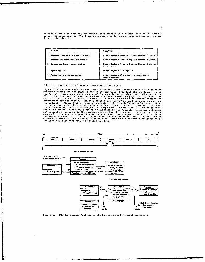
9-5
mission scenario to continue performing trade studies at a -tem level and to furtherrefine the requirements. The types of analysis performed and required disciplines aredetailed in Table 1.
Analysis Disciplines
I. Allocation of performance to functional areas Systems Engineers. Software Engineers. Hardware Engineers
2. Allocation of function to physical emnents Systems Engineers. Software Engineers. Hardware Engineers
3. Operator and System workload analysis Systems Engineers. Software Engineers. Hardware Engineers.
4. System Testability Systems Engineers. Test Engineers
5 System Maintainability and Reliability Systems Engineers. Maintainability. Integrated LogisticSupport. Reliability
Table 1. (NU) Operational Analysis and Discipline Support
Figure 5 illustrates a mission scerario and two lower level system tasks that need to beperformed during the engagement phase of the mission. Note that the two tasks have anover'ap indicating that there is a need for parallel processing. As indicated in thefigure, the functional processing has been allocated across the physical components. Inaddition, performance has been allocated to the functions to meet an overall performancerequirement for the system. Computer based tools can now be used to analyze each taskindividually. Figure 6 illustrates an analysis of the Missile/Rocket Solution and showsthat processor number 2 is 89.2% loaded with just this single task. This indicates thatthe allocation of function to the physical components, in this case, may not be optimal.Tools can assist in the reallocation of function by auiinatically analyzing alternateal'ocations of functions to the physical components. This analysis technique can now beextended to the entire system by modeling all tasks that are performed at any point 4nthe mission scenario. Figure 7 illustrates the Missile/Rocket Solution task run incombination with the Gun Pointing Solution task. Note that there was a reallocation offunction such that processor 2 is loaded at 54.6%.
Time
Preflight Take-of Enrouta Engage Return Lan
MissIle/Rocket Solution
Operator selects
Target Acquittnon PHgSeDst 4a
Procssor 3 (N) - Select missilesrocket Control & D PAplay se- Compute solution to - Display solutions|Navigation selected target 10 tn the operator|
- Cmp~e pslton0O ords. Required response 200 ms 20 Hertz |
Gun Pinting Solution
Processr 3 110 Procesor 2 J10 [ Procesor 4Nswordks Target Acd:u wordsn Controls & Displays
position afte lost. status & position
fire sequenceProcessor 1 2000 _peat:_
T s° '_. I High Speed Data 88u.TagtAqiston Gun pointing
- Sed trge 10 10 cormmdsPosiion ordswords
Figu!re 5. (NU) operational Analysis of the Functional and Physical Approaches

9-6
M so/Rocket Solution
Utlization Statistics of Hardware Components:
Resource % Utilized Resource % Utilized
Processor 1 - Processor Bus 4.0Processor 2 89.2 HSOBProcessor 3 38.2 1553 Bus 3.8Processor 4 6.9 Sensor Interface 32.9Processor 5 -
Processor 6 -
Processor 7 -
Processor 8 -
Figure 6. (NU) Computer Analysis of the Missile/Rocket Solution Task
Combined Missile/Rocket Solution
Utilization Statistics of Hardware Components:
Resource % Utilized Resource % Utilized
Processor 1 3.0 Processor Bus 12.0Processor 2 54.6 HSODB 30.9Processor 3 38.2 1553 Bus 33.8Processor 4 67.8 Sensor Interface 32.9Processor 5 60.8Processor 6 -
Processor 7Processor 8
Figure 7. (NU) Computer Analysis of the Missile/Rocket Solution Task in Combinationwith the Gun Pointing Solution Task.
Once the functional requirements and physical design are determined to be suitable usingthe operational model, the incremental level of the system development has beencompleted. An assessment of the overall system to date is made, and the iterativedevelopment process then begins again.
4.1 (NU) THE SYSTEM DEVELOPMENT PHASES
SET establishes control over the system development ohases by:
e Use of a repetitive procedure that is applied to each incremental level of systemdefinition
" Use of a plan to manage and coordinate each incremental level of system definition
" A tightly controlled exit from each incremental level of system development
To develop complex systems, it is advantageou- to use a methodology which is essentiallythe same for each level of the incremental development of the system, since it is impor-tant that one incremental level flow smoothly into the next. This can only be effectedthrough clearly defined, standardized models and procedures which pick up developmentwhere the last iteration leaves off.
Figure 1 shows major systems engineering specification activities throughout the systemdevelopment phases of a program. Each increment of system definition has a unique setof activities and objectives culminating with a system level review milestone. SETapplies the same core procedure iteratively at each increme,-t of system definition.This procedure is based upon the use of the three models, and is specialized via a setof development criteria suited to meet the objectives of the individual increment.
SET employs a Systems Engineering Management Plan (SEMP) to control the overall sytemdevelopment process. The management plan provides for control over the technical de-velopment, the engineering specialty integration, and the iterative systems engineeringdevelopment. Since SET features clearly defined end points for each incremental level,the iterative development of the system can be crisply controlled by a management plan.Just as the military standards provide for baseline control points via the system levelreviews, SET provides control points via the inspections between the system review mile-stones. The inspection provides a controlled exit to ensure that all aspects of thesystem have been developed before the next incremental level of the system is defined.

It is utilized to review technical correctness, to review and update schedules and
plans, and to baseline the system at the current level of development.
At the completion of each incremental development level, SET procedures include anevaluation step which involves the use of systems engineering measurements. These
measurements are assessments of both the system being developed and the method being
used. SET procedures specify an evaluation step for assessment in two measurement cate-gories: quality and productivity. Quality measurements serve to evaluate the effec-tiveness of the system in meeting the requirements. Productivity measurements serve toevaluate the effective use of available resources in developing the system.
5.1 (NU) SYSTEMS ENGINEERING MEASUREMENTS
The systems engineering measurements are viewed by SET as an inteqral Part of the de-velopmenL process. The rormalization of systems engineering measurements is arelatively new effort and, to date, the measurement of quality has received the most em-phasis. SET developers are currently focused on clearly defining systems engineeringmeasurements for both quality and productivity aspects of development, along with theirrespective nominal values. This ability to evaluate the system development process pro-vides SET developers with information which can be used to refine the methodolooy it-self.
Measurements are taken and evaluated both within an incremental development level andthroughout the system development phases. For each incremental level, the measurementsare directed toward measurement of the system as it exists at that particular Point indevelopment. Throughout the system development phases, a synthesis of measurements isan ongoing process, necessary in evaluation of the system as a whole. Wher, a measure-ment is identified as being less than optimal, the source of the problem is identifiedas the customer, the user, or the systems engineering organization. If the source issystems engineering, an improvement to the process is effected. If the source is thecustomer or the user, the measurements provide a vehicle for discussion of the problem.
One measurement currently used to track specification quality is the number of para-graphs changed in the specification against the major program milestones. Since thecost of fixing errors increases over time (see Figure 8), a desirable trend in the datashould be a constantly decreasing number of errors found over the system developmentphases. Initial data indicates that SET is making a difference in specification quali-ty. Figure 9 is a plot of paragraphs changed for a Software Requirements Specification(SRS) on two programs developed at IBM in Owego, New YorK. Although the avionics sys-tems were different, they were developed by essentially the same team of engineers andwere of the same order of magnitude (125,000, i6-bit words). The data shows that thespecification developed with SET (Program B) is a marked improvement over the specifi-cation that was developed before SET was available (Program A).
Cost i Changes vesus Pogfam Phase
Conceptual Validation Development Production
Figure 8. (NU) Cost of Fixing Errors Versus Program Phase
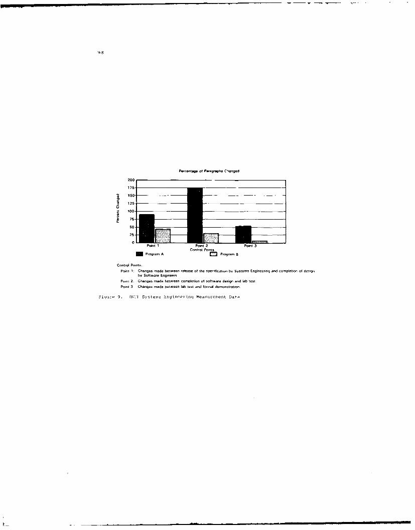
9-8
Percentage of Paragraphs Cranged
20
175-
v 150-
== 125-
.75
-
50-
25-
0 Point 1 Point 2 Point 3Control Points
m Program A O Program B
Control Points.Point 1 Changes made between release of the specification by Systems Engineering and completion of design
by Software EngineersPoint 2. Changes made between completion of software design and lab testPoint 3. Changes made between lab test and formal demonstration,
Figure 9. (NU') Systems J.ngineerinq Measurement Data
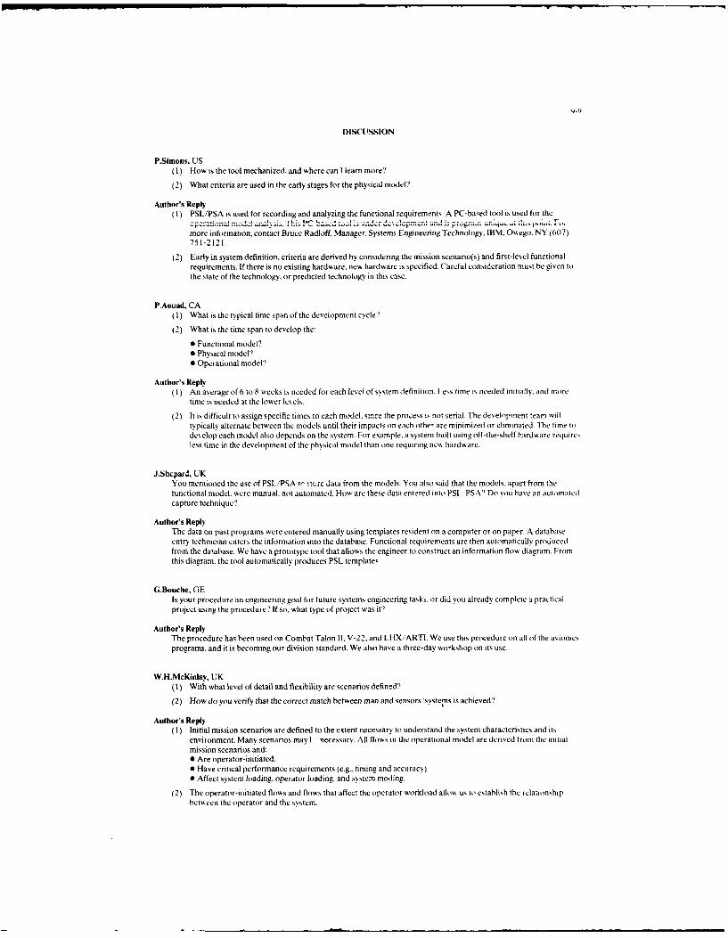
9-9
DISCUSSION
P.Simons, US(1) How is the tool mechanized, and where can I learn more'?
(2) What criteria are used in the early stages for the physical model?
Author's Reply(1) PSL/PSA is used for recording and analyzing the functional requirements. A PC-based tool is used for the
0 P m a .aacJ to .6! T. .. ...... . ,,more information, contact Bruce Radloff, Manager, Systems Engineering Technology, IBM. Owego. NY (607)751-2121.
(2) Early in system definition, criteria are derived by considering the mission scenario(s) and first-level functionalrequirements. If there is no existing hardware, new hardware is specified. Careful consideration must be given tothe state of the technology, or predicted technology in this case.
P.Aouad, CA(1) What is the typical time span of the development cycle'?
(2) What is the time span to develop the:
* Functional model?* Physical model?* Operational model?
Author's Reply(1) An average of 6 to 8 weeks is needed for each level of system definition. Less time is needed initially, and more
time is needed at the lower levels.
(2) It is difficult to assign specific times to each model, since the process is not serial- The development team willtypically alternate between the models until their impacts on each othe- are minimized or eliminated. The time todevelop each model also depends on the system. For example. a system built using off-the-shelf hardware requiresless time in the development of the physical model than one requiring new hardware.
J.Shcpard., UKYou mentioned the use of PSL/"PSA to store data from the models. You also said that the models, apart from thetunctional model, were manual, not automated. How are these data entered into PSL PSA? Do you have an automatedcapture technique'?
Author's ReplyThe data on past programs were entered manually using templates resident on a computer or on paper. A databaseentry technician enters the information into the database. Functional requirements are then automatically producedfrom the database. We have a prototype tool that allows the engineer to construct an information flow diagram. Fromthis diagram, the tool automatically produces PSL templates.
G.Bouche, GEIs your procedure an engineering goal for future systems engineering tasks, or did you already complete a practicalproject using the procedure? If so. what type of project was it?
Author's ReplyThe procedure has been used on Combat Talon 11 V-22, and LHXiARTI. We use this procedure on all of the avionicsprograms, and it is becoming our division standard. We also have a three-day wo-kshop on its use.
W.H.McKinlay, UK(1) With what level of detail and flexibility are scenarios defined?
(2) How do you verify that the correct match between man and sensors/systems is achieved?
Author's Reply(1) Initial mission scenarios are defined to the extent necessary to understand the system characteristics and its
environment. Many scenarios may 1 necessary. All flows in the operational model are derived from the initialmission scenarios and:* Are operator-initiated.* Have critical performance requirements (e.g.. timing and accuracy).* Affect system loading, operator loading, and .system moding.
(2) The operator-initiated flows and flows that affect the operator workload alloA us to establish the relationshipbetween the operator and the system.

WI
MAQUETTAGE DES SPECIFICATIONS FuNCTIONNELLES
DU LOGICIEL EMBARQUE
EXPERIENCE DU SYSTEME AVIONIQUE RAFALE
Monsieur Patrick SCHIRLEIngnieur d'Ltudes A la direction gnerale technique
AVIONS MARCEL DASSAULT78, Quai Marcel Dassault92 SAINT-CLOUD - FRANCE
RESUME
Le developpement du logiciel des systnmes avioriques requiert une documentation de specificationfonctionnelle abondante et souvent contractuelle. Le maquettage de ces specifications permet :
- daamtliorer la ualit& formelle des specification: (coherence, complktude, lisibilit6)- de realiser, tr s tot dans e cycle de vie, une validation fonctionnelle des specifications
sur cimulateur (miroir de la specification)- de fournir des elhments de recette (jeux d'essais) aux rhalisateurs de sous-ensembles du
systeme- de disposer d'une refkrence fonctionnelle commode lors de lintegration des materiels rees.
Le maquettage intervient des la phase de definition fonctionnelle du logiciel selon le scenariosuivant :
- premiere Acriture des specifications fonctionnelles du logiciel- analyse critique des specifications : contrdle de forme- codage des specifications dans l'ordinateur de simulation de la maquette- tests fonctionnels sur maquette : contrble de fond- fourniture aux rhalisateurs des @quipements e-spcifications rhputhes bonnes et des jeux
d'essais correspondants.- rhalisation du logiciel des Aquipements- integration et validation du systfme reel
Le systhne avionique de l'avion RAFALE prhsente des innovations telles que l'integration dessysttmes avion (moteur, comsandes de vol, etc...) ou la securisation des informations de pilotage. Cesnouvelles fonctions entrainent un accroissement et une evolution qualitative notables du logiciel descalculateurs embarqus.
Pour ameliorer la qualitA et le delai de mise au point des logiciels, le dhveloppenet s'estappuy6 sur une mdthodologie integrant le maquettage des specifications fonctionnelles du logiciel.
La maquette a tA construite autour d'un calculateur SEL supportant le codage Fortran des 3500pages de specifications fonctionnelles du systeme.
Chaque specificateur a pu valider sa specification, puis globalement lensemble desspecifications, directement sur maquette. A cette fin, un conversationnel specifique a dO 6tre ddveloppApour permettre la stimulation du logiciel maquette et l'exploitation des rdsultats grAce A des scenariosreprsentatifs des conditions d'utilisation du systeme ree.
Outre le gain realisA pour lintgration du systlme reel, Ia maquette a pu Atre utilisee comme
- support d'analyse de pannes-banc d'essais pour les Avolutions- gknerateur d'6lkments de recette- reference fonctionnelle pour les intervenants
1 - INTRODUCTION
Les systfmes avioniques actuellement dtveloppes par la SociktA des Avions Marcel Dassault secaractsrisent par :
- Une complexit6 croissante- Une integration de plus en plus serre de leurs fonctions- Une inflation chronique du volume de logiciel embarqu6.
Ceci implique la coordination des travaux de trhs nombreux specialistes et une organisationindustrielle adequate : face A ces problemes et pour assurer la qualitA constante du produit, lasolution actuellement retenue par l'avionneur consiste en la definition, la mise en place et le suivid'une methodologie stricte concernant le dveloppement du systeme, particulierement du logicielembarqui.

li-2
Cette methodologie prhcise sans ambiguitt quelles sont les etapes du dhveloppement. les produitset les responsabiliths qui leur sont attachto. Lide au traditionnel cycle de vie du logiciel , ellefait apparaitre des phases de rtoception/spcification, de rtalisation (codage) etd'intbgration/validation.
La phase de conception/spdcification se revle comme 6tant la plus critique. En effet,s'inscrivant dans Ia partie amont du cycle de vie, toute erreur ou imperfection a ce niveau estamplifide au cours du cycle et se traduit par des consequences avalec coOteuses et difficilementmaitrisables.
De plus, les produits issus de cette phase tant essentiellement des documents papiers, laperception du produit final A travers ceos simples documents est ddlicate et orobltmatieue.
Les deux Atapes maitresses de la phase de conception/sphcification sont
- L'6tape de spdcification globale du systIme- L'6tape de sphcification fonctionnelle ddtaille
Ltape de sp6cification globale consiste en l'6criture de deux types de documents
- R gles gnrales : il s'agit d'une description des regle et philosophies d'emploi du systeme,communes A toutes les missions (principe de dialogue homme-machine, gestion/signalisation des pannes,superposition des fonctions d'armes, etc...).
- Specifications globales des fonctions operationnelles il s'agit de decrire, pour chaque fonctiorspcifique du systeme, le schnario nominal doutilisation de cette fonction, en terme d'utilisateur(pilote) et bien entendu dans le respect des rdgles ginA-ales.
Ce type de specification, non exhaustif sur un plan fonctionnel et ne dhdiant pas les r6lesrespectifs de chacun des quipements, permet de valider en terme d'oprationnel la conception desfonctions at sert de base A A'6tape suivante.
La validation de cet ensemble de specification est rhalis~e pratiquement grace uc simulateursimplifih construit autour d'une cabine de pilotage, permettant un dialogue direct et als& avec letpilotes.
L'6tape de specification fonctionnelle dhtaillhe se compose de deux t~ches
- Etablissement d'une architecture fonctionnelle : d~composition a priori en modules des tAchesrdaliser et rhpartition de ceos modules dans leos quipements ; principes gdndraux de dialogue entreAquipements et entre modules d'un mAme Aquipement.
- Ecriture des spfcifications fonctionnelles d taill~es par module et par 6quipement, descriptionexhaustive des traitements A effectuer et des interfaces.
Ces documents reprhsentent la derni~re Atape de la phase de conception directemeot du r6te et je
a responsabuith ds l'avionneur : i serviront de refdrence contractuelle vis A yis den coophrantspoo a ralisation du logiciel des quipements.
Vest A ce niveau de sphcification que nous ressentons un besoin constant d'amlioration de ]aqualith, tant formelle que fonctionnelle.
Leos mthodes classiques que nous utilisons depuis plusieurs annfes pour "valider" ces documents(representant plusieurs milliers de pages) sont
- Canevas strict- Organisation de relectures croishes- Dictionnaire de terninologie- Traitement de texte (texte + graphique)
Nous tentons actuellement une ouverture vers aes mhthodes exploratoires plus "up-to-date" quisont :
- L'utilisation d'un langage de specification formel et contr61 par outil.- Le maquettage des sphcifications fonctionnelles dhtaillhes.
Le langage formel nest employ6 A ce jour que pour des applications sphcifiques (Commandes devol, chaines & haute shcuritd) et na pu Atre systhmatique ; en effet Ies langages actuels sent ciblessur un type particulier de specification et requirent une formation sphcifique. Etant actuellementtrop Aloignhs du langage naturel pour permettre une lecture (ou une 6criture) par un sombre importantd'individus de functions et .e compdtences diverses, leur utilisation quoique inevitable a terme, faitactuellement lobjet d' tudes.
Le maguettage fonctionnel par contre presente, outre sa faisabilite d~nontrde par les mhthodes ettactiques actueles, lavantage d'assurer A la fois la qualite formelle de la sphcification (parndcessith) et la qualitd fonctionnelle de la mme specification par effet de miroir.
Cette stratdgie de maquettage a 6t retenue et mise en pratique dons le cadre du orogrammeRAFALE A l'6tape d'6criture des spdcifications fonctionnelles d~taill~es.

10-3
2 - CONTEXTE RAFALE : HYPOTHESES ET SPECIFICITES
2.1 - Evolution des specifications fonctionnelles dtaill~es
Pour les systimes des premieres annes 80, il Atait realist un unique document despecification par Equipement, lequel d6crivait globalement I ensemble des fonctions de chaqueEquipement sans contrainte particulire de modularit. Ce document d~bouchait sur la rtalisationdu logicie Equlpement correspondent et toute modification du premier entralsait ipso-factomodification du second selon une gravitE variable et non pr~vue.
Pour des raisons de taille et d'EvolutivitE du logiciel et de la documentation, il estdevenu n~cessaire A partir des systmes MIRAGE 2000 EXPORT d'affi,ier la resolution du coupledocument de splcification/logiciel grace A la creation d'une architecture fonctionnelle dulogiciel des Oquipements.
Cette architecture reprdsente la d~coupe en un certain nombre de modules indpendants, desfonctions a r~aliser par le logiciel d'un Aquipement. Cette 06coupe, permettant le cloisonnemententre des modules bien identifies, s'appuie sur des crit~res
d'evolutivitE :modules A faible/forte probabilitO d'evolution.Esempes: forte probabiliti conversationnel homme-machine
faible probabilit: algorithmes de balistique
- de slcuritE :modules de diffhrents niveaux de criticitA (cf. DO 178)
- de ricuptrabilitAmodules specifies comme ricupirables d'un systmme A lautre (module ind~pendant delenvironnement spicifique d'un systeme donne).
L'architecture fonctionnelle, Atablie par AMD-BA pour 1'ensemble des Aquipements est priseen compte pour 1 'criture des specifications et d6bouche sur une modularitA fonctionnelle de ladocumentation et in fine du logiciel correspondant : A chaque document de specification correspondun module identifid du logiciel :
Caractiristiques des specifications "modulaires"
- Chaque module est spscifi6 par un et un seul document de specification.- Chaque module est d~fini, gsre, modifi6 de facon autonome.- Chaque module est d~crit par :
ses interfaces avec les autres modules. sa fonction de transfertChaque module peut itre machs de faton autonome
- Chaque module est decompose en sous-modules et A terme en pieces de logiciel.
2.2 - Contexte RAFALE
Le systime avionique de l'avion dimonstrateur RAFALE presente un certain nombre denouveaut~s et de spscificit~s par rapport aux avions de la gniration prscedente, telles que
- 1'integration tr~s pousste incluant les syst~mes avion- 1'extension d6 sombre de fonctions necessaires des le premier vol- la d~centralisation des fonctions systdme (riparties dans plusieurs Aquipements)- la genfralisation de 1'emploi des techniques numiriques dans des domaines dO 1'exp~rience en
Atait faible- les d~lais trls courts et tris tendus de l'operation.
Pour faire face A cette situation, il a alors Et decide de rsaliser un travail demaquettage des specifications avec les objectifs suivants :
a) AmEliorer la qualiti des specifications fonctionnelles dftaillses
b) Permettre une validation fonctionnelle de ces specifications
c) Fournir aux coop~rants des jeux d'essais cohrents pour valider aussi t~t que possible leursdiveloppements.
d) Disposer d'un banc d'essai pour tester a priori les evolutions.
Ce travail a d~butE en Mars 85 avec leS Etapes suivantes
a) Analyse critique des specifications
b) Ralisation de la maquette
c) Exploitation de la maquette

10-4
3 - ANALYSE CRITIQUE DES SPECIFICATIONS
3.1 - But
Les specifications fonctionnelles dstailles repr~sentent la charniere entre la conception(travail AMD-BA) et la rtalisation des logiciels (travail des cooperants). II est donc importantqu'eules soient a la fois :
- Entilrement reprasentatives des besoins op~rationnels du concepteur (aspect fonctionnel)- Comprshensibles et rtalisables par les cooptrants (aspect formel)
Le but de lanalyse critique des specifications est d'amliorer leur qualitA pour couvrirlaspect formel, c'est-a-dire s'assurer que les specifications sont
- lisibles- completes- cohirentes entre elles- sans ambiguTtA- r~alisables informatiquement
3.2 - Principe et organisation
Un sp~cificateur Atant natureilement satisfait de son document grAce a sa connaissance ducontexte op~rationnel, pour que lexp~rience soit rentable il a fallu isoler ies lecteurscritiques de ce mme contexte tn limitant IPq exnlirations fuurniei sur es SpicifL 0ions. Le motd'ordrp a At . se pas juger de ie do i faire la specification (fonctionnel) mais jugeruniquement la maniure dont ele est Acrite et safaisabilith.
L'6quipe de relecture na pas eu connaissance du besoin ophrationnel exprimA A travers lessphcifications d6taillies (sphcifications globales non fourniesl.
la totalith des documents de sphcification dtaillte (3000 pages) a AtA soumise A l Aquipede relecture critique. Toute fiche d'6volution, quelle que soit son origine, s'est vue appliquerla m~e proc6dure de relecture.
3.3 - R~sultats de 1'tape
Le nombre de critiques (justifihes) a tA extr~mement important : 250 pages de remarques,repr~sentant de lordre de 1000 points prhcis.
Le nombre de critiques par page de specification (d.nc in fine Ia qualitl formelle de laspecification) varie consid~rablement en fonction :
- du rhdacteur (rigoureuxi/on rigoureux. prcis/ghnral, structur-,c lect;oineui de uitails)
- du modu7esphcifih (logique/algorithmique)
Les erreurs releves par la critique entrent tIutes dans les trois categories
- erreurs de rigueur- erreurs de ghnhralit6- inadaptation de la specification A une r~alisation informatique.
a) Erreurs de rigueur
- Interface man uante : linformation utilishe par les traitements nest pas dclarte A entrhede a sp c icaton
- Interfaces incohsrentes : les interfaces dhclar6es en entrhe du module sp~cifih nexistentpas dans le syst~me (non calcules par d'autres modules)
- incomp ltude des traitemantsLe traitement relatif Aue sortie d@clarte du module nest pas spdcifiADans une combinaison logique, tous les cas ne sont pas renseignhs ; il est A noter que lecas est tr~s frequent lorsque la logiquP est exprimhe au moyen de phrases (si, alors,sauf, quand) et pratiquement inexistant si la logique est dhcrite sous forme de tableauxde vnritA.Les conditions d'initialisation, d'activation, d'enchainement des traitements ne sont passp~scifihes.
- Terminologie floue ou ambiqUeExempep"on dhterminera"dans la plupart des cas...""dans certaines conditions...""linformation existe dans les cas suivants..."
b) Erreurs de gnsralitA
- Caract~ristiques dinterfaces non splcifihes
Na mont pas prkcis~s l'unit@, le type (logique, bcoisen), les valeurs possibiem d'uneinformation.

'0-5
- Traitement dtcrit trop globalement
Ce genre d'erreur est frequent lorsque le specificateur surestime le savoir faire (oulintuition) des realisateurs de logiciel.
c) Inadaptation de la specification a une realisation informatique
- Choix de la solution informatique : le sp~cificateur, dans un louable souci de rigueurimpose la facon dont dolt 6tre realise le traitement : connaissant peu les criteres de"progranmatliii le choix est parfois non astucieux et peut d~boucher sur un logicieldLinesur4 ou non 6volutif.
3.4 - Remarques et commentaires sur l'tape d'analyse critique
L'tape d'analyse critique des specifications a et@ extrnmement fructueuse et r~velatrice.Nombre de problLmes de toute importance ont pu Atre ainsi resolus a priori, evitant de lesreporter A ]a phase d'intsgration. Par contre, I'tnergie mise en oeuvre a 6t egalementimportante : 6quipe de relecture, temps "volL" aux spicificateurs, lourdeur de mise A jour de ladocumentation.
La plupart des erreurs recenstes sont des erreurs Avitables qui ne remettent pas en cause leprofil actuel des sp~cificateurs. En effet, cette phase de relecture a conduit & am~liorer unespecification existante, non pas A crier une couche de specification plus detaillee.
Enfin, lexptrience a ete vecue par les specificateurs comme un contr~le qualitAsupplk.nt-ie m:, donc ressentie de faton tr~s mitig~e...
4 - REALISATION DE LA MAQUETTE
4.1 - Elaboration des prosrammes-maquette
La necessite de coder les specifications a mis en evidence trois impratifs d'tcriture decelles-ci. Les deux premiers sont d'ordre general et concernent toute specification devant etrecodse, le troisi~me est lie A la structure doublie du systLme RAFALE.
Premier imp~ratif completude des interfacesDeuxilme imp~ratif definition du type de chaque variableTroisieme imptratif definition pour chaque variable du type de liaison entre module Ametteur etmodule(s) recepteur(s)
D'autre part, l'opration de codage a confirme la ncessitt de description d'un logicielenveloppe pour cha 4ue module implante dans un equipement double.
Compl~tude des interfaces
Cette Atape est indispensable avant toute operation de codage. Le renseignement complet desinterfaces a donc te n~cessaire, avant codage du logiciel initial, comme avant chaque passaged'une version A lautre.
Definition du type de chaque variable
Cet imptratif a conduit A enrichir la base de donn~e d'interfaces avec la d6finition, pourchaque variable, d'un type analogue aux dclarations de variables FORTRAN, A savoir
- Zool en, tableau de boolsens, logique, r~el, entier.
Nota : La phase d'analyse critique des specifications avait dejA fait apparaltre la necessitA deU6ifnition du type de variable.
Codage des modules fonctionnels
Les programmes maquette ont ete Acrits en FORTRAN, directement A partir de la specification(apres phase d'analyse critique) et en utilisant la base de donnte d'interfaces comme referencieldes variables.
Produits
Le r~sultat de la phase d'Llaboration des prograemmes-maquette se decompose en
- Un produit interindiaire sous la forme d'un fichier de variables de 8 caractores extrait de labase de donnees d'interfaces. Ce produit constitue en fait un complement de specification,indispensable pour la gfnration du code.
- Un produit final compos des programmes-maquette (ou modules) d'une chalne de calcul.L'obtention de lensemble des modules reprfsentatifs des deux chalnes devant 4tre faite grace A]a duplication de ces programmes-maquette.

10-6
4.2 -Adaptation de ]a console de visualisation des Aschanges (CVE)
La CYE Astait, A 1lorigine, uni outil de visual isation des Ischanges entry Aquipementsnumtriques. Pour les besoins du maquettage. il a fallo faire tendre cet outil de visuelisationvers un outil de validation de specifications. Leo travaux d'adaptation ont port@ Sur
Au niveau conversationnel
- Le pilotage de la simulation (choix du mode simulation, des modules A activer, etc ...)- Le developpement de procedures d'entree de valeurs A la CYE- L'ameslioration de la gestlon des chaines memoristses (concatenation de ctiaies. appel novijiatifde celles-ci).
- Le diveloppeient des procfdures de tests automatiques
Au niveau systfne
-La generation des lexiques CYE
Ces lexiques sont n~cessaires as bol fonctionnement de la simulation et A 1 exploitation desr~ssultats de celles-ci.
Ils coviprennent:
la liste des modules et leurs adressesla correspondance des fichiers 8 caractesres par rapport aux fichiers de la base de donn~sed'interface initiale (40 caractLres)la liste des pavs~s r~cepteurs d'ure information donn~e
4.3 -Mise en oeuvre de la simulation
Les caract~sristiques essentielles de la simulation mise en place sont les suivantes
-Simulation mono-frequency-Cycle de simulation correspondant A 1 activation squentielle des modules maquett~ss-Prise en compte de 1 architecture double-chaine du RAFALE:Cette prise en coinpte se rsuame A lecablissement de deux procesdures
Eclatement des variables*Duplication des progranmmes
Afin de g~sn~rer l'ensetble des variables emses et recues dens les equipements des chaines1 et 2, ii a eteI necessaire. A parcir du fichier standard 8 caractesres, deLclater len variablespouvant Atre fmisen par deux esquipements symhtriques (voir schemas ci-dessoas).
CHFIINEMEN' NON SECURISE
AVANT ECLATESENT
-"EIINEMENT SECLJRISE
AVANT ECLATEmENT
A x B
&PvES ECLATE.MENT ~jSAES ECATESENT
IAl
B Al xi BIA22B
MASA A VARIABLE VA NE SERT QUA SIVALER LA GSTllS DESECARNSEC -MSN SON ROLE DAIAAILLAAE DES VARIABLESEMISES AL TEq A-'.C '0 A' ET AZ

BRSE OFQONNEES
0' INTERFRCES
HIC-iER SPECIEIERTIONSSTIONANRO FONCTIONS DE
8 CARRCTERES ) TRANS5FERT I
IBMIECLATEMENT
D ES VARIABLES
L E XI QUJES GEST ION COriMUNS PRODRRTSCVE ECHPNGES EOUJPEr1ENTS ENRINE 1
DUPLICATION PROGRAMMESB A U ET I
PROGR AlMMES
SEL CHIE T2
EVE SI1LRTIQN
RECAPITULATIF DES PHASES DE LA REALISATION MAQIJETTE
5 - Dre EXPLOITATION MAQUETTE - TESTS UNITAIRES ET MANUELS
Nf initions:
Tests unitaires tests portent sur las variables d'Entr~es/Sorties dun module uniqueTests manuals teuts pour lesquels les valaurs des variables d'Entr~scs doinant Atr modifi~cs
manual lerent par le sp~cificateur.
La d~roulemert da ce type da test cut le suivant
1) Constitution d'une chaina2) Entr~e des valeurs A la CVE3) Ddsclenchemant dun pas de simulation at lecture des r~sultats
5.1 - Constitution d'une chaine
Cette opfration conslute A s~lectionnar an certain nomnbra de variables parmi le total desvariables d'E/S d'un module donnA at a las regrouper dans. on ensemble appalt chalna. Suivant lataille de cc module cc choix a Et fait
10-8
Pour les modules de taille importante
En silectionnant toutes les variables d'Entr~es/Sorties se rapportant A une entit& donne.
Pour les modules de taille r~duite
La taille des sous-modules de ces specifications permet d'utiliser toutes les variables deces sous-modules pour constituer les chalnes. Chaque chalne est 1'image d'un sous-module.
Cette mithode peret :
- de retrouver chaque variable de sortie du module dans une chaisne- de disposer dans chaque chaine de toutes les informations utilis~es pour 6laborer les variables
hmises par le sous-mcdule.
On peut ainsi se rapprocher de Ia d0marche visant S valider les pieces de specification deniveau le plus bas avant de passer au niveau sup~rieur.
5.2 - Entree des valeurs A la CVE
Cette opiratlon est rtalisse en d~signant la variable A modifier dans la liste des variablesde la chaine, en stlectionnant le mode "modification de valeur", puis en entrant la nouvellevaleur.
Bien que la modification anuelle de valeur de n'importe quel type de variable soitpossible, la plupart des tests ort porte sur des modifications de variables booleenns VRAI/FAUX,et de variables logiques.
Quelques tests ont porte Sur des modifications de variables numeriques soit pour verifierdes logiques (dlclenchement de seuils, temporisations.. .), solt plus rarement, pour valider desfonctions de transfert nusriques.
6 - 26me EXPLOITATION MAQUETTE - TESTS AUTOMATIQUES
6.1 - Int~rlt des tests autoenatigues
L'utilisation des tests manuels a r@vl plusieurs limitations de ces derniers
1) Difficultls de manipulation des chaines comportant un nombre important de variables.2) Inadaptation de ces tests pour la recherche de dlpendances entre variables.3) Difficultls de validation des mlcanismes mettant en jeu des transitions ou des mnmorisations.
Ces limitations ont amenl A envisager le dtveloppc-nt de tests automatiques quipermettraiet t I. faois
- de gLsnLrer automatiquement des combinaisons de vaieurs d'entre pour les chaines A tester- de faciliter lexploitation des r6sultats par des editions appropriles Sur listings.
Generation automatique de valeurs d'entre
Les objectifs vises correspondent aux limitations mentionnes plus haut pour 1'exploitationdes tests manuels :- Pouvoir balayer toutes les combinaisons des variables d'entrLe choisies et observer leur impactSur toutes les variables Imises par le module pour dltecter d'eventuelles oependances anormalesentre variables.
- Mettre au point des scenarios nominaux permettant de simuler difflrentes configurationsd'initialisation, des enchainements de phases de vol mettant en jeu des transitions ou desmdivorisations.
Les premiers tests ainsi mis en place appells tests mono-variables ont permis de tester toutes lescombinaisons deduites d'une combinaison initiale en faisant varier une variable bool(enne de Iachalne.
La validation des transitions et mimorisations a donne lieu A Ia creation du type de test"SCENARIO DE PANNE". Ce type de test permet d'introduire A des intervalles de temps traduits ennombre de pas de simulation des jeux de valeurs dentree prepares A 1'avance.
La verification exhaustive de tous les cas possibles de valeurs d'entre d'une chaine devariables boollennes donne a 6tt rendue possible grAce aux tests combinatoires.
En tout 7 types de tests automatiques ont tI ddveloppLs:a) Combinatoire statiqueb) Combinatoire sLquentielc) Mono-variable statiqued Mono-variable soquentiele) Allatoire statiquef) Allatoire squentielg) Scenario de panne
Nota : Un test statique se distingue d'un test slquentiel par la remise de toutes les variables ATa-valeur d'initialisation aprLs chaque pas de simulation.

101-9
Facilitts d'eploitat.,n des resoltats
Parvll~lemest au d4veloppemeewt de ces types de tests, les possibilitts de sortie desrissiltats ont 61t6 Itenduen
- Possibiliths d'impreosion ou non de la "r~itrenceu (c'ent-A-dire de la divine avec ses valeursd'lnitlal isation).
- Possibilit6 di@ditions selectives des variables ayast varil par rapport as cycle prkcident.- PossibilitAs d~ditions silectives des variables ayant variA par rapport A la csmbinaison dertf~rence.
ten possibilitis ont perinis en particulier de manipuler des chaises constitutes d'un grandnombre de variables, sans pour autant avoir A rvchercter len r~sultats significatifs dass l8 listsde toutes len variables constituant la chaise.
6.2 - Exploitation des tests autoenatigues
La phase d'exploitation des tests automatigues a d~mnarris en automne 85 at a coinportA deosparties:
-Tests unitainres automnatiques-Tests globaus autonmatigues
Tests usitaires automnatigues
Suivant la nature de ]a sp~cification, dens types de tests ont AtA, priscipalement utilis~s
- Tests coebinatoires- Scenarios de passe
Pour leo sp~cifications d~crivant des ni~canismes de logigue sans ni~morisation Si problkmesd'initialisatlon, la majoritA des tests a Lstt do type csmnbinatoire statique (spbcificationo devinualisations notammnt).
Pour les sp~scificatwons d~crivant un sombre important d'6tats, de transitions et dctemnporisations, den sc~narios de passe ont AtAs g~ntralement employlo (sp~cificatios designalisatin des isformatioss soteur ou conunandes de vol notanmnent).
Tests globaus
Dtfini tionTeitgTobal :test consistant A activer 1 ensemble des modules maquett~s.
Nota :Ce type de tent, disponible Agalement en mode manuel n'a AstA stilisA pratiqoemest go'esmode automatique.
Intlsr~t
L'int~rit des tests globass est de valider le toelportement de 1 ensemble des modulesmaguett~s.
En effet chaque sp~cification peut Wte vhrifiks vs thforie, A la seule lecture du documentde sptciflcation lui-s~me.
Par contre, 11 sexlste pan de document d~crivant la r~partition prfcise des traitessentsentry len difflrentes ophcifications et assurast ainsi qun la miss bout a bout des diffbrentomodules condomse as respect de la sp~cification globale.
7 - ALAN
7.1 - Rensourcen spilcifigues mses en oeuvre
L'asalyne des sp~cificationts et leur codage dans la maquette ont reguls 50 llomme-M'oio, dontprhs de 50 % pour la phase d'analyse critique den op~cifications. Le d~veloppesest de la chaisedoutils ainsi gus la mine en oevre de la maquette ont ntcessitA 22 lovies-Mois.
Sur le plan matial, la maquette a AstA r~alis~e nur un systine informatique GOULD (SEL32/27) dont il a Wt n~cessaire d'augmester la puissance as tours du diveloppement en raison de lad~gradatlon du tempo de r~ponse. 11 fast nouligner gus la nialisation de la maguette a pu se fairedano leo tempo impartis grAce A l'utilisetlon de l'exptrience acquise lors de dlveloppementsastlrivurn dans le domalne de la simulation.
7.2 - Ripercussiossour la mithode de travail
L'istroduction do maquettage a modifli la m~thode suivie pour dlsvelopper le logicielavionigue RAFALE par rapport aus habitudes den progranmmen pr~cedents. Cette modification concernsessentiallessent:
- la diclaratlon den interfaces entry modules (y coampris modules d'un mgme Aqulpement)- 1 Acrlture d'une opfcification avec urne contrainte de maguettabilitA- la possibiliti de voir 'vivre" sine spiciTfcat1on

10-10
Declaration des interfaces entre modules
La cohlrence imposte au niveau des interfaces par la saisie de celles-ci sur loutil de basede donnfes (premiEre Etape du maquettage) a induit une plus grande rigueur dans le dialogue entrespicificateurs. En effet l'obligation de rentrer chaque interface dans une rlf~rence unique etregroupant lensemble des interfaces a 6ritE la plupart des redondances d'informations (ou lesorigines d'informations inconnues) que la dispersion des interfaces aurait risquE d'entrainer.
Ecriture des sp~cifications avec une contrainte de maguettabilitE :
La ncessitl de dscrire des traitements pouvant etre transcrits sans ambigultA en codeexEcutable (en loccurrence FORTRAN) a permis d'@viter des retards dus aux difficult~s rencontrtespar les coop~rants dans la lecture de spEcifications ddtaill6es trop 'gnlrales".
PossibilitE de voir vivre une specification
Lors d'application de fiches de modifications. ]a possibilite de valider presqueimmdiatement celles-ci a permis de "resserrer" le lien entre le sp~cificateur et son produit. Eneffet, bien qu'il soit pratiquement toujours possible de tester une modification (ou un mLcanismede facon 9gn6rale) mentalement ou sur le papier, l'utilisation d'un outil accomplissant lui-m emeI'effort n~cessaire A 1'executIon de Ia fonction de transfert a dschargE d'autant lesp~cificateur, lui permettant ainsi de se consacrer A l'interpr~tation des risultats.
Par contre le bilan de l'opAsration maquettage fait apparaltre des contraintes ayant limitel'intlr~t de celle-ci, en ce qui concerne le programme RAFALE. Ces contraintes sont de deuxtypes :
- Ergonoemie de la maquette- DMlais et disponibilitE des utilisateurs
Ergonomie de la maquette
MalgrE les efforts importants d'aminagement du conversationnel de la maquette, lapresentation tres d~sincarn~e des informations a rapidement modtrA lVempressement des utilisateurspour ce nouvel outil. II est en effet difficile de valider le comportement d'un ensemble der~ticules (A plus forte raison d'une page complste de r~ticules), A laide de VRAI/FAUX ou devariables logiques codses. Cette presentation quelque peu r~barbative na pas permis d'exploitercomplstemrent les possibilit~s pourtant importantes de la maquette.
Delais et disponibilit~s des utilisateurs
Les p~riodes de disponibilit6 des utilisateurs de la maquette Wont pas toujours coTncidtavec les p~riodes oQ il aurait te le plus profitable d'exploiter celle-ci. En particulier lestests globaux, intsrnt majeur de la maquette, nont pas eu limportance qu'ils auraient dO avoir,en raison de 1 exploitation tardive de ceux-ci.
7.3 - Repercussion sur la qualite du logiciel avionique
L'analyse de l'impact du maquettage sur la qualite du logiciel fourni aux bancsd'intsgration est rendue difficile pour les deux raisons suivantes :
- Le maquettage est l'une des composantes de la mthode de travail, au niveau des spEcificationsfonctionnelles detaill~es ; le risultat obtenu est donc inherent A I'ensemble de la methode,l'impact purement maquette etant quasiment impossible A extraire.
- La nouveautE des fonctions assurtes par le logiciel, la nouveaute de larchitecture et lecaract~re davion dmonstrateur font du Systwme Avionique RAFALE un cas particulier, rendanttoute comparaison delicate par rapport aux systemes precedents.
Nanemoins, analyse faite par le personnel des bancs d'int~gration, il ressort que le nembrede fiches d'volution li~es aux erreurs du niveau spEcification est en nette regression parrapport A son niveau habituel ; relativement A l'ensemble des fiches d'@volution, sa part a eterlduite environ de moiti6.
8 - CONCLUSIONS ET ENSEIGNEMENTS DU MAQUETTAGE DE SPECIFICATIONS FONCTIONNELLES DETAILLEES
8.1 - Ce que le maquettage permet
a) Amsliorati-n des specifications
ContrOle de forme
La relecture critique permet de corriger et de completer la specification pour l'amener Aun niveau de qualitt autorisant son coda e direct par des informaticiens (equivalent manuel desfutures specifications formelles o outil se charge de la reTecture et permet unecompilation).
Le maquettage agit a ce niveau comm un puissant r~velateur d'erreurs et un contrlequalitE efficace.

10-'11
Contr~le de fond
L'outil maquette permet one reelle validation fonctionnelle de la specification ao niveaumodule, 6quipeinent ou nysteme :validation horizontale (tests exhaustifs d'un module) auverticals (test d'une chaise fanctionneile donnls).
b) Fourniturede ,leux do test as d'ilnients de rscett!
Les tests rfalisis nor Ia maquette (combinaisons d'entrfes et sorties correspondantes) ontsemvi A fournir des jeus d'essais ass cooplrants.
Ceo jeux d'essais ont Ist6 stilists esplrimentaisment dass le cadre du RAFALE cosine aide Ala mine as point chez les cooplranto.
En effet, la meqoette Otant rerL'sentative de 1larchitecture do system reel, elle persistde g~nirer les informations de simulto uu dstmlation as niveas souhaite.
DoG la possibiliti d'organiser, en ainont de Iltape d'intigration one recettefonctionneile pertielie des hsuipenents.
c) Pisp~sojion dune r6flren!ce fonctionnelis cosmmode
Line fain velidle, ia maquette est entretenus de tastes les modific ations apportees ausysttms et rests donc la reference. 11 est alars possible ds Ilutiliser (sass reserve d'uneergonomic soffisante) cosine one "documentation vivante" et representative du systlme, portableet ne nicessitant pas de matrins s ecc us ce ades fins pLsdagogiqus didectiqses astrivialenient posr aniajuit e t tTode i a
7 feonctiosnesient son somisaus do system.
d) Visibilitl _as niveas Ivol ution/rLsc!Aplration!
La qualit@ des specifications autoriss lanalyse et is chain des evolutions, directementen terms de solution, permettant ainsi uns connaissance apri ori de leur impact sur is logiciel.La maquette eile-m..e pest servir de basc d'essal pour tester fosctionseilsment len ditesevolutions et s assurer de leor adlqoation aun beso ns avant leon miss en chantier. Enfin, lacorrsspond..zc document de splcification/module de lagicFinemet de prlvoir et de planifien lanecuperation de lagiciel. Elle permet en autne, apr15 analyse, de disposer de gabarits enmatilne de volume de logiciel, de charge caicul,... ao me coOt.
e) Efficacit6lde 1toR4~cification
La cosequence directs do maquettage est de disposer de specifications astonomes etauto-suffisntes pour rlaliser et tester is logiciel, modole pen module o Iqoipeient pardquipement.
Pour den systlmen tr~o dicentralisLss ds type RAFALE, ccci pennet de fournir A chacon denintervenants len elements precis, nlcessaires et soffisasts A Ia tiche qo'il dolt conduire. Cepoint, qui concoont A is simplicitf et A la clartl den documents, permet @gaisment one bannsprotection den informationo canfidentielles.
f) Amnlioration-de laqualitldu produit final
Outre Is gain de qualite obtsnu poor Il6tepe de specification fonctiannells dlteillee,1 esploitatian de is meqoette, particolilnment 1 'otilisatios den tests automatiquss, persist eta penmis denillioner is confience dens Is produit final. Es effet den centieis de tents ont eterlalisls nelativement A den configurations avion non nominales, penmettant ainsi de dlcoonrir(et de remedier) A den situations non prlvoss a priori dens la specification. De m~ss larecherche doun profil de pannes donne, pan balayae cambinatoirs systlmatiqus ds tooten lenentrees a pernis de conforter len analyses de passe et leo solutions chaisies.
8.2 - Ce gus is maguettags impligue
a)U e jetian niloureose et outillleeden interfaces £18000 dens is can do RAFALE}
La callection den interfaces estre modules et entre Iqoipemnents reprEsents le casur de la".machine" ;c'ent A partir de ces donness qos vast Lstre creles astomatiqoement len variableslogicielles de la maquette, lesquelles pournont Itne stimolees et scrotles en phase devel idation.
11 fast dosc disposer, avant de caommencer Is maquettage, douns description comiplete etcohlreste de ces interfaces, cc qul demands, outre one entrese riguson, us gras travail desynthiss et de rapprochement.
b) Use dsscrijtion prcise et coinleite des fanctians de trensfent
Poor len modules gus Il'n desire val ider, la rialisation do logiciel maquettecorrespondent consiste A d~crire pan do cods solcutable (manuellement dens le cadre do RAFALE)len fanctions de transfert entraites do document de specification. 11 st danc indispensable quecette description soit soffisenosent fine poor pouvair enpnimen cheque sortie du module sclon onecambinaisos mathlmatiqus den entrees ;dens le can oQ la description st trap gLsnlrale, il y avaleun ajootle entre la specification et la maquette, ce qul est cantraire a0 principe devalidation den specifications.

10-12
c) U ne qestion de la documentation et de Ia cocnfiujration
L'abondance et la varitg de la documentation, la n~cessit& de sa remise a joursystematique ftoute evolution ne peut 0tre d,6crite que par modification cohL6rente et immsdiatede la documentation concern~e), exigent un support de documentation souple et efficace.
De m~me, le parall~lisme indispensable entre les etats de dofinition
- documentation (A tous niveaux)- logiciel maquette- logiciel reel
implique une gestion de configuration rigoureuse et commode.
8.3 - Conclusion
Pour synthstiser le bilan de l'experience ainsi acquise, le mieux est de rappeler quel'avion RAFALE a effectu6 son premier vol le 4 Juillet 1986, avec six mois d'avance sur l'objectiffix6 par l'Etat, et que les 90 vols effectuLs en six mois et l'valuation conduite par le Centred'Essals en Vol, l'Arm(e de l'Air et la Marine Nationale Francaise ont conclu A l'excellenteadaptation de l'avion et de son syst6nme aux objectifs opgrationnels qui lui avaient tA fix~s.
Les principes exposes dans cette note seront done poursuivis en vue d'une application dansles programmes futurs, et d'une integration dans 1'effort mrthodologique et de d~veloppementd'outils menA par les Avions Marcel Dassault et de facon plus gentrale par l'industrieaeronautique franraise.
DISCUSSION
E.Cambise, IT(1) What is the size of the embedded software of the RAFALE?
(2) What is the ratio between the development effort of the prototype software and tlat of the "target" embeddedsoftware?
Author's Reply(1) The size of the operational software, the specifications of which were submitted for prototyping. is of the order of
200 koctets. (This software does not include flight command software.) The effort authorized for the functionalspecification stage for purely prototyping activities represents 42 man-months.
(2) 1 cannot put a number on the relationship between the effort of developing prototyping software and of deveopingoperational software, because the real software was developed from specifications in different machinery bydifferent companies. From all accounts, this ratio is well below one.
G.Bouche, GE(1) What are the key differences between the prototype software and the operational (embedded) software that make
it so much easier and faster to write the prototype software, although it will be fully functional?
(2) What is the approximate difference in man-years etween the prototype soft* are and the embedded software inRAFALE?
Author's Reply(1) The prototype software was developed very rapidly on nonspecific materials and under different constraints from
the operational software - functional reliability, efficacy, language, respect of real time, etc. - remainingfunctionally identical nonetheless (from the close temporal aspect). Only the test trials resulting from the prototypeare compatible after formatting of real interfaces.
(2) See answer to the question posed by Mr E.Cambise.

The Avionics Software Architecture Impact on System Architecture
C. Douglass Locke, PH.D.Sienior Programmer
M/D 0210IBM FSD
Owego, NY 13827
Abstract
Existing aviorucs systems are designed as a set of subsystems integrated by corrmand and control software in a centr) processorsystem. In future avionics systems, the complexity of 'his critical soP:ware is expected to increase dramatically, leading topotentially explosive growth in both software costs and the likelihood of critical software errors. As the software increases inboth its complexity and its criticality to the success of the overall mission, (e.g.. by the infusion of Al. image processing.distributed processing. etc.) the vulnerabilitv of the system to software errors also increases dramatically.
This problem can. and, we feel, must, be alleviated by the use of new methods for defining the system architecture, and allowingthe software architecture to constrain the design space of the hardware physical architecture. Thus, the process of developingthe software architecture must change both us its development methods, and the avionics system design cycle stage at which it isperformed. It is thus critical for the software arc* itecture to be a driver of the system architecture design decisions.
In this paper, we consider the technology devcopments which have led us to this problem and their impact on the functionaltsand design of new systems. Following this, we discuss the current sequence for performing the physical and softwarearchitectural design, including a defisition of the software architectare, with examples. Fr,,m this. we discuss what we feel arethe likely consequences of using these methods for designing such new avionics systems, and one potential solution to theseproblems.
1.0 Introduction
It will come as no surprise to practitioners in avionics systems that the characteristics of such systems hase undergone a rapdevolution in the last 10-15 years. and that a similar, if not greater rate of change is ahead in about the same time ntcrsal Thenature of these changes may be characterized using , variety of metincs, some of which are summarized in Figure 1. [or thosecharacteristics wXich can be numerically evaluated, the growth is described by a geometrical progression, not b a linearprogression. During this period, the sequence of steps by which an avionics system is designed has not undergone such a rapidchange; a question which we would like to address is. 'will our current systern design methods be adequate for the ~tpes of futuresystems characterized by these metrics?-
Past Present Future
Human Interface Manual Man-in-the-Loop Automated
I/O Data Rates 10*2/sec 10*4/sec 10*6/sec
DP H/W MIPS/Memory 0.4/64K 2/256K 10/4M
No. of Processors 1 2-4 10-20
S/W Processing Types Math. Comand & At, SensorEquations Control Fusion, Video
Primary Constraint H/W H/W + S/W S/W
Avionics System Evolution
Figure I
In the past, avionics systems were simple by modem standards, with architecturally small, single computers with processirglimited to conceptually simple algorithms such as vector rotations, ballistics computations, display scaling, manual operatorinterfaces, and with overall functionality constrained primarily by the amount of hardware supportable by the platform us termsof weight, power, and volume. In current moder systems, the avionics system supports man-in-the-loop operator interfaces.requiring more powerful and larger processors capable of command and control processing in conjunction with the humandecision maker. Such system designs are constrained both by the hardware, as previously, and the software which must be ableto use the constrained hardware to provide the required functionality. In future systems, characterized by automated (withmanual override) control with its inherent need for increased fault tolerance. Al. sensor fusion functions, and rather powerfulcomputers, the primary system design constraint will be the software (i.e., the set of algorithms and data structures required tofulfill the system specifications).
These future systems will require changes to the methods by which the system design is performed; the geometrical changes inthe system complexity leading to greater numbers of much more powerful processors will not allow us to continue designingsystems in the same ways as before.

11-2
The process of designing an avionics system may be described as a sequence of design stages or steps. Although the number ofsteps and their exact nature is highly variable. for the purposes ofthis paper we identify four top-lecel steps in Figure 2
rhis sequence is, of course, predicated on the assumption that these stages ma, be sequentiallx perlorned; ie., that theinformation needed to initiate each stage ongmates only with the preceding stages For past and current sstems, thisassimption is justified, but it is the premise of this paper that this assumption ma% not be warranted in highly complex systemssuch as some of those currentl on the drawing board, particularly for the last two steps listed in Figure 2 It is not obsious. insystems with a large number of interconnected, powerful processors, that it necessanly will he possible to design the processesfor each processor without subsequently modifvmg the number of processors and their interconnections, thuis signdicantlkincreasing the cost and risk .,i the avionics development.
(1) Conceptual Design -- Determining the concepts to be used in theavionics design. This activity derives these concepts from thesystem specification; for example, when the system specificationcalls for an aircraft to use acoustics for underwater detection,the conceptual design will identify the type of acoustic devicesrequired (e.g., sonobuoys, dipping sonor) and structures,irterfaces, and controls required.
(2) Functional Design -- Given that the set of system conceptshas been defined, the actual functions to be performed insupport of each concept must be determined. An eaomple ofthis would be the decision to deploy sonobuoys automaticallyin response to passing a given geographical position.
(3) systems Architecture -- Having determined a set of functions tobe provided, the systems architecture can be defined. Examplesof systems architecture decisions are the devices required tohandle a sonobuoy system, the nature of their interconnection,and the specific operator actions which are needed to managethese devices. Included in the current systems architecturephase are decisions about the numbor and type of processorsneeded and the nature of their interconnections.
(4) Software Architecture -- Upon presentation of a systemarchitecture, the software architecture may be determined. Thisactivity consists of such actions as designing the functionsto be provided by each processor, determining the communicationsprotocols to be used, defining what, if any, operating systemshould be used (including how the specific operating systemsconstructs are to be used), designing the modular breskout ofthe software, etc.
Conventional A vionics System Design Sequence
Figure 2
Considertng, for example, the LAMPS Mark III system, we note that the LAMPS conceptual development grew our ofexperience with previous LAMPS systems, as well as out of experience with several relatively simple prototypes constructed andtested over several years. For the full scale development, these concepts were used to design an avionics system consisting of 5general purpose computers. using a variety of interfaces (point-to-point channel attachments, data link, and a communicatic.isbus). The software ",rchitecure was then determined independently for each of these computers, along with the commumcatinsprotocols needed to fulfill these requirements. For the system, software architecture steps, this assumption of independence sasvalid for two principal reasons:
*The LAMPS problem, in spite of the presence of a large number of functions, was very simple structurall.
*Because of LAMPS' inherent structural sinplcity, a federated distribution of functions among the vanous processingelements provided a satisfactory solutior to the software architecture (i.e., a federated distribution is one in which thallocation of functions among processing elements is physically fixed because of asymmtical processing capability andinterfaces). A by-product of such a federated functio;al distnhution is that the choice of communications protocols foreach communication path is independent of any other communication paths.
It is clear that the avionics systems of the future, moving in the directions of increasing function exemplified b ATF and IItXand illustrated in Figure 1, are at least an order of magnitude more complex, requiring more fully integrated functions From thepoint ,f view from which this paper s being wntten, the key difference between current systems such as LAMPS and such futuresystems lies in the iegree of interconnection among the various subsystems. For example, in LAMPS. the sensor subsystems,such as the acoustics, have no direct interface with the navigation subsystem other than through a common data base. On theother hand. for systems such as ATF, virtually all functions are envisioned to be fully integrated; e.g.. the FLIR system imagescan be processed both f r targeting information to be coupled to weapons delivery. and for navigation fixing. Beyond suchdirect interfaces, the FL R video must be digitally enhanced for pilot presentation, involving both extensive hardware andsoftware interfaces.
It is important ro note also that the sequence of decisions in the design process is influenced by the factors which drive thedesign. In the past, hardware physical charactenstics such as weight, power, and size. as well as performance, were prime dctorsin determining the physical design; thus making the hardware choices first, followed by the software architecture within thephysical constraints made sense. It is the premise of this paper that the current avionics system design methodolog applied to

11-3
iuture corr'lcx systems will lead to expensive (cost and schedule) development iterations and suboptimal implementations Now.In the face of the increased system complexity required, the difficulty in successfull% integrating the required software functi-.ns inthese systems forces the software architecture to drive the overall physical design although physical attributes such as weight andpower will, of necessity, constrain the resulting design.
In the remainder of this paper, we discuss the relationship between the system architecture and software a:.hitecture in Section2.0. a new approach to a coordinated system software architecture in Section 3.0, and identifys the ke) conclusions in Section 4.0
2.0 System Architecture vs. Software Architecture
The process of defining an architecture consists of defining a structure and the relationships between the entities which make upthe structure. This definition of architecture applies to many fields; for example, in construction, the architecture consists ofdefining the relationship between shapes, colors, textures, and functions. Sinilarl), in avionics systems, the process of definingthe avionics architecture (i.e., the system architecture) consists of defining the relationships between entities such as sensors.actuators, and weapon systems and the human(s) who will operate and use the system.
For discussion, we choose to separate the concept of the avionics system architecture into the physical architecture and thesoftware architecture. The physical architecture consists of the structures and relationships among the physical elements of thesystem, e.g.. the processors, peripherals, busses, sensors, and actuators. The software architecture, on the other hand. consists ofthe assignment of the control functions which actually perform the coordination of the system entities into computationalelements, and the relationships between the computational elements and the data structures. In the software architecture, theobjects consist of two major categories: I) the processes which perform the functions required of each computational element,and 2) the data structures containing the information to be processed by each of these processes. To this point, the softwarearchitecture can be thought of as if we were targeting to a uniprocessor. The software architecture also then includes thepartitioning of these processes and data structures into a set of physical processors. Thus, the software architecture is developedin conjunction with the system architecture to define the number and type of the processors, but the software architecture alonedetermines the placement of the process functions among the processors.
In current systems, the software architecture could successfully be performed sequentially following the system architecturebecause there are only a small number and type of processing elements, and the function of each process was very closelyconnected with the system architectural elements themselves. Thus, for example, in the LAMPS hehcopter, we find the primarcommand and control computer to be a single entity, with no backup, coordinating with a set of peripherals and processors.which were, in general, not general purpose computers. Specifically in the LAMPS helicopter the other principal processorsconsist of a sensor processor for performing acoustic analysis, and an ESM processor for analysing incoming electromagneticradiation. The functions performed by these processors is specific to these subsystems, and no functional backups on the aircraftwere felt to be required (or feasible at that time) across the system boundaries. Thus, the allocation of function within theLAM PS helicopter to the various processors was dictated by the choice of sensors themselves.
In modem avionics systems, on the other hand, we find that the processing requirements are sufficiently great that it is necessar,to have a number of processors in each of the avionics functional elements. This mea-is that the processor-function assignmentis both more flexible and more complicated, as issues of communications protocols, fault tolerance, and reconfiguration becomecritical to meeting the overall avionics systems objectives. If decisions relating to the software architecture are left until theprocessors and their interconnection have been defined, the design space for the software architecture will likely have been soconstrained that it will not be feasible to fulfill the overall system objectives.
3.0 An Approach to System/Software Architecture for Complex Systems
!f the generation of a system architecture followed by the software architecture seems not to meet the needs of future systemdesigns, the logical question to ask is -What sequence of system/software architectural development will result in both areasonable architecture and a working system in a reasonable period of time?" In Figure 3, we show a refinement of steps 3 and4 for Figure I into 7 steps. These 7 steps are contrasted with a new sequence of seven steps (shown in Figure 4) to address theprojected highly complex environment of the future.
In order to evaluate these seven steps and their use in constructing a real-time avionics system, let us begin by considering thesteps as they are now generally performed (see Figure 3). It will be observed that there are some fundamental dissimilaritiesbetween the sets of steps in Figures 3 and 4. In the proposed approach we are considering, we find that by the time step (3) iscompleted, the high level algorithms and data structures are already in place that are required for the overall system solution.We note that these are not the low level algorithms (sometimes called "math flows- in the past) which describe the processing onbehalf of individual sensors or actuators. For example, we would not expect to find here the details of the navigation equationsused to generate current position from an inertial navigation system. but we would expect to find the flow of information fromthe navigation system to the low-light level TV or the radar, ECM equipment, etc. The key here is that we have defined thealgorithms and data structures based only on the sensors and actuators in use. as well as the human interfaces required, withouthaving yet considered the information processing or communications structure. In other words, we consider the processor andcommunications structure decisions to be a result of, not the determiner of, the software architecture, from the top levelperspective.
Therefore. by the time we have completed step (4), and prior to defining the processor and communications structure, we havedetermined the complete functionality at the system level, and have defined the flow of information that must occur between allof the pieces of equipment that actually interface with the operational environment. By contrast, we note that this is notaccomplished until after the defijlitioni of the data processing equipment and communications equipment in the conventionalavionics system software engineering -. chiecture procedures.

11-4
(1) 1efine each of sensors and actuators (including weaponsystems) for the system, based on the top level systemrequirements. This process accounts for required vehicleperformance, flight envelopes, weight, etc., but disregardsinformation processing and communications requirements.
(2) Define the human interface functions. This consists of alist of operator functions, both input and output, including amodel of the required operator responses and estimate ofrequired operator precision and speed.
(3) Define the computational elements and communication structuresto be used to control these sensors and actuators and interfacewith the human operators. Consider the fault tolerance, faultcontainment, and degraded modes.
(4) Define the algorithms and data structures for each of thesensors and actuators defined, constraining them to fit withthe computational and communications equipment.
(5) Deduce the information flows among each of these components forall required system modes. This includes the date structures tobe communicated, the rates at which communications must takeplace, and the required precision of each data element.
(6) Analyse the resulting system architecture for communications orprocessing bottlenecks, probably using a combination ofanalytical and simulation techniques.
(7) Iterate steps 3. through 6. until the system reliabilityrequirements have been satisfied.
Decomposition of Conventional System Architecture Development Sequence
Fgure3
(1) Define each of the sensors and actuators (including weaponsystems) for the system, based on the top level systemrequirements. This process accounts for required vehicleperformance, flight envelopes, weight, etc., but disregardsinformation processing and communications requirements.
(2) Define the human interface functions. This consists of alist of operator functions, both input and output, including amodel of the required operator responses and estimate ofrequired operator precision and speed.
(3) Define the algorithms (processes) and data structures for each ofthe components (e.g., sensors and actuators) defined in step 1.These algorithms define the interrelationships between thesecomponents, not the computations performed internally. Forexample, this might define how information from a navigationalcomponent would be used to perform a flight maneuver or positiona weapon, not how accelerations measured by an inertialnavigation system are converted to velocity or position.
(4) Deduce the information flow among each of these components forall required system modes. This includes the data structures tobe communicated, the rates at which communications must takeplace, and the required precision of each data element.
(5) Partition this information flow, considering requirements forfault tolerance, fault containment, and degraded modes(including potential software faults in addition to hardwarefaults) into processing elements and supporting communicationstructures (e.g., busses).
(6) Analyse the resulting system architecture for communications orprocessing bottlenecks, probably using a combination ofanalytical and simulation techniques.
(7) Iterate steps S. and 6. until the system reliabilityrequirements have been satisfied.
Proposed Sysem Architecture Development Sequence
Figure 4

1l-s
The big difference is that in the event of difficulty meeting any of the data processing constraints, such as fault tolerance, faultcontainment, and degraded modes, in the normal procedures the entire data processing structure and commurscations structuremay have to to be modified in several design iterations. This cannot, of course, be done until each problem has been diagnosed.which may frequently not occur until after the system has Deen developed and partially implemented.
This nsk of needing major design iterations is a critical failing of such a system since it leads to high cost and or poor quaht,.and we believe that the risk can be contained with our new approach. This belief is supported by the now well-documented factthat the early detection of errors in a system implementation dramatically reduces the cost to correct them. We note that theiterative part of the proposed approach affects only the last two steps, steps (5) and (6); rather than affecting the whole design.as in the conventional approach.
As an example of a design problem which can be avoided by this approach, there are a number of cases in which a set ofinterconnected computers has been configured to provide a high degree of fault tolerance by incorporating suitable redundancIt is frequently the case, however, that when the software is being dsigned, the required functions could not be implementedwithout additional hardware support because the underlying algorithms and data structures had not been designed andconsidered prior to defining the interconnection structure.
It might be argued that the current approach (see Figure 3) allows the detailed hardware design to begin earlier in the systemdesign cycle. I his is true, and in he past, an early start on the hardware design was considered cntical to meeting overall systemschedules. However, the new (correct) emphasis is on the use of off-the.shelf hardware elements, reducing the need for allowingfor long lead times for hardware design, and the increased software complexity has caused it to increasingly dominate both thesystem cost and schedule.
From the point of view of the skills to be used for developing a system under this paradigm, there is another fundamentaldifference between these approaches. In steps (3) and (4), at the very beginning of the high level system design, the softwareengineer must be already involved. The skills needed for this step consist of a knowledge of the data processing andcommunications issues of the avionics system, rather than the systems issues which were needed in steps (I) and (2), and whuchwill be needed in steps (5) and (6). To an increased extent, system design decisions will be determined by softwareconsiderations. While it is possible that a few individuals have the requisite education and expenence to perform all of thesesteps, the normal case is that personnel with knowledge of such things as the flight dynamics, mission profiles, and operatorinterface will not be able to optimally define the information processing and communications design. Thus, this approachencourages the use of system arcltecture teams with greater software skills and awareness to define the high level design
4.0 Conclusions
The current sequential nature of the system engineerng, determining a physical architecture followed by performng the softwareengineerng to produce the new, extremely complex avionics systems makes the design process prone to sub-optmal solutions orunworkable designs leading to critical functional errors. These errors are not so much the traditional types of errors exemplifiedby targeting errors or incorrect displays, but are likely to be some of the more subtle problems such as failure to meet timingrequirements (appearing usually as 'nterrmttent" errors), or. worse yet, failure to respond properly to component failure with anappropriate reconfiguration or degraded mode.
We have described a proposed new sequence for performing such a malor avionics system design by intermixing thesystem/software engineering tasks to isolate the complexity introduced at each step, and minimizing the number of factors whichmust be considered in the iterative part of the design process. This should result both in a less error-prone high-level design, andin a process with a much greater likelihood of success at a more controllable cost. IBM is strongly committed to the productionof such systems, and is currently carefully considering approaches such as the one presented in this paper to ensure that thecomplex avionics systems needed for the future can be as successful as those produced to date.

13-i
A COMPARISON OF INiTEGRATED AND SEPARATE SYSTEMSFOR FLIGHT CONTROL AND NAVIGATION
by
HE.utkampLITEF (Liton Technisce Werke) der Hdlige GmbH
L6rracher StraeD 7800 Freiburg
Germany
I-. Summary
Modern aircraft use signals from gyros and accelerometers in various subsystems, amongthese flight control, attitude/heading and navigation systems. Utilisation of the sameset of instruments for these three functions could be envisaged.This investigation discusses some possible steps leading to an integration of navigationand flight control functions into one system. Obvious advantages of such a system couldbe a decrease in weight, power consumption and volume.Emphasis of this paper is laid on technical feasibility and on possible developmentrisks associated with the application involving inherently unstable aircraft.The main requirements for reliability, accuracy, and bandwidth of the sensor data differaccording to whether the application is for navigation or for flight control. A study ofthese requirements forms a reasonable basis for the concept of an integrated system.
The conclusion is that an integrated system Is appropriate for an inherently stable air-craft, but that a lot of risks are involved in the development for control configuredvehicles.Investigations have shown that the essential reduction in weight, power, and volume forsystems combining navigation and flight control tasks is very difficult to achieve.Consequently, first-integration-stage systems, which include only the flight control
sensors and the attitude/heading determination, are recommended. Such systems arealready produced at LITEF and are an integral part of the EAP
1 which involves an
inherently unstable aircraft. During the first flight trials in August 1986 the systemsuccessfully demonstrated its capabilities.
2. Introduction
Modern fighter aircraft require an appropriate FCS2
to provide sufficient handling Qual-
ity and adequate stability in order to reduce the pilot's workload and simultaneouslyprovide a stable weapon delivery platform. In addition an autonomous navigation system
and an AHRS3
are required in most aircraft applications.
To date the inertial data required by the individual functions - FCS, AHRS and -,,1
has been provided by independent sets of gyros and accelerometers. The redundancy of thesensors increases the weight, size and cost of the whole aircraft. Furthermore an
increase in the number of sensors introduces extra maintenance problems. Therefore theutilisation of the same sensors for flight control purposes, for attitude and headingdetermination and for navigation purposes could be envisaged. An integrated system hasto deliver the inertial sensor data with at least the same accuracy, functional relia-bility and lower life cycle costs as that of a separate system.Using strap down technology, integrated systems for flight control, attitude/headingdetermination and navigation purposes have been successfully implemented in the trans-
port aircraft field. This goal also seems to be achievable in the very near future foragile inherently unstable fighter aircraft, but there is a great deal of work required.
A brief summary of recent development efforts in this field forms a basis for our owninvestigations.
I Experimental Aircraft Program
2 Flight Control System
3 Attitude and Heading Reference System
4 Inertial Navigation System
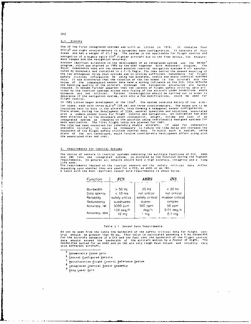
1-2
2.1. History
One of the first integrated systems was built at Litton in 1976. It contains four
DTG's5
and eight accelerometers in a pyramidal axes configuration. It consists of fourboxes and has a weight of 27.7 kg. The system is not applicable for flight control and
navigation of a highly agile CCV6
fighter aircraft due to the time delays, the measure-ment ranges and the navigation accuracy.
Another important milestone in the development of an integrated system was the MFCRS7
program, which was started in 1980 by the USAF together with McDonnell Douglas. Themajor components used are two skewed mounted inertial navigation systems H 421 manufac-tured by Honeywell and installed in a F-15 Eagle. The idea behind the skewed mounting ofthe two orthogonal strap down systems was to provide sufficient redundancy for flightsafety critical information by using two accurate, costly and heavy inertial systemsOnly. It was discovered that the location of the two boxes in the aircraft and thenoise of the compensated sensor data have a strong influence on the FCS. This affectsthe handling quality of the aircraft although the navigation accuracies are hardlyreduced. It became further apparent that the latency of flight safety criti al data pro-vided by the inertial systems allows only flying of the aircraft under conditions wheredynamics are not critical. Further investigation should be carried out in order todetermine if the navigation system, with only a few modifications, could be used forflight control.In 1983 Litton began development of the IISA
8. The system consists mainly of two simi-
lar boxes, each with three RLG'59
(28 cm) and three accelerometers. The boxes are to beinstalled back to back in the aircraft, thus forming a hexagonal sensor configuration.There arose, during the development of lISA, several questions and solutions associatedwith a common sensor block for flight control and navigation. An indication has alsobeen attained as to the necessary power consumption, weight, volume and cost of anintegrated system as compared to the solution using individually designed systems foreach application. The first flight tests are planned for 1987.The lISA has been conceived for inherently stable aircraft. If used for inherentlyunstable aircraft, it would be necessary to reduce the time delay and increase thebandwidth of the flight safety critical control data. To build such a system, usingstate of the art techniques, would involve considerable development effort along withthe associated risk and cost.
3. Requirements for Inertial Systems
The choice of sensors in inertial systems combining the multiple functions of FCS, AMRSand INS into one integrated system, is dictated by the function having the highestrequirements. In general all sensors should have a high accuracy, integrity and a longlife span.The requirements imposed on the inertial sensors and the safety critical data differdepending upon whether they are used for a FCS. an AHRS or an INS.A table with the most important sensor data requirements is shown below.
Function _ FCS AHRS INS
Bandwidth > 50 Hz 20 Hz < 20 Hz
Data latency < 10 ms not critical not criticalReliability safety critical safety critical mission criticaRedundancy quadruplex duplex simplex
Accuracy, rel 5000 ppm 500 ppm 50 ppm
100 deg/h I deg/h 0.01 deg/hAccuracy, abs 10 mg 1 mg 0.1 mg
Table 3-1 Sensor Data Requirements
As can be seen from the table the bandwidth of the safety 7ritical data for flight con-trol should be greater than 50 Hz. This value is calculated assuming a 6 Hz bandwidthfor the aircraft dynamics of a CCV and the fact that the bandwidth of the flight controldata should exceed the bandwidth of the aircraft motion by a factor of eight. Thebandwidths quoted for an AHRS and an INS are only rough mean values and actually varywith different aircraft.
Dynamically Tuned Gyro6 Control Configured Vehicle
7 Multifunction Flight Control Reference System
8 Integrated Inertial Sensor Assembly
Ring Laser Gyro

13-3
Whereas a time delay for the AHRS and INS functions is not critical, a time delay
greater than 10 ma for flight control data could cause a destabillislng effect in the
aircraft control system.The reliability can be categorised into "safety critical" and "mission critical". The
former category applies to flight control data, the loss of which would cause the air-
craft to be no longer controllable. Under special circumstances the three attitude
angles could also be safety critical. The loss of an INS does not influence the stabil-
ity of the aircraft, but loss of attitude information make it impossible to complete the
mission.
Usually a CCV aircraft needs a quadruple redundancy for the flight safety critical data.
The attitude angles are required duplex delivered by the INS and by a SAHRS1 0. Cost and
weight restrictions allow the use Of only one INS in most fighter aircraft applications.The relative accuracy of the sensor data of an INS with medium accuracy should notexceed 50 ppm including all error compensations. The same requirement for an AHRS Is 10times lower. It is sufficient that the flight control data have a relafive accuracy of
0.5 percent. The accuracy in the determination of angular rates and accelerationsdiffer in the three applications by a factor of 100 and 10 respectively.
In a nutshell, the task is to Integrate the diverging requirements of high bandwidth andhighly reliable data without special emphasis on accuracy for flight control
andhighly accurate dat4 without special emphasis on latency, noise and bandwidth for navi-gation.
4. Steps of_ Integration
There are at least three ways of solving the flight control, the attitude/heading andthe navigation tasks for a modern CCV, bearing in mind that quadruplex redundancy forflight safety critical data and duplex redundancy for both attitude/heading and naviga-tion functions are required.
No Integrotion
1. Step of integrotion
I] L ' I 12. Step of Integrotion
Figure 4-1 Steps of Integration
When using nonintegrated separate sensor blocks, it is necessary to employ four indepen-dent channels for flight control purposes and a duplex sensor package for bothattitude/heading and navigation tasks. This leads to a maximal configuration and to the
use of plurality of sensors for rates and accelerations.
One configuration described below is to use an EAP/AMSUII-system together with one INS.This AMSU-system is the result of the first step of integration outlined in figure U-1.
It provides flight control data for stability augmentation and the autopilot function ofan inherently unstable aircraft, and redundant attitude and back-up-navigation informa-tion. This system is already an integral part of the EAP-FCS and has successfully com-pleted flight trials.
In the next development step the flight control sensors, the attitude/heading determina-tion and the navigation functions are combined into one system. The principle procedurefor developing such a system and the arising risks will be discussed in chapter A.2.
10 Secondary Attitude and Heading Determination System
Aircraft Motion Sensor Unit
------------------------ mt mm mmi
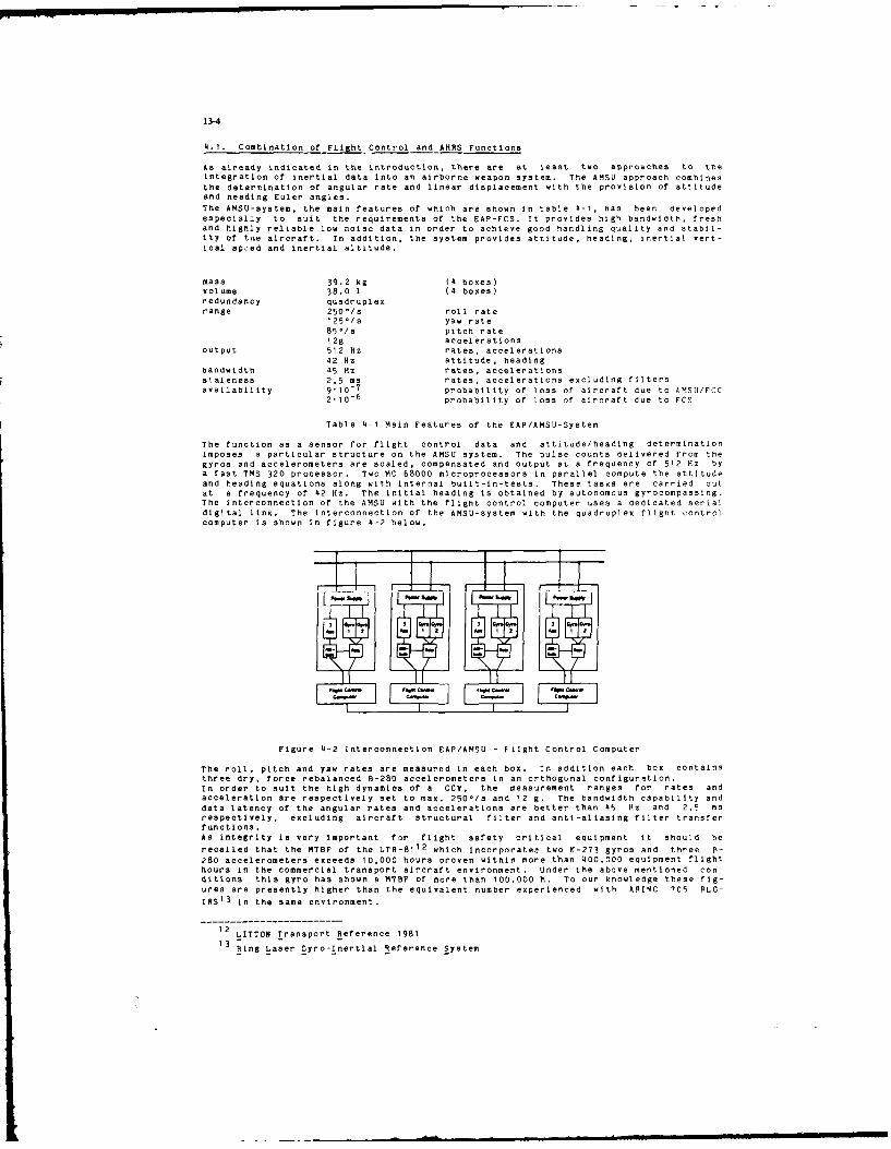
13-4
4.1. Combination of Flight Control and AHRS Functions
As already indicated in the Introduction, there are at least two approaches to theintegration of inertial data into an airborne weapon system. The AMSU approach combines
the determination of angular rate and linear displacement with the provision of attitudeand heading Euler angles.The AMSU-system, the main features of which are shown In table -I, has been developedespecially to suit the requirements of the EAP-FCS. It provides high bandwidth, freshand highly reliable low noise data in order to achieve good handling quality and stabil-ity of tne aircraft. In addition, the system provides attitude, heading, inertial vert-ical speed and inertial altitude.
mass 39.2 kg (4 boxes)volume 38.0 1 (4 boxes)redundancy quadruplexrange 250°/s roll rate
125-/s yaw rate85./s pitch rate12g accelerations
output 512 Hz rates, accelerations42 Hz attitude, heading
bandwidth 45 Hz rates, accelerationsstaleness 2,5 ms rates, accelerations excluding filtersavailability 9.10
- 7 probability of loss of aircraft due to AMSU/FCC
2.10-6
probability of loss of aircraft due to FCS
Table 4-1 Main Features of the EAP/AMSU-System
The function as a sensor for flight control data and attitude/heading determinationimposes a particular structure on the AMSU system. The pulse counts delivered from thegyros and accelerometers are scaled, compensated and output at a frequency of 512 Hz bya fast TMS 320 processor. Two MC 68000 microprocessors in parallel compute the attitudeand heading equations along with internal built-in-tests. These tasks are carried outat a frequency of 42 Hz. The initial heading is obtained by autonomous gyrocompassing.The interconnection of the AMSU with the flight control computer uses a dedicated serialdigital link. The interconnection of the AMSU-system with the quadruplex flight controlcomputer is shown in figure 4-2 below.
13 0-e.S
Ia=- I -' - - =
C.0 C 0-= .~C
Figure 4 -2 InterconnectIon EAP/AMSU - Fi ight Control Computer
The roll, pitch and yaw rates are measured in each box. In addition each box containsthree dry, force rebalanced B-280 accelerometers in an orthogonal configuration.In order to suit the high dynamics of a CCV, the measurement ranges for rates andacceleration are respectively set to max. 25 0-/s and 12 g. The bandwidth capability anddata latency of the angular rates and accelerations are better than 45 Hz and 2,5 msrespectively, excluding aircraft structural filter and anti-aliasing filter transferfunctions.As integrity is very important for flight safety critical equipment it should be
recalled that the MTBF of the LTR-8112
which Incorporatee two K-273 gyros and three F-
280 accelerometers exceeds 10,000 hours proven within more t'han 400,000 equipment flighthours in the commercial transport aircraft environment. Under the above mentioned con-ditions this gyro has shown a MTBF of more than 100.000 h. To our knowledge these fig-ures are presently higher than the equivalent number experienced with ARINC 705 RLG-IgS
1 3 in the same environment.
12 LITTON Transport Reference 1981
13 Ring Laser Gyro-Inertial Reference System

13-5
The effort required to adapt an AMSU-system for EFA1 4
is mainly to reduce weight and toimprove integrity from the EAP/AMSU. In parallel with these improvements the complexitycan be reduced by accounting for the fact that duplex redundant Euler angles are suffi-cient and twelve accelerometers would not be required. The goal to reduce the weightcan be achieved by combining two completely independent angular rate channels with oneattitude channel in one housing. This will lead to a two box solution including a qua-druplex angular rate and acceleration output and duplex attitude/heading output. Ahousing concept of 3/4 ATR size is shown iy figure 4-3 below.
Figure 4-3 EFA/AMSU System
4.2. Combination of Flight Control and Navigation Functions
Any development of an integrated system for flight control, attitude/heading determina-tion and navigation functions has to consider the impact on safety and operation of thewhole aircraft. For a CCV application it is typically required to have available qua-druplex redundancy for the stability augmentation data, duplex redundant attitude andsimplex automomous navigation data.It is necessary to use strap down technology, as opposed to a platform system, becausethe latter does not deliver sufficiently fresh stability augmentation data due to thenecessity of differentiating the Euler angles and subsequent filtering of the noise gen-erated.In order to reduce vulnerability it is advisable to split the system into two boxes,each of which is designed to deliver both navigation and flight safety critical data.For non-augmented medium accuracy INS's laser gyros, of weight I.2 kg and an accuracybetter than 0.01-/h corresponding to a path length of 25 cm, are required.
10. _
1.o_
0.1-
0.01
10 20 30 40Pathiat of to. 4 I6W (Cm)
Figure 4-4 Errors of Laser Gyros
14 European Fighter Aircraft

13-6
To Obtain the demanded quadruple redundancy using orthogonal measurement axes, 4 x I12 RLO's would be required. It can be shown however that six skewed mounted RLG'S,three in each box orthogonal to one another, are sufficient for the necessary redun-dancy.
During the development stages on an integrated system the following points have to beconsidered:
Evidence of integrity should be provided.
The INS should have at least three RLG's.
The system should be repackaged in such a way that the safety and redundancyrequirements are satisfied.
The sensor block should be rotated so that it is skewed in relation to the housing.Independent self-contained electronics for each flight safety critical rate channel
should be provided.
The individual channels should be mechanically isolated by walls.
The safety critical software and software-tests should be developed to appropriatestandards.
An appropriate redundancy management and BIT1 5
is required.
The filters, time delays and accuracies, which depend on the performance of theaircraft should be discussed with the people responsible for flight control.A new flight control computer should be developed (if integrated).
An appropriate location for the system in the aircraft should be established.
4.3. Main Problem Areas
The main problem and risk areas arising during the development of the integrated -yatmare:
- Vibration isolators
- Data processing
- Redundancy managemnt
- Separation of the system
These points are discussed in detail below.
4.3.1. Vibration Isolators
There are generally three kinds of translational vibrations specified, namely:- 11brations induced by aerodynamical effects
- vibrations induced by engines
- vibrations induced by gunblast
The specified spectra, especially in low frequency ranges, occur seldom in practice. 1nreality the vibration spectra have RMS16-values which are approximately ten times less.It is left up to the customer to decide whether the spectra are used for a realisticsimulation environment or only to test the system under extreme conditions.
When choosing the vibration isolators and the sensor block mounting method it Is neces-sary to take into account the bandwidth of the flight dynamics of the aircraft.A high bandwidth requires high natural frequencies of the vibration isolators and acorresponding hard mounting of the sensor block. The vibration power at the sensorblock increases with the natural frequency of the vibration isolators so that the burdenon the sensors, along with the resulting errors, rise. It can be said that the sensorerrors and the subsequent navigation accuracies are almost proportional to the square ofthe vibration power. Due to this fact it is necessary to use soft vibration isolatorsfor appropriate navigation accuracy.
Typical frequencies are shown in the following diagram.
15 Built-In-Test
16 Root Mean Square
--. .. . . - i I quaren

13-7
bandwidths end elaenfrequoncies
t~~~mFCC-ft
b.eW.se1M fob,
10 30 75 125 254 2044
n - h- -. -in
sampling and computing frequencies
Figure 4-5 Frequencies for Flight Control Purposes
Isolators corresponding to inertial navigation systems have natural frequencies ofaround 20 to 40 Hz at 20.C and a transmissibility of about 4 to 6. For flight controlpurposes however, a value almost twice as high is required depending on the highbandwidth (6 Hz) of modern inherently unstable aircraft. This value can vary with lowtemperatures and high vibration levels by a factor Of 1.5 up to 120 Hz. The effect oFthis is to decrease the accuracy of the navigation by a factor of about 4.It can be concluded that the choice of the vibration isolators depends on the one handon the high dynamics oF the aircraft and on the other hand on the soft mounting of thesensor block necessary to obtain the required navigation accuracy.
In order to reduce the temperature-dependent variation Of the natural frequency it isuseful to define an appropriate temperature range. The choice of the elastomeres forthe isolators can be made optimal by restricting the temperature range. This reducesthe variation in the natural frequency and transmissibility of the isolators, as shownin figure 4-6. In general a small variation in the elgenfrequency can be achieved atThe cost of a high variation of the transmissibility and vice versa. These problemscan be alleviated however by either limiting the temperature range or by installing asensor block heater, If the application allows.
OWS 12l C) 2.fl tm$ <
Figure 4-6 Variation of the Natural Frequency and Transmissibilitywith Temperature
When mounting the sensor block it is very important to consider that the rotational andtranslational natural frequencies hereof are wide apart. The reason for this is thatthe coupling of the translational into the rotational vibrations decreases with theincreasing difference of their eigenfrequencies. Rotational vibrations of the sensorblock will cause the angular rates of the aircraft to be incorrectly determined.A non-isoelastic mounting of the sensor block causes transformation of translationalinto rotational vibrations and produces dither induced coning motion. An optimal mount-ing for a cubic sensor block can be achieved using four isolators forming a tetrahedron,if the space available allows. This solution will produce a ratio between the rota-tional and translational eigenfrequencies, approaching the maximum attainable value oftwo.
If the static and dynamic mass-unbalance of the sensor block is known, then it is possi-ble to determine the rotation of the sensor block from the specified translationalvibrations by use of the transfer Function. By this method it Is possible to computesystem errors like coning and sculling and their effect on navigation accuracy.
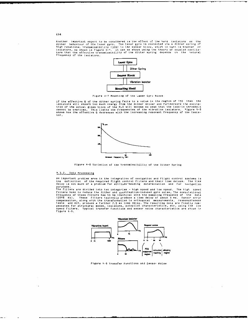
13-8
Another important aspect to be considered is the effect of the hard isolators on thedither behaviour of the laser gyro. The laser gyro is connected via a dither spring ofhigh rotational transmissibility (300) to the sensor block, whlch in turn is Cunted orisolators, as shown in figure 4-7. it can oe shown using the theory of coupled oscilla-tors that the effective transmissibility of the dither spring depends on the naturalfrequency of the isolators.
Dither Spring
Sensor Block
FV bration isolator
MounutgI Shelf
Figure 4-7 Mounting of the Laser Gyro Block
If the effective Q of the dither spring falls to a value in the region of 150 then theisolators will absorb too much energy from the dither driver and furthermore the excita-tion of the actual glass block of the RLG will become so weak that the lock-in thresholdcannot be overcome. This limits the frequencies of the vibration isolators. Figure 4-8shows how the effective Q decreases with the increasing resonant frequency of the isola-tor.
bin- Fe- , 01.)
Figure 4-8 Variation of the Transmissibility of the Dither Spring
4.3.2. Data Processing
An important problem area in the integration of navigation and flight control systems isthe definition of the required flight control filters and their time delays. The timedelay is not much of a problem for attitude'heading determination and for navigationpurposes.The filters are divided into two categories - high speed and low speed. The high speedfilters have to reduce the dither and quantisatlon-induced gyro noise. The computationalfrequency of these filters has to be identical with the sampling frequency of the data(2048 Hz). These filters typically produce a time delay of about 5 ma. Sensor errorcompensation, along with the transformation to orthogonal measurements, reasonablenesstests and BIT, produce a further 2.5 me time delay. The resulting data are finally com-pensated for structural modes, isolators, autopilot characteristics, etc. using the lowspeed filters. Typical transfer functions and sensor noise characteristics are shown infigure 4-9.
Vibrtin smieter
Vibration input I~7 Seamer eel."
I I I
iu -Taf ut adS o o aing
Figure 4-9 Transfer Functions and Sensor Noise

13-a
The time delay associated with those filters mainly depends on the algorithms used andis approximately 5 ms including the data transfer to the flight control computer. Thisyields a total time delay of 12.5 ms Which corresponds to an excess p'ase of 4q at inHz.
When using skewed sensor axes it is important to ensure that the measurements are madesimultaneously. If this is not the case then the transformation to aircraft axes framewill lead to grave errors in the flight control domain. A typical value for the timesynchronisation is 0.02 mm. A possible SOlution to this problem is high speed datatransfer or processor synchronisation. If ronnection wires for processor synchronisationare used then this could lead to single point failures which of course are to beavoided.
4.3.3. RedundancyManagement
An important point in the design of an integrated system is the denelopmenl of an effi-cient RM
17. In principle the RM is carried out in three stages:
The first step is the failure detection procedure, which distinguishes between hard andsoft failures. Hard failures have to be detected within 50 ms via BIT procedure,whereas the soft failure detection can be somewhat longer.The second step is the isolation of the failure using respectively SIT and parity equa-tions for hard and soft failures. The choice Of the thresholds necessary for the parityequations depends on the required accuracy of the flight control data, on the noise cev-els of the sensors and on the dynamics of the aircraft. In order to avoid false alarmit is necessary to take into account structural bending when using a system with twoboxes separated in the aircraft.The third step is the reconfiguration of the system after an arising failure. This isachieved by design equations which transform the intact skewed measurements into orthog-onal measurements taking into account, however. any switching transients.The detection and isolation of the failures and the reconfiguratlon of the system Intro-duce a time delay which has to be added to the existing failure detection time delav .One of the most important points is to consider the single point and common nodefailures which subsequently lead to the loss of the wrole aircraft. Some -r 'hesefailures due to the sensor package for flight control are listed below;
broken isolator
open latch in the mountswrong software (common mode failure)
defect buises
etc.
4.3.4. Separation of the System
Vulnera ility makes it necessary to split the system into two boxes. This leads to sen-sor location problems in tte aircraft. A solution to this problem could te to searchfor an optimal location in the aircraft which depends on the fuselage bending nodes andantinodes. It is necessary to pay attention to the effect of aircraft bending andvibration on the distributed system and to provide a rigid mounting structure.Another problem to be soloed is the making of safety critical and mission critical chan-nels independent, because a failure in the mission critical part must not influence thesafety critical outputs. This can be solved by sharing no components between the Chan-nels and by separating instrument power and data channels both electrically and spa-cially. Furthermore the system must he protected against slngib-pclnt failur's and t-ecross-channel communications must be minimised. The use of resistors or diodes preventsfailure propagation. All these methods lead to an increasing weight, power consumption,and size.
5. Conclusions
Described in this paper are two steps for the integration of flight control sensors,AHRS and INS. It has been shown that the use of the same sensors for flight control andAHRS functions, as for example in the AMSU-system, yield excellent results. The AMSU-system has already demonstrated its performance capabili~y in the EAP inherentlyunstable aircraft. It has to be stated that these aircraft, as opposed to conventionalaircraft, require inertial sensor data with an extremely high bandwidth and very smalldata latency for flight control purposes.The integration of flight control sensors and INS in one system is basically feasible
---- M--- Redundancy- Manag17 RM - Redundancy Management

13-10
and has already been successfully implemented in commercial aircraft. The developmentof an integrated system using dithered laser gyros for inherently unstable aircraft
involves considerable risks even when state of the art techniques are employed. Thin isdue to the fact that such systems require a compromise between flight control require-
ments and navigation Iccuracy. Furthermore, systems of the second step of Integrationlead to no substantial saving in weight or space, as demonstrated by lISA.
Taking development risks into account, the cost of an integrated system is higher tnan
that for separate systems or systems of the first integration step.
6. Acknowledgement
The author wishes to think Messrs. Dr.J.MIrk and M. Halverson for the opportunity to
discuss in depth the problems associated with integrated systems design.
7. References
R. Ebner Redundant Integrated Flight-Control/Navigatior. Inertial SensorJ. Mark CompIex, Journal of Guidance and Control, Vol1. , No. 2,
March-April, 1978, pp. 13-149
J. Mark Design of RLG Inertial Systems for High Vibration, PLANS '982R. Ebner Symposium pP. 379-385A. Brown
D. Sebring Application of Multifunction Strapdown Inertial System, AGA D,J. Perdzoce LS-No. 133, 1984
Captain Young
B. Stieler Konzept eines Sensorsystems for zuknftige Jagd- und Kampf-flugzeuge, Z. Flugwiss. Weltraumforsch. Q (19R5), Heft
J. Jankowitz Joint Development of the Multi-Fun'tlon Integrated Inertial
D. Krasnjanski Sensor Assembly (MIISA), 03rd Symposium of the Guidance and
A. Glista Control Panel on Advances in Guidance and Control Systems and
Technology, London '.-10.10.19F6
DISCUSSION
J.Nicol, UKThe reliability of the described system is based upon hardware redundancy. What steps have been taken to ensurecomparable software reliability, particularly in the microcode of unit processors?
Author's ReplyThe three main steps of codc walkthrough (i.e., module test, hardware integration. and software integration) ha, e beenaccomplished. A computer-aided simulation was conducted to test all instructions implemented in the microprocessors.The test results have been documented in a test matrin that compares software requirements with test steps. The testing
and intensive reviews covered about 5(1 percent of the software development

DEVELOPMENT INO TESTING OF A PREDICTIVE METHODOLOGYFOR OPTIMIZATION OF MAN-MACHINE INTERFACE
IN FUTURE AVIONICS SYSTEMS
Roger E. ParksGroup Engineer
Advanced Human Factors System DesignBell Helicopter Textron Inc.
P.O. Box 482Fort Worth. Texas 76101
SUMMARY
While new technologies offer the avionics designer opportunities in terms of providing systems withexpanded capabilities, those opportunities are accompanied by new kinds of challenges and constraintswhich warrant a revision of traditional design life cycle strategies. The trend of for increasingcomplexity and cost in emerging avionics systems, driven by requirements for increased functionalcapability, has created a need for a predictive analytical methodology whlch: (1) accurately forecastssystem performance early in the design process, and (2) treats the human operator and the equipment as afully integrated man-machine system. A methodology which meets tnese needs has been developed andvalidated at Bell Helicopter Textron. The process is being used to provide early, accurate avionicssystem characterization, thereby reduring design costs.
THE PROBLEM
The applications of advanced technologies in combat aircraft offer the avionics designer bothopportunities and constraints from a man-machine interface perspective. Many of the functionstraditionally performed by the human operator can be automated. With innate human capabilities remainingessentially constant, the designer has the opportunity to proviJe more total system capability, improvecombat mission effectiveness and provide the operator a workplace which optimizes his mental ar i physicalcapacities. The modern avionics designer must, in fact, exercise this opportunity. The demands ofcurrent and future battlefields dictate expanded man-machin. system capability and performance.
Advanced technology applications also impose new kinds of complex challenges and constraints. Thesechallenges and constraints are created, in part, by the pace of technology development and, in part, by anew category of problems which the advanced technology opportunities cause. The challenges andconstraints-- "the problem" --is that the fielding of an advanced avionics system is, by and large, a raceagainst time. The advanced system must remain effective against a battlefield environment which is highlydynamic. As threat capabilities change, so must system capability. If the design-to-fielding process isout-paced by battlefield demands, sub-optimum systems are fielded. While this system capability versusthreat demand game of "leap frog" is ultimately a fact of life despite the time cycle of the developmentprocess, the application of advanced technology has created a new category of design issues whichthreatens to lengthen our processes even further. The nature of advanced avionics systems forces a close,near-complete functional integration of man and machine. Successfully coping with this level ofintegration goes beyond the traditional human factors engineering concerns associated with avionicsdesign. The man-machine interface issues have become vastly more complex. The designer is, in fact, nowconfronted with the problem of predicting both man and machine performance, as both elements operate asone total, highly complex system. Predicting system performance is the issue that :onfronts us;efficiency in the design process is the objective.
Predicting the performance of the "machine part" of the man-machine system is relatively mature. Accuratepredictions of how equipment will perform are quantifiable and normal.y done with confidence. However,when the human operator is added to the system, predictive methods traditionally become less quantifiableand subjectivity reigns. The traditional answer to this dilemma is, too often, a series of inefficientand expensive part-task studies, simulations and flight tests which, wher compared to the quantificationof machine performance, appears to approach trial and error. Compoundirg the problem is the fact thatthese kinds of human performance predictions traditionally occur well into the design process whPn systemconfiguiation changes are more costly. To avoid this situation, it Is necessary to validly predict, at anearly point in the design process, that both elements of the man-machinE system will perform adequately tomeet system performance requirements.
A NEW APPROACH
Traditionally, the fidelity of performance predictions has maintained i linear relationship with thedcsign life cycle process. Performance predictions become increasingly valid as the design maturesbecause adequate data is not available earlier. Unfortunately, the cost of design changes also increaseswith design maturity. This problem, illustrated in Figure 1, becomes more acute as the complexity andcost of avionics systems increases.
If more valid system performance predictions, based on more adequate data, are made early in the designprocess, the relationship between design changes, the design life cycle, and cost can be reversed. Thisconcept is illustrated in Figure 2.
It is important to note (Figures 1 and 2) that the relative emphasis p'aced on analysis and man-in-the-loop simulation has increased. It is essential to understand that the increased analytical emphasis ismore than simply increased time spent on the process. The analysis referenced is a methodology which hasbeen developed by Bell Helicopter to support the design of advanced avionics systems which depend onoptimized man-machine integration. This analytical methodology has been validated on several advancedavionics development programs ane provides quantitative performance data for the aggregate man-machinesystem.
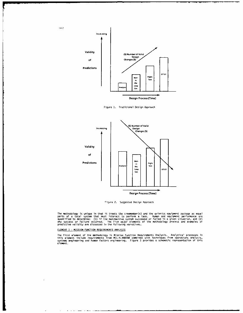
14-2
Incre3sing
Validity (S) Number of Valid
Designof Changes($)
Predictions
IliDesign Process (Time)
Figure 1. Traditional Design Approach
(MI Number of ValidIncreasing Design
Changes (S)
Validity
of
.an-Predictions in- Flight
Analysis the. TestLOOp DTIOT
sint.
Design Process (Time)
rigure 2. Suggested Design Approach
The methodology is unique in that it treats the crewmember(s) and the avionics equipment package as equalparts of a total system that must interact to perform a task. Human and equipment performance arequantified to determine: (1) if the man/machine system succeeded or failed in a given situation, and (2)why success or failure occurred. The five major elements of the methodology process and examples ofpredictive validity are discussed in the following narratives.
ELEMENT 1 - MISSION FUNCTION REQUIREMENTS ANALYSIS
The first element of the methodology is Mission Function Requirements Analysis. Analytical processes inthis element include requirements from MIL-H-468558 combined with techniques from operations analysis,systems engineering and human factors engineering. Figure 3 provides a schematic representation of thiselement.

14-3
_- -SI A, I
I Analysis
Oporattioos Ame(Torrain/~oT
C.oditionslOy Thret, TargetNqih' Etc.) Arry cabllties
& Reactieon Ties
F..I,%Miu r . i sionFncinReureetevaluatd. Theaccuac ofti hrceiaini rtcladdpnshaiyo ohsbetmte
-E F GeneriFigure 3. Mission Function Requsrements
Detailed mission scenarios are developed that reflect the battoefield environment projected for the systebeing designed. As shown candidate scenarios and mission profiles are based on a variety of inputs. Theobjective here ts to develop an accurate real world arena in which the man- achtne syste will beevaluated. The accuracy of this characterization Is critical an depends heavly on both subject matterexpert involvement and a detailed u ant ding of threat capabilities a operational requirents.
Several mission profiles are nodgally needed to execute the total scenario. These profiles ainconstructed to reflect custo r-deftned missions, tactics, capabilities of the conceptual avionicsequpment and atirfrme, and threat capabilities. Several detailed analytical battlefields are developeby locatn threats n real world terrain and planning mission operations which reflect actual operationalproblems; e.g. weather, d y/ntght, variant threat formations, etc. Profiles are sufficiently detailed to
support analys s in one-d sti segnts.
Mission profles are digitally represented and analyzed vita cputer mission dels. Models used containterrain topography and feature data. threat foratons, ntervisbtlties, etc.; and the mission profmle.The results of thts mission/scenario analysis (Figure 3) include data such as detailed threat responsetls, threat and own-system acquisition windows, and response tims required for the man-machne systeto accomplish mission tasks.
This process allows the designer considerable flexibility in that a variety of conceptual equipmentoptions may be characterized and evaluated against several battlefield situations. Candidate equipment
rras can be evaluated to determine factors such as required input/output, processing time available,alternate modes of operation and total operating timelines for the man-machine system.
ELEMENT 2 - CANDIDATE SYSTEM DEVELOPMENT AND GROSS TASK ANALYSIS
The second element of the methodology, Candidate System Development and Gross Task Analysis, refines thegeneral mission function data developed in element 1. As shown In Figure 4, the candidate equipmentpackage options are evaluated and refined and candidate equipment items are selected to work toward theobjective of a baseline mission equipment package.
r--v--d s
I F ig u reI 4 . a n dte S s D L o pt Rneqro siresmA nnys s
LTBasm
Fucin clrwo!i IIM!n DeieSsesytm .I.1Onm tr ak oAloain Tchooge acs iso
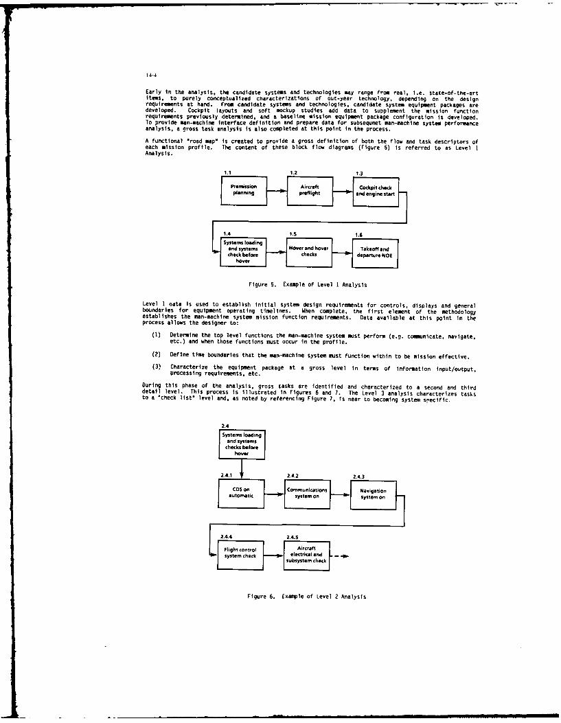
14-4
Early in the analysis, the candidate systems and technologies may range from real, i.e. state-of-the-artitems, to purely conceptualized characterizations of out-year technology, depending on the designrequirements at hand. From candidate systems and technologies, candidate system equipment packages aredeveloped. Cockpit layouts and soft mockup studies add data to supplement the mission functionrequirements previously determined, and a baseline mission equipment package configuration is developed.To provide man-machine interface definition and prepare data for subsequnet man-machine system performanceanalysis, a aross task analysis is also completed at this point in the process.
A functional "road map" Is created to provide a gross definition of both the flow and task descriptors ofeach mission profile. The content of these block flow diagrams (Figure 5) is referred to as Level 1Analysis.
1.1 1.2 1.3
planning H preflight and engine start
Llm | and systems Hover and Hover Takeoff andJcheck before checks departure NOE
hover
Figure 5. Example of Level 1 Analysis
Level 1 uata Is used to establish initial system design requirements for controls, displays and generalboundaries for equipment operating timelines. When complete, the first element of the methodologyestablishes the man-machine system mission function requirements. Data available at this point in theprocess allows the designer to:
(1) Determine the top level functions the man-machine system must perform (e.g. comeunicate, navigate,etc.) and when those functions must occur in the profile.
(2) Define time boundaries that the man-machine system must function within to be mission effective.
(3) Characterize the equipment package at a gross level in terms of information input/output,processing requirements, etc.
During this phase of the analysis, gross tasks are identified and characterized to a second and thirddetail level. This process is illustrated in Figures 6 and 7. The Level 3 analysis characterizes tasksto a "check list" level and, as noted by referencing Figure 7, is near to becoming system sPecific.
2.4Systems loading
and systemschecks before
hover
2.4.17 2.4.2 2.4.3
CDS on Commnctons Navigationautomatic system on sytmo
Flight €Ontrol 1 J Aircraftsyte.cec electrical and .p
syste chec J Isubsystem check -
Figure 6. Example of Level 2 Analysis
lml
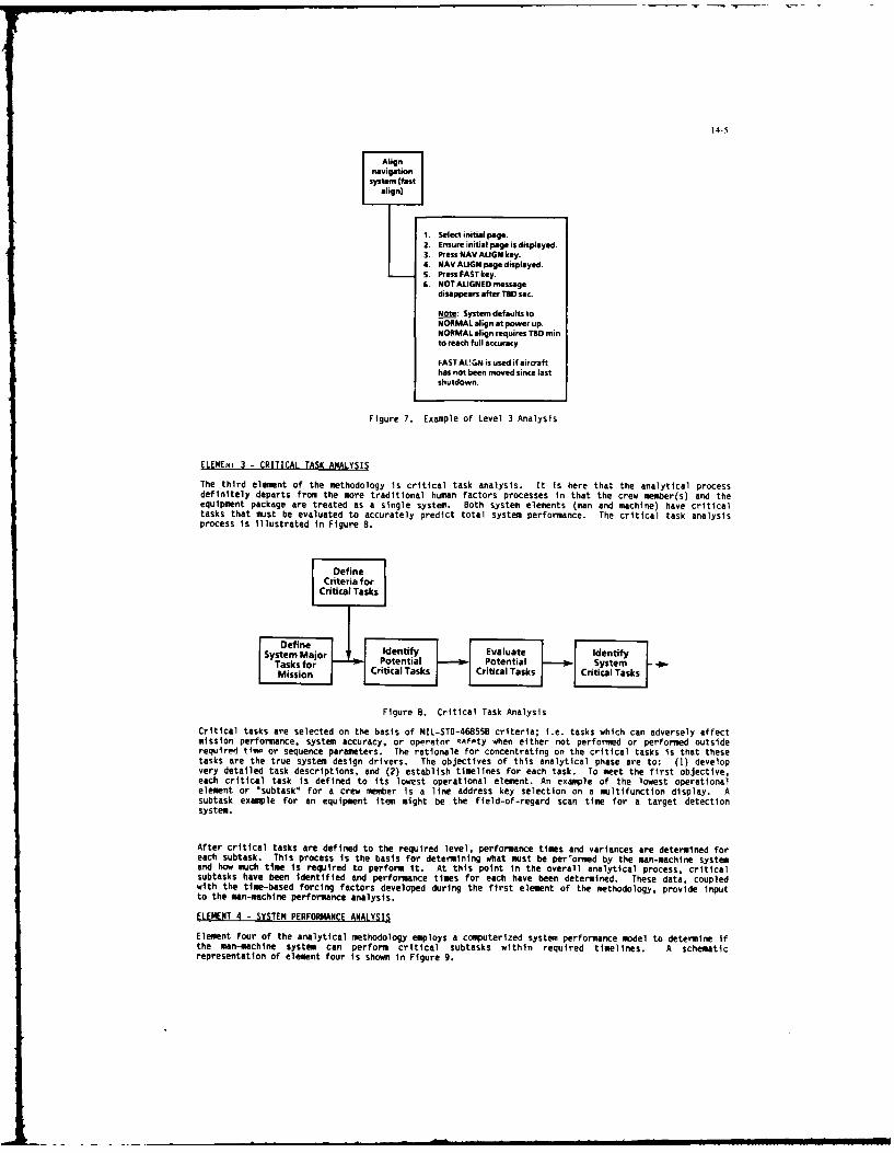
14-5
navigationsystem (fast
align)
1. Select initial paige.2. Ensure initial page is displayed.3. Press NAV ALIGN key.4. NAV ALIGN page displayed.S. Press FAST key.6. NOT ALIGNED message
disappears after TD se.
Note: System defaults toNORMAL align at power up.NORMAL align requires Ta minto reach full accuracy
FAST ALUGN is used if aircrafthas not been moved since lastshutdown.
Figure 7. Example of Level 3 Analysis
ELEMENt 3 - CRITICAL TASK ANALYSIS
The third element of the methodology is critical task analysis. It is here that the analytical processdefinitely departs from the more traditional human factors processes in that the crew member(s) and theequipment package are treated as a single system. Both system elements (man and machine) have criticaltasks that must be evaluated to accurately predict total system performance. The critical task analysisprocess is illustrated in Figure 8.
Criteria forCritical Tasks
System Major Identify Evaluate IdentifyTasks for Potential Potential SystemMission Critical Tasks Critical Tasks Critical Tasks
Figure 8. Critical Task Analysis
Critical tasks are selected on the basis of MIL-STD-468558 criteria; i.e. tasks which can adversely affectmission performance, system accuracy, or operator safety when either not performed or performed outsiderequired time or sequence parameters. The rationale for concentrating on the critical tasks is that thesetasks are the true system design drivers. The objectives of this analytical phase are to: (1) developvery detailed task descriptions, and (2) establish timelines for each task. To meet the first objective,each critical task is defined to its lowest operational element. An example of the lowest operationalelement or Isubtask" for a crew member Is a line address key selection on a multifunction display. Asubtask example for an equipment item might be the field-of-regard scan time for a target detectionsystem.
After critical tasks are defined to the required level, performance times and variances are determined foreach subtask. This process is the basis for determining what must be per'ormed by the man-machine systemand how much time is required to perform It. At this point In the overall analytical process, criticalsubtasks have been identified and performance times for each have been determined. These data, coupledwith the time-based forcing factors developed during the first element of the methodology, provide inputto the man-machine performance analysis.
ELEMENT 4 - SYSTEM PERFORMANCE ANALYSIS
Element four of the analytical methodology employs a computerized system performance model to determine ifthe man-machine system can perform critical subtasks within required timelines. A schematicrepresentation of element four is shown In Figure 9.

14-6
Critical Performance System DecisionPerformance/ DataSubtasks I Model Workload
(Threat)(Environment)
Figure 9. System Performance Analysis
The system performance model used is the Sequiter Workload Analysis System (SWAS).1 This microcomputerbased digital simulation model employs an expert system approach in its architecture, is relatively easyto use, and nas tne nigniy desirable features of minimizing Subjectivity and allowing for analysis ofconcurrent tasks.
The SWAS model yields detailed outputs in both tabular and graphical format. Using this information, theanalyst can make decisions regarding issues such as: (1) the probability of mission success, (2) thetimes required by both the crew member(s) and equipment suite to accomplish mission tasks, (3) theworkload distribution between crew members (where multiple operators are involved), and (4) task"bottlenecks" generated by task time sharing overloads or delays caused by tasks not completed on time.
At this point in the analysis, the avionics system designer has quantifiable performance data which can beused to support a variety of decisions. For example, If the analytical data indicated that the man-machine system being considered could not complete all critical subtasks in the time available, thedesigner could examine the output data to determine where the time or task bottlenecks occurred. Sinceboth human operator and equipment performance data are available, the designer could determine which partof the man-machine system was requiring excessive time and where, in the sequence of mission tasks, thetime problem occurred. Since the performance model Is computerbased, the designer is offered theflexibility of quickly re-running analyses of several alternative design strategies and selecting theoptimum results.
Another feature of the analytical process is the ability to determine required crew size. The SWAS modelprovides for interactions of up to five crew members. The designer is, therefore, provided theopportunity to explore the crew size impact of task automation and ultimately determine the optimum man-machine mix.
ELEMENT 5 - VALIDATION
A major problem with analyses which accompany complex avionics systems development is having confidence inthe analytical data. If a high level of confidence is achieved, simulation and flight test requirementscan be reduced or, at worst, better planned. Bell's predictive methodology has been validated duringseveral design programs via both man-in-the-loop (M-I-L) simulation and Flight test. As illustrated inthe following figures, extremely accurate system performance predictions have been achieved.
2
- Man-in-the-Loop Simulation
Analytical Data
System
Performance
(Time Required +
Time Available)
0Oweaf Smni I Sagmet I a.mem 3 Sy"nt 4 Sw S Sflmt S
Mission Segment
Figure 10. Predicted Versus Actual Performance

14-7
Figure 10 shows a comparison of predicted versus actual system performance data for six segments of ahelicopter anti-armor mission. The system performance data (time required versus time available) wasgenerated analytically, then collected during M-I-L simulation using six mission segments identical to theanalytical segments. As shown, the predicted vs. actual results compare quite closely.
Equipment
SystemFOperator30
25 -
Mean Time 20 -
Required
(Seconds)
10 -
F S F S F S F $
AFCSdPT AFCS/no PPT MFCSJPPT MFKS/no PPT
F - Flight Test; S - SWAS Model; PPT a Pre-Point
Figure 11. Predicted Versus Flight Test Data
Figure 11 shows a comparison of predicted performance data and actual flight test data for a series oftasks which evaluated pilot time performance during a nap-of-the-earth target acquisition exercise (withand without FLIR pre-pointing) while using automatic and manual flight control system modes. As in theprevious example, the predicted and actual performance data compare very favorably. It is important tonote that, in this example, the predicted time required data is identified as "equipment" or "operator"time. Recall that in the earlier analytical stages, critical task times are developed for both operatorand equipment tasks. The delineation of times as shown is the manifestation of that process. This allowsthe designer to more accurately examine the significance of the man-machine division of labor for eachtask and assess the impact of alternate automation strategies. As a side note, the near-linearrelationship between less system automation and increasing operator time required depicts what might beheuristically predicted; i.e., that operator workload increased as automation decreased.
Benefits to the Designer
Results obtained from the predictive methodology process provide the basis for several types of decisionsthat are integral to the advanced avionics design process. Examples of the data output and the kinds ofdecisions that data supports are shown in the following table.
DATA OUTPUTS DECISION SUPPORTED
* Operator workload by mission segmp-t Determination of required crew sizeWorkload demands oy task
Equipment workload by mission segment . Does equipment selected/conceptualized meet missiondemands?What characteristics and capabilities must new equip-ment have?
* Detailed task time ratios * Is the man-machine system able to meet mission(time required vs. time available) requirements?

14-8
While helping the designer make more valid and timely system configuration decisions reduces cost, moretangible efficiencies are realized by enabling a reduction in engineering simulation development andexperimental flight testing. Prudent use of the predictive methodology offers opportunities to reduce thenumber of part-task developmental simulations and finalize full mission simulation configurations earlier.Pert-task flight testing requirements can also be reduced. The need for manned soft-mockup studies can beeliminated in many cases. All such initiatives potentially improve design process efficiency andultimately reduce the scquisition life cycle.
REFERENCES
1. SEtITERS WORKLOAO ANALYSIS SYSTEM; Sequiter Systems, Inc. Rt. 2, Box 907CS, Ft. Worth, TX 76135;
2. "A Mission Oriented Approach to Cockpit Oesign As Applied to Observation and Attack Helicopter"; R. R.Taylor. E. R. Poole; Bell Helicopter Textron; 1984.
ACKNOWLEDGEMENTS
The author wishes to acknowledge the support and sacrifices of his wife, Rebecca Ann, to whom herespectfully dedicates this paper.

14-9
DISCUSSION
G.Hunt, UKIn addition to data on the time taken for the aircrew to perform a task, simulation tests also produce data on theaccuracy with which the result is achilveo and on the difficul.y experienced by the aircrew (e.g., the Cooper-Harperrating scale). Does the analytic model you described produce similar data?
Author's ReplyYes, the methodology accounts for error rates, missed tasks, restarts, etc. Subjective data, such as Cooper-Harper, areused to supplement quantifiable results.
G.Bouche, GEDid you develop a general guideline on how busy the operator should always be kept to achieve optimum performance
in critical situations?
Author's ReplyNo, a general guideline has not been developed on how busy the operator(s) should be kept. Optimum performance isvery difficult to define, because it is based on individual differences and is highly situational.
B.H.Adams, UKHow do you account for the crew "scare level" in your analysis model?
Author's ReplyIt is accounted for in terms of ranges of predicted performance. The "scare level" factor affects quantifiableperformance in several ways that can be generalized and measured, although results are not exact.
J.Bart, USCan this methodology be extended to account for design for maintainability (e.g., fault detection/isolation-repair)requirements and battle damage repair?
Author's ReplyYes, in fact, this type of work is under way and has been validated.
R.J.Young, CA(1) Determining crew size has, in the past. been quite subjective and often driven by a myriad of factors other than
effective mission performance (e.g., size, weight. etc.). No quantitative data/models have been used extensively inthe past to aid in establishing crew size.
(2) Intuitively, I think that single-crew aircraft in combat is a bad idea without "unacceptable" automation beingnecessary.
(3) Do you have any direct data now to indicate that a single-crew approach can be effective?
Author's ReplyYes, although our results are limited to the rotary-wing community and combat helicopter programs. i would be glad todiscuss them with you.
Also, I tend to ,,gree with your second comment. "Acceptable automation" is the key phrase.

I5-I
CREWMSTATION INFOWATIOI AND DEVELOPIENT SYSTEM (CIDS)by
M.E.Rowland and W.R.WagonerBoeing Military Airplane Company
P.O. Box 7730Wichita, Kansas67277-7730
U.S.A.
SUInY
This publication deals with the process by which requirements for an avionic system are translatedinto an integrated crewstation design. The Crewstation Information Development System (CIDS) has beendivided into three phases of activity which can be summarized in the following paragraphs and illustratedin Figure 1.
l PHASE I
METHODOLOGYDEVELOPMENT I PHASE 11
CREWSTATIONo REQUIREMENT DEVELOPMENT PHASE III
DERIVATION o DATA BASE DESIGN APPLICATIONMANAGEMENT
o REQUIREMENT - "I ALLOCATION o INFORMATION - W an
o INFORMATION ASESSLME N
ASEI2~~MENT INFRATION r T1 PRIORrT17ATION
_J MANAGEMENT _DEVLOPMEN T Tie[] ) ,
o DISPLAY FORMAT REFINEMENTo CRESTATION DESIGNc CRESTATION MANAGEMENTo USER POPULATION EVALUATION
FIGURE I CREWSTATION INFORMATION DEVELOPMENT SYSTEMPHASE SUMMARY
Phase I, Methodology Development, develops the Crewstation Information Development Methodology(CIDS) which includes derivation of a comprehensive set of requirements, requirement allocation, andinformation utilization assessment.
Phase II, entitled Crewstation Development, focuses on deriving the most effective methods ofutilizing required crewstation information taking into consideration the impact of the operationalenvironment.
The final phase, Design Application, concerns the details of crewstation design, and the develop-ment of a crewstation information manager.
These three phases of activity represent a systems engineering approach which incorporates the
disciplines of hardware engineering, software engineering and human engineering. The result is a crew-station design which addresses operator and mission requirements in a manner which enhances the manmachine interface.
PREFACE
The complexity of projected battlefield operations requires increasingly sophisticated avionicssystems and crewstation layouts. The associated demands on the operator have escalated to the pointof taxing his ability to rapidly assimilate critical information. Improving operator and systemeffectiveness mandates the development of new Control and Display avionics and the upgrading of existingaircraft avionics in a manner which results in an integrated crewstation. Systems are required to handlethe vast amount of information necessary, and still remain flexible enough to accommodate future growth.With today's technology, subsystems tend to be treated individually with the result that a unifiedintegration of the crewstation suffers. The Crewstation Information and Development System (CIDS),addresses these problems and provides the traceability and flexibility to evaluate requirement changeson a system level.
The intent of the CIDS three phase approach is to develop an avionic system architecture andcrewstation operation derived from and respondent to crewstation needs. Specifically, through thedevelopment of a software model, top level requirements are expanded, refined, and singularly allocatedto a control or display function in the crewstation. These allocations impose requirements on hardwareand software capabilities, which in turn dictate a top level tailored Controls and Display architecture.
Copyright 1987 Q The Boeing Company, all rights reserved.

15-2
The subsequent development of distinctive display formats and adaptive crewstation controls based upona methodical interactive approach provides a mission and operator effective crewstation design.
METHODOLOGY DEVELOPMENT (PASE I)
In the early stages of a typical avionics development program, requirements are provided by theuser in the form of overall system performance allocations or desired subsystem capabilities. In eithercase the designer is presented with a multitude of subsystem design goals which may or may not resultin an overall satisfactory system performance. In many circumstances the pilot becomes the de factosystem integrator of the various subsystem operations with the result that mission effectiveness suffersor workload increases. Therefore, the question becomes "How are requirements integrated into the crew-station in a manner which increases mission effectiveness and enhances operator workload?" This problemactually contains two distinct parts: 1) How can the crewstation designer incorporate all the varioussubsystem requirements in an integrated manner; and 2) assuming item one can be accomplished, what isthe best way to present information and provide system control?
Phase I activity describes the process by which questions one and two above are answered. TheCIDS Methodology Development as shown in Figure 2 is a result of this process. Representative outputsof this methodology will be presented in Phase II after the Crewstation Information Development Systemhas been discussed. The Methodology Development discussion will incorporate the following major topics:Operational Requirements; System Designer Inputs; Information Assessment; and Information AssessmentImplementation.
aOPrRuIDENER RwmiS
3 uA~wcunow o ewoomuvynwneanw mi
",OPERATIONAL RETIJIREI2
With reference to Figsre 2, requirements are provided in the form of overall system performanceand desired capabilities for a given operational environment. These requirements are translated intosystem attributes with the appropriate traceability to source documents. This process is the meansby which overall mission requirements (which reflect the projected threat environment and enemycapabilities) are allocated to system operation functions.
SYSTEM~ESIEER INPUTS
Once this set of operational requirements is compiled, the system designer is able to espand andmodify It to account for functional requirements not directly stated by the user. This activity canbe seen in Steps I and 2 of DESIGNER INPUTS In Figure 2. These requirements supply the details of systemoperation and provide the framewrk by which subsystems interact in the accomplishment of overall systemobjectives. The allocation of requirements to subsystems, Step 3, is the process by which allrequirements, whether directly stated or derived, are assigned to functional areas of the systemarchitecture. This activity Is particularly Important in that it performs several major functions.First of all, it identifies where requirements will be performed. Tin simplifies the task of identifying
multiple uses of coemmon information, and eliminates duplication of sources. Additionally, the impactof one subsystems requiremnts on another ar eadily seen. Nest, the allocation of rquirementsdetemines to a large estent, the interfaces rquired btween subsystes. These interfaces begin to
Identify control and display functions needed In the crewstation. Finally, this activity supports thedefinition of overall systm opration, or what the roles of mission and syste nagement are in theaccomplishment of mission objectives and syste operation.
These first thee steps as described aove are the mans by which operator requirements drive theavionics architecture at the initial stages of syste development. Allocation of requiremnts to specific

15-3
subsystems identifies needed hardware and software capabilities. These capabilities, will be reflectedin the total avionic system architecture, the associated hardware elements, and the software processing.The ultimate target is a system initially aimed at and ultimately tailored to improved man-machineoperation.
The activities accomplished to this point provide the ground work for the major thrust of theCrewstation Information Development System. The next task is the assessment of crewstation informationfor the purpose of determining how best to control or display it. This process is accomplished bycritically evaluating each control and or display requirement and suggesting a design implementation.Steps 1-3 of Figure 2 facilitate the identification of those requirements which either must be controlledby the operator, or displayed to him. However, these same steps that allowed the assessment ofcrewstation information, also have had a direct impact on the overall system architecture.
INFORMATI ASSESMENT
Information assessment takes the top level, derived, and lower level requirements and prioritizesthem to arrive at an optimum implementation in the crewstation. This is accomplished by performingthree tasks which are: the determination of when during the mission specific information must becontrolled or displayed; the assessment of the critical nature of the information as it relates to overallsystem operation; and the assessment of the criticality of the information itself as it relates to theaccomplishment of goals during specific phases of the mission. Once these tasks are accomplished forall the requirements, of all the subsystems, it is possible to assign specific control devices and displaytypes to the crewstation. This process can be seen in Figure 3, Information Assessment Implementation.
IL 1
aD C (Dki
'i r------ I rom n 'U.LCbUIMcrmBUTs
a-w ''VaSm"L XI Jas"
-- -L ---..... .. .
I#FO TI SSE-. FOWIL? DaIINFOMAIXOK~~ow" ASESEN MLNEJTC
Steps 1 through S of the Information Assessment Implemntation deal with functions requiringcrewstation controls on the left of the figure and creestation displays on the right of the figure.The circled numbrs indicate the sequence of activity, and the asterisks specify those areas where inputsfrom the crewstatlon designer are required. As stated earlier, the first step of the crewstationrequirement Implementation is the determination of when during the mission segment previously identifiedcontrol and or display functions are needed. For the purposes of this paper we shall consider a combatmission with the following mission segments:
o Pre-take-off o Take-off o Enroute o Air-to-air/air-to-ground
o Egress o Landing o Shut down
In addition to determining when to display or control information, the criticality of thatinformation must also be assessed. Assessing the criticality of crewstatlon information is a two parttask which corresponds to Steps 2 and 3 of the Information Assessment Implementation (Figure 3). Step2 Involves detminlng If the function is flight, survival, mission, or mission enhancement critical.The definition of these criticalitles is stated below on the next page and roughly equates to that usedin MIL-SD-882, Syst e Safety Program Requirements.

15-4
DISPLAY TYPES CONTROL DEVICES
o Alphanumerics (A) o Dedicated hands on control (DHC)
o Graphics (G) o Programmable display push button (POP)
o Symbology (S) o Dedicated Control (DCL)
o Artificial voice response (V) o Voice (VRR)
o Touch screen/bezel (FOG)
Each of these ways of displaying information to the crewmember or controlling system functions has itsunique numerical value when evaluated according to the critical parameters. A summary of this evaluationcan be seen in Table i. By totaling the individual ratings of symbology, voice reponse, graphics, andalphanumerics, it is possible to numerically rank display types. This numerical ranking suggests thatcertain ways of displaying certain types of information are more appropriate than others. For example,symbology ranks high (numerical value 5) for time criticality (TCRIT) and comprehension (CMPH). However,it is not as suitable where complexity is concerned (CMPX value of 4). Alphanumeric on the other handhas a high value for complexity, but low values for time criticality and comprehension. Using thiscriteria it is possible to compare the numerical ranking of the crewstation requirements to that ofdisplay media in order to suggest the most appropriate control or display means. The problem with thisdirect comparison is that it does not account for the importance of flight, survival, mission, and missionenhancement criticalities during specific mission segments. To account for these influences on controland display implementation, weight factors which correspond to the mission segment and flight criticalityof the requirement are factored into the numerical value of its assigned critical parameters.
TABLE I DISPLAY MEDIA/CONTROL DEVICE CRITICALITYT L; C F C T T U C P I
DIFLAT C 0 K R K 0 CONTROL C 0 K R 0MIA R N P E P T DEVICE N P E T
I X Q H A I K Q AT L T L
s5I{BOLOGY (S) 5 4 4 4 5 ZE DEDICATED HAM ONCONTROL (DHC) 5 5 1 5 16
VOICE (RESPONSE (V) 4 5 2 5 3 19 PRONUKL P3PL 3 1
DEDCATED CONTROLGRAPPIC(G) 3 2 3 3 4 15 (DC.,)
pIAJuMERICS (A) 2 3 5 2 2 14 VOICE (RR 4 3 3 4 14
TOUCH REEN(FOG) 1 2 5 2 1o
These weight factors are derived from the following three technical papers: "Artifical IntelligenceApproaches in Intelligent Helicopter Automation for Nap-of-the-Earth Missions;' 'Flight Management forAir-to-Surface Weapon Delivery;" and "Automation in Combat Aircraft." In all of these papers expertswere asked to evaluate specific mission segments and functions that have the largest impact on missionobjectives. The summation of the results of these papers is illustrated ii Table 2. Interestinglyenough, the importance of specific mission segments in the accomplishment of flight, survival and missionobjectives does not appreciably vary from fixed wing to rotorv wino aircraft missions.
TABLE 2 WEIGHT FACTORS
ISSION CRITICALITYSEGMENT FLT SUR USN USNE
PRE- TAKE OFF .2 6 4 4
TAKE OFF 5 .4 4 .4ENROUTE .7 .7 5 .5AR- TO- AR/AIR- TO-GROUND .9 .8 .7 .7
EGRE .7 .8 .5 .5LANDING .5 .4 .4 .4SHUTI)OWN .2 2 .1 .1AVERAGE m58 .56 e43wa ei
The final aspect of Phase I Methodology Development concerns t 5 y which crewstation require-ments are allocated to control devices or display information types (symbology, alphanumerics, graphicsetc.). Essentially, what this entails is matching the numerical total of a critically assessedrequirement biased by an appropriate weight factor (Table 2) against a prioritized list of control devicesor display information types (Table 1).
For example, assume that a display requirement has a total of 17 when evaluated according to thefive critical paramters discussed earlier (TCRIT, CON, CMPX, FREQ,,and CMPH). Also, assume that thedisplay requirement is survival critical (SUR) and is displayed during an enroute mission segment.The weight factor for this display requirement is 0.7 (Table 2). If we multiply 17 times 0.7, the productis 11.9 which does not immediately suggest a display type when compared to the TOTALs of Table 1. Toresolve this dilemma, a range of values which would provide a suggested control device or display typewhen compared to a requirement's weighted critical assessment was developed. The results of thisdevelopment can be seen in Table 3, Display Type Allocation Values.
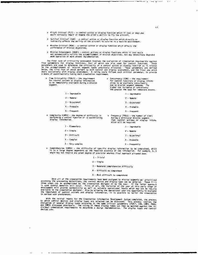
o Flight Critical (FLT) - a control action or display function which if lost or degr.dedwouli seriously impair or negate the pilot's ability to fly the aircraft.
o Survival Critical (SUR) - a control action or display function which directly orindirectly affects the ability of the aircraft to survive in a hostile environment.
o Mission Critical (MSN) - a control action or display function which affects theperformance of mission objectives.
o Mission Enhancement (MSNE) - control actions or display functions which if lost wouldnot automatically nullify the accomplishment of mission objectives, but may necessitate degradedmode operation or work around implementation.
The final task of criticality assessment involves the evaluation of crewstation requirerr-nts againstfive parameters for display functions, four of which are also used for control functions. Theseparameters are used to determine the criticality of a control action or display function as it relatesto the accomplishment of mission segment tasks previously allocated. These parameters are definedbelow, the first four of which pertain to both control and display assessment, and the final one whichdeals exclusively with display assessment. A rating scale follows each critical parameter, to providea means of quantitatively rating each crewstation requirement.
o Time Criticality (TCRIT) - the requirement o Concurrency (CON) - the requirementfor control actions or display information for control functions or display inform-to be immediately available during a mission ation to be available concurrentlysegment. due to mission segment demands. The
higher the incidence of concurrencythe greater the need for immediate access.
I - Improbable I - Improbable
2 -Remote 2 - Remote
3 - Occasional 3 - Occasional
4 - Probable 4 - Probable
5 - Frequent 5 - Frequent
o Complexity (CMPX) - the degree of difficulty in o Frequenty (FREQ) - the number of timesperforming a control function or in assimilating during a particular mission segmentdisplay information, that control actions or display inform-
ation will be required.
1 - Elementary I - Improbable
2 - Simple 2 -Remote
3 - Difficult 3 - Occasional
4 - Complex 4 - Probable
5 - Very complex 5 - Frequently
o Comprehension (CMPH) - the difficulty of specific display information to be understood, whichis to a large degree dependent on the required accuracy of the information. For example, b-1kangle may not require any great degree of precision whereas final approach airspeed does.
I - Trivial
2 - Simple
3 - Moderate comprehension difficulty
4 - Difficult to comprehend
5 - Most difficult to comprehend
Once all of the crewstation requirements have been assigned to mission segments an,' prioritizedaccording the preceeding definitions, the control device and display type can be selected. These fi--tthree steps can be accomplished by the crewstation designer or by the user. If the latter appro0-his used several benefits will occur. First of all, the inclusion of the user at this early stage ofdevelopment will provide authenticity as well as valuable operational inputs which may not be rea.ilyavailable to the crewstatlon designer. Also by allowing the operational user the opportunity to evaluatethe importance of control actions and display information, it is possible to tailor thp crewstationto various user preferences.
With the initial inputs for the Crewstation Information Development System completed, the processby which control devices and display types are selected can be discussed. This process involves theevaluation of several display types according to the same critical parameters (TCRIT, CON, CMPX, FREQ,and CMPH) discussed previously. The rating of these display types can then be matched against the in-dividual crewstation requirements to determine a design implementation. The display types and controldevices are:

15-6
The derivation of the limits for each criticality can be described in four steps: 1) upper limit;2) lower limit; 3) upper intermediate limit; and 4) lower intermediate limit. We will use flightcriticality of display types as an example.
Step 1 deals with the upper limit of flight criticality, 22.50. Since there are five possibleinformation assessment categories (timec, concurrency, complexity, frequency, and comprehension),and the highest value for each is 5, the highest total of these is 25. The highest weightfactor for flight critical is 0.9 (Table 2). Therefore, the highest value that a flightcritical display requirement could be is 25 times 0.9, or 22.5.
The derivation of the lower limit of flight criticality, Step 2, follows the same reasoningas Step 1. The lowest possible total value for the information assessment is 5. The lowestpossible flight critical weight factor is 0.2. Therefore, the lower limit is 1.00.
Step 3 deals with the derivation of intermediate limits. Symbology has the largest totalvalue of the display types listed in Table 1. If we multiply this number, 22, times the averageweight factor for flight critical, 0.58, we obtain 12.76.
The required range for flight critical symbology therefore is 12.76 to 22.5. The upper limitfor the next highest display type, Step 4, (voice, total = 19, Table 1) i 0.01 below thelower range for symbology or 12.75. Taking the average weight factor for flight critical(0.58), times the total fnr voice (19) gives the lower range for voice, 11.02. Therefore,the tange for voice is 11.02-12.75.
TABLE 3 DISPLAY TYPE ALLOCATION VALUES
DISPLAY FLIGHT CRITICAL SURVIVAL CRITICALYqESS N CITICEENTiMEDIUM ( FLT) (SUR) M (WIO i
SYMBOLOGY (S) 22.50- 12.76 20.00- 12.32 1 750- 9.46
VOICE (V) _ 12.75- 11.02 12.31 - 10.64 945- 817GRAPHICS (G) 11.01 - 8.70 10.63 - 8.40 8.16- 6.45ALPHA (A) 8,69- 8.12f 8.39 -7.84 6.44 - 6.02
OPTIN(OT) 8.11 - 1-00 7. - 1.00 L-6.01 - .05
TABLE 4 CONTROL DEVICE ALLOCATION VALUES
CONTROL IT FLIGHT CRITICAL SURVIVAL C~r1A 'CRrIALSDEVICE (FLT) (SUR) i EHANEMENT
DEDICATED HANDS-ON CONTROL (DHC) 118.00 - 9.26 16.00 - 8.91 _1400 - 6.886
VOICE (VRR) 9.25- 8.11 8S0 - 7.80 6.85- 6oiPROGRAMMABLE DISPLAY PUSHBUTTON (PDP) 8.10 - 6.37 7.79 - 6.13 6.00 - 4.72TMUCH SCREEN (FOG) 6.36 - 5.79 _ 6.12 - F 4.71 -- 4.29
DEDICATED CONTROL (DCL) 5.78 - .80 5.56 - 80 4.28 .40
Referring back to the example described earlier, a surviva] critical display requirement with atotal of 17, a weight factor of 0.7, and a product of 11.9, would result in the selection of voice astie optimum display type (see Table 3). Table 4 provides the control device allocation values. Thederivation of these values is identical to that of display types.
The development of the CIDS Methodology which facilitates the assessment of crewstation requirements,completes the activity of Phase 1. Phase II, Crewstation Development discusses the results of methodologyimplementation and the beginnings of a crewstation information management function.
CRENSTATION DEVELOPHENI (PHASE II)
The second phase of the Crewstation Information and Development System deals with: data basemanagement; information assessment results; display information prioritization; and crewstation managementdevelopment. T',e major emphasis of the second phase, is the discussion of the results obtained throughthe implementation of the CIDS Methodology developed in Phase I. The discussion of these results willbe conducted in six parts. These parts include: source requirements; functional requirements;requirement allocations; detailed allocation; information assessment values; and information allocation.Methods of prioritizing information in the crewstation will be discussed w.th the goal of providinga flexible method of dealing with a dynamic operational environment. Finally, using the results ofinformation assessment, we will briefly discuss the initial development of a crewstation informationmanager. However, before the methodology results are presented a brief conment concerning data basemanagement is appropriate.
DATA BASE MNAGEMENT
When CIDS was initially conceived, the size, complexity and intricacies of the data base were notimagined. What began as an effort to develop an integrated crewstation design with an equivalent database, became an entire avionic system with its associated data bases. This resulted from the desireto develop a realistic design effort which could, at some point, become a geneic model for a systemengineer tool. The data bar-s expanded to include total system requirements, ai. as this happened theneed to develop a common data base which included all thp significant activities of the CIDS Methodologybecame apparent. The software used throughout Phase I and II was PC FOCUS which is a comprehensiveittormatio, control system with some arithmetic applications and a limited graphics capability. In

Phase I of CIDS, data was processed for each step of the development methodology. This was accomplishedby creating programs which retrieved required data from a preceeding step of methodology development,and inputting new data as required. This process became somewhat limited, in that data generated inone step could not automatically be used in a preceeding step if the need arose. This process alsoconsumed a lot of overhead (duplicated data files and programs) and added to an already large data base.In short the need for a common data base has proven to be an important requirement which in futureapplications will be incorporated.
INFORMATION ASSESSMENT RESULTS
In order to present the results of CIDS in a logical manner, we shall follow the sequence of activityused in the discussion of the CIDS Methodology. Representative data will be presented in the form ofTables, and for the purpose of clarity we will deal with one subsystem of an avionic architecture,Armament Control.
SOURCE/FUNCTIONAL REQUIREMENTS
Table 5, Source/Functional Requirement, shows requirements which as a starting point have initiallybeen allocated to the Armament Control subsystem. At this point, the assignment of a requirement toa subsystem is somewhat arbitrary but does provide an organizational tool for the disposition of alluser stated capabilities. The first column of Table 5 shows the requirement numbers assigned to eachrequirement. These numbers are the means by which requirements are traced to source documents. Inaddition, requirements which are not directly stated by the user, and those requirements which are neededto support subsystem functions, are also documented to provide traceability.
TABLE 5 SOUIRCEFUNCTIONAL REQUIREMENTSARMAMENT CON ROL
REQ REQUIREMENT DERIVE STATED FUNCTIONA]NO REQMT REQMT REQMT
. -O.O_ M cr'AUMCUEIRG TRACKI. OF_VEIIUCLSL AIRCRAF_ T ERIVE-_ _ -30O - EQUIREDYUlNCIONS------- -- -- -- -- -- -- -- -- -- -- -- -- - -
_3 LO _2 . O . . . . ... I ER - .-I - ,-30LQ3- DOEIGNATION - EIE. --
__LO4._ LWMCH&GO4Ml fl.E ROCK5-S . .DERf.ED .3DQ FIRIN GUKS - - -DERIVED. - I_3O STRE J K~ - ERIVED. E21D -_34O BM AU CACULATIONS------------ -----JERIEI- - - - --k
_3O0 - DETERMIE 12 _.-----------------------CTION
Requirement numbers, in groups of 100, are allocated to each subsystem so that the assignment ofnumbers to requirements provides an initial subsystem allocation. For example, Armament Control isassigned the number block from 300.00 to 399.00. Therefore, a requirement stated by the user or derivedfrom the designer, which initially appears to fit in the Armament Control subsystem would be given anumber from 300.00 to 399.00. The decimal places to the right of the decimal indicate top level andlower level requirements. Two zeros indicate a top level requirement, and XXX.01 thru XXX.99 indicatelower level requirements related to the top requirement. It is important to note that this systemprovides the capability to assess the impact of requirement changes, determine degraded mode operation,and indicate how requirements have been satisfied in the design. These capabilities are possible dueto the fact that, throughout the CIDS Methodology, a requirement retains its originally assigned numberwith more decimal places added to the right as the requirement is expanded.
REQ JIREMENT ALLOCATION
Once requirements have been assigned a number and initially allocated to subsystems, they are evalu-ated as to how they interact with all the other subsystems. Initially this consists of determiningwhere the performance of the requirement in question is accomplished. Referring to Table 6, a "P" underthe appropriate subsystem column indicates that this subsystem is the source of the required information.An "0" followed by a letter corresponding to a subsystem, indicates an output from that column to thesubsystem indicated ty the letter. For example, requirement number 301.04 shows an "OW" in the CPT(cockpit) column. This means that there is an output from the cockpit to the armament subsystem (W).In addition, the accomplishment of this requirement is performed in the armament subsystem, indicatedby a "P" in the "ARM" column. The last column of the table (C&D) shows that requirement 301.04 hasboth a control function and a display requirement indicated by "C/D". The identification of these controlfunctions and display requirements provides the data required for information assessment and informationallocation steps of the CIDS process.
TABLE 6 REQUIREMENT ALOATION AND INT FACEARMAMENT CONTROL
IPMS SYS COMM NAV FLT ARM A 'NT CPT NVP R CR DI
REQ REQUIRMENT MGT MGT C'L C 0
NO (U) (R) (C) (N) (F) (T) (A) (T) ( W) (V) (K)
o o ____.. .. . . . . . . . . . . . . . . . . . . . . .. ... _ S/AUTD CU.ING/M. . . . ..YEHICI A. .RCRA.. . .. -P_ _ - C/ _
MLDQ REQUEDFUffIOR- -- -- -- ------- -- -- -- -- -- -- -- p - -
30L-04 -_ I N Q I S................ -P .... - C4-
---- - " -- - - IIII i _i[302M P -9OWJ~f ,I

15-8
Once all the requirements have been allocated to a subsystem, and an initial cut at the subsystem
interfaces has occurred, a sort of all the inputs, outputs, and assigned requirements for a subsystem
is accomplished. The assembled data from this computer sort contains all the information concerning
the functions performed by that subsystem, and the information required from other subsystems to support
them. This data provides the system designer the ability to verity proper subsystem to subsystem
communication. In addition, support data required by one subsystem from another is immediately indicated
in the sorted report data of both affected subsystems. This is important due to the fact that subsystem
design is usually allocated to separate design groups, and as such the needs of one group are not always
efficiently comuunicated to another.
DETAILED ALLOCATION
The allocation process, which was initiated with the allocation of requirements to subsystems.
continues in this next area with the allocation of requirements to software modules and hardware line
replaceable units (LRUs). In addition, unit values, frequency requirements, accuracies, and range data
are developed. This information is illustrated in Table 7, and provides additional requirement detail
to assure acceptable performance. Through this activity and that of the preceeding section, the
crewstation requirements make their impact on the other subsystems and on the total avionic architecture.
TABLE 7 DETAILED INFORMATION ALLOCATIONARMAMENT CONTROL[ REQ VARIABLE SOFTWARE HARDWARE UNITS ACCURACY RAlE
NO MODULE L HU IMCO _KMA1Ijlf CUEING/TRACKISO OFVEHICIM-A-AWRLE _M-------l_:II - lD_ 3D. RL .
.... -EDJMMM0S ---.--- --,0L O -I-- -l R O -. - - - - --'-IO . . .. . . . . . ... . . . . . . . . . ..IGITS _ 16 H z
-301 .- - -- RANGE . .I... ... .... .--- Mr-R _W _- -sW TBD la BZ-30L ----DEBINOW .. .... .. . .Cst:P_ 4- - D G- M- -t- 1 6 HZMIDI - _-( LACHMWI(M ,S.ROC S - - - - 1-- -17
INFORMATION ASSESSMENT VALUES
With the assignment of all subsystem requirements to either a "C", "D" or both "CAD" it is possible
to assess control and display functions separately for the purpose of assigning criticalities. The
assignment of these values can be seen in Table 8, Display Information Assessment Values, and Table9. Control Assessment Values.
TABLE IsPIAY INFORMATION 0lEMWirT vALUMSRMAMf'IT CONTROL
MABI1s F S Id I T C C F C I D D D D0 J _iC&DSEGM IT L I S N C o M H a C C C F C
PT T R N S R N PI P E E R 0 N R iREQ RUIRME I Q H R a I N P E FNOTE I q e
Ma3 Omfl'IS -XV4205W -~ -- -- 4 - -t 1 /2 -COY S. Y__ s S Gc/f
_10110L. ALN SOCU DT- - --- A/A B 1- 9 -t O,'2 _k _S 3_S V.G]TRA-- OER &CaONTO
30011a UE- - - - - - - a -ow. 5- Y a -3- G C/si
R5-Z~ 3_ -5- 1/ XN _L P J,OIL RE - - - / I
TABLE 9 CONTROLS ASNMENT VALSARMAMENT CONTROL
MSION F S 1 N T C C F TCR.ICON CMLPIFNRMN L U S i C if 0 R CNTL CNTh CNTL CNTL
R RQIEETT R N S R P N ER I Q
NO TIL_3OD.QD1_ N :I[MCUEM.- -.......- - ._- ER _T I - -.......... 4 ._ 3 2- -4L UM JR J R M /D
- -- TACKING OF 'VEHICES& AIRCTRAFI ------ --------- -
_ _00-1 EIj-- I----X _4_-- 4 4-- UM JI VRRLR ,DTRAj06CFI~.0 VEILE _kaRA'
M~nOM MNaj~,zuTroX u / -..... - -- B SSl ... -. .. 4- --3. __L- 2-_vee3RR .e M FOG. C/D
MM 1 _RA NGEINDOI,- .. .. . ._-A/-G_- ... -.. ... 4_ -3- -5-_- 5 IJRR_ DHr- JI DHC. CID
Table 8 shows the assigned requirement number, the requirement itself, the applicable mission
segment, the flight criticalities (FLT, SUR, MSN, and MSNE as defined in the paragraph "Information
Assessment Implementation"), the information criticalities (TCRIT, CON, CMPX, FREQ, and CMPH), where
the information is to be display (where), when it is to be displayed, the display type assignment as
a result of the information criticality (DCRIT, DCON, OCMPX, OFREQ, and DCMPH), and the control and/or
display determination (CAD). For example, requirement number 301.11 is required during the air-to-air(A-A) or air-to-ground (A-G) engagement mission segment and is survival critical. The assignment of
"5" to all the information criticalities corresponds to the selection of different display types (S
- symbology, V - voice, A - alphanumeric, V - voice, and S - symbology). These selections agree with
the data presented in Table I and represent display suggestions based upon a criticality without regard
to other moderating factors. The WHERE column indicates a suggested display location (I = head-up,
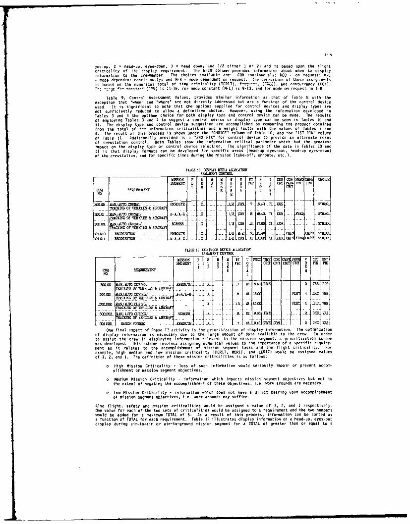
I15-v
yes-up, 2 = head-up, eyes-down, 3 = head down, and 1/2 either 1 or 2) and is based upon the flightcriticality of the display requirement. The WHEN column provides information about when to display
information to the crewmember. The choices available are: CON continuously; REQ - on request; H-C- mode dependent continuously; and M-R - mode dependent on request. The Oerivation of these assiqnmntsis based on the numerical total of time criticality (TCRIT), freq''cr.: 8',,REQ), and concurrency (CON).
::gc ':r or.tar (CN) is 14-16, for mooc constant (M-C) is 9-13, and for mode on request in 1-8.
Table 9, Control Assessment Values, provides similar information as that of Table 8 with theexception that "when" and "where" are not directly addressed but are a function of the control deviceused. It is significant to note that the options supplied for control devices and display types are
not sufficiently reduced to allow a definitive choice. However, using the information developed inTables 3 and 4 the optimum choice for both display type and control device can be made. The results
of employing Tables 3 and 4 to suggest a control device or display type can be seen in Tables 10 and11. The display type and control device suggestion are accomplished by comparing the product obtainedfrom the total of the information criticalities and a weight factor with the values of Tables 3 and4. The result of this process is shown under the "CHOICE" column of Table 10, and the "1ST PIK" columnof Table 11. Additionally provided is a "2ND PIK" for control device to provide an alternate means
of crewstation control. Both Tables show the information critical parameter which had the greatestimpact on the display type or control device selection. The significance of the data in Tables 10 and
11 is that display formats can be developed for specific areas (head-up eyes-out, head-up eyes-down)of the crewstation, and for specific times during the mission (take-off, enroute, etc.).
TABLE I0 DISPLAY MEDIA ALLOCATIONARMAMENT CONTROL
MIC3ION F S M it I I IT P T CONiCON FRQCUPH CHOICE
T R N E E 0 C CRITSEMN L QINEM-NT
FN I R TNO E T
=00 MAN CD ,. ..... . E I- _a CQL _ .7 15 _ CON - . . SYMBOLTAIC OFO EHICLES& AIRCRAFT
. 0---------2/ CON -A IR T CON -- SYMBOLTRCKING OF VERICLES k kICRA. .
3WDDJWCO. MANAf CUIEING/--. - -. - EGRS---------- 1,2 _CON -8 17.6 T11 _CONX SYMBOLTRACKING OF VEHICLES & AD5CRA ..
3MII -EDrI! -1 12 ItC -7- &4 CMI" -. CMPE M3
3 O inL RE asGNITIO o aAiviy i t-h/2 CON -ar1:to TIof diCsp info CM SYMBOL
TABLE It CONTROLS DEVICE A11,OCATIONARMAMENT CONTROL
MISSION F1 if M T T121TMCO II R F I INI
eSEGMENT hig meiu Sn So miso riiaiy RT CT 0n LCRIT) woud CHI asIgne R vaIK ues
T H N N T ERQREQUIREMENT E AQ
NO L.
3.QUIAIO AN4IJIQCTEINGJ----- ---- NXROUTE ---- a-BG3Y -2 TH D-_-TRACKING-OF VEHICLES & AIRCHAF
0 igh 1 ' rCUEINGc,' - lAoss X such i o 2.l0d -9M -4- pen acTRuIC OF VEHICLES & RAINC
f30" M AIJYUCUEING, X L_15-JEM 4 DC .
o TRAMi sOF VEHICLESrcR - infra i Js mission-egment---- ctive b ot to3QXQOCX A IUCUEING/ Er ARR59 Y R----- - 1Z- T 2DI------ - a Oj MR
TAKNG OF VEHICLES & AlECRA4
2OI . -R ANGEYISD~iG -- EXROLITE Z---------7_ LTrtiO T7 MN31 2 IIHCI ERR
One final aspect of Phase 11 activity is the prioritization of display information. The optimizationof display information is necessary due to the large amount of data available to the crew. In order
to assist the crew in displaying information relevant to the mission segment, a prioritization schemewas developed. This scheme involves assigning numerical values to the importance of a specific require-ment as it relates to the accomplishment of mission segment tasks and the flight criticality. Fur
example, high medium and low mission criticality (HCIT, MRIT, and LCRIT) would be assigned valuesof 3, 2, and 1. The definition of these mission criticalities is as follows:
o High Mission Criticality - loss of such information would seriously impair or prevent accom-plishment of mission segment objectives.
o Medium Mission Criticality - information which impacts mission segment objectives but not tothe cutest of negating the accomplishment of these objectives, i.e. work arounds are necesary.
o Low Mission Criticality - information which does not have a direct bearing upon accomplishmentof mission segment objectives, i.e. work arounds may suffice.
Also flight, safety and mission triticalities would be assigned a value of 3, 2, and 1 respectively.One value for each of the two sets of criticalities would be assigned to a requirement and the two numberswould be added for a maximum TOTAL of 6. As a result of this process, information can be sorted asa function of TOTAL for each requirement. Table 12 illustrates display information on a head-up, eyes-outdisplay during air-to-air or air-to-ground mission segment for a TOTAL of greater than or equal to 5

15-10
during contour flight. The amount of information displayed has been significantly reduced, due to thefact that information can be selectively prioritized.
7_Z12 DOMUY NFWMATVN LS A FtNCTION OFXMCN ACTIVITY
AKMENDIT CONTROL
[1 qXDT A L 10 0 Rt C C C C S 0IE IIQURV I T T I IC I ¢I I cI I Ale
NO T T T T T
30.=a. EIVYDE BE=='I SHIDRE n 1MM AS]KU= ,. 4-AA .1 1ma 1r3 L. LAA=. X3 V- _ L L Ir2i1 __RYLI-CTQDK1NSOR___
-3--~x -_-mv MVD INIIIM- NM m Mo CIL -s - -a= __ -- _ _X _ -1 - - -- - - - - - -
The impact of this process is, with the user evaluating control and display requirements accordingto the critical parameters discussed in this paper, the crewstation can be tailored to individual needs.
In addition the specific information that is shown, and how it is shown, can become a dynamic functionof the operational environment.
With the discussion of display information prioritization completed, the description of Phase II
activity is complete. Phase II presented the results of the CIDS Methodology Implementation in the
form of representative outputs of the Armament Control subsystem. Phase III will discuss the next stepsin the design implementation of the CIDS results.
DESIGN APPLICATION (PHASE III)
Phase III deals with the activity which has been initiated, but which at this point has not been
completed. The major tasks of this phase include: display format refinement; crewstation design, which
includes detailed display formats along with control device allocation; crewstation information management
development; and design evaluation. The first three tasks are in various stages of development, and
that development will be briefly discussed. The final task, design evaluation, will include a review
of the criticality assessment values and the implementation of the CIDS Methodology into a crewstationmock-up.
DISPLAY FORMAT REFINEMENT
The process by which display information is allocated to specific areas of the crewstation was
discussed in Phase II. The intent of this allocation was to generate a group of information displayrequirements for a specific crewstation location, and of specific display types (symbology, graphics,
and alphanumerics), for the purpose of developing display formats. This process has been initiated
with varying degrees of success. The major problem encountered was that the display information
requirements were not sufficiently grouped to allow the formation of functional display formats. In
other words, information which would typically be associated with system mode control and status, primary
operation, or secondary operation did not readily fall out of the CIDS Methodology in order to facilitatefunctional grouping of display information. This functional allocation is in progress. Once all of
the subsystem display information has been allocated to functional display formats, the formats will
be developed.
CREWSTATION DESIGN
The second aspect of Phase III is the detailed design of the crewstation itself. The development
of the display formats, along with a composite list of all the dedicated and non-dedicated crewstation
controls, will enable the physical layout of the crewstation. In addition, by knowing what information
is to displayed at what time and where, it is possible to determine the required number of displays
and their location. This activity equates to the development of a physical crewstation which is the
result of a methodical integrated approach.
CREWSTATION INFORMATION
The final area of Phase III activity, which is presently in work, is the development of a crewstation
information manager. The intent of this effort is to develop a crewstation manager which takes the
basic work done in CIDS and refines the prioritization of display information. To facilitate this effort
a generalized "expert system" approach is being employed. Some of the goals of this activity are:
demonstration of a prototype architecture concept; development of flexible formats for crewstation
displays; development a scenario driver; development a graphics interface to a crewstation mockup; and
demonstration of a working model within 12 months.
To accomplish these objectives a scenario was developed which provides a realistic, action packed
description of a combat mission, which initially encompasses a 2 to 3 minute time frame. This scenario
is intended to require "intelligence" either supplied by the crewmnember of inherent in the software
to provide task essential information. This "intelligence" necessitates the development of a variety
of objects and rules. Work has begun to prepare a story board which will provide a description of the
internal and external situation for time slices of the scenario. As a result of the story board activity,
the data required for the scenario from the avionic systems will be identified and corresponding objects,
attributes, and icons will be developed. Once this information is known (le. objects which must be
reasoned about), rules will be developed which take the data found in the scenario and create the required
displays. These rules are derived from two sources, pilot expertise and display expertise. The pilot
IS-I1
expert provides instruction concerning what information is to be displayed (information priority), andwhen it is to be displayed. The display expert supplies how information is to be displayed, where itshould be displayed, appropriate display size, display colors, use of voice, and any other pertinentdata.
Using information about objects and displays from the scenario driver and the rulebase, graphicdisplays for a crewstation will be developed. Initially these displays will reside on one CRT attachedto the work station, however, they will move into a crewstation mock-up as the system matures.
At the present time the development work station is in operation and the software development toolhas been incorporated into it. Software training is complete and a baseline concept for display andairborne objects is complete. The specific scenario time slice has been identified and the developmentof the data structures is in progress. The first demonstration of this knowledge based informationmanager should be late June of 1987.
DESIGN EVALUATION
The process of evaluating a design generated from the Crewstation Information Management Systemis not something which is done once and then forgotten. It is an ongoing iterative activity which h-.been conducted several times already. Although the reviews conducted have been largely internal, theexperience of employees with military aviation backgrounds has been employed. However, the majorobjective in the design evaluation is to encourage active military pilots to critically evaluate thissystem both in the assessment of control and display information criticalities, and in the crewstationdesign implementation. It is anticipated that a review of this nature will be accomplished within 18months.
CONCLUSION
The discussion of the Crewstation Information Development System has been organized in three sectionswhich correspond to the phases of system development.
Phase I presented the derivation of the CIDS Methodology. Phase II showed the results of theimplementation of that methodology. Ph:_e III discussed present activity and the direction of effortin the future.
The motivation for this project was the desire to provide a vehicle whereby the process of takinginitial requirements and implementing them in the crewstation could be accomplished in a methodicalway. In addition, the options available to Lhe system designer in the implementation of requirementsneeded to be organized and prioritized so that an optimized design approach was suggested. From tnisprocess it is possible to develop a crewstation which encompasses display formats, display location,display content, display prioritization, when to display, and what controls to incorporate.
Throughout the three phases of activity of this effort some important lessons have been learned,thc most important of which concerns the development of requirements. The requirements, as initiallyformatted by the designer, are used in every step of the CIDS Methodology. These requirements are allo-cated to several steps of the methodology where information concerning interfaces, display functionsor control functions is required. This dictates that the requirement must be very specific, and havethe capability to stand on its own. As such, the results of the implementation of the CIDS Methodologyis highly dependent on the wording of the requirements used. Therefore, care must be taken in the initialdevelopment and formatting of requirements.
The application of this system has been directed at the development of a new avionic suite witha new crewstation. However, there are no apparent reasons why applications to existing aircraft requiringsome modification, or ground vehicles, are not viable. Some modifications would be required to theexisting data base, but the CIDS approach is workable. In order to facilitate a smooth transition tovarious other applications, the development of a generic requirements data base would be a valuabletool. This data base would include basic system functions such as navigation, communication etc, andthe specific program application would add to, or delete from this generic source of requirements asrequired. In this regard considerable time and manpower savings could be realized in the developmentof an integrated system. This process can also provide a valuable tool to examine the effects of failureson crewstation operation and the level of redundancy required for critical crewstation functions.
In short, CIDS exhibits a great potential for supporting the development of comprehensive displaysand information management for state-of-the-art weapon systems. The activity of Phase III will furtheridentify and clarify the limits future application.

16-1
A CHANGE IN SYSTEM DESIGN EMPHASIS: FROM MACHINE TO MAN
M. L. MeterskyNAVAIRDEVCEN (Code 301)
Warminster, PA 18974-5000
J. L. RyderPacer Systems, Inc.
4 Horsham Business Center300 Welsc Road
Horsham, PA 14044USA
SU4MARY
In the past, and to a large extent even today, the emphasis in system design has been on defininghardware requirements. In many cases, advances in hardware technology, and not the ability to meetmission requirements, were the driving factor that determined the need for upgrades to or replacement ofa weapon system. Even though software has increased in importance and percentage of cost in systemdevelopment, it is still philosophically considered as a means to facilitate hardware performance. Thisthinking has had an adverse effect on system performance by relegating decision requirements, which canbe derived directly from mission requirements, to a minor or nonexistent role in the system designprocess. It is the premise of this paper that system design should be dictated by decision requirementssince decisions humans make determine how well and to what degree a weapon system's inherentcapabilities will be utilized. A system design approach based on an emphasis of the human in his roleas a decision-maker is presented.
INTRODUCTION
Historically, even though the majority of systems designed and fielded have met theirspecifications, they often have not exhibited predicted performance. We believe this occurs because therole played by the human in the system, particularly in terms of decision making, has not beenadequately considered in the design process. This inability to perform as expected is prevalent inweapon systems and exacerbated with command and control (C ) systems. It is more pronounced as thelevel of decision dependency increases. Regardless of decision level dependency, current designphilosoph:y ig,.ores the humn's role. We prs-jese that it Is necessary to reorient the system designapproach, especially for C systems, to stress the decision making function. As a consequence, systemperformance potential could be maximized by proper emphasis of the role played by humans.
In the past, and to a large extent even today, the emphasis in system design has been on defininghardware requirements. In many cases, advances in hardware technology, not the ability to meet missionrequirements, were the driving factor that determined the need for upgrades to or replacement of aweapon system. Even though software has increased in importance and percentage of cost in systemdevelopment, it is still philosophically considered as a means to facilitate hardware performance. Thisthinking has had an adverse effect on system performance by relegating decision requirements, which canbe derived directly from mission requirements, to a minor or nonexistent role in system design. It isthe premise of this paper that system design should be dictated by decision requirements since decisionshumans make determine how well and to what degree a weapon system's inherent capabilities will beutilized.
In the decision-oriented approach proposed, the system is considered not as a package of hardwareand software capabilities integrated to fulfill well-defined mission functions, but rather as a decisionmaking system composed of three interacting elements--hardware, software and personnel. The designapproach based on this viewpoint begins with mission requirements. From this, decisions necessary toperform specified mission functions, and hardware and software needed to support them, are then defined.This design approach focuses on maximizing the decision-making ability of an entire system by viewingthe three system components as complementary and by integrating their capabilities synergistically.
RECENT TRENDS AND POTENTIAL SOLUTIONS
Recent trends, including more and better sensors, improved comunication linka and advances in dataprocessing technology have produced more data and associated improvements in processing capability.However, large amounts of data cannot be assimilated rapidly enough for timely decision making. Inaddition, operational situations have become more complex and faster moving, creating the need forpersonnel to have expertise in multiple warfare areas and to make decisions in ever shorter timeperiods.
These developments, coupled with limited human cognitive processing capacity, necessitate thedevelopment of systems with a higher degree of integration and automation. The degree of integrationand automation required can only be achieved by newly evolving technologies and techniques. Thefollowing three elements together may provide a technology solution to the data overload problem:
a artificial intelligence (AI) technology
a human-computer interface (HCI) technology
a decision augmentation orientation

16-2
Al technology will play a large role by providing automatic and augmented functional support. Al isa set of techniques that can be employed to develop systems that simulate human cognitive functions,such as problem solving, decision making and Information processing. Advances in Al are occurringrapidly and by the 1990's. At will be able to perform many decision functions currently performed byhumans.
HCI technology deals with the methods by which a human and computer interact. It includes methodsof information presentation, data entry, and function sequence control. By careful structuring of theinterface and exploitation of innovative HCI techniques, such as color graphics, automated voicerecognition and synthesis display windowing, etc.. information transmission can be improved, and userlearning time and processing demands reduced.
The proposed system design approah is facilitated by introducing decision augmentation. Decisionaugmentation software is designed to satisfy human information requirements given a particular missionand at some level perform the data to information transformation. Information is defined here as dataprocessed to match the cognitive capability of the human and directed toward a specific decision task.Decision augmentation software is also designed to quantify information uncertainty and assist in usinguncertainty in decision making. The decision augmentation orientation focuses on the decisionrequirements necessary to successfully accomplish mission objectives. Augmenting classical techniqueswith AI and HCI technologies can provide the means by which the proposed approach can be implemented inthe operational environment.
A decision augmentation framework is most important when decision dependency in the system is high.The first graph in Figure I shows that theoretical system performance using classical approaches dropsoff as decision dependency increases. The second one shows that use of a decision augmentation approachshould bring opepstional performance closer to its theoretical limit. Figure 2 shows a simplifiedschematic of a C system with and without a decision augmentation orientation. In either case, dataincluding intelligence, environment, sensor, threat, and own force, comes into the system and isprocessed. Without a decision augmentation framework, the processed data is pesented directly to thedecision maker. The two shaded boxes are added with a decision augmentation framework. Combiningdecision augmentation software and innovative information prepentation techniques, tailored to thespecific decision-making task, should greatly improve decision-making quality. Decision augmentationsoftware can include any or all of the following:
a "expert- knowledge bases and decision rules (Al technology)
* ability to structure the situation into a set of well-defined alternative courses of action
a capability to predict the consequences of each alternative course of action
* rank ordering of each alternative against one or more utility measures
Each of these, and other decision augmentation techniques, help to overcome some cognitiveprocessing limitations and biases, and therefore improve the decision-making process. Humans havelimited working memory and are not proficient at doing complex numerical calculations unaided.Furthermore, in evaluating alternatives, they often make simplifying assumptions, are biased towardconsidering solutions from their past experience, and usually do not simultaneously consider more thanabout three hypotheses. In general, when confronted with excess data, people resort to heuristics whichsimplify the problem and reduce the amount of data that must be considered. These heuristic biases may,in fact, be erroneous. Decision augmentation, particularly using Al techniques, allows more complexdecision rules to be incorporated, more alternatives to be investigated and complex and accuratecalculations to be made. This provides the ability to predict action consequences and evaluate theirassociated utility.
Information presentation, the second additional box, is based on an understanding of humancognition, and includes the following:
a fusion of sensor data, presenting only relevant data formated to directly support the decisions
which must be made
a use of graphics, color and easy access of backup data (HCI) technology
mechanisms of information presentation directly affect the ease with which the operator canassimilate and use the information displayed must be relevant to the operator's needs. The informationshould be structured, labeled and coded to highlight information content and relationships. Graphicdisplays are superior to alphanumeric displays for representing overall relationships among variables,with alphanumeric displays being most appropriate when precise information on specific variables isrequired. Color is a powerful highlighting technique and can be utilized to draw attention to the mostimportant aspects of a situation. Since the displays should present only relevant Information, easyaccess of backup data should be provided, including specific sensor data to resolve conflicts, orhistorical data to analyze specific trends.
LEVELS AND TYPES OF DECISION AUGENTATION
Decision augmentation systems vary in the level of automation involved. They range from completelyautomatic, in which no operator action is involved, to manual, in which only computational aid isprovided for the decision maker. Intermediate levels of decision augmentation include semiautomatic, inwhich the system provides decision alternatives and recomended courses of action and the operatorreviews and accepts or overrides the system, and interactive, in which the operator and software supporteach other symbiotically. Level of decision augmentation is determined based on, at a minimum, thefollowing considerations:
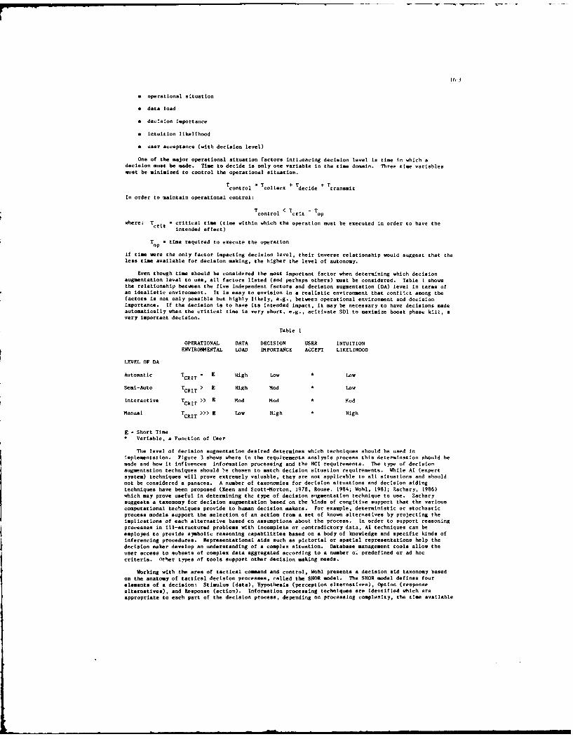
16-3
* operational situation
* data load
* decision importance
• intuition likelihood
" user acceptance (with decision level)
One of the major operational situation factors influencing decision level is time In which adecision must be made. Time to decide is only one variable in the time domain. Three time variablesmust be minimized to control the operational situation.
TcontroI c Tollect * 'decide +transmit
In order to maintain operational control:
Tcontrol < Tcrit -Top
where: Trit = critical time (time within which the operation must be executed in order to have thecr intended effect)
T - time required to execute the operationop
If time were the only factor impacting decision level, their inverse relationship would suggest that theless time available for decision making, the higher the level of autonomy.
Even though time should be considered the most important factor when determining which decisionaugmentation level to use, all factors listed (and perhaps others) must be considered. Table 1 showsthe relationship between the five independent factors and decision augmentation (DA) level in terms ofan idealistic environment. It is easy to envision in a realistic environment that confl!ct among thefactors is not only possible but highly likely, e.g., between operational environment and decisionimportance. If the decision is to have its intended impact, it may be necessary to have decisions madeautomatically when the critical time is very short, e.g., acitivate SDI to maximize boost phase kill, avery important decision.
Table I
OPERATIONAL DATA DECISION USER INTUITIONENVIRONMENTAL LOAD IMPORTANCE ACCEPT LIKELIHOOD
LEVEL OF DA
Automatic TCRIT = E High Low a Low
Semi-Auto TCRIT > E High Mod Low
Interactive TCHIT >> E Mod Mod M Mod
Manual TCRIT >>> E Low High * High
E - Short TimeC Variable, a Function of User
The level of decision augmentation desired determines which techniques should be used inimplementation. Figure 3 shows where in the requirements analysis process this determination should bemade and how it influences information processing and the HCI requirements. The type of decisionaugmentation techniques should e chosen to match decision situation requirements. While Al (expertsystem) techniques will prove extremely valuable, they are not applicable to all situations and shouldnot be considered a panacea. A number of taxonomies for decision situations and decision sidingtechniques have been proposed (Keen and Scott-Morton, 1978, Rouse, 1984; Wohl, 1981; Zachary, 1986)which may prove useful in determining the type of decision augmentation technique to use. Zacharysuggests a taxonomy for decision augmentation based on the kinds of congitive support that the variouscomputational techniques provide to human decision makers. For example, deterministic or stochasticprocess models support the selection of an action from a set of known alternatives by projecting theimplications of each alternative based cn assumptions about the process. In order to support reasoningprocesses in ill-structured problems with incomplete or contradictory data, Al techniques can beemployed to provide symbolic reasoning capabilities based on a body of knowledge and specific kinds ofinferencing procedures. Representational aids such as pictorial or spatial representations help thedecision maker develop an understanding of a complex situation. Database management tools allow theuser access to subsets of complex data aggregated according to a number o. predefined or ad hoccriteria. ether types of tools support other decision making needs.
Working with the area of tactical comand and control, Wohl presents a decision aid taxonomy basedon the anatomy of tactical decision processes, called the SHOR model. The SHOR model defines fourelements of a decision: Stimulus (data), Hypothesis (perception alternatives), Option (responsealternatives), and Response (action). Information processing techniques are identified which areappropriate to each part of the decision process, depending on processing complexity, the time available

16-4
for the decision and the degree of inforastion aggregation required. Some processing aids suggestedinclude: Sensor correlation aids, zoom in/out with variable detail, speeded-up play back of selectedbattlefield history by target or unit type, knowledge/rule based systems, if/then triggers, Englishlanguage data base access and pattern recognition aids, among others.
DECISION-ORIENTED SYSTE4 DESIGN
The usability of a weapon or C2 system is ultimately a reflection of its design philosophy. The
most commonly applied system design approach begins with a detailed statement of platform missionrequirements. Mission requirements are then used to derive functional requirements that will supportsuccessful mission accomplishment. The functional requirements are allocated to either hardware ofsoftware elements of the system. In practice, this approach emphasizes hardware considerations, withsoftware being designed to facilitate hardware use.
Because informed, timely and "correct" decisions are the key element in system effectiveness, systemdesign should be based on decision requirements. System hardware and software should be specified anddesigned to support the decision making function. Requirements should be based on operationalperformance deficiencies rather than on advanced technology, which is the teL..ency in a hardwareoriented design approach.
Figure 4 defines an R&D approach which can be systematically applied to develop a C2 system (or a
weapon system) on a decision-oriented basis. This design approach also begins with the specification ofmission requirements. Subsequent steps attempt to develop more specific system and subsystem functionsto fulfill the primary mission requirements, as is currently done. Based on the mission analysis, alldecisions necessary to perform specified mission functions are defined. The step of defining decisionrequirements is done early in the requirements analysis, and serves as the determilnant of all hardwareand software requirements. After the decision requirements are specified, each decision is analyzed toidentify the information needed to make the decision. "Information" implies data that has beenprocessed and reduced to just the elements needed for the decision. Next, the data necessary to providedecision-specific information is defined. "Data' refers to data, (e.g., target contact reports) that isneeded to derive decision-specific information. These three steps are critical because they serve asthe basis for developing all detailed requirements in the system specification.
Once the data necessary to provide decision-specific information have been defined, the hardware andsoftware (both decision augmentation and other support software) requirements are specified. As Figure4 shows, there are three parallel, but not independent, paths for specification of decision augmentationsoftware, support software and hardware requirements. The emphasis on the decision function suggeststhat the middle path, that of defining decision augmentation software, is the leading path. First, itis necessary to identify the source of each data element. Then, decision functions and theirinformation requirements must be allocated to organizational units/individuals and subsequently to human(specifc organizational units/individual) versus computer (decision augmentation software). Thehuman/computer allocation should be based on the relevant capabilities and limitations of each.Decision augmentation requirements, including HI requirements, should then be derived based on ananalysis of the decision problem and the techniques to assist that particular decision problem.
The left-hand path, that of defining support software requirements, is based on the data necessaryto provide decision-specific information as well as the decision augmentation software requirements.The support software might include operating systems, device handlers and data base management systems.
The design approach shows hardware requirements, the right-hand path, also being dependent on the"Define Data" task. First, the data parameters are defined. Hardware performance requirements arestipulated based on the hardware's capability to provide the data parameters (or performance) specified.This, then, determines the hardware specification, i.e., the ability to provide the data needed toproduce information required for decision making. The hardware elements include sensors, which mustfurnish specified data at a certain rate and accuracy to allow a meaningful and timely decision to bemade; computers which must have the requisite capacity and computational speed; and comunciationssystems which must have the required connectivity and bandwidth to handle data transmission load.Developing hardware requirements based on the decision maker's needs will provide a better fusionbetween these system components, resulting in a higher level of performance than previously achieved byusing the current system design approach.
After the hardware, support software and decision augmentation specifications have been defined, thehardware/software interface specification can be defined. By combining these specificationsappropriately, the overall system speclficatin can be developed. What will result is a C system (orweapon system) that has a greeter likelihood of meeting its theoretical performance level.
ORGANIZATION ANALYSIS
Reorientation of the system design approach to emphasize the human and his decision makingresponsibilities requires analyses that are not considered in the current approach. These analyses arequalitative and concentrate on factors that contribute to the framework of decision making in anorganizational environment. The analysis methods and data sources for the initial requirements analysisare shown in Figure 5. Mission requirements are determined by a functional analysis of operationalproblems and deficiencies, including tactics, sensor utilization, sensor performance, availableresources, and enemy order of battle. Decision requirements are identified by going directly to thedecision makers. Non-quantitative behavioral/social science methods such as questionnaires, interview,verbal protocols and observation of the decision-maker in his operatinal environment should be employed.Analysis of the operational and organizational environment is also crucial. It should includeidentification of the following elements:
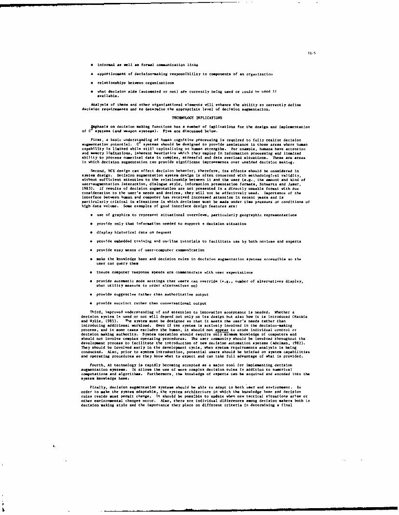
16-5
• informal as well as formal comunication links
• apportionment of decision-making responsiblilty to components of an organization
* relationships between organizations
" what decision aids (automated or not) are currently being used or could be used ifavailable.
Analysis of these and other organizational elements will enhance the ability to correctly definedecision requirements and to determine the appropriate level of decision augmentation.
TECHNOLOGY IMPLICATIONS
Iphaais on decision making functions has a number of implications for the design and implementationof C systems (and weapon systems). Five are discussed below.
First, a basic underst~nding of human cognitive processing is required to fully realize decisionaugmentation potential. C systems should be designed to provide assistance in those areas where humancapability is limited while still capitalizing on human strengths. For example, humans have attentionand memory limitations, inherent heuristics which they employ in Information processing and licmitedability to process numerical date in complex, stressful and data overload situations. These are areasin which decision augmentation can provide significant improvements over unaided decision making.
Second, HCI design can affect decision behavior; therefore, its effects should be considered insystem design. Decision augmentation system design is often concerned with methodological validity,without sufficient attention to the relationship between it and the user (e.g., the amount and kind ofuser-augmentation interaction, dialogue style, information presentation formats. Schwartz and Jamar,1983). If results of decision augmentation are not presented in a directly useable format with dueconsideration to the user's needs and desires, they will not be effecitvely used. Importance of theinterface between human and computer has received increased attention in recent years and isparticularly critical in situations in which decisions must be made under time pressure or conditions ofhigh data volume. Some examples of good interface design features are:
a use of graphics to represent situational overviews, particularly geographic representations
• provide only that information needed to support a decision situation
a display historical data on request
• provide embedded training and on-line tutorials to facilitate use by both novices and experts
a provide easy means of user-computer communication
• make the knowledge base and decision rules in decision augmentation systems accessible so theuser can query them
a insure computer response speeds are commensurate with user expectations
• provide automatic mode settings that users can override (e.g., number of alterqatives display,what utility measure to order alternatives on)
* provide suggestive rather than authoritative output
• provide succinct rather than conversational output
Third, improved understanding of and attention to innovation acceptance is needed. Whether adecision system iq used or not will depend not only on its design but also how it is introduced (Mackieand Wylie, 1985). The system must be designed so that it meets the user's needs rather thanintroducing additional workload. Even if the system is actively involved in the decision-makingprocess, and in some cases excludes the human, it should not appear to erode individual control ordecision making authority. System operation should require only minmum knowledge of computers andshould not involve complex operating procedures. The user community should be involved throughout thedevelopment process to facilitate the introduction of new decision automation systems (Adelman, 1982).They should be involved early in the development cycle, when system requirements analysis is beingconducted. Also, prior to system introduction, potential users should be briefed on system capabilitiesand operating procedures so they know what to expect and can take full advantage of what is provided.
Fourth, Al technology is rapidly becoming accepted as a major tool for implementing decisionaugmentation systems. It allows the use of more complex decision rules in addition to numericalcomputations and algoritlam. Furthermore, the knowledge of experts can be acquired and encoded into thesystem knowledge base.
Finally, decision augmentation systems should be able to adapt to both user and environment. Inorder to make the system adaptable, the system architecture in which the knowledge base and decisionrules reside must permit change. It should be possible to update when new tactical situations arise orother environmental changes occur. Also, there are individual differences among decision makers both Indecision making style and the importance they place on different criteria in determining a final
I.1IIll d l il ill •I

16-6
decision. This individuality should be accommodated to the extent possible using innovativearchitecture until technology has evolved to the point where learning can be an integral part of thedecision augmentation system. The current system design approach does not bring into focus thetechnology implications discussed, it is only through a decision oriented design approach that fulladvantage can be made of the new technology.
SIM4ARY
As a consequence of the increased data volume in current and future C2
systems and the limitationsin human cognitive processing capacity, a reorientation of the system design process has been proposed.In the approach proposed, system design is based on decision requirements rather than on hardwareperformance. Also, decision augmentation techniques and innovative information prosentation are neededto reduce the data overload. The higher degree of integration and automation possible with decisionaugmentation systems coupled with the emphasis on decision functions should greatly reduce the incomingdata load so that the decision maker can devote more time to thinkng about operational problems rather
than merely reacting to the task environment. If these changes can be accomplished, C systecapabilities should improve, and as a consequence, increased mission effectiveness.
REFERENCES
Adelman, L. Involving users in the development of decision-analytic aids: the principle factor insuccessful implementation. Journal of the Operational Research Society, 1982, 33, 333-342.
Keen, P.G. W. & Scott-Morton, M.S. Decision Support Systems: An Organization Perspective,Reading, HA: Addison Wesley, 1978
Mackie, R. R. & Wylie C. D. Technology Transfer and Artificial Intelligence: User Considerations inThe Acceptance and Use of Al Decision Aids. Goleta, CA: Human Factors Research Division EssexCorporation, Technical Report TR5i231-i, November 1985
Rouse, W. B. Design and evaluation of computer-based decision support systems. In S. J. Andriole (Ed.),Microcomputer Decision Support Systems. Wellesley, HA: QED Information Sciences, 1984.
Schwartz, J. P. & Jamar, P. Lack of guidance for decision aid interface design. Association forComputing Machinery SIGCHI Bulletin, 1983, 15, 13-17.
Wohl, J. G. Force management decision requirements for Air Force Tactical Command and Control. IEEETransactions on Systems, Man, and Cybernetics, 1981, SMC-11, 618-639.
Zachary, W. A cognitive based functional taxonomy of decision support techniques. Human-ComputerInteraction, 1986, 2, 25-63.
SYST94
STSR4 tlSO NEIC
SYSTEM
MEU NOW5ATIO
FIGURE 1. SYSTEM PERFORMANCE DEPENDENCIES
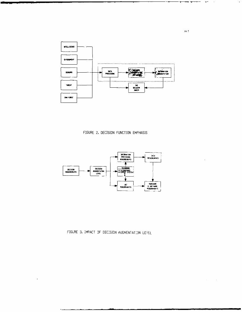
16-7
DATTA
TER
FIGURE 2. DECISION FUNCTION EMPHASIS
ATF. &MIfTS&OTWI
REQUJIREMENTS
FIGURE 3. IMPACT OF DECISION AUGMENTATION LE)EL
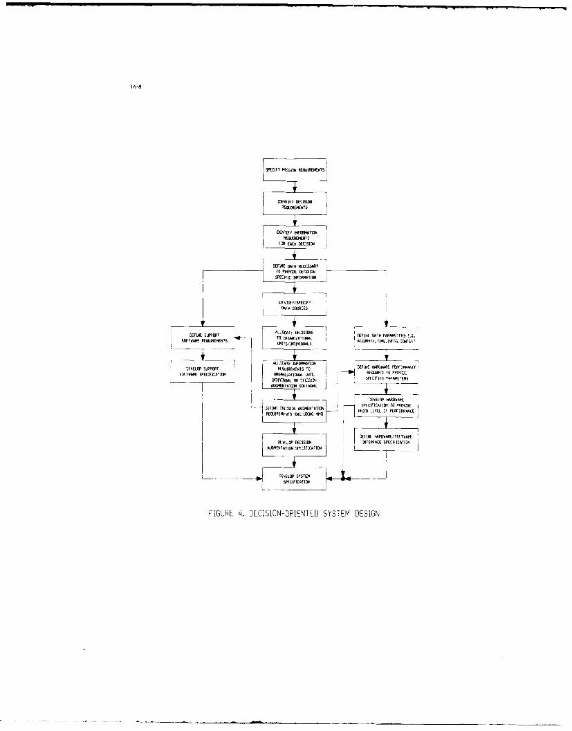
SPECIFY MISSON~ REOAIRAINENTO
IDENTIFY OIIWAINREOUIREM~NTS
DEFNTA S ELICE
DEFINE SLEPOAT ALLOTCATMVIE DECIION EIEDT FSAES ..
ALLOCATE D*MMATI
ANDIADIJAL O DECIIN EIEDAAPRMTES ..!i0FT~4'pE EQUIRMENTSTO RAMNTZATIO A TAME ~,TIEIES.COIN
DEVEOP UPPRT RIIIR I 70111141HIRAESE ERRANAEDEFINESECFIATO O ID7IONA LIMIETATRUIRECATDE TO PROVIDE
RED IEAE OF PEFORN
DEEL HARDWAREFWADEEDIDS C INEFCSPECIFICATIO =R
AAQRENTIJOPCFATD
FIGURE 4.GE ISIONGENTAYT EM RDEGN FPE

16-9J
TASK SOURCE
IENTFY
DFRMTId REWJ1RI1*TS WEN TILMWANFOR D~CISION ORANMIUATI=A feIRONpIMT
DEFINE DATA NECESSARYTOl PROVIDE DECISION N4LYSIS OF~SCIFIC INORITION LlWORMATION CONTENT
FIGURE 5. ANALYSIS ME THODOLOGY

-?-I
Managing Advanced Avionic System Design
Philip H. SimonsProject Engineer, ASET Development
Northrop CorporationOne Northrop AvenueHawthorne, CA 90250
Summary
The application of new technologies such as VHSIC, and new system
concepts such as artificial intelligence, distributed operating systems, commonhardware components, and reusable software modules/libraries has changed
the manner in which avionics suites are designed, developed, and verified.
The requirements for developing these systems are specified in U.S. military
standards and can be segregated Into requirements for the overall system,
configuration items, Interfaces, and the design process management.
Northrop has developed a design process and methodology capable of meeting
these system development requirements which involves time phased analyses,
requirements analysis and decomposition, functional decomposition, and system
synthesis and Interface definition. This process, developed through past
advanced avionic system design efforts, is now being automated through the
development of a set of tools to manage all phases of advanced avionic system
design, the Avionic System Engineering Tool (ASET).
I. Advanced Avionic System Design Requirements
The design of any system includes key elements such as software, hard-
ware, and interfaces. Although the requirements for these elements can be
specified in any number of ways, the U.S. Department of Defense (DoD) has
mandated a specific set of documents to contain these requirements. These
documents are defined in MIL-STD-483, MIL-STD-490, and DoD-STD-2167, and
include a description of the following requirements for advanced avionic sys-
tem design:
1. Overall system requirements. These requirements include the
following:
a. Definitions of the major functions of the system, and the
principal interfaces between those functions
b. The allocation of performance requirements and specific design
constraints peculiar to each system function
c. The definition of the principal interfaces between the system
being specified and other systems with which it must be
compatible
d. The operating requirements for logistically and technically sup-
porting the system
e. The design requirementp necessary to assure compatibility of
system equipment and software
f. The identification and relationship of Hardware Configuration
Items (HWCIa) and Computer Software Configuration Items(CSC~s) which comprise the system.
2. Configuration item requirements. These requirements include the
following:
a. The detailed functional, performance, interface, and qualifica-
tion requirements of all Configuration Items (CIs)
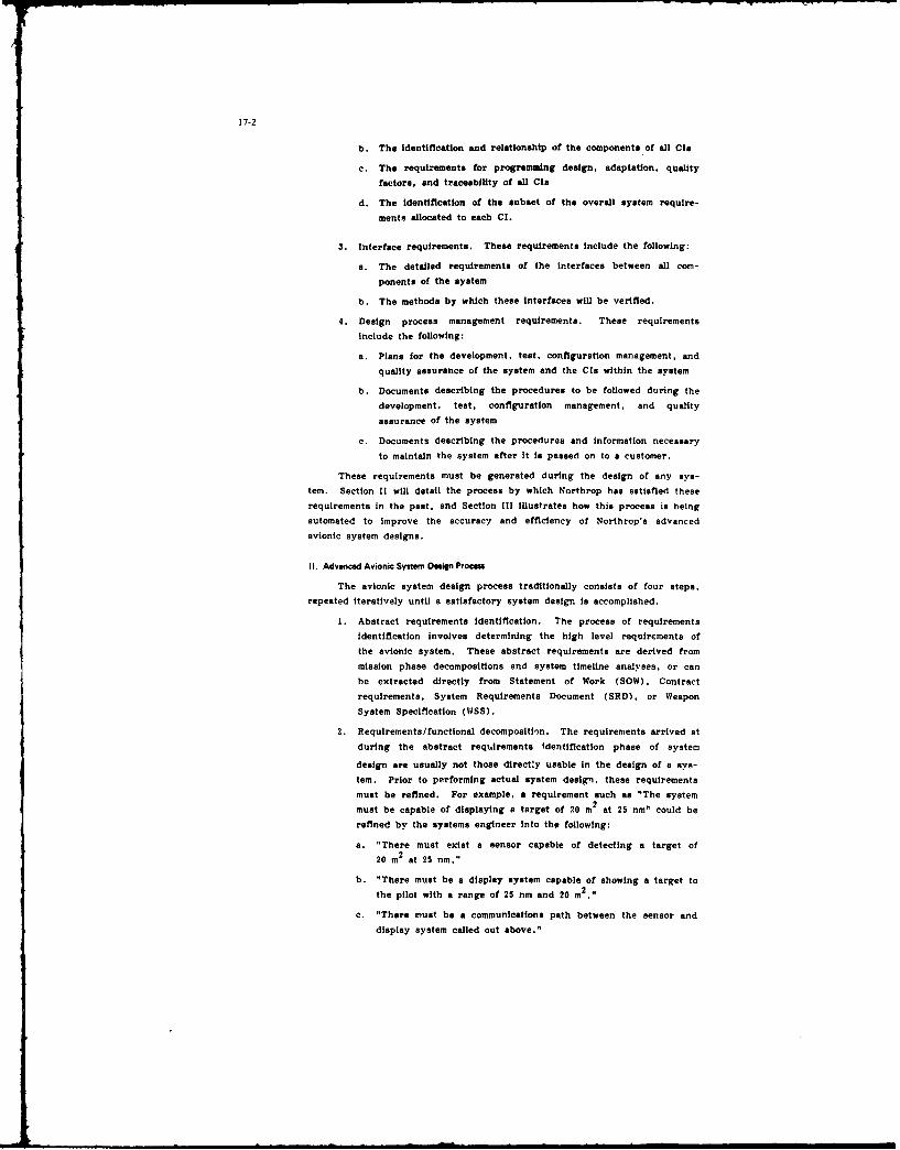
17-2
b. The Identification and relationship of the components of all Cia
c. The requirements for programming design, adaptation, quality
factors, and traceability of all CIs
d. The identification of the subset of the overall system require-
ments allocated to each Cl.
3. Interface requirements. These requirements include the following:
s. The detailed requirements of the interfaces between all com-
ponents of the system
b. The methods by which these interfaces will be verified.
4. Design process management requirements. These requirements
include the following:
a. Plans for the development, test, configuration management, and
quality assurance of the system and the CIs within the system
b. Documents describing the procedures to be followed during the
development, test, configuration management, and quality
assurance of the system
c. Documents describing the procedures and information necessary
to maintain the system after it is passed on to a customer.
These requirements must be generated during the design of any sys-
tem. Section II will detail the process by which Northrop has satisfied these
requirements in the past, and Section III illustrates how this process is being
automated to improve the accuracy and efficiency of Northrop's advanced
avionic system designs.
II. Advanced Avionic System Design Process
The avionic system design process traditionally consists of four steps,
repeated iteratively until a satisfactory system design is accomplished.
1. Abstract requirements identification. The process of requirements
identification involves determining the high level requirements of
the avionic system. These abstract requirements are derived from
mission phase decompositions and system timeline analyses, or can
be extracted directly from Statement of Work (SOW), Contract
requirements, System Requirements Document (SRD), or Weapon
System Specification (WSS).
2. Pequirements/functional decompositi~n. The requirements arrived at
during the abstract requirements identification phase of system
design are usually not those dlrecty usable in the design of a sys-
tem. Prior to performing actual system design, these requirements
must be refined. For example, a requirement such as "The system
must be capable of displaying a target of .0 m2
at 25 nm" could be
refined by the systems engineer into the following:
a. "There must exist a sensor capable of detecting a target of
20 m2
at 25 nm."
b. "There must be a display system capable of showing a target to
the pilot with a range of 25 nm and 20 m2.,
c. "There must be a communications path between the sensor and
display system called out above."

17-3
This procedure of refining requirements continues until the process
phases into a functional description and decomposition procedure.
This point is reached when the systems engineer describes a func-
tion which performs the requirements, rather than simply describing
the requirements in increasingly greater detail. An example of this
would be the definition of a Head-Up Display (HUD) in order to
meet a portion of the requirements of the display system listed
above.
This process is also characterized by decomposing and refining
requirements or functions from different viewpoints. In other
words, the system can be described from the viewpoint of
non-combat-flight vs. air-to-air vs. air-to-ground, or offensive vs.
defensive, or even from the viewpoint of the hardware system as it
is currently defined. Examining the system from these disparate
viewpoints will often identify requirements or functions not illus-
trated during the original decomposition. It must be noted that the
same lower level requirement or function can be arrived at from
different higher level entities, i.e., the HUD specified above would
meet the requirements for the display of many items, not only the
target at 25 nm. Another aspect of this phase of system design is
the assignment of functional inputs, outputs, estimates of memory,
throughput, size, weight, and power.
Finally, the result of this phase of system design is the detailed
description of a large set of functions which must be performed by
the avionic system.
3. Functional recomposition. The functional recomposition process
involves taking the large set of functions arrived at during the
requirements/functional decomposition phase of the system design,
and grouping these functions into increasingly larger sets. For
example, all functions dealing with the display of targets in air-
to-air mode might be grouped together. Then this set could be
included in the set containing air-to-ground target display func-
tions, to form an all-mode-target display group. This process con-
tinues until all functions have been included into groups, all of
which have been grouped into the complete system.
This functional recomposition is performed by the system engineer,
and requires forethought and research prior to performing the
groupings. The tasks the engineer is accomplishing in this phase
of system design include the following:
a. The definition of the system elements, from the most detailed
descriptions of functions to the actual Line Replaceable Units/
Line Replaceable Modules (LRUs/LRPls)
b. The assignment of signal paths for all input/output pairs within
each group, as that group is created
c. The summation of the estimates (memory, .hroughput, size,
weight, etc.) of the lower level functions into estimates of the
high level groupings.
The end result of the functional recomposition phase is the actual
system design, minus the detailed interface definitions.

17-4
4. Detailed interface definition. During the detailed interface/bus
definition phase of system design, the engineer first defines and
then assigns the information associated with each signal path within
the system. In other words, the engineer chooses the communica-
tions path (i.e.. bus, memory link. etc.) to be used for a given
signal path, defines the information specific to that communications
path, and then assigns the bus-specific information.
During the requirements/functional breakdown phase of the system
design, an engineer assigns Inputs and outputs to the functions
within the system. These signal definitions include in'ormation
such as frequency of update, units, maximum/minimum value, etc.
These definitions do not include Information specific to a certain
bus, such as remote terminal number, message number, bit posi-
tion, etc. Not only is this information bus-specific, but the task of
assigning this information during the requirements/decomposition
phase is extremely complex, and requires very good communications
between different engineers. After all signals traveling on a path
are defined, however, the task becomes greatly simplified. There-
fore, the mapping of the signals onto the bus-specific layout is
accomplished after functional recompoaition. after the signals are
defined and specified for each bus.
This four-step process is repeated many times, with the end result
being the system design. This system design is captured in docu-
ments defined by the MIL-STD and DoD specifications, and fulfills
the requirements of the system design as defined in Section I. The
correlation between these requirements and the system design
phases Is shown in Figure 1.
Ill. Automated Tools for System Design
Automated tools can greatly aid in the avionic system design process,
providing more efficient, more easily managed, and more accurate system
designs. For these tools to be truly usable and effective, however, the fol-
lowing requirements must be followed:
1. Information regarding tools on the system must be disseminated to
all potential users, not only those specifically targeted for tool use.
2. The tools and systems must be capable of expanding and accommodat-
ing new tools, migrating to new systems, accepting larger and more
elaborate problems and, in general, supporting the future require-
ments of avionics engineering as well as the current needs. Much
of this requirement has been fulfilled simply by documenting to
MIiL-STD-2167. coding in a Higher Order Language (HOL), and
making full use of the HOL's built-in modularity capabilities.
3. The tools must be able to be quickly and efficiently integrated into
the existing Avionics Engineering environment. This involves the
utilization of currently existing hardware (terminals and main-
frames), as well as maintaining a user intel.fsce very similar to
existing tools.
4. T1he iools must be both powerful and user-friendly. The most
involved on-line queries must take less than 30 seconds; typical
operations must take far less. In addition, the tools must include
extensive help utilities.
. . ,OWN

17-5
SYSTEM DESIGN PHASE SYSTEM DESIGN REQUIREMENTS FULFILLMENT
ABSTRACT OVERALL SYSTEM REQUIREMENTSREQUIREMENTSIDENTIFICATION CONFIGURATION ITEM REQUIREMENTS
DESIGN PROCESS MANAGEMENTREQUIREMENTS
REQUIREMENTS/ OVERALL SYSTEM REQUIREMENTSFUNCTIONALDECOMPOSITION CONFIGURATION ITEM REQUIREMENTS
FUNCTIONAL OVERALL SYSTEM REQUIREMENTSRECOMPOSITION
CONFIGURATION ITEM REQUIREMENTS
DETAILED INTERFACE REQUIREMENTSINTERFACE/BUSDEFINITION
FIGURE 1. REQUIREMENTS FULFILLMENT BY DESIGN PHASE
5. The tools must not require a long learning curve to achieve initial
benefits.
6. The tools must be capable of providing hardcopy output for review
by others (such as subcontractors).
'. The tools must facilitate securing any information entered into the
system.
Northrop's Aircraft Division is developing an automated tool called theAvionic System Engineering Tool (ASET). The ASET fulfills all of the just-
listed requirements, and is intended to provide engineers the ability to per-
form the end-to-end system design process more quickly and effectively,while improving both the turnaround time and accuracy of the documents
associated with the system. The ASET will also provide traceability from all
levels of requirements through the actual system hardware and software Cis.
Past system design efforts have relied on paper-based documentation
which was often out-of-date, difficult to understand, tnternaly inconsistent,
and usually did not reflect the entire avionic system. As a result, the test
engineers, software developers, subcontractors, Implementors, etc., had to
rely on conversations with the original designer of any system to determine
exactly what had been specified.
Another difficulty of the paper-based documentation scheme is the sepa-
ration of the engineers from their output. The design engineers prepare
their work on paper, which is redone by either their secretary or drafting
personnel for placement in the document. The personnel requiring this infor-
mation must then acquire a copy made of the document.
The manner in which the ASET overcomes many of the difficulties of the
paper-based documentation effort is by involving the avionic system designers
themselves in the process of generating the system representation. This does
not mean that they have to involve themselves in standard data entry func-
tions. The ASET allows the engineers to perform their jobs in the same man-
ner that they have always performed their jobs, only faster, as if they had
an intelligent piece of paper and pencil; ASET is recording their work and
saving it for later steps in the process. Thus. ASET improves upon the

17-6
system engineering process by slowing the design engineers to manipulate
and create the actual system representation accessed by the personnel
requiring this Information.
The ABET has been divided into four subtools - the Timeline Analyzer
Subtool (TAS), the System Analysis Subtool (SAS), the System Generation
Subtool (SOS). and the Interface Definition Subtool lIDS), which correspond
to each phase of the system design process, as shown in Figure 2.
SYSTEM DESIGN SYSTEM DESIGN CORRESPONDINGPHASE REOUIREMENTS FULFILLMENT ASET SUBTOOL
ABSTRACT OVERALL SYSTEM REQUIREMENTS TIMELINE ANALYSISREQUIREMENTS SUBTOOL (TAS)IDENTIFICATION CONFIGURATION ITEM REQUIREMENTS
DESIGN PROCESS MANAGEMENTREQUIREMENTS
REQUIREMENTS/ OVERALL SYSTEM REQUIREMENTS SYSTEM ANALYSISFUNCTIONAL SUBTOOL (SAS)DECOMPOSITION
CONFIGURATION ITEM REQUIREMENTS
FUNCTIONAL OVERALL SYSTEM REQUIREMENTS SYSTEMRECOMPOSITION GENERATION
CONFIGURATION ITEM REQUIREMENTS SUEIOOL (SGS)
DETAILED INTERFACE REQUIREMENTS INTERFACEINTERFACEIBUS DEFINITIONDEFINITION SUBTOOL (IDS'
FIGURE 2. ASET SUBTOOL CORRELATION MATRIX
The TAS allows the engineer to enter mission phases into a timeline,
and then decompose any phase of that mission into a complete, lower level
timelne. In addition, the TAS provides full cut-and-paste capabilities, and
is able to pass the requirements entered by the engineer onto the System
Analysis Subtool.
The SAS provides the capability to perform requirements/functional
decomposition on the CRT, alternating between displaying the requirements
tree as it is crested, or displaying the requirements/functions and the
entities above and below them in the tree. The SAS provides signal
verification, verifies hierarchical consistency, and provides for both redun-
dancy and nebulous requirements fulfillment checking. The SAS provides cut-
and-paste functions on the tree, and also generates the set of functions
passed on to the System Generation Subtool.
The SGS allows the engineer to perform the functional recompositton of
the system, collecting like functions upon command, and allowing the engineer
to specify which of the functions within the collection to group. In addition,
the SGS performs I/O verification, allows assignment of 3ignals to signal
paths, and rebuilds the memory, throughput, size, weight, etc., estimates
for each grouping within the system. The SOS builds the databese which is
used by the Interface Definition Subtool.
The IDS allows the user to define and then enter all bus-specific infor-
mation associated with each signal in the database. The Ia also provides
the capability to generate documents based on the information entered by the
user such as the Interface Requirements Specifications and Sections 3 and 4
of the System Requirements Specifications, and is capable of providing infor-
mation to CADAM systems for the generation of system layouts, wiring dia-
grams, etc.

17-7
IV. ASET inflits
I. Requirements Traceability. The ASET permits the users to trace
from any requirement or function within the system (entered or
generated in the SAS). to the final avionic system or systems that
fulfill that requirement. This permits anyone to determine exactly
what requirements are fulfilled by any particular LRU/LRM, and
to determine exactly which LRUsILRMs fulfill any particular
requirement.
2. Contract Modification Response Improvement. Due to the require-
ments traceability of the ASET. the impact of any changes to
system requirements can immediately be determined.
3. 1/0 Verification. The ASET verifies that all signals within the
system (input through the SAS) have constructs which generate,
transfer, and receive these signals,
4. Throughput and Memory Analysis. The ASET requests the systems
engineer to input memory and throughput estimates for each bottom
level function within the SAS. When the system grouping is being
accomplished, these memory and throughput estimates are combined
to give estimates for any subset of, or the entire, avionics system.
5. Improved Inter- and Intra-Group Communications. Communications
between different groups will improve due to the better system
description being available. Communications within the systems
engineering group will improve because engineers will be able to
"try out" their design with the other tentative designs of the
system. This will result in an even faster and more effective
system design process.
6. Improved Software Design and Test. With the development of a
better designed and documented avionics system. the software
design and software test personnel will perform more efficiently.
which will result in a more reliable, effective, and error-free
system.
In addition to all that has been specified, the ASET has been modularly
designed tc easily accommodate enhancements such as the following:
1. Automatic code generation for portions of the system. One of the
first enhancements planned for the ASET is the association of a
Program Design Language (PDL), the implementation of which may
be Ada, with each element in the SAS. This defines sequentially
executed operational steps for each function within the system.
This PDL can then be used to generate code.
2. System prototyping and analysis. With the association of a PDL
with each SAS element, system prototyping becomes merely the
execution of the PDL (or code generated from the PDL) based on
the signal paths and system hierarchy defined in the SGS and IDS.
3. Bus loading analysis. As bus definitions are added through the
use of the IDS, bus loading analysis packages can 'e developed for
the different buses to aid in developing the interfaces within
avionics systems.

17-it
V. Conclusion
In summary, the critical requirements of advanced avionic system designare overall system requirements, configuration item requirements. interfacerequirements, and design process management requirements. These
requirements can be met through the design process of abstract requirementsdefinition, requirements/functional decomposition, functional recomposition,
and detailed interface definition. This process can be greatly aided by com-
puter automation, resulting in the design of more complex avionics systems in
far leas time than would be possible using older tools,
References
1. MIL-STD-483. Configuration Management Practice for Systems.
Equipment, Munitions, and Computer Software
2. MIL-STD-490A, Specification Practices
3. DoD-STD-2167, Defense System Software Development
4. DoD-HDBK-287. Defense System Software Development Handbook.
DISCUSLSION
J.Nicol, UKWhile recognizing the potential ot -ASEL- for ne, aircraft system design, how relc.ant would it he in a retrofitsituation where the customer stipulate, lot only the requirement but also the hardware?
Author's ReplyThe functional requirements decomposition phase of systen design. as automated by "ASET," require% only thatfunctions be decomposed to the point where each function resides in a separate box. While "AS support furtherdecomposition, it does not require it. Therefore, the engineer need only decompose requirements to sufficient detail.define the prespecified hardware to he the function that satisfies those requirements. and then define that function to hea leaf-level function.

ERGONNE PSYCHOSENSORIELLE DES COCKPITS, INTERET DES SYSTEMES IFORlIATIIIIES INTELLIUkNTS
AMALBERTI R., Nliecin-Principal, Spisialiste de RechercisesDEBLOR F., Ing~nieur de 1 Arminnt, lng~nleur de Recherches
INW J.P., fidecln-Principal; Sp~ciaiste de Recherches*
*Centre d'Etudes et de Recherches de Nfidecine AMrospatialeLaboratoire Central de Biologie Mrospatlale
5 bis. avenue de la Porte de Sevres75731 PARIS CEDEX 15 AIR
RESUE
L'ergonomie psychasensorielle des cockpits saoriente de plus en plus vers des applications dysamiquesinteractives et non limitkes j l'application de normes. Le but est de ieux rkpondre aux besoins cognitifsdo pilote, de ieux laider dans so tAche rdelle. Les systkmes informatiques intelligents sont indispensa-bles A cette kOolotion. Deux types d'applicatiano sont dkcrites : a premibre consists, en dispasant dedonnkes prkcises our ]a perception visoelle, S modifier l'image source pour y faciliter la vison de telou tel dktail. La seconds consiste a Alaborer on outil d'aide au pilotage prkservant le pilate de tootes sesposoibiliths d'interventian et de dkcision mais minimisant ses dffauts (fautes d'inottention, routines ....Us modCle opkrateur abtenu par msoe A plat de 1 expertise d'un pilote de combat a 6t6 prograuok dons cecadre et sert a 6tablir la faisabilitd do projet.
ABSTRACTPsychosensory cockpit ergonomics consists in o pluridisciplinary approach, focused, we believe, on global consideration of
mon-machine interface issues. Knowledge supplied by each research field (sensory physiology. cognitive psychology, design ofintelligent systems) is used in a very concrete approach, taking into consideration aviation requiretments and technologicaladvances.
Intelligent computer systems ("intelligent" should be preferred to -expert") are ergonomics systems since they adapt therigidity of current data processing systems to man- and situation-related variabilities.
To build such systems, certain prerequisites have to be met:
- know exactly the task performed by the user (set of rules)- know exactly transfer functions of sensory organs,- be able to define exactly physical stimulations.
Based upon this knowledge, she system can follow the mission as a function of its real course and pilot's strategies.
Ergonomics goals can be listed in a hierarchy:- self-operating transparent system providing protection to man machine couple,- transparent system, modifying psychophysical properties ofdisplayed data to achieve best possible adaptation to sensory
capabilities,- consultant system for solving problem situations.
These various themes are discussed, using examples from work done in our department, which demonstrate the value of thisapproach.
INTROD4JCTIONi
L'ergonomie poychosensorielte des cockpits a beaucoup progrdssd depuis la c@lkbre 2nqokte de FITTS& JONES (1947) main il s'agit toujours dans son objet scientifique de minimiser las problkmes pasko par1 'interface entre deux modes de fonctionsement diffdrents : celui de 1 honmme et celui des machines, Caninel'homme est le directeur de ce couple, lergonomie vise A modifier l'interface afin de contraindre le mainspossible ce partesaire humais A perdre de 1 '6nergie et do tempo dons la difficultd de commoniqoer ( dancdq rkserver ses reosources A la tAche elle-adme), L'ergonomie psychasensarielle concerns traditionnellementl'adaptation des sorties de la machine eon caractkristiques des entrkes sensorielles de l'opkrateur. Ainsien va-t-il des rkgles de chain de taille de caractkres, de cooleurs, de contrastes, plus rkcessnent de posi-tion des visualisattoris doss ls cockpit, Des normes internationales de standardisation sant souvent dispa-nibles et cette ergonomie otatique s'appuie solidement our us large "base" de cansaisoances thkoriqueoacquise par la poychophysique, A ce jour, leo rksultats sant d~jA grands et ii est devens difficile si~ionimpassible de concevoir us cockpit sans s'intdresser de prks A ces dlkments.
Depuis quelques anshes, cette erganomie psychosensorielle a francti us nouveau cap, present parfaisle non d'ergonomie cognitive, tile voudrait privilkgier maintenant une adai.tation de ('interface nan pluslimitke aux seuls aspects statiques de la comunnication (normes visuelles, auditives, tactiles .. )1 maisAtendue eon aspects dynamiques de la prise et du traitement des informations ;modifications des carac-tkristiques psychaphysiques sous castraintes akronautiques; besoins informationnels, raisannements, stratA-gies .... En us mot, shle vaudrait @tre plus prks de to tAche jaurnalikre du pilots.
Le dkveloppement parallkle des techniques infornatiques rend possible cet's prise en campte dynanique,L'interface posskde alors use certaine sooplesse et c'est cette sauplesse que l'on peut qualifier de dou-blement istelligente : par so nature technologique faisant appel a l'intelligence artificielle. par son butmettant en jeo l'idk de flexibilit6 intelligente des afficheurs en fonction des besoins de lusager.

I -2
Ce long point introductif doit inclure la position originale de ce concept d'aide intelligente dansles cockpits par rapport aux mimes concepts habituellement diveloppis par les bureaux inginieurs (enpricisant que ces conceptions, loin d'itre exclusives sont complimentaires).
Rappelons avec BISSERET (1983) qu'il existe deux grandes classes de systimes d'assistances : ceuxcries pour remplacer l'oprateur dans certaines tAches (stratigie de l'automatisation) et ceux cries pouritre des aides interactives A l'opirateur (stratigie de laide personnalisie). La dimarche des inginieursse situe souvent dans ]a premiire perspective ; la dimarche du laboratoire se situe fondamentalement dansla seconde perspective. Ele s'organise selon deux applications essentielles prenant leur source dans desconcepts imanant pour l'un plutdt de la physiologie sensorielle, pour l'autre plut6t de la psychologiecognitive sans qu'il y ait (A nouveau) vraiment d'exclusive entre ces approches. Voici ces deux conceptsqui vont organiser le plan du texte :
- par la connaissance des modiles perceptifs, il est possible de concevoir un asservissement tempsriel de l'affichage (dans ses qualitis psychophysiques) afin qu'il facilite A 1'opirateur le prilevementet le traitement des informations. Cette possibiliti peut s'itendre A la possibilit6 de flexibiliti ducontenu informationnel des afficheurs en fonction des besoins.
- par la connaissance des modiles mentaux utilisis pir le pilote (raisonnements, anticipations,cohirences), il est possible d'aider le pilote dans la gestion et la surveillance de paramitres qui ne sontpas directement impliquis dans le cours d'action. Ce concept est finalement assez procne de I'idie deWIENER et CURRY (1985) de pilotage par transparence car le systime informatique ne se manifeste qu'aux li-mites du domaine de scuriti du vol.
Ces deux programes sont en cours de diveloppement au C.E.R.M.A.. Ils relivent encore pour de nom-breux aspects de la phase de recherche car ils nicessitent la construction prialable de modies defonctionnement cognitifs du pilote et leurs mise en jeu dans des systimes informatiques de maitrise archi-tecturale encore dilicate.
I - MODELES DE LA PERCEPTION ET FLEXIBILITE DES AFFICHEURS
I.). Bases thioriques :
Deux types de travaux constituent la base d'un certain modile perceptif fonctionnel.
- le premier concerne Ie modilisation de la fonction de transfert des organes sensoriels, essentiel-lement la vision dans le cadre de cette itude.
Tous les systimes sensoriels ne sont sensibles qu'6 certaines classes de stimulations et A l'intirieurde ces classes A seulement une partie des stimulations possibles. On peut itudier, en analogie avec la fonc-tion de transmittamce d'un systeme quelconque, la fonction qui dicrit au mieux le filtre imposi par cet organesensoriel aux stimulations du monde physique. Une telle relation est appellie "fonction de transfert" del'organe sensoriel considir. En vision, les stimuli sont des radiations ilectromagnitiques ; l'oeil n'estsensible qu'a un intervalle itroit de valeurs de ces radiations : le spectre visible (400-760 nm). A l'inti-rieur de ce spectre visible, la fonction de transmittance se dicrit dansle domaine spatial et dans le domainetemporel. CAMPBELL et GREEN (1965) ont montri que Ia transmittance du systime visuel dans le domaine spatialest caractirisie par une fonctios de sensibiliti aux contrastes spatiaux. MENU (1985) a pricisi ba valeurstandard de cette fonction pour les trois couleurs fondamentales, en central et en excentriciti jusqu'a 40
.
L'oeil se prisente come un filtre passe bande haut et passe bande bas (figures 1).
Cette fonction se modifie sous 1'effet de facteurs d' agressions aironautiques. L'hypoxie a iti lepremier facteur testi. 13 sujets jeunes ont participi A une expirimentation de recueil des FSC polychromesA plusieurs iveaux d'hypoxie correspondant A des altitudes simulies en caisson A dipression de 3.500, 4.500et 5.500 m. (F.S.C. : Fonction de Sesibiliti aux Contrastes, F.S. : Friquences Spatiales)
L'hypoxie modifie les seuils des diffirentes friquences spatiales en fonction des 3 couleurs primairestesties. Les seuils des hautes friquences spatiales en bleu sont les premiers modifiis. L'atteinte estd'autant plus grande que l'altitude est ilevie et elle gagne les F.S. moyennes. Les seuils des F.S. bassessont les mieux conservis. Pour le rouge et le vert les seuils sont moins perturbis surtout pour les F.S.ilevies. Le vert est la couleur dont les seuils sont les moins modifiis. MENU (1986) a pu itablir la banquede donnies permettant d'esquisser un modile fiable d'altration pour cette agression.
Des risultats comparables sont igalement acquis en ce qui concerne 1'agression lumineuse (intensitilumineuse, taille du champ de stimulation).
Les travaux se poursuivent par contre au C.E.R.M.A. pour itablir la mime banque de donnies pour lesaccilirations et les vibrations.
- la seconde concerne les itapes ultirieures de codage de 1'information. Au-delA du premier filtrage,des risultats tr@s importants ont iti obtenus en ce qui concerne la vitesse de transmission des informationsen fonction de la-frquence spatiale sous laquelle elles sont prisenties. Les ditails les plus largesnicessitent les temps de transmission les plus courts. Deux systimes anatomiques et neurophysiologiquesdiffirenciis sont responsables de cet icart : les voies des cellules ganglionnaires de type X et des cellu-les ganglionnaires de type Y. Les cellules de type X ont des champs r6cepteurs beaucoup plus petits que ceuxdes cellules Y, leurs champs dendritiques sont limitis. La vitesse de conduction des influx nerveux dansles axones est plus lente pour les cellules de type X par rapport aux cellules de type Y. Les cellules detype X correspondent A des photoricepteurs situis dans la zone de vision centrale. Les cellules Y corres-pondent a des photoricepteurs piriphiriques.
Considirant cette thiorie psychophysique des canaux, La perception des gros ditails au ditriment deditails plus fins s'imposerait au sujet du seul fait qu'il s'agit de ha premiere facette de l'image sourcedisponible pour les centres supirieurs. D'autres thiories concurrentes, notamment dirivies des thimesGestaltistes, peuvent rendre compte de cette prifirence globale sur 1'analyse fine.

18-3
Ainsi, consid~rant ces deux approches (fonction de transfert de lorgane sensoriel et modules de vitessede transmission aux centres nerveux supirieurs) I'6quipe progresse dans ]a construction d'un modele despremiers stades de la perception applicable plus directement au concept d'aide intelligente.
1.2. Un certain mdle de Ia perception et les aides intelligentes en akronautique : le projetERGO-ZNACE.
Les connaissances actuelles ne permettent pas d'avoir lambition de dresser un moddle complet et fonc-tionnel de !a perception visuelle partant d'un stimulus physique complexe et arrivant A une interpretationvalide dans le contexte. La n'est pas l'ambition de l'6quipe ni du modele.
Cette modelisation de certaines facettes des premiers stades de la perception est A beaucoup d'gardsnaive car trop incomplete. Mais cette simplicitE est d'un autre c6te un gage de fonctionnalit pour des aidesdont lambition est limit6e. Voici le principe retenu pour les 2 systmes d'tudes.
1.2.1. - le premier projet consiste - partant des caract~ristiques physiques d'une source primaireet complexe - & en deriver une ou plusieurs images secondes correspondant A des etapes de filtrage et d'int6-gration que Ion peut supposer itre - grace au modele - celle dont dispose le Systime Nerveux Central.
L'aide se manifeste dans le systdme par cette capacite A reproduire un certain sombre d'tapes senso-rielles afin d'orienter la perception vers telle ou telle facette de la realite que, spontanment, le filtreperceptif avait masque ou peu favoris6.
L'application choisie concerne les photo-interpretateurs d'images satellites, mais le principe d'unetelle aide peut 6tre applique aux visualisations du monde ext~rieur pr~sentes dans les cockpits. Cette pers-pective est d'ailleurs envisagee a plus long term.
Dans ce cadre, le programme de recherche d~bute actuellement sur 3 axes
- Psychophysique : en recherchant par voie exp~rimentale quels filtrages sont vocateurs d'un contenunon @vident en premiere lecture, le paradigm choisi est celui du test de GOTTSCHALDH sur les figures em-brouill~es. Ce test slinscrit dans la probl~matique des styles cognitifs et plus particulierement de ladependance-independance A l'gard du champ (WITKIN,1978). Les sujets dependants du champs ont du mal aanalyser finement et analytiquement une image. On utilise ce constat pour determiner differents filtragesdes images sources afin de faciliter la perception des details chez ces sujets. Ces filtrages pour-raient par Ia suite etre reconduits et testes sur des images complexes de photographies aeriennes.
- Psychologique : en recherchant chez les professionnels de la photo-interpretation quelles rkgles delecture ils airenit pendant leur formation (il s'agit ici de regles de lecture au sens exploration delimage et non au sens de linterprtation fine d'un objet donnA).
- Informati que en recherchant les algorithmes d'analyses en termes de contrastes spatiaux des imagescomplexes et surtout en recherchant les differentes possibilit~s de filtrage, recomposition de 1'image ainsique l'intgration complete de regles de production destines A conserver une s~mantique a limage.
1.2.2. - le second projet est plus directement applique A l'Aide Intelligente au pilotage : il s'agitde piloter les afficheurs afin qu'ils modifient, en parallele aux capacites perceptives et dans les limitescompatibles avec une conservation de l'information, les caract~ristiques physiques des stimulations (enterms de fr~quence spatiale, contrastes) lors des diverses agressions aeronautiques.
La faisabilite de ce projet n~cessite l'obtention premiere de banques de donnOes sur les modificationsperceptives lors d'agressions aeronautiques (cette Atape est en cours, les 6tapes de faisabilite technologiquene seront pas envisagees avant deux ans).
II - MODELES ENTAUX ET AIDES INTELLIGENTES
L'op~rateur est par essence un Atre raisonnant et anticipant. 11 dispose de connaissances que l'on peutappeler d~claratives ou cognitives sur son tableau de bord, sur sa mission. Il dispose aussi de connaissancesplus dynamiques, plus fonctionnelles groupees de faqon circonstancielles, que certains appeleront represen-tations mntales operatives (OCHANINE,lg81) ou fonctionnelles (LEPLAT,1985) et d'autres modeles mentaux(NORMAN,Ig83).
L'ensemble de ces connaissances peut 6tre lui-mr me designe par le terme de "competences sur le domaine"(de MONTMOLLIN,1983) ou encore par celui d'expertise (icole de Carnegie Mellon, 1975).
Le r6le des modeles mentaux est de guider et de reguler les activit~s, d'indiquer ce qu'il y a A faire.On parle dans ce cas de connaissances procedurales. Sans entrer dans Ia celebre controverse declaratif/proce-dural (voir par exemple WINOGRAD, 1981), il est clair que Ion sait peu de choses sur les raisonnements reelsde l'op~rateur.
Les acquis A ce jour sont souvent centres sur la resolution de problems ; les applications en tantqu'aides intelligentes interactives sont compltemnt tourn~es vers cette situatic.
La situation de problene est ici classiquement definie (NEWELL & SIMON, lgg) comme une situation pourlaquelle existe un Etat initial, un @tat final a atteindre, des op~rateurs de transformation d' tat, etaucune solution connue pour passer d'un etat A lautre. Les modelisations informatiques de la resolutionde probldms simples, tel que le jeu de la "tour de hanoi", sont maintenant nombreuses. On citera la plusclassique : General problem Solver de NEWELL et ALL. (1959) et quelques d#riv~s introduisant les capacitesde g~nralisation et de raisonnement par analogie (CARBONELL, SAGE 2, UNDERSTAND...).
Ces moddles Informatiques ont connu de nombreuses tentatives d'applications aux situations de contr6lede processus, notamment dans les industries nucleaires. Un courant de recherche tres productif s'intresse

18-4
ainsi aux situations incidentielles : resolution d'incidents graves (par exemple RASMUSSEN (1985) dansI'industrie nuclaire, SENACH (1986) dans le contr6le du trafic du mdtro.. .I. Les mithodes employdes pourrecueillir ]a base de faits ndcessaire au moddle sont soit l'observation sur site r~el ou simulC (analysede protocoles), soit des techniques de laboratoires (informations a la demande).
L'aide intelligente est souvent dans ce cas un systeme expert capable, en regroupant les dvunementsd'une certaine faqon, de proposer des conclusions interpritatives sur la cause (en tout cas, au moins desorientations).
L'dtude systdmatique des accidents adriens et les observations sur le terrain nous ont amend (AMALBERTI,1986) a une rdflexion un peu diff6rente de ces travaux.
En effet un grand nombre d'accidents se produisent non parce que l'op6rateur na pas sO r6soudre unesituation probldmatique mais parce qu'il ma pas sG ou pas compris qu'i) 6tait dans une situation probl6-matique : la premidre difficultd a rdsoudre ure situation A probl~mes cest de savoir qu'il s'agit d'unproblCme.
Exemple : le boeing des Korean Air Lines s'dcurte de plusieurs centaines de kilomdtres de sa trajectoiresans que-Tleguipage perqoive cet cart ... le problme na pas td perqu.
Dans tous les cas, I'aide qui aurait t6 prdcieuse consisterait a forcer I'equipage a changer dereprdsentation mentale, A reconsidrer ]a situation ou a ne pas focaliser son champ perceptif A quelquesinformations seulement.
C'est domc dans cette voie de d6veloppement d'aides intelligentes que le laboratoire s'est engage.
Le principe du systdme propos est le suivant :
Un module informatique travaille en paralle au pilote ; il a pour charge une surveillance globale dela situation a court et moyen terme. II dvalue notamment les 6carts entre la valeur instantannse de certainsparamftres, la valeur de ces mimes paramdtres A moyen terme compte tenu du ddroulement du vol, et une certainevaleur acceptable toujours de ces m~mes paramdtres A court et moyen terme.
Son analyse est fondle sur le recueil et 1'interprdtation des actions du pilote sur 1'interface, la con-naissance des stratigies et des heuristiques les plus importantes ndcessaires a la mission ainsi que la connais-sance d'un ddroulement formel de la mime mission et de ses variantes les plus frquentes.
Ce systime devrait itre capable A partir d'un calcul de cohirence de ddceler les dcarts et de les signalerau pilote. Pour @tre sr que ce dernier percevra cette information d'alerte, ces informations peuvent treaffichdes en lieu et place d'autres informations que le module suppose, compte tenu de la stratdgie ditectme,que 1 'opdrateur prOllve r6gulidrement.
Ce type d'aide est compi6tement orient6 vers la sicurit6 des vols A court et moyen terme. I s'agit deminimiser les cons6quences de certains inconvdnients des comportements cognitifs humains (inattentions, rou-tines, fixit6 contextuelle des reprdsentations mentales ...).
La base du systdme interactif est la partie module de ddtection de contexte, module de detection de stra-tigies. Le projet "AIDE" dveloppC au C.E.R.M.A. vise I @tablir la faisabiliti d'un tel module sur un casexemple, celui de la pdndtration tres basse altitude sans visibilit. 11 integre a plusieurs niveaux 1'ergo-nomie cognitive et les syst6mes informatiques intelligents.
Ce projet, conduit sur plusieurs anndes, comprend plusieurs itapes
- mise a plat de l'expertise d'un pilote professionnel affectd a ce type de mission,
2 - mod6lisation informatique de cette expertise et g6ndralisation a toutes les situations de ia tche etA tous les opdrateurs.
3 - rdalisation proprement dite Ou module intelligent pour ce cas exemple.
La phase I est rdalis6e, la phase 2 est en cours.
Les mdthodes utilisdes pour recueillir ]'expertise sont bases sur une analyse de la tche formelle, tresfine, des techniques de questionnement de l'expert et l'observation sur le terrain de vols rdels avec cetexpert, AMALBERTI et VALOT (1985) ; AMALBERTI et al. (1986).
La formation s'articule autour de la notion de plans, schimas et scripts. Elle inclut aussi deux dldmentsplus originaux que sont "les rdgles d'univers", connaissances capables de moduler, inhiber ou favoriser desstratdgies et les connaissances sur 1'interface encore appelles "connaissances sdmiologiques" qui sont lesatomes didmentaires du savoir ndcessaire A I'ex6cution des plans, sch..as et scripts (figure 2).
Les plans correspondent aux diffirentes variantes globales de la mission Otudi6e.
Les schimas sont des groupements de connaissances permettant 1'excution de sous parties du plan. Pourchaque sous partie (e.g. navigation sur route priparde), l'expertise rend cdmpte d' "un schdma prototypique"ou schema de rdfirence. Ce dernier est construit A partir de la synthise des entretiens conduits avec lepilote expert. C'est un "exemplaire" qui n'a jamais dtd risellement observ mais qui reprsente au mieux les
actions de ce segment. D'autres variantes de ce schima (incluant celles r6ellement observes sur le terrain)sont disponibles dans lexpertise. Eles permettent de moduler le sch6ma prototypique en fonction des contrain-tes ext6rieures.
Les scripts sont Egalement des groupements de connaissances ilmentaires destinds A 1'ex6cution sur lesystme d'actions ou de sdries d'actions dcrites dans les sch6mas. Tous les scripts sont en un certain sensprototypiques : ils sont relativement rigides (leurs d~cours est peu influenc6 par les Aednements) ; ilspeuvent s'appliquer a une mAe situation et poss~der le mme but mais leur contenu reste trks diff6rent deiun A lautre. Le pilote en connait plusieurs et se sert de l'un ou de lautre suivant le contexte. testpourquoi le choix des scripts est effectivement d~crit dans lexpertise par un systde de rdgles de produc-tion.
Les connaissances "sdmiologiques" sont assimilables A des connaissances diclaratives. Eiles font cor-respondre a un indicateur du tableau de bord une signification particulidre avec des valeurs c1 s.
L'adaptation a tous les pilotes et toutes les situations des aides intelligentes les plus sophistiqu~espose A propos de cette expertise les deux questions suivantes :
- peut-on compldter surtout pour les domaines de vol inhabituels (capacit6 a changer de strategies,stratdgies de sauvegarde). Les techniques d'entretiens et de simulation ne suffisent plus pour rechercherces connaissances.
- est-elle stable ou quasi stable entre professionnels pilotes d'un mme avion et d'exprience adro-nautique comparable ?
Le syst~me AIDE est destind, dans un premier temps, a compu ter I'expertise et a rdpondre a cesquestions sur ]a gdndralisation. 11 s'agit d'une moddlisation informatique de lexpertise d6jA poss~dde,capable dintractions temps r~el avec un moddle informatique avion.
AIDE simule la conduite de processus du pilote. II se caracthrise par sa capacit6 A justifier sur sonmodule sortie (cran cathodique) ses actions, les lieux oO il prl ve linformation (zoom sur la zone dutableau de bord consultde) et ses raisonnements (fenftre d'explications en langage naturel et affichage desbuts et sous buts poursuivis).
Le processus d'enrichissement et de g~n~ralisation repose sur la confrontation de ce fonctionnement"transparent" du moddle avec les pilotes de ce type d'avion. AIDE peut 6tre interrompu A tout moment etdispose de capacitds de playback. Son architecture permet Agalement l'insertion aisde de nouveaux plans,sch6mas, scripts et autres connaissances.
2.1. Architecture et fonctionnement du modile
2.1.1. Architecture
La structure informatique a 6t Alaborde pour reflter au mieux "Ia structure cognitive" a laquelleaboutit ('expertise.
La mission est d~compos6e en plusieurs phases pratiquement autonome.. Chaque phase est un objet (ausens des langages orient6s objet) avec une structure interne sp6cifique dont nous allons d6tailler un exem-ple (Cf. schdma).
La partie centrale est le mnoiteur communication qui centralise les flux d'informations et de dicisionss' changeant dans lobjet. 11 joue le r6le d'un "blackboard". Le moniteur sch6ma contient la liste des scriptsA accomplir par le module dans le cadre de 1'objet ainsi que leurs specifications. Les scripts proprementdits sont dans le dictionnaire de scripts.
Un moniteur "Avdnements", un moniteur "interruptions" et un moniteur "temps" sont relihs au moniteur"communication" et interviennent dans les m~canismes d'autoadaptation aux exigences de la situation.
Fonctionnement (figure 3) :
En fonctionnement normal, le moniteur "communications"donne Ia main au moniteur "schma" initialisAavec un schdma prototypique. Ce dernier d~roule sa suite de scripts et aliente la base de faits courants.
Dans le cas d'une r~ponse non attendue A un script, d'une panne, d'une interruption ou d'une alarme,la main revient au moniteur "communications" qui d6clenche le moniteur "Avnements" ou le moniteur"interruptions' Ces moniteurs disposent d'une base de r~gles sp~cifiquesqui travaille sur Ia base de faitscourants et d~cide du choix d'un ou plusieurs scripts de traitement de l'incident A insurer dans le moniteurschema.
Le moniteur "temps" est ensuite appel6 et A laide de r~gles Agalement sp6cifiques refltant le com-portement du pilote face A la pression temporelle valide le nouveau sch6ma et d6cide des caract~ristiquestemporelles des scripts (dur6e, ordre de succession et m me suppression de certains scripts).

AIDE est ainsi capable de s'autoadapter a un grand nombre de situations. Sa stratdgie consiste aconserver Ta validit6 du schema prototypique, am~nagd plus ou moins fortement selon I incident, aussi long-temps que possible. II compilera les procddures, il sautera les dtapes, ii contr6lera moins de paramdtresdans ce seul but de pouvoir effectuer ce schdma plus les corrections de ]'incident dans le temps initiale-ment imparti.
Ce mode de fonctionnement nous parait simuler correctement certains aspects du fonctionnement de larepresentation mentale humaine. Cette stratdgie a d'ailleurs quelques avantages puisqu'elle 6conomise uner~vision complete oe la situation (co teuse en temps et en complexit6) avec remise en cause du scnma voiredu plan. AIDE est cependant capable, si aucune alternative ne s'offre a lui, de faire cette rdvision ensituation incidentelle.
En relation avec ce programme purement opirateur tourne un moddle avion qui sert A simuier ;es dvolutionsde 1'avion et une interface graphique pilotde par le moddle opdrateur et qui prisente 1'dtat de la planche debord de 1'appareil. Selon les spdcifititds de l'objet et du script en cours, apparaissent des zooms sur lapartie du moniteur concernse par les prises d'informations ou les actions. En parallee ddfilent dans unefendtre ies justifications des stratdgies et des scripts employds (figure 4).
2.2. Exp~rimentatlon
Le protocole de travail avec les pilotes prdvoit deux types de scdnarios A juger
- les premiers sont des variantes du scenario prototypique de la mission dont on sait que AIDE estcapable de rdsoudre en reproduisant des heuristiques observes chez 1'expert.
- les seconds sont des variantes si contraintes que AiDE ne peut les rdsoudre par unF simple appli-cation des heuristiques qu'il connait. Le moddle propose alors des solutions pius ou moins valides.
Chaque pilote prdpare chaque scnario comme s'il allait excuter la mission afin de disposer desconnaissances factuelles de contexte et mieux juger de la qualitd des solutions proposees par le modele.
11 peut arr6ter A t"il moment le processus, revenir en arridre, verbaliser des corrections ou desdcarts de fagon de faire ; toutes les sdances sont viddoscopdes et analysdes secondairement afin d'incor-porer au moddle les nouvelles connaissances ou strat6gies.
A ce jour, AIDE est en cours de programmauico. I devroit Atre achev en fin d'dt6 1987 et les expt-rimentations sont prdvues a cette date. La construction d'un module d'analyse contextuelle applicable a cetexemple est envisage pour 1989.
III - CONCLUSION
Depuis quelques anndnu, I'avenir des recherches en ergonomie psychosensorielle passe par I'utilisationde systdmes informatiques intelligents. Nous avons essayd dans ce texte de montrer, A par
tir d'exemples
ddveloppds au C.E.R.M.A., quelques pistes A cette dvolution future des cockpits qui deviendront a la foisplus flexibles et plus personnalisds dans leurs pr6sentations. Le plus grand bdndfice de ces syst6mes serafinalement de combattre les ddfauts ou les limites psychosensorielles de I'opdrateur tout en lui prdservantses qualitds de d6cideur et d'acteur A tous les niveaux du contr6le de processus. Tout systdme participantA cette transformation mdrite le nom d'ergonomique.
Une autre forme d'ergonomie consiste et consistera sans doute A automatiser, A ddcharger le pilote detAches de plus en plus complexes. Cette voie rkduit la charge de travail mais elle exclut aussi d'unecertaine fagon l'oprateur d'un plus ou moins grand nombre d'actions. Les dtudes doivent se poursuivreavec assiduitd pour la contr6ier et l'appliquer A bon escient, c'est a dire justement de facon ergonomique.Ainsi, une meilleure connaissance des processus cognitifs du pilote permettra, mdme dans cette voie dei'automatisation, de faire fonctionner les machines avec une intelligence "plus humaine". L'opdrateur pourraalors rdeliement comprendre son partenaire machine, le diriger et "reprendre la main" a bon escient.
BIBLIOGRAPHIE
AMALBERTI R.Influence de la haute fiabilitd du matcriel adronautique sur les prises de ddcisions du pilote .... Une formed'effet boomerang.Proceedings of the 5th Intern. Conf. on Reliability and Maintenability, 1986.
AALBERTI R., VALOT C.Task analysis in Aeronautics, a new approach.Proceedings of the 2nd IFAC/IFIP/IFORS Conference. Johannsen G., Mancini G. & Martensson L. (Eds),1985 380-385.

ANALBERTI R., VALOT C., MENU J.P.Etude des m6canismes d'anticipation en Aeronautique.AGARD C.P. 414, Information, management and decision making in advanced airbone weapon systems,1986 : 1.1-1.14.
BISSERET A.Psychologie pour une co-opratio. H/M intelligente.Actes Congres IFIP, edit. AFCET, 1983 : 87-94.
BRADDICK 0., CAMPBELL F., ATKINSON J.Chanels in vision : basic aspects.In : R. HELD, H. LEIBOWITZ, H. TEUBER (Eds), Handbook of sensory physiology, Vol. VIII, Berlin,Springer-Verlag, 1978.
CAMPBELL F., GREEN D.Optical and retinal factors affecting visual resolution.Journal of physiology, 1965, 181 : 576-593.
Be MONTNOLLIN M.L'intelliyence de la tacne.P. LANG Eds, 1985.
FITTS P., JONES R.Analysis of nactors contributing to 460 "pilot error" experiences in operating aircraft controls.Report TSEAA-694 12, Air Material Command, Wright Patterson Air Force Base, 1947.
LEPLAT J.Les representations fonctionnelles dans le travail.0sycnoiogie Fran~aise, 1985, 30 (314) : 269-275.
MENU J.P.Effects of colour on the contrast sensitivity function as a function of excentricity.6th international Visual Field Symposium, Proceedings series, Vol. 42Wunk Publisher, 1985 : 247-253.
MENU J.P.THese de Doctorat 6s Sciences.UniversitA RenA Descartes, 1986 : 397p.
NEWELL A., SHAW J., SIMON H.Peport on a general problem solving program in Proceedings of the International Conference on :nformationprocessing, 1959, 256-264.
NORMAN D.Some observations on mental models.in Mental models, Stevens & Gentner Eds., Laurence Erlbaum Publishers, 1983, 7-14.
OCANINE D.L'image opdrative.Actes d'un seminaire et recueil d'articles.UniversitA de Paris :., 1981.
RASMUSSEN J.Strategies for state identification and diagnosis.in W.B. Rouse (eds) : Advances in Man Machine systems research, Vol.J.A.I. Press, 1985.
SENACH B.La recherche de solution aux incidents en contr6le d
- processus.
Psychologie Franqaise, 1984, 29 (3/4) : 279-283.
WIENER E.Cockpit automation.in Need of a philosophy.SAE technical paper 851956, October 1985.
WINOGRADFrame representations and the declarative/Procedural controversy.in Representation and understanding,Bobrow and Collins eds., Academic Press, 1975, 185-210.
WIRKIN H.A.Cognitive styles in personal and cultural adaptation.Heinz Werner Lecture Series, 1977, vol. I.Clark University Press, 1978.
Ce travail a @t@ rkalisA grAce au support financier de la D.R.E.T. (contrat 86.1054)

1000
4. z 0
0 -00
0' 0 1. 0 . 10.
FPEOtJENCES SPATIALES (CYCLES/DEGRE)
CH4AMP D OBSEPIATION
CENTPAL +TEMPORAL A 10 DEG xTEM~PAL A 20 DEG A
TEMJPORAL A 30 DEG 0
TEMPORAL A 40 DEG Z
FIGURE 1
EVOLUTION DC LA FUNCTION NOEE DC SENIBILITE AUX CONTRASTES SPATIAIIX POUR LA COULEUR BLEU(40 cd/2Z) en FONCTION DE L*ECENTRICITE KE PRESENTATION DC RESEA*IX VERTICAUX

18-9
I~ 1.
01 V1 0 S kU- 1
40
* U)
.4c14 ' "A.a e
U. 40
-I...1. 4_ -
LU
4D 0 I. o t.2 ~C a
-10 0 ~ 4
0 0 .an ID4 4.4 4
4j 6 4 . 9 9 k 0
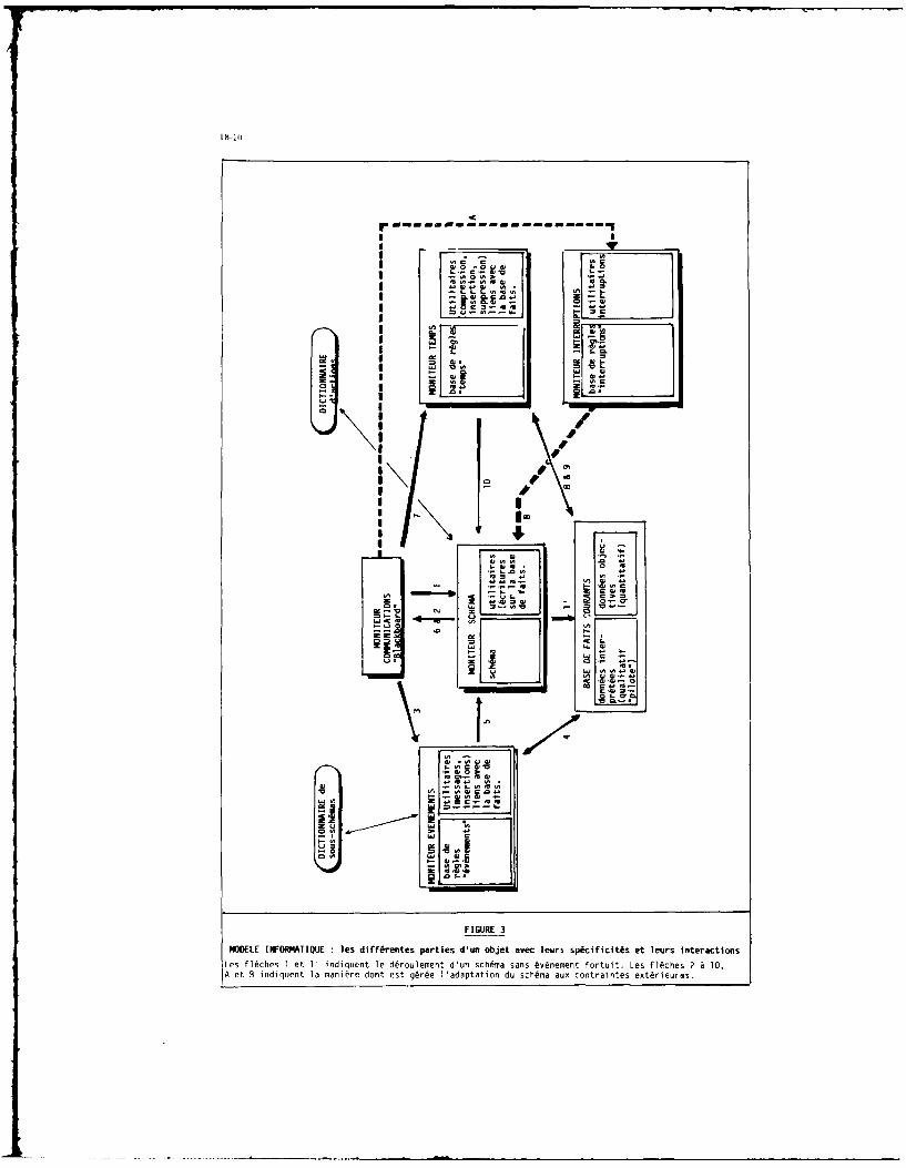
Ix-lC
Iv
IP I C
IC 0
U-- w~
w rlk
z Iu
I pmI
FIURIMOR IOKAIUE ls if~ete aris 'n betaeclur p~cfii~s t ersiteatinLe l~hs t 'inlqun l ~ruemn du shmasnsLv~een orut.Ls lchs2 0A tB niqet amai e ot s gre aapaio u c~m uxcntantsex~ieIs

- Miire des C-venents riceits
- Mfimoire des buts poursuivis
-Justification (en langage naturel)des actions men~es et des raison-nements en cours.
.4.
17--
FIGURE4
SCHERt4 GE SORTIE SUR ECRANE Dl FONCTIWWEET Ot MODELE IrrORNArrQUE DE I 'OPERATEUR.
Ce type de prdsentation est destin@ A servir de support au recuell comptdmentaire d'expertise
aupres des pilotes.
DISCUSSION
J.Nicol, UKDoes the research completed to date give the CERMA team confidence in the coherence of pilot mindset?
Author's ReplyYes, we are confident in the relative stability of pilot mindset. On one hand. pilots obviously are human. They haveopinions and, in separate conditions from real. they may vary their comments on the same situation, depending on thecontext and interlocutors.
On the other hand, increasing system complexity largely reduces the real variants of their own way to manage systems.New planes are more and more procedural in nature. Degrees of freedom are diminishing. For that reason, for the mari,heuristics at least, we are confident in the coherence of pilot mindset,
W.Mellano, ITWhich tools and languages did you use in formalizing the pilot expertise?
Author's ReplyWe used VAX station GPX- 11 (DEC) with live memory extended to 9 Moctets and LISP language in formalizing thepilot expertise.
19-1
ADVANCED DEVELOPMENT OF A COCKPITAUTOMATION
DESIGN SUPPORT SYSTEM
Philip V. KulwickiJoe W. McDaniel, PhD
Lisa M. Guadagna, 2Lt, USAFAAMRL/HEX-CAT
Wright-Patterlon AFB, Ohio 45433-6573United States Air Force
SUMMARY
Under the auspices of the United States Air Force Cockpit Automation Technology(CAT) advanced development program, a highly disciplined and structured crew systemdesign process (along with its supporting design tools and technology) is beingdeveloped to improve the efficiency and effectiveness by which advanced cockpits can b.fielded. As an initial implementation of the CAT design process. a Cockpit AutomationDesign Support System (CADSS) is being developed to provide a computer-aided designenvironment, including the software design tools and the simulation utilities that canfacilitate the development of the crew system in synchrony with the development of theavionics and weapon system. The rationale underlying the CADSS will be described interms of the system components which include a Designer's Computer-Aided Deseign System(DCADS) processor, new software tools and a breadboard cockpit iimulator which areenvisioned to complement, but not replace, existing development facilities. Thisimplementation of a cockpit design support system is described in relation to theoverall CAT program activities and schedule.
INTRODUCTION AND BACKGROUND
The CAT program stems from a management recognition of the increasing importanceof the crew system within the overall avionics and weapon system design, the lack of astandard process for development in the current design practice, and the need for asystematic design process having traceability and an audit feature to help avert (but,If necessary, to correct) design flaws early in the weapon system acquisition cycle. TheCAT design process is tightly coupled to the overall weapon system development andconcentrates on satisfying operational mission demands and aircrew needs in an iterativemanner, with a formal connectivity among engineering analysis, design at~4 pilotedsimulation.
Origins for the CAT project date to 1980, at which time the United States AirForce Systems Command (AFSC) planned for a new crew systems technology initiative tofocus on the needs of combat crews. Prior to that time, those needs were addressed inother programs, but were sometimes underemphasized due to the hardware and softwarecomplexities of emerging systems. Under the leadership of the Aerospace Medical Division(recently renamed the Human Systems Division), a component of AFSC, three advanceddevelopment projects were established (see Figure 1). An Advanced Life Support SystemsProject was activated in 1983 to provide a new generation of aircrew personal protectiveequipment (to include new flight gear for altitude and acceleration protection and forother purposes). In 1984, an Advanced Crew Escape System Technology Project began toadvance the state-of-the-art for technologies needed to expand the escape envelopeassociated with open ejection seats. Also initiated in 1984, the Cockpit AutomationTechnology (CAT) Project was established to organize and advance the process for crewsystem design (see Figure 2).
NEED FOR DESIGN PROCESS DEVELOPMENT
The CAT project is unique in that it concentrates on process rather than aircraftcomponents or point designs. The need for investment in design process could bequestioned, in view of today's scarce research and development resources, because (afterall) we have designed and fielded operational systems having substantial capability.However, the current development practice has led to a situation wheret (1) importantdesign deficiencies are identified very late in development (this leads to excessivereliance on expensive changes in both hardware and software), (2) the weapon systemdevelopment itself Is a lengthy process (often spanning more than 10 years), (3) thecost and complexity necessary for advanced weapon systems are continuing managementconcerns, (4) the systems remain in operational inventory for decades and undergosignificant configuration upgrades, and (5) significant crew system operability andworklord concerns are becoming apparent in emerging systems.
In the arena of cockpit crew systems, the emergence of digital avionics, with itspotentially massive amount of data available for display and large number of aircrew
19-2
control interactions, raises new development challenges. Today's aircrewmembers, particularly in fighter systems, must monitor and control a myriad ofsophisticated avionics systems and weapons, often in hazardous flight regimes, withdemanding time constraints, in concert with cooperative aircraft participating in thesame mission, and under potential threat attack. Pilot workload is sometimes excessive,partly due to the need for sorting through encyclopaedic quantities of data (much ofwhich, in current systems, may be irrelevant to the task at hand) to glean that which isnecessary to perform the immediate task. The consequence, in the modern combat arena,can be task "shedding" (i.e., some needed tasks are not performed) or loss of situationawareness which, once lost, may be difficult or impossible to regain. This occurs, inthe authors' opinion, because of serious limitations in the crew system design process(as it is currently applied; see Figure 3).
Based on three years of detailed examination of both development needs and currentpractices in crew system design/evaluation, we observe that:
(1) There is little or no standardization of the current crew system designprocess. There are company-to-company differences In design -process and Its application;there are system-to-system differences In the extent of management oversight.
(2) There is an over-reliance on expert opinion in crew system design decisions,with minimal dependence on formal analyses and truly objective tests.
(3) Often, steps are "skipped" and shortcuts are taken in order to meet schedule.
(4) There is an over-reliance on time-consuming manual design methods.In this regard, the crew system design community appears to seriously lag othertechnical disciplines in the field of design automation.
(5) Crew system design tends to be emphasized late in the system acquisitionprocess with other related design constraints already fixed; this inhibits the trade-offof crew system needs with other subsystem needs.
(6) Crew system design guide documents are outdated. For example, according toSmith & Mosier (1986, pp4-5), "human engineering standards and design handbooks have inthe past been of little use to the software designer ". Often, design decisions are notrecorded and, if recorded, they are not easily retrievable. Crew system design "lessonslearned" are not effectively distributed to new system developments.
(7) While there has been a substantial increase In the field of engineering flightsimulation, crew system developers have been relatively slow to exploit Its potential.Objective measures to evaluate crew system performance are argumentative (or missing).Simulator tests may not employ scientific controls and they often focus on subjectivepreferences for proof-of-concept rather than on engineering data to support designtrades.
(8) Often, high fidelity flight simulators are not directly accessible to crewsystem developers; tools that are readily accessible, such as static mock-ups andsimplified part-task design aids, tend to be useful more for form-fit-function studiesthan for understanding pilot information management and workload as they relate to thecrew system opcration (yet this latter design area is critical for mission suceas).
(9) Mission requirements established for air vehicle sizing and performanceprediction are insufficiently detailed for crew system development.
(10) The direct interrelationship between crew system development activities andother related weapon system development activities appears to be poorly understood,leading to an inefficient generation and use of design data; the extent and focus ofcrew system development varies as the design progresses toward deployment of the weaponsystem.
(I) During the system lifetime, a substantial amount of design change isinevitable, but a scheme to maintain the traceability of the crew station designevolution has not been implemented. As a result, change decisions can be based uponunnecessarily incomplete information which can aggravate the reintegration problem.
(12) Although attempts have been made to develop computer-based design "tools%,the developments have been somewhat piecemeal and the resulting products are notgenerally in wide use.
OVERVIEW OF COCKPIT AUTOMATION TECIINOLOGY PROJECT
The CAT project has been planned and organized to redress the above concerns. Useof the term "automation" in the project title confers t,..e expectatinn that automation
technology will be central to resolving the difficulties that must be resolved infielding effective combat crew systems, This project develops an organIsed,methodological crew system design and development process: it applies this process to aspecific operational mission to demonstrate proof-of-concept; it develops acomputer-based support system as a design environment to promote design process

19-3
efficiency. Collectively, these developments can help to elevate the crew system togreater status in the weapon system work breakdown hierarchy. Demonstrated gains in Prowsystem development effectiveness and efficiency are equal goals. Based on clearly stated(projected) operational requirements, the CAT process will progress through stages ofmission analysis, functional analysis/allocation, integration and design, andprogressive test/evaluation. This auditable design process will determine the need forinterrelating weapon system automazion with crew system operation based on missiondemands, aircrew abilities and technology cost/benefit. The extent of automation willbe establLshed, based upon formal engineering trade analyses, real-time pilotedsimulation tests, and objective aircrew performunce and workload measures. The CATprocess, in particular, confronts the information needs of combat aircrews to achievemission success with realistic, manageable sircrew situation awareness and workload. Assuch, the crew system can become a recognized aircraft subsystem (of equal importance toairframe or propulsion in the weapon system development).
The CAT project delivers several related products: a systematic and detailed crewsystem design process, a cockpit automation design guide, proposed revisions to existingdesign guides and standards, a cockpit design specification derived by applying the CATprocess to a specific fighter mission, a breadboard computer-aided design/engineeringsystem as an initial Implementation of the CAT process and its software support tools,prototype instrumentation for effective measurement of pilot performance and workload inground and airborne environments, and verification of the design process usingscientifically controlled, engineering flight, full mission simulations. This paperconcentrates on the computer-aided support system, which we term the Cockpit AutomationDesign Support System, or CADSS (see Figure 4). The CADSS integrates new design toolsand techniques into a self-contained support system for the crew system design team.
Programmatically, the CAT project is organized in a number of technical phases.Phase 1 was a definition phase and provided an exploration of cockpit design processimprovements. Phase 2 is currently underway and Involves the full development of theCAT design process and the partial development of the CADSS. Phase 2 has two industry'teams in direct competition (one or both may be continued through Phase 3, thedemonstr~tion phase, which is expected to commence in May 1988). For this reason,specific details of the respective design approaches for the CADSS are not presentedherein; the discussion below is applicable to both Phase 2 technical approaches. Lastly,a fourth tect-nical phase is planned and will further demonstrate and disseminate theresulting crew system development process, and its implementation in hardware andsoftware, to industry and Government organizations. We call this phase a technologytransition phase.
CADSS CONCEPT FORMATION
The idea of using computer information tools to support cockpit analysis, designand evaluation is not new. Despite some noteworthy tools, in general, crew systemdevelopment remains predominantly a manual process. This is partly because cockpitdevelopment has been by trial-and-crror engineering which (in the past) did not requiresuch support. Another likely reason is that the cockpit design necessarily involveshuman factors, which are difficult to characterize with computer analysis. For example,researchers still disagree on fundamental theories of human behavior for routinesituations (not to mention performance under combat stress). This is particularly thecase for the aircrew's mental processes as they relate to task performance,decision-making and workload. In early days of aircraft development, missionrequirements and weapon systems were less complex and the aircrsw could adapt so as tomake up for cockpit design shortcomings. Today, however, the srcrew can no longer beregarded as a "slack variable" and, thus, over-reliance on a purely experimentalengineering approach to crew system development is insufficient.
Researchers in the past two decades have anticipated that today's crew systemdesign process must be supported by modern computer tools, According to Lind (1986)t"Previous attempts to do this have yielded products of low general utility and havefailed, in general, to take into account the overall vagueness, subjective quality, andlimited integrability of much of the subject material. Moreover, the individual programssupport very limited portions of the design process and make limited provision for themanner in which the crew systems designer actually does his or her itork and for thescope of the work to be done. The crew systems designer, and in f.ctt any designer,usually does not work In a linear fashion, designing one step completely before movingon to the next; rather, the designer will lay out a rough design which is then refinedthrough many iterations. No integrated computer environment to support this style ofwork exists."
Lack of success of many early attempts may have contributed to a piecemealdevelopment of computerized design tools. Such efforts concerned isolated, stand-alone,parts of the problem. Difficulties have been noted with excessive reliance on userexpertise, with awkward and labor intensive set-up of nput data, with complex andvoluminous data output which requires Lengthy interpretation (in large systemdevelopments design questions must be resolved quLckly), with incompatible operatingsystems and programming languages (which prevent independently developed kools fromworking together), and with other diffiemlires.

19-4
The current generation of computer hardware and software technology hassignificant advantages over the systems with which previous design tools wereconfigured. Across-the-board advances are underway in speed, memory, software and evenartificial-intelligence hardware architectures. These can now be employed In the attemptto provide a practical computer support environment for crew system design in service ofthe CAT process. Part of this recent progress is associated with the rapid developmentand introduction of engineering workstations, data base management systems, andcomputer-aided design/engineering (CAD/CAE) software. The result is a greatly increasedgraphics and file manipulation capability, which appears necessary to implement apractical CADSS.
The CADSS must support the practical needs of the crew system designer. It isunrealistic to expect that purely analytic tools would suffice, just as it isunrealistic to expect a great advance in design technology would accrue from totallyrelying on the experimental engineering legacy from the past. We envision that the CATdesign process must employ both analysis tools and experimental tools and, for thatreason, have provided both capabilities In our CADBS concept.
The CADSS concept is illustrated In Figure 5, In a very "top level" description,this system is comprised of four components.
(1) DCADS. The most critical element of the CADSS is what we term a DesignersComputer-Aided Design System which hosts the main data handling portion of the CADSS. Itcontains the major computing hardware and operating software of the CADSS. Thoughdepicted as a single block in the figure, it may be separated into an array ofsupporting elements. The purpose of the DCADS is to allow the cockpit designer to usecomputerized data bases, computer models, computer analysis tools, simulations, andcomputer drafting tools. The system will have a general purpose central processing unitas its core and, as shown in the diagram, the DCADS will provide a simulation executivefor real-time, piloted, part-task tests with a breadboard simulator discussed below.Also included in the DCADS are several engineering workstations. These workstationsrepresent a major input/output environment for the designer. Many of the CAE andanalysis tools needed for crew system development will be hosted at the workstations,but each workstation will readily communicate with the DCADS central processor.
(2) CAT Software Tools. These tools are being configured specifically to supportthe designer in using the formal crow system design process being fully developed in theCAT project. The CAT software tools are in two categories: commercially available andcustom developed/adapted. Because they are mature and have been developed outside theCAT project, some commercially available software tools will be incorportted into theCADSS. For example, we envision that the crew system designer will need ready access todata bases of various natures. Accordingly, a commercially available data basemanagement system will be needed. Likewise, a variety of computer-aided-design softwarepackages are available. Commercial software may be incorporated to the extent that it isneeded for CAT, mature, documented, and likely to be supported and maintained. Othersoftware will be custom developed or adapted for use in the CADSS. Specifically fallingin this category are three analysis tools and a lessons learned data base which arebeing devised in Phase 2 of the CAT project. The analysis tools will support the crewsystem designer in mission decomposition, function analysis/allocation, and informationanalysis. Associated with these analysis tools will be one or more on-line computer databases, also to be developed in the CAT project. Such state-of-the-art tools are notcommercially available. Additional tools in this category are also shown in Figure 6.
(1) Breadboard Cockpit Simulator. The crew system designer needs convenientaccess to a real-time simulation device with which to quickly test new design ideas.lock-ups used for general layout and installation (to check clearances, for example) arenot adequate to use for design decisions concerning many critical issues includingdisplay content/format, control procedures and pilot workload. Due to a relatively highcost as well as a demand from other design disciplines, high fidelity dome simulatorsare often not directly accessible to the crew system designer. When a design questionarises it usually needs immediate resolution and often does not require the full missiondome capability. In the CADSS, we make provision for a very flexible, real-time, parttask simulator that is easily modified (both hardware and software) to quickly test crewsystem design concepts. Importantly, this device is under the direct control of the crewsystem design teem and is customized for the CAT process.
(4) Software Fxecuter System. Some users of the CAT design process, such asGovernment managers, may require only a design/analysis support capability. This systemwill allow those users to execute the CAT software tools without requiring direct accessto the DCADS or to the breadboard cockpit simulator. Because of the relief from drivinga real-time, man-in-tbe-loop simulation, it will be possible to configure this system ona smaller and less expensive computer than used for the DCADS. The system is envisionedto operate in a typica' office environnment and will be easily transportable. Inparticular, this system will include all CAT software too'.a pertinent to the evaluationof cockpit design concepts.
CADMS DEVELOPHENT AND DcHnNSTRATION
Using the above formulation of the CADSS, two independent Industry teams are
j:

19-s
preparing designs which will be developed in hardware and software. Figure 7 showswhich parts of this effort are underway In the development phase (CAT Phase 2) and whichwill be undertaken in the demonstration phase (CAT Phase 3) and in the transition phase.Cetailed requirements for the CADSS are being independently derived from the CAT designprocess being developed by eachr team. Where possible, this section will describe commollrequirements and design considerations.
The relationship of the CADSS to the CAT crew system design process Is shown InFig 8. here, four specific stages to the CAT process are illustrated. Both the CATprocess methodology and the application of the CAT process are shown in schematic. Notethat the CADSS is employed in each stage of crew system development, from the initialconception and requirements definition through analysis/design/integration and includingtest and evaluation. Two important points, not illustrated, should also be noted.
First, -crew system development is a highly iterative process which does not lenditself to this kind of diagram. In order to have a common basis for evaluating the twoCAT processes under development, we have imposed that the CAT process be described inIDFF notation (see Figure 9). IDEF stands for ICAM (Integrated Computer AidedManufacturing) Definition and is a means of organizing process information according towell-defined rules. Figure 10 shows the arrangement of IDEF notation in terms ofactivity, inputs, outputs, constraints (controls) and resources (mechanisms). For theCAT application, the terms "constraints" and "resources" better illustrate the intendedmeaning, while the terms "control" and "mechanism" were part of the original IDEFformulation. The advantage of this notation is that it permits a progressivehierarchical decomposition of process activity into its lowest constituent elements (seeFigure I). Each granular block of process activity can then be examined in terms ofpotential CADSS usage.. To illustrate this point, Figure 12 shows an IDEF representationfor the entire weapon system. The crew station portion highlighted therein can beinspected in its 'own IDEF format, as in Figure 13, which details the top level Inputs,outputs, constraints and resources. As envisioned during CAT Phase I (Quinn, 1986), thistop level activity is then exploded into constituent activities in the manner shown inFigure 14. Each constituent activity itself might be further decomposed In the samemanner. Importantly, all of the inputs, outputs, constraints and resources of the"parent" diagram would be reflected in the appropriate "child" diagram.
Again referring to Figure B, the second important point to be made is that thisdiagram depicts crew system design relationships In the CAT process. Yet, in applicationto the overall weapon system development, these relationships will be affected by theevolving maturity of the weapon system itself. That is, the design emphasis, activityand labor level of effort (and hence, CADSS usage) will change depending on the phase ofthe weapon system acquisition process. In the United States these weapon system processphases are known as Concept Exploration, Demonstration and Validation, Full ScaleEngineering Development, and Production and Deployment. Crew system design activitychanges with passage from weapon system phase to weapon system phase. The CAT process isbeing developed in tight coupling with the weapon system process (see Figure 15).Therefore, CADSS design requirements must consider not only the hierarchical granularityof necessary crew system activity noted above, but also which weapon system developmentphase is currently active. These two important dimensions to setting the CADSSdevelopment specifications are significant. The CADSS, and the CAT process it supports,will be judged by its demonstrated Improvements in design efficiency and designeffectiveness.
Demonstrating the value of the CADSS In terms of design efficiency and designeffectiveness are separate problems. True validation in these areas is infeasiblebecause: (I) there is no accepted, well-understood standard of comparison for the"current" crew system process and its supporting methods and tools, and (2) the scope ofthe CAT project is confined to ground-based simulation for proof-of-concept. Subjectiveestimates of design efficiency will be possible by applying the CAT process (itselfgeneralizable beyond a specific pre-defined operational mission) to a specificGovernment furnished mission scenario (requirement). Using the CAT process, supportedby the envisioned CADSS support environment, a specific cockpit crew system is beingdesigned in Phase 2 and will be fabricated and tested in full-mission simulation inPhase 3. It will be possible, through objective measures of task effectivenes in thePhase 3 real-time simulation, to infer design effectiveness. This will be-approached bydirect comparison of the CAT crew system against a baseline crew system derived'by"conventional" crew system design practice (using comon misslons, weapons, threats andpilots for this comparison). These demonstration events have yet to be planned indetail. However, there is provision duriig Phase 3 for 600 hours of real-time, piloted.full mission combat simulation (exclusive of tasting with the breadboard cockpitsimulator described above).
The technical approach being followed in both ongoing CADSS developments Is towardan integrated system that will support all crew system analyiis, design and evaluationsctivities throughout all weapon system development phases. Although well over toexisting computer software programs have been evaluated Cor potential use in the CAUSS,only a relatively small number of key tnola will .ffoetiv@-y mld in crew systemdevelopment. Considerable differeneas exist in the Phase 2 approaches for CADSSarchitecture (both hardware and software) and envisioned CADS application. At this
19-6
time, a comparison of approaches is premature. In general, the CADSS is being designedto:
(1) Support the CAT analysi& software algorithms,
(2) Support the CAT data bases and data base management system,
(3) Support the CAD packages adopted for the CAT process,
(4) Support the incorporation of new design evaluation tools as may bedeveloped outside the CAT projesc,
(5) Support the CAT crew system evaluation tools,
(6) Support the real-time breadboard cotkpit simulation,
(7) Support downloading the appropriate DCADS software to the Software ExecuterSystem envisioned for use in an office environment,
(8) Supprrt industry standard interfaces to permit the broadest dissemination ofCAT products,
(9) Permit an upwardly compatible path for system growth,
(10) Support the configuration managesment and design decision traceability of crewsystem development.
TECHNOLOGY TRANSITION CONCEPTS
Particular & t, ntion has been directed toward the eventual uses of the CAT crewsystem design proc-a. and its supporting CADSS. In the final analysis, system processand process support tools will be accept.d a,,d used only when the practical advantagesare understood and demonstrated. Transition of this kind of technology requires morethan a letter of transmittal and receipt of equipment. The CAT project is berindeveloped and managed by an interdisciplinary, inter-organLitional USAF team withrepresentation of the Human Systems Division, the Harry C. Armstrong Aerospace MedicalResearch Laboratory, the Avionics and Flight Dynamics Laboratories of the Air ForceWright Aeronautical Laboratories, and the Aeronautical Systems Division, Deputy forEngineering (ASD/ZN).
Responding to the above concern, the CAT project office has established a formalTechnology Transition Plan which represents an agreement naming ASD/EN as recipient ofthe technology. This organization, in turn, will adapt the technology for exploitationin major system development. Specifically identified in this transition plan is aseparate, funded transition effort (noted above) which will assist ASD/EN in testing,acquiring, using and supporting the deliverables. It is expected that the CADSSdescribed in this paper will be upgraded by a second generation variant in thattransition development.
Also related to the Transition Plan, the CAT project office has consolidated anunderstanding with the Advanced Tactical Fighter (ATF) System Program Office. Thisagreement provides for making CAT project developments available for use in thatprugrnm. Accordingly, the CAT project schedule is coordinated with, and technicalprogress is monitored by, the crew system engineering function in the ATF development.This close coordination assures ASD participation In CAT project planning, decisions andmilestones. Hore importantly, this presents an opportunity to test the viability of thedeveloping crew system design process and the CADSS in a realistic development settingand to make necessary adjustments. The active involvement of the engineeringdevelopment *customer" In an advanced technology development enturprise is considerednoteworthy with respect to planning for the technology transition.
CONCLUSIONS
Current design methodologies available for crew system designers are embodied Indesign handbooks (AISC DH 1-3 and 2-2), military standards (MIL-STD-1472C endHIL-STD-1776) and military specifications (HIlL-H-46855). These methodologies are toogeneral, antiquated in terms of the technology assumed, and do not answer the paramountquestiona "what does the crow need?" These methodologies focus on general cockpit-layout, control/display arrangements, and anthropomotric studLes that support cockpitinstallation and physical fit. They also provide for part-task simulation which helpsdefine cockpit procedures and function. Up until the mid-1970s, this procedure vasadequate due to Limited alternatives in cockpit componentry automation and avionics, amore limited flight envelope end a (comparatively) benign threat. The situation sincethen has changed In that we now have the capability ti completely overwhelm the atrerevwith complex control switcholony. uninterpretable displayed data, and automation modeswhich may or may not help. Crew system design methods have not kept pace withair-vehicle, avionics and weapons advances.
The USAF Cockpit Automation Technology Project attempts to correct this situation
19-7
by state-of-the-art advancement in crew systen design technology. The focus of this workis with a computer-supported, methodological design process that seeks to imposediscipline on today's practice (with all its current limitations). A critical part ofthe CAT project is the Cockpit Automation Design Support Subsystem, without which itwould be unrealistic to expect significant gains in either crew system design efficiencyor design effectiveness. Some of the envisioned users of the CADSS are depicted inFigure 16. Because of the interaction of the crew system with other components of theair vehicle (Figure 17), the CADSS may eventually be used in conjunction with othercomputer based support systems that will likely evolve.
The CAT project is advanced technology development. For the first time, a criticalmass of funding, along with inter-organizational cooperation within both Government andindustry, is being brought to bear on a state-of-the-art advance in the cockpit designpractice. Even partial success of this ambitious project will contribute to futuregains, both in developmental efficiency and in operational suitability. Greater successcan lead to reductions in development time and acquisition costs (in minimizing the needfor engineering changes with their attendant inefficiencies). Together with the advancedlife support and escape system projects, the Cockpit Automation Technology Projectoffers a man-centered orientation for future system development.
REFERENCES
1. Aldrich, J. R. et al, Phase I Final Technical Report for the Cockpit AutomationTechnology Project, Contract F33615-84-C-0517, Volume 1,"Description of the kefined CAT Design Process," The BDM Corporation,Dayton, OH, March 1986.
2. Aretz, A. J., "Cockpit Automation Technology", in Proceedings of the 1984 HumanFactors Society Annual Meeting, San Antonio, TX, 22-26 Oct 1984.
3. Davidson, J. (Chairman), Report of the Committee on Automation in CombatAircraft, National Academy Press, Washington DC, 1982.
4. Eggleston, R. C. and P. V. KulwLcki, "A Technology Forecasting and Assessentmethod for Evaluating System Utility and Operator Workload," in Proceedings ofthe 1984 Human Factors Society Annual Meeting, San Antonio. TX 22-26 Oct 1984.
5. Eggleston, R. G. and P. V. KulwlckL. "Estimating the Value of EmergingFighter/Attack System Technologies," in Proceedings of the NATO DefenseResearch Group Panel VIII Workshop on Application of Systems Ergonomics LoWeapon System Development. Shrivenham. England, April 1984.
6. "ICAM Architecture, Part II, Vol IV, Function Modelling Manual (IDEF)",Technical Report AFWAL-TR-81-4023, Air Force Wright AeronauticalLaboratories, Wright-Patterson AFB OH. 1981
7. Kidwell, C. H., "Workstations Take Over Conceptual Design," AerospaceAmerica, pp 18-20, January 1987
8. Kulwicki, P. V., "Addressing Human Factor Options in Conceptual Design," in AGARDConference Proceedings CPP-266 on Operational Roles, AircrewSystems and Human Factors in Future High Performance Aircraft. Lisbon, Portugal22-26 October 1979.
9. Kuperman, C. C. and P. V. Kulvicki, "Mission Scenarios for Cockpit AutomationTechnology," in Proceedings of the AIAA/IEEE Sixth Digital Avionics SystemsConference, Baltimore MD, 3-6 December 1984.
10. Lind. H. 0., "A Network Management Tool Applicable to Crew Systems Analysis andDesign Techniques." Document No. D180-29158-l, Boeing Military AirplaneCompany, 26 November 1986.
11. Littlefield, J. E. snd 1. L. Howard, "Computer Graphics Win Over Engineers,"Aerospace America, pg 22, January 1987.
12. McDaniel, J.W., "Cockpit Automation Technology: A Process for Designing AdvancedAircraft Systems", in Contemporary Ergonomics, Durham, England, pp 143-147,April 1986.
13. McNees@, M. D., Rik Warren, B. K. Woodeon, "Cockpit Automation Tmchnologyt AFurther Look." in Proceedings of the 1985 I#,,man Factors Society Annual Meeting,Baltimore MD, 29 Sep - 30 Oct 1985.
14. Mitchell, A. K., "Market Supremacy Through Engineering Automation," AerospaceAmerica, pp 24-27, January 1987.
19-8
15. tlorgan, D. R., T. A. Furness, A. J. Arets, D. E, Cole, and P, V. Kulvicki, "CockpitAutomation Technology Concepts," in Proceedings of the NATO Defense ResearchGroup Panel VIII Workshop on Application of Systems Ergonomics to Weapon SystemDevelopment, Shrivenham, England, Apr 1984.
16. Pew, R. W., at al, Phase I Final Technical Report for the Cockpit AutomationTechnology Project, Contract 733615-84-C-0516, DBN Laboratories Incorporated,Cambridge HA, June 1986.
17. Quinn, T. J., et al, Phase I Final Technical Report for the Cockpit AutomationTechnology Project, Contract P)3615-84-C-0500, McDonnell Douglas Corporation, StLouis MO. May 1906.
18. Smith, S.L. and J.N. Hoeser, "Guidelines for Designing User Interface Software,"Technical Report ZSD-TR-86-278, Electronic Syqerms Division, AFSC, Hlanscom APBHA, August 1986.
iI
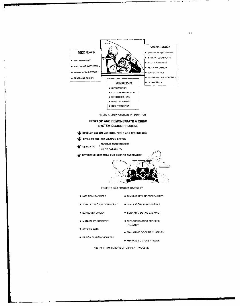
COCKPIT DESIGN
CREW ESCAPE I . . MISSION EFFECTIVENESS
f INTEGRATED DISPLAYSe SEAT GEOMETRY
0 PILOT AWARENESS
* WIND BLAST PAOTECTiON 0 HEADS UP DISPLAY
0 PROPULSION SYSTEMS _ VOICE CONTROL
o RESTRAINT DESIGN 0 MULTIFUNCTION CONTROLS
LIFE SUPPORT 0 C3
NTERFACE
" G-PROTECTION
" ALTITUDE PROTECTION
" OXYGEN SYSTEMS
" DIRECTED ENERGY
" NBC PROTECTION
FIGURE 1. CREW SYSTEMS INTEGRATION.
DEVELOP AND DEMONSTRATE A CREW
SYSTEM DESIGN PROCESS
- DEVELOP DESIGN METHODS, TOOLS AND TECHNOLOGY
APPLY TO FIGHTER WEAPON SYSTEM
DESIGN TO ICOMBAT REQUIREMENT
PILOT CAPABILITY
*W DETERMINE BEST USES FOR COCKPIT AUTOMATION
FIGURE 2. CAT PROJECT OBJECTIVE,
" NOT STANDARDIZED 0 SIMULATION UNDEREXPLOITED
" TOTALLY PEOPLE DEPENDENT 0 SIMULATORS INACCESS!BLE
" SCHEDULE DRIVEN 0 SCENARIO DETAIL LACKING
" MANUAL PROCEDURES 0 WEAPON SYSTEM PROCESS
RELATION
* APPLIED LATE
* MANAGING COCKPIT CHANGES
* DESIGN GUIDES OUTDATED* MINIMAL COMPUTER TOOLS
FIGURE 3. LIMITATIONS OF CURRENT PROCESS

SOFETAEOLS
0 ANALYSIS
- INSTALLATION
0DESIGN/DRAFTING
WuRKSTTION EVALUATION
_____ -@- __ BREADBOARD SIMULATOR
DATAANAGEMENTF RA ~PROTOTPING
ONLINE DATABASES 0 DISPLAYS
" DBMS I E
" AUDIT TRAIL - CONTROL
CENTRAL PROCESSOR 0CNRL
0 PROCEDURES
FIGURE 4. CADSS - CONFRONTING THE LIMITATIONS.
ACCETAE OSCOCKPITHLSIUANTOOLS EVALATO
FIGURBAE 5MGCPTAUOAINDEINSPOT SYSTDAGEM ATRSLS
MISO MNLYISINDCMOIINTO*FUNCTION ANALYSIS IALKOCATION SOTOOLE
IN IFOAIO ANALYSIS TOOLAIN IPLYDEIE
CA DACATA BASE MANAEMENOTOO
*LTPERFORMANCE TOL 1 EIEVAUAIONTOOLCEWOKLA WOORLOA EALURAIO TOOL S
*LTACCEPTANCE TOOL OKI HL
FIGURES LEA.E CD SOFTARETOL

COCKPIT AUTOMATION TECHNOLOGY PROJECT PHASES
CADSS COMPONENTS PHASE 2 PHASE 3 TRANSITION
OCADS FULLY DEVELOP EMPLOY AND UPGRADE SECOND GENERATIONAND DEMONSTRATE
DBMSCAD PACKAGE PERFORMANCE EVAL
CAT WORKLOAD EVALSOFTWARE MISSION ANALYSIS PILOTMODIFY FOR SESTOOLS FUNCTION ANALYSIS ADD REFORMATTER
INFO ANALYSIS DATA ACQUISITIONLESSONS LEARNED SIMULATION SIW
BREADBOARD DESIGN STUDY FULLY DEVELOP UPGRADECOCKPIT SIMULATOR PREPARE SPECS AND DEMONSTRATE
SOFTWARE DESIGN STUDY COORDINATE FULLY DEVELOPEXECUTER SYSTEM PREPARE SPECS REQUIREMENTS AND DOCUMENT
FIGURE 7. CADSS EVOLUTION.
CAT DESIGN METHODOLOGY
CAT SUPPORT SOFTWARE AND DATA BASES0 CREW PERFORMANCE 0 CREW SYSTEMS LLDB 0 BASELINE SYSTEM
CAT STAGE 1 AT STAGE 2 AT STAGE CASTG4MISSION FUCIONDSG TEST
ANALYSIS ALLOCATION INTEGRATION VALIDATION
1I
COCPI AUTOMATION DESIGN SUPPORT SYSTEM
FEATURES: AUDIT TRAIL SOFTWARE GUIDESIDEF OUTLINE LESSONS LEARNED
USER GUIDES AUTOMATION DESIGN GUIDE
BASELIN CAT MISSION DSG
CAT DESIGN APPLICATION
FIGURE 8. RELATION OF CADSS TO CAT METHODOLOGY.
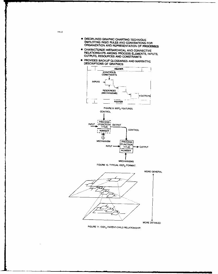
19-12
" DISCIPLINED GRAPHIC CHARTING TECHNIQUEEMPLOYING RIGID RULES AND CONVENTIONS FORORGANIZATION AND REPRESENTATION OF PROCESSES
* CHARACTERIZE HIERARCHICAL AND CONNECTIVERELATIONSHIPS AMONG PROCESS ELEMENTS, INPUTS,OUTPUTS, RESOURCES AND CONSTRAINTS
0 PROVIDES BACKUP GLOSSARIES AND NARRATIVEDESCRIPTIONS OF GRAPHICS
_____ HEADER
(CONTROLS)CONSTRAINTS
INPUTS
RESOURCES
(MECHANISMS) -*OUTPUT
, ~F O T E R
FIGURE 9. IDEF 0 FEATURES.
CONTROL
: PROCESS IINPUT '(FUNCTIONI OUTPUT
-be TITLE)SNUMER I CONTROL.- ----'NTO
MECHANISM PROCES
(FUNCTIONINPUT TILE) OUTPUT
NUMBER
MECHANISMS
FIGURE 10. TYPICAL IDEF 0 FORMAT.
MORE GENERAL
MORE DETAILED
FIGURE 11. IDEF 0 PARENT-CHILD RELATIONSHIP.

19-13
&$4&TKA PROXASS "• AEffLP '~ ARD
o ___ - ____- H MSMA A I
00MW[ MA rA
FIGURE 12. IDEF FOR WEAPON SYSTEM DEVELOPMENT.
SYSTEM
ROMTSMISSION ANTHROPOMETRIC
NEEDS DATA &DESIGN GUIDES
- ~ OES ~IF I
TETRADE STUDIES& SUPPORT DATAATEUT BEDS & - I
AM
DOPEAEO FA ILT CE NEFAESE
ODOTMOIDFAILIIE FA.TSTO MDPR3W
FIGURE 12 . IDEF FOR WEPN AYT DEELO PE.
TEHOOY0 = CREW CREWN SYSTEM DE-SIGN DWAG
SYSTEMLESSONS LEARNED
~TEST BEDS & MOCK-UPS
FIUR 3.IDFFO CTDESIGN POES
AISTRTTOT
IIEED I[l- N ___
TEAM
TW ALT 4U0TO
AIB)
AC TESADJ
FIGURE 1. IDEF OR CAT EASIBLERCES
ATTW
AgFIT0 WyFIIAT
005 E .1 ESYEIT AS
*CADSS -,;If
MANPOWER F U 1 CAT METHODOLOGYTOPLEVEL•FACILITIES FIGURE 14. CAT METHODOLOGY TOP LEVEL ,
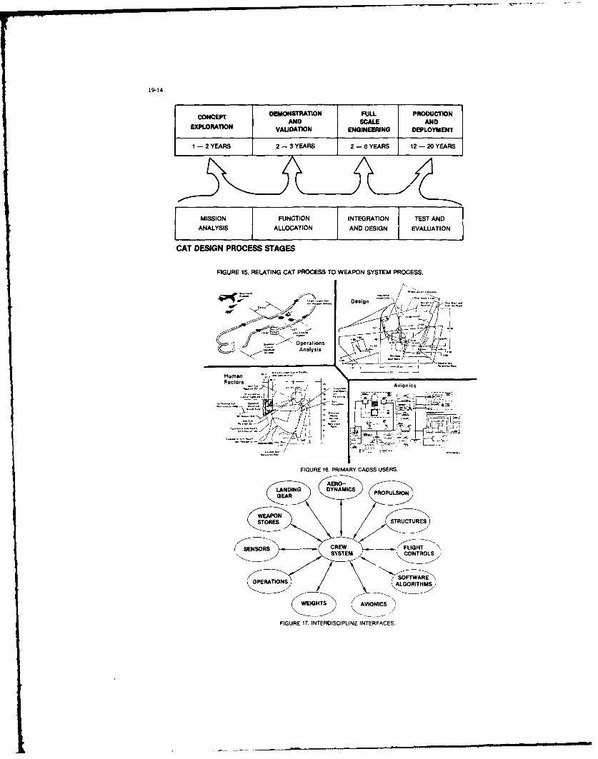
19-14
C014CEPT DEMONSTRATION FULL PRODUCTION
EXPLORATION VALIDATION ENGINEERING DEPLOYMENT
1 -2 YEARS 2 -3 YEARS 2 - 6YEARS 12 - 20YEARS
[ MISSION FUNCTION INTEGRATION TEST ANDANALYSIS ALLOCATION j AND DESIGN EVALUATION
CAT DESIGN PROCESS STAGES
FIGURE 15. RELATING CAT PROCESS TO WEAPON SYSTEM PROCESS.
Design ~
o-- Analysis ~
Sz~zHumanFactors
Avionics
FIGURE 16. PRIMARY CADSS USERS.
SYEMCNTOL
SNORATS ALRRITWS
FIGUE 1. INERDSTILIEIRFCS

19-15
ANALYI
FIGURE 18. COCKPIT AUTOMATION TECHNOLOGY DEVELOPMENTAND DEMONSTRATION.

CGOiCEPTIDW ET IEELOPBEENT 0 LiE SYSTBNE AVIWEIQIE ADAPTE MIX NISSICW BS bEL1UPTWRS
par
Daniel BOUNDRET - AERDSPAIALEDivision Nelicopteres
6.?. f313722 HARIDNANE - FRANCE
et
Jean Louis ROCH - CROUZET S.A.Division Aerospatial25 rue Jsles Vearines
260? VALENCE CEDEX - FRANCE
Cett& conference Presents l'organzsetlon et les moyeno mis en place pour le dveloppement ds systemeavsonique des DAUPHIN 365 F S.A.R do l'AEROSPATIALE. et en particulier Ou soss-systome de navigationet 04 qestion de mission diveloppi par CROUZET. Apra$ une description des missions do 1 anion et del'arcn.tecture du systdnte, laccent est mis sur l'oreanssatzoo des travaux, entre uvioneur etsoun-slntstmnC. puis sur les diffirents moyens mis en oeuvre chez I wqvipementier come cot,l'avionneur Pour assurer Ie suc ces d'un tel diveloppeient.
INTAWDCTION
La conception et Is diveloppement de nystimes avionioues complexes font appel a de nombreusestechniques et met tent en oeuvre plusiours interoenants et difforents moyens.
Ainsi I'avionneur. osi assure lii -mme en taint quo maitre d oeuvre Os systime Ia conceptisr globule
des spicifications Os systeme, puis Ia responsabilit6 des phases d'intigration au so) et d'es.ais envol. so trouve con front6 i Ia gestion d'un projet compleve. dont les intervenants orincipaus sontcunstituis par les 6quipementiers rajesrs qui fouroinsent len aliments essentlels du systdme.
Une mdtnodologiv rigsureuse eot necessaire pour mener 4 blen cv proyst. vlea incist notanevent leres,.ect d une grande riguour au roveas des specifications. ins 6troite cooperation entry l avionnesret ens fosrniossrs. ainsi que .1 utilisation de moyens coverents et compldmentairen.
On example significatif est constistud par I@ systime avionique spdcifzquement diveloPPe Par
1 Aernspatiale en collaboration avec diffdrents iquipementiers (CROUZET - SFIM - BENDIX) pourIl4quipement des hhlicoptdres de recherche et do sauvetage en mer. Ce systdvee a Ate notaneent misen oeuvresunr len DAUPHIN 365 F lmcrois iI lIrish Air Corps.
Len relations avionnour-6quipementier sont dicrites i travers Is coopiration entre l'Adrospatiale erIa societe CROUZET fournisseur du systime de navigation.
1. PRSENTATION eERALE DU SYSTE
1. 1 DESCRIPTION OF LA MISSION
La mission princi pale do lsdilicsptdre est Ia recherche et Ie sauvetage en. mer.
Cett# mission peut Etre ddcrite a partir d'un schema reprdsentant Is orofil do vol
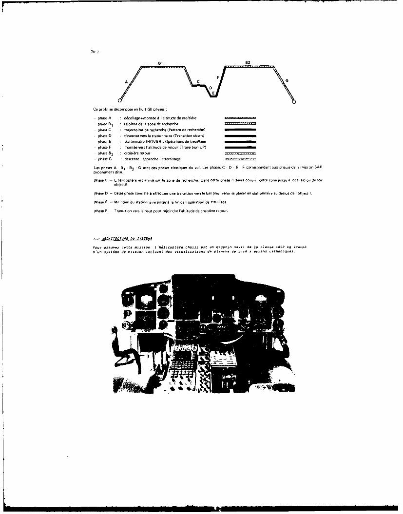
20-2
Ce profilI se decompose en hu it (8) phases
- phase A ddcoflages-montde & Ialtitude de croisi~re
- phase B relointe de la zone de recherche 777,r
- phase C strajectoires dle recherche (Pattern de recherche)
- phase 12 descente vers le stationnaire (Transition down)
- phase E stationnaire (HOVER). Optrations de treuilage
- phase F mont~e vers I'altitude de retour (Transiton UP)- phase 62 croisiAre retour
- phase G descente -approche -atterrissage
Let phases A - B, - B2 - G tont des phases classiques du vol. Les phases C -1D2 E F correspondent ass phaeas de l mission SAPpropremnent dite.
phase C - L'hWicopt~re est arriv6 sur la zone dle recherche, Days cette phase Ii devra couvrir cette zone jusqs'b localisation de sonobjectif.
phase D - Cette phase consiste A effectuer use transition vers le bat pour venir se placer en stationnaire au destus de l'objnctit.
phase E - Mrvstien du stationnaire jusqu'& la fin de l'opdration dle treuillage.
phase P - Transition vers le haut pour rejoindre I'altitude de croisi~re retour.
7.2 ARCHI1'ECTURE DU SY'STEME
Pour assumer cette mission, 15hilicoptiro ceausi eat as daaphin naval do la classe 4000 kq iquined'us systeere de meission isclsast des vualisations de Planche do bord a 6crans carssdiques.

2o-3
Le system do mission est scindi en trois sous-Oystimes
- n SOus-syntime navigation at de gostiOn de iion
- n sous-syste Pilotage aujtumatinIue
- n sous-systime, radar at visualisation
Ce systems est parfaitement intiqr6 et utilise des liaisons numiriques pour los dialogues
principaux, Son architecture est SChereatisee par 10 diagrammae suivant
R.U I CHEC ocei OCP 2 LU IU FROM RITFRADAR- RADAR RDR SAUEIILIST CO-PI LOT PILOT BATIE 2 FOR AND C.P
COUPLER SUB SYSTEM
NAVIGATION SUB-SYSTEM
OOMAEGNOR
EASE Electronic Attitude Display Indicator
EHSI Electronic Horizontal Situation Indicator
S.6 Symbol Generator
B.A.TI.E Boitier d'Adaptation at do Traiteinent d'Inforiations Electriques
I.U :Interface Unit
D.C.P Display Control Panel
F.E.C Flight Director Coupler
C.P.U Control and Display Unit
O.N.SOMEGA Navigation System

COtte archlitecture est urganisee autdur do 3 calculeteurs
-Le calculateur couplour diroctour do vol go, assure los fonctions ciassiuus do Pilot.agoautomatique ds vol ot la nose on statisonnaire automatigue
-Lt calculateur ricepteur do navigation OMEGA
-Lt caicula tour NADIR MX?
La suite do looxpod decrut plus particulidrement le sous-systoe do navigation ot do gestion do la
mis sion
1.3 LE SOdG-SYSTEME DEJNAVIGiATION FT Of GESTION DE MI5SION
to sous-systime do navigation ot do gos tin do mission ost articule autour do doss Calcula tours. 9ocalculateu. Principal quo assuro la totaliti do la geStion navigation ot us recopteur OMEGA quo onfsnctsonnomont norm~ai a us role do sonsour do position.
En cas do ddfaollance du calcula tour principal, lo repteur OMEGA rotrouve sa fonctoon calcula tourdo navigation plus recoptosr OMEGA et assure automatsgvomont la Poursuite do la navigation en cours.
tO sonsour OMEGA 051 un EQUINOX ONG 100 A do la socite CROGZET.
1.3.1 Qgjlcjgiata principal NADIR ME?
to calculatour principal do navigation ost lo NADIR MK? produot egalomont par CROGZET.
Co calculateur a 6ecoCou pour satisfairo 105 exoigences des sys tmos modornos actuols 0t futursnutanomonc on so qui csncorng Ga puissance 0e caicul, 13 taillo Veoico. ot la capacityd entrees-sorties.Ainsi, dans I oemplo ds DAUPHIIN 365 F, lo calculatour NADIe MK2 ost relie
-Ass diffdronts sonsours isi permet tart d assurer use localisatloon multi-senseursCap (compas gyromagndtiquolAttitude (gyroscope do vortucalo)Radar Dopplor do navigationVORIOME (2 lOg - I OME)OMEGAgoltier tapteur do Prossoons permettant ]a caicul des paramotresanemobaronletriques
-Aus debitmetres de carburanE, ce oui Permet doentcvtonir en permanonce les pura'etrosconsomma tion, masses machone ot carburant, distanco franchussable, ot 0 assurer los fooCt- inno0gestior carburant. gostion des performances,
-Au ponte outumatique, au radar, ot auo instruments do Polotage electroniquos. a travors losbnitiers dolnterfaces RBATIE' letZ.
-Au radio altimetre.
-A son pus to de comonde at de unsualusotuon (Pt/i tube cutnndluuo.
Le syoioptiquv du sovo-uysOcme cot decrit co-apas

NAPK2CDOMEG
AVI
* OMEGA*VORDMET
-EIZO DOm NaiVOL 1D
Vi wtened r-oier 1conomioIA* V CeIa~ damns ec0aD
* Caluls reditlfsde dstane frnthosabl
NASUVILLN ECNIUATION I OS-TTM

Si. .odes d. 9440*90 soot Possible'
*FROMITO-DIRECT To. aiiec 0 san, radIIe ptfnVntielle-Ralliemo~t ol un but .moil.
-NaVlgation Sur line route
N Hs ensainnaire HOVER) apres transition alitmiatiqie
EVOLUTIONS GIJIDEES EN HORIZONTAL F VERTICAL LORT OE LA 111SF EN STATICNNAIRE iiJTOMA~F~IQU
< VENT
MARK POINT
PON DE TRANSITION
V kACQUISITION DE LA HIAUTEUR DE SIATIO-NNAIRE FINALE
ALTITUDE STATIONNAIRE SELECTEE Vl
L _NNA---- --- SE - ------

20-7
1.3.2 Processeur stilled
Pour reeliser I'enseeble de ces lonctions, use importante puissance de celcu2 st neceusasre. t'estpourquol, dens Ia conception du NADIR HK2. CROUZET a utilise une Unite Aritfwsdtique tres puissant..l'ALPHA 732. entiirement concue pour les besoins avsoniques.
11 s'agit dun procesneur 32 bits. travaillant en virgule fine ou virgule flottante. de Is clause* de
I million d'opirations per second.
Ce calculateur est programmable en PASCAL.
Un atmlier logiciel tres puissant a 6t6 contu par CROUZFT pour peretre une production alses delogiciels importants aissi que pour assumer une grands capatiti dd6olutions et de modifications.es caracthristiques 6tant essentielles pour Is rdussite d'un programe& d'integretion de systemscomplexe come celso du DAUPHIN SAR 365 F.
Ainsi. tent dans la conception matdri vlle quo logicielle0 du celculateur ALPHA 732, ont 6te prises encompte len contraintes liies A l'intigration dens un syntime evionique important
-fonctionnement multi-tithes,
-production de logiciel par mine en parallhle do plusisurs iquipes,
-parfaite adaptation ass costrainten temps reel,
-misc en place de moyens de mine as point puissants,
-documentation abondante ot detaillee.
Pour la production de l'application DAUPHIH 355 F, environ 200 Koctets cea lugiciel ont 6te ecrits enPASCAL os ASSEHBLEUR.

2. OMWE EMNT wl mnirT
2.! CAEDI
Le d~veloppemfent d. SYStem0 s'est etendu Sur 3 ans Ut deal Solon I& planning sunsent
8 3 84 8586i.nir du Csn,4 FL
Nefir.;ibn -Sfdm
Llrdi.o f!'qup
Esiis int~g'ain Sol
W~ VoL Sy~mp u;.s todij vaL
2.2 ENCHAINEMENT DES TACHES DE DEVELOPPMENT
Le devoloppoent d'un tel system: so traduit par un Unch ijneffent do tiches successives qui net trusta contribution plusieurs seve Cnet I nnu Ut C 'UZ.quipemontier :bureau d~tude,sproduction. assurance quolite. etc ..
L 'interaction des tiches avionneur Ut Uguipgimentier se troduit par la n~cessit6
-d'un dialogue constant
-d'une grand@ riguour dans lechange des informations do depfinition
-d'une structure do travail favorisant un temps do reaction minimum.
On out resumer l'onchsjnement do ces tithes par I@ tableau qui suit
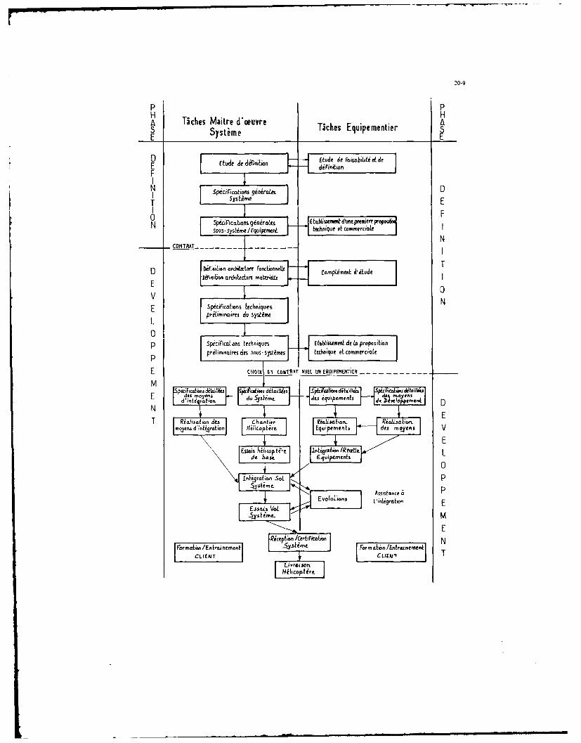
20-9
P PH HA T~ches Maitre d'oeuvre A~ksEupeeteS Systime _______________________
D Miecedii£ tude die FaisabiLitideE td edfn~o diFinitiorF
Spgciimicins ginerates
T FCONkiia on g nrat talea mr Fve pa
N
O i~alo archiectur Fonboneompiment A-itude
E *pciricabions f.echniquer.
L prtminaires do sy~Ume
P, Spkci~icabios techniques rtaJ~isement de In propositiahpreibminaires des 5ts- systimes tedvq.e el omrit
F C"01% V toW'AT INKC WE UIPEMErlitR --I e su
equipement
Ea~
N
T Rialis~bon& CI~anler e~IsjU~no Riolja 'emmyensc eru d ionU ,lp d Hiocptire Equipernents des mto.yns V
Eskias h~top ti-e lnbralin "/Re.ffL d"e"O'In.
t 0
Evoluions Assi~stance p
Evoluions tigralicn E
Ricept~on /CirfiFictaon NFeirnaio/Emieie j Forim im bnniri~~

Par ailleurs, le contr~le de 19 Qsalst4 intervient a toutes les etapes des I 'laboration desspecifications. iusqu'a la reception finale do la machine.
Enfin. I 'itude St le developpement do moyens de m~aintenance peut s'effeCtuer. en parallele dudeloppoment du system.. en fonction des demandeS do client.
2.3 HAITRISE DES EVOLUTIONS
Queule que Soit la qualite avec laquelle len specifications ot ate itablies et le sys tame reslise.dos incidents et des evolutions soot a attendre. flies proviennent do differentes causes
-Des erreurs de realisation relevees dan5 one configuration particuliere ou dan5 on environnomentnon teste en recette
-Des erreurs de specifi~ations dues, pour certaines. a l'absence d'outiis de specilicatiOnsperformants permettant de decrire le fonctionnement reel du systeme
-Des evolutios do specifications soohaitees par le ciient
La prise en coompte do cO evolutions conduit a Ia8 crention de versions successives qu it fautensuite gerer correctentent
Aussi Cot -ii indipensabie de maitriser ces evolutions par on processos do type de celui mis en Piacepoor 10 calcsiateur NADIR MK2 do DAUPHIN SAR
-Chaque anonmalie constatee chez I 'avionnor o I 6. ', sementier apres la recette, donne lieu a1'emission d une Fiche d Incident
CO ce tches d in-odents sont analyisees. frois CaS peuvent se prodUire
*soit l'anomali' constatee s'eoplique par on conteote particolier et n implique pas 000 evolution
dv I equipeMen
*soit l anomalie provient doun defaut de le6qoipement par rapport aoo spiciOficationo. La
modification est aooliouoe. et fait InDbjct d'une Fiche d'Evolution.
soit Ilanomalie conduit a one evolution des specificationis. On cree one Fiche d Evolution quisera examinee -n common entre Avionneur et Equipementier.
Apres decision 6ventole d application. Ilevolution est realisee. testae et integree a me versionulterioure de iquipement.
Cette procedure permet one parfaite identcfLCcto dos diverses anomalies et one bonne maitrise desevolutions demandees. Elle permet egalement de bien identifier. our le plan des couts. lImpct deceo evolutions, ot leur imputation reelle tequopementier. avionneor, o client finill
3. M0YEES MIS EN OEU
Lo deroulement d'un pro3vt de cette dimension necessote la mise en oeuvre d un certain onbre de
mofens specifiquvo acfeptes aux phases
-de specifications-de developpement-d'integration
-d'expoIOtation
A co moyens, se rajoute I 'ensemble des moyeno geniraus tels que leo moyens de qualificatliond'605ipement et de simulation d'enoironnement.
3.1 7 PlENS DE SPECIFICATIONS
La phase dv specifications revet One imsportance perticuliire :sa bonny voecution pernmet dv requireles risques devolutions olterioures. donc leo coits et leos dilais.
Ella imploque la participation active de nombreus onteroenants :l1utiliateur final. leo bureausdetudeo. les iqoipages d'Ossais en vol. etc ...
C'esl avant tout one phase do commnunica tin as coors do laquelle ii fast ofiaginer ce que sera I@fonctionnement reel do Sstems, ftur.

20-11
POUT C. fairet, do$ Mayon$ partoculiors daivent itr. mis en aeuvre. dona Is double but
do a. uscito Is commaunication ontro let mntterve,,antsdoa cauvrir I@ plut exhAutitofnt possisble let configurations do fonctionnement J. sysatems.
un ex*p#l* simiple, Mgai$ officace. eat l'Utisation d'un micro-ordinateur d. Is Class@ 1014 PC-ATpour dicrire Ies pages d'un post* de command* at do vlaualisatian.
Ufl autre example, plus complex, tot celul d'un Out 12 d'sido a Is conception d'une architecturefonctionnello do systims, tel quo colul dicrit dons Is achina ci-deasss
'Soltu it Iy ,7N..
_S51SSn :PoFiwd1ft sime
A r Niveau N;.
L----Eqpemn~ ifimentaires
I4'
20-12
La premiere Phase du trav'ail consist* i dicoanposer finemsent I* systme on dicrivant lea fonctionspar lours Entries, Sorties. Mjcanismes et Controlas 3usqu'au nieeS souhsite.
Ensuite on procede au regroupement des fonctiona ilimentaires pour effectuor Is projection delarchitecture fonctionnelle sur I'architecture matirielle a partir de iaquelle on pout ecrire Iaspiciflcation ditaillie dos iquipemfents (matiriel et logiciel) et en particulier Is specificationditaillio dos traitemeants relatifn ase fonctions gui doivent seexicuter dans chaque iquisment.
3.2 HO0 EMS DE DEVELOPPEMENT
Cos moyans permettent In deieeloppement Osis l'intigration at In mine as point de l'iquipement.
Pour un equipement tel que 2e calculateur de navigation et de gention do mission. un0 attentionparticuliere doit etre apporte sox moyonn do devoloppement dus logiciel.
L'atelior logiciel conCu pour Iv calculateur ALPHA 732 cot un ensemble d'outils permet tant deproduire et nmettre au point uno application dan0 Sn contexts, do diveloppomntn
-multi-fonctions; une application no decompose en un lot do fonctions interconnectes
-multi-utilisateurs : n. application ast developpie par plusieurs equipon en parallels
Cat atelier qui met on oeuvre dos methodes de conception logiciello propren a laeronaotique,comport. deux tvoen d'ostls n
-uns chaine do production logicielle
- s system. do mine as point
3.2.1 Hithoden do conceotion du looiciel
La realisation d'un logiciol complex@, tel quo tolui d'un calculateor de gention de milssion, imposelutilisation de methodes do conception pormottant d'une part d'assurer une production rapids. atdasutro part do facilitor au misux les interventions sltiriouren sur ce logiciel. au niosan d. Iaphase do "maintenance'.
Cos methodes reposent sur doux principos do bass
-une description arboroscento do I'application. gus i chaos. fonction. annocia un ensemble detichas. at un ensemble do liens ontre con tichos. depuis l'Application complute, jusquaou nivsande modules gui constituent de veritables composants logicisls
APPLICATION Ensemble do FONCTIONS ,Ensemble do LIENS,FCt.CTION Ensemble do TACHES Ensemble do LIENS,
APPLICATION Ensemble do NODULES *Ensemble de LIENS.
Cetto analyse prolongs, In description arboroscenta gui a 6t6 faite an ni van systems.
-La prisence d'informations documfentairtn abondantes. 3usqu'au nisu don modules, afin d'assuror1a milleuro llsibillt6 possible.
Des Outils logiciels spitifiguen ont 6t6ctrees Pour as$surer, on application do can methodas, Iaconception du logiciel:
*geneira tour d'applications (descriptif den lions intorfonctions),
outil do oaisoe documontuire.
*outils de simulation,
*etc ...
3.2.2 Chain@ do production looicielle
[I ouagit dsuno chains do devoloppeont croisi. installee sur Sn calculateur ho universal do 1.sen.e VAX, sos VMS. Elle comport# an. certain nombro d'outils programmes en FORTRAN on PASCAL, quipermetront Is definition du logiciol ot Ia Production do code executablo nur ALPHA 732
-Edi tear do texte-Coiplateur PASCAL- acro-asemblesr-Editeur do liens- Gierateur d'applicationo- ibliotheque do nous-prograaees-Simslateur ALPHA 732-etc...

20-13
ChaCun do Cos outiis dispose d'une documeentation complete, ainsl que d'un jeu do tests. co @51ssres mitonbilitj ot contribue a so Portabaliti sur une machine hate (choz l'auionnour par
Cetto chains, do production logicielle est ansociie iun onvironneattnt tie programation assurant UnaMe] lleuro gestios des diveloppefeenes:
*criation at gestion des Fiches d'Zncident et dtrvslution
-Outil de sali documntaire
- tc ....
3.2.2 Suit"*e do mise as oint
Cast 105uti do base do I& phose d'istigratios .. tirel-lo9!csIe. 11 permet
- lmwulation on temps reelIsl test et Is modification des logiciels d'application
-Ia gdnirstisn dos entries/sorties do leqiipomont, s-oulant ainsl son or..ironoilmdht am soin dufutur Syste
Cot outil. Piloti Par us calculoteur standard micro-VAX permet une miss as point rapid* deslogiciels avec possibilitis
-dsobservation sur Points da#rrit, os Pas A Pas
-do visuallsatissn fine du fonctionnomest tomps rith, sass aucane perturbation du deroulteet duprsgranm"
Conseswble des moyens de diveloppement logiciel est dicrit dons Is schema suivant
ALPHA 732 Software workshop
-d cOhoSW""

20-i14
3.3 MOYEMS V1N'EGRATION
Ces moaens, mis en place chez l'avionnour. pormettent l'integration den diffirents 6quipements. I&mise au point du systeme au, nol et en vol. pain la reception et une bventuelle certification deI'hiicoptire iqsipij.
3.3.1 Les bancs d'intioratipn
Les bancs d'intigration Sant realises pour pormettre 1 integration d une ou plusiours parties duSystems as sol en dehors de I'helicopter-. Len principales tichas effectues Sant
l a validation den ciblagesl a validation des interfaces den 6qniomnlntsl a mine au Point den dialogues nnmeriquen entre equipementol a mine an point den dialoguen avec len equipagen Ii, ualination, nymbologie. cor.'andes)
- nne premiere validation des fonctions de chaque equipement par den stimuliationls ntatiqnes etdynamo quenl a reconstitution as 001. on utilisant len visualisations de la planche do bord. de certainesphases de vol ayant presente des anomalies. Les iqu~pos de mine au Point disposent aipsi dunMayan d'analyse as Sol des ptn~nomines.
Le banc d integration mis en place Pour le developpement du nynteme Irlandain etait constitui
*do ciblage h~licoptere-d'une ginerattion eleCtrique-den equipementn en integration-de la pianche de bord iquipeed dun calculateur permettan't do namuler en tempo r-eal les 6quipements manquants ot do stimuler Ie
synst me de m ni re tati se ou dyn aomique n cohirenc e ave r de n ivolution n h licopt r e
Le schema nuivant illstre I' architecture de ce bant
hamnd& macyC"
Ledeur cle
SiwuAAiion entries
20-15
3.3.2 Los helcooteres de dvalooaeoMent
Ceo helicopteres iquipis du systeme sont destines a Ia mise au point at Ia validation en vol de
toutes 1es fonctions.
Plusiours drapes importantes sont necassaires
- l'intdgratxon du system@ dans I'helicoptere qua fait l'objet d'un chantier at d'une serie d'essais
au Sol
- I& montage d'une installation d'essais comprenant des equipements de rifirence ot des moyans
d'enregstrement en vol
- des vols d'essais pour Ia miss au point definitive at Ia reception
- eventuellement des vols de certification
Cas hilicoptires do diveloppement peuvent etre. soit des prototypes, soit des apparells 'societe
appartenant a t'avionnour, Sot les premiers appareils de sere.
3.4 OUTILS DE ESTION DE CONFIGURATLON
La multiplicits des fonctions realisees par Ie Systime entraine. a court tere, unc proliferat2on deversions differentes. an particulier au niveau du logiciel. I devient alors indispensable de
disposer d'outils do gestion des configurations, tant chaz Ia maitre d'oeuvre systeme quo chatlIequipomentler. Cos outils font paitle des moyens ginirauo de I entreprise et couvrent I ensembledes pro3ets developpis.
La gestion do configuration du maitre d'oeuvre gere ls itats des specifications du systeme ainsiqua les fichas di6volutions systeme. L'quipOmontier gire les configurations de 1iquipement quail
realise on regard des specifications de cat iquipement elles-mimes geris par la gestion de
configuration systime de I'avionneur.
4. CONLUSION
Ce document presento les problimes quo posent If diveloppement d'un systeme avlonique moderne et les
solutions qui y ont iti apporties dans Ie cadre du projet DAUPHIN SAR destini a I Irish Air Corps.Cet example met en relief los interactions necessaires entre l"avionneur, Maitre d oeuvre du systeme
complet. et les sous- ystimiers ma3eurs. 11 souligne I'importance doune methodologie rigoureuse danSles ichanges d informations, de Ia qualiti desquels depend 1a bonne excution des travaux, dans lesdilais at les co,;ts impartis. 11 dimontre enfin Ia nicessuti de disposer de moyens adaptes aux
differentes phases du projet, depuis les specifications jusqua la reception de l'avlon.
Ce systeme cumule ace our pris de 1 000 heure av vol en service operationnel ot donne toue
satisfaction.
Une tello experience constitue, pour tous ceu qui F"ont acquise. un reel investissement et un gage
de reoussite pour Iv developpement des systemes futurs.
Copendant la richesse fonctionnelle ot I Integration physique allant croissant. le diveloppement des
futurs systimes necesstera une accentuation de la demarche et une augmentation des moyens.

20-16
DISCUSSION
W.R.Fried, US(I) Is there any homing or direction-finding equipment on the helicopter for guidance with respect to the crash locator
beacon transmissions.'
(2) Why is the Decca system not used for navigation for the Irish application?
Author's Reply(I) There is a beacon mode in the radar subsystem. The relative position of the beacon can be transferred in the
navigation computer. This computer provides guidance to the location.
(2) The Irish Air Corps did not choose this system for its navigation.
G.Konomos, USCould you please show how the NADIR MK2 is connected to and monitored by the MICROVAX to perform real-timete,;ting with no interference.'
Author's ReplyWe cannot give you too many details. The main point is that, with the help of a dedicated processor included inside thebench, different observations can be made on the target equipment real-time functioning without any perturbation Theprocessor is never stopped. Through the connection to various probes. three traces are available: processor bus. input,outputs, and real-time tasks election description, all events being dated precisely.

21-I
OPERATION AND PERFORMANCE OF ANINTEGRATED HELICOPTER COMMUNICATION SYSTEM
Walter R. FriedSenior Scientist
Hughes Aircraft CompanyP. 0 Box 331J
Fullerton, California, USA 92631
SUMMARY
The unique operational and performance requirrs,,is of the Communicatio, Syste,for modern tactical Army helicopters are described. An integrated system architecture isdescribed which satisfies these requirements and incorporates very high levels of automationthereby reducing pilot workload. The automation concepts include the -- of a preloadedcommunication data base and a centralized communication processor containing advancedcontrol, reconfiguration and message formatting software. Link analysis and simulationresults are presented which show the performance capabilities of the system with respect tothe projected mission requirements.
INTRODUCTION
The Communication System of a modern tactical helicopter must satisfy severalunique operational and performance requirements. Because of the current trend toward singlepilot helicopters, one of the most important of these requirements is low pilnt workload foroperation of the communication system. Just flying the helicopter and protecting it fromhostile targets and terrain obstacles will keep the pilot very busy, so that he simply willnot have much time to control and operate his communication equipment. This prot
1em becomes
even more severe when the helicopter missio requires operation at Nap-of-the-Earth (NOEL)altitudes, i.e., a few meters above the terrain. The latter requirement, i.e., NOEoperation, is also one of the major performance challenges ''ir the communication systemdesinn since NOE altitudes typically result in the nun-existence of line-of-sight radiopaths between the communicating units. Since communication is a two-way process and sincedifferent military units carry different types of radio equipment, interoperability andbackward compatibility become very importart considerations in a communication system. Thispaper describes an integrated, highly automated, helicopter communication system designed tosatisfy the operational and performance requirements of future military helicopters. Typicaloperational mission requirements and unique performance requirements are first discussed insome detail. An integrated system architecture is described, which consists of severaldifferert equipments. The automation concepts included in the system architecture arehighlighted. Results of link analyses and simulation runt for the various systems, whenpc-'ting in the NOE flight environment, are presented aif the performance attributes of theselected systems are described. Availability and reliability considerations of the systemare addressed. Fially, the automation, integration and system design characteristics aresummarized and topics for future research are indicated.
OPERATIONAL REQUIREMENTS
The requirements for an aircraft or IJ'.opt~r coiunicatior sisem can hecategorized into two types, i.e., operational and pei Tormance requirements. Although theseare frequently interrelated, the operational requirements will first be discussed in thissection.
Perhaps the most critical operational requirements for the communication systemof a modern, military helicopter is that it be highly automated and simple to operate. inorder to minimize pilot workload and human error. This is particularly important for singlepilot helicopters. Currently, pilots are required to refer to Communication ElectronicOperating Instructions (CEOI) books, to determine the call signs, frequencies, nets,authentication codes, OPSEC codes, etc., for the particular time period, in order to know howto call a desired destination and what frequency or channel to select. Then, the pilot needsto operate the various controls which are separately located on each radio set and whichtypically have different characteristics. These controls need to be highly automated, so thatthere are very few pilot actions required and these actions must be simple andstraightforward.
If communication is suddenly lost, either through a link connectivity failure ora hardware failure, reconfiguration (i.e., change to a different radio resource) oust beautomatic. The pilot should merely be advised what the system has 'done for him.
Since the trend for modern military operations is toward more datacommunication, rather than only voice, the entry of data messages by the pilot must be highlyautomated, as compared to current practice. It is not acceptable for a busy helicopterpilot, partiu-ly in the middle cf coabat, to use a keyboard to enter data, even inresponse to prompts appearing on displays, e.g., filling in required message fields. Theentire operation must require very few actions by the pilot and be automated to a highdegree. A typical example of such data communication is the automated handoff of target datafrom one helicopter to another helicopter, or to a ground element.
21-2
Another important operational requirement is to have a high probability that thecommunication link is available whenever it is needed. This implies high reliability of theequipment, physical redundancy of critical hardware, or functional redundancy provided bydifferent radio systems. These automation and availability requirenents lead to the need fora highly integrated architecture.
For communication systems, the problems of interoperability with fieldedequipment and backward compatibility are of importance, since the uperation cannot be selfcontained, like, say, certain navigation systems. Thus, the design of a future helicoptercommunication system must consider the types of equipment projected for fielding at all ofthe operational elements of interest, the message formats and encryption systems used, andsuch parameters as the expected transmitter power levels and antenna gains of ground units.
In the future battlefield, helicopters will spend a significant amount of timeat NOE altitudes so that operation at these altitudes must be reliable. For self protectionreasons, the transmitted signal level should be as low as possible and transmissions as shortas possible, in order to minimize the probability of intercept by hostile force. Modernmilitary communication systems must be able to support both clear and secure voice and datatraffic, and this traffic may be required simultaneously on several bands or radios. Thehelicopter communication system should be able to act as a relay or retransmission platform,in order to provide a means for two units who are separated by too long a range tocommunicate with one another.
TYPICAL MISSION SCENARIOS
In order to quantify the operational and performance requirements for a typicalarmy helicopter communication system, the results of previous Army studies, as well ascertain projected mission scenarios, were investigated. For example, Figures 1 and 2 arederived from data in a U. S. Army Map-of-the-Earth Communication Study. (1). Figure I showsthe percentage of air-to-air and air-to-ground links out of 179 mission-critical pairedevents (i.e., transmission and acknowlegement) for an attacv helicopter company operating inthe SCORES Europe 1, Sequence 2A Scenario. It is seen that 92% were air-to-air links andonly 8% air-to-ground links. In Figure 2, the data is further broken down, showing the rangedistribution, in percentage, for both the air-to-air and air-to-ground links. For example,it is interesting to note that for the air-to-air cases, 91% of all link ranges were lessthan 5Km, and 72% were less than ?Km.
Figure 2 shows typical communication path lengths for a composite Europeantactical scenario. It is seen that the postulated path lengths are quite compatible withthose indicated on Figure 2, thus correlating well with the earlier U. S. Army results.Figure 4 shows typical anticipated communication links based on a projected battle teamflight configuration. The links represented in Figure 4 show the need for severalcommunication systems and nets. i.e., HF-SSB, VHF-FM, UHF-AM and PIR, in order to meetvarious mission requirements. For example. FM 1 (VHF-FM Net No. 1) and FM3 representintra-platoon nets for communication between the platoon over relatively short ranges, usingthe VHF-FM (SINCGARS) radios. Communication between the air battle captain and the platoonleaders might be over another VHF-FM net or, if the range requires, over an HF net (HIFI.Links to the ground manuever units might be over the FM2 net. Links to artillery units, suchas the fire support team (FIST) and the Fire Direction Center (FDC) might bc via the 0JH netor an HF net. The UHF net will provide interoperability with the Air Force and the HF 2 netor PJH might be for links to the Tactical Operations Center (TOC) or Aviation Comnand/Control.
PERFORMANCE REQUIREMENTS
Based on the typical mission scenarios discussed in the previous sections, themajor performance requirements of the communication system for future Army helicopters can bederived. Tactical air-to-air link ranges are found to be between 2 and 5KM; typical tacticalair-to-ground ranges are of the order of 15Km, with some links to rear ground elementspossibly being as much as SO to 100 Km.
For high priority tactical airborne communications, it is desirable to achieve ahigh probability of successful communication, i.e., 0.9 or greater.
Nap-of -the-Earth (NOE) operation is . Lritical requirement and the NOE altitudehas been defined as 3M above the terrain. Types of terrain encountered in tacticaloperations range from rough, wooded, mountainous terrain to more gentle, hilly terrain.Ambient radio frequency noise varies from the moderate rural areas to the more severe urbanareas.
SYSTEM ARCHITECTURE
In order to meet the operational and performance requirements described in theprevious sections, a highly integrated communication system architecture was evolved, asshown in Figure 5. It includes a central communicati,,, processor which is the "brain' of thesystem. The processor software provides the initialization, control and reconfigurfion ofall of the radio functions and of the audio control unit and it also performs the messageprocessinq required for data cemmunications. The processor is interconnected to the variousradio functions via local multiplex data busses. Typically, two busses are required, one forcontrol data and one for message data. The Communications Processors acts as the buscontroller for these local busses. As shown in the figure, a centralized Control/Display in

21-3
the crew station is used by the pilot to perform any communication control functions. Theinterface between the Comunication Processor and the Control/Display, as well as with theother avionics system, is via the global avionics bus.
To meet the performance requirements outlined earlier, a variety ofcommunication equipments are included. Because of the importance of operation at NOEaltitudes, an HF-SSB radio function operating in the 2-30 MHz frequency band with ECCMcapability, is included. The HF-SSB radio will support ground wave propagation to asignificant range; near vertical incidence skywave (NVIS) is applicable for medium rangerequirements and normal skywave for the very long ranges. The frequency hopping (ECCM)capability is required to provide anti-jam performance. The HF function supports voice anddata traffic in both clear and encrypted modes of operation,
Tie VHF-FM (SINCGARS) radio function operates in the 30-88 MHz band and providesinteroperability with a large number of U. S. Army elements. It supports NOE operation to amore limited range than the HF radio. It includes a frequency hopping (ECCM) mode to provideanti-jam performare. It has both voice and data capability, at a data rate up to l6 Kbps.In the data mode, it is compatible with the Army's TACFIRE network. The VHF-FM (SINCGARS)function is included in a dual redundant -anner, in order to facilitate simultaneous dual netoperation and to provide a retransmission capability. In order to enhance range performance,particularly at NOE altitudes, a high power VHF-FM amplifier is included.
The VHF-AM radio function operates in the 116-152 MHz band for voicecommunicatlon and is included to provide air traffic management and backup air-to-aircapabilities.
The UHF-AM (HAVE QUICK) radio function operates in the 225-400 MHz band andprimarily provides interoperability with the Air Force for voice communication and militaryair traffic management operations. It includes a frequency hopping anti-jam mode.
The PJH Enhanced PLRS User Unit (EPUU) provides a highly jam-resistant, secure,direct user-to-user data communication capability, in conjunction with the PLRS portion ofthe PLRS/JTIDS Hybrid (PJH) network. It operates in the 420-450 MHz band and uses two spreadspectrum techniques, i.e., frequency hopping and direct sequence spreading, with short bursttransmissions. The PJH system also provides inherent automatic relay and net managementcapabilities. Optimum relay paths are automatically determined by the system, based on linkquality measures. The EPUU formats the data used in normal TACFIRE messages in an efficientdata format. The current data rate capability is 1200 BPS and is in the process of beingincreased further through the insertion of VHSIC technology. As an example, PJHcommunications is particularly useful for target data transfer from the FAAO to artilleryelements, such as the FIST and FOC, since the longer ranges required for these links can beeasily achieved through the PJH relay capability. For operation beyond the forward line oftroops (FLOT), the high stability of the EPUU clocks permits communication to be maintainedfor a long period, even after connectivity with the PJH Net Control Station has been lost.Accurate position information of all elements is continuously available within the PJHnets'rk so that the EPUU can provide own-position updates to the helicopter's navigationsystem.
The Audio Control Unit (ACU) routes the voice audio from/to the pilot'smicrophone/headset and the radios. As shown in the architecture diagram in Figure 5, thecontrol of the ACU is provided by the Communication Processor via the local multiplex controlbus.
The IFF Transponder is included to provide self protection of the helicopteragainst attack by friendly forces. The IFF Interrogator is included so that potentialairborne targets can be interrogated, in order to avoid attacking friendly aircraft. Both,the IFF Transponder and Interrogator are also controlled by the Communications Processor viathe local multiplex data bus.
AUTOMATION CONCEPTS
One of the primary goals of the design of the communication system was tominimize the pilot workload associated with its operation. It became clear that the pilotshould have no involvement or very little involvement in the initialization, configurationand (in case of failures) reconfiguration of he communication system. Similarly, therequired pilot actions for entry of message data, message formatting and message receptionshould be limited to as few as possible. Toward this end, a maximum level of automation wasincluded in the design and these automation concepts ae described in this section.
In operation, before the start of a mission, a communication pre-mission database in loaded into the processing system memory. This data base includes the electronicCEOI data applicable for the geographic area of interest, such as the nets, frequencies, callsigns, authentication codes, OPSEC codes for the various Army organizational elements, fordifferent time period of the day. In addition, the data base will include a mission-uniqueCommunication Plan (COMM PLAN), which includes the units with whom communication isanticipated, the primary and alternate radio bands and the types of nets, such as voice ordata, which are to be used during the mission. After appropriate conversion to the radioparameters, the Communications Processor software then automatically initializes the variousradios at the time of takeoff.

21-4
At any time thereafter, the pilot uses the centralized control-display toinitiate a communication event. For example, using his display, the pilot may select from amatrix of symbols, representing force elements, the particular unit with which he needs to
communicate. Alternatively, a voice command system may be used for this action. TheCommunication Processor (CP) software through .se of the pre-stored data base, then causesthe applicable call sign, primary and secondary band authentication code, etc., to bedisplayed to the pilot. At the same time, the CP automatically configures the primary radiofor the channel or net applicable at that time. As a result, the system is immediately readyfor the pilot to initiate a voice transmission. The capability for a manual control overrideby the pilot must also be available.
If the transmission of a digital data message is desired, the pilot woulddesignate the desired destination in the same manner as described previously for voicetraffic and then select the data mode of operation. Again, the proper radio resource hasbeen selected and configured by the software. The data messages can then be entered andtransmitted in an automated manner. For example, for a target handoff function, the pilotmerely initiates and commands the process by selecting the recipient and the specifictarget. The software automatically performs any required coordinate conversion for thetarget position, formats the required data into the appropriate message format, (e.g., theTACFIRE format), and routes the message to the selected radio over the data bus. Acknowledgeprocessing is used to sense any link connectivity failures. In case of such a link failure(for example due to lack of line-of-sight), the software automatically reconfigures thesystem to an alternate radio resource. Similarly, if the built-in-test (BIT) functions sensea hardware failure in a particular radio, the software automatically reconfigures the system,based on the information in the pre-loaded COMM PLAN and CEOI data base. The pilot isinformed (or alerted) of the reconfiguration actions taken via his control-display, but hedoes not need to get involved in any action. Thus, the automation concepts included in thesystem design provide for control and operation of the Communication System with a minimiuminvolvement by the pilot, therefore adding little to the total pilot workload.
PERFORMANCE ANALYSIS RESULT
Link analysis and simulation runs were conducted in order to determine theperformance of the selected communication system with respect to the mission scenariosdescribed earlier. Specifically, the achievable range performance of the three primarytactical radio systems was analyzed as a function of terrain, ambient noise and probabilityof successful communication, and the results were compared to the requirements discussedearlier.
The link analysis and simulation effort made use of the Transmission SimulationProgram (TSP) which had previously been developed by Hughes Aircraft Company. It facilitatedthe parametric analysis of message error rate versus link distances for the various systemsbeing investigated, as a function of modulation waveform, message structure, data rate,terrain, ,etc. These data were then used as the basis for further link analyses, givingachievable ranges and signal margins, as a function of transmitter power, antenna gains adeddifferent link geometries. For most of the analyses, an NOE altitude of 3m and a probabilityof successful commmunication of 0.9 were assumed. Both, rough mountainous terrain (whichmight be typical of the Fulda gap in Germany) and more moderate, hilly terrain, such as mightbe typical for certain mid-east areas, were analyzed. Urban ambient radio noise levels andmore moderate rural noise levels were treated. Both air-to-air and air-to-groundcommunication links were analyzed.
Figure b shows a comparison of achievable air-to-air communication ranges forthe three primary tactical Army radio systems analyzed versus a histogram of the requiredradio transmissions, as derived from the data in Reference 1. It is seen that all three of
the systems will meet the bulk of the required link ranges in the worst type of terrain,although HF radio out-performs the other two systems. Figure 7 shows a similar performancecomparison for the projected air-to-ground links. For this case, only HF radio and multi-hop(relay) PJH links satisfy typical helicopter-to-artillery element link ranges.
Similar link analyses were performed for a jamming environment, but are beyondthe scope of this paper. The results of that analysis revealed that frequency hopping (ELCM)techniques are absolutely essential in HF and VHF-FM radio systems in order to provide therequired communication performance.
In summary, the results of the performance analyses indicate that the selectedcommunication system meets the tactical range requirements for the mission scenariosdescribed earlier. Use of the higher available transmitter powers and use of ECCM in HF andVHF-FM radios are required. For medium range requirements, the use of relay (for examplewith PJH) or a retransmission mode will be needed. HF radio NVIS and conventional skywavepropagation modes will be used to meet the longer range requirements.
To achieve the greatest possible mission critical reliability performance, bothphysical and functional redundancy are employed. Examples of physical redundancy are the useof dual VHF-FM (SINCGARS) functions, dual power supplies, dual transmitters, etc. However,use of "functional" redundancy is often equally or more important than "physical'redundancy. The reason for this arises from the fact that if the environment ortransmission medium have caused the link to fail, redundant hardware will not solve theproblem. Typical examples of this are loss of line-of-sight due to terrain features for VHFand UHF systems and ionospheric disturbances or atmospheric noise for HF systems.

21-5
CONCLUSIONS
An integrated helicopter communication system has been described, which ishighly automated, thereby relieving the p lot of the workload required in current systems forthe control and operation of distributed radios and for the entry of data messages.
Link analysis results have shown that the system meets the operational andperformance requirements which have been projected for tactical helicopter mission scenariosof the future, notably for operation at NOE altitudes.
There are several areas which deserve attention for future research anddevelopment. For example, in order to ease field operations, a simple method for centrallyloading security codes into COMSEC equipment needs to be developed. All of theCOMSEC/TRANSEC functions should be fully embedded within the radio hardware and effort isrequired to develop the interface and control functions to accomplish this.
Millimeter wave radio equipment operating in the 54-60 GHz oxygen absorptionband can provide a unique covert communication capability, i.e., an extremely low probabilityof intercept. Therefore, inclusion of that type of system in the future, either as aseparate function or possibly as an applique to another radio, should be investigated.
ACKNOWLEDGMENTS
The author wishes to acknowledge the contributions made by E. Larsen of HughesAircraft rompany in the areas of operational requirements and link performance analysis,
REFERENCES
1. "Nap-of-the-Earth Communications, Concept Formulation Package", U. S. Army AviationCenter, Ft. Rucker, Alabama, 1979, vols 3 and 5.
* 179 MISSION CRITICAL PAIREDEVENTS (TRANSMISSION + ACK)
92%
e AIRCRAFT ALTITUDES: 2 METERS
* DATA FROM U.S. ARMY 1976-78 NOE/ COMM. S UDY
8%
A/A LINKS AIG, G/A LINKS
FICURE 1. COnmUNICATION EVENTS FOR AT0ACK HELICOPTER COMPANY,
SCORES EUROPE I SEOUENCE 2A SCENAFO

21-6
6DATA FROM U.S. ARMY 1976-78 NOE COMM. STUDYA/A LINK RANGES (kmn) A/G. GIA LINK RANGES (kmn)
72%
57%/
19% 20E % 14% a~ 8%2%02 25 5-10 10-5 0 5-10 10-15 15+
FIUR RANGE P!TPFV7'- 'r 0PM EVENTS FORATTACK HEL ICOPTER COMPANY SCORET EURPOPE 1. SEDUENCE 2A SCENARIO
\ LOCATIONS
B~1 WIG-ANSRA
93 BA5- .%MMA IA
.\ 2
I)~ ~~~~~~~ 22ETKEM IIA1)N(~l
BOT FAl-ING -S A]II ILMTR
AF TOC ARTYS OR V M
HH HF2 PNT NGH ARE
k EAE FM.Nl I ATL ATI
FIGU. FM4 COMPOSIT LEADENSEAR OMUIATO
F I III MIL AEP113
LEGEND: GROUND FM3FM IS VHF-FM (SINCGARS) MANEUVERHP IS HP-Sn (WITH 7TSFM, HFl. 2,.3. 4 ARE NETS 1, 2,3,.4UHF IS UHF-AM (HAVE QUICK)PJN IS ENHANCED PLRS USER UNIT
FIGURE 4. TYPICAL TACTICAL COMMUNICATION LINES

21-7
CONTROL,DISPLAY
GLOBAL AVIONICS BUS TO OTHER SYSTEMS'E(E.. MISSION MGMT, NAVIGATION)
FII.O 5 COMMUNICATIONTMACIE UR
VOICEAHOU CFULD TRAP
AUDIOM ; ; BUSOHIL MI-AT
RANTRO AVHF VFFM F
PH I HILLY (MID-EAST)SIGE MOUNTAINOUS (FULDA GAP) LIL
60 HOP HOPS
soWORST CASE AMBIENT NOISE
REQUIRED *NOE ALTITUDEMISSION 40 *0.9 PROBABILITY OFCRITICAL SUCCESSFUL COMMRADIO MXMMPWRUIIETRANSMISSIONS 30 *MXMMPWRUIIE
20
10
RANGE IKMI101
FIGURE 6. AIR TO AIR COMMUNICATION RANGE PERFORMANCEVERSUS REQUIREMENTS
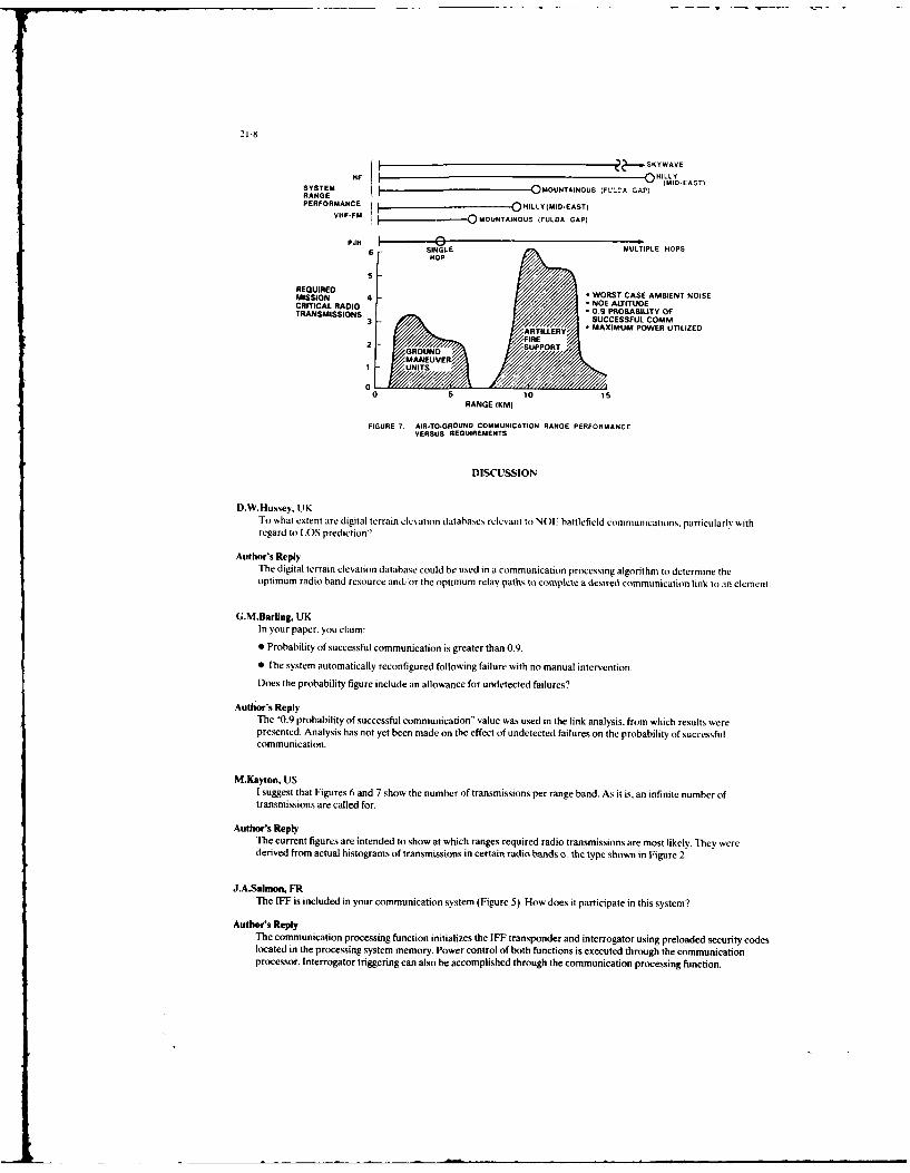
21-8
HIF ILLYESTSYSTEM I OMOUNTAINOUS (FULCA CAP; (MID-EAST)RANGE
PERFORMANCE QHILLY(MID.EAST)VNF-FM lMOUNTAINOUS (FULDA GAP)
PJ I 0 -uILE.~SMULTIPLE HOPSHOP
5
REQUIREDMISSION 4 * WORST CASE AMBIENT NOISECRITICAL RADIO * NOE ALTITUDETRANSMISSIONS . 0.9 PROBABILITY OF
3 SUCCESSFUL COMM
RTILLERY MAXIMUM POWER UTILIZED
2 FIRE
2 GROUND /SUPPORTMANEUIVER
1 UNITS
00 5 10 15
RANGE 1KM)
FIGURE 7. AIR-TO-GROUND COMMUNICATION RANGE PERFORMANCEVERSUS REQUIREMENTS
DISCUSSION
D.W.Hussey, UKTo what extent are digital terrain elevation databases relevant to NOE battlefield communications. particularly withregard to LOS prediction?
Author's ReplyThe digital terrain elevation database could be used in a communication processing algorithm to determine theoptimum radio band resource and/or the optimum relay paths, to complete a desired communication link to an element.
G.M.Barling, UK
In your paper, you claim:
* Probability of successful communication is greater than 0.9.
* The system automatically reconfigured following failure with no manual intervention.Does the probability figure include an allowance for undetected failures?
Author's ReplyThe "0.9 probability of successful communication" value was used in the link analysis, from which results werepresented. Analysis has not yet been made on the effect of undetected failures on the probability of successfulcommunication.
M.Kayton. USI suggest that Figures 6 and 7 show the number of transmissions per range band. As it is, an infinite number oftransmissions are called for.
Author's ReplyThe current figures are intended to show at which ranges required radio transmissions are most likely. They werederived from actual histograms of transmissions in certain radio bands o the type shown in Figure 2.
J.A.Salmon, FRThe IFF is included in your communication system (Figure 5). How does it participate in this system?
Author's ReplyThe communication processing function initializes the IFF transponder and interrogator using preloaded security codeslocated in the processing system memory. Power control of both functions is executed through the communicationprocessor. Interrogator triggering can also be accomplished through the communication processing function.

DESIGNING FOR DESIGN EFFECTIVENESS OF COMPLEX AVIONICS SYSTEMSby
Kenneth R. Boff, Ph.D.Human Engineering Division
Harry G. Armstrong Aerospace Medical Research LaboratoryWright-Patterson Air Force Base, Ohio 45433-6573, USA
SUMMARY
Reliable data on the aircrew's ability to acquire and process task-criticalinformation are of prime importance to the design of effective controls and displays.While the available body of psychophysical research contains a staggering volume ofhuman perceptual and performance data and principles that are of potential value tothe design process, these are not systematically considered in the typical design ofavionics systems. Though the nature and availability of these data are a key part ofthis problem, it can also be attributed to the basic skills and inclinations ofdesigners, limitations in the available support environment, and constraints imposedby the system design and acquisition processes.
Complex system design may be characterized as a creative integration and/orskillful blending of technologies counterbalanced to accomplish a predefined functionwithin material, cost and schedule constraints. Design effectiveness is a function ofthe cumulative "goodness" of design decisions and tradeoffs which collectively meetdesign requirements within these constraints. System effectiveness depends on designeffectiveness but may var with changing demands and user perspectives in the courseof system deployment. A common denominator in system design is "information" and theefficiency with which it is factored into design decisions and tradeoffs. The use ofinformation, however, varies as a function of its "perceived" value and cost (il termsof risk/time dollars) which may be independent of its "real" value and cost.
The Integrated Perceptual Information for Designers (IPID) Project is amultiagency supported effort to aid the accessibility and use of human performancedata in system design. It is formulated around five information management objectivesgeared toward: 1) Identifying, collecting, and consolidating human performance dataof potential value to system design; 2) Human factoring these data to enable theirdirect use by system designers; 3) Establishing an institute with responsibility formaintenance, update and analysis of these resources to support crew system design; 4)Developing and sponsoring of educational opportunities to train and sensitize systemdesigners in the value and application of human performance data to crew systemdesign; 5) Conducting exploratory research to define and evaluate requirements for anautomated design support capability to aid designers to efficiently access and tradeoff human performance data with other technical information germane to the effectivedesign of crew systems.
I. INTRODUCTION
Conducting modern warfare, particularly against numerically superior forces,demands that Air Force research and development programs support the design ofavionics systems that are maximally effective. However, despite an infusion of newdisplay and data-handling technologies into fighter cockpits, aircrew workloadcontinues to be a problem. State-of-the-art crew systems present a staggering volumeof codified visual and aural information which competes for the pilot's attentionalresources (see Figs 1 and 2). While few would disagree with the contention that theoperator's ability to acquire and process task critical information is a majorcontributor to system effectiveness, the design of crew systems has typically involvedlittle systematic consideration of human performance characteristics and limitations.While a good deal of potentially useful human performance data exists, these data havehad little direct impact on the design of crew system interfaces. Though the natureand availability of these data are a key part of this problem, it can also beattributed to the basic skills and inclinations of designers, limitations in theavailable support environment, and constraints imposed by the system design andacquisition processes (1, 2).
II. RELATIONS BETWEEN THE USE OF TECHNICAL INFORMATION IN SYSTEMDESIGN AND DESIGN EFFECTIVENESS
Though human performance data or other information germane to a given design mustexist before it can be used, availability of information is not a sufficient conditionto ensure its use. For information to be used, it must have some perceived value orrelevance to the problem at hand. Domains of technical information believed not to beof substantive value will not be accessed regardless of the real value of theinformation. Perceives value, in turn, is a function of the prior training andexperiential biases of the individual user.
22-2
Independent of perceived value, the functional value of pertinent technical datato a given design decision may be less than that implied when ccnsidered in a broadersystem design context. The design of an aircraft system typically involves balancingtradeoffs among many subsystem priorities to achieve a required "functionality" withinmaterial, cost, and schedule constraints. Performance optimization of the human-avionics interface is but one of many competing design goals. In aircraft systemdesign, other subsystem goals may take precedence in tradeoffs with crew systemcapabilities. For example, aerodynamic requirements will influence windscreen shapewhich will determine crew system volume which, in turn, can compromise crew subsystemdesign decisions. Therefore, satisfying, rather than optimizing, subsystem goals maybe optimal strategy in the context of a qiven system design.
In practical terms, "effective" systems are those which operate efficiently (i.e.,perform the function for which they were designed), reliably (i.e., minimalunpredictable failures and ease of supportability), and competitively (i.e., costs toacquire, operate and maintain over the system life cycle). For crew systems, in whichthe human Is a vital component, operability (i.e., functional match between user andsystem capabilities) and acceptability (i.e., users expectations of and willingness touse the system) are major factors contributing to a system's "effectiveness."Effectively designed systems, therefore, require some consideration of the factorswhich support these attributes.
Whether a given system is perceived as "effective" is also driven by factorsoutside of the control of the designer which, nonetheless, must be planned for. Tothe extent that operational mission needs change and new applicable technologiesemerge, systems become obsolete as a result of their lowered operationaleffectiveness. User acceptance, which may itself be manipulated by marketing andsales tactics, will also influence perceived effectiveness. In military systemacquisition, it is the customers and end users who define requirements :nd control thetraining, operations, and maintenance environments which influence the perceivedeffectiveness of a given system long after it has been designed.
The interdependence among thy myriad variables which contribute to the design ofcomplex systems, including such behavioral intangibles as creativity (3), makes itdifficult to predict the influence of any single factor on a given design. Incontrast, the pressures of limited time and resources typical in system design drivedesigners to bias decisions and tradeoffs towards reduction of uncertainty or risk.Hence, it is not surprising that "new" crew systems typically are "adaptive" designs(i.e.,adapting a known solution to a changed task) or "varient" designs (i.e., varyingparameters such as size, arrangement, or timing of a known design solution withoutchanging the basic design) as opposed to "original" designs which may depend onuntested approaches or technology (see reference 4 for a discussion of "adaptive" and"varient' designs). The selection of an appropriate baseline -- a "proven" system orsubsystem design analogous to the one under development -- will generally account forthe largest portion of variance In a given design's effectiveness. In other words,selecting a good baseline match should reduce risk to system effectiveness. Effectivebaselining of a system design may itself be constrained by a lack of relevant pastdesigns (e.g., prototyping the first lunar lander), inaccessibility of proprietarydata, or corporate biases. As a system design strategy, baselining is employed in oneform or another throughout system and subsystem levels within any given design.Theoretically, "original" design decisions should then precipitate from considerationof those aspects of the baseline which are either not responsive to current systemrequirements or are not effective in meeting these requirements. However, it is oftenthe case in military system acquisition that system requirements and design decisionsare biased toward potential opportunities posed by the availability or near-availability of new technologies which, in turn, adds risk to achieving designeffectiveness. Effective design, therefore, involves a skillful blending of pastbaselines with new decisions and tradeoffs, counterbalanced to minimize risks toaohieviny predefined functionality within material, cost and schedule constraints.
Raising the efficiency with which information is considered and factored intodesign decision-making should, by inference, raise the probability of "designeffectiveness." Conversely, design decisions made without consideration ofpotentially leveraging information may be sub-optimal and may collectively, dependingon their impact on system function, undermine design effectiveness (1). Ironically,enhancing design effectiveness by improving designer access to and utilization ofdesign relevant information may be hampered by the fact that designers are alreadydeluged by too much information competing for their time and attention. Given theseconditions, designers will seek new information only to the extent that it has highperceived value (i.e., may reduce risk) and low perceived cost in terms of the timeand resources to acquire and interpret (5). In other words, it is unlikely thatadditional information will be sought beyond that perceived as satisfactory.
Hence, the design of controls and displays effectively matched to the capabilitiesof the pilot is dependent on a complex set of factors bearing on the access to,handling of, and decision making with information. To the extent that sound dataexist and are used, these may enhance the probability that a given system will beeffective, though this can never be fully assured. In this context, designing fordesign effectiveness implies aiding the accessibility and use of information in designdecision making.
L
Ill. A CONCERTED APPPnACH TO DESIGN INFORMATION MANAGEMENT: THE INTEGRATEDPERCEPTUAL INFORMATION FOR DESIGNERS PROJECT
Recognizing the need to improve effectivenes of the human-avionics interface inzrew systems, the Harry G. Armstrong Aerospace Medlcal Research Laboratory set up aproject, in 1980, to develop a sound theoretical and empirical basis for human-centered crew svs-L- design. The p'incipal assimpticn of tni iujvLt, &t,AnI asTACDEP (Tactical Aircraft Cockpit Development and Evaluation Program), is that crewsystem effectiveness ultimately depends on optimizing the match between the bandwidthof controls and displays and the sensory, perceptual and cognitive characteristics ofthe huaan opurator. While this assumption is difficult to prove, it is a reasonableinference based on iessjns learned from operability and workload problems reported infielded systems and accident investigations. In addition, though it is generallyagreed that the operator's ability to acquire and process task critical information isa key contributor to system effectiveness, few resources exist to support designingfor these operator functions. Existing data of potential value to design are widelyscattered and difficult to discriminate within the voluminous research literature.Furthermore, even with germane data in hand, it may be difficult for nor speciahxtsto assess the data's relevance to their problem (1). The problem is furtherexacerbated by the low perceived value of these data by the design community which isfueled by both negative experiences with these data (6, 7) and the pressure to accountfor a myriad of other system-related variables in the course of crew system design.
Based on this characterization of the problem, the Integrated PerceptualInformation for Designers (IPID) project was set up to support TACDEP. IPID is amulti-agency effort supported by organizations within the U.S. Air Force, Army, Navy,and NASA. Its prime objective is to provide "high-value" human performance data as a"low-cost" resource to designers of operational crew systems and traiing uevices.The project is organized around five interrelated information management and productobjectives:
1) Consolidation of potentially us-f l :,;:ian performance data;
2) Presentation of these data in a form useful to system designers;
3) Real-time support for Analysis of the existing data with respect tosystem design problems;
4) Training and sensitization of system designers of the value and use of humanperformance data in system design;
5) Support Accessibility and application of human performance data in context
with other design relevant data.
Collectively, these objectives, discussed in detail below, are aimed at raisingthe perceived value and lowering the perceived cost of using human performance data in
system design.
1. CONSOLIDATION
The first objective of the project was to identify, collect, and consolidate theexisting human performance data of potential value to the design of operator controland display interfaces. This involved the design and development of a professionallevel reference work involving detailed treatment of forty-five subject areas (seeTable 1) by over sixty recognized experts. The resultant Handbook of Perception andHuman Performance (Boff, Kaufman, and Thomas, Eds; 8, 9) is a two-volume work ofapproximately 2800 pages. The Handbook differs from standard texts in its emphasis onself-contained units of information, detailed indexing and cross-referencing. It isillustrated with over 1600 figures and makes extraordinary use of data functions andschematics to present technical material. Data are plotted in standard units based onthe Systeme Internationale (10). Figures, tables, and their captions are designed to"stand alone" so as to be interpretable independently of the text. For example, thecaptions provide a description of variables evaluated in the reported study, anindication of the data reliability, a "bottom line" summary of what the data areabout, and a reference giving the source of the data. While the intended user of theHandbook is the ergonomist or R&D engineer, it provides a reliable basis forsubsequent products of more direct design relevance.
Table 1 - Handbook Table of Content;
Section 1: THEORY AND METHODS
1. Psychophysical Measurement and Theory
2. Strategy and Optimization in Human Information Processing3. Computer Graphics

22-4
Table I - Handbook Table of Contents - Continued
Section II: BASIC SENSORY PROCESSES I
4. The Eye as an Optical Instrument5. Sensitivity to Light6. Temporal Sensitivity7. Seeing Spatial Patterns8. Colorimetry and Color Discrimination9. Color Appearance
10. Eye Movement
Section III: BASIC SENSORY PROCESSES II
11. The Vestibular System12. Cutaneous Sensitivity13. Kinesthesia14. Audition 1: Stimulus, Physiology, Thresholds15. Audition II: Loudness, Pitch, Localization, Aural Distortion, Pathology
Section IV: SPACE AND MUTION PERCEPTION
16. Mttion Perception in the Frontal Plane: Sensory Aspects17. Perceptual Aspects of Motion in the Frontal Plane18. The Perception of Posture, Self Motion, and the Visual Vertical19. Motion in Depth and Visual Acceleration20. Visual Localization and Eye Movements21. Space Perceptione2. Representation of Motion and Space in Video and Cinematic Displays23. Binocular Vision24. Adaptation of Space Perception25. Intersensory Interactions
Section V: INFORMATION PROCESSING
26. Auditory Information Processing27. Speech Perception28. Visual Information Processing29. Perceiving Visual Language30. Motor Control
Section VI: PERCEPTUAL ORGANIZATION AND COGNITION
31. Tactual Perception32. Auditory Pattern Recognition33. The Description and Analysis of Object and Event Perception34. Spatial Filtering and Visual Form Perception35. Properties, Parts, and Objects36. Theoretical Approaches to Perceptual Organization37. Visual Functions of Mental Imagery38. Computational Approaches to Vision
Section VII: HUMAN PERFORMANCE
39. The Effects of Control Dynamics on Performance40. Monitoring Behavior and Supervisory Control41. Workload: An Examination of the Concept42. Workload Assessment Methodology43. Vigilance, Monitoring, and Search44. Changes in Operator Efficiency as a Function of Environmental Stress, Fatigue,
and Circadian Rhythms45. The Model Human Processor: An Engineering Model of Human Performance
2. PRESENTATION
This second objective is concerned with development of an approach tocommunicating ergonomics data to system designers who, while having little priortraining and experience with ergonomics, need reliable data to support designdecisions or tradeoffs between human performance and equipment/environmentalconsiderations. The Engineering Data Compendium (11) is 6 reference document whichconsolidates human sensory/perceptual and performance data in a form human-factoredfor system designers. It provides comprehensive and detailed specifications on thecapabilities and limitations on the human operator, with special emphasis on thosevariables which affect the operator's ability to acquire, process, and make effectiveuse of task critical information.
Information was selected for inclusion into the Compendium on the basis of itspractical potential for system design through an iterative process of review and
. .. ...
analysis employing hundreds of technical subject matter experts and "designers."Prospective entries were reviewed on the basis of statistical ano methodologicalreliability, applicability to the normal adult population, and potential relevance todesign problems. The Compendium consists of approximately 1200 concise two pageentries (see Figure 3) designed to be self-contained, with information from relatedstudies summarized and presented in graphic form wherever possible. Entries have beenprepared treating parametric data, models and quantitative laws, principles andnonquantitative laws. Expected to be published by the Air Force (11), it will consistof four volumes -- three looseleaf volumes of perception and performance data and abound User's Guide containing supplementary aids such as instructions for locating andusing individual entries, design checklists, indexes, and a glossary. Specificprogrammatic details of this effort are summarized in Reference 12.
3. ANALYSIS
In conjunction with the Tri-Services and NASA, the Harry G. Armstrong AerospaceMedical Research Laboratory will establish and host, beginning in 988, a Crew SystemErgonomics Information Analysis Center (CSERIAC). CSERIAC will provide a full rangeof technical information services in support of crew systems research, design, anddevelopment in the government, industrial and academic sectors. The essential missionof CSERIAC is to maintain contact with the relevant knowledge and experience basesacross thse -r*n ? , to develop tie ability and media to draw upon and focus thissxpeLise to solve problems, achieve expert consensus and aid planning for moreaffective use of ergonomics data in the system design process. In addition, CSERIACwill provide information services, including topical reviews, special analysisreports, data, models, design support software, methodological assistance and a"Current Awareness" newsletter. Maintenance and update of data bases, including theIPID Engineering Data Compendium will also be a function of CSERIAC.
To determine the validity of the need for a DOD center devoted to the analysis anddissemination of crew system ergonomics information, 3705 potential users within DODand industry were surveyed by a mail questionnaire (13). Eighty-seven percent (87%)of the 829 respondents agreed that a Department of Defense CSERI,C was the appropriatemechanism to meet this need. Seventy-nine percent (79%) of the respondents work 'nresearch and development, management or design. Ninety-seven percent (97%) use crewsyster's ergonomics information. Seventy-eight percent (78%) are willing to pay feesfor CSERIAC services. Over 4000 requests per year for CSERIAC services would be madeby the survey respondents alone.
The major initiating task for CSERIAC will be to achieve the credibility and auraof a "center of excellence" capable of attracting the range of professional supportacross the international community essential to its usefulness and long-termsurvivability.
4. TRAINING
This objective of the project is to ennance the perceived value and demonstratethe applicability of ergonomics data for system designers through a series ofeducational/training opportunities. Thc first of a proposed series of short oursesand seminars -as conducted under the auspices of the University of Dayton in Dayton,Ohio during 8-13 June 1986. Offered as the "Human Perception and Performance Workshopfor System Designers," its primary goal was to provide system designers with a humanperformance framework for "decomposing" equipment-related design problems whilesensitizing participants to the issues and approaches in using human performance datain human-machine system design. Future training functions are in planning and includedevelopment of ar AGARD Lecture Series.
5. ACCESSIBILITY
The fifth information management objective of the project is to aid theaccessibility and application of human performance data in the context of other systemdesign-related information and procedures. "Designer's Associate" is a four-yearexploratory research program to define and validate functional specifications for a"human engineered" design support system which efficiently services the integratedtechnical information needs of operational and training crew systems designers.
The program approach, illustrated in Figure 4, is fundamentally based on testingIPID project assumptions regarding problems and issues in the handling of technicalinformation by system designers. This has engendered the need to develop anintegrated understanding of the role and handling of technical information in theprocess of designing operational and training crew systems across Government andnd..Ltial sectors. Field interviews with system design personnel help to identify
common needs, problems, and perceived benefits in their use o technical informationand its implications for design products (14).
Information handling issues, deemed within the scope of Designer's Associate (DA),are analyzed in terms of causes and implications. Based on this analysis, candidate05 support functions and capabilities which have potential to resolve these problemsare identified; these functions are, in turn, analyzed to determine the supportingtechnologies necessary for their implementation. Those functions which can hesupported by current technology or prospectively supported by emerging technologies

22-(,
(e.g., machine intelligence; 15), collectively comprise the Designer's Associatesystem concept. This concept will be validated and documented at individual functionand integrated system levels through a series of tests and evaluations involvingsimulation, laboratory studies, field studies, interviews with designers and designmanagement, and development of research software. Research to advance "borderline"technologies will be supported in diverse areas including cross-disciplinary accessand interpretation of technical information, decision aiding, and user-systeminterface. The final products of the program will be a series of demonstrations ofDesigner's Associate functions and capabilities and a functional system specificationsufficiently validated to support justification for advanced development.
Production of the Designer's Associate support system by the mid-1990's shouldfacilitate information handling and decision making for crew system designers.Designers will have greater potential then ever before to draw upon availableknowledge resources, presently widely diffuse, and focus these consistently into alllevels of design decision making. This capability coupled with decision aiding andadvanced user interface technologies will, in turn, provide the power to rapidlyconsider more alternatives, more effectively, thereby enhancing the probability ofsystem effectiveness.
IV. CONCLUSIONS
Design effectiveness is the degree to which system function meets designrequirements within cost and schedule constraints. It is a function of the cumulativegoodness of design decisions and tradeoffs, which are, in turn, dependent on theinformation factored into these decisions. Serendipity excluded (e.g., the resistordesign that makes a fine lightbulb), design effectiveness is a necessary though notsufficient condition for system effectiveness which may vary with factors outside ofthe control of the designer and design process (i.e., changing demands or requirementsof the operational, maintenance and training environments in which the system isdeployed). Hence, while the probability of system effectiveness may be enhanced bydesign effectiveness, it can never be ensured.
The products of the IPID Project will support the avionics system designer'sability to match crew system displays and controls t the performance capabilities ifthe operator. The Handbook of Perception and Human Performance (8, 9) and humanEngineering Data Compendium (111 consolidate and package these data in acomprehensible format. CSERIAC will provide access to the state-of-the-art in crewsystem ergonomics through interactions with current experts and analysis of thLliterature. It will influence both the definition of requirements and the details ofdesign necessary to accomplish them. Professional short courses, conferences, andsymposia will sensitize and familiarize system designers with the value of these datawhile lowering perceived risks in their use. The Designer's Associate support systemwill eventually automate access and utilization of these data in the context of otherrelevant design information and aid the designer to factor these into design decisionsand tradeoffs, thereby contributing in a meaningful way to design effectiveness.
REFERENCES
1. Boff, K.R. The Tower of Babel Revisited: On Cross-disciplinary Chokepoints inSystem Design. In System Design: Behavioral Perspectives on Designers, Tools andOrganizations. 1987. Elsevier, New York.
2. Rouse, W.B. and Boff, K.R. System Design: Behavioral Perspectives on Designers,Tools and Organizations. 1987. Elsevier, New York.
3. Rouse, W.B. A Note on the Nature of Creativity in Engineering: Implications forSupporting System Design. Information Processing and Management. 1986. 22.279-285.
4. Pahl, G. and Beitz, W. Engineering Design. 1984. Springer-Verlag, New York.
5. Rouse, W.B. On the Value of Information in System Design: A Framework forUnderstanding and Aiding Designers. Information Processing and Management. 1986.22. 217-228.
6. Meister, D. and Farr, D. The Utilization of Human Factors Information byDesigners. 1966. Office of Naval Research, NONR Contract 44974-00.
7. Klein, G.A. and Brezovic, C. What do Training Device Designers want to know aboutHuman Performance Characteristics? Harry G. Armstrong Aerospace Medical ResearchLaboratory, Wright-Patterson AFB, Ohio. AAMRL-TR-87-XX, In Press.
8. Boff, K.R., Kaufman, L. and Thomas J., Eds. Handbook of Perception and HumanPerformance. V.I: Sensory Processes and Perception. 1986. John Wiley and Sons, NewYork.

9. Boff, K.R.. Kaufman, L., and Thomas, J., Eds. Handbook of Perception and HumanPerformance. V.11: Cognitive Processes and Performance. 1986. John Wiley and Sons,New York.
10. U.S. Department of Commerce: National Bureau of Standards. The InternationalSystem of Units (SI). 1977. NBS Special Publication 330. Washington D.C.
11. Boff, K.R. and Lincoln, J. Engineering Data Compendium: Human Perception andPerformance. (4 Volumes). Harry G. Armstrong Aerospace Medical Research Laboratory.Wright-Patterson AFB, OH. In Press.
12. Boff, K.R., Calhoun, G.L., and Lincoln, J. Making Perceptual and HumanPerformance Data an Effective Resource for Designer. Proceedings of the NATO DRGWorkshop (Panel 4). Royal College of Science, Shricenham, England, 1984.
13. Hennessey, R.T. and McCauley, M.E. Proposal and Justification to Establish aDepartment of Defense Crew System Ergonomics Information Analysis Center. Harry G.Armstrong Aerospace Medical Research Laboratory, Wright-Patterson AFB, Ohio. AAMRL-TR-87-XX, In Press.
14. Cody, W. and Rouse, W.B. Understanding and Aiding System Designers. Harry G.Armstrong Aerospace Medical Research Laboratory, Wright-Patterson AB, OH. AAMRL-TR-87-XX, In Press.
15. Reitman, W., Weischedel, R., Boff, K.R., Jones, M.E., and Martino, J. AutomatedInformation Manaygement Technolo: A Technology Investment Strategy. Wright-Patterson AFB, Ohio. Air Force Aerospace Medical Research Laboratory, Report No.AFAMRL-TR-85-042, 1985.
ACKNOWLEDGMENTS
Many organizations have participated in and contributed to the IPID project. Inparticular, I am indebted to Professors Lloyd Kaufman (NYU) and Jim Thomas (UCLA) fortheir support of the Handbook phase of the project. Janet Lincoln, my co-editor onthe Compendium, was a major source of ideas in the design of the Compendium concept.Edward Martin, the Project's Engineering Technical Advisor, made many importantcontributions to all phases of this effort. The staffs of the University of DaytonResearch Institute and MacAulay-Brown Inc., Dayton, Ohio, played critical and leadingroles in the development and production of the Handbook, Compendium and Design ShortCourse. I have personally enjoyed and profited from professional collaboration withBill Rouse and members of the staff of Search Technology, Georgia, in refining the"Designer's Associate" concept. Overall, the project has significantly benefited fromuncounted thousands of hours of professionally contributed time by many reviewers fromthe industrial, academic and government sectors. Finally, much of the success of theIPID project stems from the sustained encouragement, enlightened environment, andtechnical foresight provided by Charles Bates, Jr., Director of the Human EngineeringDivision and Thomas Furness, I1, Chief of the Visual Display Systems Branch.

22-8
Figure 1
Figure 2

22-9
V--5-- wOO
~ ~ U -. 5--,.,.5 - 5
s o. - -s ~i
US OFR SSE OSG
BY DESIGNER
__ I ADVANCED
DEVELOPMENT PROBLE MSISUR
-DSGNR ASOFGRAAT N CAP A I NING ICSUPOR SYTEMT ANDEAUASN....GN.,
ADV NCEPTIN EQIEDEVELOPMNT EV15 OP
DETALEDSPEII --I FUNCTIONS
CONFGURAIONCAP ILITIES
" TEST ANDNEVALUATIO
-- REEAR , I O TECHELOG
-- SPMUIATCONTmO- ASSESS
- TESTING/ - PROJECT RISKEVAUATION
Figure 4

DESIGN FOR INTEROPERABILITY(INTERCHANGEABILITY)
By: George KonomosAFWAL/AAAS-3
WRIGHT-PATTERSON AFB, OHIO 45433-6543
I. ABSTRACT:
Today the technology has reached the point that makes the communication among varioussubsystems easily realizable. On the other hand the complexity of these systems is such that theirdevelopment is time and cost demanding. It is natural therefore to design our systems tocommunicate and work with each other and move away from the methods of the past.
Interoperability of the various elements used in a system is the design property which allowsthe intermixing of elements from various sources (manufacturers) without any impact on theperformance of the system or the operational software.
One can arbitrarily distinguish at least three levels of interoperability.
a. Line Replaceable Unit. Although we are moving away from this architecture, the LRU approachrequires a RADAR to use any interoperable computer rather than the one built by the RADARmanufacturer just for that purpose.
b. Line Replaceable Module. This i the new approach to avionics where a processor module is a 6"x 6" plug-tn board with processing power many times higher than that of older LRUs. If it is in itsinfaucy wt certainly can design these modules to be interchangeable no matter who manufactures them.
c. VRLIC rhi. This is the lowest level of meaningful interoperability. The various 'fISICdevelopers have agreed to design their products "interoperable" with each other.
This paper deals with the second type. It is a case study of the two VHSIC computers we arenow developing. We plan to use modules from two manufacturers to construct a small avionic systemand then replace, both physically and electronically, any one of the modules with another made bythe other manufacturer.
II. SOME IMPORTANT CONCEPTS:
It is difficult to imagine interoperable modules without really meaning interchangeable. Ineffect, we mean modules which can be made by various manufacturers and be able to be used
indiscriminately in an avionics system. Some of these ideas were originated by the airlines. Theydemanded that any one can build a radio-cmunicationa "box" as long as it could be used in theairplane environment. That was a simple one. The only thing one had to worry about was the size,power and the radio frequencies it covered. Later, however, equipment became more complicated andhad more than a couple parameters which interfaced with each other or the environment. The inertialnavigation set, for example, needed some other input such as initial values. Eventually theairlines wrote specifications for purchasing this kind of equipment. Either because they were verysmart and could distinguish the important from the non-important parameters or because they were notsmart enough to specify manufacturing details, the result was that these specifications were shortand simple. The military, on the other hand, was faced with the problem of developing specialequipment which was not commercially available or had no use outside the military. The Heads UpDisplay (HUD) is such an example. Mainly because of these conditions, the military specificationsbecame "development" specifications and gradually became more and more complicated. Butinteroperability does not deal with the manufacturing processes or the properties of the particularcomponents used. Instead, it deals primarily with the visible by the user interfaces andperformance characteristics which impact the rest of the system. We have attempted to have all thistype of information in one document called "Functional and Interface Specification." The first onehas been issued in cooperation with the two VHSIC MIL-STD-1750A module manufacturers and two users,system manufacturers.
In the case of the new "modular" electronics where, in fact, a "module" has hundreds of timesthe performance of an older "box" or LRU, the problem is very interesting. There are those whoinsist that the communications of such modules should be kept at very high level, thus simplifyingthe electrical and protocol problems of the connecting bus. Yet there are others who insist thatthis type of module can operate efficiently in a very tightly coupled system where each module is
considered to be an extension of the other with extreme parallelism, reconfi- guration and faulttolerance. The second approach has been chosen for the first attempt of making "modular"electronics interoperable and interchangeable. In fact, the first such modules well defined at thistime are the VI750A CPU modulea provided with four channels of communications, namely; twoP1-buses, one TM-bus and one ISEE-488 bus. The above mentioned Functional an8 InterfaceSpecification reflects this definition.
An avionic system is comprised of a set of sensors and transmitters to evaluate and communicatewith the aircraft's environment. These subsystems are connected to some type of data processorswhich manipulate information from and to sensors and transmitters. The processors, in turn. areconnected to displays or other Input/output devices for convenient man-machine interface. Although

23-2
it would be ideal if interoperability would apply to all the components of an avionic system, wewill limit our discussion only to the processors. For this purpose, interoperability implies"physical or electronic replacement of one processor module with another without any impact on theOperational Flight Program (OFP)." It is important to understand that the only restriction we wouldhave to apply to the OFP is that it must not include software timing code sequences or faultdiagnostic routines dealing with hardware below the module level. These are not severerestrictions. Hardware timers are available on the modules and in an operational situation it isnot necesaty or important to isolate a fault to a particular capacitor. It is sufficient toisolate the fault to a module and then electronically remove it from the operation and perform itsfunction in another interoperable module.
This type of interoperability implies the following conditions:
a. All modules must be dimensionally identical. This is necessary to support "physical"replacement.
b. All modules must have identical electrical interfaces. This also is necessary to support"physical replacement."
c. All modules must have identical Instruction Set Architecture (ISA). This is necessary tosupport the electronic replacement.
The first two requirements are easy to understand. After all we are used to the idea of replacingone voltmeter with another. It must fit In the existing mounting hole and must cover the samescales. But why do we need to have the same ISA in the modules? Doesn't that imply identicalhardware? Doesn't Ada make the differences in the ISA invisible to the programmer?
The answer to the second question is "no." We have many implementations of the MIL-STD-I750A ISA.Each implementation uses very different hardware. Yet they all pass the software test we provide atWPAFB (MIL-STD-1750A validation).
The answer to the first question requires some assumptions. For example we must assume that ourinteroperable modules operate in a tactical fighter where "real time" is at a premium. "Real timereconfiguration" is necessary and must be accomplished at the minimum time possible. With such anassumption it becomes obvious that software programs must be stored in their "machine executable"form. We can not afford to store a program in its source form then compile it, link it and load itin a module while the fighter aircraft is in a high speed maneuver. In other words, software loadmodules must be stored in absolute machine code and ready for execution in any of the interoperablemodules. This requirement of extreme efficiency in an operational environment demands identicalISAs in all processors within the same avionic system.
111. SOM CAIDIDATE STANDARDS
In order to support this type of interoperability, the adoption of standards is necessary. Inaddition to MIL-STD-1750A ISA, the MIL-STD-1553B and the IEEE STD 488, the following should beconsidered as standards if interchangeabilty is to be taken seriously.
a) The Pi-Bus.
The PI-bus version we have adopted is a 16 parallel bit, linear, multi-drop, synchronous bus whichsupports digital communications between up to 32 modules on a single backplane.
The bus uses a master-slave communications protocol which allows the bus master to read data fromone slave or write data to any number of slaves in a single message sequence. Messages may berouted to particular modules using either logical or physical addressing. A number of independentmessages may be transmitted during a bus master's tenure. The message formats provide a 32 bitvirtual address range for each module.
The Pi-bus protocol specifies a set of bus state transitions which control the communicationsequences and allow the bus to operate in a pipelined manner at the maximum clock rate allowed bythe bus signal propagation delay. Master-slave handshaking is provided with a minimal performancepenalty by operating the slave modules in synchronism with the master and using bus statelook-ahead.
The bus provides a technique for temporarily suspending low priority block data transfers thusreducing bus acquisition latency for higher priority messages.
The bus mastership may be changed either by direct assignment or by priority arbitration. There are128 logical levels of message priority and 32 levels of physical priority.
Extensive signal line and sequence error detection capability is incorporated into the busdefinition. In addition, an optional single line error correction capability is specified.

23-3
b) The TH-Bus.
The Test and Maintenance (TM) bus is a simple, serial, linear, aultidrop communications back-panelbus between a 'MASTER' module and up to 32 'SLAVE' modules residing in the same backplane. Itoperates with a clock of up to 6.25 MHZ. There are four signal types making the TM bus.
I) The clock, usually originating in a system clock module, separate than the master module,
2) TM-master data, a single uni-directional line used to transmit from the master the address,instruction data, scan data etc. to the slaves,
3) Slave data line for the slaves to transmit acknowledgments, data, and interrupts to the master.supporting wired-OR configuration, and
4) Control signal unidirectional from the master to slaves indicating DATA TRANSFER state whenasserted or IDLE when released.
This bus is the companion of the P1-bus and uses most of the characteristics of it, including aderived clock.
Performance Characteristics Protocol Characteristics
6.25 MHz clock (Typical) 8 reserved address bits4 pin bus signal 32 module addresses (maximum)Synchronous Operation 8 sub-addresses per module
addressTwo Data Lines Multi-drop ConfigurationSLAVE status register Interrupt Capability
c) In addition, the DMA control and data structures as well as the XIO commands necessary forinterfacing the MIL-STD-1750A processor and its memory with the PI and TM buses as well as theMIL-STD-1553B and the high speed data bus electronics should be considered for standardization.
VI. CONCLUSIONS.
The processor part of an avionic system is shown in figure 1. Various types of modules areinterconnected to form a cluster and then these clusters are interconnected with the high speed databus.
Based on our discussion, we have reached the conclusion that an avionic system can be built based oninteroperable modules shown in figure 1. Each module is a processor with the left side I/O fixed.This includes two Pi-buses, one TM-bus and the IEEE-488 bus. We have made the right side variableto acconmodate present and future external cluster interfaces, yet we keep the ISA part fixed.
To support this type of Avionic System we must accept the internal architecture of each module to bethat shown in figure 2. This module requires for the left hand (BIU) interface five XIO commandsand a DMA data structure. Similarly the right hand interface requires a number of XIO and identicalDMA data structure.
Using exclusively this type of interoperable modules one can construct a high performance avionicsystem to accommodate:
a. Fast real time reconfiguration - Any module can be electronically added or subtracted from thesystem.
b. Maximum fault tolerance - Failed module can be electronically replaced by another, or at theworst case, its function can be moved to another module.
c. Graceful degradation - If remaining functioning modules can not perform all of the requiredfunctions, then functions of lesser importance can be eliminated. The functioning modules canbe assigned to perforn the more important functions.
d. Simplified on line maintenance - Modules have been designed for easy physical replacement onthe aircraft. Because of their much smaller volume and weight, the "ptug-in" feature, thevisual fault indicators, and the extensive self-testing, there should be no need for highlyskilled technicians to perform this task.
e. Economic operation - Avionics of various types of aircraft can be based exclusively on thistype of modules thus requiring reduced stock piles of different kinds, In addition, the highdemand of fewer types of modules will increase the buying quantities and encourage competitionthus lowering the price.

23-4
(2) PI-Bus
I t ... __ _ __ _ _ __ _ _--- -! -! - ! I
! I TH-Bus I t I__ I_ I .I.! t___III !I ! III I!! IIIIl1 I11 I11 II1 III
I-v -v v - 1-v -v v - 1v-v -V-I v -v v v -v vI I l . . I l I I - - - ! ! - -I Hi Sp. ! !Hi Perft IVI750AI ! I !V17501I Ar. Pr.! ! Proc. Prc.! I !HSDBI (PP) ! ! (32 b)! I ! !II ____ I ! !
I. . SDB -!I Sensor IF VCluster #1 MIL-STD 1553
I . ...... _ __ __
II t ! II I ! IItII TM-Bus II II !IAr II P !.... __ II I! 1
Il -- I -- II!! ! II! It! III
I Seso IFI
I Hi Sp. # 2Hi Peril !VI750AI l I IV175 53SAr. Pr.! I Proc. i Proc.! l i IHSDB tem! (PP) I ! (32 b)I ! 1 ! ! I
I I I _ I ___ . ! - -
------- ] --- - ---V7 ------------------------ H DB-
I Sensor IF orICluster #2 -- MIL t 1553--
Pig. 1: Avionic System
TMBs I I or__ _
I ! XIO 1 Xi x Io MIL-STD-I553BI[-..-I...... ]1 ! -.... VI750A It -...]! or I F.O.FI-Bus (2) I I Inter. I CPU I Inter. I HSDB I[-..-I... . ..1 i I. . .1 [ -.. [I or I
IBIU I 1 009 t -..Th-Bus ! I I l or I
[ . .. . ..] I v , I
I I I I IIEEE-488 I I DMA I I DMA I .--------- ------ It MEMORY 1[ .-- 1 or
I ! I I I MEMORY I! I ! _ _ _ _ I ! d lI I ! I
Typicsl Interoperable Module

- - -v- -- --
23-5
VII. REFERENCES
a) MIL-STD-1750A Notice I Sixteen-bit Computer Instruction Set Architecture (ISA)
b) VKSIC Phase 2 Interoperability Standards. PI-Bus Specification, Version 2.0 dated September 8,1986 (By: IBM, Honeywell and TRW).
c) VHSIC Phase 2 Interoperability Standards. TM-Bus Specification. Version 1.2 datedAugust 31. 1986 (By: IBM, Honeywell and TRW).
d) IEEE-488 Standard Bus Specification. IEEE-488-1978 Standard, (as revised and supplemented in1979 and 1980).
e) Module Functional and Interface Specification (FISOIRO 26 Nov 1986)V1750A CPU (By: AFWAL/AAAS-3)
f) Module Functional and Interface Specification (FISO2RO to be issued)V1750A CPU/MIL-STD-1553B (By: AFWAL/AAAS-3)
g) Module Functional and Interface Speciflcation (FIS03RO to be issued)V1750A CPU/High Speed Data Bus (By: AFWAL/AAAS-3)
h) Module Functional and Interface Specification (FIS04RO to be issued)V1750A CPU/Non Volatile Memory (By: AFWAL/AAAS-3)

24-I
THE ELECTROMAGNETIC THREAT TO FUTURE AVIONIC SYSTEMS
BRUNO AUDONEAERITALIA Gruppo Equipaggiamenti
Caselle Torinese Torino (ITALY) 10072
SUMMARY
The electromagnetic threat to future aircraft is studied and evaluated on the basisof the evolution of the avionic systems. The high level of integration of
these systems combined with the increased number of electromagnetic sources which mayinterfere with the performances of the overall weapon system create the need of reexamining the usual design and testing approach in order to reach an adequate level ofaircraft hardening It is essential to design and test at system level rather thanequipment level: this aim, obviously, is difficult to achieve mainly because of thelack of a well established methodology. The system design guidelines are discussedhighlighting areas where basic research studies shall still be undertakeni similarlythe system testing approach is discussed and a method of wide generality is describedin detail. The Electromagnetic Compatibility (EMC) tests commonly devised for a systembased upon the "black box" concept shall be formulated in a more general manner.The overall system hardening tests which are now carried out mainly on a qualitativebasis shall be specified and performed on a quantitative one.
i. INTRODUCTION
In the design of present avionic systems developed according to the "black box" functional allocation concept the electromagnetic threat to avionic equipment/subsystems isspecified in terms of different disciplines which take their names either from thesource of the electromagnetic effect such as NEMP (Nuclear Electromagnetic Pulse),STATICS (electrostatic discharge) or from the equipment/subsystems affected such asHERO (Hazard of electromagnetic radiation to ordnance), HERF (Hazard of electromagneticradiation to fuel ), HERA (Hazard of electromagnetic radiation to avionics); moreoverbesides the threat of the unwanted internal or external hard electromagnetic environment there is the large spectrum of wanted interference/disturbances created for deception or Jamming purposes: in this case one enters the broad domain of ElectronicWarfare (EW).By the replacement of the functional decomposition approach with the total systemapproach characterized by unclear definitive boundaries between subsystems the previousconcepts based upon the selective discrimination of susceptibility effects is obviouslysubstituted by the more general concept of the electromagnetic threat which will notaffect a single black box but may interfere with the correct operations of the overallweapon systems.The aircraft avionic system has followed a rapid evolution in the last years and isexpected to have an even more rapid one in the future. Till twenty years ago the avionic system was an assemblage of equipments which performed certain tasks without anydegree of integration whatsoever. Each equipment was a collection of black boxes eachone connected to the power line with independent output data presentation. There wasno electrical signal standardization apart from very specific cases such as the powerline for example. Each equipment manufacturer was free of using its own electricalstandard in terms of signal type and hardware (cables, connectors .... ). Since thoseyears until now the avionic system has become an assemblage of subsystems related toa specific weapon system function (navigation, weapon delivery, flight control...)trying to achieve a higher level of integration. Because many of these subsystems consist of common elements it seems reasonable that the sharing of these elements amongthe various subsystems could result in a more reliable and efficient system design.Through the multifunctional use cf the system elements it is possible to achieve a morehighly integrated and cooperative avionic system with the remarkable advantages of reduced weight, volu.e and power consumption.Additional advantages are:- using a single set of sensors to satisfy different requirements (a single wideband
antenna for communication and navigation)- sharing processing resources to cope with various processing needs- increasing the fault tolerance through crosscheck techniques
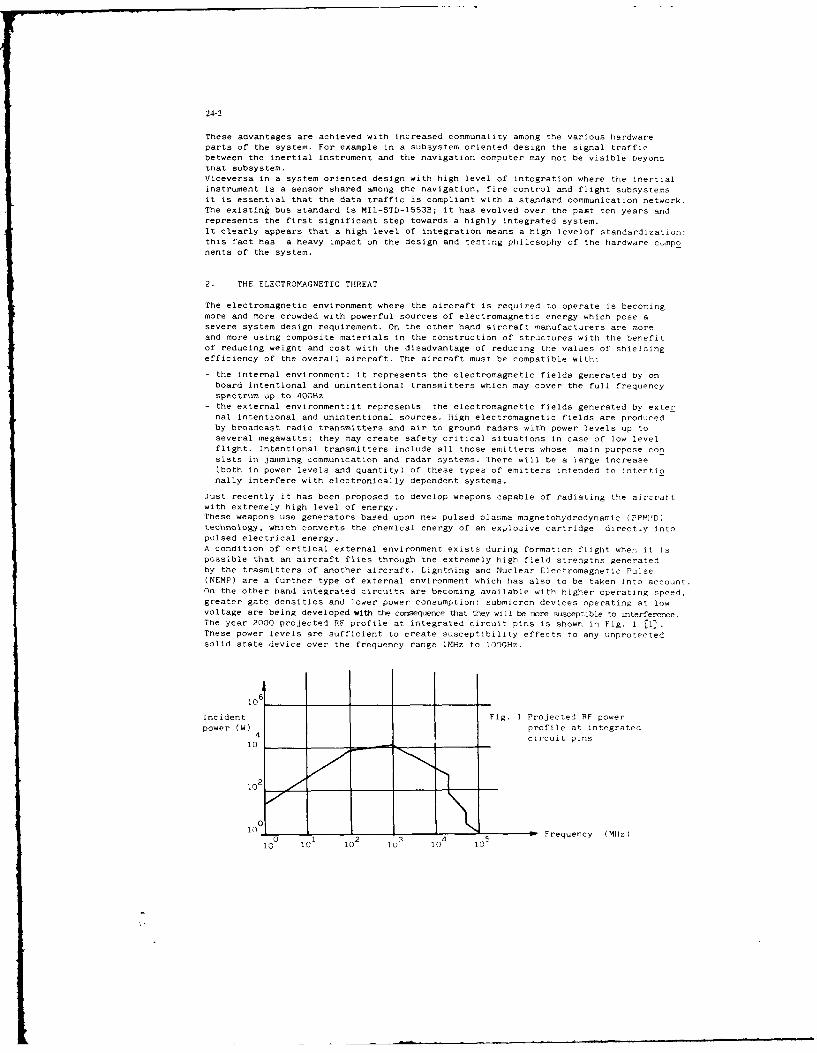
24-2
These advantages are achieved with increased communality among the various hardwareparts of the system. For example in a subsystem oriented design the signal trafficbetween the inertial instrument and the navigation computer may not be visible beyondthat subsystem.Viceversa in a system oriented design with high level of integration where the inertialinstrument is a sensor shared among the navigation, fire control and flight subsystems
it is essential that the data traffic is compliant with a standard communication network.The existing bus standard is MIL-STD-1553B; it has evolved over the past ten years andrepresents the first significant step towards a highly integrated system.It clearly appears that a high level of integration means a high levelof standardization:this fact has a heavy impact on the design and testing philosophy of the hardware cmponents of the system.
2. THE ELECTROMAGNETIC THREAT
The electromagnetic environment where the aircraft is required to operate is becomingmore and more crowded with powerful sources of electromagnetic energy which pose asevere system design requirement. On the other hand aircraft manufacturers are moreand more using composite materials in the construction of structures with the benefitof reducing weight and cost with the disadvantage of reducing the values of shieldingefficiency of the overall aircraft. The aircraft must be compatible with:
- the internal environment: it represents the electromagnetic fields generated by onboard intentional and unintentional transmitters which may cover the full frequencyspectrum up to 40GHz
- the external environment:it represents the electromagnetic fields generated by external intentional and unintentional sources. High electromagnetic fields are producedby broadcast radio transmitters and air to ground radars with power levels up toseveral megawatts; they may create safety critical situations in case of low levelflight. Intentional transmitters include all those emitters whose main purpose conslsts in jamming communication and radar systems. There will be a large increase(both in power levels and quantity) of these types of emitters intended to intentionally interfere with electronically dependent systems.
Just recently it has been proposed to develop weapons capable of radiating the aircraltwith extremely high level of energy.These weapons use generators based upon new pulsed olasma magnetohydrodynamic (PPMHD)technology, which converts the chemical energy of an explosive cartridge directly intopulsed electrical energy.
A condition of critical external environment exists during formation flight when it ispossible that an aircraft flies through the extremely high field strengths generatedby the trasmitters of another aircraft. Lightning and Nuclear Electromagnetic Pulse(NEMP) are a further type of external environment which has also to be taken into account.On the other hand integrated circuits are becoming available with higher operating speed,greater gate densities and )ower power consumption: submicron devices operating at lowvoltage are being developed with the consequence that they will be more susceptible to interference.The year 2000 projected RF profile at integrated circuit pins is shown in Fig. 1 [1].These power levels are sufficient to create susceptibility effects to any unprotectedsolid state device over the frequency range IMHz to 100GHz.
106
Incident Fig. 1 Projected PF powerpower (W) profile at integrated
4 circuit pins10
010 0 '01 10 2 __ - 4 5 Frequency (MHz)
0 1 2 5

24-3
One of the most common form of susceptibility consists in the rectification of themodulating signal of the unwanted incident radiation:a pulse modulated out of band signal may cause the unwanted trigger of the affected device. Onecan define the rectification efficiency R as the ratio of the rectified DC voltage at the device output tothe RF power level incident at the input (for an unmoduiated signal). In case of bipolartransistors:
where
KB is a constant depending on the input resistance, capacitance and emitter area
p is the emitter perimeter
w = 21ff is the operating frequency
In case of MOS devices
44 V
KM is a constant dcpending on the parasitic resistance, the transconductance
C is the Inpul gate capacitanceg
From the previous equations it appears that the rectification efficiency versus frequency of bipolar transistors is higher than the one of MOS devices. In bipolar transistors reducing the size of the component will decrease the device perimeter with theobvious increment of R. In case of logic circuits interference effects, while are notparticularly harmful to signal pnnre~sing qy~tems. may hav ea otrphic effects indecision maker systems such as signal sorters in EW equipments where pure logic operations are carried out. The susceptibility of logic circuits depends upon the noiseimmunity level (NIL) which is defined as the least DC noise margin that exists betweengate output and input voltages in conditions of "0" and "l". At present operatingwith TTL levels typical values of NIL's are O.4V; but in future circuits with ECLtechnology it is expected to operate with values of NIL's of about O.IV with the obviousincrease probability of interference.
3. SYSTEM LEVEL DESIGN
With the total system approach where the subsystems are provided by different suppliersit becomes essential to establish suitable standards as for example it has already been
done for the data bus. A standard to satisfy the electromagnetic threat hardening requirement shall be established at the beginning of a new project. These standard guidelines shall deal with all those aspects of the equipment/subsystem design which arerelated to design aspcct izualil,-.Led by U- Ei, discipline. They are:- grounding
- bonding
- filtering- shielding
- connector and wiring- electrical interfacesThe guidelines shall not be a general collection of common sense design rules (as it generally happens); but shall clearly identify the components, the values of electricalparameters which can guarantee an adequate margin of safety against the foreseen electromagnetic threat. This task is obviously difficult because it means that more responsibility shall be taken by the aircraft manufacturer or by the engineering team who hasthe design responsibility task.The grounding concept and the electrical interfaces represent 'xeypoints in the definition o; a system. Therefore they will be discussed in detail.The gernral lay-out of an electronic/electrical equipment can be sketched as shown inFig. 2.In this diagram different types of grounds are indicated: 1 and 1' are the DC and ACpower grounds respectively, 2 is the signal reference ground (SRG), 2' is the virtualsignal reference ground of balanced receivers which may be isolated from 2, 3 is the
equipment strucsure ground.
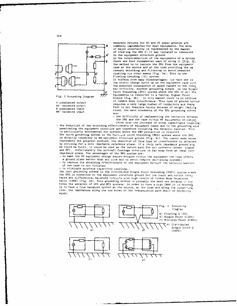
24-4
Separate returns for AC and DC power grounds are
A commonly implemented for most equipments. The areaof major uncertainty is represented by the mannerof treating the SRG 2: it may isolated or connected
A' to the equipment structure ground.In the interconnection of the equipments of a system
5 there are four fundamental ways of doing it [Fig. 3.One method is to isolate the SRG from the equipment
fcase at the source and at the load providing the necessary shielding and filtering to avoid unwanted
2' coupling via other means (Fig. 3a). This is theFloating Grouding (7G) system.It suffers from many disadvantages: the main one is
S- the static charge build up on the equipment case withthe possible consequence of spark hazard to the internal circuitry. Another grounding scheme is the Single
Point Grounding (SPG) system where the SRG of all the
Fig. 2 Grounding Diagram 7 equipments is connected to a Central Signal PointGround (Fig. 3b). In this manner there is no problemof common mode interference. This type of ground systemA unbalanced output requires a very large number of conductors and there
AA' balanced outpu't fore is not feasible mainly because of weight implicaB unbalanced input tions. The main drawbacks of the SPG grounding scheme
BB' balanced input are:
- the difficulty of implementing the isolation betweenthe SRG and the case within RF equipments in conjun
ction with the increase of stray capacitance coupling;the reduction of the shielding effectiveness of equipment cases due to the grounding wirepenetrating the equipment structure and therefore violating the metallic barrier. Thisis particularly detrimental for systems where the EMP protection is required.The third grounding scheme is the Multiple eoint Grounding (MPG) system where the SRGis directly connected to the equipment structure ground (Fig. 3c). The common mode noiserepresents the greatest problem; the reduction of this type of interference is obtainedby striving for a zero impedance reference plane. If a truly zero impedance ground plane could be built, it could be used as the return path for all currents (power signaland RF). Unfortunately the aircraft fuselage structure is far away from an ideal zeroimpedance plane. The advantages of the MPG system are:- to make the RF equipment design easier because within the equipment the case offersa ground plane better than any wire and to avoid complex dec-otpling systems;
- to improve the shielding effectiveness of the equipment because the metallic barrierof the case is not violated;
- to eliminate spurious capacitive coupling.The last grounding scheme is the Distributed Single Point Grounding (DSPG) system wherethe SRG is connected to the equipment structure ground but the input and ou'put interfaces are differential balanced circuits with high levels of Common Mode RejectionRatio (CMRR) (Fig. 3d). This grounding method is probably the best one because it combines the advantes of SPG and MPG systems. In order to have a high CMRR it is necessary to have a true balanced system at the source, at the load and along the connertingline: the impedances along the two wires of the transmission path shall be perfectlyequal.
Fig. 3 GroundingDiagram
/ L_.._ ,J----Y /a) Floating G (FG)b) Single Point G(SPG)c) Multiple Point G(MPG)
d) Distributed
Single point Ga)b )
" (DSPG)
c) d)

24-5
In Fig. 4 the schematic diagram of a
balanced circuit is shown. The follo
wing parameters can be defined
A R K= A~R61~- R*L 1'14 2; ' zxz~z,_z, 2, 1,zx Z.
It is possible to calculate [3) the
transfer functions of the wanted siZb gnal, common mode noise VNa and the
capacitively coupled noise VNb
Fig. 4 Schematic diagram of a balanc- circuit "s4 e+Z,
where: TS 6 V z
V RVZC-Z, - k + RC. Vdz. z b
, RC+Z RC,+7,
The following ratios are meaningfjl
_ (Zc
B Tr, Z+. Zb ITsb R c H
The output voltage of the differential receiver is given by
V= Ad V4+ A c V.
where V, V.
where Ad is the differential mode amplification and A is the common mode amplificactlon. In differential receiver, it is common practice to introduce the common mode
ratio CMR defined as CMR Ad
Ac
By suitable substitution it is easy to calculate the output voltage in presence of
common mode noise VNa
and in presence of the capacitively coupled noise VNb
From the previous equations some comments are in order:
- the CMR of the differential amplifier alone is not sufficient to guarantee a goodrejection ratio if the overall differential line is not properly balanced
- the degree of balance depends on the line and on the transmitter where it is requlired to have either the same unbalance qs at the receiver or a very low resistance
- the capacitively coupled noise does not only depend upon CMR but Is also relatedto RG
Zb
24-6
The balanca transmission line is a typical example of a system oriented problem.It is useless to require a very high CMR at the input terminals of an equipment if atthe same time adequate precautions are not taken at the transmitter end of the line.As it has been stated in the previous paragraph the DSPG system is mainly basec! uponsuitable interfaces between the equipments: the basic components are the isolationamplifier and the differential amplifier. The isolation amplifier is a device whichprovides ohmic isolation between the input and the output . It is particularly suitablefor applications requiring accurate measurement of low frequency voltage in the presenceof high common mode voltage (thousands of volts).The differential amplifier is a device which responds only to the difference voltagebetween inputs and produces no output for a common mode voltage.Both components are characterised in terms of the Common Mode Rejection Ratio (CMRR).Operational amplifiers are susceptible to RF energy conducted into either of the inputterminals.When stimulated in this manner the interference effect is an offset voltage at the particular input terminal entered by the RF: this offset voltage may be either a DC levelor an undesired low frequency response due to demodulation effects.The magnitude of the offset voltage depends on such factors as the power level, frequency equivalent RF source impedance and the op. amplifier input circuit.Demodulation RFI effects are greater in operational amplifiers with bipolar input transistors (741 and LMlO) than they are in operational amplifiers with MOSFET input fransistors (CA081) and with JFET input transistors (LF355).At PF frequencies above 10 MHz demodulation RFI effects in the 741 op amplif'-r 're significantly greater than in the LM10 op. amplifier. This is possibly a result of thecutoff frequency of the npn bipolar input transistors in the 741 op. amplifier beinghigher than the cutoff frequency of the less conventional (pnp substrate) bipolar inputtransistors in the LM1O op. amplifier.
4. SYSTEM LEVEL TESTING
Till now the major part of the testing activity related to the verifi-ation of the equipment hardening against external electromagnetic interference has been performed withinthe domain of the EMC susceptibility tests. These tests are carried ouit according to
one of the numerous EMC specifications existing in the world which are all more or lessderived from MIL-STD-461/462A/B. These tests are divided in two broad categories: radieted susceptibility and conducted susceptibility. Different types of signals (transicntand RF) are injected by conduction on power lines and signal lines or by radiation onthe overall equipment. During the design of a new aircrmf' these tests are specifiedby the main contractor to the equipment/subsystem suppliers. Even if they are accu.ain the definition of the test set up and in the description of the test procedure, theyhave two main drawbacks:- the type of testing implies the design at equipment level and is not related to a
system oriented design- the susceptibility criteria are not clearly specified and in any case imply malfunc
tions at equipment level
The former point is particularly misleading because the system oriented design, by itsvery nature, operates in terms of standards (data busconnector, cable, shielding, signalformat); therefore when the supplier is asked to carry out susceptibility tests it is
not always clear whether he is testing the quality of ts equipment or the quality ofthe standard he was requested to use. Additionelly the test espcclsaly the radiatedone) may not be fully representative because the lay out of the overall subsystem doesnot represent the actual situation in terms of equipment location, cable length androuting. In a highly integrated system it is difficult to have access to parametersto be monitored without affecting the system under test. In view of all these faet itis essential to develop test methods suitable to match the system oriented design andcapable of performing quantitative measurements. Simple qualitative checks intenoed todiscover gross interference/susceptibility situations on the basis of functional interactions are no longer adequate to clear complex systems: there is a well defined need ofmeasuring a quantitative level of safety before equipment malfunction occurs.
In some casesbecause of its nature or of the internal noise,the parameter of the equipment under test changes randomly around an average level wilhout the presence of theinterference source; therefore it may be difficult to fir-! out whether the parameter izaffected when the interference source Iq activated. Thls problem can be overcome bymeans of a statistical approach which can also be useful to establish the safety margin.The basic parameters of a rgndom variable x which specify its central tendency anddispersion are the mean value ux and the variance defined as
A At 4 D
"4'C4
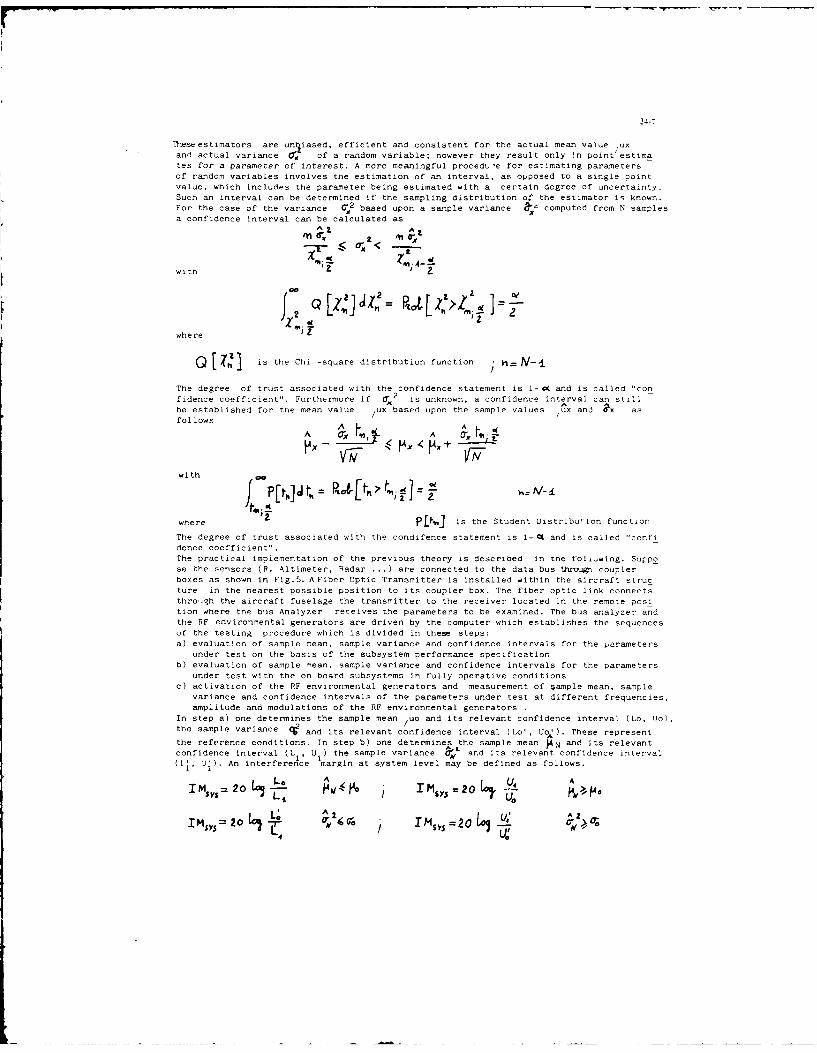
24-7
Theseestimators are uniased, efficient and consistent for the actual mean value /uxand actual variance (' of a random variable; however they result only in point estimates for a parameter of interest. A more meaningful procedL e for estimating parametersof random variables involves the estimation of an interval, as opposed to a single pointvalue, which includes the parameter being estimated with a certain degree of uncertainty.
Such an interval can be determined if the sampling distribution of the estimator is known.For the case of the variance ' based upon a sample variance &"2 computed from N samplesa confidence interval can be calculated as
^ 7. A
< <
with L'
ZZwith 00
2j, Z[4]J 2 p'2 awhere
h [: is the Chi -square distribution function h N-.
The degree of trust associated with the confidence statement is i-cK and is called "confidence coefficient". Furthermore if 0"
2 is unknown, a confidence interval can still
be established for the mean value /ux based upon the sample values /ux and ax asfollows
A __ _A ___
with
where is the Student Distribution function
The degree of trust associated with the condifence statement is 1- 0 and is called "confidence coefficient".The practical implementation of the previous theory is described in tne foli-wing. Suppose the sensors (R. Altimeter, Radar ... ) are connected to the data bus throgh couplerboxes as shown in Fig.5. A Fiber Optic Transmitter is installed within the aircraft structure in the nearest possible position to its coupler box. The fiber optic link connectsthrough the aircraft fuselage the transmitter to the receiver located in the remote position where the bus Analyzer receives the parameters to be examined. The bus analyzer andthe RF environmental generators are driven by the computer which establishes the sequencesof the testing procedure which is divided in these steps:a) evaluation of sample mean, sample variance and confidence intervals for the parameters
under test on the basis of the subsystem performance specificationb) evaluation of sample mean, sample variance and confidence intervals for the parameters
under test with the on board subsystems in fully operative conditionsc) activation of the RF environmental generators and measurement of *ample mean, sample
variance and confidence intervals of the parameters under test at different frequencies,amplitude and modulations of the RF environmental generators .
In step a) one determines the sample mean /uo and its relevant confidence interval (Lo, Uo),the sample variance and its relevant confidence interval (Lo', Uo' ). These represent
the reference conditions. In step b) one determines the sample mean. PN and its relevantconfidence interval (L , U the sample variance d, and its relevant confidence interval(LI, U). An interference margin at system level may be defined as follows.
IMS, 5= 20 ITM Y = I is20tLt tLP,>,P
U0L, A 4 A
= _ 0
I M2os O/ !M,,,=2o L, E.'A

24-8
FO. ransmitter
gCoupler Box Coupler Box Coupler Box
Aircraft structure
RF Bu .O. Receivergenera Aillyzer,
tes
CCompter
Fig. 5 Test Set up for system level test
An interference situation (IMsy S ; 0) in the fully operative conditions is a lear
symptom of an integration malfunction to be solved at system level. It 1E necessaryto solve the problem before proceeding to step c ). Viceversa when IMSyS < C thePF environmental generators can be activated. In step(-) one determines the samplemean /UN I and its relevant confidence interval (L2, U2), the sample variance l 2
and its relevant confidence interval (L', I. An effective interference margincan be defined as follows: (Fig. 6).
Err L0IME o = 20 ! I A
20 togI MEr;: ZO UIMEFF =20 tO _K 0'>O
IME = U Aot _.
An interferent situation exists when TM EFF > -.
The evaluation of the confidence interval is easily performeJ for a fixed level signal
whose level and accuracy are known. This signal may be represented as follc z:
where:
K = nominal signal level
A K - maximum deviationThe mean value confidence interval ( Lo, 1!o) may be assumed (K -AK, K A K) with aconfidence interval equal to 100%. The sample mean is K.The variance confidence interval (Lo', Uol) may be assumed K2,, K
2 with a confider,
ce interval equal to lO0%.The sample variance is AK2
These measurements can be performed at different frequencies, amplitudes and modulationsof the interference source. It is also possible to evaluate a correlation coefficientb L .e the parameter under test and the parameter of the interference source in orderto establish possible relationships which may be useful in the determination of the

JA . ... po •~
2.1-9
AA
Fig. 6 Examples of sampling distribution functions
1) non interferent situation (L 12 > Lo, U 1, < Uo) and (Ll _L , UI11 ;
2) interferent situation (L2< Lo and L( L)
source of the problem.
These tests shall be performed at rig level and at aircraft level. There may be some
difficultie s in performing radiated tests at rig level because the rig is generally 1o
cared within a laboratory. In this case it may be useful to perform the so called bulk
current injection tests (BCI). The BCI testing procedure involves current injection into
the electronic component under test by toroidal transformer excitation of the wiringharness. The bulk current injected into the comporent is monitored via a toroidal probeFig. 7. The advantage of this test method consists in the possibility of avoiding radating the rig with the tenna and localizing the interference on a selected wiring harness.
There are some disadvantages which are:
- the need of a multiple injection probe system in case the subsystem has many wirlnglooms which shall be interfered at the same time in order to avoid unrealistic up;e
ting of the subsystem- the injecte signal depends on the position of the probe along the cable ; it is necs
sary to perform the test with the probe located in different positions
- the frequency range is limited up to 400 MHzRadiated susceptibility tests [5] can also be performed by radiati the system under es
by means of EM cell which consists of a section of rectangular coaxial transmission linewith tapered sections at both ends. The taper acts as a transitia to match the winea 50 Ohm coaxial line at the two ports of the cell.Unfortunately TEM cells have a limitation on operating frequency because the TEM modeexists only at low frequency. Moreover since the polarization of the field is fixed theradiat d susceptibility test requires physical rotation of the equipment under test.
Another technique which does not require the rotation of the equipment under test usesreverberating enclosures [6] to generate an average homogeneous and isotropic field
within a metal chamber. The homogeneous and isotropic field is obtained by rotating atuner whose purpose consists in perturbing the possible modes existing within the cavity.Reverberating chamber technique is good for applications at high frequencies; therefore
they may be used as supplementary tools to TEM cells.Susceptibility tczt. ca be performed in many ways; in all cases the aim is to simulatethe environmental conditions where the equipment under test shall operate.
AntEqtcique whc doesp no4eur h oaino h qimn ne etue
AnalyzerI
Sinal Amplifier
Geeratr chab Fig. 7- Bulk urrent injection
test method

24-10
5. CONCLUSION
The electromagnetic threat will be the challenge to future avionic systems. thereforesuitable design rules and testing techniques shall be established in order to builtthe aircraft with an acceptable margin of safety: tne aim can be met by designing andtesting the aircraft at system level . Careful selection of electrical standards duringthe design phase combined with the system level testing approach represent the key
points to be successful in this difficult task.
6. REFERENCES
II H.W. Denny "Projected Susceptibilities of VHSIC VLSIC Devices to the year 2000
Electromagnetic Environment" 1986 IEEE Symposium on EMC21 Y. H. Sutu and J.J. Whalen "Statistics for demodulation RFI in Operational Ampl.
fiers" IEEE Symposium on EMC 7urich 1983131 Gottwald A:"About the suppression of spurious signals by balancing the transmission
circuitry"Proc. of the 3th Int. Symp. on EMC Wroclaw (1976)
141 B. Audone, R. Cazzola and G. Barale "Statistical evaluation of the EMC safety marginat system level "IEEE Symposium on EMC Montreux 1984
15i M.L. Crawford and e.L. Workman "Using a TEM cell for EMC measurements of electron.eequipment" TN103 NBS Boulder 1981
61 P. Corona et alias "Performance and analysis of a reverberating enclosure witevariable geometry" IEEE Transactions on EMC Vol. EMC-22 FeD 1980.
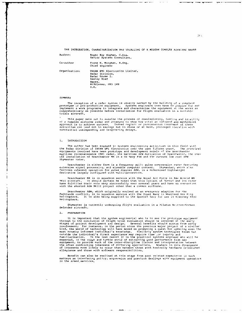
2.;.
THE INTEGRATION, CHARACTERISATION AND TRIALLING OF A MODERN COMPLEX AIRBCRNE RADAR
Author: Roger Roy Hogben. C.Eng.
Senior Systems Consultant.
Co-author Frank N. Morphet. B.Eng.
Chief Engineer
Organisation: THORN EMI Electronics Limited,
Radar Division,
Radar House 2,
Dawley Road
Hayes,Middlesex. UB3 IHN
U.K.
SUMMARY
The inception of a radar system is usually marked by the building of a completeprototype ur pre-production equipment. Systems engineers then have to prepare for andimplement a work programme to integrate and characterise the equipment at the works ascomprehensively as possible before installation for flight evaluation in a suitabletrials aircraft.
This paper sets out to examine the process of commissioning, testing and triallingof a complex airborne radar and attempts to show how vital an informed and methodicalapproach is to achieve success. Indeed neglect or parsimonious treatment of theseactivities can lead not to savings but to chaos or at best, prolonged iteration withsubstantial overspending and lengthening delays.
I. INTRODUCTION
The author has been engaged in systems engineering activities in this field withthe Radar Division of THORN EMI Electronics over the past fifteen years. The principalequipments involved have been prototype and development models of the Searchwatermaritime reconnaissance (MR) radar, the maritime AEW derivative of Searchwater, the one-off installation of Searchwater MR in a US Navy P38 and the current low cost AEWSkymaster radar.
Searchwater in either form is a frequency agile pulse compression radar featuringextensive signal processing, and sizeable computer content. Skymaster, which alsofeatures coherent operation for pulse doppler AEW, is a modernised lightweight
derivative largely configured with multi-processors.
Searchwater MR is in squadron service with the Royal Air Force in BAe Nimrod MRMKII aircraft. It should perhaps be noted that this variant of Nimrod and its radar
have fulfilled their role very successfully over several years and have no connection
with the aborted AEW MKIII project other than a common airframe.
Searchwater AEW, which originally evolved as an emergency adaption for theFalklands conflict, is in squadron service with the Royal Navy in Westland Sea Kinghelicopters. It is also being supplied to the Spanish Navy for use in Sikorsky SH3D
helicopters.
Skymaster is currently undergoing flight evaluation in a Pilatus Rritten-Norman
Defender aircraft.
2. PREPARATION
It is important that the system engineer(s) who is to see the prototype equipmentthrough to the conclusion of ffight trial evaluation should be involved at the earlystages of project development and design. Several benefits should accrue from earlyinvolvement; for instance, in the period since the previous major project of a similar
kind, the world of technology will have moved on prompting a quest for updating even themost broadly informed individual's knowledge. Similarly system techniques known but
outside the individual's direct experience may require time .or inquiry andfamiliarisation. In the last resort it is the practical systems engineer who will heexpected, in the rough and tumble world of extracting good performance from newequipment, to provide much of the inter-discipline liaison and interpretation between
the often conflicting interests of differing specialists. Nowhere in this divergenceof interests more likely to occur than between those with basically hardware orientated
allegiance and those with software responsibilities.
Benefit can also be realised at this stage from past related experience in suchmatters as interfacing policy, ergonomics and previous dealings with equipment operatorsin the armed.services.

25-2
Nevertheless, despite this it is important that the systems evaluation engineerdoes not become too involved or tied down in the detail engineering: that is forothers. The first objective must be to come to terms with the physical principles uponwnich radar performance will hinge. The engineer should feel that his or her thinkinghas got "inside" the system. It is not essential to understand in detail, circuitry,machine code or the more esoteric performance mathematics but it is crucial toappreciate the radar system and its arena meaning the customer's requirement, thefundamental physics both within the radar and in free space, the computing, the hardwareand the system role within the total aircraft avionics.
The system may now be examined with more confidence and dissected into itscomponent parts, for example the r.f. section, analogue processing, gain control,thresholding, digital processing, data computation, displays etc. It is often helpfulto draw or redraw functional block schematics to improve understanding at this stage.This type of activity assists in identifying the key points for monitoring; for exampledetector outputs, gain and threshold settings. As systems become more complex, compactand interwoven with an associated dissolution of unit or "black box" compositionidentification of clear key interfaces for monitoring becomes more difficult. Thevalue and utility of straightforward monitor or test points cannot be overstated. Incases where vital data is neither readily available nor easily decypherable,modifications or special provision should be suggested. These comments apply both tothe circuitry and the software data areas.
At this same time vital performance points and test objectives can beidentified. Particular attention should be paid to those tests whose results can standas a control reference when the programme moves on to the flight trials stage. %Isolikely to be very useful for reference purposes throughout testing and trials arereversionary type control options such as those that remove automatic operation or openlarge feedback loops. Typ)ical examples are manual rather than automatic receiver gaincontrol and manual rather than CFAR setting of thresholds. It may be prudent tointroduce options of this Ltpe even where no long term operational requirement exists.
Where reviewing the system key performance features those associated withnavigation inputs tn the radar merit close scrutiny. Motion compensation errors fromaircraft navigaticn sensors have been known to severely impair overall radar performanceonce airborne. Due to the different disciplines involved, it has not been unknown forthe Inertial Navigation System (INS) contractor to have a genuine but very differentinterpretation of a key specification clause to that ,f the radar designers.
A system test rig or area has to be prepared in readiness for the arrival of themain equipment. 9asic requir..,-ts include ample space for an accessible layout,power, temperature conditioning together with support infrastructure such as cablegantries and benches. In addition commercial items such as D.C. power supplies,keyboards, printers and capital test equipment have to be ordered or obtained.
Staffing the whole operation through to flight trialling has also to beconsidered. The author's experience is that progress is best sustained by a smallnucleus of full time staff with support from project specialists as and whenappropriate. The value of a good artisan, particularly a prototype wireman, toimplement permissible modifications and construct special to type test apparatus oughtnot to be overlooked. It is sound policy to introduce trials or field engineers to thesystem concept at this stage prior to participation in the later system characterisationmeasurements.
3. INTEGRATION AND COMMISSIONING
A schedule for these activities should be drawn up to shown in some detail thesequence, nature, effort and anticipated time for each step. The procedure outlinedmay be smartly, even sharply timed but it should always be methodical and include timefor regular written reports. The schedule may well be widely agreed at the outset buttoo often projects run late due to delays for example, in design or card manufactureincreasing pressure on the system programme. System integration, characterisation andtrialling being the last in line of all development activities there is a very realdanger of expedient policies being suggested. The argument may even he advanced thatthe system merely requires assembly, switching on and all will be fine. Unfortunatelywith complex equipment this is never so, for umpteen sundry reasons. Totalacquiescence to this type of policy therefore is very likely to result indisorganisation and further delay. In the event therefore schedules may have to bereviewed carefully but not severely compromised.
Built-In-Test-Equipment (BITE), once itself commissioned, is a useful aid to systemintegration and problem diagnosis but the rig team ought also he watchful for other waysin which the radar can in effect check itself, without res'rt to expensive testequipment. For instance, where alternative modes or facilities exist each may becross-checked against the other. It is also helpful to assess and establish the systemquiescent conditions in noise limited conditions. These include receiver gain demand,mean detector output, threshold setting and overall false alarm rates. A confidentknowledge of these simple parameters allows a rapid daily or pre-measurement check to bemade; for random component failure may occur at any time to confuse the situation andperhaps invalidate lengthy measurement results.

25-3
Self test, formal or improvised, is of course never enough to chart performancesufficiently to ensure a confident transfer of the equipment to an aircraft.Simulators, sophisticated and simple, are also required to provide amcngst other thingsinterface checks, synthetic target generation and synthetic aircraft motion (linear andmanoeuvre).
The rig will also require appropriate video and data recording together withcorresponding replay facilities. Some of this will be common with the planned aircraftinstrumentation. It may be appropriate to modify the rig signal processing to absorband reprocess in-flight video to be recorded later from a tap at the corresponding pointin the signal chain. "Real" data of this form, even though inherently frozen beyondadjustment and mildly distored by recording imperfections, can he invaluable in therefinement of some processing techniques particularly autotracking. Recorded data bothtaken in flight or from a rig may also often provide the means of capture of fast ortransient events for subsequent replay and analysis in a slower time frame.
The commissioning or integration process itself almost always progresses by aprocess of attrition. The common belief is that once the current problem or barrier toprogress is removed everything will fall into place but, in the event, removal cf thefirst problem reveals the next and so on, truly a situation analogous to a set of"Russian Dolls".
Persistence and tenacity are of course generally rewarded and the systemcredibility should rapidly improve. At this stage, if not before, some of the firmwareand software will have been exercised, improved and refined on the rig. This is finebut the software people will have discovered the benefits of rig system access to testnew ideas and directly resolve their problems on the radar itself. This factor has tobe monitored closely otherwise excessive system rig time may be absorbed in esotericsoftware development tasks. Uncontrolled or over frequent changes to software, howeverwell intentioned, may also undermine general system performance consistency. Forexample it has been known for a set of control settings to be chosen for a measurementprogramme, midway through which an apparently innocent change of software is introducedbringing about a subtle system reinterpretation of one of the control settings withconsequent confusion and time wastage.
4. CHARACTERISATION
System characterisation activities begin to infuse into the workload at about thisstage. Fmphasis changes from the somewhat mechanistic and qualititative commissioningor integration tasks to the more quantitative nature of characterisation. The purposehere is to provide calibration and reference data as far as is sensibly attainable inthe laboratory. The results obtained have to be compared with theoretical or modelledperformance and should be retained for reference purposes in subsequent flight testing.
Comparisons with anticipated performance may well present the systems engineerswith some shortfall to explain. Hopefully this is not serious but some reassessmenL oftolerances, error budgets and losses, both r.f. and processing, is all too frequentlyrequired before all the "missing dB's" can be largely accounted for.
At this stage the prototype system should approach a state of readiness for flighttesting. There may be a little tidying up to be done and where sponsorship by agovernment agency is involved some form of acceptance test to be arranged andimplemented. A stage report is usually advisable at this time.
5. FLIGHT TRIALS
Preparation and planning for flight trials will, by this point, have progressed toan advanced stage. Flight trialling is a very different situation to laboratory systemtesting. The latter, despite all the problems encountered on the way, offered arelatively clinical environment, time to think and, most importantly, opportunity torepeat an observation under virtually identical conditions. In the aircraft none ofthese luxuries can be relied upon, even in the most well appointed four enginedtransport. The equipment itself is less accessible and accurately controllableconditions are unattainable. Range and hearing geometry to a chosen contact, as asimple example, are continuously changing: no one can stop the aircraft to check ameasurement.
In response to this situation one school of thought advocates extensive videorecording and other data collection taken robot fashion in pre-planned rigid trialswithout scope for improvisation. Heavy reliance is then placed on post-flightanalysis. This approach has merit particularly in any earlier study trials but inequipment design proving trials there is no substitute for direct observer deductionwith a degree of on the spot improvisation to obtain conclusive evidence.
Where data collection and ground analysis methods are resorted to, control has tobe exercised to both avoid overwhelming the analysts with excess data and to validatethe relevance and quality of all recorded data before the termination of flying. Anincomplete set of in-flight results found after grounding the equipment may prove a veryexpensive omission.

25-4
The foregoing case for system engineers participating as flight observers implies afurther set of qualities in staff selection. This goes further than merely obtainingmedical certification and possessing a capacity for quick thinking. This same fastthought processing will often have to take place in an adverse environment. Criticaldecisions and technical deduction may well be required several hours say into an allnight trial carried out at low level in conditions which have buffeted the aircraft andits occupants without relief. Add to this the nausea-inducing odours which pervadeaircraft from their hydraulic and lubrication systems, not to mention the indelicatearoma of hot soup and foodstuffs emanating from the galley (surely intended, on suchoccasions, for only the most masochistic of the full time professionals) and the valueof a strong constitution is clear.
The observer's ordeal on a rough trip may not end on landing for, apart frompossible post-flight checks and calibration, there will, if the trial is staged from amilitary base, be other commitments. First exposure of a new equipment to the relevantmilitary is bound to provoke their intense curiosity. The trials crew are typicallyquestioned at length, often, truth to tell, over drinks at a service barb Thisliaison, whilst virtually specifying a social dimension to the job is not without worthto the project team for it provides valuable insight into the future operators' attitudeand expectations. Later this type of experience can be put to nood use in devisingtraining schemes for the service user. It also helps to establish an alternativeinformal liaison channel through which later problems or minor improvements,particularly to software, may be discussed.
The first tangible hurdle at the flight trials stage is the actual installation.This may have been preceded by "mock up" checks, involving cable and waveguide runstogether with weight and electrical dummy loading in which some preliminary flying couldhave taken place. In this, excellent support from full time field engineering isgreatly appreciated. Ideally key members from the field team will have been present atthe works during the characterisation stage to familiarise themselves with the newradar. This should materially improve the prospects of an elegant installation withminimal delay.
The value of good field engineering support, embodying knowledge and experiencepeculiar to their kind and not easily unearthed from textbooks, is high. The systemsengineers may know the radar inside out but without guidance through the formalities andeveryday jargon of the flying industry, in or out of the air, they would soon flounderin confusion.
Following installation some ground running is customary. Adequate ground supplieshave to be arranged if use of main engines or an onboard generator is to be avoided.This ground running may be the first opportunity for radiation checks on a completesystem. In such cases, with proper safety measures taken, a convenient object on orbeyond the immediate horizon such as a spire or a water tower may be enlisted to confirmessential radar loop characteristics such as pulse compression or coherence.
Other checks verifying both the integrity of the equipment and the retention ofcharacteristics following installation are performed in this ground phase.
Tests also have to be run to demonstrate that the radar is essentially hazard freeboth to the aircraft, its equipment and its occupants.
The first flights are also concerned with safety; followed soon, if all is well,with what are known as "shake down" activities. If the radar is some form ofsurveillance type with an approximation to real time display, much may be gleaned byinformed observation. System areas requiring initial in-flight verification beforepressing on with formal trialling include antenna stabilisation, host aircraft motioncompensation, any serious BITE indications, display uniformity (i.e. background levelsand false alarm rates) together with some qualitative indication of the detectability ofvalid targets of opportunity e.g. aircraft, ships or road vehicles. It should also bepossible to gauge the approximate extent of clutter penetration and compare withexpectation for the prevailing conditions. This period may reveal the need for limitedmodification and redesign but in general it should be seen as a learning phase.
All round confidence will evolve to the stage where formal trialling withcooperative targets commences. Again it is important initially to curb over ambitiousaspirations and to keep situations simple. The disposition geometry should bestraightforward, target manoeuvres limited and at each progression only a single aspectof either target or radar changed. At all times the situation should be constrained tothe minimum number of variables. In this way the results obtained will be explicableand most probably pleasing and satisfactory. It is also at this stage that the realvalue of the laboratory characterisation is apparent. The earlier laboratory andground results provide the foundation or reference agains' which airborne performancemay be both judged and understood. A trial organised in this way from such a base willbe less subject to crisis, under better control and better able to supply answers tocriticism. A major hazard which is avoided by not embarking ill-prepared into complexradar trials is that not only are the problems less likely to he difficult to unravelbut the resultant climate tends not to induce flawed theories and myths which canthemselves become further obstacles to understanding and progress.

The tendency is for the truth of these remarks to intensify as the trial progressesfrom detectability aspects into the information extraction processes such asautotracking. Throughout a disciplined and documented record of the trials should bemaintained. A minor problem to flight observers in this respect is the means of notingtheir own thoughts and jottings during flight. Handwritten notes in a standardengineers notebook which probably has to be hand held, are certainly unsuitable and animpediment to concentrated observation. Some form of shorthand, improvised perhaps, ina flip-over notepad is better while a pocket audio recorder is perhaps best. In asimilar vein the systems observer requires an ability to retrieve general systeminformation quickly if he is to react fast enough to an unexpected situation. A simpleexample could be the selection of an altitude adjustment to sight the surface horizon atan amended range. Backing up limited human memory could call for a library ofspecifications, computer print outs and other reference data to be carried on board. Asimple pocket notebook can be packed with an amazing and evolving amount of generalunclassified information to provide an excellent and compact aide-memoire.
As with the characterisation phase the trial's end and major inte-lediate stagesshould be marked with the issue of formal findings reports.
6. CONCLUSION
This paper has attempted to identify a general approach or philosophy to thecommissioning and performance evaluation of a new airborne radar. The approach setsout to achieve an integral programme from building up the system through to thecompletion of flight trials. A methodical and informed process has been advocatedwhich it is hoped gives an insight into the importance of progressing such a majoractivity from a firm and growing foundation. In this way good technical control can bemaintained and the answers to criticism or unexpected system behaviour may be providedwith authority.
It is essential to the approach that higher management understands and supportsit. The systems engineer may well be subject to overtures to cut schedules or to thinkmore positively in the hope that it will all work first time. The sense of urgencyshould he acknowledged but the basic message must be got through and retained.Otherwise the probability of debacle and associated escalating costs to the project andits reputation can be very high.
26-I
Microelectronics The Next Fifteen Years
Dean Waijace PhysicistMicroelectronics Branch Code 3318
Naval Weapons CenterChina Lake CA 93555
USA
This paper attempts to predict some future trends in microelectronics. The paper focuses on CMOSintegrated circuit technology. CMOs is presently the leading integrated circuit technology, and alltrends show that it %ill contin,te to dominate the integrated circuit market in the future.
I examine the processing of what I feel will be the two leading CMOS technologies of the future,twin tub,and silicon on insulator (SO). These two technologies have the capability of giving maximumCMOS device performance. With device geometries shrinking the problems associated with scaling areintroduced, and some possible solutions are examined. The paper is concluded with a brief descriptionof some fundamental limits in integrated circuit technology.
This paper will attempt to provide a brief overview of semiconductor processing trends andsemiconductor material trends. To start a look at where we have been is a good idea. Starting fifteenyears ago bipolar transistors were widely being used and NOS devices were starting to be widely used in
hand held calculators and products that required small power consumption. At the time a large d!vice had5000 transistors. Memory devices were just emerging as well as four bit microprocessors. In the 1960'sthe integrated circuit market was mostly comprised of bipolar transistors for both digital and analogapplications. In the mid 1970's digital MOS overtook bipolar technology in the digital arena and withdecreasing geometries MOSFET'S are also challenging in the linear arena. (Ref 1)
We have come a long way in the last fifteen years. We now have chips with hundreds of thousands oftransistors; device geometries have shrunk below the one micron range. MOS devices operate in the 100 MHZrange when not to many years ago they only operated in the several hundred KHZ range. Bipolar technologiesare approaching the GHZ range. GaAS is being used for very high speed applications i.e. a digital flipflop has had reported speeds of 18 GHZ. Technologies are being mixed, bipolar and C240S on the same chip.People are looking at using GaAs on silicon to get the advantages of both technologies. Silicon oninsulator (801) sees to be a promising technology. ASIC (application specific integrated circuits)technology has become common and device geometries in the one to three micron range have become quitecommon. Gate arrays with 50000 gates or more have become available on the commercial market. These eventshave led to a different design methodology as the systems become much more complex and the density ofthe chips increases. System designers and IC designers have become more dependent on computer tools toaide them in their work.
In this paper I am going to concentrate on C405 technology. All trends point to the continued increaseof the use of CMOS in the future. I will first give a quick overview of VLSI processing trends and a littleinsight to what the processing of the future might be. I w
!ll then talk about parasitics in CMOS devices
since these are limiting factors in device performance. Then I will talk about two different CMOSprocessing technologies, (1) twin tub and (2) silicon on insulator and show how different processingtechniques can help eliminate many of the parasitic problems. I will then examine first order scalingand show why first order scaling doesn't work in the sub micron range. I will finish by taking a brieflook at some of the fundamental limits of device physics. These limits will include quantum mechanicallimits and thermal limits.
Processing Trends
In this section I will give a brief overview of the following subjects,1) epitaxy2) diffusion3) ion implantation4) lithography5) etching6) multi level metal
This section is not necessary reading for the continuity of the paper but can serve more for a referenceor as a simple review for people not familiar with microelectronics processing. A good starting point isepitaxy. Most epitaxy is done by chemical vapor deposition. As dimensions get smaller, molecular beamepitaxy will become more prevalent. The advantage of MBE is that it is a low temperature process whichminimizes outdiffusion and autodoping. MBE allows precise control of doping, and more importantlycomplicated doping profiles can be done with MBE. Epitaxy can also be important for silicon on insulatorMOS technologyvhich will greatly increase speeds because of reduced parasitics. Because of the manyproblems associated with this a non epitaxial approach for providing single crystal silicon is beingused. There are two common non epitaxial approaches, (1) deposit polysilicon on an amophous substrate,and recrystalize the silicon by a thermal means. (2) do a deep ion implant of oxygen which forms a buriedlayer of silicon dioxide and then recrystalize the silicon on the surface.,Both of these methods haveproblem minimizing the defect density of the silicon.
The next subject that I want to discuss briefly is diffusion. Not much needs to be said aboutdiffusion other than junction depths of 1000 angstroms can be realized but profile measurement techniquescommonly used are only good for depths of about one micron. However the secondary ion mass spectroscopeallows measuremant of shallow junction profiles and is a powerful analysis tool.
The next toepic is ion implantation and is very important to VLSI technology. Ion implantation isthe bombardment of a target with energizied ionized atoms. This causes the atoms to be implanted belowthe surface. Typical energies are. from 3 to 500 KeY resulting in the atom being implanted from about100 angstrom to 10000 angstroms below the surface. A big advantage of ion implantation is the numberof dopant atom can be very well controlled and the depth profile can be well controlled. Ion Implantationis used in all or practically all doping steps in present VLSI technology. In the future very shallow I

26-2
Junction depths will be ceen in MOS technology, 100 angstroms or less. An interesting note is thatsince ion implantation is a kinetic process the eventual shallowest junctions are probably obtainablefrom thermal diffusion and not ion implantation (Ref 2). Although it will be a long time before ionimplantation is not the practical choice.
The next section is on lithography. This is the defining process an far as future IC production goes.The prevalent lithographic process now in use is optical lithography. The reason for this is the highthroughput of opticoal lithography. Good registration and the resolution is adequate for most present daycommercial processes. Diffraction is the limiting factor for optical lithography and until recently onemicron was believed to be the lower limit for optical lithography. But with the advent of tri levelphotoresists and contrast enhancement material 0.5 micron resolution has been achieved. Other ways toimprove optical lithography is to go to smaller and smaller wavelengths. Deep UV and xray lithographyare presently being examined. Xray lithography ie promising because of the short wavelengths ( aroundten angstroms) but masking is a very diffucult problem that needs to be solved before xray lithographybecomes practical. There is a real limit to optical lithography and non optical methods are becomingmore common. On the non optical front electron beam lithography is very popular. In electron beamli'hography an electron beam directly writes on the mask or the substrate. Therefore electron beamlithography gives better resolution than optical lithography. The limiting factor for electron beamlithography is the backscatter of electrcns off the substrate, this is called the proximity effect.One step further Is ion beam lithography which will reduce backscatter and thus give better resolution.Monte Carlo simulation shows ion beam lithography to have negligible backscatter and therefore shows noproximity effect.
The next subject is etching. I won't even discuss wet etching because it is not practical for VLSItechnology where the dimensions are so small that an isotropic etch cannot be tolerated. Dry etchingtechniques are the predominant etching tools for the VLSI and ULSI era. Among these reactive ion etchingis very good because it allows an anisotropic and a preferential etch. I also want to briefly touch onmultilayer metal. As device geometries continue to shrink device interconnect becomes a real problem.A large amount of useable silicon can be consumed just by device interconnect. The way to get around thisi multilevel metal. By going to two, three, four, and even five layers of interconnect the density canbe greatly increased. But going to multilevel metal is not a trivial problem. Two layer metal is now commonand three and four layer metal is being developed but there have been real yield problems associated withthese. You need good interlevel dielectrics that are planarized, free from pinholes and have a low dielectricconstant.
CMOS Parasitics
I will now discuss parasitic capacitances and resistances and latch up of CMOS devices. In orderto maximize the performance of the devices these parasitics must be greatly reduced. An understandingof the parasitics associated with these devices will help us understand what will have to je done in thefuture to maximize device performance. Parasitic capacitances play a major factor in inhibiting the devicespeed of MOO circuits so it is paramount to minimize this capacitance. There are source substrate capacit-ance, drain substrate capacitance, gate substrate, gate drain and gate source capacitance. There are manyfactors that affect the capacitance but for our purpose all we need to know is that we must minimize itto maximize device performance. Also of great concern is interconnect capacitance and resistance thusleading to RC delays. As circuit density increases and line widths decrease and wiring resistance andassociated delays become very critical. This leads us to multilayer metal schemes.
Two other effects that I want to mention are the body effect and latch up. In the region where thegate source voltage is greater than threshold voltage then the substrate bias is the voltage of thesource minus the substrate voltage. As the substrate bias increases the associated channel substratedepletion layer increases. This traps more charge in this layer causing the channel charge to decrease.So this increases the threshold voltage which lessens current flow and thus makes circuits slower. Thisis called the body effect for obvious reasons. Latch up is caused when enough current is injected intothe substrate to turn on two bipolar transistors an NPN and a PNP that are formed by the different dopings.Thus depending on substrate resistance in the parasitic path the current draw can be large and causecircuit failure. Both these effects can be minimized or eliminated with different processing techniquesi.e. silicon on insulator.
CMOS Technology
As previously pointed out, CMOS technology seems to be the technology of the future. Therefore, inthis section I am going to talk about the process integration of CMOS devices. I am not going to discusssingle well technology since I am interested in optimizing both n channel and p channel devices. There-fore the two technologies that I will discuss are twin tub CMOS and 601 processes.
TWIN TUB
Twin tub allows the optimization of both p channel and n channel transistors. The general processingsequence for the twin tub process is to start with a n+ or p+ substrate. Put a lightly dopotd epitaxiallayer on top of this to help prevent latch up, Form your n and p wells. Then a oxide is put down andpatterened for the gates. A thin oxide is grown for the gates. Polysilicon is then deposited over thewafer and etched to form the gates. Then Boron and Phosphorous implanttLions form the n and p regionsfor the source and drain regions. The circuit is then passivated and contact cuts are made to the siliconand metal is deposited, The metal is etched and another dielectric is deposited, vias are etched andmetal is again deposited. This multilayer metal could encompass two, three, cr even four layers. As afinal note, blocks of transistors are separated by deep trench isolation. By deep trench I mean trenchesdeeper than the well d!ffusions. The tubs within these regions abutt so there needs to be a Vdd and Viacontact to the n and p wulls.
01LICON ON IN5UIATOR
80 has the potential for being the fastest of the O8 devices. It is also the most diffucult toprocess and arcorsingly the most expensive. But changes in processing capability will eventually change ii

26-3
this. The processing goes as follows. Put a thin layer of silicon on an insulator. This can be sapphire
or spinel or it can be an amorphous dielectric using new ,on epitaxial means. These non epitaxial meanslook very promising for the future. Then etch the silicon to form islands. The etch must be aisotropicsince the separation of the Islands will e much less than the thickness of the islands. Next the p
islands are masked with photoresist and a phosphorous implant forms the n islands. The n islands are thenmasked with photoresist and a boron implant forms the p islands. Next a thin gate oxiae is grown over thestructures and polysilicon is deposited and etched to form the gates. Next the sources and drain areformed by selective masking of islands and phosphorous and boron implants respectively form the sourcesand drains of the p type and n type devices. Next a dielectric is deposited over the whole device andcontacts are out and metal is deposited. There will be multiple layers of metal in order to allow fullutilization of the increased gate density. With the high density, planarization techniques become veryimportant in making good step coverage possible.
Silicon on insulator is very attractive because of the following reasons;
1) High circuit density. One reason for the high circuit density is that there are no n and p wellsas in the twin tub process.
2) The circuits are very fast because of the small capacitance. The small capacitance is due to theinsulating sibstrate which leaves only a capacitive contribution from the walls of the source and drain.Also because of the insulating substrate leakage currents are negligible or non existent.
3) Latch up is eliminated.
4) The problems associated with body effect are eliminated.
SOI has the potential of being the leading CMOS technology of the future. The high speeds and thehigh densities make this technology very attractive. It also changes to 3D quite easily with devices sharinga common gate electrode.
First Order Scaling of CMOS Devices
If these devices are indeed the device of the future then the next question is how small can they
be. I am going to give a rather quick overview of first order scaling and you can see how this can beextended. This first order scaling is based on the 'constant charge model' (Ref 3) that basically says
that the operational characteristics of a device can be maintained if the device is scaled by a factor
of A. The folloving'is then scaled with this dimensional constant A.
1) vertical and lateral dimensions
2) voltages
3) doping concentrations
The actual effect is then,
device parameter scale factor
length 1/Awidth W I/Agate oxide thickness t(ox) 1/Ajunctin depth x(J) 1/Asubstrate doping 1/Asupply voltage V(dd) A
E field across oxide 1/A
depletion layer thickness 1parasitic capacitance WL/t(ox) 1/Agate delay VC/I 1/ADC power dissipation l/AS2 (02-raised to the power of 2)dynamic power dissipation 1/A2power speed product l/A*3gate area 1/AG2power density VI/A 1current density A
transconductance 1 (Ref 4)
Several things become immediately obvious from the above; first as we decrease channel length we will
have to increase doping concentration in order to narrow the depletion region. You can see the current
density scales linearily and the line vidths of the conductors will be decreasing so electromigration
becomes a real problem as does IR drops along these conductors. These problemns can be pointed out withyet another table.
parameter scale factor
line resistance r A
line response rc 1normalized line response A
line voltage drop 1normalized line voltage drop Acurrent density A
normalized contact voltage drop A*2 (Ref 5)
It becomes obvious that it will become harder to take advantage of the faster devices because of the

26-4
interconnect problem.The first order scaling rules described above do not adequately explain device behavior in the
submicron range. I will give a list of reasons why first order scaling is not accurate for submicrongeometries and then explain how processing changes can help correct these probelms. At small geometrieslarge doping concentrations are used to prevent threshold voltage falloff. These high concentrationsdecrease carrier mobility and increase the number of hot electrons (Ref 6). By hot electron, I mean anelectron that has an energy that is more than a few kT above the Fermi level. When these hot electronsbecoiae injected into the gate oxide they cause gate oxide charging and consequently change the thresholdvoltage of the device. These hot carriers are the result of not scaling the power supply voltage andcontinuing to decrease the channel lengths of the device. A problem with scaling voltages to eliminatethese effects in that as you scale down threshold voltages you are bringing the device "on" conductancecloser to the device "off" conductance. This implies that power densities cannot remain constant but willhave to be increased. Aslo as the devices become smaller and smaller we will be talking about depletionlayers in the hundreds of angstrom. As electron mean free paths and depletion layers become about thesame then the electrons can be accelerated through the thin layers without scattering thus obtaining veryhigh velocitiest these effects are called ballistic effects.
Also as doping levels are increased, there becomes a point when the gate oxide breaks before surfaceInversion can take place. This concentration is above 1E+19 cmS-3 (Ref 7). As a reference point the surfaceconcentration for a channel length of 2000 angstroms is between 1E+lT and 1E+18 cme-3. Another problemis interconnect related. As line vidths and spacing are decreased the RC delay factor in increased. Forlarge pitch metallization a parallel plate model for capacitance is fairly accurate, but as the metalruns are scaled ( spacing is often scaled less than height and width) fringing effects become veryimprotant in adding to the total capacitance. The resistance is also increasing so we can show a largeincrease in RC related delays. This again points to the importance of multilayer metallization for integratedcircuits.
Also of importance ir carrier velocity saturation. As the channel length decreases the propagationdelay scales linearily insted of as the square of the channel length. This velocity saturation occursat 2E4 V/cm for electro-,s and 1E5 V/ca for holes (Ref 9). Therefore the carrier mobility for holes andelectrons become nearly equal for short channel devices. This fact could eliminate the need for sizingof NMOS and PMOS transisors in the future.
The problems listed above are just some of the problems associated with the first order scaling model.Scaling is seldom uniformily done as might be suggested by the first order model. Often lateral dimensionsare scal.d more than vertical dimensions. This kind of scaling makes the device less prone to failuresbut also has adverse effects such as making the topography quite rough and hard to planarize. Many ofthe problems that are encountered in scaling will be solved by new materails and new IC processingtechniques. athough the two processing technologies for CMOS mentioned above will be dominant. But therewill be process variations to continually improve device performance. For instance a lot of work is beingdone to minimize hot electron effects. Lightly doped drains, doubly doped drains and doubly diffuseddrains that form a step. Even with improving technology there are still some fundamental limits of physicsand this is what will be examined next.
Physical Limits
The physical limits for device size are set by quantum mechanics and thermodynamics. Quantum mechanicstells us that for each eigenstate of a system there is an assocaited energy and transition between stateswill have an associated radiation or absorption of energy. So we have a quantization of energy in physicalsystems (Ref 10). The lower size limit of a FET depends on the discreteness of charge and the wave natureof electrons. The wave equation is then given by U-e(ikx) and for the one dimensional barrier problemwe will have three cases, E greater than V, E.V, E less than V. The case of transmission with energy lessthan V is a purely quantum mechanical effect and is called tunneling. For the conventional transistorto operate properly the current due to tunneling must be smaller than the other currents In the transistor.
Next from thermodynamics we can discuss the entropy of a system or from the second law of thermodynamicsan increase of order in one part of a system Is matched by an even greater increase of disorder in anotherpart of the system. In other words entropy is alway increasing in the univers-. So with this in hand wecan talk about switching energies. To switch ' itween an high and a low state the energy must be largeas compared to thermal energy kT. Theoritically a minumum switching energy of kT is required. Whether aworkable system can be made with this low energy is questionable. The above shows that the low voltagelimit depends on the charge of an electron and thermal fluctuation.
Conclusion
This paper has concentrated on CMOS devices because I feel MOB technology will continue to be thetechnology of the 1990's and into the 21st century. I think I have shown that advances in processingtechnology and new materials will continue to shrink device dimensions thus increasing speed and censity.This in no way implies that there won't be a demand for or improvements in other technologies. I don'tthink that there is any question that silicon will continue to be the most widely used technology into thenext century. There will still be specific needs for the very high speed of gallium arsenide. There willbe continued research into hot electron devices and quantum devices. But as CMOS speeds continue toincrease the range of uses for this technology continue to expand.
References1 S.M. Sze Ed., "VLSI Technology", Hc~raw-Hill, New York, 1983, P.3.2 T.E. Seidel "Ion Implantation", in S.M. Sze Ed., "VLSI Technology", McGraw-Hill, New York, 1983, p.261.3 R.H. Dennard at al., IEEE Js Solid State Circuits BC-9, 197.4 Neil Weste, Kaaran Eshraghian, "Principles of CMOS VLSI Design a Systems Perspective", Addison-Wesley,
Reading, 1985, p. 152.5 Neil Waeste, aran Eshraghian, "Principles of CHOS VLSI Design a System Perspective", Addison-Wesley,
Reading, 1985, p. 152.6 Dale M. Brown, Mario Ohezzo, Joseph M. Plmbley, "Trends in Advance Process Technology-Submicrometer
CMOS Device Design and Process Requiremnts", IEE Proceedings, Dec,, 1986, p. 1679.

26-5
7 Neil Weste, Kamran Eshraghian, "Principles of C140S VLSI Design a Systems Perspective", Addison-Wesley,Reading, 1985, P.155.
8 J. Mataunaga, N. Matsukava, H. Nazawa, S. Kohyoma, "Selective Polysilicon Oxidation Technology forDefect Free Isolation", IEE IEDM Tech Dig, Washington, DC, 1980, p. 565-568.
9 Dale M. Brown, Mario Ghezzo, Joseph M. Piabley, "Trends in Advanced Process Technology-SubmicrometerCMOS Device Design and Process Requirements", 1111 Proceedings, Dec., 1986, p. 168o.
10 Carver Head, Lynn Conway, "Introduction to VLSI Systems", Addison-Wesley, REading, 1980, p. 34~6.

27-1
EXPERIENCE IN THE INTEGRATION OF HUMAN ENGINEERING EFFORTWITH AVIONICS SYSTEMS DEVELOPMENT
D. BeevisHuman Engineering Section
DCIEM,1133 Sheppard Ave. West,
Downsview,Ontario M3M 3B9
Canada
SUMMARYBased on a review of human engineering activities in ten major acquisition projects, this paper outlines some con-
clusions aimed at facilitating the integration of human engineering activities with the development of advanced avionics.Conclusions are also drawn about the systems design and human engineering processes, and the role that mission, func-tion, and task analyses can play in integrating human engineering and systems development activities. It is concludedthat an approach which combines the interaction of hardware, software, and human functions is made especially neces-sary by the impact of advanced technology on the roles of human operators and maintainers, on the man-machine inter-face, and on the system development process itself. Finally it is argued that there is a need to establish standardizedapproaches to the application of human engineering in avionics system design.
INTRODUCTIONHuman Engineering (HE) and Systems Engineering (SE) were introduced as formal disciplines in response to the
technological advances of thirty to forty years ago. It was soon apparent that Human Engineering should be an integralpart of Systems Engineering, as implied in one of the earliest SE texts (1). This lead to the concept of the "systemsapproach" to IE. The inclusion of HE in SE activities is reiterated in more recent publications (2,3).
As avionics improvements have introduced increasing levels of automation over the past forty years, so the humanfactor in systems performance has become increasingly nmportant. Despite this, and despite the attention being paid tohuman engineering in some advanced projects, the integration of HE with the systems design process continues to beproblematic. A review conducted at this Institute (4) concluded that it is more likely that the HE aspects of systemdesign will be overlooked or neglected than incorporated. Discussing reasons for this lack of integration, a Panel at the1084 NATO DRG Panel VIII Workshop on Applications of Systems Ergonomics to Weapon System Development recom-mended that case studies be compiled and studied for lessons learned (5).
This paper is a partial response to that suggestion. The application of HE in ten projects involving advancedavionics, or similar technology, in which DCIEM scientists were HE advisors to the procuring agency, is reviewed. Thereview examines the application of HE throughout the systems development process. The impact of advanced technol-ogy on the systems development process Is dlsussed. Problems which arose at each stage are categorized as due toeither management Issues, or to HE procedures and techniques.
IMPACT OF ADVANCED TECHNOLOGY ON SYSTEMS DEVELOPMENTThe projects which were reviewed date from 1972 to the present. They include both development and
evaluation/selection activities for I single seat, and 5 multi-place aircraft, and 4 similar combat information systems.All included advanced technology and complex man-machine interfaces.
A key feature of these Interfaces is that the technology used has many more "degrees of freedom" than older tech-nology. Therefore it provides more opportunities to make sub-optimal design trade-offs, especially in the interactionsbetween different parameters. For example in electro-mechanical displays, which are reflective, contrast of the charac-ters or legends is dictated by the selection of paint for the background and the markings, and the control of veiling glareon the instrument glass. Contrast on a similar CRT display is a function of characteristics such as brightness and inten-tity setting, dynamic contrast of the CRT, phosphor type, shadow mask characteristics, reflection from two or threeintervening surfaces, and transmission characteristics of a notch filter.
Another feature of advanced technology Is that It implies significant changes In the roles, functions, and tasks per-formed by the human operator. Such changes increase the Importance of integrating HE activities from the outset ofsystem development.
The man-machine Interfaces associated with such advanced technology are extremely flexible. They can provide anextremely large amount of in formation to the operator, and they can change as a result of operator action or the opera-tional or environmental situation. Therefore the operator must maintain not only a current mental model of the opera-tional situation and of the system state, but also a model of the Interface, and where he is In the multi-page represents-tion of the system and environment. The design of these systems therefore requires a more thorough analysis than didmore traditional interfaces. Unfor;unately the availability of such Interfaces, and their superficial similarity, encouragessystems designers to quickly establish a design concept based on such equipment. This leads to the deferment, orneglect of important questions of concerning the roles, functions, and tasks of the operators, and exactly how the equip-ment will be used, what Information will be displayed, when, and to whom, and what controls will be provided. Thepostponement, or neglect, of HE Issues has repercussions for several aspects of system design, as will be discussed below.
- - .' -'- - ~ . -

27-2
HUMAN ENGINEERING AND SYSTEMS DEVELOPMENTIn the Canadian Fores the approach to the application of human engineering in acquisition projects is based on
that used by the US services (6). In many cases the same work items and design standards are used. The current stan-dard which specifies the approach to human engineering MIL-H-46855B (7) assumes a sequence of stages in systemdesign development which parallels the general stages recommended for Systems Engineering (Table 1).
In our experience that recommended procedure is not always followed in practice. Seldom is there a systematicsearch for, and evaluation of, candidate system concepts, followed by system development. Rather, the preferred conceptis often identified very quickly, based on precedent, and the remaining systems development effort is devoted to makingthat concept work. In this respect the proces is much closer to what has been called the "ad hoc" or "direct" approachto systems design (8), rather than the "standard" approach which includes either theoretical or experimental modellingand simulation. Athans (8) has noted that the '!rect approach is often used for the design of the overall system, withthe standard approach being used for sub-system optimization.
Although the direct approach is understandable in terms of the cost savings involved, it has obvious limitations,and those limitations are exacerbated by advanced technology. In particular it encourages the tendency to base humanengineering decisions on solutions to previous problems, rather than analysis or experimentation. In reviewing the suchproblems in the context of the systems development process, the general project management headings of TechnicalPlanning and Control, Systems Engineering Process, and Engineering Speciality Integration (3) were used.
Table 1. Recommended Stages in Systems Engineering and Human Engineering Analysis
Systems Engineering Systems Engineering Human EngineeringHall - Ref 14. MIL-STD-499A MIL-H-46855B
Problem Definition Mission Requirements Preparation of Scenarios and MissionAnalysis Profiles
Value System Design
System Synthesis Functional Analysis Definition of Functions;Information Flow and ProcessingAnalysis.
System Analysis Allocation Estimates of Potential Operator Capa-bilities;Allocation of Functions
System Analysis Synthesis Gross Analysis of Tasks;Analysis of Critical Tasks
Optimization Optimization Workload Analysis;Preliminary System and Sub-systemDesign;Equipment Detail Design;Studies, Experiments, LaboratoryTests;Procedures Development
)ecision Making Logistic Engineering; Test and EvaluationLife Cycle Cost Analysis
TECHNICAL PROGRAM PLANNING AND CONTROLThis is defined as the ..management of those design, development, test, and evaluation tasks required" (3). In the
projects reviewed, planning and control factors which Influenced the integration of HE with SE in Included managementapproach to HE, organization, staffing, planning, and scheduling.
Management Approach to Human EngineeringIn 1961 Melton (9) noted that the concept of a systems approach to human engineering had less acceptance and
was implemented les often than *...a casual examination of regulations, mission asignments, contract clauses, andresearch and development project statements might Imply. He argued that this was In part because management hadnot fully adapted to the concept, and In part because not all human engineering specialists had the time or opportunityto experience the systems approach to HE. Our experience Indicates that the same holds true today: many involved Inproject management have yet to adapt to the need for human engineering, and few engineers or systems designers haveexperience of successful applications of HE to several advanced projects.

27-3
The management approach to HiE most frequently encountered is that it is a factor in the detailed aspects of inter-face and workspace design exemplified by the various design guides or "cookbooks", and covered under the headings ofSystem, Sub-system, Equipment, Work Environment, and Crew Station Facilities Design In M1L-H-46855D (7). In halfor the projects reviewed, the HE activities were associated with design efforts, rather than with SE efforts (Table 2).Such an approach does not ensure that the benefits of advanced technology will be realized, since, as indicated above,the human engineering analyses required to optimize system performance are required prior to the design stage.
Table 2. Human Engineering Involvement in Project Development
lEEffort Project No. 1 2 3 4 5 6 7 8 9 10
Planning (HEPP) J -/V V V V
Systems Analysis V - - V V ! -
Design V V V V V V
Test and Evaluation V V V V V V T.B.D
lIE Staff Qualified/Experienced V , V V V
Organization and StaffingIf Human Engineering is to be applied as part of systems analysis, it seems clear that it should be part of the Sys-
t,,ms Engineering function. Goode and Machol (1) addressed the organization of SE functions, and argued that althoughsome organizations were not effective, several different types of organizations can work, depending on the personnelinvolved. The same appears to be true of the organization of the HE effort. When HE has been included as part of Sys-tems Engineering, it has been one of the branches of the SE management tree. This locates the HE function in the rightplace, but it does not guarantee that HE issues are treated effectively because they are. in many instances. orthoeonal toother engineering considerations. There is a need to integrate the human engineering contribution with other engineer-ing efforts through the techniques and procedures by which design/development issues are handled.
Integration cannot be achieved merely by making systems engineers responsible for HE. Despite their similarity tosystems engineering techniques, the current HE techniques seem to require training or experience. Yet in only four ofthe ten projects reviewed were the contractor's HE personnel trained or experienced. A variety of staffing arrangementswere used, ranging from the senior mechanical draftsman being responsible for human engineering, to all engineers beingresponsible for human engineering. Neither of these extremes proved satisfactory because they did not ensure that thoseresponsible for the HE function were knowledgeable in the latest developments, particularly in Function, Task, andWorkload Analysis.
Three recent projects demonstrated the importance of that knowledge. Systems engineers given the responsibilityfor HIE analyses such as Functional Analysis, Potential Operator Capabilities Report, Function Allocation, TaskAnalysis and Workload Prediction, had problems in understanding either the utility of the technique, or how it relatedto other engineering activities. In two projects they could not understand the utility of Functional Analysis, or of areview of Potential Operator Capabilities. In one of those projects they argued that since the operators perform all thetasks associated with current manual systems, any more advanced system was bound make those tasks easier. In thethird project the HE activities were planned by one company of a consortium, for implementation by another companywith no experience in HE. Those made responsible for HE argued that the Function and Task Analyses were implicit inthe way the system had been conceived, and that no other analysis was necessary. In fact, no analysis of how the sys-tem would be operated or maintained had been performed; the contractor had no rationale for the operator and main-tainer tasks, the interface design, equipment procedures or training plan. As a result changes identified as necessarythrough Test and Evaluation were implemented in a piecemeal fashion, with no understanding of their impact on sys-tem performance.
Convincing systems engineers of the value of such analyses, and obtaining analyses of an acceptable standard wouldhave been easier if clear, comprehensive, worked examples of each technique had been available. Although the humanfactors literature contains examples of the more common techniques such as the Function Flow Block Diagram, no gen-eral purpose guide has been found which covers the development and use of all techniques.
Planning and SchedulingAdvanced technology has a significant impact on the planning and scheduling of hum'an engineering activities. The
tendency to design the man-machine interface without scheduling an adequate amount of effort in the analysis stage hasalready been mentioned. A more fundamental problem arises because it is possible to introduce advanced technology ata tasLer rate Lhan i4 is posibie to under-tand Lhe human engineering issues involved, or how best to use that technology.For example recent work at this Institute shows that basic questions regarding the implementation of electro-opticalcolour displays are complex and poorly understood. Despite the lack of understanding, such displays are entering servicein increasing numbers.
The overall pace of development of such technology must be anticipated. In two of the mast recent projectsreviewed, the need to have the emerging technology implemented In the "next" system, rather than mling the
rI

27-4
opportunity by 10 to 15 years, resulted in technology implementation being rushed. There was a rapid transition fromConcept Development to Design for Production, with insufficient exploration or development of the concept. Thus theoperator's tasks were not analyzed thoroughly, and the impact of the new technology on operator roles, and the rela-tionship between senior and junior personnel was not investigated. No man-in-the-loop simulation was undertaken,despite the obvious need for such experimentation.
The key to the successful scheduling of HE activities is the Human Engineering Program Plan (7, 10). The HEPPspecifies the organization, scheduling, and extent of HE effort, and how that effort will be integrated with others in thesystems development process. Somewhat surprisingly, four of the advanced technology projects reviewed did not usesuch a plan, and in one case the plan was scheduled for delivery 8 months into the project. The surprise is in part dueto the fact that the HEPP is a standard contract requirement. The importance of the HEPP (or the attitude behind itsuse) is indicated by the use of the different HE techniques. Those projects which had an HEPP involved an average of 6of the analysis activities; those %ithout an HEPP involved an average of 2 HE analysis activities.
Continuity of ApproachThe man-machine interface in advanced technology systems is characterized by a large amount of information, and
a large number of control options. One example, the F-18 interface, has already been discussed in AGARD (11); over 200menu options are available through 12 major display pages on two CRT displays, and the IRUD display has 15 majormodes. Such complexity makes it difficult to ensure the continuity of approach to the interface as a system isdeveloped. Establishing and maintaining a rigorous application of rules for the use of spatial, colour, intensity, or sym-bolic display coding is extremely difficult, as others have noted (12).
In addition, display format "configuration control" is a major problem. In one recent case, carefully establishedconventions on symbology and display formatting were compromised by last minute changes to the software. In anothercase, what was to have been an off-line display became a primary display because of shortcomings in the capacity of thecomputer handling tactical information. Predictably the operators routinely complain about the human engineer whoplaced one of their principal displays in a scarcely accessible location. It is therefore important to maintain goodrecords, not only of what rules were developed, but of the HE rationale for those rules.
SYSTEMS ENGINEERING PROCESSSystems Engineering involves "the sequence of activities and decisions transforming an operational need into a
description of system performance parameters and a preferred system configuration" (3). The HE process implied byMIL-H-46855B involves such a sequence of activities through analysis, design, test and evaluation. The overall approachused in such analyses has been outlined in the work of AGARD Avionics Panel Working Group 08 (13). It parallels thatrecommended for Systems Engineering (3, 14), as shown in Table 1, although it differs in the emphasis on analysisrather than mathematical modelling and optimization.
Table 3 shows the use made of the different analysis techniques for the ten projects reviewed. Only one or twotechniques were used in some projects. Interestingly those projects involved the most technology development, forexample the development of a digital data bus and general purpose man-machine interface. The majority of theprojects used most of the standard HE techniques, but in different ways, and to different degrees.
Table 3. Human Engineering Analysis Activities in Individual Projects
HE Activity Project No. 1 2 3 4 5 6 7 8 9 10
Mission Analysis X/ V V - V - I/ V
Definition of Functions V V V -/V - V
Information Flow & Processing VAnalysisEstimates of Potential Operator - V V - /Processing CapabilityAllocation of Fu! ctions /V -- V - - V
Gross Analysis of Tasks V V V - V V V V V /
Analysis of Critical Tasks V V - V - V
Workload Analysis V/ V - -/ V - V
Studies, Experiments, Lab Tests V V V V - - V -
Mission Analys,Mission Analysis is equivalent to the SE stage of Problem Definition (14), or Mission Requirements Analysis (3).
The lack of any Mission Analyss In 4 of the projects reviewed Indicates that Its utility Is not fully understood. It Is avital prerequisite to HE analysis, because It sets the requirements for what the manned system is expected to do. Thusit should be done thoroughly, and from the perspective of a manned system. In one recent project, mission analyseswere prepared to show the air vehicle transmission loadings. Pilot activity was Implicit in those loadings, but the ana-lyses could not be used as the basis for HE analyses without being reworked.
ti

27-5
In conducting mission analyses it is essential to use realistic scenarios, and to describe the most demanding mis-sions. Operational problems which have arisen in at least two or the systems reviewed are directly attributable to theuse of unrealistic missions. For example, communication with other units is a significant factor in operator workload inmany modern systems. In one project the original mission and task analyses had low levels of communication, commen-surate with routine usage. Original estimates of workload were 3 on a scale of 1 to 5. Operational experience confirmsthose ratings for the missions which were analyzed, but missions which were not analyzed are being rated at "5 - exces-sive workload".
Definition of Functions
Function Definition is a logical extension of the process initiated with Mission Analysis, and again is directly com-patible with SE activities. The HE activities associated with the Definition and Allocation of Functions are intended toensure that the functions of the operators and maintainers are derived from systematic consideration of the missionrequirements. This is not always done; five of the projects reviewed did not include a systematic Definition of Func-tions. In two of the projects where functions were defined the contractors had difficulty conductinig an analysis of thefunctions currently performed by human operaton. They also had difficulty conducting the analyses down to therequired level of detail, where functions can be unambiguously allocated to man, hardware or software.
Analyzing the functions to be performed by the human operators is understandably difficult. Whereas Goode andMachol (1) viewed the primary objective of HE as optimizing the man-machine link, many human engineers hold theview that HE is the study of the human compouents of systems, and the integration of those components with other"system components. Thebe two viewpoints illustrate a fundamental problem in Human Engineering. Man iq both a sys-tem user and a system ccmponent. The former viewpoint encourages an approach to system design which treats man assomehow external to the system - someone who receives information and makes inputs to the system. The latterviewpoint encourages an approach which integrates consideration of what the user does with what other system com-ponents do. Both attitudes are important, because human operators also perform functions such as supervision, check-ing, and training, by virtue of their being system components.
The development of the CP-140 Aurora aircraft, which is one of the projects reviewed, illustrates the importance ofboth attitudes. One of the most notable features of the Aurora is that the six tactical operators are seated together in aU shaped crew compartment. The advantages that were anticipated for that layout included facilitation of a teamapproach, task sharing, consultation, reversionary mode operation, crew rotation, crew interaction, on-the-job exposureto more senior tasks, crew proficiency training, and monitoring of crew performance. Of 418 potential tasks for twooperators, 106 were judged to be facilitated by the adoption of the integrated compartment. Yet none of the functionalanalyses conducted for the Aurora, and none of the analyses for three other projects which have been reviewed, includefunctions which reflect such activities as consultation, training and monitoring. Those functions derive from theirimpact on the performance of the human operators, but do not derive from a Functional Analysis.
Allocation of Function
This stage of analysis is again directly compatible with the SE process. Geer (15) noted that there are threeapproaches to Allocation of Function: "trial and error" substitution of alternatives into a system or sub-system model;an evaluation matrix of plausible operator roles and equipment functions based on qualitative performance capabilities;an evaluation matrix using weighted performance scores for different functions. Only 4 of the projects reviewed used aformal approach to Allocation of Functions, and of these, only 3 are believed to have used such techniques (only twowere documented). Other projects presumably used the traditional "ad hoe" approach to deciding the operator andmaintainer functions. This is undesirable because there is a tendency for operators and ma'ntainers to be allocatedthose functions which are not easily engineered. This accounts for the observation that most military roles involve eithersensing, decision making, or complex, adaptive manual materials handling.
Notwithstanding current efforts (16), advanced technology makes it increasingly difficult to allocate functions on arational basis. The capabilities of technologies such as Expert Systems or Direct Voice Input are difficult to estimate,and their optimum use to complement human capabilities and limitations is difficult to determine in advance of opera-tional use. In our experience it is difficult for designers to envisage new functions, or for operators to envisage how newcapabilities will be used and exploited. The trade-off of task complexity against selection and training is particularlydifficult, despite implications to the contrary in the human factors literature.
One aid to such problems is the analysis of Potential Operator Processing Capabilities (7). That Analysis reviewswhat operators might be able to do in a new system, in terms of their ability to process information. We have notexperienced much success with it. In only 2 of the projects reviewed was there a systematic study of Potential OperatorProcessing Capabilities. In both cases they were contract requirements and in one of those cases the purpose of theanalysis was misunderstood by the contractor. The contractor's report discussed the possible effects of environmentalstress on operator performance, rather than the basic capabilities of the operators to perform anticipated functions. Yetit is the POPC Analysis which formally provides information on what operators and maintainers can be expected to do.It can make a significant contribution to two of the formal Function Allocation techniques (15), and assist In resolvingproblems about task complexity and training.
Task Analysis
Task Analybi describes the actions of operators (and maintainers), derived from the Allocation of Functions, foruse in workload prediction, equipment design, equipment procedures development, training system design, and develop-ment of performance characteristics for Test and Evaluation. In fact the preparation of Task Analyses can serve as anintegrating function for those developmental activities. It is undoubtedly a reflection of its utility that some form ofTask Analysis was undertaken In 9 of the 10 projects reviewed. Unfortunately the analyses were not always carried outat the right time, or to the most effective level of detail.
In 5 out of 8 projects involving multi-function displays and controls, designers established the man-machine Inter-face well before conducting detailed task analyses. In every ean the final display requirements were underestimated. Inthree cases displays could not hp optlmited beause of constraints Imposed by those early decisions. In three cases theoperational sequences required to use the displays and controls were unsatisfactory, being too complex or Inefficient. In

27-6
one such case where the location of displays and controls had to be modified, a suL-contrartor concluded after the eventthat the most effective approach to workplace design is to await the completion of system analysis and then design theworkpice.
The operation of all of the interfaces of a system must be considered in such analyses. In one project one particularoperator-machine interface was analyzed and used as the basis for the design of the whole multi-operator system. Sub-sequently some preferred display formats had to be modified to suit the constraints imposed by the general purposeinterface. The premature decision on the interface also resulted in the adoption of a shadow-mask colour display for allfunctions, whereas the subsequent task analyses showed that high-resolution, monochrome displays were required forsome of the system sensors.
Task Analyses must not only be timely, they must be complete. In one project Mission Analyses were not con-ducted, and Task Analyses were conducted for only the engagement sequences of the basic weapon. No anslyses wereconducted for the larger system of which the weapon is a part. As a result there is an on-going debate as to how best tohandle information from other platforms, and whether operators will have the time to handle tactical information, orwill be able to respond only to voice messages. The system was not designed as a true system, but as a number ofindependent units, with the assumption that the users will somehow make it work.
The majority of Task Analyses are conducted at a "gross" or "upper" level. Critical Task Analysis, as defined by(7), seems to be used rarely. In fact we have never seen a Critical Task Analysis which provided all the informationrequired by MIL-H-46855B. When detailed task analyses have been produced they have usually been OperationalSequence Diagrams (OSDs) (13, 15). Five of the 10 projects used such an approach. OSDs do not provide all the neces-sary information, however, because they do not readily indicate the required performance standards, the impact ofoperator error, or the necessary job skills.
Analyzing the impact of operator error is increasingly importlnt . les of operators and maintainers changeto those of a system monitor and supervisor. In one project, w.i ,% u-I- the development of a general purpose com-munication system, the contractor described the operation of the system using Signal Flow Graphs, or State Graphs.This technique is often used to describe communication systems. However the graphs were used to describe only thecorrect operational sequences. They did not describe incorrect sequences (the graphs become much more complex if thisis done), and as a result they did not show that it was possible for an operator to dismantle a whole communications netif he made one particular error.
Workload Analysis
In only 4 of the projects reviewed was there a formal Workload Analysis. Again, the problems introduced byadvanced technology require that far greater use is made of this technique. As others have noted (11, 17), advancedtechnology can add to the workload of the operator or maintainer. With Its emphasis on information, advanced.tech-nology encourages systems developers to display "all possible" information to the user(s). This is typified by thedevelopment history of the HUD, Helmet Mounted Displays, and multi-function CRT displays. As others have pointedout (11, 17), such information is not usually integrated, and can increase operator workload unless the conditions underwhich it is used have been carefully defined.
In one recent project, the original concept had 34 pages of information; engineering developments increased that to71, with a disproportionate increase in the complexity of the menu selection sequence. During trials it was observedthat the senior operator, who had a more complex page selection menu, found it easier to slave his CRT display to thejunior operator's, than to find his way about the display selection menu tree. The complexity of such systems adds tothe operator's workload because he must not only maintain a current mental model of his operational environment andthe systems he is controlling, he must also maintain a mental model of where he is in the multi-page representation ofthe system and environment.
Early attempts to use computers in Air Traffic Control resulted in increased workload as the controllers passedinformation to the computer by "induced tasks" (18). Similarly, multi-function controls and menus can increase thework required to input information by a series of selections. de Callies and Potter (17) report the case in which thechange from dedicated controls to multi-function controls tripled the activity required to initiate a simple change inradio frequency. Such problems need not occur if given sufficient attention during sAytfem development. In one projecta review of a complicated operationa ;..,encc led to a tenfold reduction in the number of individual actions requiredby the operator.
Advanced technology has an impact on the techniques used for Workload Analysis, because it changes the tasksperformed by the operators and maintainers. The "classical" aerospace approach to workload prediction has been tocalculate it from the ratio of time required to perform given tasks to time available. Such an approach works forbehaviouristic, or mechanistic tasks such as selecting operational modes in response to information obtained by lookingat a display. It is more difficult to apply in situations where the operator's tasks have a high cognitive content, or wherethe operator is task sharing. The "timeline" approach to workload prediction is therefore being replaced by otherdevelopments, several of which are based on the concept of attentional demand. To date, however, no one technique haswidespread acceptance outside the organization which originated It.
Performance Specification
Few question the importance of expressing the functional requirement of a system In clear terms of effectiveness,but this seems to be done rarely. It does not appear to have been a cleaiy Identifiable stage of analysis In any of theprojects which were reviewed. In part this may be because it Is difficult to show the Impact of human performance, orthe benefits of HE, prior to actually putting a system Into operation. Advanced technology makes such predictions even
* more difficult, because It changes the standards of acceptable performance of systems, for example the sensitivity of sein.sors, or the response time of control systems.
Chapanils, In 1961, noted that the familiar measures of operator performance such as speed and error do notimpress systems designem, particularly when compared with the cost and value estimates available from other speciali-ties (1). The suggested remedies of conducting research using "systems relevant" criteria, as advocated by Meister, forexample (20), or developing Operations Research (OR) techniques which Incorporate human performance as a factor In
4 system performance, have not been widely used.

27-7
We have had little experience cf, or success with, OR type models. In only one of the projects reviewed was an ORtype model of system performance used. The human performance characterized by the model made the usual assump-tions that the human operator is completely reliable, is linear, stationary, and has a gain of 1. In one other project acontractor did attempt to use a model of human detection performance. Unfortunately the model was used to show thatthe human operator would improve the signal-to-noise ratio of his sensor system to a level where it met thespecifications set for hardware performance, independent of the man-machine interface. Nevertheless recent develop-ments in operator performance modelling appear promising. Network modelling tools such as SAINT promise toimprove the ease of development of such models, and such an approach is being used to predict workload in the mostrecent project reviewed.
ENGINEERING SPECIALITY INTEGRATIONThis topic covers 'the timely and appropriate intermeshing of engineering efforts and disciplines such as .., human
factors ... to ensure their influence on system design" (3). Several issues which modify the integration of humanengineering with the system engineering process have been identified in the foregoing discussion. These include theapproach taken to management and planning of the HE effort, and the lack of standardization in the use of availabletechniques. The main thrust of the remaining discussion is to identify promising solutions to some of those problems.
This review indicates that many of the factors which hinder the inteirration of human engineering activities withother systems development activities are, in large part, the old complaints of the effort being too little, too late. Thatthis is still a problem is disappointing, because human performance factors have become much more critical as technol-ogy has advanced. As was predicted in 1959 (21), the task of improving the reliability of the humam components of sys-tems has become more important as the reliability of the machine components has improved; and as predicted in 1964(22), the role of the human operator has changed, and research has not dealt with the complexity of real world roles andtasks.
Organization and ProceduresThere are other factors which mediate the success of lIE integration. In our experience, the most successful organi-
zational means of integrating IE with SE activities was the Tactical Crew Compartment Review Committee that wasformed to manage HE issues in the CP-140 Aurora project. The Committee's purpose was to integrate the activitiesand opinions of operators, maintainers, engineering specialities, and human engineers working on different aspects of thecrew compartment. This appears to be the the function envisaged for the Human Interface Integration Team (1111T),which was recently suggested as a means of moving HE functions away from a reactive "wrist slapping" role to a proae-tive design resource (23).
The CP-140 Committee was very successful as a forum for examining and reaching consensus on any issue whichimpacted the operation of the crew compartment. Much of the success of the committee was due to its role in fosteringcomminiention between different specialities: our experience in that respect supports the argument (2) that SE "canonly be accomplished by an interdisciplinary team, and the first and most persistent problem of such a team is effectivecommunication". Contrasting experience was provided by two projects where the HE interests were split up betweenmanagement, operators, vehicle engineering, reliability and maintainability, and life support equipment specialists. Theresult was an ill-organized approach to human engineering which resulted in (sometimes heated) disagreements amongthe different interests.
A iE Co-ordination Committee is also able to facilitate designing for operational functionality. By this is meantthat Functional Analysis is conducted from the viewpoint of how the system will be used, rather than from a concern ofwhat it does. As this review has shown, the advanced man-machine interface is often dealt with "functionally" by pro-viding for each role and task, eg. an active sensor display, a passive sensor display etc. or a display page for U||F radiocontrol, another for VIIF etc. But that approach does not ensure true functionality, because the way the operator willuse the equipment over time has not been analyzed or refined. Indeed our experience supports the finding of Graham(24) that many designers do not know exactly how some controls and displays are used in practice. A functionalapproach which emphasizes how the system will be used couples the interaction of hardware, software and human func-tions, and leads to a more effective integration of human engineering with other engineering efforts. To do this requiresan attitude that HE can and should contribute at the Function Analysis stage, and throughout the development process,including Task Analysis and Workload Analysis.
TechniquesIf HE is to interact effectively with other engin-ering specialities early in systems development, more effort must be
scheduled for HE analyses, tests and experiments to explore alternatives at the Allocation of Functions stage. Thisshould include exploration of potential operator capabilities, and more detailed investigations of what operators can andcannot do with existing systems. In this context it seems unavoidable that more use must be made of man-in-the-loopsimulation. Recent advanced aircraft projects in the USA and Europe have employed such simulation, but not all pro-jects do so. Man-in-the-loop simulation is very expensive and time-consuming, and cannot be expected in all project,.Only one of the projects we reviewed made extensive use of it as a development tool. One possible solution to the prob-lem of coats is to arrange for any 9y-5tem. !tcgration Facility, or Laboratory to support man-in-the-loop experimenta-tion.
An increase In the In the use of experimentation must be matched by an Increase In the use of performance stan-dards. It will also require Inprovements in performance measurement techniques within the context of systems opera-tion. The author has personal experience of the benefits of using the system Parameters Document (25) as a means ofspecifying the human operator performance characteristics of a new system. It worked well, but the majority of entriesproved to be design standards rather than performance standards, because no effort had been scheduled to derive opera-tor pe'ormance standards for the system. The move to such "Parametric Documentation" which started In the 1984"does not seem to have been followed up, or fully exploited, although more recently the US Army has argued that thereshould be a shift from design specification to specification for performance in Human Engineering (28). The use of ORtype models which Incorporate human operator performance Is seen as a promising approach to Identifying the aspectsof operator performance which are critical to system effectiveness.

27-9
A consistent theme of this paper has been that available HE techniques are not being used. This agrees with a pre-viously reported conclusion that the basic problem is not one of lack of HE data or pr!nciples, but a lack of attention totheir application (4). It is also apparent that there s a need to develop improved techniques. In 1967 Singleton, Eas-terby and Whitfleld (27) argued that the increase in scale and complexity of systems required an equal advance In HEapproach and techniques, and that the most glaring gap In current expertise was In the area of Task Analysis. In 1081Topmiller (28) indicated that a range of techniques had been developed, many of them related to Operations Research,but that comparatively little use was being made of them. He argued for more effort to be devote" to technologytransfer from the developers to the potential users. In 1984 the NATO Workshop on Systems Ergonomics concludedthat many techniques were not "user friendly" and not easily transferred outside the laboratory w,*ere they weredeveloped.
Standardization of available HiE techniques applicable to systems development would facilitate their understandingand use by other engineering specialities. An initiative to do so was started within NATO MAS Aircraft InstrumentsPanel, in 1986, and such standardization is one of the aims of the recently formed NATO DRG Panel VIII ResearchStudy Group on Human Engineering Analysis Techniques. The recommendation of the 1984 NATO DRG Workshop onSystems Ergonomics, that a NATO Clearinghouse be established to evaluate, standardize, certify, and make availablehuman f rs techniques, methodologies and findings, together with their documented applicability, generalizability andmerit has yet to be acted upon.
CONCLUSIONOne premise of this conference was that the typical approach to design may not be appropriate for the develop-
ment of advanced, highly integrated avionics. This review has shown that advanced technology exacerbates many ofthe problems associated with the application of Human Engineering to systems development. It is concluded that theseproblems have their basis primarily in management issues, such as the attitude to IE, organization and staffing of thelIE effort, and, perhaps most importantly, r!anning and scheduling that effort. It is also concluded that the approachthat should be followed to improve the application of tiE in advanced development projects is directly compatible withtLe recommended approach to Systems Engineering.
A variety of procedural solutions have been discussed. Perhaps the most important is that a Human EngineeringPlan should be prepared at the outset of any developmental project, and that a coordinating committee with representa-tion from operators, engineering specialities, and human engineering, is one of the most effective ways of achieving theintegration of the different interests. It is also suggested that rn approach to functionality which emphasizes how thesystem will be used on a temporal, or mission segment basis, can integrate not only the various Human Factors activi-ties, but all engineering speciality efforts.
Finally it is concluded that some currently available tools and techniques can contribute to the successful applica-tion of tIE. Chief of these is a properly conducted Task Analysis based on a realistic Mission Analysis. Two techniqueswhich appear promising are the use of OR type models and man-in-the-loop simulation, to investigate the impact ofoperator performance on system performance. Neither technique appears to be widely used, however. It is suggestedthat man-in-the-loop simulation would be fostered if the Systems Integration Facilities, of Laboratories, which are beingused increasingly in advanced projects, are designed to support lIE tests and simulations. It is also concluded that thereis a need for standardization of the techniques which are used to apply human engineering at all stages of projectdevelopment.
REFERENCES
1. Goode, H.H., Macho, R.E.. System Engineering, New York, McGraw-Hill, 1957.
2. Chambers, G.J., What Is a Systems Engineer? IEEE Transactions on Systems, Man, and Cybernetics, Vol SMC-15,No 4, July/August 1085, pp 517-521.
3. _______, Military Standard - Engineering Management, MIL-STD-490A (USAF), I May 1974.
4. Beevis, D., and till, Capt. M.W., The Designer as the Limiting Human Factor in Military Systems, NATO, Proceed-ings of the 24th DRG Seminar on The Human as a Limiting Element in Military Systems, May 1983, DS/A/DR(83) 170,pp 355-388.
5. Merriman, S.C., Muckler, F., Howells, H., Olive, B.R., Beevis, D., NATO, Applications of Systems Ergonomics toWeapons System Development - Volume II, September 1985, DS/A/DR(84)408.
8. Beevis, D., NATO, The Ergonomist's R!ok in Lhe Weapon System Development Process in Canada, in: Applications ofSystems Erronmn!= to VWeapon System Development - Volume 1, April 1984, DS/A/DR(84)408.
7. _ , Military Specification - Human Engineering Requirements for Military Systems, Equipment and Facilities.
MUIH-46855B, 5 April 1984.
8. Athans, M, and Fab, P.L. Optimal Control, New York, McGraw-Hill, 19066.
0. Melton, A. in: Gagne, R.M., Psychological Principles in System Development, New York, Holt, Rinehart and Winston,1902, Foreword.
10. Chalkin, G. The Department of Defense Human Factor Standardization Program, Applied Ergonomics, Vol 15.3,1984, pp 197-201.
11, H Human Factors Considerations In High Performance Aircraft, AGARD Conference Proceedings,AGARD-CP-371, November 1084,

27-9
12. Merriman, S.C., and Moore, J.P., The F-18 - A New Era for Human Factors, in Human Factors Considerations ini1gh Performance Aircraft, AGARD-CP-371, November 1984, pp 19-1 to 19-5.
13. Stringer. F.S., AGARD. Optimisation of Pilot Capability and Avionic System Design, 1978, AGARD-AR-1 18.
14. Hall, A.D., Three-Dimensional Morphology of Systems Engineering, IEEE Transactions on Systems Science andCybernetics, Vol SSC-5, No 2, April 1969, pp 15-160.
15. Geer, C.W., Boeing Aerospace Co., Navy Manager's Guide for the Analysis Sections of MIL-H-46855, 1976, Di8O-19476-2, prepared for USNADC.
16. Hunt, G.R., et al, AGARD, Impact of Future Developments in Electronic Technology on Cockpit Engineering,Report of AMP to AVP Workshop on The Potential Impact of Future Developments in Electronic Technology on theFuture Conduct of Air Warfare, in draft.
17. de Callies, R.N., and Potter, N.R., Development of Human Engineering Standards for Multifunction KeyboardDesign, IEEE International Conference on Cybernetics and Society, Washington D.C., November 1976.
18. Innes, L.G., Man and Automation in Canadian Forces Terminal Air Traffic Control, DCIEM Report No 825, Febru-ary 1972.
19. Chapanis, A. On Some Relatioas Between Human Engineering, Operations Research and Systems Engineering. in:Systems: Research and Design. D.P. Eckman, Ed. New York. Wiley. 1981.
20. Meister, D. Heresies: Brief Essays on Human Factors. Naval Personnel Research and Development Center, San
Diego, Ca., March 1977.
21. Peters, G.A., Hussman, T.A., Human Factors in Systems Reliability. Human Factors, Vol 1, April 1959, pp 38-42.
22. Miller, R.B., Personal Communication to W.T. Singleton, quoted in: The Human Operator in Complex Systems. edsSingletwn, W.T., Easterby, R.S., Whitfield, D., Taylor and Francis, London, 1967.
23. Shyler, J. Letter to 'The Edge", Newsletter of the UCI (User Computer Interaction) Working Group. D.R. Eike ed.Carlow Associates Inc. September 1986.
24. Graham, D.K., JANAIR, Cockpit Switching Study - Phase I Final Report, JANAIR Report 730501, BoeingAerospace Co, Seattle, May 1973.
25. , Preparation Instructions for Parameters Document, US NAVWEPS Ordnance Data 27070, 15 Jan 1963.
26. Promisel, D.M., Miles, J.L., and Cherry, W.P., Army Research Institute for the Behavioral and Social Sciences,Human Factors, Manpower, Personnel, and Training Required Operational Capability (ROC) Enhancement, ARI-RP-84-23, 184.
27. Singleton, W.T., Easterby, R.S, Whitfield, D., The Human Operator in Complex Systems, Taylor and Francis, Lon-don, 1967.
28. Topmiller, D.A., Methods. Past Approaches, Current Trends and Future Requirements, in: Morall, J., Kraiss, K-F,Manned System Design: Methods, Equipment, and Applications, NATO Conference Series, New York, Plenum Press,1981.
28-1
LE TEST De LOCICIELS AVIONIQUES C(OMPLEXES
UNE EXPERIENCE PRATIQUE
M. MUENIER
ELECTRONIQUE SERGE DASSAULT
92214 SAINT-CLOUD - FRANCE
RESUME Get esposi prhseoce lea techniques utilisf-es a l'Electronlque Serge DASSAULT pour le test de logi-ciels aviuniquen, prlncipaleseot des logiciels e'sbarqo~s otilises A bord des avtoos MIRAGE FL etMIRAGE 2000.
Les exigences de sflrethi de fosctionnesent 'joi s'attacheot A de tels loglciels laposeot des cootri-lea cigoureos A tous lea stades de dfiveloppesent et particuliareseot A celul do test. Elles ntaussi aseoh A concevoir et A utiliser des shthodes et des outls, das one approche globale do cy-cle de vie do logictel.
C'est pourquoi 1'accenr sera ols our lispact que peut avoit our le test lartuelie &volotios desmhthodes de opkclficatlons, et lintfiRration croissote des outils.
INTRODUCTION
Les applications avioniquco, et de faqon plus g~ohrale leo applications esbarqokes, se caract~rl-sent par us certain sombre de propriitis telies que leut longue ducke de vie et des contraintes shvires envoluse et en poido.
Tin certain nombre de facteuro, propres A ces applications, nr on impact part ic-uliresent impor-tant sur les activis de test. C'est, en presier lieu, le haul niveso de oflretg de fonctionnemest requisqui, A lui seul, Justifie is part isportante prise par lea testo daos le processos de diveloppement(de 40 A 50%). C'est, ensuite, laspect -esbarqu6" qut, de par is sp~cificithi des calcolateurs cibles et deleurs entrfies-oorties, conduit N des diveloppesento "crolsis" et impose, pour les tests menfs sur calcula-
ceurs cibles, de sisuler lenvirsnnement opfrationnel. C'est, dana le same nrdre d'idhes, l'aspect'tems-r~eS'* qut esprise l'obligation dano laqoelie le logiCtel Be troove de rfasgir rapidesent A des kvne-mnts ext~rieoro. Cette caractfiristique "temps-rfel" impose, au niveso do test, one reproduction aussi fi-dile que possible des aspects tesporels tant de l'envlrosoeuent que du comportemest do logiclel lui-1n~me(eshcutlon do ingiciel r~el non iostruaest&i).
D'autres facteors, momsg spicifiques, nt igalesest us impact important or le test de logicielsavioniques ;ce soot, par eseaple, le taos Ailevfi de mondifications (tests de non rigression) et le socd dep roductlnith (tests sysboliqoes).
Tous ces facteors font do test des logiciels avloniques one ophiration dlfficile et coflteuse, pourlaquelle peo d'ootla 6taicot encore disponibles 11 y a quelques annhces. On a po dire ainsi que lea appli-cations tesps-r~el constltosient lc 'Monde Perdo' do teat et de La misc so point de Inglciel (Robert L.CLASS, BoeinR Aerospace Company).
Noos prfisentons ici leo solutions qui, A l'Electroniqoe Serge DASSAULT (ED), nt CtA spport~es Accc problases depuls plosicurs annfcs.

2K-2
CHtAPITRE I :L'EXPERLENCE DR L'ES)
L'ES eet sp~ciaiis~v dana i'6tude, lv d6veinppeent et 1. fabrication de ostlrteis 6lectruoiquesdays len doenaines devls et ,ilitatres.
L'effecrif de VlOD est actueliement de 4000 personnes, duet plus de 2000U lngbnieurs et cadres. Lechiffre d'affaires 1985 esi6evait 4 plus de 3000 IF (nit tiers environ itant rialios A lesportetion et onquart dane te doesine de iforeatique sarospatiale).
1.' RD et foursisseur de nombreus Aquipesests des anions MIRAGE Fl et MRAGE 2000 d'Avions MIarcelOASSAULT-Bcvguvt Aviation (AM-BA) pour lesquels vile a dhccioppi piusinnrs gamven de caiculateurs enbar-qude undeereels (calculateurs '1182 pour le MIRAGE Fl et skrie 84 pour Len MIRPAGE 2t)00). 155 foureic E-gale-sent in systine de transmission d'informations sun~rlques 0101301 qot est normalisi en FRANCE poor lestrots Armes (norcae GA,M-T-10i).L'RSO) dfiveinppn 6galeent depute 1977 ins togIcivis vp~rattonete oncton-nant ear tee caicolateurs ainsi que ivs ingicie de production et de test oseocibe. Rune sleet dotbe,poor r~poedre A cen besnins, d'inporrantes Eqoipes logicivi (plus de 200 personnes).
Pius de 20 militons d'octeis de ingictels opfirattonneis nt ht6 ainsi unives nor on esembie dequince projets. Pour chaqun projet. one linraison vat effectube environ roan tee mots elme conporte ennoyvene 600 000 octets de code, 60 000 pages de listings et 10 000 pages den documents.
Gee ingicive sont A 90% icrite en LTR, on langage haut nivvau temps-rfiel dlriv6 d'ALGOL. LTS fat'.n des prnmiers iasgagvs de cv type I 4tro utilsA pour den applications avloniqoes puisqu'il a 6t6 nlsen service A i'Eiectronique Serge DASSAULT en i977. Len 10% de loglcivi restant correspondent A den sec-tins critiques en teeps de caicul et sont 6crits en tangage d'aseebiage. Tris bientlt lESS dlsposerofigaieneent, pour see caiculatnurs, d'outits de progranneation en Ada.
It faut souligner Veffort important entreprie par iconk depots 10 ans dons le domatne do gboiniogiciet qol sleet tradoit, d'une part par La d~fisition et as misc en applicatiov de to nlthodologieMNERVE (i). d'autre part par ta r6aiisatton d'outite, principainment d'aide a Is spltificattos (DLAO (2))
et so test (BVL (3), IDAS (4)). Le pacagraphe suivant prlsente succincteavot ia nlthodologie MINiRE.
(1) HINERVE Nhsthodoingie iNdustriette pour i'Etude, to R~alisatin et lia Validatios de ingicield' Equlpemeereat one marque dfiposfie de t'Etectrontqan Serge DASSAULT.
(2) DLAO Dhifinition de Logictet Aseistle par Ordiesteurnet one marqon dlpos~ee dv lectroniqov Serge DASSAULT.
(3) EEL Bale de Validation de Logictl.
(4) WDAS Information de is liltectios d'Anonaiee dan ea ins etlsesveat one mearque dlpoele de i'Riectronlqav Serge DASSAULT.
28-3
CHAPITEE 2 :LA HE3'HODOLOCIE NINERVE
La a~thodologie HINERVE a dhjA fait i'objer d'une prfisentmtion dana le cadre d'un symposium ACARD(J. PERIN LOGICIEL AVIONIQUE :EXPERIENCES PEATEQUES DINME METHODOLOCIE - AGARD Conference Proceedingss* 272 - 1979). Nous rappelona idl see ilumenta principaus.
MINERVE a pour objecrifa de faciliter Ia production d'un logiciel de quslii dana des conditionsde coats et de d6iais sualtrisables.
La quaii doun logiciel se df jolt non seulement par as conformltfi sum spficificstions main aussipar sa faciii d'&voiution, as ciartfi, Is pricision de aa documentatin, s sflret6i de functionnewent,sea performances. etc.
La maicrise des coats et des dfilais rfiside dana Is possibilitfi d'entreprendre A toot moment desactions tendant au respect des engagements. Elie s'obtient par is connaissance permaneote de t'avancemsencdo projet et dea transom restant A effectuer.
Pour atteindre lea objectf prficadenta, MIHERVE, piice mairresse de isasourance et do contrale-qositE logictel so sets de 1'Eil, s'appule sor trots priocipes
- lea projets sont dhcouphis en phases et en Etapes caractfirisfies par des activitEs, des produitset des responsabilitfis cisirement difinis.
- Is qoalitfi des produits ainai que leurs coats et dilais de r~alisation sont contrlis de fagoncontinue.
- lea modifications sont prises en compte godl que soit le degrEi d'avancement des transom, scionone proc~dure osique destin~e A Eiviter toote d~gradation de la qoaliti do logicici.
2.1. Principe do dhicoupage des projets
Lea projets soot d~coop~s chronoinpiqoement A deom siveaum (lea phases et lea 6tapes) scion leschima soivnt
PHASE 1. DEPINITION
Etaps 1.1 i rfinition g'obaie do systameEtape 1.2 ituthniti' ,'rationnelle do logicielEtape i.3 DEfinition fonctionnelie do logiciel
PHASE 2. PLANIPICATION
Etape 2.1 Contrlle de la faiaabiiit6 techniqueEtape 2.2 Dhifinitinn des moyens techniques,Etape 2.3 Rfiexamen do plan-qualith logicielEtape 2.4 Rfiexmnen des plannings et des coats
PHASE 3. REALiSATION
Etape 3.1 Conception giobaleEtape 3.2 Conception dktaillhieEtape 3.3 Codage et tests onitairesEtape 3.4 Teats d'intfigrationEtape 3.5 Teats fooctionneisEtape 3.6 Validation do logiciel
PHASE 4. EXPLOITATION
itape 4.1 intfigration do systameEtape 4.2 Soini do ingiciel

28-4
Len 6tapes 1.i, 1.2 et Ia phase 4 tej~vent de Ia responnabltr do maitre d'oeuvre do nysrimed'arses (AID-BA), routes ten outres 6tapes rellocot de celte do rI.inateur do lugiciel (ESD).
Len ETAYES soot caractiris~es par ia nature de LACTIVITE PRINCIPALE q-i y est Csercfie. Ceile-cise concr~tise toujours par 00 v0 plunieurn produits formalishns on PRODULTS MINERVE :documents, cassettes,Suedes magoatiquen, etc. [Joe acttit principale termin~e, sen produics ne pemnent &tre modifiis que parone prucidure particultire (cf. paragrapse 2.3).
2.2. Principe den contriles
Les contriles n'esercest, tout mu long do projet, A deus niveaus
- qumlit6 den prodoits (programmes et documents),- coats et dlaum.
C..,iLele- de !a oUaiit&
Tout contrite de qualitAi s'effecrue nor on pruduir 'lINERVi.
Gins contriles snt de trots types
- Coot riles de type A
Ce sont den contriten internen mu produit d'one Atape. in consistent A vhirifier qme le produitde [SAtape renpecre len r~glen spficifiquen (pr~cisfics dmnn le pian-qualirA logictel) et tenntandardn ghniiraus (d~f Lin dans le mnauel-qualtt logiciet) qut lut soot appticshtes.
- Contrilen de type B
Ce nont den cootriles de cohtrence entre len prodmitn d'une Atape et ceom den itapes aotirico-ren. Ce type de contr8lc, come le pr~c~dctnt, inst r~alsti soun frme de retectoren de documentset de revuen de projet.
- Contrlles de type C
Ce nont Len testn des programmes. its se dfirootent en quatre fitapes successive. et s'effecroent""or charm. -- e *"r !'c elon den potnts de mom et par r~fArence A den docomests diff~rents.Atnni len tents r~alinfin an room den Atapes de codage et tests unitaires (3.3), testsdinrigrarion (3.4), tents fonictmonnets (3.5) et validation dm togicieL (3.6) permettent de vi-rifler La conformiti den programmes A teurn descriptions nucressives firabties mu coors des Aitm-pen nym~rriques :conception d~tatilfe (3.2), conception gLobale (3.1), dfifinirion fonctionnelie(1.3) et dhfinition opsrattonnelte ([.2).
La figure 1 sch~matine ces contrles.
A F ophirationnelte aldto
do og ittdolgiie
A. .
I iiito -e naut-oliAe
28-5
2.2.2. Contr~te des coats et des dilais
Ce concr~le s'effectue A intervalies rapprochks pendant toute la durfe du projer. 11 consiste-mesurer le degrA davancement des travaus en coflts et dilate, puts A le comparer aux pr~visinns consigniesdens on document de riffirence.
2.3. Principe des modifications
La prise en coapte d'une modification peut tetervenir quel que colt le degr& d'sacacement du pro-jet.
A~ucun prodoit MINERVE ne peut Acre modiftfi en dehors de Ia procidure dficrite ct-dessous, indiopen-sable pour conserver is cohfirence des difffirents produits pendant toute Ia vie du logictel.
- Price en coapte de Is modificstion
Apras dfiteeitnation do produit MINERVE A modifier situfi le pius en smont dens le proceseun dediveloppement do logiciel, one FICHE DE MODIFICATION de ce prodoit est rfidigie par le demandeurci cite concerne le; produits de iVtape 1.2, o par le cfiettseteor ci clle concetne lea pro-duits d'une fitape sitgieure.
- Rislisatton de Is modification
La modification ainsi price en cumpte conduit A la reprise de toutes tee icapes dont les pro-
duice coot remis en cause, en cosmeolant par Ia plus en anoot de ceites-ci.
L'exicution des modifications induitee dane ies duffirents produite concernis est coneignie socuse FICHE SLIIVELJSE, filaborfie die ta dicision de rfialieatius.

28-6
CHAPITRE 3 ;LES TESTS DE LurCIEL
Comme ii a fiAvu dana le chapitre prfic~dent, le test do ingiciel intervient dans les ktapes 3.3A 3.6 do cycle de vie. A l'isnue, de ces Aitapes, le logictel, valid our son natiriei, est testis au satred'oeuvre du systae d'armes qui procide alors S i'intigration do syst~me (fitape 4.1). Ce chapitre ne, traiteque des tests de, logiciel proprement ditn.
Lora des fitapes 1.2 A 3.2, le sysiase a kti dficospnsE A difffirents niveaus (fonctions op~ratin-achles, fonctiona Iogicieiiea, modules, places, etc..).
A chaque fitape, lea tests portent doac sot le niveau de d~composition dficrit dans litapesymEtrique" (cr. f4...e 1) scion on procesnus de recompositlon progressive do logiciel en "blocs" de tail-
le croissante. Cette approche pr6sente l'avantage de faciliter A coos len stades la simulation de1 envi ronnement.
Au fur et A aesure que des ensembles pius impurtants de togiciel nont test~s, lecplostos coohina-toire conduit A abandonner le test d'informations internes aun programmes (telies que len chenins decontrile) so profit de tests fonctionnels qui deviennent pius significatifs. Len techniques de test corres-pondantes soot habitueilenent d~sign~es par lea termes de test "bolte blanche" et test "bulte nuite".
Ceci est r~sunS par Ia figure 2:
ETAPE TEST SUITE BLANCHE TEST BUITE NOIRE
3.3. Tests Unitatren Tents de branches Tests exterues deTests de chemins pi~ces
Tests statiquen Tests de branches Tests esterues ded'intagration Tents d'tn~erfaces nodules
entre places3.4. ___________
Tents dyosmiques Tests d'interfacesd'int~gratton et de synchroni-
nation entreproce ssus
3.5. Tests Tests escerses defonctlosnels fonctioss lugi-
cielles
3.6. Validation Tests enterses defonctinns opara-tionneiles
figure 2
Ii faut nouligner que lactistS de tent ent associ~e A one artivita de nise s point. Cette der-ni~re vise A localiser inorigine den erreurn datectaes par le test et nacensite, quel que soit le siveau,l'emploitatlnn d'inforsations internes au programme (approche de type "bolte blanche").
Len techniques et les otils de test stilisais pour chaque atape (de Ia responsabiiit6 do r~siisa-teur de logiciel) soot prfisent~s dans len paragraphen nuivants.
3.1. Lea tests unitaires
Le niveso de dficuaposittnn coscerna ent Is -pice" dont les caract~rinciques soot d' tre d'un vo-lume r~duit (infarieur A 100 instructions), de correspondre A une structure du langage de prugranstionposn~dant un seul point d'entr~e et us seul point de sortie (par exmnple procadure) et da9tre use unit6de coapilation et d'archivage.
'lobjectif principal deg tests onitaires es- de v~rifier que Is iugtque de contrile des places estconforne A is. d~finition qui en a atai faite lots de i'6tape de conception datatliac, et qul eat connigo~edans le DOSSIER DE CONCEPTION DETAILLEE DUi LODICIEL, produit MINENVE de -.ette Eiape.
Trots types de tents doivent atre effectuas nut les piaces (cf. figure 2)
-Teats de branche
Lea jeum de tests dolvent Sire alaborais afin de provoquer lexicution so momns use ruts de cbs-cone des branches de is place, en s'assursnt apr~s em~cucton que i'6tst de is piace a is sortiede is branche eat bien celul attesdu.

2S-7
- Tests de cheats
in chemin eat tin ensemble de branches reliant ingiquemnt ie point d'estr~e d'une place A nonpoint de sortie. Lea inns de tents doivest permettre de parconrir charts des cheslon de In placeen s assurast A i'isaue do parcoura que In piace est bien dons 1'6tat attendu.
- Tests eaternes de place
11 a'agit de n'assrer que Is place arroapit bies la fonction (on len fonctions) pr~vue(s). bejeu de tests dolt comporter en entrfie den donn~ns cohfirestes et ayant use signification onc-tionselie.
La misc en oeuvre de ce tests est ditcrite, lor de in phase de conception dbtailien, noun formede fichen de tents unitaires.
Ges fichen contlennent troia types d'inforsations
- lea donnfies d'estrfie,- len cunnignes de nine en oeuvre (lancesent et trace),- i'Atat attendu apras ex~rution.
born de l'Atape de tests unitaires, res fiches nont traduites soos foine de programme de testsemhrcut~s par loncl IDAS (cf. Chapitre 4), n programme Atant assuciA A chaque piace.
Pour effectuer ces difffirests types de tests, ii pent atre n~cennaire de slanler lenvironnementde la place, soit par des piaces dfijA tent~na, solt par den piaces sphicialement Acrltesa Acet effet.
bes volnses r~soire et Inn temps d'es~cutiun soot Agalent conserv~s afi de saltriser cen porn-m~ltins an moum do prucessos d'istfgration.
A linsue de ces up~rations, lea prudults MIINEVE Aiabnr~s sont
- len PIECES DE CODE sauvegard~es noon forne de code source et de code objet,
- inn LISTINGS de cnn piaces,
- in DOSSIER DE CFgrTIFICATION DES PIECES coostituA des lichen de tests nitaires rensei3n~cs ltr
de i'esbrutlon de monx-cl.
3.2. Lea rears d'inct-garlon,
be sivean de dicompunition concernE pent Sire ie prucesnos on in nodule.
on prucesans correspond A 1lenneuble den traiteanc (just l'estrutius est nnbordonn4e A in n4mecondition d'activation (gs~nesent ecterlie on interne. fr~quence).
is moduie est use partie de proreasus possldast use cub~resce fontionnelie, r'est-A-dire apparte-sant A one inAne fonctios ingicielie (cf. paragraphe 3.3.). Us nodule eat cunstitnA d'une partie interfaceqol rustiest lea informations visibien de icaxtreor ainsi que lea directives d'importation de doon~en dei'estrieur et doun corps coaportast des dunsaes locales et use s~quenre dappels de piaces. Les langagesde prograamaation Ins plus rbcents (bTR3, Ada) permetteot maintenant de reprA&en-.r tras sinpinnent lenstructures de procesans et de module.
bobjertif principali es tests d'int~gration est In v~rification des interfaces entre ies coonti-toasts (ptlces, nodules, proresaus) do ingicici, via A via do DOCUMENT DE CONCEPTION ULONALE DlU LOCICIEL(prodoit MINEEVE de L'6tape de conceptin globale).
Les tests qul aunt conduita A ret ept soot ine deon types
- bea tests d'INTEGiATION STATIQUEi lea interfarcas entre places et entre moduies, A l'intreurde rhaque proresaus, sont s~rifihcas indfipendamment des costraloten 'tems r~ent
- Lea tests d'INTECRLATION DYSAMIQIE :lea diffirentes conditions d'activation soot 'nines en oeuvresfio de v~rifler les interfaces estre lea processus et Icovironnement esthrleur d'une part et-icre lea procesana eon-manes d'antre part. ^,a tents s'esercest, en particoier, our In partagedu temps (dur~e dea cyries, synchronisation,....) et des J,,u, en (coh~resre, acc*ls ann variablespartaghca,....).
Us premier travail conaiste en is r~daction do DOSSIER DEN TESTS 0 INTEGRATION DU bOGICiEL.Celiici ac prfiaesce anus In furme de PICHES DE TESTS STATIQUES de modules et de procensus ainal que deFICHES DE TESTS DYSmhiIQeS de processna.
La formalisation de ca testa s'effectue essulte de facon analogue A ceiie dea teats nitaireapar Aicnitore et archivage de programmes de teat A iside de insutil IDAS. Dens ontila suppi~sentaires sostutiliasm.

28-8
*COCODIN (1), poor le contrhie do passage des paramhtres, car Ia version do langage LTR stilisheactucliemest ye dispose pas de La compilation sfiparfie (cot outil ne sets pius shcesssire poorlea programmes Acrits dans Ia derni~re version do langage CITE)) o en Ada). Get outil recberchel'ensembie des prochdores appelhes par on module et lea insare dass Is fist de compilation decelut-ci. Le contr~le ent slots effectoh par le compilateur LTR.
* DL (2) poor le contr~ie des vntrhes-sorties de Ih6qulpemnt loraqoc ie modole 00 Ile processustenth Suet des informations nor celles-cl. MDL permet l'observasios et l'enregistremest des mes-sages ints nor on bus moitipleshi de type DIGISDS et le cootrile a posteriori des contraistes detempo et d'ordonsancenent imposfies A ces messages.
Les prouits MINFRVE de cette Stape soot:
- iv DOSSIER DES TESTS S INTEGRATION DU LOGICIEL,
- on PROGRAIVME saovegardg soon forme de code objet et cooforme so document de conception giobale.
- le DOSSER DE CERTIFICATION DES MODULES ET DES PEOCESSDS constitunh des fiches de tests otatiqoeset dynaniqoes ronneigohien lots de 1lexhcution de ceos-ci.
3.3. Leo tes-ts fooctionovls
L'objectif de cette fitape est de virifier Is conformit6 do programme, prodult de l'htapv prhchdes-te, so docomest de SPECIFICATIONS FONCTIONNELL.M DU LOGICIEL (prodoit MINERVE de lhtapv de dhfisitiosfosctlosoeiie do logiciel).
Ce travatil s'effectue en deus tempo
- toot da.bord, le DOSSIEiR DES TESTS DES li)NCTIONS LOCICIELLES est rfhdlgh. Ce dossier compreod,poor cbaqov lioraison de programme, n ensemble de tests cliroovot idestifig. Ceo tests sootregrouphs par 'I snctloos isgicielles'.
Len functions Logicielles soot lea fooctions do calculateor sues soon lasgie do rzhalisateor doiogiciel de i'6qoipement.
Files soot constituhes par des cegroopesests de troitemests ovios des ctlthreo fooctiosoels pro-pros so rhniisteur. Leo crithrem de rogroopemnst penvest Atre
in facilirA d'apprhensios do logiciel,
*is facilitfi d'hvoiutios,
Is fcclitE d'organisatton do logiclel,
Is rhotiLtsabttit6.
Chaque test comprend
Is skquesce des actions nhcessalres a non exhcotios, dicrites doun double point devuco fooc-tiosnel et de lsise en oeuvre. Le point de vue fonctiossel permet d'effectoer is corrhiatiovdes tests avec lea sphciflcstioos fonctnnettes. La description de Is nine en oevre cot ha-she nor lea outils otiliss : priocipalemest Is EVL (voir Cbspitre 4) qi rhaiise is simula-tion de lenviroonnenst de lhqoipvment et permet d'observer son coaportement an tracers desliaisons ophrstiosselles (test Incite nire) et IDAS (vnir Chapitre 4) qui permet d'effectoeris also no point vs observant le conportemeot temps rh~ei et len inormations isterses do pro-gramme tenth!.
Poor cbaque action, leo costriles A effectoer dicrits solos n double point devsue idesttqueso prhchdest. Poor cbaque systhme d'arms, cv cootrlle utilise on ensemble d "images' dhf islesso nisosou de Is IIVL. Gem images peovent simuler os 6qolpemeot (par exenpie visualisatios"thtv hasute" 00 "tfte basso") o slmplevnEt regrooper des information. posshdast nv chrvncvtone tilosnelie.
-Ces tests soot essuite vohcoths et Ivur rfisuitat ent consignS, constitnt aisi le DOSSIER SECERTIFICATION DES PONCTIONS LOCICIELLES.
Psor chaque foncLIon logicielie, htub types de tents soot effectohs
- des tests nomnsux, correnpoodast sum cas de bus fooctiosseenst do synthme daroes,
- den tents de passes, correspoodant son con prhcus lots de Is dhfioltion,
- dem tests de pannes alfiatoirvo, sisant A Susloer Is rolnostossv non seolersest do programme, mainsossi den sphclficatioss fonctionneiles et pouvant sisal conduire A reroettre vs caose con der-slates.
(1) GOGODIS Gontrbieur de Gohfrence D'Jflterface(2) EDL Eapton De Labotatoire

Lots de i'esicution de ces tests, i'ennironnement de chaque fonction est stool5
A on douhicniveao
- au niveau den Interfaces &quipesent, en otilinant 10 EEL
- au nineas des interfaces avec lea autres fonccioss logicielics. en utilisant len fouictions logi-nichles elles-m~mes, prfialablement test~es et certifi en. Cci impose de conduire len testsfonctiommein dams on ordre prdcin, premant en compte lea dipendamces des functions logicieliesestre ellen.
Cette simulation ne porte que nor les interfaces aicensaires A Ia mise em oeuvre des te~sts eparticulier la simulation des autre qoipeants du synt~mc d'ames n'est que particile.
Les produits MISERVE de cette Stape Bunt:
- le DOSSIER DES TESTS DES FONCTLOSS LOGECIELLES.
- Ie DOSSIER DE CERTIFICATION DES FUNCTIONS LOCICIELLES.
3.4. La nalidation do logiciel
Les testn conduits poor nalider in ingicini sont analogues ass tests fonctionneis main portent norSc programme coisplet et snt effectous nls-A-nis des documents de SPECIFICATIONS OPERATIOliNELLES OU
F LOCICIEL et de SPECIFICATIONS DES INTERFACES DO LOGICIEL (produits *1IIERVE de i'6tape de dkflnitinn op~ra-tionmeile do logiciel). Les m~thodes et ins outils nont identiques A ceos stilin~s lors den tests fonction-nelo. En particlier, i'utilisation de fonctions op~ratiomneiles valid~en pour In simulation de 1PennIron-sement d'autres functions op~rationneiics, impose, comme pour lea tests fonctionnels, den contruintes desequenceiment.
Par ailicurs, len tests de nalidation mont procites de uiritabies scf~earlos op~rationnels, ils montregrospis par "chalnes logicielien- et non plus par fonctioms Doglcilles et ins actions mont dat~cs dcfa~on :npr~scntatinc nis A nis do d~roulement doune mission (one chalne ingiclelin repr~semte ia part in-coinbant as Sogiclel dams En r~alisatios d'une function opgratlnnnelle).
Enfin, in test est conduit entidrement em 1)nite moire as nincau des Interfaces np~rationneiles eties tests de non-r~gresnion (tents astomatiqucs) sont utilis~s de faqon sYst~matiquc. Ceu,-ci Alaborcoitins actions de mime en oeuvre du test et le coaportesaent de rdi~rence A partir des informations enregin-tr~es lots du test doun prograune prlalabicment certifi6. Ces informations peuvent Stre mudifies nanuelic-ment, lots de icalcoution do test, pour prendre en compte ics lnolutionu dc nine en ousre et de contrllelies A ceiles do programme tente.
La validation do logiciel constitue oine nlritable 'recette usine- do programme ;celsi-ci pentItre dlsormais archivl puis rmis an maitre d'oeonre do systlme d'arnen.
Les prodults MISERVE de cette Itape snnt:
- le DOSSIER DES TESTS DES CHAISES TOGICIELLES,
- ie DOSSIER DE CERTIPICATISN OES CHAISES LOGICIELLED o5lIa conformit6 des rlsoicots obtenos Acesm prlnus inst conulgn&e pour chaque test enlcatC,
- le SUPPORT MATERiEL et le LISTING do programme archiol,
- le SORDEREAUDSE LISNAISON DII LOCICIEL donnant la rlflrence de tons len prodaits rems andenandeor.

28-10
CHAPITRE 4 :LES OUTILS
LesoOutils utilis~s lors des 6tapes de test do logiciel soot pr~sentis our le sch~ma sulvant
3.3 Tests unitaires IDAS
3.4 Tests d'int~gration WDAS COCODIN EDL
3.5 Tests fonctionnels WAS BVL
3.6 Validation du logiciel IDAS BVL
Les outils COCODIN et EDL, spicifiques de l'itape de tests d'intgration, ont kt6 pr6sent6s succin-tement lors de La description de celie-ci. Les outils IWAS et BVL foot l'objet doune prfisentatlon plus df!-taili~e dons cc chapitre.
4.1. L'outll WAS
IDAS est an systame de test de ingiciet qul permet d'automatiser le processus de test, y conprisdans le domaine tempo r~el. Le mode de fonctionnenent consinte A ex~cnter le programme testi, observer soncomportement et virifier que cc dernier est conforme as comporteoent attends. Le chasp d'applicatlon d'IDAScot vaste tar 11 pent s'adapter A tout langage de progranolation (LTR, Ada, etc) de m~me qu'A tout calcula-teur nor Sequel le programme test6 s'excute.
A ce titre, WDAS eat propos6 cosine outii de test our l'atelier ENTREPRISE, atelier de g~nie logt-ciel portable multiiangage d~veloppk A linitiative de La DGA pour liensemble de sen applications.
IDAS repose enseutietlement our ILutlisatlon d'un langage de test qut permet de formaliser lestests effectu~s sous forme de programnes de test. Ceus-ci penvent 4tre archiv~s et r~exkcutfis, permettantaiosi on "test de nun rfigresston" A chaque modification du programme testS.
Ces prograummes de test peuvent atre compils o interpr~t~s. ILs permnettent de manipuier, as ni-seaS symbolique, leo variables et leo instructions du programme testS (test boLte blanche).
A ret effet, WOAS est connectS A Ia chaise de productIon (compilateurs, ascubieurs. ....) via onpont-procesneur qui fournit an conpilateur et 5 i'interpr~teur dSDAS leo informations qui Leur soot nices-saires (adreoses, types de donn~es,....).
Le systime IDAS pest Atre utilisS asec on olnuiateur do caicuLateur cile. SeLoo len fonctiossali-t~n de ce olnoulateur, l'observatios temps-r~eL do programnme testS pent Stre rendue possible on nun. Cetteconfiguration ent habitoeLlenent utllis~e pour len tests anitaires et ics tests d'int~gration.
La configuration utilose pour leo tests fonctlonneis et len test de validation cooporte use ma-chine de tent et n machine cibie distinctes reLi~es par nc interface mat~rieile qsi Eournlt Leo capacit~sd'observation tenps-riel (points de contriLe;. Cette configuration assure que 1lex~cution du programmetest6 n'est pao pertnrb~e. Len points de contr~iie spicifient
- des 6vfinements simples survesant lot de 1'ex~cution du programme sus tent (ex~cutlon d'uneinstruction, manipulation d'une variable)
- den 6l6ments complexes obtenus par combinaison loglque d'6v~nemnts simpies.
Ceo points de contr~ie ne soot pan, conme i est courant, ins~r~s days le code, mats soot charg~sdano Pinterface mat~rille.
La structure g~n~rale do syst~me WDAD eut repriscnt~e soc la figure 3.
Le "noyaa" du oyst~me IDAS ent constitue
- d'un interpr~teur qul permet une mss as polot rapide des prograrmne de test,
- d'un compilateur utilis6 pour ex~cuter len programmes de test prkalabicncnt divermolss 5 Ilaidede l'interprteur,
- d'un ontil de mse an point qul pernet de localiser Les errears d~tect~es lot de Lex~cutlonden programmes de tent.
Ce coyan conotitne ace structure d'accuel poor des OutiiS cooplimnentaires. Dc tels outiqs ostdAIS r~alisks, ce sost
- an outil de nod~lisatlon, qul pernet d'exprimer us nodALe de conportesect en utiiisant le forma-Itsme de" r~seaux de Petri,
- us outil de simulation, qol peroet de sobstitoer des programmes de test A des parties de progran-men test~s non encore dlsponibics (instructions o proc~dures).

28-11
.... 0 II
.. 93:I" 0 I: -. II5

28-1 2
4.2. L'outii BVL
La BVL eat us ensemble de mat~riels et de logicieis perrsettant de tester dynaniquenent lea lugi-cleis des calculateurs embarqais ESD.
Lore de ces tests, le(s) calculateur(s) embarquE(s) est(sont) connectS(s) A is BVL par sesileurs)liaisons opkirationnelies (bus et liaisons analogiques). Les functions r~alis6es par La BVL consistent en Iasimulation de i'environnement rfiel du calculateur, en l'observation du comportenent du caicutateur emnbarqu6au travers de sen liaisons opirationnelies (teat boite noire) et au contrile de ce comportement.
La simulation prend en cornpte one trajectoire anion dif inie pour lea besoons du test et doot leaparainetrea soot calculis et enregistrfhs en centre de caicul. L'utiiisatioO dosne console graphique persetde simuier lea faces avant des pontes de co-sAnde et des visualisations opfirationnelles. En particulier,elie permet de simuler ies actions opfirationnelies (actions sur lea pontes de cosunande) et les actions demodification de i'environnenent (ex :raise en passe d'iquipement). Cette console permet &galement de pr6-senter ies Informations circulant sur les liaisons opirationnelies et des informations internes aus cal-colateurs de test et noun test.
Les test soot conduits de Pinion manuelle nu autonatique. En test manuel, ia simulation desactions op~rationnelies et de modification de Venvironnement ent rialis~e par l'op~rateur. En test automa-tique, cette simulation eat issue de i'enregistrenent des actions rfialiies dans us test ant~rieur d~ooss4&tcest de r~firence'. Las lisle des pararn~tres A v~rifier et len valeurs de r6f~rence irtilis~es lors d'uo
test autoisatique soot 6galement issues d'enregistremeiits r~alis~s lot de ce tent de r&fkrence.
La structure matirieile de ia 8VL est reprisent~e star la fi.ure 4.
14PPIL ANTE
!ISQiF. sysrimES LIAISOS Df :4ISE
CLAVIER ~ ~ ~ ~ E DY~E ii GETIOS ACLNi[5S
ECRA VIEOALIAIONS BU
/PIOTOSTYLE
figure 4
La BVL est cornpon~ in de'. d- ous-ensemihles mat~ricls principau
- Un syst~me de nine en oeunre et de simulat ion coonect6
1 la liaiso~n de nine en aetinre des caicriateurs s-as-test (arrtt/relance rio caiculateur),
A den filriphiriquesi standard :isprimante pour 1ildition des anomalies, dinque poor les lofor-oations n~cesuires aun tests automatiques (par.-Ztres de vol, puraitres de r~t~rence, r~sul-cts die tents), 6cran vii~o/clavier pour la else en oeuvre rio systese.
- in syst~ee de gestion d'interfaces connect6
*au(s) caiculateur(s) so-is test par I'intern~dia3ire de liaisons op6rationnelles (liaisons huset liaisons anaingiquen dilucrets et synchrns),
1 us 6cran graphiqiue dot6 d'interfacen sour is phot-style sitanlant Len Interfaces oPratiosnel-len.
La structure logicielLe de lv '. comporte quntLr,v -- otevo l eQI-,u
- un logicil detgbneiratlon de parasAtres de vol:
Ce logicieL ent exicutfi sur un satfiriel distinct de La BVL (centre de calcul LAM). 11i &labnreden paramitres de nol cohhrents relatifn A des t-ajectoires scion ;ces paraniatres sont transinisA Ia BVL sous us format compatible mccc les Echanges bus.
- tin logictel de cootr5lc de fonctionnement de la BVL:
Cc ingicici de misc en oeuvre des fnnctions de La BVL prisente one interface conversatiusnellerfialisfie noun foruc de touches fonctions programmablen impl~mentmnt den menus arborescents.Parit les foncitons principaLes, citons:
*la misc mu point de(s) caLculateur(s) nous test au niveno nymbolique (horn simulation del'esvironsement),
*len tests de validatios/recette (mccc simulation de L'cnvirosnesenr) comportant comae nous-fonctions:
" len modes de mse en oeuvre du(des) calculateur(s) soon test :lascemest, srr~i, ralenti,pan A pan (mu nivemo do cycle),
" La modification Lunuclic de lenvirnnement ("actions"),
IsL sfilection du node de fonctionnement autosatique den test-,
Sla s~lection den visualinsations et des prfisentmtions (loupe).
Ce logiciel est entcicot nor le nyntame de mine en ouure et de simulation.
- Us logiciel de simulation de lenoironnement
Ce logiciel est eshcot4 par le nystase de mse en oeuvre et de ninulation. Pour chaque 6quipe-sent fimettast den parawAtren A destination du(des) calculateur(s) noun test, ce logiciel assureLa simulation d'un noun-ensemble fonctionsel persettant de g6nfircr ces paratnatren.
Cette simulation est bashe nor len nphcificistionn des 6qoipesests (sp~cificationn dktmilLhes denfunctions op6rationnetlcs et clauses techniques d'int~gratius) pour lnnpect fonctionnel et Surlen fiches d'lnterfaces pour l'mspect organique den 6changes.
- Us logiciel de tests motoinatiquen
Cc logiclel eot execute6 dans le syst~se de nine en oeuvrne et de simulation.
Son objectif eat double:
*per-mectre de recrnter des configurations de test. Certe pvssihiLit8 eon ivt~renoance pour
L'acaipse des can de passe en test fonctionnel et en validation,
*automoriser Les proc~dores de tests (inioe en ouovrne et observation do cosportemnt) etlanaipse des risoltats (conparoison A un cosportelnent tie rfrevce). Cette fonctivnolltA rotpartcilireroient odaptie A la recette.

28-14
CHAPITRE 5 L'EVOLUIO4 DES TESTS
L'fvolutton den tests de loglciel, A court et mopen terme, ne se situe pas tant au plan den mltho-des et des oatils de test propreucot dito quAi celul de limcfigratlon du processus de test et des autresactioltis de d~vvloppenent do logiciel.
C'ent idaac A limpact de A l'apparitlon d'outiis situfis plus en aoont dans le cycle de vie do 1o-giciel (prtaclpslenent des oathls d'alde A la spicificatioo de logictel) et a La tendance actuelle Al'intigratloo den oathls so sei d'ateliern de g~mle Logiciel, que ce chapitre sera principalement connacrD.
5.1. L'inpact de ivolation den np~cificationn
Cette SnolcLion sc nirse A dean niveaun. D'une, part is prine de conscience de is croisnance cxosnentlelle des colts den modificationn so coats ds dtvvloppement a nanciti, depain quelqaes snnen, de non-breun travaun days le doosine de Is d6flnition (et A an moindre degr& de la conception) do logicici.
A iESI, net effort n'est tradult par la rialisation de 1oct11 DLAO qal permet d'enprimer defaqon nemi-fornelle les nplcificatlonn de logiclel. Les concepts de base mis 1 ls disposition deL'utilinateur soot:
- ies informatinsn qul repr~seateot len donnlcs op~rationneLien (en n ode de fonctionnesent doradar)
:- --- ca, u~pport phynique den infornations (en codage atilinP poor l~a trannainnion noran bun maltipiesS)
- ics bylnemeots qul nodlfient ivy traltemnos A effectoer (en changement de node de fonctionne-
mnt do radar)
- len Stats qai csractfirinent le fonctlomenot do logiciel 5 an intant donol (en n ode Air-Soi)
- lea traltements qai reprfinvateot Len t~cbes 61imntairen (vxs caLcal de balintique).
Len donhes ainni dfifanien par l'utlinnteur sant que lea commentairen ansocifis soot ntock~s dansany bane de donnen qui est ainni toujoars d~ponltslre d'une npficificatlon A jour. De nombreoses posnibli-t~s d'6laborer ane documentation soot offertes, expLoitant len posnlbilit6s d'ioterrogation de Ia base dvdono~es.
one telle formalisation des spiclficntloas dolt per'nvttrv, damn an farar ansen proche, de progres-ser de faqon significative daon l'aatonatinatlon den tents. L'ESD m~ne den transas dams cv sens, qal vinentA atonatiser La g6fratlon de ncfinnrion de tent. L'approche choie coniste A g~n~rcr an prototype A par-tIc d'un noun-enemble de la spficification (d~flni par L'utiiisateur) pals, A partir de stimuli d'vntr~e, SpronUare des "uao 1 zortfe - -4-rtan de cv prototype. Len stimuli d'vntrlv, qul constitoent ledona~en d'eatrie den scinarton, peosent Ztre ilaborgn mamavilement oU 61-Z gevt pati A' I- soAlfIsion.Dana cv dernier can, l'utilinatear a la posnibilitfi de limiter len informations intervemant dann Len sc~ns-clsan sim de pr~vemlr le phhinom~me d'enpioslom conblnatoire. Len dona~es de sortie g~nsr~en par le prototy-pe contitavnt les vaivurn de r~ffirence utilisgen lots de l'eslctLion dvs scknarion d, test.
5.2. L'intigratiom den outils
La prise de concience den concepts do eGhnic Logicici conduit A one int~grat ion de plan en planforte des naclls. tin enesple slgnlflcatif est constitaS par len travaun entreprin actavilenent par le coons-ortium ITi qai regroape halt nocittin franq;atnes da nectear a~rospstisl. Ces tranan viscat A Is raliss-tiom d'ateliern de conception de systamvn avionlqoes et de r~alslation de logicils cmbarqa~s et fontl'objet damne pr~nentathon lors de cette coofirvace (Mt. SLLSSA AOrospatiale et P. LAROCHE-LEVY AnionsMarcel Dassault).
Die tein ateliern foarmissent den n~ansen puinnants peroettant d'int~grer Len ootiin de tents etlen antils de np~cificstion et de conception den 6tapen nyn.6triquen (cf figare 1), scion lea princlpes Sno-qaks so paragraphe 5.1.
Cen n~camisnes connintent printpaivovot
- en one bane d"'objetn" ceatralinse, nopen de commonicaiton standard entry len oaitls,
- e n n ynt "e de gestiom de coafigaration g~n~ralinA pernettant d'annorec ann cob~rence persia-nente entry Len o bjets dv I a bane (specificatinons, docomentn de conception, code, programnes detents).
tiny avilleore integration nera 6gaienent asor~e entry len oathls de tentn -nmmen (BVL et IDAS)pernettont ainni, 1 partir do m~me ponte de travail, de piloter nimotan~nent Len ap~rations de tents roo-tionneis et de validation rlines par is SYL et len op~rations de ninc so point (de pannn lin6en A desprobl~mes temps r~el notannent) rlalinsen par IDAD.

28-15
CONCLUSION
Notre expirience du test de logiclel avionique nous permet de presenter un bilan largesentpositif.
L'objectif principal, e'est-&-dire la qoalltfi du logiciel, eat attelot on constate, en vol,mins d'une erreur par an et par programme.
Nous maltriaons 6galeuent la tenue de nos coats et de nos dflais, en d~pit du fort tauxd'&volution de nos logiciels.
Nous constatons igalement on accroissement continu de notre productlvit6. Celle-ci s'est accruedane un rapport volsin de 5 entre 1979 at 1987. Cec dolt atre pondira par taccroissement simulta:.& de no-tre consomation en ressources ordinateur, mats le bilan global eat posittf.
Nos efforts tendent aujourd'hui A saintenir cet accroissement de ls productivit6, et nous eaptronsatteindre cat objectif par deux moyens principaux :
a) on effort accru au niveau des tests unitaires et des tests d'int6gration car, commae cela a ktsoulignh au chapitre 5, plus tat lea erreurs sont ditectes dans le cycle de vie, olns cou-reuses elles sont A corriger. En particulier, nou comptons perfectionner lea -fthodes et leaoutils nous permettant de steux maltriser lea tau de couverture de ces tests,
b) par une plus grande integration de nos outils de dfveloppement so seth d'ateliers de g~nie 1o-giciel (Incluant l'utilisation de stations de travail graphiques molti-fenatres), et leur per-manente adaptation aox afthodes de conception des systimes avioniques.
DISCUSSION
E.Daley, UKWhat implementation language is used in flight-critical systems, such as fly-by-wire systems. and what is a typicalprogram size for flight-critical systems?
Author's ReplyWe are not in charge of flight-critical systems. These are manufactured by the aircraft manufacturer.
G.Bouche, GEYou addressed software testing in the development/software production phase for a specific subsystem. How do youperform software testing in the maintenance phase at thc bystem, level? Is it the responsibility of the user. Air Force?What is the relationship to the original producer?
Author's ReplyMaintenance testing at the system level is not our responsibility. Errors detected during flight tests are first analyzed onthe aircraft manufacturer's integration test bench to isolate the failure. Then, the equipment is retested according to thegeneral method described (i.e., MINERVE). This process includes completing different types of forms (e.g.. errorreports) at different levels.
P.Aouad. CAYour software validation test is limited to a single box. Do you plan a software validation test for more avionics using anintegrated test facility?
Author's ReplyIt is not planned. It is performed by a system integrated test facility developed bs the aircraft manufacturer.
K.L.Edwards, USAvionic systems contain more and more software, so system reliability is more and more a function of software. Doesyour testing enable you to prove quantitatively the reliability of your software, or do you assume your software is
perfect at the end of your testing?
Author's ReplyOf course, we cannot assume the software is perfect. No one can. Actually. we have very limited facilities to evaluate thereliability of our software. But, we have some ongoing work on this subject, essentially at the unit test level. This can bedone either by an analysis at the source code level or by inserting artificial errors and determining whether they aredetected in the testing process.

28-16
R.Gulot, FRVous etes speelaliste de l intelligence artificielle. vous n'en avez pas. parle. Pourquoi?
Reponse d' tuteurCest tres difficile d'utiliser ces techniques. Cependant, certaines parties de nos programmes commencent a ee cri enPROLOG0.
M.Kayton, USD~o the Mirage 2000's mission computers (primary and ba-p pe-ecite the ~ "-'.: of", perform the sameifunctions).'
Author's ReplyNo.

2y- I
DEVELOPING SYSTEMS USING STATE-OF-THE-ART CAD/CAM TECHNOLOGYby
Vernon A. Anderson, Code 33181, VHSIC Program ManagerNaval Weapons Center
China Lake. CA 93555-6001and
LT David J. Brewer, USN, Space and Naval Warfare Systems CommandNAVELEXCEN Charleston, 4600 Marriott Drive
N. Charleston, SC 29418
SUMMARY
STATE-OF-THE-ART CAD/CAM in this paper refers to mission-specific applications with the ability todescribe a design that is independent of technology at certain levels. That is, describing a design in a mannerindependent of any particular implementation, yet allowing integrated verification across design boundaries. Sucha high-level approach pays huge dividends in transferring designs in one technology to another, e.g., bipolar gatearrays to GaAs gate arrays. CAD/CAM TECHNOLOGY encompasses more generic aspects of systemsdevelopment requiring a common base or core of computational tools, applicable across the spectrum ofengineering disciplines. We'll present some structures useful for improving understanding of technology, systems.CAD/CAM and for better communications across interfaces. A technology planning and communicationsframework considering a hierarchical systems schema is introduced for looking at the spectrum of user tasks inthe life cycle of electronic products. The Navy's Acquisition Strategy and Plans for Computer-AidedDesign/Computer-Aided Manufacturing (CAD/CAM) are presented.
INTRODUCTION
The technology planning considerations of Figure 1 give a broad overview of the types of things that areimportant for successful corporate technology transfer and/or planning. The most critical item implied, but notspecifically shown on Figure 1 and part of any technology transfer planning, is optimizing the utilization of timeand resources. The industrial world's migration to automation and robotics indicates that buying, installing, andlearning how to use new, more cost-effective CAD/CAM tools is part of the answer. At issue are the interfacesfor communicating across boundaries in a structured CAD/CAM design process. CAD/CAM technology interfacesare considered to be an element of both common core technologies and mission specific environments depicted inthe systems acquisition environment of Figure 2. CAD/CAM implies the use of computers in systems acquisitionactivities from initial concept, through prototype testing, engineering producti.'n, to Flc, 14twuctiuon andproduct support. An example process would be computer-aided requirements, specifications, design, testing,engineering, processing, instruction, training, manufacturing, and logistics. Structured definitions to identify anddefine the interfaces needed for this complex environment start with the Figure 3 system acquisition phases fromDOD-STD-2167, Defense System Software Development. Another definition required is for "system" which theIEEE Standard Dictio."ry of Electrical and Electronics Terms defines as:
"(1) an integrated whole even though composed of diverse, interacting, specialized structures andsubjunctions, or
(2) an organized collection of men, machines, and methods required to accomplish a specific objective."The above definition doesn't explain what is meant by the terms "interacting, specialized structures or organizedcollections" inherent in modern structured design. These are the schemata, the plural of schema for systems.Figure 4 shows a hierarchical schema for electronic systems that extends the definition of a system to include itshierarchy. The analysis hierarchy c,)rresponds to the design or engineering process that covers tasks from conceptto product. A hierarchical schema to define electronic systems is necessary by virtue of the way in whichelectronic assemblies or systems are designed and built. It wouldn't be feasiblc to support the life cycle activities(describe, design, evaluate, partition, build, etc.) of today's complex avionics systems without this sophisticatedhierarchical structure to verify and determine intended and resultant operational characteristics such as response.reliability, fault tolerance, and other behavioral limitations, because in modern environments, physical systems aredirectly linked to system models via tests, measurements, and diagnostics as indicated in the interfaces depicted inFigure 4. System models are a sensitive information area for the militar'; they form the basis for calculatingperformance information used to identify areas of improvement for upgrading systems and to evaluate limitationsand measure the most effective way to employ and/or defeat a system.
SATISFYING THE NAVY'S CAD/CAM TECHNOLOGY NEEDS
By reflecting optimization of time and resources to the lowest levels, higher productivity, efficiency, andcompetitiveness in performing the following identified tasks is needed:
a. Assistance in automating typical tasks such as:1) Select, plan, and trade-off methodologies, styles, and tools appropriate for a structured design process.2) Build hierarchical models by:
a) Decomposition and partitioning.b) Developing testing criteria by defining hardware, software, and associated test vectors..
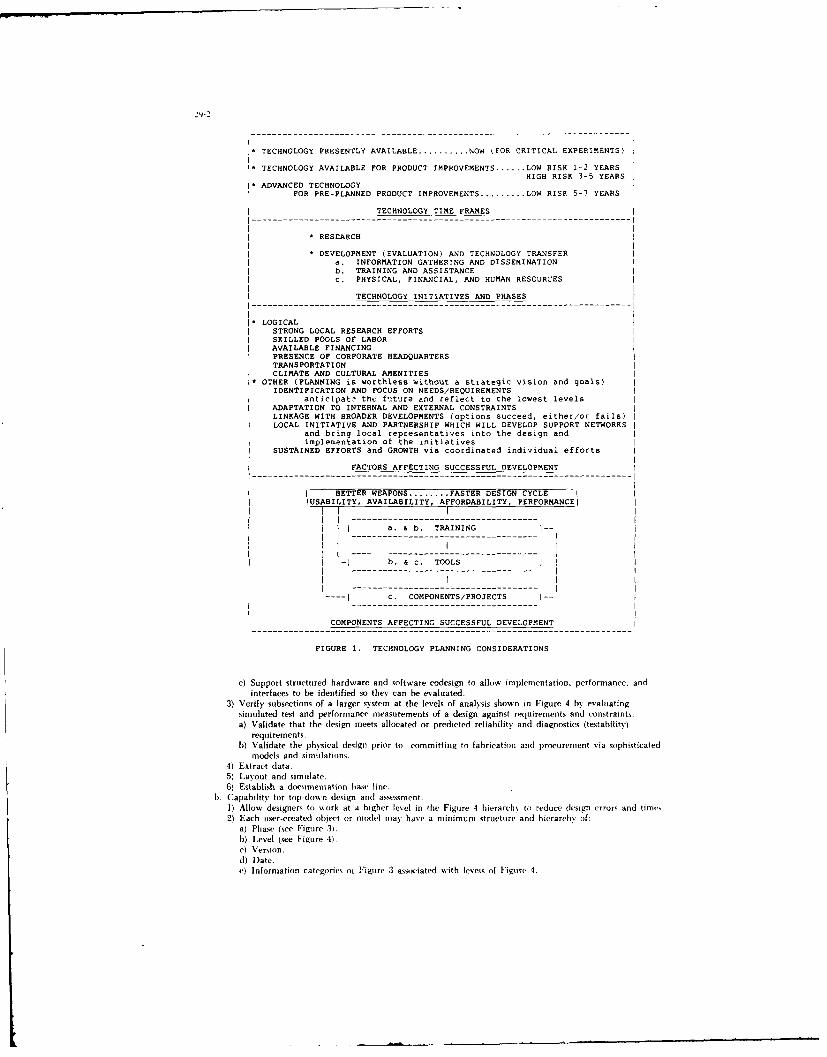
29-1
I- TECHNOLOGY PRESENTLY AVAILABLE .......... NOW FOR CRITICAL EXPERIMENTS)
TECHNOLOGY AVAILABLE FOR PRODUCT IMPROVEMENTS ...... LOW RISK 1-2 YEARS
HIGH RISK 3-5 YEARS* ADVANCED TECHNOLOGY
FOR PRE-PLANNED PRODUCT IMPROVEMENTS ......... LOW RISK 5-7 YEARS
TECHNOLOGY TIME FRAMES
* RESEARCH
* DEVELOPMENT (EVALUATION) AND TECHNOLOGY TRANSFERa. INFORMATION GATHERING AND DISSEMINATIONb. TRAINING AND ASSISTANCEc. PHYSICAL, FINANCIAL, AND HUMAN RESOURCES
TECHNOLOGY INITIATIVES AND PHASES
1 LOGICALI STRONG LOCAL RESEARCH EFFORTSI SKILLED POOLS OF LABORI AVAILABLE FINANCINGI PRESENCE OF CORPORATE HEADQUARTERSI TRANSPORTATIONI CLIMATE AND CULTURAL AMENITIES1* OTHER (PLANNING is worthless without a strategic vision and goals)
IDENTIFICATION AND FOCUS ON NEEDS/REQUIREMENTSanticipat? thc f'ture and reflect to the lowest levels
ADAPTATION TO INTERNAL AND EXTERNAL CONSTRAINTSLINKAGE WITH BROADER DEVELOPMENTS (options succeed, either/or fails)LOCAL INITIATIVE AND PARTNERSHIP WHICH WILL DEVELOP SUPPORT NETWORKS
and bring local representatives into the design andimplementation of the initiatives
SUSTAINED EFFORTS and GROWTH via coordinated individual efforts
FACTORS AFFECTING SUCCESSFUL DEVELOPMENT
j BETTER WEAPONS ........ FASTER DESIGN CYCLE IIUSABILITY, AVAILABILITY, AFFORDABILITY, PERFORMANCEi
I 1 a. & b. TRAININGI I i
I II -J b. & C. TOOLS
-----------------------------------------
c. COMPONENTS/PROJECTS --
COMPONENTS AFFECTING SUCCESSFUL DEVELOPMENT
FIGURE 1. TECHNOLOGY PLANNING CONSIDERATIONS
c) Support structured hardware and software codesign to allow implementation, performance. andinterfaces to be identified so they can be evaluated.
3) Verify subsections of a larger system at the levels of analysis shown in Figure 4 by evaluatingsimulated test and performance measurements of a design against requirements and constraints.
a) Validate that the design meets allocated or predicted reliability and diagnostics (testability)
requirements.b) Validate the physical design prior to committing to fabrication and procurement via sophisticated
models and simulations.41 Extract data.5) Layout and simulate.6) Establish a documentation base line.
b. Capability for top-down design and assessment.1) Allow designers to swork at a higher level in the Figure 4 hierarchy to reduce design errors and times.2) Each user-created object or model may have a minimum structure and hierarchy if:
a) Phase (see Figure 3).b) Level (see Figure 4).c) Version.d) Date.e) Information categories oi Figure 3 associated with leveis of Figure 4.

MISSION-SPECIFIC ENVIRONMENTS I
I MULTI-SYSTEMS7 7 _BOARD-S IISYSTEMS <->I 1<.> DEVICES II SUBSYSTEMS I CORE I CHIPS
________ MODULES TECHNOLOGY CELLS ______
I __________ IENVIRONMENT _______I
I INFORMATION \ TO SUPPORT NAVY ACQUISITION PROGRAMSNI \ACQUISITION \ AND SYSTEM LIFE CYCLE PHASES
I IIConcept I I Production II JINFORMATION IExplorationlDemonstration j--- >Deployment I
I ICATEGORIES I I and IFull-Scale I---- >Support II ________I ______I Validation IDevelopmentl --- >Redesignl
I ECHNICAL I _____ _____ _____ ____\ION-TECNNICAL______I______I_______
FIGURE 2. SYSTEMS ACQUISITION ENVIRONMENT
\INFORMATION \SYSTEM LIFE CYCLE PHASES
I EECTRONIC I Concept I [IodctII I DESIGN jExplorationlDemonatration I--- >DeploymentI
I IDATABASE II and IFull-Scale I---- >Support II ICATEGORIES I _____I Validation jDevelopment) --- >Redesignl
a. I IConnectivityl 1 1 2 1 3 1 4
b. I State 1 1 1 2 1 3 1 4
C.~ I ModelS 1I 1 2 1 3 1 4
d. i Ifelations 1I 1 2 1 3 1I
I Quali.ty i I I Ie. I [Assurance 1 1 1 2 1 3 1 4
I I Mate-r aiB _/IIf. I jProcesses 1 1 1 2 1 3 1 4
1\ IY-esting/ I - 1 - 1 1 19 ITestability 1 1 1 2 I 3 1 4
Classes of models in the system life-cycle model correspond to the numbersin the table below. The classes are defined as good enough for:
1) Research and concept exploration.2) Schematic and limited analysis to build a prototype that will
function correctly.3) Analysis in the hierarchy of Figure 4.4) Safe use, reliable operation, and affordable maintenance of the
product by the Fleet.
FIGURE 3. SYSTEMS ACQUISITION PHASES
c. Capability for bottom-tip implementation:1) Determine consistency and completeness of information transmitted between groups working on a
partitioned design or between levels of a design:a) Requirements.b) Specifications.c) Functional performance measurements.d) Functional performance constraints.e) Algorithms, test vectors, and diagrams.f) Hardware/software architectures.g) Information categories of Figure 3 and 4.
2) Verify the design as it progressews incrementally from one level to the next in the design hierarchy; Orfrom one phase to the next in the life cycle through:a) Control and verification of the configuration to reduce errors throughout the design cycle.b) Design databaseldocumentation detailing the original design and its history to facilitate
refabrication, redesign, and maintenance of the configuration.c) Incremental verification of the completed design against the design database elements of Figures 2
and 3, and the levels of Figure 4 by controls and measurements of what:1. Checks have been done.2. Constraints hnave been met.

2L-4
I'\ \ \ ANALYSISSYSTEMS HIERARCHY \ \ HIERARCHY \
IINFORMATION/ 1 1 Ii
DATABASE I HARDWARE I SOFTWARE i ANALYSISLEVELS I LEVELS I LEVELS I LEVEL!
a.) Schemata iMulti-SystemS Environments I IBehavior II~~~~~~~~ ______I__________________ I I_____
b.1 Libraries ISystems iOperating Systems I Algorithm II I !
c. I IEncyclopediaslSubsystems High-Level Languages i ArchitectureI ~ I I I______ I_______ I ________
d.I 1Dictionaries JPC Boards SAssembly Languages IBlock/I Modules, HybridsIMacrocodes I Function
I _______I ________I __________It (____ I
e. Books/RecordsIDiscrete Device I Microcodes I Logic/Families IPackaged ICs I I Circuit
f. i fields - Chips i Fields I IStructure/ 1IMacrocells I I Geometry I
I lRegisters I I I
g.\ iC-eIIs Gates iits I ProcedureI lCells i i Process
I \ INTERFACES \ \h.I \ \_ __
[ ITranslators/ ]Channels I [ I\ Formats, i.e.,Bus Interfaces, jCompilers I Diagnostics/\ Neutral file, {i.e., Optical orjReverse Compilers I ]Tests/ I\jIntermediate iVHSIC PI Bus I I IMeasurementslI -------------- i ---------------- I ------------------ I I------------
1) Information translators will be based on:a) IGES/PDES for graphic information.b) VHDL and EDIF foL non-graphic information.
FIGURE 4. INTERFACES OF THE ELECTRONIC SYSTEMS AND ANALYSIS HIERARCHIES
CAD/CAM/CAE IMPLEMENTATION PROBLEMS, DIFFERENT LEVELS, DIFFERENT NEEDS
Not only are modern electronic designs impossible to accomplish without desig.i automation tools butengineers in government and industry are faced with ever increasing design times because of increased complexitycaused by miniaturization. For example, approximately 5 Gbytes of design data are required to describe a300K-transistor device such as Motorola's 68030 microprocessor. The number of primitives we can put on a siliconchip is presently growing at an exponential rate. Integrated circuits containing over two million transistors are onthe drawing board: their macros are under fabrication. These devices are among the most complex things manhas built with large teams of researchers working on their eventual realization. Not only are very large systemscontinuing to shrink, but a complexity corresponding to neural network structures of the brain is rapidly beingapproached. These devices are multi-systems and are every bit as complex as the number of devices they containimplies. Thus, it is painfully obvious to design engineers at the lower levels that complex design, development.and product integration may only be accomplished within a reasonable time by off-loading the mundane, time-consuming, "stupid" tasks to computers. This is at a lower level than Artificial Intelligence (Al) activities whichare focused on the next level up of adding more intelligence to computer tools. The thrust of this next level up isto off-load tasks such as design or electrical rule checks that require some intelligence buried in the design tool ordatabase so that the computer may act as a design assistant. The next step-up front this is to specify openarchitecture CAD/CAM/CAE systems that will allow for the integration of multiple vendor tools with an eyetoward full implementation of AI tools.
SATISFY FRONT-END ACTIVITY NEEDS FIRST. FOR THE HIGHEST PAYOFF
The Computer-aided software engineering environment has developed data which shows that the earliererrors are found, the cheaper it is to correct them: the cost of correcting errors grows rapidly with time. Thisprinciple requires designs be -- un through the mill" as early as possible for their evaluation. The lesson here is tosupport a thorough understanding and evaluation of the system development ,r life cycle phases.shown in Figure4, and target maximum investment in the early phases of development for maximum payoff.
THE U.S. NAVY'S APPROACH TO CAD/CAM DESIGN AUTOMATION
The Navy has been implementing a three-phased strategy to provide its workers with state-of-the-art. cost-effective CAD/CAM tools to achieve a better-engineered, more maintainabie product than ever before and tosatisfy its front-end ieeds.

PHASE ONE-THE FIRST ACQUISt FION
The Navy embarked on the first phase of its design automation strategy in 1981 with a Nay-widecentralized procurement known as CAEDOS (Comput_: Aided Engineering Documentation System). Thisacquisition was a 99.9 million dollar contract from 1981 to run through the middle of 1988 and provided aminimal number of CAE systems to a small portion of the Navy. The major problems encountered in thisintroduction of design automation in 1981 were not technical, but were related to the nature of people; theywere asked to accept and embrace something new. This new technology was sophisticated. complex, and difficultto use without extensive training It was a new way to do a job and required technical guidance, extensiv"training and motivation on the part of the users to get involved in doing their jobs better by making use of thisadvanced technology. It was embraced by those who had a desire to do something new and better. Whether ornot it was successful depends on your point of view. The CAEDOS acquisition demonstrated the viability of acenttljized .ontract vehicle for activities to buy state-of-the-art technology at significant price reductions but itdidn't solve the problem of what, how and where to obtain tecic.'cal guidance in effective application of newtechnology. Technology education and acceptance are separate prob,, ns. The problems are the same onesAmerican education has today, how to effectively train and motivate people to do their best. There areindications that some CAEDOS assets are falling into disuse today due in most part to the fact they. have beensurpassed by technology which is cheap to obtain and much easier to use. In isolated cases the lack of economiesof production have caused these assets to fall into disuse. Adequate individual training and technical guidance inapplications is a continuing problem which is being addressed in the second acquisition specification by requiringbuilt in features to address these needs.
PHASE TWO-THE SECOND ACQUISITIO'"
The Navy is presently looking at benchmarks for evaluating what to procure for its CAD/CAM secondacquisition. This second acquisition is an ambitious effort which has a user developed specification that wasreleased by the Navy to industry early in 1986. The proposed systems are to provide cost effective, commerciallyavailable, non-developmental, tools to:
a. Shorten the design cycle.b. Promote better, less expensive designs:
1) Build in reliability, maintainability, and availability of equipment in the design process itself:structured design is a feature of the tool set.
2) Manage configuration over a product's life cycle for early design capture with self documenting andinstruction features built into the tools to attract and train users in a natural, friendly environment.
The hardware and proposed software tool sets in the specification are vertically integrated within five awardbands defined by NAVSEA, NAVAIR, NAVSUP, NAVFAC, and SPAWAR. The specification identifies anddefines the hardware components shown in Figure 5, linked through a local area network also defined in thespecification. An open architecture analogous to Figure 2, consisting of core functions common to the differentNavy Systems Commands with mission specific-software on top of this core, is being stressed.
Once the technical hurdle of identifying the systems to do the defined tasks has been accomplished, somefigure of merit to measure the cost benefits must be "bottom-lined." Let's compare a production-oriented privatecorporation against a design-oriented government agency to investigate the development of a quantifiable figure-of-merit with some common ground in this spectrum.
A private company derives economies of production in an integrated design, manufacturing, marketing andservice environment. The design engineers in the private sector are more likely to be tightly coupled with theproduction engineers, salesmen, and service technicians and the desired result is a producible more maintainabledesign; competition forces industry to *design to production and customer satisfaction." The mass-producedcomponent rolls off the assembly line with quantifiable regularity or the team established to maintain the productline doesn't have a job.
In contrast is the design that never appears (with emphasis on appears) to go anywhere. The output isnothing more than a design database which describes a design and is commonly - led a drawing package.Drawing packages are classifie :nto levels roughly corresponding to their completeness (system phases) and, orverified accuracy; level 3 drawings follow many standard conventions and invariably require the services of acompetent draftsman who understands these standards. The element of enlightenment that often escapes thereviewer of a design database or drawing package is the technology required to get that "intermediate" output.Yes, a design database (commonly a digital database) is nothing more than a'n intermediate form-as vet annon-quantifiable product. It is the culmination of the research, engineering prototype, or engineering developmentphase required to describe the product to be produced. In many firms and government agencies this intermediateform has been the end-product. In firms specializing in design database development, obsolete CADCAM/CAEsystems become nothing more than 2-D automated drafting tools to offset the costs associated with their purchase.Productivity has been measured on near-term investment return rather than against a more reliable.maintainable, or available design which can be verified through sophisticated simulations of the product beforefunds are committed to production.

29-6
LAN
SERVERS WORKSTATIONS
DATA BASE ---------
FILE--------------I.------ TYPE 1
PERIPHERAL ....- II.---- TYPE 2
COMMUNICATIONS --- II ----- -TYPE 3
ARRAY PROCESSOR--
VECTOR PROCESSOR--I
SPECIAL-----------I
COMPUTE-----------
DNC ---------------
CORPORATE CORE TECHNOLOGY LABS I MISSION-SPECIFIC SPECIALIZED LABS
ITYPE -_____ I I ____
ILEVEL __-____ ___
TYPE-I
LEVEL2I_ _
TYPE -I
LEVEL-I
FIGURE 5. OPEN ARCHITECTURE OF THE NAVY'S CAD/CAM SECOND ACQUISITION
TRANSFER TECHNOLOGY GRACEFULLY
The Second Acquisition plans to provide hardware and software deliverables which will be the leading edgeof technology. The specification looks into the near future and reflects this future to the needs at the lowest levelsof design tasks. The document is unparalleled in private industry because it provides a cohesive view of thedirection automation is heading from diverse viewpoints. It calls for a full spectrum of vertically integrated designtools in mission spectra which correspond to the Navy's Systems Commands yet has a common core upon whichto build these diverse applications. The inputs from industry were used to help wale the document to reality sothat the CAD'CAM systems to be benchmarked in 1987 will in fact be the yet-to-be-announced productsscheduled for release in 1988 or the leading edge products.
These leading edge tools must be phased into tasks for which they are appropriate and will give the highestpayoff. There will be problems of introduction and careful nurturing of the user base will be necessary duringtheir infancy in 1988. The CAD/CAM tools will be in danger of falling into disuse as a result of lack ofunderstanding their power or full-function capabilities, particularly in reducing costs of designing to productionconstraints. History has shown that centralized procurements fail when the user base is not represented.Fragmented procurements result in a fragmentation of common database information and a fragmentation ofdesign principles. This exacerbates "islands of information" problems even within single activities. A structuredapproach must be pursued to allow-a standardization of communications and design principles resulting inmaximum utilization of shared resources, including peripherals and design data.
FUNNELING TECHNOLOGY
There are two steps to the approach to injecting CAD/CAM technology within the context of the SecondAcquisition. The objective of the first step is to le* a separate contract award for each Systems Command as apart of the Second Acquisition. To perform this task in a coordinated fashion requires a dedicated TechnologyOffice within each Systems Command to address technology issues specific to the different missions.

T he rbjectis e of the seconid step of the Seconid Acqiitioni is to pros idc sthat is called 'teclitioloi!' ri-shth rouigh centralized griidaaice aiid expertise, "Refresh" adldresses cx lairilg the u1Sef iii e,. ajppo iri atei es alid]as ailabilit% of C AD CAM techniologs as it ex iis e ill pris ate indust rv aid is readx to he used ito sr ,i Nas%probles ap~plicable toi its k"rge user base. This requires in-depth kniissledge of design efforts th rouighiout theNax -c N ith particuliar attention beirig paid to the mrethiodologies and design techniques being~ applied in fieldagencies, and a technologN group attuned tI cx olinrg requliremtents and sollitig real probtlemis. M1issi iu-sl-ieiifi(
Tehnologs Offices forimed to address Secontd Acrquisitjor CAD CAM application proihlemis will becotte "ell -
%ersed in CAD. CAM procurement and iniplententation techniques and will he capable of injection of thistechnorige into their oss i organizations th rough iheir relationship arid assoi eation with private iiidulstFN othe r
acquisit ionsa nd ote -hoo)Ofcs h participants wit bin eachi office ni u't lie classified as tosli nirligistsand must be frilly cognizant of current research, protntxpe atid engineering deselopesent and iiaiiufacturingefforts at the various Na%) agencies in order to react dy~namiically to User requirements. Office persuinnel willfunnel evols ng riser reqiiirenients to industry in anl effort to fiirnish vendors advanced infoirmatiror on xc here tofocus their advanced products. Dorl ' through this type iof d~nanue infrriiation interchange will ic-linirloL% refreshtnake sense in the context of the Second Acquisition. Serving as a repository of technical infoirmation oii Nave\CAD/CAM sxstemx. the Technology Offices \%ill he looked uipoen as invalirable resources that will champirin strongcases iiade by the user base arid funnel industry standards to these sanme users it) a struictured manner. The fiullgamut froti design tir product can he addressedf thriough this highly integrated and structiired approach.
PHASE THREE-THE THIRD ACQUISITION
The Third Acquisition will take the Navy intir the next century , providing a fuly integrated CAD CAM'V CAE,%stenm for Nasv scientists. engineers. and orther ptersontnel.- The third phase for full hinur~ottal and certicalitgratirri is slated for beyond 1992 of this multi-year, three-phase effort. Total integration means a single
conuputer-aided cnvironinitschentata for accomplishing concept to product and support in all tlte engrineeringdisciplines. The goal is to have total or maximally' optinmized. integrated scstems across technical life-c.xcleappllicatioins in the Nasx tro fully initegrate bitth verticall% and horizontally, linking and crirss-linking ptrocesses.-thcrehsv establishing a ceirtrall '% cotntriolled.- cradle-to-grave warfare system model scith dist ~ihrted simu ilatiorns ofsvstenu (-urnripineitts This ciocept will evolve throrugh the efforts iii technihug,\ planning at all lex-els to pros idemiiigratioin ptaths fr r gi ierninent, academia, and indiistrN efforts.- Deselopitent oif the conepts and standardsnieeied fur exiiiut inn tri artd iinplenientatioin rif the Third Acquiisitiorn s-ill univ be atained lb% clorse cioioperationiain
1relat ionrshipus on ati in terriational scale.

Interfacing and Integrating Hardware and SoftwareDesign Systems
Daniel Davis, Associate ProfessorDepartment of Computer Science
Naval Postgraduate Schooliviute.y, Ca. 93943
SummaryFundamental problems in interfacing and integrating information between diverse
design systems are examined. Specifically problems associated to the contexts ofmeaning that are required to understand information in diverse systems are examined.Increased research into a general theory of design is advocated. The resolution to sornintegration problems is suggested on the basis of recent developments and experiencewith a functional design theory.
1. Introduction.
There is now considerable technological movement towards the use of automated design systems in the design ofmechanical components of systems, in the Jesign of VLSI components, dnd in the design of software systems. Each ofthese activities have proceeded in parallel, without a great deal of coordination and cross fertilization of technologies.with the result that it is becoming increasingly difficult to establish interfaces between these systems or develop anintegrated approach to the entire system design problem.
At the same time, there are a number of ideas and principles common to the design systems being developed fordifferent technologies. Most of these systems have a means of specifying the requirements of the design, all have somemeans of describing the components of a design, and all have some means of describing designs in terms ofcomponents. Some systems use the technology of expert systems to aid in the design process. There are a variety ofuser interfaces to the information in these systems, so-called views. Some views are oriented to the designer, some tothe system design management process, and some to the manufacturing or implementation process. The requirementfor multiple views or multiple interfaces within a single system is being generally acknowledged as an importantconcept.
Yet the possibilities of developing and integrating these diverse systems into a single system still seems remote,and fortunately, may be undesirable at the present time. Close coupling between divwrse technologies could seriouslyimpede progress in any one of them. At the same time, there is a need for some coupling. There is a classical tradeoffhere. Should a system be integrated so that it optimizes the interaction of information among all those who know it.but forces the user to express himself in limited ways, or should there be a variety of expressions, and thus increaseexpressivity of individual environments, but correspondingly decrease the communication between them?
A middle solution lies in providing means for standardizing the interface methodology between a variety ofsystems. As a first step, it would be an improvement if we could develop a means of uniformly relating informationin one type of environment to information in other environments. This would provide a means of transmittinginformation from one environment to another in a systematic manner. The problem of doing this is similar to theproblem of having a standard internal representation of information, for which multiple views are possible, but whichestablishes a consistency between views, in a single system. These problems arise equally in mechanical. VLSI. orsoftware design systems. It is the information capture problem.
There is another issue here. Up to the present time, system design, in each of the technological areas in which itis expressed, has not had a theoretical basis. It is in the same state as other disciplines in an early stage; a collection oftechniques, tools, and unformulated processes in the minds of users. This will probably remain an essential fact insystem design for some time to come. However, the demands of the prcblems that need to be solved, and the need forcapitalizing on previous efforts create a need for formulating established principles and techniques. Such a process isone toward greater generality and abstraction, a d ultimately leads to a better understanding of the processes themselves.
The primary objective of this paper is to describe a limited methodology for describing system functional design

311-2
information independently of the technology used to realize the design. That is, in terms of what', rather than 'how'.This methodology can be used to establish interfaces between various design environments by establishing a way of
describing design information independently of its technological idiosyncrasies. In some sense, it provides amethodology for describing a view of a design component in terms of its interface to the outside, without regard to howits properties are achieved. Equivalently, it provides a means for modeling and manipulating design elements abstractly.Yet it is also general enough and precise enough to describe specific technological properties of design elements whenrequired. An important feature of this methodology is that it has a rigorous theoretical basis. This is a feature we feelis lacking in many existing approaches to design. Also this paper is a report on work in progress toward the goal ofachieving true 'resource abstraction'; the goal of describing and designing systems in formal terms, so that designproblems can be solved in principle, not just in terms of a current technology.
In the following, we establish the background of issues and ideas, then introduce the general principle of functionalabstraction . and then a specific theory of resource abstraction. Next we illustrate these ideas with a simple example.and conclude with some remarks on future directions.
2. Background.
The primary reason that it is difficult to develop interfaces between different design systems is for the same reasonthat it is difficult to develop interfaces between any two computing systems. There are few standard methods fordescribing general information. Even the simplest types of information, such as a yes/no answer to a question has noconsistent representation in a computer. We must begin with this fundamental problem if we intend to establishinterfaces between a variety of systems.
In spite of the fact that there are ISO and IEEE efforts to standardize many aspects of the design process, such asADA, VHDL (VHSIC Hardware Description Language), EDIC (Electronic Design Interface Format), IGES (InitialGraphics Exchange Standard) and PDES (Product Description Exchange Standard), it is neither necessary, nor is itpractical, to expect that universal standards could be formulated and enforced across a wide spectrum of design activities.Although standards can be imposed successfully witihin a limited context, experience has shown that broad standardsare generally unenforceable and tend to const:an the free development of technologies and ideas. System design is inan early stage of development, and it would be premature to fix on immature concepts or principles. On the other hand,total chaos is also counterproductive to our ability to capitalize on knowledge in one domain by applying a similarknowledge in other domains. This is the problem that is already manifesting itself today. The solution is to find somereasonable middle ground. This middle ground must be based on something that is fundamental to all design systems.We need to view the processes of design in abstract terms and synthesize elements of the process as practiced in itsvarious contexts.
All design systems presuppose a collection of elements that are combined to form a design. A design establishes ajuxtaposition of and interrelations between these elemental components to achieve a desired result. Design is inherentlyhiearchical, in tl- it the result of design at one level can become elemental components at another level. The propertiesof the design follow in some complex way from the properties of the elemental components and the way that thesecomponents are combined. The hierarchical nature of design also reflects the fact that our primary strategy for handlingcomplexity is divide and conquer.
In some cases, design elements are physical abstractions that represent some material object. In other cases theyare functional abstractions that represent constructs from mathematics or a field of engineering. Some of the aspectsof the process of design represent temporal properties of the sytem as opposed to static properties. In fact, it is a safegeneralization to say that all design systems have physical, functional, and temporal dimensions. A design consists inelaborating a hierarchy of components that are interrelated in each of these dimensions and combine to create a complexresource. At our present state of knowledge, a unified theory that can handle all these dimensions is too much toexpect.
In practical situations, there is usually a great deal of information about design components that is assumed by thedesigner as part of general knowledge of a technology. This information about components is not expressed in thesystem, and may be only vaguely understood by its users. In most cases, users must expend a considerable effort justto learn the context necessary to use a particular system. This is one fact that makes the interfacing and integration ofdesign systems so difficult. In order to pass information from one system to another, or even one part of a system toanother part, we have to have some confidence that the information -; meaningful. This is the 'semantic gap'problem. There is a gap between what a design component is in the system and what it is in the mind ot a user. At thecurrent state of the art. the designer bears the burden for this discrepency and may have little or no automatedassistance. Even if the system has means for capturing the meaning of a descnption in the system, such as some rule

based reasoning, it is still difficult to export this information to another system because its meaning requires the propercontext. We can illustrate the problem with a simple analogy.
Suppose I type an English language definition of a design into an editor using ASCII characters. In this case, thedesign information is encoded into bits in a file. Not only is there a great deal of information that this design mayexpress that is not in the rile, unless I know that the data is expressed in ASCII, even its meaning as characters cannotbe communicated. If I did not know it was in English, another essential context for its meaning would be missingalso. Stated more generally, data by itself is always meaningless. It is data within a context that has meaning. In thefunctional perspective, the functions that can be applied to the data determine to large extent the meaning of the data.
A simplistic solution to the problem of exchanging information is to esablish a universal standard for tneinformation; effectively create a universal context of meaning. In the above example, if there is a universal standardthat tells me that data is in ASCII, I can get at the information it contains. If I know that the character information isVHDL or ADA. I can get more information out of it, since I can apply a larger context of meaning to it, if this contextis known to me. However as we remarked before, this seems to be a hopeless, and even undesirable, approach in thecase of design systems. Much of the context of meaning of a particular design environment is known only to usersfamiliar with it. A more modest approach is to provide a methodology for establishing, along with the information.the context of meaning required to understand it. In very practical form and in a limited manner, this concept hasalready proven its use on the Macintosh system I am using to type this paper. First the system assumes some widelyknown context of meaning necessary to perform an activity. For example typing text on a regular typewriter is suchan activity. Such a known activity is called a metaphor. Then the system attempts to recreate that activity in amanner consistent with the metaphor. The environment required to display the character data and manipulate it, that is,the aggregate of functions used to edit and display the characters in these sentences, creates the metaphor and is storedwith the textual data. Whenever the textual data is loaded, its context is assembled and also loaded. The aggregate offunctions used to manipulate the data, to create its context. is called its resources. The resources establish themeaning of the data. More precisely, the resources establish a bridge to the context of meaning. It is the data within thecontext of the functions that has meaning. This is a simple, yet powerful concept. In the following sections we willdescribe a similar approach to the description of design information that seems broadly applicable to the functionaldimension of design.
3. Abstract Functional Resources
There is a growing body of research in the areas of programming linguistics and software engineering, thatsuggests a method for resolving some of the difficulties discussed above (Refs. 1, 2, 3, 4.5). This research has grownout of efforts to design components within programming languages, and subsequently, within general software systems.It is usually called the theory of abstract data types, although at the present time, there is no single theory but rather amethodology that is evolving to handle design complexity in software systems.
There has been a realization in software design that we are continually re-implementing the same functionalresources within a variety of environments (Ref. 6.) For example, the part of a software system that accesses filesstored on a disk always includes functions to create, open, close, read, and write files. Software systems may performthese functions in a variety of ways, but in some abstract sense, they all perform the same functions. Substantialportions of software system design consists in defining a hierarchy of functional interfaces of greater and greaterabstraction. At any level it is aggregates of functions thata define the resource. For example, the file functions aboveare useful only as an aggregate. Any one, without the others, is meaningless. We will call such a functionalaggregate, together with the types of data it manipulates, a resource. Resources are the elements of functional design.In software system deiign, we would like to have a way to precisely describe resources abstractly, without regard to the
specific programming language, operating system, or hardware used to realize them. We also wish to establish theways in which resources combine to create more complex resources. We would like to describe the essence of theseoperations in a manner that allows us to reason about them consistently. This would be a step toward a true designtheory for the functional dimension of systems design. The primary problem to be solved is how to associate meaningto a formal description of a resource. How do we insure that every user of the design specification interprets itsmeaning in the same way? Also, if we wish to aid the designer with automated tools of reasoning, we must be surethat the tools manipulate the specification in meaningful ways. This is the problem of specification or descriptionsemantics. These same problems arise in any attempt to develop an automated design system, and in any attempt tointerface or integrate systems. It seems that the greatest progress in this direction is associated to the theory of abstractdata types.
There are several features in this theory that may contribute to the general problem of integrating and interfacingdesign systems:

30-4
Firsdy, the approach begins with an attempt to solve the semantic problem for design components. Not only isthere a discipline of how to go about designing components, there are theories associated to the process of descriptionthat provide rigorous meaning to design components. This means it is possible to automate much of the reasoningabout components in a way that is faithful to the model in the mind of the designer.
Secondly, the methodology seems to be very general. Although, it started out as a method to be used for softwarefunctional design and has its origins in programming linguistics, experiments indicate it can be used for the functionaldesign of hardware.(Ref. 7, 8, 9,). Since it has crossed these boundaries, it holds some promise as a basis forinterfacing between them.
Thirdly, it is an abstract methodology. It naturally provides a method of design that is independent of particulartechnologies uf impiementaion. In software, this means that the language of implementation is not a necessary issueduring design, and for hardware, it means that the manufacturing technology is not a necessary issue of design. At thesame time, it allows issues of implementation to be made issues of design, to any reasonable degree. In practice themethodology reflects the fact that abstract objects are simpler and more rarefied and thus easier to define, while objectsused for implementation are more complex, and therefore more difficult to define. Hence, if a methodology is used thatforces us to define objects precisely, there will be a bias towards defining them in their most essential, abstract, andthus simplest terms.
At the present time, the theoretical work on abstract data types has been focused on describing components strictlyin terms of the functions they perform. There has been less work on describing the temporal properties of systemcomponents. The physical properties of components, such as size, power reqirements, material properties, etc. haveyet to be addressed by this theory.
This theory is hierarchical in nature. Design components can be described in terms of more primitive components.Fundamentally, a resource is described by listing the names of the operand types it requires, and the operations(functions) that are available in the resource to manipulate values of these types. As we have indicated, the descriptionis a purely functional one. Each operation has a fiLxed number of operands, with fixed types, and a fixed return type.The operations generally include functions that generate the primary values of each operand type (constant functions).This description of the resource defines the primary functional interface to the resource. Additional parts of a resourcespecification describe the properties of the resource, and ultimately define the actual meaning of the resource byapplication of an associated semantic theory. In other words, the semantic theory can be used to systematicallydetermine which 'real' objects provide implementations of the resource defined in the specification. Error conditions canalso be defined in the specification of properties. Although much of the flavor of this approach is influenced by itsdevelopment from software design, since software is fundamentally abstract , the method is also suited for expressinggeneral functional resource notions.
4. Resource Specifications
In the following, we will take a brief look at the form of the resource specification methodology. A morecomplete treatment can be found in the literature (e. g. Refs. 1, 3, 4, 10). The actual syntax for specifications is notstandardized, although most variations are relatively minor.
Resource objects are described in two parts. The first pars is the syntactic pan, which is used to describe a form
that the resource can take. The second part, the semantic pars, is implied by the syntactic part.
A form for the syntactic part is:
Resource [Resource name] is:
Operand Types:[Operand type set]
Operators:(Operator specification set]
Properties:[Property specification set]

30-5
The operand set is simply an unordered list of names for the operand types of this resource. The operatorspecification set is an unordered list of the names of the operators together with a description of the number and types of
their operands and resulL The property specification list is a list of properties satisfied by the operators.
For the purposes of illustration, consider the following example of a resource specification for the yes/no resource.
Resource Boolean is:
Operand Types:Bool
Operators:True: -> Bool,False: -> BoolNot: Bool -> BoolAnd: Bool, Bool -> Bool
Properties:Not(TrueO) = FalseO.Not(Not(b)) = b,And(TrueO, b) = b,And(False0.b) = FalseO
Note that constants, such as True, and False above, are represented as nullary operators (or equivalently, constantfunctions).
The fundamental idea of a resource specification is not that the actual resource has the exact form given in thespecification, but that in essence, it achieves an equivalent functionality. This is stated precisely in the accompanyingsemantics of specifications, i.e., what is meant by the above syntax. Without going into the semantics in detail, let usjust remark that it is a consequence of the semantic theory associated to such specifications, that any renaming of theabove operands or operators above, or any replacement of the operators by equivalent primitives, such as 'not' and'implies', or any replacement of the axioms by other mathematically equivalent ones, would have the same meaning.Thus the specification above is only one of many descriptions that denotes the same abstract resource. And equally.the abstract resource has many equivalent realizations, or implementations. In this sense then, the resource descriptionis a way of capturing the abstract' essence of the resource.
Boolean is a primitive resource. It is not built up of more primitive elements. It is atomic. Specifications canalso be built up hierarchically. To illustrate, consider a functional specification for a stack resource that can holdboolean values:
Resource Boolean-Stack is:
Extend Boolean with:
Operands:
Stk, Bool.
Operators:
Mtstk: -> StkPush: Bool, Stk -> Stk,Pop: Stk -> Stk,Top: Stk -> Bool,
Properties:
Top(Push(b, s)) = bPop(Push(b, s)) = s
Undeined(Top(MtstkO))Undefined(Pop(MtstkO))

-- -- 5,
30-(,
The extend directive can be interpreted as: "include and expand the named specification to include the followingoperands, operators, and properties." Of course, when a resource is included as pan of a larger resource, in the contextof the larger resource, its properties could change. In the above example, without an examination of the properties ofBooleanStack, we can't be absolutely sure that we haven't altered the properties of Boolean, as given in itsspecification. (In fact, in this example, it isn't difficult to check.) A resource whose properties remain unchangedwithin a larger context is said to be 'persistent' in that context. The semantics associated to specifications provides asystematic way to check for persistence and exemplifies, in one instance, the importance of rigor.
Note that whenever a resource is specified operations in addition to the given ones are implied by combinations of
the given ones. For example, considering only the Boolean resource, we can form expressions such as:
And(Not(TreO), Not(And(TrueO, FalseO)))
In general, an infinite number of such expressions are possible. We call such combinations 'formal expressions',or 'formal terms'. A formal grammar can be written for these formal expressions as follows:
<BoolTerm> -> TrueO IFalseO INot(<BoolTerm>)lAnd(<BoolTerm>,<BoolTerm>)
Similarly, the Stack resource allows us to create more expressions in addition to these using the expressions fromthe Boolean resource. For example, if v1, v2.... vn are Boolean expressions, then the following expressions illustrate
formal terms from the Stack resource.
Push(v 6 ,Push(vi,Pop(Push(vI ,Push(v5 , Mtstko)))))
Push(Top(Push(v 1 ,Push(v 3 ,MtstkO))), Push(v 2 ,Mtstko)
A formal LL(1) grammar can be written for these additional terms by extending the above grammar as follows:
<Term> -> <BoolTerm> I<StkTerm>
<BoolTerm> -> Top( <Stk Term>)
<Stk Term> -> Mtstko IPush(< BoolTerm> , <Stk Term>) IPop(<Stk Term>)
Thus the problem of recognizing and generating all correct formal terms given an arbitrary specification isstraightforward. Note we require that there is at least one constant term (nullary term) of each operand type. For exampleTrueo and Mtstko are the constants for Bool and Stk. Note also how formal expressions are created on top of theexpressions that we already have and that there are formal terms for each type of operand.
Just as the operator list is a finite list from which we can create an infinite number of operations, the property listis a finite list from which we can induce an infinite number of properties, which are in fact, relations betweenoperations. Properties effectively specify which operations have an equivalent result. The precise rules for deducingsuch relations between formal terms are determined by the semantics. Although, this may seem to be a simple matter,it is a more difficult problem than it appears.
In Refs /, 8. 9, 10 these methods for describing and specifying system components were applied to the design ofan abstract processor, including data values, memory, and instructions. Subsequently, the same methods were appliedto the design of an abstract display device, and database. All these specifications are of course functional. Also, theyare hierarchical. The abstract processor design has approximately a dozen levels and hundreds of individual functions.And just as in a resource, a function by itself may not have meaning, the meaning of a complex resource cannot beseparated I"om its components. Another significant feature of these designs is that they are equally applicable tosoftware and hardware. In fact, the abstact processor design has been implemented in software (Ref. 10). We can nowclarify how it is possible to establish the context of meaning required to understand information about a particular partof a design, without requiring a standard means of expression.

30-7
In the designs that use the methodology just described , the meaning of "y part of the design is determinedprecisely by two factors. Firstly, there is the general semantics that is part of the context of the specificationmethodology itself. Secondly, there is the context of elements in the specification that are specifically related to theelement of interest. One is the universal context of meaning that is to be applied. The other is the private context ofmeaning that is relevant to a particular item in the context of its design. In the abstract processor design referencedabove, the context of meaning for a specific machine instruction or feature of the processor, can be rigorouslydetermined. With this type of approach to the description of design elements, the contexts that are necessary to establishthe meaning of any information in the design can be readily determined. Yet, there is no standard representation of anyparticular element in the design. (For example, the Boolean resource may have been represented differently). I iere isalso no standard way that elements must be combined. (Different elements may be combined in many ways to achievethe same functional result). Yet, we have indicated that there can be a standard methodology of description andsemantics that allows us to determine the meaning of something no matter how it is expiessed. it is this kind olapproach to the problems of design system integration and interfacing that we are suggesting.
Another way of expressing the same result, is that there need to be standardized methodologies crossing systemdesign boundaries that provide a capability for systematically understanding design information from one system insideanother, even though the two systems may support different views, and different technologies of design.
5. Concluding Remarks.
We have raised a number of points that relate to the problems of interfacing or integrating a variety of designsystLms. The semantic issue includes the problems that arise when there is a gap between what a component is in asystem compared to what it is in the mind of a user of the system. Interface difficulties will remain as long as serioussemantic gaps remain. We have suggested that the meaning of information in a design system can be represented tosome extent in the system, but always includes elements in a broader context of meaning. We have also suggested thatuniversal standards of description for design information seem premature, although some methodological standards maybe possible. In particular, a standardized semantic methodology for design descriptions that crosses system boundariesseems to be a reasonable alternative. In general, greater attention to issues of semantics and contexts of meaning seemwarranted.
For the functional dimension of design, we have indicated the importance of the concept of a resource. We havealso suggested that a theoretical basis for a general theory of functional design that can cross application boundaries iswithin our grasp. Although, such a prospect seems reasonable in the functional dimension, fundamental problems inthe physical and temporal dimensions remain. There are as yet no widely accepted notions of the general meaning ofconcurrency and communication. There is certainly no acceptable semantic context for these notions, although there areseveral efforts in this directior.
Finally, we suggest that more attention be paid to fundamentals. There is an ever increasing need for broader
perspectives on the design process, and movement away from ad-hoc methods.
References
1. Goguen, J. A., Thatcher, J.W., and Wagner, E.G., " An initail algebra approach to the specification, correctness,and implementation of abstract data types.", In Current Trends in Programming Methodology IV, Data Structuring, R.T. Yeh, Ed. Prentice Hall, Englewood Cliffs, NJ., 1978, pp. 80-149
2. Bjomer, D. "Abstract Software Specification, Proc. Winter Copenhagen School, Springer Verlag, Heidelberg, 1979.
3. Ehrich, H.D.., "On the Theory of Specification, Implementation, arJ Parameterization of Abstract Data Types",JACM , Vol. 29, Nol. January, 1982, pp. 206-227.
4. Ehrig, H., Kreowski, H.J., Mahr, B., Padawitz, P. "Compound Algegraic Implementations: An Approach toStepwise Refinement of Software Systems" Symposium on Mathematical Foundations of Computer science, 9thRydzyna, Poland, 1980.
5.McLean, John, "A Formal Method for the Abstract Specification of Software" JACM, Vol. 31, No3. July, 1984,pp.600-627
6. Wegner, Peter, "Reflections on Capital Intensive Software Technology ". Software Engineering Notes, ACM Sigsoft,Vol. 7, No. 4, October, 1982.

hit
7. Yurchak, John M., "The Formal Specification of an Abstract Machine: Design and Implementation", Master'sThesis, Department of Computer Science, Naval Poatgraduate School, Dec., 1984.
8. Hunter, James E., "The Formal Specification of a Visual Display Device: Design and Implementation", Master'sThesis, Department of Computer Science, Naval Poatgraduate School, June 1985.
9. Zang, Klaus Harald, "The Formal Specification of an Abstract Database: Design and Implementation", Master'sThesis, Department of Computer Science, Naval Poatgraduate School. Dec., 1985.
10. Davis, Daniel, and Yurchak, John, "The Specification, Design and Implementation of an Abstract Processor", Procsof the 19th Asilomar Conf. on Circuits. Systems and Computer,, N'rov., 1985.
Acknowledgements
This research has been supported in part by the Naval Weapons Center, China Lake. the Naval Ocean SystemsCommand, San Diego, and the Foundation Research Program at the Naval Postgraduate School.
DISCUSSION
R.DeSipio. USIt is difficult to communicate with words because:
0 Words change meaning relative to culture, education.
* Fads come from the top; trends come from the bottom
Please comment.
Author's ReplyMethodologically, we need to acknowCldge the importance of the semantic conlexs that gis e meanig toI \\o od, anddiagrams (i.e., forms of expression). I generally agree that fads come from the top and trends from the boitom.
Successfully shared, precise semantic contexts do exist. This is what mathematics is all about. Can we deN clop soncrigorous semantic context for design (i.e.. a design science)? Would anyone adkocatc that we can do engineetngwithout mat hematics?
W.H.McKinlay, UKWhat Lan we learn from the personal qualities and styles oi successful engineers, and \%hat are the implications foreducation'!
Author's ReplyThe unquantifiable characteristics of suecessful engineers are something we really cannot seem to address. ('an we. onthe other hand, address fundamental design principles that apply broadl, and quit rediscovering them oer and oser'We can sense that such principles must exist, but w hat are they. and how can they lb expressed and become ceneralknowledge? There is still no substitute for creative engineering.
31-1
A LOOK TOWARD THE FUTURE OF COMPLEX AVIONICS SYSTEMS DEVELOPMENT USING THEUSAF TEST PILOT SCHOOL'S AVIONICS SYSTEMS TEST TRAINING AIRCRAFT
by
Major William H. Broome, Jr., USAFUSAF Test Pilot SchoolEdwards AFB, CA 93523
and
Mr. Mike ParragArvin/Caispan Corporation - Flight Research Department
Buffalo, NY 14225
SUMMARY
Two important issues exist in addressing the solutions to future avionics systemsdevelopment problems: avionics systems training for both designers and testers, and theavionics systems development process itself. The airborne avionics training andintegration laboratory, such as the USAF Test Pilot School's Avionics Systems TestTraining Aircraft (ASTTA), may be a potential remedy for some of the underlying problemsof avionics systems development.
ASTTA is a special configuration of the NC-131H Total In-flight Simulator (TIFS), andwas developed to fill a significant gap in the education and experience of the avionicssystems test community. It provides a cost-effective means of quickly exposing bothdesigners and testers to the key issues of systems development and in-flight testing,especially the operator to systems interface human factors issues. Its benign flightenvironment is conducive to both initial and advanced training in flight test techniques.
ASTTA offers exciting potential as a test bed for a large variety of research anddevelopment activities. Proof-of-concept testing is particularly attractive with minimumpackaging required of test devices and the ability to carry several oLservers and even thedesigners themselves.
INTRODUCTION
The future development of complex avionics systems is in the hands of two groups ofpeople - the designers and the testersi In the past, these groups have generallyperformed as separate entities; their viewpoints of the ultimate operational user'senvironment and functional needs have often been inaccurate. Avionics systems have beendeveloped and deployed which were unusable by the operators due to unacceptably highworkloads. Avionics systems have been rushed into testing and operational use withoutadequate functional integration and simulation with operator-in-the-loop evaluation.Though the situation is slowly improving, problems still exist. Two important issuesexist in addressing the solutions to these avionics systems development problems:avionics systems training for both designers and testers, and the avionics systemsdevelopment process itself. These issues are the focus of this paper. They are also theunderlying reasons behind the development of the USAF Test Pilot School's Avionics SystemsTest Training Aircraft (ASTTA). ASTTA will be used as an example of a tool to potentiallyremedy some of the problems in avionics systems development.
Both the designers and testers of avionics systems are often limited in the scope andbreadth of their training, knowledge, and experience. Avionics systems designers do theirwork in the serenity of their office or laboratory, with limited attention paid to thepracticalities demanded by the operational environment. Testers are equally guiltyl Thetesters are highly proficient in performance and flying qualities flight test techniques,but often lack avionics systems test training. They remember the clichg for avionicssystems testing - "you must invent your own flight test techniques." Too often they stepinto the cockpit unprepared and unawarel
The avionics systems development process itself may also be the source of a problem.Designers develop systems that work well individually and appear to integrate adequatelyon paper and in the laboratory. The fact that a human operator is part of the operationalsystem is often forgotten during the functional development of "black boxes" and luringtheir integration into a highly fliexible system. Too much flexibility can become detri-mental when it causes excessive demands on operator dexteriti and mental capacity. Thedesigns must accommodate tactical system operators working in a strenuous environment, notcomputer wizards or video game players. Often ground verification testing and functionalground simulation are quickly followed by full up flight test in the vehicle with littlcor no ground-based operator-in-the-loop integration testing. The result is a costlyfly-fix-fly schedule that progresses at a snail's pace.
The concurrent integration of the ARN-101 avionics update and the PAVE TACK weaponssystem to the USAF F-4 was an example of the type of integration problems one would liketo avoid. The simultaneous integration of these two systems to the F-4 lacked the

31-2
required integration to each other. The result was integration flight testiicg as opposedto developmental flight testing.
The F-16 Multistage Improvement Program (MSIP) with Block 25 avionics is anotherexample of a process that resulted in a system that was not tailored to th' flightenvironment and fostered operator errors. As an example, it was common for the pilot tohave changed his radio frequency inadvertently two to three times before takeoff.Consider what could happen in combat if a pilot could not transmit on the radio to hiswingman. The development of the Block 25 systems was done in system integrationlaboratories which tested only individual black boxes. The result was a pood iea poorlyimplemented and unsuitable for a production aircraft. As a result of serious I 'icienciesuncovered during flight test, it was necessary to remechanize the avionics erior trproduction (Block 251).
These two situations were the product of a process that produced an operationallyusable system only after considerable developmental problems were solvad. Consider theadvantage of adding an airborne simulation laboratory to the development process as s'i;&xin Figure 1. One ma_, see a practical advantage but question the cost ani sche 3linqaspects. To put these considerations in proper perspective, one mst evaluate thetradeoff between cost and schedule problems of isin3 sich n aiclorne testhNI vetsdevelopmental risk as shown in Figure 2.
A PIRN SIlq2aAT IN
COYJF DFS IGN Lt3ORA7pY F!t[ F -I
Figur, 1. - Avionics Systems 1c-v,,1-pment Pr 1cess
;jtIPP PPN
SLMLTIA1ION FIDE.ITY
ANDSalm tl-E AIR1OeNE SnTIAqTIGN
PARGLI' AREA
\ tLOW AIPWTRNTSIN.fiDN FIDELITY
RISK
Figure 2. - Airborne Simulat ion Fidel ity Nssessnent

31-3
The fidelity with which such an airborne simulation laboratory represents theoperational environment is also a critical concern. High fidelity of environment simula-tion (approaching 100 percent) may require an exact test vehicle which may not exist whenyou need it or may be prohibitively costly and/or schedule prohibitive. On the otherhand, a lower fidelity simulation (60 to 70 percent for argument's sake' may suffice forproof-of-concept evaluation, and integrate the operator in a relatively realisticenvironment at an early stage and for significantly lowec cost. The question is: Whatfidelity of simulation is acceptable for developmental assessment? An airborne environ-ment simulation with the knee of the curve (in Figure 2) as its target may serve as thebest compromise between risk and cost/schedule, and hence may be the best approach toproof-of-concept testing and airborne simulation.
Ultimately, the avionics zysteos p j must oe tested in the vehicle for which thepackage is being developed. However, many of the new state of the art systems are beingdeveloped for new tactical vehicles which themselves are under development. This leads toa dilemma about the timeliness of avionics systems testing in the flight test vehicle.The "build-up technique" is the classical approach to flight test of a new vehicle and itssystems. Performance, flying qualities, and clearance of the structural flight envelopeinitially take precedence over systems testing, and rightly so to some extent. However,cost and time effective development of complex avionics systems requires the interjectionof dedicated systems development test and evaluation (DT&E) and initial operational testand evaluation (IOT&E) testing earlier in the flight test sequence than has generally beenthe case.
Lack of timely operator-in-the-loop simulation and in-flight testing has caused manyavionics development scenarios to evolve as follows. First, the testers "curse" thedesigners for a system that fails to perform adequately in the airborne arena or performsadequately, but with an intolerable workload. Next, the operational users "curse" thetesters for recommending changes to the integrated system that either they do not want orwhich will not work in the operational environment, or which fails to consider theman-machine interface at the lowest common denominator - the new second lieutenant! Thedesigners retaliate with solutions to all these claims, but at the expense of themanagers' cost and schedule. The managers respond: Is it safety related? If not, forgetitl This vicious cycle continues until initial operational capability (IOC).
Until recently, few solutions have been proposed to alleviate these developmentalheadaches. About two years ago, the USAF Test Pilot School sponsored the development ofthe ASTTA training and teF. facility to help resolve some of the problems we haveoutlined. The introductin of the ASTTA facility, we submit, represents an important stepin the right direction, though not a remedy for all our avionics development problems.
ASTTA was developed primarily to fulfill the training requirements of the USAF TestPilot School in the avionics systems flight test environment, i.e., train the testers.The evclution of ASTTA concentrated on its objectives of being a familiarization,demonstration, and evaluation tool for avionics systems development for our Test PilotSchool pilots, flight test engineers, and flight test navigators.
ASTTA CAPABILITIES
ASTTA is a new configuration of the USAF Flight Dynamics Laboratory's NC-131H TotalIn-flight Simulator (TIFS) six degree of freedom variable stability aircraft which hasbeen in research and development (R&D) operation since 1971. Figure 3 shows the twodifferent configurations of the NC-131H aircraft. Calspan Corporation of Buffalo, NewYork, developed ASTTA under contract with the USAF. The ASTTA configuration has thefollowing capabilities and limitations: test airspeeds between 160 and 250 knotsindicatee airspeed (KIAS), altitudes between 500 feet above ground level (AGL) and 10,000feet mean sea level (M3L) except for landing evaluations, normal acceleration from 0 to2.5 gs, sustained turn rates of 12 degrees per second, fuel for a oominal 2 hour mission,and full instrument flight rule (IFR) capability.
ASTTA can carry five systems evaluators in addition to the two Calspan safety pilotsand systems engineer. The systems evaluation crew station, which is just aft of thepropeller line of the aircraft as shown in Figure 4, has dual seats with standard IFRflight instruments in addition to radar, infrared (IR), and inertial navigation system(INS) controls and displays. An instructor jump seat has been provided between and aft ofthe crew station seats along with two observer seats further aft in the cabin.
The avionics systems on ASTTA include the Westinghouse APG-66 digital, multimode,pulse doppler radar from the F-16A/B (Figure 5); the Texas Instruments AN/AAS-36 infrareddetecting set (IaDS) from the P-3 aircraft (Figure 6): the commercially available LittonLTN-72R INS (Figure 7); a slewable platform with a color camera which is mechanically andfunctionally interchangeable with the IRDS (Figure 8): and an interface computer withassociated software allowing the integrated operation of thes- sensors. The integratedoperation of the ASTTA sensors include the ability to slave either the radar or IRDS tothe other in the radar air-to-air mode or the ability to slave the IRDS to the radar inthe radar air-to-ground mode. The 4ndependent operation of each sensor allows concurrentside-by-side training and testing c each system.
The ASTTA multiplex (MUX) bue structure is shown in Figure 9. The Interface ControlUnit (ICU) acts as the MIL-STD 1553 data bus controller for the integrated system (Figure10). The radar digibus is the primary radar controller. At the present time, three portson the bus are not utilized and thus cnuld be used for the addition of new systems.
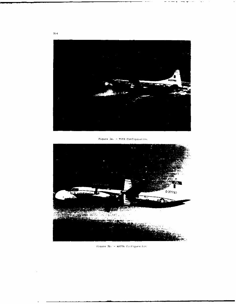
31-4
Figure 3a. -TIFS Configuration
Figure 3b. -ASTTA Configuration
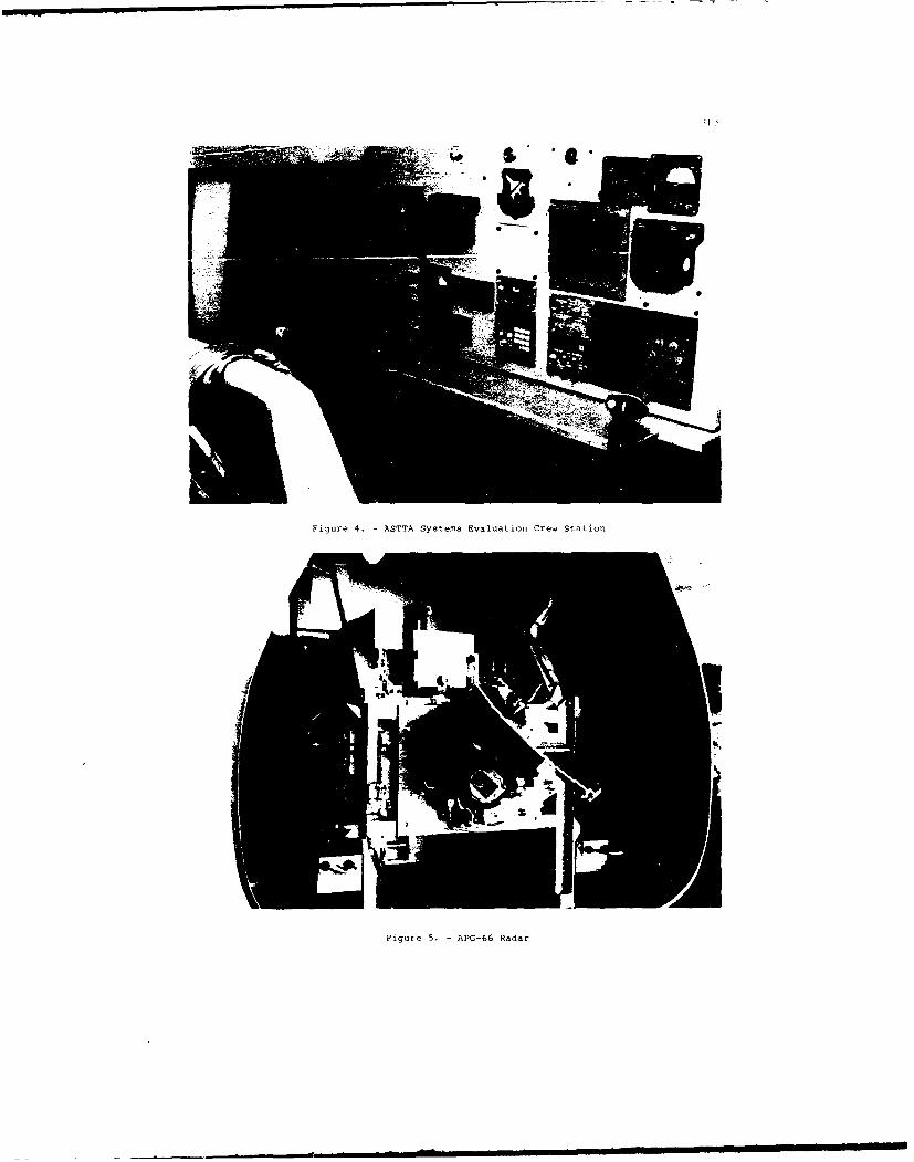
Figure 4. -ASTTA Systems Evaluation Crew Station
Figure 5. -APG-66 Radar
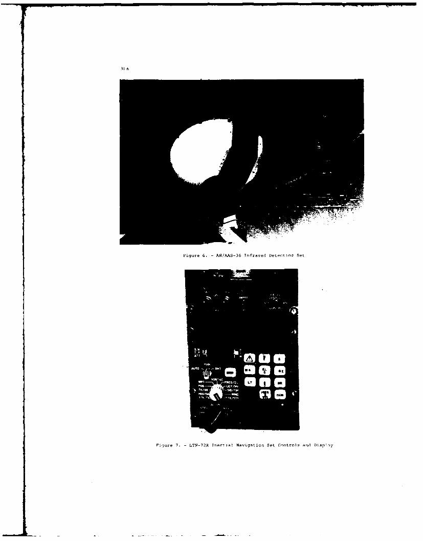
31-6
Figure 6. -AN/AAS-36 Infrared Detectina Set
AM -A.j~ *
Figure 7. -LTN-72R Inertial Navigation Set Controls and Display

Figure R. -Slewable Color Camera Platform
COMPOT(P
IN ARINC W6
BIIIBUS3 IAAX 3I
Fig're 9 - AT'rA~4uliple BuaStrZ-7r

31-8
I , ! I I I I SI t 4
SENSOR INTEGRATION PACKAGE
Sensor Crew Station Displays an Controls
Aircr t Nose ) [F thT r
li, y Fly-EynerI kC
( L I I
Figure 10. - Functional Dliagram of the Integrated Sensor Systeo
T ,e systems erngineer station (Figure 11) is the primary station for monitoring anncontrol of the aircraft electrical and cooling as well as all data recorl ing systems. Thedata recording capabilities of ASTTA include: Video Home System (VHS) record]ers for theradar display (525 lines) and hiqh resolution IRDS display (875 lines), for an over-the-shouldler camera pointed at the ASTTA crew station, and for a forward-looking video camerain the safety pilot cockpit for sitoational awareness at the ASTTA crewstation; a Jonosmicrocompuner connected to either the ICU or the radar digibus with the capability to readoat any S parameters for display on a strip chart recorder or for storage on a 58 channeldigital recorder; a complete set of aircraft state parameters from the variable stahil1t1 ,system (Fiqure 12) instrumentation (also on the 58 channel digital recorler); voicerecording on all VHS recorders; gro.nd radar tracking and positioning osing a C-bandbeacon transponder; and time code correlation of all date through an TRIO it format timecode generator, video inserfion onit, and cockpit display. Telemetry is planned for thenear fiture. The ASTTA data recording schematic is shown in Figure 13.
With a "fly-Oy-wirc" a;, tiG. cc6r:,.ili the cap.dbility to fly from either seat(Figure 14), ASTCA offers aircrews a realistic operator workload in a 'benign" airborneenvironment. This 'benign" environment includes "time expansion" and a low g environmentwhich are actoally advantageous for training purposes and for initia. tT&E. Whenrequired, sufficient closure rates can be generated with the proper choice of high speedtargets. The ASTTA aircraft can sustain torn rates comparable to 400 KIAS,!5g conditions.The variable stability system can be used to generate direct lift, direct sidetranslation, turbulence, and other environmental conditions.
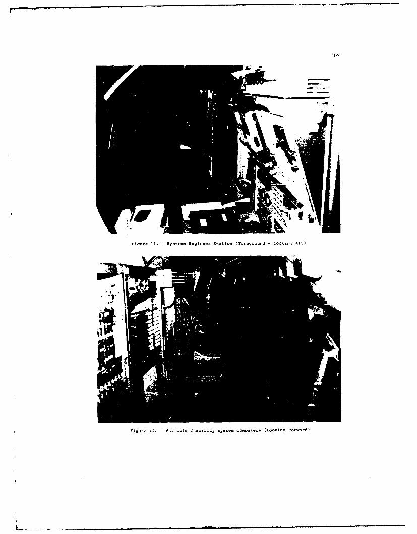
31-9
Figure 11. -Systems Engineer Station (Foreground -Looking Aft)
Figu~e LZ. V,r!-ie Ctaoi~iy bysLem o~yti (Looking Forward)

AVONC 8 D/A Channels PAND
MINI- cle ~ i rdr Ana .o SignaC 68 isscITp
*~T 64 aonW/fraw
*IO 100ALamsde
Fiur 13.E -C 372T Dat Reorin Schemtic0
figur 14P ST l-yWr ieSik Cnrle an et RrangDEmen

USAF ASTTA TRAINING CURRICULUM
The USAF Test Pilot School's approach to avionics systems test training is systematicand structured yet flexible to the individul! student s prior education and experience.The ASTTA training program is in three phases: ground training in-flight test training,and reporting, as detailed in Table I.
Ground training includes: classroom academics on avionics systems and theirintegration, human factors, and ASTTA operating procedures: laboratories dedicated todemonstrating flight test techniques; and discussion of flight test techniques descrihing
the in-flight maneuvers and data gathering procedures. This is followed by groundfamiliarization time with the ASTTA systems prior to flight. One najor advantage designedinto ASTTA is that many of the flight test techniques can be demonstrated on the groundwith all system powered up using ground and airborne targets of opportunity. A weight-on-wheels override switch allows operation of all ASTTA systems on the ground with onlythe use of external power. Experience has shown that ground run time is limited by theendurance of the operators and not the systems.
Ground Training
(Hours)Ground
Academics Laboratory Flight Test Techniques Familiarization
Human Factors 6.0 -
Electro-optics 8.0 1.5 2.0
Radar 11.0 1.5 1.0
ECM/ECCM 3.0 -
rNS 9.0 - 1.0
Avionics Integration 7.0 -
ASTTA Procedures 2.0 - 1.0 1.0Total Hours 46.0 3.0 - 5.0 1.0
In-flight Test Training
Hours
Flight #1 (day) - Air-to-air radar, air-to-ground radar, IR, INS, avionics 2.0integration, human factors, and operational navigation route
Flight #2 (night) - Air-to-ground radar, IR, INS, avionics integration, and human 2.0factors
Flight #3 - Optional (same profiles as flight $2 or #3) 2.0
Reporting
Hours
Daily Flight Report as required
Group Oral Report 1.0
Table 1. - USAF Test Pilot School ASTTA Training Program
In-flight testing includes preflight and postflight ground tests to verify contractorlaboratory data; in-flight tests of radar, IRDS, INS, and sensor integration: and theevaluation of pertinent human factors. Table 2 presents a partial list of in-flight testtraining areas performed during student training.
In the reporting phase, students are taught to accurately report what they saw and tomake recommendations to fix problem areas. Mission suitability is always the primaryobjective. Daily flight reports summarize each mission. The final oral report includes asummary of findings and recommendations from all student training missions. A questionand answer period on the oral report and systems test knowledge completes the ASTTA plA-eof training.
The avionics systems training process is not complete with ASTTA, but is only begun.Students perform numerous other systems evaluations on aircraft such as the A-6, A-7D,A-7K, E-2C, F-4 ARN-101, F-4G, RF-4C, F-14, F-15, F-16, F-18, F-1ll, P-3, S-3, and T-43.

31-12
Systes In-flight Tests
Air-to-air radar - Maximum detection range; minimum and maximum lock-on range atvarying aspects and look-up OL look-down; time to stable track:elevation, range, and azimuth resolution; track-through-the-notchevaluation; Air Combat Mode evaluation; and mission suitability
Air-to-ground radar - Minimum and maximum detection range, range and azimuth resolution,ranging accuracy, display accuracy, Doppler Beam Sharpeningevaluation, radar low level navigation, and mission suitability
Infrared Detector - Viewing distance; static and dynair; resolution; slew rates andSet limits; tactical target detection, recognition, and
identification; IR low level navigation; and mission suitability
Inertial Navigation - Position error, circular error probable, INS low level navigation,Set and mission suitability
Human FauLor. - Control and display mechanization and compatibility, illumination,atmospheric conditions, noise, procedural sequence, crew stationaccommodations, ingress/egress, and mission suitability
Avionics Integration - Radar, IRDS, and INS air-to-air and air-to-ground integration, andmission suitability
Table 2. - In-flight Test Training kreas
USE OF ASTTA FOR SPECIAL PROJECTS
A logical adjunct to the process of training students in flight test techniques on theASTTA aircraft was the initiation of an advanced systems evaluation project. The firstsuch test project took place in the fall of 1986 with a dedicated systems engineer group.The in-flight task included independent and integrated operation of the sensors whilesimultaneously flying the ASTTA aircraft via its fly-by-wire system during air-to-airintercepts, and day and night low level navigation routes. The pilot was fitted withphysiological instrumentation to yield electroencephalograms (EEG) as shown in Figure 15.The objective of this project was to correlate the pilot's subjective assessment ofworkload in the in-flight tasks using avionics test modified Cooper-Harper ratings,Subjective Workload Analysis Technique (SWAT), and pilot comments; to the objectivemeasures of workload including EEG, analysis of pilot control activity, and of deviationsfrom the specified altitude and heading profiles. This effort was in support ofcontinuing research in developing objective metrics of pilot workload for use inoptimizing pilot-system interfaces.
Figure 15. - Pilot Wired with Physiological Instrumentation (Left - Preflight,
Right - In-flight)

3i
It is in the interest of the USAF Test Pilot School to continue and expand this kin d- of utilization of the ASTTA platform for special projects conducted by the students as
practical application of their systems training. Besides giving the students valuableadditional hands-on test experience, such projects serve to develop systems test,anagement skills. There is a varied scenario of R&D activitieC (see ASTTA as an AirboriieSystems Integration Test Bed) being contemplated as an evolution of the current ASTTAsystem, which will readily serve as the basis for future student projects.
MULTI-USER FACILITY
The ASTTA aircraft is a USAF asset available for training and R&D utilization byqualified agencies or organizations. Utilization of ASTTA has evolved, in the short timesince its conception, from its original objective of training USAF Test Pilot Schoolpersonnel to familiarization and training of other Department of Defese (DOD, andcontractor testers and designers. The US Naval Test Pilot School is using the aircraftfor avionics systems test training of their test pilots, engineers and Naval FlightOfficers (NFOs): the Air Force Flight Test Center is using ASTTA for initial andcontinuation training for its avionics engineers: and Air Force personnel from other basessuch as Wrinht-Patterson AFB, Ohio and Palmdale Air Force Plant 42, California, havetrained on ASTTA. One such training session was dedicated to optical system testtechniques and was ii,6trumental in the testing of a new optical system for the USAF.Contractor engineers have flown on the aircraft on a noninterference basis as observers.Future dedicated contractor training flights are contemplated with the concurrence andsupport of their Air Force sponsors
ASTTA AS AN AIRBORNE SYSTEMS INTEGRATION TEST BED
Due to its size, modular design, and extensive instrumentation, ASTTA offers uniqueopportunities for low cost in-flight test and evaluation of new avionics systems, and inparticular, of the interface between the systems and operatars (i.e., the human factorsissues). Large pieces of equipment and large systems may be tested in a roomy environmentwith designers looking over the shoulders of the testers or designers doing the testingthemselves. "Tweaking" of avionics equipment while airborne is a big advantage of thisaircraft. Candidate systems for incorporation in the near term include a GlobalPositioning System (GPS) to supplement the INS for position information with the accuracyrequired for new navigation systems evaluations and calibrations, and a Ground ProximityWarning System (GPWS). High on the list of priorities for interface testing are head-updisplay (HUD) an': head down multifunction display (MFD) formats mixing flight status andtactical sensors information in a manner which optimize the displays for specific pilotingtasks. Flat plate dot matrix display evaluations are being planned for the near future.A modular "design-a-cockpit" concept with rapid configuration changes will allow cockpitdesign studies, along with voice activated control st,!dies, and unusual attitude studiesusing conventional attitude information and new approaches to the spatial disorientationproblem such as the Malcolm horizon. Furthermore, with color display hardware integrated,"pathway-through-the-sky" can be presented to the pilot giving threat avoidance guidancewhich he would "fly" via the fly-by-wife controls. Effective presentation of informationcontinues to be a dominant issue in operator-in-the-loop system development.
Testing of system manipulators/controllers can be performed in a realistic in-flightscenario with an appropriate turbulence environment, either natural or generated throughASTTA's variable stability system. These tests can be performed in a fully instrumentedenvironment, with the pilot/operator instrumented with extensive physiological sensors:while data recorders monitor the avionics systems, the aircraft flight pdrameters, and thepilot's control activity. This should also provide a valuable facility to test variousproposed workload reducing features of the pilot-system interface in highly demandingmissions using the single seat night attack fighter scenario as the reference critical
bench mark. For example, proof-of-concept testing of pilot associate or expert systemdevices could be performed cost effectively in a realistic environment.
Although ASTTA's Jonos minicomputer port on the radar digibus is currently passive'data retrieval only), the software can be modified to permit on-line ,ariation of radaroperating characteristics for training and R&D purposes. By flying AS
5TA over radar test
ranges, ECM/ECCM testing can performed. Alternatively, using a data link to ground basedcomputers simulating realistic electromagnetic threat environments, radar performance canbe evaluated.
Modification of the ASTTA system bus architecture to include a separate 1553 avionicsdata bus will facilitate rapid on-line integration of new systems or sensors. This willalso permit interaction with the existing basic aircraft flight control system 1553 bus topermit study of flight control/fire control integration issues. The current ASTTA nosewith its complement of sensors can be replaced with a mimic nose housing another set ofsensors, thereby permitting testing of a variety of sensor combinations and theirintegration features as shown in Figure 16. The aircraft could also accommodate externalsensor pods such as the AGM-65D Maverick, Low Altitude Navigatiun and Targeting Infraredfor Night (LANTIRN), or other new sensor pods, mounted under the nose area.
OLher potential test bed applications include: tests of artificial intelligencedevices, tactical sensor software development, tests of reprogrammed software ofoperational systems using the US DOD ADA programming language, optical/IR sensorevaluations on a slewable electro-optical platform, and "blind" landing evaluations usingonly external sensors for such aircraft as the US National Aerospace Airplane (NASP).

31-14
Mimic
Figure 16. - Mimic Nose on ASTTA (Artist's Conception)
Finally, a plan is being evolved in conjunction with the USAF Human ResourcesLaboratory (HRL) to incorporate a fighter cockpit with state of the art displays in thecabin of the ASTTA aircraft. Surrounding the cockpit will be a simulator visual dome(Figure 17). By having independent control over the cockpit's "motion base", its visualfield, and its displays, tests will be conducted to determine requirements for groundsimulators with specified objectives in training. With the ability to project on thevisual screen either computer generated imagery (CGI) or real world imagery (via theASTTA's slewable camera systems), studies dealing with simulator fidelity, avionicsintegration, and human factors issues can be readily performed.
- 'cockpitf° &Dom/ x
Figure 17. - Fighter Cockpit and Visual Dome Onboard ASTTA (Artist's Conception)
CONCLUSIONS
This paper has examined two important issues in the development of complex avionicssystems: avionics systems training for both designers and testers, and the avionicssystems development process itself. The tester training issue is being tackled at boththe USAF and USN Test Pilot Schools at this time; training for system design engineers,though started to some extent, is in its infancy and may remain there without someemphasis and push from management. Many of today's avionics development problems are theresult of attempting to fly without adequate operator-in-the-loop simulation resulting ina fly-fix-fly process which proceeds at a slow and costly pace. In many cases, verylimited funding is allocated for training and simulation, yet large sums are spentdeveloping expensive, complex hardware. When simulation is used, often too little time isallotted, or the simulation is inadequate in representing the in-flight environment of thesystem's intended operation. An airborne avionics training and integration laboratory,such as ASTTA, provides the opportunity to address both the training and developmentalissues.
ASTTA is in its infancy as an unique USAF tool to fil- a significant gap in theeducation and experience of the avionics systems test coymmunity. It provides a costeffective means of quickly exposing both designers and testers to the key issues ofavionics systems development and in-flight testing, especially the human factors issues

associated with the operator to systems interface. Its benign flight environment isconducive to both initial and advanced training in flight test techniques. Furthermore,ASTTA offers exciting potential as a test bed for a large variety of research anddevelopment activities. Proof-of-concept testing is particularly attractive with minimumpackaging required Mf test devices and the ability to carry several observers and even thedesigners themselv s.
It is the authors' hope that this paper h-s instilled awareness of the avionicssystems training problems and the need for airborne simulation in a realistic operationalenvironment. The future of avionics systems development is being shaped now, and aircraftlike ASTTA should be part of that futurel
B.Sigaud, FRPlease comment on the problems of using ASTTA for avionics development relative to:
(1) Simulators versus actual hardware.
(2) Time scale expanded.
(3) Nonrepresentation of pilot stress in actual environment.
Author's Repl)(1) Although we currently use actual flight hardware, we could use prototype boxes or even simulate the subsystems
of on-hoard Hawk computers or. if insufficient. use ground computers to simulate subsystem and data link to theASTTA. (AS7TA provides a real-world signal-to-noise environment for testing.)
(2) Target speeds can be adjusted to reduce time expansion and increase stress. In any case. we advocate the use ofAST'TA for early testing. If it does not work in "slow" time. it will not work in a I00-percent real scenario.especially with an operator in the loop.
(3) We advocate complementary use of ASTTA-type tools and tactical aircraft. Also. a very small portion of time isspent at high g levels and high air speeds. The effects of the high g level and high ai speed could be extrapolatedsomewhat from the 'benign" environment and then verified in the actual aircraft. However. the "early look'" mayidentify many of the problems you are trying to avoid.
RJ.Young, CA(1) The requirement for formal systems flight test training is a valid o3ne, and the extension ot the principle to
designers, as well as to the test community, is interesting and innovative. The use of the platform as a flying testbed, specifically as a simulation facility to support operator-n-the-loop integration testing, is less clear. Thecapability of systems integration laboratories (SILs) is increasing greatly, and dynamic stimulation is becomingmore feasible.
(2) Would it not, therefore, be more effective and less costly to involve the operator morc in the original SIL activityrather than to attempt to develop and duplicate the SIL in a test bed and 'or associated ground support facilitysimply as a method to "involve the operator earlier"?
Author's Reply(1) Yes, the capabilities of SILs arc increasing, but the fidelity to properly emulate the airborne environment does not
yet exist. Even today's best ground-based simulators are limited in their ability to transfer learning and would havea similar effect in SILs to properly represent the operator's environment.
(2) Yes and no, you must evaluate each development and the risks involved to make a value judgement on the fidelityrequirements for airborne simulation, In many cases, it may not require the same effort or duplication of the SIL.since the operator's environment would not have to be artificially duplicated. Much of the SIL hardware/softwarecould be transferred directly to the airborne simulator. Only the system/aircraft interface would differ if you havean airborne simulator with a flexible aircraft bus structure and minimum packaging requirements.
W.E.Howell, USThis comment is in response to Major Young's question. Because of the complexity of software and the time it takes todevelop it, it is sometimes cheaper and faster to put a prototype system on an aircraft and fly it. Furthermore. the resultsare highly credible even to those not involved in the particular technical field being evaluated.
Question:Are the TIFS aircraft and the ASTTA aircraft one aircraft with interchangeable nose and research hardware?

31-Is
Author's ReplyYes, and the strengths of each capability can be used jointly, although the nose change precludes using the fly-by-wirecockpit and the ASTIA tactical sensors at this time.
M.Kayton, USThis is not a question; it is a comment on the avionics design process. In your paper, you say you want to i duce thenumber of system-level -oand-aids" by offering training flights to avionic engineers and maiagers. Training rides are afine idea, but in 30 years of avionic system design, I have found that the highest cost band-aids result from prematurerelease of preliminary designs, not from flight control problems. Premature release occurs when the Governmentprogram manager or company project manager provides too little money for preliminary design or forces the earlsrelease to hardware and software cntractors. Often, one more iteration of the design, taking 2 to 4 months. wouldimprove product quality enormously. Instead, premature release leads to delays of a year or more and to costs that arehundreds of times higher than the extra iteration of the preliminary design. Unfortunately, the ASTTA cannot educatethe managers on the best time to release mne preliminary avionics design.
SOFTWARE ENGINEERING FOR THE BRITISH AEROSPACEEXPERIMENTAL AIRCRAFT PROGRAMME (RAP)
byW. E. R. Kellaway
Principal EngineerBritish Aerospace PLC
Military Aircraft DivisionWarton Aerodrome
Preston Lancs PR4 lAXEngland
SUMMARY
The software engineering approach adopted by British Aerospace in the specification,design and implementation of th- Avionics and Utility Systems Management software for theExperimental Aircraft Programme (EAP) is described.
The software life cycle and supporting r'thods and tools are described, in particularthe Controlled Requirewents Expression (CORE) method, supported by the CORE Work Station,and the PERSPECTIVE programming support environment. The considerable benefits obtainedin both productivity and quality are highlighted and developments are indicated leadingto a full Iihtegrated Project Support Environment (IPSE).
1. INTRODUCTION
In May 1983, British Aerospace (BAe) signed a contract with the UK Ministry ofDefence to design and produce a new aircraft as a technology demonstrator, the programmeto be known as the Experimental Aircraft Programme (EAP). EAP achieved first flight inAugust 1986, was demonstrated at Farnborough 1986 and is continuing a programme of flighttrials to extend its flight envelope and explore the application of its advancedtechnology.
The areas of advanced technology are extensive and include an active flight controlsystem, an all-electronic cockpit, and software control of utility systems in the systemsarea, and extensive use of CFC and super-plastic forming and diffusion bonding techniquesin the airframe construction. The programme has involved extensive European collaboration,the advanced technologies having evolved from various government research contracts overthe past decade. The technologies will be utilised in any future fighter aircraftprogramme with UK involvement. the European Fighter Aircraft (EFA) project being a currentproject.
A less visible aspect of EAP is the successful application of a software engineeringapproach that had been developed by BAe via a number of small research projects since thelate 1970's and for which the EAP project provided the first large scale use. Thesoftware engineering approach is the subject of this paper.
2. EAP SYSTEMS ARCHITECTURE
The EAP systems architecture is illustrated in Fig. 1. It consists of 3 majorsub-systems:
Flight Control System (FCS)Avionic System (AVS)Utilities Systems Management System (USMS)
The AVS and USMS each incorporate a Mil Std 1553 databus architecture and th- 3sub-systems communi ate via Remote Terminals in the AVS databus.
The FCS is a full authority digital quadruplex fly-by-wire system. For such aflight safety critical system a significantly different approach is required for thedesign and development f the software. In particular the use of a low level languageand a reduced instruction set is the norm. The EAP FCS is a derivative of the existingJaguar fly-by-wire demonstrator aircraft system for which a specialised technique hadalready been developed to support the software production [1]. This technique was usedagain for EAP FCS and is not discussed further here.
The main feature of the AVS is the all-electronic cockpit with multi-function colourdisplays generated and moded under software control according to phase of flight andpilot selection. The AVS also includes navigation and communication functions andextensive failure detection and warning handling under software control.
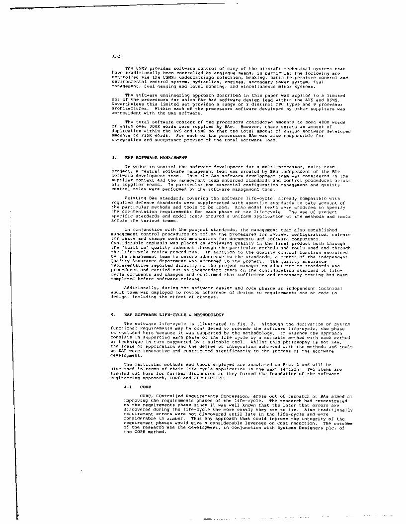
32-2
The USMS provides software control of many of the aircraft mechanical systems thathave traditionally been controlled by analogue means, in particular the following arecontrolled via the USMS: undercarriage selection, braking, cabin te-,perature control andenvironmental control system, hydraulics, engines, secondary power system, fuelmanagement, fuel gauging and level sensing, and miscellaneous minor systems.
The software engineering approach described in this paper was applied to a limitedset of the processors for which BAe had software design lead within the AVS and USMS.Nevertheless this limited set provided a range of 2 distinct CPU types and 9 processorarchitectures. Within each of the processors software developed by other suppliers wasco-resident with the BAe software.
The total software content of the processors considered amounts to some 400K wordsof which over 300K words were supplied by BAe. However, there exists an amount ofduplication within the AVS and USMS so that the total amount of unique software developedamounts to 225K words. For each of the processors BAe was also responsible forintegration and acceptance proving of the total software load.
3. RAP SOFTWARE MANAGENENT
In order to control the software development for a multi-processor, multi-teamproject, a central software management team was created by Ae independent of the BAesoftware development team. Thus the BAe software development team was considered in thesupplier context and the management team enforced standards and control procedures acrossall supplier teams. In particular the essential configuration management and qualitycontrol roles were performed by the software manageent team.
Existing BAe standards covering the software life-cycle, already compatible withrequired defence standards were supplemented with specific standards to take account ofthe particular methods and tools to be used. Also model texts were produced to specifythe documentation requirements for each phase of the life-cycle. The use of projectspecific standards and model texts ensured a uniform application of the methods and toolsacross the various teams.
In conjunction with the project standards, the management team also establishedmanagement control procedures to define the procedures for review, configuration, releasefor issue and change control mechanisms for documents and software components.Considerable emphasis was placed on achieving quality in the final product both throughthe "built in" quality inherent through the particular methods and tools used and throughthe life-cycle review procedures. In addition to the quality control function exercisedby the management team to ensure adherence to the standards, a member of the independentQuality Assurance department was seconded to the project. The quality assurancerepresentative reported directly to the project manager on adherence to standards andprocedures and carried out an independent check on the configuration standard of life-cycle documents and changes and confirmed that sufficient and necessary testing had beencompleted before software release.
Additionally, during the software design and code phases an independent technicalaudit team was employed to review adherence of design to requirements and of code todesign, including the effect of changes.
4. RAP SOFTWARE LIFE-CYCLE & METHODOLOGY
The software life-cycle is illustrated in Fig. 2. Although the derivation of systemfunctional requirements may be considered to precede the software life-cycle, the phaseis included here because it was supported by the methodology, In essence the approachconsists in supporting each phase of the life-cycle by a suitable method with each methodor technique in turn supported by a suitable tool. Whilst this philosophy is not new,the scale of application and the degree of integration achieved with the methods and toolson EAP were innovative and contributed significantly to the success of the softwaredevelopment.
The particular methods and tools employed are annotated on Fig. 2 and will bediscussed in terms of their life-cycle application in the next section. Two items aresingled out here for further discussion as they formed the foundation of the softwareengineering approach, CORE and PERSPECTIVE.
4.1 CORE
CORE, Controlled Requirements Expression, arose out of research at BAe aimed atimproving the requirements phases of the life-cycle. The research had 7oncentratedon the requirements phase since it was well known that the later that errors arediscovered during the life-cycle the more costly they are to fix. Also traditionallyrequirement errors were not discovered until late in the life-cycle and wereconsiderable in n~oaber. Thus any approach that could improve the integrity of therequirement phases would give a considerable leverage on cost reduction. The outcomeof the research was the development, in conjunction with Systems Designers plc, ofthe CORE method.

32-3
The CORE method is a top-down approach f- analysing and expressingrequirements in a contruiled and precise manrnr. It enables a subject requirementto be expressed in terms of lower level requirements which may in turn be subjectedto the method *9 produce a 'hierarchy of lower levels. The method comprises a numberof logical steps which can be summarised as information gathering, proposal ofrelationships and confirmation of relationships. The steps are described and themethod compared with other techniques in (2].
A diagrammatic notation is used extensively in CORE as an aid to understandingand to provide an unambiguous expression of the structure of the subject requirement,the data flows, data dependencies, processing actions and the time ordering of thoseactions. The notation is illustrated in Fig. 3. Production of CORE diagrams hasbeen automated in the CORE Work Station developed by British AerosDace. The COREWork Station provides a multi-user development environent for the production ofCORE requirements. It consists principally of a diagram editor which allowsdiagrams to be entered and manipulated via a high resolution graphics terminal, amulti-user database for the storage and retrieval of diagrams and a hard copyfacility. Some automatic on-line checking of diagrams is available during editing,and off-line checks are available for more comprehensive checking.
4.2 PERSPECTIVE
PERSPECTIVE is a proprietary product of Systems Designers plc, which providesa multi-user programming support environment for the development of embeddedcomputer systems written in Pascal. The product arosc -ut of considerable experiencein the development of cross-compilers and support environments for embedded systemsand first appeared on the market place in 1983.
Whilst the maturity of the product was rightly questioned for application inthe EAP timescales, for the chosen language Pascal, the features offered by theproduct were considered to far outweigh any risk associated with immaturity.
PERSPECTIVE supports a particular modular design technique which has beenimplemented through extensions to the ISO standard Pascal. The technique is basedon a data flow model of a real time system, and decomposes the structure of thesoftware into three basic component types, processes, interfaces and modules. Theprocesses are the fundamental units of parallel processing within PERSPECTIVE andconsist of independently schedulable units of sequential code. Processes can onlycommunicate with each other via the facilities specified in the interfaces. Theinterfaces contain only the specification of the facilities available, theimplementation of these facilities is defined in the modules. Modules may also usethe facilities defined in other interfaces, so that Lhe concept of software layeringor successive layers of abstraction is inherent in the technique. The basiccomponents may be grouped into larger components termed subsystems which again canonly communicate via interfaces. The technique is supported by a diagrammaticnotation which is summarised in Fig. 4. The notation has been automated in the COREWork Station to provide computer support of the design technique.
PERSPECTIVE Pascal also includes extensions to provide basic primitives forthe manipulation of processes to enable the implementation of the required schedulingregime for a particular application. The basic primitives are implemented in a runtime system supplied in source code which may be tailored for any particular hardwareconfiguration.
The design concepts and notation of PERSPECTIVE are very akin to the MASCOTapproach [31. Earlier research work at British Aerospace had indicated that arequirement expressed in CCRE notation could be mapped into a MASCOT design diagram,so that for EAP it proved a straightforward extension to map the CORE requirementsinto PERSPECTIVE designs.
Central to the PERSPECTIVE support environment is a multi-user database inwhich are stored the source code files and all associated derived products for thecomponents of one or more systems. The database is configured as a number ofindependent user domains permitting independent development of components.Components may be shared between domains through the use of a publish and acquirefacility. Components may exist in multiple versions and extensive managementfacilities are provided to keep track of versions, relationships, status, accessrights etc. providing the essentials for configuration control.
Software development within PERSPECTIVE is carried out in two major phases,Host and Target. During the host phase components are compiled and debugged throughexecution on the host (VAX series) computer. Checkout fa:ilities are built-in toenable source-code level debugging, including single-stepping, breakpoint setting,data alteration and data and system monitoring. For the target phase the componentsare re-compiled for the target configuration and downloaded via a terminal line tothe target processor. Execution in the target may continue independently from thehost or the host link may be retained to allow checkout of the target software viathe host facilities in a similar manner to host checkout. Complete target memoryimages may also be generated via a 'PROM' facility within PERSPECTIVE which generatesfiles suitable for subsequent processing by IC programming devices.

32-4
5. RIP SOFTWARE TOOLSET LIFE-CYCLE APPLICATION
This section discusses the methods and tools further in the context of theirapplication to the rAP software life-cycle.
5.1 Requirements Definition
Requirements definition encowpassed the two phases of System FunctionalRequirements and Software Requirements. Both phases were carried out by systemengineering staff (as distinct from software engineers) utilising the CORE method,implemented in the CORE work station.
Two different approaches were adopted for the AVS and USMS arising from theessentially different nature of the systems. The AVS consists of a highlyintegrated system where the problem consisted in identifying and elaborating thevarious functions and then allocating them to defined processing units. The USMSconsists of a number of largely independent subsystems which required independentanalysis and then integration into a defined processing architecture. The routestaken in each case are shown in Fig. 5. In e&Th case the end r-sult was a set fprocessor software specifications.
Each processor software specification consists of a set of CORE documentationsupplemented by information on hardware/software interfaces, constraints, errordetection and handling, scheduling etc. The CORE documentation consists of a setof thread diagrams, which show the required independent threads of execution withinthe processor, an operational diagram, which shows the required time-orderedrelationship between the individual threads, and data decomposition diagrams forcomplex data items. The diagrams are supplemented by "node notes" which supplybrief textual descriptions of each process in a thread diagram and each data lineentering or leaving the diagram. The node notes form part of the CORE documentationset and are entered into the CORE database via the work station. A typical threaddiagram is presented in Fig. 6.
In addition to the processor software specification, the system engineeringstaff produced an acceptance test specification for each processor which served asthe acceptance requirement for delivery of processor software for subsequent systemintegration.
5.2 Basic Design
The basic design phase consisted of the translation of each processor softwarespecification into a definition of the modular structure of the software within theprocessor and an identification of all software components. The basic design wascarried out by the BAe software team with participation from suppliers of co-residentsoftware where applicable. The PERSPECTIVE design approach was followed, supportedby the CORE work station. In essence the design consisted of a grouping of the COREthreids defined in the software specification into suitable PERSPECTIVE processesand/or subsystems and a grouping of the data items into suitable interfaces withspecified access procedures. A typical basic design diagram is presented in Fig. 7.
Also during the basic design phase the required testing plan for the processorwas specified. This identified the order of testing of components and the necessarytest components to progressively test and integrate the software within the processorleading to acceptance test of the full processor load.
5.3 Detailed Design
Tne detailed design phase consisted of elaboration of the detail for eachsoftware component and test component defined during the basic design phase. Forthis phase the work was carried out independently by the various software teams,working to the precise specifications derived during the basic design phase.
Since much of the detail was contained in the detailed layering of theprocessor software specification CORE threads, it was possible to transfer thisinformation into the detailed design supplemented by definition of data types andstructures and access procedures. Again the CORE work station was used to transferthe thread information into detailed design diagrams and to add the extra information.Where necessary the diagrams were supplemented by pseudo-code node notes. A typicaldetailed design diagram is presented in Fig. 8.
5.4 Code, Test, Integration
The code, test and integration phases were performed using the PERSPECTIVEsupport environment. The PERSPECTIVE database facilities were used to store thecode of all design components and test components and the various build standardsleading to complete processor software builds. Generally the test and integrationphases were as follows:
Host test of individual Pascal components using test components where necessaryand previously tested components when available. For the host tests extensiveuse was made of the PERSPECTIVE checkout facilities.

32-5
Repeat of the host test on the target processor using the PERSPECTIVE downloadand checkout facilities.
Target test of assembler language components using the download and checkoutfacilities.
Progressive integration and test of components in the target processor using thedownload and checkout facilities.
In pracLice the repeat of the host testing on the target processor was foundto be unnecessary as no errors were introduced by recompilation for the target, andthis phase was subsequently omitted.
Assembler language components were necessary in some instances to interfacewith processor hardware or for critical timing areas. Within PERSPECTIVE assemblerlanguage is confined to module components.
Two additional tools were employed during the target testing and integrationphases. A comprehensive Data Acquisition and Simulation System (DASS) attached tothe overall aircraft test rig was used to stimulate and monitor hardware interfaces.Also microprocessor development systems (NDS) were used for processor emulation,:tate analysis and logic analysis operations. The MDS facilities proved especiallyuseful in resolving hardware/software conflicts.
Whilst software developers could initially carry out informal testing onuncontrolled items for experimental or confidence checking, eventually the requiredtesting was carried out formally on "frozen" components under control of a centralsoftware librarian. This was achieved through the PERSPECTIVE configuration controlfacilities. Each developer was assigned a unique user domain and special protecteddomains were assigned to the software library. Components ready for configurationcontrol were submitted via a registration procedure to the librarian and transferredto a library domain. Components in the library domain were published and could beacquired by developers for incorporation into test builds as necessary, however thecomponents were effectively frozen and unable to be modified by acquirers. A versionnumbering convention was enforced by the librarian to accommodate formal changes ofcomponents and coding standards included a header comment identifying the versionchange history of the component. Through these simple but effective facilities,components were progressively transferred from development domains to librarydomains, building a complete library of components under configuration control withfull design traceability.
An important feature implemented as part of the library procedure was anindependent technical audit of source code components on registration with thelibrary. This ensured conformity to design documents and formal changes, andconformity to the project coding standards.
As part of the integration task, BAe was required to incorporate the softwaredelivered from other suppliers. The modular structure of the software enforcedthrough the PERSPECTIVE facilities resulted in a virtually trouble free integrationof PERSPECTIVE components. More significant problems occurred in certain caseswhere suppliers had not used the PERSPECTIVE approach, however overall the problemof integrating separately sourced software were considered to be minimal.
Formal releases of software for system rig testing or aircraft use wereassembled by the librarian in PERSPECTIVE databases from the component library.
Following acceptance of the releases, the subsequent system rig testing andsystem integration were carried out by the Systems Test department, a separateorganisation independent from the software teams, making use of the DASS facility.For early processor units with RAM storage, the systems test team made use of thedownload facility to load the units directly from the PERSPECTIVE databases. Forlater units with ROM storage, memory images were generated by the software libraryvia PERSPECTIVE facilities and subsequently programmed into storage devices.
Errors discovered during system testing were corrected via changes raised onthe appropriate requirement and/or design document and affected code componentswere raised in issue and re-tested. The implications of changes were easy to assessand few side effects were encountered. As confidence was gained in the approach,only incremental re-test was undertaken by the software team on re-release.
6. BEEFITS OF APPROACH
The benefits of the software engineering approach described have been assessed bycomparing the results achieved on EAP with the experience at British Aerospace on earlierprojects. The main gains are an increase in both productivity and quality. Comparedwith the two most recent projects, the productivity measured in delivered lines of codeper man year for the software design code and test phases has increased five-fold. Thequality measured in terms of errors detected during rig flight clearance testing expressedas a ratio per line of delivered code has improved by almost a factor of ten. Thisincrease in quality and productivity has resulted in a considerable estimated saving inthe total resources needed for design and rig testing, which outweighs the expense ofintroducing the methods and tools by a factor of six.

32-6
The use of well-defined methods and tools also provided a detailed framework tortraining, enabling a comprehensive training scheme to be planned which allowed relativelyinexperienced staff to be brought up to speed reasonably quickly. The modular approachsupported by the methods and tools also allowed the introduction of large numbers ofextra staff during the detail design, code and test phases to keep the project on timeschedule. In fact the peak software design team manning at British Aerospace reached60 whereas the maintenance of the software to incorporate requirements changes resultingfrom flight experience is handled by a team of 4.
7. CONCLUDING REMARKS
The software engineering approach described has undoubtedly contributed to thesuccess of the EAP project in meeting an extremely tight timescale. Also resultsindicate that the quality of the delivered software and the productivity achieved haveboth improved considerably through the approach. The firmly held view within BritishAerospace is that the use of the CORE method supported by the CORE workstatiun has beena major factor in the success through ensuring a structured top-down approach resultingin quality, consistent requirements and providing an essential continuity throughthe software life-cycle into the design phases. PERSPECTIVE represents the state-of-the-art in support environments for embedded applications using the Pascal language and wasa further major factor in the success. Both CORE and PERSPECTIVE are in current use onfurther projects within British Aerospace.
Developments of the approach for future projects are aimed at the introduction ofthe Ada(R
) language and providing a truly integrated project support environment (IPSE).
Whilst the methods and tools of the current approach are integrated in the sense thatthey are compatible and consistent from phase to phase of the life-cycle, neverthelessthe products of the requirements, design and code phases are held in distinct databases,each subject to individual configuration management procedures and considerable manualintervention is required to ensure overall configuration control. The IPSE approach aimsto utilise a common database implementation tool so that all life-cycle products aresubject to a common version and variant control mechanism, thus enabling automatedconfiguration management across the total life-cycle.
Several products are appearing on the market place which provide a basic IPSEframework giving the essential database manipulation and management facilities, andwhich permit the integration of specific tools via a tool interface.
Currently British Aerospace in collaboratioz, with partner companies is involved inthe procurement of a basic IPSE framework and the development and incorporation ofspecific tools. Two particular areas of development are worthy of note. Firstly COREhas been integrated with EPOS [41 which allows the EPOS facilities to be used forextensive analysis of CORE data and makes available the extensive EPOS documentationfacilities. Secondly guidelines are being developed for the translation of requirementsexpressed in CORE diagrammatic notation into software design structures suitable for Adaimplementation.
An IPSE schematic is shown in Fig. 9, however the specific tools indicated areillustrative only. The IPSE development which will form the basis of the softwareengineering approach for future projects and in particular the European Fighter Aircraft(EFA) will serve to maintain the improvement trends in quality and productivity alreadyobserved for EAP.
8. REFERENCES
[I] Daley E., Smith R. B. : 'Flight Clearance of the Jaguar Fly-by-Wire'.Certification of Avionic Systems, The Royal Aeronautical Society, London.April 1982.
[2] Price C. P., Forsyth b. Y. : 'Practical Considerations in the Introduction ofRequirements Analysis Techniques'. Proceeding No. 330, AGARD Software forAvionics. Sept. 1982.
[31 'The official Handbook of MASCOT' MASCOT 2 Issue 2. Royal Signals and RadarEstablishment, Malvern. March 1983.
[4] Biewald J., Goehner P., Lauber R., Schelling H. : 'EPOS - A Specification andDesign Technique for Computer Controlled Real-Time Automation Systems'.Proc. 4th Int. Conf. Software Engineering, Munich 1979. IEEE Comp. Soc.,Los Alamitos, Cal., 1979, pp 245-250.
9. ACKNOWLEDGEMENT
This work has been carried out with the support of the Procurement Executive,Ministry of Defence.
(R) Ada is a registered trademark of the U.S. Government - Ada Joint Program Office.
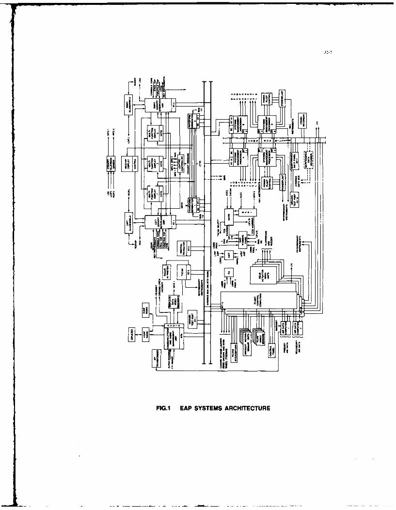
32-7
iiL 11i.
FIG.1 EAP SYSTEMS ARCHITECTURE

32-8
COREF1COREWIS S~WR
CORE ICORE W;S BASICCORE WiS DESIGN
,ASCOT/ I FPERSPECTIVE 1 OETAILED
CORE W/S DESIGNCORE llCORE/
PERSPECTIVE CODE
CORE Wis
CORE PERSPECTIVE TEST
PERSPECTIVEDASS SUPPORTMOS
-PERSPECTIVE
FIG.2 SOFTWARE LIFE CYCLE
CONTROL
FUNCTIONALEQUIVALENCE
0 REF NUMBER
SOURCE INPUT - NAME FUNCTION OUTPUT - NAME
NAME W DESTINATION
IMPLEMENTED BYINTERATION - CONTROL
FIG.3 CORE NOTATION

32-9
INTERFACES PROCESS
MODULES IMPLEMENTINGINTERFACES
DEVICESUB-SYSTEM
SUB-SYSTEMS IMPLEMENTINGINTERFACES
SYSTEM
FIG.4 PERSPECTIVE NOTATION
JSuS Ito 10 AVIOICS
PRE-EFINED COCKPIT
FUNTINA FUCTONL UNCTIONS FUNCIONES
C EQIREEWNT REQUIREMENT ROU E
I to 10PARTmTONING
PROCESSOR
REGUIRENIENT
PROCESSOR SOFWA E CIATO
UNI
SOFTWARE ~PARTITIONIGSPCFATOSPECIFICATIONS
3 3 4 5 6
FIG.5 SOFTWARE REQUIREMENT ROUTES

32-10
U-j
I L I~
.1.
L -1
FIG.6 EXAMPLE CORE THREAD DIAGRAM
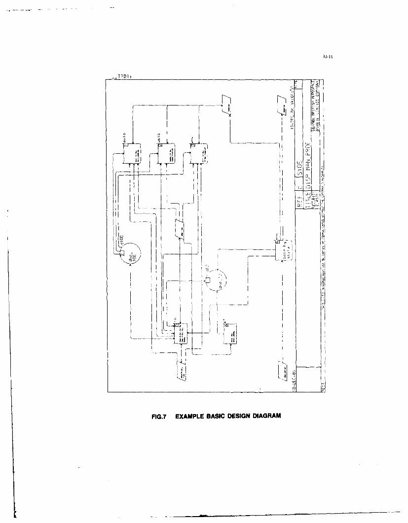
32-11
-TTrn:
04 0i
FG7AMPEBSCDSG IGA

32-12
TTB1:
cl
FIG. EXAPLEDETALED ESIN DIGRA
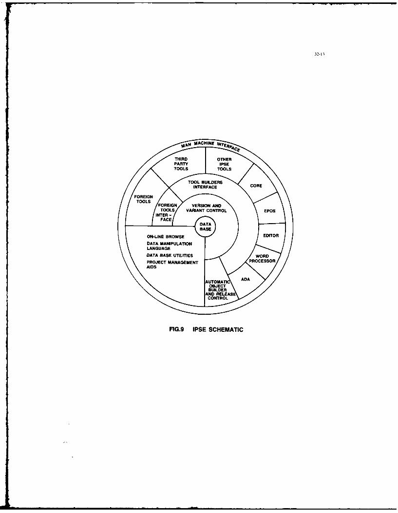
32-13
olkig MACHINE IN
THIRD OTHERPARTY IPSETOOLS TOOLS
TOOL BUILDERSINTERFACE CORE
FOREIGNTOOLS
FOREIGN VERSION ANDTOOLS VARIANT CONTROL EPOS
INTER-FACE
DATABASE
ON-LINE BROWSE EDITOR
DATA MANIPULATIONLANGUAGE
DATA BASE UTILITIES WORD
PROJECT MANAGEMENT PROCESSOR
AIDS
AUTOMATI ADA
OBJECTBUILDER
AND RELEASCONTROL
FIG.9 IPSE SCHEMATIC

32-14
DISCUSSION
M.Muenier, FRYou indicated that for the EAP, both CORE and MASCOT are used at the design stage together with real-time Pascalas an implementation language. On the other hand, you plan to use EPOS for design in the framework of the EAFprogram with Ada for coding. Would you comment on the independence of design tools with regard to programminglanguages?
Author's ReplyFor EAP, we choose CORE/MASCOT/PERSPECTIVE: PERSPECTIVE provided the support envt onment forPascal.For EFA, the required language is Ada, and work is under way to produce the Integrated Project Support Environment
(IPSE) that will embrace Ada. we system design tool will be CORE/EPOS, where the design advantage of CORE willbe coupled with the cross-checking advantages inherent in EPOS.I believe the design tools should be capable of supporting several programming languages; however, with an aircraftprogram like EFA, an Ada-dedicated IPSE would be considered acceptable.
P.R.Walwyn, UK(1) How "modular" was the software you produced? What sort of tasks" did you include in discrete modules"
(2) What proportion of your total code consisted of -repeat-calls" of common modules?
(3) How "reusable" do you think your produced modules will be for future programs (e.g. EFA'?
Author's Reply(1) The software is highly modular, in which the module size varies considerably, covering items such a, monitor, or
track compute or display drive logic.
(2) Out ofa 300K word software package, 225K words were unique.
(3) The software documentation requirement can be used again. since it is independent of project. However, EFA "itibe Ada-based, and the software modules produced for EAP in Pascal will not be reusable.

33-1
SYSTENIE AVIONIQLE - METHOIDE DE DEVELOPPFMIENT ET OUTILSINFORMATIQUES
par
P.Loroche-LevyAvions Marcel Dassault
78. Quai Marcel Dassault92260 Saint Cloud
France
I-INTRODUCTION
Les plus r~cents systL~mes avioniques, par le grand nonbrL de fonctionnalit~s qu'ils offrentet par l util1i sati on importar te de nouvellIes technol ogies dlans l eur rW a sati on ot atte int an hautniveau de complexitt.
Pour en conserver la maltrise, 1 'utilisation d'outil;, informatiques assurant la mise en oeuvredaune m~thodologie rigoureuse est n~cessaire.
D'importants travaux ont et6 entrepris ass AVIONS M4ARCEL DASSAULT - BREGLIET AVIATION, encollaboration avec d'autres industriels eL Id participation du Ministdre de la DWense, pourd~finir et d~velopper an en~emble d'outillages inforinatiques homogtses soutenant leo diff~rentesphases de d5veloppenent de systtmes avioniques.
L'objet du prdsent docuenent est de d~cire la nature des besoins as regard du cycle de viedu d~sveloppement des syst~mes avioniques, puis les principaus travaux enqag~s pour assurer iacosserturn des diffdrentes phases.
2 -SYSTEME AVIONIQUE
2.1 - OBJET D'UN SYSTEME AVIONIQUE
Leo principales fonctions assurhrs par un systbme avioniqae concernent
-le dialogue avec I'LAquipage,
- vs fonictions op~rationnelles (navigation, conduite de tir d'armes, reconnaissance,
-la pr~paration et la restitution de mission,
-la cooperation entre avions et le sol,
l a maintenance ophrationnelle.
2.2 -CARACTERISTIQUES D'UN SYSTEME AVIONIQUE
Leo syst~mes avioniques actuels soot principalement
-des syst?.mes tr~s int~grds pour r~pondre ass exigences suivantes
*assurer so grand nomtre de fonctions optra~ionnelles concourant ensemble A la reussitede la mission,
*tenir dan an volume restreint et pour la masse la plus rhduite possible,

33-2
* garantir un bon niveau de dialogue avec le pilote tout en cherchant a diminuer sacharge de travail,
Cette integration se traduit essentiellement par une interdtpendance des fonctions et
un multiplexage des ressources capteurs, commandes et visualisations.
- des systmes furtement 6volutifs pour
* pouvoir subir des transformations ihes A de nouvelles technologies de matriel,
* Atre capables de supporter I'intigration de fonctions pour rbpondre 6 de nouveaux
besoins opdrationnels,
* permettre des amhliorations de la mission,
* satisfaire A des demandes spbcifiques d'un client par le dbveloppement d'uneversion particulidre.
- des syst~mes hautement scurisfs pour
* assurer ]a scuritb de l'quipage par une gestion de pannes intbgrbe (surveillance,detection, reconfiguration).
Les progrbs technologiques de cs dernitres annes ont permis une forte numrisation dessysthmes avioniques ; cette numbrisation s'est concrbtishe par la multiplication deprocesseurs spcialishs dans les hquipements, l'utilisation de bus numbriques et un volume
croissant des logiciels.
Tous ces elhments reunis ont favoris6 la rhahisation de systhises de plus en plus inthgrfs,performants et volutifs, mais dont le niveau de complexith, liP au grand volume delogiciels et 6 ]a combinatoire des logiques systdtses, a rendu 7a maitrise difficile.
2.3 - PROBLEMES POSES
L[s problmes poses lors du ddveloppement des rcents systbmes avioniques concernentparticulifrement :
- la maitrise des coots et des dWlais,
- la comsuniration entre le grand nombre de partenaires industriels impliqus dans
un programme,
- la validation des systdmes et de leurs evolutions,
- la gestion d'une importante documentation de specifications et les difficultfs de
sa mise A jour.
Les chiffres ciths ci-dessous sont issus du dveloppement d'un systfme avionique type
MIRAGE 2000 et illustrent ces derniers points.
Pour assurer 1'ensemble des fonctions de "base" dites de conduite de la machine
(conditionnement, generation Clectrique, pilotage, navigation, localisation, ...) et desfonctions sptcifiques missions (contre-mesures, interception air/air, ttqucs air/sol,reconnaissance, ...) le systbme avionique conduit a 1'intgration d'une centaine d'quipementset a la realisation de 500 Kmots de logiciels embarques.
Rapportds aux difftrentes phases du cycle de vie, les volumes de documentations associbessont
- definition et sp@cification systme
Slensemble de la documentation de spcification systhme reprtsente une hauteur del'ordre de 3 metres.
- conception et rdalisation du logiciel
* A 500 Kmots de logiciels temps reel, la documentation de lanalyse-conception e de
maintenance correspond A 2,5 mtres dont 2 metres de listing source.
- validation, integration systkne :
* pour la validation d'une fonction ophrationnelle, ha documentation assocPee reprhsenteI metre.

La difficultA de wise au point de ces systimes et l'ad6QUation du produit final realist auvu de lexpression des besoins operationnels se traduisent par is redaction cayenne de 3,5fiches de modification par jour, ces fiches correspondant A des demandes de correction oud'6solution.
Pour le d~veloppenent d'un syst~me asionique, le temips passe sur chacune des 6tapes,exprinid en pourcentage de la durde totals est de 1'ordrs de
- phase de definition, specification systdine 30%
- phase de rdalisation, validation Liquipenent 50 %
- phase d'intisgration au sol 20 %
- phase d'essais en vol 10 %
3 - BJECT[FS DE ['UTILISATION D-OUTILLAGES INFORMATIQUES
[a complevit, du ddveloppement des sytdmes avioniques justifis pleinement 1'emploi systlisatiqued'outils infonnatiques adaptls pour supporter 1 ensemble des activitts du cycle de vie.
Cet ensemble d'outils camprend des "outils de fond" pour permettre 1 acquisition deconsaissances sur les fonctions et syst&Ines A deselopper, et des outils formels dont le r~leessentiel eut de fournir use aide a l'application d'une nlthodologie rigoureuse.
Par l'utilisation d'un ensemble d'outils informatiques adaptds ass diffdrentes etapes dudtveloppement, les obaectifs paursuisis sont les suivants
-hoeogenATttd des mdthodes de trasail par l'utilisation d'outils cnvnnavs,
-aide A la definition de syst~mes ist~sgrds et tvolutifs,
-obtention de specifications de qualit6,
-amelioration des conmunications entry les diffdrests partenaires par ]a structuratior,et la fornalisation des Uchanges,
-aide A Idelaboration de la documentation,
-reduction des colts et des d~lais par:
*la rdutilisation issue de la capitalisation de lenpdrience,
*use meilleure productivitt,
*use minimisation des phases de validation/int~gration lors des essais so sal vt envol par 1 'am~lioration de la qualitt des specifications et leur validation avantr~al isation.
II fast voter ici, que le coefficient d'amplifiatio; des colts, pour use erreur de conceptionas de specification qui nest dftouverte qu'avo essais as sol ou en val, est de l'ordre de 50 A 100.
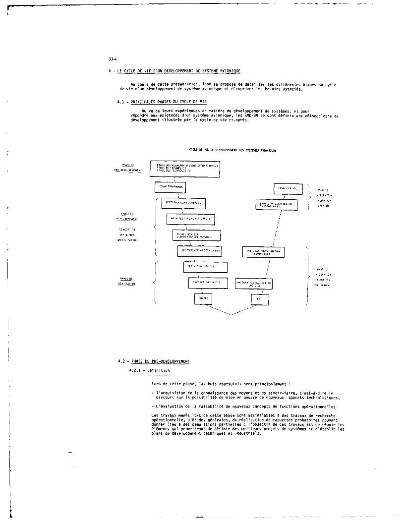
33-4
4 - LE CYCLE DE VIE D'UN DEVELOPPEMENRT DE SYSTEM4E AVONIQUE
Au courn de cette presentation. 1 'on se propose de dOtailler len differenten 6tapes du cyclede vie d'un d~veloppement de syst~me avionique et d'epriner 1es benoins ansoci Vs.
4.1 - PRINCIPALES PHASES DU CYCLE DE VIE
Au vui de leurs experiences en nati~re de dicveloppement de nyst~nes, et pourr~pondre ass exigences d'un systesne aelonique, len AND-BA se nonE d~finin tine n~thodologie ded~eeloppenent illustrise par le cycle de vie ci-apr~s.
CYCLE DE tIc nE DEVELOPME(NT DES nSsnEK uVIOniESs
PUASE DIE E...E ICI tD0jtS u EES !tS OPFEADTE.S-ETUD E CA"SAS:~ 'ET
INCAEEE.DPEUE-t FTJDE DES TECHNOLOGIES
'AS' ~ ~ tE .A OttE. . IO S
PHASE DESEN
SO 1.
0"'.DPEMENT ADTCEHt DH
DEFINITION 4t&ECTI"t SDARHITOCUE EYSIQDE
DPECI'ICATIOt
SPEOI''ricstsDEUtIDES ItTEDEATIDN.J LD'ID-
K~ EUPEME. TI
DE~~tIT' ID DIC
REtLISATION ZSGID oOIILFMEtE AA .tIt
4.2 -PHASE DE PRE-DEVELOPPEMENT
4.2.1 -Definition
Loin de cette phase, Ten huts poursuivis sont principalement
- acquisition de la connaissance des moyens et du savoir-faire, c'ent-A-dire leparcourn sur la possibilitA de mine en oeuvrne de nouveaux upports technologiquen,
-L',valuation de la faisabilit6 de nouveaux concepts de fonctions op~rationnellen.
Len travaus mes~s loins de cette phase snt ansimilablen a den travaus de rechercheop~rationnelle, d'6tuden gln~rales, de in~alisation de maquettes probatoires pouxuntdonner lieu A den simulations partiellen l'objectif de ces travaus est de r~unir lenelements qui permettront de d~finir den meilleurs pinojets de synt~mes et d'@tablir lenplans de dOveloppement techniques et industriels.

33-i
Cette phase fait appel A de nseibreuu interlocuteurs se traduisant notarmoent par
- des liens industriels-fquipenentiers pour les Lstudes, la technologie de base et lartalisation de maquettes probatoires,
- des liens indostriels-avionneurs-iquipementiers pour 1 analyse des contraintesd'avionnage, d'intigratium systfme et la caracttrisation des interfaces de dialogueLAquipage-systrne,
- des liens avec les centres 6tatiqoes pour livaluation par des utilisateurs.
4.2.2 -Besoino
Les besoins nicessaires dans cette phase de prds-divelopnewsot sont essentiellementdes "outils de fond" permnettant d'acquirir une connaihsance ;ceo outils reposentour den
- moyeno de simulation ligersou 00P4
maquettage,
- mayeno de simulation laurds.
4.3 -PHASE DIE DEFT'! loN
431- Spicifications glol'nles
4.3.1.1 - Dfinition
A partir den riosultats de la phase de pris-diveloppement (Lstudes de faisabilittet prt-Atudes de performance s) et des besoins opirationnels euprimis par lafiche programume, cette phase a pour objectif la dIffinition prilimisaire dusys time.
Par lanalyse des diffisrentes missions dont sera capable 1 avion, ii est proc~dau recensement den fonctiono opirationnelles et des moyn necessaires. Cette6tape fait one premiie description des fonctiono opirationnelles, du poste depilotage, des capteuro et de 1 architecture matirielle sous la tomye de spicificatiosginirales fisant le cadre des travauo A rialiser.
A 1 issue de ceo travaum, 11 not risalisis on document "modes et coffunandes" foomnissant1 enveloppe den posoibilitis do systime avionique. Ce document comporte deun partiesorienties "matiriel" et "fonctionnel":
- la partin "mat,§riel" prisente leo 6qoipements o soos-ensembles do syotineavionique, ceo derniero disignant leo capteors complexes nossidant diffirents modesde fonctionnement tels que radar, capteors optroniqoeo,..
- la partie "fonctionnel" prisente one philosophie ginirale d'utilisation de la cabine(coewnandes et visualisations) et dicrit leo diffirents modes de fonctionnement dosys time .
A partir de ce document "modes et coennandes", chaqom fonction optratisoselle faitlobjet d'un document "Sp&ica~tion globale" traduisant, en tenses d'objectifo Aatteindre, le ocdnario opirationnel d'utilisation :leo moyeno d'actioation, lesprincipales coewnandes/actions poosibles, leo visualisationo et leo moyn de sortie dela fonction.
4.3.1.2 -Besoins
Leo besoins ressentis pour coosrir cette 6tape sont de deus natures
- moyen de validation des concepts de dialogue Homue-machine et de certainoalgorlthmes.
Cette validation devra recoorir A des outils l~gers de oimulation mainoffrant one restitution soffiounte de l'environnenent cabine poor permettreon rebouclage avec: des utilisateuro finau.
- moyan de formalisation den risultats des travaun poor leo relectures puis letravail oval de conception.

33-6
Pour faciliter les relectures documeetaires effectu~es par ue grand sombred'istervenasts, la formnalisation dolt conserver l'util'Isution d'un langagenaturel mais garantir 1 'homogtshitEs des documents par le respect de plan-types.
4.3.2 - Architecture fonctionnelle
4.3.2.1 -Definition
A partir des besoins esprim~s loin de l'analyse fine des scenarios d'utilisationdes fonctions op~rationnelles, des hypotheses de mise en oeuvre des capteurs et dela philosophic d'utilisatios de la cabine, cette etape a pour but la description delarchitecture fonctionnelle du systfte. Ls rhsultat attends est un dhcoupage dusysteme en diffhrents modules fonctiosnels precast en compte des rigles d'evolstivit&s,de modulariti, de rhcupdrabllit6 et, rhuolvast len coeflits de ressources capteurs,cosueandes, visualisations lies A la superposition des fonctions.
Cette architecture met en evidence
- les chaises fonctionnelles par le cheminement des interfaces entres les diff~rentsmodules,
- 1 interdlspendance dec fonctios,
- le fractionsement du syst&se en modules fonctionnels pour lesquels les interfacesentrdes-sorties sont identifies.
4.3.2.2 -Besoins
Cette Atape, ensentielle pour la maltrise den systemes et particuli~rement pourla maitrine den evolutions et des modifications, justifie he recours A l'utilisationd'un outil formel pour garantir la visibilitA du synt~me. Le formahisme recherche doltpern'ettre:
1 - Use aide A ha conception du nyst~me en soutenant ha demarche de d~coupage,
2 - Use lisibilitA fonctiosnelie de chacuse den fonictioss optrationnelles aus ein de1 'architecture complete.
3 - La facilitA d'esploitatios den r~sultats pour len besoiss des ttapen avales.
4 - L'amelioratios de la commnunication estre len difftrents coscepteurs impliqu~s dams
la definition de larchitecture fonctissnelle.
4.3.3 - Architecture physique
4.3.3.1 - DHfirition
Le r~sultat de ha prec~sdeste etape permet de disposer d'une connalonance do systemsous ha foryme d'un ensemble de modules fonctionnels et de lenin interfaces. L'objet decette Atape est de projeter cette architecture fonctionnehle our larchitecturemat~rielle d~finie hors de ha phase preliminairs et, par iterations soccessives, detrouver ha meilleure rdpartitios.
Aisi len diff~rento modi en fonctionnels snt r~spartin dans les diffdrentsAquipements, cc gui permet d'idestifier A cv stade ha nature de transmission desschangen asahogiques ounsum~riques.
L'affectation de ceo modules ass differento Aquipements, outre les Avidentenaffectations as vu des fonctions premilres den Aquipements, n'effectue as regard descritLren suivants:
- vohutivith, charge calcul et volume mrAmoire des processeuro, debits des Achangestranoitast sur hen bun.

33-7
4.3.3.2 - Besoins
Au cours de cette #tape de superposition de larchitecture fonctionnelle surlarchitecteure mat~rie-$e, un tris grand sombre d'informations d'interfaces estmanipull et cette manipulation est reconduite lors des multiples it~rations. Aussile besoin se fait ressentir de disposer pour ce stade de dfinition d'un outil degestion dot@ de mecanismes visant A automatiser certalnes operations. De plus, ilconvient de pouvoir effectuer une validation de 'architecture physique au sens destransmissions numtriques par li'valuation des charges bus.
4.3.4 - Spcifications ditaillies
4.3.4.1 - DNfinition
Sur la-base des r6sultats des 6tapes amont, est 6tabli un ensemble de specificationsqui donneront lieu A la rfalisation des 6quipements et de leurs logiciels.
Chaque Aquipement est d~fini par les specifications suivantes
- Clauses Techniques d'Intsgration (CTI) :
- Son objet est de dsfinir iimplantation dans lavion, les contraintes davionnage.le r~le de li'quipement et son intigration au sein du systime.
- Specifications D~taillhes de Fonctions Op~rationnelles (SDFO) :
* Ces documents spdcifient les traitements effectuts par les fonctions logiciellesdans 1 'quipement ; pour les Aquipements de visualisations, ces specificationsd~finissent, de plus, la symbologie pr~sentte au pilote.
- Fiche d'Interface Analogique (FIA) :
Pour chaque liaison analogique de l'quipement, ces fiches specifient la naturedu chblage et les interfaces 6lectroniques d'imission o de reception.
- Fiche d'Interface Digibus (FID) :
Ceos fiches sp(cifient lensemble des communications (6change, fr~quence, nature,
codage, ...) de l'quipement via le(s) bus avec le reste du systLme.
4.3.4.2 - Besoins
L'ensemble des produits de cette 6tape forme le noeud de cnemlunicatio: entrel'avionneur-systLnier et les Aquipementiers. Aussi le besdin essentiel estd'Ltablir la meilleure communication possible entre tous leos intervenants. Cetterecherche de la meilleure communication conduit A des formalismes adapt~s A chacunedes specifications et A l'utilisation d'aides pour Aliminer les ambiguTtss, lesomissions, les incohsrences ....
Pour accroltre lefficacitA et limiter les dscouvertes tardives d'anomalies et deserreurs de sptcifications, le besoin s'exprime en termes de maquettage.
Les objectifs du maquettage sont les suivants
- s'assurer que le besoin est satisfait,
- donner aux concepteurs des moyens de verification par "une animation desspecifications papier" pour d~couvrir tr~s t6t les anomalies fonctionnelles oules erreurs de spcifications,
- #laborer des jeux de mise au point qui pourront Atre rlutilis~s lors despremires validations des logiciels relc,
- tester et valider les Avolutions.
11 faut noter la 'imite de cette validation qui ne peut prendre en compte leosressources r'lculatears et bus qu'avec une notion imparfaite du temps ; il s'agitessentiellement d'une validation fonctionnelle des specifications.
33-8
4.4 -PHASE DE REALISATION
4.4.1 - Dfinition, Besoins
['ensemble den sp~cificatlons issues des phases pricidenten, forme le point d'entrLede la phase de r4alination des 6qulpevents et des logicivln.
Pour reposdre aux exigences croisna..ten en terme dic criticitt, de volume. dtnultiplicitO des versions du logiciel, les efforts ont port@ sur la ntthodologie, legain en productivitt, lautoiatisation du procesnun de d~vvloppesent en particulier,la phase de resalisation est nubdivisee en noun-phases nO activitdn lonsalis6es, etpouvant Wte validfes avant le passage A l~a phase suivante.
Aussi pour r~pondre a cen objectifn, il consient de supporter Venemsle den Attapen der~allnation des logiciels par un ensemble d'outils coh~rents et adaptiss t en (,tapessent:
- Definition de logiciel.- Conception de logiciel.- Codage sur des chaines de programnation utilisant pluvivurs langages pour ropondreas mivux aus contraintes des diff~rentn programmnes operationnels.
- Te sts statiques et dynamiques.
4.5 -PHASE DINTESRATION ET DE NISE AU POINT
Apres la rialisation des 6quipements et leur validation unitaire chez len diff~rvntsinduntriels, la notion de systene va devenir effective. La preni~re 6tape de validation, Ace stade, concerne les travaus d'intgretien effectuts sur len "bants d'int~sqrationsyst~m'".
Un banc d'intgration syst~vie se d~finit tomine us moyes de stimulation, A partir d'enre-gistrement de veln r~vln, de l'ennemble des Equipements du nystk*s cAbl~s nur le c~blagv rc~vIde l'avion.
Le but de ten basts d'int~grution est la validation et la mine as point dusnyst:Lmeavionique et dent de sen fonctions op~tratlonnelles, dans us environnejent et use configsrationr~sistes, ass fins de limiter le nombre den essals en vol.
4.6 - ESSAIS EN VOL
Les essain en vol sent la phase finale de validation des synttnes avisniquen.
4.7 - [IASPECT DES EVOLUTIONS
4.7.1 - Origine
Len demandes d'@volution trouvent leur origine A deux niveass
- len 6volutions devandlen pour que le systfne natisfasse as mivux aus besoinsoptrationnels initialement exprim~n dens la fiche programne :cv snt len demandende modifications et d'amliorations issues des phases de nine au point et devalidation sol, vol.
- len evolutions dvnand~es pour que le nyst~ine satisfasse A de nouveaux besoinsop~rationnels ;cv sent len devandes d'Lvolutions correspondent a de nouvellesdemandes clients.
Dens len deux can, le traitement sera identique, cmune indiquAs ti-apr~n
4.7.2 -Procddure
Toute deunande ou proposition diOvolution se traduit par 1ltriture d'une fichede modification Atablie en tenses op~rationnels as nivvau syst~Ame.
Cette fiche de modification syst~ne ent inject~ dans le cycle de vie ded~veloppement as niveau appropriA pour y Atre instruite ;cette instructionpermet de6tablir lensemble des fiches d'Lvolution pour chacun des produitsconstituant le syst~me et touthfs par cette esvolution.

33-9
Une fois instruites. ces fiches de modifications systlime sont proposes lorsde conflrences techniques qui, au regard des coots, des dflais et de l'intrtopirationnel, d6cident de leur application.Lors du dlveloppenent, c'est par, le biais de ces confirences techniques quele systme avionique Ivolue en differents "tats systeme de dlveloppement"jusqu'A Il'tat oplrationnel appel "standard". De facon identique, lesystLme oplrationnel 6volue de standard en standard pour rlpondre a de nouveauxbesoins clients.
4.7.3 - besoins
Au regard des 6volutions, le besoin s'exprime par
- girer de faqon rigoureuse les demandes d'6volution et leur suivi,
- maintenir a jour l'ensemble de ]a documentation de spicification,
- Itre capable de consulter la ddfinition de chaque "ttat systdme".
5 - TRAVAUX ITI
5.1 - PRESENTATION
Dans le cadre du cycle de vie de ddveloppement d'un systeme avionique et du fait del'accroissement naturel des relations entre tous les cooptrants participant au ddveloppementde systdme (avionneurs, quipementiers, centre d'essais en vol, Ministdre de la Ddfense, ...)il est apparu ntcessaire de mieux organiser et renforcer ces relations plus particulidrementpour tout ce qui concourt a la conception du systdme, A la production et A la maintenance deslogiciels.
L'Otude ITI (Intdgration et Traitement de l'Information) rassemble des indistrielsavionneurs (AEROSPATIALE et AVIONS MARCEL DASSAULT - BREGUET AVIATION) et Equipementiers(CROUZET, ELECTRONIQUE SERGE DASSAULT, SAGEM, SFIM, SFENA, THOMSON-CSF) dejA entrainds Acoopdrer depuis de nombreuses anmes pour rlaliser des systdmes avioniques, ce qui permetde proposer de facon commune la rdalisation d'un systne de ddveloppement davionique (SDA)qui permette en particulier de formaliser les relations entre les industriels coopdrantspermettant ainsi d'assurer une meilleure qualit6 A un coot moindre et de profiter descompdtences et experiences acquises.
5.2- HISTORIQUE
Au cours de l'anne 1983, sur la constation de l'apparition systdmatique des logicielsdans les 6quipements et l'integration de plus en plus grande des difftrentes fonctions,1'6tucle IT] a orienti ses travaux vers la rlalisation d'un svt~me de dlveloppement avionique.Cette orientation rlpondait au besoin de maltriser les dllais et assurer la qualit6 dessyst6mes et plus particuliLrement le dlveloppement des logiciels. Le logiciel, par soninterchangeabilitL et son coot de production en strie quasiment nul, a permls de raiorter surlui des modifications qui auraient td longues et coOteuses d'introduire dans la partiematlrielle. Cependant, aprLs quelques annes d'exprience, les industriels adronautiques sesost apercus que cette souplesse du logiciel et son introduction massive mal maltrisepourraient presenter des risques graves.
Les premiers travaux engagls ont permis d'@tablir un cadre mlthodologique commun, synthLsed'un questionnaire prlsentant les mlthodes et outils de chacune des sociltls. Un cycle de viestandard a Ltd 6tabli mettant en evidence chacune des phases et les activitls associles. Pourchaque phase, l'analyse en matidre d'outillage a ts conduite sous les angles :
- offrir au concepteur-ddveloppeur une aide A ]a nature de l'activitd qu'il exerce,
- offrir des moyens de communication.
Ces travaux se sont concrltisls dlbut 85 par un document de splcifications globales du SDA.
A l'issue de ces travaux finalisant l'expression des besoins et A partir de l'valuationd'un grand nombre doutillages existants, la solution retenue a coneuit A la dtfinition de 2ateliers intLgrs : Un Atelier Systdme et un Atelier Logiciel communiquant entre eux.
L'Atelier Systlme couvre les phases de conception et de ddfinition de systtme, l'AtelierLogiciel les phases de conception et de dlveloppement logiclel.
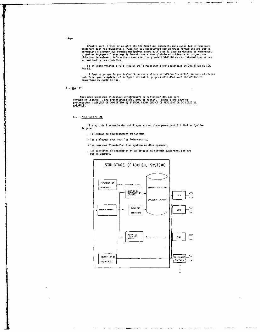
33-10
D'autre part, l atelier ne gore pas seulemnt des documents wais aussi les informnationscontenues dans ces documents ; latelier est caractfris6 par us grand formalisme des outilspermettant d'acc~der aux donntes manipultes entre outils et la base de donn~es de reference.L'atelier int~gris a lavantage de fournir une vision globale et coh~rente du projet, usereduction du volume d-informations avec une plus grande fiabilit6 de ces informations et useautuegatlsation des contr~les.
La solution retenue a fait l1objet de ]a redaction d'une Specification Detaill~e du SDAfin 85.
11 faut noter que la particularit6 de ces ateliers est d'@tre 'ouverts., au sees o6 chaqueindustriel peut comnpleter et int~grer ses outils propres afin d'assurer use meilleure
6 SAIIcouverture du cycle de
vie.
Noun noun proposons ci-dessous d'introduire la definition des AteliersSysteine et Logiclel ;use presentation plus precise faisant l'objet d'une secondepresentation :ATELIER BE CONCEPTION BE SYSTENE AVIONIQUE ET BE REALISATION DE LOGICIELEMBARQIE.
6.1 -ATELIER SYSTEME
11 s'agit de Il'essemnble des outilleges mis en place perinettant A1 'Atelier Syst~mede g~rer:
-la logique de developpement. du systne,
-les dialogues avec toun len intervenants,
-len deiandes d'6volution d'un systfine en d~veloppement,
-len activitfs de conception et de definition syst~me support~es par desoutils adapt~s.
STRUCTURE D'ACCUEIL SYSTEME
_[.ESTETS

33-11
6.1.1 -Structure d'Accueil syst~me
La Structure d'Accuejl Syst~ime assure les fonctions de
- initialisation de projet
- suivi des Avolutions
- gestion de configuration systfme
- int~gration des outils sptcifiques de latelier
- administrateur gdrant les droits d'accds.
Plus particulilsrement son rdle a pour objet
- linthgration des diff~rents outils de l'Atelier Systdine par desfchanges standards d'informations entre un outil amont et us outil anal,
- la gestlon de lenseetle de le documentation de specification du systhme,
- la gestion du plan de ddveloppenent,
- ]a gestion des coemmunications entre les diff~rents partenaires,
- par lapport d'un outil de documentation, elle assure la composition denrhsultats des diffhsrents outils pour l'laboration de la documentation despecification du systtine ,
- ]a gestion du suivi des 6volutions et la garantie de la cohitrence de l'ensembledes produits de spdcification Insus des outils par la gestion de lapplicationde mL'canismes au niveau de chacun des outils de l'Atelier assurant:
*l'instruction de la modification sous loutil tout en conservant l'6tat'avant" de la modification,
l a mesure de limpect de la modification par le csntrblv de la modi-fication en elle-cmfe et ems-A-vis de la specification,
*la redaction autoiratique de la fiche d'6volution.
6.1.2 -Outi1
de Conception Systeme (OCS)
La phase de dtfinition inst couverte per un outil en tours de d~veloppemest C(Outil de Conception SystIme).
11 supporte graphiquement une c~thode d'analyse hilrarchique, structurde etdescendante percettant d'apprfhender des nyst~mes complexes de cani~re gisneraleet d'en d~couvrir len distails au courn de l~tude.
Cet outil reprend us certain sombre de concepts de la cisthode IDEFO aunquels ostWtA adjoints de nouveaux concepts pour:
- aider Ala dhfinition d'interfaces effectu~s sicultea~ment per plusivursconcepteurn,
- identifier len diffdrenten chaises fonctionnelles,
- apporter des cdcanisines de rdcuperabilitdO.
6.1.3 -Outil cneunande de d~finition ansintl par ordisateur (DLAO)
La phase de sp~scification dftaillde inst couverte par un outil en sours dedOveloppement DIAO (Dlsfinition de Logiciel Assist~sm par Ordinateur). Cetoutil, utilinl pour l'6laboration de specifications de logiciel tempor~el, permet
- d'accroitre Ia qualit6 des sp~cificattons par un langage forcel asnoci6A des contr~les afim de limiter les erreurs de type ambigu~t@, omnission,incohirence, nursp~cification,..
- d'amlsliorer Ia comunication par la production de documents fiables etadapt~s aun besoiss den diff~rents intervenasts.

33-12
6.1.4 - Un outil de specification assistA par ordinateur (SAO)-----------------------------------------------------
En phase de sp~cification detaille, un outil conplfnentaire SAO (SpecificationAssistee par Ordinateur) est utilise.
Utilisant un outil de CAO schNnatique, cet outil permet la specification sousIa forme de planches graphiques des liaisions inter-equipements sans pr~jugerde la realisation (materiel ou logiciel) ; ces planches sont utilisees commesupport de coemmunication entre les diff~rents partenaires.
7 - ATELIER LOGICIEL
Les solutions de l'Atelier Logiciel sont proches de 1'Atelier Systeme en ce qui concerne lesfonctionnalit~s :.l'on trouvera une Structure d'Accueil assurant la gestion de configuration, lesulvi des evolutlons, iintgration des outils, le r6le d'administrateur et des outils spLcifiquespour couvrir les etapes de d~finition logiclel, conception logiciel, differentes chaines deprogrammation et des outillages de test.
Ce projet ENTREPRISE d'atelier logiciel, developpe sous la tutelle du Ministlre de la Defense,est decrit dans la seconde presentation.
8 - UTILISATION DE L'ATELIER SYSTEME AUX AMD/BA
Le coeur de l'Atelier Systeme AMD-BA est constitut de 1'Atelier Systmen ITI et de 1'ensembledes outillages communs auxquels ont ete adjoints un certain nombre d'outlis propres de maniere Aassurer une meilleure couverture de certalnes etapes du cycle de vie.
Nous presenterons ci-dessous les outlis complementaires puis un schema illustrant le supportapportE par i'ensemble des outils utilises aux AMD-BA au cycle de vie complet de d~veloppement.
8.1 - OUTILS SPECIFIQUES AMD-BA
8.1.1 - Outil d'6tude amont
La phase de spEcification globale, s'appuie sur un outil informatique OASIS (Outild'Aide A la Sp6cification d'Interface Homne-Syst&ne).
Cet outil permet la simulation pilotle de fonction operationnelle, reprAsentativedes commandes et visualisation de la cabine, pour l'itude et la validation du dialogueHomnme-machine et de certains algorithmes.
Trs souple d'utillsation, facile de mise en oeuvrn et rapide pour l'excution demodifications, cet outil d'etude offre un rebouclage rapide et efficace entre lesconcepteurs et les utilisateurs et ce, des le niveau des premieres definitions.
8.1.2 - Outils formels complmentaires
Phase architecture physique
Un outil specifique OEA (Outil d'Etude d'Architecture), en cours de realisation,permet de courvir cette etape. II assure une validation, au sens des transmissionsnumeriques, de 1'architecture ainsi definie par l'evaluation des charges bus.
Phase specification detaillse
- Un outil de specification d'imageries avioniques MITIA (Moyens Infonsatiques pour leTraitement des Imageries Avioniques) :
Cet outil se presente dans un environnement deCAO (Conception Assistee parOrdinateur) dont un ensemble de fonctions est particularise et enrichi pour cetteutilisation ; il permt de specifier par creation ou modification des reticules oudes figurations compl tes.
Le r~sultat lssu de cet outil prfsente la spscification sous la forme d'Editionpapler ou d'un fichier informatique dit "neutre" (fichier independant des machinesgraphiques) ; ce fichier par son formalisme et sa "neutralit", tisse un reseaupermettant une communication aisle entre les concepteurs, les centres desimulation et les equipementlers charges de realiser le logiciel de visualisation.

33-13
- Un outil de specification du cablage avion et des fiches dinterfaces analogiquesSYNOPTICS :
Bhti autour d'un logiciel de CAO schbnatique &lectrique, cet outil permet lasaisie des plans synoptiques de chblage avion et la rialisation des fichesdinterfaces analogiques ; il verifie les liaisons Alectriques au regard desrigles de Part et contrOle la coherence de l'ensenble de la liasse sch~matique.
- Un outil de specification des fiches d'interfaces num~riques GIN (Gestion desInterfaces Nunriques) :Cet outil supporte la specification des echanges entre les Ciff~rents 6quipementsselon 'architecture nwndrique compos~e d'un ou plusieurs bus et, & partir desprocedures de gestion d'6changes de type GINA, 1553-B, ARINC.
8.2 - COUVERTURE DU CYCLE DE VIE
Au regard du cycle de vie du developpeent d'un systne avionique, la couverture del'Atelier Syst~me precedemment expos~e se synthetise par le schema suivant
ATELIER SYSTEME DANS LE CYCLE DE VIE
VALIDATIONS"MCIMEDAIST ANALS CP0 F~TION VAL ATIOEM
VAIDTIN WWIILS ODUONLES FONTINSINN.
SMDLATSPECKF VALIDATION-lckl ANALYSEAE L AP OTION nION
VALIDATION - SCIFICATI ONS E LAI SNCTION DL VAL MIAToNE A SCAL ULS SCIENTIFIQUESO FOS ITIOTIELLOS E L
BAK 0 INTIATIONI
SDES ONCTION
VALIDATION FOKTIONI ,$ J. MO7U7 FOT /MODSLISATION - INTERFACE/
- A US qualI -pecifI N AION
- laido appRoe uT doX la diition dIt
OSS V ,FCTC S PCIT IONS KU DE MIST E IA
Do plusi obe experiences anati acenspfur ntetAeirSsmntdj t
-tiai~ porcre dve Ipnt dlue omeiviaete dostes votis. our liorin proucistenu
- lobaoitration d osoniatis entro In ir V_.E
- laideiapeore ar con ouis prlicAju olouetto o specifications.
]aderne anneotqu au couit deinareafinton do gnsy padistoicol ell
loic e CATsA (ocesptio n sis t rdmslanneIntr-Atv) raieas:N-A
Conanu anchsle d la coleurennt aoviniqui e fcie uosoou ioser aprdunctir
-ytn pourideelppenret donuveaus por ans Aur e laocnaIon deelopoientidcts
atelier en cue d'abontir a sa r alisation au debut 89.

34-1
A SOFTWARE LIFE CYCLE SUPPORT ENVIRONMENTby
L.Y. BajwaW.R. Wisehart
General Research CorporationP.O. Box 6770
Santa Barbara, CA 93160-6770U.S.A.
Frank S. LaMonicaRome Air Development Center
Griffiss Air Force Base, N.Y. 13441U.S.A.
SUMMARY
Under sponsorship of the U.S. Air Force Rome Air Development Center (RADC), aSoftware Engineering Environment known as the Software Life Cycle Support Fivironment(SLCSE) was specified and is currently undergoing a 24 month advanced development.
The SLCSE is a distributed, computer-based environment of software developmenttools and methods which span the full spectrum of the software life cycle and areintegrated through a common and consistent user interface and a life cycle projectdatabase. Primary features of the SLCSE are: (1) it supports both the development andmanagement of complex mission-critical computer resources (MCCR) software systems inaccordance with the DoD-STD-2167 life cycle model for software developsent, (2) it :multi-lingual - supporting the Air Force standard higher-order languages includirgMIL-STD-1589B (JOVIAL J73) and MIL-STD-1815A (Ada), and (3) through its unifyingframework, it enables the integration of both newly developed and existing(off-the-shelf) software tools. This paper will present the SLCSE development effort,including highlights of the SLCSE's architecture, requirements and top-level design.The implementation approach, which consists of a series r., eight incremental buil ls,will be described along with the results of the first build. Testinq and verificationplans will be discussed and risk areas identified. Finally, long-term plans by RADC toevolve the SLCSE beyond the current contractual requirements will he indicated.
I INTRODUCTION
The Software Life Cycle Support Environment (SLCSE) is a collection of i,.teqrateltools operating on a Digital Equipment Corporation VAX/VMS computer that will supportthe production of MCCR software throughout its entire life cycle. The tools areembedded in a framework consisting of a user interface and a database. At the highestlevel, integration of tools is brought about by this framework, which provides a commmon"look and feel" for all of the tools and provides access to all data avai'able toSLCSE user.
Supplementing this level of integration are the user assistance features, whichinclude tailorable, knowledge-based software development methodology direction, inaddition to the usual on-line information regarding details of tool operations.Finally, at the detail level, the tools are integrated in a particular instance of theenvironment by the specific management and development methods that are incorporateIinto the knowledge-base and the specific database entities that are incorporated intthe overall database schema. These data inputs are tailored to the project and projectmanagement parameters such as the life cycle model of the project, the project size, theskills and experience of project personnel, and so on.
1.1 Features
The principal features of SLCSE that addreds the needs of MCCR softwaredevelopment across its life cycle (regardless of the life cycle model chosen) are asfollows:
Completely Integrated Toolset. The project's needs for the entire life cycle arcmet by integrating a complete toolset in support of critical life cycle activities.Additionally, individual users will be identified by the role they are currently playingand directed to the proper tools and action sequences for performing role functions.
Flexible Development Methodology. The SLCSE will allow software developmentmethodology to be specified by the project manager. Consequently the individual uscroles can be delineated in deuail, including differing levels of control for differentroles. If the specified methodology permits a certain amount of trial-and-errordevelopment for certain user roles, SLCSE can be instructed not to issue error messagesif a set of tools is not used in a particular order. However, if a well-defined set ofprocedures is to be followed by another class of users, SLCSE can be set up to erforcethose procedures exactly as defined.
Development and Management Support. The needs of MCCR software project managerswill be addressed by the SLCSE. Project management planning, scheduling, and costingaids as well as problem reporting and status monitoring tools will be supplied.Configuration management tools will also be in place to support both software developers
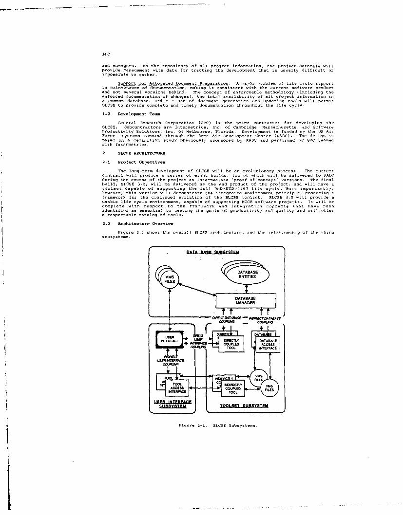
34-2
and managers. As the repository of all project information, the project database willprovide management with data for tracking the development that is usually difficult orimpossible to gather.
Support for Automated Document Preparation. A major problem of life cycle supportis maintenance of documentation, making it consistent with the current software productand not several versions behind. The concept of enforceable methodology (including theenforced documentation of changes), the total availabiiity of all project information ina common database, and t .2 use of documen' generation and updating tools will permitSLCSE to provide complete and timely documentation throughout the life cycle.
1.2 Development Team
General Research Corporation (GRC) is the prime contractor for developinc theSLCSE. Subcontractors are Intermetrics, Inc. of Cambridge, Massachusetts, and SoftwareProductivity Solutions, Inc. of Melbourne, Florida. Development is funded by the US AirForce Systems Command through the Rome Air Development Center (RADC). The design isbased on a definition study previously sponsored by RADC and performed by GRC teamedwith Intermetrics.
2 SLCSE ARCHITECTURE
2.1 Project Objectives
The long-term development of SLCSE will be an evolutionary process. The currentcontract will produce a series of eight builds, two of which will be delivered to RADCduring the course of the project as inte-mediate "proof of concept" versions. The finalbuild, SLCSE 3.0, will be delivered as the end product of the project, and will have atoolset capable of supporting the full DoD-STD-2167 life cycle. More importantly,however, this version will demonstrate the integrated environment principle, producing aframework for the continued evolution of the SLCSE toolset. SDCSE 3.0 will provide ausable life cycle environment, capable of supporting MCCR software projects. It will becomplete with respect to the franmework and integration concepts that have beenidentified as essential to aeeting the goals of productivity and quality and will offera respectable catalog of tools.
2.2 Architecture Overview
Figure 2.1 shows the overall SLCSE architecture, and the relationship of the threesuosystems.
DATA EADE SUESYSTEM
DIRECTDATaS -A VNORECTDATABASE
COUPLED ACES
USERI IWERFACE
NUBERFTE TOOLE USSE
Figure 2-1. StCSE Subsystems.

34-3
User Interface. The primary goal of the user interface is to provide a singleshell to the user for communicating with all tools in the SLCSE, for transferring datawithin the SLCSE, and for getting assistance on the use of tools and the environmentitself. The project will produce a standard set of user interface packages that will besupplied to builders of new tools along with guidelines for developing tools that matchthe desired interface principles. In SLCSE 3.0, invocation of an existing tool willadhere to the SLCSE user interface principles, but once invoked the tool will continueto use its current command language or menu systems. When off-the-shelf tools areupdated, they will be reviewed to determine the feasibility of redesigning their userinterfaces to the SLCSE standards.
Database. As with the user interface, the database subsystem for SLCSE 3.0 willemphasize the developmert of packages that will support the long-term goals of a fullyintegrated toolset. Interface routines will permit existing tools to make use of theSLCSE database, but databases or data files generated by these tools will not hereplaced in SLCSE 3.0. New tools, however, will communicate directly with the database,following guidelines published for using the database subsystem utilities. In thefuture, tools having their own internal databases may be redesigned for use of the SLCSEdatabase utilities, but that is likely to result in a more sweeping redesign than wouldbe required for changing the user interface of an existing tool.
Toolset. Users must perceive SIUSE as a unified collection of tools that workefficiently together. Tools that are added to the environment must be integrated intoit either by designing them that way, or by using the facilities of the user interfaceand database subsystem to provide the integration.
The goal criteria for integrating the toolset are as follows:
(1) Similarly invoked functions must operate from a uniformly similar user interface.
(2) User assistance must be prDvided in a uniform manner for all tools.
(3) Tools that communicate data to another tool must provide it completely, and in auniform format that all tool builders will us?.
(4) Tools Must provide management data in a uniform format to the management tols.
The degree to which these integration goals can be achieved depends on the lenreeto which tools are "coupled" to the user interface and database utilities.
(I) Directly coupled tools wil access the user interface and the database by callinntheir utilities directly to send and receive data, and will adhere strictly to theintegration goals.
(2) Indirectly coupled tools wilt generally communicate with the user interface anithe database through intermediate files, logical names, and global symbols thatare set up by interface routines and commanI procedures.
It is oenerally not possible to integrate existing tools under the above criteria.SLCSE 3.0 will call on the framework (i.e., the user interface and the database system)to providce the mechanisms for integrating such tools. This will be accomplished asfollows:
(I) Command interpreters and interface routines can be used to meet the top-level userinterface requirements, user assistance requirements, and the tool-to-toolcommunication requirements.
(2) Commands, menus, and help features that are already built into existinointeractive tools will be used as is until the maturation of the SLCSE brinusabout the desired tool modification, or the introduction of new tools tailored tothe environment.
The SLCSE 3.0 toolset will be largely assembled from existing tools, drawing oninterface routines to provide integration at the tool invocation level. Internalcommunications with the user and with data files will not be modified. This producessome compromises with respect to long-term toolset integration goals, but no compromiseswill be made in the framework itself.
Several new tools will be fully integrated into SLCSE 3.0. These inclide toolsbuilt under the SLCSE contract, and the Ada Test and Verification System (ATVS), whichwas designed under a RADC contract, and is now in its implementation phase.
In contrast to SLCSE 3.0, later versions of SLCSE will strive for direct couplinoof all tools. New tools will be built for direct coupling, using standard packages forcommunicating with the user interface subsystem and database subsystem that will be maleavailable t, tool developers as a part of their implementation contract. If an existingtool has a desired capability, it will be modified for direct coupling, or if that isnot possible due to the design cf the tool, it will be recoded using the standardinterface packages. Indirect coupling in later builds will be used primarily forevaluation of an existing tool to determine if its capabilities warrant including it asa regular (and thus directly coupled) component of the environment toolset.
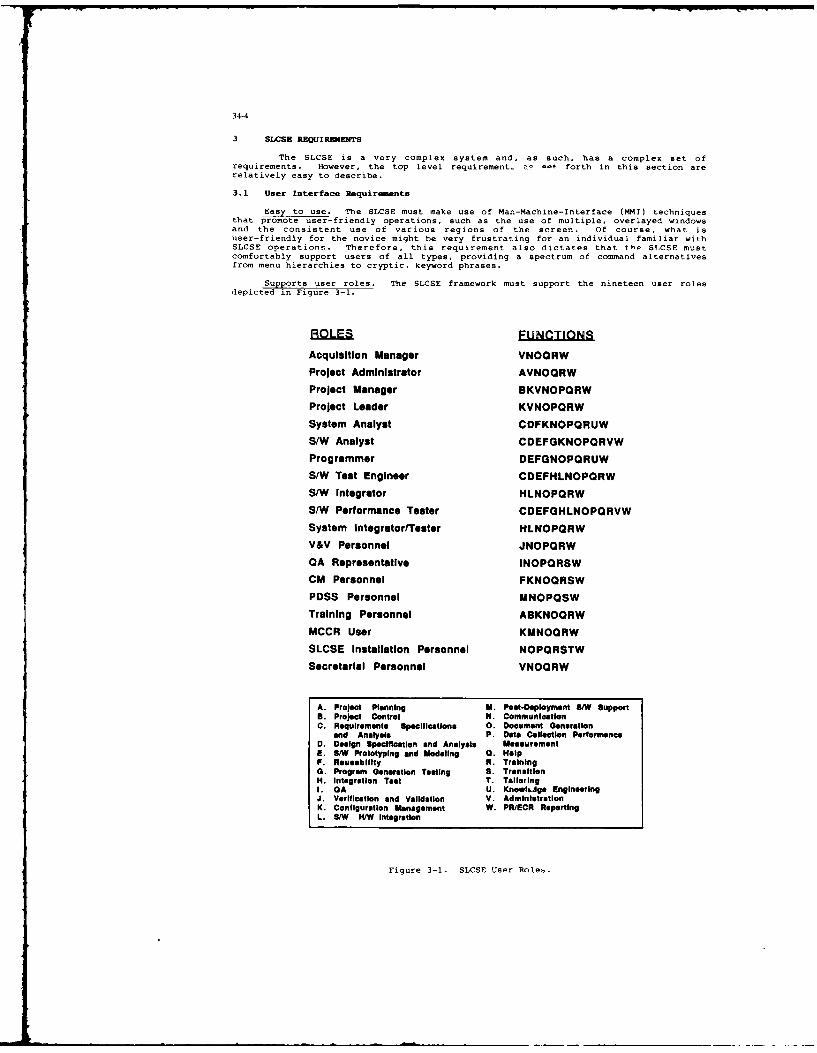
34-4
3 SLCSE REUIREMENTS
The SLCSE is a very complex system and, as such, has a complex set ofrequirements. However, the top level requirement. c -et forth in this section arerelatively easy to describe.
3.1 User Interface Requirements
Easy to use. The SLCSE must make use of Man-Machine-Interface (MMI) techniquesthat promote user-friendly operations, such as the use of multiple, overlayed windowsand the consistent use of various regions of the screen. Of course, what isuser-friendly for the novice might be very frustrating for an individual familiar withSLCSE operations. Therefore, this requirement also dictates that the SLCSE mustcomfortably support users of all types, providing a spectrum of command alternativesfrom menu hierarchies to cryptic, keyword phrases.
Supports user roles. The SLCSE framework must support the nineteen user rolesdepicted in Figure 3-1.
ROLES FUNCTINSAcquisition Manager VNOQRWProject Administrator AVNOORWProject Manager BKVNOPQRWProject Leader KVNOPORW
System Analyst CDFKNOPORUWS/W Analyst CDEFGKNOPQRVWProgrammer DEFGNOPORUW
S/W Test Engineer COEFHLNOPORWS/W Integrator HLNOPQRWS/W Performance Tester CDEFGHLNOPORVWSystem Integrator/Tester HLNOPQRWV&V Personnel JNOPORWQA Representative INOPQRSWCM Personnel FKNOORSWPDSS Personnel MNOPQSWTraining Personnel ABKNOQRWMCCR User KMNOQRWSLCSE Installation Personnel NOPORSTW
Secretarial Personnel VNOQRW
A. Project Planning M. Post-Deployment 5/W SupportB. Project Control N. CommunicationC. Requirements Specifications 0. Document Generation
and Analysis P. Data Collection PerformanceD. Design Specification and Analysis MeasurementE. 5/W Prototyping and Modeling 0. HelpF. Rusability R. Training0. Program Generation Testing S. TransitionH. Integration Test T. TailoringI. GA U. Knowh,ge EngineeringJ. Verification and Validation V. AdministrationK. Configuration Management W. PR/ECR ReportingL. S/W H/W Integration
Figure 3-1. SLCSE User Roles.
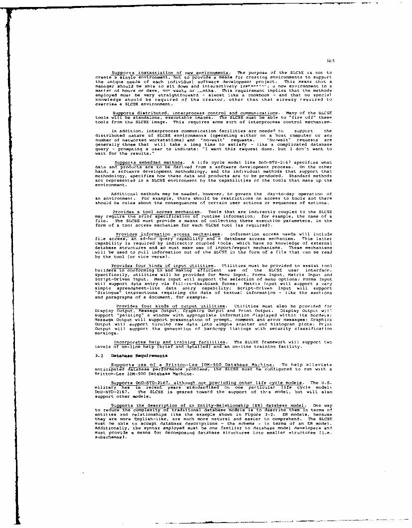
34-5
Supports instantiation of new environments, The purpose of the SLCSE is not tocreate a single environment, but to provide a means for creating environments to supportthe unique needs of each individual software development project. This means that amanager should be able to sit down and interactively instx-"t' a new environment in amattmr of hours or davs, no* weeks or ...nths. This requirement implies that the methodsemployed must be very straightforward - almost like a cookbook - and that no specialknowledge should be required of the creator, other than that already required toexercise a SLCSE environment.
Supports distributed, interprocess control and communications. Many of the SLCSEtools will be standalone, executable images. The SLCSE must be able to "fire off" thesetools from the SLCSE image. This requires some sort of interprocess control mechanism.
In addition, interprocess communication facilities are needed to support thedistributed nature of SLCSE environments (operating either on a host computer or anynumber of networked workstations) and "no-wait" requests. "No-wait" requests aregenerally those that will take a long time to satisfy - like a complicated databasequery - prompting a user to indicate: "I want this request done, but I don't want towait for the results."
Supports embedded methods. A life cycle model like DoD-STD-2167 specifies whatdata and products are to be derived from a software development process. On the otherhand, a software development methodology, and the individual methods that support thatmethodology, specifies how these data and products are to be produced. Standard methodsare represented in a SLCSE environment by the capabilities of the tools that make up theenvironment.
Additional methods may be needed, however, to govern the day-to-day operation ofan environment. For example, there should be restrictions on access to tools and thereshould be rules about the consequences of certain user actions or sequences of actions.
Provides a tool access mechanism. Tools that are indirectly coupled to the SLCSEmay require the prior specification of runtime information: for example, the name of afile. The SLCSE must provide a means of collecting these execution parameters, in theform of a tool access mechanism for each SLCSE tool (as required),
Provides information access mechanisms. Information access needs will includefile access, an ad-hoc query capability and a database access mechanism. This lattercapability is required by indirectly coupled tools, which have no knowledge of externaldatabase structures and so must make use of import/export mechanisms. These mechanismswill be used to pull information out of the SLCSE in the form of a file that can be readby the tool (or vice versa).
Provides four kinds of input Utilities. Utilities must be provided to assist toolbuilders in conforming to and making efficient use of the SLCSE user interface.Specifically, utilities will be provided for Menu Input, Forms Input, Matrix Input andScript-Driven input. Menu Input will support the selection of menu options; Forms Inputwill support data entry via fill-in-the-blank forms: Matrix Input will support a verysimple spreadsheet-like data entry capability; Script-Driven Input will support"dialogue" interactions requiring the data of textual information - like the sectionsand paragraphs of a document, for example.
Provides four kinds of Output utilities. Utilities must also be provided forDisplay Output, Message Output, Graphics Output and Print Output. Display Output willsupport "painting" a window with appropriate information displayed within its borders:Message Output will support presentation of prompt, comment and error messages: GraphicsOutput will support turning raw data into simple scatter and histogram plots: PrintOutput will support the generation of hardcopy listings with security classificationmarkings.
Incorporates help and training facilities. The SLCSE framework will support twolevels of on-line help (brief and detailed) and an on-line training facility.
3.2 Database Requirements
Supports use of a Britton-Lee IDM-500 Database Machine. To help alleviateanticipated database performance problems, the SLCSE must be configured to run with aBritton-Lee IDM-500 Database Machine.
Supports DoD-STD-2167, although not precluding other life cycle models. The U.S.military has in recent years standardixed on one particular life cycle model:DoD-STD-2167. The SLCSE is geared toward the support of this model, but will alsosupport other models.
Su ports the description of an Entity-Relationship (ER) database model. One wayto red the complexity of traditional database models is to describe them in terms ofentities and relationships like the example shown in Figure 3-2. ER models, becausethey are more English-like, are much more natural and easier to comprehend. The SLCSEmust be able to accept database descriptions - the schema - in terms of an ER model.Additionally, the syntax employed must be one familiar to database model developers andmust provide a means for decomposing database structures into smaller structures (i.e.subschemas).

34-6
Figure 3-2. Sample Entity Relationship (ER) Model.
Supports ER-type database queries. The SLCSE must support both direct andindirect ER-type database queries. Application tools that "know" about the ER structurewill make direct database queries; other applications will depend upon interfacemechanisms that make use of a standard query language. Both static (precompiled) anddynamic (on-the-fly) queries must be supported.
Supports version management. The database is not a fixed structure; it has a"timeline" sense as well. The SLCSE must support control and management of differentversions of database items.
Supports control of database access. Users must not be allowed to change the samedatabase element at the same time. The SLCSE must support a system of databaselocking/unlocking mechanisms to prevent such an occurrence.
Additionally, there must be support for data distribution. Altbhugh there will beonly one master database, hosted by a single computer, the SLCSE must be able to deelwith a network of computers running the same environment, but either requestinginformation from the master database or downloading/uploading portions of the masterdatabase.
Supports database archiving. It periodically becomes necessary to archiveportions of a database. The SLCSE must support this function in an efficient manner.
3.3 Toolset Requirements
Su8ports integration of 30 toos in ten tool cat-gories. SLCSE 3.0 will supportcommmercial tools, overnment-furnished (GFE) tools and tools especially built forintegration into the SLCSE. The tools are listed in Figures 3-3 and 3-4 in terms often tool categories. Briefly, the tools are as follows:
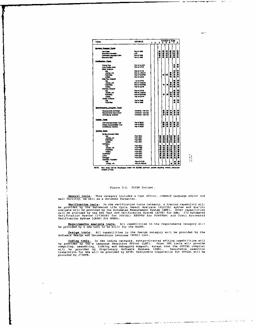
34-7,
TOOL GOURCE 1 2 32
TW Eder EUUUSE"=W wF_ s
0-. F--A O
ftU W4 P~tv UEE
00ftA.0 VCW P U AT"
AtPWI"UU
0MPaM atCAVSUUU
~VW.WI a J7AVSU UFOIrVA P.1*at5W Fur""
ccmP.I5AVS
00*P.1 W AA N d
O ~ ~ U.- U - W
.. .. C P ,U.....a0
A0 FWCOEC U UJOIAL 03 Fo~S DOUE*
FOFC *EEUUCCOs,,rsc DECEE
CIS"E
F 0C EK KU
4A. of
Xft J3 1 PIJ2Vs I I UM0
Figure 3-3. SLCSE Toolset.
General tools. This category includes a text editor, cormmand language editor andmail f-cility, as well as a document formatter.
Verification tools. In the verification tools category, a tracing capability willbe provided by the Automated Life Cycle Impact Analysis (ALICIA) system and qualityanalysis will be provided by the Automated Measurement System (AMS). other capabilitieswill be provided by the Ada Test and Verification System (ATVS) for Ada; J73 AutomatedVerification System (J73AVS) for JOVIAL; RXVPSO for FORTRAN: and Cobol Automatedverification System (CAVS) for COBOL.
aeureet anlysis tools. All capabilities in the requirements category willbe providd by a ne.watool to be built for the SLCSE.
Design tools. All capabilities in the design category will be provided by theSoftware Design and Documentation Language (SDDL) tool.
Codinqtools. In the coding category, syntax-directed editing capabilities willbe provfded by DEC's Language Sensitive Editor (LSE). Other DEC tools will providecompiling, assembling, linking and debugging support, except that the JOVIAL compilerwill be provided by Proprietary Software Systems (PSS). Executable assertiontranslation for Ada will be provided by ATVS; Executable translation for JOVIAL will beprovided by J73AVS.

34-8
TOOL. SOURCE
Aft~ PM OfATWS
CommJ7 PMO01 CAVSU
PM Eome AnyWA.PWOATVS 10U~JO7J3 PW 0J7AVS 01 11
01 Pw.g CAW UU
AmP.I.ATVSWWi's PM ofJ7AVS
00aPWIMCAVS
T" . S Tn
TW DOPU Lft...g ..hWW h~MeW&.1y PM ofAXIA U
P1 ?M a a
M- EdbPrmin P VVVNWE 0
themS. Ed Uke -= No
SElk. iw-N-5s : :
amwC...d aotft be IS SASS bU....W1
ad JNA U.
MMT! HM. US. WIN b@ d..~dW th. S. CSE .5555, .b .Idkqg., p~e.5ypV.W.. of twi
Figure 3-4. SLCSE Toolset (Continued).
etigtol.. A Test Manager and Test Data/Results Manager tool will be builtfor the LCE Other capabilities will be provided by ATVS, J73AVS, RXVP8O and CAVS.
Configuraton Waaemn tol. A Software Configuration Manager andDocumentation M1anagr will be built'Ofor the SLCSE. Change impact analysis capabilitieswill be provided by ALICIA.
Prjet manalgent tools. All project management capabilities will be provided bythe Autmated Proec t Management System (APMS).
Environment management tools. All environment management capabilities will beprovided by-new tools built for the SLCSE.
Prottypn~ tols Prototyping and special purpose tools will be included in thiscatgoy, ncudig window prototyper (WINNIE).
4 SLCSE MAJOR DESIGN CONCEPTS
4.1 User Interface Design Cncepts
Data )-iven Interfaces. The SLCSE user interface will make substantial use of aspiticaeZ idw mngmn pcae (INE n n soitd tbe die
mechanism (MOO). This existing software will make it much easier to design and tailoran easy-to-use interface. The WINNIE and MOO packages support a rich repertoire ofwi ndowing operations and do so in the fore of input data, not code. See Figure 4-1.This means that the SLCSE design process can easily include a number of successivelyimproved user interface prototypes. This is important because experience has shownthat easy-to-use is a subjective sort of requirement; users need some framework to workwith in order to provide feedback on user-friendliness.
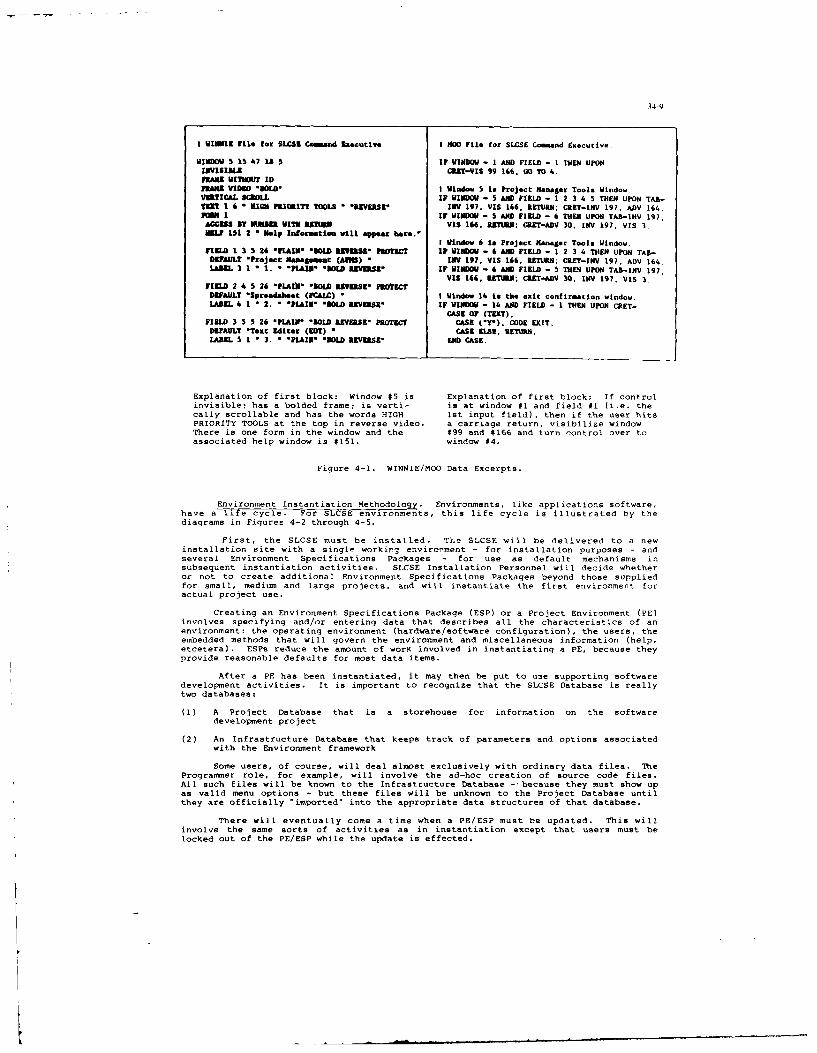
34-9
t W/fIMM FiLe for SLjCS Commnd Executive I 350 File for SLCSE Comand Executive.
WINDOW S 15 47 18 5 IF WINDOW - I AND FIELD - 1 THEN UPONIIVISIBIE CRST-ViS 99 166. GO TO 4.PAR uITiOUT IDlANE VIDEO *M0SD I Window 5 to Project Ranager Tools Window.
VERTICAL SCROLL IF WINDOW - 5 AND FIELD - 1 2 3 4 5 THEN UPON TAB-TESTI 6 * MIGK PIORITY TOOLS * "BVEUSE IIV 197. VIS 166, RETURN; CRET-INV 197. ADV 164.-M I IF WINDOW - S AND FIELD - 6 ThEN UPON TAB-INV 197,ACCESS BY MAIR WITH 311T3 VIS 166. REURN; CRZ1-ADV 30. INV 197, VIS 3.HELP 151 2 1 Nlp Inforuatite will appear bere.
I Window 6 is Project Rneger Tools Window.FIRLD 1 3 5 26 "fLAIN" 0LD 3EUS" PROECT IF WINDO - 6 AND FIELD - 1 2 3 4 THEN UPON TAB"DEFAULT *Project eaSammasut (AIM) " INV 197. VIS 166. RETURN; CRET-INV 197, ADV 164,lamEL 3 1 1 1. * PLA&IN &OLD R9EVZS IF WINDOW - 6 AND FIELD - 5 IWE UPON TAB-INV 197,
VII 166, EWWRN; C€.ET-AUV 30. INV 197, VIS 3.FIELD 2 4 5 26 Pl.IA" "SOLD RVESE, PROTECTDEFAULT "Spreadsheet (FCALC) I I Window 14 Is the exit confirmation window.LABEL 4 1 * 2. 1 *PLAIN* *OLD REVERSE" IF WINDOW - 14 AND FIELD - 1 TEN UPON CRET-
CASE OF (TEXT),FIELD 3 S 5 26 'PLAIN* "BOLA REVERSE" PROTECT CASE ('Y"). CODE EXIT.DEFAULT *Text Miter (E0T) * CASE ELSE. RETR,.LABEL 5 1 1 3. 'PLAIN* *OLD REVERSE" END CASE.
Explanation of first block: Window $5 is Explanation of first block: If controlinvisible; has a bolded frame; is verti- is at window #1 and field #1 (i.e. thecally scrollable and has the words HIGH lst input field), then if the user hitsPRIORITY TOOLS at the top in reverse video. a carriage return, visibilize windowThere is one form in the window and the #99 and #166 and turn control over toassociated help window is #151. window #4.
Figure 4-1. WINNIE/MOO Data Excerpts.
Environment Instantiation MethodoloU. Environments, like applications software,have a life cycle. For SLCSE environments, this life cycle is illustrated by thediagrams in Figuree 4-2 through 4-5.
First, the SLCSE must be installed. The SLCSE will be delivered to a newinstallation site with a single workirg environment - for installation purposes - andseveral Environment Specifications Packages - for use as default mechanisms insubsequent instantiation activities. SLCSE Installation Personnel will decide whetheror not to create additional Environment Specifications Packages beyond those suppliedfor small, medium and large projects, and will instantiate the first environment foractual project use.
Creating an Environment Specifications Package (ESP) or a Project Environment (PE)involves specifying and/or entering data that describes all the characteristics of anenvironment: the operating environment (hardware/software configuration), the users, theembedded methods that will govern the environment and miscellaneous information (help,etcetera). ESPs reduce the amount of work involved in instantiating a PE, because theyprovide reasonable defaults for most data items.
After a PE has been instantiated, it may then be put to use supporting softwaredevelopment activities. It is important to recognize that the SLCSE Database is reallytwo databases:
(1) A Project Database that is a storehouse for information on the softwaredevelopment project
(2) An Infrastructure Database that keeps track of parameters and options associatedwith the Environment framework
Some users, of course, will deal almost exclusively with ordinary data files. TheProgrammer role, for example, will involve the ad-hoc creation of source code files.All such files will be known to the Infrastructure Database -, because they must show upas valid menu options - but these files will be unknown to the Project Database untilthey are officially "imported" into the appropriate data structures of that database.
There will eventually come a time when a PE/ESP must be updated. This willinvolve the same sorts of activities as in instantiation except that users must belocked out of the PE/ESP while the update is effected.
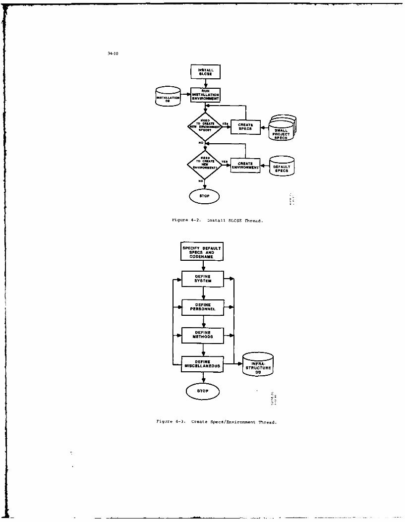
34-10
Fiue4-. IstalSCE hed
INSTALATION ENOMEN
SYToEM E CET
PERSONNEL
DEEINTHoDSEAE E
Figurure2 4nsta. Create ThrsEvo e adTred

SPECIFY
ENVIRONMENT
N TEOT EXIT
UPAT UPDA DATBAS
UPDABTE
ETHIODMEETOD
NEED TO It
UPDATE YS UPDATE
UNOCKNE PERECNNE
EVIOME METOD
UPDDATAPAAE
MSOPmsc
Figure 4-5. Update Specs/ Env irornent Thread.

34-12
HOST WORKSTATION
TOLCEE LCE TOOLERSUPOES PROCESS SRCS UBPROCESS
Figure 4-6. Scheduler Mechanism.
Scheduler Mechanism. The Scheduler Mechanism has been designed in two parts: aTooler and a Message Handler. Refer to Figure 4-6.
Each SLCSE process, during its initialization, will spawn a Tooler subprocess thatwill communicate with the main process via mailbox services. The Tooler subprocess willhibernate until sent a command from the main process. It will execute this command,taking temporary control of the screen. This is the manner in which standalone,executable images will be controlled from SLCSE processes.
Also, each computer in the environment will have a single, detached MessageHandler process. All SLCSE processes will establish communication with this MessageHandler, which will take care of "no wait" requests via a SLCSE batch queue and willhandle the distributed aspects of an environment via network utilities.
SLCSE KNOWLEDGE BASEPROCESS PROCESSFIL 1 ACTIVITY
HANDLER MONITOR
ACCESSPRIVILEGES Pp ACTS RULES
Figure 4-7. Methods Mechanism.
Methods Mechanism. The Methods Mechanism has been designed in three parts: anActivity Monitor, a File Handler and a Knowledge Base. Refer to Figure 4-7.
The Activity Monitor keeps track of user requests and sequences of user requests,deciding when to invoke the File Handler and Knowle6ge Base and when to updateinformation about the current situation (i.e. the facts). The File Handler usesoperating system utilities to prevent unauthorized access to files. The Knowledge Base- implemented in Prolog - will store and enable assessment of procedural type rulesgoverning an environment. This will be the mechanism whereby a project manager can bothencourage and enforce adherence to project specific methods.

34-13
Pa..er..
............
Figure 4-8. Schema Language Compiler.
4.2 Dtabase Desiu Concepts
SMARTSTAR/OMNI5ASE. There is only one commercial database management system thatuses the Britton Lee Database Machine: OMMIBASE. Fortunately OMIIBASE has a lookalike -SMARTSTAR - that can make use of ordinary disk units. The SLCSE will be developed usingSMARTSTAR, but wilt be installed at the RAD Computer Facility using OMNIRASE.
Schema Generator. The SLCSE Database Schemas and Subschemas will be developed inthe form of Entity-Relationship (ER) models which will be expressed in an Ada-likelanguage. This language wilt be compiled as illustrated in Figure 4-8.
The Lexer/Parser witl transform the input text into tokens, parsing them intointernal tables of information. In the process. i* will report syntax errors andproduce a cross-reference listing of entities, attributes and relationships, showingwhere they are defined and used.
The Optimizer will select attributes to be indexed and will select representationsof relationships, so as to optimize runtime access speeds.
The Generator will read the tables produced by the LexeriParser or the Optimizerand generate the final outputs of the compiler:
(1) Database Creation Code, a file of Structured Query Language (SQL) statements thatwilt create and initialize an empty database that matches Lhe input schema(s)
(2) Schema DeiiinTables, dapackages ta wilb usdfrtype checking by
SLCSE applications

34-14
SLCSE Application -
Fatill Attrboto Relationshlp Carsor V.ISI 0
SL ER Interface Ht °rSill son status
statenmts Vorials Cod
SmartStar / Omnibase
Records, Records, Tuples
Files Files J U__
Figure 4-9. Database Interfaces.
ER Interface. Ultimately, a SLCSE application will want to store and retrieveinformat ion rom the SMARTSTAR/OMNIBASE Database, still making use of the ER modelforms. Using the Schema Definition Tables produced by the Schema Language Compiler, aSLCSE application will communicate an ER-type request to the ER Interface, which will inturn communicate the request to the underlying database, SMARTSTAR/OMNIBASE. See Figure4-9.
4.3 Toolset Design Concepts
Tool Integration Guidelines. Guidelines for coupling tools with the SLCSE will bepublished as part of the Software Programmer's Manual.
Directly coupled tools will conform to user interface standards set forth in theguidelines and will know about and make direct use of the SLCSE Project Database.Directly coupled tools, then, will look and act like extensions to the SLCSE framework.
Indirectly coupled tools will maintain their original user interface and willneither know about nor make direct use of the SLCSE Project Database. This means thatthere will be a non-SLCSE look to such tools and that interface mechanisms may have tobe designed to preprocess or postprocess data for their internal, non-SLCSE databases.
5 SLCSE IMPLEMENTATION AND RESULTS TO DATE
5.1 The Eight Incremental Builds
As previously mentioned, the SLCSE is being de eloped in a series of eightincremental builds spanning a twenty-four month period. Refer to Figure 5-1. Builds 1through 7 are three months in duration (a quarter system). The last developmentalquarter will be a one month build (Build 8) followed by two months of installationactivities. An incremental build approach was chosen to enable early prototyping ofcritical functions and to provide an "early warning" mechanism for an ambitiousdevelopment schedule. New capabilities are demonstrated at the close of each quarter:if the required capabilities cannot be demonstrated, the project is behind schedulel

34-I5
APUSPrototype Knowledge One Tol
VAMfMS iegred Bae InestsedLook Tools omnieachand VWmy Integraed Complete Estblih Toolset Complete Ile*&Feel Of SLCSE Eiwroqnenl Cabe"i SLCSE Trekfi
Of Usef Scheduler Doe Dome C~ Too"t Files CompleteInteuface Mechanism Geneatton & & UIies Envrorene Convesion
Darbullon Advice/ M Comple Test. toDtabase Database Database Moi Too User Testing. OMNIBASE
IWaerfes unctona Tool Access Access i Plie Integrated Walae Tesng... DBMS
BuiW Build2 BWW id3 BLi4 Build5 Buikl6 uid7 Buid8 Install
Concept Framework Toobet I Database Method Toolsel 2 Toobet 3 Shakedown
Vaidaion Integration Oplkation Support Irtegration Integration
Figure 5-1. SLCSE Builds and Major Milestones.
Build 1 - Concept Validation - will demonstrate the "look" and "feel" of the UserInterface and establish specifications for the various Database Interfaces. Build 2 -Framework - will prove the viability of the Scheduler mechanism and will demonstratelimited Database functionality. Build 3 - Toolset I Integration - will integratestandard operating system tools into the SLCSE, will demonstrate full Databasefunctionality and will introduce a Tool Access mechanism (for indirectly coupled tools).Build 4 - Database Optimization - will complete the SLCSE Database Subsystem andassociated database management utilities, will demonstrate a Database Access mechanism(also for indirectly coupled tools) and will integrate a prototype Automated ProjectManagement System (APMS). Build 5 - Method Support - will implement a SLCSE Rule Basesupporting methodology-based advice and monitoring features and will demonstrate thecapability to instantiate a new environment. Build 6 - Toolset 2 Integration - willintegrate all Environment Management tools and at least one tool from each of the othertool categories. Build 7 - Toolset 3 Integration - will complete the SLCSE UserInterface and will integrate the complete SLCSE Toolkit, including tools being builtunder other Air-Force-sponsored contracts. Build 8 - Shakedown - will install help andtraining facilities for the SLCSE and will include production testing of the system.
The Preliminary Design Review (PDR) and Critical Design Review (CDR) will be heldat six and twelve months into the project, respectively. However, because of theincremental builds, both of these reviews will involve preliminary designs, detaileddesigns and actual code.
Three versions of the SLCSE will be installed at the Rome Air Development Centercomputer facility. Version 1.0, at ten months into the project, will be geared towardthe support of coding functions. Version 2.0, at nineteen months into the project, willsupport coding, project management and SLCSE installation functions and will demonstratesome functionality across the life cycle for at least one of the supported programminglanguages. Version 3.0, at twenty-three months into the project, will support thecomplete software development life cycle for Ada, JOVIAL, FORTRAN and COBOL.
5.2 Build I Results
Build I was completed in early December, 1986, as scheduled.
A SLCSE user interface was designed and demonstrated. Referring to the sampledisplay in Figure 5-2, the User Interface makes full use of advanced windowingtechnologies. The current process (either SLCSE or one of the SLCSE tools) is indicatedat the top of the screen, along with the current user role (on the far right) and thecurrent object (on the far left), if any has been specified. The bottom of the screenis used consistently for prompt, error and comment messages. The SLCSE may be exercisedin either Menu Mode or Keyword Input Mode. Every Menu option has an identical Keywordoption. However, in Keyword Input M'de, the user only has to enter as many charactersas are needed to uniquely identify the option. In Menu Mode, command buttons appearunderneath the top line with the following meanings:
OBJECTS - for a list of available files/database itemsTOOLS - for a list of available software development toolsPROCEDURES - for a list of available software development proceduresADVICE - for various kinds of advice on software tasksMODE - to change user modes/parametersHELP - for detailed help on how to use the SLCSEEXIT - to get out of the SLCSE

34-16
COE quarterly report AcquisitionManager
OBJECTS lNN PROCEDURES ADVICE MODE HELP EXIT
1. Verifica Mlin
2. Quality *in3. Change ' 2. Project
4. Problem/ 3. OA'Confil 2. Format and Print Text (LOP)
5. Print Li: 4. Environmi 3. PROMPT6. Text Edi: S. Requirem 4. Print Listing (PRINT)
7. Format . 6. Design i S. Electronic Mail (MAIL) SELECT
8. Electron, 7. Prototyp. 6. VAX Phone Utility (PHONE COPY9. File Tra: S. Coding 9. Spreadsheet (FCALC or 28 CREATE
18. 9. Integrat 8. File Transfer (KERMIT) EDIT
-18. Uerifica! 9. Import Data to DO DELETE
18. Export Data from DO LOWER
Press <RETURN> to select an item, use arrow keys to navigate, or press
<BACKUP KEY> to move to the previous window.
Figure 5-2. Sample SLCSE Display.
Windows drop down from the command button line. For objects, tools and procedures- referred to collectively as components - the windows cascade down and to the right inthree tiers. The highest level menu displays the components commonly used on aday-to-day basis; the next level menu displays a list of component categories; thelowest level menu displays a catalog of all components available to the user in aparticular component category. These displays are tailored for each user role so that,for example, what a Programmer sees is different than what a Project Manager sees.Additionally, each user may tailor their own particular displays by raising componentsfrom the component catalog to the "commonly used" menu or lowering components from the"commonly used" menu to the component catalog. While many of the components availableto the user are under database control, users may also work with private, non-controlledcomponents. These may be created, copied and deleted by bringing up a special menu asshown in the lower righthand corner of Figure 5-2.
The tailoring capabilities supported by the SLCSE User Interface will go a long
way toward fostering user acceptance of SLCSE environ;ents.
6 SLCSE TESTING & VERIFICATION
Development of the SLCSE will advance the state-of-the-art in software toolintegration technology and software development life cycle support by undertaking thedesign and implementation of highly sophisticated and complex Man-Machine-Interface anddatabase components as well as the difficult integration of new software developmenttools with existing off-the-shelf capabilities. There is moderate technical risk indeveloping an environment such as the SLCSE, not only due to the required functionality,but also due to performance concerns; a sluggish environment, no matter how effectiveand easy-to-use, will not be accepted by users. With this element of risk, testing andverification activities to be performed by both the contractor and the Government arecritical.
Verification is the iteratie process of deteri:ining whether the developingproduct, at each phase of the life cycle, fulfills the requirements estatlished by theprevious phase. The process provides a level of assurance that serious, -riors do notexist, that all user requirements have been supported, and that critica. runctions of
the final product will not fail during operational use. The incremental build approachfor developing SLCSE will provide a series of interim products which will give both thecontractor and the Government several test and verification (opportunities for
evaluating the adequacy of SLCSE design concepts, implemented functionality, and
performance. These opportunities also make possible timely corrective actions, as
necessary. Each of the eight SLCSE builds will be reviewed by the Government. Versions
1.0 and 2.0 of SLCSE, which will consist of "threads" or "vertical slices" of
functionality, will be formally delivered t the Government and acceptance-tested. The
final delivery, SLCSE Version 3.0, will be tested in accordance with aGovernment-approved Software Test Plan, Software Test Description, and Software Test
Procedures, each of which will be prepared in accordance with DoD-STD-2167.
Proof of SLCSE's sufficient functionality and system responsiveness will be
initially demonstrated by its ability to support itself; as development of SLCSE
proceeds, available components of SLCSE will be used by the contractor to implement

34-1
subsequent SLCSE components. As a result, upon delivery of SLCSE version 3.0, a
significant subset of SLCSE will exist and be supportable within itself.
7 SLCSE FUTURE DIRECTIONS
Beyond the scheduled SLCSE 3.0 delivery, the SLCSE will continue to evolve. TheSLCSE toolset will be considerably expanded and the supporting technologies, especiallyfor the Project Database, will continue to be developed. The SLCSE will also provide animportant R&D base for state-of-the-art advances in life cycle software developmenttechnology. The key to future advances and the potential for realization of advancedoperational life cycle software engineering capabilities lies with the project database.By providing for the efficient storage, management, and retrieval of all data generatedthroughout the life cycle, the database makes possible the development of severalhigh-payoff capabilities. Such technologies as life cycle impact analysis andassessment, automated documentation generation and data collection for quality andproductivity measurement will be the focus of much of the future research.
Impact analysis. The process of impact analysis and assessment is requiredwhenever a change is contemplated to an MCCR system. Historically, the extent ofchanges to an initial MCCR system has ranged from adding minor requirements to changingthe entire system concept. Changes can come about because of new or updatedrequirements, unexpected results, error detection/correction, inter- and intra-systeminterface anomalies, and performance characteristics that are not responsive tomission-derived specifications. Such changes can significantly contribute to cost andschedule overruns. Effective change impact analysis during development andpost-deployment support can help overcome these difficulties by providing support for(I) adapting to changing requirements, (2) evaluating proposed design changes oralternative designs, (3) correcting errors, and (4) enhancing MCCR systems. Automatedimpact analysis and assessment will improve the resulting quality of MCCR software byreflecting changes more completely and reliably, without adding undesirable sideeffects. While SLCSE 3.0 will have a limited impact analysis capability supported by asmall set of deterministic algorithms, a more advanced capability utilizing heuristicand stochastic algorithms is planned.
Automated documentation. An MCCR system development, requires the generation ofdocuments which describe the software product and which conform to military standardssuch as DoD-STD-2167. Documentation accounts for 40% of total software developmentcosts, but the lead time required for documentation updates hampers the timelytransition of a system update to the field. Thus, it is important that advancedenvironments such as SLCSE provide documentation support. The SLCHE project databasewill be capable of storing all pertinent information generated during the software lifecycle. Documentation generators are planned for each of the DoD-STD-2167 Data Item
Descriptions (DIDs). These will be available to extract information from the projectdatabase (user-generated text, graphics, tool-generated tables, etc.) and produce orupdate the relevant documents.
Quality and productivity measures. The measurement and assessment of productquality and development productivity is becoming an important concept in the control ofa software development project. The current state-of-the-art is limited to theexistence of a few tools which provide both the data collection andmeasurement/assessment functions. The data is normally collected, if not manually,through the use of static analyzers and post-processors which filter appropriate datafrom an individual software tool's data files. Future research will be focused on theautomated collection of pertinent data, throughout the entire software life cycle, in amanner which is as transparent as possible to the users of environment tools. Thisapproach not only supports the complete collection of correct and consistent data, butalso relieves measurement and assessment tools of the responsibility and burdenresulting from the storage, management, and retrieval of the data.
a CONCLUDING REMARKS
The SLCSE is but one project in a long line of successful (and unsuccessful)efforts aimed at establishing software development environments. It is, however, uniquein many r,-spects:
Distributed. The SLCSE environment operates from a host computer and any numberof workstations.
Multi-lingual. The SLCSE will support software development in any ( r all) of fourlanguages - JOVIAL, Ada, FORTRAN and COBOL.
Embedded methods. The SLCSE includes a spectrum of capabilities involvingmethods, everything from advice on how to go about doing a task to monitoring useractions to ensure adherence to particular project rules.
Detailed, high performance database. The SLCSE Project Database includes thecomplete information content of all of the project documents described inDoD-STD-2167 data item descriptions (DIDs), implemented on a high performanceIDM-500 Database Machine.
ER front end. Access to SLCSE data is via an English-like, easy-to-understandmodel, the Entity-Relationship (ER) model. This makes use and maintenance of thedetailed database more straight forward.

34-18
Evolving toolset. The SLCSE has been designed to easily accommodate new andexisting tools. This makes it a perfect starting point for developing unique MCCRenvironments.
Life cycle software development environments are one of the most important areasof research in software engineering today. They are a "precursor" technology, atechnology that must come to fruition if certain other technologies - like automatedsimulation synthesis - are to succeed. unfortunately, even though the goal is clear,the path toward achieving that goal is treacherous, littered here and there withabandoned shells and crumbling monoliths. Those who have succeeded in some measure arethose who have left the path altogether to create environments with limited scope orfunctionality.
SLCSE is not among these efforts. Its goal of a multi-lingual, integratedsoftware development environment across the complete life cycle is as ambitious, if notmore so, than those of previous efforts: Yet SLCSE is different. It preserves thegoal, but chooses to achieve that goal in small increments, finding solutions to thetough problems first and maintaining an unprecedented flexibility in design.
The SLCSE project is like the successful Design Engineer who, given a task, wouldimmediately set down the first thoughts that came to him and present them to acolleague. His colleague would, of course, tear this ill-conceived concept to shreds.The Design Engineer would carefully evaluate all this criticism and shortly come up witha revised concept, which he would present to a different colleague for review. Thisiterative process would continue until the concept was completely thought out. ThisDesign Engineer was given only the most difficult assignments and always succeeded.This person actually exists and was described in recent literature to illustrate thewinds of change that are sweeping the engineering disciplines.
The iterative design technique - what we generally refer to as incremental buildsand prototyping - is an invaluable aid for projects on the forefront of technology.SLCSE, with its eight incremental builds and intermediate prototypes, has fully embracedthis new approach and, after a successful first build, has a foot solidly on thegoal-directed path. Only time will tell if the footsteps are sure enough, or the stridelong enough, to take us into a new age of software innovation.
DISCUSSION
R.Guoit, FRWhat are you doing about the problem of performance'?
Author's ReplyWe are using a database machine, which helps a little. Also, we are using all that database technology has to offer interms of prefetching and catching data - anticipating what the user will need next. Finally, every major component ofthe SLCSE will undergo an optimization pass to ensure the production code is as efficient as possible.
QuestionHow is the SLCSE related to specific MCCR programs?
Author's Reply
The Rome Air Development Center sponsor is tasked with developing state-of-the-art technologies, which are thenprovided to operational groups with the Air Force. The SLCSE will be of great interest to those groups developingMCCR software as soon as it has been proven production-worthy.
M.Muenier, FRAda is one of the languages supported by the SLCSE. There is an ongoing effort to standardize environment to supportAda, namely the CATS. What is your position on this point?
Author's ReplyWe are very familiar with the work on CATS and agree with the basic idea; however, we feel that it has a long way to gobefore it will be of use to applications developers. Current implications of the CATS are a subset of the CAISspecification, are agonizingly slow, take up a tremendous amount of interna and external memory, and are not trulyportable (having small amounts of system-dependent code).
P.Sinons, USDoes the SLCSE support the development of embedded code?
Author's Reply
Embedded code very often requires tools such as target simulators and cross-assemblers. Such capabilities are not apart of the basic SLCSE tool set but could, of course, be added in the future.

34-IY
G.Bouche, GEWill the SLCSE be available to the NATO community? If so, when?
Author's ReplyYes, both General Research. the prime contractor, and the Rome Air Development Center, the sponsor. are committedto the expeditious transfer of this technology.
D.Schimky, USDo you think that the lack of portability of the tools (e.g., VAX/VMS) is a handicap? What do you think of recentefforts to standardize on an OS called POSIX?
Author's ReplyA great number of military installations are committed to VAX/VMS, so we think that the SLCSE has wideapplicability. On the issue of standard OSs, we have heard for the last 10 years that one OS or another would become a"standard," but we have yet to see a real standard emerge due to the vendors' reluctance to support such a move.
M.Kxyton, USFor what purpose does your customer intend to use the SLCSE after you deliver your three builds? Your paper refersto development of MCCR software, and you addressed the development of tools.
Author's Reply(1) First, we must clarify two points. The first point is that the SLCSE is being implemented in a series of eight
incremental builds consisting of three formal deliveries. The final delivery from General Research (GRC) will bedesignated SLCSE Version 3.0. Versions 1.0 and 2.0 will only be used in-house at the Rome Air DevelopmentCenter to provide effective design feedback to the contractor. It is intended that Version 3.0 will be a releasableproduct. The second point is that the Rome Air Development Center, a US AFSC R & D laboratory, is GRC'sdirect customer.
(2) The primary goal of the current SLCSE development effort is to provide the environment "framework" (i.e., userinterface, project database, executive, etc.) within which software development tools can be integrated. While theSLCSE will be delivered with a comprehensive tool set, it will by no means be extensive. The SLCSE will be usedby the Rome Air Development Center to support, in a technical way, future software engineering and knowledge-based R & D. Because of its state-of-the-art life-cycle project database component, it is an excellent vehicle foradvancing technology in areas such as knowledge-based systems, project management, software qualityspecification, data collection, quality analysis/assessment, automated documentation generation, and changeimpact analysis.
(3) The Rome Air Development Center also has potential "customers" for SLCSE who are involved in MCCRsoftware development and have a need for life-cycle support. Beyond the current General Research contract, it isvery likely that the SLCSE will be enhanced through the integration of necessary tools to support the embeddedsoftware development needs of these customers. The first likely addition will be support for MIL-STD-1750A.

35-I
DEVELOPMENT OF AN AIRBORNE FACILITY FOR ADVANCED AVIONICS RESEARCHby
N. van DrielNational Aerospace Laboratory NLR
P.O. Box 90502, 1006 BM Amsterdam,The Netherlands
ABSTRACT
The present generation of aircraft is equipped with a number of advanced avionics systems like digi-tal Flight Management or Mission Computers Flight Control Computers and Electronic Flight InstrumentSystems (EFIS). In the near future new systems may be introduced as the Microwave Landing System (MLS).Navstar Global Positioning System (GPS) and digital data link systems (SSR-Mode S or vi. satellites). Inorder to derive the maximum benefit from these systems new procedures will have to be developed. Extensivesimulator and inflight testing is required to determine the optimal use of the new avionics systems and toestablish new operational procedures.
The Netherlands National Aerospace Laboratory NLR performs research in the area of MLS using amoving-base simulator and is planning to use its Fairchild Metro II research aircraft for airbornetesting. To this purpose a multi-year program has been started called ART (Avionics Research Testbed) inthe framework of which the aircraft will be equipped with systems including:Programmable Electronic Flight Instrument SystemProgrammable Flight Management ComputerProgrammable Flight Control ComputerNavatar GPS
• MLS
Digital data link.
The fully equipped aircraft will be suited to perform inflight research in such areas as:establishing MLS proceduresuse of Navstar GPS as a navigation and approach systemconventional and unconventional presentations on the EFIS4-D navigation.
Flight tests with the system developed in the first phase of the ART-project, based on EFIS with standardnavigation sensors, are scheduled for July 1987.
LIST OF ABBREVIATIONS
ADF Automatic Direction FinderADI Attitude Director IndicatorART Avionics Research TestbedATC Air Traffic ControlBCP Bezel Control PanelCDU Control Display UnitDADC Digital Air Data ComputerDEU Display Electronics UnitDME Distance Measuring EquipmentDU Display UnitEFIS Electronic Flight Instrument SystemFCC Flight Control ComputerFCS Flight Control SystemFMC Flight Management ComputerFMS Flight Management SystemGP Glide Path (ILS)GPS Global Positioning SystemHSI Horizontal Situation IndicatorIAS Indicated Air SpeedICAO International Civil Aviation OrganizationIFR Instrument Flight RulesILS Instrument Landing SystemINS Inertial Navigation SystemIRS Inertial Reference SystemLOC Localixer (ILS)MLS Microwave Landing SystemND Navigation DisplayNLR Netherlands National Aerospace LaboratoryPFD Primary Flight DisplayFPS Precise Position Service (GPS)RA Radar AltimeterRCP Remote Control PanelBMDU Remote Multiplexing Digitizer UnitSPS Standard Position Service (GPS)SSR Secondary Surveillance RadarVON VNF Omnidirectional Radio Range
1. INTRODUCTION
The new generatlon of military and civil aircraft is equipped with s number of advanced avionicssystems as Flight Management and Flight Control Systems and Electronic Flight Instrument Systems (EFIS).In the near future new systems can be expected to be introduced, including the Microwave Landing System(MLS), satellite navigation and communication systems and digital data link systems (SSR-Mode S andsatellite data link).
35-2
In conjun~cion with the introduction of these systems new procedures and air traffic control (ATC)concepts will have to be established in order to derive mximum benefit from the use of these systems.
For example, in case of MLS new rules and procedures are required for the definition of safe and fuelefficient approach paths (even during equipment malfunctions), for the selection by the pilot of hisreference approach path, for the way in which he receives and uses guidance information, and for ATC forthe selection of different approach paths within the MLS approach sector for the mix of different cate-gories of aircraft.
The use of EFIS is considered to be an important prerequisite for the pilot to fly a complex MLSapproach. It may be anticipated that, especially for curved or segmented approaches, presentation formatswill be required quite different from those presently seen on the flight deck. An important considerationin these developments is that the pilot is provided with safe and unambiguous information with regard tohis reference track even during (MLS) equipment malfunctions.
The navigation and performance management potential of Flight Management Computers (FMC) exceeds thecapabilities of present-day ATC systems, as a result of which very often non-optimal profiles areassigned. In addition, the increasingly accurate navigation capabilities achievable tod.', especially withthe advent of satellite navigation systems, call for a more flexible route structure based on the avsl-lable area navigation (RNAV) capabilities.
What is required is a new ATC-aircraft relationship with the aircraft indicating to the ATC systemtheir preferred horizontal (RAV) and vertical flight paths, based on an individual flight profile optimi-zation in the FMC, and ATC using this information to assign a flight profile to a particular aircraftbased on a collective optimisation of the total traffic situation. A digital data link for communicationbetween the aircraft (FMC) and the ground (ATC computer) is an essential prerequisite in this concept.
Although extensive research has already taken place, a considerable amount of testing is stillrequired to support the realization of concepts and the definition of procedures in the areas indicatedhere.
Over the last decade the Netherlands National Aerospace Laboratory NLR has been involved withresearch in many of the areas indicated above. For example, extensive flight simulator research has beencarried out to support the definition of MLS approach procedures (Ref. 1). In order to expand the capabi-
lities for research in the areas discussed above, work is currently under way at NLR to realize, besidesthe moving base research flight simulator, an airborne avionics research facility and an ATC research simu-lator (figure 1). Coordinated operation is aimed for by carefully attuning the capabilities of these threeresearch facilities.
For the development of the airborne facility the Avionics Research Testbed (ART) project has beencreated, which is the topic of this paper.
2. ART SYSTEM CONCEPT
NLR operates two research airplanes: a Beechcraft Queen-Air and a Fairchild Metro II. For a number ofreasons (size, payload, operational flexibility) it was decided to use the Metro airplane (figure 2) forthe ART-project.The Metro II is a twin-engine turboprop airplane with a gross weight of 14000 lbs, operating in the speedrange between 120 and 250 kts. The airplane has been modified extensively for aerospace research purposes.
The goal of the ART-project is to equip the Metro with a number of advanced avionics systems in sucha configuration that it will be possible to perform operational research on the use of these systems.
The main areas for application of the ART-system include:- research on XLS approaches (e.g. interception angles, segment lengths and orientations, equipment
requirements, etc.),- research on the use of EFIS, both for conventional and unconventional presentations,- research on the use of digital data links,- research on the use of FMC's,- research on the use of satellite navigation systems (e.g. Navstar GPS) especially for RNAV operationsand approaches.
In order to be able to perform research in these different areas a flexible avionics system isrequired of which both hardware and software can easily be adapted to the requirements of the particulartest objectives. This means that NLR must have access to and full control over the software and that soft-ware modifications can be made by NLR. The consequences of this requirement are discussed in the nextsection.
A block diagram of the basic system is depicted in figure 3. A number of navigation systems, togetherwith an attitude reference system and air data system, provide information to a programmable FMC. Based onthis information the FMC determines the aircraft position and compares it to the desired position ordesired track derived from the flight plan. Differences in position, altitude, velocity and, in case of4-D navigation, time, are then used by the programmable Flight Control Computer (FCC) to generate steeringand power setting commands based on control laws for the airplane. Steering commands are presented to thepilot on the Primary Flight Display (PFD) of the programmable EFIS, while coupling to the autopilot may beimplemented at a later stage of the program. The navigation information of the FMC is pictoriallydisplayed on the second EFIS display, called the Navigation Display. A digital data link system is inte-grated with the FMC while a digital data recording system is instqlled for post flight analysis of testdata.
The ART system is a research tool rather than a standard aircraft avionics package. As the Metroairplane is used also for other research projects, it was a requirement from the beginning that installa-tion of the ART system would not comprise the IFR capability of the .irplane. For that reason Interactionbetween the ART system and standard avionics systems has been limited to the maximum extent possible. Thisconsideration also resulted in the decision to redesign only the right hand side of the cockpit instrumentpanel and leave the left hand side unchanged.
3. MAJOR SUBSYSTEMS
The research concentrates on the use of XLS, GPS, digital data link, FMC/FCC and EFIS. These systemswill briefly be discussed in the following chapters.
35-3
3.1 MLSThe purpose of aS is to provide an approach and landing system with improved performance compared to
the present Instrument Landing System (ILS). Worldwide replacement of ILS by MLS is scheduled for 1998(Ref. 2). The major advantages of MLS are that it does not have the siting problems of ILS, that it isless vulnerable to interference and that it provides the capability for using approach paths differentfrom the single straight ILS localizer/glideslope approach path. The MLS provides accurate proportionalguidance in an azimuth sector covering at a maximum 40 degrees on both sides of the extended runway center-line and between 0.9 and 7.5 degrees in elevation (Ref. 3). Table I provides some information on the advan-tages of 1LS over ILS.
The aircraft position relative to the runway can be derived from the MLS azimuth and elevation infor-mation together with range information from a DMN or precision DM5/P station or, possibly, from GPSderived positions.
aLS includes a ground-to-sir digital data link for the transmission of data to the aircraft. Thereare two categories of data, basic and auxiliary. The basic data category includes information regardingazimuth and elevation coverage supporting simple straight-in approaches or approaches in which the pilotselects the approach azimuth course and simple missed approach procedures. So far, the auxiliary datacategory includes information on offsets in azimuth and elevation antenna position and in DME position, tosupport area navigation (RNAV) operations. However, additional auxiliary data word capacity is available.Some additional data words will be used in an upcoming application of the ART system directed towardsresearch on a procedural MLS interception procedure.
In the Netherlands the civil aviation authorities are planning to install aLS ground equipment forone runway at Schlphol Amsterdam airport in 1989 to obtain experience with th system. NLR is at themoment exploring the market for airborne MLS equipment with the aim to integrate MLS into the ART-system in 1988.
3.2 Navscar GPSThe Navetar Global Positioning System (GPS) is a satellite navigation system that provides highly
accurate position, velocity and time information to suitably equipped users at all times and at any placeon or near the earth. It is a passive system which means that users just receive information and do nothave to transmit. The system has been developed by the United States Department of Defense, which depart-ment also exercises control over the access to the system. Only authorized users will have access to thefull accuracy of GPS. Table 2 gives an overview of the different accuracies available (Ref. 4).
Prototype GPS satellites have been launched since 1978 for testing purposes. Navatar GPS is currentlyscheduled to be operational by 1991 with 18 operational satellites in orbit.
The present constellation of prototype (Block I) GPS satellites provides ample opportunity to use GPSas an accurate position reference system for a number of projects and to test its usefulness for suchapplications as low level operations and as an approach system. NLR has procured a civilian (C/A-code)single frequency sequential receiver and has obtained good positional accuracies on a number of flightsover the Netherlands.
It must be noted that for aviation use, be it military or civilian, the most important benefits ofGPS are derived from integration with other navigation systems, especially an Inertial Navigation System(INS). Research with the ART system will therefore especially be directed towards the use of GPS as part
3.3 SSR Mode SThe Secondary Surveillance Radar System (SSR) as in use today has, because of its transmission of
identification and altitude data, provided a considerable increase in the safety of aviation and in thecapacity of the ATC-system. The carriage of SSR transponders with 4096 codes and altitude encoding capa-bilities has become mandatory for IFR controlled flights, both military and civilian, in many areas aroundthe wio.However, the increase in traffic has resulted in difficulties with the operation of SSR in busy areas(interference, fruiting, garbling, overinterrogation, airplanes switching codes, etc.). Although moderntechniques may solve a number of these problems, some of the difficulties are inherent to the presentSSR system.
Two methods for SSR enhancement have been approved by the International Civil Aviation Organization(ICAO) to satisfy future requirements: the first one, monopulse, serves to improve azimuthal accuracy, thesecond method adds a selective address and data link capability (Mode S) (Ref. 5). Besides for solving thedifficulties encountered with the present SSR system the data link capability could prove to be an essen-tial component in the future ATC system as discussed before. Research on how to use this data link as acommunication medium between the FMC and ATC is required and is one of the potential applications of theART system.
3.4 Flight Management ComputerOne of the tasks of the programmable Flight Management Computer (FMC) in the ART-system is to provide
a flexible tool for performing research on:integration of new sensor systems (KLS, GPS, SSR Mode S),pilot-FMC communication,ATC-sircraft integration/comsunication,EFIS preprocessing, especially for unconventional 3-dimensional presentations.
The fact that this 1MC is used for research implicates that software should be easily accessible andchangeable. For this reason a programable general purpose airborne computer is used rather than a
commercial FMC. The emphasis for this computer is on navigation management ra'her than performancemanagement,-as the latter function Is not directly within the scope of this project. Besides navigationmanagement the computer also incorporates a number of FCC fuonctions.
It was decided to use a ROLM 1664 computer for this task as NLR has obtained considerable experiencewith the development of hardware (interfaces) and software for this computer in the on-board datarecording system developed for the Fokker 50/100 certification flight test programs. The ROLM 1664 is a16-bit processor with a 64 K words core memory and hardware floating point processor.
35-4
3.5 EFISThe programmable EFIS used in the ART system is developed by Sperry and consists of two Display Unite
(DU) with integral Bezel Control Panel (BCP), a Remote Control Panel (RCP) and a Display Electronics Unit(DEU). A block diagram is shown in figure 4.
The hybrid (stroke/raster) color Display Unit has an active area of 6.5 a 6.5 inch and presentsformats based on data from a number of aircraft systems that is processed through the DEU. The DEUreceives sensor data through ARINC 429 serial data inputs, ARINC 708 weather radar data through a 1 MHzserial data input, and source selection and program data through discrete inputs. The BCP, containing 16pushbutton switches plus 2 potentiometers on each DU, and the RCP provide great flexibility in the selec-tion of different display modes or parameters during the flight.The formats to be displayed are controlled by software in the DEU. Graphics and raster data is transmittedby the DEU to the DU, via a 1 MHz high speed serial bus. A single DE can simultaneously provide primaryflight information to one DU and navigation information to the other DU. Figure 5 shows both DU'a with arepresentative Primary Flight Display and Navigation Display format.
The unique capability of this EFIS is that the display format is In-house programmable. The systemprovides the flexibility to define the complete composition of a dynamic display in terms of:* parameters,symbols and characters,symbol location,
* parameter priorities,colors.
New application software can be developed by NLR personael on a Software Development Station afterwhich it is downloaded to the DEU through an IEEE-bus. The hardware of this station consists of an IBM AT2PC with co-processor, 20 Mbyte hard disk and 1.2 Mbyte floppy drive, a monochrome and a color display,printer and tape streamer. The software environment consists of a number of programs and utilities mainlyprovided by Sperry. Figure 6 shows some of the hardware of this Software Development Station.
4. rROJECT PHASES
Due to the complexity of the project, the variety in project goals and the differences in system com-ponents the ART project has been divided in a number of relatively independent phases. The following pro-ject phases are presently foreseen:
1. Installation and operation of EFIS, with one display unit for display of primary flight information.and supporting systems,
2. Integration of the Phase One system with NLR'S Flight Management Computer (with limited capability)and installation of the second EFIS DU,
3. Integration with Navstar CPS,4. Integration with MLS,5. Integration with SSR Mode S,6. Provision of 4-D navigation capability.
Each project phase will be concluded with a short flight test program to demonstrate proper operation ofthe system.
The schedule for the realization of these phases is shown in figure 7. The first phase, that iscurrently under development, will be ready in July 1987, while the second phase, providing a limited FMCcapability and full EFIS, is scheduled to be realized by April 1988. The integration with CPS, MLS and SSRMode S will occur as indicated in figure 7. However, this schedule may be changed if future applicationsof the ART system require so.
5. FIRST PROJECT PHASE
The first phase in the realization of the ART-project consists of:- installation of one EFIS Display Unit in the right-hand side of the Metro instrument panel for display
of primary flight information,- installation of the EFIS DEU and required sensor systems in the cabin,- generation of sensor signals in the desired ARINC 429 format for presentatlcon on the PFD.
The second DU, for the display of navigation information will be installed in the second project phasewhen the FMC will be available.
A diagram of the systems used in phase one is shown in figure 8.In this phase the ROLM 1664 computer is used for conversion of the analog signals from the differentsensor systems to the ARINC 429 signal format required by the EFIS. Rather than having a number of ARINC700 series systems connected to their dedicated ports on the DEU, the ROLM computer provides one serialARINC 429 output containing information from all the systems that is distributed at the front end of theDEU Junction Box over the respective ARINC input busses. The data words in the ARINC output are identifiedby the proper unique ARINC label according to the ARINC 700 series specifications.
As a Digital Air Data Computer (DADC) will not be available before phase two of the project, the ROLMcomputer also contains software for the calculation of altitude, indicate' airspeed (IAS) and verticalspeed based on measured static and dynamic pressures.
As shown in figure 8 the Honeywell IRS (ARINC 704) does not require signal format conversion and cantherefore be directly connected to the EFIS for displaying attitude (roll, pitch) and heading information.
The Primary Flight Display format that is used in the realization of phase one is depicted in figure9 and features the full basic "T": attitude director indicator (ADI) with flight director bars framed withspeed data on the left, altitude and vertical speed on the right and horizontal situation indicator (HSI)below. ILS glide slope deviation indication is sandwiched between ADI and altitude tape, with radio alti-tude just below it.
Table 3 lists the parameters used to drive this display with their ARINC label and source.

35-5
Figure 10 and 11 show the cockpit panel lay-out before and after the installation of the single DU.As can be seen the DU installation was accomodated to a large extent by relocating the instruments itwas especially important to retain the HSI, mounted on this side of the panel, as this instrument is usedfor track selection in this phase of the ART-project.
After the realization of this first phase, N8R is under contract to perform research with this systemin the areas of EFIS display formats and MLS interception procedures. For this last application the systemwill initially be expanded with an accurate position determination system, simulating MLS until MLS airand ground equipment becomes available.
6 SECOND PROJECT PHASE
The hardware used in phase two is based on the phase one hardware with the addition of the secondEFIS DU, DADC and cockpit CDU. The cockpit panel lay-out is shown in figure 12. The software developmenteffort for the FNC has been started already and initial software has been created for:- flight plan generation,- position determination, and- calculation of track deviation errors (both lateral and vertical).
A computer model has been developed for an IBM AT personal computer with monochrome and colorgraphics screens for the generation of a navigation plan (Flight Plan). Because of the I/O facilitiesavailable it is intended to perform most flight planning activities on this computer, the end result beinga floppy disk or tape that will be downloaded to the ROLM 1664. Figure 13 shows an example of the use ofthis system.
For the in-flight position determination a 12-state Kalman filter has been designed based on anInertial Sensor System and a -generic- position fix system. Furthermore, software has been developed forthe processing of flight plan information and for the computation of differences between the desiredflight track and actual aircraft position.
7. CONCLUSIONS
The technical development of avionics systems takes place at a high rate. However, the advantages tobe gained from these systems can only be realized if safe and proper procedures for the use of thesesystems In relation to Air Traffic Control can be established. One of the activities required to supportthe establishment of procedures is airborne research.Based on its flight test and simulator experience NLR has started the development of such an airborneavionics research facility. In the framework of the Avionics Research Testbed (ART) project NLR's Metroresearch airplane is being equipped with a number of advanced avionics systems, including a programmableEFIS, programmable FMC, MLS, GPS and SSR-Mode S. The development of the first phase of the project,related to the installation of EFIS, is well under way and is scheduled to be finished by this summer,after which the system will be used in a number of projects. The total ART capability is scheduled to beavailable by 1989.
REFERENCES
1. Erkelens, L.J.J. Investigation on MLS approach path inter~eption andGeest, P.J. van der transition techniques
Part II: Flight Simulator InvestigationNLR TR 85097 L, Amsterdam 1985.
2. Anon ICAO Communications/Operations (COM/OPS) DivisionalMeeting 1985Montreal, 4-28 Sept. 1985.
An::. 'orncrinal Standards, Recommendet Practices andProcedures for Air Navigation Services.Aeronautical Telecommunications.Annex 10 to the Convention on International CivilAviation. ICAO April 1985.
4. Anon NATO Standardization Agreement Navstar GlobalPositioning System (GPS)System Characteristics - Preliminary DraftSTANAG 4294, Draft Issue G, NATO unclassified.6 Sept. 1985.
5. Anon Secondary Surveillance Radar.Mode SICAO Advisory Circular 174-AN/l10. Montreal 1983.
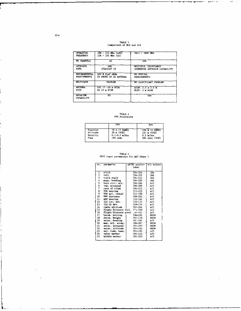
35-6
TABLE 1Comparison of MLS and ILS
OPERATING 108 - 112 MHz (LOC) 5031 - 5090 MHz
FREQUENCY 328 - 335 MHz (GS)
Ni CHANNELS 40 200
APPROACH ONE MULTIPLE, SELECTABLEPATH STRAIGHT IN SEGMENTED APPROACH CAPABILITY
ENVIRONMENTAL 500 M FLAT AREA NO SPECIALREQUIREMENTS IN FRONT OF GS ANTENNA REQUIRE4MTS
MULTIPATH PROBLEM NO SIGNIFICANT PROBLEM
ANTENNA LOC 15 -50 m WIDE AZIM. 2.5 x 2.5 mSIZE GS 10 m HIGH ELEV. 3 m HIGH
DATALINK NO YESCAPABILITY
TABLE 2GPS Accuracies
PPS SPS
Position 18 m (2 DRMS) 100 m (2 DRMS)Altitude 28 m (95%) 157 n (95%)Velocity 0.1-0.5 m/Sec 0.5 m/SecTime 180 nsec 385 nsec (95%)
TABLE 3EFIS input parameters for ART Phase I
nr. parameter ARINC source- a/c source
label
1 pitch 704-324 IRS2 roll 704-325 IRS
3 track angle 704-313 IRS
4 magn. heading 704-320 IRS5 baro corr. alt. 706-204 A/C6 Ind. airspeed 706-206 A/C
7 rate of climb 706-212 A/C8 VOR bearing 711-222 A/C
9 VOR sel. radial 711-100 A/C10 DME distance 709-202 A/C11 ADF bearing 712-162 A/C12 ILS loc. dev. 710-173 A/C
13 ILS GS dev. 710-174 A/C
14 radio altitude 707-164 A/C15 Flight Director roll 701-140 A/C16 Flight Director pitcl .jl-141 A/C17 barom. setting 706-234 ROLM
18 decis. height 701-170 ROLM
19 selec. heading 701-101 A/C
20 max. all. airsp. 706-207 ROLM21 selec. airspeed 701-103 ROLM22 selec. altitude 701-102 ROLM23 el. runw. head. 701-105 A/C
24 outer marker 701-222 A/C
25 middle marker 701-222 A/C
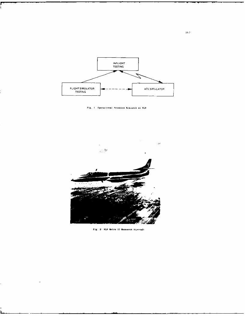
3i-7
Fig. 1 Operational Avionics Research at NLR
Fig. 2 NL1 Metro 11 Rlesearch Aircraft

35-8
/ RECORDING J
-PROGRAMMABLE
SI EFIS
TELEMETRY
FMC FLIGHT MANAGEMENT COMPUTER
FCC FLIGHT CONTROL COMPUTERTCC THRUST CONTROL COMPUTER
EFIS ELECTRONIC FLIGHT INSTRUMENTS
Fig, 3 Art Concept
Cu BCPRC
SENSORS AND SYSTEMS
Fig. 4 EFIS Color Display System.
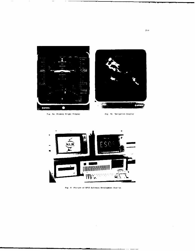
35-9
I
Fig. 5a: Primary Flight Display Fig. 5b: Navigation Display
Fig. 6 Picture of EFIS Software Development Stat'on
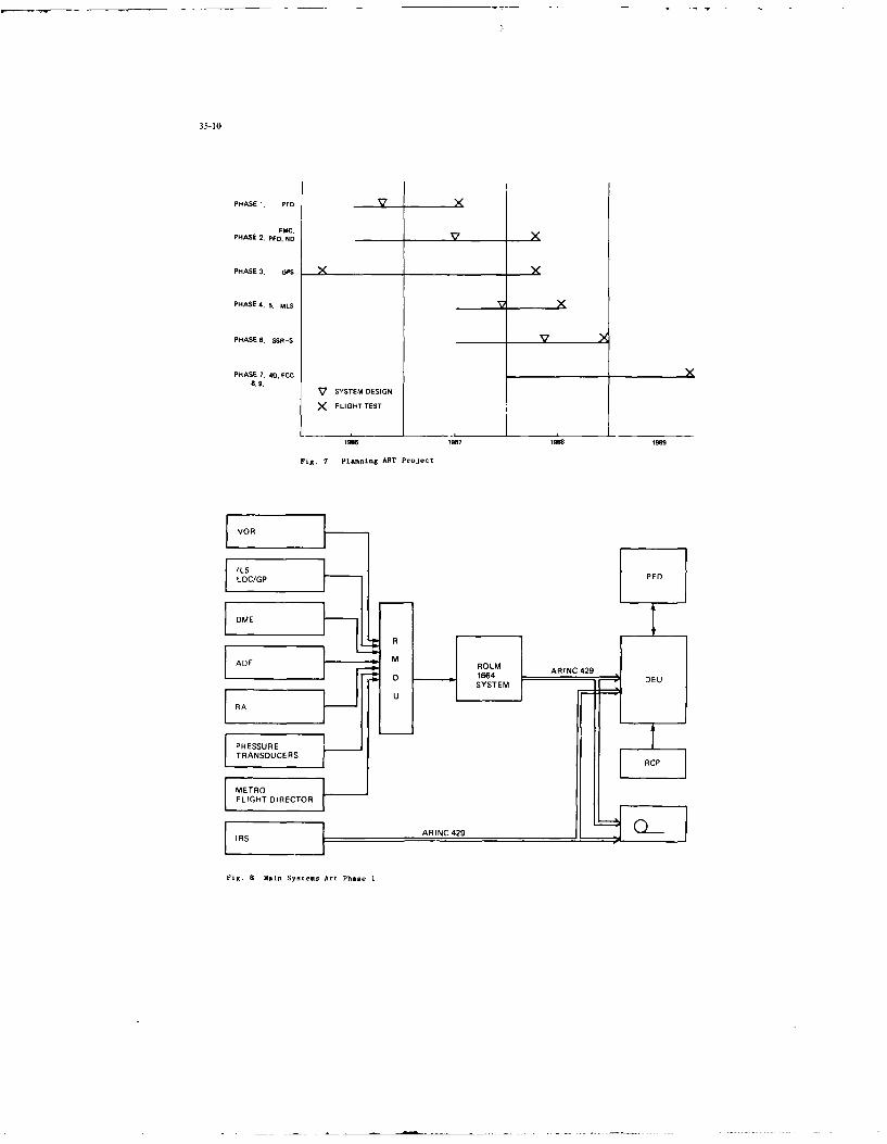
35-10
PHASE i, PFD
FPAC.,PHASE 2, PFo. ND
PHASE 3, GPS __________
PHASE 4. 5. ULS
PHASE 6. SSR-S______
PHASE7 - 4a. FCC__________8.9.
V SySTEMW DESIGN
X PLIGHT TEST
1U6 1987 1966 169
Fig. 7 Planning ART Project
VOR
FIg.8Ml SsesAr hs

35-1l
32S00ISO 0032500IS0 -170 20- 20 0
180too- 0
200 C)c 3200
240-31s00
1500 o2500RA 1015MBCRS
000 4N/, 3.4:NM 1:0
0 0 *lJ 0 2// \\ <N o
F~g. 9 Primary Flight Display Format used in ART Pha~e 1
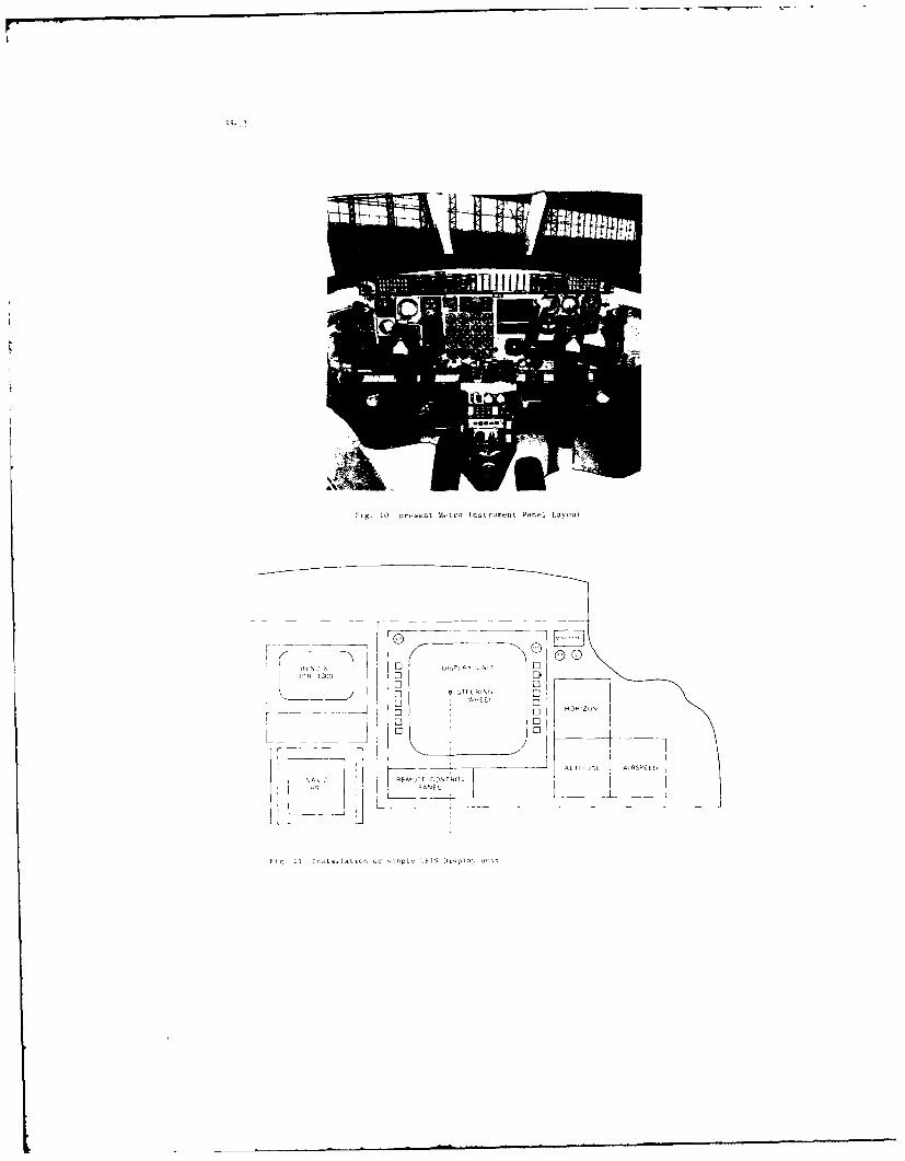
10g.IC present Metro Instrument Panel Layout
-l -: HOPIZCN
L t,
P
F2.1 f M~t C-ytSD
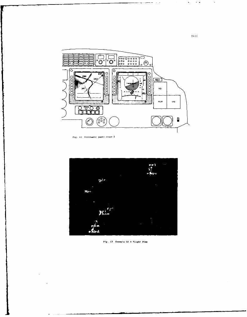
3.5-13
000 000 0000
1-011000 00 0 0 0 0 (5 0
0ZAT .0 -j 0
0 290 0 005cl 0 E3 130 0
0 Cl: o0 341 0 00 0. .. 6 A0 .0 00 U HOR IAS: AS
Q cas o (45)
I
LFig. 12 Instrument panel Phase 2
Fig. 13 Example Of A Flight Plaii

35-14
DISCUSSION
W.R.Fried, US(1) Do you have any comments on the incompatibility between the altitude measured by GPS (above the geoid) vcrsus
the altitudes needed for air traffic control (i.e.. barometric or pressure altitudes)?
(2) Could GPS time he used for the fourth dimension in air traffic control in the future?
Author's Reply(1) GPS provides vety accurate horizontal positions- Vertical accurac'N. hio.er is tot as good. Civilian uscrs ma%
obtain - 1501 m 1 o in altitude. This does not provide much advantage over barometric altitude.
(2) It certainly can. but it may be an overkill in accuracy. Also, then evcrybody wkould have to use GPS to operate inthe same time frame.

ATELIERS DE CONCEPTION DE SYSTEMES AVIONIQLTESET DE REALISATION DE LOGICIELS EMBARQUES
par
Monique SlissaAerospariale Division Hdlicopthres
et
Philippe Laroche-LevyAvions Marcel DassaultQuai Marcel Dassault
922 14 St CloudFrance
Ld qualit6 globale d'un syst~me avioniqoc complexe depend lar) ent ces chil de prircipe qui doiient ytre latit6t clans le cycle de developpernient. Ceci justifie I'emploi system~tique de mo, ens adaptes diis ce stade et tout solong du ec le de vie.
Comme sopport aux meithodolo~ies de conception et de realisation de systemes qui sont preisentees clans lexposecite en reference 1, il est done necessaire de mettre en oeuvre des moyens permettant del1aborer et de maltriser.toot au long do cycle de delveloppemnent et de vie
-La deliniton daun systeme
(Pest Pobjet de PATELIER SYSTEME.
-La realisation des logiciels embarqoes
(Pest lobjet de VATELIER LOGICIEL.
Dans la suite do propos. les points sois ants seront examines
" La demirche condolie par les avionneors AEROSPATIALE et AVIONS MARCEL DASSAILT
" La notion d'atelier
" L'i-plantation industrielle des ateliers
" L'Atelier Svst~rine
e ['Ateire, Logiciel
* Les commiocations critre (cs ateliers
- LA DEMARCHE CONDUrTE PAR LES AVIONNEURS AEROSPATIALE ET AVIONS MARCEL DASSAULT
Pour le d~veloopement des systemes asioniqoes de leurs prect~dents programmes A4rnitiques.'AEROSPATIALE et Ins AVIONS MARCEL DASSAULT ont utilis6 des outillages inlormatiqoes, en particlier poure qui ext de:
l a d&linition fonctionnelle des systemes
l a specilication des traitemnents "temps reel"
l a geolion de configuration des syst~mes et des logiciels embargoes
l a documentation associ~e aux 6tapes de conception et de r~alisation.
Ces societ~s, sous Vegide du Minist~re Fran~ais de Ia Defense, 001 largement contribus Is d~finition de mo~ensperlormants coovrant le cycle de conception d'un systemne et de re~alisation des logielels embarques qoi sonitinclus.
Comme eels a kt6 expliqi dans Vexposii cite en rel~rence 1. ces travaux ont et conduits en collaboration sync lacommunaut6 solonique fran(aise, clans Ie cadre de lekude ITt ii laquelle prenneer part, aec AEROSPATIALE etAMD-BA, Ins SOCi~res suivanites :CROUZET, Electronique Serge DASSAULT, SAGEM, SFENA, SFIM etT HOMSON-CSF.
Ils ont abouti au d~veloppement de cleat entites conforrmiment a on processos de conception descendant
" un ATELIER SYSTEME et
" un ATELIER LOGICIEL.
Ces ateliers doivent. en outre, reportdre 000 besoins de communication entre Ins activites gIUils SUPPOrlenrespectivement. Ceci doit permettre do garantir ]a coherence de cet ensemble qui constiton In S~steme deDeveloppemnent d'Avionigue IT[ (SDA ITt).
36-2
Les developpements du SDA ITI, actuellement en cours, ont pour objectifs la mise en oeuvre et lutilisation de cesateliers dans les prochains programmes aeronautiques qui impliquent des membres de la communaut6 industrielle deI'avionique franiaise.
2 - LA NOTION DATELIER
Le terme d"ATELIER", choisi pour designer ies deux grands ensembles composant les moyens d'etude et dedeveloppement de syst mes qui sont l'objet du prsent propos, met 'accent sur des notions dont ii fatit souligner'importance. Elles sont plus particulierement relatives a [a structure informatique de latelier.
* Chaque ensemble qualifi6 d'ATELIER", comprend un certain nombre d'outils logiciels.Ceux-ci peuvent ktre utiliss independamment les uns des autres et mime en ignorant )A structure delatelier. En effet, ils sont congus pour supporter les t~ches relatives une phase specifique du d6velop-pement d'un systeme. II ne s'agit donc pas d'un ensemble informatique monolithique.
* Par ailleurs, chaque atelier nest pas seulement constitue par la juxtaposition d'outils qui s'ignorent.Au contraire, chaque outil, mtme s'il peut fonctionner sans utiliser tous les autres services de lateier, estadapt6 :
Pour pouvoir recevoir des informations en provenance d'autres outils de latelier ainsi que pour en fournirlui-mCme, conform6ment sa fonctionnalitt et selon un processus d'enrichissement.
Pour permettre la preparation, le suivi et la gestion des evolutions des "produits" qui osnt 6labor6s avecson aide dans le cadre d'un programme avionique.
Ainsi, un "ATELIER" est bien un ensemble d'outils logiciels dent Iun couvre la fonction particulire d'assurerlint6gration entre tous les autres. Cet outil appel6 "STRUCTURE D'ACCUEIL", constitue ainsi la structure debase de 'atelier, - travers laquelle les utilisateurs accedent aux outils specialises en g~rant les activites [6es auxautres outils et assure une gestion coherente au sein de latelier, en particulier au sens de
* Ia circulation des donnees entre outils
* du suivi des evolutions des systmes developpes.
A ce point, Ion peut ajouter deux remarques, qui sont constquences des difinitions donnees ci-dessus et concernent larealisation informatique des ateliers :
* Les outils [ogiciels d'un atelier, attaches aux travaux spcifiques d'une phase d'6tude ou de d6veloppementgerent chacun les donn6es qui sont propres - 'activiti qu'ils sous-tendent. La structure d'accued. de son cute.g~re les informations leies a sa fonction, sans redondance avec les outils, mais en liaison avec eux.
* Comme cela a ere dit, les outils logiciels doivent tre adaptes au mode de fonctionnement intiire de latelier.Cela signifie que des outils existants peuvent subir Vadaptation necessaire sans qu'il faille recreer de toutespieces un outillage informatique offrant des fonctionnalites
6quivalentes. Certains outils du Syst~me de
Ddveloppement d'Avionique qui seront mentioonns plus loin, snt dans ce cas.
Ces deux points mettent en relief 1ouerture inforunatique au sens d'une curtyptibilite a-endante qui est le faitdes ateliers qui vont etre decrits.
3 - L'IMPLANTATION INDUSTRIELLE DES ATELIERS
Le d6coupage des moyens de developpement de syst~mes en "ATELIER SYSTEME" et "ATELIER LOGICIEL", munisdes capabilit
6s de communication necessaires dont )a nature sera explicitee plus loin, correspond a celui des
tkches faire par les industries impliquis dans un programme davionique.
En effet, . \telier Syst~me supporte les travaux de conception et de specification du svstgmier. L'Atelier Logiciel,quant lui, supporte les travaux de ralisation des logiciels embarquis, principalement effectu6s par les industrielsequipementiers, mais aussi dans certains cas, un avionneur pour les logiciels assurant la gestion du systeme, parexemple.
Sur ce point, Ion peut faire les remarques suitantes
a L'implantation industrielle de ces moyens peut d6pendre du type de cooperation imposee, dans le cadre dunprogramme davionique, i tous les partenaires (clients, avionneurs,
6quipeioentiers).
* Quelles que soient les relations 6tablies entre les partenaires d'un programme et aussi chez le m meindustriel (si tel est le cas), les 6quipes de definition des systemes d'une part et celles de realisation deslogiciels d'autre part sont par Ia nature mrne de leurs travaux, diff6rentes et nettement s
6partes.
Ceci justifie, en tout cas, la separation des moyens en deux ensembles pouvant s'6changer les informationsnecessaires la conduite des travaux.
* II apparalt ivident, dans le cadre d'un programme d'avionique donn, que I'Atelier Syst~me, permettant ausystemier de matriser la dlfinition de [ensemble du systeme, vis a vis de son client, doit Atre unique ; ceciest igalement vrai m~me si, dans les faits, le "systemier" est composi de plusieurs industriels cooerants.
Par contre, it est tout aussi clair, qu'au niveau de la rialisation des logiciels, la composante "Atelier Logiciel"est susceptible d'avoir plusieurs variantes, liees au contexte industriel et i la nature des logiciels i developper.Ce qu'il est important d'assurer, dans ce cas-lf, afin de garantir la cohirence des d~veloppements dans le cadredu programme considir6, c'est

36-3
- Une m~thodologie commune pour les divers Ateliers Logiciels,
- Des communications efficaces entre l'Atelier Systlme et chaque Atelier Logiciel.
- L'ATELIER SYSTEME
11 ne s'agit pas de reprendre ici une description ditaillee de la methodologie de conception en de definition d'unsysteme avionique. Cela est expose dans le propos cite en reference 1. Mais, celle-ci etant acquise, Ion vadiicrire pr cisement ci-dessous Pensemble des moyens qui en constituent Ie support : L'ATELIER SYSTEME.
En premier lieu, seront enumeriies les fonctionnalites attendues de l'Atelier Syst me ; ensuite [es outils niajeurs del'Atelier Systeme ITI seront presentes ; enfin les caracteristiques les plus importantes de son implantationinformatique seront indiquees.
4.1. Les fonctionnalitis attendues de I'Atelier Systrne
Elles sont de plusieurs natures
4.1.1. La mise en oeuvre de la methodologie de dveloppenient d'un systene avionique.
L'Atelier Svsteme doit offrir des outils logiciels couvrant toutes les etapes du cycle de concepton d'unsystime, chaque outillage informatique
6tant adapt6 aux travaux specifiques d'une phase.
On peut rappeler ici, de mani&e macroscopique que les etapes principales sont les suivantes
* elaboration des specifications globales des fonctions operationnelles
* determination de 'architecture fnectinnne!le
* superposition du decoupage fonctionnel sur 'architecture physique
* specifications d6taiil6es des fonctions operationnelles et des iraitements effectues dans lesequipements
4.1.2. L'obtention de sp6cifications de qualite
L'Atelier Systeme doit pouvoir ktre le garant d'un haut ni" eau de qualite pour les specificatio, -6 boresavec son support.
Ceci signifie, en particulier, que les outils logiciels doivent implementer de manire rigourcuse lesmethodes de travail prealablement choisies. II faut, egalement, qu'ils permettent dassurer un maxiumrn decontrbles de coherence a chaque niveau de specification.
L'Atelier Systeme, surtout a travers les fonctions propres a Ia Structure d'Accueil, doit faciliter Ia priseen compte des specificites lies a chaque programme d'avionique, comme la structure de Ia documenta-tion, les circuits de decision et ceux de diffusion ..., tout en garantissant, apr~s [eur d6finition, [eurstrict respect pendant les travaux mettant en oeuvre Iatelier.
4.1.3. La maitrise des evolutions de la definition d'un systeme avionique
La maltrise des 6volutions de Ia definition d'un syst~me complexe implique en particulier la mise enoeuvre de moyens efficaces pour assurer correctement :
" La gestion des fiches d'evolution, 6labories au niveau global du syst~me
- leur initialisation et la dtermination de Pimpact qu'elles ont au niveau des produits de latelierqui sont a la base des documents de specification,
- leur instruction une profondeur suffisante pour permettre d'evaluer leur repercussion en co~ts et
d(lais,
- leur prise en compte apris une decision favorable.
* La gestion de configuration du syst~me et la connaissance des applicabilits des fiches d'evoIution etla definition des itats, standards et versions du systime.
4.1.4. La gestion de la diffusion des informations
L'Atelier Systeme doit prendre en compte les rapports entre les differents intervenants dans unprogramme d'avionique : les clients, les Services Officiels et Centres Etatiques concern~s, le systemier,'ensemble des cooperants ... ).
A ce titre, il gere la diffusion entre les differents partenaires (documents de specification, fichesd'evolution ... ).
4.1.5. La mise - disposition d'un ensemble de moyens adapt6s au niveau des utilisateurs concernes et au mode detravail requis par Ia m6thodologie employee.

36-4
En effet, IlAtelier Syst~rme est destine etre utilis6 par des personnels de qualification elevee (chefs deprojet, ing~nieurs concepteurs, ... ). 11 doit donc presenter, dans ses diffeirentes fonictions des interfaces"Homme-machine" adaptees. De plus, pour let phases de travail, meneies au sein d'6quipes de conception,les outils concern~s doivent avoir des capacites 'mutiutilisateurs" puissantes afin d'assurer en permanenceIa cohirence de Ia definition.
4.2. Les outils ma'ew de J'Atelier Systfm
Les outillages informatiques qui sont decrits ci-dessous lont partie de l'Atelier Systeme inclus dass leSyst~me de D~veloppement d'Avionique IT.
4.2.1. L'Outil de Conception Syst~me OCS
a) Oblet d'OCS
La sp~cification de Parchitecture fonictionnelle d'un systeme est support~e par us outil d'analysedescendante, OCS.
L'objet principal de cet outil est de conduire ii identification des pav~s lonictionnels et au recensementdes interlaces entre ceux-ci dans Ia d~marche d'analyse lonictionnelle dus syst~me dont la complesit6peut Ctre variable. Cet outil supporte Vanalyse de type IDEFO, mais a la souplesse secessaire pour Ctreutilisi en prenant en compte lorganisation du travail propre chaque industriel.
b) Concepts manipul~s par OCS
Let concepts pris en compte sont principalement les suivants
- Les boftes:
Elles constituent Ia repr~sentation graphique d'un objet dont Ia semantique correspond a la decomf-
position, du syst~me et qui represente use activite du systme.
- Les (lots:
Ils sost le regroupement sous us seul norn d'informations ayast use caracteristique commune. [cur
representation graphique est use fl~che.
On rencontre dosc les cas par~iculiers qui sont illustres sur la fiche I
*Us (lot de commandesestun regroupement d'informations, contr~lasn au sens dIIDEFO. Vactivit6repr~sentn& par la bolte i laquelle il est relatif.
*Us (lot d'entr&e est us regroupement d'informations utilisees en entr&e de Vactisit6 repri~sentee parIa boite concersee.
*Us flot de sortie est us regroupement d'inlormatioss 6laborties par Vactivit6 de Ia fonction represen-tee par Ia botte coscernee.
*Un flotdem~canisines est us regroupement d'isformations (ressources au sent d'IDEFO), permetnantIactivit de Ia fonctios reprisent~e par Ia bolte a laquelle ii est relatif.
-Les informations:
Ce sont les donnees transitant entre plusieurs 6l1nments de la dvcomposition. Elles appartiensesttoujours un (lot dont elles represnent Pattribut (entre&, sortie,...
- Les d~pendances lonictionselles
Ce sont Ins d~pendances entre Ins informations. Ainsi que cela est schematise sur la ':Aure 1, pourchaque information de sortie son indiqu~t les liens avec les informations reiues permettast deI 'laborer.
c0 Fonctionnalitiis d'OCS
La methode d'analyse structuree hi~rarchique descendante qui a 6t choisie (vowr figure 2) permet
*de commencer par Ia description Ia plus g~n~rale du syst~me
*de dkerminer essuite les interfaces entre Ins differents 61 ments en raffinant Ia d~finition tout aulong de la dkcomposition
*de termiser Ia d~conposition en compl~tant larchitecture au fur et mesure de Pavancemest dutravail par us procettus iteratif.
On procide donc us decoupage fonictionnel it&atif, dans us costesne de mulniutilisation appropri aus6quipes de conception, qui assure en outre use propagation ascendante en descendante des isformations.
Let priscipales fonictioss de loutil sont les suivantes

36-5
* Des fonctions de creation, modification et destruction de diagrammes et d'eIements de diagraminspermettant de saisir, de maniere adaptee au mode de travail des utilisateurs, les donnees manipuleesdans loutil.
* Une fonction dite "configuration de l'outil" qui permet de determiner pour chaque type d'usage, sicela est 4cessaire, des paramitres d'utilisation, qui seront pris ensuite par difaut (comme les taillesmaximales des noms de boites, de flots, ... ou les champs reserves aux attributs des inlormations ...)
* Des contr6les assurant la coherence des travaux realises sous 'outil. lis peuvent revntir divers modeslibre ou assiste, en temps reel ou differe.
* Des aides au travail en multiutilisation qui instaurent des dialogues intelligents entre les utilisateursd'une m~me equipe de conception et permettent une utilisation simple des elements de la decompo-sition specifies par d'autres.I1 s'agit en particulier de pouvoirmesureren "temps rel" 'impact d'une modification et lampleur
de sa propagation le long d'une chatne fonctionnelle.
* La constitution et la manipulation d'arbres et de sous-arbres
Dans un but de rcup&abilit, des fonctions d'accrochage et de decrochage d'arbres et de sous-arbressont mises en oeuvre avec les verifications de coherence et de compl6tude necessaires pour en rendrel'usage valide.
* La gestion des 4volutions dans laquelle le but poursuivi est d'utiliser 'intelligence de loutil pourpreparer les modifications avec la connaissance des fiches en 6tude et formuler les etats modilisdefinitivement aprs la decision d'application relative a une "version" du svst~me.
* Le couplage a la Structure d'Accueil Systme.
d) Produits realises a 'aide d'OCS
Lorsque les travaux relatils A la spcification de 'architecture lonctionnelle, support6e par OCS, sont
termins. 'on a obtenu -
La d6composition du systrne en plusieurs niveaux rorrespondant A dilferentes cat gories de moduleslonctionnels
* La deterrmnation des llots de donn6es transitant entre les differents 6lements de )a decomposition
La spkcilication d6taill e des interlaces
La dfinition des chaTnes lonctionnelles du syst~me.
Les produits en sortie dOCS ont A la lois des composantes graphiques et textuelles dont 'assemblagecoistitue les documents de specification fonctionnelle d'un systeme.
v.2.2. Les outils de specilication detaillee
v.2.2.1. DLAO (D6finition de Logicie; Assist6e par Ordinateur)
a)Obet de DLAO
II s'agit, avec cet outil. de faire Ia r6daction des sp6cifications d6tailles des fonctions operation-nelles et de specifier les traitements qui y interviennent et les test associes.L'orientation de l'outil vers la prise en compte des activit6s A caract re temps reel le predisposeparticulijrement A une utilisation dans Ia definition des systemes avioniques.
b)Concepts manipuls par DLAO
Les donnees d'entree de toutil sont constitoees par les interfaces et les cha-ines lonctionnelles dusyst~me delinies avec I'Outil de Conception Systeme, dans one etape precedente.
La sp cification est redigee A 'aide d'un langage formel manipulant les cinq types d'objets suivants
Les traitements
Ce sont les t~ches accomplies par le pav6 logiciel A spcifier. La description se fait en utilisantdes mots-cles (faire, squence, tant que, si, alors, ...). Elle comporte notamment
- 'introduction des donn6es d'entre
- 'identification des donnes en sortie
- la liste des vnements agissant sur le traitement
- les contraintes de realisation qui sont imposes.
La definition d'un traitement exprime son comportement dynamique qui se traduit par exemple parl'affectation d'informations, l declenchement d'6v4nements,...

36-6
* Les informations
Ce sont Les donnees ogirationnelles manipulies par les traitements. Elles peuvent 6tre elementaires
ou compos6es d'autres informations.
* Les 6vinements
Ce sont les faits dont 1'arrive alatoire ou cyclique activent ou conditionnent un traltement.
* Les etats
Ce sont les elements statiques intervenant dans un traitement ou qui s'en d6duisent.
* Les interfaces
Ce sont les reprsentations physiques des informations dont la description pr6cie est indispensablepour les phases suivantes du diveloppement.
c) Fonctionnalitis de DLAO
Les principales fonctions de loutil sont les suivantes- La saisie interactive et 'analyse des objets prenant part a une specification, basie sur l'utilisation
d'un langage formel
- L'analyse et l'execution de requtes relatives aux objets dja mmoriss pour en obtenir unerepresentation graphique ou textuelle
- Les contr6les de cohirence appliques aux specifications
Une structure documentaire permettant :* La definition de plans-types de spkcification adapt~s aux besoins des utilisateurs
* Lelaboration des documents de specification, respectant les plans - types d6finispr~alablement
- La gestion des evolutions pr~sentant des m~canismes de m~me nature que ceux pris en compte parOCS
- Le couplage la Structure d'Accueil Syst~me.
d) Produits rialis6s - laide de DLAO
Chaque spgcification est une suite de d6
finitions d'objets et de leurs attributs avec les relations entreles objets. Elle fait l'objet d'un document dont la nature a pu tre d6finie par l'utilisateur.
4.2.2.2. SAO (Specification Assiste par Ordinateur)
a) Objet de SAO
Loutil SAO aide a constituer la specification qui prend en compte les exigences vis a ws du materielet celles spcifiques au logiciel d'un quipement (algorithme d'une loi de pilotage ou de guidage, parexemple).
b) Concepts manipulis par SAO
La specification est constituee par un ensemble de planches, repertori~es en livres et chapitres.
Les objets sont principalement saisis et maniputs a 'aide d'un langage graphique dont 'diteur faitappel des bibliothiques de symboles graphiques, adapt6es aux types d'appl ation.
c) Fonctionnalit6s de SAO
Comme le montre la figure 3, les principales fonctionnalit6s de SAO sont les suivantes
- La saisie interactive des specifications a 'aide d'un diteur graphique et de biblioth~ques desymboles,
- La gestion d'espaces de travail pour les concepteurs, independants de lespace offictel contenant les4tats consultables des specifications,
- Les possibilitis de modification, de suppression et d'adjonctioe de planches darts uneskcification avec une gestion associce des conflits
- Le contr6le de cohdrence au niveau d'une planche de sp6cification
- Le contr61e de cohdrence au niveau de 'ensemble de la s cification
- La gestion des 6volutions, devant mettre en oeuvre des mecanismes analogues a ceux des autres
outils de l'Atelier Systbme
- La capabilit6 d'&tre interfac6 avec Ja Structure d'Accueil Syst .me.

36-7
d) Produits rtialis~s Paide de SAO
Une 6lition de lensemble de planches coh&entes pour former une specification constitue le document(graphique et textuel relatif une version de [a spkcification concerniie).
4.2.3. La Structure d'Accueji Syst~me
a) Objet de [a Structure d'Accueil Slystime
C'ent le support informatique qui permet au systemier de gerer
l a logique de d~veloppement d'un systeme,
-les rapports entre tous les intervenants dans un programme d'avionique.
-les demandes d'ivolution concernant un syst~ne.
11 s'agit en effet;
- de maintenir lensemble de la documentation d~e spkcification jour et de gerer so diffusion,
-de pouvoir identifier partir du niveau le plus global dv syst~me 'impact d'une demande d'6voistion,
-de garantir en permanence ia coh~rence de la definition d'un syst~me,
-d'offrir aux responsables de projet ]a possibiiitei de consulter les diffiients 6tats de developpement de
Pensemble des entit~s ayant part la d~finition d'un syst~me,
-de g~rer les proc~dures d'acceptation relatives aux demandes cf'volution et les r~percvissions sur lesproduits constituant les sp~cifications.
b) Concepts manipul~s par ia Structure d'Accueil Syste'me
La Structure d'Accueil Syst~me s'appuie sur une base de donnees et rassemble des mecanismes qui ontpour but:
-d'assurer ]a coherence des informations connues dans l'Atelier Syst~me, dans le cadre d'un programmed'avionique,
-de g~rer los accis et les activit~s li~es aux outhls de lAtelier Syst~me,
-d'assvrer ]a bonne ex~cution des fonctions de communication entre outils de lAtelier Syst~nie. versPAtelier Logiciel, ven l'ext~riesr dlv Syst~me d~e DNveloppemnent d'Avionique.
c) Fonctionnalit~s de la Structure d'Accueil Syst~me
La figure 4 montre les grandes fonctions de la Structure d'Accueil Syst~me et les liens qui existent entryelles.
-L'initialisation de projet
Elie permet Iinstallation d'un projet dans [Atelier Syst~me, quant aux pr~visions relatives as plan do
developpement du projet et a Ia configuration neressaire pour utiliser l'Atelier Syst 2me pour v proiet.
-L'administrateur:
If a pour missions principales d'interpreter les commandes et les requytes des stilisateurs et de gererles acces.
-Le suivi des evolutions
Cette fonction roncerne Ia gestion des fiches d'6volution of impIlinente Ins exigences qui ont etcenoncees plus hast.
-La gestion do configuration
Cette fonction a pour r8Ie do gt~rer Ins 6tatv du d6veloppement d'un svsteme el Ins transitions entreces etats.
-Los activit~s Ii~es aux outils
L'ensemble des fonctionnalites couvertes ici concerne tous les aspect',. do liaisons entre la Structured'Accueil Syst~me et les ostils do l'Atelier Systeme.
-La composition do documents:
Elie permet do rer des documents complots partir des "produits" 61ementaires contenus dans lesbases do donnees propres aus outils et d'adapter four structure ass exigences do chaqje programme.
-En corrolaire Ia gestion do Ia diffusion

36-8
Elle s'occupe de la tenue j our des listes de diffusion des documents de sp6ctlicarion et de to
memorisation des documents diffuses dans le cadre d'un programme et en particuier en ce quiconcerne leur version et leurs destinanaires.
d) Produits riiaiis~s Ilaide de la Structure d-Accueji Syst~me
A la demairde des responsables de projet, des etats
-d'avancement du projet
-des sptiifications
-de la diffusion des documents
-des fiches deivolution prises et, compte, en etude,
peuvent A-tre giintirs.
4.3. L'implantaticn informatipir de I'Atellier Systime
Un souci tris vif de poriabilit6 a pr~valu dais les chois informatiqoes de base faits pour la misc en ocovre del'Atelier Syst~me.
Les outils logiciels qui ont kt6 d6crits sont affect6s des stations de travail, fonictionnant sous le svstemed'exploitarion UNIX. Pour I'impI~meniation des outils, I'emploi du langage C est favoris toutes les lois o6icela est possible. Les premiers choix de stations de travail sont APOLLO et IBM 6150.
La Structure d'Accueil Syst~me est implanitte sur une machine h~te, connectee aux stations de travail. Lespremiers choix sont VAX (VMS), connect5 a APOLLO et IBM (VM/CMS) connecte a IBM 6150.
Comme cela a kt6 espliquii plus haut, les outils, d'une part, la structure d'accocil d'autre part gerent lesdonn~es gui ceur sent p.ropres. dans des bases de donnecs indeipendlantes et sans redondance. Pans cce cardre-la.et toujours dans un souci de portabilit6, d'ouverture et dl'homogeineit6, Ie sjzst~rrie de gestion de bases dedonnecs relationnel ORACLE a etc retenu pour tous Ics outils et pour Ia structure d'arcucil et cela. brers sor,pour les deux versions de materiel informatiguc.
5 -L'ATELIER LO-GICIEL
Comme cela a 6t6 espligue dans levpos6 deja Cit6
en r6
fiircnce. les industiels partenarres de Vetude ITI. qipar ailleurs possbdaient en propre des elements d'Atelier Logicrel ont pris communement corrsr ence qiie led6veloplpement du logicrel a vocation embarqu~e est une acrrsit6 tr
6s Ii6e a Ia capacit
6 rr6arse des persofiues.
Cette capacite, si elle nest pas ranalis6e par des methodes et des outils rigoureus. peut condluire i desr
6sultats gui ne sont pas compatibles avec les objectrfs done entreprise industrielle err motiere de irialtrise des
delais et de Ia gualite.
En ce gui concerne les travaus de conception, realisarion et tests des logicrels, des outils norribreus etperformants sent deja en exploitation ao win des dilf6rents indostriels rienbres dIIl.
Pour ces domaines, Ic principal souci deps iravaus esi dlone- de proposer op "sembie coherent. possedoor desliens 6rroirs avec VArcher Syst~mc. et disponible poor 1ensemble de Ia comnmunoote aeronaurigrie. (e gui aconduit ai ia definition doun Atelier Logicrel pour Icqoel sent presentes successivenient c,-dessoius
*Les fonctionnalit6s attendues
*Les caracterisiqgues des outrls au regard do mcl de vie logicrel
*La mine en oeuvre.
5.1. Les fonctionnalit~s attendues de I'Atellier Logiciel
Les pruncipales forcnrnnlrres aitendlues d'un Atelier Logicrel s0cr Irs suisanres
a) 11 doii Cire Ic support ellicace d'une methodologie rigoureose de d~veroppemnert dle logiels.
En dffet, jes caracteristigocs des logiciels intervenant days les systemnes avionigues socr tr's poinrues.Elles necessitent I'adoption et Ia rise err oeusre dle m6thodes de delinrtion, dle conception. de realisatronet c tests structs et fiables.
Les logiciels de ce ispe participent a la se, unite des svtemes auugiiels its r ontribukent Its corrportenr enparticolier Ia miusc en ocuvre de traiternents "temps reel".
b) Poor r6pondrc aus besoir de divers progranimes davionigoc, gui peuvent se deroulen en mn me temnps.l'Aiclier Logiciel dcii Pire capable d'accepter des environnernenis de programmatron relarils a drfl6rentslangages.
c) L'int~gratron des modules logiciels et Ics tests relatils a ceur validation doivent Pire fac ijirs par desmoyes de test, con(gus en liaison directe aver Ics autres elements de 'Arclier Logiciel gui sent otrirsespoor g6nercr Ics cnir~cs de ces phases uirmes de Ia r6ajisatron des logiciels.
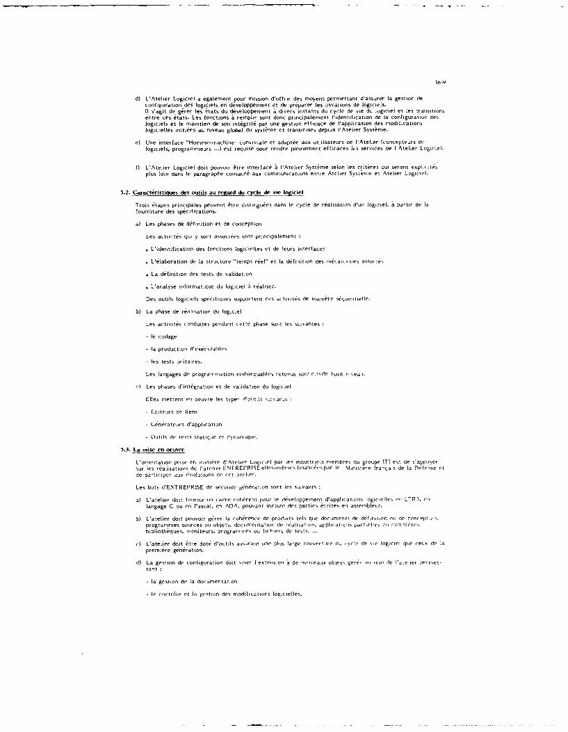
36-9
d) L'Atelier Logiciel a galement pour mission d'offrir des moyens permettant d'assurer la gestion deconfiguration des logiciels en deve!oppement et de prdparer les livraisons de logiciels.i s'agit de g&er les 4tats du developpement a divers instants du cycle de vie du logiciel et les transitionsentre ces stats. Les fonctions & remplir sont donc principalement 'identification de la configuration deslogiciels et le maintien de son int4grite par une gestion efficace de 'application des modificationslogicjeJle initiies au niveau global du systeme et transmises depuis lAtelier Syst~me.
e) Une interface "Homme-machine" conviviale et adapt6e aux utilisateurs de I'Ateler (concepteurs delogiciels, programmeurs ...) est requise pour rendre pleinement efficaces Its services de I'Ateher Logiciel.
f) L'Atelier Logiciel doit pouvoir Ptre interface a 'Atelier Systeme selon Ies criteres qui seront explicitesplus loin dans le paragraphe consacre aux communications entre Archer Sysnme et Atelier Logiciel.
5.2. Caractristiques des outils au regard du cycle de vie logiciel
Trois 6tapes principales peuvent 6tre distingutes dans le cycle de ralisation d'un logiciel, a partir de la
fourniture des spcifications.
a) Les phases de d6finition et de conception
Les activites qui y sont associees sont principalement
" L'identification des fonctions logicielles et de leurs interfaces
" Llaboration de ]a structure "temps reel" et la definition des mecanismes associes
" La dfinition des tests de validation
" L'analyse informatique du logiciel a ral'ser.
Des outils logiciels specifiques supportent ces activites de maniere sequentielle.
b) La phase de realisation du logiciel
Les activites conduites pendant cette phase sont les suivantes
- le codfage
- la production d'ex6cutables
- les tests unitaires.
Les langages de programmation embarquables retenus sont ditsde haut ni~eau.
c Les phases dintegration et de validation du logiciel
Elles mettent en oeuvre !es type- Vo,ti:!s su:v'an.s
- Editrurs de liens
- Gen6rateurs d'application
- Outils de tests statique et dynamique.
5.3. La mise en oeuvre
L'orientation prise er matiere d'Ateher Logiciel par les midustriels membres du roupe IT et de s'appuersur les r6alisations de latelier ENTREPRISE elles-m6tmes finan( 6es par It iinstere franials de la Defense etde participer aux evolutions de cet atelier.
Les buts dENTREPRISE de seconde generation sont les suivants
a) L'atelier dot fournir un cadre coherent pour le developpement d'applications logicielles en LTR3, enlangage C ou en Pascal, en ADA, pouvant inclure des parties ecrites en assembleur.
b) L'atelier doit pouvoir g6rer ha coherence de produits tels que documents de definition oii de coneptlion,
programmes sources ou objets, documentation de realisation, applications partielles o connpl&ctes.bibliotheques, moniteurs, programmes ou fichiers de tests ...
c) L'atelier doit etre dote d'outils assurant une plus large couverture di, cycle de nie logiciel que ceux de hapremiere generation.
d) La gestion de configuration doit riser lextension a de nouveaux oblets gere, au scem de hateher permet-tant :
- la gestion de ha documentation
- le contr6le et la gestion des modifications logicielles.

36-ill
e) La gestion de projet, en rapport avec [a base de donn6es d'ENTREPRISE, sera rtialisee par un outilpermettant de planifier les projets et d'en assurer le suivi en co~ts et delais.
La demarche du groupe ITI vise lobtention d'un Atelier Logiciel adapte aux activites de ses membres,ayant une definition cohrente avec latelier ENTREPRISE de seconde g
6niration et qui pourrait en
constituer un surensemble entiirement compatible. Dans ce but, laccent est mis particulirement sur lespoints suivants :
- La dfinition des capabilit&s de communication avec l'Atelier Systme
- L'outil de definition de logiciel qui dolt pouvoir exploiter les specifications de logiciels venant del'Atelier Syst~me
- L'outillage supportant les phases de conception globale et detaille de logiciel qui doit supporter unemethodologie :
* Privii6giant une approche descendante structur-e
* manipulant des concepts cohrents avec ceux utilises pour la d(finition du logiciel
* prparant de manire correcte l'utifisation de langages de programmation de haut niveau
* formalisant des notions de programmation structuree.
- L'int(gration dans l'Atelier Logiciel d'un outillage ayant pour but la mise au point et le test dynamiquedes logiciels.
Les principales caracteristiques demandees un tel outh sont les suivantes
" La formalisation et la standardisation des oprations de test
* L'automatisaion de ces op6rations et l'excution de tests de non-r6gression
" Le test en temps reel et Ia non perturbation du comportement des programmes a tester
" La description sous forme smbolique des contr6les
* L'indapendance vis a vis des moyens de productiun
SL'ind6pendance vis a vis des machines cibles
- La rrise en oeuvre d'une gestion de configuration prenant en (ompte tous les constitants d'uneapplication logicielle donne et tous les produits qui leur sont associs, disposant des mecamnisesconvenables pour Ie suivi des evolutions logicielles.
L'rientdation retenue au niveau des materiels inormatiques dans un souci de portabilit est la rise adisposition de l'Atelier Logiciel sur des stations de travail travaillant sous le systeme d'exploitation IX.le langage de realisation privilgi6
6tant C.
6 - LES COMMUNICATIONS ENTRE CES ATELIERS
Les Pchanges ncessaires entre l'Atelier Systme et les Ateliers Logiciels utiliss dans le cadre d'un mmeprogramme aionique sont identifies en tenant compte du partage industriel des t5ches.
Dn manire globale, on peut dire que
- de VAteher S sttnse vers in Atelier Logiciel
transitent ies sp6cilications des logiciels r6aliser et les demandes de modifications a appliquer
- d'un Atelier Logiciel vets lAtelier Systme
transite Pidentifi(ation de la fourniture logicielle (configuration du logiciel Iivr. equipement concern .
Pour realiser des communications efficaces :
*11 aut qu'un certain nombre de concepts soit (ommun entre ceux manipules par les outils de lAteherSyst~men pour elaborer Ies spcifications des loginiels, et ceux qui sont dans Ies Ateliers Logicmils poureffectuer la delinition proprement dite du logiciel et l'identification dn sa configuration.
II est ncessaire qun les actions d'importation et d'enportation relatives a un atelier se fassent au trasersde sa structure d'accuil, dont alors, en p.rticulier la fonction "gestion de Ia diffusion" doit ftre active

36-il
Lkipl~inentation informatique des liaisons entre ateliers comporte trots aspects
a) Les procedures de communication
Elles sont respecter rigoureusernent au cours des 6&hanges afim de maintenir la coherence et Ias~curitii des informations.
b) La r~alisation mat~rielle
Elie depend principaiement des mayens utilises par le% partenalres du programme consid~r6 et dussi deleur situation giographique relative.
c) La cool identialitei
Son respect n~cessite ]a nine en oeuvre des moyons et de prockdures sp~cifiqiios.
7 -CONCLUSION
La premi~re version du Svst~me de D36veloypemnent d'Avionique (Atelier Systeme et Atelier Logiciel) as &tmoutilisee dans los prochains programmes a~ronautiques auxquels prendront part Ins induwtiels de la (ommunauteavionique fran~aise. Ces programmes en permettront ainsi la validation en grandeur r6elle.
Compte tens du paint actuel d'avancement des travaus de mise en oeuvre, tout laisse a penser que Los loensresultant repondront aus objectils imitiaus.Ils constitueront le support necessairo pour tormaliser les relations entre industriels coop~ranvs daos unprogramme avionique et assurer par vole de cons~quence une meilleure quali s an cons MOindre en niettant Z,profit les comp4tonces et exp~rienm-es acquises.
L'aboutissement des travaus engages constituera us point do d6part.En plus des 6volutions et compiments inherents a tout produit logiciel, le souci dl6ojutivit6 qsi a gside .echoix des techniques do r~alisation er, faisant du Ssst~me do D~veloppoment d'Avioniquo so sosteffe ossert.permettra
" L'introduction d'autres outils couvrant des adtis'ites complentairos au ours du cycle do d~vejoppemvenv.,as repondant a des contraintos speciliques d'un utilisateur
" L'utilisation de techniques et de technologies informatiques nouvelles, telles Ia iit, ,n t Is misc oT-neusre de systemes experts
R~f~rence I : Systeme avionique. MWthode de drveloppemnent et outils inforniatii(.es"(Philippe LAROCH-E-LEVY -AMfD-BA, FRANCE).
Fig :1
OCS :LES CONCEPTS5 MAN IPULES
FLOT DE COMMANDE ~IN FORMATIONS
DEPENDANCES
FLOT DENTREE IFFW
FLOT DE SORTIE
LODEMCANISMES

Fig :2 OCSTOTL
/PLUS GENERAL
Fig 3
(SpE~clrlcation Assfst~e par Ordinateur)
symboles bibllothique
Gostian do SilC nngurstlons P cifl ct ion - --- I -
Con 'ro0le decoh ,renceplan h
Controle dospe i c.ton
uONNEES

Fj 4 STflHJCT(IBf VA CPIF i i Y ,T r mE
INITIALISATIOS
LIESO DEAUXE SRCTR
CCONFIGURA O TI ON D PCCELP STMBE DOCUMENTS
R.Giot FRSRTU.SUV E.Quel~~~~~~~~~~ Is ILIii ac~otk aL t~iac Y
Tuhr el
I nroutinprge~ircds tlaprsde Listusetfclt a cfi qucVTE I cs tl upitn n ~h
IIM

COHERENT FUNCTIONAL DEVELOPMENT:KEY TO SUCCESSFUL FUTURE SYSTEM INTEGRATION
Bruce L. HouseNorth American Aircraft OperationsRockwell, International Corporation
2770 E. Carson St.lakewood, CA. 90712
ABSTRACT
An advanced, computer based engineering design methodology and tool set, whichenables and enhances complex system, subsystem and component design, analysis,integration and verification/validation testing - in an operational context -is described here.
The burgeoning threat to the security of NATO alliance countries, dramaticescalation of costs and protracted schedules associated with weapons systemacquisition, from concept development to first flight, dictates theintroduction of drastic improvements in the way the technical communityapproaches the design and development process. Similar improvement must bemade in techniques utilized by the procuring agencies. Improved methods forassessing the technical merit of proposed problem solutions as well assubsequent verification of compliance with procurement design specificationsmust also be established.
The timely evolution of enabling technology in areas of high speed digitalcomputers, structured software, systems design methods, sophisticatedsimulation and graphics techniques have made these much needed improvementsnow possible.
Major failings of predecessor and even contemporary approaches to theapplication of computer-based simulation in the design process lie in:1) relative inflexibility of the simulations, 2) persistent dedication toeffectiveness analysis as an end-product rather than design optimization,3) lack of deterministic assessment in favor of stochastic methods,4) inadequate and/or esoteric means for data base access and manipulation,land5) awkward, difficult to understand and use output data.
However, by far the most significant drawback of existing approaches todesign, using computer based simulation tools, is that they fail to producethe coherent time-line state data essential to complete evaluation of thedesign objects (system/subsystem/component), in a dynamic, high fidelity andoperational context.
When fully implemented, functional development by means of manipulation ofcoherently derived time-line state data, in a dynamic, high fidelity andoperational context, will enable concurrent, fully integrated, rapidprototyping and subsequent detailed design synthesis of the avionics, vehicle,weapons and crew systems components of a total weapon system.
Having once put in place the described methodology and tool-set, opportunitiesfor exploitation of the resulting coherent time-line state data are limitless,ranging from mission effectiveness analysis and detailed design, to test setsfor logistic support and training devices, for both operations and maintenance.

37-2
INTRODUCTION
Central to our ability to bring the current protracted development cycle backinto an affordable time span is the introduction of new and more powerfuldevelopment tools and methods. Figure 1 illustrates our current postire ofaround twelve (12) years from CDI to IOC. This is nearly three (3) times thatof only a decade or so ago.
The tremendous challenge precipitated by the "hypothetical" systemrequirements illustrated in Figure 1 creates a virtual log jam which may beportrayed by Figure 2. Elevated threat levels as well as rapidly evolvingtechnology creates a much more difficult problem to solve and results insolutions featuring extremely complex design, development and testapproaches. The end result is envariably protracted schedules, increased costand uncertainty in performance achievability.
Contemporary weapons systems development approaches will not meet thechallenge of the 1990's and needs help. A structured, formal andoperationally relevant approach such as that alluded to in Figure 3 will berequired. Traditional approaches fail in several respects. Firstly, eachphase of the process generally employs stand-alone, unrelated andoperationally non-relevant tool methods and procedures. Secondly, top levelas well as flowed-down requirements are generally not derived in a dynamicoperational context. This, of course, makes functional thread traceabilityvirtually impossible. Figure 4 illustrates this traditional approach.
Advanced avionics systems are characterized by several important featureswhich bear heavily upon the need for "requirements" to be developed andmaintained (from mission level to the lowest level IPO and chip) in a dynamicoperational context. First of all, advanced systems typically will contain2 - 4 x 10⁶ higher order language lines of code (Ada). This infers thatmany of the functional processes here-to-fore accomplished in hardware are nowdone in software. Secondly, processing speeds in the order of 3 - 4 x l09
complex operations per second (BOPS) for vector processing and 30 - 40 x 106instructions per second (MIPS) will be required. Therefore, not only are mostof the functional processes executed in a physically transparent andinaccessible media, but they are running at incredibly high speeds.Functional performance capability of a given system process, therefore, canonly be assessed when operating in that high-speed, inter-active domain.Figure 5 itemizes some of the more important steps to be taken.
CONCEPT
A need is suggested by the foregoing for a methodology to "capture" the"design state" of each and every design variaole involved in either the objectof the design process or the "environment" to which the design object issubjected. Figure 6 depicts the process of coherently eALdcting the "state"data. The "state" data is referred to as "time-line" state data because it isdeveloped and produced in response to some pre-determined time-orderedsequence of events.
To those who have labored rigorously over the past several years on advancedweapons system projects the need for "coherency" isself-evldent. Quitesimply stated, in an advanced weapons system (avionics suite specifically inthis case) all components, i.e., sensors, busses, computers, etc., areutilized at all times when they can spatially, spectrally or temporallycontribute to a functional process. Moreover, the components mustcontinuously be assessed for availability as well. Data fusion (Radar/IR/CNI)is one example. Dynamic processor reconfiguration is another.
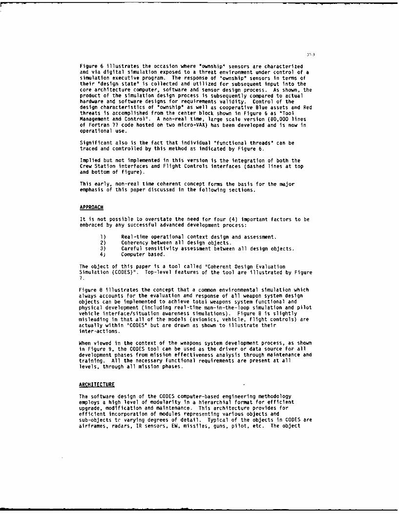
37-3
Figure 6 illustrates the occasion where "ownship" sensors are characterizedand via digital simulation exposed to a threat environment under control of asimulation executive program. The response of "ownship" sensors in terms oftheir "design state" is collected and utilized for subsequent input into thecore architecture computer, software and sensor design process. As shown, theproduct of the simulation design process is subsequently compared to actualhardware and software designs for requirements validity. Control of thedesign characteristics of 'ownship" as well as cooperative Blue assets and Redthreats is accomplished from the center block shown in Figure 6 as "ToolManagement and Control". A non-real time, large scale version (80,000 linesof Fortran 77 code hosted on two micro-VAX) has been developed and is now inoperational use.
Significant also is the fact that individual "functional threads" can betraced and controlled by this method as indicated by Figure 6.
Implied but not implemented in this version is the integration of both theCrew Station interfaces and Flight Controls interfaces (dashed lines at topand bottom of figure).
This early, non-real time coherent concept forms the basis for the majoremphasis of this paper discussed in the following sections.
APPROACH
It is not possible to overstate the need for four (4) important factors to beembraced by any successful advanced development process:
1) Real-time operational context design and assessment.2) Coherency between all design objects.3) Careful sensitivity assessment between all design objects.4) Computer based.
The object of this paper is a tool called "Coherent Design EvaluationSimulation (CODES)". Top-level features of the tool are illustrated by Figure7.
Figure 8 illustrates the concept that a common environmental simulation whichalways accounts for the evaluation and response of all weapon system designobjects can be implemented to achieve total weapons system functional andphysical development (including real-time man-in-the-loop simulation and pilotvehicle interface/situation awareness simulations). Figure 8 is slightlymisleading in that all of the models (avionics, vehicle, flight controls) areactually within "CODES" but are drawn as shown to illustrate theirinter-actions.
When viewed in the context of the weapons system development process, as shownin Figure 9, the CODES tool can be used as the driver or data source for alldevelopment phases from mission effectiveness analysis through maintenance andtraining. All the necessary functional requirements are present at alllevels, through all mission phases.
ARCHITECTURE
The software design of the CODES computer-based engineering methodologyemploys a high level of modularity in a hierarchial format for efficientupgrade, modification and maintenance. This architecture provides forefficient incorporation of modules representing various objects andsub-objects tc varying degrees of detail. Typical of the objects in CODES areairframes, radars, IR sensors, EW, missiles, guns, pilot, etc. The object

37-4
oriented approach allows for accommodating variable levels of detail withinthe methodology consistent with the objectives of the engineering designanalysis. For example, radar system design analysis would use high levels ofdetail in those models. While other factors such as IRSTS, might be handledby first order models. Simulation fidelity versus run-time is an importantconsideration in virtually all applications of these types of methodologies.While the technical purist desires models, algorithm, and simulations to theNth degree in detail, the pragmatist understands too well the impact uponcomputer run-time resource requirements, and ultimately the utility of themethodology. The methodology must be efficient to be useful and run-time isimportant. Obviously this factor becomes even more important when coupled tocrew design synthesis tools and simulators in particular. The impact ofinefficiency can be very expensive through the need for extensivecomputational facilities to support required simulator performance. Hence abalanced level-of-detail/fidelity versus resources trade-off is required ifcosts are going to be maintained within a manageable level. To partiallyachieve this, the methodology must be immersed within a "low-fidelity"context, to allow efficient utilization of Ohigh fidelity" modules applied tothe specific objective of study, This means putting the fidelity where itdoes the most good while using lower fidelity in areas which exhibit onlysecond order effects.
Factors of a user friendly nature play a key role in the versatility of theCODES methodology. This aspect is of singular importance as it providesefficient operation, training, and simulation/methodology management withminimal operator expertise and effort. This aspect has been particularlyimportant in the past as the operation and maintenance of a large number ofdata items in itself consumes extensive manpower resources. Thisconsideration requires the application of modern software tools such asrelational data bases, interactive menus, configuration agents, and a host ofoutput display graphics which provide for flexible presentation of coherenttime-line data. These latter elements, coupled with hard copy/presentationformats of data and graphics provide for maximum communication and transmittalof ideas, concepts, data, and trends, with minimal effort free effort.
The overall hierarchy of CODES is shown in Figure 10. It consists of anexecutive for interfacing the engineering software with the applicationstools, i.e., crew and avionics design synthesis tools. The executive controlsthe data base management systems (DBMS), simulation models, and the postprocessors to provide formatted outputs to the applications.
Simulation Executive
The Simulation Executive provides the overall control for organizing,synthesizing, operating, and interfacing the computer methodology with variousapplications. It provides the mechanism for setting up the problem on aninteractive basis with a minimal amount of manual overhead. It also assuresthat relevant modules communicate properly, synchronously developing theoutputs to assure coherent time-line data. The executive routes these datafor processing, graphic output and/or simulator interface.
Data Base Management System (DBMS)
The Data Base Management System (DBMS) provides the where-with-all to maintainand manipulate large amounts of weapon system desigr parameters. The CODESmethodology is predicated upon evaluation of various system design options inan operational context. As such, not only are the engineering designparameters of interest stored in the DBMS, but so are parameters of allancillary operational factors interacting with the methodology. As threatperception plays a key role, the organic variability and changing assessmentof their design and performance factors must be easily updated in eithermanual or automatic (via data tape) fashion. Periodic update of threat

37-5
parameters occurs approximately every six months. Nominally 10,000 data itemsare required to define th performance parameters of the threat air defensesystem excluding geographic coordinates. The maintenance of these data is acritical task if relevant timely results are to be obtained.
In CODES, threat and engineering design parameters are maintained in a"bonded" data base with multiple password access. For a specific analysis/simulator run, these data are accessed and transferred to a run file wherethey may be used as is, or varied parametrically for purposes of engineeringperformance and sensitivity analysis. The DBMS configuration agent archiveseach runs data results so that future reconstruction of the analysis ispossible. The flexibility of interactively modifying the run-file allowsanalytical exploration of various design alternatives, operations and tacticsas well as long term assessment of threat growth implications.
Simulation Models
The simulation models in CODES develop the operation and performance of allthe major elements of the weapon system and interacting environment for theconditions specified. These object-oriented models are of sufficient detailto permit sub-system design trades to optimize weapon system performance.These models represent all major avionic systems on the aircraft includingradar, IRSTS, EW, IGNIA, etc. as well as the environmental factors thatinteract with weapon system operations, i.e., threat radars, missiles, C3 ,GCI, clutter, visibility, etc. The executive links together these elements toconstruct somewhat generically the scenarios to be analyzed. For example,interactive menus provide prompts for selecting the number and type of redaircraft, blue aircraft, engagement geometry, scenario, key sub-systems ofinterest, tactics, operations, etc. The executive retrieves the relevantdesign parameters from the DBMS to convert the linked generic models torepresent a specific engagement scenario. Fully specified, the simulation canbe run over a broad set of engagement parameters to determine outcome.Obviously, the parameters can be exercised over excursions to identifysensitivity of system design to performance.
Post-Processor
The Post Processor.performs data bookkeeping and develops graphic outputs foreach engagement. Here the coherent time-line data generated in the systemmodels and engagements is processed to develop measures of effectiveness.This output may vary from time-lines of design parameters, variables, and keyevents, i.e., target detection, missile launch, aircraft state, inventorydraw-down; to generation of three-dimensional situational and syntheticcockpit displays (HUDI'S C-SCOPE, etc.). This output is further processed andformatted to interface with the crew station synthesis tool. In thisapplication, it provides the basic input for driving the various elements ofthe simulator.
MAN MACHINE/DESIGN TOOL INTERFACE
The Man Machine/Design Tool provides the Interactive computer aidedengineering design work station for purposes of performing system designtrades in an operational context. With this methodology, the system engineercan synthesize an aircraft configuration including observables, offensive/defensive avionics, weapons tactics, performance, etc., and fly it through ahostile air defense environment. Furthermore, menu prompts provide the designengineer a training mechanism as well as continuous "help" functiors to assistin data set-up, manipulation and engineering analysis. This methodologyprovides the system engineer the first evaluations as to the performance andshortcoming of his aircraft design from an avionics point of view. He can

37-6
observe via situation and synthetic cockpit displays how the engagement isprogressing and what are the key performance drivers for maximizing systemdesign. By varying design parameters, improvements in aircraft performancecan be easily observed.
Approaches to aircraft system design have been exercised in a fragmentedmanner in the past. Each major sub-system designer has developed theirrequirements somewhat independently and in a piecemeal fashion. For example,the radar engineer would address the operational scenario differently than theweapons designer. This was often a laborious and time consuming process withfull integration not occurring until the equipment was installed.Furthermore, the required coherent time-line data has been buried in a vastamount of analysis and test data with different assumptions and baselines usedby the sub-systems developer. This made interpretation of results in anintegrated fashion difficult if not impossible.
CODES utilizes the efficiencies of computer aided engineering methodology byproviding an automated means of setting up and solving problems in a trulyintegrated fashion. The total aircraft configuration is synthesized in thecomputer, exercised in an operational context, optimized as an integrateddesign, and evaluated over a broad set of operational conditions. Theseevaluations can be conducted for both near- and far-term requirements toaddress an evolving advancing threat capability. The result is a set ofcoherent time-line data which provides state information on all major elementsof the problem. This factor is key to developing optimized solutions fortomorrow's advanced aircraft system designs in a totally integrated manner.
REAL TIME MAN-IN-THE-LOOP INTEGRATION
CODES provides the core software for generating the reaction a hostile airdefense system would undertake in response to an impending penetration. Assuch CODES Provides the methodology for driving a man-in-the-loop simulator,for simulating penetration of the hostile airspace.
Utilization of the core CODES software optimizes the utility of the tool andprovides an efficient transition from engineering analysis to pilot-in-the-loop simulations. It is also important from the aspect of softwaremaintenance and data base management. Further it not only allows efficienttransition of variables from one weapon system design to another in the workstation as well as the simulation, but easily accommodates changing threatsand different operational scenarios. The work station and simulator can beeasily "reprogrammed" by simply calling up the relevant menus and changing theappropriate engineering design parameters.
For example, suppose it is desirable to optimize the radar requirements versusan IR sensor. The engineerinO work station would be used to first performsystem design trades between these sensors to identify performance overlapsand options. Then the sub-systems design modules for each would be exercisedto verify the feasibility of designs to meet performance requirements. Oncedesign baselines are established, engagements would be run inter-actively onthe work station, and then the design data used to drive the simulator so thatthe vehicle can be evaluated with the pilot-in-the-loop.
HARDWARE/SOFTWARE
The utility of CODES can be extended even further for digital hardware-in-the-loop hot bench testing. An extension of CODES generates a bus of digitalpulses as would be generated by various avionics sensors and processed by anASA or PAVE PILLAR onboard the aircraft. As CODES generates coherent time-line data on all participants or the engagement, this data can be utilized tocontrol "digital signal generators" and provide the proper signal bus format

37-7
to the digital processors. This feature allows the hardware to be tested overa broad range of test scenarios for validation and verification of processorperformance.
Digital processors can also be tested by tying in with cockpit displays andindicators. Hence, the pilot-in-the-loop provides for effective evaluation ofprocessor design through simulated flight runs in the simulator. With thisconfiguration, data bus traffic, response format and timing can be tested andevaluated.
EFFECTIVENESS ANALYSIS
A fundamental role of CODES is mission effectiveness analysis. CODES providesthe operations analysis the tool to efficiently evaluate vehicle missioneffectiveness over a broad range of operational conditions and scenarios. Thescope of CODES provides a full complement of Threats, C3 environments,operations, tactics, etc. to allow synthesis of scenarios representing vastmajor operations. With CODES, the transition from work station, to simulator,to hardware-in-the-loop, to mission analysis represents a relatively straight-forward process accomplished with menus and pointers through a totally inter-active process. Hence the aircraft configuration can be optimized on theengineering work station, tested by a pilot-in-the-loop simulation, testedwith digital processors-in-the-loop and ultimately exercised over a broad setof operational scenarios.
The utility of CODES in this respect is even broader as it provides a quickand efficient means of testing aircraft performance specifications againstmission requirements. Further it allows integrated mission assessment fromclose air support to deep interdiction, identifying new or overlapping rolesof advanced aircraft designs. Here the true value resides to the modernaircraft designer. For he must design his aircraft in a totally integratedmanner to successfully compete and accomplish today's challenging requirements.
GENERAL CAPABILITIES
Figure 11 is typical of the CODES implementation process.
Proceeding from a set of requirements specified to the CODES tool via one ofthe many tools now under development, the design console shown is utilized toconstruct the mission scenarios and tactics statements appropriate to themissions as well as statements of the problem to be used as a basis forevaluating performance in terms of measures of effectiveness (MOEs).
The real-time mission scenarios are now executable, under simulation executivecontrol, so that the design approach effectiveness can be observed andoptimized. Figure 12 further illustrates important operational features ofthe CODES tool. Capabilities illustrated are real-time dynamic interventioncapability of the operator, availability of time-line state data for on-lineor off-line use by associated computer based analysis tools and on-lineperformance assessment of design performance. Some of the more salientfeatures of CODES including why it is unique, are listed in Figures 13-(a)through (e).
Probably the most significant breakthrough presented by the CODES concept isthe integration of the actual design procrss with real-time man-in-the-loopsimulation. Through this integration process the designer can observeon-line, inter-actively and dynamically the effects of changes in the state ofdesign variables. More importantly, the effects of simultaneously altering

37-8
the design of several design variables can be observed for impact upcn totalweapon system performance.
The CODES tool will evolve through several levels ranging from all-digitalsimulation to incorporation of actual hardware and software. Figure 15illustrates CODES Level 1 (all digital) with the heavy arrows indicatingpoints of primary operator control. Figure 16 shows a heavy darkened linearound the "Signal Processor Hardware" indicating incorporation of actualhardware or a hardware emulator. Figure 17 similarly illustratesincorporation of actual "Data Processor Hardware" (this infers, of course, theactual operational flight programs would be operating). Finally, Figure 18illustrates the integration of CODES with a real-time, man-in-the-loopsimulation. Important to note that the CODES "Level" is neither indicative oftime phasing nor is it homogenous as sequenced. For example, real-time, man-in-the-loop simulation integration prior to completion of many other CODESdesign features is planned in the earliest phases.
One of the more important characteristics of the common concept, in additionto providing high-fidelity rapid prototyping capability at the systems,sub-systems or component level, is its software reconfigurability. Asillustrated in Figure 19, for instance, the CODES tool is rapidlyreconfigurable to address a wide variety of weapon system requirements throughsimple construction of data files, scenarios and unique algorithms.
Additional capabilities planned for the CODES tool include automatic software
code generation and validation as well as Al algorithm development.
SUMMARY AND CONCLUSIONS
Protracted development schedules and escalating costs can be, at least inlarge measure, contained through utilization of advanced methods and tools.CODES represents but one offering of the type of tools necessary to do the jobfor reasons identified in Figure 20. The methodology must be pervasivethroughout the many company disciplines (procurement, manufacturing, humanresources, finance) for the development process to be truly speeded-up. Manycompanies are well on their way in most areas except the design areasaddressed by this paper.
The impact of technological credibility upon social acceptance of defenseprojects becomes larger each year. For programs vital to our collectivedefense posture to be accepted requires high levels of technical credibilityand fiscal responsibility. Only then will we again widen the narrowing gapbetween our alliance and the burgeoning threat.

37-9
(U)
Do We Have a Development Option?1990
HYPOTHETICAL WEAPON SYSTEM POMREQUIREMENTS SON
TRD
RFP" Hi Mach sustained supersonic 5 YR cot T IOC
cruise DEV 3 -D/V
" Long combat radius PLANS C3 FSD
• Hi sustained G's = ,PROD* Minimum TOGW II .
* Minimum crew 0 2 4 6 8 10 12 14
* Maximum payload REQUIRED CYCLE* BVR and CIC capable POM
* Extreme low observables - 4,- SON
* Passive sensom across band - 4- TRD
* Active sensors across band - 4- RFP
Day/night/in weather targeting . IOC
Autonomous/co-operative capability 10 YR CDI
* Operable away from M.O.B. DEV = IHighly reliable/maintainable PLANSand supportable r--nPROD
* Highly affordable I I
* Technologically transparent 0 2 4 6 8 10 12 14
PRESENT UNACCEPTABLE CYCLE
(U) FIGURE
(U)Breaking the Log Jam
THE MISSING METHODOLOGY
ELEVATED HIGHER COMPROMISEDTHREAT COST 2OTIONS
LEVELS DRAMATICALLY i SIGNIFICANTLY
MUCH PROPOSED INCREASED LONGER INCREASED UNTENABLETOUGHER SOLUITION COMPLEXITY SCHEDULE i UNCERTAINTY DELAYS
RAPIDLY TECHNICAL -" DESIGN ' RISKEVOLVING PROBLEM - DEVELOPMENT ADVOCACY WEAKENED
TECHNOLOGY: -. INTEGRATION/ LESS PERFORMANCE DEFENSETET RDIL QUESTIONS POSTURE
(U) FIGURE 2

37-10
(U)
The Development ChallengeThe Threat
. Lethal * Reliable* Survivable * Maintainable. Affordable
System/Core RequirementsDPevelopment
" Coherent functional development" Functional decomposition
" Close coupled interactive designdevelopment integration and test process
" Requirements traceability thru V&V andsupport u-
* Designed in technologicaltransparency F31
(U FIGURE 3
(U)
This Approach Needs HelpM KILLS • POWER LEVELS TRADITIONAL SYSTEM
LOSSES * LCC DEVELOPMENT APPROACHANALYSS EXCHANGE RATIO
* FUNCTIONAL PERFORMANCE ROTSS PERFORMANCE LEVELS
TOOLSALFILINE REQUIREMENTS
TOOLSFOANALSI
DCREW STATION SYSTEM DESIGNHARDWARE DESIGNswOFFILINE SOFTWARE DESIGN
TOOLS /RELIMAINT
SYSTEMSYSTE SYSTEM DEVELOPMENT
UNRELATED S GROUND TESTOFFLINE NTHESIS FLIGHT TEST
SSUBSSE MON-DYNAMIC Q UALIFICATIONSSPEC
UNRELATED DEPOT MAINTELEMENT OFFUNEN A TRAINING
SPEC NON-DYNAMIC
\SYS INT TEST V&VSPEC SPEC __- SPEC
PRESENT SITUATION (U) RGUE

37-11
(U)
Help Must Come in the Form of---" New coherent methodologies for
- Requirements analysis- Design synthesis- Design verification/validation- Integration and test
" Methodologies wrapped around computer based tools
* Automated, computer based project management and control
" Reduced levels of hi-tec staff
" Training programs to upgrade staff
" Organizational re-alignments
* Insight into requirements for long lead time capital investmentto meet the challenge of the 1990's and beyond
(U) FIGURE 5
(U)Application of System DevelopmentTools
n~l~L 55550 Sfl~t~05 oO~a sYsTI ENGJSEJN PSOCESS
r -E(U) LFNGUREA6
/ ' I I" ~ ~~~~~~. I i' ""1I IK-ilI-

37-12
(u)
Coherent Design EvaluationSimulation (CODES)
- CODES is an advanced computer based
engineering tool to enable and enhance
Design analysis and rapid prototyping
Dynamic hi fidelity real time man-in-the-loopsimulations
Hardware-software system integration"in the dynamic environment"
Complete system design, developmentand integration capability
(U) FIGURE 7
(U)
Coherent Design EvaluationSimulation Concept
SITUATIONAWARENESS
METRICSTASKTIMELINE (HFE)
ANALYSIS
REAL TIMEMAN-IN-THE-LOOP
SIMULATIONTIMELINE RESPONSESTATE DATA RSOS
TIMELINE TIMELINE
SYSTES DESIGN(DESIGN SYNTH ESUION RESPONSE E8N SYNTHESISi .o ,s I - gIMULATION 1 w oE~
SYNTHESISMODELS
(U) FIGURE
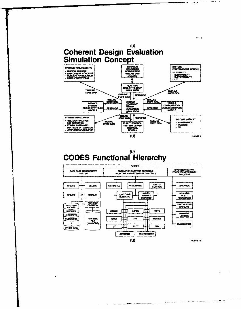
37-13
(U)
Coherent Design EvaluationSimulation Concept
CODESREOS Funtina HirachEMPLOYMENT CONCEPTSCTI EILN HV SRI0BLT
DACETAAS FOMAAMNTSULATION AAYI SUPPORT XCUIE N LNE IDTA
STIEM RUIME INANINRP COTRM ELINE E
UPDATE DLTE AI ATEE INEGRATOED STAT OK
cREATE DISPLAY 1ART AIR AC lTIMELIMROTIMELIN
CYTESOEENTIO DISPLAYS
MISSILNHSIESSOSE M GN -REPNS
YSTEMSDEVELOMENT SATE 'S
SYE AR DW ARUN U STCTHA SY RAM MISSILEAIIN
SOTWR INERION~ SYNTHEOISIP3
OTER FCrO/ALDAT O ODL
(U) FIGURE 10
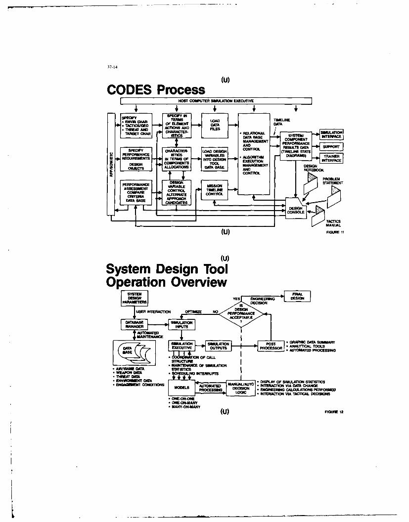
37-14
(u)
CODES ProcessMOST COMPUTER SIMULATION4 EXECIJTIVE
S seNVRam DeigO ToOpertiCGon Ov ErviewAT
THAREM DAM CIN N
E TARGET CHA *HRCR ISLAYO IUAINSAITCMOICS DEiIN * NFER IG ACTION P OE
WA BASE COMPNEN
* MANYON-AND
(U)IF CHIGURER 12DDSIN CNRO TT
37-15
(U)
What Makes Codes Unique?" Integrated end-to-end penetrator/air defense engagement simulation
" Fully stand alone and menu driven
* Turn-key operation, user-friendly interface
" Automated data management of thousands of unique input parameters
" Modeling of all major avionics subsystems
" Automated model adjustment to selected scope of simulation- Air battle- Air-to-surface- Integrated- One-on-one- One-on-many- Many-on-many
(U) FIGURE 13a
(U)
What Makes Codes Unique?(Continued)
* User interaction with simulation- Interrupt and display of simulation state
Parameter adjustment/optimization during simulation- Tactical decision making
* Custom graphic displays- Pilot displays- Situation displays
o Automated analysis tools- Data reduction- Design effectiveness measures- Graphical representations
(U) FIGURE 138 (CONTfll

37-1(
(U)
Simulation Executive Module Scope
* Menu driven
* Variable I/0 and data recording
9 Interrupt scheduling- Time- Event
* Interrupt handling/manual decision logic- View pilot displays- Modify data- Perform engineering calculations- Plot scenario- Make tactical decisions
(U) FIGURE 13b
(U)
Simulation Executive Module Scope(Continued)
" Coordination of players/scope of simulation- Air-battle- Air-to-surface- Integrated- One-on-one- One-on-many- Many-on-many
" Error checking and error handling
* Interrupt logging/data modification logging
Event listings
(U) nau ,t Co,,,ro)

37-17
(U)
System Models Scope" Airframe * Gun
- One or many - AAA- Blue and red - One or many
" Avionics * Threat radar- IRSTS - One or many- ICNIA - Networked- IIR - Airborne and ground based- INEWS- AI radar * C3 network
- Blue and red" Missile •Environment
- One or many- Blue and red - Terrain- IR, semiactive, command - Atmospherics- Ground and air launched - Visibility
(U) FIGURE 13c
(U)Data Base Manager Module Scope
" Menu driven1 Automated input and maintenance of data
" Data display options
" Two level data base
Data file data base - system dataAirframe parametersMissile parametersGun parametersADS site laydownC3 network Types ofIRST parameters data filesICNIA parameters
(U) FIGURE 13

37-1ll
(U)Data Base Manager Module Scope(Continued)
* Two level data base (continued)
- Input file data base - engagement specsWhich aircraftWhich weapons IntegratedWhich avionicsdata filesInitial conditionsEnvironment I
o Error checking and error handling
o File protection with passwords
(U) FIGURE 13d (CONT'D)
(u)
Post-Processor/Analysis Module" Menu driven
" Error checking and error handling
" Data displays- Threat laydown and flightpaths- Aircraft signatures- Site masking
" Simulation output displays- Detection contours (range vs angle)
IR and radar burnthroughWith and without jamming
- Vulnerability contours (range vs angle)With and without maneuvers Self-protectionWith and without jamming efectinWith and without expendables effectiveness
(U) FIGURE 13e

37-19
(U)Post-Processor/Analysis Module(Continued)
* Simulation output displays (continued)- PK and shot opportunities- Weapon lethality- RWR signal history/sensitivity- Synthesized displays (snapshot)
* Situation plots
* Analytical tools (outputs)- Sensor data correlation- Signal/data processor loading histories- C3 network loading histories Mission- Exchange ratios sucsion- Weapon delivery accuracy Success- Target kill probability- Targets/penetrators missed
(U) FIGURE 13e (CONT-D)
(u)Dome/CODES Integration
(U) '. 1
FLGHAVONC
COERN DEINEAUTIN DSLY
MUAIN(OE)AK1WIPT
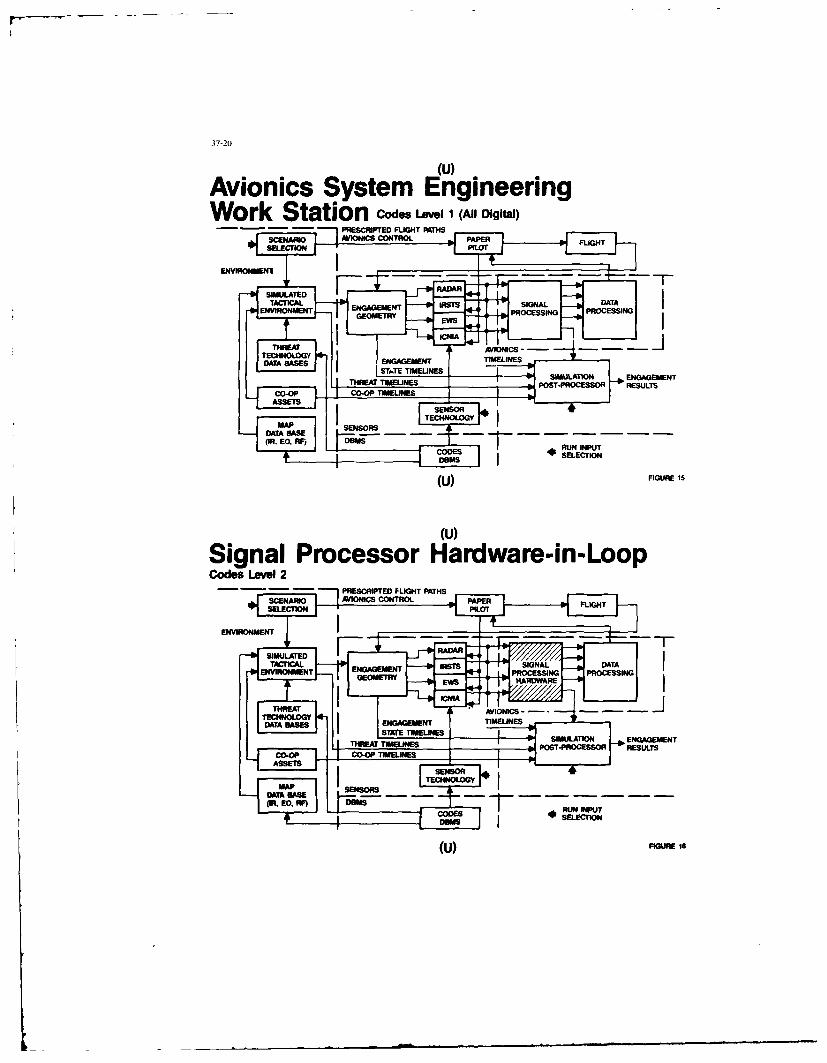
Avionics System EngineeringWork Station codes Level 1 (All Digital)
ENVWAT40NEGAGMEN
GEOETR EIS p POSTNG PROCESS INESLT
- - - - PREcITE FL EST I SMULTIO
(U TIEIE 1146NGGMN

Digital Processor Hardware-in-LoopCodes Level 3
CTIOINOAGMENRTIMUNE
SIIULATION ENAEMN
ENVIRONENPOST-PEMOCESSOR RPRCSULTS
GEMERYES RUNRDNPR T
IBM SLETION EGGMN
(U FIGURE COO1T7LIE
MDBM
(u) FIGURE 17

37-22
(U)
File Based - Software Reconfigurablei Snake B
coc
WO.-a
j G unship NASP(U) FIGURE 19
(U)
Summary and Conclusions" An engineering methodology which allows detailed system,
subsystem, and component design trade-offs to be performed andevaluated in an operational context IS MANDATORY, DOES NOTEXIST but IS ACHIEVABLE!
" Protracted development cycles are assured due to- Difficulty in achieving advocacy quickly- Lack of confidence in ability to meet performance predictions- Escalating costs- Inability to come to grips with evolving technology
* Concerted focus on methodology and tools by top talent withadequate funding will quickly resolve (we are solving design issues100 times more complex than this today)
" Codes initial configuration characteristics summary- Hosted on two (2) Harris 1200 CPU's plus ADI-100- Approximately 100K LOC Fortran 77- Interfaced to Evens and Southerland CT-6 graphics system
(U) FIGURE 20
A "QUASI-CONVENTIONAL" APPROACH TO
FUTURE SYSTEM DESIGN AND MANAGEMENT
byPaul A. Bross, Dipl.Phys.Manager System Studies
Messerschmitt-Boelkow-Blohm GmbHPoetfach 8011608000 Munich 80
Germany
Unclassified Summary
With the advent of the Bus System and the possibility for using multi-bus structures,also using distributed processing and an overall modular approach to partitioningHardware and Software, we are now in the position to structure future Avionic Systemsdifferently than in the past. A straightforward simple decomposition of the Systeminto "Black Boxes", which perform only one function, will belong to the past.
My paper will deal with our approach to structuring modern integrated,multifunctional Avionic Systems and its Subsystems, making use of the newtechnologies emerging for system hardware and also using the new methods appearingfor system design and management, however not to the vastest extent possible in termsof technologies where the advent of VHSIC and system structures decomposing down tomodules would of course impose different architectures altogether.
This is why we call our approach to system architecture "quasi-conventional",because it still provides you with the impression of "black boxes". But this is notthe case in terms of the past time definition.
with the arising new technologies, with digitization and computerization, our futurehardware in the avionic system will be Multifunctional, i.e. a single line-replaceable item LRI (equipment) will perform several functions, exhibit severalmodes, in many cases serving various subsystems. Nevertheless, we still use the termsubsystem, actually aiding us in structuring the overall system.
The first part of my paper will be mostly devoted to outline the guidelines fordesigning the systems architecture, highlighting the various subsystems and "multi"-functions required, then describing the system architecture, expedite a little on busload considerations and explain the concept of multifunctional LRIs, which serveseveral subsystems, provide for several functions.
This really forms a highly integrated, netted system guided by the followingdialectics:
Several Subsystems serve one function or
Several LRIs serve one function
AND
One Subsystem provides for several functions orOne LRI provides for several functions
Designing such a system in terms of system management, system architecture, busstructure, data transfer and distributed processing will take a lot of carefulinvestigations also looking at irportant issues like bus loading, computer timeloading and redundancy management of system functions. The second part of my paperwill outline these special assign considerations on bus load and distributedprocessing power. It will also highlight our modern approach to a highly IntegratedTest System.
In order to handle such a netted system and to manage a proper "top-down" systemdesign, a structured approach using computer-aided tools is foreseen, also fcr
documentation. Only with a data basis, which is established right in 1he beginning of
the programme and which is continued consistently throughout the development phaseuntil system integration, test and validation, a proper control can be exercised. Thesystem decomposition during design can then be validated during integration, using
the same tool and same data base.
Therefore, the third part of my paper will describe how to handle, manage and controlsuch a complex, netted system for decomposition "top-down" as well as integration
"bottom-up", test and validation, using computer-aided tools. In the absence of a

proper IPSE, we are using a tool called CORE-EPOS, whose features will be shortlydescribed. It will be highlighted, that there is a need for integration of a testsupport Environment. At present the tool TUS is used but needs further development.
In conclusion it can be stated, that modern technologies available completely reviseour approach to system design, system architectures and system development/management.
The hardware is dominated by the advent of Multifunction Sensors, Computerization andDigitisation which leads to the Capability of Sensorfusion and multifunctional use ofAvionic items.
The software is dominated by multiprocessor items and multi media data transfer. Thisleads to a modular design of software, high throughput and memory and fast datatransfer.
And the System Management is dominated by m set of integrated, computer aided tools,leading to a proper, consistent, effective control of all system life cycle phases.
List of Contents
Introduction
System Design and Management
1. Decomposition of Multifunctional Systems/Subsystems1.1 System Functions1.2 Subsystem Descriptions and Decomposition1.3 System Structure (Multifuntion Matrix)
2. Additional Design Aspects2.1 Bus Load, Distributed Processing2.2 Integrated Test System
3. Managing a Complex, Netted System3.1 Controlling Functional Decomposition in Hardware and
Software (Database)3.2 Controlling Integration, Test, Validation3.3 Documentation
Conclusion
4fl-1
0
-0 0-0
DEVELGPIPEENT DES SYSTEMES AVK"GR.FS COWY6LEXES
EXPRIEIM SSLIE DES PW LXRAWE.S hUJITAIRES FRANCAIS
PAR
ICA AflT03W CXBSADLJLT
SERVICE TEICVINIQE
DES PRDCV~kVW AERC04AMCKJES - FRANCE
-0 0-0
PREABIE
Les nouvelles q~ndrations d'a~ronefs sont dquipdes de syst~mes dont limportance et les coOts ne cessent
de crottre.
Le d~veloppement de ces systbme, a ndcessit6 ]a mise en place par lea Services Officiels Frangais de
mdthodgs:
" danalyse du besoin
" de conception et de d~veloppemnent des mat~sriels
" de production
* de suivi
" d'dvolution de [a definition en fonction du temps.
Ces m6thodes ont essentiellement pour but drarriver A
" satiafaire Putilisateur (en loccurence lea Etats-Mnjors)
" en reapectant lea ddlais
" en contr~lant strictement lea coOts
Elles aunt basdes sur l'expdrience aes d~veloppements ant~rieurs et sont donc am~Iiordes b chaque
nouveau programme.
Les paragraphes gui suivent d~veloprent lea iddes conductrices utilisdes lbra du d~veloppement du
MIRAGE 2000 et de IATL2 (ATLANTIQUE), leo anomalies constat~ea et leo am~sliorations asceptibles d 8tre
apportdes dans le cadre du Programme ACT (RAF ALE).
40-2
- L'ANALYE OES HE913.65
Les besoins en renouvellement des a~ronefs sont expri~fl~s par lee utilisateurs, en fonction de
I'dvatution de lour pare et des utifisations potentielles.
Les dvolutions du parc aont essentiellement dues 6
" la durde de vie
* I'sttrition
Les utilisationa potentielies varient selon
" lee besomns en performances.
" longueur de piste
" fa BLotur de charge en combat
" capacitd d'emport
* Ia definition de nouvelles missions:
" ddfense aerienne
" supdrioritd
" reconnaissance tr~s haute attitude
9 ...
" Is prdvision dutilisation dons divers types de conf lit
" centre Europe
" thdaitres extdrieurs
* INvolution des armaments* missiles stand off
*armes & guidage terminal
* I'6volution des menaces:
* radio~lectriques
* infrarouges
L'utilisateur a ainsi Is possibilitd desprimer sev besoins g6n~raus, qui vont permettre de demarrer lee
travaux prdIiminaires indispensables A Ia binne apprehension des becomes r~els.
1I faut insister stir Is difficuit6 de Is tbche dTeepressioi des besoins. L'Etat Major qul definit ses
besoiiis vs coil sc responsabilit6 engag6e cur un nombre cdann6es tr~s important.
11 fout en effet rappeler que Ie cycle de vie dfun programme davion s16tend sur 40 one comme Ie
montre Is diagramme ci-dessous.
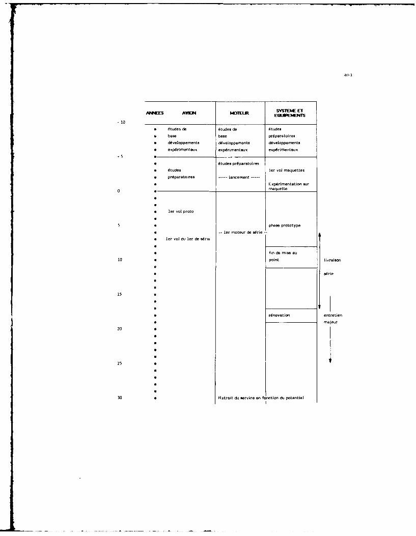
401-3
ANNEE AVM OTEURSYSTEKhE ETAMES AN U]1LRE0RJPIAETS
* tudes de 6tudes de dtudes
* base base prdparatoires
* d~veloppemnents d~veloppements d~veloppernents
* expdrimentaux expdrimentaux expdrimentaux
* ees Oit udspdaaors ler vol maquettes
* prdparatoires --- lancement -- x~ietto u
0 * ____________ maquette
leIr vol proto
5* phase prototype
* e -- u e e ~i ler moteur de s~rie --
* fin de mise au
10 6point livraison
15 a
200
20
30 0 FRtrait dui service en fonction du potentiel

40-4
2- aX4CPTEKN IDES HA1EELS
A Ia suite do lanalyse et do [a mise en forme de ces bosoins gdn~raux, va commencer Is travail do
conception.
Diverses solutions sont g6ndrelement capables de repondre aus bosoins et Is premi&re difficuhtd
reside dens he choix.
Celui-ci pout, bien &Or, Otre aidd par hesamen attentif do solutions utihiades dens certains pays en
avance technologiquo, mais di eat souvent n6cesaaire de so conforter par des litudes do base at deffectuer des
doveloppomnentsa pLoratoiros. Les doveloppements explorstoires peuvont sarrter au stado "papier" ou conduire
b Is fabrication do maquettes.
F Le schima suivant donne un exemple do d~rouhoment d'un d~velopperment exploratoire syant pour but
l'dtude do maquettes avionnables do Radars AMroportts do combat a~rien et dappui sol (RACAAS).
03 84 05 86 87 88 99Maquetto d'enregistrement on vol do aignaux
numdriques regus par tin radar en moyenne
et basse frdqtinnco do r~currence
* analyse du modbhe de clutter do sol
a analyse dos signatures do cibles
isoles ou non
Ddfinition
Essais en vol
Maquette do validation dos innovations pour
radar futur
* moyenne frdquence do recurrence
a Emetteur permettant le fonctionnement
en haute, moyonne, basso fr~quence do
rdcurrence
* traitement du signal
" multicibles
" affinage doppler, image haute rdsolution
06finition
Essais en vol
Maquette avec balsyage Electronique tin plan
D36finition- - - - -
Essais en vol
Ces dMveloppements exploratoires peuvent aussi porter stir Is hogiciel. Ainsi, pour doter Is communsu-
t6 avionique frangaise d'un Systbme do D~veloppement dAvionique (SDA), adaptE' aus besoins do dL'veloppement
des logiciels d'6quipements des systbmes embsrqu~s, il a Etd dMcidE do lancer he d~veloppement exploratoire: IT[
(int~gration du traitement do linformation).

40-5
7-9 80 81 82 83 04 85 86 b/, 88 89
Etude 9"nrale de d~finition des besoins en - -- - - --
traiternent des systbmes avi05iiques fuiture
D~finition globele du SDA- - -
Ddfinition d~taillde, planification
Ddveloppement d'une maquette probatoire
do Is structure d'sccueil,
D6veloppement des outila logiciels
Enfin ces d6veloppemnents peuvent 6tre poussds trbs loin comma eels a 6td le cas avec le
ddrmonstrateur Rafale (photo page 6), dont Ie r~le a dtol de prouver
* les qualitils de commandes de vol numdriques
" lea possibilit~s qU'apportent les structures nouvelles
* Is validitd du concept d'interface homnme/machina qui avert dtE regard6 au cours dun d6veloppement
exploratoire sur l'organisation des postes dEquipage (OPE) (photos page 6)
a sibge inclint!
* combind de pilotage avec W~e moyenne collimat~e
* collimateur t~te haute holographique
a manche lat~ral
3 -AS P-IP "ARATCOW
Les dtudaa de base et d~veloppemnents exploratoires ayant permis de valider des solutions technologi-
ques, le lancament du programme pout Otre pr~parE. Lea principales Etapes sont
* Etablissement de Ia fiche programme
" Sp~cifications prolimirraires
* Etablissament du plan de d~veloppernent technique
* Etablissement du plan de financement
" Lancement
La fiche programme eat ]'expression du besoin des utilisateurs. Tir~e des besoina g~ndraus cit~s plus
haut, ella precise lea points lea plus importants, flee lea limites du produit aussi bien vera Is bas (performances
minimales acceptable$, ... ) qua Vera le haut. 11 faut n~cessairement limiter lea demeandes et trouver Is compromis
capable d'Otre r~alisE avec les budgets, ddlais, matdriels disponibles.
Par exemple les Etata-Majors aimeralent souvent disposer dun avian de supdriorit6 adfrienne (grands
vitesse, rapport pouss~e-poids dlev6, grande manoeuvrabilitE) at crun avian d'appui tectique (M : 0, 9, basse
altitude, capable d'emporta multiples, bien prot~gE par des systbmes complexes de contremesures). Ila doivent se
contanter d'un avian polyvalent (le compromis) pour des raisons cfdconomie de moyes.
Cette fiche programme, purement op~rationnelle, sara transfornde en sp~cifications prdliminaires
par lea Services Techniques qui y ajouteront lea performances A r~aliser.
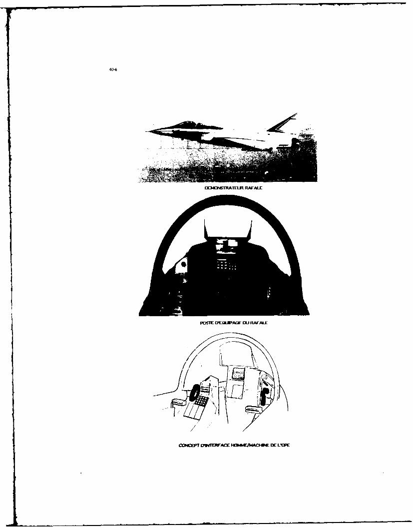
4"-
E34W5RATLJR RAF-ALE
FlU6TE EVECWALE IIU RAF-ALE
CONEPT D'341'ERFAI ~FUKMAO-E DIE LIOPE
401-7
4 - IELOPbfNW
A partir des spdCifiCatioieb Lechniques, it vs 6tre possible d'entreprendre Vanalyse du developpement
et en particulier celui du systL~me (farmes qui sere detaid ci-aprbs.
La premibre dtape consists h effectuer I'analyse opirationnelle des besoins de fagon h determiner les
solutions envisageables du point de vue
" capteurs
* traiterrent et analyse du signal
* interfaces pilots
" interfaces armaments
" enregistrament, transmisaion
a bus
Cette analyse est effectude avec Is participation de groupes de travail constitu~s par Les principaux
industrials concern~s at par lavionneur.
Elle aboutit 4 une architecture fonctionnelle et h une liste d'~quipements.
Cette architecture, comme Ie mantre Is planche (page 8) peut 6tre relstivement complexe.
La tfiche de choix de l'architecture et des 6quipements est du resaort des Services. Cette tAche est
sousent compliquile par la ndcessitds de r~psrtition entre 6quipementiers prenant en compte des didments peu
techniques de politique industrielle, en particulier pour les 6quipements dont Ic ddveloppement et Is misc au
point sont de coOta tellement 6lev6s et IPacquisition cfexp~rlence tellement difyicile que Is concurrence nexiste
pas en France.
D'autre part, Il6volution des techniques vera Ie numdrique conduisant h dispoar doe cheque
6quipement d'un calculateur qui, par nature, salt tiaiter nombre de probl~mes math6metiques et de gestion, il
convient de valider une architecture logicialle et une r6partition des calculs
" dimirajant les charges bus
* minimisant lea collte en:
" svitant la duplications de calculateurs sophistiqu~s
" rdduisant au maximum lea developpements du logicial
Enfin, comma cela a ddjb 6t6 dit, Ia syatbme sera utilia6 pour de nombreuses anindcs pendant
lesquelles la volutions technologiques seront continuellas. 11 eat du reasort des Services de v6rifier que
l'architecture choisie eat susceptible de d~veloppements ou de modifications, sans probibmes majeurs.
Line des voices ouvertes consists h essayer de cr~er une standardisation su niveau des entr~es/sorties
des 6quipemnenta.
Pour cheque fonction du Syatime dArmes, il taut alors doefinir des Specifications Globales qui
concernant fleneembla des 6quipernents rdalissnt cette fonction at qui definissent avec beaucoup de precision
* l'objectif do Ia fonction
" Is r6la de chacun des Oquipernento
" lea interfaces homme/machine
* las raconfigurat ions en cas de panne
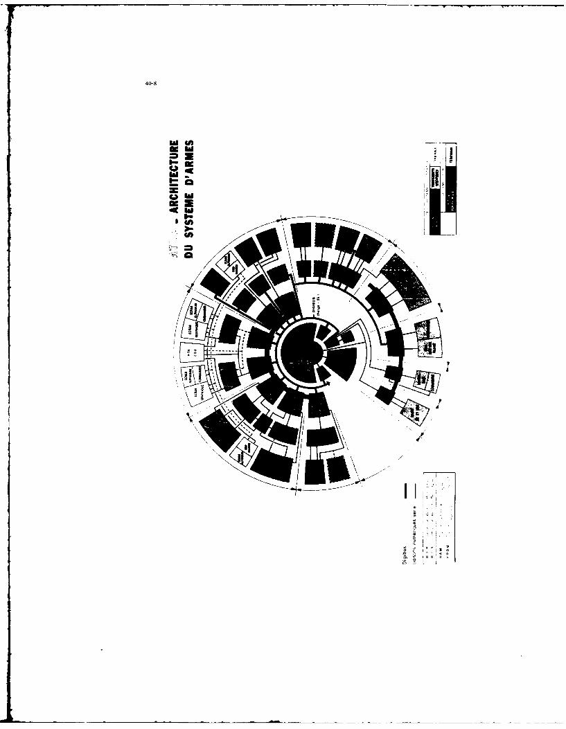
40-8
Am #A) - -
C9I
Ch=
40-9
Ce document suffit en lui-m~me pour ddfinir Is fonction 6ldmentaire qui est achetde par les Services.
Bien que, actuellement, ceux-ci entrent plus dens le detail, i! conviendrait, pour limiter leur charge
de travail et surtout leur dviter de rentrer dans des d~tails d . niveau du spdcialiste, de limiter Ia surveillance des
Services b Idl6aboration de ces Spcifications Globales.
Afin qu'ils puissant engager leur responsabilitd A ce niveau, il est ndcessaire de disposer de moyens de
vrification des Spdcifications Globales.
Les moyens existent d~jA sous Is form
* outil d'aide A Is Spdcification (OASIS) (photo page 10)
* simulateur de combat du Centre Electranique de l'Armement (CELAR) (photo page 10)
* simulateur du Centre d'Essais an Vol d'Istres (C.E.V.) (photo page 10)
D'autres moyens informatiques qui pourraient tre plus simples de mise en oeuvre at d'emploi qua leas prdcddents
sont envisageables.
Ces moyens doivent permettre Is validation at donc donner une rdponse trbs tot apr~s 'dition des
2pbuh~lcL.u~s. c.En effet una rdponsae tardive peut donner Peffet contraire, Ia suite du diveloppement s'etant
poursuivi, les rdsultats issus des outils conduisent A des propositions de modification avec les incidences sur les
prix, ddlais at en g6nral bon ddroulement du programme qua Ion imagine.
Apris validation des Spdcifications Globales il serait envisageable de voir lea Services acheter une
fonction validde sans participer de faon ddtaillde A Is suite du ddveloppement at en intervenant uniquement
pour Ia r~ception officielle. Cat achat pourrait Atre forfaitaire, les prix incluart de base une provision pour
correction de malfaqons Eventuelles.
Seules les modifications de Spdcifications Globales resteraient sous contr6le des Services. Ces
modifications justifides devraient tre peu nombreuses si un consensus dtait obtent au tours de Is validation
entre les pilotes chargs de Ia mise au point (pilotes constructeurs, pilotes du Centre d'Essais an Vol (C.E.V.),
pilote du Centre dFExpdrimentation de I'Armde de lAir (CEAM)) at les pilotes opdrationnels. Dens ce cas les vols
dessais devraient cesser d0tre des vols de mise au point des SpEcifications Globales pour devenir des vols de
verification finale de Ia Specification, ce qui conduirait & rdduire leur nombre done leur coOt. Le droit A Perreur
due A des phdnombnes non accessiblas an simulation (par example : ddfectuositd des capteurs, modifications des
caractdristiqueas dues A des influences extdrieures) donneraient seules lieu A des modifications justifides.
Le dtveloppement se poursuit au niveeu dquipement et logiciels par I6laboration de Spdcifications
ddtailldes.
Leas quipements sont ddveloppds:
* soit sous Is responsabilitd de l'Etat qui an assure aussi l'intdgration at Ia montage : matdriel A
* sait sous Ia responsabilitd des Services avec intdgration par Ia Coordination Industrielle composde des
Industrials majeurs impliquds dens Ie dveloppement at de Pavionneur % matdriel B
* soit directement sous Is responsabilitd de lAvionneur : matdriel C
La notion de Coordination Industrielle permet dFassurer Ia coh~rence temporelle et matdrielle du
ddveloppement des Equipements at logiciala. Ella pose par contre I problime de Ia concurrence industrielle et de
Is non-divulgation de lexpdrience. Lavionneur, moins impliquE dens Is concurrence qua lea Equipementiers, sert
dgent de liaison. La Coordination Industrielle fait Pobjet dun contrat s9parE.

40-10
OASIS gSDAAELAR DE COMBAT lxU CELAR
9MLAATEA ODU C(NTAE DUMS EN VOL DIS1RL

Le developpement des matdriels de Ia catdgorie Bl peot poser plusieurs probl~mes
e non ,pdcificitL6 du produit qui ne pourra istre adapt6 que par modifications salt internee, soit de Ia chalne
fonctionnalle
a developpement asynchrone
a manque de moyens des Services pour assurer Ie developpement fdquipements complexes
Les mat~riels B font l'objet de Clauses Techniques d'Int~gration sous Is responsabilit6 de leavionneur.
L'6volution normele semble Otre une diminution des developpements B au profit des C.
Le developpement des fonctions s termine par on contr~le sor on banc dint~gration donE Ie but est
de valider lee sp~cifications globales 6 travers lea dquipements r~els.
Avant d'Atre mont~a sur lea bancs, lea Equipements doivent subir une racette matdrielle et logicielle
parmettant d'6liminer one majorit6 de d~fauts. (photo page 12)
Pour ceas it eat n~cessaire que lea Eqoipementiers puissant disposer drun outil g~n~ral de simulation de
laenvironnement parmettant d'abord Ia mise au point puis donnant h Is coordination industrialle Cu aux Services,
les moyene de recette en usine.
Cette mdthode devrait aussi permettre de r~duire la volutione en phase de d~veloppemnent
actuellement 96r~es par la comit~s locaux de modification du mattriel (CLM) ou lea comit~s de modification du
logicel (CML). Cee comitds sont souvant surchergda par le nombre &.s Evolutions, traitdes sans notion
d'importance at dont Is bienfondd nest pee toujours, accessible aus Services charg~s de lea gdrer do point devsue
temporal et financier.
La situation actualle eat encore acceptable :il faut an effet compter 1500 modifications de toos
types pour un eviori dont Ia logiciel occupe 250K< ... male peut-on imaginer Ia geetion n~ceaire pour on loqiciel
de 2500K<.
Un effort considerable eat n~cessaira, lea outils IT! doivent alder mais lee outk.'s g~ndraus de
simulation de l'environnment sont certainement n~ceseaires pour pouvoir traiter de tels logiciels.
Enfin cette tAche, comma it a ddjA 60S diE, pourrait 6tre laiss~e h Is Coordination Indoetrielle, lea
Services se r~servant la cas litigieus at ceux touchant lea Sp~cifications globales.
La d~veloppement as termine aprLs introduction des dernibres modifications issues des Essais en Vol.
5- MWEN RI
La passage en s~ria na posereit pee de difficult~s sp~cialee:
" si tout lae ddveloppements Etaient effectuds de fagon synchrone at [a mise as point compl~tement termin~e
" si lea m~thodes d'industrialieation nevalent pee d'influance sur lee performances do mat~riel
La non synchronisms des tl~veloppements, lintroduction de demendes nouvelles par rapport aux
Spdcifications Globales da base entratnant des retards de livraison des dquipaments et logiciels qui ont obligE A
introduira Is notion de standard.
40-12
MWN O?4TECA1EN CU SYSMWh CFARMf 3
flU NWU a=i

40-13
Les premiers standards sont tivr6s avec
* des fonctions ircompltes ou manquantes
" des dquipements encore ivolutifs qul seront rattraps par mises b hauteur successives
It faut insister sur le fait que, at dans un premier temps, lea livraisons partielles satisfont les
utilisateur, elies aminent de r~els probltmes
" de gestion U.. parc disponible
" de noria des 4quipements entratnent des diminutions de la disponibilit6 affectant les avions
* de reprogrammation des calcutateurs et de developpement indispensable d'outils de rechargement
* de mise A niveau de Ia documentation
* de disponibilit des moyens de test et de maintenance, eux aussi au hon standard
A ces probltmes techniques sont associis Ovidemment des probtbmes de coOt. La solution consiste
contrdler I'homogri'tt6 des cycles et A r~duire au maximum le nombre de standards. LA encore, apparalt la
n6ressitt du contrtle strict des Specifications Globales et des 6volutions tardives de ces specifications.
A titre d'exemple, le diagramme ci-aprhs donne le plan de dsveloppement et les diff~rents standards
du MIRAGE 2000.
82 83 84 85 86 87 88 89
Standard St 'sans radar) -
Standard S2 (avec radar RDM)
Standard 53 (aver ELM am61ior
Standard S4 'avec radar RDI) -
Le standard S2 est celui correspondent aux spdcifications qlobales initiales avec radar RDM 'Radar
Doppler Mutifonctions)
Lev mdthodes d'industrialisation rdaqissent aussi sur le passaqe en Osrie du fail
" des modifications de rndthodes de fabrication
i automatisation
* changement de technologie et en particulier de composants
" des modifications de tolerances
* des changements de mdthode de recette
et mime parfois de [a reprigrammation.
Actuellement, le d6veloppement srie s'accompagne d'une phase de mise au point non n*liqeable.
Cette phase pourrait 6tre r~duite par un contr6te plus strict de la production de afrie par rapport A la production
prototype. Cela demande des m6thodea, des moyens et du personnel tr~s qualifi4& en nombre suffisant.
Ceta conduit b la mise en place de ta gestion "qualitA".
40-14
6 - LA VIE EN UYTISATEN, LES IflJOYATIGNS
Les diagrammes ci-avant ont montr6 que le ddbut de la vie de lavion est affecte par des restrictions
opd rationnelles.
Cette vie doit dvoluer en fonctiun des demandes nouvelles des utilisateurs.
Celles-ci peuvent :
* soit 6tre intgrdes dans le syst~me existant par un processus de modification
* soit demander une etude complexe remettant en cause le systbme prdcddemment d~fini. 1I s'agit alors de
r6novation.
Les rdnovations sont des ph6nom6nes de plus an plus courants du fait
* de la rapiditd de I'dvolution de Ia technotogie des capteurs d'adaptation
" des besoins des interfaces homme/machine
* des diveloppements des armements et des menaces
11 est n~cessaire darts la conception des syst6mes de base de tenir compte dhs le ddpart des
r6novations 6ventuelles en erdant une architecture systhme modulaire, capable d'extensions, de reconfiqurations
et travaillde au iveau des entr6es et des sorties pour accepter des fonctions nouvelles.
11 faut nuter qu'une telle arrhit~cture permettrait aussi en utilisation de r6soudre certains problhmes
l'int~rnp6rabilitd rencontrds par les utilisateurs.
Ce souhait peut voir le jour, dons leas avions modernes, avec la banalisation des 6crans et des
cummandes mais ['effort de standardisation au nveau des Lquipements doit 6tre poursuivi, m6me si cela oblige
un droit de regard du concepteur du systbme sur la technologie et ['architecture interne des 6quipements.
CW3LaN
En conclusion, les besoins suivants sont mis en dvidence
* Ncessit6 d'une 6tude et dune formalisation pr6cises des besoins par les utilisateurs. Ceci conditionne le bon
d~roulement de tout le programme
i Nfcessit6 dune analyse fonctionnelle, de ldcriture, de la validation et lacceptation de Spdcifications Globales des
Fonctions. Ces specifications globales constituent le niveau dengagement entre I'Etat et les responsables du
dLveloppement. Cela entraine le besoin en outils de validation et d'acceptation des Specifications rapides et sures
" Ndcessit6 de rdduire les Evolutions aussi bien en cours de d6veloppement prototype qu'au moment du passage en
serie
" Ncessitf dun contrdle constant de ia qualit4
L'expdriencr acquise sur lea programmes MIRAGE 2000 pourra ainsi Atre reportde sur I'ACT (RAFALE)
dans le but d'augmenter Ia qualit6 et les possibilit~s opdrationnelles tout an rdduisant les coots.
-000-0

40-I"
DISCUSSION
E.Daley, UKEmphasis was placed on the importance of agreed specifications. What form "sere the expressed in. and w hatprocedures were used to check them at the specification stage?
Autlhor's ReplyThe specifications were expressed in the form of documents. The %erification procedures were those described in themiddle of the paper, essentially, piloted simulations as realistic as possible.
W.R.Fried, USWould you please describe the ',pe of communication. nasigation. and radar equipment implemented on the Mirage2000 (e.g.. HF, 'HF. UHF radio: voice: and data)?
Author's ReplyTle Mirage 2000 is very flexible and can receive on several system variants with different types of radar: impulsedoppler radar (Thomson-CSF), multimode doppler radar (Thomson-CSF). and Antilope radar (FSD). Navigationdepends on an inertial system using recover, of accrued performance in the case of Antilope radar. Basicaly, there aretwo VHF:UIF radios and a transmission system for interception data (tcleadhesion). Increased protection radio, arcavailable as an option.

41-1
THE FUTURE MARITIME RECONNAISSANCE AIRCRAFT AS PART OF AN INTEGRATED MARITIMEBATILEFIELD SYSTEM
by
D.BaldwinsonBritish Aerospace PlcStockport, Cheshire
UK
Although operating in a relatively more benign environment than a fast jet combat aircraft, a maritime reconnaissanceaircraft is a complex weapon system which has a highly integrated set of subsystems. Future developments in the ASW/ASVWscene will strengthen the requirement for the weapon system to be a fully integrated member of a higher order system.
A move to carry out more research and development in industry, as opposed to government establishments, has helped toinvolve companies in higher order system investigation. This paper discusses how the concept of this greater system can beinvestigated, the implications for the platforms involved and the tools which could assist in these tasks.

REPORT DOCUMENTATION PAGE
1. Recipient's Reference 2. Originator's Reference 3. Further Reference 4. Security Classificationof Document
AGARD-CP-417 ISBN 92-835-0437-2 UNCLASSIFIED
5. Originator Advisory Group for Aerospace Research and DevelopmentNorth Atlantic Treaty Organization7 rue Ancelle, 92200 Neuilly sur Seine, France
6. TitleTHE DESIGN, DEVELOPMENT AND TESTING OF COMPLEX AVIONICSSYSTEMS
7. Presented at
the Avionics Panel Symposium held in Las Vegas, US, on 27 April-I May 1987.
8. Author(s)/Editor(s) 9. Date
Various December 1987
t0. Author's/Editor's Address 1I. Pages
Various 434
12. Distribution Statement This document is distributed in accordance with AGARD
policies and regulations, which are outlined on theOutside Back Covers of all AGARD publications.
13. Keywords/Descriptors
Avionics systems SoftwareArchitecture Hardware"Black boxes" Interface
Sensors VHSICArtificial intelligence Sensor data fusion
14. Abstract
This symposium was designed to explore how today's system designer is addressing the solution totomorrow's avionics systems design.
As government budgets become more limited for the research, development, testing andproduction of military aircraft systems, and the Warsaw Pact nations continue to produce all typesof aircraft in greater numbers, the NATO nations must "re-look" at how avionic systems aredeveloped. In general, the avionics community has thought of avionic architecture as the integrationof a collection, of "black boxes" (sensor, navigation, communication, display, etc.) with the softwareallowing for the communication between "black boxes", computers and man. Normally, the systemis decomposed into manageable parts with accurately defined interfaces. With the advent of theVHSIC, distributed processing, artificial intelligence, sensor data fusion, etc., the technologies areblurring the clear functional allocation defined for the "black box". Two factors, technology andcost, provide both an opportunity and a challenge to the system designers to design future avionicssystems whose performance degrades gracefully, is reliable, and is affordable.

02
z z
-n E
-' 0.
Z Z E ~ . Z- -
U V5 t- 0 nr ; =
sz -0 r X 2 - V..
z 0 0.; ~. .ZC;- .5 C<in- E .0 .0M.
u z Z 0M QOZ>
U 0 > EU w.> X a-
< U?
<~~ 2. a: .22-2 c 1 2-
0 0o 2
0 N
~. 0
Z q V3 0o Q 0
.; 0 cm
00
0. 0. 0'
a0 z < .02 E~2
U , 0.) QL UJ~ 0.> . >-=
0 ~ ~ . 0. 05< z U) ~ IE g i

00
0~O .6i2z i
'o -0Q ' >
c o 2 ~ tu i0 .u~~
U- 13~ m
C-
;g u
;: g -o- 0'l
r. .<~
E r
CC -ICC ' 4r
E -o E rV c
U - v
92 C
u~ u02
r -
9-S. a i2~~ ~ CL
C COVU -' v CL ?- 0 !
. 2~ U.nC
-.. .2 Zr u-~ S 0< .15~ a- a: 0
NATO + OTAN
7 rue Ancelle • 92200 NEUILLY-SUR-SEINE DI ArGTRBU1ON OF UNCLASSIFIED
FRANCE AGARD PUBLICATIONS
Telephone (1)47.36.57.00 -Telex 610176
AGARD does NOT hold stocks of AGARD publications at the above address for general distribution- Initial distribution of AGARDpublications is made to AGARD Member Nations through the following National Distribution Centres.Further copies are sometimesavailable from these Centres, but if not may be purchased in Microfiche or Photocopy form from the Purchase Agencies listed below.
NATIONAL DISTRIBUTION CENTRESBELGIUM ITALY
Coordonnateur AGARD - VSL Aeronautica MilitareEtat-Major de la Force Aerienne Ufficio del Delegato Nazionale alr*AGARDQuartier Reine Elisabeth 3 Piazzale AdenauerRue d'Evere. 1140 Bruxelles 00144 Roma/EUR
CANADA LUXEMBOURGDefence Scientific Information Services See BelgumDept of National Defence NETHERLANDSOttawa, Ontario K IA OK- Netherlands Delegation to AGARD
National Aerospace Laboratory, NLRDENMARK P.O. Box 126
Danish Defence Research Board 2600 AC DelftVed Idraetsparken 42100 Copenhagen 0 NORWAY
Norwegian Defence Research EstablishmentFRANCE Attn: Biblioteket
O.N.E.R.A. (Direction) P.O. Box 2529 Avenue de Ia Division Leclerc N-2007 Kjeller92320 Chiilon PORTUGAL
Portuguese National Coordinator to AGARDGERMANY Gabinete de Estudos e Programas
Fachinformationszentrum Energie, CLAFAPhysik, Mathematik GmbH Base de AlfragideKernforschungszentrum AlfragideD-7514 Eggenstein-Leopoldshafen 2700 Amadora
GREECE TURKEYHellenic Air Force Genera) Staff Milli Savunia BakanlitResearch and Development Directorate ARGE Daire BakanhipHolargos. Athens Ankara
UNITED KINGDOMICELAND Defence Research Information Centre
Director of Aviation Kentigern Housec/o Flugrad 65 Brown StreetReyjavik UGlasgow G2 8EX
UNITED STATES
National Aeronautics and Space Administration (NASA)Langley Research CenterM/S 180Hampton. Virginia 23665
THE UNITED STATES NATIONAL DISTRIBUTION CENTRE (NASA) DOES NOT HOLDSTOCKS OF AGARD PUBLICATIONS. AND APPLICATIONS FOR COPIES SHOULD BE MADE
DIRECT TO THE NATIONAL TECHNICAL INFORMATION SERVICE (NTIS) AT THE ADDRESS BELOW.
PURCHASE AGENCIES
National Technical ESA/Information Retrieval Service The British LibraryInformation Service (NTIS) European Space Agency Document Supply Division5285 Port Royal Road 10. rue Mario Nikis Boston Spa, WetherbySpringfield 75015 Paris, France West Yorkshire LS23 7BQVirginia 22161, USA England
Requests for microfiche or photocopies of AGARD documents should include the AGARD serial number, title, author or editor, andpublication date. Requests to NTIS should include the NASA accession report number. Full bibliographical references and abstracts of
AGARD publications are given in the following journals:
Scientific and Technical Aerospace Reports (STAR) Government Reports Announcements (GRA)published by NASA Scientific and Technical published by the National TechnicalInformation Branch Information Services, SpringfieldNASA Headquarters (NIT-40) Virginia 2216 1. USAWashington D.C. 20546, USA
Printed by Specialised Printing Sersices Limited40 Chigwell Lane, Loughton, Essex IGIO 3TZ
ISBN 92-835-0437-2