
Stripper - Header - Shelbourne Reynolds
49
.. ~AN- 0010 Stripper Header , .. . , Operator \_ Manual f•-C•l-'£ T,.:<;, ;,1tr .1.ov:.rl• • tf<:'J"NCt OC,1C.,U 11(:•1 ~.•'' ""'•"'"'' Stud~.iourn3 fi eyn 1 1!(~s ~qgln~t~r; .,u !.~IJ., •;h1:1phards Gro':. '(~ .. $( Jri1nP.. c\, uv St. Ed,,., ,,m1~ if' J ·J ~Ml, Si Ji !"OLK. E,,g! and T9t G3)9 f,U 41~ f.a~. :,~9 ~{M,6t..
-
Upload
khangminh22 -
Category
Documents
-
view
1 -
download
0
Transcript of Stripper - Header - Shelbourne Reynolds

.. ~AN- 0010
Stripper
Header , .. . ,
Operator \_
Manual
f•-C•l-'£T,.:<;, ;,1tr.1.ov:.rl••
tf<:'J"NC t OC,1C.,U 11(:•1 ~. •' ' ""'•"'"''
Stud~.iourn3 fieyn11!(~s ~qgln~t~r;.,u !.~IJ., •;h1:1phards Gro':.'(~ . . $ (Jri1nP..
c\,uv St. Ed,,., ,,m1~ if'J ·J ~Ml, SiJi !"OLK. E,,g!and
T9t G3)9 f,U41~ f.a~. :,~9 ~{M,6t..

Section 1 1. 1 1. 2 1. 3 1. 4 1. 5
Section 2 2. 1 2 . 2 2. 3 2. 4 2. 5 2. 6
Secti on 3
Section 4 4 . 1 4. 2 4. 3
Se c tion 5 5 . 1 5. 2 5. 3 5. 4 5. 5 5. 6 5. 7 5. 8 5 . 9
Section 6 6. 1 6 . 2 6 . 3 6. 4 6. 5 6 . 6
0 P ER A- ~ b RS M A N U A L
C O N T E N T S
INTRODUCTION Forword Improvements and changes Service parts Machine identification Wa r ranty
SAFETY PROCEDURES Accident prevention Before starting the machine The machine in the field Leaving the machine Servicing the stripper header Header attachment and transportation
SPECIFICATI ON AND DESCRIPTION
TRANSPORTATION AND HEADER ATTACHMENT Shelbourne Reynolds transport trailer Setting the trailer to suit combine Trailer routine maintenance
PREPARATION FOR USE Header drive Concave setting Header lowering speed Combine front elevator dust cover Levelling the headGr Rotor ground clearance Header height indicator Aligning header drive Axial flow combines
FIELD OPERATION Field adjustments Stripping rotor speed combinations Tacho performance monitor Basic machine setting table Operating the Stripper header Adjustment c harts
1

Section 7 7. 1 7. 2 7. 3 7. 4 7. 6 7. 7 7. 8 7. 9 7 . 10 7. 11 7. 12 7. 13 7. 14
Section 8
Section 9
Section 10
ADJUSTMENTS AND MAINTENANCE Angle of stripper Al i gning header drive Auger slip clutch setting Auger position setting Auger stripper plates Chain tensioning Conveyor belt tension Conveyor belt tracking Rot or anti-wrap plates Str ipping element wear assessment Dividers Ski ds Drop box type rotor drive
LUBRICATION
MACHINE STORAGE
APPENDIXES
2

13EG'Ll ON 1
1. 1
FORWORD
This manual heade r and loss levels conj unction
1 N T R O D U C T I O N
will assist the operator in setting the stripper combine combination to give optimum throughputs and in part icular crops and field conditions when us ed in with the combi ne manufacturers operators manua.l.
The Shel bourne Reynolds stripping header has been successfully tested i n a wide ra nge of crops a nd crop conditions in terms of throughpu~ and c~op recovory wi th a g rain stri pper a nd combine combina tion, when c ompared against a conventional cutterbar and combine combination of si~ilar size in the same crop and condi t:L ons.
PATENTS
The Shelbourne Reynolds strippar header i s protected b y worl dwide Patents:
PCT/GB/85/00442 and o ther s.
1. 2
IMPROVEMENTS AND CHANGES
She lbourne Reynol ds Engineeri ng a r e continually improving their product s to meet the farmers needs and therefore reserve t he right to ciake improvements a nd changes when practical to do so, wi thout incurring any obligation to make changea and a dditions to equipment which has been s old previously.
3

1. 3
SERVICE PARTS
Use guaranteed and genuine Shelbourne Reynolds Engineering service parts on Shelbourne Reynolds machinery to ensure maximum life and best performance. These are available through your Shelbourne Reynolds Engineering dealer.
When ordering service parts always quote the model, serial number and machine number.
1. 4
MACHI NE I DENTI FICATION
The s e ri a l and machi ne numbers of the stripping header are located on t h e top right hand corner of the header.
Th e ma c hi ne number of the adaptor plate is located on the top righ t hand c o r ne r of t he adaptor plate.
1. 5
SHELBOURNE REYNOLDS ENGINEERING LTD -WARRANTY TERMS AND CONDITIONS TO THE PURCHASER
GENERAL 1. Thi s warranty wi l l become available to you when you have paid f or the equipment and returned, duly completed, the delivery and warranty registration forms. It will expire on the anniversary o f purchase from the dealer. After that date Shelbourne Reynolds wil l hav e no f u r ther l iabil ity under thi s war ranty to you except i n r espec t o f cl a ims already notified. This warranty is not transferable and i s available only to the original purchaser from our dealer. In the case of purchasers having leasing or similar arrangements the first user shall be deemed the original purchaser and you shall be deemed to have paid for the equipment.
USE AND MAINTENANCE 2. To maintain the benefit of the warranty throughout the twelve month period you must have the machine serviced in accordance with our recommendations and use the machine properly. If on inspection the machine appears to have been either misused, overloaded, improperly operated, neglected, not properly maintained, altered or repaired without our consent this will invalidate t he warranty. We shall have no further liability under it to you at all. (If you require any guidance as to use you should contact the dealer. ) 3. Our liability under this warranty is dependent upon your making the equipment and facilities available, for inspection and testing.
4. In thi s warranty t he expression, "defective product" means any part of the e quipment you have purchased which shows e vidence o f a d e fect i n the ma t e ri a ls, des i gn (du e regard being give n fo r t h e state of the a rt at the time we d es i gned i t ) o r She l bourne Reynolds' workmanship. Weari ng p a rts, suc h a s belting, are e x cluded. Parts not manufactur ed by Shelbourne Reynolds, f o r
4

example t yres a nd alternators, are also excluded.
OUR OBLIGATIONS 5. I f you discover a defective product you should contact the dealer from whom your machine was purchased. The dealer will notity us of your claim. Our obligation will then be to either replace, or if we consider it appropriate, repair the defective product . Alternatively, we may arrange for our dealer to carry out this work. YOU MUST NOTIFY THE DEALER OF THE DEFECT WITHIN SEVEN DAYS OF THE DAY ON WHICH IT IS DISCOVERED AND YOU MUST NOT USE THE EQUIPMENT AFTER DISCOVERY. FAILURE TO OBSERVE EITHER OF THESE OBLIGATIONS WILL INVALIDATE THE WARRANTY AS IS APPLIES TO THAT DEFECT. Any defective products replaced must be returned to SRE for i nspection.
NO ADMI SSI ON 6. On occasions we may, to preserve goodwil l , replace parts even though the y are not i n our opi nion defective . Accordingly, our agreeing tc r e p a ir or r eplace a part cannot in any circumstance be deemed an admission tha t i t was defecti ve .
LIMITATIONS 7. This warranty s hall not apply to products made up i n accord ance with customer originated designs .
8 . No warranty, condition or other t erm implied by statute or c ommon law a s to t he me r chantabi l ity or fitness for a particular purpose , is intended or given by this warranty. All such war ranti es whi c h may apply between Shelbourne Reynolds and your s elf are excluded t o the fullest extent permitted by law.
9. In any c as e , e xcept i n respect of death or personal injury c aused by ou r negligence , we shall not be liable to you by reason o f a ny rep r esent ation o r i mplied warranty, condition or other term, or any duty at, l aw or under the e xpress t e r ms of any contract , for the consequential loss or damage (whether for loss o r p r ofi t o r o t he r wi se a nd including delay in harvesting, loss of crops, e xpense i ncurred for labour, additional or substitute material, r ental whatsoever and whether caused by our negligence, the negligence or our employees or agents or otherwise) which arises out of or in connection with the use of the goods by you.
10. Time of repair is not of the essence.
11. No person or persons are authorised to alter, modify or enlarge this warranty on behalf of Shelbourne Reynolds.
Shelbourne Reynolds shall not be liable for any failure to comply with any part of the warranty where such failure is due to circumstances beyond their reasonable control, including diffi culty in obtaining materials or replacement parts.
CALL OUT CHARGES 13. Shel bourne Re ynol ds and all dealers reserve the right t o make a reasonable charge fo r call out s made at your r equest whic h do not turn out to relate to defective products.
YOUR S'rATUTORY RIGHTS ARE UNAFFECTED.
5

SECTION 2 S A F E T Y P R O C E D U R E S
2. 1
&. ACCIDENT PREVENTION
Accident operation equipment.
programmes can only prevent accidents with of the persons responsible for the operation
the of
cothe
For safety of yourself and others, operate equipment with care and do not take u nnecessary risks which could cause an accident.
The combine manufacturers operators manual safety precautions should be adhered to along with the following additional safety precautions listed when usi ng a stripping header.
&. CAUTION
In addition to the followi ng list, this symbol will appear throughout this manual whenever your safety is involved.
PRECAUTIONS:
2. 2
BEFORE STARTING THE MACHINE
1. Read the manual thoroughly. 2. Check that all guards are properly secured. 3. Ensure that no person is working on or inside the machine . 4. Check that all observers are clear of the machine. Warn
bystanders by sounding the horn several times.
2. 3
THE MACHINE IN THE FIELD
5. Do not brake abruptly to avoid tipping the combine. 6. Do not permit anyone other than the operator to ride on the
combine. 7. Always stop the engine and apply handbrake before removing
or opening any guards or clearing a blockage. 8. Do not go under the combine header unless it is securely
blocked or the header safety latch is lowered onto the lifting cylinder.
9. NEVER go in front of the machine whilst the rotor is rotating.
10. Always use locktight, (or self locking bolts) for rotor stripping element attachment.
11. Always replace al l guards after making any adjustments or lubricating the machine. Replace or repair any damaged or missing guards immediately.
12. Do not work around the machine in loose clothing that might get caught in moving parts.
13. Keep hands away from moving parts . 14. Keep children away from and off the machine at all times .
6
2. 4
LEAVING THE MACHINE
15. Park the machine on reasonably level ground. 16. Apply the parking brake. 17. Lower the header to the ground. 18. Stop the engine and remove ignition key.
2. 5
SERVICING THE STRIPPER HEADER
19. Ensure that the header is on the ground or if in the raised position, that it is securely blocked or the header safety latch is lowered onto the lifting cylinder.
20. Stop engine and apply handbrake before performing any adjustments or lubrication and before opening or removing any guard.
21. Always re-install all safety guards on completion of servicing.
2. 6
HEADER ATTACHMENT AND TRANSPORTATION
22. Follow the procedure described in the combine operators manual for header attachment and detachment.
23. When using the Shelbourne Reynolds Engineering header trailer ensure header is situated correctly in its seats and that all securing hooks are locked in position.
7

SECTION 3 SPECIFICATION A N D D E S C R I P T I O N
RIGHT AND LEFT HAND OF THE MACHINE AS TERMED IN THE MANUAL IS AS VIEWED WHEN IN THE DRIVERS SEAT.
I STRIPPER I I I
LH COMBINE
RH
0 .0.T
ALL MACHINES
Multi -plate - interchangeable adaptor plates and drive kits for mounting stripping header to other popular combine types.
Rotor speed Variable in six steps from between 400 to 1000 rpm
Auger - Fixed speed, diameter 504mm over adjustable retractable fingers, slip stripping plates.
flights clutch,
with and
Rotor and auger speed - electronic performance monitor and alarm.
Feed conveyor - Fixed speed - Self tensioning when pre-set - Fitted with flights
Adjustable crop deflector - operated by combine hydraulics . (reel lift).
Torpe~o dividers - adjustable with wing.
Adjustable skids.
Hinged side guards for ease of access.
3. OM WIDE STRIPPING HEADER
Stripping rotor: - 1 rotor 3. Om wide Norn: 8 rows of 5 elements.
Rotor drive line: - protected by an 800 N/M audible ratchet type torq~e limiter and an overunning clutch.
Conveyor belt: - 1 conveyor~- Om wide Norn
8

3. 6M WIDE STRI PPING HEADER
Stripping rotors: - left hand 1. 8m wide Nom;8 rows of 3 elements. - right hand 1. 8m wide Nom: 8 rows of 3 elements.
Rotor drive line: - protected by an 800 N/M audible ratchet type torque limiter and an overunning clutch.
Conveyor belts: - left hand 1. 8m wide Norn right hand 1. 8m wide Norn
4. 2M WIDE STRIPPING HEADER
Stripping rotors: - left hand 2. 4m wide Norn: 8 rows of 4 elements - right hand 1. 8m wide Norn: 8 rows of 3 elements
Rotor drive li ne : - protected by a 1000 N/M shear bol t type torque l imiter, and overunning clutch.
Conveyor bel ts : - l eft hand 2. 4m wide Norn r ight hand 1 . 8m wide Norn
4. 8M WIDE STRIPPING HEADER
Stripping rotors: - left hand 2. 4m wide Norn: 8 rows of 4 elements - right hand 2. 4m wide Norn: 8 rows of 4 elements
Rotor drive line: - protected by a 1000 N/M shear bolt type torque limiter and overunning clutch
Conveyor belts: - left hand 2. 4m wide Norn right hand 2. 4m wide Norn
5. 4M WIDE STRIPPING HEADER
Stripping rotors: - left hand 3. Om wide Norn: 8 rows of 5 elements - right hand 2. 4m wide Nom;O rows of 4 elements
Rotor drive line: - protected by a 1200 N/M shear bolt type torque limiter and overunning clutch
Conveyor belts: - left hand 3. Om wide Norn right hand 2. 4m wide Norn
6. OM WIDE STRIPPING HEADER
Stripping rotors : - left hand 3.0m wide Norn: 8 rows of 5 elements - right hand 3. Om wide Norn: 8 rows of 5 elements
Rotor drive line: - protected by a 1200 N/M shear bolt type torque limiter and overunning clutch
Conveyor belts: - l eft hand 3. Om wide Norn r ight hand 3. Om wide Norn
9

RANGE OF SIZES
Sizes ar e as follows:-
' A' I B' IC' ID ' WEIGHT *
SR3000 1200 2050 3000 3420 1100 kg appx
SR3600 1200 2050 3600 4020 1250 kg appx
SR4200 1200 2050 4200 4620 1400 kg appx
SR4800 1200 2050 4800 5220 1600 kg appx
SR5400 1200 2050 5400 5820 1750 kg appx
I SR6000 1200 2050 6000 6420 1850 kg appx I
1 IJ C
8
0
STRIPP1NG w10TH" I D
For complete details of the correct sizes ~nd fitting f or the combine on which the Stripper Head 1 s intended t o be used , please contact your local SHELBOURNE REYNOLDS Dea l er or t he f actory direct .
10

SECTI ON 4 T R A N S P O R T A T I O N
To prevent damage to the stripping header, moved either by:
- Attatching to combine
thG machine should be
- By s lings through the lifting lugs provided for overhead lifting.
- On a trailer which gives suitable support in the correct positi ons of the header and prov.ides adequate stability.
DO NO'r
- Attempt to 11ft under the header wi th a fork lift, unless the header is on an adequately supportive pallet,
- Remove header onto floor without placing secure blocks under the front corners of the machine.
- Never support machine f ully on the skids, unless attached to the c ombine.
··· Never support machines weight on the front beam under the machi ne.
4. l SHELBOURNE REYNOLDS TRANSPORT TRAILER
The Shelbourne Reynol d s Engineering transport trailer is specially des igned for the stripping header. It is engineered to r educe down time and to make it eas y for the operator to attach, transport and detach the header safely and ef~iciently on his own.
FI G 1

ATTACHMENT AND DETACHMENT PROCEDURE
DETACHMENT 1. Drive the combine and stripper h eader over the head er
trailer. 2 . I f t he trai ler is not on level ground, then ensure that the
t raile r tilts more towards the combine and header than away. i e. further wheel on higher ground.
3. Adjust the trailer screw jack so that the trailer beam is a pproxi mat ely parrallel t o the angl e of the header on the c ombine.
4. Disconnect the header drive and hydrauli c pipe, then rel ease the bottom s ecuring c lamps of the header t o combine elevator a ttachment .
5. Gently l ower t he h e ade r, when positioned correctly, approximately 150mm of the support brackets of the trailer s houl d b e s ~en emerging from u nder the header. The front beam will s it on the front of t he t r ai l er support brackets fi r st, a l lowi ng the botto m of the combine feeder housing to move away from t he bottom of the header.
FI G 2
6.
CAUTION I f you a re in doubt at any s tage that the aligni ng correctly on the brackets, then combine and check. Stop lower ing the header when the combine starts t o move away from the header top b eam, lugs .
header is not get out of the
feede r housing or top mounting
7. Li ft the two hooks 'D' fig 2 on the f ront o f the two trail~r ~ounting brackets over t he front beam and
e nd lock
i r1t.0 posi tion wi t h the l o cki ng J?i n. B. Bngagc, t.he t wo lowe.1:- 1oGkl. n q p J.:15 'E' fig 2.

9. Lower t he combine f eeder housing and drive backwards until clear of the machine .
The header is now ready for transport.
ATTACHMENT 1. Drive combine to align with header. 2 . If necessary, adjust trailer screw jack to make the top beam
of the header parallel to the combine feeder housing. 3. Lift feeder housing to locate top mounting lugs. 4. Remove the locking pins located on the trailer mounting
brackets, and drop the hooks back from the front beam to release the header from the trailer.
5. Lift header clear of trailer. 6 . Connect lower locking clamps of feeder housing to header and
also connect drive and hydraulic connection. 7 . Drive clear of trailer.
4. 2
SETTING TRAILER TO SUIT COMBINE
When first using the Shelbourne Reynolds stripper trailer, it may be necessary to adjust t he support clamps to suit the machine.
Procedure
& The drive end of t he machine must be nearest to the front of the trailer i.e. towing end. Machine and trailer must be on level ground for setting up.
When positioning the stripper header on the trailer, the end of t he machine should be approximately level with the end of the main b eam of the trailer.
The c entre support bracket should then be positioned in suitable holes in the axle with the axle being as near centre of the machine as possible. The axle position on beam i s also adjustable to achieve this.
the most to the
the main
The outer brackets are then located setting them to allow approximately 50mm each side for error when putting the machine on the trailer.
The front telescopic drawbar can then be put in a suitable postion, where when the trailer is attached to the combine, the combine does not hit the stripper header when turning a corner.
Drive the header over the trailer brackets and lower until just clear of the brackets. The front beam behind the rotor, under the machine, should just touch the front of the support plates, when the rear location is approximately 30 to 40mm above t heir seating. This will enable the feede r hous ing to move away from the bottom of the header for detachment .
If this setting is not correct then the bolt I A' & 1 B' should be slackened and bolt 'C' fig 2 should be removed. angle of the bracket can now be changed, and bolt 'C' c an
fig 2 The
be the relocated in another hole. Each hole position changes
13

bracket angle by approx 3 degrees . Re -tighten all bolts and ensure that all three brackets angle positions are set exactly the same .
filNever adjust these brackets with the stripper header mounted on the trailer.
MACHINES FITTED WITH OUTER AND CENTRE SKID KITS
Top plates' F' fig 2 will need to be removed, and replaced with different top plates when the stripper has outer and centre skids fitted. The plates are supplied with the skid kit. When fitted normal attachment and detachment procedure applies irrespective of skid position.
4. 3
TRAILER ROUTINE MAINTENANCE
Daily: Check tyre pressures
Weekly:Check wheel nuts
Check all bolts
94 PSI 6. 5 BAR
Torque 110 Ib. ft 1 50 N.m
14

SECTION 5 P R E P A R A T I O N F O R U S E
.6, Read this section carefully before use.
I f in a ny doubt of adjusting the following, consult your dealer.
When using the Shelbourne Reynolds stripping header, the following features are required on your combine. (Some of these f eatures may a l ready be fitted as standard to your combine.)
5. 1
1 . HEADER DRI VE Due to the extra power required to drive the stripping h eader compared to the conventional cutterbar, most makes a nd model of c ombine requi re a maize header drive kit which will i ncre ase t he power avai lable to drive the stripping heade r.
Sh e lbourne Reynolds dealers should be consulted to select t he correct drive f or your machine.
2. Combi ne gra i n loss monitors , mainly on t he sieves .
3. De - awner or c oncave blan king plates .
4. Lights o n t op corne r s o f c ab f or nightwork. The lights whi ch are mounted a t the bottom of the cab are designed to t hrow t he li ght through t he cutterbar reel, but as the stripper heade r has a sol i d cowl, the l ight cannot shine t h r ough it. The ope r ator wi l l require l ight at the front of t he nose whe re t h e c r op enters the header.
5. A str aw c hoppe r will be useful for dealing with straw intake i n l aid and lodged c rops .
5. 2
CONCAVE SETTING As t here is les s s t r aw i ntake in most crop conditions, it is necessary t o ad j ust t he concave to give a minimum clearance of 3-4mm on the first 5 bar s.
This is achieved by putting the concave lever(s) into the top hole to give minimum clearance between the drum and concave.
Refer t o t he c ombine manufacturers manual to reduce this clearance, which is usually adjusted by threaded studs on each s i de of t he c ombine supporting the concave . The clearance is normal ly measured by r emovi ng side covers at the end of the drum on each side of the machine, and using a piece of flat metal to the depth of 3- 4mm t o check the clearance between the concave bar and drum bars.
A CAUTION
After adjus ting but before running , c hec k t hat t he concave cannot hit t h e drum whe n the concave hand adjusting l ever i s released from the top notch and pulled up as f ar a s it will go , i e. u nti l it hi s the stop.
15

If when t his is carried out the concave touches t he drum r a s p bars whe n the machine is rotated by hand, it is necessary to adjust the stop on the concave, adj us ting lever to prevent it from going up so high. The stop i s often a bolt in the top of t he lever ratchet plate.
5 . 3
HEADER LOWERING SPEED
~ Beware until set
The s trippi ng header is heavier than most types of conventional cutte r bar header, t herefore the stripper header, when on the combine , wil l drop at a very fast speed until adjusted.
This is us ually ad j usted on the hydraulic feeder housing di r ecti on control valve whi c h is usually mounted under t he cab floor. Whe n s e t cor r ectl y , the header will gently lower to the ground without banging on the skids. Header damage can be caused if t he drop i s to f as t.
5. 4
Re fer to the combi ne operators manual for adjustme nt of the he ade r lowe ri ng speed.
COMBI NE FRONT ELEVATOR DUST COVERS Mos t of t he stripper header adaptor plates for various combine models with t he e xception of New Holland and John Deere, have an el evato r dus t c over built i nto the stripper header adaptor plate itself . For this r eason it i s necessary to remove the dust cover f rom the combine elevator if f i tted. If this cov-er is not r emoved, uneven f e e ding and blockage may occur.
It is not nec e ssary to r emove t h e c ove r o n New Hol land or John Dee re combi nes , but often feeding will be improved if the centre s ec tion of t he c ove r is r emoved, leaving the outer side defle c t ors of the c over in place.
5 . 5
LEVELLING THE HEADER The header should be parallel with the front axle of the combine, if it i s not, then it should be adjusted according to the combine operators manual , as adjustment method is the same as that for the conventional cutterbar.
5. 6
ROTOR GROUND CLEARANCE See stripper header adjustments and maintenance section 7. 1.
5. 7
HEADER HEIGHT INDICATOR Thi s shoul d be set a s desc r ibed in the combine operators manual.
5. 8
ALIGNING HEADER DRIVE See stripper header adjustments and maintenance section.
16

5 . 9
AXIAL FLOW COMBINES All crops except Rice.
When fitting the stripper header to an axial flow combine it will be necessary to adjust the concave hole sizes.
The axial flow concave will consist of front concaves, usually on 3 sections and a rear separating grate also usually in 3 sections.
The front concaves will adjust in relation to the rotor, the back separat i ng grate is fixed.
Fo r harves t ing most crops of wheat and barley and other small seed crops, it will be necessary to put concave wires in all the holes o f the fi rs t concave . Second and third concave should have t he wires f i tted in every other hole. The rear grate which is a welded construc t ion should be of the small hole type. The rotor and c onc ave clear a nce should be 1mm to 3mm.
If al l the c r op is not threshed, then it may be necessary to fill t he s econd c onc ave with wires in each hole, or bolt blanking pl a tes on the fir s t c oncave to block it completely.
Howev~r, if t h e crop is damp i t may be necessary to remove wires from t he c oncaves , and/or open the rotor to concave clearance to al l ow the damp crop to flow through. If the drum to concave c learance is opened above 3mm, short straw etc. may block the c oncaves due t o centrifugal force, if this occurs the clearance should be r educed.
The rotor speed and cleaning shoe settings will be set the same as for a conventi onal cutterbar.
Axial fl ow combi nes have a narrow feeder housing, it will be necessary to raise the front roller to the top position and lock the float of the roller to allow even feed.
RICE When harvesting rice with axial flow combines it will also be neccessary to raise the front roller of the feeder housing to the top position, and lock the float of the roller to enable an even feed.
On IHC1680, 1480 combines it will be necessary to have 4 ears onthe front of the rotor to keep the feed even. The front 3 concaves should be of the rice type. The rear grates should be changed to the SRE modified type KIT-00903, and best results are achieved with the speciality rotor fitted with spiked raspbars in the area of the rear grates.
Best results are usually achieved with an axial rotor speed of 660 rpm.
On smaller I HC combines ie . 1660 it will also be necessary to fit t he SRE modi fi ed gr a tes , c onsult your dealer for details .
17

SECTION o F'IBL:J 0 P B R A T I O N
This section of the manual contains tables and other to the basic settings of certain components of the header and combine in various crops.
references stripping
As the stripper header does not feed much straw into the combine the settings may vary to those you would normally set with a conventional cutterbar.
It is impractical to give the settings for every crop variety and conditions in the various soil types and weather conditions , so the settings given in the tables are initial settings to be used as a starting point.
This section then follows on to indicate furt her adjustments which can be made to suit specific conditions.
Read and carry out che procedures in section 5 before attemp ting to operate the machine.
Field adjustment details are only given for the Shelbourne Reynolds Engineering stripping header. For specific combine adjustment details use the combine manufacturers operators manua.1.,
6. 1
F'I ELD ADJTJS'l'MENTS
Crop dividers
Both the right and left hand adjustable crop dividers are quick release attachment and detachment at point A as shown in FIG 3 and also described ir:. sE:ct.i.on 7. 12.
FIG 3
13

The inner wing should bs set to guide the crop away from the edge of the rotor and side plate, to acheive this the wing i s adjustable in and out from the divider. The height of the dividers are adjustable with plate C.
Header height
The height of the header is adjusted from the combine cab by the operator using the header height hydraulic adjusting lever.
When working in laid crops the header should be allowed to f l oat over the ground contours using the header skids and combine header float system. Do not exert too much of the header weight onto the skids as this will cause the skids to dig 1nto t he g:r..-ound.
Adjustable deflector
This is adjusted hydraulically by the operator from the combine cab using the conventional header real lift lever.
When correctly set the heads of the crop should be approximately 100mm below the top of the nose.
This is an adjustment which the operator uill have to continually adjust to suit the crop height as the machine travels across the field,
6. 2
Stripping rotor speed
The rotation speed of the stripping rotor is variable speed gearbox using change wheels required speed.
FIG 4
adjusted by a to select the
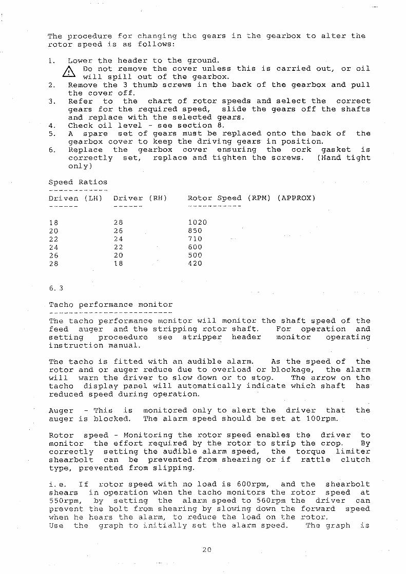
The procedure fo r changing t he gears in the gearbox to alter the rotor speed is as follows:
1. Lower the header to the ground. &, Do not remove the cover unless this is carried out, or oil
· will spill out of the gearbox. 2. Remove the 3 thumb screws in the back of the gearbox and pull
the cover off. 3 . Refer to the chart of rotor speeds and select the correct
gears for the required speed, slide the gears off the shafts and replace with the selected gears .
4. Check oil level - see section 8. 5. A spare set of gears must be replaced onto the back of the
gearbox cover to keep the driving gears· in position. 6. Replace the gearbox cover ensuring the cork gasket is
correctly set, replace and tighten the screws. (Hand tight only)
Speed Ratios
Dr iven (LH ) Driver (RH) Rotor Speed (RPM) (APPROX)
18 20 22 24 26 2 8
6. 3
28 26 24 22 20 18
1020 850 710 600 500 420
Tacho performance monitor
The tacho performance monitor will monitor the shaft speed of the feed auge r and t he stripping rotor shaft . For operation and setting proceedure see stripper header monitor operating instruction manual.
The tacho is fitted with an audible alarm. As the speed of the rotor and or auger reduce due to overload or blockage, the alarm will warn the driver to slow down or to stop. The arrow on the tacho display panel will automatically indicate which shaft has reduced speed during operation.
Auger This is auger is blocked.
monitored only to alert the driver that the The alarm speed should be set at l00rpm.
Rotor speed - Monitoring the rotor speed enables the driver to monitor the effort required by the rotor to strip the crop. By correctly setting the audible alarm speed, the torque limiter shearbolt can be prevented from shearing or if rattle clutch type, prevented from slipping.
i.e. If rotor speed with no l oad is 600rpm, and the shearbolt shears in ope r a t ion when the tacho monitors the rotor speed at 550rpm, by setting the alarm speed to 560rpm the driver can prevent the bolt from shearing by slowing down the forward speed when he hears the alarm, to reduce the load on the rotor . Use the graph to initially set t he alarm speed. The graph is
20

only a guide, as engine power, and combine drive design to the stripper header will affect the value the alarm needs to be set. The values on the graph are conservative, and the operator may wish to reduce the alarm speed in increments of 1 or 2 rows rpm, until a shearbolt shears, at which point he should note the alarm speed and then raise it by 4 or 5 rpm so as to give advanced warning, to prevent the bolt from shearing again.
Example: -The NO LOAD speed is when the machine is running empty.
If the NO LOAD speed of the tacho is 650rpm follow the graph horizontally across until you meet the appropriate line for your torque limiter rating (in this case 1200N/M), if you are not sure see section 3. Then go vertically down and read the TACHO WARNING SETTING from the bottom scale.
1000
900
800
NO LOAD RPM
700
600
500
400
300
TACHO WARNING SETTING CHART
I ', .. 1, ..
400 500 600 700
TACHO WARNING SETTING
21
800
RPM
;i!! t ti : : :::1 ,,;; ''i'
, ll, • '•;
:::1 ;;;
900

6. 4
B A S I C
TYPE OF CROP
WHEAT DURAM TRI TI CALE RYE
BARLEY WINTER BARLEY
OATS
GRASS
RICE
LINSE ED
CLOVER
PEAS
GRASS FESCUE
&
M A C H I N E S E T T I N G
DI VI DERS STRIPPING AUGER
SOMETI MES
NO
YES
ROTOR SPEED ADJ RPM (APPROX)
500/600 APPROX 5/l0MM
50 0 /6 0 0 5 TO l 0MM
500/60 0 5 TO l 0MM
NO APPROX 10 TO
YES
YES
NO
NO
YES
50 0 / 700 12MM
400/ 50 0
700
400
400/500
600
5 TO l0MM
5 TO l0MM
5 TO l0MM
5 TO l0MM
5 TO
T A B L E
DRUM SPEED RPM
900- 1000
900 -1 000
60 0 -70 0
800 -90 0
CONCAVE CLEARANCE
3 -6MM
3 -6MM
7-15 MM
6-15 MM
CAN USE RI CE OR STD DRUM AND CONCAVE
FULL 3 -4MM
FULL 3MM
500-600 15-20MM
800/900 5 -8MM
NOTE: When harvesting peas bes t results are achieve d with a soil kit fitted to combine .
22

CONCAVE BLANKING PLATES
YES BOTH SETS
YES BOTH SETS
YES 1 SET
NONE OR 1 SE'l'
NONE
YES BOTH SE'fS
YES BOTH SETS
NONE
1 SET OR BO'l'I-l
STRAW WALKERS
WHEN DRY, INSTALL COVER PLATES
VCP WHEN DRY
VCP WHEN DRY
23
FAN POSITION
FULL
JUST BELOW FULL
APPROX 3/4 OPEN
1/2 TO 2/3
3/4 TO FULL
3/4 TO FULL
LOW TO 1/4
3/4 TO FULL
1/2
SIEVES
TOP:FULLY OPN BTM: 1/3 OR
MORE OPN
TOP:FULLY OPN BTM: 1/3 OR MORE OPN
TOP: FULLY OPN BTM: 1/3 TO 1/2 OPN
TOP: 1/4 TO 1/2 OPN BTM: 1/4 OPN
TOP: FULL OPEN BTM: 1/2 TO FULL
TOP: 3/4 OPN BTM: 1/4 OPN
TOP: 1/4 OPN BTM:ALMOST FULLY
CLOSED
TOP: FULLY OPN BTM: 1 / 2 TO 3 / 4
OPN
TOP 1/4 TO 1/3 BTM: 1/4OR LESS
6. 5 0 P E R A T I N G T H E S T R I P P E R H E A D E R
Read this manual carefully before operating the stripper header.
To get optimum performance from your stripping header the operator should procedures of operation.
Engaging the drive
Shelbourne follow the
Reynolds following
In order to prevent the rotor drive torque limiter from operating when engaging t he header drive the following procedure should be f ollowed: 1. Run c ombi ne engine at idle speed. 2. If manual engagement, engage the drum of the combine and then
gently operate the lever to engage the stripping head, avoiding snatch in the drive.
3. If your combine is fitted with electric or hydro-electric clutch engagement, the header drive should be engaged before t he drum, therefore the complete workings of the combine and heade r wi ll engage at t he same time, thus reducing the snatch i n the header drive line . Alternatively, hydro-electric c lutches maybe fitted with a restrictor.
4. Increase combine engine speed to the working rpm.
Stripping rotor speed setting
The minimum s peed should be set to ensure that all grains/seed is stripped from the e ar of the crop. It is unnecessary to run the rotor faster than that required to strip all the crop as this only causes the machine to intake more straw and also will reduce the life of t he stripping elements.
Header height setting
Stand i ng Crops
When operating in standing crops the rotor will be carried between 150-300mm from the ground.
The aim is to carry the rotor as high as possible to reduce the amount of straw intake, but it must be low enough to lift and remove heads which maybe attached to stems low down in the crop, eg. bent over stems .
Laid Crops
When operating in laid crops it will ba necessary to operate with the rotor as close to the ground as possible but without digging up dirt. This is achieved by floating the header on the skids. When set correctly, the skids will prevent the rotor touching the g r ound .
To keep h e ader losses to a minimum, l aid crops should be approached by harvesting either across or towards the way o f lay, l os ses wi ll i n c rease if harvesting with the way of lay as the rotor is unable t o l i ft t he heads of the c rop clear of the ground . However, if harvesting standing crop and sma l l patches are laid, eg at headl ands , t hese p a tches can be harves ted with
24

t he way of lay providing that the header and front cowl are l owered enough. Also see front cowl setting.
When operating in laid crops, forward speed will be limited to being able to keep the header settings correct.
Standing and lodged or laid crop
There will be occasions where standing and laid crop will need to be harvested in the same pass. In these situations the header should be lowered down to lift and recover the laid crop.
Front cowl setting
The front cowl setting is important to ensure optimum performance of your stripping header. When correctly s et in standing crop the front nose of the cowl should deflect crop below it, the top of the crop being about 100mm below the top of the nose.
When correctly set in laid crops, the front nose of the cowl should ride over the top of the crop, the aim being not to push the c rop down any further but to close the gap at the front to prevent grain losses .
When harvesting lai d and standing crop in the same pass, the nose to recover the laid crop, therefore pushing over standing crop, so it becomes laid.
Forward speed
lower the
The Shelbourne Reynolds stripper header is capable of very fast fo rward speeds due to its rotary action, unlike a conventional cutterbar.
The forward speed will depend on the following:
1. Crop ripeness 2. Moisture level 3. Standing or laid 4. Levelness of the field 5. Power available to drive the rotor 6. Combine capacity 7. Crop yield
Normal operating speeds in standing crops are expected to be between 4 - 12 km/hour. In laid crops the speed may be slower.
Set performance monitor
Set the performance monitor rpm warning value to that indicated by the graph. Section 6. 3.
25

HARVESTING THE CROP
Follow in order the following procedures and checks to set the stripping header and combine to give optimum performance:
1. Ensure that all the necessary procedures of preparation for use described in this manual have been carried out.
2. Set the combine and header to the basic setting chart for the particular crop to be harvested.
3. Harvest approximately 50 metres of crop.
4. Stop the machine and look at the stripped crop for the fol lowing:
Check that a ll grain is stripped from the heads . - Check that t here are no heads which have been missed low
down in t he crop. Note: The stripper header will not recove r pre-harvest l osses .
- Check combine sieve and straw walker losses .
Note: Do not do thi s from behind t he combine where you have just stopped. The check should be carried out i n an area where t he r e has b een continous crop flow through the machine, whi l st it has been on the move.
- Che ck header losses: This should again not be carried out where the machine has jus t stopped. An easy c heck i s to back the combine away from the crop. Look in t he area 2 - 3 metres back from where the header stopped, but before you get to t he area where the sieves of the combine has blown out unwanted material . Another way t o check header losses is to put a narrow tray between the rows of the crop, taking care not to disturb the crop near t he tray, drive the header over the tray and then count the grai ns which are caught by the tray. From this, the l osses c an be calculated. Great care should be taken when carrying out such a test to ensure that grains from areas other than the header are not caught in the tray. Also check the grain sample for cleanliness and cracked grains .
5. Use adjustment charts to correct the results.
6. Go back to step 3 and repeat until satisfactorily set.
During Operation
When operating the machine in the field it is important to keep the stripping header front cowl and height to the correct settings to suit t he crop as it varies across the field. This means the operator will have to raise and lower the header and front cowl continually to suit the crop . If the crop is very even then very little adjustment will be necessary. I f the crop i s very uneven then the ope rator will have t o adjus t t he heade r to suit the conditions much more frequently. Us e the combine grain loss moni tors to determi ne the forward speed, unless the field i s too rough or if the stripping rotor
26

power requirment is high. This can occur in unripe or damp crops and will be indicated by an audible torque limiter on the rotor drive line.
PERFORMANCE MONITOR AUDIBLE ALARM SPEED ADJUSTMENT
When operating the machine it will be noted that the power required to drive the rotor depends mainly on forward speed and the height of the rotor from the ground.
i.e. - The requirement
- The requirement
cl ose r the rotor to the ground, and hence the rotor speed will faster t he forward speed, and hence the rotor speed will
the more reduce. the more reduce.
the
the
power
power
If t he rpm warning has been selected from the graph, yet the shearbolt breaks before the audible warning is heard, then the r pm warning value should be raised. See stripper header monitor oper ating instructions manual section B3 .
This i s carried out by operating the machine in work, and gradual ly increasing the forward speed, watching closely the rotor rpm, until t he shearbolt shears . Set the rotor rpm warning value about 3 to 6 rpm above the value the shearbolt sheared.
The same procedure will appJ.y if you feel that the rpm warning value is set to high.
If a fault occurs with the monitor, reset the tacho as described in the stripper header monitor operating instruction manual. If this fails consult your RDS dealer see appendixes.
27
6. 6
PROBLEM
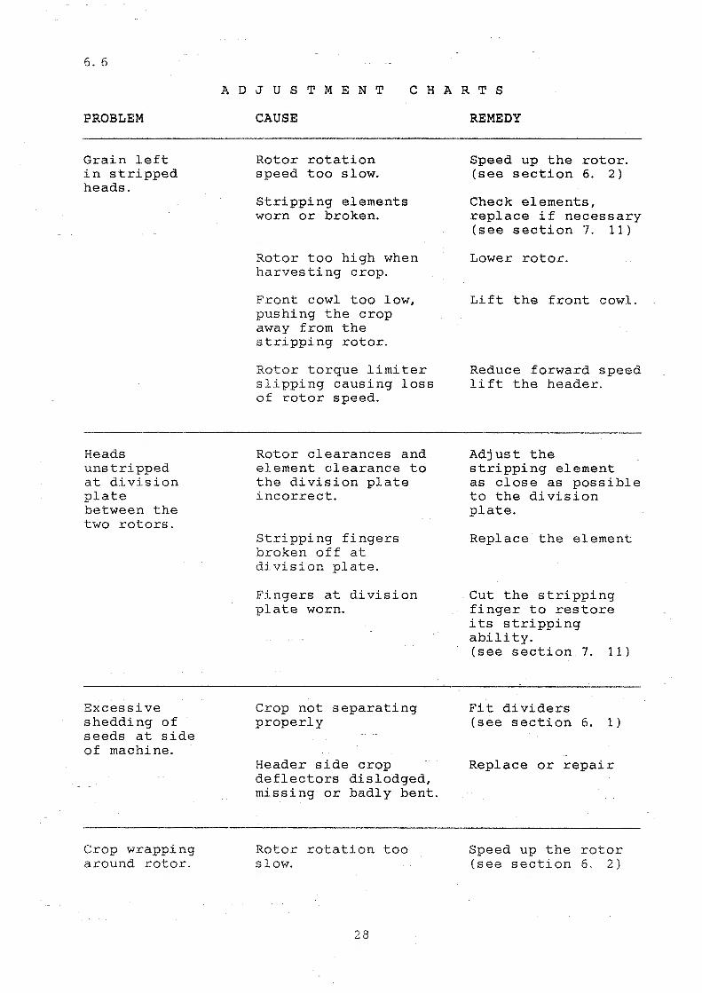
Grain left in stripped heads .
Heads unstripped at division plate between the two rotors .
Excessive shedding of seeds at side of machine.
Crop wrapping around rotor.
A D J U S T M E N T
CAUSE
C H A R T S
REMEDY
Rotor rotation speed too slow.
Stripping elements worn or broken.
Rotor too high when harvesting crop.
Front c owl too l ow, pushing the crop away from the strippi ng rotor.
Rotor torque limiter slipping causing loss of rotor speed.
Rotor clearances and element clearance to the division plate incorrect.
Stripping fingers broken off at d i vision plate.
Fingers at division plate worn.
Crop not separating properly
Header side crop deflectors dislodged, missing or badly bent.
Rotor rotation too slow.
28
Speed up the rotor. (see section 6. 2)
Check elements, replace if necessary (see section 7. 11)
Lower rotor.
Lift the front cowl .
Reduce forward speed lift the header.
Adjust the stripping element as close as possible to the division plate.
Replace the element
Cut the stripping finger to restore its stripping ability. (see section 7. 11)
Fit dividers (see section 6. 1)
Replace or repair
Speed up the r otor (see section 6. 2)

PROBLEM
Material not feeding to the header auger
Auger torque limiter slipping
Irregular feeding into feed elevator
Excessive shelling of seeds at header.
CAUSE
Conveyor belt slipping.
Conveyor belt flights missing
Auger blocked by foreign object.
Auger to low to auger trough
Auger torque limiter spring tension incorrectly set
Elevator feed chain too high at entrance.
Elevator feed chain too far away from auger
Crop building up on feed elevator dust cover
Rotor too high in relation to the ground.
Front adjustable cowl too high.
Front adjustable cowl too 1 ow.
Crop is laid and leaning away from direction of travel.
Conveyor belt behind rotor not working.
Forward speed t oo sl ow.
29
REMEDY
Tension the belt. (See section 7. 8)
Replace conveyor belt
Clear blockage
Adjust the auger clearance. ( See section 7. 4)
Re-adjust springs, (see section 7. 5)
Lower chain. (See combine manufacturers manual.
Move auger back or move elevator chain forward. (see section 7. 4)
Remove the centre section of the elevator dust cover.
Lower rotor.
Lower cowl.
Li ft front cowl.
Approach crop from different angle.
Check for slippage or broken drive.
Increase fo rward speed.

PROBLEM
Grain sample not properly cleaned.
Excess ive c r acked grain in g r a i n s ampl e .
Grain loss over t he si eve s .
CAUSE
No concave blanking plates fitted.
Concave to drum clearance not close enough.
Bottom sieve open too wide.
Drive speed too slow.
Drum speed too f ast
Concave set t oo c lose to drum.
Concave blanking plates fitted.
Sieves blocked
Top sieve blocked air blast full.
Too much air blast from the cleaning fan.
Excessive short straw on the sieves.
3 0
REMEDY
Fit concave blanking plates. (See C. M. 0. M. )
Adjust clearnace (See C. M. 0 . M. )
Close the sieve slightly. (See C. M. 0. M. )
Increase dri v e speed (See C. M. 0. M. )
Reduce drum speed. (See C. M. 0. M. )
I ncrease drum to concave clearance. ( See C. M. 0. M. )
Remove plates one set at a time. (See C. M. 0. M. )
Increase air blast . {See C. M. 0 . M.
Close top s i eve slightly, ( See C. M. 0. M. )
Reduce air blast or increase forward speed if possible to load more material onto the sieves. ( See C. M. 0. M. )
1. Reduce drum speed 2. Open concave 3. Remove concave
blanking plates . ( See C. M. 0. M. )
For other causes see C. M. 0 . M.

PROBLEM
Stripping r otor torque limiter operating excessively.
Stripping r otor torque limiter operating b e fore tacho a udi b l e wa rning he a rd.
Crop wrapping i n rotor ends and centre.
CAUSE
Rotor hitting the ground.
Forward speed too fast.
Crop too unripe.
Rotor rotating too slow.
Audible warning device rpm valve set too slow.
Anti-wrap plates out of adjustment
Conditions very severe anti-wrap plates will not stay adjusted.
31
REMEDY
Lift rotor.
Slow down.
Allow crop to ripen.
Increase rotor speed. ( See section 6 . 2)
Check value setting from graph. (See section 6. 3)
Check audible device is switched on.
If the above is correct then recheck the value as in section operating the stripper header. (see section 6. 5 performance monitor audible alarm speed adjustment)
Adjust (see section 7. 10)
Fit Kit-00902 available from your dealer

SECTION 7
7, 1
S 'f R I P P E R
A N D
ANGLE OF STRIPPER
H E A O E R A D J U S T M E N T S
M A I N T E N A N C E
The angle of the stripper header is adjustable. The bolt in adaptor plate attaching the stripper to your combine has two fixing studs at the top, {A) Fig 5 located just under the top beam near the centre opening. These fixing studs are adjustable and will therefore adjust the angle of the stripper head, and hence the rotor height from the ground.
F'IG 3
To correctly set:~
- If your machine is fitted with a bearing box drive input, which is fitted to the stripper main frame and not the adaptor pl ate i.e. JD then DISCONNECT the drive coupling.
- Set the stripper head skids in the uppermost position.
- On the level concrete lower the stripper head to the ground, i.e. so the skids touch the concrete.
- The rotor fingers should have ground interferance of approx 10mm.
- If adjustment is required, before adjusting the studs, the bolts securing the ~uger stripper plates on the adaptor p l ate only ahould be loosened to prevent jamming.
- Adjust the studs (A) Fig 5 of the adaptor plate equal amounts untiJ the se~ting ~s app~oxi~ately correct.
32

Lock the adjusting stud nuts .
Re-set the auger stripper plates to give approx 5mm clearance from the auger flights.
For machines fitted with the bearing box on the stripper main frame, realign the header drive.
Lower the skids to a position where the stripping fingers clear the ground by approx 20mm.
NOTE: When making this adjustment the auger to feed elevator clearance will also change. Before operating the machine, check that the auger and feed elevator do not hit each other, re-adjust the auger, or elevator if necessary.
7 . 2
ALIGNING HEADER DRIVE If your stripping heade r i s fitted with a bearing box assembly supporting t he header drive shaft, on i nitial header attachment , this will need aligning with t he combine drive shaft as described below.
1. Attach the str i pper header to the combine. t o connect the drive shaft at t his stage.
DO NOT attempt
2. The header should be levelled as described in section 5, preparation f or use. If your machine is fitted with a bearing box assembly which is bolted to the back of the header securing the drive shaft, then follow the following p rocedure to al i gn the drive. If your machine is fitted with a standar d PTO shaft eg. Claas, then simply press in the button o f t he coupling and push the coupling onto the shaft . Ensure tha t t he coupling seast correctly ie. when the pin pops out again.
3. Remove guard and slacken the 4 bolts which hold the beari ng box as shown in Fig 6 (A).
4. Move the bearing box to align the shaft in the correct pos iti on and engage the coupling connector to the drive shaft on the feed elevator.
5. Tighten the 4 bolts which hold the bearing box to lock the shaft in the set position.
6. Replace the guard.
JD American combines.
9600 and 8800 When aligning the drive on these combines, the f emale drive sleeve on the header is required. The grub screw on t he male hub should be removed to allow the whole assembly to slide so that the header can be taken off and put on without the dri ves interf ering. When fitting to other JD American combines the female sleeve should be r e moved, and the mal e hub locked with the grub screw so it does not s lide .
33
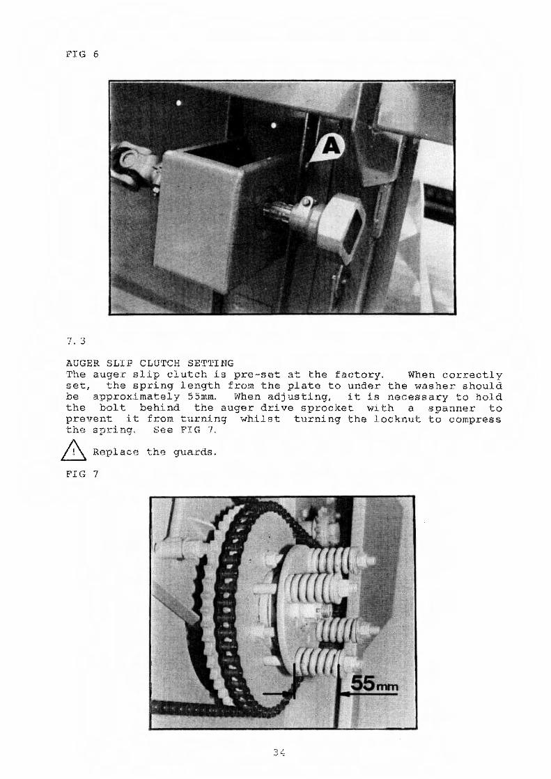
FIG 6
7. 3
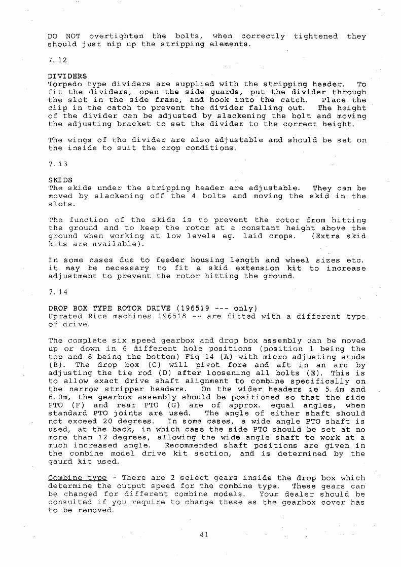
AUGER SLIP CLUTCH SETTING The auger slip clutch is pre-set at the factory. When correctly set, the spring length from the plate to under the washer should be approximately 55mm. When adjusting, it is necessary to hold the bolt behind the auger drive sprocket with a spanner to prevent it from turning whilst turning the locknut to compress the spring. See FIG 7.
6 Replace the guards.
FIG 7

7. 4
AUGER POSITION SETTING The auger position is set at the factory. This pre-set position should be suitable for most crops and conditions, however, if the position needs to be altered the auger can be adjusted up or down FIG 8 (B), and fore or aft. See FIG 8 (A).
FIG 8
NO'T.'E: drive
It adjusting chain, a.nd. a11
f<)rwards c.r down, first slacken the auger st~ipper plate securing bolts.
1. 'ro mo•te up or down, slacken off the auger support plate loeking bolt and adjust stud 'N as indicated. Adjust both ends of the auger to equal amounts.
2. For fore und aft movement, slacken off the augar support plate locking bolt and adjust stud' B' es indicated. Again adjust both sid0s of the auger equal amounts.
3. Tighten bolts and lccknuts when adjuEtment is complete. 4. Reset auger stripper plates.
IMPORTANT
After adjusting the auger, it should be rotated by hand to ensure that nothing on the auger fouls on the conveyor or frame.
5. Re-adjust the auger drive chain to correct tension. 6, Replace the guards.
.3 5

7. S
AUGER FINGERS The position of the auger finger retraction is pre-set at the factory. It is adjusted by removing the guard on the right hand s1.ae, slacken off the bolt on the handle as shown in FIG 8 (C) and move the handle to the required position.
7. 6
AUGER STRIPPER PLATES The stripper plates are behind the auger across the width of the machine, Fig 9 {B) except for the centre opening. These should be set approximately 5mm from the auger flight. They are adjusted by slackening all the bolts Fig 9 (A) on the stripper plate and moving it on the slots before re-tightening. The stripper pl a te or the adaptor plate is adjusted independantly to the same clP-ara.nce<
FIG 9
7. 7
CHAIN TENSIONING The conveyor and auger drive chains are all fitted with jockey sprockets and idler adjusters, so that the chains can be correctly tensioned. The position of the adjusting idlers is as shown in FIG 10 (A}.

FIG 10
S 'l'RI PPI NG ROTOR SAFETY CLUTCH The rotor safety clutch is positioned as seen in Fig 10 {CJ . I f the clutch is the shearbolt type, if the clutch operates , bolt (B) Fig 10 must be replaced.
8 .A.lways stop the combine engine before replacing the shear bol t .
CONVEYOR BELTS The conveyor belts are a low maintenance desiqn. Once t hey are pre-set, they should not need much attention as they a r e also fitted with a self tensioning system.
The stripping header is fitted with two conveyor belts which are independantly tensioned and tracked. All adjustment is carried out at the ends of the machine, there are no adjusters inboard of the conveyor ends.
7. 8
SETTING CONVEYOR BELT PRE-LOAD The conveyor belt pre-load is set by adjustin~ the threaded rod as shown in FIG 11 (A) to increase or decrease t he spring tension, which in turn pre-loads the conveyor bel t. The left hand adjuster: will pre-load the left hand conveyor belt and the right hand adjuster will pre-load the right hand conveyor belt. The spring length, hook centre to centre, to give the correct conveyor belt tension should be as follows:
l. 8m belts - 130mm 2. 4m belts - 135mm 3.0m b(c~lts ·· 1.40:nrr.

JTIG 11
7. '.)
TRACKING CONVEYOR BELTS The drive and Jdle conveyor rollers should be set parellel to each other. Th.is is adjusted by rod FIG 11 (B) on the left h and side of the machine which adjusts the left hand conveyor belt, and the adjuster:: on the right hand side of the machine adjusts the right hand conveyor belt. To set parallel, the distance over the rollers should be measured at either end of the conveyor hel t.
7. 10
R O T O R
& CAUTION -· Block or fit header safety latch before carrying out adjustments on the rotor.
ANTI-WRAP PLATES The ends of the rotor are fitted with anti-wrap plates around the rotor circumferance - FIG 12 (A) to prevent the crop entering and wrapping in the rotor ends.
The plates are pre-set at the factory but if they need adjusting, follow the procedure below:
1. Loosen the two screws securing the plate as shown. FIG 12 (A)
2. Pust the. anti-wrap plate to the machine side plate or division plate until the tip just touches.
• Move the anti-wrap plate in a further 2mm, to apply slight sprj_ng p.r.0.ssu.r.:,~.
4. Tighten thB two secu:::-ir:.g screw·s, ;:,. R2pee.·;:: fo!.". t::.1e o~:he:~: ple.r:e.s.

FI G 12
Al though not usua lly requi red, anti-wrap k it (KIT- 00902) may purchased from your dealer .
STRIPPING FINGERS
in be
- -
severe conditions necessary. This
an extra can be
The s tripping fingers o r crop engaging elements are sectioned into 600mm lengths to all ow replacement o f i ndividual s ections .
.ANTI --WEAR P!..ATE (PORTCULLIS) •rhe rotor 1.;3 fitted with metal anti --wear plates wh:i.ch bol t in front o f t he plastic fingers, Fi g. 12 ( B) t h es e are replacea ble, in sections . Note, the ends are different t o the centres and are handed left or right. The boits securing the steel wear plates s hould b e s et t o a tor que o f 17lb/ft .
7. 11
STRIPPING ELEMENT WEAR ASSESSMENT Duri ng the f irst hours of use, it wil l be noticed that the corne rs o f the str ipping elements wil l round off, this is normal. When the stripping el ement holes become distorted or enlarged, i t is time to replac e some of the elements. Two new rows of elements sho uld .replace the ol d ones, the selecte d rows being opposite e ach other t o keep the rotor in balance (1 80 degrees) . This, al ong with the parti all y worn o nes, wi ll give effective stripping,
When these new 8trip p ing elements begin to distort or enlarge, then two di fferent rows should be selected for renewal and so on alternatively around the rotor.
I f a single f inger breaks off a section of a st r ipping element, the o t her f..i.n.gers o n the other r ows a r oi.md t he rotor wil l :;-;:J1npens~te, fo r i.t o.l~d ~tr::.pping wj_ l.l still .be jus t a s effic ient.

If a few fingers break off in the same area around or along the rotor, then these stripping element sections should be replaced. As the stripping elements at the division plate between the two rotors wear, stripping efficiency may reduce, and some unstripped heads maybe noticed at this position. This can be cured by slackening the bolts of two opposing rows (i.e. at 180 degrees) of elements on each rotor of the element nearest the division plate, and push them upto the division plate until they just touch, re - tighten the bolts . Then cut the inner stripping finger, the one closest to the division plate as shown below, to restore its stripping ability, care must be taken not to overcut in the corner or the finger will break off in use.
StriP.ping elements. ______ ,
Centre division plate.
E E
LO
10mm max. Cut at tangent to hole.
Each element can only be cut once, opposing rows must be cut.
when t hese wear, another two
REPLACING STRIPPING ELEMENTS To replace the s tripping elements, follow the procedure below:
1. A If the machine is on the combine, lift header and securely block or engage l ift ram safety catch.
2.
3.
4.
Lift the front cowl with the combine hydraulics and secure, ie. with a rope or block. Each individual stripping element is secured to the rotor by six bolts. Each element section can be clearly seen by the joints. Remove element
the six bolts securing the ele~ent out of the rotor.
and pull the
NOTE: Someti mes it may be necessary to slacken the first two or three bolts of the neighbouring elements to release the one you want t o remove.
5. Place the new element in position. If it is difficult to push i nto the r otor, i t may be tapped into place with a small bar in the bottom of the stripping holes.
6. Replace the six bolts including the spring washer. Nut Lock (locti te) or a locking bolt must be used on thG bolts.
CAUTION - Nut Lock or l ocking bolts must be element securing bolts.
40
used on the
DO NOT o verti ghten the bolts , whe n correctly tightened they should j ust nip up the stripping elements.
7. 12
DIVIDERS Torpedo type dividers are supplied with the stripping header. To fit the dividers, open the side guards, put the divider through the slot in the side frame, and hook into the catch. Place the clip in the catch to prevent the divider falling out. The height of the divider can be adjusted by slackening the bolt and moving the adjusting bracket to set the divider to the correct height .
The wings of the divider are also adjustable and should be set on the i nside to suit t he crop conditions.
7 . 13
SKIDS The skids under the stripping header are adjustable. They can be moved b y slackening off the 4 bolts and moving t he skid in t he slots.
The f unction of the skids is to prevent the rotor from hitting the ground and to keep the rotor at a constant height above the ground whe n working at low l evels e g. laid crops. (Extra skid kits are avail able).
In some cases due to feeder housing length and wheel sizes etc. it may be necessary to fit a skid extens i on kit to increase adjustment to prevent t he r otor hitti ng the ground.
7. 14
DROP BOX TYPE ROTOR DRIVE (1 96519 --- only) Uprated Rice machines 196518 -- are fitt ed with a different type o f drive.
The complete six speed gearbox a nd drop box assembly can be moved up or down i n 6 dif ferent hole positions (position 1 being the top and 6 being the bottom) Fig 14 (A) with micro adjusting studs (B) . The drop box (C) will pivot fore and aft in an arc by adjusting the tie rod (D) after loosening all bolts (E). This is to allow exact drive shaft alignment to combine specifically on the narrow stripper headers. On the wider headers ie 5. 4m and 6. Om, the gearbox assembly should be positioned so that the side PTO ( F) and rear PTO ( G) are of approx. equal angles, when standard PTO joints are used. The angle of either shaft should not exceed 20 degrees . In some cases, a wide angle PTO shaft is used, at the back, in which case the side PTO should be set at no more than 1 2 degrees, allowing the wide angle shaft to work at a much increased angle . Recommended shaft positions are given in the c ombine model drive kit section, and is determined by the gaurd kit used.
Combine type - There are 2 select gears inside the drop box which determine the output speed for t he combine t ype . These gears can be c hanged for differe nt combine models. Your dealer should be consulted i f y ou r equire to change these as the gearbox c ove r has to be removed.
41

F't G :. 4

SECTI ON 8
Your Shelbourne down time and l ubrication.
L U B R I C A T I O N
Reynolds Stripper Header is therefore requires the
designed to reduce minimum amount of
Most of the bearings are of the sealed type, requiring no maintenance .
b CAUTION - Stop engi ne before lubricating.
CHAINS Al l chains as i ndicated, should be lubricated daily, and after work s o that t he oil wil l adhere t o the chain to provide good lubrication.
Use an a e ros ol NOTE: I f your
c hain to daily.
PIVOT POINTS
cha in l ubricant of SAE 90 gear oil . c ombi ne was fit ted with a maize drive kit , with a
d r ive t he header, this too should be lubricated
It i s recomme nded tha t all pivot points which may become sti ff from corrosion should be o c cas i onal l y oil ed.
SIX SPEED GEARBOX (ma chi ne number 1965 15 -- and 1965 16 -- o nl y ) To check the leve l on t he six s peed gearbox, lower the header onto the s kids on level ground.
Re move t he three thumb sc r ews on the rear of the gearbox securing t he b ac k c over, and remove the back cover. Remove the oil level plug on the si de of t he gearbox. Replenish the gearbox with SAE 90 gea r oil to the level of t he p l ug.
Replace the ba ck cover.
BEVEL GEARBOX (ma c hi ne numbe r 196515 - - and 196516 -- only) To check the l evel the gearbox should be set l evel. Remove the d i psti ck i n t he t op o f the gearbox, and check the level with the ma rks o n t he s tick. Repl eni sh with SAE 90 gear oil .
SIX SPEED GEARBOX (machine number 196518 -- only) Check t he level as above. Use oil type (synthetic) MOBILUBE S. H.C . or equivalent .
The gearbox capacity 1. 25 litre (2. 2 pints)
BEVEL GEARBOX (machine number 196518 -- only) To check the oil level the machine should be level ie. in the lowered pos i tion so the gearbox is at 30 degrees. Remove the dipsti c k in the t op of the gearbox, and check the level with the marks on the stick. Use oil type (synthetic) MOBILUBE S.H.C. or e quival ent .
The gearbox c apac i t y 1. 5 litre (2 . 64 p i nts)
The input housing has a s eperate r eser voi r, oil c a n be dra ine d and replenished by removi ng the plugs top and bottom.
The reservoir capacity is 0. 13 litre ( O. 23 pi nts )
43

LONG AND SHORT DROP BOXES (machine number 196519 -- only ) To check the oil level the gearbox should be set vertically to the ground. This can usually be achieved by raising the header on the combine. The level plug is on the side of the gearbox.
Use oil type (synthetic) MOBILUBE S.H.C. or equivalent.
The gearbox capacity is 1. 25 litre (2. 2 pints).
NOTE - ALL GEARBOXES After the first 20 hours of use the oil should be drained from all gearboxes and replaced with the recommended type.
Oil should then be changed annually.
Only the recommended lubricant oils should be used.
Grease the following points at 10 hour intervals;
1. Overunning clutch. 2. Universal joints.
Grease the following at 50 hour intervals;
1. Torque limiter. 2. Rotor end bearings. 3. Adjustable deflector pivot arm bushes .
NOTE: - Grade of grease to be used - Mobilux EP3 or equivalent.
44

SECTION 9 S T O R A G E O F T H E H E A D E R
The following procedure should be followed prior to off-season storage of your stripping header to preserve and protect your machine.
1. Remove the stripping header from the combine feeder housing, either onto the trailer or on adequately supportive blocks to prevent header damage.
2. Thoroughly clean the interior and exterior of the header, as any chaff , straw and dirt left on the machine will d r aw moisture and cause corrosion.
3. Dismantle t he conveyor assembly, and remove conveyor belts to prevent t hem taking a permenant set.
4. Clean and 1 ubricate all chains with oil.
5. Di smant le the auger slip clutch, before r eassembly. When assembling sl ack f o r s t orage .
check and lubricate leave the springs
6. Lubri cate the machine thoroughly as described in the lubricati on section of this manual .
7. Coat al l the bright parts preservative to protect them.
with paint or anti-rust
IMPORTANT; DO NOT PUT ANY OIL, PAINT, PRESERVATIVE ETC ON THE PLASTIC STRIPPING FINGERS AS IT MAY DAMAGE THEM
8. Retrac t the hydraulic rams of the front deflector.
9. Store the header i n a d ry place p r otected from t he weather and r odents.
10. Support height during header
the header on the trailer or on at the ends and under the header storage, to prevent header damage.
weight on skids during storage.
blocks of equal division plate
Do not support
11. Use the combine operators manual for storage procedure of your combine.
45
SECTION 10 A P P E N D I X E S
RDS UK DISTRIBUTORS
Barr Specialist Services Newmarket Nails worth Glostershire GL6 0RL Tel. 045 383 3337 Car phone 0836 237913
East Coast Electrical Services Chigborough Road Mal den Essex CM9 ?RE Tel. 0621 52113 Car phone 0836 73 7028
R & L Services 31 Highfield Road Ormskirk Lanes L39 lNP Tel. 0695 7239 7 Car phone 0836 620049
RDS ( NE) Ltd 8-12 Albany Road Woodhall Spa Li ncs LNl O 6TS Tel. 052 6 53677 Car phone 0836 711697
0836 711696
Wallace Agricultural Services Unit 12 Camps Industrial Estate Kirknewton Midlothian EH27 8DF Tel. 0506 882903 Car phone 0860 359912
RDS OVERSEAS DISTRIBUTORS
I. Mclean Esq. RDS Farm Electronics (Aust) Pty Ltd Private Bag 74 Via Waikerie South Australia 5330
46

Frank M. Winstone Lt d PO Box 40 348 Upper Hutt New Zealand
Frank M. Winstone Lt d PO Box 14 002 Auckland New Zealand
Di t t a Eni o Moschini Via Enrico Millo 32 2 9 100 0 Pi acenz a I taly
M. J . Neuville Es q . RDS Electronics BVBA Groot Br ittannielaan 2 897 0 Poperinge Be l gium
Vi dakovi t s Antal 1151 Budapest Koss ut c h. U 59 1 EMI I 1 Hu ngary
Mo ns ieur D. Sohi er Emani Ge r ant Libr e D Agro Elec t ro niqu e 23 Rue Leo Lagran ge 93 161 Nois y Le Grand Fra nc e
Mr Enric Segarra Sistemes Electronics Progres SA Te r r Ferma s/n Bellpuig (Lleida) Espagna
Messrs. E. Assland RDS Norsk Male og Veieteknikk A/S P. Box 1571 Kjelvene 4004 Stavenger Norway
47

S & O Kingman Co Ltd Church House Main Street Leixlip Co Kildare Eire
Eduardo Rebeiro EICA Equipamentos Agriculas E Industriais LDA Estrade de Aveuri 'Brenha Apartado 165 3080 Figueira Da Foz Portugal
48