
IMPELLER POWER DRAW ACROSS THE FULL REYNOLDS ...
81
IMPELLER POWER DRAW ACROSS THE FULL REYNOLDS NUMBER SPECTRUM Thesis Submitted to The School of Engineering of the UNIVERSITY OF DAYTON In Partial Fulfillment of the Requirements for The Degree of Master of Science in Chemical Engineering By Zheng Ma Dayton, OH August, 2014
-
Upload
khangminh22 -
Category
Documents
-
view
0 -
download
0
Transcript of IMPELLER POWER DRAW ACROSS THE FULL REYNOLDS ...

IMPELLER POWER DRAW
ACROSS THE FULL REYNOLDS NUMBER SPECTRUM
Thesis
Submitted to
The School of Engineering of the
UNIVERSITY OF DAYTON
In Partial Fulfillment of the Requirements for
The Degree of
Master of Science in Chemical Engineering
By
Zheng Ma
Dayton, OH
August, 2014

ii
IMPELLER POWER DRAW
ACROSS THE FULL REYNOLDS NUMBER SPECTRUM
Name: Ma, Zheng
APPROVED BY:
______________________ ________________________
Kevin J. Myers, D.Sc., P.E. Eric E. Janz, P.E.
Advisory Committee Chairman Research Advisor
Research Advisor & Professor Chemineer Research &
Chemical & Materials Engineering Development Manager
NOV-Process & Flow
Technologies
________________________
Robert J. Wilkens, Ph.D., P.E.
Committee Member & Professor
Chemical & Materials Engineering
_______________________ ___________________________
John G. Weber, Ph.D. Eddy M. Rojas, Ph.D., M.A., P.E.
Associate Dean Dean, School of Engineering
School of Engineering

iii
ABSTRACT
IMPELLER POWER DRAW
ACROSS THE FULL REYNOLDS NUMBER SPECTRUM
Name: Ma, Zheng
University of Dayton
Research Advisors: Dr. Kevin J. Myers
Eric E. Janz
The objective of this work is to gain information that could be used to design full
scale mixing systems, and also could develop a design guide that can provide a reliable
prediction of the power draw of different types of impellers. To achieve this goal, the
power number behavior,including three operation regimes, the limits of the operation
regimes, and the effect of baffling on power number,was compared across the full
Reynolds number spectrum for Newtonian fluids in a laboratory-scale agitator. Six
industrially significant impellers were tested, including three radial flow impellers: D-6,
CD-6, and S-4, and also three axial flow impellers: P-4, SC-3, and HE-3.
Results in laminar regime indicate that baffling has no effect on power number in
this operation regime. There is an inversely proportional relationship between power
number and Reynolds number. The upper limit for this operation regime should be lower
than 10, the limit commonly noted in the literature. The product of power number and

iv
Reynolds number in this particular regime is approximately proportional to the number of
blades for these six impellers; however, other shape factors that were not included in this
study also contribute to it.
In turbulent operation, baffling has a significant effect on power number: the
power number for most impellers remains relatively constant in the baffled configuration
while that for unbaffled configuration decreases with increasing Reynolds number. The
impeller blade number is not the dominant factor that affects power number in this
regime. Two hydrofoil impellers, SC-3 and HE-3, exhibit much lower power numbers
when compared with the other impellers. Additionally, the impellers with higher power
numbers in baffled tank tend to have lower ratios between unbaffled power number and
average baffled power number when comparing at same Reynolds number.
No difference between two configurations, baffled and unbaffled, exists at low
Reynolds number end of transitional regime, and the difference starts at intermediate
Reynolds number and increases with an increase of Reynolds number. In the baffled
configuration, four out of six impellers exhibit a minimum power number. In the
unbaffled configuration, power numbers drop with increasing Reynolds number
throughout the entire transitional regime for all impellers. The ratio of unbaffled to
turbulent average power number for the six impellers retains a consistent order through
the entire Reynolds number range with two high efficiency impellers having the highest
ratio, then pitched blade impeller, and three radial flow impellers having the lowest ratios.

v
ACKNOWLEDGEMENTS
I would like to thank Dr. Kevin Myers for all the help he has given throughout the
past three years. Without his encouragement and guidance I would have never made it
this far. Dr. Myers gave me a great opportunity to pick up chemical engineering from
basics three years ago. He accepted me to work on this research so I can complete the
degree with a written thesis and get prepared for future study. I will be thankful to him
for his support and benefactions forever. I also want to thank Eric Janz who offered me
this opportunity to be part of the team and gave me the access to carry out this
experiment in the Chemineer laboratory. I want to express my thankfulness to Prof.
Robert Wilkens for being my committee member and providing constructive feedback on
my thesis. I would also like to thank Erin Duff, Robert Strong, and Michael Adams for
their support on both the laboratory measurements and my daily life.
I want to acknowledge everyone else who has offered support: my family for their
continuous love; my boyfriend, Zhengchao, as he has tried his best to take care of me and
been supportive all the way through; Jin, my best friend here in UD, for all the
suggestions and her willingness to share my joys and sorrows; Jie and his wife, Jing, who
encouraged me when I had a tough time. I would have failed my study here in UD
without those people.

vi
TABLE OF CONTENTS
ABSTRACT ................................................................................................................... iii
ACKNOWLEDGEMENTS ............................................................................................ v
LIST OF FIGURES ...................................................................................................... vii
LIST OF TABLES ......................................................................................................... ix
NOMENCLATURE ...................................................................................................... xi
.................................................................................... 1 CHAPTER 1 INTRODUCTION
1.1 Background ............................................................................................... 1
1.2 Power Number and Reynolds Number...................................................... 2
1.3 Rheology ................................................................................................... 4
1.4 System Geometry ...................................................................................... 5
1.5 Objective ................................................................................................... 6
.................................... 7 CHAPTER 2 EXPERIMENTAL SETUP AND PROCEDURE
2.1 Experimental Setup ................................................................................... 7
2.2 Viscosity Measurement ............................................................................. 9
2.3 Procedure ................................................................................................. 10
............................................................. 12 CHAPTER 3 RESULTS AND DISCUSSION
CHAPTER 4 CONCLUSIONS AND RECOMMENDATIONS ................................. 42
BIBLIOGRAPHY ......................................................................................................... 46
APPENDIX: RAW AND REDUCED EXPERIMENTAL DATA .............................. 47

vii
LIST OF FIGURES
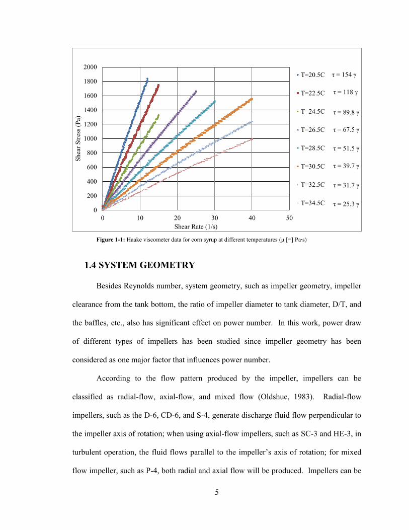
Figure 1-1: Haake viscometer data for corn syrup at different temperatures (μ [=] Pa s) .. 5
Figure 2-1: Experimental apparatus .................................................................................... 8
Figure 2-2: Readout of torque and speed from agitator ...................................................... 9
Figure 2-3: Assembled agitator shaft and impeller ............................................................. 9
Figure 3-1: D-6 low Reynolds number data ..................................................................... 13
Figure 3-2: CD-6 low Reynolds number data ................................................................... 13
Figure 3-3: S-4 low Reynolds number data ...................................................................... 14
Figure 3-4: P-4 low Reynolds number data ...................................................................... 14
Figure 3-5: SC-3 low Reynolds number data ................................................................... 15
Figure 3-6: HE-3 low Reynolds number data ................................................................... 15
Figure 3-7: Comparison of baffled low Reynolds number data ....................................... 18
Figure 3-8: D-6 high Reynolds number data .................................................................... 19
Figure 3-9: CD-6 high Reynolds number data .................................................................. 19
Figure 3-10: S-4 high Reynolds number data ................................................................... 20
Figure 3-11: P-4 high Reynolds number data ................................................................... 20
Figure 3-12: SC-3 high Reynolds number data ................................................................ 21
Figure 3-13: HE-3 high Reynolds number data ................................................................ 21
Figure 3-14: Comparison of baffled high Reynolds number data .................................... 25
Figure 3-15: Comparison of unbaffled high Reynolds number data ................................ 26

viii
Figure 3-16: D-6 transitional Reynolds number data ....................................................... 27
Figure 3-17: CD-6 transitional Reynolds number data ..................................................... 27
Figure 3-18: S-4 transitional Reynolds number data ........................................................ 28
Figure 3-19: P-4 transitional Reynolds number data ........................................................ 28
Figure 3-20: SC-3 transitional Reynolds number data ..................................................... 29
Figure 3-21: HE-3 transitional Reynolds number data ..................................................... 29
Figure 3-22: Ratio of unbaffled to baffled power numbers in transitional and turbulent
operation ........................................................................................................................... 34
Figure 3-23: Ratio of unbaffled to turbulent average power numbers in transitional and
turbulent operation ............................................................................................................ 34
Figure 3-24: Ratio of baffled to turbulent average power numbers in transitional and
turbulent operation ............................................................................................................ 35
Figure 3-25: Comparison of all baffled power number data ............................................. 38
Figure 3-26: Comparison of all unbaffled power number data ......................................... 38
Figure 3-27: Baffled and unbaffled data of D-6 for all Reynolds numbers ...................... 39
Figure 3-28: Baffled and unbaffled data of CD-6 for all Reynolds numbers ................... 39
Figure 3-29: Baffled and unbaffled data of S-4 for all Reynolds numbers ...................... 40
Figure 3-30: Baffled and unbaffled data of P-4 for all Reynolds numbers ...................... 40
Figure 3-31: Baffled and unbaffled data of SC-3 for all Reynolds numbers .................... 41
Figure 3-32: Baffled and unbaffled data of HE-3 for all Reynolds numbers ................... 41

ix
LIST OF TABLES
Table 2-1: Impellers ............................................................................................................ 8
Table 3-1: Comparison of baffled and unbaffled Newtonian fluid KL values .................. 17
Table 3-2: Highest Reynolds number for laminar operation ............................................ 17
Table 3-3: Comparison of baffled Newtonian fluid turbulent power numbers ................ 23
Table 3-4: Unbaffled to baffled power number ratios in turbulent operation ................... 23
Table 3-5: Lowest Reynolds number for turbulent power number in baffled
configuration ..................................................................................................................... 24
Table 3-6: Power number comparison .............................................................................. 25
Table 3-7: Reynolds number range with baffled NP lower than average baffled
turbulent Np ....................................................................................................................... 31
Table 3-8: Unbaffled to baffled power number ratios in transitional operation ............... 33
Table 3-9:Unbaffled power number to turbulent average power number ratios in
transitional operation ........................................................................................................ 36
Table 3-10: Baffled power number to turbulent average power number ratios in
transitional operation ........................................................................................................ 37
Appendix 1: Raw and reduced data from impeller power draw experiments for baffled
D-6………………………………………………….............................…………………47

x
Appendix 2: Raw and reduced data from impeller power draw experiments for
unbaffled D-6 .................................................................................................................... 49
Appendix 3: Raw and reduced data from impeller power draw experiments for baffled
CD-6 .................................................................................................................................. 51
Appendix 4: Raw and reduced data from impeller power draw experiments for
unbaffled CD-6 ................................................................................................................. 53
Appendix 5: Raw and reduced data from impeller power draw experiments for baffled
S-4 ..................................................................................................................................... 55
Appendix 6: Raw and reduced data from impeller power draw experiments for
unbaffled S-4 ..................................................................................................................... 57
Appendix 7: Raw and reduced data from impeller power draw experiments for baffled
P-4 ..................................................................................................................................... 59
Appendix 8: Raw and reduced data from impeller power draw experiments for
unbaffled P-4 ..................................................................................................................... 61
Appendix 9: Raw and reduced data from impeller power draw experiments for baffled
SC-3 .................................................................................................................................. 63
Appendix 10: Raw and reduced data from impeller power draw experiments for
unbaffled SC-3 .................................................................................................................. 65
Appendix 11: Raw and reduced data from impeller power draw experiments for baffled
HE-3 .................................................................................................................................. 67
Appendix 12: Raw and reduced data from impeller power draw experiments for
unbaffled HE-3 ................................................................................................................. 69

xi
NOMENCLATURE
A Impeller area which the fluid is pumped through (m2)
D Impeller diameter (m)
H Velocity head (Pa)
KL Constant that equals to the product of power number and Reynolds number in
laminar regime (-)
L Characteristic length (m)
M Torque (N∙m)
N Agitator rotational speed (rpm)
NP Power number (-)
NRe Reynolds number (-)
P Power draw (W)
Q Impeller pumping rate (m3/s)
T Tank diameter (m)
υ Fluid velocity (m/s)
W Impeller blade width (m)
Z Liquid level (m)
γ Shear rate (1/s)
μ Fluid viscosity (Pa∙s)
ρ Fluid density (kg/m3)
τ Shear stress (Pa)

1
CHAPTER 1
INTRODUCTION
1.1 BACKGROUND
Agitation is the introduced motion of a material in a circulatory pattern inside a
container. This operation tends to reduce gradients in composition and properties.
During agitation, kinetic energy is transferred from a rotating impeller to the surrounding
fluid. Mechanical agitators are widely used in the chemical processing and related
industries as they speed interphase mass transfer and chemical reactions. Additionally,
the suspension of solids in liquids, the dispersion of liquids and gases, and the agitation
of dry solid powders are commonly encountered applications of agitation. Agitators are a
necessity in the processing industries due to their various applications.
Agitators must be designed from both mechanical and process viewpoints.
Mechanical design, such as the design of motor, gear reducer, seal, shaft, impellers and
tank, is essential for successful operation, and is usually determined by the component
manufacturer. However, process environment, such as fluid properties, desired process
results, and agitator’s power consumption, directly impact the mechanical design. Power
number, one of the most important parameters in mixing research and practice (Calabrese
et al., 2014), is used to predict the power requirement of a given agitation system and is
the main focus of this study.

2
In order to design full-scale mixing systems and develop a design guide that can
be used to reliably predict the different types of impellers’ power draw, this study
focused on the relationship between power number and Reynolds number for Newtonian
fluids in a laboratory-scale agitator across the spectrum of Reynolds number for six
industrially significant impellers.
1.2 POWER NUMBER AND REYNOLDS NUMBER
As mentioned, power number can be used to predict power consumption and is a
key consideration in both the mechanical and process design of an agitation system. The
power applied to the agitation system impeller produces velocity head, H, and pumping
capacity, Q, with the impeller power draw being the product of these two quantities
(Hemrajani et al., 2004):
( 1.1 )
The velocity head that provides the kinetic energy is dependent on the product of the
fluid density and the square of its velocity:
( 1.2 )
The fluid velocity near the impeller is directly proportional to the impeller tip (πND) and
thus:
( 1.3 )
The pumping capacity Q is the product of the fluid velocity and area through which the
fluid is pumped:
( )( ) ( 1.4 )

3
Then Equation 1.1 can be rewritten as:
( ) ( ) ( 1.5 )
The preceding result leads to the most commonly seen dimensionless form for the power
number, NP (Rushton et al., 1950):
( 1.6 )
The power number is a function of impeller type, Reynolds number, and
geometric parameters such as the impeller diameter to tank diameter ratio, D/T (Bates et
al., 1966). It can be seen from this equation that if the power number for a given system
is known, the power consumption, P, can be predicted from the fluid density, ρ, impeller
diameter, D, and rotational speed, N.
The Reynolds number is the ratio of inertial forces to viscous forces (McCabe et
al., 2005). It is defined as:
( 1.7 )
L represents a characteristic length, represents velocity, and μ represents the fluid
viscosity. For agitation, impeller diameter, D, is employed as characteristic length, and
the velocity is proportional to the impeller tip speed and can be replaced by the product of
impeller rotational speed and the impeller diameter:
( )
( 1.8 )
The Reynolds number can be used to classify the impeller operation regimes (McCabe et
al., 2005). In the laminar regime, the power number is inversely proportional to
Reynolds number (NP NRe-1
); in the turbulent regime, the power number is constant in

4
fully baffled tanks; and the transitional regime occurs at Reynolds numbers between the
laminar and turbulent regimes with the power number gradually changing from laminar
(inversely dependent on Reynolds number) to fully developed turbulent behavior
(Reynolds number independent). The laminar regime is generally taken to occur when
the Reynolds number is smaller than ten, and viscosity dominates in this regime. At high
Reynolds number of turbulent operation (i.e., NRe > 104), viscosity has little effect and the
process is mainly controlled by inertial forces. In transitional regime, both viscous and
inertial forces affect the process.
1.3 RHEOLOGY
Fluids can be classified as Newtonian and non-Newtonian depending upon the
relationship between shear stress and shear rate (Strong and Myers, 2013). For
Newtonian fluids, the shear stress, τ, is proportional to the local shear rate, γ, at every
point:
( 1.9 )
The constant of proportionality, μ, is known as Newtonian viscosity. It depends only on
the material and its temperature and pressure. Figure 1-1 presents the shear stress - shear
rate data taken using a Haake concentric cylinder viscometer for corn syrup at different
temperatures. It can be seen that the slope of shear stress-shear rate (the viscosity, μ) is
constant at each temperature, but it decreases with increasing temperature. Both water
and aqueous corn syrup solutions used in this study are Newtonian fluids.
5
Figure 1-1: Haake viscometer data for corn syrup at different temperatures (μ [=] Pa s)
1.4 SYSTEM GEOMETRY
Besides Reynolds number, system geometry, such as impeller geometry, impeller
clearance from the tank bottom, the ratio of impeller diameter to tank diameter, D/T, and
the baffles, etc., also has significant effect on power number. In this work, power draw
of different types of impellers has been studied since impeller geometry has been
considered as one major factor that influences power number.
According to the flow pattern produced by the impeller, impellers can be
classified as radial-flow, axial-flow, and mixed flow (Oldshue, 1983). Radial-flow
impellers, such as the D-6, CD-6, and S-4, generate discharge fluid flow perpendicular to
the impeller axis of rotation; when using axial-flow impellers, such as SC-3 and HE-3, in
turbulent operation, the fluid flows parallel to the impeller’s axis of rotation; for mixed
flow impeller, such as P-4, both radial and axial flow will be produced. Impellers can be
τ = 154 γ
τ = 118 γ
τ = 89.8 γ
τ = 67.5 γ
τ = 51.5 γ
τ = 39.7 γ
τ = 31.7 γ
τ = 25.3 γ 0
200
400
600
800
1000
1200
1400
1600
1800
2000
0 10 20 30 40 50
Shea
r S
tres
s (P
a)
Shear Rate (1/s)
T=20.5C
T=22.5C
T=24.5C
T=26.5C
T=28.5C
T=30.5C
T=32.5C
T=34.5C

6
further classified by the application. Propellers, pitched-blade turbines, and high-
efficiency impellers are normally used for low- to moderate-viscosity liquids, while
helical impellers and anchor agitators are employed for high viscosity liquids. For the six
impellers used in this study, SC-3 and HE-3 are high-efficiency impellers, and the other
four impellers, D-6, CD-6, P-4 and S-4, are turbines.
1.5 OBJECTIVE
The objective of this work is to gain information that could be used to design full
scale mixing systems, and also could develop a design guide that can provide a reliable
prediction of the power draw of different types of impellers. To achieve this goal,
extensive power number data was taken in Newtonian fluids on six industrially
significant impellers from Reynolds numbers less than 0.1 to greater than 100,000.
Power number behaviors of these impellers, including laminar operation, turbulent
operation, transitional operation, the Reynolds number limits of the operating regimes,
and the effect of baffling on power number were compared.

7
CHAPTER 2
EXPERIMENTAL SETUP AND PROCEDURE
2.1 EXPERIMENTAL SETUP
All experiments were performed in a flat-bottomed clear acrylic cylindrical tank
of 23.5 inches diameter. To broaden the understanding of the effects of impeller type on
power draw, ten different impellers that were supplied by Chemineer, Inc. (Dayton, OH)
were studied, although the data for only six impellers are reported in this thesis, with the
data of the other four impellers being proprietary. Table 2-1 shows the images of the
impellers and lists the impeller diameter to tank diameter ratios (D/T). The off-bottom
clearance for the impellers was set to 7.8 inches (C/T=1/3), while the liquid level to tank
diameter ratio was set equal to unity (Z/T=1).
A laboratory-scale mixer, shown Figure 2-1, was used in this study. A Baldor
(Fort Smith, AR) three phase electric motor (VM3558T) that was used as a power source
to provide shaft and impeller rotation was connected to a 4-speed gearshift transmission,
with gear ratios of 1:1, 1.33:1, 2:1 and 4:1. A zero velocity magnetic pickup was used as
transducer to measure the rotational speed, N. A 500 in∙lbf (56.5 N∙m) strain gauge was
used to measure shaft torque, M. Both the speed signal and torque signal were sent to a
Honeywell (Columbus, OH) conditioner indicator (Model 7541) with a digital readout.
This conditioner indicator is shown in Figure 2-2. Accurate determination of the power

8
draw, P, can be obtained by knowing the torque and speed of an agitator since .
Assembled agitator shaft with impeller is shown in Figure 2-3. The shaft has a 0.75 inch
diameter at the drive that reduced to a 0.50 inch diameter about midway along the shaft.
Impellers were mounted to the bottom end of the shaft with setscrews as shown in the
same figure.
Table 2-1: Impellers
Impeller D-6 CD-6 S-4 P-4 SC-3 HE-3
Diameter
(inch) 7.99 8.78 9.54 9.50 9.50 9.51
D/T
0.340 0.374 0.406 0.404 0.404 0.405
Figure 2-1: Experimental apparatus

9
Figure 2-2: Readout of torque and speed from agitator
Figure 2-3: Assembled agitator shaft and impeller
2.2 VISCOSITY MEASUREMENT
The viscosity data of Figure 1-1 was taken using a concentric cylinder Haake
viscometer designed to provide viscosity as a function of shear rate. This viscometer was
not used during power number testing because insertion of a sample in the viscometer
cup would change the sample temperature and thus its viscosity. Viscosity measurements
were performed by Brookfield DV-E Viscometer, Gardco® Standard Ford Viscosity Cups

10
and Cannon-Fenske Routine (Capillary) Viscometer from Cannon Instrument Company®
depending on the viscosity range. Brookfield DV-E Viscometer was employed when
viscosity was higher than 200 cp. This type of viscometer measures fluid dynamic
viscosity at given rotational speeds. After immersing a sensing element (spindle) in a
fluid, the viscous drag of the test fluid against the spindle is measured with a rotary
transducer that provides a torque signal. The range of measurement is affected by the
spindle’s rotational speed, size and shape, and the container in which the spindle is
rotating. For Newtonian fluids, viscosity appears in units of centipoise (cp) on the
viscometer’s display directly. Standard Ford Viscosity Cups were used to achieve better
accuracy when viscosity was between 50 and 200 cp. This viscometer is a simple gravity
device. By timing the flow of known volume of liquid passing through an orifice located
at the bottom of the Ford Cup, kinematic viscosity in mm2/s (cSt) can be determined by
referring to the corresponding conversion table. The dynamic viscosity can then be found
by multiplying the kinematic viscosity by the density of fluid in gram per milliliter (g/ml)
that is defined as its weight per unit volume. When viscosity was lower than 50 cp,
Cannon-Fenske Routine Viscometer was used. Similar to Standard Ford Viscosity Cups,
Cannon-Fenske Routine Viscometer measures kinematic viscosity instead of dynamic
viscosity using the time required for gravity flow of a fixed volume of fluid through a
capillary.
2.3 PROCEDURE
The experimental procedure began with agitating the Newtonian fluid to reach a
spatially uniform status. After that, the density of the Newtonian fluid was measured by
weighting a 100 ml volumetric flask sample that was taken from the tank. Temperature

11
and viscosity were recorded. In order to produce Reynolds number and power number
for the chosen impeller, readings of torque at various impeller rotational speeds were
required. Temperature and viscosity measurements were performed again after the power
number data collection process. The viscosity at each torque data point was estimated by
using the viscosities measured before and after data collection and linearly interpolating
based on torque. When at high viscosity (μ > 300 cp), the agitation process tended to
take a longer time than for agitation at lower viscosity. Temperature changed
significantly due to conversion of mechanical energy to thermal energy. That led to a
significant viscosity change as shown in Figure 1-1. At low viscosity (μ < 50 cp),
agitation in unbaffled tank led to the formation of a large surface vortex when the
Reynolds number is high (greater than about to 104). Data acquisition was stopped
before the vortex reached the impeller, and gaps in the data at higher Reynolds number
appeared due to the fact that data could be obtained at only a few speeds at each fluid
viscosity.

12
CHAPTER 3
RESULTS AND DISCUSSION
A key parameter in agitator design, power number strongly depends on both
Reynolds number and the impeller geometry. In advance of a study of impeller power
draw in non-Newtonian fluids, extensive data was taken in Newtonian fluids with both
baffled and unbaffled configurations. This section compares the power number behaviors
of these different impellers, including three operation regimes (laminar, transitional, and
turbulent), the Reynolds number limits of the operation regimes, and the effect of baffling
on power number.
Figures 3-1 through 3-6 present the measured power numbers as functions of
Reynolds number in the laminar regime (D-6 in Figure 3-1, CD-6 in Figure 3-2, S-4 in
Figure 3-3, P-4 in Figure 3-4, SC-3 in Figure 3-5, and HE-3 in Figure 3-6). As can been
clearly seen, the data for all six impellers in both baffled and unbaffled configurations
agree with each other, indicating that the baffling has no effect on power number at low
Reynolds number. Another point these impellers have in common is that the slopes of
the power number – Reynolds number relations on logarithmic coordinates are all equal
to -1, indicating that the power number in this regime is inversely proportional to
Reynolds number (NP NRe-1
, with data correlations included on each figure).

13
Figure 3-1: D-6 low Reynolds number data
Figure 3-2: CD-6 low Reynolds number data
NP = 60.7 NRe-1
1
10
100
1,000
0.01 0.1 1 10 100
Po
wer
Num
ber
(N
P)
Reynolds Number (NRe)
D-6 Baffled
D-6 Unbaffled
NP = 61.9 NRe-1
1
10
100
1,000
0.01 0.1 1 10 100
Po
wer
Num
ber
(N
P)
Reynolds Number (NRe)
CD-6 Baffled
CD-6 Unbaffled

14
Figure 3-3: S-4 low Reynolds number data
Figure 3-4: P-4 low Reynolds number data
NP = 45.5 NRe-1
1
10
100
1,000
0.01 0.1 1 10 100
Po
wer
Num
ber
(N
P)
Reynolds Number (NRe)
S-4 Baffled
S-4 Unbaffled
NP = 43.2 NRe-1
1
10
100
1,000
0.01 0.1 1 10 100
Po
wer
Num
ber
(N
P)
Reynolds Number (NRe)
P-4 Baffled
P-4 Unbaffled

15
Figure 3-5: SC-3 low Reynolds number data
Figure 3-6: HE-3 low Reynolds number data
NP = 26.0 NRe-1
0.1
1
10
100
1,000
0.01 0.1 1 10 100
Po
wer
Num
ber
(N
P)
Reynolds Number (NRe)
SC-3 Baffled
SC-3 Unbaffled
NP = 27.0 NRe-1
0.1
1
10
100
1,000
0.01 0.1 1 10 100
Po
wer
Num
ber
(N
P)
Reynolds Number (NRe)
HE-3 Baffled
HE-3 Unbaffled

16
Due to the inversely proportional relationship, the product of power number and
Reynolds number in laminar regime is a constant as shown in Equation 3.1 below.
( 3.1 )
This constant KL also equals the impeller power number at a Reynolds number of one.
Table 3-1 presents the values of KL for different types of impeller. As can be seen, the
KL values of baffled and unbaffled configurations differ by no more than two percent for
all six impellers, reinforcing the conclusion that the baffles have no effect on impeller
power draw in laminar operation. Besides this, the small KL COV (coefficient of
variation, which equals the ratio of the standard deviation to the arithmetic average)
shows the low point to point variation in the data. Because of the lack of baffling effect,
it is reasonable to take a weighted average of the baffled and unbaffled KL values for
each impeller (weighted by the number of data points taken with each configuration.).
D-6 and P-4 values agree with literature KL values while the HE-3 is considerably lower.
Table 3-2 lists the laminar operation range for different impellers based on the
experimental results. The highest Reynolds number with less than ten percent difference
between the experimental power number value and that found from the data correlation
(Np= KL/NRe, with the baffled-unbaffled weighted average KL being used) is treated as
the highest laminar operation Reynolds number data point for each impeller. It is widely
accepted that laminar operation takes place when Reynolds number is less than 10. From
the results from this work, the upper limit for laminar operation should be lower than 10,
as four out of six impellers have their highest laminar operation Reynolds number smaller
than 10.

17
Table 3-1: Comparison of baffled and unbaffled Newtonian fluid KL values
Impeller D-6 CD-6 S-4 P-4 SC-3 HE-3
Baffled
KL
Average 61.0 61.7 45.4 43.1 25.7 26.9
KL
COV**
2.6% 2.7% 2.5% 1.2% 3.3% 2.5%
Unbaffled
KL
Average 60.4 62.1 45.5 43.2 26.2 27.4
KL
COV**
2.7% 2.2% 2.1% 1.3% 3.1% 2.4%
Weighted KL
Average 60.7 61.9 45.5 43.2 26.0 27.2
Literature KL*
65 N/A N/A 44.5 N/A 43
* Literature KL values are from McCabe et al. [4]. ** COV = Coefficient of Variation = Standard Deviation/Arithmetic Average
Table 3-2: Highest Reynolds number for laminar operation
Impeller D-6 CD-6 S-4 P-4 SC-3 HE-3
Highest NRe*
8.6 7.6 10.0 8.0 7.2 10.3
* The highest NRe with less than 10% difference between the experimental value and that found from the data correlation, Np= KL/NRe
According to Table 3-1, KL values seem to be affected only by the impeller’s
blade number, with the impellers that have the same number of blades having similar KL
values and impellers with more blades having higher KL values with the KL values being
roughly proportional to the number of blades. This phenomenon is illustrated graphically
in Figure 3-7, as CD-6 and D-6, S-4 and P-4, and SC-3 and HE-3 data almost coincide.
However, this conclusion is not applicable to all impellers. Other shape factors such as
the ratio between the width of impeller blades and the impeller diameter (W/D) (Smith,
1985) also contribute to the value of KL. One wide-blade impeller that was tested has a
KL value close to 100 with only three blades. This impeller’s data is not included here
due to confidentiality. Figure 3-7 presents only baffled data for these six impellers’
power number-Reynolds number laminar results since baffling doesn’t affect the data in

18
this regime. It should also be noticed that all data sets in this regime are parallel, which
reinforces what was said in the previous discussion that these impellers have same
exponent of -1 in their laminar regime power number-Reynolds number relations.
Figure 3-7: Comparison of baffled low Reynolds number data
Figures 3-8 through 3-13 present the measured power numbers as functions of
Reynolds number in the turbulent regime (D-6 in Figure 3-8, CD-6 in Figure 3-9, S-4 in
Figure 3-10, P-4 in Figure 3-11, SC-3 in Figure 3-12, and HE-3 in Figure 3-13. Due to
their lower baffled turbulent power numbers, the SC-3 and HE-3 data plots use a different
y axis range than the other four impellers). The average baffled power number and
power-law correlations for the unbaffled power numbers are included as well. Baffling
has significant effect on power number in this regime for all six impellers: power number
stays relatively constant in the baffled tank while in the tank with no baffles installed, the
power number drops with increasing Reynolds number.
1
10
100
1,000
0.01 0.1 1 10
Po
wer
Num
ber
(N
p)
Reynolds Number (NRe)
D-6
CD-6
S-4
P-4
SC-3
HE-3

19
Figure 3-8: D-6 high Reynolds number data
Figure 3-9: CD-6 high Reynolds number data
NP = 8.35 NRe-0.198
R² = 0.98
NP = 5.41
0.1
1
10
1,000 10,000 100,000 1,000,000
Po
wer
Num
ber
(N
P)
Reynolds Number (NRe)
D-6 Baffled
D-6 Unbaffled
NP = 5.55 NRe-0.184
R² = 0.99
NP = 2.79
0.1
1
10
1,000 10,000 100,000 1,000,000
Po
wer
Num
ber
(N
P)
Reynolds Number (NRe)
CD-6 Baffled
CD-6 Unbaffled

20
Figure 3-10: S-4 high Reynolds number data
Figure 3-11: P-4 high Reynolds number data
NP = 4.14 NRe-0.162
R² = 0.97
NP = 3.10
0.1
1
10
1,000 10,000 100,000 1,000,000
Po
wer
Num
ber
(N
P)
Reynolds Number (NRe)
S-4 Baffled
S-4 Unbaffled
NP = 2.42 NRe-0.144
R² = 0.98
NP = 1.15
0.1
1
10
1,000 10,000 100,000 1,000,000
Po
wer
Num
ber
(N
P)
Reynolds Number (NRe)
P-4 Baffled
P-4 Unbaffled

21
Figure 3-12: SC-3 high Reynolds number data
Figure 3-13: HE-3 high Reynolds number data
NP = 1.13 NRe-0.144
R² = 0.98
NP = 0.503
0.1
1
1,000 10,000 100,000 1,000,000
Po
wer
Num
ber
(N
P)
Reynolds Number (NRe)
SC-3 Baffled
SC-3 Unbaffled
NP = 0.695 NRe-0.120
R² = 0.94
NP = 0.309
0.1
1
1,000 10,000 100,000 1,000,000
Po
wer
Num
ber
(N
P)
Reynolds Number (NRe)
HE-3 Baffled
HE-3 Unbaffled

22
Table 3-3 shows power number values for the six impellers in baffled tank when
the Reynolds number is larger than 104. In this range, SC-3 and HE-3 power numbers are
more than an order of magnitude lower than that of the D-6 (recall from Table 3-1 that
these power numbers vary by only a factor of two in the laminar regime). Their low
turbulent power numbers make the SC-3 and HE-3 impellers the popular choice when
mixing low or moderate viscosity liquids. CD-6 and S-4 have similar power numbers
which indicates the number of impeller blades is no longer the dominant factor that
affects power number in this regime. Comparison of the P-4 and S-4 power numbers
illustrates the impact that blade angle has on turbulent power number in baffled tanks. It
is normally considered that the turbulent power number in a baffled tank should remain
constant. According to the results in this work, the power numbers for D-6 and S-4 still
increase with increasing Reynolds number. The ranges in the power numbers of these
impellers is more than ten percent of the average values and they both have a relatively
large coefficient of variation when compared with the other impellers. When available,
the average values of the baffled impeller power numbers obtained during this work
agree with the literature values with less than 10% difference. For D-6, using 6.3 as its
turbulent power number as reported by Rushton et al. (1950) is considered to be high;
with 5.5 being more acceptable according to Bates et al. (1966).
In Table 3-4, power number ratio between unbaffled power number correlation
equation and baffled power number average has been used to examine the difference
between these two configurations. For all impellers, unbaffled power number continually
decreases with increasing Reynolds number. Besides this, the impellers with higher
power numbers in baffled tank tend to have lower power number ratios when comparing

23
at same Reynolds number. HE-3, the only impeller with power number ratio larger than
0.5 in the entire turbulent regime, has the lowest baffled power number.
Table 3-3: Comparison of baffled Newtonian fluid turbulent power numbers
Impeller D-6 CD-6 S-4 P-4 SC-3 HE-3
Lowest NP 5.03 2.75 2.86 1.10 0.484 0.300
Highest
NP 5.70 2.84 3.28 1.18 0.521 0.321
NP
Average 5.41 2.79 3.10 1.15 0.503 0.309
Range
/Average 12.4% 3.2% 13.5% 7.0% 7.4% 6.8%
NP COV 4.3% 1.0% 4.8% 2.0% 2.4% 2.1%
Literature
NP*
4.8-5.5 [1]
6.3 [7]
2.9
[4] 3.1
[4]
1.1 [3]
1.27 [4]
N/A 0.28
[4]
* Literature NP values are from McCabe et al. [4], Rushton et al. [7], Bates et al. [1], and Deng [3]
Table 3-4: Unbaffled to baffled power number ratios in turbulent operation
Impeller D-6 CD-6 S-4 P-4 SC-3 HE-3
Unbaffled NP 8.35 NRe
-0.198
5.55 NRe
-0.184
4.14 NRe
-0.162
2.42 NRe
-0.144
1.13 NRe
-0.144
0.696 NRe
-0.120
Average Baffled NP 5.41 2.79 3.10 1.15 0.503 0.309
NP Ratio
(Unbaffled NP /Baffled NP) 1.54 NRe
-0.198
1.99 NRe
-0.184
1.34 NRe
-0.162
2.10 NRe
-0.144
2.26 NRe
-0.144
2.25 NRe
-0.120
NRe NP Ratio
10,000 0.25 0.37 0.30 0.56 0.60 0.75
20,000 0.22 0.32 0.27 0.50 0.54 0.69
50,000 0.18 0.28 0.23 0.44 0.48 0.61
100,000 0.16 0.24 0.21 0.40 0.43 0.57
200,000 0.14 0.21 0.19 0.36 0.39 0.52

24
Table 3-5: Lowest Reynolds number for turbulent power number in baffled configuration
Impeller D-6 CD-6 S-4 P-4 SC-3 HE-3
Average Np 5.41 2.79 3.10 1.15 0.503 0.309
Lowest NRe in the
±10% NP range 10,500 176 4160 2800 5790 1040
Corresponding Np 5.03 3.04 2.79 1.04 0.454 0.336
Table 3-5 shows the lowest Reynolds number for which power number remains
within 10% of the average turbulent power number in the baffled configuration. This
lowest Reynolds number for D-6 is higher than 10,000, the point that is generally
accepted as starting point for turbulent regime. For CD-6, the impeller with the lowest
power number coefficient of variation in Table 3-3, the lowest Reynolds number where
the power number is within 10% of its turbulent value is 176. This is considerably less
than 10,000, indicating that the baffled power number of the CD-6 is relatively constant
throughout much of the transitional regime. Except for CD-6 and HE-3, the power
numbers for the other four impellers are all lower than their average turbulent power
numbers, indicating that their power numbers exhibit a minimum in transitional operation.
Turbulent operation results for the six impellers are compared both quantitatively
(Table 3-6) and qualitatively (Figure 3-14 and 3-15 for baffled and unbaffled
configurations, respectively). In Table 3-6, the two configurations’ power numbers in
laminar and turbulent operation are normalized by the HE-3’s corresponding power
number to obtain the relative values. The relative unbaffled turbulent power number is
calculated by averaging the ratio of each impeller and the HE-3’s correlation power
numbers at five Reynolds numbers (10,000, 20,000, 50,000, 100,000, and 200,000). In
the laminar regime, D-6 has a power number that is twice that of the HE-3. In the
turbulent regime, the power numbers vary by a factor of 18 for these two impellers in

25
baffled operation. As has been discussed relative to Table 3-4, the turbulent power
number decreases significantly in the unbaffled configuration for D-6, but it is still four
times higher than that of the SC-3 and over five times higher than that of the HE-3.
Table 3-6: Power number comparison
Impeller D-6 CD-6 S-4 P-4 SC-3 HE-3
Average Laminar KL 60.7 61.9 45.5 43.2 26.2 27.4
Relative Laminar KL 2.2 2.3 1.7 1.6 0.96 1
Average Baffled
Turbulent Np 5.41 2.79 3.10 1.15 0.503 0.309
Relative Baffled
Turbulent Np*
18 9.0 10 3.7 1.6 1
Relative Unbaffled
Turbulent Np*
5.2 4.0 3.8 2.7 1.3 1
* All relative power number values are normalized with respect to the HE-3
Figure 3-14: Comparison of baffled high Reynolds number data
0.1
1
10
1,000 10,000 100,000 1,000,000
Po
wer
Num
ber
(N
P)
Reynolds Number (NRe)
D-6
CD-6
S-4
P-4
SC-3
HE-3

26
Figure 3-15: Comparison of unbaffled high Reynolds number data
Figures 3-16 through 3-21 present the measured power numbers as functions of
Reynolds number in the transitional regime (D-6 in Figure 3-16, CD-6 in Figure 3-17,
S-4 in Figure 3-18, P-4 in Figure 3-19, SC-3 in Figure 3-20, and HE-3 in Figure 3-21).
For reference, the baffled turbulent power number for each impeller is included in the
corresponding figure. Additionally, these figures include power law correlations for
unbaffled data at higher Reynolds numbers, with the Reynolds number range for each
curve noted below the corresponding power law equation. In the transitional regime,
baffling has no effect on the power number at low Reynolds number, as was observed in
the laminar regime. With increasing Reynolds number there is an increasing difference
between the unbaffled and baffled power numbers of all impellers, with the D-6 having
the biggest power number difference between the two configurations and the HE-3
having the least difference. Besides this, D-6, S-4, P-4, and SC-3 impellers, as was
0.1
1
10
1,000 10,000 100,000 1,000,000
Po
wer
Num
ber
(N
P)
Reynolds Number (NRe)
D-6
CD-6
S-4
P-4
SC-3
HE-3

27
suggested when discussing baffled turbulent operation, exhibit a minimum power number
in baffled transitional operation. The CD-6, one of two impellers that have no minimum
power number in baffled transitional operation, has a power number higher than the
average turbulent power number by an average of 4% and a maximum of 8% for
Reynolds numbers between 490 and 2500.
Figure 3-16: D-6 transitional Reynolds number data
Figure 3-17: CD-6 transitional Reynolds number data
NP = 5.41
NP = 12.2 NRe-0.241
R² = 0.99
NRe = 210 - 10,200
1
10
1 10 100 1,000 10,000 100,000
Po
wer
Num
ber
(N
P)
Reynolds Number (NRe)
D-6 Baffled
D-6 Unbaffled
NP = 2.79
NP = 10.3 NRe-0.253
R² = 1.00
NRe = 20 - 10,500
0.1
1
10
1 10 100 1,000 10,000 100,000
Po
wer
Num
ber
(N
P)
Reynolds Number (NRe)
CD-6 Baffled
CD-6 Unbaffled

28
Figure 3-18: S-4 transitional Reynolds number data
Figure 3-19: P-4 transitional Reynolds number data
NP = 3.1
NP = 7.85 NRe-0.234
R² = 1.00
NRe = 200 - 10,500
0.1
1
10
1 10 100 1,000 10,000 100,000
Po
wer
Num
ber
(N
P)
Reynolds Number (NRe)
S-4 Baffled
S-4 Unbaffled
NP = 1.15
NP = 3.77 NRe-0.193
R² = 0.99
NRe = 190 - 10,900
0.1
1
10
1 10 100 1,000 10,000 100,000
Po
wer
Num
ber
(N
P)
Reynolds Number (NRe)
P-4 Baffled
P-4 Unbaffled

29
Figure 3-20: SC-3 transitional Reynolds number data
Figure 3-21: HE-3 transitional Reynolds number data
NP = 0.503
NP = 1.23 NRe-0.155
R² = 0.99
NRe = 960 - 8100
0.01
0.1
1
10
1 10 100 1,000 10,000 100,000
Po
wer
Num
ber
(N
P)
Reynolds Number (NRe)
SC-3 Baffled
SC-3 Unbaffled
NP = 0.309 NP = 0.85 NRe-0.143
R² = 0.96
NRe = 970 - 9700
0.01
0.1
1
10
1 10 100 1,000 10,000 100,000
Po
wer
Num
ber
(N
P)
Reynolds Number (NRe)
HE-3 Baffled
HE-3 Unbaffled

30
Table 3-7 presents the Reynolds number range for each impeller for which the
baffled power number is lower than the average baffled turbulent power number. This is
not applicable for CD-6 and HE-3 as their power numbers do not have a minimum in the
transitional regime. For the other four impellers, the lower Reynolds number value is the
lowest Reynolds number for which the measured power number is less than the turbulent
average value, while the upper Reynolds number is that for which the measured power
number is more than ten percent less than the turbulent average value (as in Table 3-5).
Also, the lower Reynolds number value can be either from baffled or unbaffled
configuration since baffling makes no difference in the results at low Reynolds number,
but the upper Reynolds number limit is from baffled configuration only. For D-6 and S-4,
two impellers that have relatively high coefficients of variation in their average baffled
turbulent power numbers according to Table 3-3, this Reynolds number range extends
through more than two orders of magnitude. For the P-4, which has the lowest
coefficient of variation in the average baffled turbulent power number among these four
impellers, the Reynolds number range is less than one order of magnitude.
Table 3-7 also presents the minimum transitional power number with its
corresponding Reynolds number for each impeller in the baffled configuration. Again,
this is not applicable for CD-6 and HE-3 as has been stated previously. For the other four
impellers, D-6 and S-4 have the minimum power number at relatively low Reynolds
number of approximately 200, while the P-4 and SC-3 have their minimum power
numbers at higher Reynolds number near 2000. The power number ratios between the
minimum power number and the average turbulent power number for S-4, P-4 and SC-3

31
are close to each other, ranging between eighty and ninety percent, while the ratio for the
D-6 is significantly lower than the rest with a value of 0.66.
Table 3-7: Reynolds number range with baffled NP lower than average baffled turbulent Np
Impeller D-6 CD-6 S-4 P-4 SC-3 HE-3
Average baffled
turbulent Np 5.41 2.79 3.10 1.15 0.503 0.309
NRe range 18.7 - 10,500 N/A 35.7 - 4160 773 - 2800 504 – 5790 N/A
Minimum Np 3.56 N/A 2.47 1.02 0.422 N/A
Corresponding
NRe 200 N/A 200 2200 2000 N/A
NP Ratio
(Minimum NP /
Average
turbulent NP)
0.66 N/A 0.80 0.89 0.83 N/A
Figure 3-22 is plotted based on the result from Table 3-8 that presents the power
number ratios between baffled and unbaffled configurations in both transitional and
turbulent operation (Table 3-8 contains transitional data while the turbulent data was
previously presented in Table 3-4. Interpolation with approximately four adjacent data
points was used to generate the value at each particular Reynolds numbers in the table.).
The ratio for laminar operation is not included as baffling has no effect in this regime and
the ratio will be equal to one for all impellers. In the transitional regime, the ratios of
unbaffled to baffled power numbers for all impellers stay above 0.9 until the Reynolds
number reaches 200. When the Reynolds number is higher than 200, the ratios for three
radial flow impellers, D-6, CD-6 and S-4, drop significantly to lower than 0.75 and then
stay similar through the entire Reynolds number range. As Reynolds number hits 2000,
the ratio for P-4 is lower than 0.9 as well and leaves only the two hydrofoil impellers
above the 0.9 line. The unbaffled power number is about half of the baffled power

32
number at this Reynolds number for the three radial flow impellers. For Reynolds
number higher than 5,000, SC-3 and P-4 are similar with the SC-3 being a bit higher.
HE-3 is the only impeller that the unbaffled to baffled power number ratio remains above
0.5 in the entire Reynolds number range.
Figures 3-23 and 3-24 are generated from data in Tables 3-9 and 3-10,
respectively (again, data interpolation was used to generate these values at particular
Reynolds numbers). Figure 3-23 and Table 3-9 show the ratios between unbaffled power
numbers and turbulent average power numbers in transitional and turbulent operation (the
turbulent data in Figure 3-23 was previously presented in Table 3-4), while Figure 3-24
and Table 3-10 show the ratios between baffled power numbers and turbulent average
power numbers in the same Reynolds number range. In Figure 3-23, the ratios for the six
impellers retain the same order through the entire Reynolds number range with HE-3
having the highest unbaffled to turbulent average baffled power number ratio and the D-6
having the lowest ratio. When Reynolds number equals ten, the ratio for HE-3 is 8.96,
which is more than six times larger than the 1.35 ratio of the D-6. As expected, the ratios
of all impellers continually decrease with increasing Reynolds number. The baffled to
baffled turbulent average power number ratios in Figure 3-24 exhibit a similar trend as
that in Figure 3-23 for Reynolds numbers lower than 100. After that, the ratios start to
converge to one. It should be noticed that the ratios in Figure 3-24 for CD-6 and HE-3
stay above one in transitional operation, as there is no minimum power number point for
these two impellers in the baffled configuration. Laminar operation ratios are not
included for Figures 3-23 and 3-24 as this would compress the power number axis since
the ratios increase rapidly with decreasing Reynolds number. The ratios for laminar

33
operation at Reynolds number less than ten can be found by using the fact that the power
numbers are inversely proportional to Reynolds number in this regime.
Table 3-8: Unbaffled to baffled power number ratios in transitional operation
Impeller D-6 CD-6 S-4 P-4 SC-3 HE-3
NRe
10
Unbaffled NP 7.29 7.32 5.02 4.65 2.97 2.77
Baffled NP 7.13 7.26 4.89 4.78 2.95 2.87
Ratio 1.02 1.01 1.03 0.97 1.00 0.97
20
Unbaffled NP 5.17 4.84 3.71 3.09 1.84 1.79
Baffled NP 5.32 4.95 3.70 3.22 1.85 1.80
Ratio 0.97 0.98 1.00 0.96 0.99 0.99
50
Unbaffled NP 4.03 3.84 2.82 2.01 1.12 1.05
Baffled NP 4.07 3.83 2.89 2.10 1.11 1.08
Ratio 0.99 1.00 0.97 0.96 1.00 0.97
100
Unbaffled NP 3.59 3.22 2.50 1.59 0.822 0.756
Baffled NP 3.73 3.32 2.64 1.63 0.832 0.738
Ratio 0.96 0.97 0.95 0.98 0.99 1.02
200
Unbaffled NP 3.29 2.70 2.27 1.36 0.624 0.541
Baffled NP 3.58 2.95 2.51 1.38 0.665 0.553
Ratio 0.92 0.92 0.90 0.99 0.93 0.98
500
Unbaffled NP 2.72 2.14 1.83 1.14 0.504 0.401
Baffled NP 3.86 2.90 2.69 1.21 0.507 0.409
Ratio 0.70 0.74 0.68 0.94 0.98 0.98
1,000
Unbaffled NP 2.30 1.80 1.56 0.99 0.420 0.318
Baffled NP 4.21 2.93 2.74 1.09 0.451 0.340
Ratio 0.55 0.61 0.57 0.91 0.93 0.94
2,000
Unbaffled NP 1.95 1.51 1.33 0.87 0.377 0.288
Baffled NP 4.67 2.98 2.72 1.05 0.412 0.317
Ratio 0.42 0.51 0.49 0.83 0.92 0.91
5,000
Unbaffled NP 1.56 1.20 1.07 0.73 0.327 0.253
Baffled NP 4.72 2.83 2.82 1.07 0.447 0.305
Ratio 0.33 0.42 0.38 0.68 0.73 0.83
10,000
Unbaffled NP 1.32 1.00 0.91 0.64 0.294 0.229
Baffled NP 4.97 2.80 2.83 1.12 0.494 0.310
Ratio 0.27 0.36 0.32 0.57 0.60 0.74
The highlighted values are the highest Reynolds number for which the ratio is greater than ninety percent.

34
Figure 3-22: Ratio of unbaffled to baffled power numbers in transitional and turbulent operation
Figure 3-23: Ratio of unbaffled to turbulent average power numbers in transitional and turbulent operation
Ratio = 0.9
Ratio = 0.5
0.0
0.2
0.4
0.6
0.8
1.0
1.2
1 10 100 1,000 10,000 100,000 1,000,000
Po
wer
Num
ber
Rat
io (
Unb
affl
ed/B
affl
ed)
Reynolds Number (NRe)
D-6
CD-6
S-4
P-4
SC-3
HE-3
0.1
1
10
1 10 100 1,000 10,000 100,000 1,000,000
Po
wer
Nu
mb
er R
atio
(U
nb
affl
ed/T
urb
ule
nt
Aver
age)
Reynolds Number (NRe)
D-6
CD-6
S-4
P-4
SC-3
HE-3

35
Figure 3-24: Ratio of baffled to turbulent average power numbers in transitional and turbulent operation
0.1
1
10
1 10 100 1,000 10,000 100,000 1,000,000
Po
wer
Num
ber
Rat
io (
Baf
fled
/Turb
ule
nt
Aver
age)
Reynolds Number (NRe)
D-6
CD-6
S-4
P-4
SC-3
HE-3

36
Table 3-9: Unbaffled power number to turbulent average power number ratios in transitional operation
Impeller D-6 CD-6 S-4 P-4 SC-3 HE-3
Average baffled turbulent Np 5.41 2.79 3.10 1.15 0.503 0.309
NRe
10
Np 7.29 7.32 5.02 4.65 2.97 2.77
Ratio 1.35 2.62 1.62 4.04 5.90 8.96
20
Np 5.17 4.84 3.71 3.09 1.84 1.79
Ratio 0.96 1.73 1.20 2.69 3.66 5.79
50
Np 4.03 3.84 2.82 2.01 1.12 1.05
Ratio 0.74 1.38 0.91 1.75 2.23 3.40
100
Np 3.59 3.22 2.50 1.59 0.822 0.756
Ratio 0.66 1.15 0.81 1.38 1.63 2.45
200
Np 3.29 2.70 2.27 1.36 0.624 0.541
Ratio 0.61 0.97 0.73 1.18 1.24 1.75
500
Np 2.72 2.14 1.83 1.14 0.504 0.401
Ratio 0.50 0.77 0.59 0.99 1.00 1.30
1,000
Np 2.30 1.80 1.56 0.99 0.420 0.318
Ratio 0.43 0.65 0.50 0.86 0.83 1.03
2,000
Np 1.95 1.51 1.33 0.87 0.377 0.288
Ratio 0.36 0.54 0.43 0.76 0.75 0.93
5,000
Np 1.56 1.20 1.07 0.73 0.327 0.253
Ratio 0.29 0.43 0.35 0.63 0.65 0.82
10,000
Np 1.32 1.00 0.91 0.64 0.294 0.229
Ratio 0.24 0.36 0.29 0.56 0.58 0.74

37
Table 3-10: Baffled power number to turbulent average power number ratios in transitional operation
Impeller D-6 CD-6 S-4 P-4 SC-3 HE-3
Average baffled turbulent Np 5.41 2.79 3.10 1.15 0.503 0.309
NRe
10 Np 7.13 7.26 4.89 4.78 2.95 2.87
Ratio 1.32 2.60 1.58 4.16 5.86 9.29
20 Np 5.32 4.95 3.70 3.22 1.85 1.80
Ratio 0.98 1.77 1.19 2.80 3.68 5.83
50 Np 4.07 3.83 2.89 2.10 1.11 1.08
Ratio 0.75 1.37 0.93 1.83 2.21 3.50
100 Np 3.73 3.32 2.64 1.63 0.832 0.738
Ratio 0.69 1.19 0.85 1.42 1.65 2.39
200 Np 3.58 2.95 2.51 1.38 0.665 0.553
Ratio 0.66 1.06 0.81 1.20 1.32 1.80
500 Np 3.86 2.90 2.69 1.24 0.507 0.409
Ratio 0.70 1.04 0.87 1.08 1.01 1.32
1,000 Np 4.21 2.93 2.74 1.09 0.451 0.340
Ratio 0.78 1.05 0.88 0.95 0.90 1.10
2,000 Np 4.67 2.98 2.72 1.05 0.412 0.317
Ratio 0.86 1.07 0.88 0.91 0.82 1.03
5,000 Np 4.72 2.83 2.82 1.07 0.447 0.305
Ratio 0.87 1.01 0.91 0.93 0.89 0.99
10,000 Np 4.97 2.80 2.83 1.12 0.494 0.310
Ratio 0.92 1.00 0.91 0.97 0.98 1.00
20,000 Np 5.22 2.81 2.97 1.13 0.496 0.307
Ratio 0.96 1.01 0.96 0.98 0.99 0.99
50,000 Np 5.42 2.80 3.10 1.14 0.503 0.309
Ratio 1.00 1.00 1.00 1.00 1.00 1.00
100,000 Np 5.58 2.80 3.19 1.16 0.508 0.311
Ratio 1.03 1 1.03 1 1.01 1.01
200,000 Np 5.74 2.79 3.30 1.17 0.514 0.312
Ratio 1.06 1 1.06 1.01 1.02 1.01

38
To conclude the power number data presentation, Figure 3-25 combines the
baffled data for all six impellers through the entire Reynolds number range, and Figure
3-26 compares the impellers’ unbaffled data. Figures 3-27 through 3-32 present the
baffled and unbaffled data of each impeller for all Reynolds numbers.
Figure 3-25: Comparison of all baffled power number data
Figure 3-26: Comparison of all unbaffled power number data
0.10
1
10
100
1,000
0.01 0.10 1 10 100 1,000 10,000 100,000 1,000,000
Po
wer
Num
ber
(N
P)
Reynolds Number (NRe)
D-6
CD-6
S-4
P-4
SC-3
HE-3
0.10
1
10
100
1,000
0.01 0.10 1 10 100 1,000 10,000 100,000 1,000,000
Po
wer
Num
ber
(N
P)
Reynolds Number (NRe)
D-6
CD-6
S-4
P-4
SC-3
HE-3

39
Figure 3-27: Baffled and unbaffled data of D-6 for all Reynolds numbers
Figure 3-28: Baffled and unbaffled data of CD-6 for all Reynolds numbers
0.10
1
10
100
1,000
0.01 0.10 1 10 100 1,000 10,000 100,000 1,000,000
Po
wer
Num
ber
(N
P)
Reynolds Number (NRe)
D-6 Baffled
D-6 Unbaffled
0.10
1
10
100
1,000
0.01 0.10 1 10 100 1,000 10,000 100,000 1,000,000
Po
wer
Num
ber
(N
P)
Reynolds Number (NRe)
CD-6 Baffled
CD-6 Unbaffled

40
Figure 3-29: Baffled and unbaffled data of S-4 for all Reynolds numbers
Figure 3-30: Baffled and unbaffled data of P-4 for all Reynolds numbers
0.1
1
10
100
1,000
0.01 0.10 1 10 100 1,000 10,000 100,000 1,000,000
Po
wer
Num
ber
(N
P)
Reynolds Number (NRe)
S-4 Baffled
S-4 Unbaffled
0.10
1
10
100
1,000
0.01 0.10 1 10 100 1,000 10,000 100,000 1,000,000
Po
wer
Num
ber
(N
P)
Reynolds Number (NRe)
P-4 Baffled
P-4 Unbaffled

41
Figure 3-31: Baffled and unbaffled data of SC-3 for all Reynolds numbers
Figure 3-32: Baffled and unbaffled data of HE-3 for all Reynolds numbers
0.10
1
10
100
1,000
0.10 1 10 100 1,000 10,000 100,000 1,000,000
Po
wer
Num
ber
(N
P)
Reynolds Number (NRe)
SC-3 Baffled
SC-3 Unbaffled
0.10
1
10
100
1,000
0.01 0.10 1 10 100 1,000 10,000 100,000 1,000,000
Po
wer
Num
ber
(N
P)
Reynolds Number (NRe)
HE-3 Baffled
HE-3 Unbaffled

42
CHAPTER 4
CONCLUSIONS AND RECOMMENDATIONS
This work aimed to acquire design information for Newtonian fluid mixing,
focusing on measuring the power numbers of six different impellers across the full
Reynolds number spectrum. Power number behaviors of these six impellers were
compared in three operation regimes – laminar, turbulent, and transitional.
In laminar operation, baffling has no effect on power number for all six impellers.
The slope of the power number – Reynolds number relations on logarithmic coordinates
are all equal to -1, indicating an inversely proportional relationship between power
number and Reynolds number. It is widely accepted that laminar operation takes place
when Reynolds number is less than 10; however, four of the six impellers in this work
have their highest laminar operation Reynolds number smaller than 10, suggesting that
the upper limit for laminar operation should be lower than 10. The constant KL, the
product of power number and Reynolds number in this particular regime, is
approximately proportional to the number of blades based on the results from these six
impellers. However, this is not applicable for all the impellers. Other shape factors such
as the ratio between the width of impeller blades and the impeller diameter also
contribute to the parameter KL.
In turbulent operation, baffling has a significant effect on power number for all
six impellers with the power number continually decreasing with increasing Reynolds

43
number for unbaffled configuration while the power number in a baffled configuration
remains relatively constant for most impellers; however, the power number for D-6 and
S-4 still increase with increasing Reynolds number, with their power numbers increasing
by more than ten percent as the Reynolds number increases from 10,000 to 200,000. In
turbulent operation, the number of impeller blades is not the dominant factor that affects
power number. In the baffled configuration, two hydrofoil impellers exhibit much lower
power numbers when compared with the other impellers: the baffled power number range
of the six impellers was only a factor of two in the laminar regime and increased to 18 in
the turbulent regime. In the unbaffled configuration, power number decreases with
increasing Reynolds numbers with power-law exponents between -0.20 and -0.12
depending on impeller (NP = K NRen, -0.20 < n < -0.12). Additionally, the impellers with
higher power numbers in baffled tank tend to have lower ratios between unbaffled power
number and average baffled power number when comparing at same Reynolds number.
At the low Reynolds number end of transitional regime, the power numbers show
no difference between baffled and unbaffled configurations for all impellers. The
differences between the two configurations start at intermediate Reynolds numbers and
increase with an increase of Reynolds number. In the baffled configuration, four of six
impellers exhibit a minimum power number, with the D-6 and S-4 having the minimum
at Reynolds number of approximately 200 and the P-4 and SC-3 having their minima at
Reynolds number near 2000. Three of these impellers have ratios between the minimum
power number and the average turbulent power number that are close to each other, in the
range between eighty and ninety percent, while D-6 has a considerably lower ratio of
0.66. The range of Reynolds numbers for which the baffled transitional power number is

44
less than the baffled turbulent value extends through more than two orders of magnitude
for D-6 and S-4, around one order of magnitude for SC-3, and less than one order of
magnitude for P-4. The CD-6, one of two impellers that have no minimum power
number in baffled transitional operation, has a power number higher than the average
turbulent power number by an average of 4% and a maximum of 8% for Reynolds
numbers in the range of 490 and 2500. For HE-3, there is little difference between the
baffled power number and the average turbulent power number in the high Reynolds
number end of transitional regime (NRe > 1,000). In the unbaffled configuration, power
numbers drop with increasing Reynolds number throughout the entire transitional regime
for all impellers. The range of the exponent of power law correlations in unbaffled data
is between -0.25 and -0.14 (NP = K NRen, -0.25 < n < -0.14). The HE-3 has an unbaffled
to baffled power number ratio above 0.5 over the entire Reynolds number range, while
the ratios for the other five impellers are lower than 0.4 for high Reynolds number. For
the power number ratios between unbaffled and turbulent average power numbers, the
same order occurred throughout both transitional and turbulent operation, with this order
being the reverse of the order of the baffled turbulent power number (D-6 < S-4 < CD-6 <
P-4 < SC-3 < HE-3).
Extensive power number data has been taken for six industrially significant
impellers; power number behavior and significant trends have been identified and
compared; however, the data has a degree of uncertainty due to inherent uncertainty and
temporal variance in the system and the method of mentally averaging the visually
displayed torque data. An automated data acquisition system that can determine the
uncertainty of each data point statistically would help to improve this. Additional

45
uncertainty could be caused by the way viscosity was measured since the viscosity for
each torque data point was not measured. Finding a way to physically measure the
viscosity for every torque data point would help to achieve better accuracy.
Other variables such as different tank geometry (dish bottom, non-standard
baffling, etc.), impeller off-bottom clearance and impeller to tank diameter ratio and
system scale could be investigated in the future to learn about the effects these system
parameters might have on power draw. Additionally, non-Newtonian fluids power draw
measurements on these six impellers could be performed with the data of this work
providing a basis for comparison.

46
BIBLIOGRAPHY
1. Bates, R. L., P. L. Fondy, and J. G. Fenic. (1966). “Impeller characteristics and
power”, Chapter 3 in Mixing: Theory and Practice. V. W. Uhl and J. B. Gray (Eds.).
New York, Academic Press Inc.
2. Calabrese, R. V., S. M. Kresta, and M. Liu. (2014). "Recognizing the 21 Most
Influential Contributions To Mixing Research." Chemical Engineering Progress.
January: 20-29.
3. Deng, J. (May 2014). Mechanical Mixing of High Concentration Biomass Slurry.
Thesis, Chemical and Materials Engineering. University of Dayton. Dayton, Ohio.
Master of Science in Chemical Engineering.
4. McCabe, W. L., J. C. Smith, and P. Harriott. (2005). “Agitation and Mixing of
Liquids”, Chapter 9 in Unit Operations of Chemical Engineering. New York,
McGraw-Hill.
5. Oldshue, J. Y. (1983). Fluid Mixing Technology. New York: McGraw-Hill.
6. Hemrajani, R. R., and G. B. Tatterson. (2004). “Mechanically Stirred Vessels”,
Chapter 6 in Handbook of Industrial Mixing - Science and Practice. Paul, E. L., V. A.
Atiemo-Obeng, and S. M. Kresta (Eds.). Hoboken, John Wiley & Sons, Inc.
7. Rushton, J. H., E. W. Costich, and H. J. Everett. (1950). "Power characteristics of
mixing impellers." Chemical Engineering Progress 46: 395-404, and 467-479.
8. Strong, R. J., and K. J. Myers (November, 2013). "Introductory Rheology".
9. Smith, J. M. (1985). “Dispersion of Gases in Liquids: The Hydrodynamics of Gas
Dispersion in Low Viscosity Liquids”, Chapter 5 in Mixing of Liquids by Mechanical
Agitation. J. J. Ulbrecht and G. K. Patterson (Eds.). New York, Gordon and Breach
Science Publishers.

47
APPENDIX: RAW AND REDUCED EXPERIMENTAL DATA
Appendix 1: Raw and reduced data from impeller power draw experiments for baffled D-6
Impeller: D-6 Configuration: Baffled Diameter: 7.99'' D/T: 0.34
N (rpm) M (in lbf) SG (-) μ (cp) NP (-) NRe (-)
8 11.75 1.48 122886 909 0.066
23 35.15 1.48 122861 329 0.19
32.5 49.45 1.48 122845 232 0.27
44 66.525 1.48 122827 170 0.37
56 84.55 1.48 122807 133 0.47
68 103.2 1.48 122787 110 0.57
81 122.375 1.48 122767 92.3 0.67
94 140.25 1.48 122747 78.6 0.78
116 171 1.48 122714 62.9 0.97
74 50 1.42 57659 47.7 1.25
97.5 65.4 1.42 57279 35.9 1.65
115 76.9 1.42 57789 30.4 1.94
144.5 96.9 1.42 57867 24.2 2.43
177 119.6 1.42 57968 19.9 2.98
207 139 1.42 58054 16.9 3.48
74.5 7.675 1.40 8294 7.33 8.63
107 13.15 1.40 8292 6.09 12.4
188 33.125 1.40 8281 4.97 21.8
244 52.325 1.40 8271 4.66 28.4
281 67.075 1.40 8263 4.50 32.7
315 81.85 1.40 8255 4.37 36.7
355 100.9 1.40 8245 4.24 41.4
391 119.8 1.40 8235 4.15 45.6
390 119.1 1.40 8236 4.15 45.5
416 133.75 1.40 8228 4.10 48.6
415 132.9 1.40 8228 4.09 48.5
463 162.4 1.40 8213 4.01 54.2
462 161.6 1.40 8213 4.01 54.1
461 160.9 1.40 8214 4.01 53.9
460 160.5 1.40 8214 4.02 53.8
315.5 73 1.37 4123 4.07 59.5
112 8.775 1.37 1503 3.79 70.1
132.5 12.25 1.37 1501 3.78 83.0
173 20.625 1.37 1497 3.73 109
217 31.8 1.37 1492 3.66 137
250 41.675 1.37 1487 3.61 158
282.5 52.75 1.37 1482 3.58 179
313 64.475 1.37 1476 3.56 199
342 76.875 1.37 1470 3.56 219
372 91.925 1.37 1463 3.60 239
395 104.25 1.37 1457 3.62 255
417 116.3 1.37 1452 3.62 270
442 132.75 1.37 1444 3.68 288
466.5 149 1.37 1436 3.71 306
199 26.7 1.32 386 3.79 468
224.5 35.2 1.32 384 3.93 529

48
Appendix 1: Raw and reduced data from impeller power draw experiments for baffled D-6 (continued)
Impeller: D-6 Configuration: Baffled Diameter: 7.99'' D/T: 0.34
N (rpm) M (in lbf) SG (-) μ (cp) NP (-) NRe (-)
224.5 35.2 1.32 383 3.89 596
252 44 1.32 381 4.01 671
282 56.7 1.32 379 4.13 722
302 67 1.32 378 4.11 755
315 72.5 1.32 377 4.16 798
127.5 11.5 1.29 135 4.07 835
157 18 1.29 135 4.20 1028
202 30.65 1.29 135 4.32 1322
229 40.5 1.29 135 4.44 1499
254 50.3 1.29 135 4.48 1663
288.5 65.5 1.29 135 4.53 1888
312.5 78 1.29 135 4.59 2046
127 12.05 1.25 50.6 4.43 2154
181 25.55 1.25 50.6 4.63 3070
217.5 37.5 1.25 50.6 4.71 3689
255 52 1.25 50.6 4.75 4325
289.5 67.6 1.25 50.6 4.79 4910
315 80.5 1.25 50.6 4.82 5342
149.5 17.6 1.22 19.8 4.81 6298
200 31.75 1.22 19.8 4.85 8426
250 51.5 1.22 19.8 5.03 10532
300 74.35 1.22 19.8 5.04 12639
114 10.4 1.13 5.08 5.24 17447
149.5 18 1.13 5.08 5.27 22879
200 33.1 1.13 5.08 5.42 30608
250 51.6 1.13 5.08 5.40 38260
300 74.2 1.13 5.08 5.40 45912
118 10.2 1.00 1.09 5.45 74167
159 19.05 1.00 1.09 5.61 99937
210 33.75 1.00 1.09 5.70 131993
262 52.45 1.00 1.09 5.69 164677
304 70.25 1.00 1.09 5.66 191075

49
Appendix 2: Raw and reduced data from impeller power draw experiments for unbaffled D-6
Impeller: D-6 Configuration: Unbaffled Diameter: 7.99'' D/T: 0.34
N (rpm) M (in lbf) SG (-) μ (cp) NP (-) NRe (-)
8 11.75 1.48 122886 909 0.066
10.5 7.3 1.42 58284 346 0.18
19.5 13.5 1.42 58246 185 0.33
32 21.925 1.42 58195 112 0.54
50 34.9 1.42 58115 72.9 0.84
73.5 51.75 1.42 58012 50.1 1.24
97 67.7 1.42 57915 37.6 1.63
122 83.9 1.42 57815 29.5 2.06
159.5 109 1.42 57662 22.4 2.70
185 126 1.42 57558 19.2 3.13
216 142 1.42 57460 15.9 3.66
54 8.45 1.40 13753 15.4 3.77
70 11 1.40 13744 11.9 4.90
104 18 1.40 13720 8.82 7.29
182 38.4 1.40 13650 6.14 12.8
232 56.275 1.40 13589 5.54 16.4
264 69.275 1.40 13544 5.27 18.7
303 87.2 1.40 13482 5.03 21.6
337 104.1 1.40 13424 4.86 24.1
378 126.4 1.40 13348 4.69 27.2
104 9.2 1.37 3495 4.61 28.0
128 13.025 1.37 3485 4.31 34.5
165.5 20.675 1.37 3464 4.09 44.9
224 36.05 1.37 3422 3.89 61.6
276 53.15 1.37 3376 3.78 76.9
111 8.225 1.37 1252 3.62 83.4
140.5 12.85 1.37 1250 3.53 106
170.5 18.8 1.37 1248 3.50 128
196 24.625 1.37 1246 3.47 148
221 30.85 1.37 1244 3.42 167
239.5 35.75 1.37 1242 3.38 181
258 40.9 1.37 1240 3.33 196
279.5 46.65 1.37 1238 3.23 212
307 55.075 1.37 1235 3.16 234
162.5 14.75 1.34 589 3.09 254
205 22.975 1.34 586 3.02 322
232.5 29.05 1.34 584 2.97 367
264.5 37.1 1.34 581 2.93 419
152 11.8 1.32 321 2.88 428
181 15.9 1.32 322 2.73 509
222 23.45 1.32 323 2.68 623
250.5 29.25 1.32 323 2.62 701
274 34.5 1.32 324 2.59 766
192 16 1.31 223 2.45 776
238 23.4 1.31 223 2.34 962
273.5 29.4 1.31 223 2.22 1106
202 15.65 1.29 153 2.21 1169
227 19 1.29 153 2.12 1314
255.5 23.85 1.29 153 2.10 1479
287 29.65 1.29 153 2.07 1661
188 11.95 1.28 93.8 1.96 1766
213 15 1.28 93.8 1.91 2001
235.5 18.05 1.28 93.8 1.88 2213
265 22.3 1.28 93.8 1.84 2490

50
Appendix 2: Raw and reduced data from impeller power draw experiments for unbaffled D-6 (continued)
Impeller: D-6 Configuration: Unbaffled Diameter: 7.99'' D/T: 0.34
N (rpm) M (in lbf) SG (-) μ (cp) NP (-) NRe (-)
284.5 25.4 1.28 93.8 1.81 2673
181.5 9.35 1.25 53.2 1.68 2928
210 12.2 1.25 53.2 1.64 3388
235 15.25 1.25 53.2 1.64 3791
261 18.45 1.25 53.2 1.61 4210
281 21.25 1.25 53.2 1.60 4533
199 9.05 1.22 19.8 1.40 8384
220 10.9 1.22 19.8 1.38 9268
242 13.05 1.22 19.8 1.36 10195
265 15.55 1.22 19.8 1.35 11164
283 17.55 1.22 19.8 1.34 11922
233 8.5 1.14 5.00 1.02 36472
244 9.2 1.14 5.00 1.01 38193
256 10.05 1.14 5.00 1.00 40072
265 7.65 1.00 1.09 0.81 166562

51
Appendix 3: Raw and reduced data from impeller power draw experiments for baffled CD-6
Impeller: CD-6 Configuration: Baffled Diameter: 8.78'' D/T: 0.374
N (rpm) M (in lbf) SG (-) μ (cp) NP (-) NRe (-)
7 11.625 1.48 108357 738 0.079
19.5 34.075 1.4 107735 279 0.22
13 10.425 1.42 51786 201 0.30
23.5 19.4 1.42 51483 115 0.54
41.5 33.95 1.42 50993 64.3 0.96
60.5 48.775 1.42 50493 43.5 1.41
94 74.475 1.42 49626 27.5 2.23
113.5 89.55 1.42 49118 22.7 2.72
141.5 110 1.42 48429 17.9 3.44
181 140 1.42 47417 13.9 4.49
57 11.05 1.40 11525 11.2 5.74
56 8 1.40 8518 8.44 7.63
69.5 10.85 1.40 8514 7.43 9.47
139 29.95 1.40 8487 5.13 19.0
77 8.1 1.37 3754 4.62 23.3
111 15.325 1.37 3753 4.20 33.6
147.5 25.225 1.37 3751 3.92 44.7
212 48 1.37 3746 3.61 64.3
256 67.65 1.37 3742 3.49 77.7
255 66.95 1.37 3742 3.48 77.4
291 85.45 1.37 3739 3.41 88.4
290 84.9 1.37 3739 3.41 88.1
327 105.15 1.37 3735 3.32 99.4
326 104.5 1.37 3735 3.32 99.1
349 118.3 1.37 3732 3.28 106
347 117 1.37 3732 3.28 106
369 130.45 1.37 3730 3.24 112
368 129.85 1.37 3730 3.24 112
389 143.25 1.37 3727 3.20 119
388 142.65 1.37 3727 3.20 118
417 162.3 1.37 3723 3.15 127
414 160.2 1.37 3724 3.16 126
428 169.85 1.37 3722 3.13 131
427 169.2 1.37 3722 3.14 130
426 168.2 1.37 3722 3.13 130
88 8.2 1.37 1499 3.11 149
119.5 14.375 1.37 1498 3.04 176
157 23.675 1.37 1497 2.97 203
196 35.35 1.37 1496 2.87 228
231 47.95 1.37 1495 2.84 245
267 62.575 1.37 1493 2.80 264
299 75.8 1.37 1491 2.78 280
321.5 86.9 1.37 1490 2.75 303
346 99.3 1.37 1489 2.75 302
367 110.85 1.37 1487 2.77 318
396 127.6 1.37 1486 2.78 332
395 127.15 1.37 1486 2.83 344
126 12.85 1.32 373 2.84 369
167 22.6 1.32 373 2.84 490
202.5 34.8 1.32 372 2.98 595
238.5 48.3 1.32 372 2.98 702
265 60.2 1.32 371 3.01 781
286.5 70.25 1.32 371 3.00 845
108 9.35 1.29 134 2.88 864

52
Appendix 3: Raw and reduced data from impeller power draw experiments for baffled CD-6 (continued)
Impeller: CD-6 Configuration: Baffled Diameter: 8.78'' D/T: 0.374
N (rpm) M (in lbf) SG (-) μ (cp) NP (-) NRe (-)
116.5 10.95 1.29 133.5 2.90 933
148 17.95 1.29 133.5 2.94 1185
189 29.9 1.29 133.5 3.01 1513
221 40.9 1.29 133.5 3.01 1769
252 53.3 1.29 133.5 3.02 2017
110.5 9.7 1.25 52.4 2.94 2185
127.5 12.85 1.25 52.4 2.93 2521
169.5 22.4 1.25 52.4 2.89 3352
208 33.5 1.25 52.4 2.87 4113
233.5 41.8 1.25 52.4 2.84 4618
274 57.6 1.25 52.4 2.84 5419
116.5 9.95 1.22 19.8 2.79 5926
150 16.5 1.22 19.8 2.79 7631
200.5 29.5 1.22 19.8 2.80 10200
250 45.75 1.22 19.8 2.79 12718
300 65.6 1.22 19.8 2.78 15261
121 9.95 1.14 5.05 2.77 22595
170 20.1 1.14 5.05 2.83 31744
221 33.9 1.14 5.05 2.83 41268
272 51.5 1.14 5.05 2.84 50791
135 10.8 1.09 1.00 2.75 102461
185 20.45 1.09 1.00 2.78 140410
236 33.4 1.09 1.00 2.79 179118
286.5 49 1.09 1.00 2.77 217446

53
Appendix 4: Raw and reduced data from impeller power draw experiments for unbaffled CD-6
Impeller: CD-6 Configuration: Unbaffled Diameter: 8.78'' D/T: 0.374
N (rpm) M (in lbf) SG (-) μ (cp) NP (-) NRe (-)
7 11.625 1.48 108357 738 0.079
19.5 34.075 1.48 107735 279 0.22
13.5 10.5 1.42 48250 188 0.33
23 18.1 1.42 48206 112 0.56
36.5 28.6 1.42 48145 70.0 0.89
48 37.65 1.42 48092 53.3 1.17
61 47.825 1.42 48033 41.9 1.49
75 58.7 1.42 47970 34.0 1.84
90 69.85 1.42 47906 28.1 2.21
112 86.85 1.42 47807 22.6 2.76
34.5 6.275 1.40 11523 17.4 3.47
57 11.05 1.40 11525 11.2 5.74
86 18 1.40 11529 8.05 8.66
143 36.15 1.40 11538 5.85 14.4
186 54.25 1.40 11546 5.19 18.7
73 7.825 1.37 3725 4.96 22.3
92 10.675 1.37 3719 4.26 28.1
130 19.475 1.37 3700 3.89 39.9
171.5 31.675 1.37 3674 3.64 53.0
214 46.75 1.37 3641 3.45 66.8
252 62.6 1.37 3607 3.33 79.3
283 76.7 1.37 3577 3.24 89.9
327 98.9 1.37 3529 3.13 105
358 115.9 1.37 3492 3.06 116
389 134.55 1.37 3452 3.01 128
154 20.35 1.37 1270 2.90 138
184.5 28.4 1.37 1269 2.82 165
209 35.3 1.37 1267 2.73 187
229 41.45 1.37 1266 2.67 205
251 48.475 1.37 1265 2.60 225
267 53.5 1.37 1264 2.54 240
155.5 17.425 1.34 590 2.49 293
179.5 22.75 1.34 590 2.44 339
194.5 26.1 1.34 590 2.38 367
214 30.75 1.34 590 2.32 403
234.5 36.25 1.34 591 2.27 442
253 41.35 1.34 591 2.23 476
174 17.85 1.32 314 2.08 604
216 26 1.32 312 1.96 754
235 30.575 1.32 311 1.95 823
251 34.75 1.32 310 1.94 882
136 9.15 1.29 134 1.78 1087
171.5 13.5 1.29 134 1.65 1371
205 18.6 1.29 134 1.59 1639
234.5 23.8 1.29 134 1.55 1874
248 26.15 1.29 134 1.53 1982
211 17.55 1.28 93.0 1.42 2413
238.5 21.8 1.28 93.0 1.38 2728
252 24.15 1.28 93.0 1.37 2882
173 10.1 1.25 53.0 1.25 3383
193 12.5 1.25 53.0 1.24 3774
214 15.05 1.25 53.0 1.22 4184
237 18 1.25 53.0 1.19 4634
263 22 1.25 53.0 1.18 5142
185 9.15 1.22 19.8 1.02 9411

54
Appendix 4: Raw and reduced data from impeller power draw experiments for unbaffled CD-6 (continued)
Impeller: CD-6 Configuration: Unbaffled Diameter: 8.78'' D/T: 0.374
N (rpm) M (in lbf) SG (-) μ (cp) NP (-) NRe (-)
207 11.25 1.22 19.8 1.00 10530
227 13.45 1.22 19.8 0.99 11548
249 16.05 1.22 19.8 0.99 12667
263 17.9 1.22 19.8 0.99 13379
230 9.75 1.14 5.00 0.75 43473
240 10.6 1.14 5.00 0.75 45363
260 8.75 1.00 1.09 0.60 197333

55
Appendix 5: Raw and reduced data from impeller power draw experiments for baffled S-4
Impeller: S-4 Configuration: Baffled Diameter: 9.54'' D/T: 0.406
N (rpm) M (in lbf) SG (-) μ (cp) NP (-) NRe (-)
7 13.2 1.48 122714 559 0.082
22.5 41.375 1.48 122485 170 0.27
12.5 9.75 1.42 53230 134 0.33
26.5 20.95 1.42 52832 64 0.70
40 31.5 1.42 52458 42.4 1.06
52.5 41.5 1.42 52103 32.4 1.40
74 57.75 1.42 51526 22.7 2.00
95.5 73.6 1.42 50963 17.4 2.60
97 73.35 1.42 49722 16.8 2.71
115.5 86.675 1.42 49224 14.0 3.26
135 100.75 1.42 48698 11.9 3.85
164 120.2 1.42 47971 9.62 4.75
196 142 1.42 47156 7.96 5.78
51.5 7.35 1.40 9823 6.05 7.18
71.5 11.35 1.40 9782 4.85 10.0
134 29.8 1.40 9590 3.62 19.1
182 50.25 1.40 9378 3.31 26.6
227 73.85 1.40 9133 3.13 34.1
262 94.8 1.40 8916 3.02 40.3
297 118.3 1.40 8673 2.93 46.9
296 117.8 1.40 8678 2.94 46.7
295 116.8 1.40 8688 2.93 46.5
293 115.2 1.40 8705 2.93 46.1
320 134.8 1.40 8501 2.87 51.6
318 133.2 1.40 8518 2.88 51.2
192 45.925 1.37 3973 2.78 64.8
239 69.05 1.37 3969 2.70 80.7
267 85.1 1.37 3966 2.66 90.3
300 106.05 1.37 3962 2.63 102
332 128.2 1.37 3958 2.60 112
331 127.8 1.37 3958 2.60 112
367 155 1.37 3954 2.57 124
366 154.3 1.37 3954 2.57 124
385 169.85 1.37 3951 2.56 131
384 168.85 1.37 3951 2.56 130
168.5 32.175 1.37 1549 2.53 146
191.5 41.025 1.37 1544 2.50 166
228 57.5 1.37 1536 2.47 199
249 69.6 1.37 1529 2.51 218
270.5 83.425 1.37 1522 2.54 238
280.5 90.3 1.37 1518 2.56 248
297 102.475 1.37 1512 2.59 263
312.5 114.05 1.37 1506 2.61 278
329.5 126.65 1.37 1499 2.60 295
119 16.1 1.33 496 2.61 313
148 25.9 1.33 496 2.71 389
176 36.8 1.33 496 2.72 463
94.5 10.15 1.31 230 2.65 528
115 15.25 1.31 230 2.69 643
143 23.8 1.31 229 2.71 802
178 37.6 1.31 228 2.77 1003
199 46.75 1.31 227 2.75 1125
225 59.8 1.31 226 2.75 1277
249 73.4 1.31 225 2.76 1420
266 84 1.31 224 2.77 1522

56
Appendix 5: Raw and reduced data from impeller power draw experiments for baffled S-4 (continued)
Impeller: S-4 Configuration: Baffled Diameter: 9.54'' D/T: 0.406
N (rpm) M (in lbf) SG (-) μ (cp) NP (-) NRe (-)
133 19.975 1.28 96.0 2.69 1740
174 35.2 1.28 96.0 2.77 2276
200 46.35 1.28 96.0 2.76 2616
233.5 63.4 1.28 96.0 2.77 3054
128 18.5 1.25 48.6 2.76 3220
165.5 31.25 1.25 48.6 2.79 4163
200 46.25 1.25 48.6 2.83 5031
235 64.5 1.25 48.6 2.86 5912
260 79 1.25 48.6 2.86 6541
123.5 16.9 1.22 19.8 2.79 7417
149.5 24.75 1.22 19.8 2.79 8979
190 41 1.22 19.8 2.86 11411
231 61.5 1.22 19.8 2.90 13874
97 10.2 1.13 5.13 2.92 20981
135 20.3 1.13 5.13 3.00 29201
167.5 32.2 1.13 5.13 3.10 36231
200 47 1.13 5.13 3.17 43261
238 67.3 1.13 5.13 3.21 51480
103 11 1.00 1.09 3.18 92294
150 23.5 1.00 1.09 3.20 134408
200 42.25 1.00 1.09 3.24 179211
252 68 1.00 1.09 3.28 225806

57
Appendix 6: Raw and reduced data from impeller power draw experiments for unbaffled S-4
Impeller: S-4 Configuration: Unbaffled Diameter: 9.54'' D/T: 0.406
N (rpm) M (in lbf) SG (-) μ (cp) NP (-) NRe (-)
7 13.2 1.48 122714 559 0.082
22.5 41.375 1.48 122485 170 0.27
12.5 9.75 1.42 53230 134 0.33
26.5 20.95 1.42 52832 64.2 0.70
40 31.5 1.42 52458 42.4 1.06
52.5 41.5 1.42 52103 32.4 1.40
74 57.75 1.42 51526 22.7 2.00
95.5 73.6 1.42 50963 17.4 2.60
121 92.6 1.42 50288 13.6 3.34
150 114 1.42 49528 10.9 4.21
182.5 136 1.42 48747 8.79 5.20
203.5 150 1.42 48250 7.80 5.86
53 8.55 1.40 10518 6.65 6.90
62 10.5 1.40 10527 5.97 8.07
108 22.8 1.40 10584 4.27 14.0
159 41.95 1.40 10674 3.62 20.4
199 61.25 1.40 10764 3.38 25.3
233.5 80.55 1.40 10854 3.23 29.5
262 97.85 1.40 10935 3.11 32.8
287 114.5 1.40 11012 3.04 35.7
286 113.6 1.40 11008 3.03 35.6
322 139.6 1.40 11129 2.94 39.6
321 138.675 1.40 11125 2.94 39.5
125.5 20.375 1.37 3806 2.89 44.2
170.5 35.5 1.37 3798 2.73 60.2
213 53.325 1.37 3788 2.62 75.4
241 66.725 1.37 3781 2.56 85.5
270 82.35 1.37 3772 2.52 96.0
304 102.6 1.37 3761 2.48 108
339 124.7 1.37 3748 2.42 121
367 145.35 1.37 3737 2.41 132
366 144.6 1.37 3737 2.41 131
394 166.8 1.37 3725 2.40 142
149.5 23.4 1.37 1293 2.34 155
168 29.425 1.37 1289 2.33 175
194.5 38.675 1.37 1284 2.28 203
214 45.025 1.37 1281 2.19 224
231 52.75 1.37 1276 2.21 243
252 61.175 1.37 1272 2.15 266
259 64.35 1.37 1270 2.14 273
136 16.4 1.34 532 2.02 336
165 22.95 1.34 533 1.92 407
190 29.475 1.34 533 1.86 468
205 33.775 1.34 534 1.83 504
223.5 39.25 1.34 535 1.79 549
149 16.5 1.32 313 1.73 613
178 22.7 1.32 312 1.67 734
210.5 30.8 1.32 311 1.62 872
234 37.35 1.32 310 1.59 972
116 8.68 1.29 134 1.53 1095
139 11.85 1.29 134 1.45 1312
164.5 16.05 1.29 134 1.41 1552
189 20.55 1.29 134 1.36 1783
208.5 24.6 1.29 134 1.34 1967
223 27.85 1.29 134 1.33 2104

58
Appendix 6: Raw and reduced data from impeller power draw experiments for unbaffled S-4 (continued)
Impeller: S-4 Configuration: Unbaffled Diameter: 9.54'' D/T: 0.406
N (rpm) M (in lbf) SG (-) μ (cp) NP (-) NRe (-)
177 16.55 1.28 97.5 1.26 2280
208 22.3 1.28 97.5 1.23 2679
231 27.3 1.28 97.5 1.22 2975
163 12.1 1.26 52.3 1.11 3843
187 15.8 1.26 52.3 1.10 4409
202 18 1.26 52.3 1.07 4763
225 21.9 1.26 52.3 1.05 5305
154 8.95 1.22 19.8 0.95 9249
174 11.2 1.22 19.8 0.93 10450
194 13.8 1.22 19.8 0.92 11651
217 17.1 1.22 19.8 0.91 13033
154 8.95 1.00 1.09 0.71 41060
174 11.2 1.00 1.09 0.71 43068
194 13.8 1.00 1.09 0.71 46416
207 8.475 1.00 1.09 0.61 185483

59
Appendix 7: Raw and reduced data from impeller power draw experiments for baffled P-4
Impeller: P-4 Configuration: Baffled Diameter: 9.50'' D/T: 0.404
N (rpm) M (in lbf) SG (-) μ (cp) NP (-) NRe (-)
6.5 11.05 1.48 121371 552 0.077
18 30.475 1.48 120843 198 0.21
26.5 44.9 1.48 120450 135 0.32
39 66.825 1.48 119854 92.7 0.47
47.5 80.9 1.48 119471 75.6 0.57
60 101.2 1.48 118919 59.3 0.72
79.5 130.25 1.48 118129 43.5 0.97
43.5 34.925 1.42 56532 40.6 1.06
54 43.3 1.42 56175 32.7 1.32
73 57.5 1.42 55571 23.7 1.81
100 78.4 1.42 54681 17.2 2.52
121 92.85 1.42 54066 13.9 3.08
151.5 115 1.42 53123 11.0 3.93
183 138.2 1.42 52136 9.07 4.84
56 10.1 1.40 12451 7.18 6.11
104 21.55 1.40 12310 4.44 11.5
150 35.45 1.40 12138 3.51 16.8
177 45 1.40 12020 3.20 20.0
207 56.825 1.40 11874 2.96 23.7
231 67 1.40 11749 2.80 26.7
259 79.375 1.40 11596 2.64 30.3
281.5 89.55 1.40 11470 2.52 33.3
311 104.1 1.40 11290 2.40 37.4
352 124.6 1.40 11037 2.24 43.3
387 144 1.40 10798 2.14 48.7
386 143 1.40 10810 2.14 48.5
187.5 29.9 1.37 4210 1.94 59.2
239.5 44.625 1.37 4193 1.77 76.0
297 63.975 1.37 4169 1.65 94.7
355 86.375 1.37 4142 1.56 114
400 106.175 1.37 4118 1.51 129
438 124.5 1.37 4096 1.48 142
468 139.9 1.37 4077 1.46 153
467 139.1 1.37 4078 1.45 152
492 152.6 1.37 4062 1.44 161
491 151.8 1.37 4063 1.44 161
516 165.9 1.37 4046 1.42 170
515 165.15 1.37 4047 1.42 169
527 171.5 1.37 4039 1.41 173
213 28.375 1.37 1594 1.43 178
250 37.575 1.37 1590 1.37 209
270.5 43.325 1.37 1587 1.35 227
306.5 55.225 1.37 1581 1.34 258
337.5 65.4 1.37 1576 1.31 285
374.5 79.4 1.37 1569 1.29 317
412.5 94.9 1.37 1561 1.27 351
149.5 11.85 1.34 506 1.23 385
190 18.85 1.34 505 1.22 490
251 31.975 1.34 503 1.18 650
297.5 43.45 1.34 501 1.14 773
326 50.5 1.34 500 1.11 849
169 13.25 1.31 234 1.10 922
222 22.15 1.31 233 1.07 1213
276.5 34.2 1.31 232 1.06 1514
318.5 45.25 1.31 232 1.06 1749

60
Appendix 7: Raw and reduced data from impeller power draw experiments for baffled P-4 (continued)
Impeller: P-4 Configuration: Baffled Diameter: 9.50'' D/T: 0.404
N (rpm) M (in lbf) SG (-) μ (cp) NP (-) NRe (-)
355.5 56.65 1.31 231 1.07 1956
166 11.6 1.28 96.0 1.02 2153
216 19.85 1.28 96.0 1.04 2802
270 31.3 1.28 96.0 1.04 3502
320 44.35 1.28 96.0 1.05 4151
354 54.65 1.28 96.0 1.06 4592
400 70.85 1.28 96.0 1.08 5188
244 25.55 1.25 48.9 1.07 6054
293.5 37.3 1.25 48.9 1.08 7282
340.5 50.85 1.25 48.9 1.10 8448
393.5 69.2 1.25 48.9 1.12 9763
419.5 79 1.25 48.9 1.12 10408
185 14.6 1.22 19.8 1.10 11018
238 24.55 1.22 19.8 1.11 14174
288 36.05 1.22 19.8 1.12 17152
344.5 52.4 1.22 19.8 1.13 20517
404 72.9 1.22 19.8 1.15 24061
160 10.8 1.14 4.96 1.16 35585
220 20.45 1.14 4.96 1.16 48929
281 33.5 1.14 4.96 1.17 62496
340 49 1.14 4.96 1.16 75617
401.5 68.1 1.14 4.96 1.16 89295
175 11.2 1.00 1.09 1.15 155497
224.5 18.55 1.00 1.09 1.15 199481
275 28 1.00 1.09 1.16 244353
330 40.5 1.00 1.09 1.16 293223
375 53 1.00 1.09 1.18 333208

61
Appendix 8: Raw and reduced data from impeller power draw experiments for unbaffled P-4
Impeller: P-4 Configuration: Unbaffled Diameter: 9.50'' D/T: 0.404
N (rpm) M (in lbf) SG (-) μ (cp) NP (-) NRe (-)
6.5 11.05 1.48 121371 552 0.077
18 30.475 1.48 120843 198 0.21
26.5 44.9 1.48 120450 135 0.32
39 66.825 1.48 119854 92.7 0.47
47.5 80.9 1.48 119471 75.6 0.57
60 101.2 1.48 118919 59.3 0.72
79.5 130.25 1.48 118129 43.5 0.97
38.5 22.1 1.42 40003 32.8 1.33
56 32.475 1.42 39988 22.8 1.93
74 43.3 1.42 39973 17.4 2.55
92 53.2 1.42 39958 13.8 3.17
103.5 59.55 1.42 39949 12.2 3.57
118 68.15 1.42 39936 10.8 4.07
130 74.225 1.42 39927 9.66 4.49
148.5 84.2 1.42 39913 8.40 5.13
168 95.5 1.42 39896 7.44 5.80
190 107.7 1.42 39879 6.56 6.57
218 124.7 1.42 39854 5.77 7.54
230 130 1.42 39846 5.40 7.96
87.5 14.3 1.40 10170 4.17 11.7
78.5 12.275 1.40 10171 4.44 10.5
141 27.8 1.40 10164 3.12 18.8
194 45 1.40 10157 2.67 26.0
242 63.55 1.40 10148 2.42 32.4
276 77.55 1.40 10142 2.27 37.0
318 96.3 1.40 10134 2.12 42.6
373 123.3 1.40 10122 1.98 50.1
372 122.675 1.40 10123 1.98 49.9
428 152.85 1.40 10109 1.86 57.5
427 152.2 1.40 10110 1.86 57.4
426 151.15 1.40 10110 1.86 57.3
172 24.875 1.37 3763 1.92 60.8
210 34.25 1.37 3755 1.77 74.4
255 47.125 1.37 3744 1.65 90.6
299 61.2 1.37 3733 1.56 107
334 74 1.37 3722 1.51 119
366 86.2 1.37 3712 1.47 131
136 11.825 1.37 1307 1.46 138
186 20.6 1.37 1305 1.36 189
211 26.05 1.37 1304 1.33 215
230 30.475 1.37 1303 1.31 235
252 36.575 1.37 1302 1.31 257
267.5 40.4 1.37 1301 1.29 273
148 12.075 1.36 683 1.27 285
187.5 18.65 1.36 692 1.22 357
223 25.65 1.36 702 1.19 419
247 30.25 1.36 708 1.14 460
176 14.6 1.32 425 1.11 531
201 18.5 1.32 424 1.08 607
230 24.1 1.32 424 1.08 695
238 25.8 1.32 424 1.08 719
181 14.5 1.32 314 1.05 737
212 19.475 1.32 314 1.03 862
226 21.8 1.32 314 1.01 918
177 13.2 1.31 223 1.00 1012

62
Appendix 8: Raw and reduced data from impeller power draw experiments for unbaffled P-4 (continued)
Impeller: P-4 Configuration: Unbaffled Diameter: 9.50'' D/T: 0.404
N (rpm) M (in lbf) SG (-) μ (cp) NP (-) NRe (-)
197 16.4 1.31 223 1.01 1126
216 18.8 1.31 96.8 0.82 2445
170 9.6 1.28 96.8 0.81 2574
180 11.1 1.28 96.8 0.81 2703
190 12.1 1.28 49.4 0.74 4109
200 13.3 1.28 49.4 0.74 4951
210 14.7 1.28 49.4 0.72 5694
166 8.2 1.26 49.4 0.70 6288
200 12 1.26 49.4 0.71 6758
230 15.3 1.26 19.8 0.64 10839
254 18.2 1.26 19.8 0.63 12090
273 21.5 1.26 19.8 0.62 13400
182 8.2 1.22 19.8 0.62 14353
203 10.15 1.22 5.00 0.51 44478
225 12.15 1.22 5.00 0.50 47798
241 14.05 1.22 5.00 0.50 51117
201 7.45 1.14 1.09 0.43 205256

63
Appendix 9: Raw and reduced data from impeller power draw experiments for baffled SC-3
Impeller: SC-3 Configuration: Baffled Diameter: 9.50'' D/T: 0.404
N (rpm) M (in lbf) SG (-) μ (cp) NP (-) NRe (-)
11.5 10.45 1.48 114300 163 0.15
27 26.7 1.48 113171 75.7 0.35
40 40.05 1.48 112244 51.7 0.52
57 56.75 1.48 111084 36.1 0.74
69 68.6 1.48 110260 29.8 0.91
84.5 82 1.48 109330 23.7 1.12
48 19.475 1.42 49035 18.6 1.35
69.5 28.2 1.42 48716 12.8 1.97
91 36.775 1.42 48403 9.76 2.59
108 43.325 1.42 48163 8.17 3.09
125.5 50.4 1.42 47905 7.04 3.61
159 64 1.42 47408 5.57 4.62
180.5 71 1.42 47152 4.79 5.28
207 82 1.42 46750 4.21 6.10
73 7.125 1.40 10140 2.98 9.78
98.5 10.425 1.40 10138 2.40 13.2
136 16 1.40 10135 1.93 18.2
189 25.45 1.40 10129 1.59 25.4
254 39.25 1.40 10120 1.36 34.1
303 50.85 1.40 10113 1.24 40.7
348 62.675 1.40 10105 1.15 46.8
390 74.3 1.40 10098 1.09 52.5
181.5 14.625 1.37 4023 1.01 60.0
52.5 24.725 1.37 3995 0.88 84.0
349 41.825 1.37 3947 0.78 118
426 58.075 1.37 3901 0.73 145
503 76.825 1.37 3849 0.69 174
552 89.675 1.37 3813 0.67 193
582.5 98.275 1.37 3789 0.66 204
596.5 101.975 1.37 3778 0.65 210
627 110.95 1.37 3753 0.64 222
626 110.6 1.37 3754 0.64 222
267.5 19.375 1.37 1438 0.62 247
319 26.6 1.37 1439 0.60 295
372 35.2 1.37 1441 0.58 343
418 41.175 1.37 1442 0.54 386
468 50.3 1.37 1443 0.52 431
520 60.4 1.37 1445 0.51 478
231 11.7 1.34 607 0.51 495
313.5 20.05 1.34 608 0.47 672
382 28.7 1.34 609 0.46 818
455 40 1.34 609 0.45 972
498.5 47.8 1.34 610 0.45 1064
459 39.5 1.32 313 0.45 1872
217 8.2 1.29 133 0.42 2044
238 9.95 1.29 133 0.43 2240
252 11.25 1.29 133 0.43 2371
290 15.1 1.29 133 0.43 2724
355 22.65 1.29 134 0.44 3324
400 28.95 1.29 134 0.44 3735
462 38.95 1.29 135 0.44 4295
501 46.7 1.29 135 0.45 4643
229 9.25 1.25 53.0 0.44 5242
253 11.4 1.25 53.0 0.45 5791
308 17.2 1.25 53.0 0.46 7050

64
Appendix 9: Raw and reduced data from impeller power draw experiments for baffled SC-3 (continued)
Impeller: SC-3 Configuration: Baffled Diameter: 9.50'' D/T: 0.404
N (rpm) M (in lbf) SG (-) μ (cp) NP (-) NRe (-)
369.5 25.4 1.25 53.0 0.47 8458
415.5 33.6 1.25 53.0 0.50 9511
466 42.25 1.25 53.0 0.50 10667
522 53.35 1.25 53.0 0.50 11949
236 10.5 1.22 19.8 0.48 14055
287 15.6 1.22 19.8 0.49 17093
338 21.7 1.22 19.8 0.49 20130
382 28 1.22 19.8 0.49 22751
446 38.65 1.22 19.8 0.50 26562
251 11.7 1.13 5.06 0.51 54540
301 16.9 1.13 5.06 0.51 65404
381.5 27 1.13 5.06 0.51 82896
451.5 38 1.13 5.06 0.51 98107
267 11.45 1.00 1.09 0.50 237244
321 16.85 1.00 1.09 0.51 285226
389.5 25.25 1.00 1.09 0.52 346092
506.5 42.7 1.00 1.09 0.52 450053

65
Appendix 10: Raw and reduced data from impeller power draw experiments for unbaffled SC-3
Impeller: SC-3 Configuration: Unbaffled Diameter: 9.50'' D/T: 0.404
N (rpm) M (in lbf) SG (-) μ (cp) NP (-) NRe (-)
11.5 10.45 1.48 114300 163 0.15
27 26.7 1.48 113171 75.7 0.35
40 40.05 1.48 112244 51.7 0.52
57 56.75 1.48 111084 36.1 0.74
69 68.6 1.48 110260 29.8 0.91
84.5 82 1.48 109330 23.7 1.12
53.5 25.25 1.42 55237 19.4 1.33
71 33.725 1.42 55033 14.7 1.78
90 42.875 1.42 54812 11.6 2.26
106.5 50.7 1.42 54623 9.83 2.69
135.5 64 1.42 54303 7.66 3.44
168 78.3 1.42 53958 6.10 4.29
202.5 93 1.42 53604 4.99 5.21
241.5 108.5 1.42 53230 4.09 6.25
70 8.35 1.40 13178 3.80 7.22
97.5 12.525 1.40 13115 2.94 10.1
156 22.525 1.40 12964 2.06 16.4
246 42.15 1.40 12667 1.55 26.4
317 60.975 1.40 12383 1.35 34.8
378 78.525 1.40 12117 1.23 42.4
436 96.85 1.40 11840 1.14 50.0
154 10.9 1.37 3698 1.05 55.4
204 17 1.37 3690 0.93 73.5
256 24.3 1.37 3681 0.85 92.5
320 34.725 1.37 3668 0.77 116
393 48.35 1.37 3652 0.71 143
457 61.7 1.37 3635 0.67 167
458 61.8 1.37 3635 0.67 168
515 74.6 1.37 3619 0.64 189
514 74.2 1.37 3620 0.64 189
188 9.55 1.37 1261 0.62 198
223.5 13.1 1.37 1259 0.60 236
270.5 18.55 1.37 1257 0.58 286
299.5 22.1 1.37 1255 0.56 317
326 25.7 1.37 1253 0.55 346
345.5 28.45 1.37 1252 0.54 367
263 16.05 1.35 781 0.54 443
299.5 19.5 1.35 781 0.50 504
330 23.05 1.35 782 0.49 555
226 10.4 1.33 527 0.48 555
266 14 1.33 520 0.46 661
292 16.55 1.33 516 0.45 733
310.5 18.45 1.33 512 0.45 784
326 20 1.33 510 0.44 828
263 12.55 1.32 392 0.43 860
294.5 15.5 1.32 394 0.42 959
321 18.4 1.32 395 0.42 1040
330 19.2 1.32 396 0.42 1068
288 14.4 1.32 316 0.41 1165
305.5 16 1.32 318 0.41 1228
329 18.65 1.32 321 0.41 1309
271 12.4 1.31 264 0.40 1310
294 14.55 1.31 264 0.40 1421
319 16.75 1.31 264 0.39 1542
246 9.3 1.29 134 0.37 2302

66
Appendix 10: Raw and reduced data from impeller power draw experiments for unbaffled SC-3 (continued)
Impeller: SC-3 Configuration: Unbaffled Diameter: 9.50'' D/T: 0.404
N (rpm) M (in lbf) SG (-) μ (cp) NP (-) NRe (-)
275 11.35 1.29 134 0.36 2573
292 12.6 1.29 134 0.36 2732
305 13.75 1.29 134 0.36 2854
256 9.25 1.28 96.0 0.34 3321
291 11.95 1.28 96.0 0.34 3775
301.5 12.5 1.28 96.0 0.33 3911
318 14.2 1.28 96.0 0.34 4125
331 15.15 1.28 96.0 0.34 4293
263 8.7 1.25 52.6 0.31 6066
286.5 10.25 1.25 52.6 0.31 6608
304 11.6 1.25 52.6 0.31 7012
321 12.9 1.25 52.6 0.31 7404
350 15.2 1.25 52.6 0.31 8073
280 8.55 1.22 19.8 0.28 16676
302 9.85 1.22 19.8 0.28 17986
324 11.2 1.22 19.8 0.27 19296
340 12.3 1.22 19.8 0.27 20249
301 7.35 1.14 5.00 0.22 66607
312.5 7.75 1.14 5.00 0.22 69152
313 6 1.00 1.09 0.19 278118

67
Appendix 11: Raw and reduced data from impeller power draw experiments for baffled HE-3
Impeller: HE-3 Configuration: Baffled Diameter: 9.51'' D/T: 0.405
N (rpm) M (in lbf) SG (-) μ (cp) NP (-) NRe (-)
7 6.65 1.48 114500 285 0.088
19.5 20.15 1.48 114056 111 0.25
33 34.05 1.48 113598 65.6 0.42
44 45.4 1.48 113225 49.2 0.56
57 58.02 1.48 112809 37.5 0.73
72 73.375 1.48 112304 29.7 0.92
90 90 1.48 111757 23.3 1.16
50 20.825 1.42 46615 18.2 1.48
70 28.275 1.42 46546 12.6 2.08
92 37.275 1.42 46462 9.63 2.73
111 45.45 1.42 46385 8.07 3.30
141.5 58.625 1.42 46262 6.40 4.22
175 72 1.42 46137 5.14 5.24
204 84 1.42 46025 4.41 6.12
75 7.6 1.40 11018 3.00 9.27
95 10.325 1.40 10992 2.54 11.8
171 22.65 1.40 10875 1.72 21.4
261 40.975 1.40 10701 1.33 33.2
287 47 1.40 10644 1.27 36.7
332 58.025 1.40 10539 1.17 42.9
376 69.55 1.40 10429 1.09 49.1
427 83.2 1.40 10300 1.01 56.5
489 100 1.40 10140 0.93 65.7
259 23.175 1.37 3947 0.78 87.5
362 39 1.37 3943 0.67 123
440 53 1.37 3934 0.62 149
510 67.125 1.37 3926 0.59 173
572 80.725 1.37 3918 0.56 195
624.5 92.25 1.37 3910 0.54 213
685 106.7 1.37 3904 0.52 234
751 123.7 1.37 3896 0.50 258
329 22.775 1.37 1464 0.48 299
387 30.45 1.37 1455 0.46 354
423.5 35.45 1.37 1449 0.45 389
464 40.325 1.37 1443 0.42 428
511.5 48.1 1.37 1434 0.42 475
559 55.45 1.37 1425 0.40 523
610.5 64.125 1.37 1414 0.39 575
640 69.65 1.37 1407 0.39 606
663 73.875 1.37 1402 0.38 630
259 10.7 1.34 533 0.37 634
349.5 18.275 1.34 529 0.35 862
419 25.5 1.34 525 0.34 1041
483.5 33.55 1.34 521 0.33 1212
529 39.75 1.34 517 0.33 1335
568 45.575 1.34 514 0.33 1442
610.5 52.45 1.34 510 0.33 1561
653.5 59.95 1.34 506 0.33 1685
406.5 21.55 1.31 231 0.31 2250
493.4 31.85 1.31 230 0.31 2733
566.5 42 1.31 230 0.31 3139
639 54.2 1.31 230 0.31 3544
682 62.1 1.31 230 0.32 3784
370 17.2 1.28 97 0.30 4760
462.5 27.25 1.28 97 0.31 5950

68
Appendix 11: Raw and reduced data from impeller power draw experiments for baffled HE-3 (continued)
Impeller: HE-3 Configuration: Baffled Diameter: 9.51'' D/T: 0.405
N (rpm) M (in lbf) SG (-) μ (cp) NP (-) NRe (-)
534.5 36.45 1.28 97 0.31 6876
602 46.5 1.28 97.0 0.31 7744
391 19 1.25 49.2 0.31 9668
463 26.8 1.25 49.2 0.31 11449
538 36.25 1.25 49.2 0.31 13303
614 47.3 1.25 49.2 0.31 15183
291.5 10 1.22 19.8 0.30 17397
387.5 17.9 1.22 19.8 0.30 23127
479 27.8 1.22 19.8 0.31 28588
546 36.05 1.22 19.8 0.31 32586
310 10.6 1.13 5.11 0.30 66920
380 15.9 1.13 5.11 0.30 82031
450.5 22.8 1.13 5.11 0.31 97250
518 29.4 1.13 5.11 0.30 111821
338 10.5 1.00 1.09 0.32 268362
414 15.5 1.00 1.09 0.32 328704
501 22.7 1.00 1.09 0.32 397780
577 30.4 1.00 1.09 0.32 458122

69
Appendix 12: Raw and reduced data from impeller power draw experiments for unbaffled HE-3
Impeller: HE-3 Configuration: Unbaffled Diameter: 9.51'' D/T: 0.405
N (rpm) M (in lbf) SG (-) μ (cp) NP (-) NRe (-)
7 6.65 1.48 114500 285 0.088
19.5 20.15 1.48 114056 111 0.25
33 34.05 1.48 113598 65.6 0.42
44 45.4 1.48 113225 49.2 0.56
57 58.02 1.48 112809 37.5 0.73
72 73.375 1.48 112304 29.7 0.92
90 90 1.48 111757 23.3 1.16
35.5 11.225 1.42 35511 19.5 1.38
50 16.1 1.42 35537 14.1 1.94
73 23.85 1.42 35579 9.79 2.83
93.5 29.95 1.42 35612 7.49 3.63
114.5 36.925 1.42 35649 6.16 4.44
136 44.75 1.42 35691 5.29 5.26
163 53.8 1.42 35740 4.43 6.30
186.5 61.725 1.42 35783 3.88 7.20
210.5 69.55 1.42 35825 3.43 8.12
234 76.875 1.42 35864 3.07 9.01
267 88 1.42 35924 2.70 10.3
103.5 12.15 1.40 11559 2.52 12.2
174 23.9 1.40 11434 1.75 20.7
248 39.025 1.40 11273 1.41 30.0
313 54.35 1.40 11110 1.23 38.4
117.5 7.325 1.37 4159 1.20 37.6
146 10.175 1.37 4152 1.08 46.9
198.5 16.125 1.37 4136 0.93 63.9
252 23.075 1.37 4118 0.82 81.5
307.5 30.925 1.37 4097 0.74 100
365 40.175 1.37 4073 0.68 119
422 50.15 1.37 4047 0.64 139
489 62.775 1.37 4014 0.60 162
539.5 72.95 1.37 3987 0.57 180
596 85.05 1.37 3955 0.54 201
194 8.775 1.37 1271 0.53 203
216.5 10.6 1.37 1269 0.51 227
265.5 15.05 1.37 1266 0.48 280
317 20.35 1.37 1261 0.46 335
362.5 25.35 1.37 1257 0.44 384
401.5 29.9 1.37 1253 0.42 427
245 10.875 1.36 728 0.42 444
293.5 14.775 1.36 732 0.39 529
345.5 19.725 1.36 737 0.38 618
247 9.8 1.33 507 0.37 632
270.5 11.55 1.33 506 0.37 693
335 16.45 1.33 506 0.34 859
354 18.2 1.33 505 0.34 909
376.5 20.2 1.33 505 0.33 967
319 14.1 1.32 395 0.33 1036
355 17.2 1.32 395 0.32 1154
375.5 19 1.32 395 0.32 1222
316.5 12.85 1.32 313 0.30 1294
340 14.6 1.32 313 0.30 1389
358 16.1 1.32 313 0.30 1462
325 13.125 1.31 264 0.29 1574
347.5 14.75 1.31 264 0.29 1683
359.5 15.8 1.31 264 0.29 1741

70
Appendix 12: Raw and reduced data from impeller power draw experiments for unbaffled HE-3 (continued)
Impeller: HE-3 Configuration: Unbaffled Diameter: 9.51'' D/T: 0.405
N (rpm) M (in lbf) SG (-) μ (cp) NP (-) NRe (-)
334 13.1 1.31 223 0.28 1913
350.5 14.45 1.31 223 0.28 2007
293 9.25 1.28 98.3 0.26 3721
315 10.5 1.28 98.3 0.26 4001
329 11.35 1.28 98.3 0.25 4179
343 12.5 1.28 98.3 0.26 4356
362 13.85 1.28 98.3 0.26 4598
381.5 15.25 1.28 98.3 0.25 4845
307 8.95 1.25 49.4 0.24 7550
325.5 10.1 1.25 49.4 0.24 8005
344 11.2 1.25 49.4 0.24 8460
371 13.2 1.25 49.4 0.24 9124
394 14.6 1.25 49.4 0.23 9690
313 8.1 1.22 19.8 0.21 18680
334.5 9.2 1.22 19.8 0.21 19964
359.5 10.7 1.22 19.8 0.21 21456
373 11.55 1.22 19.8 0.21 22261
332 6.9 1.14 5.00 0.17 73621
347 7.5 1.14 5.00 0.17 76948
344 5.6 1.00 1.09 0.17 273126