Strategies for three-dimensional particle tracking with holographic video microscopy
11
Strategies for three-dimensional particle tracking with holographic video microscopy Fook Chiong Cheong, Bhaskar Jyoti Krishnatreya, and David G. Grier Department of Physics and Center for Soft Matter Research, New York University, New York, NY 10003 Abstract: The video stream captured by an in-line holographic mi- croscope can be analyzed on a frame-by-frame basis to track individual colloidal particles’ three-dimensional motions with nanometer resolution. In this work, we compare the performance of two complementary analysis techniques, one based on fitting to the exact Lorenz-Mie theory and the other based on phenomenological interpretation of the scattered light field reconstructed with Rayleigh-Sommerfeld back-propagation. Although Lorenz-Mie tracking provides more information and is inherently more precise, Rayleigh-Sommerfeld reconstruction is faster and more general. The two techniques agree quantitatively on colloidal spheres’ in-plane positions. Their systematic differences in axial tracking can be explained in terms of the illuminated objects’ light scattering properties. © 2010 Optical Society of America OCIS codes: (090.1760) Computer holography; (180.6900) Three-dimensional microscopy; (120.0120) Instrumentation, measurement, and metrology References and links 1. J. C. Crocker and D. G. Grier, “Methods of digital video microscopy for colloidal studies,” J. Colloid Interface Sci. 179, 298–310 (1996). 2. J. C. Crocker and D. G. Grier, “Microscopic measurement of the pair interaction potential of charge-stabilized colloid,” Phys. Rev. Lett. 73, 352–355 (1994). 3. G. M. Wang, E. M. Sevick, E. Mittag, D. J. Searles, and D. J. Evans, “Experimental demonstration of violations of the second law of thermodynmaics for small systems and short time scales,” Phys. Rev. Lett. 89, 050601 (2002). 4. T. G. Mason, K. Ganesan, J. H. van Zanten, D. Wirtz, and S. C. Kuo, “Particle tracking microrheology of complex fluids,” Phys. Rev. Lett. 79, 3282–3285 (1997). 5. T. T. Perkins, D. E. Smith, R. G. Larson, and S. Chu, “Stretching of a single tethered polymer in a uniform flow,” Science 268, 83–87 (1995). 6. C. Gosse and V. Croquette, “Magnetic tweezers: Micromanipulation and force measurement at the molecular level,” Biophys. J. 82, 3314–3329 (2002). 7. J. Sheng, E. Malkiel, and J. Katz, “Digital holographic microscope for measuring three-dimensional particle distributions and motions,” Appl. Opt. 45, 3893–3901 (2006). 8. S.-H. Lee and D. G. Grier, “Holographic microscopy of holographically trapped three-dimensional structures,” Opt. Express 15, 1505–1512 (2007). 9. S.-H. Lee, Y. Roichman, G.-R. Yi, S.-H. Kim, S.-M. Yang, A. van Blaaderen, P. van Oostrum, and D. G. Grier, “Characterizing and tracking single colloidal particles with video holographic microscopy,” Opt. Express 15, 18,275–18,282 (2007). 10. F. C. Cheong, B. Sun, R. Dreyfus, Amato-Grill, K. Xiao, L. Dixon, and D. G. Grier, “Flow visualization and flow cytometry with holographic video microscopy,” Opt. Express 17, 13,071–13,079 (2009). 11. F. C. Cheong, K. Xiao, and D. G. Grier, “Characterization of individual milk fat globules with holographic video microscopy,” J. Dairy Sci. 92, 95–99 (2009). 12. J. W. Goodman, Introduction to Fourier Optics, 3rd ed. (McGraw-Hill, New York, 2005).
Transcript of Strategies for three-dimensional particle tracking with holographic video microscopy
Strategies for three-dimensional particletracking with holographic video
microscopy
Fook Chiong Cheong, Bhaskar Jyoti Krishnatreya, and David G. GrierDepartment of Physics and Center for Soft Matter Research, New York University, New York,
NY 10003
Abstract: The video stream captured by an in-line holographic mi-croscope can be analyzed on a frame-by-frame basis to track individualcolloidal particles’ three-dimensional motions with nanometer resolution.In this work, we compare the performance of two complementary analysistechniques, one based on fitting to the exact Lorenz-Mie theory and theother based on phenomenological interpretation of the scattered light fieldreconstructed with Rayleigh-Sommerfeld back-propagation. AlthoughLorenz-Mie tracking provides more information and is inherently moreprecise, Rayleigh-Sommerfeld reconstruction is faster and more general.The two techniques agree quantitatively on colloidal spheres’ in-planepositions. Their systematic differences in axial tracking can be explained interms of the illuminated objects’ light scattering properties.
© 2010 Optical Society of America
OCIS codes: (090.1760) Computer holography; (180.6900) Three-dimensional microscopy;(120.0120) Instrumentation, measurement, and metrology
References and links1. J. C. Crocker and D. G. Grier, “Methods of digital video microscopy for colloidal studies,” J. Colloid Interface
Sci. 179, 298–310 (1996).2. J. C. Crocker and D. G. Grier, “Microscopic measurement of the pair interaction potential of charge-stabilized
colloid,” Phys. Rev. Lett. 73, 352–355 (1994).3. G. M. Wang, E. M. Sevick, E. Mittag, D. J. Searles, and D. J. Evans, “Experimental demonstration of violations
of the second law of thermodynmaics for small systems and short time scales,” Phys. Rev. Lett. 89, 050601(2002).
4. T. G. Mason, K. Ganesan, J. H. van Zanten, D. Wirtz, and S. C. Kuo, “Particle tracking microrheology of complexfluids,” Phys. Rev. Lett. 79, 3282–3285 (1997).
5. T. T. Perkins, D. E. Smith, R. G. Larson, and S. Chu, “Stretching of a single tethered polymer in a uniform flow,”Science 268, 83–87 (1995).
6. C. Gosse and V. Croquette, “Magnetic tweezers: Micromanipulation and force measurement at the molecularlevel,” Biophys. J. 82, 3314–3329 (2002).
7. J. Sheng, E. Malkiel, and J. Katz, “Digital holographic microscope for measuring three-dimensional particledistributions and motions,” Appl. Opt. 45, 3893–3901 (2006).
8. S.-H. Lee and D. G. Grier, “Holographic microscopy of holographically trapped three-dimensional structures,”Opt. Express 15, 1505–1512 (2007).
9. S.-H. Lee, Y. Roichman, G.-R. Yi, S.-H. Kim, S.-M. Yang, A. van Blaaderen, P. van Oostrum, and D. G. Grier,“Characterizing and tracking single colloidal particles with video holographic microscopy,” Opt. Express 15,18,275–18,282 (2007).
10. F. C. Cheong, B. Sun, R. Dreyfus, Amato-Grill, K. Xiao, L. Dixon, and D. G. Grier, “Flow visualization and flowcytometry with holographic video microscopy,” Opt. Express 17, 13,071–13,079 (2009).
11. F. C. Cheong, K. Xiao, and D. G. Grier, “Characterization of individual milk fat globules with holographic videomicroscopy,” J. Dairy Sci. 92, 95–99 (2009).
12. J. W. Goodman, Introduction to Fourier Optics, 3rd ed. (McGraw-Hill, New York, 2005).
13. J. Garcia-Sucerquia, W. Xu, S. K. Jericho, P. Klages, M. H. Jericho, and H. J. Kreuzer, “Digital in-line holo-graphic microscopy,” Appl. Opt. 45, 836–850 (2006).
14. F. C. Cheong and D. G. Grier, “Rotational and translational diffusion of copper oxide nanorods measured withholographic video microscopy,” Opt. Express 18, 6555–6562 (2010).
15. F. Dubois, L. Joannes, and J. C. Legros, “Improved three-dimensional imaging with a digital holography micro-scope with a source of partial spatial coherence,” Appl. Opt. 38, 7085–7094 (1999).
16. J. Garcia-Sucerquia, J. H. Ramırez, and R. Castaneda, “Incoherent recovering of the spatial resolution in digitalholography,” Opt. Commun. 260, 62–67 (2006).
17. C. F. Bohren and D. R. Huffman, Absorption and Scattering of Light by Small Particles (Wiley Interscience, NewYork, 1983).
18. M. I. Mishchenko, L. D. Travis, and A. A. Lacis, Scattering, Absorption and Emission of Light by Small Particles(Cambridge University Press, Cambridge, 2001).
19. W. J. Lentz, “Generating Bessel functions in Mie scattering calculations using continued fractions,” Appl. Opt.15, 668–671 (1976).
20. W. J. Wiscombe, “Improved Mie scattering algorithms,” Appl. Opt. 19, 1505–1509 (1980).21. C. B. Markwardt, “Non-linear least squares fitting in IDL with MPFIT,” in Astronomical Data Analysis Software
and Systems XVIII, D. Bohlender, P. Dowler, and D. Durand, eds. (Astronomical Society of the Pacific, SanFrancisco, 2009).
22. J. More, “The Levenberg-Marquardt algorithm: Implementation and theory,” in Numerical Analysis, G. A. Wat-son, ed., vol. 630, p. 105 (Springer-Verlag, Berlin, 1977).
23. B. Rappaz, P. Marquet, E. Cuche, Y. Emery, C. Depeursinge, and P. J. Magistretti, “Measurement of the integralrefractive index and dynamic cell morphometry of living cells with digital holographic microscopy,” Opt. Express13, 9361–9373 (2005).
24. G. C. Sherman, “Application of the convolution theorem to Rayleigh’s integral formulas,” J. Opt. Soc. Am. 57,546–547 (1967).
25. U. Schnars and W. P. O. Juptner, “Digital recording and reconstruction of holograms,” Meas. Sci. Tech. 13,R85–R101 (2002).
26. E. R. Dufresne and D. G. Grier, “Optical tweezer arrays and optical substrates created with diffractive opticalelements,” Rev. Sci. Instrum. 69, 1974–1977 (1998).
27. D. G. Grier, “A revolution in optical manipulation,” Nature 424, 810–816 (2003).28. M. Polin, K. Ladavac, S.-H. Lee, Y. Roichman, and D. G. Grier, “Optimized holographic optical traps,” Opt.
Express 13(15), 5831–5845 (2005).29. P. Messmer, P. J. Mullowney, and B. E. Granger, “GPULib: GPU computing in high-level languages,” Comp.
Sci. Engin. 10, 70–73 (2008).30. K. Xiao and D. G. Grier, “Multidimensional optical fractionation with holographic verification,” Phys. Rev. Lett.
104, 028302 (2010).31. F. C. Cheong, S. Duarte, S.-H. Lee, and D. G. Grier, “Holographic microrheology of polysaccharides from
Streptococcus mutans biofilms,” Rheol. Acta 48, 109–115 (2009).
1. Introduction
Particle tracking based on quantitative analysis of video microscopy images [1] has becomea standard technique in several branches of science and engineering. Time-resolved particletrajectories obtained from sequences of video images have been used to study the interactionsbetween colloidal particles [2], to address fundamental questions in statistical physics [3], toprobe the viscoelastic properties of soft media [4] and to measure the dynamical properties ofsingle polymers [5], among many other applications. Most of these studies have focused onmotion parallel to the microscope’s focal plane because three-dimensional tracking with con-ventional techniques requires extensive calibrations and accesses only a limited axial range [6].Recent advances in in-line holographic video microscopy [7, 8, 9, 10] promise to overcomethese limitations, providing access to three-dimensional trajectory data with nanometer resolu-tion over very large volumes, with only the overall magnification of the optical train requiringcalibration.
Here, we report on a head-to-head comparison between two complementary approaches toanalyzing holographic video snapshots. The first involves fitting each image to predictions ofthe Lorenz-Mie theory of light scattering [9, 10]. It provides a wealth of information with out-standing resolution [9, 10, 11], but is computationally very demanding and works only for
particles whose light-scattering properties are described well by the theory. The second is moregeneral and less computationally expensive, but relies on phenomenological interpretation toyield particle-tracking information. This approach uses Fourier diffraction theory [12] to ap-proximately reconstruct the three-dimensional light field responsible for the recorded hologram[7, 8, 13] and associates features in this reconstruction with the structure [14] and orientation[7, 8, 14] of the sample. Using measurements on micrometer-scale colloidal spheres as a testcase, we demonstrate that these two approaches agree quantitatively, except for a systematicoffset in the measured axial positions, which can be accounted for quantitatively with Lorenz-Mie optics.
2. In-line Holographic Video Microscopy
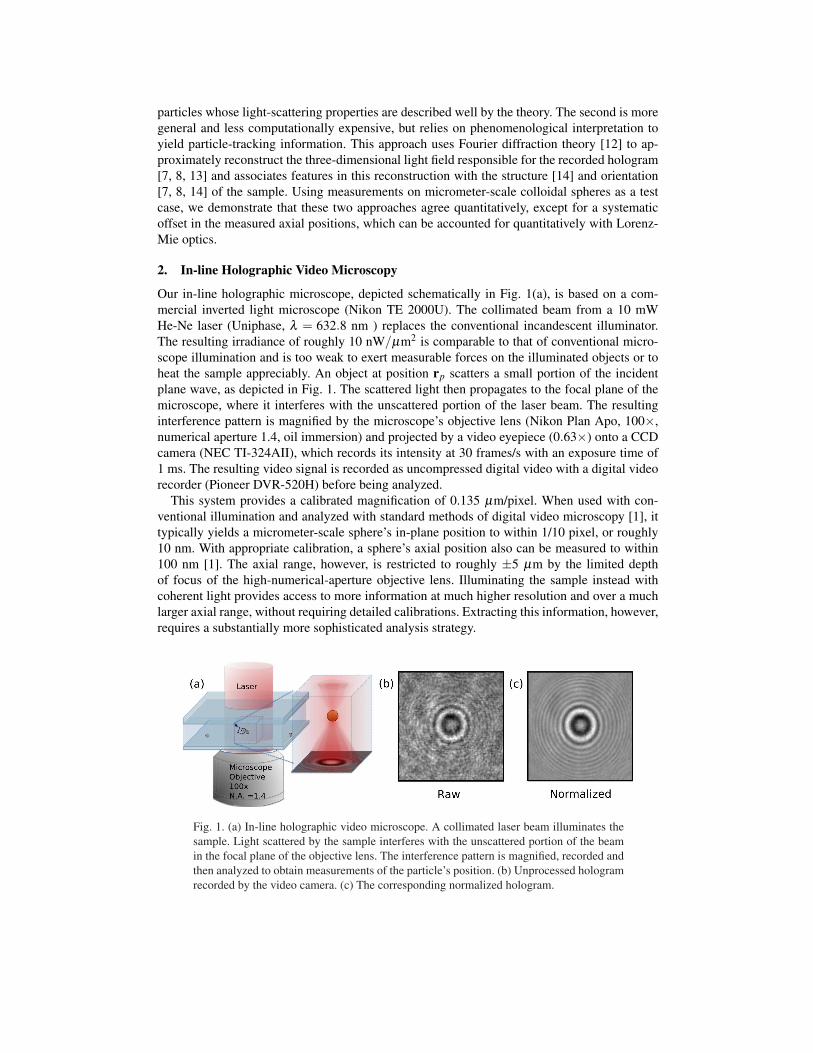
Our in-line holographic microscope, depicted schematically in Fig. 1(a), is based on a com-mercial inverted light microscope (Nikon TE 2000U). The collimated beam from a 10 mWHe-Ne laser (Uniphase, λ = 632.8 nm ) replaces the conventional incandescent illuminator.The resulting irradiance of roughly 10 nW/µm2 is comparable to that of conventional micro-scope illumination and is too weak to exert measurable forces on the illuminated objects or toheat the sample appreciably. An object at position rp scatters a small portion of the incidentplane wave, as depicted in Fig. 1. The scattered light then propagates to the focal plane of themicroscope, where it interferes with the unscattered portion of the laser beam. The resultinginterference pattern is magnified by the microscope’s objective lens (Nikon Plan Apo, 100×,numerical aperture 1.4, oil immersion) and projected by a video eyepiece (0.63×) onto a CCDcamera (NEC TI-324AII), which records its intensity at 30 frames/s with an exposure time of1 ms. The resulting video signal is recorded as uncompressed digital video with a digital videorecorder (Pioneer DVR-520H) before being analyzed.
This system provides a calibrated magnification of 0.135 µm/pixel. When used with con-ventional illumination and analyzed with standard methods of digital video microscopy [1], ittypically yields a micrometer-scale sphere’s in-plane position to within 1/10 pixel, or roughly10 nm. With appropriate calibration, a sphere’s axial position also can be measured to within100 nm [1]. The axial range, however, is restricted to roughly ±5 µm by the limited depthof focus of the high-numerical-aperture objective lens. Illuminating the sample instead withcoherent light provides access to more information at much higher resolution and over a muchlarger axial range, without requiring detailed calibrations. Extracting this information, however,requires a substantially more sophisticated analysis strategy.
Fig. 1. (a) In-line holographic video microscope. A collimated laser beam illuminates thesample. Light scattered by the sample interferes with the unscattered portion of the beamin the focal plane of the objective lens. The interference pattern is magnified, recorded andthen analyzed to obtain measurements of the particle’s position. (b) Unprocessed hologramrecorded by the video camera. (c) The corresponding normalized hologram.
The unprocessed holographic image of a colloidal sphere in Fig. 1(b) illustrates some of thechallenges of in-line holographic microscopy. In addition to the sphere’s light-scattering pat-tern, this image is marred by speckle and is obscured by fringes due to all of the other surfacesand particles along the optical train. Many of these distracting features could be mitigated byreducing the correlation length of the illumination [15], for example with a rotating diffuser[16]. This, however, would reduce the benefits of holographic imaging relative to conventionalincoherent imaging. Most of the unwanted interference fringes could be scaled out of the spa-tial bandwidth of the imaging system by illuminating the sample with a diverging laser beam.Collimated illumination, however, presents a much simpler scattering geometry that lends itselfto precision analysis.
3. Holographic Particle Tracking
We model the incident illumination as a plane wave,
E0(r,z) = u0(r)eikz ε0, (1)
propagating along z with wavenumber k = 2πnm/λ in a medium of refractive index nm. Boththe transverse amplitude profile u0(r) and the polarization ε0 are assumed to be independent ofz. The wave scattered by the sample,
Es(r,z) = Es(r,z) ε(r,z) (2)
propagates in three dimensions with complex amplitude Es(r,z) and spatially varying polariza-tion ε(r,z). The measured intensity at point r in the focal plane is due to the superposition ofthe incident and scattered waves,
I(r) = |E0(r,0)+ES(r,0)|2 (3)
= u20(r)+2ℜ{u0(r)Es(r,0) ε∗0 · ε(r,0)}+ |Es(r,0)|2 . (4)
If we assume that most of the static defects in the recorded image arise from variation in theillumination, then they can be removed by normalizing I(r) with a measured background im-age [8, 10, 11, 14]. The success of this procedure can be judged by the normalized hologram inFig. 1(c), whose visual quality approaches that of a conventional microscope image. Assuming,furthermore, that the object’s height above the focal plane is greater than its size, the geomet-ric rotation of the scattered polarization will be comparatively small, so that ε∗0 · ε(r,0) ≈ 1.This approximation can be improved by deliberately defocusing the microscope. An opticallyisotropic sample’s normalized hologram then is described by
b(r)≈ 1+2ℜ{ER(r,0)}+ |ER(r,0)|2 , (5)
where the reduced scattered field is ER(r,z) = Es(r,z)/u0(r).Equation (5) is the point of departure for the two approaches to holographic particle tracking
that we will compare. The first involves fitting the recorded images to predictions of the ex-act Lorenz-Mie theory for light scattering. The second involves tracking features in the three-dimensional light field reconstructed from a recorded hologram using the Rayleigh-Sommerfelddiffraction integral.
3.1. Lorenz-Mie Fitting
The scattered field at position r in the focal plane due to an object at rp relative to the center ofthe focal plane may be written as
Es(r,0) = u0 (rp) fs (k (r− rp)) , (6)
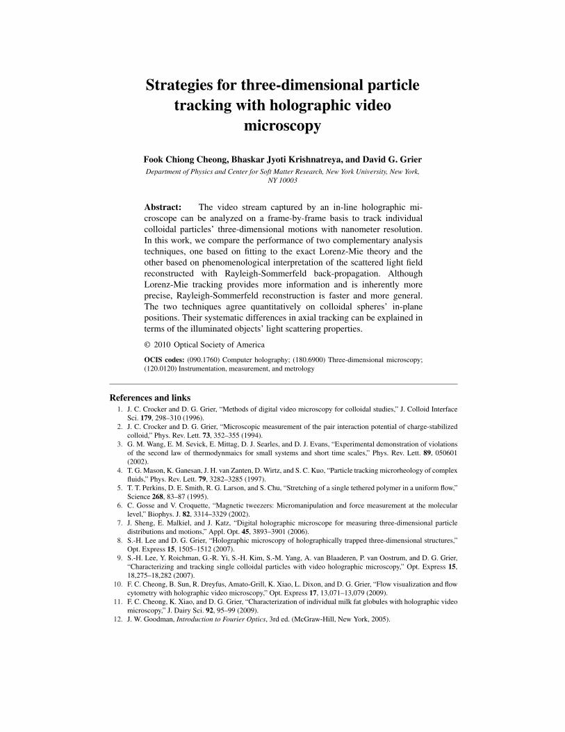
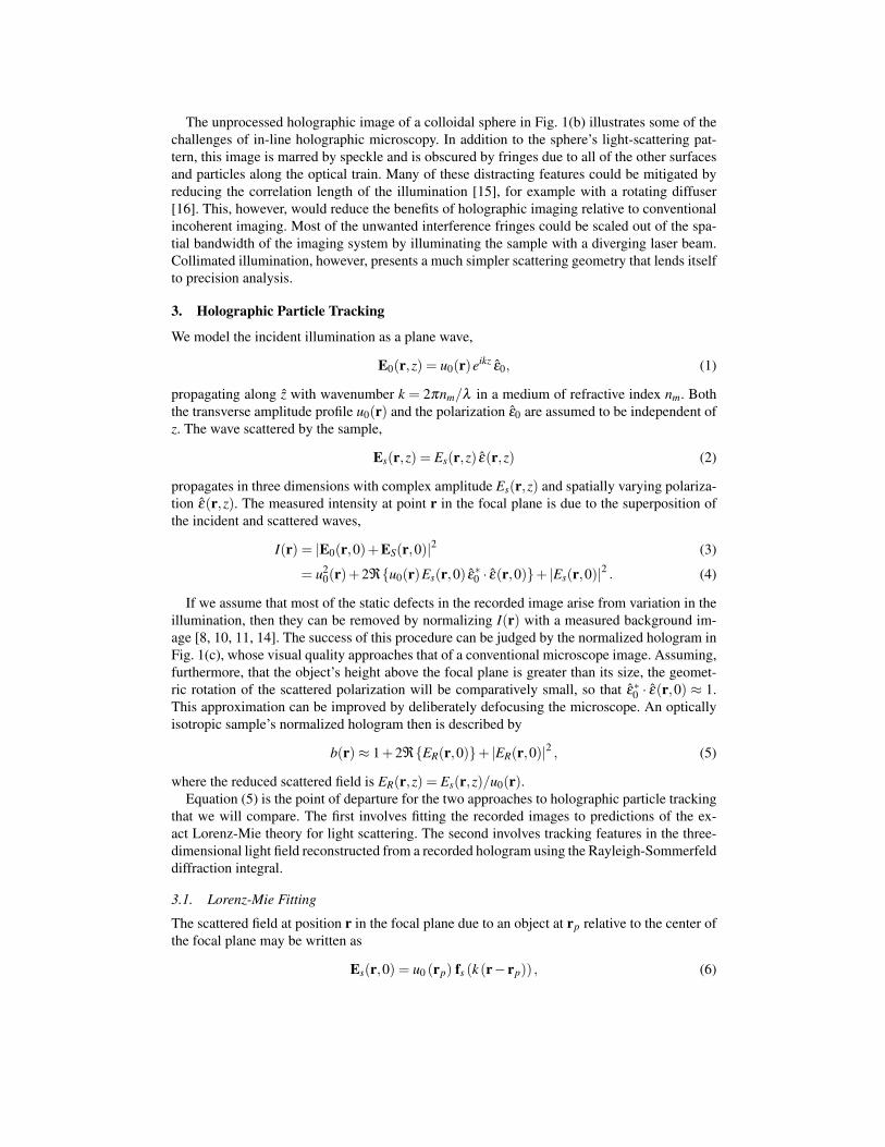
Fig. 2. Lorenz-Mie particle tracking and characterization. The upper image is the normal-ized hologram b(r) of a 1.51 µm diameter polystyrene sphere in water. The lower image isa fit to the Lorenz-Mie theory. The solid curve is the azimuthal average b(r) of the measuredintensity around the center identified by the fit. Dashed curves indicate the azimuthal stan-dard deviation of the hologram’s values, and indicates the measurement error. Plot pointsshow the corresponding radial profiles of the fit. Error bars on the fit values are smaller thanthe plot symbols.
where fs(r) is the normalized scattering function. In this case, Eq. (5) reduces to
b(r) = 1+2ℜ{
fs(k (r− rp)) · ε0}
+∣∣fs(k (r− rp))
∣∣2. (7)
Given an analytic form for fs(kr), a normalized hologram may be fit to Eq. (7) for the positionof the particle rp as well as any free parameters in the scattering function [9].
Lorenz-Mie theory describes the scattering function as an expansion [17]
fs (kr) =nc
∑n=1
in(2n+1)n(n+1)
(iαn N(3)
e1n (kr)−βn M(3)o1n (kr)
)(8)
in the vector spherical harmonics, N(3)e1n (kr) and M(3)
o1n (kr), whose coefficients, αn and βn, de-pend on the size, shape, composition, and orientation of the object and on the structure of theilluminating field. For a homogeneous isotropic sphere of radius ap and refractive index np il-luminated by a linearly polarized plane wave, the expansion coefficients are expressed in termsof spherical Bessel functions and spherical Hankel functions as [17]
αn =m2 jn(mkap) [kap jn(kap)]′− jn(kap) [mkap jn(mkap)]′
m2 jn(mkap) [kap h(1)n (kap)]′−h(1)
n (kap) [mkap jn(mkap)]′and (9)
βn =jn(mkap) [kap jn(kap)]′− jn(kap) [mkap jn(mkap)]′
jn(mkap) [kap h(1)n (kap)]′−h(1)
n (kap) [mkap jn(mkap)]′, (10)
where m = np/nm and where primes denote derivatives with respect to the argument. Thisform assumes ε0 = x, which is appropriate for our microscope. The scattering coefficients falloff rapidly with order n, and the series is found to converge after a number of terms nc =kap + 4.05(kap)1/3 + 2 [17, 18], which typically is less than 30 for micrometer-scale latexspheres in water. To compute fs(kr) in practice, we use the accurate but numerically intensivecontinued fraction algorithm due to Lentz for the expansion coefficients [19] and the moreefficient recurrence algorithm due to Wiscombe for the vector spherical harmonics [20].

The images in Fig. 2 are the normalized image of a 1.51 µm diameter polystyrene spherein water (Polysciences Lot 526826) and a pixel-by-pixel nonlinear least-squares fit to Eqs. (7)through (10) for rp, ap and np. Fits are performed with the MPFIT implementation [21] of theLevenberg-Marquardt algorithm [22] whose rigorous estimates for the adjustable parameters’uncertainties suggest that the sphere’s center has been identified with a precision of 1 nm in allthree dimensions. This estimate of the measurement resolution has been confirmed by indepen-dent measurements of similar colloidal particles’ dynamics [9, 10]. Similar part-per-thousandresolution is achieved for the particle’s radius and refractive index. The quality of the fit can beseen in the azimuthally averaged results that also are plotted in Fig. 2. In this particular exam-ple, the particle is found to have a radius of ap = 0.816± 0.001 µm, a purely real refractiveindex of np = 1.5821± 0.0006, and is centered at zp = 11.534± 0.003 µm above the focalplane.
Fits to Lorenz-Mie theory can be this successful because the interference fringes in eachholographic image can be defocused enough to cover thousands of pixels. In conventionalbright-field imaging, by contrast, a particle at such a large height above the focal plane wouldbe effectively invisible.
If the illumination were not sufficiently collimated, the incident wavefronts’ curvature wouldintroduce position-dependent distortions into the holograms that would not be accounted for byEq. (7). We find the fit values for a particle’s size and refractive index to be independent of itsposition in the microscope’s 78× 65 µm2 field of view. Wavefront curvature therefore shouldnot affect estimates for particles’ positions.
3.2. Rayleigh-Sommerfeld Back-Propagation
The hologram of a colloidal particle also can be used to reconstruct the three-dimensional lightfield that created the hologram. Although such reconstructions may be treated as volumetricrenderings of the scattered object [7, 8, 23], they are more properly interpreted as renderingsof the scattered field, Es(r,z) or its intensity, |Es(r,z)|2. Such volumetric reconstructions can
(a) (b)
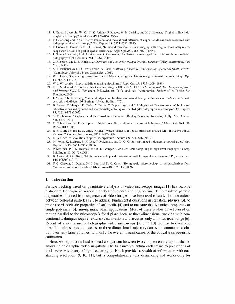
Fig. 3. Rayleigh-Sommerfeld back-propagation. (a) Volumetric reconstruction of the scat-tered intensity due to a single colloidal sphere, colored by intensity. The diverging rays arisefrom the spurious mirror image of the sphere in the focal plane. (b) Volumetric reconstruc-tions of 22 individual 1.58 µm diameter silica spheres organized in body center crystallinelattice with holographic optical tweezers in distilled water. Colored regions indicate theisosurface of the brightest 1 percent of reconstructed voxels. (Media 1)
be computed from any hologram without knowledge of the scattering object’s shape, size orcomposition. They also are much less computationally expensive than Lorenz-Mie fits. Featuresin the reconstructed light field may be associated with the positions and orientations of objectsin the scattering volume [7, 8, 14]. Volumetric reconstructions therefore promise high-speedmodel-free measurements of multiple objects’ positions and motions in three dimensions. Howobjects’ actual positions are related to features in their back-projected holograms has not beenassessed quantitatively in previous studies, however. To address this, we compare the precisionmeasurements of the previous section with three-dimensional particle tracking results obtainedwith Rayleigh-Sommerfeld back propagation.
The wave scattered by a particle spreads as it propagates. Its amplitude, consequently, shouldbe substantially smaller than the illumination’s once it reaches the focal plane. In that case, thethird term in Eq. (5) is negligible compared with the other two and
b(r)−1≈ 2ℜ{ER(r,0)} . (11)
If the complex scattered field were completely specified in the focal plane, it could be recon-structed at height z above the focal plane as the convolution,
Es(r,z) = Es(r,0)⊗h−z(r) (12)
of the scattered amplitude in the focal plane with the Rayleigh-Sommerfeld propagator [12]
h−z(r) =1
2π∂∂ z
eikR
R, (13)
where R2 = r2 +z2. The sign convention for z accounts for the object’s position upstream of thefocal plane. Equation (12) may be rewritten with the Fourier convolution theorem as
U(q,z) = U(q,0)H(q,−z), (14)
whereU(q,z) =
∫ ∞
−∞Es(r,z)e−iq·r d2r (15)
and [24, 25, 12]
H(q,−z) = eiz(k2−q2)12. (16)
To use this formalism to reconstruct the scattered field, we note that the Fourier transform ofb(r)−1 is
B(q)≈UR(q,0)+U∗R(q,0), (17)
where UR(q,z) is the Fourier transform of ER(r,z). From this,
B(q)H(q,−z) = UR(q,z)+U∗R(q,−z) (18)
may be recognized to be the superposition of the scattered field at height z above the focal planeand a spurious field due to the object’s mirror image in the focal plane, which is known as thetwin image. The twin image’s influence on the reconstructed field is reduced by defocusing,which also improves the approximations underlying Eq. (11). In the further approximation thatthe illumination is uniform, the reconstructed scattered field is
Es(r,z)≈ e−ikz
4π2
∫ ∞
−∞B(q)H(q,−z)eiq·r d2q. (19)
The associated intensity, Is(r,z) = |Es(r,z)|2, is an estimate for the scattered light’s intensity atheight z above the focal plane. The example in Fig. 3(a) shows a typical volumetric reconstruc-tion in 0.135 µm slices for a 1.5 µm diameter polystyrene sphere in water, the reconstructedrays converging to the diffraction-limited bright red spot roughly 10 µm above the focal plane.
Because the projection operation in Eq. (12) assumes the medium to be homogeneous andisotropic, it cannot account for light’s distortion by the object itself. Consequently, the recon-structed field upstream of an object is degraded by artifacts, as is the case for z > 12 µm inFig. 3(a). Reconstruction artifacts overlap the images of objects that are located upstream of ascattering particle. Nevertheless, the volumetric image in Fig. 3(b) (Media 1) of the intensityscattered by a collection 1.58 µm diameter silica spheres in water (Duke Scientific Lot 24169)shows clearly resolved maxima, even when spheres are occluded by their neighbors [8]. These22 spheres were arranged with holographic optical traps [26, 27, 28] into a body-centered cubic(bcc) lattice with a 10.8 µm lattice constant. The colored regions in Fig. 3(b) (Media 1) areisosurfaces of the brightest 1 percent of the reconstructed voxels and clearly suggest the posi-tions of all of the spheres in the lattice. Interpreting such a complicated hologram with fits toLorenz-Mie theory would be challenging.
x
z
yx
y
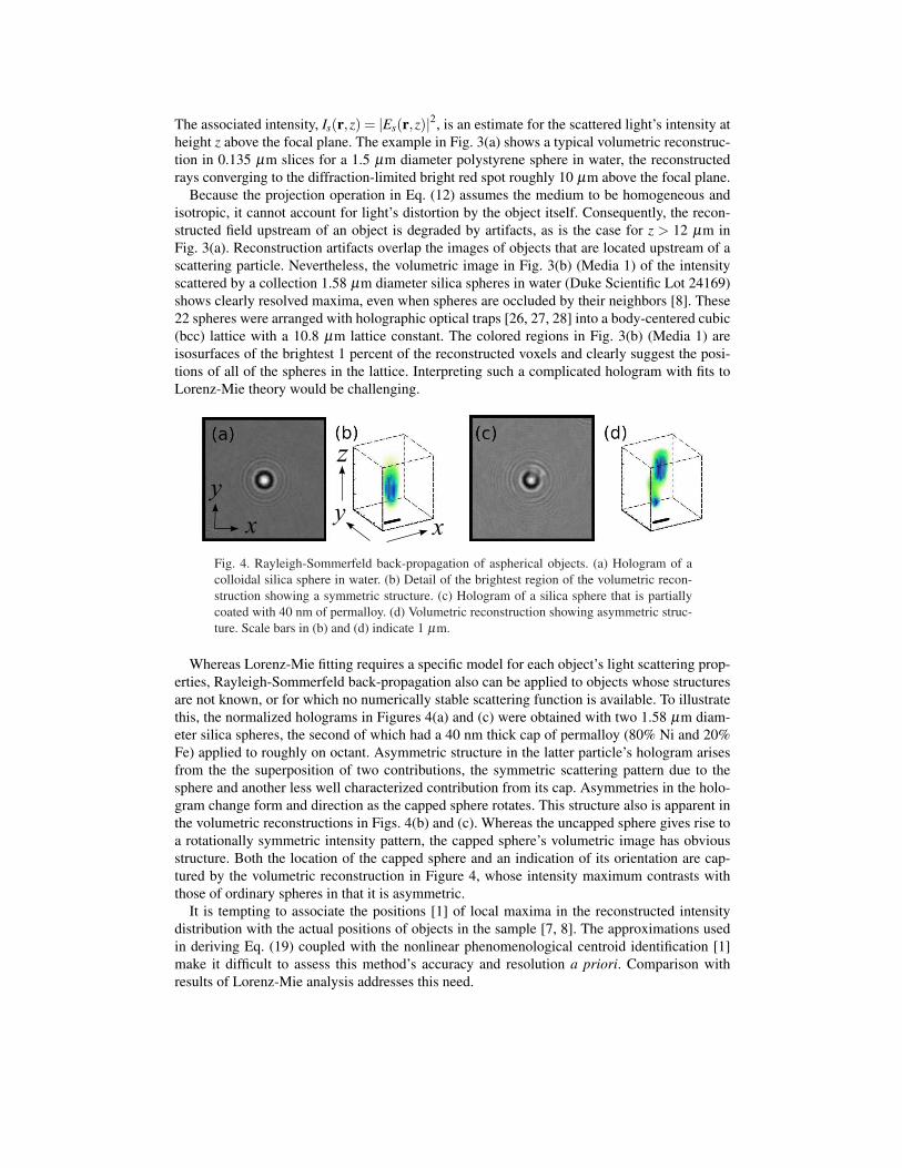
Fig. 4. Rayleigh-Sommerfeld back-propagation of aspherical objects. (a) Hologram of acolloidal silica sphere in water. (b) Detail of the brightest region of the volumetric recon-struction showing a symmetric structure. (c) Hologram of a silica sphere that is partiallycoated with 40 nm of permalloy. (d) Volumetric reconstruction showing asymmetric struc-ture. Scale bars in (b) and (d) indicate 1 µm.
Whereas Lorenz-Mie fitting requires a specific model for each object’s light scattering prop-erties, Rayleigh-Sommerfeld back-propagation also can be applied to objects whose structuresare not known, or for which no numerically stable scattering function is available. To illustratethis, the normalized holograms in Figures 4(a) and (c) were obtained with two 1.58 µm diam-eter silica spheres, the second of which had a 40 nm thick cap of permalloy (80% Ni and 20%Fe) applied to roughly on octant. Asymmetric structure in the latter particle’s hologram arisesfrom the the superposition of two contributions, the symmetric scattering pattern due to thesphere and another less well characterized contribution from its cap. Asymmetries in the holo-gram change form and direction as the capped sphere rotates. This structure also is apparent inthe volumetric reconstructions in Figs. 4(b) and (c). Whereas the uncapped sphere gives rise toa rotationally symmetric intensity pattern, the capped sphere’s volumetric image has obviousstructure. Both the location of the capped sphere and an indication of its orientation are cap-tured by the volumetric reconstruction in Figure 4, whose intensity maximum contrasts withthose of ordinary spheres in that it is asymmetric.
It is tempting to associate the positions [1] of local maxima in the reconstructed intensitydistribution with the actual positions of objects in the sample [7, 8]. The approximations usedin deriving Eq. (19) coupled with the nonlinear phenomenological centroid identification [1]make it difficult to assess this method’s accuracy and resolution a priori. Comparison withresults of Lorenz-Mie analysis addresses this need.
4. Comparison of Strategies
(a)
LM
RS
SiO(c) 2PS
(d)
(b)
(c)
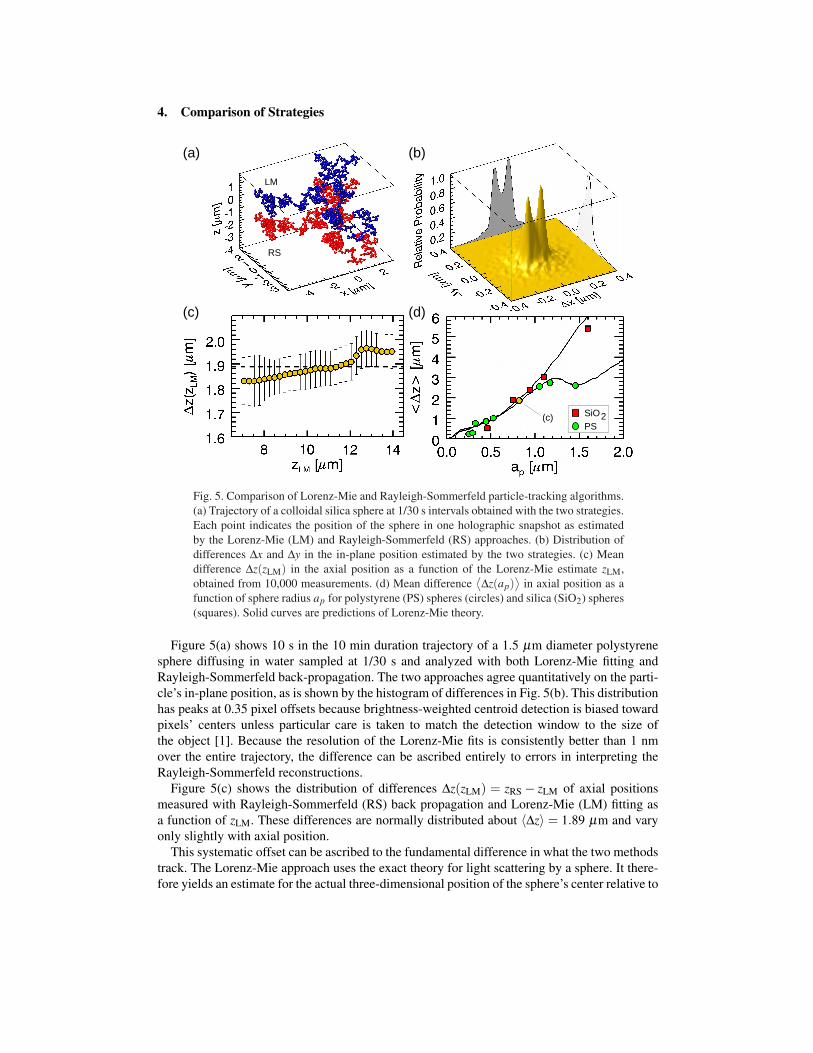
Fig. 5. Comparison of Lorenz-Mie and Rayleigh-Sommerfeld particle-tracking algorithms.(a) Trajectory of a colloidal silica sphere at 1/30 s intervals obtained with the two strategies.Each point indicates the position of the sphere in one holographic snapshot as estimatedby the Lorenz-Mie (LM) and Rayleigh-Sommerfeld (RS) approaches. (b) Distribution ofdifferences ∆x and ∆y in the in-plane position estimated by the two strategies. (c) Meandifference ∆z(zLM) in the axial position as a function of the Lorenz-Mie estimate zLM,obtained from 10,000 measurements. (d) Mean difference
⟨∆z(ap)
⟩in axial position as a
function of sphere radius ap for polystyrene (PS) spheres (circles) and silica (SiO2) spheres(squares). Solid curves are predictions of Lorenz-Mie theory.
Figure 5(a) shows 10 s in the 10 min duration trajectory of a 1.5 µm diameter polystyrenesphere diffusing in water sampled at 1/30 s and analyzed with both Lorenz-Mie fitting andRayleigh-Sommerfeld back-propagation. The two approaches agree quantitatively on the parti-cle’s in-plane position, as is shown by the histogram of differences in Fig. 5(b). This distributionhas peaks at 0.35 pixel offsets because brightness-weighted centroid detection is biased towardpixels’ centers unless particular care is taken to match the detection window to the size ofthe object [1]. Because the resolution of the Lorenz-Mie fits is consistently better than 1 nmover the entire trajectory, the difference can be ascribed entirely to errors in interpreting theRayleigh-Sommerfeld reconstructions.
Figure 5(c) shows the distribution of differences ∆z(zLM) = zRS − zLM of axial positionsmeasured with Rayleigh-Sommerfeld (RS) back propagation and Lorenz-Mie (LM) fitting asa function of zLM. These differences are normally distributed about 〈∆z〉 = 1.89 µm and varyonly slightly with axial position.
This systematic offset can be ascribed to the fundamental difference in what the two methodstrack. The Lorenz-Mie approach uses the exact theory for light scattering by a sphere. It there-fore yields an estimate for the actual three-dimensional position of the sphere’s center relative to
the center of the focal plane. The Rayleigh-Sommerfeld approach, by contrast, seeks the centerof brightness in the reconstructed scattering pattern, which generally falls downstream of thesample’s center. This distinction has been noted in passing by previous studies [7, 8]. How itvaries with the sample’s position and physical properties has not previously been addressed.
Although the axial offset plotted in Fig. 5(c) varies only weakly with axial position, the datain Fig. 5(d) for colloidal silica and polystyrene spheres of varying radii show a much strongerdependence on both composition and size. This means that back-propagation cannot reliablybe used to measure three-dimensional separations in polydisperse and heterogeneous samples.Lorenz-Mie analysis accounts explicitly for individual spheres’ size and refractive index and soshould provide accurate estimates for axial positions regardless of size and composition.
Trends in the observed axial offsets constitute a self-consistency test both for the analysesand also for our instrumentation. The solid curves in Fig. 5 represent the distance from the cen-ter of a sphere to the point of maximum intensity in its forward scattering pattern computed withEqs. (8) through (10). This distance should correspond to the difference in axial position ob-tained with Rayleigh-Sommerfeld and Lorenz-Mie analyses. Quantitative agreement betweenthese predictions and our measurements on two different materials over an order of magni-tude in particle size supports both the correctness of our analysis and also the efficacy of ourexperimental implementation.
The axial offset is comparable to the measurement error in the Rayleigh-Sommerfeld methodfor the smallest spheres in Fig. 5(d). This observation suggests that objects with features smallerthan the wavelength of light may be tracked in three dimensions at high resolution usingRayleigh-Sommerfeld back propagation, even if the shape and composition of the object isnot known. This, in turn, explains why Rayleigh-Sommerfeld back-propagation has provedsuccessful at tracking the three-dimensional positions and orientations of diffusing metal oxidenanorods, two of whose dimensions are smaller than the wavelength of light [14].
Although Rayleigh-Sommerfeld back-propagation provides less information than Lorenz-Mie fitting, it is more flexible and substantially faster. Computing each reconstructed axial slicerequires roughly a dozen float-point array operations and a Fourier transform. Depending onthe desired axial range and resolution, a few hundred slices may be computed for a single vol-ume. By contrast, each evaluation of the Lorenz-Mie scattering function with Eq. (8) requireswell over a hundred float-point array operations, and each fit requires as many as a hundredevaluations. Ten full Rayleigh-Sommerfeld reconstructions consequently can be computed inthe time required for a single Lorenz-Mie fit. Identifying and locating maxima in the recon-structions does not add substantially to the processing time [1].
We reduce the computational overhead of both analysis methods by performing array calcu-lations on the graphical processing unit (GPU) of a high-end graphics card using the GPUliblibrary [10, 29]. Hardware-accelerated analysis typically yields ten volumetric reconstructionsper second or one Lorenz-Mie fit, which is fast enough for near-real-time characterization ofindividual colloidal particles [9, 10, 11, 30], visualization of three-dimensional flows [10],measurement of rheological properties [31] and performance of medical diagnostic tests [10].
5. Conclusion
Our measurements on colloidal spheres demonstrate that Rayleigh-Sommerfeld back-propagation can be a fast, flexible and effective method for tracking objects in three dimen-sions. Axial positions obtained by tracking intensity maxima in the reconstructed light fielddiffer systematically from the true position for spheres larger than the wavelength of light.These deviations depend on the spheres’ size and refractive index, and thus can lead to errorsin estimates for relative separations among dissimilar objects in three dimensions. Fortunately,particles smaller than the wavelength of light have negligibly small offsets, suggesting that
Rayleigh-Sommerfeld back propagation may be most useful for analyzing the motions of smallobjects whose shapes sizes and compositions are unknown.
Our comparison of these techniques over an order of magnitude in particle size suggeststhat the measurement error in Rayleigh-Sommerfeld tracking can be better than 100 nm inall directions over the entire accessible axial range. Although this compares poorly with thenanometer resolution of Lorenz-Mie tracking, Rayleigh-Sommerfeld tracking appears to bemore effective for many-body systems and can be applied to objects of any shape [14].
Alternatives to Lorenz-Mie theory such as the discrete dipole approximation (DDA) or fi-nite difference time-domain (FDTD) calculations may be able to provide the basis for high-resolution tracking and characterization for more highly structured samples than isotropic ho-mogeneous spheres. In all such cases, Rayleigh-Sommerfeld back-propagation can provide auseful starting point for the fitting process, provided that account is taken of the size- andcomposition-dependent axial offset.
6. Acknowledgements
This work was supported in part by the National Science Foundation through Grant NumberDMR-0922680 and in part through the MRSEC program of the NSF through Grant NumberDMR-0820341.