Stelron Vari-Pak
24
Stelron Vari-Pak Linear Pick and Place
-
Upload
khangminh22 -
Category
Documents
-
view
2 -
download
0
Transcript of Stelron Vari-Pak

Stelron Vari-Pak
Linear Pick and Place
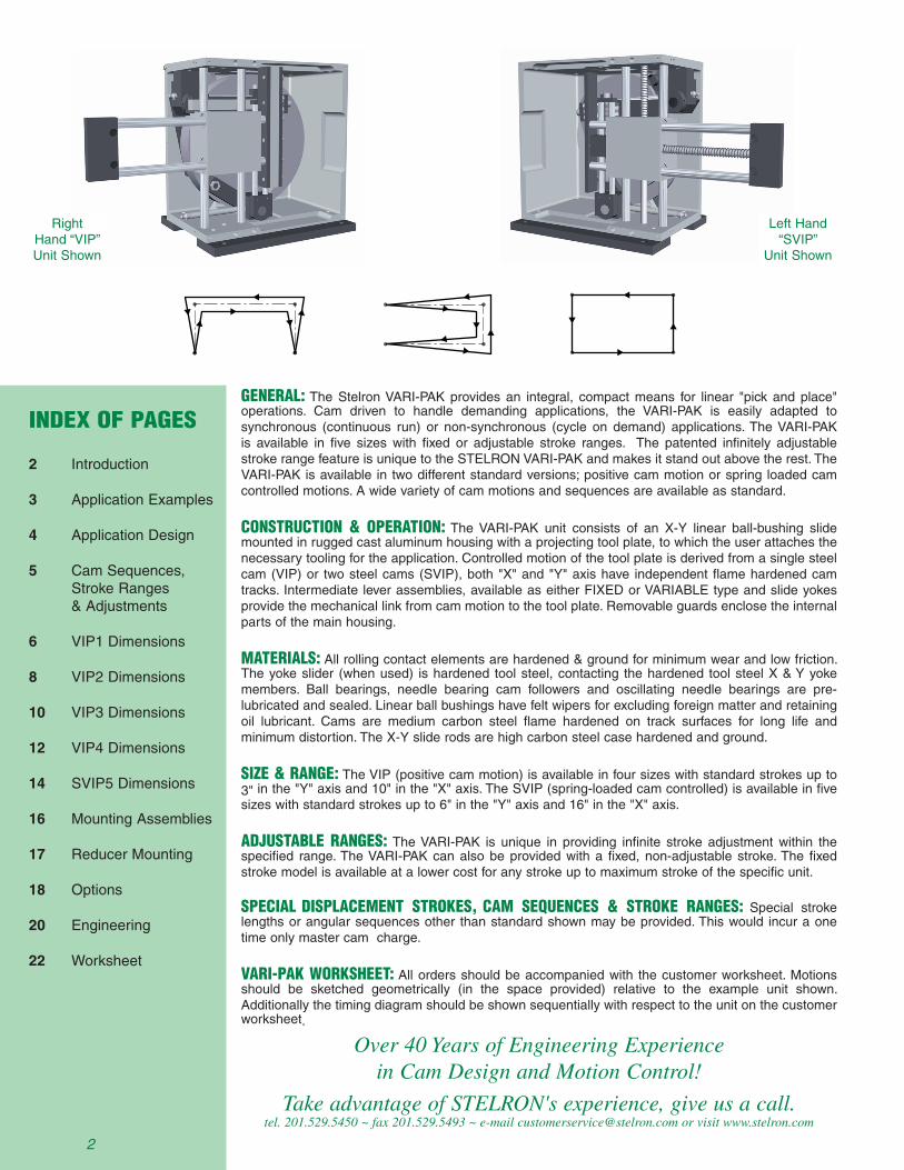
GENERAL: The Stelron VARI-PAK provides an integral, compact means for linear "pick and place" operations. Cam driven to handle demanding applications, the VARI-PAK is easily adapted to synchronous (continuous run) or non-synchronous (cycle on demand) applications. The VARI-PAK is available in five sizes with fixed or adjustable stroke ranges. The patented infinitely adjustable stroke range feature is unique to the STELRON VARI-PAK and makes it stand out above the rest. The VARI-PAK is available in two different standard versions; positive cam motion or spring loaded cam controlled motions. A wide variety of cam motions and sequences are available as standard.
CONSTRUCTION & OPERATION: The VARI-PAK unit consists of an X-Y linear ball-bushing slide mounted in rugged cast aluminum housing with a projecting tool plate, to which the user attaches the necessary tooling for the application. Controlled motion of the tool plate is derived from a single steel cam (VIP) or two steel cams (SVIP), both "X" and "Y" axis have independent flame hardened cam tracks. Intermediate lever assemblies, available as either FIXED or VARIABLE type and slide yokes provide the mechanical link from cam motion to the tool plate. Removable guards enclose the internal parts of the main housing.
MATERIALS: All rolling contact elements are hardened & ground for minimum wear and low friction. The yoke slider (when used) is hardened tool steel, contacting the hardened tool steel X & Y yoke members. Ball bearings, needle bearing cam followers and oscillating needle bearings are pre-lubricated and sealed. Linear ball bushings have felt wipers for excluding foreign matter and retaining oil lubricant. Cams are medium carbon steel flame hardened on track surfaces for long life and minimum distortion. The X-Y slide rods are high carbon steel case hardened and ground.
SIZE & RANGE: The VIP (positive cam motion) is available in four sizes with standard strokes up to 3" in the "Y" axis and 10" in the "X" axis. The SVIP (spring-loaded cam controlled) is available in five sizes with standard strokes up to 6" in the "Y" axis and 16" in the "X" axis.
ADJUSTABLE RANGES: The VARI-PAK is unique in providing infinite stroke adjustment within the specified range. The VARI-PAK can also be provided with a fixed, non-adjustable stroke. The fixed stroke model is available at a lower cost for any stroke up to maximum stroke of the specific unit.
SPECIAL DISPLACEMENT STROKES, CAM SEQUENCES & STROKE RANGES: Special stroke lengths or angular sequences other than standard shown may be provided. This would incur a one time only master cam charge.
VARI-PAK WORKSHEET: All orders should be accompanied with the customer worksheet. Motions should be sketched geometrically (in the space provided) relative to the example unit shown. Additionally the timing diagram should be shown sequentially with respect to the unit on the customer worksheet.
Over 40 Years of Engineering Experiencein Cam Design and Motion Control!
Take advantage of STELRON's experience, give us a call.tel. 201.529.5450 ~ fax 201.529.5493 ~ e-mail [email protected] or visit www.stelron.com
INDEX OF PAGES
2 Introduction
3 Application Examples
4 Application Design
5 Cam Sequences, Stroke Ranges & Adjustments
6 VIP1 Dimensions
8 VIP2 Dimensions
10 VIP3 Dimensions
12 VIP4 Dimensions
14 SVIP5 Dimensions
16 Mounting Assemblies
17 Reducer Mounting
18 Options
20 Engineering
22 Worksheet
2
Right Hand “VIP” Unit Shown
Left Hand “SVIP”
Unit Shown

Application Examples
Synchronous Motion ~ Continuous Drive:
Synchronous linear pick and place applications are very common. Stelron has an extensive line of cam components that can provide synchronized motions in applications utilizing a high-speed continuous drive or line shaft drive. The examples show a STELRON RWB (Recirculating Walking Beam Pallet Transfer System) designed with multiple VARI-PAKS for a variety of pick and place or linear motions.
Cycle on Demand Drive Packages:
Many applications require non-synchronous operation of components. The Stelron VARI-PAK can be supplied with a cycling drive package allowing independent "Cycle on Demand" operation. The example below shows a STELRON PLC (Precision Link Chassis) with multiple VARI-PAKS for a variety of pick and place motions.
Here the smooth cam controlled movement of the VARI-PAK is maintained while adding the control flexibility of having an independent motor drive. The VARI-PAK is often used for "Cycle on Demand" applications.
3

How to design a STELRON “Vari-Pak”into your application.
4
When adjusting the “X” axis stroke, the “R” dimension changes in the retracted position by the exact amount of the change in stroke. The Fixed “X” dimension equals the “R” dimension plus the “X” stroke (as ordered) in the extended position.
Example: Part number VIP-3-A-M-P-3.0Qx-1.25Ry-1.0-LH
In this example the Fixed “X” dimension (fully extended) equals 4.0” (3.0 “X” stroke + 1.0 “R” dim.) from the back surface of the tooling plate to the outer surface of the cover panel. If an adjustment is made to increase the “X” stroke from 3.0” to 3.125”, the “R” dimension would be automatically reduced from 1.0” to .875”.
At the bottom of each size unit dimension page is a “How To Order” chart with sample information in the data fields and page reference tabs to help guide you through the selection process. Below is a check list to get you started. If you have trouble determining any of the selections consult Stelron’s knowledgeable engineers.
1) Determine the available sizes based on the desired strokes from the “Standard Sizes & Stroke Ranges” chart on page 5 then, use the engineering information on pages 20 and 21 to more accurately size the unit by calculating the loads and capacities for your application.
2) Determine if you want an adjustable stroke or fixed stroke unit. If adjustable, select the stroke range “A” or “B” from the chart at the top of the dimensions page for the selected size unit.
3) Select the mounting position of the unit for your application from the chart on page 16.
4) Add optional mounting plates if desired.
5) Select standard cam sequences from the “Standard “X” and “Y” Cam Sequences” chart on page 5. If no standard sequences apply use the worksheets on pages 22 and 23 and consult Stelron engineers.
Specify the “R” dimension using the information below. The “R” dimension defined is a customer specified distance between the back surface of the tooling plate, in the fully retracted position, and the outer surface of the cover panel. If you have selected a fixed stroke unit simply specify the “R” dimension to suit your application needs however, if you have selected an adjustable unit the information below may prove valuable for determining the “R” dimension. This information will provide you with a better understanding as to what happens when you make an adjustment in either the “X” or “Y” stroke.
7) Select a Left Hand unit or Right Hand unit.
8) Determine if a spring type unit would be right for you application. A few factors that must be considered are speed, weight of tooling
When adjusting the “Y” axis stroke, the distance from the bottom of the tooling plate to the bottom of the unit housing
changes by the exact amount of the change in stroke. The Fixed “Y” dimension is given for each size unit on their respective dimension page.
Note: This information does not apply to the SVIP-5.
see page 19 see page 5 see page 16 see page 18 see page 5 see page 5 see page 5 see page 5 see page 4 see page 16
- VIP-3 A M P 6.000 Mx 2.000 Sy 3.00 RH
SpringOption
S
Model
VIP-3
Rangeor Fixed
B
MountingPosition
M
OptionalMtg Plate
-
“X” AxisStroke
2.000
“X” CamSeq.
Qx
“Y” AxisStroke
0.500
“Y” CamSeq.
Sy
“R”Dim.
2.50
Handof Unit
LH
HOW TO ORDER: 7
Fixed "Y"
"Y" Stroke
"R" Dim.(Fully retracted)
.06 typ.(Cover Panel)
Fixed "X" .06 typ.(Cover Panel)
6
6
6
6

C A
BD
Reverse Motion(Optional - Specify)
CA(D)DCD(D)CDAC(D)B(D) BA“Y” SEQ. AB SEQ. AB BC(D) CD DA(D)
“X”SEQ.
ABA (DWELL) CDC (DWELL)AC CASEQ.
AB(D) BC CD(D) DA
“Y”
CA
MS
“X”
CA
MS
MyNyPyQyRySyTyUy
MxNxPxQxRxSxTxUx
EyFyGyHyJyKyLy
ExFxGxHxJxKxLx
30°45°60°30°45°55°30°45°
30°45°60°30°45°55°30°45°
30°45°60°30°45°55°30°45°
30°45°60°30°45°55°30°45°
120°90°60°105°75°55°90°60°
120°90°60°105°75°55°90°60°
30°45°60°75°90°105°120°
30°45°60°75°90°105°120°
150°135°120°105°90°75°60°
150°135°120°105°90°75°60°
0°0°0°15°15°15°30°30°
0°0°0°15°15°15°30°30°
120°90°60°105°75°55°90°60°
120°90°60°105°75°55°90°60°
60°90°120°75°105°125°90°120°
60°90°120°75°105°125°90°120°
30°45°60°75°90°105°120°
30°45°60°75°90°105°120°
150°135°120°105°90°75°60°
150°135°120°105°90°75°60°
5
B
A
C
D
Pick and Place Walking Beam
Right HandUnit Shown
Standard “X” and “Y” Cam Sequences
Standard Size & Stroke Ranges
Adjustment & Calibration : By referring to the example on the left it will be observed that the “X” & “Y” strokes may be
changed by repositioning the yoke pin block. This is done by loosening the clamp screw “S” and adjusting the lever screw “T” through access holes provided in the main housing. When the desired stroke is obtained retighten the clamp screw “S”. Note: The “X” & “Y” lever adjustments are identical.
It will be noted that changing the stroke does not affect the fixed extended up position of the external end plate. The termination of the “X” & “Y” strokes will always return the slide yoke position “inline” vertically & horizontally with respective lever pivot shafts.
It is recommended that orders for variable stroke units specify the “X” & “Y” strokes so that initial calibration can be performed prior to shipment
(S) VIP
“X” RANGE
“Y” RANGE
1A
1.75 - 3.5
.88 - 2
1B
1 - 2
.44 - 1
2A
2 - 4
1.13 - 2.5
2B
1 - 2.13
.5 - 1.25
3A
3 - 6
1.38 - 3
3B
1.5 - 3.13
.75 - 1.5
4A
6 - 10
1.38 - 3
4B
3.25 - 6.25
.75 - 1.5
5A
10 - 16
2.5 - 6
5B
6.5 - 10.25
1.25 - 3
1F
1 - 3.5
.44 - 2
2F
1 - 4
.5 - 2.5
3F
1.5 - 6
.75 - 3
4F
3.25 - 10
.75 - 3
5F
6.5 - 16
1.25 - 6
ALL CAMS, OUTPUT MOTIONS AND INPUT SHAFT ROTATIONS GEOMETRICALLY PERTAIN TO RIGHT HAND ASSEMBLY SHOWN ABOVE.
“X” “Y”
6

see page 19 see page 5 see page 16 see page 18 see page 5 see page 5 see page 5 see page 5 see page 4 see page 16
- VIP-1 A M P 2.500 Qx 1.000 Ry 0.50 RH
SpringOption
S
Model
VIP-1
Rangeor Fixed
F
MountingPosition
M
OptionalMtg Plate
-
“X” AxisStroke
3.000
“X” CamSeq.
Nx
“Y” AxisStroke
1.500
“Y” CamSeq.
Sy
“R”Dim.
1.50
Handof Unit
LH
"M" Mount (far side)"P" Mount (near side)
8.00
6.63
1.50 typ.
6.00
5.50
.25 typ.
.50 typ.
3.00
(4) 5/16-18 taps aresupplied standard only formounting assembly ordered.
.69 typ.
.28 dia. typ.
.375 .500
4.31
3.63 .69 typ.
2.25
.88
6.63
.69 typ.
8.00
4.00
3.88
.625shaft dia.
"R" Mount nearside only
.69
1.00
2.25
1.7503.13
3.00.06 typ.cover plate
1.56
5.00 .06 typ.coverplate
6.13
.69
GreaseLocations
.375typ.
"N" Mount nearside only
"R" Dim.from cover
7
Optionalmounting plate
NOTES:1 - THE TOOLING PLATE DIMENSION SHOWNIS MEASURED IN THE UP AND RETRACTEDPOSITION.
2 - SPECIAL MACHINING TO HOUSING ANDSHAFTS ARE AVAILABLE UPON REQUEST.PRINTS ARE REQUIRED.
3 - OPTIONS AVAILABLE ARE LISTED IN THEBACK OF THE CATALOG. SOME LIMITATIONSMAY APPLY. CONTACT A STELRONAPPLICATION ENGINEER WITH INQUIRIES.
4 - MOUNTING PLATES ARE OPTIONAL.
5 - RIGHT HAND UNIT (AS SHOWN) OR LEFTHAND AVAILABLE AS STANDARD.
6 - FOR INFORMATION ON "SVIP" SPRINGOVERLOAD MODELS REFER TO THEOPTIONS SECTION.
7 - "R" DIMENSION MINIMUM IS 1/8".ALLOWANCE SHOULD BE MADE FORCHANGES IN "R" DIMENSION EQUAL TOCHANGE IN "X" STROKE ON ADJUSTABLEUNITS WITH EXCEPTION TO MODEL SVIP-5.
.188
Fixed "Y"
STELRON VIP-1 VARI-PAKDIMENSIONS
1.75” - 3.5” 0.88” - 2”VIP-1-A1” - 2” 0.44” - 1”VIP-1-B
“X” “Y”
Stroke RangeSize
1” - 3.5” 0.44” - 2”VIP-1-F
6
1
HOW TO ORDER: (Samples)
see page 18 see page 17a
see page 17
.625 1.812.633.28
“M” dim.
FLGR SFLGR
“J” dim.
n/a
1.81
Std. CapacityTorque in-lbs.2
High CapacityTorque in-lbs.3
G F E
D
C J
B
2" 3/8"
A M
Nema / SizeFLGR
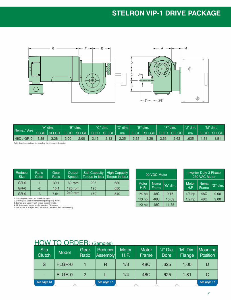
“A” dim. “B” dim. “C” dim. “D” dim. “F” dim.“E” dim.
SFLGR FLGR SFLGR FLGR SFLGR n/a FLGR FLGR SFLGR
48C / GR-0 3.38 3.38 2.00 2.00 2.13 2.13 2.25 3.28 2.63
Reducer Size
RatioCode
GearRatio
OutputSpeed1
GR-0 -1 30:1 60 rpm
GR-0 -2 15:1 120 rpm
GR-0 -3 7.5:1 240 rpm
1. Output speed based on 1800 RPM input.2. Delrin® gear used in standard torque capacity model.3. Bronze gear used in high torque capacity model.4. All dimensions shown are for standard DC motors.5. Unit shown is a Right Hand VIP with a Left Hand Reducer assembly.
MotorH.P.
Nema Frame
“G” dim.
1/4 hp
90 VDC MotorInverter Duty 3 Phase
230 VAC Motor
48C 9.16
1/3 hp 48C 10.09
1/2 hp 48C 11.85
205
195
160
680
650
540
SFLGR
MotorH.P.
Nema Frame
“G” dim.
1/3 hp 48C 9.00
1/2 hp 48C 9.00
STELRON VIP-1 DRIVE PACKAGE
SlipClutch
S
Model
FLGR-0
GearRatio
1
ReducerAssembly
R
MotorH.P.
1/3
MotorFrame
48C
“J” Dia.Bore
.625
“M” Dim.Flange
1.00
MountingPosition
D
- FLGR-0 2 L 1/4 48C .625 1.81 C
HOW TO ORDER: (Samples)
7
Refer to reducer catalog for complete dimensional information

see page 19 see page 5 see page 16 see page 18 see page 5 see page 5 see page 5 see page 5 see page 4 see page 16
- VIP-2 A M P 4.000 Mx 2.500 Sy 3.00 RH
SpringOption
S
Model
VIP-2
Rangeor Fixed
B
MountingPosition
M
OptionalMtg Plate
-
“X” AxisStroke
1.500
“X” CamSeq.
Qx
“Y” AxisStroke
0.500
“Y” CamSeq.
Sy
“R”Dim.
2.50
Handof Unit
LH
.188
2.25 typ.
8.00
7.00
1.00 typ.
.50 typ. 3.50
5.13
.625.500
.34 dia. typ.
.81 typ.
10.25
8.63
"M" Mount (far side)"P" Mount (near side)
(4) 3/8-16 taps aresupplied standard only formounting assembly ordered
.81 typ. 4.38 .81 typ.
2.50
8.63
1-1/16
"N" Mount nearside only
"R" Mount nearside only
5.13
10.25
5.13
.750shaft dia.
.06 typ.cover plate
3.19
4.062.500
3.13
1.50
.81
"R" Dim.from cover
7
6.00
1.63
1.94
9.06
.06 typ.coverplate
GreaseLocations.500
typ.
Optionalmounting plate
NOTES:1 - THE TOOLING PLATE DIMENSION SHOWNIS MEASURED IN THE UP AND RETRACTEDPOSITION.
2 - SPECIAL MACHINING TO HOUSING ANDSHAFTS ARE AVAILABLE UPON REQUEST.PRINTS ARE REQUIRED.
3 - OPTIONS AVAILABLE ARE LISTED IN THEBACK OF THE CATALOG. SOME LIMITATIONSMAY APPLY. CONTACT A STELRONAPPLICATION ENGINEER WITH INQUIRIES.
4 - MOUNTING PLATES ARE OPTIONAL.
5 - RIGHT HAND UNIT (AS SHOWN) OR LEFTHAND AVAILABLE AS STANDARD.
6 - FOR INFORMATION ON "SVIP" SPRINGOVERLOAD MODELS REFER TO THEOPTIONS SECTION.
7 - "R" DIMENSION MINIMUM IS 1/8".ALLOWANCE SHOULD BE MADE FORCHANGES IN "R" DIMENSION EQUAL TOCHANGE IN "X" STROKE ON ADJUSTABLEUNITS WITH EXCEPTION TO MODEL SVIP-5.
Fixed "Y"
STELRON VIP-2 VARI-PAKDIMENSIONS
2” - 4” 1.13” - 2.5”VIP-2-A1” - 2.13” 0.5” - 1.25”VIP-2-B
“X” “Y”
Stroke RangeSize
1” - 4” 0.5” - 2.5”VIP-2-F
8
2
HOW TO ORDER: (Samples)

3/4 hp 48C 9.50
.750 1.813.133.78 1.4156C / GR-1 3.38 4.13 2.50 2.50 2.625 2.725 3.25 3.78 3.13
see page 18 see page 17a
see page 17
.750 1.813.133.78
“M” dim.
FLGR SFLGR
“J” dim.
n/a
1.41
Std. CapacityTorque in-lbs.2
High CapacityTorque in-lbs.3
G F E
D
C
B
J
2" 3/8"
A M
3/8"
Nema / SizeFLGR
“A” dim. “B” dim. “C” dim. “D” dim. “F” dim.“E” dim.
SFLGR FLGR SFLGR FLGR SFLGR n/a FLGR FLGR SFLGR
48C / GR-1 3.38 4.13 2.50 2.50 2.625 2.725 2.25 3.78 3.13
Reducer Size
RatioCode
GearRatio
OutputSpeed1
GR-1 -1 40:1 45 rpm
GR-1 -2 20:1 90 rpm
GR-1 -3 10:1 180 rpm
1. Output speed based on 1800 RPM input.2. Delrin® gear used in standard torque capacity model.3. Bronze gear used in high torque capacity model.4. All dimensions shown are for standard DC motors.5. Unit shown is a Right Hand VIP with a Left Hand Reducer assembly.
MotorH.P.
Nema Frame
“G” dim.
1/3 hp
90 VDC MotorInverter Duty 3 Phase
230 VAC Motor
48C 10.09
1/3 hp 56C 11.19
1/2 hp 48C 11.85
1/2 hp 56C 12.94
3/4 hp 56C 12.57
320
315
275
1060
1050
920
SFLGR
MotorH.P.
Nema Frame
“G” dim.
1/3 hp 48C 9.00
1/2 hp 48C 9.00
STELRON VIP-2 DRIVE PACKAGE
SlipClutch
-
Model
FLGR-1
GearRatio
1
ReducerAssembly
R
MotorH.P.
1/2
MotorFrame
48C
“J” Dia.Bore
.750
“M” Dim.Flange
0.81
MountingPosition
E
S FLGR-1 2 L 1/2 56C .750 1.41 D
HOW TO ORDER: (Samples)
9
Refer to reducer catalog for complete dimensional information

see page 19 see page 5 see page 16 see page 18 see page 5 see page 5 see page 5 see page 5 see page 4 see page 16
- VIP-3 A M P 6.000 Mx 2.000 Sy 3.00 RH
SpringOption
S
Model
VIP-3
Rangeor Fixed
B
MountingPosition
M
OptionalMtg Plate
-
“X” AxisStroke
2.000
“X” CamSeq.
Qx
“Y” AxisStroke
0.750
“Y” CamSeq.
Sy
“R”Dim.
2.50
Handof Unit
LH
"M" Mount (far side)"P" Mount (near side)
13.13
11.13 1.00 typ.
.41 dia. typ.
.750 .875
5.88
3.50.63 typ.
1.25 typ.
8.25
9.50
3.00 typ.
(4) 3/8-16 taps aresupplied standard only formounting assembly ordered.
.250
1.00 typ. 5.00 1.00 typ.
11.13
1-1/16
3.00
"N" Mount nearside only
6.69
13.13
6.56
1.000shaft dia.
"R" Mount nearside only
1.00
1.50
3.50
2.500
5.63
3.88.06 typ.cover plate
.500typ.
7.00
2.00
10.38
1.19
GreaseLocations
.06 typ.coverplate
Optionalmounting plate
"R" Dim.from cover
7
NOTES:1 - THE TOOLING PLATE DIMENSION SHOWNIS MEASURED IN THE UP AND RETRACTEDPOSITION.
2 - SPECIAL MACHINING TO HOUSING ANDSHAFTS ARE AVAILABLE UPON REQUEST.PRINTS ARE REQUIRED.
3 - OPTIONS AVAILABLE ARE LISTED IN THEBACK OF THE CATALOG. SOME LIMITATIONSMAY APPLY. CONTACT A STELRONAPPLICATION ENGINEER WITH INQUIRIES.
4 - MOUNTING PLATES ARE OPTIONAL.
5 - RIGHT HAND UNIT (AS SHOWN) OR LEFTHAND AVAILABLE AS STANDARD.
6 - FOR INFORMATION ON "SVIP" SPRINGOVERLOAD MODELS REFER TO THEOPTIONS SECTION.
7 - "R" DIMENSION MINIMUM IS 1/8".ALLOWANCE SHOULD BE MADE FORCHANGES IN "R" DIMENSION EQUAL TOCHANGE IN "X" STROKE ON ADJUSTABLEUNITS WITH EXCEPTION TO MODEL SVIP-5.
Fixed "Y"
STELRON VIP-3 VARI-PAKDIMENSIONS
3” - 6” 1.38” - 3”VIP-3-A1.5” - 3.13” 0.75” - 1.5”VIP-3-B
“X” “Y”
Stroke RangeSize
1.5” - 6” 0.75” - 3”VIP-3-F
10
3
HOW TO ORDER: (Samples)

3/4 hp 48C 9.50
1 hp 56C 9.94
1.000 1.664.064.72 1.6656C / GR-2 3.38 4.13 3.50 3.44 3.625 3.625 3.25 4.78 4.13
see page 18 see page 17a
see page 17
1.000 1.664.064.72
“M” dim.
FLGR SFLGR
“J” dim.
n/a
1.66
Std. CapacityTorque in-lbs.2
High CapacityTorque in-lbs.3
G F E
D
C
B
J
A M
2" 3/8"
Nema / SizeFLGR
“A” dim. “B” dim. “C” dim. “D” dim. “F” dim.“E” dim.
SFLGR FLGR SFLGR FLGR SFLGR n/a FLGR FLGR SFLGR
48C / GR-2 3.38 4.13 3.50 3.44 3.625 3.625 2.25 4.78 4.13
Reducer Size
RatioCode
GearRatio
OutputSpeed1
GR-2 -1 60:1 30 rpm
GR-2 -2 30:1 60 rpm
GR-2 -3 15:1 120 rpm
1. Output speed based on 1800 RPM input.2. Delrin® gear used in standard torque capacity model.3. Bronze gear used in high torque capacity model.4. All dimensions shown are for standard DC motors.5. Unit shown is a Right Hand VIP with a Left Hand Reducer assembly.
MotorH.P.
Nema Frame
“G” dim.
1/2 hp
90 VDC Motor
Inverter Duty 3 Phase230 VAC Motor
48C 11.85
1/2 hp 56C 12.94
3/4 hp 56C 12.57
1 hp 56C 13.44
710
700
675
2360
2320
2250
SFLGR
MotorH.P.
Nema Frame
“G” dim.
1/2 hp 48C 9.00
STELRON VIP-3 DRIVE PACKAGE
SlipClutch
S
Model
FLGR-2
GearRatio
1
ReducerAssembly
R
MotorH.P.
1/2
MotorFrame
48C
“J” Dia.Bore
1.000
“M” Dim.Flange
1.66
MountingPosition
B
- FLGR-2 2 L 1/2 56C 1.000 1.66 D
HOW TO ORDER: (Samples)
11
Refer to reducer catalog for complete dimensional information
1 hp 56C 9.94
3 Phase230/460 VAC Motor
MotorH.P.
Nema Frame
“G” dim.
1/2 hp 56C 9.29
3/4 hp 56C 9.29

"M" Mount (far side) "P" Mount (near side)
18.63
16.63
3.00 typ.
11.13
9.88
1.25 typ.
.63 typ. 4.75
1.00 typ.
.53 dia. typ.
1.000 1.250
7 3/32"
(4) 1/2-13 taps are supplied standard only for mounting assembly ordered
8.63
2.25 1.38 2.00
5.00
16.63
4.75
4.63
7 3/32"
3.875
.06 typ. cover plate
.06 typ. cover plate
.63 typ.
Optional mounting plate
Grease Locations
1.250 shaft dia.
"R" Mount near side only
"N" Mount near side only
4.50
1-3/16
9.31
18.63
16.63
1.00 typ.
6.63 1.00 typ. 9.56
.312
"R" Dim. from cover
7
NOTES: 1 - THE TOOLING PLATE DIMENSION SHOWN IS MEASURED IN THE UP AND RETRACTED POSITION. 2 - SPECIAL MACHINING TO HOUSING AND SHAFTS ARE AVAILABLE UPON REQUEST. PRINTS ARE REQUIRED. 3 - OPTIONS AVAILABLE ARE LISTED IN THE BACK OF THE CATALOG. SOME LIMITATIONS MAY APPLY. CONTACT A STELRON APPLICATION ENGINEER WITH INQUIRIES. 4 - MOUNTING PLATES ARE OPTIONAL. 5 - RIGHT HAND UNIT (AS SHOWN) OR LEFT HAND AVAILABLE AS STANDARD. 6 - FOR INFORMATION ON "SVIP" SPRING OVERLOAD MODELS REFER TO THE OPTIONS SECTION. 7 - "R" DIMENSION MINIMUM IS 1/8". ALLOWANCE SHOULD BE MADE FOR CHANGES IN "R" DIMENSION EQUAL TO CHANGE IN "X" STROKE ON ADJUSTABLE UNITS WITH EXCEPTION TO MODEL SVIP-5.
Fixed "Y"
see page 19 see page 5 see page 16 see page 18 see page 5 see page 5 see page 5 see page 5 see page 4 see page 16
- VIP-4 A M P 10.000 Mx 2.000 Sy 3.00 RH
SpringOption
S
Model
VIP-4
Rangeor Fixed
B
MountingPosition
M
OptionalMtg Plate
-
“X” AxisStroke
3.500
“X” CamSeq.
Qx
“Y” AxisStroke
0.750
“Y” CamSeq.
Sy
“R”Dim.
2.50
Handof Unit
LH
STELRON VIP-4 VARI-PAKDIMENSIONS
6” - 10” 1.38” - 3”VIP-4-A3.25” - 6.25” 0.75” - 1.5”VIP-4-B3.25” - 10” 0.75” - 3”VIP-4-F
“X” “Y”
Stroke RangeSize
12
4
HOW TO ORDER: (Samples)

3/4 hp 48C 9.50
1 hp 56C 9.94
1.250 1.664.064.72 1.6656C / GR-2 3.38 4.13 3.50 3.44 3.625 3.625 3.25 4.78 4.13
see page 18 see page 17a
see page 17
1.250 1.664.064.72
“M” dim.
FLGR SFLGR
“J” dim.
n/a
1.66
Std. CapacityTorque in-lbs.2
High CapacityTorque in-lbs.3
G F E
D
C
B
A M
2"3/8"
J
Nema / SizeFLGR
“A” dim. “B” dim. “C” dim. “D” dim. “F” dim.“E” dim.
SFLGR FLGR SFLGR FLGR SFLGR n/a FLGR FLGR SFLGR
48C / GR-2 3.38 4.13 3.50 3.44 3.625 3.625 2.25 4.78 4.13
Reducer Size
RatioCode
GearRatio
OutputSpeed1
GR-2 -1 60:1 30 rpm
GR-2 -2 30:1 60 rpm
GR-2 -3 15:1 120 rpm
1. Output speed based on 1800 RPM input.2. Delrin® gear used in standard torque capacity model.3. Bronze gear used in high torque capacity model.4. All dimensions shown are for standard DC motors.5. Unit shown is a Right Hand VIP with a Left Hand Reducer assembly.
MotorH.P.
Nema Frame
“G” dim.
1/2 hp
90 VDC Motor
Inverter Duty 3 Phase230 VAC Motor
48C 11.85
1/2 hp 56C 12.94
3/4 hp 56C 12.57
1 hp 56C 13.44
710
700
675
2360
2320
2250
SFLGR
MotorH.P.
Nema Frame
“G” dim.
1/2 hp 48C 9.00
STELRON VIP-4 DRIVE PACKAGE
SlipClutch
S
Model
FLGR-2
GearRatio
1
ReducerAssembly
R
MotorH.P.
1/2
MotorFrame
48C
“J” Dia.Bore
1.250
“M” Dim.Flange
1.66
MountingPosition
B
- FLGR-2 2 L 1/2 56C 1.250 1.66 D
HOW TO ORDER: (Samples)
13
Refer to reducer catalog for complete dimensional information
1 hp 56C 9.94
3 Phase230/460 VAC Motor
MotorH.P.
Nema Frame
“G” dim.
1/2 hp 56C 9.29
3/4 hp 56C 9.29

see page 5 see page 16 see page 18 see page 5 see page 5 see page 5 see page 5 see page 4 see page 16
SVIP-5 A M P 16.000 Mx 6.000 Sy 3.00 RH
Model
SVIP-5
Rangeor Fixed
F
MountingPosition
M
OptionalMtg Plate
-
“X” AxisStroke
14.000
“X” CamSeq.
Qx
“Y” AxisStroke
4.500
“Y” CamSeq.
Sy
“R”Dim.
2.50
Handof Unit
LH
.312
9.31
18.63
9.3114.06
4.56
1-3/16
4.501.54 ref.
2.25 ref.4.56 ref.
1.250shaft dia.
.06 typ.cover plate
1.50min.
5.00
3.875
1.38
4.75
13.25
2.63
1.38
2.00
"R" Dim.from cover
7.97
9.88
11.13
1.25 typ.
.63 typ.
.56ref.
"M" Mount (far side)"P" Mount (near side) 11.78
2.00 typ.1.00 typ.
25.5623.56
11.781.00
.53 dia. typ.
1.000 1.250
4.75
7.06
NOTES:1 - THE FIXED POSITIONS ARE MEASURED AT THE "X" AXIS MID-STROKE AND "Y" AXIS DOWNLOCATION ONLY ON THE SVIP-5.
2 - SPECIAL MACHINING TO HOUSING AND SHAFTS ARE AVAILABLE UPON REQUEST.PRINTS ARE REQUIRED.
3 - OPTIONS AVAILABLE ARE LISTED IN THE BACK OF THE CATALOG. SOME LIMITATIONSMAY APPLY. CONTACT A STELRON APPLICATION ENGINEER WITH INQUIRIES.
4 - MOUNTING PLATES ARE OPTIONAL.
5 - AVAILABLE ONLY AS SVIP. AIR SPRING PROVIDED IN "X" AXIS AND COIL SPRING USED IN "Y" AXIS.
6 - AIR SPRING SYSTEM REQUIRES 20 PSI OF FILTERED, REGULATED AIR. APRESSURE RELIEFVALVE IS PROVIDED AND IS PRESET FOR 25 PSI.
7 - "R" DIMENSION MINIMUM IS 2". ALLOWANCE SHOULD BE MADE FOR CHANGES IN "R" DIMENSIONWITH RESPECT TO "X" STROKE ON ADJUSTABLE UNITS.
7.06 typ. cover plate
8.63
STELRON SVIP-5 VARI-PAKDIMENSIONS
10” - 16” 2.5” - 6”SVIP-5-A6.5” - 10.25” 1.25” - 3”SVIP-5-B
“X” “Y”
Stroke RangeSize
6.5” - 16” 1.25” - 6”SVIP-5-F
14
5
HOW TO ORDER: (Samples)

1 hp 56C 9.94
1.375 0.755.696.34 0.7556C / GR-3 3.63 5.06 5.06 5.06 5.125 5.125 3.25 6.34 5.69
see page 18 see page 17a
see page 17
1.375 0.755.696.34
“M” dim.
FLGR SFLGR
“J” dim.
n/a
0.75
Std. CapacityTorque in-lbs.2
High CapacityTorque in-lbs.3
G F E
D
C
B
J
1/2"
2"
A M
1"
Nema / SizeFLGR
“A” dim. “B” dim. “C” dim. “D” dim. “F” dim.“E” dim.
SFLGR FLGR SFLGR FLGR SFLGR n/a FLGR FLGR SFLGR
48C / GR-3 3.63 5.06 5.06 5.06 5.125 5.125 2.25 6.34 5.69
Reducer Size
RatioCode
GearRatio
OutputSpeed1
GR-3 -1 90:1 20 rpm
GR-3 -2 45:1 40 rpm
GR-3 -3 22.5:1 80 rpm
1. Output speed based on 1800 RPM input.2. Delrin® gear used in standard torque capacity model.3. Bronze gear used in high torque capacity model.4. All dimensions shown are for standard DC motors.5. Unit shown is a Right Hand VIP with a Left Hand Reducer assembly.
MotorH.P.
Nema Frame
“G” dim.
1/2 hp
90 VDC Motor
Inverter Duty 3 Phase230 VAC Motor
48C 11.85
1/2 hp 56C 12.94
3/4 hp 56C 12.57
1 hp 56C 13.44
880
1240
1220
2930
4130
4090
SFLGR
MotorH.P.
Nema Frame
“G” dim.
1/2 hp 48C 9.00
3/4 hp 48C 9.50
STELRON SVIP-5 DRIVE PACKAGE
SlipClutch
S
Model
FLGR-3
GearRatio
1
ReducerAssembly
R
MotorH.P.
1/2
MotorFrame
48C
“J” Dia.Bore
1.375
“M” Dim.Flange
0.75
MountingPosition
E
- FLGR-3 2 L 1/2 56C 1.375 0.75 B
HOW TO ORDER: (Samples)
15
Refer to reducer catalog for complete dimensional information
2 hp 56C 11.18
3 hp 56C 12.06
3 Phase230/460 VAC Motor
MotorH.P.
Nema Frame
“G” dim.
1 hp 56C 9.94
1.5 hp 56C 10.18

VARI-PAK MOUNTING ASSEMBLIES
16
All VARI-PAKS are available as standard in any of the four mounting positions shown above. Tapped holes, as noted on the dimension pages, are provided only for mounting surfaces specified. Refer to the above assembly views to determine the correct mounting position for each specific application. Units are shown in normal operating orientation with respect to the cam shaft and output shafts being horizontal and access cover plates facing out. Consult with a STELRON engineer for alternate orientations.
NOTE:
“M” Mount Bottom side
“M” Mount Bottom side
“N” Mount Back side
“P” Mount Top side
“N” Mount Back side
“P” Mount Top side
“R” Mount Support Shaft side
“R” Mount Support Shaft side
“LH” VARI-PAK ASSEMBLYLeft Hand
“RH” VARI-PAK ASSEMBLYRight Hand

“Right Hand” VIP
Mounting Position “A”
Mounting Position “B”
Mounting Position “C”
Mounting Position “D”
Mounting Position “A”
Mounting Position “B”
Mounting Position “C”
Mounting Position “D”
Mounting Position “A”
Mounting Position “B”
Mounting Position “C”
Mounting Position “D”
Mounting Position “A”
Mounting Position “B”
Mounting Position “C”
Mounting Position “D”
“Right Hand” VIP“Left Hand” VIP “Left Hand” VIP
REDUCER TO COMPONENT SELECTION GUIDE
REDUCER MOUNTING POSITIONS
Reducer Size Gear Ratio Max. RPMGR-0-1 30 : 1 60GR-0-2 15 : 1 120
GR-0-3 7.5 : 1 240
GR-1-1 40 : 1 45
GR-1-2 20 : 1 90GR-1-3 10 : 1 180
GR-2-1 60 : 1 30
GR-2-2 30 : 1 60
GR-2-3 15 : 1 120
GR-3-1 90 : 1 20
GR-3-2 45 : 1 40
GR-3-3 22.5 : 1 80
“L” REDUCER ASSEMBLYLeft Hand
“R” REDUCER ASSEMBLYRight Hand
Model GR-0 GR-2S/VIP-1 XS/VIP-2
S/VIP-3
S/VIP-4 XSVIP-5
GR-1
XX
GR-3
X
NOTES:1. "SFLGR" and "FLGR" style motoreducers are hollow bored, for flange mounting to components.2. Nema 48C is standard for most components, limited to 1/2 HP. Nema 56C is standard on the GR-3 reducer, motors up to 3HP can be used.3. Standard cam shaft extension is two inches (2”) beyond the reducer shaft collar. Special shaft extensions are available.4. Components and reducer matches for camshaft diameters and bores that do not correspond with above reference chart will be turned to size.5. Maximum reducer output RPM based on 1800 RPM input motor.
17

1/21/8
(2) #10-32Set Screws
1/8
Bore to ShaftSize as Req'd.
120º
120º
R 1 1/2
R 1 3/8
3 1/4"ref.
.811.00
.881.00
(2) .17 Dia. Thru
1"
4" ref.
Ø0.32 [Ø8.00mm] Barrel
Mounting Nuts& Lock Washer
Right AngleConnector
ROLLER LEVER LIMIT SWITCH
ADJUSTABLE SIGNAL CAM
8mm PROXIMITY SENSOR
Order Part Number: "C"
Order Part Number: "LS"
Order Part Number: "PS"
STANDARD OPTIONS AVAILABLE FOR ALL VARI-PAKS:
NOTE: Standard options may be specified without engineeringreview;someadditionaldetailmayberequired.
• DCMOTOREDUCERDRIVEPACKAGE- All VARI-PAKS are available with cycling or continuous
operationmotor,reducerandcontrollerdrivepackages.AllmotordimensionsshownincatalogareforDCmotors.
• LIMIT SWITCH or PROXIMITY SENSOR AND SIGNALCAM-Adjustableor fixed lobesignalcaminconjunctionwith switch or sensor provides a positional feedbackrelativetocampositiontomotorcontrolorPLC.StandardmountingisonsideofMOTOREDUCER.
• MOUNTING PLATES - Allows for easy flange stylemountingofVAR-PAKtoanyflatsurface,dimensionsareshownwitheachsizeVARI-PAK.
• HOUSINGSLOTGUARD -Prevents foreignobjectsandcontaminant from entering the housing through the slotopening.Notethisoptionchangesthe“R”dimension,refertoslotguardoptiondimensions.
• MOTOREDUCERSLIPCLUTCH-Integral,adjustableslipclutchforoverloadprotection.
SPECIAL OPTIONS AVAILABLE FOR VARI-PAKS:
NOTE: Allspecialoptionsrequireengineeringreview.
• HIGH PRECISION FIT - Reduces clearance between
ball bushing’s and slide rods, aids in reducing toleranceaccumulation for higher repeatability requirementapplications.
• ACDRIVEPACKAGE-StandardorInverterdutyACmotoranddrivecontrolsareavailableuponrequest.Subjecttoapplicationreview,control limitationmayapply.Electricalrequirementsmustbespecified.
• CLUTCH BRAKE CYCLING PACKAGE - Available in
electricorpneumaticclutchandbrakepackages;usedforhighcycledutyrateorasacustomerpreference.
• CUSTOM MACHINING - Extended camshafts, additional
mountingsurfaces,tapped,drilled,reamedholes,etc.Anyspecialmachining requiredcanbeprovidedatadditionalcost. Prints are required for feasibility review and pricequotation.
18
Options

19
Spring Overload Option
BC
A
Min. "R" dim.
Unit Size “A” dim. “B” dim. “C” dim.
(S)VIP-1 .30 .43 .97
(S)VIP-2 .30 .30 .97
(S)VIP-3 .37 .87 1.07
(S)VIP-4
Add Prefix
Sample SG-VIP-3-A-M-P-4.5X-2.0Y-.437-RH
to Part NumberSG-
.37 .87 1.07
Min. “R” dim.
.375
.375
.437
.437
Add Prefix
Sample S-VIP-3-A-M-P-4.5X-2.0Y-1.75-RH
to Part NumberS-
"Y"
"X" Spring ExtendPositive Cam Retract
Spring DownPositive Cam Up
“SVIP” Vari-PakThe SVIP provides full stroke compliance in both axes thus reducing the risk of major damage to expensive tooling while improving repeatability and reducing backlash. There is no dimensional difference to the VIP unit. There is however, a minimum “R” dimension required for different length “X” strokes. The formula for determining the minimum “R” dimension is: (“X” Stroke x 0.25 + 0.5”) Note: Formula is valid for SVIP-1 through SVIP-4.
Slot Guard Option
EXTENDED RANGE
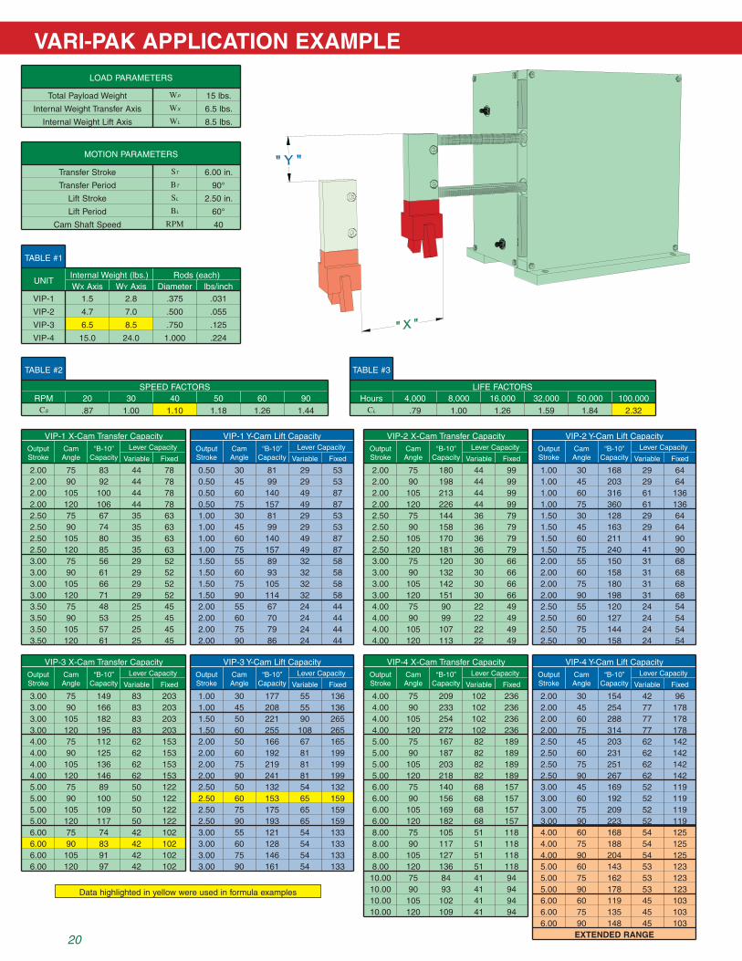
VARI-PAK APPLICATION EXAMPLE
20
Table #1
Table #2
VIP-1
UNITWx axis Wy axis Diameter lbs/inch
VIP-2
VIP-3
VIP-4
1.5
4.7
6.5
15.0
2.8
Internal Weight (lbs.) Rods (each)
7.0
8.5
24.0
.375
.500
.750
1.000
.031
.055
.125
.224
Cs
2.00
VIP-1 X-Cam Transfer Capacity
75 83 44Variable
lever Capacity
78Fixed
2.00 90 92 44 782.00 105 100 44 782.00 120 106 44 782.50 75 67 35 632.50 90 74 35 632.50 105 80 35 632.50 120 85 35 633.00 75 56 29 523.00 90 61 29 523.00 105 66 29 523.00 120 71 29 523.50 75 48 25 453.50 90 53 25 453.50 105 57 25 453.50 120 61 25 45
5.00 75 162 53 1235.00 90 178 53 1236.00 60 119 45 1036.00 75 135 45 1036.00 90 148 45 103
OutputStroke
Camangle
“b-10”Capacity
3.00 75 149 83 2033.00 90 166 83 2033.00 105 182 83 2033.00 120 195 83 2034.00 75 112 62 1534.00 90 125 62 1534.00 105 136 62 1534.00 120 146 62 1535.00 75 89 50 1225.00 90 100 50 1225.00 105 109 50 1225.00 120 117 50 1226.00 75 74 42 1026.00 90 83 42 1026.00 105 91 42 1026.00 120 97 42 102
VIP-3 X-Cam Transfer Capacity
Variable
lever Capacity
FixedOutputStroke
Camangle
“b-10”Capacity
10.00 75 84 41 9410.00 90 93 41 9410.00 105 102 41 9410.00 120 109 41 94
RPMSPeeD FaCTORS
20 30 40 50 60 90.87 1.00 1.10 1.18 1.26 1.44
Table #3
Cl
HourslIFe FaCTORS
4,000 8,000 16,000 32,000 50,000 100,000.79 1.00 1.26 1.59 1.84 2.32
lOaD PaRaMeTeRS
Total Payload Weight Wp 15 lbs.
Internal Weight Transfer axis Wx 6.5 lbs.
Internal Weight lift axis Wl 8.5 lbs.
MOTION PaRaMeTeRS
lift Stroke Sl 2.50 in.
lift Period Bl 60°
Transfer Stroke St 6.00 in.
Transfer Period Bt 90°
Cam Shaft Speed RPM 40
0.50
VIP-1 Y-Cam lift Capacity
30 81 29Variable
lever Capacity
53Fixed
0.50 45 99 29 530.50 60 140 49 870.50 75 157 49 871.00 30 81 29 531.00 45 99 29 531.00 60 140 49 871.00 75 157 49 871.50 55 89 32 581.50 60 93 32 581.50 75 105 32 581.50 90 114 32 582.00 55 67 24 442.00 60 70 24 442.00 75 79 24 442.00 90 86 24 44
OutputStroke
Camangle
“b-10”Capacity
1.00 30 177 55 1361.00 45 208 55 1361.50 50 221 90 2651.50 60 255 108 2652.00 50 166 67 1652.00 60 192 81 1992.00 75 219 81 1992.00 90 241 81 1992.50 50 132 54 1322.50 60 153 65 1592.50 75 175 65 1592.50 90 193 65 1593.00 55 121 54 1333.00 60 128 54 1333.00 75 146 54 1333.00 90 161 54 133
VIP-3 Y-Cam lift Capacity
Variable
lever Capacity
FixedOutputStroke
Camangle
“b-10”Capacity
2.00
VIP-2 X-Cam Transfer Capacity
75 180 44Variable
lever Capacity
99Fixed
2.00 90 198 44 992.00 105 213 44 992.00 120 226 44 992.50 75 144 36 792.50 90 158 36 792.50 105 170 36 792.50 120 181 36 793.00 75 120 30 663.00 90 132 30 663.00 105 142 30 663.00 120 151 30 664.00 75 90 22 494.00 90 99 22 494.00 105 107 22 494.00 120 113 22 49
OutputStroke
Camangle
“b-10”Capacity
4.00 75 209 102 2364.00 90 233 102 2364.00 105 254 102 2364.00 120 272 102 2365.00 75 167 82 1895.00 90 187 82 1895.00 105 203 82 1895.00 120 218 82 1896.00 75 140 68 1576.00 90 156 68 1576.00 105 169 68 1576.00 120 182 68 1578.00 75 105 51 1188.00 90 117 51 1188.00 105 127 51 1188.00 120 136 51 118
VIP-4 X-Cam Transfer Capacity
Variable
lever Capacity
FixedOutputStroke
Camangle
“b-10”Capacity
1.00
VIP-2 Y-Cam lift Capacity
30 168 29Variable
lever Capacity
64Fixed
1.00 45 203 29 641.00 60 316 61 1361.00 75 360 61 1361.50 30 128 29 641.50 45 163 29 641.50 60 211 41 901.50 75 240 41 902.00 55 150 31 682.00 60 158 31 682.00 75 180 31 682.00 90 198 31 682.50 55 120 24 542.50 60 127 24 542.50 75 144 24 542.50 90 158 24 54
OutputStroke
Camangle
“b-10”Capacity
2.00 30 154 42 962.00 45 254 77 1782.00 60 288 77 1782.00 75 314 77 1782.50 45 203 62 1422.50 60 231 62 1422.50 75 251 62 1422.50 90 267 62 1423.00 45 169 52 1193.00 60 192 52 1193.00 75 209 52 1193.00 90 223 52 1194.00 60 168 54 1254.00 75 188 54 1254.00 90 204 54 1255.00 60 143 53 123
VIP-4 Y-Cam lift Capacity
Variable
lever Capacity
FixedOutputStroke
Camangle
“b-10”Capacity
Data highlighted in yellow were used in formula examples
TrANSFEr LOAD CALCULATIONS
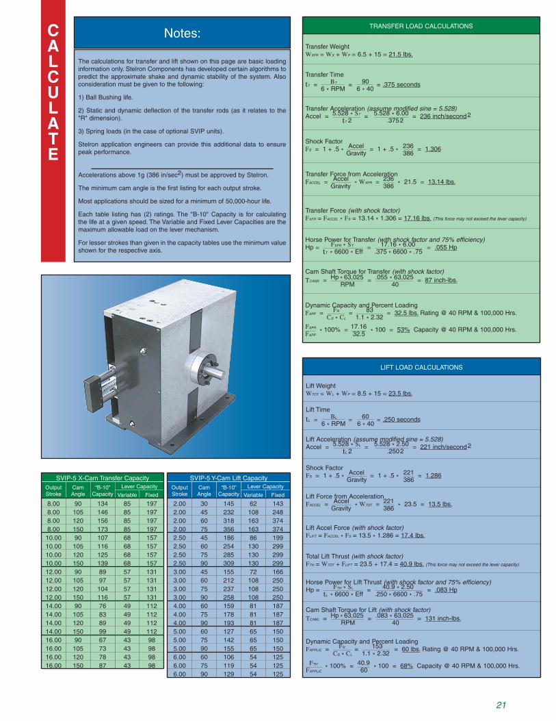
Transfer WeightWxfr = Wx + Wp = 6.5 + 15 = 21.5 lbs.
Transfer Force (with shock factor)Fxfr = Faccel * Fs = 13.14 * 1.306 = 17.16 lbs. (This force may not exceed the lever capacity)
Transfer Acceleration (assume modified sine = 5.528)Accel = 5.528 * St = 5.528 * 6.00 = 236 inch/second 2 tt 2 .375
2
Horse Power for Transfer (with shock factor and 75% efficiency)Hp = Fxfr * St = 17.16 * 6.00 = .055 Hp tt * 6600 * Eff .375
* 6600 * .75
Cam Shaft Torque for Transfer (with shock factor)Tcamx = Hp * 63,025 = .055 * 63,025 = 87 inch-lbs. rPM 40
Transfer Time
tt = Bt = 90 = .375 seconds 6 * rPM 6 * 40
Shock FactorFs = 1 + .5 *
Accel = 1 + .5 * 236 = 1.306
Gravity 386
Transfer Force from AccelerationFaccel = Accel
* Wxfr = 236
* 21.5 = 13.14 lbs.
Gravity 386
Dynamic Capacity and Percent LoadingFapp = Fr = 83 = 32.5 lbs. rating @ 40 rPM & 100,000 Hrs. Cs * Cl 1.1 * 2.32
Fxfr * 100% =
17.16 * 100 = 53% Capacity @ 40 rPM & 100,000 Hrs.
Fapp 32.5
21
LIFT LOAD CALCULATIONS
Lift WeightWtot = Wl + Wp = 8.5 + 15 = 23.5 lbs.
Lift Accel Force (with shock factor)Flift = Faccel * Fs = 13.5 * 1.286 = 17.4 lbs.
Total Lift Thrust (with shock factor)Fth = Wtot + Flift = 23.5 + 17.4 = 40.9 lbs. (This force may not exceed the lever capacity)
Lift Acceleration (assume modified sine = 5.528)Accel = 5.528 * Sl = 5.528 * 2.50 = 221 inch/second 2 tl 2 .250
2
Horse Power for Lift Thrust (with shock factor and 75% efficiency)Hp = Fth * Sl = 40.9 * 2.50 = .083 Hp tl * 6600 * Eff .250
* 6600 * .75
Cam Shaft Torque for Lift (with shock factor)Tcaml = Hp * 63,025 = .083 * 63,025 = 131 inch-lbs. rPM 40
Lift Time
tl = Bl = 60 = .250 seconds 6 * rPM 6 * 40
Shock FactorFs = 1 + .5 *
Accel = 1 + .5 * 221 = 1.286
Gravity 386
Lift Force from AccelerationFaccel = Accel
* Wtot = 221
* 23.5 = 13.5 lbs.
Gravity 386
Dynamic Capacity and Percent LoadingFapplic = Fr = 153 = 60 lbs. rating @ 40 rPM & 100,000 Hrs. Cs * Cl 1.1 * 2.32
Fth * 100% = 40.9 *
100 = 68% Capacity @ 40 rPM & 100,000 Hrs.Fapplic 60
The calculations for transfer and lift shown on this page are basic loading information only. Stelron Components has developed certain algorithms to predict the approximate shake and dynamic stability of the system. Also consideration must be given to the following:
1) Ball Bushing life.
2) Static and dynamic deflection of the transfer rods (as it relates to the "r" dimension).
3) Spring loads (in the case of optional SVIP units).
Stelron application engineers can provide this additional data to ensure peak performance.
Accelerations above 1g (386 in/sec2) must be approved by Stelron.
The minimum cam angle is the first listing for each output stroke.
Most applications should be sized for a minimum of 50,000-hour life.
Each table listing has (2) ratings. The "B-10" Capacity is for calculating the life at a given speed. The Variable and Fixed Lever Capacities are the maximum allowable load on the lever mechanism.
For lesser strokes than given in the capacity tables use the minimum value shown for the respective axis.
CALCULATE
5.00 75 142 65 1505.00 90 155 65 1506.00 60 106 54 1256.00 75 119 54 1256.00 90 129 54 125
16.00 90 67 43 9816.00 105 73 43 9816.00 120 78 43 9816.00 150 87 43 98
8.00 90 134 85 1978.00 105 146 85 1978.00 120 156 85 1978.00 150 173 85 19710.00 90 107 68 15710.00 105 116 68 15710.00 120 125 68 15710.00 150 139 68 15712.00 90 89 57 13112.00 105 97 57 13112.00 120 104 57 13112.00 150 116 57 13114.00 90 76 49 11214.00 105 83 49 11214.00 120 89 49 11214.00 150 99 49 112
SVIP-5 X-Cam Transfer Capacity
Variable
Lever Capacity
FixedOutputStroke
CamAngle
“B-10”Capacity
2.00 30 145 62 1432.00 45 232 108 2482.00 60 318 163 3742.00 75 356 163 3742.50 45 186 86 1992.50 60 254 130 2992.50 75 285 130 2992.50 90 309 130 2993.00 45 155 72 1663.00 60 212 108 2503.00 75 237 108 2503.00 90 258 108 2504.00 60 159 81 1874.00 75 178 81 1874.00 90 193 81 1875.00 60 127 65 150
SVIP-5 Y-Cam Lift Capacity
Variable
Lever Capacity
FixedOutputStroke
CamAngle
“B-10”Capacity
Notes:

22
Customer: Date:
Project:
Engineer:
SpecifyitemsasshowninsamplePICKandPLACEmotiondiagramwithrespecttoviewsonpage23.
1)“X”axisstroke2)“Y”axisstroke3)Motionoverlapallowedineachcorner;specify
amountofallowableblending;usenotationA,B,C,Dtoidentifyeachrespectivecorner
4)Directionofoutputmotion5)Dwelllocationandtimerequired;specifytheamount
ofdwellrequiredateachlocation;useA,B,C,Dtoidentifylocationofdwellindegreesorseconds
1/4" X-YBlending
3
"Y" = 2.000
2
Dwell
5
AD
1/2" X-YBlending
3
C B4
1
"X" = 4.000
Stelron VARI-PAK Worksheet
Cycletime: (in seconds) Rate: (in cycles per minutes)
Descriptionofloadincludingweightanddimensions:
SpecifyitemsasshowninsampleWALKINGBEAMmotiondiagramwithrespecttoviewsonpage23.
(check one) Cycleondemand
Continuousrun
1)“X”axisstroke2)“Y”axisstroke3)Motionoverlapallowedineachcorner;specify
amountofallowableblending;usenotationA2,C1andC2toidentifyeachrespectivecorner
4)Dwelllocationandtimerequired;specifytheamountofdwellrequiredateachlocation;useA1,BandDtoidentifylocationofdwellindegreesorseconds
PickDwell
4 PlaceDwell
4
D B
C1
C2
A2
A1
3
"X" = 4.000
"Y" = 2.000
1
2
.500 Ref.
1/2" X-YBlending
3
34
HomeDwell
Cycletime: (in seconds) Rate: (in cycles per minutes)
Descriptionofloadincludingweightanddimensions:
(check one) Cycleondemand
Continuousrun

Left HandAssembly
(Indicate rotation of input shaft)
Right HandAssembly
(Indicate rotation of input shaft)
0˚ 30˚ 60˚ 90˚ 120˚ 150˚ 180˚ 210˚ 240˚ 270˚ 300˚ 330˚ 360˚
"X"Axis
"Y"Axis
0˚ 30˚ 60˚ 90˚ 120˚ 150˚ 180˚ 210˚ 240˚ 270˚ 300˚ 330˚ 360˚
tel - 201.529.5450 ~ fax - 201.529.5493 ~ e-mail - [email protected] 23
Cam Worksheet

© Stelron Components, Inc. Cat #VIP 2002
Stelron Components, Inc.1495 MacArthur Boulevard, Mahwah, NJ 07430phone 201-529-5450 • fax 201-529-5493e-mail [email protected] site www.stelron.com