Brueckner-Hartree-Fock–based optical potential for proton-4,6,8He and proton-6,7,9,11Li scattering
Upload
independentCategory
view
1download
0
A
fmhiaietfstiT©
K
1
ae[mtfiprc
0d
Journal of Power Sources 161 (2006) 492–502
Steady state and dynamic performance of proton exchange membrane fuelcells (PEMFCs) under various operating conditions and load changes
Qiangu Yan a,∗, H. Toghiani b, Heath Causey a
a Center for Advanced Vehicular Systems (CAVS), Box 5405, Mississippi State University, MS 39762-5405, United Statesb Dave C. Swalm School of Chemical Engineering, Box 9595, Mississippi State University, MS 39762, United States
Received 21 January 2006; received in revised form 13 March 2006; accepted 28 March 2006Available online 5 May 2006
bstract
The steady-state performance and transient response for H2/air polymer electrolyte membrane (PEM) fuel cells are investigated in both singleuel cell and stack configurations under a variety of loading cycles and operating conditions. Detailed experimental parameters are controlled andeasured under widely varying operating conditions. In addition to polarization curves, feed gas flow rates, temperatures, pressure drop, and relative
umidity are measured. Performance of fuel cells was studied using steady-state polarization curves, transient I–V response and electrochemicalmpedance spectroscopy (EIS) techniques. Different feed gas humidity, operating temperature, feed gas stoichiometry, air pressure, fuel cell sizend gas flow patterns were found to affect both the steady state and dynamic response of the fuel cells. It was found that the humidity of cathodenlet gas had a significant effect on fuel cell performance. The experimental results showed that a decrease in the cathode humidity has a detrimentalffect on fuel cell steady state and dynamic performance. Temperature was also found to have a significant effect on the fuel cell performancehrough its effect on membrane conductivity and water transport in the gas diffusion layer (GDL) and catalyst layer. The polarization curves of theuel cell at different operating temperatures showed that fuel cell performance was improved with increasing temperature from 65 to 75 ◦C. The air
toichiometric flow rate also influenced the performance of the fuel cell directly by supplying oxygen and indirectly by influencing the humidity ofhe membrane and water flooding in cathode side. The fuel cell steady state and dynamic performance also improved as the operating pressure wasncreased from 1 to 4 atm. Based on the experimental results, both the steady state and dynamic response of the fuel cells (stack) were analyzed.hese experimental data will provide a baseline for validation of fuel cell models.2006 Elsevier B.V. All rights reserved.ettuIoIttr
eywords: PEMFCs; Performance; Transient response; Various conditions
. Introduction
Fuel cells have attracted great attention in recent years aspromising replacement for traditional internal combustion
ngines due to their high power density and ultra-low emissions1–3]. Though significant improvements in polymer electrolyteembrane (PEM) fuel cell technology has been achieved over
he past decade, the performance, stability, reliability, and costor today’s fuel cell technology is not sufficient to replace thenternal combustion engine [4–6]. A number of fundamental
roblems must be overcome to improve their performance andeduce their cost. The objectives for further development of fuelells include: to identify critical issues, such as what are the∗ Corresponding author. Tel.: +1 662 325 5906; fax: +1 662 325 5433.E-mail address: [email protected] (Q. Yan).
isiumd[
378-7753/$ – see front matter © 2006 Elsevier B.V. All rights reserved.oi:10.1016/j.jpowsour.2006.03.077
ffects of start-up, shut-down, and transient response; to iden-ify key parameters for fuel cell performance and examine howo optimize stack and system design; and examine performancender extreme conditions, such as sub-freezing temperatures.t is important to study the dynamic behavior of fuel cells tobtain stable performance under various operating conditions.n particular, knowledge of the dynamic behavior is critical tohe engineering and design of the fuel cells, stacks, and sys-ems [7]. A control system is needed to ensure that the flowate and temperature of fuel and air are within prescribed lim-ts during normal operation at variable loads, as well as duringystem start-up and shut-down. Dynamic behavior is the mostmportant aspect of fuel cell operation that should be studied
nder wide operating conditions. The control, design, and opti-um operation of fuel cells require an understanding of theirynamics when there are changes in current, voltage, or power8]. Fuel cell dynamic response is very important; unfortunately,
er So
towamacctaupie[flsi[Dcr
ieVwtseftfiaibidodiNimwifiyCltNo
A
PfafdadCapimDdfcmlmdhnsawSi(tvtaBisdWsorwe
me(wttndhv
Q. Yan et al. / Journal of Pow
here are few publications describing the dynamic behaviorf PEM fuel cells under various operating conditions. Someork has been preformed on the dynamic response of PEM
nd direct methanol fuel cells (DMFC) through experimentalethods [9–16]. Hamelin et al. [9] investigated the behavior
nd performance of a proton exchange membrane (PEM) fuelell under fast load commutations. It was found that the fuelell system response was faster than 0.15 s to load commu-ations; however, load transients were present in the voltagend current response. Morner et al. [10] experimentally eval-ated the dynamic behavior of an air-breathing fuel cell. Theerformance of an air-breathing PEM fuel cell has been exper-mentally measured to investigate the steady state and transientffects of temperature, humidity, and air flow rate. Kim et al.11,12] examined the effect of stoichiometry, reservoirs, anduel dilution on the dynamic behavior of a PEM fuel cell duringoad change. Overshoot and undershoot behavior of the steadytate current density was observed for various rates of changen the voltage at a constant inlet flow rate. Argyropoulos et al.13,14] investigated the influential parameters for a liquid-fedMFC and showed experimentally the impact of anode con-
entration, flow, and cathode pressure on the dynamic fuel cellesponse.
Many mathematical models of PEM fuel cells can be foundn the literature [15–23]. The earliest and most cited mod-ls were developed by Springer et al. [15], and Bernardi andebrugge [16,17]. The first one-dimensional fuel cell modelas by Springer et al. [15] at Los Alamos National Labora-
ory (LANL). This model was an isothermal, one-dimensional,teady state model that considered polarization and electrodeffects through the polarization equation. In the model, water dif-usion coefficients, electro-osmotic drag coefficient, water sorp-ion isotherms, and membrane conductivity were measured as aunction of the membrane water content. The model predicted anncrease in membrane resistance with increased current densitynd demonstrated the great advantage of a thinner membranen alleviating the resistance problem. The Bernardi and Ver-rugge model [16,17] assumed a fully hydrated membrane andncorporated porous-electrode equations and Stefan–Maxwelliffusion in the diffusion media and catalyst layers. The modelf Springer et al. [15] did not use porous-electrode equations butid consider changing water content in the membrane. The othermportant early fuel cell models included those by Fuller andewman [18] and Nguyen and White [19]. These models exam-
ned flow effects along the channel. Their models treated theembrane as a two-phase system similar to a porous medium,here there were separate gas and liquid channels, and the poros-
ty remained constant. Liu and co-workers [20] performed therst two-dimensional computational fluid dynamics (CFD) anal-sis of a PEM fuel cell. Wang and Savinell [21] first applied aFD model to liquid water transport in the porous gas diffusion
ayer. The liquid water and gaseous species governing equa-ions were primarily coupled by an interfacial mass-transfer rate.
guyen and co-workers also performed notable work in devel-ping fuel cell models [22,23].The earliest dynamic fuel cell models were developed bymphlett et al. [24,25] for predicting transient responses of
bcpw
urces 161 (2006) 492–502 493
EM fuel cells. The transient models can predict fuel cell per-ormance in terms of fuel cell voltage output and heat lossess a function of time due to various changes imposed on theuel cell system. Um et al. [26] developed a transient, multi-imensional model to simulate PEM fuel cells. The modelccounts simultaneously for electrochemical kinetics, currentistribution, hydrodynamics, and multi-component transport.eraolo et al. [27] developed a simplified dynamic model ofPEM fuel cell based on physicochemical knowledge of the
henomena occurring inside the fuel cell. The model has beenmplemented in the MATLAB/SIMULINK environment. Sund-
acher et al. [28] used a mathematical approach for the liquidM fuel cell under dynamic load conditions. Kulikovsky [29]escribed analytically the gas dynamics in channels of a gas-ed DM fuel cell and Xu et al. [30] examined a DM fuelell model that captures the essence of electrode kinetics andethanol crossover through the membrane. Berning and Dji-
ali [31] presented a computational fluid dynamics multiphaseodel of a PEM fuel cell. The model accounted for three-
imensional (3D) transport processes with phase change andeat transfer in the gas-diffusion layers, the gas flow chan-els, and the cooling channels. Xue et al. [32] developed aystem-level dynamic model of a PEM fuel cell capable of char-cterizing the effects of temperature, gas flow, and capacitanceith particular emphasis focused on system transient behavior.himpalee et al. [33,34] presented a three-dimensional numer-
cal simulation of the transient response of a PEM fuel cellPEMFC) subjected to a variable load. The predictions showedransients in the current density that overshoot the final statealue when the fuel cell voltage was abruptly changed from 0.7o 0.5 V for fixed excess initial stoichiometric flow rates. Yu etl. [35] developed a water and thermal management model for aallard PEM fuel cell. The model provided information regard-
ng the reaction products (i.e., water and heat), stack power,tack temperature, and system efficiency, thereby assisting theesigner in achieving the best thermal and water management.ang and Wang [36,37] developed a three-dimensional, tran-
ient model to study the transient dynamics of PEM fuel cellperation. The results showed that the time for fuel cells toeach steady state was on the order of 10 s due to the effect ofater accumulation in the membrane, consistent with theoretical
stimations.Though significant progress has been made in PEM fuel cell,
odeling during the past ten years, some key problems stillxist. Key issues in modeling PEM fuel cell systems include:i) balancing the complexity of the model (computing time)ith realism, and applicability of model; (ii) detailed verifica-
ion of the model is often difficult; (iii) lack of measurementechniques, especially real time (in situ) and non-intrusive tech-iques; (iv) lack of existing fuel cell systems and performanceata. Along with these issues, how to validate the model is per-aps the most difficult and challenging issue. A series of bulkalidations have been done for validating the fuel cell models
y comparison of simulation results to the fuel cell polarizationurves [38–40]. These authors validated their models by com-aring experimentally measured fuel cell polarization curvesith their predicted fuel cell current. Some researchers have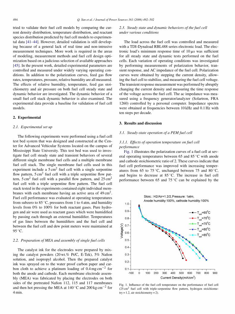
4 wer S
trstimom[cdrTcdsem
2
2
ttMtdfefltfsbFflgbob9
2
isibbbsa4
2u
wtfcbsciTcos1wt
3
3
3p
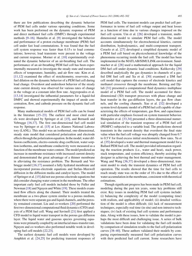
eafuel cell performance was improved with increasing temper-atures from 65 to 75 ◦C, unchanged between 75 and 80 ◦C,and begins to decrease at 85 ◦C. The increase in fuel cellperformance between 65 and 75 ◦C can be explained by the
94 Q. Yan et al. / Journal of Po
ried to validate their fuel cell models by comparing the cur-ent density distribution, temperature distribution, and reactantpecies distribution predicted by fuel cell models to experimen-al data [41–44]. However, detailed validation is still develop-ng because of a general lack of real time and non-intrusive
easurement techniques. More work is required in the areasf modeling, measurement methods and fuel cell design opti-ization based on a judicious selection of available approaches
45]. In the present work, detailed experimental parameters areontrolled and measured under widely varying operating con-itions. In addition to the polarization curves, feed gas flowates, temperatures, pressure, relative humidity are all measured.he effects of relative humidity, temperature, feed gas stoi-hiometry and air pressure on both fuel cell steady state andynamic behavior are investigated. The dynamic behavior of amall fuel cell stack dynamic behavior is also examined. Thexperimental data provide a baseline for validation of fuel cellodels.
. Experimental
.1. Experimental set up
The following experiments were performed using a fuel cellest bed system that was designed and constructed at the Cen-er for Advanced Vehicular Systems located on the campus of
ississippi State University. This test bed was used to inves-igate fuel cell steady state and transient behaviors of severalifferent single membrane fuel cells and a multiple membraneuel cell stack. The single membrane fuel cells used in thisxperiment include a 5 cm2 fuel cell with a single serpentineow pattern, 5 cm2 fuel cell with a triple serpentine flow pat-
ern, 5 cm2 fuel cell with a parallel flow pattern, and 25 cm2
uel cell with a triple serpentine flow pattern. The fuel celltack tested in the experiments contained eight individual mem-ranes with each membrane having an active area of 49 cm2.uel cell performance was evaluated at operating temperaturesrom subzero to 85 ◦C, pressures from 1 to 4 atm, and humidityevels from 0% to 100% for both reactant gases. Pure hydro-en and air were used as reactant gases which were humidifiedy passing each through an external humidifier. Temperaturesf gas lines between the humidifiers and the fuel cell andetween the fuel cell and dew point meters were maintained at5 ◦C.
.2. Preparation of MEA and assembly of single fuel cells
The catalyst ink for the electrodes were prepared by mix-ng the catalyst powders (20 wt.% Pt/C, E-Tek), 5% Nafionolution, and isopropyl alcohol. Then the prepared catalystnk was sprayed on to the water proof carbon paper and car-on cloth to achieve a platinum loading of 0.4 mg cm−2 foroth the anode and cathode. Each membrane electrode assem-
ly (MEA) was fabricated by placing the electrodes on bothides of the pretreated Nafion 112, 115 and 117 membranesnd then hot pressing the MEA at 140 ◦C and 200 kg cm−2 formin.F(t
ources 161 (2006) 492–502
.3. Steady state and dynamic behaviors of the fuel cellnder various conditions
The load across the fuel cell was controlled and measuredith a TDI-Dynaload RBL488 series electronic load. The elec-
ronic load’s minimum response time of 10 �s was sufficientor all steady state and dynamic tests performed on the fuelells. Each variation of operating conditions was investigatedy performing measurements of polarization behavior, tran-ient response, and AC impedance of the fuel cell. Polarizationurves were obtained by stepping the current density, allow-ng the fuel cell to stabilize, and measuring the fuel cell voltage.he transient response measurement was performed by abruptlyhanging the current density and measuring the time responsef the voltage across the fuel cell. The ac impedance was mea-ured using a frequency generator/analyzer (Solartron, FRA260) controlled by a personal computer. Impedance spectraere obtained at frequencies between 10 kHz and 0.1 Hz with
en steps per decade.
. Results and discussion
.1. Steady-state operation of a PEM fuel cell
.1.1. Effects of operation temperature on fuel cellerformance
Fig. 1 illustrates the polarization curves of a fuel cell at sev-ral operating temperatures between 65 and 85 ◦C with anodend cathode stoichiometric ratio of 2. These curves indicate that
ig. 1. Influence of the fuel cell temperature on the performance of fuel cell25 cm2 fuel cell with triple-serpentine flow pattern, hydrogen stoichiome-ry = 1.2, air stoichiometry = 2).
Q. Yan et al. / Journal of Power Sources 161 (2006) 492–502 495
F 2 fuel cc
ihpcoathhbtiWtdtdwf
3
aioTWfabastlc
ig. 2. Polarization curves as function of feed gas humidity fuel cell (25 cmhiometry = 2).
ncrease in the gas diffusivity and membrane conductivity atigher temperatures. Water is easily condensed at lower tem-eratures; water flooding may deteriorate gas diffusivity in theatalyst layer and gas diffusion layer (GDL). The gas diffusivityf the fuel cell is improved with increased fuel cell temper-ture; therefore, fuel cell performance is improved at higheremperatures. However, membrane conductivity decreases atigh temperatures because of the reduction in the relativeumidity of reactant gases and water content in the mem-rane. Therefore, the fuel cell performance was worse whenhe temperature was increased to 85 ◦C. As the temperaturencreases, there will be a greater rate of water evaporation.
hen the temperature reaches a critical temperature wherehe amount of evaporated water exceeds the amount of pro-uced water, the membrane will start to dry out. The resis-
ance will increase as the membranes dried out and thereby,ecreases both the current and the water production. The reducedater production will cause the membrane to dry out evenaster.
hhfo
ell with triple-serpentine flow pattern, hydrogen stoichiometry = 1.2, air stoi-
.1.2. Effect of humidity on fuel cell performanceThe polarization curves for different operating levels of air
nd hydrogen relative humidity are shown in Fig. 2. As seenn Fig. 2, the best case performance for low air humidity levelsccurred when the hydrogen was at its highest humidity level.his observation is consistent with the results of Nguyen andhite [19] who found that at high current density the transport
rom the anode by electro-osmotic drag exceeds transport to thenode by back diffusion from the cathode; thus, leading to mem-rane dehydration and performance degradation. Low humidityir can exacerbate this effect by reducing the rate of back diffu-ion from the cathode. Humidification of the anode gases helpso counteract this effect leading to higher performance at highevels of anode humidification. Fig. 2 also shows the polarizationurves for the fuel cell at different operating levels of hydrogen
umidity. The trend toward improved fuel cell performance withigher humidity levels of hydrogen was not observed. Similarly,or high relative humidity levels of air, the performance wasnly marginally improved with increased hydrogen humidifica-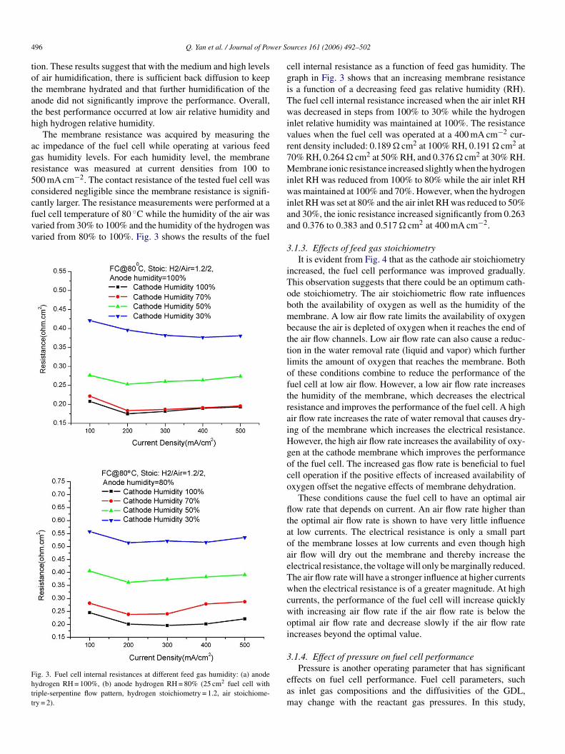
4 wer S
totath
agr5ccfvv
Fhtt
cgiTwivr7Miw
96 Q. Yan et al. / Journal of Po
ion. These results suggest that with the medium and high levelsf air humidification, there is sufficient back diffusion to keephe membrane hydrated and that further humidification of thenode did not significantly improve the performance. Overall,he best performance occurred at low air relative humidity andigh hydrogen relative humidity.
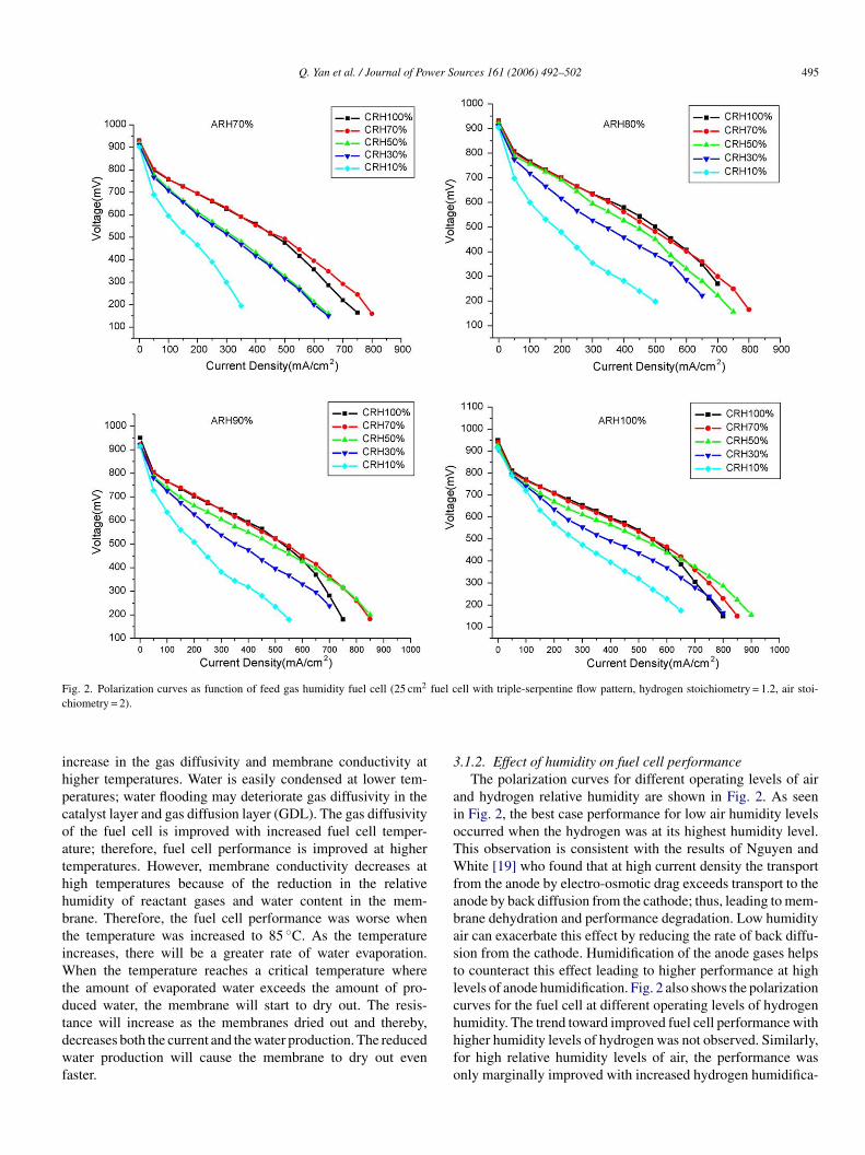
The membrane resistance was acquired by measuring thec impedance of the fuel cell while operating at various feedas humidity levels. For each humidity level, the membraneesistance was measured at current densities from 100 to00 mA cm−2. The contact resistance of the tested fuel cell wasonsidered negligible since the membrane resistance is signifi-
antly larger. The resistance measurements were performed at auel cell temperature of 80 ◦C while the humidity of the air wasaried from 30% to 100% and the humidity of the hydrogen wasaried from 80% to 100%. Fig. 3 shows the results of the fuelig. 3. Fuel cell internal resistances at different feed gas humidity: (a) anodeydrogen RH = 100%, (b) anode hydrogen RH = 80% (25 cm2 fuel cell withriple-serpentine flow pattern, hydrogen stoichiometry = 1.2, air stoichiome-ry = 2).
iaa
3
iTobmbttloftraiHgoco
fltaoaeTwcwoi
3
eam
ources 161 (2006) 492–502
ell internal resistance as a function of feed gas humidity. Theraph in Fig. 3 shows that an increasing membrane resistances a function of a decreasing feed gas relative humidity (RH).he fuel cell internal resistance increased when the air inlet RHas decreased in steps from 100% to 30% while the hydrogen
nlet relative humidity was maintained at 100%. The resistancealues when the fuel cell was operated at a 400 mA cm−2 cur-ent density included: 0.189 � cm2 at 100% RH, 0.191 � cm2 at0% RH, 0.264 � cm2 at 50% RH, and 0.376 � cm2 at 30% RH.embrane ionic resistance increased slightly when the hydrogen
nlet RH was reduced from 100% to 80% while the air inlet RHas maintained at 100% and 70%. However, when the hydrogen
nlet RH was set at 80% and the air inlet RH was reduced to 50%nd 30%, the ionic resistance increased significantly from 0.263nd 0.376 to 0.383 and 0.517 � cm2 at 400 mA cm−2.
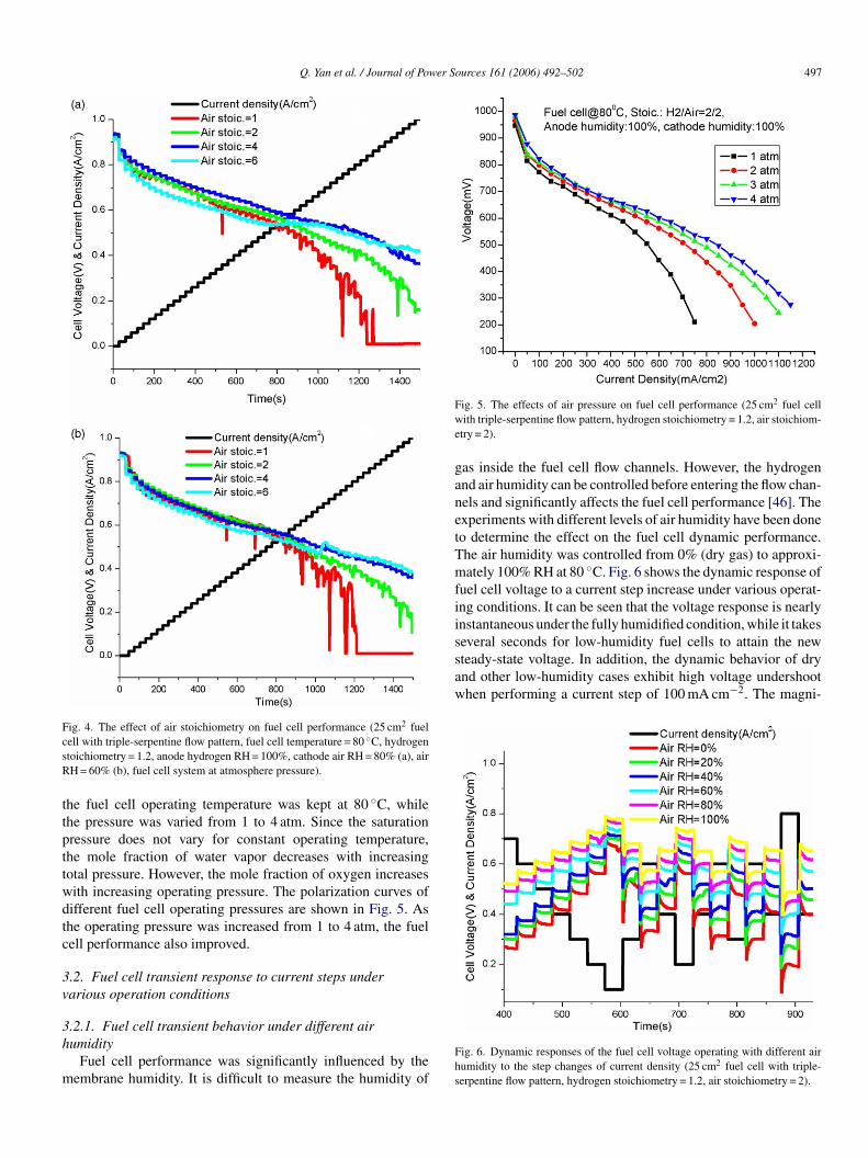
.1.3. Effects of feed gas stoichiometryIt is evident from Fig. 4 that as the cathode air stoichiometry
ncreased, the fuel cell performance was improved gradually.his observation suggests that there could be an optimum cath-de stoichiometry. The air stoichiometric flow rate influencesoth the availability of oxygen as well as the humidity of theembrane. A low air flow rate limits the availability of oxygen
ecause the air is depleted of oxygen when it reaches the end ofhe air flow channels. Low air flow rate can also cause a reduc-ion in the water removal rate (liquid and vapor) which furtherimits the amount of oxygen that reaches the membrane. Bothf these conditions combine to reduce the performance of theuel cell at low air flow. However, a low air flow rate increaseshe humidity of the membrane, which decreases the electricalesistance and improves the performance of the fuel cell. A highir flow rate increases the rate of water removal that causes dry-ng of the membrane which increases the electrical resistance.owever, the high air flow rate increases the availability of oxy-en at the cathode membrane which improves the performancef the fuel cell. The increased gas flow rate is beneficial to fuelell operation if the positive effects of increased availability ofxygen offset the negative effects of membrane dehydration.
These conditions cause the fuel cell to have an optimal airow rate that depends on current. An air flow rate higher than
he optimal air flow rate is shown to have very little influencet low currents. The electrical resistance is only a small partf the membrane losses at low currents and even though highir flow will dry out the membrane and thereby increase thelectrical resistance, the voltage will only be marginally reduced.he air flow rate will have a stronger influence at higher currentshen the electrical resistance is of a greater magnitude. At high
urrents, the performance of the fuel cell will increase quicklyith increasing air flow rate if the air flow rate is below theptimal air flow rate and decrease slowly if the air flow ratencreases beyond the optimal value.
.1.4. Effect of pressure on fuel cell performance
Pressure is another operating parameter that has significantffects on fuel cell performance. Fuel cell parameters, suchs inlet gas compositions and the diffusivities of the GDL,ay change with the reactant gas pressures. In this study,
Q. Yan et al. / Journal of Power Sources 161 (2006) 492–502 497
Fig. 4. The effect of air stoichiometry on fuel cell performance (25 cm2 fuelcsR
ttpttwdtc
3v
3h
m
Fwe
ganetTmfiiseveral seconds for low-humidity fuel cells to attain the newsteady-state voltage. In addition, the dynamic behavior of dryand other low-humidity cases exhibit high voltage undershootwhen performing a current step of 100 mA cm−2. The magni-
ell with triple-serpentine flow pattern, fuel cell temperature = 80 ◦C, hydrogentoichiometry = 1.2, anode hydrogen RH = 100%, cathode air RH = 80% (a), airH = 60% (b), fuel cell system at atmosphere pressure).
he fuel cell operating temperature was kept at 80 ◦C, whilehe pressure was varied from 1 to 4 atm. Since the saturationressure does not vary for constant operating temperature,he mole fraction of water vapor decreases with increasingotal pressure. However, the mole fraction of oxygen increasesith increasing operating pressure. The polarization curves ofifferent fuel cell operating pressures are shown in Fig. 5. Ashe operating pressure was increased from 1 to 4 atm, the fuelell performance also improved.
.2. Fuel cell transient response to current steps underarious operation conditions
.2.1. Fuel cell transient behavior under different airumidity
Fuel cell performance was significantly influenced by theembrane humidity. It is difficult to measure the humidity of
Fhs
ig. 5. The effects of air pressure on fuel cell performance (25 cm2 fuel cellith triple-serpentine flow pattern, hydrogen stoichiometry = 1.2, air stoichiom-
try = 2).
as inside the fuel cell flow channels. However, the hydrogennd air humidity can be controlled before entering the flow chan-els and significantly affects the fuel cell performance [46]. Thexperiments with different levels of air humidity have been doneo determine the effect on the fuel cell dynamic performance.he air humidity was controlled from 0% (dry gas) to approxi-ately 100% RH at 80 ◦C. Fig. 6 shows the dynamic response of
uel cell voltage to a current step increase under various operat-ng conditions. It can be seen that the voltage response is nearlynstantaneous under the fully humidified condition, while it takes
ig. 6. Dynamic responses of the fuel cell voltage operating with different airumidity to the step changes of current density (25 cm2 fuel cell with triple-erpentine flow pattern, hydrogen stoichiometry = 1.2, air stoichiometry = 2).
4 wer S
ttvrped
3t
toFwc
Fuh
aaaddTtcsdToa
98 Q. Yan et al. / Journal of Po
ude of undershoots increase with the current step size. Whenhe current density changed from 0.4 to 0.8 A cm−2, the fuel celloltage undershoot dropped more than 0.15 V. With a larger cur-ent increase (i.e. >0.4 A cm−2), the PEMFC voltage will reverseolarity which may lead to fuel cell degradation. This can bexplained by the water electro-osmotic drag, which increasesirectly proportional to the current density jump.
.2.2. Fuel cell transient behavior under different fuel cellemperatures
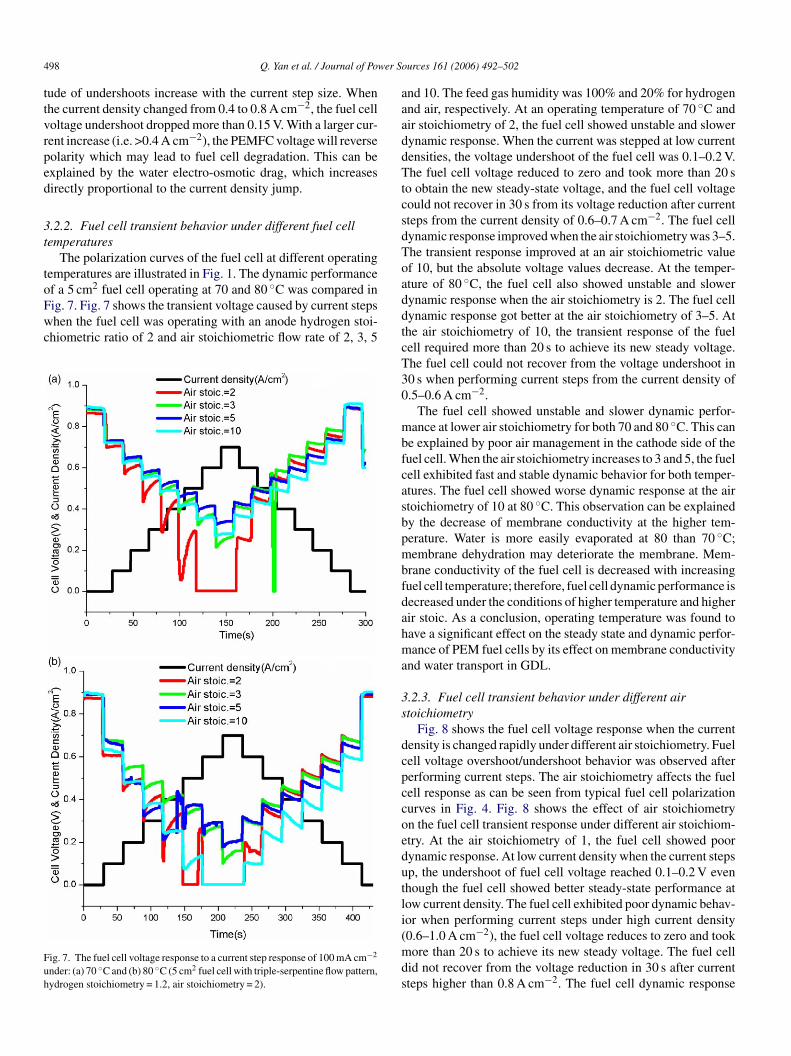
The polarization curves of the fuel cell at different operatingemperatures are illustrated in Fig. 1. The dynamic performance
2 ◦
f a 5 cm fuel cell operating at 70 and 80 C was compared inig. 7. Fig. 7 shows the transient voltage caused by current stepshen the fuel cell was operating with an anode hydrogen stoi-hiometric ratio of 2 and air stoichiometric flow rate of 2, 3, 5
ig. 7. The fuel cell voltage response to a current step response of 100 mA cm−2
nder: (a) 70 ◦C and (b) 80 ◦C (5 cm2 fuel cell with triple-serpentine flow pattern,ydrogen stoichiometry = 1.2, air stoichiometry = 2).
ddtcT30
mbfcasbpmbfdahma
3s
dcpccoedutli(mds
ources 161 (2006) 492–502
nd 10. The feed gas humidity was 100% and 20% for hydrogennd air, respectively. At an operating temperature of 70 ◦C andir stoichiometry of 2, the fuel cell showed unstable and slowerynamic response. When the current was stepped at low currentensities, the voltage undershoot of the fuel cell was 0.1–0.2 V.he fuel cell voltage reduced to zero and took more than 20 s
o obtain the new steady-state voltage, and the fuel cell voltageould not recover in 30 s from its voltage reduction after currentteps from the current density of 0.6–0.7 A cm−2. The fuel cellynamic response improved when the air stoichiometry was 3–5.he transient response improved at an air stoichiometric valuef 10, but the absolute voltage values decrease. At the temper-ture of 80 ◦C, the fuel cell also showed unstable and slowerynamic response when the air stoichiometry is 2. The fuel cellynamic response got better at the air stoichiometry of 3–5. Athe air stoichiometry of 10, the transient response of the fuelell required more than 20 s to achieve its new steady voltage.he fuel cell could not recover from the voltage undershoot in0 s when performing current steps from the current density of.5–0.6 A cm−2.
The fuel cell showed unstable and slower dynamic perfor-ance at lower air stoichiometry for both 70 and 80 ◦C. This can
e explained by poor air management in the cathode side of theuel cell. When the air stoichiometry increases to 3 and 5, the fuelell exhibited fast and stable dynamic behavior for both temper-tures. The fuel cell showed worse dynamic response at the airtoichiometry of 10 at 80 ◦C. This observation can be explainedy the decrease of membrane conductivity at the higher tem-erature. Water is more easily evaporated at 80 than 70 ◦C;embrane dehydration may deteriorate the membrane. Mem-
rane conductivity of the fuel cell is decreased with increasinguel cell temperature; therefore, fuel cell dynamic performance isecreased under the conditions of higher temperature and higherir stoic. As a conclusion, operating temperature was found toave a significant effect on the steady state and dynamic perfor-ance of PEM fuel cells by its effect on membrane conductivity
nd water transport in GDL.
.2.3. Fuel cell transient behavior under different airtoichiometry
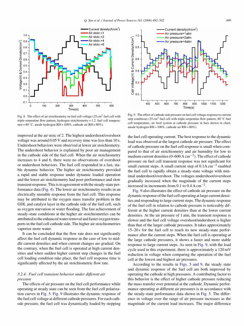
Fig. 8 shows the fuel cell voltage response when the currentensity is changed rapidly under different air stoichiometry. Fuelell voltage overshoot/undershoot behavior was observed aftererforming current steps. The air stoichiometry affects the fuelell response as can be seen from typical fuel cell polarizationurves in Fig. 4. Fig. 8 shows the effect of air stoichiometryn the fuel cell transient response under different air stoichiom-try. At the air stoichiometry of 1, the fuel cell showed poorynamic response. At low current density when the current stepsp, the undershoot of fuel cell voltage reached 0.1–0.2 V evenhough the fuel cell showed better steady-state performance atow current density. The fuel cell exhibited poor dynamic behav-or when performing current steps under high current density
0.6–1.0 A cm−2), the fuel cell voltage reduces to zero and tookore than 20 s to achieve its new steady voltage. The fuel cellid not recover from the voltage reduction in 30 s after currentteps higher than 0.8 A cm−2. The fuel cell dynamic response
Q. Yan et al. / Journal of Power Sources 161 (2006) 492–502 499
Ftt
ivUTiiobaatfemGasapv
adtscs
3p
otto
Fig. 9. The effect of cathode side pressure on fuel cell voltage response to currentsca
tlopmpstigi
dtofdst1mtrcrc
aott
ig. 8. The effect of air stoichiometry on fuel cell voltage (25 cm2 fuel cell withriple-serpentine flow pattern, hydrogen stoichiometry = 1.2, fuel cell tempera-ure = 80 ◦C, anode hydrogen RH = 100%, cathode air RH = 80%).
mproved at the air stoic of 2. The highest undershoot/overshootoltage was around 0.05 V and recovery time was less than 10 s.ndershoot behaviors were observed at lower air stoichiometry.he undershoot behavior is explained by poor air management
n the cathode side of the fuel cell. When the air stoichiometryncreases to 4 and 6, there were no observations of overshootr undershoot behaviors. The fuel cell responded in a fast, sta-le dynamic behavior. The higher air stoichiometry providedrapid and stable response under dynamic loaded operation
nd the lower air stoichiometry had poor performance and slowransient response. This is in agreement with the steady-state per-ormance data (Fig. 4). The lower air stoichiometry results in anlectrically unstable response from the fuel cell. This responseay be attributed to the oxygen mass transfer problem in theDL and catalyst layer in the cathode side of the fuel cell, such
s oxygen starvation or water flooding. The fast achievement ofteady-state conditions at the higher air stoichiometries can bettributed to the enhanced water removal and faster oxygen trans-orts in the fuel cell cathode side. The higher air stoichiometriesaporize more water.
It can be concluded that the flow rate does not significantlyffect the fuel cell dynamic response in the case of low to mid-le current densities and when current changes are gradual. Onhe contrary, when the fuel cell is operated at high current den-ities and when sudden higher current step changes in the fuelell loading condition take place, the fuel cell response time isignificantly affected by the air stoichiometric flow rate.
.2.4. Fuel cell transient behavior under different airressure
The effects of air pressure on the fuel cell performance while
perating at steady state can be seen from the fuel cell polariza-ion curves in Fig. 5. Fig. 9 illustrates the dynamic response ofhe fuel cell voltage at different cathode pressures. For each cath-de pressure, the fuel cell was dynamically loaded by steppingmtem
tep conditions (25 cm2 fuel cell with triple-serpentine flow pattern, 80 ◦C fuelell temperature, air feed system at cathode pressure in bars shown in chart,node hydrogen RH = 100%, cathode air RH = 80%).
he fuel cell operating current. The best response to the dynamicoad was observed at the largest cathode air pressure. The effectf cathode pressure on the fuel cell response is small when com-ared to that of air stoichiometry and air humidity for low toedium current densities (0–600 A cm−2). The effect of cathode
ressure on fuel cell transient response was not significant formall current steps. A small current step of 0.1A cm−2 enabledhe fuel cell to rapidly obtain a steady-state voltage with min-mal undershoot/overshoot. The voltages undershoot/overshootradually increased when the magnitude of the current stepsncreased in increments from 0.1 to 0.4 A cm−2.
Fig. 9 also illustrates the effect of cathode air pressure on theynamic response of the fuel cell operating at large current densi-ies and responding to large current steps. The dynamic responsef the fuel cell in relation to cathode pressure is noticeably dif-erent at the higher current densities than at the lower currentensities. At the air pressure of 1 atm, the transient response islower and the fuel cell voltage overshoot/undershoot is higherhan that of the larger cathode pressures. It takes approximately5–20 s for the fuel cell to reach its new steady-state perfor-ance after the current steps. When the fuel cell is operating at
he large cathode pressures, it shows a faster and more stableesponse to large current steps. As seen in Fig. 9, with the loadycle used in this experiment, there is approximately a 120 mVeduction in voltage when comparing the operation of the fuelell at the lowest and highest air pressures.
According to the results in Figs. 5 and 9, the steady statend dynamic response of the fuel cell are both improved byperating the cathode at high pressures. A contributing factor tohis behavior is the effect of higher cathode pressure reducinghe mass transfer over potential at the cathode. Dynamic perfor-
ance operating at different air pressures is in accordance withhe steady-state performance data shown in Fig. 5. The differ-nce in voltage over the range of air pressure increases as theagnitude of the current load increases. The major difference
500 Q. Yan et al. / Journal of Power Sources 161 (2006) 492–502
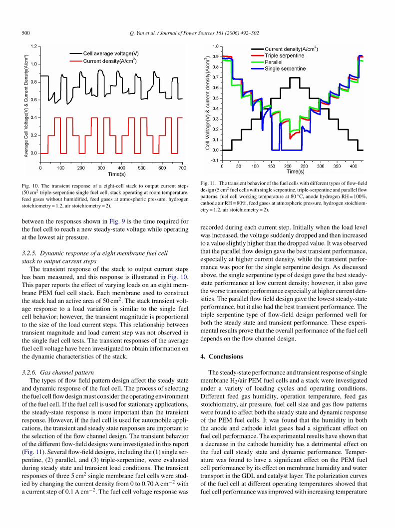
Fig. 10. The transient response of a eight-cell stack to output current steps(fs
bta
3s
hTbtactttft
3
atotrcto(pdria
Fig. 11. The transient behavior of the fuel cells with different types of flow-fielddesign (5 cm2 fuel cells with single serpentine, triple-serpentine and parallel flowpce
rwttemastsptbmd
4
muDswotfata
50 cm2 triple-serpentine single fuel cell, stack operating at room temperature,eed gases without humidified, feed gases at atmospheric pressure, hydrogentoichiometry = 1.2, air stoichiometry = 2).
etween the responses shown in Fig. 9 is the time required forhe fuel cell to reach a new steady-state voltage while operatingt the lowest air pressure.
.2.5. Dynamic response of a eight membrane fuel celltack to output current steps
The transient response of the stack to output current stepsas been measured, and this response is illustrated in Fig. 10.his paper reports the effect of varying loads on an eight mem-rane PEM fuel cell stack. Each membrane used to constructhe stack had an active area of 50 cm2. The stack transient volt-ge response to a load variation is similar to the single fuelell behavior; however, the transient magnitude is proportionalo the size of the load current steps. This relationship betweenransient magnitude and load current step was not observed inhe single fuel cell tests. The transient responses of the averageuel cell voltage have been investigated to obtain information onhe dynamic characteristics of the stack.
.2.6. Gas channel patternThe types of flow field pattern design affect the steady state
nd dynamic response of the fuel cell. The process of selectinghe fuel cell flow design must consider the operating environmentf the fuel cell. If the fuel cell is used for stationary applications,he steady-state response is more important than the transientesponse. However, if the fuel cell is used for automobile appli-ations, the transient and steady state responses are important tohe selection of the flow channel design. The transient behaviorf the different flow-field designs were investigated in this reportFig. 11). Several flow-field designs, including the (1) single ser-entine, (2) parallel, and (3) triple-serpentine, were evaluated
uring steady state and transient load conditions. The transientesponses of three 5 cm2 single membrane fuel cells were stud-ed by changing the current density from 0 to 0.70 A cm−2 withcurrent step of 0.1 A cm−2. The fuel cell voltage response wasctof
atterns, fuel cell working temperature at 80 ◦C, anode hydrogen RH = 100%,athode air RH = 80%, feed gases at atmospheric pressure, hydrogen stoichiom-try = 1.2, air stoichiometry = 2).
ecorded during each current step. Initially when the load levelas increased, the voltage suddenly dropped and then increased
o a value slightly higher than the dropped value. It was observedhat the parallel flow design gave the best transient performance,specially at higher current density, while the transient perfor-ance was poor for the single serpentine design. As discussed
bove, the single serpentine type of design gave the best steady-tate performance at low current density; however, it also gavehe worse transient performance especially at higher current den-ities. The parallel flow field design gave the lowest steady-stateerformance, but it also had the best transient performance. Theriple serpentine type of flow-field design performed well foroth the steady state and transient performance. These experi-ental results prove that the overall performance of the fuel cell
epends on the flow channel design.
. Conclusions
The steady-state performance and transient response of singleembrane H2/air PEM fuel cells and a stack were investigated
nder a variety of loading cycles and operating conditions.ifferent feed gas humidity, operation temperature, feed gas
toichiometry, air pressure, fuel cell size and gas flow patternsere found to affect both the steady state and dynamic responsef the PEM fuel cells. It was found that the humidity in bothhe anode and cathode inlet gases had a significant effect onuel cell performance. The experimental results have shown thatdecrease in the cathode humidity has a detrimental effect on
he fuel cell steady state and dynamic performance. Temper-ture was found to have a significant effect on the PEM fuel
ell performance by its effect on membrane humidity and waterransport in the GDL and catalyst layer. The polarization curvesf the fuel cell at different operating temperatures showed thatuel cell performance was improved with increasing temperature
er So
feobttftosita
A
Av
R
[
[
[
[
[
[
[
[
[
[
[
[
[
[
[
[
[
[
[
[
[
[
[
[
[
[
[
[
[
[
Q. Yan et al. / Journal of Pow
rom 65 to 75 ◦C. The air stoichiometric flow rate also influ-nced the performance of the fuel cell directly by supplyingxygen and indirectly by influencing the humidity of the mem-rane and water flooding in cathode side. Experiments showedhat an optimum air stoichiometry exists that is much larger thanhe stoichiometric value required for oxidation of the fuel. Theuel cell steady state and dynamic performance also improved ashe operating pressure was increased from 1 to 4 atm. The typesf flow field pattern design were found to affect both the steadytate and dynamic response of the fuel cell. Based on the exper-mental results, both the steady state and dynamic response ofhe fuel cells were analyzed. This experimental data will providebaseline for validation of fuel cell models.
cknowledgment
This project is generously supported by the Center fordvanced Vehicular Systems (CAVS) at Mississippi State Uni-ersity.
eferences
[1] D. Oliver, J. Murphy, G. Duncan Hitchens, D.J. Manko, J. Power Sources47 (1994) 353–368.
[2] S.J.C. Cleghorn, X. Ren, T.E. Springer, M.S. Wilson, C. Zawodzinski, T.A.Zawodzinski, S. Gottesfeld, Int. J. Hydrogen Energy 22 (1997) 1137–1144.
[3] Prater FK.B., J. Power Sources 61 (1996) 105–109.[4] Z.-G. Zhang, G. Xu, X. Chen, K. Honda, T. Yoshida, Process develop-
ment of hydrogenous gas production for PEFC from biogas, Fuel Process.Technol. 85 (2004) 1213–1229.
[5] B.C.H. Steele, Material science and engineering: the enabling technologyfor the commercialisation of fuel cell systems, J. Mater. Sci. 36 (2001)1053–1068.
[6] J. Xie, D.L. Wood III, D.M. Wayne, T.A. Zawodzinski, P. Atanassov, R.L.Borup, Durability of PEFCs at high humidity conditions, J. Electrochem.Soc. 152 (2005) A104–A113.
[7] J.T. Pukrushpan, A.G. Stefanopoulou, H. Peng, Control of Fuel Cell PowerSystems: Principles, Modeling Analysis and Feedback Design, Springer,2004, ISBN 1-85233-816-4 (XVII).
[8] M. Grujicic, K.M. Chittajallu, Appl. Surf. Sci. 227 (2004) 56–72.[9] J. Hamelin, K. Agbossou, A. Laperriere, F. Laurenfuel celle, T.K. Bose,
Dynamic behavior of a PEM fuel cell stack for stationary applications, Int.J. Hydrogen Energy 26 (6) (2001) 625–629.
10] S.O. Morner, S.A. Klein, Experimental evaluation of the dynamic behaviorof an air-breathing fuel cell stack, J. Solar Energy Eng. 123 (3) (2001)225–231.
11] S. Kim, S. Shimpalee, J.W. Van Zee, The effect of stoichiometry on dynamicbehavior of a proton exchange membrane fuel cell (PEMFC) during loadchange, J. Power Sources 135 (1/2) (2004) 110–121.
12] S. Kim, S. Shimpalee, J.W. Van Zee, The effect of reservoirs and fueldilution on the dynamic behavior of a PEMFC, J. Power Sources 137 (1)(2004) 43–52.
13] P. Argyropoulos, K. Scott, W.M. Taama, Dynamic response of the directmethanol fuel cell under variable load conditions, J. Power Sources 87(2000) 153–161.
14] P. Argyropoulos, K. Scott, W.M. Taama, The effect of operating conditionson the dynamic response of the direct methanol fuel cell, Electrochim. Acta45 (2000) 1983–1998.
15] T.E. Springer, T.A. Zawodzinski, S. Gottesfeld, Polymer electrolyte fuelcell model, J. Electrochem. Soc. 138 (8) (1991) 2334–2342.
16] D.M. Bernardi, M.W. Verbrugge, A mathematical model of the solid-polymer-electrolyte fuel cell, J. Electrochem. Soc. 139 (9) (1992)2477–2491.
[
[
urces 161 (2006) 492–502 501
17] D.M. Bernardi, M.W. Verbrugge, Mathematical model of a gas-diffusionelectrode bonded to a polymer electrolyte, AIChE J. 37 (1991) 1151–1163.
18] T.F. Fuller, J. Newman, Water and thermal management in solid-polymer-electrolyte fuel cells, J. Electrochem. Soc. 140 (5) (1993) 1218–1225.
19] T.V. Nguyen, R.E. White, A water and heat management model forproton-exchange-membrane fuel cells, J. Electrochem. Soc. 140 (8) (1993)2178–2186.
20] V. Gurau, H. Liu, S. Kakac, Two-dimensional model for proton exchangemembrane fuel cells, AIChE J. 44 (11) (1998) 2410–2422.
21] J.T. Wang, R.F. Savinell, Simulation studies on the fuel electrode of ahydrogen–oxygen polymer electrolyte fuel cell, Electrochim. Acta 37 (15)(1992) 2737–2745.
22] J.S. Yi, T.V. Nguyen, An along-the-channel model for proton exchangemembrane fuel cells, J. Electrochem. Soc. 145 (4) (1998) 1149–1159.
23] W. He, J.S. Yi, T.V. Nguyen, Two-phase flow model of the cathode of PEMfuel cells using interdigitated flow fields, AIChE J. 46 (2000) 2053–2064.
24] J.C. Amphlett, R.F. Mann, B.A. Peppley, P.R. Roberge, A. Rodrigues, J.Power Sources 61 (1/2) (1996) 183–188.
25] J.C. Amphlett, E.H. de Oliveira, R.F. Mann, P.R. Roberge, A. Rodrigues,J.P. Salvador, Dynamic interaction of a proton exchange membrane fuelcell and a lead-acid battery, J. Power Sources 65 (1/2) (1997) 173–178.
26] S. Um, C.-Y. Wang, K.S. Chen, Computational fluid dynamics modelingof proton exchange membrane fuel cells, J. Electrochem. Soc. 147 (12)(2000) 4485–4493.
27] M. Ceraolo, C. Miulli, A. Pozio, Modelling static and dynamic behaviorof proton exchange membrane fuel cells on the basis of electro-chemicaldescription, J. Power Sources 113 (1) (2003) 131–144.
28] K. Sundmacher, T. Schultz, S. Zhou, K. Scott, M. Ginkel, E.D. Gilles,Dynamics of the direct methanol fuel cell (DMFC): experiments and model-based analysis, Chem. Eng. Sci. 56 (2001) 333–341.
29] A.A. Kulikovsky, Gas dynamics in channels of a gas-feed direct methanolfuel cell: exact solutions, Electrochem. Commun. 3 (2001) 572–579.
30] C. Xu, P.M. Follmann, L.T. Biegler, M.S. Jhon, Numerical simulation andoptimization of a direct methanol fuel cell, Comput. Chem. Eng. 29 (2005)1849–1860.
31] T. Berning, N. Djilali, A 3D, multiphase, multicomponent model of thecathode and anode of a PEM fuel cell, J. Electrochem. Soc. 150 (12) (2003)A1589–A1598.
32] X. Xue, J. Tang, A. Smirnova, R. England, N. Sammes, System levellumped-parameter dynamic modeling of PEM fuel cell, J. Power Sources133 (2) (2004) 188–204.
33] S. Shimpalee, W.-K. Lee, J.W. Van Zee, H. Naseri-Neshat, Predicting thetransient response of a serpentine flow-field PEMFC. I. Excess to normalfuel and air, J. Power Sources 156 (2006) 355–368.
34] S. Shimpalee, W.-K. Lee, J.W. Van Zee, H. Naseri-Neshat, Predicting thetransient response of a serpentine flow-field PEMFC. II. Normal to minimalfuel and air, J. Power Sources 156 (2006) 369–374.
35] X. Yu, B. Zhou, A. Sobiesiak, Water and thermal management for Bal-lard PEM fuel cell stack, J. Power Sources 147 (1/2) (2005) 184–195.
36] Y. Wang, C.-Y. Wang, Transient analysis of polymer electrolyte fuel cells,Electrochim. Acta 50 (6) (2005) 1307–1315.
37] Y. Wang, C.-Y. Wang, Dynamics of polymer electrolyte fuel cells under-going load changes, Electrochim. Acta, in press.
38] S. Enback, G. Lindbergh, Experimentally validated model for CO oxidationon PtRu/C in a porous PEFC electrode, J. Electrochem. Soc. 152 (1) (2005)A23–A31.
39] H. Ju, C.-Y. Wang, Experimental validation of a PEM fuel cell model bycurrent distribution data, J. Electrochem. Soc. 151 (11) (2004) A1954–A1960.
40] J.J. Baschuk, X. Li, Modelling CO poisoning and O2 bleeding in a PEMfuel cell anode, Int. J. Energy Res. 27 (2003) 1095–1116.
41] P. Costamagna, E. Arato, E. Achenbach, U. Reus, Fluid dynamic study offuel cell devices: simulation and experimental validation, J. Power Sources52 (2) (1994) 251–260.

5 wer S
[
[
[
[Electrochem. Syst. 8 (3) (2005) 163–176.
[46] Q. Yan, J. Wu, Q. Liu, Experiments toward fundamental validation of PEMfuel cell models, in: Proceeding of the Third International Conference on
02 Q. Yan et al. / Journal of Po
42] M. Noponen, E. Birgersson, J. Ihonen, M. Vynnycky, A. Lundblad, G.Lindbergh, A two-phase non-isothermal PEFC model: theory and valida-tion, Fuel Cells (Weinheim, Germany) 4 (4) (2004) 365–377.
43] N.P. Siegel, M.W. Ellis, D.J. Nelson, M.R. von Spakovsky, A two-
dimensional computational model of a PEMFC with liquid water transport,J. Power Sources 128 (2) (2004) 173–184.44] M.M. Mench, C.Y. Wang, M. Ishikawa, In situ current distribution mea-surements in polymer electrolyte fuel cells, J. Electrochem. Soc. 150 (8)(2003) A1052–A1059.
ources 161 (2006) 492–502
45] J. St.-Pierre, J. Roberts, K. Colbow, S. Campbell, A. Nelson, J. New Mater.
Fuel Cell Science, Engineering and Technology, Ypsilanti, MI, May 23–25,2005, pp. 183–190.
Copyright © 2022 FDOKUMEN