Static synchronous compensator with superconducting magnetic energy storage for high power utility...
16
Static synchronous compensator with superconducting magnetic energy storage for high power utility applications q Marcelo G. Molina a, * , Pedro E. Mercado a , Edson H. Watanabe b a CONICET, Instituto de Energı ´a Ele ´ctrica, Universidad Nacional de San Juan, Argentina b COPPE, Grupo de Eletro ˆnica de Potencia, Universidade Federal do Rio de Janeiro, Brazil Received 24 July 2006; accepted 6 March 2007 Available online 26 April 2007 Abstract Power systems security in the case of contingencies is ensured by maintaining adequate ‘‘short-term generation reserve’’. This reserve must be appropriately activated by means of the primary frequency control (PFC). Because the generation is an electro-mechanical pro- cess, the primary control reserve controllability is not as fast as required, especially by modern power systems. Since the new improve- ments achieved on the conventional control methods have not been enough to satisfy the high requirements established, the necessity of enhancing the performance of the PFC has arisen. At present, the new energy storage systems (ESS) are a feasible alternative to store excess energy for substituting for the primary con- trol reserve. In this way, it is possible to combine this new ESS with power converter based flexible ac transmission systems (FACTS). This allows an effective exchange of active power with the electric grid and, thus, enhances the PFC. This paper presents an improved PFC scheme incorporating a static synchronous compensator (STATCOM) coupled with a superconducting magnetic energy storage (SMES) device. A detailed full model and a control algorithm based on a decoupled current control strategy of the enhanced compen- sator are proposed. The integrated STATCOM/SMES controller topology includes three level, multi-pulse, voltage source inverters (VSI) with phase control and incorporates a two quadrant, three level, dc–dc chopper as the interface between the STATCOM and the SMES coil. A novel three level control scheme is proposed by using concepts of instantaneous power in the synchronous rotating d–q reference frame. The dynamic performance of the presented control algorithms is evaluated through digital simulation performed by using SimPowerSystems of SIMULINK/MATLAB TM , and technical analysis is performed to obtain conclusions about the benefits of using SMES devices in the PFC of the electric system. Presently, a laboratory scale prototype device based on digital signal processors (DSP) is being implemented. Ó 2007 Elsevier Ltd. All rights reserved. Keywords: Primary frequency control; Energy storage; FACTS; SMES; STATCOM; Control techniques 1. Introduction The aim of power systems is to provide energy to custom- ers by meeting basically certain technical, financial and social requirements. Among these requirements, security and economy are the most important ones during the oper- ation of the electric system. Security is related to the system capability of maintaining operation in the case of an unex- pected failure of any of the components. From this, the necessity emerges of having available enough ‘‘short-term generation reserve’’ in order to preserve adequate security levels. This reserve must be properly activated by means of the primary frequency control (PFC) in order to keep the system frequency above the admissible minimum level during the dynamic transients. Otherwise, serious problems could occur in the utility system. Should this be the case, the disturbance increase would lead to the system collapse. Because generation is an electro-mechanical process, the primary control reserve controllability is not as fast as 0196-8904/$ - see front matter Ó 2007 Elsevier Ltd. All rights reserved. doi:10.1016/j.enconman.2007.03.011 q This work was supported by SECyT (Argentina) and CAPES (Brazil) under joint project Cod. BR/PA03-EX/022, No. 0.64/04. * Corresponding author. Tel.: +54 264 4226444; fax: +54 264 4210299. E-mail address: [email protected] (M.G. Molina). www.elsevier.com/locate/enconman Energy Conversion and Management 48 (2007) 2316–2331
-
Upload
independent -
Category
Documents
-
view
2 -
download
0
Transcript of Static synchronous compensator with superconducting magnetic energy storage for high power utility...

www.elsevier.com/locate/enconman
Energy Conversion and Management 48 (2007) 2316–2331
Static synchronous compensator with superconducting magneticenergy storage for high power utility applications q
Marcelo G. Molina a,*, Pedro E. Mercado a, Edson H. Watanabe b
a CONICET, Instituto de Energıa Electrica, Universidad Nacional de San Juan, Argentinab COPPE, Grupo de Eletronica de Potencia, Universidade Federal do Rio de Janeiro, Brazil
Received 24 July 2006; accepted 6 March 2007Available online 26 April 2007
Abstract
Power systems security in the case of contingencies is ensured by maintaining adequate ‘‘short-term generation reserve’’. This reservemust be appropriately activated by means of the primary frequency control (PFC). Because the generation is an electro-mechanical pro-cess, the primary control reserve controllability is not as fast as required, especially by modern power systems. Since the new improve-ments achieved on the conventional control methods have not been enough to satisfy the high requirements established, the necessity ofenhancing the performance of the PFC has arisen.
At present, the new energy storage systems (ESS) are a feasible alternative to store excess energy for substituting for the primary con-trol reserve. In this way, it is possible to combine this new ESS with power converter based flexible ac transmission systems (FACTS).This allows an effective exchange of active power with the electric grid and, thus, enhances the PFC. This paper presents an improvedPFC scheme incorporating a static synchronous compensator (STATCOM) coupled with a superconducting magnetic energy storage(SMES) device. A detailed full model and a control algorithm based on a decoupled current control strategy of the enhanced compen-sator are proposed. The integrated STATCOM/SMES controller topology includes three level, multi-pulse, voltage source inverters(VSI) with phase control and incorporates a two quadrant, three level, dc–dc chopper as the interface between the STATCOM andthe SMES coil. A novel three level control scheme is proposed by using concepts of instantaneous power in the synchronous rotatingd–q reference frame. The dynamic performance of the presented control algorithms is evaluated through digital simulation performedby using SimPowerSystems of SIMULINK/MATLABTM, and technical analysis is performed to obtain conclusions about the benefitsof using SMES devices in the PFC of the electric system. Presently, a laboratory scale prototype device based on digital signal processors(DSP) is being implemented.� 2007 Elsevier Ltd. All rights reserved.
Keywords: Primary frequency control; Energy storage; FACTS; SMES; STATCOM; Control techniques
1. Introduction
The aim of power systems is to provide energy to custom-ers by meeting basically certain technical, financial andsocial requirements. Among these requirements, securityand economy are the most important ones during the oper-ation of the electric system. Security is related to the system
0196-8904/$ - see front matter � 2007 Elsevier Ltd. All rights reserved.
doi:10.1016/j.enconman.2007.03.011
q This work was supported by SECyT (Argentina) and CAPES (Brazil)under joint project Cod. BR/PA03-EX/022, No. 0.64/04.
* Corresponding author. Tel.: +54 264 4226444; fax: +54 264 4210299.E-mail address: [email protected] (M.G. Molina).
capability of maintaining operation in the case of an unex-pected failure of any of the components. From this, thenecessity emerges of having available enough ‘‘short-termgeneration reserve’’ in order to preserve adequate securitylevels. This reserve must be properly activated by meansof the primary frequency control (PFC) in order to keepthe system frequency above the admissible minimum levelduring the dynamic transients. Otherwise, serious problemscould occur in the utility system. Should this be the case, thedisturbance increase would lead to the system collapse.
Because generation is an electro-mechanical process, theprimary control reserve controllability is not as fast as

M.G. Molina et al. / Energy Conversion and Management 48 (2007) 2316–2331 2317
required, causing the reduction of transient stability mar-gins and, therefore, the decrease of dynamic security. Now-adays, this situation has become worse by the increasingnumber of solid state based voltage controllers at loads,such as fast voltage regulators or reactive power compensa-tors. These devices cause the voltage dependence of theload to be reduced so that the fastest component of theload reserve is diminished. In addition, the increasing useof loads insensitive to frequency changes (as is the trend)reduces the reserve even more [1].
The electric system has inherent natural frequencies(0.2–7 Hz) in which power swings could be produced dur-ing its operation. If there is no adequate damping at allof these frequencies, the system will be dynamically unsta-ble. This condition may occur with the increase in loadingof the power system (PS). Because of the slow response ofgenerators, preventive measures must be taken, such aslimiting transmission margins. Moreover, weakly meshedstructures become power systems highly sensitive to distur-bances due to the limitation of capacity of transmissionlines. This condition causes a reduction in the reserve thatcan be effectively used.
The new deregulated markets with high competitivenessimpose greater challenges to power systems, as they can nolonger be operated in a structured, conservative manner.The significant structural changes and complex ownershipissues associated with this new environment demandimproved approaches to system security. The efficient useof the electric systems while maintaining security levelsrequires more sophisticated control schemes usingadvanced technologies [2].
All the above considerations lead to the necessity ofenhancing the performance of the PFC, so as to cope withthe challenges imposed by modern power systems. In thissense, new improvements have been made on the conven-tional methods for PFC. Nevertheless, all these improve-ments have not been enough to satisfy the highrequirements established. The need to seek more effectivesolutions emerges.
In recent years, it has been gradually seen that energystorage systems (ESS), advanced solutions such as super-conducting magnetic energy storage (SMES), havereceived significant interest for high power utility applica-tions. The rapid advances in superconductive technologyhave permitted such devices of reasonable size to bedesigned and commissioned successfully. In this way, themain features of SMES coils, such as rapid response(ms), high power (hundred MW), high efficiency and fourquadrant control can be effectively used in order to storeexcess energy for substituting for the generation reserveduring the action of the primary frequency control. Bycombining the technology of superconduction with recenttypes of power electronic equipments, such as power con-verter based FACTS (flexible alternating current transmis-sion systems) controllers, the PS can take advantage ofthe flexibility benefits provided by SMES coils and thehigh controllability provided by power electronics aiming
at controlling and optimizing the performance of the elec-tric system. A previous study of the dynamic performanceof power converter based FACTS devices jointly withSMES systems has suggested the use of static synchro-nous compensators (STATCOM) as the most adequatefor PFC applications [3].
The current work presents an enhanced PFC schemebased on incorporating a static synchronous compensator(STATCOM) coupled with a superconducting magneticenergy storage (SMES) device. A detailed full model anda control algorithm based on a decoupled current controlstrategy of the improved compensator are proposed. Theintegrated STATCOM/SMES controller topology includesthree level, multi-pulse, voltage source inverters (VSI) withphase control and incorporates a two quadrant, three level,dc–dc chopper as the interface between the STATCOMand the SMES coil. For this device configuration, a novelthree level control approach is proposed by using conceptsof instantaneous power in the synchronous rotating d–q
reference frame. The dynamic performance of the pre-sented control algorithms is evaluated through digital sim-ulation performed by using SimPowerSystems ofSIMULINK/MATLABTM on a test power system in thecase of a three phase to ground fault.
2. Proposed full detailed model for the STATCOM/SMES
2.1. General concepts
In principle, a STATCOM controller coupled with aSMES coil is comparable to an ideal synchronous machinethat generates a balanced set of three sinusoidal voltages atthe fundamental frequency with controllable amplitudeand phase angle [4]. This ideal controller has no inertia;its response is almost instantaneous; it does not signifi-cantly modify the PS impedance; and it can internally gen-erate continuously reactive power. In addition, it canexchange active power dynamically with the utility gridby means of the storage capabilities (charge and discharge)of the SMES coil. In this way, the STATCOM/SMES com-bination can provide a better dynamic performance than astand alone STATCOM. The fast and independent controlof both active and reactive power of the device makes it theideal candidate in order to improve the PFC of the system.
A functional model of a STATCOM integrated with aSMES coil is summarized in Fig. 1. This model consistsmainly of the STATCOM controller, the SMES coil andthe interface between both devices. The STATCOM com-prises the static power inverter, the dc bus capacitors andthe step up coupling transformer, while the interface ofthe SMES coil to the dc bus comprises the dc–dc converteror chopper.
2.2. STATCOM compensator
Fig. 2 summarizes the proposed full detailed model ofthe STATCOM/SMES device for dynamic performance

Fig. 1. General model of the proposed STATCOM/SMES controller.
2318 M.G. Molina et al. / Energy Conversion and Management 48 (2007) 2316–2331
studies in the transmission level. The basic component ofthe STATCOM, as derived from Fig. 1, is the power inver-ter. Since the SMES coil is a stiff current source, the use ofa current source inverter (CSI) emerges as the natural selec-tion. However, the wide range of variation of the coil cur-rent and voltage would cause the device to exceed its rating,
Fig. 2. Detailed model of the propos
which makes impractical the use of conventional CSIs. Onthis basis, detailed analyses were made to evaluate hybridcurrent source inverters (HCSI) and voltage source invert-ers (VSI); concluding that VSIs are a more cost effectivesolution [5].
The VSI presented in Fig. 2 (middle side, into the STAT-COM) corresponds to a dc to ac switching power converterusing gate turn off (GTO) thyristors. A phase controlscheme involving multi-connected, elementary, three levelinverters in an appropriate multi-pulse arrangement is pro-posed here for large scale power system applications. Theproposed VSI makes use of a three level structure, alsoknown as neutral point clamped (NPC) multi-level inver-ter, instead of a standard two level, six pulse structure. Thismulti-level inverter topology attempts to address some ofthe limitations of the standard two level inverter such asthe need of pulse width modulation (PWM) or pulse drop-ping techniques for improving the harmonic performanceof the inverter. Thus, the three level pole offers the addi-tional flexibility of a level in the output voltage, whichcan be controlled in duration, either to vary the fundamen-tal output voltage or to assist in the output waveformconstruction.
The elementary three level, six pulse inverters can be com-bined, so as to obtain the required multi-pulse inverter struc-ture. Hence, by using zig-zag phase shifting transformers
ed STATCOM/SMES controller.

Table 1Three level chopper output voltage vectors and their corresponding GTOswitching states
States G1 G2 G3 G4 Vab
1 1 1 1 1 +Vd
2 0 0 0 0 �Vd
3 0 1 0 1 0
4 1 0 1 0 0
5 1 1 0 0 0
6 1 1 0 1 +Vd/27 1 1 1 0 +Vd/28 1 0 0 0 �Vd/29 0 1 0 0 �Vd/2
M.G. Molina et al. / Energy Conversion and Management 48 (2007) 2316–2331 2319
and the appropriate valves switching phase, the principle ofharmonic neutralization can be applied. This allows reduc-ing the harmonic level of the output voltage waveform.The connection scheme of two three level elementary invert-ers makes up an equivalent structure of a twelve pulse VSI.By combining two twelve pulse VSIs, phase shifted 7.5�from each other, an equivalent 24 pulse inverter can be built.This structure is able to behave like an equivalent standardtwo level, 48 pulse inverter for an optimum setting of thedead angle b during which the elementary VSI output volt-age is zero. Thus, by choosing an appropriate value for b,that is boptimum = 3.75�, the 23rd and 25th harmonics ofthe equivalent 24 pulse inverter can be minimized. In thisway, the first significant harmonics are the 47th and 49thwith the inverter acting as a 48 pulse conventional VSI.The total harmonic distortion (THD) level of the outputvoltage of this equivalent 48 pulse inverter is less than 3%,which allows avoiding the use of ac capacitor banks for har-monics filtering and becomes a satisfactory inverter fortransmission level applications.
The relation between the dc side voltage Vd and the gen-erated ac voltage vinv in the d–q reference frame can bedescribed by using the average switching function matrixS and the factor kinv, as given by Eqs. (1) and (2).
vinvd
vinvq
" #¼ kinv
Sd
Sq
� �V d ; ð1Þ
with the factor
kinv ¼ k a sinr2; ð2Þ
where k ¼ 2p is the constant associated with the proposed
voltage source inverter; a ¼ 4 n2
n1is the total voltage ratio
of the zig-zag phase shifting transformers; r = 180�–2b isthe conduction angle of GTOs, related to the dead angleb of level 0, and the average switching factor matrix forthe d–q reference frame
Sd
Sq
� �¼
cos a
sin a
� �; ð3Þ
with a the phase shift of the converter output voltage fromthe reference position.
2.3. Dc–dc converter or chopper
The inclusion of a SMES coil into the dc bus of theSTATCOM demands the use of an interface to adapt thewide range of variation in voltage and current levelsbetween both devices. Controlling the SMES coil rate ofcharge/discharge requires varying the coil voltage magni-tude as much as the polarity according to the coil stateof charge, while keeping essentially constant the STAT-COM dc bus voltage.
To this aim, a two quadrant, three level dc–dc converteror chopper is proposed to be employed. This converter (topleft side of Fig. 2) allows decreasing the ratings of the over-
all power devices by regulating the current flowing from theSMES coil to the inverter of the STATCOM and viceversa. In addition, it allows varying the amplitude of theoutput voltage of the VSI, keeping constant the conductionangle r of the inverter valves. Thus, the harmonic distor-tion of the output voltage waveform can be preservedlow independently of the voltage level, and the dynamicperformance of the standard STATCOM results are signif-icantly enhanced by the action of the chopper coupled withthe SMES device.
Major advantages of three level chopper topologiescompared to the traditional two level ones include reduc-tion of voltage stress of each thyristor by half, permittingincrease of the chopper power ratings and maintaining highdynamic performance. Furthermore, the availability ofredundant switching states allows generating the same out-put voltage vector through various states. This last featureis very significant in order to reduce switching losses and dccurrent ripple, but mainly to maintain the charge balanceof the dc capacitors. This condition of neutral point (NP)voltage balancing is crucial for avoiding contributing addi-tional distortion to the three level equivalent 48 pulse VSIoutput voltage.
Table 1 lists all possible combinations of the chopperoutput voltage vectors, Vab (defining the SMES side ofthe circuit as the output side) and their correspondingGTO switching states.
The addition of an extra level to the dc–dc chopperallows enlarging its degrees of freedom. As a result, thecharge balance of the dc bus capacitors can be controlledby using the extra switching states, at the same time actingas a conventional dc–dc converter. The output voltage vec-tors can be selected based on the required SMES coil volt-age and dc bus NP voltage. In this way, multiplesubtopologies can be used in order to obtain output voltagevectors of magnitude 0 and Vd/2 in such a way that differ-ent vectors of magnitude Vd/2 produce opposite currentsflowing from/to the neutral point. This condition causesa fluctuation in the NP potential that permits maintainingthe charge balance of the dc link capacitors. By properlyselecting the duration of the different output voltage vec-tors, an efficient dc–dc controller with NP voltage controlcapabilities is obtained.

Fig. 3. SMES coil terminal impedance vs. frequency with and withoutinput filter.
2320 M.G. Molina et al. / Energy Conversion and Management 48 (2007) 2316–2331
The dc–dc chopper has basically three modes of opera-tion, namely the buck or charge mode, the boost or dis-charge mode and the stand by mode. These modes areobtained in this work by using a buck-boost topology con-trol mode vs. the bang–bang control mode, which produceshigher ac losses on the SMES coil.
In the charge mode, the chopper works as a step down(buck) converter. This topology makes use of switchingstates 1, 5, 6 and 7 in order to produce output voltage vec-tors +Vd, 0 and +Vd/2 with separate contributions ofcharge at the NP from capacitors Cd1 and Cd2. In thismode, thyristors G1 and G2 are always kept on, while thy-ristors G3 and G4 are modulated to obtain the appropriateoutput voltage, Vab, across the SMES coil. In this way,only subtopologies closest to the state 1 are used. In conse-quence, only one semiconductor device is switched perswitching cycle Ts, this reducing the switching losses com-pared to the standard two level converter and, thus, alsoreducing the current ripple.
Upon completing the charging of the SMES coil, theoperating mode of the converter is changed to the standby mode, for which only state 5 is used. In this condition,thyristors G3 and G4 are switched off, while thyristors G1
and G2 are kept on all the time.In the discharge mode, the chopper operates as a step up
(boost) converter in collaboration with the dc bus capaci-tors. This topology employs switching states 2, 5, 8 and 9in order to produce, at terminals ab, vectors �Vd, 0 and�Vd/2 with independent contributions of charge at theNP from capacitors Cd1 and Cd2. In this mode, thyristorsG3 and G4 are constantly kept off, while thyristors G1 andG2 are controlled to obtain the suitable voltage Vab acrossthe SMES coil. In this way, only subtopologies closest tostate 2 are utilized.
A general expression relating the chopper average out-put voltage VL to the VSI average dc bus voltage Vd canbe derived through Eq. (4):
V L ¼ mV d ð4Þm being the modulation index expressed as m = (D1 + D2)is the chopper buck mode (charge); m = �(1 � D1 � D2) isthe chopper boost mode (discharge) where D1 ¼ ton1
2T sis the
duty cycle for switching states 6 or 7 for buck mode, or 8or 9 for boost mode; D2 ¼ ton2
T sis the duty cycle for switching
state 1 for buck mode or 2 for boost mode.
2.4. Multi-segment SMES coil
The equivalent circuit of the SMES coil depicted at thebottom left side of Fig. 1 makes use of a lumped param-eters network represented by a six segment model com-prising self inductances (Li), mutual couplings betweensegments (i and j, Mij), ac loss resistances (Rsi), skin effectrelated resistances (Rpi), turn ground capacitance (shunt-CShi) and turn capacitance (series-CSi). This model isbased on the one previously proposed in Ref. [6] and isreasonably accurate for electric systems transients studies
over a frequency range from dc to several thousandHertz.
Fig. 3 shows the frequency domain analysis of the sixsegment SMES model, measuring the impedance of thesuperconducting coil across its terminals (Zab) for the caseof the coil including (solid lines) and not including (dashedlines) surge capacitors (Cs1 and Cs2) in parallel withgrounding balance resistors (Rg1 and Rg2) as well as a filtercapacitor CF for reducing the effect of resonance phenom-ena. As can be seen from the magnitude of the terminalimpedance, the coil has parallel (higher magnitudes ofZab) and series (lower magnitudes of Zab) resonance fre-quencies. As the chopper output voltage Vab contains botheven and odd harmonics of the switching frequency, thecoil resonances may be excited, which may cause significantvoltage amplification with the consequent addition of insu-lation stress within the coil. Since the SMES coil has arather high inductance, these resonance frequenciesbecome lower, turning this phenomenon into an issue forselecting the chopper operating frequency. Moreover, highpower dc–dc converters utilize low operating frequencies inorder to minimize losses, being significant in consequenceto take into consideration the coil resonance phenomenafor choosing a safety frequency band of operation for thechopper. In this work, the switching frequency of the chop-per is set at 500 Hz, minimizing the appearance of reso-nance effects and switching losses.
As seen from Fig. 4, the straight line 1 restricts the volt-age VL by insulation of the superconducting coil, while themaximum SMES current is limited by the maximum rate ofchange in the coil current under constant voltage feeding(diL/dt)max without violating the superconductivity of thedevice (curve 2). In fact, the coil is fed with a pulsing cur-rent from the VSI, and these pulsations create additionalcomponents of the derivative current diL/dt (curve 3).Hence, the resulting curve 3 passes below curve 2 andmay be approximated with some excess by line BC. Conse-quently, the OEBC zone restricts the permissible range ofoperation of the SMES coil. In this region, the SMES coilpower increases with the device current following the curveOEC (solid lines), reaching the maximum power PLm atiLm. In order to reduce the complexity of the SMES controldesign, the maximum voltage VL may be limited to VLmax

Fig. 4. Admissible operating range of the SMES coil.
M.G. Molina et al. / Energy Conversion and Management 48 (2007) 2316–2331 2321
for any state of charge so as to obtain a linear relationshipbetween the coil current and power. In this way, for work-ing the superconducting coil in the linear operation rangeof maximum power, the permissible range of operationmay be limited to OABD. In this case, the SMES powercurve follows the lines OED (dashed lines).
In order to prevent the dc–dc chopper from operating indiscontinuous conduction mode, the lower value of theSMES coil current needs to be limited. In this way, prelim-inarily, the minimum operating current iLn may be assumedto be at 20% of maximum rating. Similarly, the state ofcharge of the SMES coil is chosen taking into account ananalysis of the occurrence of major disturbances. A generalassumption may be the use of a discrete uniform distribu-tion for the probability of occurrence of power imbalanceresulting in a shortage or an excess of power, i.e. equalprobability for either case of power imbalance. In theseconditions, in order to establish the inductor current valuein stand by mode, the equal energy absorption/dischargecriterion is employed, so that the maximum allowableenergy absorption equals the maximum allowable energydischarge. This makes the SMES unit equally effective indamping swings caused by a sudden increase as well asdecrease in power balance. Thus, under these consider-ations, the state of charge of the SMES coil is set at 60%of the rating capacity.
The current and voltage of the superconducting induc-tor are related as
iL ¼1
L
Z t
t0
V Ldsþ IL0 ð5Þ
where L is the equivalent full inductance of the SMES coil,accounting for self inductances Li of each segment and IL0
is the initial current of the inductor.High power utility applications of a SMES coil for
counteracting large disturbances require the use of themaximum power from the storage device. In the permissi-ble linear operating range of the SMES device, the coil
power PLm for a given value of the coil current iL is statedby Eq. (6) as follows:
P Lm ¼ V LmaxiL; ð6Þwhere VLmax is the maximum SMES coil voltage for anystate of charge, determined by its insulation level.
The maximum SMES possible power is reached at pointB when iL is at maximum current and equals to
P Lmax ¼ V LmaxiLm; ð7Þwhere iLm is the maximum SMES coil current for maxi-mum power.
At this point, the SMES energy reaches its maximumvalue, given by
W m ¼i2Lm
2L; ð8Þ
Assuming the previously stated condition of limiting theminimum coil current to iLn = iLm/5, which correspondsto a power PLn = PLmax/5 in the linear operating range,then the operative SMES capacity (O 0A 0BD zone) will beequal to
W 0 ¼ W m � W n ¼ði2
Lm � i2LnÞ
2L ¼ 96%ofW m; ð9Þ
where Wn is the minimum energy of the SMES coil.
3. Novel multi-level control scheme for the STATCOM/
SMES
The novel multi-level control scheme for the integratedSTATCOM/SMES device is based on a decoupled currentcontrol strategy using synchronous rotating instantaneouscomponents, which incorporates the new control algo-rithms of the three level, multi-pulse chopper with capabil-ities of equalization of the voltage at the dc bus neutralpoint and a supplementary regulator loop for transient sta-bility enhancement. The extra dc voltage control block pro-vides the capability of managing the redundant switchingstates of the chopper, which allow generating the same out-put voltage vector through various states and, thus, main-taining the charge balance of the dc capacitors for reducinginstability problems caused by harmonics as much in theSTATCOM/SMES device as in the power system. The aux-iliary differential signal of the frequency error providesadditional damping and transient stability enhancementby modulating both active and reactive power componentsof the STATCOM/SMES.
The hierarchical control system, consisting of an exter-nal, middle and internal level, is based on concepts ofinstantaneous power on the synchronous rotating d–q ref-erence frame [7] as depicted in Fig. 5.
3.1. External level design
The external level control, which is shown in Fig. 5 (leftside) in a simplified form, is responsible for determining theactive and reactive power exchange between the STAT-
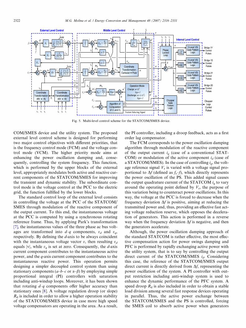
Fig. 5. Multi-level control scheme for the STATCOM/SMES device.
2322 M.G. Molina et al. / Energy Conversion and Management 48 (2007) 2316–2331
COM/SMES device and the utility system. The proposedexternal level control scheme is designed for performingtwo major control objectives with different priorities, thatis the frequency control mode (FCM) and the voltage con-trol mode (VCM). The higher priority mode aims atenhancing the power oscillation damping and, conse-quently, controlling the system frequency. This function,which is performed by the upper blocks of the externallevel, appropriately modulates both active and reactive cur-rent components of the STATCOM/SMES for improvingthe transient and dynamic stability. The subordinate con-trol mode is the voltage control at the PCC to the electricgrid, the function fulfilled by the lower blocks.
The standard control loop of the external level consistsin controlling the voltage at the PCC of the STATCOM/SMES through modulation of the reactive component ofthe output current. To this end, the instantaneous voltageat the PCC is computed by using a synchronous rotatingreference frame. Thus, by applying Park’s transformation[7], the instantaneous values of the three phase ac bus volt-ages are transformed into d–q components, vd and vq,respectively. By defining the d-axis to be always coincidentwith the instantaneous voltage vector v, then resulting vd
equals jvj, while vq is set at zero. Consequently, the d-axiscurrent component contributes to the instantaneous activepower, and the q-axis current component contributes to theinstantaneous reactive power. This operation permitsdesigning a simpler decoupled control system than usingstationary components (a–b–c or a–b) by employing simpleproportional integral (PI) controllers with saturationincluding anti-windup loops. Moreover, it has been shownthat rotating d–q components offer higher accuracy thanstationary ones [8]. A voltage regulation droop (or slope)Rd is included in order to allow a higher operation stabilityof the STATCOM/SMES device in case more high speedvoltage compensators are operating in the area. As a result,
the PI controller, including a droop feedback, acts as a firstorder lag compensator.
The FCM corresponds to the power oscillation dampingalgorithm through modulation of the reactive componentof the output current iq (case of a conventional STAT-COM) or modulation of the active component id (case ofa STATCOM/SMES). In the case of controlling iq, the volt-age reference signal Vr is varied with a voltage signal pro-portional to Df (defined as fr–f), which directly representsthe power oscillation of the PS. This added signal causesthe output quadrature current of the STATCOM iq to varyaround the operating point defined by Vr, the purpose ofthis variation being to counteract power oscillations. In thisway, the voltage at the PCC is forced to decrease when thefrequency deviation Df is positive, aiming at reducing thetransmitted power and, thus, providing an effective fast act-ing voltage reduction reserve, which opposes the decelera-tion of generators. This action is performed in a reverseway when the frequency deviation Df is negative, and thenthe generators accelerate.
Although, the power oscillation damping approach ofthe standard STATCOM is rather effective, the most effec-tive compensation action for power swings damping andPFC is performed by rapidly exchanging active power withthe utility system, that is to say by controlling the outputdirect current of the STATCOM/SMES id. Consideringthis case, the reference of the STATCOM/SMES outputdirect current is directly derived from Df, representing thepower oscillation of the system. A PI controller with out-put restriction including anti-windup system is used toenhance the dynamic performance of the PFC system. Aspeed droop Rd is also included in order to obtain a stableload division among several fast response devices operatingin parallel. Thus, the active power exchange betweenthe STATCOM/SMES and the PS is controlled, forcingthe SMES coil to absorb active power when generators

Fig. 6. Test power system.
M.G. Molina et al. / Energy Conversion and Management 48 (2007) 2316–2331 2323
accelerate (charge mode) or to inject active power whenthey decelerate (discharge mode). The PI controller includ-ing a droop feedback acts as a first order lag compensator.An auxiliary feed forward signal proportional to the rate ofchange of the system frequency has been included in orderto speed up the transient response of the controller. A dif-ferential signal of the frequency error with restricted highfrequency gain is obtained by using a first order washoutfilter. Thus, the auxiliary signal can be used to improvethe transient stability of the network by incorporatingoscillation damping to the power system. In this way, bothsteady state and transient objectives are fulfilled by the pro-posed control strategy.
3.2. Middle level design
A simplified functional scheme of the middle level con-trol algorithm is shown in Fig. 5 (middle side). This schemecoordinates the subsystems of the internal level controlblock.
The middle level control design is based on a simplifiedstate space mathematical model of the STATCOM/SMEScontroller in the d–q reference frame [9]. The control blocksmake use of standard PI compensators with proper feed-back of the STATCOM/SMES output current componentsin the d–q reference frame, aiming at eliminating the crosscoupling of both components in the steady state. There-fore, this decoupling of the control of id and iq gives adecoupled control of the active and reactive power. Thecoordinate transformation from cartesian to polar yieldsthe required magnitude of the output voltage vector pro-duced by the VSI (Vinv) and the phase shift rating a of thisvector from the reference position, represented by the volt-age vector measured in the PCC of the STATCOM/SMES.From Vinv, the required voltage at the dc bus (Vdr) isderived, and the duty cycle of the chopper thyristors (D*)is estimated, taking into consideration the active powerinjection ratings required from the STATCOM/SMESand the actual current of the SMES coil iL. This estimatedvalue yields m* by relying on the various modes of opera-tion of the dc–dc chopper (quadrants of operation). A cor-rective action of integral type (PI) is needed for the finalcomputation of the duty cycle (m). Therefore, dc bus volt-age deviations caused by actual VSI switching losses andcapacitors power losses can be counteracted. Finally, dutycycles D1 and D2 are derived from the charge unbalance ofthe dc bus capacitors.
3.3. Internal level design
The internal level provides dynamic control of input sig-nals for the dc–dc and ac–dc converters. This level isresponsible for generating the switching signals for the dif-ferent valves of the 48 pulse, three level VSI and the threelevel dc–dc chopper (triggering and blocking control sig-nals), according to the control mode (phase control) andtypes of valves (GTOs) used. Fig. 5 (right side) shows a
basic scheme of the internal level control of the STAT-COM/SMES compensator. This level is mainly composedof a line synchronization module and a firing pulses gener-ator for both the STATCOM VSI and the dc–dc chopper.The line synchronization module consists mainly of a phaselocked loop (PLL). This circuit is used to synchronize theSTATCOM/SMES device switching pulses with the posi-tive sequence components of the ac voltage vector at thePCC.
In the case of the firing pulses generator block, the con-troller of the VSI is made up of four basic, three level, 6-pulse switching generators with specific phase shifting inorder to obtain an overall 48-pulse structure. The phaseshifting between control pulses of Bridges 1Y and 1Dmakes an equivalent structure of a 24-pulse VSI. Hence,by lagging the control pulses of the second equivalent 24-pulse structure by 15� with respect to the first, accordingto the phase shifting of zig-zag transformers primaries, anequivalent 48-pulse VSI is obtained. Even though the con-duction angle r can be changed to control the output volt-age amplitude of the VSI, in this work, the amplitude iscontrolled just by using the duty ratio m of the chopper.In this way, r is kept constant at 172.5� in order to obtainthe lowest voltage total harmonic distortion (THD) for thistopology, independently of the output voltage amplitude.
4. Test power system description
The test power system used to study the dynamic perfor-mance of the proposed STATCOM/SMES device is shownin Fig. 6 as a single line diagram. This seven bus radialtransmission system operates at 220 kV/50 Hz and imple-ments a dynamically modelled single machine small utilitylinked to a bulk power system represented by an infinitebus type. The generator is powered by a steam turbineimplementing a complete tandem compound steam primemover including a speed governing system, a detailedmodel of a four-stage steam turbine and a shaft with fourmasses, similar to one of the models proposed in Ref.[10]. The unit includes a single reheater and is operatedin the boiler following control mode. The controls of theunit also include an excitation system implemented by anIEEE dc type-1a exciter [11]. All loads are modelled by
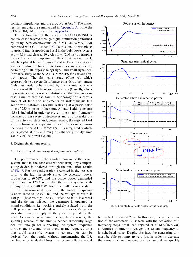
Fig. 7. Case study A: fault results for the base case.
2324 M.G. Molina et al. / Energy Conversion and Management 48 (2007) 2316–2331
constant impedances and are grouped at bus 7. The majortest system data are summarized in Appendix A, while theSTATCOM/SMES data are in Appendix B.
The performance of the proposed STATCOM/SMEScontroller is analyzed through digital simulation performedby using SimPowerSystems of SIMULINK/MATLABcombined with C++ codes [12]. To this aim, a three phaseto ground fault is applied at bus 2 in the bulk power systemat t = 0.1 s and cleared 10 cycles later (200 ms) by trippingthe tie line with the opening of the circuit breaker Bk 1,which is placed between buses 3 and 4. Two different casestudies relative to basic protection rules are considered,permitting a full large (spacing) signal and small signal per-formance study of the STATCOM/SMES for various con-trol modes. The first case study (Case A), whichcorresponds to a severe disturbance, considers a permanentfault that needs to be isolated by the instantaneous tripoperation of Bk 1. The second case study (Case B), whichrepresents a much less severe disturbance than the previouscase, assumes that the fault is temporary for a certainamount of time and implements an instantaneous tripaction with automatic breaker reclosing at a preset delaytime of 250 ms prior to lock out. A load shedding scheme(LS) is included in order to prevent the system frequencycollapse during severe disturbances and also to make useof the activated steps and, consequently, the rejected loadas a performance comparison index for various scenariosincluding the STATCOM/SMES. This integrated control-ler is placed at bus 4, aiming at enhancing the dynamicsecurity of the power system.
5. Digital simulations results
5.1. Case study A: large-signal performance analysis
The performance of the standard control of the powersystem, that is, the base case without using any compen-sating device, is analyzed through the simulation resultsof Fig. 7. For the configuration presented in the test caseprior to the fault in steady state, the generator powerproduction is 80 MW, and the active power demandedby the load is 120 MW so that the utility system needsto import about 40 MW from the bulk power system.In this interconnected operation, the system frequencyis at its rated value (50 Hz), and the voltage at bus 4 is1.01 p.u. (base voltage 220 kV). After the fault is clearedand the tie line tripped, the generator is operated inisland conditions, i.e. working entirely isolated from thebulk power system. Under these circumstances, the gener-ator itself has to supply all the power required by theload. As can be seen from the simulation results, thespinning reserve of the unit is neither sufficiently largenor fast enough for supporting the system frequencythrough the PFC and, thus, avoiding the frequency dropthat could cause the system to collapse. As can bederived from the results without implementing the LS,i.e. frequency in dashed lines, the system collapse would
be reached in almost 2.5 s. In this case, the implementa-tion of the automatic LS scheme with the activation of 8frequency steps (total load rejected of 40 MW/16 Mvar)is required in order to recover the system frequency toits scheduled value. Despite this fact, the generating unitmust be able to ramp up very fast in order to decreasethe amount of load rejected and to ramp down quickly
Fig. 8. Case study A: fault results for the case with a standard STATCOMin voltage control mode.
M.G. Molina et al. / Energy Conversion and Management 48 (2007) 2316–2331 2325
for reducing the frequency deviation overshoot and set-tling time after the demand is stabilized, as can bederived from the mechanical power of the machine.Under these circumstances, the required demand cannot be fully satisfied, bringing technical and economicconsequences that are related to the costs of deficits.Load rejection also permits improving the steady statevoltage profile at bus 4 with each LS step activated, untilreaching 1.012 V. After the fault clearance, a voltageovershoot of nearly 11.4% occurs until the voltage regu-lator of the unit stabilizes the bus voltage.
Consider the inclusion at bus 4 of a standard ±80 MvarSTATCOM controller. Major applications of this FACTSdevice include voltage/VAR support at the PCC and poweroscillation damping. Based on these features, two externalcontrol modes are studied, namely the voltage controlmode (VCM) and the frequency control mode (FCM).
The impact of the addition of a conventional STAT-COM controller at bus 4 operating in VCM can be ana-lyzed by the simulation results of Fig. 8. The goodperformance of voltage regulation at the PCC of theSTATCOM is evidently depicted by compensation ofthe reactive power. The rapid exchange of reactive powerafter fault clearance permits limiting the maximum volt-age overshoot to near 7.5%, i.e. almost 3.9% less thanthe base case shown in dashed lines. PI controller gainsof the external level control scheme in VCM were deter-mined to give the power system the fastest voltage regu-lation at bus 4 while keeping the maximum overshootless than 10% as can be noted from Fig. 8. The shortestsettling time obtained for this case study is 0.2 s, approx-imately 30% lesser than the base case. However, this con-trol objective of the standard STATCOM device comesinto conflict with the primary frequency control of thePS. Thus, by controlling the voltage at bus 4, a largeractive power flow is forced into the electric system, whichcauses an increase of the system frequency drop and itsrate of change after the disturbance. In this way, twoextra frequency steps of load rejection need to be acti-vated with respect to the base case (total 10 steps) inorder to recuperate the system frequency during the dis-turbance effect. In the post fault steady state, the voltagelevel at bus 4 is enhanced by the STATCOM, providing acompensation of approximately 30 Mvar, which allowsincreasing the voltage from 1.012 V in the base case to1.043 V, representing a 3% improvement.
Fig. 9 depicts the simulation results for the case of a con-ventional STATCOM controller operating in FCM. In thiscase, the voltage reference signal of the VCM is modulatedwith a voltage signal proportional to Df, which directly rep-resents the power oscillation of the PS. The effect of thisvariation is to counteract the frequency deviation by mod-ulating the reactive power without exceeding the voltage atthe PCC of the STATCOM (bus 4) within the limits of�5% and +10%. As can be noted, the reactive powerexchanged is initially inductive during the disturbance(with a maximum of �80 Mvar) in order to reduce the
active power transmitted from the generator while the fre-quency is dropping and, thus, to provide an effective fastacting voltage reduction reserve that opposes the decelera-tion of the machine. This action allows reducing the rejec-tion of load necessary for recovering the system frequencyto the reference value, being necessary in this case to acti-vate six frequency steps (2 less than the base case and 4 less

Fig. 9. Case study A: fault results for the case with a standard STATCOMin frequency control mode.
Fig. 10. Case study A: fault results for the case with a STATCOM/SMEScontroller in frequency control mode.
2326 M.G. Molina et al. / Energy Conversion and Management 48 (2007) 2316–2331
compared to the VCM). In the steady state, the reactivepower exchanged with the utility system changes to acapacitive mode until it reaches the same value as theVCM (30 Mvar). Obviously, the FCM transiently makesthe voltage profile at bus 4 worse compared to the caseof the VCM.
The effect of incorporating a 50 MW/700 MJ SMES coilinto the dc bus of the conventional ±80 Mvar STATCOMdevice, yielding an enhanced integrated STATCOM/SMEScontroller, can be studied through the simulation results ofFig. 10. These results clearly show the outstanding dynamicperformance of the frequency control mode of the STAT-COM/SMES system. The rapid active power supply, added

Fig. 11. Case study A: system frequency for various active and reactivepower ratings of the STATCOM/SMES controller.
M.G. Molina et al. / Energy Conversion and Management 48 (2007) 2316–2331 2327
to the conventional reactive power compensation previ-ously described, quickly absorbs the sudden power lossthat occurred after tie line tripping. Thus, the generatoris able to find the balance with the load at a lower speedthan in the previous test cases without producing a signif-icant frequency deviation, resulting in a much smoothervariation of the mechanical power of the machine. Thiscondition permits greatly decreasing the power strain ofthe generating unit, which results in an improvement ofthe reliability of the power system. In this case, the effectsof the disturbance are totally mitigated in a shorter timethan in the base case without it being necessary to activatethe load shedding scheme. In fact, the frequency drop isdrastically reduced and maintained far away from the loadshedding limit. The minimum frequency reached during thedisturbance is 0.9934 p.u. vs. 0.9619 p.u. for the base case.Furthermore, the maximum reactive power required fromthe STATCOM/SMES is reduced with respect to the con-ventional STATCOM. In the inductive mode, the maxi-mum reactive power exchanged is reduced from�80 Mvar for the case of the conventional STATCOM to�50 Mvar for the case with SMES, whereas in the capaci-tive mode, the maximum reactive power is the same in allcontrol modes because it corresponds to the steady statevalue determined by the VCM. The voltage profile at bus4 is improved with respect to the base case without requir-ing shedding load, also showing a better performance thanthe standard STATCOM in FCM. If the comparison isextended to the STATCOM device in VCM, the voltageprofile obtained with SMES in FCM is somewhat worse.However, the SMES adds extra flexibility to the power sys-tem, allowing both objectives to be accomplished at thesame time without rejecting load. The improvement ofthe PFC is obtained by the immediate action of the SMEScoil for supplying/absorbing active power, which providesactive power for about 20 s (approximately 580 MJ ofenergy). AGC control action has not been shown in orderto focus the study on the primary frequency controlperformance.
Fig. 11 shows the minimum system frequency during thedisturbance for the case study A with several ratings forthe active power of the SMES coil (fully charged) andthe inductive reactive power of the STATCOM. As canbe clearly derived, reactive power exchange with the powergrid is not as effective as active power exchange for sup-porting the frequency during the transient. Providing reac-tive inductive power at the PCC, aiming at rapidlyreducing the terminal voltage and, consequently, decreas-ing the demand has a limited effect on the frequency drop,not being able to evade the activation of the LS. On theother hand, by providing active power at the PCC permitscounteracting the power imbalance and, thus, avoiding theactivation of the LS for power ratings of the SMES coilhigher than only 10 MW. It can be noted as well that bycombining both controls of active and reactive power opti-mizes the size of the STATCOM/SMES device for applica-tions on the PFC.
5.2. Case study B: small signal performance analysis
The performance of the standard control of the powersystem (base case) is now analyzed for case study Bthrough the simulation results of Fig. 12. The disturbanceoccurring in the power system after fault clearance andsubsequent automatic reclosing of the breaker Bk1 causeselectro-mechanical oscillations of the generator. Theselocal oscillations, also called power swings between theelectrical machine and the rest of the electric system (typi-cally in the frequencies range from 0.8 to 4.0 Hz), must beeffectively damped to maintain the power system stability.During the fault period, the transfer of energy from themachine to the infinite bus is considerably reduced, andhence, the input mechanical energy during this periodappears as an increase in the kinetic energy of the systemwith the consequent increase in the speed of the unit. Sincethe line resistances are inherently low, oscillations persistfor a long time. As can be noted from digital simulations,a local mode of approximately 1.25 Hz that settles downto its steady state value only after 12 s is induced in theelectric system. As expected, this low frequency powerswing influences not only the system frequency, the rotorangle deviation and the active and reactive power suppliedby the generating machine but also the voltage profile atbus 4.
As in the previous case study, consider now the inclusionat bus 4 of a standard ±80 Mvar STATCOM operating inthe voltage control mode and in the frequency controlmode.
The impact of incorporating a conventional STATCOMcontroller at bus 4 operating in VCM can be studied by thesimulation results of Fig. 13. Although the objective of thiscontrol system mode is to support and regulate the voltageat the PCC of the STATCOM, which can be verifiedthrough the voltage profile at bus 4, the good performanceof the voltage controller also succeeds in moderately damp-ing the low frequency oscillation mode. Aiming at control-ling bus 4 voltage, the compensation signal for voltagesupport (about 50 Mvar) also includes a superimposed

Fig. 12. Case study B: fault results for the base case.Fig. 13. Case study B: fault results for the case with a standardSTATCOM in voltage control mode.
2328 M.G. Molina et al. / Energy Conversion and Management 48 (2007) 2316–2331
oscillating component for stabilizing the voltage profileand, thus, reducing the amplitude of the oscillations.
For the case of a conventional STATCOM controlleroperating in FCM, as depicted in the simulation resultsof Fig. 14, the power oscillation is largely damped, morethan in the VCM, through a more effective modulation ofthe reactive power injected by the STATCOM. Duringthe transient, a greater oscillating component is superim-posed to the reactive power required from the STATCOMfor stabilizing purposes, which forces a peak inductivereactive power of �60 Mvar from the STATCOM. Thiscauses a better damping of the system frequency and therotor angle but at the expense of worsening the voltageprofile obtained.
The effect of incorporating a ±50 MW/700 MJ SMEScoil into the dc bus of the conventional ±80 Mvar STAT-
COM can be verified through the simulation results ofFig. 15. The transient response clearly proves the outstand-ing small signal dynamic performance of the frequencycontrol mode of the STATCOM/SMES system, the sameas in the case studied for large-signal. The SMES unit actsas an efficient damper, absorbing surplus energy from thesystem and releasing energy at the appropriate time whenrequired. The SMES unit with the proposed controller iscapable of damping the oscillations in a short time andreducing the amplitude of the pulsations on the frequencyconsiderably. In the present analysis, the settling time forthe system frequency is about 2 s when the SMES unitis used for active power compensation. This implies areduction of almost 10 s with respect to the base case.

Fig. 14. Case study B: fault results for the case with a standardSTATCOM in frequency control mode.
Fig. 15. Case study B: fault results for the case with a STATCOM/SMEScontroller in frequency control mode.
M.G. Molina et al. / Energy Conversion and Management 48 (2007) 2316–2331 2329
Furthermore, the frequency and rotor angle deviations aregreatly reduced to values less than the maximum reached atthe end of the fault when the peak increase in the kineticenergy of the system exists. A noteworthy point is thatthe capacity rating of the SMES unit used in this case studyfor damping low frequency power swings is only 6.3 MJwith a power rating of almost ±50 MW. Another signifi-cant feature is that the maximum inductive reactive powerrequired from the STATCOM is also reduced, from�60 MW for the STATCOM alone in FCM to �30 MWfor the case with SMES (about 50%, the same as in casestudy A). This allows reducing the overall power ratingsof the integrated STATCOM/SMES controller.
6. Conclusions
This paper presents an improved PFC scheme by incor-porating a STATCOM controller coupled with a SMEScoil. A detailed fully realistic model of the enhanced com-pensator and a novel control algorithm based on a decou-pled current control strategy in the synchronous rotatingd–q reference frame are proposed. Simulation results verifythe effectiveness of the primary frequency control strategypresented and the models and control algorithms pro-posed. The novel control scheme ensures fast controllabil-ity of the STATCOM/SMES operating in four quadrantmodes, which enables effectively increasing the transient

Table 6Load data
ID# Bus PL MW QL Mvar LS
Ld7 7 120 32 YLd4 4 3 0.95 NLd6 6 5 1.1 N
PL and QL: load real and reactive power; LS: load shedding scheme; (Y:included; N: not included).
2330 M.G. Molina et al. / Energy Conversion and Management 48 (2007) 2316–2331
and dynamic stability of the power system. The incorpora-tion of the superconducting coil into the STATCOM alsopermits reducing the requirement of spinning reserve ofthe electric system and the power strain of the generators.The SMES unit, controlled as suggested, can effectivelyact as a buffer between the power system and the distur-bances that arise in the system. Other additional benefitsprovided by incorporation of a SMES coil include the pre-vention of cascading outages by minimizing the impact offaults, damping power systems oscillations and increasingthe overall reliability and power quality of the electricsystem.
Appendix A. Test system data
Transmission lines are modelled as distributed parame-ters with lumped losses. Major lines data are given in Table2, using p.u. quantities on 220 kV and 100 MVA base.Table 3 shows the most important transformer data. In thiscase, all p.u. quantities are on 220 kV and the generatingunit nominal MVA base. Major generating unit data and
Table 2Line data
ID# From bus To bus L (km
L1 2 3 170L2 5 4 45L3 4 7 35
ID#: component identifier; R, X and B: total positive sequence resistance, rea
Table 3Transformer data
ID# From bus To bus R (p.u.) X (p.u.) G (
T1 6 5 0.00413 0.1653 0.6
R and X: winding resistance and reactance; G and B: magnetizing conductanc
Table 4Generating unit data
ID# Unittype
Unit size(MW)
PG
(MW)QG
(Mvar)SN
(MVA)VN
(kV)VS
(p.u.)H
(MWMJ)
G1 ST 112 80 15 140 18 1.03 5.5
Unit type: ST – fossil fuelled steam turbine with tandem compound single massgenerating unit voltage output; H: inertia constant; Rs and Xl: stator resistancsynchronous reactances; T 0d0 and T 0q0: direct and quadrature axis open circuit
Table 5Generating unit data (Cont. 1)
ID# R (%) DB (mHz) TSR (ms) TSM (ms)
G1 5 180 1 150
R: speed regulation or governor droop; DB: dead band of speed regulator; TSR
gain of the excitation system IEEE type dc type-1A; TA: regulator time constregulator time constant of the damping filter; TR: low pass filter time constan
the active and reactive power quantities used in the basecase load flow are shown in Table 4. In addition, the mainparameters related to synchronous machines, voltage regu-lator and prime mover systems are shown in Table 5.Finally, in Table 6, the most important load data areshown.
An underfrequency load shedding scheme is utilized.The scheme is composed of 10 frequency steps, each onerejecting 5 MW and 2 Mvar, as described in Table 7. Con-sequently, up to 50 MW of real power can be rejected, rep-resenting 41.66% of the real power load. The operating
) R (p.u.) X (p.u.) B (p.u.)
0.0223 0.1227 0.29480.0149 0.0818 0.19660.0062 0.0341 0.0819
ctance and susceptance of transmission lines.
p.u. · 10�3) B (p.u. · 10�3) SN (MVA) Np/Ns (kV/kV)
53 3.0976 250 230/18
e and susceptance; Np/Ns: voltage transformation ratio.
/RS
(p.u.)Xl
(p.u.)Xd
(p.u.)Xq
(p.u.)X 0dðp:u:Þ X 0qðp:u:Þ T 0d0ðsÞ T 0q0ðsÞ
0.001 0.14 1.569 1.548 0.324 0.918 5.140 1.5
generator; PG and QG: generating unit real and reactive power output; VS:e and leakage inductance; Xd, X 0d , Xq and X 0q: direct and quadrature axistransient and subtransient time constants.
KA TA (ms) KF TF (ms) TR (ms)
300 1 0.001 100 20
: speed relay time constant; TSM: servo-motor time constant; KA: regulatorant of the excitation system; KF: regulator gain of the damping filter; TF:t of the excitation system.

Table 8STATCOM/SMES data
Qmax (Mvar) Pmax (MW) ESC max (MJ) ISC max (kA) Vd (kV) Cd1,Cd2 (mF) LT (H)
±80 ±50 700 5.5 24 10 50
Qmax: maximum rated reactive power; Pmax: maximum rated real power; ESC max: maximum rated storage capacity of the SMES system; ISC max: maximumrated current of the superconducting coil; Vd: rated voltage of the dc bus; Cd1, Cd2: capacitances of the dc bus capacitors; LT: total inductance of the SMESdevice.
Table 9SMES model data
# Segments Li (H) Mij (H) CSi (lF) CShi (lF) Rp i (X) Rp (X)
6 8.334 3.12 0.01 0.488 0.05 5
#Segments: number of segments of the coil model; Li: self inductance per segment; Mij: mutual coupling inductance between segments; CSj: series straycapacitance between turns of the coil; CShj: shunt stray capacitance between turn and ground; Rpi: AC loss resistance per segment; Rp: stray resistancebetween segments due to skin effect.
Table 7Load shedding Scheme
Frequency step f (Hz) f (p.u.) Frequency step (cont.) f (Hz) f (p.u.)
1 48.539 0.97078 6 48.312 0.966242 48.512 0.97024 7 48.25 0.9653 48.475 0.9695 8 48.185 0.96374 48.422 0.96844 9 48.115 0.96235 48.369 0.96738 10 48.042 0.96084
fmin, Admissible = 47.5 Hz= 0.95 p.u.
Table 10Chopper and SMES filter data
TF (ls) TT (ls) VFG/ VFD (V) RON (mX) CS1,CS2 (lF) Rg1, Rg2 (kX) CF(lF)
5 10 1/0.6 1 1.1 27.5 6
TF: fall time of the GTO of the chopper (similar for the inverter); TT: tail time of the GTO of the chopper; VFG, VFD: forward voltages for GTOs anddiodes, respectively; RON: internal resistance of the GTO device; CS1, CS2, CF: capacitances of SMES filter; Rg1, Rg2: ground resistances.
M.G. Molina et al. / Energy Conversion and Management 48 (2007) 2316–2331 2331
time delay of each load shedding step, which utilizes solidstate relays, is 0.2 s.
Appendix B. STATCOM/SMES controller data
Tables 8–10 summarize the most important data corre-sponding to the STATCOM, chopper and SMESsubsystems.
References
[1] Hingorani NG. Role of FACTS in a deregulated market. In: IEEE/PES Winter Meeting 2000 Proc 1; 2000. p. 1463–67.
[2] Kundur P, Morison GK, Moshref A. Measures to improve powersystem security in the competitive market environment. In: VIISEPOPE Proc. 1; 2000. p. 1–6.
[3] Molina MG, Mercado PE. Comparative evaluation of perfor-mance of a STATCOM and SSSC both integrated with SMESfor controlling the power system frequency. In: IEEE/PESTransmission and Distribution C&E Lat. 2004 Proc.1; 2004.p. 535–41.
[4] Hingorani NG, Gyugyi L. Understanding FACTS. New York: IEEEPress; 2000.
[5] Lasseter RH, Lalali SG. Power conditioning systems for supercon-ductive magnetic energy storage. IEEE Trans Energ Convers1991;6(3):381–7.
[6] Arsoy AB, Wang Z, Liu Y, Ribeiro PF. Transient modeling andsimulation of a SMES coil and its power electronics interface. IEEETrans Appl Superconduct 1999;9(4):4715–24.
[7] Krause PC. Analysis of electric machinery. New York: Mc Graw-Hill; 1992.
[8] Acha E, Agelidis V, Anaya-Lara O, Miller T. Power electroniccontrol in electrical system. first ed. United Kingdom: Newness;2002.
[9] Schauder CD, Mehta H. Vector analysis and control of advancedstatic Var compensators. In: IEE Proceedings-C140, 4; 1993. p. 299–306.
[10] Dynamic models for fossil fuelled steam units in power systemstudies, IEEE working group report. IEEE Trans. on Power Systems,6(3); 1991. p.753–61.
[11] IEEE Recommended practice for excitation system models for powersystem stability studies. IEEE standard, 421; 1992. p. 5–92.
[12] SimPowerSystems User’s Guide, TransEnergie Technologies Inc,2002.