Re-Planning for Compensator-Based IMRT with Original Compensators
7
doi:10.1016/j.meddos.2010.01.004 RE-PLANNING FOR COMPENSATOR-BASED IMRT WITH ORIGINAL COMPENSATORS GEOFFREY ZHANG,PH.D., VLADIMIR FEYGELMAN,PH.D., CRAIG STEVENS, M.D., PH.D., WEIQI LI,SUSAN LEUTHOLD,GREGORY SPRINGETT, M.D., and SARAH HOFFE, M.D. Division of Radiation Oncology; and GI Tumor Program, Moffitt Cancer Center, Tampa, FL (Received 8 July 2009; accepted 10 January 2010) Abstract—Compared with multileaf collimator (MLC)– based intensity-modulated radiotherapy (IMRT) for moving targets, compensator-based IMRT has advantages such as shorter beam-on time, fewer monitor units with potentially decreased secondary carcinogenesis risk, better optimization-to-deliverable dose conversion, and often better dose conformity. Some of the disadvantages include additional time for the compensators to be built and delivered, as well as extra cost. Patients undergoing treatment of abdominal cancers often experience weight loss. It would be necessary to account for this change in weight with a new plan and a second set of compensators. However, this would result in treatment delays and added costs. We have developed a method to re-plan the patient using the same set of compensators. Because the weight changes seen with the treatment of abdominal cancers are usually relatively small, a new 4D computed tomography (CT) acquired in the treatment position with markers on the original isocenter tattoos can be registered to the original planning scan. The contours of target volumes from the original scans are copied to the new scan after fusion. The original compensator set can be used together with a few field-in-field (FiF) beams defined by the MLC (or beams with cerrobend blocks for accelerators not equipped with a MLC). The weights of the beams with compensators are reduced so that the FiF or blocked beams can be optimized to mirror the original plan and dose distribution. Seven abdominal cancer cases are presented using this technique. The new plan on the new planning CT images usually has the same dosimetric quality as the original. The target coverage and dose uniformity are improved compared with the plan without FiF/block modification. Techniques combining additional FiF or blocked beams with the original compensators optimize the treatment plans when patients lose weight and save time and cost compared with generating plans with a new set of compensators. © 2010 American Association of Medical Dosimetrists. Key Words: Compensator, IMRT, Field-in-field, Treatment planning. INTRODUCTION Intensity modulation across the radiotherapy x-ray beam can be accomplished by either segmenting the field ap- erture with a multileaf collimator (MLC) 1 or by intro- ducing variable-thickness attenuators (compensators). 2 Figure 1 illustrates how the compensator modulates the radiation beam intensity. The fluence maps for a set of beams are optimized to deliver the dose to the treatment target and spare the nearby critical structures. The uni- form beam from the accelerator is differentially attenu- ated following the variation of the thickness of the com- pensator designed to reproduce this fluence map as closely as possible. Intensity-modulated radiotherapy (IMRT) can therefore be delivered using an isocentric set of beams modulated by the compensators. 2 Compared with MLC-based IMRT, compensator- based IMRT has the advantages of shorter treatment times, 2–4 fewer monitor units (MUs) 5 with less poten- tial secondary carcinogenesis, better optimization-to- deliverable dose conversion, 6 and usually better target con- formity. 7,8 Prolonged fraction time could reduce treatment efficiency. 9 Compensator-based IMRT in combination with a high-dose-rate linear accelerator would biologically enhance the treatment efficiency. With the compensator technique, IMRT treatments can be delivered with accel- erators not equipped with a MLC. Disadvantages of com- pensator-based IMRT include limited intensity modulation range 2 and additional time and cost for the compensators to be manufactured. In the treatment of abdominal cancers, a change in patient weight before or during treatment is a fre- quent clinical problem. A re-plan could potentially improve dose distribution after weight change, avoid- ing the potential unwanted increase in dose to normal tissue. 10 A new IMRT plan using the same compen- sators would save time without adding any extra cost. This paper introduces 2 methods of re-planning while retaining the original compensators: one uses MLC-de- fined field-in-field (FiF) technique and the other uses cerrobend blocks to simulate the use of accelerators without a MLC. As a forward IMRT planning technique, FiF is often used to generate homogeneous dose in target volumes. 11 Cerrobend blocks are often used in blocking normal Presented at the World Congress of Medical Physics and Bio- medical Engineering, Munich, Germany, September 7–12, 2009 Reprint requests to: Vladimir Feygelman, Ph.D., Division of Radiation Oncology, Moffitt Cancer Center, 12902 Magnolia Drive, Tampa, FL 33612. E-mail: vladimir.feygelman@moffitt.org Medical Dosimetry, Vol. xx, No. x, pp. xxx, 2010 Copyright © 2010 American Association of Medical Dosimetrists Printed in the USA. All rights reserved 0958-3947/10/$–see front matter 1 ARTICLE IN PRESS
-
Upload
independent -
Category
Documents
-
view
1 -
download
0
Transcript of Re-Planning for Compensator-Based IMRT with Original Compensators

IcedFrbtfapc(o
btt
m
RT
Medical Dosimetry, Vol. xx, No. x, pp. xxx, 2010Copyright © 2010 American Association of Medical Dosimetrists
ARTICLE IN PRESS
doi:10.1016/j.meddos.2010.01.004
RE-PLANNING FOR COMPENSATOR-BASED IMRT WITH ORIGINALCOMPENSATORS
GEOFFREY ZHANG, PH.D., VLADIMIR FEYGELMAN, PH.D., CRAIG STEVENS, M.D., PH.D.,WEIQI LI, SUSAN LEUTHOLD, GREGORY SPRINGETT, M.D., and SARAH HOFFE, M.D.
Division of Radiation Oncology; and GI Tumor Program, Moffitt Cancer Center, Tampa, FL
(Received 8 July 2009; accepted 10 January 2010)
Abstract—Compared with multileaf collimator (MLC)–based intensity-modulated radiotherapy (IMRT) formoving targets, compensator-based IMRT has advantages such as shorter beam-on time, fewer monitor unitswith potentially decreased secondary carcinogenesis risk, better optimization-to-deliverable dose conversion, andoften better dose conformity. Some of the disadvantages include additional time for the compensators to be builtand delivered, as well as extra cost. Patients undergoing treatment of abdominal cancers often experience weightloss. It would be necessary to account for this change in weight with a new plan and a second set of compensators.However, this would result in treatment delays and added costs. We have developed a method to re-plan thepatient using the same set of compensators. Because the weight changes seen with the treatment of abdominalcancers are usually relatively small, a new 4D computed tomography (CT) acquired in the treatment positionwith markers on the original isocenter tattoos can be registered to the original planning scan. The contours oftarget volumes from the original scans are copied to the new scan after fusion. The original compensator set canbe used together with a few field-in-field (FiF) beams defined by the MLC (or beams with cerrobend blocks foraccelerators not equipped with a MLC). The weights of the beams with compensators are reduced so that the FiFor blocked beams can be optimized to mirror the original plan and dose distribution. Seven abdominal cancercases are presented using this technique. The new plan on the new planning CT images usually has the samedosimetric quality as the original. The target coverage and dose uniformity are improved compared with the planwithout FiF/block modification. Techniques combining additional FiF or blocked beams with the originalcompensators optimize the treatment plans when patients lose weight and save time and cost compared withgenerating plans with a new set of compensators. © 2010 American Association of Medical Dosimetrists.
Printed in the USA. All rights reserved0958-3947/10/$–see front matter
Key Words: Compensator, IMRT, Field-in-field, Treatment planning.
dfeaeteprb
iqiitsTrficw
u
INTRODUCTION
ntensity modulation across the radiotherapy x-ray beaman be accomplished by either segmenting the field ap-rture with a multileaf collimator (MLC)1 or by intro-ucing variable-thickness attenuators (compensators).2
igure 1 illustrates how the compensator modulates theadiation beam intensity. The fluence maps for a set ofeams are optimized to deliver the dose to the treatmentarget and spare the nearby critical structures. The uni-orm beam from the accelerator is differentially attenu-ted following the variation of the thickness of the com-ensator designed to reproduce this fluence map aslosely as possible. Intensity-modulated radiotherapyIMRT) can therefore be delivered using an isocentric setf beams modulated by the compensators.2
Compared with MLC-based IMRT, compensator-ased IMRT has the advantages of shorter treatmentimes,2– 4 fewer monitor units (MUs)5 with less poten-ial secondary carcinogenesis, better optimization-to-
Presented at the World Congress of Medical Physics and Bio-edical Engineering, Munich, Germany, September 7–12, 2009
Reprint requests to: Vladimir Feygelman, Ph.D., Division of
Cadiation Oncology, Moffitt Cancer Center, 12902 Magnolia Drive,ampa, FL 33612. E-mail: [email protected]
1
eliverable dose conversion,6 and usually better target con-ormity.7,8 Prolonged fraction time could reduce treatmentfficiency.9 Compensator-based IMRT in combination with
high-dose-rate linear accelerator would biologicallynhance the treatment efficiency. With the compensatorechnique, IMRT treatments can be delivered with accel-rators not equipped with a MLC. Disadvantages of com-ensator-based IMRT include limited intensity modulationange2 and additional time and cost for the compensators toe manufactured.
In the treatment of abdominal cancers, a changen patient weight before or during treatment is a fre-uent clinical problem. A re-plan could potentiallymprove dose distribution after weight change, avoid-ng the potential unwanted increase in dose to normalissue.10 A new IMRT plan using the same compen-ators would save time without adding any extra cost.his paper introduces 2 methods of re-planning while
etaining the original compensators: one uses MLC-de-ned field-in-field (FiF) technique and the other useserrobend blocks to simulate the use of acceleratorsithout a MLC.
As a forward IMRT planning technique, FiF is oftensed to generate homogeneous dose in target volumes.11
errobend blocks are often used in blocking normal

sa
C
c5(GfesgdflsfmpRad
T
pMlo
owI
waws86twcAoonlmdioawa
cttnaichpp
iFptolhabthFwcwTM1n
FTp
Medical Dosimetry Volume xx, Number x, 20102
ARTICLE IN PRESS
tructure volumes in 3D conformal treatment planningnd delivery.12
MATERIALS AND METHODS
linical casesAll cases included in this study were pancreatic
ancer cases. The patients were treated to a dose of either0 Gy prescribed to 95% of the planning target volumePTV), with 2 Gy per fraction in 25 daily fractions, or 45y to 95% of the PTV with 1.8 Gy per fraction in 25
ractions, followed by a 5.4 Gy boost to the gross dis-ase. The patients treated to 50 Gy had borderline re-ectable disease so a dose painting strategy of 50 Gy toross disease and 45 Gy to the clinical target volume wasesigned with volumes drawn on 4D CT scans to accountor respiratory motion. In other cases, the patients hadocally advanced disease and were treated on a protocolpecifying that all target volumes receive 180 cGy perraction. Compensator-based IMRT was chosen to opti-ize coverage to targets moving with respiration. All
atients had weight loss during the treatment course.e-planning was performed to confirm tumor coveragefter weight loss and to reduce the possibility of over-osing the target.
reatment planningAll treatment plans were generated using the XiO
lanning system (Version 4.34.02.1, CMS, Inc, St. Louis,O) for an Oncor linear accelerator (Siemens Medical So-
utions USA, Inc., Malvern, PA). A 5-beam IMRT plan was
ig. 1. Illustration of intensity modulation by a compensator.he variation in attenuation, introduced by the variable com-ensator thickness, modulates the uniform beam from an
accelerator.
riginally generated for each case. Based on the fluence maps
f the intensity-modulated beams, the brass compensatorsere manufactured by a commercial vendor (.decimal,
nc., Sanford, FL).New treatment planning CT scans were taken
hen weight loss was clinically noticeable, usuallyfter the treatment source-to-surface distances (SSDs)ere recorded to be out of tolerance. For the 7 cases
tudied in this paper, the average weight loss was.31 � 4.39 kg (range 3.4 –17.1 kg), or 11.67% �.45% (range 3.6%–23.1%), with 1 standard devia-ion. The new CT images in the free breathing modeere registered to the original set. The original iso-
enter was determined before the PTV was contoured.fter the registration of the new CT to the originalne, the old PTV was copied to the new CT. Theriginal isocenter was not automatically copied to theew CT. The new isocenter was often not at the sameocation as the original one in relation to the externalarkers on the isocenter tattoos. Necessary shifts were
etermined to place the isocenter at the same anatom-cal location after the patient was virtually triangulatedn the original tattoos. Normal structures were drawnnew on the repeat CT. The original IMRT beamsere copied to the new CT and aligned to the new
natomically correct isocenter.Review of these plans demonstrated that the PTV
overage would be altered with increased hot spots ifhe number of monitor units (MUs) were not reduced forhe new plan, because of decreased treatment depth. Theumber of MUs of each beam was reduced proportion-lly, so that the resulting PTV coverage was the same asn the original plans. With the reduced MU and sameoverage to the PTV, the new plans often demonstratedigher dose inhomogeneity. The hot spots could be a fewercentage points higher compared with the originallan.
MLC-defined FiF beams, often two of them, werentroduced in the new plans to reduce the hot spots. TheiF beams included the compensators, so that the thera-ists did not have to enter the treatment room to removehe compensators to deliver the FiF beams. The selectionf the beams to add the FiF beams is based on theocations of hot spots in the beam’s eye view (BEV). Theot spots are easier to block with an MLC when they aret the field edge in the BEV. Because the MLC cannotlock “island” areas, for the beams with the hot spots inhe center of the aperture, FiF cannot improve the doseomogeneity. Figure 2A shows an example of an addediF beam. The isodose line used to define the apertureas 111% of the prescribed dose. The high dose volume
lose to the treatment aperture edge was blocked,hereas those closer to the center of the field were not.o do otherwise would reduce the PTV coverage. TheU used for all the FiF beams were in the range of
0–12. The parent beam MUs were reduced by theumber of the FiF MUs.
For the new plans that did not use a MLC, the
bTbssgbvfirtacs
tcuaa
ifa
I
nl
M
Coamtahsro
Fciaw(cw
*Pt
Compensator IMRT replanning ● G. ZHANG et al. 3
ARTICLE IN PRESS
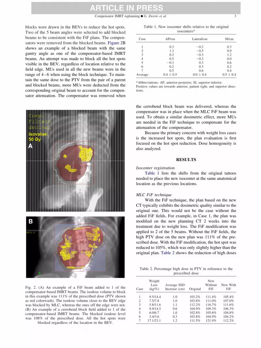
locks were drawn in the BEVs to reduce the hot spots.wo of the 5 beam angles were selected to add blockedeams to be consistent with the FiF plans. The compen-ators were removed from the blocked beams. Figure 2Bhows an example of a blocked beam with the sameantry angle as one of the compensator-based IMRTeams. An attempt was made to block all the hot spotsisible in the BEV, regardless of location relative to theeld edge. MUs used in all the new beams were in theange of 4–6 when using the block technique. To main-ain the same dose to the PTV from the pair of a parentnd blocked beams, more MUs were deducted from theorresponding original beam to account for the compen-ator attenuation. The compensator was removed when
ig. 2. (A) An example of a FiF beam added to 1 of theompensator-based IMRT beams. The isodose volume to blockn this example was 111% of the prescribed dose (PTV showns red colorwash). The isodose volume close to the BEV edgeas blocked by MLC, whereas the ones off the edge were not.
B) An example of a cerrobend block field added to 1 of theompensator-based IMRT beams. The blocked isodose levelas 108% of the prescribed dose. All the hot spots were
blocked regardless of the location in the BEV.
he cerrobend block beam was delivered, whereas theompensator was in place when the MLC FiF beam wassed. To obtain a similar dosimetric effect, more MUsre needed in the FiF technique to compensate for thettenuation of the compensator.
Because the primary concern with weight loss casess the increased hot spots, the plan evaluation is firstocused on the hot spot reduction. Dose homogeneity islso analyzed.
RESULTS
socenter registrationTable 1 lists the shifts from the original tattoos
eeded to place the new isocenter at the same anatomicalocation as the previous locations.
LC FiF techniqueWith the FiF technique, the plan based on the new
T typically exhibits the dosimetric quality similar to theriginal one. This would not be the case without thedded FiF fields. For example, in Case 1, the plan wasodified on the new planning CT 2 weeks into the
reatment due to weight loss. The FiF modification waspplied to 2 of the 5 beams. Without the FiF fields, theigh PTV dose on the new plan was 111% of the pre-cribed dose. With the FiF modification, the hot spot waseduced to 105%, which was only slightly higher than theriginal plan. Table 2 shows the reduction of high doses
Table 1. New isocenter shifts relative to the originalisocenters*
Case AP/cm Lateral/cm SI/cm
1 0.3 �0.2 0.32 1.3 �0.5 0.93 0.2 �0.3 1.24 0.5 �0.2 0.05 �0.3 0.3 0.66 0.2 0.3 0.27 0.5 0.6 0.4
Average 0.4 � 0.5 0.0 � 0.4 0.5 � 0.4
Abbreviations: AP, anterior-posterior; SI, superior-inferior.ositive values are towards anterior, patient right, and superior direc-
ions.
Table 2. Percentage high dose in PTV in reference to theprescribed dose
Case
WeightLoss
(kg/%)Average SSDIncrease (cm) Original
NewWithout
FiFNew With
FiF
1 9.5/14.4 1.0 103.2% 111.4% 105.4%2 7.5/7.8 1.0 103.8% 111.0% 107.0%3 5.8/11.6 1.1 112.2% 116.7% 111.6%4 8.9/14.5 0.6 104.9% 109.3% 106.3%5 6.0/6.7 1.0 102.8% 105.6% 104.8%6 3.4/3.6 0.3 103.8% 104.9% 104.2%
7 17.1/23.1 1.2 111.5% 121.9% 112.2%
ie
fwiD
rsr1PFv
wp9wewpaw
C
u
ificati
F(
Medical Dosimetry Volume xx, Number x, 20104
ARTICLE IN PRESS
n all 7 cases. In 1 case (Case 3), the maximum dose wasven lower than that in the original plan.
Figure 3 shows a comparison of the isodose linesor Case 1 between the plans on the new planning CTith and without the FiF modification. Dose homogene-
ty improvement can be clearly seen. Figure 4 shows theVH comparison for the same case.
Fig. 3. A comparison of the isodose lines between the plmod
ig. 4. DVH comparison. (A) Original plan on the original CT;B) new plans with and without FiF modification on the new
planning CT.
The dose homogeneity improvement is not onlyeflected in the maximum relative dose reduction. For theame isodose level, the size of the hot spots is alsoeduced. For example, in Case 3, 8.0% of PTV receives10% dose in the new plan without FiF, whereas 0.8%TV receives the same relative dose in the new plan withiF. Figure 5 shows the comparison of the percentageolume of PTV covered by the 105% isodose.
PTV coverage of the new plan could be improvedith the FiF modification compared with the originallan on the original CT (Fig. 4). In Case 1, originally7% of the PTV received the prescribed 50 Gy dose,hereas with the new plan 100% of the PTV was cov-
red with the prescription isodose. This better coverageas the major reason that the maximum dose in the newlan was often slightly higher than that in the original,nd they would be about the same if the PTV coverageas scaled down to the same value.
errobend block techniqueThe same new isocenters used in the FiF plans were
sed in the plans with blocks.
the new planning CT with (A) and without (B) the FiFon.
ans on
Fig. 5. The hot spot size reduction of the new plans.

twFaMteotcsbi(rbFb
wiioametb
M
wtrtc
fbna
Mh
tmssmbotsms
pcwtpp9aaea
N
a
Fb
Fdrct
Compensator IMRT replanning ● G. ZHANG et al. 5
ARTICLE IN PRESS
The PTV dose-volume histogram (DVH) in allhe cases was better for the block technique comparedith the MLC FiF in terms of the dose homogeneity.or most of the normal structures, block techniquelso shows better DVH curves (Fig. 6). Unlike theLC FiF, the block technique has little limitation on
he hot spot location in the BEV. It can be used forither the hot spots at the aperture edge or “island”nes. Because of this advantage, the plans using blockechnique usually exhibit better dose homogeneityompared with the ones using FiF. Figure 7 demon-trates the hot spot reduction for both the FiF andlock techniques. Noticeably high doses can be foundf the original plans were used with the new CT datasecond bar from left in each case). The hot spots areeduced by reducing the number of MUs only (thirdar). The dose homogeneity is further improved afteriF or block modifications are made (fourth and fifthars, respectively).
Because there is no hot spot location limitationhen using the block technique, more beams can be used
n the new plan. However more time and careful exper-mentation is required to adjust the beam weightings toptimize the dose homogeneity when more beams aredded. The magnitude of dose homogeneity improve-ent is much smaller for the additional beams. Consid-
ring the prolonged planning and treatment deliveryimes with the limited dosimetric benefit, more than 2locked beams are not recommended.
U adjustment onlyWe encountered 2 cases where an MU adjustment
as made but no FiF or block beams were necessary inhe new plans. In these cases, patient weight loss waselatively modest (less than 4%) compared with the oneshat required FiF or block beam modifications. For all the
ig. 6. Comparison of new plans using FiF (dashed curves) andlocks (solid curves). Two additional beams were used in both
plans.
ases in which FiF or block beam modification were
ound useful, the average SSD increase between the 5eams was between 0.6 and 1.1 cm. When only the MUseeded to be adjusted, the average SSD increase was 0.1nd 0.3 cm.
inimum, maximum, and mean doses and doseomogeneity
The new plans using either technique follow therend of the original plans in minimum, maximum, andean doses in the PTV. Figure 8 demonstrates close
imilarity in these parameters. Table 3 quantitativelyhows the average differences of the 7 cases studied. Theaximum difference between the new plans, including
oth FiF and block plans, and the original plans is �4%ver all the minimum, maximum, and mean doses, withhe exception of Case 7. This case exhibited the mostignificant weight loss. The relatively big drop in mini-um doses in the new plans for Case 7 is because of the
ignificant anatomical change.Although dose homogeneity is worse in the new
lans compared with the original ones, it is signifi-antly improved with the FiF or block fields comparedith the plans on the new CT but without the addi-
ional fields (Fig. 9). Although most of the originallans cover 95% of the PTV in the 95%–105% of therescribed dose range, most of the new plans cover the5% PTV in the 92%–108% range, which is clinicallycceptable. Despite the significant weight loss andnatomical change in Case 7, the 95% PTV was cov-red within the dose range of 92%–108% with FiFdded in the new plan.
ormal structuresThe normal structures contoured on the new CT
re often quite different from the original. An example
ig. 7. Dose homogeneity improvement corresponding to theifferent replanning steps. High dose in all the cases is theesult of using original plans on the new CT data without anyhange (light purple). Reducing the number of MUs reduceshe hot spots (red). The high doses are further reduced by
adding FiF (green) or blocked (dark purple) beams.

olcsi
s1aencttiomidI
dod
rlwFnu
buistIib2ct
FB
Ac
0 Gy.
FP
Medical Dosimetry Volume xx, Number x, 20106
ARTICLE IN PRESS
f stomach contour variation is shown in Fig. 10. Mostikely, the differences are not because of weighthange. For example, the volume and shape of thetomach depend on how much food and gas are presentnside at the time of the CT scan.
In most cases, the DVH changes for the normaltructures were more significant than for the PTV. Figure1 shows the DVH differences for the kidneys, bowel,nd stomach, which is the most significant variationncountered in all the cases. Because of the randomature of the daily variation of the normal structures, noertain pattern of the DVH variation can be derived fromhe studied cases. The DVH curves of the normal struc-ures in the new plan could be better or worse than thosen the original plans. With the original compensators,ptimization in the new plan aiming at DVH improve-ent for normal structures is difficult. This optimization
s not necessary unless adaptive plans are generatedaily, which may not be practical for compensator-basedMRT in terms of planning and delivery time.
DISCUSSION
The reduction of hot spots using the FiF techniqueepends on their location. If the hot spots are at the edgesf the beam aperture in 1 or more BEV, decreasing theose in these regions can be easily accomplished. Further
Table 3. Relative mean differences of minimum, maximum,and mean doses between the new and original plans
DifferenceMinimumDose (%) Maximum Dose (%) Mean Dose (%)
iF-original �2.71 � 7.36 1.16 � 1.66 0.58 � 0.67lock-original �1.51 � 5.76 0.66 � 1.72 0.50 � 0.64
Fig. 8. Comparison of the minimum, maximum, andfor 7 cases. Cases 2, 3, 4, and 7 were treated with 45
5
ll mean differences are listed with 1 standard deviation over all 7ases.
eduction cannot be achieved once the hot spots are noonger at the edges of any BEV aperture. For the plansith hot spots in the center of all the BEV openings, theiF technique can do little to improve the dose homoge-eity. Because of this, usually only 1 or 2 beams can besed to add FiF.
The reduction of the hot spots with the cerrobendlocks is easier to realize in treatment planning thansing the FiF technique, because of the greater flexibilityn the aperture shape afforded by the blocks. This alsoimplifies beam selection for modification with the blockechnique. The blocked beams can be added to all theMRT beams, and can even be added as a new beam withts separate gantry angle. However, adding many neweams increases both planning and delivery time. One oradditional blocked beams appear to be a reasonable
ompromise in terms of both plan quality and deliveryime.
doses in PTV between the new and original plans95% of the PTV, whereas the rest were treated with
ig. 9. Statistical dose homogeneity comparisons for theTV between the original and new plans. The vertical error
meanGy to
bars are the PTV coverage ranges of all 7 cases studied.

apcfi
oobbM
tep
ItmpwAnoM
hc
1
1
1F(
Compensator IMRT replanning ● G. ZHANG et al. 7
ARTICLE IN PRESS
The dose homogeneity improvement is achieved bydding the FiF fields or the blocked beams to the newlans. The maximum dose reduction is a result of theombination of MU reduction and the FiF/block modi-cation of the new plans.
The treatment delivery time is longer for the newptimized IMRT treatments compared with the originalnes because of the additional beams, especially if thelock technique is used. The beam-on time for the neweams is short (10–12 MUs in each FiF beam and 4–6Us in each block beam).
Because the dosimetric difference between usinghe 2 techniques is not significant, when an acceleratorquipped with a MLC is used, the FiF technique isreferable because of the shorter treatment time.
CONCLUSIONS
Failure to account for weight change duringMRT treatment of the abdomen could lead to subop-imal target coverage and unwanted normal tissue
orbidity. To save time and cost, the original com-ensators can be used to generate a new IMRT planhen the patient’s weight changes during treatment.dding a few FiF segments can achieve a plan on theew CT, which is dosimetrically very similar to theriginal. For accelerators that are not equipped withLC, cerrobend blocks can be used to improve dose
ig. 10. The contour of the stomach from the repeat CTorange) overlapped on the original CT with the original con-
tour (purple).
omogeneity in the new IMRT plans using the sameompensators.
REFERENCES
1. Xia, P.; Verhey, L.J. Multileaf collimator leaf sequencing algo-rithm for intensity modulated beams with multiple static segments.Med. Phys. 25:1424–34; 1998.
2. Chang, S.X.; Cullip, T.J.; Deschesne, K.M.; et al. Compensators:An alternative IMRT delivery technique. J. Appl. Clin. Med. Phys.5:15–36; 2004.
3. Chang, S.; Deschesne, K.; Chen, H.; et al. A multi-institutionalretrospective study on clinical IMRT treatment delivery efficiency.Med. Phys. 35:2746; 2008.
4. Tyagi, A.; Nangia, S.; Chufal, K.; et al. Quality assurance and dosi-metric analysis of intensity modulated radiotherapy using compensa-tors for head and neck cancers. Med. Phys. 35:2763; 2008.
5. Tang, X.; Tyagi, N.; Wang, J.; et al. Dosimetric comparison ofcompensator and multi-leaf collimator (MLC) based intensitymodulated radiosurgery (IMRS). Med. Phys. 35:2826; 2008.
6. Chang, S.; Levinson, L.; Potter, L.; et al. Comparison of compensator-IMRT and segmental MLC-IMRT techniques: A retrospective studyon treatment time, monitor units, and dosimetry in clinical application.Med. Phys. 34:2428; 2007.
7. Ahunbay, E.; Li, X.A. Investigation of the reliability, accuracy,and efficiency of gated IMRT delivery with a commercial linearaccelerator. Med. Phys. 34:2928–38; 2007.
8. Chang, S.X.; Cullip, T.J.; Deschesne, K.M. Intensity modulationdelivery techniques: “Step & shoot” MLC auto-sequence versusthe use of a modulator. Med. Phys. 27:948–59; 2000.
9. Mu, X.; Lf̈roth, P.-O.; Karlsson, M.; et al. The effect of fraction time inintensity modulated radiotherapy: Theoretical and experimental evalua-tion of an optimisation problem. Radiother. Oncol. 68:181–7; 2003.
0. Hansen, E.K.; Bucci, M.K.; Quivey, J.M.; et al. Repeat CT imag-ing and replanning during the course of IMRT for head-and-neckcancer. Int. J. Radiat. Oncol. Biol. Phys. 64:355–62; 2006.
1. Kestin, L.L.; Sharpe, M.B.; Frazier, R.C.; et al. Intensity modula-tion to improve dose uniformity with tangential breast radiother-apy: Initial clinical experience. Int. J. Radiat. Oncol. Biol. Phys.48:1559–68; 2000.
2. Perez, C.A.; Einhorn, L.; Oldham, R.K.; et al. Randomized trial ofradiotherapy to the thorax in limited small-cell carcinoma of the lung
Fig. 11. Example of the normal structure DVH variations.
treated with multiagent chemotherapy and elective brain irradiation: Apreliminary report. J. Clin. Oncol. 2:1200–8; 1984.