
SRAC: JAERI Thermal Reactor Standard Code System for ...
252
in oo JAERI 1285 UJ SRAC : JAERI Thermal Reactor Standard Code System for Reactor Design and Analysis January 1983 B * nc ? ti m % ft Japan Atomic Energy Research Institute
-
Upload
khangminh22 -
Category
Documents
-
view
1 -
download
0
Transcript of SRAC: JAERI Thermal Reactor Standard Code System for ...
inooJAERI 1285
UJ
SRAC : JAERI Thermal Reactor StandardCode System for Reactor Design and Analysis
January 1983
B * nc ? ti m % ftJapan Atomic Energy Research Institute
(WSSSC)
mm a *
mi a-
iEft
« S «H <M%«S)
Japan Atomic Energy Research Institute
Board of Editors
Shigeru Mori (Chief Editor)
Takumi Asaoka Toyojiro Fuketa
Motoyoshi Hatada Masashi Iizumi
Akihiko Ito Takuji Komori
Takao Numakunai Koncmo Sanokawa
Masayuki Sato Eiji Sikata
Junichi Shimokawa Nobutake Suzuki
Masatoshi Tanaka Hirokazu Umezawa
Mitsuo Yokota Ken*.c Yoshida
Muneo Handa
Michio Ishikawa
Mitsuru Mizuho
Kazuo Sato
Naomoto Shikazono
Ya«un Suzuki
Takehiko Yasuno
JAERI \, ;K- h it,
(f319-11 3
JAERI reports are reviewed by the Board of Editors and issued irregularly.Inquiries about availability of the reports should be addressed to Information Section,
Division of Technical Information, Japan Atomic Energy Research Institute, Tokai-mura,Naka-gun, Ibaraki-ken 319-11, Japan.
©Japan Atomic Energy Research Institute, 1983
XAERI1285
SRAC : JAERI TherMl Reactor Standard Code Systemfor Reactor Design and Analysis
Keichiro TSUCHIHASHI, Hideki TAKANO, Kunihiko HORIKAMI*Yukio ISHIGURO, Kunio KANEKOw and Toshiharu HARA***
Division of Reactor Engineering, Tokai Research EstablishmentJapan Atomic Energy Research Institute
Tokai-mura, Naka-gun, Ibaraki-ken
(Received September 24, 1962)
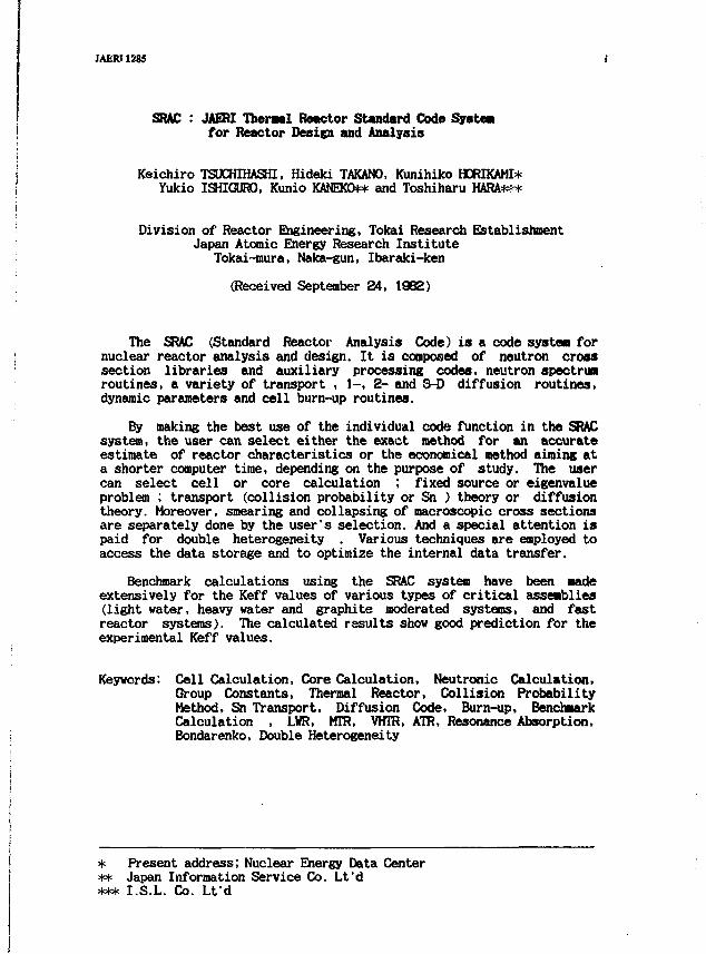
The SRAC (Standard Reactor Analysis Code) is a code systea fornuclear reactor analysis and design. It is composed of neutron crosssection libraries and auxiliary processing codes, neutron spectrumroutines, a variety of transport , 1-, 2- and 3-D diffusion routines,dynamic parameters and cell burn-up routines.
By making the best use of the individual code function in the SRACsystem, the user can select either the exact method for an accurateestimate of reactor characteristics or the economical method aiming ata shorter computer time, depending on the purpose of study. The usercan select cell or core calculation ; fixed source or eigenvalueproblem ; transport (collision probability or Sn ) theory or diffusiontheory. Moreover, smearing and collapsing of macroscopic cross sectionsare separately done by the user's selection. And a special attention ispaid for double heterogeneity . Various techniques are employed toaccess the data storage and to optimize the internal data transfer.
Benchmark calculations using the SRAC system have been Badeextensively for the Keff values of various types of critical assemblies(light water, heavy water and graphite moderated systems, and fastreactor systems). The calculated results show good prediction for theexperimental Keff values.
Keywords: Cell Calculation, Core Calculation, Neutronic Calculation,Group Constants, Thermal Reactor, Collision ProbabilityMethod, Sn Transport, Diffusion Code, Burn-up, BenchmarkCalculation , LWR, MTR, VHTR, ATR, Resonance Absorption,Bondarenko, Double Heterogeneity
* Present address; Nuclear Energy Data Center** Japan Information Service Co. Lt'd*** I.S.L. Co. L f d
JAERI12I5
SRAC :
±««-fi
1982 *£ 9 E 24
II ; t
SRAC
i - K , 1 . 2,
-9, '
ift,
M.
Keff
* • • I. S. L.
-U
SRAC:核設計と解析のための原研熱中性子炉
標準コードシステム
日本原子力研究所東海研究所原子炉工学部
土橋敬一郎・高野秀機・堀上邦彦.
石黒幸雄・金子邦男"・原 俊治
1982年9月24日受思
要 J富
IAEJU 1215
SRACは熱中性子炉の被段肘と解併のためのコードシ主テムである.ζのシステムli中性子断面積予
イプラリーとそのための処理コード.中性子スベクトルω計算ルーチン及び珊々の輸送コード, 1, 2.
3次元拡散ルーチンや動特性パラメ -1), 格子燃焼ルー!~ンから成っている.
SRAC の個々のコードの掻遣な利用によって.そ η目 'i~l1:従って炉特性を輔鹿島〈予測する正砲な方
法.或いは計算時間の短い経済的な方腕迦ぶ乙とがでゆ.オプシ四ンにより非斉次問魁又は固有問
題,衝突6t串法や SN法のような愉送車輸又は拡散理蛤小選ぶ乙とができる.ニ量非均質性への配.か
ら断函績の空間平均と繍約は別々に行うととができる.うr'ータの収納や内郎データの引き渡しにも喧々
のテクニックが用いられている
SRACを用いたベンチマーク計算がいろいろの臨界集計体で行われ.計算結果li実蛾値の Kerrと良
い一致を示している
-現在.原子力データセンタ-
H 日本情報サービス
・・・ I. S. L.
JAERI1285 in
Progrui Abstract in NEA DATA BAHC foraat
1. Name : SRAC
2. Computer for which the program is designed and others upon which itis possible : FACOM M-2Q0
3. Nature of physical problem solved : Cell calculation including burn-up where care is paid to solve double heterogeneity even inresonance integral, and core calculation. Applicable to any type ofthermal reactor.
4. Method of solution : Collision probability method , ID and 2D Sn forcell calculation; ID, 2D, and 3D diffusion for core calculation.
5. Restriction on the complexity of the problem : Not more than twodifferent mixtures in a cell which have resolved resonance levels
6. Typical running time : It varies by the number of energy group,geometry option, and with or without burn-up calculation.
7. Unusual features of the program : POS files are used to transfer andkeep the libraries, macroscopic cross sections, neutron fluxes,etc..
8. Related and auxiliary programs : PROF-GROUCK Gil to update the fastneutron library. TIMS to update the unresolved resonance data inthe library. SRACTLIB to update the thermal neutron library.PDSEDT and PDSEEGRP to control and edit of PDS files.
9. Status : Under testing
10. References : JAERI-1285
11. Machine requirement : 768 KB core memory for normal work area of60,000 words. Plotter facility
12. Programming language used : FACOM Fortran IV
13. Operating system or monitor under which the program is executed :FACOM OS IV
14. Any other programming or operating information or restrictions :A PDS file (Partitioned Data Set) is used with undefined recordformat. A member contains an array of binary data. An assemblerroutine RWPDSF enables read, write, rename, and delete member byFortran statements
15. Name and establishment of author : K. Tsuchihashi et al, JAERITokai establishment Tokai-mura Japan
16. Material available : the present report
JAERI1285
Foreword
A number of computer codes have been introduced from foreigncountries and also developed at Japan Atomic Energy ResearchInstitute(JAERI) for thermal reactor analysis. Unfortunately, thesecodes have been used separately at the individual sections orlaboratories on the various usages of methods adopting differentnuclear data libraries. This situation has been occasionally introducedsome troublesome problems at safety licensing stage, for instance.Hence, the necessity of standard analysis code system has beenpersisted for a detailed estimate of reactor characteristics, safetyanalysis, fuel cycle strategy etc.. On the other hand, thestandardization under state of the art has been thought to be possibleat the present state where much knowledge has been accumulated both onexperimental and theoretical fields.
The JAERI thermal reactor standard code committee was started onJuly 1978 at The Tokai Establishment for the purpose of standardizingthe data and method used in thermal reactor design study. Three workinggroups were estadished under the committee and, since then, haveplayed an active part in standardizing the data and method that can becommonly used with high reliability in the design and analysis of avariety of thermal reactors . This standardization was thought of beingessential to safety analysis of thermal reactors, detailed design ofVHTR, reconstruction plan of research reactors, establishment ofnuclear energy strategy etc.. Here, in setting forward thestandardization, the intent was to enhance the development efficiencyof the code system and to generalize the code system under a newviewpoint based on the technological level of this age and under anunified control of the committee.
The standard reactor analysis code (SRAC) system has beendeveloped during the four years of active work under one of the workinggroups, the nuclear design working group. Benchmark calculations usingthe SRAC system have been made extensively for the Keff values ofvarious types of critical assemblies (light water, heavy water andgraphite moderated systems, and fast reactor systems). The SRAC systemhas been successfully applied to the works for the reconstruction planof The Japan Research Reactor-3 (JRR-3) and for the reduction of fuelenrichment of JAERI research reactors and Japan Material TestingReactor (JKTR). Its application has been also made for thereconstruction plan of Semi-Homogeneous Experiment (SHE) assembly forVery High Temperature Gas-Cooled Reactor (VHTR) development.
The extension work of the SRAC system continues for fuel cyclecalculation. Moreover, the nuclear design working group makes a plan toamalgamate the SRAC system with the fruits of other two working groups.
JAERI1285
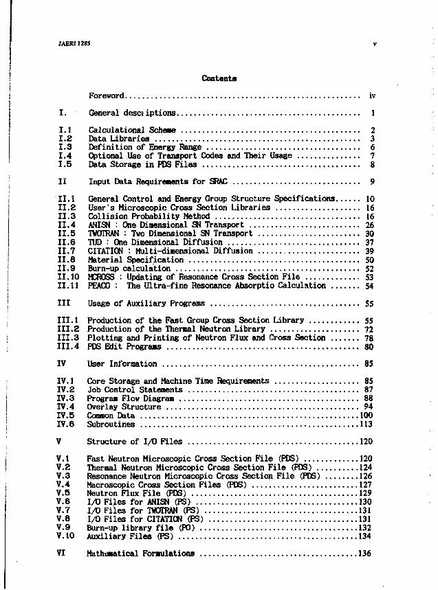
Contents
Foreword iv
I. General desct iptions 1
1.1 Calculational Scheme 21.2 Data Libraries 31.3 Definition of Energy Range 61.4 Optional Use of Transport Codes and Their Usage 7
1.5 Data Storage in PDS Files 8
II Input Data Requirements for SRAC 9
II. 1 General Control and Energy Group Structure Specifications 1011.2 User's Microscopic Cross Section Libraries 1611.3 Collision Probability Method 1611.4 ANISN : One Dimensional SN Transport 2611.5 TWDTRAN : Two Dimensional SN Transport 3011.6 TUD : One Dimensional Diffusion 3711.7 CITATION : Multi-dimensional Diffusion 3911.8 Material Specification SO11.9 Burn-up calculation 52II. 10 MCROSS : Updating of Resonance Cross Section File 5311.11 PEACO : The Ultra-fine Resonance Absorptio Calculation 54III Usage of Auxiliary Programs 55
III. 1 Production of the Fast Group Cross Section Library 55111.2 Production of the Thermal Neutron Library 72111.3 Plotting and Printing of Neutron Flux and Cross Section 78111.4 PDS Edit Programs 80
IV User Information 85
IV. 1 Core Storage and Machine Time Requirements 85IV.2 Job Control Statements 87IV.3 Program Flow Diagram 88IV.4 Overlay Structure 94IV.5 Common Data 100IV.6 Subroutines 113
V Structure of 1/0 Files 120
V.1 Fast Neutron Microscopic Cross Section File (PDS) 120V.2 Thermal Neutron Microscopic Cross Section File (PDS) 124V.3 Resonance Neutron Microscopic Cross Section File (PDS) 126V.4 Macroscopic Cross Section Files (PDS) 127V.5 Neutron Flux File (PDS) 129V.6 1/0 Files for ANISN (PS) 130V.7 1/0 Files for TWOTRAN (PS) 131V.8 I/O Files for CITATION (PS) 131V.9 Burn-up library file (P0) 132V.1O Auxiliary Files (PS) 134
VI Mathematical Formulations 136

JAERI1285
VI.1 Group Cross Sections in the Fast Neutron Library 136VI.2 Group Cross Sections in the Thermal Neutron Library 146VI.3 Optional Processes for Calculational Method of Transport Cross
Sections and Diffusion Coefficients 1S1VI.4 Optional Processes for Resonance Absorption 155VI.5 Collision Probability and Applications -.168VI.6 Collapsing of Energy Structure for Few Group Calculations 187VI.7 Burn-up Calculation 191
VII Dictionaries 194
VII. 1 Element Tag 194VII.2 Compound Symbol 195VII.3 Nuclides in the SRAC Public Libraries 195VII.4 Energy Group Structure of the SRAC Public Libraries 199VII.5 Burn-up Chains 202VII.6 Temperatures 212
VIII Applications ; Benchmark Calculations 213
VIII.1 Benchmark Calculation of TCA (Light-Water Moderated Assembly) .213
VIII.2 Benchmark Calculation of JMTRC (Japan Material Testing ReactorCritical Facility) ; 215
VIII.3 Benchmark Calculation of DCA (Heavy-Water Moderated Assembly) .Initial Core 218
VIII.4 Benchmark Calculation of SHE (Graphite Moderated Assembly) 219VIII.5 Benchmark Calculations of Fast Critical Assemblies for
Assessment of Fast Energy Group Constants 2?3
IX Sample Input and Output 225
IX. 1 Pin-Rod Cell and Burn-up Calculation 225
IX.2 Plane Cell and Core Calculation . 230
Acknowledgements 239
References 239
JAERI1285 vif
B *
ivI. « 15 1I. 1 It*x + -A 2I. 2 x-*5-f 7*5 <)- : 3I. 3 i*^**-|gfflO£« 6I. 4 awWttlftg^-^yieoipjffi 7I . S PDS7r'f;HtJ:.5f-:?©8?» 8n. SRAC ©A# 9II. 1 -ftfflavl-D-^ix^u+'-gMaJtOf&JE 10II. 2 fiJffl#©*«WKrIi*7<f 7 5 ' J - 16ii. 3 mmmmm ieII. 4 ANISN : -&7C SN tftig 26II. 6 TWOTRAN : r&Ti; SN tftg 30
II. 8 TUD : HfcS&ft 37n . 7 CITATION : £<fc£j£»: 39
n . 8 tlHOfliJS 50
n. 9 mm$m 52O.I0 MCROSS: «flfi*Wffi«7 r-( * « M 53n. 11 PEACO : mm&mmftim 54IK. ftJSrD/7A 55ni. 1 &i£+tt:p7'f y ? y-©ftfi£ 55III. 2 »*tt?7'f7'5'J-©ffBK 72ID. 3 BfB»4*tt^*©7-D.y (- 78
ffl. 4 PDS 7 T -f O«I6 80IV. fUffl#««i 85
IV. 1 E«S«il+»0fS«fH 85IV. 2 i>3/3yfD-«f-M>'|> 87
IV. 3 7 D o / 7 i 7 P - ^ r 5 ' 7 i 88
IV. 4 *-'<-!• 4 «£ 94IV. 5 a t v f - j 100
IV. 6 t / A - ? y 113
V. AtHtiy r -f ©*iS 120
V. 1 &84ite?»«itt*Tffi»7 r A * 120V. 2 «l*tt?»a«BTffi«7 T-< 124
V. 3 * # * i t t ? * » t t M B * 7 T 4 *- 126V. 4 E«W»rffi*7 T 4 " 127V. 6 tp t t ; f ^7T ' f* 129V. 6 ANISN»fflAW*7r'f^ 130V. 7 TWOTRAN *fflAtii2j 7 T - ( * 131V. 6 CITATION mmAthtl7 r 1 * 131
m IAERI1285
V. 9 ««SIt»7'f ^ 7 ' J - 7 T - f ^ 132
V. 10 *©ffe©7 W ^ 134VI. S^WiB^ 136
vi. i K i * * t t ? 7 - f yy>)-a>m»mm 136VI. 2 mfri&yi 7*7 y-©SfrffiW 146VI. 3 «iilfrE*fffififc<£»©«iRW71'o-(rx 151VI. 4 *«IJ&iRfflSHRtt7"a-iix 155
VI. 5 f5Sg«$£*©JEffl 168VI. 6 '>»#S»®;fcsl©gMJ!i&©»!& 187
VI. 7 ««SltW 19JVD. - K 2 t 194«1. 1 &«*SIJ:>-K 194
VD. 2 it&mmfA^-V 195
TO. 3 # # 7 4 7"7'J-©(*«-« 195Vn. 4 Miyi ^5iJ-ffli**+'-Hliifi 199
VH. 6 «$«5**-y 202
VII. 8 (fl BE 212
VI. IJSm : ^Xf -v - :? l tW 213
VI. 1 TCA©'*:'*-?-?!!-!-* 233« . 2 JMTRCO^'i'-fT-i'It* 215
VI. 3 DCA <D<*v?^-9im 218VI. 4 SHEC'-O'TW-^ltat 219VI. 5 iUa+fe^SSKffl^flSOfctoOiliiiEISII^^O^^^v-^ltW 223
K. AtiJA©W 225IX. 1 fyn-v KtS^iJ-O^ffiltW 225IX. 2 ¥*£&•? £-t©««&§t* 230
IB 5* 239X iK 239
JAER11285
I. General Descriptions
The SRAC system is designed so as to have a unique feature bypositively incorporating the data and methods which have been developedand verified in JAERI. Furtheris e, this system is designed to allow avariety of usages described as follows :
1) The fundamental group constant library has been produced painly fromthe ENDF/B-IV nuclear data file (Ref.(l)) with the energy groupstructure of 107 groups (45 groups for thermal and 74 for fast energyranges, respectively, with 12 overlapping groups). The library holdsthe Bondarenko type table (Ref.(2)) for resonance shielding factors andkeeps, additionally, the resonance parameters on the energy rangebetween 130.7 to 0.4 eV for the optional use of intermediate resonanceapproximation (Refs.O, 4)) or the rigorous calculations using thecollision probability method (Ref.(5)).
The thermal group-to-group transfer matrices are compiled on theeleven fixed-temperatures. The macroscopic cross sections used in cellcalculations are generated on any of the given temperatures. The groupconstants for core calculations can be obtained on arbitrarytemperatures by the linear interpolation of the resulting effectivecross sections.
2) The user must construct his own library from the fundamental libraryfor the desired nuclei and temperatures with his own energy groupstructure, where the thermal cut off energy can be chosen from theoverlapping energy range between the thermal and fast energy regions.
3) The SRAC system can solve the fixed source problem in a partialenergy range, which is mainly used for cell calculation, and can alsosolve the eigenvalue problem in the whole energy range which appears incell and/or core calculation.
4) A variety of the transport codes are available for cell calculations(collision probability method with 14 types of geometries (Ref.(6) ),1D-SN (Ref. (7)), 2D-SN (Ref. (8)). The one space-point solution by P|or B[ approximation (Ref.(9)) is also available after smearing thecross sections.
5) The 1-, 2- and 3-D diffusion codes (Ref.(10)) in addition to abovementioned transport codes are available for normal and adjoint fluxcalculations.
6) Shearing and/or collapsing of macroscopic cross sections is doneseparately by the user's selection.
7) Double heterogeneity such as the grain effect in the HFGR fuel rodor the pin rods in a channel box can be treated by utilizing smearedcross sections obtained from homogenizing the microscopic heterogeneityinto the macroscopic heterogeneity.
8) The several PDS (Partitioned Data Set) files (Ref. 01)) are used forthe data storage. The built-in FACOM utility program is used for thefile control (LIST DIRECTORY, DELETE, CONDENSE, COPY, RENAME), and afew service programs are ready to read/write the contents of thesefiles.
? SRAC: JAERI Thermal RetctorStintod Code Syrtem for Reirtoi Derijn and Analysis JAERI128S
By making the best use of the specific character of the SRACsystem, the user can select either the exact method for accuracyassessment or the economical method aiming at a shorter computer time,depending on the purpose of study
In this report, descriptions are given at first on an outline ofthe SRAC system. Successively described are instructions to the userabout input data requirements for the SRAC system and its auxiliarycodes , user information needed in use of the SRAC system, structure ofI/O file, formulations used in the methods adopted, dictionaries andsample I/O.
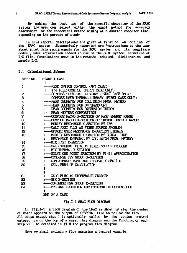
I.I Calculational Scheme
STEP NO. START A CASEI
1 +—READ OPTION CONTROL (ANY CASE)I and FILE CONTROL (FIRST CASE ONLY)
2 +—OPPOSE USER FAST LIBRARY (FIRST CASE ONLY)3 +—COMPOSE USER THERMAL LIBRARY (FIRST CASE ONLY)4 +—READ GEOMETRY FOR COLLISION PROB. METHOD5 +—READ GEOMETRY FOR SN TRANSPORT5' +—READ GEOMETRY FOR DIFFUSION THEORY6 H READ MIXTURE COMPOSITION7 •* COMPOSE MACRO X-SECTION OF FAST ENERGY RANGE8 -i COMPOSE MACRO X-SECTION OF TPEHMAL ENERGY RANGE10 H MODIFY RESONANCE X-SECTION BY IRA11 H CALC FAST FLUX AS FIXED SOURCE PROBLEM12 H UPDATE USER RESONANCE X-SECTION LIBRARY13 H MODIFY RESONANCE X-SECTION BY ULTRA- FINE
I RESONANCE INTEGRAL BY COLLISION PROB. METHOD14 i MIX FAST X-SECTION15 H CALC THERMAL FLUX AS FIXED SOURCE PROBLEM16 ^ MIX THERMAL X-SECTION17 H SOLVE ONE POINT SPECTRUM BY Pl-Bl APPROXIMATION18 H CONDENSE FEW GROUP X-SECTION19 H CONCATENATE FAST AND THERMAL X-SECTION20 H CELL BURN-UP CALCULATION
II
21 H CALC FLUX AS EIGENVALUE PROBLEM22 H MIX X-SECTION23 •* CONDENSE FEW GROUP X-SECTION24 H PREPARE X-SECTION FOR EXTERNAL CITATION CODE
IEND OF A CASE
Fig.1-1 SRAC FLOW DIAGRAM
In Fie.1-1, a flow diagram of the SRAC is shown by step the numberof which appears on the output of SYSPRINT file to follow the flow.All steps except step 1 is optionally called by the option controlentered in on the top of a case. This diagram and the function of eachstep will be detailed in IV.3 the program flow diagram.
Here we shall explain a flow assuming a typical example.
JAER11285 I. General deicriptlon
Specification of the example
Cell calculation for a pin rod lattice cellin fixed source problemby collision probability methodwhere resonance integral by IRA approximation
Core calculation for simplified core of a homogenized active coresurrounded by reflectorin eigenvalue problemin multigroup energy group structureby one-dimensional diffusion theory calculation
Condense of macroscopic cross sections for external CITATION
The following steps are traced to execute the above example as;Step 1 read the option and file controlStep 2,3 prepare the user fast and thermal libraries by specifying the
energy group structure, nuclides, temperaturesStep 4 read the geometry of the pin rod cell for collision methodStep 6 read the geometry of tne core for one-dimensional diffusion
calculationStep 6' read the edit control for the macroscopic cross sections in
format of CITATIONStep 10 modify cross sections in resolved resonance energy range by
IRA approximationStep 11 solve linear equations in the fast energy range by collision
probability methodStep 14 homogenize cross sections using the spatial distribution of
neutron flux obtained by cell calculationStep 15 solve linear equations in the thermal energy range by col-
lision probability methodStep 16 homogenize cross sections using the spatial distribution of
neutron flux obtained by cell calculationStep 17 calculate Kinf,Keff by a point modelStep 19 concatenate fast and thermal cress sections into a set for
succeeding core calculationStep 20 solve an eigenvalue problem for a core calculation by one-
dimensional diffusion routineStep 23 condense cross sections into those of few group structure using
neutron fluxes obtained in the above core calculationStep 24 store macroscopic cross sections in catalogued file for
external use of CITATION
1.2 Data Libraries
There are two kinds of nuclear group constants libraries : One isnamed 'Public' (P) library, which is the fundamental one in the "3RACsystem, and the other is 'User'(U) library. The U-library is used asthe user's own library after the group constants in the P-library arecollapsed into the proper group number for the necessary number ofnuclei. All the calculations can be started from the U-library onceafter it is created. The addition Gf new nuclides to the U- library canbe readily made.
The present P-library was produced by processing the nuclear datafiles ENDF/B-III (Ref.(12)) and IV (Ref.(D). The nuclides cited fromthese files are listed in Dictionary VII.3. Some evaluation works(Ref .(13)) were also made for Hf isotopes, which were not included in
4 SRAC: JAERI Thermal Reactor Standard Code System for Roactor Design and Analysis JAERI1285
the ENDF/B-IV. The P-library is planned to be replaced by a librarybased on the JENDL-2B nuclear data file (Ref. (14)).
1.2.1 Energy Group Structure
The energy group structure of the P-library is shown in DictionaryVII.4, where the energy range from 10 MeV to 1.8554 eV is divided bythe lethargy width of 0.25 into 62 groups, that from 1.8554 to 0.41399eV by the lethargy width of 0.125 into 12 groups and the energy regionbelow 0.41399 eV is divided with the equal velocity width of 270m/secinto 33 groups. The structure corresponds to those widely adopted inthe world for thermal and fast reactor analysis, hence has aconvenience when comparison is made among the cross section librariesand/or the calculated results.
The P-library is classified into the library corresponding to thefast neutron energy region (En fe 0.41399 eV) and that to the thermal(En S 3.9279 eV), with the overlapping region (3.9279 eV £ En £0.41399 eV). This overlapping region is provided for the optionalchoice of the thermal cut off energy to take account of the thermalneutron spectrum shift due to higher temperature or to leave the optionfor the treatment of the first resonance level of m P u .
1.2.2 Group Constants in Fast Neutron Energy Region
The fast neutron energy region is defined as the range from 0.41399eV to 10 MeV, which includes all the energy ranges except for thethermal neutron energy range described in Sect.1.3. The group constantsin this energy region are arranged in the form of the cross section setof the Bondarenko type (Ref.(2)), that is, the self- shielding factorsare given for scattering, removal, capture, fission and transport crosssections, which are tabulated by temperature T and admixed crosssection ao . This library carries also the standard spectrum forcollapsing the P-library into the U-library. The angular dependence ofelastic scattering is taken into consideration up to the P| component,for which the shielding factor is presently not prepared. The presentlibrary was produced by use of PROF GROUCH-GII code (Ref.(15)) andTIMS-1 code (Ref. (16)).
1.2.3 Resonance Parameters and MCROSS Library
The effective resonance cross sections in the second resonancerange defined in Sect.1.3 are, on simple treatment, calculated by thecombined use of the intermediate resonance approximation (IRA) and thetable-look-up method of the resonance shielding factors, while those inthe first resonance range are always obtained by the method based onthe narrow resonance approximation (NR), which is widely used in fastreactor analysis. The resonance parameters needed for the IRA areaccommodated in the fast group constants library. In Dictionary VII.3 ,the assignment IRES = 1 is given to the nuclides having the parameters.
The SRAC system provides another option, by which the effectiveresonance cross sections in the second resonance region are calculatedwith the collision probability method using the ultrafine energy groupstructure of 4600 points (Dictionary VII.4). The resonance cross
JAERI1285 I. General deieripUon
section library needed for the ultrafine group calculation is given,for every temperature used, by the MCROSS-2 code (Ref.(17)) and storedin the PDS files (See Sect.I.5) . Here in general a multilevelformalism is used for the cross section representation (Ref.(18)), andthe necessary multilevel parameters are also prepared for the energyrange( g 130.07 eV) in the fast group constant library.
1,2.4 Group Constants in Thermal Energy Region
The thermal neutron scattering library consists of the matriceswith fixed dimension of 45 energy groups. For moderator materials, thescattering matrices were constructed from the scattering lav S(a,H) andtabulated on the discrete values of temperature. Especially for themoderators for which the chemical binding effects are important, thecoherent elastic scattering cross section calculated by the HEXSCATcode (Ref.(19)) was added.
The self-shielding factors were prepared for the fission andcapture cross sections of the nuclides whose resonance levels exist inthe thermal neutron energy region. For some of such nuclides, arepresentative matrix without temperature dependence was assigned forall the temperatures used in the tabulation of the thermal library,because of their smaller contributions to neutron energy transfer inpractical reactor calculation. Here, the weighting spectrum used forcollapsing the P-library into the U-library was assumed to be (theMaxvellian distributions corresponding to the above temperatures + 1/Espectrum), commonly for all the nuclides concerned.
1.2.5 Nuclear Data for Depletion Calculation
Several fission product models (Refs.(20 - 24)) for BWR latticecalculation have been proposed, which consist of a few explicitnuclides and several pseudo groups representing the residualabsorption. In the SRAC system, three models are available, dependingon the purpose of burnup calculations.
The first model of Garrison and Roos (Ref.(20)) consists of twoexplicit nuclides (Xe-135 and Sm-149) and three pseudo groups (rapidlysaturating, slowly saturating and non-saturating fission products).This model is very useful for economical calculations of cell burn-up.The group cross sections were produced from ENDF/B-II for three pseudofission products and from the ENDF/B-IV {Ref.(1)) for two explicitnuclides, respectively. The nuclear data of ENDF/B-IV are used forhalf-lives and fission yields for these nuclides.
Secondly, a detailed model by Iijiraa et al.(Ref.(22)) is availableto predict the burnup reactivity chaiige with high precision. This modelconsists of 45 explicit nuclides and one pseudo group. The nuclear dataof ENDF/B-IV were used for half-life and fission yield data. The groupconstants of the explicit nuclides were mostly produced from ENDF/B-IV,except for Cd-113,Xe-133,Cs-134 and pseudo fission product.
Thirdly, the VSOP-chain model (Ref.(24)) developed in KFA Jeulichis available. In this model, four branches can be selected, whichconsist of 27, 32, 37 and 42 explicit nuclides, respectively. The groupcross sections for these nuclides were produced from ENDF/B-IV. For the
; SRAC: JAERI Theimd Reactor Standard Cede Svrtem foi Reactor Dejijn and Analyiii JAERI1285
fission product yields, the data recommended in the VSOPscheme are used.
1.3 Definition of Energy Range
The method producing the cross section library, the methodologyused and the way to divide spatial meshes in the SRAC system are ingeneral changeable depending on the energy range. Here the energy rangeis defined as follows :
i) Fission Energy Range
This range corresponds to the fast energy region higher than thethreshold energy of fertile nuclei , where the weighting spectrum usedfor producing the P-library is assumed to be fission spectrum. Theenergy averaged spectrum in each group is used as the standard one forthe P-library collapsing into the U-library. For lower enriched fuelrods with larger radius, fast fission effect and its heterogeneityeffect are important in this energy range.
ii) Smooth Energy Range
Since the fluctuations of the various reaction cross section arerather small in the energy range below about 1 MeV, the neutron energyspectrum is smooth, hence the spatial distribution can be assumed to beflat. Though there happen to be some small variations in the neutronspectrum due to the resonance scattering of light and medium weightnudides, this effect is not so important in thermal reactor. Theweighting spectrum is assumed to be l/(EEt(/',•) , as well as in thefollowing two energy ranges. The energy averaged spectrum is again usedas the standard one.
iii) The First Resonance Range
Below about 50 KeV, fine structure appears in the neutron spectrumdue to isolated and/or statistical resonance levels of heavyisotopes .and the Doppler effect must be taken into account. For heavyresonant nuclides, an exact calculation is made for the resonanceshielding- factor production using TIMS-1 code (Ref.(16)). There ishowever no special difference in programing between the smooth andresonance energy ranges in the SRAC system.
iv) The Second Resonance Range
This energy range corresponds to be lower resonance energy regionwhere are many sharp and strong resonance levels of fission and fertileisotopes. A special attention must be paid for this range in thermalreactor analyses, because most of resonance absorption occur in thesestrong resonances. The resonance shielding-factors for heavy resonantisotopes are obtained again by the exact calculation. The upper energyboundary of this range is fixed to be 130.07 eV( u = 11.5 ), while thelower energy boundary is selected by the user from one of the groupenergy boundaries of the SRAC library between 3.9279 and 0.41399 eV,depending on the problem under study. The lower boundary is located inthe overlapping region previously mentioned. Here, for a simplecalculation the intermediate resonance approximation is used for
JAERII28S I. General deKtlption S
calculating the effective resonance cross sections, and the ultrafinespectrum can be also calculated by use of the collision probabilitymethod when higher accuracy is needed.
v) Thermal Neutron Energy Range
Since the thermal scattering matrices in the library are preparedonly for the given temperatures, the calculations of the thermalneutron spectrum are restricted in the temperature that can be treated,hence some interpolations would be needed for a detailed calculation oftemperature coefficients. The scattering up to the second resonancerange can be taken into consideration only with the few groupcalculation after the homogenized cross sections are obtained.
1.4 Optional Use of Transport Codes and Their Usage
Several kinds of optional paths can be available for neutrontransport and/or diffusion calculations. The path based on thecollision probability method can treat the 14 types of geometries shownin Fig.II.3-1 . The SN path adopts the ANISN code (Ref.(7)) for IDcalculation and the TWOTRAN code (Ref.(8)) for 2D, respectively. On theother hand, the diffusion code CITATION (Ref.(10)) is generally usedfor the diffusion-calculation path, though the ID code TUD (Ref.(6)) isadditionally prepared for the sole purpose of ID calculation. Anyselection from these pathes is possible for each energy range exceptfor the second resonance energy range in cell calculation. Theultrafine group calculation based on the intermediate resonanceapproximation (IRA) of the resonance absorption in the second resonancerange always uses the collision probability method.
The neutron spectrum calculation for smearing and/or collapsingof macroscopic cross sections can be made by choice of a propersequence of the paths. Moreover, the P\ or B\ approximation based onthe fundamental mode assumption is available for the nultigroupcollapse into few group after smearing the multigroup cross sections.
Particularly for cell calculations, various space regions andmeshes are defined to enhance the calculation accuracy or to save thecomputer time, as the needs of the case demand.
i) Sub-region
This is the fundamental region that is formed by the lines orcircles used to define the geometry under consideration for thecollision probability program.
ii) T-region
Each 'T'-region consists of a few sub-regions when the neutron fluxdistributions in the sub-regions are the same due to geometricalsymmetry or when those in the adjacent sub-regions can be assumed to bethe same due to the smallness of their cross sections or of theirvolumes. This T"-region is used for the calculation of the spatialfine structure of the neutron flux in the thermal energy range.
iii) R-regioa
8 SRAC: JA ERI Thermal Retctoi Standard Code System for Retctoi Design and Anilyr J JAERI12S5
In some cases of the neutron flux calculations in the fission orresonance energy range, it is not always necessary to divide thegeometry into so many meshes as in the thermal energy range. Such beingthe case, several T-regions are collected to form the R- region.
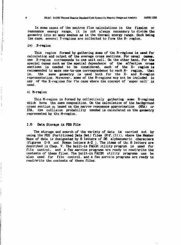
iv) X-region
This region formed by gathering some of the R-regions is used forcalculation and output of the average cross sections. For usual cases,one X-region corresponds to one unit cell. On the other hand, for thespecial cases such as the spatial dependence of the effective Croatsections is needed to be considered, each of the X- region isrecommended to make one-to-one correspondence to each R- region, thatis, the same geometry is used both for the X- and R-regionrepresentation. Moreover, some of the R-regions may not be included inany of the X-reg:Lons for the case where the concept of 'super cell' isused.
v) M-region
This M-region is formed by collectively gathering some R-regionswhich have the .same composition. On the calculation of the backgroundcross section oo based on the narrow resonance approximation (NRA) orIRA, the collision probability needed is calculated on the geometryrepresented by the M-region.
1.5 Data Storage in PBS File
The storage and search of the variety of data is carried out byusing the PDS (Partitioned Data Set) files (Rnf.(il)), where the MeatberName of data is designated by 8 letters of 36 alphanumeric characters(figures 0-9 and Roman letters A-Z ). The items of the 8 letters aredescribed in Chap. V. The built-in FACCfl utility program is used forfile control, and a few service programs fire ready to read/write thecontents of these files. The built-in FACOM utility programs can bealso used for file control, and a few service programs are ready toread/write the contents of these files.
JAER1128S '•
II Input Data Requirements for SRAC
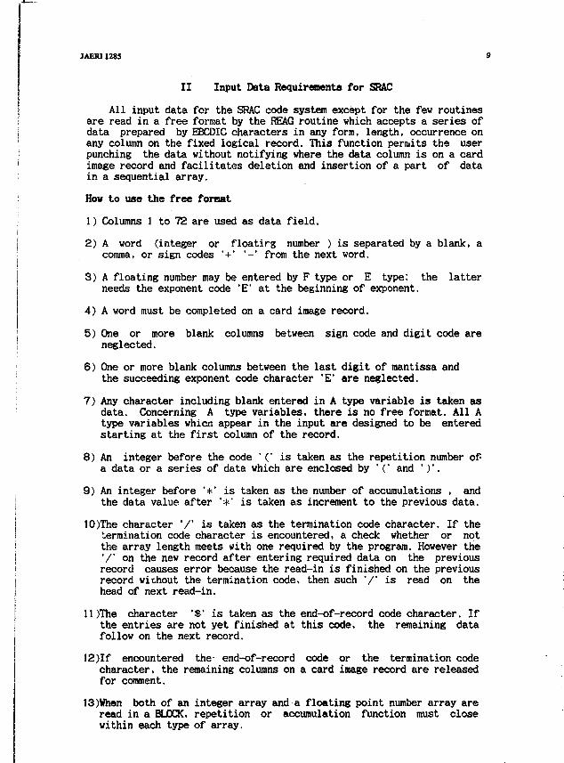
All input data for the SRAC code system except for the few routinesare read in a free format by the REAG routine which accepts a series ofdata prepared by EBCDIC characters in any form, length, occurrence onany column on the fixed logical record. This function permits the userpunching the data without notifying where the data column is on a cardimage record and facilitates deletion and insertion of a part of datain a sequential array.
How to use the free fornat
1) Columns 1 to 72 are used as data field.
2) A word (integer or floatirg number ) is separated by a blank, acomma, or sign codes '+' '-' from the next word.
3) A floating number may be entered by F type or E type; the latterneeds the exponent code "E" at the beginning of exponent.
4) A word must be completed on a card image record.
5) One or more blank columns between sign code and digit code areneglected.
6) One or more blank columns between the last digit of mantissa andthe succeeding exponent code character 'E' are neglected.
7) Any character including blank entered in A type variable is taken asdata. Concerning A type variables, there is no free format. All Atype variables whicn appear in the input are designed to be enteredstarting at the first column of the record.
8) An integer before the code '(' is taken as the repetition number ofa data or a series of data which are enclosed by '(' and ' ) ' .
9) An integer before '*' is taken as the number of accumulations , andthe data value after '*' is taken as increment to the previous data.
10)The character '/' is taken as the termination code character. If thetermination code character is encountered, a check whether or notthe array length meets with one required by the program. However the'/' on the new record after entering required data on the previousrecord causes error because the read-in is finished on the previousrecord without the termination code, then such '/' is read on thehead of next read-in.
Il)The character '$' is taken as the end-of-record code character. Ifthe entries are not yet finished at this code, the remaining datafollow on the next record.
12)If encountered the- end-of-record code or the termination codecharacter, the remaining columns on a card image record are releasedfor comment.
13)When both of an integer array and a floating point number array areread in a BLOCK, repetition or accumulation function must closewithin each type of array.
10 SRAC: JAERIThemalRetctotStuidud Code System for RMCtorDed|nudA]»lyili JAERI1285
ExamplesA record ' 1 0.0002 3. E-3 -.4E3 $ COMMENT ' is accepted as
' 1.0 2.0E-3 3.0E-3 -4.0E+2
A record " 5(2.) 2*1 $ COMMENT ' is accepted as' 2.0 2.0 2.0 2.0 2.0 3.0 4.0
A record ' 2+2-3 El+1 2(5 6)1 2.0 2.0 -30.0 1.0 5. 6. 5. 6.
' is accepted as
Although data type (A, I, or E) of variable or array in thefollowing description is not always mentioned, the user can recognizeA-type data by finding Hollerith count after the variable name as (4H),and concerning numerical data the user can discriminate I-type or El-type by the first character of the variable name whether if it is oneof characters I through N. For any type of numerical data the REAGroutine reads the data as floating type, then converts into integertype if required so that the user has not be so careful about datatype.
The term BLOCK appearing in the descriptions denotes one or a seriesof data required by a Fortran read statement which may be entered onany number of cards. The use of the termination code V 1 is recommendedto have suitable message if the data length is mismatched. The datalength required in BLOCK is shown as /20/ or /NRR/.
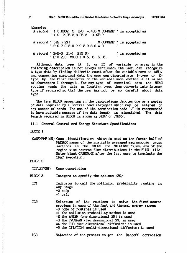
II.1 General Control and Energy Structure Specifications
BLOCK 1
CASENAME(4H) Case identification which is used as the former half ofMEMBER names of the spatially averaged macroscopic crosssections in the MACRO and MACROWRK files, and of theregion-wise neutron flux distributions in the FLUX file.Enter blank CASENAME after the last case to terminate theSRAC execution.
BLOCK 2
TITLE (72H)
BLOCK 3
IC1
IC2
IC3
Case description
Integers to specify the options /20/
Indicator to call the collision probability routine inany usage=0 skip=1 call
Selection of the routines to solve the fixed sourceproblems in each of the fast and thermal energy ranges=0 none of routines is used=1 the collision probability method is used=2 the ANISN (one dimensional SN) is used=3 the TWOTRAN (two dimensional SN) is used=4 the TUD (one dimensional diffusion) is used=5 the CITATION (multi-dimensional diffusion) is used
Selection of the process to get the Dancoff correction
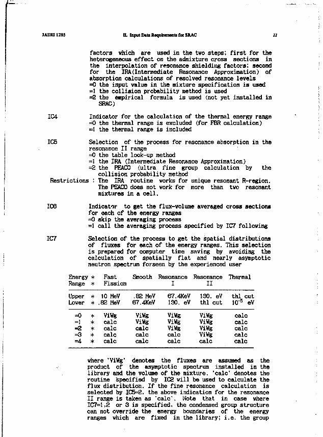
JAERI1285 D. Input Dttt Requirements fot SRAC 11
factors which are used in the two steps; first for theheterogeneous effect on the admixture cross sections inthe interpolation of resonance shielding factors; secondfor the IRA(Intermediate Resonance Approximation) ofabsorption calculations of resolved resonance levels=0 the input value in the mixture specification is used=1 the collision probability method is used^2 the empirical formula is used (not yet installed in
SRAC)
IC4 Indicator for the calculation of the thermal energy range=O the thermal range is excluded (for FBR calculation)=1 the thermal range is included
IC5 Selection of the process for resonance absorption in theresonance II range=0 the table look-up method=1 the IRA (Intermediate Resonance Approximation)=2 the PEACO (ultra fine group calculation by the
collision probability methodRestrictions : The IRA routine works for unique resonant R-region.
The PEACO does not work for more than two resonantmixtures in a cell.
IC6 Indicator to get the flux-volume averaged cross sectionsfor each of the energy ranges=0 skip the averaging process=1 call the averaging process specified by IC7 following
IC7 Selection of the process to get the spatial distributionsof fluxes for each of the energy ranges. This selectionis prepared for computer time saving by avoiding thecalculation of spatially flat and nearly asymptoticneutron spectrum forseen by the experienced user
Energy * Fast Smooth Resonance Resonance ThermalRange * Fission I II
Upper * 10 MeV .82 MeV 67.4KeV 130. eV thl cutLower * .82 MeV 67.4KeV 130. eV thl cut 10"5 eV
=0—1
=2=3=4
*****
ViWgcalccalccalccalc
ViWgViWgcalccalccalc
ViWgViWgViWgcalccalc
ViWgViWgViWgViWgcalc
calccalccalccalccalc
where 'ViWg' denotes the fluxes are assumed as theproduct of the asymptotic spectrum installed in thelibrary and the volume of the mixture, "calc* denotes theroutine specified by IC2 will be used to calculate theflux distribution. If the fine resonance calculation isselected by IC5=2, the above indication for the resonanceII range is taken as 'calc'. Note that in case whereIC7=1,2 or 3 is specified, the condensed group structurecan not override the energy boundaries of the energyranges which are fixed in the library; i.e. the group

12 SRAC: JAERI Thenml RMCUX Studud Cod* System fat Rcwtor Dtdjn i»d Amly* JAEUIMS
boundaries of the condensed energy structure have tocoincide with the boundaries of the ranges if they arethe boundaries of 'calc' and 'ViWg'.
IC8 Indicator to call MCROSS routine to create or to updatethe microscopic resonance neutron file=0 skip=1 callIf IC8=1, the user has to prepare his own file as DD=MCROSS to write the data.
•IC9 Indicator to call HOMOS' routine to calculate the one
point (bare) reactor neutron spectrum and K-infinitive=0 skip=+-1 call and PI approximation=+-2 call and Bl approximationIf negative value is read, P0 spectrum is used tocollapse the homogenized cross sections, otherwise thespectrum of infinite cell is used.
Note: The geometrical buckling given in BL0CK4 is used in theleakage term.
IC10 Indicator to call CONDENSE routine to collapse the energystructure of the macroscopic cross sections in theMACROWRK file to put into the MACRO file before theeigenvalue calculation.=0 skip=1 call
IC11 Indicator to read the geometric information of the case=0 read in the new geometry=1 skip reading and use the same as the previous case
IC12 Selection of the routine for eigenvalue calculation=0 end of the case ; go to the next case=1 the collision probability method is used=2 the ANISN (one dimensional SN) is used=3 the TWOTRAN (two dimensional SN) is used=4 the TUD (one dimensional diffusion) is used=5 the CITATION (multi-dimensional diffusion) is used
IC13 Indicator to call CONDENSE to collapse the energystructure of the macroscopic cross sections in theMACROWRK file to put into the MACRO file after theeigenvalue calculation=0 skip=1 call
IC14 Indicator to write the macroscopic cross sections in theformat of the CITATION into the PS file FT3IF001 for theseparate use of the CITATION. The energy structure of thecross section is decided by whether or not the routineCONDENSE was called in the case.
IC15 Selection of the process to compose (or define) themicroscopic total cross sections in the resonance energyrange=1 interpolation of the self-shielding factor tabulation
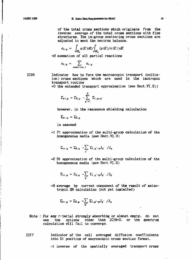
JAERI1285 n. Input D«U Requfceiwnti few SRAC 13
of the total cross sections which originate from theinverse average of the total cross sections with finestructures. The in-group scattering cross sections areadjusted to meet the neutron balance.
ot.g = f <p{E)dE/(
=2 summation of all partial reactions
°t.g = E Or,greaclion.r
IC16 Indicator how to form the macroscopic transport (collis-ion) cross sections which are used in the isotropictransport routine=0 the extended transport approximation (see Sect.VI.3))
g'-l
however, in the resonance shielding calculation
is assumed
=1 PI approximation of the multi-group calculation of thehomogeneous media (see Sect.VI.3)
V"1
=2 Bl approximation of the mul.ti-group calculation of thehomogeneous media (see Sect.VI.3)
=Q average by current component of the result of aniso-tropic SN calculation (not yet installed)
Note : For any r-rterial strongly absorbing or almost empty, do notuse the options other than IC16=0. or the spectrumcalculation will fail to converge.
IC17 Indicator of the cell averaged diffusion coefficientsinto Dl position of macroscopic cross section format.
=1 inverse of the spatially averaged transport cross
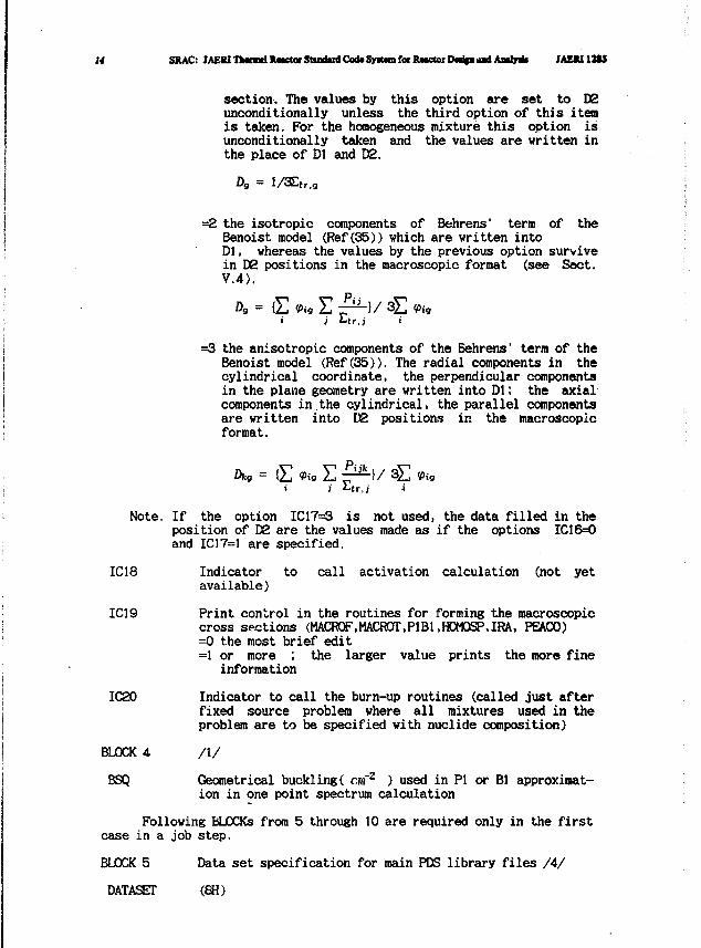
U SRAC: JAERITlxnndXmctorStandudCod*Spt«nforRMCtotDN^aaadAaily* JAEM12S3
section. The values by this option are set to D2unconditionally unless the third option of this itemis taken. For the homogeneous mixture this option isunconditionally taken and the values are written inthe place of Dl and D2.
Dg = l/S£tT,g
=2 the isotropic components of Behrens' term of theBenoist model (Ref(35)) which are written intoDl, whereas the values by the previous option survivein D2 positions in the macroscopic format (see Sect.V.4).
=3 the anisotropic components of the Behrens' term of theBenoist model (Ref(35)). The radial components in thecylindrical coordinate, the perpendicular componentsin the plane geometry are written into Dl; the axialcomponents in the cylindrical, the parallel componentsare written into D2 positions in the macroscopicformat.
Dkg = {£ Vig E £&)/ 3E 9ig
Note. If the option IC17=3 is not used, the data filled in theposition of D2 are the values made as if the options IC16=0and IC17=1 are specified.
IC18 Indicator to call activation calculation (not yetavailable)
IC19 Print control in the routines for forming the macroscopiccross sections (MACROF.MACROT.PIBI,H0M0SP,IRA, PEACO)=0 the most brief edit=1 or more ; the larger value prints the more fine
information
IC20 Indicator to call the burn-up routines (called just afterfixed source problem where all mixtures used in theproblem are to be specified with nuclide composition)
BLOCK 4 /I/
BSQ Geometrical buckling( cm'2 ) used in PI or Bl approximat-ion in one point spectrum calculation
Following BLOCKs from 5 through 10 are required only in the firstcase in a job step.
BLOCK 5 Data set specification for main PDS library files /4/
DATASET (8H)
JAERI1285 H. Input DtU RequlmnMtt foe SRAC 15
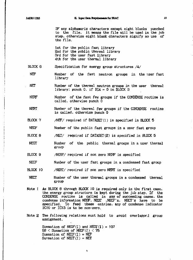
IF any alphameric characters except eight blanks punchedto the file, it means the file will be used in the jobstep, otherwise eight blank characters signify no use ofthe file.
1st for the public fast library2nd for the public thermal library3rd for the user fast library4th for the user thermal library
Specification for energy group structures /A/
Number of the fast neutron groups in the user fastlibrary
Number of the thermal neutron groups in the user thermallibrary; punch 0, if IC4 = 0 in BLOCK 3
Number of the fast few groups if the CONDENSE routine iscalled, otherwise punch 0
Number of the thermal few groups if the CONDENSE routineis called, otherwise punch 0
/NEF/ required if DATASETO) is specified in BLOCK 5
Number of the public fast groups in a user fast group
/NET/ required if DATASET(2) is specified in BLOCK 5
Number of the public thermal groups in a user thermalgroup
/NERF/ required if non zero NERF is specified
Number of the user fast groups in a condensed fast group
/NERT/ required if non zero NERT is specified
Number of the user thermal groups in a condensed thermalgroup
Note 1 As BLOCK 6 through BLOCK 10 is required only in the first case,the energy group structure is kept during the job step. If theCONDENSE routine is called in any of succeeding cases, thecondense information NEGF, NEGT ,NECF's, NECT's have to bespecified. To feed these entries, any of condense indicatorIC10 or IC13 is to be non-zero.
Note 2 The following relations must hold to avoid overlapped groupassignment.
Summation of NEGF (I) and NEGT(I) = 10758 < Summation of NEGF (I) < 75Summation of NECF(I) = NEFSummation of NECT(I) = NET
BLOCKNEF
NET
NERF
NERT
BLOCK
NEGF
BLOCK
NEGT
BLXK
NECF
BLOCK
NECT
6
7
8
9
10
16 SRAC: J AERI Thermal Retctoi Standard Code System for Recctoi Deijgn and Amlyiii MEM1285
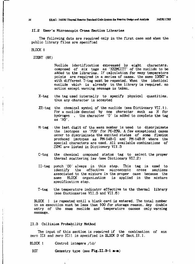
II.2 User's Microscopic Cross Section Libraries
The following data are required only in the first case and when thepublic library files are specified
BUCK 1
IDENT (8H)
Nuclide identification expressed by eight characters,composed of six tags as 'XZZMCIIT of the nuclide to beadded to the libraries. If calculation for many temperaturepoints are required in a series of cases, the same IDENTswith different f-tag must be repeated. When the identicalnuclide which is already in the library is required, noaction except warning message is taken.
X-tag the tag used internally to specify physical quantities,then any character is accepted
ZZ-tag the chemical symbol of the nuclide (see Dictionary VII.1).For a nuclide denoted by one character such as H forhydrogen , the character "0" is added to complete the tagas 'HO1.
M-tag • the last digit of the mass number is used to discriminatethe isotopes as 'PU9' for PU-239. A few exceptional casesoccur to discriminate the excited states of some fissionproduced isotopes as PM-148-G and PM-148-M where thespecial characters are used. All available combinations ofZZMC are listed in Dictionary VII.3
C-tag the chemical compound status tag to select the properthermal scattering law (see Dictionary VII.2)
II-tag punch "00" always in this step. This tag is used toidentify the effective microscopic cross sectionsassociated to the mixture in the proper case because thesame BLOCK organisation is applied in the mixturespecification step.
T-tag the temperature indicator effective to the thermal(see Dictionaries VII.3 and VII.6)
library
BLOCK 1 is repeated until a blank card is entered. The total numberin an execution must be less than 100 for storage reason. Any doubleentry of the same nuclide and temperature causes only warningmessage.
II.3 Collision Probability Method
The input of this section is required if the combination of nonzero IC1 and zero IC11 is specified in BLOCK 3 of Sect.II.1.
BLOCK 1 Control integers /I3/
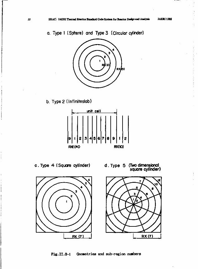
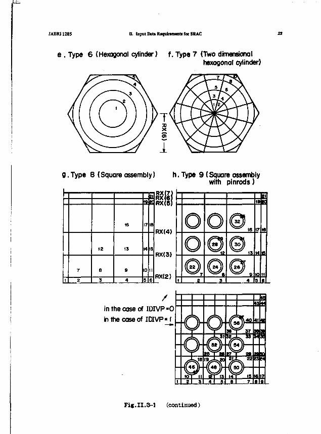
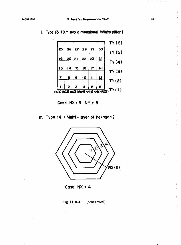
IGT Geometry type (see Fig.II. 3-1
JAER1128S II. Input Data Requirement! for SRAC 17
NZ
NR
NRR
NXR
IBOUND
NX
NY
NTPIN
NAPIN
NCELL
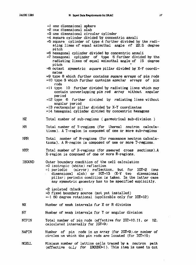
=1 one dimensional sphere=2 one dimensional slab=3 one dimensional circular cylinder=4 square cylinder divided by concentric annuli=5 square cylinder of type 4 further divided by the radi-
ating lines of equal azimuthal angle of 22.5 degreepitch
=6 hexagonal cylinder divided by concentric annuli=7 hexagonal cylinder of type 6 further divided by the
radiating lines of equal azimuthal angle of 15 degreepitch
=8 octant symmetric square pillar divided by X-Y coordi-nates
=9 type 8 which further contains square arrays of pin rods=10 type 3 which further contains annular arrays of pin
rods=11 type 10 further divided by radiating lines which may
contain unoverlapping pin rod array without angularperiod
=12 type 6 further divided by radiating lines withoutangular period
=13 rectangular pillar divided by X-Y coordinates=14 hexagonal cylinder divided by concentric hexagons
Total number of sub-regions ( geometrical sub-division )
Total number of T-regions (for thermal neutron calcula-tions). A T-region is composed of one or more sub-regions
Total number of R-regions (for resonance neutron calcula-tions). A R-region is composed of one or more T-regions.
Total number of X-regions (for smeared cross sections).AX-region is composed of one or more R-regions.
Outer boundary condition of the cell calculation=0 isotropic (white) reflection=1 periodic (mirror) reflection, but for IGT=2 (one
dimensional slab) or IGT=13 (X-Y two dimensionalpillar) periodic condition is taken. In the latter caseany symmetric geometry has to be specified explicitly.
=2 isolated (black)=3 fixed boundary source=-1 60 degree rotational
(not yet installed)(applicable only for IGTT=12)
Number of mesh intervals for X or R division
Number of mesh intervals for Y or angular division
Total number of pin rods (effective for IGT=1O,11, or 12,calculated internally for IGT=9;
Number of pin rods in an array (for IGT=9.).or number ofcircles on which the pin rods are located (for IGT=!0>
Minimum number of lattice cells traced by a neutron path(effective or.ly for IBOUND=1). This item is used to cut
18 SRAC: JAERI Theinul Retctoi Sttndud Code Syitem for Retctoi Derifn and Antlysb JAERI 12(5
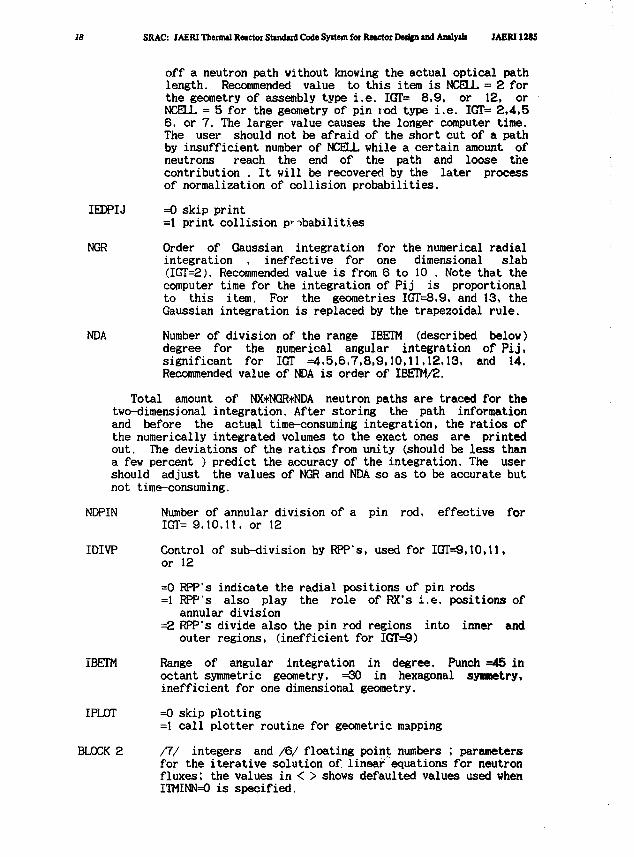
off a neutron path without knowing the actual optical pathlength. Recommended value to this item is NCELL = 2 forthe geometry of assembly type i.e. IGT= 8,9, or 12, orNCELL = 5 for the geometry of pin rod type i.e. IGT= 2,4,56, or 7. The larger value causes the longer computer time.The user should not be afraid of the short cut of a pathby insufficient number of NCELL while a certain amount ofneutrons reach the end of the path and loose thecontribution . It will be recovered by the later processof normalization of collision probabilities.
IEDPIJ =0 skip print=1 print collision probabilities
NGR Order of Gaussian integration for the numerical radialintegration , ineffective for one dimensional slab(IGT=2). Recommended value is from 6 to 10 . Note that thecomputer time for the integration of Pij is proportionalto this item. For the geometries IGT=8,9, and 13, theGaussian integration is replaced by the trapezoidal rule.
NDA Number of division of the range IBETM (described below)degree for the numerical angular integration of Pij,significant for IGT =4,5,6,7,8,9,10,11,12,13, and 14.Recommended value of NDA is order of IBETM/2.
Total amount of NX*NGR*NDA neutron paths are traced for thetwo-dimensional integration. After storing the path informationand before the actual time-consuming integration, the ratios ofthe numerically integrated volumes to the exact ones are printedout. The deviations of the ratios from unity (should be less thana few percent ) predict the accuracy of the integration. The usershould adjust the values of NGR and NDA so as to be accurate butnot time-consuming.
NDPIN Number of annular division of a pin rod, effective forIGT= 9,10,11, or 12
IDIVP Control of sub-division by RPP's, used for IGT=9,10,11,or 12
=0 RPP's indicate the radial positions of pin rods=1 RPP's also play the role of RX's i.e. positions of
annular division=2 RPP's divide also the pin rod regions into inner and
outer regions, (inefficient for IGT=9)
IBETM Range of angular integration in degree. Punch =45 inoctant symmetric geometry, =30 in hexagonal symmetry,inefficient for one dimensional geometry.
IPLOT =0 skip plotting=1 call plotter routine for geometric mapping
BLOCK 2 /7/ integers and /6/ floating point numbers ; parametersfor the iterative solution of. linear equations for neutronfluxes; the values in < > shows defaulted values used whenITMINN=0 is specified.

JAEKI1285 H. Input D«U Requirement* for SRAC 19
IEDIT EHit control=0 suppress printplus 1 print reaction balance and flux distributionplus 2 print macroscopic cross sectionsplus 4 print collision probabilitiesplus 8 print fixed source distribution
ITMINN Maximum number of inner iterations per an outer . iteration<100> for the fixed source problem in each energy range< 4> for the eigenvalue problem
ITMOUT Maximum number of outer iterations for the eigenvalueproblem < 50 >
ITBG Minimum number of iterations before extrapolation < 5 >
LCMX Number of iterations for testing over-relaxation factor< 5 >
ITDM Minimum delay between extrapolation < 5 >
IPT Control of monitor print at each iteration < 0 >=0 suppress print=1 print record
EPSI Convergence criterion for inner iterations < .0001 >
EPSO Convergence criterion for outer iterations < .001 >
EPSG Extrapolation criterion < .05 >
RELC Initial over-relaxation factor < 1.2 >
OVERX Maximum extrapolation < 100. >
FACTOR Under extrapolation factor < 1.0 >
BLOCK 3 /NZ/ required if NR < NZ
NREX3 T-region number by sub-region
BLOCK 4 /NR/ required if NRR < NR
IRR R-region number by T-region
BLOCK 5 /NRR/ required if NXR < NRR
IXR X-region number by R-region
BLOCK 6 /NRR/
MAR Material number by R-region ; sequential order in themixture specification is used as material number
BLOCK 7 /NAPIN/ required only if IGT=10
NPIN Number of pin rods on each ring
SRAC: JAER1 Theniul Reactor Standard Code System for Rc*ctor Dtdjn ind Amlyil» JAERI 12t5
BLOCK
RX
BLOCK
TY
BLOCK
TY
BLOCK
RPP
BLOCK
RPP
BLOCK
THEM
BLOCK
RDP
BLOCK
RIP
BLOCK
IG
8
9
91
10
10
11
t
12
12
13
ISCALE
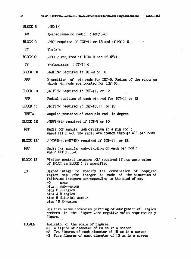
/NX+1/
X-abscissae or radii ;.RX(1)=O
/NY/ required if IGT=11 or 12 and if NY > 0
Theta's
/NY+1/ required if IGT=13 and if NY>1
Y-abscissae ; TY(1 )=0
/NAPIN/ required if KTT=9 or 10
X-position of pin rods for IGT^. Radius of the rings onwhich pin rods are located for IGT=10.
/NTPIN/ required if IGT=11, or 12
Radial position of each pin rod for IGT=11 or 12
/NTPIN/ required if IGT=1O,11, or 12
Angular position of each pin rod in degree
/NDPIN+1/ required if IOT=9 or 10
Radii for annular sub-division in a pin rod ;where RDP(1)=O. The radii are common through all pin rods.
/(NDPIN+1)*NTPIN/ required if IGT=11, or 12
Radii for annular sub-division of each pin rod ;where RDP(1,J)=O.
Plotter control integers /3/ required if non zero valueof IPLOT in BLOCK 1 is specified
Signed integer to specify the combination of requiredregion map ;the integer is made of the summation offollowing integers corresponding to the kind of map.=0 noneplus 1 sub-regionplus 2 T-regionplus 4 R-regionplus 8 Material numberplus 16 X-region
Positive value indicates printing of assignment of regionnumbers in the figure .and negative value requires onlyfigure.
Indicator of the scale of figures=1 A figure of diameter of 20 cm in a screen=2 Two figures of each diameter of 15 cm in a screen=3 Five figures of each diameter of 10 cm in a screen
JAERI1285 a Input Date R«qubemnt> for SRAC 21
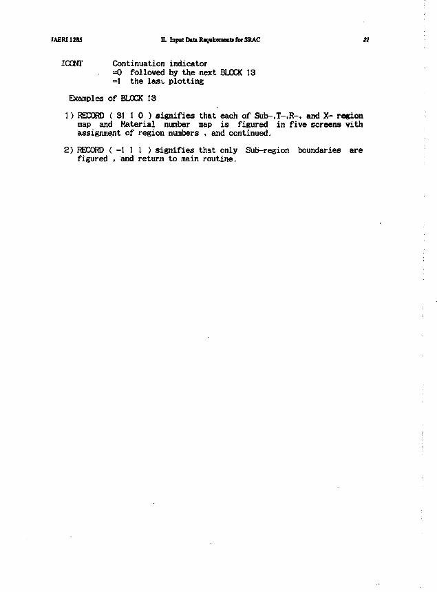
ICONT Continuation indicator=0 followed by the next BLOCK 13=1 the last plotting
Examples of BLOCK 13
1) RECORD ( 31 1 0 ) signifies that each of Sub-.T-.R-. and X- regionmap and Material number map is figured in five screens withassignment of region numbers , and continued.
2) RECORD (-111 ) signifies that only Sub-region boundaries arefigured , and return to main routine.
SRAC: JAERIThenml Raactor Student Cod* Syrian for XMCtor DMipi u d Anilpk JAEM12t5
a. Type 1 (Sphere) and Type3 (Circular cylinder)
b. Type2 (Infiniteslab)
unit ctn
RXIPO
8
RX{(0)
c.Type 4 (Square cylinder) d.Type 5 (Twodimensionalsquare cylinder)
Fie.II.3-1 Geometries and sub-region niwbers
JAERI1285 Input DtU Requirement* for SRAC 23
e . Type 6 (Hexagonal cylinder) f. Type 7 (Two dimensionalhexagonal cylinder)
g. Type 8 (Square assembly) h. Type 9 (Square assemblywith pinrods)
12
16
13
IS
17
B RX(5
RX(4)
RX(3)
RX(2)
J2_
16
J5.
17
5JSJ_
in the case of IDIVP «Ointhecaseof IDIVP-1
Fif.II.3-1 (continued)

U SRAC: JAERIThenndRwctoiStuidudCodeSyttnnfoiRMCtorDM^nudAnlyrii JAEM12U
i .Type 10(Annular assembly with regular arrays of pin rods)
ID1VP-0
1DIVP*1
case N«4,NA»tNPIN (t) • 6
ID1VP-2
j.Type II (Annular assembly with k.Type 12 (Hexagonal assemblyasymmetric pin rods) with asymmetric pin rods)
case N * 5 , M • 3N P * 6 .
Fig. II. 3-1 (continued)
JAER11285 H. IapttIMtlUq«JraMMsforSltAC
I. Type 13 (XY two dimensionol infinite pillar)
TY (6)
TY(5)
TY(4)
TY(3)
TY(2)
2S
25
19
(3
7
1
26
20
14
8
2
27
21
15
9
3
26
22
16
10
4
29
23
17
II
5
30
24
16
12
6
Case NX - 6 NY - 5
m. Type 14 ( Multi - layer of hexagon )
RX(5)
Case NX « 4
Fie II.3-1 (continued)
26 SRAC: JAERI Thermal Reutor Stiadud Code Sy*«n foe KMCtoi DMfcn u d Amly* JAERI1285
IX.4 ANISN ; One dimensional SN Transport
The one dimensional SN routine ANISN can be used in either cellcalculation or core calculation. The original input format (Ref(7)) isreplaced by our free format described in the top of II, however theoriginal keycodes corresponding to the array names and their ordersare still kept t~ facilitate the reference to the original manual. Theway of reading by indicating the array code of three characters andthen entering the array beginning on the next logical record is notchanged.
As the cross sections are prepared after reading the input of thissection, several control integers relating to cross sections are auto-matically set at that step, then they are indicated here as internallyset. And also the user will find that several functions are suppresseddue to the restricted use of ANISN in the SRAC.
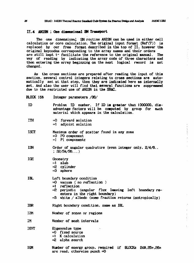
BLOCK 15S Integer parameters /36/
ID Problem ID number. If ID is greater than 1000000, dis-advantage factors will be computed by group for eachmaterial which appears in the calculation.
ITH =0 forward solution=1 adjoint solution
ISCT Maximum order of scatter found in any zone=0 P0 component=1 PI components
ISN Order of angular quadrature (even integer only, 2/4/6..; S2/S4/S6...)
IGE Geometry=1 slab=2 cylinder=3 sphere
IBL Left boundary condition=0 vacuum ( no reflection )=1 reflection=2 periodic (angular flux leaving left boundary re-
enters in the right boundary)=3 white / albedo (some fraction returns isotropically)
IBR Right boundary condition, sane as IBL
IZM Number of zones or regions
IM Number of mesh intervals
IEVT Eigenvalue type=0 fixed source=1 K calculation=2 alpha search
IGM Number of energy group, required if BLOCKs 24$,25*,25*are read, otherwise punch =0
JAERI1285 H. Input Data Requirement! for SRAC 27
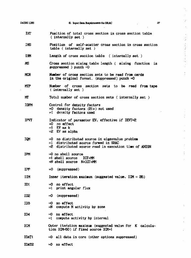
IHT Position of total cross section in cross section table( internally set )
IHS Position of self-scatter cross section in cross sectiontable ( internally set )
Irti Length of cross section table ( internally set )
MS Cross section mixing table length { mixing function issuppressed ) punch =0
MCR Number of cross section sets to be read from cardsin the original format, (suppressed) punch =0
MTP Number of cross section sets to be read from tape( internally set )
MT Total number of cross section sets ( internally set )
IDFW Control for density factors=0 density factors (21*) not used=1 density factors used
IPVT Indicator of parameter EV, effective if IEVT=2=0 no effect=1 EV as k=2 EV as alpha
IQM =0 no distributed source in eigenvalue problem=1 distributed source formed in SRAC=2 distributed source read in execution time of ANISN
IPM =0 no shell source=1 shell source IGT*MM=N shell source N*IGT>l<MM
IPP =0 (suppressed)
IIM Inner iteration maximum (suggested value, IIM = 35)
ID1 =0 no effect
=1 print angular flux
IDE =0 (suppressed)
ID3 =0 no effect=N compute N activity by zone
IIM =0 no effect=1 compute activity by interval
ICM Outer iteration maximum (suggested value for K calcula-tion ICM=50) if fixed source ICM=1
IDAT1 =0 all data in core (other options suppressed)
IDAT2 =0 no effect
28 SRAC: JAERI Thermal RMCtor Standard Code Syttem foe RMCtorDeriin and Amlyrii JAERI 1215
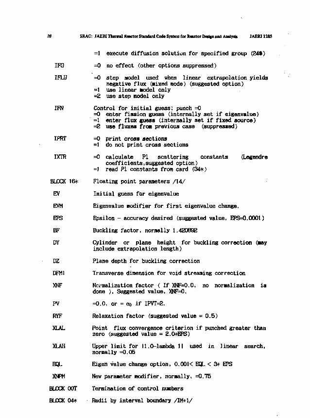
=1 execute diffusion solution for specified group (24$)
IFG =0 no effect (other options suppressed)
IFLU =0 step model used when linear extrapolation yieldsnegative flux (mixed mode) (suggested option)
=1 use linear model only=2 use step model only
IFN Control for initial guess; punch =0=0 enter fission guess (internally set if eigenvalue)=1 enter flux guess (internally set if fixed source)=2 use fluxes from previous case (suppressed)
IPRT =0 print cross sections=1 do not print cross sections
IXTR =0 calculate PI scattering constants (Legendrecoefficients,suggested option)
=1 read PI constants from card (34*)
BLOCK 16* Floating point parameters /14/
EV Initial guess for eigenvalue
EVM Eigenvalue modifier for first eigenvalue change.
EPS Epsilon - accuracy desired (suggested value, EPS=0.0001)
BF Buckling factor, normally 1.420632
DY Cylinder or plane height for buckling correction (mayinclude extrapolation length)
DZ Plane depth for buckling correction
DFM1 Transverse dimension for void streaming correction
XNF Normalization factor ( If XNF=O.O, no normalization isdone ), Suggested value, XNF=O.
PV =0.0, or = ao if IPVT=2.
RYF Relaxation factor (suggested value = 0.5)
XLAL Point flux convergence criterion if punched greater thanzero (suggested value = 2.0+EPS)
XLAH Upper limit for 11.0-lambda II used in linear search,normally =0.05
SQL Eigen value change option, 0.00K SQL < 3* EPS
XNPM New parameter modifier, normally, =0.75
BLOCK OOT Termination of control numbers
BLOCK 04* Radii by interval boundary /IM+1/
JAERI1285 n. Input D«tt Requirement! fcwSRAC
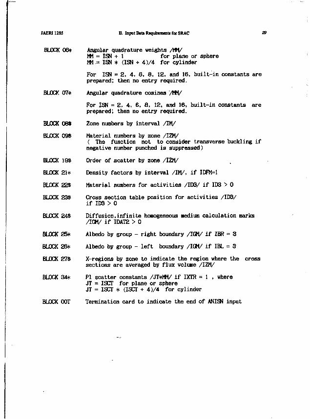
BLOCK 06* Angular quadrature weights AWMM = ISN + 1 for plane or sphereMM = ISN * (ISN + 4)/4 for cylinder
For ISN = 2, 4, 6, 8, 12, and 16, built-in constants areprepared; then no entry required.
BLOCK 07* Angular quadrature cosines /MM/
For ISN = 2, 4, 6, 8, 12, and 16, built-in constants areprepared; then no entry required.
BLOCK 08* Zone numbers by interval /IM/
BLOCK 09$ Material numbers by zone /IZM/( The function not to consider transverse buckling ifnegative number punched is suppressed)
BLOCK 19$ Order of scatter by zone /IZM/
BLOCK 21* Density factors by interval /IM/, if IDFM=1
BLOCK 22S Material numbers for activities /ID3/ if ID3 > 0
BLOCK 238 Cross section table position for activities /ID3/if ID3 > 0
BLOCK 24$ Diffusion,infinite homogeneous medium calculation marks/IGH/ if IDAT2 > 0
BLOCK 25* Albedo by group - right boundary /IGM/ if IBR = 3
BLOCK 26* Albedo by group - left boundary /IGM/ if IBL = 3
BLOCK 27$ X-regions by zone to indicate the region where the crosssections are averaged by flux volume /IZM/
BLOCK 34* PI scatter constants /JT*MM/ if I3CTR = 1 , whereJT = ISCT for plane or sphereJT = ISCT * (ISCT + 4)/4 for cylinder
BLOCK OOT Termination card to indicate the end of ANISN input
30 SRAC: JAER1 Thermil Reactor Standard Code Syttem for Reactor Design and Anlyut JAERI12S5
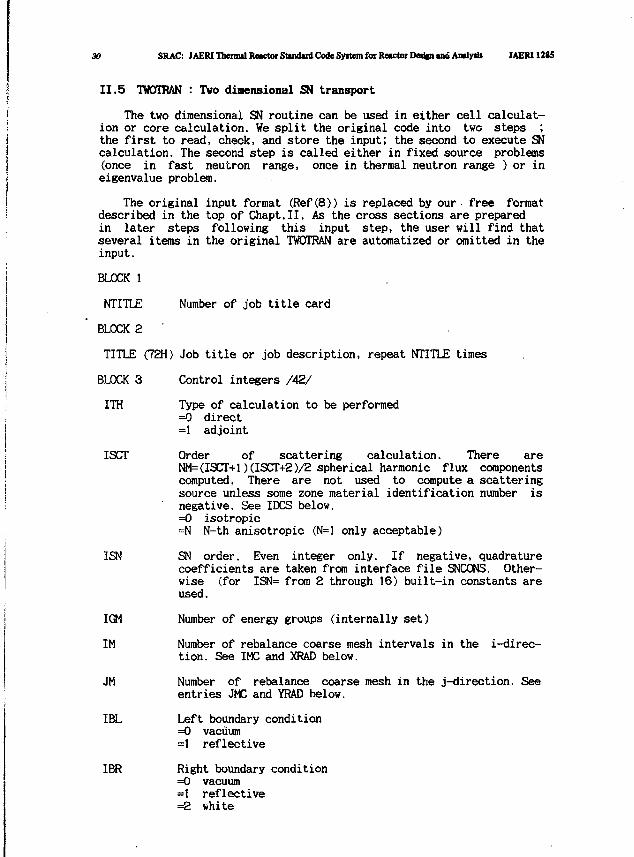
II.5 TWOTRAN : Two dimensional SN transport
The two dimensional SN routine can be used in either cell calculat-ion or core calculation. We split the original code into two steps ;the first to read, check, and store the input; the second to execute SNcalculation. The second step is called either in fixed source problems(once in fast neutron range, once in thermal neutron range ) or ineigenvalue problem.
The original input format (Ref(8)) is replaced by our free formatdescribed in the top of Chapt.II. As the cross sections are preparedin later steps following this input step, the user will find thatseveral items in the original TWOTRAN are automatized or omitted in theinput.
BLOCK 1
NTITLE Number of job title card
BLOCK 2 '
TITLE (72H) Job title or job description, repeat NTITLE times
BLOCK 3 Control integers /42/
ITH Type of calculation to be performed=0 direct=1 adjoint
ISCT Order of scattering calculation. There areNM=(ISCT+l)(ISCT+2)/2 spherical harmonic flux componentscomputed. There are not used to compute a scatteringsource unless some zone material identification number isnegative. See IDCS below.=0 isotropic=N N-th anisotropic (N=l only acceptable)
ISN SN order. Even integer only. If negative, quadraturecoefficients are taken from interface file SNCONS. Other-wise (for ISN= from 2 through 16) built-in constants areused.
IGM Number of energy groups (internally set)
IM Number of rebalance coarse mesh intervals in the i-direc-tion. See IMC and XRAD below.
JM Number of rebalance coarse mesh in the j-direction. Seeentries JMC and YRAD below.
IBL Left boundary condition=0 vacuum=1 reflective
IBR Right boundary condition=0 vacuum=1 reflective=2 white
; JAERU285 II. Input Data Requirement* for SRAC 31
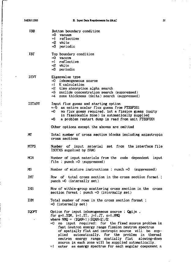
] IBB Bottom boundary conditionI =0 vacuumj =1 reflective[ =2 whiteJ =3 periodic
IBT Top boundary conditionj =0 vacuum> =1 reflective
=2 white=3 periodic
IEVT Eigenvalue type=0 inhomogeneous source=1 K calculation=2 time absorption alpha search=3 nuclide concentration search (suppressed)=4 zone thickness (delta) search (suppressed)
ISTART Input flux guess and starting option=-5 an entire scalar flux guess from FT33F001=0 no flux guess required, but a fission guess (unity
in fissionable zone) is automatically supplied=6 a problem restart dump is read from unit FT33P001
Other options except the aboves are omitted
MT Total number of cross section blocks including anisotropiccross sections
WTPS Number of input material set from the interface fileISOTXS supplied by SRAC
MCR Number of input materials from the code dependent inputfile : punch =0 (suppressed)
MS Number of mixture instructions ; punch =0 (suppressed)
IHT Row of total cross section in the cross section format ;punch =0 (internally set)
IHS Row of within-group scattering cross section in the crosssection format ; punch =0 (internally set)
IHM Total number of rows in the cross section format ;=0 (internally set)
IQOPT Option for input inhomogeneous source ; Qgijn ,for g=l,IGM. i=l,IT, j=l,JT, n=l,NMQwhere NMQ = (IQAN+1 )(IQAN+2 )/Z=0 no input required: for the fixed source problem in
fast neutron energy range fission neutron spectrumof spatially flat and isotropie source will be sup-plied automatically, for the problem in thermalneutron energy range spatially flat slowing-downsource in each zone will be supplied automatically.
=1 enter an energy spectrum for each angular component n
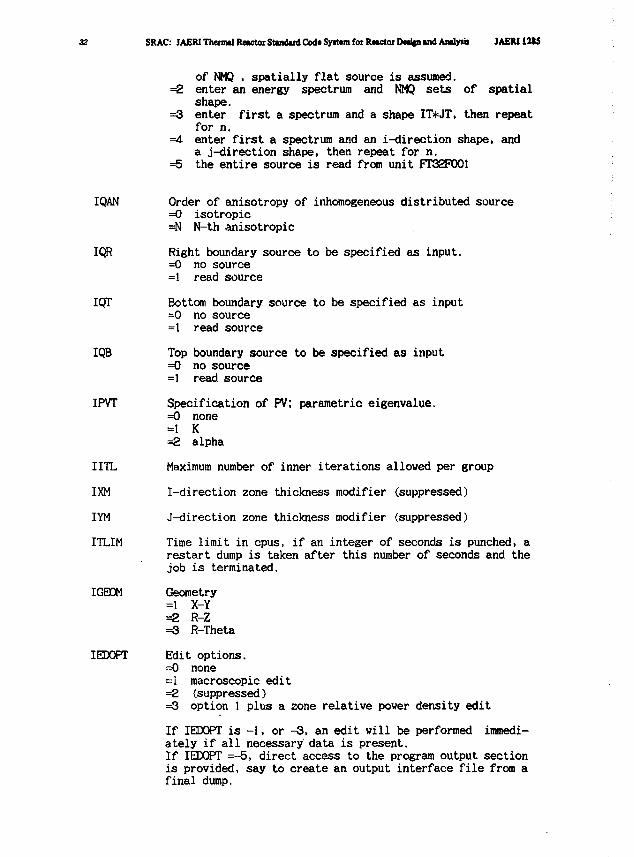
32 SRAC: JAERITheiTOlRwwtorStuidinl Code Syitem for RwwtoiDwtjnind Amljnii JAEN12S5
of NMQ , spatially flat source is assumed.=2 enter an energy spectrum and NMQ sets of spatial
shape.=3 enter first a spectrum and a shape IT*JT, then repeat
for n.=4. enter first a spectrum and an i-direction shape, and
a j-direction shape, then repeat for n.=5 the entire source is read from unit FT32P001
IQAN Order of anisotropy of inhomogeneous distributed source=0 isotropic=N N-th anisotropic
IQR Right boundary source to be specified as input.=0 no source=1 read source
IQT Bottom boundary source to be specified as input=0 no source=1 read source
IQB Top boundary source to be specified as input=0 no source=1 read source
IPVT Specification of PV; parametric eigenvalue.=0 none=1 K=2 alpha
IITL Maximum number of inner iterations allowed per group
IXM I-direction zone thickness modifier (suppressed)
IYM J-direction zone thickness modifier (suppressed)
ITLIM Time limit in cpus, if an integer of seconds is punched, arestart dump is taken after this number of seconds and thejob is terminated.
IGEOM Geometry=1 X-Y=2 R-Z=3 R-Theta
IEDOPT Edit options.=0 none=i macroscopic edit=2 (suppressed)=3 option 1 plus a zone relative power density edit
If IEDOPT is -1, or -3, an edit will be performed immedi-ately if all necessary data is present.If IEDOPT =-5, direct access to the program output sectionis provided, say to create an output interface file from afinal dump.
JAERI1285 n. Input D»U Requirement* for SRAC 33
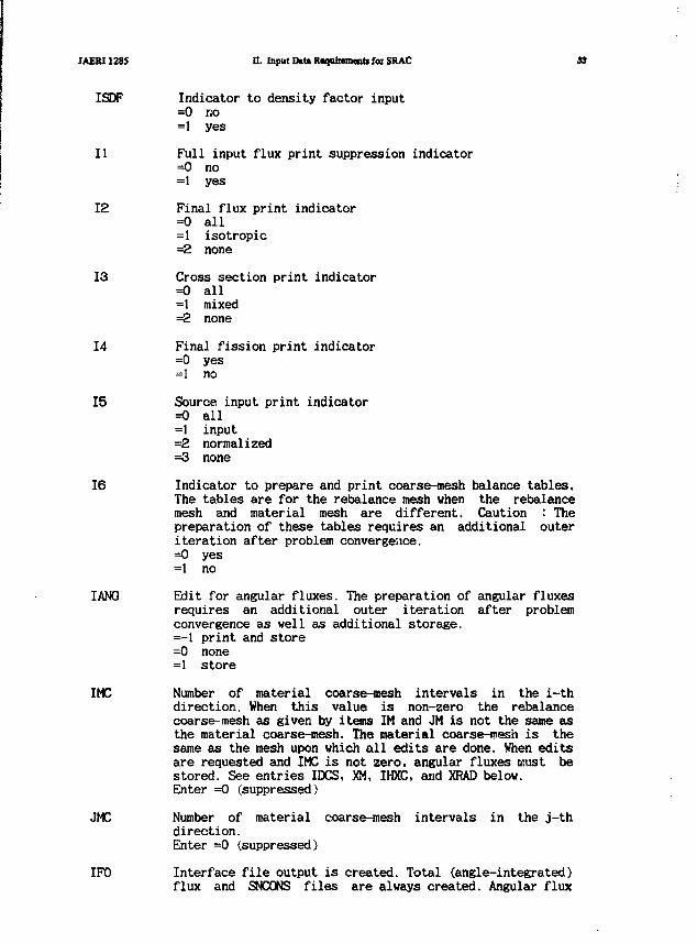
ISDF Indicator to density factor input=0 no=1 yes
11 Full input flux print suppression indicator=0 no=1 yes
12 Final flux print indicator=0 all=1 isotropic=2 none
13 Cross section print indicator=0 all=1 mixed=2 none
14 Final fission print indicator=0 yes=1 no
15 Source input print indicator=0 all=1 input=2 normalized=3 none
16 Indicator to prepare and print coarse-mesh balance tables.The tables are for the rebalance mesh when the rebalancemesh and material mesh are different. Caution : Thepreparation of these tables requires an additional outeriteration after problem convergence.=0 yes=1 no
IANG Edit for angular fluxes. The preparation of angular fluxesrequires an additional outer iteration after problemconvergence as well as additional storage.=-1 print and store=0 none=1 store
IMC Number of material coarse-mesh intervals in the i-thdirection. When this value is non-zero the rebalancecoarse-mesh as given by items IM and JM is not the same asthe material coarse-mesh. The material coarse-isesh is thesame as the mesh upon which all edits are done. When editsare requested and IMC is not zero, angular fluxes must bestored. See entries IDCS, XM, IHXC, and XRAD below.Enter =0 (suppressed)
JMC Number of material coarse-mesh intervals in the j-thdirection.Enter =0 (.suppressed)
IF0 Interface file output is created. Total (angle-integrated)flux and SNCONS files are always created. Angular flux
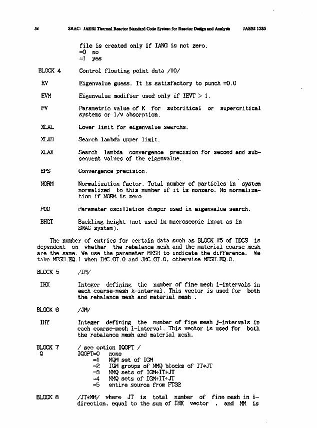
3t SRAC: JAERI Themal Rtactor Stmdinl Code SyiUm for Rwtctor Pwlpi tnd Antlyrii JAERU285
file is created only if IANG is not zero.=0 no=1 yes
BLOCK 4 Control floating point data /10/
EV Eigenvalue guess. It is satisfactory to punch =0.0
EVM Eigenvalue modifier used only if IEVT > 1.
PV Parametric value of K for subcritical or supercriticalsystems or 1/v absorption.
XLAL Lower limit for eigenvalue searchs.
XLAH Search lambda upper limit.
XLAX Search lambda convergence precision for second and sub-sequent values of the eigenvalue.
EPS Convergence precision.
NORM Normalization factor. Total number of particles in systemnormalized to this number if it is nonzero. No normaliza-tion if NORM is zero.
POD Parameter oscillation dumper used in eigenvalue search.
BHGT Buckling height (not used in macroscopic input as inSRAC system).
The number of entries for certain data such as BLOCK 15 of IDCS isdependent on whether the rebalance mesh and the material coarse meshare the same. We use the parameter MESH to indicate the difference. Wetake MESH.EQ.l when IMC.GT.O and JMC.GT.O, otherwise MESH.EQ.O.
BLOCK 5 /IM/
IHX Integer defining the number of fine mesh i-intervals ineach coarse-mesh k-interval. This vector is used for boththe rebalance mesh and material mesh .
BLOCK 6 /JM/
IHY Integer defining the number of fine mesh j-intervals ineach coarse-mesh 1-interval. This vector is used for boththe rebalance mesh and material mesh.
BLOCK 7 /see option IQOPT /Q IQQPT=0 none
=1 NQM set of IGM=2 IGM groups of NMQ blocks of IT*JT=3 NMQ sets of IGM+IT*JT=4 NMQ sets of IGM+IT+JT=5 entire source from FT32
BLOCK 8 /JT*MM/ where JT is total number of fine mesh in i-direction, equal to the sum of IHX vector , and MM is
JAERI1285 D. Input DtU Requirements for SRAC
QR1
BLOCK
QR2
BLOCK
QB1
BLOCK
QB2
BLOCK
QT1
BLOCK
QT2
BLOCK
XRAD
BLOCK
YRAD
BLOCK
IDCS
9
10
!1
12
13
14
15
16
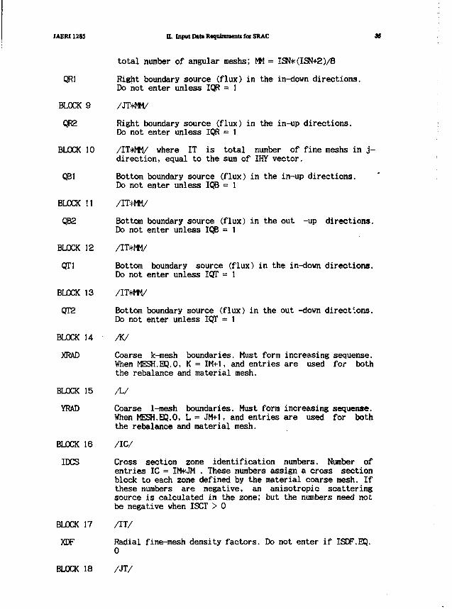
total number of angular meshs; MM = ISN*(ISN+2)/B
Right boundary source (flux) in the in-down directions.Do not enter unless IQR = 1
/JT*MM/
Right boundary source (flux) in the in-up directions.Do not enter unless IQR = I
/IT*MM/ where IT is total number of fine meshs in j-direction, equal to the sum of IHY vector.
Bottom boundary source (flux) in the in-up directions.Do not enter unless IQB = 1
/IT*MM/
Bottom boundary source (flux) in the out -up directions.Do not enter unless IQB = 1
/IT*MM/
Bottom boundary source (flux) in the in-down directions.Do not enter unless IQT = 1
/IT*MM/
Bottom boundary source (flux) in the out -down directions.Do not enter unless IQT = 1
BLOCK 17
XDF
Coarse k-mesh boundaries. Must form increasing sequense.When MESH.EQ.O, K = IM+1, and entries are used for boththe rebalance and material mesh.
/L/
Coarse 1-mesh boundaries. Must form increasing sequense.When MESH.EQ.O, L = JM+1, and entries are used for boththe rebalance and material mesh.
/IC/
Cross section zone identification numbers. Number ofentries IC = IM*JM . These numbers assign a cross sectionblock to each zone defined by the material coarse mesh. Ifthese numbers are negative, an anisotropic scatteringsource is calculated in the zone; but the numbers need notbe negative when ISCT > 0
/IT/
Radial fine-mesh density factors. Do not enter if ISDF.BQ.0
BLOCK 18 /JT/
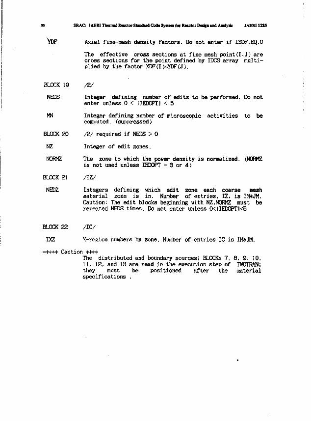
36 SRAC: JAERI Theimd Rwctor Standard Cod* Systam foe tUtctor Deafen and Analyaii JAERI12S5
YDF Axial fine-mesh density factors. Do not enter if ISDF.EQ.O
The effective cross sections at fine mesh point(I,J) arecross sections for the point defined by IDCS array multi-plied by the factor XDF(I)*YDF(J).
BLOCK 19 /2/
NEDS Integer defining number of edits to be performed. Do notenter unless 0 < IIEDOPTI < 5
MN Integer defining number of microscopic activities to becompu ted. (suppressed)
BLOCK 20 /2/ required if NEDS > 0
NZ Integer of edit zones.
NORMZ The zone to which the power density is normalized. (NORMZis not used unless IEDOPT = 3 or 4)
BLOCK 21 /IZ/
NEDZ Integers defining which edit zone each coarse meshmaterial zone is in. Number of entries, IZ, is IM*JM.Caution: The edit blocks beginning with NZ,NORMZ must berepeated NEDS times. Do not enter unless 0<IIEDOPTl<5
BLOCK 22 /IC/
IXZ X-region numbers by zone. Number of entries IC is IM*JM.
***** Caution ****The distributed and boundary sources; BLOCKs 7, 8, 9, 10,11. 12, and 13 are read in the execution step of TWOTRAN;they must be positioned after the materialspecifications .
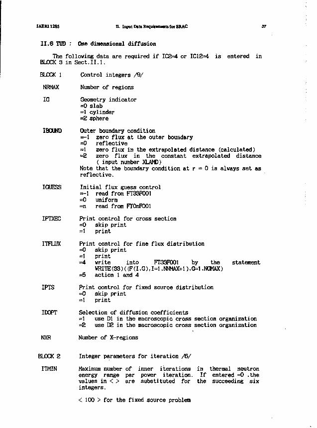
JAERI 12»5 U. Input D»URequinn»nt» fof SRAC 37
II.6 TUD : One dimensional diffusion
The following data are required if IC2=4 or IC12=4 is entered inBLOCK 3 in Sect.II.1.
BLOCK 1 Control integers /9/
NRMAX Number of regions
IG Geometry indicator=0 slab=1 cylinder=2 sphere
IBOUND Outer boundary condition=-1 zero flux at the outer boundary=0 reflective=1 zero flux in the extrapolated distance (calculated)=2 zero flux in the constant extrapolated distance
( input number XLAMD)Note that the boundary condition at r = 0 is always set asreflective.
IGUESS Initial flux guess control=-1 read from FT33P001=0 uniform=n read from FTOnFOOl
IPTXBC Print control for cross section=0 skip print=1 print
ITFLUX Print control for fine flux distribution=0 skip print=1 print=4 write into FT33P001 by the statement
WRITE (33)((F(I.G),1=1 .NNMAX+1 ),G=1 .NGMAX)=5 action 1 and 4
IPTS Print control for fixed source distribution=0 skip print=1 print
IDOPT Selection of diffusion coefficients=1 use Dl in the macroscopic cross section organization=2 use D2 in the macroscopic cross section organization
NXR Number of X-regions
BLOCK 2 Integer parameters for iteration /6/
ITMIN Maximum number of inner iterations in thermal neutronenergy range per power iteration. If entered =0 ,thevalues in < > are substituted for the succeeding sixintegers.
< 100 > for the fixed source problem

SRAC: JAEMThenrtRwctoiSiiiidtxdCodeSyitemfoiRMcUxDcd^iadAiidyrii JAEMIMS
< 10 > for the eigenvalue problem
ITMOUT Maxmum number of power i t e r a t i o n s < 25 >
ITBG Minimum number of inner i t e r a t i o n s before ex t rapo la t ion< 5 >
LCMX Number of inner iterations for testing over-relaxationfactor < 5 >
ITDM Minimum delay between extrapolation < 5 >
IPT Control for monitor print < 0 >=0 skip print=1 monitor print at each inner iteration
BLOCK 3 Floating point parameters /6/
EPSI Convergence criterion for inner iteration.If entered =0.0 , the values in < > are substitutedfor succeeding six floating numbers < 0.001 >
EPSO Convergence criterion for outer iteration < .0001 >
EPSG Extrapolation criterion < 0.05 >
RELC Initial over-relaxation factor < 1.2 >
OVERX Maximum extrapolation factor < 100. >
FACTOR Under extrapolation factor < 1.0 >
BLOCK 4 /NRMAX/
NK Number of mesh intervals by region
BLOCK 5 /NRMAX/
IK Material number by region ; the material number isassigned by the order of the material appears in themixture specification.
BLOCK 6 /NRMAX/
IXR X-region number by region
BLOCK 7 /NRMAX/
RK Outer radii by region
BLOCK 8 /I/
BSQ Transverse buckling in cm-2
BLOCK 9 /I/ required if IB0UND=2
XLAMD Extrapolation distance in cm
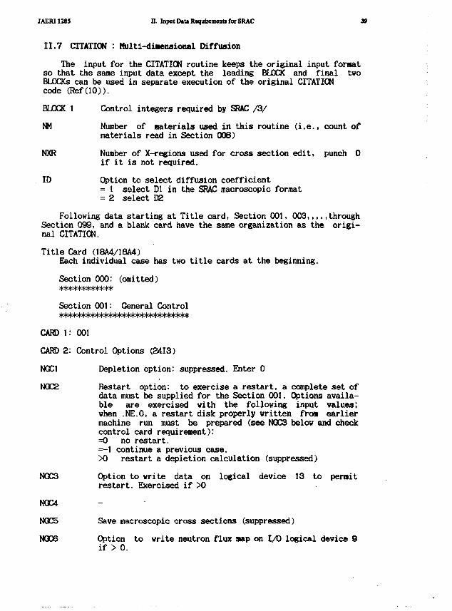
JAER112B5 D. Input DiU Requirement* for SRAC 1
II.7 CITATION : Multi-diaeoaional Diffusion
The input for the CITATION routine keeps the original input formatso that the same input data except the leading BLOCK and final twoBLOCKs can be used in separate execution of the original CITATIONcode (Ref(lO)).
BLOCK 1 Control integers required by SRAC /3/
NM Number of materials used in this routine (i.e., count ofmaterials read in Section 006)
NXR Number of X-regions used for cross section edit, punch 0if it is not required.
ID Option to select diffusion coefficient= 1 select Dl in the SRAC macroscopic format= 2 select D2
Following data starting at Title card, Section 001, 003,,,,.throughSection 099, and a blank card have the same organization as the origi-nal CITATION.
Title Card (18A4/18A4)Each individual case has two title cards at the beginning.
Section 000: (omitted)************
Section 001: General Control
CARD l: 001
CARD 2: Control Options (2413)
NGC1 Depletion option: suppressed. Enter 0
NGC2 Restart option: to exercise a restart, a complete set ofdata must be supplied for the Section 001. Options availa-ble are exercised with the following input values;when .NE.O, a restart disk properly written from earliermachine run must be prepared (see NGC3 below and checkcontrol card requirement):=0 no restart.=-1 continue a previous case.Xt restart a depletion calculation (suppressed)
NGC3 Option to write data on logical device 13 to permitrestart. Exercised if X)
NGC4
NQC5 Save macroscopic cross sections (suppressed)
NGC6 Option to write neutron flux map on 1/0 logical device 9if > 0.
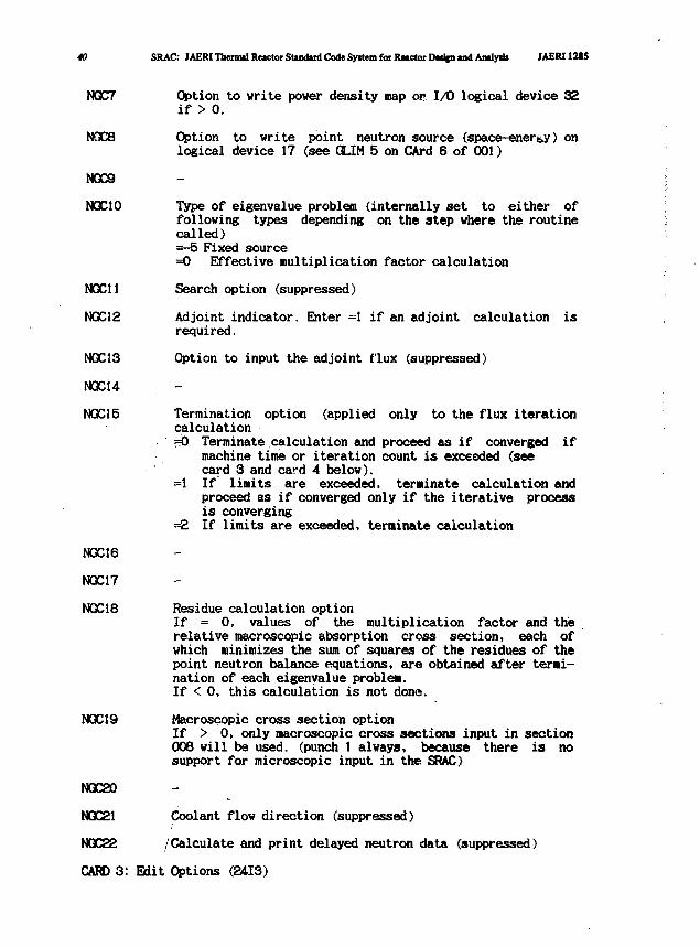
40 SRAC: JAERIThenml Reactor Standard Code Syrtem for Reactor Detfcn and Andy* JAERI12I5
NQC7
N0C8
NQC9
NQC10
NGC11
NGC12
N0C13
NGC14
NGC15
NGC16
NGC17
NQC18
NQC19
NQC20
NQC21
N0C22
CARD 3:
Option to write power density map or I/O logical device 32if > 0.
Option to write point neutron source (space-energy) onlogical device 17 (see GLIM 5 on CArd 6 of 001)
Type of eigenvalue problem (internally set to either offollowing types depending on the step where the routinecalled)=-5 Fixed source=0 Effective multiplication factor calculation
Search option (suppressed)
if an adjoint calculation is
Option to input the adjoint flux (suppressed)
Adjoint indicator. Enterrequired.
Termination option (applied only to the flux iterationcalculation=0 Terminate calculation and proceed as if converged if
machine time or iteration count is exceeded (seecard 3 and card 4 below).
=1 If limits are exceeded, terminate calculation andproceed as if converged only if the iterative processis converging
-2 If limits are exceeded, terminate calculation
Residue calculation optionIf = 0, values of the multiplication factor and therelative macroscopic absorption cross section, each ofwhich minimizes the sum of squares of the residues of thepoint neutron balance equations, are obtained after termi-nation of each eigenvalue problem.If < 0, this calculation is not done.
Macroscopic cross section optionIf > 0, only macroscopic cross sections input in section006 will be used, (punch 1 always, because there is nosupport for microscopic input in the SRAC)
Coolant flow direction (suppressed)
/Calculate and print delayed neutron data (suppressed)
Edit Options (2413)
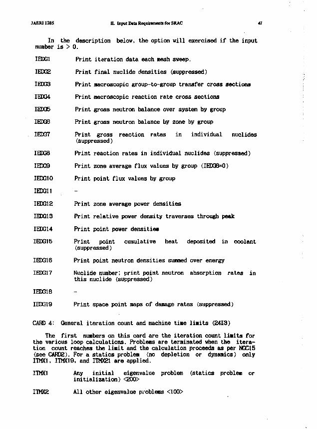
JAERI1285 II. Input D«U Requinmenti for SRAC 41
In the description below, the option will exercised if the inputnumber is > 0.
IEDG1 Print iteration data each mesh sweep.
IEDG2 Print final nuclide densities (suppressed)
IEDG3 Print macroscopic group-to-group transfer cross sections
IEDG4 Print macroscopic reaction rate cross sections
IEDG5 Print gross neutron balance over system by group
IEDG6 Print gross neutron balance by zone by group
IEDG7 Print gross reaction rates in individual nuclides(suppressed)
IEDG8 Print reaction rates in individual nuclides (suppressed)
IEDG9 Print zone average flux values by group (IEDG6=0)
IEDG10 Print point flux values by group
IEDG11
IEDG12 Print zone average power densities
IEDG13 Print relative power density traverses through peak
IEDG14 Print point power densities
IEDG15 Print point cumulative heat deposited in coolant(suppressed)
IEDG16 Print point neutron densities summed over energy
IEDG17 Nuclide number; print point neutron absorption rates inthis nuclide (suppressed)
IEDG18
IEDG19 Print space point maps of damage rates (suppressed)
CARD 4: General iteration count and machine time limits (2413)
The first numbers on this card are the iteration count limits forthe various loop calculations. Problems are terminated when the itera-tion count reaches the limit and the calculation proceeds as per NQC15(see CARD2). For a statics problem (no depletion or dynamics) onlyITMX1, ITMX19, and ITMX21 are applied.
ITMX1 Any initial eigenvalue problem (statics problem orinitialization) <200>
ITMX2 All other eigenvalue problems <100>
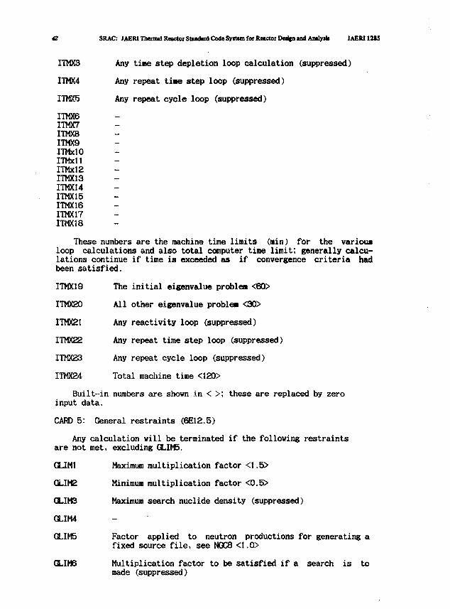
42 SRAC: JAERJ Thermal Reactor Standard Code Syitem for Reactor Dedpi and Antlym JAERI12I5
ITMX3 Any tine step depletion loop calculation (suppressed)
ITMX4 Any repeat tiae step loop (suppressed)
I7MX5 Any repeat cycle loop (suppressed)
ITMX6ITMX7ITMXBITMX9ITMxlOITMxllITMxl2ITMX13ITMX14ITMX15ITMX16ITMX17ITMX18
These numbers are the machine time limits (min) for the variousloop calculations and also total computer time limit; generally calcu-lations continue if time is exceeded as if convergence criteria hadbeen satisfied.
ITMX19 The initial eigenvalue problem <60>
ITMX20 All other eigenvalue problem <30>
ITMX21 Any reactivity loop (suppressed)
ITMX22 Any repeat time step loop (suppressed)
ITMX23 Any repeat cycle loop (suppressed)
ITMX24 Total machine time <120>
Built-in numbers are shown \n < >; these are replaced by zeroinput data.
CARD 5: General restraints (6E12.5)
Any calculation will be terminated if the following restraintsare not met, excluding GLIM5.
GLIM1 Maximum multiplication factor <1.5>
GLIMS Minimum multiplication factor <0.5>
GLIM3 Maximum search nuclide density (suppressed)
GLIM4
GLIM5 Factor applied to neutron productions for generating afixed source file, see NQC8 <1.0>
GLIM6 Multiplication factor to be satisfied if a search is tomade (suppressed)
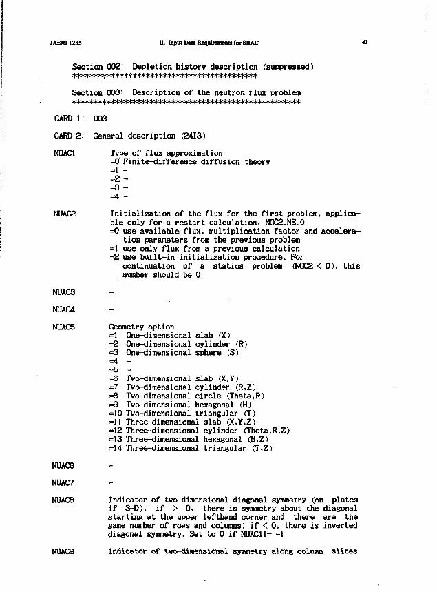
JAER11285 II. Input Dtt» Requirement* for SRAC
Section 002: Depletion history description (suppressed)
Section 003: Description of the neutron flux problem
CARD l: 003
CARD 2: General description (2413)
NUAC1
NUAC2
NUAC3
NUAC4
NUAC5
NUAC6
NUAC7
NUACB
Type of flux approximation=0 Finite-difference diffusion theory=1 -=2 -=3 -=4 -
Initialization of the flux for the first problem, applica-ble only for a restart calculation, NQC2.NE.0=0 use available flux, multiplication factor and accelera-
tion parameters from the previous problem=1 use only flux from a previous calculation=2 use built-in initialization procedure. For
continuation of a statics problem (NGC2 < 0), thisnumber should be 0
Geometry option=1 One-dimensional slab (X)
One-dimensional cylinder (R)One-dimensional sphere (S)
=2=3=4=5=6=7=8=9
Two-dimensional slab (X,Y)Two-dimensional cylinder (R,Z)Two-dimensional circle (Theta.R)Two-dimensional hexagonal (H)
=10 Two-dimensional triangular (T)=11 Three-dimensional slab (X.Y.Z)=12 Three-dimensional cylinder (Theta.R.Z)=13 Three-dimensional hexagonal (H,Z)=14 Three-dimensional triangular (T,Z)
Indicator of two-dimensional diagonal symmetry (on platesif 3-D); if > 0, there is symmetry about the diagonalstarting at the upper lefthand corner and there are thesame number of rows and columns; if < 0, there is inverteddiagonal symmetry. Set to 0 if NUAC11= -1
NUAC9 Indicator of two-dimensional symmetry along column slices
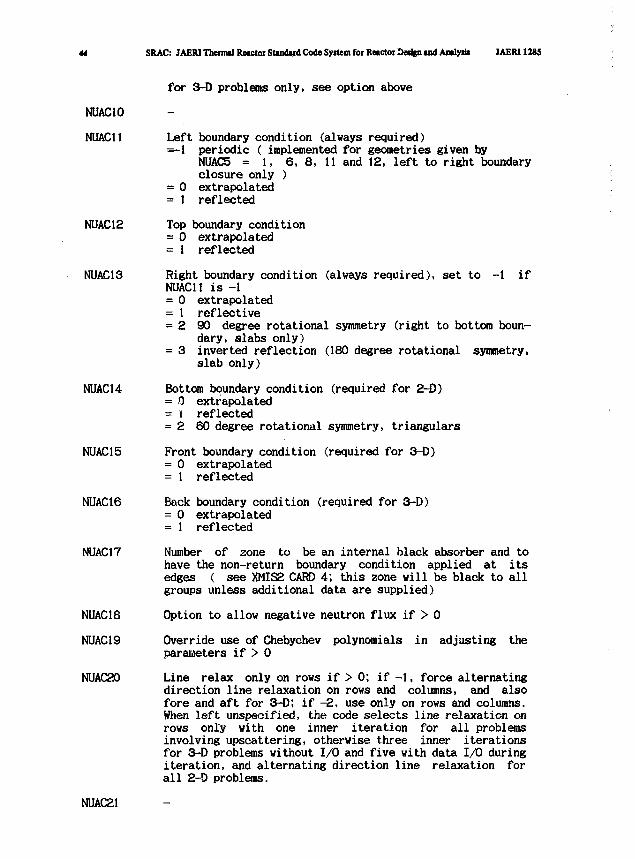
44 SRAC: JAERI Thennal Retctoi Stindud Code System foi Retctor Design u d Amlytls JAERI1285
NUAC10
NUAC11
NUAC12
NUAC13
NUAC14
NUAC15
NUAC16
NUAC17
NUAC18
NUAC19
NUAC20
for 3-D problems only, see option above
Left boundary condition (always required)=-1 periodic ( implemented for geometries given by
NUAC5 = 1, 6, 8, 11 and 12, left to right boundaryclosure only )
= 0 extrapolated= 1 reflected
Top boundary condition= 0 extrapolated= 1 reflected
Right boundary condition (always required), set to -1 ifNUAC11 is -1= 0 extrapolated= 1 reflective= 2 90 degree rotational symmetry (right to bottom boun-
dary, slabs only)= 3 inverted reflection (180 degree rotational symmetry,
slab only)
Bottom boundary condition (required for 2-D)= 0 extrapolated= i reflected= 2 60 degree rotational symmetry, triangulars
Front boundary condition (required for 3-D)= 0 extrapolated= 1 reflected
Back boundary condition (required for 3-D)= 0 extrapolated= 1 reflected
Number of zone to be an internal black absorber and tohave the non-return boundary condition applied at itsedges ( see XMIS2 CARD 4; this zone will be black to allgroups unless additional data are supplied)
Option to allow negative neutron flux if > 0
Override use of Chebychev polynomials in adjusting theparameters if > 0
Line relax only on rows if > 0; if -1, force alternatingdirection line relaxation on rows and columns, and alsofore and aft for 3-D; if -2, use only on rows and columns.When left unspecified, the code selects line relaxation onrows only with one inner iteration for all problemsinvolving upscattering, otherwise three inner iterationsfor 3-D problems without I/O and five with data I/O duringiteration, and alternating direction line relaxation forall 2-D problems.
NUAC21
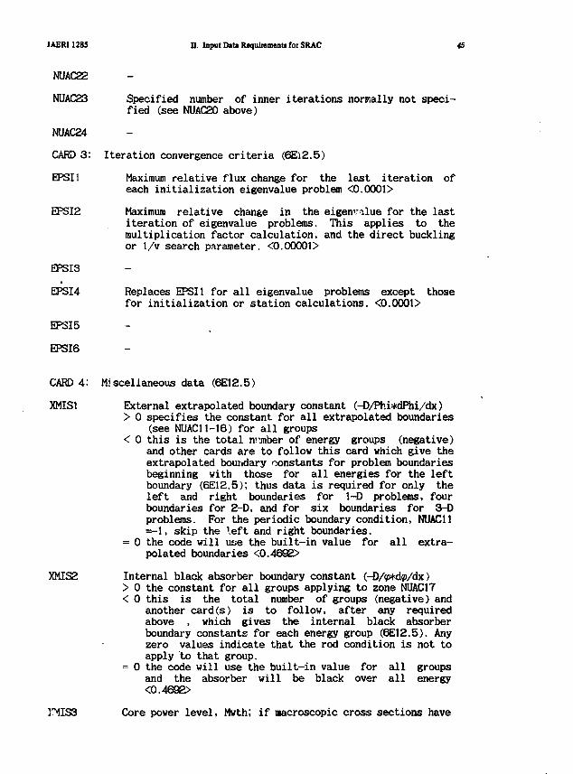
JAERI1285 D. Input Data Requirement* for SRAC 45
NUAC22
NUAC23 Specified number of inner iterations normally not speci-fied (see NUAC20 above)
NUAC24
CARD 3: Iteration convergence criteria (6E12.5)
EPSI1 Maximum relative flux change for the last iteration ofeach initialization eigenvalue problem <0.0001>
EPSI2 Maximum relative change in the eigenvalue for the lastiteration of eigenvalue problems. This applies to themultiplication factor calculation, and the direct bucklingor 1/v search parameter. <0.00001>
EPSI3
EPSI4 Replaces EPSI1 for all eigenvalue problems except thosefor initialization or station calculations. <0.0001>
EP3I5
EPSI6
CARD 4: Miscellaneous data (6E12.5)
XMIS1 External extrapolated boundary constant (-D/Phi*dPhi/dx)> 0 specifies the constant for all extrapolated boundaries
(see NUAC11-16) for all groups< 0 this is the total n jnber of energy groups (negative)
and other cards are to follow this card which give theextrapolated boundary constants for problem boundariesbeginning with those for all energies for the leftboundary (6E12.5); thus data is required for only theleft and right boundaries for 1-D problems, fourboundaries for 2-D, and for six boundaries for 3-Dproblems. For the periodic boundary condition, NUAC11=-1, skip the left and right boundaries.
= 0 the code will uae the built-in value for all extra-polated boundaries <0.4692>
XMIS2 Internal black absorber boundary constant (-D/p*d?>/dx)> 0 the constant for all groups applying to zone NUAC17< 0 this is the total number of groups (negative) and
another card(s) is to follow, after any requiredabove , which gives the internal black absorberboundary constants for each energy group (6E12.5). Anyzero values indicate that the rod condition is not toapply "to that group.
= 0 the code will use the built-in value for all groupsand the absorber will be black over all energy<0.4692>
}*MIS3 Core power level, Mwth; if macroscopic cross sections have
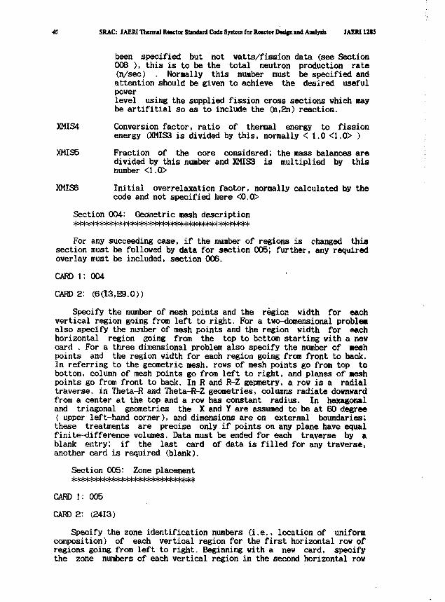
46 SRAC: JAERI Thermil Rttctot Stuidud Code Syitem foi Retctot Dedfn u d Anuysii JAEMUSi
been specified but not watts/fission data (see Section008 ), this is to be the total neutron production rate(n/sec) . Normally this number must be specified andattention should be given to achieve the desired usefulpowerlevel using the supplied fission cross sections which maybe artifitial so as to include the (n,2n) reaction.
XMIS4 Conversion factor, ratio of thermal energy to fissionenergy (XMIS3 is divided by this, normally < 1.0 <1.0> )
XMIS5 Fraction of the core considered; the mass balances aredivided by this number and XMIS3 is multiplied by thisnumber <1.0>
XMIS6 Initial overrelaxation factor, normally calculated by thecode and not specified here <0.0>
Section 004: Geometric mesh description|oM°|c^3|°l<H°l^^
For any succeeding case, if the number of regions is changed thissection must be followed by data for section 005; further, any requiredoverlay must be included, section 006.
CARD 1: 004
CARD 2: (6(13,E9.0))
Specify the number of mesh points and the region width for eachvertical region going from left to right. For a two-domensional problemalso specify the number of mesh points and the region width for eachhorizontal region going from the top to bottom starting with a newcard . For a three dimensional problem also specify the number of Meshpoints and the region width for each region going from front to back.In referring to the geometric mesh, rows of mesh points go from top tobottom, column of mesh points go from left to right, and planes of aeshpoints go from front to back. In R and R-Z gepmetry, a row is a radialtraverse, in Theta-R and Theta-R-Z geometries, columns radiate downwardfrom a center at the top and a row has constant radius. In hexagonaland triagonal geometries the X and Y are assumed to be at 60 degree( upper left-hand corner), and dimensions are on external boundaries;these treatments are precise only if points on any plane have equalfinite-difference volumes. Data must be ended for each traverse by ablank entry; if the last card of data is filled for any traverse,another card is required (blank).
Section 005: Zone placement
CARD l: 005
CARD 2: (2413)
Specify the zone identification numbers (i.e., location of uniformcomposition) of each vertical region for the first horizontal row ofregions going from left to right. Beginning with a new card, specifythe zone numbers of each vertical region in the second horizontal row
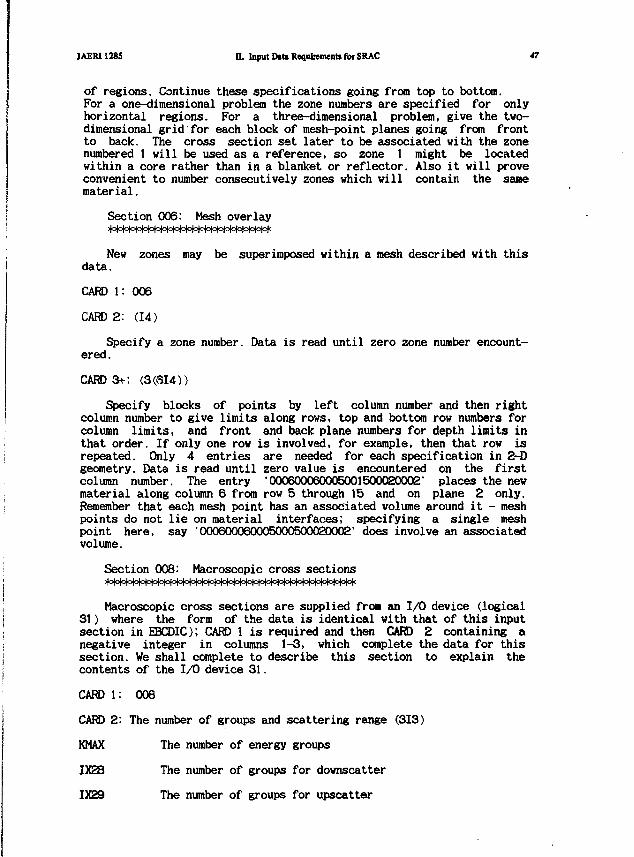
JAERI1285 n. Input Dita Requirement* for SRAC *7
of regions. Continue these specifications going from top to bottom.For a one-dimensional problem the zone numbers are specified for onlyhorizontal regions. For a three-dimensional problem, give the two-dimensional grid for each block of mesh-point planes going from frontto back. The cross section set later to be associated with the zonenumbered 1 will be used as a reference, so zone 1 might be locatedwithin a core rather than in a blanket or reflector. Also it will proveconvenient to number consecutively zones which will contain the samematerial.
Section 006: Mesh overlay
New zones may be superimposed within a mesh described with thisdata.
CARD l: 006
CARD 2: (14)
Specify a zone number. Data is read until zero zone number encount-ered.
CARD 3+: (3(614))
Specify blocks of points by left column number and then rightcolumn number to give limits along rows, top and bottom row numbers forcolumn limits, and front and back plane numbers for depth limits inthat order. If only one row is involved, for example, then that row isrepeated. Only 4 entries are needed for each specification in 2-Dgeometry. Data is read until zero value is encountered on the firstcolumn number. The entry '000600060005001500020002' places the newmaterial along column 6 from row 5 through 15 and on plane 2 only.Remember that each mesh point has an associated volume around it - meshpoints do not lie on material interfaces; specifying a single meshpoint here, say '000600060005000500020002' does involve an associatedvolume.
Section 008: Macroscopic cross sections>|om**=W°W=>(=l°l<>m
Macroscopic cross sections are supplied froa an 1/0 device (logical31) where the form of the data is identical with that of this inputsection in EBCDIC); CARD 1 is required and then CARD 2 containing anegative integer in columns 1-3, which complete the data for thissection. We shall complete to describe this section to explain thecontents of the I/O device 31.
CARD 1: 008
CARD 2: The number of groups and scattering range (313)
KMAX The number of energy groups
1X28 The number of groups for downscatter
1X29 The number of groups for upscatter
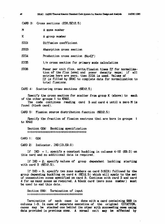
48 SRAC: JAERI Thermal Reactor SUndird Code Syitem for Retctot Dedjn and Analyst JAERI 12S5
CARD 3: Cross sections (2I6.5E12.5)
M A zone number
K A group number
SIG1 Diffusion coefficient
SIG3 Absorption cross section
SIG4 Production cross section (Nu*Ef)
SIG5 1/v cross section for primary mode calculation
SIG6 Power per unit flux, watts/fission times £f for normaliza-tion of the flux level and power density maps; if allentries here are zero, then SIG4 is used. Values ofEf is filled by SRAC to complete data for normalization tototal fissions.
CARD 4: Scattering cross sections (6E12.5)
Specify the cross section for scatter from group K (above) to eachof the other groups 1 to KMAX.
The code continues reading card 3 and card 4 until a zero M isfound (blank card).
CARD 5: Fission source distribution function (6E12.5)
Specify the fraction of fission neutrons that are born in groups 1to KMAX
Section 024: Buckling specification
CARD l: 024
CARD 2: Indicator, IND(I3,E9.0)
If IND = 1, specify a constant buckling in columns 4-12 (E9.0) onthis card and no additional data is required.
If IND = 2, specify values of group dependent buckling startingwith card 3 (6E12.5).
If IND = 3, specify two zone numbers on card 3(813) followed by thegroup depending buckling on card 4 (6E12.5) which will apply to the setof consecutive zones specified on card 3. Continue with card 3 and card4 for as many zones as required. A blank card (zero zone number) mustbe used to end this data.
Section 099: Termination of input
Termination of each case is done with a card containing 999 incolumns 1-3. In case of separate execution of the original CITATION,cases may be stacked one behind the other with succeeding ones usingdata provided in previous ones. A normal exit may be affected by
JAERI1285 n. Input Drtt Requirement! for SRAC 49
locating a blank card after the 999 card of the last case. In SRAC onlya case is allowed.
CARD l: 999
CARD 2: 000 (blank)
For the use of CITATION in the SRAC, succeeding two BLOCKs arerequired to complete the input of Sect.II.7
BLOCK for Material number specification A W
This item is to select and to nuaber the materials used in CITATIONroutine from the materials listed in the mixture specification in Sect.II.8.
MAT(M) M=l ,NMPosition of material M (zone number in Section 008) inthe mixture specification in Sect.II.8
BLOCK for X-region specification /IZN/ required if NXRX)
This item is to edit the averaged few group cross sections usingthe neutron fluxes of the case where the multi-group problem issolved.
NXREG(I),I=1,IZNX-region number by region ; IZN is the product of numberof horizontal regions, that of vertical regions and thatof planes for 3-D case.
H°l°MoM°!°t=|o!o|o|o|oMo|^^
When the CITATION format macroscopic cross sections are requiredby IC14 in Block 3 in Sect.II.1, the Block 1 (NM.NXR.ID) and the Blockfor Material number specification (MAT(M),1,NM) are read in this step.
so SRAC: JAERI TbenntlRMCtor Stindud Code Sytttin foi Rnctor DedgnindAmlyiii JAERI 12(5
II.8 Material Specification
BLOCK 1
NMAT
BLOCK 2
Number of mixtures specified. It is not necessary tospecify the homogenized mixtures by X-region if they arenot used in the later step in the case.
MTNAME (8H) Mixture identification expressed by eight characters,composed of five tags as mmmmebxp which appears as MEMBERname in macroscopic cross section files and flux file.
mmmm-tag Effective mixture identification; any alphabetic characterfor the first and any alphameric character for theremaining three columns is accepted. For a set of X-regionaveraged cross sections CASENAME <4H) is assigned to thistag.
e-tag the tag internally used to specify the neutron energyrange of a set of macroscopic cross sections, as the setfor fast and thermal energy range are separately composedand lately concatenated into the set for whole energyrange. The code 'F' for fast, "I" for thermal, 'A' forwhole energy range is assigned, respectively.
b-tag the tag to indicate burn-up step as '0','I','2',...,'9'or 'A'.'B',.., corresponding to fresh, step 1, step 2,..,step 9, and step 10, step 11,... respectively, when cellburn-up calculation is called by IC20 in BLOCK 1 of Sect.II.1. In non-depletion case this tag is filled by thecharacter punched in the input.
x-tag the tag to specify X-region number of a set of homoge-nized cross sections. For a set of mixture cross sectionscomposed in MACROF or in MACROT routine , this tag isfilled by the character punched.
p-tag the tag internally used to specify Legendre component andalso whether fine or coarse in energy structure. Anycharacter punched in the input is replaced by the tag.="0' coarse and isotropic='2' fine and isotropic (after transport correction)='3* fine and PI component='4' fine and P0 component
NCOM Number of comment words in the future use of Data Poolsystem (fill 0 for the present PDS file )
NISO Number of nuclides to compose the mixture. If punched =0the program assumes that the mixture exists already inMACROWRK file or will be-made in the MIXX step, thenthe formation of macroscopic cross section is skippedin the MACROF and the MACROT steps. Contrarily if thecomposition is specified to the already existing mixturethe formation of macroscopic cross sections is skipped.When the IRA or the PEACO routine is used, punch the
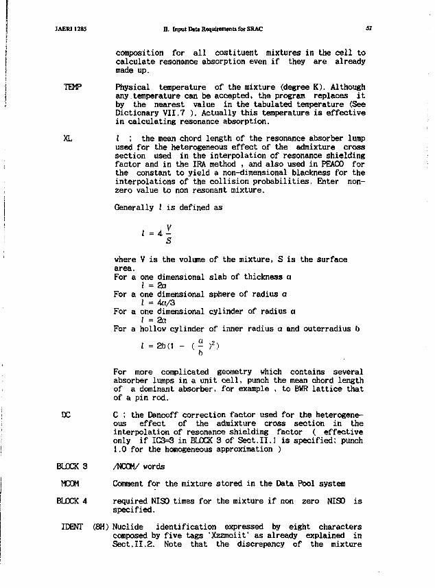
JAERI1285 n. Input Dtta Requirements for SRAC 51
composition for all costituent mixtures in the cell tocalculate resonance absorption even if they are alreadymade up.
TEMP Physical temperature of the mixture (degree K). Althoughany temperature can be accepted, the program replaces itby the nearest value in the tabulated temperature (SeeDictionary VII.7 ). Actually this temperature is effectivein calculating resonance absorption.
XL i ; the mean chord length of the resonance absorber lumpused for the heterogeneous effect of the admixture crosssection used in the interpolation of resonance shieldingfactor and in the IRA method , and also used in PEACO forthe constant to yield a non-dimensional blackness for theinterpolations of the collision probabilities. Enter non-zero value to non resonant mixture.
Generally I is defined as
where V is the volume of the mixture, S is the surfacearea.For a one dimensional slab of thickness ci
I = 2aFor a one dimensional sphere of radius a
I = 4a/3For a one dimensional cylinder of radius a
I = 2aFor a hollow cylinder of inner radius a and outerradius b
I = 2b(l - (- )2)6
For more complicated geometry which contains severalabsorber lumps in a unit cell, punch the mean chord lengthof a dominant absorber, for example , to BWR lattice thatof a pin rod.
DC C ; the Dancoff correction factor used for the heterogene-ous effect of the admixture cross section in theinterpolation of resonance shielding factor ( effectiveonly if IC3=3 in BLOCK 3 of Sect.II.1 is specified; punch1.0 for the homogeneous approximation )
BLOCK 3 /NCOM/ words
MCOM Comment for the mixture stored in the Data Pool system
BLOCK 4 required NISO times for the mixture if non zero NISO isspecified.
IDENT (8H) Nuclide identification expressed by eight characterscomposed by five tags "Xzzmciif as already explained inSect.II.2. Note that the discrepancy of the mixture
52 SRAC: JAERI Thermal Re»ctoi Sttndud Code Syrtem for Reactoi Deiifn and Analyib IAERI12IS
temperature and the temperature indicated by t-tag isaccepted with some warning message; the former is used forthe resonance shielding calculations , the lattet is ucadto choose the thermal neutron data.
IRES Resonance process indicator ( effective if non zero 1(5of BJJOCK 3 in Sect.II. 1 is specified )=0 normal non absorbing nuclide=-1 pseudo non resonant nuclide whose cross sections in
resonance energy range have been stored in MICREFfile as the output of the IRA approximation in theprevious case ( effective if IC5=1 )
=1 non resonant nuclide whose cross section in resonanceenergy range are replaced by those of the abovepseudo nuclide of the same IDENT ( effective if IC5=1 )
Both input records of IRES=-1 and 1 must be entered to thesame resonant nuclide in the macroscopic step in thetreatment of double heterogeneity.
=2 resonant nuclide ( if the BURNUP routine is calledthis item is set automatically for resonant nuclide )
=3 non resonant but absorbing nuclide whose fine energydependent absorption cross sections are assumedconstant in each user's fine group which are takenfrom the user fast library (effective if IC5=2 )
=4- non resonant 1/v absorbing nuclide whose fine energydependent absorbing cross sections are treated exactlyas 1/v in resonance energy range ( effective ifIC5=2 )
IXMICR Indicator to write the effective cross sections into theeffective microscopic cross section file and the theresonance cross section file=0 no editplus 1 write the effective cross section into the
effective microscopic cross section file in the sameformat as in the user fast and thermal libraries
plus 2 write the microscopic cross sections averaged inM-region into the user fast library ( if IC5=1 ) orinto the resonance cross section file ( if IC5=2 ), andalso rewite the macroscopic cross sections of themixture using the effective microscopic cross sectionsin macroscopic file. The IDENT (nuclide identification)of resultant microscopic cross sections are formed assame as the IDENT of this nuclide except ii-tag ( twocharacters ) which are taken from the sixth and seventhcharacters of MTNAME of the mixture. This option is forthe output of primary step in the treatment of double-heterogeneity.
DN Nuclide density ( 10""2W3 )
Repeat BLOCKs from 2 through 4- NMAT times
II.9 Burn-up calculation
JAERI1285 D. Input OtUR*quitMMats for SRAC SS
The input for cell burn-up calculation is minimized because theinformation such as chain scheme, yield, decay constant, power perfission, etc. is compiled in the burn-up library. The user has still tochoose the chain schemes which are stored in separate members in thelibrary.(See Dictionary VII.5)
Following input data are required if IC20 > 0 in Sect.II.l.
BLOCK 1 Control integers /3/
NEP Number of burn-up steps to modify the effective micro-scopic cross sections for burnable nuclides «=15). Itmeans (NEP+1) times cell calculations are executed in acase.
IBUNIT Burn-up unit to control exposure time under the fixedpower=0 MWD (Mega Watt Days)=1 fraction of U-235 burnt
IBEDIT Edit control=0 brief edit=1 detailed edit
=2 more detail for code testing
BLOCK 2 Floating numbers / 2 /
POWERL Whole core power in MWCVOL The factor to yield the total amount of fuel volume in
core by multiplying it to the cell volume. For example ina one dimensional calculation of a cell of a fuel plate, the thickness of fuel meat stands for the fuel volume,then the factor is the product of width * height of fuelplate * number of fuel plate in the core.
The ratio of the above two items is used to get absoluteneutron flux, then any common factor to the above's may bemultiplied. For example, the term "core" appearing in thisitem can be read as "fuel element' or "assembly".
BLOCK 3 /NEP/
PERIOD Burn-up steps in ascending order (not including freshstep ) in unit specified by IUNIT
11.10 MCnOSS ; Updating of Resonance Cross Section File
The routine MCROSS is called if IC8 > 0 in Sect.II.I. This routineproduces the temperature dependent cross sections of the requiredresonant nuclides of " the specified temperatures in the ultra-fineenergy structure which will be used in the ultra fine resonance calcu-lations. The resonance level parameters required are taken from theuser fast library. The user who are satisfied with the public resonancecross section file where we have compiled the cross sections for allavailable nuclides over all range of temperature does not need thisroutine. Otherwise if the user wants to treat the double heterogeneity
St SRAC: JAEMTl>eiinlReKtoiSUndiMCod«SytMmfarRMetotDM%tudAMlyik JAERI12U
in resonance neutron energy, he has to prepare his own resonance crosssection file which contains the information for all concerning nuclidesover the necessary temperature range to be able to write the effectivecross sections into his file. The above preparation may be substitutedby the TSS operations to copy the necessary members from the publicinto the user library, (see Sect.V.3)
BLOCK 1
IDENT (8H ) Nuclide identification of the organization 'Xzzmciif asdescribed in Sect.II.2 User's microscopic cross sectionlibraries, while the chemical tag 'c' and the temperaturetag 'f are not effective in this routine.
BLOCK 2 /3/
NT Number of temperatures
IOUT Print control=0 brief edit=1 detailed edit
IPLOT Plotter control=0 skip plot=1 plot cross sections vs energy
BLOCK 3 /NT/
TT Temperatures for which cross sections are calculated.Each temperature is replaced by the nearest value in thetabulated values ( see Dictionary II.6 )
Repeat BLOCKs from 1 through 3 until a blank identification isencountered.
11.11 PEACO ; The Ultra-fine Resonance Absorption Calculation
An integer is required if IC5 = 2 in BLOCK 3 of Sect.II.1 isspecified for edit control of the PEACO routine.
BLOCK 1 /I/
IPLOT =0 skip plot=1 plot neutron spectra by up-to five R-regions in a
figure=2 plot neutron spectra by R-region for a R-region per
figureX) print modified group cross sections
JAERI1285 55
III. Usage of Auxiliary Progr.
III. 1 Production of the Fast Group Cross Section Library
The group cross section library for the SRAC code is generated byusing the TIMS-PQG code system (Ref.(76)) from the evaluated nucleardata files in the ENDF/B-IV type format. The TIMS-PQG code systemconsists of several codes and a flowchart of the generation system isshown in Fig.III.1-1. At each intermediate step, a code is used toprocess intermediate data libraries and produces an output library.
The PROF-QROUCH-GIIR code calculates the group averaged crosssections of the Bondarenko's type by weighting the 1/E and/or fissionspectra, depending on the energy range defined by Section 1.1.3. TheTIMS-1 code generates mainly the group constants for heavy resonantnuclei by solving numerically neutron slowing down equations. Thecalculated results are stored to the Master Fast Library in the PCSformat by XTABPDS. The SPEC code calculates the group fission spectrafrom using the distribution given in the ENDF/B-IV nuclear data file.Finally, the fast group cross section library for the SRAC code systemis produced by using FASTMAKE.
The TIMS-1 code (Ref.(16)) calculates the group constants of heavynuclides in resonance energy region. The flowdiagram is shown inFig.III.1.2 and the general features of each subprogram are as follows:
FILEREAD : The resonance parameters and floor correction crosssections are read from the data file in the ENDF/B format, and aresuitably arranged for the ARCFIT-2, ARCFIT-3 and MCROSS codes.
ARCFIT-2 : In the unresolved resonance region the average crosssections are calculated by using the average resonance parameters. Theformulas of the average cross sections are the same as those used inthe ENDF/B-IV processing (Ref. (12)).
ARCFIT-3 : In the unresolved region, the resonance parameters andthe level spacings are generated by using Monte Carlo method from thePorter-Thomas and Wigner distributions, respectively. The generatedladder of resonance parameters and the resolved resonance parametersare finally connected and a set of resonance parameters is suppliedranging from the unresolved to the resolved regions.
MCROSS : The Doppler broadened cross sections are calculated on theultra-fine lethargy meshes of about 5000 groups below 130.7 eV. Thecalculations are performed by use of either the Breit-Wigner single-level formula or the multilevel formula (Ref.(55)). The symmetric andasymmetric Doppler line shape functions are calculated by using theBuckler method (Ref.(39)).
PEACO : The neutron spectra on the ultra-fine lethargy meshescalculated by solving numerically the neutron slowing down equationwith the use of the recurrence formula developed by Kier(Refs.(40,41))in which the lethargy meshes are assumed to be extremely narrowcompared to the maximum lethargy gain per collision with the heaviestnuclei in the considered system.
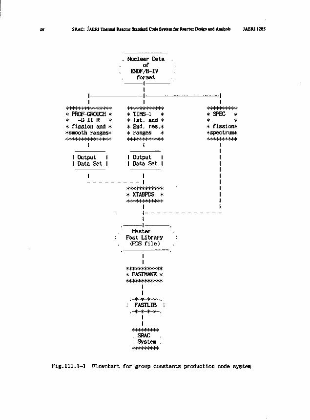
56 SRAC: JAERI Thennal Reactor Standard Cod* SyiMm fot JUactoi Deupi and AnalyiU JAERI 1285
II
**************** PR0F-<3R0UCH ** -G I I R ** fission and **smooth ranges****************
I
Nuclear Dataof
ENDF/&-IVformat
1I1I
************* TIMS-1 ** 1st. and ** 2nd. res.** ranges *
I
I Output II Data Set I
I Output II Data Set I
II
************* XTABPDS *************
II _ — _ _
I-I-
MasterFast Library(PDS file)
II
* FASTMAKE *************
II
: FASTLIB :
II
*********. SRAC .. System .*********
1I
*********** SPEC ** ** fission**spectrum***********
Fig.III.1-1 Flowchart for group constants production code system
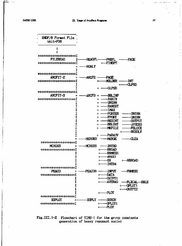
JAERI1285 m. UMjeofAiixlhiyftofiimi 57
ENDF/B Format Fileunit=F08
FILEREAD
ARCFIT-2
ARCFIT-3
MCROSS
PEACO
XSPLOT
I READFL PREFL PACE
RONLYH—FINDPT
ARCF2H MOLDER
+ CLPSD
INTi CLPSD
ARCF3 + BBLINP+ RANIN
UNIRNRANOUTMAXPORTER UNIRN
+ FPORT UNIRN+ RESINT OUTPUT+ BBLOUT JFSDXS+ MKFILE FBLOCK
H RESOLV+ PARAUV
MERGED MERGE
+ MCROSS INTRD•> BROADH ENMESHH AMAX1H SX +—NBROADH INTB4
+ PEACO6 INPUT —FNMESHH DATAH OUTPT1H AVERAG
H PLOT
XSPLT SERCH-i GPLOT1+ PLOT
—FLXCAL—DBLEH GPL0T1n 0UTPT2
Fig.III.1-2 Flowchart of TIMS-1 for the group constantsgeneration of heavy resonant nuclei
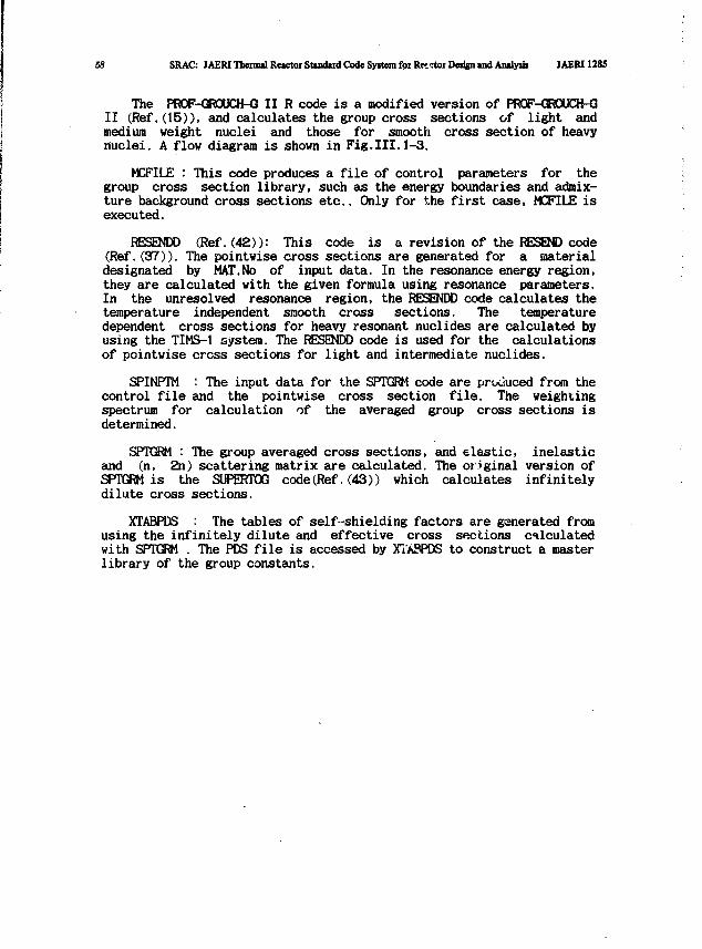
58 SRAC: JAERI Thermal Reictoi Standard Code Syitem for Rector Dedgn and Amly»i« JAERI1285
The PROF-GROUCH-G II R code is a modified version of FR0F-GR0UOM3II (Ref. (15)), and calculates the group cross sections of light andmedium weight nuclei and those for smooth cross section of heavynuclei. A flow diagram is shown in Fig,III.1-3.
MCFILE : This code produces a file of control parameters for thegroup cross section library, such as the energy boundaries and admix-ture background cross sections etc.. Only for the first case, MCFILE isexecuted.
RESENDD (Ref. (42)): This code is a revision of the RESEND code(Ref. (37)). The pointwise cross sections are generated for a materialdesignated by MAT.No of input data. In the resonance energy region,they are calculated with the given formula using resonance parameters.In the unresolved resonance region, the RESENDD code calculates thetemperature independent smooth cross sections. The temperaturedependent cross sections for heavy resonant nuclides are calculated byusing the TIMS-1 system. The RESENDD code is used for the calculationsof pointwise cross sections for light and intermediate nuclides.
SPINPTM : The input data for the SPTGRM code are produced from thecontrol file and the pointwise cross section file. The weightingspectrum for calculation of the averaged group cross sections isdetermined.
SPTGRM : The group averaged cross sections, and elastic, inelasticand (n, 2n) scattering matrix are calculated. The original version ofSPTGRM is the SUPERTOG code(Ref.(43)) which calculates infinitelydilute cross sections.
XTABPDS : The tables of self-shielding factors are generated fromusing the infinitely dilute and effective cross sections calculatedwith SPTGRM . The PDS file is accessed by XTABPDS to construct a masterlibrary of the group constants.
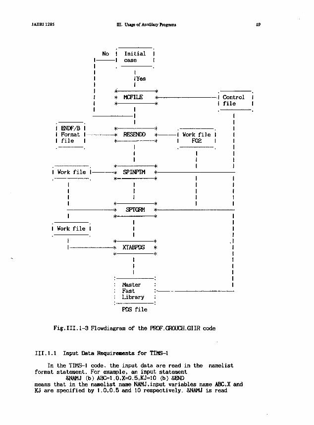
JAERI1285 III. Usige of Auxiliuy Programs
I ENDF/B II Format I-I file I
I Work file I-
I Work file I
No I Initial II case I
I Yes
* MCFILE*
RESENDD
*--*
*-
SPINPTM *-* *
-* SPTGRM *-* *
III
* *-* XTABPDS ** *
I
MasterFastLibrary
PDS file
-! ControlI file
-I Work file II F02 I
Fig.III.1-3 Flowdiagram of the PROF.GROUCH.GIIR code
III.1.1 Input Data Requirements for TIHS-1
In the TIMS-1 code, the input data are read in the namelistformat statement. For example, an input statement
&NAMJ (b) ABC=1.0.X=0.5,KJ=10 (b) SENDmeans that in the namelist name NAMJ.input variables name ABC.X andKJ are specified by 1.0,0.5 and 10 respectively. SNAMJ is read
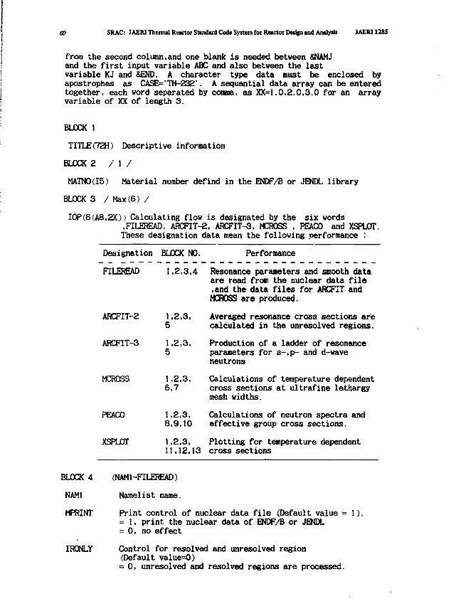
60 SRAC: )AER1 Thermal Reactor Standard Code System foi Reactor Deiign and Analyiii JAtR11285
from the second column,and one blank is needed between 8NAMJand the first input variable ABC and also between the lastvariable KJ and SEND. A character type data must be enclosed byapostrophes as CASE='TH-232'. A sequential data array can be enteredtogether, each word separated by comma, as XX=1.0,2.0,3.0 for an arrayvariable of XX of length 3.
BLOCK 1
TITLE(72H) Descriptive information
BLOCK 2 / 1 /
MATN0(I5) Material number defind in the ENDF/B or JENDL library
BLOCK 3 / Max(6) /
I0P(6(A8,2X)) Calculating flow is designated by the six words,FILEREAD, ARCFTT-2, ARCFIT-3, MCROSS , PEACO and XSPLOT.These designation data mean the following performance :
Designation
FILEREAD
ARCFIT-2
ARCFIT-3
MCROSS
PEACO
XSPLOT
BLOCK NO.
1.2,3,4
1,2,3,5
1,2,3,5
1.2,3,6,7
1,2,3,8,9,10
1,2,3,11,12,13
Performance
Resonance parameters and smooth dataare read from the nuclear data file.and the data files for ARCFIT andMCROSS are produced.
Averaged resonance cross sections arecalculated in the unresolved regions.
Production of a ladder of resonanceparameters for s-,p- and d-waveneutrons
Calculations of temperature dependentcross sections at ultrafine lethargymesh widths.
Calculations of neutron spectra andeffective group cross sections.
Plotting for temperature dependentcross sections
BLOCK 4 (NAM1--FILEREAD)
NAM1 Namelist name.
MPRINT Print control of nuclear data file (Default value = 1).= 1, print the nuclear data of ENDF/B or JENDL= 0, no effect
IRONLY Control for resolved and unresolved region(Default value=0)= 0, unresolved and resolved regions are processed.

JAERI1285 HI. Umeof AuxituyPtotruiu 61
= 1, only resolved region is processed.
BLOCK 5 (NAhE-ARCFIT-2)
NAM2 Namelist name.
ICFT Fissile or fertile material option (Default value = 1 ) .= 1, fertile material= 2, fissile material
BLOCK 6 (NAM3-MCR0SS)
NAM 3 Namelist name.
NT No. of temperatures (Max.= 5)(Default value = 1 ) .
NOMS If NOMS = 0, the group boundary is searched automatically.(Default value = 0) The group number for the upper energygroup where calculation is started are shown as follows:
NOMS
1234567891011
Energy boundary(eV)
100000.046500.021500.010000.04650.01000.0465.0100.046.510.00.2
CASE Name of nuclide to be processed.By assigning 'Name"of nuclide,the s-,p- and d-wave neutronresonance levels to be summed up in the calculations aredefined in the program. The installed nuclide names areTH-232,U-233,U-234,U-235,U-236,U-238, PU-239.PU-240and PU-241,and for the others,the "Name" of nuclide towhich resonance structure is analogous,nay be selected.
TT
BLOCK 7
NAM 4
IOUT
BLOCK 8
NAM 5
) (Default values = 300., 800., 2100.,Temperature ( °Kand 4500. ).
(NAM4-MCROSS)
Namelist name.
Print control of ultrafine group cross sections (Defaultvalue = 0).= 1, print ultrafine group cross sections.
= 0, no effect.
(NAM5-PEAC0)
Namelist name.

62 SRAC: JAERITheiculRcwtocStandudCodeSyitemfotRMCtotDMJinuidAoilydi JAERI12S5
NTEMP No. of temperatures (Max.= 5) (Default value = 4).
KRAT No. of the atonic density ratio, R - values (Max.= 5)(Default value= 1).
KSIGM No. of admixture cross sections(Max.= 10)(Defalut value = 8).
KRES No. of resonant materials (Max.= 2) (Default value = 1 ) .
NPLOT Plot control of neutron spectra (Default value = 0).= 1, neutron spectra are plotted.= 0, no plotting.
NPRINT Print control (Default value = 0). = 0, only the resultsfor resonant material of interest are printed. = 1, alsothe results for background resonant material are printed.
KMOD Starting energy group number for the group structure ofthe JFS-2.SRAC or JFS-3 type. The SRAC group structure isshovn in Dictionary VII.4. =-l,-2,and -3 searchautomatically the starting number for JFS-2.SRAC or JFS-3.If you designate specially upper group number,as for SRACtype, input KMOD = 200 plus group number shovn inDictionary VII.4. and if KM0D=O ,the number of energygroups(KBG) and energy boundaries(EN) are read in BLOCK 9.
BLOCK 9 (NAM6-PEAC0)
NAM 6 Namelist name.
KBG No. of energy groups (Default value = 0). When users wantto calculate group constants for a different structurefrom JFS or SRAC type, (KBG+1) energy boundaries should beread for EN (Max.= 60).
EN Group energy boundaries (eV) (Default values are shovn inDictionary VII.4).
SIGM Admixture background cross sections of Bondarenko type(Default values = 0, 1, 10, 100,1000,10000,100000,1000000)
RATIO R - values of the number density ratios between the tworesonant nuclei. These values are defined at eachadmixture cross sections.(Max.=5). (Defaultvalues=0.1,1.0,10.0,1000.0,1000000.0)
MUCLID Nuclide identified vith 4 letters (Max.= 3). For example.NUCLID=U2381, P239". A30*. If two resonant materials areconsidered, NUCLID=>U238>, U235-, -A30\
TEMP Temperature (°K ) (Default values = 300., 800., 2100.,and 4500. ).
AMASS Average mass for background moderator nuclide(Default value= 30).
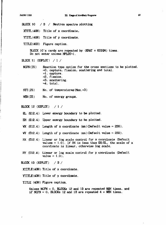
JAERI1285 in. UMfe of Auxiliary Pzognuns 63
BLOCK 10 / 3 / Neutron spectra plotting
XTITL(40H) Title of x coordinate,
YTnL(40H) Title of y coordinate.
TITLE(40H) Figure caption.
BLOCK 10"s cards are repeated by (KRAT * KSIGM) times.Do not enter unless NPLOT=1.
BLOCK 11 (XSPLOT) / 1 /
NCFN(I5) Reaction type option for the cross sections to be plotted.=0, capture, fission, scattering and total.=1, capture.=2, fission.=3, scattering.=4, total.
NTT(15) No. of temperatures(Max.=3)
NEN(I5) No. of energy groups.
BLOCK 12 (XSPLOT) / 1 /
0- (E12.4) Lower energy boundary to be plotted.
EH (E12.4) Upper energy boundary to be plotted.
WX (E12.4) Length of x coordinate (mm)(Default, value = 230).
WY (E12.4) Length of y coordinate (mm)(Default value = 230).
RX (E12.4) Linear or log scale control for x coordinate (Defaultvalues =1.0). If RX is less than EH/EL, the scale of xcoordinate is linear, otherwise log scale.
RY (E12.4) Linear or log scale control for y coordinate (Defaultvalue = 1.0).
BLOCK 13 (XSPLOT) / 3 /
XTITLE(40H) Title of x coordinate.
YTITLE(40H) Title of y coordinate.
TITLE (40H) Figure caption.
Unless NCFN = 0, BLOCKs 12 and 13 are repeated NEN times, andif NCFN = 0, BLOCKs 12 and 13 are repeated 4 * NEN times.
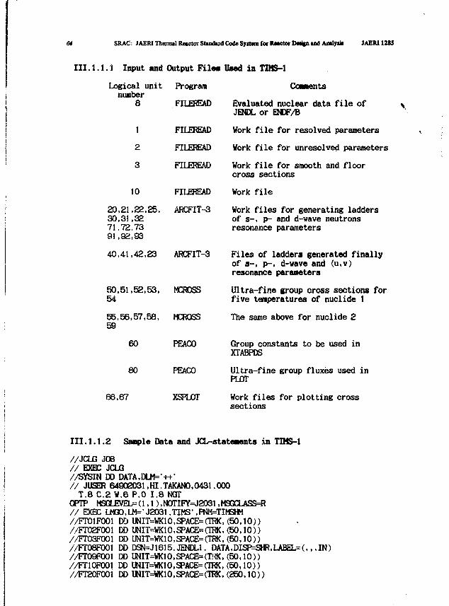
64 SRAC. JAERI Thermtl Retctoi Sttndud Code System foe Rwctor DtifD tnd Amlyiii IAERI128S
III.1.1.1 Input and Output Files Used in TIMS-1
logical unit Programnumber
8 FILEREAD
1 FILEREAD
2 FILEREAD
3 FILEREAD
10
20,21,22,25,30,31,3271.72.7391,92,93
60
80
FILEREAD
ARCFIT-3
40,41,42,23 ARCFIT-3
50,51,52,53, MCROSS54
55,56,57,58, MCROSS59
66,67
PEACO
PEACO
XSPLOT
Coaaents
Evaluated nuclear data file ofJENDL or ENDF/B
Work file for resolved parameters
Work file for unresolved parameters
Work file for smooth and floorcross sections
Work file
Work files for generating laddersof s-, p- and d-wave neutronsresonance parameters
Files of ladders generated finallyof s--, p-, d-wave and (u,v)resonance parameters
Ultra-fine group cross sections forfive temperatures of nuclide 1
The same above for nuclide 2
Group constants to be used inXTABPDS
Ultra-fine group fluxes used inPLOT
Work files for plotting crosssections
III.1,1.2 Sanple Data and JCL-stateaents in TIMS-1
//JCLG JOB// EXEC JCLG//SYSIN DD DATA,DLM=-++-// JUSER 64902031,HI.TAKAN0.0431.000T.8C.2W.6 P.O 1.8 NGT
OPTP M9GLEVEb=(l,l),N0TIFY=J2031,MSQCLASS=«// EXEC LMQ0,LM=' J2031 .TIMS' ,PNM=TIMSm//FT01F001 t» UNIT=WK10,SPACE=(TRK,(50,10))//FT02F001 DD UNIT=WK10,SPACE=(TRK,(50,10))//FT03F001 CO UNIT=WK10,SPACE=(TRK,(50,10))//FT08F001 E» DSN=J1615.JENDL1. DATA,DISP^SHR,LABEL=(,,,IN)//FT09F001 DD UNIT=WK10,SPACE=(T!«, (50,10))//FT10F001 DD UNIT=WK10,SPACE=(TRK,(50,10))//FT20F001 DDUNIT=WK10,SPACE=(TRK,(250,10))
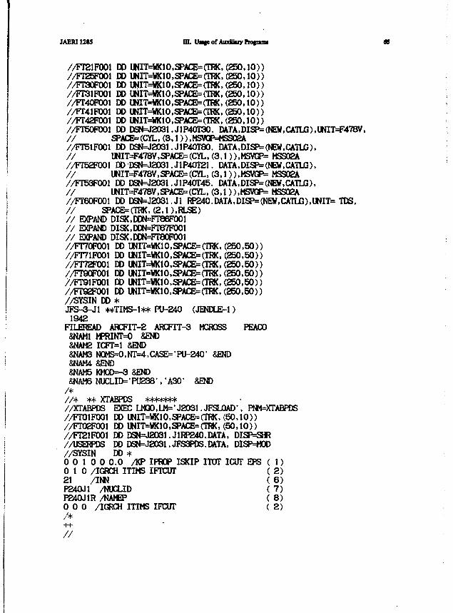
JAER112$5 m. Vrngt of AuxBJuy Frofoiu
//FT21P001 DDUNIT=*K10,SPAOJ=(TRK, (250 ,10) )//FT25TO01 DDWIT=WK10,SPACB=(TRK, (250 ,10 ) )//FT30F001 DOUNIT=WK10,SPACE=(TRK,(250,IO))//FT31P001 DD UNIT=WK10,SPAGE=(TRK,(250,10))//FT4OP001 DDIMIT=WK1O,SPACE=(TRK,(25O,1O))//FT41P001 DDIJNIT=WK1O,SPACE=(TRK, ( 2 5 0 , 1 0 ) )//FT42F001 DD lfttT=WK10,SPACE=(TRK, (250 ,10 ) )//FT50F001 DDDSN=J2031.J1P40T30. DATA,DISP= (NEW,CATLG),UNIT=F478V,/ / SPACEMCYL, ( 3 , 1 ) ) ,MSVCP=HS902A//FT51P001 DD DSN=J2O31.J1P4OT8O. DATA,DISP=(NEW,CATLG),/ / UNIT^478V,aPAraJ=(CYL, (3,1 )),MSVGP= HSS02A//FT52F001 DDDSN=J2O31.J1P4OT21. DATA,DISP= (NEW,C^TLG),/ / UNIT^478V,aPACE=(CYL, (3,1)),MSVGP= MES02A//FT53F001 DD DSN=J2031.J1P40T45. DATA,DISP=(NEW,CATLG),// UNIT=F478V,SPACE=(CYL,(3,1)),MSVGP= MSS02A//FT60FXX)l DDDSN=J2O31.J1 RP240.DATA,DISP= (NEW,CATLC),UNIT= TDS,/ / SPACE=(TRK, (2.D.RLSE)/ / EXPAND DISK,DDN=FT86P001/ / EXPAND DISK,DDN=FTe7FX)01/ / EXPAND DISK,DDN=FT80P001//FT7OP001 DD UNIT=WK10,SPACE=(TRK, (250 ,50 ) )//FT71RJ01 DD UNIT=WK10,SPACE=(TRK, (250 ,50 ) )//FT72FXJ01 DD UNIT=WK10,SPACE=(TRK, ( 2 5 0 , 5 0 ) )//FT90P001 DD UNIT=WK10,SPACE=(TRK, ( 2 5 0 , 5 0 ) )//FT91FX»1 DD UNIT=WK10,SPACE=(TRK, ( 2 5 0 , 5 0 ) )//Freerooi DD UNIT=WKIO,SPACE=(TRK,(25O,5O))//SYSIN DD *JFS-3-J1 **TIMS-1** PU-240 (JENDLE-1)
1942FILEREAD ARCFIT-^ A K y i T - 3 MCROSS PEACO
&NAM1 hPRINT=O S£ND&NAM2 IOT=1 8St}D8MAM3 N0MS=0,NT=4,CASE='PU-2401 &END&NAM4 &END&NAM5 KM0D=-3 &END8NAM6 NUCLID=>PU238-,-A301 &END
/*/ / * ** XTABPDS *******//OCTABPDS EXEC U13D,lh='JSO31. JFSJOAD", PNM=XTABPDS//FT01F1001 DDUNIT=WK10,SPACE=(TRK,(50,10))//FT02P001 DD UNIT=«£1O.SPACE=(TRK, ( 5 0 , 1 0 ) )//FT21FX»1 DDDSN=J2O31.J1RP24O.DATA, DISP^SH?//USERPDS DD DSN=J2031.JFS3PDS.DATA, DISP^OD//SYSIN DD *0 0 1 0 0 0 . 0 /KP IPHOP ISKIP ITOT ICUT EPS ( 1)0 1 0 /IGRCH ITIMS IFTCUT ( 2)21 /INN ( 6)P240J1 /NUCLID ( 7)P240J1R /NAttP ( 8)0 0 0 /IGRCH ITIMS IPCUT ( 2)/*
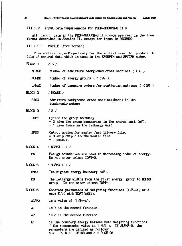
66 SRAC: JAEIUThennliUwto Standard Cod* Syittm for ItoctorDMi|n and Aialyrit JAEXI12SS
III.1.2 Input Data Requirements for PBCF-GBOUCH-G II ft
All input data in the PROF-GROOCH-G II R code are read in the freeformat described in Section II, except for input in RESENDD.
Ill. 1.2.1 MCFILE (free format)
This routine is performed only for the initial case to produce afile of control data which is used in the SPINPTM and SPTGRM codes.
BLOCK 1 / 3 /
NCASE Number of admixture background cross sections ( < 8 ).
NGRMX Number of energy groups ( < 199 ).
LPMAX Number of Legendre orders for scattering matrices ( < 20 )
BLOCK 2 / NCASE /
SIGO Admixture background cross sections(barn) in theBondarenko scheme.
BLOCK 3 / 2 /
I0PT Option for group boundary.= 0 give the group boundaries in the energy unit (eV).= 1 give those in the lethargy unit.
IPDS Output option for master fast library file.= 0 skip output to the master file.= 1 output.
BLOCK 4 / NGRMX + 1 /
EN Energy boundaries are read in decreasing order of energy.Do not enter unless IOPT=O.
BLOCK 5 / NGRMX + 1 /
EMAX The highest energy boundary (eV).
DU The lethargy widths from the first energy group to NGRMXgroup. Do not enter unless IOPT=1.
BLOCK 6 Constant parameters of weighting functions (1/E**a) or Aexp(-E/b) sinh(SQRT(c*E)).
ALPHA is a-value of (1/E**a).
Al is b in the second function.
A2 is c in the second function.
El is the boundary energy between both weighting functions( the recommended value is 1 MeV ). If ALPHA=0, theparameters are defined as follows;a = 1.0, b = 1.0E+06 and c = 2.0E-06.
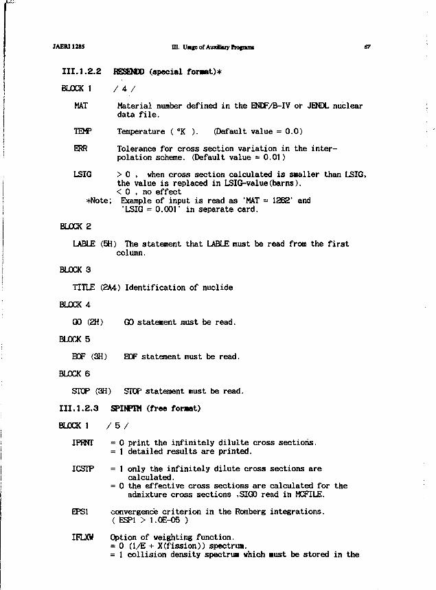
JAER11285 UI. Uwjeof AuxJUuy Ptofams
III.1.2.2 RESENDD (special foraet)*
BLOCK 1 / 4 /
MAT Material number defined in the ENDF/B-IV or JEMJL nucleardata file.
TEMP Temperature ( °K ). (Default value = 0.0)
ERR Tolerance for cross section variation in the inter-polation scheme. (Default value = 0.01)
LSIG > 0 , when cross section calculated is smaller than LSIG,the value is replaced in LSIG-value(barns).< 0 , no effect
*Note; Example of input is read as 'MAT = 1862' and•LSIG = 0.001" in separate card,
BLOCK 2
LABLE (5H) The statement that LABLE must be read from the firstcolumn.
BLOCK 3
TITLE (2A4) Identification of nuclide
BLOCK 4
GO (2H) GO statement must be read.
BLOCK 5
EOF (3H) EOF statement must be read.
BLOCK 6
STOP (3H) STOP statement must be read.
III.1.2.3 SPINPTM (free foraat)
BLOCK 1 / 5 /
IPRNT = 0 print the infinitely dilulte cross sections.= 1 detailed results are printed.
ICSTP = 1 only the infinitely dilute cross sections arecalculated.
= 0 the effective cross sections are calculated for theadmixture cross sections ,SIG0 read in MCFILE.
EPS1 convergence criterion in the Romberg integrations.( ESP1 > 1.0E-O5 )
IFLXW Option of weighting function.= 0 (1/E + X(fission)) spectrum.= 1 collision density spectrua which Bust be stored in the
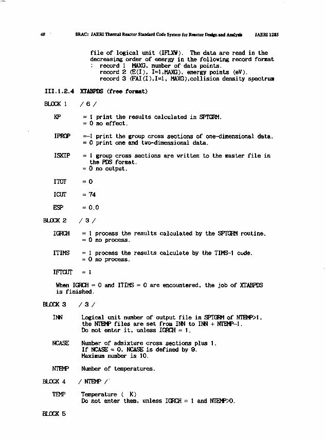
68 SRAC: JAERI Thermal Reactor Standaid Code Syitem for Reactor Derign and Analydi JAERH2S5
file of logical unit (IFLXW). The data are read in thedecreasing order of energy in the following record format: record 1 MAXG, number of data points.
record 2 (E(I), 1=1,MAXG), energy points (eV).record 3 (FAI(I),I=1, MAXG),collision density spectrum
III.1.2.4 XTABPDS (free foraat)
BLOCK 1 /6 /
KP = 1 print the results calculated in SPTGRM.= 0 no effect.
IPROP =-1 print the group cross sections of one-dimensional data.= 0 print one and two-dimensional data.
ISKIP = 1 group cross sections are written to the master file inthe PDS format.
= 0 no output.
ITOT = 0
ICUT = 74
ESP = 0.0
BLOCK 2 / 3 /
ICKCH = 1 process the results calculated by the SPTGRM routine.= 0 no process.
ITIMS = 1 process the results calculate by the TIMS-1 code.= 0 no process.
IFTCUT = 1
When IGRCH = 0 and ITIMS = 0 are encountered, the job of XTABPDSis finished.
BLOCK 3 / 3 /
INN Logical unit number of output file in SPTGRM of NTQPM,the NTEM> files are set from INN to INN + NTQP-l.Do not enter it, unless IGRCH = 1.
NCASE Number of admixture cross sections plus 1.If NCASE = 0, NCASE is defined by 9.Maximum number is 10.
NTEJP Number of temperatures.
BLOCK 4 / NTH*5 /
TEMP Temperature ( K)Do not enter them, unless IGRCH = 1 and NTEWX).
BLOCK 5
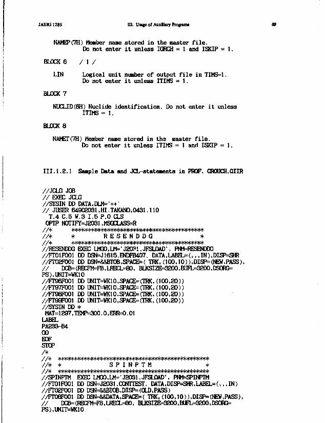
JAERI128S m. Vote of Auxiliary ftofrtnu
NAMEP(7H) Member nane stored in the naster file.Do not enter it unless IGRCH = t and ISKIP = 1.
BLOCK 6 / 1 /
LIN Logical unit nunber of output file in TIMS-1.Do not enter it unless ITIMS = 1.
BLOCK 7
NUCLID(8H) Nuclide identification. Do not enter it unlessITIMS = 1.
BLOCK 8
NAMETC7H) Member nane s tored i n the master f i l e .Do not enter i t un le s s ITIMS = 1 and ISKIP = 1.
I I I . 1 . 2 . 1 Saaple Data and JCL-statewsnts i n PROF. CROUCH.GIIR
//JCLG JOB/ / EXEC JCLG//SYSIN DD DATA.DLM^-H-'/ / JUSER 64902031,HI.TAKAN0.0431.110
T.4 C.5 W.3 1 .5 P.O CLSOPTP N0TIFY=J2031 ,MSGCLASS=R
/ / * * R E S E N D D G *
//RESENDDG EXEC LMQO.LM^J^l .JFSLOAD1, PNM=RESEMXX3//FT01F001 DD DSN=J1615.ENDFB407. DATA,LABEL=(,,,IN),DISP^SHR//FT02F001 DD DSN=&&BTOB,SPACE=( TRK, (100,10)),DISP=(NEW,PASS),/ / DCB=(RBCFW=FB,LRECL=aO, BLKSIZE=3200,BUFL=32Q0,DSORG=PS),UNIT=WK10//FT96FX)01 DD UNIT=WK10,SPACE=(TRK, (100 ,20) )//FT97F001 DD UNIT=VK10,SPACE=(TRK. (100 ,20 ) )//FT98FO01 DD UNIT=WK10,SPACE=(TRK, (100 ,20 ) )//rT99FXX)l DD UNIT=WK10,SPACE=(TRK, (100 ,20 ) )//SYSIN DD *
MAT= 129f7, TEMP=300.0, ERR=0.01LABELPA233-B4GOEOFSTOP/ *
/ / * * SPINPTM *
//SPINPTM EXEC LMGO.Ii^-jaoai.JFSLOAD-. PNM=SPINPTM//FTO1FXX)1 DD DSN=J2031 .CONTTEST. DATA,DISP=SHR.LABEL=(, , , I N )//FT02FXJ01 DD DSN=&&BTOB,DISP= (OLD,PASS)//FT0S!t)01 DD DSN=&&DATA,SPACE=( TRK, (100,10)),DISP=(NEW,PASS),/ / DCB=(RECFM=*B,LREEL=eO, BLKSIZE=3200.BUFL=3200,DSORG=PS),UNIT=WK10
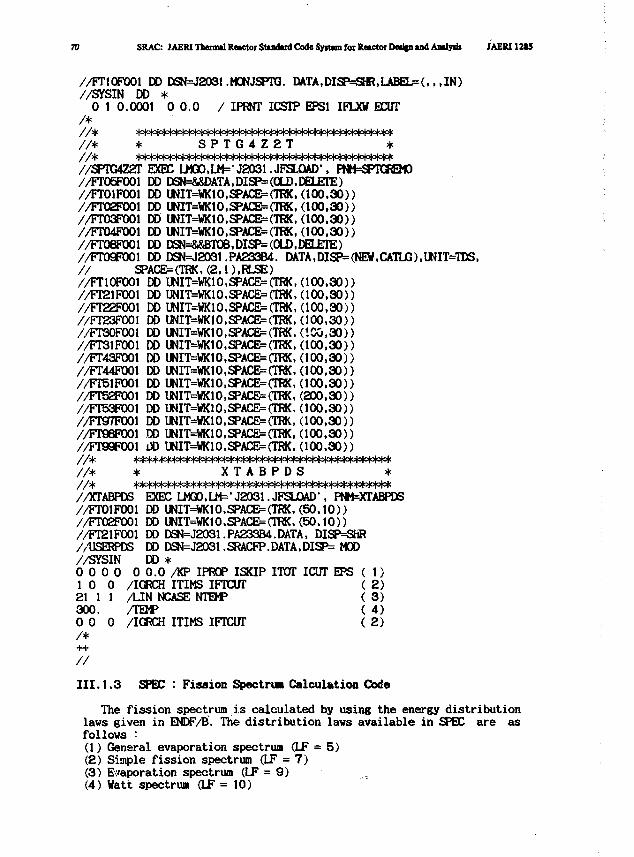
70 SRAC: JAEW Thenml Rewtoi Sturfud Code Syitra for Retctoi Deiljn ind Amlyat MERI12«5
//FT1OFOO1 DD DSN=J203t.MONJSPTG. DATA,DISP=SHR,LABEL=(,, ,IN)//SYSIN DD *
0 1 0.0001 0 0 . 0 / IPRNT ICSIP EPS1 IFLXV EEITT/*
/ / * S P T G 4 Z 2 T
//SFTG4Z2T EXEC 0*30,111=^2031 . JFSLCKD', PNM=SPTGREMO//FT05F001 DD DSN=&&DATA,DISP=(OLD,DELETE)//FT01F001 DD UNIT=WK1O,SPACE={TRK, (100 .30) )//FT02F001 DD UNIT=WK10,SPACB=(TRK, (100 ,30) )//FT03F001 DDUNIT=WK10,SPACE=(TPK, (100 .30) )//FT04F001 DD IMT=WK1O.SPACE=(TRK. (100 ,30) )//FT08F001 DD DSN=&&BTOB,DISP= (OLD,DELETE)//FT09P001 DD DSN=J2031.PA233B4. DATA,DISP=(NEW,CATLja),UNIT=TDS,/ / SPACE=(TOK, (2,1 ),RLSE)//FTlOPOOl DD UNIT=WK10,SPACE=(TRK,(100,30))//FT21F001 DD UNIT=WK10,SPACE=(TRK, (100 ,30) )//FT22P001 DD UNIT=WK10,SPACE=(TRK,(100,30))//FT23P001 DD UNIT=WK10,SPACE=(TRK, (100 ,30 ) )//FT30F001 DD UNIT=WK10,SPACE=(TRK, (100 ,30 ) )//FT31FX»1 DD UNIT=WK10,SPACE=(TRK, (100 ,30 ) )//FT43F001 DD UNIT=VK10,SPACE=(TRK, (100 ,30) )//FT44F001 DD UNIT=WK10,SPACE=(TRK,(100.30))//FT51P001 DD UNIT=WK1O,SPACE=(TRK, (100 ,30) )//FT52FXX)1 DD UNIT=VK1O,SPACE=(TRK, (200 ,30) )//FT53F001 DD UNIT=WK10,SPACE=(TRK, (100 ,30) )//Fr9f7P001 DD UNIT=WK10,SPACE=(TRK, (100 ,30) )//FT96FXX)1 DD UNIT=«K10.SPACED(TK(, (100 ,30 ) )//FT99P001 i » UNIT=WK10,SPACE=(TRK,(100,30))
/ / * * X T A B P D S */ / * H ° M < * * * = W < * * * * * * * * * ^ ^//XTABPDS EXEC LMQ0,LM=>J2031.JFSLOAD>, P»i=XrABPDS//FT01P001 DD UNIT=WK10,SPACE=(TRK, ( 5 0 , 1 0 ) )//FT02F001 DD UNIT=WK10,SPACE=(TOK,(50,10))//FT21F001 DD DSN=J2031 .PA233B4.DATA, DISP=SHR//IJSEiyDS DD DSN=J2031. SRACFP. DATA, DISP= MOD//SYSIN DD *0 0 0 0 0 0 . 0 /KP IPROP ISKIP ITOT IOJT EPS ( 1)1 0 0 /IGRCH ITIMS IFTCUT ( 2 )21 1 1 /LIN NCASE NTEMP ( 3 )300. /TEMP ( 4 )0 0 0 /IGRCH ITIMS IFTCUT ( 2 )/*
III. 1.3 SPEC : Fission Spectrw Calculation Code
The fission spectrum is calculated by using the energy distributionlaws given in ENDF/B. The distribution laws available in SPEC are asfollows :(1) General evaporation spectrum (LF = 5)(2) Simple fission spectrum (LF = 7)(3) Evaporation spectrum (LF = 9)(4) Watt spectrum (LF = 10)
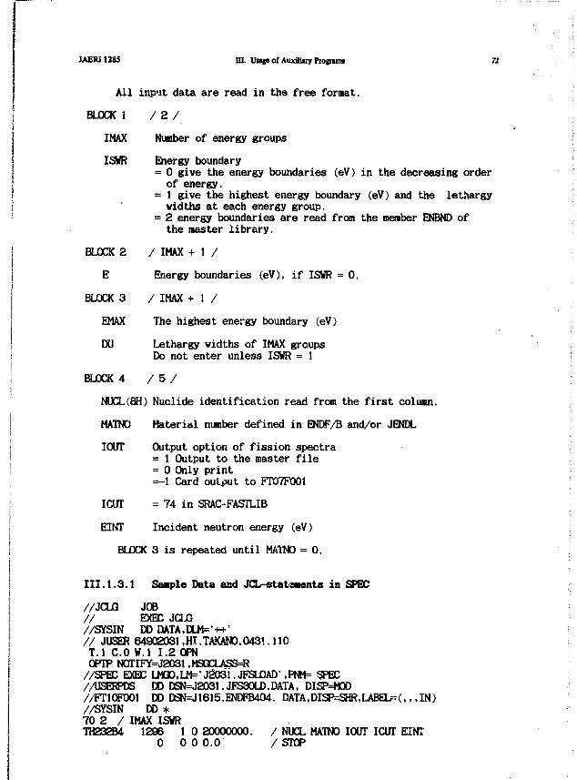
JAERI1285 UI. Uuje of Auxiliiiy Programs 71
All input data are read in the free format.
BLOCK 1 / 2 /
IMAX Number of energy groups
ISWR Energy boundary= 0 give the energy boundaries (eV) in the decreasing orderof energy.
= 1 give the highest energy boundary (eV) and the lethargywidths at each energy group.
= 2 energy boundaries are read from the member ENBND ofthe master library.
BLOCK 2 / IMAX + 1 /
E Energy boundaries (eV), if ISWR = 0.
BLOCK 3 / IMAX + 1 /
EMAX The highest energy boundary (eV)
DU Lethargy widths of IMAX groupsDo not enter unless ISWR = 1
BLOCK 4 / 5 /
NUCL(8H) Nuclide identification read from the first column.
MATNO Material number defined in ENDF/B and/or JENDL
IOUT Output option of fission spectra= 1 Output to the master file= 0 Only print=-1 Card output to FT07F001
ICUT = 74 in SRAC-FASTLIB
EINT Incident neutron energy (eV)
BLOCK 3 is repeated until MATNO = 0.
II1.1.3.1 Staple Data and JCL-statamnts in SPEC
//JCLG JOB// EXEC JCLG//SYSIN DD DATA,DLM=v++>// JUSER 64902031,HI.TAKAN0.0431.110T.I C O W.I 1.2 OPNOPTP N0TIFY=J2031,MSGCLASS=R//SPEC EXEC LMaO,LM='J2031.JFSLOAD1,PNM= SPEC//USERPDS DD DSN=J2031.JFS30LD.DATA, DISP=M0D//FT1OF0O1 DD DSN=J1615.ENDFB404. DATA,DISP=3HR,LABEL-(.,,IN)//SYSIN DD *70 2 / IMAX ISWRTH232B4 1296 1 0 20000000. / NUCL MATNO IOUT ICUT EINT
0 0 0 0.0 /STOP
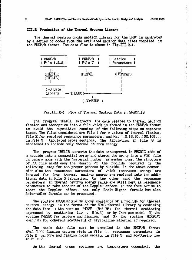
72 SRAC: JAERI Therm*! Retctoi SUndud Code Syitem for Reactor Design tnd Analyst JAERI12S5
III.2 Production of the Thermal Neutron Library
The thermal neutron cross section library for the SRAC is generatedby a series of codes from the evaluated neutron data files compiled inthe ENDF/B format. The data flow is shown in Fig.III.2-1.
! ENDF/B II File 1,2,3 I
I(THEFIL)(THELIB)
I
I 1-D Data II Library I —
I ENDF/B I I Lattice II File 7 I I Parameters I
(PIXSE)I
•(THESEC)-I
( COMBINE )
I(HEXSCAT)
II
Fig.III.2-1 Flow of Thermal Neutron Data in SRACTLIB
The program THEFIL extracts the data related to thermal neutronfission and absorption into a file which is formed in the ENDF/B formatto avoid the repetitive running of the following steps on separatetapes. The files considered are File 1 for v valuos of thermal fission,File 2 for resolved resonance parameters, and Mat 1,2,18,101,102,103...in File 3 ; tabulated cross sections. The tabulation in File 3 isshortened to include only thermal neutron energy.
The program THELIB converts the data arrangement in EBCDIC mode ofa nuclide into a sequential array and stores the ar: y into a PDS filein binary mode with the 'material number' as member h*me. The structureof PDS file makes easy the search of the nuclide required by thefollowing step for the proper process by nuclide. In the above conver-sion also the resonance parameters of which resonance energy arelocated far from thermal neutron energy are replaced into the addi-tional data in File 3 tabulation. On the other hand the resonanceparameters in thermal neutron energy range are still kept as resonanceparameters to take account of the Doppler effect. In the formulation totreat the Doppler effect, not only Breit-Wigner formula but alsoAdler-Adler formula can be processed.
The routine CQ1BINE yields group constants of a nuclide for thermalneutron energy in the format of the SRAC thermal library by combiningthe data from 1) the routine PIXSE (Ref.75) for thermal scatteringexpressed by scattering law , S(ou/3) or by free gas model, 2) theroutine THESEC for capture and fission, and 3) the routine HEXSCAT(Ref.19) for coherent scattering of crystalline material if required.
The basic data file must be compiled in the ENDF/B format(Ref.(1)); fission neutron yield in File 1, resonance parameters inFile 2, capture and fission cross section in File 3, and scattering lawin File 7.
As the thermal cross sections are temperature dependent, the
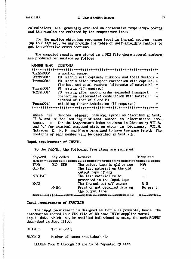
JAERI1285 III. UMgeof Auxiliary Protnnu 73
calculations are generally executed on consecutive temperature pointsand the results are referred by the tenperature index.
For the nuclide which has resonance level in thermal neutron range(up to 3.Se8 eV), we may provide the table of self-shielding factors toget the effective cross sections.
The computed results are stored in a PDS file, where several membersare produced per nuclide as follows;
MEMBER NAME CONTENTS
'CzzmcOOO' a control csember *"KzzmcOOf PO matrix with capture, fission, and total vectors *"MzzmcOOf PO matrix after transport correction with capture, *
fission, and total vectors (alternate of matrix K) *•PzzmcOOf PI matrix (if required) *'NzzmcOOf PO matrix after second order expanded transport *
correction (alternative combination with matrix P *instead of that of K and P)
'FzzmcOOf shielding factor tabulation (if required) *Wofta|o|Q|o|o|o|o|o|o|o|o|o|c^
where 'zz' denotes element chemical symbol as described in Sect.II.8, and 'm' for last digit of mass number to discriminate iso-topes, t' for the temperature index as shown in Dictionary VII.6,and 'c* for chemical compound state as shown in Dictionary VII.2.Matrices K, M, P, and F are organized to have the same length. Thecontents of each member will be described in Sect.V.2.
Input requirements of THEFIL
To the THEFIL, the following five items are required.
Keyword Key codes Remarks DefaultedHcM°l°|cH*|oto|ot=l°W°^^TAPE OLD NEW The output tape is old or new NEWOLD-MAT The last material 6& the old -1
output tape if anyNEW-MAT The last material to be -1
processed in the input tapeEMAX The thermal cut off energy 5.0
PRINT Print or not detailed data on No printthe output tape
Input requirements of SRACTLIB
The input requirement is designed as little as possible, hence theinformation stored in a PDS file of DD name THCON supplies normalinput data which may be modified beforehand by using the code PDSEDTdecsribed in Sect.III.6.
BLOCK ! Title (72H)
BLOCK 2 Number of cases (nuclides) /I/
BLOCKs from 3 through 10 are to be repeated by case
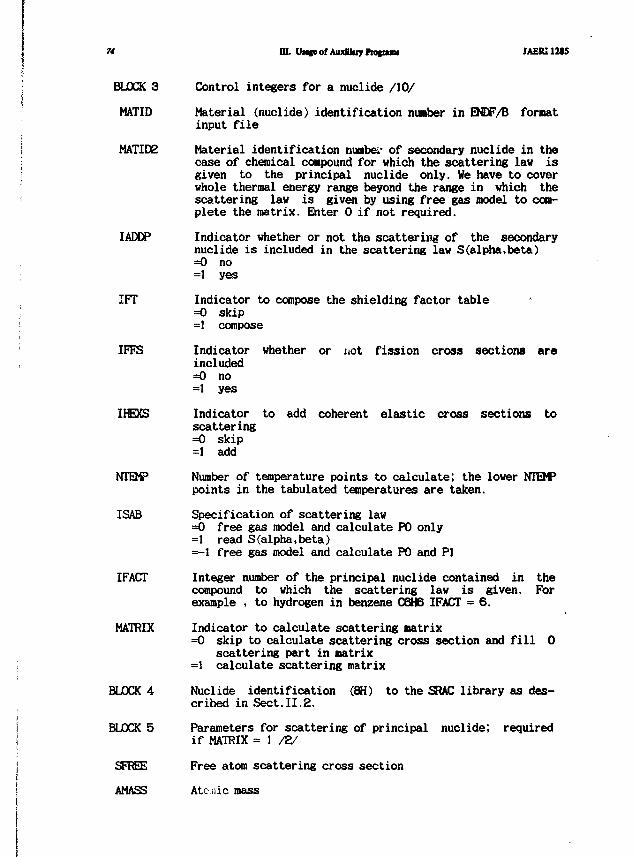
74 m. Unteof AuxSluyProfuju JAERU2S5
BLOCK 3
MATID
MATIDE
IADDP
IFT
IFFS
IHEXS
NTEMP
ISAB
IFACT
MATRIX
BLOCK 4
BLOCK 5
SFREE
AMASS
Control integers for a nuclide /10/
Material (nuclide) identification number in ENDF/B formatinput file
Material identification numbe.- of secondary nuclide in thecase of chemical compound for which the scattering lav isgiven to the principal nuclide only. We have to coverwhole thermal energy range beyond the range in which thescattering law is given by using free gas model to com-plete the matrix. Enter 0 if not required.
Indicator whether or not the scattering of the secondarynuclide is included in the scattering law S(alpha,beta)=0 no=1 yes
Indicator to compose the shielding factor table=0 skip=1 compose
Indicator whether or not fission cross sections areincluded=0 no=1 yes
Indicator to add coherent elastic cross sections toscattering=0 skip=1 add
Number of temperature points to calculate; the lower NTEMPpoints in the tabulated temperatures are taken.
Specification of scattering law=0 free gas model and calculate P0 only=1 read S(alpha,beta)=-1 free gas model and calculate P0 and PI
Integer number of the principal nuclide contained in thecompound to which the scattering law is given. Forexample , to hydrogen in benzene C6H6 IFACT = 6.
Indicator to calculate scattering matrix=0 skip to calculate scattering cross section and fill 0
scattering part in matrix=! calculate scattering matrix
Nuclide identification (8H) to the SRAC library as des-cribed in Sect.II.2.
Parameters for scattering of principal nuclide; requiredif MATRIX = 1
Free atom scattering cross section
Atcniic mass
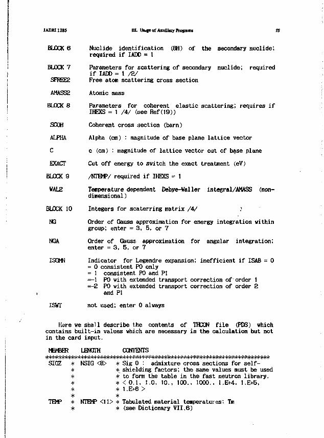
JAERI1285 UuteofAuxiliuyFtotnnu 75
BLOCK 6 Nuclide identification (8H) of the secondary nuclide;required if IADD = 1
BLOCK 7 Parameters for scattering of secondary nuclide; requiredif IADD = 1 /2/
SFREE2 Free atom scattering cross section
AMASS2 Atomic mass
BLOCK 8 Parameters for coherent elastic scattering; requires ifIHEXS = 1 /4/ {see Ref (19))
SCOH Coherent cross section (barn)
ALPHA Alpha (cm) : magnitude of base plane latLice vector
C c (cm) : magnitude of lattice vector out of base plane
EXACT Cut off energy to switch the exact treatment (eV)
BLOCK 9 /NTEMV required if IHEXS =- 1
WAL2 Temperature dependent Debye-Waller inteeral/AMASS (non-dimensional )
BLOCK 10 Integers for scaterring matrix /4/ .'
NG Order of Gauss approximation for energy integration withingroup; enter = 3 , 5, or 7
NGA Order of Gauss approximation for angular integration;enter = 3, 5, or 7
ISGMN Indicator for Legendre expansion; inefficient if ISAB = 0= 0 consistent P0 only= 1 consistent. P0 and PI=-1 P0 with extended transport correction of order 1=-2 P0 with extended transport correction of order 2
and PI
ISWT not used; enter 0 always
Here we shall describe t.he contents of THCON file (PDS) whichcontains built-in values which are necessary in the calculation but notin the card input.
MEMBER LENGTH
SIGZ*
NSIG <8>
CONTENTS
* Sig 0 : admixture cross sections for self-* shielding factors; the same values must be used* to form the table in the fast neutron library.* < 0 . 1 , 1.0, 10., 100., 1000., l.E+4, l.E+5,* l.E+6 >*
TEM> * NTEfP <11> * Tabulated material temperatures: Tm* * (see Dictionary VII.6)
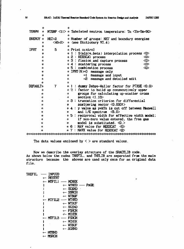
76 SRAC: JAERI Thermal Reactor Stindud Code System for Reactor Deafen and Analy* JAF,RI13tS
TEMPN **
ENERGY **
*
NTEMP <11> * Tabulated neutron temperature: Tn <Tn=Tm+50>
NET+2<48+2>
IPRT
**
DEFAULT**
**
**
Number of groups: NET and boundary energies(see Dictionary VI.4)
*
* Print ccntrol* I* 2* 3* 4* 5
S(alpha,beta) interpolation process <0>HEXSCA1 processfission and capture processscattering processcombination process
IPRT(N)=0 message only=1 message and input=2 message and detailed edit
**** 1* 2*** 3
* 4*
*** 6* 7
dummy Debye-Waller factor for PI5CSE <0.0>factor to build up consecutively uppergroups for calculating up-scatter crosssection <I.13>truncation criterion for differentialscattering vector <0.0001>y value as y*kTn is cut off between Maxwelland 1/E spectrum <5.0>reciprocal width for effective width model;if non-zero value entered, the free gasmodel is substituted. <0.>NAV value for HEXSCAT <0>NAYX value for HEXSCAT <2>
The data values enclosed by < > are standard values.
Now we describe the overlay structure of the SRACTLIB code.As shown below the codes THEFTL, and THFi.TB are separated from the mainstructure because the aboves are used only once for an original datafile.
THEFIL INPUTDRESTRTMTFIL1 — MCHEK
+- WTHED+- SCEND+- SSRCH+- WTBUF
MTFIL2 WTHED+- WTBUF+- SCEND-i— FSRCH-f- MCHEX
MTFIL3 — FSRCH+- MCHEK+- WTBUF+- SCEND
MTENDMSRCH
PAGE
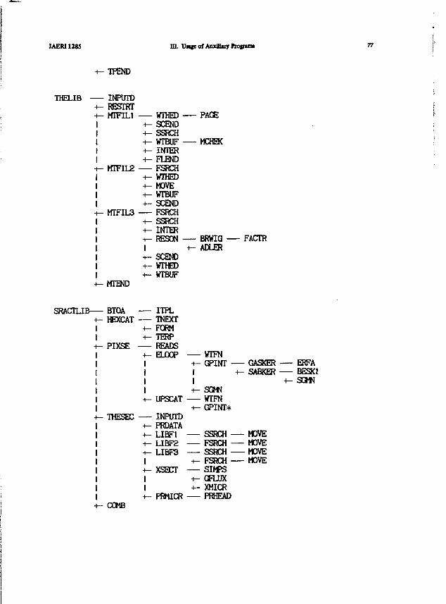
IAERI1285 ni. UMgeof AuxUJuy ftojnmt 77
TPEND
THELIB -— INPUTD+- RESTRT-i- MTFILI WTHED -i -I-SCEND1 +- SSRCH1 +- WTBUF -1 -i— INTER1 +- FLENDi- MTFIL2 FSRCH
•f— WTHED+- MOVE-t— WTBUF+- SCEND
i- MTFIL3 FSRCH+- SSRCH+- INTER+- RESON -1+- SCEND+- WTHED+- WTBIF
+- MTEND
SRACTLIB BTQA ITPL+- HEXCAT TNEXT
H
+- FORM+- TERP
h- PIXSE READS-i- ELOOP1111+- UPSCAT
i- THESEC INPITTD+- PRDATA-^LIBFl+- LIBF2+- LIBF31+- XSECT11+- PRMICR
— PAGE
— MCHEK
— BRWIG —+- ADLER
— WTFN+- GPINT -1 H1+- SGMN
WTFN+- GPINT*
SSRCH -FSRCH -SSRCH -
+- FSRCH —— SIMPS+- GFLUX+- XMICR
PRHEAD
- FACTR
- GASKER ERFAi- SABKER BESK1
+- SGMN
- MOVE- MOVE- MOVE- MOVE
+ - COMB
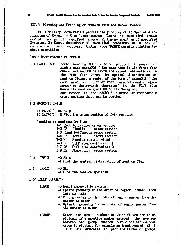
75 SRAC: JAEM Thentud RMgtoc Shadtri Cod« SyHam tat RMCKW Dw%i m< AMJJT* JAEJU12U
III.3 Plottinc and Printinc of Neutrbn Flux and Crooc Section
! An auxiliary code MFPLOT permits the plotting of 1) Spatial dist-ribution of R-reginn-(Zone-)vise neutron fluxes of specified groupsor/and average of specified groups, 2) Energy spectrum of specifiedX-region, 3) Energy dependence of specified reactions of a set ofmacroscopic cross sections. Another code MACRPR permits printing theabove quantities.
Input Requirements of MFPLOT
1.1 LABEL (AB) Member name in PCS file to be plotted. A member ofsuch a name caseA002 ( the case name in the first fourcharacters and 00 on sixth and seventh characters) inthe FLUX file keeps the spatial distribution ofneutron fluxes. A member of the form of caseA0n2 ( thecase name on the first four characters and X-regionnumber on the seventh character) in the FLUX filekeeps the neutron spectrum of the X-region.Any member in the MACRO file keeps the macroscopiccross section which may be plotted.
1.2 MACRO(I) 1=1,8
If MACRO(I) =0 skipIf MACRO(I) =0 Plot the cross section of I-th reaction
Reaction is assigned by I as,1=1 Eact Activation cross section1=2 Ef Fission cross section1=3 uEact Nu*fission cross section1=4 Et Total cross section1=5 X Fission neutron yield1=6 Dl Diffusion coefficient 11=7 D2 Diffusion coefficient 21=8 Ea Absorption cross section
1.2' IRFLX =0 Skip=1 Plot the spatial distribution of neutron flux
1.3 IXFLX =0 Skip=1 Plot the neutron spectrum
1.3' IGBOM.IGRQUP's
IGEOH =0 Equal interval by region=1 Sphere geometry in the order of region number from
left to right=2 Slab geometry in the order of region number from the
center to outer=3 Cylinder geometry in the order of region number from
tfie center to outer
IGROUP Enter the group numbers of which fluxes are to beplotted. If a negative number entered, the averagebetween the group entered before and the current£;roup is plotted. For example an input record (2 410 5 -8) indicates to plot the fluxes of groups
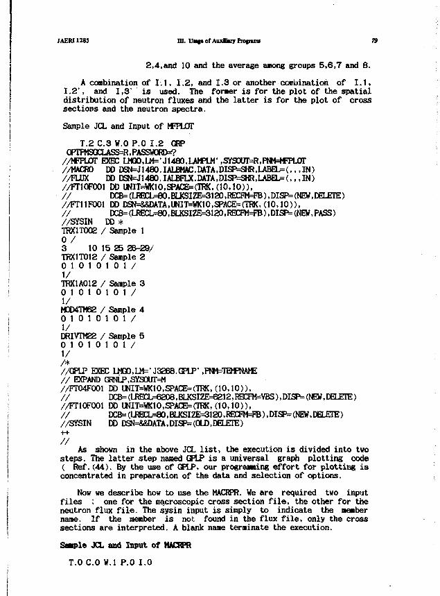
JAERI1285 HI. U«i«of AuxikiyProfrinu 79
2,4,and 10 and the average among groups 5,6,7 and 8.
A combination of I.I, 1.2, and 1.3 or another combination of I.I,1.2', and 1,3' is used. The former is for the plot of the spatialdistribution of neutron fluxes and the latter is for the plot of crosssections and the neutron spectra.
! Sample JCL and Input of MFPLOT
! T.2 C.3 W.O P.O 1.2 GRPOPTPMSGCLASS==R,PASSWORD=?//MFFLOT EXEC LMaO,LM='J148O.LAMPLM' ,SYSOUr=R,PNM=*FPL0T
j //MACRO DDDSN^1480.IALBMAC.DATA,DISP=SHR,IJu3EL=(,,,IN)! //FLUX DD DSN=J1480.IALBFLX.DATA,DISP=SHR>LABEL=(,,,IN)i //FT10F001 DD bNIT=WKIO.SPACE=(TRK. (10,10)),
// O»=(LRECL=80,BU<SIZE>=3120,RElCFM=FB),DISP= (NEW, DELETE)//FT11F0O1 DD DSN=&&DATA,UNIT=WK10,SPACE=(TRK,(10,10)),// DCB=(LREX^=«0>BLKSIZE=3120,RElCyM=FB).DISP=(NEW,PASS)//SYSIN DD *TRX1T002 / Sample 10 /3 10 15 25 25-29/TRX1T012 / Sample 20 10 10 10 1/1/TRX1A012 / Sample 30 10 10 10 1/1/H0D4TM62 / Sample 40 10 10 10 1/1/DRIVTM22 / Sample 50 10 10 10 1/1//*//GPLP EXEC LMQO,LM=-J32B8.GPLP1 ,PNM=TEMPNAfE/ / EXPAND GRNLP,SYSOUT=M//FT04F001 E» UNIT=WK10,SPACE=(TRK, ( 1 0 , 1 0 ) ) ,/ / EICB=(IJSCL=6208.BLKSIZE==6212,I®2^VBS),DISP=(^^,DELE^E)//FT10F001 DD UNIT=WK10,SPACE=(TRK, (10 ,10) ) ,///SYSIN DD DSN=&SDATA,DISP=(OLD,DELETE)
//As shown in the above JCL list, the execution is divided into two
steps. The latter step named GPLP is a universal graph plotting code( Ref. (44). By the use of GPLP, our programing effort for plotting isconcentrated in preparation of the data and selection of options.
Now we describe how to use the MACRPR. We are required two inputfiles ; one for the macroscopic cross section file, the other for theneutron flux file. The sysin input is simply to indicate the membername. If the member is not found in the flux file, only the crosssections are interpreted. A blank name terminate the execution.
Sample JCL and Input of tttCRPR
T.O C O W.I P.O 1.0
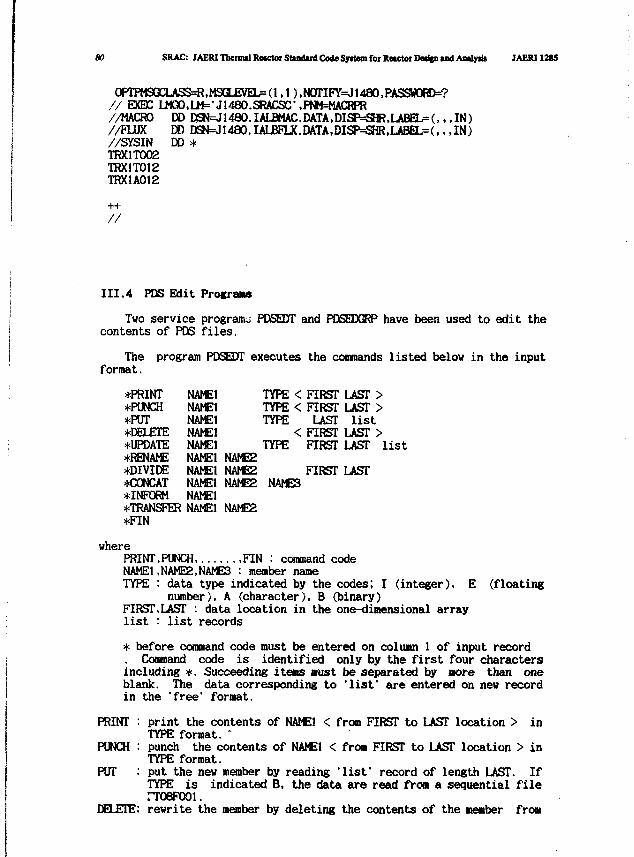
BO SRAC: JAERI Tbeimal Rctctoi Standard Code Syitem for Reactor DMfen and Aialyris JAERI128S
),N0TIFY=J1480,PASS«ORD=?/ / EXEC U10»,LW=-J148O.SRACSC\PNM=MACRPR//MACRO//FLUX//SYSINTRX1T002TRX1TO12TRX1A012
DD DSN=J1480.IALE«AC.DATA.DISF^SH?,LABEL=(,, . IN)DD DSN=J1480.IAUBFLX.DATA,DISP=SHR,LAEaj=(,, , IN)DD *
III.4 PDS Edit Programs
Two service progranu PDSEDT and PDSEDGRP have been used to edit thecontents of PDS files.
Theformat.
program PDSEDT executes the commands listed below in the input
*PRINT*PUNCH*PUT*DELETE*UPDATE•RENAME•DIVIDE•CONCAT•INFORM•TRANSFER•FIN
NAME1NAME1NAME1NAME1NAME1NAHE1NAME1NAME1NAME1NAME1
NAMESNAME2NAME2
NAME2
TYPE < FIRST LAST >TYPE < FIRST LAST >TYPE LAST list
< FIRST LAST >TYPE FIRST LAST list
FIRST LASTNAMES
wherePRINT,PUNCH FIN : command codeNAME1.NAME2,NAMES : member nameTYPE : data type indicated by the codes; I (integer), E (floating
number), A (character), B (binary)FIRST,LAST : data location in the one-dimensional arraylist : list records
* before command code must be entered on column 1 of input record. Command code is identified only by the first four charactersincluding *. Succeeding item; aust be separated by aore than oneblank. The data corresponding to 'list' are entered on new recordin the "free" format.
PRINT : print the contents of NAME1 < from FIRST to LAST location > inTYPE format. "
PUNCH : punch the contents of NAME1 < from FIRST to LAST location > inTYPE format.
PUT : put the new member by reading 'list' record of length LAST. IfTYPE is indicated B, the data are read from a sequential filerroepooi.
DELETE: rewrite the member by deleting the contents of the member from
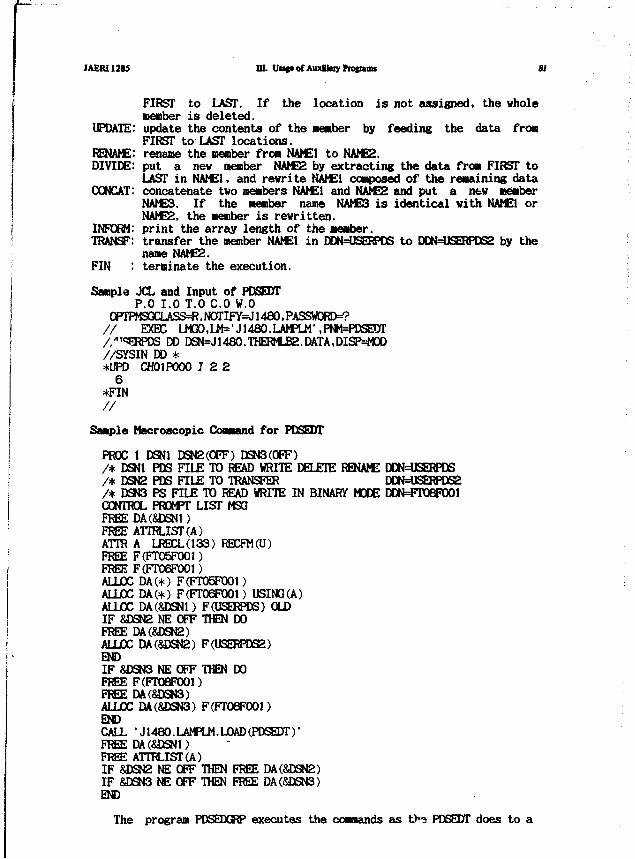
JAERI1285 HI. Vatt of Auxlhiy h o p m 81
FIRST to LAST. If the location is not assigned, the wholemember is deleted.
UPDATE: update the contents of the member by feeding the data fromFIRST to LAST locations.
RENAME: rename the nenber from NAME1 to NAME2.DIVIDE: put a new member NAME2 by extracting the data fro* FIRST to
LAST in NAME1, and rewrite NAME1 composed of the remaining dataCCNCAT: concatenate two members NAME1 and NAME2 and put a new member
NAME3. If the member name NAMES is identical with NAME1 orNAME2, the member is rewritten.
INFORM: print the array length of the member.TRANSF: transfer the member NAME1 in DDN=USERPDS to DDN=USERPDS2 by the
name NAME2.FIN : terminate the execution.
Sample JCL and Input of PDSEDTP.O 1.0 T.O C O W.O
OPTPMSQCLASS=R, NOTI FY=J 1480, PASSWORDS// EXEC U*»,IJ1=M1480.UmM\FW=PDSEDT//I<:!ERPDS DD DSN=J1480.THERMLB2.DATA,DISP=M0D//SYSIN DD **UPD CH01P000 7 2 26
*FIN
Sample Macroscopic Command for PDSEDT
PROC 1 DSN1 DSN2(0FF) DSN3(0FF)/* DSNt PDS FILE TO READ WRITE DELETE RENAME DDN=USERPDS/* DSN2 PDS FILE TO TRANSFER DDN=USBRPDS2/* DSN3 PS FILE TO READ WRITE IN BINARY MODE DDN=FT0eF001CONTROL PROMPT LIST MSGFREE DA(SDSN1)FREE ATTRLIST(A)ATTR A LRECL(133) RECFM(U)FREE F(FT05F001)FREE F(FT06F001)ALLOC DA(*) F(FT05F001)ALLOC DA(*) F(FT06F001) USING(A)ALLOC DA(&DSN1) F(USERPDS) OLDIF &DSN2 NE OFF THEN DOFREE DA(&DSN2)ALLOC DA(&DSN2) F(USERPDS2)ENDIF &DSN3 NE OFF THEN DOFREE F(FT06F001)FREE DA(&DSN3)ALLOC DA(&DSN3) F(FT0BF001)ENDCALL •J1480.LAMPLM.L0AD{PDSEDT)'FREE DA(SDSN1)FREE ATTRLIST(A)IF SJDSN2 NE OFF THEN FREE DA(SDEN2)IF &DSN3 NE OFF THEN FREE DA(&DSN3)END
The program PDSEDGRP executes the commands as t)*o PDSEDT does to a
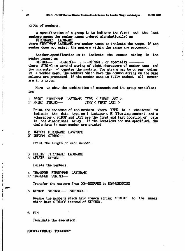
82 SRAC: JAERI Ttonnil Retctor Sttndud Code System for Retctoi .Owlpi uvl Amlyik JAERI 12t5
group of members.
A specification of a group is to indicate the first and the lastmembers among the member names ordered alphabetically; as
FIRSTNAME LASTNAMEwhere FIRSTNAME.LASTNAME are member names to indicate the range. If themember does not exist, the members within the range are processed.
Another specification is to indicate the common string in themember names; as
STRING— , -STRING— , —STRING , or speciallywhere STRING is partial string of eight characters of member name, andthe character '-' denotes the Masking. The string may be on any columnin a member name. The members which have the common string on the samecolumns are processed. If the member name is fully masked, all memberare in a group.
Here we show the combination of commands and the group specificat-ion
1 PRINT FIRSTNAME LASTNAME TYPE < FIRST LAST >1 • PRINT STRING— TYPE < FIRST LAST >
Print the contents of the members, where TYPE is a character toindicate the data type as I (integer), E (floating number), and A(character), FIRST and LAST are the first and last location of datain one-dimensional array. If the locations are not specified, thewhole data in each member are printed.
2 INFORM FIRSTNAME LASTNAME2' INFORM STRING
Print the length of each member.
3 DELETE FIRSTNAME LASTNAME3' DELETE STRING
Delete the members.
4 TRANSFER FIRSTNAME LASTNAME4' TRANSFER STRING
Transfer the members from DDN=USERPDS to DDN=USERPDS2
5 RENAME STRING1 STRING2
Rename the members which have common string STRING1 to the nameswhich have STRING2 instead of STRING1.
6 FIN
Terminate the execution.
MACRO-COMMAND 'PDSESGRP*
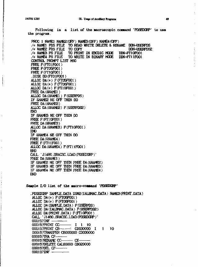
JAERI1285 m. UHfe of Auxlfaiy ftosnuas 83
Following is a list of the Microscopic cownand 'PDSEDGRP' to usethe program.
PROC 1 NAME1 NAME2(OFF) NAME3(0FF) NAME4(0FF)/* NAME1 PDS FILE TO READ WRITE DELETE & RENAME DDN=USERPDS/* NAME2 PDS FILE TO COPY DDN=USERPDS2/* NAME3 PS FILE TO PRINT IN EBCDIC MODE DDN=FNCIF001/• NAME4 PS FILE TO WRITE IN BINARY MODE DDN=FT11FOOICONTROL PROMPT LIST MSGFREE F(FTO1FOO1)FREE F(FT05F001)FREE F(FT10F001).DISK DD(FT01FOOl)ALLOC DA(*) F(FT05F001)ALLOC DA(*) F(FT06F001)ALLOC DA(*) F(FT1OFOO1)FREE DA(SNAMEl)ALLOC DAC&NAME1) F(USERPDS)IF &NAME2 NE OFF THEN DOFREE DA(8NAME2)ALLOC DA(&NAME2) F(USERPDS2)ENDIF &NAME3 NE OFF THEN DOFREE F(FT10F001)FREE DA(&NAME3)ALLOC DA(SNAME3) F(FT10F001)ENDI F 8NAME4 NE OFF THEN DOFREE DAC&NAME4)FREE F(FT11FOO1)ALLOC DA(&NAME4) F(FT11FOO1)ENDCALL •J1480.SRACSC.LOAD(PDSEDGRP)1FREE DA(&NAME1)IF SNAME2 NE OFF THEN FREE DA(&NAME2)IF &NAME3 NE OFF THEN FREE DA(SNAMES)IF SNAME4 NE OFF THEN FREE DA(SNAME4)END
S a a p l e I /O l i s t o f t h e nacro-co—and "POSEDCKP"
.PDSEDGRP SAMPLE.DATA DSN2(IALBMAC.DATA) NAMES (PRINT. DATA)ALLOC DA(+) F(FT05F001)AULOC DA(*) FCFTOofWl)ALLOC DA (SAMPLE. DATA) FflBERPDS)ALLOC DA(IALBMAC.DATA) F(USERPDS2)ALLOC DA (PRINT. DATA) F(FT10F001)CALL •J1480.SRACSC.LOAD(PDSEDGRP)1
00015?INF0O0157PRINT CC I 1 1000015?PRINT CB CD030000 I 1 10000157TRANSFER CBOOOOOO CD030000000157TRA CF000157RENAME CC CX000157DELETE CAL80000 CB02000000015^1EL CF00015?INF
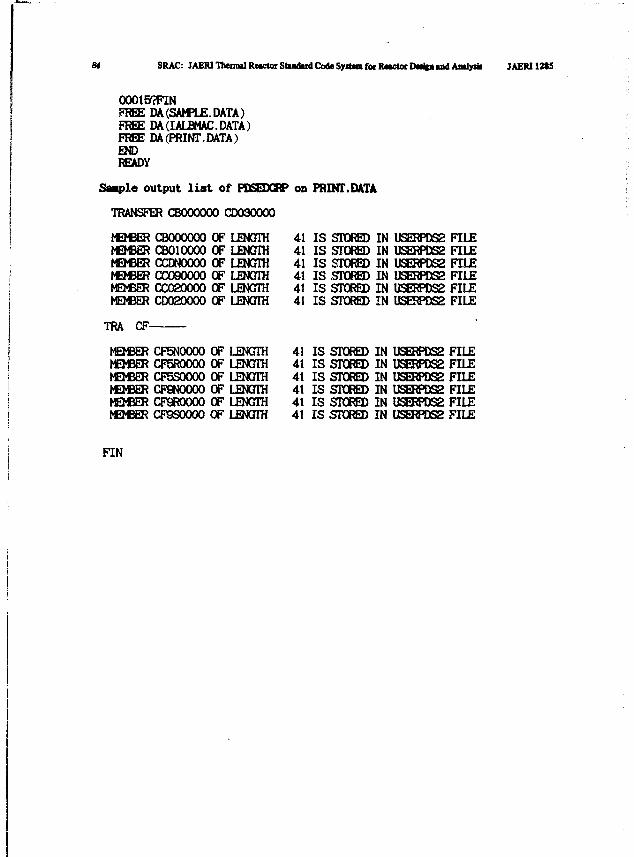
SRAC: JAER1 Themul Reactor Standard Code System for RMCtor D«ifa and Anlysk JAERI1M5
OOO15PFINFREE DA (SAMPLE. DATA)FREE DA(IALBMAC.DATA)FREE DA(PRINT.DATA)ENDREADY
Staple output list of PDSEDCRP on PRINT.DATA
TRANSFER CBOOOOOO CD030000
MEMBERMEMBERMEMBERMEMBERMEMBERMEMBER
CBOOOOOOCBO1OOOOCCDNOOOOCCO90000CC020000CD020000
OF LENGTHOF LENGTHOF LENGTHOF LENGTHOF LENGTHOF LENGTH
TRA CF-
MEMBERMEMBERMEMBERMEMBERMEMBERMEMBER
CF5N0000CF5R0000CF5S0000CF9NOO0OCF9R0O0OCF9S0000
OF LENGTHOF LENGTHOF LENGTHOF LENGTHOF LENGTHOF LENGTH
414141414141
414141414141
IS STOREDIS STOREDIS STOREDIS STOREDIS STOREDIS STORED
IN USERPDS2 FILEIN USERPDS2 FILEIN USERPDS2 FILEIN USERPDS2 FILEIN USERPDS2 FILEIN USERPDS2 FILE
IS STOREDIS STOREDIS STOREDIS STOREDIS STOREDIS STORED
IN USERPDS2 FILEIN USERPDS2 FILEIN USERPDS2 FILEIN USERPDS2 FILEIN USERPDS2 FILEIN USERPDS2 FILE
FIN
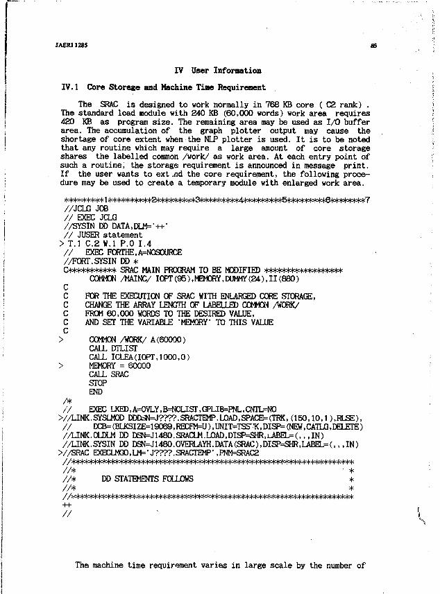
JAERI1285 S5
IV User Information
IV.1 Core Storage and Machine Time Requirement
The SRAC is designed to work normally in 768 KB core ( C2 rank) .The standard load module with 240 KB (60,000 words) work area requires420 KB as program size. The remaining area may be used as 1/0 bufferarea. The accumulation of the graph plotter output may cause theshortage of core extent when the NIP plotter is used. It is to be notedthat any routine which may require a large amount of core storageshares the labelled common /work/ as work area. At each entry point ofsuch a routine, the storage requirement is announced in message print.If the user wants to extend the core requirement, the following proce-dure may be used to create a temporary module with enlarged work area.
//JCLG JOB// EXEC JCLG//SYSIN DD DATA,DLM=-++'// JUSER statement> T.I C.2 W.I P.O 1.4// EXEC PORTHE,A=NOSOURCE//FORT.SYSIN CO *&W<*****H<*** SRAC MAIN PROGRAM TO BE MODIFIED ***m=W°|cM<*l<>l°(=l=t=)<
COMMON /MAINC/ IOPT (95), MEMORY, DUMMY (24), 11 (880)CC FOR THE EXECUTION OF SRAC WITH ENLARGED CORE STORAGE,C CHANGE THE ARRAY LENGTH OF LABELLED COMMON A'ORK/C FROM 60,000 WORDS TO THE DESIRED VALUE,C AND SET THE VARIABLE 'MEMORY1 TO THIS VALUEC> COMMON /WORK/ A(60000)
CALL DTLISTCALL ICLEA(IOPT,1000,0)
> MEMORY = 60000CALL SRACSTOPEND
/*// EXEC IJ<ED,A==OVLY,B^CLIST,GPLIB=PNL,CNTL=NO
V/LINK.SYSLMOD DDDciN=J????.SRACTEMP.LOAD,SPACE=(TRK, ( 1 5 0 , 1 0 , 1 ) ,RLSE),/ / D C B = ( B I J ( S I Z E = 1 9 0 6 9 , R E C R ^ U ) , U N I T = T S S ' T ( , D I S P = ( N E M , C A T 1 J G , D E L E T E )//LINK.OLDLM DD DSN=J1480.SRACLM.L0AD,DISP^SHR,i^BEL=(,,,IN)/ /LINK.SYSIN DD DSN=Jl480.OVERLAYH.DATA(SRAC),DISP=SHR,LABEL=(,,,IN)
>//SRAC EXECLMG0,LM=>J????.SRACTEMP#,PNM=SRAC2//**=tto|o|°l°!c)o|=l°t=t*l^^/ / * • *
//* DD STATEMENTS FOLLOWS *//* */7=m=m=i=m=i<*>i°woi°to|^^
The machine time requirement varies in large scale by the number of
36 SRAC: JAERITbennal Reastoi Stindud Code Syntemfoi Rnctoi DeiJgnindAnalyiU JAERI1285
energy groups, the geometry (specially ID or 2D), the number of spatialdivision, and the repetitive cell calculations by burn-up step. Alsothe use of PDS files which is always accompanied by file open/closeprocess at each read/write execution increases the core time (not cputime).
For example a series of burn-up calculation for a DIDO type latticecell consumes 7 cpu minutes by FACOM M-20Q computer by the followingspecifications.
Geometry : One dimensional cylinder18 groups, 19 spatial regions in fast range4 groups, 19 spatial regions in resonance range31 groups, 25 spatial regions in thermal range
Method : Collision probability ( in fast, thermal)aluo in resonance range by 5,000 energy pts. 19 regioncollision probability method
Number of burn-up steps : 6 (including fresh step)
In the above example the computer time is almost used in the onedimensional numerical integration for collision probabilities. It is tobe noted that the another process for resonance integral by IR methodneeds the same order of computing time as the exact method, because thelatter process saves the computing time for collision probabilitycalculation by interpolation of the tabulated values which correspondto 11 group calculation.
Another series of similar calculations for a MTR type fuel platecell requires only 50 cpu seconds due to the analytical expression ofcollision probability for one dimensional slab, and fewer spatialdivision (3 regions).
It is not necessary to mention about the machine time requirementfor the well experienced routines ANISN, TWOTRAN, and CITATION,however, we should mention about ths one dimensional diffusion routineTUD sometimes requires several ten cpu seconds when it is used in 60-70group structure ( 30-40 thermal groups) for a well reflected core dueto slow convergence in thermal flux distribution.
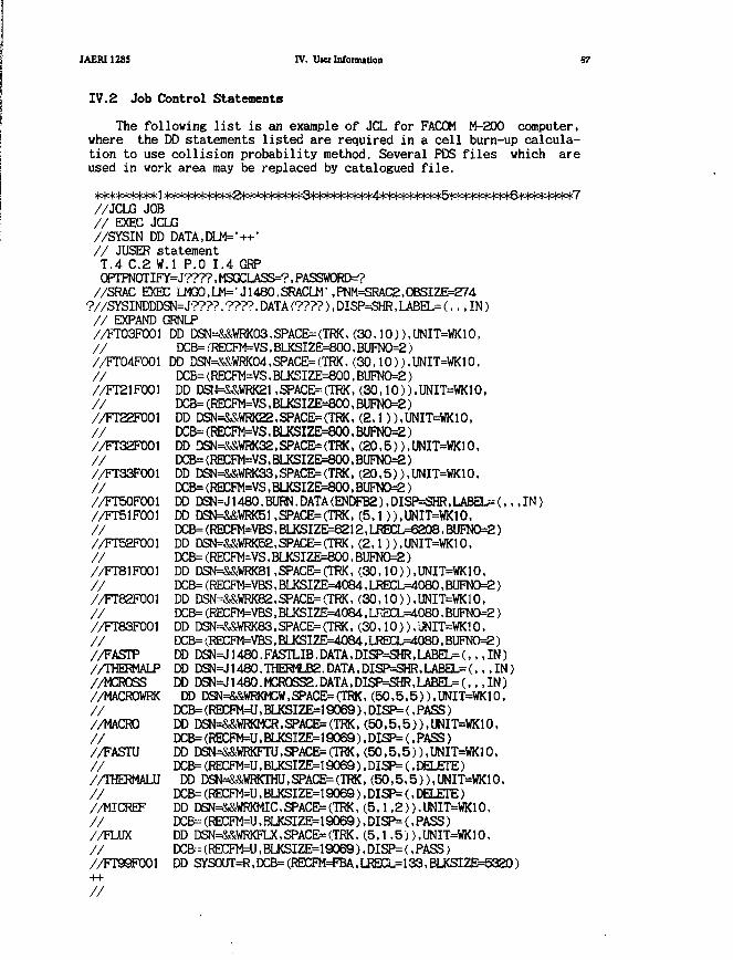
JAERI1285 IV. UKI Information
IV.2 Job Control Statements
The following list is an example of X L for FACOM M-200 computer,where the DD statements listed are required in a cell burn-up calcula-tion to use collision probability method. Several PDS files which areused in work area may be replaced by catalogued file.
>)o)c)c(o|o(o|o|okl >)o|o|cMo|ofo|o|=)c&o|o|o)o|o^^
//JCLG JOB// EXEC JCLG//SYSIN DD DATA,DLM=>++>// JUSER statementT.4 C.2 W.I P.O 1.4 GRPOPTPNOTIFY=J????, MSGCLASS=?, PASSWORDS//SRAC EXEC LMC50,LM=tJ1480.SRACLM',PNM=SRAC2,0BSIZE=274
?//SYSINDDDSN=J????. ????. DATA (????), DISP=5HR, LABEL= (,,, IN)// EXPAND GRNLP//FT03F001 DD DSN=&&WRK03,SPACE=(TRK,(30,10)),UNIT=WK10,// DCB=(RECFM=VS,BLKSIZE=800.BUFN0=2)//FT04F001 DD DSN^&WRK04,SPACE=(TRK. (30,10)),UNIT=WK10,// DCB=(RECFM=VS.BLKSIZE=800,BUFNO=2)//FT21F001 DD DSM=&&WRK21,SPACE--(TRK, (30,10)),UNIT=WK10,// DCB=(RECFM=VS,BLKSIZE=800,BUFN0=2)//FT22F001 DD DSN=&&WRK22. SPACE= (TRK ,(2.1)). UNIT=WK10,// DCB=(RECFM=VS,BLKSIZE=800,BUFNO^)//FT32F001 DD DSN=&&WRK32,SPACE=(TRK.(20,5)),UNIT=WK10,// DCB=(RECFM=VS.BLKSIZE=800.BUFNO=2)//FT33F001 DD DSN=&&WRK33.SPACE=(TRK,(20,5)),UNIT=WK10.// DCB=(RECFM=VS,BLKSIZE=800.BUFN0=2)//FT50F001 DD DSN=J1480.BURN.DATA(ENDFB2),DISP=SHR,LABEL=(,,,IN)//FT51F001 DD DSN=&&WRK51,SPACE=(TRK,(5,1)),UNIT=WK10,// DCB=(REEFW=VBS,BIJ<SIZE>^212,LiECL==6208>BUFN0=2)//FT52F001 DD DSN=&&WRK52,SPACE=(TRK,(2,1)),UNIT=WK10,// DCB= (RECFM=VS,BLKSIZE=800,BUFN0=2)//FT81F001 DD DSN=&&WRK81,SPACE=(TRK,(30,10)),UNIT=WK10.// DCB= (RECFM=VBS,BLKSIZE=4084.LRECL=4080,BUFN0=2)//FT82F001 DD DSN=&&WRK82,SPACE=(TRK,(30,10)),UNIT=WK10,// DCB=(RECFM=VBS>BLKSIZE=4084,LRE1CL=4080.BUFNO=2)//FT83F001 DD DSN=&&WRK83,SPACE=(TRK,(30,10)),UNIT=WK10,// DCB=(I?ECFM=VBS,BIJeiZE>=4084,IJ«CL=4080,BUFNO=2)//FASTP DD DSN=J1480.FASTLIB.DATA,DISP=SHR,LABEL=(,,,IN)//THERMALP DD DSN=J1480.THERMLB2.DATA,DISP=SHR,LABEL=(,,,IN)//MCROSS DD DSN=J1480.HCR0SS2.DATA,DISP=SHR,LABEL=(.,,IN)//MACROWRK DD DSN=&&WRKMCW,SPACE=(TRK,(50,5.5)),UNIT=WK10,// DCB=(RECFM=U,BLKSIZE=19069),DISP=(,PASS)//MACRO DD DSN=&&WI«MCR,SPACE=(TRK.(50,5,5)),UNIT=WK10,// DCB=(RECFM=U,BLKSIZE=19069),DISP=(.PASS)//FASTU DD DSN=&&WRKFTU,SPACE=(TRK,(50,5.5)),UNIT=WK10,// DCB=(RECFM=U,BLKSIZE=19069),DISP=(,DELETE)//THERMALU DD DSN=&&WRKTHU,SPACE=(TF«,(50,5,5)),UNIT=WK10,// XB=(RECFM=U,BLKSIZE=19069),DISP=(,DELETE)//MICREF DD DSN=&&WRKMIC,SPACE=(TRK,(5,1,2)),UNIT=WK10.// DCB-(RECFM=U,BLKSIZE=19069),DISP=(,PASS)//FLUX DD DSN=&&WRKFLX,SPACE=(TRK,(5,1.5)),UNIT=WK10,// rcB.KRECFM=U,BLKSIZE=19069),DISP=(,PASS)//FT99F001 DD SYSOUT=R>DCB=(RECFM=FBA,LRECL=133,BLKSIZE=5320)
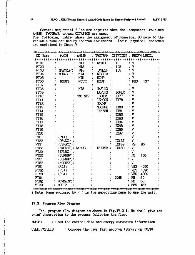
SRAC: JAER1 Thermil Reactor Standard Code Syitem for Reactor Deripi and AmlytU I/iERI 1285
Several sequential files are required when the component routinesANISN, TWOTRAN, or/and CITATION are used.The following table shows the assignment of numerical DD name to thevariable name defined by Fortran statements. Their physical contentsare explained in Chapt.V.
DD Name : MAIN : ANISN : TWOTRAN :CITATION : RECFM LFECLHcf=M°W<*=W**HoMe|c|<*H°|a|o|^^FT01FT02FT03FT04FT05FT06FT07FT08FT09FT10FT11FT12FT13FT14FT15FT16FT17FT18FT19FT20FT21FT22FT31FT32FT33FT50FT51FTS2FT81FT82FT83FT91FreeFT99
(MACROF)(SRAC )
NOUT1
(PU)(DR,DZ)(CVMACT)(MACROF)ITFLUX(BURNUP)(BURNUP)(MICREF)(PU)(PU)(PIJ)
(CVMACT)N0UT2
NT1NT2NT3NT4NINNOUT1
NT8
NT6.NT7
NSOUC
NEDIT
IVMESHNEXTRANINPNOUT
NAFLUXLAFLUXISOTXSISNCONNDUMP1NDUMP2IZMESH
IFIXSR
101102103
IOFLX1X771X78
1X801X811X821X831X841X851X861X87
1X1371X1381X139
IOIN
VVVVVFBS 137
VVVVVVVVVVVVVVVFBVVFBVVVBS 4090VBS 4090VBS 4090FB 80FB 80FBS 137
80
136
* Note Name enclosed by ( ) is the subroutine name to use the unit.
IV.3 Program Flow Diagram
The program flow diagram is shown in Fig»IV.3-l. We shall give thebrief description to the process following the flow.
INPUT1 : Read the control data and energy structure information
USETi.FASTLIB : Compose the user fast neutron library on FASTU
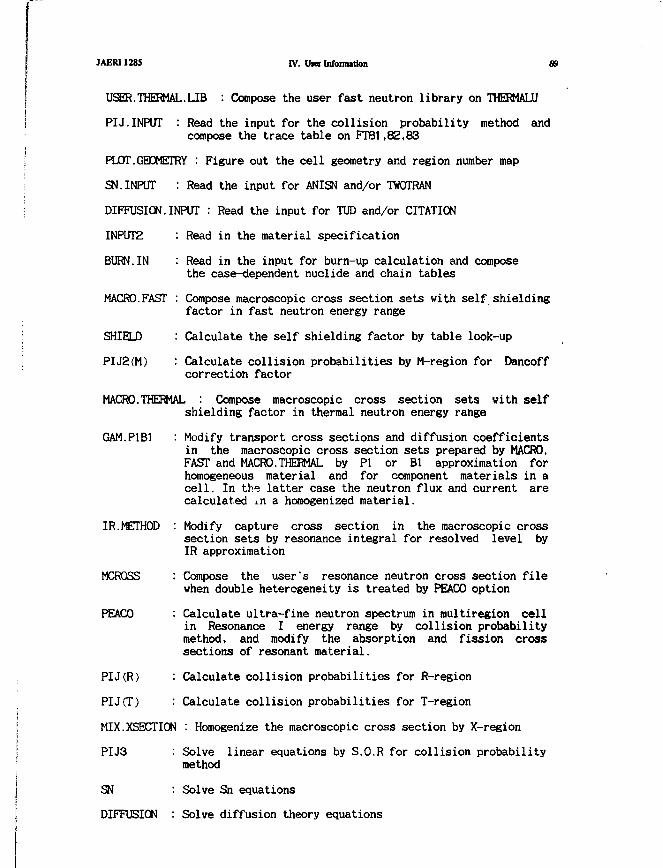
JAERI1285 IV. Oier Information 89
USER. THERMAL.LIB : Compose the user fast neutron library on THERMALU
PIJ.INPUT : Read the input for the collision probability method andcompose the trace table on FT81,82,83
PLOT.GEOMETRY : Figure out the cell geometry and region number map
SN.INPUT : Read the input for ANISN and/or TWOTRAN
DIFFUSION.INPUT : Read the input for TUD and/or CITATION
INPUT2 : Read in the material specification
BURN.IN : Read in the input for burn-up calculation and composethe case-dependent nuclide and chain tables
MACRO.FAST : Compose macroscopic cross section sets with self shieldingfactor in fast neutron energy range
SHIELD : Calculate the self shielding factor by table look-up
PIJ2(M) : Calculate collision probabilities by M-region for Dancoffcorrection factor
MACRO.THERMAL : Compose macroscopic cross section sets with selfshielding factor in thermal neutron energy range
GAM.P1B1 : Modify transport cross sections and diffusion coefficientsin the macroscopic cross section sets prepared by MACRO.FAST and MACRO.THERMAL by PI or BI approximation forhomogeneous material and for component materials in acell. In the latter case the neutron flux and current arecalculated j.n a homogenized material.
IR.METHOD : Modify capture cross section in the macroscopic crosssection sets by resonance integral for resolved level byIR approximation
MCROSS : Compose the user's resonance neutron cross section filewhen double heterogeneity is treated by PEACO option
PEACO : Calculate ultra-fine neutron spectrum in multiregion cellin Resonance I energy range by collision probabilitymethod, and modify the absorption and fission crosssections of resonant material.
PIJ(R) : Calculate collision probabilities for R-region
PIJ(T) : Calculate collision probabilities for T-region
MIX.XSECTION : Homogenize the macroscopic cross section by X-region
PIJ3 : Solve linear equations by S.O.R for collision probabilitymethod
SN : Solve Sn equations
DIFFUSION : Solve diffusion theory equations
90 SRAC: JAERI Thenml Rnctot Standud Coda Syttemfoi Retctoi Dedfn wd Amlyik JAER11M5
HOMOS3 : Solve a bare reactor equation by PI or Bl approximation
CONDENSE : Collapse the energy structure of the macroscopic crosssections to get few group cross sections
BURNUP : Calculate the change of nuclide concentrations in aburn-up step
CVMACT : Convert the format of the macroscopic cross sectionsfor separate execution of the original CITATION code
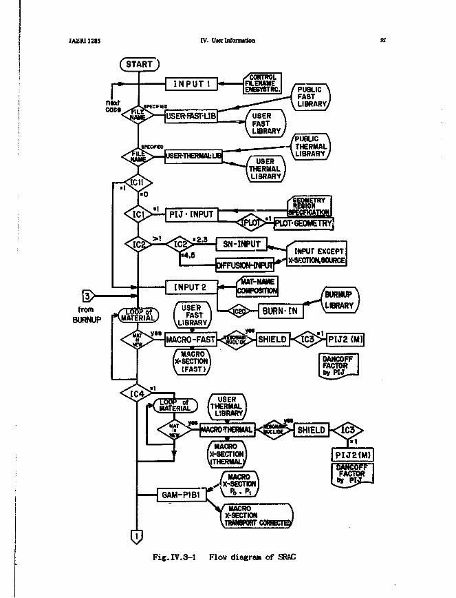
JA2RI12SS IV. Ui« Information 91
fromBURNUP
INPUT EXCEPTX-«ECTWN.90URCE
SHIELD {<IC3>HPtJ2 (M)|
Fig.IV.3-1 Flow diagraa of SRAC
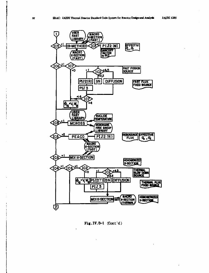
92 SRAC: JAERI Thermal Reactor Standard Code System fo; Reactor Det||n and Andy* JAERI 1215
MACRO(X-SECnONlV(FAST) /
|WJ2(R)1|SN|| DIFFUSION|
I P I J 3
Fif.IV.3-1 (Confd)
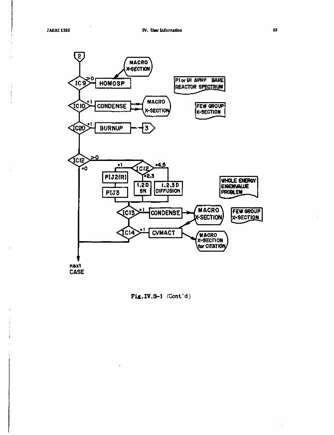
JAERI1285 IV. Uiei Information S3
PlorBI APRP BAREREACTOR SPECTRUM
FEWOROUPlX-SECTIg&J
M A C R O \X-SECTION )
CITATION/
Fi«.IV.3-l (Conf d)
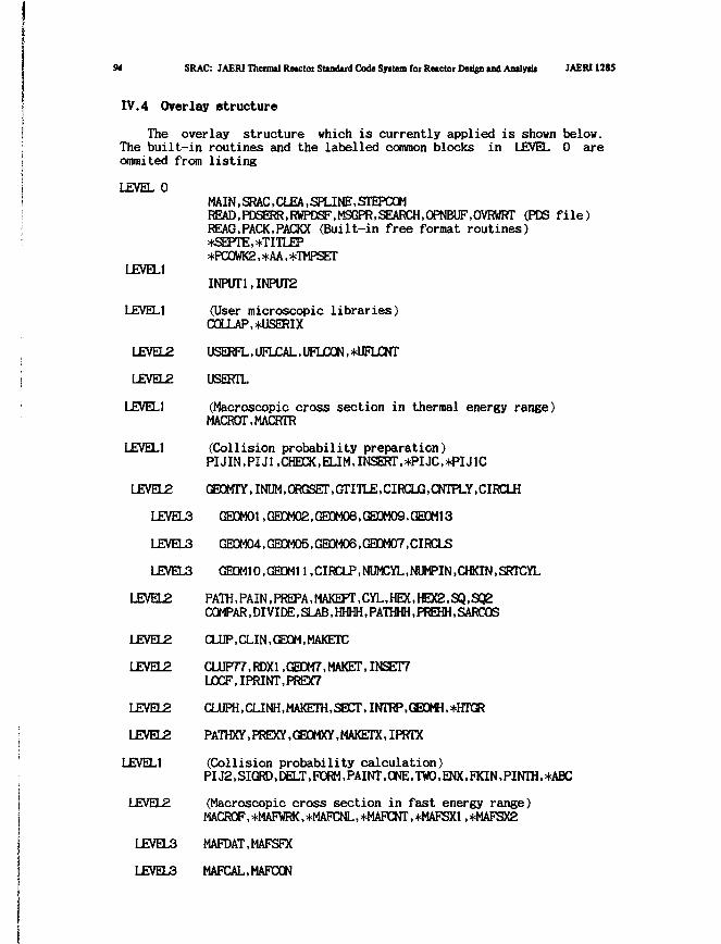
94 SRAC: JAERI Thetmtl Retctot Standard Code System fot Retctot Deijgn tnd Analydi JAERI 1285
IV.4 Overlay structure
The overlay structure which is currently applied is shown below.The built-in routines and the labelled common blocks in LEVEL 0 areommited from listing
LEVEL 0
LEVEL1
LEVEL1
LEVEL2
LEVELS
LEVEL1
LEVEL1
MAIN.SRACCLEA.SPLINE.STEPCOMf?E^,H)SEI«,RWFB^,beGF«,SEAfOi,CIPNBUF,OVRWRr (PDS file)REAG^PACK.PACKX (Built-in free format routines)*SEPTE,*TITLEP*PC0WK2, *AA, *TMPSET
INPUT1,INPUT2
(User microscopic libraries)COLLAP,*USERIX
USERFL, UFLCAL, UFLCON, *UFLCNT
USERTL
(Macroscopic cross section in thermal energy range)MACROT.MACRTR
(Collision probability preparation)PIJIN.PIJ1.CHECK,ELIM,INSERT,*PIJC,*PIJ1C
LEVEL2 CH3MTY,I^e4,C«GSE^,GrrITLE,CIRCLG,CNTPLY,CIRCLH
LEVEL3 GE0MOl,GEC)M02,GE0M0B,GECIM09,GE0M13
GE0M04, GE0M05, GE0M06, GECM07,CIRCLS
GEOM10,(E0M11,CIRCLP,NUMCYL,NUMPIN,CHKIN,SRTCYL
LEVEL3
LEVEL3
LEVEL2
LEVEL2
LEVEL2
LEVEL2
LEVEL2
LEVELl
LEVEL2
LEVEL3
LEVEL3
PATH, PAIN, PREPA,MAKEPT,CYL,HEX,HEX2,SQ,SQ2COMPAR,DIVIDE,SLAB,HHHH,PATHHH,PREHH,SARCOS
CLUP.CLIN.GEOM.MAKETC
CLUP77,RDX1 ,GE0M7,MAKEr,INSET7L0CF,IPRINT,PREX7
PATHXY.FREXY.GEOMXY.MAKErX.IPRTX
(Collision probability calculation)PIJg.SICMt.rM-T.PORM.PAINT.ONE.TWO.ENX.FKIN.PINTH.+ABC
(Macroscopic cross section in fast energy range)MACRCF,*MAFVRK,*MAFX^L,*MAFCNT,*MAFSX1 ,*MAFSX2
MAFDAT.MAFSEvX
MAFICAL.MAFCON
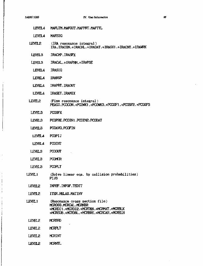
JAERI1285 IV. User Information 95
LEVEL4
LEVEL4
LEVEL2
LEVEL3
LEVEL3
LEVEL4
LEVEL4
LEVEL4
LEVEU
LEVEL2
LEVEL3
LEVEL3
LEVEL3
LEVEL4
LEVEL4
LEVEL3
LEVEL3
LEVEL3
LEVEL1
LEVEL2
LEVEL2
LEVEL1
LEVEL2
LEVEL2
LEVEL2
LEVEL2
MAFLTM.MAFaJT.HAFPRr.MAFITL
MAFSIG
(IRA resonance i n t e g r a l )
IRA,IRACON,*IRACNL,*IRADAT,*IRASX1,*IRACNT,*IRAWRK
IRACMPJRASFX
IRACAL,*IRAPRM,*IRAPSE
IRASIG
IRARSP
IRAPRT,IRAOUT
IRASET.IRAMIX
(Fine resonance i n t e g r a l )
FEACO,PCOCON,*PCOWKi ,+PC0WK3,*PC0SF1 ,*PC0SF2,*PC0SF3
PCOSFX
PCOPRE,PCOIN1,PC0IN2, PCODAT
PCOAVG.PCOFIN
PCOPIJ
PCOINT
PCOOUT
PCOMCR
PCOPLT(Solve linear eqs. by collision probabilities)PIJ3
INP2F.INP3F.TEDIT
ITER, RELAX,MATINV(Resonance cross section file)MCROSS,MCRCAL,MCRNBR*MCRDI1 ,H^CRDI2,*MCRIKN,*MC3»1AT,*MCRBU(
, *MCRDBL, *hCRH?E, *MCRCAR, *MCRELH
MCRBRD
MCRPLT
MCRINT
MCRNTL
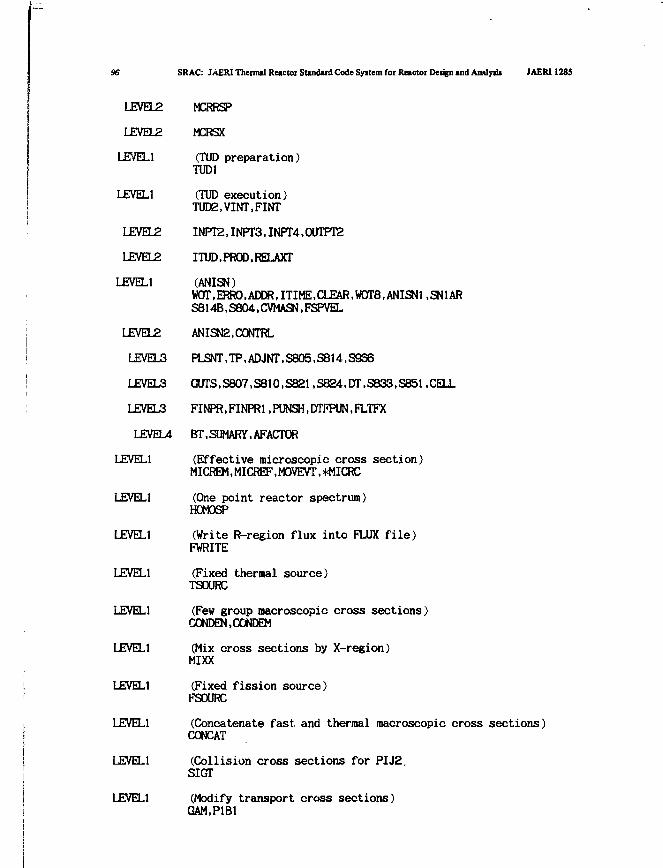
96 SRAC: JAERI Thermal Reactor Standard Code Syitem for Reactor Design and Amlytii JAERI 1285
LEVEL2 MCRRSP
UEVEL2 MCRSX
LEVEL1 (TUD preparation)TUD1
LEVEL1 (TUD execution)TUD2,VINT,FINT
LEVEL2 INPT2,INPT3,INPT4,0UTPT2
LEVEL2 ITUD.PROD.RELAXT
LEVEL1 (ANISN)WOT,ERRO.ADDR.ITIME,CLEAR,W0T8,ANISN1.SN1ARS814B.S804.CVMASN.FSPVEL
LEVEL2 ANISN2,C0NTRL
LEVEL3 PLSNT,TP,ADJNT,S805,S814,S9S6
LEVEL3 GUTS,S807,S810,S821,S824,DT,S833,S851,CELL
LEVEL3 FINPR, FINPR1, PUNSH, DTI'PUN, FLTFX
LEVEL4 BT,SUMARY,AFACTOR
LEVEL1 (Effective microscopic cross section)MICREM,MICREF,MOVEVT,*MICRC
IJEVEL1 (One point reactor spectrum)HOMOSP
LEVEL1 (Write R-region flux into FLUX file)FWRITE
LEVEL1 (Fixed thermal source)TSOURC
LEVEL1 (Few group macroscopic cross sections)CONDEN.CONDEM
LEVEL1 (Mix cross sections by X-region)MIXX
LEVEL1 (Fixed fission source)FSOURC
LEVEL1 (Concatenate fast, and thermal macroscopic cross sections)CONCAT
LEVEL1 (Collision cross sections for PIJ2.SIGT
LEVEL1 (Modify transport cross sections)GAM.PIBI
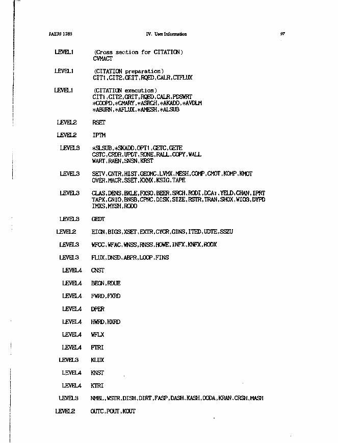
JAERI1285 IV. UKI Infomution
LEVEL1 (Cross section for CITATION)CVMACT
LEVEL1 (CITATION preparation)CIT1 ,CIT2,GKIT,RC¥D,CALR,CTFLUX
LEVEL1 (CITATION execution)CITi,CIT2,GRIT,RQED,CALR,PDSWRT*COOPD, *CMARY, *ASRCH, *AKADD, *AVDLM*ABURN,*AFLUX,+AMESH, *ALSUB
97
• LEVEL2
LEVEL2
LEVEL3
LEVEL3
LEVEL3
• LEVEL3
LEVEL2
LEVEL3
LEVEL3
LEVEU
LJEVEU
LEVEU
LEVEU
LEVEU
LEVEU
LEVEU
LEVEL3
L5VEU
LEVEU
LEVELS
LEVEL2
RSET
IPTM
*SLSUB,*SKADD,OPTt .GETCGETECSTC, CFJM?, UPCT, RONE, RALL, COPY, WALLWART.RAEN.SNSN.KRST
SETV,CNTR,HIST,GEOMC,LVMX,MESH.COM5,CMOT,KOMP,KMOTOVER,MACR,SSET,KXNX,KSIQ,TAPE
CLAS,DENS,BKLE,FXSO,BEER,SRCH,RODI.DCAi.YELD.CHAN,IPR"TAPX,CNI0,BNSB,CPNC,DISK,SIZE,RSTR,TRAN (SH0X,WI03,DYHIMXS.WSH.RODO
GEDT
EIGN,BIGS,XSEr,EXTR,CYCR,GINS,ITED,UDTE,SSZU
WPCC,WFAC,WNSS,RNSS.HOWE,INFX,KNEX,RODX
FLUX,DNSD, AEPR,LOOP.FINS
CNST
BEIGN.RDUE
FWRD.FXRD
DPER
HWRD.HXRD
WFLX
FTRI
KLUX
KNST
KTRI
NMH..WSTR,DISH,DIRT,FASP,DASH,KASH,DODA,KRAN,CR3H,MASH
OUTCPOUT.KOUT
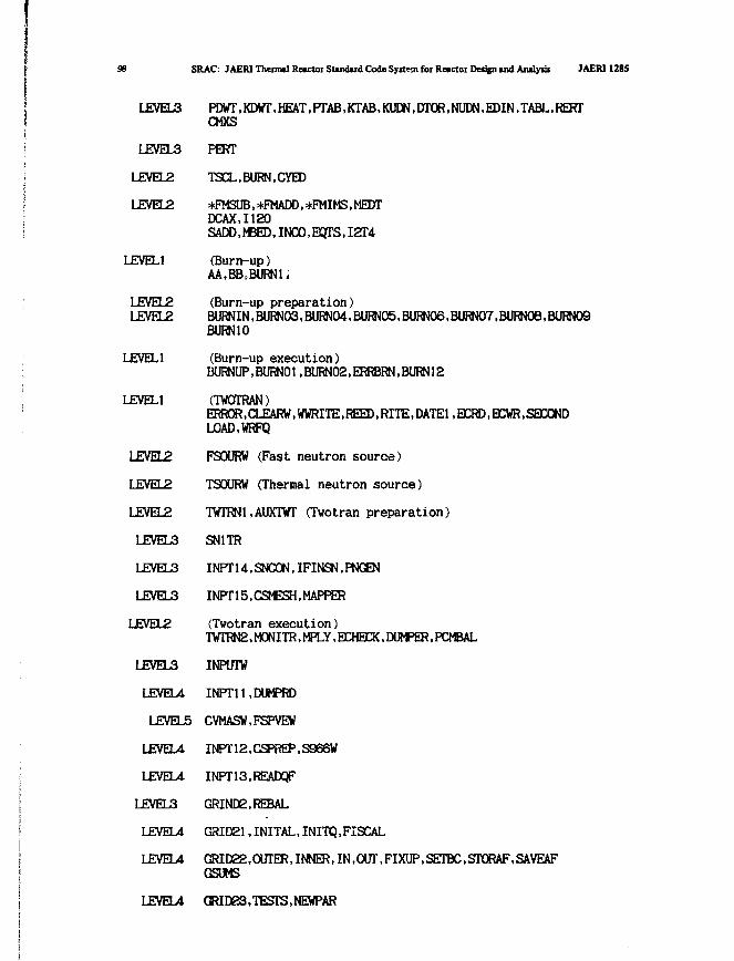
SRAC: JAERI Thermal Reactoi Standard Code System for Reactor Design and Analysis JAERI 1285
LEVELS
LEVEL3
LEVEL2
LEVEL2
LEVEL1
LEVEL2LEVEL2
LEVEL1
LEVEL1
LEVEL2
LEVEL2
LEVEL2
LEVELS
LEVEL3
LEVEL3
LEVEL2
LEVEL3
LEVEL4
LEVELS
LEVEU
LEVEL4
LEVEL3
LEVEU
LEVEU
PDWT,KDtfT,HEAT,PTAB,lCTAB,KUm,DTOR,NUDN,EOIN,TABL,RERrCMXS
PERT
TSCL.BURN.CYED
*FM3UB,*FWADD,*FMIMS,MEDTDCAX.I120SADD.hBED, INCO.ECJTS, I2T4(Burn-up)AA,BB,BURN1,
(Burn-up preparation)BURNIN,BLnM)3,BieBURN10
(Burn-up execution)BURNUP.BURN01,BURN02,ERRBRN,BURN12
(TWOTRAN)ERROR,CLEARW.WWRITE,REED,RITE,DATE1.ECRD.ECWR,SECOND
LOAD.WRFQ
FSOURW (Fast neutron source)
TSOURW (Thermal neutron source)
TWTRN1.AUXTWT (Twotran preparation)
SN1TR
INPT14,SNC0N,IFINSN,PNGEN
INPT15.CSMESH,MAPPER
(Twotran execution)
TWTRN2, MONITR, VPLY, ECHECK, DIMPER, PCMBAL
INPOTW
INPTll.DUMPRD
CVMASW.FSPVEW
INPT12,CSPiS5,S966W
INPT13.READQF
GRIND2,REBAL
GRID21, INITAL, INITQ, FISCALGRID22,aJTER,Ii^ra,IN,OlJl\FIXUP,SEreC,STORAF,SAVEAFGSUMS
LEVEU GRID23,TESTS,NEWPAR
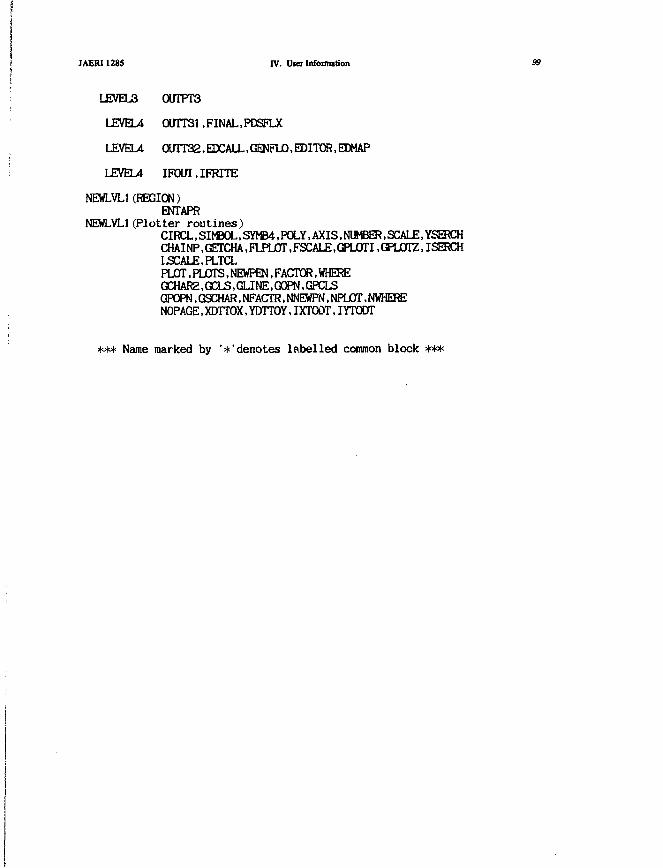
JAERI128S IV. UKI Information 99
LEVEL3 0UTPT3
LEVEL4 0UTT31,FINAL,PDSFLX
LEVEU CXnT32,EDCALL,GENFlJ0,EDITCS,EDMAP
LEVEL4 IFOUT.IFRITE
NEWLVL1(REGION)ENTAPR
NEWLYLl (Plotter routines)CIRCL,SIMBOL,SYMB4,POLY,AXIS.NUMBER,SCALE,YSERCHCHAINP,GETCHA,FIPLOT,FSCALE,GPLOTI.GPLOTZ.ISERCHLSCALE.PLTCLPLOT.PLOTS.NEWPEN.FACTCR.WHEra:GCHAR2, GCLS, GLINE, C3CFN, GPCLSGPOPN,G9CHAR,NFACTR,NNEWFN,NPLOT,NWHERENOPAGE,XDTTOX,YDTTOY,IXT(»T,IYTODT
*** Name marked by '^'denotes labelled common block ***

100 SRAC: JAERI Thermal Reactor Standard Code Syitem for Reactor Design and Analysis JAERI 12S5
IV.5 Common Data
We classify the common data used Jn the SRAC into following cate-gory;
Rank A Common data throughout, the systemRank B Common data between the particular routine and the main
Rank C Common data within the particular routine.
We shall describe the contents of common data in Rank A and B.
Rank A MAINC /2000/
1 IOPT /20/ Control integers read in Sect.II.1
2 1 - 3 6 Reserved area for file names in Data Pool system (4*16H)
37 IUPSCAT Control if the upscattering is assumed as selfscatter.
38 IBSPEC Control whether if the PI or Bl approx. spectrum
is used to collapse the energy structure.
3 9 - 5 2 not used
53 NEFL Number of energy groups in the public fast library(= 0 if the public file is not used)
54 NEIL Number of energy groups in the public thermal library
(= 0 if the public file is not used)
55 NEF Number of energy groups in the user fast library
56 NET Number of energy groups in the user thermal library
57 NERF Number of energy groups in the condensed fast groupstructure (= 0 if CONDENSE routine is not used)
58 NERT Number of energy groups in the condensed thermal groupstructure (= 0 if CONDENSE routine is not used)Number of mixtures specified in Sect.II.8
Group number in the public thermal library correspondsto the highest user's group below the thermal cut off
Buckling in cm-2 read in BLOCK 4 in Sect.II.1
Card input device unit number (set to 5)
not used
Logical device number for message print (set to 6)
Logical device number for edit print (set to 99)
Initial clock in second used to check elapsed time
59
60
61
62
63
64
65
66
NMAT
NTL1
BSQ
NIN1
NIN2
N0UT1
N0UT2
ITO
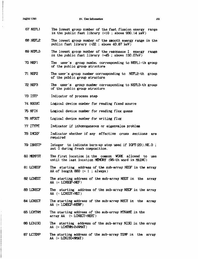
JAERI1285
67
68
69
70
71
72
73
74
75
76
77
78
79
80
81
82
83
84
85
86
87
' NEFL1
i NEFL2
NEFL3
NEF1
NEF2
NEF3
ISTP
NSOUC
NFIN
NPOUT
ITYPE
IMCEF
IBNSTP
MEMFST
LCNEGF
LCNBGTr
LCNBCF
LJCNEET
LCMTNM
LCNISO
LCTEMP
IV. Uier Information 101
The lowest group number of the fast fission energy rangein the public fast library (=10 ; above 930.14 keV)
The lowest group number of the smooth energy range in thepublic fast library (=22 ; above 40.87 keV)
The lowest group number of the resonance I energy rangein the public fast library (=45 ; above 130.07eV)
The user's group numbei corresponding to NEFLl-th groupof the public group structure
The user's group number corresponding to NEFL2-th groupof the public group structure
The user's group number corresponding to NEFL3-th groupof the public group structure
Indicator of process step
Logical device number for reading fixed source
Logical device number for reading flux guess
Logical device number for writing flux
Indicator if inhomogeneous or eigenvalue problem
Indicator whether if any effective cross sections arerequired
Integer to indicate burn-up step used if IOPT(2O).NE.O ;set 0 during fresh composition.
The first location in the common WORK allowed to useuntil the last location MEMORY (96-th word in MAINC)
The starting address of the sub-array NEGF in the arrayAA of length 880 (= 1 ; always)
The starting address of the sub-array NEGfT in the arrayAA (= LCNEGF+NEF)
The starting address of the sub-array NECF in the arrayAA (= LCNEGT+NET)
The starting address of the sub-array NECT in the arrayAA (= LCNBCF+NERF)
The starting address of the sub-array MTNAME in thearray AA (= LCNECT+NEKT)
The starting address of the sub-array NISO in the arrayAA (= LJCMTNM+2*NMAT)
The starting address of the sub-array TEMP in the arrayAA (= LCNISO+NMAT)

ice SRAC: JAERIThemul Reactor Standard Code System fot Reactor Dettgn and Anilyiii JAERI1285
88 LCXL The starting address of the sub-array XL in the arrayAA (= LCTEMP+NMAT)
89 LCXCDC The starting address of the sub-array DC in the arrayAA (= LCXL+NMAT)
90 LCLISO The starting address of the sub-array LISO in the arrayAA (= LCXCDC+NMAT)
91 LCIDNT The starting address of the sub-array IDNT in the arrayAA (= LCLISO+NMAT)
92 LCDN The starting address of the sub-array DN in the arrayAA C= LCIDNT+2*NTIS0) where NTISO is total number ofnuclides appearing in the mixture specification Sect.II.8.
93 LCIRES The starting address of the sub-array IRES in the arrayAA <= LCDN+NTISO)
94 LCIXMC The starting address of the sub-array IMCR in the arrayAA (= LCDN+NTISO)
95 NTOT Logical device number for macroscopic collision crosssections used in Pij production (set to 4)
96 MEMORY Maximum length of the common WORK ; normally set to60,000, which is commonly used as work area in transportor diffusion codes. The user has to recompile the MAINroutine after chainging the common length so as to usemore core storage.
97 IPLOT Indicater for opening the files relating to plotter toavoid dupulicative opening (0/1:no/yes)
96 IRANG Indicator in which energy range the present step is;=0 in fast=1 in thermal=2 in whole energy range
99 ICF Indicator in which energy structure the present step is;='0000' processing in condensed energy structure='0002' processing in fine energy structure
100 INITL Case counter=0 in first case of job step>0 in secondary case
101 CASEID Case identification (8H)
103 TITLE Case description (72H)
121 M /1880/ The array which includes sub-arrays ; NEGF, NEGT, NECF,NECT, MTNM, NISO, TEMP, XL, DC, LISO, IDNT, DN, IRES,and IMCR ; as described below
NEGF /NEF/ Number of public fast groups in each user's fine group
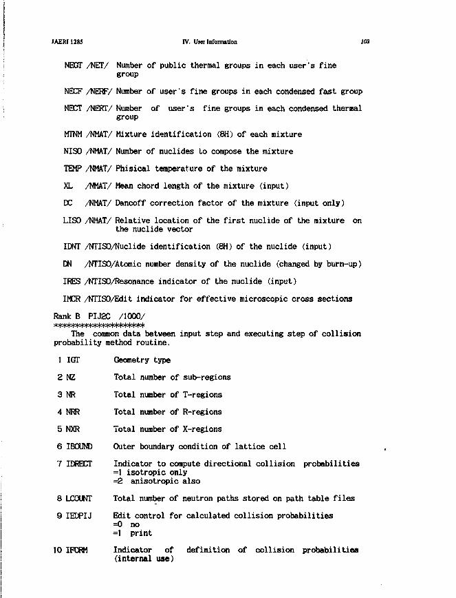
JAERJ1285 IV. User Information 203
NEXJT /NET/ Number of public thermal groups in each user's finegroup
NECF /NERF/ Number of user's fine groups in each condensed fast group
NBCT /NERT/ Number of user's fine groups in each condensed thermalgroup
MTNM /NMAT/ Mixture identification (8H) of each mixture
NISO /NMAT/ Number of nudides to compose the mixture
TEMP /NMAT/ Phisical temperature of the mixture
XL /NMAT/ Mean chord length of the mixture (input)
DC /NMAT/ Dancoff correction factor of the mixture (input only)
LISO /NMAT/ Relative location of the first nuclide of the mixture onthe nuclide vector
IDNT /NTISO/Nuclide identification (8H) of the nuclide (input)
DN /NTISO/Atomic number density of the nuclide (changed by burn-up)
IRES /NTISO/Resonance indicator of the nuclide (input)
IMCR /NTISO/Edit indicator for effective microscopic cross sections
Rank B PIJ2C /I000/
The common data between input step and executing step of collisionprobability method routine.
1 IGT Geometry type
2 NZ Total number of sub-regions
3 NR Total number of T-regions
4 NRR Total number of R-regions
5 NXR Total number of X-regions
6 IBOUND Outer boundary condition of lattice cell
7 IDRECT Indicator to compute directional collision probabilities=1 isotropic only=2 anisotropic also
8 LCOUNT Total number of neutron paths stored on path table files
9 IEDPIJ Edit control for calculated collision probabilities=0 no=1 print
10 IFORM Indicator of definition of collision probabilities(internal use)
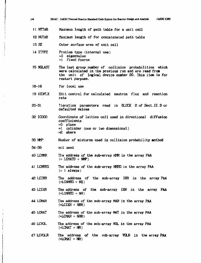
lOi SRAC: JAERI Thermal Reactor Standard Code Syitem for Reactor Design and Analysis JAER11285
11
12
13
14
15
NTTAB
NUTAB
SZ
ITYPE
NGLAST
16-18
19 IEDFLX
20-31
32 ICOOD
33 NMP
34-39
40
41
42
43
44
45
46
47
LCMMR
LCNREG
LCIRR
LCIXR
LCMAR
LCMAT
LCVOL
LCVOUR
Maximun length of path table for a unit cell
Maximum length of for concatenated path table
Outer surface area of unit cell
Problem type (internal use)=0 eigenvalue=1 fixed fource
The last group number of collision probabilities whichwere calculated in the previous run and are read fro*the unit of logical device number 20. This item is forrestart purpose.
for local use
Edit control for calculated neutron flux and reactionrate
Iteration parameters read in BLOCK 2 of Sect.II.3 ordefaulted values
Coordinate of lattice cell used in directional diffusioncoefficients=0 plane=1 cylinder (one or two dimensional)=2 shere
Number of mixtures used in collision probability method
net used
The address of the sub-array t M? in the array PAA(= LCMATD + NMP)
The address of the sub-array NRBG in the array PAA(= 1 always)
The address of the sub-array IRR in the array PAA(=LCNREG + NZ)
The address of the sub-array IXR in the array PAA(=LCNREG + NR)
The address of the sub-array MAR in the array PAA(=LCIXR + NRR)
The address of the sub-array MAT in the array PAA(=LCMAR + NRR)
The address of the sub-array VOL in the array PAA(=LCMAT + NR)
The address of the sub-array VOLR in the array PAA(=LCMAT + NR)
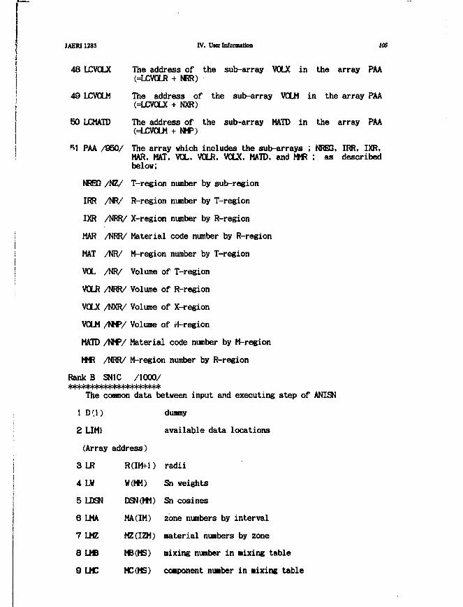
IAERI1285 IV. Uier Infomutkm 105
t
\ 48 LCVOLX The address of the sub-array V O X in the array PAAj (=LCVOLR + NRR)
| 49 LCVOLM The address of the sub-array VOLM in the array PAAj (=LCVOLX + NXR)
50 LCMATD The address of the sub-array MATD in the array PAA(=LCV0LM + NMP)
i 51 PAA /960/ The array which includes the sub-arrays ; NREG, IRR, IXR,MAR. MAT. VOL. VGLR. VOLX, MATD. and MMR ; as describedbelow;
NREG /NZ/ T-region number by sub-region
IRR /NR/ R-region number by T-regionI
, IXR /NRR/ X-region number by R-region
MAR /NRR/ Material code number by R-region
i MAT /NR/ M-region number by T-region!
! VOL /NR/ Volume of T-region
VOLR /NRR/ Volume of R-region
VOLX /NXR/ Volume of X-region
VOLM /NMP/ Volume of i4-region
MATD /NMP/ Material code number by M-region
MMR /NRR/ M-region number by R-region
Rank B SN1C /1000/
The common data between input and executing step of ANISN
, 1 D(l) dummy
• 2 LIM1 available data locations
(Array address)
j 3 L R R(IM+1) radii
I 4 LV W(MM) Sn weights
5 LDSN DSN(MM) Sn cosines6 LMA MA(IM) zone numbers by interval
i
7 LMZ MZ(IZM) material numbers by zone
8 LMB MB (MS) mixing number in Mixing table
9 LMC MC(MS) component number in nixing table

I
106 SRAC: JAERI Theimal Reactor Standud Code Syttem for Reactor Dedfn and Aoalyik JAERI1285
10 LXMD XMD(MS) number density in mixing table
11 LFIX (36) integer parameters
12 LFLT (14) floating parameters
13 LJ5 J5(IZM) order of scatter by zone
: 14 LRM RM(IZM) radius modifier by zone
15 LDF DF(IM*IDFM) densisy factors
16 LJ3 J3(ID3) material numbers for activities
17 LJ4 J4(ID3) position for activities
18 LIGT IGT(IGM) Sn/diffusion/homogeneous cell indicators, only
if IDAT2.NE.0
19 LART ART(IGM) albedo-right boundary, if IBR=3 only
20 LALFT ALFT(IQM) albedo-left boundary, if IBL=3 only
21 LCNXRA PGP(IZM) X-region number by zone
22 IFF dummy
23 LEND last address
24 LV V(IM) volumes
25 LAA AA(IM+1) areas
26 LWD WD(MM) veight*cosine
27 LMR M*(MM) reflective direction indices
28 LPNC PNC(m.IT) PI coefficients, if ISCT.NE.O only
(Integer parameters (see Sect.II.4))
Problem ID number.i 30 ITH =0 forvard solution
=1 adjoint solution
29
30
31
32
33
34
35
36
ID
ITH
ISCT
ISN
IGE
IBL
IBR
IZM
Maximum order of scatter found in any zone
Order of angular quadrature
Geometry
Left boundary condition
Right boundary condition
Niwber of zones or regions
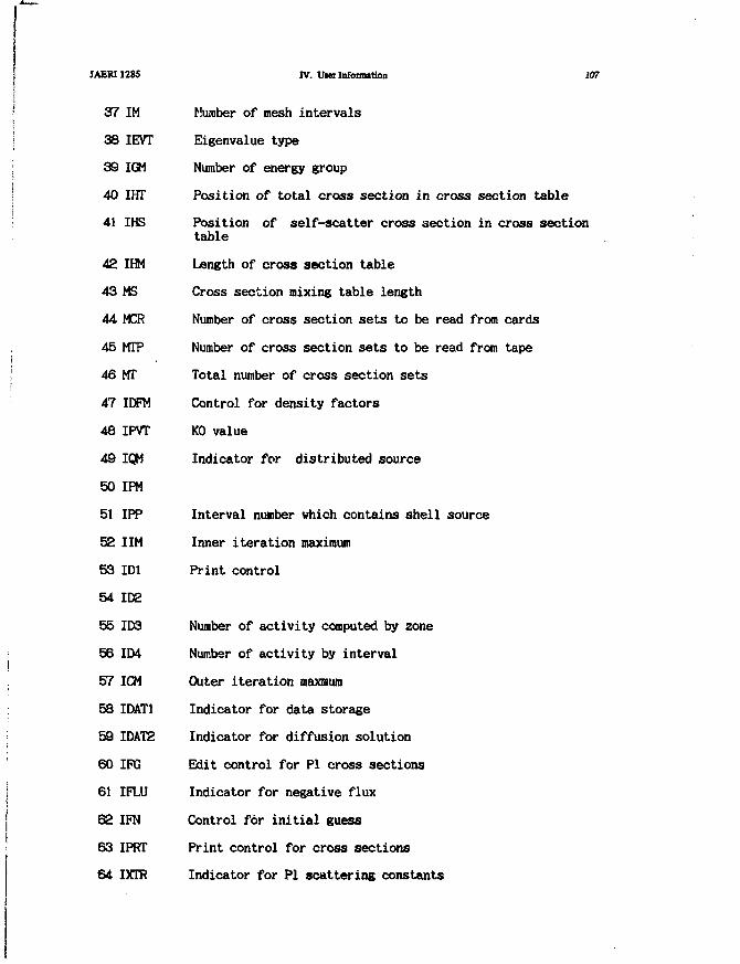
JAERI1285
37
38
39
40
41
42
43
44
45
46
47
48
49
50
51
52
53
54
55
56
57
58
59
60
61
62
63
64
IM
IEVT
IGM
IHT
IHS
IHM
MS
MCR
MTP
MT
IDFM
IPVT
IQM
IPM
IPP
IIM
ID1
ID2
ID3
IIM
ICM
IDAT1
IDAT2
ire
IFLU
IFN
IPRT
IXTR
IV. Uier Infoimition 107
Number of mesh intervals
Eigenvalue type
Number of energy group
Position of total cross section in cross section table
Position of self-scatter cross section in cross sectiontable
Length of cross section table
Cross section mixing table length
Number of cross section sets to be read from cards
Number of cross section sets to be read from tape
Total number of cross section sets
Control for density factors
KO value
Indicator for distributed source
Interval number which contains shell source
Inner iteration maximum
Print control
Number of activity computed by zone
Number of activity by interval
Outer iteration maxmum
Indicator for data storage
Indicator for diffusion solution
Edit control for PI cross sections
Indicator for negative flux
Control for initial guess
Print control for cross sections
Indicator for PI scattering constants
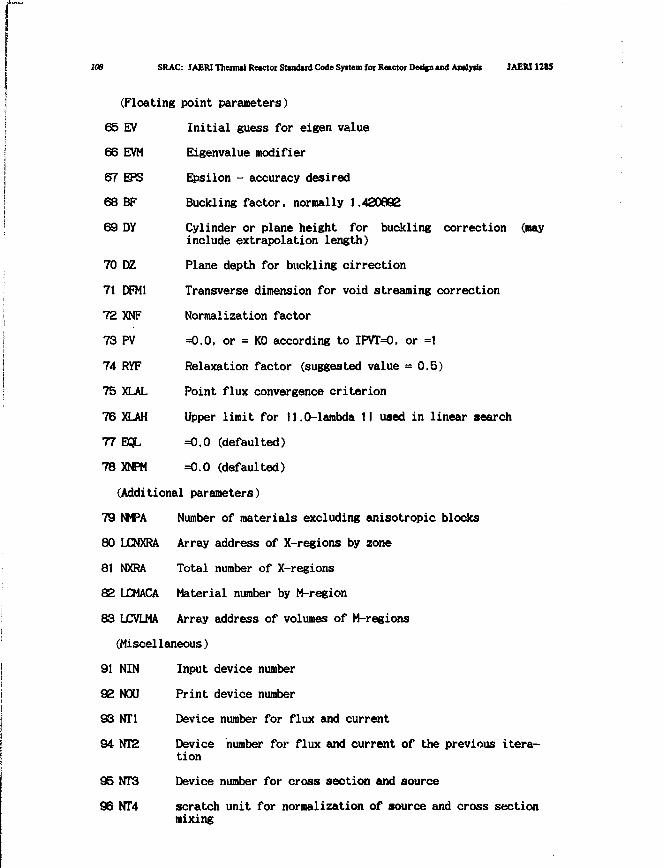
108 SRAC: JAERI Theimal Reactor Standard Code Syitem for Reactor Dedfn and Analy»l» JAERI 1285
(Floating point parameters)
Initial guess for eigen value
Eigenvalue modifier
Epsilon - accuracy desired
Buckling factor, normally 1.420892
Cylinder or plane height for buckling correction (nayinclude extrapolation length)
Plane depth for buckling cirrection
Transverse dimension for void streaming correction
Normalization factor
=0.0, or = K0 according to IPVT=O, or =1
Relaxation factor (suggested value = 0.5)
Point flux convergence criterion
Upper limit for 11.0-lambda II used in linear search
=0.0 (defaulted)
=0.0 (defaulted)
(Additional parameters)
79 NMPA Number of materials excluding anisotropic blocks
80 LCNXRA Array address of X-regions by zone
81 NXRA Total number of X-regions
82 LCMACA Material number by M-region
83 LCVLMA Array address of volumes of M-regions
(Miscellaneous)
91 NIN Input device number
92 NOU Print device number
93 NT1 Device number for flux and current
94 NT2 Device number for flux and current of the previous itera-
tion
95 NT3 Device number for cross section and source
96 NT4 scratch unit for normalization of source and cross sectionmixing
65
66
67
68
69
70
71
72
73
74
75
76
77
78
EVEVM
EPS
BF
DY
DZ
DFM1
XNF
PV
RYF
XLAL
XLAH
EQL
XNPM

JAERI1285 IV. Uwr Information 109
97 NT5 Initial tine
96 NT6 Device number of library (not used)
99 NT7 Device number for specially group independent cross sec-tions
100 NT8 Device number for weighted cross sections
101-1000 Dummy vector which contains the arrays
Rank B TWC1 /2000/
The common data between input step and executing step of TWOTRAN.We shall introduce only the data exchanged between TVOTRAN and externalroutines.
4 IGM Number of groups
5 IM Number of coarse meshes in X-direction
6 JM Number of coarse meshes in Y-direction
15 MT Total number of materials
18 IHT Position in table of total cross section
19 IKS Position in table of self-scatter cross section
SO UK Length of cross section table
21 IQOPT Source input option
22 IQAN Distributed source anisotropic order
°5 IPVT Parametric eigenvalue or Keff indicator
34 IGE0M Geometry type
58 IMJM Product of IM * JM
66 IT Total number of radial fine-mesh intervals
67 JT Total number of axial fine-mesh intervals
68 ITJT Product of IT * JT
157 NOUT Print device logical number <99>
170 NMPW Number of materials not counting anisotropic block
181 LZRNUM Address of array for M-region number by coarse mesh
204 L R F Address of array for X-region number by coarse mesh
205 LZRDUC Address of array for Material code number by M-region
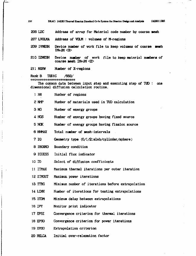
110 SRAC: JAEW Thermil Retctoi Standard Cole System for Reictoi Detfcn u d A n l y * JAER112I5
206 LDC Address of array for Material code number by coarse mesh
207 LVOLMA Address of VOLM : volumes of M-regions
209 IVMESH Device number of vork file to keep volumes of coarse mothIM*JM
210 IZMESH Device number of vork file to keep material numbers of
coarse mesh IM*JM <2>
211 NXRW Number of X-regions
Rank B TUD1C /550/The common data between input step and executing step of TUD : one
dimensional diffusion calculation routine.
1 NR Number of regions
2 NHP Number of materials used in TUD calculation
3 NQ Number of energy groups
4 NGS Number of energy groups having fixed source
5 NGK Number of energy groups having fission source
6 NNMAX Total number of mesh-intervals
7 IG Geometry type (0/l/2;slab/cylinder/sphere)
8 IBCXAID Boundary condition
9 IGUESS Initial flux indicator
10 ID Select of diffusion coefficients
11 ITMAX Maximum thermal iterations per outer iteration
12 ITMOUT Maxirauir, power iterations
13 ITBG Minimum number of iterations before extrapolation
14 LCMX Number of iterations for testing extrapolations
15 ITDM Minimum delay between extrapolations
16 IPT Monitor print indicator
17 EPSI Convergence criterion for thermal iterations
18 EPSO Convergence criterion for power iterations
19 EPSG Extrapolation criterion
20 RELCA Initial over-relaxation factor
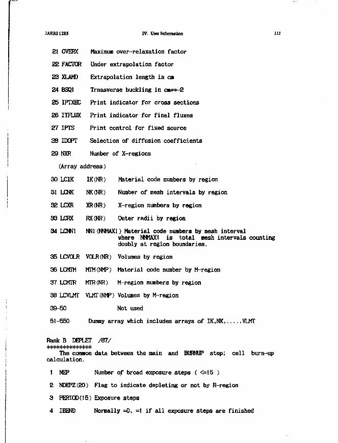
JAERI1285 IV. Userlnfoimition 111
21 OVERX Maximum over-relaxation factor
22 FACTOR Under extrapolation factor
23 XLAMD Extrapolation length in en
24 BSQ1 Trnasverse buckling in ca**-2
25 IPTXEC Print indicator for cross sections
26 ITFLUX Print indicator for final fluxes
27 IPTS Print control for fixed source
SB IDOPT Selection of diffusion coefficients
29 NXR Number of X-regions
(Array address)
30 LCIK IK(NR) Material code numbers by region
31 LCNK NK(NR) Number of mesh intervals by region
32 LCXR XR(NR) X-region numbers by region
33 LCRX RX(NR) Outer radii by region
34 LCNN1 NNl(NNHAXl} Material code numbers by mesh intervalwhere NNMAX1 is total mesh intervals countingdoubly at region boundaries.
35 LCVOLR V0LR(NR) Volumes by region
36 LCMTM MTM(NMP) Material code number by M-region
37 LJCMTR MTR(NR) M-region numbers by region
38 LCVLMT VLMT(NMP) Volumes by M-region
39-50 Not used
51-550 Dummy array which includes arrays of IK.NK ,VLJMT
Rank B DEPLET /87/
The common data between the main and BURNUP step; cell burn-upcalculation.
1 NEP Number of broad exposure steps ( <=15 )
2 NDEPZ(20) Flag to indicate depleting or not by R-region
3 PERIOD(15) Exposure steps
4 IBEND Normally =0, =1 if all exposure steps are finished
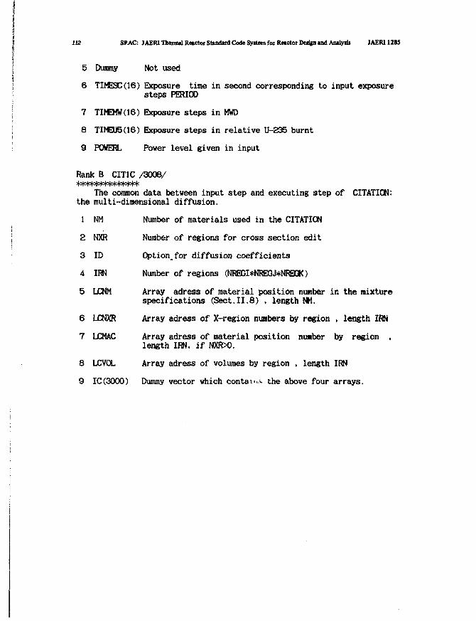
112 SFAC: JAERI Thermal Reactor Standard Code System for Reactor Design and Analysis JAER11285
5 Dummy Not used
6 TIMESC(16) Exposure time in second corresponding to input exposure
steps PERIOD
7 TM3W(16) Exposure steps in MWD
8 TIMEU5(16) Exposure steps in relative U-235 burnt
9 POWERL Power level given in input
Rank B CIT1C /3006/
The common data between input step and executing step of CITATION:the multi-dimensional diffusion.
Number of materials used in the CITATION
Number of regions for cross section edit
Option.for diffusion coefficients
Number of regions (MREGI*NREGJ*NREGK)
Array adress of material position number in the mixturespecifications (Sect.II.8) , length NM.
Array adress of X-region numbers by region , length IRN
Array adress of material position number by region ,length IRN, if NXR>0.
Array adress of volumes by region , length IRN
Dummy vector which conta!•.,<- the above four arrays.
1
2
3
4
5
6
7
8
9
NM
NXR
ID
IRN
LCNM
LCNXR
LCMAC
LJCVOL
IC(3000)

JAERI1285 IV. Uier Infonwtion 113
IV.6 Subroutines
We shall show tree structure how to call subroutines in the SRAC.In the following figure FACOM built-in functions, frequently appearingI/O routines, their associated error print routines, and clock routinesare omitted.
MAIN -1
1SRAC STPCOM
+-- INPUTl+- USERFL -1+- USERTL -+- PIJIN -
-i
H
— UFLCAL -
— COLLAP— PIJ1f- CHECKf- GEOMTY -
H
H
HH
h- PATH -
- CLUP77 —
— COLLAPf- UFLCON
— ORGSETt- GEOM01f- GE0M02i- GEOM041i- GE0M051t- GEOM061i- GEOM07
h- GEOM06i- GE0M09h- GEOM1O
- GEOM11
- GE0M13— GEOMU- PAIN- PREPA- MAKEPT
- RDX1
GTITLECIRCLED
CNTPLY+- CIRCLS
CNTPLY•(-CIRCLS •
CNTPLY+-CIRCLH-
CNTPLY+- CIRCLH •
CIRCLG— CIRCLG+- CIRCLP -+- NUMPIN-t- NUMCYL -
CIRCLG+- CNTPLY+- SRTCYL+-CIRCLH -+- CIRCLP -+- NUMPIN+- NUMCYL -
— CIRGJQ
— CIRCLG
— CIRCLG
— CIRCLG
— CIRCLG
— CHKPIN
— CIRCLG— CIRCLG
— CHKPIN
(not yet included)
SLAB+- CYL —+- SQ —+- SQ2 —1 +-+- HEX —+- HEX2 —1 +-+- ELIM
- INSERT- INSERT- INSERT- DIVIDE- INSERT- INSERT- COMPAR — DIVIDE
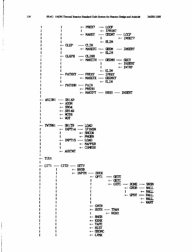
114 SRAC: JAERI Thermal Reactor Standard Code Syitcm for Reictoi Deiifn and Analysii JAERI 1285
4
H
4!
1-f
ANISN1 —+++++
TWTRNl —
- CLUP
- CLUPH
- PATHXT
- PATHHH
- SN1AR- ADDR- S804- S8143- wore- WOT
- SN1TR+- INPTU11+11
- INPT15
+- PREX71+- MAKET
CLIN+- MAKETC
CLINH+- MAKETH
PREXY-i- MAKETX
PAIN+- PREHH+- MAKEPT
— LOADIFINSN
+- SNCON+- PNGEN— LOAD+- MAPPER+- CSMESH
LCCF4- IPRINT— GEOM7 -1 4+- ELIM
GEOM —+- ELIM
GEOMH -1 H
- LOCFi- INSET7
- INSERT
— SECT- INSERT
1 +- INTRP+- ELIM
IPRXYGEOMXY
+- ELIM
— HHHH —- INSERT
AUXTWT
TUD1
CIT1 CIT2 SETV+- BNSB+- INPTM SHQX
+- OPT1
I
CNTRRSTR -
BNSBh- KXNXh- TAPEH- HISTh- GEOMCi- LVMX
GETEGETCCSTC RONE
+- CRDRI +-+- UPDT
TRANRODO
SNSNWALLRALLRALLWALLWART
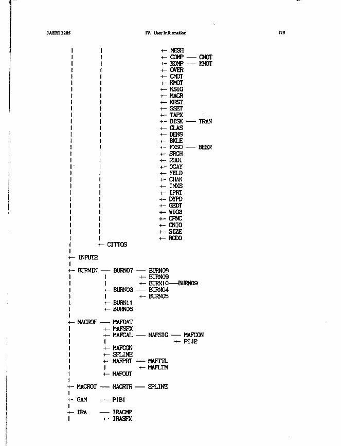
JAERI 1285 IV. Uiet Infonnation US
INPUT2
BURNIN
MACRCF
CITTOS
— BURN07II+- BURN03I+- BURN11+- BURNO6
— MAFDAT+- MAFSFX+- MAFCALI+- MAFCON-t- SPLINE+- MAFPRTI
-i- MESH+- COMP CMOT+- KOMP KMOT+- OVER+- CMOT+- KMOT+- KSIG+- MACR-i- KRST+- SSET+- TAPX+- DISK TRAN-i- CLAS+- DENS+- BKLE•+- FXSO BEER+- SRCH+- RODI+- X A Y+- YELD+- CHAN+- IMXS+- IPRT+- DYPD+- GEDT+- WIO3+- CPNC+- CNIO+- SIZE+- RODO
BURN08BURN09BURN1O BURN09BURNO4BURN05
MAFSIG MAFCON+- PIJ2
MAFTTLMAFLTM
+- MAFOUT
MACROT MACRTR — SPLINE
GAM P1B1
IRA IRACMP+- IRASFX
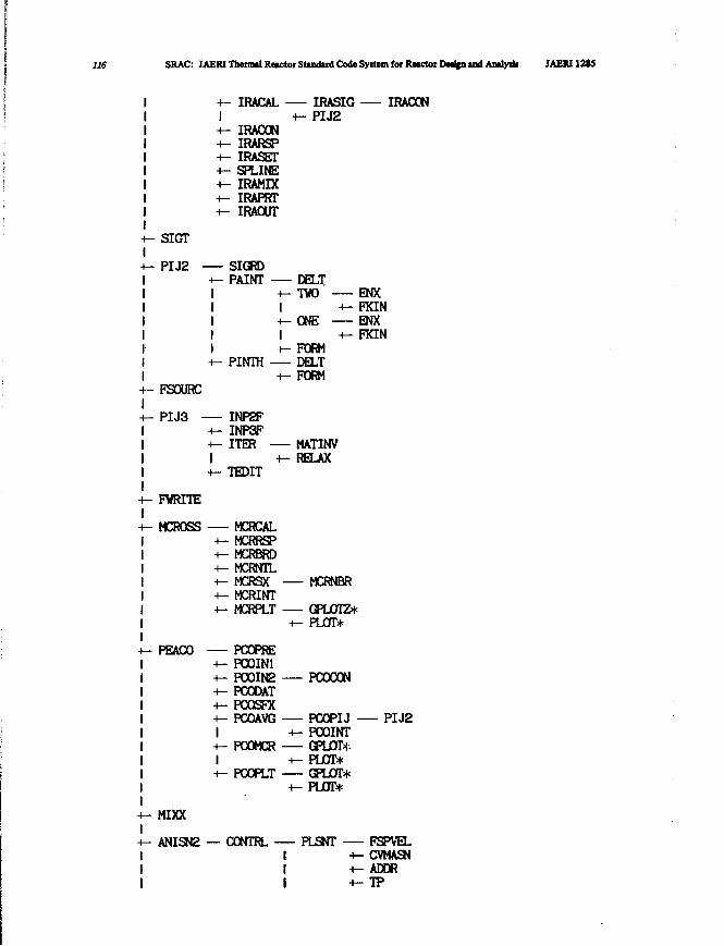
116 SRAC: JAERI Themitl Reactor Standard Code Syttem for RMGtor Dedfn and Amlysii JAERI128J
IRACAL IRASIG+-PIJ2
IRACGNIRARSPIRASETSPLINEIRAMIXIRAPRTIRAOUT
IRACGN
SIGT
+- PIJ2 SIGRDPAINT DELT
-i- TWOI +-+- ONE
ENXFKINENXFKIN
t- FSOURC
PIJ3 -
FVRITE
MCROSS
PINTH
INP2FINP3FITER
TEDIT
MCRCALMCRRSPMCRBRDMCRNTLMCRSXMCRINTMCRPLT
PEACO PCOPRE-i- PCOIN1+- PC0IN2+- PCODAT+- PCQSFX+- PCOAVGI+- POOMCRI+- POOPLT
MIXX
ANISN2 — CONTRL -
FORMDELTFORM
MATINVRELAX
MO^NBR
— GPLOTZ*+- PLOT*
PCOCON
PCOPIJPCOINTGPLOT+PLOT*GPLOT*PLOT*
PLSNT
PIJ2
FSPVELCVMASNADDRTP
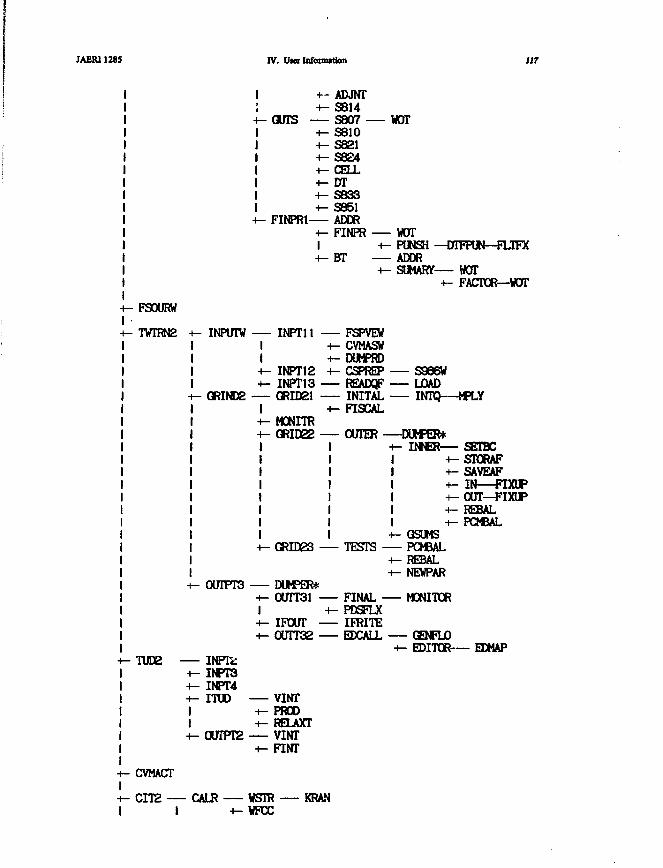
JAERI 1285 IV. U w Infonnitkm 117
+- ADJNT+-S8U
GUTS S807 -+-S810+-S821+- S824+- CELL+- DT+-S833+-S851
FINPR1 ADDR+ - FINPRI+ - BT
WOT
WOTPUNSH —DTFPUN—FLTFXADDRSUMARY— HOT
+ - FACTOR—WOT
FSOURW
TWTRN2 INFVTW INPT11
+- INPT12+- INPT13
GRINDS — GRID21I
MONITRGRID22
FSPVEVCVMASWDUMPRDCSPREPREADQFINITALFISCAL
S966WLOADINTQ—MPLY
OUTER —DUMPER*+- INNER— SETBC
+- STORAF+-SAVEAF4- I N — F I M P+-OUT—FIXUP+- REBAL+- PCMBAL
GSUMS-I- GRID23 TESTS PCMBAL
+- REBAL-i- NEWPAR
0UTPT3 DUMPER*4- 0UTT31 FINAL MONITOR
TUD2 INPtk.INPT3INPT4ITUD
0UTPT2
IFCUT0UTT32
VINTPRODRELAXTVINTFINT
FINALPDSFLXIFRITEEDCALL GENFLO
EDITOR— EDMAP
CVMACT
CIT2 — CALR WSTRWFCC
KRAN
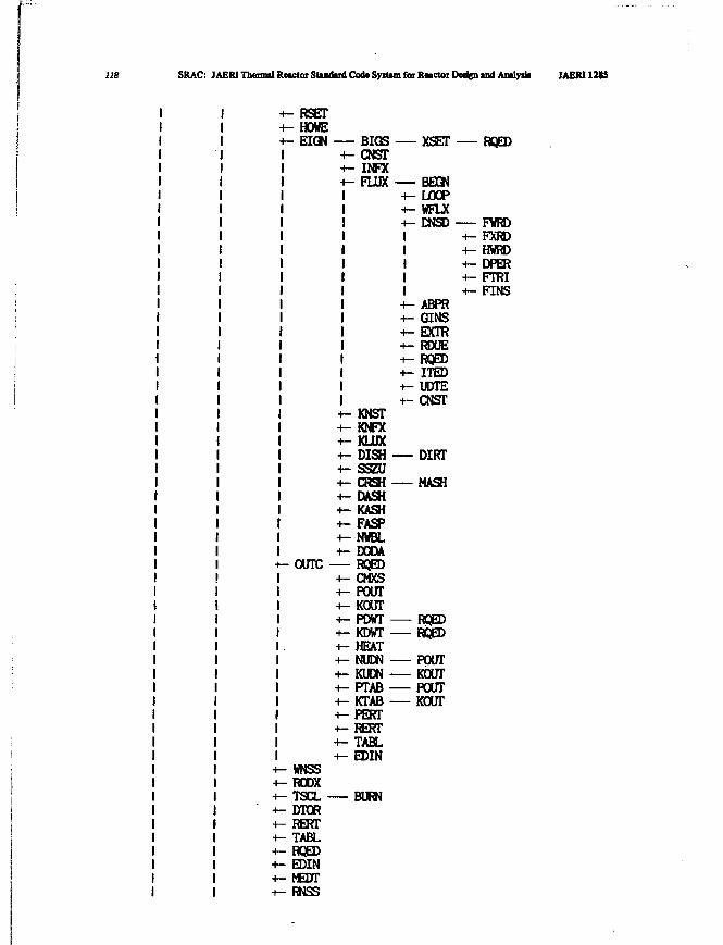
118 SRAC: JAERI Thermil Ractor Stiadud Cod* System for RMCtoi Dadgn and Amly* JAERI 12*5
RSETHOWEEIQN BIGS XSET RQEDBIGS
CNSTINFXFLUX BEGN
LOOPVFLXDNSD
OUTC
WNSSRODXTSCLDTORRERTTABLRQEDEDINMEDTRNSS
- KNST- KNFX- KLUX- DISH• SSZUCRSHDASHKASHFASPNWBLDODARQEDCMXSPOUTROUTPDWTKDWTHEATNUDNKUDNPTABKTABPERTRERTTABLEDIN
BURN
IIIII+- ABPR+- GINS+- EXTR+- RDUE+- RQED+- ITED+- UDTE+-CNST
DIRT
MASH
FWRDFXRDHWRDDPERFTRIFINS
RQED— RQED
POUTKOUTPOUTKOUT
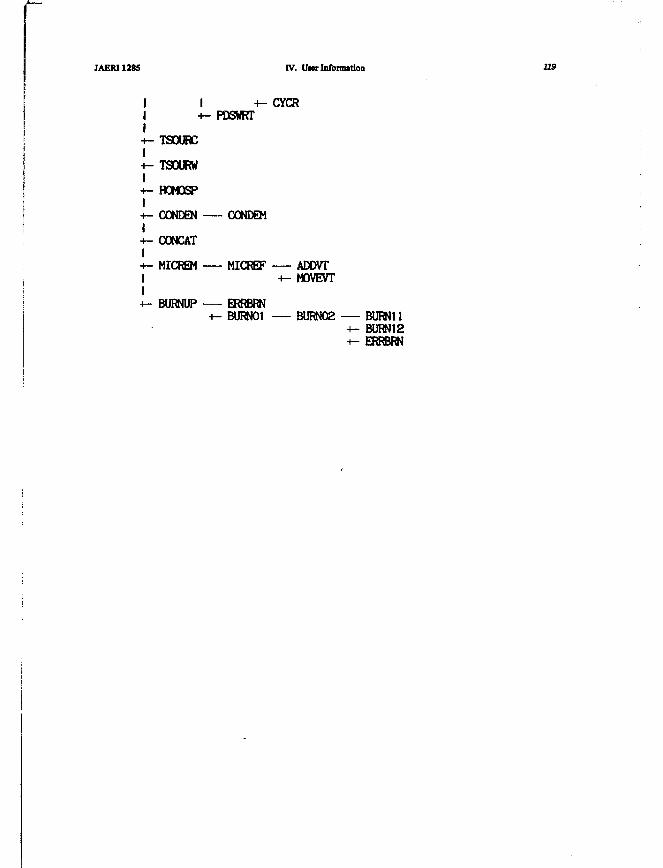
JAERI 1285 IV. Uter Information 119
I +-CYCR+- PDSWRT
TSOURC
TSOURW
HOMOSP
CONDEN CONDEM
CONCAT
MICREM MICREF ADDVT+- MOVEVT
BURNUP ERRBRNBURNO1 BURN02 — BURN11
BURN12ERRBRN
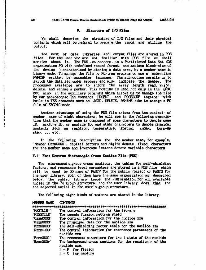
ISO SRAC: JAERITlwnml Reictor Standard Code Syitem for Reactor Dedgn and Analy* JAEW12JJ
V. Structure of I/O Files
We shall describe the structure of I/O files and their physicalcontents which will be helpful to prepare the input and utilize theoutput.
The most of data libraries and output files are scored in PCSfiles . For the user who are not faniliar with PCS file we shallmention about it. The POS ,we concern, is a Partitioned Data Set (DSorganization PO with undefined record format, and Maximum block-size ofthe device ) charaterized by storing a data array by a member name inbinary mode. To manage the file by Fortran program we use a subroutineRWPDSF written by assembler language. The subroutine permits us toswitch the data set under process and also indicate the member. Theprocesses available are to inform the array length, read, write,delete, and rename a member. This routine is used not only in the SRACbut also in the auxiliary programs which allows us to manage the fileby our macroscopic TSS commands PDSEDT, and PDSEDGRP together withbuilt-in TSS commands such as LISTD, DELETE, RENAME like to manage a POfile of EBCDIC mode.
Another advantage of using the PDS file arises from the control' ofmember name of eight characters. We will see in the following descrip-tion that the member name is composed of some character* to denote c u eID, mixture ID, or nuclide ID, and other characters to denote physicalcontents such as reaction, temperature, spatial index, burn-upstep, ... etc..
In the following description for the member name, for example,'Member CzzmOOOO', capital letters and digits denote fixed charactersfor the member name and lowercase letters denote variable characters.
V.I Fast Neutron Microscopic Cross Section File (PDS)
The microscopic group cross sections, the tables for self-shieldingfactors, and resonance level parameters are stored in a PDS fiie whichwill be used by DD name of FASTP for the public (basic) or FASTU forthe user library. Both of them have the same organization as describedbelow. The public library keeps the -information for all availablenuclei in the 74 group structure, and the user library does that forthe selected nuclei in the user's group structure.
The following eight kinds of members are stored in the library.
MEMBERNAME CONTENTS
'FASTLIB ' The control information for the library'FISSYILD' The pseudo fission neutron yield'CzzmOOOO' The control information for the nuclide zzmMzzmOOOO' The principal data for the nuclide zzm'FzzmOOOO' The self-shielding factor table for the nuclide zza•RzzmOOOO' The control information for resonance parameters of the
nuclide zzm'PzzmOOOl' The resonance parameters for the 1-state of the nuclide'BzzmOOOr' The background cross sections for the reaction r of the
nuclide zzm.r = F for fissionr = C for capture
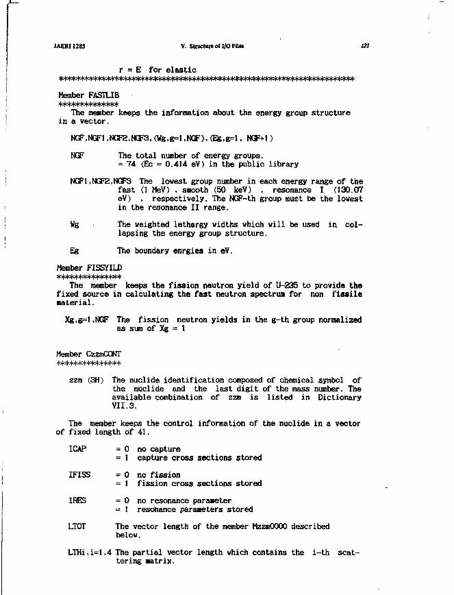
JAERI1285 V. Structureofl/OFflet 121
r = E for elastic
Member FASTLIB
The member keeps the information about the energy group structurein a vector.
NGF,NGFl,NCa;2,NGF3,(Wg,g=l.NCSF),(Efe,g=l. NGF+1)
NGF The total number of energy groups.=• 74 (Ec = 0.414 eV) in the public library
NGF1,NGF2,NGF3 The lowest group number in each energy range of thefast (1 MeV) , smooth (50 keV) , resonance I (130.07eV) , respectively. The NGF-th group must be the lowestin the resonance II range.
Wg The weighted lethargy widths which will be used in col-lapsing the energy group structure.
Eg The boundary enrgies in eV.
Member FISSYILD
The member keeps the fission neutron yield of U-235 to provide thefixed source in calculating the fast neutron spectrum for non fissilematerial.
Xg,g=l,NGF The fission neutron yields in the g-th group normalizedas sum of Xg = 1
Member CzzmCONT
zzm (3H) The nuclide identification composed of chemical symbol ofthe nuclide and the last digit of the mass number. Theavailable combination of zzm is listed in DictionaryVII.3.
The member keeps the control information of the nuclide in a vectorof fixed length of 41.
ICAP = 0 no capture= 1 capture cross sections stored
IFISS = 0 no fission= 1 fission cross sections stored
IRES = 0 no resonance parameter= 1 resonance parameters stored
LTOT The vector length of the member MzzmOOOO describedbelow.
LTHi,i=l,4 The partial vector length which contains the i-th scat-tering matrix.
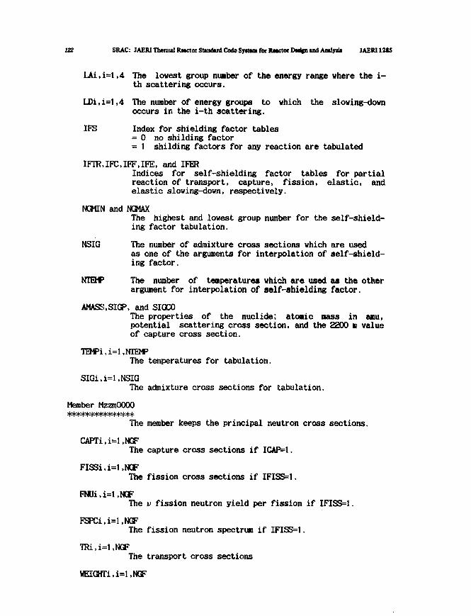
122 SRAC: IAERI Thermal Reactor Standard Code Syitdn for Raactor Derifn and Analyiii JAERI12IS
LAi,i=l,4 The lowest group nuaber of the energy range where the i-th scattering occurs.
LDi,i=l,4 The number of energy groups to which the slowing-downoccurs in the i-th scattering.
IPS Index for shielding factor tables= 0 no shilding factor= 1 shilding factors for any reaction are tabulated
IFTR.IFC.IFF.IFE, and IFERIndices for self-shielding factor tables for partialreaction of transport, capture, fission, elastic, andelastic slowing-down, respectively.
NGMIN and NGMAXThe highest and lowest group number for the self-shield-ing factor tabulation.
NSIG The number of admixture cross sections which are usedas one of the arguments for interpolation of self-shield-ing factor.
NTEMP The number of temperatures which are used as the otherargument for interpolation of self-shielding factor.
AMASS.SIGP, and SIGCOThe properties of the nuclide; atonic mass in ami,potential scattering cross section, and the 2200 m valueof capture cross section.
TEWi.i^.NTOPThe temperatures for tabulation.
SIGi,i=l,NSIG
The admixture cross sections for tabulation.
Member MzzmOOOO
The member keeps the principal neutron cross sections.
CAPTi,i=l,NGFThe capture cross sections if ICAP=1.
FISSi,i=l,NGFThe fission cross sections if IFISS=1.
FNUi,i=l,NGFThe v fission neutron yield per fission if IFISS=1.
FSPCi,i=l,NGFThe fission neutron spectrum if IFISS=1.
TRi,i=l,NGFThe transport cross sections
WEIGHTi,i=l,NGF
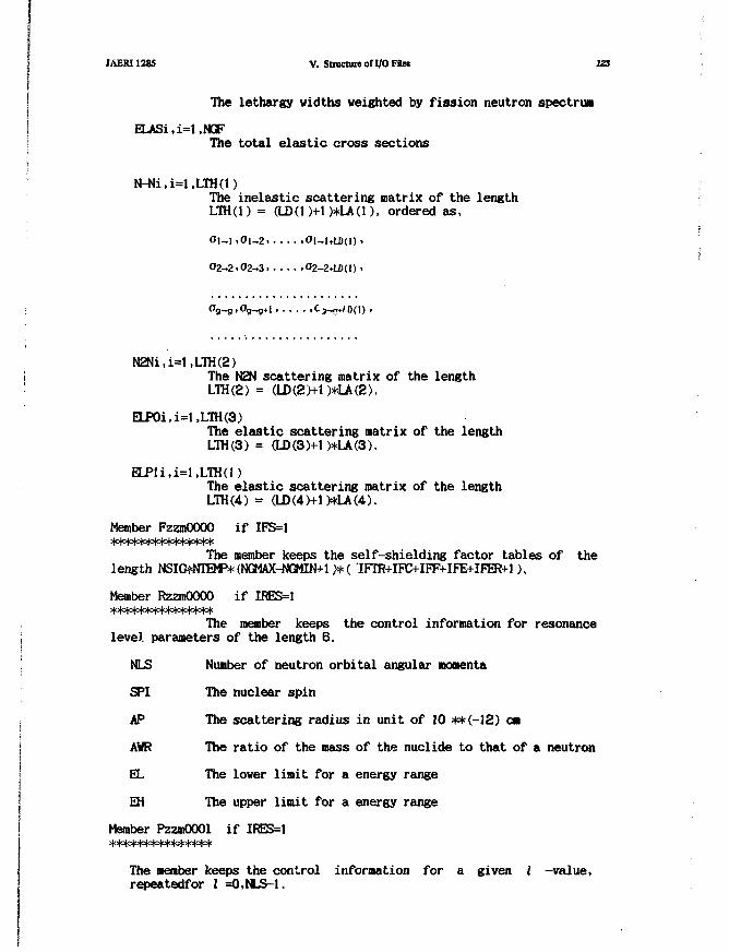
JAERI1285 V. Structure of I/O F«et 123
The lethargy widths weighted by fission neutron spectrum
ELASi,i=l,NGFThe total elastic cross sections
N-Ni,i=l,LTH(l)The inelastic scattering matrix of the lengthLTH(l) = (LD(1)+1)*LA(1), ordered as,
01-1 .Ol_2 .Ol-I+LDU) >
02-2.02-3 »O2-2+LC(l) .
N2Ni,i=1,LTH(2)The N2N scattering matrix of the lengthLTH(2) = (LD(2)+1)*LA(2).
ELP0i,i=l.LTH(3)The elastic scattering matrix of the lengthLTH(3) = (LD(3)+1)*LA(3).
ELPli,i=l,LTH(l)The elastic scattering matrix of the lengthLTH(4) = (LD(4)+1)*LA(4).
Member FzzmOOOO if IFS=1***************
The member keeps the self-shielding factor tables of thelength MSIG*NIllf^(NGMAX-N(MIN+l)*( IFTR+IFC+IFF+IFE+IFER+l).
Member RzzmOOOO if IRES=1
The member keeps the control information for resonance: level parameters of the length 6.
'. NLS Number of neutron orbital angular momenta
SPI The nuclear spin
AP The scattering radius in unit of 10 **(-12) cm
! AWR The ratio of the mass of the nuclide to that of a neutron
EL The lower limit for a energy range
EH The upper limit for a energy range
Member PzzmOOOl if IRES=1***************
The member keeps the control information for a given 2 -value,repeatedfor I =O,NLS-1.
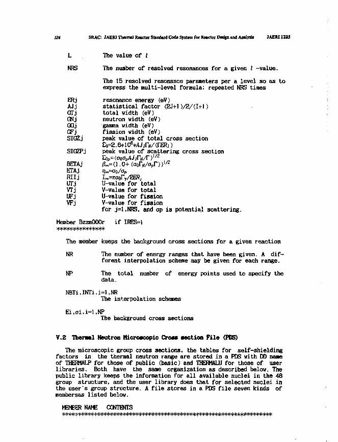
124 SRAC: IAERI Tbennd R«Ktot Studud Code Syrtem for Rector Reiipund AwUyiJi JAEIU1235
L The value of I
NRS The number of resolved resonances for a given I -value.
The 15 resolved resonance paraneters per a level so as toexpress the multi-level formula; repeated NRS times
ERj resonance energy <eV)AJj statistical factor (2J+1 )/2/(I+l)GfTj total width (eV)GNj neutron width (eV)QGj gamma width (eV)GFj fission width (eV)SIGZj peak value of total cross section
6
SIGZPj peak value of scattering cross sect ion" 2Eop^ooap/Ujrvr)
BETA j /?o.= ( 1 . 0 + (oorN/opr))l/2
ETAj. >?o«=oo/OpRIIj I«,=7roor\/2SfyUTj U-value for tota lVTj V-value for totalUFj U-value for f i s s i o nVFj V-value for f i s s ion
for j=l,NRS, and op i s potential scattering.
Member BzzmOOOr i f IRES=1
The member keeps the background cross sections for a given reaction
NR The number of energy ranges that have been given. A dif-ferent interpolation scheme may be given for each range.
NP The total number of energy points used to specify thedata.
NBTi,INTi,i=l,NRThe interpolation schemes
Ei,ai,i=l,NPThe background cross sections
V.2 Tfaeraal Neutron Microscopic Cross section File (PDS)
The microscopic group cross sections, the tables for self-shieldingfactors in the thermal neutron range are stored in a PDS with DO naaeof THERMALP for those of public (basic) and THERMALU for those of userlibraries. Both have the sane organization as described below. Thepublic library keeps the information for all available nuclei in the 48group structure, and the user library does that for selected nuclei inthe user's group structure. A file stores in a PDS file seven kinds ofmembersas listed below.
MB€ERNAM£ CONTENTS
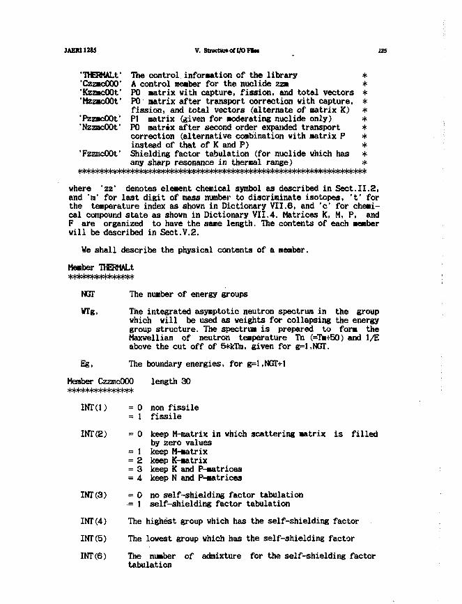
JAEM1285 V. Structure* I/O Ftat 125
'TMERMALt' The control information of the library *'CzzmcOOO' A control member for the nuclide zzm *'KzzmcOOt' PO matrix with capture, fission, and total vectors *'MzzmcOOt' PO matrix after transport correction with capture, *
fission, and total vectors (alternate of matrix K) *'PzzmcOOt' PI matrix (given for moderating nuclide only) *'NzzmcOOf PO matrix after second order expanded transport *
correction (alternative combination with matrix P *instead of that of K and P) *
'FzzmcOOt' Shielding factor tabulation (for nuclide which has *any sharp resonance in thermal range) *
where 'zz' denotes element chemical symbol as described in Sect.II.2,and 'm' for last digit of mass number to discriminate isotopes, 't' forthe temperature index as shown in Dictionary VII.6, and 'c' for chemi-cal compound state as shown in Dictionary VII.4. Matrices K, M, P, andF are organized to have the same length. The contents of each memberwill be described in Sect.V.2.
We shall describe the physical contents of a member.
Member THERMALtstololobiololotolotolololololc
NGTT The number of energy groups
WTg, The integrated asymptotic neutron spectrum in the groupwhich will be used as weights for collapsing the energygroup structure. The spectrum is prepared to form theMaxwellian of neutron temperature Tn (=Tm+50) and 1/Eabove the cut off of 5*kTm, given for g=l,NGT.
Eg, The boundary energies, for g=l,NGT+1
Member CzzmcOOO length 30
INTO) = 0 non fissile= 1 fissile
INT(2) = 0 keep M-matrix in which scattering matrix is filledby zero values
= 1 keep M-matrix= 2 keep K-matrix= 3 keep K and P-matrices= 4 keep N and P-matrices
INT (3) = 0 no self-shielding factor tabulation•= 1 self-shielding factor tabulation
INT(4) The highest group which has the self-shielding factor
INT(5) The lowest group which has the self-shielding factor
INT(6) The number of admixture for the self-shielding factortabulation
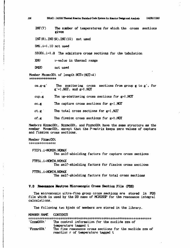
126 SRAC: JAERI Thenml Retctor Stindud Code System for Reactor Detfcn and Antlytls JAERI 1285
INT (7) The number of temperatures for which the cross sectionsgiven
INT(8),INT(9),INT(10) not used
DMi,i=l,10 not used
SIG0i,i=l,8 The admixture cross sections for the tabulation
XNU p-value in thermal range
DM20 not used
Member MzzmcOOt of length NGT*(NGT+4)
os,g-g' The scattering cross sections from group g to g', forg'=l,NGT, and g=1,NGT
oup.g The up-scattering cross sections for g=l .NGTT
oc,g The capture cross sections for g=l,NGT
ot,g The total cross sections for g=l,NGT
af,g The fission cross sections for g=l,NGT
Members KzzmcOOt, NzzmcOOt, and PzzmcOOt have the same structure as themember MzzmcOOt, except that the P-matrix keeps zero values of captureand fission cross sections.
Member FzzmcOOt
FTCPi,i=NGMIN,NGMAXThe self-shielding factors for capture cross sections
FTFSi,i=NGMIN,NGMAXThe self-shielding factors for fission cross sections
FTTRi,i=NGMIN,NGMAXThe self-shielding factors for total cross sections
V.3 Resonance Neutron Microscopic Cross Section File (PDS)
The microscopic ultra-fine group cross sections are stored in PDSfile which is used by the DD name of MCROSSP for the resonance integralcalculations.
The following two kinds of members are stored in the library.
MEMBER NAME CONTENTS
'CzzmOOOf The control information for the nuclide zzm oftemperature tagged t
'FzzmrOOt' The fine resonance cross sections for the nuclide zzm ofreaction r of temperature tagged t
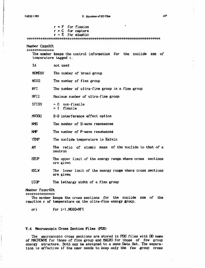
JAERI1285 V. Structure ofl/O Filei 127
r = F for fissionr = C for capturer = E for elastic
Member CzzmOOt
The member keeps the control information for the nuclide zzm oftemperature tagged t.
IA not used
NOMESH The number of broad group
NOIG The number of fine group
NFI The number of ultra-fine group in a fine group
NFII Maximum number of ultra-fine group
IFISS = 0 non-fissile= 1 fissile
MVOQO S-S interference effect option
NMS The number of S-wave resonances
NMP The number of P-wave resonances
TEMP The nuclide temperature in Kelvin
AM The ratio of atomic mass of the nuclide to that of aneutron
EEtIP The upper limit of the energy range>where cross sectionsare given
EELW The lower limit of the energy range where cross sectionsare given
UIGP The lethargy width of a fine group
Member FzzmrOOt
The member keeps the cross sections for the nuciide zzm of thereaction r of temperature on the ultra-fine energy group.
ari for i=l,NOIG*NFI
V.4 Macroscopic Cross Section Files (PDS)
The macroscopic cross sections are stored in PDS files with DD nameof MACROWRK for those of fine group and MACRO for those of few groupenergy structure. Both may be assigned to a same Data Set. The separa-tion is effective if the user needs to keep only the few group cross
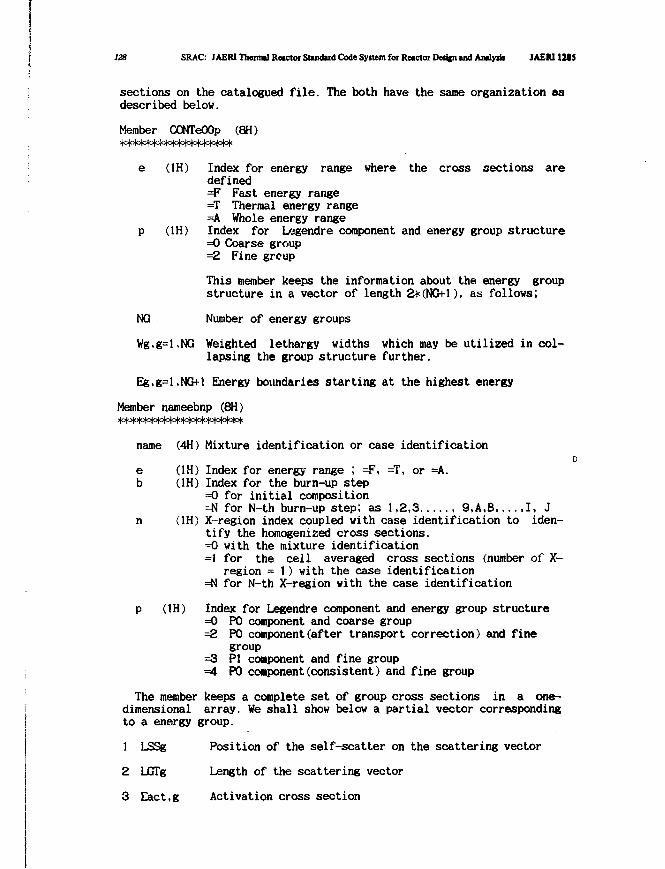
128 SRAC: JAERI Thermal Retctot Standard Code Syitem for Reactor Detitn and Analysb JAEN1MS
sections on the catalogued file. The both have the same organization asdescribed below.
Member CONTeOOp (8H)
e (1H) Index for energy range where the cross sections aredefined=F Fast energy range=T Thermal energy range=A Whole energy range
p (1H) Index for Legendre component and energy group structure=0 Coarse group=2 Fine group
This member keeps the information about the energy groupstructure in a vector of length 2+(NG+l), as follows;
NG Number of energy groups
Wg,g=l,NG Weighted lethargy widths which may be utilized in col-lapsing the group structure further.
Eg,g=l,NG+l Energy boundaries starting at the highest energy
Member nameebnp (8H)
name (4H) Mixture identification or case identificationD
e (1H) Index for energy range ; =F, =T, or =A.b (1H) Index for the burn-up step
=0 for initial composition=N for N-th burn-up step; as 1,2,3 , 9,A,B,...,1, J
n (1H) X-region index coupled with case identification to iden-tify the homogenized cross sections.=0 with the mixture identification=1 for the cell averaged cross sections (number of X-
region = 1) with the case identification=N for N-th X-region with the case identification
p (1H) Index for Legendre component and energy group structure=0 P0 component and coarse group=2 P0 component(after transport correction) and fine
group=3 PI component and fine group=4 P0 component(consistent) and fine group
The member keeps a complete set of group cross sections in a one-dimensional array. We shall show below a partial vector correspondingto a energy group.
1 LSSg Position of the self-scatter on the scattering vector
2 LGTg Length of the scattering vector
3 Eact.g Activation cross section
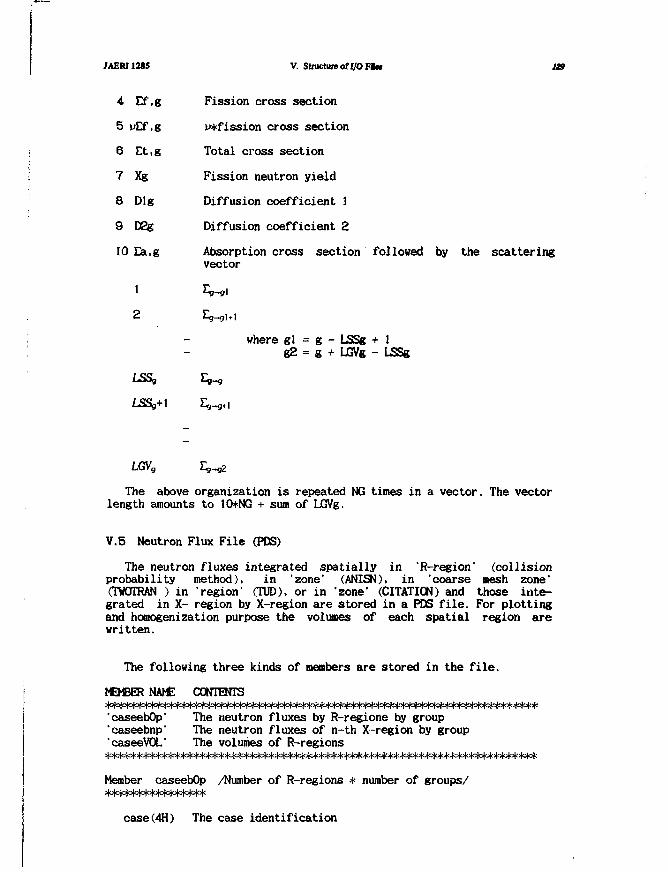
JAERI1285
4
5
6
7
8
9
10
Ef.g
vEf.g
Et.g
Xg
Dig
D2g
Ea.g
1
2
V. Structure of I/O FBM 129
Fission cross section
p*fission cross section
Total cross section
Fission neutron yield
Diffusion coefficient 1
Diffusion coefficient 2
Absorption cross section followed by the scatteringvector
where gl = g - LSSg + 1g2 = g + LJGVg - LSSg
LSSg
LSSg+1
LGVg
The above organization is repeated NG times in a vector. The vectorlength amounts to 10+NG + sum of LGVg.
V.5 Neutron Flux File (PDS)
The neutron fluxes integrated spatially in 'R-region' (collisionprobability method). in 'zone' (ANISN). in 'coarse mesh zone'(TWOTRAN ) in "region" (TUD), or in 'zone' (CITATION) and those inte-grated in X- region by X-region are stored in a PDS file. For plottingand homogenization purpose the volumes of each spatial region arewritten.
The following three kinds of members are stored in the file.
MEMBER NAME CONTENTS
'caseebOp' The neutron fluxes by R-regione by group'caseebnp' The neutron fluxes of n-th X-region by group"caseeVOL" The volumes of R-regions
Member caseebOp /Number of R-regions * number of groups/
case(4H) The case identification
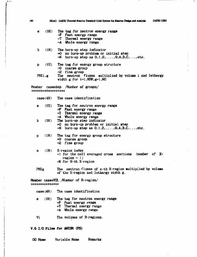
130 SRAC: JAERI Themul Rctctor Stomdiid Code Syitom fot Rwctot Dwjpi mil Amly* JAEUlt tS
e (1H) The tag for neutron energy range=F Fast energy range=T Thermal energy range=A Whole energy range
b (1H) The burn-up step indicator=0 no burn-up problem or initial step=N burn-up step as 0,1,2, 9.A.B.C,... ,etc.
p (1H) The tag for energy group structure=0 coarse group=2 fine group
PHIi.g The neutron fluxes multiplied by volume i and lethargywidth g for i=l,NRR,g=t,NG
Member caseebnp /Number of groups/
case(4H) The case identification
e (1H) The tag for neutron energy range=F Fast energy range=T Thermal energy range=A Whole energy range
b (1H) The burn-up step indicator=0 no burn-up problem or initial step=N burn-up step as 0,1,2,....,9,A,B,C,...,etc.
p (1H) The tag for energy group structure=0 coarse group=2 fine group
n (1H) X-region index=1 for the cell averaged cross sections (number of X-
region = 1)=N for N-th X-region
PHIg The neutron fluxes of n-th X-region multiplied by volumeof the X-region and lethargy width g.
Member caseeVOL /Number of R-region/
case(4H) The case identification
e (1H) The tag for neutron energy range=F Fast energy range=T Thermal energy range=A Whole energy range
Vi The volumes of R-regions.
V.6 1/0 Files for ANISN (PS)
DO Name Variable Name Remarks
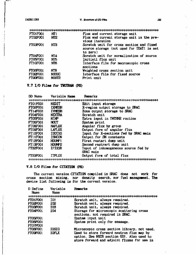
IAERI1285 V. Structure of I/O FJIM 131
**>m=m=w<H°w°(=i°M°w***How^FT01F001FT02F001
FT03F001
FTO4F001FT05F001FT1OFOO1
FT08F001FT32FO01FT99F001
NT1NT2
NT3
NT4NT5NT6
NTSNSOUCN0UT2
Flux and current storage unitFlux and current storage unit in the pre-vious iterationScratch unit for cross section and fixedsource storage (not used for IDAT1 is setto zero)Scratch unit for normalization of sourceInitiatl flux unitInterface file for macroscopic crosssectionsWeighted cross section unitInterface file for fixed sourcePrint unit
V.7 I/O Files for TOOTRAN (PS)
Remarks
Edit input storageX-region output storage to SRACZone output storage to SRACScratch unitExtra input in TWTRN2 routineSystem printAngular flux by groupOutput form of angular fluxInput for X-sections fed by SRAC mainOutput for SN constantsFirst restart dump unitSecond restrart dump unitInput of inhomogeneous source fed bySRAC mainOutput form of total flux
The current version CITATION compiled in SRAC does not vork forcross section mixing, nor density search, nor fuel Management. Thedevice list following is for the current version.
D Define Variable ReaarksName Name
Scratch unit, always required.Scratch unit, always required.Scratch unit, always required.Storage for microscopic scattering crosssections, not required in SRAC.System input unitSystem print only for message.
Microscopic cross section library, not used.Used to store forward neutron flux map byoption. See NQC6 section 001. Also used tostore forward and adjoint fluxes for use in
DD Name
FTO1F001FTO2F001FT14F001FT04F001FT05FO01FT06F001FT08F001FT09F001FT1OFOO1FT11FO01FT12F001FT13FO01FT32F001
FT33F001***********
V.8 I/O File
Variable Namet * * * * * * * * * * * * * *
NEOITIXMESHIVMESHNEXTRANINPNOUTNAFLUXLAFLUXISOTXSISNCONNDUMP1NDUMP2IFIXSR
ITFLUX**************:
a for CITATION
FTOlFOOlFT02F001FT03F001FTO4FO01
FT05F001FT06F001FT07F001FT08F001FT09F001
101102103104
IOSIGIOFLX
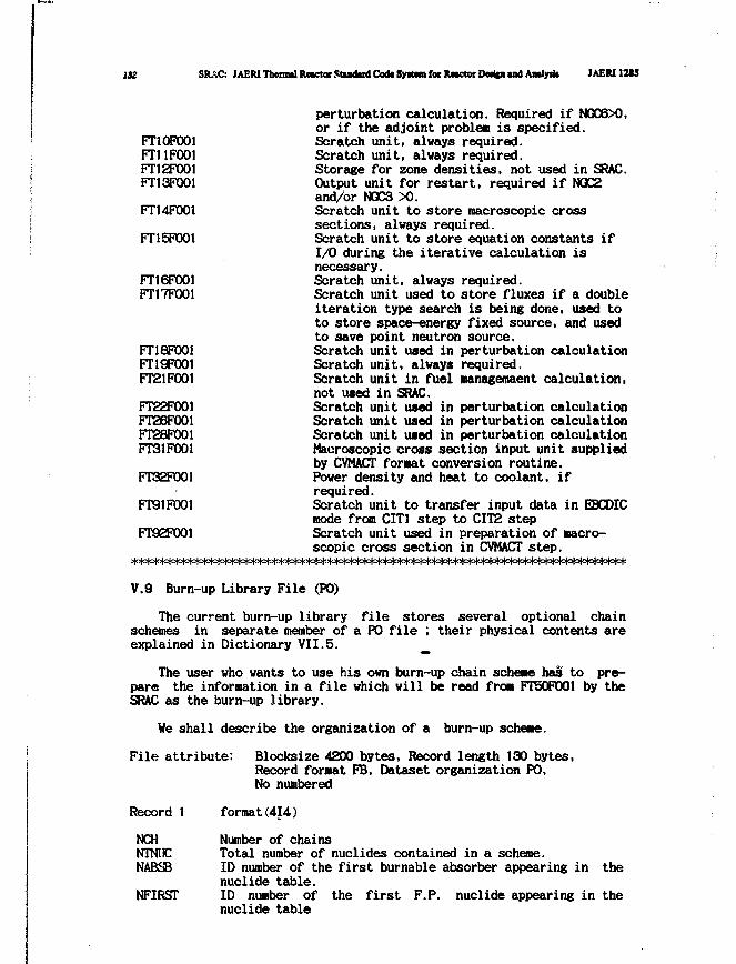
132 SRAC: JAERITherntf ftoctorStiadiriCodcSytftmforlUKtor Dtdcnand Aadytk IAERIIM5
perturbation calculation. Required if NQC6X),or if the adjoint problem is specified.
FT10F001 Scratch unit, always required.FT11F001 Scratch unit, always required.FT12F001 Storage for zone densities, not used in SRAC.FT13F001 Output unit for restart, required if NQC2
and/or NQC3 X).FT14F001 Scratch unit to store macroscopic cross
sections, always required.FT15F001 Scratch unit to store equation constants if
I/O during the iterative calculation isnecessary.
FT16F001 Scratch unit, always required.FT17F001 Scratch unit used to store fluxes if a double
iteration type search is being done, used toto store space-energy fixed source, and usedto save point neutron source.
FT18F001 Scratch unit used in perturbation calculationFT19F001 Scratch unit, always required.FT21F001 Scratch unit in fuel managemaent calculation,
not used in SRAC.FT22F001 Scratch unit used in perturbation calculationFT26F001 Scratch unit used in perturbation calculationFT28F001 Scratch unit used in perturbation calculationFT31F001 Macroscopic cross section input unit supplied
by CVMACT format conversion routine.FT32F001 Power density and heat to coolant, if
required.FT91P001 Scratch unit to transfer input data in EBCDIC
mode from CIT3 step to CITS stepFT92F001 Scratch unit used in preparation of macro-
scopic cross section in CVMACT step.
V.9 Burn-up Library File (PO)
The current burn-up library file stores several optional chainschemes in separate member of a PO file ; their physical contents areexplained in Dictionary VII.5. _
The user who wants to use his own burn-up chain scheme has to pre-pare the information in a file which will be read from FT50F001 by theSRAC as the burn-up library.
We shall describe the organization of a burn-up scheme.
File attribute: Blocksize 4200 bytes, Record length 130 bytes,Record format FB, Dataset organization PO,No numbered
Record 1 format(414)
NCH Number of chainsNTNlfC Total number of nuclides contained in a scheme.NABSB ID number of the first burnable absorber appearing in the
nuclide table.NFIRST ID number of the first F.P. nuclide appearing in the
nuclide table
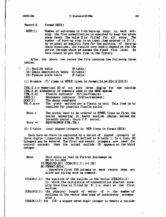
JAER112M V. Structure of I/O F i «
Record 2
NSIP(I)
Aftertables;
format (3214)
Number of sub-steps in I-th burn-up step; in each sub-step the flux normalization is executed to keep the givenpower level. The value 3 is filled for all steps. Thenumber of burn-up step is an input item entered in 11.11.As we adopt an analytic fora for the solution of burn-upchain equations, the results very weakly depend on the theperiod through which we assume the fixed flux level. Bythis reason we put this item in the library.
the above two record the file contains the following three
(1) Nuclide table (N-table)(2) Chain description table (C-table)(3) Fission yield table (F-table)
(1) N-table /!/ items in NTNUC lines in format(14,A4.2I4.2 E13.5)
ITBL(I,1 )* Numerical ID of not more three digits for the nuclideITBL(I,2) Alphabetic ID commonly used in the SRAC systemITBL(I,3) Fissile indicator (0/1;no/fissile)IRES (I) Resonance indicator (0/2;no/resonant)DCAY(I) The decay constantsTBL(I,4)** The power emitted per a fissin in watt. This item is to
supplied for possible fissile nuclei.
Note * The nuclei have to be ordered in NTNUC lines as first thenuclei appearing in heavy nuclide chains, second theburnable nuclei, third F.P. nuclei.
Note ** EQUIVALENCEttTBL.TBL)
(2) C-table /any/ signed integers in NCH lines in format(3214)
Each burn-up chain is expressed by a series of signed integers ofthree digits ( numerical nuclide ID defined in N-table ). In a line, 32integers may be entered. The first and second integers are used forcontrol purpose, then the actual nuclide ID appears at the thirdinteger.
Note This table is read by Fortran statenens asDO 10 1=1 ,NCH
10 READ(50,20) (ICHAIN(J,I),J=1,32)20 FORMAT (3214)
, therefore first 128 columns in each record does notallow any string such as comment.
ICHAIN(l.I): the position of the nuclide in the vector ICHAIN(*,I)to which the calculation of concentration started, norm-ally this item is filled by '3' i.e. start at the firstnuclide.
ICHAIN(2,I): the physical length of vector -2 (= the number ofnuclides in the vector when none of interpreter accompa-nied )
ICHAIN(J.I) for J>2: a signed three digit integer to denote a nuclide
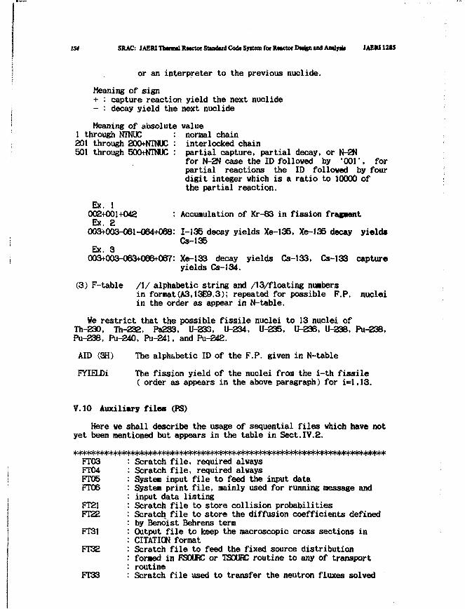
134 SRAC: JAERI Thmul RMctoi Stindud Codt System few Rnctor DMfen u d Amly* JAERI12U
or an interpreter to the previous nuclide.
Meaning of sign+ : capture reaction yield the next nuclide- : decay yield the next nuclide
Meaning of absolute value1 through NTNUC201 through 200+NTNUC501 through 500+NTNUC
normal chaininterlocked chainpartial capture, partial decay, or N-2Nfor N-2N case the ID followed by '001', forpartial reactions the ID followed by fourdigit integer which is a ratio to 10000 ofthe partial reaction.
Accumulation of Kr-83 in fission fragmentEx. 1002+001+042Ex. 2003+003-061-064+088: 1-135 decay yields Xe-135, Xe-135 decay yields
Cs-135Ex. 3003+003-063+066+067: Xe-133 decay yields Cs-133, Cs-133 capture
yields Cs-134.
(3) F-table /I/ alphabetic string and /13/floating numbersin format(A3,13E9.3); repeated for possible F.P. nucleiin the order as appear in N-table.
We restrict that the possible fissile nuclei to 13 nuclei ofTh-230, Th-232. Pa233, U-233, U-234, U-235, U-23S, U-238, Pu-238,Pu-238, Pu-240, Pu-241, and Pu-242.
AID (3H) The alphabetic ID of the F.P. given in N-table
FYIELDi The fission yield of the nuclei from the i-th fissile( order as appears in the above paragraph) for i-1,13.
V.10 Auxiliary files (PS)
Here we shall describe the usage of sequential files which have notyet been mentioned but appears in the table in Sect.IV.2.
FT03FT04FT05FT06
FT21FT22
FT31
FT32
FT33
Scratch file, required alwaysScratch file, required alwaysSystem input file to feed the input dataSystem print file, mainly used for running message andinput data listingScratch file to store collision probabilitiesScratch file to store the diffusion coefficients definedby Benoist Behrens termOutput file to keep the macroscopic cross sections inCITATION formatScratch file to feed the fixed source distributionformed in FSOURC or TSOURC routine to any of transportroutineScratch file used to transfer the neutron fluxes solved

JAERI1285 V. Structure of I/O Filei IX
FT50
FT5!
FT5S
FT81
FT82
FT83
FT92FT99
by any of the transport routine to MIXX routineInput file to keep the chain scheme for burn-up calcula-tionScratch file to transfer the information from the pre-paration step of burn-up calculation to the executionstepScratch file to transfer the effective Microscopic crosssections from MICREF step to BURNUP stepScratch file to keep the neutron traces across T-regionboundaries in collision probability calculation ; writtenby the fixed logical record length of 4096 bites inbinary modeScratch file to keep the neutron traces across R-regionboundariesScratch file to keep the neutron traces across M-regionboundariesScratch file to prepare the file FT31System print file
WMsWcp&Wdp^^
136 iRAC: JAERITheirol Re^ocSttmkrd Code Sy»t«i foe R«ctOfD«i(n and A«ly»ii JAER112IS
VI Mathematical Formulation*
Presented here are the equations programmed into the SRAC system.
VI.1 Group Cross Sections in the Fast Neutron Library
The multigroup transport or diffusion calculations are often basedon the concept of group constants such as the ABBN(Ref.(2)) orJAERI-Fast set(Refs.(45 and 46 )). The principal advantage of themultigroup constant method is that reactor calculation can be made byusing the same group constant set for the various reactors withdifferent compositions and sizes. Consequently, some processing codesuch as EK)X(Ref. (47)), MIHXflRef. (48)) and PR0F-€R0UCH-G(Ref. (15)) weredeveloped to calculate economically and conveniently the group const-ants using a nuclear data file. However, the calculational method ofgroup constants used in these codes are different. Especially, theeffective cross sections in resonance energy region are calculated byusing various methods.
Though the ETOX and MINX codes can take into account for both thecomposition and temperature dependence of group cross sections, theeffective group cross sections are calculated by assuming the constancyof collision density. Moreover, the isolated narrow-resonance appro-ximation is used for unresolved resonance region, and the mutualinterference between resonances of different nuclides and the self-overlapping effects are ignored. Furthermore, the self-shielding ofelastic removal cross section is assumed to be neglected.
In the TIMS-PQG code system (Ref.(76)) for group constantsproduction, the TIMS-1 code calculates the effective cross sections bysolving numerically the neutron slowing down equation using therecurrence formula (Refs.(40 ,41)) for slowing down source, in orderto avoid the errors (Refs.(49, 50)) caused from the approximations usedin the ETOX and MINX codes. In the unresolved resonance region for thispurpose, TIMS-1 generates required resonance levels and parameters inthe unresolved resonance region by using Monte Carlo method(Refs.(51,52, 53)). TIMS-1 is a code system which is composed of some codes,ARCFIT-2(Ref. (54)), ARCFIT -3(Ref. (54)). MCR0SS-2(Ref. (17)) andPEACO-IKRef. (5)) developed for the production of the JAERI Fastset(JFS).
In this Chapter, the calculational methods used in the TIMS-PQGcode system are described. Section VI.1.1 describes the expression ofOoppler broadened cross sections based on the multilevel formula. Theultrafine group cross sections are calculated by using this formula.The expressions of average cross sections in the unresolved resonanceregion are described in Section VI.1.2. In Section VI.1.3, a ladder ofresonance parameters and levels which reproduces the average cresssections are generated by a random sampling technique. Also for theunresolved region, the ultrafine group cross sections are calculated byusing the ladder of resonance parameters on the basis of the formuladescribed in Section VI.1.1. The ultrafine group neutron spectra arecalculated l>y solving numerically the neutron slowing down equation inan infinite homogeneous system. This calculational method is describedin Section VI.1.4, The group constants are calculated by weighting theultrafine group neutron spectra as described in Section VI.1.5. InSection VI.1.6,the interpolation method for the self-shielding factorsare described.
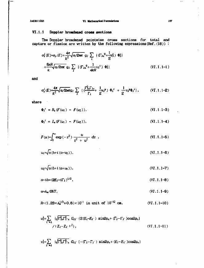
JAERI1285 VI. M»them»tfc»lFonnutotkmi 137
VI. 1.1 Doppler broadened cross sections
The Doppler broadened pointwise cross sections for total andcapture or fission are written by the following expressions(Ref.(18)) :
(VI. 1.1-1gj £ ((Txn°+—vi 4kR
and
where
F(ai)=r°exp(-x2) a dxJo x2 + «z
G)2=/a(b+i(a+uo)),
a-ib=(2Ei-in)1/2,
ft=(1.23xAj/3+0.8)xKr' in unit of 10"12cm,
(VZ. 1.1-2)
(VI. 1.1-3)
(VI. 1.1-4)
(VI.1.1-5)
(VI.1.1-6)
(VI.1.1-7)
(VI. 1.1-8)
(VI. 1.1-9)
(VI.l.I-10)
X/\Zx-Zv\
z\, ( V I . 1 . 1 - 1 1 )
sin2?>n+ (£ i -
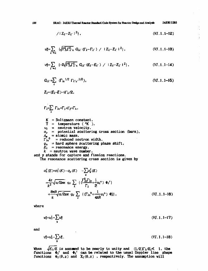
138 SRAC: JAERIThenml R«ctor Standard Code Syifrm for R«trtor Dedpi and Aaalyak JAEM12S5
=E nc=r>rv+rn,
K = Boltzroann constant.T = temperature ( °K ),vo = neutron velocity,op = potential scattering cross section (barn),Am = atomic mass,nn° = reduced neutron width,<pn = hard sphere scattering phase shift,Ei = resonance energy,fc = neutron wave number,
and y stands for capture and fission reactions.The resonance scattering cross section is given by
where
(VI. 1.1-12)
i-H-) / I Zi-Zr 12), (VI. 1.1-13)
{-2^l1nr8'n Qia- (Bi-Br ) / I Z A - Z , I 2|, (VI.1.1-14)
Ire-1*). (VI.1.1-15)
(VI. 1.1-16)
(VI. 1.1-17)
and
(VI. 1.1-18)
When iJEx/E is assumed to be nearly to unity and (l/2Ti/Ei< 1, thefunctions */ and *j' can be related to the usual Doppler line shapefunctions ii(6,x) and Xx(0,x) > respectively. The assumption will
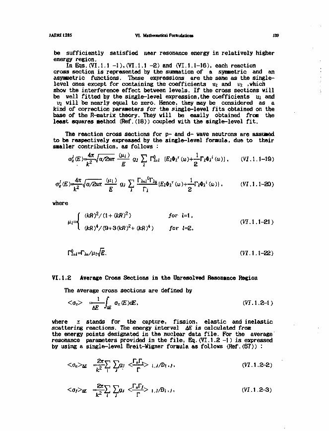
JAERI1285 VI. Mtthenutical FormulitioM 139
be sufficiently satisfied near resonance energy in relatively higherenergy region.
In Eqs.(VI.l.l -1), (VI. 1.1 -2) and (VI. 1.1-16), each reactioncross section is represented by the summation of a symmetric and anasymmetric functions. These expressions are the same as the single-level ones except for containing the coefficients ux and vx ,whichshow the interference effect between levels. If the cross sections willbe veil fitted by the single-level expression,the coefficients ux andvx will be nearly equal to zero. Hence, they may be considered as a
kind of correction parameters for the single-level fits obtained on thebase of the R-matrix theory. They will be easily obtained from theleast squares method (Ref.(18)) coupled with the single-level fit.
The reaction cross sections for p- and d- wave neutrons are assumedto be respectively expressed by the single-level formula, due to theirsmaller contribution, as follows :
ai (E)Jj-Ja/2m — gj £ li,,i \Ex*xr (<»)+—IW (<a)|, (VIA. 1-19)K E* X 2
gj £ ^-^(£j*i r(co)+—rW(a>)), (VI.l.i-20)
where
(fcR)2/(l+(fcR)2) for 1=1,J(VI. 1.1-21)
V(9+3(fcR)2+(fcft)4) for 1=2,
(VI. 1.1-22)
VI.1.2 Average Cross Sections in the Unresolved Resonance Region
The average cross sections are defined by
< O l > = — — f ox(.E)dE, (VI. 1.2-1)
where x stands for the capture, fission, elastic and inelasticscattering reactions. The energy interval M is calculated fromthe energy points designated in the nuclear data file. For the averageresonance parameters provided in the file, Eq.(VI.1.2 -1) is expressedby using a single-level Breit-Wigner formula as follows (Ref.(57)) :
(VI. 1.2-2)
i .J/Dt, j, (VIA .2-3)
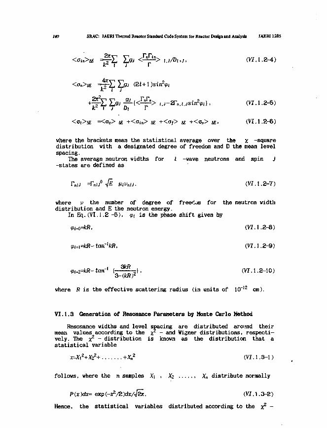
140 SRAC: JAERI Thermal Reactor Standard Code Syitem for Reactor Design and Analysis JAERI1285
(VI. 1.2-4)
1 J
] D T(VI. 1.2-5)
kd i ] Di T
<Ot>iE =<OC> 4£ +<Ojn> 4£ +<O/> fi£ +<On> 4E, (VI. 1.2-6)
where the brackets mean the statistical average over the x -squaredistribution with a designated degree of freedom and D the mean levelspacing.
The average neutron widths for I -wave neutrons and spin J-states are defined as
=TnU° # Ml nlJ. (VI. 1.2-7)
where v the number of degree of freedom for the neutron widthdistribution and E the neutron energy.
In Eq. (VI. 1.2 -5), <pi is the phase shift given by
(VI. 1.2-8)
<Pt=i=kR- tan'kR, (VI. 1.2-9)
<p,.2=kR-tan] 1 ^ 7 " 2 } , (VI. 1.2-10)
where R is the effective scattering radius (in units of 10 12 cm).
VI.1.3 Generation of Resonance Parameters by Monte Carlo Method
Resonance widths and level spacing are distributed around theirmean values according to the it - and Wigner distributions, respecti-vely. The x2 - distribution is known as the distribution that astatistical variable
x=X\2+Xzz+ +Xn2 (VI. 1.3-1)
follows, where the n samples Xi , Xz , Xn distribute normally
P (x )dx= exp (-x*/2 )dxA/ar. (VI. 1.3-2)
Hence, the statistical variables distributed according to the x2 -
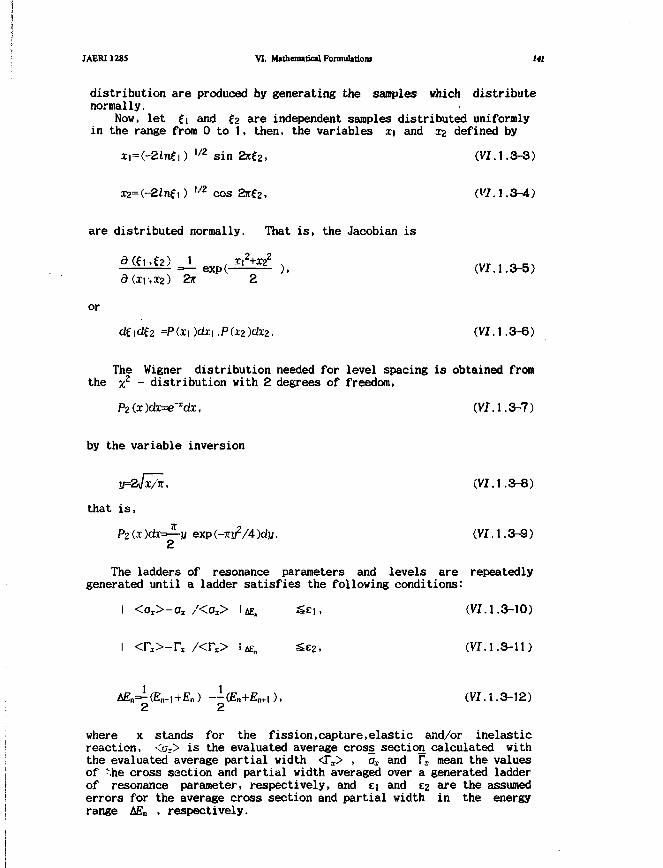
JAERI1285 VI. Mathematical Formulations 141
distribution are produced by generating the samples which distributenormally.
Now, let fi and ?2 are independent samples distributed uniformlyin the range from 0 to 1, then, the variables xi and x2 defined by
H=(-2lnfi) uz sin ar£2, (VI.1.3-3)
cos
are distributed normally. That is, the Jacobian is
a(xi,x2) 2 K
or
dfidf2 =P(x|)(±c|.PCx2)c/x2. (VI. 1.3-6)
The Wigner distribution needed for level spacing is obtained fromthe x2 - distribution with 2 degrees of freedom,
P2(x)dx=e-Idx, (VI. 1.3-7)
by the variable inversion
y=2v/xA, (VI.1.3-8)
that is,
exp (-7^/4 )dy. (VI. 1.3-9)2
The ladders of resonance parameters and levels are repeatedlygenerated until a ladder satisfies the following conditions:
I <az>-ax /<Ox> IAE, Sei. (VI. 1.3-10)
1 <r*>-rx /<r x> i *£„ se2, (vi.1.3-11)
ABn—(En-i+En) --(£n+En.,), (VI.1.3-12)2 2
where x stands for the fission,capture,elastic and/or inelasticreaction, <ax> is the evaluated average cross section calculated withthe evaluated average partial width <TX> , ox and I"l mean the valuesof Mie cross section and partial width averaged over a generated ladderof resonance parameter, respectively, and a and c2 are the assumederrors for the average cross section and partial width in the energyrange ££„ , respectively.
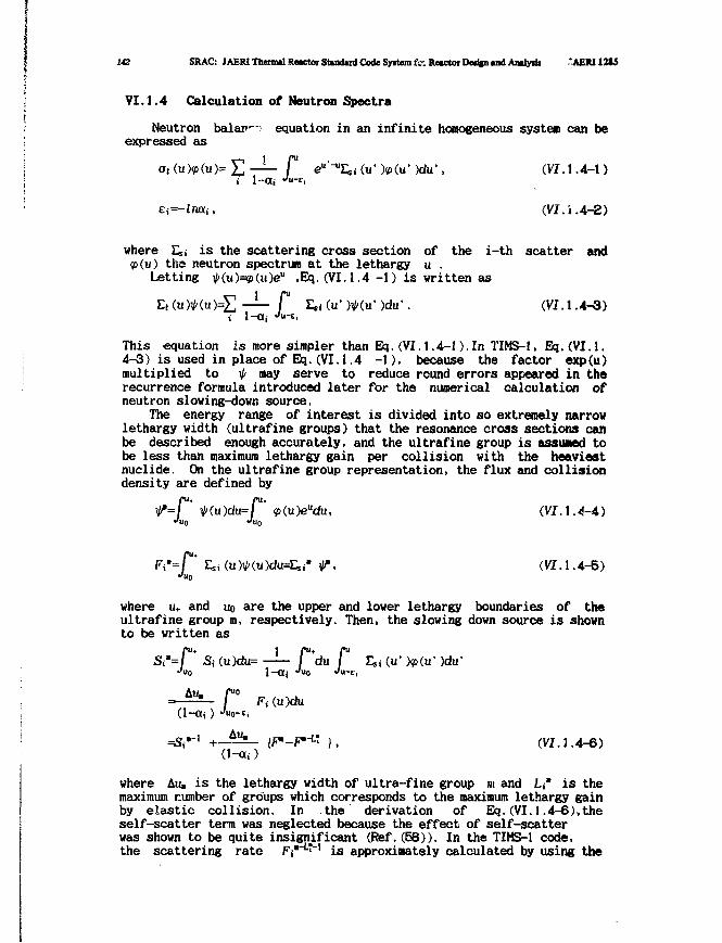
142 SRAC: JAERI Thermal Reactor Standud Code Syitem to: Retctot Deafen and Analydi .*AERI12tS
VI.1.4 Calculation of Neutron Spectra
Neutron balan~-.• equation in an infinite homogeneous system can beexpressed as
o,(u)p(u)=£ — f eu'-uESi(u>)(p(u')du', (VI.1.4-1)
i 1-O(j J«-ti
Ei=-lntXi, (VI. i.4-2)
where Esi is the scattering cross section of the i-th scatter andthe neutron spectrum at the lethargy u .
Letting V(u)=*(«)eu ,Bq.(VI.1.4 -1) is written as
— P )du-. (VI.1.4-3)
This equation is more simpler than Eq.(VI.1.4-1).In TIMS-1, Bq.(VI.l.4-3) is used in place of Eq.(VI.1.4 -1), because the factor exp(u)multiplied to f may serve to reduce round errors appeared in therecurrence formula introduced later for the numerical calculation ofneutron slowing-down source.
The energy range of interest is divided into so extremely narrowlethargy width (ultrafine groups) that the resonance cross sections canbe described enough accurately, and the ultrafine group is assumed tobe less than maximum lethargy gain per collision with the heaviestnuclide. On the ultrafine group representation, the flux and collisiondensity are defined by
<p(u )eudu, (VI. 1.4-4)
sj(u)V(u)du=Esj> V, (VI. 1.4-5)
where u+ and no are the upper and lower lethargy boundaries of theultrafine group m, respectively. Then, the slowing down source is shownto be written as
)du'
(VI. 1.4-6)
where &u, is the lethargy width of ultra-fine group »t and Li" is themaximum number of groups which corresponds to the maximum lethargy gainby elastic collision. In the derivation of Eq.(VI.1.4-6),theself-scatter term was neglected because the effect of self-scatterwas shown to be quite insignificant (Ref.(58)). In the TIMS-1 code,the scattering rate F*'L"^ is approximately calculated by using the
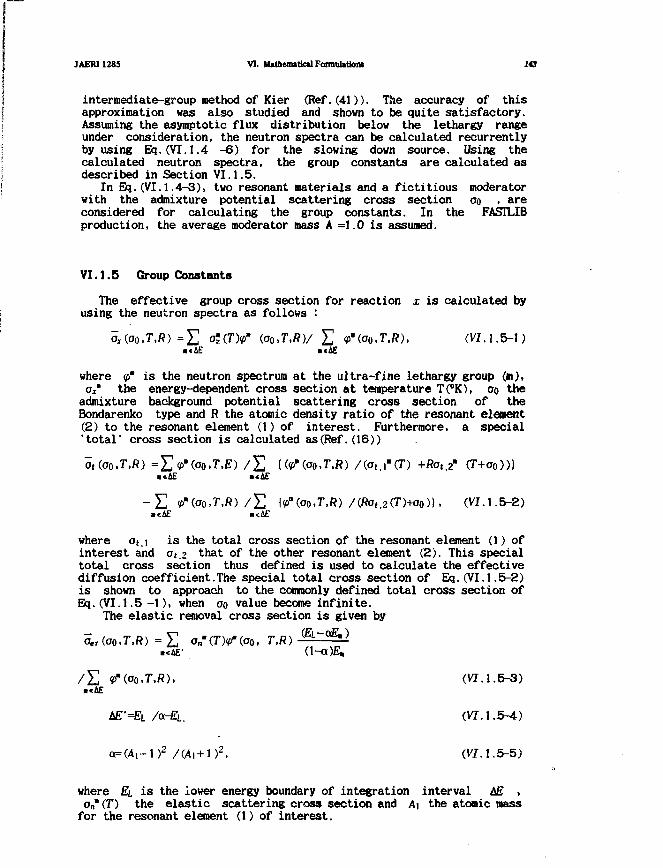
JAERI1285 VI. MatherottkalFormuUtioni 143
intermediate-group method of Kier (Ref.(41)). The accuracy of thisapproximation was also studied and shown to be quite satisfactory.Assuming the asymptotic flux distribution below the lethargy rangeunder consideration, the neutron spectra can be calculated recurrentlyby using Eq.(VI.1.4 -6) for the slowing down source. Using thecalculated neutron spectra, the group constants are calculated asdescribed in Section VI.1.5.
In Eq.(VI.1.4-3), two resonant materials and a fictitious moderatorwith the admixture potential scattering cross section 00 , areconsidered for calculating the group constants. In the FASILIBproduction, the average moderator mass A =1.0 is assumed.
VI.1.5 Group Constants
The effective group cross section for reaction x is calculated byusing the neutron spectra as follows :
2 (oo,T,RV E <fu(ao,T,R), (VI. 1.5-1)
where <p* is the neutron spectrum at the ultra-fine lethargy group (m),Ox" the energy-dependent cross section at temperature T(°K), 00 the
admixture background potential scattering cross section of theBondarenko type and R the atomic density ratio of the resonant element(2) to the resonant element (1) of interest. Furthermore, a special'total' cross section is calculated as(Ref.(16))
a,(oo,T,R) =Yl<f>'(oo,T,E) / £ {(^(oo.T.ft) /(o,.r(D +ftat.2" (T+a0)))
- E <p'(ao,T,R) / £ {<PB(ao,T.ft) /(ftot,2(T)+oo)}. (VI.1.5-2)
where at,\ is the total cross section of the resonant element (1) ofinterest and at.2 that of the other resonant element (2). This specialtotal cross section thus defined is used to calculate the effectivediffusion coefficient.The special total cross section of Eq.(VI.1.5-2)is shown to approach to the commonly defined total cross section ofEq.(VI.1.5 -1), when 00 value become infinite.
The elastic removal cross section is given by
aer(oo,r,R) = £ on'(7>'(oo, T,R)•«AE-
/ £ <p'(aa,T,R), (VI. 1.5-3)»«4E
AE'=EL /a-£L. (VI. 1.5-4)
oc=(A,-l)2 /(Ai+1)2, (VI. 1.5-5)
where EL is the lower energy boundary of integration interval AE ,on*(T) the elastic scattering cross section and A\ the atonic massfor the resonant element (1) of interest.
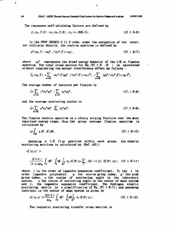
144 SRAC: JAERI Thermal Rnctoi Stindird Code System for Reactor Dedfn tnd Aailyiii JAERI12I5
The resonance self-shielding factors are defined by
fx(oo.T,R) =oAoo>T,R) /Ox(oo,300,0). (VI. 1.5-6)
In the PROF.GROUCH G II R code, under the assumption of the const-ant collision density, the neutron spectrum is defined by
<p'(ao,T) =<pom /{o t"(T)+o 0}. (VI.1.5-7)
where <po* represents the broad energy behavior of the 1/E or fissionspectrum. The total cross section for Eq.(VI.1.5 -2 ) is calculatedwithout considering the mutual interference effect as follows :
ot(oo,T)=£ iotu<T>rf /(ot"(T)+a0)2) / £ {
4E E
The average number of neutorns per fission is
/£ °/"W. (W.I.5-8)
and the average scattering cosine is
M = £ n"oe*({>o* /£, o e W . (VI. 1.5-9)
The fission neutron spectrum is a slowly varying function over the mostimportant energy range, thus the group average fission spectrum iscalculated by
•,E)dE. (VI. 1.5-10)
Assuming a 1/E flux spectrum within each group, the elasticscattering matrices is calculated by (Ref.(43))
ai(g,g' )=
j dE' JdE -g as (E)Pi ( M ) £ (21' +1 )/r (E)Pi •(>?), (VI.1.5-11)
where I is the order of Legendre expansion coefficient, Pi the i thorder Legendre polynomial, g the source group index, g' the sinkgroup index, n the cosine of scattering angle in the laboratorysystem, rj the cosine of scattering angle in the center of mass systemand /i the Legendre expansion coefficient. The hydrogen elasticscattering matrix is a simplification of Eq.(VI.1.5-11) and assumingisotropic in the center of mass system is given by
ol(g,g')= ( 2 m ) [ dE- fdE-^ O S(E)PIGI). (VI. 1.5-12)Alig -V J9 ft"
The inelastic scattering transfer cross section is
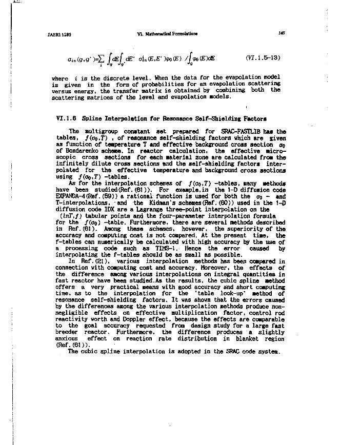
JAER11285 VI. MathemiticilFoim»I»tk)M M5
(VI.1.5-13)
where i is the discrete level. When the data for the evapolation modelis given in the form of probabilities for an evapolation scatteringversus energy, the transfer matrix is obtained by combining both thescattering matrices of the level and evapolation models.
VI.1.6 Spline Interpolation for Resonance Self-Shielding Factors
The multigroup constant set prepared for SRAC-FASTLIB has thetables, /(oo.T) • of resonance self-shielding factors which are givenas function of temperature T and effective background cross section ooof Bondarenko scheme. In reactor calculation, the effective Micro-scopic cross sections for each material zone are calculated from theinfinitely dilute cross sections and the self-shielding factors inter-polated for the effective temperature and background cross sectionsusing /(oo.T) -tables.
As for the interpolation schemes of /(oo.T) -tables, many methodshave been studied(Ref.(61)). For example,in the 1-0 diffusion CodeEXPANDA-4(Ref.(59)) a rational function is used for both the o0 - andT-interpolations, and the Kidman's schemes(Ref.(60)) used in the !-Ddiffusion code IDX are a Lagrange three-point interpolation on the(lnT,f) tabular points and the four-parameter interpolation formula
for the /(oo) -table. Furthermore, there are several methods describedin Ref.(61). Among these schemes, however, the superiority of theaccuracy and computing cost is not compared. At the present time, thef-tables can numerically be calculated with high accuracy by the use ofa processing code such as TIMS-1. Hence the error caused byinterpolating the f-tables should be as small as possible.
In Ref.(21), various interpolation methods has been compared inconnection with computing cost and accuracy. Moreover, the effects ofthe difference among various interpolations on integral quantities infast reactor have been studied.As the results, the cubic spline methodoffers a very practical means with good accuracy and short computingtime, as to the interpolation for the 'table look-up' method ofresonance self-shielding factors. It was shown that the errors causedby the differences among the various interpolation methods produce non-negligible effects on effective multiplication factor, control rodreactivity worth and Doppler effect, because the effects are comparableto the goal accuracy requested from design study for a large fastbreeder reactor. Furthermore, the difference produces a slightlyanxious effect on reaction rate distribution in blanket region(Ref. (61)).
The cubic spline interpolation is adopted in the SRAC code system.

146 SRAC: JAERI Thenml Re«ctor Sttwltid Code Syrtwn foe R«ctor Detign ind Amlyiij JAERI121S
VI.2 Group Cross Sections in the Thermal Neutron Library
The thermal neutron library of the SRAC keeps the group crosssections and also Bondarenko type self-shielding factor tables for thenuclides which have any strong resonance level in the thermal neutronenergy range. The data for the library is prepared by the SRACTLIB codesystem which is composed of several codes, the THERMO- series forone-dimensional cross sections, the PIXSE code (Ref.(75)) for groupscattering cross sections, and the FEXSCAT code (Ref. (19)) for elasticscattering cross sections of crystalline material.
The input data for the SRACTLIB are assumed to be formed in ENDF/Bformat. The information needed for thermal calculations are listedbelow.
v neutron yield per fission
Crojss sections of the form az(E) , where E is the neutron energy,and x denotes elastic, absorption, fission, total, or(n, y )
The thermal neutron scattering law, S(a,/3,T), which is representedas a tabulated part plus analytic part of the free gas or diffusivemotion form.
Resolved resonance parameters in the single level Breit-Vigner,the multi-level Breit-Wigner, or Adler-Adler representation.
Lattice constant, Debye Waller factor, etc. for coherent elasticscattering of polycrystaline material.
The input requirements for the SRACTLIB described in Sect.III.2are minimized by preparing the built-in values, however, the usercan reset the standard values as he likes.
The resultant group constants are always averaged by the asymptoticneutron spectrum, as follows,
= ff A M ) / ( <p(E,T )dEt£, J&E
<p{E,T )dE (VJ.2-2)
where I denotes the order of the Legendre expansion; g and g' arethe group number of the energy interval i£g , T is the material tempe-rature, T' is the neutron temperature (exactly the average temperatureof Maxwellian neutron density distribution). It is to be noted thateven if the cross sections are not dependent on the material tempera-ture, the group constants are temperature dependent due to the averageby the temperature dependent neutron spectrum which is formed by thecombination of the Maxwellian of the neutron temperature T' and 1/Epart above the given value of
However it is very difficult to predict the neutron temperaturein general. We can say only the neutron temperature is always higherthan that of material. In active reactor core, the neutron temperature
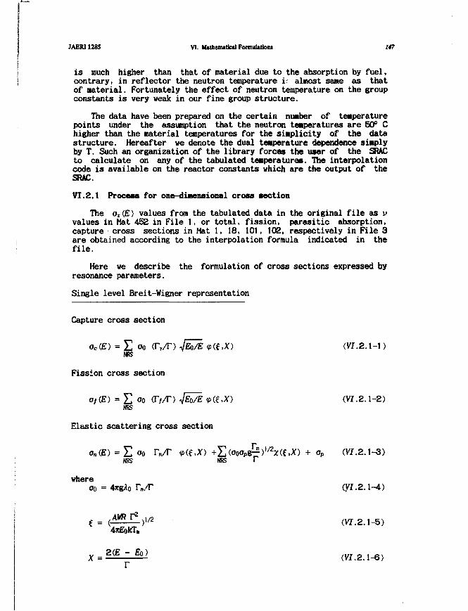
JAERI1285 VI. Mathematical Formulationi 147
is much higher than that of material due to the absorption by fuel,contrary, in reflector the neutron temperature i- almost same as thatof material. Fortunately the effect of neutron temperature on the groupconstants is very weak in our fine group structure.
The data have been prepared on the certain number of temperaturepoints under the assumption that the neutron temperatures are 50° Chigher than the material temperatures for the simplicity of the datastructure. Hereafter we denote the dual temperature dependence simplyby T. Such an organization of the library forces the user of the SRACto calculate on any of the tabulated temperatures. The interpolationcode is available on the reactor constants which are the output of theSRAC.
VI.2.1 Process for one-dimensional cross section
The Ox(E) values from the tabulated data in the original file as vvalues in Mat 452 in File 1, or total, fission, parasitic absorption,capture cross sections in Mat 1, 18, 101, 102, respectively in File 3are obtained according to the interpolation formula indicated in thefile.
Here we describe the formulation of cross sections expressed byresonance parameters.
Single level Breit-Wigner representation
Capture cross section
oc(E) = E oo (Ty/T) 4EO~/E 9(t,X) (VI.2.1-1)NfiS
Fission cross section
of(E) = 2J a0 (r//T) V^o/E *>(f.X) (VI.2.1-2)NRS
Elastic scattering cross section
on(£) = E oo rn/r «>(f,x) +I]NRS NRS F
where00 = 4*gAo rn/r (vi.2.
4zEokT.
2(E - g0)
(Vf.2.1-5)
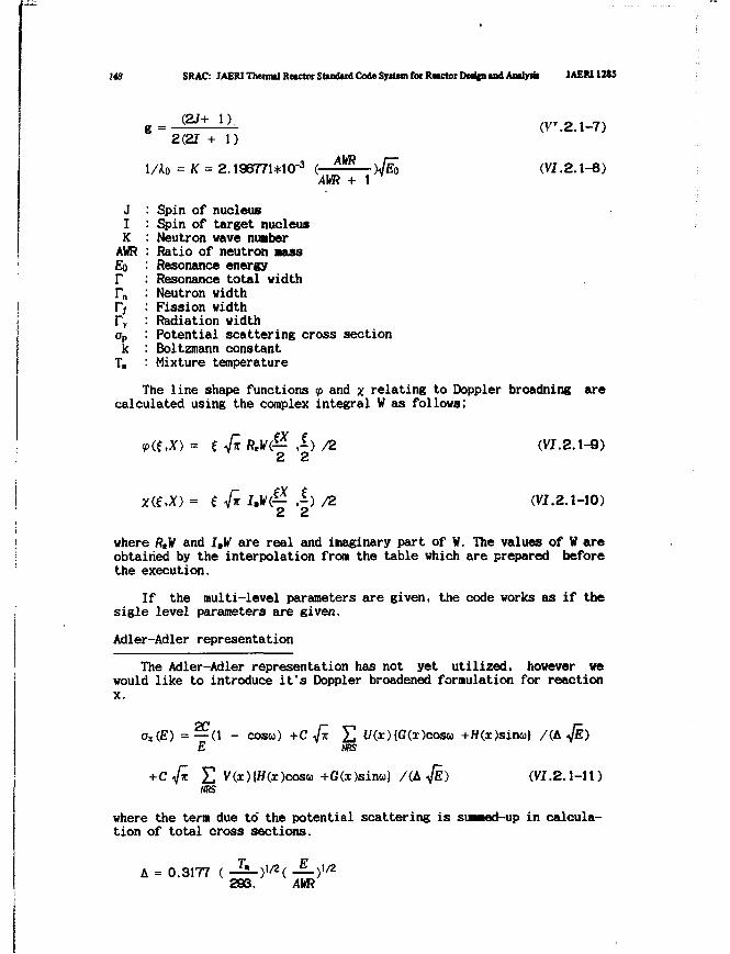
148 SRAC: JAERI Thermal Reactor Standard Code System foi Rwctoi DMfcn and Antlyrii JAEM12SS
= (2J+ 1), (VT .2.1-7)2(21 + 1)
1/Ao = *T = 2.196771*10-3 ( AWR >/io (VI.2.1-8)AW? + 1
JIKAWREorr.1 yaD
T,
Spin of nucleusSpin of target nucleusNeutron wave nuaberRatio of neutron nassResonance energyResonance total widthNeutron widthFission widthRadiation widthPotential scattering cross sectionBoltzmann constantMixture temperature
The line shape functions <p and x relating to Doppler broadning arecalculated using the complex integral W as follows;
*<e.X) = f V* W(— •-) /2 (VI.2A-Q)2 2
Z(6.X) = { V« J-^(— •") /2 (VI.2.1-10)2 2
where ReV and 1,1/ are real and imaginary part of W. The values of W areobtained by the interpolation from the table which are prepared beforethe execution.
If the multi-level parameters are given, the code works as if thesigle level parameters are given.
Adler-Adler representation
The Adler-Adler representation has not yet utilized, however wewould like to introduce it's Doppler broadened formulation for reactionx.
Oj(£) = — ( 1 - cosw) +C Jn 2 U(X){G(S)COSG> +H(x)sinu} /(L<fE)E tss
+cVJc E V(x){H(x)cosu +G(x)sin<») /(&$.) (VI.2.1-11)NRS
where the tern due to' the potential scattering is su—od-up in calcula-tion of total cross sections.
A = 0.3177 ( JL)i/2( JL)i/2293. AVR
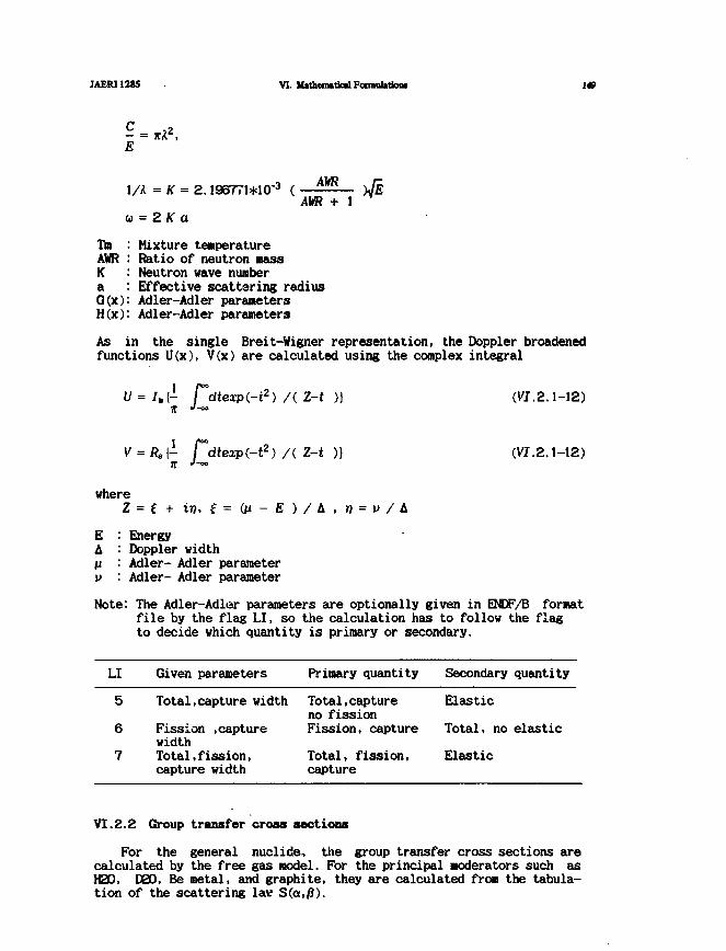
JAERI1285 VI. M»them»tk»IFonnul»tioM 148
I/A = K = 2.196771+10"3 (
u = 2K a
iTjn
AVR + 1
TmAWRKaG(x)H(x)
Mixture temperatureRatio of neutron massNeutron wave numberEffective scattering radiusAdler-Adler parametersAdler-Adler parameters
As in the single Breit-Vigner representation, the Doppler broadenedfunctions U(x)> V(x) are calculated using the complex integral
U = I.[- r°dtexp(-t2) /(Z-t )) (Vf.2.1-12)
A Z-t (VZ.2.1-12)
where
EA
EnergyDoppler widthAdler- Adler parameterAdler- Adler parameter
Note: The Adler-Adler parameters are optionally given in ENDF/B formatfile by the flag LI, so the calculation has to follow the flagto decide which quantity is primary or secondary.
LI
5
6
7
Given parameters
Total,capture width
Fission .capturewidthTotal,fission,capture width
Primary quantity
Total,captureno fissionFission, capture
Total, fission,capture
Secondary
Elastic
Total, no
Elastic
quantity
elastic
VI.2.2 Group transfer cross sections
For the general nuclide, the group transfer cross sections arecalculated by the free gas model. For the principal moderators such asH20, D0O, Be metal, and graphite, they are calculated from the tabula-tion of the scattering lav S(a,/3).
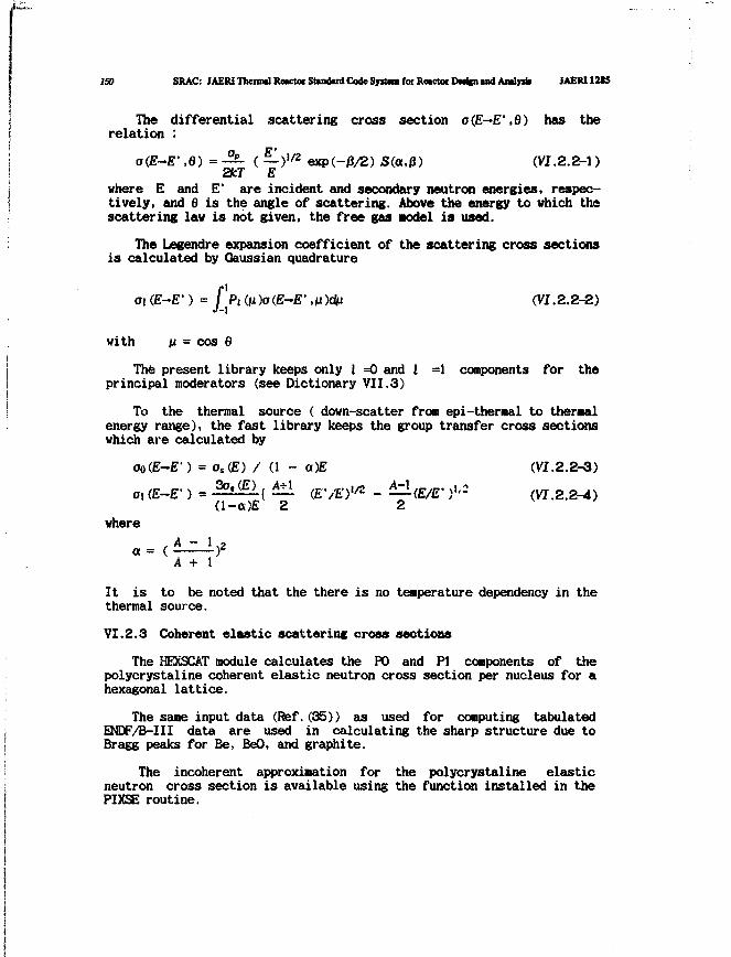
ISO SRAC: TiirnThrrnul FmrtnrStiniiirtifniln lyifrni fnr PwrtnrHwlpimil flml]nh IAER11U5
The differential scattering cross section a{E—E' ,6) has therelation :
o(E-E' ,e) = - - ( — ) " 2 exp(-/3/2) S(a,0) (VI.2.2-1)2kT E
where E and E' are incident and secondary neutron energies, respec-tively, and 6 is the angle of scattering. Above the energy to which thescattering law is not given, the free gas Model is used.
The Legendre expansion coefficient of the scattering cross sectionsis calculated by Gaussian quadrature
oi (E-E1) = [ Pi (v)o(E-E' ,n)du (VI.2.2-2)
with n = cos 6
The present library keeps only I =0 and 1 =1 components for theprincipal moderators (see Dictionary VII.3)
To the thermal source ( down-scatter from epi-thermal to thermalenergy range), the fast library keeps the group transfer cross sectionswhich are calculated by
oo(E-E1) = os(.E) / (1 - a)E (VI.2.2-3)
o, (E-E-) = -^J£l{ (EYE)"2 - (E/E- >«•= (VI.2.2-^)
where
a = ( - ) z
A + 1
It is to be noted that the there is no temperature dependency in thethermal source.
VI. 2.3 Coherent elastic scatter ins cross sections
The KEXSCAT module calculates the PO and PI components of thepolycrystaline coherent elastic neutron cross section per nucleus for ahexagonal lattice.
The same input data (Ref,(35)) as used for computing tabulatedENDF/B-III data are used in calculating the sharp structure due toBragg peaks for Be, BeO, and graphite.
The incoherent approximation for the polycrystaline elasticneutron cross section is available using the function installed in thePIXSE routine.
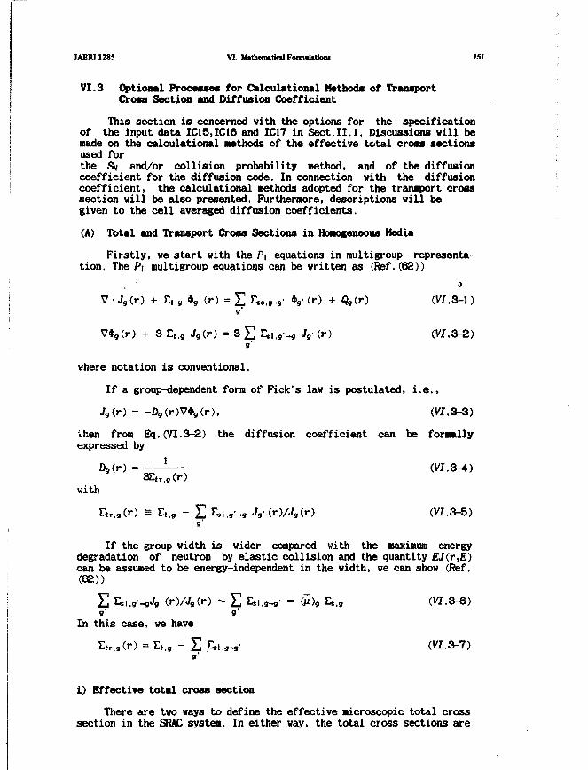
JAERI1285 VI. Uttheroitiad Formulation* 151
VI.3 Optional Processes for Calculational Methods of TransportCross Section and Diffusion Coefficient
This section is concerned with the options for the specificationof the input data IC15.IC16 and IC17 in Sect.II.l. Discussions will bemade on the calculational Methods of the effective total cross sectionsused forthe SH and/or collision probability method, and of the diffusioncoefficient for the diffusion code. In connection with the diffusioncoefficient, the calculational methods adopted for the transport crosssection will be also presented. Furthermore, descriptions will begiven to the cell averaged diffusion coefficients.
(A) Total and Transport Cross Sections in Homogeneous Media
Firstly, ve start with the P\ equations in multigroup representa-tion. The P\ multigroup equations can be written as (Ref.(62))
V-Jg{r) + E,,9 *9 (r) = E £„.«-„• *g- (r) + Qg(.r) (VI.3-1)9'
V*9(r) + 3 Lt.g Jg(,r) = 3 £ Esi.g-g Jg- (r) (V'I.3-2)
9'
where notation is conventional.
If a group-dependent form of Fick's law is postulated, i.e.,
J9(r) = -D9(r)V*9(r). (VI.3-3)then from Bq.(VI.3-2) the diffusion coefficient can be formallyexpressed by
a»(r) = ' (VI.3-4)3Etr,g(r)
withEtr,9(r) = Et,g - E Esi.g'-g Jg (r)/Jg(r). (VI.3-5)
9'
If the group width is wider compared with the maximum energydegradation of neutron by elastic collision and the quantity EJ(r,E)can be assumed to be energy-independent in the width, we can show (Ref.(62))
E W * V t r > ~ E ti.s-9' = 6>9 Es.9 (VI.3-6)9' 9'
In this case, we have
E,r.9(r) = E,.9 - E &!.«• (VI.3-7)
i) Effective total cross section
There are two ways to define the effective microscopic total crosssection in the SRAC system. In either way, the total cross sections are
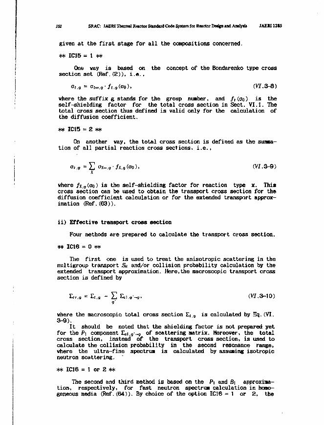
152 SRAC: IAERI Thermil Reictor Standud Code Syitem for Retctot DMjpi and Analysis JAERI12I5
given at the first stage for all the compositions concerned.
** IC15 = 1 **
One way is based on the concept of the Bondarenko type crosssection set (Ref.(2)), i.e.,
Ot.g = atoo.g/t.g(O0), (W.3-8)
where the suffix g stands for the group number, and ft (OQ) is theself-shielding factor for the total cross section in Sect. VI.J. Thetotal cross section thus defined is valid only for the calculation ofthe diffusion coefficient.
** IC15 = 2 **
On another way, the total cross section is defined as the summa-tion of all partial reaction cross sections, i.e.,
°t,g = E <JX~,g'/j(,g(O0). (VI.3-9)X
where /x,g(oo) is the self-shielding factor for reaction type x. Thiscross section can be used to obtain the transport cross section for thediffusion coefficient calculation or for the extended transport approx-imation (Ref. (63)).
ii) Effective transport cross section
Four methods are prepared to calculate the transport cross section.
** IC16 = 0 **
The first one is used to treat the anisotropic scattering in themultigroup transport SN and/or collision probability calculation by theextended transport approximation. Here,the macroscopic transport crosssection is defined by
E*r.« = Eil9 - E E.i.g-9. (VI.3-10)
where the macroscopic total cross section Lt 9 is calculated by Sq.(VI.3-9).
It should be noted that the shielding factor is not prepared yetfor the Pi component Es-i. -a of scattering matrix. Moreover, the totalcross section, instead of the transport cross section, is used tocalculate the collision probability in the second resonance range,where the ultra-fine spectrum is calculated by assuning isotropicneutron scattering. '
** IC16 = 1 or 2 **
The second and third method is based on the Pi and 61 approxima-tion-, respectively, for fast neutron spectrum calculation in homo-geneous media (Ref.(64)). By choice of the option IC16 = 1 or 2, the
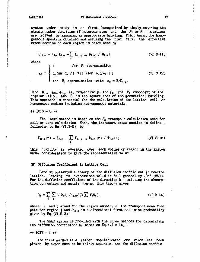
JAERI1285 VI. Mathematical Fonnulatio™ 153
system under study is at first homogenized by simply smearing theatomic number densities if heterogeneous, and the Pi or B\ equationsare solved by assuming an appropriate buckling. Then, using the homo-geneous spectrum obtained and assuming the flat flux, the effectivecross section of each region is calculated by
Etr,9 = (Yg Lt.g ~ E Esl.g'-g *l.g' / *l.g) (VI.3-11)g'
where1 for P] approximation
Xg /[ 3{l-(tan-'ag)/ag } ) (VI.3-12)
for B| approximation with Og = B/Et,g.
Here, *o,g and *i,9 is, respectively, the PQ and P\ component of theangular flux, and B is the square root of the geometrical buckling.This approach is essential for the calculation of the lattice cell orhomogenous medium including hydrogeneous materials.
** IC16 = 3 **
The last method is based on the SN transport calculation used forcell or core calculation. Here, the transport cross section is define .following to Eq.(VI.3-5), by
Etr.g(r) = Et.g - E Esi.g1-* *i.g' (r> / •i.g(r) (VI.3-13)9'
This quantity is averaged over each volume or region in the systemunder consideration to give the representative value
(6) Diffusion Coefficient in Lattice Cell
Benoist presented a theory of the diffusion coefficient in reactorlattice, leading to expressions valid in full generality (Ref.(36)).For the diffusion coefficient of the direction k , omitting the absorp-tion correction and angular terms, this theory gives
Dk = E E Vj*jAj Pa.k/iS E Vj*j). (VI.3-14)i ) i
where i and j stand for the region number, Ay the transport mean freepath for region j and Pa* is a directional first collision probabilitygiven by Eq.(VI.5-3).
The SRAC system is* provided with the three methods for calculatingthe diffusion coefficient Dk based on Eq.(VI.3-14).
** IC17 = 1 **
The first method is a rather sophisticated one which has beenproven by experience to be fairly accurate, and the diffusion coeffic-
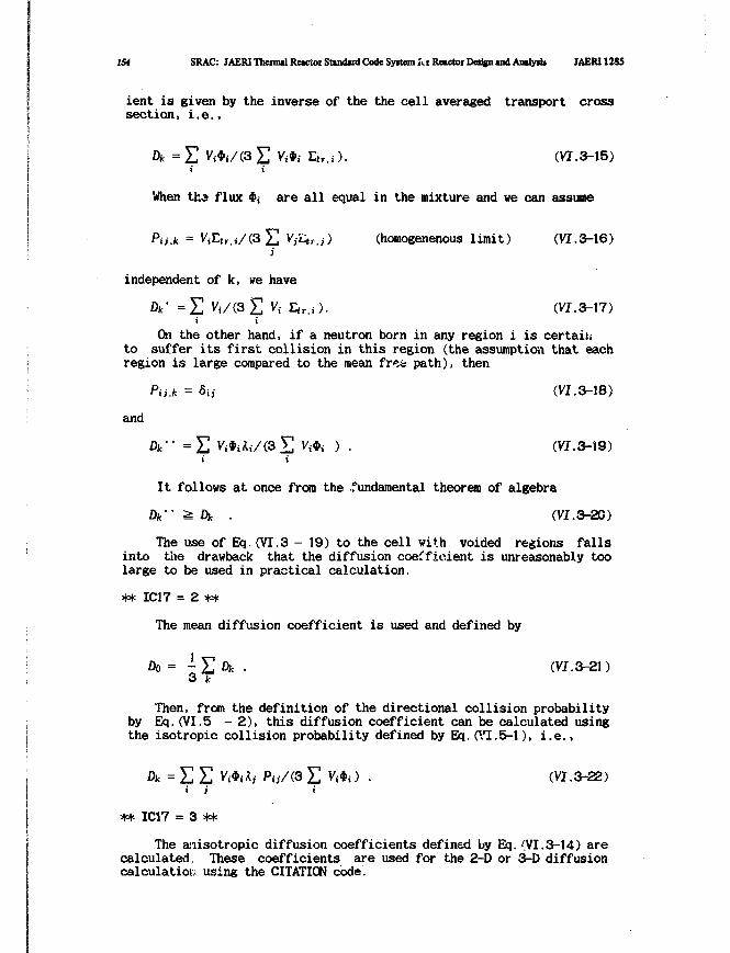
154 SRAC: JAERI Thermal Reactor Standard Code Syitem ftr Reactor Detjgn and Analyrij JAERI 12S5
ient is given by the inverse of the the cell averaged transport crosssection, i.e.,
Dk = E Vi*j/(3 £ Vi*i Ltr.i). (VI.3-15)i t
When tfca flux ${ are a l l equal in the mixture and we can assume
Pn.k = ViLtr.i/(3 E VjLtr.j) (homogenenous l imit) (VI.3-16)i
independent of k, we have
Dk' = E V . / o E Vi Ltr,i). (VI.3-17)j t
On the other hand, if a neutron born in any region i is certainto suffer its first collision in this region (the assumption that eachregion is large compared to the mean fre*s path), then
Pii.k = 6;, (VI.3-18)
and
Dk" = E V i M i / o E V<*< > • (VI.3-19)j t
It follows at once from the .fundamental theorem of algebra
Dk-- > Dk . (VI.3-20)
The use of Eq.(VI.3 - 19) to the cell with voided regions fallsinto the drawback that the diffusion coefficient is unreasonably toolarge to be used in practical calculation.
** IC17 = 2 **
The mean diffusion coefficient is used and defined by
Do = -T,Dk . (VI.3-21)3 k
Then, from the definition of the directional collision probabilityby Eq.(VI.5 - 2), this diffusion coefficient can be calculated usingthe isotropic collision probability defined by Eq.(VI.5-1), i.e.,
Dk = E E Vi*i*i *V<3 E W J ) • (VI.3-22)• i t
•* IC17 = 3 **
The anisotropic diffusion coefficients defined by Eq.{VI.3-14) arecalculated These coefficients are used for the 2-0 or 3-D diffusioncalculatiot; using the CITATION code.
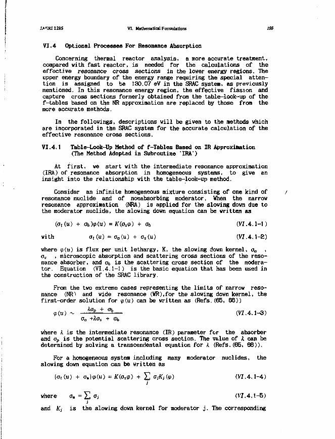
JA3RI1285 VI. Mathematical Framulattoni 155
VI. 4 Optional Processes For Resonance Absorption
Concerning thermal reactor analysis, a more accurate treatment,compared with fast reactor, is needed for the calculations of theeffective resonance cross sections in the lower energy regions. Theupper energy boundary of the energy range requiring the special atten-tion is assigned to be 130.07 eV in the SRAC system, as previouslymentioned. In this resonance energy region, the effective fission andcapture cross sections formerly obtained from the table-look-up of thef-tables based on the NR approximation are replaced by those from themore accurate methods.
In the follovings, descriptions will be given to the methods whichare incorporated in the SRAC system for the accurate calculation of theeffective resonance cross sections.
VI.4.1 Table-Look-Up Method of f-Tables Based on IR Approximation(The Method Adopted in Subroutine 'IRA')
At first, we start with the intermediate resonance approximation(IRA) of resonance absorption in homogeneous systems, to give aninsight into the relationship with the table-look-up method.
Consider an infinite homogeneous mixture consisting of one kind ofresonance nuclide and of nonabsorbing moderator. When the narrowresonance approximation (NRA) is applied for the slowing down due tothe moderator nuclide, the slowing down equation can be written as
(o,(u) + ObMu) =/C(os<p) + Ob (VI. 4.1-1)
with ot(.u) = oa(u) + os(u) (VI. 4.1-2)
where <p(u) is flux per unit lethargy, K, the slowing down kernel, o0 ,os , microscopic absorption and scattering cross sections of the reso-nance absorber, and ot is the scattering cross section of the modera-tor. Equation (VI.4.1-1) is the basic equation that has been used inthe construction of the SRAC library.
From the two extreme cases representing the limits of narrow reso-nance (NR) and wide resonance (WR),for the slowing down kernel, thefirst-order solution for <p(u) can be written as (Refs. (65, 66))
A<Tp + °b+Aos +
(VJ.4.1-3)
where A is the intermediate resonance (IR) parameter for the absorberand op is the potential scattering cross section. The value of A can bedetermined by solving a transcendental equation for A (Refs.(65, 66)).
For a homogeneous system including many moderator nuclides, theslowing down equation can be written as
where o. = E °i (VI.4.1-5)i
and Kj is the slowing down kernel for moderator j. The corresponding
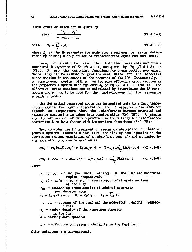
156 SRAC: JAERI Thenml Rctctor Standard Code Syitem foi Retctoi Detign and Aailytit JAER11285
first-order solution can be given byA<T + °b* (VI.4.1-6)
oa +Aas + at'
with ob'=Y, ijOj, (VI.4.1-7)i
where I, is the IR parameter for moderator j and can be again deter-mined by solving a coupled set of transcendental equations (Ref.(66)).
Here, it should be noted that both the fluxes obtained from anumerical integration of Eq.(VI.4.1-1) and given by Eq.(VI.4.1-2) or(VI.4.1-6) are the weighting functions for cross section averaging.Hence, they can be assumed to give the same value for the effectivecross section in the extent of the accuracy of the IRA. Consequently,a homogeneous system with Ob has the same effective cross section asthe homogeneous system with the same <jb of Eq. (VI.4.1-1). That is, theeffective cross sections can be calculated by determining the IR para-meters and Ob* as to be used for the table-look-up of the resonanceshielding tables.
The IRA method described above can be applied only to a zero tempe-rature system. For nonzero temperature, the IR parameter I for absorberdepends on temperature when the interference between potential andresonance scattering is taken into consideration (Ref.(67)). A simpleway to take account of this dependence is to multiply the interferencescattering term by a factor with temperature dependence (Ref.(67)).
Next consider the IR treatment of resonance absorption in hetero-geneous systems. Assuming a flat flux, the slowing down equation in thetwo-region system, consisting of an absorbing lump (f) and a nonabsorb-ing moderator (m), can be written as
+ Kf(.Ost<l>f)} + (1 ~Pff )<J/£ {RkKk fob )) (VI.4 .1-8)k
+ 0,9. ••• j^Kanfo/) + Kf(osf<i>f) + oE,{RkKk fob)} (VI.4.1-9)k
where
<Pf(u), <(>* = flux per unit lethargy in the lump and moderatorregion, respectively
o/(u) = aa{u) + os + om = microscopic total cross sectionof the lump
Go. = scattering cross section of admixed moderatorper absorber atom
o. = E.v./infVf), Rk =
Vf ,Ub = volumes of the lunp and the moderator regions, respec-tively
n/ = number density of the resonance absorberin the lump
K = slowing down operator
Pf{ = effective collision probability in the fuel lump.
Other notations are conventional.

JAERI1285 VI. Mithenutical Foi.-nulitioM 157
We make use of the simple interpolation formula for the collisionprobability as proposed by Wigner:
I _ Of
X + 9(C)(1 - C) Of + SPff =
with x =
(VI. 4.1-10)
(VI. 4.1-11)
s = and g(c) =1 + (a-l)c
where If the lump mean chord length, c, the Dancoff factor,and ais a purely geometrical quantity.
(VI.4.1-12)
Generalized collision probability theory shows
1 - cPff 1 - for x -
- x(VI.4.1-13)
where the Dancoff factor, c, is zero for isolated lumps. A rationalinterpolation of p// leads to g = 1 in Eq. (VI.4.1-10) when use is madeonly of the behavior of p// at L = °° , given by Eq. (VI.4.1-13). Onthe other hand, since the bulk of resonance absorption occurs at finitevalues of E/ , we need some corrections for the rational approximation.It is this quantity a that has been introduced for the corrections(Refs. (68,69,70)).
Being based on Eq.(VI.4.1-13), the Dancoff factor,c,is calculatedby using the value of p// for a sufficiently large value ofE/, as E/ = 300 cm'1,
1- c = (VI.4.1-13')
As the quantity, a , usually referred to as the Bell or Levinefactor , somewhat fluctuate among resonances, there might be some minorproblems with the choice. The exact choice of this quantity is notbelieved to be important, considering from the results of many studiesdone in this field. The values recommended in the SRAC system for thegeometric quantities are shown in the following table:
Table VI.4.1-1
Geometry
Sphere of Radius rSlab of Thickness rInfinite Cylinder of Radius rInfinite Long Cylinderof Radius r
• If
4r/32r2r
2rcos28
a
1.691.21.21.2
Remarks
Ref.(4,71)Ref.(71,7S)Ref. (68,69)Ref. (72,73)
Substituting Eq.(VI.4.1-10) into Eq.(VI.4.1-8) end subtracting Eq.(VI.4.1-9) from the resulting equation, we obtain the following set ofequations for neutron balance :
(Of + S)tpf = + Kf(osf9f) (VI.4.1-14)

158 SRAC: JAERI Thermal Reactor Standard Code System for Reactor Detifn and Analysis JAERI1285
f (S -OmJEUWkfa)) (VI.4.1-15)k
Then, from the two extreme cases representing the limits of narrowresonance (NR) and wide resonance (WR), respectively, for the slowingdown kernels, the first-order solution for <pf and <p, can be writtenas (Ref. (3))
Oa + kOsf + KOcm + US
p,l"(u) = 1 - s{l -<pfw (u)}/{ita,
with
and <J = £ fi^ , (VI.4.1-18)k
where jjfc is the IR parameter for the outside moderator.!*. Here, aset of the IR parameters can be determined by the same procedure asthose in a homogeneous system (Ref.(3)).
The simple result of Eq.(VI.4.1-16) again reveals the followingequivalence relation with practical usefulness : A homogeneous systemwith Ob = KOo, + M*s has the same effective resonance cross sectionas a homogeneous system of Eq.(VI.4.1-1) with the same oo • In otherwords, the effective cross sections in a heterogeneous system can beestimated by using a cross section set of the Bondarenko type(Ref.(4)) which is calculated based on Eq.(VI.4.1-1).
VI.4.2 Numerical Method for Calculating Neutron Flux Distribution(The Method Adopted in Subroutine 'PEACO')
We assume that heterogeneous systems are built up of an infinitenumber of 'unit cells' and the neutron balance in a heterogeneoussystem can be described by using the first-flight collision probabil-ities. To reduce the numerical errors caused by the flat-flux assump-tion, each region of the system may be divided into subregions as manyas necessary or possible. Then, assuming the isotropic elastic scatter-ing, the neutron balance in a cell may be written by the neutronslowing down equation
J K
VtLi (u)*i (u) = £ Pa (u)Vj J] Sjk(.u) (VI.4.2-1)i'\ fc-l
S j f c ( u ) = — f «tp{-(«MT)}E«fc<uf)*j<«'>*»• (VI.4.2-2)
with
a = ( ^ - ) 2 and c =-ln a. (VI.4.2-3)4+1
Here,the subscript i or j stands for the subregion number and the kcorresponds to the nuclear species. The quantity P,, is the effectiveprobability in a unit cell that a neutron scattered isotropically inregion j ,into lethargy u.will have its first collision in region i ,and other notation has the customary meanings.
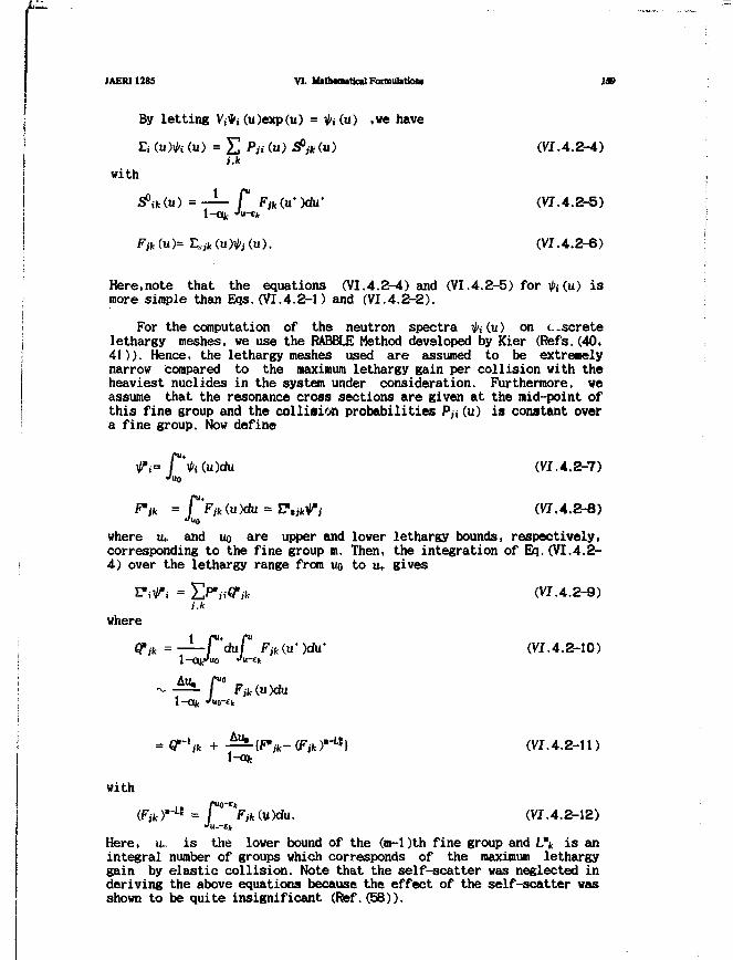
JAERI1285 VI. M»th«autic«lFoniiul»tioni IX
By letting Vj*i (u)exp(u) = Vi(u) »we have
(u) = £ P,, (u) flfy*<u> (VI.4.2-4)i.k
with
rfikCu) = — f F>fc(u-)du' (VI.4.2-5)1 — O O J •'u-ejt1—OOJ
Fjk(u)= Lsjk(u)V, (u). (VI.4.2-6)
Here,note that the equations (VI.4.2--4) and (VI.4.2-5) for Vi(u) ismore simple than Eqs. (VI.4.2-1) and (VI.4.2-2).
For the computation of the neutron spectra V»(u) on c-scretelethargy meshes, we use the RABBLE Method developed by Kier (Refs.(40,41)). Hence, the lethargy meshes used are assumed to be extremelynarrow compared to the maximum lethargy gain per collision with theheaviest nuclides in the system under consideration. Furthermore, weassume that the resonance cross sections are given at the mid-point ofthis fine group and the collision probabilities P/i(u) is constant overa fine group. Now define
(VI.4.2-7)
(VI.4.2-8)uo
where u+ and uo are upper and lower lethargy bounds, respectively,corresponding to the fine group m. Then, the integration of Eq.(VI.4.2-4) over the lethargy range from no to u+ gives
Fi^i = E ^ i Q V (VI .4.2-9)i.k
where
GTJk = — P d u f F>(u-)du- (VI.4.2-10)
GT-lk +GTik I1-aic
withLt r 0 E V (VI.4.2-12)
Here, u_ is the lower bound of the (m-1)th fine group and L\ is anintegral number of groups which corresponds of the maximum lethargygain by elastic collision. Note that the self-scatter was neglected inderiving the above equations because the effect of the self-scatter wasshown to be quite insignificant (Ref.(58)).
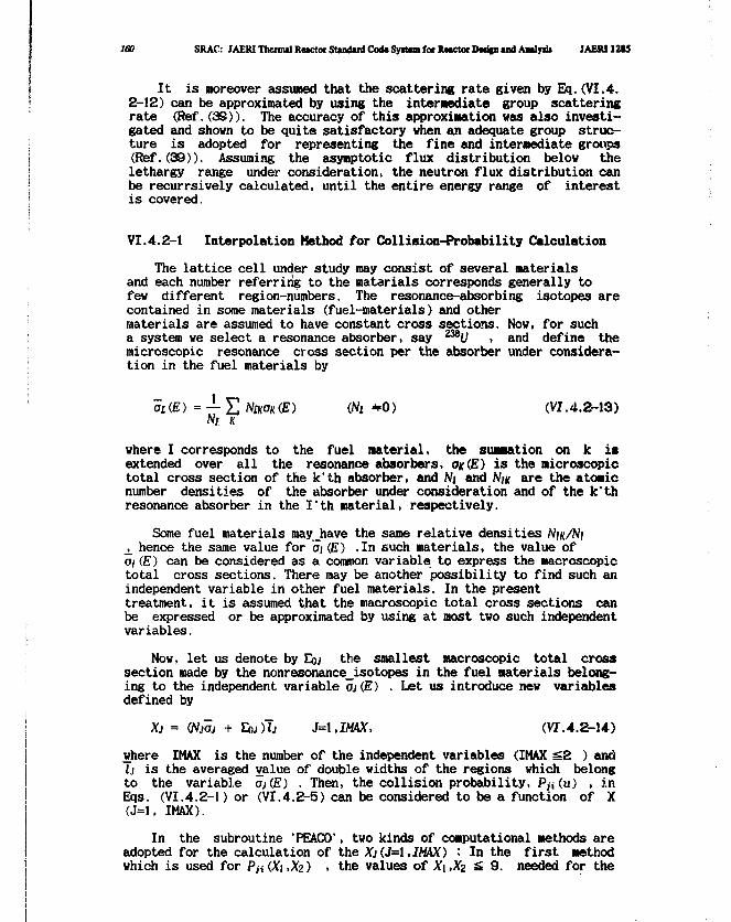
160 SRAC: JAERIThcrmil Rector Stand»rdCo<USy»Uin for Rector D«i|n«ndAMayn» JAERI12I5
It is moreover assumed that the scattering rate given by Eq.(VI.4.2-12) can be approximated by using the intermediate group scatteringrate (Ref.(39)). The accuracy of this approximation was also investi-gated and shown to be quite satisfactory when an adequate group struc-ture is adopted for representing the fine and intermediate groups(Ref.(39)). Assuming the asymptotic flux distribution below thelethargy range under consideration, the neutron flux distribution canbe recurrsively calculated, until the entire energy range of interestis covered.
VI.4.2-1 Interpolation Method for Collision-Probability Calculation
The lattice cell under study may consist of several materialsand each number referring to the materials corresponds generally tofew different region-numbers. The resonance-absorbing isotopes arecontained in some materials (fuel-materials) and othermaterials are assumed to have constant cross sections. Now, for sucha system we select a resonance absorber, say 238U , and define themicroscopic resonance cross section per the absorber under considera-tion in the fuel materials by
ai(E) = — Y, NIKOK(E) (Ni *0) (V7.4.2-13)Ni K
where I corresponds to the fuel material, the summation on k isextended over all the resonance absorbers, OK(E) is the microscopictotal cross section of the k'th absorber, and Ni and NIK are the atomicnumber densities of the absorber under consideration and of the k'thresonance absorber in the I'th material, respectively.
Some fuel materials may_have the same relative densities_j_ hence the same value for at (E) .In such materials, the value ofai (E) can be considered as a common variable to express the macroscopictotal cross sections. There may be another possibility to find such anindependent variable in other fuel materials. In the presenttreatment, it is assumed that the macroscopic total cross sections canbe expressed or be approximated by using at most two such independentvariables.
Now, let us denote by EOJ the smallest macroscopic total crosssection made by the nonresonance_isotopes in the fuel materials belong-ing to the independent variable aj(E) . Let us introduce new variablesdefined by
Xj = (NJOJ + EOJ)T; J=\,IMAX, (VI. 4.2-14)
where IMAX is the number of the independent variables (IMAX g 2 ) andlj is the averaged value of double widths of the regions which belongto the variable oj(£) . Then, the collision probability, Pji(u) , inEqs. (VI.4.2-1) or (VI.4.2-5) can be considered to be a function of X(J=l, IMAX).
In the subroutine 'PEACO', two kinds of computational methods areadopted for the calculation of the Xj(J=\,IMAX) : In the first methodwhich is used for P^ (Xt ,Xz) , the values of X\ ,Xz £ 9. needed for the

JAERI1285 VI. Mathematical Fonnulitioiii 161
interpolation are calculated by calling the subroutine 'PIJ-2'. Thesecond one uses the asymptotic expansion of P« (XI ,XZ ) whenXi or Xz «£ 9. .
(I) One Reaonance-Absorbinc Composition Problem (IMAX=1)
It is easy to show (Refs.(69,71,73))
PwflO - Va + yu/X /or X - =» (VI.4.2-15)
with
and[Pii<X)-iHi)X\x-- if i e R
0 otherwise,
where RAC stands for the resonance-absorbing material.
= J
(VI. 4.2-16)
(VI.4.2-17)
The above equation (VI.4.2-15) is used for X > 9 and the genera-lized Dancoff factor y^y given by Eq.(VI.4.2-17) is calculated at X =9, while r)ij is obtained as the value of P^ (X) at X = 10* .
On the other hand, for the range of X < 9 we introduce a newvariable
Z =X+l
or X =\-Z
(VI.4.2-18)
The interpolation of the collision probability is made by using thevalues of Pti(X) calculated on ten points of the variable Z withZ=O.l and the Lagrangian three points interpolation formula (Ref.(74))
/(Zo + SZ) = ^
withSZ ,
u = — andAZ
(VI.4.2-19)
(VI.4.2-20)
where the quantity AZ is the mesh width of the variable Z at Z = Zocorresponding to the direction of the increment SZ .
The values of Z and X used for the interpolation are shown in thefollowing table:
Table VI.4.2-1
No.
23456
Z
00.10.20.30.40.5
: X
00.1111110.250.4235710.6666671.
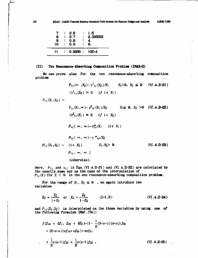
162 SRAC: IAERI Thenntl Rttctor Studud Code System fof RMCtoi DMfen and Andy* JAEM12SS
7 : 0.6 : 1.58 : 0.7 : 2.3333339 : 0.8 : 4.
10 : 0.9 : 9.
11 : 0.9809 : 10E+4
(II) Two Resonance-Absorbing Composition Problea (IMAX=£)
We can prove also for the two resonance-absorbing compositionproblea
P>,(~ ,Xz)-y\j{Xz)/X\ X|>9. Xz £ 9 (VJ.4.2-21)
(y'w(X2) = 0 if ii Xi)
9, Xz >6 (VJ.4.2-22)
X2)
X2) X,,X2>9 (VI.4.2-23)
(otherwise).
Here, P^ and y 0 in Eqs.(VI.4.2-21) and (VI.4.2-22) are calculated bythe exactly same way as the case of the interpolation ofPij(X) for X < 9 in the one resonance-absorbing coraposition problea.
For the range of Xi, Xz S 9 > we again introduce twovariables
Z r = - ^ - or X j = - ^ - (1=1,2) (VI.4.2-24)1+X; 1-Zi
and Pij(X\,Xz) is interpolated on the these variables by using one ofthe following formulae (Ref.(74))
/(Zio + aZi, Za + SZ2)={1- -(3-u-u)(u+u)}/oo2
-u(u-l)/02 . (VI.4.2-25)2
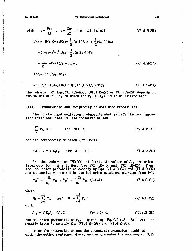
JAERI1285 VI. M«th<fniticalFocmiilatio« 163
with u = — , v=— , l u l £ l , l v l £ l , (VI.4.2-26)SZ AZ
/(Zio+fiZi ,Z2o+5Z2)= -u(u- l )/-i j2
+ (l-un-u2-v2)/oo+ -u(u-2u-l2
+ -U(V-2U+1)/OI + UW/M.. (VI.4.2-27)2
/ ( Z I O + S Z | , Z 2 O + 8 Z 2 )
=(l-u)(l-ii)/oo+u(l-u)/io+u(l-u)/oi+uu/n. (VI.4.2-28)
The choice of Eqs.(VI.4.2-25), (VI.4.2-27) or (VI.4.2-28) depends onthe values of Z\, Zz on which the Pa(X\,Xz) is to be interpolated.
(Ill) Conservation and Reciprocity of Collision Probability
The first-flight collision probability must satisfy the two impor-tant relations, that is, the conservation lav
£ Pa = 1 for all i (VI.4.2-29)i
and the reciprocity relation (Ref.(62))
ViLiPtj = VjLjPn for all i,j. (VI.4.2-30)
In the subroutine 'PEACO', at first, the values of Pj;- are calcu-lated only for i £ j by Eqs. from (VI.4.2-15) and (VI.4.2-3B). Then,the collision probabilities satisfying Eqs.(VI.4.2-29) and (VI.4.2-30)are successively obtained by the following equations starting from i=I:
Pit* = — Pa . Pa* = — Pa U=i.J) (VI.4.2-31)
where
ft, = E Pa and j8, = E Pu* (VI.4.2-32)
with
Pii = VfcPa /(VjEi)- for j > i. (VI.4.2-33)
The collision probabilities Pi;* given by Eq.(VI.4.2- 31) will bereadily known to satisfy Eqs.(VI.4.2- 29) and (VI.4.2-30).
Using the interpolation and the asymptotic expansion, combinedwith the method mentioned above, we can guarantee the accuracy of 0.1%
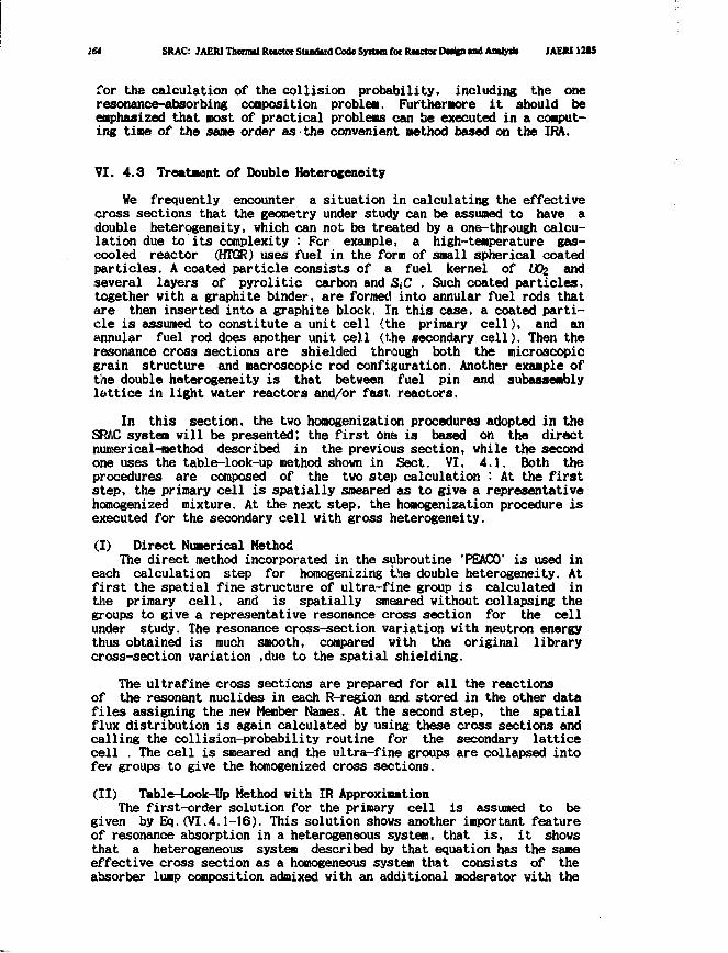
164 SRAC: JAER1 Thenml Rwctor Stindiid Code Syttom for Ructot Dw%n mil Antlyrit IAERI12S5
for the calculation of the collision probability, including the oneresonance-absorbing conposition problem. Furthermore it should beemphasized that most of practical problems can be executed in a comput-ing tine of the sane order as the convenient method based on the IRA.
VI. 4.3 Treatment of Double Heterogeneity
We frequently encounter a situation in calculating the effectivecross sections that the geometry under study can be assumed to have adouble heterogeneity, which can not be treated by a one-through calcu-lation due to its complexity : Fcr example, a high-temperature gas-cooled reactor (HTGR) uses fuel in the form of small spherical coatedparticles. A coated particle consists of a fuel kernel of UOz andseveral layers of pyrolitic carbon and SiC . Such coated particles,together with a graphite binder, are formed into annular fuel rods thatare then inserted into a graphite block. In this case, a coated parti-cle is assumed to constitute a unit cell (the primary cell), and anannular fuel rod does another unit cell (the secondary cell). Then theresonance cross sections are shielded through both the microscopicgrain structure and macroscopic rod configuration. Another example ofthe double heterogeneity is that between fuel pin and subassemblylattice in light water reactors and/or fast reactors.
In this section, the two homogenization procedures adopted in theSRAC system will be presented; the first one is based on the directnumerical-method described in the previous section, while the secondone uses the table-look-up method shown in Sect. VI. 4.1. Both theprocedures are composed of the two step calculation : At the firststep, the primary cell is spatially smeared as to give a representativehomogenized mixture. At the next step, the homogenization procedure isexecuted for the secondary cell with gross heterogeneity.
(I) Direct Numerical MethodThe direct method incorporated in the subroutine 'PEACO' is used in
each calculation step for homogenizing the double heterogeneity. Atfirst the spatial fine structure of ultra-fine group is calculated inthe primary cell, and is spatially smeared without collapsing thegroups to give a representative resonance cross section for the cellunder study. The resonance cross-section variation with neutron energythus obtained is much smooth, compared with the original librarycross-section variation ,due to the spatial shielding.
The ultrafine cross sections are prepared for all the reactionsof the resonant nuclides in each R-region and stored in the other datafiles assigning the new Member Names. At the second step, the spatialflux distribution is again calculated by using these cross sections andcalling the collision-probability routine for the secondary latticecell . The cell is smeared and the ultra-fine groups are collapsed intofew groups to give the homogenized cross sections.
(II) Table-Look-Up Method with IR ApproximationThe first-order solution for the primary cell is assumed to be
given by Eq.(VI.4.1-16). This solution shows another important featureof resonance absorption in a heterogeneous system, that is, it showsthat a heterogeneous system described by that equation has the sameeffective cross section as a homogeneous system that consists of theabsorber lump composition admixed with an additional moderator with the
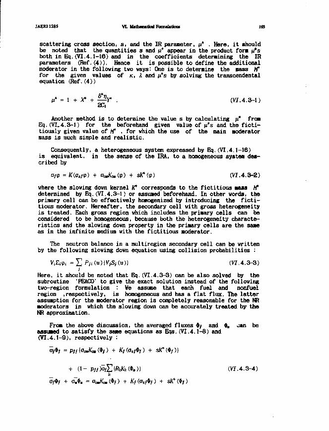
MER11285 VI. Mith»m»tk»l FonmOttiow 165
scattering cross section, s, and the IR parameter, /J* • Here, it shouldbe noted that the quantities s and 11* appear in the product fora n*sboth in Eq. (VI.4.1-16) and in the coefficients determining the IRparameters (Ref. (4)). Hence it is possible to define the additionalmoderator in the following two ways: One is to determine the mass M"for the given values of K, A and n*s by solving the transcendentalequation (Ref. (4))
M* = 1 + X* + —Y* . (VI.4.3-1)
Another method is to determine the value s by calculating is* fromEq.(VI,4.3-1) for the beforehand given value of n*s and the ficti-tiously given value of Af , for which the use of the main moderatormass is much simple and realistic.
Consequently, a heterogeneous system expressed by Eq.(VI.4.1-16)is equivalent, in the sense of the IRA, to a homogeneous system des-cribed by
oftp = K(ost<p) + aJKm(<p) + sK*(<p) (VI. 4.3-2)
where the slowing down kernel K* corresponds to the fictitious mass M*determined by Eq.(VI.4.3-1) or assumed beforehand. In other words, theprimary cell can be effectively homogenized by introducing the ficti-tious moderator. Hereafter, the secondary cell with gross heterogeneityis treated. Each gross region which includes the primary cells can beconsidered to be homogeneous, because both the heterogeneity characte-ristics and the slowing down property in the primary cells are the sameas in the infinite medium with the fictitious moderator.
The neutron balance in a multiregion secondary cell can be writtenby the following slowing down equation using collision probabilities :
ViEiPi = £ Pa (u) [VjSj (u)} (VI.4.3-3)
Here, it should be noted that Eq.(VI.4.3-3) can be also solved by thesubroutine 'PEACO' to give the exact solution instead of the followingtwo-region formulation : We assume that each fuel and nonfuelregion .respectively, is homogeneous and has a flat flux. The latterassumption for the moderator region is completely reasonable for the NRmoderators in which the slowing down can be accurately treated by theNR approximation.
From the above discussion, the averaged fluxes */ and •. oan beassumed to satisfy the same equations as Eqs.(VI.4.1-8) and(VI.4.1-9), respectively :
+ ( 1 - P//>o*£tfWfc«W» (VI.4.3-4)kk
+ a.*. = omKmQf) + Kf(os}<i>f) + sK*(*/)
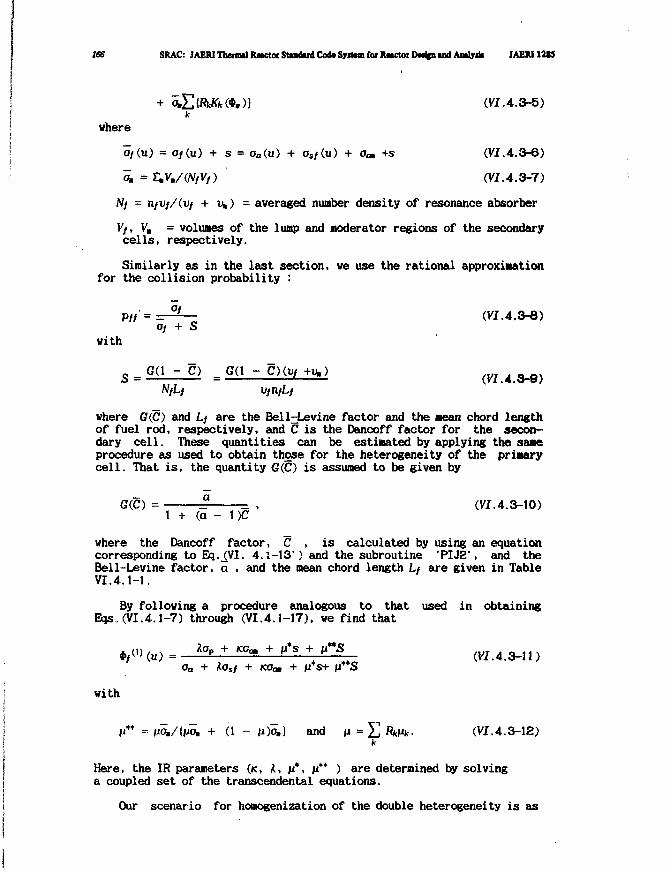
IBS SRAC: JAERITbenndRnctotStududCodcSyittmfoiItMctoiDMjpandAialylii JAERU2SS
£{&Kfc (*.)) (VI. 4.3-5)k
where
a/(u) = Of(u) + s = aa(u) + as/(u) + o<» +s (VI. 4.3-6)
^ =£V./(N/V/) (VI.4.3-7)
W/ = tifVf/(Vf + v*) = averaged number density of resonance absorber
V>, V. = volumes of the lump and moderator regions of the secondarycells, respectively.
Similarly as in the last section, we use the rational approximationfor the collision probability :
PffzrOf + S
with
(VI.4.3-8)
S = G(1 5 ) = G(1 CKvf+v.) (VI.4.3-9)NL L
where G(C) and L/ are the Bell^Levine factor and the mean chord lengthof fuel rod, respectively, and C is the Dancoff factor for the secon-dary cell. These quantities can be estimated by applying the sameprocedure as used to obtain those for the heterogeneity of the primarycell. That is, the quantity G(JC) is assumed to be given by
G(£) = ^ = , (VI.4.3-10)1 + (a - 1 )C
where the Dancoff factor, C , is calculated by using an equationcorresponding to Eq._(VI. 4.1-13") and the subroutine 'PLJ2', and theBell-Levine factor, a , and the mean chord length L/ are given in TableVI.4.1-1.
By following a procedure analogous to that used in obtainingEqs,(VI.4.1-7) through (VI.4.1-17), we find that
«,<•>(«)= ** + «*• + » * + H»a (VI.4.3-11)Oa + kosf + KOcm + ITS+ fl S
with
I?* =vam/[imm + (1 - u)o.} and n = E f i i A . (VI.4.3-12)
Here, the IR parameters (K, K, n*, n** ) are determined by solvinga coupled set of the transcendental equations.
Our scenario for homogenization of the double heterogeneity is as

JAERI12J5 VL Mathematical Fonnubtiont . 167
follows: First.in a practical situation, the heterogeneity character-istics, s and S for the primary and secondary cells, are independen-tly obtained by calculating the respective Dancoff factor. In the nextstage, a fictitious moderator is determined for the infinite mediumcomposed of the primary cell through the IR treatment to eliminate theheterogeneity. Finally, the secondary heterogeneity is homogenizedusing the fictitious moderator, also through the IR procedure, whereeach fuel lump is treated as homogeneous.
The simple results of Eq.(VI.4.3-11) reveal the following equiva-lence relation with practical usefulness : For the determined values ofa set of IR parameters, we define a scattering cross section by
Ob = KOo. + M*S + n**S (VI. 4.3-13)
Then, the IRA solution of Eq.(VI.4.3-11) becomes equivalent to that ofthe simple equation (VI.4.1-1).
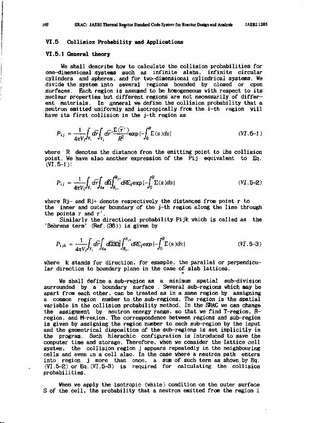
168 SRAC: JAERI Thermil Rejctor Stindaid Code System for Rwctor Design and Amlyiis JAERII285
VI.5 Collision Probability and Applications
VI.5.1 General theory
We shall describe how to calculate the collision probabilities forone-dimensional systems such as infinite slabs, infinite circularcylinders and spheres, and for two-dimensional cylindrical systems. Wedivide the system into several regions bounded by closed or opensurfaces. Each region is assumed to be homogeneous with respect to itsnuclear properties but different regions are not necessarily of differ-ent materials. In general we define the collision probability that aneutron emitted uniformly and isotropically from the i-th region willhave its first collision in the j-th region as
Pa = —f */ dT'^pexpl-f"E(s)ds) (V7.5-1)
where R denotes the distance from the emitting point to the collisionpoint. We have also another expression of the Pij equivalent to Eq.(VI.5-1):
Pw = — f drf <&[ "dRLjexpi-f Z(s)ds) (VI.5-2)
where Rj- and Rj+ denote respectively the distances from point r tothe inner and outer boundary of the j-th region along the line throughthe points r and r'.
Similarly the directional probability Pijk which is called as the'Behrens term' (Ref.(36)) is given by
Piik = — f d r f <mifli'tclR£jexpl-f>L(s)ds} (W.5-3)
4TCY(*V, •>** •%- •'0
where k stands for direction, for example, the parallel or perpendicu-lar direction to boundary plane in the case of slab lattices.
We shall define a sub-region as a minimum spatial sub-divisionsurrounded by a boundary surface , Several sub-regions which may beapart from each other, can be treated as in a same region by assigninga common region number to the sub-regions. The region is the spatialvariable in the collision probability method. In the SRAC we can changethe assignment by neutron energy range, so that we find T-region, R-region, and M-refUon. The correspondence between regions and sub-regionis given by assigning the region number to each sub-region by the inputand the geometrical disposition of the sub-regions is set implicitly inthe program. Such hierachic configuration is introduced to save thecomputer time and storage. Therefore, when we consider the lattice cellsystem, the collision region j appears repeatedly in the neighbouringcells and even in a cell also. In the case where a neutron path entersinto region j more than once, a sum of such term as shown by Eq.(VI.5-2) or Eq.(VI.5-3) is required for calculating the collisionprobabilities.
When we apply the isotropic (white) condition on the outer surfaceS of the cell, the probability that a neutron emitted from the region i
JAERI1285 VI. MtthenutkalFonmilitiom 1S9
j crosses S, Pis, is required.
(VI.5-4)
or as an alternative expression
Pa = — f drf cfftexpf-/*E(s)ds} (VI.5-5)
where Rs is a distance frou the emitting point to the surface.
The isotropic boundary condition is frequently used for the latticecell calculation not only in the collision probability method but alsoin the Sn calculation. We shall describe its physical meaning and theapplication in the collision probability method.
We assume the system without source nor absorption where theneutron flux distribution is uniform and isotropic everywhere. Then wesuppose a cell in the entire space surrounded by a surface S (it may beopen) is divided into several regions. We consider the balance of thecollision rate in the i-th region
N
? j<pVj (VI. 5-6)
where the subscript i denotes that the quantity is assigned to the i-thregion ; and
E( ;The total macroscopic cross section,<p ; the uniform scalar flux,Vj ;the volume,S ; the area of the surface,G, ;the probability that a neutron impinging on the surface has
its first collision in the i-th region,Pji ;the probability that a neutron emitted in the j-th region
has its first collision in the i-th region.
The term on the left hand side (L.H.S.) denotes the collision rate inthe i-th region. The first term on the right hand side (R.H.S.) de-notes the contribution from the outside of the surface and the secondterm the contribution of the emission in each region inside of thesurface. Using the reciprocity theorem :
PijLjQVj = PiyE^Vj (VI. 5-7)
and the conservation theorem :
H£ Pii+Pis = 1 (VI.5-8)H
where Pis is the probability that a neutron emitted in the i-th regionescapes from the outer surface S without suffering any collision, we
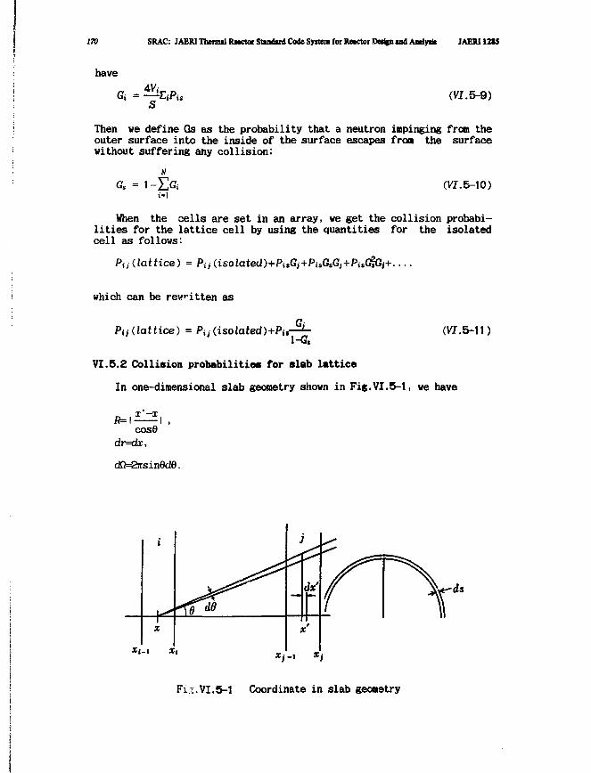
170 SRAC: JAERI Thenul Retctor Stindud Code System for Rotctor.Oedjnind Andyik JAERI IMS
have
s(VI. 5-9)
Then we define Gs as the probability that a neutron impinging from theouter surface into the inside of the surface escapes from the surfacewithout suffering any collision:
Gs = 1- (VI.5-10)
When the cells are set in an array, we get the collision probabi-lities for the lattice cell by using the quantities for the isolatedcell as follows:
Pi j {lattice) = Pa (isolated)+PiSGj+PiSGtGJ+P;tGiG)+
which can be rev it ten as
Pi i (lattice) = Pi; (isolated)+Pj,-1-G,
(VI.5-11)
VI.5.2 Collision probabilities for slab lattice
In one-dimensional slab geometry shown in Fig.VI.5-1, we have
f = I — — — | tcose
dr=dx,
dfi=27rsin0d6.
Fig.VI.5-1 Coordinate in slab geometry
JAERJ1285 VI. Mithenutlcal Foo7iuI»aoM 171
We assume that the system is divided into an array of slabs.. The i-thslab has its left edge at xi and its total cross section denoted by Ei.Then we have the Pij's as
; —x — rdzpcfc-rV
2 ( i f - i M y*.-i J*,-i Jo cose
*exp( T E(t)d*/cos9 I }d0, (VI.5-12)
for the case xi < xj-1, and the optical distance which appears in theexponential term in Eq. (VI.5-12) is reduced to
HE(t )dt = Ei (Xj-x)+E,- (x'-Xj-i)+ E 4<
where fa = Efcdk-Xk-i).
Then we can carry out the integration over x and x' , and we get
Pa = — f sin6cos0de(l-exp(—— )]*(l-«cp(——2Ai Jo cose cose
k-,+ICOS0
Now we introduce the Ein function defined by
Ein(x) =Jo
We have the final form of Pij for the case xi < xj as follows
1
l> ~ 2Ai '3 W '3 "J+ ' '3 " + ' + '3 " + '+ '
where
j-i
lii=Y,h, for ii<x>. (VI. 5-14)k-i+l
Next we shall consider the case where xi>xj, the optical distanceis reduced to
i-i
E(t )dt = Ej (x-Xi-i )+Ej (Xj-x1)+ E
by using the same procedure as xi < xj we get the same expression asEq.(VI.5-13) except for the definition of Aij. In this case we have
172 SRAC: JAERI Thermal Retctor Standard Code Syitem for Rwctor Dwljii ind Analyrit JAERI 1285
t-l
Aii=E*fc. for Xi>Xj. (VI. 5-15)
In the last case where xi = xj, the optical distance in Eq. (VI.5-12)is reduced to
Ei(i'-x), for x'>x.
l |
I Ei(x-x'), for x'<x.
Integrating over x and x' gives the final form of Pii as
Pa = l~{Ei3(0)-Ei5(Ai)J (VI.5-16)
If the Ai's are so small that the differences in Eq.(VI.5-13) andin Eq. (VI.5-16) can not be obtained accurately in the numericalcalculation, we should use the following differential foras insteadof Eqs.(VI.5-13) and (VI.5-16),
Pu = -^ En ao+Ai/2+^/2), (VI.5-17)
Pa = <UEii<ili/2). (VI.5-18)
We, however, should take care of the property of the Eil function whichhas the logarithmic singularity.
We consider now the lattice cell system where a unit cell is divid-ed into N regions and the collision region j lies periodically. A sumof such terms as Eq. (VI.5-13) gives
Pii = — E2Rj i-o
\[j+ki )-Ei3 mj+Kj )+Ei3 (Ajf+Aj+Aj)}.
where
H N
fc-i+1 k-\
=E*k+ E Ak+E*fc+**E*k. (vi.5-20)fc-1 k-M k'\ k-\
The summation over 1 is achieved separately by AJj or Ajf series until*ij or ktf exceeds the fixed optical length of 6, respectively. For the
JAERI1285 VI. MathciMtkalFonnulatioiii 173
case where j<i, i and j in Eq. (VI.5-20) must be replaced by j and i,respectively.
For the case i=j we have
Pu = l~{Ei3(0)-Ei3«i))
+— %{Bi3a\}hEa(k\i+lLi>-EaUli+li>*Eaalj+ki+i.j) (VJ.5-21)Aj (-0
where
N
where AJ, =(1+1 )*2^-Ai. (VI.5-22)fe-1
When the lattice cell is arranged symmetrically, we may reduce thecomputing time into half, but the program is not prepared to take careof the symmetry. Therefore, the user must give the full geometry ininput and allocate the same region number to the corresponding sub-regions .
Now we consider the explicit form of the directional probability.For the perpendicular direction to the boundary plane, we have 2c(x?6as 3fii , c.f. Fig.VI.5-1, by which the integrand in Eq.(VI.5-12) hasto be multiplied. The similar procedure gives us the expression of P uxcorresponding to Eq. (VI.5-13) as follows:
^ +E<5 au+ki+kt», (vi.5-23)
and corresponding to Eq. (VI.5-16)
Pax = 1 — [Ei5(0)-Ei5ai)} (VI. 5-24)2l
For the parallel direction we can easily obtain the explicit form, butit is not necessary because the following relation holds.
Pa = I Pn± + \ Put (Vf .5-25)3 3
The relation comes from
i =Efi£ = ni + 20?k
So we can obtain PJJH by subtraction.
At the end of this section we show the expression for the escapeprobability Pis:
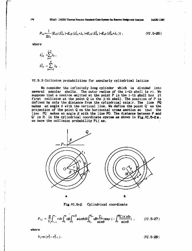
174 SRAC: JAERI Tbeimal Reictoi SUndud Coda Syittm for Rnctof DMifn u d Amlydt JAEM12I5
— {Ei3 W! s)-£ i 3ai s+;U )+£i3(A?s)-Ej3(A?s+Ai)}, (VI.5-26)
where
i-l
fr-lN
& = E *k •
VI.5.3 Collision probabilities for annularly cylindrical lattice
We consider the infinitely long cylinder which is divided intoseveral annular shells. The outer radius of the i-th shell is ri. Wesuppose that a neutron emitted at the point P in the i-th shell has itfirst collision at the point Q in the j-th shell. The position of P isdefined by only the distance from the cylindrical axislr. The line PQmakes an angle Q with the vertical line. We define the point Q' as theprojection of the point Q on the horizontal cross section so that theline PQ makes an angle R with the line PO. The distance between P andQ' is R. In the cylindrical coordinate system as shown in Fic.VI.5-2a.we have the collision probability Pij as,
« b
Fig.VI.5-2 Cylindrical coordinate
} . (V7.5-27)Jo Jo JR,- sine Jo sinO
where
Vi=rt(r?-r?-i). (VI.5-28)
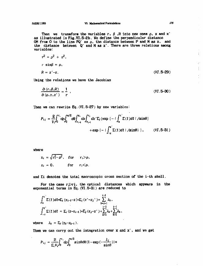
JAERI128S VI. Mathematical Formulation! ITS
Then we transform the variables r, 0 ,R into new ones p, x and x'as illustrated in Fig.VI.5-2b. We define the perpendicular distanceOM from 0 to the line PQ' as p, the distance between P and H a s x. andthe distance between Q' and M as x*. There are three relations amongvariables:
r2 = p2 + x2,
r sin/? = p,
R = x'-x. (VI.5-29)
Using the relations we have the Jacobian
(VI.5-30)d(p,x,xf) r
Then we can rewrite Eq.(VI.5-27) by new variables:
Pi; = —PdpF cfflF'dxF'dx'tj (exp (- I [* L(.t)dt I /sinfl)V/O JO Jii-i •'i,.i J*
+exp{-\ [* L(t)dt\/sine) } , (VI.5-31)J-x
where
= 0, for
and Ei denotes the total macroscopic cross section of the i-th shell.
For the case rj>ri> the optical distances which appears in theexponential terms in Eq.(VI.5-31) are reduced to
/ E(t )dt=E( (Xi-|-x)+Ej (x'-x,')+ 2J Ak•
E(t)dt = 3k-1
where 4 = Ek (x^-ik-i).
Then we can carry out the integration over x and x', and we get
D i , = - = - / dpi sin6d6{l-exp(—^~r.V;J0 Jo sin(
176 SRAC: JAERI Thermal Reretor Standard Code Syitem for Reactor Dedfn and Amlpb JAER11H5
>-l i-l j-l
* {exp(- J] fa/sind)+ €«p(.-2^,h+^i+ Y> fa/sind)} } .k-t-t-l fc-l fc-ii-l
Now we introduce Kin function defined by
r/2 x
desin""'e exp( ).sine
We have the final form of Pij for the case ri<rj, as follows:
2 f-Pii = ^ 0 *
+Ki3U?>)-Ki3
(VI.5-33)where
H
i-l > -l
=£*fc + £Afc for r K ^ . (VI. 6-8*)k-l h'\
Next we consider Pij for the case ri>rj where the optical distancesdiffer from the case ri<rj because Q is located inside of P so thatx'< x. In this sense the symbol of the absolute value is required. Werewrite locally the optical distance as follows:
L(t )dt I = P E J (t )dt = Lj (i;-x- )+(Ei (x-ij-i)+ £ fc.
Integration over x and x' gives the final form of Pij for the caserj<ri, which is exactly same expression as in Eq. (VI.5-33) but AJ, inBq. (VI.5-34) must be replaced by
i-l
ill, = I] 4 for ri>r,. (VI.5-35)
We have not yet considered the case where the i-th shell coincidewith the j-th shell. In this case the optical distances reduced to
f Ej (x'-x), for x'>x,
\ J* L(t)dt \ =»I Ei(x-x'), for x'<x,
f E(t )dt =Ej (x'-XiJ-x
'"'
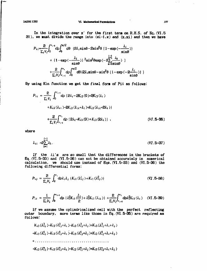
JAERI12B5 VI. M»themtOc«lFonnulition» 177
In the integration over x' for the first ter« on R.H.S. of Eq.(VI.531), we must divide the range into (xi-l,x) and (x.xi) and then we have
-• f*/z • _2 Aj
Jo ' sin9J. Ill ,.
{l-exp( '-sine jc-isine2+-^-fT'dpF dO{ZH.i3inB-sij?e {l-exp(-Z-^~)) )
EiV/r,-! •'0 sine
By using Kin function we get the final form of Pii as follows:
dp {2Ai-Ki3(0)+Kj3(2Aj)} , (VI.
where
i-l
Aii =2X>fe. (VI. 5-37)
If the Ai's are so small that the differences in the brackets ofEq.(VI.5-33) and (VI.5-36) can not be obtained accurately in numericalcalculation, we should use instead of Eqs.(VI.5-33) and (VI.5-36) thefollowing differential forms:
(V7.5-38)
(VI.5-39)
If we assume the cylindricalized cell with the perfect reflectingouter boundary, more terms like those in Eq.(VI.5-35) are required asfollows:
K<3 ah H
+Ki3 ah y
+Ki3 ah hKa (A?i+Ai
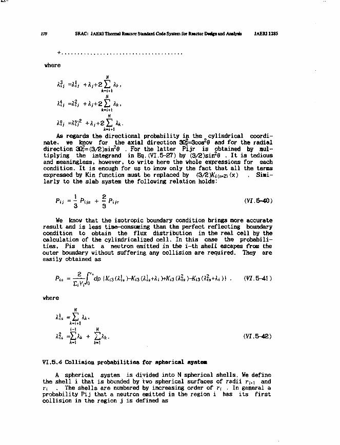
178 SRAC: JAERI Thcnnal Reactor Standard Code Syttem for Reactor IHrifn ind AnalytU JAERI 1285
+.
where
k-t+l
N
N
A?/ =A?72 + A / + 2 ] [ ] Ak.(c-i+l
As regards the directional probability in the cylindrical coordi-nate, we know for the axial direction &%=3c<x£d and for the radialdirection 3fi?=(3/2)sin28 . For the latter Pijr is obtained by mul-tiplying the integrand in Eq.(VI.5-27) by (3/2)sin2e . It is tediousand meaningless, however, to write here the whole expressions for eachcondition. It is enough for us to know only the fact that all the ternsexpressed by Kin function must be replaced by (3/2)Kj(n*2) (x) . Simi-larly to the slab system the following relation holds:
Pi; = I Pa* + ~ Par (VI.5-40)3 3
We know that the isotropic boundary condition brings more accurateresult and is less time-consuming than the perfect reflecting boundarycondition to obtain the flux distribution in the real cell by thecalculation of the cylindrical!zed cell. In this case the probabili-ties, Pis that a neutron emitted in the i-th shell escapes from theouter boundary without suffering any collision are required. They areeasily obtained as
where
i-l N
=XX + I X (VI.5-42)
VI.5.4 Collision probabilities for spherical systea
A spherical system is divided into N spherical shells. We definethe shell i that is bounded by two spherical surfaces of radii n-\ andr, . The shells are numbered by increasing order of r, . In general aprobability Pij that a neutron emitted in the region i has its firstcollision in the region j is defined as
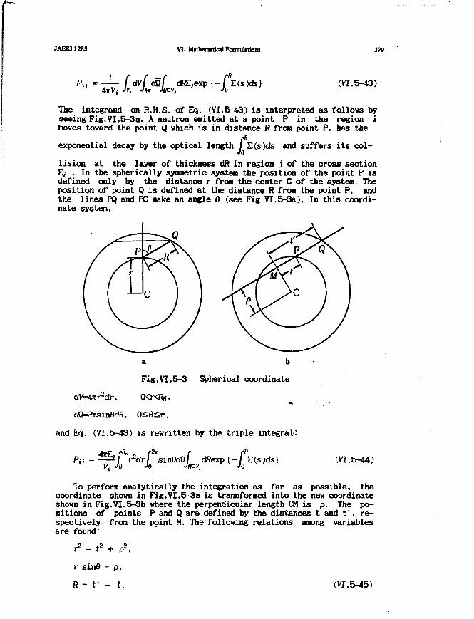
JAERI1285 VI. Mtthtmitical FormiiUtioni 179
Pa = — f dvf daf dREjexp {- fns)(is}47tVj JVi J** JfcVj Jo
(VI. 5-43)
The integrand on R.H.S. of Eq. (VI.5-43) is interpreted as follows byseeing Fig.VI.5-3a. A neutron emitted at a point P in the region imoves toward the point Q which is in distance R from point P, has the
exponential decay by the optical length / £(s)ds and suffers its col-Jo
lision at the layer of thickness dR in region j of the cross sectionE, . In the spherically synaetric system the position of the point P isdefined only by the distance r from the center C of the system. Theposition of point Q is defined at the distance R from the point P, andthe lines PQ and PC make an angle 6 (see Fig.VI.5-3a). In this coordi-nate system,
a b
Fig.VI.5-3 Spherical coordinate
CKKRN,
dO=arsinfide, OS0g7r.
and Eq. (VI.5-43) is rewritten by the triple integral:
r fitl dRexp {-/ E(s)ds| .JRCV, JO
(VI
To perform analytically the integration as far as possible, thecoordinate shown in Fig.VI.5-3a is transformed into the new coordinateshown in Fig.VI.5-3b where the perpendicular length CM is p. The po-sitions of points P and Q are defined by the distances t and t', re-spectively, from the point M. The following relations among variablesare found:
r = t2 + p2,
r sin6 = p,
ft = V - t. (VI.5-45)
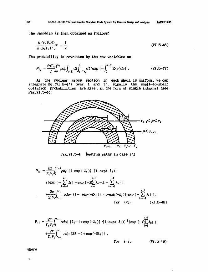
180 SRAC: JAERI Thennal Reactor Standard Code Syitem for Reactor Derifn and Aatlytb JAERI 12SS
The Jacobian is then obtained as follows:
a(r,e,R) _ j_
d(.p,t,f) r
The probability is rewritten by the new variables asrt-f^ > / - f r d t . e x p { _ r ' E ( s ) d s )
" vt Jo f^'V.cvj Jfcv, Jo
(VI.5-46)
(VI.5-47)
As the nuclear cross section in each shell is uniform, we canintegrate Eq. (VI.5-47) over t and f . Finally the shell-to-shellcollision probabilities are given in the form of single integral (seeFig.VI.5-4);
r,_,_,
Fig.VI.5-4 Neutron paths in case i<j
Pa = \ 1-expHii)) {1-exp(-kj))
t - l
*{exp { - +exp i-fc-i
2.Kpdpl [I- exp(-2Ai)( {l-exp(-A>)} exp {-
kfor i<j, (VI.5-48)
Pn =
pdp{2Ai-l+exp(-2Ai)] ,
for i=j,
i-1
X
(VI. 5-49)
where
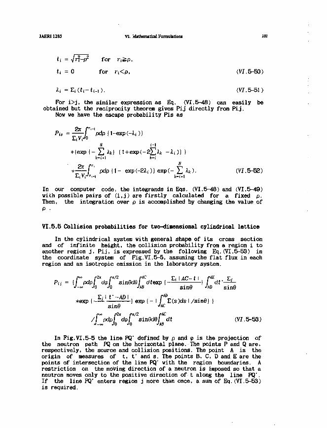
JAERI1285 VI. flUthemtticalFonnubtioiu 181
for n i p ,
t, = 0 for n<p, (VI.5-50)
It =Ec(ti-ti-,). (VJ.5-51)
For i>j, the similar expression as Eq. (VI.5-48) can easily beobtained but the reciprocity theorem gives Pij directly from Pij.
Now we have the escape probability Pis as
Pis = -["'pdp {l-exp(-Aj)}
N i-l
*iexp{- Y. h) U + exp(-2lX -A,)} )k-i+l k-i
+ — f ' pdp 11- exp(-2A;)} exp(- £ 4). (VI.5-52)
In our computer code, the integrands in Eqs. (VI.5-48) and (VI.5-49)with possible pairs of (i,j) are firstly calculated for a fixed p.Then, the integration over p is accomplished by changing the value ofP •
VI.5.5 Collision probabilities for two-dimensional cylindrical lattice
In the cylindrical system with general shape of its cross sectionand of infinite height, the collision probability from a region i toanother region j, Pij, is expressed by the following Eq.(VI.5-53) inthe coordinate system of Fig.VI.5-5, assuming the flat flux in eachregion and an isotropic emission in the laboratory system.
/*~ /"2i pt/2 rAC y\ I 4C— t I f^Pii = { pdp d<p\ sinQdQl dtexp {—— —} /
J-co Jo Jo JAB sine •MDr-1 f -An i r^
*exp (~=^ -—^^-} exp {- I / E(s)ds I /sine} )sine J*c
ro° fi.% rx/2 rAC
/ pdp dtp] sinddd dt (VI. 5-53)•>-<» JQ JQ JAB
In Fig.VI.5-5 the line PQ' defined by p and <p is the projection ofthe neutron path PQ on the horizontal plane. The points P and Q are,respectively, the source and collision positions. The point A is theorigin of measures of t, f and s. The points B, C, D and E are thepoints of intersection of the line PQ' with the region boundaries. Arestriction on the moving direction of a neutron is imposed so that aneutron moves only to the positive direction of t along the line PQ'.If the line PQ' enters region j more than once, a sum of Eq.(VI.5-53)is required.

182 SRAC: JAERI Thermal Reactoi Standard Code System fot Reactoi Design and Analysis JAERI1285
V.
Fig.VI.5-5 Cylindrical coordinate system
The self collision probability, Pii is expressed by the followingEq.(VI.5-54), rfhere the point Q is in region i.
sinO
/•°° fit p*/2 pAC pAC y. y. i f_ f>•< = / Pdp/ dp/ sinBdB dt d f - ^ - e x p { '
J-«. Jo Jo JAB Jt s i n 8
/^o p2x pit/2 pAC/ I pdp I d<p\ sinBdel dt
J_TO Jo Jo JAB(VI.5-54)
If the line PQ' reenters region i, a sum of such a term as Eq.(VI.5-53)is required for obtaining Pii.
The six-fold integrals of Eqs.(VI.5-53) and (VI.5-54) are reducedto the double integrals as follows:
1
-Ki3
dpJQ*d<p{Kt
)+Ki
'i)
(VI.5-55)
(VI. 5-56)
where Ui and Uj denote the optical path lengths (the physical pathmultiplied by the macroscopic total cross section), Ui=BC*Ei, andUj=DE*Ej and Uo stands for the sum of optical path lengths between Cand D; and 3 is the third order Bickley function.
The escape probability Pis defined as a neutron emitted in regioni escapes from the system without suffering collision, is expressed as
Pis = — f " dpf *d<p{Kis(Uis )-K,3<(/,,+Ui)},iVjJ-- Jo
(VI. 5-57)
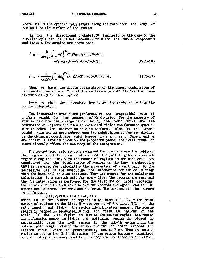
JAER11285 VI. Mathematical Formulationi 183
where Uis is the optical path length along the path from the edge ofregion i to the surface of the system.
As for the directional probability, similarly to the case of thecircular cylinder, it is not necessary to write the whole componentsand hence a few samples are shown here:
Par = — — r dpf *dp{Ki5{Vo)-Ki5Wo+Ui)
-K>5 (Uo+Uj )+K,-5 (Vo+Ui+Uj)], (VI .5-58)
PiiT = — — r dpf *d<p{2Uj-3l<i3(0)+3Ki3Wi)). (VI.5-59)47tEjVi-'-~
Jo
Thus we have the double integration of the linear combination ofKin function as a final form of the collision probability for the two-dimensional cylindrical system.
Here we show the procedure how to get the probability from thedouble integration.
The integration over p are performed by the trapezoidal rule ofuniform weight for the geometry of XY division. For the geometry ofannular division the <p range is divided by the radii which are theboundaries of regions and then in each subdivision the Gaussian quadra-ture is taken. The integration of <p is performed also by the trape-zoidal rule and in some subprograms the subdivision is further dividedby the Gaussian coordinate, which however is inefficient. Once p and <pare chosen, a line is drawn on the projected plane. The total number oflines directly affect the accuracy of the integration.
The geometrical informations required for the line are the table ofthe region identification numbers and the path lengths across eachregion along the line, with the number of regions in the base cell nowconsidered and the total number of regions on the line. A subroutineGEOM is prepared for calculating the information of a unit cell. By thesuccessive use of the subroutine, the information for the cells otherthan the base cell is also obtained. They are stored for the raultigroupcalculation in a scratch unit for every line. The records are read andthe Pij integration is performed for the first set of cross sections,the scratch unit is then rewound and the records are again read for thesecond set of cross sections, and so forth. The content of the recordis as follows,
LO.LLL.W, (T(L).II (L),L=1 ,LLL)where L0 = the number of regions in the base cell, LLL = the totalnumber of regions on the line, W = the weight of the line, T(L) = thepath length and II(L) = the region identification number. The sourceregion is picked up sequentially from the first L0 regions in thetable. If the L-th region is set to the source region (the regionidentification number is II(L)), the collision region is picked upsequentially from the L-th region to the LLL-th region until theoptical path length between the source and the collision exceeds thelimited value (which is provisionally set to 7.0). Then the sourceregion is set to the (L+l)-th region. If the vacuum boundary conditionor the isotropic boundary condition is adopted, the table is cut off at
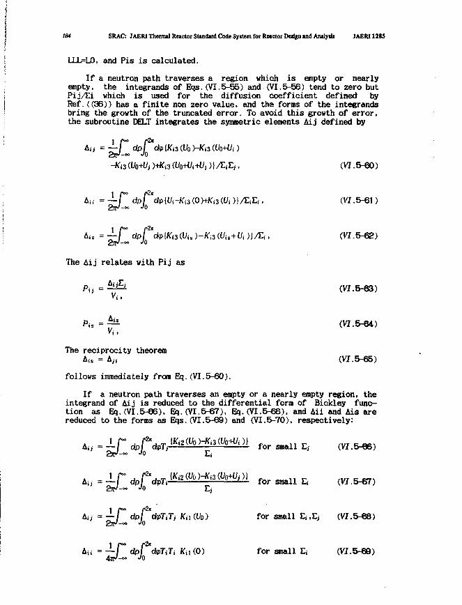
184 SRAC: JAERI Thermal Reactor Standard Code Syitem for Reactor Design and Analyiii JAERI 1285
LLLFLO, and Pis is calculated.
If a neutron path traverses a region which is empty or nearlyempty, the integrands of Eqs.(VI.5-55) and (VI.5-56) tend to zero butPij/ti which is used for the diffusion coefficient defined byRef.((36)) has a finite non zero value, and the forms of the integrandsbring the growth of the truncated error. To avoid this growth of error,the subroutine DELT integrates the symmetric elements Aij defined by
f>)+^3(l/o-*i+t/,)}/EiE,, (VI. 5-60)
r dpf 'dp[Ui-Ki3(.0hKi3(!Ui )}/EjEi, (VI.5-61)-oo JO
'i. )-Ka M,+U( )J/Ei, (VI.5-62)
The Aij relates with Pij as
Pu=^& (VI.5-63)
Pis = — (VI.5-64)Vi ,
The reciprocity theoremAis = Aji (VI.5-65)
follows immediately from Bq.(VI.5-60).
If a neutron path traverses an empty or a nearly empty region, theintegrand of Aij is reduced to the differential form of Bickley func-tion as Eq.(VI.5-66), Eq.(VI.5-67), Eq.(VI.5-68). and Aii and Ais arereduced to the forms as Eqs.(VI.5-69) and (VI.5-70), respectively:
A, - -if d p f V ^ 2 ^ ^ 3 ^ ^ 1 for small E,- (VI.5 6)2ay Jo E
forE,
Au = — r dpf 'dpTtTj Kn (Uo) for small Ej.E^ (VI.5-68)
jTi Kii (0) for small Es (VI.5-69)
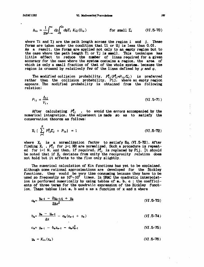
JAERI1285 VI. Mathematical Formulation! i«
1 r f= —/ dpi
' Ki2(Vis) for small Ef (VI.5-70)
where Ti and Tj are the path length across the region i and j. Theseforms are taken under the condition that Ui or Uj is less than 0.01.As a result, the forms are applied not only to an empty region but tothe case where the path length Ti or Tj is small. This technique haslittle effect to reduce the number of lines required for a givenaccuracy for the case where the system contains a region, the area ofwhich is only a small fraction of that of the whole system, because theregion is crossed by relatively few of the lines defined by p and <p.
The modified collision probability, P?/(P?/=PJJ/EJ) is preferredrather than the collision probability, Pij, where an empty regionappears. The modified probability is obtained from the followingrelation:
Pa = - (VI.5-71)
After calculating P*a , to avoid the errors accompanied by thenumerical integration, the adjustment is made so as to satisfy theconservation theorem as follows:
Xi { E $ & + Pu) = 1 (VI.5-72)H
where X, is a normalization factor to satisfy Eq.(VI.5-72). Afterfinding X< , P?y for j=i NR are normalized. Such a procedure is repeat-ed for i=l N, and then, if required, P?, is replaced by Pij. It shouldbe noted that if Xf deviates from unity the reciprocity relation doesnot hold but it affects to the flux only slightly.
The numerical calculation of Kin functions has yet to be explained.Although some rational approximations are developed for the Bickleyfunctions, they would be very time consuming because they have to beused so frequently as lO^lO 7 times. In SRAC the quadratic interpolat-ion is performed numerically by using tables of a, b, c ; the coeffici-ents of three terms for the quadratic expression of the Bickley funct-ion. These tables list a, b and c as a function of x and n where
lh-1 - 2S/-./2 + V.
b.= * " y'-' - a.(x.-, + x.) (VI.5-74)Ax
c.= y,-i - b»x»-i - a.x£-i (VI.5-75)
y.=KinCx,) (VI. 5-76)

186 SRAC: JAERI Thermil Retctor Studud Code System for Retctot DMifn u d Andy* JAERI 1285
A i = (i. - x,-i) (VI.5-7T
The pitch and range of the tabulation of a, b and c is as follows:Ax/x :0.01/<0.0, 0.48), 48 points,
0.04/(0.48, 2.4), 48 points,0.1/(2.4, 9.6), 72 points,
«> /(9.6 oo ),i points,where x>9.6, Kin(x) is assumed to be zero.
Thus the Bickley function is computed by performing twice themultiplication and twice the summations after table look-up:
Kin Or) = (amx + 6n.)i + cn. (W.5-78)
where x,-i S x( x»
The table look-up and the interpolation is performed in the routineitself to avoid the process of calling any external subroutine.
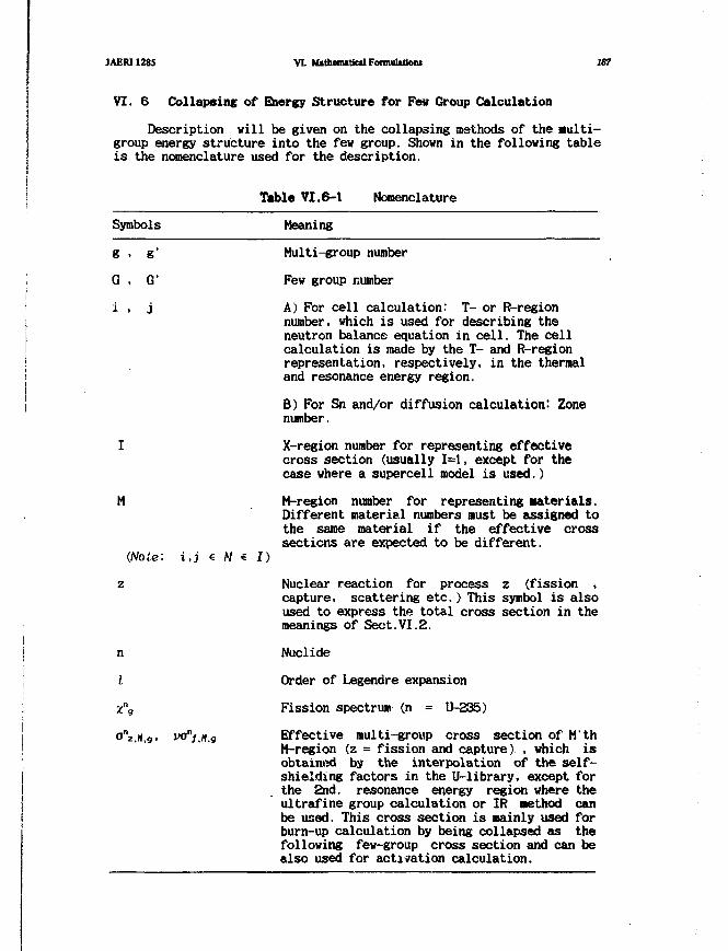
JAERI1285 VI. itothemitfcilFonnuUtioni 187
VI. 6 Collapsins of Energy Structure for Few Group Calculationi
I Description will be given on the collapsing methods of the aulti-1 group energy structure into the few group. Shown in the following table] is the nomenclature used for the description.
| Table VI.6-1 Nomenclature
Symbols Meaning
g , g' Multi-group number
i G , G' Few group number
'• i , j A) For cell calculation: T- or R-region; number, which is used for describing the| neutron balance equation in cell. The celli calculation is made by the T- and R-regionI representation, respectively, in the thermal| and resonance energy region.
| B) For Sn and/or diffusion calculation: Zone| number.
I X-region number for representing effectivecross section (usually 1=1, except for thecase where a supercell model is used.)
M M-region number for representing Materials.Different material numbers must be assigned tothe same material if the effective crosssections are expected to be different.
(Note: i,j € M e I)
z Nuclear reaction for process z (fission ,capture, scattering etc.) This symbol is alsoused to express the total cross section in themeanings of Sect.VI.2.
I
j n Nuclide
| I Order of Legendre expansion
I x"g Fission spectrum (n = U-235)o"z.n,g> WJ"/,«,9 Effective multi-group cross section of M'th
M-region (z = fission and capture) , which is' obtained by the interpolation of the self-
shielding factors in the U-library, except forthe 2nd. resonance energy region where the
| ultrafine group calculation or IR Method can! be used. This cross section is mainly used for
burn-up calculation by being collapsed as thefollowing few-group cross section and can bealso used for activation calculation.
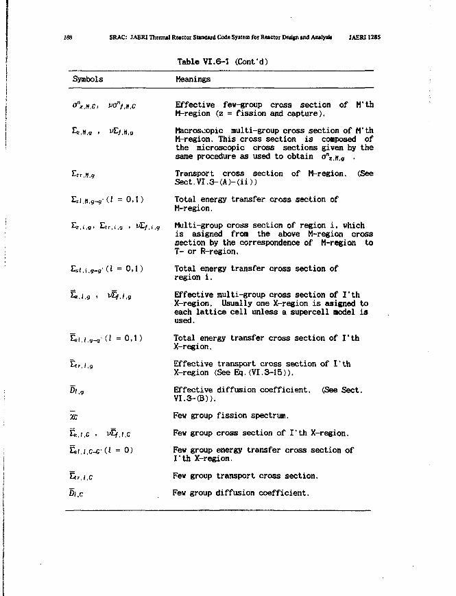
188 SRAC: JAERI Thermal Reactoi Standard Code System for Reactor Deiifn and Analytb JAERI 1285
Table VI. 6-1 (Confd)
Symbols Meanings
on ,«,c. vo"f,H,c Effective few-group cross section of M'thM-region (z = fission and capture).
Ez.M.g . vLf.H.g Macroscopic multi-group cross section of M'thM-region. This cross section is composed ofthe microscopic cross sections given by thesame procedure as used to obtain o\.(f,g .
Etr H g Transport cross section of M-region. (SeeSect.VI.3-(A)-<ii))
£si,M,g_g'(i =0,1) Total energy transfer cross section ofM-region.
£z,i,g> £tr,i,g > v^f.i.g Multi-group cross section of region i, which
is asigned from the above M-region crosssection by the correspondence of M-region toT- or R-region.
Esi,i.g-g'd =0,1) Total energy transfer cross section ofregion i.
fe.i.g , vLf.i,g Effective multi-group cross section of I'thX-region. Usually one X-region is asigned toeach lattice cell unless a supercell model isused.
Esi.i.a-g'd = O'D Total energy transfer cross section of I'thX-region.
Etr / 9 Effective transport cross section of I'thX-region (See Eq.(VI.3-15)).
0/ g Effective diffusion coefficient. (See Sect.
VT.3-(B)).
Few group fission spectrum.
Few group cross section of I'th X-region.Few group energy transfer cross section ofI'th X-region.
Few group transport cross section.
Few group diffusion coefficient.
•xc
E,
a,
EM
DI.
.I.C >
I./.C-C1
r.l.C
c
i £
(I
f . I . C
= 0)
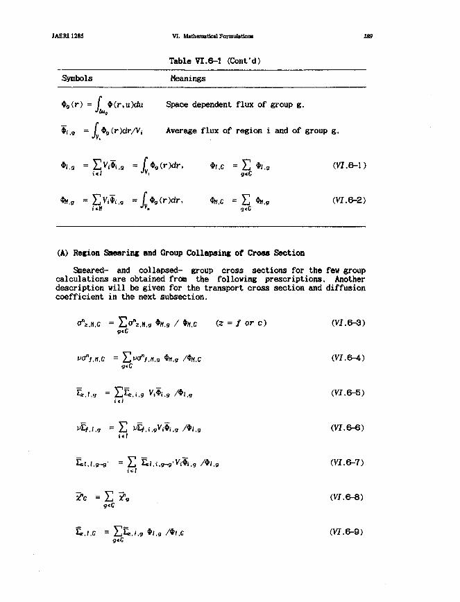
JAER11285 VI. lI»thom»UcilFormuUtk>iii 189
Table VI.6-1 (Confd)
Symbols Meanings
•g(r) = / $(r,u)du Space dependent flux of group g.
*i.9 = / •g(r)dr/Vi Average flux of region i and of group g.
•/.« = E ^ . g =[$g(r)dr, *,,c = E */.g (VI.6-1)
*».« = EVi*i.g = (*g(r)dr, to.c = E *h.9 (W.6-2)g«C
(A) Recion Smearing and Group Collapsing of Cross Section
Smeared- and collapsed- group cross sections for the few groupcalculations are obtained from the following prescriptions. Anotherdescription will be given for the transport cross section and diffusioncoefficient in the next subsection.
an*.H.c = E ° V M . 9 *tf.9 / *«.c (2 = / or c) (VI.6-3)
g«C
C = E ^ . K . 9 *M.g /*«.C (VI.6-4)
.i.9 Vi*i.g /*J.g (VI.6-5)
= E ^.(.gVjSj.g /*/,g (VI.6-6)
' = E Sl.i.g-gV^.g /*,,g (VI.6-7)
(VI.6-8)
&.I.C = E&./.9 *l.g /»I.C (VI.6-9)g<C
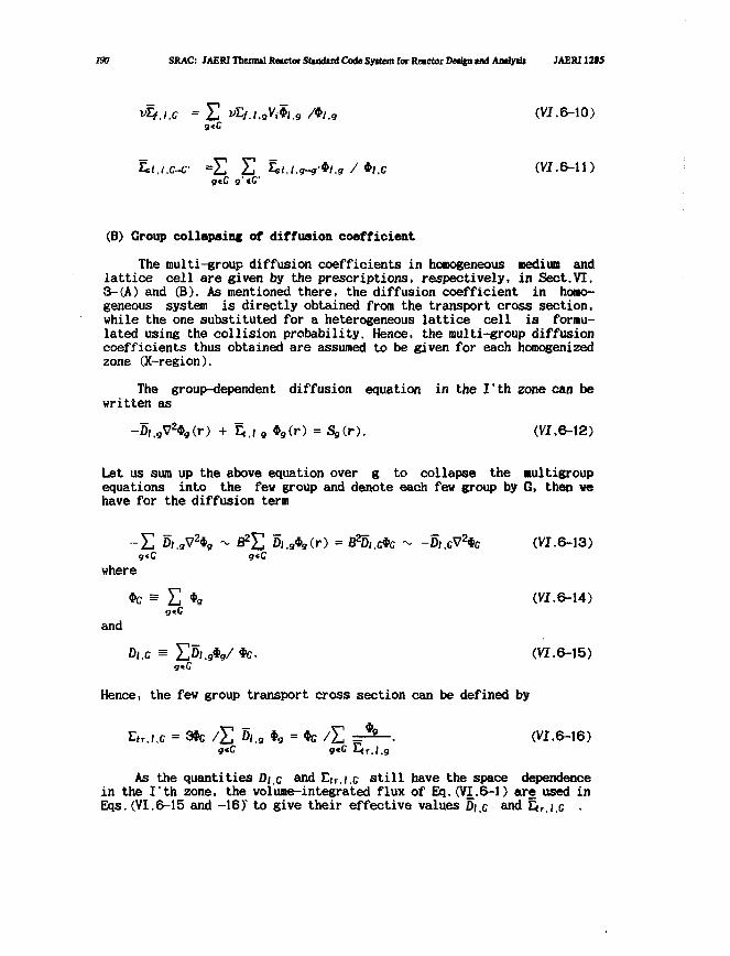
190 SRAC: JAERI Thermal Reactor Stutdird Code Syttem for Reactor Design ind Amlytb JAERJ1205
E ri4.i.,Vi*i.g /»/.„ (VT.6-10)g«C
= E E Si./.W»/../#J.c (VJ.6-1I)gtC g'cC
(B) Group collapsing of diffusion coefficient
The multi-group diffusion coefficients in homogeneous medium andlattice cell are given by the prescriptions, respectively, in Sect.VI.3-(A) and (B). As mentioned there, the diffusion coefficient in homo-geneous system is directly obtained from the transport cross section,while the one substituted for a heterogeneous lattice cell is formu-lated using the collision probability. Hence, the multi-group diffusioncoefficients thus obtained are assumed to be given for each homogenizedzone (X-region).
The group-dependent diffusion equation in the I'th zone can bewritten as
-D/.gV249(r) + %,, , *9(r) = (r). (VI.6-12)
Let us sum up the above equation over g to collapse the nultigroupequations into the few group and denote each few group by G, then wehave for the diffusion term
~ E D(,gV2*9 - E Of.9*g(r) = Eft),,etc - -D,,cV2«c (VI.6-13)
g«C gcC
where
*c s E *g (VI.6-14)9«C
and
Dl.C = E D l . g V *C- (VI.6-15)
Hence, the few group transport cross section can be defined by
Etr.l.c = 3*c / E Oi.g *9 = *c / E =r^-- (VJ.6-16)gtC g«C Etr.l.g
As the quantities Die and Elr,i,c still have the space dependencein the I'th zone, the volume-integrated flux of Bq.(VI.6-1) are used inEqs. (VI.6-15 and -16)' to give their effective values Di,c and Etr,j.c •
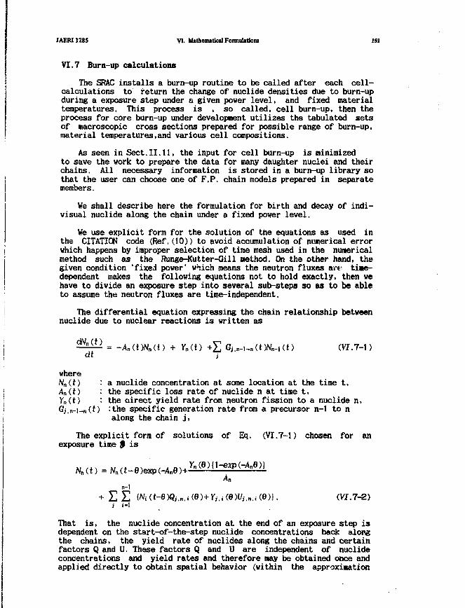
JAERI1285 VI. Mathematical Foimulationi 191
VI. 7 Burn-up calculations
The SRAC installs a burn-up routine to be called after each cell-calculations to return the change of nuclide densities due to burn-upduring a exposure step under a given power level, and fixed materialtemperatures. This process is , so called, cell burn-up, then theprocess for core burn-up under development utilizes the tabulated setsof macroscopic cross sections prepared for possible range of burn-up,material temperatures,and various cell compositions.
As seen in Sect.11.11, the input for cell burn-up is minimizedto save the work to prepare the data for many daughter nuclei and theirchains. All necessary information is stored in a burn-up library sothat the user can choose one of F,P. chain models prepared in separatemembers.
We shall describe here the formulation for birth and decay of indi-visual nuclide along the chain under a fixed power level.
We use explicit form for the solution of the equations as used inthe CITATION code (Ref.(10)) to avoid accumulation of numerical errorwhich happens by improper selection of time mesh used in the numericalmethod such as the Runge-Kutter-Gill method. On the other hand, thegiven condition 'fixed power' which means the neutron fluxes art: time-dependent makes the following equations not to hold exactly, then wehave to divide an exposure step into several sub-steps so as to be ableto assume the neutron fluxes are time-independent.
The differential equation expressing the chain relationship betweennuclide due to nuclear reactions is written as
dt
where
A"(t)
= -An(t)Nn(t)
a nuclide concentration at some location at the time t,the specific loss rate of nuclide n at time t,the oirect yield rate from neutron fission to a nuclide n,:the specific generation rate from a precursor n-1 to nalong the chain j,
The explicit form of solutions of Eq. (VI.7-1) chosen for anexposure time $ is
Ann-1
+ E E M (t-0)Qi.n.i (BHYj.i (fiWi,n.i (6)}. (VT.7-2)i i-I
That is, the nuclide concentration at the end of an exposure step isdependent on the start-of-the-step nuclide concentrations back alongthe chains, the yield rate of nuclides along the chains and certainfactors Q and U. These factors Q and U are independent of nuclideconcentrations and yield rates and therefore nay be obtained once andapplied directly to obtain spatial behavior (within the approximation

132 SRAC: JAERI Thermal Reactor Stindud Code System for Reactor Deujn tnd Amlytii JAERI1285
of exposure to the constant neutron fluxes). These factors are given by
QjniAn—A, k~ Am
n-l.
Ann-1
Am(An-A.)
n-l.
In the above equations the term An represents the total specific lossrate of a nuclide, neglecting time change of neutron flux,
An = An 1CT24 (VI, 7-5)
where $9iZ denotes neutron flux integrated in spatial region z andenergy width g, and the generation rate from a precursor is given by
10"2*
by capture
by decay
by partial decay
by partial capture
by n-2n reaction (VI.7-6)
depending on the chain route specifications, where Hn and En denotethe fraction of the reaction to the nuclide n.
It is assumed that F.P. nuclides follow in order all fissilenuclides, and strong absorbers. The end-of-step concentrations are cal-culated by processing the chain relationship specified. When the firstF.P. nuclide is encountered, all the yield rates in Eq. (VI.7-2) arecalculated as
(VI.7-7)
where Y»_n is the specified fission yield (fraction) of product nucliden from fissile nuclide m, and the arithmetic average of the end-pointvalues of the fissile nuclide concentrations are used as shown in Eq.(VI.7-7).
For a non-depleting, one-nuclide chain, the equation solved is
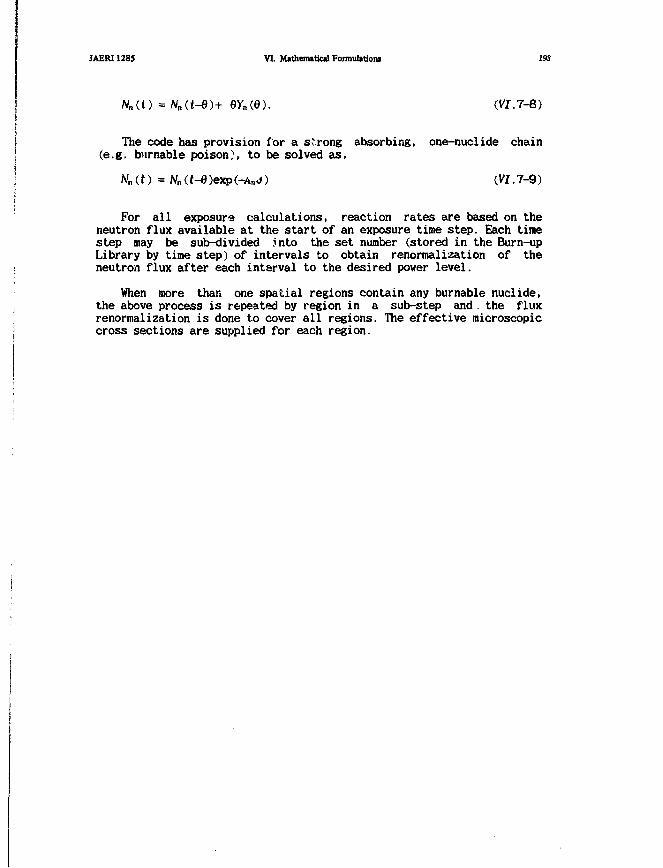
JAERI1285 VI. Mathematical Formulations 193
A U O = AUt-e>+ eyn(e). (vi.7-8)
The code has provision for a strong absorbing, one-nuclide chain(e.g. burnable poison), to be solved as,
Nn (t) = Nn (t-6 )exp(-An d) (VI .7-9)
For all exposure calculations, reaction rates are based on theneutron flux available at the start of an exposure time step. Each tinestep may be sub-divided into the set number (stored in the Burn-upLibrary by time step) of intervals to obtain renormalization of theneutron flux after each interval to the desired power level.
When more than one spatial regions contain any burnable nuclide,the above process is repeated by region in a sub-step and . the fluxrenormalization is done to cover all regions. The effective microscopiccross sections are supplied for each region.
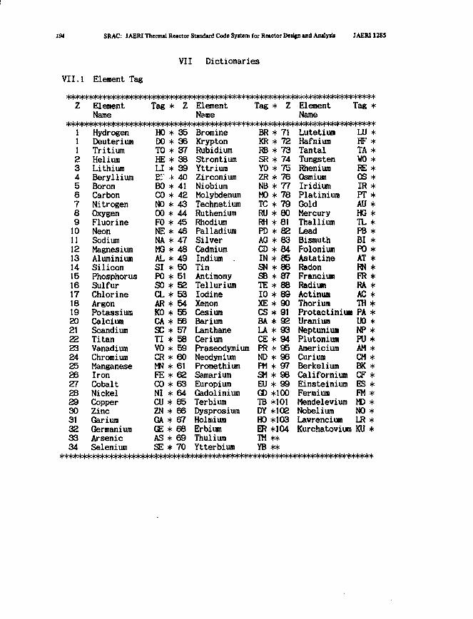
194 SRAC: JAERlTherirud Reactor StamUrd Code Syttem for Reactor Dedp) and Analyiif JAERI1285
VII Dictionaries
VII.1 Element Tag
Z
1112345678910111213141516171819202122232425262728293031323334
ElementName
• • I t i i t i i t t f l i
HydrogenDeuteriumTritiumHeliumLithiumBerylliumBoronCarbonNitrogenOxygenFluorineNeonSodiumMagnesiumAluminiumSiliconPhosphorusSulfurChlorineArgonPotassiumCalciumScandiumTitanVanadiumChromiumManganeseIronCobaltNickelCopperZincGariumGermaniumArsenicSelenium
rTT-TT"
Tag
(o|c(o)ojo
HODOTOHELIE''BOCONO00F0NENAMGALSIP0SOCLARK0CASCTIVOCRMNFECONICUZNGAGEASSE
*
*****
******************************
TTTT
Z
353637383940414243444546474849505152535455565758596061626364656667686970
T T T T T m 1 —1-1—1 -)"
ElementName
=(O|o(o(o|c(c(c)o|c)o)o(oto
BromineKryptonRubidiumStrontiumYttriumZirconiumNiobiumMolybdenumTechnetiumRutheniumRhodiumPalladiumSilverCadmiumIndium .TinAntimonyTelluriumIodineXenonCesiumBariumLanthaneCeriumPraseodymiumNeodymiumPromethiumSamariumEuropiumGadoliniumTerbiumDysprosiumHolmiumErbiumThuliumYtterbium
Tag
BRKRRBSRY0ZRNBM0TCRURHPDAGCDINSNSBTE10XECSBALACEPRNDPMSMEUGDTBDYHOERTMYB
* Z
|c{ots|°Tcr
* 71* 72* 73* 74* 75* 76* 77* 78* 79* 80* 81* 82* 83* 84* 85* 86* 87* 88* 89* 90* 91* 92* 93* 94* 95* 96* 97* 98* 99*100*101*IO2*103*104**
ElementName
LutetiumHafniumTantalTungstenRheniumOsmiumIridiumPlatiniumGoldMercuryThalliumLeadBismuthPoloniumAstatineRadonFranciumRadiumActinumThoriumProtactiniumUraniumNeptuniumPlutoniumAmericiumCuriumBerkeliumCaliforniumEinsteiniumFermiumMendeleviumNobeliumLawrenciumKurchatovium
Tag
LUHFTAWOREOSIRPTAUHGTLPBBIPOATRNFRRAACTHPAUONPPUAMCMBKCFESFMMDNOLRKU
*
**********
*
*********************
>|o|olo|o|o|o(c^o(oMo(o(oM=*^=|o|o(°M=l^^
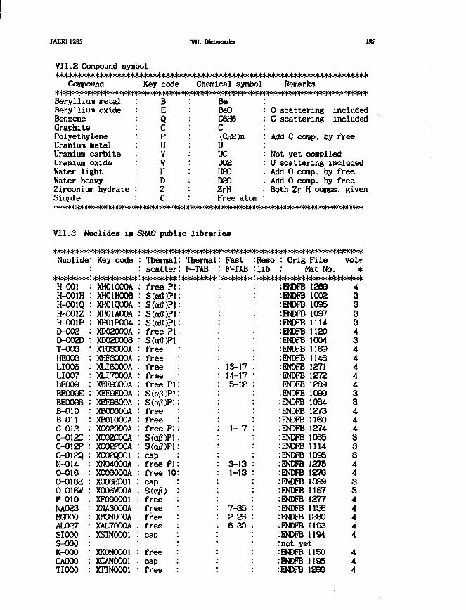
JAERI128S VD. Dictionuies 195
VII.2 Compound symbolHo|o|<****=mo|o|o|o)o!c(olo^^
Compound Key code Chemical symbol Remarks**>|o(ot3M=m*************^
0 scattering includedC scattering included
Add C comp. by free
Not yet compiledU scattering includedAdd 0 comp. by freeAdd 0 comp. by freeBoth Zr H comps. given
Beryllium metalBeryllium oxideBenzeneGraphitePolyethyleneUranium metalUranium carbiteUranium oxideWater lightWater heavyZirconium hydrateSimple
: B: E
QCPuVwHD20
BeBeOC6H6C(CH2)nUXuoeH20D20ZrHFree atom
VII.3 Nuclides in SBAC public libraries
*>|o|cm*****************^
FastF-TAB*******
Nuclide
********H-001H-001HH-001QH-001ZH-001PD-002D-002DT-003HE003LI006LI007BE009BE009EBE009BB-O1OB-OllC-012C-012CC-012PC-012QM-0140-0160-016E0-016WF-019NA023MGOOOAL027SIOOOS-000K-OOOCAOOO :TIOOO
: Key code
:**********: XH01000A: XH01H008: XH01Q00A: XH01AO0A: XH01P004• XD02000AXD02D008XT03000AXHE3000AXLI6000AXLI7000AXBE9000AXBE9E00AXBE9B00AXBOOOOOAXB01000AXC02000AXC02C00AXC02POOAXCO2qOOlXN04000AX006000AX006E001 :X006WOOAXF090001 :XNA3000AXMGNOOOA •XAL7000A .XSIN0001 :
XKONOOOl :XCAN0001 :XTIN0001 :
: Thermal: Thermal: scatter: F-TAB:********:********: free PI:: S («/?)?!:S (a/J )P1:S(a/3)P1:S (aJ3 )P1:free PI:S(ot0)Pl:freefree :free :free :free PI:S(a/3)P1:S(a/J)Pl:free :free :free PI:S(a/J)Pl:S(a0)Pl:cap :free PI:free 10:cap :S(c$) :free :free :free :free :cap :
free :cap :free :
13-1714-175-12
1- 7
3-131-13
7-352-266-30
Reso : Orig Filelib : Nat No.
:ENDFB 1269:ENDFB 1002: ENDFB 1095:ENDFB 1097:ENDFB 1114: ENDFB 1120:ENDFB 1004: ENDFB 1169:ENDFB 1146: ENDFB 1271:ENDFB 1272:ENDFB 1289:ENDFB 1099:ENDFB 1064:ENDFB 1273:ENDFB 1160:ENDFB 1274:ENDFB 1065.•ENDFB 1114: ENDFB 1095: ENDFB 1275: ENDFB 1276: ENDFB 1099:ENDFB 1167:ENDFB 1277:ENDFB 1156:ENDFB 1280:ENDFB 1193:ENDFB 1194:not yet:ENDFB 1150:ENDFB 1195:ENDFB 1286
vol**
43333434444433444333443344444
444

196
V-000CROOOMN056FEXXX)C0059NIOOOOJOOOCU063KR083ZROOOZROOOZNB093MOOOOM0099TC-99RU1O1RU103RU105RH103RH105PD105PD107PD108AG107AG109CDOOOCD113INI 13INI 151-1311-135SB121SB123XE131 •XE133 •XE135 :CS133 :CS134 :CS135 :PR143 :ND143 :ND145 :NDU7 :PM147 :PM148g :PM148m :PM149 :PM151 :SMI47 :SM148 :SMI49 :SM150 :SMI51 :SM152 :EU153 :EU154 :EU155 :EU156 :
: XVONOOOl: XCRWOOA: XMN50001: XFENOOOA: XC090001: XNINOOOA: XCUN0001: XCU30001: XKR30001: XZRNOOOA: XZRNZOOA: XNB30001: XMONOOOA: XM090001: XTC90001• XRU10001XRU30001XRU50001XRH30001XRH50001XPD50001XPD70001XPD60001XAQ70001XAG9000AXCDNOOOAXCD30001XIN3000AXIN5000AXI010001XI050001XSB10001XSB30001XXE10001XXE30001XXE50001XCS30001XCS40001XCS50001 .XPR30001 :XND30001 :XND50001 :XND70001 :XPM70001 :XPMQ0001 :XPMM0001 :XPM90001 :XPM10001 :XSM70001 :XSM80001 :XSM90001 :XSM00001 :XSM10001 :XSM20001 :XEU30001 :XEU40001 :XEU50001 :XEU60001 :
: free: free: cap: free: free: free: cap: cap: cap: free: S(a/3)P1: free: free: cap: cap: cap: cap: cap: capcapcapcapcapcapfreefreecapfreefreecapcapfreefreecapcapcapcapcapcapcapcapcapcapcapcapcapcapcapcapcapcapcapcapcapcapcapcapcap
6-35
6-37
9-34
not yet
20-44
35-55
49-6539-69
ctor Derign ind Anlyiit
:ENDFB 1196:ENDFB 1191:ENDFB 1197:ENDFB 1192:ENDFB 1199:ENDFB 1190:ENDFB 1295
fast:ENDFB 6411: ENDFB 1184:ENDFB 1284:ENDFB 1096:ENDFB 0235:ENDFB 1287:ENDFB 0269.ENDFB 1137:ENDFB 0310:ENDFB 0312: ENDFB 0314:ENDFB 0330:ENDFB 0334:ENDFB 0359: ENDFB 0361:ENDFB 0363
1 :ENDFB 11381 : ENDFB 1139
: ENDFB 1281:ENDFB 1282
1 :ENDFB 04451 :ENDFB 0449:ENDFB 0570:ENDFB 0576: ENDFB 0511:ENDFB 0514:ENDFB 0592:ENDFB 0433: ENDFB 1294:ENDFB 0613:TAKAN00434: ENDFB 0616:ENDFB 0695:ENDFB 0714: ENDFB 0716:ENDFB 0718: ENDFB 0733: ENDFB 0734: ENDFB 0735:ENDFB 0736: ENDFB 0738-ENDFB 0753: ENDFB 0754:ENDFB 1027:ENDFB 0756:ENDFB 0757:ENDFB 0758:ENDFB 0776:ENDFB 0777:ENDFB 0778:ENDFB 0779
JAERI 1285
4444444444334444444444444444444444S44S44444444444444444444
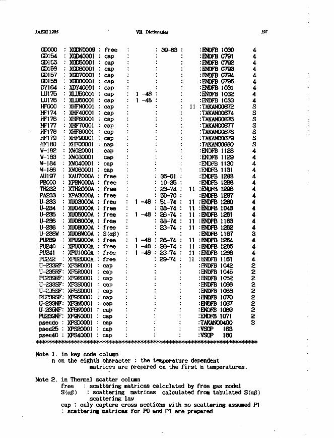
MERI1285 VII. DfctJonuie* 137
CDOOOGDI 54GDI CoGDI 56GDI 57GD158DY164LU175LU176HFOOOHF174HF176HF177HF178HF179HF180W-182W-183W-184W-186AU197PBOOOTH232PA233U-233U-234U-235U-236U-238U-238WPU239PU240PU241PU242U-233RFU-235RFPU239RFU-S33SFU-235SFPU239SFU-233NFU-235NFPU239NFpseudopseu25pseu40
XGEN0009XGD40001XQD60001XGO60O01XGD70001XGD6OOO1XDY40001XLU50001XLU60001XHFNOOO1XHF40001XHP60001XHF70001XHF8O0O1XHP90001XHFOOOOlXW020001XW030001XW040001XW060001XAU7000AXPBNOOOAXTH2000AXPA3000AXU03000AXU04000AXU06000AXU06000AXU08000AxuoewooAXPU9000AXPUOOOOAXPUIOOOAXPU2000AXF3R00O1XF5R0001XF9ROOOIXF3S0001XF5S0001XF9S0001XF3N0001XP5N0001XF9NOOO1XPSDOOO1XPS20001XPS40001
: free: cap: cap: cap: cap: cap: cap: cap: cap: cap: cap: cap: cap: cap: cap: cap: cap: cap: cap: cap: free: free: free: free: free: free: free: free: free
: free: free: free: free: cap :: cap: cap: cap :: cap :: cap :: cap :: cap :: cap :: cap :: cap :: cap :
: 1 -48: 1 -48
1 -48
1 -48
1 -481 -481 -48
: 39-63 :
35-61 :10-35 :23-74 :50-70 :51-74 :38-74 :26-74 :38-74 :23-74 :
26-74 :26-74 :23-74 :29-74 :
11
11
1111111111
11111111
:ENDFB 1030:ENDFB0791:ENDFB0792:ENDFB0793:EMDFB 0794:ENDFB 0795:ENDFB 1031:ENDF6 1032:ENDFB 1033:TAKAN00872:TAKAN00874:TAKAN00876:TAKAN00877:TAKAN00678:TAKAN00879:TAKAN00680:ENDFB 1128:ENDFB 1129:ENDFB 1130:ENDFB 1131:ENDFB 1283:ENDFB 1286:ENDFB 1296:ENDFB 1297:ENDFB 1260:ENDFB 1043:ENDFB 1261:ENDFB 1163:ENDFB 1262:ENDFB 1167:ENDFB 1264:ENDFB 1265:ENDFB 1266:ENDFB 1161:ENDFB 1042:BNDFB 1045:ENDFB 1052:ENDFB 1066:ENDFB 1068:ENDFB 1070:ENDFB 1067:ENDFB 1068:ENDFB 1071:TAKAN00400:VSOP 163:VSOP 160
444444444SSSSSSS444444444444434444222222222S
* * * * * * * * * * * > M ° M < * * * * * * * * * * * ^ ^
Note 1. in key code columnn on the eighth character : the temperature dependent
matrices are prepared on the first n temperatures.
Note 2. in Thermal scatter columnfree : scattering matrices calculated by free gas modelS(a0) : scattering matrices calculated from tabulated S(a/3)
scattering lawcap : only capture cross sections with no scattering assumed PI: scattering matrices for PO and PI are prepared
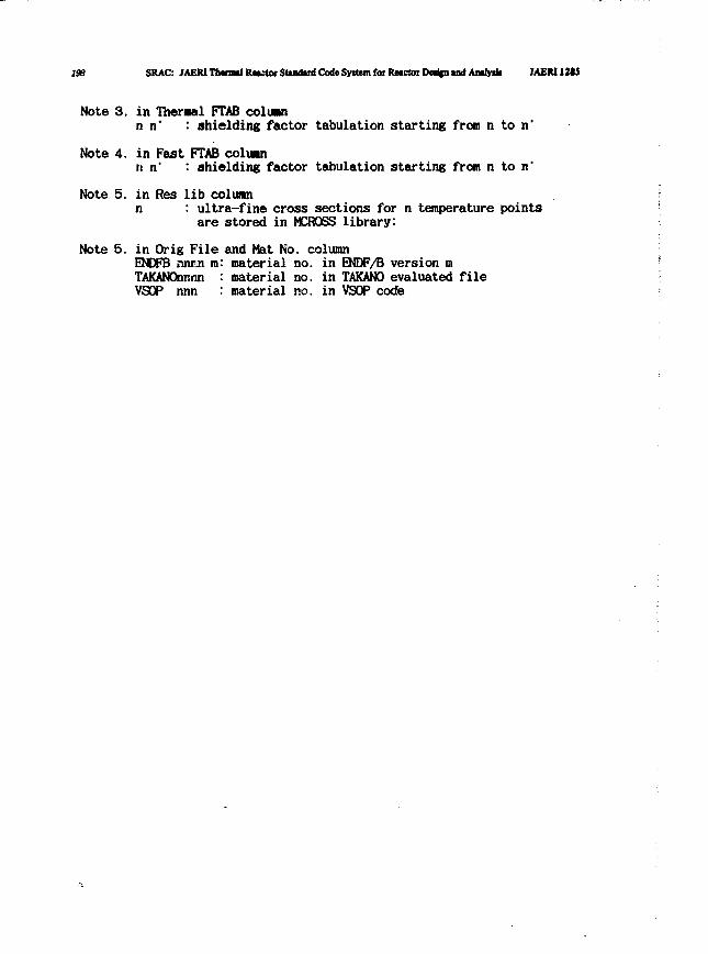
296 SRAC: JAEW Tbmni Rttctor Standard Code Syitem for Reactor Dec%n and Analy* MEN12t5
Note 3. in Theraal FTAB coluann n' : shielding factor tabulation starting from n ton'
Note 4. in Fast FTAB coluann n" : shielding factor tabulation starting from n ton'
Note 5. in Res lib columnn : ultra-fine cross sections for n temperature points
are stored in MCRQSS library:
Note 5. in Orig File and Mat No. columnENDFB nnrin mTAKANOnr.nnVSOP nnn
material no. in EMDF/B version mmaterial no. in TAKANO evaluated filematerial no. in VSOP code
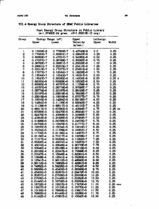
JAERI12S5 VII. DfctkntiiN 199
VII.4 Enercy Group Structure of SRAC Public Libraries
Fast Energy Group Structure in Public Library(m=l.67482E-24 gram, eV=l.60210E-12 erg)
Group
12345678910111213141516171819202122232425262728293031323334353637383940414243444546474849
Energy Range (eV)Upper
0.10000E+80.77880E+70.60653E+70.47237E+70.36788E+70.28651E+70.22313E+70.17377E+70.13534E+70.10540E+70.82085E+60.63928E+60.49787E+60.38774E+60.30197E+60.23518E+60.18316E+60.142B4E+60.11109E+60.86517E+50.67380E+50.52475E+50.408t8E+50.31828E+50.24788E+50.19305E+50.15034E+50.11709E+50.91188E+40.71017E+40.5530BE+40.43074E+40.33546E+40.26126E+40.20347E+40.15846E+40.12341E+40.96112E+30.74852E+30.58295E+30.45400E+30.35357E+30.27535E+30.21445E+30.16702E+30.13007E+30.10130E+30.78893E+20.61442E+2
Lower
0.77880E+70.60653E+70.47237E+70.36788E+70.28651E+70.223I3E+70.17377E+70.13534E+70.10540E+70.8R085E+80.639S8E+60.49787E+60.38774E+60.30197E+60.23518E+60.18316E+60.14264E-+60.11109E+60.86517E+50.67380E+50.52475E+50.40868E+50.31828E+50.24788E+50.19305E+50.15034E+50.11709E+50.9U88E+40.71017E+40.55308E+40.43074E+40.33546E+40.25125E+40.20347E+40.15846E+40.12341E+40.93112E+30.74852E+30.58295E+30.45400E+30.35357E+30.27536E+30.21445E+30.16702E+30.13007E+30.10130E+30.78893E+20.61442E+20.47851E+2
UpperVelocity(m/sec)
0.43740E+80.38600E+80.34065E+80.30062E+80.26529E+80.23412E+80.20661E+80.18233E+80.16091E+80.14200E+80.12532E+80.11059E+80.975Q6E+70.86129E+70.76008E+70.67077E+70.59195E+70.52240E+70.46101E+70.40684E+70.35904E+70.31685E+70.27962E+70.24676E+70.21777E+70.19218E+70.16960E+70.14967E+70.13208E+70.11656E+70.10287E+70.90779E+60.80112E+60.70699E+60.62391E+60.55060E+60.48590E+60.42881E+60.37842E+60.33396Et60.29472E+60.26009EH60.22952E+60.20255E+60.17875E+60.15775E+60.13921E+60.12286E+60.10642E+6
LethargyUpper
0.00.250.500.751.001.251.501.752.002.252.502.753.003.253.503.754.004.254.504.755.005.255.505.756.006.256.506.757.007.257.507.758.008.258.508.759.009.259.509.7510.0010.2510.5010.7511.0011.2511.5011.7512.00
Width
0.250.250.250.250.250.250.250.250.250.25 *0.250.250.250.250.250.250.250.250.250.25 **0.250.250.250.250.250.250.250.250.250.250.250.250.250.250.250.250.250.250.250.250.250.250.250.250.25 ***0.250.250.250.25
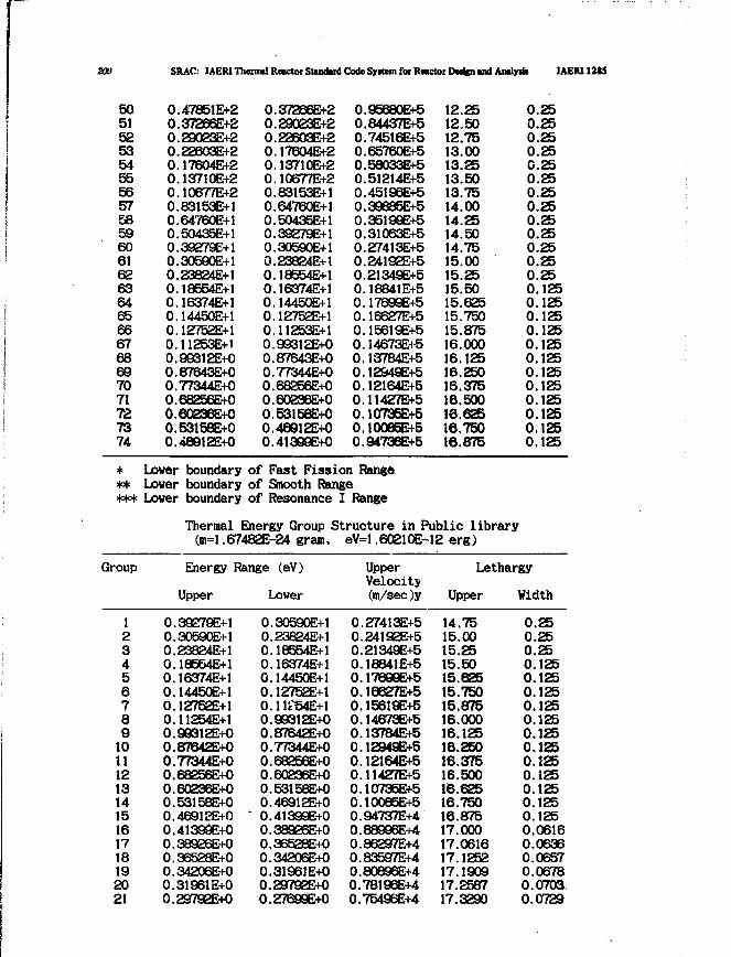
200 SRAC: JAERIThemul Reictor Standard Code Syitem for RMctor Dedfn and Andy* IAERI12S5
50515253545556575859606162636465666768697071727374
0.47851E+20.37266E+20.29023E+20.22603E+20.17604E+20.13710E+20.10677E+20.83153E+10.64760E+10.50435E+10.39279E+10.30590E+10.23824E+10.18554E+10.16374E+10.14450E+10.12752E+10.11253E+10.99312E+00.87643E+00.77344E+00.682S6E+00.60236E+00.53158E+00.48912E+0
0.37266E+20.29023E+20.23603E+20.17604E+20.13710E+20.10677E+20.83153E+10.64760E+10.50435E+10.39279E+10.30590E+10.23824E+10.18554E+10.16374E+10.14450E+10.12752E+10.11253E+10.99312E+00.87643E+00.77344E+00.68256E+00.60236E+00.53158E+00.48912E+00.41399E+0
0.956B0E+50.84437E+50.74516E+50.65760E+50.58033E+50.51214E+50.45193E+50.39685E+50.35199E+50.31063E+50.27413E+50.2419eE+50.21349E+50.18841E+50.17699E+50.16627E+50.15619E+50.14673E+50.13784E+50.12949E+50.12164E+50.11427E+50.10736E+50.10086E+50.94736E+5
12.2512.5012.7513.0013.2513.5013.7514.0014.2514.5014.7515.0015.2515.5015.62515.75015.87516.00016.12516.25016.37516.50016.62516.750t6.875
0.250.250.250.25C.250.250.250.250.250.250.250.250.250.1250.1250.1250.1250.1250.1250.1250.1250.1250.1250.1250.125
* Lover boundary of Fast Fission Range** Lover boundary of Smooth Range*** Lover boundary of Resonance I Range
Thermal Energy Group Structure in Public library(m=l.67482E-24 gram, eV=l.60210E-12 erg)
Group Energy Range (eV)
Upper Lower
UpperVelocity(m/sec)y
Lethargy
Upper Width
123456789101112131415161718192021
0.39279E+10.30590E+10.23824E+10.18554E+10.16374E+10.14450E+10.12752E+10.11254E+10.9G312E+00.87642E+00.77344E+00.68256E+00.60236E+00.53158E+00.46912E+00.41399E+00.38926E+00.36528E+00.34206E+00.31961E+00.29792E+0
0.30590E+I0.23824E+10.18554E+10.16374E+10.14450E+10.12752E+10.11F54E+10.99312E+00.87642E+00.77344E+00.68256E+00.60236E+O0.53158E+00.46912E+0
" 0.41399E+00.38926E+00.36528E+00.34206E+00.3196JE+00.29792EK)0.27699E+0
0.27413E+50.24192E+50.21349E+50.18841E+50.17699E+50.16627E+50.15619E+50.14673E+50.13784E+50.12949E+50.12164E+50.11427E+50.10735E+50.10085E+50.94737E+40.88996E+40.86297E+40.83597E+40.8O896E+40.78196E+40.75496E+4
14.7515.0015.2515.5015.62515.75015.87516.00016.12516.25016.37516.50016.62516.75016.87517.00017.061617.125217.190917.258717.3290
0.250.250.250.1250.1250.1250.1250.1250.1250.1250.1250.1250.1250.1250.1250.06160.06360.06570.06780.07030.0729
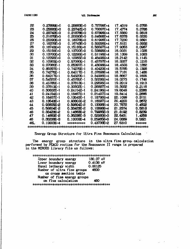
JAERI1285
22232425262728293031323334353637383940414243444546474848L
0.27699E+0Q.25683E+00.23742E+00.21878E+00.20090E+00.18378E+00.16743E+00.15183E+00.13700E+00.I2293E+00.10963E+00.97080E-10.85397E-10.74276E-10.64017E-10.54520E-10.45785E-10.37813E-10.30602E-10.24154E-10.18467E-10.13543E-10.93806E-20.59804E-20.33423E-20.I4863E-20.35238E-30.10000E-4
vn.
0.25683E+00.23742E+00.21878E+00.20090E+00.18378E+00.16743E+00.15183E+00.13700E+00.12293E+O0.10963E+00.97080E-10.85397E-10.74276E-10.64017E-10.54520E-10.45785E-10.37813E-10.30602E-10.24154E-10.18467E-10.13543E-10.938O5E-20.56804E-20.33423E-20.14663E-20.35238E-3o.iooooe-4**********
DktiouiiM
0.72796E+40.70097E+40.673Q6E+40.64896E+40.61996E+40.59296E+40.56597E+40.53896E+40.51196E+40.4849SE+40.45797E+40.43096E+40.40420E+40.37696E+40.34996E+40.32296E+40.29596E+40.26897E+40.24196E+40.21497E+40.18796E+40.16O97E+40.13396E+40.10696E+40.79Q65E+30.52965E+30.25965E+30.43738E+2
17.401917.477417.559017.637817.723017.812117.905318.003118.105918.214218.328718.450318.578518.718118.866719.027319.201919.393219.604819.841420.109920.420020.787221.237421.819222.643124.068927.6310
0.07550.07860.08180.02300.08910.09320.09370.10280.10630.11450.12160.12820.13960.14860.16060.17460.19130.21160.23660.26850.31010.36720.45020.68180.82391.42583.5621******
301
************************** ^
Energy Group Structure for Ultra Fine Resonance Calculation
The energy group structure in the ultra fine group calculationperformed by PEACO routine for the Resonance II range is preparedin the MCROSS library file as follows;
Upper boundary energy 130.07 eVLower boundary energy 0.4139 eVEqual lethargy width 0.00125Number of ultra fine groups 4600
on cross section tableNumber of fine energy groups
on flux calculation 460
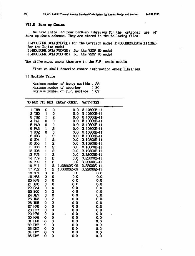
202 SRAC: JAERI Thermal Reictor Standud Code Syitem for Retctot Dedjn and Analvtit JAERI 12SS
VII.5 Burn-up Chains
We have installed four burn-up libraries for the optional use ofburn-up chain schemes. They are stored in the following files.
01480.BURN.DATA(ENDFB2) for the Garrison model J1480.BURN.DATA(IIJIMA)for the Iijiraa modelJ1480.BURN.DATA(VS0P25) for the VSOP 25 modelJ1480.BURN.DATA(VS0P40) for the VSOP 40 model
The differences among them are in the F.P. chain models.
First we shall describe common information among libraries.
1) Nuclide Table
Maximum number of heavy nuclideMaximum number of absorberMaximum number of F.P. nuclide
222067
NO NUC FIS RES DECAY CONST. WATT/FISS.
1234567891011121314151617181920212223242526272829303132333435
TH8THOTH2PA1PA2PA3U02U03U04U05U06U08PU8PU9PUOPU1PU2NP7NP8NP9AM3CM4BOOACTIN3IN5HF6HF7HF8HF9HFODMYDMYDMYDMY
01100101111111111000000000000000000
00200202222222222000002022000000000
0.00.00.00.00.00.00.00.00.00.00.00.00.00.00.0
1.68000E-091.68000E-09
0.00.00.00.00.00.00.00.00.00.00.0
- 0.00.00.00.00.00.00.0
3.3.3.3.3.3.3.3.3.3.3.3.3.3.3.3.3.
10B00E-1110800E-11
loeooE-nloeooE-n10800E-1110800E-1110800EM1loeooE-ii10800E-1110800E-1110800E-1110800E-1122000E-1122000E-1122000E-1122000E-1122000E-11
0.00.00.00.00.00.00.00.00.00.00.00.00.00.00.00.00.00.0
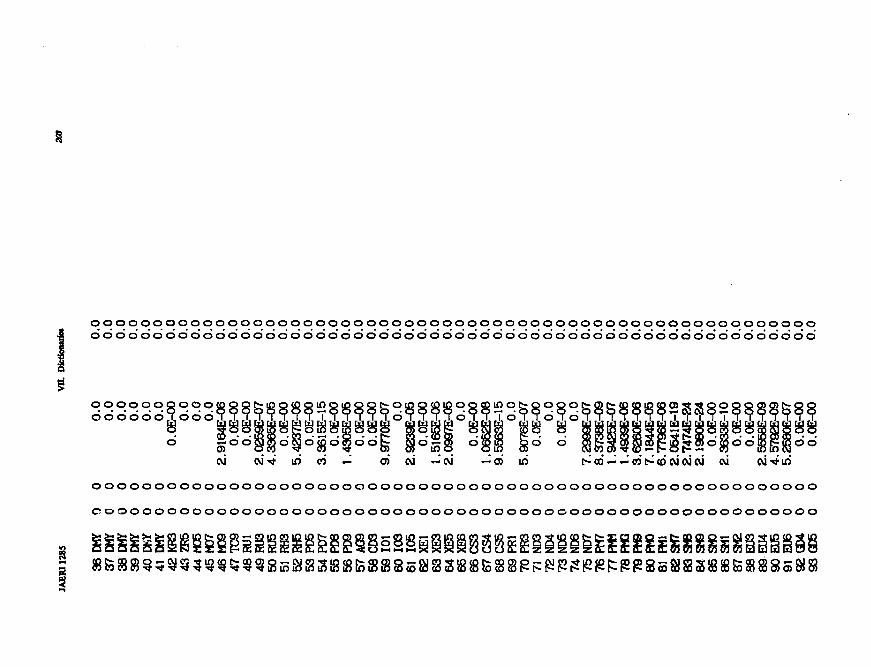
O O O O O O O O O O O O O O O O O O O O O O O O O O O O O O O O O O O_ O_ O O O O_ O O O O O O O O O O O O O O O O O O
o o o o o o o o o o o o o o o o o o o o o o o o o o o o o o o o o o o o o o o o o o o o o o o o o o o o o o o o o o
oooooooooodo'6d6c>5,dod
0 6
N CVlTf lf> CO — O) CM —CM — 0) Ifl t" CO — — CO t - <D CVJ CM W W CVl-^lfl
OOOOOOOOOOOOOOOOOOOOOOOOOOOOOOOOOOOOOOOOi
OOOOOOOOOOOOOOOOi
.££S82S2HSp3SoooSuiI " ^ CD a c* *•• J CO 2 1 \£) $0 j1 tf?• C 3d 3S 3S £ 3C 3S £5 M) 3 25 CJ CJ
1
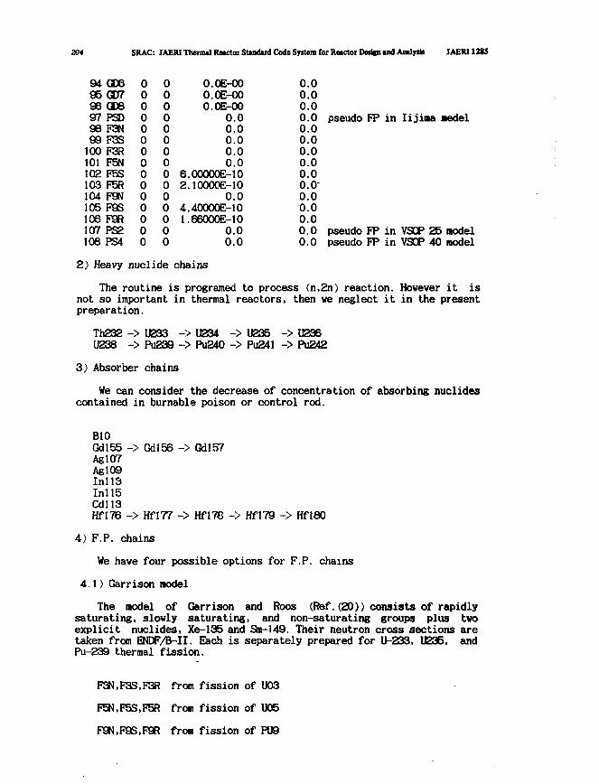
204 SRAC: JAERI Thennal Reactor Standard Code Syitem for Reactor Derifn and Analysb JAERI 1H5
949596979899100101102103104105106107108
GD6OCRGDBPSDF3NF3SF3RF5NF5SF5RF9NF9SF9RPS2PS4
000000000000000
000000000000000
6.2.
4.1.
O.OE-00O.OE-00O.OE-00
0.00.00.00.00.0
00000E-1O10000E-10
0.040000E-1066000E-10
0.00.0
0.00.00.00.00.00.00.00.00.00.0"0.00.00.00.00.0
pseudo FP in Iijima Bedel
pseudo FP in VSOP 25 nodelpseudo FP in VSOP 40 model
2) Heavy nuclide chains
The routine is programed to process (n,2n) reaction. However it isnot so important in thermal reactors, then we neglect it in the presentpreparation.
Th232 -> U233 -> U234 -> U235 -> U236U238 -> Pu239 -> Pu240 -> Pu241 -> Pu242
3) Absorber chains
We can consider the decrease of concentration of absorbing nuclidescontained in burnable poison or control rod.
B10Gdl55 ->AglO7AglO9Inll3Inll5Cdll3Hfl76 ->
Gdl56 -> Gdl57
Hfl77 -> HflTG -> Hfl79 -> Hfl80
4) F.P. chains
We have four possible options for F.P. chains
4.1) Garrison nodel
The nodel of Garrison and Roos (Ref.(20)) consists of rapidlysaturating, slowly saturating, and non-saturating groups plus twoexplicit nuclides, Xe-135 and Sm-149. Their neutron cross sections aretaken from ENDF/B-II. Each is separately prepared for U-233, U235, andPu-239 thermal fission.
F3N,F3S,F3R from fission of U03
F5N,F5S,F5R from fission of U05
F9N,F9S,F9R fron fission of PU9
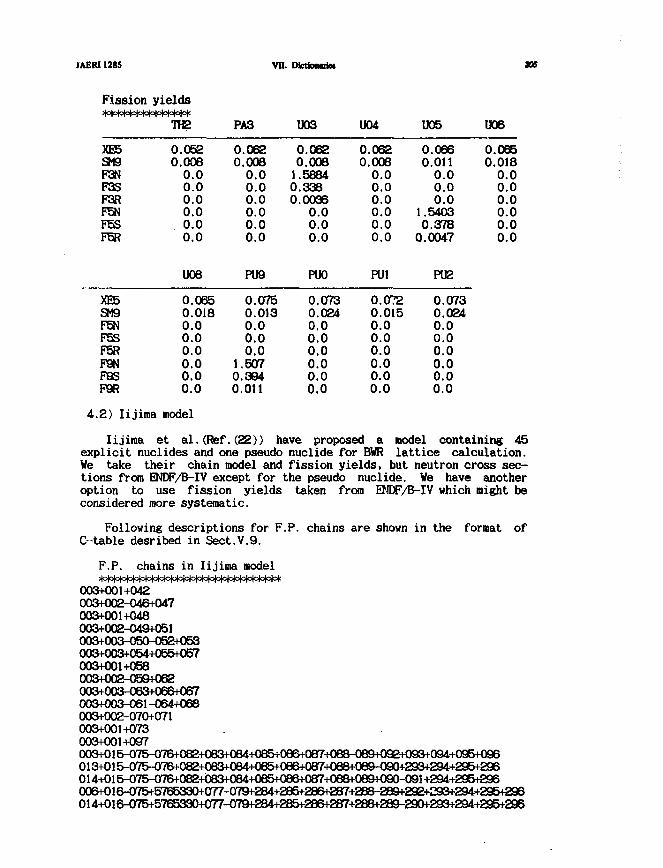
JAERI128$
Fission>|ototo(ctoteW
XE5SM9F3NF3SF3RF5NF5SF5R
XE5SM9F5NF5SF5RF9N
yields
TH2
0.0520.008
0.00.00.00.00.00.0
U08
0.0650.0180.00.00.00.0
vn.
PA3
0.0620.008
0.00.00.00.00.00.0
PU9
0.0750.0130.00.00.0
1.507
DictkotdM
U03
0.0620.008
1.58840.3380.0036
0.00.00.0
PUO
0.0730.0240.00.00.00.0
U04
0.0620.008
0.00.00.00.00.00.0
PU1
0.0720.0150.00.00.00.0
U05
0.0660.011
0.00.00.0
1.54030.378
0.0047
PU2
0.0730.0240.00.00.00.0
U06
0.0650.018
0.00.00.00.00.00.0
aos
F9S 0.0 0.394 0.0 0.0 0.0P9R 0.0 0.011 0.0 0.0 0.0
4.2) Iijima model
Iijiraa et al.(Ref.(22)) have proposed a model containing 45explicit nuclides and one pseudo nuclide for BWR lattice calculation.We take their chain model and fission yields, but neutron cross sec-tions from ENDF/B-IV except for the pseudo nuclide. We have anotheroption to use fission yields taken from ENDF/B-IV which might beconsidered more systematic.
Following descriptions for F.P. chains are shown in the format ofC--table desribed in Sect.V.9.
F.P. chains in Iijima model
003+001+042003+002-046+047003+001+048003+002-049+051003+003-050-052+053003+003+054+055+057003+001+058003+002-059+062003+003-063+066+067003+003-061-064+068003+002-070+071003+001+073003+001+097003+015-075-076+082+CI83+0B4+08O+086+087+088-089+092+093+094+095+096013+015-CI75-076+082+083+084+085+086+087+08B+089-090+293+294+295+296014+015-075-076+082+083+084+085+086+087+088+089+090-091 +294+295+296006+016-075+5765330+077-079+284+285+286+287+288-289+292+293+294+295+296014+016^)75+5765330+077-079+284+285+286^287+288+289-290+293+294+295+296
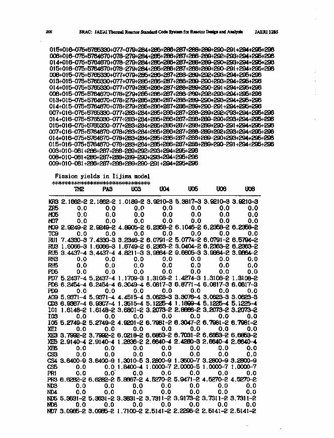
206 SRAC: JAEii<I Thmntl Resctoi Stindud Cod* Syrtwn foe RMCtoi DMfea u d AaOy* IAEM128S
015+016-075+57B5330+077-079+284+285+2B6+2B7+28B+2B9+290-291+294+295+296006+016-075+5764*370+078-279+284+285+2B6+287+2B8-289+29£+293+294+295+296014+016-075+5764670+078-279+284+285+286+2B7+2B8+289-290+293+294+295+296015+016-075+5764670+078-279*284+285+286+287+288+288+290-291+294+295+296006+015-075+5765330+077+079+285+286+287+288-288+292+293+294+295+296013+0!5-<]75+5765330+077+079+285+286+287+28B+288-290+293+294+296+296014+015-O75+5765330+077+079+285+286+287+288+289+290-291 +294+295+296006+015-075+5764670+0m279+285+286+287+288-289+29e+293+294+295+296013+015-075+5764670+078+279*285+286+287+288+289-290+293+294+295+296014+015-075+5764670+078+279+285+286+287+288+289+290-291+294+295+296CI07+016-<y75f5765830-077+28^284+285+286+287+288-2a9+292+J«5+294+295f296014+016-075+ 5765330-O77+283+2B4+285+286+287+288+2B9-290+293+294+295+296015+016-075+576533CWJ77+283+284+285+286+2B7+28B+2B9+290-291 +294+295+296(507+016-075+5764670-078+283+284+285+286+287+288-289+292+293+294+295+296014+016-075+5764670-078+283+284+285+286+287+288+289-290+293+294+295+293015+016-O75+5764670-078+283+284+285+286+287+288+2B9+290-291+294+295+296003+010-081+286+287+288-289+292+293+294+295+296008+01CK»l+286+287+288+289-290+293+294+295+296009+010-081 +286+287+288+289+290-291 +294+295+296
Fis s ion y i e l d s in Iij ima model
TH2 PA3 U03 U04 U05 U06 U08
KR3 2.1662-2 2 .1662-2 1.0189-2 3 .9210-3 5.3817-3 3.9210-3 3 .9210-3ZR5 0.0 0.0 0.0 0.0 0.0 0.0 0.0M05 0 .0 0.0 0.0 0.0 0.0 0.0 0.0M07 0 .0 0.0 0.0 0.0 0.0 0.0 0.0M09 2.9249-2 2.9249-2 4.8905-2 6.2358-2 6.1046-2 6.2358-2 6.2358-2TC9 0.0 0.0 0.0 0.0 0.0 0.0 0.0RU1 7.4330-3 7.4330-3 3.2346-2 6.0791-2 5.0774-2 6.0791-2 6.5794-2RU3 1.6066-3 1.6086-3 1.6749-2 6.2363-2 3.0404-2 6.2363-2 6.2363-2RU5 3.4437-4 3.4437-4 4.8211-3 3.9864-2 9.6605-3 3.9864-2 3.9864-2RH3 0.0 0.0 0.0 0.0 0.0 0.0 0.0RH5 0.0 0.0 0.0 0.0 0.0 0.0 0.0PD5 0.0 0.0 0.0 0.0 0.0 0.0 0.0PD7 5.2437-4 5.2437-4 1.1709-3 1.3108-2 1.4274-3 1.3108-2 1.3108-2PD8 6.2454-4 6.2454-4 6.3049-4 6.0817-3 6.8771-4 6.0817-3 6.0817-3PD9 0.0 0.0 0.0 0.0 0.0 0.0 0.0ACS 5.9371-4 5.9371-4 4.4515-4 3.0623-3 3.3076-4 3.0623-3 3.0623-3CDS 6.9367-4 6.93S7-4 1.3515-4 5.1225-4 1.1899-4 5.1225-4 5.1225-4101 1.6148-2 1.6148-2 3.6801-2 3.2073-2 2.8896-2 3.2073-2 3.2073-2103 0.0 0.0 0.0 0.0 0.0 0.0 0.0105 5.2749-2 5.2749-2 4.9201-2 6.7981-2 6.3047-2 6.7981-2 6.7981-2XE1 0.0 0.0 0.0 0.0 0.0 0.0 0.0XE3 3.7992-2 3.7992-2 6.0218-2 6.6853-2 6.7031-2 6.6853-2 6.6853-2XE5 2.9140-4 2.9140-4 1.2836-2 2.6640-4 2.4280-3 2.6640-4 2.6640-4XE6 0.0 0.0 0.0 0.0 0.0 0.0 0.0CS3 0.0 0.0 0.0 0.0 0.0 0.0 0.0CS4 3.6400-9 3.6400-9 1.3010-5 3.2800-9 1.3500-7 3.2800-9 3.2800-9CS5 0.0 0.0 1.8400-4 1.0000-7 2.0000-5 I.0000-7 1.0000-7PR1 0.0 0.0' 0.0 0.0 0.0 0.0 0.0PR3 6.6282-2 6.6282-2 5.8667-2 4.5270-2 5.9471-2 4.5270-2 4.5270-2ND3 0.0 0.0 0.0 0.0 0.0 0.0 0.0ND4 0.0 0.0 0.0 0.0 0.0 0.0 0.0ND5 5.3631-2 5.3631-2 3.3831-2 3.7311-2 3.9173-2 3.7311-2 3.7311-2ND6 0.0 0.0 0.0 0.0 0.0 0.0 0.0NDT7 3.0985-2 3.0985-2 1.7100-2 2.5141-2 2.2296-2 2.5141-2 2.5141-2
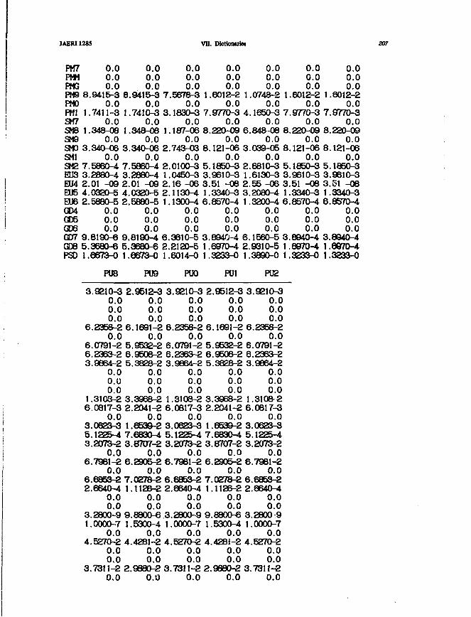
JAERI1285 VH. Dktkmtrie. 20?
FM7 0.0 0.0 0.0 0.0 0.0 0.0 0.0PMM 0.0 0.0 0.0 0.0 0.0 0.0 0.0PMG 0.0 0.0 0.0 0.0 0.0 0.0 0.0PM9 8.9415-3 8.9415-3 7.5678-3 1.6012-2 1.0748-2 1.6012-2 1.6012-2PMO 0.0 0.0 0.0 0.0 0.0 0.0 0.0PM1 1.7411-3 1.7410-3 3.1830-3 7.9770-3 4.1650-3 7.9770-3 7.9770-3SM7 0.0 0.0 0.0 0.0 0.0 0.0 0.0SM8 1.348-08 1.348-08 1.187-06 8.220-09 6.84&-08 8.220-09 8.220-09SM9 0.0 0.0 0.0 0.0 0.0 0.0 0.0SMO 3.340-06 3.340-06 2.743-03 8.121-06 3.039-05 8.121-06 8.121-06SMI 0.0 0.0 0.0 0.0 0.0 0.0 0.0SM2 7.5860-4 7.5860-4 2.0100-3 5.1850-3 2.6810-3 5.1850-3 5.1850-3EU3 3.2880-4 3.2880-4 1.0450-3 3.9610-3 1.6130-3 3.9610-3 3.9610-3EU4 2.01 -09 2.01 -09 2.16 -06 3.51 -08 2.55 -06 3.51 -08 3.51 -08EU5 4.0320-5 4.0320-5 2.1130-4 1.3340-3 3.2080-4 1.3340-3 1.3340-3EU6 2.5880-5 2.5880-5 1.1300-4 6.8570-4 1.3200-4 6.8570-4 6.8570-4GD4 0.0 0.0 0.0 0.0 0.0 0.0 0.0GD5 0.0 0.0 0.0 0.0 0.0 0.0 0.0GD6 0.0 0.0 0.0 0.0 0.0 0.0 0.0GOT 9.8190-6 9.8190-4 6.3610-5 3.8940-4 6.1560-5 3.8940-4 3.8940-4GD8 5.3680-6 5.3680-6 2.2120-5 1.6970-4 2.9310-5 1.6970-4 1.6970-4PSD 1.6673-0 1,6673-0 1.6014-0 1.3233-0 1.3890-0 1.3233-0 1.3233-0
PU8 PU9 PUO PU1 PU2
3.9210-3 2.9512-3 3.9210-3 2.9512-3 3.9210-30.0 0.0 0.0 0.0 0.00.0 0.0 0.0 0.0 0.00.0 0.0 0.0 0.0 0.0
6.2358-2 6.1691-2 6.2358-2 6.1691-2 6.2358-20.0 0.0 0.0 0.0 0.0
6.0791-2 5.9532-2 6.0791-2 5.9532-2 6.0791-26.2363-2 6.9508-2 6.2363-2 6.9508-2 6.2363-23.9964-2 5.3328-2 3.9864-2 5.3828-2 3.9864-2
0.0 0.0 0.0 0.0 0.00.0 0.0 0.0 0.0 0.00.0 0.0 C O 0.0 0.0
1.3103-2 3.3968-2 1.3108-2 3.3968-2 1.3108-26.0817-3 2.2041-2 6.0817-3 2.2041-2 6.0817-3
0.0 0.0 0.0 0.0 0.03.0623-3 1.6539-2 3.0623-3 1.6539-2 3.0623-35.1225-4 7.6830-4 5.1225-4 7.6830-4 5.1225-43.2073-2 3.8707-2 3.2073-2 3.8707-2 3.2073-2
0.0 0.0 0.0 0.0 0.06.7981-2 6.2905-2 6.7981-2 6.2905-2 6.7981-2
0,0 0.0 0.0 0.0 0.06.6853-2 7.0278-2 6.6853-2 7.0278-2 6.6853-22.6640-4 1.1126-2 2.6640-4 1.1126-2 2.6640-4
0.0 0.0 0.0 0.0 0.00.0 0.0 0.0 0.0 0.0
3.2800-9 9.8800-6.3.2800-9 9.8800-6 3.2800-91.0000-7 1.5300-4 1.0000-7 1.5300-4 1.0000-7
0.0 0.0 0.0 0.0 0.04.5270-2 4.4281-2 4.5270-2 4.428J-2 4.5270-2
0.0 0.0 0.0 0.0 0.00.0 0.0 0.0 0.0 0.0
3.7311-2 2.9880-2 3.7311-2 2.9890-2 3.7311-20.0 0.0 0.0 0.0 0.0
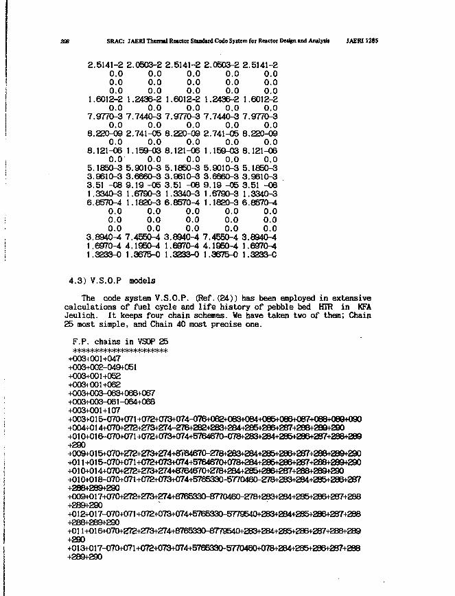
208 SRAC: JAERI Thermal Reactor Standard Code System for Reactor Design md Aiulysii JAERI1285
2.5141-2 2.0503-2 2.5141-2 2.0503-2 2.5141-20.0 0.0 0.0 0.0 0.00.0 0.0 0.0 0.0 0.00.0 0.0 0.0 0.0 0.0
1.6012-2 1.2436-2 1.6012-2 1.2436-2 1.6012-20.0 0.0 0.0 0.0 0.0
7.9770-3 7.7440-3 7.9770-3 7.7440-3 7.9770-30.0 0.0 0.0 0.0 0.0
8.220-09 2.741-05 8.220-09 2.741-05 8.220-090.0 0.0 0.0 0.0 0.0
8.121-06 1.159-03 8.121-06 1.159-03 8.121-060.0 0.0 0.0 0.0 0.0
5.1850-3 5.9010-3 5.1850-3 5.9010-3 5.1850-33.9610-3 3.6660-3 3.9610-3 3.6660-3 3.9610-33.51 -08 9.19 -05 3.51 -08 9.19 -05 3.51 -081.3340-3 1.6790-3 1.3340-3 1.6790-3 1.3340-36.8570-4 1.1820-3 6.8570^1 1.1820-3 6.8570-4
0.0 0.0 0.0 0.0 0.00.0 0.0 0.0 0.0 0.00.0 0.0 0.0 0.0 0.0
3.8940-4 7.4550-4 3.8940-4 7.4550-4 3.8940-41.6970-4 4.1950-4 1.6970-4 4.1950-4 1.6970-41.3233-0 1.3675-0 1.3233-0 1.3675-0 1.3233-C
4.3) V.S.O.P models
The code system V.S.O.P. (Ref.(24)) has been employed in extensivecalculations of fuel cycle and life history of pebble bed HTR in KFAJeulich. It keeps four chain schemes. We have taken two of them; Chain25 most simple, and Chain 40 most precise one.
F.P. chains in VSOP 25
+003+001+047+003+002-049+051+003+001+052+003+001+062+003+003-063+066+067+003+003-061-064+068+003+001+107+003+015-070+071 +072+073+074-076+()82+063+084+Oe5+066+(>87+088+089+090+004+014+07CM-272+273+274-276+282+263+284+285+286+287+288+289+290+010+016-070+071+()72+073+OT4+5764670-078+283+284+285+286+287+288+289+290+009+015+070+272+273+274+8TO4670-278+283+284+285+286+287+288+289+290+011+015-070+071+072+073+074+5764670+078+284+285+286+287+288+289+290+01 CM^14+070+272+273+274+8764670+278+284+285+286+287+288+289+290+010+018-070+071+072+073+074+5765330-5770460-278+283+284+285+286+287+288+289+290+009+017+070+272+273+274+8765330-8770460-278+283+284+285+286+287+288+289+290+012+017-070+071+072+073+074+5765330-5779540+283+284+285+286+287+288+288+289+290+01 l+016+07C^272+273+274+8765330-8779540+283+284+285+286+287+28B+289+290+013+017-070+071+072+073+074+5765330-5770460+078+284+285+286+287+288+289+290
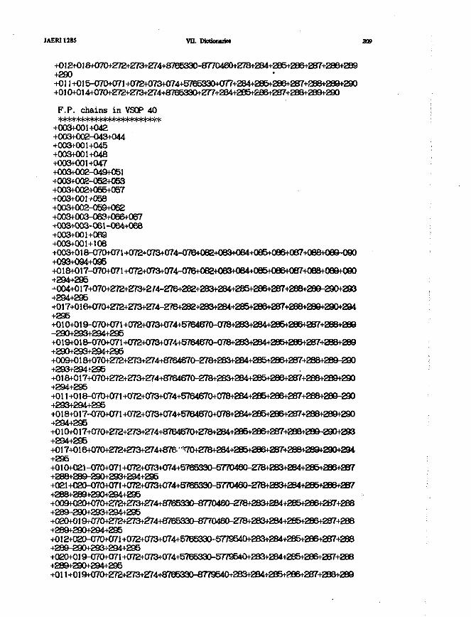
JAER11285 VU. DictiowiiM 309
+012+016+070+272+273+274+8765330-8770460+278+284+285+286+287+286+289+290+03 1+015-070+071+072+073+074+5765330+Cm+284+285+286+287+aB8+289+290+010+014+070+272+273+m+8765330+2m284+285+296+287+288+289+290
F.P. chains in VSOP 40
+003+001+042+003+002-043+044+003+001+045+003+001+048+003+001+047+003+002-049+051+003+002-052+053+003+002+055+057+003+001+058+003+002-059+062+003+003-063+066+067+003+003-061-064+068+003+001+069+003+001+108+003+018-07Cl+071+072*073+()74-076+082+083+084+085+086+Oe7+088+Oe9-090+093+094+095+018+017-070+071 +C)72+CI73+CI74-<)7B+082+083+084+Oe5+086+Oe7+08B+089+090+294+295^Cm+017+07CM-272+273+2M-276+282+2a3+284+285+286+267+288+289-290+293+294+295+017+016+070+272+Z73+274-276+282+263+284+285+286+287+28B+289+290+294+295+010+019-070+071 +072+073+074+5764670-078+283+284+285+286+287+288+289-290+293+294+295+019+018-07CW)71+072+073+074+5764670-078+283+284+285+286+287+288+289+290+293+294+295+009+018+070+272+273+274+8764670-278+283+284+285+286+287+288+289-290+293+294+295+018+017+070+272+273+274+8764670-278+283+284+285+286+287+288+289+290+294+295+01 l+018-07D+071+072+073+OT4+576467()+078+284+285+286+287+288+289-290+293+294+295+018+017-070+071+072+073+074+5764670+078+284+285+286+287+288+289+290+294+295+010+017+070+272+273+274+8764670+278+284+285+286+287+288+289-290+293+294+295+017+016+070+272+273+274+876. "'^70+278+284+285+286+287+288+289+290+294+295+010+021 -070+071 +072+073+074+5765330-5770460-278+283+284+285+286+287+288+289-290+293+294+295+021+020-070+C)71+ff72+073+C)74+5TB5330-5770460-£78+283+284+285+286+287+288+289+290+294+295+009+()20+Cr70+272+273+274+8765330-8770460-278+283+284+285+286+287+288+289-290+293+294+295+020+019+070+272+273+274+8765330-877CI460-278+283+284+285+286+287+288+289+290+294+295+012+020-070+071 +072+073+074+5765330-5779540+283+284+285+286+287+288+289-290+293+294+295+OeO+019^70+071+072+073+074+576533C)-5779540+283+284+285+286+287+288+289+290+294+295+011+019+070+272+273+274+8765330-8779540+283+284+285+386+287+288+289
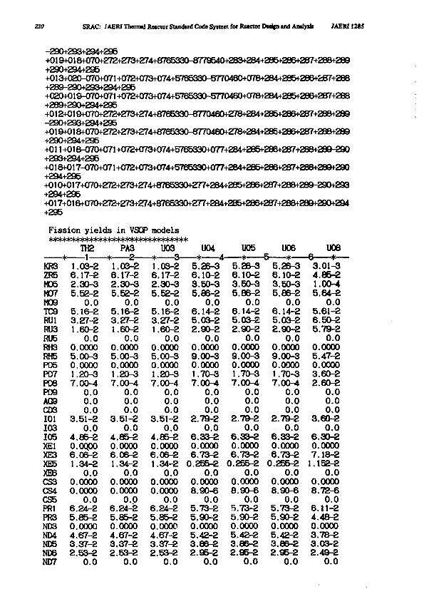
210 SRAC: JAERI Thermal Reacior Standard Code Syitem for Reactor DMJCn and Amlydi JAERI1285
-290+293+294+295+019+018+070+272+273+274+8765330-8779540+283+284+285+286+287+288+289+290+294+295+013+020-070+071+072+073+074+576533Ch5770460+078+284+285+286+aB7+288+289-290+293+294+295+020+019-070+(m+072+073+074+5765330-5770460+078+284+235+286+287+288+289+290+294+295+012+019+070+272+273+274+876533CM-8770460+278+284+285+286+287+288+289-290+293+294+295+019+018+070+272+273+274+8765330-8770460+278+284+285+286+287+288+289+290+294+295+011+018-070+071+072+073+074+5765330+077+284+285+286+287+288+289-290+293+294+295+018+017-070+071+072+073+074+5765330+077+284+285+286+287+288+289+290+294+295+010+017+070+272+273+274+8765330+277+284+285+286+287+288+289-290+293+294+295+017+016+070+272+273+274+8765330+277+284+285+286+287+288+289+290+294+295
Fission yields in VSOP models
uo6 uoeKR3 1.03-2 1.03-2 1.03-2 5.26-3 5.26-3 5.26-3 3.01-3ZR5 6.17-2 6.17-2 6.17-2 6.10-2 6.10-2 6.10-2 4.85-2M05 2.30-3 2.30-3 2.30-3 3.50-3 3.50-3 3.50-3 1.00-4M07 5.52-2 5.52-2 5.52-2 5.86-2 5.86-2 5.86-2 5.64-2M09 0.0 0.0 0.0 0.0 0.0 0.0 0.0TC9 5.16-2 5.16-2 5.16-2 6.14-2 6.14-2 6.14-2 5.61-2RU1 3.27-2 3.27-2 3.27-2 5.03-2 5.03-2 5.03-2 6.50-2RU3 1.60-2 1.60-2 1.60-2 2.90-2 2.90-2 2.90-2 5.79-2RU5 0.0 0.0 0.0 0.0 0.0 0.0 0.0RH3 0.0000 0.0000 0.0000 0.0000 0.0000 0.0000 0.0000RH5 5.00-3 5.00-3 5.00-3 9.00-3 9.00-3 9.00-3 5.47-2PD5 0.0000 0.0000 0.0000 0.0000 0.0000 0.0000 0.0000PDT7 1.20-3 1.20-3 1.20-3 1.70-3 1.70-3 1.70-3 3.60-2PD8 7.00-4 7.00-4 7.00-4 7.00-4 7.00-4 7.00-4 2.60-2PD9 0.0 0.0 0.0 0.0 0.0 0.0 0.0AG9 0.0 0.0 0.0 0.0 0.0 0.0 0.0CD3 0.0 0.0 0.0 0.0 0.0 0.0 0.0101 3.51-2 3.51-2 3.51-2 2.79-2 2.79-2 2.79-2 3.60-2103 0.0 0.0 0.0 0.0 0.0 0.0 0.0105 4.85-2 4.85-2 4.85-2 6.33-2 6.33-2 6.33-2 6.30-2XE1 0.0Q00 0.0000 0.0000 0.0000 0.0000 0.0000 0.0000XE3 6.06-2 6.06-2 6.06-2 6.73-2 6.73-2 6.73-2 7.18-2XE5 1.34-2 1.34-2 1.34-2 0.255-2 0.255-2 0.255-2 1.152-2XE6 0.0 0.0 0.0 0.0 0.0 0.0 0.0CS3 0.0000 0.0000 0.0000 0.0000 0.0000 0.0000 0.0000CS4 0.0000 0.0000 0.0000 8.90-6 8.90-6 8.90-6 8.72-6CS5 0.0 0.0 0.0 0.0 00 0.0 0.0PR1 6.24-2 6.24-2 6.24-2 5.73-2 5.73-2 5.73^2 6.11-2PR3 5.85-2 5.85-2 5.85-2 5.90-2 5.90-2 5.90-2 4.48-2ND3 0.0000 0.0000 0.0000 0.0000 0.0000 0.0000 0.0000ND4 4.67-2 4.67-2 4.67-2 5.42-2 5.42-2 5.42-2 3.78-2ND5 3.37-2 3.37-2 3.37-2 3.86-2 3.86-2 3.86-2 3.03-2ND6 2.53-2 2.53-2 2.53-2 2.95-2 2.95-2 2.95-2 2.4*2ND7 0.0 0.0 0.0 0.0 0.0 0.0 0.0
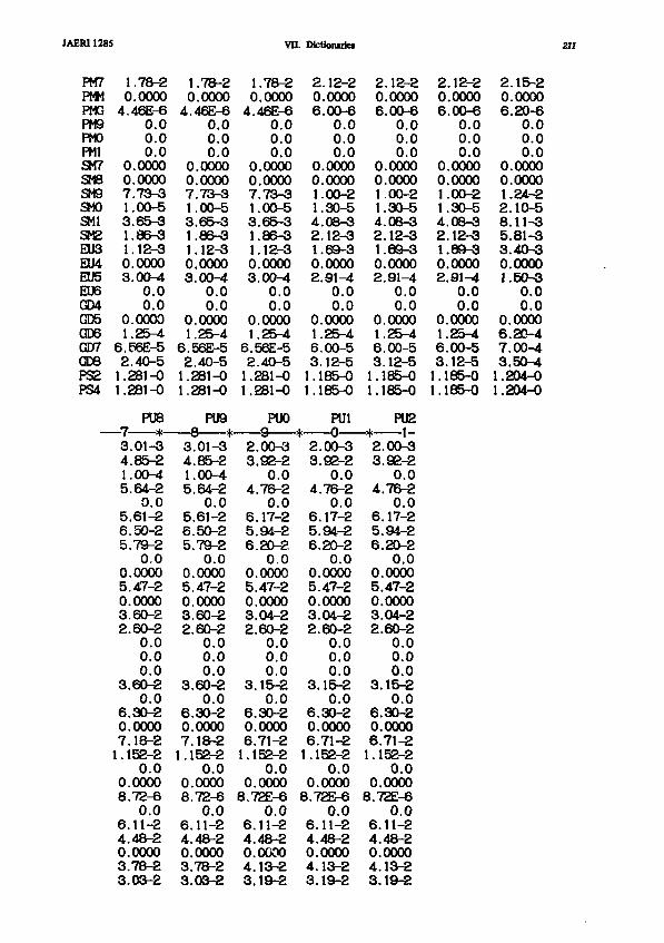
JAER11281
PM7PMMPMGPM9PMOPM1SM7SM8SM9SMOSMISM2EU3EU4EU5EU6GD4GD5GD6GD7QD8PS2PS4
5
1.78-20.00004.46E-6
0.00.00.0
0.00000.00007.73-31.00-53.65-31.86-31.12-30.00003.00-4
0.00.0
0.00001.25-4
6.56E-52.40-51.281-01.281-0
PU87 &3.01-34.85-21.00-45.64-2
0.05.61-26.50-25.79-2
0.00.00005.47-20.00003.60-22.60-2
0.00.00.0
3.60-20.0
6.30-20.00007.18-21.152-2
0.00.00008.72-6
0.06.11-24.48-20.00003.78-23.03-2
1.78-20.00004.46E-6
0.00.00.0
0.00000.00007.73-31.00-53.65-31.86-31.12-30.00003.00-4
0.00.0
0.00001.25-4
6.56E-52.40-51.281-01.281-0
PU9
3.01-34.85-21.00-45.64-2
0.05.61-26.50-25.79-2
0.00.00005.47-20.00003.60-22.60-2
0.00.00.0
3.60-20.0
6.30-20.00007.18-21.152-2
0.00.00008.72-6
0.06.11-24.48-20.00003.78-23.03-2
VII
1.78-20.00004.46E-6
0.00.00.0
0.00000.00007.73-31.00-53.65-31.86-31.12-30.00003.00-4
0.00.0
0.00001.25-4
6.56E-52.40-51.281-01.281-0
PUO0 :
2.00-33.92-2
0.04.76-2
0.06.17-25.94-26.20-2
0.00.00005.47-20.00003.04-22.60-2
0.00.00.0
3.15-20.0
6.30-20.00006.71-21.152-2
0.00.00008.72E-6
0.06.11-24.48-20.00004.13-23.19-2
. Dktionuiei
206
001142102
0163l.:1.!
Jr.. —
2.3,
4.
6.5.6.
0.5.0.3.2.
3.
6.0.6.
:. 12-2.0000.00-60.00.00.0
.0000
.0000
.00-2
.30-5
.08-3
.12-3
.69-3
.0000
.91-40.00.0
.0000
.25-4
.00-5
.12-5185-0185-0
PU1Q
,00-3,92-20.0
,76-20.0
.17-294-220-20.0000047-2000004-260-20.00.00.015-20.030-2000071-2
1.152-2
0.0.00000
8.72E-6
6.4.0.4.3.
0.011-248-2000013-219-2
206
001142102
01631.;1.1
• #2.3,
4.
6.5.6.
0.5.0.3.2.
3.
6.0.6.
.12-2
.0000
.00-60.00.00.0
.0000
.0000
.00-2
.30-5
.08-3
.12-3
.69-3
.0000
.91-40.00.0
.0000
.25-4
.00-5
.12-5185-0185-0
PU21
,00-3.92-20.0
,76-20.017-294-220-20.0000047-2000004-260-20.00.00.015-20.030-2000071-2
1.152-2
0.0.00000
8.72E-6
6.4.0.4.3.
0.011-248-2000013-219-2
206
00,1.1,4.2.1.0.2.
0.1.6.3.1.11.1
.12-2
.0000
.00-60.00.00.0
.0000,0000.00-230-508-312-369-3000091-40.00.0000025-400-512-585-085-0
2.0.6.
0.0.1.2.8.5.3.0.1.
0.6.7.3.
15-2000020-60.00.00.00000000024-210-511-381-340-3000050-30.00.0000020-400-450-4
1.204-01.204-0
211
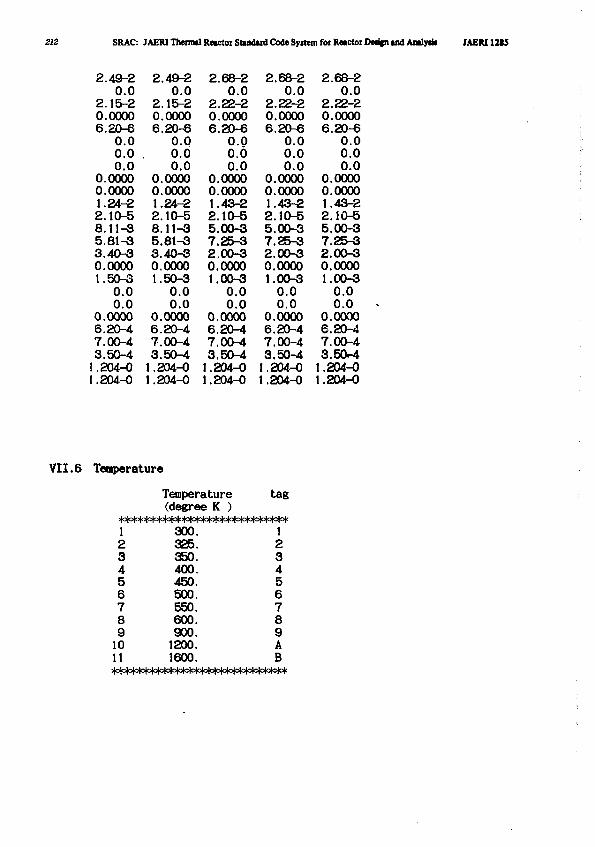
212 SRAC: JAERI Theimil Reactor Stindaid Code Syitem foi Rwctor Dedin ind Amly* JAEM12S5
2.49-2 2.49-2 2.68-2 2.68-2 2.68-20.0 0.0 0.0 0.0 0.0
2.15-2 2.15-2 2.22-2 2.22-2 2.22-20.0000 0.0000 0.0000 0.0000 0.00006.20-6 6.20-6 6.20-6 6.20-6 6.20-6
0.0 0.0 0.0 0.0 0.00.0 . 0.0 0.6 0.0 0.00.0 0.0 0.0 0.0 0.0
0.0000 0.0000 0.0000 0.0000 0.00000.0000 0.0000 0.0000 0.0000 0.00001.24-2 1.24-2 1.43-2 1.43-2 1.43-22.10-6 2.10-5 2.10-5 2.10-5 2.10-58.11-3 8.11-3 5.00-3 5.00-3 5.00-35.81-3 5.81-3 7.25-3 7.25-3 7.25-33.40-3 3.40-3 2,00-3 2.00-3 2.00-30.0000 0.0000 0.0000 0.0000 0.00001.50-3 1.50-3 1.00-3 1.00-3 1.00-3
0.0 0.0 0.0 0.0 0.00.0 0.0 0.0 0.0 0.0
0.0000 0.0000 0.0000 0.0000 0.00006.20-4 6.20-4 6.20-4 6.20-4 6.20-47.00-4 7.00-4 7.00-4 7,00-4 7.00-43.50-4 3.50-4 3.50-4 3.50-4 3.50-41.204-0 1.204-0 1.204-0 1.204-0 1.204-01.204-0 1.204-0 1.204-0 1.204-0 1.204-0
VII.6 Temperature
123456789
1011
Temperature(degree K )
300.325.350.400.450.500.550.600.900.
1200.1600.
ta
|o|ofofctc
123456789AB
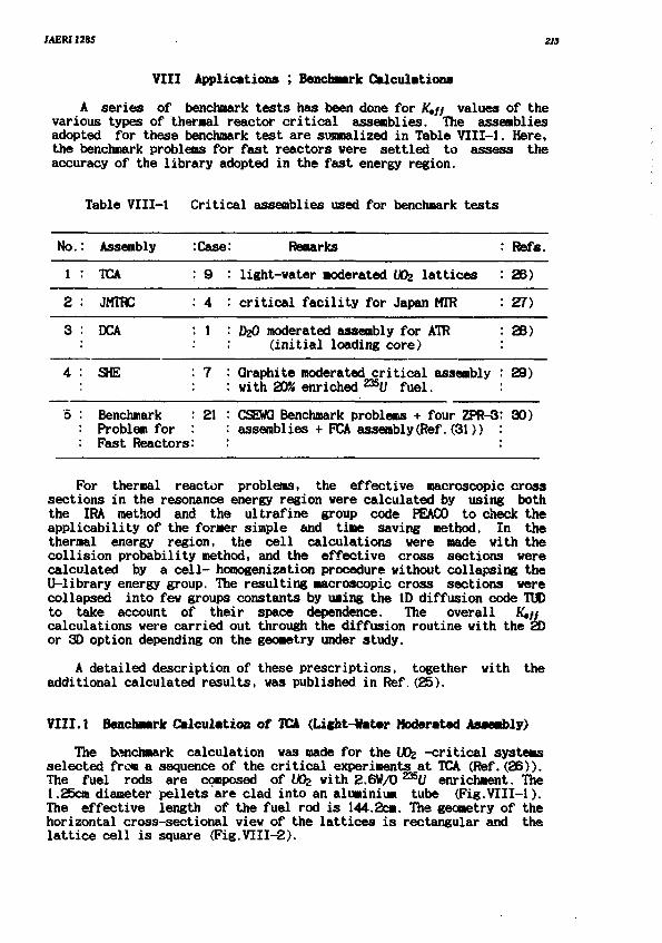
JAERI1285 313
VIII Applications ; Benchmark Calculations
A series of benchmark tests has been done for Ktft values of thevarious types of thermal reactor critical assemblies. The assembliesadopted for these benchmark test are sunnalized in Table VIII-1. Here,the benchnark problems for fast reactors were settled to assess theaccuracy of the library adopted in the fast energy region.
Table VIII-1 Critical assemblies used for benchmark tests
No.
1
2
3
4
'5
: Assembly
• TCA
JMTOC
DCA
SHE
BenchmarkProblem forFast Reactors
:Case
: 9
: 4
. 1
7
21
: Remarks
light-water moderated UOz lattices
critical facility for Japan MTR
DzO moderated assembly for ATR(initial loading core)
Graphite moderated critical assemblywith 20* enriched ^ U fuel.
CSEWQ Benchmark problems + four ZPR-3assemblies + FCA assembly(Ref.(31))
: Refs.
26)
27)
28)
29)
30)
For thermal reactor problems, the effective macroscopic crosssections in the resonance energy region were calculated by using boththe IRA method and the ultrafine group code PEACO to check theapplicability of the former simple and time saving method. In thethermal energy region, the cell calculations were made with thecollision probability method, and the effective cross sections werecalculated by a cell- hooogenization procedure without collapsing theU-library energy group. The resulting macroscopic cross sections werecollapsed into few groups constants by using the ID diffusion code TUDto take account of their space dependence. The overall R'e//calculations were carried out through the diffusion routine with the 2Dor 3D option depending on the geometry under study.
A detailed description of these prescriptions, togetheradditional calculated results, was published in Ref. (25).
with the
VIII.1 Benchmark Calculation of TCA (Light-Hater Moderated Asaembly)
The benchmark calculation was made for the Wz -critical systemsselected frc« a sequence of the critical experiments at TCA (Ref.(26)).The fuel rods are composed of Wfc with 2.6W/O 235U enrichment. The1.25cm diameter pellets are clad into an aluminium tube (Fig.VIII-1).The effective length of the fuel rod is 144.2cm. The geometry of thehorizontal cross-sectional view of the lattices is rectangular and thelattice cell is square (Fig.VIII-2).
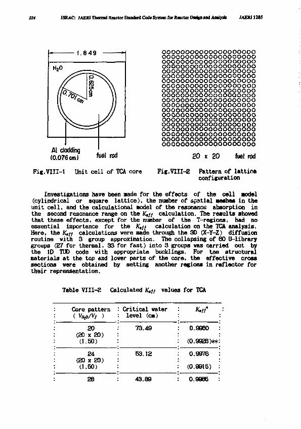
214 1SRAC: JAERI Thcnntl Rttctor Standard Code Syitwn for Rwctor Dmign «ml Amlytk JAERI12t5
Al clodding(0.076cm) f u e l rod
Fic.VIII-1 Unit cell of TCA core
oooooooooooooooooooooooooooooooooooooooooooooooooooooooooooooooooooooooooooooooooooooooooooooooooooooooooooooooooooooooooooooooooooooooooooooooooooooooooooooooooooooooooooooooooooooooooooooooooooooooooooooooooooooooooooooooooooooooooooooooooooooooooooooooooooooooooooooooooooooooooooooooooooooooooooooooooooooooooooooooooooooooooooooooooooooooooooooooooooooooooooooooooooooooooooooooooooooooooooooooo
Fic.VIII-2
20 x 20 fuel rod
Pattern of latticeconfiguration
Investigations have been made for the effects of the cell Model(cylindrical or square lattice), the number of spatial meshes in theunit cell, and the calculational model of the resonance absorption inthe second resonance range on the Ktff calculation. The results shovedthat these effects, except for the number of the T-regions, had noessential importance for the Ktff calculation on the TCA analysis.Here, the K,// calculations were made through the 3D (X-Y-Z) diffusionroutine with 3 group approximation. The collapsing of 60 U-librarygroups (27 for thermal, 33 for fast) into 3 groups was carried out bythe ID TUD code with appropriate Ducklings. For tfle structuralmaterials at the top and lower parts of the core, the effective crosssections were obtained by setting another regions in reflector fortheir reprensentation.
Table VI11-2 Calculated Ktff values for TCA
: Core pattern: ( VHlp/Vf )
20: (20 x 20): (1.50)
: 24(20 x 20)
: (1.50)
: 28
Critical waterlevel (cm)
73.49
53.12
43.89
0.9960 :
(0.9926)**:
0.9978 :
(0.9915) :
0.9985 :
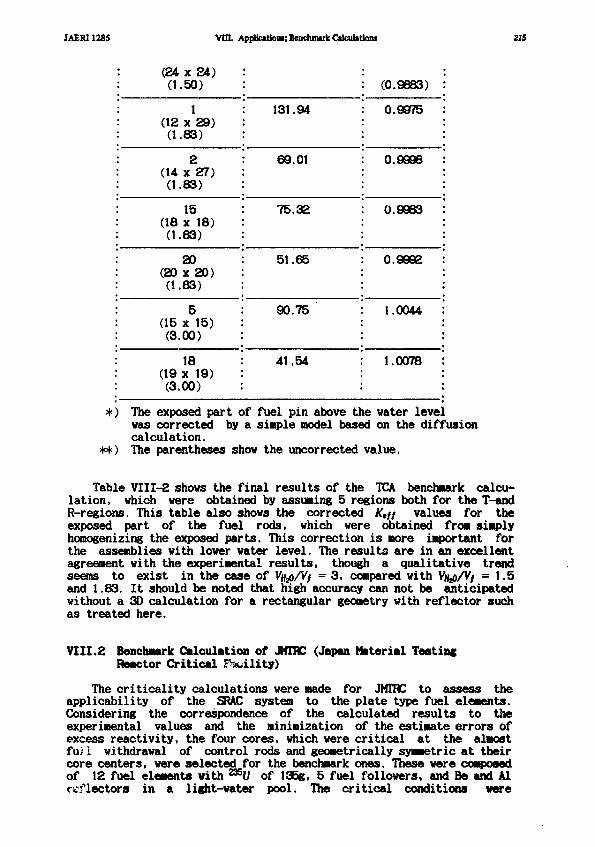
JAERI1285 VIII. Application; BenchmukCalculationi 215
: (24 x 24): (1.50)
: 1: (12 x 29): (1.83)
: 2: (14 x 27): (1.83)
: 15: (18 x 18): (1.83)
: 20: (20 x 20): (1.83)
: 5: (15 x 15): (3.00)
: 18: (19 x 19): (3.00)
: 131.94
69.01
75.32
51.65
90.75
41.54
: (0.9883) :
• 0.9975 :
0.9998 :
0.9963 :
0.9992 :
1.0044 :
1.0078 :
*) The exposed part of fuel pin above the water levelwas corrected by a simple model based on the diffusioncalculation.
**) The parentheses show the uncorrected value.
Table VII1-2 shows the final results of the T O benchmark calcu-lation, which were obtained by assuming 5 regions both for the T-andR-regions. This table also shows the corrected K,ff values for theexposed part of the fuel rods, which were obtained from simplyhomogenizing the exposed parts. This correction is more important forthe assemblies with lower water level. The results are in an excellentagreement with the experimental results, though a qualitative trendseems to exist in the case of Vjfeo/V/ = 3, compared with Vjyj/V/ = 1.5and 1.83. It should be noted that high accuracy can not be anticipatedwithout a 3D calculation for a rectangular geometry with reflector suchas treated here.
VIII.2 Benchmark Calculation of JHTRC (Japan Material TestingReactor Critical Facility)
The criticality calculations were made for JMTRC to assess theapplicability of the SRAC system to the plate type fuel elements.Considering the correspondence of the calculated results to theexperimental values and the minimization of the estimate errors ofexcess reactivity, the four cores, which were critical at the almostfu)i withdrawal of control rods and geometrically symmetric at theircore centers, were selected for the benchmark ones. These were composedof 12 fuel elements with U of 135g, 5 fuel followers, and Be and Alreflectors in a light-water pool. The critical conditions were
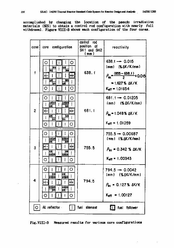
216 SRAC: JAERI Thermal Reactor Standard Code System for Reactor Dedtn and Analydi MEM12I5
accomplished by changing the location of the pseudo irradiationmaterials (32S) to obtain a control rod configuration with nearly fullwithdrawal. Figure VIII-3 shows each configuration of the four cores.
case core configurationcontrol rodposition ofSHI ond SH2
(mm)
reactivity
O I I I O 638.1 — 0.015
(mm) (%AK/K/mm)
638.1 <855-638.1)x 0.015
-1.627% AK/K
K,f f-1.01654
32!»!121
•I"
o
681. I
O
681.1 — 0.01205(mm) (%AK/K/mm)
ftx« 1.048% AK/K
K,ff = 1.01059
SH
K9K9KS
755.5
755.5—0.00687(mm) (%AK/K/mm)
Pn ' 0.342 % AK/K
Ktf(« 1.00343
O
SH(
o
J2S
sssnskt 794.5
S2SBJ
ES
794.5 — 0.0042(mm) (%AK/K/mm)
^,x * 0.127% AK/K
Ktff - 1.00t27
Al reflector fuei element fuel follower
Fig.VIII-3 Measured results for various core configurations
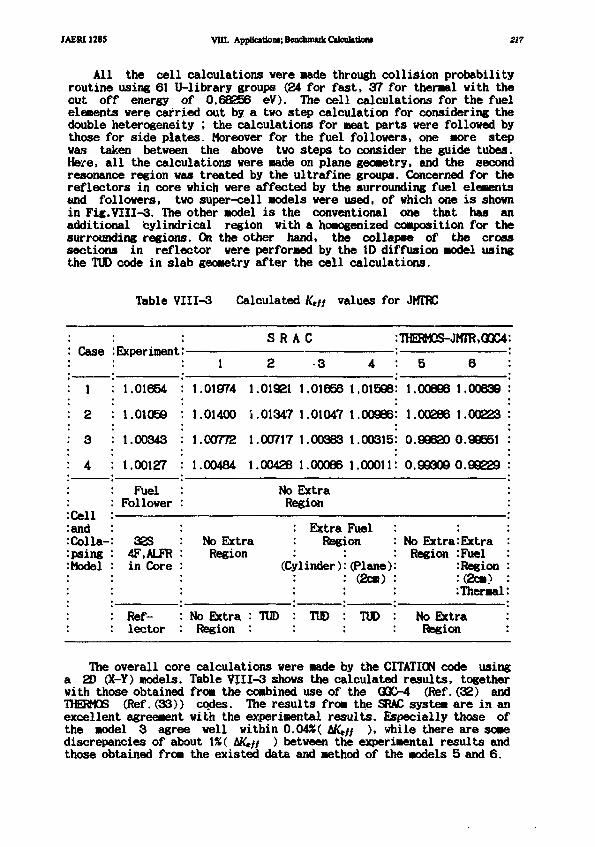
JAER11285 Vin. Application*; BendimukC»lcuktk>m 217
All the cell calculations were made through collision probabilityroutine using 61 U-library groups (24 for fast, 37 for thermal with thecut off energy of 0.68256 eV). The cell calculations for the fuelelements were carried out by a two step calculation for considering thedouble heterogeneity ; the calculations for meat parts were followed bythose for side plates. Moreover for the fuel followers, one more stepwas taken between the above two steps to consider the guide tubes.Here, all the calculations were made on plane geometry, and the secondresonance region was treated by the ultrafine groups. Concerned for thereflectors in core which were affected by the surrounding fuel elementsand followers, two super-cell models were used, of which one is shownin Fig.VIII-3. The other model is the conventional one that has anadditional cylindrical region with a homogenized composition for thesurrounding regions. On the other hand, the collapse of the crosssections in reflector were performed by the ID diffusion model usingthe TUD code in slab geometry after the cell calculations.
Table VIII-3 Calculated Kt!} values for JMTRC
: Case
: 1
: 2
: 3« J
:Cell:and:Colla-:psing: Model
:Experiment
1.01654
1.01059
1.00343
1.00127
FuelFollower
3254F.ALFRin Core
Ref-lector
: SR
: 1 2
: 1.01974 1.01921
: 1.01400 i.01347
: 1.00772 1.00717
1.00484 1.00426
K C
3
1.01656
1.01047
1.00363
1.00066
4
1.01598
1.00966
1.00315
1.00011
:THEBM0S-JMTR,GQC4:
: 5 6 :
: 1.00896 1.00839 :
: 1.00286 1.00223 :
: 0.99620 0.99551 :
: 0.99309 0.99229 :
No Extra :Region :
No ExtraRegion
(Cj
No Extra : TUDRegion :
ExtraReg]
rlinder)
TUD
FuelLon
(Plane)(2cm)
TUD
' No Extra:Extra :Region :Fuel :
: Region :: (2cm) ::Thermal:
No Extra :Region :
The overall core calculations were made by the CITATION code usinga 2D (X-Y) models. Table VIII-3 shows the calculated results, togetherwith those obtained from the combined use of the QQC-4 (Ref.(32) andTHERMOS (Ref.(33)) codes. The results from the SRAC system are in anexcellent agreement with the experimental results. Especially those ofthe model 3 agree well within 0.04»( tK,jf ), while there are somediscrepancies of about 1%( AK,// ) between the experimental results andthose obtained from the existed data and method of the models 5 and 6.
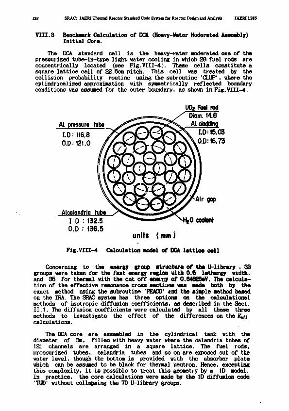
218 SRAC: JAERI Thenntl Rwctoi Studud Code System fot Retctor Dedfii and Aulyili JAERU2I5
VIII.3 BenchMrk Calculation of DCA (Heavy-Hater Moderated Assembly)Initial Core.
The DCA standard cel l i s the heavy-water Moderated one of thepressurized tube-in-type light water cooling in which 28 fuel rods areconcentrically located (see Fig.VIII-4). These ce l l s constitute asquare latt ice cell of 22.5cn pitch. This cell was treated by thecollision probability routine using the subroutine 'CUP', where thecylindricalized approximation with symmetrically reflected boundaryconditions was assumed for the outer boundary, as shown in Fig.VIII-4.
UOa Fuel rodDiom. 14.8
Al pressure tube / > ~ > ? S . Atdodflnq
0.D: 121.0 //-kP£y£XtS\0.0:16.73
Aicakindrio tube1.0 : 132.50.D •• 136.5
units {mm)Fig.VTII-4 Calculation model of DCA lattice oell
Concerning to the energy croup structure of the U-library , 33groups were taken for the fast energy region with 0.5 lethargy width,and 35 for thermal with the cut off energy of O.MOXeV. The calcula-tion of the effective resonance cross sections was made both by theexact method using the subroutine 'PEACO' «ad the simple method basedon the IRA. The SRAC system has three options on the calculationalmethods of isotropic diffusion coefficients, as described in the Sect.II.1. The diffusion coefficients were calculated by all these threemethods to investigate the effect of the differences on thecalculations.
The DCA core are assembled in the cylindrical tank with thediameter of 3m, filled with heavy water where the calandria tubes of121 channels are arranged in a square lattice. The fuel rods,pressurized tubes, calandria tubes and so on are exposed out of thewater level, though the bottom is provided with the absorber platewhich can be assumed to be black for thermal neutron. Hence, exceptingthis complexity, it is possible to treat this geometry by a ID model.In practice, the core calculations were made by the ID diffusion code'TUD' without collapsing the 70 U-library groups.
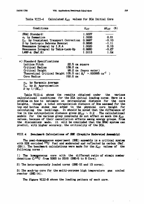
JAERI1285 VIU. AppUctJomiBenchmtikOacul-tioni
Table VI11-4 Calculated Ktff values for OCA
Conditions
SRAC Standard:at by SumationEtr by Consistent Transport CorrectionD by Zsotropic Behrens BenoistResonance Integral by I.R.AResonance Integral by Table-Look-UpLAM>-A (Ref.6)
K*ii
1.00071.00080.99970.98961.00200.99801.0113
Initial Core
tKeft (X
0.01-0.10-1.110.13
-0.271.04
219
*) Standard SpecificationsLattice Pitch 22.5 en squareCritical Radius 139.2 enCritical Height 96.2 cm (heavy water)Theoretical Critical Height 105.0 cm( Bz
2 =.000895 cm"2 )Core Radius 150.0 cm
otr by Harmonic AverageEtr by B\ ApproximationD by l/(SEir> '
Table VII1-4 shows the results obtained under the variouscalculational conditions for the DCA initial loading cores. Here is aproblem on how to estimate an extrapolated distance for the coreheights, though a total extrapolation distance of 9cm assumed for thetop and bottoQ sides was added to the physical core height forcalculating the buddings. It should be noted that the difference oflem in the extrapolation distance gives AK*// ~ 0.2 . The calculationalmodels for the various group constants do not affect so much the Ktftvalues, because of their cancellation effects among energy groups. Fromthe discussions made, it will be concluded that the SRAC system canpredict, with higher accuracy, the criticality of the DCA.
VIII.4 Benchmark Calculations of S E (Graphite Moderated Assembly)
The semi-homogeneous experiment (SHE) assembly is a critical systemwith 20% enriched 235U fuel and moderated and reflected by carbon (Ref.(29)). The benchmark calculations were made for the K,// values of thefollowing cores :
1) The homogeneous core with the different ratio of atomic numberdensities C/mU from 5333 to 2316 (SHE-5 to 8 Core).
2) The heterogeneously loaded cores (SHE-12 and 13 cores).
3) The mock-up core for the multi-purpose high temperature gas cooledreactor (SHE-14).
The figure VIII-6 shows the loading pattern of each core.
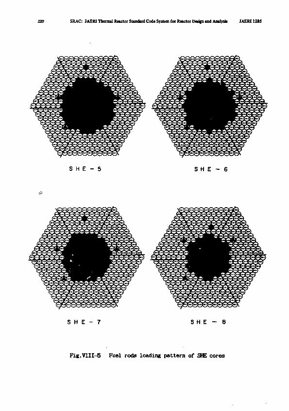
Z2O SRAC: JAERI Thermal Retctor Standud Code System for Retctoi Dedfn u d Analysis JAERI 12S5
S H E - 5 S H E - 6
i j Im ffl ttf ffl. fffi fffl ^^ y fflffl1
fl^ ffl ff^ !ff ff ft b £ S S
% ^ ^^ ffi ^^ S^^ % s ^^ j j
S H E - 7 S H E - 8
Fig.VIII-5 Fuel rods loading pattern of SHE cores
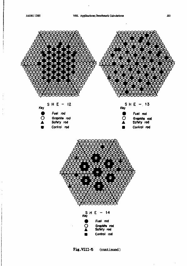
JAERI1285 Vlll. Applications; Benchmazk Calculations 221
^ jft (Jft Jiffl ^6 {ft. ffl> (ft (ft ffl*^p p ft {ft p ffp p (ft ft ft
,ff) (ft ^n fffUm (ft. iff) tff* ift .ft ^p <ft fft ^
K«y
o•
S H E - 12
Fu«l rod
Graphite rod
Softly rod
Control rod
S H E - 1 3Kty
OA
m
Futl rod
Graphite rodSafety rod
Control rod
S HKty
•
o••
E - 14
Futl rod
Graphite rodSafety rodControl rod
Fic.VIII-5 (continued)
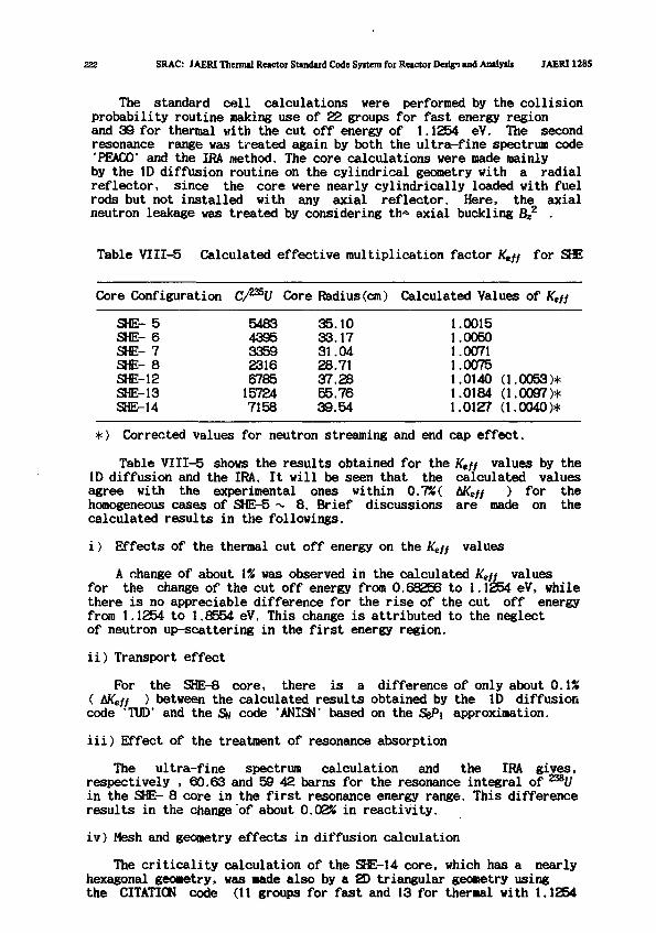
222 SRAC: IAERI Thermal Reactor Standard Code System for Reactor Design and Analysis JAERI1285
The standard cell calculations vere performed by the collisionprobability routine making use of 22 groups for fast energy regionand 39 for thermal with the cut off energy of 1.1254 eV. The secondresonance range was treated again by both the ultra-fine spectrum code'PEACO' and the IRA method. The core calculations were made mainlyby the ID diffusion routine on the cylindrical geometry with a radialreflector, since the core were nearly cylindrically loaded with fuelrods but not installed with any axial reflector. Here, the axialneutron leakage was treated by considering th<* axial buckling Bz
2 .
Table VIII-5 Calculated effective multiplication factor K*ff for SHE
Core Configuration
SHE- 5SHE- 6SHE- 7SHE- 8SHE-12SHE-13SHE-14
C/235!/
54834395335923166785
157247158
Core Radius(cm)
35.1033.1731.0428.7137.2855.7639.54
Calculated Values of Ktff
1.00151.00501.00711.00751.0140 (1.0053)*1.0184 (1.0097)*1.0127 (1.0040)*
*) Corrected values for neutron streaming and end cap effect.
Table VIII-5 shows the results obtained for the Ktff values by theID diffusion and the IRA. It will be seen that the calculated valuesagree with the experimental ones within 0.7%{ 6Keff ) for thehomogeneous cases of SHE-5 ~ 8. Brief discussions are made on thecalculated results in the followings.
i) Effects of the thermal cut off energy on the Keff values
A change of about \% was observed in the calculated Keff valuesfor the change of the cut off energy from 0.68256 to 1.1254 eV, whilethere is no appreciable difference for the rise of the cut off energyfrom 1.1254 to 1.8554 eV. This change is attributed to the neglectof neutron up-scattering in the first energy region.
ii) Transport effect
For the SHE-8 core, there is a difference of only about 0.1%( bKeff ) between the calculated results obtained by the ID diffusioncode 'TUD' and the Sn code 'ANISN' based on the SBP\ approximation.
iii) Effect of the treatment of resonance absorption
The ultra-fine spectrum calculation and the IRA gives,respectively , 60.63 and 59 42 barns for the resonance integral of 238Uin the SHE- 8 core in the first resonance energy range. This differenceresults in the change "of about 0.028 in reactivity.
iv) Mesh and geometry effects in diffusion calculation
The criticality calculation of the SHE-14 core, which has a nearlyhexagonal geometry, was made also by a 2D triangular geometry usingthe CITATION code (11 groups for fast and 13 for thermal with 1.1254
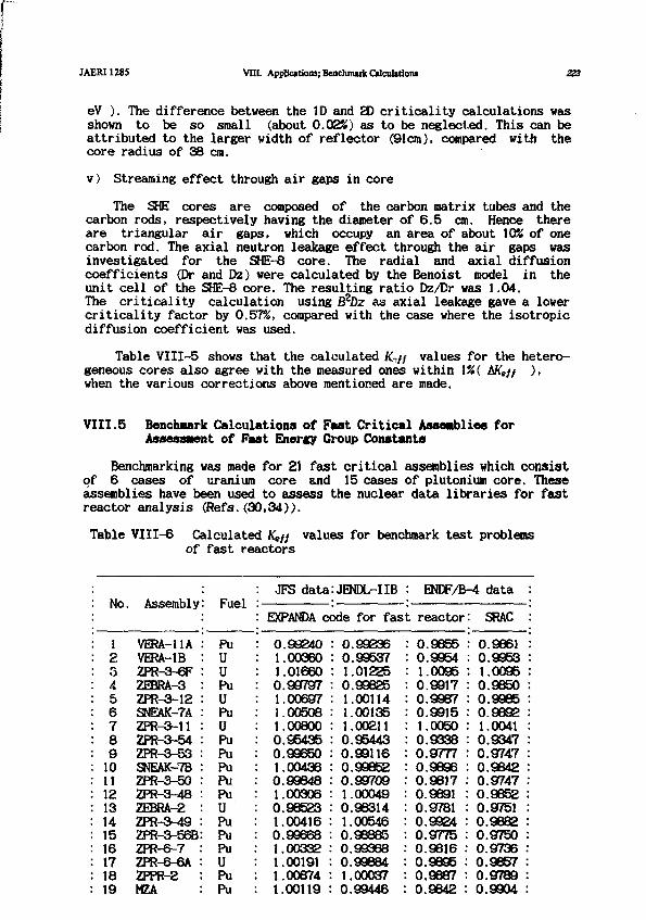
JAERI128S VIII. Applications; Benchmark Calculation! 223
eV ). The difference between the ID and 2D criticality calculations wasshown to be so small (about 0.02%) as to be neglected. This can beattributed to the larger width of reflector (91cm), compared with thecore radius of 38 cm.
v) Streaming effect through air gaps in core
The SHE cores are composed of the carbon matrix tubes and thecarbon rods, respectively having the diameter of 6.5 cm. Hence thereare triangular air gaps, which occupy an area of about 10% of onecarbon rod. The axial neutron leakage effect through the air gaps wasinvestigated for the SHE-8 core. The radial and axial diffusioncoefficients (Dr and Dz) were calculated by the Benoist model in theunit cell of the SHE-6 core. The resulting ratio Dz/Dr was 1.04.The criticality calculation using BzDz as axial leakage gave a lovercriticality factor by 0.57%, compared with the case where the isotropicdiffusion coefficient was used.
Table VIII-5 shows that the calculated Kr}i values for the hetero-geneous cores also agree with the measured ones within 1%( AKeff )>when the various corrections above mentioned are made.
VIII.5 Benchmark Calculations of Fast Critical Assemblies forAssessment of Past Energy Group Constants
Benchmarking was made for 21 fast critical assemblies which consistof 6 cases of uranium core and 15 cases of plutonium core. Theseassemblies have been used to assess the nuclear data libraries for fastreactor analysis (Refs. (30,34)).
Table VI11-6 Calculated Keff values for benchmark test problemsof fast reactors
: No. Assembly
: 1 VERA-11A: 2 VERA-1B: S ZPR-3-6F: 4 ZEBRA-3: 5 ZPR-3-12: 6 SNEAK-7A: 7 ZPR-3-11: 8 ZPR-3-54: 9 ZPR-3-53: 10 SNEAK-7B: 11 ZPR-3-50: 12 ZPR-3-48: 13 ZEBRA-2: 14 ZPR-3-49: 15 ZPR-3-56B: 16 ZPR-6-7: 17 ZPR-6-6A: 18 ZPPR-2: 19 MZA
: Fuel
PuUUPuUPuUPuPuPuPuPuUPu •PuPu .UPuPu
: JFS data
: EXPANDA c<
0.992401.003601.016600.997971.006971.005081.008000.954350.996501.004360.998481.003060.985231.004160.996681.00332 .1.001911.00874 •1.00119 :
:JENDL-IIB
Dde for fas
- 0.992360.995371.012250.996251.001141.001351.002110.954430.991160.998520.997091.000490.963141.005460.938850.99368 .0.99884 :1.00037 :0.99446 :
: ENDF/B-4 data :
L reactor
• 0.98550.9954
• 1.00950.99170.99670.99151.00500.93380.97770.96960.98170.98910.97810.99240.97750.9616 .0.9895 :0.9887 •0.9842 :
: SRAC :
: 0.9861 :: 0.9953 :: 1.0095 :. 0.9650 :. 0.9985 :0.9892 :1.0041 :0.9347 :0.9747 :0.9842 :0.9747 :0.9652 :0.9751 :0.9882 :0.9750 :0.9736 :0.9657 :0.9789 :0.9904 :
224 SRAC: JAERI Thermal Reactor Standard Code System for Reactor Design and Analysis JAERI 1285
: 20 MZB : Pu : 1.00129 : 0.99114 : 0.9909 : 0.9784 :: 21 FCA-V-2 : Pu : 1.00910 : 1.00567 : 0.9787 : 0.9797 :
The criticality calculations were Bade by using the ID diffusioncode TUD without collapsing the P-library. The fission spectrum of 235Vwas assumed for all the cases. The calculated results are shown inTable VII1-4-6 in comparison with those obtained from other groupconstant libraries. Here, the symbol JFS-II stands for JAERI-Fast Set,Version II (Ref.(34)), and JFS-IIB is a library with the same groupstructure as JFS-II but produced using the nuclear data file JENDL-IIB(Ref.(14)). On the other hand, the symbol ENDF/B-4 shows a librarybased on the nuclear data file ENDF/B-IV, which has the same groupstructure as the P-library of the SRAC system and contrasts with it inthe following points :
i) The resonance shielding factors of JFS-II were calculated byassuming M = 30 for moderator mass, while the NRA was assumed for themoderator slowing-down on the P- library production.
ii) The self-shielding factors of medium weight nuclides were taken tobe unity when they were close to unity, since the SRAC library is tobe used in thermal reactor analysis.
iii) The temperature dependence of the shielding factors were neglectedfor the capture reaction of structural materials.
iv) The shielding factor of the scattering cross sections weresubstituted for those of the removal, while the inherent shieldingfactors were prepared in the library of JAERI Fast Set.
The item ii) above described is already modified to be consistentwith the JAERI Fast Set library.
Table VIII-6 shows that the qualitative trend of ENDF/B-IV that thecalculated values of Keff decrease with increase of the fertile tofission ratio of the core. This tendency is also seen in the P-library.There are, however, some quantitative differences; for example, theamount of this difference is nearly \% on the No.18 core, ZPPR-2.These causes are not so clear, but may be attributed to an overallresult of the above four contrasts. Particularly for the ZPR-3-54 whichhas an iron reflector, the discrepancy between measured and calculatedresults is remarkable, while the SR calculation gives almost ktf{ = 1 .Hence, there seem to be some problems on the calculating method of thetransport cross section to obtain diffusion coefficient, especially fora simple composition( oo = 0 ) .

JAERI1285
IX Sample Input and Output
Here we present tvo sample input data to help the user understandthe input specifications and ccwpose his own calculation scheme.
IX.1 Pin-Rod Csll and Burn-up Calculation
The following is an input data which was vsed for a burn-up calcu-lation of single pin rod cell as a reference of NEA benchmark calcula-tions of BWR elements with adjacent poisoned fuel pins which wereperformed in 1961.
SpecificationFuel: Material = U02, density = 10 g/cc, temperature = 600 °C.
U-235 enrichment = 3 w/0, diameter = 1 cm.Clad: Material = Zircalloy-2, density =6.55 g/cc, temperature = 300 °C
inside diameter = 1 cm, outside diameter = 1.2 cm.Moderator: Material = H20, void content = 0 %, temperature = 286 °C,
lattice pitch = 1.6 cm.Power density = 20 w/U-metal gram in the fresh fuel.
Calculation modelGeometry: Cylinder of five regionsResonance absorption: By PEACOEnergy group structure: 33 fast groups 37 thermal groups, thermal cut
off = 0.6825 eV.Burn-up scheme: Garrison model
*********l *********2*********3******^^NEAPBWR BENCHMARK SINGLE PIN ROD CELL ; BURN-UP1 1 1 1 5 1 4 0 2 0 0 0 0 0 1 2 1 0 0 1 / SRAC CONTROL.00020 / AXIAL BUCKLING ONLY
J1480 0 0 / UPDATE USER FAST LIBJ1480 0 0 / UPDATE USER THERMAL LIBJ1480 0 0J1480 0 033 37 0 0 / NEF NET NERF NERT31 (2) 2(4)/ FINE FAST GROUP MESH37(1) / FINE THERMAL GROUP MESH
XH01H008X0060006XU050009XU060009XU06V009X006W009XQD50009XGD70009XZRN0008XFEN0008XNIN0008XCRN0008XPU90009XPU00009XPU10009XPU20009XF5N0001
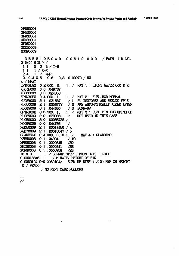
SRAC: JAERI Thennd Reactor Standard Code Syrtem for Reactor Dedpi and Analy* JAEM12SS
XF5R0001XF5SO0O!XP9N0001XP9R0001XF9S0OO1XXE50009XSM90009
3 5 5 3 1 0 5 0 0 00 6(0) 6(0.) /11 2 3 3 / T-R11 1 / X-R2 4 1 / M-R0. 0.4 0.5 0.64 / NMATLWTRXLWX 0 2 600. 2.
0 0 .0497370 0 .024868
1. // 1/ 2/
2 02 00 02
1. /
XH01H008X0060006FPINXOFX 0 4 900. 1.XU08W009XU050009X006W009GPINXOGXXU08W009XU050009X006V009XGD50009XGD70009CLADXCLX 0XZRN0008 0XFEN0006 0XNIN0006 0XCRN0008 0 110 0 00.00013846 1.0.0069194 9*0.0069194/0 / PEACO
/NO NEXT CASE FOLLOWS
0 0 6 1 0 0 0 0 / PATH 1-D CYL
0.8 0.90270 / RX
1. / MAT 1 : LIGHT WATER 600 D K
2 1 .0216372 1 .00067770 1 .0446300 5 900. 1.
.020968
.00065738/
.044786 /
.00014850 / 4
.00015647 / 54 600. 0.18 1. /
MAT 2 : FUEL ROD NORMALPU ISOTOPES AND PSEUDO FP'SARE AUTOMATICALLY ADDED AFTERBURN-UPMAT 3 : FUEL PIN INCLUDING QDNOT USED IN THIS CASE
MAT 4 : CLADDING/ 19/20/22/23
/ BURNUP STEP , BURN UNIT , EDIT/ M WATT, HEIGHT OF PIN
BURN UP STEP (1/10) PER CM HEIGHT
.04294
.0000845
.0000341
.0000759

JAERI1285 tX. Sample Input and Output 227
USE OF COLLISION M O B . RDUTINE (N0*CALLLO,L>SELECT OP ROUTINE FOR PIN I CALCCNO»P1J,1D SN ,2B SN ,» B1FP.2D »IFF:C,1.2.3.4,]>
BANCOPP PACTOR BY(INPVT,PIJ,PORMILAIO,I.»CALC or THERMAL RANBE (IXCLUDED*lNCLUDEBtO,l>PROCESS OF M 1 0 H M C I > RANSE(TAGLELOOK.IP.,PEACOIO,1,2>FLIH CALCULATION ST RANGES(SKIP»CALCtQ,l>FAtT RANSES FOR TRANSPORT CALC(O,1.2,3,4)UPBATE OF MCROSB FILE (RO,CALLIO,1>CALC OF BAKE REACTOR SPECTRUM(SK1P*P1.•110,1*2)COLLAPSE NACBO K-SECTIOA « B A M I I U l ' . C A L L I C S )INPUT OF BEMETRV CNIU,IAr)E At PREVIOUS CASEtOfl)SELECT ROUTINE FOB EMERVALUE CALCOO.PIJ .H I N . l t EH.IB N!»,» »IM1O,1.J,J,»,3)
COLLAPSE HACP.0 AFTER E1BENVALUE CALCtSKIP«CALLIO>l>PIEPAIE KACDO FOR CITATION IBHIP.CALLIO.tlTOTAL N1CRO X-SECT1ON BY (HARNONIC»AR1THHETIC AVI1*2>TRANSPORT MCRO I-SECTION IT <PO,P1,B1.SNIO,1.I.I>BIFF COEF (INVERSE Tlt,BENOIIT ISD,BENO1ST ANI101t*Z,3>PLOT OF FLU> NACBO H-SECTION <1«1>PBINT OF DACBO-I (O,!,2>BURN-UP CALCULATION <C,HSKZP.CXECUTEI
NUNBER OF USER'S THERNAL CROUPS
NUMBER OF USER'S CDNtENIED THERNAL BROUPS
NUNBER OF LIBRARY BROUPI IN THE USER'S FAST fROUP2 I > 9
2 1 1 1
NUNBSR OF LIBRARY CROUPS IN THE USER'S THERMAL tROUPS
NUNBIR OF USER'S SROUPS IH THE CONDENSE* FAST fROUP
NUMBER OF UBIR'S 4R0UPS IN THE CONDINSEB THERMAL SROUP
nRIA BERCHMARR SIRBLE PIN ROD CELL I BURN-UP
BEOHCTRV TYPENUMBER OP BUB • REGIONSNUMBEB OP T - REGIONSNUMGEB OP » - REGIONSRUMGER OP I - REGIONSOUTER BOVNA-Altr COMXTIM <*t,O,l,2>BIBSCTIONAL PIJ (1,1)NUMBER OP R OB R "ISMRUMGER OP TMETA OR V M E NTOTAL NUMBER OF PIN ROBSHUNGER OP RINGS OF PIN ROB ARRATRUMEN OP LATTICE CELLS TRACEDPRINT CORTROL OF PIJ (0,1)ORDER OF GAUSS RADIAL INTEGRATIONNO. OF DIVISION FOR ANGULAR INTEGRATIONNUHGER OP ANNULAR DIVISION IN A PIN RODDIVISION BY RPP (0,1,2)ANGLE RANGE !»v DEGREEPLOTER OPTION (0,1)
•--R-REGION NO./T •••1 1 2 3
*a-X-RECION NO./N •••
• • • STEP «•• INPUT FOR PIJ( CIRCULAR CTLINBSR I
STRAGE USED 3425 FROM 40000
VOLUME OF (Sl-RECION11S.024S4E-01 Z)2.B27«3E-O1 3>3.4SsrSE-01 4>8.7»444S-0t S1S.4BS4BE-01
VOLUME OF (T)-REGION11S.02494E-01 2)9.B2K3E-01 3>H.4SsrsE-Dl 4>B.7t444E-0S S1S.4BIME-0I
VOLUME OF (R>-REBION»r . t5>PM-01 I1J.45575E-0I »1.4>P01t*M
V0LUM OF (I)-RIGION1>1.SS»BE*G«
RATIO OF VOLUMES OP T-RECXCHS NUMBICALLT INTEGRATE* Tt ANALTTIC»l.G«024« IIB.IttMT »B.t»4T4 4>B.ttMt» llt.tttMS
J4 LINES BRAVN ••• ELAPSEB TIME
MO. OP MATERIALS HSEB IN TNI CASE • 4

SRAC: JAERI Thennal Reactot Sttndud Code Systran for. Rwctoi DMtjn »nd Amlyik JAERI 12(5
.42*741*11 u m i b i i •.ii7SM*oi o
.14707C*ll •.142441*01 I.1HUMI t
. I H H M I • . i» i7 i .« i • . M i m m •
.114741*11 •.MMUtOl 4.123441*41 •
.2141ft**l S.2414*!**! 0.144771*01 I,
.344141*41 •.UlITIttl 4.333731*41 •
.3I3MKH I.IHIIKH O.*7*4M-O1 I.
• • • BARE REACTOR IPECTRIM CALCULATION • « • OF STE F 15 • • • mwRM STEP • ••••HEAP • • • • • A MROKARIE SXMLt M l «00 CELL I • » • • »• • • 07 01 APPROXIMATION **•RATIO OF THIIML SOURCE TO KMWL 0.10011EX1•EUTRON SPECTRUM MR U l a t l l i
O . ( » H I » M O.1SM1E*« •.372441*01l . l i m c « 0,UI04B*M •.177111*01O.ltilHXI 4.14I»1E*41 «.1I»t«»«l• .U143E*tl *.1M74E*M I.IHI7MI4.14tt4E*«l I . IHHMI •.1*413E»414.37S43SO1 4.34744H41 t ,IIH1ltn• . IU4*B»«I l . n u m H •.42S7IB«M
miiTiiM CIMRIRT n i l LITHMIY• .47M4E-» *.1S4S*I-M •.344131-41 0.20722E-02 O.1O327E-M 4.117331-42 I• .3MSSE-H 4.391271-43 O.WHI-IS l.lllin-1! 0.2447*E-»3 I.IHMI-n 0t.nnu-n 4.210471-13 0.133241-03 o.itaui-i> o .nwu-u •.msti-M aO.ltStfE-M 0.1MI*E*M 0.17S41E-M O.«tllTI-O( O.tS2*tE-»4 A.*U«tE-M •O.USm-01 •.111ME-0I 0 . 1 I l » E - n O.l*"tl-OJ O.KOODI-t} a.JTMtE-H •O.X2T3St-O3 fl.tt72iE-n t.ZtllTE-OS O.2»t4«E-03 0.1t311E-03 0.171S1E-M •O.SOIHI-H «.JJ70«-M O.ltrMt-M O.110SU-04 O.S>4I>E-09 O.»4«E-i> O
r«IT fXttlON t.241«7E»MMil MIMPTIOa O.J»H7I.Mmn LIIUII o.iMitE-nTOTAL H t l l M 0.1Il»E>ttTOTAL AIIODPTIOa O. t l t lOE«MTOTAL LEAKAIE O.19l fSE-« l< - i « - i . ! i « miir-i.no> mm <E»ITIIICAL IUCICLKI. O.IOOOOE-OJ
4IH1EX1 I .1HUMI l , m i l M I •.1IIIIEX1 • . l l l l t t«m •.14tMI«*l (.1I4WEM1 (.UTtHMl •.•74NKM «1USHX1 t
MriMMlll«7H*tSlM47t«lM C t l
L •.94M4t-U ••12M4I-W «.
,110421-02 •.117171-43 •.44*4H-*S •.,2S24»-a3 O.ISW4C>>1 • .14*S4l-« • .,191371-M • .ltlllE-H •.17MOE-<1 • ..t«lSII-«4 • .1M32I-M 4.14417E-4S 4.1441*1-49 • . i M m - u •••iMsi-ra «.141341-43 •.111331-41 *.4(*41I-M «,.441471-04 •.ltHH-04 *.lt011l-«7 *.
HM7I-44
,<*MH-U1UMI-II,U114I-*SMI1H-0I
COAR
ENEROT RAI0.10000EIOI0.201471*040.412341*00
HHOL EHERO* RXCill
IE (EV)0.20347E*040.412942*00O.I0010E-04
III-1.474I1E-14 MM, tVl.»0110l-U EM)
VELOCITY RAMIE CCHVIEO0.4I740E»l« C l l l t l l ' O I0.421*IE»0S 0.114171*07O.U427E»O7 O.4S7«1E*O4
LETHAMT RAHII0.O I.SIMl.tOOO U . I I M
lt.SOOO 27.11M
• • • l » t MACTO* IPIC:«U« CALCULATION • • • 01 ITEP II • • •• • •* IA* •••NIA •l«CN«I«lt I INILI H» IID> CiLL I IU««-UP• •• I ) II APH0«»ATI0« •••• ATIO Or IHBMAL I01HCI TO RIMVAL 0.100111*01NIUIIOH IMCTRIM PI* LEIHAMI
O.<II7II*OO «.I«OI4I*II 0.171411*01 «.«10III*OI O.tllOIKOl0.110*11*01 0.1*lfttl*0l 0.177141*01 0.117911*01 0.1*1111*010.141411*01 •.141101*01 C.ISI11K01 t.1)1111*01 0.111441*010.111111*11 •.110111*01 I.IMIIK01 0.111101*01 0.IIIIIK010.1A47tl«ll O.l?}!!!*!! I.1I771I*O1 0.204t7l*ll 0.111111*010.M171KI1 M I H H d l 1.171711*01 •.HCI7I.II 0.144741*010.111111*11 I . I I X I I I H l . » I U I * 0 0 ••»4O4I»IO O.HI»4I«00
N1UTA0H tU«»l»t M« LITHAHt0.4MISI-01 0.1I1I0I-0I O.IOIItl-02 0.114711-12 O.10IJ1I-0I0.4000II-I1 0.111111-01 O.IO«7OE-OI 0.»>IIE-U 0.1»»l»E-OJ0.I1S7U-I1 0.I1UIE-01 0.I11III-01 0.1M74E-01 0.20MVE-010.101111-01 O.ltllIE-» 0.17.411-0J 0.0M4M-04 O.«»7SE-04O.lllkll-gi 0.11II1E-I1 0.121101-01 0.1S44IE-0] O.H»7II-OJ0.211711-01 0.211411-01 0.207471-01 0.1t434E-03 0.1I14IE-010.471171-04 0.11M1E-I4 O.tllltt-04 0.10I4SI-04 O.SO0«7E-0S
M«I • l t l t » 0.11*MI*0>FAIT AIIMFTIOM ••Ut22E*OOr«IT LIAIAIt «.114111-01TOTAL riSISM 0.114111*01TOTAL AMOimOa •.»HI»*0*TOTAL LEAKAOI A.tH^il-tl«-IF"1.14JJ KIIF'1.2771 UWII »HT«ICAL IU»L1M> 0.200001-
0.417471*11 O,4SI1M*O1• •1I04IK01 0 . l )» t l* l l• .111111*01 • .IKflKIl• •1I1MK01 «.11SMKI1• .114171*01 O.mi»l«ll•.111111*01 •.111141*11• .•11771-01 *.14WII-01
0.K11M-0I •.117411-110.14100I-II •.311441-110.IOIIM-01 0.1M41I-01I.MIOII-04 •.•771IE-I40.141471-01 0.1777II-I10.141411-01 •.1MME-01I.tl4ltl-Ol •.41149I-04
t.lHIIUII . m i KI.UHrilll •.147131*41•.•rr<M»4« «,ittiH*oi• .U l l t l t l l «,1IMN*>1• .117431*41 l . H H H W• •IM1HXI •,1444H*41• •1I4»E-M «.<4H4I-I4
.174141*41
.111141*01111IIK4I134441*411041HM1I47**l*41lt lSl l -42
471771-13 •.44MII-01 «.4MS4t-4114*171-01 •.117*71-43 •.243111-431*1*11-11 I.171141-11 •.1II44I-<IIH1M-0S 4.I4M1I-41 •.144411-43I*14H-*I 4.1414H-4I • • l i a t H - a iI147H-43 4.4*1441-44 •.474411-44131771-44 4.I441M-17 •,111741-W
RESULT OF O[»LETIO« CALCULATIDH
OATS 4 .«f l»E*01 f.t»»44E*01 l.S0022E*02 2.00D44E*02 2.90124E*02 3.001tSE*02 3.502411*12 4.M174t*l2 4.SI47SI**!.S.M507I*02
HMD 4.«lt40C-03 1.3I30IE-02 2.07SS2E-02 2.74774E-02 3.4S«70E-02 4.1S144E-02 4.I41S0I-U S.51SME-I2 4.I2744E-U 4 .*1I4M-U
U235-I r..0t4!2l-02 I.O3340E-O2 1.1I200E-01 l.S4t91E-01 l.t0451E-01 2.24II2E-01 2 .SII4U-M 2.K444E-01 I . I 1 I U M I 3.1274M-0I
< MATERIAL N0.«
10 NA« >>•
VOLimE- 7.0S3ME-01 CR-J FACTOR- 1.000001*00 )
4 .* l fE-03 1.344E-02 2.0741-02 2.7441-02 3.4401-02 4.1321-02 4.0441-02 3.1341-41 4 .117I-M 4 . N K - N
UOS 4.777E-04 4 .4ttE-04 4.2331-04 S.«79E-04 5.727E-04 5.4IIE-O4 9.2S3E-M 3.0271-04 4U04 0.0 4.744E-04 «.330E-04 1.375E-09 1.7tlE-0S 2.2041-03 >.Sm-09 2.t70l-09 3U0I 2.144E-02 2.143E-02 2.141E-02 2.1401-02 2.1SIE-I2 2.13K-O2 1.194E-02 2.1S9I-U 2PUt O.O f.01SE-04 i..047E-0l 2.4451-03 3.312E-05 l .«3IE-9S 4.473E-05 4.*4SI-0S 5PUO 0.0 2.4111-07 •.213K-07 l.tlOE-04 1.14SE-04 4.SI7C-04 4.J70E-04 7.O10E-04 •PU1 0.0 I . t t«-O» I.44M-00 1.04«E-07 4.4752-07 7.«24C-07 1.24IE-W 1.7451-44 IPUI • > • 7.21*1-11 l .*74E-Sf S.OtSE-St 1.4fSE-00 3.3I7E-00 «.312E-M l . l l * E - * 7 1>E3 0.0 4.1«ll-» 4.1541-4* 4.1141-4* 4.1III-M 4.44H-H 4.WIE-0* S.M1I-M 5Sat 0.0 S.22M-U 5.331E-H 9.125r-M 5.J4M-04 S.242E-H 5.2I3S-M 3.1941-N >FIR • • • 1 .4*41-05 7.242E-05 1 . 0 7 K - S 4 1.401E-04 1.727E-04 2 . M H - 0 4 2 .3451-04 *<F5S • • • * . « i n - 0 4 1.7S0E-05 2J.574E-M 1.351E-0S 4 . 0 * 3 1 - 1 1 4 .4411-45 I .477E-45 4FSR 0.0 0.0111-00 1.14IE-47 1.3I5E-47 1.31tt-47 1.1451-17 1.3141-47 1.1441-07 t.m 0.0 4.0111-07 2.4111-04 3.7I4B-M *.024t-04 1.4OH-0I l .«7M-l l 2.7UI-43 I.PIS • • • 1.7711-47 4.0IM-07 1.473E-04 2.31U-04 3.7*H-04 S.244t-04 ».»HE-44 0.>H • • • 1.4141-14 *.MII-I« 1.474E-M 2 . 3 H f - n 1.0451-0* 1.M7C-0* 3.I13I-W 4.
.M7E-04 4.3*41-04 4.3UE-44
.344E-0S 1.4*71-13 4.O37C-M
.1141-01 2.1131-42 t . l S I I - H
.3411-43 5.7171-05 4.«4M-H
.40*t-04 1.14H-05 1.1411-45
.4171-44 3 .K4I-H 3.7741-44• 77H-07 1.4411-07 3.73M-07• l f l - n S.OTM-a* 5 .7t«-4»
.4*11-4* S.41I1-M < .T4M-M4tH-H l.flll-M 1.2111-*411M-4I 4.74K-*S 7.UM-M.!lM-*7 I . l4»-t7 1.11M-<74*4B-(S 4.1I4I-M l.MH-M74H-44 i . m < - n i . m t - n1IM-M t.SWfW *.MM-**
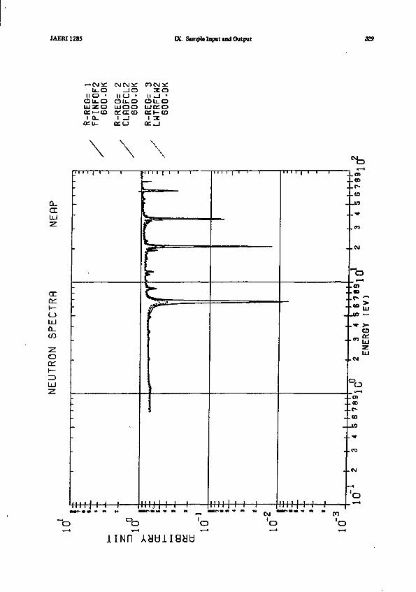
IAERI1285 K. Sample Input and Output
U - OII O •
Ci) li_ OUJZO/v i—i (o
1 0 .CCLL.
J OI ICJ •
LUQOctrccco1 _J
3 OII _ l •
CiJU_Oii t fv»r">Oi l— CD
1 ^
CLcrLU
UJQ_
cn
Illll I I I I I J l I I I II I 1 I 111 1 1 i I
Hi
>
tu
. .CO
. ( D
°oCM
o
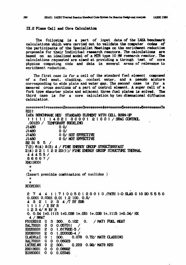
230 SRAC: JAEIUThenialRwctocStaBdudCo<l*S]rit«nfar]UKtorDMi|nudAiidy)b JAEM13SS
IX.2 Plane Cell and Core Calculation
The following is a part of input data of the IAEA benchmarkcalculations which were carried out to validate the computer code* ofthe participants of the Specialist Meetings on the enrichment reductionproposals for their Individual research reactors. The calculations arebased on an idealized Model of a HTR type 10 MV research reactor. Thecalculations requested are aimed at providing a through test of corephysics computing code and data in several areas of relevance toenrichment reduction.
The first case is for a cell of the standard fuel eleaent composedof a fuel meat, cladding, coolant water, and a pseudo mixturecorresponding to side plate and water gap. The second case is for asneared cross sections of a part of control element. A super cell of afork type absorber plate and adjacent three fuel plates is solved. Thethird case is for a core calculation by two dimensional diffusioncalculation.
* * * * * * * * * 1 >l°|o|o|o)otoio|ot<24ot<^^
HsuIAEA BENCHMARK HEU STANDARD ELEMSNT WITH CELL BURN-UP
M i l l 1 4 0 2 1 0 0 0 0 1 2 1 0 0 1 / SRAC CONTROL. 00120 / TEMPORARY BUCKLING
J1480 0 0 /J1480 0 0 /J1480 0 0 / HOT EFFECTIVEJ1480 0 0 / NOT EFFECTIVE22 31 5 5 /7 ( 2 ) 6 ( 4 ) 8 ( 3 ) 4 / FINE ENERGY GROUP STRUCTUREFAST2 ( 4 ) 2 2 1 1 2 2 2 3 ( 1 ) / FINE ENEMY GROUP STRUCTURE THERMAL4 4 4 5 5 /6 6 6 6 7 /
XH01H001**
(Insert possible combination of nuclides )**
XC02C001
2 7 4 4 1 1 7 1 0 0 5 0 1 2 0 0 1 0 /PATH 1-D SLAB 0 10 20 5 5 5 00.0001 0.0001 0.01 1.2 100. 0 . 8 /4 3 2 1 2 3 4 / T B Y S U B1 1 1 1 / X BY R1 2 3 4 / M BY R0. 0.04 1*0.1115 1*0.038 l*.O51 1+.038 1*.1115 1*0.04/ RX4 /NMAT
FH1DXD1X 0 3 300. 0.102 0. / MAT1 FUEL MEATXAL70001 0 0 0.057011 /XU050001 2 0 1.61790E-3 /XU060001 2 0 1.20050E-4 /CLADXCUC 0 1 300. 0.076 0.72/ MAT2 CLADDINGXAL70001 0 0 0.06023LVTRXLWX 0 2 300. 0.223 0.98/ MAT3 H20XH01H001 0 0 0.06692X0060001 0 0 0.03346
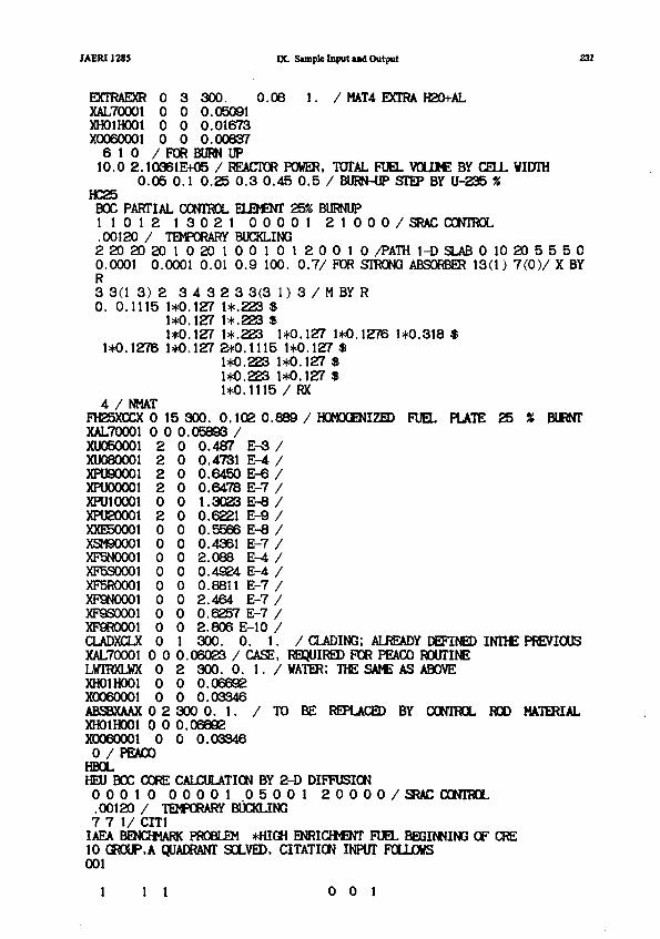
JAERI1285 K. Sample Input and Output 231
EXTRAE3(R 0 3 300. 0 . 0 8 1. / MAT4 EXTRA H20+ALXAL70001 0 0 0.05091XHOlHOOl 0 0 0 .01673X0060001 0 0 0.00637
6 1 0 / FOR BURN UP10.0 2.10361E+05 / REACTOR POWER, TOTAL FUEL VOLUME BY CELL WIDTH
0 . 0 5 0.1 0 .25 0 . 3 0 . 4 5 0 . 5 / BURN-UP STEP BY U-235 %HC25
BOC PARTIAL CONTROL ELEMENT 25% BURNUP1 1 0 1 2 1 3 0 2 1 0 0 0 0 1 2 1 0 0 0 / SRAC CONTROL.00120 / TEMPORARY BUCKLING2 2 0 2 0 2 0 1 0 2 0 1 0 0 1 0 1 2 0 0 1 0 /PATH 1-D SLAB 0 10 20 5 5 5 00.0001 0.0001 0.01 0 . 9 100. 0 . 7 / FDR STRONG ABSORBER 13(1) 7 ( 0 ) / X BYR3 3(1 3) 2 3 4 3 2 3 3(3 1) 3 / M BY R0. 0.1115 1*0.127 1*.223 $
1*0.127 1*.223 *1*0.127 1*.223 1*0.127 1*0.1276 1*0.318 *
1*0.1276 1*0.127 2*0.1115 1*0.127 *1*0.223 1*0.127 *1*0.223 1*0.127 $1*0.1115 / RX
4 / NMATFH25XCCX 0 15 300. 0.102 0.889 / HOMOGENIZED FUEL PLATE 25 » BURNTXAL70001 0 0 0.05893 /XU050001 2 0 0.487 E-3 /XU080001 2 0 0.4731 E-4 /XPU90001 2 0 0.6450 E-6 /XPU00001 2 0 0.6478 E-7 /XPUlOOOl 0 0 1.3023 E-8 /XPU20001 2 0 0.6221 E-9 /XXE50001 0 0 0.5566 E-8 /XSM90001 0 0 0.4361 E-7 /XF5N0001 0 0 2.088 E-4 /XF5S0001 0 0 0.4924 E-4 /XF5R0001 0 0 0.8811 E-7 /XF9N0001 0 0 2.464 E-7 /XP9S0001 0 0 0.6257 E-7 /XP9R0001 0 0 2.806 E-10 /CLADXCLX 0 1 300. 0 . 1 . / CLADING; ALREADY DEFINED INTHE PREVIOUSXAL70001 0 0 0.06023 / CASE, REQUIRED FOR PEACO ROUTINELWTRXLWX 0 2 300. 0 . 1 . / WATER; THE SAME AS ABOVEXHOlHOOl 0 0 0.06692X0060001 0 0 0.03346ABSBXAAX 0 2 300 0. 1. / TO BE REPLACED BY CONTROL ROD MATERIALXHOlHOOl 0 0 0.08692X0060001 0 0 0.033460 / PEACOHBOLHEU B X CORE CALCULATION BY 2-D DIFFUSION0 0 0 1 0 0 0 0 0 1 0 5 0 0 1 2 0 0 0 0 / SRAC CONTROL.00120 / TEMPORARY BUCKLING7 7 1/ CIT1IAEA BENCHMARK PROBLEM *HIGH ENRICHMENT FUEL BEGINNING OF CRE10 GROUP.A QUADRANT SOLVED, CITATION INPUT FOLLOWS001
1 1 1 001
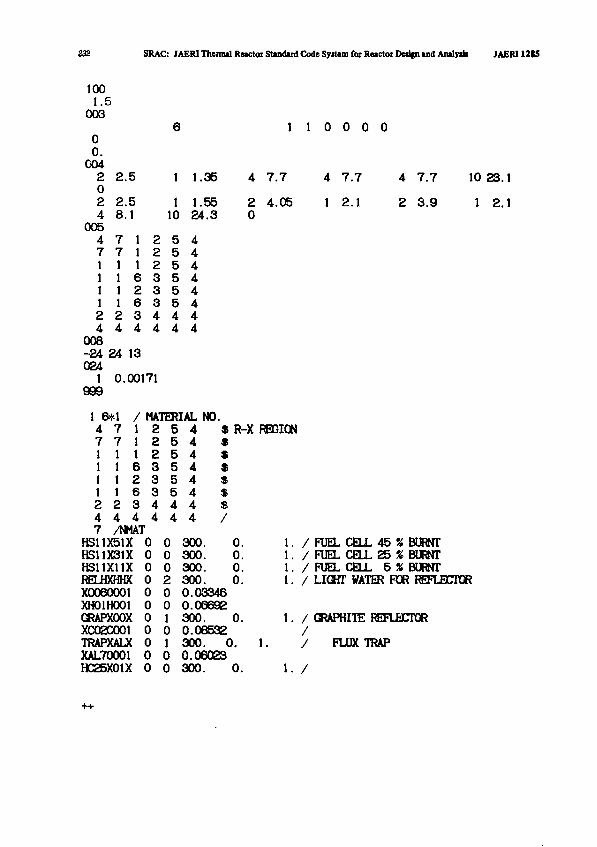
232 SRAC: JAERI Thennal Reactor Standard Code Syitem for Reactor Design and Analysis JAERI 1215
1001.5
0036
00.
0042 2.5 1 1.3502 2.5 1 1.554 8.1 10 24.3
0054 7 1 2 5 47 7 1 2 5 41 1 1 2 5 41 1 6 3 5 41 1 2 3 5 41 1 6 3 5 42 2 3 4 4 44 4 4 4 4 4
008-24 24 13024
1 0.00171999
1 1 0 0 0 0
4 7.7
2 4.050
4 7.7
1 2.1
4 7.7
2 3.9
10 23.1
1 2.1
1 6*1 / MATERIAL NO.4 7 1 2 5 4 * R-X REGION7 7 1 2 5 4 *1 1 1 2 5 4 *1 1 6 3 5 4 $1 1 2 3 5 4 $1 1 6 3 5 4 $2 2 3 4 4 4 $4 4 4 4 4 4 /
0 00 0
7 /NMATHS11X51XHS11X31XHS11X11X 0 0RELHXHHX 0 2X0060001XH01H001GRAPXOOXXC02C001TRAPXALXXAL70001HC25X01X
300.300.300.300.
0.0.0.0.
0 0 0.033460 0 O.(0 10 00 10 00 0
300. 0.0.06532300. 0.0.06023300. 0.
1. / FUEL CELL 4 5 % BURNT1. / FUEL CELL 2 5 % BURNT1. / FUEL CELL 5 » BURNT1. / LIGHT WATER FOR REFLECTOR
1. / GRAPHITE REFLECTOR
/
1. /
FLUX TRAP
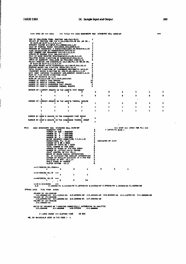
JAERI128S DC Sample Input and Output 233
USE OP COLLISION HOI. ROUTINE (MO.CALLIO,!)SELECT OP RDUTINI FOR FIX S CALCdtOfPU,!! III ,IB SN ,i» BIFF,21 >IPPIO,i,z,:,.,:>
BANCOPF FACTOR titi»nn.ni,n>m)in*,i,i>CALC OP THERMAL RANCE CCXCU»EB,1NCLWM>B,1>PROCIBI OP RESONANCE 2 AUHKTAILILOOI. IR.PKCOiO.l . l )FLUX CALCULATION BV RANCISCSKlP#CALCtO,l>FAST RAMIES POR TRANSPORT CALCtO,l,l,1.4>UPOATI OP KNOBS PILE CNO.CALLIO.l)CALC OP IARE REACTOR SMCTRIMCIKIP#Pl,tl!O#l«2)COLLHHE MCRO I - H C I I M IT IAME«»ir .CALLtO.l>mPUT or tEOItETRT <REU,tAM AS fREVIOVI CAtE10»l>IILECT ROUTIM POR EIIEHVALUI CAlCt«O,PU.l l l « . » l 1R,
ID tIPP.JO HIPP 1 0 , 1 , 2 . 1 , i . »COLLAPIt KACRO APTIR tMIRVALUE C»LC(»«If,C«LLrO,l>
TOTAL PIICRO >->ICT10R I I IKARMHICARITHHETIC AH 1,2)TRAPSRORT MACRO X-SECT10II tT CN,P1,01,11110,1,2,S>DIPP COtP cmvCRIE T R . U M H T I IO. I IR01IT A R I 1 0 U , 2 . »PLOT OP PLUX MACRO X-IECTIOR <1«2>PRINT OP HACRO-X (0 ,1 ,21•URN-UP CALCULATION (O,1ISK1P,EXECUTE!NUNIER OP USER*S PAST CROUPSNUNIER OP USER'I THERMAL CROUPSKUHIIR OP USSR'S C0W1NSO PAST IIOUPINUIIIER OP USER'S CONtEHSEI THERMAL I IOUM
NUMIII OP LIIRART SROUPI IN THE USSR'S PAST CROUP2 I I >
i t » 3
NDHRtft Or LIIRARV CROUPI ID THI UIIR»I THERMAL CROUPS4 4 1 1
1 1 1 I
1 1 1 1
NUMIIR OP USER'S CROUPI IN THE COHIINICD PAST CROUP* * 4 S
NUMBER OP UIIR'I IIOUPI IN THE CONMMIEI THERMAL CROW• l i t
Htlt IAEA IENCHNARK HIU STANDARB CILl tURN-UPleOMETKV TVPINUMRER Of SUI • R M I M INUMER Of T - RHIONIHUHIIR 0t> R - RCIIMIKUMER OF I • REIIOMlOUTER tOUMART COMITZM t-l,O.l»»B1RECT1ORIL KIJ tl,I>
Hunt en or TMIT* H T M MTOTAL NIHWIR 01* PIN RODSNlSntER OP R1NM Or PIN *0» ARRAYNUMCR Or LATTICE CELLS TRACE•PRINT CONTROL OF HI ( 0 *U
NO. OP DIVISION FOR ANVULAR INTEIRATIONNUNICR Or ANNULAR DIVISION IN A PIN ROBDIVISION IV RPP CO,1,21ANILE RANK RY »EIKEEPLOTER OPTION <0,l>
—-T-RtllOH NO./SUS*"4 3 2 1
•»X-ftI«ION NO./R • «t i l l
-•• MATERIAL NO./R • «
• • • ITEP • • • INPUT POR PIJ • • •( 1NP1N1TI SLAI )
INDICATES IT 1C1T
0.0
STMASE USED
.--1-X DIVISION •••O.AOOOOE-01 0.151506*00 0.1<*SOE*00 0.210SOE+00 O.lTtSOE^OO O.SffOODE*00 O.*50*0E»M
7431 FROK 40000
VOLUME OP CS>-REC10N1>4.00000E-02 2U.11SOOE-01 3J3.S0000E-02 4>S.0ttVtE>02 S)3.B0OO0E-D2 411.11300EO1 7I4.M00BE-B2
VOLUNE OP (T>-REC10N1}S.O»*»DE-O2 2>7.«O000E-02 3}3.23000E-C1 4>7.tttftE<-02
VOLUME OP (X>-RECIOND4.30000E-01
RATIO OF VOLUMES OP T-RES10NS NUMERICALLY 1NTECRATIB TO ANALYTIC1)1.00000* 2)1.0000*0 3>l.ftt»t 4)1.H**00
2 LIMES DRAW • • • ELAPSSI TIME

234 SRAC: JAERI Theimal Retctot Standard Code Syitem for Retctoi Duifn ind Anilym JAERI12S5
• •• Mil HUCTM IPICTHIM CALCULATION ••> OF 1TEP IS ••• M M STEP • ••••Hill •••IAEA UNCHHARK HEU 1TANIARI CELL •URN-UP •••• •• OT 01 APPRDKIHATIDN •••MTIO OP THEIML U W C I TO REMOVAL 0.10004E*01NEUTROfl IPECTRIM PE1 LETHARIT
O.SSSOIKOO o.230tu*oi o.4»s2E*ti o.s»ssi*oi o .n iu t>« o.ti<tit*n * .n»4i *o i O.»4PM>OI0.114121401 0.110731*01 0.1O031E401 0.107011*11 O.1«I711*O1 • .M41IE«01 ••102111*11 0.M10SI4110.M301I4M 0.tSS01t*OO 0.071301*00 0.104441*11 0.103231*01 1.1M>4I*11 0.1MSII*ll 1.1112M401O.1411tl*0t 0.133221*11 0.171041*01 0.100011*11 0.213411*11 0.244741*11 ••272131*11 0.39004I4010.33274I4O1 0.519141.01 0.111411*41 0.141341411 O.19O»|4|1 l . l i n i m O.0137M400 0.33041I4M0.202331-01 0.302031-02 O.t717tE-O4
NEUTRON CURRENT PER LETHARGY0.220311-02 0 .7H4M-01 0.147>OE-01 0.13»t?l-01 O . M > M t - M 0 . 7 M t 4 E - « « .4>74t t -M t . M 7 7 I I - »0 .1»4«e-« 0.1<I!<f-M 9.11IME-02 C.lltCH-0! 0 . I I 3 U I - U C.1117»-«t O . U M H - M • .1H74 I -M0.101&1E-02 O.10C0IE-O2 O.Sff42*E-O3 O.tlOOU~O3 0.U7SIE-H 0.SM44E-03 0.37S77I-03 e.SrwXE-OS0.49O3EE-O3 0.47«>M-03 0.SSM3E-03 «.9«31tE-03 0.4I170C-I3 0.4U24E-03 0.7t047t-03 O.TMlil-OJ0.7««17E-O3 0.4I33SE-03 0.577CU-03 0.454ff7C«03 O.S3434E-» O.»54OE-oa 0.137331-03 0.740A5E-040.M310E-0S 0.374UI-04 0.39IS5E-OR
PAIT PXISION 0.1Z030E«00FAIT AMORPTIOa O.»OtO»t-OlPAST LIAKAIE 0.52734E-01TOTAL P l f f im 0.14»5E>01TOTAL ARIORPTIOR O.t44»tE*«OTOTAL LEAKAIE 0.53W4E-01K-EPP-1.4443 KINF>1.7429 UNDER •EOHTRICAL •UCKLINI* O.120O0E-02
•.1H*7«MI I . U W M I1 M 4 ) H M.ff1«H
e.lltMB*! •.1UIIMI• .UI44EX1 «.334»EX1• .24M*E>H l . tHUItH
».StHlE-« (.I4H2E-Ui.iami-11 a.iit*M-o20.3tff3tE-*3 «.412tff-0S(.C1II1I-4S « .MM2E-n4>.34*tOE-«4 « . t 2 l 3 H - H
UP1 02 0.3 0.I 0 .9 0.1 0.7 0 .1 0.F 0.0 0.
• • •
ENERM RAN1E (1V1
1 I I 0 U 4 0 I 0.101171.01203471404372441402112341401274101*00137001*00•40171-01114471-01
0.3721414020.111911*010.174001*000.137001*000.040171-010.114171-01O.1O01OI-O1
0.441011*000.423»ll*010.144171*070.141731*070.717011*04
0.340011*040.117011*01
• A l l RIACTO* IPICTRUM CALCULATIOR • • • OF ITIP
>.123011*01I.1443714071.144731*07I.71701E401.111011*01.340O11I04•117011*01
O.4!7«1E*O4
1 • • •
1
1
01-11 ERO>
ETHARI> 1AMI.0 2.0000.0000 4.1000.3000 0.3000
.1000
.0000
.40101 .101011.111710.IOOO
• UM STIP-
11.100114.000417.401110.101110.111710.100127.0)00
1• • •
• • • or oi APPROKHATioa • • •RATIO OF THERMAL IOURCB TO RENOVAL 0.100041*01REUTROK IPECTRUFl PI* LETHARMO.lSStlKOO 0.1304»l»«l O . O N S K O I O . I I»»«OIO.II4t3E*Ol 0.110411*01 0.101371*01 0.107041*110.«47«ll«00 O.«S4S1I*O4 0.t7l»l|*00 0.1047tlt0lO.I4»H«O1 0.111111*01 0.170HI.O1 O.l l>3tl*t l0.32l0tl«01 0.311141*01 O.ttlOOI*Ol O.23R4tltilO.H014I-01 O.3t*tlt-Ol O.t49MI-O4
NEUTRON CURRENT PER LETHARIV0.22flSl-02 O.7904IE-01 0.1471SE-Q1 0.134I4E-QI0 . I1H4E-0 I 0 . I224SI -U 0.11I40I-02 0.114171-010.101701-02 0.100231-02 0.3«744t-03 0.411t3E-030.43203B-03 O.47733E-O3 0.31943E-03 O.34133E-O30.791341-03 0.471411-03 O.S4«07(-03 0.4S010E-030.27*7tE-QS 0.2I7SIE-04 0.3S330E-0I
PAIT F1III0N 0.114iI(400FAIT ARI0RPT10N O.S*423E-O1FAIT LEAKAIE 0.S2774E-01TOTAL PIIS10N 0.1S50St«01TOTAL AOIOHPTION 0.tl»H(*00TOTAL LEAKAIE 0.SS1174-Q1
0.4I2MI401 0.4I4MK01 » . l l> r»» l >.1I)MI*I1 > . l » l l l * t l 0.1IMMO10.I0II1KI1 •,1M43I«O1 0.101411*01 1.141101*11 l . t r H I H H l . n H H t H1.101441*01 O.1M«4I*I1 O.IH»II*OI 0.111741*11 t.ll«l4t*0t 0.117011*010.114131*01 •.141101*01 •.140111*01 O.»U4I»O1 0.ll4Ht*01 O.3l»4l>01O.IOIOIKOl •.137141*01 0.<14lll*04 0.I34I4KH 0.244>0t*M 0.111171*00
O.»33OI-O> 4.7117H-01 O.4n3K-0l 0.347401-41 0.1H9II-01 0.110171-01O.114O3I-02 O.1110OB-02 0.1003IE-OI 0.100141-02 0.1M44B-0I •.10IS7E-M0.30I70E-03 O.Umi-03 0.170371-03 0.S7044I-03 0.3tl>7I-03 (.41447E-U0.417)71-03 O.47O4OB-03 0.711411-43 0.771411-03 0.707041-03 •.70304E-031.330441-01 (.22302B-03 0.13I04E-03 0.733401-04 4.334141-14 0.1100M-04
K-EI I I - 0.120DDE-O2.
REIULT OF DEPLETION CALCULAT10«
0AV3 2.424571*01 3.2S1O3C*O1 1.33044E402 1.5t34IE«02 2.413132*02 2.40124E*02
NHD 2.40274E*02 5.20422C402 1.30333E403 1.54922E*03 2.332022*03 2.41402E*03
U235-S 5.OOOOQE-O2 l.OOOOOt-01 2.3OOOOE-O1 3.00000E-01 4.5OOOOE-01 3.00000E-01
( MATERIAL NO.- 1 VOLUME- S.0«f»E-02 C«-J FACTOR- 2 . I03I1K05 )
10 NAME U239-I 5.000E-02 1.0001-01 2.9COE-O1 3.O00E-01 t.5001-01 9.0001-01
uosU04
1 UOOt PU9
PW1 PU1
PUI1 «3t INt
10 FIN1 PSI12 F3R13 I H1 POt13 F9R
1.410E
0.00 . 0o.ft0 . 0O.ft0 . *0 . 00 .00 .9o.ft0 .0o.«
-03 1.337E-03
4.050E-077.0t4E-0P3.731E-102.tSSE-121.17SE-001.344E-071.03IE-U1.3301-031.4771-072.404E-H4.404E-M1.090E-11
1.4S4E-03
7.I49E-073.05>E-0l2.047E-004.0UE-111.4041-041.20IE-07» O71E-O4s.oiot-os2.30tE-071.0171-072.120E-001.1411-11
1
114111312117
.1131-03
.703E-01
.4441-07
.OItE-00
.1421-Ot
.3MI-M
.0031-07
. i m - 0 4
.2231-04
.2101-07
.3171-47
.4141-47
.S90E-11
1.13' £-03
1/111-042.2441-074.940E-004.103E-0*1.207E-H
O.tOOE-04 O.092E-O41.14tE-04 1.2ME-04
2.400E-04 2.4341-044.230E-07 9.4111-071.1101-17 l . l t l I -071.07K-H 3.19M-H1.444I-H ».4411-lt
1.OO2K-07 •.113E-M 7.14M-M1.12IE-041.4J3E-041.4191-470.4ME-072.3HE-071.7131-11
t.3111-04 1.03M-032.1HE-H 1.3141-041.3071-07 1.3011-071.1101-M I.7701-H3.4S4E-07 0.77M-071.1371-10 1.14M-1*
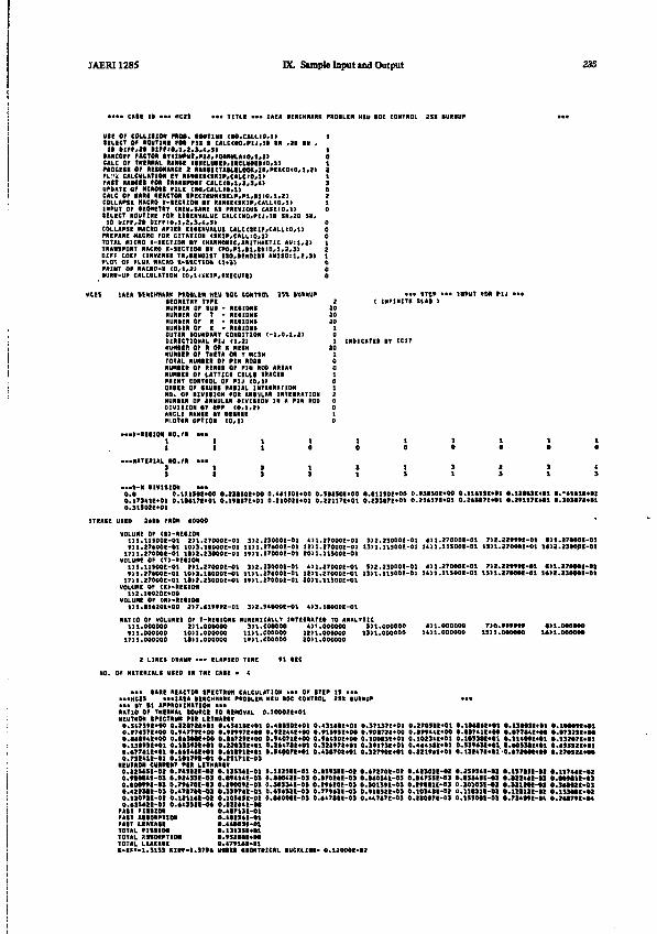
JAER11285 DC Sample Input and Output 235
M l OF COLLISION PROt. ROUTINE (NO.CALLtO.l)tCLECT or ROUTINE re* pii • CALCMO.PIJ.II an .it » ,i i tirt.it iirpio.i.t.i.t.s)IANCOPP FACTO lr<MPIIT,F>lj,FOMm.A10,l.»CALC OF tMRHAL HAME (l»CLWI»,INCLWEt>O,l!PROCESS OF RESONANCE I «AMEITAM.ELOC«.II.PEACOtO.l,MFLVi CALCULATION « •AMMIKIP.CALCie.ilPAtT RAMfl POD TRANSPORT CALCtO.l.2,3.4)UPDATE OF DCIOIt rlLI (M.CALLIO.l)CALC OF (AW REACTOR SPECtIIM(SIiF.ri.t.|IO,l,I>COLLAPSE HACRO X-SECT10N ST RANtE(SKlP.CALLto.l)INPUT OP tEOHETRV (NEW.SAHE At PREVIOUS CASEto.l)SELECT ROUTINE FOR E1CENVALUE CAUCN0.P1J.1D SN.2D SN,ID »1PF,2I DIFriO.l.i.S.i.S)COLLAPSE MACRO APTER EltENVALUE CALC(SK1P.CALL:O.1>PREPARE MACRO FOR CITATION (SKIP.CALLtO.l)
TRANSPORT KACRO K-IECTIOR It (PO.Pl.tl.SHtO,1,2,3)'DIFF COEF flNVERSE TR.tENOlST IS0.REND1ST ANISOtl.2,3)PLOT OF FLUK PfACRO X-SECTION (1*2)PRINT OF NACRO-K (0,1,19RURN-UP CALCULATION (0.1J8K1P,EXECUTE)
IAEA IEHCHHAHK PROtLM HtU IOC CONTROL 2S1 1URNUP•EOKETNT TTPE•UNIER OF SUI - REtlONSNUHIEIt OF T - REtlONSNUKRER OF R - REtlONSNUKIER OF R - REtlONtOUTER IDUNDARV CONRITION (-1.0.1.2)DIRECTIONAL PIJ (1.1)«umin OF R an « mtuNUNIER OF THETA OR T NC3HTOTAL NUNIER OP PIR ROOINUHIER OP RIMI OF PIN ROD ARRATNUPIIER OP LATTICE CELLI TRACEDPRINT CONTROL OF PIJ (0.1>ORDER OF (AUII RAIIAL IHTIIRATIONNO. OF HVIttON POR ANIULAR IHTEtRATIONNUNIIR OF ANNULAR DIVIIION IN A PIN RODDIVISION iv RPP (0.1.I>
• • • STEP • • • INPUT FOR HJ 1( INFINITE SLAI >
PI.DTIR OPTION
• • • IC -RE I ION NO,11
•••MATERIAL NO,SS
, /R •
./I •
• •11
• •1t
(D.REE1)
11
SS
10
13
INDICATED IV IC17
--•ft-X t l V I S I M • • •0.0 C.1IUOI»OO 0.131501*00 0,**150K*00 0.5II50E*00 O.IUSOt'OO 0.?3IS0«*OO 0.11419E*»t 0 .1ZMSI* t l • . * « » 1 I * K0.17S41E+01 0.1M17l*01 O.S*II7C*O1 0.210021*01 O.ZZ117E*O1 O.ZSSI7E*O1 0.2S«17t+01 O.tftM7E*«l O.*tU7E«*I • .S0MTI*Bl
S X 0
STRASE USED 2*1* PROM AOOOO
VOLUME Ok* (S)-RECtOHtll.ttSOOE-01 Z)1.Z7000£-01 S)2.2S000E-Ol «)t.27000E-01 5)2.23000E-01 *)1-27000E-01 7)2.2Zt»tC-0l*)1.27*00E-01 1O)3.1IOOOE-O1 11>1.27*OOE-01 12>1.27000E-Ol 13)1.11500E-01 1*)1.115001-01 15)1.270001-01
17)1.27000C-01 1D2.23000E-01 If )1.I?OODE-O1 20J1. U500E-01VOLUME OP (T)-K!iIO«
D1.M90QE-01 2U.27000E-01 3)2.230001-01 4)1.270001-01 312.23000E-01 1)1.270001-01 7}3.22tfftl-01f)1.27*O0E-Ol 10>3.1tOOOC-01 Il)1.27i00e-01 1211.Z7O00E-01 13)1.11SOOE-01 14)1.115001-01 1S)1.27«OOC-01
17>1.Z7000E-Ol U>Z.23000E-01 If11.27OOOE-01 2OJ1.11SO0E-O1VOLUME OF <X>-NEC1M
l>2 .1O020E*O0VOLUME OF <H>-RECIDN
S}l.tl*2OE*Q0 Z)7.*ltttl-01 3)2.940001-01 4>3.1tO00E-01
RATIO OF VOLUMES OF T-RECIONS NUMERICALLY INTECRATE* TO ANALYTIC1)1.000000 2)1.000000 3)1.000000 4)7.000000 5)1.000000 4)1.000000 7>0.ff»ftfm.OOOOOO 10)1.000000 lm.OOOOOO 12)1.000000 13>l.O000OO 14)1.00D0OO 15)1.000000
17)J.OODOOO II)1.000000 lt)l.000000 20)1.000000
•>1.27«OQE-01M ) 2 . Z S t 0 0 E - 0 1
CLAMED TIME
• • • IARE REACTOR SPECTRUM CALCULATION » • • OF STEP IS•••HC2S • • • I A t A BENCHMARK PROBLEM HEU IOC CONTROL 25K• • • BT I I APPROXIMATION • • •RATIO OF THERMAL SOURCE TO REMOVAL 0.10002E«01NEUTRON SPECTRUM PIR LETHAMT0.5475BE*H 0.31B73C+01 •.4S*1BE«B1 O.«IB3OE+O1 O0.ff7*S7E*O0 O.f477tl+OO • . f X t * 7 E * M O.t2Z441+» OO.B*t**C*OO O.B*3HE+OO 0.l472»E*00 O.»*07.E+OO O.Q.1SSBSE*O1 0.1B3t2E*Bl 0.22033E*B1 0.2ftt7ai+01 0.O.*77* l t *Bl t . * *S4*E* * l B.*1B*1E*B1 ».S4007E*01 00.7324U-B1 0.1017VE-B1 B.2S171C-03
NEUTRON CURRENT PER LETHARIT0.22S4SI-01 0.74S22C-M • -13SU1-0) B.122SIE-O1 O.BSV3IE-O20.9BM4t<03 O.*2*33E-O3 O.tt*141-OS 0.CS04ZE-03 0.S702BE-03O.BOOtft-03 0.7ffi70E-03 0.2*OOtC-03 O.M33tE-O3 O.2U20E-030.4Z23U-03 0.471701-03 O.33ff7«l-03 0.45*521-05 0.77*43E-030.130721-02 0.121I4C-02 O.10S43E-02 0.M00BC-03 0.447SBE-030.43542E-09 0.443321-OB O.I2244E-H
FAST f l l l l M O.4S713I-O1FAST ABSMPTJtHI O.4B2SBE-MFAIT LIAKAtl •.449031-01TOTAL r i t t lCM O.1313SE*B1TOTAL »SORPTION O.ffS2HE«MTOTAL LEAKRIE 0.47V14I-B1K-EFK-1.S1S5 KINF.1.37** UNBtR •EOMTRICAL BUCKL1H1- «.1L2DO0E-
1 0.37137E+D1 0.270311*01 • . U t t « E * « I» e.*oi72E*oo o.»t44E*eo t . » 7 4 i t * e e <I O.100131+01 0.10234E*01 0.1«S3««ei (I 0.3*173E*01 0.4«45tE*tl e.S3tAM*ei II O.]2»0E«01 0.I21MK01 I.1324TEVI1 I
t.«T270E-02 «.42302E-02 •.2SH4E-0IO.tt034t-0> 0.H7IJE-03 0.IM4IE-U0.301»E-03 0.2HS1E-03 D.3O»3E-t3O.«1IS2I-O3 D.10S4IE-D2 O.HISlt-020.447t7E-03 O.2IOI7E'O3 0.1550tt-03
0.S37ISE-W 4.11744I-B2O.H24U-U 0.MH1E-B30.3212«E-» O.MM2E-63•.12B12E-B2 O.tSSME-M•.734tfE-W 0.2U7BE-M
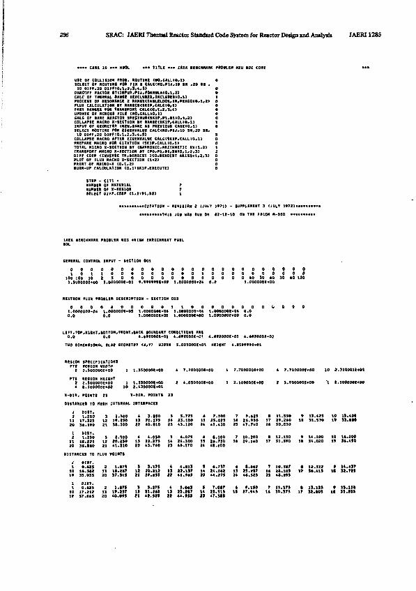
236 SRAC: JAERI Thermal Reactor Standard Code Syttem for Reactor Design and Analysis IAERI1285
> T1TLC " • - IAEA ICMCKMffK PMM.M HEU »Dt COM
DAHOFF FACTOR SVf INPUT,PU,FQMMILAlO,l,2>CALC Or THERMAL * A M I UXCLUI», lNCLUIEH0.1)PROCESS Of RESONANCE X ftAMIE<TAILtLOCm,lR*MACQiO.l,2>FLU» CALCULATION IT RANtES(SKtP,CALC10,1)PAST KANUS 'OB TRANSPMT CftLCCO,!,2,3,4)UPDATE OF MCROSS FILE (NO,CALUO*1>CALC OP M M MACTOR SPECTRUMtSKIP,Pl*tltO.l,2)COLLAPSE MACRO X-SECTION IT RANIE<SKIP,CALL:O,l>INPUT OF CEONETftV (HEW,SAME At PREVIOUS CASEiO»llSELECT ROUTINE fOR CUB* VALUE £ALC<NO,P1J,1» SN,2D SB,
COLLAPSE'nACRO AFTER EIGENVALUE CA.LCCSKIP,CALLtO,l)PREPARE MACRO FOR CITATION <SK1P,CALLIO,3>TOTAL MICRO X-SECTION »V (HAD NO N I C ARITHMETIC AVU*2>TMNJPONT HKKQ X-«CT10N fV [PO*»3,*1,SN:O,1,2,.3>
PLOT OF FLUX MACttO I-SECTION C l * »PRINT OF MACRO-X ( 0 * 1 , 2 )•URN-UP tALCULATION CQ,1:SK1P,EXECUTE)
STEP - C IT1 -NIMtER OF MATERIALNUNICR OF X-KEB10NfELECT OI^r.COEF ( 1 .
fiENEKAL CONTROL INPUT - HCT10N 0D1
D O O O O O O O O O O O O O O O O Q O O O O O O
100 JOO 10 2 3 0 0 0 0 0 0 0 0 0 0 0 0 0 4 0 SO 10 30 10 120l.S'JOOOOE+00 S.ODOOOOE-01 t . * t f f f f f E « O f J.OOOOOOl*** 0 . 0 1 . 0 0 0 0 0 0 1 * 0 0
NEUTRON FLUX PRQILEH DESCRIPTION - SECTION 005
0 0 0 O A O 0 0 0 0 1 1 O O 0 O O 0 0 O O O O 0l.OOOOOOe-0* l.OOOOODE-OS 1.0DO0D0I-04 l.OOOOOOI-Qi 1.000000C-0& 0 .00.0 0 .0 1.000000E*00 1.0000001*00 1.000000(400 0 . 0
LEFT,TOP,J(1SHT,»DTTON,FRONT,SACK IOUNDARV CONDITIONS ARE0.0 0.0 4.4V20Q0E-01 4.*f2000E-01 * . « « 0 0 0 t - 0 ! i.«t200DE-0]
TWO DIMENSIONAL SLAB etQMtTltV <X,ry WJ0TH 3.O05OO0E+O1 HEICHT «.ISfff»E«01
RESION SPECIFICATIONSPTS RC6I0N WIDTH
2 2.5OO0O0E+0O 1 1.3SO00OE+OQ 4 7.7OO00OE+OO « 7.7000001*00 A 7.?00000t*00 JO 3.310001E«01
2 2.5OOO0OE*O0 1 t.SSODOOE+OO 2 *.0500006*00 1 2.10O000E4O0 2 3.V00OO0E«O0 1 «.100000E«00
A «.1000001*00 10 2.430000E+01
X-DIR. POINTS 25 T-DIR. POINTS 23
DISTANCES TO MESH INTERVAL INTERFACES
2 1.230 3 2.S00 4 3.MO 3 5.775 * 7.700 7 V * J 3 « 11.590 • 13.475 10 IS . 40*11 17.325 12 lf.eSO 13 21.175 1 * 23.100 13 25.025 14 26.990 1? 29.2*0 I I SI.570 1 * 33.11020 36'1VO 21 31.300 22 40.HO 23 43.120 24 4S•430 25 47«740 24 30.050
1 DIST.2 1*250 3 2.500 4 4.050 5 4 *073 4 1.100 7 10* 200 I 12.150 t 14 • 100 10 lisa 2 DO
11 It.223 12 70.S50 13 22.275 1* 24.300 15 24.730 14 29.140 17 Sl.SfO IS 34.020 1* 34.45020 31.110 21 41.310 22 43.740 23 44.170 24 tS.600
DISTANCES TO FLUX POINTS
J oisr.1 0.425 2 l.»7» 3 3.175 4 4.113 9 4*757 4 ft.442 7 10.517 « 1».517 » »4.*J7
10 14.342 11 II.M7 12 20.212 13 22.137 14 24.042 15 25.9S7 14 21.105 IT 30.41S It 31.72S1* 35.035 20 37.345 23 3t.*5S » i l .MJ 23 44.275 24 44.5S5 25 41.195
i OUT.1 0.425 2 1.175 3 3.275 4 5.043 5 7,017 4 9.150 7 11.175 • 13.325 f IS.13*10 17.212 13 19.237 12 21.242 13 23.217 14 25,515 15 27.*45 14 30.375 17 32.105 It 3S.23S19 37.445 20 40.095 21 42.925 22 44.»55 23 47.315
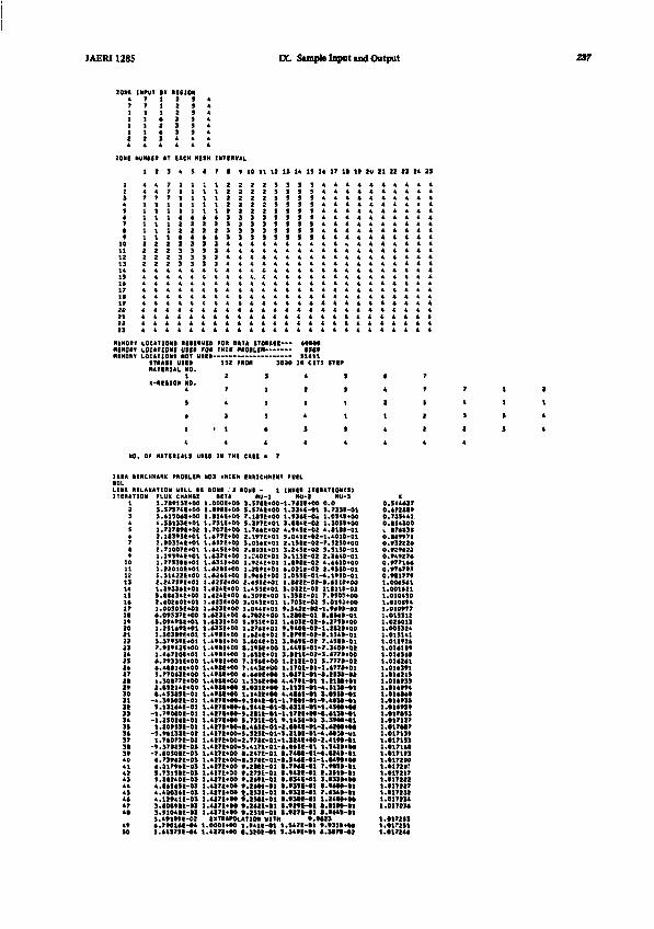
JAERI 1285 DC Simple Input ind Output
ZONE INPUT i r RE81ON* 7 1 2 5 *
1 1 1 2 5 *
2 2 3 4 4 A
ZONE NUMBER AT EACH HE3H INTERVAL
1 2 3 4 5 * 7 1 9 I I 17 It 1» 20 21 22 23 24 29
KtnORI LOCATIDNI RtSERVHMINOR* LOCATION! UIE9 FOR
ITNAII M E 'MATERIAL NO.
1N-RE010N NO.
4
3
*
1 •
4
FORTHII
1S2
1
7
4
3
1
4
DATA I I O M I IPROBLEM
FROM 30M
9
1
1
1
•
4
40000•Mt
IN CIT1
4
1
1
4
3
4
•Tlf
1
1
1
I
S
4
*
4
3
1
4
4
T
7
1
1
1
4
NO. OF MATERIALI UtEO IN THI CAIE • 7
1TCMT
1112
1 *IS1 *
111 *
312223242S2 *272 1
303 1323334353 *373 13 t40
4»
44454 *47
4»SO
ON FLUX CHANCE1.7t»13E+O03.57S74E+O05.41504E+004.5I333C+011.727S9C+022.ia3f5E*01
2.71OO7E*O1
1.22010E*015.51422E*00
1.3f334E+01
2.40240E*01
5*0f4ttE*01
lllo3»E-»Olsl3793tE*017.9S942E+Q01.4*72OE*Q1*.79331E*00».4tll«E*00S.77043E+00a.30!77E*OO2.aSH4E*00• .453HE-01
-4.39SO2E-O1S.131441-01
-1.7ff0»E-01-J.250J41-011.20tSSI-0t
-3.M132C-021 .74077E-D2
-t.37323E-0S-7.I030SE-034.73t42E-034.21794E-033.7313IE-03
4.l»S«SE-t>34.490341-034.12f41E-033.I0IVIE-U
• l7»0UE-t4 33.44S7SE-04 1
SETA1.000E+00l . i t f |+OOl.S14E*>001.7S1E*DQ1.707C+001.477E«O0
1.44SE400
1.42tE*00l.«24E*0Q
l.«24E«0(t1.424E*0Q.423E*00
^4231*00.423E»0a
.4*IE-»00
.4tIE-»00
. t f l l *0O
.49IE+00
.49SE+00
MU-13.97IE«00-tS.374E*007.1tSE*003.3»7t*011.744E«022.tf7E*01
2.tO3E*Ol
1.2l»E*01
1.453E+014.30tE+OD3.04SE+01
11
mi-z.7411*00 0.324C-01 3.934E-Oof 1
3.M4E-02 14S
3
4
5
1
4.702E+00 1S.V31E4-01
1.424E+013.404E*01S.ltSE^OO1.432E*017.294E*OO
.4ff<E*00 7.443EO0
.4tIttM
.4fflE«-00
.427C+M-
.427l tH-
.427E*M-
.4171^00
.427E^M-
4.440E*Hl.S3«I*00S.031E*M1.14»«M
1*
.945E-02 4
.041E-02-1
.245E-02 3
.021E-Q2 2
.0S5C-01-4
PHI-3. 0.7330-01.0519*00.3059*00.0189-01.4010-01
.5130-01
.9500-01
.1950-01
.032E-02 1*.B11D-O2
.350E-01 7
.703E-02 3
200E-D1 04D3E-02-4
279E-02-23.94tE-02 7t 449E-01-73.a21E-O2-31114I4
t.3f11-01-1
212E-01 9170E-01-1027E-01-0479E-01 1H3t-Sl-4488E-B1 37MI-81-9
i.S44E-01-l.«m-H»lS.IIU-01-1S.7311-01 tI.4CSI-01-1
.4371*00-5.SZSt-01-S
.427E«00-2.77*t-01-l
.427E*00-
.427E«00S.4171-01-4t . 2471-01 a
.427E*H-t.37«E-01*t
.4271*00 f.27SE-01
.437K«M V.24M-41
.427E*H
.427E*H
.437C*OO
t.293E-01V.2SM-01V.24U-I1
«lT«*HH,AtIWi HITM.OHItM.4271*00
1.9411-01•.32OE-O1
17*E*M-8149E-81 38041-81-1
.9500*00
.0113*009<9>-018349-012790*00
1949-014900-013400-024770*007778-028770*012338-82
9130-010990-01403B-014900*008130-*!9900-014IM*00
2UE-B1-4.0030-M3141*00-194SI-91 1 .7481-91-4348I-B1-1.
a.«42E-ai z.
aaa
9991-81 a.
4190-013428*000249-010490*00
1910-81
•000-01O32B-O1 7.8348-019MI-81 1.
a.tan-ai a.1400*008100-01
».0023l.347E-ai 9.s.349E-01 «.
9318*003070-01
00
o0
c<c
0001111
11
11111111
K.344437.472SB9.733441.854300B74838
.B49971
!»J*.I;
.977144
.97479J
.981779.004541.001421.010450.020094.010977015512024013
015141012*24014109014540014281014391018213018933
3.01899411111111111
1 .
I !
018040018939018959017093017127017007017139017199017140817193817200
017217017222017227
1.0172321 .1 .
1 .1 .1 .
017134017138
017233017291017148

SRAC: JAERI Thenmi Rttxtot Stendtrd Code Sytfm for Rwctor Didgn mil Amlyifa JAERI 12*5
sisi3394
4.444122-04s. •nm-i>«3.374011-04>.«r»ti-o«2.440732-042.sr«4se-e*i.unti-otl U > M 0
.427E»K S.4ME-01 7.4ME-61 t.tff7»-tl
.4I7KM «.ltlI-Ol l .USttH I.3S1KH
.4I7E>W «.»7E-D< 7.<S4E-0t «.«3»-tl
.»J7(«OO t.1711-01 t.1171-11 7.1411-11
.427C«» •••17E-01 «.5»»t-«] 1.11H«»7 0 7 7.427E«Q0 •.9491-01 •.30*1-01 7.473I-01
.427E*00 t.«Z7C-01 •.itfC-ai 7.3**1-01
.4271*00 •.tlSC-01 ••77St-tl •.41M-S1
.4271*00 S.f21C-Bl a.«Mt-01 S.ff7U-Dl
.*27c*oo • . m c - e i s.M3t-oi 5.77i»-oi
.4Z7C+00 •.•721-01 •.4411-01 i . 2 t » - 0 l1.33S14E-0C 3.427C400 •.ffltl-Ol I.*34C-D1-3.M71>-»1t. l*20«-04 1.4271+00 l.ffS0K-»l l.*i«E-01 4,13S»**01.0SSSU-0X I.il7f+00 I.UIE-Ol S.*StE-01 l .«7»*H7.47*f3e-04 CXTIAPXATIOM VITH 7.0*U
.OOOE OO 1.O11E-O1 2.423E-*! 1.020»*01
.427E400 l.**7E*00 4.3«*E-01 4.3«S»-»l,*27E400-1.45*E«OQ-4.3*7e*00 *.3421-01
END OF E1«CNVALUC CALCULATION - ITERATION TIRE 0.21* NIKVTH
CONVERGENCE INDICATION IT MININIZINS THE BLM OF THE tlUARIS OF Ti E ft ESIDUES - RELATIVE AStORPTIDN 1.0000000 K 1.01721*7
LEAKACE 4.SII03E+03 TOTAL LOSSES 2.3S004E*0* TOTAL FKOSUCTIONS 2.42101E+0* REACTOR rOHEKtHATTS) 1.0*0*0E*M
I I.•17111.•17137.•17111.•17132.•1723*.01712S.•17224.117224.017211.•17212.017211.117210
.017115
.017211
.0172191.017119
JAERI128S 21!
Acknovlegaents
The code system SRAC has been developed as the activity of thenuclear design working group under the JAERI Thermal Reactor CodeCommittee. The authors are debted to the other members of the workinggroup; Takumi Asaoka (the leader), Yorio Gotoh, Kiyoshi Asai, FujiyoshiAkino, Yasuyuki Kikuchi. Naganori Aoyagi, Masayoshi Kurosawa. KeijiroShima, Yoshitaka Naito, Ryuichi Shindo, and Yoshiharu Nagaoka; fortheir valuable discussions and participitations to the benchmarkcalculations. The authors are also debted to Shojiro Matsuura, thedeputy head of Reactor Engineering Division for his encouragement andadvice to this publication.
References
DENDF/B Summary Documentation, BNL-NCS-17541 (ENDF-201), 2ndEdition , compiled by D.GARBER, available from the National NuclearData Center, BNL, Upton, N.Y. (1975).
2) BONDARENKO I.I., Ed.: "Group Constants for Nuclear ReactorCalculations", Consultant Burea, New York (1964).
3) ISHIGURO Y. and TAKANO H. : J. Nucl. Sci. Technol., 6 380 (1969).
4) TSUCHIHASHI K., ISHIGURO Y. and KANEKO K. : Nucl. Sci. Bng., 73,164 (I960).
5) ISHIGURO Y. : "REACO-II: A Code for Calculation of Effective CrossSections in Heterogeneous Systems", JAERI-M 5587 (1974).
6) TSUCHIHASHI K. : "LAMP-B: A Fortran Program Set for the LatticeCell Analysis by Collision Probability Method", JAERI 1259 (1979).
7) ENGLE Jr. W.W. : "A User's Manual for ANISN", K-1693 (1967).
8) LATHROP K.D. and BRINKLY F.W. : 'Theory and Use of the GeneralGeometry TWOTRAN Program', LA-4432 (1970).
9) DUREK J.S. et al. : "GAM-I : A Consistent P| Multigroup Code forthe Calculation of Fast Neutron Spectra and Multigroup Constants',GA-1850 (1951).
10) FOWLER T.B. et al. : "Nuclear Reactor Core Analysis Code:CITATION", ORNL-TM-2496 (1969).
11) ASAI K. : Private Communication (1974).
12) ENDF/B Summary Documentation, BNL-NCS-17541 (ENDF-201). 1stEdition , compiled by D.GARBER, available from the National NuclearData Center, BNL, Upton, N.Y. (1973).
13) TAKANO H. et al.: to be published.
14) IGARASHI S. et al.: Private communication (1979).
15) HASEGAWA S. et al.: to be published in JAERI Report.
16) TAKANO H..ISHIGURO Y. and MATSUI Y. : "TIMS-1: A Processing C ode
240 SRAC: JAERI Thermal Reactor SUndird Code Syitem for Reictor Dotipi uti Anilyjii JAERI12S5
for Production of Group Constants of Heavy Resonant Nuclides'.JAERI 1267 (I960).
17) TAKANO H. : rMCR0SS-2: A Code for Calculation of Microscopic andEffective Cross Sections", JAERI-M 4721 (1972).
18) TAKANO H. and ISHIGURO Y. : J. Nucl. Sci. Technol.,4, 627 (1967).
19) NALIBOFF Y. D. and KOPPEL J. U.: "HEXSCAT Coherent ElasticScattering of Neutrons by Hexagonal Lattices', GA-6026 (1964).
20) GARRISON G. D. and ROOS B. W. : Nucl.Sci.Eng., 12, 115 (1962).
21) SAKATA H. et al.: JAERI 1226 (1973).
22) IIJIMA S. et al.: J.Nucl.Sci.Technol.,19,96 (1982).
23) NAITO Y. : Private communication (1981).
24) TEUCHERT E., HANSEN U. and HAAS K. A. :"V.S.O.P.— Computer CodeSystem for Reactor Physics and Fuel Simulation", Jul-1649 (I960).
25) TSUCHIHASHI K. et al.: "Benchmark Calculations by the ThernalReactor Standard Nuclear Design Code System SRAC", JAERI-M 9781(1981).
26) TSURUTA H. et al.: "Critical Sizes of Light-Water Moderated102 and PuQ2-fJD2 Lattices", JAERI 1254 (1977).
27) NAGAOKA H et al.: to be published.
28) HACHIYA Y. et al.: J. Nucl. Sci. Technol., 13, 618 (1976).
29) KANEKO Y. et al.: "Critical Experiments on Enriched UraniumGraphite Moderated Cores", JAERI 1257 (1978) (in Japanese).
30) NNCSC (Ed.): "CSEWG benchmark specifications", ENDF-202 (1974).
31) IltfMA T. et al.: "FCA Assembly VI-2 Critical Experiment",JAERI-M 7888 (1978) (in Japanese).
32) ADIR J. and LATHROP K.D.: "Theory of Methods Used in the GQC-4Multigroup Cross Section Code", and TSUTSUI T. and ISE T.:"Multigroup Cross Section Production by the QQC-4 Computer Code">JAERI-5991 (1971).
33) HONECK H.: "A Thermalization Transport Theory Code for ReactorLattice Calculations", BNL-5826 (1964).
34) TAKANO H. et al.: "JAERI Fast Reactor Group Constants Set, VersionII", JAERI 1255 (1970).
35) KOPPEL J.U. and HOUSTON D.H.:"Reference Manual for ENDF ThermalNeutron Scattering Data",GA-8774 (1968).
36) BENOIST P.: "Theorie du Coefficient des Diffusion des Neutronsdans un Reseau Comportant des Cavites", CEA-R 2278 (1964).
JAERI128S RtftnocM MI
37) OZER 0.: "RESEND: A Program to Process ENDF/B, Materials withResonance Files into a Pointwise Fom", BNL-17134 (1972).
38) TONE T., et al.: "PROF-GROUCH-G : A Processing Code for GroupConstants for a Fast Reactor", JAERI 1192 (1970).
39) BUCKLER MRS.P.A.C. and PULL I.C.: AEEW-R 236 (1962).
40) KIER P.H.:"RIFF-RAFF, A Program for Computation of ResonanceIntegrals in a two Region Cell", ANL-7326 (1967).
41) KIER P.H. and ROBBA A. A.:"RABBLE, A Program for Computation ofResonance Integrals in Multiregion Reactor Cells", ANL 7645 (1975).
42) NAKAGAWA T.: private communication.
43) WRIGHT R.Q. et al.:"SUPERTOG: A Program to Generate Fine GroupConstants and Pn Scattering Matrices From ENDF/B",0RNL-TM-2679(1969).
44) IHARA H.: "GPLP : Genaral Purpose Line Plotting Program", JAERI-M 82-197 (1982)
45) KATSURAGI S., TONE T, HASEGAWA A.: 'JAERI Fast Reactor GroupConstants Systems Part I", JAERI 1195 (1970).
46) KATSURAGI S., ISHIGURO Y., TAKANO H., et al.:"JAERI Fast ReactorGroup Constants Systems Part II-l", JAERI 1199 U970).
47) SCHENTER R.E., BAKER J.L. and KIDMAN R.B.: BNWL-1002, 1969.
48) WEISBIN C.R. et al.: LA-6486-MS (1976).
49) TAKANO H., et al.: J.Nucl. Sci. Technol. ,7(10),500 (1970).
50) TAKANO H. et al.: JAERI-M 7724 (1978).
51) DYOS M.W. and STEVENS C.A.: Nuel. Sci. Eng.,25,294 (1966), andibid, 34, 181 (1968).
52) KELBER C.N. and KIER P.H.: Nucl. Sci. Eng.,24, 383 (1986), and 26,67 (1966).
53) ISHIGURO Y. et al.: ibid, 40,25 (1970).
54) TAKANO H. and OGAWA S.:-ARCFIT-1, -2 and -3: Codes for Revisionof Group Constants for Heavy Nuclides of JAERI-Fast set*, JAERI-M6372 (1976).
55) TAKANO H. and ISHIGURO Y.: J. Nucl. Sci. Technol., 14 (9), 627(1977).
56) VOGT E.: Phys. Rev., 112,203 (1958); 118,724 (1960).
57) DRAKE M.K.:"Data Formats and Procedures for the ENDF Neutron CrossSection Library", BNL 50274 (1970).
58) ISHIGURO Y. and TAKANO H.:"PEACO : A Code for Calculation of Group
242 SRAC: JAERI Thennal Rnctot Standud Code Syitem foi Rnctoi DMifn and Amlysb JAER11285
Constants of Resonance Energy Region in Heterogeneous Systems",JAERI 1219 (1971).
59) SUZUKI T.:"EXPANDA-4: One-Dimensional Diffusion Equation Code forFast Reactors Using the JAERI-Fast Set",JAERI-M 3660 (1969).
60) KIDMAN R.B. et al.: Nucl.Sci.Eng.,48,189(1972).
61) TAKANO H. and MATSUI Y.:"Accuracy of Interpolation Methods forResonance Self-Shielding Factors", J. Nucl. Sci. Tecnol., 18(2),152, (1981).
62) For example, BELL G.I. and GLASSTONE S.:"Nuclear Reactor Theory",Van Nostrand Co. (1970).
63) BELL G.I., HANSEN G.E. and SANDMEIR H.A.: Nucl. Sci. Eng. 28,376 (1967).
64) DUREK J.S. et al. : "GAM-I : A Consistent PI Multigroup Code forthe Calculation of Fast Neutron Spectra and Multigroup Constants",GA-1850 (1961).
66) GOLDSTEIN R, and COHEN E. R.: Nucl. Sci. Eng.,13, 132 (1962).
66) ISHIGURO Y.: Nucl.Sci.Eng., 32, 422 (1968).
67) ISHIGURO Y., INOUE S. and TAKANO H.: J.Nucl.Sci.Tecnol., 6,308 (1969).
68) LEVINE M. M.: Nucl.Sci.Eng., 16, 271 (1963).
69) LESLIE D. C., HILL J. G., and JONSSON A.: Nucl. Sci. Eng., 22, 78(1965).
70) HUMMEL H. H. and OKRENT D.:"Reactivity Coefficients in Large FastPower Reactors," American Nuclear Society (1970).
71) CASE K, M., DE HOFFMAN F., and PLACZEX C.:"Introduction to theTheory of Neutron Diffusion", U.S. Government Printing Office,Washington, D. C. (1953).
72) DWORK J. et al.:"Self-shielding Factors for Infinitely Long, HollowCylinders", KAPL-1262 (1955).
73) ISHIGURO Y.: Nucl. Sci. Eng., 51, 441 (1973).
74) SCARBOROUGH J. B.:"Numerical Mathematical Analysis'. The JohnsHopkins Press, Baltimore (1962).
75) MACDOUGALL J.: "PIXSE" .AEEW-M 318 0963)
76) TAKANO H, HASEGAWA A. and KANEKO K.:" TIMS-PGG: A Code Systemfor Producing Group Constants in Fast Neutron Energy Region",JAERI-M 82-072 (1982).