Special Feature: Fault Diagnosis of Microprocessor Systems
6
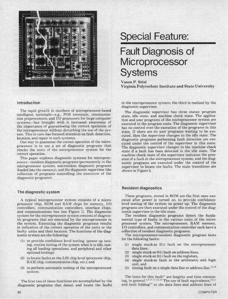
Special Feature: Fault Diagnosis of Microprocessor Systems Vason P. Srini Virginia Polytechnic Institute and State University Introduction The rapid growth in numbers of microprocessor-based intelligent terminals-e.g., POS terminals, communica- tion preprocessors, and I/O processors for large computer systems-has brought with it increased awareness of the importance of guaranteeing the correct operation of the microprocessor without disturbing the use of the sys- tem. This in turn has focused attention on fault detection, location, and repair in such systems. One way to guarantee the correct operation of the micro- processor is to use a set of diagnostic programs that checks the units of the microprocessor system for the correct operation. This paper explores diagnostic systems for microproc- essors-resident diagnostic programs (permanently in the microprocessor system), non-resident diagnostic programs (loaded into the memory), and the diagnostic supervisor (the collection of programs controlling the execution of the diagnostic programs). The diagnostic system A typical microprocessor system consists of a micro- processor chip, ROM and RAM chips for memory, I/O controllers, communication controllers, interface chips, and communications bus (see Figure 1). The diagnostic system for the microprocessor system consists of diagnos- tic programs that are executed by the microprocessor in the system. Executing the diagnostic programs results in indication of the correct operation of the units or the faulty units and their location. The functions of the diag- nostic system are the following: (1) to provide confidence level testing, (power up test- ing, routine testing of the system when it is idle, test- ing all loading operations, and peripheral and other optional testing); (2) to locate faults at the LSI chip level (processor chip, RAM chip, communication chip, etc.); and (3) to perform automatic testing of the microprocessor system. The first two of these functions are accomplished by the diagnostic programs that detect and locate the faults 60 in the microprocessor system; the third is realized by the diagnostic supervisor. The diagnostic supervisor has three states: program state, idle state, and machine check state. The applica- tion and user programs of the microprocessor system are executed in the program state. The diagnostic supervisor has no control over the execution of the programs in this state. If there are no user programs waiting to be exe- cuted, then the supervisor changes to the idle state. The diagnostic programs performing fault detection are exe- cuted under the control of the supervisor in this state. The diagnostic supervisor changes to the machine check state if a fault has been detected in the idle state. The machine check state of the supervisor indicates the pres- ence of a fault in the microprocessor system, and the diag- nostic programs are executed under the control of the supervisor to locate the faults. The state transitions are shown in Figure 2. Resident diagnostics These programs, stored in ROM are the first ones exe- cuted after power is turned on, to provide confidence- level testing of the system on power up. The diagnostic programs are then executed under the control of the diag- nostic supervisor in the idle state. The resident diagnostic programs detect the funda- mental type of faults in the various units of the micro- processor system. The microprocessor, RAM memory, I/O controllers, and communication controller each have a collection of resident diagnostic programs. The microprocessor-resident diagnostic program tests for the following faults: (1) single stuck-at 0(1) fault on the microprocessor data lines, (2) single stuck-at 0(1) fault on address lines, (3) single stuck-at 0(1) fault on the registers, (4) single stuck-at fault in the arithmetic and logic unit, and (5) timing fault on a single data line or address line.'4'5 The tests for this fault"7 are lengthy and time consuin- ing, in general.2 91'6,1724,26 The use of fault equivalence,23 27 and fault folding3" to the data lines and address lines of COMPUTER
-
Upload
independent -
Category
Documents
-
view
0 -
download
0
Transcript of Special Feature: Fault Diagnosis of Microprocessor Systems
Special Feature:Fault Diagnosis ofMicroprocessorSystemsVason P. SriniVirginia Polytechnic Institute and State University
Introduction
The rapid growth in numbers of microprocessor-basedintelligent terminals-e.g., POS terminals, communica-tion preprocessors, and I/O processors for large computersystems-has brought with it increased awareness ofthe importance of guaranteeing the correct operation ofthe microprocessor without disturbing the use of the sys-tem. This in turn has focused attention on fault detection,location, and repair in such systems.One way to guarantee the correct operation of the micro-
processor is to use a set of diagnostic programs thatchecks the units of the microprocessor system for thecorrect operation.This paper explores diagnostic systems for microproc-
essors-resident diagnostic programs (permanently in themicroprocessor system), non-resident diagnostic programs(loaded into the memory), and the diagnostic supervisor (thecollection of programs controlling the execution of thediagnostic programs).
The diagnostic system
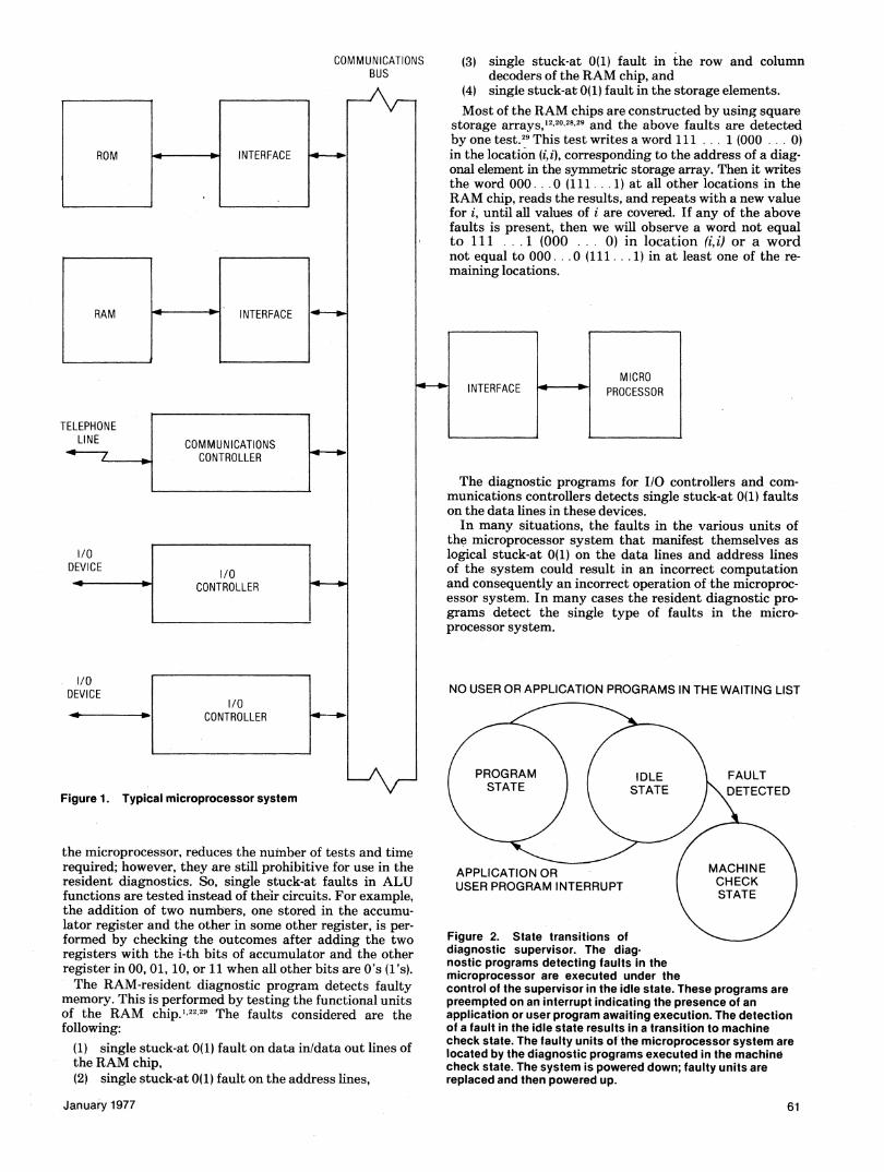
A typical microprocessor system consists of a micro-processor chip, ROM and RAM chips for memory, I/Ocontrollers, communication controllers, interface chips,and communications bus (see Figure 1). The diagnosticsystem for the microprocessor system consists of diagnos-tic programs that are executed by the microprocessor inthe system. Executing the diagnostic programs resultsin indication of the correct operation of the units or thefaulty units and their location. The functions of the diag-nostic system are the following:
(1) to provide confidence level testing, (power up test-ing, routine testing of the system when it is idle, test-ing all loading operations, and peripheral and otheroptional testing);
(2) to locate faults at the LSI chip level (processor chip,RAM chip, communication chip, etc.); and
(3) to perform automatic testing of the microprocessorsystem.
The first two of these functions are accomplished by thediagnostic programs that detect and locate the faults
60
in the microprocessor system; the third is realized by thediagnostic supervisor.The diagnostic supervisor has three states: program
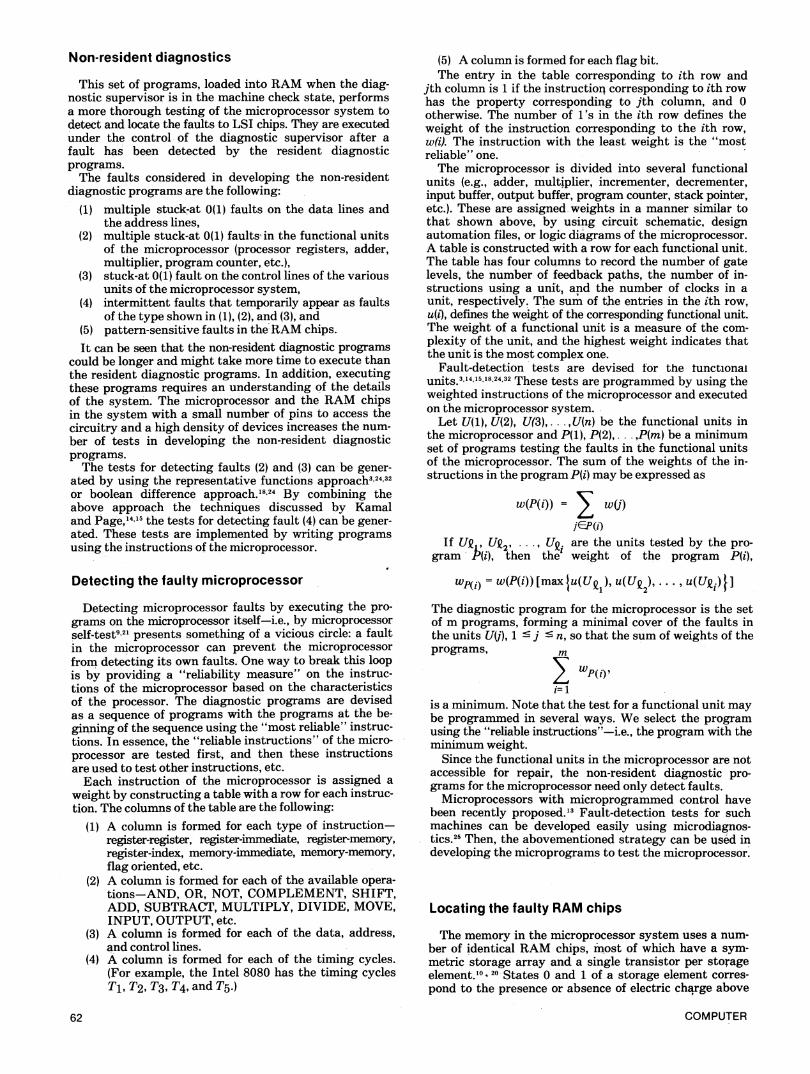
state, idle state, and machine check state. The applica-tion and user programs of the microprocessor system areexecuted in the program state. The diagnostic supervisorhas no control over the execution of the programs in thisstate. If there are no user programs waiting to be exe-cuted, then the supervisor changes to the idle state. Thediagnostic programs performing fault detection are exe-cuted under the control of the supervisor in this state.The diagnostic supervisor changes to the machine checkstate if a fault has been detected in the idle state. Themachine check state of the supervisor indicates the pres-ence of a fault in the microprocessor system, and the diag-nostic programs are executed under the control of thesupervisor to locate the faults. The state transitions areshown in Figure 2.
Resident diagnostics
These programs, stored in ROM are the first ones exe-cuted after power is turned on, to provide confidence-level testing of the system on power up. The diagnosticprograms are then executed under the control of the diag-nostic supervisor in the idle state.The resident diagnostic programs detect the funda-
mental type of faults in the various units of the micro-processor system. The microprocessor, RAM memory,I/O controllers, and communication controller each have acollection of resident diagnostic programs.The microprocessor-resident diagnostic program tests
for the following faults:(1) single stuck-at 0(1) fault on the microprocessor
data lines,(2) single stuck-at 0(1) fault on address lines,(3) single stuck-at 0(1) fault on the registers,(4) single stuck-at fault in the arithmetic and logic
unit, and(5) timing fault on a single data line or address line.'4'5
The tests for this fault"7 are lengthy and time consuin-ing, in general.2 91'6,1724,26 The use of fault equivalence,23 27and fault folding3" to the data lines and address lines of
COMPUTER
COMMUNICATION!BUS
INTERFACE J
S (3) single stuck-at 0(1) fault in the row and columndecoders of the RAM chip, and
(4) single stuck-at 0(1) fault in the storage elements.Most of the RAM chips are constructed by using square
storage arrays,,20,28,29 and the above faults are detectedby one test.29 This test writes a word 111 ... 1 (000 ... 0)in the location (i,i), corresponding to the address of a diag-onal element in the symmetric storage array. Then it writesthe word 000 .0. (111 ... 1) at all other locations in theRAM chip, reads the results, and repeats with a new valuefor i, until all values of i are covered. If any of the abovefaults is present, then we will observe a word not equalto 111 ... 1 (000 ... 0) in location (i,i) or a wordnot equal to 000... .0 (111... 1) in at least one of the re-maining locations.
The diagnostic programs for I/O controllers and com-munications controllers detects single stuck-at 0(1) faultson the data lines in these devices.In many situations, the faults in the various units of
the microprocessor system that manifest themselves aslogical stuck-at 0(1) on the data lines and address linesof the system could result in an incorrect computationand consequently an incorrect operation of the microproc-essor system. In many cases the resident diagnostic pro-grams detect the single type of faults in the micro-processor system.
NO USER OR APPLICATION PROGRAMS IN THE WAITING LIST
the inicroprocessor, reduces the number of tests and timnerequired; however, they are still prohibitive for use in theresident diagnostics. So, single stuck-at faults in ALUfunctions are tested instead of their circuits. For example,the addition of two numbers, one stored in the accumu-lator register and the other in some other register, is per-formed by checking the outcomes after adding the tworegisters with the i-th bits of accumulator and the otherregister in 00, 01, 10, or 11 when all other bits are O's (l's).The RAM-resident diagnostic program detects faulty
memory. This is performed by testing the functional unitsof the RAM chip.' 22.29 The faults considered are thefollowing:
(1) single stuck-at 0(1) fault on data in/data out lines ofthe RAM chip,(2) single stuck-at 0(1) fault on the address lines,
January 1977
Figure 2. State transitions ofdiagnostic supervisor. The diag-nostic programs detecting faults in themicroprocessor are executed under thecontrol of the supervisor in the idle state. These programs arepreempted on an interrupt indicating the presence of anapplication or user program awaiting execution. The detectionof a fault in the idle state results in a transition to machinecheck state. The faulty units of the microprocessor system arelocated by the diagnostic programs executed in the machinecheck state. The system is powered down; faulty units arereplaced and then powered up.
61
ROM INTERFACE
RAM -- W
COMMUNICATIONSCONTROLLER
TELEPHONELINE
4 7
I/O~~~~~~~~~~~~~~~~~~~~~~~~~~~~~~~~~~1/0DEVICE
I l/0DEVICE
1/0CONTROLLER
1/0I CONTROLLER .0
Figure 1. Typical microprocessor system
Non-resident diagnostics
This set of programs, loaded into RAM when the diag-nostic supervisor is in the machine check state, performsa more thorough testing of the microprocessor system todetect and locate the faults to LSI chips. They are executedunder the control of the diagnostic supervisor after a
fault has been detected by the resident diagnosticprograms.The faults considered in developing the non-resident
diagnostic programs are the following:(1) multiple stuck,at 0(1) faults on the data lines and
the address lines,(2) multiple stuck-at 0(1) faults' in the functional unlits
of the microprocessor (processor registers, adder,multiplier, program counter, etc.),
(3) stuck-at 0(1) fault on the control lines of the variousunits of the microprocessor system,
(4) intermittent faults that temporarily appear as faultsof the type shown in (1), (2), and (3), and
(5) pattern-sensitive faults in the^RAM chips.It can be seen that the non-resident diagnostic programs
could be longer and might take more time to execute thanthe resident diagnostic programs. In addition, executingthese programs requires an understanding of the detailsof the system. The microprocessor and the RAM chipsin the system with a small number of pins to access thecircuitry and a high density of devices increases the num-ber of tests in developing the non-resident diagnosticprograms.The tests for detecting faults (2) and (3) can-be gener-
ated by using the representative functions approach3,24'32or boolean difference approach.'1824 By combining theabove approach the techniques discussed by Kamaland Page,'4 the tests for detecting fault (4) can be gener-
ated. These tests are implemented by writing programsusing the instructions of the microprocessor.
Detecting the faulty microprocessor
Detecting microprocessor faults by executing the pro-grams on the microprocessor itself-i.e., by microprocessorself-test9'2' presents something of a vicious circle: a faultin the microprocessor can prevent the microprocessorfrom detecting its own faults. One way to break this loopis by providing a "reliability measure" on the instruc-tions of the microprocessor based on the characteristicsof the processor. The diagnostic programs are devisedas a sequence of programs with the programs at the be-ginning of the sequence using the "most reliable" instruc-tions. In essence, the "reliable instructions" of the micro-processor are tested first, and then these instructionsare used to test other instructions, etc.Each instruction of the microprocessor is assigned a
weight by constructing a table with a row for each instruc-tion. The columns of the table are the following:
(1) A column is formed for each type of instruction-register-register, register-immediate, register-memory,register-index, memory-immediate, memory-memory,flag oriented, etc.
(2) A column is formed for each of the available opera-tions-AND, OR, NOT, COMPLEMENT, SHIFT,ADD, SUBTRACT, MULTIPLY, DIVIDE, MOVE,INPUT, OUTPUT, etc.
(3) A column is formed for each of the data, address,and control lines.
(4) A column is formed for each of the timing cycles.(For example, the Intel 8080 has the timing cyclesT1, T2, T3, T4, and Ts.)
62
(5) A column is formed for each flag bit.The entry in the table corresponding to ith row and
jth column is 1 if the instruction corresponding to ith rowhas the property corresponding to jth column, and 0otherwise. The number of l's in the ith row defines theweight of the instruction corresponding to the ith row,w(i). The instruction with the least weight is the "mostreliable" one.The microprocessor is divided into several functional
units (e.g., adder, multiplier, incrementer, decrementer,input buffer, output buffer, program counter, stack pointer,etc.). These are assigned weights in a manner similar tothat shown above, by using circuit schematic, designautomation files, or logic diagrams of the microprocessor.A table is constructed with a row for each functional unit.The table has four columns to record the number of gatelevels, the number of feedback paths, the number of in-structions using a unit, and the number of clocks in aunit, respectively. The sum of the entries in the ith row,u(i), defines the weight of the corresponding functional unit.The weight of a functional unit is a measure of the com-plexity of the unit, and the highest weight indicates thatthe unit is the most complex one.
Fault-detection tests are devised for the tunctionalunits.3,14,15,'8,24,32 These tests are programmed by using theweighted instructions of the microprocessor and executedon the microprocessor system.Let U(1), U(2), U(3),...,U(n) be the functional units in
the microprocessor and P(1), P(2),.. ,P(m) be a minimumset of programs testing the faults in the functional unitsof the microprocessor. The sum of the weights of the in-structions in the program P(i) may be expressed as
w(P(i)) = w(j)
jWP(i)If UQ, UQ2. UQ. are the units tested by the pro-
gram P(i), then the' weight of the program P(i),
Wp(i) = w(P(i)) [maxlu(U I), u(UQ2), * ., u(Uwi]The diagnostic program for the microprocessor is the setof m programs, forming a minimal cover of the faults inthe units U(j), 1 5 j c n, so that the sum of weights of theprograms, m* E ~~~~~wp(i)
i=1
is a minimum. Note that the test for a functional unit maybe programmed in several ways. We select the programusing the "reliable instructions"-i.e., the program with theminimum weight.Since the functional units in the microprocessor are not
accessible for repair, the non-resident diagnostic pro-grams for the microprocessor need only detect faults.Microprocessors with microprogrammed control have
been recently proposed.'3 Fault-detection tests for suchmachines can be developed easily using microdiagnos-tics.2' Then, the abovementioned strategy can be used indeveloping the microprograms to test the microprocessor.
Locating the faulty RAM chips
The memory in the microprocessor system uses a num-ber of identical RAM chips, most of which have a sym-metric storage array and a single transistor per storageelement.'° 20 States 0 and 1 of a storage element corres-pond to the presence or absence of electric charge above
COMPUTER
L- J
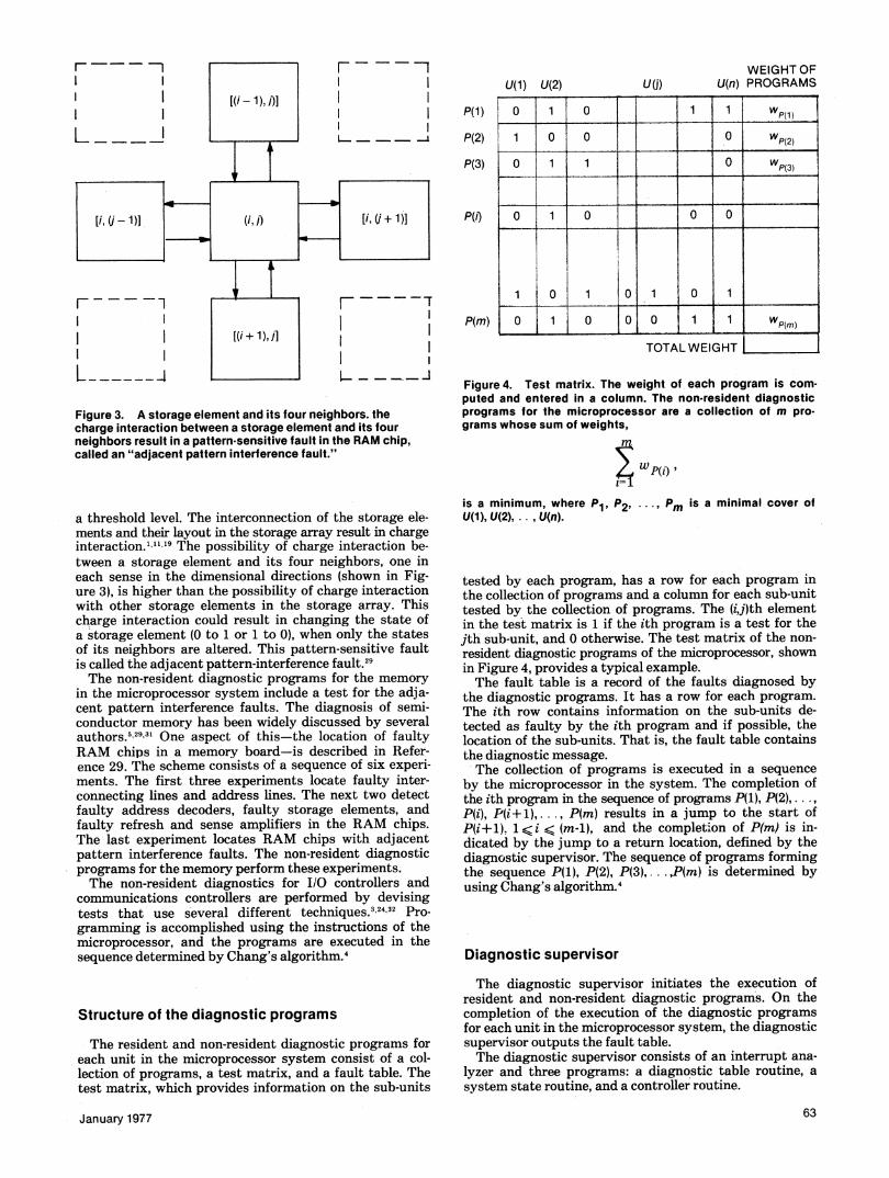
Figure 3. A storage element and its four neighbors. thecharge interaction between a storage element and its fourneighbors result in a pattern-sensitive fault in the RAM chip,called an "adjacent pattern interference fault."
a threshold level. The interconnection of the storage ele-ments and their layout in the storage array result in chargeinteraction.1"'' 9 The possibility of charge interaction be-tween a storage element and its four neighbors, one ineach sense in the dimensional directions (shown in Fig-ure 3), is higher than the possibility of charge interactionwith other storage elements in the storage array. Thischarge interaction could result in changing the state ofa storage element (0 to 1 or 1 to 0), when only the statesof its neighbors are altered. This pattern-sensitive faultis called the adjacent pattern-interference fault.29The non-resident diagnostic programs for the memory
in the microprocessor system include a test for the adja-cent pattern interference faults. The diagnosis of semi-conductor memory has beeln widely discussed by severalauthors.5293' One aspect of this-the location of faulty
RAM chips in a memory board-is described in Refer-ence 29. The scheme consists of a sequence of six experi-ments. The first three experiments locate faulty inter-connecting lines and address lines. The next two detectfaulty address decoders, faulty storage elements, andfaulty refresh and sense amplifiers in the RAM chips.The last experiment locates RAM chips with adjacentpattern interference faults. The non-resident diagnosticprograms for the memory perform these experiments.The non-resident diagnostics for I/O controllers and
communications controllers are performed by devisingtests that use several different techniques.3 24I32 Pro-
gramming is accomplished using the instructions of themicroprocessor, and the programs are executed in thesequence determined by Chang's algorithm.4
Structure of the diagnostic programs
The resident and non-resident diagnostic programs foreach unit in the microprocessor system consist of a col-lection of programs, a test matrix, and a fault table. Thetest matrix, which provides information on the sub-units
January 1977
WEIGHT OFU(j) U(n) PROGRAMS
TOTALWEIGHT
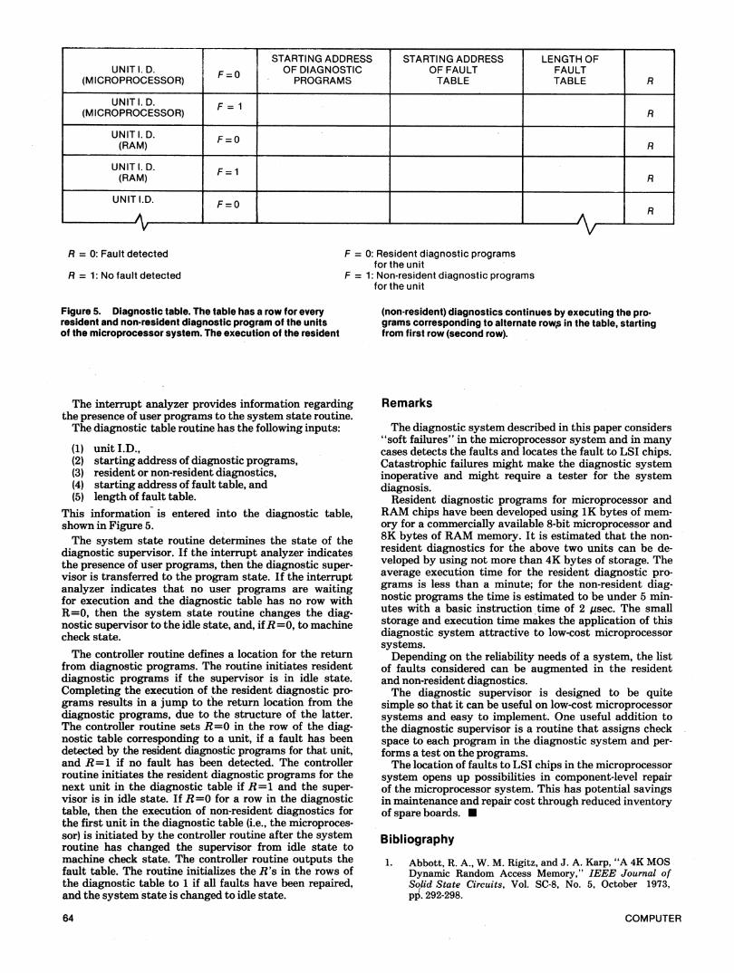
Figure 4. Test matrix. The weight of each program is com-puted and entered in a column. The non-resident diagnosticprograms for the microprocessor are a collection of m pro-
grams whose sum of weights,
is a minimum, where P1, P2, ..., Pm is a minimal cover ofU(1), U(2), . , U(n).
tested by each program, has a row for each program inthe collection of programs and a column for each sub-unittested by the collection of programs. The (i,j)th elementin the test matrix is 1 if the ith program is a test for thejth sub-unit, and 0 otherwise. The test matrix of the non-
resident diagnostic programs of the microprocessor, shownin Figure 4, provides a typical example.The fault table is a record of the faults diagnosed by
the diagnostic programs. It has a row for each program.The ith row contains information on the sub-units de-tected as faulty by the ith program and if possible, thelocation of the sub-units. That is, the fault table containsthe diagnostic message.The collection of programs is executed in a sequence
by the microprocessor in the system. The completion ofthe ith program in the sequence of programs P(1), P(2),....P(i), P(i+l),..., P(m) results in a jump to the start ofP(i+ 1), 1 <i < (m-i), and the completion of P(m) is in-dicated by the jump to a return location, defined by thediagnostic supervisor. The sequence of programs formingthe sequence P(1), P(2), P(3),.. .,P(m) is determined byusing Chang's algorithm.4
Diagnostic supervisor
The diagnostic supervisor initiates the execution ofresident and non-resident diagnostic program's. On thecompletion of the execution of the diagnostic programsfor each unit in the microprocessor system, the diagnosticsupervisor outputs the fault table.The diagnostic supervisor consists of an interrupt ana-
lyzer and three programs: a diagnostic table routine, a
system state routine, and a controller routine.
63
II
Fr- -ml l
ll ll l
U(1) U(2)
P(1)
P(2)
P(3)
P(i)
0 1 0 1 1 Wp(1)
1 0 0 0 Wp(2)
0 1 1 0- p(3)
0 1 0 0 0
1 0 1 0 1 0 1
0 1 0 0 0 1 1 wP(m)a 1 .I I .-
r - - ---P(m)
II
STARTING ADDRESS STARTING ADDRESS LENGTH OFUNIT I. D. F-Q OF DIAGNOSTIC OF FAULT FAULT
(MICROPROCESSOR) _ PROGRAMS TABLE TABLE R
UNIT I. D.(MICROPROCESSOR) F 1R
UNITI.D. F=O(RAM) F=1 R
UNITI1.D.F=(RAM) FlR
UNIT I.D.
v
F=0 R
F = 0: Resident diagnostic programsfor the unit
F = 1: Non-resident diagnostic programsfor the unit
Figure 5. Diagnostic table. The table has a row for everyresident and non-resident diagnostic program of the unitsof the microprocessor system. The execution of the resident
The interrupt analyzer provides information regardingthe presence of user programs to the system state routine.The diagnostic table routine has the following inputs:
(1) unit I.D.,(2) starting address of diagnostic programs,(3) resident or non-resident diagnostics,(4) starting address of fault table, and(5) length of fault table.
This information is entered into the diagnostic table,shown in Figure 5.The system state routine determines the state of the
diagnostic supervisor. If the interrupt analyzer indicatesthe presence of user programs, then the diagnostic super-visor is transferred to the program state. If the interruptanalyzer indicates that no user programs are waitingfor execution and the diagnostic table has no row withR=0, then the system state routine changes the diag-nostic supervisor to the idle state, and, ifR=0, to machinecheck state.
The controller routine defines a location for the returnfrom diagnostic programs. The routine initiates residentdiagnostic programs if the supervisor is in idle state.Completing the execution of the resident diagnostic pro-grams results in a jump to the return location from thediagnostic programs, due to the structure of the latter.The controller routine sets R=0 in the row of the diag-nostic table corresponding to a unit, if a fault has beendetected by the resident diagnostic programs for that unit,and R=1 if no fault has been detected. The controllerroutine initiates the resident diagnostic programs for thenext unit in the diagnostic table if R=1 and the super-visor is in idle state. If R=0 for a row in the diagnostictable, then the execution of non-resident diagnostics forthe first unit in the diagnostic table (i.e., the microproces-sor) is initiated by the controller routine after the systemroutine has changed the supervisor from idle state tomachine check state. The controller routine outputs thefault table. The routine initializes the R's in the rows ofthe diagnostic table to 1 if all faults have been repaired,and the system state is changed to idle state.
64
(non-resident) diagnostics continues by executing the pro-
grams corresponding to alternate row, in the table, startingfrom first row (second row).
Remarks
The diagnostic system described in this paper considers"soft failures" in the microprocessor system and in manycases detects the faults and locates the fault to LSI chips.Catastrophic failures might make the diagnostic systeminoperative and might require a tester for the systemdiagnosis.Resident diagnostic programs for microprocessor and
RAM chips have been developed using 1K bytes of mem-ory for a commercially available 8-bit microprocessor and8K bytes of RAM memory. It is estimated that the non-resident diagnostics for the above two units can be de-veloped by using not more than 4K bytes of storage. Theaverage execution time for the resident diagnostic pro-grams is less than a minute; for the non-resident diag-nostic programs the time is estimated to be under 5 min-utes with a basic instruction time of 2 ,sec. The smallstorage and execution time makes the application of thisdiagnostic system attractive to low-cost microprocessorsystems.Depending on the reliability needs of a system, the list
of faults considered can be augmented in the residentand non-resident diagnostics.The diagnostic supervisor is designed to be quite
simple so that it can be useful on low-cost microprocessorsystems and easy to implement. One useful addition tothe diagnostic supervisor is a routine that assigns checkspace to each program in the diagnostic system and per-forms a test on the programs.The location of faults to LSI chips in the microprocessor
system opens up possibilities in component-level repairof the microprocessor system. This has potential savingsin maintenance and repair cost through reduced inventoryof spare boards.
Bibliography
1. Abbott, R. A., W. M. Rigitz, and J. A. Karp, "A 4K MOSDynamic Random Access Memory," IEEE Journal ofSolid State Circuits, Vol. SC-8, No. 5, October 1973,pp. 292-298.
COMPUTER
R = 0: Fault detected
R = 1: No fault detected
2. Armstrong, D. B., "On Finding a Nearly Minimal Set ofFault Detection Tests for Combinational Logic Nets,"IEEE Transactions on Computers, Vol. C-15, 1966,pp. 66-73.
3. Breuer, M. A., et al., "Identification of Multiple Stuck-Type Faults in Combinational Networks," IEEE Trans-actions on Computers, Vol. C-25, No. 1, January 1976,pp. 44-45.
4. Chang, H. Y., "An Algorithm for Selecting an OptimumSet of Diagnostic Tests," IEEE Transactions on Computers,Vol. EC-14, No. 5, October 1965, pp. 706-711.
5. Digest of Papers, 1972 Symposium on SemiconductorMemory Testing, Cherry Hill, New Jersey, 96 pp.
6. Digest of Papers, 1973 Symposium on SemiconductorMemory Testing, 125 pp.
7. Digest of Papers, 1974 Symposium on SemiconductorMemory Testing, 264 pp.
8. Digest of Papers, 1975 Symposium on SemiconductorMemory Testing, 110 pp.
9. Friedman, A. D. and P. R. Menon, Fault Detection inDigital Circuits, Prentice-Hall, Englewood Cliffs, NewJersey, 1971.
10. Hnatek, E. R., "4-kilobit Memories Present a Challengeto Testing," Computer Design, May 1975, Vol. 14, No. 5,pp. 117-125.
11. Hoffman, W. K. and H. L. Kalter, "An 8K b RandomAccess Memory Chip Using the One Device FET Cell,"IEEE Journal of Solid State Circuits, Vol. SC-8, No. 5,October 1973, pp. 298-304.
12. Intel Memory Design Handbook, Intel Corp., Santa Clara,Calif., August 1973.
13. Kartashev, S. I., "A Microcomputer with a Shift RegisterMemory," IEEE Transactions on Computers, Vol. C-25,No. 5, May 1976, pp. 470-484.
19. Kuo, C., et al., "Sense Amplifier Design is Key to1-Transistor Cell in 4K-bit RAM," Electronics, Septem-ber 13,1973, pp. 116-121.
20. Kuo, C., et al, "16K-RAM Built with Proven ProcessMay Offer High Start-up Reliability," Electronics, Vol. 49,No. 10, May 13,1976, pp. 81-86.
21. Leaman, R. J., M. H. Lloyd, and C. S. Repton, "TheDevelopment and Testing of a Processor Self-TestProgram," The Computer Journal, Vol. 16, No. 4, pp. 303-314.
22. Luecke, G., J. P. Mize, and W. C. Carr, SemiconductorMemory Design and Application, McGraw Hill, NewYork, 1973.
23. McCluskey, E. J. and F. W. Clegg, "Fault Equivalence inCombinational Networks," IEEE Transactions on Com-puters, Vol. 6, C-20, No. 11, November 1971, pp. 1286-1293.
24. Putzolu, G. and J. P. Roth, "A Heuristic Algorithm forthe Test of Asynchronous Circuits," IEEE Transactionson Computers, Vol. C-20, June 1971, pp. 639-647.
25. Ramamoorthy, C. V. and L. C. Chang, "System Modelingand Testing Procedures for Microdiagnostics," IEEETransactions on Computers, Vol. C-21, No. 11, November1972, pp. 1169-1183.
26. Roth, J. P., "Diagnosis of Automata Failures," IBMJournal of Research and Development, Vol. 10, 1966,pp. 278-291.
27. Roy, B. K., "Diagnosis and Equivalence in CombinationalCircuits," IEEE Transactions on Computers, Vol. C-17,No. 4, April 1968, pp. 352-366.
28. Semiconductor Data Library/MOS Memories, MotorolaSemiconductor Products Inc., Vol. 7, Series A, 1975.
29. Srini, V. P., "Fault Location in a Semiconductor Random-Access Memory Unit," submitted for publication inIEEE Transactions on Computers.
30. To, K., "Fault Folding for Irredundant and RedundantCombinational Circuits, IEEE Transactions on Computers,Vol. C-22, No. 11, November 1973, pp. 1008-1015.
31. Webb, C., and W. Richardson, "Pattern Sensitivity in a4096-bit RAM," Digest of Papers, 1974 SemiconductorMemory Test Symposium, pp. 33-52.
32. Yau, S. S. and S. C. Yang, "Multiple Fault Detectionfor Combinational Logic Circuits," IEEE Transactions onComputers, Vol. C-24, No. 3, March 1975, pp. 233-241.
14. KamaL S., "An Approach to the Diagnosis of IntermittentFaults," IEEE Transactions on Computers, Vol. C-24,No. 5, May 1975, pp. 461-467.
15. Kamal, S. and C. V. Page, "Intermittent Faults: A Modeland Detection Procedure," IEEE Transactions on Com-puters, Vol. C-23, No. 7, July 1974, pp. 713-719.
16. Kautz, W. H., "Fault Testing and Diagnosis in Combina-tional Digital Circuits," IEEE Transactions on Computers,Vol. C-17, No. 4, April 1968, pp. 352-366.
17.' Kohavi, Z. and I. Berger, "Fault Diagnosis in Combina-tional Tree Networks," IEEE Transactions on Computers,Vol. C-24, No. 12, December 1975, pp. 1161-1167.
18. Ku, C. T. and G. M. Masson, "The Boolean Difference andMultiple Fault Analysis," IEEE Transactions on Com-puters, Vol. C-24, No. 1, January 1975, pp. 62-71.
January 1977
Vason P. Srini is on the faculty of the Depart-ment of Computer Science at Virginia Poly-technic Institute and State University.Earlier he was with the Microprocessor Soft--;l t ; ware Department and Advanced Develop-
WX _ > ment Department at NCR, the Electricaly_ XEngineering Department at Virginia Poly-
technical Institute and State University, andthe Electrical Engineering Department atTennessee Technological University.He received a BE from the University of Madras, an MSEE
from Tennessee Technological University, and is working on hisPhD in computer science at VPI and State University. His researchinterests are in the diagnosis of digital systems, artificial intelli-gence, automata theory, and software reliability.
65