Evolution of Microprocessor, Internal architecture, of 8086
34
UNIT – 1: 8086 architecture: Evolution of Microprocessor, Internal architecture, of 8086; Programming Model, Real mode memory addressing, Addressing modes, Data transfer instructions, Arithmetic instructions For Reference: Number Conversions: 1.Binary to hex: 0100 1010 1111 = (4AF)h 2.10h=16 (decimal), ie, 0*16 0 + 1*16 1 = 0+ 16 = 16 3.If a processor have n address lines,then memory accessing capacity is 2 n 4. 2 10 = 1KB, 2 20 = 1MB, 2 30 = 1GB, 2 40 = 1TB(Terra Byte), 2 50 = 1PB(Peta byte),2 60 = 1EB(Exa Byte) 2 16 = 2 6 2 10 = (64)(1KB)=64KB, 2 32 =2 2 2 30 = 4GB 5. for example, No.of address lines Memory size Memory starting & ending address No.of locations 16 2 16 = 164KB 0000h-FFFFh 65536 20 2 20 = 1MB 00000h-FFFFFh 10,48,576 24 2 24 =2 4 2 20 = 16MB 000000h-FFFFFFh 1,67,77,216 32 2 32 =2 2 2 30 = 4GB 0000 0000h-FFFF FFFFh 42949667296 6. 1 byte = 8bits, word = 16 bits , double word = 32 bits, quad word = 64 bits, octal word = 128 bits 1. Evolution of Microprocessor The historical background can be studied in three different accounts: 1.The Mechanical Age 2. The Electrical Age 3. The Microprocessor Age The Mechanical Age: i. the Babylonians invented the abacus the first mechanical calculator during 500 BC, which uses strings of beads to perform calculations. ii. In 1642, Blaise Pascal invented a calculator that was constructed of gears and wheels. Each gear contained 10 teeth that after one complete revolution advanced a second gear one place. Automated geared mechanical machines arrived in the 1800's. iii. Charles Babbage invented a machine called 'Analytical Engine'. It could store thousand 20 digit decimal numbers and a variable program that could modify the function of this engine. The input to the analytical engine was through punched cards. iv. After many years of work, Charles Babbage realised that it's not possible to make the analytical engine as the machinists of his era where unable to produce the parts needed for his work The Electrical & electronic age: 1.The Electrical age began with the invention of electric motor by Michael Faraday. In 1889 Herman Hollerith developed a punched card for storing data, he also made a mechanical calculator driven by the electric motors. •His machine counted, sorted and collated(to arrange in proper sequence) the data stored in the punched card. The United States government commissioned Herman Hollerith to use his punched card system to store and tabulate information for the 1890 census. •In 1896 Herman Hollerith started a company called the Tabulating Machine Company which developed machines that used punched cards for tabulation. Later it was known as the International Business Machines Corporations now known as the IBM. 2.The first electronic calculating machine , something which did not require an electric motor was developed by the German Inventor named Konrad Zuse. The electronic computer ‘colossus’ was invented by Allan Turing which used vacuum tubes to perform calculations. •The first general purpose, programmable electronic computer was developed in 1946 at the University of Pennsylvania. This first modern computer was called as ENIAC(Electronic Numerical Integrator and Calculator). • The ENIAC was a huge machine weighing more than 30 tons and used 17000 vacuum tubes and 500 miles of wires. The ENIAC could perform only 100,000 operations per second. Invention of transistor and Integrated Chips led to the development of microprocessor at Intel. The Microprocessor Age • The world’s first microprocessor was the Intel 4004 which was a 4-bit microprocessor.
-
Upload
khangminh22 -
Category
Documents
-
view
3 -
download
0
Transcript of Evolution of Microprocessor, Internal architecture, of 8086
UNIT – 1: 8086 architecture: Evolution of Microprocessor, Internal architecture, of 8086; Programming Model, Real mode memory addressing, Addressing modes, Data transfer instructions, Arithmetic instructions
For Reference:
Number Conversions:
1.Binary to hex: 0100 1010 1111 = (4AF)h
2.10h=16 (decimal), ie, 0*160 + 1*16
1 = 0+ 16 = 16
3.If a processor have n address lines,then memory accessing capacity is 2n
4. 210
= 1KB, 220
= 1MB, 230
= 1GB, 240
= 1TB(Terra Byte), 250
= 1PB(Peta byte),260
= 1EB(Exa Byte)
216
= 262
10 = (64)(1KB)=64KB, 2
32 =2
22
30 = 4GB
5. for example,
No.of address
lines
Memory size Memory starting & ending address No.of locations
16 216
= 164KB 0000h-FFFFh 65536
20 220
= 1MB 00000h-FFFFFh 10,48,576
24 224
=242
20 = 16MB 000000h-FFFFFFh 1,67,77,216
32 232
=222
30 = 4GB 0000 0000h-FFFF FFFFh 42949667296
6. 1 byte = 8bits, word = 16 bits , double word = 32 bits, quad word = 64 bits, octal word = 128 bits
1. Evolution of Microprocessor
The historical background can be studied in three different accounts:
1.The Mechanical Age 2. The Electrical Age 3. The Microprocessor Age
The Mechanical Age: i. the Babylonians invented the abacus the first mechanical calculator during 500 BC, which uses strings of beads to perform
calculations.
ii. In 1642, Blaise Pascal invented a calculator that was constructed of gears and wheels. Each gear contained
10 teeth that after one complete revolution advanced a second gear one place. Automated geared mechanical
machines arrived in the 1800's.
iii. Charles Babbage invented a machine called 'Analytical Engine'. It could store thousand 20 digit decimal
numbers and a variable program that could modify the function of this engine. The input to the analytical
engine was through punched cards.
iv. After many years of work, Charles Babbage realised that it's not possible to make the analytical engine as
the machinists of his era where unable to produce the parts needed for his work
The Electrical & electronic age:
1.The Electrical age began with the invention of electric motor by Michael Faraday. In 1889 Herman Hollerith developed a punched
card for storing data, he also made a mechanical calculator driven by the electric motors. •His machine counted, sorted and collated(to
arrange in proper sequence) the data stored in the punched card. The United States government commissioned Herman Hollerith to use
his punched card system to store and
tabulate information for the 1890 census.
•In 1896 Herman Hollerith started a company called the Tabulating Machine Company which developed machines that used punched
cards for tabulation. Later it was known as the International Business Machines Corporations now known as the IBM.
2.The first electronic calculating machine , something which did not require an electric motor was developed by the German Inventor
named Konrad Zuse. The electronic computer ‘colossus’ was invented by Allan Turing which used vacuum tubes to perform
calculations.
•The first general purpose, programmable electronic computer was developed in 1946 at the University of
Pennsylvania. This first modern computer was called as ENIAC(Electronic Numerical Integrator and Calculator).
• The ENIAC was a huge machine weighing more than 30 tons and used 17000 vacuum tubes and 500 miles of wires. The ENIAC
could perform only 100,000 operations per second. Invention of transistor and Integrated Chips led to the development of
microprocessor at Intel.
The Microprocessor Age
• The world’s first microprocessor was the Intel 4004 which was a 4-bit microprocessor.

• 4004 addressed a mere 4096, 4-bit-wide memory locations.
• The instruction-set contained only 45 instructions.
• 4004 was fabricated with P-channel MOSFET technology.
• 4004 executed instructions at the slow rate of 50 KIPs (kilo-instructions per second).
• When compared to 30-ton ENIAC computer, 4004 weighed much less than an ounce.
• Later in 1971, Intel released the 8008— an extended 8-bit version of the 4004 microprocessor.
• The 8008 addressed a memory size (16K bytes) and contained additional instructions (a total of 48)
• The main drawbacks of both 4004 and 8008: slow speed,small memory-size,limited instruction set
• 8080 was the first of the modern 8-bit microprocessor. executed the instructions 10 times faster than the 8008.
• In 1977, Intel introduced an updated version of the 8080—the 8085.
The Modern Microprocessor
• In 1978, Intel released the 8086 microprocessor; a year later, it released the 8088.
• Both devices are 16-bit microprocessors, which executed instructions in as little as 400 ns (2.5 MIPs).
• In addition, the 8086 /88 addressed 1Mbyte of memory, which was 16 times more memory than the 8085.
• This higher execution speed and larger memory size allowed the 8086/88 to replace smaller mini computers in many applications.
• One other feature found in the 8086/8088 was a small queue (or 6-byte instruction cache) that pre-fetched a
few instructions before they were executed.
The 80286 Microprocessor
• 80286 is basically an 8086 that is optimized to execute instructions faster than 8086 and it addresses 16MB ie(24 address lines,so
224
) memory instead of 1MB system.
• The 80286 operates in both the real and protected modes.
→ In the real mode, the 80286 addresses a 1 MByte memory address space.
→ In the protected mode, the 80286 addresses a 16 MByte memory-space
The 80386 Microprocessor
• The 80386 microprocessor is an enhanced version of the 80286 microprocessor.
• it includes memory paging. 80386 also includes 32-bit extended registers and a 32-bit address and data bus.
• 80386 has a physical memory size of 4GBytes(232
=4GB) and operates in the pipelined mode.
• 80386 operates in both the real and protected modes.
→ In the real mode, the 80386 addresses a 1MByte memory address space and is virtually identical to 8086
→ In the protected mode, the 80386 addresses a 4 Gbytes memory space

The 80486 Microprocessor
• This is an improved version of the 80386 that contains an 8K-byte cache and 80387 arithmetic co processor
• 80486 executes a few new instructions that control the internal cache memory.
• A new feature found in the 80486 is the BIST(builtin self-test) that tests the microprocessor, coprocessor, and
cache at reset time.
• These new test registers are TR3 (cache data), TR4 (cache status), and TR5 (cache control).
Pentium Microprocessor
• This is almost identical to the earlier 80386 and 80486 microprocessors and has 64 bit data bus.
• Pentium has been modified internally to contain a dual cache (instruction and data) and a dual integer unit
• The Pentium also operates at a higher clock speed of 66 MHz.
• Memory access time, without wait states, is only about 18 ns in the 66 MHz Pentium.
• The superscalar structure of the Pentium contains three independent processing units:
a floating point processor and two integer processing units
• Pentium contains a new mode of operation called the System Memory Management (SMM) mode.
• Another feature found in the Pentium is the BIST(built-in self-test) that tests the microprocessor, coprocessor,
and cache at reset time.
• The Pentium allows 4MByte memory pages instead of the 4Kbyte pages.
Pentium Pro Microprocessor
• The Pentium Pro is an enhanced version of the Pentium microprocessor that contains
→ level 1 caches found inside the Pentium
→ level 2 cache of 256 K or 512K found on most main boards
• The Pentium Pro operates using the same 66 MHz bus speed as the Pentium and the 80486.
• The only significant software difference between the Pentium Pro and earlier microprocessors is the addition of FCMOV and CMOV
instructions.
• The only hardware difference between the Pentium Pro and earlier microprocessors is the addition of 2M paging and four extra
address lines that allow access to a memory address space of 64G Bytes.
• The Pentium uses an internal clock generator to multiply the bus speed by various factors to obtain higher internal Execution speeds.
Pentium II and Pentium Xeon Microprocessors
• Released in 1997, the Pentium II was an adaptation of the Pentium Pro aimed at the general public.
• The main reason for the change is that the L2 cache found on the main circuit board of the Pentium was not fast enough to function
properly with the Pentium II.
• On the Pentium system, the L2 cache operates at the system bus speed of 60 MHz or 66 MHz.
• New features are MMX (SIMD) support and a doubling of the Level 1 cache.
Pentium III Microprocessor
• Released in 1999, the Pentium III microprocessor uses a faster core than the Pentium II, but it is still a P6 or
Pentium Pro processor.

• Another difference is that the Pentium III is available with clock frequencies of up to 1 GHz.
• The slot 1 version contains a 512K cache and the flip-chip version contains a 256K cache.
• The speeds are comparable because the cache in the slot 1 version runs at one-half the clock speed, while the
cache in the flip-chip version runs at the clock speed.
•Both versions use a memory bus speed of 100 MHz, while the Celeron7 uses memory bus clock speed of 66 MHz.
Pentium 4 and Core2 Microprocessors
• In late 2000, Intel announced its new processor, the Pentium 4.
• The most recent version of the Pentium is called the Core2 by Intel.
• The Pentium 4 and Core2, like the Pentium Pro through the Pentium III, use the Intel P6 architecture.
• The main difference is that
→ The Pentium 4 is available in speeds to 3.2 GHz and faster and
→ The chip sets that support the Pentium 4 use the RAMBUS or DDR memory technologies.
• Intel has changed the level 1 cache size from 32K to 8K bytes and most recently to 64K.
----------------------------------------------------------------------------------------------------------------------------- ----------
2. Microprocessor Internal Architecture
• 8086 is 16-bit microprocessor , it has 16 bit data bus
• 8086 has 20-bit address lines. It can access 2 20
= 10, 48,576 locations = 1Mb, each of these locations is byte wide. (only 8 bits can
be stored in one location).So 16-bit stored in two consecutive memory locations. It can generate 16-bit I/O address , it can access 2 16
= 65536 I/O ports.
• It supports 6Byte Instruction Queue
• Architecture is internally divided into 1)Bus Interface Unit (BIU) 2) Execution Unit(EU)
• BIU : This is responsible for 8086 Interface to external devices.
• It contains Instruction queue , segment registers , Instruction pointers , address summer and Bus control logic.
• Its functions are Sends the address the memory or I/O , Fetches the Instruction from memory, Read/Write data from memory or I/O ,
supports instruction queuing and provides address re-location facility.
•EU : This unit tells BIU from where to fetch instructions to decode and execute . It includes controls circuitry, ALU , Instruction
decode , flag register , general purpose register, pointers and index registers.
•Pipelining: Fetching the next instruction when the current instruction is being executed.
•Instruction Queue : 8086 has a instruction queue register which stores pre-fetched instruction bytes. It is 6Bytes length and operates
the principle of FIFO. This queue speeds up the processing.
Fetch Decode Execute
Clk1 Instruction1
Clk2 Instruction2 Instruction1
Clk3 Instruction3 Instruction2 Instruction1
At clk3 instruction3 is fetched, instruction2 is decoded and instruction gets executed simultaneously
3.The Programming Model of 8086 through core 2 microprocessor including 64 bit extensions:
• The programming model of the 8086 is considered to be program-visible because its registers are used during application
programming and are specified by the instructions.
• Other registers are considered to be program-invisible because they are not addressable directly during applications programming,
but may be used indirectly during system programming.
• Only 80286 contain the program-invisible registers used to control and operate the protected memory system
and other features of the microprocessor.

• The programming model contains 8-, 16- and 32-bit registers.
• The 8-bit registers are AH, AL, BH, BL, CH, CL, DH and Dl.
• The 16-bit registers are AX, BX, CX, DX, SP, BP, DI and SI,FLAGS (AX contains AH and AL)
• The segment registers are CS, DS, ES and SS.
• The 32-bit extended registers are EAX, EBX, ECX, EDX, ESP, EBP, EDI,ESI,EIP,EFLAGS and 16 bit registers FS & GS are
available only in 80386 and above.
• The 64-bit registers are designated as RAX, RBX, RCX, RDX, RSP, RBP, RDI and RSI,RFLAGS and so on.
• There are also additional 64-bit registers that are called R8 through R15.
The shaded region specifies only 8086.
Figure : The programming model of 8086 through Core2 microprocessor
Multipurpose Registers
RAX (Accumulator)
• AX is used for instructions such as multiplication, division &some adjustment instructions (Figure ).
• In 80386 & above, the EAX may also hold the offset address of a location in the memory.
AH,AL-8bits, AX-16 bit, EAX-32 bit, RAX-64 bit
RBX (Base Index)
• BX holds the offset address of a location in the memory.
• In 80386, EBX also can address memory data.
RCX (Count)
• CX holds the count for various instructions.
• The shift & rotate instructions use CL as the count. Repeated string & loop instructions use CX as the count.
•In 80386 & above ECX can hold offset address
RDX (Data)
• DX holds a part of the result from a multiplication or a part of the dividend before a division

• In 80386, EDX also can address memory data.
RBP (Base Pointer)
• BP points to a memory location for memory data transfers in all versions of microprocessor.
RDI (destination Index) : DI addresses string destination-data for the string instructions.
RSI (Source Index): SI addresses source string-data for the string instructions.
R8 through R15
• These are only found in the Pentium if 64-bit extensions are enabled.
Eg:8 bits transfer-MOV R9B,R8B -> B – Byte(0-7)(B has to be mentioned)
16 bits transfer-MOV R9W,R8W -> W – Word(0-15bit)(W has to be mentioned)
Special Purpose Registers
RIP (Instruction Pointer)
• It is used to addresses the next sequential instruction in a program located within the code segment.
• It can be modified with a jump or a call instruction.
•16 bit IP is used in real mode addressing,32bit IP in protected mode addressing
RSP (Stack Pointer)
• It addresses an area-of-memory called the stack.
• The stack-memory stores data through this pointer.
Segment Registers
• Segment-registers generate memory-addresses when combined with other registers. Segments are limited to 64 KB in 8084.(216
=
64KB)
CS (Code)
• It is a section of memory that holds the code(programs & procedures) used by the microprocessor.
• CS register contains the starting-address of the code-segment.
• In real-mode operation, it defines the start of a 64Kbyte code-segment.In protected-mode, it selects a descriptor that describes the
starting-address and length of a code segment memory.
• The code-segment is limited to → 64 KB in the 8086 and
→ 4 GB in the 80386
DS(Data)
• The data-segment is a section-of-memory that contains most data used by a program.
• Data are accessed in the data-segment by an offset-address (or the contents of other registers that hold the
offset-address).
ES(Extra)
• The extra-segment is an additional data-segment that is used by some of the string instructions to hold
Destination-data.
SS(Stack)
• The stack-segment is a section-of-memory used for the stack.
• The stack entry-point is determined by the stack-segment(SS) and stack-pointer(SP) registers.(sometimes BP)
FS and GS
• The FS and GS segments allow 2 additional memory segments for access by programs in 80386 microprocessor. Windows OS uses
these segments.
FLAG registers:
Figure: The EFLAG register of microprocessor family
C (Carry)
• Carry holds the carry after addition or the borrow after subtraction.
• The carry flag also indicates error conditions (as dictated by some programs and procedures).
P(Parity)
• Parity is logic 0 for odd-parity and logic 1 for even-parity.
• Parity is the count of 1s in a binary-number expressed as even or odd.
For example, if a number contains three binary 1 bits, it has odd-parity.
A(Auxiliary Carry)
• The auxiliary-carry holds the carry after addition (or borrow after subtraction) between bit-positions 3 and 4 of
the result.
• This flag bit is tested by the DAA or DAS instructions to adjust the value of AL after a BCD addition or
Subtraction.
Z(Zero)
• Zero flag shows that the result of an arithmetic or logic operation is zero.
If Z=1, the result is zero; if Z=0, the result is not zero.
S(Sign)
• Sign flag holds the sign of the result after an arithmetic or logic instruction executes.
If S=1, the sign bit is set(or negative); if S=0,the sign bit is cleared(or positive).
T(Trap)
• If T=1, the microprocessor interrupts the flow of the program on conditions as indicated by the debug registers
and control registers. If the T=0, the trapping feature is disabled.
I(Interrupt)
• This flag controls the operation of the INTR(interrupt request) input pin.
If I=1, the INTR pin is enabled; if I=0, the INTR pin is disabled.
• The I flag is set with STI(set I flag) and cleared with the CLI(clear I flag) instructions.
D(Direction)
• This flag selects either the increment or decrement mode for the DI or SI registers during string instructions.
• If D=1, registers are automatically decremented; if D=0, registers are automatically incremented.
• The D flag is set with STD(set direction) and cleared with the CLI(clear direction) instructions.
O(Overflow)
• Overflows occur when signed-numbers are added or subtracted.
• An overflow indicates that the result has exceeded the capacity of the machine.
IOPL(I/O Privileged Level)
• IOPL is used to select the privilege-level for I/O devices.
• If current privilege-level is higher or more trusted than the IOPL, I/O executes without difficulty.
If current privilege-level is lower than the IOPL, an interrupt occurs, causing execution to suspend.
NT (Nested Task)
• This flag indicates that the current task is nested within another task.
RF (Resume)
• This flag is used with debugging to control the resumption of execution after the next instruction.
VM (Virtual Mode)
• This flag selects virtual mode operation in protected mode operation
AC (Alignment Check)
• This flag activates if a word is addressed on a non-word boundary.
VIF (Virtual Interrupt)
• This is a copy of the interrupt flag bit available to the Pentium4 microprocessor.
VIP (Virtual Interrupt Pending)
• This is used in multitasking environments to provide the operating-system with virtual interrupt flags and
interrupt pending information.
ID (Identification)
• This flag indicates that the Pentium4 microprocessor supports the CPUID instruction. provides information
Like version number & manufacturer.
---------------------------------------------------------------------------------------------------------------------------------------
4.Real Mode Memory Addressing
• Real-mode operation allows the microprocessor to address only first 1Mbyte of memory-space.
(The first 1M byte of memory is called the real memory, conventional memory or DOS memory system).
•Only 8086/88 operates exclusively works in real mode.80286 & above operate either in real or protected mode.
•Windows doesn’t use real mode. Pentium to core 2 operate in 64 bit mode, cant execute real mode applications
•DOS applications will not execute in 64 bit mode unless a program that emulates DOS is written for64bitmode
Segments & Offsets
• In real mode, a combination of a segment-address and an offset-address accesses a memory-location(Figure ).
• The segment-address (located within one of the segment registers) defines the starting-address of any 64Kbyte
Memory-segment. The offset-address selects any location within the 64KB memory segment.
• Segments always have a length of 64KB (216
).
•Segment & offset address is represented as, Segment: offset,
• Physical address calculation (20 bit address calculation):
i.Each segment-register is internally appended with a 0H on its rightmost end and added with offset address. This forms a 20-bit
memory address allowing it to access the start of a segment.
for eg 1200h:1000h, Then physical address calculation append a 0 and add offset address,

So, 12000h + 1000h = 12000h
• Because of the internally appended 0H, real-mode segments can begin only at a 16byte boundary in the
memory. This 16-byte boundary is called a paragraph.
For eg,1200:0000, then physical address is 12000h
1201:0000, then physical address is 12010h
The difference =12010-12000 = 10h=16(decimal number)
• Because a real-mode segment of memory is 64K in length, once the beginning address is known, the ending
address is found by adding FFFFH.
• The offset address is added to the start of the segment to address a memory location within that segment.
(For example, if the segment address is 1000H and the offset address is 2000H,the microprocessor
addresses memory location 12000H).
•If the beginning address of the segment is known then the ending address can be calculated by adding FFFFh because the segment
size is 64KB.
eg, segment register =2000h,then starting address is 20000h and ending address is 20000h+FFFFh = 2FFFFh
•Some addressing modes combines more than one register and offset to form offset address.
Eg. Seg : offset4000:(5000+3000)40000 +8000 = 48000.
Fig:The real mode memory-addressing using a segment address plus an offset
4.1.Default Segment & Offset Registers
• The microprocessor has a set of rules that apply to segments whenever memory is addressed. These rules
define the segment-register and offset-register combination for real mode and protected mode. For example, the CS register is always
used with the IP to address the next instruction in a program.
•8086-80286 has 4 segments.80386-core 2 has 6 segments.
• The CS register defines the start of the code-segment and the IP locates the next instruction within the code segment.
For example, 1) CS : IP, if CS=1400H and IP=1200H, the microprocessor fetches its next instruction from memory location
14000H+1200H=15200H
2) SS : SP , if SS=2000,SP =1000, then Physical address = 20000+1000 = 21000
Segment
name
Offset 16 bit (8086-80286) Offset 32 bit (80386 & above) Purpose
CS IP EIP Instruction address
DS BX,DI,SI,8 or 16 bit number EAX,EBX,ECX,EDX,EDI,ESI, 32 bit number Data address
SS SP or BP ESP or EBP Stack address
ES DI for string instructions EDI String destination address
FS - No default General address
GS - No default General address
Fig: Default 16-bit segment and offset combinations.
The following fig. shows a system that contains memory segments.Segment starting and ending address is given in the figure.The
complete 1MB memory starting from 00000h to FFFFFh.
The 1MB of memory is divided into segments of size 64KB.So, 1MB / 64KB = 220
/ 216
= 24 =16.

For eg, if the segment starting address is 2000h and the segment ending address is calculated by appending a 0 to the rightmost of
segment address and add with FFFFh.So,20000h + FFFFh = 2FFFFh .(refer fig)
Figure: A memory system showing the placement of four memory segments
4.2.Segment overlapping:
•Memory segments can be overlapped if a segment doesn’t require 64KB of memory.
•Figure shows an overlap and how an application is loaded in the memory . The side view of the segments clearly shows the overlap.
•For example an application program needs 1000h bytes of memory for its code , 190h bytes per data 200h bytes of stack and this
application doesn’t need any extra segment.
•when this program is placed in the memory system by DOS it is loaded in TPA this area is indicated by a free pointer which is
maintained by DOS.
•Program loading is handled by the program loader automatically in DOS. Segments can be moved over any area of memory by
changing the segment starting address.
• All the above steps are done by Program loader.
• As per the example code memory + data memory + stack memory = 1000 + 190 +200 = 1390h.
• So this program needs only 1390h bytes of memory which is less than the standard segment size 64K bytes , so segments can be
overlapped as shown in below fig.
•let code segment starts at CS=090F then,
090F0+1000(code given in eg) =0A0F0
0A0F0 + 190(data) = 0A280 , DS=0A0F
0A280 + 200(stack) = 0A480 , SS = 0A28
(Refer the figure for the values)

4.3.Segment & Offset Addressing Scheme Allows Relocation
• Relocatable-program can be placed into any area of memory and executed without change.
• Relocatable-data can be placed in any area of memory and used without any change to the program.
• Segment and offset addressing allows both programs and data to be relocated in the memory .
• This also allows programs written to function in the real-mode to operate in a protected-mode system.
• Entire program can be moved to new memory area only by changing the content of segment address register without changing offset
address.
• If relocation feature is not allowed then the program has to be re-written which is time consuming.
4.4. Advantages of segmentation 8086:
1. With 16 bit data register 1MB of memory can be accessed
2. The 1MB is divided into segments and each of size is 232
=222
30 = 1MB
3. Relocation of code and data is possible
4. All the code, data, stack data can be handled separately as four different segments are there.
5. Overlapping of segments can be done if the application requires more than or less than the size of a
Segment ie, 64KB
5.Data Addressing Modes
There are 9 data addressing modes depends on how the data is addressed while writing a program.
• Each statement in an assembly language program consists of 4 parts:
1) Label is used to store a symbolic-name for the memory-location that it represents. A label may be of
any length from 1 to 35 characters.
2) Opcode-field is used to hold the instruction or opcode
3) Operand-field contains information used by the opcode
4) Comment-field contains a comment about an instruction or a group of instructions. A comment always
begins with a semicolon (;)

5.1.Register Addressing
• MOV AX,BX; This instruction transfers the word contents of the source-register(BX) into the destination
register( AX). The source never changes, but the destination always changes.
• This instruction always copies the source-data into the destination.
• Memory-to-memory transfers are not allowed by any instruction except for the MOVS instruction.
• The source & destination are called operands (ex: contents of AX, BX)
• An opcode(operation code) tells microprocessor which operation to perform(ex ADD, MOV, SUB).
•The microprocessor contains the following 8-bit registers used with register addressing: AH, AL, BH, BL,
CH, CL,DH and DL. Also present are the following 16-bit registers: AX, BX, CX, DX, SP, BP, SI and DI.
• MOV ES,DS -moving from segment to segment not allowed
• MOV BL,DX -BL is 8bit and DX is 16 bit.This mixed size is not allowed.both source & destination
should be of same size.(shift instruction is exceptional.)
• MOV CS,AX -CS register may not be the destination register.
• None of the MOV instructions affect the flag bits.The flag bits are normally modified by arithmetic or logic
instructions (ADD, SUB, INC).
• The contents of the destination-register (or memory-location) change for all instructions except the CMP and
TEST instructions.
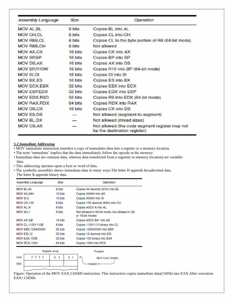
5.2.Immediate Addressing
• MOV immediate instruction transfers a copy of immediate-data into a register or a memory-location.
• The term ‘immediate’ implies that the data immediately follow the opcode in the memory.
• Immediate-data are constant-data, whereas data transferred from a register( or memory-location) are variable-
data.
• This addressing operates upon a byte or word of data.
• The symbolic assembler shows immediate-data in many ways.The letter H appends hexadecimal data.
The letter B appends binary data.
Figure: Operation of the MOV EAX,13456H instruction. This instruction copies immediate data(13456) into EAX.After execution
EAX=13456h.

5.3.Direct Data Addressing
• There are 2 basic forms of direct data addressing:
1) Direct addressing applies to a MOV between a memory-location and the AL or AX,EAX (accumulator)
2) Displacement addressing applies to almost any instruction in the instruction set.AX & CX can be used.
• In either case, the effective-address(EA) is formed by adding the displacement to the default data-segment
address.(ex: if DS=1000 and BP=200, then EA=DS*10+BP=1000*10+200=10200H)
Direct Addressing
• Direct addressing with a MOV instruction transfers data between a memory-location, located within the data segment and the AL or
AX register.
• A MOV instruction is usually a 3-byte long instruction.
• The MOV AL,DATA ;This instruction loads AL from the memory-location DATA(1234H)
• Memory location ‘DATA’ is a symbolic memory location,while the 1234H is the actual hexadecimal location.
• MOV AL, [1234H] ;This instruction transfers a copy of the byte-sized contents of memory-location 11234H
into AL. The effective address is formed by adding 1234H(offset address) and 10000H(data segment address of 1000H multiplied
by10H) in a system operating in the real mode.
Table : Direct addressed instructions using AX and AL
Displacement addressing:
•same as direct addressing except that instruction is 4 byte long.
•MOV between memory location to Accumulator & CX register.
5.4.Register Indirect Addressing
• This mode allows data to be addressed at any memory location through an offset address which is stored in
Any of the registers BP, BX, DI and SI.
• The [] symbols denote indirect addressing.
• If BP addresses memory, the stack-segment is used by default.
•If BX, DI or SI addresses memory, the data-segment is used by default.

Figure : The operation of the MOV AX,[BX] instruction when BX=1000H and DS=0100H.
Table : Examples of register indirect addressing
Special assembler directive: 1.In some cases, indirect addressing requires specifying the size of the data. The size is specified by the
special assembler directive BYTE PTR, WORD PTR. These directives indicate the size of the memory data addressed by the memory
pointer(PTR).
1. For example, the MOV AL,[DI] instruction is clearly a byte-sized move instruction, but the MOV [DI],10H
instruction is ambiguous. Does the MOV [DI],10H instruction address a byte, word sized memory location?
The assembler can’t determine the size of the 10H. The instruction MOV BYTE PTR[DI],10H clearly
designates the location addressed by DI as a byte-sized memory location.
2. OFFSET directive: MOV BX,OFFSETDATAthis tells the assembler to load BX with offset address of
memory location DATA
Example : Program loads register BX with the starting address of the table and it initializes the count,located in register CX to 50.
MODEL SMALL ; select small model
.DATA ; start data segment
DATAS DW 50 DUP(?) ; setup array of 50 words
.CODE ; start code segment
.STARTUP ; start program
MOV AX,0
MOV ES,AX ; address segment 0000 with ES
MOV BX,OFFSET DATAS ; address DATAS array with BX
MOV CX,50 ; load counter with 50
AGAIN:
MOV AX,ES:[046CH] ; get clock value

MOV [BX],AX ; save clock value in DATAS
INC BX ; increment BX to next element
LOOP AGAIN ; repeat 50 times
.EXIT ; exit to DOS
END ; end program listing
The LOOP instruction decrements the counter(CX); if CX is not zero, LOOP causes a jump to memory location
AGAIN. If CX becomes zero, no jump occurs and this sequence of instruction ends.
5.5.Base Plus Index Addressing
• This uses one base-register(BP or BX) & one index-register(DI or SI) to indirectly address-memory.
• The base-register often holds the beginning location of a memory-array, whereas
Index-register holds the relative position of an element in the array.
Figure : An example showing how the base-plus-index addressing mode functions for the
MOV DX,[BX+DI instruction].
Memory address 02010H is accessed because DS=0100H, BX=100H and DI=0010H
Exmple:
Figure :An example of the base-plus-index addressing mode.

Here an element(DI) of an ARRAY(BX) is addressed.
Example: Program to move array element 10H into array element 20H.
.MODEL SMALL ; select small model
.Data ; start data segment
ARRAY DB 16 DUP(?) ; setup array of 16 bytes
DB 29H ; element 10H
DB 20 dup(?)
.CODE ; start code segment
.STARTUP
MOV BX,OFFSET ARRAY ; address ARRAY
MOV DI,10H ; address element 10H
MOV AL,[BX+DI] ; get element 10H
MOV DI,20H ; address element 20H
MOV [BX+DI],AL ; save in element 20H
.EXIT :exit to DOS
END : end program
5.6.Register Relative Addressing
• This is similar to base plus index addressing and displacement addressing. Displacement is added with the
contents of Base or Index register.
• moves byte/word between a register and the memory-location addressed by an index- or base- register
plus a displacement (BP, BX, DI or SI).
Table: Examples of register relative addressing
Figure:The operation of the MOV AX,[BX+1000H] instruction when BX=0100H and DS=0200H
Example:

Figure: Register relative addressing used to address an element of ARRAY. The displacement addresses the start of ARRAY and DI
accesses an element
5.7.Base Relative Plus Index Addressing
• This transfers a byte between a register and the memory-location addressed by a base-and an index-register
plus a displacement.
• This often addresses a 2-dimensional array of memory-data.least used method.
Table : Example base relative-plus-index instructions
Figure : An example of base relative-plus-index addressing using a MOV AX,[BX+SI+100H] instruction. Note DS=1000H.
5.8.Scaled index addressing
•This is unique to 80386 thr’ core 2 processor.
• uses two 32 bit register,base register and index register and the index register multiplied by scaling factor.
• For example, MOV EDX, [EAX+4*EBX] ;This instruction loads EDX from memory-location addressed by
EAX plus four times EBX.
• Scaling allows access to word(2*), doubleword(4*) and quadword(8*) memory array-data.
•.386 directive is used to select 80386 instruction.

•Examples: MOV EAX,[EDI+2*ECX]
MOV EAX,[4*EDI]
5.9.RIP Relative Addressing
• This mode allows access to any location in the memory by adding a 32-bit displacement to the 64-bit contents
of the 64-bit instruction pointer.
•used in flat mode.The inline assembler program of VC++ doesnot contain 64 bit addressing mode.
•But when microsoftfinally places a inline assembler into VC++ for 64 bit,it resembles RIP relative addressing.
MODULE-1(second half)
Machine Language
• Machine-language is the native binary-code that the microprocessor understands and uses as its instructions to control its operation.
Length of Machine instructions= 1 to 13 bytes.
• In 8086, instructions are 16-bit mode-instructions (real-mode).
• In real-mode, 80386 & above, assume that all instructions are 16-bit mode instructions (Fig 1).
• For 32 bit, register- size prefix(66H) and The address size prefix(67H)is appended to the front of the instruction.
Figure 1: The formats of the 8086-Core2 instructions. a) The 16-bit form and b)The 32-bit form
Byte 1 of machine language:Opcode(Operation Code)
• This selects operation (addition, subtraction, move and so on) that is performed by the microprocessor.
• Opcode is either 1 or 2 bytes long for most machine language instructions (Figure 2).
• First 6 bits of first byte are the opcode. The remaining 2 bits are
i) If D=1, data flow from the R/M field to the register REG field.
If D=0, data flow from the REG field to the R/M field.
ii) If W=1, the data size is a word or doubleword; if W=0, the data size is always a byte.
Figure 2: Byte-1 of many machine language instructions, showing the position of the D- and W-bits.
Byte 2 of machine language
Figure -3: Byte -2 of machine language instructions, showing the position of the MOD, REG and R/M fields.
MOD Field
• This specifies addressing-mode(MOD) for the selected instruction (i.e. it selects the type of addressing and whether a
displacement is present with the selected type) (Figure -3).
• If MOD=11, it selects the register-addressing mode (Table -1&-2).
• If MOD contains 00, 01 or 10, the R/M field selects one of the data memory-addressing modes.
Table -1: MOD field for the 16-bit instruction mode Table -2: MOD field for the 32-bit instruction mode

• When MOD selects a data-memory addressing-mode, it indicates that the addressing-mode contains
→ no displacement(00) {e.g. MOV AL, [DI]}
→ 8-bit sign extended displacement(01) {e.g. MOV AL,[DI+2] }or
→ 16-bit displacement(10) {e.g. MOV AL,[DI+1000H }
Table -3: REG and R/M when MOD=11 assignments. Table -4: 16-bit R/M memory-addressing modes
When mod = 00,01,10
Example 1: Find the assembly language code for 8BECh.
Because neither 67h or 66h appears as first byte (the register-size prefix66H &address size prefix 67H),the first byte 8B is opcode.
8BEC -1000 1011 1110 1100
Figure -4: The 8BEC instruction placed into bytes 1 and 2 formats.
From the above, opcode 100010 is for MOV. And D=1 ,so data flow is from R/M to Reg. w=1,so it is word.
MOD = 11 so R/M is a register.by referring table 3, REG field 101 is for BP & R/M field 100 is for SP.
So the instruction for 8BECh is is MOV BP, SP
Example 2: Find the assembly language code for 668BE8h.
The first byte is 66h (the register size override prefix)that selects 32 bit register operand for 16 bit instruction code.
8BE8 = 1000 1011 1110 1000.
By comparing with standard formats,(fig 2 &3), 100010 is for MOV. And D=1 ,so data flow is from R/M to Reg.
W=1,so it is word.as 66 is prefixed we have to consider double word.
MOD = 11 so R/M is a register.by referring table 3, REG field 101 is for EBP & R/M field 000 is for EAX.
So the instruction for 668BE8h is is MOV EBP, EAX
Example 3: Find the machine code for MOV DL, [DI].
Opcode for mov = 100010. data flow is from R/M to Reg so D=1.register size is 8bits. So W=0. And MOD = 00(ie.memory
addressing and no displacement).Code for DL is 010(table-3).Code for DI is 101(table-4).
So the machine code is 1000 1010 0001 0101 = 8A15h.(refer the standard strucure fig 2 & 3)
Figure -5: A MOV DL, [DI] instruction converted to its machine language form
Example 4: Find the machine code for MOV DL, [DI+1].
Opcode for mov = 100010. data flow is from R/M to Reg so D=1.register size is 8bits. So W=0. And MOD = 01(ie.memory
addressing and 8 bit displacement).Code for DL is 010(table-3).Code for DI is 101(table-4).the displacement is 01h.
So the machine code is 1000 1010 0101 0101 0000 0001= 8A5501h.
displacement
Example 5: Find the machine code for MOV DL, [DI+1000].
Opcode for mov = 100010. data flow is from R/M to Reg so D=1.register size is 8bits. So W=0. And MOD = 10(ie.memory
addressing and 16 bit displacement).Code for DL is 010(table-3).Code for DI is 101(table-4).the displacement is 1000h.
So the machine code is 1000 1010 0101 0101 0000 0000 0001 0000= 8A550010h.
Lower byte of higher byte of
Displacement displacement
Special Addressing Mode
• This is not appearing in any of the tables. This mode is used whenever memory-data are referenced by only the
displacement mode of addressing for 16-bit instructions.
• Example:
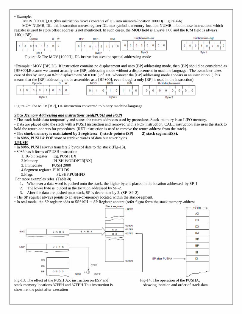
MOV [1000H],DL ;this instruction moves contents of DL into memory-location 1000H( Figure 4-6).
MOV NUMB, DL ;this instruction moves register DL into symbolic memory-location NUMB.in both these instructions which
register is used to store offset address is not mentioned. In such cases, the MOD field is always a 00 and the R/M field is always
110(ie.BP).
Figure -6: The MOV [1000H], DL instruction uses the special addressing mode
•Example : MOV [BP],DL. If instruction contains no displacement and uses [BP] addressing mode, then [BP] should be considered as
[BP+00].Because we cannot actually use [BP] addressing mode without a displacement in machine language . The assembler takes
care of this by using an 8-bit displacement(MOD=01) of 00H whenever the [BP] addressing mode appears in an instruction. (This
means that the [BP] addressing mode assembles as a [BP+00], even though a only [BP] is used in the instruction)
Figure -7: The MOV [BP], DL instruction converted to binary machine language
Stack Memory Addressing and instructions used(PUSH and POP)
• The stack holds data temporarily and stores the return addresses used by procedures.Stack-memory is an LIFO memory.
• Data are placed onto the stack with a PUSH instruction and removed with a POP instruction. CALL instruction also uses the stack to
hold the return-address for procedures. (RET instruction is used to remove the return address from the stack).
• The stack-memory is maintained by 2 registers: i) stack-pointer(SP) 2) stack segment(SS).
• In 8086, PUSH & POP store or retrieve words of data but never bytes
1.PUSH
• In 8086, PUSH always transfers 2 bytes of data to the stack (Fig-13).
• 8086 has 6 forms of PUSH instruction
1. 16-bit register Eg, PUSH BX
2.Memory PUSH WORDPTR[BX]
3. Immediate PUSH 2000
4.Segment regiater PUSH DS
5.Flags PUSHF,PUSHFD
For more examples refer (Table-8)
1. Whenever a data-word is pushed onto the stack, the higher byte is placed in the location addressed by SP-1
2. The lower byte is placed in the location addressed by SP-2.
3. After the data are pushed onto stack, SP is decrement by 2. (SP=SP-2)
• The SP register always points to an area-of-memory located within the stack-segment.
• In real mode, the SP register adds to SS*10H + SP Register content (refer fig)to form the stack memory-address
Fig-13: The effect of the PUSH AX instruction on ESP and Fig-14: The operation of the PUSHA,
stack memory locations 37FFH and 37FEH.This instruction is showing location and order of stack data
shown at the point after execution

•PUSHA(push all)copies the contents of the internal register-set(except the segment registers) to the stack in the following order: AX,
CX, DX, BX, SP, BP, SI and DI (Fig-14).After all registers are pushed, SP is decremented by 16. (SP=SP-16)
Some Examples:
1.PUSHF – copies FLAG register to the stack.
2.PUSHFD– copies EFLAG register to the stack.
3.PUSHA – Copies AX,CX,DX,BX,SP.BP.DI,SI to the stack.
4.PUSHAD – Copies EAX,ECX,EDX,EBX,ESP.EBP.EDI,ESI to the stack.
5.PUSH QWORDPTR[RDX]-pushes RDX content to stack.
Table-8: The PUSH instruction
2.POP
• In 8086, POP always retrieves 2 bytes of data from the stack (Fig-15).
• 8086 has 6 forms of POP instruction
1. 16-bit register Eg, POP BX
2.Memory POP WORDPTR[BX]
3. Immediate no immediate POP
4.Segment regiater POP DS
5.Flags POPF,POPFD
For more examples refer (Table-9)
• Whenever data are popped from the stack,
1. The lower byte is removed from the location addressed by SP.
2. The higher byte is removed from the location addressed by SP+1.
3. The SP register is then incremented by 2.
•Data may be popped off from the stack into any register or any segment register except CS.Because this will change the address of
next instruction.
Some Examples:
1. POPF(pop flags) : removes 2 bytes of data from the stack & places it into the flag-register
2.POPFD – Removes a double word from stack place it into flag register.
3.POPA(pop all):removes 16 bytes of data from the stack &places them into the following registers (in the order: DI, SI, BP, SP, BX,
DX, CX and AX).

Fig -15: The POP BX instruction showing how data are
removed from the stack. This instruction is shown after execution Table-9: The POP instructions
Other Data Movement Instructions:
1.LEA(Load-Effective Address)
• This loads a 16-bit register with the offset-address of the data specified by the operand(Table-10).
• LEA BX,[DI] ;this loads offset-address specified by [DI] into register BX.
Whereas MOV BX, [DI] ;this loads data stored at memory-location addressed by [DI] into BX.
• The OFFSET directive performs the same function as an LEA instruction.
For example, the MOV BX, OFFSET LIST performs the same function as LEA BX, LIST.
• Difference between OFFSET & LEA instruction
OFFSET only functions with simple operands such as LIST. It may not be used for an operand such as
[DI], LIST [SI] and so on. OFFSET directive is more efficient than the LEA instruction for simple operands.
Because it takes the microprocessor longer to execute the LEA BX, LIST instruction than MOV BX, OFFSET LIST.
• The reason that the MOV BX, OFFSET LIST instruction executes faster is because the assembler calculates the
offset address of LIST, whereas the microprocessor calculates the address for the LEA instruction.
Table -10: Load-effective address instructions
2.LDS, LES, LFS, LGS and LSS (LFS,LGS and LSS available only with 80386 and above)
• The LDS, LES, LFS, LGS and LSS instructions load
→ any 16-bit register with an offset-address &
→ DS, ES, FS, GS or SS with a segment-address.
• For example, LDS BX,[DI] ;this instruction transfers 32-bit number addressed by DI (16 bit for segment & 16 bit for offset) into the
DS & BX registers (Fig-17).
• For example, LDS EDI,LIST1 ;this instruction transfers 48-bit number (16 bit for segment & 32 bit for offset of LIST1) into the
DS &EDI registers
(Note: segment register size is always 16 bit from 8086 to core2 processor)

Fig-17:The LDS BX,[DI] instruction loads register BX from addresses 11000H and 11001H and register DS from locations 11002H
and 11003H.After execution DS changes to 3000H and BX changes to 127AH.
Segment Override Prefix
• This allows the programmers to deviate from the default-segment (Table-21).
• This may be added to almost any instruction in any memory addressing-mode.
• This is an additional byte that appends the front of an instruction to select an alternate segment-register.
• Only instructions that cannot be prefixed are JMP and CALL that must use the CS register for address generation.
•When the instruction is prefixed,instruction length(machine language code) becomes 1 byte longer.So the execution time
becomes more.usually,the segment override prefix
• For example, MOV AX,ES ;[DI] this instruction addresses extra-segment instead of data-segment.
Table-21: Instructions that include segments override prefixes
ARITHMETIC INSTRUCTIONS
1.ADDITION INSTRUCTIONS:
1.1.ADD(Addition)
• This is used to add byte/word of data of 2 registers or a register & a memory-location
• The only types of addition not allowed are memory-to-memory and segment register (Table 5-1).
Table -23: Example addition instructions

There are 4 types of addition instructions
1.Register Addition
• Whenever arithmetic and logic instructions execute, the contents of the flag-register changes.
• Any ADD instruction modifies contents of sign, zero, carry, auxiliary, carry, parity & overflow flags.
Example -1: Program to compute AX=BX+CX+DX.
ADD AX,BX
ADD AX,CX
ADD AX,DX
2.Immediate Addition
• Immediate addition is employed whenever constant-data are added.
Example -2: Program to add immediate data
MOV DL,12H
ADD DL,33H
3.Memory-to-Register Addition
•Adds the content of register & Memory location. For eg, ADD AL,[DI]
Example -3: Program to add two consecutive bytes of data(stored at the data segment offset locations NUMB and
NUMB+1) to the AL register.
LEA DI,NUMB ;address NUMB
MOV AL,0 ;clear sum
ADD AL,[DI] ;add NMB
ADD AL,[DI+1] ;add NUMB+1
4.Array Addition
Example : ADD AX,ARRAY[DI]
Example -4: Program to add the contents of array element at indices 3, 5 and 7
MOV AL,0 ;clear sum
MOV SI,3 ;address element 3
ADD AL,ARRAY[SI] ;add element 3
ADD AL,ARRAY[SI+2] ;add element 5
ADD AL,ARRAY[SI+4] ;add element 7
1.2.INC(Increment Addition)
• This adds 1 to any register or memory-location, except a segment-register (Table -24).
• With indirect memory increments, the data size must be described by using the BYTE PTR, WORD PTRdirectives.
Because, the assembler cannot determine if, for example, INC [DI] instruction is a byte or word sized increment.

The INC BYTE PTR[DI] instruction clearly indicates byte sized memory data.
Example 5: Using INC instruction, program to add two consecutive bytes of data(stored at the data segment
offset locations NUMB and NUMB+1) to the AL register.
LEA DI,NUMB ;address
MOV AL,0 ;clear sum
ADD AL,[DI] ;add NUMB
INC DI ;increment DI
ADD AL,[DI] ;add NUMB+1
Table 24: Example increment instructions
1.3.ADC(Addition with Carry)
• This adds the bit in the carry-flag(C) to the operand-data (Table 25).
• This mainly appears in software that adds numbers that are wider than 16 bits in the 8086.
Example 6: To add the 32-bit number in BX and AX to the 32-bit number in DX and CX (Fig-21
ADD AX,CX
ADC BX,DX
Fig-21: ADC showing how the carry flag(C)
links the two 16-bit additions into one 32-bit addition Table 25: Example add-with-carry instructions
1.4.XADD(Exchange & Add)
• This instruction is used in 80486-Core2 microprocessors.
• This adds the source to the destination and stores the sum in the destination.
• The difference is that after the addition takes place, the original value of the destination is copied into the
source-operand.
For example, if BL=12H and DL=02H, XADD BL,DL instruction executes, after execution BL=12+2=14h and DL =12h
SUBTRACTION INSTRUCTIONS:
2.SUB(Subtraction)
• Only types of subtraction not allowed are memory-to-memory and segment register subtractions.
• This affects the flag bits (Table 26).
Table 26: Example subtraction instructions

2.1.Register Subtraction
Example :To subtract the 16-bit contents of registers CX and DX from the contents of register BX
SUB BX,CX
SUB BX,DX
2.2.Immediate Subtraction
Example :To subtract 44H from 22H
MOV CH,22H
SUB CH,44H
After the subtraction, the difference(0DEH) moves into the CH register. The flags change as follows for this
subtraction:Z=0(result not zero), C=1(borrow), A=1(half borrow), S=1(result negative), P=1(even parity), O=0(no overflow)
2.3.DEC(Decrement Subtraction)
• This subtracts 1 from a register or the contents of a memory-location (Table 27).
• The decrement indirect memory-data instructions require BYTE PTR or WORD PTR because
the assembler cannot distinguish a byte from a word when an index-register addresses memory.
• For example, DEC [SI] is unclear because the assembler cannot determine whether the location addressed by SI
is a byte or word. Using DEC BYTE PTR[SI],DEC WORD PTR[DI] tells the size of the data to the assembler.
Table 28: Example decrement instructions
2.4.Subtraction-with-Borrow(SBB)
• This functions as a regular subtraction except that the carry flag(which holds the borrow) also subtracts from the
difference (Table 28).
Example : Program to subtract BX-AX from SI-DI (Fig-22)
SUB AX,DI
SBB BX,SI
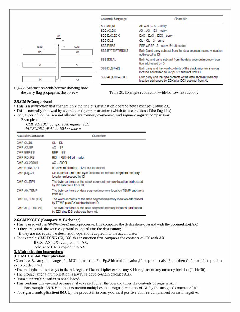
Fig-22: Subtraction-with-borrow showing how
the carry flag propagates the borrow Table 28: Example subtraction-with-borrow instructions
2.5.CMP(Comparison)
• This is a subtraction that changes only the flag bits,destination-operand never changes (Table 29).
• This is normally followed by a conditional jump instruction (which tests condition of the flag-bits)
• Only types of comparison not allowed are memory-to-memory and segment register comparisons
Example :
CMP AL,10H ;compare AL against 10H
JAE SUPER ;if AL is 10H or above
2.6.CMPXCHG(Compare & Exchange)
• This is used only in 80486-Core2 microprocessor.This compares the destination-operand with the accumulator(AX).
• If they are equal, the source-operand is copied into the destination;
if they are not equal, the destination-operand is copied into the accumulator.
• For example, CMPXCHG CX, DX; this instruction first compares the contents of CX with AX.
If CX=AX, DX is copied into AX;
otherwise CX is copied into AX.
3. Multiplication instructions
3.1 MUL (8-bit Multiplication)
•Overflow & carry bit changes for MUL instruction.For Eg.8 bit multiplication,if the product also 8 bits then C=0, and if the product
is 16 bit then C=1.
•The multiplicand is always in the AL register.The multiplier can be any 8-bit register or any memory location (Table30).
• The product after a multiplication is always a double-width product(AX).
• Immediate multiplication is not allowed.
• This contains one operand because it always multiplies the operand times the contents of register AL.
For example, MUL BL ; this instruction multiplies the unsigned-contents of AL by the unsigned contents of BL.
• For signed multiplication(IMUL), the product is in binary-form, if positive & in 2's complement forms if negative.

Example 5-13:Program to compute DX=BL*CL
MOV BL,5 ;load data
MOV CL,10
MOV AL,CL ;position data
MUL BL ;multiply
MOV DX,AX ;position product
Table 30: Example MUL & IMUL instructions
3.2. MUL (16-bit Multiplication)
• AX contains the multiplicand while any 16-bit general purpose register contains the multiplier.
• The 32-bit product is stored in DX-AX. DX always contains the most significant 16-bits of the product, and
AX contains the least significant 16 bits.
Note; For 32 bit,change the registers as EAX & EDX
A Special Immediate 16-bit Multiplication
• This instruction is available in 80286-Core2 microprocessors (Table 31).
• This contains 3 operands.
1. First operand is 16-bit destination-register;
2. Second operand is a register or memory-location that contains the 16-bit multiplicand &
3. Third operand is either 8-bit or 16-bit immediate-data used as the multiplier
• Example: IMUL CX,DX,12H ; this instruction multiplies 12H times DX and leaves a 16-bit signed product in CX.
Table 31: Example 16-bit multiplication instructions
4.DIVISION INSTRUCTION
4.1. DIV (8-bit Division)
• There is no immediate division.2 types of error will occur with DIV. 1.attempt to divide by zero.2.divide overflow.
•AX is used to store the dividend that is divided by the contents of any 8-bit register or memory-location (Table 32).
• After division, quotient appears in AL and remainder appears in AH.
• For a signed division, quotient is positive or negative;the remainder always assumes the sign of the dividend and is
always an integer.
For eg, 1. DIV CL means Content of AX is divided by the content of CL and AL has quotient & AH has Remainder.
Ex.2. if AX=0010(+16) and BL=0FDH(-3) and IDIV BL instruction executes AX=01FBH (This represents a
quotient of -5(AL) with a remainder of 1(AH))
Table 32: Example 8-bit division instructions
Example : Program to divide the unsigned byte contents of memory location NUMB by the unsigned contents of memory

location NUMB1.
MOV AL,NUMB ;get NUMB
MOV AH,0 ;zero extend
DIV NUMB1 ;divide by NUMB1
MOV ANSQ,AL ;save quotient
MOV ANSR,AH ;save remainder
4.2: DIV (16-Bit Division)
• DX-AX register is used to store the dividend that is divided by the contents of any 16-bit register or memory location
• After division, the quotient appears in AX and the remainder appears in DX.
Table 33: Example 16-bit division instructions
BCD Arithmetic
• Two arithmetic operation on BCD data are: addition and subtraction.
• The instruction-set provides 2 instructions that correct the result of a BCD addition and a BCD subtraction.
1) DAA(decimal adjust after addition) instruction follows BCD addition.
2) DAS(decimal adjust after subtraction) follows BCD subtraction.
(Both instructions corrects result of addition or subtraction so that it is a BCD number)
• For BCD data, the numbers always appear in the packed BCD form and are stored as 2 BCD digits per byte.
• These instructions use only AL as the source and as the destination.
ASCII Arithmetic
• The ASCII arithmetic instructions function with ASCII coded-numbers. These numbers range in value from 30H to 39H for
the numbers 0-9. There are 4 instructions used with ASCII arithmetic operations:
1. AAA (ASCII adjust after addition) 2.AAD (ASCII adjust before division)
3. AAM (ASCII adjust after multiplication) 4. AAS (ASCII adjust after subtraction)
• These instructions use only AX as the source and as the destination.
Example : Program to illustrate ASCII addition
MOV AX,31H ;load ASCII 1
ADD AL,39H ;add ASCII 9
AAA ;adjust sum
ADD AX,3030H ;answer to ASCII
Example : Program to divide 72 in unpacked BCD by 9 to produce a quotient of 8.
MOV BL,9 ;load divisor
MOV AL,0702H ;load dividend
AAD ;adjust
DIV BL ;divide
Example : Program to multiply 5 times 3
MOV AL,5 ;load multiplicand
MOV CL,3 ;load multiplier
MUL CL
AAM ;adjust