Increasing Silver Nanowire Network Stability through Small ...
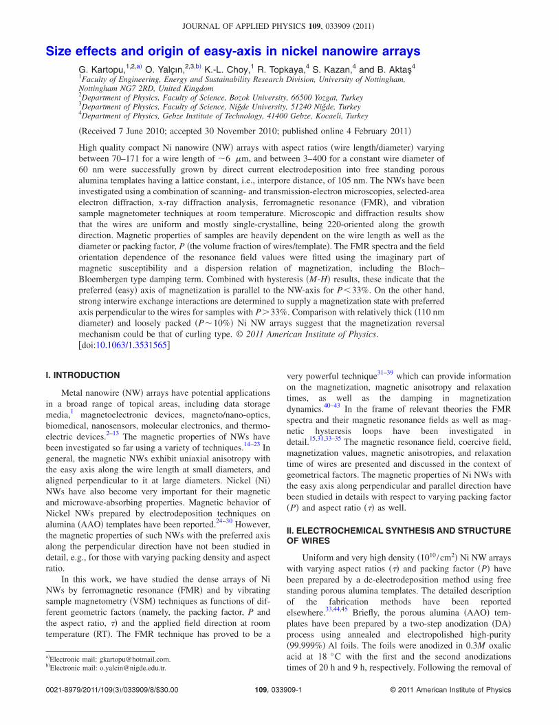
Size effects and origin of easy-axis in nickel nanowire arraysG. Kartopu,1,2,a� O. Yalçın,2,3,b� K.-L. Choy,1 R. Topkaya,4 S. Kazan,4 and B. Aktaş4
1Faculty of Engineering, Energy and Sustainability Research Division, University of Nottingham,Nottingham NG7 2RD, United Kingdom2Department of Physics, Faculty of Science, Bozok University, 66500 Yozgat, Turkey3Department of Physics, Faculty of Science, Niğde University, 51240 Niğde, Turkey4Department of Physics, Gebze Institute of Technology, 41400 Gebze, Kocaeli, Turkey
�Received 7 June 2010; accepted 30 November 2010; published online 4 February 2011�
High quality compact Ni nanowire �NW� arrays with aspect ratios �wire length/diameter� varyingbetween 70–171 for a wire length of �6 �m, and between 3–400 for a constant wire diameter of60 nm were successfully grown by direct current electrodeposition into free standing porousalumina templates having a lattice constant, i.e., interpore distance, of 105 nm. The NWs have beeninvestigated using a combination of scanning- and transmission-electron microscopies, selected-areaelectron diffraction, x-ray diffraction analysis, ferromagnetic resonance �FMR�, and vibrationsample magnetometer techniques at room temperature. Microscopic and diffraction results showthat the wires are uniform and mostly single-crystalline, being 220-oriented along the growthdirection. Magnetic properties of samples are heavily dependent on the wire length as well as thediameter or packing factor, P �the volume fraction of wires/template�. The FMR spectra and the fieldorientation dependence of the resonance field values were fitted using the imaginary part ofmagnetic susceptibility and a dispersion relation of magnetization, including the Bloch–Bloembergen type damping term. Combined with hysteresis �M-H� results, these indicate that thepreferred �easy� axis of magnetization is parallel to the NW-axis for P�33%. On the other hand,strong interwire exchange interactions are determined to supply a magnetization state with preferredaxis perpendicular to the wires for samples with P�33%. Comparison with relatively thick �110 nmdiameter� and loosely packed �P�10%� Ni NW arrays suggest that the magnetization reversalmechanism could be that of curling type. © 2011 American Institute of Physics.�doi:10.1063/1.3531565�
I. INTRODUCTION
Metal nanowire �NW� arrays have potential applicationsin a broad range of topical areas, including data storagemedia,1 magnetoelectronic devices, magneto/nano-optics,biomedical, nanosensors, molecular electronics, and thermo-electric devices.2–13 The magnetic properties of NWs havebeen investigated so far using a variety of techniques.14–23 Ingeneral, the magnetic NWs exhibit uniaxial anisotropy withthe easy axis along the wire length at small diameters, andaligned perpendicular to it at large diameters. Nickel �Ni�NWs have also become very important for their magneticand microwave-absorbing properties. Magnetic behavior ofNickel NWs prepared by electrodeposition techniques onalumina �AAO� templates have been reported.24–30 However,the magnetic properties of such NWs with the preferred axisalong the perpendicular direction have not been studied indetail, e.g., for those with varying packing density and aspectratio.
In this work, we have studied the dense arrays of NiNWs by ferromagnetic resonance �FMR� and by vibratingsample magnetometry �VSM� techniques as functions of dif-ferent geometric factors �namely, the packing factor, P andthe aspect ratio, �� and the applied field direction at roomtemperature �RT�. The FMR technique has proved to be a
very powerful technique31–39 which can provide informationon the magnetization, magnetic anisotropy and relaxationtimes, as well as the damping in magnetizationdynamics.40–43 In the frame of relevant theories the FMRspectra and their magnetic resonance fields as well as mag-netic hysteresis loops have been investigated indetail.15,31,33–35 The magnetic resonance field, coercive field,magnetization values, magnetic anisotropies, and relaxationtime of wires are presented and discussed in the context ofgeometrical factors. The magnetic properties of Ni NWs withthe easy axis along perpendicular and parallel direction havebeen studied in details with respect to varying packing factor�P� and aspect ratio ��� as well.
II. ELECTROCHEMICAL SYNTHESIS AND STRUCTUREOF WIRES
Uniform and very high density �1010 /cm2� Ni NW arrayswith varying aspect ratios ��� and packing factor �P� havebeen prepared by a dc-electrodeposition method using freestanding porous alumina templates. The detailed descriptionof the fabrication methods have been reportedelsewhere.33,44,45 Briefly, the porous alumina �AAO� tem-plates have been prepared by a two-step anodization �DA�process using annealed and electropolished high-purity�99.999%� Al foils. The foils were anodized in 0.3M oxalicacid at 18 °C with the first and the second anodizationstimes of 20 h and 9 h, respectively. Following the removal of
a�Electronic mail: [email protected]�Electronic mail: [email protected].
JOURNAL OF APPLIED PHYSICS 109, 033909 �2011�
0021-8979/2011/109�3�/033909/8/$30.00 © 2011 American Institute of Physics109, 033909-1

nonoxidizied Al and the oxide barrier layer, one face of thefree standing AAO membrane was metallized with a bilayerfilm of Au/Cu �200 nm/1000 nm�. Prewetting of the porechannels with pure �deionized� water prior to electrodeposi-tion ensured a remarkably high Ni filling ratio close to 100%.The wire lengths and diameters were controlled, respectively,by monitoring the total deposited charge and by adjusting thetemplate pore size. In one set of the samples, the wire length�L� was fixed at 6�1 �m while the wire diameter �d� wasvaried from 35 to 85 nm ��10 nm� �series 1�, and in anotherset the wire length was tuned from 200�30 nm to24�2 �m for the same wire diameter of 60�10 nm �series2�. In these samples, the lattice constant �center-to-center dis-tance between neighborings pores/wires� has been fixed at105 nm. In addition to these samples, a hard anodization�HA� method28 was also employed to prepare low packingfactor Ni NW arrays for comparison. In this case, the AAOtemplate was prepared using the same electrolyte by increas-ing the anodization voltage from 40 to 128V, thereby increas-ing the lattice constant from 105 to �300 nm. The Ni NWsare embedded in the porous AAO matrix. The pore channelsand hence the Ni NWs are normal to the template and exhibithexagonal symmetry in the lateral dimensions �Figs. 1 and9�.
The individual pores are noninteracting and span the en-tire thickness of the film. Cross-sectional imaging for all thesamples shows that the pore filling efficiency is relativelyhigh and that the length of NWs is relatively uniform �Figs.1�e� and 1�f��.
Figure 2 shows typical x-ray diffraction �XRD�, trans-mission electron microscopy �TEM�, and selected-area elec-tron diffraction �SAED� results of Ni NWs with 105 nmlattice constant. For TEM studies, the wires were freed byetching the template in a 2M NaOH solution. The averagewire diameter for a given sample was determined by analyz-ing at least five TEM images collected from different NWs.Figures 2�a� and 2�b� show examples of two individual Niwires of different diameters collected from the series 1 speci-mens. The XRD and SAED patterns have indicated that themajority of Ni wires are single-crystals and �200�-oriented inthe axial direction �Fig. 2�c��.
III. MAGNETIC CHARACTERIZATIONS ANDMODELING OF THE FMR SPECTRA
The FMR spectra have been obtained using an X-band�9.5 GHz� Bruker EMX spectrometer at RT. A goniometerhas been employed to rotate the sample around the wire axis.Anisotropic spectra have been recorded at different angles ofexcitation as the fields sweep from the parallel-toperpendicular-to the wire axis.
Hysteresis curves of Ni NW arrays have been collectedusing a VSM at RT. From these results, magnetic parameterssuch as coercive field, magnetization, etc. have been deter-mined.
The experimental and theoretical coordinate systems forthe NW-sample geometry, dc magnetic field H� , relative ori-entation of equilibrium magnetization M� as well as the geo-metric factors and hexagonal close packed �hcp� arrangementof NWs are depicted in Fig. 3.
The free-energy density equation for homogeneouslymagnetized Ni NWs films can be written as
E = − M� · H� + Keff sin2 � , �1�
where the first term corresponds to Zeeman energy, and thesecond term to the effective anisotropy energy.18,31,46 Here,
FIG. 1. SEM images of various normal AAO templates and Ni NWs with105 nm lattice constant. �a� The AAO template in two-dimensional �top-view� and three-dimensional �inset, tilted cross-section�. ��b�, �c�, and �d��Close-up view of AAO pores showing their uniform, hexagonal arrange-ment. The pore diameter is �80 nm in �c� and 35 nm in �d�. ��e� and �f��Cross-section of Ni-filled AAO films with d=35 nm and L=2.4�0.5 �m,respectively.
FIG. 2. ��a� and �b�� Representative TEM images of single Ni NWs of d=60�10 and 85�10 nm diameter. �c� XRD profile of a Ni NW array �L=24�2 �m� indicating that the wires are predominantly �200�-texturedalong the growth axis. Inset: typical SAED pattern obtained on an isolatedNi NW, confirming the single-crystalline character of the synthesized wires.
FIG. 3. �a� Sketch of the sample geometry of the considered Ni NW systemand the relative orientations of the equilibrium magnetization M� and the dccomponent of external magnetic field H� , for the FMR experiments. �b�Sample parameters used in the packing factors �P� calculation. �c� Sche-matic representation of a hexagonal NW array exhibiting a total of sevenwires. The dashed lines indicate the sixfold symmetry.
033909-2 Kartopu et al. J. Appl. Phys. 109, 033909 �2011�

�� ,�� and ��H ,�H� are angles in spherical coordinates for M�
and H� , respectively, while Keff=M2�1−3P�+KU denotesthe effective uniaxial anisotropy constant. The first term inKeff is due to the magnetostatic energy of perpendicularly-arrayed NWs �Refs. 47 and 48� and constant Ku takes intoaccount some additional second-order uniaxial anisotropywith the symmetry axis along the wire direction.31 The pack-ing factor �P� for a perfectly ordered hcp NW array is de-fined as P= � /2�3��d /r�2. In fact, the effective uniaxial an-isotropy, namely, Keff, should decrease linearly withincreasing packing factor �P� and finally the leading the pre-ferred axis rotate to the transverse direction for thicker NWswith high P. The equilibrium values of polar angles � for themagnetization vector M� are obtained from static equilibriumconditions
E� = �E/�� = 0,
MH�cos � sin �H cos�� − �H�− sin � cos �H
− Keff sin2 � = 0. �2�
The resonance field values as a function of external fieldangles have been obtained from the dispersion relation Eq.�3� given by the Landau–Lifshitz dynamical equation of mo-tion for magnetization with the Bloch–Bloembergen damp-ing term,34–36,49–52
�0
�2
− � 1
�2T22
= �H cos�� − �H� + Heff cos 2����H cos�� − �H� + Heff cos2 �� � .
�3�
Here, �0 /��=g�BH is the Larmour frequency of the mag-netization in the external dc effective magnetic field andHeff=2MS�1−3P�+ �2Ku /Ms�, which is the effective aniso-tropy field derived from the total magnetic anisotropy energyof NWs from Eq. �1�. The values for total magnetizationhave been obtained by fitting Heff with experimental resultsof FMR measurements at different angles ��H� of externalfield H� . The experimental spectra are proportional to the de-rivative of the absorbed power with respect to the appliedfield which is also proportional to the imaginary part of themagnetic susceptibility. The theoretical absorption curves areobtained by using the d 2 /dH as a function of applied field�see Refs. 53–55 for details�
= 1 + i 2,
2 =�2/�2T2�
��0/��2 − �/��2�2 + �2/�2T2�2 , �4�
where T2 is the effective relaxation time for the magnetiza-tion. This term contributes to the line-width of the FMRspectra on the maximum of the derivative of absorption spec-tra. =�H represents the Larmour frequency of the magne-tization in the dc applied field and � is the gyromagneticratio. The magnetic parameters have been established by fit-ting of the experimental FMR spectra and their resonancefield using Eqs. �3� and �4� for computer simulations.
IV. EXPERIMENTAL AND THEORETICAL MAGNETICRESULTS
Figure 4 shows experimental and simulated FMR spectra�fitted magnetic parameters are tabulated in Table I� for theselected samples with d�35, 60, 67, and 85 nm �or P=11,29.6, 36.9 and 59.4%� from series 1 �the upper panel�, andL�24, 1.4, and 0.8 �m �or �=400, 23, and 13� from series2 �the lower panel�. Here, the applied field is either perpen-dicular or parallel to the wire axis as noted in Fig. 4. Accord-ingly, it is relatively straightforward to conclude that, exceptfor the sample with the lowest diameter �d�35 nm�, theeasy axis of all samples are perpendicular to the wire axis.The “parallel” spectra for most wire samples are asymmetric
FIG. 4. �Color online� FMR spectra of selected Ni NWs samples of differentdiameters from 35�85 nm �with P=11%,29.6%,36.9%,59.4%� and of dif-ferent lengths from 0.8�24 �m �with �=400, 23, and 13�. The applied fieldis parallel �the lower field signal� and perpendicular �the high field signal� tothe wire axis for d=35 nm sample. The applied field is perpendicular �thelower field spectra� and parallel �the high field spectra� to the wires for allthe other samples.
TABLE I. Theoretically fitted magnetic parameters for the series 1 and 2samples in Figs. 4 and 5.
d�nm�
P�%�
Ku
�erg /cm3��106 /��G�
T2�10−7
�s�
35 11 �5.69 2200 3�160 29.6 �2.65 2980 4�267 36.9 �1.19 2850 4�285 59.4 3.10 2800 4�3
L��m� �
Ku
�erg /cm3��106 /��G�
T2�10−7
�s�
24 400 �2.71 2880 4�51.4 23 �2.30 3150 5�40.8 13 �1.94 3150 6�30.5 8 �1.50 3250 3�50.2 3 �1.12 3360 2�5
033909-3 Kartopu et al. J. Appl. Phys. 109, 033909 �2011�

with respect to the resonance field, and are distorted. Themagnetic dipoles are aligned antiparallel or parallel accord-ing to the applied magnetic field at a given time. The mag-netic moments orientation of NWs array domains is antipar-allel, which produces a net antiferromagnetic order. Theantiparallel arrangements of magnetic moments with magne-tization direction are perpendicular to the long axis of wires.Thus, this might result from antiferromagnetic resonancesdue to the dipolar interactions of antiferromagneticallyaligned giant wire domains �see Refs. 56 and 57 for details�.The minor peaks in the samples with L�24 �m �series 2�and d�35 nm and 67 nm �series 1� in parallel conditioncorrespond to spin wave modes.33
Dependence of the resonance field on the applied fielddirection for different diameters and packing factors �P=11%, 29.6%, 36.9%, and 59.4%�, and different lengths andaspect ratios ��=400, 25, 13, 8, and 3� are given in Fig. 5,along with their theoretical fits. In general, the resonancefield shows strongly anisotropic behavior with respect to thedirection of the dc magnetic field. At angles below �30°,apart from the lowest diameter sample, the resonance fielddecreases with an increase in P �Fig. 5�a�� and increases withan increase in � �Fig. 5�b��. This trend is opposite for thelowest diameter sample �see Sec. V�. By the analysis of reso-nance field-applied field direction relations, easy axis of allsamples with d�60 nm is determined to be perpendicular tothe wire axis, whereas the easy axis of the thinner wires �d=35 nm� is parallel to the wire axis.
The resonance field values exhibit drastic changes be-tween “nanoscale” Ni NWs samples with ��100. As theapplied field increases up to the resonance values, the equi-librium position of the average magnetization continuouslyrotates toward the field direction so that the magnetization
satisfies the resonance conditions for different values of theapplied field, even though the field direction is kept constant.
The dependence of axial resonance field and uniaxialanisotropy constant, Ku, on the geometric parameters P and �are shown in Figs. 6�a� and 6�b�, respectively. The resonancefields first increases sharply and then remains constant withthe increase in P, while Ku increases linearly with the in-crease in P. On the other hand, both the resonance field andKu increase logarithmically with �.
As seen from Fig. 6�b�, Ku depends strongly on P. FromKeff=M2�1−3P�+Ku it can be understood that for a givenP, Keff reduces Ku. Further 2Ms�1−3P� changes sign forP�33%. Therefore, it is obviously expected that KU varieslinearly with P and changes sign �from negative to positive�for series 1. As a consequence, according to the relation�Heff=2Ms�1−3P�+2Ku /Ms� the Heff approaches to thecontinuous film limit for P→100%.18,46 The isolated wireslimit is obtained as P→0. As well-known, the preferred axisof continuous films is in-plane dominantly.
Figure 7 shows normalized perpendicular �the full lines�and parallel �the dotted lines� magnetization curves for se-lected samples as well as the variation of perpendicular �fullcircles� and parallel �open circles� coercive fields �Hc� withthe parameters � and P. It is evident from Figs. 7�a�–7�d� thatmagnetization easy axis is parallel to the wire axis for P=11% �d=35 nm� and perpendicular to it for P�33%,which is in accordance with the FMR results above �see Figs.4 and 5�. The evolution of parallel Hc with varying � exhibits
FIG. 5. �Color online� Experimental �open/closed symbols� and calculated�full lines� �fitted magnetic parameters are given in Table I� resonance fieldsfor Ni NWs of �a� Different diameters and hence packing factors �P=11%,29.6%, 36.9%, and 59.4%� and �b� different lengths which give differentaspect ratio ��=400, 23, 13, 8, and 3�.
FIG. 6. Packing factor �P� and aspect ratio ��� dependences. �a� The axial�parallel� resonance field. �b� The uniaxial anisotropy constant �Ku� for se-ries 1 and 2 Ni NWs samples.
033909-4 Kartopu et al. J. Appl. Phys. 109, 033909 �2011�

a logarithmic behavior as can easily be observed from thebest fit in Fig. 7�f�. However, in the perpendicular direction,Hc��� first decreases sharply �polynomial best fit� up to ��20, and, subsequently, increases logarithmically at high �.Moreover, the parallel Hc�P� exhibits very drastic changesfor small packing factors �Fig. 7�e��. As a result, it can beconcluded that the P�30% coercive field depends stronglyon the wire length �or equivalently �� rather than the wirediameter �or equivalently P� for the studied sample set. How-ever, for smaller values of P, it is strongly dependent on P.Furthermore, a comparison of Fig. 6�a� with Fig. 7 revealsthat the parallel FMR fields and hysteresis coercive fieldsdisplay similar behavior with the wire length, i.e., the aspectratio ���, for high packing factor �P�33%� samples of theseries 1.
The total magnetization curves of Ni NWs for series 1and series 2, as derived from M-H measurements, are plottedin Fig. 8 as a function of P �the upper panel� and � �the lowerpanel�. As expected, the slope of the total magnetizationcurve increases linearly with �, and has a tendency to in-crease with P. This behavior verifies our results for the series1 and 2.
As an alternative to the above, we also prepared Ni NWarrays having low P��10%� but a remarkably large diameter�d�110 nm� and lattice constant �r�300 nm� using theaforementioned HA method and characterized them with theVSM. Figure 9 shows scanning electron microscopy �SEM�
images of the blank- and Ni-infiltrated pores of a HA-AAOtemplate, and corresponding M-H curves for a Ni NW arraywith L�1 �m and ��9. As can be seen, the hysteresis loopchanges dramatically between the parallel and perpendiculardirections. The parallel loop is fairly wide and displays alarge remanence ��80%�, while the perpendicular loop isalmost nonhysteretic with a near-zero remanence. Also pro-vided in Fig. 9�d� is a comparison of this HA specimen withthe series 1 samples presented above, in terms of the varia-tion in axial coercive field with the ratio of wire diameter/lattice constant, d /r, i.e., Hc�d /r�, which is closely related topacking factor via P= /2�3�d /r�2. It can be seen that anexponential increase in coercive field can be identified for
FIG. 7. ��a�, �b�, �c�, and �d�� Normalized perpendicular and parallel M-Hcurves for selected Ni NWs samples; ��100 from �a� to �c�. Dependence ofparallel and perpendicular coercive fields �Hc� on aspect ratio ��� and pack-ing factor �P� for �e� series 1 �L constant and d varying�, and �f� series 2 �dconstant and L varying� samples.
FIG. 8. Total magnetization of the series 1 and 2 samples �normalized to thesample area� as function of P and �.
FIG. 9. HA-AAO when �a� “blank” and �b� “infiltrated” with Ni NWs. �c�Normalized parallel and perpendicular hysteresis loops of a Ni NW arrayembedded in HA-AAO �the cross-section is shown on the inset� �d�110 nm, L�1000 nm, and r�300 nm�. �d� Comparison of the depen-dence of axial coercivity on the wire diameter/interwire-distance ratio �d /r�between the HA sample shown in �c� and series 1 samples produced innormal �mildanodized� AAO templates.
033909-5 Kartopu et al. J. Appl. Phys. 109, 033909 �2011�

series 1 with decreasing d /r. The coercive field is as high as900 G when d /r�0.4. Despite the HA specimen shares thesame d /r value �and porosity of �10%� with this sample, itdisplays a somewhat lower coercive field of only 380 G. Inother word, the HA sample does not follow the exponentialtrend followed by series 1 samples.
V. DISCUSSION
In this work, we focused on the size effects in orderedarrays of Ni NWs. Experimental and theoretical magneticfindings are scrutinized below, paying due attention to inferthe origin�s� of changing preferred magnetization direction.
�i� In general, for relatively thick �d�60 nm� Ni NWarrays of series 1 �and series 2�, the preferred direc-tion of magnetization appears perpendicular to thewire axis. Meanwhile, as for the d=35 nm Series 1sample it is parallel to the wire axis. It is also parallelto the wire axis for the HA samples despite their ex-ceedingly large wire thickness �d=110 nm�. Thus, itbecomes clear that rather than the wire diameter alonethe packing factor is the dominant factor governingthe preferred magnetization direction �probably besideother magnetic properties� of ordered Ni NW arrays.
Nevertheless, for series 1 and 2 it is noteworthythat even when the preferred axis is in �or close to� thefilm plane, i.e., transverse to wire axis, the parallelhysteresis loop is still wider than the perpendicularcase �corresponding to the case Hc
�Hc
��. This is oneof the signatures of the “individual” wirelike characterof the NWs–inherited from the shape anisotropy �SA�effect.4 Therefore, in a highly dense array, effectsother than SA must be in action to influence the mag-netic properties. It is likely, for example, that wire-wire interactions are very powerful, and consequently,pushing the preferred axis �in parallel direction for asingle wire� toward the perpendicular direction. Thisis accompanied by shearing of the parallel loop andshrinkage of its remanence and coercivity.
This also explains the reason why the reducedinterwire interactions in HA �Fig. 9� and low-diameterseries 1 samples �Fig. 7�a�� display hysteresis loopsthat are qualitatively similar to single/isolatedNWs.4,11,16 In all these cases, the parallel loop is pseu-dosquare and fairly wide, while the perpendicularloop displays only a negligible hysteresis/remanence.
�ii� We now compare these findings with other results�which partially covered diameter/length effects in NiNWs� found in the literature. It is observed byVázquez et al. that as the wire diameter in dense NiNW arrays �d�18–83 nm and r�65–105 nm� isincreased, the preferred magnetization axis rotatesgradually from the parallel to the perpendiculardirection.58 The switching occurs at the wire diameterof �50 nm, in accordance with the work reportedherein. Another study which reported that NW arraysin alumina templates with �10 nm diameter �latticeconstant 35 nm, wire length �500 nm� exhibits thepreferred magnetization along the wire axis.59 From
these results, it appears plausible that the preferreddirection of thicker/densely packed Ni NWs can in-deed be perpendicular to the wire axis.
�iii� Apart from the SA, there are several other kinds ofanisotropy that can determine the effective magneticanisotropy, including primarily the crystal anisotropy�CA� and the magnetoelastic �stress� anisotropy�MA�.
About the CA, in cubic materials such as Ni andFe, the CA is relatively low when compared to the SAeffects. Further, the crystal growth direction of our NiNW samples appears �Fig. 2�c�� parallel to the “me-dium” preferred direction of Ni, i.e., �110�,60 thussurely the CA cannot support a strong anisotropy �ineither of the longitudinal or the transverse directions�.
As for the MA, it is shown that for Ni NWs em-bedded in alumina templates the MA can be indeedsignificant but only at low temperatures below 250K.61 All magnetic measurements in the current studyare performed at the RT, and so the MA effects can beassumed to be negligible.
It then appears that it must the interplay betweenthe SA and magnetostatic �wire-wire� interactionfields that predominantly determines �the magnitudeand the direction of� the effective anisotropy in highlydensely packed Ni NW arrays.
�iv� In general, arrays of Co, Fe and Ni NWs display dif-ferent magnetic behaviors.62 For Fe and Ni magneticstructures, it is mostly the geometrical shape and theparticle density that determine the magnetization easyaxis.58,63,64 Thus, it can be suggested that the effectiveuniaxial anisotropy constant �Keff=M2�1−3P�+KU�and hence KU should decrease linearly with P and theeasy axis should eventually change from axial totransverse direction, as experimentally observed, fordense Ni NWs arrays.65,66 Here, it is demonstrated forthin �d�90 nm� Ni NWs that the preferred axis de-pends indeed profoundly on P �or d /r� �Fig. 9�d��. Onthe contrary, a relatively smaller dependence �associ-ated with reduced axial coercivity� could be observedfor thick �d�110 nm� Ni NWs arrays, i.e., HA speci-mens, despite their low P �or d /r value� and reducedinterwire interactions. This suggested that the size ef-fects are more obvious/important below a critical wirediameter in Ni NWs, which appears to be about 100nm from our study. It is to be noted that for wirelikesingle-domain Ni particles with ��10 the critial wirediameter is on the order of several hundred nm. As-suming all Ni NW samples studied in this work aresingle domain, this would also imply that the magne-tization reversal is that of the curling type, rather thancoherent which is indifferent to changes in particlesize for single-domain objects �see Fig. 12 in Ref. 4�.Other factors for the observed difference would berelated to geometrical differences �dispersion in wirediameter, spatial order, etc.�20 and variations in thecrystalline quality67 between the two NW array types.Finally, it is established that in ordered compact NiNW arrays � is an important factor at only small wire
033909-6 Kartopu et al. J. Appl. Phys. 109, 033909 �2011�

lengths, see Figs. 6 and 7�f�, in agreement with resultsobtained from series of Co NWs arrays having similardimensions.45 The narrowing gap between the axialand perpendicular coercivities with decreasing � in NiNW arrays �series 2, Fig. 7�f�� can thus be attributedto a reduction in the SA of individual wires throughapproaching axial and perpendicular demagnetizationfactors at low �.4
VI. CONCLUSIONS
In this study, FMR and VSM techniques have systemati-cally been applied to study the size effects in ordered anddense �r�105 nm� Ni NW arrays as functions of diameter�60–85 nm, L�6 �m� and wire length �0.2–24 �m, d�60�10 nm�. A comparison has also been made with fairlythick �d�110 nm� NW arrays having large lattice constant�r�300� and thereby reduced interparticle interactions.
The evolution of coercive field, uniaxial anisotropy con-stant �Ku� and resonance field display similar behaviors, viz.,logarithmic increase, with � in parallel direction. Ku has alinear dependence on the packing factor. The Hc
� increasessharply with decreasing � bringing it closer to the Hc
, whichtends to reduce at small �, both indicative of the loss in theSA of individual wires.4,45 While Hc
� exhibits very smallchanges with P, Hc
, depends strongly on it, particularly forlow P �or d /r�, displaying an exponential dependence withinthe studied experimental range of parameters, i.e., P�10%–60% or d /r�0.4–0.8. Hc
was significantly smallerin thick �d�110 nm� Ni NW arrays despite having compa-rable P and d /r values, indicating that the magnetizationreversal mechanism in single-domain Ni NWs is probablythat of the curling type. The preferred magnetic axis is per-pendicular to the wire axis for samples of high P, while it isparallel to the wire axis at small P �or d /r�. In other words,the magnetic hardness along the wire axis of highly dense NiNW arrays is higher than the one which is perpendicular toit. As a result, changes in the preferred axis of dense Ni NWarrays originates predominantly from a competition betweenthe SA �due to individual wires� and interwire interactionfields.
ACKNOWLEDGMENTS
The support of the Scientific and Technological ResearchCouncil of Turkey �TUBİTAK� for Project No. 107T635 andthe European Commission for the EXCELL Project No.515703-2 are gratefully acknowledged. We would like tothank Professors İnci Varinli and Talat Özpozan of BozokUniversity for providing the facilities for the specimen-preparation laboratory.
1G. Kartopu and O. Yalçın, Electrodeposited Nanowires and their Applica-tions, edited by N. Lupu �INTECH, 2010�; available from: http://sciyo.com/articles/show/title/fabrication-and-applications-of-metal-nanowire-arrays-electrodeposited-in-ordered-porous-templates
2S. Sun, C. B. Murray, D. Weller, L. Folks, and A. Moser, Science 287,1989 �2000�.
3T. M. Whitney, J. S. Jiang, P. C. Searson, and C. L. Chien, Science 261,1316 �1993�.
4L. Sun, Y. Hao, C.-L. Chien, and P. C. Searson, IBM J. Res. Dev. 49, 79
�2005�.5S. Y. Chou, P. R. Krauss, and P. J. Renstrom, Science 272, 85 �1996�.6C. A. Ross, M. Hwang, M. Shima, H. I. Smith, M. Farhoud, T. S. Savas,W. Schwarzacher, J. Parrochon, W. Schoffier, H. N. Bertrame, F. B. Hum-phrey, and M. Redjdal, J. Magn. Magn. Mater. 249, 200 �2002�.
7R. O’Barr, S. Y. Yamamoto, S. Schultz, W. Xu, and A. Scherer, J. Appl.Phys. 81, 4730 �1997�.
8R. Skomski, H. Zeng, M. Zheng, and D. J. Sellmyer, Phys. Rev. B 62,3900 �2000�.
9S. H. Xue and Z. D. Wang, Mater. Sci. Eng., B 135, 74 �2006�.10P. Evans, W. R. Hendren, R. Atkinson, G. A. Wurtz, W. Dickson, A. V.
Zayats, and R. J. Pollard, Nanotechnology 17, 5746 �2006�.11K. Nielsch, R. B. Wehrspohn, J. Barthel, J. Kirschner, and U. Gösele,
Appl. Phys. Lett. 79, 1360 �2001�.12H. Zeng, R. Skomski, L. Menon, Y. Liu, S. Bandyopadhyay, and D. J.
Sellmyer, Phys. Rev. B 65, 134426 �2002�.13H. Masuda and K. Fukuda, Science 268, 1466 �1995�.14D. AlMawlawi, N. Coombs, and M. Moskovits, J. Appl. Phys. 70, 4421
�1991�.15Y. Henry, K. Ounadjela, L. Piraux, S. Dubois, J.-M. George, and J.-L.
Duvail, Eur. Phys. J. B 20, 35 �2001�.16U. Ebels, J.-L. Duvail, P. E. Wigen, L. Piraux, L. D. Buda, and K. Oun-
adjela, Phys. Rev. B 64, 144421 �2001�.17L. Vila, M. Darques, A. Encinas, U. Ebels, J.-M. George, G. Faini, A.
Thiaville, and L. Piraux, Phys. Rev. B 79, 172410 �2009�.18A. Encinas-Oropesa, M. Demand, L. Piraux, U. Ebels, and I. Huynen, J.
Appl. Phys. 89, 6704 �2001�.19E. L. Silva, W. C. Nunes, M. Knobel, J. C. Denardin, D. Zanchet, K.
Pirota, D. Navas, and M. Várquez, Physica B 384, 22 �2006�.20M. Vázquez, M. Hernández-Vélez, K. Pirota, A. Asenjo, D. Navas, J.
Velázquez, P. Vargas, and C. Ramos, Eur. Phys. J. B 40, 489 �2004�.21J. Escrig, D. Altbir, M. Jaafar, D. Navas, A. Asenjo, and M. Vázquez,
Phys. Rev. B 75, 184429 �2007�.22S. Allende, D. Altbir, and K. Nielsch, Phys. Rev. B 80, 174402 �2009�.23D. Srivastava, T. R. Hendricks, and I. Lee, Nanotechnology 18, 245305
�2007�.24D. J. Sellmyer, M. Zheng, and R. Skomski, J. Phys.: Condens. Matter 13,
R433 �2001�.25P. M. Paulus, F. Luis, M. Kröll, G. Schmid, and L. J. De Jongh, J. Magn.
Magn. Mater. 224, 180 �2001�.26K. Nielsch, R. B. Wehrspohn, J. Barthel, J. Kirschner, S. F. Fischer, H.
Kronmüller, T. Schweinböck, D. Weiss, and U. Gösele, J. Magn. Magn.Mater. 249, 234 �2002�.
27K. Nielsch, F. Müller, A.-P. Li, and U. Gösele, Adv. Mater. �Weinheim,Ger.� 12, 582 �2000�.
28W. Lee, R. Ji, U. Gösele, and K. Nielsch, Nature Mater. 5, 741 �2006�.29H. Masuda, K. Yada, and A. Osaka, Jpn. J. Appl. Phys., Part 2 37, L1340
�1998�.30A. P. Li, F. Muller, A. Birner, K. Nielsch, and U. Gösele, J. Appl. Phys.
84, 6023 �1998�.31A. Encinas-Oropesa, M. Demand, L. Piraux, I. Huynen, and U. Ebels,
Phys. Rev. B 63, 104415 �2001�.32M. Darques, L. Piraux, A. Encinas, P. Bayle-Guillemaud, A. Popa, and U.
Ebels, Appl. Phys. Lett. 86, 072508 �2005�.33G. Kartopu, O. Yalçın, S. Kazan, M. Es-souni, and B. Aktaş, J. Magn.
Magn. Mater. 321, 1142 �2009�, and references therein.34O. Yalçın, F. Yıldız, M. Özdemir, B. Aktaş, Y. Köseoğlu, M. Bal, and M.
T. Touminen, J. Magn. Magn. Mater. 272–276, 1684 �2004�.35O. Yalçın, S. Kazan, R. Şahingöz, F. Yildiz, Y. Yerli, and B. Aktaş, J.
Nanosci. Nanotechnol. 8, 841 �2008�.36S. Güner, O. Yalçın, S. Kazan, F. Yıldız, and R. Şahingöz, Phys. Status
Solidi A 203, 1539 �2006�.37P. E. Wigen, Thin Solid Films 114, 135 �1984�.38J. Velázquez, C. García, M. Vázquez, and A. Hernando, Phys. Rev. B 54,
9903 �1996�.39J. De La Torre Medina, L. Piraux, J. M. Olais Govea, and A. Encinas,
Phys. Rev. B 81, 144411 �2010�.40R. Hertel and J. Kirschner, Physica B 343, 206 �2004�.41B. Aktaş and M. Özdemir, Physica B 193, 125 �1994�.42B. Aktaş, Solid State Commun. 87, 1067 �1993�.43B. Aktaş, B. Heinrich, G. Woltersdorf, R. Urban, L. R. Tagirov, F. Yıldız,
K. Özdoğan, M. Özdemir, O. Yalçın, and B. Z. Rameev, J. Appl. Phys.102, 013912 �2007�.
44G. Kartopu, M. Es-Souni, A. V. Sapelkin, and D. Dunstan, Phys. Status
033909-7 Kartopu et al. J. Appl. Phys. 109, 033909 �2011�
Solidi A 203, R82 �2006�; J. Nanosci. Nanotechnol. 8, 931 �2008�.45G. Kartopu, O. Yalçın, M. Es-Souni, and A. C. Başaran, J. Appl. Phys.
103, 093915 �2008�.46A. Encinas, M. Demand, L. Vila, and L. Piraux, Appl. Phys. Lett. 81, 2032
�2002�.47M. Demand, A. Encinas-Oropesa, S. Kenane, U. Ebels, I. Huynen, and L.
Piraux, J. Magn. Magn. Mater. 249, 228 �2002�.48J. Dubowik, Phys. Rev. B 54, 1088 �1996�.49B. Aktaş, Thin Solid Films 307, 250 �1997�.50A. A. Stashkevich, Y. Roussigné, P. Djemia, S. M. Chérif, P. R. Evans, A.
P. Murphy, W. R. Hendren, R. Atkinson, R. J. Pollard, A. V. Zayats, G.Chaboussant, and F. Ott, Phys. Rev. B 80, 144406 �2009�.
51A. Kharmouche, J. Ben Youssef, A. Layadi, and S.-M. Chérif, J. Appl.Phys. 101, 113910 �2007�.
52O. Yalçın, F. Yıldız, M. Özdemir, B. Rameev, M. Bal, and M. T. Tuom-inen, in Nanostructured Magnetic Materials and Their Applications editedby B. Aktaş, L. Tagirov, and F. Mikailov, NATO Science Series, II Math-ematics, Physics, and Chemistry �Kluwer Academic, Dordrecht, 2004�,Vol. 143, p. 347.
53J. H. Min, J. U. Cho, Y. K. Kim, J.-H. Wu, Y.-D. Ko, and J.-S. Chung, J.Appl. Phys. 99, 08Q510 �2006�.
54Y. Öner, M. Özdemir, B. Aktaş, C. Topacli, E. A. Haris, and S. Senoussi,J. Magn. Magn. Mater. 170, 129 �1997�.
55B. D. Cullity and C. D. Graham, Introduction to Magnetic Materials�Wiley, New York, 2009�, p. 199.
56D. Serantes, D. Baldomir, M. Pereiro, B. Hernando, V. M. Prida, J. L.Sánchez Llamazares, A. Zhukov, M. Ilyn, and J. González, J. Phys. D:Appl. Phys. 42, 215003 �2009�.
57J. I. Martín, J. Nogués, K. Liu, J. L. Vicent, and I. K. Schuller, J. Magn.Magn. Mater. 256, 449 �2003�.
58M. Vázquez, K. Pirota, M. Hernández-Vélez, V. M. Prida, D. Navas, R.Sanz, F. Batallán, and J. Velázquez, J. Appl. Phys. 95, 6642 �2004�.
59M. Zheng, R. Skomsky, Y. Liu, and D. J. Sellmyer, J. Phys.: Condens.Matter 12, L497 �2000�.
60A. Kumar, S. Fähler, H. Schlörb, K. Leistner, and L. Schultz, Phys. Rev. B73, 064421 �2006�.
61D. Navas, K. R. Pirota, P. Mendoza Zelis, D. Velazquez, C. A. Ross, andM. Vazquez, J. Appl. Phys. 103, 07D523 �2008�.
62K. Ounadjela, R. Ferré, L. Louail, J. M. George, J. L. Maurice, L. Piraux,and S. Dubois, J. Appl. Phys. 81, 5455 �1997�.
63A. Radulescu, U. Ebels, Y. Henry, K. Ounadjela, J. L. Duvail, and L.Piraux, IEEE Trans. Magn. 36, 3062 �2000�.
64S. Dubois, J. Colin, J. L. Duvail, and L. Piraux, Phys. Rev. B 61, 14315�2000�.
65B. Das, K. Mandal, P. Sen, and S. K. Bandopadhyay, J. Appl. Phys. 103,013908 �2008�.
66C. A. Ramos, E. Vassallo Brignetia, D. Navas, K. Pirota, and M. Vázquez,Physica B 384, 19 �2006�.
67G. Yue, Q. Zu, G. Meng, X. He, F. Han, and L. Zhang, J. Alloys Compd.477, L30 �2009�.
033909-8 Kartopu et al. J. Appl. Phys. 109, 033909 �2011�
Copyright © 2022 FDOKUMEN