Ultraviolet photoconductive sensor based on single ZnO nanowire
Upload
independentCategory
view
1download
0
Dipolar interactions in magnetic nanowire aggregatesThomas Maurer, Fatih Zighem, Weiqing Fang, Frédéric Ott, Grégory Chaboussant, Yaghoub Soumare, Kahina
Ait Atmane, Jean-Yves Piquemal, and Guillaume Viau Citation: Journal of Applied Physics 110, 123924 (2011); doi: 10.1063/1.3671540 View online: http://dx.doi.org/10.1063/1.3671540 View Table of Contents: http://scitation.aip.org/content/aip/journal/jap/110/12?ver=pdfcov Published by the AIP Publishing
[This article is copyrighted as indicated in the article. Reuse of AIP content is subject to the terms at: http://scitation.aip.org/termsconditions. Downloaded to ] IP:
194.254.166.120 On: Mon, 23 Dec 2013 15:17:22

Dipolar interactions in magnetic nanowire aggregates
Thomas Maurer,1,a) Fatih Zighem,2,b) Weiqing Fang,2 Frederic Ott,2 Gregory Chaboussant,2
Yaghoub Soumare,3 Kahina Ait Atmane,3 Jean-Yves Piquemal,3 and Guillaume Viau4
1Laboratoire de Nanotechnologie et d’Instrumentation Optique, ICD CNRS UMR STMR 6279, Universite deTechnologie de Troyes, BP 2060, 10010 Troyes cedex, France2Laboratoire Leon Brillouin, IRAMIS, CEA-CNRS UMR 12, CEA Saclay, F-91191 Gif sur Yvette, France3Univ. Paris Diderot, Sorbonne Paris Cite, ITODYS, UMR 7086, CNRS, F-75205 Paris, France4Universite de Toulouse, LPCNO, INSA, UMR CNRS 5215, 135, avenue de Rangueil, F-31077 ToulouseCedex 4, France
(Received 11 July 2011; accepted 18 November 2011; published online 30 December 2011)
We investigate the effect of dipolar interactions on the magnetic properties of nanowire aggregates.
Micromagnetic simulations show that dipolar interactions between wires are not detrimental to the
high coercivity properties of magnetic nanowires, even in very dense aggregates. This is confirmed
by experimental magnetization measurements and Henkel plots, which show that the dipolar
interactions are small. Indeed, we show that misalignment of the nanowires in aggregates leads to a
coercivity reduction of only 30%. Direct dipolar interactions between nanowires, even as close as
2 nm, have small effects (maximum coercivity reduction of �15%) and are very sensitive to the
detailed geometrical arrangement of the wires. These results strengthen the potential of elongated
single domain particles for applications requiring high coercivity properties. VC 2011 AmericanInstitute of Physics. [doi:10.1063/1.3671540]
I. INTRODUCTION
Taking advantage of shape anisotropy for the fabrication
of high coercivity materials has been considered in the past.
We can mention the development of elongated single domain
particles1–3 or the AlNiCo materials4 in which elongated
magnetic structures are formed by a proper metallurgical
process. These materials are, however, limited in their per-
formance to coercive fields on the order of a few mT. During
the past decade it has been shown that elongated magnetic
nano-objects with well defined shapes can be synthesized.5–9
We have considered the use of magnetic nanorods for appli-
cations as permanent magnets and have shown that rather
high coercive fields, up to 600 kA/m (¼ 0.75 T), could be
obtained.10 However, the nanowires are not optimally dis-
persed in the matrix material and tend to form aggregates
(Fig. 1). The aim of this paper is to address the role of dipo-
lar interactions in the coercive field in nanowire aggregates.
The role of dipolar interactions in assemblies of mag-
netic nanoparticles has already been addressed in several sit-
uations. In some geometries, such as planar arrays of
magnetic nanowires fabricated in porous alumina mem-
branes, the dipolar fields play a very important role. It has
been experimentally demonstrated that the demagnetizing
field Hd is simply proportional to the packing density P:
Hd¼�PMs.11,12 Because P can reach values of up to 30%,
the demagnetizing fields are very large and significantly
reduce the coercivity and, more generally, the anisotropy
properties of the arrays.12,13
The effects of dipolar fields have also been considered
for granular hard magnetic materials.14 In this case, Henkel
plots15 obtained from isothermal remanent magnetization
and dc demagnetization experiments allow one to put into
evidence interactions between magnetic grains.16
In the above situations, macroscopic demagnetizing field
effects must be taken into account. In this work we focus on
local dipolar field effects between individual wires and use
micromagnetic simulations to quantify the effect of the mag-
netic interactions between nanowires on the coercive field.
II. MAGNETIC NANOWIRES AND AGGREGATES
We consider the experimental case of Co and Co80Ni20
nanowires synthesized via the polyol process.5–8 These nano-
wires exhibit diameters in the range of 7-15 nm and lengths in
the range of 100–250 nm. In previous studies, these nanowires,
either randomly oriented or well aligned in solvents, have been
magnetically characterized. The experimental hysteresis cycles
have been discussed within the Stoner-Wohlfarth model.10 The
reversal mechanism is usually not a coherent one, and it is initi-
ated at the wires’ tips. Micromagnetic simulations put into evi-
dence the role of the detailed shape of these objects in the
magnetization reversal.17 The chemical synthesis of magnetic
wires has been optimized to achieve a cylindrical shape so as to
optimize the shape anisotropy.7
When the nanowires are dispersed in solvents and dried
under a magnetic field, they tend to form microscopic aggre-
gates (Fig. 1) so that there can be direct magnetic dipolar
interactions between the objects. The nanowires are covered
with an oxide shell that is typically 1 to 2 nm thick,18 so that
the minimal distance between the ferromagnetic cores is on
the order of 2 to 4 nm.
Figure 2 represents the dipolar stray field at the tip of a
nanowire (L¼ 100 nm, r¼ 5 nm, l0Ms¼ 1T) calculated
a)Author to whom correspondence should be addressed. Electronic mail:
[email protected])Present address: Laboratoire des Sciences des Procedes et des Materiaux,
CNRS UPR 3407, Universite Paris 13, F-93430 VILLETANEUSE, France.
0021-8979/2011/110(12)/123924/6/$30.00 VC 2011 American Institute of Physics110, 123924-1
JOURNAL OF APPLIED PHYSICS 110, 123924 (2011)
[This article is copyrighted as indicated in the article. Reuse of AIP content is subject to the terms at: http://scitation.aip.org/termsconditions. Downloaded to ] IP:
194.254.166.120 On: Mon, 23 Dec 2013 15:17:22

using Finite Element Method Magnetics (FEMM).19 It illus-
trates that the dipolar field is very localized around the tip (in a
volume with a typical size given by the radius of the nanowire).
The stray fields are on the order of 0.1 T at a distance of 4 to 7
nm from the nanowire tip (see Fig. 2(b)). Thus, because the
nanowires are separated by distances that can be as small as 2
to 4 nm, the dipolar field radiated by one wire on its neighbors
can still be on the order of a fraction of one tesla.
In the present paper, we address the question of whether
global or local stray fields can significantly affect the mag-
netic properties of nanowire aggregates. Several effects can
play a role in modifying the overall coercivity of nanowire
assemblies. They can be classified in the following way:
(i) The wires can be disoriented with respect to each
other. This leads to a significant loss of macro-
scopic coercivity.
(ii) The fact that the wires are assembled in cigar
shaped structures has in principle the effect of
decreasing the macroscopic demagnetizing field
effects and increasing the overall coercivity.
(iii) The local stray fields created by a wire tip can cre-
ate a local nucleation point and promote the rever-
sal of a neighboring wire.
(iv) The presence of “defective wires” with low coer-
civity because of a poorly defined shape, a strong
misorientation, or a structural defect might play
the role of a nanoscopic nucleation point inside the
cigar microstructure.
In the following, we quantify these different effects in
order to estimate the requirements for obtaining composite
materials with optimum coercivity properties.
III. MODELING
The model objects considered are cylindrical objects of
length L¼ 100 nm and radius r¼ 5 nm. The magnetic pa-
rameters used correspond to hcp cobalt epitaxial thin films;20
the saturation magnetization MS¼ 1400 kA m�1, and the
exchange constant A¼ 1.2� 10�11 J/m. The micromagnetic
calculations have been performed using the NMAG package.21
The objects were meshed using NETGEN (Ref. 22) with
meshes consisting of about 1000 points so that the distance
between two nodes is on the order of the exchange length
‘ex ¼ffiffiffiffiffiffiffiffiffiffiffiffiffiffiffiffiffiffiffi2A=l0M2
S
q� 3.1 nm. Increasing the fineness of the
meshes did not change the results. Magnetocrystalline ani-
sotropy was not included in the calculation on purpose so as
to avoid masking the dipolar effects with extra anisotropy
effects. Adding an extra magnetic anisotropy to the wires
would not change the conclusions.
A. Orientation effects
For perfectly aligned infinite ellipsoids, the expected co-
ercive field (obtained from the shape anisotropy) is MS/2,
that is, 700 kA/m (� 0.88T), in the considered experimental
situation. However, in the case of nanowires of finite length
instead of infinite ellipsoids, a significant drop in the shape
anisotropy is expected (�25%).17 On top of that, the misor-
ientation of the nanowires induces a loss of effective coerciv-
ity. We assume a Gaussian distribution. Let r be the width
of the distribution of the wires’ orientations with respect to
the applied field. Hc drops from 0.38 MS for a very narrow
orientation distribution (r¼ 1�) down to 0.21 MS for a ran-
dom orientation distribution (see Fig. 3). In the observed
FIG. 2. (Color online) Dipolar field outside the tip of a magnetic nanowire
(L¼ 100 nm, r¼ 5 nm, Ms¼ 1 T) (gray bar) calculated using FEMM
(Ref. 19). (a) Axial mapping of the induction outside the wire. (b) Magni-
tude of the induction along the wire axis and the radial axis. The dipolar
stray fields drop quickly but are still on the order of 0.1 T at a distance of
4 to 7 nm from the wire edges.
FIG. 1. Scanning electron microscope images of
Co nanowires deposited under a magnetic field
on a Si substrate. (a) At the microscopic scale,
the objects form microstructures with cigar-like
shapes. (b) Inside these microscopic structures,
the Co nanowires are rather well aligned with an
angular dispersion on the order of r¼ 7�.
123924-2 Maurer et al. J. Appl. Phys. 110, 123924 (2011)
[This article is copyrighted as indicated in the article. Reuse of AIP content is subject to the terms at: http://scitation.aip.org/termsconditions. Downloaded to ] IP:
194.254.166.120 On: Mon, 23 Dec 2013 15:17:22
situation of Fig. 1, the angular distribution of wires has a
width of about r¼ 7�, leading to a moderate loss of coerciv-
ity (�15%) compared to that for r¼ 1�. Thus extremely well
aligned nanowires do not significantly boost the performance
of the material.
B. Demagnetizing field effects
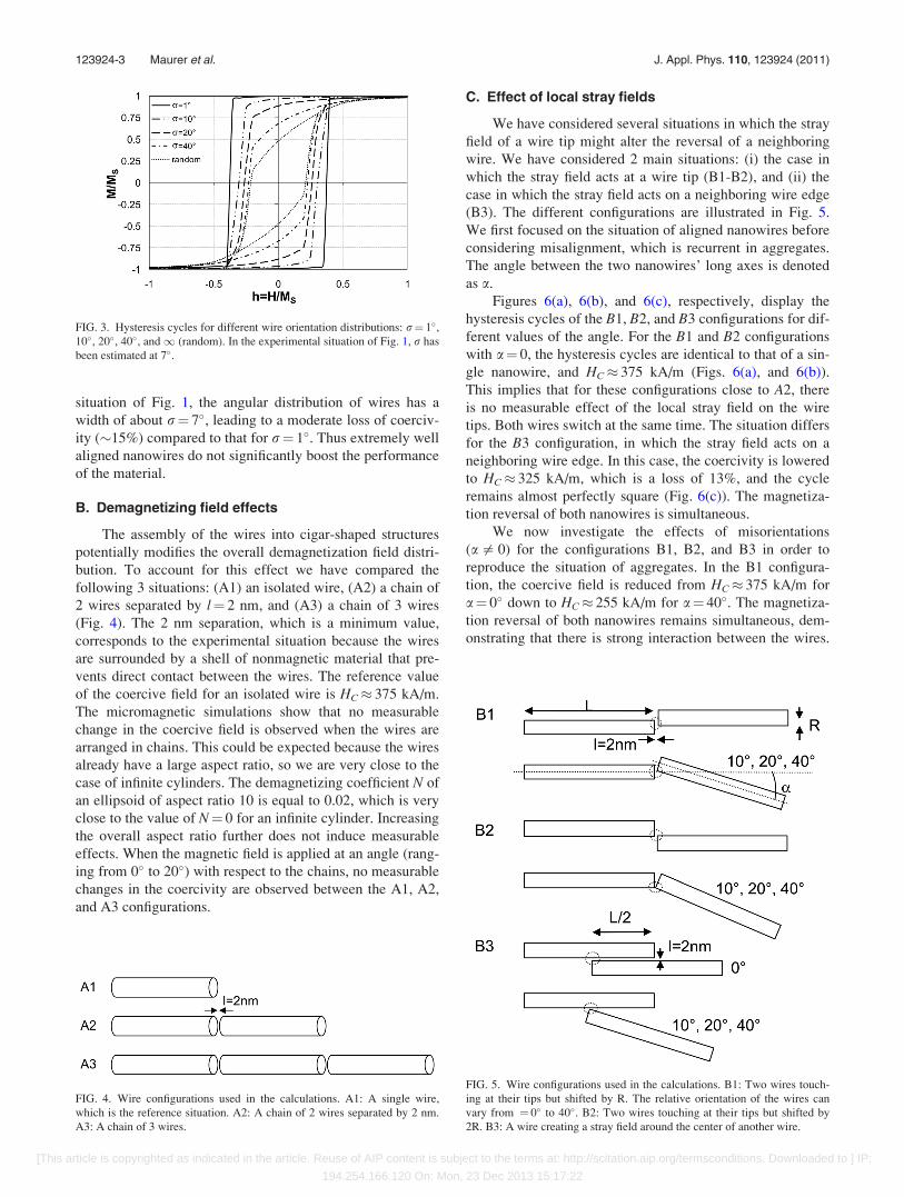
The assembly of the wires into cigar-shaped structures
potentially modifies the overall demagnetization field distri-
bution. To account for this effect we have compared the
following 3 situations: (A1) an isolated wire, (A2) a chain of
2 wires separated by l¼ 2 nm, and (A3) a chain of 3 wires
(Fig. 4). The 2 nm separation, which is a minimum value,
corresponds to the experimental situation because the wires
are surrounded by a shell of nonmagnetic material that pre-
vents direct contact between the wires. The reference value
of the coercive field for an isolated wire is HC� 375 kA/m.
The micromagnetic simulations show that no measurable
change in the coercive field is observed when the wires are
arranged in chains. This could be expected because the wires
already have a large aspect ratio, so we are very close to the
case of infinite cylinders. The demagnetizing coefficient N of
an ellipsoid of aspect ratio 10 is equal to 0.02, which is very
close to the value of N¼ 0 for an infinite cylinder. Increasing
the overall aspect ratio further does not induce measurable
effects. When the magnetic field is applied at an angle (rang-
ing from 0� to 20�) with respect to the chains, no measurable
changes in the coercivity are observed between the A1, A2,
and A3 configurations.
C. Effect of local stray fields
We have considered several situations in which the stray
field of a wire tip might alter the reversal of a neighboring
wire. We have considered 2 main situations: (i) the case in
which the stray field acts at a wire tip (B1-B2), and (ii) the
case in which the stray field acts on a neighboring wire edge
(B3). The different configurations are illustrated in Fig. 5.
We first focused on the situation of aligned nanowires before
considering misalignment, which is recurrent in aggregates.
The angle between the two nanowires’ long axes is denoted
as a.
Figures 6(a), 6(b), and 6(c), respectively, display the
hysteresis cycles of the B1, B2, and B3 configurations for dif-
ferent values of the angle. For the B1 and B2 configurations
with a¼ 0, the hysteresis cycles are identical to that of a sin-
gle nanowire, and HC� 375 kA/m (Figs. 6(a), and 6(b)).
This implies that for these configurations close to A2, there
is no measurable effect of the local stray field on the wire
tips. Both wires switch at the same time. The situation differs
for the B3 configuration, in which the stray field acts on a
neighboring wire edge. In this case, the coercivity is lowered
to HC� 325 kA/m, which is a loss of 13%, and the cycle
remains almost perfectly square (Fig. 6(c)). The magnetiza-
tion reversal of both nanowires is simultaneous.
We now investigate the effects of misorientations
(a= 0) for the configurations B1, B2, and B3 in order to
reproduce the situation of aggregates. In the B1 configura-
tion, the coercive field is reduced from HC� 375 kA/m for
a¼ 0� down to HC� 255 kA/m for a¼ 40�. The magnetiza-
tion reversal of both nanowires remains simultaneous, dem-
onstrating that there is strong interaction between the wires.
FIG. 3. Hysteresis cycles for different wire orientation distributions: r¼ 1�,10�, 20�, 40�, and1 (random). In the experimental situation of Fig. 1, r has
been estimated at 7�.
FIG. 4. Wire configurations used in the calculations. A1: A single wire,
which is the reference situation. A2: A chain of 2 wires separated by 2 nm.
A3: A chain of 3 wires.
FIG. 5. Wire configurations used in the calculations. B1: Two wires touch-
ing at their tips but shifted by R. The relative orientation of the wires can
vary from ¼ 0� to 40�. B2: Two wires touching at their tips but shifted by
2R. B3: A wire creating a stray field around the center of another wire.
123924-3 Maurer et al. J. Appl. Phys. 110, 123924 (2011)
[This article is copyrighted as indicated in the article. Reuse of AIP content is subject to the terms at: http://scitation.aip.org/termsconditions. Downloaded to ] IP:
194.254.166.120 On: Mon, 23 Dec 2013 15:17:22

However, in the limiting case in which a¼ 90� (i.e., the
nanowires are perpendicular to each other), the coercive field
recovers somewhat to HC� 330 kA/m, but the two wires’
reversals are disconnected. The magnetization of the wire at
90� simply follows a linear dependence with respect to the
applied field.
The situation slightly differs in the B2 configurations;
the magnetization reversal of both nanowires is no longer si-
multaneous for a¼ 20� and 40�, showing that the interaction
between wire tips is very sensitive to geometrical details.
Furthermore, in the limiting case of a¼ 90�, the coercivity
almost recovers to the value of the isolated nanowire case,
suggesting that there are no more measurable interactions
between the wires.
The situation is qualitatively different in the B3 configu-
rations. Figure 6(c) shows that for a¼ 10�, 20�, or 40�, the
magnetization reversal of both nanowires is no longer simul-
taneous, and the coercivity of the aligned wires recovers to a
value of HC� 375 kA/m, corresponding to the case of an iso-
lated wire (A1). Surprisingly, this shows that neighboring
wires in the B3 configuration have measurable effects on the
coercive field only when they are parallel to their neighbors,
and as soon as there is a small misalignment, there are no
more interactions.
Finally, for perfectly aligned wires (a¼ 0), stray fields
lead to a moderate loss of coercivity (13%) only in the B3
configuration. Misalignment of the nanowires (a= 0) indu-
ces a significant loss of coercivity in the B1 and B2 configu-
rations, whereas stray field effects become negligible in the
B3 configuration. The dipolar interactions on the coercivity
are very sensitive to the geometrical arrangement of the
wires.
D. Effect of nanoscopic nucleation or pinning points
We now consider the case of nucleation or pinning
points created inside a cigar shaped micro-structure by wires
that have either a lower coercivity or a higher coercivity. In
the case of a wire with a geometrical defect—corked or with
3 endings, for example—the coercivity will be decreased.
On the other hand, one might imagine that some wires con-
tain structural defects that pin their magnetization. For the
micro-magnetic modeling, we have thus pinned the magnet-
ization M0 of one of the wires of the structure in a direction
along the nanowire long axis (Fig. 7 top). Starting from a
negative saturation field�Hsat, when arriving at remanence,
none of the wires has flipped except for the pinned one. This
pinned wire can thus be considered as a nucleation point that
will promote the reversal of neighboring wires when the field
is further increased. A loss of coercivity is expected. In con-
trast, starting from a positive saturation fieldþHsat, when
arriving at remanence, the magnetization of all the wires is
still parallel. When the field is further decreased, the pinnedFIG. 6. Hysteresis cycles of the (a) B1 configuration for a¼ 0�, 10�, 20�,40�, and 90�. (b) Hysteresis cycles of the B2 configuration for a¼ 0�, 10�,20�, 40�, and 90�. (c) Hysteresis cycles of the B3 configuration for a¼ 0�,10�, 20�, 40�, and 90�.
FIG. 7. (Color online) Various configurations of aggregated wires in which
the magnetization of one of the wire is pinned. C1: Chain of 3 wires. C2:
Staggered rows of wires. mx is the averaged magnetization (normalized to 1).
123924-4 Maurer et al. J. Appl. Phys. 110, 123924 (2011)
[This article is copyrighted as indicated in the article. Reuse of AIP content is subject to the terms at: http://scitation.aip.org/termsconditions. Downloaded to ] IP:
194.254.166.120 On: Mon, 23 Dec 2013 15:17:22

wire will not flip and will thus act as a pinning point. A slight
increase in coercivity is expected. Thus, in the calculated
hysteresis cycle, the effect of pinning can be observed on the
left-hand side, whereas on the right-hand side the effect of
nucleation is observed (see Fig. 7).
We performed micromagnetic simulations on various
configurations of aggregated wires. Let us discuss the two
situations illustrated in the geometries of Fig. 7 (top). In the
first case, we looked at the behavior of a row of 3 wires in
which the middle one has its magnetization pinned. The hys-
teresis cycles in Fig. 7 show the evolution of the magnetiza-
tion of the free wires. That is, we plot the average
magnetization (normalized to one) of all the wires except the
pinned one. The reference situation of an isolated wire is rep-
resented by the black dashed line. When the field is swept to
negative values, the coercive field of the wire chain is
unchanged with respect to the isolated wire; the pinned wire
has no effect. When sweeping the field to positive values, the
pinned wire acts as a strong nucleation point and induces a
40% drop of the coercive field with respect to an isolated
wire. The configuration C2 consists of 9 wires, of which one
is pinned. The reference situation (9 free wires) is plotted in
Fig. 7 as a solid gray line. The coercivity is 317 kA/m. In the
C2 configuration, when the field is swept to negative values,
the coercive field of the wires chain is unchanged. There is
only a small step appearing in the hysteresis cycle, which
corresponds to a stiffer reversal for wire 1 (see small sketch
of Fig. 7). We suggest that the different behavior of wires 1
and 2 is due to demagnetizing field effects. When sweeping
the field to positive values, the pinned wire acts as a strong
nucleation point and promotes a first reversal of wires 1 and
2 at a field 40% lower than the coercive field. The other
wires’ behavior is barely modified. The coercivity is slightly
increased, which can be accounted for by dipolar interactions
with the flipped row. Thus, in conclusion, a pinned wire
affects the behavior of its neighbor along a chain but not its
side neighbors.
IV. EXPERIMENTAL RESULTS
In order to probe the interactions in granular magnetic
materials, Henkel15 proposed comparing the isothermal re-
manent magnetization (IRM) and direct current demagnet-
ization (DCD) curves. The difference dm(H)¼ (2IRM(H)
�DCD(H))/IRM(1)� 1 is zero in the case of noninteracting
particles,23 positive for interactions promoting the magne-
tized state, and negative for interactions assisting magnetiza-
tion reversal. Note that we are measuring the DCD with an
initial negative saturation field that is opposite to the usual
convention, which results in the change of sign in the previ-
ous formula for the DCD contribution. We think that this
way of measuring the DCD is more natural, though.
We performed IRM and DCD measurements on aligned
Co nanowires deposited on a Si substrate (see Fig. 1). The
measurements were performed both parallel and perpendicu-
lar to the easy axis of the nanowire aggregates (Fig. 8). One
can notice that dm(H) is zero except in 2 small regions dur-
ing the reversal process. The dm(H) value is small (max
�� 14%) and negative, suggesting that only dipolar interac-
tions assisting reversal take place. This is in agreement with
the above calculations because it shows that (i) the formation
of aggregates does not stabilize the magnetic structures and
only extra nucleations can be induced by dipolar effects, and
(ii) these effects remain rather small even in very compact
structures with densities close to 1. No qualitative difference
is observed in the measurements along and perpendicular to
the easy axis. The fact that two small peaks are observed in
dm(H) during the reversal process suggests that different
mechanisms are taking place at the beginning and at the end
of the aggregate reversal. This needs to be investigated
further.
V. CONCLUSION AND PERSPECTIVES
We have investigated the role of magnetic dipolar interac-
tions between nanowires in aggregates via micromagnetic sim-
ulations. In the case of aggregates composed of perfectly
aligned nanowires, these simulations show that no major
change should be observed in the shape of the hysteresis cycles
or in the values of the coercivity and the remanence. In the
worst situation, a drop of 20% in the coercive field might be
observed. We underline that local dipolar interaction effects on
the coercivity are very sensitive to the detailed geometrical
arrangement of wires. As for the effect of nanowire misalign-
ment inside aggregates, we show that even very poor alignment
leads to only a 30% reduction in the coercive field. Using Hen-
kel plots, we have experimentally confirmed that dipolar effects
are indeed small in these aggregates of nanowires, or that at
least they do not significantly modify the magnetic behavior.
This validates the way of interpreting the experimental mag-
netic hysteresis cycles presented in Ref. 10.
It is striking that in dense aggregates of magnetic nano-
wires, dipolar interactions play a very limited role. We con-
clude that in dense materials based on magnetic nanowires, the
interactions between wires are negligible, and the optimization
FIG. 8. IRM, DCD, and Henkel plots measured on aligned Co wires in a
polymer matrix. The magnetic field was applied either parallel (top) or per-
pendicular (bottom) to the aggregate axis.
123924-5 Maurer et al. J. Appl. Phys. 110, 123924 (2011)
[This article is copyrighted as indicated in the article. Reuse of AIP content is subject to the terms at: http://scitation.aip.org/termsconditions. Downloaded to ] IP:
194.254.166.120 On: Mon, 23 Dec 2013 15:17:22

of the materials goes through the optimization of the properties
of individual wires.
ACKNOWLEDGMENTS
The authors gratefully acknowledge the Agence Natio-
nale de la Recherche for their financial support (project P-
Nano MAGAFIL). We thank J.B. Moussy (CEA-IRAMIS)
for his help with the magnetometry measurements.
1L. I. Mendelsohn, F. E. Luborsky, and T. O. Paine, J. Appl. Phys. 26, 1274
(1955).2R. B. Falk, J. Appl. Phys. 37, 1108 (1966).3D. J. Craik and R. Lane, Br. J. Appl. Phys. 18, 1269 (1967).4R. O’Handley, Modern Magnetic Materials, Principles and Applications(Wiley, New York, 2000), p. 480.
5D. Ung, G. Viau, C. Ricolleau, F. Warmont, P. Gredin, and F. Fievet, Adv.
Mater. 17, 338 (2005).6D. Ung, Y. Soumare, N. Chakroune, G. Viau, M.-J. Vaulay, V. Richard,
and F. Fievet, Chem. Mater. 19, 2084 (2007).7Y. Soumare, J.-Y. Piquemal, T. Maurer, F. Ott, G. Chaboussant, A. Falqui,
and G. Viau, J. Mater. Chem. 18, 5696 (2008).8Y. Soumare, C. Garcia, T. Maurer, G. Chaboussant, F. Ott, F. Fievet, J.-Y.
Piquemal, and G. Viau, Adv. Funct. Mater. 19, 1 (2009).
9K. Soulantica, F. Wetz, J. Maynadie, A. Falqui, R. P. Tan, T. Blon,
B. Chaudret, and M. Respaud, Appl. Phys. Lett. 95, 152504 (2009).10T. Maurer, F. Ott, G. Chaboussant, Y. Soumare, J.-Y. Piquemal, and
G. Viau, Appl. Phys. Lett. 91, 172501 (2007).11A. Encinas-Oropesa, M. Demand, L. Piraux, I. Huynen, and U. Ebels,
Phys. Rev. B 63, 104415 (2001).12F. Zighem, T. Maurer, F. Ott, and G. Chaboussant, J. Appl. Phys. 109,
013910 (2011).13K. Nielsch, R. B. Wehrspohn, J. Barthel, J. Kirschner, U. Gosele, S. F.
Fischer, and H. Kronmuller, Appl. Phys. Lett. 79, 1360 (2001).14A. N. Dobrynin, V. M. T. S. Barthem, and D. Givord, Appl. Phys. Lett. 95,
052511 (2009).15O. Henkel, Phys. Status Solidi 7, 919 (1964).16J. Garcia-Otero, M. Porto, and J. Rivas, J. Appl. Phys. 87, 7376 (2000).17F. Ott, T. Maurer, G. Chaboussant, Y. Soumare, J.-Y. Piquemal, and
G. Viau, J. Appl. Phys. 105, 013915 (2009).18T. Maurer, F. Zighem, F. Ott, G. Chaboussant, G. Andre, Y. Soumare,
J. Y. Piquemal, G. Viau, and C. Gatel, Phys. Rev. B 80, 064427
(2009).19D. C. Meeker, Finite Element Method Magnetics, http://www.femm.info.20P. E. Tannenwald and R. Weber, Phys. Rev. 121, 715 (1961).21T. Fischbacher, M. Franchin, G. Bordignon, and H. Fangohr, IEEE Trans.
Magn. 43, 2896 (2007).22NETGEN, See http://www.hpfem.jku.at/netgen/ for information about the
mesh generator.23E. P. Wohlfarth, J. Appl. Phys. 29, 595 (1958).
123924-6 Maurer et al. J. Appl. Phys. 110, 123924 (2011)
[This article is copyrighted as indicated in the article. Reuse of AIP content is subject to the terms at: http://scitation.aip.org/termsconditions. Downloaded to ] IP:
194.254.166.120 On: Mon, 23 Dec 2013 15:17:22
Copyright © 2022 FDOKUMEN