Size-dependent Ultrahigh Electrocaloric Effect near Pseudo-First-Order Phase Transition Temperature...
9
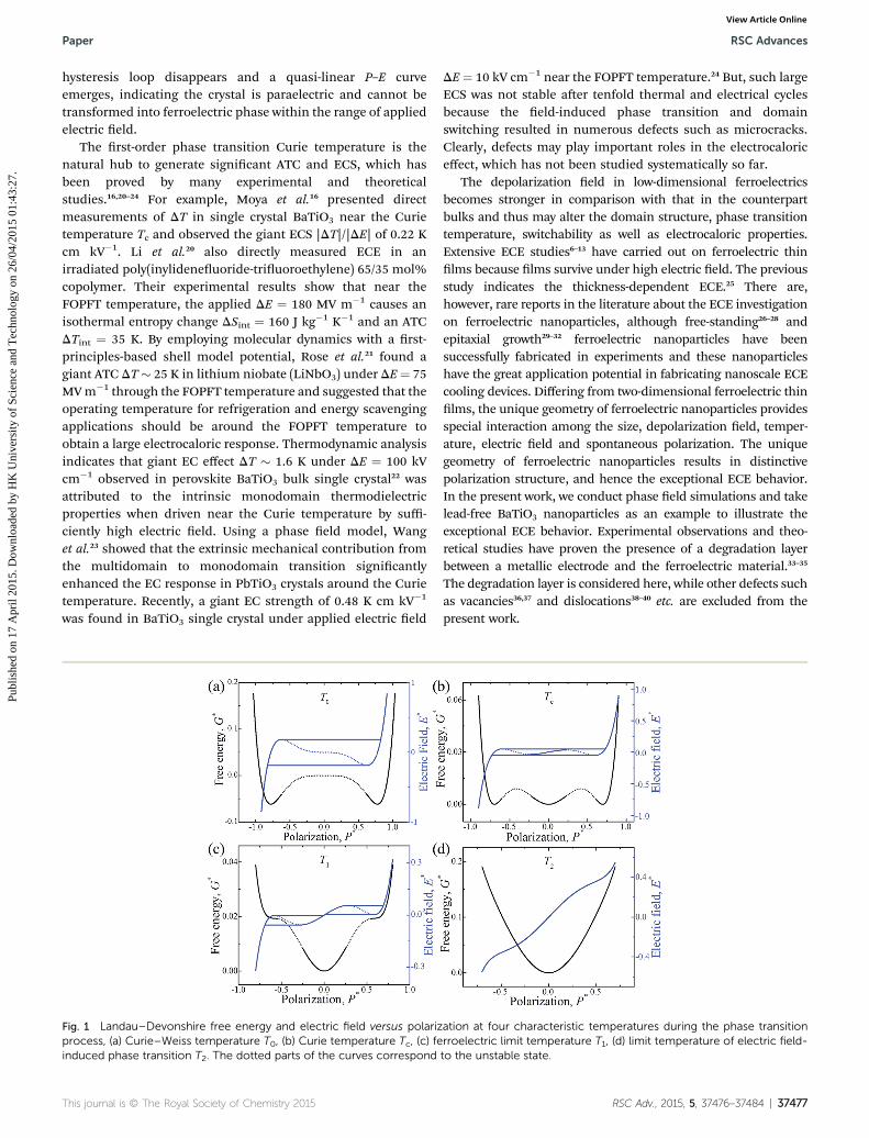
Size-dependent ultrahigh electrocaloric effect near pseudo-first-order phase transition temperature in barium titanate nanoparticles Hong-Hui Wu, Jiaming Zhu and Tong-Yi Zhang * The electrocaloric effect (ECE) of ferroelectric materials, which occurs significantly in a narrow temperature region near the first-order paraelectric/ferroelectric transition (FOPFT) Curie temperature, has great potential in solid-state refrigeration. Most ferroelectric materials, however, bear the second-order paraelectric/ferroelectric transition (SOPFT). In the present study, we demonstrate a size-dependent pseudo-first-order phase transition (PFOPT), associated with ultrahigh ECE and Curie temperature in ferroelectric nanoparticles with degradation layers by employing phase field modeling. The PFOPT behavior of the polarization component P 3 along the applied electric field direction x 3 versus temperature is similar to the classical FOPFT behavior. The results indicate that the ultrahigh ECE and PFOPT occur at temperatures below the Curie temperature of a given nanoparticle size. The adiabatic temperature change is 3.347 K in the simulated barium titanate nanoparticle of 10 10 8 normalized size under a 96.502 kV cm 1 applied electric field change. The concept of PFOPT should be general, applicable to all ferroelectric perovskite materials. Therefore, the current results provide a novel physical perspective for experiments and for lower power/higher efficiency solid-state cooling devices. 1. Introduction The electrocaloric (EC) effect, which refers to the change in adiabatic temperature of a ferroelectric by varying an applied electric eld, in ferroelectric materials has attracted widespread interest due to the prospect of a novel approach to realize solid- state cooling devices instead of the existing vapor-compression refrigeration. 1–5 Although bulk ferroelectric (FE) ceramics at low electric elds produced only small changes in adiabatic temperature (DT < 2 K) at temperatures near the Curie temperature T c , an adiabatic temperature change (ATC) of DT ¼ 12 K was observed under applied 776 kV cm 1 at 226 C in a 350 nm PbZr 0.95 Ti 0.05 O 3 thin lm prepared by a sol–gel method, 6 and an ATC of 5 K in a 260 nm thick relaxor ferroelectric thin lm 7 0.9PbMg 1/3 Nb 2/3 O 3 –0.1PbTiO 3 (PMN–PT) at 895 kV cm 1 and 75 C. Aer that, the large EC effect has been observed in other ferroelectric and antiferroelectric systems, relaxor and polymer lms. 8–13 The ATC in ferroelectric thin lms is greatly enhanced by varying electric eld from zero to ultrahigh elds of hundreds kV cm 1 due to the enhanced breakdown strengths of the materials in thin lms compared to their bulk counter- parts, whereas the associated electrocaloric strength (ECS) |DT|/ |DE| is even lower than that of the bulk counterparts. 14–16 The ECE of ferroelectrics intrinsically stems from the temperature dependence of polarization, an applied electric eld can change the temperature of an electrocaloric material under adiabatic condition, and the effect becomes strongest near the FOPFT point. In principle, Landau–Devonshire theory describes the thermodynamic behaviors of ferroelectric materials including FOPFT and the free energy as a function of polarization and the relationship between electric eld and polarization at various temperatures. 17,18 As a typical example, Fig. 1 plots the one- dimensional Landau–Devonshire free energy and electric eld versus polarization at four characteristic temperatures during the phase transition process, i.e. Curie–Weiss temperature T 0 , Curie temperature T c , ferroelectric limit temperature T 1 and limit temperature of electric eld-induced phase transition T 2 , where the BaTiO 3 material properties are used 19 and the dotted parts of the curves correspond to the unstable state. At the Curie–Weiss temperature T 0 shown in Fig. 1(a), the regular polarization versus electric eld (P–E) hysteresis loop appears as the consequence of the double-wells-free energy prole. When the temperature increases to the Curie temperature T c , the three-wells-function of Landau–Devonshire free energy leads to the critical P–E hysteresis loop amid regular shape and a double-hysteresis loop, as shown in Fig. 1(b). At the ferroelectric limit temperature T 1 shown in Fig. 1(c), the double-hysteresis loop occurs with the unequal three-wells-free energy function. This double-hysteresis loop originates from a typical electric- eld-induced phase transition from paraelectric phase to ferroelectric phase. At the limit temperature of eld-induced phase transition T 2 , as shown in Fig. 1(d), the double- Department of Mechanical and Aerospace Engineering, Hong Kong University of Science and Technology, Clear Water Bay, Kowloon, Hong Kong, China. E-mail: [email protected]; Fax: +852 2358 1543; Tel: +852 2358 7192 Cite this: RSC Adv. , 2015, 5, 37476 Received 21st March 2015 Accepted 16th April 2015 DOI: 10.1039/c5ra05008a www.rsc.org/advances 37476 | RSC Adv. , 2015, 5, 37476–37484 This journal is © The Royal Society of Chemistry 2015 RSC Advances PAPER View Article Online View Journal | View Issue
Transcript of Size-dependent Ultrahigh Electrocaloric Effect near Pseudo-First-Order Phase Transition Temperature...
RSC Advances
PAPER View Article OnlineView Journal | View Issue
Size-dependent u
Department of Mechanical and Aerospace
Science and Technology, Clear Water Bay
[email protected]; Fax: +852 2358 1543; Te
Cite this: RSC Adv., 2015, 5, 37476
Received 21st March 2015Accepted 16th April 2015
DOI: 10.1039/c5ra05008a
www.rsc.org/advances
37476 | RSC Adv., 2015, 5, 37476–3748
ltrahigh electrocaloric effect nearpseudo-first-order phase transition temperature inbarium titanate nanoparticles
Hong-Hui Wu, Jiaming Zhu and Tong-Yi Zhang*
The electrocaloric effect (ECE) of ferroelectric materials, which occurs significantly in a narrow temperature
region near the first-order paraelectric/ferroelectric transition (FOPFT) Curie temperature, has great
potential in solid-state refrigeration. Most ferroelectric materials, however, bear the second-order
paraelectric/ferroelectric transition (SOPFT). In the present study, we demonstrate a size-dependent
pseudo-first-order phase transition (PFOPT), associated with ultrahigh ECE and Curie temperature in
ferroelectric nanoparticles with degradation layers by employing phase field modeling. The PFOPT
behavior of the polarization component P3 along the applied electric field direction x3 versus
temperature is similar to the classical FOPFT behavior. The results indicate that the ultrahigh ECE and
PFOPT occur at temperatures below the Curie temperature of a given nanoparticle size. The adiabatic
temperature change is 3.347 K in the simulated barium titanate nanoparticle of 10 � 10 � 8 normalized
size under a 96.502 kV cm�1 applied electric field change. The concept of PFOPT should be general,
applicable to all ferroelectric perovskite materials. Therefore, the current results provide a novel physical
perspective for experiments and for lower power/higher efficiency solid-state cooling devices.
1. Introduction
The electrocaloric (EC) effect, which refers to the change inadiabatic temperature of a ferroelectric by varying an appliedelectric eld, in ferroelectric materials has attracted widespreadinterest due to the prospect of a novel approach to realize solid-state cooling devices instead of the existing vapor-compressionrefrigeration.1–5 Although bulk ferroelectric (FE) ceramics at lowelectric elds produced only small changes in adiabatictemperature (DT < 2 K) at temperatures near the Curietemperature Tc, an adiabatic temperature change (ATC) of DT¼12 K was observed under applied 776 kV cm�1 at 226 �C in a 350nm PbZr0.95Ti0.05O3 thin lm prepared by a sol–gel method,6
and an ATC of 5 K in a 260 nm thick relaxor ferroelectric thinlm7 0.9PbMg1/3Nb2/3O3–0.1PbTiO3 (PMN–PT) at 895 kV cm�1
and 75 �C. Aer that, the large EC effect has been observed inother ferroelectric and antiferroelectric systems, relaxor andpolymer lms.8–13 The ATC in ferroelectric thin lms is greatlyenhanced by varying electric eld from zero to ultrahigh eldsof hundreds kV cm�1 due to the enhanced breakdown strengthsof the materials in thin lms compared to their bulk counter-parts, whereas the associated electrocaloric strength (ECS) |DT|/|DE| is even lower than that of the bulk counterparts.14–16 TheECE of ferroelectrics intrinsically stems from the temperature
Engineering, Hong Kong University of
, Kowloon, Hong Kong, China. E-mail:
l: +852 2358 7192
4
dependence of polarization, an applied electric eld can changethe temperature of an electrocaloric material under adiabaticcondition, and the effect becomes strongest near the FOPFTpoint. In principle, Landau–Devonshire theory describes thethermodynamic behaviors of ferroelectric materials includingFOPFT and the free energy as a function of polarization and therelationship between electric eld and polarization at varioustemperatures.17,18 As a typical example, Fig. 1 plots the one-dimensional Landau–Devonshire free energy and electric eldversus polarization at four characteristic temperatures duringthe phase transition process, i.e. Curie–Weiss temperature T0,Curie temperature Tc, ferroelectric limit temperature T1 andlimit temperature of electric eld-induced phase transition T2,where the BaTiO3 material properties are used19 and the dottedparts of the curves correspond to the unstable state. At theCurie–Weiss temperature T0 shown in Fig. 1(a), the regularpolarization versus electric eld (P–E) hysteresis loop appears asthe consequence of the double-wells-free energy prole. Whenthe temperature increases to the Curie temperature Tc, thethree-wells-function of Landau–Devonshire free energy leads tothe critical P–E hysteresis loop amid regular shape and adouble-hysteresis loop, as shown in Fig. 1(b). At the ferroelectriclimit temperature T1 shown in Fig. 1(c), the double-hysteresisloop occurs with the unequal three-wells-free energy function.This double-hysteresis loop originates from a typical electric-eld-induced phase transition from paraelectric phase toferroelectric phase. At the limit temperature of eld-inducedphase transition T2, as shown in Fig. 1(d), the double-
This journal is © The Royal Society of Chemistry 2015
Paper RSC Advances
Publ
ishe
d on
17
Apr
il 20
15. D
ownl
oade
d by
HK
Uni
vers
ity o
f Sc
ienc
e an
d T
echn
olog
y on
26/
04/2
015
01:4
3:27
. View Article Online
hysteresis loop disappears and a quasi-linear P–E curveemerges, indicating the crystal is paraelectric and cannot betransformed into ferroelectric phase within the range of appliedelectric eld.
The rst-order phase transition Curie temperature is thenatural hub to generate signicant ATC and ECS, which hasbeen proved by many experimental and theoreticalstudies.16,20–24 For example, Moya et al.16 presented directmeasurements of DT in single crystal BaTiO3 near the Curietemperature Tc and observed the giant ECS |DT|/|DE| of 0.22 Kcm kV�1. Li et al.20 also directly measured ECE in anirradiated poly(inylideneuoride-triuoroethylene) 65/35 mol%copolymer. Their experimental results show that near theFOPFT temperature, the applied DE ¼ 180 MV m�1 causes anisothermal entropy change DSint ¼ 160 J kg�1 K�1 and an ATCDTint ¼ 35 K. By employing molecular dynamics with a rst-principles-based shell model potential, Rose et al.21 found agiant ATC DT� 25 K in lithium niobate (LiNbO3) under DE¼ 75MVm�1 through the FOPFT temperature and suggested that theoperating temperature for refrigeration and energy scavengingapplications should be around the FOPFT temperature toobtain a large electrocaloric response. Thermodynamic analysisindicates that giant EC effect DT � 1.6 K under DE ¼ 100 kVcm�1 observed in perovskite BaTiO3 bulk single crystal22 wasattributed to the intrinsic monodomain thermodielectricproperties when driven near the Curie temperature by suffi-ciently high electric eld. Using a phase eld model, Wanget al.23 showed that the extrinsic mechanical contribution fromthe multidomain to monodomain transition signicantlyenhanced the EC response in PbTiO3 crystals around the Curietemperature. Recently, a giant EC strength of 0.48 K cm kV�1
was found in BaTiO3 single crystal under applied electric eld
Fig. 1 Landau–Devonshire free energy and electric field versus polarizprocess, (a) Curie–Weiss temperature T0, (b) Curie temperature Tc, (c) feinduced phase transition T2. The dotted parts of the curves correspond
This journal is © The Royal Society of Chemistry 2015
DE¼ 10 kV cm�1 near the FOPFT temperature.24 But, such largeECS was not stable aer tenfold thermal and electrical cyclesbecause the eld-induced phase transition and domainswitching resulted in numerous defects such as microcracks.Clearly, defects may play important roles in the electrocaloriceffect, which has not been studied systematically so far.
The depolarization eld in low-dimensional ferroelectricsbecomes stronger in comparison with that in the counterpartbulks and thus may alter the domain structure, phase transitiontemperature, switchability as well as electrocaloric properties.Extensive ECE studies6–13 have carried out on ferroelectric thinlms because lms survive under high electric eld. The previousstudy indicates the thickness-dependent ECE.25 There are,however, rare reports in the literature about the ECE investigationon ferroelectric nanoparticles, although free-standing26–28 andepitaxial growth29–32 ferroelectric nanoparticles have beensuccessfully fabricated in experiments and these nanoparticleshave the great application potential in fabricating nanoscale ECEcooling devices. Differing from two-dimensional ferroelectric thinlms, the unique geometry of ferroelectric nanoparticles providesspecial interaction among the size, depolarization eld, temper-ature, electric eld and spontaneous polarization. The uniquegeometry of ferroelectric nanoparticles results in distinctivepolarization structure, and hence the exceptional ECE behavior.In the present work, we conduct phase eld simulations and takelead-free BaTiO3 nanoparticles as an example to illustrate theexceptional ECE behavior. Experimental observations and theo-retical studies have proven the presence of a degradation layerbetween a metallic electrode and the ferroelectric material.33–35
The degradation layer is considered here, while other defects suchas vacancies36,37 and dislocations38–40 etc. are excluded from thepresent work.
ation at four characteristic temperatures during the phase transitionrroelectric limit temperature T1, (d) limit temperature of electric field-to the unstable state.
RSC Adv., 2015, 5, 37476–37484 | 37477
RSC Advances Paper
Publ
ishe
d on
17
Apr
il 20
15. D
ownl
oade
d by
HK
Uni
vers
ity o
f Sc
ienc
e an
d T
echn
olog
y on
26/
04/2
015
01:4
3:27
. View Article Online
2. Methodology
Polarization P¼ (P1, P2, P3) is used as the order parameter in theGinzburg–Landau–Devonshire theory based phase eld simu-lations. The phase transition and domain evolution are a directconsequence of the minimization process of the total freeenergy over the whole system. The total free energy of ferro-electrics is obtained by integrating an electrical enthalpydensity over the whole system,41,42
F ¼ðU
f dV (1)
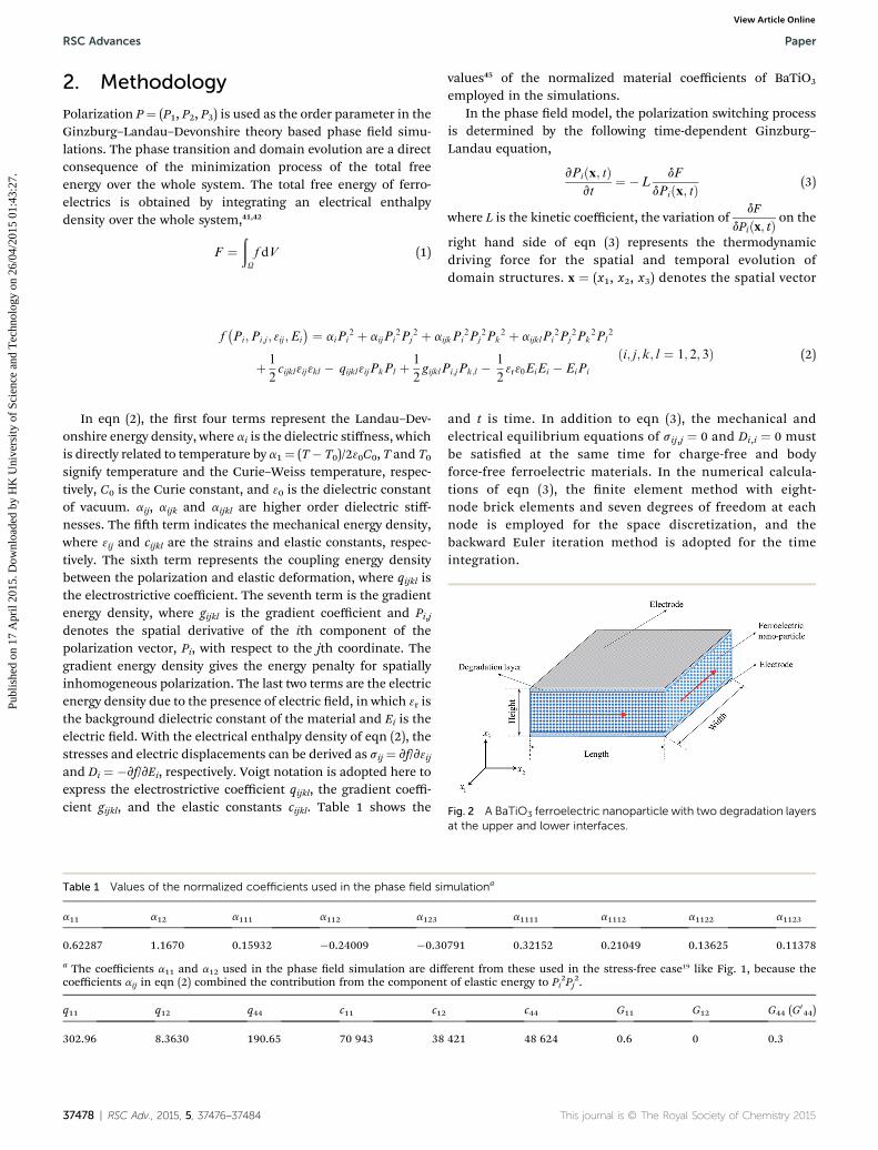
Fig. 2 A BaTiO3 ferroelectric nanoparticle with two degradation layers
f�Pi;Pi;j ; 3ij ;Ei
� ¼ aiPi2 þ aijPi
2Pj2 þ aijkPi
2Pj2Pk
2 þ aijklPi2Pj
2Pk2Pl
2
þ 1
2cijkl3ij3kl � qijkl3ijPkPl þ 1
2gijklPi;jPk;l � 1
23r30EiEi � EiPi
ði; j; k; l ¼ 1; 2; 3Þ (2)
In eqn (2), the rst four terms represent the Landau–Dev-onshire energy density, where ai is the dielectric stiffness, whichis directly related to temperature by a1¼ (T� T0)/230C0, T and T0signify temperature and the Curie–Weiss temperature, respec-tively, C0 is the Curie constant, and 30 is the dielectric constantof vacuum. aij, aijk and aijkl are higher order dielectric stiff-nesses. The h term indicates the mechanical energy density,where 3ij and cijkl are the strains and elastic constants, respec-tively. The sixth term represents the coupling energy densitybetween the polarization and elastic deformation, where qijkl isthe electrostrictive coefficient. The seventh term is the gradientenergy density, where gijkl is the gradient coefficient and Pi,jdenotes the spatial derivative of the ith component of thepolarization vector, Pi, with respect to the jth coordinate. Thegradient energy density gives the energy penalty for spatiallyinhomogeneous polarization. The last two terms are the electricenergy density due to the presence of electric eld, in which 3r isthe background dielectric constant of the material and Ei is theelectric eld. With the electrical enthalpy density of eqn (2), thestresses and electric displacements can be derived as sij¼ vf/v3ijand Di ¼ �vf/vEi, respectively. Voigt notation is adopted here toexpress the electrostrictive coefficient qijkl, the gradient coeffi-cient gijkl, and the elastic constants cijkl. Table 1 shows the
Table 1 Values of the normalized coefficients used in the phase field sim
a11 a12 a111 a112 a123
0.62287 1.1670 0.15932 �0.24009 �0.30
a The coefficients a11 and a12 used in the phase eld simulation are diffcoefficients aij in eqn (2) combined the contribution from the componen
q11 q12 q44 c11 c12
302.96 8.3630 190.65 70 943 38
37478 | RSC Adv., 2015, 5, 37476–37484
values45 of the normalized material coefficients of BaTiO3
employed in the simulations.In the phase eld model, the polarization switching process
is determined by the following time-dependent Ginzburg–Landau equation,
vPiðx; tÞvt
¼ �LdF
dPiðx; tÞ (3)
where L is the kinetic coefficient, the variation ofdF
dPiðx; tÞ on the
right hand side of eqn (3) represents the thermodynamicdriving force for the spatial and temporal evolution ofdomain structures. x ¼ (x1, x2, x3) denotes the spatial vector
and t is time. In addition to eqn (3), the mechanical andelectrical equilibrium equations of sij,j ¼ 0 and Di,i ¼ 0 mustbe satised at the same time for charge-free and bodyforce-free ferroelectric materials. In the numerical calcula-tions of eqn (3), the nite element method with eight-node brick elements and seven degrees of freedom at eachnode is employed for the space discretization, and thebackward Euler iteration method is adopted for the timeintegration.
ulationa
a1111 a1112 a1122 a1123
791 0.32152 0.21049 0.13625 0.11378
erent from these used in the stress-free case19 like Fig. 1, because thet of elastic energy to Pi
2Pj2.
c44 G11 G12 G44 (G044)
421 48 624 0.6 0 0.3
at the upper and lower interfaces.
This journal is © The Royal Society of Chemistry 2015
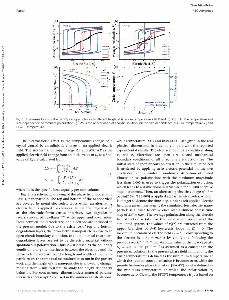
Fig. 3 Hysteresis loops of the BaTiO3 nanoparticles with different height at (a) room temperature 298 K and (b) 331 K, (c) the temperature andsize dependence of remnant polarization Pr,*3 , AS is the abbreviation of analytic solution, (d) the size dependence of Curie temperature Tc andPFOPT temperature.
Paper RSC Advances
Publ
ishe
d on
17
Apr
il 20
15. D
ownl
oade
d by
HK
Uni
vers
ity o
f Sc
ienc
e an
d T
echn
olog
y on
26/
04/2
015
01:4
3:27
. View Article Online
The electrocaloric effect is the temperature change of acrystal caused by an adiabatic change in an applied electriceld. The isothermal entropy change DS and ATC DT as theapplied electric eld change from an initial value of Ea to a nalvalue of Eb are calculated from,1
DS ¼ �ðEb
Ea
�vPi
vT
�Ei
dEi
DT ¼ �ðEb
Ea
T
Cr
�vPi
vT
�Ei
dEi
(4)
where Cr is the specic heat capacity per unit volume.Fig. 2 is a schematic drawing of the phase eld model for a
BaTiO3 nanoparticle. The top and bottom of the nanoparticleare covered by metal electrodes, cross which an alternatingelectric eld is applied. To consider the material degradationat the electrode–ferroelectrics interface, two degradationlayers also called deadlayer33–35 at the upper and lower inter-faces between the ferroelectric and electrode are included inthe present model, due to the existence of top and bottomdegradation layers, the ferroelectric nanoparticle is close to anopen-circuit boundary condition. In the numerical treatment,degradation layers are set to be dielectric material withoutspontaneous polarization. Thus P ¼ 0 is used as the boundarycondition along the interfaces between the electrode and theferroelectric nanoparticle. The length and width of the nano-particles are the same and maintained at 10 nm in the presentwork and the height of the nanoparticles is allowed to change,ranging from 2 nm to 8 nm, to study the height dependentbehavior. For convenience, dimensionless material parame-ters with superscript * are used in the numerical calculations,
This journal is © The Royal Society of Chemistry 2015
while temperature, ATC and instant ECS are given in the realphysical dimensions in order to compare with the reportedexperimental results. The electrical boundary condition alongx1 and x2 directions are open circuit, and mechanicalboundary conditions of all directions are traction-free. Theinitial state of spontaneous polarization in the simulated cellis achieved by applying zero electric potential on the twoelectrodes, and a uniform random distribution of initialdimensionless polarizations with the maximum magnitudeless than 0.005 is used to trigger the polarization evolution,which leads to a stable domain structure aer 50 000 adaptivestep increments. Then, an alternating electric voltage 4ex,* ¼4*0 sin(2.5ps/125 000) is applied across the electrodes, where s
is integer to denote the time step. Under each applied electriceld at a given time step s, the simulated ferroelectric nano-particle is allowed to evolve once with a dimensionless timestep of Dt* ¼ 0.04. The average polarization along the electriceld direction is taken as the macroscopic response of thesimulated system. The values of P*
3(T) are extracted from theupper branches of P–E hysteresis loops in E*
3 > 0. Themaximum normalized electric eld E*
3 ¼ 1.0, corresponding tothe electric eld E3 ¼ 96.502 kV cm�1, and following theprevious work,6,22,35,43,44 the absolute value of the heat capacityCr ¼ 3.05 � 106 JK�1 m�3 is assumed as a constant in thepresent calculation. In the present phase eld simulations, theCurie temperature is dened as the minimum temperature atwhich the spontaneous polarization P becomes zero, while thepseudo rst-order phase transition (PFOPT) point is dened asthe minimum temperature at which the polarization P3becomes zero. Clearly, the PFOPT temperature is just based on
RSC Adv., 2015, 5, 37476–37484 | 37479
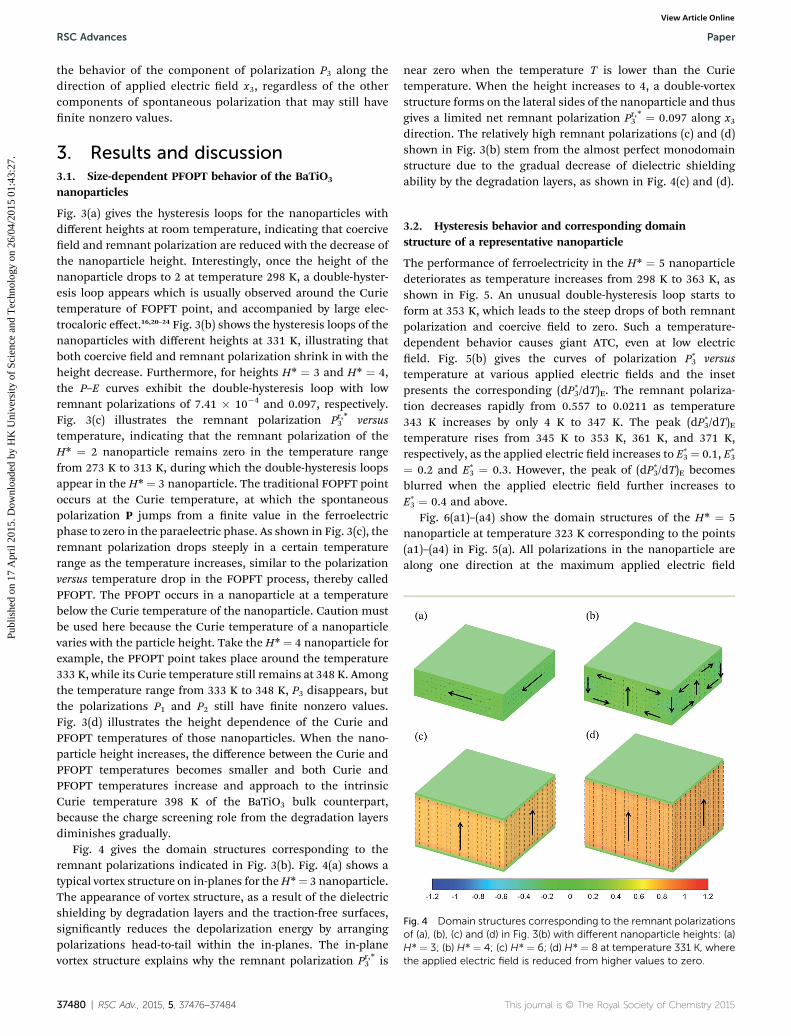
Fig. 4 Domain structures corresponding to the remnant polarizationsof (a), (b), (c) and (d) in Fig. 3(b) with different nanoparticle heights: (a)H* ¼ 3; (b) H* ¼ 4; (c) H* ¼ 6; (d) H* ¼ 8 at temperature 331 K, wherethe applied electric field is reduced from higher values to zero.
RSC Advances Paper
Publ
ishe
d on
17
Apr
il 20
15. D
ownl
oade
d by
HK
Uni
vers
ity o
f Sc
ienc
e an
d T
echn
olog
y on
26/
04/2
015
01:4
3:27
. View Article Online
the behavior of the component of polarization P3 along thedirection of applied electric eld x3, regardless of the othercomponents of spontaneous polarization that may still havenite nonzero values.
3. Results and discussion3.1. Size-dependent PFOPT behavior of the BaTiO3
nanoparticles
Fig. 3(a) gives the hysteresis loops for the nanoparticles withdifferent heights at room temperature, indicating that coerciveeld and remnant polarization are reduced with the decrease ofthe nanoparticle height. Interestingly, once the height of thenanoparticle drops to 2 at temperature 298 K, a double-hyster-esis loop appears which is usually observed around the Curietemperature of FOPFT point, and accompanied by large elec-trocaloric effect.16,20–24 Fig. 3(b) shows the hysteresis loops of thenanoparticles with different heights at 331 K, illustrating thatboth coercive eld and remnant polarization shrink in with theheight decrease. Furthermore, for heights H* ¼ 3 and H* ¼ 4,the P–E curves exhibit the double-hysteresis loop with lowremnant polarizations of 7.41 � 10�4 and 0.097, respectively.Fig. 3(c) illustrates the remnant polarization Pr,*3 versustemperature, indicating that the remnant polarization of theH* ¼ 2 nanoparticle remains zero in the temperature rangefrom 273 K to 313 K, during which the double-hysteresis loopsappear in the H* ¼ 3 nanoparticle. The traditional FOPFT pointoccurs at the Curie temperature, at which the spontaneouspolarization P jumps from a nite value in the ferroelectricphase to zero in the paraelectric phase. As shown in Fig. 3(c), theremnant polarization drops steeply in a certain temperaturerange as the temperature increases, similar to the polarizationversus temperature drop in the FOPFT process, thereby calledPFOPT. The PFOPT occurs in a nanoparticle at a temperaturebelow the Curie temperature of the nanoparticle. Caution mustbe used here because the Curie temperature of a nanoparticlevaries with the particle height. Take the H* ¼ 4 nanoparticle forexample, the PFOPT point takes place around the temperature333 K, while its Curie temperature still remains at 348 K. Amongthe temperature range from 333 K to 348 K, P3 disappears, butthe polarizations P1 and P2 still have nite nonzero values.Fig. 3(d) illustrates the height dependence of the Curie andPFOPT temperatures of those nanoparticles. When the nano-particle height increases, the difference between the Curie andPFOPT temperatures becomes smaller and both Curie andPFOPT temperatures increase and approach to the intrinsicCurie temperature 398 K of the BaTiO3 bulk counterpart,because the charge screening role from the degradation layersdiminishes gradually.
Fig. 4 gives the domain structures corresponding to theremnant polarizations indicated in Fig. 3(b). Fig. 4(a) shows atypical vortex structure on in-planes for theH*¼ 3 nanoparticle.The appearance of vortex structure, as a result of the dielectricshielding by degradation layers and the traction-free surfaces,signicantly reduces the depolarization energy by arrangingpolarizations head-to-tail within the in-planes. The in-planevortex structure explains why the remnant polarization Pr,*3 is
37480 | RSC Adv., 2015, 5, 37476–37484
near zero when the temperature T is lower than the Curietemperature. When the height increases to 4, a double-vortexstructure forms on the lateral sides of the nanoparticle and thusgives a limited net remnant polarization Pr,*3 ¼ 0.097 along x3direction. The relatively high remnant polarizations (c) and (d)shown in Fig. 3(b) stem from the almost perfect monodomainstructure due to the gradual decrease of dielectric shieldingability by the degradation layers, as shown in Fig. 4(c) and (d).
3.2. Hysteresis behavior and corresponding domainstructure of a representative nanoparticle
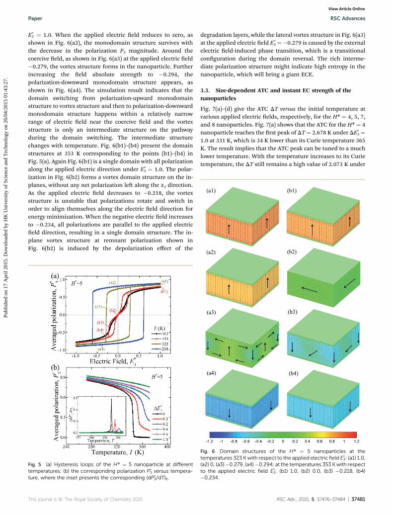
The performance of ferroelectricity in the H* ¼ 5 nanoparticledeteriorates as temperature increases from 298 K to 363 K, asshown in Fig. 5. An unusual double-hysteresis loop starts toform at 353 K, which leads to the steep drops of both remnantpolarization and coercive eld to zero. Such a temperature-dependent behavior causes giant ATC, even at low electriceld. Fig. 5(b) gives the curves of polarization P*
3 versustemperature at various applied electric elds and the insetpresents the corresponding (dP*
3/dT)E. The remnant polariza-tion decreases rapidly from 0.557 to 0.0211 as temperature343 K increases by only 4 K to 347 K. The peak (dP*
3/dT)Etemperature rises from 345 K to 353 K, 361 K, and 371 K,respectively, as the applied electric eld increases to E*
3 ¼ 0.1, E*3
¼ 0.2 and E*3 ¼ 0.3. However, the peak of (dP*
3/dT)E becomesblurred when the applied electric eld further increases toE*3 ¼ 0.4 and above.Fig. 6(a1)–(a4) show the domain structures of the H* ¼ 5
nanoparticle at temperature 323 K corresponding to the points(a1)–(a4) in Fig. 5(a). All polarizations in the nanoparticle arealong one direction at the maximum applied electric eld
This journal is © The Royal Society of Chemistry 2015
Paper RSC Advances
Publ
ishe
d on
17
Apr
il 20
15. D
ownl
oade
d by
HK
Uni
vers
ity o
f Sc
ienc
e an
d T
echn
olog
y on
26/
04/2
015
01:4
3:27
. View Article Online
E*3 ¼ 1.0. When the applied electric eld reduces to zero, as
shown in Fig. 6(a2), the monodomain structure survives withthe decrease in the polarization P3 magnitude. Around thecoercive eld, as shown in Fig. 6(a3) at the applied electric eld�0.279, the vortex structure forms in the nanoparticle. Furtherincreasing the eld absolute strength to �0.294, thepolarization-downward monodomain structure appears, asshown in Fig. 6(a4). The simulation result indicates that thedomain switching from polarization-upward monodomainstructure to vortex structure and then to polarization-downwardmonodomain structure happens within a relatively narrowrange of electric eld near the coercive eld and the vortexstructure is only an intermediate structure on the pathwayduring the domain switching. The intermediate structurechanges with temperature. Fig. 6(b1)–(b4) present the domainstructures at 353 K corresponding to the points (b1)–(b4) inFig. 5(a). Again Fig. 6(b1) is a single domain with all polarizationalong the applied electric direction under E*
3 ¼ 1.0. The polar-ization in Fig. 6(b2) forms a vortex domain structure on the in-planes, without any net polarization le along the x3 direction.As the applied electric eld decreases to �0.218, the vortexstructure is unstable that polarizations rotate and switch inorder to align themselves along the electric eld direction forenergy minimization. When the negative electric eld increasesto �0.234, all polarizations are parallel to the applied electriceld direction, resulting in a single domain structure. The in-plane vortex structure at remnant polarization shown inFig. 6(b2) is induced by the depolarization effect of the
Fig. 5 (a) Hysteresis loops of the H* ¼ 5 nanoparticle at differenttemperatures; (b) the corresponding polarization P*
3 versus tempera-ture, where the inset presents the corresponding (dP*
3/dT)E.
This journal is © The Royal Society of Chemistry 2015
degradation layers, while the lateral vortex structure in Fig. 6(a3)at the applied electric eld E*
3¼�0.279 is caused by the externalelectric eld-induced phase transition, which is a transitionalconguration during the domain reversal. The rich interme-diate polarization structure might indicate high entropy in thenanoparticle, which will bring a giant ECE.
3.3. Size-dependent ATC and instant EC strength of thenanoparticles
Fig. 7(a)–(d) give the ATC DT versus the initial temperature atvarious applied electric elds, respectively, for the H* ¼ 4, 5, 7,and 8 nanoparticles. Fig. 7(a) shows that the ATC for the H* ¼ 4nanoparticle reaches the rst peak of DT¼ 2.678 K under DE*
3 ¼1.0 at 331 K, which is 34 K lower than its Curie temperature 365K. The result implies that the ATC peak can be tuned to a muchlower temperature. With the temperature increases to its Curietemperature, the DT still remains a high value of 2.073 K under
Fig. 6 Domain structures of the H* ¼ 5 nanoparticles at thetemperatures 323 Kwith respect to the applied electric field E*
3: (a1) 1.0,(a2) 0, (a3)�0.279, (a4)�0.294; at the temperatures 353 K with respectto the applied electric field E*
3: (b1) 1.0, (b2) 0.0, (b3) �0.218, (b4)�0.234.
RSC Adv., 2015, 5, 37476–37484 | 37481

Fig. 7 ATC DT as a function of temperature and applied electric field of the nanoparticle height: (a) H* ¼ 4 (b) H* ¼ 5 (c) H* ¼ 7 (d) H* ¼ 8. Thedashed line corresponds to its Curie temperature.
RSC Advances Paper
Publ
ishe
d on
17
Apr
il 20
15. D
ownl
oade
d by
HK
Uni
vers
ity o
f Sc
ienc
e an
d T
echn
olog
y on
26/
04/2
015
01:4
3:27
. View Article Online
DE*3 ¼ 1.0. As expected, the ATC DT increase monotonically with
the increase of DE*3. The ATC DT in the H* ¼ 5 nanoparticle
shown in Fig. 7(b) is similar to that in Fig. 7(a), with the rstpeak value of DT ¼ 2.933 K under DE*
3 ¼ 1.0 at 346 K. Fig. 7(c)
Fig. 8 Instant EC strength (dT/dE*3)S as a function of temperature and ap
H* ¼ 7 (d) H* ¼ 8. The labels (a1)–(a4), (b1)–(b4), (c1)–(c4) and (d1)–(d4
37482 | RSC Adv., 2015, 5, 37476–37484
indicates the rst peak of DT ¼ 3.294 K in the H* ¼ 7 nano-particle at 363 K under DE*
3 ¼ 1.0, while Fig. 7(d) illustrates therst peak of DT ¼ 3.347 K in the H* ¼ 8 nanoparticle at 373 Kunder DE*
3 ¼ 1.0. The results clearly imply that a higher value of
plied electric field of the nanoparticle height: (a) H* ¼ 4 (b) H* ¼ 5 (c)) are shown to guide the understandings.
This journal is © The Royal Society of Chemistry 2015
Paper RSC Advances
Publ
ishe
d on
17
Apr
il 20
15. D
ownl
oade
d by
HK
Uni
vers
ity o
f Sc
ienc
e an
d T
echn
olog
y on
26/
04/2
015
01:4
3:27
. View Article Online
the height yields a higher value DT at a higher temperature. Thedegradation layers generate the depolarization effect on thesurfaces of the nanoparticles, which makes the generalizedpolarization along the x3 direction smaller. The higher theheight is, the weaker the depolarization effect and the higherthe generalized polarization along the x3 direction will be. Ahigher generalized polarization along the x3 direction has alarger capacity to change its magnitude by an applied electriceld, which in turn can produce a higher change in adiabatictemperature. For comparison, the intrinsic ATC of DT¼ 3.891 Kunder DE*
3 ¼ 1.0 in BaTiO3 bulk single crystal is calculated byphase eld simulation,46 which should be the saturation limitwith the further increase of the nanoparticle height. Despite theATC DT induced by the PFOPT is slightly smaller than theintrinsic ATC DT at FOPFT, the lower temperature of PFOPTmakes it competitive to the FOPFT. Besides, the PFOPT conceptcan be applied to the ferroelectric perovskite materials withoutthe rst-order paraelectric/ferroelectric transition and thus willgreatly promote the application of ferroelectric nanoparticles inthe next generation of solid-state cooling devices.
Obviously, a great change in applied electric eld achieves alarge ATC DT. But, too high applied electric eld brings twopotential problems. One is the high applied electric eld willcause large energy consumption and the other is the possibilityof dielectric breakdown of ferroelectric ceramic/thin lm/capacitor will be much higher. Therefore, the present ndingthat a change in relatively low electric eld can also achieve alarge ATC DT has considerably reduced or completely avoidedthe two potential problems. Fig. 8(a)–(d) show the instant ECSs(dT/dE*
3)S versus electric eld at different temperatures for thenanoparticles of H*¼ 4, 6, 7, and 8, respectively. At temperature298 K, the instant ECS (dT/dE*
3)S in the H* ¼ 4 nanoparticle isalmost zero at an applied electric eld E*
3 ranging from zero to1.0, as shown in Fig. 8(a), while at temperature 330 K, a peak of(dT/dE*
3)S¼ 0.743 K cm kV�1 occurs at E*3¼ 0.0157, as marked by
point (a2). As temperature further increases to T ¼ 343 K and T¼ 365 K, the peak values decreased to (dT/dE*
3)S ¼ 0.143 K cmkV�1 at point (a3) and (dT/dE*
3)S ¼ 0.0719 K cm kV�1 at point(a4), respectively, shiing to higher applied electric elds E*
3 ¼0.156 and 0.264. This result indicates that most efficient ATCelectric eld (or temperature) can be tuned by temperature (orelectric eld). The similar behavior of the instant ECS asdescribed above for the H* ¼ 4 nanoparticle is also observed forthe nanoparticles with H* ¼ 5, 7, and 8 with the rst peaks (b2),(c2) and (d2) shiing to higher temperatures of 345 K, 362 K,and 367 K, respectively. The exciting simulation result willprovide a clue to future ECE experiment.
4. Conclusions
In summary, the ECE in BaTiO3 nanoparticles with degradationlayers has been theoretically investigated by phase eld simu-lations. The simulation results exhibit the size dependentultrahigh electrocaloric effect occurring at temperatures lowerthan the Curie temperature of the nanoparticle. The PFOPT isdened based on the behavior of the polarization component P3along the applied electric eld direction x3 versus temperature
This journal is © The Royal Society of Chemistry 2015
under the charge screening of the degradation layers and thetraction-free boundary condition along the nanoparticlesurfaces. The double P–E hysteresis loops are accompanied withthe PFOPT, and large ATC and ultrahigh instant ECS are ach-ieved by a change in the applied electric eld near the PFOPTtemperature. The double-hysteresis loops are manifested by thedomain switching from upward monodomain structure tovortex domain structure to downward monodomain structure.The vortex domain structure possesses more entropy incompared to the monodomain structure, thereby giving anelectric eld induced isothermal entropy change. The simula-tions show also the interplay among the electric eld, temper-ature, nanoparticle height, and polarization. It is the interplaythat varies the most efficient ATC and instant ECS to occur atdifferent temperature, electric eld, and nanoparticle height.The present ndings imply that it is possible to accomplishengineering feasible ECE at relatively low electric eld, therebyleading to a new strategy to tailor ferroelectric materials and toimprove the electrocaloric properties.
Acknowledgements
This work was supported by the Hong Kong Research GrantsCouncil under the General Research Fund, 622813.
References
1 M. E. Lines and A. M. Glass, Principles and applications offerroelectrics and related materials, Oxford University Press,Clarendon, 1977.
2 J. D. Childress, J. Appl. Phys., 1962, 33, 1793.3 G. G. Wiseman and J. K. Kuebler, Phys. Rev., 1963, 131, 2023.4 G. Lombardo and R. O. Pohl, Phys. Rev. Lett., 1965, 15, 291–293.
5 P. D. Thacher, J. Appl. Phys., 1968, 39, 1996.6 A. S. Mischenko, Q. Zhang, J. F. Scott, R. W. Whatmore andN. D. Mathur, Science, 2006, 311, 1270–1271.
7 A. S. Mischenko, Q. Zhang, R. W. Whatmore, J. F. Scott andN. D. Mathur, Appl. Phys. Lett., 2006, 89, 242912.
8 B. Neese, B. Chu, S. G. Lu, Y. Wang, E. Furman andQ. M. Zhang, Science, 2008, 321, 821–823.
9 B. Neese, S. G. Lu, B. Chu and Q. M. Zhang, Appl. Phys. Lett.,2009, 94, 042910.
10 H. Chen, T. L. Ren, X. M. Wu, Y. Yang and L. T. Liu, Appl.Phys. Lett., 2009, 94, 182902.
11 J. Hagberg, A. Uusimaki and H. Jantunen, Appl. Phys. Lett.,2008, 92, 132909.
12 S. G. Lu, B. Rozic, Q. M. Zhang, Z. Kutnjak and B. Neese,Appl. Phys. Lett., 2011, 98, 122906.
13 T. M. Correia, J. S. Young, R. W. Whatmore, J. F. Scott,N. D. Mathur and Q. Zhang, Appl. Phys. Lett., 2009, 95,182904.
14 Y. Bai, K. Ding, G. P. Zheng, S. Q. Shi, J. L. Cao and L. J. Qiao,AIP Adv., 2012, 2, 022162.
15 Y. Bai, K. Ding, G. P. Zheng, S. Q. Shi and L. J. Qiao, Phys.Status Solidi A, 2012, 209, 941–944.
RSC Adv., 2015, 5, 37476–37484 | 37483

RSC Advances Paper
Publ
ishe
d on
17
Apr
il 20
15. D
ownl
oade
d by
HK
Uni
vers
ity o
f Sc
ienc
e an
d T
echn
olog
y on
26/
04/2
015
01:4
3:27
. View Article Online
16 X. Moya, E. Stern-Taulats, S. Crossley, D. Gonzalez-Alonso,S. Kar-Narayan, A. Planes, L. Manosa and N. D. Mathur,Adv. Mater., 2013, 25, 1360–1365.
17 W. J. Merz, Phys. Rev., 1953, 91, 513.18 Y. L. Li, L. E. Cross and L. Q. Chen, J. Appl. Phys., 2005, 98,
064101.19 Landau–Devonshire free energy function f(P, E) ¼ a1P
2 +a11P
4 + a111P6 + a1111P
8 � EP, where the normalizedcoefficient a1 ¼ (T � 388)/90, a11 ¼ �0.38193, a111 ¼0.15932, a1111 ¼ 0.32152. The relationship between appliedelectric eld E and polarization P can be obtained by vf(P,E)/vP.
20 X. Li, X. S. Qian, H. Gu, X. Chen, S. G. Lu, M. Lin, F. Batemanand Q. M. Zhang, Appl. Phys. Lett., 2012, 101, 132903.
21 M. C. Rose and R. E. Cohen, Phys. Rev. Lett., 2012, 109,187604.
22 G. Akcay, S. P. Alpay, J. V. Mantese and G. A. Rossetti, Appl.Phys. Lett., 2007, 90, 252909.
23 J. Wang, M. Liu, Y. Zhang, T. Shimada, S. Shi andT. Kitamura, J. Appl. Phys., 2014, 115, 164102.
24 Y. Bai, X. Han, X. C. Zheng and L. Qiao, Sci. Rep., 2013, 3,2895.
25 J. H. Qiu and Q. Jiang, J. Appl. Phys., 2008, 103, 034119.26 J. Q. Qi, Y. Wang, W. P. Chen, L. T. Li and H. L. W. Chan, J.
Solid State Chem., 2005, 178, 279–284.27 M. Niederberger, G. Garnweitner, N. Pinna and
M. Antonietti, J. Am. Chem. Soc., 2004, 126, 9120–9126.28 G. Xu, W. Jiang, M. Qian, X. Chen, Z. Li and G. Han, Cryst.
Growth Des., 2009, 9, 13–16.29 I. Szafraniak, C. Harnagea, R. Scholz, S. Bhattacharyya,
D. Hesse and M. Alexe, Appl. Phys. Lett., 2003, 83, 2211–2213.
37484 | RSC Adv., 2015, 5, 37476–37484
30 M. W. Chu, I. Szafraniak, R. Scholz, C. Harnagea, D. Hesse,M. Alexe and U. Gosele, Nat. Mater., 2004, 3, 87–90.
31 A. Roelofs, T. Schneller, K. Szot and R. Waser, Appl. Phys.Lett., 2002, 81, 5231.
32 I. Szafraniak, M. W. Chu, C. Harnagea, R. Scholz, D. Hesseand M. Alexe, Integr. Ferroelectr., 2004, 61, 231–238.
33 A. Artemev, Philos. Mag., 2010, 90, 89–101.34 X. L. Li, B. Chen, H. Y. Jing, H. B. Lu, B. R. Zhao, Z. H. Mai
and Q. J. Jia, Appl. Phys. Lett., 2005, 87, 222905.35 M. Liu and J. Wang, Sci. Rep., 2015, 5, 7728.36 Y. Xiao, V. B. Shenoy and K. Bhattacharya, Phys. Rev. Lett.,
2005, 95, 247603.37 L. Hong, A. K. Soh, Q. G. Du and J. Y. Li, Phys. Rev. B:
Condens. Matter Mater. Phys., 2008, 77, 94104.38 H. H. Wu, J. Wang, S. G. Cao and T. Y. Zhang, Appl. Phys.
Lett., 2013, 102, 232904.39 H. H. Wu, J. Wang, S. G. Cao, L. Q. Chen and T. Y. Zhang, J.
Appl. Phys., 2013, 114, 164108.40 H. H. Wu, J. Wang, S. G. Cao, L. Q. Chen and T. Y. Zhang,
Smart Mater. Struct., 2014, 23, 025004.41 J. Wang and M. Kamlah, Smart Mater. Struct., 2009, 18,
104008.42 L. Jiang, Y. Zhou, Y. Zhang, Q. Yang, Y. Gu and L. Q. Chen,
Acta Mater., 2015, 90, 344–354.43 B. L. Liu, J. B. Wang, X. L. Zhong, K. Huang, B. Li, F. Wang,
J. Xie and Y. C. Zhou, RSC Adv., 2014, 4, 24533–24537.44 L. Wang, J. Wang, B. Li, X. Zhong, F. Wang, H. Song, Y. Zeng,
D. Huang and Y. Zhou, RSC Adv., 2014, 4, 21826–21829.45 L. Q. Chen, Physics of Ferroelectrics: A Modern Perspective,
Springer-Verlag, Berlin, 2007, 105, pp. 363–371.46 Unpublished data.
This journal is © The Royal Society of Chemistry 2015