SIPROTEC Differential Protection 7UT6x
690
SIPROTEC Differential Protection 7UT6x V4.6 Manual C53000-G1176-C230-3 Preface Contents Introduction 1 Functions 2 Mounting and Commissioning 3 Technical Data 4 Appendix A Literature Glossary Index
-
Upload
khangminh22 -
Category
Documents
-
view
1 -
download
0
Transcript of SIPROTEC Differential Protection 7UT6x

SIPROTEC
Differential Protection7UT6x
V4.6
Manual
C53000-G1176-C230-3
Preface
Contents
Introduction 1Functions 2Mounting and Commissioning 3Technical Data 4Appendix ALiterature
Glossary
Index

Siemens Aktiengesellschaft Order no.: C53000-G1176-C230-3
Note
For safety purposes, please note instructions and warnings in the preface.
Disclaimer of Liability
We have checked the text of this manual for conformity with the hardware and software described. However, since deviations cannot be ruled out entirely, we do not accept liability for complete conformity or for any any errors or omissions.
The information given in this document is reviewed regularly and any necessary corrections will be included in subsequent editions. We appreciate any suggestions for improvement.
We reserve the right to make technical improvements without notice.
Document Version: 04.02.00
Release date: 05.2013
Copyright
Copyright© Siemens AG 2013. All rights reserved.
The reproduction, transmission or use of this document or its con-tents is not permitted without express written authority. Offenders will be liable for damages. All rights reserved, particularly for the purposes of patent application or trademark registration.
Registered Trademarks
SIPROTEC, SINAUT, SICAM and DIGSI are registered trademarks of SIEMENS AG. Other designations in this manual might be trade-marks whose use by third parties for their own purposes would infringe the rights of the owner.
SIPROTEC, 7UT6x, ManualC53000-G1176-C230-3, Release date 05.2013
3
Preface
Purpose of this Manual
This manual describes the functions, operation, installation, and commissioning of the 7UT6x devices. In
particular, one will find:
� Information regarding the configuration of the device and descriptions of device functions and settings →
Chapter 2;
� Instruction for mounting and commissioning → Chapter 3,
� List of technical data → Chapter 4;
� As well as a compilation of the most significant data for experienced users → Appendix A.
General information about design, configuration, and operation of SIPROTEC 4 devices are laid down in the
SIPROTEC 4 System Description /1/.
Target Audience
Protection engineers, commissioning engineers, personnel concerned with adjustment, checking, and service
of selective protective equipment, automatic and control facilities, and personnel of electrical facilities and
power plants.
Applicability of this Manual
This manual is valid for: SIPROTEC 4 Differential Protection 7UT6x; firmware version V4.60.
Indication of Conformity
This product is UL-certified according to the Technical Data:
This product complies with the directive of the Council of the European Communities on the approximation of the laws of the Member States relating to electromagnetic compatibility (EMC Council Directive 2004/108/EEC) and concerning electrical equipment for use within specified voltage limits (Low-voltage directive 2006/95 EEC).This conformity is proved by tests conducted by Siemens AG in accordance with the directives in agreement with the generic standards EN 61000-6-2 and EN 61000-6-4 for EMC directive and standard EN 60255-5 (for low-voltage directive).This device was designed and produced for industrial use.The product conforms to the international standards of the IEC 60255 series and the German standard VDE 0435.
Preface
SIPROTEC, 7UT6x, ManualC53000-G1176-C230-3, Release date 05.2013
4
Additional Support
Should further information on the SIPROTEC 4 System be desired or should particular problems arise which
are not covered sufficiently for the purchaser's purpose, the matter should be referred to the local Siemens
representative.
Our Customer Support Center provides a 24-hour service.
Phone: +49 1 80/5 24 8437
Fax: +49 1 80/5 24 24 71
e-mail: [email protected]
Training Courses
Enquiries regarding individual training courses should be addressed to our Training Center:
Siemens AG
Siemens Power Academy TD
Humboldt Street 59
90459 Nuremberg
Telephone:+49 911 / 4 33-70 05
Fax:+49 911 / 4 33-79 29
Internet: www.ptd-training.de
Safety Information
This manual does not constitute a complete index of all required safety measures for operation of the equip-
ment (module, device), as special operational conditions may require additional measures. However, it com-
prises important information that should be noted for purposes of personal safety as well as avoiding material
damage. Information that is highlighted by means of a warning triangle and according to the degree of danger,
is illustrated as follows.
DANGER!
Danger indicates that death, severe personal injury or substantial material damage will result if proper
precautions are not taken.
WARNING!
indicates that death, severe personal injury or substantial property damage may result if proper precautions are
not taken.
Caution!
indicates that minor personal injury or property damage may result if proper precautions are not taken. This
particularly applies to damage to or within the device itself and consequential damage thereof.
Note
indicates information on the device, handling of the device, or the respective part of the instruction manual
which is important to be noted.
Preface
SIPROTEC, 7UT6x, ManualC53000-G1176-C230-3, Release date 05.2013
5
WARNING!
Qualified Personnel
Commissioning and operation of the equipment (module, device) as set out in this manual may only be carried
out by qualified personnel. Qualified personnel in terms of the technical safety information as set out in this
manual are persons who are authorized to commission, activate, to ground and to designate devices, systems
and electrical circuits in accordance with the safety standards.
Use as prescribed
The operational equipment (device, module) may only be used for such applications as set out in the catalogue
and the technical description, and only in combination with third-party equipment recommended or approved
by Siemens.
The successful and safe operation of the device is dependent on proper handling, storage, installation,
operation, and maintenance.
When operating an electrical equipment, certain parts of the device are inevitably subject to dangerous voltage.
Severe personal injury or property damage may result if the device is not handled properly.
Before any connections are made, the device must be grounded to the ground terminal.
All circuit components connected to the voltage supply may be subject to dangerous voltage.
Dangerous voltage may be present in the device even after the power supply voltage has been removed
(capacitors can still be charged).
Operational equipment with exposed current transformer circuits may not be operated.
The limit values as specified in this manual or in the operating instructions may not be exceeded. This aspect
must also be observed during testing and commissioning.
Preface
SIPROTEC, 7UT6x, ManualC53000-G1176-C230-3, Release date 05.2013
6
Typographic and Symbol Conventions
The following text formats are used when literal information from the device or to the device appear in the text
flow:
Parameter Names
Designators of configuration or function parameters which may appear word-for-word in the display of the
device or on the screen of a personal computer (with operation software DIGSI), are marked in bold letters in
monospace type style. The same applies to the titles of menus.
1234A
Parameter addresses have the same character style as parameter names. Parameter addresses contain the
suffix A in the overview tables if the parameter can only be set in DIGSI via the option Display additional
settings.
Parameter Options
Possible settings of text parameters, which may appear word-for-word in the display of the device or on the
screen of a personal computer (with operation software DIGSI), are additionally written in italics. The same
applies to the options of the menus.
„Messages“
Designators for information, which may be output by the relay or required from other devices or from the switch
gear, are marked in a monospace type style in quotation marks.
Deviations may be permitted in drawings and tables when the type of designator can be obviously derived from
the illustration.
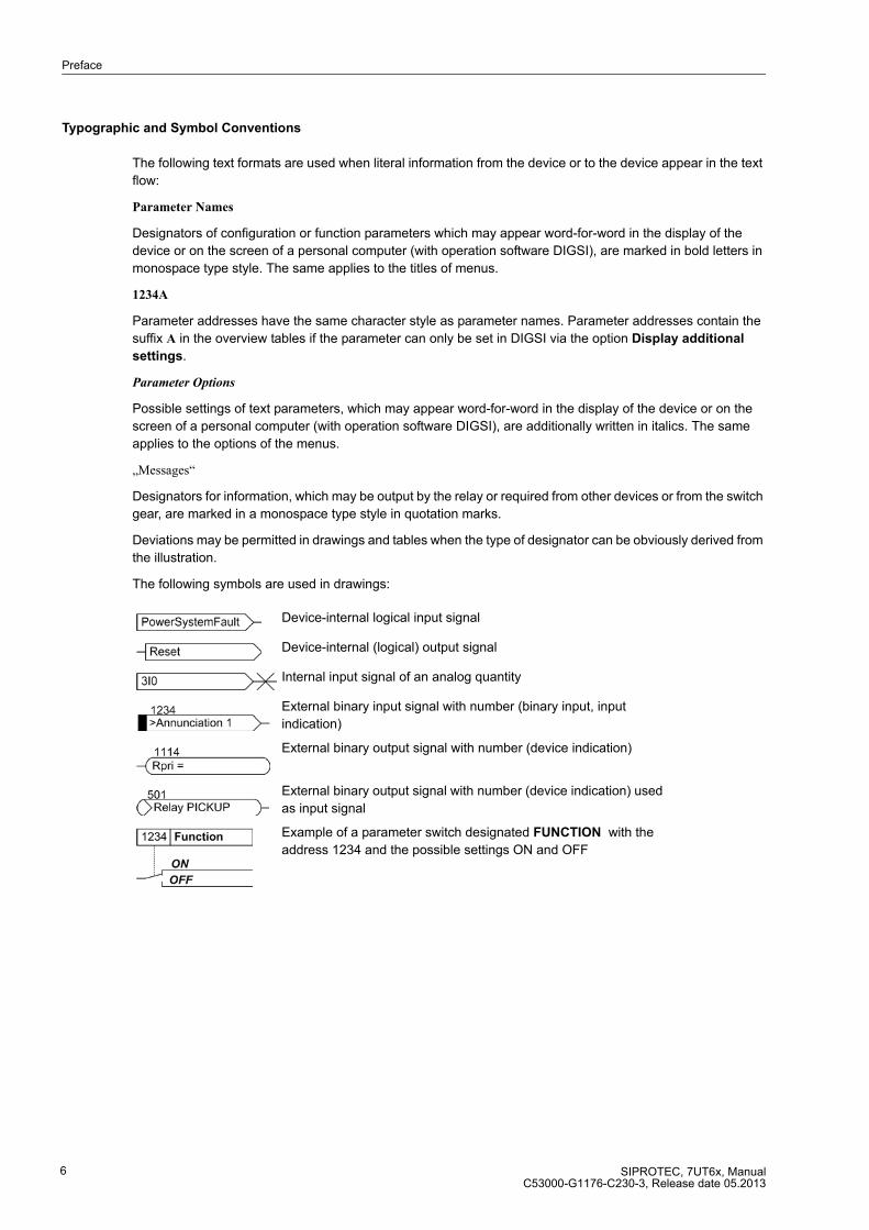
The following symbols are used in drawings:
Device-internal logical input signal
Device-internal (logical) output signal
Internal input signal of an analog quantity
External binary input signal with number (binary input, input
indication)
External binary output signal with number (device indication)
External binary output signal with number (device indication) used
as input signal
Example of a parameter switch designated FUNCTION with the
address 1234 and the possible settings ON and OFF
Preface
SIPROTEC, 7UT6x, ManualC53000-G1176-C230-3, Release date 05.2013
7
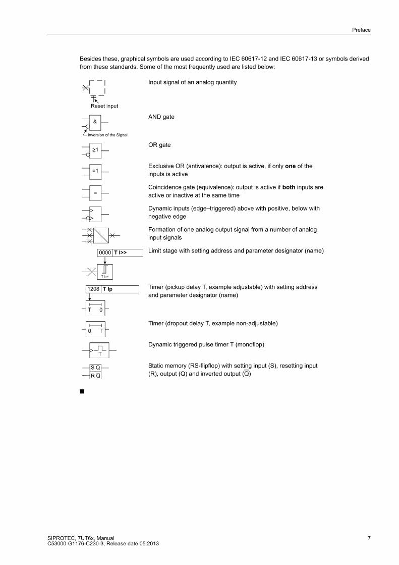
Besides these, graphical symbols are used according to IEC 60617-12 and IEC 60617-13 or symbols derived
from these standards. Some of the most frequently used are listed below:
■
Input signal of an analog quantity
AND gate
OR gate
Exclusive OR (antivalence): output is active, if only one of the
inputs is active
Coincidence gate (equivalence): output is active if both inputs are
active or inactive at the same time
Dynamic inputs (edge–triggered) above with positive, below with
negative edge
Formation of one analog output signal from a number of analog
input signals
Limit stage with setting address and parameter designator (name)
Timer (pickup delay T, example adjustable) with setting address
and parameter designator (name)
Timer (dropout delay T, example non-adjustable)
Dynamic triggered pulse timer T (monoflop)
Static memory (RS-flipflop) with setting input (S), resetting input
(R), output (Q) and inverted output (Q)

Preface
SIPROTEC, 7UT6x, ManualC53000-G1176-C230-3, Release date 05.2013
8

SIPROTEC, 7UT6x, ManualC53000-G1176-C230-3, Release date 05.2013
9
Contents
1 Introduction. . . . . . . . . . . . . . . . . . . . . . . . . . . . . . . . . . . . . . . . . . . . . . . . . . . . . . . . . . . . . . . . . . . . . . . . . . . . . .17
1.1 Overall Operation. . . . . . . . . . . . . . . . . . . . . . . . . . . . . . . . . . . . . . . . . . . . . . . . . . . . . . . . . . . . . . . . . .18
1.2 Application Scope . . . . . . . . . . . . . . . . . . . . . . . . . . . . . . . . . . . . . . . . . . . . . . . . . . . . . . . . . . . . . . . . .21
1.3 Characteristics . . . . . . . . . . . . . . . . . . . . . . . . . . . . . . . . . . . . . . . . . . . . . . . . . . . . . . . . . . . . . . . . . . . .23
2 Functions. . . . . . . . . . . . . . . . . . . . . . . . . . . . . . . . . . . . . . . . . . . . . . . . . . . . . . . . . . . . . . . . . . . . . . . . . . . . . . . .31
2.1 General . . . . . . . . . . . . . . . . . . . . . . . . . . . . . . . . . . . . . . . . . . . . . . . . . . . . . . . . . . . . . . . . . . . . . . . . .32
2.1.1 Device . . . . . . . . . . . . . . . . . . . . . . . . . . . . . . . . . . . . . . . . . . . . . . . . . . . . . . . . . . . . . . . . . . . . . . .33
2.1.1.1 Setting Notes . . . . . . . . . . . . . . . . . . . . . . . . . . . . . . . . . . . . . . . . . . . . . . . . . . . . . . . . . . . . . . .33
2.1.1.2 Settings . . . . . . . . . . . . . . . . . . . . . . . . . . . . . . . . . . . . . . . . . . . . . . . . . . . . . . . . . . . . . . . . . . .33
2.1.1.3 Information List . . . . . . . . . . . . . . . . . . . . . . . . . . . . . . . . . . . . . . . . . . . . . . . . . . . . . . . . . . . . . .34
2.1.2 EN100-Modul 1 . . . . . . . . . . . . . . . . . . . . . . . . . . . . . . . . . . . . . . . . . . . . . . . . . . . . . . . . . . . . . . . .35
2.1.2.1 Function Description. . . . . . . . . . . . . . . . . . . . . . . . . . . . . . . . . . . . . . . . . . . . . . . . . . . . . . . . . .35
2.1.2.2 Setting Notes . . . . . . . . . . . . . . . . . . . . . . . . . . . . . . . . . . . . . . . . . . . . . . . . . . . . . . . . . . . . . . .35
2.1.2.3 Information List . . . . . . . . . . . . . . . . . . . . . . . . . . . . . . . . . . . . . . . . . . . . . . . . . . . . . . . . . . . . . .35
2.1.3 Configuration of the Functional Scope. . . . . . . . . . . . . . . . . . . . . . . . . . . . . . . . . . . . . . . . . . . . . . .36
2.1.3.1 Setting Notes . . . . . . . . . . . . . . . . . . . . . . . . . . . . . . . . . . . . . . . . . . . . . . . . . . . . . . . . . . . . . . .36
2.1.3.2 Settings . . . . . . . . . . . . . . . . . . . . . . . . . . . . . . . . . . . . . . . . . . . . . . . . . . . . . . . . . . . . . . . . . . .43
2.1.4 Power System Data 1 . . . . . . . . . . . . . . . . . . . . . . . . . . . . . . . . . . . . . . . . . . . . . . . . . . . . . . . . . . .46
2.1.4.1 Topology of the Protected Object . . . . . . . . . . . . . . . . . . . . . . . . . . . . . . . . . . . . . . . . . . . . . . . .46
2.1.4.2 General Power System Data (Power System Data 1) . . . . . . . . . . . . . . . . . . . . . . . . . . . . . . . .64
2.1.4.3 Assignment of Protection Functions to Measuring Locations / Sides. . . . . . . . . . . . . . . . . . . . .78
2.1.4.4 Circuit Breaker Data . . . . . . . . . . . . . . . . . . . . . . . . . . . . . . . . . . . . . . . . . . . . . . . . . . . . . . . . .82
2.1.4.5 Settings . . . . . . . . . . . . . . . . . . . . . . . . . . . . . . . . . . . . . . . . . . . . . . . . . . . . . . . . . . . . . . . . . . .83
2.1.4.6 Information List . . . . . . . . . . . . . . . . . . . . . . . . . . . . . . . . . . . . . . . . . . . . . . . . . . . . . . . . . . . . . .95
2.1.5 Setting Groups . . . . . . . . . . . . . . . . . . . . . . . . . . . . . . . . . . . . . . . . . . . . . . . . . . . . . . . . . . . . . . . . .96
2.1.5.1 Setting Groups . . . . . . . . . . . . . . . . . . . . . . . . . . . . . . . . . . . . . . . . . . . . . . . . . . . . . . . . . . . . . .96
2.1.5.2 Setting Notes . . . . . . . . . . . . . . . . . . . . . . . . . . . . . . . . . . . . . . . . . . . . . . . . . . . . . . . . . . . . . . .97
2.1.5.3 Settings . . . . . . . . . . . . . . . . . . . . . . . . . . . . . . . . . . . . . . . . . . . . . . . . . . . . . . . . . . . . . . . . . . .97
2.1.5.4 Information List . . . . . . . . . . . . . . . . . . . . . . . . . . . . . . . . . . . . . . . . . . . . . . . . . . . . . . . . . . . . . .97
2.1.6 Power System Data 2 . . . . . . . . . . . . . . . . . . . . . . . . . . . . . . . . . . . . . . . . . . . . . . . . . . . . . . . . . . .98
2.1.6.1 Setting Notes . . . . . . . . . . . . . . . . . . . . . . . . . . . . . . . . . . . . . . . . . . . . . . . . . . . . . . . . . . . . . . .98
2.1.6.2 Settings . . . . . . . . . . . . . . . . . . . . . . . . . . . . . . . . . . . . . . . . . . . . . . . . . . . . . . . . . . . . . . . . . .100
2.1.6.3 Information List . . . . . . . . . . . . . . . . . . . . . . . . . . . . . . . . . . . . . . . . . . . . . . . . . . . . . . . . . . . . .102
Contents
SIPROTEC, 7UT6x, ManualC53000-G1176-C230-3, Release date 05.2013
10
2.2 Differential Protection . . . . . . . . . . . . . . . . . . . . . . . . . . . . . . . . . . . . . . . . . . . . . . . . . . . . . . . . . . . . . 105
2.2.1 Functional Description of the Differential Protection . . . . . . . . . . . . . . . . . . . . . . . . . . . . . . . . . . . 105
2.2.2 Differential Protection for Transformers. . . . . . . . . . . . . . . . . . . . . . . . . . . . . . . . . . . . . . . . . . . . . 114
2.2.3 Differential Protection for Generators, Motors, and Series Reactors . . . . . . . . . . . . . . . . . . . . . . 123
2.2.4 Differential Protection for Shunt Reactors . . . . . . . . . . . . . . . . . . . . . . . . . . . . . . . . . . . . . . . . . . . 124
2.2.5 Differential Protection for Mini-Busbars and Short Lines. . . . . . . . . . . . . . . . . . . . . . . . . . . . . . . . 125
2.2.6 Single-phase Differential Protection for Busbars. . . . . . . . . . . . . . . . . . . . . . . . . . . . . . . . . . . . . . 127
2.2.7 Setting Notes. . . . . . . . . . . . . . . . . . . . . . . . . . . . . . . . . . . . . . . . . . . . . . . . . . . . . . . . . . . . . . . . . 132
2.2.8 Settings . . . . . . . . . . . . . . . . . . . . . . . . . . . . . . . . . . . . . . . . . . . . . . . . . . . . . . . . . . . . . . . . . . . . . 137
2.2.9 Information List . . . . . . . . . . . . . . . . . . . . . . . . . . . . . . . . . . . . . . . . . . . . . . . . . . . . . . . . . . . . . . . 138
2.3 Restricted Earth Fault Protection . . . . . . . . . . . . . . . . . . . . . . . . . . . . . . . . . . . . . . . . . . . . . . . . . . . . 140
2.3.1 Application Examples . . . . . . . . . . . . . . . . . . . . . . . . . . . . . . . . . . . . . . . . . . . . . . . . . . . . . . . . . . 140
2.3.2 Function Description . . . . . . . . . . . . . . . . . . . . . . . . . . . . . . . . . . . . . . . . . . . . . . . . . . . . . . . . . . . 144
2.3.3 Setting Notes. . . . . . . . . . . . . . . . . . . . . . . . . . . . . . . . . . . . . . . . . . . . . . . . . . . . . . . . . . . . . . . . . 149
2.3.4 Settings . . . . . . . . . . . . . . . . . . . . . . . . . . . . . . . . . . . . . . . . . . . . . . . . . . . . . . . . . . . . . . . . . . . . . 151
2.3.5 Information List . . . . . . . . . . . . . . . . . . . . . . . . . . . . . . . . . . . . . . . . . . . . . . . . . . . . . . . . . . . . . . . 151
2.4 Time Overcurrent Protection for Phase and Residual Currents . . . . . . . . . . . . . . . . . . . . . . . . . . . . . 152
2.4.1 General . . . . . . . . . . . . . . . . . . . . . . . . . . . . . . . . . . . . . . . . . . . . . . . . . . . . . . . . . . . . . . . . . . . . . 152
2.4.1.1 Definite Time, Instantaneous Overcurrent Protection . . . . . . . . . . . . . . . . . . . . . . . . . . . . . . . 152
2.4.1.2 Inverse Time Overcurrent Protection . . . . . . . . . . . . . . . . . . . . . . . . . . . . . . . . . . . . . . . . . . . . 157
2.4.1.3 Manual Close Command . . . . . . . . . . . . . . . . . . . . . . . . . . . . . . . . . . . . . . . . . . . . . . . . . . . . . 160
2.4.1.4 Dynamic Cold Load Pickup . . . . . . . . . . . . . . . . . . . . . . . . . . . . . . . . . . . . . . . . . . . . . . . . . . . 160
2.4.1.5 Inrush Restraint . . . . . . . . . . . . . . . . . . . . . . . . . . . . . . . . . . . . . . . . . . . . . . . . . . . . . . . . . . . . 161
2.4.1.6 Fast Busbar Protection Using Reverse Interlocking . . . . . . . . . . . . . . . . . . . . . . . . . . . . . . . . 162
2.4.2 Time Overcurrent Protection for Phase Currents . . . . . . . . . . . . . . . . . . . . . . . . . . . . . . . . . . . . . 163
2.4.2.1 Setting Notes . . . . . . . . . . . . . . . . . . . . . . . . . . . . . . . . . . . . . . . . . . . . . . . . . . . . . . . . . . . . . . 164
2.4.2.2 Settings . . . . . . . . . . . . . . . . . . . . . . . . . . . . . . . . . . . . . . . . . . . . . . . . . . . . . . . . . . . . . . . . . . 171
2.4.2.3 Information List . . . . . . . . . . . . . . . . . . . . . . . . . . . . . . . . . . . . . . . . . . . . . . . . . . . . . . . . . . . . 173
2.4.3 Time Overcurrent Protection for Residual Current . . . . . . . . . . . . . . . . . . . . . . . . . . . . . . . . . . . . 174
2.4.3.1 Setting Notes . . . . . . . . . . . . . . . . . . . . . . . . . . . . . . . . . . . . . . . . . . . . . . . . . . . . . . . . . . . . . . 174
2.4.3.2 Settings . . . . . . . . . . . . . . . . . . . . . . . . . . . . . . . . . . . . . . . . . . . . . . . . . . . . . . . . . . . . . . . . . . 179
2.4.3.3 Information List . . . . . . . . . . . . . . . . . . . . . . . . . . . . . . . . . . . . . . . . . . . . . . . . . . . . . . . . . . . . 181
2.5 Time Overcurrent Protection for Earth Current . . . . . . . . . . . . . . . . . . . . . . . . . . . . . . . . . . . . . . . . . . 182
2.5.1 General . . . . . . . . . . . . . . . . . . . . . . . . . . . . . . . . . . . . . . . . . . . . . . . . . . . . . . . . . . . . . . . . . . . . . 182
2.5.2 Definite Time, Instantaneous Overcurrent Protection . . . . . . . . . . . . . . . . . . . . . . . . . . . . . . . . . . 183
2.5.3 Inverse Time Overcurrent Protection . . . . . . . . . . . . . . . . . . . . . . . . . . . . . . . . . . . . . . . . . . . . . . 185
2.5.4 Manual Close Command. . . . . . . . . . . . . . . . . . . . . . . . . . . . . . . . . . . . . . . . . . . . . . . . . . . . . . . . 187
2.5.5 Dynamic Cold Load Pickup . . . . . . . . . . . . . . . . . . . . . . . . . . . . . . . . . . . . . . . . . . . . . . . . . . . . . . 187
2.5.6 Inrush Restraint . . . . . . . . . . . . . . . . . . . . . . . . . . . . . . . . . . . . . . . . . . . . . . . . . . . . . . . . . . . . . . . 188
2.5.7 Setting Notes. . . . . . . . . . . . . . . . . . . . . . . . . . . . . . . . . . . . . . . . . . . . . . . . . . . . . . . . . . . . . . . . . 188
2.5.8 Settings . . . . . . . . . . . . . . . . . . . . . . . . . . . . . . . . . . . . . . . . . . . . . . . . . . . . . . . . . . . . . . . . . . . . . 192
2.5.9 Information List . . . . . . . . . . . . . . . . . . . . . . . . . . . . . . . . . . . . . . . . . . . . . . . . . . . . . . . . . . . . . . . 194
2.6 Dynamic Cold Load Pickup for Time Overcurrent Protection . . . . . . . . . . . . . . . . . . . . . . . . . . . . . . . 195
2.6.1 Function Description . . . . . . . . . . . . . . . . . . . . . . . . . . . . . . . . . . . . . . . . . . . . . . . . . . . . . . . . . . . 195
2.6.2 Setting Notes. . . . . . . . . . . . . . . . . . . . . . . . . . . . . . . . . . . . . . . . . . . . . . . . . . . . . . . . . . . . . . . . . 198
2.6.3 Settings . . . . . . . . . . . . . . . . . . . . . . . . . . . . . . . . . . . . . . . . . . . . . . . . . . . . . . . . . . . . . . . . . . . . . 199
2.6.4 Information List . . . . . . . . . . . . . . . . . . . . . . . . . . . . . . . . . . . . . . . . . . . . . . . . . . . . . . . . . . . . . . . 199

Contents
SIPROTEC, 7UT6x, ManualC53000-G1176-C230-3, Release date 05.2013
11
2.7 Single-Phase Time Overcurrent Protection . . . . . . . . . . . . . . . . . . . . . . . . . . . . . . . . . . . . . . . . . . . . .200
2.7.1 Function Description . . . . . . . . . . . . . . . . . . . . . . . . . . . . . . . . . . . . . . . . . . . . . . . . . . . . . . . . . . .200
2.7.2 High-impedance Differential Protection . . . . . . . . . . . . . . . . . . . . . . . . . . . . . . . . . . . . . . . . . . . . .202
2.7.3 Tank Leakage Protection . . . . . . . . . . . . . . . . . . . . . . . . . . . . . . . . . . . . . . . . . . . . . . . . . . . . . . . .204
2.7.4 Setting Notes . . . . . . . . . . . . . . . . . . . . . . . . . . . . . . . . . . . . . . . . . . . . . . . . . . . . . . . . . . . . . . . . .205
2.7.5 Settings . . . . . . . . . . . . . . . . . . . . . . . . . . . . . . . . . . . . . . . . . . . . . . . . . . . . . . . . . . . . . . . . . . . . .209
2.7.6 Information List. . . . . . . . . . . . . . . . . . . . . . . . . . . . . . . . . . . . . . . . . . . . . . . . . . . . . . . . . . . . . . . .210
2.8 Unbalanced Load Protection . . . . . . . . . . . . . . . . . . . . . . . . . . . . . . . . . . . . . . . . . . . . . . . . . . . . . . . .211
2.8.1 Function Description . . . . . . . . . . . . . . . . . . . . . . . . . . . . . . . . . . . . . . . . . . . . . . . . . . . . . . . . . . .212
2.8.2 Setting Notes . . . . . . . . . . . . . . . . . . . . . . . . . . . . . . . . . . . . . . . . . . . . . . . . . . . . . . . . . . . . . . . . .218
2.8.3 Settings . . . . . . . . . . . . . . . . . . . . . . . . . . . . . . . . . . . . . . . . . . . . . . . . . . . . . . . . . . . . . . . . . . . . .224
2.8.4 Information List. . . . . . . . . . . . . . . . . . . . . . . . . . . . . . . . . . . . . . . . . . . . . . . . . . . . . . . . . . . . . . . .225
2.9 Thermal Overload Protection. . . . . . . . . . . . . . . . . . . . . . . . . . . . . . . . . . . . . . . . . . . . . . . . . . . . . . . .226
2.9.1 General . . . . . . . . . . . . . . . . . . . . . . . . . . . . . . . . . . . . . . . . . . . . . . . . . . . . . . . . . . . . . . . . . . . . .226
2.9.2 Overload Protection Using a Thermal Replica . . . . . . . . . . . . . . . . . . . . . . . . . . . . . . . . . . . . . . . .226
2.9.3 Overload protection using a thermal replica with ambient temperature influence . . . . . . . . . . . . .229
2.9.4 Hot-Spot Calculation and Determination of the Ageing Rate . . . . . . . . . . . . . . . . . . . . . . . . . . . . .230
2.9.5 Setting Notes . . . . . . . . . . . . . . . . . . . . . . . . . . . . . . . . . . . . . . . . . . . . . . . . . . . . . . . . . . . . . . . . .232
2.9.6 Settings . . . . . . . . . . . . . . . . . . . . . . . . . . . . . . . . . . . . . . . . . . . . . . . . . . . . . . . . . . . . . . . . . . . . .238
2.9.7 Information List. . . . . . . . . . . . . . . . . . . . . . . . . . . . . . . . . . . . . . . . . . . . . . . . . . . . . . . . . . . . . . . .239
2.10 RTD-Boxes for Overload Detection . . . . . . . . . . . . . . . . . . . . . . . . . . . . . . . . . . . . . . . . . . . . . . . . . . .240
2.10.1 Function Description . . . . . . . . . . . . . . . . . . . . . . . . . . . . . . . . . . . . . . . . . . . . . . . . . . . . . . . . . . .240
2.10.2 Setting Notes . . . . . . . . . . . . . . . . . . . . . . . . . . . . . . . . . . . . . . . . . . . . . . . . . . . . . . . . . . . . . . . . .240
2.10.3 Settings . . . . . . . . . . . . . . . . . . . . . . . . . . . . . . . . . . . . . . . . . . . . . . . . . . . . . . . . . . . . . . . . . . . . .241
2.10.4 Information List. . . . . . . . . . . . . . . . . . . . . . . . . . . . . . . . . . . . . . . . . . . . . . . . . . . . . . . . . . . . . . . .246
2.11 Overexcitation Protection. . . . . . . . . . . . . . . . . . . . . . . . . . . . . . . . . . . . . . . . . . . . . . . . . . . . . . . . . . .247
2.11.1 Function Description . . . . . . . . . . . . . . . . . . . . . . . . . . . . . . . . . . . . . . . . . . . . . . . . . . . . . . . . . . .247
2.11.2 Setting Notes . . . . . . . . . . . . . . . . . . . . . . . . . . . . . . . . . . . . . . . . . . . . . . . . . . . . . . . . . . . . . . . . .249
2.11.3 Settings . . . . . . . . . . . . . . . . . . . . . . . . . . . . . . . . . . . . . . . . . . . . . . . . . . . . . . . . . . . . . . . . . . . . .252
2.11.4 Information List. . . . . . . . . . . . . . . . . . . . . . . . . . . . . . . . . . . . . . . . . . . . . . . . . . . . . . . . . . . . . . . .252
2.12 Reverse Power Protection . . . . . . . . . . . . . . . . . . . . . . . . . . . . . . . . . . . . . . . . . . . . . . . . . . . . . . . . . .253
2.12.1 Function Description . . . . . . . . . . . . . . . . . . . . . . . . . . . . . . . . . . . . . . . . . . . . . . . . . . . . . . . . . . .253
2.12.2 Setting Notes . . . . . . . . . . . . . . . . . . . . . . . . . . . . . . . . . . . . . . . . . . . . . . . . . . . . . . . . . . . . . . . . .255
2.12.3 Settings . . . . . . . . . . . . . . . . . . . . . . . . . . . . . . . . . . . . . . . . . . . . . . . . . . . . . . . . . . . . . . . . . . . . .257
2.12.4 Information List. . . . . . . . . . . . . . . . . . . . . . . . . . . . . . . . . . . . . . . . . . . . . . . . . . . . . . . . . . . . . . . .257
2.13 Forward Power Supervision. . . . . . . . . . . . . . . . . . . . . . . . . . . . . . . . . . . . . . . . . . . . . . . . . . . . . . . . .258
2.13.1 Function Description . . . . . . . . . . . . . . . . . . . . . . . . . . . . . . . . . . . . . . . . . . . . . . . . . . . . . . . . . . .258
2.13.2 Setting Notes . . . . . . . . . . . . . . . . . . . . . . . . . . . . . . . . . . . . . . . . . . . . . . . . . . . . . . . . . . . . . . . . .260
2.13.3 Settings . . . . . . . . . . . . . . . . . . . . . . . . . . . . . . . . . . . . . . . . . . . . . . . . . . . . . . . . . . . . . . . . . . . . .262
2.13.4 Information List. . . . . . . . . . . . . . . . . . . . . . . . . . . . . . . . . . . . . . . . . . . . . . . . . . . . . . . . . . . . . . . .262

Contents
SIPROTEC, 7UT6x, ManualC53000-G1176-C230-3, Release date 05.2013
12
2.14 Undervoltage Protection . . . . . . . . . . . . . . . . . . . . . . . . . . . . . . . . . . . . . . . . . . . . . . . . . . . . . . . . . . . 263
2.14.1 Function Description . . . . . . . . . . . . . . . . . . . . . . . . . . . . . . . . . . . . . . . . . . . . . . . . . . . . . . . . . . . 263
2.14.2 Setting Notes. . . . . . . . . . . . . . . . . . . . . . . . . . . . . . . . . . . . . . . . . . . . . . . . . . . . . . . . . . . . . . . . . 264
2.14.3 Settings . . . . . . . . . . . . . . . . . . . . . . . . . . . . . . . . . . . . . . . . . . . . . . . . . . . . . . . . . . . . . . . . . . . . . 266
2.14.4 Information List . . . . . . . . . . . . . . . . . . . . . . . . . . . . . . . . . . . . . . . . . . . . . . . . . . . . . . . . . . . . . . . 266
2.15 Overvoltage Protection . . . . . . . . . . . . . . . . . . . . . . . . . . . . . . . . . . . . . . . . . . . . . . . . . . . . . . . . . . . . 267
2.15.1 Function Description . . . . . . . . . . . . . . . . . . . . . . . . . . . . . . . . . . . . . . . . . . . . . . . . . . . . . . . . . . . 268
2.15.2 Setting Notes. . . . . . . . . . . . . . . . . . . . . . . . . . . . . . . . . . . . . . . . . . . . . . . . . . . . . . . . . . . . . . . . . 269
2.15.3 Settings . . . . . . . . . . . . . . . . . . . . . . . . . . . . . . . . . . . . . . . . . . . . . . . . . . . . . . . . . . . . . . . . . . . . . 270
2.15.4 Information List . . . . . . . . . . . . . . . . . . . . . . . . . . . . . . . . . . . . . . . . . . . . . . . . . . . . . . . . . . . . . . . 270
2.16 Frequency Protection . . . . . . . . . . . . . . . . . . . . . . . . . . . . . . . . . . . . . . . . . . . . . . . . . . . . . . . . . . . . . 271
2.16.1 Function Description . . . . . . . . . . . . . . . . . . . . . . . . . . . . . . . . . . . . . . . . . . . . . . . . . . . . . . . . . . . 271
2.16.2 Setting Notes. . . . . . . . . . . . . . . . . . . . . . . . . . . . . . . . . . . . . . . . . . . . . . . . . . . . . . . . . . . . . . . . . 273
2.16.3 Settings . . . . . . . . . . . . . . . . . . . . . . . . . . . . . . . . . . . . . . . . . . . . . . . . . . . . . . . . . . . . . . . . . . . . . 275
2.16.4 Information List . . . . . . . . . . . . . . . . . . . . . . . . . . . . . . . . . . . . . . . . . . . . . . . . . . . . . . . . . . . . . . . 276
2.17 Circuit Breaker Failure Protection . . . . . . . . . . . . . . . . . . . . . . . . . . . . . . . . . . . . . . . . . . . . . . . . . . . . 277
2.17.1 Function Description . . . . . . . . . . . . . . . . . . . . . . . . . . . . . . . . . . . . . . . . . . . . . . . . . . . . . . . . . . . 277
2.17.2 Setting Notes. . . . . . . . . . . . . . . . . . . . . . . . . . . . . . . . . . . . . . . . . . . . . . . . . . . . . . . . . . . . . . . . . 281
2.17.3 Settings . . . . . . . . . . . . . . . . . . . . . . . . . . . . . . . . . . . . . . . . . . . . . . . . . . . . . . . . . . . . . . . . . . . . . 285
2.17.4 Information List . . . . . . . . . . . . . . . . . . . . . . . . . . . . . . . . . . . . . . . . . . . . . . . . . . . . . . . . . . . . . . . 285
2.18 External Trip Commands . . . . . . . . . . . . . . . . . . . . . . . . . . . . . . . . . . . . . . . . . . . . . . . . . . . . . . . . . . 286
2.18.1 Function Description . . . . . . . . . . . . . . . . . . . . . . . . . . . . . . . . . . . . . . . . . . . . . . . . . . . . . . . . . . . 286
2.18.2 Setting Notes. . . . . . . . . . . . . . . . . . . . . . . . . . . . . . . . . . . . . . . . . . . . . . . . . . . . . . . . . . . . . . . . . 287
2.18.3 Settings . . . . . . . . . . . . . . . . . . . . . . . . . . . . . . . . . . . . . . . . . . . . . . . . . . . . . . . . . . . . . . . . . . . . . 288
2.18.4 Information List . . . . . . . . . . . . . . . . . . . . . . . . . . . . . . . . . . . . . . . . . . . . . . . . . . . . . . . . . . . . . . . 288
2.19 Monitoring Functions. . . . . . . . . . . . . . . . . . . . . . . . . . . . . . . . . . . . . . . . . . . . . . . . . . . . . . . . . . . . . . 289
2.19.1 Measurement Supervision. . . . . . . . . . . . . . . . . . . . . . . . . . . . . . . . . . . . . . . . . . . . . . . . . . . . . . . 289
2.19.1.1 Hardware Monitoring . . . . . . . . . . . . . . . . . . . . . . . . . . . . . . . . . . . . . . . . . . . . . . . . . . . . . . . . 289
2.19.1.2 Software Monitoring. . . . . . . . . . . . . . . . . . . . . . . . . . . . . . . . . . . . . . . . . . . . . . . . . . . . . . . . . 290
2.19.1.3 Monitoring of Measured Quantities . . . . . . . . . . . . . . . . . . . . . . . . . . . . . . . . . . . . . . . . . . . . . 291
2.19.1.4 Setting Notes . . . . . . . . . . . . . . . . . . . . . . . . . . . . . . . . . . . . . . . . . . . . . . . . . . . . . . . . . . . . . . 294
2.19.1.5 Settings . . . . . . . . . . . . . . . . . . . . . . . . . . . . . . . . . . . . . . . . . . . . . . . . . . . . . . . . . . . . . . . . . . 295
2.19.1.6 Information List . . . . . . . . . . . . . . . . . . . . . . . . . . . . . . . . . . . . . . . . . . . . . . . . . . . . . . . . . . . . 296
2.19.2 Trip Circuit Supervision . . . . . . . . . . . . . . . . . . . . . . . . . . . . . . . . . . . . . . . . . . . . . . . . . . . . . . . . . 297
2.19.2.1 Function Description . . . . . . . . . . . . . . . . . . . . . . . . . . . . . . . . . . . . . . . . . . . . . . . . . . . . . . . . 297
2.19.2.2 Setting Notes . . . . . . . . . . . . . . . . . . . . . . . . . . . . . . . . . . . . . . . . . . . . . . . . . . . . . . . . . . . . . . 300
2.19.2.3 Settings . . . . . . . . . . . . . . . . . . . . . . . . . . . . . . . . . . . . . . . . . . . . . . . . . . . . . . . . . . . . . . . . . . 300
2.19.2.4 Information List . . . . . . . . . . . . . . . . . . . . . . . . . . . . . . . . . . . . . . . . . . . . . . . . . . . . . . . . . . . . 300
2.19.3 Monitoring . . . . . . . . . . . . . . . . . . . . . . . . . . . . . . . . . . . . . . . . . . . . . . . . . . . . . . . . . . . . . . . . . . . 301
2.19.3.1 Broken Wire Detection, Fuse Failure Monitoring . . . . . . . . . . . . . . . . . . . . . . . . . . . . . . . . . . . 301
2.19.3.2 Setting Notes . . . . . . . . . . . . . . . . . . . . . . . . . . . . . . . . . . . . . . . . . . . . . . . . . . . . . . . . . . . . . . 305
2.19.3.3 Settings . . . . . . . . . . . . . . . . . . . . . . . . . . . . . . . . . . . . . . . . . . . . . . . . . . . . . . . . . . . . . . . . . . 306
2.19.3.4 Information List . . . . . . . . . . . . . . . . . . . . . . . . . . . . . . . . . . . . . . . . . . . . . . . . . . . . . . . . . . . . 307
2.19.4 Malfunction Responses of the Device . . . . . . . . . . . . . . . . . . . . . . . . . . . . . . . . . . . . . . . . . . . . . . 308
2.19.4.1 Summary of the most important Monitoring Functions . . . . . . . . . . . . . . . . . . . . . . . . . . . . . . 309
2.19.5 Parameterisation Error . . . . . . . . . . . . . . . . . . . . . . . . . . . . . . . . . . . . . . . . . . . . . . . . . . . . . . . . . 310

Contents
SIPROTEC, 7UT6x, ManualC53000-G1176-C230-3, Release date 05.2013
13
2.20 Protection Function Control . . . . . . . . . . . . . . . . . . . . . . . . . . . . . . . . . . . . . . . . . . . . . . . . . . . . . . . . .311
2.20.1 Pickup Logic for the Entire Device . . . . . . . . . . . . . . . . . . . . . . . . . . . . . . . . . . . . . . . . . . . . . . . . .311
2.20.1.1 General Device Pickup. . . . . . . . . . . . . . . . . . . . . . . . . . . . . . . . . . . . . . . . . . . . . . . . . . . . . . .311
2.20.2 Tripping Logic for the Entire Device . . . . . . . . . . . . . . . . . . . . . . . . . . . . . . . . . . . . . . . . . . . . . . . .312
2.20.2.1 General Tripping. . . . . . . . . . . . . . . . . . . . . . . . . . . . . . . . . . . . . . . . . . . . . . . . . . . . . . . . . . . .312
2.21 Disconnection of Measuring Locations . . . . . . . . . . . . . . . . . . . . . . . . . . . . . . . . . . . . . . . . . . . . . . . .314
2.21.1 Functional Description . . . . . . . . . . . . . . . . . . . . . . . . . . . . . . . . . . . . . . . . . . . . . . . . . . . . . . . . . .314
2.21.2 Information List. . . . . . . . . . . . . . . . . . . . . . . . . . . . . . . . . . . . . . . . . . . . . . . . . . . . . . . . . . . . . . . .316
2.22 Additional Functions . . . . . . . . . . . . . . . . . . . . . . . . . . . . . . . . . . . . . . . . . . . . . . . . . . . . . . . . . . . . . .317
2.22.1 Processing of Messages . . . . . . . . . . . . . . . . . . . . . . . . . . . . . . . . . . . . . . . . . . . . . . . . . . . . . . . .317
2.22.1.1 General. . . . . . . . . . . . . . . . . . . . . . . . . . . . . . . . . . . . . . . . . . . . . . . . . . . . . . . . . . . . . . . . . . .317
2.22.1.2 Operational Annunciations (Buffer: Event Log) . . . . . . . . . . . . . . . . . . . . . . . . . . . . . . . . . . . .319
2.22.1.3 Fault Annunciations (Buffer: Trip Log) . . . . . . . . . . . . . . . . . . . . . . . . . . . . . . . . . . . . . . . . . . .319
2.22.1.4 Spontaneous Annunciations. . . . . . . . . . . . . . . . . . . . . . . . . . . . . . . . . . . . . . . . . . . . . . . . . . .320
2.22.1.5 General Interrogation . . . . . . . . . . . . . . . . . . . . . . . . . . . . . . . . . . . . . . . . . . . . . . . . . . . . . . . .320
2.22.1.6 Switching Statistics. . . . . . . . . . . . . . . . . . . . . . . . . . . . . . . . . . . . . . . . . . . . . . . . . . . . . . . . . .320
2.22.2 Measurement . . . . . . . . . . . . . . . . . . . . . . . . . . . . . . . . . . . . . . . . . . . . . . . . . . . . . . . . . . . . . . . . .321
2.22.2.1 Display and Transmission of Measured Valuables . . . . . . . . . . . . . . . . . . . . . . . . . . . . . . . . .321
2.22.2.2 Settings . . . . . . . . . . . . . . . . . . . . . . . . . . . . . . . . . . . . . . . . . . . . . . . . . . . . . . . . . . . . . . . . . .325
2.22.2.3 Information List . . . . . . . . . . . . . . . . . . . . . . . . . . . . . . . . . . . . . . . . . . . . . . . . . . . . . . . . . . . . .325
2.22.3 Thermal Measurement . . . . . . . . . . . . . . . . . . . . . . . . . . . . . . . . . . . . . . . . . . . . . . . . . . . . . . . . . .328
2.22.3.1 Description . . . . . . . . . . . . . . . . . . . . . . . . . . . . . . . . . . . . . . . . . . . . . . . . . . . . . . . . . . . . . . . .328
2.22.3.2 Information List . . . . . . . . . . . . . . . . . . . . . . . . . . . . . . . . . . . . . . . . . . . . . . . . . . . . . . . . . . . . .329
2.22.4 Differential and Restraining Measured Values . . . . . . . . . . . . . . . . . . . . . . . . . . . . . . . . . . . . . . . .330
2.22.4.1 Function Description. . . . . . . . . . . . . . . . . . . . . . . . . . . . . . . . . . . . . . . . . . . . . . . . . . . . . . . . .330
2.22.4.2 Information List . . . . . . . . . . . . . . . . . . . . . . . . . . . . . . . . . . . . . . . . . . . . . . . . . . . . . . . . . . . . .330
2.22.5 Set Points for Measured Values. . . . . . . . . . . . . . . . . . . . . . . . . . . . . . . . . . . . . . . . . . . . . . . . . . .331
2.22.5.1 User Defined Set-Points . . . . . . . . . . . . . . . . . . . . . . . . . . . . . . . . . . . . . . . . . . . . . . . . . . . . . .331
2.22.6 Energy Metering. . . . . . . . . . . . . . . . . . . . . . . . . . . . . . . . . . . . . . . . . . . . . . . . . . . . . . . . . . . . . . .331
2.22.6.1 Energy Metering . . . . . . . . . . . . . . . . . . . . . . . . . . . . . . . . . . . . . . . . . . . . . . . . . . . . . . . . . . . .331
2.22.6.2 Information List . . . . . . . . . . . . . . . . . . . . . . . . . . . . . . . . . . . . . . . . . . . . . . . . . . . . . . . . . . . . .332
2.22.7 Flexible Function . . . . . . . . . . . . . . . . . . . . . . . . . . . . . . . . . . . . . . . . . . . . . . . . . . . . . . . . . . . . . .333
2.22.7.1 Function Description. . . . . . . . . . . . . . . . . . . . . . . . . . . . . . . . . . . . . . . . . . . . . . . . . . . . . . . . .333
2.22.7.2 Setting Notes . . . . . . . . . . . . . . . . . . . . . . . . . . . . . . . . . . . . . . . . . . . . . . . . . . . . . . . . . . . . . .335
2.22.7.3 Settings . . . . . . . . . . . . . . . . . . . . . . . . . . . . . . . . . . . . . . . . . . . . . . . . . . . . . . . . . . . . . . . . . .339
2.22.7.4 Information List . . . . . . . . . . . . . . . . . . . . . . . . . . . . . . . . . . . . . . . . . . . . . . . . . . . . . . . . . . . . .341
2.22.8 Flexible Function . . . . . . . . . . . . . . . . . . . . . . . . . . . . . . . . . . . . . . . . . . . . . . . . . . . . . . . . . . . . . .342
2.22.8.1 Settings . . . . . . . . . . . . . . . . . . . . . . . . . . . . . . . . . . . . . . . . . . . . . . . . . . . . . . . . . . . . . . . . . .342
2.22.9 Oscillographic Fault Recording . . . . . . . . . . . . . . . . . . . . . . . . . . . . . . . . . . . . . . . . . . . . . . . . . . .344
2.22.9.1 Function Description. . . . . . . . . . . . . . . . . . . . . . . . . . . . . . . . . . . . . . . . . . . . . . . . . . . . . . . . .344
2.22.9.2 Setting Notes . . . . . . . . . . . . . . . . . . . . . . . . . . . . . . . . . . . . . . . . . . . . . . . . . . . . . . . . . . . . . .345
2.22.9.3 Settings . . . . . . . . . . . . . . . . . . . . . . . . . . . . . . . . . . . . . . . . . . . . . . . . . . . . . . . . . . . . . . . . . .345
2.22.9.4 Information List . . . . . . . . . . . . . . . . . . . . . . . . . . . . . . . . . . . . . . . . . . . . . . . . . . . . . . . . . . . . .345
2.22.10 Commissioning Aids. . . . . . . . . . . . . . . . . . . . . . . . . . . . . . . . . . . . . . . . . . . . . . . . . . . . . . . . . . . .346
2.22.10.1 Web Monitor . . . . . . . . . . . . . . . . . . . . . . . . . . . . . . . . . . . . . . . . . . . . . . . . . . . . . . . . . . . . . . .346
Contents
SIPROTEC, 7UT6x, ManualC53000-G1176-C230-3, Release date 05.2013
14
2.23 Average Values, Minimum and Maximum Values . . . . . . . . . . . . . . . . . . . . . . . . . . . . . . . . . . . . . . . . 348
2.23.1 Demand Measurement Setup . . . . . . . . . . . . . . . . . . . . . . . . . . . . . . . . . . . . . . . . . . . . . . . . . . . . 349
2.23.1.1 Setting Notes . . . . . . . . . . . . . . . . . . . . . . . . . . . . . . . . . . . . . . . . . . . . . . . . . . . . . . . . . . . . . . 349
2.23.1.2 Settings . . . . . . . . . . . . . . . . . . . . . . . . . . . . . . . . . . . . . . . . . . . . . . . . . . . . . . . . . . . . . . . . . . 349
2.23.2 Min/Max Measurement Setup . . . . . . . . . . . . . . . . . . . . . . . . . . . . . . . . . . . . . . . . . . . . . . . . . . . . 350
2.23.2.1 Setting Notes . . . . . . . . . . . . . . . . . . . . . . . . . . . . . . . . . . . . . . . . . . . . . . . . . . . . . . . . . . . . . . 350
2.23.2.2 Settings . . . . . . . . . . . . . . . . . . . . . . . . . . . . . . . . . . . . . . . . . . . . . . . . . . . . . . . . . . . . . . . . . . 350
2.23.2.3 Information List . . . . . . . . . . . . . . . . . . . . . . . . . . . . . . . . . . . . . . . . . . . . . . . . . . . . . . . . . . . . 350
2.24 Command Processing. . . . . . . . . . . . . . . . . . . . . . . . . . . . . . . . . . . . . . . . . . . . . . . . . . . . . . . . . . . . . 351
2.24.1 Control Authorization. . . . . . . . . . . . . . . . . . . . . . . . . . . . . . . . . . . . . . . . . . . . . . . . . . . . . . . . . . . 351
2.24.1.1 Type of Commands . . . . . . . . . . . . . . . . . . . . . . . . . . . . . . . . . . . . . . . . . . . . . . . . . . . . . . . . . 351
2.24.1.2 Sequence in the Command Path . . . . . . . . . . . . . . . . . . . . . . . . . . . . . . . . . . . . . . . . . . . . . . 352
2.24.1.3 Interlocking . . . . . . . . . . . . . . . . . . . . . . . . . . . . . . . . . . . . . . . . . . . . . . . . . . . . . . . . . . . . . . 353
2.24.1.4 Recording and Acknowledgement of Commands . . . . . . . . . . . . . . . . . . . . . . . . . . . . . . . . . . 357
2.24.1.5 Information List . . . . . . . . . . . . . . . . . . . . . . . . . . . . . . . . . . . . . . . . . . . . . . . . . . . . . . . . . . . . 358
3 Mounting and Commissioning . . . . . . . . . . . . . . . . . . . . . . . . . . . . . . . . . . . . . . . . . . . . . . . . . . . . . . . . . . . . . 359
3.1 Mounting and Connections . . . . . . . . . . . . . . . . . . . . . . . . . . . . . . . . . . . . . . . . . . . . . . . . . . . . . . . . . 360
3.1.1 Configuration Information . . . . . . . . . . . . . . . . . . . . . . . . . . . . . . . . . . . . . . . . . . . . . . . . . . . . . . . 360
3.1.2 Hardware Modifications. . . . . . . . . . . . . . . . . . . . . . . . . . . . . . . . . . . . . . . . . . . . . . . . . . . . . . . . . 365
3.1.2.1 General . . . . . . . . . . . . . . . . . . . . . . . . . . . . . . . . . . . . . . . . . . . . . . . . . . . . . . . . . . . . . . . . . . 365
3.1.2.2 Disassembly . . . . . . . . . . . . . . . . . . . . . . . . . . . . . . . . . . . . . . . . . . . . . . . . . . . . . . . . . . . . . . 367
3.1.2.3 Switching Elements on Printed Circuit Boards . . . . . . . . . . . . . . . . . . . . . . . . . . . . . . . . . . . . 371
3.1.2.4 Interface Modules . . . . . . . . . . . . . . . . . . . . . . . . . . . . . . . . . . . . . . . . . . . . . . . . . . . . . . . . . . 390
3.1.2.5 Reassembly . . . . . . . . . . . . . . . . . . . . . . . . . . . . . . . . . . . . . . . . . . . . . . . . . . . . . . . . . . . . . . . 396
3.1.3 Mounting . . . . . . . . . . . . . . . . . . . . . . . . . . . . . . . . . . . . . . . . . . . . . . . . . . . . . . . . . . . . . . . . . . . . 397
3.1.3.1 Panel Flush Mounting . . . . . . . . . . . . . . . . . . . . . . . . . . . . . . . . . . . . . . . . . . . . . . . . . . . . . . . 397
3.1.3.2 Rack and Cubicle Mounting . . . . . . . . . . . . . . . . . . . . . . . . . . . . . . . . . . . . . . . . . . . . . . . . . . 399
3.1.3.3 Panel Surface Mounting . . . . . . . . . . . . . . . . . . . . . . . . . . . . . . . . . . . . . . . . . . . . . . . . . . . . . 401
3.1.3.4 Removing the Transport Protection . . . . . . . . . . . . . . . . . . . . . . . . . . . . . . . . . . . . . . . . . . . . . 402
3.2 Checking Connections . . . . . . . . . . . . . . . . . . . . . . . . . . . . . . . . . . . . . . . . . . . . . . . . . . . . . . . . . . . . 404
3.2.1 Checking Data Connections of Interfaces . . . . . . . . . . . . . . . . . . . . . . . . . . . . . . . . . . . . . . . . . . . 404
3.2.2 Checking the System Connections . . . . . . . . . . . . . . . . . . . . . . . . . . . . . . . . . . . . . . . . . . . . . . . . 408
3.3 Commissioning . . . . . . . . . . . . . . . . . . . . . . . . . . . . . . . . . . . . . . . . . . . . . . . . . . . . . . . . . . . . . . . . . . 410
3.3.1 Test Mode / Transmission Block . . . . . . . . . . . . . . . . . . . . . . . . . . . . . . . . . . . . . . . . . . . . . . . . . . 411
3.3.2 Test Time Synchronisation Interface . . . . . . . . . . . . . . . . . . . . . . . . . . . . . . . . . . . . . . . . . . . . . . . 411
3.3.3 Testing the System Interface . . . . . . . . . . . . . . . . . . . . . . . . . . . . . . . . . . . . . . . . . . . . . . . . . . . . . 412
3.3.4 Checking the switching states of the binary Inputs/Outputs . . . . . . . . . . . . . . . . . . . . . . . . . . . . . 414
3.3.5 Checking the Setting Consistency . . . . . . . . . . . . . . . . . . . . . . . . . . . . . . . . . . . . . . . . . . . . . . . . 417
3.3.6 Secondary Tests . . . . . . . . . . . . . . . . . . . . . . . . . . . . . . . . . . . . . . . . . . . . . . . . . . . . . . . . . . . . . . 422
3.3.7 Circuit Breaker Failure Protection Tests . . . . . . . . . . . . . . . . . . . . . . . . . . . . . . . . . . . . . . . . . . . . 428
3.3.8 Symmetrical, Primary Current Tests on the Protected Object . . . . . . . . . . . . . . . . . . . . . . . . . . . . 430
3.3.9 Zero Sequence Current Tests on the Protected Object. . . . . . . . . . . . . . . . . . . . . . . . . . . . . . . . . 437
3.3.10 Current Tests for Busbar Protection . . . . . . . . . . . . . . . . . . . . . . . . . . . . . . . . . . . . . . . . . . . . . . . 443
3.3.11 Testing of the Non-Assigned 1-Phase Current Inputs . . . . . . . . . . . . . . . . . . . . . . . . . . . . . . . . . . 445
3.3.12 Checking the Voltage Connections and Polarity Check . . . . . . . . . . . . . . . . . . . . . . . . . . . . . . . . 446
3.3.13 Testing User-defined Functions. . . . . . . . . . . . . . . . . . . . . . . . . . . . . . . . . . . . . . . . . . . . . . . . . . . 451
3.3.14 Stability Check and Triggering Oscillographic Recordings . . . . . . . . . . . . . . . . . . . . . . . . . . . . . . 451
3.4 Final Preparation of the Device . . . . . . . . . . . . . . . . . . . . . . . . . . . . . . . . . . . . . . . . . . . . . . . . . . . . . 453
Contents
SIPROTEC, 7UT6x, ManualC53000-G1176-C230-3, Release date 05.2013
15
4 Technical Data. . . . . . . . . . . . . . . . . . . . . . . . . . . . . . . . . . . . . . . . . . . . . . . . . . . . . . . . . . . . . . . . . . . . . . . . . . .455
4.1 General . . . . . . . . . . . . . . . . . . . . . . . . . . . . . . . . . . . . . . . . . . . . . . . . . . . . . . . . . . . . . . . . . . . . . . . .456
4.1.1 Analogue Inputs . . . . . . . . . . . . . . . . . . . . . . . . . . . . . . . . . . . . . . . . . . . . . . . . . . . . . . . . . . . . . .456
4.1.2 Auxiliary Voltage . . . . . . . . . . . . . . . . . . . . . . . . . . . . . . . . . . . . . . . . . . . . . . . . . . . . . . . . . . . . . .457
4.1.3 Binary Inputs and Outputs . . . . . . . . . . . . . . . . . . . . . . . . . . . . . . . . . . . . . . . . . . . . . . . . . . . . . . .458
4.1.4 Frequency Measurement via the Positive Phase-sequence Voltage U1 . . . . . . . . . . . . . . . . . . . .459
4.1.5 Communications Interfaces . . . . . . . . . . . . . . . . . . . . . . . . . . . . . . . . . . . . . . . . . . . . . . . . . . . . . .460
4.1.6 Electrical Tests . . . . . . . . . . . . . . . . . . . . . . . . . . . . . . . . . . . . . . . . . . . . . . . . . . . . . . . . . . . . . . .466
4.1.7 Mechanical Tests . . . . . . . . . . . . . . . . . . . . . . . . . . . . . . . . . . . . . . . . . . . . . . . . . . . . . . . . . . . . . .468
4.1.8 Climatic Stress Test . . . . . . . . . . . . . . . . . . . . . . . . . . . . . . . . . . . . . . . . . . . . . . . . . . . . . . . . . . . .469
4.1.9 Service Conditions . . . . . . . . . . . . . . . . . . . . . . . . . . . . . . . . . . . . . . . . . . . . . . . . . . . . . . . . . . . .469
4.1.10 Constructional Details . . . . . . . . . . . . . . . . . . . . . . . . . . . . . . . . . . . . . . . . . . . . . . . . . . . . . . . . . .470
4.2 Differential Protection . . . . . . . . . . . . . . . . . . . . . . . . . . . . . . . . . . . . . . . . . . . . . . . . . . . . . . . . . . . . .471
4.3 Restricted earth fault protection . . . . . . . . . . . . . . . . . . . . . . . . . . . . . . . . . . . . . . . . . . . . . . . . . . . . .478
4.4 Time Overcurrent Protection for Phase and Residual Currents. . . . . . . . . . . . . . . . . . . . . . . . . . . . . .480
4.5 Time Overcurrent Protection for Earth Current (Starpoint Current) . . . . . . . . . . . . . . . . . . . . . . . . . .492
4.6 Dynamic Cold Load Pickup for Time Overcurrent Protection . . . . . . . . . . . . . . . . . . . . . . . . . . . . . . .494
4.7 Single-Phase Time Overcurrent Protection . . . . . . . . . . . . . . . . . . . . . . . . . . . . . . . . . . . . . . . . . . . .495
4.8 Unbalanced Load Protection . . . . . . . . . . . . . . . . . . . . . . . . . . . . . . . . . . . . . . . . . . . . . . . . . . . . . . .496
4.9 Thermal Overload . . . . . . . . . . . . . . . . . . . . . . . . . . . . . . . . . . . . . . . . . . . . . . . . . . . . . . . . . . . . . . .505
4.10 RTD Boxes for Overload Detection . . . . . . . . . . . . . . . . . . . . . . . . . . . . . . . . . . . . . . . . . . . . . . . . . . .508
4.11 Overload Protection . . . . . . . . . . . . . . . . . . . . . . . . . . . . . . . . . . . . . . . . . . . . . . . . . . . . . . . . . . . . . .509
4.12 Reverse Power Protection . . . . . . . . . . . . . . . . . . . . . . . . . . . . . . . . . . . . . . . . . . . . . . . . . . . . . . . . . .511
4.13 Forward active power supervision . . . . . . . . . . . . . . . . . . . . . . . . . . . . . . . . . . . . . . . . . . . . . . . . . . . .512
4.14 Undervoltage Protection . . . . . . . . . . . . . . . . . . . . . . . . . . . . . . . . . . . . . . . . . . . . . . . . . . . . . . . . . . .513
4.15 Overvoltage Protection (ANSI 59) . . . . . . . . . . . . . . . . . . . . . . . . . . . . . . . . . . . . . . . . . . . . . . . . . . . .514
4.16 Frequency Protection. . . . . . . . . . . . . . . . . . . . . . . . . . . . . . . . . . . . . . . . . . . . . . . . . . . . . . . . . . . . . .515
4.17 Circuit Breaker Failure Protection . . . . . . . . . . . . . . . . . . . . . . . . . . . . . . . . . . . . . . . . . . . . . . . . . . . .517
4.18 External Trip Commands . . . . . . . . . . . . . . . . . . . . . . . . . . . . . . . . . . . . . . . . . . . . . . . . . . . . . . . . . .518
4.19 Monitoring Functions . . . . . . . . . . . . . . . . . . . . . . . . . . . . . . . . . . . . . . . . . . . . . . . . . . . . . . . . . . . . .519
4.20 User-defined Functions (CFC) . . . . . . . . . . . . . . . . . . . . . . . . . . . . . . . . . . . . . . . . . . . . . . . . . . . . . .520
4.21 Flexible Protection Functions. . . . . . . . . . . . . . . . . . . . . . . . . . . . . . . . . . . . . . . . . . . . . . . . . . . . . . . .524
4.22 Additional Functions . . . . . . . . . . . . . . . . . . . . . . . . . . . . . . . . . . . . . . . . . . . . . . . . . . . . . . . . . . . . . .526
4.23 Dimensions . . . . . . . . . . . . . . . . . . . . . . . . . . . . . . . . . . . . . . . . . . . . . . . . . . . . . . . . . . . . . . . . . . . . .530
4.23.1 Panel surface mounting (housing size 1/3) . . . . . . . . . . . . . . . . . . . . . . . . . . . . . . . . . . . . . . . . . .530
4.23.2 Panel Surface Mounting (Enclosure Size 1/2) . . . . . . . . . . . . . . . . . . . . . . . . . . . . . . . . . . . . . . . .530
4.23.3 Panel Surface Mounting (Enclosure Size 1/1). . . . . . . . . . . . . . . . . . . . . . . . . . . . . . . . . . . . . . . . .531
4.23.4 Panel flush mounting or cubicle mounting (housing size 1/3) . . . . . . . . . . . . . . . . . . . . . . . . . . . . .532
4.23.5 Panel Surface and Cabinet Mounting (Enclosure Size 1/2) . . . . . . . . . . . . . . . . . . . . . . . . . . . . . .533
4.23.6 Panel Surface and Cabinet Mounting (Enclosure Size 1/1) . . . . . . . . . . . . . . . . . . . . . . . . . . . . . .534
4.23.7 RTD box . . . . . . . . . . . . . . . . . . . . . . . . . . . . . . . . . . . . . . . . . . . . . . . . . . . . . . . . . . . . . . . . . . . .535

Contents
SIPROTEC, 7UT6x, ManualC53000-G1176-C230-3, Release date 05.2013
16
A Appendix. . . . . . . . . . . . . . . . . . . . . . . . . . . . . . . . . . . . . . . . . . . . . . . . . . . . . . . . . . . . . . . . . . . . . . . . . . . . . . . 537
A.1 Ordering Information and Accessories . . . . . . . . . . . . . . . . . . . . . . . . . . . . . . . . . . . . . . . . . . . . . . . . 538
A.1.1 Ordering Information . . . . . . . . . . . . . . . . . . . . . . . . . . . . . . . . . . . . . . . . . . . . . . . . . . . . . . . . . . . 538
A.1.1.1 Differential Protection 7UT612 for 2 Measuring Locations . . . . . . . . . . . . . . . . . . . . . . . . . . . 538
A.1.1.2 Differential Protection 7UT613 for 3 Measuring Locations . . . . . . . . . . . . . . . . . . . . . . . . . . . 540
A.1.1.3 Differential Protection 7UT633 and 7UT635 for 3 to 5 measuring locations . . . . . . . . . . . . . . 543
A.1.2 Accessories . . . . . . . . . . . . . . . . . . . . . . . . . . . . . . . . . . . . . . . . . . . . . . . . . . . . . . . . . . . . . . . . . . 546
A.2 Terminal Assignments . . . . . . . . . . . . . . . . . . . . . . . . . . . . . . . . . . . . . . . . . . . . . . . . . . . . . . . . . . . . . 550
A.2.1 Panel Flush and Cubicle Mounting . . . . . . . . . . . . . . . . . . . . . . . . . . . . . . . . . . . . . . . . . . . . . . . . 550
A.2.2 Panel Surface Mounting . . . . . . . . . . . . . . . . . . . . . . . . . . . . . . . . . . . . . . . . . . . . . . . . . . . . . . . . 560
A.3 Connection Examples . . . . . . . . . . . . . . . . . . . . . . . . . . . . . . . . . . . . . . . . . . . . . . . . . . . . . . . . . . . . . 570
A.3.1 Current Transformer Connection Examples . . . . . . . . . . . . . . . . . . . . . . . . . . . . . . . . . . . . . . . . . 570
A.3.2 Voltage Transformer Connection Examples . . . . . . . . . . . . . . . . . . . . . . . . . . . . . . . . . . . . . . . . . 583
A.3.3 Assignment of Protection Functions to Protected Objects . . . . . . . . . . . . . . . . . . . . . . . . . . . . . . 585
A.4 Current Transformer Requirements . . . . . . . . . . . . . . . . . . . . . . . . . . . . . . . . . . . . . . . . . . . . . . . . . . 586
Current Transformer in accordance with BS 3938/IEC 60044-1 (2000) . . . . . . . . . . . . . . . . . . . . 587
Current Transformer in accordance with ANSI/IEEE C 57.13 . . . . . . . . . . . . . . . . . . . . . . . . . . . . 587
A.5 Default Settings. . . . . . . . . . . . . . . . . . . . . . . . . . . . . . . . . . . . . . . . . . . . . . . . . . . . . . . . . . . . . . . . . . 590
A.5.1 LEDs . . . . . . . . . . . . . . . . . . . . . . . . . . . . . . . . . . . . . . . . . . . . . . . . . . . . . . . . . . . . . . . . . . . . . . . 590
A.5.2 Binary Input . . . . . . . . . . . . . . . . . . . . . . . . . . . . . . . . . . . . . . . . . . . . . . . . . . . . . . . . . . . . . . . . . . 590
A.5.3 Binary Output . . . . . . . . . . . . . . . . . . . . . . . . . . . . . . . . . . . . . . . . . . . . . . . . . . . . . . . . . . . . . . . . 591
A.5.4 Function Keys . . . . . . . . . . . . . . . . . . . . . . . . . . . . . . . . . . . . . . . . . . . . . . . . . . . . . . . . . . . . . . . . 591
A.5.5 Default Display . . . . . . . . . . . . . . . . . . . . . . . . . . . . . . . . . . . . . . . . . . . . . . . . . . . . . . . . . . . . . . . 592
A.5.6 Pre-defined CFC Charts . . . . . . . . . . . . . . . . . . . . . . . . . . . . . . . . . . . . . . . . . . . . . . . . . . . . . . . . 594
A.6 Protocol-dependent Functions . . . . . . . . . . . . . . . . . . . . . . . . . . . . . . . . . . . . . . . . . . . . . . . . . . . . . . 595
A.7 Functional Scope . . . . . . . . . . . . . . . . . . . . . . . . . . . . . . . . . . . . . . . . . . . . . . . . . . . . . . . . . . . . . . . . 596
A.8 Settings . . . . . . . . . . . . . . . . . . . . . . . . . . . . . . . . . . . . . . . . . . . . . . . . . . . . . . . . . . . . . . . . . . . . . . . . 599
A.9 Information List . . . . . . . . . . . . . . . . . . . . . . . . . . . . . . . . . . . . . . . . . . . . . . . . . . . . . . . . . . . . . . . . . . 629
A.10 Group Alarms . . . . . . . . . . . . . . . . . . . . . . . . . . . . . . . . . . . . . . . . . . . . . . . . . . . . . . . . . . . . . . . . . . . 662
A.11 Measured Values . . . . . . . . . . . . . . . . . . . . . . . . . . . . . . . . . . . . . . . . . . . . . . . . . . . . . . . . . . . . . . . . 664
Literature. . . . . . . . . . . . . . . . . . . . . . . . . . . . . . . . . . . . . . . . . . . . . . . . . . . . . . . . . . . . . . . . . . . . . . . . . . . . . . . 669
Glossary . . . . . . . . . . . . . . . . . . . . . . . . . . . . . . . . . . . . . . . . . . . . . . . . . . . . . . . . . . . . . . . . . . . . . . . . . . . . . . . 671
Index . . . . . . . . . . . . . . . . . . . . . . . . . . . . . . . . . . . . . . . . . . . . . . . . . . . . . . . . . . . . . . . . . . . . . . . . . . . . . . . . . . 683

SIPROTEC, 7UT6x, ManualC53000-G1176-C230-3, Release date 05.2013
17
Introduction 1
Differential ProtectionThe SIPROTEC 4 device 7UT6x is introduced in this chapter. You are presented with an
overview of the scope of application, the properties and functional scope of the 7UT6x.
1.1 Overall Operation 18
1.2 Application Scope 21
1.3 Characteristics 23

Introduction
1.1 Overall Operation
SIPROTEC, 7UT6x, ManualC53000-G1176-C230-3, Release date 05.2013
18
1.1 Overall Operation
The digital differential protection devices SIPROTEC 4 7UT6x are equipped with a powerful microprocessor
system. This provides fully numerical processing of all functions in the device, from the acquisition of the
measured values up to the output of commands to the circuit breakers
Figure 1-1 Hardware structure of the digital differential current protection relay 7UT6x — Example of a 7UT613 for a three-winding transformer with measuring locations M1, M2 and M3, with 3 auxiliary 1-phase inputs X1, X2 and X3
Introduction
1.1 Overall Operation
SIPROTEC, 7UT6x, ManualC53000-G1176-C230-3, Release date 05.2013
19
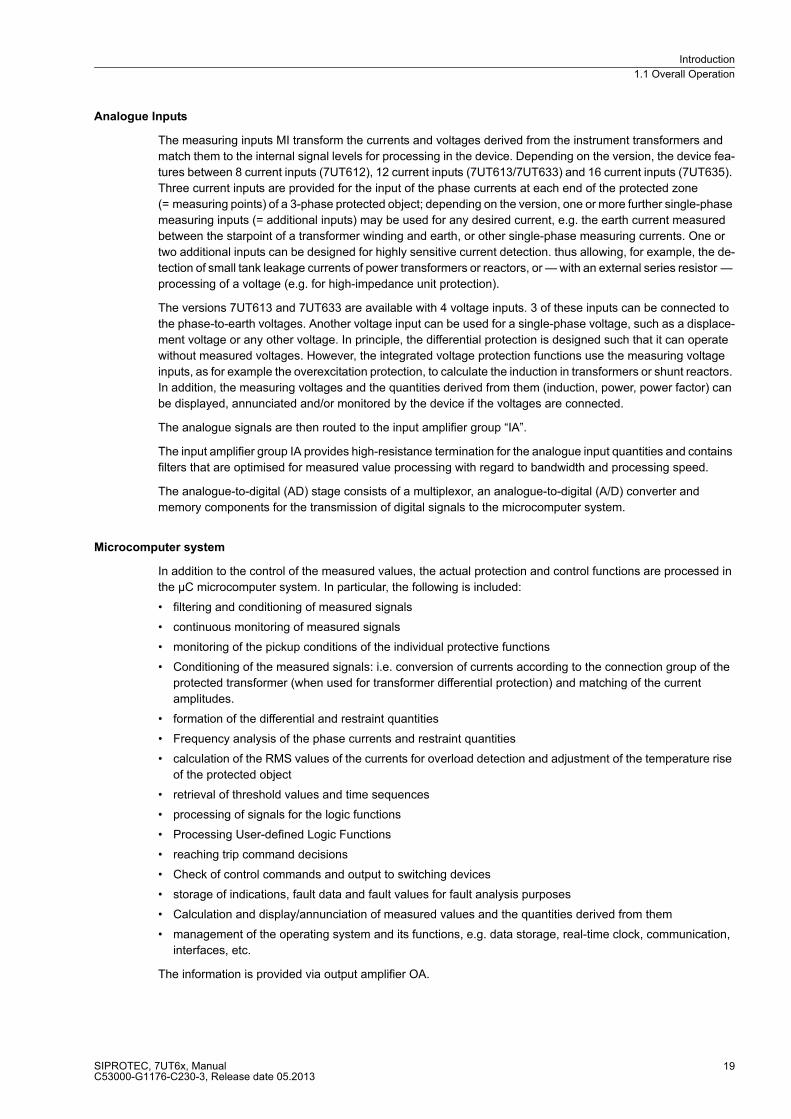
Analogue Inputs
The measuring inputs MI transform the currents and voltages derived from the instrument transformers and
match them to the internal signal levels for processing in the device. Depending on the version, the device fea-
tures between 8 current inputs (7UT612), 12 current inputs (7UT613/7UT633) and 16 current inputs (7UT635).
Three current inputs are provided for the input of the phase currents at each end of the protected zone
(= measuring points) of a 3-phase protected object; depending on the version, one or more further single-phase
measuring inputs (= additional inputs) may be used for any desired current, e.g. the earth current measured
between the starpoint of a transformer winding and earth, or other single-phase measuring currents. One or
two additional inputs can be designed for highly sensitive current detection. thus allowing, for example, the de-
tection of small tank leakage currents of power transformers or reactors, or — with an external series resistor —
processing of a voltage (e.g. for high-impedance unit protection).
The versions 7UT613 and 7UT633 are available with 4 voltage inputs. 3 of these inputs can be connected to
the phase-to-earth voltages. Another voltage input can be used for a single-phase voltage, such as a displace-
ment voltage or any other voltage. In principle, the differential protection is designed such that it can operate
without measured voltages. However, the integrated voltage protection functions use the measuring voltage
inputs, as for example the overexcitation protection, to calculate the induction in transformers or shunt reactors.
In addition, the measuring voltages and the quantities derived from them (induction, power, power factor) can
be displayed, annunciated and/or monitored by the device if the voltages are connected.
The analogue signals are then routed to the input amplifier group “IA”.
The input amplifier group IA provides high-resistance termination for the analogue input quantities and contains
filters that are optimised for measured value processing with regard to bandwidth and processing speed.
The analogue-to-digital (AD) stage consists of a multiplexor, an analogue-to-digital (A/D) converter and
memory components for the transmission of digital signals to the microcomputer system.
Microcomputer system
In addition to the control of the measured values, the actual protection and control functions are processed in
the µC microcomputer system. In particular, the following is included:
� filtering and conditioning of measured signals
� continuous monitoring of measured signals
� monitoring of the pickup conditions of the individual protective functions
� Conditioning of the measured signals: i.e. conversion of currents according to the connection group of the
protected transformer (when used for transformer differential protection) and matching of the current
amplitudes.
� formation of the differential and restraint quantities
� Frequency analysis of the phase currents and restraint quantities
� calculation of the RMS values of the currents for overload detection and adjustment of the temperature rise
of the protected object
� retrieval of threshold values and time sequences
� processing of signals for the logic functions
� Processing User-defined Logic Functions
� reaching trip command decisions
� Check of control commands and output to switching devices
� storage of indications, fault data and fault values for fault analysis purposes
� Calculation and display/annunciation of measured values and the quantities derived from them
� management of the operating system and its functions, e.g. data storage, real-time clock, communication,
interfaces, etc.
The information is provided via output amplifier OA.
Introduction
1.1 Overall Operation
SIPROTEC, 7UT6x, ManualC53000-G1176-C230-3, Release date 05.2013
20
Binary Inputs and Outputs
Binary inputs and outputs from and to the computer system are routed via the I/O modules (inputs and outputs).
The computer system obtains the information from the system (e.g remote resetting) or from other devices (e.g.
blocking commands). These outputs include, in particular, trip commands to switchgear and signals for remote
annunciation of important events and conditions.
Front Elements
Devices with operator panel have light emitting diodes (LEDs) and a display screen (LCD) on the front panel
to provide information such as measured values, messages related to events or faults, status, and functional
status..
Integrated control and numeric keys in conjunction with the LCD facilitate local interaction with the 7UT6. All
information of the device can be accessed using the integrated control and numeric keys. The information
includes protective and control settings, operating and fault messages, and measured values.
In addition, control of circuit breakers and other equipment is possible from the 7UT6 front panel.
The versions 7UT612 and 7UT613 have a 4-line LC display in front, whereas the versions 7UT633 and 7UT635
have a graphic display. The latter devices also have integrated keyswitches and control buttons for on-site
control.
Serial interfaces
Via the serial operator interface in the front panel, communication with a personal computer using the
operating program DIGSI is possible. This facilitates a comfortable handling of all device functions.
A serial service interface can likewise make communication via PC with the device possible by using DIGSI.
This port is especially well suited for the fixed wiring of the devices to the PC or operation via a modem.
All data can be transferred to a central control or monitoring system via the serial system port. This interface
may be provided with various protocols and physical transmission schemes to suit the particular application.
A further interface is provided for the time synchronization of the internal clock via external synchronization
sources.
Further communication protocols can be realized via additional interface modules.
The service port, or an optional additional interface, can also be used to connect a RTD-Box (= resistance
temperature detector) for entering external temperatures (e.g. for overload protection). The additional inter-
face is available for all 7UT6x devices.
Power Supply
The functional units described are supplied by a power supply PS with the necessary power in the different
voltage levels. Transient dips of the supply voltage, which may occur during short-circuit in the power supply
system, are bridged by a capacitor (see also Technical Data).

Introduction
1.2 Application Scope
SIPROTEC, 7UT6x, ManualC53000-G1176-C230-3, Release date 05.2013
21
1.2 Application Scope
The numerical differential protection SIPROTEC 4 7UT6x is a selective short-circuit protection for transformers
of all voltage levels, for rotating machines, for series and shunt reactors, or for short lines and mini-busbars with
2 to 5 feeders (depending on the version). Being a single-phase device, it can also be used for small busbars
with up to 7, 9 or 12 feeders (depending on the version). The individual application can be configured, which
ensures optimum matching to the protected object.
The devices 7UT613, 7UT633 and 7UT635 can also be run with 2-phase connection for 16.7 Hz applications.
A major advantage of the differential protection principle is the instantaneous tripping in the event of a short-
circuit at any point within the entire protected zone. The current transformers limit the protected zone at the
ends towards the network. This rigid limit is the reason why the differential protection scheme shows such an
ideal selectivity.
For use as transformer protection, the device is normally connected to the current transformer sets which limit
the power transformer windings against the remainder of the system. The phase displacement and the inter-
linkage of the currents due to the winding connection of the transformer are matched in the device by calcula-
tion algorithms. The earthing conditions of the starpoint(s) can be adapted to the user's requirements and are
automatically considered in the matching algorithms. Also, the currents from multiple measuring points on one
side of the protected object can be combined.
For use as generator or motor protection, the device compares the currents in the starpoint leads of the
machine and at its terminals. Similar applies for series reactors.
Short lines or mini-busbars with 2 to 5 ends or feeders (depending on the version) can be protected as well.
Short means that the current transformer connections from the CTs to the device cause no impermissible
burden for the current transformers.
For transformers, generators, motors, or shunt reactors with earthed starpoint, the current between the star-
point and earth can be measured and used for highly sensitive earth fault protection.
The 7, 9 or 12 standard current inputs (depending on the version) of the device allow for a single-phase
protection for busbars with up to 7, 9 or 12 feeders. One 7UT6x is used per phase in this case. Alternatively,
(external) summation transformers can be installed in order to allow a busbar protection for up to 7, 9 or 12
feeders with one single 7UT6x relay.
Where not all analog measuring inputs are needed for the measured values of the protected object, the remain-
ing inputs can be used for other, independent measurement or protection tasks. If a 7UT635 (with 5 three-
phase measuring inputs) is used, for instance, on a three-winding transformer, the two remaining measuring
inputs can be used for overcurrent time protection of one or two protected objects e.g. the auxiliaries system
circuit.
One or two additional current inputs designed for very high sensitivity are also available. They may be used
e.g. for detection of small leakage currents between the tank of transformers or reactors an earth, thus
recognising even high-resistance faults. High-resistance voltage measurement is also possible using an
external series resistor.
For transformers (including auto-transformers), generators, and shunt reactors, a high-impedance unit protec-
tion system can be formed using high-impedance earth fault protection. In this case, the currents of all current
transformers (of equal design) at the ends of the protected zone feed a common (external) high-ohmic resistor.
The current of this resistor is measured using one of the high-sensitive current inputs of the device.
The device provides backup time overcurrent protection functions for all types of protected objects. The
functions can be enabled for any side or measuring location.
A thermal overload protection function is available for any type of machine. The functions can be enabled for
any side. External detectors account for the coolant temperature (by means of an external RTD-box). This
allows to calculate and output the hot-spot temperature and the relative ageing rate.

Introduction
1.2 Application Scope
SIPROTEC, 7UT6x, ManualC53000-G1176-C230-3, Release date 05.2013
22
An unbalanced load protection function is provided for the detection of unsymmetrical currents. Phase failures
and negative sequence currents, which are especially dangerous for rotating machines, can thus be detected.
Performance functions allow devices with voltage measuring inputs to implement a reverse power protection
or monitor the forward power supply(in the power station sector). In the system they can be used for network
decoupling. Power results and their components can be emitted as measured values.
The versions with voltage inputs are provided with an integrated overexcitation protection for the detection of
excessive induction states in shunt reactions (transformers, shunt reactors). This protection function monitors
the ratio U/f, which is proportional to the induction B in the iron core. An imminent iron core saturation, which
can occur especially in power stations following (full) load shutdown and/or frequency reduction, is thus
detected.
An undervoltage and overvoltage protection is to be integrated into devices with voltage measuring inputs. A
4-stage frequency protection monitors the frequency from the measured voltages.
A version for two-phase application is available for traction supply (transformers or generators) which provides
all functions suited for this application (differential protection, restricted earth fault protection, overcurrent pro-
tection, overload protection).
A circuit breaker failure protection checks the reaction of one circuit breaker after a trip command.
Fruther-reaching protection, monitoring and measuring functions can be configured individually by means of
flexible functions. For up to 12 such functions, you determine yourself which measuring quantities to process
and how to process them, and also which reactions the device is to trigger when settable limit values are over-
or undershot. Thus you can, for instance, create further time overcurrent protection functions and process volt-
ages, powers or symmetrical components.
One can configure the calculation of minimum, maximum and/or average values and/or minimum, maximum of
the average values of up to 20 selectable measured quantities, thus receiving one's own statistical data.
For the devices 7UT613, 7UT633 and 7UT635, you can optionally create some protective functions several
times and assign them flexibly to the measuring locations of the protected object. Examples: Time overcurrent
protection, breaker failure protection, and the like (see Technical Data).
Introduction
1.3 Characteristics
SIPROTEC, 7UT6x, ManualC53000-G1176-C230-3, Release date 05.2013
23
1.3 Characteristics
General Features
� Powerful 32-bit microprocessor system.
� Complete digital measured value processing and control, from the sampling and digitalization of the
analogue input quantities to the initiation of outputs for tripping or closing circuit breakers.
� Complete galvanic and reliable separation between the internal processing circuits of the device and the
external measurement, control, and power supply circuits because of the design of the analog input trans-
ducers, binary input and output modules, and the DC/DC or AC/DC converters.
� Suitable for power transformers, generator, motors, reactors, or smaller busbar arrangements, as well as for
multi-terminal lines and multi-winding transformers
� Easy device operation through an integrated operator panel or by means of a connected personal computer
running DIGSI.
Transformer Differential Protection
� Current restraint tripping characteristic
� Restraint feature against high inrush currents with 2nd harmonic
� Restraint feature against transient and steady-state fault currents caused e.g. by overexcitation of transform-
ers, using a further harmonic (3rd or 5th harmonic)
� Insensitivity to DC components and current transformer saturation
� High level of stability even with different degrees of current transformer saturation
� High-speed instantaneous trip in case of high-current transformer faults
� Independent of the conditioning of the starpoint(s) of the power transformer.
� Adjustable to the conditioning of the starpoint(s) of the power transformer
� Increased earth-fault sensitivity during detection of the ground current of an earthed transformer winding
� Integrated matching of the transformer connection group
� Integrated matching of the transformation ratio including different rated currents of the transformer windings
Differential Protection for Generators and Motors
� Current restraint tripping characteristic.
� High sensitivity
� Short tripping time
� Insensitivity to DC components and current transformer saturation
� High level of stability even with different degrees of current transformer saturation
� Independent of the conditioning of the starpoint
Introduction
1.3 Characteristics
SIPROTEC, 7UT6x, ManualC53000-G1176-C230-3, Release date 05.2013
24
Differential Protection for Mini-Busbars and Short Lines
� Tripping characteristic with current restraint
� Short tripping time
� Insensitivity to DC components and current transformer saturation
� High level of stability even with different degrees of current transformer saturation
� Monitoring of the current connections with operation currents
Busbar Protection
� Single-phase differential protection for a busbar with up to 7 or 9 or 12 feeders (depending on the variant
ordered)
� Either one relay per phase or one relay connected via interposed summation current transformers
� Tripping characteristic with current restraint
� Short tripping time
� Insensitivity to DC components and current transformer saturation
� High level of stability even with different degrees of current transformer saturation
� Monitoring of the current connections with operation currents.
Earth Fault Differential Protection
� Earth fault protection for earthed transformer windings, generators, motors, shunt reactors, or starpoint
formers
� Short command duration
� High sensitivity for earth faults within the protected zone
� High stability against external earth faults using the magnitude and phase relationship of through-flowing
earth current.
� 2 restricted earth fault protection functions possible (only 7UT613/63x)
High-impedance Unit Protection
� Highly sensitive fault current detection using a common (external) burden resistor
� Short tripping time
� Insensitive against DC components and current transformer saturation
� High stability with optimum matching
� Suitable for earth fault detection on earthed generators, motors, shunt reactors, and transformers, including
auto-transformers, with or without earthed starpoint.
� Suitable for any voltage measurement (via the resistor current) for application of high-impedance unit
protection
Tank Leakage Protection
� For transformers or reactors the tank of which is installed isolated or with high resistance
� Monitoring of the current flowing between the tank and ground
� Can be connected via a „normal“ current input of the device or the special highly sensitive current input
(3 mA smallest setting).

Introduction
1.3 Characteristics
SIPROTEC, 7UT6x, ManualC53000-G1176-C230-3, Release date 05.2013
25
Time Overcurrent Protection for Phase Currents and Residual Current
� Two definite time delayed overcurrent stages for each of the phase currents and the residual (threefold zero
sequence) current, can be assigned to any of the sides of the protected object or to any measuring point
� Additionally, one inverse time delayed overcurrent stage for each of the phase currents and the residual
current
� Selection of various inverse time characteristics of different standards is possible, alternatively a user
defined characteristic can be specified
� The stages can be combined as desired, different characteristics can be selected for phase currents on the
one hand and the residual current on the other
� External blocking facility for any stage (e.g. for reverse interlocking)
� Instantaneous tripping possible at any stage when closing onto a short-circuit
� Inrush restraint using the second harmonic of the measured current
� Dynamic switchover of the time overcurrent protection settings, e.g. during cold-load start-up of the power
plant
� 3 time overcurrent protection functions each for phase currents and zero sequence current possible (only
7UT613/63x)
Time Overcurrent Protection for Earth Current
� Two definite time delayed overcurrent stages for the earth current, e.g. current between starpoint and earth
� Additionally, one inverse time delayed overcurrent stage for the earth current
� Selection of various inverse time characteristics of different standards is possible, alternatively a user
defined characteristic can be specified
� The three can be combined as desired
� External blocking facility for any desired stage (e.g. for reverse interlocking)
� Instantaneous trip when switching on a dead fault with any desired stage
� Inrush restraint function with 2nd harmonic
� Dynamic switchover of the time overcurrent parameters, e.g. during cold-loaded start-up of the power plant
� 2 time overcurrent protection functions for earth current possible (only 7UT613/63x)
1-phase Overcurrent Protection
� Two definite time delayed overcurrent stages which can be combined as desired
� For any 1-phase overcurrent detection
� Can be assigned to the „normal “1-phase current input or to the highly sensitive current input
� Suitable for detection of very small current (e.g. for high-impedance unit protection or tank leakage
protection)
� Suitable for detection of any desired AC voltage using an external series resistor (e.g. for high-impedance
unit protection)
� External blocking facility for any stage
Introduction
1.3 Characteristics
SIPROTEC, 7UT6x, ManualC53000-G1176-C230-3, Release date 05.2013
26
Unbalanced Load Protection
� Evaluation of the negative sequence system of the three phase currents of any desired side of the protected
object or any three-phase measuring point
� Two definite time delayed negative sequence current stages and one additional inverse time delayed
negative sequence current stage
� Selection of various inverse time characteristics of different standards is possible, alternatively a user
defined characteristic can be specified
� The stages can be combined as desired.
� Trip blocking on detection of broken wire
� Thermal characteristic with adjustable negative sequence factor and adjustable cooldown time.
Thermal Overload Protection
� Thermal replica of current-initiated heat losses
� True RMS current calculation
� Can be assigned to any desired side of the protective object
� Adjustable thermal warning stage
� Adjustable current warning stage
� With or without including the ambient or coolant temperature (by means of external resistance temperature
detector via RTD-box)
� Alternative evaluation of the hot-spot temperature according to IEC 60354 with calculation of the reserve
power and ageing rate (by means of external resistance temperature detector via RTD-box)
� 2 overload protection functions possible (only 7UT613/63x)
Overexcitation protection (only 7UT613 and 7UT633)
� Processing of the voltage/frequency ration U/f, which represents the induction B of a shunt reactance
(transformer, shunt reactor)
� Adjustable warning and tripping stage (with independent delay time)
� Inverse standard characteristic or user-defined trip characteristic for calculation of the thermal stress,
selectable
Reverse power protection (only 7UT613 and 7UT633)
� Real power calculation from positive sequence components
� Short operating time or exact calculation of the active power via 16 cycles
� Exact real power calculation for small power factor by compensating the error angle of the measuring
locations
� Insensitive to power fluctuations
� Short-time stage with external criteria, e.g. with closed emergency tripping

Introduction
1.3 Characteristics
SIPROTEC, 7UT6x, ManualC53000-G1176-C230-3, Release date 05.2013
27
Forward power supervision (only 7UT613 and 7UT633)
� Real power calculation from positive sequence components
� Supervision of overvoltage (P>) or undervoltage (P<) of power with individually adjustable power limits
� Short operating time or exact calculation of the active power via 16 cycles
� Automatic blocking of stage P< for recognised measured voltage failure or wire break in CT secondary circuit
Undervoltage protection (only 7UT613 and 7UT633)
� Two-stage three-phase undervoltage measurement
� Evaluation of positive sequence component of the connected voltages, therefore independent of
asymmetries
� Automatic blocking for measuring voltage failure
� Adjustable dropout ratio
Overvoltage protection (only 7UT613 and 7UT633)
� Two-stage three-phase overvoltage measurement
� Evaluation of the largest of the three phase-to-ground voltages or the largest of the three phase-to-phase
voltages (largest of the three phase-to-phase voltages (can be set)
� Adjustable dropout ratio
Frequency protection (only 7UT613 and 7UT633)
� Three underfrequency stages and one overfrequency stage
� Frequency measurement via the positive sequence component of the voltages
� Insensitive to harmonics and abrupt phase angle changes
� Adjustable undervoltage threshold
Circuit Breaker Failure Protection
� With monitoring of current flow through each breaker pole on any side of the protected object
� Supervision of the breaker position possible (if breaker auxiliary contacts or feedback signal available)
� Initiation by each of the internal protection functions
� Start by external trip functions possible
� Single-stage or two-stage
� Short dropout and overshoot times
� 2 breaker failure protection functions possible (only 7UT613/63x)
Introduction
1.3 Characteristics
SIPROTEC, 7UT6x, ManualC53000-G1176-C230-3, Release date 05.2013
28
External Direct Trip
� Tripping of either circuit breaker by an external device via binary inputs
� Inclusion of external commands into the internal processing of information and trip commands
� With or without trip time delay
Processing of external information
� Inclusion of external signals (user defined information) in internal information processing
� Pre-defined transformer annunciations for Buchholz protection and oil gassing
� Transmission to output relays, LEDs, and via serial system interfaces to central control and data storage
facilities
Flexible functions (only 7UT613/63x)
� Up to 12 individually configurable protection or monitoring functions
� Input quantities can be selected from all the connected 3-phase or 1-phase measured quantities
� Also possible from the measured or combined input quantities: symmetrical components, power
components, frequency
� Standard logic with supervision of the input quantities to over/undershooting of an adjustable limit value
� Settable time and dropout delay
� External blocking via „Blocking on Measured Quantities Failure“ parameterisable
� Editable message texts
� Additional determination and output of up to 20 mean values from measured quantities or calculated values
� Additional determination and output of up to 20 mean values from measured quantities or calculated values
User-defined Logic Functions (CFC)
� Freely programmable combination of internal and external signals for the implementation of user-defined
logic functions
� All typical logic functions
� Time delays and limit value inquiries
Commissioning, Operation
� Isolation of one side or measuring point for maintenance work: the isolated line or measuring point is
withdrawn from the differential protection system processing, without affecting the remainder of the
protection system
� Comprehensive support facilities for operation and commissioning
� Indication of all measured values, amplitudes and phase relation
� Indication of the calculated differential and restraint currents
� Integrated help tools can be visualised by means of a standard browser: Phasor diagrams of all currents of
all sides and measuring locations of the protected object are displayed as a graph.
� Connection and direction checks as well as interface check

Introduction
1.3 Characteristics
SIPROTEC, 7UT6x, ManualC53000-G1176-C230-3, Release date 05.2013
29
Monitoring Functions
� Availability of the device is greatly increased because of self-monitoring of the internal measurement circuits,
power supply, hardware, and software
� Supervision of the current transformer secondary circuits of symmetry and phase sequence
� Monitoring of the voltage transformer circuits (if voltage inputs are available) for symmetry, voltage sum and
phase rotation
� Supervision of the voltage transformer circuits (if voltage inputs are available) for voltage failure with fast
function blocking that measure undervoltages
� Checking the consistency of protection settings regarding the protected object and possible assignment of
the current inputs: Blocking of the differential protection system in case of inconsistent settings which could
lead to a malfunction
� Trip circuit supervision is possible.
� Broken wire supervision for the secondary CT circuits with fast phase segregated blocking of the differential
protection functions and the unbalanced load protection in order to avoid spurious tripping.
Further Functions
� Battery-buffered real-time clock, which may be synchronised via a synchronisation signal (e.g. DCF77, IRIG
B via satellite receiver), binary input or system interface
� Continuous calculation and display of operational measured values on the front of the device; indication of
measured quantities of all sides of the protected object
� Fault event memory (trip log) for the last 8 network faults (faults in the power system), with real-time
assignment
� Fault recording memory and transmission of the data for analogue and user-defined binary signals with a
maximum time range of about 5s
� Switching Statistics: Recording of the trip commands issued by the device, as well as recording of the fault
current data and accumulation of the interrupted fault currents
� Communication with central control and data storage equipment possible via serial interfaces (depending
on the individual ordering variant) by means of data cable, modem or optical fibres Various transmission
protocols are provided for this purpose.
■

Introduction
1.3 Characteristics
SIPROTEC, 7UT6x, ManualC53000-G1176-C230-3, Release date 05.2013
30
SIPROTEC, 7UT6x, ManualC53000-G1176-C230-3, Release date 05.2013
31
Functions 2
This chapter describes the individual functions of the SIPROTEC 4 device 7UT6x. It shows the setting
possibilities for each function in maximum configuration. Guidelines for establishing setting values and, where
required, formulae are given.
Based on the following information, it can also be determined which of the provided functions should be used.
2.1 General 32
2.2 Differential Protection 105
2.3 Restricted Earth Fault Protection 140
2.4 Time Overcurrent Protection for Phase and Residual Currents 152
2.5 Time Overcurrent Protection for Earth Current 182
2.6 Dynamic Cold Load Pickup for Time Overcurrent Protection 195
2.7 Single-Phase Time Overcurrent Protection 200
2.8 Unbalanced Load Protection 212
2.9 Thermal Overload Protection 227
2.10 RTD-Boxes for Overload Detection 241
2.11 Overexcitation Protection 248
2.12 Reverse Power Protection 254
2.13 Forward Power Supervision 259
2.14 Undervoltage Protection 264
2.15 Overvoltage Protection 268
2.16 Frequency Protection 272
2.17 Circuit Breaker Failure Protection 278
2.18 External Trip Commands 287
2.19 Monitoring Functions 290
2.20 Protection Function Control 312
2.21 Disconnection of Measuring Locations 315
2.22 Additional Functions 318
2.23 Average Values, Minimum and Maximum Values 349
2.24 Command Processing 352
Functions
2.1 General
SIPROTEC, 7UT6x, ManualC53000-G1176-C230-3, Release date 05.2013
32
2.1 General
A few seconds after the device is switched on, the default display appears on the LCD. In the 7UT6x the
measured values are displayed.
The function parameters, i.e. function options, threshold values, etc., can be changed via the front panel of the
device, or via the operator or service interface from a personal computer using DIGSI. Password no. 5
(individual parameters) is required. Operation via DIGSI is described in the SIPROTEC system description /1/.
In this general section, you make the basic decision for the correct interaction between your system, its
measuring points, the analog device connections and the protective functions of the device. Because of the
comprehensive range of features provided by the devices of the 7UT6x family, this section is quite extensive.
The device here acquires as complete as possible a profile of the system to be protected with its measuring
locations, i.e. the current and voltage transformers, and which protective functions of the device are to take
effect in what way.
In a first step (Section 2.1.3), you specify which type of system element you want to protect, since the scope of
additional features offered varies depending on the type of main protected object. Then you decide which pro-
tection functions you want to use, because not all of the functions integrated in the device are necessary, useful
or even possible for your relevant case of application.
In the next step (section 2.1.4), you describe the topology of the protected object. i.e. the arrangement of the
protected object, its sides (windings for transformers, sides for generators/motors, ends for lines, feeders for
busbars), and the measuring locations which will provide the respective measured values.
After entering some General Power System Data (frequency, phase sequence), you inform the device in
section 2.1.4 of the properties of the main protected object. Object properties include the ratings and (in the
case of transformers) the starpoint treatment, vector group and, where applicable, the auto-transformer
winding.
Subsection 2.1.4 also deals with the CT data which must be set to ensure that the currents acquired at the
various measuring locations are evaluated in the device with the correct scale factor.
The above information is sufficient to describe the protected object to the device's main protection function, i.e.
the differential protection. For the other protection functions, you select in section 2.1.6 the measured values
which will be processed by you and in which way.
The same section 2.1.6 provides information with regard to how to set the circuit breaker data, and finding out
about setting groups and how to use them. Last but not least, you can set general data which are not dependent
on any protection functions.

Functions
2.1 General
SIPROTEC, 7UT6x, ManualC53000-G1176-C230-3, Release date 05.2013
33
2.1.1 Device
2.1.1.1 Setting Notes
The parameters for the tripping logic of the entire device and the circuit breaker test have already been set in
section 2.1.4.
Address 201 FltDisp.LED/LCD also decides whether the alarms that are allocated to local LEDs and the spon-
taneous displays that appear on the local display after a fault should be displayed on every pickup of a protec-
tion function (Target on PU) or whether they should be stored only when a tripping command is given (Target on
TRIP).
For devices with graphical display, use address 202 Spont. FltDisp. to specify whether or not a spontaneous
annunciation will appear automatically on the display (YES) or not (NO). For devices with text display such in-
dications will appear after a system fault by any means.
In devices with text display, the start page of the basic display can be selected under address 204 Start image
DD.
2.1.1.2 Settings
Addr. Parameter Setting Options Default Setting Comments
201 FltDisp.LED/LCD Target on PUTarget on TRIP
Target on PU Fault Display on LED / LCD
202 Spont. FltDisp. NOYES
NO Spontaneous display of flt.annunciations
204 Start image DD image 1image 2image 3image 4image 5image 6image 7
image 1 Start image Default Display
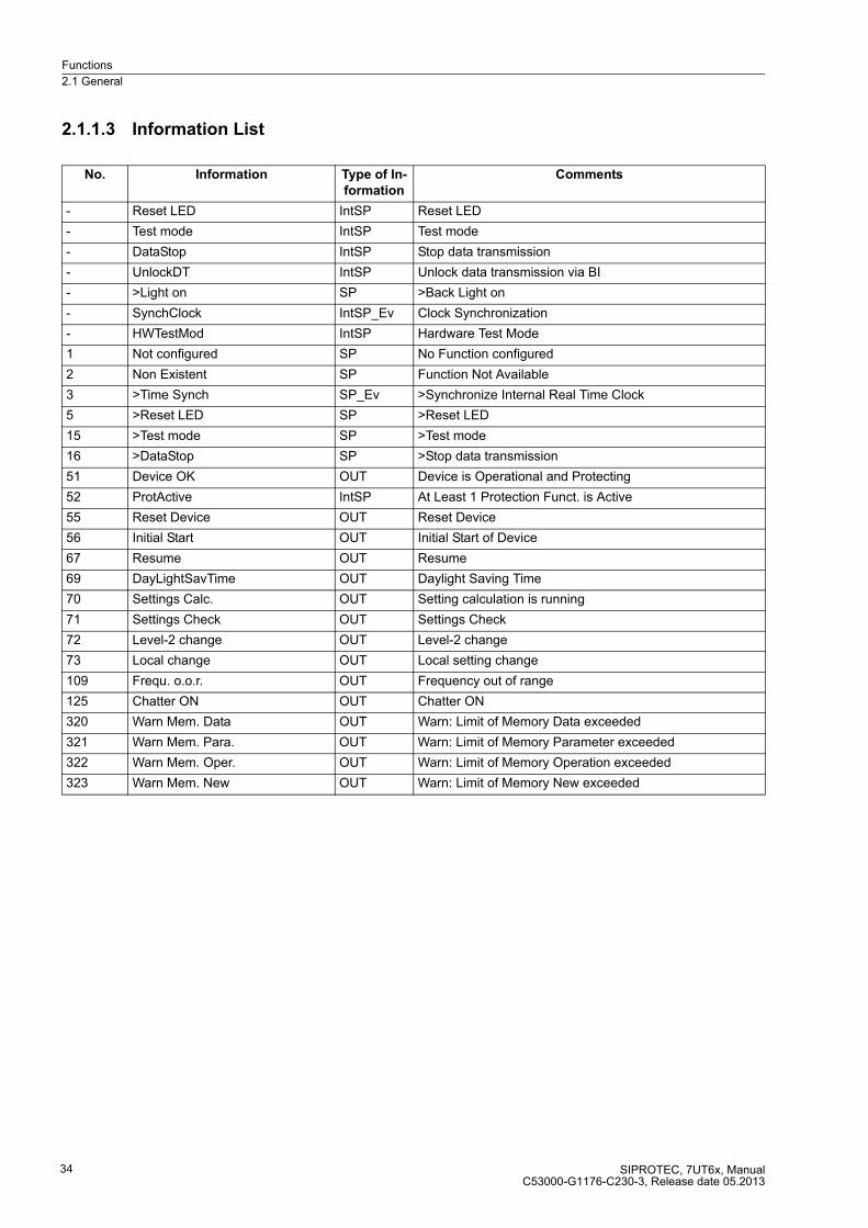
Functions
2.1 General
SIPROTEC, 7UT6x, ManualC53000-G1176-C230-3, Release date 05.2013
34
2.1.1.3 Information List
No. Information Type of In-
formation
Comments
- Reset LED IntSP Reset LED
- Test mode IntSP Test mode
- DataStop IntSP Stop data transmission
- UnlockDT IntSP Unlock data transmission via BI
- >Light on SP >Back Light on
- SynchClock IntSP_Ev Clock Synchronization
- HWTestMod IntSP Hardware Test Mode
1 Not configured SP No Function configured
2 Non Existent SP Function Not Available
3 >Time Synch SP_Ev >Synchronize Internal Real Time Clock
5 >Reset LED SP >Reset LED
15 >Test mode SP >Test mode
16 >DataStop SP >Stop data transmission
51 Device OK OUT Device is Operational and Protecting
52 ProtActive IntSP At Least 1 Protection Funct. is Active
55 Reset Device OUT Reset Device
56 Initial Start OUT Initial Start of Device
67 Resume OUT Resume
69 DayLightSavTime OUT Daylight Saving Time
70 Settings Calc. OUT Setting calculation is running
71 Settings Check OUT Settings Check
72 Level-2 change OUT Level-2 change
73 Local change OUT Local setting change
109 Frequ. o.o.r. OUT Frequency out of range
125 Chatter ON OUT Chatter ON
320 Warn Mem. Data OUT Warn: Limit of Memory Data exceeded
321 Warn Mem. Para. OUT Warn: Limit of Memory Parameter exceeded
322 Warn Mem. Oper. OUT Warn: Limit of Memory Operation exceeded
323 Warn Mem. New OUT Warn: Limit of Memory New exceeded

Functions
2.1 General
SIPROTEC, 7UT6x, ManualC53000-G1176-C230-3, Release date 05.2013
35
2.1.2 EN100-Modul 1
2.1.2.1 Function Description
An EN100-Modul 1 allows to integrate the 7UT6x into 100 Mbit communication networks used by process
control and automation systems in accordance with IEC 61850. This standard provides consistent inter-relay
communication without gateways or protocol converters. This allows open and interoperable use of
SIPROTEC 4 devices even in heterogeneous environments. In parallel to the process control integration of the
device, this interface can also be used for communication with DIGSI and for inter-relay communication via
GOOSE.
2.1.2.2 Setting Notes
Interface Selection
No settings are required for operation of the Ethernet system interface module (IEC 61850 EN100-Modul 1). If
the device is equipped with such a module (see MLFB), the module is automatically configured to the interface
available for it, namely Port B.
2.1.2.3 Information List
No. Information Type of In-
formation
Comments
009.0100 Failure Modul IntSP Failure EN100 Modul
009.0101 Fail Ch1 IntSP Failure EN100 Link Channel 1 (Ch1)
009.0102 Fail Ch2 IntSP Failure EN100 Link Channel 2 (Ch2)

Functions
2.1 General
SIPROTEC, 7UT6x, ManualC53000-G1176-C230-3, Release date 05.2013
36
2.1.3 Configuration of the Functional Scope
The devices 7UT6x contain a series of protective and additional functions. The scope of hardware and firmware
is matched to these functions. Additionally, the control functions can be in accordance with the system require-
ments. In addition, individual functions may be enabled or disabled during configuration, or interaction between
functions may be adjusted. Functions not to be used in the actual 7UT6x device can thus be masked out.
Example for the configuration of the scope of functions:
7UT6x devices are intended to be used for busbars and transformers. Overload protection should only be
applied on transformers. If the device is used for busbars this function is set to Disabled, for the transformers
this function is set to Enabled.
The available protection and additional functions can be configured as Enabled or Disabled. For various func-
tions, a choice may be presented between several options which are explained below. Functions configured as
Disabled are not processed by the 7UT6x. There are no indications, and associated settings (functions, limit
values) are not displayed during detailed settings.
2.1.3.1 Setting Notes
Determination of the Functional Scope
Configuration settings can be entered using a PC and the software program DIGSI and transferred via the front
serial port or the rear service interface. The operation via DIGSI is explained in the SIPROTEC System
Description/1/.
In order to change configuration parameter, entering of password no. 7 (for parameter set) is required.
Without the password, the settings may be read, but may not be modified and transmitted to the device.
Function scope and, if necessary, the available options are set in the Function Scope dialogue box to match
plant requirements.
Note
The available functions and default settings depend on the order variant of the device.
Special characteristics are set out in detail below. The annex includes a list of the functions with the suitable
protective objects.
Setting group switching
If the parameter group changeover function is desired, address 103 Grp Chge OPTION should be set to
Enabled. In this case, it is possible to apply up to four different groups of settings for the function parameters.
During normal operation, a convenient and fast switch-over between these setting groups is possible. The
setting Disabled implies that only one function parameter setting group can be applied and used.

Functions
2.1 General
SIPROTEC, 7UT6x, ManualC53000-G1176-C230-3, Release date 05.2013
37
Protected Object
The definition of the PROT. OBJECT (address 105) is important for the correct assignment of the setting
parameters and the possible inputs and outputs and functions of the device. This object is defined as the main
protected object which is intended to be protected by the differential protection. It should be mentioned here
that further parts of the power plant can be protected by other part functions if not all measured current inputs
of the device are necessary for the differential protection of the main protected object. The settings for the
protected object and the following protection functions are irrespective of how the protection functions act on
the protected object and which measuring locations (current transformers) are available.
� Normal Power transformers with separate windings are set as PROT. OBJECT = 3 phase transf. regardless
of the number of windings, vector groups and the earthing conditions of the starpoints. This is also valid if a
neutral earthing reactor is situated within the protected zone. If the differential protection shall cover a gen-
erator or motor and a unit-connected power transformer (also with more than 2 windings), the protected
object is also declared as transformer protection.
� For PROT. OBJECT = 1 phase transf. phase input L2 is not connected. This option is suited especially to
single-phase power transformers with 16.7 Hz (7UT613/63x). Single-phase transformers are generally
treated as three-phase protected objects.
� For auto-transformers select PROT. OBJECT = Autotransf., regardless whether the auto-transformer has
one or more further seperate windings. This option is also applicable for shunt reactors if current
transformers are installed at both sides of the connection points.
� If three single-phase auto-transformers are arranged as a power transformer bank (see figure 2-1), the
connections of the starpoint leads of the windings are accessible and often provided with current
transformers. Here, it is possible, instead of a normal transformer differential protection via an entire power
transformer bank, to realise three single-phase current comparison circuits via each auto transformer
winding. In figure 2-1 the protected zone of each phase is shaded.
Figure 2-1 Transformer bank, consisting of 3 single-phase auto-transformers with current comparison via each single phase
Functions
2.1 General
SIPROTEC, 7UT6x, ManualC53000-G1176-C230-3, Release date 05.2013
38
� Such current comparison is more sensitive to 1-phase earth faults in one of the transformers than the normal
differential protection. This has a certain importance considering that 1-phase earth faults are the most
probable faults in such banks.
� On the other hand, the compensation winding cannot and must not be included into this protection even if it
is accessible and equipped with current transformers. This application variant is based on the current law in
that all currents flowing into a winding must total to zero.
� If this protection variant is desired, set address 105 to PROT. OBJECT = Autotr. node.
� Equal setting is valid for generators and motors. The setting PROT. OBJECT = Generator/Motor also applies
to series reactors and shunt reactors, if a complete 3-phase set of current transformers is connected to both
sides.
� If the device is used for mini-busbars, select the option PROT. OBJECT = 3ph Busbar. The maximum number
of feeders is determined by the greates possible number of three-phase measuring inputs of the device.
7UT612 allows up to 2, 7UT613 and 7UT633 allow a maximum number of 3, 7UT635 a maximum of 5 mea-
suring locations. This setting applies also for short lines which are terminated by sets of current transformers
at each terminal. „Short“ means in this context that the current transformer connections from the CTs to the
device do not cause impermissible load to the current transformers.
� The device can be used as single-phase differential protection for busbars, either using one device per
phase or one device connected via external summation CTs. Select the optionPROT. OBJECT = 1ph Busbar
in this case. The maximum number of feeders is determined by the maximum possible number of single-
phase measuring locations of the device (7UT612 provides up to 7, 7UT613 and 7UT633 provide up to 9,
7UT635 up to 12 measuring locations).
Differential Protection
The differential protection is the main protective function of the device. Address 112 DIFF. PROT. is thus set to
Enabled.
Restricted Earth Fault Protection
The Restricted earth fault protection (address 113 REF PROT.) compares the sum of the phase currents flowing
into the three-phase protected object together with the current flowing into the earthed starpoint. Further infor-
mation is given in section 2.3.
Note that this is not applicable to the protected object busbar (address 105 PROT. OBJECT= 1ph Busbar and
address 105 PROT. OBJECT= 3ph Busbar).
Restricted Earth Fault Protection 2
The same is true in 7UT613/63x for the second potential restricted earth fault protection at address114 REF
PROT. 2
Dynamic Pickup Switching for Overcurrent Protection
The dynamic parameter switching (address 117 COLDLOAD PICKUP) permits temporary switching to alterna-
tive pickup values in case of overcurrent protection function for phase currents, zero sequence currents and
earth currents. Further information is given in section 2.6.
Functions
2.1 General
SIPROTEC, 7UT6x, ManualC53000-G1176-C230-3, Release date 05.2013
39
Overcurrent Protection for Phase Currents
To select the characteristic group according to which the phase overcurrent time protection is to operate use
address 120 DMT/IDMT Phase. This protection is not applicable for single-phase busbar protection
(address105 PROT. OBJECT = 1ph Busbar). If it is only used as definite time overcurrent protection (O/C), set
Definite Time. In addition to the definite time overcurrent protection an inverse time overcurrent protection may
be configured, if required. The latter operates according to an IEC-characteristic (TOC IEC), to an ANSI-char-
acteristic (TOC ANSI) or to a user-defined characteristic. In the latter case, the trip time characteristic (User
Defined PU) or both the trip time characteristic and the reset time characteristic (User def. Reset) are configured.
For the characteristics please refer to Technical Data.
Time overcurrent protection 2 and 3 for phase currents
With 7UT613/63x you have the option to use two further phase time overcurrent protection functions. This
enables you to implement one time overcurrent protection each on various sides of the protected object or on
various 3-phase measuring locations independent of each other. For DMT/IDMT Phase2, you may select from
the same options as for the first time overcurrent protection under address 130, the same applies under address
132 for DMT/IDMT Phase3. The selected options may be the same or different for the three time overcurrent
protection functions.
Time overcurrent protection for zero-sequence currents
The type of characteristics used for the zero sequence (residual) overcurrent time protection can be set in
address 122 DMT/IDMT 3I0. The same options are available as for the phase overcurrent protection. However,
for zero sequence current time overcurrent protection the settings may be different to the settings selected for
phase time overcurrent protection. This protection function always acquires the residual current 3I0 of the su-
pervised side. This current is calculated from the sum of the corresponding phase currents. This measuring
location may be different from that of the phase overcurrent protection. Note that the zero sequence overcurrent
protection is not possible on single-phase protected objects (address 105 PROT. OBJECT = 1 phase transf. or
1ph Busbar).
Time overcurrent protection 2 and 3 for zero sequence currents
With 7UT613/63x you have the option to use two further zero-sequence current time overcurrent protection
functions. This enables you to detect the zero sequence current at various 3-phase measuring locations
independent of each other. For DMT/IDMT 3I0 2, you may again select from the same options under address
134. Similar considerations apply, under address 136, forDMT/IDMT 3I0 3. The selected options may be the
same or different for the three time overcurrent protection functions.
Time Overcurrent Protection for Earth Current
There is another earth current time overcurrent protection which is independent from the before-described zero
sequence time overcurrent protection. This protection, to be configured in address 124 DMT/IDMT Earth, ac-
quires the current connected to a single-phase current measuring input. In most cases, it is the starpoint current
of an earthed starpoint (for transformers, generators, motors or shunt reactors). For this protection you may
select one of the characteristic types, the same way as for the phase time overcurrent protection, no matter
which characteristic has been selected for the latter.
Time overcurrent protection 2 for earth current (starpoint current)
For the detection of earth current, 7UT613/63x has another earth-current time overcurrent protection available
with which you can realize another single-phase time overcurrent protection. If, for example, you have earthed
a transformer YNyn0 at both starpoints, you can monitor the inflowing earth current in each starpoint. Of course,
you can also use the two earth-current time overcurrent protection funtions at completely different locations of
your system for the detection of single-phase currents. For DMT/IDMT Earth2, you may independently select
under address 138 from the same options as for the other time overcurrent protection functions .
Functions
2.1 General
SIPROTEC, 7UT6x, ManualC53000-G1176-C230-3, Release date 05.2013
40
Single-phase Overcurrent Protection
A single-phase definite-time overcurrent protection DMT 1PHASE for different user requirements is available
in address 127. This protection function is very well suited e.g. for highly sensitive tank leakage protection or
high-impedance unit protection. A high-sensitivity current input can be used for this purpose.
Asymmetrical Load Protection
The asymmetrical load protection monitors the asymmetrical current (negative sequence system) in three-
phase protected objects. In address 140 UNBALANCE LOAD the trip time characteristics can be set to definite
time (Definite Time), additionally operate according to an IEC–characteristic (TOC IEC) or to an ANSI–charac-
teristic (TOC ANSI). It can also be supplemented by a thermal stage (DT/thermal). The asymmetrical load pro-
tection is normally not possible in single-phase applications (address 105 PROT. OBJECT = 1 phase transf. or
1ph Busbar).
Thermal Overload Protection
In address 142 THERM. OVERLOAD the user can additionally choose one of the two methods of overload
detection. Note that the overload protection for single-phase busbar protection (address 105 PROT. OBJECT
= 1ph Busbar) is not possible. If the overload protection is not required, set to Disabled. Furthermore, the follow-
ing is available:
� Overload protection with a thermal replica according to IEC 60255-8,
� Overload protection with calculation of hot-spot temperature and the aging rate according to IEC 60354
� Overload protection using a thermal replica with ambient temperature influence
In the first case it can still be selected whether only the overtemperature in the thermal replica, resulting from
the ohmic losses in the windings of the protected object must be detected, or whether the total temperature
under consideration of the coolant or environmental temperature must be calculated.
If the coolant or environmental temperature must be taken into consideration, a RTD-box must be connected
to the device (see below), via which the coolant or environmental temperature is entered into the device. In this
case set address 142 THERM. OVERLOAD = th repl w. sens (thermal replica with temperature measurement).
If there is no possibility to measure the coolant or environmental temperature and to pass to the device, address
142 THERM. OVERLOAD = th rep w.o. sen (thermal replica without temperature measurement) can be set. In
this case the device calculates the overtemperature in the protected object from the flowing current, with refer-
ence to the permissible temperature. This method is characterised by its easy handling and a low number of
setting values.
Detailed knowledge about the protected object, the environment and cooling is required for overcurrent protec-
tion with hot-spot calculation in accordance with IEC 60354; it is advisable in case of transformers with inte-
grated temperature detectors. For this method, set address to 142 THERM. OVERLOAD = IEC354. For further
details see section 2.9
Thermal overload protection 2
With 7UT613/63x you have the option to use another overload protection. It allows you, for example in a trans-
former, to detect the overtemperature of two windings by current measurement, or, in addition to a transformer,
to monitor the windings of a shunt reactor. For THERM.OVERLOAD2, you may select under address 144 from
the same options as for the first overload protection .
Functions
2.1 General
SIPROTEC, 7UT6x, ManualC53000-G1176-C230-3, Release date 05.2013
41
RTD-boxes for Overload
If, in case of an overload with thermal replica, the coolant temperature must be taken into consideration, or if
an overload protection with hot-spot calculation in accordance with IEC 60354 is used (address 142 THERM.
OVERLOAD = th repl w. sens or IEC354), at least one RTD-box 7XV5662–xAD must be connected at the
service interface or an additional interface of the device, which informs the device with regard to the coolant
temperature. The additional interface is set in address 190 RTD-BOX INPUT. The possible interfaces are
dependent on the version of 7UT6x (cf. Ordering Information and Accessories in the Appendix). Port C (service
interface) is available in all versions. Depending on the device version, Port D is also possible.
RTD-box Type
If you operate RTD boxes with the device, the number and transmission type of the temperature detectors (RTD
= Resistance Temperature Detector) can be specified in address191 RTD CONNECTION: 6 RTD simplex or 6
RTD HDX (with one RTD-box) or 12 RTD HDX (with two RTD-boxes). The settings have to comply with those
of the RTD-box.
Note
The assignment with regard to which temperature measuring point shall be used for which overload protection
will be effected later during setting of the protection functions.
Overexcitation Protection
The overexcitation protection is used to detect increased overflux or overinduction conditions in generators and
transformers, especially in power station unit transformers, which cause impermissible temperature rise in the
iron. Note that the overexcitation protection (address 143 OVEREXC. PROT.) can only be used if the device is
equipped with voltage measurement inputs and voltages are connected. This protection is not applicable for
single-phase busbar protection (address105 PROT. OBJECT = 1ph Busbar). For further details see section 2.11
Reverse Power Protection
The reverse power protection (only for devices with measuring voltage inputs, address150 REVERSE POWER)
primarily protects a turbine generator unit on failure of energy to the prime mover. In the system it can be used,
for example, as a de-coupling criterion. It can only be used for three-phase protected objects, thus not for
address 105 PROT. OBJECT = 1 phase transf. or 1ph Busbar. The reverse current protection requires that the
device is connected to a voltage transformer set and, together with a connected current transformer, allows for
a reasonable calculation of the active power. The definition of the reverse direction is explained in detail else-
where.
Forward Power Monitoring
The forward power supervision (only in devices with measuring voltage inputs, address151 FORWARD
POWER) can monitor a protected object both for undershooting and for overshooting a pre-defined active
power. It can only be used for three-phase protected objects, thus not for address 105 PROT. OBJECT = 1 phase
transf. or 1ph Busbar. The forward power supervision requires that the device is connected to a voltage trans-
former set and, together with a connected current transformer, allows for a reasonable calculation of the active
power. The definition of the forward direction is explained in detail elsewhere.
Functions
2.1 General
SIPROTEC, 7UT6x, ManualC53000-G1176-C230-3, Release date 05.2013
42
Undervoltage Protection
Undervoltage protection (address 152 UNDERVOLTAGE) detects voltage dips in electrical machines and
avoids inadmissible operating states and possible loss of stability in electrical devices. It can only be used in
three-phase protected objects, thus not at address 105 PROT. OBJECT = 1 phase transf. or 1ph Busbar. It is
normally only possible in device variant that have a voltage measuring input.
Overvoltage Protection
The overvoltage protection (address 153 OVERVOLTAGE) protects the system from impermissible voltage
increases, thus avoiding damage to its insulation. It can only be used in three-phase protected objects, thus
not at address 105 PROT. OBJECT = 1 phase transf. or 1ph Busbar. It is normally only possible in device variant
that have a voltage measuring input.
Frequency Protection
The frequency protection (address 156 FREQUENCY Prot.) has the task to detect increased or decreased fre-
quencies in the power station sector. It can be applied, for example, as load shedding in the system. It can only
be used in three-phase protected objects, thus not at address 105 PROT. OBJECT = 1 phase transf. or 1ph
Busbar. As the frequency is derived from the measuring voltage, this is only possible in device versions with
voltage measuring inputs.
Circuit-breaker failure protection
The circuit-breaker protection (address 170 BREAKER FAILURE) is applicable to any circuit breaker. The
assignment is carried out at a later stage. Note that in a single-phase busbar protection (address 105 PROT.
OBJECT = 1ph Busbar) it is not possible.
Circuit breaker failure protection 2
The devices 7UT613/63x have a second curcuit breaker failure protection (address 171 BREAKER FAIL. 2) for
another circuit breaker of the system. The same as was specified for the first one applies here as well.
Measuring Location Disconnection
The disconnection of the measuring location (address 180 DISCON.MEAS.LOC) is a help function for
commissioning and revision works in the system.
Measured Value Monitoring
The different methods of measured value monitoring (address 181 M.V. SUPERV) are set out in detail in section
2.19.1. Voltages can of course also be monitored if the device provides voltage inputs.
Trip Circuit Supervision
For trip circuit monitoring, under address 182 Trip Cir. Sup., a selection can be made with regard to operation
with two binary inputs (2 Binary Inputs) or only one binary input (1 Binary Input). The inputs must be potential-
free.
External Trip Command
The possibilities of two trip commands from external sources can be configured in addresses 186 EXT. TRIP
1 and 187 EXT. TRIP 2.

Functions
2.1 General
SIPROTEC, 7UT6x, ManualC53000-G1176-C230-3, Release date 05.2013
43
Flexible Functions
The devices 7UT613/63x have flexible functions that can be used for protection, monitoring or measuring tasks.
If you wish to use such functions, please create them here. Options are
up to 12 flexible protection and monitoring functions are possible,
up to 20 average values from measured values or calculated values and
up to 20 minimum or maximum values for measured values or calculated values.
At this point, only select the respective required number. The configuration of this function, i.e. which input
variables are most relevant, and the setting of function parameters is carried out at a later stage, see section
2.22.7.
2.1.3.2 Settings
Addr. Parameter Setting Options Default Setting Comments
103 Grp Chge OPTION DisabledEnabled
Disabled Setting Group Change Option
105 PROT. OBJECT 3 phase transf.1 phase transf.Autotransf.Autotr. nodeGenerator/Motor3ph Busbar1ph Busbar
3 phase transf. Protection Object
112 DIFF. PROT. DisabledEnabled
Enabled Differential Protection
113 REF PROT. DisabledEnabled
Disabled Restricted earth fault protection
114 REF PROT. 2 DisabledEnabled
Disabled Restricted earth fault protection 2
117 COLDLOAD PICKUP DisabledEnabled
Disabled Cold Load Pickup
120 DMT/IDMT Phase DisabledDefinite TimeTOC IECTOC ANSIUser Defined PUUser def. Reset
Disabled DMT / IDMT Phase
122 DMT/IDMT 3I0 DisabledDefinite TimeTOC IECTOC ANSIUser Defined PUUser def. Reset
Disabled DMT / IDMT 3I0
124 DMT/IDMT Earth DisabledDefinite TimeTOC IECTOC ANSIUser Defined PUUser def. Reset
Disabled DMT / IDMT Earth
127 DMT 1PHASE DisabledEnabled
Disabled DMT 1Phase

Functions
2.1 General
SIPROTEC, 7UT6x, ManualC53000-G1176-C230-3, Release date 05.2013
44
130 DMT/IDMT Phase2 DisabledDefinite TimeTOC IECTOC ANSIUser Defined PUUser def. Reset
Disabled DMT / IDMT Phase 2
132 DMT/IDMT Phase3 DisabledDefinite TimeTOC IECTOC ANSIUser Defined PUUser def. Reset
Disabled DMT / IDMT Phase 3
134 DMT/IDMT 3I0 2 DisabledDefinite TimeTOC IECTOC ANSIUser Defined PUUser def. Reset
Disabled DMT / IDMT 3I0 2
136 DMT/IDMT 3I0 3 DisabledDefinite TimeTOC IECTOC ANSIUser Defined PUUser def. Reset
Disabled DMT / IDMT 3I0 3
138 DMT/IDMT Earth2 DisabledDefinite TimeTOC IECTOC ANSIUser Defined PUUser def. Reset
Disabled DMT / IDMT Earth 2
140 UNBALANCE LOAD DisabledDefinite TimeTOC IECTOC ANSIDT/thermal
Disabled Unbalance Load (Negative Sequence)
142 THERM. OVERLOAD Disabledth rep w.o. senth repl w. sensIEC354
Disabled Thermal Overload Protection
143 OVEREXC. PROT. DisabledEnabled
Disabled Overexcitation Protection (U/f)
144 THERM.OVERLOAD2 Disabledth rep w.o. senth repl w. sensIEC354
Disabled Thermal Overload Protection 2
150 REVERSE POWER DisabledEnabled
Disabled Reverse Power Protection
151 FORWARD POWER DisabledEnabled
Disabled Forward Power Supervision
152 UNDERVOLTAGE DisabledEnabled
Disabled Undervoltage Protection
153 OVERVOLTAGE DisabledEnabled
Disabled Overvoltage Protection
156 FREQUENCY Prot. DisabledEnabled
Disabled Over / Underfrequency Protection
Addr. Parameter Setting Options Default Setting Comments

Functions
2.1 General
SIPROTEC, 7UT6x, ManualC53000-G1176-C230-3, Release date 05.2013
45
170 BREAKER FAILURE DisabledEnabled
Disabled Breaker Failure Protection
171 BREAKER FAIL. 2 DisabledEnabled
Disabled Breaker Failure Protection 2
180 DISCON.MEAS.LOC DisabledEnabled
Disabled Disconnect measurment location
181 M.V. SUPERV DisabledEnabled
Enabled Measured Values Supervision
182 Trip Cir. Sup. Disabled2 Binary Inputs1 Binary Input
Disabled Trip Circuit Supervision
186 EXT. TRIP 1 DisabledEnabled
Disabled External Trip Function 1
187 EXT. TRIP 2 DisabledEnabled
Disabled External Trip Function 2
190 RTD-BOX INPUT DisabledPort CPort D
Disabled External Temperature Input
191 RTD CONNECTION 6 RTD simplex6 RTD HDX12 RTD HDX
6 RTD simplex Ext. Temperature Input Connection Type
Addr. Parameter Setting Options Default Setting Comments
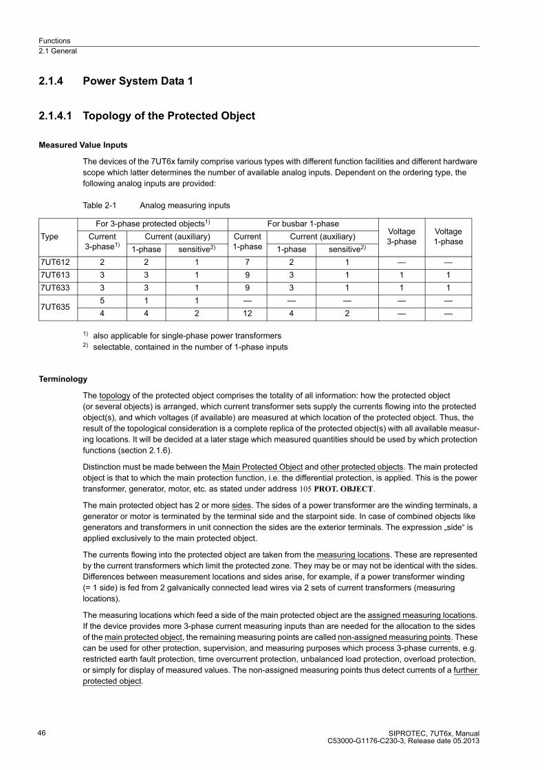
Functions
2.1 General
SIPROTEC, 7UT6x, ManualC53000-G1176-C230-3, Release date 05.2013
46
2.1.4 Power System Data 1
2.1.4.1 Topology of the Protected Object
Measured Value Inputs
The devices of the 7UT6x family comprise various types with different function facilities and different hardware
scope which latter determines the number of available analog inputs. Dependent on the ordering type, the
following analog inputs are provided:
Table 2-1 Analog measuring inputs
1) also applicable for single-phase power transformers2) selectable, contained in the number of 1-phase inputs
Terminology
The topology of the protected object comprises the totality of all information: how the protected object
(or several objects) is arranged, which current transformer sets supply the currents flowing into the protected
object(s), and which voltages (if available) are measured at which location of the protected object. Thus, the
result of the topological consideration is a complete replica of the protected object(s) with all available measur-
ing locations. It will be decided at a later stage which measured quantities should be used by which protection
functions (section 2.1.6).
Distinction must be made between the Main Protected Object and other protected objects. The main protected
object is that to which the main protection function, i.e. the differential protection, is applied. This is the power
transformer, generator, motor, etc. as stated under address 105 PROT. OBJECT.
The main protected object has 2 or more sides. The sides of a power transformer are the winding terminals, a
generator or motor is terminated by the terminal side and the starpoint side. In case of combined objects like
generators and transformers in unit connection the sides are the exterior terminals. The expression „side“ is
applied exclusively to the main protected object.
The currents flowing into the protected object are taken from the measuring locations. These are represented
by the current transformers which limit the protected zone. They may be or may not be identical with the sides.
Differences between measurement locations and sides arise, for example, if a power transformer winding
(= 1 side) is fed from 2 galvanically connected lead wires via 2 sets of current transformers (measuring
locations).
The measuring locations which feed a side of the main protected object are the assigned measuring locations.
If the device provides more 3-phase current measuring inputs than are needed for the allocation to the sides
of the main protected object, the remaining measuring points are called non-assigned measuring points. These
can be used for other protection, supervision, and measuring purposes which process 3-phase currents, e.g.
restricted earth fault protection, time overcurrent protection, unbalanced load protection, overload protection,
or simply for display of measured values. The non-assigned measuring points thus detect currents of a further
protected object.
Type
For 3-phase protected objects1) For busbar 1-phaseVoltage3-phase
Voltage1-phase
Current3-phase1)
Current (auxiliary) Current1-phase
Current (auxiliary)
1-phase sensitive2) 1-phase sensitive2)
7UT612 2 2 1 7 2 1 — —
7UT613 3 3 1 9 3 1 1 1
7UT633 3 3 1 9 3 1 1 1
7UT6355 1 1 — — — — —
4 4 2 12 4 2 — —

Functions
2.1 General
SIPROTEC, 7UT6x, ManualC53000-G1176-C230-3, Release date 05.2013
47
Depending on the device version, one to four single-phase auxiliary current inputs for auxiliary transformers.
These can be used for processing of 1-phase currents, e.g. the earth current between a winding starpoint and
earth, or the leakage current between a transformer tank and earth. They can also be assigned to the main
protected object or can be non-assigned. If they are assigned to a side of the main protected object, they can
be processed by the differential protection (example: inclusion of the starpoint current in the differential current).
The currents of the non-assigned auxiliary inputs can be processed by other protection functions (example:
detection of a tank leakage current by the single-phase overcurrent protection, or they can also be combined
with other non-assigned 3-phase measuring points (example: restricted earth fault protection on a protected
object other than the main protected object).
Figure 2-2 illustrates the terminology by an example. Note that the example is not practicable in this
arrangement as it contains more connections than possible; it serves only for clarification of the terminology.
The main protected object is a two-winding transformer YNd with an earthed starpoint at the Y-side. Side S1 is
the upper voltage side (Y), side S2 is the lower voltage side (d). This definition of the sides for the main
protected object (and only for it) is the basis for the formation of the differential and restraint currents used in
the differential protection.
For the side S1 2 measuring locations M1 and M2 exist. The currents that are measured there belong to the
side S1, their sum flowing on side 1 in the protected zone of the main protected object. The position of the
busbar isolator is not important here. Likewise, the polarity of the currents is not yet considered under topology
aspects.
At the lower voltage side, side S2 also has two measuring locations because of its branch point to the auxiliaries
system circuit: M3 and M4. The sum of these currents flows into the low voltage side (S2) of the main protected
object.
The 4 measuring locations M1 to M4 are assigned to the sides of the main protected object, thus assigned
measuring locations. They are the basis for the measured value processing of three-phase currents for the
differential protection. Basically, the same applies to a single-phase transformer; Here, only the measured
currents of the measuring locations are connected in two-phase.
Measuring location M5 is not assigned to the main protected object, but to the cable feeder, which is not related
in any way to the transformer. M5 is thus a non-assigned measuring location. The currents of this measuring
location can be used for other protection functions, e.g. for 3-phase overcurrent protection for protection of the
cable feeder.
In 3-phase busbar protection there is no difference between measuring locations and sides; both correspond
with the feeders of the busbar.
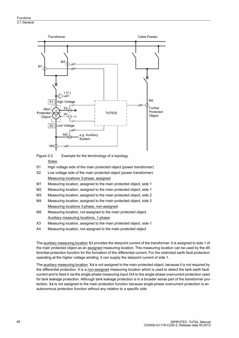
Functions
2.1 General
SIPROTEC, 7UT6x, ManualC53000-G1176-C230-3, Release date 05.2013
48
Figure 2-2 Example for the terminology of a topology
Sides:
S1 High voltage side of the main protected object (power transformer)
S2 Low voltage side of the main protected object (power transformer)
Measuring locations 3-phase, assigned:
M1 Measuring location, assigned to the main protected object, side 1
M2 Measuring location, assigned to the main protected object, side 1
M3 Measuring location, assigned to the main protected object, side 2
M4 Measuring location, assigned to the main protected object, side 2
Measuring locations 3-phase, non-assigned:
M5 Measuring location, not assigned to the main protected object
Auxiliary measuring locations, 1-phase:
X3 Measuring location, assigned to the main protected object, side 1
X4 Measuring location, not assigned to the main protected object
The auxiliary measuring location X3 provides the starpoint current of the transformer. It is assigned to side 1 of
the main protected object as an assigned measuring location. This measuring location can be used by the dif-
ferential protection function for the formation of the differential current. For the restricted earth fault protection
operating at the higher voltage winding, it can supply the starpoint current of side 1.
The auxiliary measuring location X4 is not assigned to the main protected object, because it is not required by
the differential protection. It is a non-assigned measuring location which is used to detect the tank earth fault
current and to feed it via the single-phase measuring input IX4 to the single-phase overcurrent protection used
for tank leakage protection. Although tank leakage protection is in a broader sense part of the transformer pro-
tection, X4 is not assigned to the main protection function because single-phase overcurrent protection is an
autonomous protection function without any relation to a specific side.
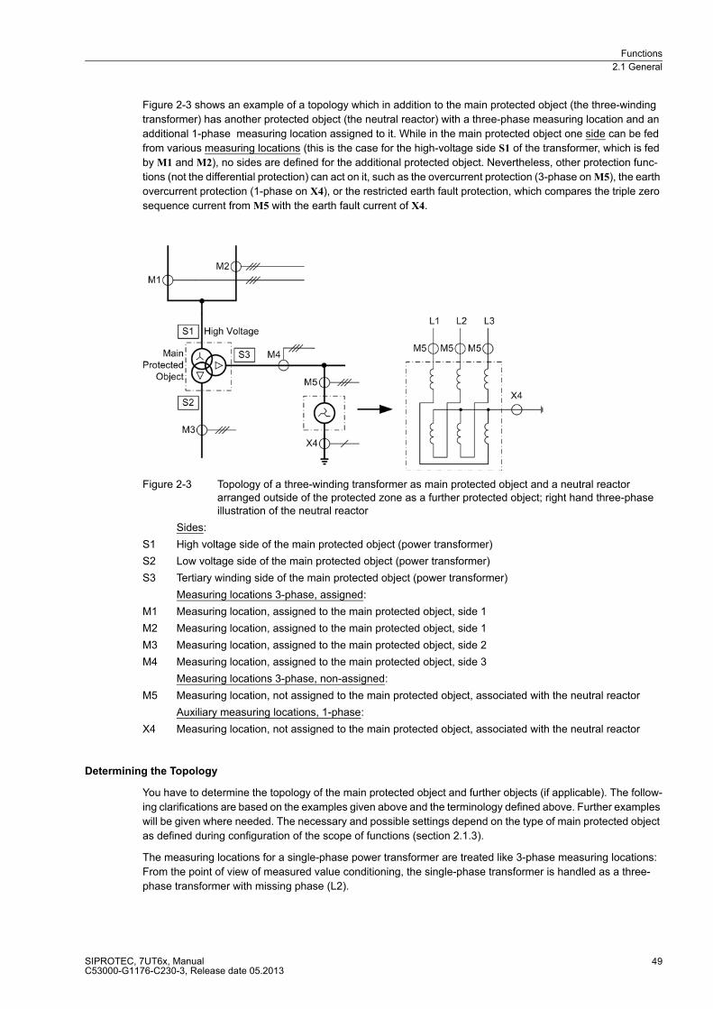
Functions
2.1 General
SIPROTEC, 7UT6x, ManualC53000-G1176-C230-3, Release date 05.2013
49
Figure 2-3 shows an example of a topology which in addition to the main protected object (the three-winding
transformer) has another protected object (the neutral reactor) with a three-phase measuring location and an
additional 1-phase measuring location assigned to it. While in the main protected object one side can be fed
from various measuring locations (this is the case for the high-voltage side S1 of the transformer, which is fed
by M1 and M2), no sides are defined for the additional protected object. Nevertheless, other protection func-
tions (not the differential protection) can act on it, such as the overcurrent protection (3-phase on M5), the earth
overcurrent protection (1-phase on X4), or the restricted earth fault protection, which compares the triple zero
sequence current from M5 with the earth fault current of X4.
Figure 2-3 Topology of a three-winding transformer as main protected object and a neutral reactor arranged outside of the protected zone as a further protected object; right hand three-phase illustration of the neutral reactor
Sides:
S1 High voltage side of the main protected object (power transformer)
S2 Low voltage side of the main protected object (power transformer)
S3 Tertiary winding side of the main protected object (power transformer)
Measuring locations 3-phase, assigned:
M1 Measuring location, assigned to the main protected object, side 1
M2 Measuring location, assigned to the main protected object, side 1
M3 Measuring location, assigned to the main protected object, side 2
M4 Measuring location, assigned to the main protected object, side 3
Measuring locations 3-phase, non-assigned:
M5 Measuring location, not assigned to the main protected object, associated with the neutral reactor
Auxiliary measuring locations, 1-phase:
X4 Measuring location, not assigned to the main protected object, associated with the neutral reactor
Determining the Topology
You have to determine the topology of the main protected object and further objects (if applicable). The follow-
ing clarifications are based on the examples given above and the terminology defined above. Further examples
will be given where needed. The necessary and possible settings depend on the type of main protected object
as defined during configuration of the scope of functions (section 2.1.3).
The measuring locations for a single-phase power transformer are treated like 3-phase measuring locations:
From the point of view of measured value conditioning, the single-phase transformer is handled as a three-
phase transformer with missing phase (L2).

Functions
2.1 General
SIPROTEC, 7UT6x, ManualC53000-G1176-C230-3, Release date 05.2013
50
Note
If you have changed the protected object, you will have to check and re-adjust all topological data.
Note
When configuring the topology proceed exactly in the order given below. Some of the following settings and
setting possibilities depend on settings performed before. In DIGSI the tabs (setting sheets) under Power
System Data 1 should be edited from the left tab to the right.
First of all, number the sides of the main protected object consecutively, next number the measuring locations,
beginning with those for the main object, then for the remaining. In the example (Figure 2-2) there are 2 sides
S1 and S2, the 5 measuring locations are M1 to M5.
The following sequence of sides is advised:
� For power transformers, start with the higher voltage side, as well for generator/transformer units or
motor/transformer units.
� For auto-transformers, the common winding must be declared as side 1 and side 2, further taps shall follow
(if applicable), then a delta winding (if applicable). Side 5 is not permitted here.
� For generators, start with the terminal side.
� For motors and shunt reactors, start with the current supply side.
� For series reactors, lines, and busbars, there is no preferred side.
Side determination plays an important role for all of the following settings.
Proceed to number the measuring locations, beginning with those which are assigned to the main protected
object. Take the order of side numbering, next the non-assigned measuring locations (if used). Refer also to
Figure 2-2.
Proceed numbering the auxiliary measuring locations (1-phase), again in the order: assigned locations and
then further (if used).
Note
The determination of the sides and measuring locations is imperative for all further setting steps. It is also im-
portant that the currents from the measuring locations (current transformers) are connected to the associated
analogue current inputs of the device: The currents of measuring location M1 must be connected to the device
at measuring locations IL1M1, IL2M1, IL3M1 (in single-phase transformers IL2M1), is omitted!
The topological data can be altered only with a PC using DIGSI.
Global Data for 3-Phase Measuring Locations
Determine the total number of 3-phase current measuring locations (= connected current transformer sets)
which are connected to the device. Enter this number in address 211 No Conn.MeasLoc (number of measuring
locations connected). 7UT612 allows a maximum number of 2, 7UT613 and 7UT633 allow a maximum number
of 3, 7UT635 a maximum of 5 measuring locations. The examples in Figures 2-2 and 2-3 contain 5 measuring
locations each.
The number of 3-phase measuring locations assigned to the main protected object are set in address 212 No
AssigMeasLoc (number of assigned measuring locations). Of course, this number cannot be higher than that of
address 211. The difference No Conn.MeasLoc – No AssigMeasLoc is the number of non-assigned three-phase
measuring locations. Both examples in the Figures 2-2 and 2-3 show five of the four assigned
3-phase measuring locations: M1 to M4. M5 is a non-assigned measuring location.

Functions
2.1 General
SIPROTEC, 7UT6x, ManualC53000-G1176-C230-3, Release date 05.2013
51
The number of sides associated with the main protected object is set in address 213 NUMBER OF SIDES. In
the example of figure 2-2, the protected object is a power transformer with 2 windings; the number of sides is
2: S1 and S2. In the example of Figure 2-3, the main protected object is a power transformer with 3 windings;
the number of sides is 3. In case of an auto-transformer, a maximum of 4 sides is permissible (see below).
Of course, the number of sides can be equal to the number of measuring locations (but never greater). The
example in Figure 2-4 shows a three-winding power transformer with one set of current transformers at each
side. In this example: No AssigMeasLoc = 3 and NUMBER OF SIDES = 3.
No distinction between sides and measuring locations is made in case of a busbar. Both correspond to the
feeders. Therefore, address 213 is missing if address 105 PROT. OBJECT = 3ph Busbar has been set.
Figure 2-4 Example of a topology on a three-winding transformer
Sides:
S1 High voltage side of the main protected object (power transformer)
S2 Low voltage side of the main protected object (power transformer)
S3 Tertiary winding side of the main protected object (power transformer)
Measuring locations 3-phase, assigned:
M1 Measuring location, assigned to the main protected object, side 1
M2 Measuring location, assigned to the main protected object, side 2
M3 Measuring location, assigned to the main protected object, side 3
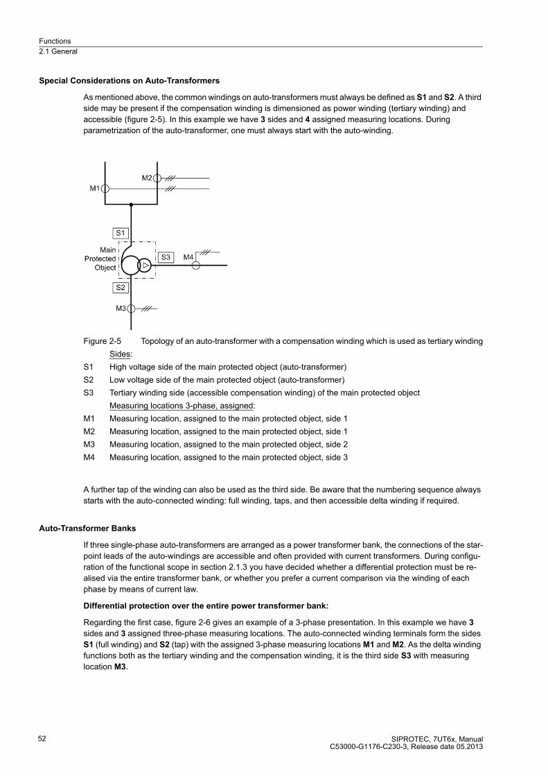
Functions
2.1 General
SIPROTEC, 7UT6x, ManualC53000-G1176-C230-3, Release date 05.2013
52
Special Considerations on Auto-Transformers
As mentioned above, the common windings on auto-transformers must always be defined as S1 and S2. A third
side may be present if the compensation winding is dimensioned as power winding (tertiary winding) and
accessible (figure 2-5). In this example we have 3 sides and 4 assigned measuring locations. During
parametrization of the auto-transformer, one must always start with the auto-winding.
Figure 2-5 Topology of an auto-transformer with a compensation winding which is used as tertiary winding
Sides:
S1 High voltage side of the main protected object (auto-transformer)
S2 Low voltage side of the main protected object (auto-transformer)
S3 Tertiary winding side (accessible compensation winding) of the main protected object
Measuring locations 3-phase, assigned:
M1 Measuring location, assigned to the main protected object, side 1
M2 Measuring location, assigned to the main protected object, side 1
M3 Measuring location, assigned to the main protected object, side 2
M4 Measuring location, assigned to the main protected object, side 3
A further tap of the winding can also be used as the third side. Be aware that the numbering sequence always
starts with the auto-connected winding: full winding, taps, and then accessible delta winding if required.
Auto-Transformer Banks
If three single-phase auto-transformers are arranged as a power transformer bank, the connections of the star-
point leads of the auto-windings are accessible and often provided with current transformers. During configu-
ration of the functional scope in section 2.1.3 you have decided whether a differential protection must be re-
alised via the entire transformer bank, or whether you prefer a current comparison via the winding of each
phase by means of current law.
Differential protection over the entire power transformer bank:
Regarding the first case, figure 2-6 gives an example of a 3-phase presentation. In this example we have 3
sides and 3 assigned three-phase measuring locations. The auto-connected winding terminals form the sides
S1 (full winding) and S2 (tap) with the assigned 3-phase measuring locations M1 and M2. As the delta winding
functions both as the tertiary winding and the compensation winding, it is the third side S3 with measuring
location M3.
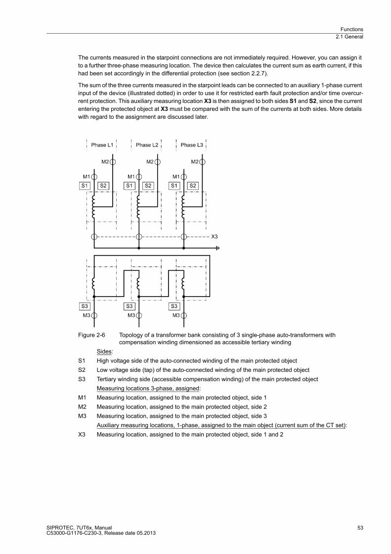
Functions
2.1 General
SIPROTEC, 7UT6x, ManualC53000-G1176-C230-3, Release date 05.2013
53
The currents measured in the starpoint connections are not immediately required. However, you can assign it
to a further three-phase measuring location. The device then calculates the current sum as earth current, if this
had been set accordingly in the differential protection (see section 2.2.7).
The sum of the three currents measured in the starpoint leads can be connected to an auxiliary 1-phase current
input of the device (illustrated dotted) in order to use it for restricted earth fault protection and/or time overcur-
rent protection. This auxiliary measuring location X3 is then assigned to both sides S1 and S2, since the current
entering the protected object at X3 must be compared with the sum of the currents at both sides. More details
with regard to the assignment are discussed later.
Figure 2-6 Topology of a transformer bank consisting of 3 single-phase auto-transformers with compensation winding dimensioned as accessible tertiary winding
Sides:
S1 High voltage side of the auto-connected winding of the main protected object
S2 Low voltage side (tap) of the auto-connected winding of the main protected object
S3 Tertiary winding side (accessible compensation winding) of the main protected object
Measuring locations 3-phase, assigned:
M1 Measuring location, assigned to the main protected object, side 1
M2 Measuring location, assigned to the main protected object, side 2
M3 Measuring location, assigned to the main protected object, side 3
Auxiliary measuring locations, 1-phase, assigned to the main object (current sum of the CT set):
X3 Measuring location, assigned to the main protected object, side 1 and 2

Functions
2.1 General
SIPROTEC, 7UT6x, ManualC53000-G1176-C230-3, Release date 05.2013
54
Current comparison for common winding of an auto-transformer:
If during configuration of the functional scope in section 2.1.3 a pure current comparison via each winding has
been selected, then the example of figure 2-7 applies. Besides the common winding terminals of the sides S1
(full winding) and S2 (tap) with the assigned 3-phase measuring locations M1 and M2, one more side S3 is
defined at the starpoint terminals with the 3-phase measuring location M3. In this way, a current comparison
can be realised over each of the three transformer windings, i.e. each phase with its 3 measuring locations.
Such current comparison is more sensitive to 1-phase earth faults in one of the transformers than the normal
differential protection. This has a certain importance considering that 1-phase earth faults are the most proba-
ble faults in such banks. By means of the parameter setting at address 105 PROT. OBJECT = Autotransf.Autotr.
node, the current comparison protection of the auto-transf. node is supported.
On the other hand, the compensation winding cannot and must not be included into this protection even if it is
accessible and equipped with current transformers. This application variant is based on the current law in that
all currents flowing in to a winding must total to zero. In auto-transformers with stabilising winding, the stabilising
winding should be protected separately (e.g. with time overcurrent protection). During setting of address 105
PROT. OBJECT = Autotransf., a stabilising winding can be included.
The current transformer X1 in figure 2-7 is not required. In order to realise an earth overcurrent protection or a
restricted earth fault protection in this arrangement, you can feed the sum of the three currents measured at
M3 to an auxiliary 1-phase current input of the device. An example of a connection, where a measuring location
M3 serves as 3-phase measuring location for the current comparison and where simultaneously the total
current 3I0 of the transformer set is led to a 1-phase measuring location IX1 of the device, is available in the
annex.

Functions
2.1 General
SIPROTEC, 7UT6x, ManualC53000-G1176-C230-3, Release date 05.2013
55
Figure 2-7 Topology of a transformer bank consisting of 3 single-phase auto-transformers, topology definitions for a current comparison protection for each phase
Sides:
S1 High voltage side of the auto-connected winding of the main protected object
S2 Low voltage side (tap) of the auto-connected winding of the main protected object
S3 Starpoint side of the auto-connected winding of the main protected object
Measuring locations 3-phase, assigned:
M1 Measuring location, assigned to the main protected object, side 1
M2 Measuring location, assigned to the main protected object, side 2
M3 Measuring location, assigned to the main protected object, side 3
Auxiliary measuring locations, 1-phase, assigned to the main object:
X1 Measuring location, assigned to the main protected object, side 1 and 2
Global Data for 1-Phase Busbar Protection
If the device is used as busbar protection, either as single-phase protection or as three-phase protection via
external summation transformers, set the number of feeders of the busbar in address 216 NUMBER OF ENDS.
The minimum number amounts to 3 ends (with less than that the operation of a 7UT6x would not make sense).
In 7UT612, the maximum number of feeders is 7, in 7UT613 and 7UT633 it is 9, and in 7UT635 12.
Assignment of 3-phase Measuring Locations
After determination of the global data, the 3-phase measuring locations must be assigned to the sides of the
main protected object. Only few meaningful combinations are possible for this assignment because of the
condition that always NUMBER OF SIDES ≤ No AssigMeasLoc ≤ No Conn.MeasLoc and that a protected object
provides at least 2 sides. In order to exclude impossible combinations at all, only those addresses of the fol-
lowing lists are requested which correspond to the global settings of addresses 211, 212, and 213. Furthermore,
only meaningful setting options appear.

Functions
2.1 General
SIPROTEC, 7UT6x, ManualC53000-G1176-C230-3, Release date 05.2013
56
If the global data are implausible, the device does not find any meaningful combination of assignment
possibilities. In this case you will find address 230 ASSIGNM. ERROR, which shows one of the following
options:
� No AssigMeasLoc the number of assigned measuring locations is implausible;
� No of sides the number of sides is implausible.
This parameter cannot be changed. It merely informs you about the implausibility of the global settings. If it ap-
pears, you cannot make any further assignments. Recheck in this case carefully the addresses 211, 212, and
213 and correct the settings.
Only one of the variety of the following listed assignment parameter is possible. But in the actual case, only one
address appears, namely the address which corresponds to the above mentioned number of sides and as-
signed measuring locations. The measuring location and side are separated by a comma, e.g. 3M,2S means 3
assigned measuring locations at 2 sides.
Only the combinations possible for the number of measuring locations and sides appear as setting options. The
measuring locations of the same side are connected by a „+“ sign; the side sequence by a comma. In the
following, all possibilities are explained.
Address 220 ASSIGNM. 2M,2S appears if 2 assigned measuring locations (address 212) have been selected
for 2 sides (address 213). Only one option is possible:
� M1,M2, i.e. the 2 measuring locations are assigned: M1 to side S1, M2 to side S2.
Since no other possibilities exist there are no further options.
Address 221 ASSIGNM. 3M,2S appears if 3 assigned measuring locations (address 212) have been selected
for 2 sides (address 213). The following options are possible:
� M1+M2,M3, i.e. the 3 measuring locations are assigned: M1 and M2 to side S1, M3 to side S2.
� M1,M2+M3, i.e. the 3 measuring locations are assigned: M1 to side S1, M2 and M3 to side S2.
Address 222 ASSIGNM. 3M,3S appears if 3 assigned measuring locations (address 212) have been selected
for 3 sides (address 213). Only one option is possible:
� M1,M2,M3, i.e. the 3 measuring locations are assigned: M1 to side S1, M2 to side S2, M3 to side S3. This
corresponds to the examples in figures 2-4 and 2-6 2-7.
The further assignment possibilities can only occur in 7UT635 since 7UT612 provides two 3-phase current
measuring inputs, and 7UT613 and 7UT633 provide a maximum of three 3-phase current inputs (cf. Table 2-1).
Address 223 ASSIGNM. 4M,2S appears if 4 assigned measuring locations (address 212) have been selected
for 2 sides (address 213). The following options are possible:
� M1+M2,M3+M4, i.e. the 4 measuring locations are assigned: M1 and M2 to side S1, M3 and M4 to side S2.
This corresponds to the example in Figure 2-2 (M5 is not assigned there).
� M1+M2+M3,M4, i.e. the 4 measuring locations are assigned: M1 and M2 and M3 to side S1, M4 to side S2.
� M1,M2+M3+M4, i.e. the 4 measuring locations are assigned: M1 to side S1, M2 and M3 and M4 to side S2.
Address 224 ASSIGNM. 4M,3S appears if 4 assigned measuring locations (address 212) have been selected
for 3 sides (address 213). The following options are possible:
� M1+M2,M3,M4, i.e. the 4 measuring locations are assigned: M1 and M2 to side S1, M3 to side S2, M4 to
side S3. This corresponds to the examples in Figures 2-3 and 2-5.
� M1,M2+M3,M4, i.e. the 4 measuring locations are assigned: M1 to side S1, M2 and M3 to side S2, M4 to
side S3.
� M1,M2,M3+M4, i.e. the 4 measuring locations are assigned: M1 to side S1, M2 to side S2, M3 and M4 to
side S3.
Functions
2.1 General
SIPROTEC, 7UT6x, ManualC53000-G1176-C230-3, Release date 05.2013
57
Address 225 ASSIGNM. 4M,4S appears if 4 assigned measuring locations (address 212) have been selected
for 4 sides (address 213). Only one option is possible:
� M1,M2,M3,M4, i.e. the 4 measuring locations are assigned: M1 to side S1, M2 to side S2, M3 to side S3, M4
to side S4.
Address 226 ASSIGNM. 5M,2S appears if 5 assigned measuring locations (address 212) have been selected
for 2 sides (address 213). The following options are possible:
� M1+M2+M3,M4+M5, i.e. the 5 measuring locations are assigned: M1 and M2 and M3 to side S1, M4 and
M5 to side S2.
� M1+M2,M3+M4+M5, i.e. the 5 measuring locations are assigned: M1 and M2 to side S1, M3 and M4 and
M5 to side S2.
� M1+M2+M3+M4,M5, i.e. the 5 measuring locations are assigned: M1 and M2 and M3 and M4 to side S1,
M5 to side S2.
� M1,M2+M3+M4+M5, i.e. the 5 measuring locations are assigned: M1 to side S1, M2 and M3 and M4 and
M5 to side S2.
Address 227 ASSIGNM. 5M,3S appears if 5 assigned measuring locations (address 212) have been selected
for 3 sides (address 213). The following options are possible:
� M1+M2,M3+M4,M5, i.e. the 5 measuring locations are assigned: M1 and M2 to side S1, M3 and M4 to side
S2, M5 to side S3.
� M1+M2,M3,M4+M5, i.e. the 5 measuring locations are assigned: M1 and M2 to side S1, M3 to side S2, M4
and M5 to side S3.
� M1,M2+M3,M4+M5, i.e. the 5 measuring locations are assigned: M1 to side S1, M2 and M3 to side S2, M4
and M5 to side S3.
� M1+M2+M3,M4,M5, i.e. the 5 measuring locations are assigned: M1 and M2 and M3 to side S1, M4 to side
S2, M5 to side S3.
� M1,M2+M3+M4,M5, i.e. the 5 measuring locations are assigned: M1 to side S1, M2 and M3 and M4 to side
S2, M5 to side S3.
� M1,M2,M3+M4+M5, i.e. the 5 measuring locations are assigned: M1 to side S1, M2 to side S2, M3 and M4
and M5 to side S3.
Address 228 ASSIGNM. 5M,4S appears if 5 assigned measuring locations (address 212) have been selected
for 4 sides (address 213). The following options are possible:
� M1+M2,M3,M4,M5, i.e. the 5 measuring locations are assigned: M1 and M2 to side S1, M3 to side S2, M4
to side S3, M5 to side S4.
� M1,M2+M3,M4,M5, i.e. the 5 measuring locations are assigned: M1 to side S1, M2 and M3 to side S2, M4
to side S3, M5 to side S4.
� M1,M2,M3+M4,M5, i.e. the 5 measuring locations are assigned: M1 to side S1, M2 to side S2, M3 and M4
to side S3, M5 to side S4.
� M1,M2,M3,M4+M5, i.e. the 5 measuring locations are assigned: M1 to side S1, M2 to side S2, M3 to side
S3, M4 and M5 to side S4.
Address 229 ASSIGNM. 5M,5S appears if 5 assigned measuring locations (address 212) have been selected
for 5 sides (address 213). Only one option is possible:
� M1,M2,M3,M4,M5, i.e. the 5 measuring locations are assigned: M1 to side S1, M2 to side S2, M3 to side S3,
M4 to side S4, M5 to side S5.

Functions
2.1 General
SIPROTEC, 7UT6x, ManualC53000-G1176-C230-3, Release date 05.2013
58
Assignment of Sides in Auto-Transformers
If auto-transformers are protected the additional question arises how the sides of the protected object are to be
handled by the main protection function, the differential protection. As mentioned above, various possibilities
exist how the sides are defined. Further information is necessary in order to achieve an exact replica of the
auto-transformer. Therefore, the following addresses only apply to auto-transformers (address 105 PROT.
OBJECT = Autotransf. or Autotr. node).
Both of the following tables show which version of configuration is supported for Autotransf. and for a Autotr.
node and which principle of the transformer is applied. The earth winding is included as a side due to the pa-
rameterisation.
Table 2-2 Configuration Versions in an Autotransf.
Table 2-3 Configuration Versions in an Autotr. node
address 241 SIDE 1 of the auto-transformer must be assigned to a auto-connected (primary winding, as recom-
mended above). This is imperative and, therefore, cannot be changed.
Address 242 SIDE 2 of the auto-transformer must also be assigned to an auto-connected (secondary tap as rec-
ommended above). This is imperative and, therefore, cannot be changed.
For the sides 3 and 4, alternatives exist. If the auto-transformer provides another tap, the side thereof is
declared as auto-connected.
In the example in figure 2-6 is for a PROT. OBJECT = Autotransf. the side S3 the tertiary winding, thus the ac-
cessible and load capable compensation winding. In this example the setting would be:
Address 243 SIDE 3 = compensation.
This option is only possible for PROT. OBJECT = Autotransf..
In the examples of figure 2-7 for PROT. OBJECT = Autotr. node side 3 is facing the earthing electrode of the
transformer. Here:
Address 243 SIDE 3 = earth.electrode.
This option is only possible if PROT. OBJECT = Autotransf. or if PROT. OBJECT = Autotr. node, if no further
side has been assigned.
The same applied to address 244 SIDE 4 = earth.electrode
Number of sides
Configuration types of the side
SIDE 1 SIDE 2 SIDE 3 SIDE 4
2 auto-connected auto-connected — —
3 auto-connected auto-connected auto-connected —
3 auto-connected auto-connected compensation. —
3 auto-connected auto-connected earth.electrode —
4 auto-connected auto-connected auto-connected auto-connected
4 auto-connected auto-connected auto-connected compensation.
4 auto-connected auto-connected auto-connected earth.electrode
4 auto-connected auto-connected compensation. auto-connected
4 auto-connected auto-connected compensation. compensation.
4 auto-connected auto-connected compensation. earth.electrode
Number of sides
Configuration types of the side
SIDE 1 SIDE 2 SIDE 3 SIDE 4
3 auto-connected auto-connected earth.electrode —
4 auto-connected auto-connected auto-connected earth.electrode

Functions
2.1 General
SIPROTEC, 7UT6x, ManualC53000-G1176-C230-3, Release date 05.2013
59
In summary we can say: the sides S1 and S2 are imperatively assigned to the connections of the auto-connect-
ed winding. For SIDE 3 and SIDE 4 you have to select the option corresponding to the topology: auto-connected
(for another tap of the auto-connected winding), compensation (for an accessible and load-capable compensa-
tion winding) or earth.electrode (for the earthed side of the auto-connected windings).
Assignment of Auxiliary 1-phase Measuring Locations
Each of the auxiliary (1-phase) current inputs must now be assigned in the addresses 251 to 254. The number
of auxiliary inputs depends on the device type (cf. Table 2-1). In 7UT635 all inputs IX1 to IX3 are only available
as additional 1-phase measuring inputs if they are not needed for a fifth 3-phase measuring location, i.e. if only
four 3-phase measuring locations are needed.
The auxiliary inputs can be assigned to a side or a measuring location, or they can remain non-assigned. If you
have assigned exactly one measuring location to a side, this side is equivalent to the measuring location.
Single-phase auxiliary measured currents are used in the following cases:
1. In differential protection, to include the starpoint current of an earthed transformer winding (either directly
or via a neutral earthing reactor in the protected zone);
2. In restricted earth fault protection, to compare the starpoint current of an earthed winding (transformer,
generator, motor, shunt reactor, neutral earthing reactor) with the zero sequence current from the phase
currents;
3. In earth fault overcurrent protection, to detect the earth fault current of an earthed winding or neutral
earthing reactor;
4. In single-phase overcurrent protection, to detect any 1-phase current ;
5. For operational limit monitoring tasks and/or display of measured values.
� 1st case: It is essential to assign the 1-phase input to that side of the main protected object whose incoming
phase currents are to be compared with the earth fault current. Make sure that you assign the 1-phase input
to the correct side. In case of transformers, this can only be a side with an earthed starpoint (directly or via
a neutral earthing transformer in the protected zone).
In the example shown in Figure 2-2, the auxiliary measuring location X3 must be assigned to side S1. Once
the device has been "informed" of this assignment, the current measured at current input IX3 will be reliably
interpreted as the current flowing to the starpoint of the high-voltage winding (side 1).
in the example shown in Figure 2-6 the additional measuring location X3 must be assigned to the common
winding. This winding, however, has 2 sides with 2 three-phase measuring locations. X3 is assigned to side
S1. Since the device has been informed in address 105 PROT. OBJECT = Autotransf. that the protected
object is an auto-transformer, and via the assignment of sides 1 and 2 that these belong to the common
winding, it is obvious that X3 belongs to the common winding, and that it is therefore assigned to sides S1
and S2. The result is the same if X3 is assigned to side S2. For the auto-transformer, it is therefore irrelevant
which voltage side of the common winding (start of winding or any tap) the starpoint current is assigned to.
� 2nd case: For this case, the same considerations apply as for the 1st case. In the case of generators, motors
or shunt reactors, select the terminal side. You can also use in the 2nd case a measuring location that is not
assigned to the main protected object. In the example shown in Figure 2-3, you can use the restricted earth
fault protection for the neutral reactor: The auxiliary measuring location X4 is in this case assigned to the
measuring location M5. This informs the device that the measured values of the non-assigned measuring
location M5 (3-phase) must be compared with the measured value of the additional measuring location X4
(1-phase).
Functions
2.1 General
SIPROTEC, 7UT6x, ManualC53000-G1176-C230-3, Release date 05.2013
60
� 3rd case: Here again, the auxiliary measuring location must be assigned to that side whose earth fault
current is to be processed. You can also use a measuring location that is not assigned to the main protected
object. Please note that this auxiliary measuring location will provide not only the measured value for the
earth fault overcurrent protection but also circuit breaker information (current flow and manual-close
detection) from the corresponding 3-phase measuring location.
One can also proceed as described in cases 4 and 5, if the current used by the earth fault overcurrent
protection cannot be assigned to a specific side or 3-phase measuring location.
� 4th and 5th case: In these cases you set the parameter for the assignment of the auxiliary measuring loca-
tion to conn/not assig. (connected but not assigned). The auxiliary measuring location is then assigned to
neither a specific side of the main protected object nor to any other 3-phase measuring location. These pro-
tection and measuring functions do not need any information on their assignment to a 3-phase measuring
location because they only process 1-phase currents.
� General advice: If you want to use a 1-phase auxiliary measuring location both for a function as per the 3rd
to 5th case and for the 1st or 2nd case, you must of course assign it as described in the 1st and 2nd case.
If the device is equipped with a 1-phase measuring input but you do not need it, leave the setting Not connected
unchanged (not connected).
Of the addresses described in the following paragraphs, only those available in your device will be displayed.
Please keep in mind
� that in 7UT612 only the additional inputs IX1 and IX3 are available and that they can be assigned to no more
than 2 sides or 3-phase measuring locations,
� that in 7UT613 and 7UT633 only the additional inputs IX1 to IX3 are available and that they can be assigned
to no more than 3 sides or 3-phase measuring locations, and
� that in 7UT635 the auxiliary inputs IX1 to IX3 cannot be assigned to the measuring location M5, since in this
device either M5 or IX1 to IX3 are available.
Addresses 251 AUX. CT IX1, 252 AUX. CT IX2, 253 AUX. CT IX3 and 254 AUX. CT IX4 determine to which
side of the main protected object or to which 3-phase measuring location the single-phase measuring input IX1,
IX2, IX3 or IX4 is assigned. Set here the side or measuring location, or no assignment at all, as described
above.
High-Sensitivity Additional 1-phase Measuring Locations
Depending on the version, the devices of the 7UT6x family are equipped with 1 or 2 auxiliary high-sensitivity
measuring inputs which can detect currents as low as 3mA present at the input. These inputs can be used for
single-phase overcurrent protection.
The single-phase independent overcurrent protection is suited e.g. for high-sensitivity tank leakage protection
or for a high-impedance differential protection (cf. section 2.7), if a high-sensitivity measuring input is used.
If you want to use such a high-sensitivity current measuring input, you can specify this to the device at the ad-
dresses 255 and 256.
In 7UT612, input IX3 can be used as a high-sensitivity input. In 7UT613 and 7UT633, input IX3 can be used
as a high-sensitivity input. Set address 255 AUX CT IX3 TYPE to sensitiv input if you want to use IX3 as a high-
sensitivity input; otherwise leave the setting 1A/5A input unchanged.
In 7UT635 the input IX3 can be used as a high-sensitivity input provided that it is not used for a fifth 3-phase
measuring location, i.e. that only four 3-phase measuring locations are needed. In this case, set address 255
AUX CT IX3 TYPE = sensitiv input, if IX3 is used as a high-sensitivity input.
The input IX4 is always available as a single-phase input in 7UT635 and can be set at address 256 AUX CT
IX4 TYPE as sensitiv input or 1A/5A input.
Functions
2.1 General
SIPROTEC, 7UT6x, ManualC53000-G1176-C230-3, Release date 05.2013
61
Assignment of Voltage Measuring Inputs
The 7UT613 and 7UT633 (not the 7UT612 and 7UT635) can be provided with voltage measuring inputs. The
3-phase set of voltage inputs and the fourth voltage input can each be assigned to one side or one measuring
location, or to the busbar voltage (for busbar protection).
Measured voltages can be used in 7UT6x for the overexcitation protection, the undervoltage protection, the
overvoltage protection, the reverse power protection, the forward power monitoring, the frequency protection,
or for measuring tasks like the display of voltages or the calculation and output of power and energy metering.
Figure 2-8 shows the various possible voltage assignments (which, of course do not occur all at the same time
in practice). Address 261 must be set to VT SET.
� For voltage measurement at Ua the voltages are measured on Side 1 of the main protected object.
� For voltage measurement at Ub, the voltages at the Measuring loc.2 are measured that are assigned to side
1 of the main protected object.
� For voltage measurement at Uc the voltages are measured at the Busbar (only possible in busbar
protection).
� For voltage measurement at Ud, voltages at the Measuring loc.3 are measured that are not assigned to the
main protected object.
� For voltage measurement at Ue the voltages are measured on Side 2 of the main protected object.
As these examples show, you can select sides, busbars, assigned or non-assigned measuring locations.
In 1-phase busbar protection, voltages can only be measured on the Busbar.
In practice, the voltage assignment depends therefore on the voltages which the device is expected to receive
and process. Of course, voltage transformers must be installed at the appropriate locations and connected to
the device.
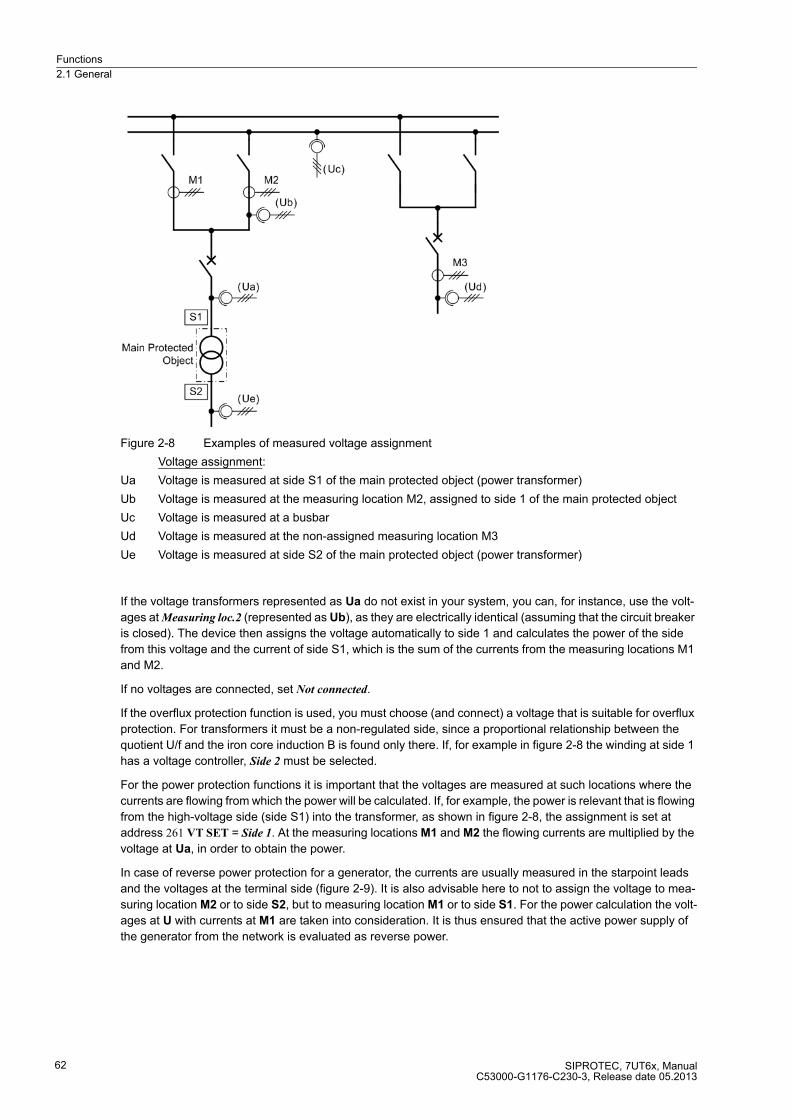
Functions
2.1 General
SIPROTEC, 7UT6x, ManualC53000-G1176-C230-3, Release date 05.2013
62
Figure 2-8 Examples of measured voltage assignment
Voltage assignment:
Ua Voltage is measured at side S1 of the main protected object (power transformer)
Ub Voltage is measured at the measuring location M2, assigned to side 1 of the main protected object
Uc Voltage is measured at a busbar
Ud Voltage is measured at the non-assigned measuring location M3
Ue Voltage is measured at side S2 of the main protected object (power transformer)
If the voltage transformers represented as Ua do not exist in your system, you can, for instance, use the volt-
ages at Measuring loc.2 (represented as Ub), as they are electrically identical (assuming that the circuit breaker
is closed). The device then assigns the voltage automatically to side 1 and calculates the power of the side
from this voltage and the current of side S1, which is the sum of the currents from the measuring locations M1
and M2.
If no voltages are connected, set Not connected.
If the overflux protection function is used, you must choose (and connect) a voltage that is suitable for overflux
protection. For transformers it must be a non-regulated side, since a proportional relationship between the
quotient U/f and the iron core induction B is found only there. If, for example in figure 2-8 the winding at side 1
has a voltage controller, Side 2 must be selected.
For the power protection functions it is important that the voltages are measured at such locations where the
currents are flowing from which the power will be calculated. If, for example, the power is relevant that is flowing
from the high-voltage side (side S1) into the transformer, as shown in figure 2-8, the assignment is set at
address 261 VT SET = Side 1. At the measuring locations M1 and M2 the flowing currents are multiplied by the
voltage at Ua, in order to obtain the power.
In case of reverse power protection for a generator, the currents are usually measured in the starpoint leads
and the voltages at the terminal side (figure 2-9). It is also advisable here to not to assign the voltage to mea-
suring location M2 or to side S2, but to measuring location M1 or to side S1. For the power calculation the volt-
ages at U with currents at M1 are taken into consideration. It is thus ensured that the active power supply of
the generator from the network is evaluated as reverse power.

Functions
2.1 General
SIPROTEC, 7UT6x, ManualC53000-G1176-C230-3, Release date 05.2013
63
Figure 2-9 Power measurement at generator
If you have the choice to assign a side or a measuring location to the main protected object as shown in figure
2-9 (S1 is identical to M1), such assignment of the side is preferable, because the power can be set later directly
in the (mostly known) reference values. As the nominal data of the main protected object are known to the
device, no conversion of reference values to secondary values will be required.
The under- and overvoltage protection and the frequency protection also use the voltages connected to the
device. Select the side or measuring location here, which is electrically connected to the voltage transformer
set.
Should the voltages not be required for the protection functions, select the voltages that must be indicated or
transferred as operational measured values during operation, or on the basis of which you wish to calculate the
power.
For the 1-phase voltage measurement input U4, likewise a side or measuring location can be selected at
address 262 VT U4 - irrespective of the assignment of the 3-phase voltage inputs. This measuring input is fre-
quently used for the displacement voltage, measured at the e-n windings of the voltage transformer set, but
you can also use it for detection of any other measured voltage. In this case set VT U4 = conn/not assig. (con-
nected, but not assigned). If no voltage is needed at the 1-phase voltage input, set Not connected (not connect-
ed).
As different connections are possible, you must now specify in the device how the connected 1-phase voltage
should be interpreted. This is done at address 263 VT U4 TYPE. Set Udelta transf. if the voltage assigned acc.
to address 262 is a displacement voltage. It can also be any phase-to-earth voltage (e.g. UL1E transform.), or
a phase-to-phase voltage (e.g. UL12 transform.). If U4 is connected to a voltage which is assigned to no side
or measuring location, set Ux transformer.

Functions
2.1 General
SIPROTEC, 7UT6x, ManualC53000-G1176-C230-3, Release date 05.2013
64
2.1.4.2 General Power System Data (Power System Data 1)
General
The device requires some plant and power system data in order to be able to adapt its functions accordingly,
dependent on the actual application. The data required include for instance rated data of the substation and the
measuring transformers, polarity and connection of the measured quantities, if necessary features of the circuit
breakers, and others. There are also certain parameters common to all functions, i.e. not associated with a spe-
cific protection, control or monitoring function. These data can only be changed from a PC running DIGSI and
are discussed in this section.
Rated Frequency
The rated frequency of the power system is set under address 270 Rated Frequency. The available rated fre-
quencies are 50 Hz, 60 Hz and 16,7 Hz (7UT613/63x).
Phase Sequence
Under address 271 PHASE SEQ. the presetting for clockwise rotation L1 L2 L3 can be changed if a power plant
has an anticlockwise rotation L1 L3 L2. The phase sequence has no influence on the vector group conversion
of the differential protection as long as the identical phase rotation is present on all sides of the protected object.
This setting is irrelevant for single-phase application and is not accessible.
Figure 2-10 Phase rotation
Temperature Unit
The temperature of the hot-spot temperature calculation can be displayed in Celsius or Fahrenheit. This applies
in particular for the output of the hot-spot temperature if you are using the overload protection with hot-spot
calculation. Set the desired temperature unit in address 276 TEMP. UNIT. Changing temperature units does
not mean that setting values which are linked to these temperature units will automatically be converted. They
have to be re-entered into their corresponding valid addresses.
Object Data with Transformers
Transformer data are required if the device is used for differential protection for transformers, i.e. if the following
was set with the configuration of the protection functions (functional scope) under address 105 PROT. OBJECT
= 3 phase transf. or 1 phase transf. or Autotr. node. In cases other than that, these settings are not available.
Please observe the definition of the sides which you have performed during setting of the topology of the main
protected object (cf. Determining the Topology). Generally, side 1 is the reference winding having a current
phase angle of 0° and no vector group indicator. Usually this is the higher voltage winding of the transformer.
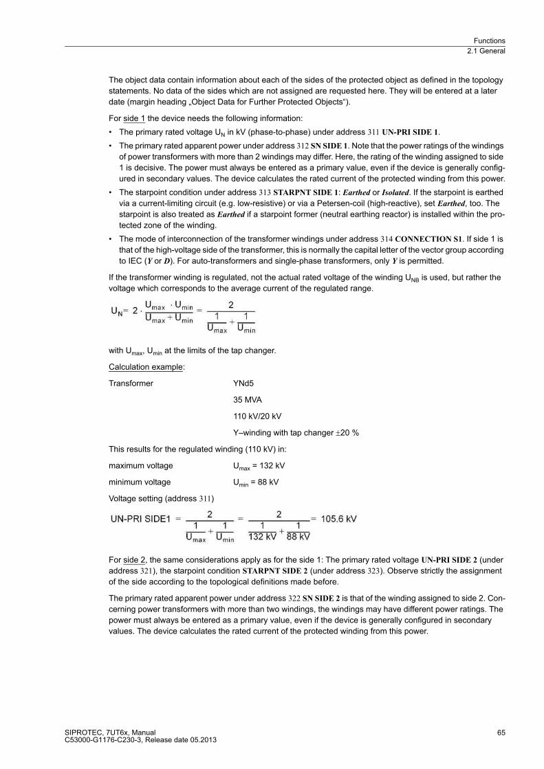
Functions
2.1 General
SIPROTEC, 7UT6x, ManualC53000-G1176-C230-3, Release date 05.2013
65
The object data contain information about each of the sides of the protected object as defined in the topology
statements. No data of the sides which are not assigned are requested here. They will be entered at a later
date (margin heading „Object Data for Further Protected Objects“).
For side 1 the device needs the following information:
� The primary rated voltage UN in kV (phase-to-phase) under address 311 UN-PRI SIDE 1.
� The primary rated apparent power under address 312 SN SIDE 1. Note that the power ratings of the windings
of power transformers with more than 2 windings may differ. Here, the rating of the winding assigned to side
1 is decisive. The power must always be entered as a primary value, even if the device is generally config-
ured in secondary values. The device calculates the rated current of the protected winding from this power.
� The starpoint condition under address 313 STARPNT SIDE 1: Earthed or Isolated. If the starpoint is earthed
via a current-limiting circuit (e.g. low-resistive) or via a Petersen-coil (high-reactive), set Earthed, too. The
starpoint is also treated as Earthed if a starpoint former (neutral earthing reactor) is installed within the pro-
tected zone of the winding.
� The mode of interconnection of the transformer windings under address 314 CONNECTION S1. If side 1 is
that of the high-voltage side of the transformer, this is normally the capital letter of the vector group according
to IEC (Y or D). For auto-transformers and single-phase transformers, only Y is permitted.
If the transformer winding is regulated, not the actual rated voltage of the winding UNB is used, but rather the
voltage which corresponds to the average current of the regulated range.
with Umax, Umin at the limits of the tap changer.
Calculation example:
Transformer YNd5
35 MVA
110 kV/20 kV
Y–winding with tap changer ±20 %
This results for the regulated winding (110 kV) in:
maximum voltage Umax = 132 kV
minimum voltage Umin = 88 kV
Voltage setting (address 311)
For side 2, the same considerations apply as for the side 1: The primary rated voltage UN-PRI SIDE 2 (under
address 321), the starpoint condition STARPNT SIDE 2 (under address 323). Observe strictly the assignment
of the side according to the topological definitions made before.
The primary rated apparent power under address 322 SN SIDE 2 is that of the winding assigned to side 2. Con-
cerning power transformers with more than two windings, the windings may have different power ratings. The
power must always be entered as a primary value, even if the device is generally configured in secondary
values. The device calculates the rated current of the protected winding from this power.
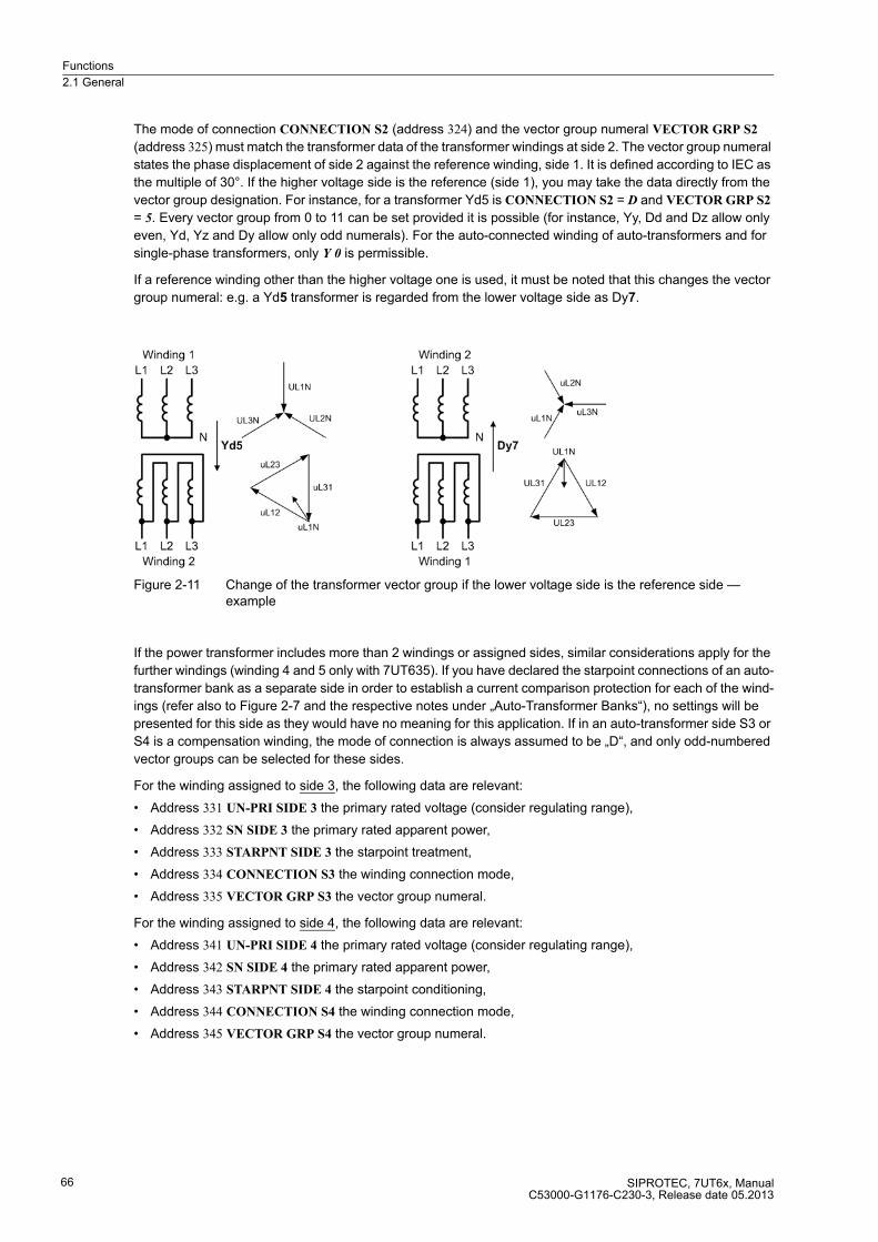
Functions
2.1 General
SIPROTEC, 7UT6x, ManualC53000-G1176-C230-3, Release date 05.2013
66
The mode of connection CONNECTION S2 (address 324) and the vector group numeral VECTOR GRP S2
(address 325) must match the transformer data of the transformer windings at side 2. The vector group numeral
states the phase displacement of side 2 against the reference winding, side 1. It is defined according to IEC as
the multiple of 30°. If the higher voltage side is the reference (side 1), you may take the data directly from the
vector group designation. For instance, for a transformer Yd5 is CONNECTION S2 = D and VECTOR GRP S2
= 5. Every vector group from 0 to 11 can be set provided it is possible (for instance, Yy, Dd and Dz allow only
even, Yd, Yz and Dy allow only odd numerals). For the auto-connected winding of auto-transformers and for
single-phase transformers, only Y 0 is permissible.
If a reference winding other than the higher voltage one is used, it must be noted that this changes the vector
group numeral: e.g. a Yd5 transformer is regarded from the lower voltage side as Dy7.
Figure 2-11 Change of the transformer vector group if the lower voltage side is the reference side — example
If the power transformer includes more than 2 windings or assigned sides, similar considerations apply for the
further windings (winding 4 and 5 only with 7UT635). If you have declared the starpoint connections of an auto-
transformer bank as a separate side in order to establish a current comparison protection for each of the wind-
ings (refer also to Figure 2-7 and the respective notes under „Auto-Transformer Banks“), no settings will be
presented for this side as they would have no meaning for this application. If in an auto-transformer side S3 or
S4 is a compensation winding, the mode of connection is always assumed to be „D“, and only odd-numbered
vector groups can be selected for these sides.
For the winding assigned to side 3, the following data are relevant:
� Address 331 UN-PRI SIDE 3 the primary rated voltage (consider regulating range),
� Address 332 SN SIDE 3 the primary rated apparent power,
� Address 333 STARPNT SIDE 3 the starpoint treatment,
� Address 334 CONNECTION S3 the winding connection mode,
� Address 335 VECTOR GRP S3 the vector group numeral.
For the winding assigned to side 4, the following data are relevant:
� Address 341 UN-PRI SIDE 4 the primary rated voltage (consider regulating range),
� Address 342 SN SIDE 4 the primary rated apparent power,
� Address 343 STARPNT SIDE 4 the starpoint conditioning,
� Address 344 CONNECTION S4 the winding connection mode,
� Address 345 VECTOR GRP S4 the vector group numeral.

Functions
2.1 General
SIPROTEC, 7UT6x, ManualC53000-G1176-C230-3, Release date 05.2013
67
For the winding assigned to side 5, the following data are relevant:
� Address 351 UN-PRI SIDE 5 the primary rated voltage (consider regulating range),
� Address 352 SN SIDE 5 the primary rated apparent power,
� Address 353 STARPNT SIDE 5 the starpoint conditioning,
� Address 354 CONNECTION S5 the winding connection mode,
� Address 355 VECTOR GRP S5 the vector group numeral.
The device automatically computes from these data of the protected transformer and its windings the current-
matching formulae which are required to match the vector group and the different rated winding currents. The
currents are converted such that the sensitivity of the protection always refers to the power rating of the trans-
former. In case of different rating of the windings, the rated apparent power of the most powerful winding is the
rated apparent power of the transformer. In general, no circuits are required for matching of the vector group
and no manual calculations for converting of rated current are normally necessary.
Object Data with Generators, Motors and Reactors
Using the 7UT6x for protection of generators or motors, the following must have been set when configuring the
scope of functions (see section Functional Scope, address 105): PROT. OBJECT = Generator/Motor. These set-
tings also apply for series and shunt reactors if a complete set of current transformers is connected to both
sides. In cases other than that, these settings are not available.
With address 361 UN GEN/MOTOR you inform the device of the primary rated voltage (phase-to-phase) of the
machine to be protected.
The primary rated power set under address 362 SN GEN/MOTOR is the direct primary rated apparent power
of the machine. The power must always be entered as a primary value, even if the device is generally config-
ured in secondary values. The device calculates the rated current of the protected object and its sides from this
power and the rated voltage. This is the reference for all referred values.
Object Data with Mini-Busbars, Branch-Points, Short Lines (3-phase)
These data are only required if the device is used as 3-phase differential protection for mini busbars or short
lines. When configuring the scope of functions (see Scope of Functions, address 105), the following must have
been set: PROT. OBJECT = 3ph Busbar. In cases other than that, these settings are not available.
The primary rated voltage (phase-to-phase) 370 UN BUSBAR is important for voltage-dependent protection
functions (such as overexcitation protection, voltage protection, frequency protection, power protection
functions). It also influences the calculation of the operational measured values.
The feeders of a busbar may be rated for different currents. For instance, an overhead line may be able to carry
higher load than a cable feeder or a transformer feeder. You can define a primary rated current for each side
(feeder) of the protected object; this current will be the reference for all referred values. These ratings may differ
from the rated currents of the associated current transformers which latter will be entered at a later stage
(current transformer data). Figure 2-12 shows the example of a busbar with 3 feeders.
Additionally, a rated current for the entire busbar as the main protected object can be determined. The currents
of all measuring locations assigned to the main object are converted such that the values of the differential
protection are referred to this rated current of the main protected object, here the busbar. If the current rating
of the busbar is known, set this rated current in address 371 I PRIMARY OP.. If no rated current of the busbar
is defined, you should select the highest of the rated currents of the sides (= feeders). In Figure 2-12, the rated
object current (busbar current) would be 1000 A.
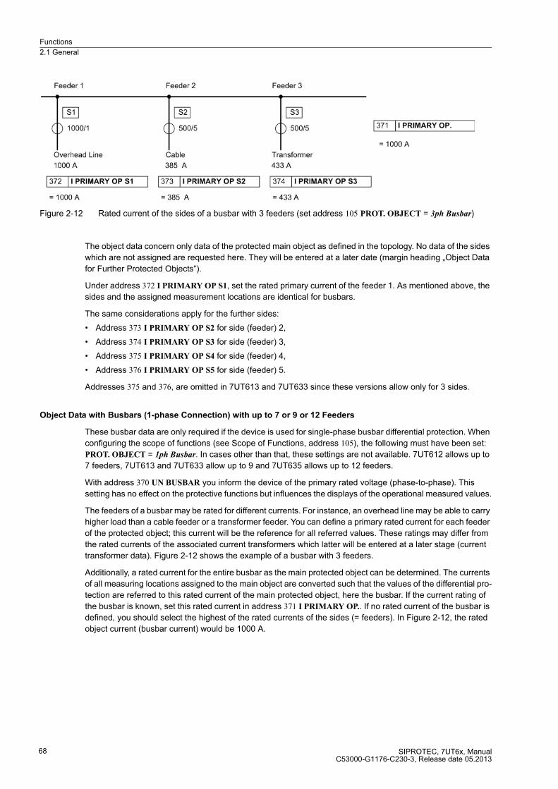
Functions
2.1 General
SIPROTEC, 7UT6x, ManualC53000-G1176-C230-3, Release date 05.2013
68
Figure 2-12 Rated current of the sides of a busbar with 3 feeders (set address 105 PROT. OBJECT = 3ph Busbar)
The object data concern only data of the protected main object as defined in the topology. No data of the sides
which are not assigned are requested here. They will be entered at a later date (margin heading „Object Data
for Further Protected Objects“).
Under address 372 I PRIMARY OP S1, set the rated primary current of the feeder 1. As mentioned above, the
sides and the assigned measurement locations are identical for busbars.
The same considerations apply for the further sides:
� Address 373 I PRIMARY OP S2 for side (feeder) 2,
� Address 374 I PRIMARY OP S3 for side (feeder) 3,
� Address 375 I PRIMARY OP S4 for side (feeder) 4,
� Address 376 I PRIMARY OP S5 for side (feeder) 5.
Addresses 375 and 376, are omitted in 7UT613 and 7UT633 since these versions allow only for 3 sides.
Object Data with Busbars (1-phase Connection) with up to 7 or 9 or 12 Feeders
These busbar data are only required if the device is used for single-phase busbar differential protection. When
configuring the scope of functions (see Scope of Functions, address 105), the following must have been set:
PROT. OBJECT = 1ph Busbar. In cases other than that, these settings are not available. 7UT612 allows up to
7 feeders, 7UT613 and 7UT633 allow up to 9 and 7UT635 allows up to 12 feeders.
With address 370 UN BUSBAR you inform the device of the primary rated voltage (phase-to-phase). This
setting has no effect on the protective functions but influences the displays of the operational measured values.
The feeders of a busbar may be rated for different currents. For instance, an overhead line may be able to carry
higher load than a cable feeder or a transformer feeder. You can define a primary rated current for each feeder
of the protected object; this current will be the reference for all referred values. These ratings may differ from
the rated currents of the associated current transformers which latter will be entered at a later stage (current
transformer data). Figure 2-12 shows the example of a busbar with 3 feeders.
Additionally, a rated current for the entire busbar as the main protected object can be determined. The currents
of all measuring locations assigned to the main object are converted such that the values of the differential pro-
tection are referred to this rated current of the main protected object, here the busbar. If the current rating of
the busbar is known, set this rated current in address 371 I PRIMARY OP.. If no rated current of the busbar is
defined, you should select the highest of the rated currents of the sides (= feeders). In Figure 2-12, the rated
object current (busbar current) would be 1000 A.

Functions
2.1 General
SIPROTEC, 7UT6x, ManualC53000-G1176-C230-3, Release date 05.2013
69
Under address 381 I PRIMARY OP 1, set the rated primary current of feeder 1.
The same considerations apply for the further feeders:
� Address 382 I PRIMARY OP 2 for feeder 2,
� Address 383 I PRIMARY OP 3 for feeder 3,
� Address 384 I PRIMARY OP 4 for feeder 4,
� Address 385 I PRIMARY OP 5 for feeder 5,
� Address 386 I PRIMARY OP 6 for feeder 6,
� Address 387 I PRIMARY OP 7 for feeder 7,
� Address 388 I PRIMARY OP 8 for feeder 8,
� Address 389 I PRIMARY OP 9 for feeder 9,
� Address 390 I PRIMARY OP 10 for feeder 10,
� Address 391 I PRIMARY OP 11 for feeder 11,
� Address 392 I PRIMARY OP 12 for feeder 12.
Addresses 388 and 392, are omitted in 7UT612 since this version allows only for 7 feeders. Addresses 390
to392, are omitted in 7UT613 and 7UT633 since these versions allow only for 9 feeders.
If one 7UT6x is used per phase, set the same rated current and voltage of a feeder for all three devices. For
the identification of the phases for fault annunciations and measured values each device is to be informed on
the phase to which it is assigned. This is to be set in address 396 PHASE SELECTION.
Object Data for Further Protected Objects
The object data described in the previous paragraphs relate to the main protected object whose sides and
measuring locations have been assigned according to section 2.1.4.1. If you have defined further protected
objects in your topology, a number of non-assigned measuring locations will be left. The rated values of these
are requested now.
The considerations concerning rated voltages and current are the same as for the main protected object. Only
those of the following addresses will appear during setting which relate to the non-assigned measuring loca-
tions, according to the set topology. Since the main protected object provides at least 2 measuring locations
(differential protection would make no sense with fewer), M1 and M2 will never appear here.
Address 403 I PRIMARY OP M3 requests the rated primary operating current at the measuring location M3
provided this is not assigned to the main protected object.
Address 404 I PRIMARY OP M4 requests the rated primary operating current at the measuring location M4
provided this is not assigned to the main protected object.
Address 405 I PRIMARY OP M5 requests the rated primary operating current at the measuring location M5
provided this is not assigned to the main protected object.
Addresses 403 to 405, are omitted in 7UT612 since this version allows only for 2 measuring locations.
Addresses 404 and 405, are omitted in 7UT613 and 7UT633 since these versions allow only 3 measuring
locations.
Voltage data have only a meaning in 7UT613 or 7UT633 if the device is equipped with voltage inputs. In case
the 3-phase voltage inputs relate to the main protected object, the rated voltages have already been set. But,
if 3-phase voltage measurement is intended at a measuring location which is not assigned to the main protect-
ed object, e.g. in address 261 VT SET a non-assigned Measuring loc.3 is selected, then you have to enter the
rated voltage of this measuring location in address 408 UN-PRI M3. This is a precondition for correct display
and transmission of measured values (voltages, powers). Similar considerations apply to address 409 UN-PRI
U4.

Functions
2.1 General
SIPROTEC, 7UT6x, ManualC53000-G1176-C230-3, Release date 05.2013
70
Current Transformer Data for 3-phase Measuring Locations
The rated primary operational currents for the protected object and its sides derive from the object data. The
data of the current transformer sets at the sides of the protected object generally differ slightly from the object
data before-described. They can also be completely different. Currents have to have a clear polarity to ensure
correct function of the differential protection and restricted earth fault protection as well as for correct display
of operational measured values (power etc.).
Therefore the device must be informed about the current transformer data. For 3-phase protected objects, this
is done by entering rated currents and the secondary starpoint position of the current transformer sets.
In address 512 IN-PRI CT M1 the rated primary current of the current transformer set of measuring location M1
is set, in address 513 IN-SEC CT M1 the rated secondary current. Please make sure that the sides were
defined correctly (see subsection 2.1.4.1, margin heading „Assignment of 3-phase Measuring Locations“).
Please also make sure that the rated secondary transformer currents match the setting for the rated currents
of these measuring inputs of the device. Otherwise the device will calculate incorrect primary data, and
malfunction of the differential protection may occur.
Indication of the starpoint position of the current transformers determines the polarity of the currents. To inform
the device of the starpoint position in relation to the measuring location 1, use address 511 STRPNT->OBJ M1
(starpoint versus object: YES or NO). Figure 2-13 shows some examples for this setting.
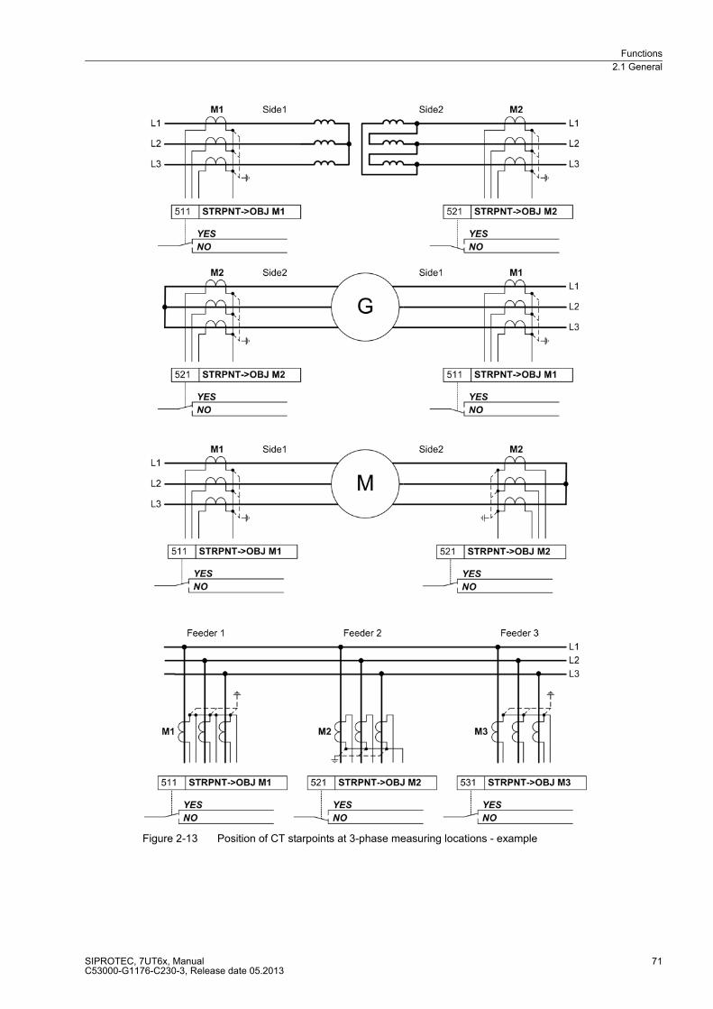
Functions
2.1 General
SIPROTEC, 7UT6x, ManualC53000-G1176-C230-3, Release date 05.2013
71
Figure 2-13 Position of CT starpoints at 3-phase measuring locations - example

Functions
2.1 General
SIPROTEC, 7UT6x, ManualC53000-G1176-C230-3, Release date 05.2013
72
Similar applies for the further measuring locations (assigned or non-assigned to the main protected object).
Only those addresses will appear during setting which are available in the actual device version.
Measuring Location 2
� Address 521 STRPNT->OBJ M2 starpoint position of CTs for measuring location M2,
� Address 522 IN-PRI CT M2 prim. rated current of CTs for measuring location M2,
� Address 523 IN-SEC CT M2 sec. nominal current CT for measuring location M2,
Measuring Location 3
� Address 531 STRPNT->OBJ M3 starpoint position of CT for measuring location M3,
� Address 532 IN-PRI CT M3 prim. rated current of CTs for measuring location M3,
� Address 533 IN-SEC CT M3 sec. nominal current CT for measuring location M3,
Measuring Location 4
� Address 541 STRPNT->OBJ M4 starpoint position of CT for measuring location M4,
� Address 542 IN-PRI CT M4 prim. rated current of CTs for measuring location M4,
� Address 543 IN-SEC CT M4 sec.. rated current of CTs for measuring location M4.
Measuring Location 5
� Address 551 STRPNT->OBJ M5 starpoint position of CTs for measuring location M5,
� Address 552 IN-PRI CT M5 prim. rated current of CTs for measuring location M5,
� Address 553 IN-SEC CT M5 sec. nominal current CT for measuring location M5,
If the device is applied as transverse differential protection for generators or motors, special considerations
must be observed for the CT connections: In a healthy operational state all currents flow into the protected
object, i.e. in contrast to the other applications. Therefore you have to set a „wrong“ polarity for one of the
current transformer sets. The part windings of the machine windings correspond to the „sides“.
One example is illustrated in figure 2-14. Although the starpoints of both current transformer sets are looking
towards the protected object, the opposite setting is to be selected for “side 2”: STRPNT->OBJ M2 = NO.
Figure 2-14 Current transformer starpoints in transverse differential protection - example

Functions
2.1 General
SIPROTEC, 7UT6x, ManualC53000-G1176-C230-3, Release date 05.2013
73
Current Transformer Data for Single-phase Busbar Protection
The operational nominal currents of each feeder already have been set under margin heading „Object Data
with Busbars (1-phase Connection) with up to 7 or 9 or 12 Feeders“. All feeder currents are referred to these
nominal feeder currents. However, the rated currents of the current transformers may differ from the nominal
feeder currents. Therefore, the device must be informed about the primary nominal currents of the current
transformers, too. In Figure 2-15 the rated CT currents are 1000 A (Feeder 1), and 500 A (Feeder 2 and 3).
If rated currents have already been matched by external equipment (e.g. by matching transformers), the rated
current value, used as a base value for the calculation of the external matching transformers, is to be indicated
uniform. Normally, it is the rated operational current. The same applies if external summation transformers are
used.
Indicate the rated primary transformer current for each feeder. The interrogation only applies to data of the
number of feeders determined during the configuration according to section 2.1.4, margin heading „Global Data
for 1-phase Busbar Protection“ (address 216 NUMBER OF ENDS).
For rated secondary currents please make sure that rated secondary transformer currents match with the rated
current of the corresponding current input of the device. Rated secondary currents of a device can be matched.
If summation transformers are used, the rated current at the outgoing side is usually 100 mA. For rated
secondary currents a value of 0.1 A is therefore set for all feeders.
Indication of the starpoint position of the current transformers determines the polarity of the current transform-
ers. Set for each feeder if the starpoint is looking towards the busbar or not. Figure 2-15 shows an example of
3 feeders in which the transformer starpoint in feeder 1 and feeder 3 are looking towards the busbar, unlike
feeder 2.
If external interposed transformers are used, it is presumed that these are connected with correct polarity.
Figure 2-15 Position of the CT starpoints — example for phase L1 of a busbar with 3 feeders

Functions
2.1 General
SIPROTEC, 7UT6x, ManualC53000-G1176-C230-3, Release date 05.2013
74
Hereinafter the parameters for the individual feeders:
Feeder 1
� Address 561 STRPNT->BUS I1 = transformer starpoint versus busbar for feeder 1,
� Address 562 IN-PRI CT I1 = rated primary transformer current for feeder 1,
� Address 563 IN-SEC CT I1 = rated secondary transformer current for feeder 1.
Feeder 2
� Address 571 STRPNT->BUS I2 = transformer starpoint versus busbar for feeder 2,
� Address 572 IN-PRI CT I2 = rated primary transformer current for feeder 2,
� Address 573 IN-SEC CT I2 = rated secondary current for feeder 2.
Feeder 3
� Address 581 STRPNT->BUS I3 = transformer starpoint versus busbar for feeder 3,
� Address 582 IN-PRI CT I3 = rated primary transformer current for feeder 3,
� Address 583 IN-SEC CT I3 = rated secondary current for feeder 3.
Feeder 4
� Address 591 STRPNT->BUS I4 = transformer starpoint versus busbar for feeder 4,
� Address 592 IN-PRI CT I4 = rated primary transformer current for feeder 4,
� Address 593 IN-SEC CT I4 = rated secondary current for feeder 4.
Feeder 5
� Address 601 STRPNT->BUS I5 = transformer starpoint versus busbar for feeder 5,
� Address 602 IN-PRI CT I5 = rated primary transformer current for feeder 5,
� Address 603 IN-SEC CT I5 = rated secondary current for feeder 5.
Feeder 6
� Address 611 STRPNT->BUS I6 = transformer starpoint versus busbar for feeder 6,
� Address 612 IN-PRI CT I6 = rated primary transformer current for feeder 6,
� Address 613 IN-SEC CT I6 = rated secondary current for feeder 6.
Feeder 7
� Address 621 STRPNT->BUS I7 = transformer starpoint versus busbar for feeder 7
� Address 622 IN-PRI CT I7 = rated primary transformer current for feeder 7,
� Address 623 IN-SEC CT I7 = rated secondary current for feeder 7.
The following settings are only available in 7UT613/63x:
Feeder 8
� Address 631 STRPNT->BUS I8 = transformer starpoint versus busbar for feeder 8,
� Address 632 IN-PRI CT I8 = rated primary transformer current for feeder 8,
� Address 633 IN-SEC CT I8 = rated secondary current for feeder 8.
Feeder 9
� Address 641 STRPNT->BUS I9 = transformer starpoint versus busbar for feeder 9,
� Address 642 IN-PRI CT I9 = rated primary transformer current for feeder 9,
� Address 643 IN-SEC CT I9 = rated secondary current for feeder 9.

Functions
2.1 General
SIPROTEC, 7UT6x, ManualC53000-G1176-C230-3, Release date 05.2013
75
The following settings are only available in 7UT635:
Feeder 10
� Address 651 STRPNT->BUS I10 = transformer starpoint versus busbar for feeder 10,
� Address 652 IN-PRI CT I10 = rated primary transformer current for feeder 10,
� Address 653 IN-SEC CT I10 = rated secondary current for feeder 10.
Feeder 11
� Address 661 STRPNT->BUS I11 = transformer starpoint versus busbar for feeder 11,
� Address 662 IN-PRI CT I11 = rated primary transformer current for feeder 11,
� Address 663 IN-SEC CT I11 = rated secondary current for feeder 11.
Feeder 12
� Address 671 STRPNT->BUS I12 = transformer starpoint versus busbar for feeder 12,
� Address 672 IN-PRI CT I12 = rated primary transformer current for feeder 12,
� Address 673 IN-SEC CT I12 = rated secondary current for feeder 12.
Current Transformer Data for 1-phase Further Current Inputs
The number of 1-phase further current inputs depends on the device version. Such inputs are used for
detection of the starpoint current of an earthed winding of a transformer, generator, or motor, shunt reactor, or
neutral reactor, or for different 1-phase measuring purposes. The assignment has already been carried out in
Subsection 2.1.4, margin heading „Assignment of Auxiliary 1-phase Measuring Locations“, the assignment of
the protection functions will be done in section „Assignment of the Protection Functions to the Measuring
Locations/Sides“. These settings concern exclusively the current transformer data, regardless of whether or not
they belong to the main protected object.
The device requests also the polarity and rated currents of the connected 1-phase CTs. The clarifications below
comprise all possible settings, in the actual case only those addresses will appear which are available in the
actual version and defined in the topology.
Enter the primary rated current of each further 1-phase current transformer which is connected and assigned
to a further 1-phase current input of the device. Please note the previous assignment of the measuring locations
(see section 2.1.4.1, margin heading „Assignment of Auxiliary 1-phase Measuring Locations“).
Distinction must be made for the secondary rated currents whether the 1-phase current input is a „normal“ or
a „high-sensitivity“ input of the device:
If a „normal“ input is concerned, set the secondary current in the same way as for the 3-phase current inputs.
Please make sure that the rated secondary CT current matches the rated current of the corresponding current
input of the device. Rated secondary currents of the device can be matched.
If a „high-sensitivity“ current input is used, no rated secondary current is defined. In order to calculate primary
values for such measuring inputs (e.g. for setting in primary values or for output of primary measured values),
the conversion factor INprim/INsec of the current transformer is set.
The polarity of a 1-phase current input is important for correct function of the differential protection and the
restricted earth fault protection. If only the magnitude of the current is of interest (e.g. for earth overcurrent
protection or single-phase overcurrent protection) the polarity is irrelevant, Even though a high-sensitive
1-phase current input has been selected, the polarity setting is omitted as it only processes the current amount.
For polarity information, set to which device terminal the side of the current transformer facing the earth
electrode is connected, i.e. not the side facing the starpoint itself. The secondary earthing point of the CT is of
no interest. Figure 2-16 shows the alternatives using as an example an earthed transformer winding for
auxiliary current IX1.
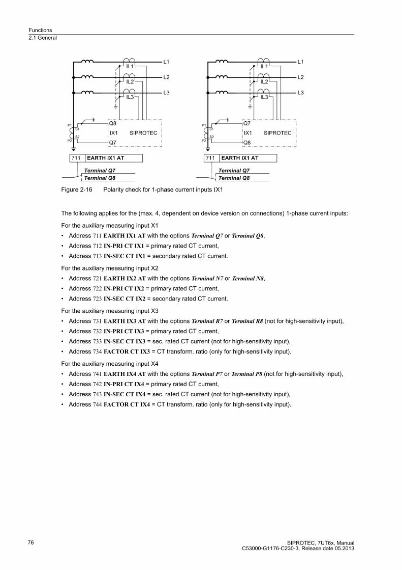
Functions
2.1 General
SIPROTEC, 7UT6x, ManualC53000-G1176-C230-3, Release date 05.2013
76
Figure 2-16 Polarity check for 1-phase current inputs IX1
The following applies for the (max. 4, dependent on device version on connections) 1-phase current inputs:
For the auxiliary measuring input X1
� Address 711 EARTH IX1 AT with the options Terminal Q7 or Terminal Q8,
� Address 712 IN-PRI CT IX1 = primary rated CT current,
� Address 713 IN-SEC CT IX1 = secondary rated CT current.
For the auxiliary measuring input X2
� Address 721 EARTH IX2 AT with the options Terminal N7 or Terminal N8,
� Address 722 IN-PRI CT IX2 = primary rated CT current,
� Address 723 IN-SEC CT IX2 = secondary rated CT current.
For the auxiliary measuring input X3
� Address 731 EARTH IX3 AT with the options Terminal R7 or Terminal R8 (not for high-sensitivity input),
� Address 732 IN-PRI CT IX3 = primary rated CT current,
� Address 733 IN-SEC CT IX3 = sec. rated CT current (not for high-sensitivity input),
� Address 734 FACTOR CT IX3 = CT transform. ratio (only for high-sensitivity input).
For the auxiliary measuring input X4
� Address 741 EARTH IX4 AT with the options Terminal P7 or Terminal P8 (not for high-sensitivity input),
� Address 742 IN-PRI CT IX4 = primary rated CT current,
� Address 743 IN-SEC CT IX4 = sec. rated CT current (not for high-sensitivity input),
� Address 744 FACTOR CT IX4 = CT transform. ratio (only for high-sensitivity input).

Functions
2.1 General
SIPROTEC, 7UT6x, ManualC53000-G1176-C230-3, Release date 05.2013
77
Note
For devices in panel surface mounted housing, terminal designations apply as per table 2-4.
Table 2-4 Terminal designation with surface mounted housing
Voltage Transformer Data
If the device is equipped with measuring voltage inputs and these inputs are assigned, the voltage transformer
data are of relevance.
For the 3-phase voltage input, you set at address 801 UN-PRI VT SET the primary rated VT voltage (phase-to-
phase), and at address 802 UN-SEC VT SET the secondary rated VT voltage.
If the reverse power protection with high-precision active power measurement is used, a correction of the angle
faults of the current and voltage transformers is particularly important, as in this case a very low active power
is computed from a very high apparent power (for small cos ϕ). In other cases, absolute compliance with the
angle of measured values is usually not required. In 7UT6x angle errors are corrected in the voltage paths. The
question of which current transformer set refers to the correction, is thus irrelevant, and an influence on the
currents for differential protection and all current functions by this correction is avoided. All power functions are
corrected on the other side. The angle correction is not important to the pure voltage functions (overexcitation
protection, undervoltage protection, overvoltage protection, frequency protection), as the precise phase angle
of the voltages is not relevant there. Set the resulting angle difference of the current and voltage transformers
relevant for the reverse power protection under address 803 CORRECT. U Ang. In electrical machines, deter-
mination of the corrective value is possible at primary commissioning of the machine.
For the 1-phase voltage input, you set at address 811 UN-PRI VT U4 the primary rated voltage of the connected
1-phase voltage transformer, and at address 812 UN-SEC VT U4 the secondary voltage. The addresses 811
and 812 must be set if the U4 transformer set has a different reference than the VT SET.
If the single-phase voltage input of a U4 transformer is a Uen transformer and equally assigned like the main
transformer set, then a different transformation ratio of the single-phase voltage transformer from the three-
phase voltage transformer set can be set under address 816 Uph / Udelta. If the single-phase voltage input at
the open delta winding e-n of the voltage transformer set is connected, the voltage transformation of the trans-
former is normally as follows:
Flush mounted
housing
corresponds to surface mounted housing terminals 1-phase
current input7UT612 7UT613 7UT633 7UT635
Terminal Q7 12 22 47 47IX1
Terminal Q8 27 47 97 97
Terminal N7 – 11 36 36IX2
Terminal N8 – 36 86 86
Terminal R7 6 18 43 43IX3
Terminal R8 21 43 93 93
Terminal P7 – – – 32IX4
Terminal P8 – – – 82
Functions
2.1 General
SIPROTEC, 7UT6x, ManualC53000-G1176-C230-3, Release date 05.2013
78
Factor Uph/Uen (secondary voltage) 3/√3 = √3 ≈ 1.73 must be used. For other transformation ratios, e.g. if the
residual voltage is formed by an interposed transformer set, the factor must be adapted accordingly. This factor
is of importance for the monitoring of the measured values and the scaling of the measurement and disturbance
recording signals.
If the U4 transformer set is a Uen transformer, then address 817 Uph(U4)/Udelta must be set.
817 Uph(U4)/Udelta ()
2.1.4.3 Assignment of Protection Functions to Measuring Locations / Sides
Main Protection Function = Differential Protection
The main protected object, i.e. the protected object which has been selected at address 105 PROT. OBJECT
during the configuration of the protection function, is always defined by its sides, each of which can have one
or multiple measuring locations assigned to them (section 2.1.4 under „Assignment of 3-phase Measuring
Locations“ and subsequent margin headings. Combined with the object and transformer data according to
subsection „General Power System Data“, the sides define unambiguously the manner in which to process the
currents supplied by the measuring locations (CT sets) for the main protection function, differential protection
(section 2.2.1).
In the example shown in Figure 2-2, the 3-phase measuring locations M1 and M2 have been assigned to side
S1 (high voltage side of the transformer). This ensures that the summated currents flowing through M1 and M2
towards the protected object are evaluated as currents flowing into the transformer side S1. Likewise, the
currents flowing through M3 and M4 towards the protected object are evaluated as currents flowing into the
transformer. Where an external current flows in via M4 and out again through M3, the sum of IM3 + IM4 = 0, i.e.
no current flows into the protected object at that point. Nevertheless both currents are used for restraint of the
differential protection. For more details, please refer to the description of the differential protection function
(subsection 2.2.1).
By the assignment of the auxiliary measuring location X3 to side S1 of the transformer, it is defined that the
1-phase earth fault current measured at X3 flows into the starpoint of the high-voltage winding, (subsection
2.1.4, „Topology of the Protected Object“ under margin heading „Assignment of Auxiliary 1-phase Measuring
Locations“).
As the topology thus provides for the differential protection a full description of the protected object with all its
sides and measuring locations, no further information is required for this function. There are, however, various
possibilities to enter information for the other protection functions.
Restricted Earth Fault Protection
Normally, the restricted earth fault protection (section 2.3) is assigned to one side of the main protected object,
namely the side with the earthed starpoint. In the example shown in Figure 2-2, this would be the side S1; there-
fore, address 413 REF PROT. AT would be set to Side 1 The 3-phase measuring locations M1 and M2 have
been assigned to this side during the definition of the topology. Therefore, the sum of the currents IM1 + IM2 is
considered to be flowing into side S1 of the transformer.
By the assignment of the auxiliary measuring location X3 to side S1 of the transformer, it is defined that the
1-phase earth fault current measured at X3 flows into the starpoint of the higher voltage winding, (subsection
2.1.4, „Topology of the Protected Object“ under margin heading „Assignment of Auxiliary 1-phase Measuring
Locations“).
Functions
2.1 General
SIPROTEC, 7UT6x, ManualC53000-G1176-C230-3, Release date 05.2013
79
If the main protected object is an auto-transformer, the restricted earth fault protection must use the currents of
both power supply circuits of the auto-connected winding, since it cannot be determined which portion of the
earth fault current from the earthing electrode goes to the full winding and which to the tap. In Figure 2-6 the
currents of the 3-phase measuring locations M1 and M2 flow into the auto-connected winding, the 1-phase
earth fault current is measured at the auxiliary measuring location X3. The 3-phase measuring location M3 is
irrelevant for the restricted earth fault protection. Since the assignment of the 3-phase measuring locations and
of the auxiliary measuring location is also defined by the topology, you only need to set auto-connected for the
restricted earth fault protection REF PROT. AT. This is also true if the auto-connected winding has more than
one tap.
But the restricted earth fault protection can also act upon an object other than the main protected object. In
Figure 2-3 the main protected object is a three-winding transformer with the sides S1, S2 and S3. The 3-phase
measuring location M5, on the other hand, belongs to the neutral reactor. You have now the option to use the
restricted earth fault protection for this reactor. Since for this further protected object no sides are defined, you
can assign here the restricted earth fault protection to the 3-phase measuring location M5, which is not as-
signed to the main protected object: set address 413 REF PROT. AT to n.assigMeasLoc5.
By the assignment of the auxiliary measuring location X4 to the 3-phase measuring location M5, it is defined
that the 1-phase earth fault current measured at X4 belongs to the neutral reactor connected to M5 (subsection
„Topology of the Protected Object“ under margin heading „Assignment of Auxiliary 1-phase Measuring Loca-
tions“).
7UT613/63x provides a second earth fault differential protection. With a YNyn transformer, for example, that is
earthed at the two starpoints, you can realize a restricted earth fault protection for each of the two windings. Or
you can use the first restricted earth fault protection for the earthed winding of a transformer and the second
for another protected object, e.g. a neutral reactor. Set address 414 REF PROT. 2 AT following the same con-
siderations as for the first restricted earth fault protection.
Further 3-phase Protection Functions
A reminder: the single-phase power transformer is treated like a three-phase power transformer (without phase
L2). Therefore, the three-phase protection functions apply also for this (except the overcurrent protection for
zero sequence current and asymmetrical load protection).
These further protection functions can operate on the main protected object or on a further protected object.
The possibilities depend on the definitions made in the topology.
For the main protection object, you normally choose one side for which the protection function will be effective.
If in the example shown in Figure 2-2 you want to use the time overcurrent protection for phase currents
(Section 2.4.1) as a backup protection on the high-voltage side, you set address 420 DMT/IDMT Ph AT to Side
1. The phase overcurrent protection then acquires the sum of the currents flowing through the measuring loca-
tions M1 and M2 (for each phase) towards the transformer.
You can also set the phase overcurrent protection to be effective for one single measuring location of the main
protected object. If in the same example you want to use the overcurrent protection as a protection for the
auxiliaries system circuit, you set address 420 DMT/IDMT Ph AT to Measuring loc.3.
Finally, you can also set the overcurrent protection to be effective for another protection object, i.e. assign it to
a 3-phase measuring location which is not assigned to the main protection object. To do so, you select that
measuring location. In the example shown in Figure 2-2, you can use the overcurrent protection as a protection
for the cable feeder by setting address 420 DMT/IDMT Ph AT to Measuring loc.5.

Functions
2.1 General
SIPROTEC, 7UT6x, ManualC53000-G1176-C230-3, Release date 05.2013
80
As the above examples show, the protection function can be assigned as desired. Generally speaking:
� Where a 3-phase protection function is assigned to a measuring location, the currents are acquired at this
location, regardless of whether it is assigned to the main protected object or not.
� Where a 3-phase protection function is assigned to a side (of the main protected object), the sum of the
currents flowing in at this side from the measuring locations assigned to it is acquired (for each phase).
� Please note also that the earth overcurrent protection will receive from the auxiliary measuring location
assigned here not only its measured value, but also circuit breaker information (current flow and manual-
close detection).
The same basic principles apply to the two additional overcurrent protection functions. With reference to the
example in figure 2-2, the first overcurrent protection can be determined as reserve protection at the high-
voltage side by setting address 420 DMT/IDMT Ph AT= Side 1 (as above), the second overcurrent protection
as protection of the station's own requirement feeder (address 430 DMT/IDMT Ph2 AT = Measuring loc.3) and
the third overcurrent protection as protection of the cable feeder (address 432 DMT/IDMT Ph3 AT = Measuring
loc.5).
The same applies also to the assignment of the overcurrent protection for zero sequence current (section 2.4.1)
in address 422 DMT/IDMT 3I0 AT. Please keep in mind that this protection function acquires the sum of the
phase currents and is therefore considered as a three-phase protection function. The assignment, however,
can differ from the assignment used by the overcurrent protection for phase currents. This means that in the
example shown in figure 2-2, the overcurrent protection can be easily used for phase currents (DMT/IDMT Ph
AT) at the higher voltage side of the transformer (Side 1), and the overcurrent protection for residual currents
(DMT/IDMT 3I0 AT) at the lower voltage side (Measuring loc.4).
The two additional protection functions in addresses 434 DMT/IDMT3I0-2AT can also be assigned to the
second residual current overcurrent protection and address 436 DMT/IDMT3I0-3AT to the third residual
overcurrent protection.
The same options exist for the unbalanced load protection (address 440 UNBAL. LOAD AT, section 2.8), which
can also be used at a side of the main protection object or at any - assigned or non-assigned - 3-phase
measuring location.
The overload protection (section 2.9) always refers to one side of the main protected object. Consequently,
address 442 THERM. O/L AT allows to select only a side, not a measuring location.
Since the cause for overload comes from outside of the protected object, the overload current is a traversing
current. Therefore it does not necessarily have to be detected at the infeeding side.
� For transformers with tap changer the overload protection is assigned to the non-regulated side as it is the
only side where we have a defined relation between rated current and rated power.
� For generators, the overload protection is usually on the starpoint side.
� For motors and shunt reactors, the overload protection is connected to the current transformers of the
feeding side.
� For series reactors or short cables, any side can be selected.
� For busbar sections or overhead lines, the overload protection is, generally, not used since climate and
weather conditions (air temperature, wind) change too quickly and it is therefore not reasonable to calculate
the temperature rise. In this case, however, a current-dependent alarm stage is able to warn of an imminent
overload.
The same applies to the second overload protection that is assigned to a side under address 444 THERM. O/L
2 AT.
The overexcitation protection (section 2.11) is only possible for devices with voltage connection, and requires
a measuring voltage to be connected and declared in the topology (section „Topology of the Protected Object“
under margin heading „Assignment of Voltage Measuring Inputs“). It is not necessary to assign the protection
function, since it always evaluates the three-phase measuring voltage at the voltage input, and the frequency
derived from it. The same applies to the undervoltage protection, the overvoltage protection and the frequency
protection.

Functions
2.1 General
SIPROTEC, 7UT6x, ManualC53000-G1176-C230-3, Release date 05.2013
81
When using the circuit breaker failure protection (section 2.17) (address 470 BREAKER FAIL.AT) please make
sure that the assignment of this protection function corresponds to that side or measuring location whose
current actually flows through the circuit breaker to be monitored. In the example shown in Figure 2-2, the
assignment must be set in address BREAKER FAIL.AT to Side 1 if you want to monitor the circuit breaker of
the high-voltage side, since both currents flow through the breaker (via M1 and M2). If on the other hand you
want to monitor the circuit breaker of the cable feeder, you set address BREAKER FAIL.AT to Measuring loc.5.
When assigning the circuit breaker failure protection function, make sure that the breaker auxiliary contacts or
feedback information are correctly configured and assigned.
If you do not wish to assign any measuring location or side to the circuit breaker failure protection because you
want only the breaker position to be processed, set BREAKER FAIL.AT to Ext. switchg. 1. In this case, the pro-
tection handles only the breaker position but not any current flow for its operation. This allows even to monitor
a circuit breaker the current of which is not connected to the device. But you have to ensure that the feedback
information of this breaker is correctly connected and configured.
In 7UT613/63x, you can monitor another m.c.b. using the second circuit breaker failure protection. The
considerations for the assignment in address 471 BREAKER FAIL2AT correspond to those for the first circuit
breaker failure protection.
Further 1-phase Protection Functions
The 1-phase protection functions evaluate the 1-phase measuring current of 1-phase additional measuring
input. It is irrelevant in this context whether the connect current belongs to the main protected object or not.
Only the current connected to the additional measuring input is decisive.
The device must now be informed which current is to be evaluated by the 1-phase protection functions.
Address 424 DMT/IDMT E AT assigns the time overcurrent protection for earth current (section 2.5) to a
1-phase additional measuring input. In most cases this will be the current flowing in the neutral leads of an
earthed winding, measured between the starpoint and the earth electrode. In figure 2-2 the auxiliary measuring
location X3 would be a good choice; so you set here AuxiliaryCT IX3. As this protection function is autonomous,
i.e. independent of any other protection function, any 1-phase additional measuring input can be used. This
requires, however, that it is not a high-sensitivity measuring input and, of course, that it is connected. Please
note also that the earth overcurrent protection will receive from the auxiliary measuring location assigned here
not only its measured value, but also circuit breaker information (current flow and manual-close detection).
The second earth overcurrent protection can be assigned to another single-phase measuring location
according to the same aspects under address 438 DMT/IDMT E2 AT.
Address 427 DMT 1PHASE AT assigns the single-phase time overcurrent protection (section 2.7). This
protection function is mainly used for high-sensitivity current measurement, e.g. for tank leakage protection or
high-impedance differential protection. Therefore a high-sensitivity 1-phase additional measuring input is
particularly suited for it. In figure 2-2 this would be the auxiliary measuring location X4; so you set this address
to AuxiliaryCT IX4. However, it is also possible to assign this protection function to any other additional mea-
suring input used, regardless of its sensitivity.
Functions
2.1 General
SIPROTEC, 7UT6x, ManualC53000-G1176-C230-3, Release date 05.2013
82
2.1.4.4 Circuit Breaker Data
Circuit Breaker Status
Various protection and ancillary functions require information on the status of the circuit breaker for faultless
operation. Command processing makes also use of the feedback information from the switching devices.
If, for instance, the circuit breaker failure protection is used to monitor the reaction of a specific circuit breaker
(CB), the protection device must know the measuring location at which the current flowing through the breaker
is acquired, and the binary inputs which provide information on the breaker status. During the configuration of
the binary inputs you merely assigned the (physical) binary inputs to the (logic) functions. The device, however,
must also know to which measuring location(s) the circuit breaker is assigned.
The breaker failure protection — and thus the circuit breaker that is monitored by it — is normally assigned to
a measuring location or to a side (see above, under margin heading „Further 3-Phase Protection Functions“).
You can therefore set addresses 831 to 835 SwitchgCBaux S1 to SwitchgCBaux S5 if a side is concerned, or
addresses 836 to 840 SwitchgCBaux M1 to SwitchgCBaux M5 if a measuring location is concerned.
You can, alternatively, monitor any desired circuit breaker, exclusively by means of the CB position indication,
i.e. without consideration of current flow. In this case you must have selected 470 under address BREAKER
FAIL.AT Ext. switchg. 1. You have then to select the corresponding breaker feedback information under
address 841 SwitchgCBaux E1 (switching device auxiliary contact of external breaker).
Select the address which corresponds to the assignment of the circuit breaker failure protection. There, you
choose from the following options:
1. If during the configuration of the binary inputs you have defined the circuit breaker as a control object, and
allocated the appropriate feedback indications, you choose these feedback indications to determine the
circuit breaker position, e.g. „Q0“. The breaker position is then automatically derived from the circuit
breaker Q0.
2. If during the configuration of the binary inputs you have generated a single-point indication which is
controlled by the NC or NO auxiliary contacts of the circuit breaker, you select this indication.
3. If during the configuration of the binary inputs you have generated a double indication which is controlled
by the NC or NO auxiliary contact of the circuit breaker (feedback from the protected object), you select
this indication.
4. If you have generated appropriate indications using CFC, you can select these indications.
In any case, you must make sure that the selected option indicates also the position of the monitored circuit
breaker. If you have not yet generated an indication for control and feedback of the breaker to be monitored
you should do so now. Detailed information is given in the SIPROTEC 4 System Description.
Example:
The group „Control Devices“ of the configuration matrix contains a double-point indication „Q0“. Assuming this
should be the breaker to be monitored, you have determined during configuration the physical inputs of the
device at which the feedback indications of the breaker Q0 arrive. For example, if the breaker failure protection
should monitor the breaker at the high-voltage side (= Side 1) of the transformer in Figure 2-2 you set:
Address 831 SwitchgCBaux S1 (because breaker at Side S1 is monitored) = „Q0“ (because indication „Q0“ in-
dicates feedback of the breaker).
Of course, you can define any desired input indication which indicates the breaker position via an
correspondingly assigned physical input.

Functions
2.1 General
SIPROTEC, 7UT6x, ManualC53000-G1176-C230-3, Release date 05.2013
83
Manual Close Indication of a Circuit Breaker
If a protection function is to make use of an external manual-close command indicated via a binary input, you
must have selected that logical input indication during the configuration of the binary inputs that corresponds
to the side or measuring location to which the protection function is assigned. From the internal control, the
device uses the same switching objects that were selected at the addresses 831 to 840.
Example:
If you have assigned the time overcurrent protection for phase currents to measuring location M4 and want it
to receive the manual-close command from circuit breaker CB2, you connect the Close command for breaker
CB2 to a binary input and allocate that input to „>ManualClose M4“ (No 30354).
Command Duration
The minimum trip command duration 851 is set in address TMin TRIP CMD. This duration is valid for all
protection functions which can issue a trip command. This parameter can only be altered in DIGSI at Display
Additional Settings.
2.1.4.5 Settings
Addresses which have an appended "A" can only be changed with DIGSI, under Additional Settings.
Addr. Parameter Setting Options Default Setting Comments
211 No Conn.MeasLoc 2345
3 Number of connected Measuring Locations
212 No AssigMeasLoc 2345
3 Number of assigned Measuring Locations
213 NUMBER OF SIDES 2345
3 Number of Sides
216 NUMBER OF ENDS 3456789101112
6 Number of Ends for 1 Phase Busbar
220 ASSIGNM. 2M,2S M1,M2 M1,M2 Assignment at 2 assig.Meas.Loc./ 2 Sides
221 ASSIGNM. 3M,2S M1+M2,M3M1,M2+M3
M1+M2,M3 Assignment at 3 assig.Meas.Loc./ 2 Sides
222 ASSIGNM. 3M,3S M1,M2,M3 M1,M2,M3 Assignment at 3 assig.Meas.Loc./ 3 Sides

Functions
2.1 General
SIPROTEC, 7UT6x, ManualC53000-G1176-C230-3, Release date 05.2013
84
223 ASSIGNM. 4M,2S M1+M2,M3+M4M1+M2+M3,M4M1,M2+M3+M4
M1+M2,M3+M4 Assignment at 4 assig.Meas.Loc./ 2 Sides
224 ASSIGNM. 4M,3S M1+M2,M3,M4M1,M2+M3,M4M1,M2,M3+M4
M1+M2,M3,M4 Assignment at 4 assig.Meas.Loc./ 3 Sides
225 ASSIGNM. 4M,4S M1,M2,M3,M4 M1,M2,M3,M4 Assignment at 4 assig.Meas.Loc./ 4 Sides
226 ASSIGNM. 5M,2S M1+M2+M3,M4+M5M1+M2,M3+M4+M5M1+M2+M3+M4,M5M1,M2+M3+M4+M5
M1+M2+M3,M4+M5
Assignment at 5 assig.Meas.Loc./ 2 Sides
227 ASSIGNM. 5M,3S M1+M2,M3+M4,M5M1+M2,M3,M4+M5M1,M2+M3,M4+M5M1+M2+M3,M4,M5M1,M2+M3+M4,M5M1,M2,M3+M4+M5
M1+M2,M3+M4,M5
Assignment at 5 assig.Meas.Loc./ 3 Sides
228 ASSIGNM. 5M,4S M1+M2,M3,M4,M5M1,M2+M3,M4,M5M1,M2,M3+M4,M5M1,M2,M3,M4+M5
M1+M2,M3,M4,M5 Assignment at 5 assig.Meas.Loc./ 4 Sides
229 ASSIGNM. 5M,5S M1,M2,M3,M4,M5 M1,M2,M3,M4,M5 Assignment at 5 assig.Meas.Loc./ 5 Sides
230 ASSIGNM. ERROR No AssigMeasLocNo of sides
without Assignment Error
241 SIDE 1 auto-connected auto-connected Side 1 is assigned to
242 SIDE 2 auto-connected auto-connected Side 2 is assigned to
243 SIDE 3 auto-connectedcompensationearth.electrode
auto-connected Side 3 is assigned to
244 SIDE 4 auto-connectedcompensationearth.electrode
compensation Side 4 is assigned to
251 AUX. CT IX1 Not connectedconn/not assig.Side 1 earthSide 2 earthSide 3 earthSide 4 earthMeasLoc.1 earthMeasLoc.2 earthMeasLoc.3 earthMeasLoc.4 earth
Not connected Auxiliary CT IX1 is used as
Addr. Parameter Setting Options Default Setting Comments
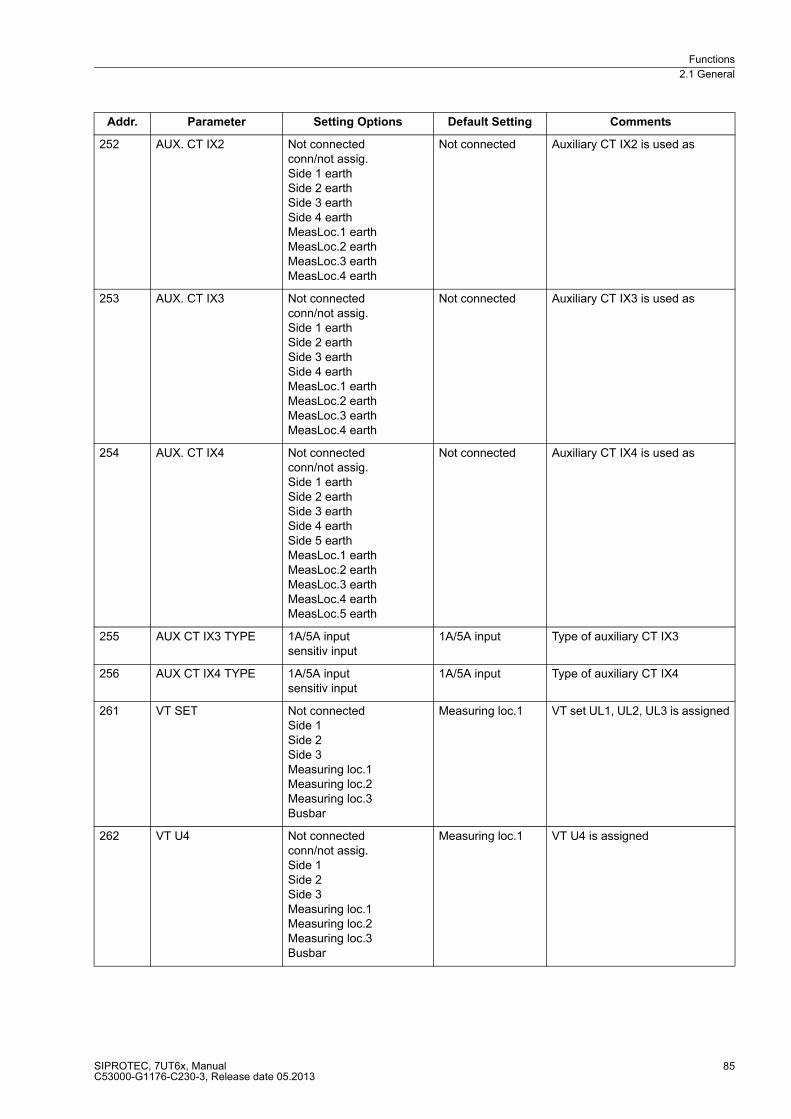
Functions
2.1 General
SIPROTEC, 7UT6x, ManualC53000-G1176-C230-3, Release date 05.2013
85
252 AUX. CT IX2 Not connectedconn/not assig.Side 1 earthSide 2 earthSide 3 earthSide 4 earthMeasLoc.1 earthMeasLoc.2 earthMeasLoc.3 earthMeasLoc.4 earth
Not connected Auxiliary CT IX2 is used as
253 AUX. CT IX3 Not connectedconn/not assig.Side 1 earthSide 2 earthSide 3 earthSide 4 earthMeasLoc.1 earthMeasLoc.2 earthMeasLoc.3 earthMeasLoc.4 earth
Not connected Auxiliary CT IX3 is used as
254 AUX. CT IX4 Not connectedconn/not assig.Side 1 earthSide 2 earthSide 3 earthSide 4 earthSide 5 earthMeasLoc.1 earthMeasLoc.2 earthMeasLoc.3 earthMeasLoc.4 earthMeasLoc.5 earth
Not connected Auxiliary CT IX4 is used as
255 AUX CT IX3 TYPE 1A/5A inputsensitiv input
1A/5A input Type of auxiliary CT IX3
256 AUX CT IX4 TYPE 1A/5A inputsensitiv input
1A/5A input Type of auxiliary CT IX4
261 VT SET Not connectedSide 1Side 2Side 3Measuring loc.1Measuring loc.2Measuring loc.3Busbar
Measuring loc.1 VT set UL1, UL2, UL3 is assigned
262 VT U4 Not connectedconn/not assig.Side 1Side 2Side 3Measuring loc.1Measuring loc.2Measuring loc.3Busbar
Measuring loc.1 VT U4 is assigned
Addr. Parameter Setting Options Default Setting Comments
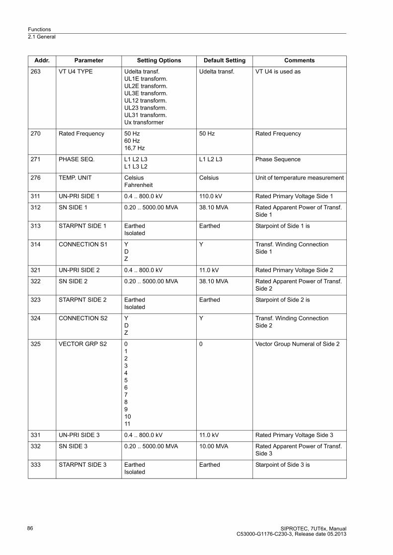
Functions
2.1 General
SIPROTEC, 7UT6x, ManualC53000-G1176-C230-3, Release date 05.2013
86
263 VT U4 TYPE Udelta transf.UL1E transform.UL2E transform.UL3E transform.UL12 transform.UL23 transform.UL31 transform.Ux transformer
Udelta transf. VT U4 is used as
270 Rated Frequency 50 Hz60 Hz16,7 Hz
50 Hz Rated Frequency
271 PHASE SEQ. L1 L2 L3L1 L3 L2
L1 L2 L3 Phase Sequence
276 TEMP. UNIT CelsiusFahrenheit
Celsius Unit of temperature measurement
311 UN-PRI SIDE 1 0.4 .. 800.0 kV 110.0 kV Rated Primary Voltage Side 1
312 SN SIDE 1 0.20 .. 5000.00 MVA 38.10 MVA Rated Apparent Power of Transf. Side 1
313 STARPNT SIDE 1 EarthedIsolated
Earthed Starpoint of Side 1 is
314 CONNECTION S1 YDZ
Y Transf. Winding Connection Side 1
321 UN-PRI SIDE 2 0.4 .. 800.0 kV 11.0 kV Rated Primary Voltage Side 2
322 SN SIDE 2 0.20 .. 5000.00 MVA 38.10 MVA Rated Apparent Power of Transf. Side 2
323 STARPNT SIDE 2 EarthedIsolated
Earthed Starpoint of Side 2 is
324 CONNECTION S2 YDZ
Y Transf. Winding Connection Side 2
325 VECTOR GRP S2 01234567891011
0 Vector Group Numeral of Side 2
331 UN-PRI SIDE 3 0.4 .. 800.0 kV 11.0 kV Rated Primary Voltage Side 3
332 SN SIDE 3 0.20 .. 5000.00 MVA 10.00 MVA Rated Apparent Power of Transf. Side 3
333 STARPNT SIDE 3 EarthedIsolated
Earthed Starpoint of Side 3 is
Addr. Parameter Setting Options Default Setting Comments
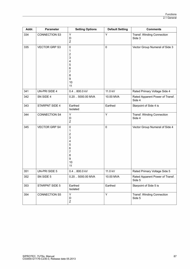
Functions
2.1 General
SIPROTEC, 7UT6x, ManualC53000-G1176-C230-3, Release date 05.2013
87
334 CONNECTION S3 YDZ
Y Transf. Winding Connection Side 3
335 VECTOR GRP S3 01234567891011
0 Vector Group Numeral of Side 3
341 UN-PRI SIDE 4 0.4 .. 800.0 kV 11.0 kV Rated Primary Voltage Side 4
342 SN SIDE 4 0.20 .. 5000.00 MVA 10.00 MVA Rated Apparent Power of Transf. Side 4
343 STARPNT SIDE 4 EarthedIsolated
Earthed Starpoint of Side 4 is
344 CONNECTION S4 YDZ
Y Transf. Winding Connection Side 4
345 VECTOR GRP S4 01234567891011
0 Vector Group Numeral of Side 4
351 UN-PRI SIDE 5 0.4 .. 800.0 kV 11.0 kV Rated Primary Voltage Side 5
352 SN SIDE 5 0.20 .. 5000.00 MVA 10.00 MVA Rated Apparent Power of Transf. Side 5
353 STARPNT SIDE 5 EarthedIsolated
Earthed Starpoint of Side 5 is
354 CONNECTION S5 YDZ
Y Transf. Winding Connection Side 5
Addr. Parameter Setting Options Default Setting Comments

Functions
2.1 General
SIPROTEC, 7UT6x, ManualC53000-G1176-C230-3, Release date 05.2013
88
355 VECTOR GRP S5 01234567891011
0 Vector Group Numeral of Side 5
361 UN GEN/MOTOR 0.4 .. 800.0 kV 21.0 kV Rated Primary Voltage Generator/Motor
362 SN GEN/MOTOR 0.20 .. 5000.00 MVA 70.00 MVA Rated Apparent Power of the Generator
370 UN BUSBAR 0.4 .. 800.0 kV 110.0 kV Rated Primary Voltage Busbar
371 I PRIMARY OP. 1 .. 100000 A 200 A Primary Operating Current of Busbar
372 I PRIMARY OP S1 1 .. 100000 A 200 A Primary Operating Current Side 1
373 I PRIMARY OP S2 1 .. 100000 A 200 A Primary Operating Current Side 2
374 I PRIMARY OP S3 1 .. 100000 A 200 A Primary Operating Current Side 3
375 I PRIMARY OP S4 1 .. 100000 A 200 A Primary Operating Current Side 4
376 I PRIMARY OP S5 1 .. 100000 A 200 A Primary Operating Current Side 5
381 I PRIMARY OP 1 1 .. 100000 A 200 A Primary Operating Current End 1
382 I PRIMARY OP 2 1 .. 100000 A 200 A Primary Operating Current End 2
383 I PRIMARY OP 3 1 .. 100000 A 200 A Primary Operating Current End 3
384 I PRIMARY OP 4 1 .. 100000 A 200 A Primary Operating Current End 4
385 I PRIMARY OP 5 1 .. 100000 A 200 A Primary Operating Current End 5
386 I PRIMARY OP 6 1 .. 100000 A 200 A Primary Operating Current End 6
387 I PRIMARY OP 7 1 .. 100000 A 200 A Primary Operating Current End 7
388 I PRIMARY OP 8 1 .. 100000 A 200 A Primary Operating Current End 8
389 I PRIMARY OP 9 1 .. 100000 A 200 A Primary Operating Current End 9
390 I PRIMARY OP 10 1 .. 100000 A 200 A Primary Operating Current End 10
391 I PRIMARY OP 11 1 .. 100000 A 200 A Primary Operating Current End 11
392 I PRIMARY OP 12 1 .. 100000 A 200 A Primary Operating Current End 12
396 PHASE SELECTION Phase 1Phase 2Phase 3
Phase 1 Phase selection
403 I PRIMARY OP M3 1 .. 100000 A 200 A Primary Operating Current Meas. Loc. 3
404 I PRIMARY OP M4 1 .. 100000 A 200 A Primary Operating Current Meas. Loc. 4
Addr. Parameter Setting Options Default Setting Comments
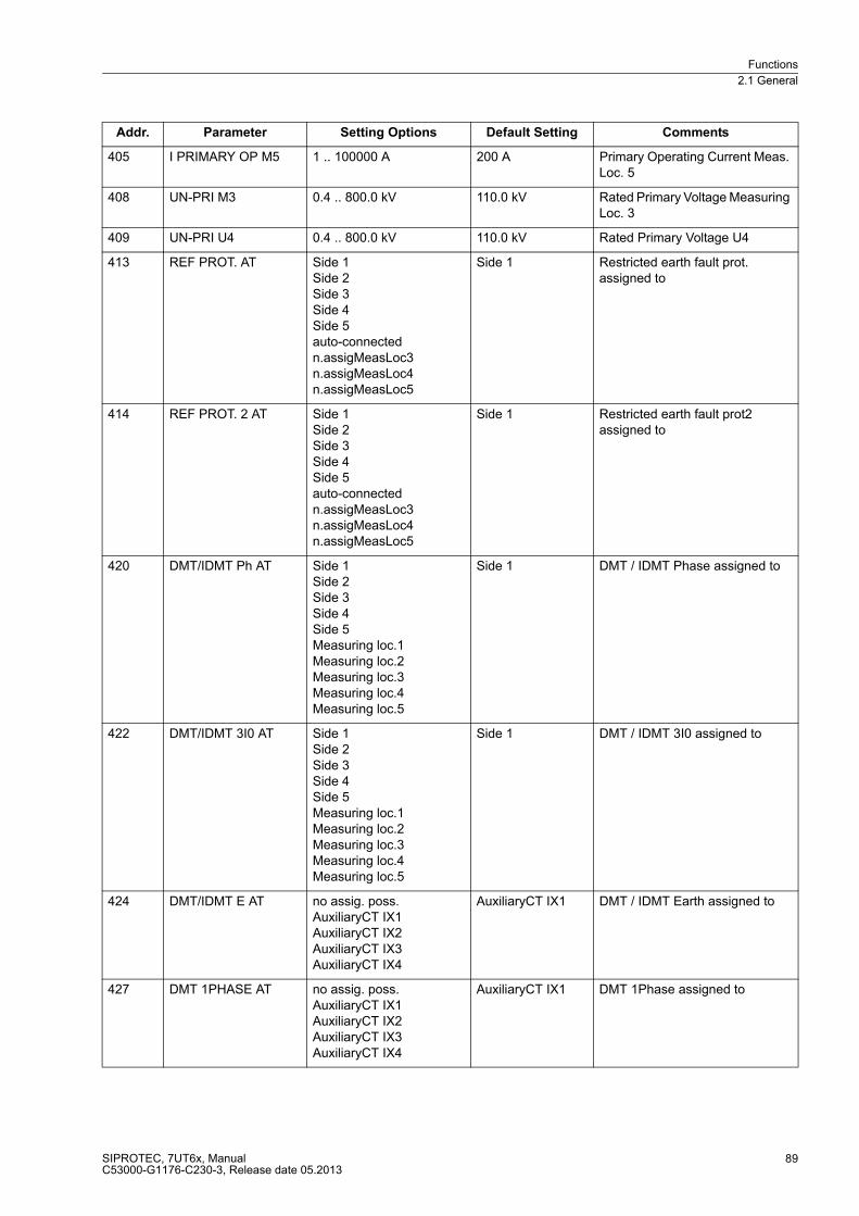
Functions
2.1 General
SIPROTEC, 7UT6x, ManualC53000-G1176-C230-3, Release date 05.2013
89
405 I PRIMARY OP M5 1 .. 100000 A 200 A Primary Operating Current Meas. Loc. 5
408 UN-PRI M3 0.4 .. 800.0 kV 110.0 kV Rated Primary Voltage Measuring Loc. 3
409 UN-PRI U4 0.4 .. 800.0 kV 110.0 kV Rated Primary Voltage U4
413 REF PROT. AT Side 1Side 2Side 3Side 4Side 5auto-connectedn.assigMeasLoc3n.assigMeasLoc4n.assigMeasLoc5
Side 1 Restricted earth fault prot. assigned to
414 REF PROT. 2 AT Side 1Side 2Side 3Side 4Side 5auto-connectedn.assigMeasLoc3n.assigMeasLoc4n.assigMeasLoc5
Side 1 Restricted earth fault prot2 assigned to
420 DMT/IDMT Ph AT Side 1Side 2Side 3Side 4Side 5Measuring loc.1Measuring loc.2Measuring loc.3Measuring loc.4Measuring loc.5
Side 1 DMT / IDMT Phase assigned to
422 DMT/IDMT 3I0 AT Side 1Side 2Side 3Side 4Side 5Measuring loc.1Measuring loc.2Measuring loc.3Measuring loc.4Measuring loc.5
Side 1 DMT / IDMT 3I0 assigned to
424 DMT/IDMT E AT no assig. poss.AuxiliaryCT IX1AuxiliaryCT IX2AuxiliaryCT IX3AuxiliaryCT IX4
AuxiliaryCT IX1 DMT / IDMT Earth assigned to
427 DMT 1PHASE AT no assig. poss.AuxiliaryCT IX1AuxiliaryCT IX2AuxiliaryCT IX3AuxiliaryCT IX4
AuxiliaryCT IX1 DMT 1Phase assigned to
Addr. Parameter Setting Options Default Setting Comments

Functions
2.1 General
SIPROTEC, 7UT6x, ManualC53000-G1176-C230-3, Release date 05.2013
90
430 DMT/IDMT Ph2 AT Side 1Side 2Side 3Side 4Side 5Measuring loc.1Measuring loc.2Measuring loc.3Measuring loc.4Measuring loc.5
Side 1 DMT / IDMT Phase 2 assigned to
432 DMT/IDMT Ph3 AT Side 1Side 2Side 3Side 4Side 5Measuring loc.1Measuring loc.2Measuring loc.3Measuring loc.4Measuring loc.5
Side 1 DMT / IDMT Phase 3 assigned to
434 DMT/IDMT3I0-2AT Side 1Side 2Side 3Side 4Side 5Measuring loc.1Measuring loc.2Measuring loc.3Measuring loc.4Measuring loc.5
Side 1 DMT / IDMT 3I0 2 assigned to
436 DMT/IDMT3I0-3AT Side 1Side 2Side 3Side 4Side 5Measuring loc.1Measuring loc.2Measuring loc.3Measuring loc.4Measuring loc.5
Side 1 DMT / IDMT 3I0 3 assigned to
438 DMT/IDMT E2 AT no assig. poss.AuxiliaryCT IX1AuxiliaryCT IX2AuxiliaryCT IX3AuxiliaryCT IX4
AuxiliaryCT IX1 DMT / IDMT Earth 2 assigned to
440 UNBAL. LOAD AT Side 1Side 2Side 3Side 4Side 5Measuring loc.1Measuring loc.2Measuring loc.3Measuring loc.4Measuring loc.5
Side 1 Unbalance Load (Neg. Seq.) assigned to
Addr. Parameter Setting Options Default Setting Comments
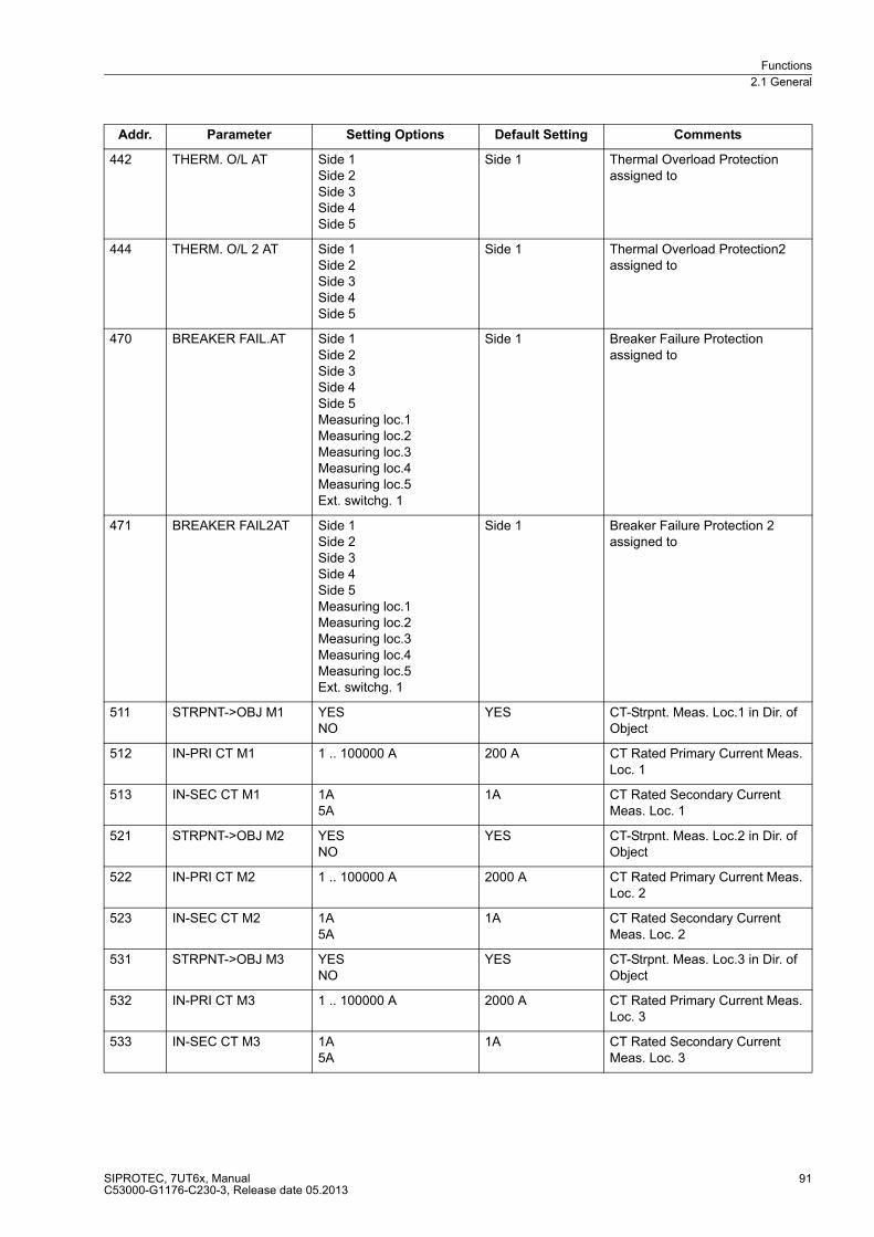
Functions
2.1 General
SIPROTEC, 7UT6x, ManualC53000-G1176-C230-3, Release date 05.2013
91
442 THERM. O/L AT Side 1Side 2Side 3Side 4Side 5
Side 1 Thermal Overload Protection assigned to
444 THERM. O/L 2 AT Side 1Side 2Side 3Side 4Side 5
Side 1 Thermal Overload Protection2 assigned to
470 BREAKER FAIL.AT Side 1Side 2Side 3Side 4Side 5Measuring loc.1Measuring loc.2Measuring loc.3Measuring loc.4Measuring loc.5Ext. switchg. 1
Side 1 Breaker Failure Protection assigned to
471 BREAKER FAIL2AT Side 1Side 2Side 3Side 4Side 5Measuring loc.1Measuring loc.2Measuring loc.3Measuring loc.4Measuring loc.5Ext. switchg. 1
Side 1 Breaker Failure Protection 2 assigned to
511 STRPNT->OBJ M1 YESNO
YES CT-Strpnt. Meas. Loc.1 in Dir. of Object
512 IN-PRI CT M1 1 .. 100000 A 200 A CT Rated Primary Current Meas. Loc. 1
513 IN-SEC CT M1 1A5A
1A CT Rated Secondary Current Meas. Loc. 1
521 STRPNT->OBJ M2 YESNO
YES CT-Strpnt. Meas. Loc.2 in Dir. of Object
522 IN-PRI CT M2 1 .. 100000 A 2000 A CT Rated Primary Current Meas. Loc. 2
523 IN-SEC CT M2 1A5A
1A CT Rated Secondary Current Meas. Loc. 2
531 STRPNT->OBJ M3 YESNO
YES CT-Strpnt. Meas. Loc.3 in Dir. of Object
532 IN-PRI CT M3 1 .. 100000 A 2000 A CT Rated Primary Current Meas. Loc. 3
533 IN-SEC CT M3 1A5A
1A CT Rated Secondary Current Meas. Loc. 3
Addr. Parameter Setting Options Default Setting Comments
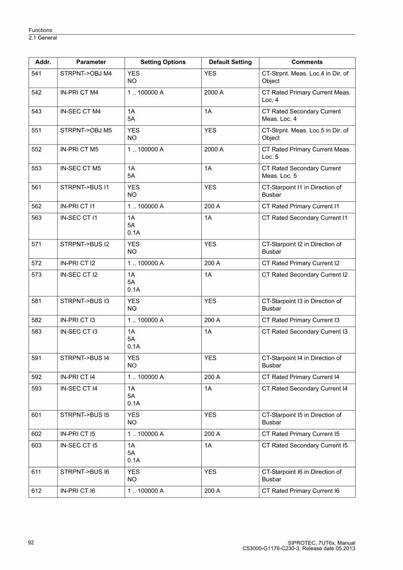
Functions
2.1 General
SIPROTEC, 7UT6x, ManualC53000-G1176-C230-3, Release date 05.2013
92
541 STRPNT->OBJ M4 YESNO
YES CT-Strpnt. Meas. Loc.4 in Dir. of Object
542 IN-PRI CT M4 1 .. 100000 A 2000 A CT Rated Primary Current Meas. Loc. 4
543 IN-SEC CT M4 1A5A
1A CT Rated Secondary Current Meas. Loc. 4
551 STRPNT->OBJ M5 YESNO
YES CT-Strpnt. Meas. Loc.5 in Dir. of Object
552 IN-PRI CT M5 1 .. 100000 A 2000 A CT Rated Primary Current Meas. Loc. 5
553 IN-SEC CT M5 1A5A
1A CT Rated Secondary Current Meas. Loc. 5
561 STRPNT->BUS I1 YESNO
YES CT-Starpoint I1 in Direction of Busbar
562 IN-PRI CT I1 1 .. 100000 A 200 A CT Rated Primary Current I1
563 IN-SEC CT I1 1A5A0.1A
1A CT Rated Secondary Current I1
571 STRPNT->BUS I2 YESNO
YES CT-Starpoint I2 in Direction of Busbar
572 IN-PRI CT I2 1 .. 100000 A 200 A CT Rated Primary Current I2
573 IN-SEC CT I2 1A5A0.1A
1A CT Rated Secondary Current I2
581 STRPNT->BUS I3 YESNO
YES CT-Starpoint I3 in Direction of Busbar
582 IN-PRI CT I3 1 .. 100000 A 200 A CT Rated Primary Current I3
583 IN-SEC CT I3 1A5A0.1A
1A CT Rated Secondary Current I3
591 STRPNT->BUS I4 YESNO
YES CT-Starpoint I4 in Direction of Busbar
592 IN-PRI CT I4 1 .. 100000 A 200 A CT Rated Primary Current I4
593 IN-SEC CT I4 1A5A0.1A
1A CT Rated Secondary Current I4
601 STRPNT->BUS I5 YESNO
YES CT-Starpoint I5 in Direction of Busbar
602 IN-PRI CT I5 1 .. 100000 A 200 A CT Rated Primary Current I5
603 IN-SEC CT I5 1A5A0.1A
1A CT Rated Secondary Current I5
611 STRPNT->BUS I6 YESNO
YES CT-Starpoint I6 in Direction of Busbar
612 IN-PRI CT I6 1 .. 100000 A 200 A CT Rated Primary Current I6
Addr. Parameter Setting Options Default Setting Comments

Functions
2.1 General
SIPROTEC, 7UT6x, ManualC53000-G1176-C230-3, Release date 05.2013
93
613 IN-SEC CT I6 1A5A0.1A
1A CT Rated Secondary Current I6
621 STRPNT->BUS I7 YESNO
YES CT-Starpoint I7 in Direction of Busbar
622 IN-PRI CT I7 1 .. 100000 A 200 A CT Rated Primary Current I7
623 IN-SEC CT I7 1A5A0.1A
1A CT Rated Secondary Current I7
631 STRPNT->BUS I8 YESNO
YES CT-Starpoint I8 in Direction of Busbar
632 IN-PRI CT I8 1 .. 100000 A 200 A CT Rated Primary Current I8
633 IN-SEC CT I8 1A5A0.1A
1A CT Rated Secondary Current I8
641 STRPNT->BUS I9 YESNO
YES CT-Starpoint I9 in Direction of Busbar
642 IN-PRI CT I9 1 .. 100000 A 200 A CT Rated Primary Current I9
643 IN-SEC CT I9 1A5A0.1A
1A CT Rated Secondary Current I9
651 STRPNT->BUS I10 YESNO
YES CT-Starpoint I10 in Direction of Busbar
652 IN-PRI CT I10 1 .. 100000 A 200 A CT Rated Primary Current I10
653 IN-SEC CT I10 1A5A0.1A
1A CT Rated Secondary Current I10
661 STRPNT->BUS I11 YESNO
YES CT-Starpoint I11 in Direction of Busbar
662 IN-PRI CT I11 1 .. 100000 A 200 A CT Rated Primary Current I11
663 IN-SEC CT I11 1A5A0.1A
1A CT Rated Secondary Current I11
671 STRPNT->BUS I12 YESNO
YES CT-Starpoint I12 in Direction of Busbar
672 IN-PRI CT I12 1 .. 100000 A 200 A CT Rated Primary Current I12
673 IN-SEC CT I12 1A5A0.1A
1A CT Rated Secondary Current I12
711 EARTH IX1 AT Terminal Q7Terminal Q8
Terminal Q7 Earthing electrod IX1 connected to
712 IN-PRI CT IX1 1 .. 100000 A 200 A CT rated primary current IX1
713 IN-SEC CT IX1 1A5A
1A CT rated secondary current IX1
721 EARTH IX2 AT Terminal N7Terminal N8
Terminal N7 Earthing electrod IX2 connected to
Addr. Parameter Setting Options Default Setting Comments

Functions
2.1 General
SIPROTEC, 7UT6x, ManualC53000-G1176-C230-3, Release date 05.2013
94
722 IN-PRI CT IX2 1 .. 100000 A 200 A CT rated primary current IX2
723 IN-SEC CT IX2 1A5A
1A CT rated secondary current IX2
731 EARTH IX3 AT Terminal R7Terminal R8
Terminal R7 Earthing electrod IX3 connected to
732 IN-PRI CT IX3 1 .. 100000 A 200 A CT rated primary current IX3
733 IN-SEC CT IX3 1A5A
1A CT rated secondary current IX3
734 FACTOR CT IX3 1.0 .. 300.0 60.0 Factor: prim. over sek. current IX3
741 EARTH IX4 AT Terminal P7Terminal P8
Terminal P7 Earthing electrod IX4 connected to
742 IN-PRI CT IX4 1 .. 100000 A 200 A CT rated primary current IX4
743 IN-SEC CT IX4 1A5A
1A CT rated secondary current IX4
744 FACTOR CT IX4 1.0 .. 300.0 60.0 Factor: prim. over sek. current IX4
801 UN-PRI VT SET 0.1 .. 1200.0 kV 110.0 kV VT Rated Prim. Voltage Set UL1, UL2, UL3
802 UN-SEC VT SET 80 .. 125 V 100 V VT Rated Sec. Voltage Set UL1, UL2, UL3
803 CORRECT. U Ang -5.00 .. 5.00 ° 0.00 ° Angle correction UL1, UL2, UL3 - VT
811 UN-PRI VT U4 0.1 .. 1200.0 kV 110.0 kV VT Rated Primary Voltage U4
812 UN-SEC VT U4 80 .. 125 V 100 V VT Rated Secondary Voltage U4
816 Uph / Udelta 0.10 .. 9.99 1.73 Matching ratio Phase-VT to Open-Delta-VT
817 Uph(U4)/Udelta 0.10 .. 9.99 1.73 Matching ratio Ph-VT(U4) to Open-DeltaVT
831 SwitchgCBaux S1 (Setting options depend on configuration)
Q0 Switchgear / CBaux at Side 1
832 SwitchgCBaux S2 (Setting options depend on configuration)
None Switchgear / CBaux at Side 2
833 SwitchgCBaux S3 (Setting options depend on configuration)
None Switchgear / CBaux at Side 3
834 SwitchgCBaux S4 (Setting options depend on configuration)
None Switchgear / CBaux at Side 4
835 SwitchgCBaux S5 (Setting options depend on configuration)
None Switchgear / CBaux at Side 5
836 SwitchgCBaux M1 (Setting options depend on configuration)
None Switchgear / CBaux at Measuring Loc. M1
837 SwitchgCBaux M2 (Setting options depend on configuration)
None Switchgear / CBaux at Measuring Loc. M2
838 SwitchgCBaux M3 (Setting options depend on configuration)
None Switchgear / CBaux at Measuring Loc. M3
839 SwitchgCBaux M4 (Setting options depend on configuration)
None Switchgear / CBaux at Measuring Loc. M4
Addr. Parameter Setting Options Default Setting Comments
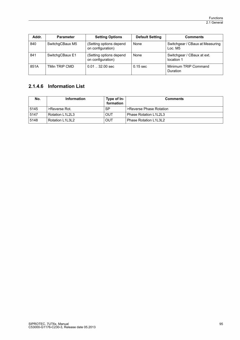
Functions
2.1 General
SIPROTEC, 7UT6x, ManualC53000-G1176-C230-3, Release date 05.2013
95
2.1.4.6 Information List
840 SwitchgCBaux M5 (Setting options depend on configuration)
None Switchgear / CBaux at Measuring Loc. M5
841 SwitchgCBaux E1 (Setting options depend on configuration)
None Switchgear / CBaux at ext. location 1
851A TMin TRIP CMD 0.01 .. 32.00 sec 0.15 sec Minimum TRIP Command Duration
No. Information Type of In-
formation
Comments
5145 >Reverse Rot. SP >Reverse Phase Rotation
5147 Rotation L1L2L3 OUT Phase Rotation L1L2L3
5148 Rotation L1L3L2 OUT Phase Rotation L1L3L2
Addr. Parameter Setting Options Default Setting Comments
Functions
2.1 General
SIPROTEC, 7UT6x, ManualC53000-G1176-C230-3, Release date 05.2013
96
2.1.5 Setting Groups
Four independent groups of parameters can be set for the device functions. During operation, you may switch
between setting groups locally, via binary inputs (if so configured), via the operator or service interface using a
personal computer, or via the system interface.
2.1.5.1 Setting Groups
Purpose of Setting Groups
A setting group includes the setting values for all functions that have been selected as Enabled during config-
uration of the functional scope. In the 7UT6x device, four independent setting groups (Group A to Group D) are
available. Whereas setting values and options may vary, the selected scope of functions is the same for all
groups.
Setting groups enable the user to save the corresponding settings for each application. Settings may be loaded
quickly. While all setting groups are stored in the relay, only one setting group may be active at a given time. If
multiple setting groups are not required, Group Group A is the default selection.
If the changeover option is desired, group changeover must be set to Grp Chge OPTION = Enabled during con-
figuration of the functional scope (address 103). For the setting of the function parameters, each of the required
4 setting groups Group A to Group D must be configured.
More details on how to navigate between the setting groups, to copy and reset setting groups, and how to
switch over between the setting groups during operation, can be found in the SIPROTEC 4 System Description
/1/.
The preconditions for switching from one setting group to another via binary inputs is described in the
Subsection „Mounting and Commissioning“.

Functions
2.1 General
SIPROTEC, 7UT6x, ManualC53000-G1176-C230-3, Release date 05.2013
97
2.1.5.2 Setting Notes
CHANGE
Activates the setting group switching (address 302), only possible, if the setting group switching feature in the
function selection has been set to Enabled.
2.1.5.3 Settings
2.1.5.4 Information List
Addr. Parameter Setting Options Default Setting Comments
302 CHANGE Group AGroup BGroup CGroup DBinary InputProtocol
Group A Change to Another Setting Group
No. Information Type of In-
formation
Comments
- P-GrpA act IntSP Setting Group A is active
- P-GrpB act IntSP Setting Group B is active
- P-GrpC act IntSP Setting Group C is active
- P-GrpD act IntSP Setting Group D is active
7 >Set Group Bit0 SP >Setting Group Select Bit 0
8 >Set Group Bit1 SP >Setting Group Select Bit 1
Functions
2.1 General
SIPROTEC, 7UT6x, ManualC53000-G1176-C230-3, Release date 05.2013
98
2.1.6 Power System Data 2
The general protection data (P.System Data 2) include settings associated with all functions rather than a spe-
cific protection, monitoring or control function. In contrast to the P.System Data 1 as discussed before, they can
be changed over with the setting groups and set on the operator panel of the device. Only a subset of the in-
formation contained in the information list can appear, depending on the version and the selected protected
object.
2.1.6.1 Setting Notes
Sign of Power
For all protective and additional functions, in which the polarity of the measured values plays a role, the
definition of signs is important. As a matter of principle, currents and power are defined positive when flowing
into the protected object. The consistency of the polarity of currents thus needs to be ensured by means of the
polarity settings set out in the section General System Data.
Protection and ancillary functions which, in addition to currents, also consider voltages, principally use the
same definition of current direction. Thus, in 7UT613 and 7UT633, this also applies to the reverse power
protection, the forward power supervision, the operational measured values for power and energy and any
user-defined flexible protection functions. When the device is delivered from the factory, its power and energy
values are defined such that power in the direction of the protected object is considered as positive: Active
components and inductive reactive components in the direction of the protected object are positive. The same
applies to the power factor cos ϕ.
It is occasionally desired to define the power draw of the protected object (e.g. as seen from the busbar) as
positive. The signs for these components can be inverted by using parameter address 1107 P,Q sign.
Please ensure that the definition of signs conforms with the direction of the reverse power protection and the
forward power monitoring when using these power functions. In case of a generator in accordance with figure
“Power Measurement on a Generator” (in section "Topology of the Protected Object", margin heading "Assign-
ment of Voltage Measuring Inputs") where the voltage measuring location U is assigned to the current measur-
ing location M1, the default setting not reversed is not inverted, because the in-flowing current into the generator
from the starpoint at M1 together with the measured voltage at U results in positive power. However, if the
voltage at U is assigned to the current measuring location M2, P,Q sign = reversed must be set, because the
current flowing out of the generator withU is supposed to be positive power.
Circuit Breaker Status
In order to function optimally, several protection and supplementary functions require information regarding the
state of the circuit breaker. Command processing makes also use of the feedback information from the switch-
ing devices.
If, for instance, the circuit breaker failure protection is used to monitor the reaction of a specific circuit breaker
by evaluating the current flow, the protection device must know the measuring location at which the current
through the breaker is acquired.
In addition to such circuit breaker information, as may be available from the feedback indications provided by
the circuit breaker auxiliary contacts, the device evaluates the electrical criteria that determine that a circuit
breaker cannot be open if a current is flowing through it. This current criterion is defined by a pre-determined
current value I-REST, below which an open breaker is detected.
As the topologies encountered in a system can be quite complex, the circuit breaker can be assigned to a
measuring location or to a side.

Functions
2.1 General
SIPROTEC, 7UT6x, ManualC53000-G1176-C230-3, Release date 05.2013
99
In 3-phase protected objects a residual current for each of the up to 5 possible sides of the main protected
object can be set and for each of the up to 5 possible measuring locations. In this device, the options are of
course restricted to the sides and measuring locations that actually exist and have been specified by the
topology. The maximum range of possible addresses includes:
Note
When setting the residual current parameters for the sides of three-phase protected objects, the following order
must be followed:
1. Determination of the ratio IP (primary current of transformer) / INS (rated current of the side)
2. As a minimum setting for parameters 1111 to1115, this results in a value of 0.04 IP / INS
Example:
IP = 3000 A, INS = 1128 A --> IP / INS = 2,66.I-REST SIDE 1 (min.) = 0,04 · 2,66 = 0,11
If a value smaller than described under 2 is set (faulty configuration), this fact will be detected in a plausibility
check and reported, and the differential protection will be blocked.
If parasitic currents (e.g. through induction) can be excluded when the circuit breaker is open, these settings
may normally be very sensitive. Otherwise the settings must be increased correspondingly. In most cases the
setting can be the same for all addresses displayed.
However, please note that current summation measuring errors may occur on the sides which are fed by
multiple measuring locations.
Address 1111 PoleOpenCurr.S1 for side 1 of the main protected object,
Address 1112 PoleOpenCurr.S2 for side 2 of the main protected object,
Address 1113 PoleOpenCurr.S3 for side 3 of the main protected object,
Address 1114 PoleOpenCurr.S4 for side 4 of the main protected object,
Address 1115 PoleOpenCurr.S5 for side 5 of the main protected object.
Address 1121 PoleOpenCurr.M1 for measuring location 1,
Address 1122 PoleOpenCurr.M2 for measuring location 2,
Address 1123 PoleOpenCurr.M3 for measuring location 3,
Address 1124 PoleOpenCurr.M4 for measuring location 4,
Address 1125 PoleOpenCurr.M5 for measuring location 5.

Functions
2.1 General
SIPROTEC, 7UT6x, ManualC53000-G1176-C230-3, Release date 05.2013
100
In the 1-phase busbar protection, you can set such an open-pole current for each of the up to 9 feeders
(7UT613 and 7UT633 for 1-phase connection with or without summation CT) or 12 feeders (7UT635 with or
without summation CT) of the busbar. The maximum range of possible addresses includes:
Finally, it is also possible to monitor the residual currents at the auxiliary measuring locations. These residual
currents are needed by the dynamic cold-load pickup feature of the earth overcurrent protection, if no side or
measuring location is assigned to the earth overcurrent protection. The maximum range of possible addresses
includes:
Please remember to also allocate all binary inputs that are needed to generate a manual close pulse for the
various protection functions (FNos 30351 to 30360).
Note
In the following settings overview, the values are referred to the rated current of the assigned side (I/INS).
2.1.6.2 Settings
The table indicates region-specific presettings. Column C (configuration) indicates the corresponding
secondary nominal current of the current transformer.
Address 1131 PoleOpenCurr I1 for feeder 1,
Address 1132 PoleOpenCurr I2 for feeder 2,
Address 1133 PoleOpenCurr I3 for feeder 3,
Address 1134 PoleOpenCurr I4 for feeder 4,
Address 1135 PoleOpenCurr I5 for feeder 5,
Address 1136 PoleOpenCurr I6 for feeder 6,
Address 1137 PoleOpenCurr I7 for feeder 7,
Address 1138 PoleOpenCurr I8 for feeder 8,
Address 1139 PoleOpenCurr I9 for feeder 9,
Address 1140 PoleOpenCurrI10 for feeder 10,
Address 1141 PoleOpenCurrI11 for feeder 11,
Address 1142 PoleOpenCurrI12 for feeder 12.
Address 1151 PoleOpenCurrIX1 for further measuring location 1,
Address 1152 PoleOpenCurrIX2 for further measuring location 2,
Address 1153 PoleOpenCurrIX3 for further measuring location 3,
Address 1154 PoleOpenCurrIX4 for further measuring location 4.
Addr. Parameter C Setting Options Default Setting Comments
1107 P,Q sign not reversedreversed
not reversed sign of P,Q
1111 PoleOpenCurr.S1 0.04 .. 1.00 I/InS 0.10 I/InS Pole Open Current Threshold Side 1
1112 PoleOpenCurr.S2 0.04 .. 1.00 I/InS 0.10 I/InS Pole Open Current Threshold Side 2
1113 PoleOpenCurr.S3 0.04 .. 1.00 I/InS 0.16 I/InS Pole Open Current Threshold Side 3
1114 PoleOpenCurr.S4 0.04 .. 1.00 I/InS 0.16 I/InS Pole Open Current Threshold Side 4
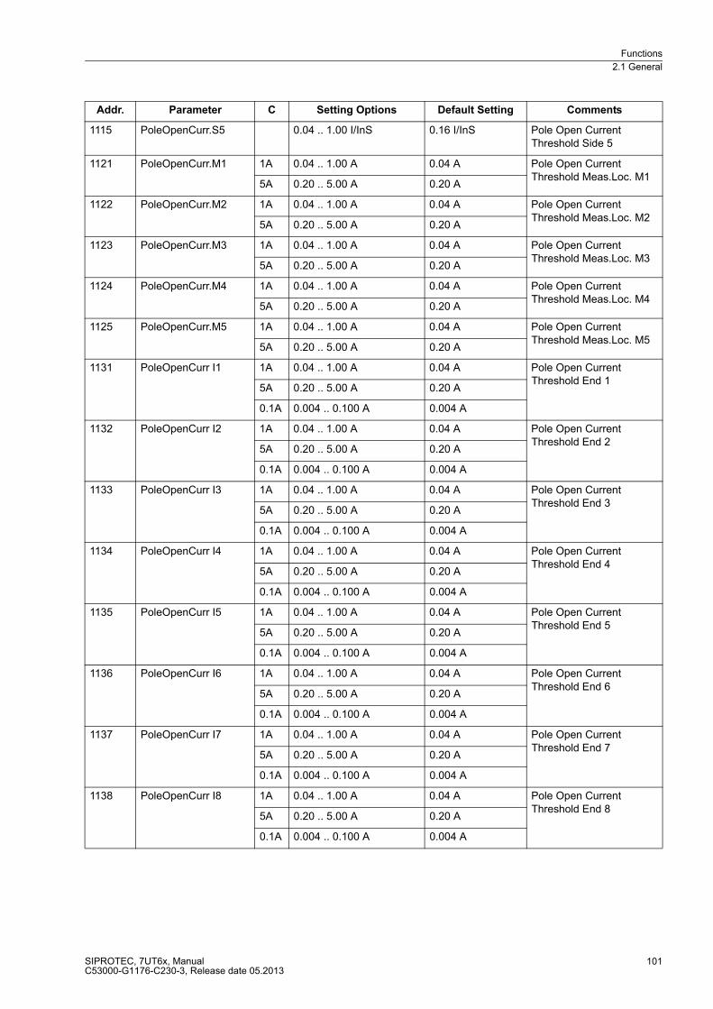
Functions
2.1 General
SIPROTEC, 7UT6x, ManualC53000-G1176-C230-3, Release date 05.2013
101
1115 PoleOpenCurr.S5 0.04 .. 1.00 I/InS 0.16 I/InS Pole Open Current Threshold Side 5
1121 PoleOpenCurr.M1 1A 0.04 .. 1.00 A 0.04 A Pole Open Current Threshold Meas.Loc. M1
5A 0.20 .. 5.00 A 0.20 A
1122 PoleOpenCurr.M2 1A 0.04 .. 1.00 A 0.04 A Pole Open Current Threshold Meas.Loc. M2
5A 0.20 .. 5.00 A 0.20 A
1123 PoleOpenCurr.M3 1A 0.04 .. 1.00 A 0.04 A Pole Open Current Threshold Meas.Loc. M3
5A 0.20 .. 5.00 A 0.20 A
1124 PoleOpenCurr.M4 1A 0.04 .. 1.00 A 0.04 A Pole Open Current Threshold Meas.Loc. M4
5A 0.20 .. 5.00 A 0.20 A
1125 PoleOpenCurr.M5 1A 0.04 .. 1.00 A 0.04 A Pole Open Current Threshold Meas.Loc. M5
5A 0.20 .. 5.00 A 0.20 A
1131 PoleOpenCurr I1 1A 0.04 .. 1.00 A 0.04 A Pole Open Current Threshold End 1
5A 0.20 .. 5.00 A 0.20 A
0.1A 0.004 .. 0.100 A 0.004 A
1132 PoleOpenCurr I2 1A 0.04 .. 1.00 A 0.04 A Pole Open Current Threshold End 2
5A 0.20 .. 5.00 A 0.20 A
0.1A 0.004 .. 0.100 A 0.004 A
1133 PoleOpenCurr I3 1A 0.04 .. 1.00 A 0.04 A Pole Open Current Threshold End 3
5A 0.20 .. 5.00 A 0.20 A
0.1A 0.004 .. 0.100 A 0.004 A
1134 PoleOpenCurr I4 1A 0.04 .. 1.00 A 0.04 A Pole Open Current Threshold End 4
5A 0.20 .. 5.00 A 0.20 A
0.1A 0.004 .. 0.100 A 0.004 A
1135 PoleOpenCurr I5 1A 0.04 .. 1.00 A 0.04 A Pole Open Current Threshold End 5
5A 0.20 .. 5.00 A 0.20 A
0.1A 0.004 .. 0.100 A 0.004 A
1136 PoleOpenCurr I6 1A 0.04 .. 1.00 A 0.04 A Pole Open Current Threshold End 6
5A 0.20 .. 5.00 A 0.20 A
0.1A 0.004 .. 0.100 A 0.004 A
1137 PoleOpenCurr I7 1A 0.04 .. 1.00 A 0.04 A Pole Open Current Threshold End 7
5A 0.20 .. 5.00 A 0.20 A
0.1A 0.004 .. 0.100 A 0.004 A
1138 PoleOpenCurr I8 1A 0.04 .. 1.00 A 0.04 A Pole Open Current Threshold End 8
5A 0.20 .. 5.00 A 0.20 A
0.1A 0.004 .. 0.100 A 0.004 A
Addr. Parameter C Setting Options Default Setting Comments

Functions
2.1 General
SIPROTEC, 7UT6x, ManualC53000-G1176-C230-3, Release date 05.2013
102
2.1.6.3 Information List
1139 PoleOpenCurr I9 1A 0.04 .. 1.00 A 0.04 A Pole Open Current Threshold End 9
5A 0.20 .. 5.00 A 0.20 A
0.1A 0.004 .. 0.100 A 0.004 A
1140 PoleOpenCurrI10 1A 0.04 .. 1.00 A 0.04 A Pole Open Current Threshold End 10
5A 0.20 .. 5.00 A 0.20 A
0.1A 0.004 .. 0.100 A 0.004 A
1141 PoleOpenCurrI11 1A 0.04 .. 1.00 A 0.04 A Pole Open Current Threshold End 11
5A 0.20 .. 5.00 A 0.20 A
0.1A 0.004 .. 0.100 A 0.004 A
1142 PoleOpenCurrI12 1A 0.04 .. 1.00 A 0.04 A Pole Open Current Threshold End 12
5A 0.20 .. 5.00 A 0.20 A
0.1A 0.004 .. 0.100 A 0.004 A
1151 PoleOpenCurrIX1 1A 0.04 .. 1.00 A 0.04 A Pole Open Current Threshold AuxiliaryCT1
5A 0.20 .. 5.00 A 0.20 A
1152 PoleOpenCurrIX2 1A 0.04 .. 1.00 A 0.04 A Pole Open Current Threshold AuxiliaryCT2
5A 0.20 .. 5.00 A 0.20 A
1153 PoleOpenCurrIX3 1A 0.04 .. 1.00 A 0.04 A Pole Open Current Threshold AuxiliaryCT3
5A 0.20 .. 5.00 A 0.20 A
1154 PoleOpenCurrIX4 1A 0.04 .. 1.00 A 0.04 A Pole Open Current Threshold AuxiliaryCT4
5A 0.20 .. 5.00 A 0.20 A
No. Information Type of In-
formation
Comments
- >QuitG-TRP IntSP >Quitt Lock Out: General Trip
- G-TRP Quit IntSP Lock Out: General TRIP
126 ProtON/OFF IntSP Protection ON/OFF (via system port)
236.2127 BLK. Flex.Fct. IntSP BLOCK Flexible Function
301 Pow.Sys.Flt. OUT Power System fault
302 Fault Event OUT Fault Event
311 FaultConfig/Set OUT Fault in configuration / setting
312 GenErrGroupConn OUT Gen.err.: Inconsistency group/connection
313 GenErrEarthCT OUT Gen.err.: Sev. earth-CTs with equal typ
314 GenErrSidesMeas OUT Gen.err.: Number of sides / measurements
501 Relay PICKUP OUT Relay PICKUP
511 Relay TRIP OUT Relay GENERAL TRIP command
545 PU Time VI Time from Pickup to drop out
546 TRIP Time VI Time from Pickup to TRIP
576 IL1S1: VI Primary fault current IL1 side1
577 IL2S1: VI Primary fault current IL2 side1
Addr. Parameter C Setting Options Default Setting Comments
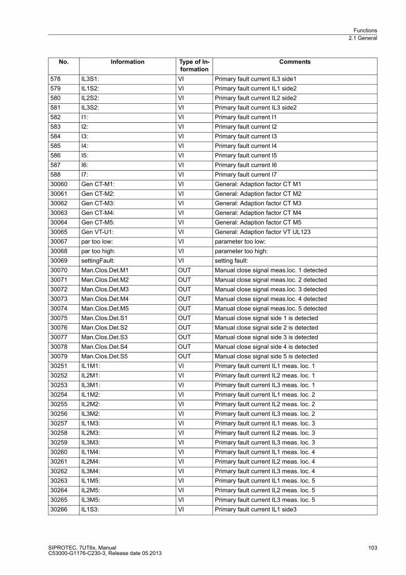
Functions
2.1 General
SIPROTEC, 7UT6x, ManualC53000-G1176-C230-3, Release date 05.2013
103
578 IL3S1: VI Primary fault current IL3 side1
579 IL1S2: VI Primary fault current IL1 side2
580 IL2S2: VI Primary fault current IL2 side2
581 IL3S2: VI Primary fault current IL3 side2
582 I1: VI Primary fault current I1
583 I2: VI Primary fault current I2
584 I3: VI Primary fault current I3
585 I4: VI Primary fault current I4
586 I5: VI Primary fault current I5
587 I6: VI Primary fault current I6
588 I7: VI Primary fault current I7
30060 Gen CT-M1: VI General: Adaption factor CT M1
30061 Gen CT-M2: VI General: Adaption factor CT M2
30062 Gen CT-M3: VI General: Adaption factor CT M3
30063 Gen CT-M4: VI General: Adaption factor CT M4
30064 Gen CT-M5: VI General: Adaption factor CT M5
30065 Gen VT-U1: VI General: Adaption factor VT UL123
30067 par too low: VI parameter too low:
30068 par too high: VI parameter too high:
30069 settingFault: VI setting fault:
30070 Man.Clos.Det.M1 OUT Manual close signal meas.loc. 1 detected
30071 Man.Clos.Det.M2 OUT Manual close signal meas.loc. 2 detected
30072 Man.Clos.Det.M3 OUT Manual close signal meas.loc. 3 detected
30073 Man.Clos.Det.M4 OUT Manual close signal meas.loc. 4 detected
30074 Man.Clos.Det.M5 OUT Manual close signal meas.loc. 5 detected
30075 Man.Clos.Det.S1 OUT Manual close signal side 1 is detected
30076 Man.Clos.Det.S2 OUT Manual close signal side 2 is detected
30077 Man.Clos.Det.S3 OUT Manual close signal side 3 is detected
30078 Man.Clos.Det.S4 OUT Manual close signal side 4 is detected
30079 Man.Clos.Det.S5 OUT Manual close signal side 5 is detected
30251 IL1M1: VI Primary fault current IL1 meas. loc. 1
30252 IL2M1: VI Primary fault current IL2 meas. loc. 1
30253 IL3M1: VI Primary fault current IL3 meas. loc. 1
30254 IL1M2: VI Primary fault current IL1 meas. loc. 2
30255 IL2M2: VI Primary fault current IL2 meas. loc. 2
30256 IL3M2: VI Primary fault current IL3 meas. loc. 2
30257 IL1M3: VI Primary fault current IL1 meas. loc. 3
30258 IL2M3: VI Primary fault current IL2 meas. loc. 3
30259 IL3M3: VI Primary fault current IL3 meas. loc. 3
30260 IL1M4: VI Primary fault current IL1 meas. loc. 4
30261 IL2M4: VI Primary fault current IL2 meas. loc. 4
30262 IL3M4: VI Primary fault current IL3 meas. loc. 4
30263 IL1M5: VI Primary fault current IL1 meas. loc. 5
30264 IL2M5: VI Primary fault current IL2 meas. loc. 5
30265 IL3M5: VI Primary fault current IL3 meas. loc. 5
30266 IL1S3: VI Primary fault current IL1 side3
No. Information Type of In-
formation
Comments

Functions
2.1 General
SIPROTEC, 7UT6x, ManualC53000-G1176-C230-3, Release date 05.2013
104
30267 IL2S3: VI Primary fault current IL2 side3
30268 IL3S3: VI Primary fault current IL3 side3
30269 IL1S4: VI Primary fault current IL1 side4
30270 IL2S4: VI Primary fault current IL2 side4
30271 IL3S4: VI Primary fault current IL3 side4
30272 IL1S5: VI Primary fault current IL1 side5
30273 IL2S5: VI Primary fault current IL2 side5
30274 IL3S5: VI Primary fault current IL3 side5
30275 I8: VI Primary fault current I8
30276 I9: VI Primary fault current I9
30277 I10: VI Primary fault current I10
30278 I11: VI Primary fault current I11
30279 I12: VI Primary fault current I12
30351 >ManualClose M1 SP >Manual close signal measurement loc. 1
30352 >ManualClose M2 SP >Manual close signal measurement loc. 2
30353 >ManualClose M3 SP >Manual close signal measurement loc. 3
30354 >ManualClose M4 SP >Manual close signal measurement loc. 4
30355 >ManualClose M5 SP >Manual close signal measurement loc. 5
30356 >ManualClose S1 SP >Manual close signal side 1
30357 >ManualClose S2 SP >Manual close signal side 2
30358 >ManualClose S3 SP >Manual close signal side 3
30359 >ManualClose S4 SP >Manual close signal side 4
30360 >ManualClose S5 SP >Manual close signal side 5
No. Information Type of In-
formation
Comments

Functions
2.2 Differential Protection
SIPROTEC, 7UT6x, ManualC53000-G1176-C230-3, Release date 05.2013
105
2.2 Differential Protection
The differential protection represents the main protection feature of the device. It is based on current
comparison under consideration of the transformation ratio of the transformer.7UT6x is suitable for unit protec-
tion of transformers, generators, motors, reactors, short lines, also with feeders, and (under observance of the
available number of current inputs) for busbar arrangements. Protection of generator/transformer units, trans-
former/winding combinations or transformer/starpoint former, can also be realised. 7UT612 allows up to two,
7UT613 and 7UT633 allow up to 3, 7UT635 allows up to 5 three-phase measuring locations.
7UT6x can be used as a single-phase differential protection relay. In this case, 7UT612 allows up to 7, 7UT613
and 7UT633 allow up to 9, and 7UT635 up to 12 measuring locations, e.g. currents from a busbar with up to 7
or 9 or 12 feeders.
The protected zone is selectively limited by the CTs at its ends.
2.2.1 Functional Description of the Differential Protection
Processing of the measured values depends on the way the differential protection is used. This section
discusses first the differential protection function in general, regardless of the type of protected object. A single-
phase system is referred to. Particulars with regard to the individual protected objects follow thereafter.
Basic Principle with Two Sides
Differential protection is based on current comparison. It makes use of the fact that a protected object carries
always the same current i (dashed line in 2-17 below) at its two sides in healthy operation. This current flows
into one side of the considered zone and leaves it again on the other side. A difference in currents is a clear
indication of a fault within this section. If the actual current transformation ratio is the same, the secondary wind-
ings of the current transformers CT1 and CT2 at the sides of the protected object can be connected to form a
closed electric circuit with a secondary current I; a measuring element M, which is connected to the electrical
balance point, remains at zero current in healthy operation.
Figure 2-17 Basic principle of differential protection for two sides (single-phase illustration)
When a fault occurs in the zone limited by the transformers, a current i1 + i2, which is proportional to the fault
currents I1 + I2 flowing in from both sides is fed to the measuring element. As a result, the simple circuit shown
in Figure 2-17 ensures a reliable tripping of the protection if the fault current flowing into the protected zone
during a fault is high enough for the measuring element M to respond.
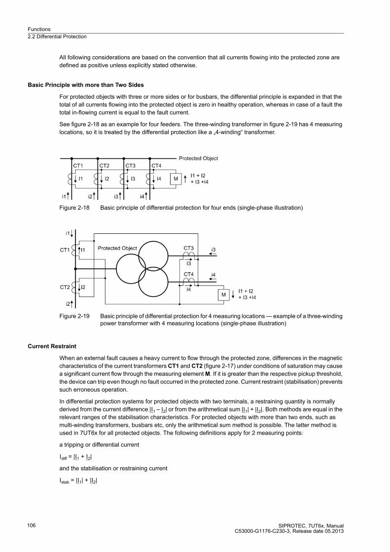
Functions
2.2 Differential Protection
SIPROTEC, 7UT6x, ManualC53000-G1176-C230-3, Release date 05.2013
106
All following considerations are based on the convention that all currents flowing into the protected zone are
defined as positive unless explicitly stated otherwise.
Basic Principle with more than Two Sides
For protected objects with three or more sides or for busbars, the differential principle is expanded in that the
total of all currents flowing into the protected object is zero in healthy operation, whereas in case of a fault the
total in-flowing current is equal to the fault current.
See figure 2-18 as an example for four feeders. The three-winding transformer in figure 2-19 has 4 measuring
locations, so it is treated by the differential protection like a „4-winding“ transformer.
Figure 2-18 Basic principle of differential protection for four ends (single-phase illustration)
Figure 2-19 Basic principle of differential protection for 4 measuring locations — example of a three-winding power transformer with 4 measuring locations (single-phase illustration)
Current Restraint
When an external fault causes a heavy current to flow through the protected zone, differences in the magnetic
characteristics of the current transformers CT1 and CT2 (figure 2-17) under conditions of saturation may cause
a significant current flow through the measuring element M. If it is greater than the respective pickup threshold,
the device can trip even though no fault occurred in the protected zone. Current restraint (stabilisation) prevents
such erroneous operation.
In differential protection systems for protected objects with two terminals, a restraining quantity is normally
derived from the current difference |I1 – I2| or from the arithmetical sum |I1| + |I2|. Both methods are equal in the
relevant ranges of the stabilisation characteristics. For protected objects with more than two ends, such as
multi-winding transformers, busbars etc, only the arithmetical sum method is possible. The latter method is
used in 7UT6x for all protected objects. The following definitions apply for 2 measuring points:
a tripping or differential current
Idiff = |I1 + I2|
and the stabilisation or restraining current
Istab = |I1| + |I2|
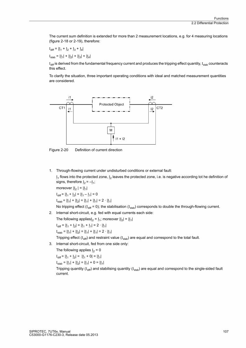
Functions
2.2 Differential Protection
SIPROTEC, 7UT6x, ManualC53000-G1176-C230-3, Release date 05.2013
107
The current sum definition is extended for more than 2 measurement locations, e.g. for 4 measuring locations
(figure 2-18 or 2-19), therefore:
Idiff = |I1 + I2 + I3 + I4|
Istab = |I1| + |I2| + |I3| + |I4|
Idiff is derived from the fundamental frequency current and produces the tripping effect quantity, Istab counteracts
this effect.
To clarify the situation, three important operating conditions with ideal and matched measurement quantities
are considered.
Figure 2-20 Definition of current direction
1. Through-flowing current under undisturbed conditions or external fault:
I1 flows into the protected zone, I2 leaves the protected zone, i.e. is negative according tot he definition of
signs, therefore I2 = –I1;
moreover |I2 | = |I1|
Idiff = |I1 + I2| = |I1 – I1| = 0
Istab = |I1| + |I2| = |I1| + |I1| = 2 · |I1|
No tripping effect (Idiff = 0); the stabilisation (Istab) corresponds to double the through-flowing current.
2. Internal short-circuit, e.g. fed with equal currents each side:
The following appliesI2 = I1; moreover |I2| = |I1|
Idiff = |I1 + I2| = |I1 + I1| = 2 · |I1|
Istab = |I1| + |I2| = |I1| + |I1| = 2 · |I1|
Tripping effect (Idiff) and restraint value (Istab) are equal and correspond to the total fault.
3. Internal short-circuit, fed from one side only:
The following applies I2 = 0
Idiff = |I1 + I2| = |I1 + 0| = |I1|
Istab = |I1| + |I2| = |I1| + 0 = |I1|
Tripping quantity (Idiff) and stabilising quantity (Istab) are equal and correspond to the single-sided fault
current.
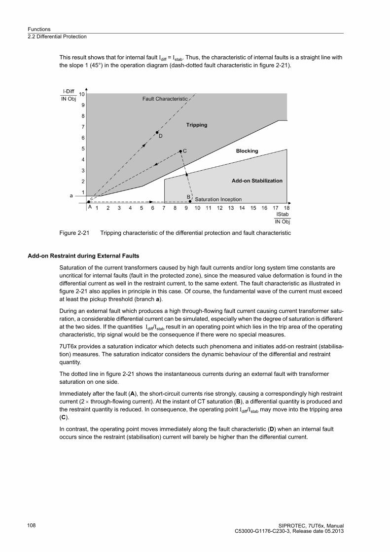
Functions
2.2 Differential Protection
SIPROTEC, 7UT6x, ManualC53000-G1176-C230-3, Release date 05.2013
108
This result shows that for internal fault Idiff = Istab. Thus, the characteristic of internal faults is a straight line with
the slope 1 (45°) in the operation diagram (dash-dotted fault characteristic in figure 2-21).
Figure 2-21 Tripping characteristic of the differential protection and fault characteristic
Add-on Restraint during External Faults
Saturation of the current transformers caused by high fault currents and/or long system time constants are
uncritical for internal faults (fault in the protected zone), since the measured value deformation is found in the
differential current as well in the restraint current, to the same extent. The fault characteristic as illustrated in
figure 2-21 also applies in principle in this case. Of course, the fundamental wave of the current must exceed
at least the pickup threshold (branch a).
During an external fault which produces a high through-flowing fault current causing current transformer satu-
ration, a considerable differential current can be simulated, especially when the degree of saturation is different
at the two sides. If the quantities Idiff/Istab result in an operating point which lies in the trip area of the operating
characteristic, trip signal would be the consequence if there were no special measures.
7UT6x provides a saturation indicator which detects such phenomena and initiates add-on restraint (stabilisa-
tion) measures. The saturation indicator considers the dynamic behaviour of the differential and restraint
quantity.
The dotted line in figure 2-21 shows the instantaneous currents during an external fault with transformer
saturation on one side.
Immediately after the fault (A), the short-circuit currents rise strongly, causing a correspondingly high restraint
current (2 × through-flowing current). At the instant of CT saturation (B), a differential quantity is produced and
the restraint quantity is reduced. In consequence, the operating point Idiff/Istab may move into the tripping area
(C).
In contrast, the operating point moves immediately along the fault characteristic (D) when an internal fault
occurs since the restraint (stabilisation) current will barely be higher than the differential current.
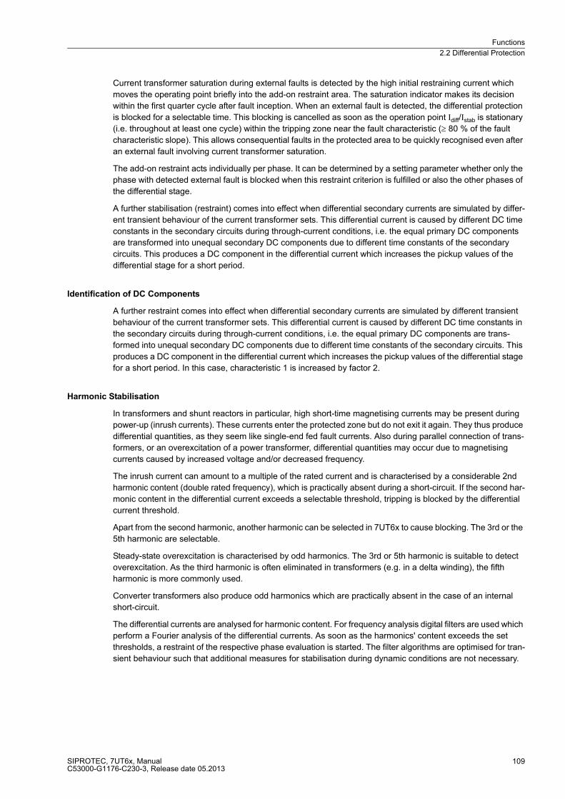
Functions
2.2 Differential Protection
SIPROTEC, 7UT6x, ManualC53000-G1176-C230-3, Release date 05.2013
109
Current transformer saturation during external faults is detected by the high initial restraining current which
moves the operating point briefly into the add-on restraint area. The saturation indicator makes its decision
within the first quarter cycle after fault inception. When an external fault is detected, the differential protection
is blocked for a selectable time. This blocking is cancelled as soon as the operation point Idiff/Istab is stationary
(i.e. throughout at least one cycle) within the tripping zone near the fault characteristic (≥ 80 % of the fault
characteristic slope). This allows consequential faults in the protected area to be quickly recognised even after
an external fault involving current transformer saturation.
The add-on restraint acts individually per phase. It can be determined by a setting parameter whether only the
phase with detected external fault is blocked when this restraint criterion is fulfilled or also the other phases of
the differential stage.
A further stabilisation (restraint) comes into effect when differential secondary currents are simulated by differ-
ent transient behaviour of the current transformer sets. This differential current is caused by different DC time
constants in the secondary circuits during through-current conditions, i.e. the equal primary DC components
are transformed into unequal secondary DC components due to different time constants of the secondary
circuits. This produces a DC component in the differential current which increases the pickup values of the
differential stage for a short period.
Identification of DC Components
A further restraint comes into effect when differential secondary currents are simulated by different transient
behaviour of the current transformer sets. This differential current is caused by different DC time constants in
the secondary circuits during through-current conditions, i.e. the equal primary DC components are trans-
formed into unequal secondary DC components due to different time constants of the secondary circuits. This
produces a DC component in the differential current which increases the pickup values of the differential stage
for a short period. In this case, characteristic 1 is increased by factor 2.
Harmonic Stabilisation
In transformers and shunt reactors in particular, high short-time magnetising currents may be present during
power-up (inrush currents). These currents enter the protected zone but do not exit it again. They thus produce
differential quantities, as they seem like single-end fed fault currents. Also during parallel connection of trans-
formers, or an overexcitation of a power transformer, differential quantities may occur due to magnetising
currents caused by increased voltage and/or decreased frequency.
The inrush current can amount to a multiple of the rated current and is characterised by a considerable 2nd
harmonic content (double rated frequency), which is practically absent during a short-circuit. If the second har-
monic content in the differential current exceeds a selectable threshold, tripping is blocked by the differential
current threshold.
Apart from the second harmonic, another harmonic can be selected in 7UT6x to cause blocking. The 3rd or the
5th harmonic are selectable.
Steady-state overexcitation is characterised by odd harmonics. The 3rd or 5th harmonic is suitable to detect
overexcitation. As the third harmonic is often eliminated in transformers (e.g. in a delta winding), the fifth
harmonic is more commonly used.
Converter transformers also produce odd harmonics which are practically absent in the case of an internal
short-circuit.
The differential currents are analysed for harmonic content. For frequency analysis digital filters are used which
perform a Fourier analysis of the differential currents. As soon as the harmonics' content exceeds the set
thresholds, a restraint of the respective phase evaluation is started. The filter algorithms are optimised for tran-
sient behaviour such that additional measures for stabilisation during dynamic conditions are not necessary.

Functions
2.2 Differential Protection
SIPROTEC, 7UT6x, ManualC53000-G1176-C230-3, Release date 05.2013
110
Since the harmonic restraint operates individually per phase, the protection is fully operative even when the
transformer is switched onto a single-phase fault, whereby inrush currents may possibly be present in one of
the healthy phases. It is, however, possible to set the protection in a way that when the permissible harmonic
content in the current of only one single phase is exceeded, not only the phase with the inrush current but also
the remaining phases of the differential stage are blocked. This crossblock can be limited to a selectable
duration.
Fast Unrestrained Trip with High-Current Faults
High-current faults in the protected zone may be cleared instantaneously without regard to the restraint currents
when the current amplitude excludes an external fault. If the protected object has a high direct impedance
(transformers, generators, series reactors), a threshold can be found which can never be exceeded by a
through-fault current. This threshold (primary) is, for example, for a power transformer.
The differential protection of the 7UT6x provides such an unstabilised high-current trip stage. This stage can
operate even when, for example, a considerable second harmonic is present in the differential current caused
by current transformer saturation by a DC component in the fault current, which could be interpreted by the
inrush restraint function as an inrush current.
Fast tripping uses both the fundamental component of the differential current as well as instantaneous values.
Instantaneous value processing ensures fast tripping even if the current fundamental component was strongly
attenuated by current transformer saturation. Due to the possible DC offset after fault inception, the
instantaneous value stage operates only above twice the set threshold.
Increase of Pickup Value on Startup
The increase of pickup value is especially suited for motors. In contrast to the inrush current of transformers
the inrush current of motors is a traversing current. Differential currents, however, can emerge if current trans-
formers still contain different remanent magnetisation before energise. Therefore, the transformers are ener-
gised from different operation points of their hysteresis. Although differential currents are usually small, they
can be harmful if the differential protection is set very sensitive.
An increase of the pickup value on startup provides additional security against overfunctioning when a non-
energised protection object is switched in. As soon as the restraint current of one phase has undershot a set-
table value I-REST. STARTUP, the increase of the pickup value is activated. As the restraint current is twice
the through-flowing current in normal operation, its undershooting of that threshold is a criterion for detecting
that the protected object is not energised. The pickup value I-DIFF> and the other branches of the IDiff> stage
are now increased by a settable factor (figure 2-22).
The return of the restraint current indicates the startup. After a settable time T START MAX the increase of the
characteristic is undone. Current ratios Idiff/Istab close to the fault characteristic (≥ 80 % of the fault characteristic
slope) cause tripping even before the time T START MAX has lapsed.

Functions
2.2 Differential Protection
SIPROTEC, 7UT6x, ManualC53000-G1176-C230-3, Release date 05.2013
111
Figure 2-22 Increase of pickup value of the stage on startup
Tripping Characteristic
Figure 2-23 illustrates the complete tripping characteristic of the 7UT6x. The characteristic branch a represents
the sensitivity threshold of the differential protection (setting I-DIFF>) and considers constant error currents
such as magnetising currents.
Branch b considers current-proportional errors which may result from transformation errors of the main CTs or
the input CTs of the device, or which for example may be caused by mismatching or by the influence of tap
changers in transformers with voltage control.
For high currents which may give rise to current transformer saturation, characteristic branch c provides for
additional restraint.
Figure 2-23 Tripping characteristic of the differential protection
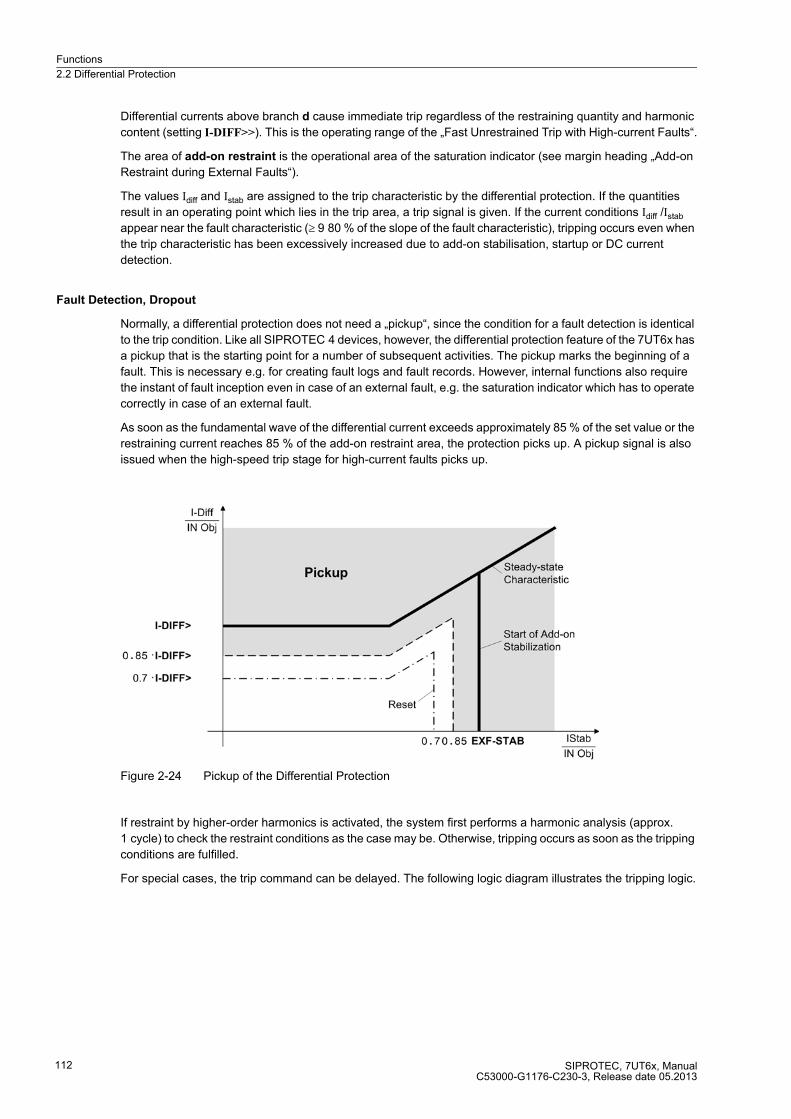
Functions
2.2 Differential Protection
SIPROTEC, 7UT6x, ManualC53000-G1176-C230-3, Release date 05.2013
112
Differential currents above branch d cause immediate trip regardless of the restraining quantity and harmonic
content (setting I-DIFF>>). This is the operating range of the „Fast Unrestrained Trip with High-current Faults“.
The area of add-on restraint is the operational area of the saturation indicator (see margin heading „Add-on
Restraint during External Faults“).
The values Idiff and Istab are assigned to the trip characteristic by the differential protection. If the quantities
result in an operating point which lies in the trip area, a trip signal is given. If the current conditions Idiff /Istab
appear near the fault characteristic (≥ 9 80 % of the slope of the fault characteristic), tripping occurs even when
the trip characteristic has been excessively increased due to add-on stabilisation, startup or DC current
detection.
Fault Detection, Dropout
Normally, a differential protection does not need a „pickup“, since the condition for a fault detection is identical
to the trip condition. Like all SIPROTEC 4 devices, however, the differential protection feature of the 7UT6x has
a pickup that is the starting point for a number of subsequent activities. The pickup marks the beginning of a
fault. This is necessary e.g. for creating fault logs and fault records. However, internal functions also require
the instant of fault inception even in case of an external fault, e.g. the saturation indicator which has to operate
correctly in case of an external fault.
As soon as the fundamental wave of the differential current exceeds approximately 85 % of the set value or the
restraining current reaches 85 % of the add-on restraint area, the protection picks up. A pickup signal is also
issued when the high-speed trip stage for high-current faults picks up.
Figure 2-24 Pickup of the Differential Protection
If restraint by higher-order harmonics is activated, the system first performs a harmonic analysis (approx.
1 cycle) to check the restraint conditions as the case may be. Otherwise, tripping occurs as soon as the tripping
conditions are fulfilled.
For special cases, the trip command can be delayed. The following logic diagram illustrates the tripping logic.
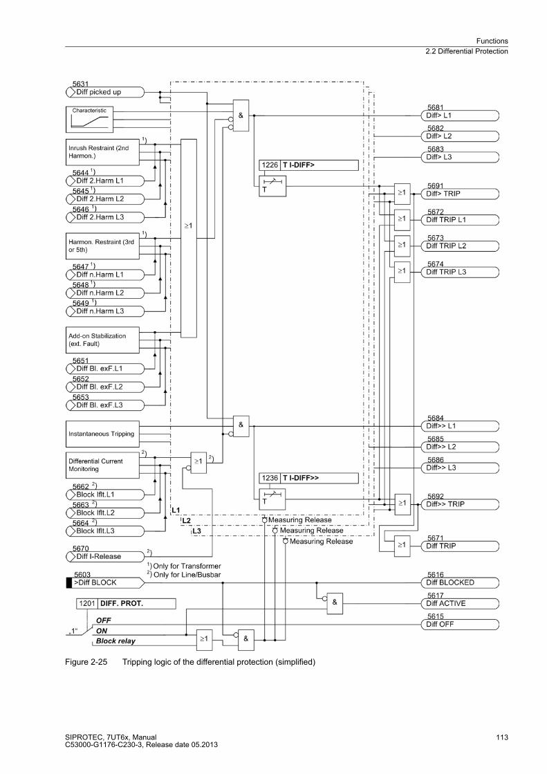
Functions
2.2 Differential Protection
SIPROTEC, 7UT6x, ManualC53000-G1176-C230-3, Release date 05.2013
113
Figure 2-25 Tripping logic of the differential protection (simplified)
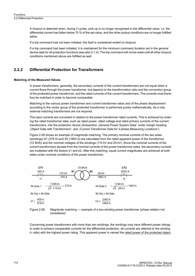
Functions
2.2 Differential Protection
SIPROTEC, 7UT6x, ManualC53000-G1176-C230-3, Release date 05.2013
114
A dropout is detected when, during 2 cycles, pick-up is no longer recognised in the differential value, i.e. the
differential current has fallen below 70 % of the set value, and the other pickup conditions are no longer fulfilled
either.
If a trip command has not been initiated, the fault is considered ended on dropout.
If a trip command had been initiated, it is maintained for the minimum command duration set in the general
device data for all protection functions (see also 2.1.4). The trip command will not be reset until all other dropout
conditions mentioned above are fulfilled as well.
2.2.2 Differential Protection for Transformers
Matching of the Measured Values
In power transformers, generally, the secondary currents of the current transformers are not equal when a
current flows through the power transformer, but depend on the transformation ratio and the connection group
of the protected power transformer, and the rated currents of the current transformers. The currents must there-
fore be matched in order to become comparable.
Matching to the various power transformer and current transformer ratios and of the phase displacement
according to the vector group of the protected transformer is performed purely mathematically. As a rule,
external matching transformers are not required.
The input currents are converted in relation to the power transformer rated currents. This is achieved by enter-
ing the rated transformer data, such as rated power, rated voltage and rated primary currents of the current
transformers, into the protection device (Subsection „General Power System Data“ under margin heading
„Object Data with Transformers“, and „Current Transformer Data for 3-phase Measuring Locations“).
Figure 2-26 shows an example of magnitude matching. The primary nominal currents of the two sides
(windings) S1 (378 A) and S2 (1663 A) are calculated from the rated apparent power of the transformer
(72 MVA) and the nominal voltages of the windings (110 kV and 25 kV). Since the nominal currents of the
current transformers deviate from the nominal currents of the power transformer sides, the secondary currents
are multiplied with the factors k1 and k2. After this matching, equal current magnitudes are achieved at both
sides under nominal conditions of the power transformer.
Figure 2-26 Magnitude matching — example of a two-winding power transformer (phase relation not considered)
Concerning power transformers with more than two windings, the windings may have different power ratings.
In order to achieve comparable currents for the differential protection, all currents are referred to the winding
(= side) with the highest power rating. This apparent power is named the rated power of the protected object.
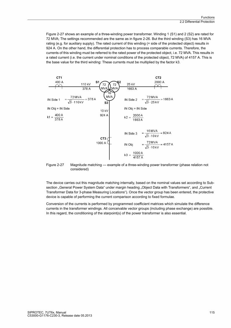
Functions
2.2 Differential Protection
SIPROTEC, 7UT6x, ManualC53000-G1176-C230-3, Release date 05.2013
115
Figure 2-27 shows an example of a three-winding power transformer. Winding 1 (S1) and 2 (S2) are rated for
72 MVA; The settings recommended are the same as in figure 2-26. But the third winding (S3) has 16 MVA
rating (e.g. for auxiliary supply). The rated current of this winding (= side of the protected object) results in
924 A. On the other hand, the differential protection has to process comparable currents. Therefore, the
currents of this winding must be referred to the rated power of the protected object, i.e. 72 MVA. This results in
a rated current (i.e. the current under nominal conditions of the protected object, 72 MVA) of 4157 A. This is
the base value for the third winding: These currents must be multiplied by the factor k3.
Figure 2-27 Magnitude matching — example of a three-winding power transformer (phase relation not considered)
The device carries out this magnitude matching internally, based on the nominal values set according to Sub-
section „General Power System Data“ under margin heading „Object Data with Transformers“, and „Current
Transformer Data for 3-phase Measuring Locations“). Once the vector group has been entered, the protective
device is capable of performing the current comparison according to fixed formulae.
Conversion of the currents is performed by programmed coefficient matrices which simulate the difference
currents in the transformer windings. All conceivable vector groups (including phase exchange) are possible.
In this regard, the conditioning of the starpoint(s) of the power transformer is also essential.

Functions
2.2 Differential Protection
SIPROTEC, 7UT6x, ManualC53000-G1176-C230-3, Release date 05.2013
116
Non-earthed Transformer Starpoint
Figure 2-28 illustrates an example for a power transformer Yd5 (wye-delta with 150° phase displacement)
without any earthed starpoint. The figure shows the windings (above) and the vector diagrams of symmetrical
currents (below). The general form of the matrix equation is:
(Im) Matrix of the matched currentsIA, IB, IC,
k Constant factor for magnitude matching,
(C) Coefficient matrix, dependent on the vector group,
(In) Matrix of the phase currents IL1, IL2, IL3.
On the left (delta) winding, the matched currents IA, IB, IC are derived from the difference of the phase currents
IL1, IL2, IL3. On the right (wye) side, the matched currents are equal to the phase currents (magnitude matching
not considered).
Figure 2-28 Matching the transformer vector group, example Yd5 (magnitudes not considered)
Since there is no point earthed within the protected zone, no considerable zero sequence current can be
produced within the protected zone in case of an earth fault outside the protected zone, regardless whether or
not the system starpoint is earthed anywhere else in the system. In case of an earth fault within the protected
zone, a zero sequence current may occur at a measuring location if the system starpoint is earthed anywhere
else or another earth fault is present in the system (double earth fault in a non-earthed system). Thus, zero
sequence currents are of no concern for the stability of the differential protection as they cannot occur in case
of external faults.
However, in case of internal earth faults, the zero sequence currents are practically fully included in the
differential quantity because they pass the measuring points from outside. Even higher earth fault sensitivity
during internal earth fault is possible by means of the time overcurrent protection for zero sequence currents
(section 2.4.1) and/or the single-phase time overcurrent protection (section 2.7),

Functions
2.2 Differential Protection
SIPROTEC, 7UT6x, ManualC53000-G1176-C230-3, Release date 05.2013
117
Earthed Starpoint
Differential protection makes use of the fact that the total of all currents flowing into the protected object is zero
in healthy operation. If the starpoint of a power transformer winding is connected to earth, a current can flow
into the protected zone across this earth connection in case of earth faults. Consequently, this current should
be included in the current processing in order to obtain a complete image of the in-flowing quantities. Figure
2-29 shows an external earth fault which produces an out-flowing zero sequence current (–IL3 = –3 · I0), which
corresponds with the in-flowing starpoint current (ISt = 3 · I0). As a result, these currents cancel each other out.
Figure 2-29 Example for an earth fault outside a transformer with current distribution
The complete matrix equation for the earthed side (right) is in this case, including all in-flowing currents:
ISP corresponds to –3 I0 in case of through-flowing current. The zero sequence current is included in case of
an internal fault (from I0 = 1/3 ISP); in case of an external earth fault, the zero sequence current component of
the line currents 3 · I0 = (IL1 + IL2 + IL3) (negative here) is compensated by the starpoint current ISP. In this way,
almost full sensitivity (with zero sequence current) is achieved for internal earth faults and full elimination of the
zero sequence current in case of external earth faults. For consideration of the earth fault current, the advanced
parameter diff protection with measured earth current, side x must be switched on (addresses 1211 DIFFw.IE1-
MEAS to 1215 DIFFw.IE5-MEAS = YES).
Even higher earth fault sensitivity during internal earth fault is possible by means of the restricted earth fault
protection (section 2.3).
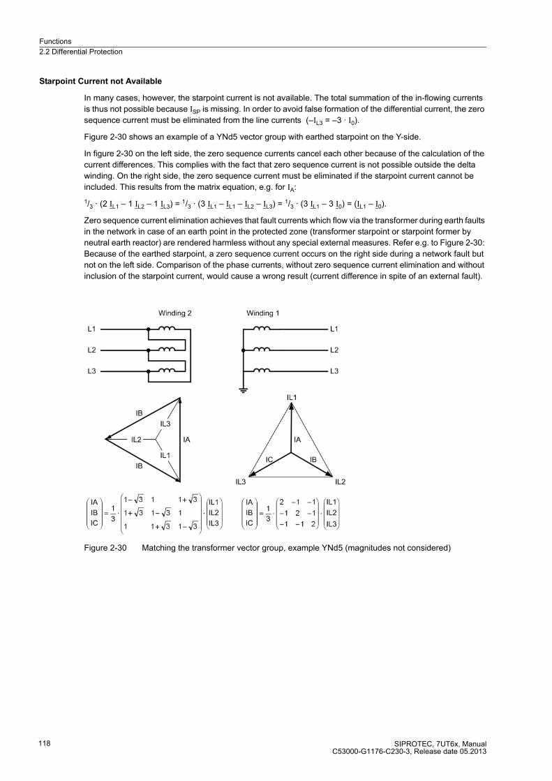
Functions
2.2 Differential Protection
SIPROTEC, 7UT6x, ManualC53000-G1176-C230-3, Release date 05.2013
118
Starpoint Current not Available
In many cases, however, the starpoint current is not available. The total summation of the in-flowing currents
is thus not possible because ISP is missing. In order to avoid false formation of the differential current, the zero
sequence current must be eliminated from the line currents (–IL3 = –3 · I0).
Figure 2-30 shows an example of a YNd5 vector group with earthed starpoint on the Y-side.
In figure 2-30 on the left side, the zero sequence currents cancel each other because of the calculation of the
current differences. This complies with the fact that zero sequence current is not possible outside the delta
winding. On the right side, the zero sequence current must be eliminated if the starpoint current cannot be
included. This results from the matrix equation, e.g. for IA:
1/3 · (2 IL1 – 1 IL2 – 1 IL3) = 1/3 · (3 IL1 – IL1 – IL2 – IL3) = 1/3 · (3 IL1 – 3 I0) = (IL1 – I0).
Zero sequence current elimination achieves that fault currents which flow via the transformer during earth faults
in the network in case of an earth point in the protected zone (transformer starpoint or starpoint former by
neutral earth reactor) are rendered harmless without any special external measures. Refer e.g. to Figure 2-30:
Because of the earthed starpoint, a zero sequence current occurs on the right side during a network fault but
not on the left side. Comparison of the phase currents, without zero sequence current elimination and without
inclusion of the starpoint current, would cause a wrong result (current difference in spite of an external fault).
Figure 2-30 Matching the transformer vector group, example YNd5 (magnitudes not considered)
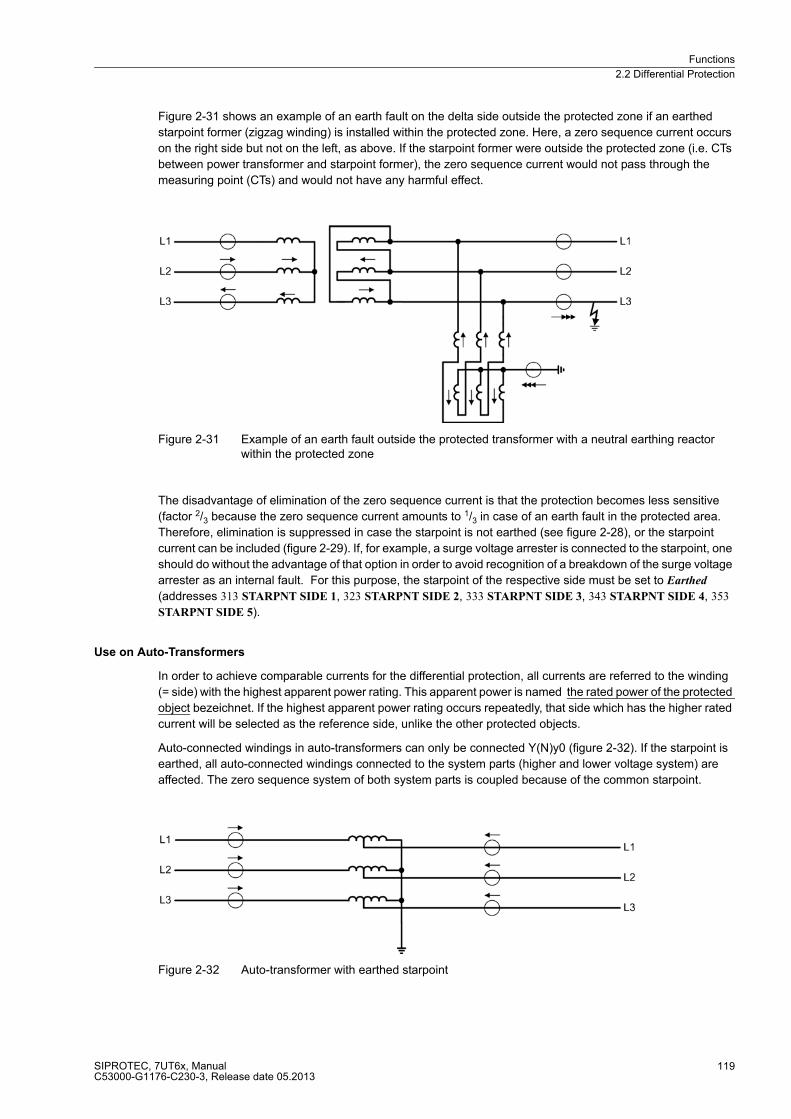
Functions
2.2 Differential Protection
SIPROTEC, 7UT6x, ManualC53000-G1176-C230-3, Release date 05.2013
119
Figure 2-31 shows an example of an earth fault on the delta side outside the protected zone if an earthed
starpoint former (zigzag winding) is installed within the protected zone. Here, a zero sequence current occurs
on the right side but not on the left, as above. If the starpoint former were outside the protected zone (i.e. CTs
between power transformer and starpoint former), the zero sequence current would not pass through the
measuring point (CTs) and would not have any harmful effect.
Figure 2-31 Example of an earth fault outside the protected transformer with a neutral earthing reactor within the protected zone
The disadvantage of elimination of the zero sequence current is that the protection becomes less sensitive
(factor 2/3 because the zero sequence current amounts to 1/3 in case of an earth fault in the protected area.
Therefore, elimination is suppressed in case the starpoint is not earthed (see figure 2-28), or the starpoint
current can be included (figure 2-29). If, for example, a surge voltage arrester is connected to the starpoint, one
should do without the advantage of that option in order to avoid recognition of a breakdown of the surge voltage
arrester as an internal fault. For this purpose, the starpoint of the respective side must be set to Earthed
(addresses 313 STARPNT SIDE 1, 323 STARPNT SIDE 2, 333 STARPNT SIDE 3, 343 STARPNT SIDE 4, 353
STARPNT SIDE 5).
Use on Auto-Transformers
In order to achieve comparable currents for the differential protection, all currents are referred to the winding
(= side) with the highest apparent power rating. This apparent power is named the rated power of the protected
object bezeichnet. If the highest apparent power rating occurs repeatedly, that side which has the higher rated
current will be selected as the reference side, unlike the other protected objects.
Auto-connected windings in auto-transformers can only be connected Y(N)y0 (figure 2-32). If the starpoint is
earthed, all auto-connected windings connected to the system parts (higher and lower voltage system) are
affected. The zero sequence system of both system parts is coupled because of the common starpoint.
Figure 2-32 Auto-transformer with earthed starpoint
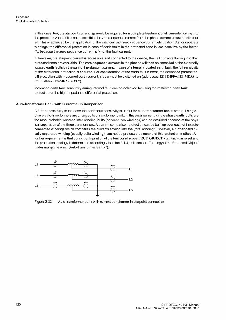
Functions
2.2 Differential Protection
SIPROTEC, 7UT6x, ManualC53000-G1176-C230-3, Release date 05.2013
120
In this case, too, the starpoint current ISP would be required for a complete treatment of all currents flowing into
the protected zone. If it is not accessible, the zero sequence current from the phase currents must be eliminat-
ed. This is achieved by the application of the matrices with zero sequence current elimination. As for separate
windings, the differential protection in case of earth faults in the protected zone is less sensitive by the factor 2/3, because the zero sequence current is 1/3 of the fault current.
If, however, the starpoint current is accessible and connected to the device, then all currents flowing into the
protected zone are available. The zero sequence currents in the phases will then be cancelled at the externally
located earth faults by the sum of the starpoint current. In case of internally located earth fault, the full sensitivity
of the differential protection is ensured. For consideration of the earth fault current, the advanced parameter
diff protection with measured earth current, side x must be switched on (addresses 1211 DIFFw.IE1-MEAS to
1215 DIFFw.IE5-MEAS = YES).
Increased earth fault sensitivity during internal fault can be achieved by using the restricted earth fault
protection or the high-impedance differential protection.
Auto-transformer Bank with Current-sum Comparison
A further possibility to increase the earth fault sensitivity is useful for auto-transformer banks where 1 single-
phase auto-transformers are arranged to a transformer bank. In this arrangement, single-phase earth faults are
the most probable whereas inter-winding faults (between two windings) can be excluded because of the phys-
ical separation of the three transformers. A current comparison protection can be built up over each of the auto-
connected windings which compares the currents flowing into the „total winding“. However, a further galvani-
cally separated winding (usually delta winding), can not be protected by means of this protection method. A
further requirement is that during configuration of the functional scope PROT. OBJECT = Autotr. node is set and
the protection topology is determined accordingly (section 2.1.4, sub-section „Topology of the Protected Object“
under margin heading „Auto-transformer Banks“).
Figure 2-33 Auto-transformer bank with current transformer in starpoint connection
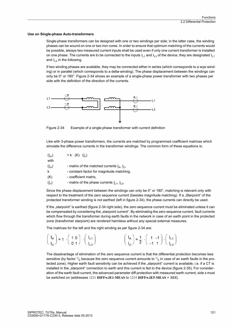
Functions
2.2 Differential Protection
SIPROTEC, 7UT6x, ManualC53000-G1176-C230-3, Release date 05.2013
121
Use on Single-phase Auto-transformers
Single-phase transformers can be designed with one or two windings per side; in the latter case, the winding
phases can be wound on one or two iron cores. In order to ensure that optimum matching of the currents would
be possible, always two measured current inputs shall be used even if only one current transformer is installed
on one phase. The currents are to be connected to the inputs IL1 and IL3 of the device, they are designated IL1
and IL3 in the following.
If two winding phases are available, they may be connected either in series (which corresponds to a wye-wind-
ing) or in parallel (which corresponds to a delta-winding). The phase displacement between the windings can
only be 0° or 180°. Figure 2-34 shows an example of a single-phase power transformer with two phases per
side with the definition of the direction of the currents.
Figure 2-34 Example of a single-phase transformer with current definition
Like with 3-phase power transformers, the currents are matched by programmed coefficient matrices which
simulate the difference currents in the transformer windings. The common form of these equations is:
Since the phase displacement between the windings can only be 0° or 180°, matching is relevant only with
respect to the treatment of the zero sequence current (besides magnitude matching). If a „Starpoint“ of the
protected transformer winding is not earthed (left in figure 2-34), the phase currents can directly be used.
If the „starpoint“ is earthed (figure 2-34 right side), the zero sequence current must be eliminated unless it can
be compensated by considering the „starpoint current“. By eliminating the zero sequence current, fault currents
which flow through the transformer during earth faults in the network in case of an earth point in the protected
zone (transformer starpoint) are rendered harmless without any special external measures.
The matrices for the left and the right winding as per figure 2-34 are:
The disadvantage of elimination of the zero sequence current is that the differential protection becomes less
sensitive (by factor 1/2 because the zero sequence current amounts to 1/2 in case of an earth faults in the pro-
tected zone). Higher earth fault sensitivity can be achieved if the „starpoint“ current is available, i.e. if a CT is
installed in the „starpoint“ connection to earth and this current is fed to the device (figure 2-35). For consider-
ation of the earth fault current, the advanced parameter diff protection with measured earth current, side x must
be switched on (addresses 1211 DIFFw.IE1-MEAS to 1215 DIFFw.IE5-MEAS = YES).
(Im) = k· (K)· (In)
with
(Im) - matrix of the matched currents IA, IC,
k - constant factor for magnitude matching,
(K) - coefficient matrix,
(In) - matrix of the phase currents IL1, IL3.
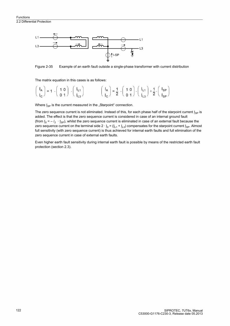
Functions
2.2 Differential Protection
SIPROTEC, 7UT6x, ManualC53000-G1176-C230-3, Release date 05.2013
122
Figure 2-35 Example of an earth fault outside a single-phase transformer with current distribution
The matrix equation in this cases is as follows:
Where ISP is the current measured in the „Starpoint“ connection.
The zero sequence current is not eliminated. Instead of this, for each phase half of the starpoint current ISP is
added. The effect is that the zero sequence current is considered in case of an internal ground fault
(from I0 = – /2 · ISP), whilst the zero sequence current is eliminated in case of an external fault because the
zero sequence current on the terminal side 2 · I0 = (IL1 + IL3) compensates for the starpoint current ISP. Almost
full sensitivity (with zero sequence current) is thus achieved for internal earth faults and full elimination of the
zero sequence current in case of external earth faults.
Even higher earth fault sensitivity during internal earth fault is possible by means of the restricted earth fault
protection (section 2.3).

Functions
2.2 Differential Protection
SIPROTEC, 7UT6x, ManualC53000-G1176-C230-3, Release date 05.2013
123
2.2.3 Differential Protection for Generators, Motors, and Series Reactors
Matching of the Measured Values
Equal conditions apply for generators, motors, and series reactors. The protected zone is limited by the sets of
current transformers at each side of the protected object. On generators and motors, the CT are installed in
starpoint connection at the terminal side. Since the current direction is normally defined as positive in the
direction of the protected object, for differential protection schemes, the definitions shown in figure 2-36 apply.
Figure 2-36 Definition of current direction with longitudinal differential protection
The differential protection in 7UT6x refers all currents to the rated current of the protected object. The device
is informed about the rated machine data during setting: the rated apparent power, the rated voltage, and the
rated currents of the current transformers. Measured value matching is therefore reduced to magnitude factors.
Transverse Differential Protection
The use as transverse differential protection involves a special point. For this application, the definition of the
current direction is shown in figure 2-37.
For transverse differential protection, the phases connected in parallel constitute the border between the
protected zone and the network. A differential current appears in this case only, but always, if there is a current
difference within the particular parallel phases, so that a fault current in one phase can be assumed.
Figure 2-37 Definition of current direction with transverse differential protection
The currents flow into the protected object even in case of healthy operation, in contrast to all other applica-
tions. For this reason, the polarity of one current transformer set must be reversed, i.e. you must set a „wrong“
polarity, as described in Subsection 2.1.4 under „Current Transformer Data for 3-Phase Measuring Locations“.

Functions
2.2 Differential Protection
SIPROTEC, 7UT6x, ManualC53000-G1176-C230-3, Release date 05.2013
124
Starpoint Conditioning
If the differential protection is used as generator or motor protection, the starpoint condition need not be con-
sidered even if the starpoint of the machine is earthed (high- or low-resistant). The phase currents are always
equal at both measuring points in case of an external fault. With internal faults, each fault current is completely
included in the formation of the differential current.
If the machine starpoint (high- or low-ohmic) is earthed, increased earth fault sensitivity in the protected zone
can be achieved by „restricted earth fault protection“ (see Section 2.3) or by the „high-impedance differential
protection“ (see Section 2.7).
2.2.4 Differential Protection for Shunt Reactors
If current transformers are available for each phase at both sides of a shunt reactor, the same considerations
apply for series reactors.
In most cases, current transformers are installed in the lead phases and in the starpoint connection (see figure
2-38). In this case, comparison of the zero sequence currents is reasonable. The „Restricted Earth Fault Pro-
tection“ is most suitable for this application (see 2.3).
If current transformers are installed in the line at both sides of the connection point of the reactor (see figure
2-38), the same conditions as for auto-transformers apply. Such an arrangement is therefore treated like an
auto-transformer.
A neutral earthing reactor (starpoint former) outside the protected zone of a power transformer can be treated
as a separate protected object provided it is equipped with current transformers like a shunt reactor. The
difference is that the starpoint former has a low impedance for zero sequence currents.
Figure 2-38 Definition of current direction on a shunt reactor
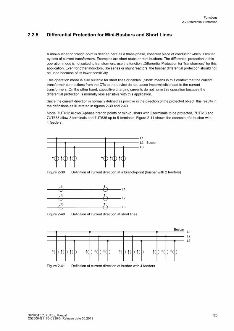
Functions
2.2 Differential Protection
SIPROTEC, 7UT6x, ManualC53000-G1176-C230-3, Release date 05.2013
125
2.2.5 Differential Protection for Mini-Busbars and Short Lines
A mini-busbar or branch-point is defined here as a three-phase, coherent piece of conductor which is limited
by sets of current transformers. Examples are short stubs or mini-busbars. The differential protection in this
operation mode is not suited to transformers; use the function „Differential Protection for Transformers“ for this
application. Even for other inductors, like series or shunt reactors, the busbar differential protection should not
be used because of its lower sensitivity.
This operation mode is also suitable for short lines or cables. „Short“ means in this context that the current
transformer connections from the CTs to the device do not cause impermissible load to the current
transformers. On the other hand, capacitive charging currents do not harm this operation because the
differential protection is normally less sensitive with this application.
Since the current direction is normally defined as positive in the direction of the protected object, this results in
the definitions as illustrated in figures 2-39 and 2-40.
Model 7UT612 allows 3-phase branch points or mini-busbars with 2 terminals to be protected, 7UT613 and
7UT633 allow 3 terminals and 7UT635 up to 5 terminals. Figure 2-41 shows the example of a busbar with
4 feeders.
Figure 2-39 Definition of current direction at a branch-point (busbar with 2 feeders)
Figure 2-40 Definition of current direction at short lines
Figure 2-41 Definition of current direction at busbar with 4 feeders
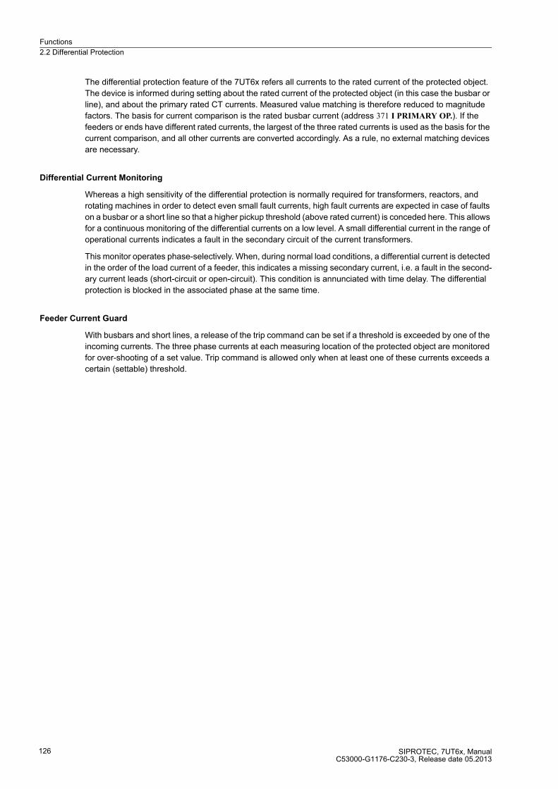
Functions
2.2 Differential Protection
SIPROTEC, 7UT6x, ManualC53000-G1176-C230-3, Release date 05.2013
126
The differential protection feature of the 7UT6x refers all currents to the rated current of the protected object.
The device is informed during setting about the rated current of the protected object (in this case the busbar or
line), and about the primary rated CT currents. Measured value matching is therefore reduced to magnitude
factors. The basis for current comparison is the rated busbar current (address 371 I PRIMARY OP.). If the
feeders or ends have different rated currents, the largest of the three rated currents is used as the basis for the
current comparison, and all other currents are converted accordingly. As a rule, no external matching devices
are necessary.
Differential Current Monitoring
Whereas a high sensitivity of the differential protection is normally required for transformers, reactors, and
rotating machines in order to detect even small fault currents, high fault currents are expected in case of faults
on a busbar or a short line so that a higher pickup threshold (above rated current) is conceded here. This allows
for a continuous monitoring of the differential currents on a low level. A small differential current in the range of
operational currents indicates a fault in the secondary circuit of the current transformers.
This monitor operates phase-selectively. When, during normal load conditions, a differential current is detected
in the order of the load current of a feeder, this indicates a missing secondary current, i.e. a fault in the second-
ary current leads (short-circuit or open-circuit). This condition is annunciated with time delay. The differential
protection is blocked in the associated phase at the same time.
Feeder Current Guard
With busbars and short lines, a release of the trip command can be set if a threshold is exceeded by one of the
incoming currents. The three phase currents at each measuring location of the protected object are monitored
for over-shooting of a set value. Trip command is allowed only when at least one of these currents exceeds a
certain (settable) threshold.

Functions
2.2 Differential Protection
SIPROTEC, 7UT6x, ManualC53000-G1176-C230-3, Release date 05.2013
127
2.2.6 Single-phase Differential Protection for Busbars
Dependent on the ordered model, 7UT6x provides 7, 9, or 12 current inputs of equal design. This allows for a
single-phase differential current busbar protection for up to 7 or 9 or 12 feeders.
There are two connection possibilities:
� One 7UT6x is used for each phase. Each phase of all busbar feeders is connected to one phase dedicated
device 7UT6x.
� The three phase currents of each feeder are summarised into a single-phase summation current. These
currents are fed to one device per feeder.
Phase Dedicated Connection
For each of the phases, a 7UT6x is used in case of single-phase connection. The fault current sensitivity is
equal for all types of fault. 7UT612 is suited for a busbar with up to 7, 7UT613 and 7UT633 are suited for a
busbar with up to 9, 7UT635 for up to 12 feeders.
The differential protection feature of the 7UT6x refers all currents to the rated current of the protective object.
Therefore, a common rated current must be defined for the entire busbar even if the feeder CTs have different
rated currents. This common rated current has been set in address 371 I PRIMARY OP.. It is the maximum of
the rated currents of all feeders set in the device in the data of the protected object. Measured value matching
in the device is thus limited to current quantity factors. No external matching devices are necessary even if the
feeders and/or the current transformer sets at the ends of the protected zone have different primary currents.
Figure 2-42 Single-phase busbar protection, illustrated L1
Connection via Summation CT
One single device 7UT6x is sufficient for the busbar if the device is connected via summation current trans-
formers. The 3 phase currents of each feeder are converted into single-phase back-up current by means of the
summation CTs. Current summation is unsymmetrical; thus, different sensitivity is valid for different types of
fault. 7UT612 is suited for a busbar with up to 7, 7UT613 and 7UT633 are suited for a busbar with up to 9,
7UT635 for up to 12 feeders.
A common nominal current must be defined for the entire busbar. Matching of the currents can be performed
in the summation transformer connections if the feeder CTs have different nominal currents. The output of the
summation transformers is normally designed for IM = 100 mA at symmetrical rated busbar current. The
nominal current at the device input IN Obj = 100 mA is applicable.
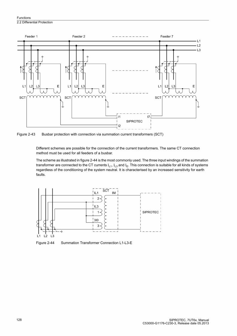
Functions
2.2 Differential Protection
SIPROTEC, 7UT6x, ManualC53000-G1176-C230-3, Release date 05.2013
128
Figure 2-43 Busbar protection with connection via summation current transformers (SCT)
Different schemes are possible for the connection of the current transformers. The same CT connection
method must be used for all feeders of a busbar.
The scheme as illustrated in figure 2-44 is the most commonly used. The three input windings of the summation
transformer are connected to the CT currents IL1, IL3 and IE. This connection is suitable for all kinds of systems
regardless of the conditioning of the system neutral. It is characterised by an increased sensitivity for earth
faults.
Figure 2-44 Summation Transformer Connection L1-L3-E
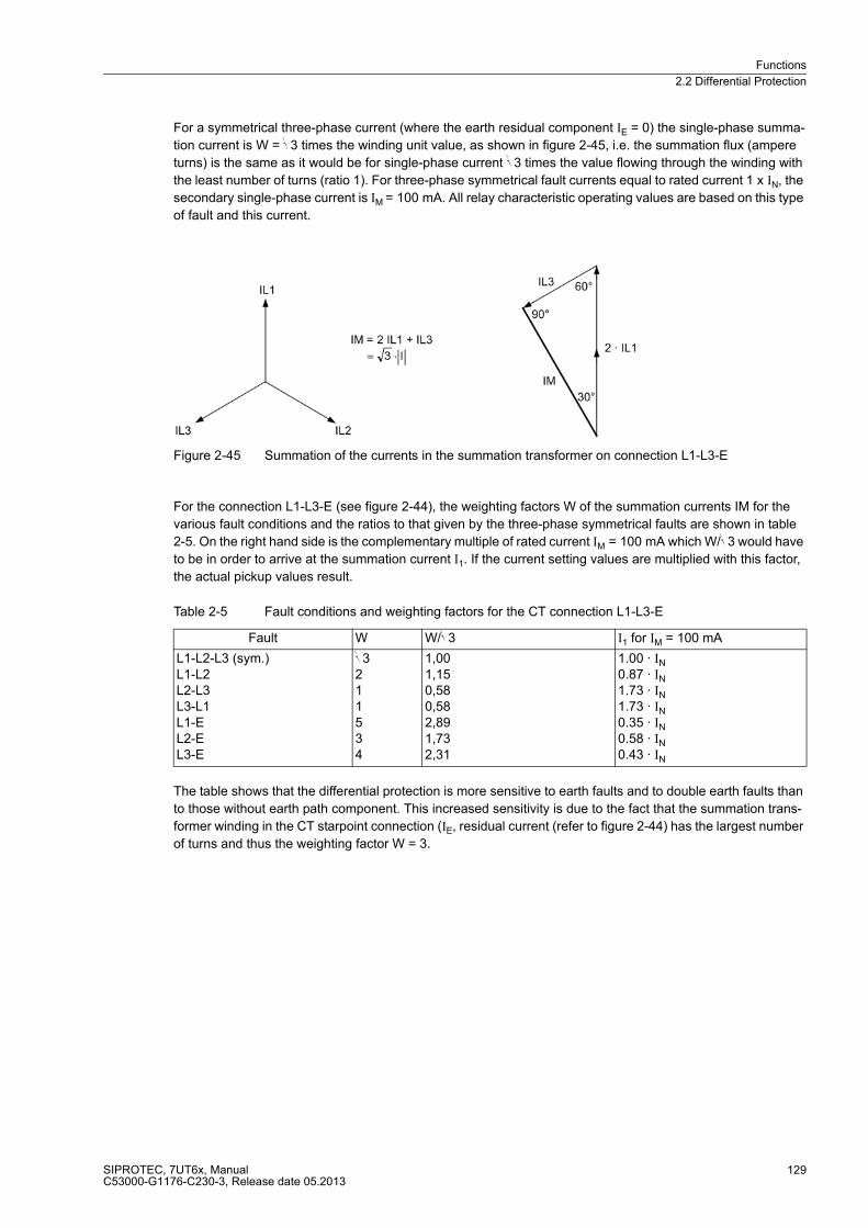
Functions
2.2 Differential Protection
SIPROTEC, 7UT6x, ManualC53000-G1176-C230-3, Release date 05.2013
129
For a symmetrical three-phase current (where the earth residual component IE = 0) the single-phase summa-
tion current is W = √3 times the winding unit value, as shown in figure 2-45, i.e. the summation flux (ampere
turns) is the same as it would be for single-phase current √3 times the value flowing through the winding with
the least number of turns (ratio 1). For three-phase symmetrical fault currents equal to rated current 1 x IN, the
secondary single-phase current is IM = 100 mA. All relay characteristic operating values are based on this type
of fault and this current.
Figure 2-45 Summation of the currents in the summation transformer on connection L1-L3-E
For the connection L1-L3-E (see figure 2-44), the weighting factors W of the summation currents IM for the
various fault conditions and the ratios to that given by the three-phase symmetrical faults are shown in table
2-5. On the right hand side is the complementary multiple of rated current IM = 100 mA which W/√3 would have
to be in order to arrive at the summation current I1. If the current setting values are multiplied with this factor,
the actual pickup values result.
Table 2-5 Fault conditions and weighting factors for the CT connection L1-L3-E
The table shows that the differential protection is more sensitive to earth faults and to double earth faults than
to those without earth path component. This increased sensitivity is due to the fact that the summation trans-
former winding in the CT starpoint connection (IE, residual current (refer to figure 2-44) has the largest number
of turns and thus the weighting factor W = 3.
Fault W W/√3 I1 for IM = 100 mA
L1-L2-L3 (sym.) L1-L2 L2-L3L3-L1 L1-EL2-E L3-E
√3 2 1 1 5 3 4
1,00 1,15 0,58 0,58 2,89 1,73 2,31
1.00 · IN 0.87 · IN 1.73 · IN 1.73 · IN 0.35 · IN 0.58 · IN 0.43 · IN
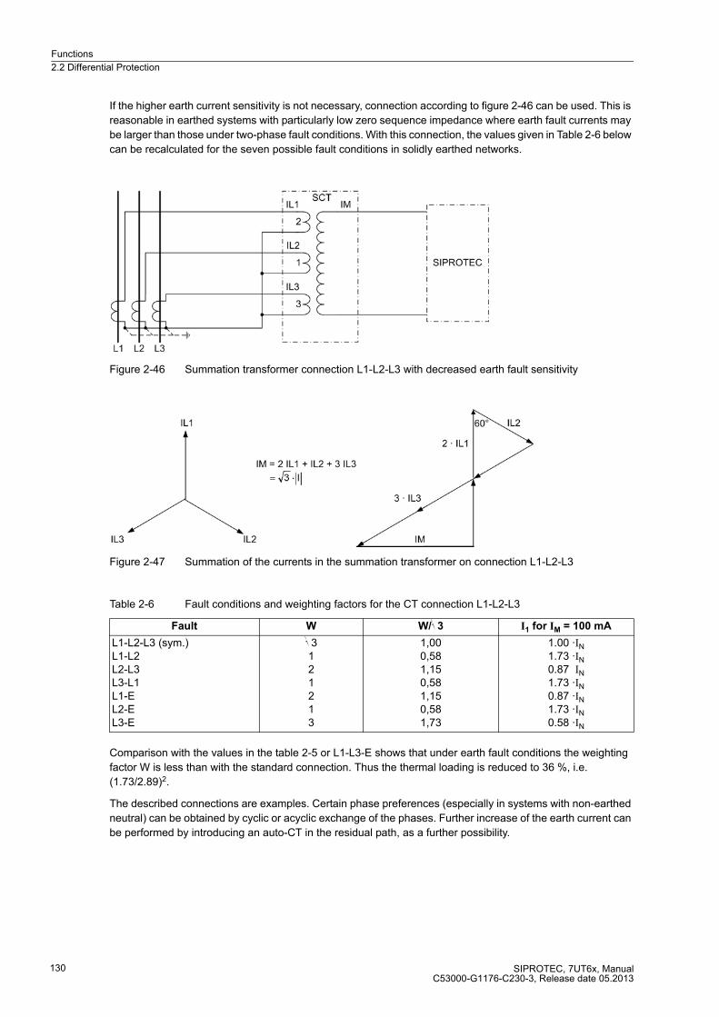
Functions
2.2 Differential Protection
SIPROTEC, 7UT6x, ManualC53000-G1176-C230-3, Release date 05.2013
130
If the higher earth current sensitivity is not necessary, connection according to figure 2-46 can be used. This is
reasonable in earthed systems with particularly low zero sequence impedance where earth fault currents may
be larger than those under two-phase fault conditions. With this connection, the values given in Table 2-6 below
can be recalculated for the seven possible fault conditions in solidly earthed networks.
Figure 2-46 Summation transformer connection L1-L2-L3 with decreased earth fault sensitivity
Figure 2-47 Summation of the currents in the summation transformer on connection L1-L2-L3
Table 2-6 Fault conditions and weighting factors for the CT connection L1-L2-L3
Comparison with the values in the table 2-5 or L1-L3-E shows that under earth fault conditions the weighting
factor W is less than with the standard connection. Thus the thermal loading is reduced to 36 %, i.e.
(1.73/2.89)2.
The described connections are examples. Certain phase preferences (especially in systems with non-earthed
neutral) can be obtained by cyclic or acyclic exchange of the phases. Further increase of the earth current can
be performed by introducing an auto-CT in the residual path, as a further possibility.
Fault W W/√3 I1 for IM = 100 mA
L1-L2-L3 (sym.) L1-L2L2-L3 L3-L1 L1-E L2-EL3-E
√3 1 2 1 2 1 3
1,00 0,58 1,15 0,58 1,15 0,58 1,73
1.00 ·IN 1.73 ·IN 0.87 IN 1.73 ·IN 0.87 ·IN 1.73 ·IN 0.58 ·IN

Functions
2.2 Differential Protection
SIPROTEC, 7UT6x, ManualC53000-G1176-C230-3, Release date 05.2013
131
The type 4AM5120 is recommended for summation current transformers. These transformers have different
input windings which allow for summation of the currents with the ratio 2 : 1 : 3 as well as matching of different
primary currents of the main CTs to a certain extent. Figure 2-48 shows the winding arrangement.
The nominal input current of each summation CT must match the nominal secondary current of the connected
main CT set. The output current of the summation CT (= input current of the 7UT6x) amounts to IN = 0.1 A at
nominal conditions, with correct matching.
Figure 2-48 Winding arrangement of summation and matching transformers 4AM5120
Differential Current Monitoring
Whereas a high sensitivity of the differential protection is normally required for transformers, reactors, and
rotating machines in order to detect even small fault currents, high fault currents are expected in case of faults
on a busbar so that a higher pickup threshold (above rated current) is conceded here. This allows for a
continuous monitoring of the differential currents on a low level. A small differential current in the range of
operational currents indicates a fault in the secondary circuit of the current transformers.
When, during normal load conditions, a differential current is detected in the order of the load current of a
feeder, this indicates a missing secondary current, i.e. a fault in the secondary current leads (short-circuit or
open-circuit). This condition is annunciated with time delay. The differential protection is blocked at the same
time.
Feeder Current Guard
With busbars a release of the trip command can be set if a threshold is exceeded by one of the incoming
currents. The currents of each feeder are monitored for over-shooting of a set value. Trip command is allowed
only when at least one of these currents exceeds a certain (settable) threshold.
Functions
2.2 Differential Protection
SIPROTEC, 7UT6x, ManualC53000-G1176-C230-3, Release date 05.2013
132
2.2.7 Setting Notes
General
Differential protection is only effective and available if this function was set during configuration of the Function-
al Scope DIFF. PROT. = Enabled (address 112) . If the function is not required Disabled is to be set.
Additionally, the type of protected object must be decided during configuration (address 105 PROT. OBJECT).
Only those parameters are offered which are reasonable for the selected type of protected object; all remaining
are suppressed.
The differential protection can be switched 1201 or DIFF. PROT. in address ON OFF. The option Block relay
allows to operate the protection but the trip output relay is blocked.
Note
When delivered from factory, the differential protection is switched OFF. The reason is that the protection must
not be in operation unless at least the connection group (of a transformer) and the matching factors have been
set before. Without proper settings, the device may show unexpected reactions (incl. tripping)!
Starpoint Conditioning
If there is a current transformer in the starpoint connection of an earthed transformer winding, i. e. between
starpoint and earth electrode, the starpoint current may be taken into consideration for calculations of the
differential protection. The earth-fault sensitivity is thus ensured.
If a starpoint is earthed but the earth current is not available for the measurement, the zero sequence current
is eliminated automatically in order to avoid false operation in case of an external earth fault; the following pa-
rameters are then omitted. Equally, the parameters are not available if the respective transformer side has no
earthed starpoint in the protected zone. You have informed the device about the earthing conditions during
setting of the object properties (Subsection „General Power System Data“ under margin heading „Object Data
with Transformers“, addresses 313, 323, 333, 343 and/or 353 and Subsection „Topology of the Protected Object“
under margin heading „Assignment of Further 1-phase Measuring Locations“).
The conclusion is: If the starpoint of a side of the protected power transformer is earthed and the starpoint
current is fed to the device (via a further 1-phase current input) you can, nevertheless, leave the default setting
for inclusion of the earth current unchanged in address 1211DIFFw.IE1-MEAS for side 1 on „Yes“.
This parameter can only be altered with DIGSI under Additional Settings. The same considerations apply to
any other or additional earthed sides:
� 1212 DIFFw.IE2-MEAS for side 2 if earthed,
� 1213 DIFFw.IE3-MEAS for side 3 if earthed,
� 1214 DIFFw.IE4-MEAS for side 4 if earthed,
� 1215 DIFFw.IE5-MEAS for side 5 if earthed.
During setting YES the corresponding earth current will be considered by the differential protection.
In auto-transformers the earth current flowing in the winding can be considered even if a complete three-phase
CT set has been installed as illustrated in figure 2-6, where instead of measuring location Z3 also the three
phase currents can be connected to a three-phase measuring input of the device. The device then calculates
the sum of the three currents and uses it as earth current. Set address 1216 DIFFw.IE3phMEAS to YES. It is
required to assign the respective three-phase measuring location to one side and to declare it as earth winding
(the side of the auto-connected winding facing the earth electrode). This parameter can only be altered in DIGSI
at Display Additional Settings.
Functions
2.2 Differential Protection
SIPROTEC, 7UT6x, ManualC53000-G1176-C230-3, Release date 05.2013
133
Differential Current Monitoring
With busbar protection or short-line protection differential current can be monitored. At address 1208 I-DIFF>
MON. the monitoring can be set to ON and OFF. Its use is only sensible if one can distinguish clearly between
operational error currents caused by missing transformer currents and fault currents caused by a fault in the
protected object.
The pickup value I-DIFF> MON. (address 1281) must be high enough to avoid a pickup caused by a transfor-
mation error of the current transformers and by minimum mismatching of different current transformers. On the
other hand, the pickup value must lie clearly below the differential protection (I-DIFF>, address 1221); other-
wise no differentiation between operational errors caused by missing secondary currents and fault currents due
to short-circuit in the protected object would be possible. The pickup value is referred to the rated current of the
protected object. Time delay T I-DIFF> MON. (address 1282) applies to the annunciation and blocking of the
differential protection. This setting ensures that blocking with the presence of faults (even of external ones) is
avoided. The time delay usually amounts to a few seconds.
Feeder Current Guard
With busbars and short lines a release of the trip command can be set if one of the incoming currents is ex-
ceeded. The differential protection only trips if one of the measured currents exceeds the threshold I> CURR.
GUARD (address 1210). The pickup value is referred to the rated current of the respective side. With setting
(pre-setting) this release criterion will not be used.
If the feeder current guard is set (i. e. to a value of > 0), the differential protection will not trip before the release
criterion is given. This is also the case if, in conjunction with very high differential currents, the extremely fast
instantaneous value scheme has detected the fault already after a few milliseconds.
Trip Characteristic Differential Current
The parameters of the tripping characteristic are set in addresses 1221 to 1265. Figure 2-49 illustrates the
meaning of the different settings. The numbers at the different branches of the characteristic signify the ad-
dresses of the settings.
I-DIFF> (address 1221) is the pickup value of the differential current. This is the total fault current into the pro-
tected object, regardless of the way this is distributed between the sides. The pickup value is referred to the
rated current of the protected object. You may select a high sensitivity (small pickup value) for transformers
(presetting 0.2 · IN Obj). With reactors, generators and motors the sensitivity can be set even higher, provided
that the current transformer sets are of similar design. A higher value (above rated current) should be selected
for lines and busbars. Higher measuring tolerances must be expected if the rated currents of the current trans-
formers differ extensively from the rated current of the protected object, or if there are multiple measuring loca-
tions.
Besides the threshold I-DIFF> is a second threshold available. In case of exceeding this threshold I-DIFF>>
(address 1231) is independent of the value of the restraint current and recognized independently of a possible
inrush stabilization on a tripping (not stabilized instantaneous stage). This stage must be set greater than I-
DIFF>. For protection objects with high longitudinal impedance (Transformer, Generator, Reactor) can find a
current value of a flowing through the short circuit current is not exceeded. In a transformer e.g., the (primary)
value:
In case of busbars and short lines, the through-flowing current can increase substantially, depending on the
system. The unstable I-DIFF>> stage could trip. In such cases I-DIFF>> should be set to ∞.

Functions
2.2 Differential Protection
SIPROTEC, 7UT6x, ManualC53000-G1176-C230-3, Release date 05.2013
134
Figure 2-49 Tripping characteristic of the differential protection
The tripping characteristic comprises two further branches. The base point of the first branch is determined by
address 1242 BASE POINT 1 and its slope by address 1241 SLOPE 1. This parameter can only be set with
DIGSI under Additional Settings. This branch covers current-proportional errors. These are mainly errors of
the main current transformers and, in case of power transformers with tap changers, differential currents which
occur due to the transformer regulating range.
The percentage of this differential current in this latter case is equal to the percentage of the regulating range
provided the rated voltage is corrected according to the description of the 2.1.4 in „Object Data with Transform-
ers“.
The second branch produces a higher restraint in the range of high currents which may lead to current trans-
former saturation. Its base point is set at address 1244 BASE POINT 2 and is referred to the rated object current.
The slope is set at address 1243 SLOPE 2. The restraint during current transformer saturation can be influenced
by this parameter branch. A higher gradient results in a higher restraint. This parameter can only be set with
DIGSI at Additional Settings.
Delay Times
In special cases it may be advantageous to delay the trip signal of the differential protection. For this, an addi-
tional delay can be set. The delay time1226 T I-DIFF> is started if an internal fault in the protected object has
been detected by the IDIFF>-stage and the trip characteristic. 1236 T I-DIFF>> is the time delay for the tripping
stage I-DIFF>>. This parameter can only be set with DIGSI at Additional Settings. The dropout time of all
stages is determined by the minimum trip time duration of all protection functions.
All setting times are additional delay times which do not include the operating times (measuring time, dropout
time) of the protective function.

Functions
2.2 Differential Protection
SIPROTEC, 7UT6x, ManualC53000-G1176-C230-3, Release date 05.2013
135
Increase of Pickup Value on Startup
The increase of the pickup value on startup serves as an additional safety against overfunctioning when a non-
energised protection object is connected. At address 1205 INC.CHAR.START it can be switched to ON or OFF.
Especially for motors or motor/transformer units in block connection it should be set to ON.
The restraint current value I-REST. STARTUP (address 1251) is the value of the restraining current which is
likely to be undershot before startup of the protected object takes place. This parameter can only be set with
DIGSI at Additional Settings. Please be aware of the fact that the restraint current is twice the traversing
operational current. The pre-set value of 0.1 represents 0.05 times the rated current of the protected object.
Address 1252 START-FACTOR determines by which factor the pickup value of the Diff> stage is to be increased
on startup. The characteristic of this stage increases by the same factor. The IDiff>> stage is not affected. For
motors or motor/transformer in unit connection, a value of 2 is normally adequate. This parameter can only be
set with DIGSI under Additional Settings.
The increase of the pickup value is set back to its original value after time period T START MAX (address 1253)
has passed.
Add-on Restraint
In systems with very high traversing currents a dynamic add-on restraint is enabled for external faults. The initial
value is set at address 1261 I-ADD ON STAB.. The value is referred to the rated current of the protected object.
The slope is the same as for characteristic branch b (SLOPE 1, address 1241). This parameter can only be set
with DIGSI at Additional Settings. Please note that the fact that the restraint current is the arithmetical sum
of the currents flowing into the protected object, i.e. it is twice the traversing current. The additional stabilisation
does not influence the stage I-DIFF>>.
The maximum duration of the add-on restraint after detection of an external fault is set to multiples of an AC-
cycle (address 1262 T ADD ON-STAB.). This parameter can only be set with DIGSI at Additional Settings.
The add-on restraint is disabled automatically even before the set time period expires as soon as the device
has detected that the operation pointIdiff/Istab stationary (i.e. via at least one cycle) within the tripping zone near
the fault characteristic (≥ 80 % of the fault characteristic slope).
Add-on restraint operates individually per phase, but blocking can be extended to all three phases (so-called
crossblock function). By means of address 1263 CROSSB. ADD ON it can be determined how long the cross-
block should be effective. This parameter can only be set with DIGSI at Additional Settings. Here, too, setting
is in multiple of one AC-cycle. If 0 Per. cycle is set, crossblock is ineffective, i.e. only the phase with detected
external fault will be blocked. Otherwise all phases will be blocked. in this case the same setting as for 1262 T
ADD ON-STAB. is advisable. When set to ∞, the crossblock function is always effective.
Harmonic Restraint
Restraint with harmonic content is available only when the device is used as transformer protection, i.e. the
PROT. OBJECT (address 105) is a 3 phase transf. or 1 phase transf. or Autotransf. or Autotr. node. This function
is also used for shunt reactors if current transformers are installed at both sides of the connection points.
The inrush restraint function with 2nd harmonic can be switched in address 1206 INRUSH 2.HARM. OFF and
ON. It is based on evaluation of the 2nd harmonic present in the switch-on inrush current. The ratio of 2nd har-
monics to the fundamental (address 1271, 2. HARMONIC) is set to I2fN/IfN = as default setting. It can be used
without being changed. To provide more restraint in exceptional cases, where energising conditions are partic-
ularly unfavourable, a smaller value can be set at the afore-mentioned address. The restraint with harmonics
does not influence the stage I-DIFF>>.
Functions
2.2 Differential Protection
SIPROTEC, 7UT6x, ManualC53000-G1176-C230-3, Release date 05.2013
136
The inrush restraint can be extended by the so-called "crossblock" function. This means that on harmonic
content overshoot in only one phase all three phases of the differential stage IDIFF> stage are blocked. The
duration for which the crossblock function is active can be limited at address 1272 CROSSB. 2. HARM. Setting
is in multiple of the AC-cycle. This parameter can only be set with DIGSI at Additional Settings. If set to 0 (pre-
setting is 3) the protection can trip when the transformer is switched on a single-phase fault even while the other
phases carry inrush current. If set to ∞ the crossblock function remains effective for as long as high-order har-
monics are detected in any phase.
Apart from the second harmonic, the 7UT6x can provide restraint with a further harmonic. Address 1207
RESTR. n.HARM. is used to disable this harmonics restraint, or to select the harmonic for it. Available for
selection are the 3. Harmonic and the 5. Harmonic.
Steady-state overexcitation of transformers is characterised by odd harmonic content. The 3rd or 5th harmonic
is suitable to detect overexcitation. As the third harmonic is often eliminated in transformers (e.g. in a delta
winding), the fifth harmonic is more commonly used.
Converter transformers also produce odd harmonics which are practically absent in the case of an internal
short-circuit.
The harmonic content intended for blocking the differential protection is set at address 1276 n. HARMONIC.
For example, if the 5th harmonic restraint is used to avoid trip during overexcitation, 30 % (default setting) are
convenient.
Harmonic restraint with the n-th harmonic operates individually per phase. However, it is also possible – as it
is for the inrush restraint – to set the protection in such manner that not only the phase with harmonic content
overshoot but also the other phases of the differential stage I-DIFF> are blocked (so-called "crossblock" func-
tion). The duration for which the crossblock function is active can be limited at address 1277 CROSSB.
n.HARM. Setting is in multiple of the AC-cycle. This parameter can only be set with DIGSI at Additional Set-
tings. If set to 0 the crossblock function remains effective for as long as high-order harmonics are detected in
any phase. When set to ∞, the crossblock function is always active. .
If the differential current exceeds the magnitude set at address 1278 IDIFFmax n.HM no n-th harmonic restraint
takes place. This parameter can only be altered in DIGSI at Display Additional Settings.
Note
The current values I/INO in the settings overview below always refer to the rated current of the main protected
object. The current values I/INS always refer to the rated current of the relevant side of the main protected
object.

Functions
2.2 Differential Protection
SIPROTEC, 7UT6x, ManualC53000-G1176-C230-3, Release date 05.2013
137
2.2.8 Settings
Addresses which have an appended "A" can only be changed with DIGSI, under Additional Settings.
Addr. Parameter Setting Options Default Setting Comments
1201 DIFF. PROT. OFFONBlock relay
OFF Differential Protection
1205 INC.CHAR.START OFFON
OFF Increase of Trip Char. During Start
1206 INRUSH 2.HARM. OFFON
ON Inrush with 2. Harmonic Restraint
1207 RESTR. n.HARM. OFF3. Harmonic5. Harmonic
OFF n-th Harmonic Restraint
1208 I-DIFF> MON. OFFON
ON Differential Current monitoring
1210 I> CURR. GUARD 0.20 .. 2.00 I/InS; 0 0.00 I/InS I> for Current Guard
1211A DIFFw.IE1-MEAS NOYES
NO Diff-Prot. with meas. Earth Current S1
1212A DIFFw.IE2-MEAS NOYES
NO Diff-Prot. with meas. Earth Current S2
1213A DIFFw.IE3-MEAS NOYES
NO Diff-Prot. with meas. Earth Current S3
1214A DIFFw.IE4-MEAS NOYES
NO Diff-Prot. with meas. Earth Current S4
1215A DIFFw.IE5-MEAS NOYES
NO Diff-Prot. with meas. Earth Current S5
1216A DIFFw.IE3phMEAS NOYES
NO Diff-Prot.with meas.current earth.electr
1221 I-DIFF> 0.05 .. 2.00 I/InO 0.20 I/InO Pickup Value of Differential Curr.
1226A T I-DIFF> 0.00 .. 60.00 sec; ∞ 0.00 sec T I-DIFF> Time Delay
1231 I-DIFF>> 0.5 .. 35.0 I/InO; ∞ 7.5 I/InO Pickup Value of High Set Trip
1236A T I-DIFF>> 0.00 .. 60.00 sec; ∞ 0.00 sec T I-DIFF>> Time Delay
1241A SLOPE 1 0.10 .. 0.50 0.25 Slope 1 of Tripping Characteristic
1242A BASE POINT 1 0.00 .. 2.00 I/InO 0.00 I/InO Base Point for Slope 1 of Charac.
1243A SLOPE 2 0.25 .. 0.95 0.50 Slope 2 of Tripping Characteristic
1244A BASE POINT 2 0.00 .. 10.00 I/InO 2.50 I/InO Base Point for Slope 2 of Charac.
1251A I-REST. STARTUP 0.00 .. 2.00 I/InO 0.10 I/InO I-RESTRAINT for Start Detection
1252A START-FACTOR 1.0 .. 2.0 1.0 Factor for Increasing of Char. at Start
1253 T START MAX 0.0 .. 180.0 sec 5.0 sec Maximum Permissible Starting Time
1261A I-ADD ON STAB. 2.00 .. 15.00 I/InO 4.00 I/InO Pickup for Add-on Stabilization
1262A T ADD ON-STAB. 2 .. 250 Cycle; ∞ 15 Cycle Duration of Add-on Stabilization

Functions
2.2 Differential Protection
SIPROTEC, 7UT6x, ManualC53000-G1176-C230-3, Release date 05.2013
138
2.2.9 Information List
1263A CROSSB. ADD ON 2 .. 1000 Cycle; 0; ∞ 15 Cycle Time for Cross-blocking Add-on Stabiliz.
1271 2. HARMONIC 10 .. 80 % 15 % 2nd Harmonic Content in I-DIFF
1272A CROSSB. 2. HARM 2 .. 1000 Cycle; 0; ∞ 3 Cycle Time for Cross-blocking 2nd Harm.
1276 n. HARMONIC 10 .. 80 % 30 % n-th Harmonic Content in I-DIFF
1277A CROSSB. n.HARM 2 .. 1000 Cycle; 0; ∞ 0 Cycle Time for Cross-blocking n-th Harm.
1278A IDIFFmax n.HM 0.5 .. 20.0 I/InO 1.5 I/InO Limit IDIFFmax of n-th Harm.Restraint
1281 I-DIFF> MON. 0.15 .. 0.80 I/InO 0.20 I/InO Pickup Value of diff. Current Monitoring
1282 T I-DIFF> MON. 1 .. 10 sec 2 sec T I-DIFF> Monitoring Time Delay
No. Information Type of In-
formation
Comments
5603 >Diff BLOCK SP >BLOCK differential protection
5615 Diff OFF OUT Differential protection is switched OFF
5616 Diff BLOCKED OUT Differential protection is BLOCKED
5617 Diff ACTIVE OUT Differential protection is ACTIVE
5620 Diff Adap.fact. OUT Diff err.: adverse Adaption factor CT
5631 Diff picked up OUT Differential protection picked up
5644 Diff 2.Harm L1 OUT Diff: Blocked by 2.Harmon. L1
5645 Diff 2.Harm L2 OUT Diff: Blocked by 2.Harmon. L2
5646 Diff 2.Harm L3 OUT Diff: Blocked by 2.Harmon. L3
5647 Diff n.Harm L1 OUT Diff: Blocked by n.Harmon. L1
5648 Diff n.Harm L2 OUT Diff: Blocked by n.Harmon. L2
5649 Diff n.Harm L3 OUT Diff: Blocked by n.Harmon. L3
5651 Diff Bl. exF.L1 OUT Diff. prot.: Blocked by ext. fault L1
5652 Diff Bl. exF.L2 OUT Diff. prot.: Blocked by ext. fault L2
5653 Diff Bl. exF.L3 OUT Diff. prot.: Blocked by ext. fault.L3
5657 DiffCrosBlk 2HM OUT Diff: Crossblock by 2.Harmonic
5658 DiffCrosBlk nHM OUT Diff: Crossblock by n.Harmonic
5660 DiffCrosBlk exF OUT Diff: Crossblock by ext. fault
5662 Block Iflt.L1 OUT Diff. prot.: Blocked by CT fault L1
5663 Block Iflt.L2 OUT Diff. prot.: Blocked by CT fault L2
5664 Block Iflt.L3 OUT Diff. prot.: Blocked by CT fault L3
5666 DiffStrtInChaL1 OUT Diff: Increase of char. phase (start) L1
5667 DiffStrtInChaL2 OUT Diff: Increase of char. phase (start) L2
5668 DiffStrtInChaL3 OUT Diff: Increase of char. phase (start) L3
5670 Diff I-Release OUT Diff: Curr-Release for Trip
5671 Diff TRIP OUT Differential protection TRIP
5672 Diff TRIP L1 OUT Differential protection: TRIP L1
Addr. Parameter Setting Options Default Setting Comments

Functions
2.2 Differential Protection
SIPROTEC, 7UT6x, ManualC53000-G1176-C230-3, Release date 05.2013
139
5673 Diff TRIP L2 OUT Differential protection: TRIP L2
5674 Diff TRIP L3 OUT Differential protection: TRIP L3
5681 Diff> L1 OUT Diff. prot.: IDIFF> L1 (without Tdelay)
5682 Diff> L2 OUT Diff. prot.: IDIFF> L2 (without Tdelay)
5683 Diff> L3 OUT Diff. prot.: IDIFF> L3 (without Tdelay)
5684 Diff>> L1 OUT Diff. prot: IDIFF>> L1 (without Tdelay)
5685 Diff>> L2 OUT Diff. prot: IDIFF>> L2 (without Tdelay)
5686 Diff>> L3 OUT Diff. prot: IDIFF>> L3 (without Tdelay)
5691 Diff> TRIP OUT Differential prot.: TRIP by IDIFF>
5692 Diff>> TRIP OUT Differential prot.: TRIP by IDIFF>>
5701 Diff L1: VI Diff. curr. in L1 at trip without Tdelay
5702 Diff L2: VI Diff. curr. in L2 at trip without Tdelay
5703 Diff L3: VI Diff. curr. in L3 at trip without Tdelay
5704 Res. L1: VI Restr.curr. in L1 at trip without Tdelay
5705 Res. L2: VI Restr.curr. in L2 at trip without Tdelay
5706 Res. L3: VI Restr.curr. in L3 at trip without Tdelay
5721 Diff CT-I1: VI Diff. prot: Adaption factor CT I1
5722 Diff CT-I2: VI Diff. prot: Adaption factor CT I2
5723 Diff CT-I3: VI Diff. prot: Adaption factor CT I3
5724 Diff CT-I4: VI Diff. prot: Adaption factor CT I4
5725 Diff CT-I5: VI Diff. prot: Adaption factor CT I5
5726 Diff CT-I6: VI Diff. prot: Adaption factor CT I6
5727 Diff CT-I7: VI Diff. prot: Adaption factor CT I7
5728 Diff CT-I8: VI Diff. prot: Adaption factor CT I8
5729 Diff CT-I9: VI Diff. prot: Adaption factor CT I9
5730 DiffCT-I10: VI Diff. prot: Adaption factor CT I10
5731 DiffCT-I11: VI Diff. prot: Adaption factor CT I11
5732 DiffCT-I12: VI Diff. prot: Adaption factor CT I12
5733 Diff CT-M1: VI Diff. prot: Adaption factor CT M1
5734 Diff CT-M2: VI Diff. prot: Adaption factor CT M2
5735 Diff CT-M3: VI Diff. prot: Adaption factor CT M3
5736 Diff CT-M4: VI Diff. prot: Adaption factor CT M4
5737 Diff CT-M5: VI Diff. prot: Adaption factor CT M5
5738 Diff CT-IX1: VI Diff. prot: Adaption factor aux. CT IX1
5739 Diff CT-IX2: VI Diff. prot: Adaption factor aux. CT IX2
5740 Diff CT-IX3: VI Diff. prot: Adaption factor aux. CT IX3
5741 Diff CT-IX4: VI Diff. prot: Adaption factor aux. CT IX4
5742 Diff DC L1 OUT Diff: DC L1
5743 Diff DC L2 OUT Diff: DC L2
5744 Diff DC L3 OUT Diff: DC L3
5745 Diff DC InCha OUT Diff: Increase of char. phase (DC)
No. Information Type of In-
formation
Comments
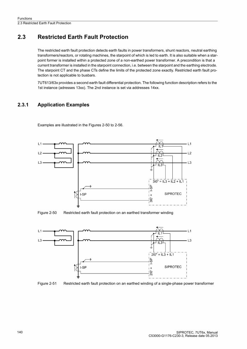
Functions
2.3 Restricted Earth Fault Protection
SIPROTEC, 7UT6x, ManualC53000-G1176-C230-3, Release date 05.2013
140
2.3 Restricted Earth Fault Protection
The restricted earth fault protection detects earth faults in power transformers, shunt reactors, neutral earthing
transformers/reactors, or rotating machines, the starpoint of which is led to earth. It is also suitable when a star-
point former is installed within a protected zone of a non-earthed power transformer. A precondition is that a
current transformer is installed in the starpoint connection, i.e. between the starpoint and the earthing electrode.
The starpoint CT and the phase CTs define the limits of the protected zone exactly. Restricted earth fault pro-
tection is not applicable to busbars.
7UT613/63x provides a second earth fault differential protection. The following function description refers to the
1st instance (adresses 13xx). The 2nd instance is set via addresses 14xx.
2.3.1 Application Examples
Examples are illustrated in the Figures 2-50 to 2-56.
Figure 2-50 Restricted earth fault protection on an earthed transformer winding
Figure 2-51 Restricted earth fault protection on an earthed winding of a single-phase power transformer
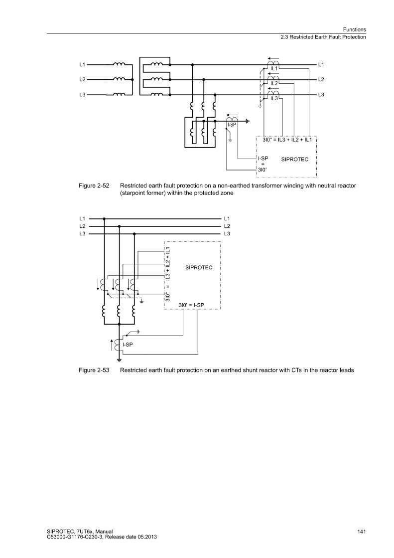
Functions
2.3 Restricted Earth Fault Protection
SIPROTEC, 7UT6x, ManualC53000-G1176-C230-3, Release date 05.2013
141
Figure 2-52 Restricted earth fault protection on a non-earthed transformer winding with neutral reactor (starpoint former) within the protected zone
Figure 2-53 Restricted earth fault protection on an earthed shunt reactor with CTs in the reactor leads

Functions
2.3 Restricted Earth Fault Protection
SIPROTEC, 7UT6x, ManualC53000-G1176-C230-3, Release date 05.2013
142
Figure 2-54 Restricted earth fault protection on an earthed shunt reactor with 2 CT sets (treated like an auto-transformer)
Figure 2-55 Restricted earth fault protection on an earthed auto-transformer

Functions
2.3 Restricted Earth Fault Protection
SIPROTEC, 7UT6x, ManualC53000-G1176-C230-3, Release date 05.2013
143
Figure 2-56 Restricted earth fault protection on a generator or motor with earthed starpoint
The restricted earth fault protection can operate on one of the sides of the main protected object (power trans-
former, generator, motor, reactor) or on a further protected object, according to the topology configured. In case
of auto-transformers, it is assigned to the auto-windings. Furthermore, it is presumed that the assignment of
the different measuring locations to the sides of the main protected object or to a further protected object as
well as the assignment of the 1-phase current input for the starpoint current has been performed correctly
according to the Subsection „Topology of the Protected Object“.
The 7UT613/63x provides two of the protective functions that can be used independently from each other in
different locations. For example you can realise a restricted earth fault protection for each of both windings on
a YNyn transformer that is earthed at both starpoints. Or use the first restricted earth fault protection for an
earthed winding of a transformer and the second for another protected object, e.g. a neutral reactor. You carried
out the assignment of both restricted earth fault protection functions to the sides or measuring locations accord-
ing the section „Assignment of Protection Functions to Measuring Location/Sides“.
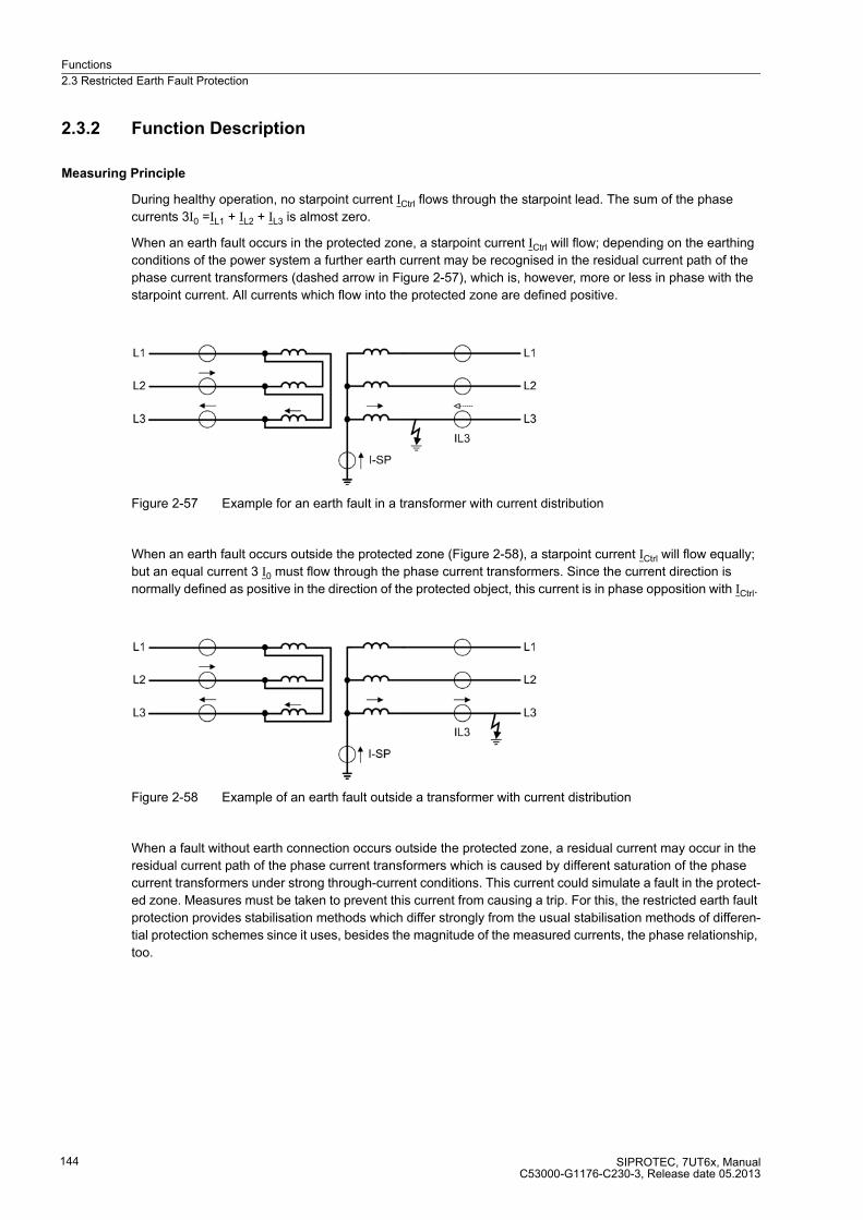
Functions
2.3 Restricted Earth Fault Protection
SIPROTEC, 7UT6x, ManualC53000-G1176-C230-3, Release date 05.2013
144
2.3.2 Function Description
Measuring Principle
During healthy operation, no starpoint current ICtrl flows through the starpoint lead. The sum of the phase
currents 3I0 =IL1 + IL2 + IL3 is almost zero.
When an earth fault occurs in the protected zone, a starpoint current ICtrl will flow; depending on the earthing
conditions of the power system a further earth current may be recognised in the residual current path of the
phase current transformers (dashed arrow in Figure 2-57), which is, however, more or less in phase with the
starpoint current. All currents which flow into the protected zone are defined positive.
Figure 2-57 Example for an earth fault in a transformer with current distribution
When an earth fault occurs outside the protected zone (Figure 2-58), a starpoint current ICtrl will flow equally;
but an equal current 3 I0 must flow through the phase current transformers. Since the current direction is
normally defined as positive in the direction of the protected object, this current is in phase opposition with ICtrl.
Figure 2-58 Example of an earth fault outside a transformer with current distribution
When a fault without earth connection occurs outside the protected zone, a residual current may occur in the
residual current path of the phase current transformers which is caused by different saturation of the phase
current transformers under strong through-current conditions. This current could simulate a fault in the protect-
ed zone. Measures must be taken to prevent this current from causing a trip. For this, the restricted earth fault
protection provides stabilisation methods which differ strongly from the usual stabilisation methods of differen-
tial protection schemes since it uses, besides the magnitude of the measured currents, the phase relationship,
too.

Functions
2.3 Restricted Earth Fault Protection
SIPROTEC, 7UT6x, ManualC53000-G1176-C230-3, Release date 05.2013
145
Evaluation of Measurement Quantities
The earth fault differential protection compares the fundamental wave of the current flowing in the starpoint
connection, which is designated as 3I0' in the following, with the fundamental wave of the sum of the phase
currents, which should be designated in the following as 3I0". Thus, the following applies (Figure 2-59):
3I0' = ICtrl
3I0" = IL1 + IL2 + IL3
Only 3I0' acts as the tripping effect quantity. During a fault within the protected zone this current is always
present.
Figure 2-59 Principle of restricted earth fault protection
For auto-transformers 3I0" is valid as the sum of all phase currents flowing to auto-connected winding (full
winding and tap(s)).
When an earth fault occurs outside the protected zone, another earth currents flows through the phase current
transformers. This is, on the primary side, in counter-phase with the starpoint current and has equal magnitude.
The maximum information of the currents is evaluated for restraint: the magnitude of the currents and their
phase position. The following is defined:
a tripping effect current
Ifrom = |3I0'|
and the stabilisation or restraining current
Istab = k · ( |3I0 ' – 3I0"| – |3I0' + 3I0"| )
k is a stabilisation factor which will be explained below, at first we assume k = 1. Ifrom produces the tripping effect
quantity, Istab counteracts this effect.
To clarify the situation, three important operating conditions with ideal and matched measurement quantities
are considered:
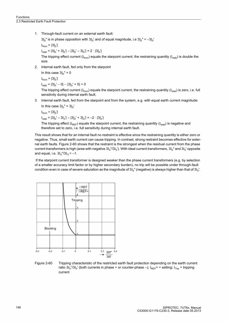
Functions
2.3 Restricted Earth Fault Protection
SIPROTEC, 7UT6x, ManualC53000-G1176-C230-3, Release date 05.2013
146
1. Through-fault current on an external earth fault:
3I0" is in phase opposition with 3I0' and of equal magnitude, i.e 3I0" = –3I0'
Ifrom = |3I0'|
Istab = |3I0' + 3I0'| – |3I0' – 3I0'| = 2 · |3I0'|
The tripping effect current (Ifrom) equals the starpoint current; the restraining quantity (Istab) is double the
size.
2. Internal earth fault, fed only from the starpoint
In this case 3I0" = 0
Ifrom = |3I0'|
Istab = |3I0' – 0| – |3I0' + 0| = 0
The tripping effect current (Ifrom) equals the starpoint current, the restraining quantity (Istab) is zero, i.e. full
sensitivity during internal earth fault.
3. Internal earth fault, fed from the starpoint and from the system, e.g. with equal earth current magnitude:
In this case 3I0" = 3I0'
Ifrom = |3I0'|
Istab = |3I0' – 3I0'| – |3I0' + 3I0'| = –2 · |3I0'|
The tripping effect (IREF) equals the starpoint current; the restraining quantity (Istab) is negative and
therefore set to zero, i.e. full sensitivity during internal earth fault.
This result shows that for an internal fault no restraint is effective since the restraining quantity is either zero or
negative. Thus, small earth current can cause tripping. In contrast, strong restraint becomes effective for exter-
nal earth faults. Figure 2-60 shows that the restraint is the strongest when the residual current from the phase
current transformers is high (area with negative 3I0"/3I0'). With ideal current transformers, 3I0" and 3I0' opposite
and equal, i.e. 3I0"/3I'0 = –1.
If the starpoint current transformer is designed weaker than the phase current transformers (e.g. by selection
of a smaller accuracy limit factor or by higher secondary burden), no trip will be possible under through-fault
condition even in case of severe saturation as the magnitude of 3I0" (negative) is always higher than that of 3I0'.
Figure 2-60 Tripping characteristic of the restricted earth fault protection depending on the earth current ratio 3I0”/3I0' (both currents in phase + or counter-phase –); IREF> = setting; ITrip = tripping
current

Functions
2.3 Restricted Earth Fault Protection
SIPROTEC, 7UT6x, ManualC53000-G1176-C230-3, Release date 05.2013
147
It was assumed in the above examples that the currents 3I0" and 3I0' are in counter-phase for external earth
faults which is only true for the primary measured quantities. Current transformer saturation may cause phase
shifting between the fundamental waves of the secondary currents which reduces the restraint quantity. If the
phase displacement ϕ(3I0"; 3I0') = 90° then the restraint quantity is zero. This corresponds to the conventional
method of direction determination by use of the vectorial sum and difference comparison.
Figure 2-61 Phasor diagram of the restraint quantity during internal fault
The restraint quantity can be influenced by means of a factor k. This factor has a certain relationship to the limit
angle ϕLimit.
This limit angle determines for which phase displacement between 3I0" and 3I0' the pickup value for 3I0" = 3I0'
grows to ∞, i.e. no pickup occurs. In 7UT6x k is equal to 4.
The restraint quantity Istab in the above example a) is quadrupled once more; it becomes thus 8 times the trip-
ping effect quantity Ifrom.
The limit angle is ϕLimit = 100°.This means, no tripping is possible anymore for a phase displacement
ϕ(3I0"; 3I0') ≥ 100°.
Figure 2-62 shows the operating characteristics of the restricted earth fault protection dependent of the phase
displacement between 3I0" and 3I0', for a constant infeed ratio |3I0"| = |3I0'|.
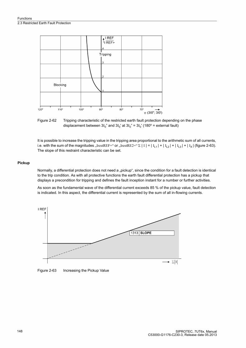
Functions
2.3 Restricted Earth Fault Protection
SIPROTEC, 7UT6x, ManualC53000-G1176-C230-3, Release date 05.2013
148
Figure 2-62 Tripping characteristic of the restricted earth fault protection depending on the phase
displacement between 3I0” and 3I0' at 3I0” = 3I0' (180o = external fault)
It is possible to increase the tripping value in the tripping area proportional to the arithmetic sum of all currents,
i.e. with the sum of the magnitudes „IrestREF=“ or „IrestRE2=“ Σ | I | = | IL1 | + | IL2 | + | IL3 | + | IX | (figure 2-63).
The slope of this restraint characteristic can be set.
Pickup
Normally, a differential protection does not need a „pickup“, since the condition for a fault detection is identical
to the trip condition. As with all protective functions the earth fault differential protection has a pickup that
displays a precondition for tripping and defines the fault inception instant for a number or further activities.
As soon as the fundamental wave of the differential current exceeds 85 % of the pickup value, fault detection
is indicated. In this aspect, the differential current is represented by the sum of all in-flowing currents.
Figure 2-63 Increasing the Pickup Value

Functions
2.3 Restricted Earth Fault Protection
SIPROTEC, 7UT6x, ManualC53000-G1176-C230-3, Release date 05.2013
149
Figure 2-64 Logic diagram of the earth fault protection (simplified)
2.3.3 Setting Notes
General
Note
The first restricted earth fault protection is described in the setting instructions. The parameter addresses and
message numbers of the second restricted earth fault protection are described at the end of the setting instruc-
tions under „Additional Restricted Earth Fault Protection Functions“.
The restricted earth fault protection can only operate if this function has been set during configuration of the
functional scope (section 2.1.4) under address 113 REF PROT. to Enabled. If the second restricted earth fault
protection is used, it also needs to be set at address 114REF PROT. 2Enabled. Furthermore, a further 1-phase
measured current input must be assigned to the same side or measuring location where the starpoint current
is to be processed (see section 2.1.4, margin heading „Assignment of Auxiliary 1-phase Measuring Locations“).
The restricted earth fault protection itself must have been assigned to this side or measuring location (see
section 2.1.4, margin heading „Earth Fault Differential Protection“).
The first restricted earth fault protection can be set at address 1301 REF PROT. to enabled (ON) or disabled
(OFF); when set to Block relay, the protection function operates but no trip command is issued. Block relay).
Note
When delivered from factory, the restricted earth fault protection is switched OFF. The reason is that the
protection must not be in operation unless at least the assigned side and CT polarity have been properly set
before. Without proper settings, the device may show unexpected reactions (incl. tripping)!
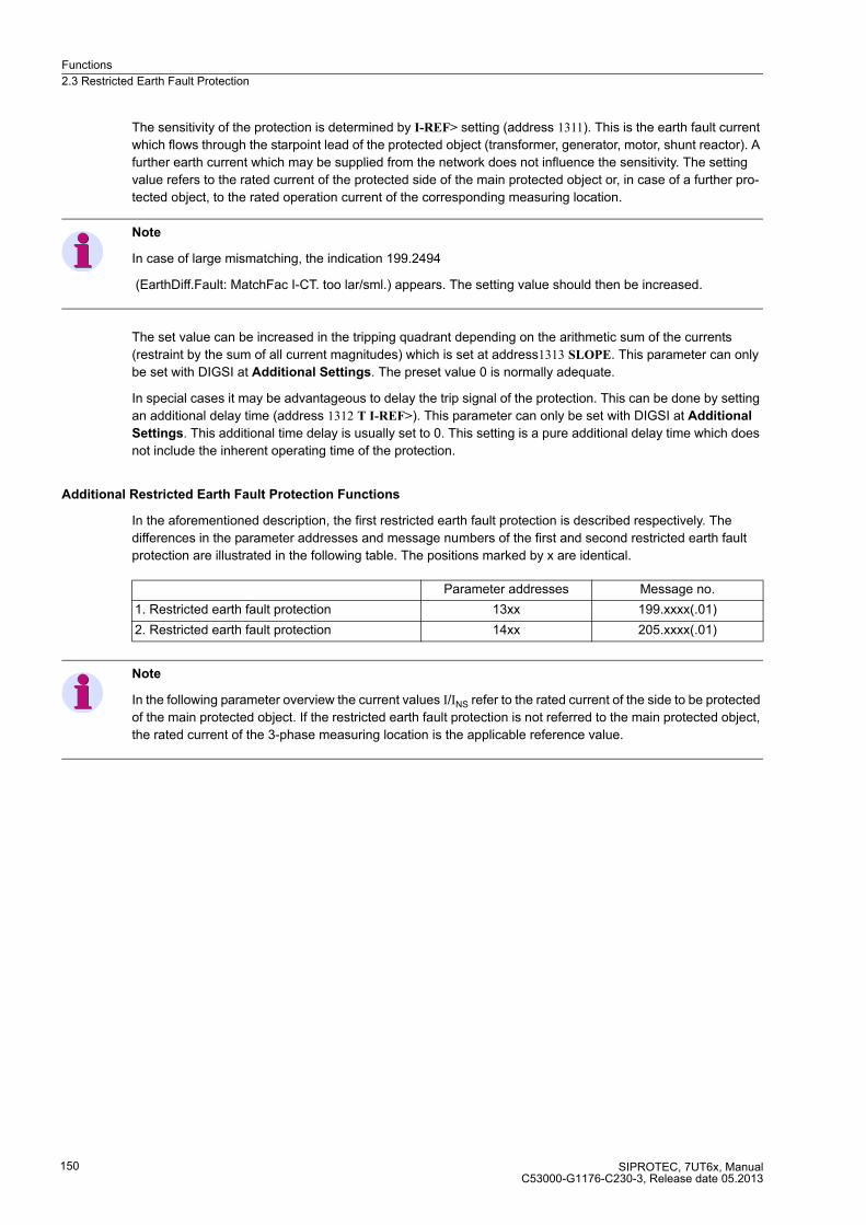
Functions
2.3 Restricted Earth Fault Protection
SIPROTEC, 7UT6x, ManualC53000-G1176-C230-3, Release date 05.2013
150
The sensitivity of the protection is determined by I-REF> setting (address 1311). This is the earth fault current
which flows through the starpoint lead of the protected object (transformer, generator, motor, shunt reactor). A
further earth current which may be supplied from the network does not influence the sensitivity. The setting
value refers to the rated current of the protected side of the main protected object or, in case of a further pro-
tected object, to the rated operation current of the corresponding measuring location.
Note
In case of large mismatching, the indication 199.2494
(EarthDiff.Fault: MatchFac I-CT. too lar/sml.) appears. The setting value should then be increased.
The set value can be increased in the tripping quadrant depending on the arithmetic sum of the currents
(restraint by the sum of all current magnitudes) which is set at address1313 SLOPE. This parameter can only
be set with DIGSI at Additional Settings. The preset value 0 is normally adequate.
In special cases it may be advantageous to delay the trip signal of the protection. This can be done by setting
an additional delay time (address 1312 T I-REF>). This parameter can only be set with DIGSI at Additional
Settings. This additional time delay is usually set to 0. This setting is a pure additional delay time which does
not include the inherent operating time of the protection.
Additional Restricted Earth Fault Protection Functions
In the aforementioned description, the first restricted earth fault protection is described respectively. The
differences in the parameter addresses and message numbers of the first and second restricted earth fault
protection are illustrated in the following table. The positions marked by x are identical.
Note
In the following parameter overview the current values I/INS refer to the rated current of the side to be protected
of the main protected object. If the restricted earth fault protection is not referred to the main protected object,
the rated current of the 3-phase measuring location is the applicable reference value.
Parameter addresses Message no.
1. Restricted earth fault protection 13xx 199.xxxx(.01)
2. Restricted earth fault protection 14xx 205.xxxx(.01)
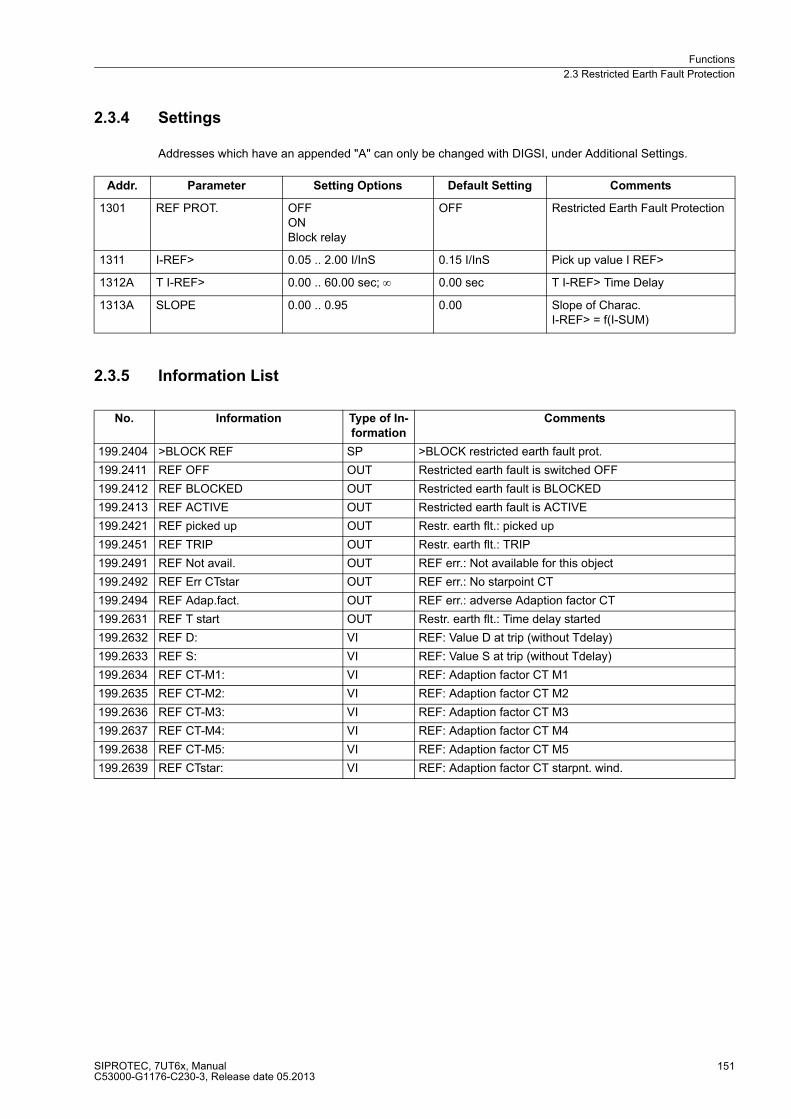
Functions
2.3 Restricted Earth Fault Protection
SIPROTEC, 7UT6x, ManualC53000-G1176-C230-3, Release date 05.2013
151
2.3.4 Settings
Addresses which have an appended "A" can only be changed with DIGSI, under Additional Settings.
2.3.5 Information List
Addr. Parameter Setting Options Default Setting Comments
1301 REF PROT. OFFONBlock relay
OFF Restricted Earth Fault Protection
1311 I-REF> 0.05 .. 2.00 I/InS 0.15 I/InS Pick up value I REF>
1312A T I-REF> 0.00 .. 60.00 sec; ∞ 0.00 sec T I-REF> Time Delay
1313A SLOPE 0.00 .. 0.95 0.00 Slope of Charac. I-REF> = f(I-SUM)
No. Information Type of In-
formation
Comments
199.2404 >BLOCK REF SP >BLOCK restricted earth fault prot.
199.2411 REF OFF OUT Restricted earth fault is switched OFF
199.2412 REF BLOCKED OUT Restricted earth fault is BLOCKED
199.2413 REF ACTIVE OUT Restricted earth fault is ACTIVE
199.2421 REF picked up OUT Restr. earth flt.: picked up
199.2451 REF TRIP OUT Restr. earth flt.: TRIP
199.2491 REF Not avail. OUT REF err.: Not available for this object
199.2492 REF Err CTstar OUT REF err.: No starpoint CT
199.2494 REF Adap.fact. OUT REF err.: adverse Adaption factor CT
199.2631 REF T start OUT Restr. earth flt.: Time delay started
199.2632 REF D: VI REF: Value D at trip (without Tdelay)
199.2633 REF S: VI REF: Value S at trip (without Tdelay)
199.2634 REF CT-M1: VI REF: Adaption factor CT M1
199.2635 REF CT-M2: VI REF: Adaption factor CT M2
199.2636 REF CT-M3: VI REF: Adaption factor CT M3
199.2637 REF CT-M4: VI REF: Adaption factor CT M4
199.2638 REF CT-M5: VI REF: Adaption factor CT M5
199.2639 REF CTstar: VI REF: Adaption factor CT starpnt. wind.
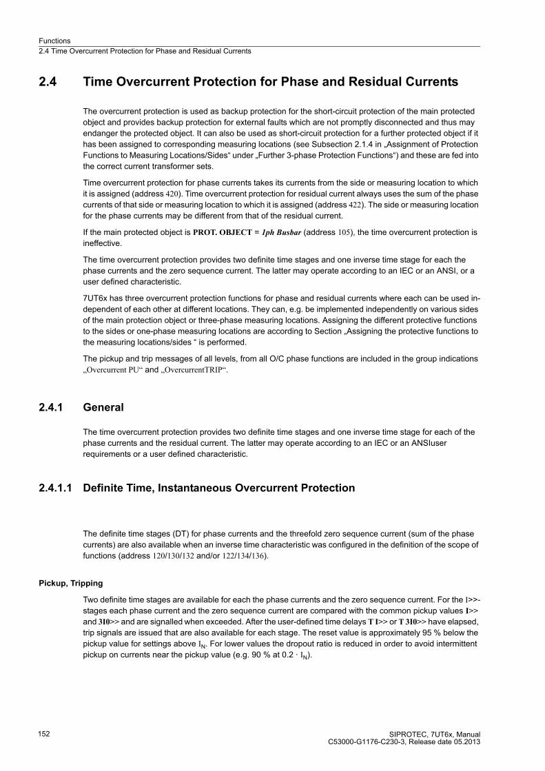
Functions
2.4 Time Overcurrent Protection for Phase and Residual Currents
SIPROTEC, 7UT6x, ManualC53000-G1176-C230-3, Release date 05.2013
152
2.4 Time Overcurrent Protection for Phase and Residual Currents
The overcurrent protection is used as backup protection for the short-circuit protection of the main protected
object and provides backup protection for external faults which are not promptly disconnected and thus may
endanger the protected object. It can also be used as short-circuit protection for a further protected object if it
has been assigned to corresponding measuring locations (see Subsection 2.1.4 in „Assignment of Protection
Functions to Measuring Locations/Sides“ under „Further 3-phase Protection Functions“) and these are fed into
the correct current transformer sets.
Time overcurrent protection for phase currents takes its currents from the side or measuring location to which
it is assigned (address 420). Time overcurrent protection for residual current always uses the sum of the phase
currents of that side or measuring location to which it is assigned (address 422). The side or measuring location
for the phase currents may be different from that of the residual current.
If the main protected object is PROT. OBJECT = 1ph Busbar (address 105), the time overcurrent protection is
ineffective.
The time overcurrent protection provides two definite time stages and one inverse time stage for each the
phase currents and the zero sequence current. The latter may operate according to an IEC or an ANSI, or a
user defined characteristic.
7UT6x has three overcurrent protection functions for phase and residual currents where each can be used in-
dependent of each other at different locations. They can, e.g. be implemented independently on various sides
of the main protection object or three-phase measuring locations. Assigning the different protective functions
to the sides or one-phase measuring locations are according to Section „Assigning the protective functions to
the measuring locations/sides “ is performed.
The pickup and trip messages of all levels, from all O/C phase functions are included in the group indications
„Overcurrent PU“ and „OvercurrentTRIP“.
2.4.1 General
The time overcurrent protection provides two definite time stages and one inverse time stage for each of the
phase currents and the residual current. The latter may operate according to an IEC or an ANSIuser
requirements or a user defined characteristic.
2.4.1.1 Definite Time, Instantaneous Overcurrent Protection
The definite time stages (DT) for phase currents and the threefold zero sequence current (sum of the phase
currents) are also available when an inverse time characteristic was configured in the definition of the scope of
functions (address 120/130/132 and/or 122/134/136).
Pickup, Tripping
Two definite time stages are available for each the phase currents and the zero sequence current. For the I>>-
stages each phase current and the zero sequence current are compared with the common pickup values I>>
and 3I0>> and are signalled when exceeded. After the user-defined time delays T I>> or T 3I0>> have elapsed,
trip signals are issued that are also available for each stage. The reset value is approximately 95 % below the
pickup value for settings above IN. For lower values the dropout ratio is reduced in order to avoid intermittent
pickup on currents near the pickup value (e.g. 90 % at 0.2 · IN).

Functions
2.4 Time Overcurrent Protection for Phase and Residual Currents
SIPROTEC, 7UT6x, ManualC53000-G1176-C230-3, Release date 05.2013
153
Figures 2-65 and 2-66 show the logic diagrams for the high-set stages I>> and 3I0>>.
Figure 2-65 Logic diagram of the high-set stages I>> for phase currents (simplified)
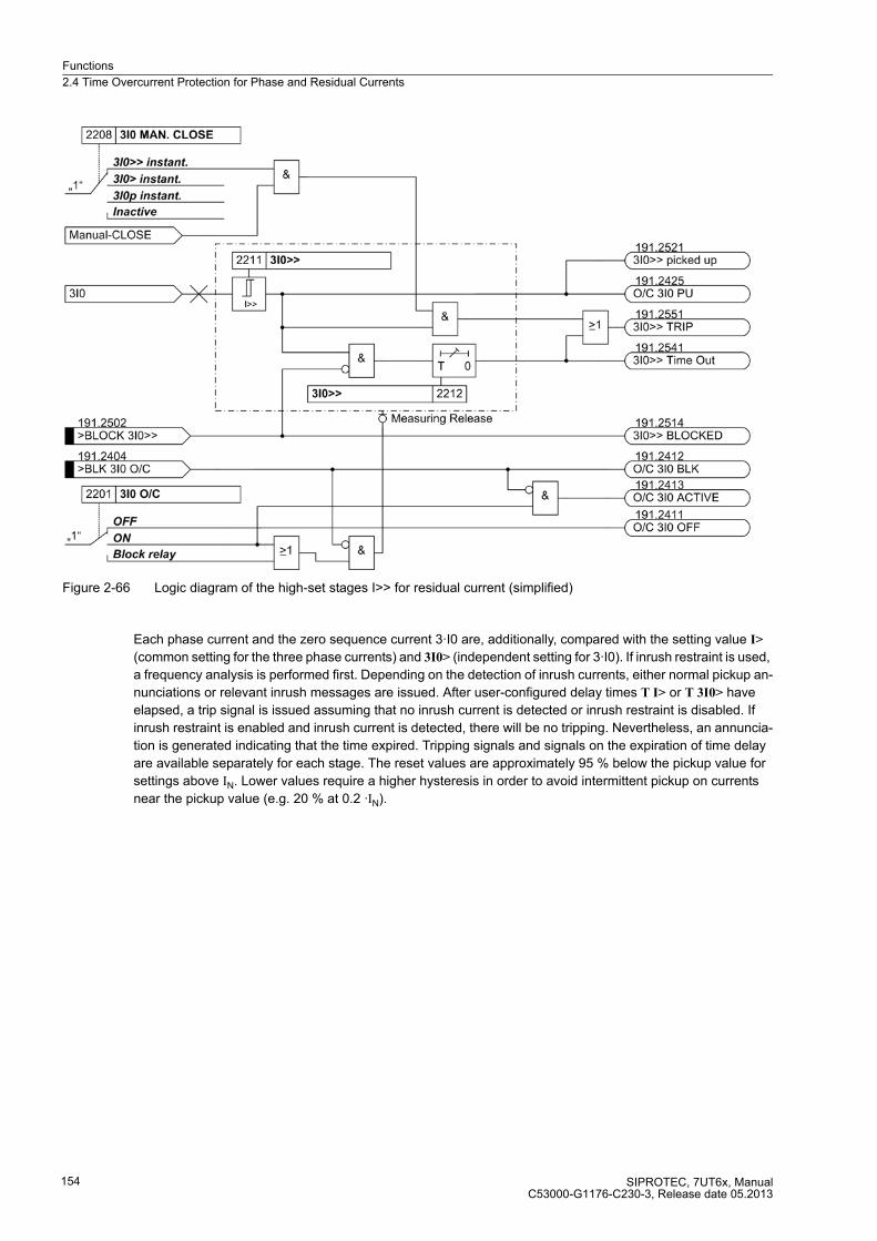
Functions
2.4 Time Overcurrent Protection for Phase and Residual Currents
SIPROTEC, 7UT6x, ManualC53000-G1176-C230-3, Release date 05.2013
154
Figure 2-66 Logic diagram of the high-set stages I>> for residual current (simplified)
Each phase current and the zero sequence current 3·I0 are, additionally, compared with the setting value I>
(common setting for the three phase currents) and 3I0> (independent setting for 3·I0). If inrush restraint is used,
a frequency analysis is performed first. Depending on the detection of inrush currents, either normal pickup an-
nunciations or relevant inrush messages are issued. After user-configured delay times T I> or T 3I0> have
elapsed, a trip signal is issued assuming that no inrush current is detected or inrush restraint is disabled. If
inrush restraint is enabled and inrush current is detected, there will be no tripping. Nevertheless, an annuncia-
tion is generated indicating that the time expired. Tripping signals and signals on the expiration of time delay
are available separately for each stage. The reset values are approximately 95 % below the pickup value for
settings above IN. Lower values require a higher hysteresis in order to avoid intermittent pickup on currents
near the pickup value (e.g. 20 % at 0.2 ·IN).
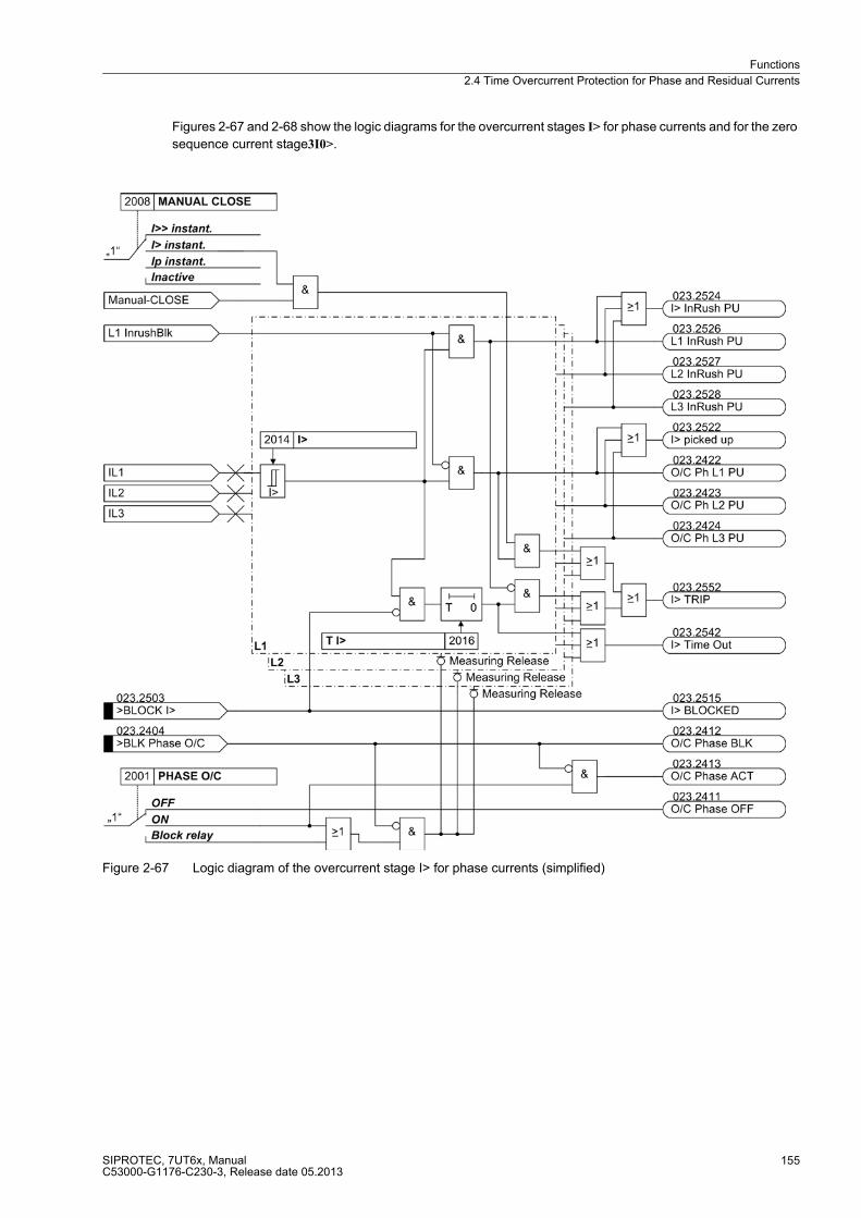
Functions
2.4 Time Overcurrent Protection for Phase and Residual Currents
SIPROTEC, 7UT6x, ManualC53000-G1176-C230-3, Release date 05.2013
155
Figures 2-67 and 2-68 show the logic diagrams for the overcurrent stages I> for phase currents and for the zero
sequence current stage3I0>.
Figure 2-67 Logic diagram of the overcurrent stage I> for phase currents (simplified)
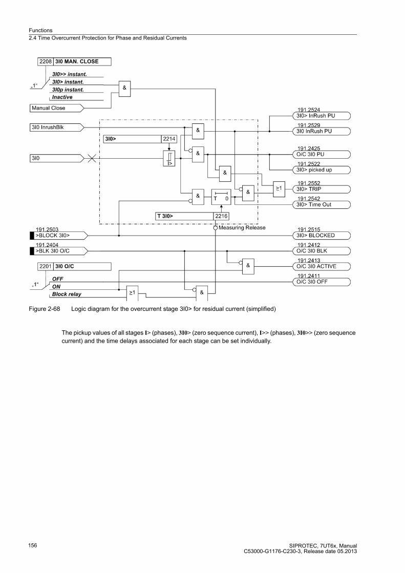
Functions
2.4 Time Overcurrent Protection for Phase and Residual Currents
SIPROTEC, 7UT6x, ManualC53000-G1176-C230-3, Release date 05.2013
156
Figure 2-68 Logic diagram for the overcurrent stage 3I0> for residual current (simplified)
The pickup values of all stages I> (phases), 3I0> (zero sequence current), I>> (phases), 3I0>> (zero sequence
current) and the time delays associated for each stage can be set individually.

Functions
2.4 Time Overcurrent Protection for Phase and Residual Currents
SIPROTEC, 7UT6x, ManualC53000-G1176-C230-3, Release date 05.2013
157
2.4.1.2 Inverse Time Overcurrent Protection
The inverse-time overcurrent protection stages always operate with a characteristic either according to the IEC
or the ANSI standards or according to a user-defined characteristic. The characteristics and their equations are
displayed in the Technical Data. When configuring one of the inverse time characteristics, definite time stages
I>> and I> are also enabled.
Pickup, Tripping
Each phase current and the zero sequence current (sum of phase currents) are compared individually to a
common setting value Ip or 3I0p. If a current exceeds the setting value by 1.1 times, the corresponding stage
picks up and is signalled selectively. If inrush restraint is used, a frequency analysis is performed first. Depend-
ing on the detection of inrush currents, either normal pickup annunciations or relevant inrush messages are
issued. For pickup, the RMS values of the fundamental harmonics are used. During the pickup of an Ipstage,
the tripping time is calculated from the flowing fault current by means of an integrating measuring procedure,
depending on the selected tripping characteristic. After expiration of this time period, a trip command is output
as long as no inrush current is detected or inrush restraint is disabled. If inrush restraint is enabled and inrush
current is detected, there will be no tripping. Nevertheless, an annunciation is generated indicating that the time
expired.
For the zero sequence current 3I0p the characteristic can be selected independently of the characteristic used
for the phase currents.
The pickup values of the stages Ip (phases) and 3I0p (zero sequence current) and the time multipliers valid for
each of these states can be set individually.

Functions
2.4 Time Overcurrent Protection for Phase and Residual Currents
SIPROTEC, 7UT6x, ManualC53000-G1176-C230-3, Release date 05.2013
158
Figures 2-69 and 2-70 show the logic diagrams of the inverse overcurrent time protection for phase currents Ip
and for the zero sequence currents 3I0p.
Figure 2-69 Logic diagram of the inverse overcurrent protection for phase currents — example of IEC characteristic (simplified)

Functions
2.4 Time Overcurrent Protection for Phase and Residual Currents
SIPROTEC, 7UT6x, ManualC53000-G1176-C230-3, Release date 05.2013
159
Figure 2-70 Logic diagram of the definite time overcurrent protection for zero sequence current — example of IEC characteristic (simplified)
Dropout
You can determine whether the dropout of a stage is to follow right after the threshold is undershot or whether
it is to be evoked by disk emulation. "Right after" means that the pickup drops out when approx. 95 % of the
set pickup value is undershot and in a new pickup the time counter starts at zero.
The disk emulation evokes a dropout process (time counter is decrementing) which begins after de-energiza-
tion and this process corresponds to the reset rotation of a Ferraris disk (explaining its denomination „disk em-
ulation“). In case several faults occur successively, it is ensured that due to the inertia of the Ferraris disk the
„history“ is taken into consideration and the time behaviour is adapted. Reset begins as soon as 90 % of the
setting value is undershot, in accordance with the dropout curve of the selected characteristic. In the range
between the dropout value (95 % of the pickup value) and 90 % of the setting value, the incrementing and the
decrementing processes are in idle state.
Disk emulation offers advantages when the grading coordination chart of the time overcurrent protection must
be coordinated with other devices in the system on an electro-mechanical or an induction base.

Functions
2.4 Time Overcurrent Protection for Phase and Residual Currents
SIPROTEC, 7UT6x, ManualC53000-G1176-C230-3, Release date 05.2013
160
User-Specified Curves
When user-defined curves are utilized, the tripping curve may be defined point by point. Up to 20 pairs of values
(current, time) may be entered. With these values the device approximates the characteristic by means of linear
interpolation.
If required, the dropout characteristic can also be defined. For the functional description see „Dropout“. If no
user-configurable dropout characteristic is desired, dropout is initiated when approx. 95 % of the pickup value
is undershot; when a new pickup is evoked, the timer starts again at zero.
2.4.1.3 Manual Close Command
When a circuit breaker is closed onto a faulted protective object, a high speed re-trip by the breaker is often
desired. The manual closing feature is designed to remove the delay from one of the time overcurrent stages
when the breaker is manually closed onto a fault. The time delay is then bypassed via an impulse from the
external control switch. This pulse is prolonged by at least 300 ms. To enable the device to react properly on
occurrence of a fault, address 2008A MANUAL CLOSE and/or address 2208A 3I0 MAN. CLOSE have to be
set accordingly. Thus, the user determines for both stages, the phase and the residual current stage, which
pickup value is active with which delay when the circuit breaker is closed manually.
Figure 2-71 Manual close processing (simplified)
Processing of the manual close command can be executed for each measuring location or side. Manual close
signal is also generated when an internal control command is given to a breaker which is assigned to the same
protection function as the time overcurrent protection, in the Power System Data 1 (Subsection 2.1.4).
Strict attention must be paid that the manual close condition is derived from that circuit breaker which feeds the
object that is protected by the time overcurrent protection! The breaker concerning the phase overcurrent pro-
tection may be different from that for the zero sequence overcurrent protection, dependent of the assignment
of these protection functions.
2.4.1.4 Dynamic Cold Load Pickup
With the dynamic cold load pickup feature, it is possible to dynamically increase the pickup values of the time
overcurrent protection stages when dynamic cold load overcurrent conditions are anticipated, i.e. when
consumers have increased power consumption after a longer period of dead condition, e.g. in air conditioning
systems, heating systems, motors, etc. By allowing pickup values and the associated time delays to increase
dynamically, it is not necessary to incorporate cold load capability in the normal settings.
This function of the dynamic cold load pickup conditions is common for all time overcurrent stages and is
explained in the section 2.6 „Dynamic Cold Load Pickup for Time Overcurrent Protection“. The alternative
pickup values themselves can be set for each of the stages of the time overcurrent protection.
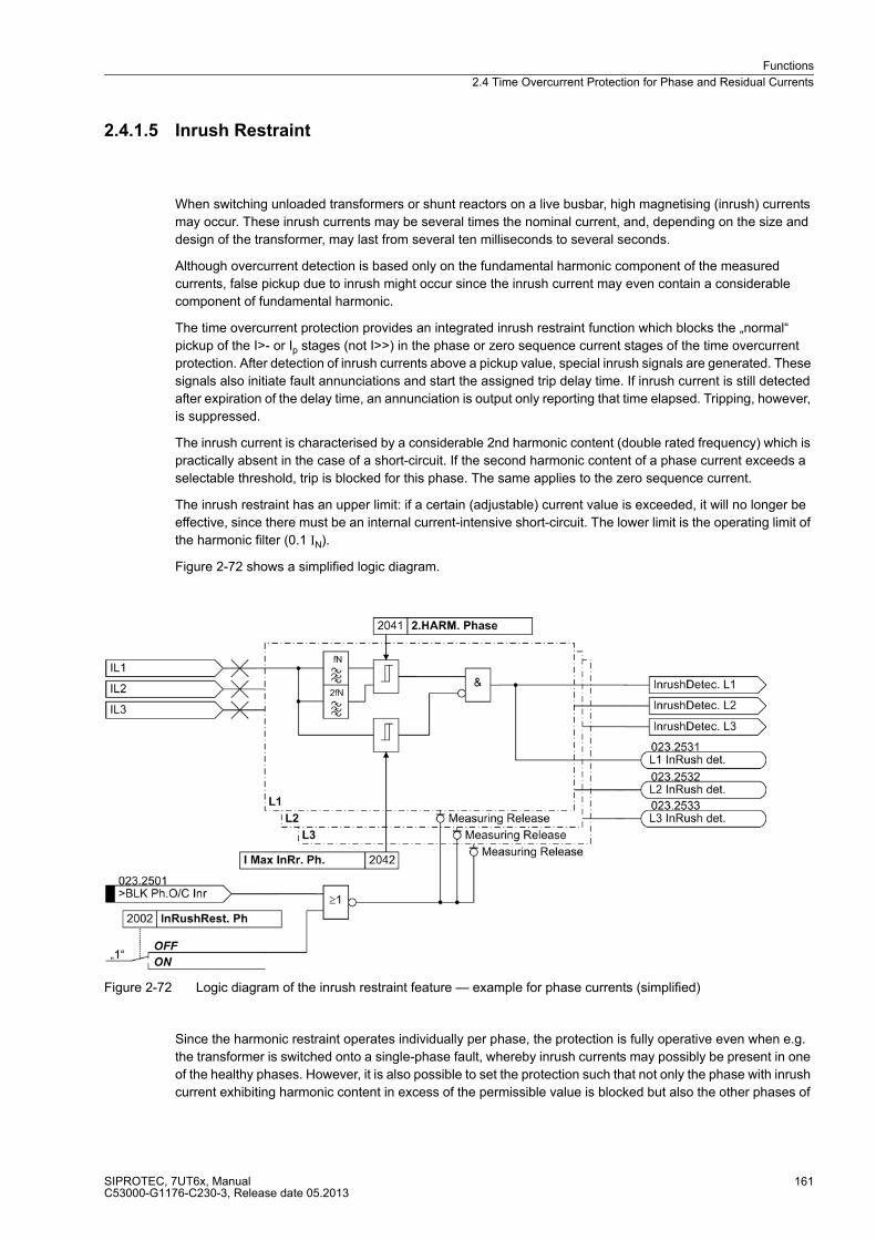
Functions
2.4 Time Overcurrent Protection for Phase and Residual Currents
SIPROTEC, 7UT6x, ManualC53000-G1176-C230-3, Release date 05.2013
161
2.4.1.5 Inrush Restraint
When switching unloaded transformers or shunt reactors on a live busbar, high magnetising (inrush) currents
may occur. These inrush currents may be several times the nominal current, and, depending on the size and
design of the transformer, may last from several ten milliseconds to several seconds.
Although overcurrent detection is based only on the fundamental harmonic component of the measured
currents, false pickup due to inrush might occur since the inrush current may even contain a considerable
component of fundamental harmonic.
The time overcurrent protection provides an integrated inrush restraint function which blocks the „normal“
pickup of the I>- or Ip stages (not I>>) in the phase or zero sequence current stages of the time overcurrent
protection. After detection of inrush currents above a pickup value, special inrush signals are generated. These
signals also initiate fault annunciations and start the assigned trip delay time. If inrush current is still detected
after expiration of the delay time, an annunciation is output only reporting that time elapsed. Tripping, however,
is suppressed.
The inrush current is characterised by a considerable 2nd harmonic content (double rated frequency) which is
practically absent in the case of a short-circuit. If the second harmonic content of a phase current exceeds a
selectable threshold, trip is blocked for this phase. The same applies to the zero sequence current.
The inrush restraint has an upper limit: if a certain (adjustable) current value is exceeded, it will no longer be
effective, since there must be an internal current-intensive short-circuit. The lower limit is the operating limit of
the harmonic filter (0.1 IN).
Figure 2-72 shows a simplified logic diagram.
Figure 2-72 Logic diagram of the inrush restraint feature — example for phase currents (simplified)
Since the harmonic restraint operates individually per phase, the protection is fully operative even when e.g.
the transformer is switched onto a single-phase fault, whereby inrush currents may possibly be present in one
of the healthy phases. However, it is also possible to set the protection such that not only the phase with inrush
current exhibiting harmonic content in excess of the permissible value is blocked but also the other phases of
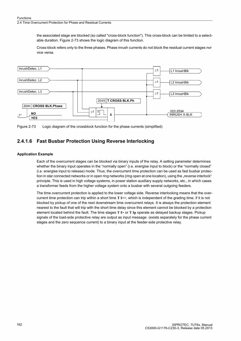
Functions
2.4 Time Overcurrent Protection for Phase and Residual Currents
SIPROTEC, 7UT6x, ManualC53000-G1176-C230-3, Release date 05.2013
162
the associated stage are blocked (so called "cross-block function"). This cross-block can be limited to a select-
able duration. Figure 2-73 shows the logic diagram of this function.
Cross-block refers only to the three phases. Phase inrush currents do not block the residual current stages nor
vice versa.
Figure 2-73 Logic diagram of the crossblock function for the phase currents (simplified)
2.4.1.6 Fast Busbar Protection Using Reverse Interlocking
Application Example
Each of the overcurrent stages can be blocked via binary inputs of the relay. A setting parameter determines
whether the binary input operates in the “normally open” (i.e. energise input to block) or the “normally closed”
(i.e. energise input to release) mode. Thus, the overcurrent time protection can be used as fast busbar protec-
tion in star connected networks or in open ring networks (ring open at one location), using the „reverse interlock“
principle. This is used in high voltage systems, in power station auxiliary supply networks, etc., in which cases
a transformer feeds from the higher voltage system onto a busbar with several outgoing feeders.
The time overcurrent protection is applied to the lower voltage side. Reverse interlocking means that the over-
current time protection can trip within a short time T I>>, which is independent of the grading time, if it is not
blocked by pickup of one of the next downstream time overcurrent relays. It is always the protection element
nearest to the fault that will trip with the short time delay since this element cannot be blocked by a protection
element located behind the fault. The time stages T I> or T Ip operate as delayed backup stages. Pickup
signals of the load-side protective relay are output as input message (exists separately for the phase current
stages and the zero sequence current) to a binary input at the feeder-side protective relay.
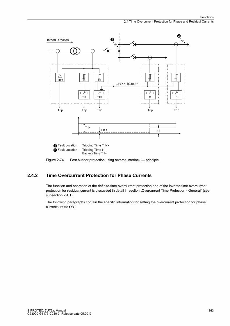
Functions
2.4 Time Overcurrent Protection for Phase and Residual Currents
SIPROTEC, 7UT6x, ManualC53000-G1176-C230-3, Release date 05.2013
163
Figure 2-74 Fast busbar protection using reverse interlock — principle
2.4.2 Time Overcurrent Protection for Phase Currents
The function and operation of the definite-time overcurrent protection and of the inverse-time overcurrent
protection for residual current is discussed in detail in section „Overcurrent Time Protection - General“ (see
subsection 2.4.1).
The following paragraphs contain the specific information for setting the overcurrent protection for phase
currents Phase O/C.

Functions
2.4 Time Overcurrent Protection for Phase and Residual Currents
SIPROTEC, 7UT6x, ManualC53000-G1176-C230-3, Release date 05.2013
164
2.4.2.1 Setting Notes
General
Note
The first overcurrent protection for phase currents is described in the setting instructions. The parameter
addresses and message numbers of the second and third overcurrent protection are described at the end of
the setting instructions under „Additional Overcurrent Protection Functions for Phase Currents“.
During configuration of the functional scope (section 2.1.3) the characteristic type is determined under address
120 DMT/IDMT Phase. Only the settings for the selected characteristic can be performed here. The definite
time stages I>> and I> are available in all cases.
If a second or third phase overcurrent protection is used, this must be configured accordingly in address 130
DMT/IDMT Phase2 and 132 DMT/IDMT Phase3.
Each protection function must be assigned to a side of the main protected object or another 3-phase current
measuring location. This can be carried out separately for each protection function (section 2.1.4 under margin
heading „Additional Three-phase Protection Functions“). Consider also the assignment of the measured
current inputs of the device against the measuring locations (current transformer sets) of the power plant
(section 2.1.4 under margin heading „Assignment of 3-phase Measuring Locations“).
Note
If the time overcurrent protection is assigned to a side of the main protected object, the current values are set
referred to the rated current of that side II/INS. In other cases, current values are set in amps.
At address 2001 PHASE O/C, phase overcurrent protection may be switched to ON or OFF. The option Block
relay allows to operate the protection but the trip output relay is blocked.
Address 2008 MANUAL CLOSE determines which phase current stage is to be activated instantaneously with
a detected manual close. Settings I>> instant. and I> instant. can be set independently from the selected type
characteristics;Ip instant. is only available if one of the inverse time stages is configured. This setting can only
be made with DIGSI under Additional Settings.
If time overcurrent protection is applied on the feeding side of a transformer, select the higher stage
I>>, which does not pick up by the inrush current or set the manual close feature to Inactive.
In address 2002 InRushRest. Ph inrush restraint (restraint with 2nd harmonic) is enabled or disabled for all
phase current stages of time overcurrent protection (except stage I>>). Set ON if one time overcurrent protec-
tion stage is to operate at the supply side of a transformer. Otherwise, retain setting OFF. If you intend to set a
very small pickup value for any reason, consider that the inrush restraint function cannot operate below 10 %
nominal current (lower limit of harmonic filtering).
Functions
2.4 Time Overcurrent Protection for Phase and Residual Currents
SIPROTEC, 7UT6x, ManualC53000-G1176-C230-3, Release date 05.2013
165
High-set Stages I>>
The I>> stage (address 2011 or 2212) combined with the I> stage or the Ip stage, results in a two-stage char-
acteristic. If one stage is not required, the pickup value has to be set to ∞. Stage I>> always operates with a
defined delay.
If time overcurrent protection is used on the supply side of a transformer, a series reactor, a motor or starpoint
of a generator, this stage can also be used for current grading. Setting instructs the device to pick up on faults
only inside the protected object but not for traversing fault currents.
Example:
Transformer used in the infeed of a bus supply with the following data:
Transformer YNd5
35 MVA
110 kV/20 kV
usc = 15 %
Current Transformer 200 A / 5 A on the 110 kV side
The time overcurrent protection is assigned to the 110 kV side (= feeding side).
The maximum possible three-phase fault current on the 20 kV side, assuming an impressed voltage source on
the 110 kV side, is:
Assuming a safety margin of 20 %, the following primary setting value results:
Setting value I>> = 1.2 · 1224.7 A = 1470 A
For settings with secondary values the currents will be converted for the secondary side of the current trans-
formers.
Secondary setting value:
i.e. for fault currents higher than 1470 A (primary) or 36.7 A (secondary) the fault is in all likelihood located in
the transformer zone. This fault may be cleared immediately by the overcurrent protection.
When setting in per-unit values, the rated current of the protected object (here equal to the rated current of the
side) is cancelled. Thus the formula gives:
With the same safety factor results:
Setting value I>> = 8 · IINS (rated current of the side).
Increased inrush currents, if their fundamental oscillation exceeds the setting value, are rendered harmless by
delay times (address 2013T I>>). The inrush restraint does not apply to the stages I>>.

Functions
2.4 Time Overcurrent Protection for Phase and Residual Currents
SIPROTEC, 7UT6x, ManualC53000-G1176-C230-3, Release date 05.2013
166
Using the principle of the „Reverse Interlocking“ the multi-stage function of the time overcurrent protection
offers its advantages: Stage I>> is used as a fast busbar protection with a short safety delay T I>> (e.g. 50
ms). Stage I>> is blocked for faults at the outgoing feeders. Stages I> or Ip serve as backup protection. The
pickup values of both elements (I> or Ip and I>>) are set equal. Delay time T I> or T Ip (IEC characteristic) or
D Ip (ANSI characteristic) is set in such manner that it overgrades the delay for the outgoing feeders.
If fault protection for motors is applied, it has to be ensured that the setting value I>> is smaller than the small-
est (two-pole) fault current and higher than the highest startup current. Since the maximum appearing startup
current is usually below 1.6x the rated startup current (event in unfavourable conditions), the following setting
is adequate for fault current stages I>>:
1.6 · Istartup < I>> < Ik 2pol
The potential increase in starting current caused by overvoltage conditions is already accounted for by the 1.6
factor. The I>> stage can trip instantaneously (T I>> = 0.00 s), since there is no saturation of shunt reactance
for motors, other than for transformers.
The set time T I>> is an additional delay time and does not include the operating time (measuring time, etc.).
The delay can be set to ∞. If set to infinity, the pickup of this function will be indicated but the stage will not trip
after pickup. If a pickup threshold is set to ∞, neither a pickup annunciation nor a trip is generated.
Definite Overcurrent Stages I>
The setting of the I> stage (address 2014 or 2015) is mainly determined by the maximum operating current. A
pickup caused by an overload must be excluded, as the device operates in this mode as fault protection with
correspondingly short tripping times and not as overload protection. For lines or busbars a rate of approx. 20
% above the maximum expected (over)load is set, for transformers and motors a rate of approx. 40 %.
The time delays to be set (address 2116 T I>) are derived from the coordination chart of the network.
The set times are purely additional time delays that do not include the operating time (measuring time, etc.).
The delay can be set to ∞. If set to infinity, the pickup of the corresponding function will be signaled but the
stage will not issue a trip command. If a pickup threshold is set to ∞, neither a pickup indication or a trip will be
triggered.
Overcurrent StagesIp with IEC characteristics
The inverse time stages, depending on the configuration („Functional Scope“, address 120 (see section
2.1.3.1), enables the user to select different characteristics.
With the IEC characteristics (address 120 DMT/IDMT Phase = TOC IEC) the following options are available at
address 2026 IEC CURVE:
� Normal Inverse (inverse, type A according to IEC 60255-3),
� Very Inverse (very inverse, type B according to IEC 60255-3),
� Extremely Inv. (extremely inverse, type C according to IEC 60255-3), and
� Long Inverse (longtime, type B according to IEC 60255-3).
The characteristics and the equations on which they are based, are listed in the „Technical Data“.
If the inverse time trip characteristic is selected, it must be noted that a safety factor of about 1.1 has already
been included between the pickup value and the setting value. This means that a pickup will only occur if a
current of about 1.1 times the setting value is present.

Functions
2.4 Time Overcurrent Protection for Phase and Residual Currents
SIPROTEC, 7UT6x, ManualC53000-G1176-C230-3, Release date 05.2013
167
The current value is set under address 2021 Ip or2022 Ip. The maximum operating current is of primary
importance for the setting. Pickup due to overload should never occur, since the device, in this modem,
operates as fault protection with correspondingly short tripping times and not as overload protection.
The corresponding time multiplier is accessible via address 2023 T Ip. It must be coordinated with the time
grading of the network.
The time multiplier can also be set to ∞. If set to infinity, the pickup of this function will be indicated but the stage
will not trip after pickup. If the p stage is not required at all, select address 120 DMT/IDMT Phase = Definite Time
when configuring the protection functions.
If under address 2225 TOC DROP-OUT the Disk Emulation are set, dropout is produced in accordance with the
dropout characteristic, as set out in the functional description of the inverse time overcurrent protection in
section „Dropout Behaviour“.
Inverse Time Overcurrent Stages Ip with ANSI Curves
The inverse time stage, depending on the configuration of the functional scope enables the user to select
different characteristics.
With the ANSI characteristics (address 120 DMT/IDMT Phase = TOC ANSI) the following is made available in
address 2027 ANSI CURVE:
� Definite Inv.,
� Extremely Inv.,
� Inverse,
� Long Inverse,
� Moderately Inv.,
� Short Inverse, and
� Very Inverse
The characteristics and the formulas on which they are based, are listed in the „Technical Data“.
If the inverse time trip characteristic is selected, it must be noted that a safety factor of about 1.1 has already
been included between the pickup value and the setting value. This means that a pickup will only occur if a
current of about 1.1 times of the setting value is present.
The current value is set under address 2021 Ip or 2022 Ip. The maximum operating current is of primary impor-
tance for the setting. Pickup due to overload should never occur, since the device, in this modem, operates as
fault protection with correspondingly short tripping times and not as overload protection.
The corresponding time multiplier is set at address 2024 D Ip. It must be coordinated with the time grading of
the network.
The time multiplier can also be set to ∞. If set to infinity, the pickup of this function will be indicated but the stage
will not trip after pickup. If the Ip stage is not required at all, select address 120 DMT/IDMT Phase = Definite
Time.
If disk emulation is set in address 2025 TOC DROP-OUT, dropout is produced according to the dropout
characteristic. For further information refer to section „Dropout Behaviour“ (see section 2.4.1, margin heading
„Dropout Behaviour“).

Functions
2.4 Time Overcurrent Protection for Phase and Residual Currents
SIPROTEC, 7UT6x, ManualC53000-G1176-C230-3, Release date 05.2013
168
Dynamic Cold Load Pickup
An alternative set of pickup values can be set for each stage. It may be selected automatically in a dynamic
manner during operation (see section 2.6).
For the stages the following alternative values are set:
� For definite time overcurrent protection (phases):
address 2111 or 2112 for pickup value I>>,
address 2113 for delay time T I>>,
address 2114 or 2115 for pickup value I>,
address 2116 for delay time T I>,
� For inverse time overcurrent protection (phases) acc. to IEC curves:
address 2121 or 2122 for pickup value Ip,
address 2123 for time multiplier T Ip;
� For inverse time overcurrent protection (phases) acc. to ANSI curves:
address 2121 or 2122 for pickup value Ip,
address 2124 for time multiplier D Ip;
User-defined Characteristics
For inverse time overcurrent protection the user may define his own tripping and dropout characteristic. For
configuration in DIGSI a dialogue box appears. Enter up to 20 pairs of current value and tripping time value.
The characteristics can also be viewed in DIGSI as an illustration.
Figure 2-75 Entry and visualisation of a user-specific trip characteristic with DIGSI - example
In order to be able to create a user-defined tripping characteristic, the following must be set during configuration
of the scope of functions in address120 DMT/IDMT Phase, option User Defined PU (see section 2.1.3.1). If you
also want to specify the dropout characteristic, set User def. Reset.
The value pairs refer to the setting values for current and time.
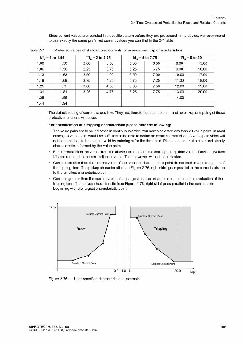
Functions
2.4 Time Overcurrent Protection for Phase and Residual Currents
SIPROTEC, 7UT6x, ManualC53000-G1176-C230-3, Release date 05.2013
169
Since current values are rounded in a specific pattern before they are processed in the device, we recommend
to use exactly the same preferred current values you can find in the 2-7 table.
Table 2-7 Preferred values of standardized currents for user-defined trip characteristics
The default setting of current values is ∞. They are, therefore, not enabled — and no pickup or tripping of these
protective functions will occur.
For specification of a tripping characteristic please note the following:
� The value pairs are to be indicated in continuous order. You may also enter less than 20 value pairs. In most
cases, 10 value pairs would be sufficient to be able to define an exact characteristic. A value pair which will
not be used, has to be made invalid by entering ∞ for the threshold! Please ensure that a clear and steady
characteristic is formed by the value pairs.
� For currents select the values from the above table and add the corresponding time values. Deviating values
I/Ip are rounded to the next adjacent value. This, however, will not be indicated.
� Currents smaller than the current value of the smallest characteristic point do not lead to a prolongation of
the tripping time. The pickup characteristic (see Figure 2-76, right side) goes parallel to the current axis, up
to the smallest characteristic point.
� Currents greater than the current value of the largest characteristic point do not lead to a reduction of the
tripping time. The pickup characteristic (see Figure 2-76, right side) goes parallel to the current axis,
beginning with the largest characteristic point.
Figure 2-76 User-specified characteristic — example
I/Ip = 1 to 1.94 I/Ip = 2 to 4.75 I/Ip = 5 to 7.75 I/Ip = 8 to 20
1.00 1.50 2.00 3.50 5.00 6.50 8.00 15.00
1.06 1.56 2.25 3.75 5.25 6.75 9.00 16.00
1.13 1.63 2.50 4.00 5.50 7.00 10.00 17.00
1.19 1.69 2.75 4.25 5.75 7.25 11.00 18.00
1.25 1.75 3.00 4.50 6.00 7.50 12.00 19.00
1.31 1.81 3.25 4.75 6.25 7.75 13.00 20.00
1.38 1.88 14.00
1.44 1.94

Functions
2.4 Time Overcurrent Protection for Phase and Residual Currents
SIPROTEC, 7UT6x, ManualC53000-G1176-C230-3, Release date 05.2013
170
For specification of a dropout characteristic please note the following:
� For currents select the values from table 2-8 and add the corresponding time values. Deviating values I/Ip
are rounded. This, however, will not be indicated.
� Currents greater than the current value of the largest characteristic point do not lead to a prolongation of the
dropout time. The dropout characteristic (see Figure 2-76, left side) goes parallel to the current axis, up to
the largest characteristic point.
� Currents smaller than the current value of the smallest characteristic point do not lead to a reduction of the
dropout time. The dropout characteristic (see Figure 2-76, left side) goes parallel to the current axis,
beginning with the smallest characteristic point.
� Currents smaller than 0.05 · times the setting value of currents lead to an immediate dropout.
Table 2-8 Preferred values of standard currents for user-defined dropout characteristics
Inrush Restraint
At address 2002 InRushRest. Ph of the general settings, the inrush restraint can be enabled (ON) or disabled
(OFF). Especially for transformers and if overcurrent time protection is used on the supply side, this inrush re-
straint is required. Function parameters of the inrush restraint are set in „Inrush“.
The inrush restraint is based on an evaluation of the 2nd harmonic present in the inrush current. The ratio of
2nd harmonics to the fundamental component 2.HARM. Phase (address 2041) is set to I2fN/IfN = 15 % as default
setting. It can be used without being changed. To provide more restraint in exceptional cases, where energising
conditions are particularly unfavourable, a smaller value can be set in the afore-mentioned address.
If the current exceeds the value indicated in address 2042 or 2043 I Max InRr. Ph., no restraint will be provoked
by the 2nd harmonic.
The inrush restraint can be extended by the so-called "crossblock" function. This means that on harmonic
content overshoot in only one phase, all three phases of the I> or p stage are blocked. At address 2044 CROSS
BLK.Phase the crossblock function is set to YES or to NO.
The time period for which the crossblock function is active after detection of inrushes is set in address 2045 T
CROSS BLK.Ph.
I/Ip = 1 to 0.86 I/Ip = 0.84 to 0.67 I/Ip = 0.66 to 0.38 I/Ip = 0.34 to 0.00
1.00 0.93 0.84 0.75 0.66 0.53 0.34 0.16
0.99 0.92 0.83 0.73 0.64 0.50 0.31 0.13
0.98 0.91 0.81 0.72 0.63 0.47 0.28 0.09
0.97 0.90 0.80 0.70 0.61 0.44 0.25 0.06
0.96 0.89 0.78 0.69 0.59 0.41 0.22 0.03
0.95 0.88 0.77 0.67 0.56 0.38 0.19 0.00
0.94 0.86
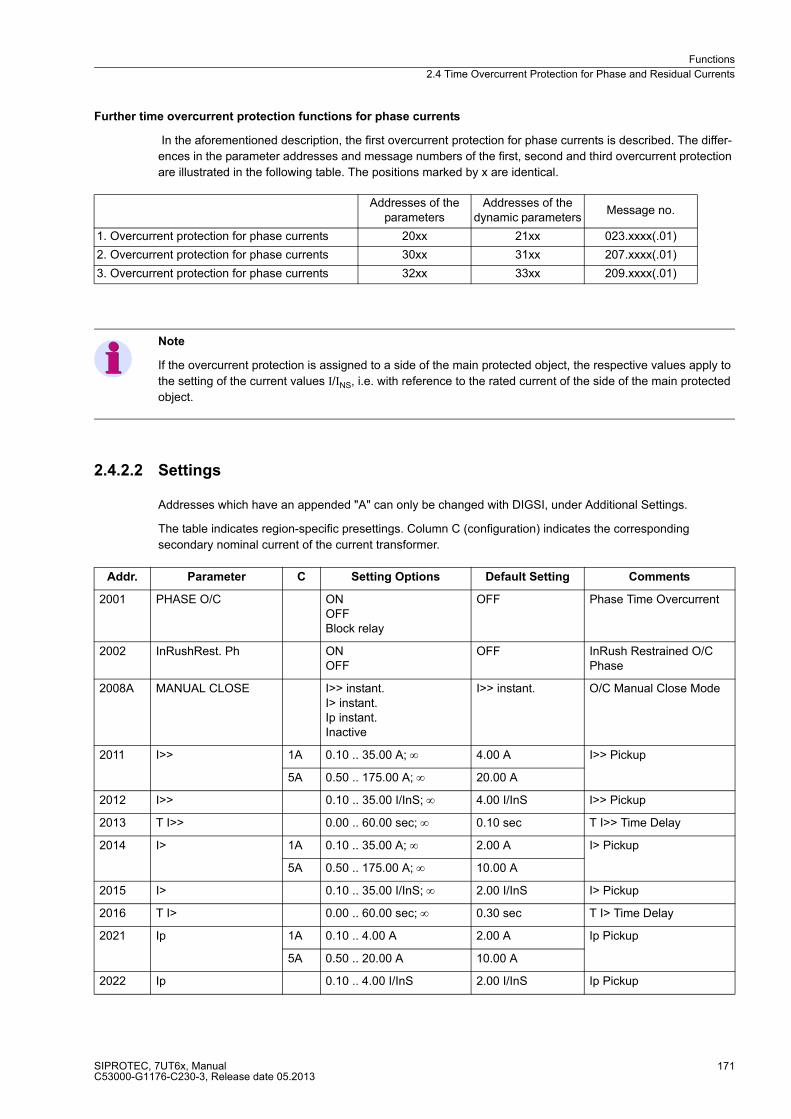
Functions
2.4 Time Overcurrent Protection for Phase and Residual Currents
SIPROTEC, 7UT6x, ManualC53000-G1176-C230-3, Release date 05.2013
171
Further time overcurrent protection functions for phase currents
In the aforementioned description, the first overcurrent protection for phase currents is described. The differ-
ences in the parameter addresses and message numbers of the first, second and third overcurrent protection
are illustrated in the following table. The positions marked by x are identical.
Note
If the overcurrent protection is assigned to a side of the main protected object, the respective values apply to
the setting of the current values I/INS, i.e. with reference to the rated current of the side of the main protected
object.
2.4.2.2 Settings
Addresses which have an appended "A" can only be changed with DIGSI, under Additional Settings.
The table indicates region-specific presettings. Column C (configuration) indicates the corresponding
secondary nominal current of the current transformer.
Addresses of theparameters
Addresses of the dynamic parameters
Message no.
1. Overcurrent protection for phase currents 20xx 21xx 023.xxxx(.01)
2. Overcurrent protection for phase currents 30xx 31xx 207.xxxx(.01)
3. Overcurrent protection for phase currents 32xx 33xx 209.xxxx(.01)
Addr. Parameter C Setting Options Default Setting Comments
2001 PHASE O/C ONOFFBlock relay
OFF Phase Time Overcurrent
2002 InRushRest. Ph ONOFF
OFF InRush Restrained O/C Phase
2008A MANUAL CLOSE I>> instant.I> instant.Ip instant.Inactive
I>> instant. O/C Manual Close Mode
2011 I>> 1A 0.10 .. 35.00 A; ∞ 4.00 A I>> Pickup
5A 0.50 .. 175.00 A; ∞ 20.00 A
2012 I>> 0.10 .. 35.00 I/InS; ∞ 4.00 I/InS I>> Pickup
2013 T I>> 0.00 .. 60.00 sec; ∞ 0.10 sec T I>> Time Delay
2014 I> 1A 0.10 .. 35.00 A; ∞ 2.00 A I> Pickup
5A 0.50 .. 175.00 A; ∞ 10.00 A
2015 I> 0.10 .. 35.00 I/InS; ∞ 2.00 I/InS I> Pickup
2016 T I> 0.00 .. 60.00 sec; ∞ 0.30 sec T I> Time Delay
2021 Ip 1A 0.10 .. 4.00 A 2.00 A Ip Pickup
5A 0.50 .. 20.00 A 10.00 A
2022 Ip 0.10 .. 4.00 I/InS 2.00 I/InS Ip Pickup

Functions
2.4 Time Overcurrent Protection for Phase and Residual Currents
SIPROTEC, 7UT6x, ManualC53000-G1176-C230-3, Release date 05.2013
172
2023 T Ip 0.05 .. 3.20 sec; ∞ 0.50 sec T Ip Time Dial
2024 D Ip 0.50 .. 15.00 ; ∞ 5.00 D Ip Time Dial
2025 TOC DROP-OUT InstantaneousDisk Emulation
Disk Emulation TOC Drop-out characteristic
2026 IEC CURVE Normal InverseVery InverseExtremely Inv.Long Inverse
Normal Inverse IEC Curve
2027 ANSI CURVE Very InverseInverseShort InverseLong InverseModerately Inv.Extremely Inv.Definite Inv.
Very Inverse ANSI Curve
2031 I/Ip PU T/Tp 1.00 .. 20.00 I/Ip; ∞0.01 .. 999.00 TD
Pickup Curve I/Ip - TI/TIp
2032 MofPU Res T/Tp 0.05 .. 0.95 I/Ip; ∞0.01 .. 999.00 TD
Multiple of Pickup <-> TI/TIp
2041 2.HARM. Phase 10 .. 45 % 15 % 2nd harmonic O/C Ph. in % of fundamental
2042 I Max InRr. Ph. 1A 0.30 .. 25.00 A 7.50 A Maximum Current for Inr. Rest. O/C Phase
5A 1.50 .. 125.00 A 37.50 A
2043 I Max InRr. Ph. 0.30 .. 25.00 I/InS 7.50 I/InS Maximum Current for Inr. Rest. O/C Phase
2044 CROSS BLK.Phase NOYES
NO CROSS BLOCK O/C Phase
2045 T CROSS BLK.Ph 0.00 .. 180.00 sec 0.00 sec CROSS BLOCK Time O/C Phase
2111 I>> 1A 0.10 .. 35.00 A; ∞ 10.00 A I>> Pickup
5A 0.50 .. 175.00 A; ∞ 50.00 A
2112 I>> 0.10 .. 35.00 I/InS; ∞ 10.00 I/InS I>> Pickup
2113 T I>> 0.00 .. 60.00 sec; ∞ 0.10 sec T I>> Time Delay
2114 I> 1A 0.10 .. 35.00 A; ∞ 4.00 A I> Pickup
5A 0.50 .. 175.00 A; ∞ 20.00 A
2115 I> 0.10 .. 35.00 I/InS; ∞ 4.00 I/InS I> Pickup
2116 T I> 0.00 .. 60.00 sec; ∞ 0.30 sec T I> Time Delay
2121 Ip 1A 0.10 .. 4.00 A 4.00 A Ip Pickup
5A 0.50 .. 20.00 A 20.00 A
2122 Ip 0.10 .. 4.00 I/InS 4.00 I/InS Ip Pickup
2123 T Ip 0.05 .. 3.20 sec; ∞ 0.50 sec T Ip Time Dial
2124 D Ip 0.50 .. 15.00 ; ∞ 5.00 D Ip Time Dial
Addr. Parameter C Setting Options Default Setting Comments
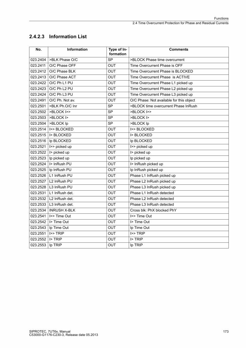
Functions
2.4 Time Overcurrent Protection for Phase and Residual Currents
SIPROTEC, 7UT6x, ManualC53000-G1176-C230-3, Release date 05.2013
173
2.4.2.3 Information List
No. Information Type of In-
formation
Comments
023.2404 >BLK Phase O/C SP >BLOCK Phase time overcurrent
023.2411 O/C Phase OFF OUT Time Overcurrent Phase is OFF
023.2412 O/C Phase BLK OUT Time Overcurrent Phase is BLOCKED
023.2413 O/C Phase ACT OUT Time Overcurrent Phase is ACTIVE
023.2422 O/C Ph L1 PU OUT Time Overcurrent Phase L1 picked up
023.2423 O/C Ph L2 PU OUT Time Overcurrent Phase L2 picked up
023.2424 O/C Ph L3 PU OUT Time Overcurrent Phase L3 picked up
023.2491 O/C Ph. Not av. OUT O/C Phase: Not available for this object
023.2501 >BLK Ph.O/C Inr SP >BLOCK time overcurrent Phase InRush
023.2502 >BLOCK I>> SP >BLOCK I>>
023.2503 >BLOCK I> SP >BLOCK I>
023.2504 >BLOCK Ip SP >BLOCK Ip
023.2514 I>> BLOCKED OUT I>> BLOCKED
023.2515 I> BLOCKED OUT I> BLOCKED
023.2516 Ip BLOCKED OUT Ip BLOCKED
023.2521 I>> picked up OUT I>> picked up
023.2522 I> picked up OUT I> picked up
023.2523 Ip picked up OUT Ip picked up
023.2524 I> InRush PU OUT I> InRush picked up
023.2525 Ip InRush PU OUT Ip InRush picked up
023.2526 L1 InRush PU OUT Phase L1 InRush picked up
023.2527 L2 InRush PU OUT Phase L2 InRush picked up
023.2528 L3 InRush PU OUT Phase L3 InRush picked up
023.2531 L1 InRush det. OUT Phase L1 InRush detected
023.2532 L2 InRush det. OUT Phase L2 InRush detected
023.2533 L3 InRush det. OUT Phase L3 InRush detected
023.2534 INRUSH X-BLK OUT Cross blk: PhX blocked PhY
023.2541 I>> Time Out OUT I>> Time Out
023.2542 I> Time Out OUT I> Time Out
023.2543 Ip Time Out OUT Ip Time Out
023.2551 I>> TRIP OUT I>> TRIP
023.2552 I> TRIP OUT I> TRIP
023.2553 Ip TRIP OUT Ip TRIP
Functions
2.4 Time Overcurrent Protection for Phase and Residual Currents
SIPROTEC, 7UT6x, ManualC53000-G1176-C230-3, Release date 05.2013
174
2.4.3 Time Overcurrent Protection for Residual Current
The function and operation of the definite-time overcurrent protection and of the inverse-time overcurrent
protection for residual current is discussed in detail in the section „Time Overcurrent Protection - General“
above (see subsection 2.4.1). The following paragraphs contain the specific information for setting the
overcurrent protection for residual current 3I0 O/C.
2.4.3.1 Setting Notes
General
Note
The first time overcurrent protection for residual current is described in the setting instructions. The parameter
addresses and message numbers of the second and third time overcurrent protection are described at the end
of the setting instructions under „Additional Time Overcurrent Protection Functions for Residual Current“.
During configuration of the functional scope (section 2.1.3) the characteristic type for the residual current
stages is determined under address 122 DMT/IDMT 3I0. Only the settings for the characteristic selected can
be performed here. The definite time stages 3I0>> and 3I0> are available in all cases.
If a second or third residual overcurrent protection is used, this must be configured accordingly in addresses
134 DMT/IDMT 3I0 2 and 136 DMT/IDMT 3I0 3.
Each protection function must be assigned to a side of the main protected object or another 3-phase current
measuring location. This can be carried out separately from the phase overcurrent protection (section 2.1.4
under margin heading „Additional Three-phase Protection Functions“). Consider also the assignment of the
measured current inputs of the device against the measuring locations (current transformer sets) of the power
plant (section 2.1.4 under margin heading „Assignment of 3-phase Measuring Locations“).
Note
Note: If the time overcurrent protection is assigned to a side of the main protected object, the current values
are set referred to the rated current of that side II/INS. In other cases, current values are set in amps.
In address 2201 3I0 O/C, the time overcurrent protection for residual current can be set to ON or OFF. The
option Block relay allows to operate the protection but the trip output relay is blocked.
Address 2208A 3I0 MAN. CLOSE determines which of the zero sequence current stages must be activated in-
stantaneously with a detected manual close. Settings 3I0>> instant. and 3I0> instant. can be set independently
from the selected type characteristics; 3I0p instant. is only possible if one of the inverse time stages has been
configured. The stabilisation does not affect 3I0>>. This parameter can only be set with DIGSI at Additional
Settings. For this setting, similar considerations apply as for the phase current stages.
In address 2202 InRushRest. 3I0 inrush restraint (inrush restraint with 2nd harmonic) is enabled or disabled. Set
ON if the residual current stage of the time overcurrent protection is applied at the supply side of a transformer
whose starpoint is earthed. Otherwise, retain setting OFF. If you set a very small pickup value, consider that
the inrush restraint function cannot operate below 10 % nominal current (lower limit of harmonic filtering).
Functions
2.4 Time Overcurrent Protection for Phase and Residual Currents
SIPROTEC, 7UT6x, ManualC53000-G1176-C230-3, Release date 05.2013
175
High Set Current Stage 3I0>>
If stage 3I0>> (address 2211 or 2212) is combined with the 3I0> stage or the 3I0p stage, a two-stage
characteristic will be the result. If one stage is not required, the pickup value has to be set to ∞. Stage 3I0>>
always operates with a defined delay.
If the protected winding is not earthed, zero sequence current only emerges due to an inner earth fault or
double earth fault with one inner base point. Here, the 3I0>> stage is usually not required.
The 3I0>> stage can, for example, be applied for current grading. Please note that the zero sequence system
of currents is of importance. For transformers with separate windings, zero sequence systems are usually kept
separate (exception: bilateral starpoint earthing or earthed auto-transformer).
Inrush currents can only be created in zero sequence systems if the starpoint of the respective winding is
earthed. If the fundamental exceeds the setting value, the inrush currents are rendered harmless by delay times
(address 2213 T 3I0>>).
„Reverse Interlocking“ is only sensible if the respective winding is earthed. In that case, the multi-stage function
of the time overcurrent protection is beneficial: For example, stage 3I0>> is used as fast busbar protection with
a short safety delay T 3I0>> (e.g. 50 ms). Stage 3I0>> is blocked for faults at the outgoing feeders. Stages 3I0>
or 3I0p serve as backup protection. The pickup values of both elements (3I0> or 3I0p and 3I0>>) are set equal.
Delay time T 3I0> or T 3I0p (IEC characteristic) or D 3I0p (ANSI characteristic) is set in such manner that it
overgrades the delay for the outgoing feeders. Here, the grading coordination chart for earth faults, which
mostly allows shorter setting times, is of primary importance.
The set time T 3I0>>is an additional delay time and does not include the operating time (measuring time, etc.).
The delay can be set to ∞. If set to infinity, the pickup of this function will be indicated but the stage will not trip
after pickup. If the pickup threshold is set to ∞, neither a pickup annunciation nor a trip is generated.
Definite Time Overcurrent Stage 3I0>
The minimum appearing earth fault current is relevant for the setting of the time overcurrent stage 3I0>
(address 2214 or 2215). Please note that, in case of various measuring locations, higher measuring tolerance
may occur due to summation errors.
The time delay to be set (parameter 2216 T 3I0>) is derived from the grading coordination chart created for the
network. For earth currents with earthed network, a separate grading coordination chart with shorter delay
times can be set up. If you set a very small pickup value, it must be taken into consideration that the inrush
restraint function cannot operate below 10 % nominal current (lower limit of harmonic filtering). An adequate
time delay could be reasonable if inrush restraint is used.
The set time is an additional delay time and does not include the operating time (measuring time, etc.). The
delay can also be set to ∞. If set to infinity, the pickup of this function will be indicated but the stage will not trip
after pickup. If the pickup threshold is set to ∞, neither a pickup annunciation nor a trip is generated.
Functions
2.4 Time Overcurrent Protection for Phase and Residual Currents
SIPROTEC, 7UT6x, ManualC53000-G1176-C230-3, Release date 05.2013
176
Inverse Time Overcurrent Stage3I0p with IEC Characteristics
The inverse time stage, depending on the configuration of the functional scope, address 122 (see 2.1.3.1),
enables the user to select different characteristics.
With the IEC characteristics (address 122 DMT/IDMT 3I0 = TOC IEC) the following options are available at
address 2226 IEC CURVE:
� Normal Inverse (inverse, type A according to IEC 60255-3),
� Very Inverse (very inverse, type B according to IEC 60255-3),
� Extremely Inv. (extremely inverse, type C according to IEC 60255-3), and
� Long Inverse (longtime, type B according to IEC 60255-3).
The characteristics and the equations on which they are based, are listed in the „Technical Data“.
If the inverse time trip characteristic is selected, it must be noted that a safety factor of about 1.1 has already
been included between the pickup value and the setting value. This means that a pickup will only occur if a
current of about 1.1 times the setting value is present.
The current value is set under address 2221 or 2222 3I0p. The most relevant for this setting is the minimum
appearing earth fault current. Please note that, in case of various measuring locations, higher measuring
tolerance may occur due to summation errors.
The corresponding time multiplier is accessible via address 2223 T 3I0p. This has to be coordinated with the
grading coordination chart of the network. For earth currents with earthed network, you can mostly set up a
separate grading coordination chart with shorter delay times. If you set a very small pickup value, consider that
the inrush restraint function cannot operate below 10 % nominal current (lower limit of harmonic filtering). An
adequate time delay could be reasonable if inrush restraint is used.
The time multiplier can also be set to ∞. If set to infinity, the pickup of this function will be indicated but the stage
will not trip after pickup. If the Ip stage is not required at all, select address 122 DMT/IDMT 3I0 = Definite Time
when configuring the protection functions.
If under address 2225 TOC DROP-OUT the Disk Emulation is set, dropout is produced according to the dropout
characteristic, as described in subsection „Dropout Behaviour“.
Inverse Time Overcurrent Stage 3I0p with ANSI Characteristics
The inverse time stage, depending on the configuration of the functional scope, address 122 (see 2.1.3.1),
enables the user to select different characteristics.
With the ANSI characteristics (address 122 DMT/IDMT 3I0 = TOC ANSI) the following is made available in
address 2227 ANSI CURVE:
� Definite Inv.,
� Extremely Inv.,
� Inverse,
� Long Inverse,
� Moderately Inv.,
� Short Inverse, and
� Very Inverse.
The characteristics and the formulas on which they are based, are listed in the „Technical Data“.
If the inverse time trip characteristic is selected, please note that a safety factor of about 1.1 has already been
included between the pickup value and the setting value. This means that a pickup will only occur if a current
of about 1.1 times the setting value is present.
The current value is set in address 2221 or 2222 3I0p. The most relevant for this setting is the minimum appear-
ing earth fault current. Please consider that measuring tolerances may be higher with multiple measuring loca-
tions due to summation errors.
Functions
2.4 Time Overcurrent Protection for Phase and Residual Currents
SIPROTEC, 7UT6x, ManualC53000-G1176-C230-3, Release date 05.2013
177
The corresponding time multiplier is set in address 2224 D 3I0p. This has to be coordinated with the grading
coordination chart of the network. For earth currents with earthed network, you can mostly set up a separate
grading coordination chart with shorter delay times.
If you set a very small pickup value, consider that the inrush restraint function cannot operate below 10 %
nominal current (lower limit of harmonic filtering). An adequate time delay could be reasonable if inrush restraint
is used.
The time multiplier can also be set to ∞. If set to infinity, the pickup of this function will be indicated but the stage
will not trip after pickup. If the 3I0p stage is not required at all, select address 122 DMT/IDMT 3I0 = Definite
Time during configuration of the protection function.
If under address 2225 TOC DROP-OUT the Disk Emulation is set, a dropout in accordance with the dropout
characteristic occurs, as described in section „Dropout Behaviour“
Dynamic Cold Load Pickup
An alternative set of pickup values can be set for each stage. It may be selected automatically in a dynamic
manner during operation. The following alternative values are set for the stages here (section 2.6).
for definite time overcurrent protection 3I0:
� address 2311 or 2312 for pickup value 3I0>>,
� address 2313 for delay time T 3I0>>,
� address 2314 or 2315 for pickup value 3I0>,
� address 2316 for delay time T 3I0>,
for inverse time overcurrent protection 3I0 acc. to IEC characteristics:
� address 2321 or 2322 for pickup value 3I0p,
� address 2323 for time multiplier T 3I0p;
for inverse time overcurrent protection 3I0 acc. to ANSI characteristics:
� address 2321 or 2322 for pickup value 3I0p,
� address 2324 for time multiplier D 3I0p;
User-Defined Curves
For inverse time overcurrent protection the user may define his own tripping and dropout characteristic. For
configuration in DIGSI a dialogue box appears. Enter up to 20 pairs of current and tripping time values.
The procedure is the same as for „Phase Current Stages“ under „User-specific Characteristics“ (see section
2.4.2.1).
To create a user defined tripping characteristic, the following must have been set for configuration of the scope
of functions: address 122 DMT/IDMT 3I0 the option User Defined PU. Should you also wish to specify the
dropout characteristic, select option User def. Reset.
Functions
2.4 Time Overcurrent Protection for Phase and Residual Currents
SIPROTEC, 7UT6x, ManualC53000-G1176-C230-3, Release date 05.2013
178
Inrush Restraint
At address 2202 InRushRest. 3I0 of the general settings, the inrush restraint can be enabled (ON) or disabled
(OFF). Especially for transformers and if overcurrent time protection is activated on the earthed supply side,
this inrush restraint is required. Function parameters of the inrush restraint are set in „Inrush“.
The inrush restraint is based on the evaluation of the 2nd harmonic present in the inrush current. The ratio of
2nd harmonics to the fundamental component 2.HARM. 3I0 (address 2241) is set to I2fN/IfN = 15 % as default
setting. It can be used without being changed. To provide more restraint in exceptional cases, where energising
conditions are particularly unfavourable, a smaller value can be set in the above-mentioned address.
If the current exceeds the value indicated in address 2242 or 2243 I Max InRr. 3I0, no restraint will be provoked
by the 2nd harmonic.
Additional Time Overcurrent Protection Functions for Residual Current
In the aforementioned description, the first overcurrent protection for zero sequence current is described. The
differences in the parameter addresses and message numbers of the first, second and third overcurrent pro-
tection are illustrated in the following table. The positions marked by x are identical.
Note
If the time overcurrent protection is assigned to a side of the main protected object, the current values are set
referred to the rated current of that side II/INS.
Addresses of theparameters
Addresses of the dynamic parameters
Message no.
1st time overcurrent protection for residual current
22xx 23xx 191.xxxx(.01)
2nd time overcurrent protection for residual current
34xx 35xx 321.xxxx(.01)
3rd time overcurrent protection for residual current
36xx 37xx 323.xxxx(.01)
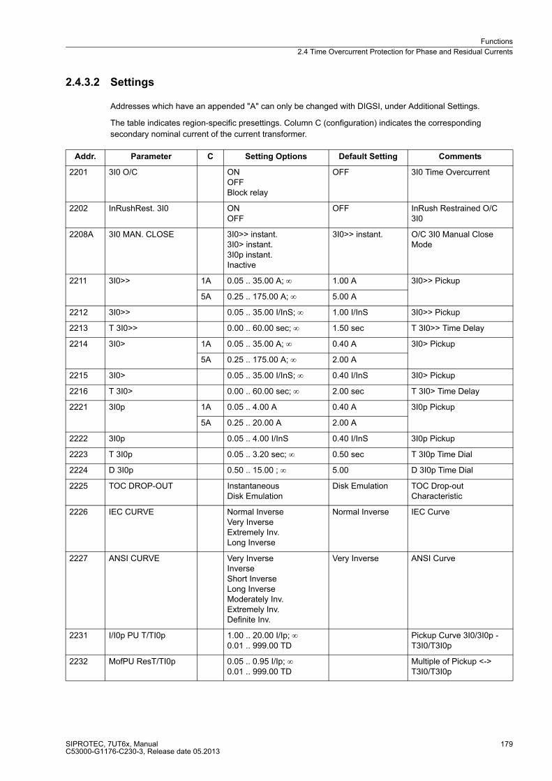
Functions
2.4 Time Overcurrent Protection for Phase and Residual Currents
SIPROTEC, 7UT6x, ManualC53000-G1176-C230-3, Release date 05.2013
179
2.4.3.2 Settings
Addresses which have an appended "A" can only be changed with DIGSI, under Additional Settings.
The table indicates region-specific presettings. Column C (configuration) indicates the corresponding
secondary nominal current of the current transformer.
Addr. Parameter C Setting Options Default Setting Comments
2201 3I0 O/C ONOFFBlock relay
OFF 3I0 Time Overcurrent
2202 InRushRest. 3I0 ONOFF
OFF InRush Restrained O/C 3I0
2208A 3I0 MAN. CLOSE 3I0>> instant.3I0> instant.3I0p instant.Inactive
3I0>> instant. O/C 3I0 Manual Close Mode
2211 3I0>> 1A 0.05 .. 35.00 A; ∞ 1.00 A 3I0>> Pickup
5A 0.25 .. 175.00 A; ∞ 5.00 A
2212 3I0>> 0.05 .. 35.00 I/InS; ∞ 1.00 I/InS 3I0>> Pickup
2213 T 3I0>> 0.00 .. 60.00 sec; ∞ 1.50 sec T 3I0>> Time Delay
2214 3I0> 1A 0.05 .. 35.00 A; ∞ 0.40 A 3I0> Pickup
5A 0.25 .. 175.00 A; ∞ 2.00 A
2215 3I0> 0.05 .. 35.00 I/InS; ∞ 0.40 I/InS 3I0> Pickup
2216 T 3I0> 0.00 .. 60.00 sec; ∞ 2.00 sec T 3I0> Time Delay
2221 3I0p 1A 0.05 .. 4.00 A 0.40 A 3I0p Pickup
5A 0.25 .. 20.00 A 2.00 A
2222 3I0p 0.05 .. 4.00 I/InS 0.40 I/InS 3I0p Pickup
2223 T 3I0p 0.05 .. 3.20 sec; ∞ 0.50 sec T 3I0p Time Dial
2224 D 3I0p 0.50 .. 15.00 ; ∞ 5.00 D 3I0p Time Dial
2225 TOC DROP-OUT InstantaneousDisk Emulation
Disk Emulation TOC Drop-out Characteristic
2226 IEC CURVE Normal InverseVery InverseExtremely Inv.Long Inverse
Normal Inverse IEC Curve
2227 ANSI CURVE Very InverseInverseShort InverseLong InverseModerately Inv.Extremely Inv.Definite Inv.
Very Inverse ANSI Curve
2231 I/I0p PU T/TI0p 1.00 .. 20.00 I/Ip; ∞0.01 .. 999.00 TD
Pickup Curve 3I0/3I0p - T3I0/T3I0p
2232 MofPU ResT/TI0p 0.05 .. 0.95 I/Ip; ∞0.01 .. 999.00 TD
Multiple of Pickup <-> T3I0/T3I0p

Functions
2.4 Time Overcurrent Protection for Phase and Residual Currents
SIPROTEC, 7UT6x, ManualC53000-G1176-C230-3, Release date 05.2013
180
2241 2.HARM. 3I0 10 .. 45 % 15 % 2nd harmonic O/C 3I0 in % of fundamental
2242 I Max InRr. 3I0 1A 0.30 .. 25.00 A 7.50 A Maximum Current for Inr. Rest. O/C 3I0
5A 1.50 .. 125.00 A 37.50 A
2243 I Max InRr. 3I0 0.30 .. 25.00 I/InS 7.50 I/InS Maximum Current for Inr. Rest. O/C 3I0
2311 3I0>> 1A 0.05 .. 35.00 A; ∞ 7.00 A 3I0>> Pickup
5A 0.25 .. 175.00 A; ∞ 35.00 A
2312 3I0>> 0.05 .. 35.00 I/InS; ∞ 7.00 I/InS 3I0>> Pickup
2313 T 3I0>> 0.00 .. 60.00 sec; ∞ 1.50 sec T 3I0>> Time Delay
2314 3I0> 1A 0.05 .. 35.00 A; ∞ 1.50 A 3I0> Pickup
5A 0.25 .. 175.00 A; ∞ 7.50 A
2315 3I0> 0.05 .. 35.00 I/InS; ∞ 1.50 I/InS 3I0> Pickup
2316 T 3I0> 0.00 .. 60.00 sec; ∞ 2.00 sec T 3I0> Time Delay
2321 3I0p 1A 0.05 .. 4.00 A 1.00 A 3I0p Pickup
5A 0.25 .. 20.00 A 5.00 A
2322 3I0p 0.05 .. 4.00 I/InS 1.00 I/InS 3I0p Pickup
2323 T 3I0p 0.05 .. 3.20 sec; ∞ 0.50 sec T 3I0p Time Dial
2324 D 3I0p 0.50 .. 15.00 ; ∞ 5.00 D 3I0p Time Dial
Addr. Parameter C Setting Options Default Setting Comments
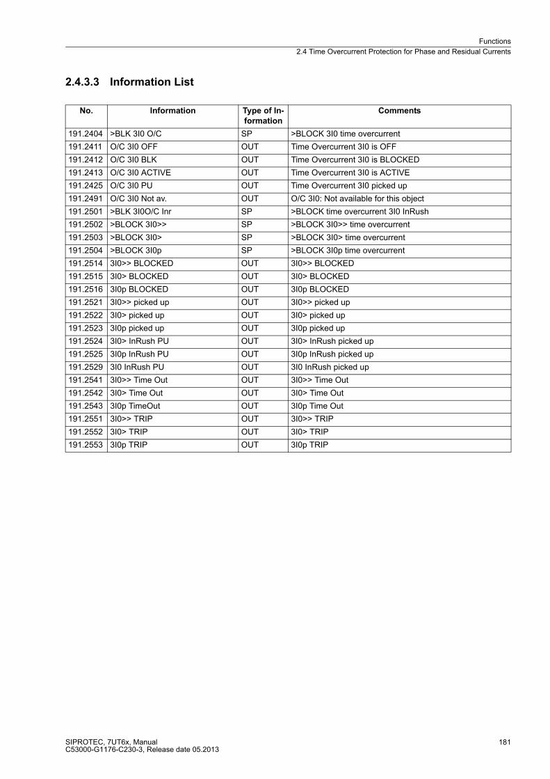
Functions
2.4 Time Overcurrent Protection for Phase and Residual Currents
SIPROTEC, 7UT6x, ManualC53000-G1176-C230-3, Release date 05.2013
181
2.4.3.3 Information List
No. Information Type of In-
formation
Comments
191.2404 >BLK 3I0 O/C SP >BLOCK 3I0 time overcurrent
191.2411 O/C 3I0 OFF OUT Time Overcurrent 3I0 is OFF
191.2412 O/C 3I0 BLK OUT Time Overcurrent 3I0 is BLOCKED
191.2413 O/C 3I0 ACTIVE OUT Time Overcurrent 3I0 is ACTIVE
191.2425 O/C 3I0 PU OUT Time Overcurrent 3I0 picked up
191.2491 O/C 3I0 Not av. OUT O/C 3I0: Not available for this object
191.2501 >BLK 3I0O/C Inr SP >BLOCK time overcurrent 3I0 InRush
191.2502 >BLOCK 3I0>> SP >BLOCK 3I0>> time overcurrent
191.2503 >BLOCK 3I0> SP >BLOCK 3I0> time overcurrent
191.2504 >BLOCK 3I0p SP >BLOCK 3I0p time overcurrent
191.2514 3I0>> BLOCKED OUT 3I0>> BLOCKED
191.2515 3I0> BLOCKED OUT 3I0> BLOCKED
191.2516 3I0p BLOCKED OUT 3I0p BLOCKED
191.2521 3I0>> picked up OUT 3I0>> picked up
191.2522 3I0> picked up OUT 3I0> picked up
191.2523 3I0p picked up OUT 3I0p picked up
191.2524 3I0> InRush PU OUT 3I0> InRush picked up
191.2525 3I0p InRush PU OUT 3I0p InRush picked up
191.2529 3I0 InRush PU OUT 3I0 InRush picked up
191.2541 3I0>> Time Out OUT 3I0>> Time Out
191.2542 3I0> Time Out OUT 3I0> Time Out
191.2543 3I0p TimeOut OUT 3I0p Time Out
191.2551 3I0>> TRIP OUT 3I0>> TRIP
191.2552 3I0> TRIP OUT 3I0> TRIP
191.2553 3I0p TRIP OUT 3I0p TRIP
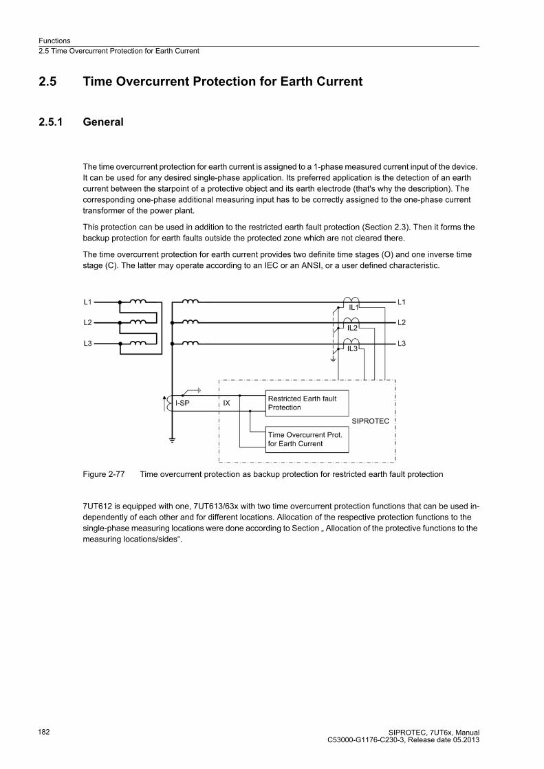
Functions
2.5 Time Overcurrent Protection for Earth Current
SIPROTEC, 7UT6x, ManualC53000-G1176-C230-3, Release date 05.2013
182
2.5 Time Overcurrent Protection for Earth Current
2.5.1 General
The time overcurrent protection for earth current is assigned to a 1-phase measured current input of the device.
It can be used for any desired single-phase application. Its preferred application is the detection of an earth
current between the starpoint of a protective object and its earth electrode (that's why the description). The
corresponding one-phase additional measuring input has to be correctly assigned to the one-phase current
transformer of the power plant.
This protection can be used in addition to the restricted earth fault protection (Section 2.3). Then it forms the
backup protection for earth faults outside the protected zone which are not cleared there.
The time overcurrent protection for earth current provides two definite time stages (O) and one inverse time
stage (C). The latter may operate according to an IEC or an ANSI, or a user defined characteristic.
Figure 2-77 Time overcurrent protection as backup protection for restricted earth fault protection
7UT612 is equipped with one, 7UT613/63x with two time overcurrent protection functions that can be used in-
dependently of each other and for different locations. Allocation of the respective protection functions to the
single-phase measuring locations were done according to Section „ Allocation of the protective functions to the
measuring locations/sides“.
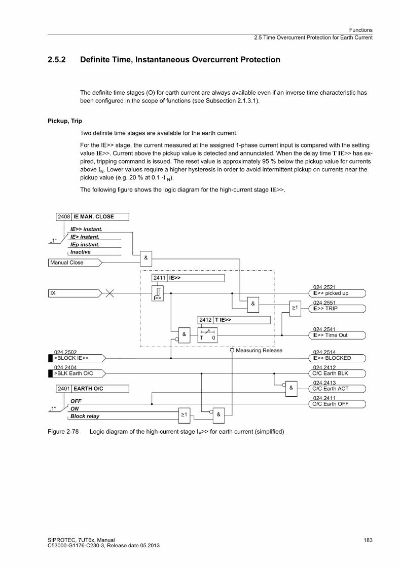
Functions
2.5 Time Overcurrent Protection for Earth Current
SIPROTEC, 7UT6x, ManualC53000-G1176-C230-3, Release date 05.2013
183
2.5.2 Definite Time, Instantaneous Overcurrent Protection
The definite time stages (O) for earth current are always available even if an inverse time characteristic has
been configured in the scope of functions (see Subsection 2.1.3.1).
Pickup, Trip
Two definite time stages are available for the earth current.
For the IE>> stage, the current measured at the assigned 1-phase current input is compared with the setting
value IE>>. Current above the pickup value is detected and annunciated. When the delay time T IE>> has ex-
pired, tripping command is issued. The reset value is approximately 95 % below the pickup value for currents
above IN. Lower values require a higher hysteresis in order to avoid intermittent pickup on currents near the
pickup value (e.g. 20 % at 0.1 ·I N).
The following figure shows the logic diagram for the high-current stage IE>>.
Figure 2-78 Logic diagram of the high-current stage IE>> for earth current (simplified)
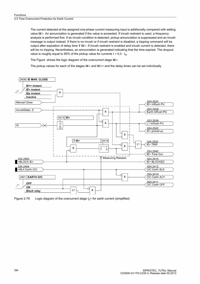
Functions
2.5 Time Overcurrent Protection for Earth Current
SIPROTEC, 7UT6x, ManualC53000-G1176-C230-3, Release date 05.2013
184
The current detected at the assigned one-phase current measuring input is additionally compared with setting
value IE>. An annunciation is generated if the value is exceeded. If inrush restraint is used, a frequency
analysis is performed first. If an inrush condition is detected, pickup annunciation is suppressed and an inrush
message is output instead. If there is no inrush or if inrush restraint is disabled, a tripping command will be
output after expiration of delay time T IE>. If inrush restraint is enabled and inrush current is detected, there
will be no tripping. Nevertheless, an annunciation is generated indicating that the time expired. The dropout
value is roughly equal to 95% of the pickup value for currents I > 0,3 · IN.
The Figure shows the logic diagram of the overcurrent stage IE>.
The pickup values for each of the stages IE> and IE>> and the delay times can be set individually.
Figure 2-79 Logic diagram of the overcurrent stage IE> for earth current (simplified)
Functions
2.5 Time Overcurrent Protection for Earth Current
SIPROTEC, 7UT6x, ManualC53000-G1176-C230-3, Release date 05.2013
185
2.5.3 Inverse Time Overcurrent Protection
The inverse time overcurrent stage operates with a characteristic either according to the IEC- or the ANSI-
standard or to a user-defined characteristic. The characteristics and their equations are given in the „Technical
Data“. When configuring one of the inverse time characteristics, definite time stages IE>> and IE> are also
enabled.
Pickup, Trip
The current measured at the assigned 1-phase current input is compared with setting value IEp. If the current
exceeds 1.1 times the set value, the stage picks up and an annunciation is made. If inrush restraint is used, a
frequency analysis is performed first. If an inrush condition is detected, pickup annunciation is suppressed and
an inrush message is output instead. The RMS value of the fundamental is used for the pickup. During the
pickup of an IEp stage, the tripping time is calculated from the flowing fault current by means of an integrating
measuring procedure, depending on the selected tripping characteristic. After expiration of this time period, a
trip command is output as long as no inrush current is detected or inrush restraint is disabled. If inrush restraint
is enabled and inrush current is detected, there will be no tripping. Nevertheless, an annunciation is generated
indicating that the time expired.
The following figure shows the logic diagram of the inverse-time overcurrent protection function.

Functions
2.5 Time Overcurrent Protection for Earth Current
SIPROTEC, 7UT6x, ManualC53000-G1176-C230-3, Release date 05.2013
186
Figure 2-80 Logic Diagram of the Inverse Overcurrent Protection for Earth Currents — example of IEC characteristic (simplified)
Dropout
You can determine whether the dropout of the stage is to follow right after the threshold undershot or whether
it is evoked by disk emulation. "Right after" means that the pickup drops out when approx. 95 % of the set
pickup value is undershot. For a new pickup the time counter starts at zero.
The disk emulation evokes a dropout process (time counter is decrementing) which begins after de-energisa-
tion. This process corresponds to the back turn of a Ferraris-disk (explaining its denomination „disk emulation“).
In case several faults occur successively, it is ensured that due to the inertia of the Ferraris disk the „history“ is
taken into consideration and the time behaviour is adapted. Reset begins as soon as 90 % of the setting value
is undershot, in accordance with the dropout curve of the selected characteristic. In the range between the
dropout value (95 % of the pickup value) and 90 % of the setting value, the incrementing and the decrementing
process is in idle state. If 5 % of the setting value is undershot, the dropout process is completed, i.e. when a
new pickup occurs, the timer starts again at zero.
The disk emulation offers its advantages when the grading coordination chart of the time overcurrent protection
is combined with other devices (on electro-mechanical or induction base) connected to the system.

Functions
2.5 Time Overcurrent Protection for Earth Current
SIPROTEC, 7UT6x, ManualC53000-G1176-C230-3, Release date 05.2013
187
User-defined Characteristics
When user-defined curves are utilised, the tripping curve may be defined point by point. Up to 20 pairs of values
(current, time) may be entered. The device then approximates the characteristics by linear interpolation.
If required, the dropout characteristic can also be defined (see function description for „Dropout“. If no user-
configurable dropout characteristic is desired, dropout is initiated when approx. a 95 % of the pickup value is
undershot; when a new pickup is evoked, the timer starts again at zero.
2.5.4 Manual Close Command
When a circuit breaker is closed onto a faulted protective object, a high speed re-trip by the breaker is often
desired. The manual closing feature is designed to remove the delay from one of the time overcurrent stages
when the breaker is manually closed onto a fault. The time delay is then bypassed via an impulse from the
external control switch. This pulse is prolonged by at least 300 ms. To enable the device to react properly on
occurrence of a fault, address 2408A IE MAN. CLOSE have to be set accordingly.
Processing of the manual close command can be executed for each measuring location or side. Manual close
signal is also generated when an internal control command is given to a breaker which is assigned to the same
protection function as the time earth overcurrent protection, in the Power System Data 1 (subsection 2.1.4).
Strict attention must be paid that the manual close condition is derived from that circuit breaker which feeds
the object that is protected by the earth overcurrent protection!
2.5.5 Dynamic Cold Load Pickup
Dynamic changeover of pickup values is available also for time overcurrent protection for earth current as it is
for the time overcurrent protection for phase currents and zero sequence current. Processing of the dynamic
cold load pickup conditions is the same for all time overcurrent stages, and is explained in Section 2.6.
The alternative values themselves are individually set for each of the stages.

Functions
2.5 Time Overcurrent Protection for Earth Current
SIPROTEC, 7UT6x, ManualC53000-G1176-C230-3, Release date 05.2013
188
2.5.6 Inrush Restraint
Earth current time overcurrent protection provides an integrated inrush restraint function which blocks the over-
current stages
If the second harmonic content of the earth current exceeds a selectable threshold, tripping is blocked.
The inrush stabilisation has an upper limit: If a certain (adjustable) current value is exceeded, it will not be
effective any more, since it must then be an internal current-intensive short-circuit. The lower limit is the
operating limit of the harmonic filter (0.1 IN).
Figure 2-81 Logic diagram of the inrush restraint feature (simplified)
2.5.7 Setting Notes
General
Note
The first time overcurrent protection for earth current is described in the setting instructions. The parameter
addresses and message numbers of the second and third time overcurrent protection are described at the end
of the setting instructions under „Additional Time Overcurrent Protection Functions for Earth Current“.
During configuration of the functional scope, the characteristic type has been set in address 124. Only the
settings for the characteristic selected can be performed here. The definite time stages IE>> and IE> are
always available.
If a second overcurrent protection is used, it also needs to be set at address 138 DMT/IDMT Earth2 and must
be configured accordingly.
The overcurrent protection for earth current is assigned to a 1-phase current measuring input (section 2.1.4
under margin heading „Additional 1-phase Protection Functions“). Consider also the assignment of the 1-phase
current input of the device against the current transformer of the power plant (section 2.1.4 under margin
heading „Assignment of Auxiliary 1-phase Measuring Locations“).
Functions
2.5 Time Overcurrent Protection for Earth Current
SIPROTEC, 7UT6x, ManualC53000-G1176-C230-3, Release date 05.2013
189
At address 2401 EARTH O/C, time overcurrent protection for earth current can be set to ON or OFF. The option
(Block relay) allows to operate the protection function but the trip output relay is blocked.
Address 2408 IE MAN. CLOSE determines which earth current stage is to be activated instantaneously with a
detected manual close. Settings IE>> instant. and IE> instant. can be set independently from the selected type
characteristics;IEp instant. is only available if one of the inverse time stages is configured. This parameter can
only be altered in DIGSI at Additional Settings.
If time overcurrent protection is applied on the feeding side of a transformer, select the higher stage IE>>, which
does not pick up by the inrush current or set the manual close feature to Inactive.
At address 2402 InRushRestEarth inrush restraint (inrush restraint with 2nd harmonic) is enabled or disabled.
Set ON if the protection is applied at the feeding side of an earthed transformer. Otherwise, retain setting OFF.
High-set Stage IE>>
The IE>> stage (address 2411), combined with the IE> stage or the IEp stage, results in a two-stage charac-
teristic. If this stage is not required, the pickup value shall be set to ∞. The IE>> stage always operates with a
defined delay time.
This current and time setting shall exclude pickup during switching operations. With a certain degree, current
grading can also be achieved similar to the corresponding stages of the time overcurrent protection for phase
and residual currents. However, zero sequence system quantities must be taken into consideration.
In most cases this stage operates instantaneously. A time delay, however, can be achieved by setting address
2412 T IE>>.
The set time is an additional delay time and does not include the operating time (measuring time, etc.). The
delay can be set to ∞. If set to infinity, the pickup of this function will be indicated but the stage will not trip after
pickup. If the pickup threshold is set to ∞, neither a pickup annunciation nor a trip is generated.
Definite Time Overcurrent Stage IE>
Using the time overcurrent stage IE> (address 2413), earth faults can also be detected with weak fault currents.
Since the starpoint current originates from one single current transformer, it is not affected by summation effects
evoked by different current transformer errors like, for example, the zero sequence current derived from phase
currents. Therefore, this address can be set to very sensitive. Consider that the inrush restraint function cannot
operate below 10 % nominal current (lower limit of harmonic filtering). An adequate time delay could be rea-
sonable for very sensitive setting if inrush restraint is used.
Since this stage also picks up with earth faults in the network, the time delay (address 2414 T IE>) has to be
coordinated with the grading coordination chart of the network for earth faults. In most cases, shorter tripping
times than for phase currents may be set since a galvanic separation of the zero sequence systems of the con-
nected power system sections is ensured by a transformer with separate windings.
The set time is an additional delay time and does not include the operating time (measuring time, etc.). The
delay can be set to ∞. If set to infinity, the pickup of this function will be indicated but the stage will not trip after
pickup. If the pickup threshold is set to ∞, neither a pickup annunciation nor a trip is generated.

Functions
2.5 Time Overcurrent Protection for Earth Current
SIPROTEC, 7UT6x, ManualC53000-G1176-C230-3, Release date 05.2013
190
Overcurrent Stage IEp with IEC curves
The inverse time stage, depending on the configuration, enables the user to select different characteristics. In
case of IEC characteristics (address 124 DMT/IDMT Earth = TOC IEC) the following options are available at
address 2425 IEC CURVE:
� Normal Inverse (inverse, type A according to IEC 60255-3),
� Very Inverse (very inverse, type B according to IEC 60255-3),
� Extremely Inv. (extremely inverse, type C according to IEC 60255-3), and
� Long Inverse (longtime, type B according to IEC 60255-3).
The characteristics and the equations on which they are based, are listed in the „Technical Data“.
If the inverse time trip characteristic is selected, it must be noted that a safety factor of about 1.1 has already
been included between the pickup value and the setting value. This means that a pickup will only occur if a
current of about 1.1 times of the setting value is present.
Using the overcurrent stageIEp (address 2421) earth faults can also be detected with weak fault currents. Since
the starpoint current originates from one single current transformer, it is not affected by summation effects
evoked by different current transformer errors like, for example, the zero sequence current derived from phase
currents. Therefore, this address can be set to very sensitive. Consider that the inrush restraint function cannot
operate below 10 % nominal current (lower limit of harmonic filtering). An adequate time delay could be rea-
sonable for very sensitive setting if inrush restraint is used.
Since this stage also picks up with earth faults in the network, the time multiplier (address 2422 T IEp) has to
be coordinated with the grading coordination chart of the network for earth faults. In most cases, shorter tripping
times than for phase currents may be set since a galvanic separation of the zero sequence systems of the con-
nected power system sections is ensured by a transformer with separate windings.
The time multiplication factor may also be set to ∞. If set to infinity, the pickup of this function will be indicated
but the stage will not trip after pickup. If the IEp–stage is not required, select address 124 DMT/IDMT Earth =
Definite Time when configuring the protection functions.
If under address 2424 TOC DROP-OUT the Disk Emulation are set, dropout is produced in accordance with the
dropout characteristic, as set out in the functional description of the inverse time overcurrent protection under
margin heading „Dropout Behaviour“.
Overcurrent Stage IEp with ANSI Characteristics
The inverse time stage, depending on the configuration, enables the user to select different characteristics.
With the ANSI characteristics (address 124 DMT/IDMT Earth = TOC ANSI) the following is made available in
address 2426 ANSI CURVE:
� Definite Inv.,
� Extremely Inv.,
� Inverse,
� Long Inverse,
� Moderately Inv.,
� Short Inverse, and
� Very Inverse.
The characteristics and equations they are based on are listed in the „Technical Data“.
If the inverse time trip characteristic is selected, it must be noted that a safety factor of about 1.1 has already
been included between the pickup value and the setting value. This means that a pickup will only occur if a
current of about 1.1 times the setting value is present.

Functions
2.5 Time Overcurrent Protection for Earth Current
SIPROTEC, 7UT6x, ManualC53000-G1176-C230-3, Release date 05.2013
191
Using the time overcurrent stage IEp (address 2421) earth faults can also be detected with weak fault currents.
Since the starpoint current originates from one single current transformer, it is not affected by summation effects
evoked by different current transformer errors like, for example, the zero sequence current derived from phase
currents. Therefore, this address can be set to very sensitive. Consider that the inrush restraint function cannot
operate below 10 % nominal current (lower limit of harmonic filtering). An adequate time delay could be rea-
sonable for very sensitive setting if inrush restraint is used.
Since this stage also picks up with earth faults in the network, the time delay (address 2423 D IEp) has to be
coordinated with the grading coordination chart of the network for earth faults. In most cases, shorter tripping
times than for phase currents may be set since a galvanic separation of the zero sequence systems of the con-
nected power system sections is ensured by a transformer with separate windings.
The time multiplier can also be set to ∞. If set to infinity, the pickup of this function will be indicated but the stage
will not trip after pickup. If stage IEp is not required at all, select address 124 DMT/IDMT Earth = Definite Time
during configuration of the protection functions.
If at address 2424 TOC DROP-OUT the Disk Emulation is set, dropout is thus produced in accordance with the
dropout characteristic, as described under margin heading„ Dropout Behaviour“ in subsection 2.5.
Dynamic Cold Load Pickup
An alternative set of pickup values can be set for each stage. It may be selected automatically in a dynamic
manner during operation. For more information on this function, see Section 2.6. For the stages the following
alternative values are set here.
for definite time overcurrent protection IE:
� address 2511 for pickup value IE>>,
� address 2512 for delay time T IE>>,
� address 2513 for pickup value IE>,
� address 2514 for delay time T IE>,
for inverse time overcurrent protection IE acc. to IEC characteristics:
� address 2521 for pickup value IEp,
� address 2522 for time multiplier T IEp;
for inverse time overcurrent protection IE acc. to ANSI characteristics:
� address 2521 for pickup value IEp,
� address 2523 for time multiplier D IEp;
User-Defined Curves
For inverse time overcurrent protection the user may define his own tripping and dropout characteristic. For
configuration in DIGSI a dialogue box appears. Enter up to 20 pairs of current value and tripping time value.
The procedure is the same as for phase current stages. See subsection 2.4.2 under margin heading „User-
Defined Curves“.
To create a user defined tripping characteristic for earth current, the following has to be set for configuration of
the functional scope: address 124 DMT/IDMT Earth, option User Defined PU. If you also want to specify the
dropout characteristic, set option User def. Reset.
Functions
2.5 Time Overcurrent Protection for Earth Current
SIPROTEC, 7UT6x, ManualC53000-G1176-C230-3, Release date 05.2013
192
Inrush Restraint
In address 2402 InRushRestEarth of the general settings, the inrush restraint can be enabled (ON) or disabled
(OFF). This inrush restraint is only sensible for transformers and if overcurrent time protection is activated on
the earthed feeding side. Function parameters of the inrush restraint are set in „Inrush“.
The inrush restraint is based on the evaluation of the 2nd harmonic present in the inrush current. The ratio of
2nd harmonics to the fundamental component 2.HARM. Earth (address 2441) is set to I2fN/IfN = 15 % as default
setting. It can be used without being changed. To provide more restraint in exceptional cases, where energising
conditions are particularly unfavourable, a smaller value can be set in the afore-mentioned address.
If the current exceeds the value indicated in address 2442 I Max InRr. E, no restraint will be provoked by the
2nd harmonic.
Additional Overcurrent Protection Functions for Earth Current
In the aforementioned description, the first overcurrent protection is described respectively. The differences in
the parameter addresses and message numbers of the first and second overcurrent protection are illustrated
in the following table. The positions marked by x are identical.
2.5.8 Settings
Addresses which have an appended "A" can only be changed with DIGSI, under Additional Settings.
The table indicates region-specific presettings. Column C (configuration) indicates the corresponding
secondary nominal current of the current transformer.
Addresses of the pa-rameters
Addresses of the dynamic parameters
Message no.
1. Overcurrent protection for earth current 24xx 25xx 024.xxxx(.01)
2. Overcurrent protection for earth current 38xx 39xx 325.xxxx(.01)
Addr. Parameter C Setting Options Default Setting Comments
2401 EARTH O/C ONOFFBlock relay
OFF Earth Time Overcurrent
2402 InRushRestEarth ONOFF
OFF InRush Restrained O/C Earth
2408A IE MAN. CLOSE IE>> instant.IE> instant.IEp instant.Inactive
IE>> instant. O/C IE Manual Close Mode
2411 IE>> 1A 0.05 .. 35.00 A; ∞ 1.00 A IE>> Pickup
5A 0.25 .. 175.00 A; ∞ 5.00 A
2412 T IE>> 0.00 .. 60.00 sec; ∞ 1.50 sec T IE>> Time Delay
2413 IE> 1A 0.05 .. 35.00 A; ∞ 0.40 A IE> Pickup
5A 0.25 .. 175.00 A; ∞ 2.00 A
2414 T IE> 0.00 .. 60.00 sec; ∞ 2.00 sec T IE> Time Delay
2421 IEp 1A 0.05 .. 4.00 A 0.40 A IEp Pickup
5A 0.25 .. 20.00 A 2.00 A
2422 T IEp 0.05 .. 3.20 sec; ∞ 0.50 sec T IEp Time Dial
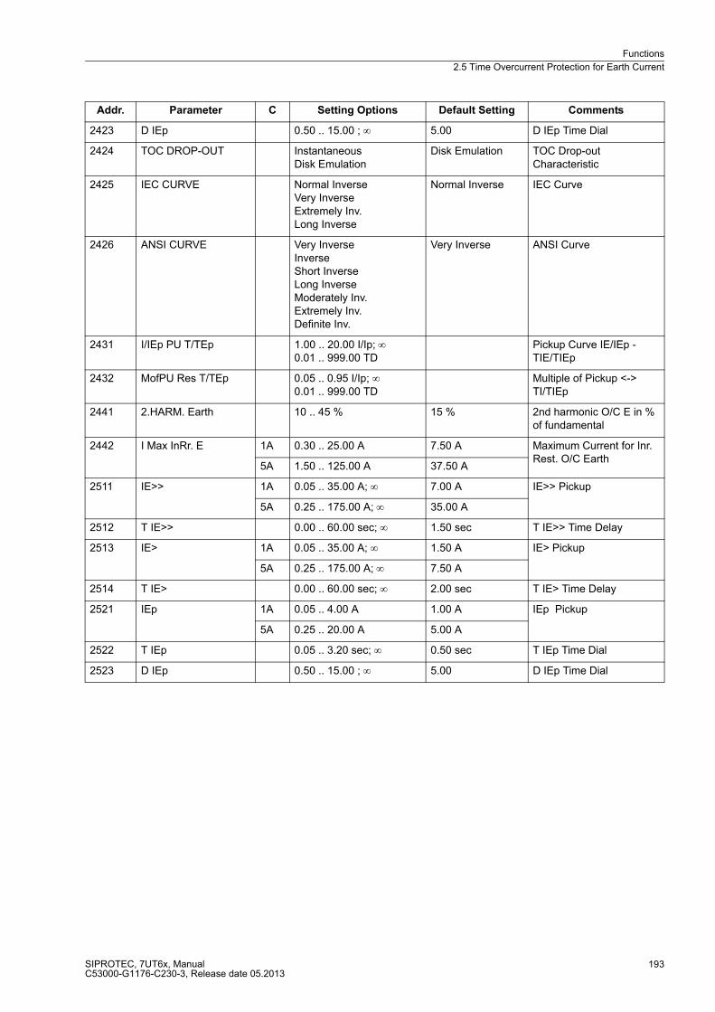
Functions
2.5 Time Overcurrent Protection for Earth Current
SIPROTEC, 7UT6x, ManualC53000-G1176-C230-3, Release date 05.2013
193
2423 D IEp 0.50 .. 15.00 ; ∞ 5.00 D IEp Time Dial
2424 TOC DROP-OUT InstantaneousDisk Emulation
Disk Emulation TOC Drop-out Characteristic
2425 IEC CURVE Normal InverseVery InverseExtremely Inv.Long Inverse
Normal Inverse IEC Curve
2426 ANSI CURVE Very InverseInverseShort InverseLong InverseModerately Inv.Extremely Inv.Definite Inv.
Very Inverse ANSI Curve
2431 I/IEp PU T/TEp 1.00 .. 20.00 I/Ip; ∞0.01 .. 999.00 TD
Pickup Curve IE/IEp - TIE/TIEp
2432 MofPU Res T/TEp 0.05 .. 0.95 I/Ip; ∞0.01 .. 999.00 TD
Multiple of Pickup <-> TI/TIEp
2441 2.HARM. Earth 10 .. 45 % 15 % 2nd harmonic O/C E in % of fundamental
2442 I Max InRr. E 1A 0.30 .. 25.00 A 7.50 A Maximum Current for Inr. Rest. O/C Earth
5A 1.50 .. 125.00 A 37.50 A
2511 IE>> 1A 0.05 .. 35.00 A; ∞ 7.00 A IE>> Pickup
5A 0.25 .. 175.00 A; ∞ 35.00 A
2512 T IE>> 0.00 .. 60.00 sec; ∞ 1.50 sec T IE>> Time Delay
2513 IE> 1A 0.05 .. 35.00 A; ∞ 1.50 A IE> Pickup
5A 0.25 .. 175.00 A; ∞ 7.50 A
2514 T IE> 0.00 .. 60.00 sec; ∞ 2.00 sec T IE> Time Delay
2521 IEp 1A 0.05 .. 4.00 A 1.00 A IEp Pickup
5A 0.25 .. 20.00 A 5.00 A
2522 T IEp 0.05 .. 3.20 sec; ∞ 0.50 sec T IEp Time Dial
2523 D IEp 0.50 .. 15.00 ; ∞ 5.00 D IEp Time Dial
Addr. Parameter C Setting Options Default Setting Comments

Functions
2.5 Time Overcurrent Protection for Earth Current
SIPROTEC, 7UT6x, ManualC53000-G1176-C230-3, Release date 05.2013
194
2.5.9 Information List
No. Information Type of In-
formation
Comments
024.2404 >BLK Earth O/C SP >BLOCK Earth time overcurrent
024.2411 O/C Earth OFF OUT Time Overcurrent Earth is OFF
024.2412 O/C Earth BLK OUT Time Overcurrent Earth is BLOCKED
024.2413 O/C Earth ACT OUT Time Overcurrent Earth is ACTIVE
024.2425 O/C Earth PU OUT Time Overcurrent Earth picked up
024.2492 O/C Earth ErrCT OUT O/C Earth err.: No auxiliary CT assigned
024.2501 >BLK E O/C Inr SP >BLOCK time overcurrent Earth InRush
024.2502 >BLOCK IE>> SP >BLOCK IE>>
024.2503 >BLOCK IE> SP >BLOCK IE>
024.2504 >BLOCK IEp SP >BLOCK IEp
024.2514 IE>> BLOCKED OUT IE>> BLOCKED
024.2515 IE> BLOCKED OUT IE> BLOCKED
024.2516 IEp BLOCKED OUT IEp BLOCKED
024.2521 IE>> picked up OUT IE>> picked up
024.2522 IE> picked up OUT IE> picked up
024.2523 IEp picked up OUT IEp picked up
024.2524 IE> InRush PU OUT IE> InRush picked up
024.2525 IEp InRush PU OUT IEp InRush picked up
024.2529 Earth InRush PU OUT Earth InRush picked up
024.2541 IE>> Time Out OUT IE>> Time Out
024.2542 IE> Time Out OUT IE> Time Out
024.2543 IEp TimeOut OUT IEp Time Out
024.2551 IE>> TRIP OUT IE>> TRIP
024.2552 IE> TRIP OUT IE> TRIP
024.2553 IEp TRIP OUT IEp TRIP
Functions
2.6 Dynamic Cold Load Pickup for Time Overcurrent Protection
SIPROTEC, 7UT6x, ManualC53000-G1176-C230-3, Release date 05.2013
195
2.6 Dynamic Cold Load Pickup for Time Overcurrent Protection
With the dynamic cold load pickup feature, it is possible to dynamically increase the pickup values of the time
overcurrent protection stages when dynamic cold load overcurrent conditions are anticipated, i.e. in cases
where consumers have increased power consumption after a longer period of dead condition, e.g. in air
conditioning systems, heating systems, motors, etc. Thus a general raise of pickup thresholds can be avoided
taking into consideration such starting conditions.
2.6.1 Function Description
The dynamic cold load pickup feature operates with the time overcurrent protection functions as described in
the above sections2.4.32.5. A set of alternative pickup values can be set for each stage. It is selected
automatically-dynamically during operation.
Note
Dynamic cold load pickup is in addition to the four setting groups (A to D) which are configured separately.
There are two methods used by the device to determine if the protected equipment is de-energised:
� Via a binary inputs, an auxiliary contact in the circuit breaker can be used to determine if the circuit breaker
is open or closed.
� The current flow monitoring threshold may be used to determine if the equipment is de-energised.
You may select one of these criteria for the time overcurrent protection for phase currents and for that for re-
sidual current. The device assigns automatically the correct side or measuring location for current detection or
the breaker auxiliary contact in accordance with the assignment of the associated protection functions. The
time overcurrent protection for earth current allows the breaker criterion only if it is assigned to a certain side
of the protective object (Section 2.1.4, margin heading „The assignment of the 1-phase measuring inputs “);
otherwise the current criterion can be used exclusively.
If the device recognises the protected equipment to be de-energised via one of the above criteria, then the
alternative pickup values will become effective for the overcurrent stages once a specified time delay CB Open
Time has lapsed. When the protected equipment is re-energised (i.e. the device receives input via a binary
input that the assigned circuit breaker is closed or the assigned current flowing through the breaker increases
above the current flow monitoring threshold), the active time Active Time is initiated. Once the active time has
elapsed, the pickup values of the overcurrent stages return to their normal settings. The time may be reduced
when current values after startup, i.e. after the circuit breaker is closed, fall below all normal pickup values for
a set period of time Stop Time. The start condition for the fast reset time is made up of an OR-combination of
the dropout conditions of all time overcurrent elements. When Stop Time is set to ∞ or binary input is active,
no comparison is made with the „normal“ setpoints. The function is inactive and the fast reset time, if applied,
is reset.
If overcurrent elements are picked up while Active Time is running, the fault generally prevails until pickup drops
out, using the dynamic pickup values. Only then are the parameters set back to „normal“.
If the dynamic cold load pickup function is blocked via the binary input all triggered timers will be immediately
reset and all „normal“ settings will be restored. If blocking occurs during an on-going fault with dynamic cold
load pickup functions enabled, the timers of all overcurrent stages will be stopped, and then restarted based
on their „normal“ duration.
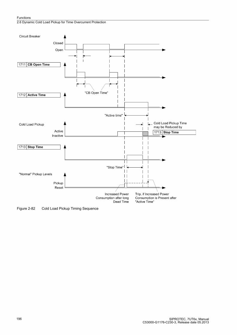
Functions
2.6 Dynamic Cold Load Pickup for Time Overcurrent Protection
SIPROTEC, 7UT6x, ManualC53000-G1176-C230-3, Release date 05.2013
196
Figure 2-82 Cold Load Pickup Timing Sequence

Functions
2.6 Dynamic Cold Load Pickup for Time Overcurrent Protection
SIPROTEC, 7UT6x, ManualC53000-G1176-C230-3, Release date 05.2013
197
During power up of the protective relay with an open circuit breaker, the time delay CB Open Time is started,
and is processed using the „normal“ settings. Therefore, when the circuit breaker is closed, the „normal“
settings are effective.
Figure 2-83 Logic diagram for dynamic cold load pickup feature — illustrated for phase overcurrent protection stage on side 1 (simplified)
Functions
2.6 Dynamic Cold Load Pickup for Time Overcurrent Protection
SIPROTEC, 7UT6x, ManualC53000-G1176-C230-3, Release date 05.2013
198
2.6.2 Setting Notes
General
Dynamic cold load pickup can only be enabled if during configuration of the functional scope was set at the
address 117 COLDLOAD PICKUP. = Enabled (see Subsection 2.1.3). If the function is not required is to be
set. In address 1701 COLDLOAD PICKUP the function can be set to ON or OFF.
Cold Load Criteria
You can determine the criteria for dynamic switchover to the cold load pickup values for all protective functions
which allow this switchover. Select the current criterion or the breaker position criterion breaker position:
� address 1702 Start CLP Phasefor the phase current stages,
� address 1703 Start CLP 3I0 for the residual current stages,
� address 1704 Start CLP Earth for the earth current.
The current criterion takes the currents of such side or measuring location to which the corresponding protec-
tive function is assigned. When using the breaker position criterion, the feedback information of the assigned
breaker must inform the device about the breaker position.
The time overcurrent protection for earth current allows the breaker criterion only if an unequivocal relationship
exists between its assigned side or measuring location and the feedback information of the breaker
(SwitchgCBaux S1, SwitchgCBaux S2 to SwitchgCBaux M5, addresses 831 to 840).
Timers
There are no specific procedures on how to set the delay times CB Open Timeat addresses1711), Active Time
(address 1712) and Stop Time (address 1713. These time delays must be based on the specific loading char-
acteristics of the equipment being protected, and should be set to allow short-term overloads associated with
dynamic cold load conditions.
Cold Load Pickup Values
The dynamic pickup values and time delays associated with the time overcurrent stages are set in the related
addresses of the stages themselves.
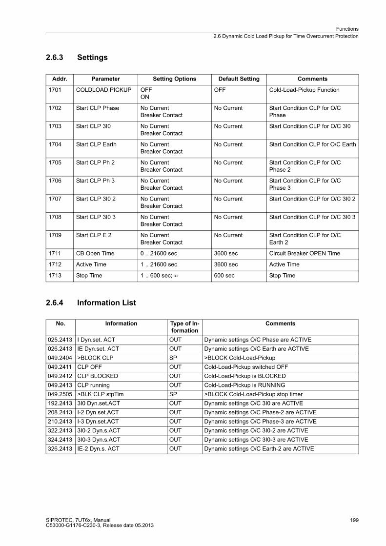
Functions
2.6 Dynamic Cold Load Pickup for Time Overcurrent Protection
SIPROTEC, 7UT6x, ManualC53000-G1176-C230-3, Release date 05.2013
199
2.6.3 Settings
2.6.4 Information List
Addr. Parameter Setting Options Default Setting Comments
1701 COLDLOAD PICKUP OFFON
OFF Cold-Load-Pickup Function
1702 Start CLP Phase No CurrentBreaker Contact
No Current Start Condition CLP for O/C Phase
1703 Start CLP 3I0 No CurrentBreaker Contact
No Current Start Condition CLP for O/C 3I0
1704 Start CLP Earth No CurrentBreaker Contact
No Current Start Condition CLP for O/C Earth
1705 Start CLP Ph 2 No CurrentBreaker Contact
No Current Start Condition CLP for O/C Phase 2
1706 Start CLP Ph 3 No CurrentBreaker Contact
No Current Start Condition CLP for O/C Phase 3
1707 Start CLP 3I0 2 No CurrentBreaker Contact
No Current Start Condition CLP for O/C 3I0 2
1708 Start CLP 3I0 3 No CurrentBreaker Contact
No Current Start Condition CLP for O/C 3I0 3
1709 Start CLP E 2 No CurrentBreaker Contact
No Current Start Condition CLP for O/C Earth 2
1711 CB Open Time 0 .. 21600 sec 3600 sec Circuit Breaker OPEN Time
1712 Active Time 1 .. 21600 sec 3600 sec Active Time
1713 Stop Time 1 .. 600 sec; ∞ 600 sec Stop Time
No. Information Type of In-
formation
Comments
025.2413 I Dyn.set. ACT OUT Dynamic settings O/C Phase are ACTIVE
026.2413 IE Dyn.set. ACT OUT Dynamic settings O/C Earth are ACTIVE
049.2404 >BLOCK CLP SP >BLOCK Cold-Load-Pickup
049.2411 CLP OFF OUT Cold-Load-Pickup switched OFF
049.2412 CLP BLOCKED OUT Cold-Load-Pickup is BLOCKED
049.2413 CLP running OUT Cold-Load-Pickup is RUNNING
049.2505 >BLK CLP stpTim SP >BLOCK Cold-Load-Pickup stop timer
192.2413 3I0 Dyn.set.ACT OUT Dynamic settings O/C 3I0 are ACTIVE
208.2413 I-2 Dyn.set.ACT OUT Dynamic settings O/C Phase-2 are ACTIVE
210.2413 I-3 Dyn.set.ACT OUT Dynamic settings O/C Phase-3 are ACTIVE
322.2413 3I0-2 Dyn.s.ACT OUT Dynamic settings O/C 3I0-2 are ACTIVE
324.2413 3I0-3 Dyn.s.ACT OUT Dynamic settings O/C 3I0-3 are ACTIVE
326.2413 IE-2 Dyn.s. ACT OUT Dynamic settings O/C Earth-2 are ACTIVE
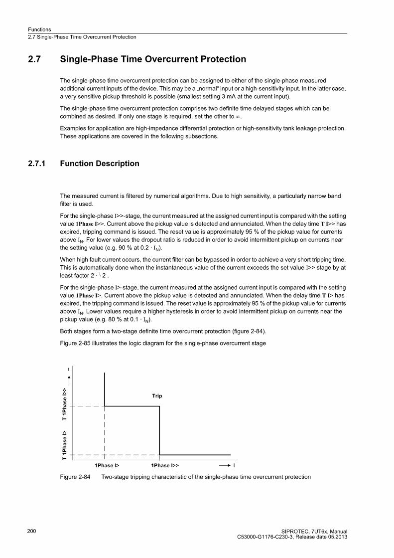
Functions
2.7 Single-Phase Time Overcurrent Protection
SIPROTEC, 7UT6x, ManualC53000-G1176-C230-3, Release date 05.2013
200
2.7 Single-Phase Time Overcurrent Protection
The single-phase time overcurrent protection can be assigned to either of the single-phase measured
additional current inputs of the device. This may be a „normal“ input or a high-sensitivity input. In the latter case,
a very sensitive pickup threshold is possible (smallest setting 3 mA at the current input).
The single-phase time overcurrent protection comprises two definite time delayed stages which can be
combined as desired. If only one stage is required, set the other to ∞.
Examples for application are high-impedance differential protection or high-sensitivity tank leakage protection.
These applications are covered in the following subsections.
2.7.1 Function Description
The measured current is filtered by numerical algorithms. Due to high sensitivity, a particularly narrow band
filter is used.
For the single-phase I>>-stage, the current measured at the assigned current input is compared with the setting
value 1Phase I>>. Current above the pickup value is detected and annunciated. When the delay time T I>> has
expired, tripping command is issued. The reset value is approximately 95 % of the pickup value for currents
above IN. For lower values the dropout ratio is reduced in order to avoid intermittent pickup on currents near
the setting value (e.g. 90 % at 0.2 · IN).
When high fault current occurs, the current filter can be bypassed in order to achieve a very short tripping time.
This is automatically done when the instantaneous value of the current exceeds the set value I>> stage by at
least factor 2 · √2 .
For the single-phase I>-stage, the current measured at the assigned current input is compared with the setting
value 1Phase I>. Current above the pickup value is detected and annunciated. When the delay time T I> has
expired, the tripping command is issued. The reset value is approximately 95 % of the pickup value for currents
above IN. Lower values require a higher hysteresis in order to avoid intermittent pickup on currents near the
pickup value (e.g. 80 % at 0.1 · IN).
Both stages form a two-stage definite time overcurrent protection (figure 2-84).
Figure 2-85 illustrates the logic diagram for the single-phase overcurrent stage
Figure 2-84 Two-stage tripping characteristic of the single-phase time overcurrent protection

Functions
2.7 Single-Phase Time Overcurrent Protection
SIPROTEC, 7UT6x, ManualC53000-G1176-C230-3, Release date 05.2013
201
Figure 2-85 Logic diagram of the single-phase overcurrent protection — example for detection of the current at input II8
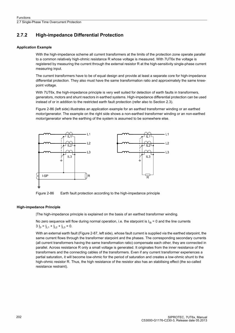
Functions
2.7 Single-Phase Time Overcurrent Protection
SIPROTEC, 7UT6x, ManualC53000-G1176-C230-3, Release date 05.2013
202
2.7.2 High-impedance Differential Protection
Application Example
With the high-impedance scheme all current transformers at the limits of the protection zone operate parallel
to a common relatively high-ohmic resistance R whose voltage is measured. With 7UT6x the voltage is
registered by measuring the current through the external resistor R at the high-sensitivity single-phase current
measuring input.
The current transformers have to be of equal design and provide at least a separate core for high-impedance
differential protection. They also must have the same transformation ratio and approximately the same knee-
point voltage.
With 7UT6x, the high-impedance principle is very well suited for detection of earth faults in transformers,
generators, motors and shunt reactors in earthed systems. High-impedance differential protection can be used
instead of or in addition to the restricted earth fault protection (refer also to Section 2.3).
Figure 2-86 (left side) illustrates an application example for an earthed transformer winding or an earthed
motor/generator. The example on the right side shows a non-earthed transformer winding or an non-earthed
motor/generator where the earthing of the system is assumed to be somewhere else.
Figure 2-86 Earth fault protection according to the high-impedance principle
High-impedance Principle
|The high-impedance principle is explained on the basis of an earthed transformer winding.
No zero sequence will flow during normal operation, i.e. the starpoint is ISt = 0 and the line currents
3 I0 = IL1 + IL2 + IL3 = 0.
With an external earth fault (Figure 2-87, left side), whose fault current is supplied via the earthed starpoint, the
same current flows through the transformer starpoint and the phases. The corresponding secondary currents
(all current transformers having the same transformation ratio) compensate each other, they are connected in
parallel. Across resistance R only a small voltage is generated. It originates from the inner resistance of the
transformers and the connecting cables of the transformers. Even if any current transformer experiences a
partial saturation, it will become low-ohmic for the period of saturation and creates a low-ohmic shunt to the
high-ohmic resistor R. Thus, the high resistance of the resistor also has an stabilising effect (the so-called
resistance restraint).
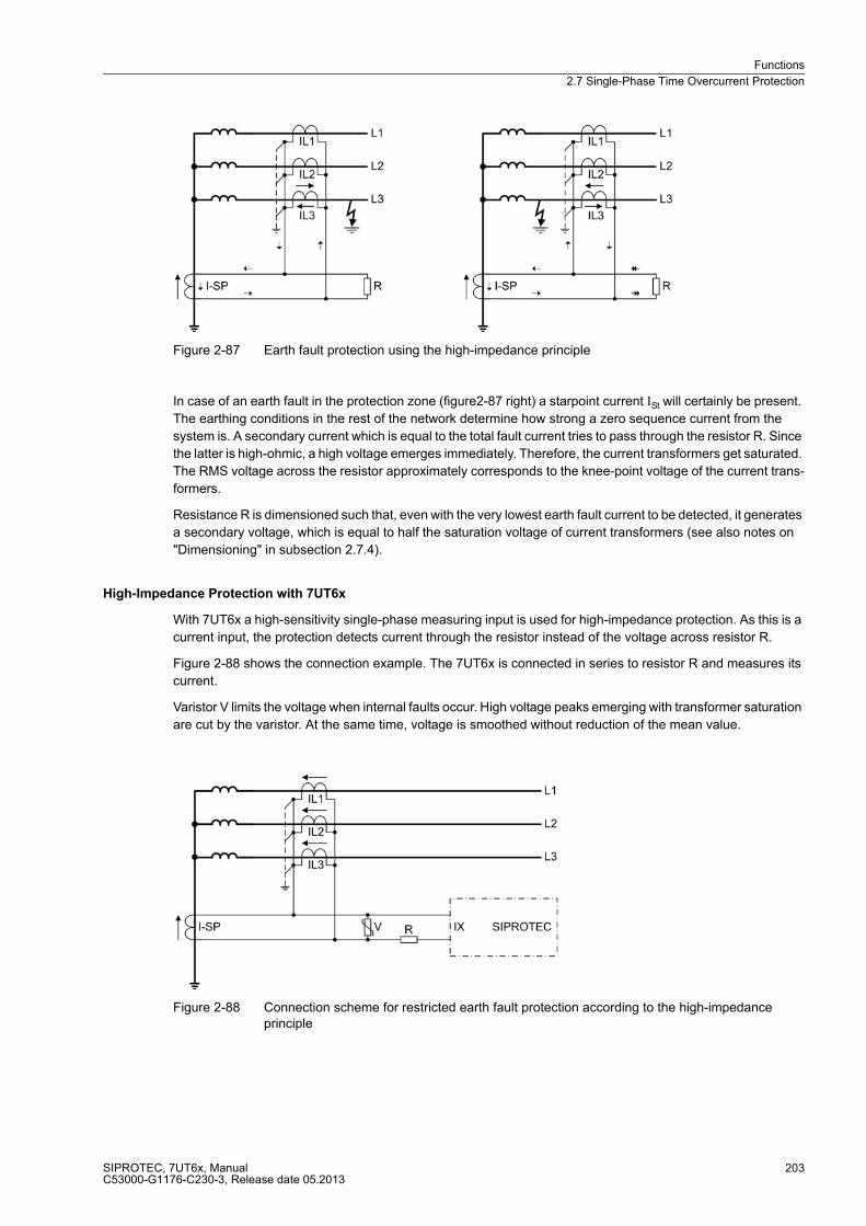
Functions
2.7 Single-Phase Time Overcurrent Protection
SIPROTEC, 7UT6x, ManualC53000-G1176-C230-3, Release date 05.2013
203
Figure 2-87 Earth fault protection using the high-impedance principle
In case of an earth fault in the protection zone (figure2-87 right) a starpoint current ISt will certainly be present.
The earthing conditions in the rest of the network determine how strong a zero sequence current from the
system is. A secondary current which is equal to the total fault current tries to pass through the resistor R. Since
the latter is high-ohmic, a high voltage emerges immediately. Therefore, the current transformers get saturated.
The RMS voltage across the resistor approximately corresponds to the knee-point voltage of the current trans-
formers.
Resistance R is dimensioned such that, even with the very lowest earth fault current to be detected, it generates
a secondary voltage, which is equal to half the saturation voltage of current transformers (see also notes on
"Dimensioning" in subsection 2.7.4).
High-Impedance Protection with 7UT6x
With 7UT6x a high-sensitivity single-phase measuring input is used for high-impedance protection. As this is a
current input, the protection detects current through the resistor instead of the voltage across resistor R.
Figure 2-88 shows the connection example. The 7UT6x is connected in series to resistor R and measures its
current.
Varistor V limits the voltage when internal faults occur. High voltage peaks emerging with transformer saturation
are cut by the varistor. At the same time, voltage is smoothed without reduction of the mean value.
Figure 2-88 Connection scheme for restricted earth fault protection according to the high-impedance principle
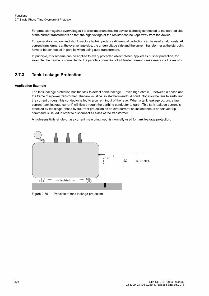
Functions
2.7 Single-Phase Time Overcurrent Protection
SIPROTEC, 7UT6x, ManualC53000-G1176-C230-3, Release date 05.2013
204
For protection against overvoltages it is also important that the device is directly connected to the earthed side
of the current transformers so that the high voltage at the resistor can be kept away from the device.
For generators, motors and shunt reactors high-impedance differential protection can be used analogously. All
current transformers at the overvoltage side, the undervoltage side and the current transformer at the starpoint
have to be connected in parallel when using auto-transformers.
In principle, this scheme can be applied to every protected object. When applied as busbar protection, for
example, the device is connected to the parallel connection of all feeder current transformers via the resistor.
2.7.3 Tank Leakage Protection
Application Example
The tank leakage protection has the task to detect earth leakage — even high-ohmic — between a phase and
the frame of a power transformer. The tank must be isolated from earth. A conductor links the tank to earth, and
the current through this conductor is fed to a current input of the relay. When a tank leakage occurs, a fault
current (tank leakage current) will flow through the earthing conductor to earth. This tank leakage current is
detected by the single-phase overcurrent protection as an overcurrent; an instantaneous or delayed trip
command is issued in order to disconnect all sides of the transformer.
A high-sensitivity single-phase current measuring input is normally used for tank leakage protection.
Figure 2-89 Principle of tank leakage protection
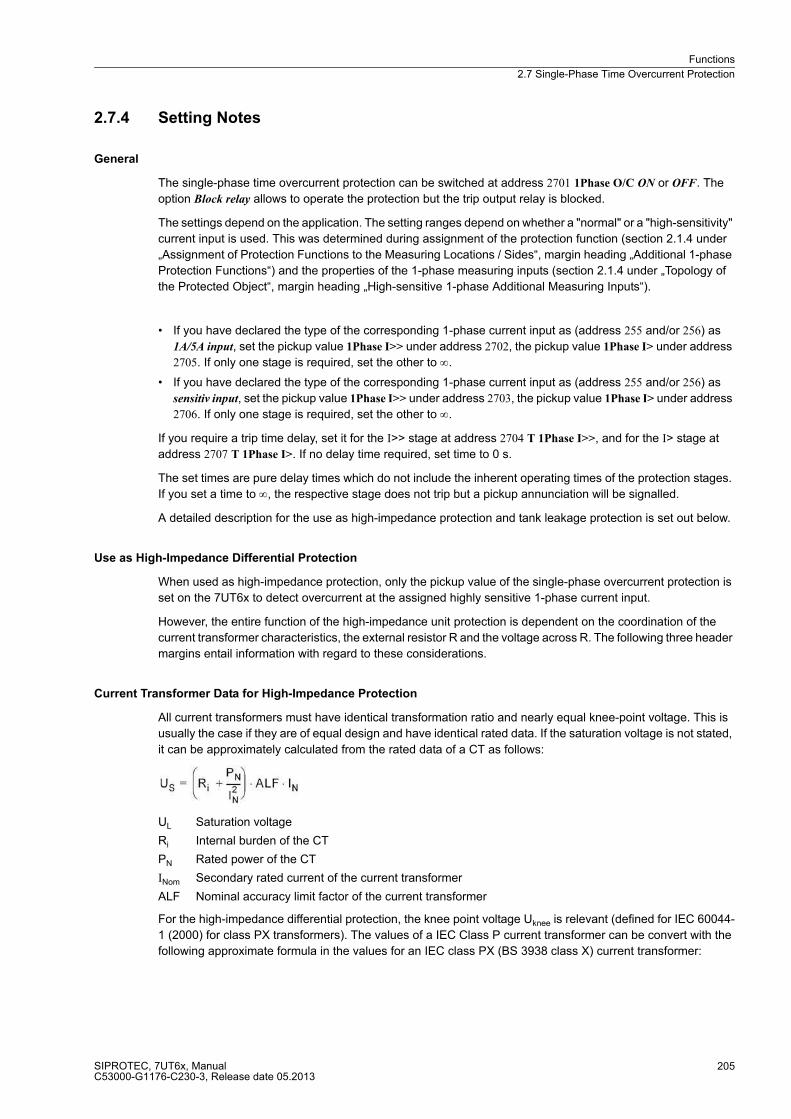
Functions
2.7 Single-Phase Time Overcurrent Protection
SIPROTEC, 7UT6x, ManualC53000-G1176-C230-3, Release date 05.2013
205
2.7.4 Setting Notes
General
The single-phase time overcurrent protection can be switched at address 2701 1Phase O/C ON or OFF. The
option Block relay allows to operate the protection but the trip output relay is blocked.
The settings depend on the application. The setting ranges depend on whether a "normal" or a "high-sensitivity"
current input is used. This was determined during assignment of the protection function (section 2.1.4 under
„Assignment of Protection Functions to the Measuring Locations / Sides“, margin heading „Additional 1-phase
Protection Functions“) and the properties of the 1-phase measuring inputs (section 2.1.4 under „Topology of
the Protected Object“, margin heading „High-sensitive 1-phase Additional Measuring Inputs“).
� If you have declared the type of the corresponding 1-phase current input as (address 255 and/or 256) as
1A/5A input, set the pickup value 1Phase I>> under address 2702, the pickup value 1Phase I> under address
2705. If only one stage is required, set the other to ∞.
� If you have declared the type of the corresponding 1-phase current input as (address 255 and/or 256) as
sensitiv input, set the pickup value 1Phase I>> under address 2703, the pickup value 1Phase I> under address
2706. If only one stage is required, set the other to ∞.
If you require a trip time delay, set it for the I>> stage at address 2704 T 1Phase I>>, and for the I> stage at
address 2707 T 1Phase I>. If no delay time required, set time to 0 s.
The set times are pure delay times which do not include the inherent operating times of the protection stages.
If you set a time to ∞, the respective stage does not trip but a pickup annunciation will be signalled.
A detailed description for the use as high-impedance protection and tank leakage protection is set out below.
Use as High-Impedance Differential Protection
When used as high-impedance protection, only the pickup value of the single-phase overcurrent protection is
set on the 7UT6x to detect overcurrent at the assigned highly sensitive 1-phase current input.
However, the entire function of the high-impedance unit protection is dependent on the coordination of the
current transformer characteristics, the external resistor R and the voltage across R. The following three header
margins entail information with regard to these considerations.
Current Transformer Data for High-Impedance Protection
All current transformers must have identical transformation ratio and nearly equal knee-point voltage. This is
usually the case if they are of equal design and have identical rated data. If the saturation voltage is not stated,
it can be approximately calculated from the rated data of a CT as follows:
UL Saturation voltage
Ri Internal burden of the CT
PN Rated power of the CT
INom Secondary rated current of the current transformer
ALF Nominal accuracy limit factor of the current transformer
For the high-impedance differential protection, the knee point voltage Uknee is relevant (defined for IEC 60044-
1 (2000) for class PX transformers). The values of a IEC Class P current transformer can be convert with the
following approximate formula in the values for an IEC class PX (BS 3938 class X) current transformer:
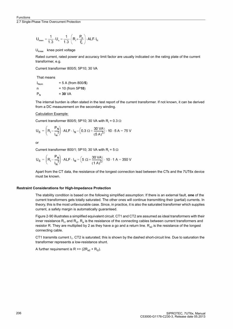
Functions
2.7 Single-Phase Time Overcurrent Protection
SIPROTEC, 7UT6x, ManualC53000-G1176-C230-3, Release date 05.2013
206
Uknee knee point voltage
Rated current, rated power and accuracy limit factor are usually indicated on the rating plate of the current
transformer, e.g.
Current transformer 800/5; 5P10; 30 VA
The internal burden is often stated in the test report of the current transformer. If not known, it can be derived
from a DC measurement on the secondary winding.
Calculation Example:
Current transformer 800/5; 5P10; 30 VA with Ri = 0.3 Ω
or
Current transformer 800/1; 5P10; 30 VA with Ri = 5 Ω
Apart from the CT data, the resistance of the longest connection lead between the CTs and the 7UT6x device
must be known.
Restraint Considerations for High-Impedance Protection
The stability condition is based on the following simplified assumption: If there is an external fault, one of the
current transformers gets totally saturated. The other ones will continue transmitting their (partial) currents. In
theory, this is the most unfavourable case. Since, in practice, it is also the saturated transformer which supplies
current, a safety margin is automatically guaranteed.
Figure 2-90 illustrates a simplified equivalent circuit. CT1 and CT2 are assumed as ideal transformers with their
inner resistance Ri1 and Ri2. Ra is the resistance of the connecting cables between current transformers and
resistor R. They are multiplied by 2 as they have a go and a return line. Ra2 is the resistance of the longest
connecting cable.
CT1 transmits current I1. CT2 is saturated; this is shown by the dashed short-circuit line. Due to saturation the
transformer represents a low-resistance shunt.
A further requirement is R >> (2Ra2 + Ri2).
That means
INom = 5 A (from 800/5)
n = 10 (from 5P10)
PN = 30 VA
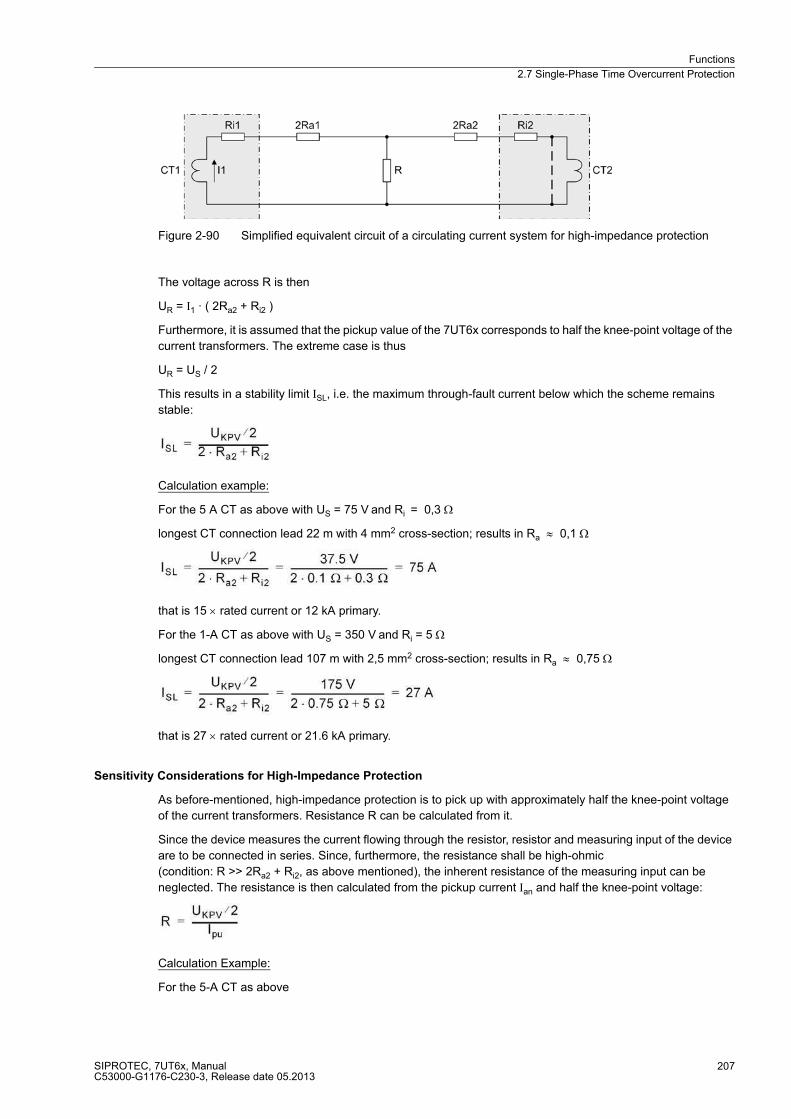
Functions
2.7 Single-Phase Time Overcurrent Protection
SIPROTEC, 7UT6x, ManualC53000-G1176-C230-3, Release date 05.2013
207
Figure 2-90 Simplified equivalent circuit of a circulating current system for high-impedance protection
The voltage across R is then
UR = I1 · ( 2Ra2 + Ri2 )
Furthermore, it is assumed that the pickup value of the 7UT6x corresponds to half the knee-point voltage of the
current transformers. The extreme case is thus
UR = US / 2
This results in a stability limit ISL, i.e. the maximum through-fault current below which the scheme remains
stable:
Calculation example:
For the 5 A CT as above with US = 75 V and Ri = 0,3 Ω
longest CT connection lead 22 m with 4 mm2 cross-section; results in Ra ≈ 0,1 Ω
that is 15 × rated current or 12 kA primary.
For the 1-A CT as above with US = 350 V and Ri = 5 Ω
longest CT connection lead 107 m with 2,5 mm2 cross-section; results in Ra ≈ 0,75 Ω
that is 27 × rated current or 21.6 kA primary.
Sensitivity Considerations for High-Impedance Protection
As before-mentioned, high-impedance protection is to pick up with approximately half the knee-point voltage
of the current transformers. Resistance R can be calculated from it.
Since the device measures the current flowing through the resistor, resistor and measuring input of the device
are to be connected in series. Since, furthermore, the resistance shall be high-ohmic
(condition: R >> 2Ra2 + Ri2, as above mentioned), the inherent resistance of the measuring input can be
neglected. The resistance is then calculated from the pickup current Ian and half the knee-point voltage:
Calculation Example:
For the 5-A CT as above
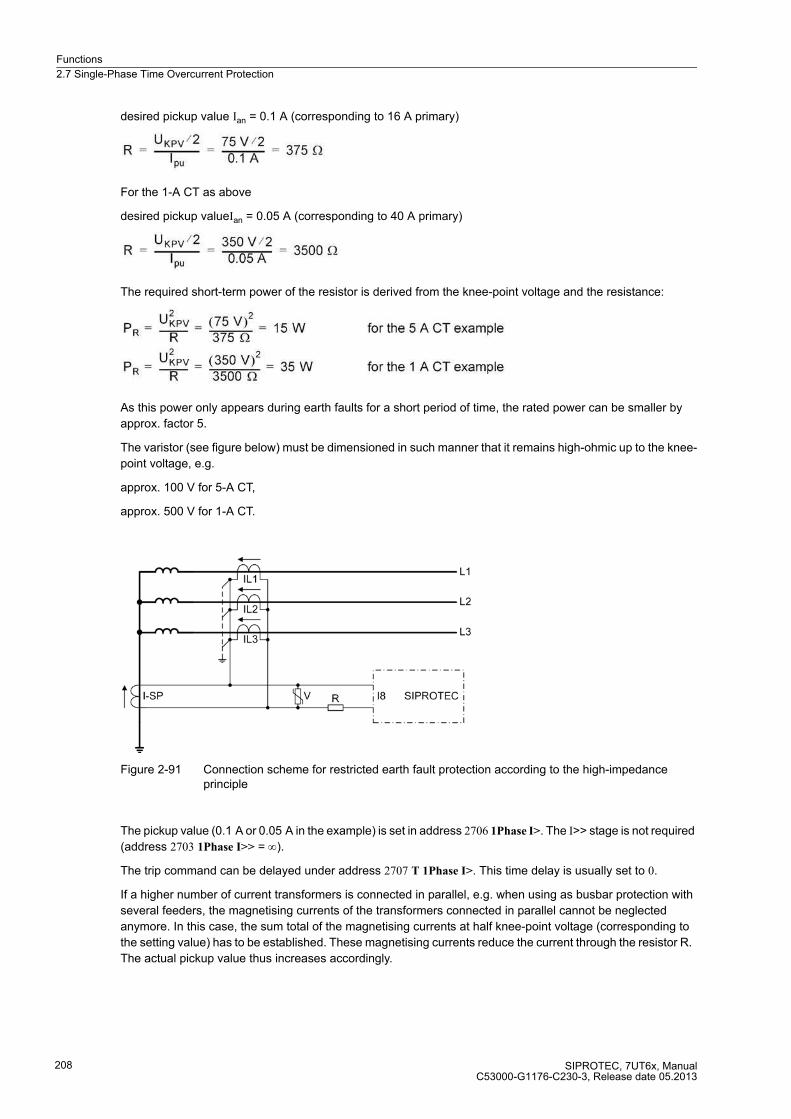
Functions
2.7 Single-Phase Time Overcurrent Protection
SIPROTEC, 7UT6x, ManualC53000-G1176-C230-3, Release date 05.2013
208
desired pickup value Ian = 0.1 A (corresponding to 16 A primary)
For the 1-A CT as above
desired pickup valueIan = 0.05 A (corresponding to 40 A primary)
The required short-term power of the resistor is derived from the knee-point voltage and the resistance:
As this power only appears during earth faults for a short period of time, the rated power can be smaller by
approx. factor 5.
The varistor (see figure below) must be dimensioned in such manner that it remains high-ohmic up to the knee-
point voltage, e.g.
approx. 100 V for 5-A CT,
approx. 500 V for 1-A CT.
Figure 2-91 Connection scheme for restricted earth fault protection according to the high-impedance principle
The pickup value (0.1 A or 0.05 A in the example) is set in address 2706 1Phase I>. The I>> stage is not required
(address 2703 1Phase I>> = ∞).
The trip command can be delayed under address 2707 T 1Phase I>. This time delay is usually set to 0.
If a higher number of current transformers is connected in parallel, e.g. when using as busbar protection with
several feeders, the magnetising currents of the transformers connected in parallel cannot be neglected
anymore. In this case, the sum total of the magnetising currents at half knee-point voltage (corresponding to
the setting value) has to be established. These magnetising currents reduce the current through the resistor R.
The actual pickup value thus increases accordingly.

Functions
2.7 Single-Phase Time Overcurrent Protection
SIPROTEC, 7UT6x, ManualC53000-G1176-C230-3, Release date 05.2013
209
Use as Tank Leakage Protection
If the single-phase time overcurrent protection is used as tank leakage protection, only the pickup value for the
respective 1-phase current input is set on 7UT6x.
The tank leakage protection is a highly sensitive overcurrent protection which detects the leakage current
between the isolated transformer tank and earth. Its sensitivity is set in address 2706 1Phase I>. Stage I>> is
not used (address 2703 1Phase I>> = ∞).
The trip command can be delayed in address 2707 T 1Phase I>. Normally, this delay time is set to 0.
Note
In the following parameter overview the addresses 2703 and 2706 apply to a high-sensitive current measuring
input and are independent from the rated current.
2.7.5 Settings
The table indicates region-specific presettings. Column C (configuration) indicates the corresponding
secondary nominal current of the current transformer.
Addr. Parameter C Setting Options Default Setting Comments
2701 1Phase O/C OFFONBlock relay
OFF 1Phase Time Overcurrent
2702 1Phase I>> 1A 0.05 .. 35.00 A; ∞ 0.50 A 1Phase O/C I>> Pickup
5A 0.25 .. 175.00 A; ∞ 2.50 A
2703 1Phase I>> 0.003 .. 1.500 A; ∞ 0.300 A 1Phase O/C I>> Pickup
2704 T 1Phase I>> 0.00 .. 60.00 sec; ∞ 0.10 sec T 1Phase O/C I>> Time Delay
2705 1Phase I> 1A 0.05 .. 35.00 A; ∞ 0.20 A 1Phase O/C I> Pickup
5A 0.25 .. 175.00 A; ∞ 1.00 A
2706 1Phase I> 0.003 .. 1.500 A; ∞ 0.100 A 1Phase O/C I> Pickup
2707 T 1Phase I> 0.00 .. 60.00 sec; ∞ 0.50 sec T 1Phase O/C I> Time Delay
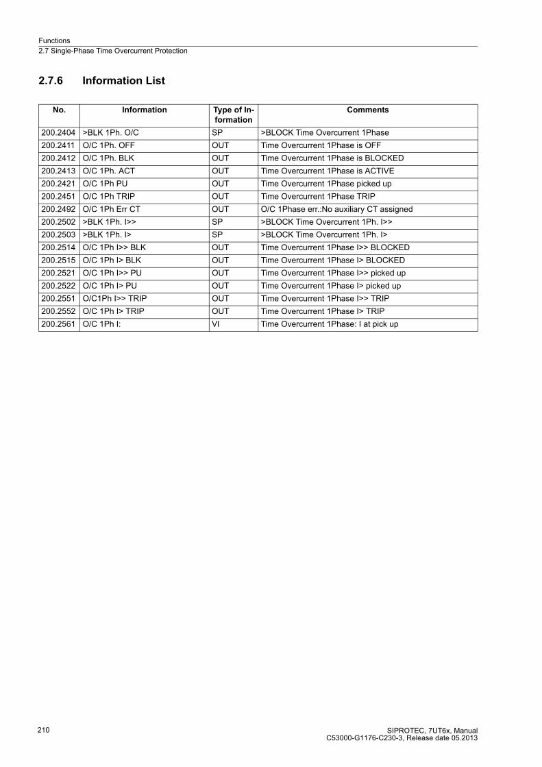
Functions
2.7 Single-Phase Time Overcurrent Protection
SIPROTEC, 7UT6x, ManualC53000-G1176-C230-3, Release date 05.2013
210
2.7.6 Information List
No. Information Type of In-
formation
Comments
200.2404 >BLK 1Ph. O/C SP >BLOCK Time Overcurrent 1Phase
200.2411 O/C 1Ph. OFF OUT Time Overcurrent 1Phase is OFF
200.2412 O/C 1Ph. BLK OUT Time Overcurrent 1Phase is BLOCKED
200.2413 O/C 1Ph. ACT OUT Time Overcurrent 1Phase is ACTIVE
200.2421 O/C 1Ph PU OUT Time Overcurrent 1Phase picked up
200.2451 O/C 1Ph TRIP OUT Time Overcurrent 1Phase TRIP
200.2492 O/C 1Ph Err CT OUT O/C 1Phase err.:No auxiliary CT assigned
200.2502 >BLK 1Ph. I>> SP >BLOCK Time Overcurrent 1Ph. I>>
200.2503 >BLK 1Ph. I> SP >BLOCK Time Overcurrent 1Ph. I>
200.2514 O/C 1Ph I>> BLK OUT Time Overcurrent 1Phase I>> BLOCKED
200.2515 O/C 1Ph I> BLK OUT Time Overcurrent 1Phase I> BLOCKED
200.2521 O/C 1Ph I>> PU OUT Time Overcurrent 1Phase I>> picked up
200.2522 O/C 1Ph I> PU OUT Time Overcurrent 1Phase I> picked up
200.2551 O/C1Ph I>> TRIP OUT Time Overcurrent 1Phase I>> TRIP
200.2552 O/C 1Ph I> TRIP OUT Time Overcurrent 1Phase I> TRIP
200.2561 O/C 1Ph I: VI Time Overcurrent 1Phase: I at pick up

Functions
2.8 Unbalanced Load Protection
SIPROTEC, 7UT6x, ManualC53000-G1176-C230-3, Release date 05.2013
211
2.8 Unbalanced Load Protection
Unbalanced load protection (negative sequence protection) detects unbalanced loads on the system. In
addition, this protection function may be used to detect interruptions, faults, and polarity problems with current
transformers. Furthermore, it is useful in detecting phase-to-earth, phase-to-phase, and double phase-to-earth
faults with magnitudes lower than the maximum load current.
The tripping circuit monitoring is only sensible in three-phase protected objects. Whereas PROT. OBJECT =
1ph Busbar or 1 phase transf. (see Functional Scope, address 105, section 2.1.3.1) the following settings are not
available.
In case of generators and motors, unbalanced loads create counter-rotating fields which act on the rotor at
double frequency. Eddy currents are induced at the rotor surface leading to local overheating in rotor end zones
and slot wedges.
In case of motors with fuses connected in series, a motor operating in single-phase condition due to operation
of a fuse, only generates small and pulsing torque so that it is soon thermally strained assuming that the torque
required by the machine remains unchanged. In addition, with unbalanced supply voltage it is endangered by
thermal overload. Due to the small negative sequence reaction even small voltage asymmetries lead to
negative sequence currents.
The negative sequence protection always refers to the three phase currents of the configured side or
measuring location (see „Assigning the Functional Scope“, in Subsection 2.1.4).
The unbalanced load protection consists of two definite time stages and one inverse time stage, The latter may
operate according to an IEC or an ANSI characteristic. A stage with a power-proportional characteristic
(negative sequence current) is possible instead of the inverse time stage.
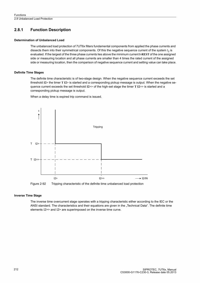
Functions
2.8 Unbalanced Load Protection
SIPROTEC, 7UT6x, ManualC53000-G1176-C230-3, Release date 05.2013
212
2.8.1 Function Description
Determination of Unbalanced Load
The unbalanced load protection of 7UT6x filters fundamental components from applied the phase currents and
dissects them into their symmetrical components. Of this the negative sequence current of the system I2 is
evaluated. If the largest of the three phase currents lies above the minimum current I-REST of the one assigned
side or measuring location and all phase currents are smaller than 4 times the rated current of the assigned
side or measuring location, then the comparison of negative sequence current and setting value can take place.
Definite Time Stages
The definite time characteristic is of two-stage design. When the negative sequence current exceeds the set
threshold I2> the timer T I2> is started and a corresponding pickup message is output. When the negative se-
quence current exceeds the set threshold I2>> of the high-set stage the timer T I2>> is started and a
corresponding pickup message is output.
When a delay time is expired trip command is issued.
Figure 2-92 Tripping characteristic of the definite time unbalanced load protection
Inverse Time Stage
The inverse time overcurrent stage operates with a tripping characteristic either according to the IEC or the
ANSI standard. The characteristics and their equations are given in the „Technical Data“. The definite time
elements I2>> and I2> are superimposed on the inverse time curve.
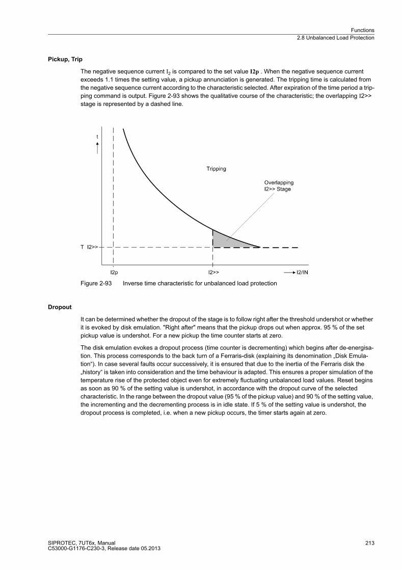
Functions
2.8 Unbalanced Load Protection
SIPROTEC, 7UT6x, ManualC53000-G1176-C230-3, Release date 05.2013
213
Pickup, Trip
The negative sequence current I2 is compared to the set value I2p . When the negative sequence current
exceeds 1.1 times the setting value, a pickup annunciation is generated. The tripping time is calculated from
the negative sequence current according to the characteristic selected. After expiration of the time period a trip-
ping command is output. Figure 2-93 shows the qualitative course of the characteristic; the overlapping I2>>
stage is represented by a dashed line.
Figure 2-93 Inverse time characteristic for unbalanced load protection
Dropout
It can be determined whether the dropout of the stage is to follow right after the threshold undershot or whether
it is evoked by disk emulation. "Right after" means that the pickup drops out when approx. 95 % of the set
pickup value is undershot. For a new pickup the time counter starts at zero.
The disk emulation evokes a dropout process (time counter is decrementing) which begins after de-energisa-
tion. This process corresponds to the back turn of a Ferraris-disk (explaining its denomination „Disk Emula-
tion“). In case several faults occur successively, it is ensured that due to the inertia of the Ferraris disk the
„history“ is taken into consideration and the time behaviour is adapted. This ensures a proper simulation of the
temperature rise of the protected object even for extremely fluctuating unbalanced load values. Reset begins
as soon as 90 % of the setting value is undershot, in accordance with the dropout curve of the selected
characteristic. In the range between the dropout value (95 % of the pickup value) and 90 % of the setting value,
the incrementing and the decrementing process is in idle state. If 5 % of the setting value is undershot, the
dropout process is completed, i.e. when a new pickup occurs, the timer starts again at zero.
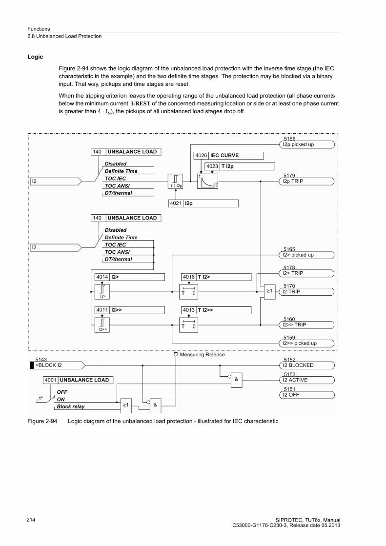
Functions
2.8 Unbalanced Load Protection
SIPROTEC, 7UT6x, ManualC53000-G1176-C230-3, Release date 05.2013
214
Logic
Figure 2-94 shows the logic diagram of the unbalanced load protection with the inverse time stage (the IEC
characteristic in the example) and the two definite time stages. The protection may be blocked via a binary
input. That way, pickups and time stages are reset.
When the tripping criterion leaves the operating range of the unbalanced load protection (all phase currents
below the minimum current I-REST of the concerned measuring location or side or at least one phase current
is greater than 4 · IN), the pickups of all unbalanced load stages drop off.
Figure 2-94 Logic diagram of the unbalanced load protection - illustrated for IEC characteristic
Functions
2.8 Unbalanced Load Protection
SIPROTEC, 7UT6x, ManualC53000-G1176-C230-3, Release date 05.2013
215
Thermal Stage
With the aid of the thermal stages the unbalanced load protection can be well adapted to the thermal loading
of the electrical motor rotor during asymmetric load.
Pickup, Warning
The permissible continuous load imbalance is determined with the setting „I2 Permissible“. If this value is
exceeded, it applies as "Pickup" for the negative sequence protection. At the same time this sets the alarm
stage: After a set time „T WARN“ has expired, a warning message „I2> alarm“is given.
Thermal Characteristic
The thermal characteristic allows an approximate calculation of the thermal loading of the electrical motor rotor
by load imbalance in the stator. This follows the simplified equation:
with:
t Tripping time
O Asymmetry factor
I2 Negative sequence current
IN Obj Rated current of the protective object
The asymmetry factor K designates how long a negative sequence current may flow at nominal machine
current. It is therefore the distinctive number of the object to be protected.
If the constantly permissible unbalanced load „I2 ADM“ is exceeded, the summation of the warming negative
sequence system power commences. In this context, the current-time-area is calculated constantly to ensure
a correct consideration of changing load cases. As soon as the current-time-area (I2/INObj)2 · t) has exceeded
the K asymmetry factor, the thermal characteristic is tripped.
The model of the heating of the object to be protected is limited to 200 % of the thermal tripping limit.
Cool Down, Drop-Out
The „pickup“ of the unbalanced load protection falls back, when the allowable unbalanced load „I2 adm“ is
undershot. The thermal image maintains its state and an adjustable cool down time „T COOL DOWN“ is started.
In this context, this cool down time is defined as the time required by the thermal replica to cool down from 100
% to 0 %. In synchronous machines this depends on the construction, especially the damper winding. If there
is again an asymmetrical loading during the cool-down phase, the previous history is considered. The tripping
time would then decrease considerably.
Resulting Characteristic
As the thermal replica only works after exceeding the permissible continuous negative sequence current „I2
adm“, this value is the lower limit for resulting tripping characteristic Fig. 2-95). The area of the thermal replica
connects to it with increasing negative sequence current. High negative sequence currents can only be caused
by a phase-to-phase short circuit, which must be covered in accordance with the grading coordination chart.
The thermal characteristics are therefore cut off by the definite time I2>>-stage (see above under „Definite time
stage (DT)“). The trigger time of the thermal replica does not fall below the trigger time of the I2>>-stage

Functions
2.8 Unbalanced Load Protection
SIPROTEC, 7UT6x, ManualC53000-G1176-C230-3, Release date 05.2013
216
Figure 2-95 Resulting characteristic of the thermal asymmetrical load protection
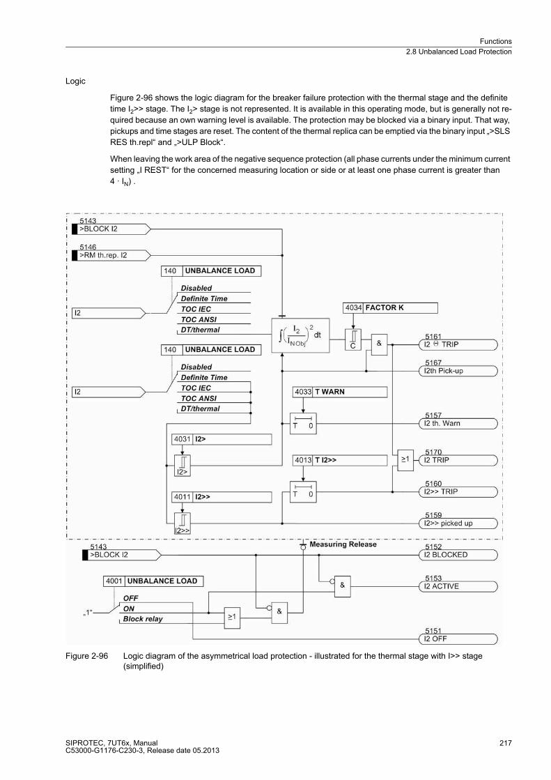
Functions
2.8 Unbalanced Load Protection
SIPROTEC, 7UT6x, ManualC53000-G1176-C230-3, Release date 05.2013
217
Logic
Figure 2-96 shows the logic diagram for the breaker failure protection with the thermal stage and the definite
time I2>> stage. The I2> stage is not represented. It is available in this operating mode, but is generally not re-
quired because an own warning level is available. The protection may be blocked via a binary input. That way,
pickups and time stages are reset. The content of the thermal replica can be emptied via the binary input „>SLS
RES th.repl“ and „>ULP Block“.
When leaving the work area of the negative sequence protection (all phase currents under the minimum current
setting „I REST“ for the concerned measuring location or side or at least one phase current is greater than
4 · IN) .
Figure 2-96 Logic diagram of the asymmetrical load protection - illustrated for the thermal stage with I>> stage (simplified)
Functions
2.8 Unbalanced Load Protection
SIPROTEC, 7UT6x, ManualC53000-G1176-C230-3, Release date 05.2013
218
2.8.2 Setting Notes
General
Unbalanced load protection only makes sense with three-phase protected objects. For PROT. OBJECT = 1ph
Busbar or 1 phase transf. (address 105) the following settings are not available.
The characteristic type has been determined during configuration of the functional scope under address 140
UNBALANCE LOAD (see section 2.1.3.1). Only the settings for the characteristic selected can be performed
here. The inverse time curves I2>> and I2> are available in all cases.
The unbalanced load protection must have been assigned to a side of the main protected object or another
3-phase current measuring location (Subsection 2.1.4 under margin heading „Further 3-Phase Protection
Functions“). Consider also the assignment of the measured current inputs of the device against the measuring
locations (current transformer sets) of the power plant (section 2.1.4 under margin heading „Assignment of
3-phase Measuring Locations“).
In address 4001 UNBALANCE LOAD the function can be set to ON or OFF. The option Block relay allows to
operate the protection but the trip output relay is blocked.
Note
If the unbalanced load protection is assigned to a side of the main protected object, the current values are set
referred to the rated current of that side I/INS, as stated in section 2.1.4. In other cases, current values are set
in amps.
Definite Time StagesI2>>, I2> (O/C)
A two-stage characteristic enables the user to set a short time delay (address 4013 T I2>>) for the upper stage
(address 4011 or 4012 I2>>), and a longer time delay (address 4016 T I2>) for the lower stage (address 4014 or
4015 I2>). Stage I2>, for example, can be used as alarm stage, stage I2>> as tripping stage.
In most cases, the I2>> stage will be set such that it will not pick up in the event of phase failure. Setting I2>>
to a percentage higher than 60 % ensures that no tripping is performed with stage I2>> in case of phase failure.
If power supply with current I is provided via just two phases, the following applies for the inverse current:
On the other hand, with more than 60 % negative sequence current, a two-phase fault in the system may be
assumed. Therefore, the delay time T I2>> must be coordinated with the time grading of the system.
On line feeders, unbalanced load protection may serve to identify low-current unsymmetrical faults below the
pickup values of the time overcurrent protection. The following applies
a phase-to-phase fault with current I corresponds to a negative sequence current:
a phase-to-earth current I corresponds to a negative sequence current:
With more than 60% unbalanced load, a two-phase fault can be assumed. The delay time thus needs to be
coordinated with the system grading for phase-to-phase faults.
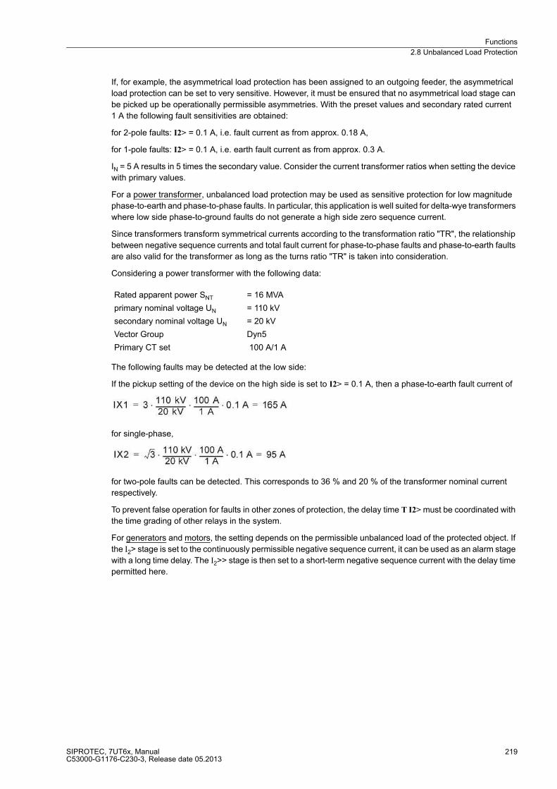
Functions
2.8 Unbalanced Load Protection
SIPROTEC, 7UT6x, ManualC53000-G1176-C230-3, Release date 05.2013
219
If, for example, the asymmetrical load protection has been assigned to an outgoing feeder, the asymmetrical
load protection can be set to very sensitive. However, it must be ensured that no asymmetrical load stage can
be picked up be operationally permissible asymmetries. With the preset values and secondary rated current
1 A the following fault sensitivities are obtained:
for 2-pole faults: I2> = 0.1 A, i.e. fault current as from approx. 0.18 A,
for 1-pole faults: I2> = 0.1 A, i.e. earth fault current as from approx. 0.3 A.
IN = 5 A results in 5 times the secondary value. Consider the current transformer ratios when setting the device
with primary values.
For a power transformer, unbalanced load protection may be used as sensitive protection for low magnitude
phase-to-earth and phase-to-phase faults. In particular, this application is well suited for delta-wye transformers
where low side phase-to-ground faults do not generate a high side zero sequence current.
Since transformers transform symmetrical currents according to the transformation ratio "TR", the relationship
between negative sequence currents and total fault current for phase-to-phase faults and phase-to-earth faults
are also valid for the transformer as long as the turns ratio "TR" is taken into consideration.
Considering a power transformer with the following data:
The following faults may be detected at the low side:
If the pickup setting of the device on the high side is set to I2> = 0.1 A, then a phase-to-earth fault current of
for single-phase,
for two-pole faults can be detected. This corresponds to 36 % and 20 % of the transformer nominal current
respectively.
To prevent false operation for faults in other zones of protection, the delay time T I2> must be coordinated with
the time grading of other relays in the system.
For generators and motors, the setting depends on the permissible unbalanced load of the protected object. If
the I2> stage is set to the continuously permissible negative sequence current, it can be used as an alarm stage
with a long time delay. The I2>> stage is then set to a short-term negative sequence current with the delay time
permitted here.
Rated apparent power SNT = 16 MVA
primary nominal voltage UN = 110 kV
secondary nominal voltage UN = 20 kV
Vector Group Dyn5
Primary CT set 100 A/1 A

Functions
2.8 Unbalanced Load Protection
SIPROTEC, 7UT6x, ManualC53000-G1176-C230-3, Release date 05.2013
220
Example:
The inverse curves (see below) permit a consideration of load imbalance per unit of time. However, especially
for generators and motors a better adjustment to the protected object can be achieved with the thermal stage
(see below under „Thermal Tripping Characteristic“).
Inverse Time ElementI2p for IEC Characteristics
Having selected an inverse time tripping characteristic the thermal load of a machine caused by unbalanced
load can be simulated easily. Use the characteristic which is most similar to the thermal asymmetrical load
curve of the machine manufacturer.
With the IEC characteristics (address 140 UNBALANCE LOAD = TOC IEC) the following options are available
at address 4026 IEC CURVE:
� Normal Inverse (inverse, type A according to IEC 60255-3),
� Very Inverse (very inverse, type B according to IEC 60255-3),
� Extremely Inv. (extremely inverse, type C according to IEC 60255-3).
The characteristics and equations they are based on are listed in the „Technical Data“.
If an inverse-time characteristic is selected, it must be noted that a safety factor of about 1.1 has already been
included between the pickup value and the setting value. This means that a pickup will only occur if an
unbalanced load of about 1.1 times the setting value of I2p (address 4021 or 4022) is present.
The corresponding time multiplier is accessible via address 4023 T I2p.
The time multiplication factor may also be set to ∞. If set to infinity, the pickup of this function will be indicated
but the stage will not trip after pickup. If the inverse time stage is not required, select 140 = UNBALANCE LOAD
in address Definite Time when configuring the protection functions.
If under address 4025 I2p DROP-OUT the Disk Emulationis set, dropout is thus produced in accordance with
the dropout characteristic, as described in the function description of the asymmetrical load protection under
margin heading „Dropout Behaviour“.
The definite time stages as discussed above under „Definite Time Stages I2>>, I2>“ can be used in addition to
the inverse-time stage as alarm and tripping stages.
Motor IN Motor = 545 A
I2 dd prim / IN Motor = 0.11 continuous
I2 max prim / IN Motor = 0.55 for Tmax = 1 s
Current trans-
former
TR = 600 A / 1 A
Setting I2> = 0.11 · 545 A = 60 A primary or
0.11· 545 A · (1/600) = 0.10 A secondary
Setting I2>> = 0.55 · 545 A = 300 A primary or
0.55· 545 A · (1/600) = 0.50 A secondary
Delay T I2>> = 1 s
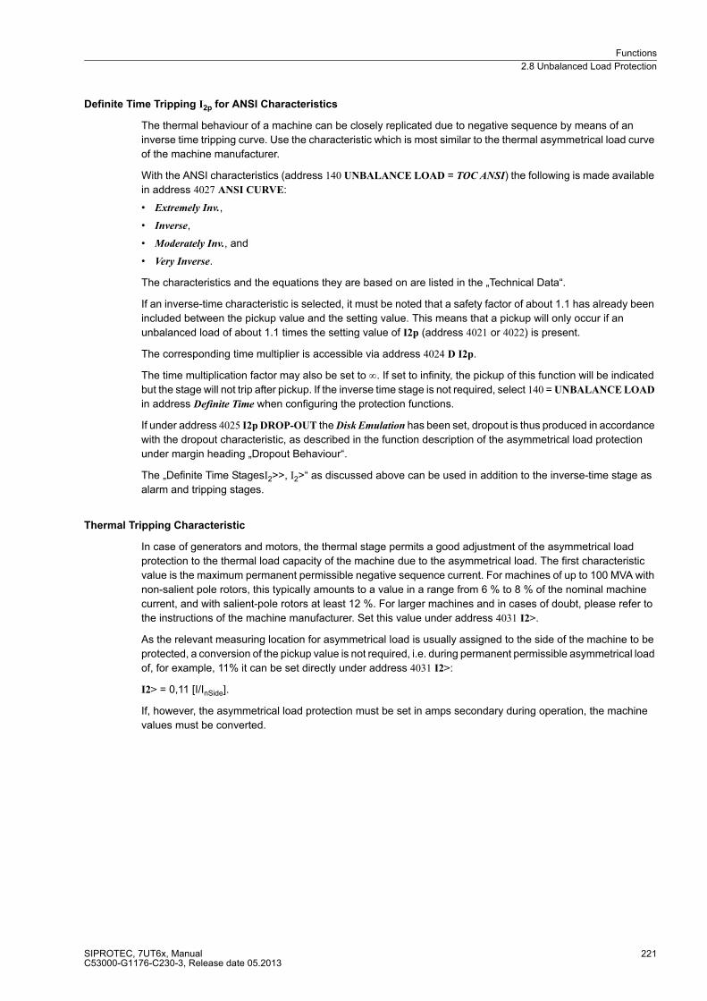
Functions
2.8 Unbalanced Load Protection
SIPROTEC, 7UT6x, ManualC53000-G1176-C230-3, Release date 05.2013
221
Definite Time Tripping I2p for ANSI Characteristics
The thermal behaviour of a machine can be closely replicated due to negative sequence by means of an
inverse time tripping curve. Use the characteristic which is most similar to the thermal asymmetrical load curve
of the machine manufacturer.
With the ANSI characteristics (address 140 UNBALANCE LOAD = TOC ANSI) the following is made available
in address 4027 ANSI CURVE:
� Extremely Inv.,
� Inverse,
� Moderately Inv., and
� Very Inverse.
The characteristics and the equations they are based on are listed in the „Technical Data“.
If an inverse-time characteristic is selected, it must be noted that a safety factor of about 1.1 has already been
included between the pickup value and the setting value. This means that a pickup will only occur if an
unbalanced load of about 1.1 times the setting value of I2p (address 4021 or 4022) is present.
The corresponding time multiplier is accessible via address 4024 D I2p.
The time multiplication factor may also be set to ∞. If set to infinity, the pickup of this function will be indicated
but the stage will not trip after pickup. If the inverse time stage is not required, select 140 = UNBALANCE LOAD
in address Definite Time when configuring the protection functions.
If under address 4025 I2p DROP-OUT the Disk Emulation has been set, dropout is thus produced in accordance
with the dropout characteristic, as described in the function description of the asymmetrical load protection
under margin heading „Dropout Behaviour“.
The „Definite Time StagesI2>>, I2>“ as discussed above can be used in addition to the inverse-time stage as
alarm and tripping stages.
Thermal Tripping Characteristic
In case of generators and motors, the thermal stage permits a good adjustment of the asymmetrical load
protection to the thermal load capacity of the machine due to the asymmetrical load. The first characteristic
value is the maximum permanent permissible negative sequence current. For machines of up to 100 MVA with
non-salient pole rotors, this typically amounts to a value in a range from 6 % to 8 % of the nominal machine
current, and with salient-pole rotors at least 12 %. For larger machines and in cases of doubt, please refer to
the instructions of the machine manufacturer. Set this value under address 4031 I2>.
As the relevant measuring location for asymmetrical load is usually assigned to the side of the machine to be
protected, a conversion of the pickup value is not required, i.e. during permanent permissible asymmetrical load
of, for example, 11% it can be set directly under address 4031 I2>:
I2> = 0,11 [I/InSide].
If, however, the asymmetrical load protection must be set in amps secondary during operation, the machine
values must be converted.
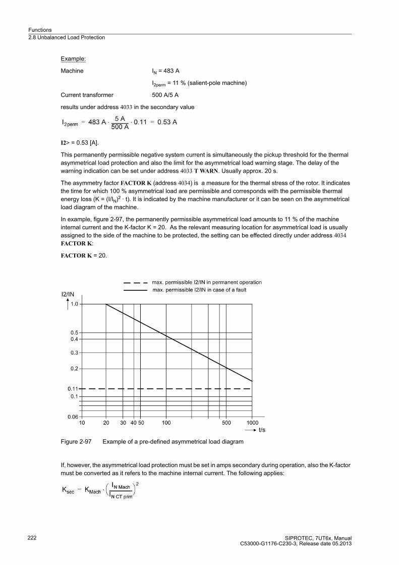
Functions
2.8 Unbalanced Load Protection
SIPROTEC, 7UT6x, ManualC53000-G1176-C230-3, Release date 05.2013
222
Example:
Machine IN = 483 A
I2perm = 11 % (salient-pole machine)
Current transformer 500 A/5 A
results under address 4033 in the secondary value
I2> = 0.53 [A].
This permanently permissible negative system current is simultaneously the pickup threshold for the thermal
asymmetrical load protection and also the limit for the asymmetrical load warning stage. The delay of the
warning indication can be set under address 4033 T WARN. Usually approx. 20 s.
The asymmetry factor FACTOR K (address 4034) is a measure for the thermal stress of the rotor. It indicates
the time for which 100 % asymmetrical load are permissible and corresponds with the permissible thermal
energy loss (K = (I/IN)2 · t). It is indicated by the machine manufacturer or it can be seen on the asymmetrical
load diagram of the machine.
In example, figure 2-97, the permanently permissible asymmetrical load amounts to 11 % of the machine
internal current and the K-factor K = 20. As the relevant measuring location for asymmetrical load is usually
assigned to the side of the machine to be protected, the setting can be effected directly under address 4034
FACTOR K:
FACTOR K = 20.
Figure 2-97 Example of a pre-defined asymmetrical load diagram
If, however, the asymmetrical load protection must be set in amps secondary during operation, also the K-factor
must be converted as it refers to the machine internal current. The following applies:
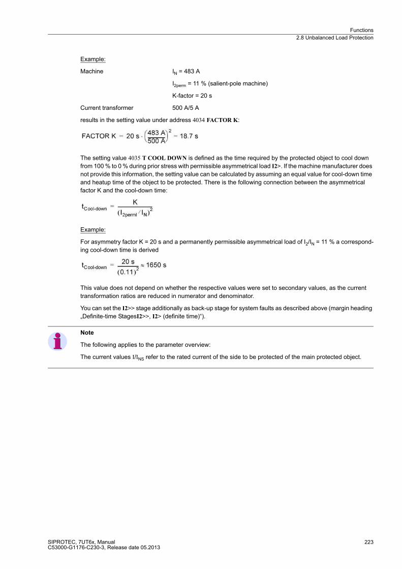
Functions
2.8 Unbalanced Load Protection
SIPROTEC, 7UT6x, ManualC53000-G1176-C230-3, Release date 05.2013
223
Example:
Machine IN = 483 A
I2perm = 11 % (salient-pole machine)
K-factor = 20 s
Current transformer 500 A/5 A
results in the setting value under address 4034 FACTOR K:
The setting value 4035 T COOL DOWN is defined as the time required by the protected object to cool down
from 100 % to 0 % during prior stress with permissible asymmetrical load I2>. If the machine manufacturer does
not provide this information, the setting value can be calculated by assuming an equal value for cool-down time
and heatup time of the object to be protected. There is the following connection between the asymmetrical
factor K and the cool-down time:
Example:
For asymmetry factor K = 20 s and a permanently permissible asymmetrical load of I2/IN = 11 % a correspond-
ing cool-down time is derived
This value does not depend on whether the respective values were set to secondary values, as the current
transformation ratios are reduced in numerator and denominator.
You can set the I2>> stage additionally as back-up stage for system faults as described above (margin heading
„Definite-time StagesI2>>, I2> (definite time)“).
Note
The following applies to the parameter overview:
The current values I/INS refer to the rated current of the side to be protected of the main protected object.
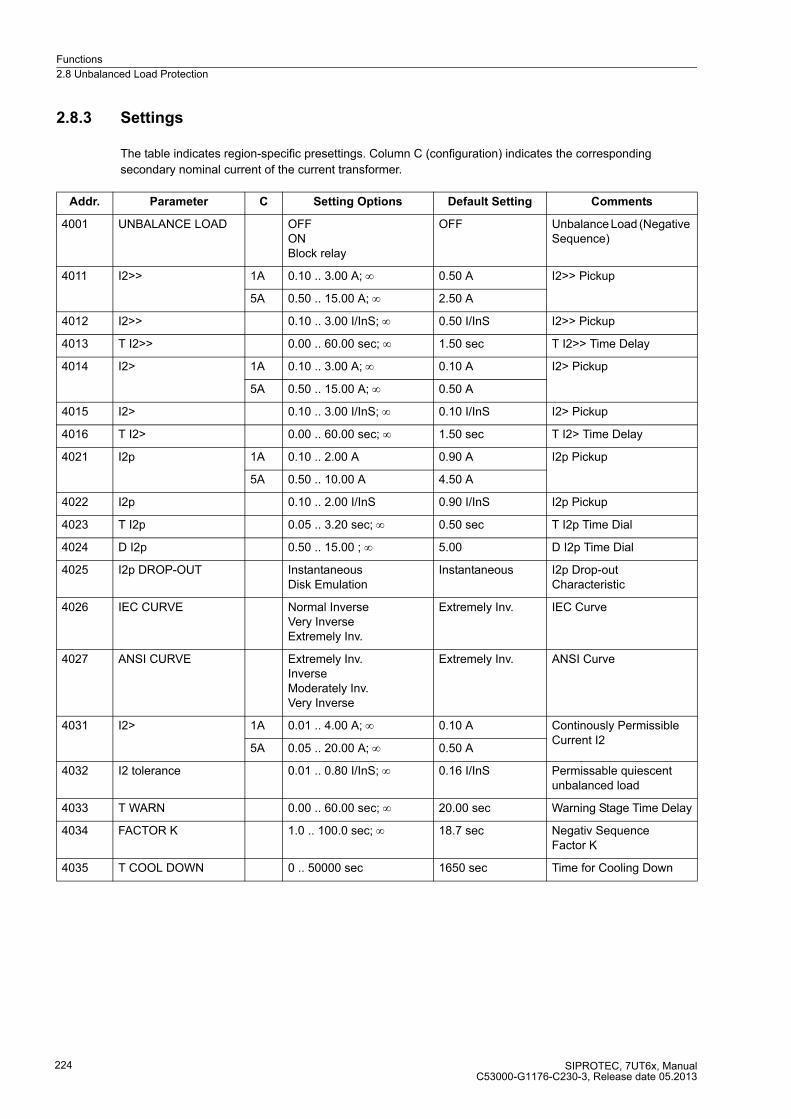
Functions
2.8 Unbalanced Load Protection
SIPROTEC, 7UT6x, ManualC53000-G1176-C230-3, Release date 05.2013
224
2.8.3 Settings
The table indicates region-specific presettings. Column C (configuration) indicates the corresponding
secondary nominal current of the current transformer.
Addr. Parameter C Setting Options Default Setting Comments
4001 UNBALANCE LOAD OFFONBlock relay
OFF Unbalance Load (Negative Sequence)
4011 I2>> 1A 0.10 .. 3.00 A; ∞ 0.50 A I2>> Pickup
5A 0.50 .. 15.00 A; ∞ 2.50 A
4012 I2>> 0.10 .. 3.00 I/InS; ∞ 0.50 I/InS I2>> Pickup
4013 T I2>> 0.00 .. 60.00 sec; ∞ 1.50 sec T I2>> Time Delay
4014 I2> 1A 0.10 .. 3.00 A; ∞ 0.10 A I2> Pickup
5A 0.50 .. 15.00 A; ∞ 0.50 A
4015 I2> 0.10 .. 3.00 I/InS; ∞ 0.10 I/InS I2> Pickup
4016 T I2> 0.00 .. 60.00 sec; ∞ 1.50 sec T I2> Time Delay
4021 I2p 1A 0.10 .. 2.00 A 0.90 A I2p Pickup
5A 0.50 .. 10.00 A 4.50 A
4022 I2p 0.10 .. 2.00 I/InS 0.90 I/InS I2p Pickup
4023 T I2p 0.05 .. 3.20 sec; ∞ 0.50 sec T I2p Time Dial
4024 D I2p 0.50 .. 15.00 ; ∞ 5.00 D I2p Time Dial
4025 I2p DROP-OUT InstantaneousDisk Emulation
Instantaneous I2p Drop-out Characteristic
4026 IEC CURVE Normal InverseVery InverseExtremely Inv.
Extremely Inv. IEC Curve
4027 ANSI CURVE Extremely Inv.InverseModerately Inv.Very Inverse
Extremely Inv. ANSI Curve
4031 I2> 1A 0.01 .. 4.00 A; ∞ 0.10 A Continously Permissible Current I2
5A 0.05 .. 20.00 A; ∞ 0.50 A
4032 I2 tolerance 0.01 .. 0.80 I/InS; ∞ 0.16 I/InS Permissable quiescent unbalanced load
4033 T WARN 0.00 .. 60.00 sec; ∞ 20.00 sec Warning Stage Time Delay
4034 FACTOR K 1.0 .. 100.0 sec; ∞ 18.7 sec Negativ Sequence Factor K
4035 T COOL DOWN 0 .. 50000 sec 1650 sec Time for Cooling Down
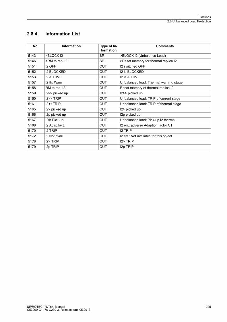
Functions
2.8 Unbalanced Load Protection
SIPROTEC, 7UT6x, ManualC53000-G1176-C230-3, Release date 05.2013
225
2.8.4 Information List
No. Information Type of In-
formation
Comments
5143 >BLOCK I2 SP >BLOCK I2 (Unbalance Load)
5146 >RM th.rep. I2 SP >Reset memory for thermal replica I2
5151 I2 OFF OUT I2 switched OFF
5152 I2 BLOCKED OUT I2 is BLOCKED
5153 I2 ACTIVE OUT I2 is ACTIVE
5157 I2 th. Warn OUT Unbalanced load: Thermal warning stage
5158 RM th.rep. I2 OUT Reset memory of thermal replica I2
5159 I2>> picked up OUT I2>> picked up
5160 I2>> TRIP OUT Unbalanced load: TRIP of current stage
5161 I2 Θ TRIP OUT Unbalanced load: TRIP of thermal stage
5165 I2> picked up OUT I2> picked up
5166 I2p picked up OUT I2p picked up
5167 I2th Pick-up OUT Unbalanced load: Pick-up I2 thermal
5168 I2 Adap.fact. OUT I2 err.: adverse Adaption factor CT
5170 I2 TRIP OUT I2 TRIP
5172 I2 Not avail. OUT I2 err.: Not available for this object
5178 I2> TRIP OUT I2> TRIP
5179 I2p TRIP OUT I2p TRIP
Functions
2.9 Thermal Overload Protection
SIPROTEC, 7UT6x, ManualC53000-G1176-C230-3, Release date 05.2013
226
2.9 Thermal Overload Protection
The thermal overload protection prevents damage to the protected object caused by thermal overloading,
particularly in case of transformers, rotating machines, power reactors and cables. This protection is not
applicable to single-phase busbar protection. It can be assigned to any of the sides of the main protected
object, however, not to a non-assigned measuring point.
2.9.1 General
Three methods of overload detection are available in 7UT6x:
� Overload calculation using a thermal replica according to IEC 60255-8, without ambient temperature
influence
� Overload calculation using a thermal replica according to IEC 60255-8, with ambient temperature influence
� Calculation of the hot-spot temperature and determination of the ageing rate according to IEC 60354.
You may select one of these three methods. The first one is characterised by easy handling and setting; it
calculates the overtemperature caused by current heat losses.
For the second one the ambient or coolant temperature is taken into consideration; it calculates the total tem-
perature. It is required that the decisive coolant temperature is signalled to the device via a connected RTD box.
The third needs some knowledge about the protected object and its thermal characteristics and the input of the
cooling medium temperature.
7UT6xis equipped with two breaker failure protection functions that can be used independent of each other and
for different locations of the protective object. One can also work with different starting criteria. The assignment
of the protective functions to the protected object are performed as described in section „Assignment of
Protection Functions to Measuring Locations/Sides“.
2.9.2 Overload Protection Using a Thermal Replica
Principle
The overload protection of 7UT6x can be assigned to one of the sides of the main protected object (selectable).
Since the cause of overload is normally outside the protected, the overload current is a through-flow current.
The unit computes the temperature rise according to a thermal single-body model as per the following thermal
differential equation
T actual valid temperature rise referred to the final temperature rise at maximum permissible current of the assigned side of the protected object k · IN Obj
τth thermal time constant for the heating
k k-factor which states the maximum permissible continuous current, referred to the rated current of the assigned side of the protected object
I currently valid RMS current of the assigned side of the protected object
IN Obj rated current of the assigned side of the protected object
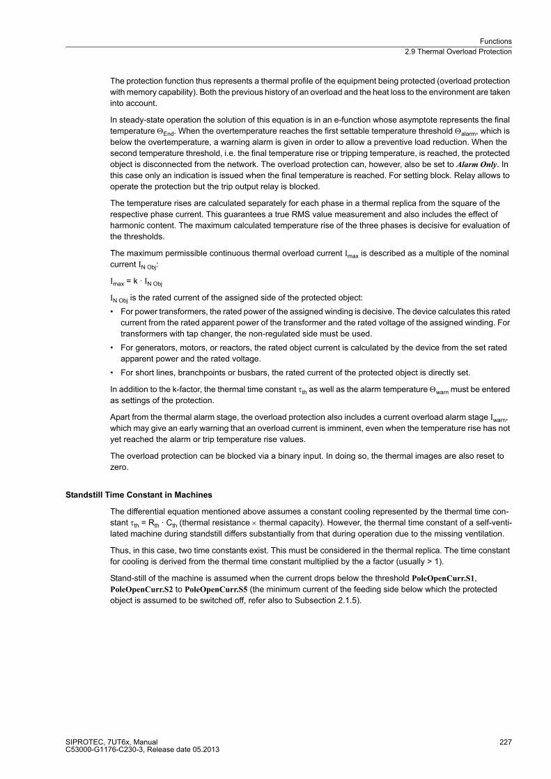
Functions
2.9 Thermal Overload Protection
SIPROTEC, 7UT6x, ManualC53000-G1176-C230-3, Release date 05.2013
227
The protection function thus represents a thermal profile of the equipment being protected (overload protection
with memory capability). Both the previous history of an overload and the heat loss to the environment are taken
into account.
In steady-state operation the solution of this equation is in an e-function whose asymptote represents the final
temperature ΘEnd. When the overtemperature reaches the first settable temperature threshold Θalarm, which is
below the overtemperature, a warning alarm is given in order to allow a preventive load reduction. When the
second temperature threshold, i.e. the final temperature rise or tripping temperature, is reached, the protected
object is disconnected from the network. The overload protection can, however, also be set to Alarm Only. In
this case only an indication is issued when the final temperature is reached. For setting block. Relay allows to
operate the protection but the trip output relay is blocked.
The temperature rises are calculated separately for each phase in a thermal replica from the square of the
respective phase current. This guarantees a true RMS value measurement and also includes the effect of
harmonic content. The maximum calculated temperature rise of the three phases is decisive for evaluation of
the thresholds.
The maximum permissible continuous thermal overload current Imax is described as a multiple of the nominal
current IN Obj:
Imax = k · IN Obj
IN Obj is the rated current of the assigned side of the protected object:
� For power transformers, the rated power of the assigned winding is decisive. The device calculates this rated
current from the rated apparent power of the transformer and the rated voltage of the assigned winding. For
transformers with tap changer, the non-regulated side must be used.
� For generators, motors, or reactors, the rated object current is calculated by the device from the set rated
apparent power and the rated voltage.
� For short lines, branchpoints or busbars, the rated current of the protected object is directly set.
In addition to the k-factor, the thermal time constant τth as well as the alarm temperature Θwarn must be entered
as settings of the protection.
Apart from the thermal alarm stage, the overload protection also includes a current overload alarm stage Iwarn,
which may give an early warning that an overload current is imminent, even when the temperature rise has not
yet reached the alarm or trip temperature rise values.
The overload protection can be blocked via a binary input. In doing so, the thermal images are also reset to
zero.
Standstill Time Constant in Machines
The differential equation mentioned above assumes a constant cooling represented by the thermal time con-
stant τth = Rth · Cth (thermal resistance × thermal capacity). However, the thermal time constant of a self-venti-
lated machine during standstill differs substantially from that during operation due to the missing ventilation.
Thus, in this case, two time constants exist. This must be considered in the thermal replica. The time constant
for cooling is derived from the thermal time constant multiplied by the a factor (usually > 1).
Stand-still of the machine is assumed when the current drops below the threshold PoleOpenCurr.S1,
PoleOpenCurr.S2 to PoleOpenCurr.S5 (the minimum current of the feeding side below which the protected
object is assumed to be switched off, refer also to Subsection 2.1.5).

Functions
2.9 Thermal Overload Protection
SIPROTEC, 7UT6x, ManualC53000-G1176-C230-3, Release date 05.2013
228
Motor Startup
On startup of electrical machines the overtemperature calculated by the thermal replica may exceed the alarm
overtemperature or even the trip overtemperature. In order to avoid an alarm or trip, the starting current is
acquired and the resulting increase of temperature rise is suppressed. This means that the calculated temper-
ature rise is kept constant as long as the starting current is detected.
Emergency Starting of Machines
When machines must be started for emergency reasons, operating temperature above the maximum permis-
sible operating temperature can be allowed by blocking the tripping signal via a binary input („>Emer.Start O/L“).
After startup and dropout of the binary input, the thermal replica may still be greater than the trip temperature
rise. Therefore the thermal replica features a settable run-on time (T EMERGENCY) which is started when the
binary input drops out. It also suppresses the trip command. Tripping by the overload protection will be defeated
until the time interval has lapsed. This binary input only affects the trip command. There is no effect on fault
recording, nor does the thermal replica reset.
Figure 2-98 Logic diagram of the thermal overload protection (simplified)
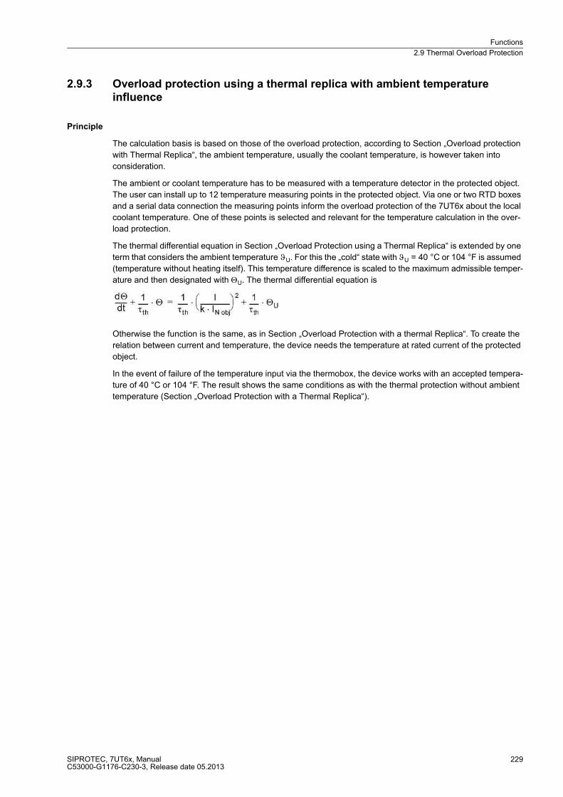
Functions
2.9 Thermal Overload Protection
SIPROTEC, 7UT6x, ManualC53000-G1176-C230-3, Release date 05.2013
229
2.9.3 Overload protection using a thermal replica with ambient temperature influence
Principle
The calculation basis is based on those of the overload protection, according to Section „Overload protection
with Thermal Replica“, the ambient temperature, usually the coolant temperature, is however taken into
consideration.
The ambient or coolant temperature has to be measured with a temperature detector in the protected object.
The user can install up to 12 temperature measuring points in the protected object. Via one or two RTD boxes
and a serial data connection the measuring points inform the overload protection of the 7UT6x about the local
coolant temperature. One of these points is selected and relevant for the temperature calculation in the over-
load protection.
The thermal differential equation in Section „Overload Protection using a Thermal Replica“ is extended by one
term that considers the ambient temperature ϑU. For this the „cold“ state with ϑU = 40 °C or 104 °F is assumed
(temperature without heating itself). This temperature difference is scaled to the maximum admissible temper-
ature and then designated with ΘU. The thermal differential equation is
Otherwise the function is the same, as in Section „Overload Protection with a thermal Replica“. To create the
relation between current and temperature, the device needs the temperature at rated current of the protected
object.
In the event of failure of the temperature input via the thermobox, the device works with an accepted tempera-
ture of 40 °C or 104 °F. The result shows the same conditions as with the thermal protection without ambient
temperature (Section „Overload Protection with a Thermal Replica“).
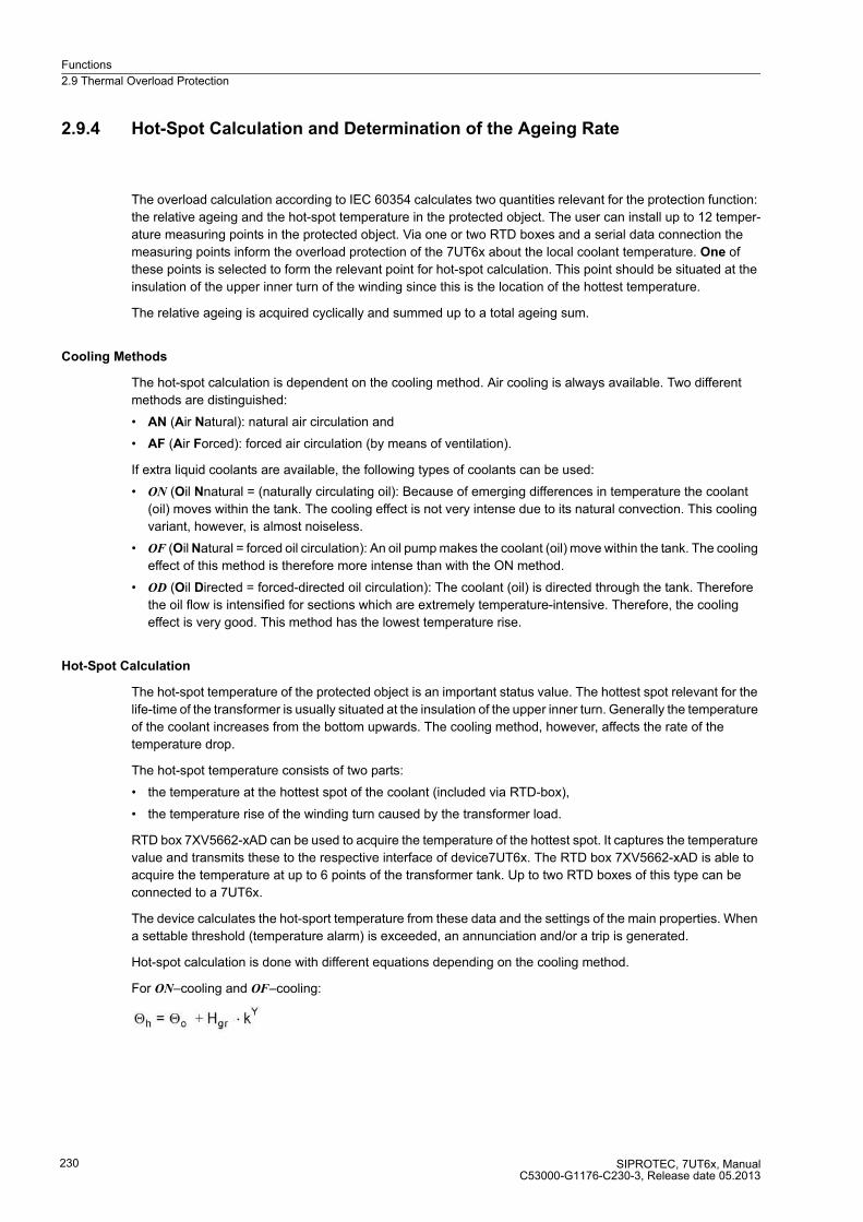
Functions
2.9 Thermal Overload Protection
SIPROTEC, 7UT6x, ManualC53000-G1176-C230-3, Release date 05.2013
230
2.9.4 Hot-Spot Calculation and Determination of the Ageing Rate
The overload calculation according to IEC 60354 calculates two quantities relevant for the protection function:
the relative ageing and the hot-spot temperature in the protected object. The user can install up to 12 temper-
ature measuring points in the protected object. Via one or two RTD boxes and a serial data connection the
measuring points inform the overload protection of the 7UT6x about the local coolant temperature. One of
these points is selected to form the relevant point for hot-spot calculation. This point should be situated at the
insulation of the upper inner turn of the winding since this is the location of the hottest temperature.
The relative ageing is acquired cyclically and summed up to a total ageing sum.
Cooling Methods
The hot-spot calculation is dependent on the cooling method. Air cooling is always available. Two different
methods are distinguished:
� AN (Air Natural): natural air circulation and
� AF (Air Forced): forced air circulation (by means of ventilation).
If extra liquid coolants are available, the following types of coolants can be used:
� ON (Oil Nnatural = (naturally circulating oil): Because of emerging differences in temperature the coolant
(oil) moves within the tank. The cooling effect is not very intense due to its natural convection. This cooling
variant, however, is almost noiseless.
� OF (Oil Natural = forced oil circulation): An oil pump makes the coolant (oil) move within the tank. The cooling
effect of this method is therefore more intense than with the ON method.
� OD (Oil Directed = forced-directed oil circulation): The coolant (oil) is directed through the tank. Therefore
the oil flow is intensified for sections which are extremely temperature-intensive. Therefore, the cooling
effect is very good. This method has the lowest temperature rise.
Hot-Spot Calculation
The hot-spot temperature of the protected object is an important status value. The hottest spot relevant for the
life-time of the transformer is usually situated at the insulation of the upper inner turn. Generally the temperature
of the coolant increases from the bottom upwards. The cooling method, however, affects the rate of the
temperature drop.
The hot-spot temperature consists of two parts:
� the temperature at the hottest spot of the coolant (included via RTD-box),
� the temperature rise of the winding turn caused by the transformer load.
RTD box 7XV5662-xAD can be used to acquire the temperature of the hottest spot. It captures the temperature
value and transmits these to the respective interface of device7UT6x. The RTD box 7XV5662-xAD is able to
acquire the temperature at up to 6 points of the transformer tank. Up to two RTD boxes of this type can be
connected to a 7UT6x.
The device calculates the hot-sport temperature from these data and the settings of the main properties. When
a settable threshold (temperature alarm) is exceeded, an annunciation and/or a trip is generated.
Hot-spot calculation is done with different equations depending on the cooling method.
For ON–cooling and OF–cooling:
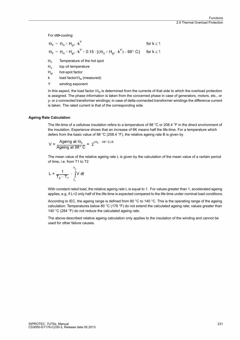
Functions
2.9 Thermal Overload Protection
SIPROTEC, 7UT6x, ManualC53000-G1176-C230-3, Release date 05.2013
231
For OD-cooling:
Θh Temperature of the hot spot
Θo top oil temperature
Hgr hot-spot factor
k load factorI/IN (measured)
Y winding exponent
In this aspect, the load factor I/IN is determined from the currents of that side to which the overload protection
is assigned. The phase information is taken from the concerned phase in case of generators, motors, etc., or
y- or z-connected transformer windings; in case of delta-connected transformer windings the difference current
is taken. The rated current is that of the corresponding side.
Ageing Rate Calculation
The life-time of a cellulose insulation refers to a temperature of 98 °C or 208.4 °F in the direct environment of
the insulation. Experience shows that an increase of 6K means half the life-time. For a temperature which
defers from the basic value of 98 °C (208.4 °F), the relative ageing rate B is given by
The mean value of the relative ageing rate L is given by the calculation of the mean value of a certain period
of time, i.e. from T1 to T2
With constant rated load, the relative ageing rate L is equal to 1. For values greater than 1, accelerated ageing
applies, e.g. if L=2 only half of the life-time is expected compared to the life-time under nominal load conditions.
According to IEC, the ageing range is defined from 80 °C to 140 °C. This is the operating range of the ageing
calculation: Temperatures below 80 °C (176 °F) do not extend the calculated ageing rate; values greater than
140 °C (284 °F) do not reduce the calculated ageing rate.
The above-described relative ageing calculation only applies to the insulation of the winding and cannot be
used for other failure causes.
Functions
2.9 Thermal Overload Protection
SIPROTEC, 7UT6x, ManualC53000-G1176-C230-3, Release date 05.2013
232
Output of Results
The hot-spot temperature is calculated for the winding which corresponds to the side of the protected object
configured for overload protection (Subsection 2.1.4, margin heading „Further 3-phase Protection Functions“,
address 442). The calculation includes the current of that side and the cooling temperature measured at a
certain measuring point. The phase information is taken from the concerned phase in case of generators,
motors, etc., or wye- or zigzag-connected transformer windings; in case of delta-connected transformer
windings the phase-difference currents are decisive which correspond to the current flowing in the winding.
There are two thresholds which can be set. They output a warning (Stage 1) and an alarm (Stage 2) signal.
When the alarm signal is assigned to a trip output, it can also be used for tripping the circuit breaker(s).
For the middle ageing rate, there is also a threshold for each of the warning and the alarm signal.
The status can be read out from the operational measured values at any time. The information includes:
� hot-spot temperature for each winding in °C or °F (as configured),
� relative ageing rate expressed in per unit,
� load backup up to warning signal (Stage 1) expressed in per cent,
� load backup up to alarm signal (Stage 2) expressed in per cent.
Further limit values can be set on the thermobox itself, as in Section „RTD-Boxes for Overload Recognition“
2.9.5 Setting Notes
General
Note
The first thermal overload protection is described in the setting instructions. The parameter addresses and
message numbers of the second thermal overload protection are described at the end of the setting instructions
under „Additional Thermal Overload Protection Functions“.
The overload protection can be assigned to any desired side of the protected object. Since the cause of the
overload current is outside the protected object, the overload current is a through-flowing current, the overload
protection may be assigned to a feeding or a non-feeding side. When setting the assignment of the protection
functions to the sides of the protected object according to Subsection 2.1.4, margin heading „Further 3-Phase
Protection functions“, you have performed this assignment under address 442 THERM. O/L AT. Respective
notes are given here.
Three methods are available for overload detection, as set out above. During configuration of the functional
scope (section 2.1.3.1) it was set under address 142 THERM. OVERLOAD whether the overload protection
must function according to the thermal replica (THERM. OVERLOAD = th rep w.o. sen), if necessary, under
inclusion of the environmental or coolant temperature (THERM. OVERLOAD = th repl w. sens) or whether the
hot-spot calculation according to IEC 60354 must be executed (THERM. OVERLOAD = IEC354). In the latter
two cases, at least one RTD-box 7XV5662-xAD must be connected to the device in order to digitally inform the
device about the coolant temperature. The required data for the RTD-box were set under address 191 RTD
CONNECTION (section 2.1.3.1).
Under address 4201 THERM. OVERLOAD overload protection ON or OFF can be set. If address 142 THERM.
OVERLOAD has been set to th rep w.o. sen during configuration of the functional scope, the setting Alarm Only
is also possible. With that latter setting the protection function is active but only outputs an alarm when the trip-
ping temperature rise is reached, i.e. the output function is not active. The option Block relay allows to operate
the protection but the trip output relay is blocked.
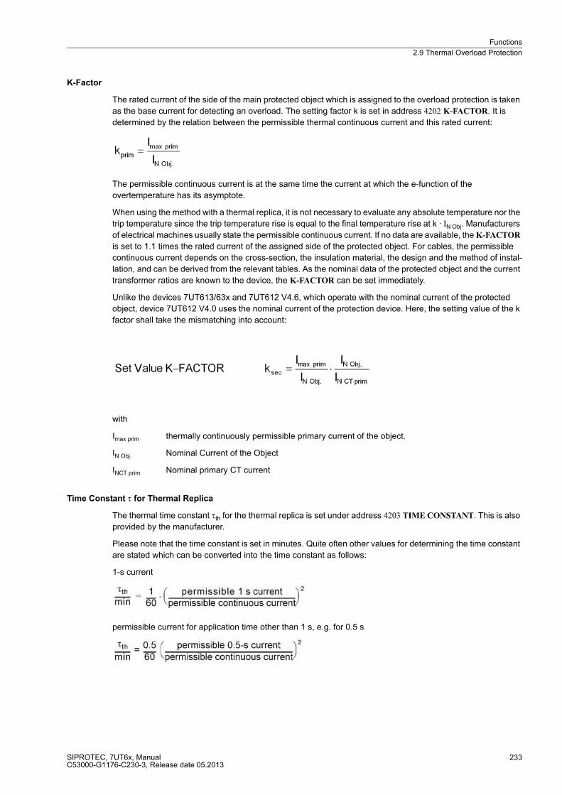
Functions
2.9 Thermal Overload Protection
SIPROTEC, 7UT6x, ManualC53000-G1176-C230-3, Release date 05.2013
233
K-Factor
The rated current of the side of the main protected object which is assigned to the overload protection is taken
as the base current for detecting an overload. The setting factor k is set in address 4202 K-FACTOR. It is
determined by the relation between the permissible thermal continuous current and this rated current:
The permissible continuous current is at the same time the current at which the e-function of the
overtemperature has its asymptote.
When using the method with a thermal replica, it is not necessary to evaluate any absolute temperature nor the
trip temperature since the trip temperature rise is equal to the final temperature rise at k · IN Obj. Manufacturers
of electrical machines usually state the permissible continuous current. If no data are available, the K-FACTOR
is set to 1.1 times the rated current of the assigned side of the protected object. For cables, the permissible
continuous current depends on the cross-section, the insulation material, the design and the method of instal-
lation, and can be derived from the relevant tables. As the nominal data of the protected object and the current
transformer ratios are known to the device, the K-FACTOR can be set immediately.
Unlike the devices 7UT613/63x and 7UT612 V4.6, which operate with the nominal current of the protected
object, device 7UT612 V4.0 uses the nominal current of the protection device. Here, the setting value of the k
factor shall take the mismatching into account:
with
Imax prim thermally continuously permissible primary current of the object.
IN Obj. Nominal Current of the Object
INCT prim Nominal primary CT current
Time Constant τ for Thermal Replica
The thermal time constant τth for the thermal replica is set under address 4203 TIME CONSTANT. This is also
provided by the manufacturer.
Please note that the time constant is set in minutes. Quite often other values for determining the time constant
are stated which can be converted into the time constant as follows:
1-s current
permissible current for application time other than 1 s, e.g. for 0.5 s

Functions
2.9 Thermal Overload Protection
SIPROTEC, 7UT6x, ManualC53000-G1176-C230-3, Release date 05.2013
234
t6-time; this is the time in seconds for which a current of 6 times the rated current of the protected object may
flow
Functions
2.9 Thermal Overload Protection
SIPROTEC, 7UT6x, ManualC53000-G1176-C230-3, Release date 05.2013
235
Calculation examples:
Cable with
permissible continuous current 322 A
permissible 1-s current 13.5 kA
Setting value TIME CONSTANT = 29.4 min
Motor with t6–time 12 s
Setting value TIME CONSTANT = 7.2 min
For rotating machines, the thermal time constant set under TIME CONSTANT is valid for as long as the
machine is running. The machine will cool down significantly slower during stand-still or running down, if it is
self-ventilated. This phenomenon is considered by a higher stand-still time constant Kτ-FACTOR (address
4207) which is set as a factor of the normal time constant. This parameter can only be set with DIGSI under
Additional Settings.
If it not necessary to distinguish between different time constants, e.g. with cables, transformers, reactors, etc.,
retain the factor Kτ-FACTOR = 1.0 (default setting).
Environment Temperature Influence in Thermal Replica
If the environmental or coolant temperature must be taken into consideration in the thermal replica, the device
must be informed as to which of the temperature detectors (RTD = Resistance Temperature Detector) is appli-
cable. With RTD-box 7XV5662–xAD up to 6 detectors are possible, with 2 boxes up to 12. In case of connection
of one RTD-box, under address 4210 TEMPSENSOR RTD the number of the applicable temperature detector
(1 to 6) must be set, in case of connection of two RTD-boxes under address 4211 TEMPSENSOR RTD (1 to
12). Only such address is always available that corresponds with the setting in accordance with the functional
scope (section 2.1.3.1) under address 191 RTD CONNECTION.
All calculations are performed with standardised quantities. The ambient temperature must also be stan-
dardised. The temperature with nominal current of the protected object is used as standardised quantity. Set
this temperature under address 4212 TEMP. RISE I in °C or under address 4213 TEMP. RISE I in °F, depending
on which temperature unit was selected in accordance with section 2.1.4.
Alarm Stages with Thermal Replica
By setting a thermal alarm stage Θ ALARM (address 4204) an alarm can be released before the tripping tem-
perature is reached, so that a trip can be avoided by early load reduction or by switching over. The percentage
refers to the tripping temperature rise. Note that the final temperature rise is proportional to the square of the
current.
Example:
k-factor k = 1.1
Nominal current flow results in the following temperature rise:
Functions
2.9 Thermal Overload Protection
SIPROTEC, 7UT6x, ManualC53000-G1176-C230-3, Release date 05.2013
236
The thermal warning stage should be set above temperature rise at nominal current (82.6 %). A sensible setting
value would be Θ ALARM = 90 %.
The current overload alarm setpoint I ALARM (address 4205) is referred to the rated current of the side and
should be set equal to or slightly below the permissible continuous current k ·IN Obj. It can also be used instead
of the thermal alarm stage. In this case, the thermal alarm stage is set to 100 % and is thus virtually ineffective.
Emergency Start for Motors
The run-on time value to be entered at address 4208 T EMERGENCY must ensure that, after an emergency
start and dropout of the binary input , the trip command is blocked until the thermal replica has fallen below the
dropout threshold. This parameter can only be set with DIGSI under Additional Settings.
The startup itself is only recognised if the startup current 4209 set in address I MOTOR START is exceeded.
Under each load and voltage condition during motor start, the value must be overshot by the actual startup cur-
rent. With short-time permissible overload the value must not be reached. This parameter can only be set with
DIGSI under Additional Settings. For other protected objects retain setting ∞. The emergency start is thus
disabled.
Temperature Detector for Hot-spot Calculation
For the hot-spot calculation according to IEC 60354 the device must be informed on the type of resistance tem-
perature detectors (RTD) that will be used for measuring the oil temperature, the one relevant for the hot-spot
calculation and ageing determination. With a RTD-box 7XV5662x–xAD up to 6 detectors are possible, with 2
boxes up to 12. On connection of one RTD-box set under address 4220 OIL-DET. RTD the number of the rel-
evant temperature detector (1 to 6), on connection of two RTD-boxes under address 4221 OIL-DET. RTD (1
to 12). Only such address is always available that corresponds with the setting in accordance with the func-
tional scope (section 2.1.3.1) under address 191 RTD CONNECTION.
The characteristic values of the temperature detectors are set separately, see section RTD-boxes 2.10).
Hot-Spot Stages
There are two annunciation stages for hot-spot temperature. To set a specific hot-spot temperature value
(expressed in °C), which is meant to generate the warning signal (stage 1), use address 4222 HOT SPOT ST.
1. Use address 4224 HOT SPOT ST. 2 to indicate the corresponding alarm temperature (stage 2). It can also
be used for the tripping of circuit breakers if the outgoing message (No 1542) is allocated to a trip relay.
If address 276TEMP. UNIT is set to degree Fahrenheit during configuration of the Power System Data 1, thresh-
olds for warning and alarm temperatures have to be expressed in Fahrenheit at addresses 4223 and 4225.
If the temperature unit is changed in address 276, after having set the thresholds for temperature, these
thresholds changed for the temperature unit, must be reset in the respective addresses.
Ageing Rate
For ageing rate L thresholds can also be set, i.e. for the warning signal (Stage 1) in address 4226AG. RATE ST.
1 and for alarm signal (Stage 2) in address 4227AG. RATE ST. 2. This information is referred to the relative
ageing, i.e. L=1 is reached at 98°C or 208°F at the hot spot. L > 1 refers to an accelerated ageing, L < 1 to
delayed ageing.
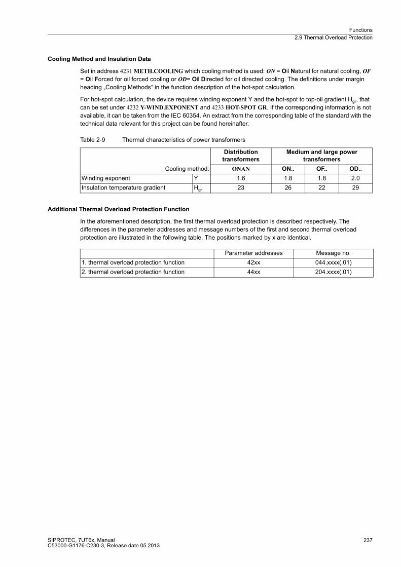
Functions
2.9 Thermal Overload Protection
SIPROTEC, 7UT6x, ManualC53000-G1176-C230-3, Release date 05.2013
237
Cooling Method and Insulation Data
Set in address 4231 METH.COOLING which cooling method is used: ON = Oil Natural for natural cooling, OF
= Oil Forced for oil forced cooling or OD= Oil Directed for oil directed cooling. The definitions under margin
heading „Cooling Methods“ in the function description of the hot-spot calculation.
For hot-spot calculation, the device requires winding exponent Y and the hot-spot to top-oil gradient Hgr, that
can be set under 4232 Y-WIND.EXPONENT and 4233 HOT-SPOT GR. If the corresponding information is not
available, it can be taken from the IEC 60354. An extract from the corresponding table of the standard with the
technical data relevant for this project can be found hereinafter.
Table 2-9 Thermal characteristics of power transformers
Additional Thermal Overload Protection Function
In the aforementioned description, the first thermal overload protection is described respectively. The
differences in the parameter addresses and message numbers of the first and second thermal overload
protection are illustrated in the following table. The positions marked by x are identical.
Cooling method:
Distribution
transformers
Medium and large power
transformers
ONAN ON.. OF.. OD..
Winding exponent Y 1.6 1.8 1.8 2.0
Insulation temperature gradient Hgr 23 26 22 29
Parameter addresses Message no.
1. thermal overload protection function 42xx 044.xxxx(.01)
2. thermal overload protection function 44xx 204.xxxx(.01)
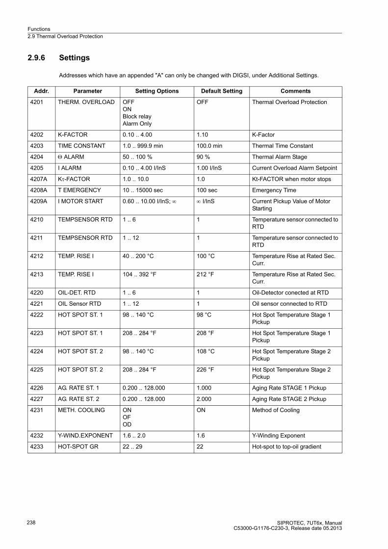
Functions
2.9 Thermal Overload Protection
SIPROTEC, 7UT6x, ManualC53000-G1176-C230-3, Release date 05.2013
238
2.9.6 Settings
Addresses which have an appended "A" can only be changed with DIGSI, under Additional Settings.
Addr. Parameter Setting Options Default Setting Comments
4201 THERM. OVERLOAD OFFONBlock relayAlarm Only
OFF Thermal Overload Protection
4202 K-FACTOR 0.10 .. 4.00 1.10 K-Factor
4203 TIME CONSTANT 1.0 .. 999.9 min 100.0 min Thermal Time Constant
4204 Θ ALARM 50 .. 100 % 90 % Thermal Alarm Stage
4205 I ALARM 0.10 .. 4.00 I/InS 1.00 I/InS Current Overload Alarm Setpoint
4207A Kτ-FACTOR 1.0 .. 10.0 1.0 Kt-FACTOR when motor stops
4208A T EMERGENCY 10 .. 15000 sec 100 sec Emergency Time
4209A I MOTOR START 0.60 .. 10.00 I/InS; ∞ ∞ I/InS Current Pickup Value of Motor Starting
4210 TEMPSENSOR RTD 1 .. 6 1 Temperature sensor connected to RTD
4211 TEMPSENSOR RTD 1 .. 12 1 Temperature sensor connected to RTD
4212 TEMP. RISE I 40 .. 200 °C 100 °C Temperature Rise at Rated Sec. Curr.
4213 TEMP. RISE I 104 .. 392 °F 212 °F Temperature Rise at Rated Sec. Curr.
4220 OIL-DET. RTD 1 .. 6 1 Oil-Detector conected at RTD
4221 OIL Sensor RTD 1 .. 12 1 Oil sensor connected to RTD
4222 HOT SPOT ST. 1 98 .. 140 °C 98 °C Hot Spot Temperature Stage 1 Pickup
4223 HOT SPOT ST. 1 208 .. 284 °F 208 °F Hot Spot Temperature Stage 1 Pickup
4224 HOT SPOT ST. 2 98 .. 140 °C 108 °C Hot Spot Temperature Stage 2 Pickup
4225 HOT SPOT ST. 2 208 .. 284 °F 226 °F Hot Spot Temperature Stage 2 Pickup
4226 AG. RATE ST. 1 0.200 .. 128.000 1.000 Aging Rate STAGE 1 Pickup
4227 AG. RATE ST. 2 0.200 .. 128.000 2.000 Aging Rate STAGE 2 Pickup
4231 METH. COOLING ONOFOD
ON Method of Cooling
4232 Y-WIND.EXPONENT 1.6 .. 2.0 1.6 Y-Winding Exponent
4233 HOT-SPOT GR 22 .. 29 22 Hot-spot to top-oil gradient

Functions
2.9 Thermal Overload Protection
SIPROTEC, 7UT6x, ManualC53000-G1176-C230-3, Release date 05.2013
239
2.9.7 Information List
No. Information Type of In-
formation
Comments
044.2404 >BLK ThOverload SP >BLOCK Thermal Overload Protection
044.2411 Th.Overload OFF OUT Thermal Overload Protection OFF
044.2412 Th.Overload BLK OUT Thermal Overload Protection BLOCKED
044.2413 Th.Overload ACT OUT Thermal Overload Protection ACTIVE
044.2421 O/L Th. pick.up OUT Thermal Overload picked up
044.2451 ThOverload TRIP OUT Thermal Overload TRIP
044.2491 O/L Not avail. OUT Th. Overload Not available for this obj.
044.2494 O/L Adap.fact. OUT Th. Overload err.:adverse Adap.factor CT
044.2601 >Emer.Start O/L SP >Emergency start Th. Overload Protection
044.2602 O/L I Alarm OUT Th. Overload Current Alarm (I alarm)
044.2603 O/L Θ Alarm OUT Thermal Overload Alarm
044.2604 O/L ht.spot Al. OUT Thermal Overload hot spot Th. Alarm
044.2605 O/L h.spot TRIP OUT Thermal Overload hot spot Th. TRIP
044.2606 O/L ag.rate Al. OUT Thermal Overload aging rate Alarm
044.2607 O/L ag.rt. TRIP OUT Thermal Overload aging rate TRIP
044.2609 O/L No Th.meas. OUT Th. Overload No temperature measured

Functions
2.10 RTD-Boxes for Overload Detection
SIPROTEC, 7UT6x, ManualC53000-G1176-C230-3, Release date 05.2013
240
2.10 RTD-Boxes for Overload Detection
For thermal overload protection, taking into consideration the ambient or coolant temperature as well as the
overload protection with hot-spot calculation and relative ageing rate determination, the coolant temperature in
the protected object or the temperature of the hottest spot of the winding (e.g. of a transformer) is required. At
least one resistance temperature detector (RTD) must be installed at the hot-spot location which informs the
device about this temperature via an RTD box 7XV5662-xAD. One RTD box is able to process up to 6 RTDs.
One or two RTD boxes 7XV5662-xAD can be connected to the device.
2.10.1 Function Description
One RTD box 7XV5662-xAD can be used for up to 6 measuring points (RTDs) in the protected object, e.g. in
the transformer tank. The RTD box detects the coolant temperature of each measuring point from the resis-
tance value of the temperature detectors (Pt 100, Ni 100 or Ni 120) connected with a two- or three-wire line and
converts it to a digital value. The digital values are output at the serial interface RS485.
One or two RTD boxes can be connected to the service interface of the 7UT6x. Thus, up to 6 or 12 measuring
points (RTDs) can be processed. For each temperature detector, characteristic data as well as alarm (stage 1)
and trip (stage 2) can be set.
The RTD box also acquires thresholds of each single measuring point. The information is then passed on via
an output relay. For further information, refer to the instruction manual of the RTD box.
2.10.2 Setting Notes
General
Set the type of temperature detector for RTD 1 (temperature sensor for measuring point 1) at address 9011 RTD
1 TYPE. You can choose between Pt 100 Ω, Ni 120 Ω and Ni 100 Ω. If no temperature detector is available for
RTD 1, set RTD 1 TYPE = Not connected. This parameter can only be set with DIGSI under Additional Set-
tings.
Address 9012 RTD 1 LOCATION informs the device regarding the mounting location of RTD 1. You can choose
between Oil, Ambient, Winding, Bearing and Other. This parameter can only be set with DIGSI under Additional
Settings.
Furthermore, in the 7UT6x an alarm temperature (stage 1) and a tripping temperature (stage 2) can be set.
Depending on the temperature unit selected in the power system data in address 276 TEMP. UNIT, the alarm
temperature can be selected in degree Celsius (°C) in address 9013 RTD 1 STAGE 1 or in degree Fahrenheit
(°F) in address 9014 RTD 1 STAGE 1. The trip temperature expressed in Celsius (°C) is set in address 9015
RTD 1 STAGE 2, and under address 9016 RTD 1 STAGE 2 it can be set in degree Fahrenheit (°F) .
Temperature Detectors
The setting options and addresses of all connected temperature detectors for the first and the second RTD-box
are listed in the following parameter overview.
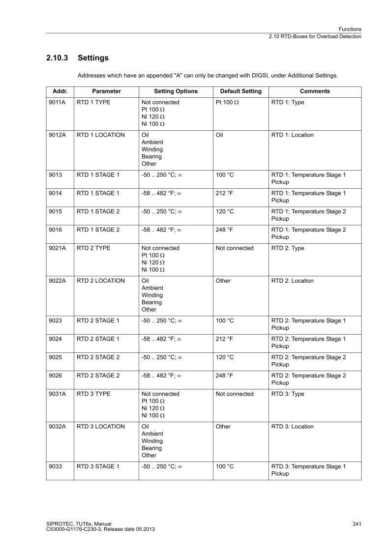
Functions
2.10 RTD-Boxes for Overload Detection
SIPROTEC, 7UT6x, ManualC53000-G1176-C230-3, Release date 05.2013
241
2.10.3 Settings
Addresses which have an appended "A" can only be changed with DIGSI, under Additional Settings.
Addr. Parameter Setting Options Default Setting Comments
9011A RTD 1 TYPE Not connectedPt 100 ΩNi 120 ΩNi 100 Ω
Pt 100 Ω RTD 1: Type
9012A RTD 1 LOCATION OilAmbientWindingBearingOther
Oil RTD 1: Location
9013 RTD 1 STAGE 1 -50 .. 250 °C; ∞ 100 °C RTD 1: Temperature Stage 1 Pickup
9014 RTD 1 STAGE 1 -58 .. 482 °F; ∞ 212 °F RTD 1: Temperature Stage 1 Pickup
9015 RTD 1 STAGE 2 -50 .. 250 °C; ∞ 120 °C RTD 1: Temperature Stage 2 Pickup
9016 RTD 1 STAGE 2 -58 .. 482 °F; ∞ 248 °F RTD 1: Temperature Stage 2 Pickup
9021A RTD 2 TYPE Not connectedPt 100 ΩNi 120 ΩNi 100 Ω
Not connected RTD 2: Type
9022A RTD 2 LOCATION OilAmbientWindingBearingOther
Other RTD 2: Location
9023 RTD 2 STAGE 1 -50 .. 250 °C; ∞ 100 °C RTD 2: Temperature Stage 1 Pickup
9024 RTD 2 STAGE 1 -58 .. 482 °F; ∞ 212 °F RTD 2: Temperature Stage 1 Pickup
9025 RTD 2 STAGE 2 -50 .. 250 °C; ∞ 120 °C RTD 2: Temperature Stage 2 Pickup
9026 RTD 2 STAGE 2 -58 .. 482 °F; ∞ 248 °F RTD 2: Temperature Stage 2 Pickup
9031A RTD 3 TYPE Not connectedPt 100 ΩNi 120 ΩNi 100 Ω
Not connected RTD 3: Type
9032A RTD 3 LOCATION OilAmbientWindingBearingOther
Other RTD 3: Location
9033 RTD 3 STAGE 1 -50 .. 250 °C; ∞ 100 °C RTD 3: Temperature Stage 1 Pickup
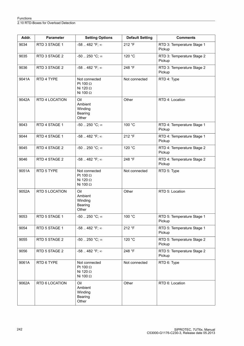
Functions
2.10 RTD-Boxes for Overload Detection
SIPROTEC, 7UT6x, ManualC53000-G1176-C230-3, Release date 05.2013
242
9034 RTD 3 STAGE 1 -58 .. 482 °F; ∞ 212 °F RTD 3: Temperature Stage 1 Pickup
9035 RTD 3 STAGE 2 -50 .. 250 °C; ∞ 120 °C RTD 3: Temperature Stage 2 Pickup
9036 RTD 3 STAGE 2 -58 .. 482 °F; ∞ 248 °F RTD 3: Temperature Stage 2 Pickup
9041A RTD 4 TYPE Not connectedPt 100 ΩNi 120 ΩNi 100 Ω
Not connected RTD 4: Type
9042A RTD 4 LOCATION OilAmbientWindingBearingOther
Other RTD 4: Location
9043 RTD 4 STAGE 1 -50 .. 250 °C; ∞ 100 °C RTD 4: Temperature Stage 1 Pickup
9044 RTD 4 STAGE 1 -58 .. 482 °F; ∞ 212 °F RTD 4: Temperature Stage 1 Pickup
9045 RTD 4 STAGE 2 -50 .. 250 °C; ∞ 120 °C RTD 4: Temperature Stage 2 Pickup
9046 RTD 4 STAGE 2 -58 .. 482 °F; ∞ 248 °F RTD 4: Temperature Stage 2 Pickup
9051A RTD 5 TYPE Not connectedPt 100 ΩNi 120 ΩNi 100 Ω
Not connected RTD 5: Type
9052A RTD 5 LOCATION OilAmbientWindingBearingOther
Other RTD 5: Location
9053 RTD 5 STAGE 1 -50 .. 250 °C; ∞ 100 °C RTD 5: Temperature Stage 1 Pickup
9054 RTD 5 STAGE 1 -58 .. 482 °F; ∞ 212 °F RTD 5: Temperature Stage 1 Pickup
9055 RTD 5 STAGE 2 -50 .. 250 °C; ∞ 120 °C RTD 5: Temperature Stage 2 Pickup
9056 RTD 5 STAGE 2 -58 .. 482 °F; ∞ 248 °F RTD 5: Temperature Stage 2 Pickup
9061A RTD 6 TYPE Not connectedPt 100 ΩNi 120 ΩNi 100 Ω
Not connected RTD 6: Type
9062A RTD 6 LOCATION OilAmbientWindingBearingOther
Other RTD 6: Location
Addr. Parameter Setting Options Default Setting Comments
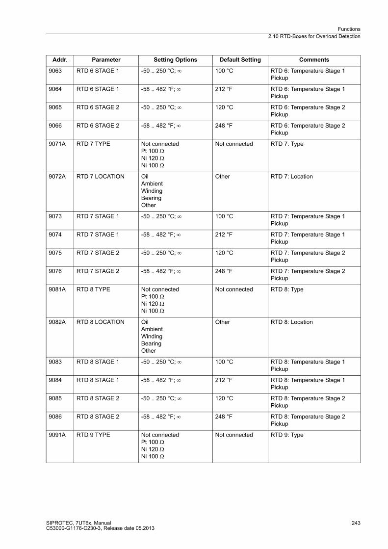
Functions
2.10 RTD-Boxes for Overload Detection
SIPROTEC, 7UT6x, ManualC53000-G1176-C230-3, Release date 05.2013
243
9063 RTD 6 STAGE 1 -50 .. 250 °C; ∞ 100 °C RTD 6: Temperature Stage 1 Pickup
9064 RTD 6 STAGE 1 -58 .. 482 °F; ∞ 212 °F RTD 6: Temperature Stage 1 Pickup
9065 RTD 6 STAGE 2 -50 .. 250 °C; ∞ 120 °C RTD 6: Temperature Stage 2 Pickup
9066 RTD 6 STAGE 2 -58 .. 482 °F; ∞ 248 °F RTD 6: Temperature Stage 2 Pickup
9071A RTD 7 TYPE Not connectedPt 100 ΩNi 120 ΩNi 100 Ω
Not connected RTD 7: Type
9072A RTD 7 LOCATION OilAmbientWindingBearingOther
Other RTD 7: Location
9073 RTD 7 STAGE 1 -50 .. 250 °C; ∞ 100 °C RTD 7: Temperature Stage 1 Pickup
9074 RTD 7 STAGE 1 -58 .. 482 °F; ∞ 212 °F RTD 7: Temperature Stage 1 Pickup
9075 RTD 7 STAGE 2 -50 .. 250 °C; ∞ 120 °C RTD 7: Temperature Stage 2 Pickup
9076 RTD 7 STAGE 2 -58 .. 482 °F; ∞ 248 °F RTD 7: Temperature Stage 2 Pickup
9081A RTD 8 TYPE Not connectedPt 100 ΩNi 120 ΩNi 100 Ω
Not connected RTD 8: Type
9082A RTD 8 LOCATION OilAmbientWindingBearingOther
Other RTD 8: Location
9083 RTD 8 STAGE 1 -50 .. 250 °C; ∞ 100 °C RTD 8: Temperature Stage 1 Pickup
9084 RTD 8 STAGE 1 -58 .. 482 °F; ∞ 212 °F RTD 8: Temperature Stage 1 Pickup
9085 RTD 8 STAGE 2 -50 .. 250 °C; ∞ 120 °C RTD 8: Temperature Stage 2 Pickup
9086 RTD 8 STAGE 2 -58 .. 482 °F; ∞ 248 °F RTD 8: Temperature Stage 2 Pickup
9091A RTD 9 TYPE Not connectedPt 100 ΩNi 120 ΩNi 100 Ω
Not connected RTD 9: Type
Addr. Parameter Setting Options Default Setting Comments

Functions
2.10 RTD-Boxes for Overload Detection
SIPROTEC, 7UT6x, ManualC53000-G1176-C230-3, Release date 05.2013
244
9092A RTD 9 LOCATION OilAmbientWindingBearingOther
Other RTD 9: Location
9093 RTD 9 STAGE 1 -50 .. 250 °C; ∞ 100 °C RTD 9: Temperature Stage 1 Pickup
9094 RTD 9 STAGE 1 -58 .. 482 °F; ∞ 212 °F RTD 9: Temperature Stage 1 Pickup
9095 RTD 9 STAGE 2 -50 .. 250 °C; ∞ 120 °C RTD 9: Temperature Stage 2 Pickup
9096 RTD 9 STAGE 2 -58 .. 482 °F; ∞ 248 °F RTD 9: Temperature Stage 2 Pickup
9101A RTD10 TYPE Not connectedPt 100 ΩNi 120 ΩNi 100 Ω
Not connected RTD10: Type
9102A RTD10 LOCATION OilAmbientWindingBearingOther
Other RTD10: Location
9103 RTD10 STAGE 1 -50 .. 250 °C; ∞ 100 °C RTD10: Temperature Stage 1 Pickup
9104 RTD10 STAGE 1 -58 .. 482 °F; ∞ 212 °F RTD10: Temperature Stage 1 Pickup
9105 RTD10 STAGE 2 -50 .. 250 °C; ∞ 120 °C RTD10: Temperature Stage 2 Pickup
9106 RTD10 STAGE 2 -58 .. 482 °F; ∞ 248 °F RTD10: Temperature Stage 2 Pickup
9111A RTD11 TYPE Not connectedPt 100 ΩNi 120 ΩNi 100 Ω
Not connected RTD11: Type
9112A RTD11 LOCATION OilAmbientWindingBearingOther
Other RTD11: Location
9113 RTD11 STAGE 1 -50 .. 250 °C; ∞ 100 °C RTD11: Temperature Stage 1 Pickup
9114 RTD11 STAGE 1 -58 .. 482 °F; ∞ 212 °F RTD11: Temperature Stage 1 Pickup
9115 RTD11 STAGE 2 -50 .. 250 °C; ∞ 120 °C RTD11: Temperature Stage 2 Pickup
9116 RTD11 STAGE 2 -58 .. 482 °F; ∞ 248 °F RTD11: Temperature Stage 2 Pickup
Addr. Parameter Setting Options Default Setting Comments
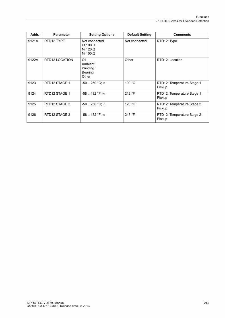
Functions
2.10 RTD-Boxes for Overload Detection
SIPROTEC, 7UT6x, ManualC53000-G1176-C230-3, Release date 05.2013
245
9121A RTD12 TYPE Not connectedPt 100 ΩNi 120 ΩNi 100 Ω
Not connected RTD12: Type
9122A RTD12 LOCATION OilAmbientWindingBearingOther
Other RTD12: Location
9123 RTD12 STAGE 1 -50 .. 250 °C; ∞ 100 °C RTD12: Temperature Stage 1 Pickup
9124 RTD12 STAGE 1 -58 .. 482 °F; ∞ 212 °F RTD12: Temperature Stage 1 Pickup
9125 RTD12 STAGE 2 -50 .. 250 °C; ∞ 120 °C RTD12: Temperature Stage 2 Pickup
9126 RTD12 STAGE 2 -58 .. 482 °F; ∞ 248 °F RTD12: Temperature Stage 2 Pickup
Addr. Parameter Setting Options Default Setting Comments

Functions
2.10 RTD-Boxes for Overload Detection
SIPROTEC, 7UT6x, ManualC53000-G1176-C230-3, Release date 05.2013
246
2.10.4 Information List
No. Information Type of In-
formation
Comments
14101 Fail: RTD OUT Fail: RTD (broken wire/shorted)
14111 Fail: RTD 1 OUT Fail: RTD 1 (broken wire/shorted)
14112 RTD 1 St.1 p.up OUT RTD 1 Temperature stage 1 picked up
14113 RTD 1 St.2 p.up OUT RTD 1 Temperature stage 2 picked up
14121 Fail: RTD 2 OUT Fail: RTD 2 (broken wire/shorted)
14122 RTD 2 St.1 p.up OUT RTD 2 Temperature stage 1 picked up
14123 RTD 2 St.2 p.up OUT RTD 2 Temperature stage 2 picked up
14131 Fail: RTD 3 OUT Fail: RTD 3 (broken wire/shorted)
14132 RTD 3 St.1 p.up OUT RTD 3 Temperature stage 1 picked up
14133 RTD 3 St.2 p.up OUT RTD 3 Temperature stage 2 picked up
14141 Fail: RTD 4 OUT Fail: RTD 4 (broken wire/shorted)
14142 RTD 4 St.1 p.up OUT RTD 4 Temperature stage 1 picked up
14143 RTD 4 St.2 p.up OUT RTD 4 Temperature stage 2 picked up
14151 Fail: RTD 5 OUT Fail: RTD 5 (broken wire/shorted)
14152 RTD 5 St.1 p.up OUT RTD 5 Temperature stage 1 picked up
14153 RTD 5 St.2 p.up OUT RTD 5 Temperature stage 2 picked up
14161 Fail: RTD 6 OUT Fail: RTD 6 (broken wire/shorted)
14162 RTD 6 St.1 p.up OUT RTD 6 Temperature stage 1 picked up
14163 RTD 6 St.2 p.up OUT RTD 6 Temperature stage 2 picked up
14171 Fail: RTD 7 OUT Fail: RTD 7 (broken wire/shorted)
14172 RTD 7 St.1 p.up OUT RTD 7 Temperature stage 1 picked up
14173 RTD 7 St.2 p.up OUT RTD 7 Temperature stage 2 picked up
14181 Fail: RTD 8 OUT Fail: RTD 8 (broken wire/shorted)
14182 RTD 8 St.1 p.up OUT RTD 8 Temperature stage 1 picked up
14183 RTD 8 St.2 p.up OUT RTD 8 Temperature stage 2 picked up
14191 Fail: RTD 9 OUT Fail: RTD 9 (broken wire/shorted)
14192 RTD 9 St.1 p.up OUT RTD 9 Temperature stage 1 picked up
14193 RTD 9 St.2 p.up OUT RTD 9 Temperature stage 2 picked up
14201 Fail: RTD10 OUT Fail: RTD10 (broken wire/shorted)
14202 RTD10 St.1 p.up OUT RTD10 Temperature stage 1 picked up
14203 RTD10 St.2 p.up OUT RTD10 Temperature stage 2 picked up
14211 Fail: RTD11 OUT Fail: RTD11 (broken wire/shorted)
14212 RTD11 St.1 p.up OUT RTD11 Temperature stage 1 picked up
14213 RTD11 St.2 p.up OUT RTD11 Temperature stage 2 picked up
14221 Fail: RTD12 OUT Fail: RTD12 (broken wire/shorted)
14222 RTD12 St.1 p.up OUT RTD12 Temperature stage 1 picked up
14223 RTD12 St.2 p.up OUT RTD12 Temperature stage 2 picked up
Functions
2.11 Overexcitation Protection
SIPROTEC, 7UT6x, ManualC53000-G1176-C230-3, Release date 05.2013
247
2.11 Overexcitation Protection
The overexcitation protection is used to detect increased overflux or overinduction conditions in generators and
transformers, especially in power station unit transformers, which cause impermissible temperature rise in the
iron. An increase in induction above the rated value leads very quickly to saturation of the iron core and to large
eddy current losses which cause impermissible temperature rise in the iron. This protection is not applicable to
single-phase busbar protection.
The overexcitation protection picks up when the permissible limit of induction is exceeded in the core of the
protected object (e.g. power station unit transformer). Increased induction occurs, for example, when the power
station block is disconnected from the system from full-load, and the voltage regulator either does not operate
or does not operate sufficiently fast to control the associated voltage rise. Similarly a decrease in frequency
(speed), e.g. in island systems, can cause increased induction in the transformer.
2.11.1 Function Description
Measured Values
The use of the overexcitation protection presumes that measured voltages are connected to the device: This
is therefore only possible for 7UT613 and 7UT633. Overexcitation protection makes no sense on 1-phase
busbar protection and is, therefore, not available for this application.
The overexcitation protection measures the ration voltage/frequency U/f, which is proportional to the induction
B in the iron core (with invariable dimensions).
If the quotient UU/f is set in relation to the voltage and frequency under nominal conditions of the protected
object UNObj/fN, a direct measure of the induction B, referred to the induction B/BNObj under nominal conditions,
is achieved. All constant quantities cancel each other:
The benefit of these referred values is that no explicit calculations are necessary. You can enter all values di-
rectly referred to the induction under nominal conditions of the protected object. The device has been informed
about the rated values of the protected object and the voltage transformer data when setting the object and
transformer data.
The maximum of the three phase-to-phase voltages is decisive for the calculation. The voltages are filtered by
numerical algorithms. Monitoring is carried out throughout the frequency tagging range.
Characteristics
The overexcitation protection includes two definite time stages and a further thermal characteristic which latter
forms an approximate replica of the temperature rise caused by overflux in the protected object.
As soon as a threshold (warning stage U/f >) has been exceeded, the pickup indication is output and a timer T
U/f > starts. A warning message is transmitted subsequently to the expiration of this timer. As soon as a second
threshold (warning stage U/f >>) has been exceeded, another pickup indication is output and a timer T U/f >>
starts. A trip command is issued subsequent to the expiration of this timer.

Functions
2.11 Overexcitation Protection
SIPROTEC, 7UT6x, ManualC53000-G1176-C230-3, Release date 05.2013
248
Figure 2-99 Logic diagram of the overexcitation protection (simplified)
The thermal replica is realised by a counter which is incremented in accordance with the value U/f calculated
from the measured voltages. A prerequisite is that the U/f value has exceeded the pickup value U/f > of the
warning stage. If the counter reaches a level corresponding with the set trip characteristic, the trip command is
given.
The trip signal is cancelled as soon as the value falls below the pickup threshold and the counter is
decremented according to the set cooldown rate.
The thermal characteristic is specified by 8 value pairs concerning the U/f value (referred to nominal value) and
the associated trip time T. In most cases, the default characteristic for standard transformers provides for
sufficient protection. If this characteristic does not correspond to the actual thermal behaviour of the object to
be protected, any desired characteristic can be implemented by entering user-specific trip times for the
specified U/f overexcitation values. Intermediate values are determined by a linear interpolation within the
device.
The counter can be reset to zero by means of a blocking input or a reset input. The internal upper limit of the
thermal replica is 150 % of trip temperature rise.
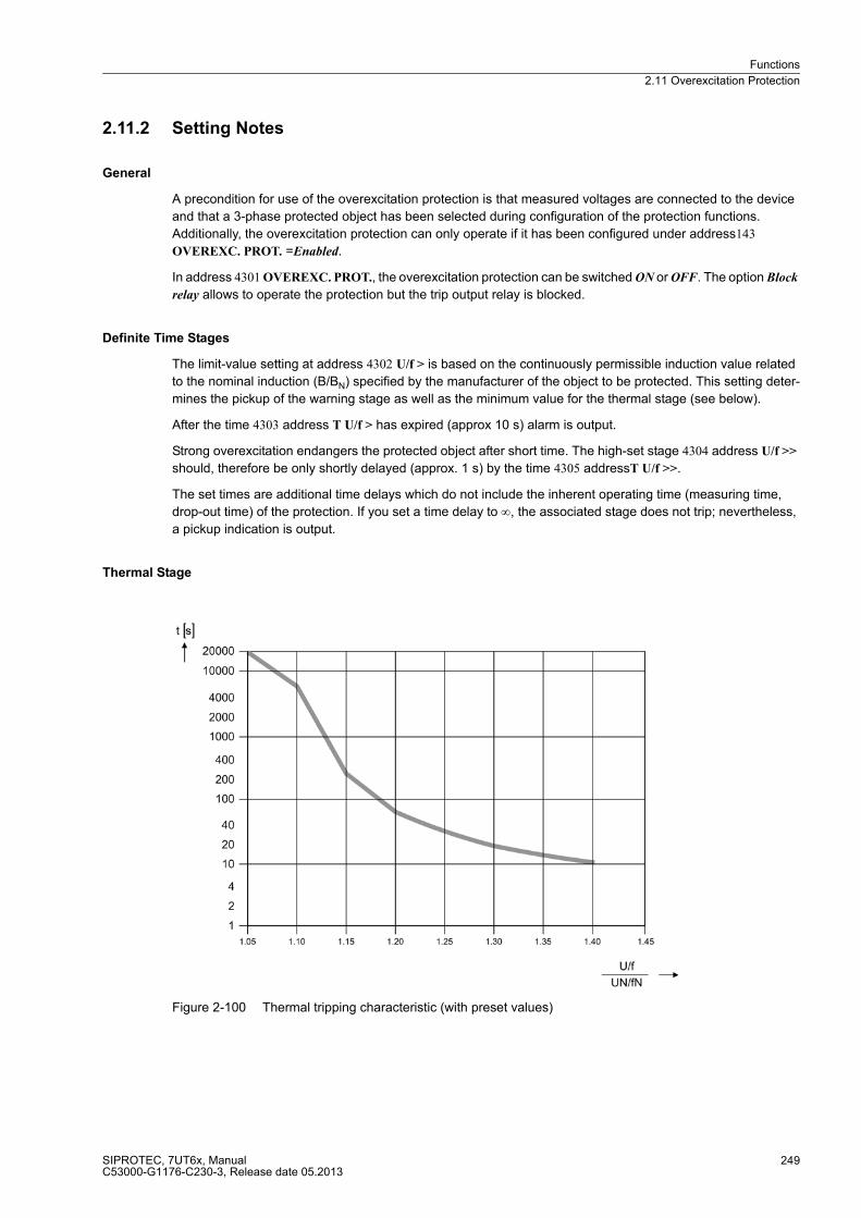
Functions
2.11 Overexcitation Protection
SIPROTEC, 7UT6x, ManualC53000-G1176-C230-3, Release date 05.2013
249
2.11.2 Setting Notes
General
A precondition for use of the overexcitation protection is that measured voltages are connected to the device
and that a 3-phase protected object has been selected during configuration of the protection functions.
Additionally, the overexcitation protection can only operate if it has been configured under address143
OVEREXC. PROT. =Enabled.
In address 4301 OVEREXC. PROT., the overexcitation protection can be switched ON or OFF. The option Block
relay allows to operate the protection but the trip output relay is blocked.
Definite Time Stages
The limit-value setting at address 4302 U/f > is based on the continuously permissible induction value related
to the nominal induction (B/BN) specified by the manufacturer of the object to be protected. This setting deter-
mines the pickup of the warning stage as well as the minimum value for the thermal stage (see below).
After the time 4303 address T U/f > has expired (approx 10 s) alarm is output.
Strong overexcitation endangers the protected object after short time. The high-set stage 4304 address U/f >>
should, therefore be only shortly delayed (approx. 1 s) by the time 4305 addressT U/f >>.
The set times are additional time delays which do not include the inherent operating time (measuring time,
drop-out time) of the protection. If you set a time delay to ∞, the associated stage does not trip; nevertheless,
a pickup indication is output.
Thermal Stage
Figure 2-100 Thermal tripping characteristic (with preset values)

Functions
2.11 Overexcitation Protection
SIPROTEC, 7UT6x, ManualC53000-G1176-C230-3, Release date 05.2013
250
The thermal characteristic is intended to simulate the temperature rise of the iron core due to overflux. The
heating-up characteristic is approximated by 8 time values for the 8 predefined induction values B/BNObj
(reduced U/f). Intermediate values are gained in the device by linear interpolation.
If no instructions of the manufacturer are available, the preset standard characteristic should be used; this
corresponds to a standard Siemens transformer (figure 2-100).
Figure 2-101 Tripping time characteristic of the overexcitation protection

Functions
2.11 Overexcitation Protection
SIPROTEC, 7UT6x, ManualC53000-G1176-C230-3, Release date 05.2013
251
Otherwise, any tripping characteristic can be specified by point-wise entering the delay times for the
8 predefined U/f-values:
As mentioned above, the thermal characteristic is effective only if the pickup threshold U/f> is exceeded. Figure
2-101 illustrates the behaviour of the protection on the assumption that the setting for the pickup threshold was
chosen higher or lower than the first setting value of the thermal characteristic.
Cool-down Time
Tripping by the thermal image is reset at the time of the pickup threshold reset. However, the counter content
is counted down to zero with the cooldown time parametrized at address 4314 T COOL DOWN. In this context,
this parameter is defined as the time required by the thermal replica to cool down from 100 % to 0 %.
Note
All U/f values in the following settings overview are referred to the induction of the protected object under
nominal conditions, i.e. UNObj/fN.
Address 4306 t(U/f=1.05)
Address 4307 t(U/f=1.10)
Address 4308 t(U/f=1.15)
Address 4309 t(U/f=1.20)
Address 4310 t(U/f=1.25)
Address 4311 t(U/f=1.30)
Address 4312 t(U/f=1.35)
Address 4313 t(U/f=1.40)
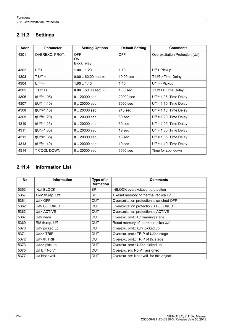
Functions
2.11 Overexcitation Protection
SIPROTEC, 7UT6x, ManualC53000-G1176-C230-3, Release date 05.2013
252
2.11.3 Settings
2.11.4 Information List
Addr. Parameter Setting Options Default Setting Comments
4301 OVEREXC. PROT. OFFONBlock relay
OFF Overexcitation Protection (U/f)
4302 U/f > 1.00 .. 1.20 1.10 U/f > Pickup
4303 T U/f > 0.00 .. 60.00 sec; ∞ 10.00 sec T U/f > Time Delay
4304 U/f >> 1.00 .. 1.40 1.40 U/f >> Pickup
4305 T U/f >> 0.00 .. 60.00 sec; ∞ 1.00 sec T U/f >> Time Delay
4306 t(U/f=1.05) 0 .. 20000 sec 20000 sec U/f = 1.05 Time Delay
4307 t(U/f=1.10) 0 .. 20000 sec 6000 sec U/f = 1.10 Time Delay
4308 t(U/f=1.15) 0 .. 20000 sec 240 sec U/f = 1.15 Time Delay
4309 t(U/f=1.20) 0 .. 20000 sec 60 sec U/f = 1.20 Time Delay
4310 t(U/f=1.25) 0 .. 20000 sec 30 sec U/f = 1.25 Time Delay
4311 t(U/f=1.30) 0 .. 20000 sec 19 sec U/f = 1.30 Time Delay
4312 t(U/f=1.35) 0 .. 20000 sec 13 sec U/f = 1.35 Time Delay
4313 t(U/f=1.40) 0 .. 20000 sec 10 sec U/f = 1.40 Time Delay
4314 T COOL DOWN 0 .. 20000 sec 3600 sec Time for cool down
No. Information Type of In-
formation
Comments
5353 >U/f BLOCK SP >BLOCK overexcitation protection
5357 >RM th.rep. U/f SP >Reset memory of thermal replica U/f
5361 U/f> OFF OUT Overexcitation protection is swiched OFF
5362 U/f> BLOCKED OUT Overexcitation protection is BLOCKED
5363 U/f> ACTIVE OUT Overexcitation protection is ACTIVE
5367 U/f> warn OUT Overexc. prot.: U/f warning stage
5369 RM th.rep. U/f OUT Reset memory of thermal replica U/f
5370 U/f> picked up OUT Overexc. prot.: U/f> picked up
5371 U/f>> TRIP OUT Overexc. prot.: TRIP of U/f>> stage
5372 U/f> th.TRIP OUT Overexc. prot.: TRIP of th. stage
5373 U/f>> pick.up OUT Overexc. prot.: U/f>> picked up
5376 U/f Err No VT OUT Overexc. err: No VT assigned
5377 U/f Not avail. OUT Overexc. err: Not avail. for this object
Functions
2.12 Reverse Power Protection
SIPROTEC, 7UT6x, ManualC53000-G1176-C230-3, Release date 05.2013
253
2.12 Reverse Power Protection
Reverse power protection is used to protect a turbo-generator unit on failure of energy to the prime mover when
the synchronous generator runs as a motor and drives the turbine taking motoring energy from the network.
This condition endangers the turbine blades the and must be interrupted within a short time by tripping the
network circuit-breaker. For the generator, there is the additional risk that, in case of a malfunctioning residual
steam pass (defective stop valves) after the switching off of the circuit breakers, the turbine-generator-unit is
speeded up, thus reaching an overspeed. For this reason, the decoupling should only be performed after the
detection of active power input into the machine. The reverse power protection can be used as a criteria for the
decoupling in the system.
The reverse power protection can only be used for a three-phase protective objects. This understands that the
device is connected to a voltage transformer set and that this voltage, together with an assigned corresponding
current transformer, allows for a logical calculation of the active power. This is therefore only possible for
7UT613 and 7UT633.
2.12.1 Function Description
Reverse Power Determination
The reverse power protection in 7UT613 / 7UT633 calculates the active power from the symmetrical
components of the fundamental waves of voltages and currents.
There are two measurement methods:
� The "precise" measuring procedure is especially suited for reverse power protection on generators, as in
this case a very low active power is calculated from a very high apparent power (for small cos ϕ). The
positive sequence systems from voltages and currents are used to obtain a very high accuracy of the last
16 cycles. The evaluation of the positive phase-sequence systems makes the reverse power determination
independent of current and voltage asymmetries and corresponds to actual loading of the drive end. By
taking the error angles of the voltage and current transformers into account, the active power component is
exactly calculated even with very high apparent powers and low cos ϕ. The angle correction is performed
by a correction angle ϕcorr (see Subsection 2.1.4, "General System data"), which is appropriately determined
by the commissioning of the protective device in the system (see Subsection "Installation and Commission-
ing", "Checking the Voltage Connections and Polarity Check").
� The "fast" measurement also uses the positive-sequence components of currents and voltages that are
calculated over a cycle. A short tripping time is hereby achieved. It is therefore well suited in system
applications where short tripping times are more desired than high accuracy of real power.
Pickup Seal-In Time
To ensure that frequently occurring short pickups can cause tripping, a selectable prolongation of these pickup
signals is provided. Should new fault detection signals appear within this seal-in time the pickup is maintained,
so that a delayed tripping can take place.
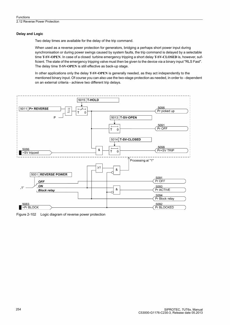
Functions
2.12 Reverse Power Protection
SIPROTEC, 7UT6x, ManualC53000-G1176-C230-3, Release date 05.2013
254
Delay and Logic
Two delay times are available for the delay of the trip command.
When used as a reverse power protection for generators, bridging a perhaps short power input during
synchronisation or during power swings caused by system faults, the trip command is delayed by a selectable
time T-SV-OPEN. In case of a closed turbine emergency tripping a short delay T-SV-CLOSED is, however, suf-
ficient. The state of the emergency tripping valve must then be given to the device via a binary input "RLS Fast".
The delay time T-SV-OPEN is still effective as back-up stage.
In other applications only the delay T-SV-OPEN is generally needed, as they act independently to the
mentioned binary input. Of course you can also use the two-stage protection as needed, in order to - dependent
on an external criteria - achieve two different trip delays.
Figure 2-102 Logic diagram of reverse power protection

Functions
2.12 Reverse Power Protection
SIPROTEC, 7UT6x, ManualC53000-G1176-C230-3, Release date 05.2013
255
2.12.2 Setting Notes
General
The application of reverse power protection is only possible in 3-phase protected objects. It can only be
assigned to a side of the main protected object or another measuring location. Furthermore, it is a prerequisite
that the device is connected to a three-phase voltage transformer set.
The reverse power protection is only effective and accessible if address 150 was set to REVERSE POWER
Enabledduring configuration of the protection function (section 2.1.3).
Under address 5001 REVERSE POWER the reverse power protection can be switched ON or OFF. The option
Block relay allows to operate the protection but the trip output relay is blocked.
Pickup Value
In case of a reverse power, the turbine set must be disconnected from the system as the turbine operation is
not permissible without a certain minimum steam throughout (cooling effect). In case of a gas turbine set, the
motor load can also become too heavy for the network.
In case of a turbine generator unit the level of the active power input is mainly determined by the friction losses
to be overcome and lies within the following ranges:
Steam turbines: PRevere/SN ≈ 1 % to 3 %
Gas turbines: PReverse/SN ≈ 3 % to 5 %
Diesel drives: PReverse/SN > 5 %
It is recommended, however, to measure the reverse power of the turbine generator unit with the protection
yourself during primary test (section "Commissioning", "Verification of the Voltage Connections"). As setting
value, use approx. half the measured motoring power. The feature to correct angle faults of the current and
voltage transformers should be used especially for very large machines with a particularly low motoring energy
(see sections 2.1.4 and "Commissioning", "Verification of the Voltage Connections and Directional Check").
If the reverse power protection has been assigned to one side of the machine to be protected, the pickup value
of the reverse power can be set as relative value (relevant to machine rated power) under address 5012 Pr pick-
up. As the reverse power is a negative active power, it is set as a negative value (a positive setting value cannot
be set).
However, if the reverse power protection must be set in ampere (secondary) during operation, the reverse
power must be recalculated as a secondary value and set under address 5011 P> REVERSE. This is the case
if the reverse power protection has been assigned to a measuring location and not to a side of the main pro-
tected object, thus usually in system applications. The following applies:
with
Psec secondary power
UNprim primary rated voltage of the voltage transformer (interlinked)
UNsec secondary nominal voltage of the voltage transformers (phase-to-phase)
INprim primary rated current of the current transformer
INsec secondary rated current of the current transformer
Pprim primary power
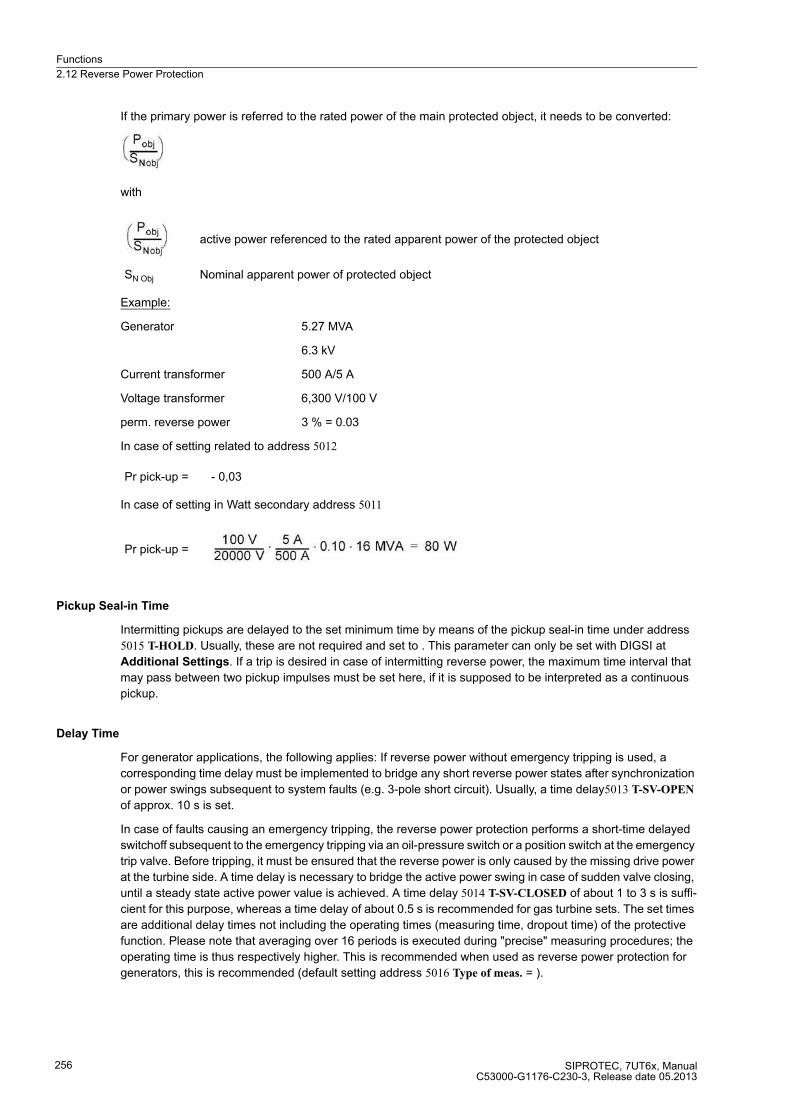
Functions
2.12 Reverse Power Protection
SIPROTEC, 7UT6x, ManualC53000-G1176-C230-3, Release date 05.2013
256
If the primary power is referred to the rated power of the main protected object, it needs to be converted:
with
Example:
Generator 5.27 MVA
6.3 kV
Current transformer 500 A/5 A
Voltage transformer 6,300 V/100 V
perm. reverse power 3 % = 0.03
In case of setting related to address 5012
In case of setting in Watt secondary address 5011
Pickup Seal-in Time
Intermitting pickups are delayed to the set minimum time by means of the pickup seal-in time under address
5015 T-HOLD. Usually, these are not required and set to . This parameter can only be set with DIGSI at
Additional Settings. If a trip is desired in case of intermitting reverse power, the maximum time interval that
may pass between two pickup impulses must be set here, if it is supposed to be interpreted as a continuous
pickup.
Delay Time
For generator applications, the following applies: If reverse power without emergency tripping is used, a
corresponding time delay must be implemented to bridge any short reverse power states after synchronization
or power swings subsequent to system faults (e.g. 3-pole short circuit). Usually, a time delay5013 T-SV-OPEN
of approx. 10 s is set.
In case of faults causing an emergency tripping, the reverse power protection performs a short-time delayed
switchoff subsequent to the emergency tripping via an oil-pressure switch or a position switch at the emergency
trip valve. Before tripping, it must be ensured that the reverse power is only caused by the missing drive power
at the turbine side. A time delay is necessary to bridge the active power swing in case of sudden valve closing,
until a steady state active power value is achieved. A time delay 5014 T-SV-CLOSED of about 1 to 3 s is suffi-
cient for this purpose, whereas a time delay of about 0.5 s is recommended for gas turbine sets. The set times
are additional delay times not including the operating times (measuring time, dropout time) of the protective
function. Please note that averaging over 16 periods is executed during "precise" measuring procedures; the
operating time is thus respectively higher. This is recommended when used as reverse power protection for
generators, this is recommended (default setting address 5016 Type of meas. = ).
active power referenced to the rated apparent power of the protected object
SN Obj Nominal apparent power of protected object
Pr pick-up = - 0,03
Pr pick-up =
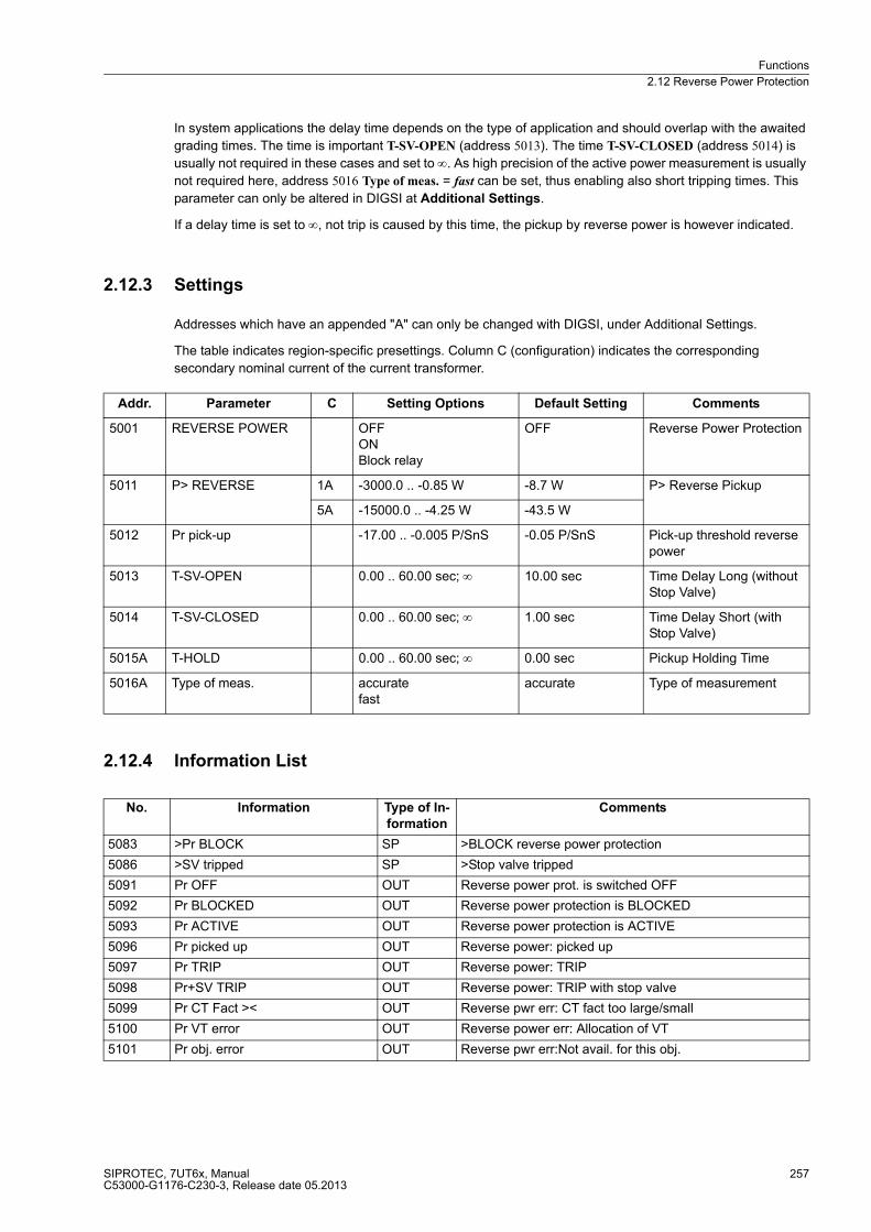
Functions
2.12 Reverse Power Protection
SIPROTEC, 7UT6x, ManualC53000-G1176-C230-3, Release date 05.2013
257
In system applications the delay time depends on the type of application and should overlap with the awaited
grading times. The time is important T-SV-OPEN (address 5013). The time T-SV-CLOSED (address 5014) is
usually not required in these cases and set to ∞. As high precision of the active power measurement is usually
not required here, address 5016 Type of meas. = fast can be set, thus enabling also short tripping times. This
parameter can only be altered in DIGSI at Additional Settings.
If a delay time is set to ∞, not trip is caused by this time, the pickup by reverse power is however indicated.
2.12.3 Settings
Addresses which have an appended "A" can only be changed with DIGSI, under Additional Settings.
The table indicates region-specific presettings. Column C (configuration) indicates the corresponding
secondary nominal current of the current transformer.
2.12.4 Information List
Addr. Parameter C Setting Options Default Setting Comments
5001 REVERSE POWER OFFONBlock relay
OFF Reverse Power Protection
5011 P> REVERSE 1A -3000.0 .. -0.85 W -8.7 W P> Reverse Pickup
5A -15000.0 .. -4.25 W -43.5 W
5012 Pr pick-up -17.00 .. -0.005 P/SnS -0.05 P/SnS Pick-up threshold reverse power
5013 T-SV-OPEN 0.00 .. 60.00 sec; ∞ 10.00 sec Time Delay Long (without Stop Valve)
5014 T-SV-CLOSED 0.00 .. 60.00 sec; ∞ 1.00 sec Time Delay Short (with Stop Valve)
5015A T-HOLD 0.00 .. 60.00 sec; ∞ 0.00 sec Pickup Holding Time
5016A Type of meas. accuratefast
accurate Type of measurement
No. Information Type of In-
formation
Comments
5083 >Pr BLOCK SP >BLOCK reverse power protection
5086 >SV tripped SP >Stop valve tripped
5091 Pr OFF OUT Reverse power prot. is switched OFF
5092 Pr BLOCKED OUT Reverse power protection is BLOCKED
5093 Pr ACTIVE OUT Reverse power protection is ACTIVE
5096 Pr picked up OUT Reverse power: picked up
5097 Pr TRIP OUT Reverse power: TRIP
5098 Pr+SV TRIP OUT Reverse power: TRIP with stop valve
5099 Pr CT Fact >< OUT Reverse pwr err: CT fact too large/small
5100 Pr VT error OUT Reverse power err: Allocation of VT
5101 Pr obj. error OUT Reverse pwr err:Not avail. for this obj.
Functions
2.13 Forward Power Supervision
SIPROTEC, 7UT6x, ManualC53000-G1176-C230-3, Release date 05.2013
258
2.13 Forward Power Supervision
The forward power supervision monitors wether the active power undershoots one set value or overshoots a
separate second value. Each of these functions can initiate different control functions.
When, for example, with generators operating in parallel, the active power output of one machine becomes so
small that other generators could take over this power, then it is often appropriate to shut down the lightly loaded
machine. The criteria here is that the forward power supplied into the network falls below a certain value.
In some applications it may be useful to give a control command when the issuing real power exceeds a specific
value. If only one of two parallel connected transformers is active, the second one can be activated, as soon
as the transferred power exceeds a preset ratio.
When a fault in a utility network is not cleared within critical time, the utility network should be split or for
example, an industrial network with internal supply decoupled from it. As criteria for decoupling, in addition to
power flow direction, are undervoltage, overcurrent and/or frequency. As a result, the 7UT6 can also be used
for network decoupling.
The forward power supervision can only be used for three-phase protective objects. This understands that the
device is connected to a voltage transformer set and that this voltage, together with an assigned corresponding
current transformer, allow for a logical calculation of the active power. This is therefore only possible for 7UT613
and 7UT633.
When the circuit breakers are deactivated, the P< stage should be blocked via external signals.
2.13.1 Function Description
Determining Real Power
The forward active power supervision in 7UT613 / 7UT633 calculates the active power from the symmetrical
components of the fundamental waves of voltages and currents.
There are two measurement methods:
� The "exact" measurement method averages the active power via the last 16 cycles of the measured quan-
tities. The evaluation of the positive phase-sequence systems makes the active power definition indepen-
dent of current and voltage asymmetries. If an exact derivation of real power at high apparent powers (low
cos ϕ) is desired, it will be necessary to consider the angle error of voltage and current transformers. The
angle correction is performed by a correction angle ϕcorr (see Subsection 2.1.4).
� The "fast" measurement method calculates the positive-sequence components of currents and voltage over
a cycle. A short tripping time is hereby achieved. It is therefore well suited in system applications where short
tripping times are more desired than high accuracy, e.g. used for purposes of network decoupling.
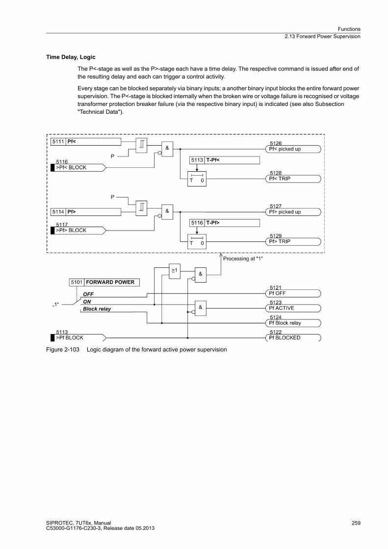
Functions
2.13 Forward Power Supervision
SIPROTEC, 7UT6x, ManualC53000-G1176-C230-3, Release date 05.2013
259
Time Delay, Logic
The P<-stage as well as the P>-stage each have a time delay. The respective command is issued after end of
the resulting delay and each can trigger a control activity.
Every stage can be blocked separately via binary inputs; a another binary input blocks the entire forward power
supervision. The P<-stage is blocked internally when the broken wire or voltage failure is recognised or voltage
transformer protection breaker failure (via the respective binary input) is indicated (see also Subsection
"Technical Data").
Figure 2-103 Logic diagram of the forward active power supervision
Functions
2.13 Forward Power Supervision
SIPROTEC, 7UT6x, ManualC53000-G1176-C230-3, Release date 05.2013
260
2.13.2 Setting Notes
General
The application of forward power monitoring is only possible in 3-phase protected objects. It can only be as-
signed to a side of the main protected object or another measuring location. Furthermore, it is a prerequisite
that the device is connected to a three-phase voltage transformer set, that permits a sensible calculation of the
active power with the respective current transformer connection.
The forward power monitoring can only be effective and is only accessible if it has been set during configuration
under address 151 FORWARD POWER = Enabled (section 2.1.3).
Under address 5101 FORWARD POWER the forward power monitoring can be switched ON or OFF. Further-
more, the command can be blocked during enabled monitoring function (Block relay).
Pickup Values
For undershooting of a preset active power and the exceeding of another preset active power, one pickup value
each must be set.
If the forward power monitoring has been assigned to a side of the protected object, the pickup value can be
set directly as reference value (with reference to the nominal power of the respective side), thus under address
5112 P< fwd for undershooting of active power and under address 5115 P> fwd for exceeding of active power.
If, however, the forward power monitoring must be set in amps secondary, the active power must be converted
to a secondary value. The settings can then be effected under address 5111 Pf< for undershooting of active
power and under address 5114 Pf> for exceeding of active power.
The latter is always the case if the forward power monitoring has been assigned to a measuring location, and
not a side of the main protected object.
The following applies to the conversion:
where
Psec secondary power
UNprim primary rated voltage of the voltage transformer (interlinked)
UNsec secondary rated current of the voltage transformer (interlinked)
INprim primary rated current of the current transformer
INsec secondary rated current of the current transformer
Pprim primary power
Functions
2.13 Forward Power Supervision
SIPROTEC, 7UT6x, ManualC53000-G1176-C230-3, Release date 05.2013
261
Example:
Transformer 16 MVA
(winding) 20 kV
Current transformer 500 A/5 A
Voltage transformer 20 kV/100 V
Switching off during P< 10 % = 0.1
Connecting a parallel transformer
Parallel transformer during P> 90 % = 0.9
In case of reference setting (with reference to the sides = winding data)
Address5112 P< fwd = 0.10
Address 5115 P> fwd = 0.90
When setting in watt secondary, this has the following effect
the setting values
Address 5111 Pf< = 80 W
Address 5114 Pf> = 720 W
Delay Times
The setting of the delay times depend on the application. In the example of transformer switchover or also in
case of generator switchover, a long delay (up to one minute = 60 s) will be set so that short-term load
fluctuations do not result in repeated switchover. In case of network splitting, short delays are permitted, which,
amongst others, must conform with the time grading of the short-circuit protective relays.
For undershooting of active power, address 5113 T-Pf< applies and for the exceeding of active power address
5116 T-Pf> applies.
the set times are additional time delays that do not include the operating times (measuring time, dropout time)
of the monitoring function. Please note that averaging over 16 periods is executed during "precise" measuring
procedures; the operating time is thus respectively higher. If a delay time is set to ∞, this does not result in a
trip, however, the pickup will be indicated.
Measuring Procedure
The measuring procedure can be set under address 5117 MEAS. METHOD. This parameter can only be set
with DIGSI at Additional Settings. The option MEAS. METHOD = is mainly required if also small active power
from great apparent power must be calculated precisely, e.g. in generator range or in protected objects with
high reactive power. Please also note that the operating time in this option is higher due to averaging over 16
periods. A precise measurement requires that the angle errors of the current and voltage transformers are
compensated by means of a respective setting of the fault angle in address 803 CORRECT. U Ang (see section
2.1.4). Short trip times are possible with this option MEAS. METHOD = fast as the power is determined over
one period only.
P< =
P> =

Functions
2.13 Forward Power Supervision
SIPROTEC, 7UT6x, ManualC53000-G1176-C230-3, Release date 05.2013
262
2.13.3 Settings
Addresses which have an appended "A" can only be changed with DIGSI, under Additional Settings.
The table indicates region-specific presettings. Column C (configuration) indicates the corresponding
secondary nominal current of the current transformer.
2.13.4 Information List
Addr. Parameter C Setting Options Default Setting Comments
5101 FORWARD POWER OFFONBlock relay
OFF Forward Power Supervision
5111 Pf< 1A 1.7 .. 3000.0 W 17.3 W P-forw.< Supervision Pickup
5A 8.5 .. 15000.0 W 86.5 W
5112 P< fwd 0.01 .. 17.00 P/SnS 0.10 P/SnS Pick-up threshold P<
5113 T-Pf< 0.00 .. 60.00 sec; ∞ 10.00 sec T-P-forw.< Time Delay
5114 Pf> 1A 1.7 .. 3000.0 W 164.5 W P-forw.> Supervision Pickup
5A 8.5 .. 15000.0 W 822.5 W
5115 P> fwd 0.01 .. 17.00 P/SnS 0.95 P/SnS Pick-up threshold P>
5116 T-Pf> 0.00 .. 60.00 sec; ∞ 10.00 sec T-P-forw.> Time Delay
5117A MEAS. METHOD accuratefast
accurate Method of Operation
No. Information Type of In-
formation
Comments
5113 >Pf BLOCK SP >BLOCK forward power supervision
5116 >Pf< BLOCK SP >BLOCK forw. power superv. Pf< stage
5117 >Pf> BLOCK SP >BLOCK forw. power superv. Pf> stage
5121 Pf OFF OUT Forward power supervis. is switched OFF
5122 Pf BLOCKED OUT Forward power supervision is BLOCKED
5123 Pf ACTIVE OUT Forward power supervision is ACTIVE
5126 Pf< picked up OUT Forward power: Pf< stage picked up
5127 Pf> picked up OUT Forward power: Pf> stage picked up
5128 Pf< TRIP OUT Forward power: Pf< stage TRIP
5129 Pf> TRIP OUT Forward power: Pf> stage TRIP
5130 Pf> CT fact >< OUT Forward pwr err: CT fact too large/small
5131 Pf> VT error OUT Forward power error: VT assignment
5132 Pf> Object err OUT Forward pwr err:Not avail. for this obj.
Functions
2.14 Undervoltage Protection
SIPROTEC, 7UT6x, ManualC53000-G1176-C230-3, Release date 05.2013
263
2.14 Undervoltage Protection
Undervoltage protection detects voltage dips in electrical machines and avoids inadmissible operating states
and possible loss of stability in electrical devices. The stability and permissible torque thresholds of an induction
machine is affected by undervoltage. In network coupling this can be used as a criteria for the network
decoupling.
The undervoltage protection can only be used for three-phase protective objects. This implies that the device
is connected to a voltage transformer. This is therefore only possible for 7UT613 and 7UT633. As the under-
voltage protection only gets its measuring information from the connected voltage measurement, it leaves the
assignment of currents to one side or a measuring location for the function without coating. Setting causes the
same differences as in other protection functions. If the undervoltage protection is assigned to one side of the
main protective object or the three-phase busbar, the voltage limits in related values (U/UN) have to be set. The
values are set to secondary in volts when assigned to a measuring location.
2.14.1 Function Description
The undervoltage protection in 7UT613 / 7UT633 uses the positive sequence system from the fundamental har-
monic of the connected phase-to-earth voltages. Compared to three single-phase measuring systems, the de-
tection of the positive phase-sequence system is not influenced by 2-pole faults or earth faults.
Overvoltage protection includes two stages. A pickup is signalled as soon as selectable voltage thresholds are
undershot. A trip signal is transmitted if a voltage pickup exists for a selectable time.
If a fuse failure (failure of the measuring voltage) is detected, or a voltage transformer protection breaker trip
(via a correspondingly marshalled binary input) is indicated (refer also to Subsection 2.19.1), both stages are
internally blocked, in order to avoid malfunction of the protection in the event of secondary voltage failure. Each
stage can be blocked individually and/or for both stages can be blocked, via binary inputs.
Particular attention must be paid to the status of the interrupted system during undervoltage protection. As pro-
tective objects have no primary or measurement voltage, the pickup conditions are therefore always fulfilled.
The same can apply after a tripping of the undervoltage protection or another protection function. The under-
voltage protection should therefore (according to suitable criteria) be completely blocked externally - e.g.
dependent on circuit breaker - via an appropriate binary input.

Functions
2.14 Undervoltage Protection
SIPROTEC, 7UT6x, ManualC53000-G1176-C230-3, Release date 05.2013
264
Figure 2-104 Logic diagram of the undervoltage protection
2.14.2 Setting Notes
General
The application of undervoltage protection is only possible in 3-phase protected objects. Furthermore, it is a
prerequisite that the device is connected to a three-phase voltage transformer set.
Undervoltage protection is only effective and accessible if address 152 was set to UNDERVOLTAGE
Enabledduring configuration of the protection function (section 2.1.3).
Under address 5201 UNDERVOLTAGE the undervoltage protection ON or OFF can be set. Additionally, the
command can be blocked if the protection function is enabled (Block relay).
Pickup Values, Times
The undervoltage protection consists of two phases. The equivalent of the phase-phase voltage is detected,
therefore √3 · U1. The setting is thus effected in interlinked values.
The U< stage is set slightly below the minimum operational expected voltage under address 5212 U<, if the
reference values are relevant, under address 5211 U< when setting in volts. This setting method depends on
whether the voltage transformer set has been assigned to one side of the main protected object or to any mea-
suring location. Normally, 75 % to 80 % of the nominal voltage is recommended; i.e. 0.75 to 0.80 for reference
values or 75 V to 80 V for UN sec = 100 V (adjusted accordingly in case of different nominal voltage).
The respective delay time T U< (address 5213) is supposed to bridge the permissible short-term voltage dips
during continuous undervoltage, which may lead to an unstable operation, however, it is supposed to be
switched off within a few seconds.
Functions
2.14 Undervoltage Protection
SIPROTEC, 7UT6x, ManualC53000-G1176-C230-3, Release date 05.2013
265
For the U<< stage, a lower pickup threshold with a short delay should be set so that in case of heavy voltage
dips a quick trip can occur, e.g. 65 % of the nominal voltage with 0.5 s delay.
If the undervoltage protection is assigned to one side of the main protected object or the three-phase busbar,
the pickup value must be set as reference value under address 5215 U<<, e.g. 0.65. When assigned to a
measuring location, the value of phase-phase voltage must be set under address 5214 U<< in Volt , e.g. 71.5. V
at UN sec = 110 V (65 % of 110 V).
The set times are additional time delays that do not include the operating time (measuring time, dropout time)
of the protection function. If a delay time is set to ∞, this does not result in a trip, however, the pickup will be
indicated.
Dropout Ratio
The drop-out ratio can be adjusted to the operating conditions at address 5217 DOUT RATIO. This parameter
can only be altered in DIGSI at Additional Settings.
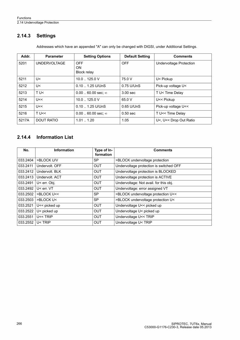
Functions
2.14 Undervoltage Protection
SIPROTEC, 7UT6x, ManualC53000-G1176-C230-3, Release date 05.2013
266
2.14.3 Settings
Addresses which have an appended "A" can only be changed with DIGSI, under Additional Settings.
2.14.4 Information List
Addr. Parameter Setting Options Default Setting Comments
5201 UNDERVOLTAGE OFFONBlock relay
OFF Undervoltage Protection
5211 U< 10.0 .. 125.0 V 75.0 V U< Pickup
5212 U< 0.10 .. 1.25 U/UnS 0.75 U/UnS Pick-up voltage U<
5213 T U< 0.00 .. 60.00 sec; ∞ 3.00 sec T U< Time Delay
5214 U<< 10.0 .. 125.0 V 65.0 V U<< Pickup
5215 U<< 0.10 .. 1.25 U/UnS 0.65 U/UnS Pick-up voltage U<<
5216 T U<< 0.00 .. 60.00 sec; ∞ 0.50 sec T U<< Time Delay
5217A DOUT RATIO 1.01 .. 1.20 1.05 U<, U<< Drop Out Ratio
No. Information Type of In-
formation
Comments
033.2404 >BLOCK U/V SP >BLOCK undervoltage protection
033.2411 Undervolt. OFF OUT Undervoltage protection is switched OFF
033.2412 Undervolt. BLK OUT Undervoltage protection is BLOCKED
033.2413 Undervolt. ACT OUT Undervoltage protection is ACTIVE
033.2491 U< err. Obj. OUT Undervoltage: Not avail. for this obj.
033.2492 U< err. VT OUT Undervoltage: error assigned VT
033.2502 >BLOCK U<< SP >BLOCK undervoltage protection U<<
033.2503 >BLOCK U< SP >BLOCK undervoltage protection U<
033.2521 U<< picked up OUT Undervoltage U<< picked up
033.2522 U< picked up OUT Undervoltage U< picked up
033.2551 U<< TRIP OUT Undervoltage U<< TRIP
033.2552 U< TRIP OUT Undervoltage U< TRIP

Functions
2.15 Overvoltage Protection
SIPROTEC, 7UT6x, ManualC53000-G1176-C230-3, Release date 05.2013
267
2.15 Overvoltage Protection
The overvoltage protection has the task of preventing from insulation problems by protecting electrical
equipment against inadmissible abnormally high voltage levels.
High voltages occur in the power station sector, e.g. caused by incorrect manual operation of the excitation
system, faulty operation of the automatic voltage regulator, (full) load shedding of a generator, separation of the
generator from the system or during island operation.
High voltages can also occur in the network by faulty operation of a voltage regulator on the transformer or on
longer weak load.
The overvoltage protection can only be used for three-phase protective objects. This implies that the device is
connected to a voltage transformer. This is therefore only possible for 7UT613 and 7UT633. As the overvoltage
protection only gets its measuring information from the connected voltage measurement, it leaves the
assignment of currents to one side or a measuring location for the function without coating. Setting causes the
same differences as in other protection functions. If the overvoltage protection is assigned to one side of the
main protective object or the three-phase busbar, the voltage limits in related values (U/UN) have to be set. The
values are set to secondary in volts when assigned to a measuring location.

Functions
2.15 Overvoltage Protection
SIPROTEC, 7UT6x, ManualC53000-G1176-C230-3, Release date 05.2013
268
2.15.1 Function Description
The overvoltage protection assesses the largest of the three phase-to-phase voltages or the highest of the
three phase-to-earth voltages (adjustable).
Overvoltage protection includes two stages. In case of a high overvoltage, the switchoff is performed with a
short-time delay, whereas in case of lower overvoltages, the switchoff is performed with a longer time delay.
Voltage limit values and delay times can be set individually for both stages.
Furthermore, the entire overvoltage protection can be blocked vie a binary input.
Figure 2-105 Logic diagram of the overvoltage protection

Functions
2.15 Overvoltage Protection
SIPROTEC, 7UT6x, ManualC53000-G1176-C230-3, Release date 05.2013
269
2.15.2 Setting Notes
General
The application of overvoltage protection is only possible in 3-phase protected objects. Furthermore, it is a
prerequisite that the device is connected to a three-phase voltage transformer set.
Overvoltage protection is only effective and accessible if address 153 was set to OVERVOLTAGE
Enabledduring configuration of the protection function (section 2.1.3).
Under address 5301 OVERVOLTAGE the overvoltage protection ON or OFF can be set. Furthermore, the
command can be blocked if the protective function is enabled (Block relay).
Pickup Values, Times
Address 5318A VALUES serves to specify the measured quantities used by the protection feature. Setting U-
ph-ph evaluates the phase-phase voltages. This is not influenced by displacement voltages that occur during
ground connections or earth faults at a certain distance from the grounding point. The setting U-ph-e of the
phase-earth voltage reflects the actual insulation damage against earth and can also be used in an earthed
starpoint. This parameter can only be set with DIGSI at Additional Settings. Please note that the setting
values for the voltages always refer to the phase-phase voltages, even though the measured values phase-
earth have been selected, in other words, U-ph-e evaluates √3×phase-earth voltages.
The settings of the voltage threshold and the timer values depend on the type of application. Stage U> records
stationary overvoltages. It is set to approx. 5 % above the maximum stationary operating voltage that is
expected in operation. If the overvoltage protection is assigned to one side of the main protected object or the
three-phase busbar, the pickup value must be set as reference value under address 5312 U>, e.g. 1.20. When
assigned to a measuring location, the value of phase-phase voltage must be set under address 5311 U> in Volt
, e.g. 132. V at UN sec = 110 V (120 % of 110 V).
The corresponding delay time T U> (address 5313) should amount to a few seconds so that short-term over-
voltages do not result in a trip.
The U>> stage is provided for high overvoltages of short duration. Here, an correspondingly high pickup value
is set, e.g. 1.3 to 1.5 times the rated voltage. If the overvoltage protection is assigned to one side of the main
protected object or the three-phase busbar, the pickup value must be set as reference value under address
5315 U>>, e.g. 1.30. When assigned to a measuring location, the value of phase-phase voltage must be set
under address 5314 U>> in Volt , e.g. 130. V at UN sec = 100 V.
For the delay T U>> (address 5316) 0.1 s to 0.5 s are sufficient.
In generators or transformers with voltage regulator, the settings also depend on the speed with which the
voltage regulator regulates voltage variations. The protection must not intervene in the regulation process of
the faultlessly functioning voltage regulator. The two-stage characteristic must therefore always be above the
voltage time characteristic of the regulation procedure.
All setting times are additional time delays which do not include the operating times (measuring time, dropout
time) of the protective function. If a delay time is set to ∞, this does not result in a trip, however, the pickup is
indicated.
Dropout Ratio
The drop-out ratio can be adjusted to the operating conditions at address 5317 DOUT RATIO. This parameter
can only be altered in DIGSI at Additional Settings.
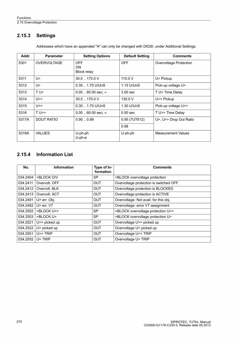
Functions
2.15 Overvoltage Protection
SIPROTEC, 7UT6x, ManualC53000-G1176-C230-3, Release date 05.2013
270
2.15.3 Settings
Addresses which have an appended "A" can only be changed with DIGSI, under Additional Settings.
2.15.4 Information List
Addr. Parameter Setting Options Default Setting Comments
5301 OVERVOLTAGE OFFONBlock relay
OFF Overvoltage Protection
5311 U> 30.0 .. 170.0 V 115.0 V U> Pickup
5312 U> 0.30 .. 1.70 U/UnS 1.15 U/UnS Pick-up voltage U>
5313 T U> 0.00 .. 60.00 sec; ∞ 3.00 sec T U> Time Delay
5314 U>> 30.0 .. 170.0 V 130.0 V U>> Pickup
5315 U>> 0.30 .. 1.70 U/UnS 1.30 U/UnS Pick-up voltage U>>
5316 T U>> 0.00 .. 60.00 sec; ∞ 0.50 sec T U>> Time Delay
5317A DOUT RATIO 0.90 .. 0.99 0.95 (7UT612) U>, U>> Drop Out Ratio
0.98
5318A VALUES U-ph-phU-ph-e
U-ph-ph Measurement Values
No. Information Type of In-
formation
Comments
034.2404 >BLOCK O/V SP >BLOCK overvoltage protection
034.2411 Overvolt. OFF OUT Overvoltage protection is switched OFF
034.2412 Overvolt. BLK OUT Overvoltage protection is BLOCKED
034.2413 Overvolt. ACT OUT Overvoltage protection is ACTIVE
034.2491 U> err. Obj. OUT Overvoltage: Not avail. for this obj.
034.2492 U> err. VT OUT Overvoltage: error VT assignment
034.2502 >BLOCK U>> SP >BLOCK overvoltage protection U>>
034.2503 >BLOCK U> SP >BLOCK overvoltage protection U>
034.2521 U>> picked up OUT Overvoltage U>> picked up
034.2522 U> picked up OUT Overvoltage U> picked up
034.2551 U>> TRIP OUT Overvoltage U>> TRIP
034.2552 U> TRIP OUT Overvoltage U> TRIP

Functions
2.16 Frequency Protection
SIPROTEC, 7UT6x, ManualC53000-G1176-C230-3, Release date 05.2013
271
2.16 Frequency Protection
The frequency protection function detects abnormally high and low frequencies. If the network frequency lies
outside the admissible range, appropriate actions are initiated. For generators, e.g. the machine is separated
from the network. Network decoupling or load shedding can be initiated in networks.
A frequency decrease occurs when the system experiences an increase in real power demand or sub-networks
that cannot (or not fast enough) be compensated by additional performance generation. Real power demand
has to be decreased by load shedding. A faulty frequency, or speed regulation, can also be the cause in the
power station sector. Frequency decrease protection is also applied for generators which operate (temporarily)
to an island network. This is due to the fact that the reverse power protection cannot operate in case of a drive
power failure. The generator can be disconnected from the power system using the frequency decrease pro-
tection.
An increase in system frequency occurs when large blocks of load are removed from the system, or again when
a malfunction occurs with a generator governor or AGC system. For rotating machines this increased speed
means an increased mechanical loading. There is also a risk of self-excitation for generators feeding long lines
under no-load conditions.
Frequency protection consists of four frequency elements. Each stage is independent and can initiate different
control functions. Three frequency stages are designed for decreased frequency detection (f<, f<<, f<<<), the
fourth is an overfrequency stage (f>).
It can also be used for three-phase protective objects. This implies that the device is connected to a voltage
transformer. This is therefore only possible for 7UT613 and 7UT633. As the frequency protection only gets its
measuring information from the connected voltage measurement, it leaves the assignment of currents to one
side or a measuring location for the function without coating. For the setting of the minimum voltage for the
frequency measurement: If the line protection for the frequency protection is assigned to a specific side of the
protective object or to the three-phase busbar, the voltage threshold is to be set as relative value (U/UN). The
value is set to secondary in volts when assigned to a measuring location.
2.16.1 Function Description
The frequency protection in 7UT613 / 7UT633 uses the positive sequence system from the fundamental
harmonic of the connected phase-to-earth voltages. The lack of phase voltages or phase-to-phase voltages
thus has no negative impact as long as the positive sequence voltage is present and of sufficient magnitude. If
the positive sequence voltage drops below a settable value U MIN, frequency protection is disabled because
precise frequency values can no longer be calculated from the measured quantity.
The frequency protection cannot work if voltage or frequency are outside the working range of the frequency
protection (see Technical Data). If a frequency stage picks up frequencies at >66 Hz (or >22 Hz at 16,7 Hz
nominal frequency), the pickup is maintained. If the frequency increases and exceeds the operational range,
or if the positive phase-sequence voltage of 8.6 V as phase-phase voltage or 5 V as non-interlinked voltage is
undershot, the pickup is maintained and a trip on overfrequency is thus enabled.
Maintaining the pickup is ended if the frequency measurement reads again frequencies <66 Hz (or <22 Hz) or
the frequency protection is blocked via the indication >FQS. Each frequency stage has a set delay time.
Each of the four frequency elements can be blocked individually by binary inputs. The entire frequency
protection can be blocked via a binary input. A corresponding command is signalled after the delay time.

Functions
2.16 Frequency Protection
SIPROTEC, 7UT6x, ManualC53000-G1176-C230-3, Release date 05.2013
272
Figure 2-106 Logic diagram of frequency protection
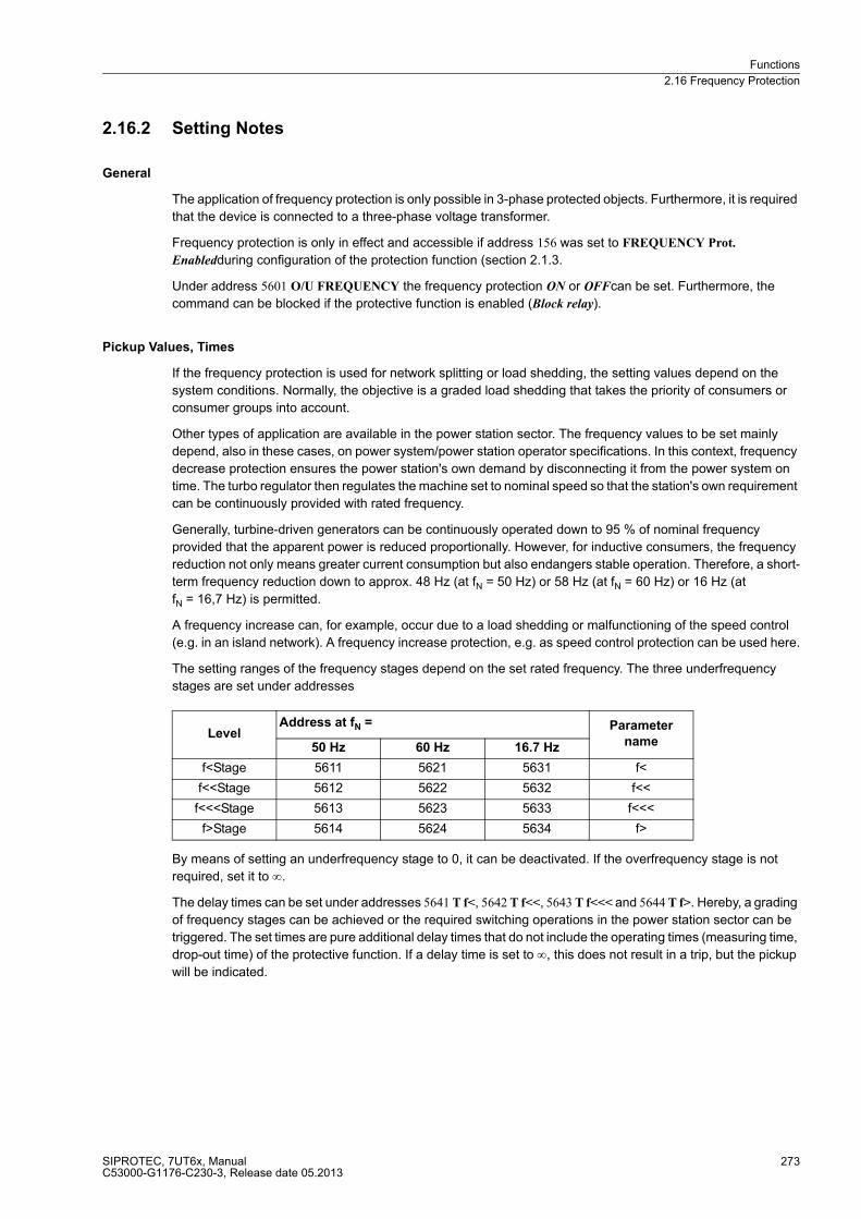
Functions
2.16 Frequency Protection
SIPROTEC, 7UT6x, ManualC53000-G1176-C230-3, Release date 05.2013
273
2.16.2 Setting Notes
General
The application of frequency protection is only possible in 3-phase protected objects. Furthermore, it is required
that the device is connected to a three-phase voltage transformer.
Frequency protection is only in effect and accessible if address 156 was set to FREQUENCY Prot.
Enabledduring configuration of the protection function (section 2.1.3.
Under address 5601 O/U FREQUENCY the frequency protection ON or OFFcan be set. Furthermore, the
command can be blocked if the protective function is enabled (Block relay).
Pickup Values, Times
If the frequency protection is used for network splitting or load shedding, the setting values depend on the
system conditions. Normally, the objective is a graded load shedding that takes the priority of consumers or
consumer groups into account.
Other types of application are available in the power station sector. The frequency values to be set mainly
depend, also in these cases, on power system/power station operator specifications. In this context, frequency
decrease protection ensures the power station's own demand by disconnecting it from the power system on
time. The turbo regulator then regulates the machine set to nominal speed so that the station's own requirement
can be continuously provided with rated frequency.
Generally, turbine-driven generators can be continuously operated down to 95 % of nominal frequency
provided that the apparent power is reduced proportionally. However, for inductive consumers, the frequency
reduction not only means greater current consumption but also endangers stable operation. Therefore, a short-
term frequency reduction down to approx. 48 Hz (at fN = 50 Hz) or 58 Hz (at fN = 60 Hz) or 16 Hz (at
fN = 16,7 Hz) is permitted.
A frequency increase can, for example, occur due to a load shedding or malfunctioning of the speed control
(e.g. in an island network). A frequency increase protection, e.g. as speed control protection can be used here.
The setting ranges of the frequency stages depend on the set rated frequency. The three underfrequency
stages are set under addresses
By means of setting an underfrequency stage to 0, it can be deactivated. If the overfrequency stage is not
required, set it to ∞.
The delay times can be set under addresses 5641 T f<, 5642 T f<<, 5643 T f<<< and 5644 T f>. Hereby, a grading
of frequency stages can be achieved or the required switching operations in the power station sector can be
triggered. The set times are pure additional delay times that do not include the operating times (measuring time,
drop-out time) of the protective function. If a delay time is set to ∞, this does not result in a trip, but the pickup
will be indicated.
LevelAddress at fN = Parameter
name50 Hz 60 Hz 16.7 Hz
f<Stage 5611 5621 5631 f<
f<<Stage 5612 5622 5632 f<<
f<<<Stage 5613 5623 5633 f<<<
f>Stage 5614 5624 5634 f>
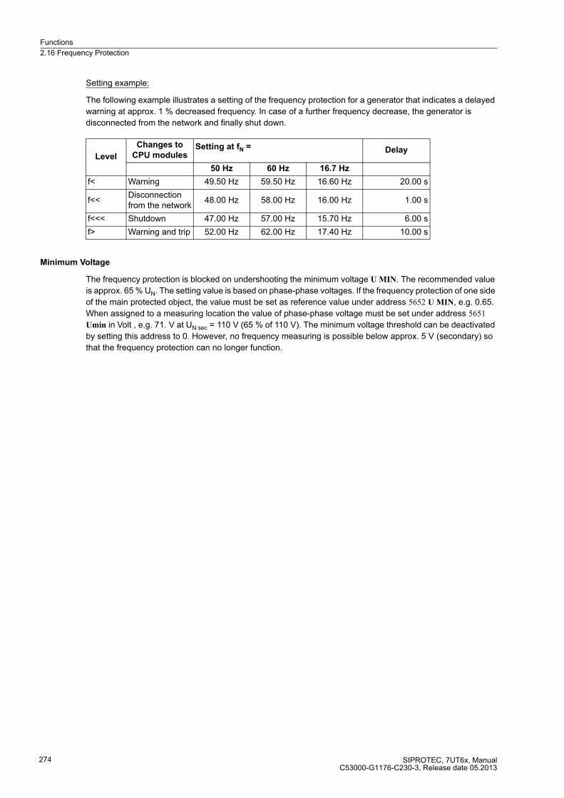
Functions
2.16 Frequency Protection
SIPROTEC, 7UT6x, ManualC53000-G1176-C230-3, Release date 05.2013
274
Setting example:
The following example illustrates a setting of the frequency protection for a generator that indicates a delayed
warning at approx. 1 % decreased frequency. In case of a further frequency decrease, the generator is
disconnected from the network and finally shut down.
Minimum Voltage
The frequency protection is blocked on undershooting the minimum voltage U MIN. The recommended value
is approx. 65 % UN. The setting value is based on phase-phase voltages. If the frequency protection of one side
of the main protected object, the value must be set as reference value under address 5652 U MIN, e.g. 0.65.
When assigned to a measuring location the value of phase-phase voltage must be set under address 5651
Umin in Volt , e.g. 71. V at UN sec = 110 V (65 % of 110 V). The minimum voltage threshold can be deactivated
by setting this address to 0. However, no frequency measuring is possible below approx. 5 V (secondary) so
that the frequency protection can no longer function.
Level
Changes to
CPU modulesSetting at fN = Delay
50 Hz 60 Hz 16.7 Hz
f< Warning 49.50 Hz 59.50 Hz 16.60 Hz 20.00 s
f<<Disconnection from the network
48.00 Hz 58.00 Hz 16.00 Hz 1.00 s
f<<< Shutdown 47.00 Hz 57.00 Hz 15.70 Hz 6.00 s
f> Warning and trip 52.00 Hz 62.00 Hz 17.40 Hz 10.00 s
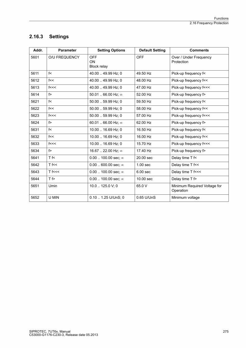
Functions
2.16 Frequency Protection
SIPROTEC, 7UT6x, ManualC53000-G1176-C230-3, Release date 05.2013
275
2.16.3 Settings
Addr. Parameter Setting Options Default Setting Comments
5601 O/U FREQUENCY OFFONBlock relay
OFF Over / Under Frequency Protection
5611 f< 40.00 .. 49.99 Hz; 0 49.50 Hz Pick-up frequency f<
5612 f<< 40.00 .. 49.99 Hz; 0 48.00 Hz Pick-up frequency f<<
5613 f<<< 40.00 .. 49.99 Hz; 0 47.00 Hz Pick-up frequency f<<<
5614 f> 50.01 .. 66.00 Hz; ∞ 52.00 Hz Pick-up frequency f>
5621 f< 50.00 .. 59.99 Hz; 0 59.50 Hz Pick-up frequency f<
5622 f<< 50.00 .. 59.99 Hz; 0 58.00 Hz Pick-up frequency f<<
5623 f<<< 50.00 .. 59.99 Hz; 0 57.00 Hz Pick-up frequency f<<<
5624 f> 60.01 .. 66.00 Hz; ∞ 62.00 Hz Pick-up frequency f>
5631 f< 10.00 .. 16.69 Hz; 0 16.50 Hz Pick-up frequency f<
5632 f<< 10.00 .. 16.69 Hz; 0 16.00 Hz Pick-up frequency f<<
5633 f<<< 10.00 .. 16.69 Hz; 0 15.70 Hz Pick-up frequency f<<<
5634 f> 16.67 .. 22.00 Hz; ∞ 17.40 Hz Pick-up frequency f>
5641 T f< 0.00 .. 100.00 sec; ∞ 20.00 sec Delay time T f<
5642 T f<< 0.00 .. 600.00 sec; ∞ 1.00 sec Delay time T f<<
5643 T f<<< 0.00 .. 100.00 sec; ∞ 6.00 sec Delay time T f<<<
5644 T f> 0.00 .. 100.00 sec; ∞ 10.00 sec Delay time T f>
5651 Umin 10.0 .. 125.0 V; 0 65.0 V Minimum Required Voltage for Operation
5652 U MIN 0.10 .. 1.25 U/UnS; 0 0.65 U/UnS Minimum voltage
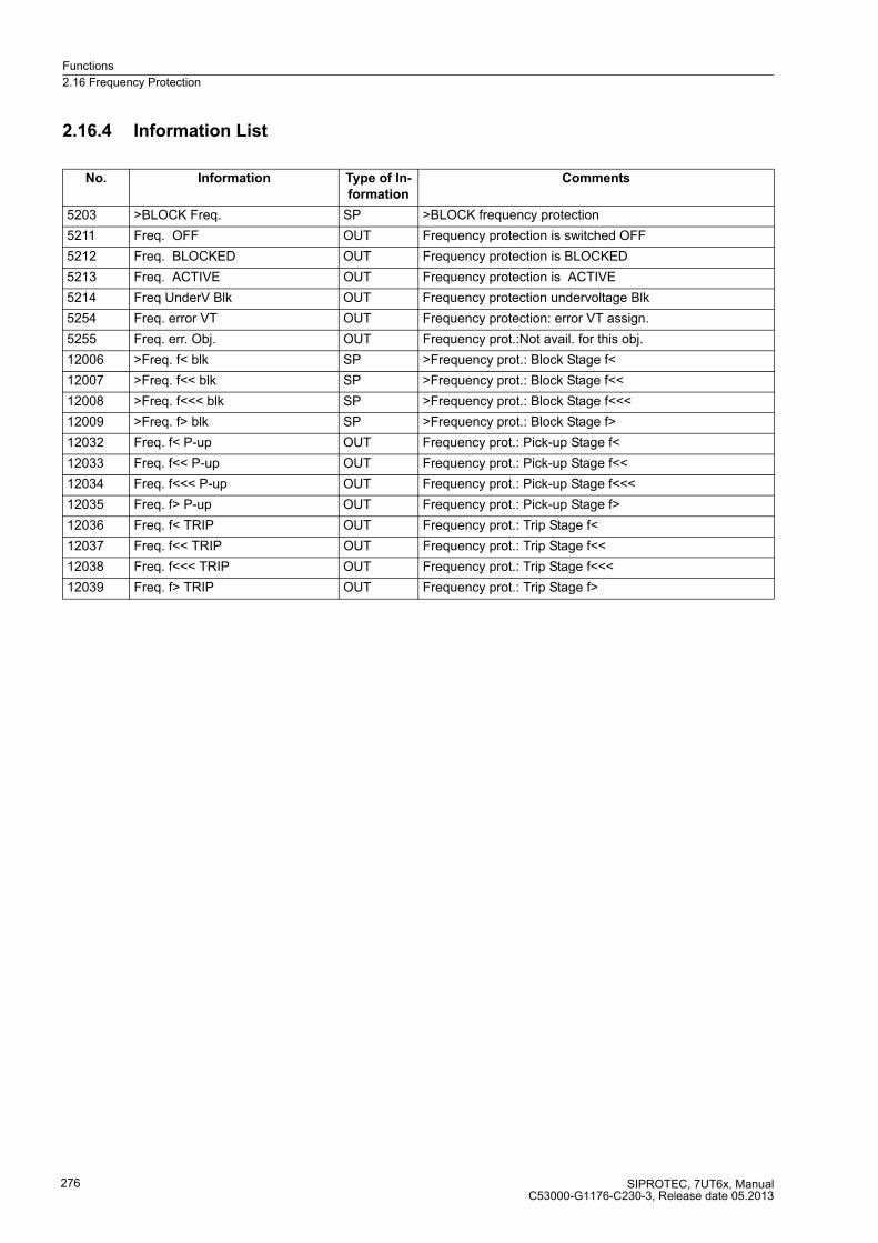
Functions
2.16 Frequency Protection
SIPROTEC, 7UT6x, ManualC53000-G1176-C230-3, Release date 05.2013
276
2.16.4 Information List
No. Information Type of In-
formation
Comments
5203 >BLOCK Freq. SP >BLOCK frequency protection
5211 Freq. OFF OUT Frequency protection is switched OFF
5212 Freq. BLOCKED OUT Frequency protection is BLOCKED
5213 Freq. ACTIVE OUT Frequency protection is ACTIVE
5214 Freq UnderV Blk OUT Frequency protection undervoltage Blk
5254 Freq. error VT OUT Frequency protection: error VT assign.
5255 Freq. err. Obj. OUT Frequency prot.:Not avail. for this obj.
12006 >Freq. f< blk SP >Frequency prot.: Block Stage f<
12007 >Freq. f<< blk SP >Frequency prot.: Block Stage f<<
12008 >Freq. f<<< blk SP >Frequency prot.: Block Stage f<<<
12009 >Freq. f> blk SP >Frequency prot.: Block Stage f>
12032 Freq. f< P-up OUT Frequency prot.: Pick-up Stage f<
12033 Freq. f<< P-up OUT Frequency prot.: Pick-up Stage f<<
12034 Freq. f<<< P-up OUT Frequency prot.: Pick-up Stage f<<<
12035 Freq. f> P-up OUT Frequency prot.: Pick-up Stage f>
12036 Freq. f< TRIP OUT Frequency prot.: Trip Stage f<
12037 Freq. f<< TRIP OUT Frequency prot.: Trip Stage f<<
12038 Freq. f<<< TRIP OUT Frequency prot.: Trip Stage f<<<
12039 Freq. f> TRIP OUT Frequency prot.: Trip Stage f>
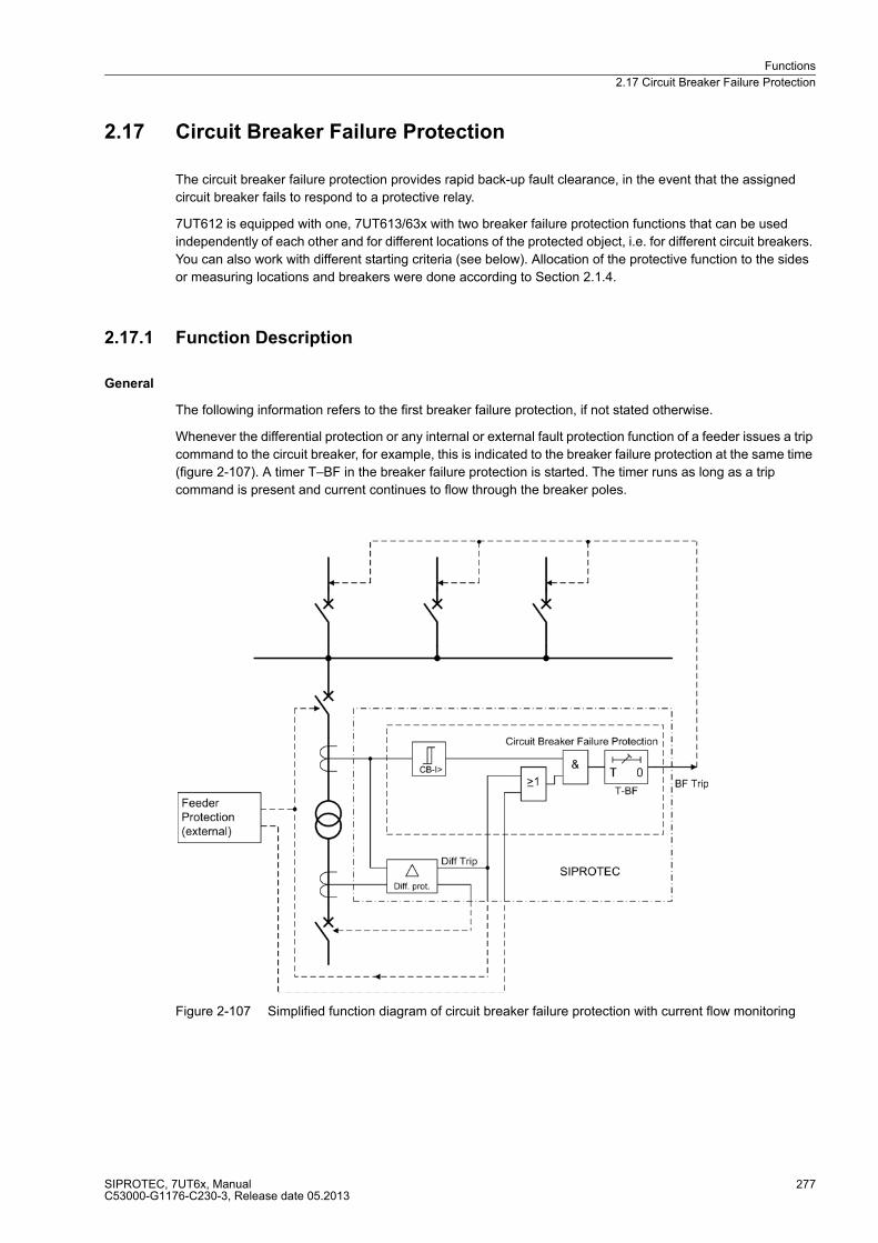
Functions
2.17 Circuit Breaker Failure Protection
SIPROTEC, 7UT6x, ManualC53000-G1176-C230-3, Release date 05.2013
277
2.17 Circuit Breaker Failure Protection
The circuit breaker failure protection provides rapid back-up fault clearance, in the event that the assigned
circuit breaker fails to respond to a protective relay.
7UT612 is equipped with one, 7UT613/63x with two breaker failure protection functions that can be used
independently of each other and for different locations of the protected object, i.e. for different circuit breakers.
You can also work with different starting criteria (see below). Allocation of the protective function to the sides
or measuring locations and breakers were done according to Section 2.1.4.
2.17.1 Function Description
General
The following information refers to the first breaker failure protection, if not stated otherwise.
Whenever the differential protection or any internal or external fault protection function of a feeder issues a trip
command to the circuit breaker, for example, this is indicated to the breaker failure protection at the same time
(figure 2-107). A timer T–BF in the breaker failure protection is started. The timer runs as long as a trip
command is present and current continues to flow through the breaker poles.
Figure 2-107 Simplified function diagram of circuit breaker failure protection with current flow monitoring
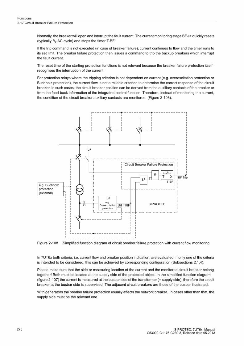
Functions
2.17 Circuit Breaker Failure Protection
SIPROTEC, 7UT6x, ManualC53000-G1176-C230-3, Release date 05.2013
278
Normally, the breaker will open and interrupt the fault current. The current monitoring stage BF-I> quickly resets
(typically 1/2 AC cycle) and stops the timer T-BF.
If the trip command is not executed (in case of breaker failure), current continues to flow and the timer runs to
its set limit. The breaker failure protection then issues a command to trip the backup breakers which interrupt
the fault current.
The reset time of the starting protection functions is not relevant because the breaker failure protection itself
recognises the interruption of the current.
For protection relays where the tripping criterion is not dependent on current (e.g. overexcitation protection or
Buchholz protection), the current flow is not a reliable criterion to determine the correct response of the circuit
breaker. In such cases, the circuit breaker position can be derived from the auxiliary contacts of the breaker or
from the feed-back information of the integrated control function. Therefore, instead of monitoring the current,
the condition of the circuit breaker auxiliary contacts are monitored. (Figure 2-108).
Figure 2-108 Simplified function diagram of circuit breaker failure protection with current flow monitoring
In 7UT6x both criteria, i.e. current flow and breaker position indication, are evaluated. If only one of the criteria
is intended to be considered, this can be achieved by corresponding configuration (Subsections 2.1.4).
Please make sure that the side or measuring location of the current and the monitored circuit breaker belong
together! Both must be located at the supply side of the protected object. In the simplified function diagram
(figure 2-107) the current is measured at the busbar side of the transformer (= supply side), therefore the circuit
breaker at the busbar side is supervised. The adjacent circuit breakers are those of the busbar illustrated.
With generators the breaker failure protection usually affects the network breaker. In cases other than that, the
supply side must be the relevant one.
Functions
2.17 Circuit Breaker Failure Protection
SIPROTEC, 7UT6x, ManualC53000-G1176-C230-3, Release date 05.2013
279
Initiation
The breaker failure protection can be initiated by internal protective functions of the 7UT6x, i.e. trip commands
of protective functions or via CFC (internal logic functions), or by external trip signals via a binary input. Both
sources are processed in the same way but separately annunciated.
The breaker failure protection checks now the continuation of current flow through the breaker to be monitored.
Additionally, the breaker position (read from the feedback of the auxiliary contacts) is checked provided
associated feedback information is available.
The current criterion is met if at least one of the three phase currents exceeds a settable threshold, e.g.
PoleOpenCurr.S1 if the breaker failure protection is assigned (see also Subsection 2.1.4 under margin heading
„Circuit Breaker Status“. Special features detect the instant of current interruption. In case of sinusoidal currents
the current interruption is detected after approximately 1/2 AC cycle. With aperiodic DC current components in
the fault current and/or in the current transformer secondary circuit after interruption (e.g. current transformers
with linearized core), or saturation of the current transformers caused by the DC component in the fault current,
it can take one AC cycle before the interruption of the primary current is reliably detected.
Evaluation of the breaker auxiliary contacts is carried out only when no current flow is detected at the instant
of initiation, i.e. the trip command of a protection function (internal or external) which is to start the breaker
failure protection. In this case the breaker is assumed to be open as soon as the auxiliary contact criterion
indicates open breaker.
Once the current flow criterion has picked up before the trip signal from the initiating protection, the circuit
breaker is assumed to be open as soon as the current disappears, even if the associated auxiliary contact does
not (yet) indicate that the circuit breaker has opened. This gives preference to the more reliable current criterion
and avoids false operation due to a defect e.g. in the auxiliary contact mechanism or circuit. If the auxiliary
contacts indicate open breaker even though current is flowing, an alarm is given (FNos 30135 to 30144).
If both positions of the breaker are indicated (NO contact and NC contact via double point indication) the
auxiliary contact criterion is not evaluated if, at the instant of initiation, an intermediate position is indicated, but
only the current criterion. On the other hand, if the breaker failure protection is already started, the breaker is
assumed to have opened as soon as it is no longer indicated as closed, even if it is actually in intermediate
position.
Initiation can be blocked via the binary input „>BLOCK BkrFail“ (No 047.2404 (e.g. during test of the feeder
protection relay).
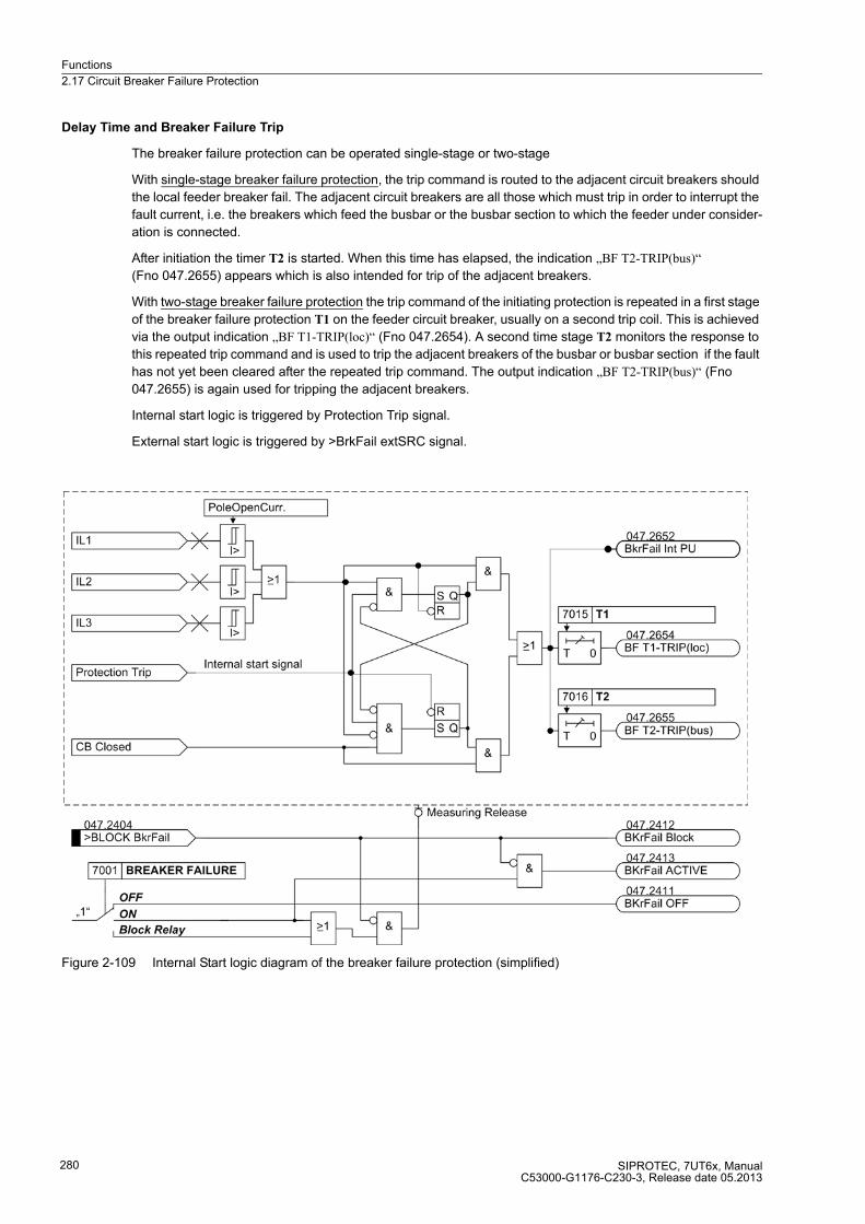
Functions
2.17 Circuit Breaker Failure Protection
SIPROTEC, 7UT6x, ManualC53000-G1176-C230-3, Release date 05.2013
280
Delay Time and Breaker Failure Trip
The breaker failure protection can be operated single-stage or two-stage
With single-stage breaker failure protection, the trip command is routed to the adjacent circuit breakers should
the local feeder breaker fail. The adjacent circuit breakers are all those which must trip in order to interrupt the
fault current, i.e. the breakers which feed the busbar or the busbar section to which the feeder under consider-
ation is connected.
After initiation the timer T2 is started. When this time has elapsed, the indication „BF T2-TRIP(bus)“
(Fno 047.2655) appears which is also intended for trip of the adjacent breakers.
With two-stage breaker failure protection the trip command of the initiating protection is repeated in a first stage
of the breaker failure protection T1 on the feeder circuit breaker, usually on a second trip coil. This is achieved
via the output indication „BF T1-TRIP(loc)“ (Fno 047.2654). A second time stage T2 monitors the response to
this repeated trip command and is used to trip the adjacent breakers of the busbar or busbar section if the fault
has not yet been cleared after the repeated trip command. The output indication „BF T2-TRIP(bus)“ (Fno
047.2655) is again used for tripping the adjacent breakers.
Internal start logic is triggered by Protection Trip signal.
External start logic is triggered by >BrkFail extSRC signal.
Figure 2-109 Internal Start logic diagram of the breaker failure protection (simplified)
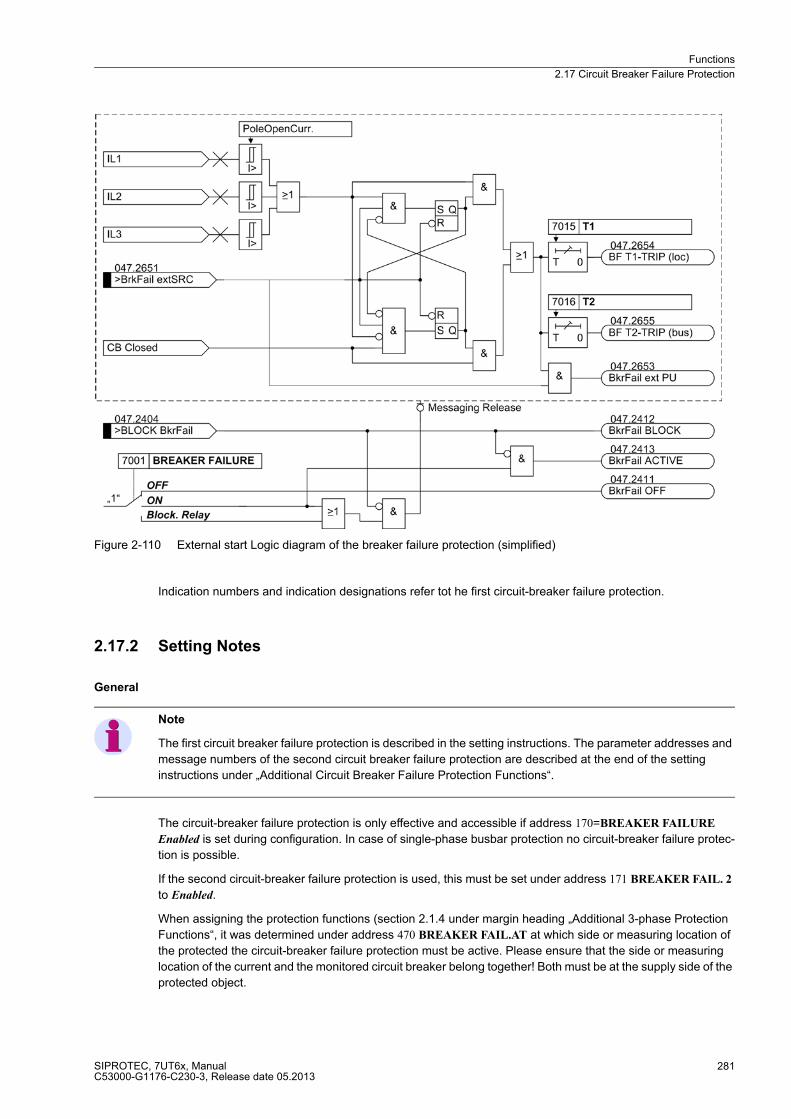
Functions
2.17 Circuit Breaker Failure Protection
SIPROTEC, 7UT6x, ManualC53000-G1176-C230-3, Release date 05.2013
281
Figure 2-110 External start Logic diagram of the breaker failure protection (simplified)
Indication numbers and indication designations refer tot he first circuit-breaker failure protection.
2.17.2 Setting Notes
General
Note
The first circuit breaker failure protection is described in the setting instructions. The parameter addresses and
message numbers of the second circuit breaker failure protection are described at the end of the setting
instructions under „Additional Circuit Breaker Failure Protection Functions“.
The circuit-breaker failure protection is only effective and accessible if address 170=BREAKER FAILURE
Enabled is set during configuration. In case of single-phase busbar protection no circuit-breaker failure protec-
tion is possible.
If the second circuit-breaker failure protection is used, this must be set under address 171 BREAKER FAIL. 2
to Enabled.
When assigning the protection functions (section 2.1.4 under margin heading „Additional 3-phase Protection
Functions“, it was determined under address 470 BREAKER FAIL.AT at which side or measuring location of
the protected the circuit-breaker failure protection must be active. Please ensure that the side or measuring
location of the current and the monitored circuit breaker belong together! Both must be at the supply side of the
protected object.

Functions
2.17 Circuit Breaker Failure Protection
SIPROTEC, 7UT6x, ManualC53000-G1176-C230-3, Release date 05.2013
282
For the second circuit-breaker failure protection the respective address 471 BREAKER FAIL2AT applies.
Under address 7101 BREAKER FAILURE the first circuit-breaker failure protection ON or OFF is set. The
option Block relay allows to operate the protection but the trip output relay is blocked.
The second breaker failure protection is switched at address 7101 BREAKER FAILURE ON or OFF.
Initiation
Three statements are essential for the correct initiation of the circuit breaker failure protection:
The Current-flow MonitoringCurrent flow monitoring ensures that the current flow stops after the trip command
has been issued to the breaker to be monitored. It uses the values set in the General Power System Data 2 is
decisive (see section 2.1.6.1 under margin heading „Circuit Breaker Status“). The decisive value is the setting
assigned to the side or measuring location that indicates the current of the monitored circuit breaker (addresses
1111 to 1125). This value will certainly be undershot in case of an open circuit breaker.
The assignment of the CB auxiliary contacts or the CB feed-back information was executed in accordance with
section 2.1.4 under „Circuit-breaker Data“. The configuration of the respective binary inputs must be complete.
The tripping command for the monitored breaker is determined by address 7111 or 7112 START WITH REL.
(depending on the version of the device). Choose the number of the output relay which shall trip the breaker to
be monitored. If START WITH REL. is parameterised on 0 , no initiation occurs via the internal binary output.
Since 7UT6x will normally trip several circuit breakers by the various protection functions, the device must be
informed about which trip command is decisive for the initiation of the breaker failure protection. If the breaker
failure protection is intended to be initiated also by external trip commands (for the same breaker) the device
has to be informed about this trip via the binary input „>BrkFail extSRC“ (No 047.2651).
The activation of the relay contact set under START WITH REL., only causes the initiation of the circuit breaker
failure protection if this activation is effected simultaneously with the indication (fast indication) of a protection
function.
If the circuit breaker is supposed to be activated behind the respective relay contact by means of a controlled
indication, this message must be conducted, for example, via the DC (direct coupling) function and its TRIP
command. During configuration, the DC-TRIP would cause the respective relay to start the circuit breaker
failure protection.
Two-stage Breaker Failure Protection
In two-stage operation, the trip command is sent after a delay time T1 (address 7115) to the locally monitored
feeder circuit breaker, normally to a separate set of trip coils of the breaker.
The TRIP command of a circuit breaker failure protection may not be allocated to a relay, which is monitored
by a different circuit breaker failure protection. This cascading does not cause initiation.
If the circuit breaker does not respond to the repeated trip command, the protection trips after a second delay
time T2 (address 7116) the adjacent circuit breakers, i.e. those of the busbar or the affected busbar section and,
if necessary, also the circuit breaker at the remote end, if the fault is not yet eliminated.
The delay times are set dependant on the maximum operating time of the feeder circuit breaker and the reset
time of the current detectors of the breaker failure protection, plus a safety margin which allows for any toler-
ance of the delay timers. The time sequences are illustrated in Figure 2-111. For sinusoidal currents one can
assume that the reset time of the current detectors is about 1/2 cycle but if current transformer saturation is
expected, then 11/2 cycles should be assumed as worst case.
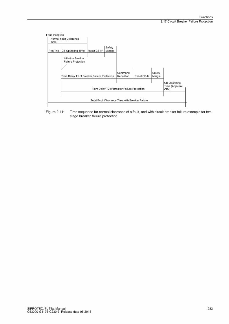
Functions
2.17 Circuit Breaker Failure Protection
SIPROTEC, 7UT6x, ManualC53000-G1176-C230-3, Release date 05.2013
283
Figure 2-111 Time sequence for normal clearance of a fault, and with circuit breaker failure example for two-stage breaker failure protection

Functions
2.17 Circuit Breaker Failure Protection
SIPROTEC, 7UT6x, ManualC53000-G1176-C230-3, Release date 05.2013
284
Single-stage Breaker Failure Protection
With single-stage operation, the adjacent circuit breakers (i.e. the breakers of the busbar zone and, if
applicable, the breaker at the remote end) are tripped after a delay time T2 (address 7116) following initiation,
should the fault not have been cleared within this time.
The delay time T1 (address 7115) is then set to ∞ since it is not needed.
The delay times are determined from the maximum operating time of the feeder circuit breaker, the reset time
of the current detectors of the breaker failure protection, plus a safety margin which allows for any tolerance of
the delay timers. The time sequences are illustrated in Figure 2-112. For sinusoidal currents one can assume
that the reset time of the current detectors is about 1/2 cycle but if current transformer saturation is expected,
then11/2 cycles should be assumed as worst case.
Figure 2-112 Time sequence for normal clearance of a fault, and with circuit breaker failure example for single-stage breaker failure protection
Additional Circuit Breaker Failure Protection Functions
In the aforementioned description, the first circuit breaker failure protection is described respectively. The
differences in the parameter addresses and message numbers of the first and second circuit breaker failure
protection are illustrated in the following table. The positions marked by x are identical.
Parameter addresses Message no.
1. Circuit breaker failure protection 70xx 047.xxxx(.01)
2. Circuit breaker failure protection 71xx 206.xxxx(.01)

Functions
2.17 Circuit Breaker Failure Protection
SIPROTEC, 7UT6x, ManualC53000-G1176-C230-3, Release date 05.2013
285
2.17.3 Settings
2.17.4 Information List
Addr. Parameter Setting Options Default Setting Comments
7001 BREAKER FAILURE OFFONBlock relay
OFF Breaker Failure Protection
7011 START WITH REL. 0 .. 8 0 Start with Relay (intern)
7012 START WITH REL. 0 .. 24 0 Start with Relay (intern)
7015 T1 0.00 .. 60.00 sec; ∞ 0.15 sec T1, Delay of 1st stage (local trip)
7016 T2 0.00 .. 60.00 sec; ∞ 0.30 sec T2, Delay of 2nd stage (busbar trip)
No. Information Type of In-
formation
Comments
047.2404 >BLOCK BkrFail SP >BLOCK Breaker failure
047.2411 BkrFail OFF OUT Breaker failure is switched OFF
047.2412 BkrFail BLOCK OUT Breaker failure is BLOCKED
047.2413 BkrFail ACTIVE OUT Breaker failure is ACTIVE
047.2491 BkrFail Not av. OUT Breaker failure Not avail. for this obj.
047.2651 >BrkFail extSRC SP >Breaker failure initiated externally
047.2652 BkrFail int PU OUT Breaker failure (internal) PICKUP
047.2653 BkrFail ext PU OUT Breaker failure (external) PICKUP
047.2654 BF T1-TRIP(loc) OUT BF TRIP T1 (local trip)
047.2655 BF T2-TRIP(bus) OUT BF TRIP T2 (busbar trip)
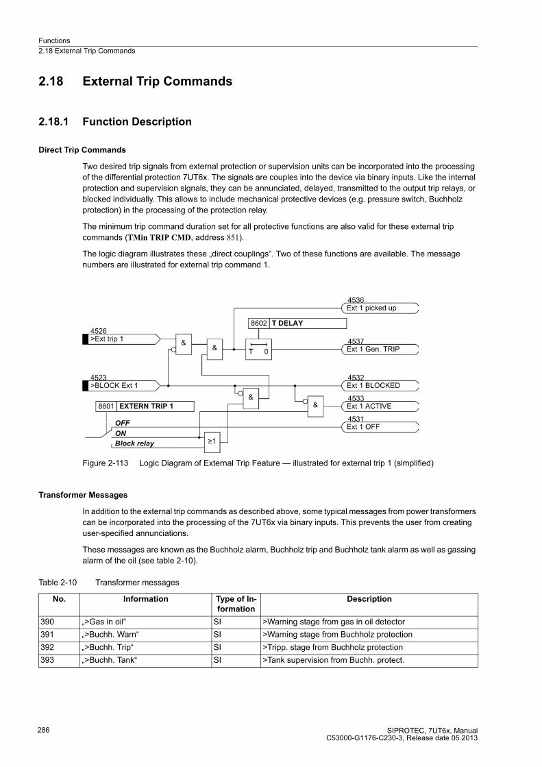
Functions
2.18 External Trip Commands
SIPROTEC, 7UT6x, ManualC53000-G1176-C230-3, Release date 05.2013
286
2.18 External Trip Commands
2.18.1 Function Description
Direct Trip Commands
Two desired trip signals from external protection or supervision units can be incorporated into the processing
of the differential protection 7UT6x. The signals are couples into the device via binary inputs. Like the internal
protection and supervision signals, they can be annunciated, delayed, transmitted to the output trip relays, or
blocked individually. This allows to include mechanical protective devices (e.g. pressure switch, Buchholz
protection) in the processing of the protection relay.
The minimum trip command duration set for all protective functions are also valid for these external trip
commands (TMin TRIP CMD, address 851).
The logic diagram illustrates these „direct couplings“. Two of these functions are available. The message
numbers are illustrated for external trip command 1.
Figure 2-113 Logic Diagram of External Trip Feature — illustrated for external trip 1 (simplified)
Transformer Messages
In addition to the external trip commands as described above, some typical messages from power transformers
can be incorporated into the processing of the 7UT6x via binary inputs. This prevents the user from creating
user-specified annunciations.
These messages are known as the Buchholz alarm, Buchholz trip and Buchholz tank alarm as well as gassing
alarm of the oil (see table 2-10).
Table 2-10 Transformer messages
No. Information Type of In-
formation
Description
390 „>Gas in oil“ SI >Warning stage from gas in oil detector
391 „>Buchh. Warn“ SI >Warning stage from Buchholz protection
392 „>Buchh. Trip“ SI >Tripp. stage from Buchholz protection
393 „>Buchh. Tank“ SI >Tank supervision from Buchh. protect.

Functions
2.18 External Trip Commands
SIPROTEC, 7UT6x, ManualC53000-G1176-C230-3, Release date 05.2013
287
Blocking Signal for External Faults
For transformers so-called sudden pressure relays (SPR) are occasionally installed in the tank which are meant
to switch off the transformer in case of a sudden pressure increase. Not only transformer failures but also high
traversing fault currents originating from external faults can lead to a pressure increase.
External faults are quickly recognised by the 7UT6x (also refer to differential protection, „Add-on Restraint
during External Faults“, section 2.2). A blocking signal can be created by means of a CFC logic in order to
prevent from erroneous trip of the SPR.
Figure 2-114 CFC chart for blocking of a pressure sensor during external fault
2.18.2 Setting Notes
General
The direct external trip functions are only enabled if addresses 186 EXT. TRIP 1 and/or 187 EXT. TRIP 2 have
been set to Enabled during the configuration of the functional scope.
Addresses 8601 EXTERN TRIP 1 and 8701 EXTERN TRIP 2 are used to switch the functions individually ON
or OFF, or to block only the trip command (Block relay).
Signals included from outside can be stabilised by means of a delay time and thus increase the dynamic margin
against interference signals. For external trip functions 1 settings are done in address 8602 T DELAY, for
external trip function 2 in address 8702 T DELAY.

Functions
2.18 External Trip Commands
SIPROTEC, 7UT6x, ManualC53000-G1176-C230-3, Release date 05.2013
288
2.18.3 Settings
2.18.4 Information List
Addr. Parameter Setting Options Default Setting Comments
8601 EXTERN TRIP 1 OFFONBlock relay
OFF External Trip Function 1
8602 T DELAY 0.00 .. 60.00 sec; ∞ 1.00 sec Ext. Trip 1 Time Delay
8701 EXTERN TRIP 2 OFFONBlock relay
OFF External Trip Function 2
8702 T DELAY 0.00 .. 60.00 sec; ∞ 1.00 sec Ext. Trip 2 Time Delay
No. Information Type of In-
formation
Comments
4523 >BLOCK Ext 1 SP >Block external trip 1
4526 >Ext trip 1 SP >Trigger external trip 1
4531 Ext 1 OFF OUT External trip 1 is switched OFF
4532 Ext 1 BLOCKED OUT External trip 1 is BLOCKED
4533 Ext 1 ACTIVE OUT External trip 1 is ACTIVE
4536 Ext 1 picked up OUT External trip 1: General picked up
4537 Ext 1 Gen. TRIP OUT External trip 1: General TRIP
4543 >BLOCK Ext 2 SP >BLOCK external trip 2
4546 >Ext trip 2 SP >Trigger external trip 2
4551 Ext 2 OFF OUT External trip 2 is switched OFF
4552 Ext 2 BLOCKED OUT External trip 2 is BLOCKED
4553 Ext 2 ACTIVE OUT External trip 2 is ACTIVE
4556 Ext 2 picked up OUT External trip 2: General picked up
4557 Ext 2 Gen. TRIP OUT External trip 2: General TRIP
Functions
2.19 Monitoring Functions
SIPROTEC, 7UT6x, ManualC53000-G1176-C230-3, Release date 05.2013
289
2.19 Monitoring Functions
The device incorporates comprehensive supervision functions which cover both hardware and software; the
measured values are continuously checked for plausibility, so that the CT circuits are also included in the
monitoring system to a large extent. It is also possible to implement trip circuit supervision, using appropriate
binary inputs as available.
2.19.1 Measurement Supervision
2.19.1.1 Hardware Monitoring
The device is monitored by the measurement inputs and the output relays. Monitoring circuits and the
processor check the hardware for malfunctions and abnormal states.
Auxiliary and Reference Voltages
The processor voltage of 5 V is monitored by the hardware, as the processor cannot operate if the voltage drops
below the minimum value. In that case, the device is not operational. When the correct voltage has re-estab-
lished the processor system is restarted.
Failure or switch-off of the supply voltage sets the device out of operation; this status is signalled by a „life
contact“ (closed or open). Transient dips in supply voltage do not disturb the function of the device (see
Technical Data).
The processor monitors the offset and the reference voltage of the AD (analogue-to-digital converter). The
protection is blocked in case of inadmissible deviations. Continuous malfunctioning is indicated by the alarm
„Error MeasurSys“, No 181.
Back-up Battery
The back-up battery guarantees that the internal clock continues to work and that metered values and alarms
are stored if the auxiliary voltage fails. The charge level of the battery is checked regularly. On its undershooting
a minimum admissible voltage, the indication „Fail Battery“, No. 177 is issued.
Memory Components
The working memory (RAM) is tested during booting of the system. If a malfunction occurs, the starting se-
quence is interrupted and an LED blinks. During operation the memories are checked with the help of their
checksum.
For the program memory, the cross-check sum is cyclically generated and compared to a stored reference
program cross-check sum.
For the parameter memory, the cross-check sum is cyclically generated and compared to the cross-check sum
that is refreshed after each prarameterisation change.
If a fault occurs, the processor system is restarted.
Functions
2.19 Monitoring Functions
SIPROTEC, 7UT6x, ManualC53000-G1176-C230-3, Release date 05.2013
290
Sampling Frequency
The sampling frequency and the synchronism between the ADC s (analog-to-digital converters) is continuously
monitored. If deviations cannot be corrected by another synchronisation, the device sets itself out of operation
and the red LED „ERROR“ lights up. The readiness relay drops off and signals the malfunction by its „life
contact“.
2.19.1.2 Software Monitoring
Watchdog
For the continuous monitoring of the program execution, a time monitoring is incorporated in the hardware
(hardware watchdog). The watchdog expires and resets the processor system causing a complete reboot if the
processor fails or when a program loses synchronism.
A further software watchdog ensures that any error in the processing of the programs will be recognised. Such
errors also lead to a reset of the processor.
If such an error is not eliminated by restarting, another restart attempt is initiated. If the fault is still present after
three restart attempts within 30 s, the protection system will take itself out of service, and the red LED „Blocked“
lights up. The readiness relay („life contact“) drops off and signals the malfunction by its healthy status contact
(alternatively as NO or NC contact).
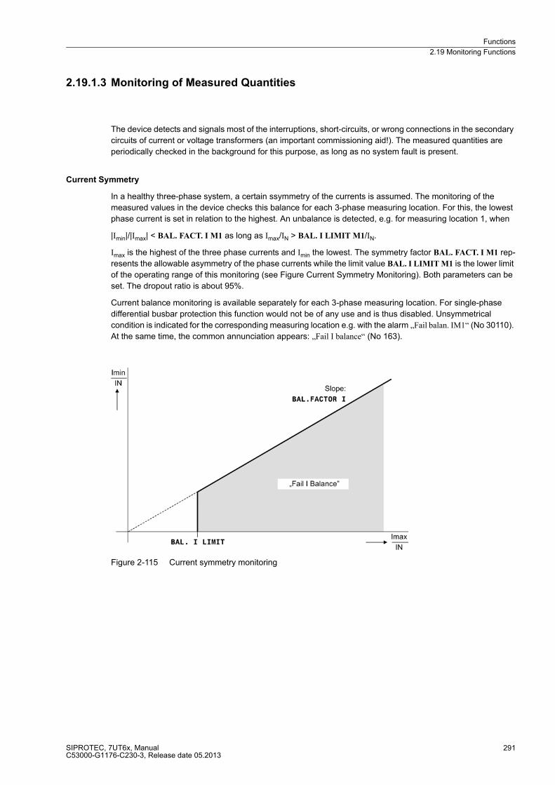
Functions
2.19 Monitoring Functions
SIPROTEC, 7UT6x, ManualC53000-G1176-C230-3, Release date 05.2013
291
2.19.1.3 Monitoring of Measured Quantities
The device detects and signals most of the interruptions, short-circuits, or wrong connections in the secondary
circuits of current or voltage transformers (an important commissioning aid!). The measured quantities are
periodically checked in the background for this purpose, as long as no system fault is present.
Current Symmetry
In a healthy three-phase system, a certain ssymmetry of the currents is assumed. The monitoring of the
measured values in the device checks this balance for each 3-phase measuring location. For this, the lowest
phase current is set in relation to the highest. An unbalance is detected, e.g. for measuring location 1, when
|Imin|/|Imax| < BAL. FACT. I M1 as long as Imax/IN > BAL. I LIMIT M1/IN.
Imax is the highest of the three phase currents and Imin the lowest. The symmetry factor BAL. FACT. I M1 rep-
resents the allowable asymmetry of the phase currents while the limit value BAL. I LIMIT M1 is the lower limit
of the operating range of this monitoring (see Figure Current Symmetry Monitoring). Both parameters can be
set. The dropout ratio is about 95%.
Current balance monitoring is available separately for each 3-phase measuring location. For single-phase
differential busbar protection this function would not be of any use and is thus disabled. Unsymmetrical
condition is indicated for the corresponding measuring location e.g. with the alarm „Fail balan. IM1“ (No 30110).
At the same time, the common annunciation appears: „Fail I balance“ (No 163).
Figure 2-115 Current symmetry monitoring
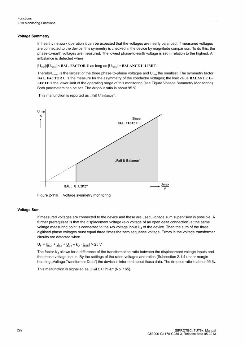
Functions
2.19 Monitoring Functions
SIPROTEC, 7UT6x, ManualC53000-G1176-C230-3, Release date 05.2013
292
Voltage Symmetry
In healthy network operation it can be expected that the voltages are nearly balanced. If measured voltages
are connected to the device, this symmetry is checked in the device by magnitude comparison. To do this, the
phase-to-earth voltages are measured. The lowest phase-to-earth voltage is set in relation to the highest. An
imbalance is detected when
|Umin|/|Umax| < BAL. FACTOR U as long as |Umax| > BALANCE U-LIMIT.
TherebyUmax is the largest of the three phase-to-phase voltages and Umin the smallest. The symmetry factor
BAL. FACTOR U is the measure for the asymmetry of the conductor voltages; the limit value BALANCE U-
LIMIT is the lower limit of the operating range of this monitoring (see Figure Voltage Symmetry Monitoring).
Both parameters can be set. The dropout ratio is about 95 %.
This malfunction is reported as „Fail U balance“.
Figure 2-116 Voltage symmetry monitoring
Voltage Sum
If measured voltages are connected to the device and these are used, voltage sum supervision is possible. A
further prerequisite is that the displacement voltage (e-n voltage of an open delta connection) at the same
voltage measuring point is connected to the 4th voltage input U4 of the device. Then the sum of the three
digitised phase voltages must equal three times the zero sequence voltage. Errors in the voltage transformer
circuits are detected when
UF = |UL1 + UL2 + UL3 – kU · UEN| > 25 V.
The factor kU allows for a difference of the transformation ratio between the displacement voltage inputs and
the phase voltage inputs. By the settings of the rated voltages and ratios (Subsection 2.1.4 under margin
heading „Voltage Transformer Data“) the device is informed about these data. The dropout ratio is about 95 %.
This malfunction is signalled as „Fail Σ U Ph-E“ (No. 165).
Functions
2.19 Monitoring Functions
SIPROTEC, 7UT6x, ManualC53000-G1176-C230-3, Release date 05.2013
293
Current Phase Sequence
To detect swapped connections in the current input circuits, the direction of rotation of the phase currents for
three-phase application is checked. Therefore the sequence of the zero crossings of the currents (having the
same sign) is checked for each 3-phase measuring location. For single-phase busbar differential protection and
single-phase transformers, this function would not be of any use and is thus disabled.
Especially the unbalanced load protection requires clockwise rotation. If rotation in the protected object is
reverse, this must be considered during the configuration of the general power system data (Subsection 2.1.4
under „Phase rotation“).
Phase rotation is checked by supervising the phase sequence of the currents, i.e. for clockwise rotation.
IL1 before IL2 before IL3.
The supervision of current rotation requires a minimum current of
|IL1|, |I L2|, |I L3| > 0,5 IN.
If the rotation measured differs from the rotation set, the annunciation for the corresponding measuring location
is output, e.g. „FailPh.Seq IM1“ (No 30115). At the same time, the common annunciation appears: „Fail Ph. Seq.
I“ (No 175).
Voltage Phase Sequence
If measured voltages are connected to the device and these are used, the voltage phase rotation is supervised.
On clockwise phase rotation this is done by supervising the phase sequence of the voltages
UL1 before UL2 before UL3.
This check is done as long as the voltages have a magnitude of at least
|UL1|, |UL2|, |UL3| > 40 V/√3.
Wrong phase rotation is indicated by the alarm „Fail Ph. Seq. U“ (No 176).

Functions
2.19 Monitoring Functions
SIPROTEC, 7UT6x, ManualC53000-G1176-C230-3, Release date 05.2013
294
2.19.1.4 Setting Notes
Measured Value Monitoring
The sensitivity of the measured value monitoring can be changed. Default values are set at the factory, which
are sufficient in most cases. If especially high operating asymmetry in the currents and/or voltages is to be ex-
pected for the application, or if it becomes apparent during operation that certain monitoring functions activate
sporadically, then the setting should be less sensitive.
The current symmetry supervision can be switched ON or OFF in address 8101 BALANCE I, the voltage
supervision (if available) in address 8102 BALANCE U.
The current phase sequence can be switched ON or OFF in address 8105 PHASE ROTAT. I; the voltage
sequence monitoring (if available) in address 8106 PHASE ROTAT. U.
In address 8104 SUMMATION U the voltage sum monitoring ON or OFF can be set (if available).
Address 8111 BAL. I LIMIT M1 determines the threshold current for measuring location 1 above which the
current balance supervision is effective. Address 8112 BAL. FACT. I M1 is the associated symmetry factor; that
is, the slope of the symmetry characteristic curve. In order to avoid activation during short-term asymmetries,
the monitoring is delayed at address 8113 T Sym. I th. M1. This parameter can only be set with DIGSI at Addi-
tional Settings. The time delay usually amounts to a few seconds.
The same considerations apply for the further measuring locations, as far as they are available and allocated:
Address 8121 BAL. I LIMIT M2, 8122 BAL. FACT. I M2 and 8123 T Sym. I th. M2 for measuring location 2,
address 8131 BAL. I LIMIT M3, 8132 BAL. FACT. I M3 and 8133 T Sym. I th. M3 for measuring location 3,
address 8141 BAL. I LIMIT M4, 8142 BAL. FACT. I M4 and 8143 T Sym. I th. M4 for measuring location 4,
address 8151 BAL. I LIMIT M5, 8152 BAL. FACT. I M5 and 8153 T Sym. I th. M5 for measuring location 5.
Address 8161 BALANCE U-LIMIT determines the threshold voltage above which the voltage balance super-
vision is effective. Address 8162 BAL. FACTOR U is the associated symmetry factor, i.e. the slope of the sym-
metry characteristic curve (if voltages available). In order to avoid activation during short-term asymmetries,
the monitoring is delayed at address 8163 T BAL. U LIMIT. This parameter can only be set with DIGSI at Ad-
ditional Settings. The time delay usually amounts to a few seconds.
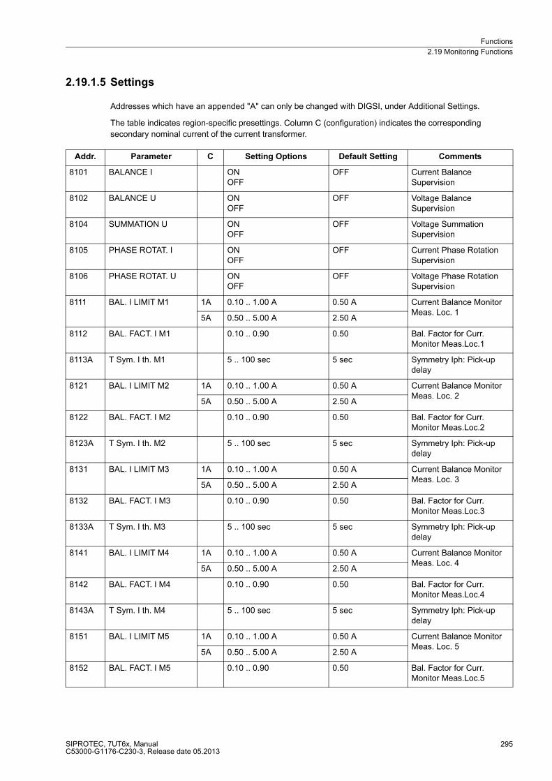
Functions
2.19 Monitoring Functions
SIPROTEC, 7UT6x, ManualC53000-G1176-C230-3, Release date 05.2013
295
2.19.1.5 Settings
Addresses which have an appended "A" can only be changed with DIGSI, under Additional Settings.
The table indicates region-specific presettings. Column C (configuration) indicates the corresponding
secondary nominal current of the current transformer.
Addr. Parameter C Setting Options Default Setting Comments
8101 BALANCE I ONOFF
OFF Current Balance Supervision
8102 BALANCE U ONOFF
OFF Voltage Balance Supervision
8104 SUMMATION U ONOFF
OFF Voltage Summation Supervision
8105 PHASE ROTAT. I ONOFF
OFF Current Phase Rotation Supervision
8106 PHASE ROTAT. U ONOFF
OFF Voltage Phase Rotation Supervision
8111 BAL. I LIMIT M1 1A 0.10 .. 1.00 A 0.50 A Current Balance Monitor Meas. Loc. 1
5A 0.50 .. 5.00 A 2.50 A
8112 BAL. FACT. I M1 0.10 .. 0.90 0.50 Bal. Factor for Curr. Monitor Meas.Loc.1
8113A T Sym. I th. M1 5 .. 100 sec 5 sec Symmetry Iph: Pick-up delay
8121 BAL. I LIMIT M2 1A 0.10 .. 1.00 A 0.50 A Current Balance Monitor Meas. Loc. 2
5A 0.50 .. 5.00 A 2.50 A
8122 BAL. FACT. I M2 0.10 .. 0.90 0.50 Bal. Factor for Curr. Monitor Meas.Loc.2
8123A T Sym. I th. M2 5 .. 100 sec 5 sec Symmetry Iph: Pick-up delay
8131 BAL. I LIMIT M3 1A 0.10 .. 1.00 A 0.50 A Current Balance Monitor Meas. Loc. 3
5A 0.50 .. 5.00 A 2.50 A
8132 BAL. FACT. I M3 0.10 .. 0.90 0.50 Bal. Factor for Curr. Monitor Meas.Loc.3
8133A T Sym. I th. M3 5 .. 100 sec 5 sec Symmetry Iph: Pick-up delay
8141 BAL. I LIMIT M4 1A 0.10 .. 1.00 A 0.50 A Current Balance Monitor Meas. Loc. 4
5A 0.50 .. 5.00 A 2.50 A
8142 BAL. FACT. I M4 0.10 .. 0.90 0.50 Bal. Factor for Curr. Monitor Meas.Loc.4
8143A T Sym. I th. M4 5 .. 100 sec 5 sec Symmetry Iph: Pick-up delay
8151 BAL. I LIMIT M5 1A 0.10 .. 1.00 A 0.50 A Current Balance Monitor Meas. Loc. 5
5A 0.50 .. 5.00 A 2.50 A
8152 BAL. FACT. I M5 0.10 .. 0.90 0.50 Bal. Factor for Curr. Monitor Meas.Loc.5
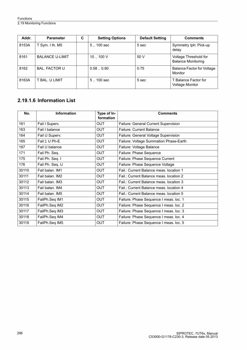
Functions
2.19 Monitoring Functions
SIPROTEC, 7UT6x, ManualC53000-G1176-C230-3, Release date 05.2013
296
2.19.1.6 Information List
8153A T Sym. I th. M5 5 .. 100 sec 5 sec Symmetry Iph: Pick-up delay
8161 BALANCE U-LIMIT 10 .. 100 V 50 V Voltage Threshold for Balance Monitoring
8162 BAL. FACTOR U 0.58 .. 0.90 0.75 Balance Factor for Voltage Monitor
8163A T BAL. U LIMIT 5 .. 100 sec 5 sec T Balance Factor for Voltage Monitor
No. Information Type of In-
formation
Comments
161 Fail I Superv. OUT Failure: General Current Supervision
163 Fail I balance OUT Failure: Current Balance
164 Fail U Superv. OUT Failure: General Voltage Supervision
165 Fail Σ U Ph-E OUT Failure: Voltage Summation Phase-Earth
167 Fail U balance OUT Failure: Voltage Balance
171 Fail Ph. Seq. OUT Failure: Phase Sequence
175 Fail Ph. Seq. I OUT Failure: Phase Sequence Current
176 Fail Ph. Seq. U OUT Failure: Phase Sequence Voltage
30110 Fail balan. IM1 OUT Fail.: Current Balance meas. location 1
30111 Fail balan. IM2 OUT Fail.: Current Balance meas. location 2
30112 Fail balan. IM3 OUT Fail.: Current Balance meas. location 3
30113 Fail balan. IM4 OUT Fail.: Current Balance meas. location 4
30114 Fail balan. IM5 OUT Fail.: Current Balance meas. location 5
30115 FailPh.Seq IM1 OUT Failure: Phase Sequence I meas. loc. 1
30116 FailPh.Seq IM2 OUT Failure: Phase Sequence I meas. loc. 2
30117 FailPh.Seq IM3 OUT Failure: Phase Sequence I meas. loc. 3
30118 FailPh.Seq IM4 OUT Failure: Phase Sequence I meas. loc. 4
30119 FailPh.Seq IM5 OUT Failure: Phase Sequence I meas. loc. 5
Addr. Parameter C Setting Options Default Setting Comments
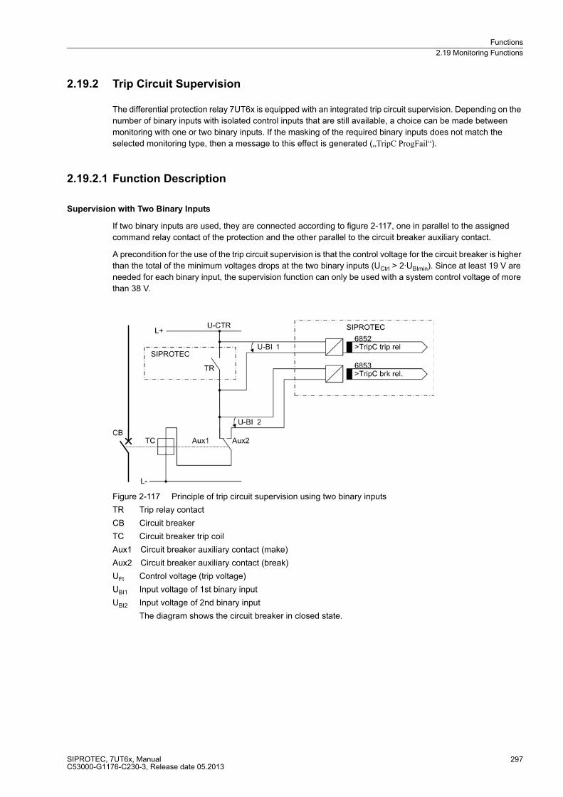
Functions
2.19 Monitoring Functions
SIPROTEC, 7UT6x, ManualC53000-G1176-C230-3, Release date 05.2013
297
2.19.2 Trip Circuit Supervision
The differential protection relay 7UT6x is equipped with an integrated trip circuit supervision. Depending on the
number of binary inputs with isolated control inputs that are still available, a choice can be made between
monitoring with one or two binary inputs. If the masking of the required binary inputs does not match the
selected monitoring type, then a message to this effect is generated („TripC ProgFail“).
2.19.2.1 Function Description
Supervision with Two Binary Inputs
If two binary inputs are used, they are connected according to figure 2-117, one in parallel to the assigned
command relay contact of the protection and the other parallel to the circuit breaker auxiliary contact.
A precondition for the use of the trip circuit supervision is that the control voltage for the circuit breaker is higher
than the total of the minimum voltages drops at the two binary inputs (UCtrl > 2·UBImin). Since at least 19 V are
needed for each binary input, the supervision function can only be used with a system control voltage of more
than 38 V.
Figure 2-117 Principle of trip circuit supervision using two binary inputs
TR Trip relay contact
CB Circuit breaker
TC Circuit breaker trip coil
Aux1 Circuit breaker auxiliary contact (make)
Aux2 Circuit breaker auxiliary contact (break)
UFt Control voltage (trip voltage)
UBI1 Input voltage of 1st binary input
UBI2 Input voltage of 2nd binary input
The diagram shows the circuit breaker in closed state.

Functions
2.19 Monitoring Functions
SIPROTEC, 7UT6x, ManualC53000-G1176-C230-3, Release date 05.2013
298
Depending on the state of the trip relay and the circuit breaker s auxiliary contacts, the binary inputs are
triggered (logical state „H“ in the following table) or short-circuited (logical state and „L“).
The state where both binary inputs are not activated („L“), is only possible during a short transition phase in
intact trip circuits (command relay has issued trip command, but the CB has not yet opened).
A continuous state of this condition is only possible when the trip circuit has been interrupted, a short-circuit
exists in the trip circuit, or battery voltage failure occurs. It is thus used as a monitoring criterion.
Table 2-11 Status table of the binary inputs depending on command relay and circuit breaker switching state
The conditions of the two binary inputs are checked periodically. A query takes place about every 500 ms. Only
after n = 3 of these consecutive state queries have detected a fault, an alarm is given. The repeated measure-
ments determine the delay of the alarm message and avoid that an alarm is output during short transition
periods. After the fault in the trip circuit is removed, the alarm is reset automatically after the same time.
Figure 2-118 Logic Diagram of the Trip Circuit Supervision with Two Binary Inputs (simplified)
No. Trip relay
contact
Circuit breaker Aux.1 Aux.2 BI 1 BI 2
1 Open ON Closed Open H L
2 Open OFF Open Closed H H
3 Closed ON Closed Open L L
4 Closed OFF Open Closed L H

Functions
2.19 Monitoring Functions
SIPROTEC, 7UT6x, ManualC53000-G1176-C230-3, Release date 05.2013
299
Supervision Using One Binary Input
The binary input is connected in parallel to the respective command relay contact of the protection device
according to figure 2-119. The circuit breaker auxiliary contact is bridged with the help of a high-ohmic substitute
resistor R.
The control voltage for the circuit breaker should be at least double the size of the minimum voltage drops at
the binary input (UCtrl > 2 · UBImin). Since at least 19 V are needed for the binary input, the monitor can be used
with a system control voltage of over 38 V.
An calculation example for the substitute resistance of R is shown in the subsection „Installation and
Commissioning“.
Figure 2-119 Logic diagram of the trip circuit supervision using one binary input
TR Trip relay contact
CB Circuit breaker
TC Circuit breaker trip coil
Aux1 Circuit breaker auxiliary contact (make)
Aux2 Circuit breaker auxiliary contact (break)
UFt Control voltage (trip voltage)
UBI Input voltage of binary input
UR Voltage across the substitute resistor
R Bypass resistor
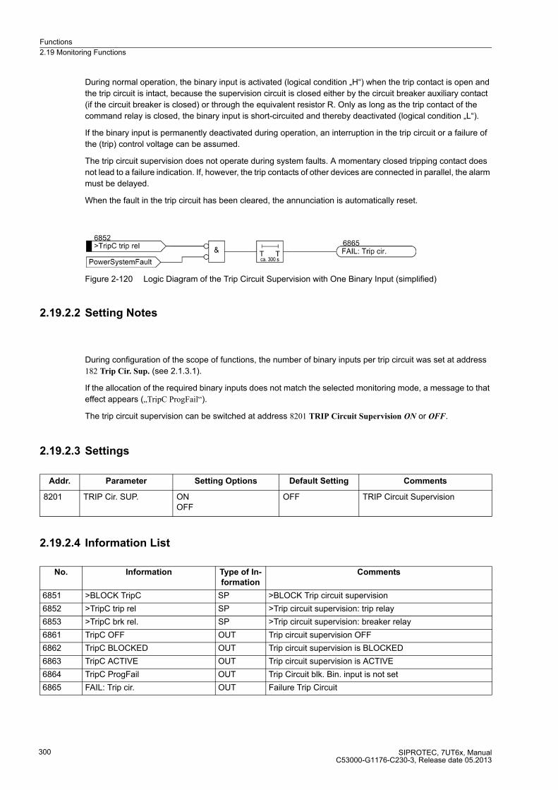
Functions
2.19 Monitoring Functions
SIPROTEC, 7UT6x, ManualC53000-G1176-C230-3, Release date 05.2013
300
During normal operation, the binary input is activated (logical condition „H“) when the trip contact is open and
the trip circuit is intact, because the supervision circuit is closed either by the circuit breaker auxiliary contact
(if the circuit breaker is closed) or through the equivalent resistor R. Only as long as the trip contact of the
command relay is closed, the binary input is short-circuited and thereby deactivated (logical condition „L“).
If the binary input is permanently deactivated during operation, an interruption in the trip circuit or a failure of
the (trip) control voltage can be assumed.
The trip circuit supervision does not operate during system faults. A momentary closed tripping contact does
not lead to a failure indication. If, however, the trip contacts of other devices are connected in parallel, the alarm
must be delayed.
When the fault in the trip circuit has been cleared, the annunciation is automatically reset.
Figure 2-120 Logic Diagram of the Trip Circuit Supervision with One Binary Input (simplified)
2.19.2.2 Setting Notes
During configuration of the scope of functions, the number of binary inputs per trip circuit was set at address
182 Trip Cir. Sup. (see 2.1.3.1).
If the allocation of the required binary inputs does not match the selected monitoring mode, a message to that
effect appears („TripC ProgFail“).
The trip circuit supervision can be switched at address 8201 TRIP Circuit Supervision ON or OFF.
2.19.2.3 Settings
2.19.2.4 Information List
Addr. Parameter Setting Options Default Setting Comments
8201 TRIP Cir. SUP. ONOFF
OFF TRIP Circuit Supervision
No. Information Type of In-
formation
Comments
6851 >BLOCK TripC SP >BLOCK Trip circuit supervision
6852 >TripC trip rel SP >Trip circuit supervision: trip relay
6853 >TripC brk rel. SP >Trip circuit supervision: breaker relay
6861 TripC OFF OUT Trip circuit supervision OFF
6862 TripC BLOCKED OUT Trip circuit supervision is BLOCKED
6863 TripC ACTIVE OUT Trip circuit supervision is ACTIVE
6864 TripC ProgFail OUT Trip Circuit blk. Bin. input is not set
6865 FAIL: Trip cir. OUT Failure Trip Circuit
Functions
2.19 Monitoring Functions
SIPROTEC, 7UT6x, ManualC53000-G1176-C230-3, Release date 05.2013
301
2.19.3 Monitoring
2.19.3.1 Broken Wire Detection, Fuse Failure Monitoring
Broken Wire
During steady-state operation the broken wire monitoring registers interruptions in the secondary circuit of the
current transformers. In addition to the hazard potential caused by high voltages in the secondary circuit, this
kind of interruption simulates differential currents to the differential protection, such as those evoked by faults
in the protected object.
The broken-wire monitor scans the transient behaviour of the currents of each phase for each measuring
location. The instantaneous current values are checked for plausibility. If an instantaneous value does not
correspond to the expected value although the other steady-state currents continue to flow, a broken wire is
considered. Moreover it is checked, whether the current decays strongly or drops abruptly to 0 (from >0.1 · IN),
or no zero crossing is registered. At the same time, the currents flowing in other phases must not exceed 2 ·IN.
The protection functions which react on unsymmetrical currents are blocked as well provided they are assigned
to the defective measuring location: the time overcurrent protection for residual current and the unbalanced
load protection. The device issues the message "Broken wire" indicating also the affected phase and measur-
ing location.
The blocking is released as soon as a current flow is registered again in the appropriate phase of the device
concerned.

Functions
2.19 Monitoring Functions
SIPROTEC, 7UT6x, ManualC53000-G1176-C230-3, Release date 05.2013
302
The following figure shows the logic of the wire break detection for 3 measuring locations.
Figure 2-121 Logic of the Broken Wire Detection

Functions
2.19 Monitoring Functions
SIPROTEC, 7UT6x, ManualC53000-G1176-C230-3, Release date 05.2013
303
Detection of a broken wire is restricted by technical limits. A broken wire in the secondary circuit can, of course,
only be detected when a steady state current has been flowing through the respective phase. Furthermore, a
wire break at the instant of zero crossing in current cannot always be detected reliably. No expected value can
be calculated when the frequency is out of the operation frequency (fN ± 10 %).
Note that electronic test devices do not simulate the correct behaviour of broken wire so that pickup may occur
during such tests.
Asymmetrical measuring voltage failure "Fuse Failure Monitor"
In the event of measured voltage failure due to a short-circuit or a broken conductor in the voltage transformer
secondary circuit, protection and monitoring functions whose operating principle is based on undershooting the
measured voltage can cause faulty pickup, which would lead to a time-delayed spurious tripping. In 7UT6x, this
concerns the forward active power supervision P<, the undervoltage protection and the configurable flexible
protection functions.
If, for example, fuses are used instead of a secondary miniature circuit breaker with correspondingly connected
auxiliary contacts, then the fuse failure monitoring can become active. Of course, the VT miniature circuit
breaker and the fuse failure monitor can be used at the same time.
The asymmetrical measured voltage failure is characterised by its voltage asymmetrical with simultaneous
current symmetry. Figure 2-121 depicts the logic diagram of the fuse failure monitor during asymmetrical failure
of the measured voltage. As measured values, the connected voltages and currents of that measuring location
or side are used to which the voltages are assigned. The fuse failure monitor is, therefore, only possible for
7UT613 and 7UT633, as 7UT612 and 7UT635 are not equipped with measuring voltage inputs. The fuse failure
monitor can only be used for three-phase protected objects.
If there is substantial voltage asymmetry of the measured values without asymmetry of the currents being reg-
istered at the same time, this indicates the presence of an asymmetrical failure in the voltage transformer sec-
ondary circuit.
The asymmetry of the voltage is detected by the fact that the negative sequence voltage exceeds a settable
value FFM U>(min) . The current is assumed to be sufficiently symmetrical if both the zero sequence and the
negative sequence current are below the settable threshold. In at least one phase, the current has to flow above
the limit, as the asymmetry detection cannot function without a minimal measured quantity.
As soon as this state is recognized, all functions that operate on the basis of undervoltage are blocked. The
immediate blocking demands that current flows in at least one of the phases.
If a zero sequence or negative sequence current is detected within approximately 10 s after recognition of this
criterion, the protection assumes a short-circuit in the system and removes the blocking by the fuse failure
monitor for the duration of the fault. If, on the other hand, the voltage failure criterion is present for longer than
approx. 10 s, the blocking is permanently activated (latching of the voltage criterion after 10 s). Only 10 s after
the voltage criterion has been removed by correction of the secondary circuit failure, the blocking will automat-
ically reset thereby releasing the blocked protection functions again.
Release of the current criterion for "VT FuseFail" ensues based on the assignment VT SET to selective
measuring locations.
Figure 2-121 shows the assignment to measuring location 1 or side 1 with one assigned measuring location.
That means, for instance, for assignment to side 2, with measuring location 2 and measuring location 3 being
assinged to side 2, the evaluation of addresses 1122 PoleOpenCurr.M2 and 1123 PoleOpenCurr.M3 is
performed.
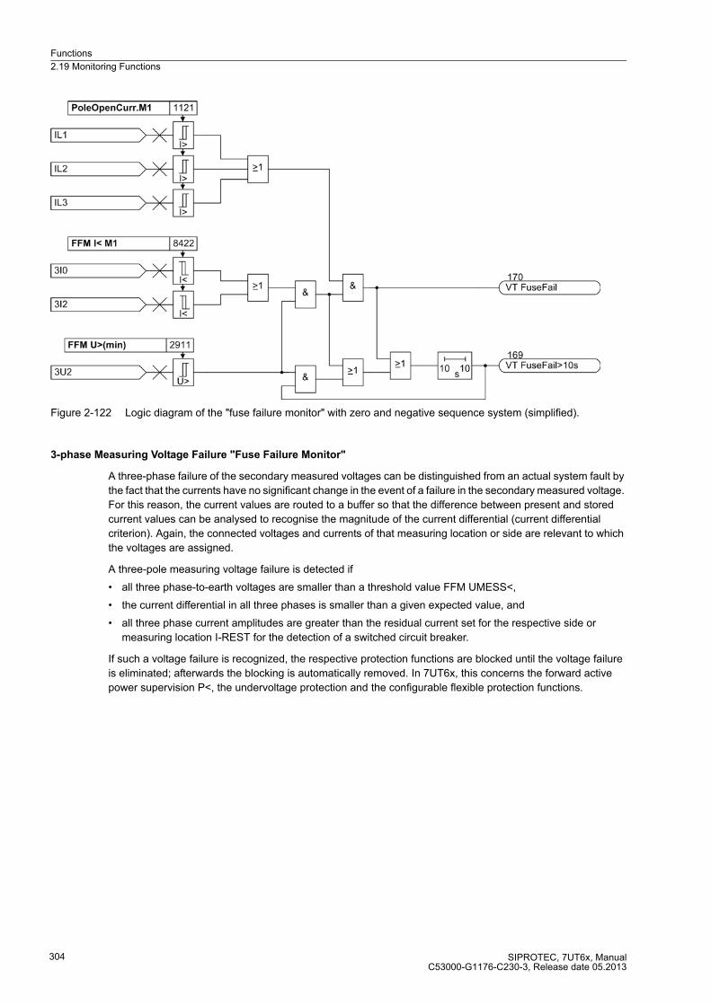
Functions
2.19 Monitoring Functions
SIPROTEC, 7UT6x, ManualC53000-G1176-C230-3, Release date 05.2013
304
Figure 2-122 Logic diagram of the "fuse failure monitor" with zero and negative sequence system (simplified).
3-phase Measuring Voltage Failure "Fuse Failure Monitor"
A three-phase failure of the secondary measured voltages can be distinguished from an actual system fault by
the fact that the currents have no significant change in the event of a failure in the secondary measured voltage.
For this reason, the current values are routed to a buffer so that the difference between present and stored
current values can be analysed to recognise the magnitude of the current differential (current differential
criterion). Again, the connected voltages and currents of that measuring location or side are relevant to which
the voltages are assigned.
A three-pole measuring voltage failure is detected if
� all three phase-to-earth voltages are smaller than a threshold value FFM UMESS<,
� the current differential in all three phases is smaller than a given expected value, and
� all three phase current amplitudes are greater than the residual current set for the respective side or
measuring location I-REST for the detection of a switched circuit breaker.
If such a voltage failure is recognized, the respective protection functions are blocked until the voltage failure
is eliminated; afterwards the blocking is automatically removed. In 7UT6x, this concerns the forward active
power supervision P<, the undervoltage protection and the configurable flexible protection functions.
Functions
2.19 Monitoring Functions
SIPROTEC, 7UT6x, ManualC53000-G1176-C230-3, Release date 05.2013
305
2.19.3.2 Setting Notes
Broken Wire
In Address 8401 BROKEN WIRE the broken wire monitoring can be switched on or off. The option BWD Al and
Blk blocks the respective protective functions. With option BWD Al and ABlk, the differential current for the re-
straint is additionally taken into account. With the setting BWD Al only, a wire break is merely announced without
blocking the protective functions.
With the time delay 8414 T BWD delay the wire break message can be output with a user-defined delay. In all
other device versions, this time is always set to zero.
Parameter 8415 ΔI< BWD determines the pick-up threshold for the minimum differential current where wire
break is detected.
Asymmetrical measuring voltage failure "Fuse Failure Monitor"
The settings for the fuse failure monitor for single-phase measuring voltage failure (address 8426 FFM U<max
(3ph)) are to be selected such that reliable activation occurs if a phase voltage fails, but not such that false ac-
tivation occurs during earth faults Addresses 8422 FFM I< M1, 8423 FFM I< M2 and 8424 FFM I< M3 must be
set as sensitive as required for the respective measuring location or side (with earth faults, below the smallest
fault current). This parameter can only be altered using DIGSI under Additional Settings.
In address 8403 FUSE FAIL MON. the fuse failure monitor can be switched off, e.g. during asymmetrical
testing.
Three-phase measuring voltage failure "Fuse Failure Monitor"
In address 8426 FFM U<max (3ph) the minimum voltage threshold is set. If the measured voltage drops below
this threshold and a simultaneous current jump is not detected while all three phase currents are greater than
the minimum current set for the respective side or measuring location (addresses 1111 to 1142). This parameter
can only be altered using DIGSI under Additional Settings.
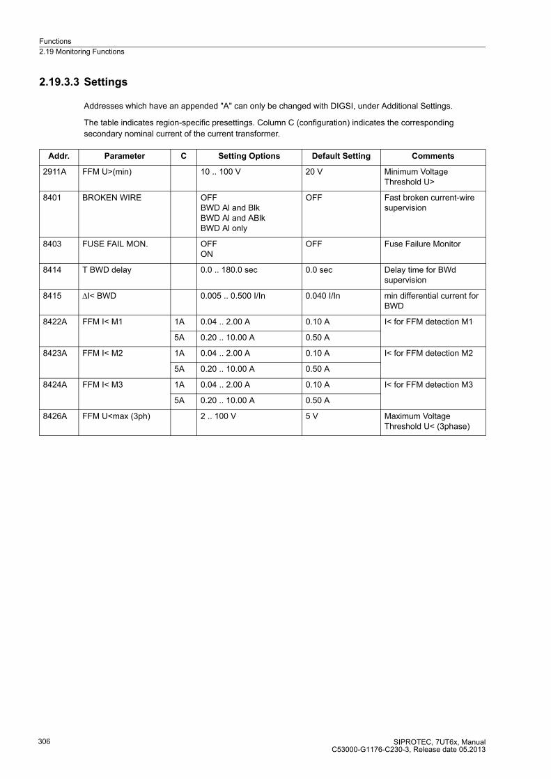
Functions
2.19 Monitoring Functions
SIPROTEC, 7UT6x, ManualC53000-G1176-C230-3, Release date 05.2013
306
2.19.3.3 Settings
Addresses which have an appended "A" can only be changed with DIGSI, under Additional Settings.
The table indicates region-specific presettings. Column C (configuration) indicates the corresponding
secondary nominal current of the current transformer.
Addr. Parameter C Setting Options Default Setting Comments
2911A FFM U>(min) 10 .. 100 V 20 V Minimum Voltage Threshold U>
8401 BROKEN WIRE OFFBWD Al and BlkBWD Al and ABlkBWD Al only
OFF Fast broken current-wire supervision
8403 FUSE FAIL MON. OFFON
OFF Fuse Failure Monitor
8414 T BWD delay 0.0 .. 180.0 sec 0.0 sec Delay time for BWd supervision
8415 ΔI< BWD 0.005 .. 0.500 I/In 0.040 I/In min differential current for BWD
8422A FFM I< M1 1A 0.04 .. 2.00 A 0.10 A I< for FFM detection M1
5A 0.20 .. 10.00 A 0.50 A
8423A FFM I< M2 1A 0.04 .. 2.00 A 0.10 A I< for FFM detection M2
5A 0.20 .. 10.00 A 0.50 A
8424A FFM I< M3 1A 0.04 .. 2.00 A 0.10 A I< for FFM detection M3
5A 0.20 .. 10.00 A 0.50 A
8426A FFM U<max (3ph) 2 .. 100 V 5 V Maximum Voltage Threshold U< (3phase)
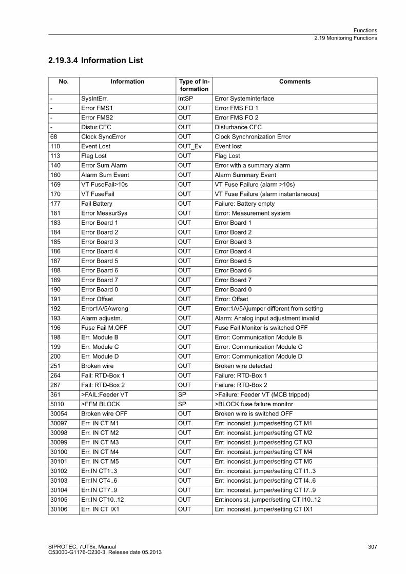
Functions
2.19 Monitoring Functions
SIPROTEC, 7UT6x, ManualC53000-G1176-C230-3, Release date 05.2013
307
2.19.3.4 Information List
No. Information Type of In-
formation
Comments
- SysIntErr. IntSP Error Systeminterface
- Error FMS1 OUT Error FMS FO 1
- Error FMS2 OUT Error FMS FO 2
- Distur.CFC OUT Disturbance CFC
68 Clock SyncError OUT Clock Synchronization Error
110 Event Lost OUT_Ev Event lost
113 Flag Lost OUT Flag Lost
140 Error Sum Alarm OUT Error with a summary alarm
160 Alarm Sum Event OUT Alarm Summary Event
169 VT FuseFail>10s OUT VT Fuse Failure (alarm >10s)
170 VT FuseFail OUT VT Fuse Failure (alarm instantaneous)
177 Fail Battery OUT Failure: Battery empty
181 Error MeasurSys OUT Error: Measurement system
183 Error Board 1 OUT Error Board 1
184 Error Board 2 OUT Error Board 2
185 Error Board 3 OUT Error Board 3
186 Error Board 4 OUT Error Board 4
187 Error Board 5 OUT Error Board 5
188 Error Board 6 OUT Error Board 6
189 Error Board 7 OUT Error Board 7
190 Error Board 0 OUT Error Board 0
191 Error Offset OUT Error: Offset
192 Error1A/5Awrong OUT Error:1A/5Ajumper different from setting
193 Alarm adjustm. OUT Alarm: Analog input adjustment invalid
196 Fuse Fail M.OFF OUT Fuse Fail Monitor is switched OFF
198 Err. Module B OUT Error: Communication Module B
199 Err. Module C OUT Error: Communication Module C
200 Err. Module D OUT Error: Communication Module D
251 Broken wire OUT Broken wire detected
264 Fail: RTD-Box 1 OUT Failure: RTD-Box 1
267 Fail: RTD-Box 2 OUT Failure: RTD-Box 2
361 >FAIL:Feeder VT SP >Failure: Feeder VT (MCB tripped)
5010 >FFM BLOCK SP >BLOCK fuse failure monitor
30054 Broken wire OFF OUT Broken wire is switched OFF
30097 Err. IN CT M1 OUT Err: inconsist. jumper/setting CT M1
30098 Err. IN CT M2 OUT Err: inconsist. jumper/setting CT M2
30099 Err. IN CT M3 OUT Err: inconsist. jumper/setting CT M3
30100 Err. IN CT M4 OUT Err: inconsist. jumper/setting CT M4
30101 Err. IN CT M5 OUT Err: inconsist. jumper/setting CT M5
30102 Err.IN CT1..3 OUT Err: inconsist. jumper/setting CT I1..3
30103 Err.IN CT4..6 OUT Err: inconsist. jumper/setting CT I4..6
30104 Err.IN CT7..9 OUT Err: inconsist. jumper/setting CT I7..9
30105 Err.IN CT10..12 OUT Err:inconsist. jumper/setting CT I10..12
30106 Err. IN CT IX1 OUT Err: inconsist. jumper/setting CT IX1
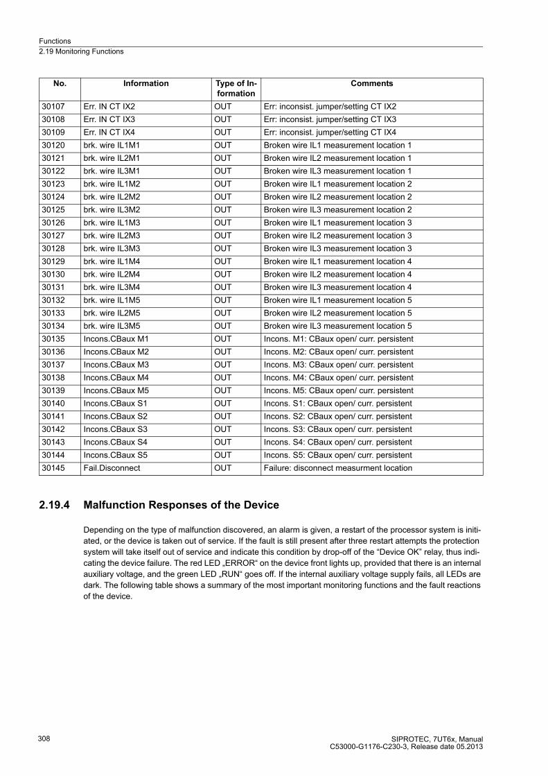
Functions
2.19 Monitoring Functions
SIPROTEC, 7UT6x, ManualC53000-G1176-C230-3, Release date 05.2013
308
2.19.4 Malfunction Responses of the Device
Depending on the type of malfunction discovered, an alarm is given, a restart of the processor system is initi-
ated, or the device is taken out of service. If the fault is still present after three restart attempts the protection
system will take itself out of service and indicate this condition by drop-off of the “Device OK” relay, thus indi-
cating the device failure. The red LED „ERROR“ on the device front lights up, provided that there is an internal
auxiliary voltage, and the green LED „RUN“ goes off. If the internal auxiliary voltage supply fails, all LEDs are
dark. The following table shows a summary of the most important monitoring functions and the fault reactions
of the device.
30107 Err. IN CT IX2 OUT Err: inconsist. jumper/setting CT IX2
30108 Err. IN CT IX3 OUT Err: inconsist. jumper/setting CT IX3
30109 Err. IN CT IX4 OUT Err: inconsist. jumper/setting CT IX4
30120 brk. wire IL1M1 OUT Broken wire IL1 measurement location 1
30121 brk. wire IL2M1 OUT Broken wire IL2 measurement location 1
30122 brk. wire IL3M1 OUT Broken wire IL3 measurement location 1
30123 brk. wire IL1M2 OUT Broken wire IL1 measurement location 2
30124 brk. wire IL2M2 OUT Broken wire IL2 measurement location 2
30125 brk. wire IL3M2 OUT Broken wire IL3 measurement location 2
30126 brk. wire IL1M3 OUT Broken wire IL1 measurement location 3
30127 brk. wire IL2M3 OUT Broken wire IL2 measurement location 3
30128 brk. wire IL3M3 OUT Broken wire IL3 measurement location 3
30129 brk. wire IL1M4 OUT Broken wire IL1 measurement location 4
30130 brk. wire IL2M4 OUT Broken wire IL2 measurement location 4
30131 brk. wire IL3M4 OUT Broken wire IL3 measurement location 4
30132 brk. wire IL1M5 OUT Broken wire IL1 measurement location 5
30133 brk. wire IL2M5 OUT Broken wire IL2 measurement location 5
30134 brk. wire IL3M5 OUT Broken wire IL3 measurement location 5
30135 Incons.CBaux M1 OUT Incons. M1: CBaux open/ curr. persistent
30136 Incons.CBaux M2 OUT Incons. M2: CBaux open/ curr. persistent
30137 Incons.CBaux M3 OUT Incons. M3: CBaux open/ curr. persistent
30138 Incons.CBaux M4 OUT Incons. M4: CBaux open/ curr. persistent
30139 Incons.CBaux M5 OUT Incons. M5: CBaux open/ curr. persistent
30140 Incons.CBaux S1 OUT Incons. S1: CBaux open/ curr. persistent
30141 Incons.CBaux S2 OUT Incons. S2: CBaux open/ curr. persistent
30142 Incons.CBaux S3 OUT Incons. S3: CBaux open/ curr. persistent
30143 Incons.CBaux S4 OUT Incons. S4: CBaux open/ curr. persistent
30144 Incons.CBaux S5 OUT Incons. S5: CBaux open/ curr. persistent
30145 Fail.Disconnect OUT Failure: disconnect measurment location
No. Information Type of In-
formation
Comments
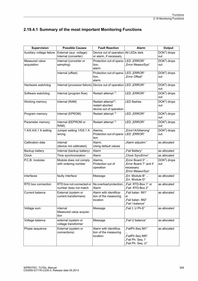
Functions
2.19 Monitoring Functions
SIPROTEC, 7UT6x, ManualC53000-G1176-C230-3, Release date 05.2013
309
2.19.4.1 Summary of the most important Monitoring Functions
Supervision Possible Causes Fault Reaction Alarm Output
Auxiliary voltage failure External (aux. voltage) Internal (converter)
Device out of operationor alarm, if necessary
All LEDs dark DOK2) drops out
Measured value acquisition
Internal (converter or sampling)
Protection out of opera-tion, alarm
LED „ERROR“ „Error MeasurSys“
DOK2) drops out
Internal (offset) Protection out of opera-tion, alarm
LED „ERROR“ „Error Offset“
DOK2) drops out
Hardware watchdog Internal (processor failure) Device out of operation LED „ERROR“ DOK2) drops out
Software watchdog Internal (program flow) Restart attempt 1) LED „ERROR“ DOK2) drops out
Working memory Internal (RAM) Restart attempt1), restart aborted device out of operation
LED flashes DOK2) drops out
Program memory Internal (EPROM) Restart attempt 1) LED „ERROR“ DOK2) drops out
Parameter memory Internal (EEPROM or RAM)
Restart attempt 1) LED „ERROR“ DOK2) drops out
1 A/5 A/0.1 A setting Jumper setting 1/5/0.1 A wrong
Alarms,Protection out of opera-tion
„Error1A/5Awrong“LED „ERROR“
DOK2) drops out
Calibration data internal (device not calibrated)
Alarm, Using default values
„Alarm adjustm.“ as allocated
Backup battery Internal (backup battery) Alarm „Fail Battery“ as allocated
Clock Time synchronization Alarm „Clock SyncError“ as allocated
P.C.B. modules Module does not comply with ordering number
Alarms, Protection out of operation
„Error Board 0“ ... „Error Board 7“ and if necessary„Error MeasurSys“
DOK2) drops out
interfaces faulty interface Message „Err. Module B“ ... „Err. Module D“
as allocated
RTD box connection RTD box not connected or number does not match
No overload protection; Alarm
„Fail: RTD-Box 1“ or„Fail: RTD-Box 2“
as allocated
Current balance External (system orcurrent transformers)
Alarm with identifica-tion of the measuring location
„Fail balan. IM1“or„Fail balan. IM2“„Fail I balance“
as allocated
Voltage sum internalMeasured value acquisi-tion
Message „Fail Σ U Ph-E“ as allocated
Voltage balance external (system orvoltage transformer
Message „Fail U balance“ as allocated
Phase sequence External (system orconnections)
Alarm with identifica-tion of the measuring location
„FailPh.Seq IM1“...„FailPh.Seq IM5“„Fail Ph. Seq. I“„Fail Ph. Seq. U“
as allocated
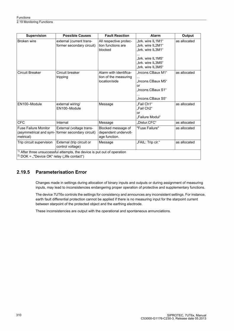
Functions
2.19 Monitoring Functions
SIPROTEC, 7UT6x, ManualC53000-G1176-C230-3, Release date 05.2013
310
2.19.5 Parameterisation Error
Changes made in settings during allocation of binary inputs and outputs or during assignment of measuring
inputs, may lead to inconsistencies endangering proper operation of protective and supplementary functions.
The device 7UT6x controls the settings for consistency and announces any inconsistent settings. For instance,
earth fault differential protection cannot be applied if there is no measuring input for the starpoint current
between starpoint of the protected object and the earthing electrode.
These inconsistencies are output with the operational and spontaneous annunciations.
Broken wire external (current trans-former secondary circuit)
All respective protec-tion functions are blocked
„brk. wire IL1M1“„brk. wire IL2M1“„brk. wire IL3M1“...„brk. wire IL1M5“„brk. wire IL3M5“„brk. wire IL3M5“
as allocated
Circuit Breaker Circuit breakertripping
Alarm with identifica-tion of the measuring location/side
„Incons.CBaux M1“ ...„Incons.CBaux M5“or„Incons.CBaux S1“...„Incons.CBaux S5“
as allocated
EN100–Module external wiring/EN100–Module
Message „Fail Ch1“„Fail Ch2“or„Failure Modul“
as allocated
CFC Internal Message „Distur.CFC“ as allocated
Fuse Failure Monitor (asymmetrical and sym-metrical)
External (voltage trans-former secondary circuit)
Blocked message of dependent undervolt-age function.
"Fuse Failure" as allocated
Trip circuit supervision External (trip circuit or control voltage)
Message „FAIL: Trip cir.“ as allocated
1) After three unsuccessful attempts, the device is put out of operation 2) DOK = „"Device OK“ relay („life contact“)
Supervision Possible Causes Fault Reaction Alarm Output
Functions
2.20 Protection Function Control
SIPROTEC, 7UT6x, ManualC53000-G1176-C230-3, Release date 05.2013
311
2.20 Protection Function Control
The function logic coordinates the sequence of both the protective and ancillary functions, processes the
functional decisions, and data received from the system.
2.20.1 Pickup Logic for the Entire Device
2.20.1.1 General Device Pickup
The fault detection logic combines the pickup signals of all protection functions. The pickup signals are
combined with OR and lead to a general pickup of the device. It is signalled with the alarm „Relay PICKUP“. If
a protection function of the device is not picked up any longer, „Relay PICKUP“ disappears (indication „func-
tioning“).
General fault detection is a requirement for a series of internal and external subsequent functions.
Among these functions, which are controlled by the general pickup, are:
� Start of a fault log: All fault messages are entered into the trip log from the beginning of the general pickup
to the dropout.
� Initialization of the fault recording: The recording and storage of fault wave forms can additionally be made
subject to the presence of a trip command.
� Creation of spontaneous displays: Certain fault messages can be displayed as so-called spontaneous
displays. This display can be made dependent on occurrence of a trip command.
� External functions can be controlled via an output contact. Examples are: starting of additional devices, or
similar.
Spontaneous Displays
Spontaneous indications are fault indications which appear in the display automatically following a general fault
detection or trip command of the device. For 7UT6x, these indications include:
� „Relay PICKUP“: the pickup of a protection function with phase indication;
� „Relay TRIP“: trip of any protection function;
� „PU Time“: = running time from general device pickup to dropout of the device, in ms;
� „Trip time“: = the operating time from the general pickup to the first trip command of the device, the time is
given in ms.
Please note that the overload protection does not have a pickup in comparison to the other protective functions.
The general device pickup time (PU Time) is started with the trip signal, which starts the trip log. The dropout
of the thermal image of the overload protection ends the fault case and, thereby the running PU Time.
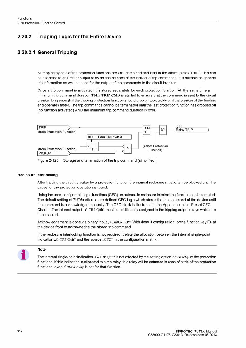
Functions
2.20 Protection Function Control
SIPROTEC, 7UT6x, ManualC53000-G1176-C230-3, Release date 05.2013
312
2.20.2 Tripping Logic for the Entire Device
2.20.2.1 General Tripping
All tripping signals of the protection functions are OR–combined and lead to the alarm „Relay TRIP“. This can
be allocated to an LED or output relay as can be each of the individual trip commands. It is suitable as general
trip information as well as used for the output of trip commands to the circuit breaker.
Once a trip command is activated, it is stored separately for each protection function. At the same time a
minimum trip command duration TMin TRIP CMD is started to ensure that the command is sent to the circuit
breaker long enough if the tripping protection function should drop off too quickly or if the breaker of the feeding
end operates faster. The trip commands cannot be terminated until the last protection function has dropped off
(no function activated) AND the minimum trip command duration is over.
Figure 2-123 Storage and termination of the trip command (simplified)
Reclosure Interlocking
After tripping the circuit breaker by a protection function the manual reclosure must often be blocked until the
cause for the protection operation is found.
Using the user-configurable logic functions (CFC) an automatic reclosure interlocking function can be created.
The default setting of 7UT6x offers a pre-defined CFC logic which stores the trip command of the device until
the command is acknowledged manually. The CFC block is illustrated in the Appendix under „Preset CFC
Charts“. The internal output „G-TRP Quit“ must be additionally assigned to the tripping output relays which are
to be sealed.
Acknowledgement is done via binary input „>QuitG-TRP“. With default configuration, press function key F4 at
the device front to acknowledge the stored trip command.
If the reclosure interlocking function is not required, delete the allocation between the internal single-point
indication „G-TRP Quit“ and the source „CFC“ in the configuration matrix.
Note
The internal single-point indication „G-TRP Quit“ is not affected by the setting option Block relay of the protection
functions. If this indication is allocated to a trip relay, this relay will be actuated in case of a trip of the protection
functions, even if Block relay is set for that function.
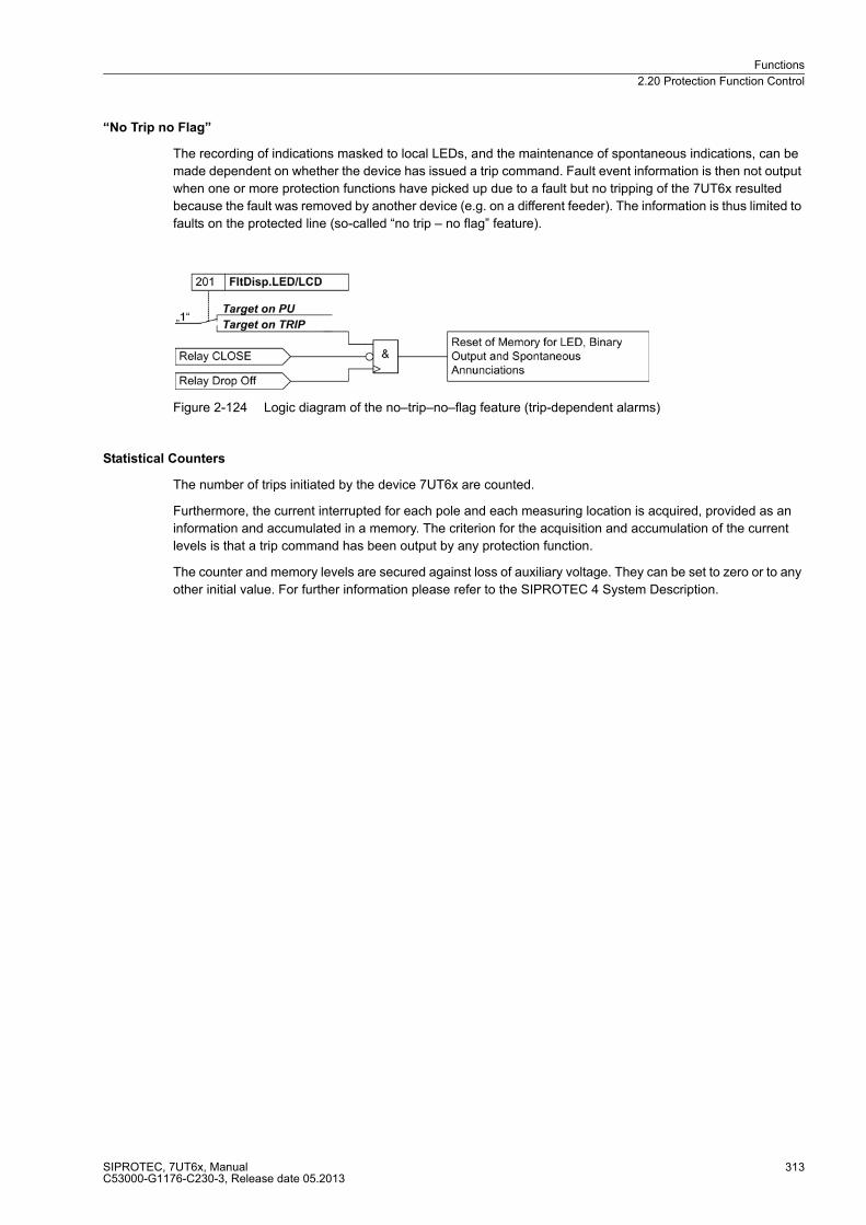
Functions
2.20 Protection Function Control
SIPROTEC, 7UT6x, ManualC53000-G1176-C230-3, Release date 05.2013
313
“No Trip no Flag”
The recording of indications masked to local LEDs, and the maintenance of spontaneous indications, can be
made dependent on whether the device has issued a trip command. Fault event information is then not output
when one or more protection functions have picked up due to a fault but no tripping of the 7UT6x resulted
because the fault was removed by another device (e.g. on a different feeder). The information is thus limited to
faults on the protected line (so-called “no trip – no flag” feature).
Figure 2-124 Logic diagram of the no–trip–no–flag feature (trip-dependent alarms)
Statistical Counters
The number of trips initiated by the device 7UT6x are counted.
Furthermore, the current interrupted for each pole and each measuring location is acquired, provided as an
information and accumulated in a memory. The criterion for the acquisition and accumulation of the current
levels is that a trip command has been output by any protection function.
The counter and memory levels are secured against loss of auxiliary voltage. They can be set to zero or to any
other initial value. For further information please refer to the SIPROTEC 4 System Description.

Functions
2.21 Disconnection of Measuring Locations
SIPROTEC, 7UT6x, ManualC53000-G1176-C230-3, Release date 05.2013
314
2.21 Disconnection of Measuring Locations
2.21.1 Functional Description
During maintenance work, or when parts of the system are shut down during operation, it is sometimes
necessary to suspend the processing of individual measuring locations by the differential protection system.
For maintenance work on the circuit breaker CBC in Figure 2-125, for instance, the breaker would be isolated
by opening the adjacent isolators.
The main protected object transformer is in this example fed on side S1 through measuring locationsM1 and
M2, on side S2 lies the measuring location M3. Assuming the measuring location M2 should now be suspended
due to the maintenance work on the circuit breaker. If this information is sent to the device through a binary
input — in this case „>disconnect M2“ –, the measuring location will no longer be included in the formation of
the differential protection values. The measuring location is disconnected, i.e. any kind of work can be
performed there without affecting any operating function of the sides, for example, the differential protection.
Figure 2-125 Arrangement with 11/2 circuit breakers (3 breakers for 2 transformer feeders)
Any measuring location can be disconnected by means of an appropriate binary input. In 1-phase busbar
protection, such a binary input can be used for each feeder.
The disconnection works only in the specified frequency range of the protection, i.e at fN = 50/60 Hz from 10
to 66 Hz and at fN = 16.7 Hz (only 7UT613/63x) from 10 to 22 Hz. If the current criterion is disabled via binary
input „>disconn. I>=0“ , the specified frequency range is also not applicable. The activation is thus not suited
for blocking the protection during startup of a machine. Instead, the blocking features provided in the protection
functions must be used.
The isolation becomes effective only if no current is flowing through the measuring location to be isolated. This
is ensured by checking whether the current arriving from the measuring location has dropped below the thresh-
old PoleOpenCurr.M1, PoleOpenCurr.M2 to PoleOpenCurr.M5 of the measuring location. Once the disconnec-
tion has become effective, this fact is reported by a binary input, e.g. with the indication „M2 disconnected“. The
current threshold is no longer checked from then on.
The disconnection ends when the binary input is deactivated. This requires, once again, that no current is
flowing at the moment the disconnection is ended.
Functions
2.21 Disconnection of Measuring Locations
SIPROTEC, 7UT6x, ManualC53000-G1176-C230-3, Release date 05.2013
315
One can evade the condition that the disconnection mode can only be started or ended when no current is
flowing via the measuring location. If you wish to start and end the disconnection mode even in case of current
flow, you have to activate — together with the corresponding binary input („>disconnect Mx“) — the input
„>disconn. I>=0“ (30361). This can be done by means of a logical CFC-combination.
The effectiveness of the disconnection is stored in the device's NV RAM and saved against auxiliary voltage
failure, i.e. the last information about the disconnection state is maintained when the power supply of the device
fails. When the power supply returns, the state of the binary input(s) for disconnection is checked against the
stored information. Only when they match will the protection functions become active again. Inconsistencies
are indicated as an alarm „Fail.Disconnect“ (FNo 30145), and the life contact of the relay remains open. The
device cannot operate again until the state of the binary input(s) has been adapted to the stored information.
The effect of the disconnection is that the currents from the disconnected measuring location — as far as they
are assigned to a side of the main protected object — are set to zero for those protection functions that are
assigned to this side. Currents arriving from the system after disconnecting the measuring location are not ef-
fective here. The currents from 1-phase auxiliary measuring inputs allocated to the isolated measuring input
stay valid. Currents remain valid for those protection functions which are not assigned to a side.
No protection functions are blocked. The differential protection continues to work with the remaining available
measured values. In the above example, the transformer can still operate through measuring location M1, with
the differential protection remaining fully effective.
Overcurrent protection functions assigned to a side continue to work without the current from the disconnected
measuring location.
Overcurrent protection functions which are assigned exclusively to the disconnected measuring location (i.e.
not via a side definition) are supplied with the currents of the disconnected measuring location, i.e. continue to
operate with these currents. If necessary, they must be blocked by the information about disconnection (either
by corresponding assignment in the matrix of binary inputs or by user defined logical combination by means of
CFC).
The restricted earth fault protection, too, does not receive any more currents from the isolated measuring loca-
tion. If it is assigned to a side with two or more measuring locations, it can continue to work with the currents
from the remaining measuring location(s). If the isolated measuring location is the only 3-phase source for the
restricted earth fault protection, the starpoint current stays effective. This means that the restricted earth fault
protection will trip immediately if the starpoint current exceeds the pickup threshold. Such a current must be a
fault current in the protected object: it cannot come from the power system, which is in fact isolated from the
protected object.
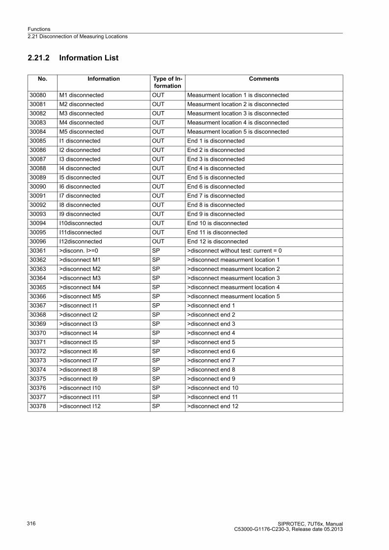
Functions
2.21 Disconnection of Measuring Locations
SIPROTEC, 7UT6x, ManualC53000-G1176-C230-3, Release date 05.2013
316
2.21.2 Information List
No. Information Type of In-
formation
Comments
30080 M1 disconnected OUT Measurment location 1 is disconnected
30081 M2 disconnected OUT Measurment location 2 is disconnected
30082 M3 disconnected OUT Measurment location 3 is disconnected
30083 M4 disconnected OUT Measurment location 4 is disconnected
30084 M5 disconnected OUT Measurment location 5 is disconnected
30085 I1 disconnected OUT End 1 is disconnected
30086 I2 disconnected OUT End 2 is disconnected
30087 I3 disconnected OUT End 3 is disconnected
30088 I4 disconnected OUT End 4 is disconnected
30089 I5 disconnected OUT End 5 is disconnected
30090 I6 disconnected OUT End 6 is disconnected
30091 I7 disconnected OUT End 7 is disconnected
30092 I8 disconnected OUT End 8 is disconnected
30093 I9 disconnected OUT End 9 is disconnected
30094 I10disconnected OUT End 10 is disconnected
30095 I11disconnected OUT End 11 is disconnected
30096 I12disconnected OUT End 12 is disconnected
30361 >disconn. I>=0 SP >disconnect without test: current = 0
30362 >disconnect M1 SP >disconnect measurment location 1
30363 >disconnect M2 SP >disconnect measurment location 2
30364 >disconnect M3 SP >disconnect measurment location 3
30365 >disconnect M4 SP >disconnect measurment location 4
30366 >disconnect M5 SP >disconnect measurment location 5
30367 >disconnect I1 SP >disconnect end 1
30368 >disconnect I2 SP >disconnect end 2
30369 >disconnect I3 SP >disconnect end 3
30370 >disconnect I4 SP >disconnect end 4
30371 >disconnect I5 SP >disconnect end 5
30372 >disconnect I6 SP >disconnect end 6
30373 >disconnect I7 SP >disconnect end 7
30374 >disconnect I8 SP >disconnect end 8
30375 >disconnect I9 SP >disconnect end 9
30376 >disconnect I10 SP >disconnect end 10
30377 >disconnect I11 SP >disconnect end 11
30378 >disconnect I12 SP >disconnect end 12

Functions
2.22 Additional Functions
SIPROTEC, 7UT6x, ManualC53000-G1176-C230-3, Release date 05.2013
317
2.22 Additional Functions
The additional functions of the 7UT6x differential protection relay include:
� processing of messages,
� processing of operational measured values,
� storage of fault record data.
2.22.1 Processing of Messages
2.22.1.1 General
For a detailed fault analysis, information regarding the reaction of the protection device and the measured
values following a system fault are of interest. For this purpose, the device provides information processing
which operates in a threefold manner:
Indicators and Binary Outputs (Output Relays)
Important events and states are displayed by LEDs on the front cover. The device also contains output relays
for remote signaling. Most indications and displays can be configured differently from the delivery default set-
tings (for information on the delivery default setting see Appendix). The SIPROTEC 4 System Description gives
a detailed description of the configuration procedure.
The output relays and the LEDs may be operated in a latched or unlatched mode (each may be individually set).
The latched conditions are protected against loss of the auxiliary voltage. They are reset
� On site by pressing the LED key on the relay,
� Remotely using a binary input configured for that purpose,
� Using one of the serial interfaces,
� Automatically at the beginning of a new pickup.
Status messages should not be latched. Also, they cannot be reset until the criterion to be reported is remedied.
This applies to, e.g., indications from monitoring functions, or the like.
A green LED displays operational readiness of the relay („RUN“); it cannot be reset. It extinguishes if the self-
check feature of the microprocessor detects an abnormal occurrence, or if the auxiliary voltage fails.
When auxiliary voltage is present but the relay has an internal malfunction, the red LED („ERROR“) lights up
and the processor blocks the relay.
DIGSI enables you to selectively control each output relay and LED of the device and, in doing so, check the
correct connection to the system. In a dialog box, you can, for instance, cause each output relay to pick up, and
thus test the wiring between the 7UT6x and the system without having to create the indications masked to it.
Functions
2.22 Additional Functions
SIPROTEC, 7UT6x, ManualC53000-G1176-C230-3, Release date 05.2013
318
Information on the Integrated Display (LCD) or to a Personal Computer
Events and conditions can be read out on the display on the front panel of the relay. Using the front operator
interface or the rear service interface, for instance, a personal computer can be connected, to which the
information can be sent.
In the quiescent state, i.e. as long as no system fault is present, the LCD can display selectable operational
information (overview of the operational measured values) (default display). In the event of a system fault,
information regarding the fault, the so-called spontaneous displays, are displayed instead. After the fault
indications have been acknowledged, the quiescent data are shown again. Acknowledgement is accomplished
by pressing the LED buttons on the front panel (see above).
The device in addition has several event buffers for operational annunciations, switching statistics, etc., which
are saved against loss of auxiliary supply by means of a backup battery. These messages can be displayed on
the LCD at any time by keypad selection, or transferred to the PC via the serial service interface. Readout of
indications during operation is described in detail in the SIPROTEC 4 System Description.
With a PC and the DIGSI protection data processing software it is also possible to retrieve and display the
events and visualised on a monitor and menu-guided dialogue. The data may either be printed, or stored at
another location, and then be evaluated.
Information to a Control Centre
If the device has a serial system interface, stored information may additionally be transferred via this interface
to a central control and storage device. Transmission is possible via different transmission protocols.
You may test whether the indications are transmitted correctly with DIGSI.
Also the information transmitted to the control centre can be influenced during operation or tests. The IEC
60870-5-103 protocol allows to identify all indications and measured values transferred to the central control
system with an added indication „test mode“ while the device is being tested on site (test mode). This identifi-
cation prevents the indications from being incorrectly interpreted as resulting from an actual power system dis-
turbance or event. Alternatively, you may disable the transmission of indications to the system interface during
tests („Transmission Block“).
To influence information at the system interface during test mode („test mode“ and „transmission block“), a CFC
logic is required. Default settings already include this logic (see Appendix).
The SIPROTEC 4 System Description describes in detail how to activate and deactivate test mode and blocked
data transmission.
Classification of Indications
The messages are categorized as follows:
� Event Log: These are annunciations that may be generated during operation of the device: Information
regarding the status of device functions, measured data, power system data, control command logs, etc.
� Trip Log: These are fault messages from the last eight network faults that were processed by the device.
� Messages in switching statistics: These messages count the breaker control commands initiated by the
device, values of accumulated circuit currents and interrupted currents.
� Resetting/setting of the above messages.
A complete list of all indication and output functions that can be generated by the device with the maximum
functional scope can be found in the Appendix. All functions are associated with an information number. There
it is also indicated to which destination the annunciation can be reported. If functions are not present in the
specific device version , or if they are set to disable, then the associated indications cannot appear.

Functions
2.22 Additional Functions
SIPROTEC, 7UT6x, ManualC53000-G1176-C230-3, Release date 05.2013
319
2.22.1.2 Operational Annunciations (Buffer: Event Log)
The operational annunciations contain information that the device generates during operation and on
operational conditions.
Up to 200 operational annunciations are stored in chronological order in the device. New annunciations are
added at the end of the list. If the memory has been exceeded, the oldest annunciation is overwritten for each
new message.
Operational annunciations come in automatically and can be read out from the device display or a personal
computer. Faults in the power system are indicated with „Network Fault“ and the present fault number. The fault
annunciations (Trip Log) contain details about the history of faults.
2.22.1.3 Fault Annunciations (Buffer: Trip Log)
Following a system fault, it is possible, for example, to retrieve important information regarding its progress,
such as pickup and trip. The time the initial occurrence of the short circuit fault occurred is accurately provided
via the system clock. The progress of the disturbance is output with a relative time referred to the instant of fault
detection (first pickup of a protection function), so that the duration of a fault until tripping and up to reset of the
trip command can be ascertained. The tripping of the time entry is about 1 ms.
A system fault starts with the recognition of the fault by the fault detection, i.e. first pickup of any protection
function, and ends with the reset of the fault detection, i.e. dropout of the last protection function. Where fault
causes several protective functions to pick up, the fault is considered to include all that occurred between
pickup of the first protection function and dropout of the last protection function.
Spontaneous Displays
After a fault, the device displays automatically and without any operator action on its LCD display the most
important fault data in the sequence 2-126 shown in the following figure.
Figure 2-126 Display of spontaneous messages in the display – example
Retrieved Annunciations
The annunciations of the last eight network faults can be retrieved and output. Altogether up to 600
annunciations can be stored. New annunciations are added at the end of the list. If the memory has been
exceeded, the oldest annunciation is overwritten for each new message.
Functions
2.22 Additional Functions
SIPROTEC, 7UT6x, ManualC53000-G1176-C230-3, Release date 05.2013
320
2.22.1.4 Spontaneous Annunciations
Spontaneous indications contain information on new incoming indication. Each new incoming annunciation
appears immediately, i.e. the user does not have to wait for an update or initiate one. This can be useful help
during operation, testing and commissioning.
Spontaneous indications can be read out via DIGSI. For more information see the SIPROTEC 4 System
Description.
2.22.1.5 General Interrogation
The present condition of a SIPROTEC 4 device can be examined with DIGSI by viewing the contents of the
General Interrogation. All of the annunciations that are needed for a general interrogation are shown along with
the actual values or states.
2.22.1.6 Switching Statistics
The function counts the number of trips initiated by the device, determines and signals the interrupted current
for each trip command, and stores a summated value of the current.
The messages in switching statistics are counters for the accumulation of interrupted currents by each of the
breaker poles, the number of control commands issued by the device to the breakers. The interrupted currents
are in primary terms.
The counters and memories of the statistics are saved by the device. Therefore the information will not get lost
in case the auxiliary voltage supply fails. The counters, however, can be reset back to zero or to any value within
the setting range.
They can be called up at the front of the device, read out via the operating interface using a PC with DIGSI, or
transferred to a central master station via the system interface.
A password is not required to read switching statistics; however, a password is required to change or delete
the statistics.

Functions
2.22 Additional Functions
SIPROTEC, 7UT6x, ManualC53000-G1176-C230-3, Release date 05.2013
321
2.22.2 Measurement
2.22.2.1 Display and Transmission of Measured Valuables
Operational measured and metered values are determined in the background by the processor system. They
can be called up at the front of the device, read out via the operating interface using a PC with DIGSI, or trans-
ferred to a central master station via the system interface.
The computation of the operational measured values is also executed during an existent system fault in inter-
vals of approx. 0.6 s.
Next to the measured values that can be acquired directly at the device's measuring inputs, the device calcu-
lates a wide range of other values. Many measured values are calculated from the measured quantities and
referenced to the application. The device can flexibly adapt to various protective objects with varying topolo-
gies; this picks up a flexible adaptation of an operational measured values output. Only operational values
appear that result from the connected measured quantities and that make sense of the configured cases.
A correct display of primary and percentage values requires the complete and correct entry of the topology of
the protected object and its rated values, as well as of the transformer ratings.
For the measuring locations the primary and secondary measured values as per Table 2-12 are issued.
Depending on the device’s order number, connection type, topology and protection functions configured, only
a part of the magnitudes listed there is available. For single-phase transformers all phase sizes are missing L2.
The powers S, P, Q are calculated from the measuring location to which the voltage transformers are assigned.
If the voltage transformers are assigned to a side of the main protected object, the current sum applies, if the
side has two or more measuring locations. With single-phase busbar protection, power calculation is not
possible.
The definition of the signs is normally that the power flowing into the protective object is considered as positive:
Active components and inductive reactive components in the direction of the protective object are positive. The
same applies for the power factor cos ϕ. It is occasionally desired to define the power draw from the protected
object (e.g. as seen from the user side of the transformer) positively. Using parameter address 1107 P,Q sign
the signs for these components can be inverted.
For devices without voltage measuring inputs a voltage and apparent power can be issued, if the voltage is
connected to a one-phase current measuring input via an external series resistor. Via a user-configurable CFC
logic (CFC block „Life_Zero“) the current proportional to the voltage can be measured and indicated as voltage
„Umeas“. For more details on the procedure refer to the CFC manual.
The apparent power „S“ is not a measured value, but a value calculated from the rated voltage of the protected
object which is set and the actually flowing currents of side 1: so
for three-phase application or
for single-phase transformers. If, however, the voltage measurement described in the previous paragraph is
applied, this voltage measurement is used to calculate the apparent power with the currents of side 1. The
apparent power is given as magnitude; it does not contain direction information.

Functions
2.22 Additional Functions
SIPROTEC, 7UT6x, ManualC53000-G1176-C230-3, Release date 05.2013
322
Table 2-12 Operational measured values (magnitudes) of the measuring locations
1) only for 3-phase objects, also for single-phase transformers2) only for 3-phase objects, not for single-phase transformers3) only for single-phase busbar protection4) only for 7UT613 and 7UT633 with voltage measuring inputs5) only for 7UT6356) if configured and prepared in CFC7) calculated from phase currents and rated voltage or measured voltage Umeas
Measured Values Primary Secondary % referred to
IL1M1, IL2M1, IL3M1IL1M2, IL2M2, IL3M2IL1M3, IL2M3, IL3M3 1)
Phase currents at the measuring locations M1 to M3 1)
A; kA R
Rated operational current of the assigned side; if the mea-suring location is not as-signed, then 403..405 „I PRIMARY OP M3..5“
I1M1, I2M1, 3I0M1I1M2, I2M2, 3I0M2I1M3, I2M3, 3I0M3 2)
Positive, negative and zero sequence component of the currents at the measuring locations M1 to M3 2)
A; kA R
IL1M4, IL2M4, IL3M4IL1M5, IL2M5, IL3M5 1) 5)
Phase currents at the measuring locations M4 to M5 1) 5)
A; kA R
I1M4, I2M4, 3I0M4I1M5, I2M5, 3I0M5 2) 5)
Positive, negative and zero sequence component of the currents at the measuring locations M4 to M5 2) 5)
A; kA R
IX1; IX2; IX3 Currents at the 1-phase further measuring locations X1 to X3
A; kA R - if allocated to side → see measured value „ILxSy“ - if allocated to measuring lo-cation → see measured value „ILxMz“ - if not allocated → then „IN-PRI WDL IX1..4“
IX4 5) Current at the further measuring location X4 5)
A; kA R
I1 to I9 3) Currents at the measuring inputs 3) A; kA R Rated operational current
I10 to I12 3) 5) Currents at the measuring inputs 3) 5) A; kA R Rated operational current
UL1E; UL2E; UL3E 1) 4) Phase-to-earth voltages at the 3-phase voltage measuring location 1) 4)
V; kV; MV V Operational rated voltage/√3
UL12; UL23; UL31 1) 4) Phase-to-phase voltages at the 3-phase voltage measuring location 1) 4)
V; kV; MV V Operational rated voltage
U1; U2; U0 2) 4) Positive, negative and zero sequence component of the voltages at the 3-phase voltage measuring location 2) 4)
V; kV; MV V Operational rated voltage/√3
Uen 4) Displacement voltage if connected to the 1-phase voltage measuring input 4)
— V Operational rated voltage
U4 4) Voltage at the 1-phase voltage measuring input 4)
V; kV; MV V Operational rated voltage
S, P, Q 1) 4) Apparent, active and reactive power 1) 4)
MVA, MW, kVA; kW
— Operational rated apparent power
f Frequency Hz Hz Rated frequency
cos ϕ 1) 4) Power factor 1) 4) (abs) — (abs)
Umeas 6) Voltage from the current measured at the 1-phase measuring input 6)
V; kV; MV — —
S 7) Apparent power 7) kVA; MVA
— —
U/f 4) Overexcitation 4) UN/fN — UN/fN

Functions
2.22 Additional Functions
SIPROTEC, 7UT6x, ManualC53000-G1176-C230-3, Release date 05.2013
323
In addition to the measured and calculated values at the measuring locations, measured values are output at
the sides of the main protected object. This makes if possible to obtain the data relevant for the protected
object, even if they are fed to the protected object from several measuring locations, as for example the higher
voltage side (S1) of the transformer. Also, relative values are always referred to a specific side of the protected
object. A current which does not flow into the object from 2 measuring locations (e. g. a current flowing from
one busbar through M1 and M2 to the other busbar) is theoretically zero because no current flows into the
protected object.
Table 2-13 summarizes the operational measured values that are assigned to the sides. Depending on the
device’s order number, connection type, topology and protection functions configured, only a part of the
magnitudes listed there is available. The table does not apply to the single-phase busbar protection, since no
sides are defined there.
Table 2-13 Operational measured values (magnitudes) of the sides
1) only for 3-phase protected objects, also single-phase transformers (not in 7UT612)2) only for 3-phase protected objects, not for single-phase transformers (not in 7UT612)3) only for 7UT635
The phase angles are listed separately in Table 2-14. The reference value for 3-phase objects is the current
IL1M1 (current in phase L1 at measuring location M1), which has thus a phase angle = 0°. With 1-phase busbar
protection, the current I1 has the phase angle 0°, i.e. it is the reference value.
Depending on the device’s order number, connection type, topology and protection functions configured, only
a part of the phase angles listed there is available.
Phase angles are indicated in degrees. Since further processing of such values (in CFC or when transmitted
through serial interfaces) requires values without dimension, arbitrary references have been chosen, which are
contained in Table 2-14 in the column „% Conversion“.
Measured Values Primary Secondary % referred to
IL1S1, IL2S1, IL3S1IL1S2, IL2S2, IL3S2IL1S3, IL2S3, IL3S3 1)
Phase currents flowing in from the sides S1 to S3 1)
A; kA — Rated operating current of the respective side
I1S1, I2S1, 3I0S1I1S2, I2S2, 3I0S2I1S3, I2S3, 3I0S3 2)
Positive, negative and zero sequence component of the currents at the sides S1 to S3 2)
A; kA — Rated operating current of the respective side
IL1S4, IL2S4, IL3S4IL1S5, IL2S5, IL3S5 1) 3)
Phase currents flowing in from the sides S4 to S5 1) 3)
A; kA — Rated operating current of the respective side
I1S4, I2S4, 3I0S4I1S5, I2S5, 3I0S5 2) 3)
Positive, negative and zero sequence component of the currents at the sides S4 to S5 2) 3)
A; kA — Rated operating current of the respective side
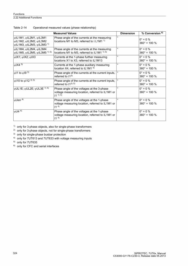
Functions
2.22 Additional Functions
SIPROTEC, 7UT6x, ManualC53000-G1176-C230-3, Release date 05.2013
324
Table 2-14 Operational measured values (phase relationship)
1) only for 3-phase objects, also for single-phase transformers2) only for 3-phase objects, not for single-phase transformers3) only for single-phase busbar protection4) only for 7UT613 and 7UT633 with voltage measuring inputs5) only for 7UT6356) only for CFC and serial interfaces
Measured Values Dimension % Conversion 6)
ϕIL1M1, ϕIL2M1, ϕIL3M1ϕIL1M2, ϕIL2M2, ϕIL3M2ϕIL1M3, ϕIL2M3, ϕIL3M3 1)
Phase angle of the currents at the measuring locations M1 to M3, referred to I L1M1 1)
°0° = 0 %360° = 100 %
ϕIL1M4, ϕIL2M4, ϕIL3M4ϕIL1M5, ϕIL2M5, ϕIL3M5 1) 5)
Phase angle of the currents at the measuring locations M1 to M3, referred to IL1M1 1) 5)
° 0° = 0 %360° = 100 %
ϕIX1; ϕIX2; ϕIX3 Currents at the 1-phase further measuring locations X1 to X3, referred to IL1M13
° 0° = 0 %360° = 100 %
ϕIX4 5) Currents at the 1-phase auxiliary measuring location X4, referred to IL1M1 5)
° 0° = 0 %360° = 100 %
ϕI1 to ϕI9 3) Phase angle of the currents at the current inputs, referred to I13)
° 0° = 0 %360° = 100 %
ϕI10 to ϕI12 3) 5) Phase angle of the currents at the current inputs, referred to I13) 5)
° 0° = 0 %360° = 100 %
ϕUL1E; ϕUL2E; ϕUL3E 1) 4) Phase angle of the voltages at the 3-phase voltage measuring location, referred to IL1M1 or I1 1) 4)
° 0° = 0 %360° = 100 %
ϕUen 4) Phase angle of the voltages at the 1-phase voltage measuring location, referred to IL1M1 or I1 4)
° 0° = 0 %360° = 100 %
ϕU4 4) Phase angle of the voltages at the 1-phase voltage measuring location, referred to IL1M1 or I1 4)
° 0° = 0 %360° = 100 %
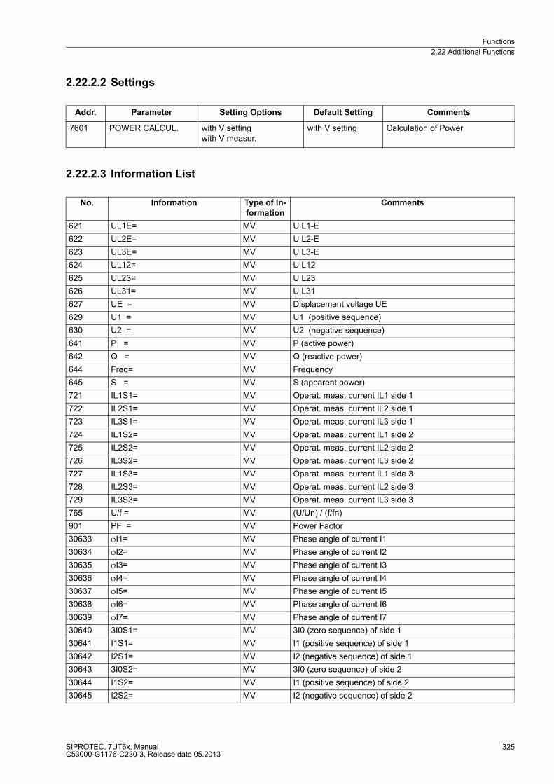
Functions
2.22 Additional Functions
SIPROTEC, 7UT6x, ManualC53000-G1176-C230-3, Release date 05.2013
325
2.22.2.2 Settings
2.22.2.3 Information List
Addr. Parameter Setting Options Default Setting Comments
7601 POWER CALCUL. with V settingwith V measur.
with V setting Calculation of Power
No. Information Type of In-
formation
Comments
621 UL1E= MV U L1-E
622 UL2E= MV U L2-E
623 UL3E= MV U L3-E
624 UL12= MV U L12
625 UL23= MV U L23
626 UL31= MV U L31
627 UE = MV Displacement voltage UE
629 U1 = MV U1 (positive sequence)
630 U2 = MV U2 (negative sequence)
641 P = MV P (active power)
642 Q = MV Q (reactive power)
644 Freq= MV Frequency
645 S = MV S (apparent power)
721 IL1S1= MV Operat. meas. current IL1 side 1
722 IL2S1= MV Operat. meas. current IL2 side 1
723 IL3S1= MV Operat. meas. current IL3 side 1
724 IL1S2= MV Operat. meas. current IL1 side 2
725 IL2S2= MV Operat. meas. current IL2 side 2
726 IL3S2= MV Operat. meas. current IL3 side 2
727 IL1S3= MV Operat. meas. current IL1 side 3
728 IL2S3= MV Operat. meas. current IL2 side 3
729 IL3S3= MV Operat. meas. current IL3 side 3
765 U/f = MV (U/Un) / (f/fn)
901 PF = MV Power Factor
30633 ϕI1= MV Phase angle of current I1
30634 ϕI2= MV Phase angle of current I2
30635 ϕI3= MV Phase angle of current I3
30636 ϕI4= MV Phase angle of current I4
30637 ϕI5= MV Phase angle of current I5
30638 ϕI6= MV Phase angle of current I6
30639 ϕI7= MV Phase angle of current I7
30640 3I0S1= MV 3I0 (zero sequence) of side 1
30641 I1S1= MV I1 (positive sequence) of side 1
30642 I2S1= MV I2 (negative sequence) of side 1
30643 3I0S2= MV 3I0 (zero sequence) of side 2
30644 I1S2= MV I1 (positive sequence) of side 2
30645 I2S2= MV I2 (negative sequence) of side 2

Functions
2.22 Additional Functions
SIPROTEC, 7UT6x, ManualC53000-G1176-C230-3, Release date 05.2013
326
30646 I1= MV Operat. meas. current I1
30647 I2= MV Operat. meas. current I2
30648 I3= MV Operat. meas. current I3
30649 I4= MV Operat. meas. current I4
30650 I5= MV Operat. meas. current I5
30651 I6= MV Operat. meas. current I6
30652 I7= MV Operat. meas. current I7
30653 I8= MV Operat. meas. current I8
30656 Umeas.= MVU Operat. meas. voltage Umeas.
30661 IL1M1= MV Operat. meas. current IL1 meas. loc. 1
30662 IL2M1= MV Operat. meas. current IL2 meas. loc. 1
30663 IL3M1= MV Operat. meas. current IL3 meas. loc. 1
30664 3I0M1= MV 3I0 (zero sequence) of meas. loc. 1
30665 I1M1= MV I1 (positive sequence) of meas. loc. 1
30666 I2M1= MV I2 (negative sequence) of meas. loc. 1
30667 IL1M2= MV Operat. meas. current IL1 meas. loc. 2
30668 IL2M2= MV Operat. meas. current IL2 meas. loc. 2
30669 IL3M2= MV Operat. meas. current IL3 meas. loc. 2
30670 3I0M2= MV 3I0 (zero sequence) of meas. loc. 2
30671 I1M2= MV I1 (positive sequence) of meas. loc. 2
30672 I2M2= MV I2 (negative sequence) of meas. loc. 2
30673 IL1M3= MV Operat. meas. current IL1 meas. loc. 3
30674 IL2M3= MV Operat. meas. current IL2 meas. loc. 3
30675 IL3M3= MV Operat. meas. current IL3 meas. loc. 3
30676 3I0M3= MV 3I0 (zero sequence) of meas. loc. 3
30677 I1M3= MV I1 (positive sequence) of meas. loc. 3
30678 I2M3= MV I2 (negative sequence) of meas. loc. 3
30679 IL1M4= MV Operat. meas. current IL1 meas. loc. 4
30680 IL2M4= MV Operat. meas. current IL2 meas. loc. 4
30681 IL3M4= MV Operat. meas. current IL3 meas. loc. 4
30682 3I0M4= MV 3I0 (zero sequence) of meas. loc. 4
30683 I1M4= MV I1 (positive sequence) of meas. loc. 4
30684 I2M4= MV I2 (negative sequence) of meas. loc. 4
30685 IL1M5= MV Operat. meas. current IL1 meas. loc. 5
30686 IL2M5= MV Operat. meas. current IL2 meas. loc. 5
30687 IL3M5= MV Operat. meas. current IL3 meas. loc. 5
30688 3I0M5= MV 3I0 (zero sequence) of meas. loc. 5
30689 I1M5= MV I1 (positive sequence) of meas. loc. 5
30690 I2M5= MV I2 (negative sequence) of meas. loc. 5
30713 3I0S3= MV 3I0 (zero sequence) of side 3
30714 I1S3= MV I1 (positive sequence) of side 3
30715 I2S3= MV I2 (negative sequence) of side 3
30716 IL1S4= MV Operat. meas. current IL1 side 4
30717 IL2S4= MV Operat. meas. current IL2 side 4
30718 IL3S4= MV Operat. meas. current IL3 side 4
30719 3I0S4= MV 3I0 (zero sequence) of side 4
No. Information Type of In-
formation
Comments
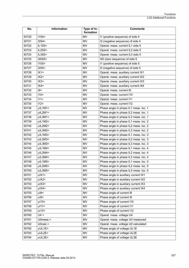
Functions
2.22 Additional Functions
SIPROTEC, 7UT6x, ManualC53000-G1176-C230-3, Release date 05.2013
327
30720 I1S4= MV I1 (positive sequence) of side 4
30721 I2S4= MV I2 (negative sequence) of side 4
30722 IL1S5= MV Operat. meas. current IL1 side 5
30723 IL2S5= MV Operat. meas. current IL2 side 5
30724 IL3S5= MV Operat. meas. current IL3 side 5
30725 3I0S5= MV 3I0 (zero sequence) of side 5
30726 I1S5= MV I1 (positive sequence) of side 5
30727 I2S5= MV I2 (negative sequence) of side 5
30728 IX1= MV Operat. meas. auxiliary current IX1
30729 IX2= MV Operat. meas. auxiliary current IX2
30730 IX3= MV Operat. meas. auxiliary current IX3
30731 IX4= MV Operat. meas. auxiliary current IX4
30732 I9= MV Operat. meas. current I9
30733 I10= MV Operat. meas. current I10
30734 I11= MV Operat. meas. current I11
30735 I12= MV Operat. meas. current I12
30736 ϕIL1M1= MV Phase angle in phase IL1 meas. loc. 1
30737 ϕIL2M1= MV Phase angle in phase IL2 meas. loc. 1
30738 ϕIL3M1= MV Phase angle in phase IL3 meas. loc. 1
30739 ϕIL1M2= MV Phase angle in phase IL1 meas. loc. 2
30740 ϕIL2M2= MV Phase angle in phase IL2 meas. loc. 2
30741 ϕIL3M2= MV Phase angle in phase IL3 meas. loc. 2
30742 ϕIL1M3= MV Phase angle in phase IL1 meas. loc. 3
30743 ϕIL2M3= MV Phase angle in phase IL2 meas. loc. 3
30744 ϕIL3M3= MV Phase angle in phase IL3 meas. loc. 3
30745 ϕIL1M4= MV Phase angle in phase IL1 meas. loc. 4
30746 ϕIL2M4= MV Phase angle in phase IL2 meas. loc. 4
30747 ϕIL3M4= MV Phase angle in phase IL3 meas. loc. 4
30748 ϕIL1M5= MV Phase angle in phase IL1 meas. loc. 5
30749 ϕIL2M5= MV Phase angle in phase IL2 meas. loc. 5
30750 ϕIL3M5= MV Phase angle in phase IL3 meas. loc. 5
30751 ϕIX1= MV Phase angle in auxiliary current IX1
30752 ϕIX2= MV Phase angle in auxiliary current IX2
30753 ϕIX3= MV Phase angle in auxiliary current IX3
30754 ϕIX4= MV Phase angle in auxiliary current IX4
30755 ϕI8= MV Phase angle of current I8
30756 ϕI9= MV Phase angle of current I9
30757 ϕI10= MV Phase angle of current I10
30758 ϕI11= MV Phase angle of current I11
30759 ϕI12= MV Phase angle of current I12
30760 U4 = MV Operat. meas. voltage U4
30761 U0meas.= MV Operat. meas. voltage U0 measured
30762 U0calc.= MV Operat. meas. voltage U0 calculated
30792 ϕUL1E= MV Phase angle of voltage UL1E
30793 ϕUL2E= MV Phase angle of voltage UL2E
30794 ϕUL3E= MV Phase angle of voltage UL3E
No. Information Type of In-
formation
Comments

Functions
2.22 Additional Functions
SIPROTEC, 7UT6x, ManualC53000-G1176-C230-3, Release date 05.2013
328
2.22.3 Thermal Measurement
Depending on its configuration, the device can determine and display thermal measurement values.
2.22.3.1 Description
The measured thermal values are listed in table 2-15. They can only be displayed if the overload protection
functions has been configured as Enabled. Which measured values are possible also depends on the overload
detection method chosen and, in certain cases, of the number of temperature detectors connected via the RTD-
box.
The hot-spot temperatures are calculated in transformers for each leg. Therefore, temperatures are indicated
with a phase (in the case of Y windings), or with a phase-phase concatenation (D windings). For standard
vector groups, this information correspond to the ends of the windings. In more unusual vector groups (which
are created by phase swapping), the phase assignment in the vector group is not always clear.
The thermal values are referred to the tripping temperature rise. For degrees of temperature there are no
referred values. However, since further processing of such values (in CFC or when transmitted through serial
interfaces) requires values without dimension, arbitrary references have been chosen, which are contained in
Table 2-15 in the column „% conversion“.
Table 2-15 Thermal Measured Values
1) only for overload protection with thermal replica (IEC 60255-8): Address 142 THERM. OVERLOAD = th repl w. sens2) only for overload protection with hot-spot calculation (IEC 60354): Address 142 THERM. OVERLOAD = IEC3543) only if RTD box(es) available4) only for CFC and serial interfaces
30795 ϕU4= MV Phase angle of voltage U4
30796 ϕUE= MV Phase angle of voltage UE
No. Information Type of In-
formation
Comments
Measured values Dimension % Conversion 4)
θL1/θOFF; θL2/θOFF; θL3/θOFF 1)
Thermal value of each phase, referred to the tripping value
%
θ/θTrip 1) Thermal resultant value, referred to the
tripping value%
Ag.rate 2) 3) Relative ageing rate L p.u.
Res Warn 2)3) Load reserve to hot-spot/ageing alarm (stage 1)
%
Res Alarm 2) 3) Load reserve to hot-spot tripping (stage 1) %
θ leg L1; θ leg L2; θ leg L3 2) 3)
Hot-spot temperature for each phase (Y winding or Z winding)
°C or °F0 °C = 0 %
500 °C = 100 %
0 °F = 0 %1000 °F = 100 %
θ leg L12; θ leg L23; θ leg L31 2) 3)Hot-spot temperature for each phase (D winding)
°C or °F
θ RTD 1... θ RTD 12 3)
Temperature measured at the Temperature detectors 1 to 12
°C or °F
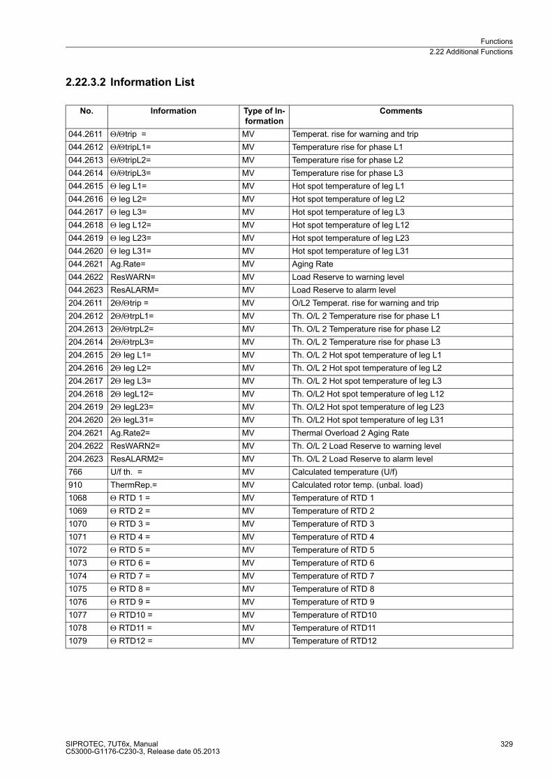
Functions
2.22 Additional Functions
SIPROTEC, 7UT6x, ManualC53000-G1176-C230-3, Release date 05.2013
329
2.22.3.2 Information List
No. Information Type of In-
formation
Comments
044.2611 Θ/Θtrip = MV Temperat. rise for warning and trip
044.2612 Θ/ΘtripL1= MV Temperature rise for phase L1
044.2613 Θ/ΘtripL2= MV Temperature rise for phase L2
044.2614 Θ/ΘtripL3= MV Temperature rise for phase L3
044.2615 Θ leg L1= MV Hot spot temperature of leg L1
044.2616 Θ leg L2= MV Hot spot temperature of leg L2
044.2617 Θ leg L3= MV Hot spot temperature of leg L3
044.2618 Θ leg L12= MV Hot spot temperature of leg L12
044.2619 Θ leg L23= MV Hot spot temperature of leg L23
044.2620 Θ leg L31= MV Hot spot temperature of leg L31
044.2621 Ag.Rate= MV Aging Rate
044.2622 ResWARN= MV Load Reserve to warning level
044.2623 ResALARM= MV Load Reserve to alarm level
204.2611 2Θ/Θtrip = MV O/L2 Temperat. rise for warning and trip
204.2612 2Θ/ΘtrpL1= MV Th. O/L 2 Temperature rise for phase L1
204.2613 2Θ/ΘtrpL2= MV Th. O/L 2 Temperature rise for phase L2
204.2614 2Θ/ΘtrpL3= MV Th. O/L 2 Temperature rise for phase L3
204.2615 2Θ leg L1= MV Th. O/L 2 Hot spot temperature of leg L1
204.2616 2Θ leg L2= MV Th. O/L 2 Hot spot temperature of leg L2
204.2617 2Θ leg L3= MV Th. O/L 2 Hot spot temperature of leg L3
204.2618 2Θ legL12= MV Th. O/L2 Hot spot temperature of leg L12
204.2619 2Θ legL23= MV Th. O/L2 Hot spot temperature of leg L23
204.2620 2Θ legL31= MV Th. O/L2 Hot spot temperature of leg L31
204.2621 Ag.Rate2= MV Thermal Overload 2 Aging Rate
204.2622 ResWARN2= MV Th. O/L 2 Load Reserve to warning level
204.2623 ResALARM2= MV Th. O/L 2 Load Reserve to alarm level
766 U/f th. = MV Calculated temperature (U/f)
910 ThermRep.= MV Calculated rotor temp. (unbal. load)
1068 Θ RTD 1 = MV Temperature of RTD 1
1069 Θ RTD 2 = MV Temperature of RTD 2
1070 Θ RTD 3 = MV Temperature of RTD 3
1071 Θ RTD 4 = MV Temperature of RTD 4
1072 Θ RTD 5 = MV Temperature of RTD 5
1073 Θ RTD 6 = MV Temperature of RTD 6
1074 Θ RTD 7 = MV Temperature of RTD 7
1075 Θ RTD 8 = MV Temperature of RTD 8
1076 Θ RTD 9 = MV Temperature of RTD 9
1077 Θ RTD10 = MV Temperature of RTD10
1078 Θ RTD11 = MV Temperature of RTD11
1079 Θ RTD12 = MV Temperature of RTD12
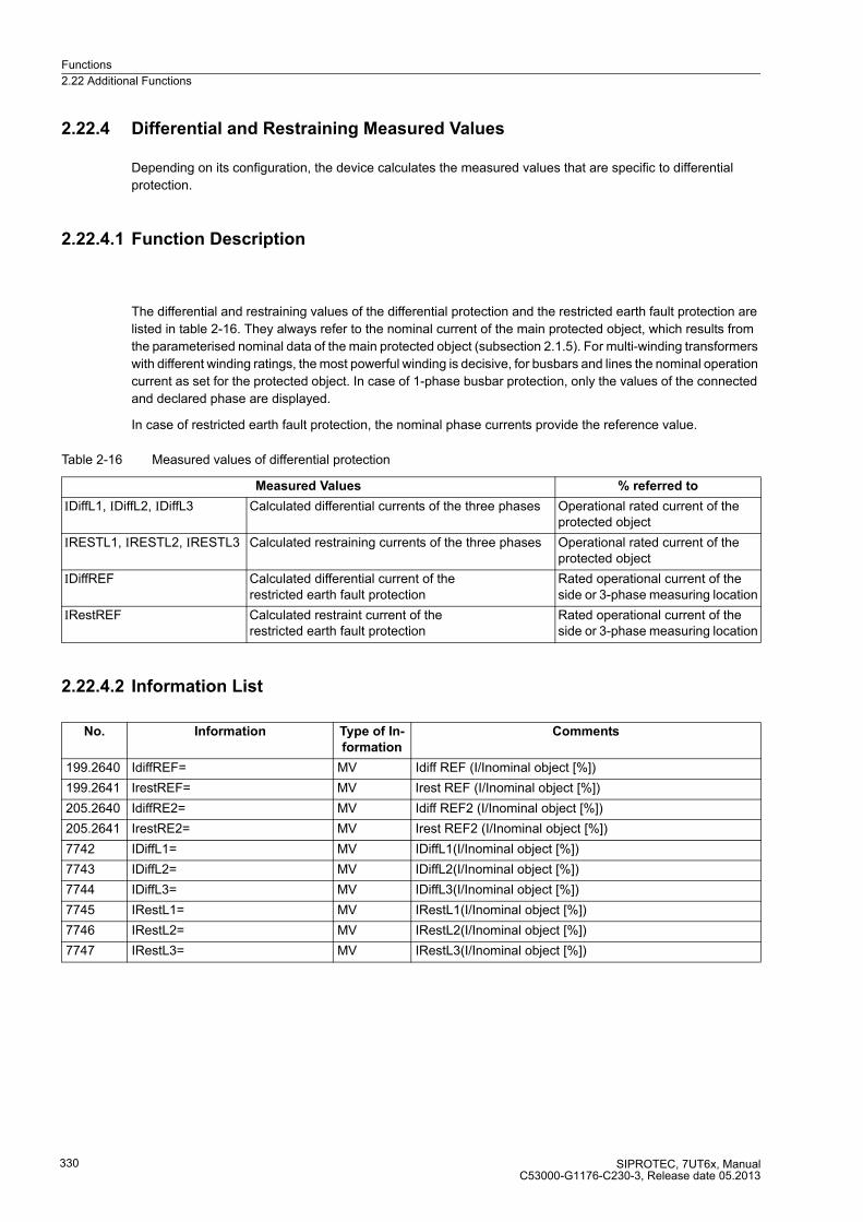
Functions
2.22 Additional Functions
SIPROTEC, 7UT6x, ManualC53000-G1176-C230-3, Release date 05.2013
330
2.22.4 Differential and Restraining Measured Values
Depending on its configuration, the device calculates the measured values that are specific to differential
protection.
2.22.4.1 Function Description
The differential and restraining values of the differential protection and the restricted earth fault protection are
listed in table 2-16. They always refer to the nominal current of the main protected object, which results from
the parameterised nominal data of the main protected object (subsection 2.1.5). For multi-winding transformers
with different winding ratings, the most powerful winding is decisive, for busbars and lines the nominal operation
current as set for the protected object. In case of 1-phase busbar protection, only the values of the connected
and declared phase are displayed.
In case of restricted earth fault protection, the nominal phase currents provide the reference value.
Table 2-16 Measured values of differential protection
2.22.4.2 Information List
Measured Values % referred to
IDiffL1, IDiffL2, IDiffL3 Calculated differential currents of the three phases Operational rated current of the protected object
IRESTL1, IRESTL2, IRESTL3 Calculated restraining currents of the three phases Operational rated current of the protected object
IDiffREF Calculated differential current of the restricted earth fault protection
Rated operational current of the side or 3-phase measuring location
IRestREF Calculated restraint current of the restricted earth fault protection
Rated operational current of the side or 3-phase measuring location
No. Information Type of In-
formation
Comments
199.2640 IdiffREF= MV Idiff REF (I/Inominal object [%])
199.2641 IrestREF= MV Irest REF (I/Inominal object [%])
205.2640 IdiffRE2= MV Idiff REF2 (I/Inominal object [%])
205.2641 IrestRE2= MV Irest REF2 (I/Inominal object [%])
7742 IDiffL1= MV IDiffL1(I/Inominal object [%])
7743 IDiffL2= MV IDiffL2(I/Inominal object [%])
7744 IDiffL3= MV IDiffL3(I/Inominal object [%])
7745 IRestL1= MV IRestL1(I/Inominal object [%])
7746 IRestL2= MV IRestL2(I/Inominal object [%])
7747 IRestL3= MV IRestL3(I/Inominal object [%])

Functions
2.22 Additional Functions
SIPROTEC, 7UT6x, ManualC53000-G1176-C230-3, Release date 05.2013
331
2.22.5 Set Points for Measured Values
2.22.5.1 User Defined Set-Points
7UT6x allows limit levels for important measured and counter values to be set
If, during operation, a value reaches one of these set-points, the device generates an alarm which is indicated
as an operational message. As for all operational messages, it is possible to output the information to LED
and/or output relay and via the serial interfaces. Unlike real protection functions such as time overcurrent
protection or overload protection, this supervision routine runs in the background, so that in the case of a fault
and rapidly changing measured values it may not respond when protection functions pick up. Also, the super-
vision does not respond immediately before a trip because an alarm is only output if the setpoint are repeatedly
violated.
Set-points can only be set if their measured and metered values have been configured correspondingly in CFC
(see SIPROTEC 4 System Description /1/).
2.22.6 Energy Metering
Metered values for active and reactive power are determined in the background by the processor system. They
can be called up at the front of the device, read out via the operating interface using a PC with DIGSI, or
transferred to a central master station via the system interface.
2.22.6.1 Energy Metering
7UT6x integrates the calculated power which is then made available with the Measured Values. The
components as listed in Table 2-17 can be read out. Note that „input“ and „output“ are always as seen from the
protective object. The signs of the operating values depend (as for the powers) on the setting at address 1107
P,Q sign. Work calculation is not possible for single-phase busbar protection.
Energy metering can only be used in situations where a calculation of the power is possible.
The values are always positively incremented, decrementing does not occur. This means, for instance, that
Wp+ goes up if the real power is positive and that in the presence of a negative real power Wp– goes up, but
Wp+ does not go down, etc.
Please be aware that 7UT6x is, above all, a protection device. The precision of the metered values depends
on the transformer (normally protection core) and the device tolerance. The metering is therefore not suited for
tariff purposes.
The counters can be reset to zero or any initial value (see SIPROTEC 4 System Description).
Table 2-17 Operational metered values
Measured values Primary
Wp+ Active power, output kWh, MWh, GWh
Wp– Active power, input kWh, MWh, GWh
Wq+ Reactive power, output kVARh, MVARh, GVARh
Wq– Reactive power, input kVARh, MVARh, GVARh

Functions
2.22 Additional Functions
SIPROTEC, 7UT6x, ManualC53000-G1176-C230-3, Release date 05.2013
332
Operating Hours Meter
The main protective object is considered to be in operation if a current flows at least on one side, i.e. if the
minimum threshold for detection of a current flow is exceeded, e.g. for side 1 the threshold PoleOpenCurr.S1
(address 1111). A current which does not flow into the object from 2 measuring locations is theoretically zero
because no current flows into the protective object.
In busbar protection, the busbar is considered to be in operation if a current flows through at least one
measuring location (i.e. one feeder).
The 7UT6x counts the operating hours and outputs them in the measured values. The upper limit is
999.999 hours (approx. 114 years).
You can define a setpoint for the operating hours for the output of an operational indication.
2.22.6.2 Information List
No. Information Type of In-
formation
Comments
- Meter res IntSP_Ev Reset meter
888 Wp(puls)= PMV Pulsed Energy Wp (active)
889 Wq(puls)= PMV Pulsed Energy Wq (reactive)
916 WpΔ= - Increment of active energy
917 WqΔ= - Increment of reactive energy
924 Wp+= MVMV Wp Forward
925 Wq+= MVMV Wq Forward
928 Wp-= MVMV Wp Reverse
929 Wq-= MVMV Wq Reverse
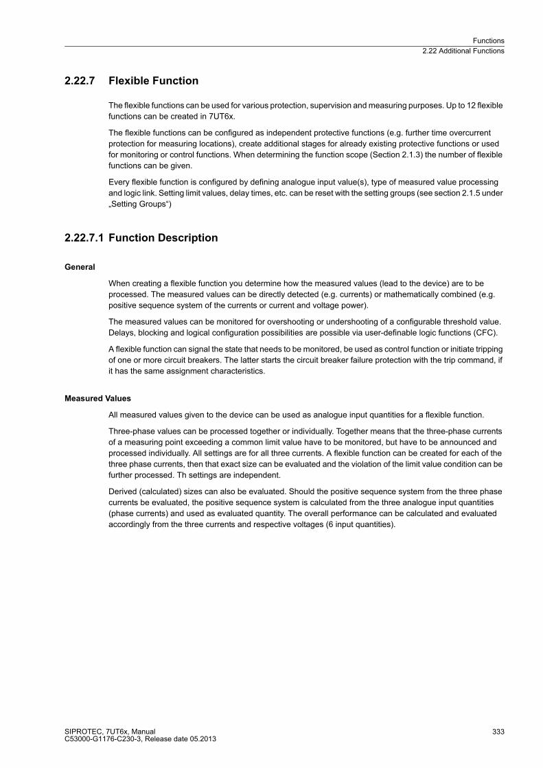
Functions
2.22 Additional Functions
SIPROTEC, 7UT6x, ManualC53000-G1176-C230-3, Release date 05.2013
333
2.22.7 Flexible Function
The flexible functions can be used for various protection, supervision and measuring purposes. Up to 12 flexible
functions can be created in 7UT6x.
The flexible functions can be configured as independent protective functions (e.g. further time overcurrent
protection for measuring locations), create additional stages for already existing protective functions or used
for monitoring or control functions. When determining the function scope (Section 2.1.3) the number of flexible
functions can be given.
Every flexible function is configured by defining analogue input value(s), type of measured value processing
and logic link. Setting limit values, delay times, etc. can be reset with the setting groups (see section 2.1.5 under
„Setting Groups“)
2.22.7.1 Function Description
General
When creating a flexible function you determine how the measured values (lead to the device) are to be
processed. The measured values can be directly detected (e.g. currents) or mathematically combined (e.g.
positive sequence system of the currents or current and voltage power).
The measured values can be monitored for overshooting or undershooting of a configurable threshold value.
Delays, blocking and logical configuration possibilities are possible via user-definable logic functions (CFC).
A flexible function can signal the state that needs to be monitored, be used as control function or initiate tripping
of one or more circuit breakers. The latter starts the circuit breaker failure protection with the trip command, if
it has the same assignment characteristics.
Measured Values
All measured values given to the device can be used as analogue input quantities for a flexible function.
Three-phase values can be processed together or individually. Together means that the three-phase currents
of a measuring point exceeding a common limit value have to be monitored, but have to be announced and
processed individually. All settings are for all three currents. A flexible function can be created for each of the
three phase currents, then that exact size can be evaluated and the violation of the limit value condition can be
further processed. Th settings are independent.
Derived (calculated) sizes can also be evaluated. Should the positive sequence system from the three phase
currents be evaluated, the positive sequence system is calculated from the three analogue input quantities
(phase currents) and used as evaluated quantity. The overall performance can be calculated and evaluated
accordingly from the three currents and respective voltages (6 input quantities).
Functions
2.22 Additional Functions
SIPROTEC, 7UT6x, ManualC53000-G1176-C230-3, Release date 05.2013
334
Processing
Violation of the set limit value picks up the function.
The pickup message follows a configurable time delay. The time delay is necessary when the pickup has to
have time stabilisation. The condition to be monitored should first have sustained a certain minimum time
before further action can be taken. The time delay is also useful when the sensitive reset ration (near 1) is
necessary and therefore sporadic pickup signals should be avoided for measured quantities around the pickup
value. The time delay is usually not necessary (set to 0) for protection tasks, except, if transient conditions need
to be bridged (e.g. increased inrush currents).
The pickup drop-off can be postponed. After clearing the pickup criteria, the pickup signal will be maintained
for this dropout relay time This can be used to monitor the intermittent events, if small gaps are to be bridged
between the threshold transgressions.
If the function is to be triggered, a trip delay will be necessary. This starts with an effective pickup, i.e. after an
approximate time delay. Time delay continues as long as no pickup reset is available, i.e. even during an ap-
proximate dropout relay. This should be considered when a dropout delay has been specified (see also the
setting values in this section).
A trip command once transmitted is retained until the pickup is terminated, if applicable, also via the dropout
delay. The command is retained for all together set minimum tripping times of the tripping functions (address
851 TMin TRIP CMD, see section 2.1.4 under „Circuit Breaker Data (Power System Data)“).
The dropout ration can be adapted to the requirements. When exceeding a limit value it may only be smaller
than 1, if below then only greater than 1.
Blocking
Every flexible function can be blocked externally from the correspondingly configured binary input. Pickup is
not possible during blocking. A possibly existing pickup will drop off. Delay times as well as dropout relay are
reset.
Internal blocking is activated when, e.g. the measured quantities lie outside the function working area, as well
as for internal faults (hardware, software).
Monitoring of measured quantities can also lead to blocking of flexible functions. One can chose if a function,
which reacts to voltage processing (voltage or power), should have an internal blocking at a secondary mea-
suring voltage failure. Voltage failure can be signalled by the circuit breaker for voltage transformers, via the
binary input „>FAIL:Feeder VT“ (FNo. 361) as well as recognised by an internal voltage monitoring ("Fuse
Failure Monitor“, see section 2.19.1).
For a function that reacts to current processing (current or power), you can chose if the function should be
blocked for an indicated wire break in the secondary current of the affected measuring location.
Additional Possibilities of Intervention
Last but not least, you can influence a flexible function by logically interlinking own signals with other internal
ones, or by signals that are externally coupled via binary inputs. The link can be created through the user-
definable logic functions (CFC).
Blocking an overcurrent time protection time function can thus be done after detection of inrush currents. The
detection of inrushes is functional part of the time overcurrent protection, as per Section 2.4.2.
A dynamic cold load pickup can be achieved by twice creating a flexible protective function (time overcurrent
protection) with different pickup values. Depending on the dynamic cold load pickup according to section 2.6
one of the functions is released and the other one blocked.
You can combine overcurrent, undercurrent, direction and task frequency of the network decoupling or for load
shedding. Criteria for under and overexcitation or reactive power control can be derived from reactive power
measurement.
Functions
2.22 Additional Functions
SIPROTEC, 7UT6x, ManualC53000-G1176-C230-3, Release date 05.2013
335
2.22.7.2 Setting Notes
General
Flexible functions can be created only with a PC using DIGSI. Up to 12 flexible functions for protection or
monitoring are available. Each function can be individually configured with the options described below.
Please note that the available functions depend on the ordered device version as well as the configured as-
signments in accordance with 2.4.1. Voltage-controlled functions are only possible, for example, if measured
voltages are connected to the device which have been assigned in accordance with section 2.4.1.
The required flexible functions must have been set during configuration of the functional scope (section 2.1.3).
During setting, please follow the sequence as described below. In DIGSI the tabs (setting sheets) should be
edited from left to right.
Configuration Settings
The configuration settings can be executed for each desired flexible function. These settings are fixed and are
not influenced by the setting group change-over. In contrast to this, the group of the function settings as
described in the following next subsection can be executed for each setting group. Therefore, together with
other protection and monitoring function, a setting group change-over can be carried out during operation.
Firstly, a rough selection must be made with regard to the measured value(s) to be evaluated by the flexible
functions. Please note that where the polarity of measured values is important (power), the actual connections
as well as the respective settings must also be taken into consideration. This applies both to the current polarity
for the involved current measuring locations in accordance with section 2.1.4 and the respective CT data as
well as the definition of signs in accordance with section 2.1.6 (address 1107 P,Q sign).
Functions
2.22 Additional Functions
SIPROTEC, 7UT6x, ManualC53000-G1176-C230-3, Release date 05.2013
336
Only those of the following options appear, which compute with the existing measured values and the set
protected object. Select the following:
� Current measuring location / side, if three-phase currents of a measuring location or side must be
evaluated (also applicable to single-phase transformer). This applies to the evaluation of individual phase
currents as well as three-phase currents of calculated values, for example symmetrical components
(positive, negative and zero sequence network).
� Current I1..I12 if single-phase currents are to be evaluated in single-phase busbar protection. For 7UT612
only 7, and for 7UT613 and 7UT633 only 9 currents are possible.
� Current IX1..IX4 if single-phase currents are to be evaluated in the auxiliary single-phase measuring inputs.
For 7UT612 only 2, and for 7UT613 and 7UT633 only 3 auxiliary single-phase measuring inputs are
possible. For 7UT635, only 1 single-phase auxiliary measuring input is possible if 5 three-phase inputs have
been configured.
� Voltage, if voltages must be evaluated. This is only possible for 7UT613 or 7UT633 with voltage inputs.
� Active power forward, if forward power must be evaluated. This is only possible for 7UT613 or 7UT633
with voltage measuring inputs. Please ensure to use the correct assignment of voltages to the currents, from
which the power is to be calculated, as well as polarity.
� Active power reverse, if reverse active power must be evaluated. This is only possible for 7UT613 or
7UT633 with voltage measuring inputs. Please ensure to use the correct assignment of voltages to the
currents, from which the power is to be calculated, as well as polarity.
� Reactive power forward, if forward reactive power must be evaluated. This is only possible for 7UT613 or
7UT633 with voltage measuring inputs. Please ensure to use the correct assignment of voltages to the
currents, from which the power is to be calculated, as well as polarity.
� Reactive power reverse, if reverse reactive power must be evaluated. This is only possible for 7UT613 or
7UT633 with voltage measuring inputs. Please ensure to use the correct assignment of voltages to the
currents, from which the power is to be calculated, as well as polarity.
� Power factor, if the power factor must be evaluated. This is only possible for 7UT613 or 7UT633 with
voltage measuring inputs. Please ensure to use the correct assignment of voltages to the currents, from
which the power is to be calculated, as well as polarity.
� Frequency, if the frequency must be evaluated. As the frequency is derived from the measuring-circuit
voltage, this is only possible for 7UT613 or 7UT633 with voltage measuring inputs.
If you have selected the 3-phase currents from the pre-selection above, (current measuring location / side),
it is determined which exact measured values are supposed to be used for the evaluation of the flexible
functions. The following applies to three-phase currents (incl. single-phase CT):
� Side1 to Side 5: Select the respective side where three-phase evaluation of the currents is desired. Only
those sides are possible which have been defined in accordance with the configuration in Section2.4.1. For
7UT612 only 2, and for 7UT613 or 7UT633 a maximum of 3 sides is possible.
� Measuring location 1 to measuring location 5: If you do not wish to process the currents of a side of the
main protected object, but those of a three-phase measuring location (assigned or not assigned to the main
protected object), please specify them here. For 7UT612 only 2, and for 7UT613 or 7UT633 a maximum of
3 measuring locations is possible.
Furthermore, it can be determined how the currents shall be processed. The respective phase currents can be
evaluated jointly or individually or by means of the symmetrical component calculated from the three phase
currents (the latter does not apply to single-phase CT):
� IL1..IL3: The phase currents are individually evaluated (e.g. with regard to overcurrent) and processed:
Pickup, delays, commands. The setting values (pickup value, delay times) are however combined.
� IL1 or IL2 or IL3: Only the selected current will be evaluated (IL2 not applicable to single-phase CT). The
flexible function thus evaluates only the selected phase current here. Each current to be evaluated requires
a separate flexible function, however, each can be set and delayed individually.
� 3I0 or I1 or I2: The selected symmetrical component is calculated and evaluated from the three phase
currents (not applicable to single-phase CT).
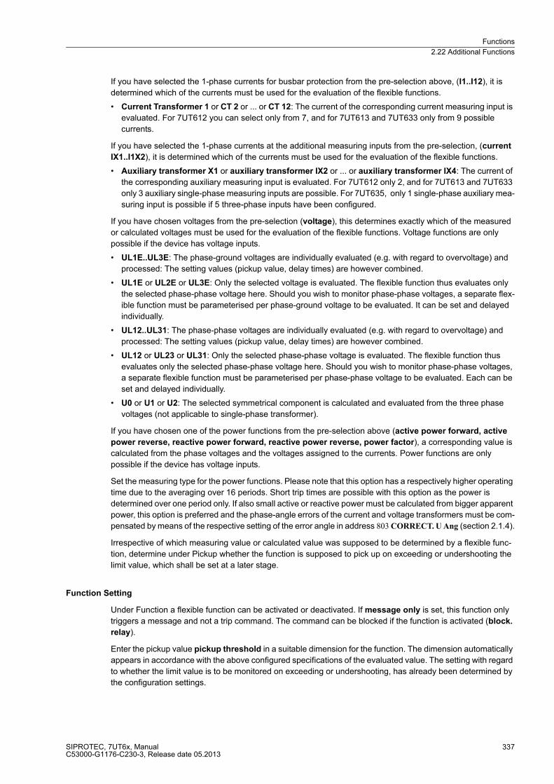
Functions
2.22 Additional Functions
SIPROTEC, 7UT6x, ManualC53000-G1176-C230-3, Release date 05.2013
337
If you have selected the 1-phase currents for busbar protection from the pre-selection above, (I1..I12), it is
determined which of the currents must be used for the evaluation of the flexible functions.
� Current Transformer 1 or CT 2 or ... or CT 12: The current of the corresponding current measuring input is
evaluated. For 7UT612 you can select only from 7, and for 7UT613 and 7UT633 only from 9 possible
currents.
If you have selected the 1-phase currents at the additional measuring inputs from the pre-selection, (current
IX1..I1X2), it is determined which of the currents must be used for the evaluation of the flexible functions.
� Auxiliary transformer X1 or auxiliary transformer IX2 or ... or auxiliary transformer IX4: The current of
the corresponding auxiliary measuring input is evaluated. For 7UT612 only 2, and for 7UT613 and 7UT633
only 3 auxiliary single-phase measuring inputs are possible. For 7UT635, only 1 single-phase auxiliary mea-
suring input is possible if 5 three-phase inputs have been configured.
If you have chosen voltages from the pre-selection (voltage), this determines exactly which of the measured
or calculated voltages must be used for the evaluation of the flexible functions. Voltage functions are only
possible if the device has voltage inputs.
� UL1E..UL3E: The phase-ground voltages are individually evaluated (e.g. with regard to overvoltage) and
processed: The setting values (pickup value, delay times) are however combined.
� UL1E or UL2E or UL3E: Only the selected voltage is evaluated. The flexible function thus evaluates only
the selected phase-phase voltage here. Should you wish to monitor phase-phase voltages, a separate flex-
ible function must be parameterised per phase-ground voltage to be evaluated. It can be set and delayed
individually.
� UL12..UL31: The phase-phase voltages are individually evaluated (e.g. with regard to overvoltage) and
processed: The setting values (pickup value, delay times) are however combined.
� UL12 or UL23 or UL31: Only the selected phase-phase voltage is evaluated. The flexible function thus
evaluates only the selected phase-phase voltage here. Should you wish to monitor phase-phase voltages,
a separate flexible function must be parameterised per phase-phase voltage to be evaluated. Each can be
set and delayed individually.
� U0 or U1 or U2: The selected symmetrical component is calculated and evaluated from the three phase
voltages (not applicable to single-phase transformer).
If you have chosen one of the power functions from the pre-selection above (active power forward, active
power reverse, reactive power forward, reactive power reverse, power factor), a corresponding value is
calculated from the phase voltages and the voltages assigned to the currents. Power functions are only
possible if the device has voltage inputs.
Set the measuring type for the power functions. Please note that this option has a respectively higher operating
time due to the averaging over 16 periods. Short trip times are possible with this option as the power is
determined over one period only. If also small active or reactive power must be calculated from bigger apparent
power, this option is preferred and the phase-angle errors of the current and voltage transformers must be com-
pensated by means of the respective setting of the error angle in address 803 CORRECT. U Ang (section 2.1.4).
Irrespective of which measuring value or calculated value was supposed to be determined by a flexible func-
tion, determine under Pickup whether the function is supposed to pick up on exceeding or undershooting the
limit value, which shall be set at a later stage.
Function Setting
Under Function a flexible function can be activated or deactivated. If message only is set, this function only
triggers a message and not a trip command. The command can be blocked if the function is activated (block.
relay).
Enter the pickup value pickup threshold in a suitable dimension for the function. The dimension automatically
appears in accordance with the above configured specifications of the evaluated value. The setting with regard
to whether the limit value is to be monitored on exceeding or undershooting, has already been determined by
the configuration settings.
Functions
2.22 Additional Functions
SIPROTEC, 7UT6x, ManualC53000-G1176-C230-3, Release date 05.2013
338
The pickup and the drop-off of the fault detection can be delayed. Delay of the pickup means that after non-
compliance with the limit value condition, this period must first expire before a pickup can be indicated and
result in further actions. Delay of the drop-off means that, after activated pickup, same can be maintained and
delayed by such time period after non-compliance of the limit value has stopped.
The trip command (if desired) is thus delayed by means of the trip command delay. The time starts on acti-
vation of the pickup (if necessary, also after time delay). Please note that the command delay must be set in
such manner that it is significantly longer than a possibly set reset delay. Otherwise, every pickup will result in
a trip because the pickup for the reset delay is maintained, although the criterion to be monitored is no longer
complied with.
Please also note that the set times are pure additional delays that do not include the inherent operating time of
the function (functional internal pickup and drop-off times). This has an effect especially on accurate power
functions as these carry out measurements over 16 network period.
The dropout ratio can be set to wide ranges. If functions react on exceeding a limit value, such value is smaller
than 1; if the functions that react on undershooting the limit value, such value is greater than 1. The possible
setting range is automatically determined in accordance with the function, which has either been configured to
exceeding or undershooting.
The drop-out ratio to be set depends on the application. In general, it can be stated that: the limit value must
be closer to 1 the lesser the pickup value differs from the operating valid values. Latching of the pickup due to
short-term fluctuations of the measured values during operation must be avoided.
Conversely, the drop-out ratio should not be set more sensitive (closer to 1) than necessary, thus avoiding an
intermitting pickup to be caused in conditions close to the pickup value.
Apart from internal blockings that, for example, are activated outside the working range of the functions, internal
monitoring of the measured values can lead to the blocking of a flexible function.
If a flexible function has been configured in such manner that it reacts on the processing of voltages (voltage
or power), a blocking on failure of measured voltages can be effected. This applies to undervoltage func-
tions and exceeding of power components, but also to the detection of negative sequence and zero systems.
However, there may be cases where overfunctioning is preferred to underfunctioning. In such case set to no.
A blocking on voltage failure is usually not required for overvoltage functions.
If a flexible function is configured in such manner that it reacts on the processing of currents (current or power),
a blocking on wire break in the current path can be effected. This applies to undercurrent functions and
exceeding of power components, but also to the detection of negative sequence and zero systems. However,
there may be cases where overfunctioning is preferred to underfunctioning. In such case set to no. A blocking
on wire break in the current path in overcurrent functions is usually not required.
Additional Steps
If an additional flexible function has been created, configured and set, the corresponding indications are
entered in the DIGSI configuration matrix. These indications are kept general and assign the ld. number to the
flexible functions, e.g. "Flx01 Pickup L1“. You can now change their names to texts in accordance with your
application.
Thereafter, configure these indications to binary inputs/outputs, if required.
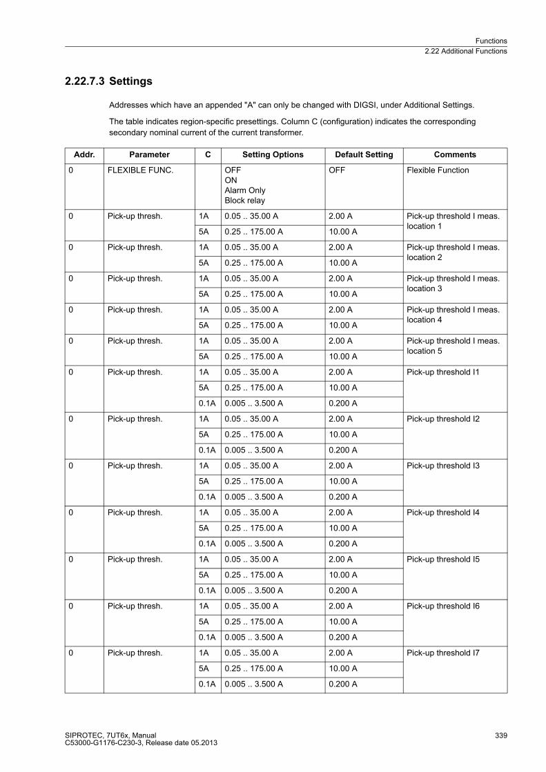
Functions
2.22 Additional Functions
SIPROTEC, 7UT6x, ManualC53000-G1176-C230-3, Release date 05.2013
339
2.22.7.3 Settings
Addresses which have an appended "A" can only be changed with DIGSI, under Additional Settings.
The table indicates region-specific presettings. Column C (configuration) indicates the corresponding
secondary nominal current of the current transformer.
Addr. Parameter C Setting Options Default Setting Comments
0 FLEXIBLE FUNC. OFFONAlarm OnlyBlock relay
OFF Flexible Function
0 Pick-up thresh. 1A 0.05 .. 35.00 A 2.00 A Pick-up threshold I meas. location 1
5A 0.25 .. 175.00 A 10.00 A
0 Pick-up thresh. 1A 0.05 .. 35.00 A 2.00 A Pick-up threshold I meas. location 2
5A 0.25 .. 175.00 A 10.00 A
0 Pick-up thresh. 1A 0.05 .. 35.00 A 2.00 A Pick-up threshold I meas. location 3
5A 0.25 .. 175.00 A 10.00 A
0 Pick-up thresh. 1A 0.05 .. 35.00 A 2.00 A Pick-up threshold I meas. location 4
5A 0.25 .. 175.00 A 10.00 A
0 Pick-up thresh. 1A 0.05 .. 35.00 A 2.00 A Pick-up threshold I meas. location 5
5A 0.25 .. 175.00 A 10.00 A
0 Pick-up thresh. 1A 0.05 .. 35.00 A 2.00 A Pick-up threshold I1
5A 0.25 .. 175.00 A 10.00 A
0.1A 0.005 .. 3.500 A 0.200 A
0 Pick-up thresh. 1A 0.05 .. 35.00 A 2.00 A Pick-up threshold I2
5A 0.25 .. 175.00 A 10.00 A
0.1A 0.005 .. 3.500 A 0.200 A
0 Pick-up thresh. 1A 0.05 .. 35.00 A 2.00 A Pick-up threshold I3
5A 0.25 .. 175.00 A 10.00 A
0.1A 0.005 .. 3.500 A 0.200 A
0 Pick-up thresh. 1A 0.05 .. 35.00 A 2.00 A Pick-up threshold I4
5A 0.25 .. 175.00 A 10.00 A
0.1A 0.005 .. 3.500 A 0.200 A
0 Pick-up thresh. 1A 0.05 .. 35.00 A 2.00 A Pick-up threshold I5
5A 0.25 .. 175.00 A 10.00 A
0.1A 0.005 .. 3.500 A 0.200 A
0 Pick-up thresh. 1A 0.05 .. 35.00 A 2.00 A Pick-up threshold I6
5A 0.25 .. 175.00 A 10.00 A
0.1A 0.005 .. 3.500 A 0.200 A
0 Pick-up thresh. 1A 0.05 .. 35.00 A 2.00 A Pick-up threshold I7
5A 0.25 .. 175.00 A 10.00 A
0.1A 0.005 .. 3.500 A 0.200 A
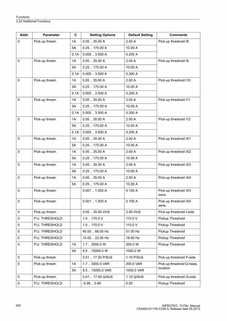
Functions
2.22 Additional Functions
SIPROTEC, 7UT6x, ManualC53000-G1176-C230-3, Release date 05.2013
340
0 Pick-up thresh. 1A 0.05 .. 35.00 A 2.00 A Pick-up threshold I8
5A 0.25 .. 175.00 A 10.00 A
0.1A 0.005 .. 3.500 A 0.200 A
0 Pick-up thresh. 1A 0.05 .. 35.00 A 2.00 A Pick-up threshold I9
5A 0.25 .. 175.00 A 10.00 A
0.1A 0.005 .. 3.500 A 0.200 A
0 Pick-up thresh. 1A 0.05 .. 35.00 A 2.00 A Pick-up threshold I10
5A 0.25 .. 175.00 A 10.00 A
0.1A 0.005 .. 3.500 A 0.200 A
0 Pick-up thresh. 1A 0.05 .. 35.00 A 2.00 A Pick-up threshold I11
5A 0.25 .. 175.00 A 10.00 A
0.1A 0.005 .. 3.500 A 0.200 A
0 Pick-up thresh. 1A 0.05 .. 35.00 A 2.00 A Pick-up threshold I12
5A 0.25 .. 175.00 A 10.00 A
0.1A 0.005 .. 3.500 A 0.200 A
0 Pick-up thresh. 1A 0.05 .. 35.00 A 2.00 A Pick-up threshold IX1
5A 0.25 .. 175.00 A 10.00 A
0 Pick-up thresh. 1A 0.05 .. 35.00 A 2.00 A Pick-up threshold IX2
5A 0.25 .. 175.00 A 10.00 A
0 Pick-up thresh. 1A 0.05 .. 35.00 A 2.00 A Pick-up threshold IX3
5A 0.25 .. 175.00 A 10.00 A
0 Pick-up thresh. 1A 0.05 .. 35.00 A 2.00 A Pick-up threshold IX4
5A 0.25 .. 175.00 A 10.00 A
0 Pick-up thresh. 0.001 .. 1.500 A 0.100 A Pick-up threshold IX3 sens.
0 Pick-up thresh. 0.001 .. 1.500 A 0.100 A Pick-up threshold IX4 sens.
0 Pick-up thresh. 0.05 .. 35.00 I/InS 2.00 I/InS Pick-up threshold I-side
0 P.U. THRESHOLD 1.0 .. 170.0 V 110.0 V Pickup Threshold
0 P.U. THRESHOLD 1.0 .. 170.0 V 110.0 V Pickup Threshold
0 P.U. THRESHOLD 40.00 .. 66.00 Hz 51.00 Hz Pickup Threshold
0 P.U. THRESHOLD 10.00 .. 22.00 Hz 18.00 Hz Pickup Threshold
0 P.U. THRESHOLD 1A 1.7 .. 3000.0 W 200.0 W Pickup Threshold
5A 8.5 .. 15000.0 W 1000.0 W
0 Pick-up thresh. 0.01 .. 17.00 P/SnS 1.10 P/SnS Pick-up threshold P-side
0 Pick-up thresh. 1A 1.7 .. 3000.0 VAR 200.0 VAR Pick-up threshold Q meas. location
5A 8.5 .. 15000.0 VAR 1000.0 VAR
0 Pick-up thresh. 0.01 .. 17.00 Q/SnS 1.10 Q/SnS Pick-up threshold Q-side
0 P.U. THRESHOLD -0.99 .. 0.99 0.50 Pickup Threshold
Addr. Parameter C Setting Options Default Setting Comments
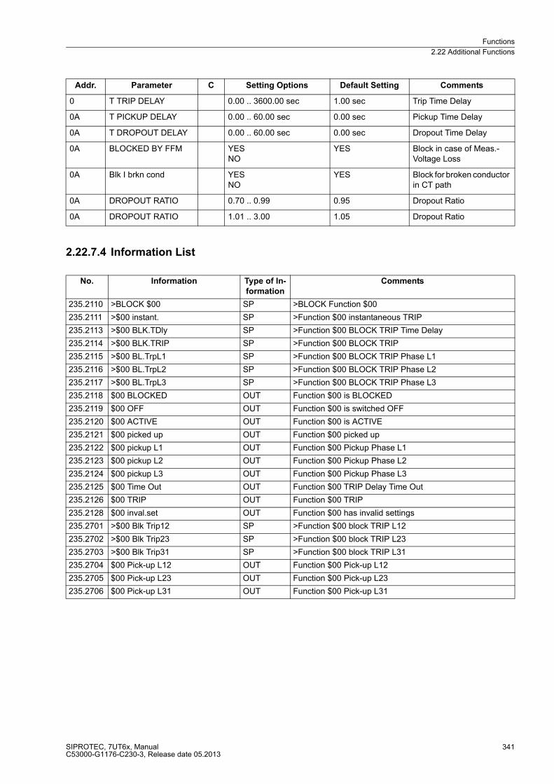
Functions
2.22 Additional Functions
SIPROTEC, 7UT6x, ManualC53000-G1176-C230-3, Release date 05.2013
341
2.22.7.4 Information List
0 T TRIP DELAY 0.00 .. 3600.00 sec 1.00 sec Trip Time Delay
0A T PICKUP DELAY 0.00 .. 60.00 sec 0.00 sec Pickup Time Delay
0A T DROPOUT DELAY 0.00 .. 60.00 sec 0.00 sec Dropout Time Delay
0A BLOCKED BY FFM YESNO
YES Block in case of Meas.-Voltage Loss
0A Blk I brkn cond YESNO
YES Block for broken conductor in CT path
0A DROPOUT RATIO 0.70 .. 0.99 0.95 Dropout Ratio
0A DROPOUT RATIO 1.01 .. 3.00 1.05 Dropout Ratio
No. Information Type of In-
formation
Comments
235.2110 >BLOCK $00 SP >BLOCK Function $00
235.2111 >$00 instant. SP >Function $00 instantaneous TRIP
235.2113 >$00 BLK.TDly SP >Function $00 BLOCK TRIP Time Delay
235.2114 >$00 BLK.TRIP SP >Function $00 BLOCK TRIP
235.2115 >$00 BL.TrpL1 SP >Function $00 BLOCK TRIP Phase L1
235.2116 >$00 BL.TrpL2 SP >Function $00 BLOCK TRIP Phase L2
235.2117 >$00 BL.TrpL3 SP >Function $00 BLOCK TRIP Phase L3
235.2118 $00 BLOCKED OUT Function $00 is BLOCKED
235.2119 $00 OFF OUT Function $00 is switched OFF
235.2120 $00 ACTIVE OUT Function $00 is ACTIVE
235.2121 $00 picked up OUT Function $00 picked up
235.2122 $00 pickup L1 OUT Function $00 Pickup Phase L1
235.2123 $00 pickup L2 OUT Function $00 Pickup Phase L2
235.2124 $00 pickup L3 OUT Function $00 Pickup Phase L3
235.2125 $00 Time Out OUT Function $00 TRIP Delay Time Out
235.2126 $00 TRIP OUT Function $00 TRIP
235.2128 $00 inval.set OUT Function $00 has invalid settings
235.2701 >$00 Blk Trip12 SP >Function $00 block TRIP L12
235.2702 >$00 Blk Trip23 SP >Function $00 block TRIP L23
235.2703 >$00 Blk Trip31 SP >Function $00 block TRIP L31
235.2704 $00 Pick-up L12 OUT Function $00 Pick-up L12
235.2705 $00 Pick-up L23 OUT Function $00 Pick-up L23
235.2706 $00 Pick-up L31 OUT Function $00 Pick-up L31
Addr. Parameter C Setting Options Default Setting Comments
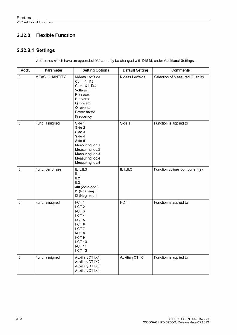
Functions
2.22 Additional Functions
SIPROTEC, 7UT6x, ManualC53000-G1176-C230-3, Release date 05.2013
342
2.22.8 Flexible Function
2.22.8.1 Settings
Addresses which have an appended "A" can only be changed with DIGSI, under Additional Settings.
Addr. Parameter Setting Options Default Setting Comments
0 MEAS. QUANTITY I-Meas Loc/sideCurr. I1..I12Curr. IX1..IX4VoltageP forwardP reverseQ forwardQ reversePower factorFrequency
I-Meas Loc/side Selection of Measured Quantity
0 Func. assigned Side 1Side 2Side 3Side 4Side 5Measuring loc.1Measuring loc.2Measuring loc.3Measuring loc.4Measuring loc.5
Side 1 Function is applied to
0 Func. per phase IL1..IL3IL1IL2IL33I0 (Zero seq.)I1 (Pos. seq.)I2 (Neg. seq.)
IL1..IL3 Function utilises component(s)
0 Func. assigned I-CT 1I-CT 2I-CT 3I-CT 4I-CT 5I-CT 6I-CT 7I-CT 8I-CT 9I-CT 10I-CT 11I-CT 12
I-CT 1 Function is applied to
0 Func. assigned AuxiliaryCT IX1AuxiliaryCT IX2AuxiliaryCT IX3AuxiliaryCT IX4
AuxiliaryCT IX1 Function is applied to

Functions
2.22 Additional Functions
SIPROTEC, 7UT6x, ManualC53000-G1176-C230-3, Release date 05.2013
343
0 Func. per phase UL1E..UL3EUL1EUL2EUL3EUL12..UL31UL12UL23UL31U0 (Zero seq.)U1 (Pos. seq.)U2 (Neg. seq.)U4/Uen
UL1E..UL3E Function utilises component(s)
0 PICKUP WITH ExceedingDropping below
Exceeding Pickup with
0A Type of meas. accuratefast
accurate Selection of type of measurement
Addr. Parameter Setting Options Default Setting Comments
Functions
2.22 Additional Functions
SIPROTEC, 7UT6x, ManualC53000-G1176-C230-3, Release date 05.2013
344
2.22.9 Oscillographic Fault Recording
The 7UT6x differential protection is equipped with a fault recording function.
2.22.9.1 Function Description
The instantaneous values of measured values
IL1 S1, IL2 S1, IL3 S1, IL1 S2, IL2 S2, IL3S2, 3I0S1, 3I0S2, I7, I8 as well as
Idiff L1, Idiff L2, Idiff L3, Irest L1, Irest L2, Irest L3
are sampled at intervals of 1,667 ms (for 50 Hz) and stored in a circulation buffer (16 samples per cycle). When
used as single-phase busbar protection, the first six feeder currents 1 to I6 are stored instead of the phase
currents, the zero sequence currents are not applicable.
During a system fault, these data are stored over a time span that can be set (5 s at most for each fault record).
Up to 8 faults can be stored. The total capacity of the fault record memory is approx. 5 s. The fault recording
buffer is updated when a new fault occurs, so that acknowledgement is not required. Storage of the fault re-
cording by the protection fault detection can also be initiated via binary input, the integrated keypad and display,
or via the serial operator or service interface.
The data can be retrieved via the serial interfaces by means of a personal computer and evaluated with the
operating software DIGSI and the graphic analysis software SIGRA 4. The latter graphically represents the data
recorded during the system fault and calculates additional information such as power or rms values from the
measured values. A selection may be made as to whether the measured quantities are represented as primary
or secondary values. Binary signal traces (marks) of particular events e.g. „fault detection“, „tripping“ are also
represented.
If the device has a serial system interface, the fault recording data can be passed on to a central device via this
interface. The evaluation of the data is done by the respective programs in the central device. The measured
quantities are referred to their maximum values, scaled to their rated values and prepared for graphic repre-
sentation. Binary signal traces (marks) of particular events e.g. „fault detection“, „tripping“ are also represented.
Where transfer to a central device is possible, the request for data transfer can be executed automatically. It
can be selected to take place after each protection pickup or after a trip only.
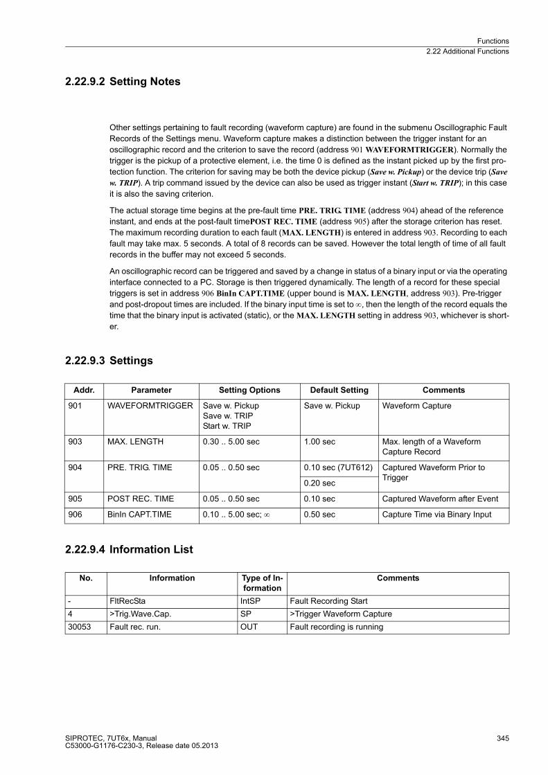
Functions
2.22 Additional Functions
SIPROTEC, 7UT6x, ManualC53000-G1176-C230-3, Release date 05.2013
345
2.22.9.2 Setting Notes
Other settings pertaining to fault recording (waveform capture) are found in the submenu Oscillographic Fault
Records of the Settings menu. Waveform capture makes a distinction between the trigger instant for an
oscillographic record and the criterion to save the record (address 901 WAVEFORMTRIGGER). Normally the
trigger is the pickup of a protective element, i.e. the time 0 is defined as the instant picked up by the first pro-
tection function. The criterion for saving may be both the device pickup (Save w. Pickup) or the device trip (Save
w. TRIP). A trip command issued by the device can also be used as trigger instant (Start w. TRIP); in this case
it is also the saving criterion.
The actual storage time begins at the pre-fault time PRE. TRIG. TIME (address 904) ahead of the reference
instant, and ends at the post-fault timePOST REC. TIME (address 905) after the storage criterion has reset.
The maximum recording duration to each fault (MAX. LENGTH) is entered in address 903. Recording to each
fault may take max. 5 seconds. A total of 8 records can be saved. However the total length of time of all fault
records in the buffer may not exceed 5 seconds.
An oscillographic record can be triggered and saved by a change in status of a binary input or via the operating
interface connected to a PC. Storage is then triggered dynamically. The length of a record for these special
triggers is set in address 906 BinIn CAPT.TIME (upper bound is MAX. LENGTH, address 903). Pre-trigger
and post-dropout times are included. If the binary input time is set to ∞, then the length of the record equals the
time that the binary input is activated (static), or the MAX. LENGTH setting in address 903, whichever is short-
er.
2.22.9.3 Settings
2.22.9.4 Information List
Addr. Parameter Setting Options Default Setting Comments
901 WAVEFORMTRIGGER Save w. PickupSave w. TRIPStart w. TRIP
Save w. Pickup Waveform Capture
903 MAX. LENGTH 0.30 .. 5.00 sec 1.00 sec Max. length of a Waveform Capture Record
904 PRE. TRIG. TIME 0.05 .. 0.50 sec 0.10 sec (7UT612) Captured Waveform Prior to Trigger
0.20 sec
905 POST REC. TIME 0.05 .. 0.50 sec 0.10 sec Captured Waveform after Event
906 BinIn CAPT.TIME 0.10 .. 5.00 sec; ∞ 0.50 sec Capture Time via Binary Input
No. Information Type of In-
formation
Comments
- FltRecSta IntSP Fault Recording Start
4 >Trig.Wave.Cap. SP >Trigger Waveform Capture
30053 Fault rec. run. OUT Fault recording is running
Functions
2.22 Additional Functions
SIPROTEC, 7UT6x, ManualC53000-G1176-C230-3, Release date 05.2013
346
2.22.10 Commissioning Aids
For commissioning of the device, a comprehensive commissioning and monitoring tool is available.
2.22.10.1Web Monitor
The device is provided with a comprehensive commissioning and monitoring tool that monitors and checks the
measured values and the whole differential protection system. Using a personal computer in conjunction with
a web browser, this tool enables the user to clearly chart the state of the system and the differential protection
values, measured values and indications. The necessary operator software is integrated in the device; online
help can be found on the DIGSI CD and is also available in the Internet.
To ensure a proper communication between the device and the PC browser the transmission speed must be
equal for both. Furthermore, an IP-address is necessary so that the browser can identify the device. For 7UT6x,
the following is valid:
The „Web Monitor“ shows the device front with its keypad and LCD display on the screen, thus allowing to
operate the device from the PC. The actual operation of the device can be simulated with the mouse pointer.
Measured values and the values derived from them are graphically displayed as phasor diagrams.
You can also view tripping diagrams, scalar values are shown in numerical form. Most of the measured values
discussed in Subsection 2.22.2 can also be displayed in the „Web Monitor“.
For more details on working with the „Web Monitor“, refer to the Online Help attached.
Transmission speed: 115 kBaud;
IP-address
for connection at the front operator interface: 192.168.1.1,
for connection to the rear service interface (port C): 192.168.2.1.

Functions
2.22 Additional Functions
SIPROTEC, 7UT6x, ManualC53000-G1176-C230-3, Release date 05.2013
347
Function Description
This tool allows to graphically illustrates on a PC, for example, the currents and their phase angles for both
sides of the protected object during commissioning and during operation. In addition to phasor diagrams of
measured values, numerical values are indicated. The following figure shows an example of this function.
Additionally the position of the differential and restraint values can be viewed in the tripping characteristic.
Figure 2-127 Phasor Diagram of the Secondary Measured Values — Example
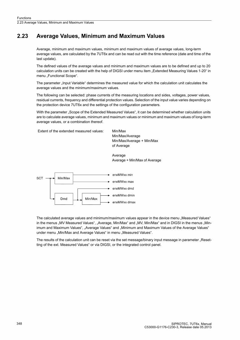
Functions
2.23 Average Values, Minimum and Maximum Values
SIPROTEC, 7UT6x, ManualC53000-G1176-C230-3, Release date 05.2013
348
2.23 Average Values, Minimum and Maximum Values
Average, minimum and maximum values, minimum and maximum values of average values, long-term
average values, are calculated by the 7UT6x and can be read out with the time reference (date and time of the
last update).
The defined values of the average values and minimum and maximum values are to be defined and up to 20
calculation units can be created with the help of DIGSI under menu item „Extended Measuring Values 1-20“ in
menu „Functional Scope“.
The parameter „Input Variable“ determines the measured value for which the calculation unit calculates the
average values and the minimum/maximum values.
The following can be selected: phase currents of the measuring locations and sides, voltages, power values,
residual currents, frequency and differential protection values. Selection of the input value varies depending on
the protection device 7UT6x and the settings of the configuration parameters.
With the parameter „Scope of the Extended Measured Values“, it can be determined whether calculation units
are to calculate average values, minimum and maximum values or minimum and maximum values of long-term
average values, or a combination thereof.
The calculated average values and minimum/maximum values appear in the device menu „Measured Values“
in the menus „MV Measured Values“, „Average, Min/Max“ and „MV, Min/Max“ and in DIGSI in the menus „Min-
imum and Maximum Values“, „Average Values“ and „Minimum and Maximum Values of the Average Values“
under menu „Min/Max and Average Values“ in menu „Measured Values“.
The results of the calculation unit can be reset via the set message/binary input message in parameter „Reset-
ting of the ext. Measured Values“ or via DIGSI, or the integrated control panel.
Extent of the extended measured values: Min/Max
Min/Max/Average
Min/Max/Average + Min/Max
of Average
Average
Average + Min/Max of Average
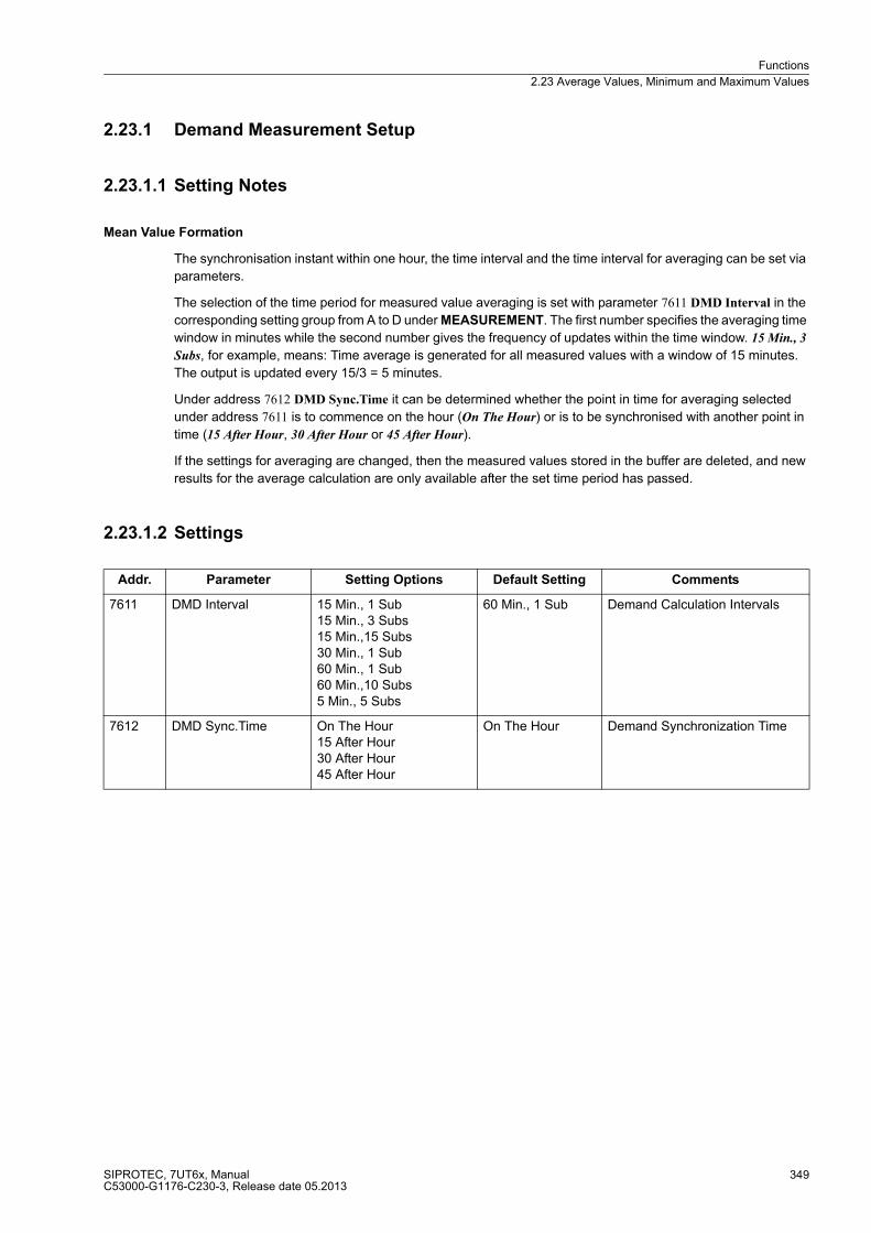
Functions
2.23 Average Values, Minimum and Maximum Values
SIPROTEC, 7UT6x, ManualC53000-G1176-C230-3, Release date 05.2013
349
2.23.1 Demand Measurement Setup
2.23.1.1 Setting Notes
Mean Value Formation
The synchronisation instant within one hour, the time interval and the time interval for averaging can be set via
parameters.
The selection of the time period for measured value averaging is set with parameter 7611 DMD Interval in the
corresponding setting group from A to D under MEASUREMENT. The first number specifies the averaging time
window in minutes while the second number gives the frequency of updates within the time window. 15 Min., 3
Subs, for example, means: Time average is generated for all measured values with a window of 15 minutes.
The output is updated every 15/3 = 5 minutes.
Under address 7612 DMD Sync.Time it can be determined whether the point in time for averaging selected
under address 7611 is to commence on the hour (On The Hour) or is to be synchronised with another point in
time (15 After Hour, 30 After Hour or 45 After Hour).
If the settings for averaging are changed, then the measured values stored in the buffer are deleted, and new
results for the average calculation are only available after the set time period has passed.
2.23.1.2 Settings
Addr. Parameter Setting Options Default Setting Comments
7611 DMD Interval 15 Min., 1 Sub15 Min., 3 Subs15 Min.,15 Subs30 Min., 1 Sub60 Min., 1 Sub60 Min.,10 Subs5 Min., 5 Subs
60 Min., 1 Sub Demand Calculation Intervals
7612 DMD Sync.Time On The Hour15 After Hour30 After Hour45 After Hour
On The Hour Demand Synchronization Time

Functions
2.23 Average Values, Minimum and Maximum Values
SIPROTEC, 7UT6x, ManualC53000-G1176-C230-3, Release date 05.2013
350
2.23.2 Min/Max Measurement Setup
2.23.2.1 Setting Notes
Resetting of the minimum and maximum values can also be done cyclically, commencing with the preselected
starting time. To select this feature, address 7621 MinMax cycRESET should be set to YES. The point in time
when reset is to take place (the minute of the day in which reset will take place) is set at address 7622 MiMa
RESET TIME. The reset cycle in days is entered at address 7623 MiMa RESETCYCLE, and the beginning
date of the cyclical process, from the time of the setting procedure (in days), is entered at address 7624
MinMaxRES.START.
2.23.2.2 Settings
2.23.2.3 Information List
Addr. Parameter Setting Options Default Setting Comments
7621 MinMax cycRESET NOYES
YES Automatic Cyclic Reset Function
7622 MiMa RESET TIME 0 .. 1439 min 0 min MinMax Reset Timer
7623 MiMa RESETCYCLE 1 .. 365 Days 7 Days MinMax Reset Cycle Period
7624 MinMaxRES.START 1 .. 365 Days 1 Days MinMax Start Reset Cycle in
No. Information Type of In-
formation
Comments
- ResMinMax IntSP_Ev Reset Minimum and Maximum counter
11001 >Reset MinMax SP >Reset MinMaxValues
Functions
2.24 Command Processing
SIPROTEC, 7UT6x, ManualC53000-G1176-C230-3, Release date 05.2013
351
2.24 Command Processing
The SIPROTEC 4 7UT6x includes a command processing function for initiating switching operations in the
system.
Control commands can originate from four command sources:
� Local operation using the keypad on the local user interface of the device
� Operation using DIGSI
� Remote operation using a substation automation and control system (e.g. SICAM)
� Automatic functions (e.g., using a binary input)
Switchgear with single and multiple busbars are supported. The number of switchgear devices to be controlled
is limited only by the number of binary inputs and outputs present. High security against inadvertent device
operations can be ensured if interlocking checks are enabled. A standard set of optional interlocking checks is
provided for each command issued to circuit breakers/switchgear.
2.24.1 Control Authorization
2.24.1.1 Type of Commands
Commands to the Process
These commands are directly output to the switchgear to change their process state:
� Commands for the operation of circuit breakers (asynchronous; or synchronized through integration of the
synchronism check and closing control function) as well as commands for the control of isolators and earth
switches.
� Step commands, e.g. for raising and lowering transformer taps,
� Setpoint commands with configurable time settings, e.g. to control Petersen coils.
Device-internal Commands
These commands do not directly operate binary outputs. They serve for initiating internal functions,
communicating the detection of status changes to the device or for acknowledging them.
� Manual override commands for „manual update“ of information on process-dependent objects such as
annunciations and switching states, e.g. if the communication with the process is interrupted. Manually over-
idden objects are marked as such in the information status and can be displayed accordingly.
� Tagging commands (for „setting“) the information value of internal objects, such switching authority
(remote/local), parameter changeovers, transmission blocks and deletion/presetting of metered values.
� Acknowledgment and resetting commands for setting and resetting internal buffers or data stocks.
� Information status commands to set/delete the additional „Information Status“ item of a process object, such
as
– Acquisition blocking,
– Output blocking.
Functions
2.24 Command Processing
SIPROTEC, 7UT6x, ManualC53000-G1176-C230-3, Release date 05.2013
352
2.24.1.2 Sequence in the Command Path
Safety mechanisms in the command sequence ensure that a command can only be released after a thorough
check of preset criteria has been successfully concluded. Additionally, user-defined interlocking conditions can
be configured separately for each device. The actual execution of the command is also monitored after its
release. The entire sequence of a command is described briefly in the following.
Checking a Command Path
Please observe the following:
� Command entry, e.g. using the keypad on the local user interface of the device
– Check password → access rights;
– Check switching mode (interlocking activated/deactivated) → selection of deactivated interlocking status.
� User configurable interlocking checks:
– Switching authority;
– Device position check (set vs. actual comparison);
– Zone controlled / bay interlocking (logic using CFC);
– System interlocking (centrally via SICAM);
– Double operation (interlocking against parallel switching operation);
– Protection blocking (blocking of switching operations by protection functions);
– Checking the synchronism before a close command.
� Fixed commands:
– Internal process time (software watch dog which checks the time for processing the control action
between initiation of the control and final close of the relay contact);
– Configuration in process (if setting modification is in process, commands are rejected or delayed);
– Equipment present as output;
– Output block (if an output block has been programmed for the circuit breaker, and is active at the moment
the command is processed, then the command is rejected);
– Component hardware malfunction;
– Command in progress (only one command can be processed at a time for each circuit breaker or switch);
– 1–of–n check (for multiple allocations such as common contact relays or multiple protection commands
configured to the same contact it is checked if a command procedure was already initiated for the output
relays concerned or if a protection command is present. Superimposed commands in the same switching
direction are tolerated).
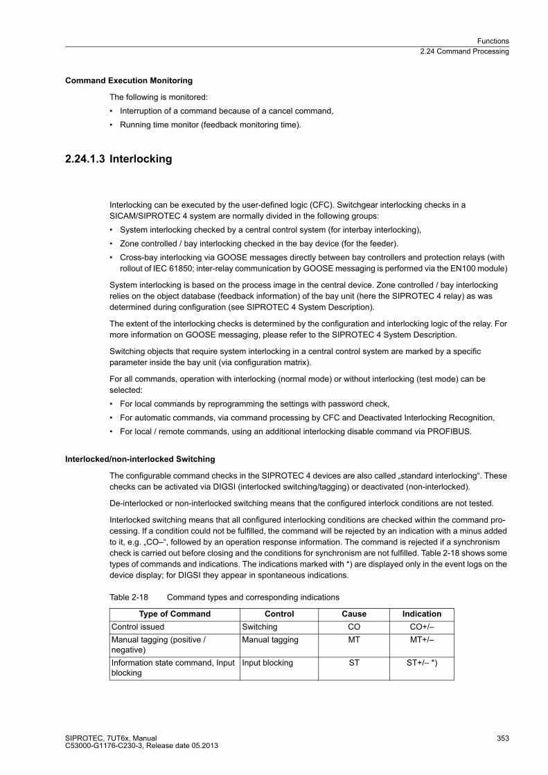
Functions
2.24 Command Processing
SIPROTEC, 7UT6x, ManualC53000-G1176-C230-3, Release date 05.2013
353
Command Execution Monitoring
The following is monitored:
� Interruption of a command because of a cancel command,
� Running time monitor (feedback monitoring time).
2.24.1.3 Interlocking
Interlocking can be executed by the user-defined logic (CFC). Switchgear interlocking checks in a
SICAM/SIPROTEC 4 system are normally divided in the following groups:
� System interlocking checked by a central control system (for interbay interlocking),
� Zone controlled / bay interlocking checked in the bay device (for the feeder).
� Cross-bay interlocking via GOOSE messages directly between bay controllers and protection relays (with
rollout of IEC 61850; inter-relay communication by GOOSE messaging is performed via the EN100 module)
System interlocking is based on the process image in the central device. Zone controlled / bay interlocking
relies on the object database (feedback information) of the bay unit (here the SIPROTEC 4 relay) as was
determined during configuration (see SIPROTEC 4 System Description).
The extent of the interlocking checks is determined by the configuration and interlocking logic of the relay. For
more information on GOOSE messaging, please refer to the SIPROTEC 4 System Description.
Switching objects that require system interlocking in a central control system are marked by a specific
parameter inside the bay unit (via configuration matrix).
For all commands, operation with interlocking (normal mode) or without interlocking (test mode) can be
selected:
� For local commands by reprogramming the settings with password check,
� For automatic commands, via command processing by CFC and Deactivated Interlocking Recognition,
� For local / remote commands, using an additional interlocking disable command via PROFIBUS.
Interlocked/non-interlocked Switching
The configurable command checks in the SIPROTEC 4 devices are also called „standard interlocking“. These
checks can be activated via DIGSI (interlocked switching/tagging) or deactivated (non-interlocked).
De-interlocked or non-interlocked switching means that the configured interlock conditions are not tested.
Interlocked switching means that all configured interlocking conditions are checked within the command pro-
cessing. If a condition could not be fulfilled, the command will be rejected by an indication with a minus added
to it, e.g. „CO–“, followed by an operation response information. The command is rejected if a synchronism
check is carried out before closing and the conditions for synchronism are not fulfilled. Table 2-18 shows some
types of commands and indications. The indications marked with *) are displayed only in the event logs on the
device display; for DIGSI they appear in spontaneous indications.
Table 2-18 Command types and corresponding indications
Type of Command Control Cause Indication
Control issued Switching CO CO+/–
Manual tagging (positive / negative)
Manual tagging MT MT+/–
Information state command, Input blocking
Input blocking ST ST+/– *)
Functions
2.24 Command Processing
SIPROTEC, 7UT6x, ManualC53000-G1176-C230-3, Release date 05.2013
354
Information state command, Output blocking
Output blocking ST ST+/– *)
Cancel command Cancel CA CA+/–
Type of Command Control Cause Indication

Functions
2.24 Command Processing
SIPROTEC, 7UT6x, ManualC53000-G1176-C230-3, Release date 05.2013
355
The plus sign in the indication is a confirmation of the command execution: The command output has a positive
result, as expected. A minus sign means a negative, i.e. an unexpected result; the command was rejected.
Figure 2-128 shows an example for successful switching of the circuit breaker in the Event Log (command and
feedback).
The check of interlocking can be programmed separately for all switching devices and tags that were set with
a tagging command. Other internal commands such as overriding or abort are not tested, i.e. are executed
independently of the interlockings.
Figure 2-128 Example of an operational indication for switching circuit breaker (Q0)
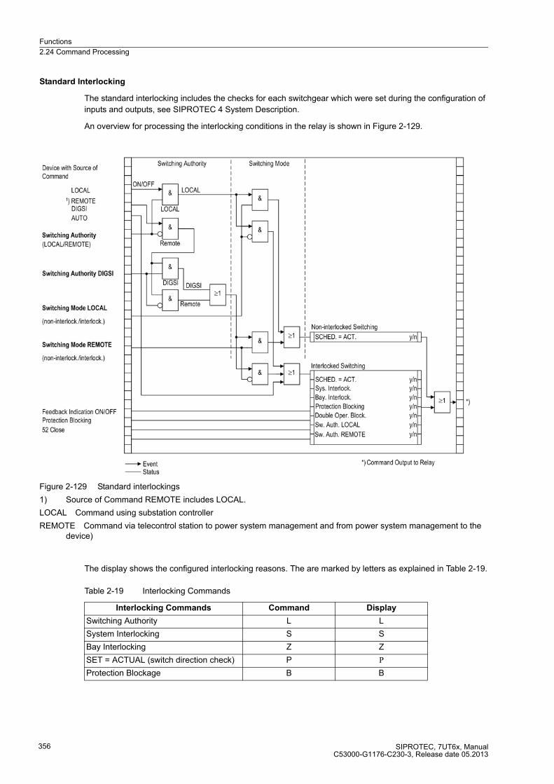
Functions
2.24 Command Processing
SIPROTEC, 7UT6x, ManualC53000-G1176-C230-3, Release date 05.2013
356
Standard Interlocking
The standard interlocking includes the checks for each switchgear which were set during the configuration of
inputs and outputs, see SIPROTEC 4 System Description.
An overview for processing the interlocking conditions in the relay is shown in Figure 2-129.
Figure 2-129 Standard interlockings
1) Source of Command REMOTE includes LOCAL.
LOCAL Command using substation controller
REMOTE Command via telecontrol station to power system management and from power system management to the device)
The display shows the configured interlocking reasons. The are marked by letters as explained in Table 2-19.
Table 2-19 Interlocking Commands
Interlocking Commands Command Display
Switching Authority L L
System Interlocking S S
Bay Interlocking Z Z
SET = ACTUAL (switch direction check) P P
Protection Blockage B B
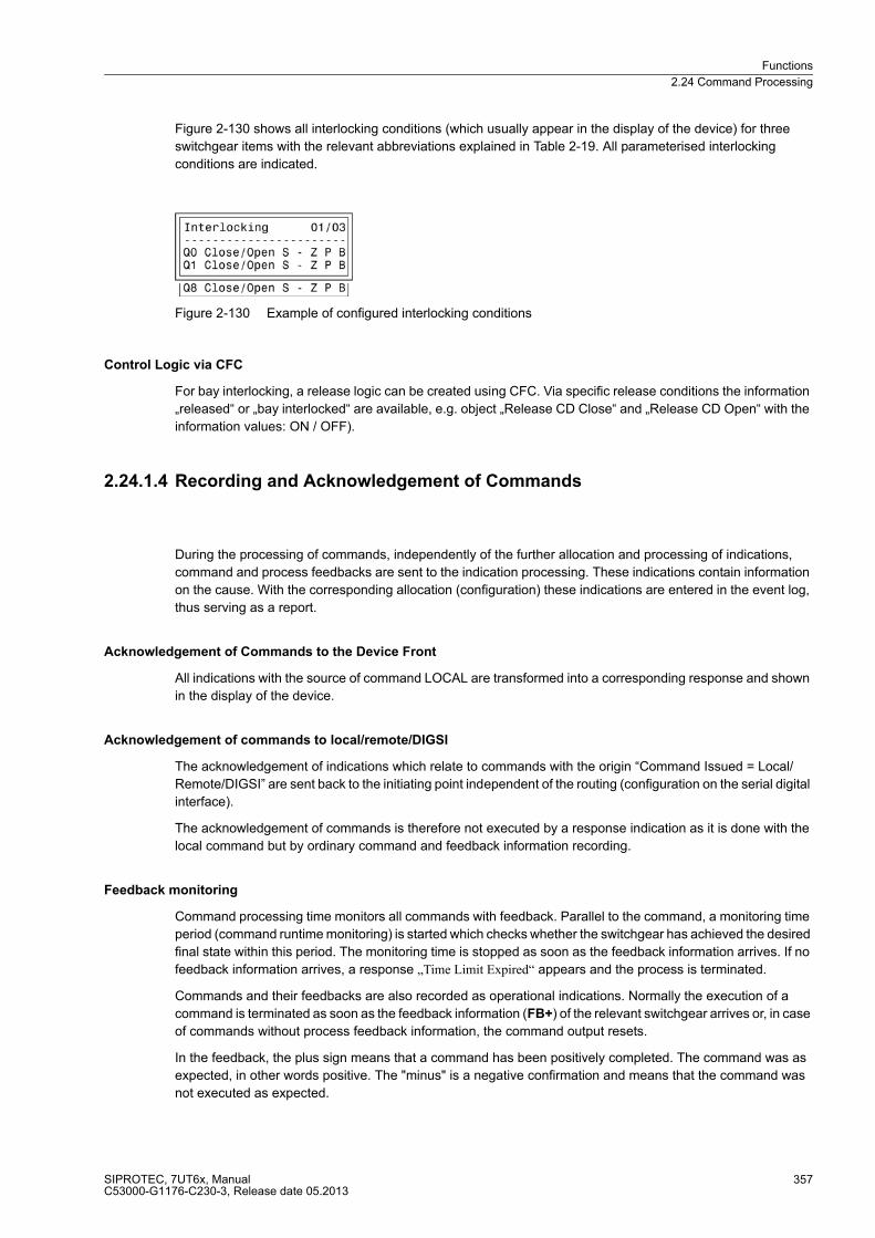
Functions
2.24 Command Processing
SIPROTEC, 7UT6x, ManualC53000-G1176-C230-3, Release date 05.2013
357
Figure 2-130 shows all interlocking conditions (which usually appear in the display of the device) for three
switchgear items with the relevant abbreviations explained in Table 2-19. All parameterised interlocking
conditions are indicated.
Figure 2-130 Example of configured interlocking conditions
Control Logic via CFC
For bay interlocking, a release logic can be created using CFC. Via specific release conditions the information
„released“ or „bay interlocked“ are available, e.g. object „Release CD Close“ and „Release CD Open“ with the
information values: ON / OFF).
2.24.1.4 Recording and Acknowledgement of Commands
During the processing of commands, independently of the further allocation and processing of indications,
command and process feedbacks are sent to the indication processing. These indications contain information
on the cause. With the corresponding allocation (configuration) these indications are entered in the event log,
thus serving as a report.
Acknowledgement of Commands to the Device Front
All indications with the source of command LOCAL are transformed into a corresponding response and shown
in the display of the device.
Acknowledgement of commands to local/remote/DIGSI
The acknowledgement of indications which relate to commands with the origin “Command Issued = Local/
Remote/DIGSI” are sent back to the initiating point independent of the routing (configuration on the serial digital
interface).
The acknowledgement of commands is therefore not executed by a response indication as it is done with the
local command but by ordinary command and feedback information recording.
Feedback monitoring
Command processing time monitors all commands with feedback. Parallel to the command, a monitoring time
period (command runtime monitoring) is started which checks whether the switchgear has achieved the desired
final state within this period. The monitoring time is stopped as soon as the feedback information arrives. If no
feedback information arrives, a response „Time Limit Expired“ appears and the process is terminated.
Commands and their feedbacks are also recorded as operational indications. Normally the execution of a
command is terminated as soon as the feedback information (FB+) of the relevant switchgear arrives or, in case
of commands without process feedback information, the command output resets.
In the feedback, the plus sign means that a command has been positively completed. The command was as
expected, in other words positive. The "minus" is a negative confirmation and means that the command was
not executed as expected.
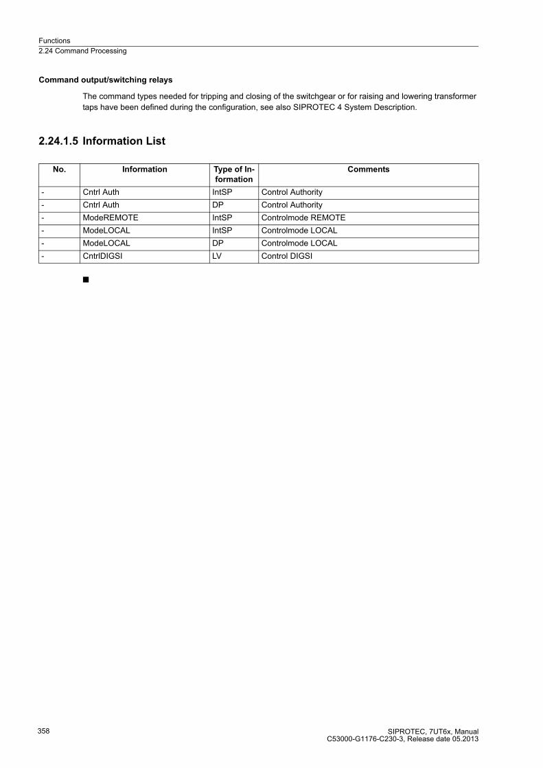
Functions
2.24 Command Processing
SIPROTEC, 7UT6x, ManualC53000-G1176-C230-3, Release date 05.2013
358
Command output/switching relays
The command types needed for tripping and closing of the switchgear or for raising and lowering transformer
taps have been defined during the configuration, see also SIPROTEC 4 System Description.
2.24.1.5 Information List
■
No. Information Type of In-
formation
Comments
- Cntrl Auth IntSP Control Authority
- Cntrl Auth DP Control Authority
- ModeREMOTE IntSP Controlmode REMOTE
- ModeLOCAL IntSP Controlmode LOCAL
- ModeLOCAL DP Controlmode LOCAL
- CntrlDIGSI LV Control DIGSI
SIPROTEC, 7UT6x, ManualC53000-G1176-C230-3, Release date 05.2013
359
Mounting and Commissioning 3
This chapter is primarily intended for experienced commissioning engineers. The commissioning engineer
must be familiar with the commissioning of protection and control systems, with the management of power
systems and with the relevant safety rules and guidelines. Under certain circumstances adaptations of the
hardware to the particular power system data may be necessary. The primary tests require the protected object
(line, transformer etc.) to carry load.
3.1 Mounting and Connections 360
3.2 Checking Connections 404
3.3 Commissioning 410
3.4 Final Preparation of the Device 453
Mounting and Commissioning
3.1 Mounting and Connections
SIPROTEC, 7UT6x, ManualC53000-G1176-C230-3, Release date 05.2013
360
3.1 Mounting and Connections
General
WARNING!
Warning of improper transport, storage, installation, and application of the device.
Non-observance can result in death, personal injury or substantial property damage.
Trouble free and safe use of this device depends on proper transport, storage, installation, and application of
the device according to the warnings in this instruction manual.
Of particular importance are the general installation and safety regulations for work in a high-voltage environ-
ment (for example, VDE, IEC, EN, DIN, or other national and international regulations). These regulations must
be observed.
3.1.1 Configuration Information
Prerequisites
For installation and connections the following conditions must be met:
The rated device data has been tested as recommended in the SIPROTEC 4 System Description and their
compliance with the Power System Data is verified.
Connection Variants
General diagrams are shown in the Appendix A.2. Connection examples for current and voltage transformer
circuits are provided in Appendix A.3. It must be checked that the settings for configuration (Subsection 2.1.3)
and the Power System Data (Subsection 2.1.4) match the connections to the device.
Protected Object
The setting of the protected object (address 105) must correspond to the object to be protected. An incorrect
setting may cause unforeseeable reactions by the device.
Please note that for auto-transformers PROT. OBJECT = autotransf. and not 3-phase transf. must be set.
For single-phase transformer , the centre phase L2 is not used.
Currents
Connection of the CT currents depends on the mode of application.
With three-phase connection the three phase currents are assigned to the measuring locations. Connection
examples for the various protected objects are provided in the Appendix A.3. Please refer also to the Appendix
A.2 for the general diagrams that apply to this device. Check that the measuring locations are correctly
assigned to the sides of the protected object and to the measuring inputs on the device.
With two-phase connection of a single-phase transformer the centre phase (IL2) will not be used. Appendix A.3
shows connection examples. Even if there is only one current transformer, both phases (IL1 and IL3) will be
used. Also observe the General Diagrams in annex A.2 that apply to the current device.
With single-phase busbar protection the measuring inputs are each assigned to one busbar feeder. Appendix
A.3 illustrates an example for one phase. The other phases are to be connected accordingly. Also observe the
General Diagrams in annex A.2 that apply to the current device.
Mounting and Commissioning
3.1 Mounting and Connections
SIPROTEC, 7UT6x, ManualC53000-G1176-C230-3, Release date 05.2013
361
For the CT connection, please observe that the rated output current of the summation transformers is usually
100 mA. The measuring inputs of the device have to be matched accordingly. Consider also that in 7UT612
only 7, in 7UT613 and 7UT633 only 9 of the current inputs can be changed to 0.1 A rated input, and in 7UT635
12 current inputs. Pay attention to the assignment of the different feeder currents to the current inputs of the
device.
The assignment of the 1-phase current inputs must be checked. Connections also differ according to the
application the device is used for. The Appendix A.3 offers some connection examples. Please refer also to
Appendix A.2 for the general diagrams that apply to this device. Pay attention to the assignment of the different
1-phase measuring locations to the 1-phase measuring inputs of the device. For more details, refer to
subsection 2.1.4.
Also check the rated data and the matching factors of the current transformers.
The allocation of the protection functions to the sides must be consistent. This applies particularly to the circuit
breaker failure protection whose measuring point (side) must correspond with the side of the circuit breaker to
be monitored.
Voltages
Voltage measurement is only possible in the appropriate variants of the versions 7UT613 and 7UT633. This
paragraph only applies when measured-circuit voltage is connected to the device and this has been stated in
the configuration according to 2.1.4, margin heading „Assignment of Voltage Measuring Inputs“.
In the Appendix A.3 you will find possible examples of the voltage transformer connection options.
The voltage transformer connections must comply with the settings in paragraph 2.1.4 (margin heading
„Assignment of Voltage Measuring Inputs“). Pay attention to the type of connection of the 4th voltage input U4
if it is used.
Binary Inputs and Outputs
The connections to the power plant depend on the possible allocation of the binary inputs and outputs, i.e. how
they are assigned to the power equipment. The preset allocation can be found in the tables in Section A.5 of
the Appendix. Check also whether the labelling corresponds to the allocated indication functions.
Here it is also very important that the feedback (auxiliary contacts) used for the breaker failure protection of the
circuit-breaker to be monitored, are connected to the correct binary inputs which correspond to the assigned
side of the circuit breaker failure protection and the cold load pickup. Similar applies for the manual close
recognition of the time overcurrent protection functions.
Changing Setting Groups
If the setting group change-over function is done via binary inputs, please observe the following:
To enable the control of 4 possible setting groups, 2 binary inputs must be made available. These have been
marked with „>Set Group Selec.1“ and „Set Group Selec.2“ and must be allocated to 2 physical binary inputs so
that they can be controlled.
One binary input is sufficient to control 2 setting groups, namely „>Set Group Selec.1“, since the non-allocated
binary input „Set Group Selec.2“ is then considered as not activated.
The control signals must be continuously present in order that the selected setting group remains active.
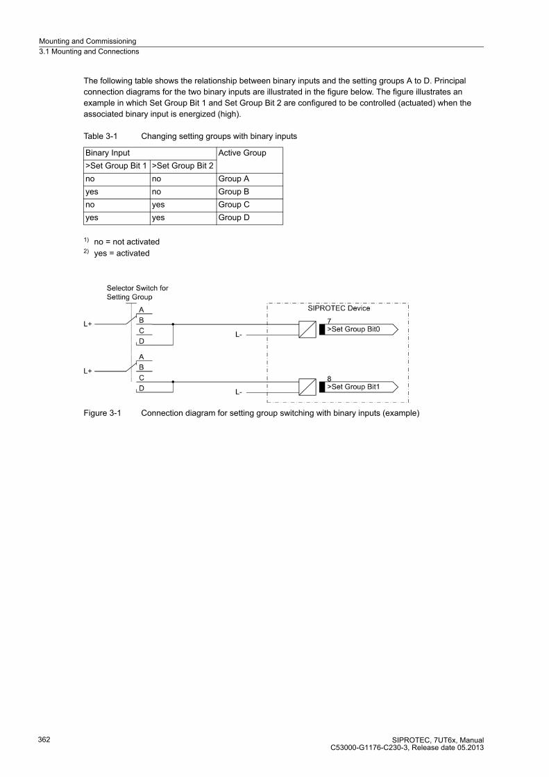
Mounting and Commissioning
3.1 Mounting and Connections
SIPROTEC, 7UT6x, ManualC53000-G1176-C230-3, Release date 05.2013
362
The following table shows the relationship between binary inputs and the setting groups A to D. Principal
connection diagrams for the two binary inputs are illustrated in the figure below. The figure illustrates an
example in which Set Group Bit 1 and Set Group Bit 2 are configured to be controlled (actuated) when the
associated binary input is energized (high).
Table 3-1 Changing setting groups with binary inputs
1) no = not activated2) yes = activated
Figure 3-1 Connection diagram for setting group switching with binary inputs (example)
Binary Input Active Group
>Set Group Bit 1 >Set Group Bit 2
no no Group A
yes no Group B
no yes Group C
yes yes Group D
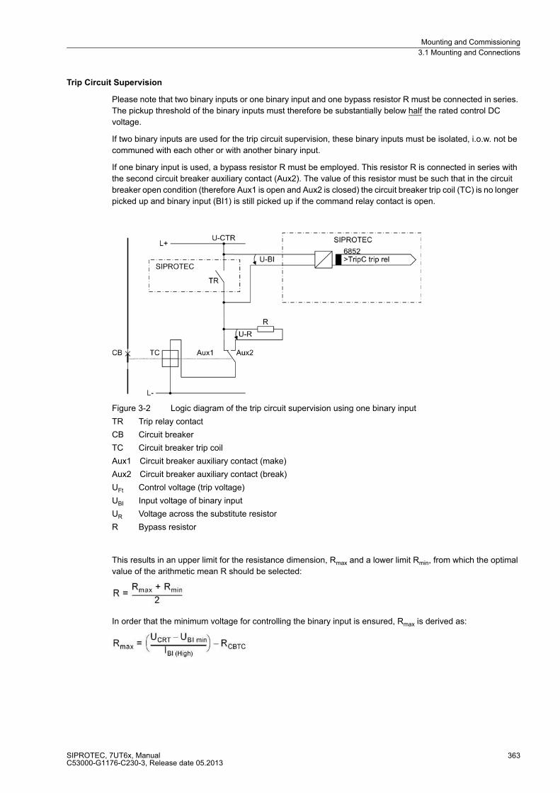
Mounting and Commissioning
3.1 Mounting and Connections
SIPROTEC, 7UT6x, ManualC53000-G1176-C230-3, Release date 05.2013
363
Trip Circuit Supervision
Please note that two binary inputs or one binary input and one bypass resistor R must be connected in series.
The pickup threshold of the binary inputs must therefore be substantially below half the rated control DC
voltage.
If two binary inputs are used for the trip circuit supervision, these binary inputs must be isolated, i.o.w. not be
communed with each other or with another binary input.
If one binary input is used, a bypass resistor R must be employed. This resistor R is connected in series with
the second circuit breaker auxiliary contact (Aux2). The value of this resistor must be such that in the circuit
breaker open condition (therefore Aux1 is open and Aux2 is closed) the circuit breaker trip coil (TC) is no longer
picked up and binary input (BI1) is still picked up if the command relay contact is open.
Figure 3-2 Logic diagram of the trip circuit supervision using one binary input
TR Trip relay contact
CB Circuit breaker
TC Circuit breaker trip coil
Aux1 Circuit breaker auxiliary contact (make)
Aux2 Circuit breaker auxiliary contact (break)
UFt Control voltage (trip voltage)
UBI Input voltage of binary input
UR Voltage across the substitute resistor
R Bypass resistor
This results in an upper limit for the resistance dimension, Rmax and a lower limit Rmin, from which the optimal
value of the arithmetic mean R should be selected:
In order that the minimum voltage for controlling the binary input is ensured, Rmax is derived as:
Mounting and Commissioning
3.1 Mounting and Connections
SIPROTEC, 7UT6x, ManualC53000-G1176-C230-3, Release date 05.2013
364
So the circuit breaker trip coil does not remain energized in the above case, Rmin is derived as:
IBI (HIGH) Constant Current with BI on (= 1.7 mA)
UBI min Minimum control voltage for BI (= 19 V for delivery setting for nominal voltage of 24/48/60 V;
88 V for delivery setting for nominal voltage of 110/125/220/250 V)
UCTR Control voltage for trip circuit
RCBTC DC resistance of circuit breaker trip coil
UCBTC (LOW) maximum voltage on the circuit breaker trip coil that does not lead to tripping
If the calculation results in Rmax < Rmin, then the calculation must be repeated with the next lower switching
threshold UBI min, and this threshold must be implemented in the relay using plug-in jumpers.
For the power consumption of the resistor the following applies:
Example
IBI (HIGH) 1.7 mA (SIPROTEC 4 device 7UT6x)
UBI min 19 V for delivery setting for nominal voltages of 24/48/60 V (SIPROTEC 4 device 7UT6x)
88 V for delivery setting for nominal voltages of 110/125/220/250 V ( SIPROTEC 4 device
7UT6x)
UCTR 110 V (from system / trip circuit)
RTC 500 Ω (system / trip circuit)
UCBTC (LOW) 2 V (from system / trip circuit)
Rmax = 53 kΩ
Rmin = 27 kΩ
The closest standard value of 39 kΩ is selected; the power is:
PR ≥ 0.3 W

Mounting and Commissioning
3.1 Mounting and Connections
SIPROTEC, 7UT6x, ManualC53000-G1176-C230-3, Release date 05.2013
365
RTD-Box
If the overload protection operates with processing of the coolant temperature (overload protection with hot-
spot calculation), one or two RTD boxes 7XV5662-xAD can be connected to the serial service interface at
port C.
3.1.2 Hardware Modifications
3.1.2.1 General
Hardware modifications concerning, for instance, nominal currents, the control voltage for binary inputs or
termination of serial interfaces might be necessary. Follow the procedure described in this subsection,
whenever hardware modifications are done.
Auxiliary Voltage
There are different input ranges for the power supply voltage (refer to the data ordering information in the
Appendix). The power supplies with the ratings DC 60/110/125 V and DC 110/125/220/250 V / AC 115/230 V
are interconvertible. Jumper settings determine the rating. The assignment of these jumpers to the supply volt-
ages and their physical location on the PCB are described below under „CPU Processor Board“. When the
device is delivered, these jumpers are set according to the name-plate sticker and generally need not be al-
tered.
Rated Currents
When the device is delivered from the factory, the binary inputs are set to operate with a voltage that corre-
sponds to the rated DC voltage of the power supply. In general, to optimize the operation of the inputs, the pick-
up voltage of the inputs should be set to most closely match the actual control voltage being used.
If the current transformer sets at the measuring locations and/or the 1-phase measurement inputs have differ-
ent secondary rated currents, this must be adapted in the device. The same applies for the current transformers
of the various busbar feeders when single-phase busbar protection is applied. Using single-phase busbar
protection with interposing summation transformers, the rated currents are usually 100 mA.
The assignment of the jumpers to the current rating and their physical arrangement on the PCB are described
below under margin heading „Input/Output Board A-I/O-3 (only 7UT612)“, „Input/Output Board C-I/O-2“,
„Input/Output Board C–I/O-9 (all versions)“ and „ Input/Output Board C–I/O-9 (only 7UT635)“.
Mounting and Commissioning
3.1 Mounting and Connections
SIPROTEC, 7UT6x, ManualC53000-G1176-C230-3, Release date 05.2013
366
When performing changes, please make sure that the device is always informed about them:
� Using three-phase applications and single-phase transformers, check the current transformer data for the
three-phase measuring locations, see Section 2.1.4 under margin heading „Current Transformer Data for
Three-phase Measuring Locations“.
� Using three-phase applications and single-phase transformers, check the current transformer data for the
auxiliary single-phase measuring locations, see Section 2.1.4 under margin heading „Current Transformer
Data for Auxiliary Single-phase Measuring Locations“.
� In case of changes regarding the sensitive 1-phase auxiliary inputs, check the CT ratios - refer to the para-
graph 2.1.4 under margin heading „Current Transformer Data for Single-phase Auxiliary Inputs“.
� Using single-phase busbar protection, changes for the different measuring locations must correspond to the
associated current transformer data (refer to subsection 2.1.4 under margin heading „Current Transformer
Data for Single-Phase Busbar Protection“.
Control Voltage for Binary Inputs
Jumper settings determine the rating of the current input transducers of the device. The position of jumpers are
set according to the name-plate sticker to 1 A or 5 A.
A jumper position is changed to adjust the pick-up voltage of a binary input. The assignment of the jumpers to
the binary inputs and their physical arrangement on the PCB are described below under margin headings
„Processor Board A-CPU (only 7UT612)“, „Input/Output Board C-CPU-2“ and „Input/Output Board(s) C-I/O-1
and C-I/O-10“.
Note
If binary inputs are used for trip circuit monitoring, please note that two binary inputs (or a binary input and an
equivalent resistance) are connected in series. The switching threshold must lie clearly below half the nominal
control voltage.
Contact Mode for Binary Outputs
Some input/output modules can have relays which can be set to have either NO or NC contacts. To do so a
jumper location must be changed. For which relays on which boards this is valid can be found in the following
sections under „Switching Elements on Printed Circuit Boards“.
Replacing Interface Modules
The serial interface modules can be replaced. For details please refer to the section „Interface Modules“.
Terminating Serial Interfaces
If the device is equipped with a serial RS485 port, the RS485 bus must be terminated with resistors at the last
device on the bus to ensure reliable data transmission. For this purpose, terminating resistors are provided on
the interface board and on the interface modules, which can be connected with jumpers. The physical arrange-
ment and jumper positions on the interface module are described below under margin heading „RS485 Inter-
face“.
Spare parts
Spare parts may be the backup battery that maintains the data in the battery-buffered RAM when the voltage
supply fails, and the miniature fuse of the internal power supply. Their physical location is shown in the illustra-
tion of the processor board.

Mounting and Commissioning
3.1 Mounting and Connections
SIPROTEC, 7UT6x, ManualC53000-G1176-C230-3, Release date 05.2013
367
The ratings of the fuse are printed on the board next to the fuse itself (also see table 3-5).
When exchanging the fuse, please observe the hints given in the SIPROTEC System Manual /1/ in the section
„Maintenance“.
3.1.2.2 Disassembly
Disassembly of the Device
Note
It is assumed for the following steps that the device is not operative.
Work on the Printed Circuit Boards
Caution!
Caution when changing jumper settings that affect nominal values of the device:
As a consequence, the ordering number (MLFB) and the ratings on the name plate no longer match the actual
device properties.
Where such changes are necessary in exceptional cases, they MUST be marked clearly and visibly on the
device. Self-adhesive stickers are available that can be used as supplementary name plate.
To perform work on the printed circuit boards, such as checking or moving switching elements or exchanging
modules, proceed as follows:
� Prepare your workplace: provide a suitable pad for electrostatically sensitive devices (ESD). Also the
following tools are required:
– screwdriver with a 5 to 6 mm wide tip,
– a crosstip screwdriver for Pz size 1,
– a 5 mm socket wrench.
� Remove the covers on the front panel and loosen the screws which can then be accessed.
� If the device has additional communication interfaces (to „A“ and „C“) at the locations „B“ and/or „D“ on the
rear, the screws located diagonally to the interfaces must be removed. This activity does not apply if the
device is for surface mounting.
� Unfasten the screw-posts of the D-subminiature connectors on the back panel at location „A“ and „C“. This
step is not necessary if the device is designed for surface mounting.
� Carefully take off the front cover.
Work on the Plug Connectors
Caution!
Mind electrostatic discharges:
Non-observance can result in minor personal injury or property damage.
In order to avoid electrostatic discharges when handling plug connectors, first touch an earthed metal surface.
Do not plug or unplug interface connectors under voltage!

Mounting and Commissioning
3.1 Mounting and Connections
SIPROTEC, 7UT6x, ManualC53000-G1176-C230-3, Release date 05.2013
368
The arrangement of the boards for the different housing sizes can be seen in the following figures.
When performing work on plug connectors, proceed as follows:
� Release the connector of the ribbon cable between A-CPU (only 7UT612)(1) or C–CPU-2 (1) processor
module and front cover. Press the top latch of the plug connector up and the bottom latch down so that the
plug connector of the ribbon cable is pressed out.
� Disconnect the ribbon cables between the processor module and the I/O boards (1 to 4, depending on the
variant ordered).
� Remove the boards and set them on the grounded mat to protect them from ESD damage. In the case of
the device variant for panel surface mounting, please be aware that a certain amount of force is required to
remove the A-CPU or C-CPU board because of the plug connector.
� Check the jumpers in accordance with the figures and information provided below, and as the case may be
change or remove them.
Board Arrangement 7UT612
Figure 3-3 Front view after removal of the front cover (simplified and scaled down)

Mounting and Commissioning
3.1 Mounting and Connections
SIPROTEC, 7UT6x, ManualC53000-G1176-C230-3, Release date 05.2013
369
Board Arrangement 7UT613/63x
Figure 3-4 Front view with housing size 1/2 after removal of the front panel (simplified and scaled down)
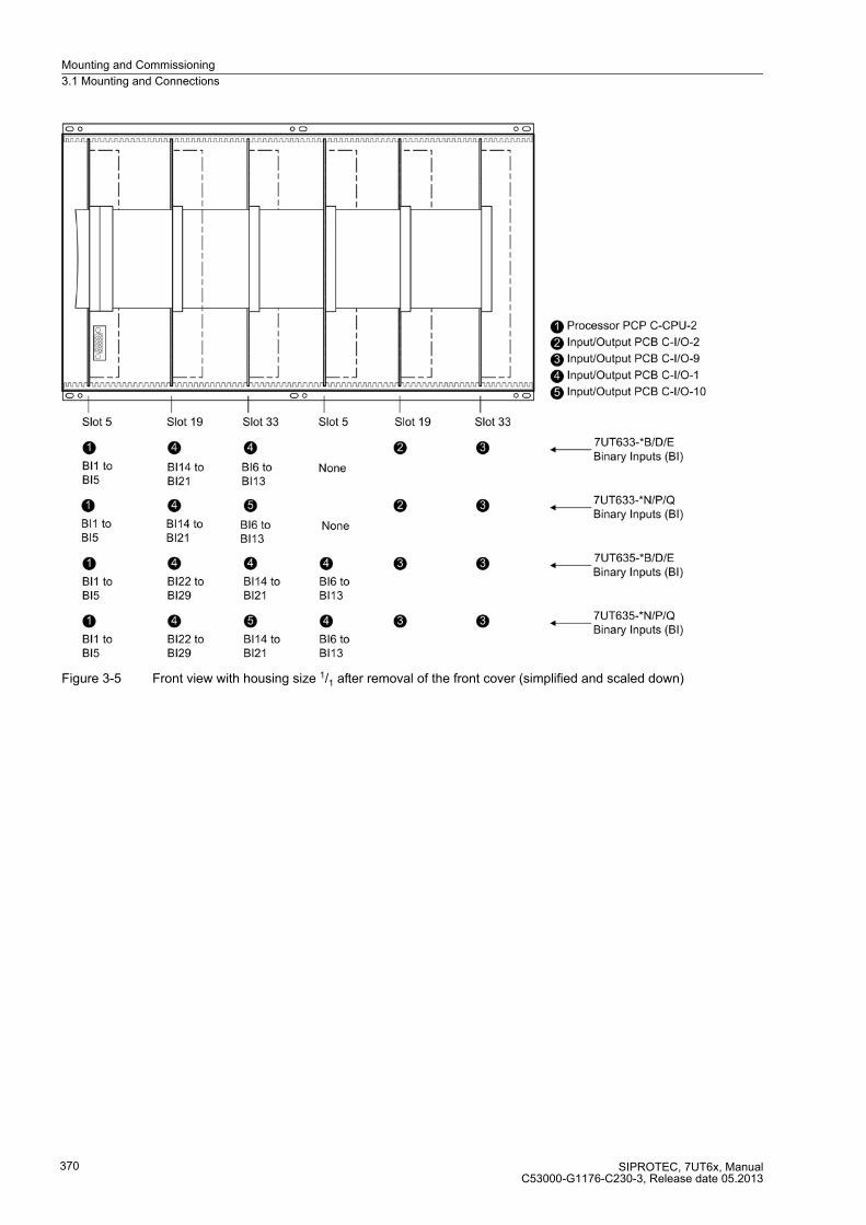
Mounting and Commissioning
3.1 Mounting and Connections
SIPROTEC, 7UT6x, ManualC53000-G1176-C230-3, Release date 05.2013
370
Figure 3-5 Front view with housing size 1/1 after removal of the front cover (simplified and scaled down)
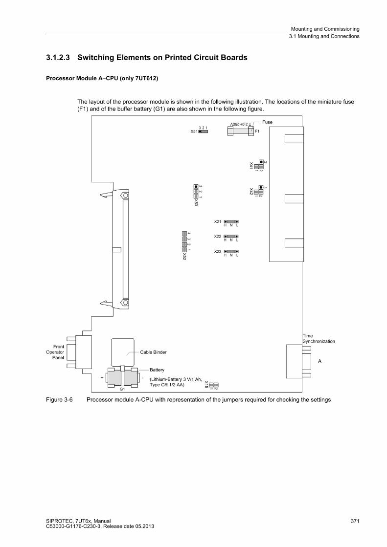
Mounting and Commissioning
3.1 Mounting and Connections
SIPROTEC, 7UT6x, ManualC53000-G1176-C230-3, Release date 05.2013
371
3.1.2.3 Switching Elements on Printed Circuit Boards
Processor Module A–CPU (only 7UT612)
The layout of the processor module is shown in the following illustration. The locations of the miniature fuse (F1) and of the buffer battery (G1) are also shown in the following figure.
Figure 3-6 Processor module A-CPU with representation of the jumpers required for checking the settings

Mounting and Commissioning
3.1 Mounting and Connections
SIPROTEC, 7UT6x, ManualC53000-G1176-C230-3, Release date 05.2013
372
Table 3-2 Jumper setting of the rated voltage of the integrated power supply on the A-CPU processor module
Table 3-3 Jumper setting of the pickup voltages of the binary inputs BI1 to BI3 on the A-CPU processor module
1) Factory settings for devices with rated power supply voltage DC 24 V to 125 V2) Factory settings for devices with rated power supply voltage DC 110 V to 220 V and AC 115 V to 230 V to
250 V3) Only for control voltage DC 200 V or DC 250 V
Table 3-4 Jumper settings for the contact mode of the binary inputs BI1 to BI3 on the processor module A–CPU
Jumper Rated voltage
DC 24 V to 48 V DC 60 V to 125 V DC 110 V to 250 V, AC115 V to 230 V
X51 not used 1-2 2-3
X52 not used 1-2 and 3-4 2-3
X53 not used 1-2 2-3
Binary input Jumper 19 V Pickup 1) 88 V Pickup 2) 176 V Pickup 3)
BI1 X21 1-2 2-3 3-4
BI2 X22 1-2 2-3 3-4
BI3 X23 1-2 2-3 3-4
For Jumper Quiescent State Open
(NO)
Quiescent State
Closed (NC)
Factory setting
BO1 X41 1-2 2-3 1-2
BO2 X42 1-2 2-3 1-2
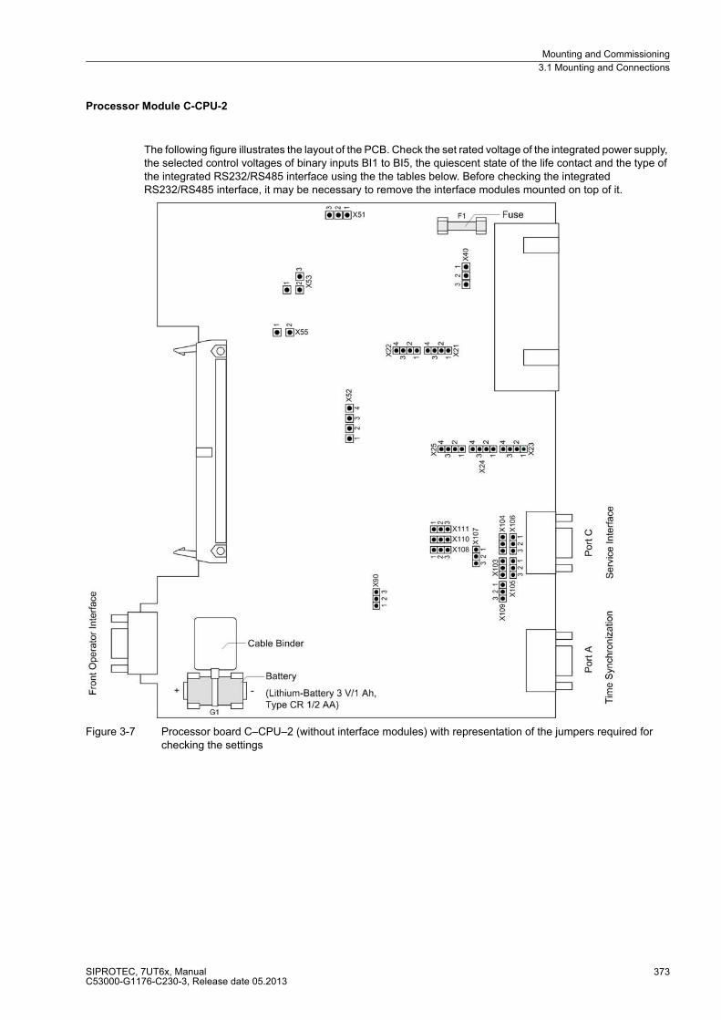
Mounting and Commissioning
3.1 Mounting and Connections
SIPROTEC, 7UT6x, ManualC53000-G1176-C230-3, Release date 05.2013
373
Processor Module C-CPU-2
The following figure illustrates the layout of the PCB. Check the set rated voltage of the integrated power supply, the selected control voltages of binary inputs BI1 to BI5, the quiescent state of the life contact and the type of the integrated RS232/RS485 interface using the the tables below. Before checking the integrated RS232/RS485 interface, it may be necessary to remove the interface modules mounted on top of it.
Figure 3-7 Processor board C–CPU–2 (without interface modules) with representation of the jumpers required for checking the settings
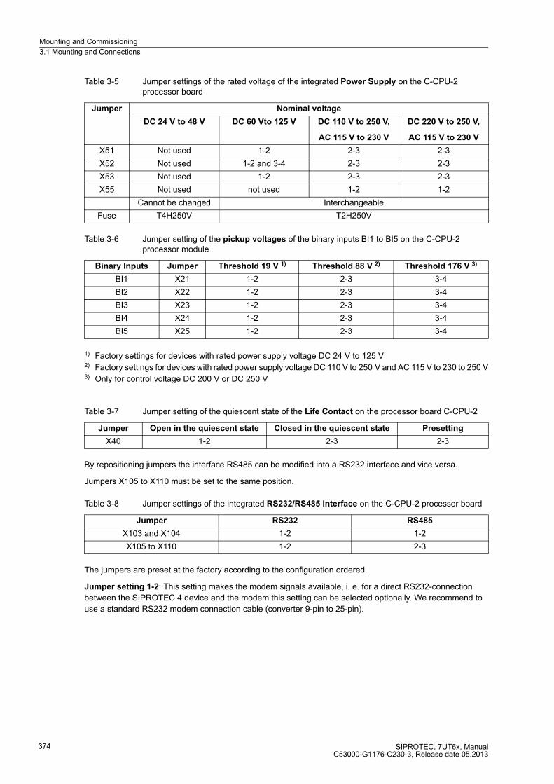
Mounting and Commissioning
3.1 Mounting and Connections
SIPROTEC, 7UT6x, ManualC53000-G1176-C230-3, Release date 05.2013
374
Table 3-5 Jumper settings of the rated voltage of the integrated Power Supply on the C-CPU-2 processor board
Table 3-6 Jumper setting of the pickup voltages of the binary inputs BI1 to BI5 on the C-CPU-2 processor module
1) Factory settings for devices with rated power supply voltage DC 24 V to 125 V2) Factory settings for devices with rated power supply voltage DC 110 V to 250 V and AC 115 V to 230 to 250 V3) Only for control voltage DC 200 V or DC 250 V
Table 3-7 Jumper setting of the quiescent state of the Life Contact on the processor board C-CPU-2
By repositioning jumpers the interface RS485 can be modified into a RS232 interface and vice versa.
Jumpers X105 to X110 must be set to the same position.
Table 3-8 Jumper settings of the integrated RS232/RS485 Interface on the C-CPU-2 processor board
The jumpers are preset at the factory according to the configuration ordered.
Jumper setting 1-2: This setting makes the modem signals available, i. e. for a direct RS232-connection
between the SIPROTEC 4 device and the modem this setting can be selected optionally. We recommend to
use a standard RS232 modem connection cable (converter 9-pin to 25-pin).
Jumper Nominal voltage
DC 24 V to 48 V DC 60 Vto 125 V DC 110 V to 250 V,
AC 115 V to 230 V
DC 220 V to 250 V,
AC 115 V to 230 V
X51 Not used 1-2 2-3 2-3
X52 Not used 1-2 and 3-4 2-3 2-3
X53 Not used 1-2 2-3 2-3
X55 Not used not used 1-2 1-2
Cannot be changed Interchangeable
Fuse T4H250V T2H250V
Binary Inputs Jumper Threshold 19 V 1) Threshold 88 V 2) Threshold 176 V 3)
BI1 X21 1-2 2-3 3-4
BI2 X22 1-2 2-3 3-4
BI3 X23 1-2 2-3 3-4
BI4 X24 1-2 2-3 3-4
BI5 X25 1-2 2-3 3-4
Jumper Open in the quiescent state Closed in the quiescent state Presetting
X40 1-2 2-3 2-3
Jumper RS232 RS485
X103 and X104 1-2 1-2
X105 to X110 1-2 2-3

Mounting and Commissioning
3.1 Mounting and Connections
SIPROTEC, 7UT6x, ManualC53000-G1176-C230-3, Release date 05.2013
375
Table 3-9 Jumper setting for CTS (Clear To Send, flow control) on the C-CPU-2 processor board
1) Delivery state
With interface RS232 jumper X111 is needed to activate CTS which enables the communication with the
modem.
Jumper setting 2-3: The connection to the modem is usually established with a star coupler or fibre-optic
converter. Therefore the modem control signals according to RS232 standard DIN 66020 are not available.
Modem signals are not required since the connection to the SIPROTEC 4 devices is always operated in the
half-duplex mode. Please use the connection cable with order number 7XV5100-4.
Note
For a direct connection to DIGSI with interface RS232 jumper X111 must be plugged in position 2-3.
If there are no external terminating resistors in the system, the last devices on a RS485 bus must be configured
via jumpers X103 and X104.
Table 3-10 Jumper settings of the Terminating Resistors of the RS485 interface on the C-CPU-2 processor board
Note: Both jumpers must always be plugged in the same way!
When the device is delivered from the factory, the terminating resistors are disconnected (jumper setting 1-2).
The terminating resistors can also be connected externally (e.g. to the connection module as illustrated in
Figure 3-19). In that case the terminating resistors provided on the C-CPU-2 processor board must be switched
off.
Jumper X90 has no function. The factory setting is 1-2.
Jumper /CTS from interface RS232 /CTS triggered by /RTS
X111 1–2 2-3 1)
Jumper Terminating Resistor
enabled
Terminating resistor
disabled
Presetting
X103 2-3 1-2 1-2
X104 2-3 1-2 1-2

Mounting and Commissioning
3.1 Mounting and Connections
SIPROTEC, 7UT6x, ManualC53000-G1176-C230-3, Release date 05.2013
376
Input/Output Board A-I/O-3 (only 7UT612)
The rated current settings of the input current transformers are checked on the A–I/O–3 module.
Figure 3-8 Input/output module A–I/O-3 with representation of the jumper settings required for the module configuration
With default settings, all jumpers (X61 bis X70) are set to the same rated current (according to the order number
of the device). However, rated currents can be changed for each individual input transformer.
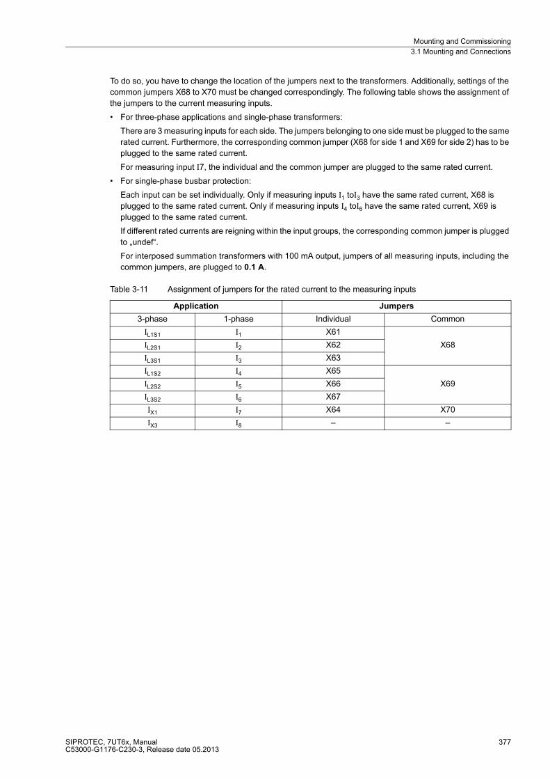
Mounting and Commissioning
3.1 Mounting and Connections
SIPROTEC, 7UT6x, ManualC53000-G1176-C230-3, Release date 05.2013
377
To do so, you have to change the location of the jumpers next to the transformers. Additionally, settings of the
common jumpers X68 to X70 must be changed correspondingly. The following table shows the assignment of
the jumpers to the current measuring inputs.
� For three-phase applications and single-phase transformers:
There are 3 measuring inputs for each side. The jumpers belonging to one side must be plugged to the same
rated current. Furthermore, the corresponding common jumper (X68 for side 1 and X69 for side 2) has to be
plugged to the same rated current.
For measuring input I7, the individual and the common jumper are plugged to the same rated current.
� For single-phase busbar protection:
Each input can be set individually. Only if measuring inputs I1 toI3 have the same rated current, X68 is
plugged to the same rated current. Only if measuring inputs I4 toI6 have the same rated current, X69 is
plugged to the same rated current.
If different rated currents are reigning within the input groups, the corresponding common jumper is plugged
to „undef“.
For interposed summation transformers with 100 mA output, jumpers of all measuring inputs, including the
common jumpers, are plugged to 0.1 A.
Table 3-11 Assignment of jumpers for the rated current to the measuring inputs
Application Jumpers
3-phase 1-phase Individual Common
IL1S1 I1 X61
X68IL2S1 I2 X62
IL3S1 I3 X63
IL1S2 I4 X65
X69IL2S2 I5 X66
IL3S2 I6 X67
IX1 I7 X64 X70
IX3 I8 – –

Mounting and Commissioning
3.1 Mounting and Connections
SIPROTEC, 7UT6x, ManualC53000-G1176-C230-3, Release date 05.2013
378
Input/Output Board(s) C-I/O-1 and C-I/O-10 (only 7UT633 and 7UT635)
The PCB layout for the C-I/O-1 input/output board is shown in Figure 3-9 and the input/output group C-I/O-10
as from release 7UT6../EE in Figure 3-10.
The input/output board C-I/O-1 is only available in the versions 7UT633 and 7UT635.
Figure 3-9 C-I/O-1 input/output boards with representation of jumper settings required for checking configuration settings
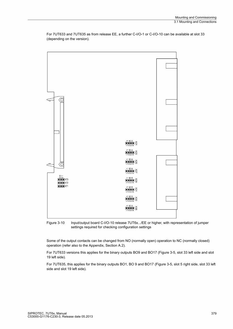
Mounting and Commissioning
3.1 Mounting and Connections
SIPROTEC, 7UT6x, ManualC53000-G1176-C230-3, Release date 05.2013
379
For 7UT633 and 7UT635 as from release EE, a further C-I/O-1 or C-I/O-10 can be available at slot 33
(depending on the version).
Figure 3-10 Input/output board C-I/O-10 release 7UT6x.../EE or higher, with representation of jumper settings required for checking configuration settings
Some of the output contacts can be changed from NO (normally open) operation to NC (normally closed)
operation (refer also to the Appendix, Section A.2).
For 7UT633 versions this applies for the binary outputs BO9 and BO17 (Figure 3-5, slot 33 left side and slot
19 left side).
For 7UT635, this applies for the binary outputs BO1, BO 9 and BO17 (Figure 3-5, slot 5 right side, slot 33 left
side and slot 19 left side).
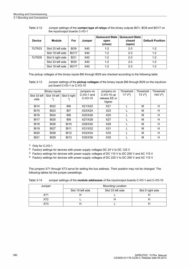
Mounting and Commissioning
3.1 Mounting and Connections
SIPROTEC, 7UT6x, ManualC53000-G1176-C230-3, Release date 05.2013
380
Table 3-12 Jumper settings of the contact type of relays of the binary outputs BO1, BO9 and BO17 on the input/output boards C-I/O-1
The pickup voltages of the binary inputs BI6 through BI29 are checked according to the following table
Table 3-13 Jumper settings of the pickup voltages of the binary inputs BI6 through BI29 on the input/out-put board C-I/O-1 or C-I/O-10
1) Only for C-I/O-12) Factory settings for devices with power supply voltages DC 24 V to DC 125 V3) Factory settings for devices with power supply voltages of DC 110 V to DC 250 V and AC 115 V4) Factory settings for devices with power supply voltages of DC 220 V to DC 250 V and AC 115 V
The jumpers X71 through X73 serve for setting the bus address. Their position may not be changed. The
following tables list the jumper presettings.
Table 3-14 Jumper settings of the module addresses of the input/output boards C-I/O-1 and C-I/O-10
Device Module For Jumper
Quiescent State
open
(close)
Quiescent State
closed
(open)
Default Position
7UT633 Slot 33 left side BO9 X40 1-2 2-3 1-2
Slot 19 left side BO17 X40 1-2 2-3 1-2
7UT635 Slot 5 right side BO1 X40 1-2 2-3 1-2
Slot 33 left side BO9 X40 1-2 2-3 1-2
Slot 19 left side BO17 X40 1-2 2-3 1-2
Binary inputs Jumpers on C-I/O-1 and
C-I/O-10
Jumpers on C-I/O-10 up
release EE or higher
Threshold 17 V2)
Threshold 73 V3)
Threshold 154 V4)Slot 33 left
sideSlot 19 left
1)Slot 5 right
1)
BI14 BI22 BI6 X21/X22 X21 L M H
BI15 BI23 BI7 X23/X24 X23 L M H
BI16 BI24 BI8 X25/X26 X25 L M H
BI17 BI25 BI9 X27/X28 X27 L M H
BI18 BI26 BI10 X29/X30 X29 L M H
BI19 BI27 BI11 X31/X32 X31 L M H
BI20 BI28 BI12 X33/X34 X33 L M H
BI21 BI29 BI13 X35/X36 X35 L M H
Jumper Mounting Location
Slot 19 left side Slot 33 left side Slot 5 right side
X71 H L H
X72 L H H
X73 H L H

Mounting and Commissioning
3.1 Mounting and Connections
SIPROTEC, 7UT6x, ManualC53000-G1176-C230-3, Release date 05.2013
381
Input/Output Board C-I/O-2 (only 7UT613 and 7UT633)
The input/output board C-I/O-2 is available only in 7UT613 and 7UT633. Mounting location: for 7UT613 slot 19,
for 7UT633 slot 19 right side
Figure 3-11 C-I/O-2 input/output board release 7UT6x .../EE or higher, with representation of jumper settings required for checking configuration settings
The relay contacts of the binary outputs BO6 to BO8 can be changed from NO (normally open) to NC (normally
closed) operation (refer also to Appendix A.2).

Mounting and Commissioning
3.1 Mounting and Connections
SIPROTEC, 7UT6x, ManualC53000-G1176-C230-3, Release date 05.2013
382
Table 3-15 Jumper setting for the contact type of the relay for BO6 to BO8
1) Delivery state
The relay contacts for binary outputs BO1 through BO5 can be connected to common potential, or configured
individually for BO1, BO4 and BO5 (BO2 and BO3 are without function in this context) (see also General
Diagrams in the Appendix A.2).
Table 3-16 Jumper settings for the configuration of the common potential of BO1 through BO5 or for configuration of BO1, BO4 and BO5 as single relays
1) Delivery state
Jumpers X71 through X73 on the input/output board C-I/O-2 serve for setting the bus address. Their position
may not be changed. The following table shows the preset jumper positions.
Table 3-17 Jumper Position of the Module Addresses of the input/output board C-I/O-2
The rated currents of the measured current inputs can be determined for each analogue input via jumpers.
With default settings all jumpers are set to the same rated current (according to the order number of the device).
for Jumper Quiescent state open(close) 1)
Quiescent state closed (open)
BO6 X41 1-2 2-3
BO7 X42 1-2 2-3
BO8 X43 1-2 2-3
Jumper BO1 to BO5connected to common potential 1)
BO1, BO4, BO5 configured as single relays (BO2 and BO3 without function)
X80 1-2, 3-4 2-3, 4-5
X81 1-2, 3-4 2-3, 4-5
X82 2-3 1-2
Jumper Presetting
X71 1-2 (H)
X72 1-2 (H)
X73 2-3 (L)

Mounting and Commissioning
3.1 Mounting and Connections
SIPROTEC, 7UT6x, ManualC53000-G1176-C230-3, Release date 05.2013
383
The input/output board C-I/O-2 carries the following measured current inputs:
� For 3-phase applications and 1-phase transformers:
There are 3 measuring inputs for the three-phase measuring location M3. IL1M3, IL2M3, IL3M3. The jumpers
X61, X62, X63 belonging to this measuring location must be plugged all to the rated secondary current of
the connected current transformers: „1A “or „5A“. Furthermore, the corresponding common jumpers (X51
and X60) have to be plugged to the same rated current.
� For 1-phase busbar protection:
There are 3 measuring inputs for 3 different measuring locations, i.e. the feeders 7 to 9: I7, I8, I9. Each input
can be set individually (X61, X62, X63) to „1A“, „5A“ or „0.1A“. Only if the measuring inputs I7 to I9 have the
same rated current, the common jumpers X60 are plugged to this rated current.
If different rated currents (X51 and X60) are reigning within the input group, the position of the common
jumpers (X51 and X60) is irrelevant.
� For the additional single-phase measuring input IX2:
Jumper X64 is set to the required rated current for this 1-phase current input: „1A“ or „5A“.
Table 3-18 Jumper setting for nominal current or measuring range
Jumper Nominal current 0.1 A
Measuring range 10 A
Nominal current 1 A
Measuring range 100 A
Nominal current 5 A
Measuring range 500 A
X51 2-3 1-2 1-2
X60 1-2 1-2 2-3
X61 1-5 3-5 4-5
X62 1-5 3-5 4-5
X63 1-5 3-5 4-5
X64 1-5 3-5 4-5
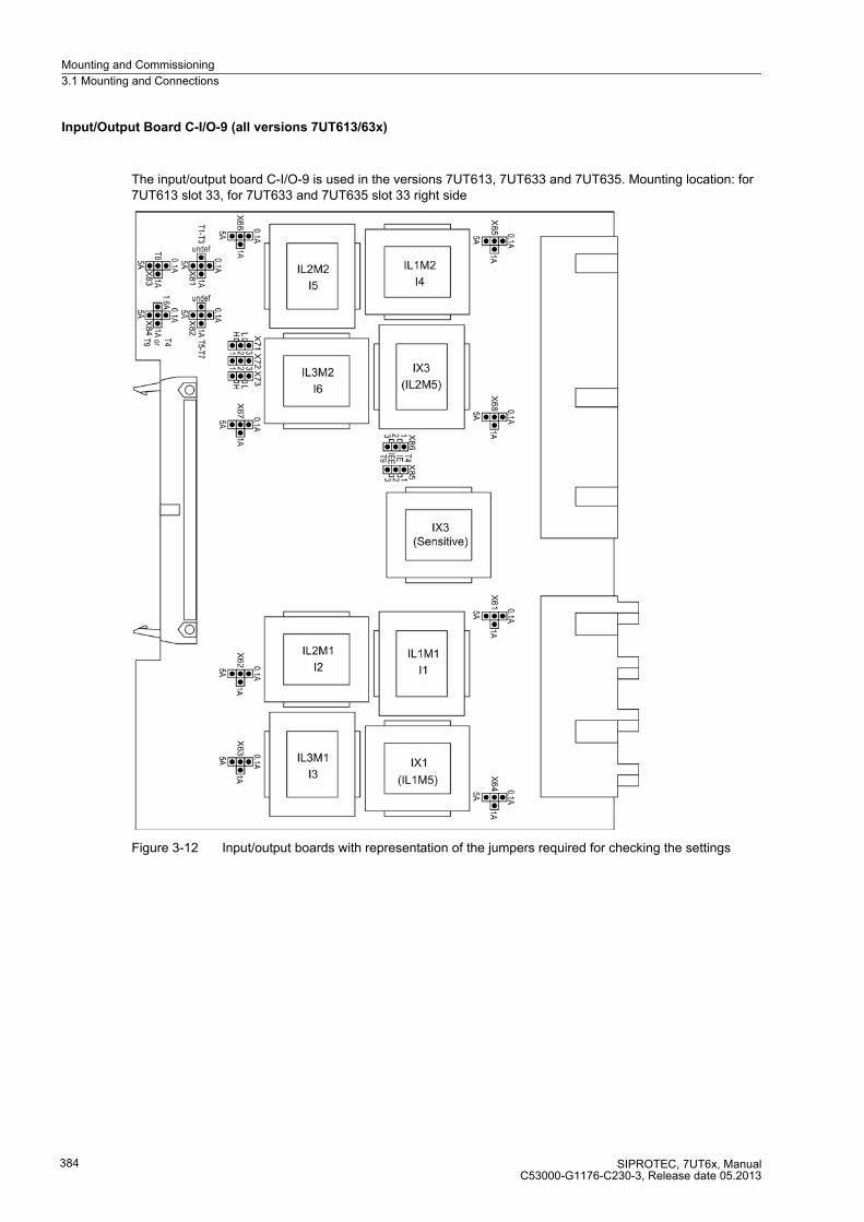
Mounting and Commissioning
3.1 Mounting and Connections
SIPROTEC, 7UT6x, ManualC53000-G1176-C230-3, Release date 05.2013
384
Input/Output Board C-I/O-9 (all versions 7UT613/63x)
The input/output board C-I/O-9 is used in the versions 7UT613, 7UT633 and 7UT635. Mounting location: for 7UT613 slot 33, for 7UT633 and 7UT635 slot 33 right side
Figure 3-12 Input/output boards with representation of the jumpers required for checking the settings
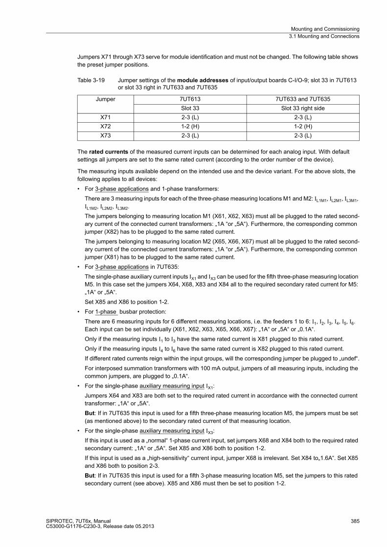
Mounting and Commissioning
3.1 Mounting and Connections
SIPROTEC, 7UT6x, ManualC53000-G1176-C230-3, Release date 05.2013
385
Jumpers X71 through X73 serve for module identification and must not be changed. The following table shows
the preset jumper positions.
Table 3-19 Jumper settings of the module addresses of input/output boards C-I/O-9; slot 33 in 7UT613 or slot 33 right in 7UT633 and 7UT635
The rated currents of the measured current inputs can be determined for each analog input. With default
settings all jumpers are set to the same rated current (according to the order number of the device).
The measuring inputs available depend on the intended use and the device variant. For the above slots, the
following applies to all devices:
� For 3-phase applications and 1-phase transformers:
There are 3 measuring inputs for each of the three-phase measuring locations M1 and M2: IL1M1, IL2M1, IL3M1,
IL1M2, IL2M2, IL3M2.
The jumpers belonging to measuring location M1 (X61, X62, X63) must all be plugged to the rated second-
ary current of the connected current transformers: „1A “or „5A“). Furthermore, the corresponding common
jumper (X82) has to be plugged to the same rated current.
The jumpers belonging to measuring location M2 (X65, X66, X67) must all be plugged to the rated second-
ary current of the connected current transformers: „1A “or „5A“). Furthermore, the corresponding common
jumper (X81) has to be plugged to the same rated current.
� For 3-phase applications in 7UT635:
The single-phase auxiliary current inputs IX1 and IX3 can be used for the fifth three-phase measuring location
M5. In this case set the jumpers X64, X68, X83 and X84 all to the required secondary rated current for M5:
„1A“ or „5A“.
Set X85 and X86 to position 1-2.
� For 1-phase busbar protection:
There are 6 measuring inputs for 6 different measuring locations, i.e. the feeders 1 to 6: I1, I2, I3, I4, I5, I6.
Each input can be set individually (X61, X62, X63, X65, X66, X67): „1A“ or „5A“ or „0.1A“.
Only if the measuring inputs I1 to I3 have the same rated current is X81 plugged to this rated current.
Only if the measuring inputs I4 to I6 have the same rated current is X82 plugged to this rated current.
If different rated currents reign within the input groups, will the corresponding jumper be plugged to „undef“.
For interposed summation transformers with 100 mA output, jumpers of all measuring inputs, including the
common jumpers, are plugged to „0.1A“.
� For the single-phase auxiliary measuring input IX1:
Jumpers X64 and X83 are both set to the required rated current in accordance with the connected current
transformer: „1A“ or „5A“.
But: If in 7UT635 this input is used for a fifth three-phase measuring location M5, the jumpers must be set
(as mentioned above) to the secondary rated current of that measuring location.
� For the single-phase auxiliary measuring input IX3:
If this input is used as a „normal“ 1-phase current input, set jumpers X68 and X84 both to the required rated
secondary current: „1A“ or „5A“. Set X85 and X86 both to position 1-2.
If this input is used as a „high-sensitivity“ current input, jumper X68 is irrelevant. Set X84 to„1.6A“. Set X85
and X86 both to position 2-3.
But: If in 7UT635 this input is used for a fifth 3-phase measuring location M5, set the jumpers to this rated
secondary current (see above). X85 and X86 must then be set to position 1-2.
Jumper 7UT613 7UT633 and 7UT635
Slot 33 Slot 33 right side
X71 2-3 (L) 2-3 (L)
X72 1-2 (H) 1-2 (H)
X73 2-3 (L) 2-3 (L)

Mounting and Commissioning
3.1 Mounting and Connections
SIPROTEC, 7UT6x, ManualC53000-G1176-C230-3, Release date 05.2013
386
Table 3-20 gives a summary of the jumpers for the rated currents on C–I/O-9.
Table 3-20 Assignment of the jumpers for the rated currents to the measured current inputs
1) IN-01 in 7UT635 applicable for measuring location M5
Application Jumpers
3-phase 1-phase individual common
IL1M1 I1 X61
X82IL2M1 I2 X62
IL3M1 I3 X63
IL1M2 I4 X65
X81IL2M2 I5 X66
IL3M2 I6 X67
IX1 (IL1M5) 1) — X64 X83
IX1 (IL2M5) 1) — X68
X84/X85/X86IX3 (sensitive) — —
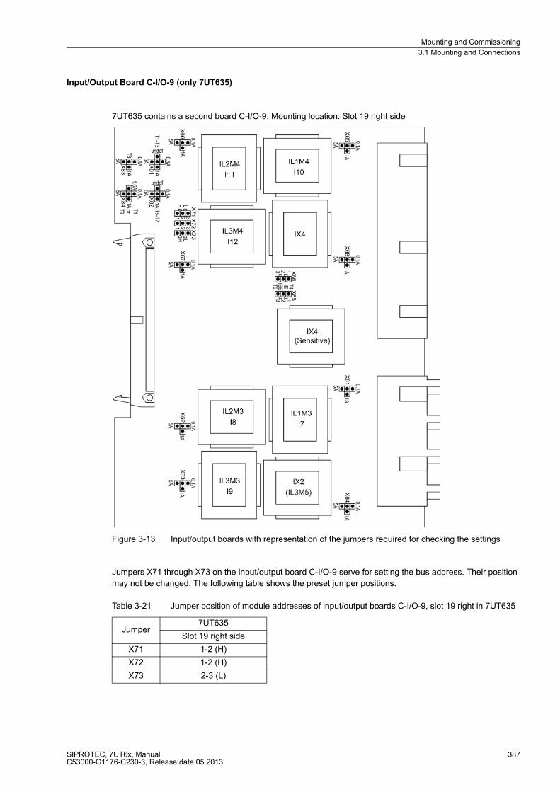
Mounting and Commissioning
3.1 Mounting and Connections
SIPROTEC, 7UT6x, ManualC53000-G1176-C230-3, Release date 05.2013
387
Input/Output Board C-I/O-9 (only 7UT635)
7UT635 contains a second board C-I/O-9. Mounting location: Slot 19 right side
Figure 3-13 Input/output boards with representation of the jumpers required for checking the settings
Jumpers X71 through X73 on the input/output board C-I/O-9 serve for setting the bus address. Their position
may not be changed. The following table shows the preset jumper positions.
Table 3-21 Jumper position of module addresses of input/output boards C-I/O-9, slot 19 right in 7UT635
Jumper7UT635
Slot 19 right side
X71 1-2 (H)
X72 1-2 (H)
X73 2-3 (L)

Mounting and Commissioning
3.1 Mounting and Connections
SIPROTEC, 7UT6x, ManualC53000-G1176-C230-3, Release date 05.2013
388
The rated currents of the measured voltage inputs can be set for each input transformer by jumpers on the
PCB. With default settings all jumpers are set to the same rated current (according to the order number of the
device).
� For 3-phase applications and 1-phase transformers:
There are 3 measuring inputs for each of the three-phase measuring locations M3 and M4: IL1M3, IL2M3, IL3M3,
IL1M4, IL2M4, IL3M4.
The jumpers belonging to measuring location M3 (X61, X62, X63) must all be plugged to the rated second-
ary current of the connected current transformers: „1A “or „5A“). Furthermore, the corresponding common
jumper (X82) has to be plugged to the same rated current.
The jumpers belonging to measuring location M4 (X65, X66, X67) must all be plugged to the rated
secondary current of the connected current transformers: „1A “or „5A“. Furthermore, the corresponding
common jumper (X81) has to be plugged to the same rated current.
� For 3-phase applications in 7UT635:
The auxiliary current input IX2 can be used for a fifth 3-phase measuring location M5. In this case set the
jumpers X64 and X83 both to the required rated secondary current for M5: „1A“ or „5A“.
� For 1-phase busbar protection:
There are 6 measuring inputs for 6 different measuring locations, i.e. the feeders 7 to 12: I7, I8, I9, I10, I11,
I12. Each input can be set individually to „1A“ or „5A“ or „0.1A“ (X61, X62, X63, X65, X66, X67).
Only if measuring inputs I7 to I9 have the same rated current, will the common jumper X82 be plugged to this
current
Only if measuring inputs I10 to I12 have the same rated current, will the common jumper X81 be plugged to
this current.
If different rated currents reign within the input groups, will the corresponding jumper be plugged to „undef“.
For interposed summation transformers with 100 mA output, jumpers of all measuring inputs, including the
common jumpers, are plugged to „0.1A“.
� For the single-phase auxiliary measuring input IX2:
Jumper X64 and X83 are both set to the required rated secondary current for this single-phase current input:
„1A“ or „5A“.
But: If in 7UT635 this input is used for a fifth three-phase measuring location M5, the jumpers must be set
(as mentioned above) to the secondary rated current of that measuring location.
� For the single-phase auxiliary measuring input IX4:
If this input is used as a „normal“ 1-phase current input, set jumpers X68 and X84 both to the required rated
secondary current: „1A “ or „5A“. Set X85 and X86 both to position 1-2.
If this input is used as a „high-sensitivity“ single-phase current input, jumper X68 is irrelevant. Set X84 to
„1.6A“. Set X85 and X86 both to position 2-3.
Table 3-22 gives a summary of the jumpers for the rated currents on C–I/O-9.

Mounting and Commissioning
3.1 Mounting and Connections
SIPROTEC, 7UT6x, ManualC53000-G1176-C230-3, Release date 05.2013
389
Table 3-22 Assignment of jumpers for the rated current to the measuring inputs
1) in 7UT635 applicable for measuring location M5
Application Jumpers
3-phase 1-phase individual common
IL1M3 I7 X61
X82IL2M3 I8 X62
IL3M3 I9 X63
IL1M4 I10 X65
X81IL2M4 I11 X66
IL3M4 I12 X67
IX2 (IL3M5) 1) — X64 X83
IX4 — X68X84/X85/X86
IX4 (sensitive) — —
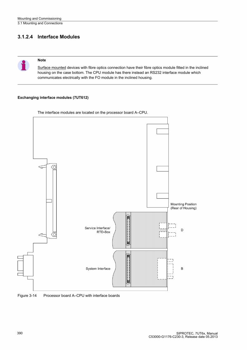
Mounting and Commissioning
3.1 Mounting and Connections
SIPROTEC, 7UT6x, ManualC53000-G1176-C230-3, Release date 05.2013
390
3.1.2.4 Interface Modules
Note
Surface mounted devices with fibre optics connection have their fibre optics module fitted in the inclined
housing on the case bottom. The CPU module has there instead an RS232 interface module which
communicates electrically with the FO module in the inclined housing.
Exchanging interface modules (7UT612)
The interface modules are located on the processor board A–CPU.
Figure 3-14 Processor board A–CPU with interface boards
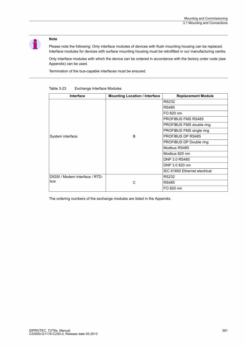
Mounting and Commissioning
3.1 Mounting and Connections
SIPROTEC, 7UT6x, ManualC53000-G1176-C230-3, Release date 05.2013
391
Note
Please note the following: Only interface modules of devices with flush mounting housing can be replaced.
Interface modules for devices with surface mounting housing must be retrofitted in our manufacturing centre.
Only interface modules with which the device can be ordered in accordance with the factory order code (see
Appendix) can be used.
Termination of the bus-capable interfaces must be ensured.
Table 3-23 Exchange Interface Modules
The ordering numbers of the exchange modules are listed in the Appendix.
Interface Mounting Location / Interface Replacement Module
System interface B
RS232
RS485
FO 820 nm
PROFIBUS FMS RS485
PROFIBUS FMS double ring
PROFIBUS FMS single ring
PROFIBUS DP RS485
PROFIBUS DP Double ring
Modbus RS485
Modbus 820 nm
DNP 3.0 RS485
DNP 3.0 820 nm
IEC 61850 Ethernet electrical
DIGSI / Modem Interface / RTD-box C
RS232
RS485
FO 820 nm

Mounting and Commissioning
3.1 Mounting and Connections
SIPROTEC, 7UT6x, ManualC53000-G1176-C230-3, Release date 05.2013
392
Exchanging interface modules (7UT613/63x)
The interface modules are dependent on the variant ordered. They are located on the processor board C-CPU-2.
Figure 3-15 C-CPU-2 board with interface modules
Note
Please note the following: Only interface modules of devices with flush mounting housing can be replaced.
Interface modules of devices with surface mounting housing must be replaced in our manufacturing centre.
Use only interface modules that can be ordered as an option of the device (see also Appendix A.1).
Termination of the serial interfaces in case of RS485 must be ensured.
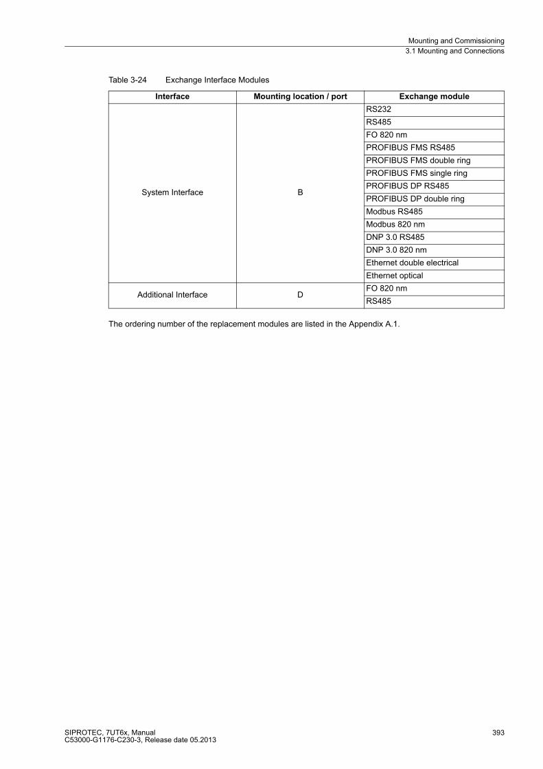
Mounting and Commissioning
3.1 Mounting and Connections
SIPROTEC, 7UT6x, ManualC53000-G1176-C230-3, Release date 05.2013
393
Table 3-24 Exchange Interface Modules
The ordering number of the replacement modules are listed in the Appendix A.1.
Interface Mounting location / port Exchange module
System Interface B
RS232
RS485
FO 820 nm
PROFIBUS FMS RS485
PROFIBUS FMS double ring
PROFIBUS FMS single ring
PROFIBUS DP RS485
PROFIBUS DP double ring
Modbus RS485
Modbus 820 nm
DNP 3.0 RS485
DNP 3.0 820 nm
Ethernet double electrical
Ethernet optical
Additional Interface DFO 820 nm
RS485

Mounting and Commissioning
3.1 Mounting and Connections
SIPROTEC, 7UT6x, ManualC53000-G1176-C230-3, Release date 05.2013
394
RS232 Interface
The RS232 interface can be transformed into a RS485 interface and vice versa, according to Figure 3-17.
Figure 3-15 shows the PCB C-CPU-2 with the layout of the boards.
Figure 3-16 shows how jumpers of interface RS232 are located on the interface module.
Figure 3-16 Location of the jumpers for configuration of RS232
Terminating resistors are not required. They are disconnected.
Please observe that in surface-mounted devices with fibre optics connection the CPU module is equipped with
an RS232 interface module. In this application, the jumpers X12 and X13 on the RS232 module are set to
position 2-3, unlike the arrangement shown in Figure 3-16.
Jumper X11 is used to activate the flow control which is important for the modem communication.
Table 3-25 Jumper setting for CTS (Clear To Send, flow control) on the interface module
1) Default Setting
Jumper setting 2-3: The connection to the modem is usually established with a star coupler or fibre-optic con-
verter. Therefore the modem control signals according to RS232 standard DIN 66020 are not available. Modem
signals are not required since the connection to the SIPROTEC 4 devices is always operated in the half-duplex
mode. Please use the connection cable with order number 7XV5100-4.
Jumper setting 1-2: This setting makes the modem signals available, i. e. for a direct RS232-connection
between the SIPROTEC 4 device and the modem this setting can be selected optionally. We recommend to
use a standard RS232 modem connection cable (converter 9-pin to 25-pin).
Note
For a direct connection to DIGSI with interface RS232 jumper X11 must be plugged in position 2-3.
Jumper /CTS from Interface RS232 /CTS controlled by /RTS
X11 1-2 2-3 1)
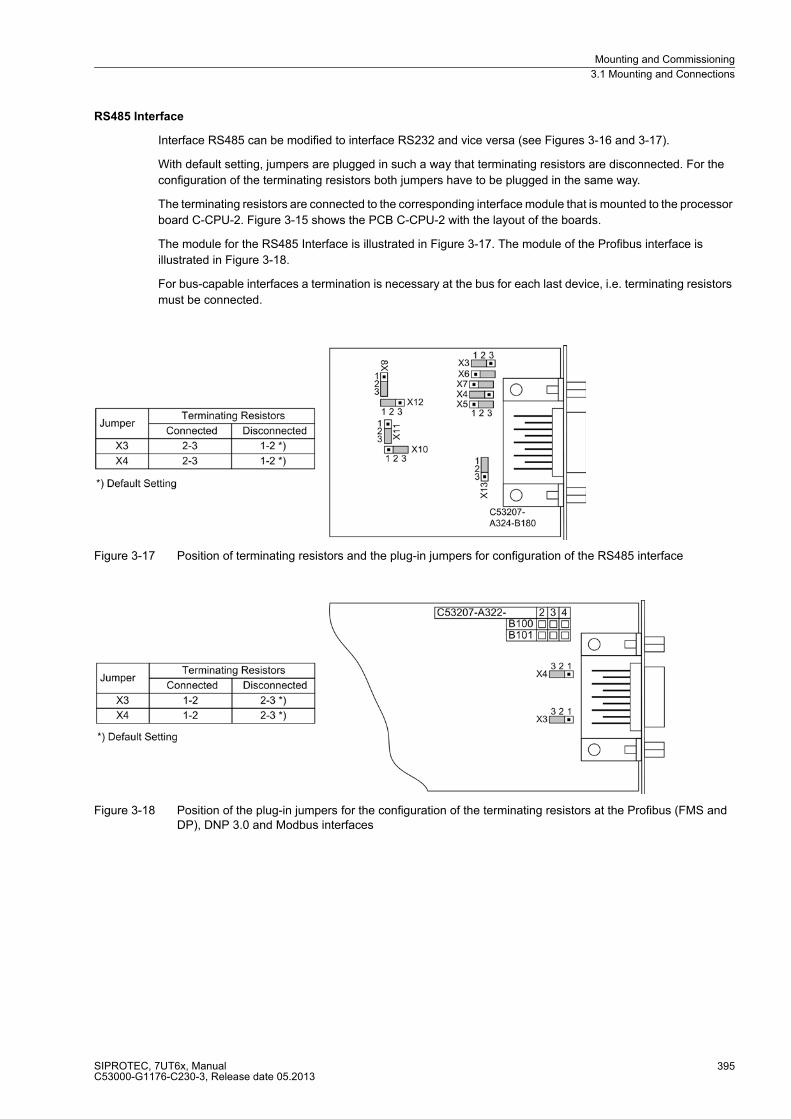
Mounting and Commissioning
3.1 Mounting and Connections
SIPROTEC, 7UT6x, ManualC53000-G1176-C230-3, Release date 05.2013
395
RS485 Interface
Interface RS485 can be modified to interface RS232 and vice versa (see Figures 3-16 and 3-17).
With default setting, jumpers are plugged in such a way that terminating resistors are disconnected. For the
configuration of the terminating resistors both jumpers have to be plugged in the same way.
The terminating resistors are connected to the corresponding interface module that is mounted to the processor
board C-CPU-2. Figure 3-15 shows the PCB C-CPU-2 with the layout of the boards.
The module for the RS485 Interface is illustrated in Figure 3-17. The module of the Profibus interface is
illustrated in Figure 3-18.
For bus-capable interfaces a termination is necessary at the bus for each last device, i.e. terminating resistors
must be connected.
Figure 3-17 Position of terminating resistors and the plug-in jumpers for configuration of the RS485 interface
Figure 3-18 Position of the plug-in jumpers for the configuration of the terminating resistors at the Profibus (FMS and DP), DNP 3.0 and Modbus interfaces
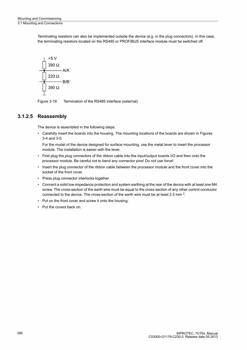
Mounting and Commissioning
3.1 Mounting and Connections
SIPROTEC, 7UT6x, ManualC53000-G1176-C230-3, Release date 05.2013
396
Terminating resistors can also be implemented outside the device (e.g. in the plug connectors). In this case,
the terminating resistors located on the RS485 or PROFIBUS interface module must be switched off.
Figure 3-19 Termination of the RS485 interface (external)
3.1.2.5 Reassembly
The device is assembled in the following steps:
� Carefully insert the boards into the housing. The mounting locations of the boards are shown in Figures
3-4 and 3-5.
For the model of the device designed for surface mounting, use the metal lever to insert the processor
module. The installation is easier with the lever.
� First plug the plug connectors of the ribbon cable into the input/output boards I/O and then onto the
processor module. Be careful not to bend any connector pins! Do not use force!
� Insert the plug connector of the ribbon cable between the processor module and the front cover into the
socket of the front cover.
� Press plug connector interlocks together.
� Connect a solid low-impedance protection and system earthing at the rear of the device with at least one M4
screw. The cross-section of the earth wire must be equal to the cross-section of any other control conductor
connected to the device. The cross-section of the earth wire must be at least 2.5 mm 2.
� Put on the front cover and screw it onto the housing.
� Put the covers back on.

Mounting and Commissioning
3.1 Mounting and Connections
SIPROTEC, 7UT6x, ManualC53000-G1176-C230-3, Release date 05.2013
397
3.1.3 Mounting
3.1.3.1 Panel Flush Mounting
Depending on the version, the device housing can be 1/3, 1/2 or 1/1. For housing size 1/3 (7UT612) and
1/2 (7UT613), there are 4 caps and 4 mounting holes, for size1/1 (7UT633 or 7UT635), there are 6 caps and
6 mounting holes.
� Remove the 4 or 6 caps on the corners of the front cover to reveal the 4 or 6 elongated holes in the mounting
bracket.
� Re-fasten the interfaces on the rear of the device housing. This activity is not necessary if the device is
designed for surface mounting.
� Insert the device into the panel cut-out and fasten it with four or six screws. For dimensions refer to Section
4.23.
� Put the four or six covers back into place.
� Connections are realised via the plug terminals or screw terminals on the rear side of the device in accor-
dance with the circuit diagram. For screw connections with forked lugs or direct connection the screws must
be tightened before inserting wires so that the screw heads are flush with the outer edge of the connection
block. If ring lugs are used, the lug must be centred in the connection chamber in such a way that the screw
thread fits in the hole of the lug. The SIPROTEC 4 System Description /1/ has pertinent information
regarding wire size, lugs, bending radii, etc.
Figure 3-20 Panel flush mounting of a 7UT612
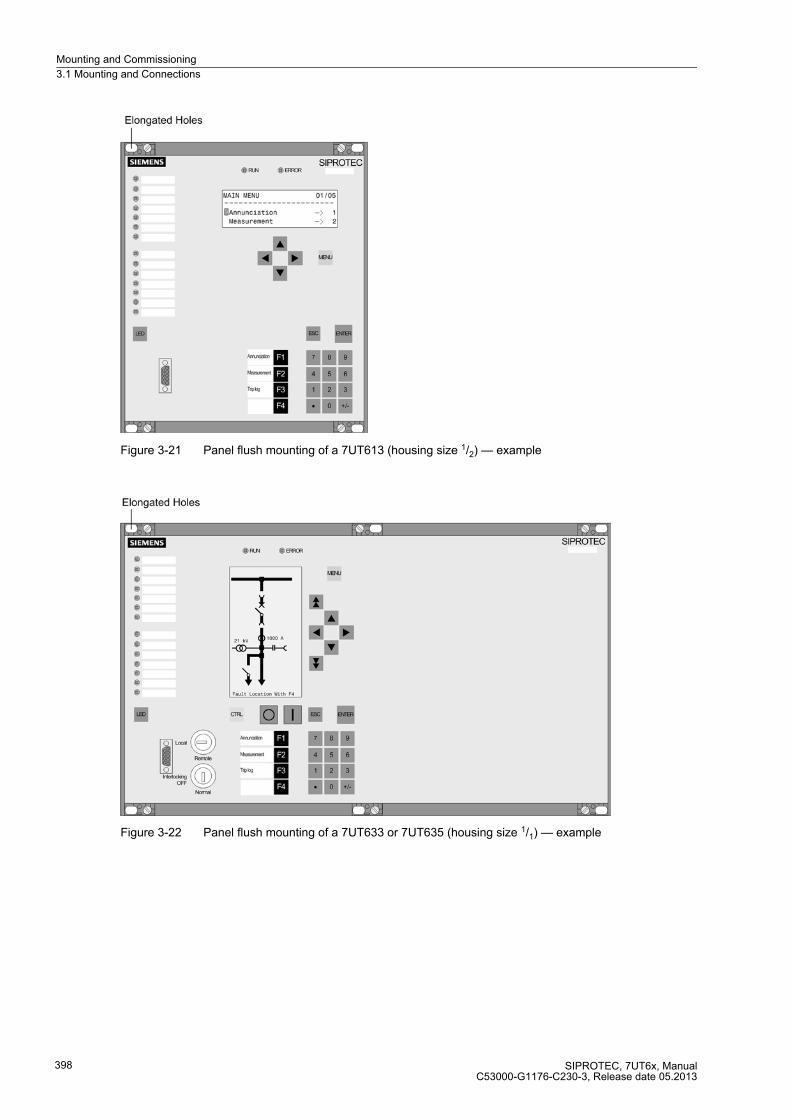
Mounting and Commissioning
3.1 Mounting and Connections
SIPROTEC, 7UT6x, ManualC53000-G1176-C230-3, Release date 05.2013
398
Figure 3-21 Panel flush mounting of a 7UT613 (housing size 1/2) — example
Figure 3-22 Panel flush mounting of a 7UT633 or 7UT635 (housing size 1/1) — example

Mounting and Commissioning
3.1 Mounting and Connections
SIPROTEC, 7UT6x, ManualC53000-G1176-C230-3, Release date 05.2013
399
3.1.3.2 Rack and Cubicle Mounting
Depending on the version, the device housing can be 1/3, 1/2 or 1/1. For housing size 1/3 (7UT612) and
1/2 (7UT613), there are 4 caps and 4 mounting holes, for size1/1 (7UT633 or 7UT635), there are 6 caps and
6 mounting holes.
2 mounting brackets are required for incorporating a device in a rack or cubicle. The order numbers can be
found in the Appendix under A.1.
� Loosely screw the two mounting brackets in the rack with four screws.
� Remove the 4 or 6 caps on the corners of the front cover to reveal the 4 or 6 elongated holes in the mounting
bracket.
� Fasten the device to the mounting brackets with 4 or 6 screws (refer to Figure 4.23 for dimensions).
� Put the four or six covers back into place.
� Connections use the plug terminals or screw terminals on the rear side of the device in accordance the wiring
diagram. For screw connections with forked lugs or direct connection, before inserting wires the screws must
be tightened so that the screw heads are flush with the outer edge of the connection block. A ring lug must
be centred in the connection chamber, in such a way that the screw thread fits in the hole of the lug. The
SIPROTEC 4 System Description /1/ has pertinent information regarding wire size, lugs, bending radii, etc.
� Tighten fast the eight screws of the angle brackets in the rack or cabinet.
� Connect a solid low-impedance protection and system earthing at the rear of the device with at least one M4
screw. The cross-section of the earth wire must be equal to the cross-section of any other control conductor
connected to the device. The cross-section of the earth wire must be at least 2.5 mm 2.
Figure 3-23 Assembly of a 7UT612 in the rack or cabinet
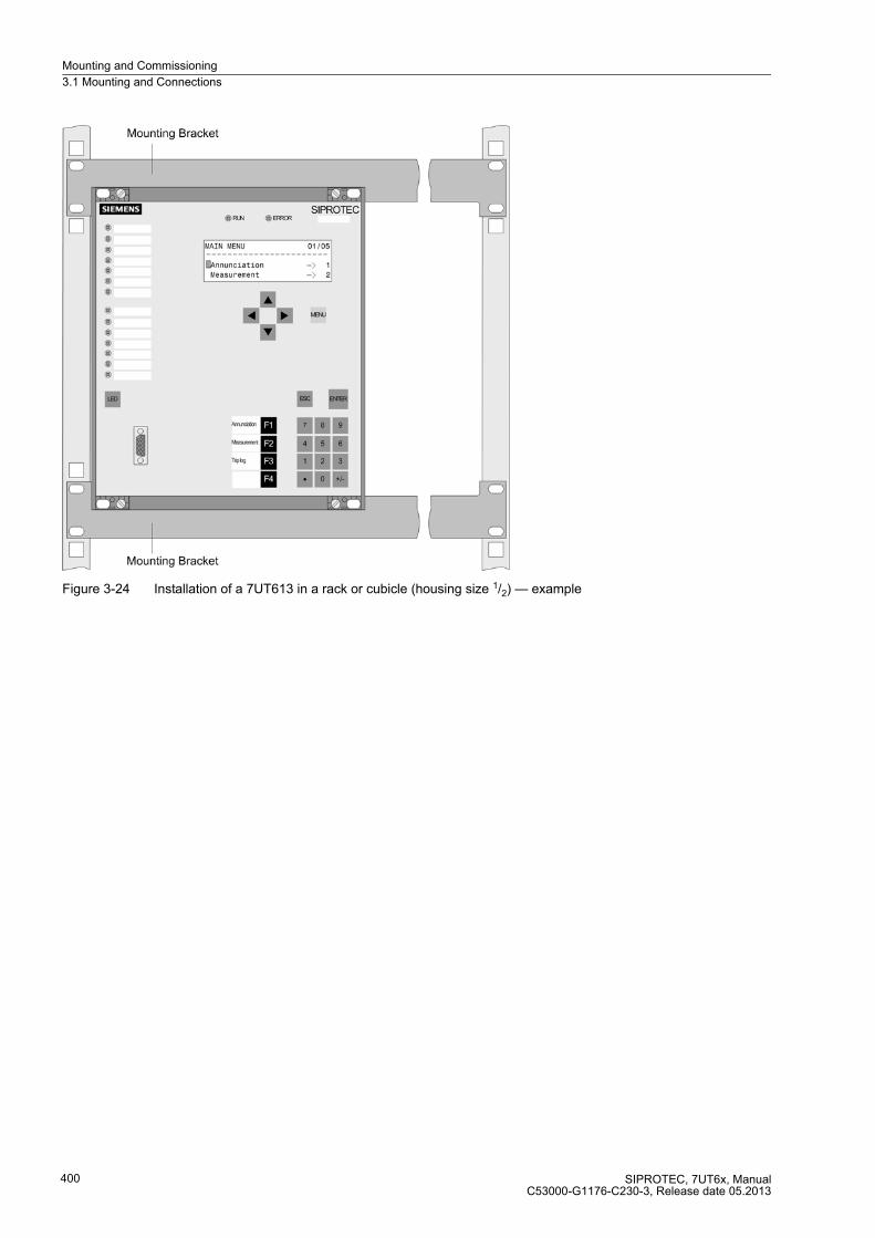
Mounting and Commissioning
3.1 Mounting and Connections
SIPROTEC, 7UT6x, ManualC53000-G1176-C230-3, Release date 05.2013
400
Figure 3-24 Installation of a 7UT613 in a rack or cubicle (housing size 1/2) — example
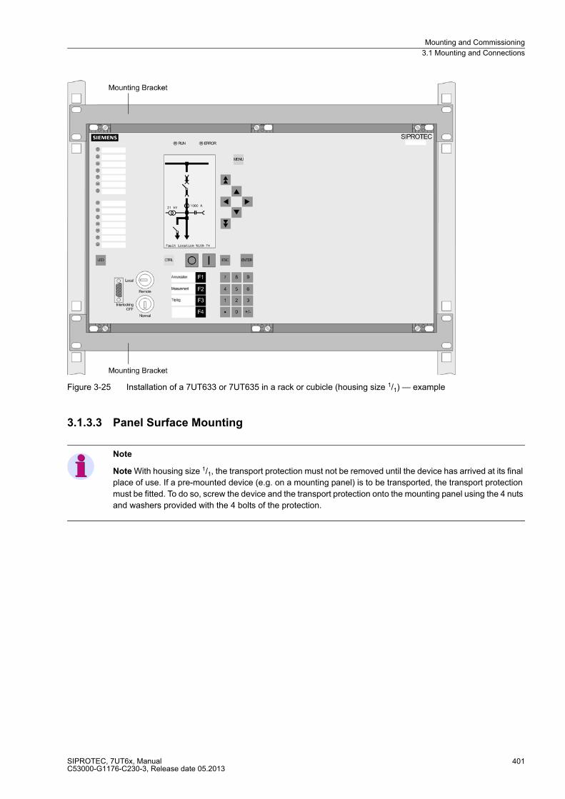
Mounting and Commissioning
3.1 Mounting and Connections
SIPROTEC, 7UT6x, ManualC53000-G1176-C230-3, Release date 05.2013
401
Figure 3-25 Installation of a 7UT633 or 7UT635 in a rack or cubicle (housing size 1/1) — example
3.1.3.3 Panel Surface Mounting
Note
Note With housing size 1/1, the transport protection must not be removed until the device has arrived at its final
place of use. If a pre-mounted device (e.g. on a mounting panel) is to be transported, the transport protection
must be fitted. To do so, screw the device and the transport protection onto the mounting panel using the 4 nuts
and washers provided with the 4 bolts of the protection.

Mounting and Commissioning
3.1 Mounting and Connections
SIPROTEC, 7UT6x, ManualC53000-G1176-C230-3, Release date 05.2013
402
In all other cases, remove the transport protection when you install a device with housing size 1/1 (see below
„Removing the Transport Protection“:
� Secure the device to the panel with four screws. For dimension drawings see Section 4.23.
� Alternatively, there is the possibility to connect the aforementioned earthing to the lateral earthing surface
with at least one M4 screw.
� Connect the low-resistance operational and protective earth to the ground terminal of the device. The cross-
sectional area of the ground wire must be equal to the cross-sectional area of any other control conductor
connected to the device. It must thus be at least 2.5 mm2.
� Connections according to the circuit diagram via screw terminals, connections for optical fibres and electrical
communication modules via the console housing. The SIPROTEC 4 System Description /1/ has pertinent
information regarding wire size, lugs, bending radii, etc. Installation notes are also given in the brief
reference booklet attached to the device.
3.1.3.4 Removing the Transport Protection
Devices in housings size 1/1 (7UT633 and 7UT635) for surface mounting are delivered with a transport protec-
tion (Figure 3-26). This protection must not be removed until the device has arrived at its final place of use.
Figure 3-26 View of a housing with transport protection (without front cover nor boards)

Mounting and Commissioning
3.1 Mounting and Connections
SIPROTEC, 7UT6x, ManualC53000-G1176-C230-3, Release date 05.2013
403
� Remove the 4 covers at the corners and the 2 covers in the centre above and below on the front cover to
reveal 6 elongated holes.
� Loosen the 6 screws (2) in the elongated holes.
� Remove all other screws on the rails (1) and remove the top and bottom rails.
� Loosen the 2 screws each (4) in the elongated holes on the right and left side walls (3), and remove the side
walls.
� Firmly tighten again all 10 screws that you loosened.
� Attention! If the device is pre-mounted, e.g. on a mounting panel, and secured with a transport protection,
do not remove all bolts at once. In such a case, remove only one bolt at a time and immediately re-screw
the device to the mounting panel at the place where you removed the bolt.
� Remove the nuts and washers (6) from the 4 bolts (5), and remove the bolts.
� The device can now be secured to the panel with four screws.
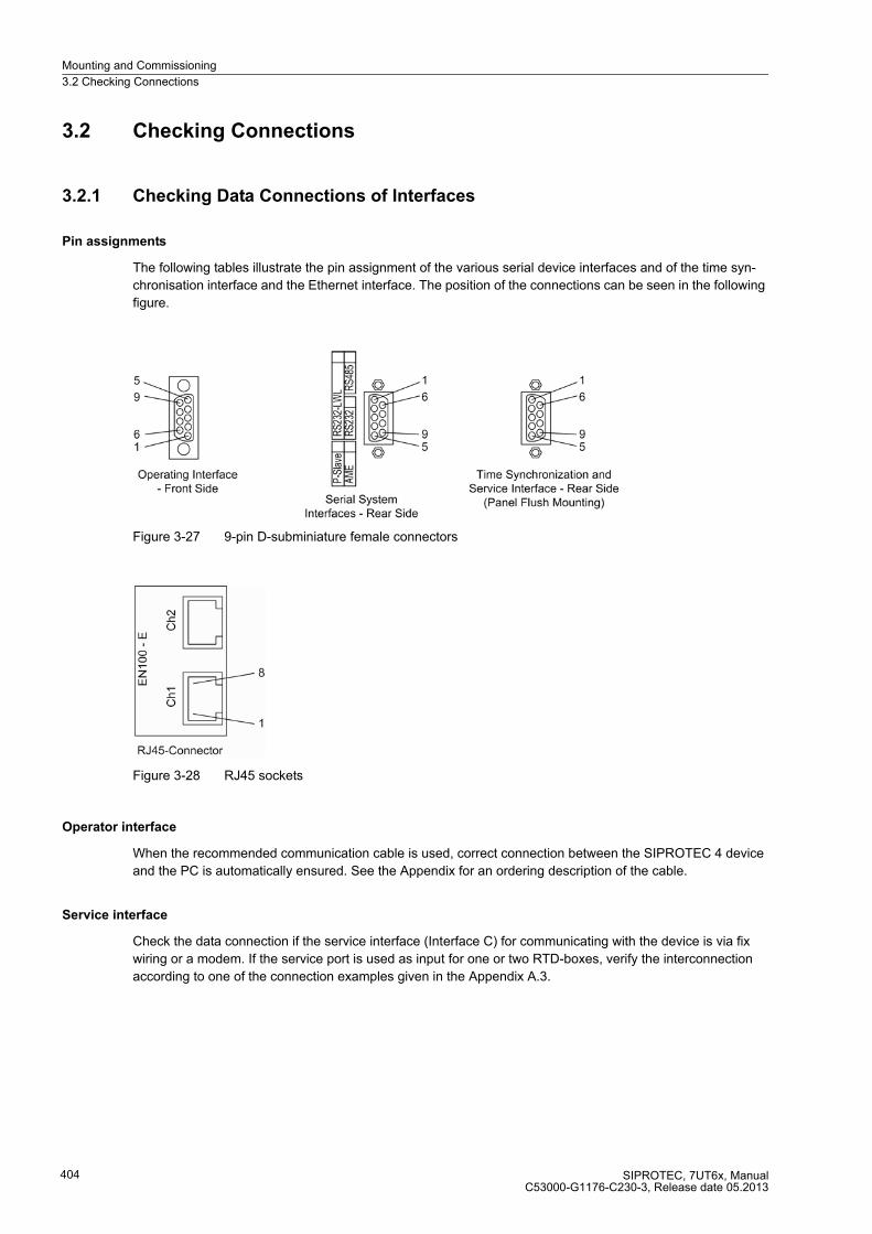
Mounting and Commissioning
3.2 Checking Connections
SIPROTEC, 7UT6x, ManualC53000-G1176-C230-3, Release date 05.2013
404
3.2 Checking Connections
3.2.1 Checking Data Connections of Interfaces
Pin assignments
The following tables illustrate the pin assignment of the various serial device interfaces and of the time syn-
chronisation interface and the Ethernet interface. The position of the connections can be seen in the following
figure.
Figure 3-27 9-pin D-subminiature female connectors
Figure 3-28 RJ45 sockets
Operator interface
When the recommended communication cable is used, correct connection between the SIPROTEC 4 device
and the PC is automatically ensured. See the Appendix for an ordering description of the cable.
Service interface
Check the data connection if the service interface (Interface C) for communicating with the device is via fix
wiring or a modem. If the service port is used as input for one or two RTD-boxes, verify the interconnection
according to one of the connection examples given in the Appendix A.3.
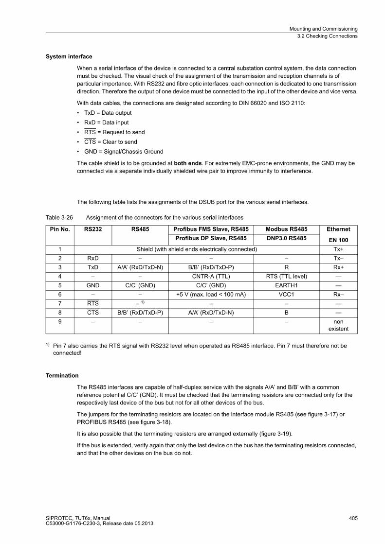
Mounting and Commissioning
3.2 Checking Connections
SIPROTEC, 7UT6x, ManualC53000-G1176-C230-3, Release date 05.2013
405
System interface
When a serial interface of the device is connected to a central substation control system, the data connection
must be checked. The visual check of the assignment of the transmission and reception channels is of
particular importance. With RS232 and fibre optic interfaces, each connection is dedicated to one transmission
direction. Therefore the output of one device must be connected to the input of the other device and vice versa.
With data cables, the connections are designated according to DIN 66020 and ISO 2110:
� TxD = Data output
� RxD = Data input
� RTS = Request to send
� CTS = Clear to send
� GND = Signal/Chassis Ground
The cable shield is to be grounded at both ends. For extremely EMC-prone environments, the GND may be
connected via a separate individually shielded wire pair to improve immunity to interference.
The following table lists the assignments of the DSUB port for the various serial interfaces.
Table 3-26 Assignment of the connectors for the various serial interfaces
1) Pin 7 also carries the RTS signal with RS232 level when operated as RS485 interface. Pin 7 must therefore not be connected!
Termination
The RS485 interfaces are capable of half-duplex service with the signals A/A’ and B/B’ with a common
reference potential C/C’ (GND). It must be checked that the terminating resistors are connected only for the
respectively last device of the bus but not for all other devices of the bus.
The jumpers for the terminating resistors are located on the interface module RS485 (see figure 3-17) or
PROFIBUS RS485 (see figure 3-18).
It is also possible that the terminating resistors are arranged externally (figure 3-19).
If the bus is extended, verify again that only the last device on the bus has the terminating resistors connected,
and that the other devices on the bus do not.
Pin No. RS232 RS485 Profibus FMS Slave, RS485 Modbus RS485 Ethernet
EN 100Profibus DP Slave, RS485 DNP3.0 RS485
1 Shield (with shield ends electrically connected) Tx+
2 RxD – – – Tx–
3 TxD A/A’ (RxD/TxD-N) B/B’ (RxD/TxD-P) R Rx+
4 – – CNTR-A (TTL) RTS (TTL level) —
5 GND C/C’ (GND) C/C’ (GND) EARTH1 —
6 – – +5 V (max. load < 100 mA) VCC1 Rx–
7 RTS – 1) – – —
8 CTS B/B’ (RxD/TxD-P) A/A’ (RxD/TxD-N) B —
9 – – – – non existent

Mounting and Commissioning
3.2 Checking Connections
SIPROTEC, 7UT6x, ManualC53000-G1176-C230-3, Release date 05.2013
406
Time Synchronisation Interface
Either DC 5 V, DC 12 V or DC 24 V time synchronisation signals can be processed if the connections are made
as indicated in the table below.
Table 3-27 D-subminiature connector assignment of the time synchronisation interface
1) assigned, but not used
Fibre-optic Cables
WARNING!
Laser rays!
Do not look directly into the fiber-optic elements!
Signals transmitted via optical fibers are unaffected by interference. The fibers guarantee electrical isolation
between the connections. Transmit and receive connections are represented by symbols.
The character idle state for the optical fibre interface is „Light off“. If the character idle state is to be changed,
use the operating program DIGSI, as described in the SIPROTEC 4 System Description.
Pin No. Designation Signal significance
1 P24_TSIG Input 24 V
2 P5_TSIG Input 5 V
3 M_TSIG Return line
4 M_TYNC 1)
Return line 1)
5 SCREEN Screen potential
6 – –
7 P12_TSIG Input 12 V
8 P_TSYNC 1) Input 24 V 1)
9 SCREEN Screen potential
Mounting and Commissioning
3.2 Checking Connections
SIPROTEC, 7UT6x, ManualC53000-G1176-C230-3, Release date 05.2013
407
RTD box
If one or two RTD-boxes 7XV5662-xAD are connected for considering the coolant temperature when using
overload protection with hot-spot calculation, check their connection at the service interface (Port C) or the
auxiliary interface (Port D).
Also verify the termination. The terminating resistors must be connected to the device (see margin heading
„Termination“).
For further information refer to the operating manual of 7XV5662-xAD. Check the transmission settings at the
temperature meter. Besides the baud rate and the parity, the bus number is also important.
For connection of RTD-box(es) proceed as follows:
� For connection of 1 RTD-box 7XV5662-xAD:
Bus number = 0 with Simplex transmission (to be set at 7XV5662-xAD),
Bus number = 1 with Duplex transmission (to be set at 7XV5662-xAD).
� For connection of 2 RTD-boxes 7XV5662-xAD:
Bus number = 1 for the 1st RTD-box (to be set at 7XV5662-xAD for RTD 1 to 6),
Bus number = 2 for the 2nd RTD-box (to be set at 7XV5662-AD for RTD 7 to 12).

Mounting and Commissioning
3.2 Checking Connections
SIPROTEC, 7UT6x, ManualC53000-G1176-C230-3, Release date 05.2013
408
3.2.2 Checking the System Connections
Before the device is energized for the first time, the device should be in the final operating environment for at
least 2 hours to equalize the temperature, to minimize humidity and avoid condensation. Connections are
checked with the device at its final location. The plant must first be switched off and grounded.
WARNING!
Warning of dangerous voltages
Non-observance of the following measures can result in death, personal injury or substantial property damage.
Therefore, only qualified people who are familiar with and adhere to the safety procedures and precautionary
measures shall perform the inspection steps.
Caution!
Be careful when operating the device on a battery charger without a battery
Non-observance of the following measure can lead to unusually high voltages and consequently, the
destruction of the device.
Do not operate the device on a battery charger without a connected battery. (Limit values can be found in the
technical data).
Connection examples for current transformer circuits are provided in the Appendix A.3. Please observe the
terminal assignments (see Appendix A.2).
Proceed as follows in order to check the system connections:
� Protective switches for the power supply and the measured voltages must be switched off.
� Check the continuity of all current and voltage transformer connections against the system and connection
diagrams:
– Is the connection of all 3-phase current transformer sets to the device inputs correct and in accordance
with the set topology?
– Is the connection of all 1-phase current transformers to the device inputs correct and in accordance with
the set topology?
– Are the current transformers earthed properly?
– Are the polarities of the current transformers the same for each CT set?
– Phase assignment of all 3-phase current transformers correct?
– Are the polarities of all single-phase current inputs correct (if used)?
– Are the voltage transformers earthed properly (if used)?
– Are the polarities of the voltage transformers correct (if used)?
– Is the phase relationship of the voltage transformers correct (if used)?
– Is the polarity for voltage input U4 correct (if used, e.g. with open delta winding)?
Mounting and Commissioning
3.2 Checking Connections
SIPROTEC, 7UT6x, ManualC53000-G1176-C230-3, Release date 05.2013
409
� Check the functions of all test switches that may be installed for the purposes of secondary testing and iso-
lation of the device. Of particular importance are test switches in current transformer circuits. Be sure these
switches short-circuit the current transformers when they are in the „test“ mode (open).
� The short-circuiters of the connectors for the current circuits have to be checked. This can be done using
secondary test equipment or other test equipment for checking continuity. Make sure that terminal continuity
is not wrongly simulated in reverse direction via current transformers or their short-circuiters.
– Remove the front panel.
– Remove the ribbon cable connected to the input/output module and pull the module out until there is no
contact between the module and the rear connections of the device.
7UT612: A-I/O-3 slot 19
7UT613: C-I/O-9 slot 33
7UT633: C-I/O-9 slot 33 right side
7UT635: C-I/O-9 slot 33 right side
– At the terminals of the device, check continuity for each pair of terminals that receives current from the
CTs.
– Firmly re-insert the I/O board.
– At the terminals of the device, again check continuity for each pair of terminals.
– Repeat the above continuity tests for the other boards that receive current from the CTs.
7UT613: C-I/O-2 slot 19
7UT633: C-I/O-2 slot 19 right
7UT635: C-I/O-9 slot 19 right side
– Carefully plug in the ribbon cable. Be careful not to bend any connector pins. Do not apply force!
– Attach the front panel and tighten the screws.
� Connect an ammeter in the supply circuit of the power supply. A range of about 2.5 A to 5 A for the meter is
appropriate.
� Close the protective switches.
� Switch on m.c.b. for auxiliary voltage (supply protection), check the voltage level and, if applicable, the
polarity of the voltage at the device terminals or at the connection modules.
� Open the miniature circuit breakers for the power supply.
� Disconnect the ammeter; restore the normal power supply connections.
� Switch on voltage transformer protective breaker (if used).
� The measured steady-state current should correspond to the quiescent power consumption of the device.
Transient movement of the ammeter merely indicates the charging current of capacitors.
� Verify that the voltage phase rotation at the device terminals is correct.
� Open the miniature circuit breakers for the transformer voltage (VT mcb) and the power supply.
� Check tripping circuits to the circuit breakers.
� Verify that the control wiring to and from other devices is correct.
� Check the signalling connections.

Mounting and Commissioning
3.3 Commissioning
SIPROTEC, 7UT6x, ManualC53000-G1176-C230-3, Release date 05.2013
410
3.3 Commissioning
WARNING!
Warning of dangerous voltages when operating an electrical device
Non-observance of the following measures can result in death, personal injury or substantial property damage.
Only qualified people shall work on and around this device. They must be thoroughly familiar with all warnings
and safety notices in this instruction manual as well as with the applicable safety steps, safety regulations, and
precautionary measures.
Before making any connections, the device must be earthed at the protective conductor terminal.
Hazardous voltages can exist in the power supply and at the connections to current transformers, voltage trans-
formers, and test circuits.
Hazardous voltages can be present in the device even after the power supply voltage has been removed
(capacitors can still be charged).
After removing voltage from the power supply, wait a minimum of 10 seconds before re-energizing the power
supply. This wait allows the initial conditions to be firmly established before the device is re-energized.
The limit values given in Technical Data must not be exceeded, neither during testing nor during
commissioning.
For tests with a secondary test equipment ensure that no other measurement voltages are connected and the
trip and close commands to the circuit breakers are blocked, unless otherwise specified.
DANGER!
Hazardous voltages during interruptions in secondary circuits of current transformers
Non-observance of the following measure will result in death, severe personal injury or substantial property
damage.
Short-circuit the current transformer secondary circuits before current connections to the device are opened.
During the commissioning procedure, switching operations must be carried out. The tests described require
that they can be done without danger. They are accordingly not meant for operational checks.
WARNING!
Warning of dangers evolving from improper primary tests
Non-observance of the following measure can result in death, personal injury or substantial property damage.
Primary tests may only be carried out by qualified persons who are familiar with commissioning protection
systems, with managing power systems and the relevant safety rules and guidelines (switching, earthing etc.).
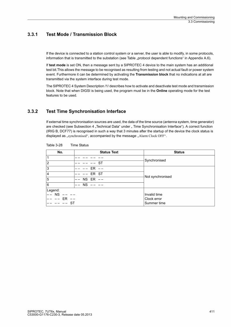
Mounting and Commissioning
3.3 Commissioning
SIPROTEC, 7UT6x, ManualC53000-G1176-C230-3, Release date 05.2013
411
3.3.1 Test Mode / Transmission Block
If the device is connected to a station control system or a server, the user is able to modify, in some protocols,
information that is transmitted to the substation (see Table „protocol dependent functions“ in Appendix A.6).
If test mode is set ON, then a message sent by a SIPROTEC 4 device to the main system has an additional
test bit.This allows the message to be recognised as resulting from testing and not actual fault or power system
event. Furthermore it can be determined by activating the Transmission block that no indications at all are
transmitted via the system interface during test mode.
The SIPROTEC 4 System Description /1/ describes how to activate and deactivate test mode and transmission
block. Note that when DIGSI is being used, the program must be in the Online operating mode for the test
features to be used.
3.3.2 Test Time Synchronisation Interface
If external time synchronisation sources are used, the data of the time source (antenna system, time generator)
are checked (see Subsection 4 „Technical Data“ under „ Time Synchronisation Interface“). A correct function
(IRIG B, DCF77) is recognised in such a way that 3 minutes after the startup of the device the clock status is
displayed as „synchronised“, accompanied by the message „Alarm Clock OFF“.
Table 3-28 Time Status
No. Status Text Status
1 – – – – – – – –Synchronised
2 – – – – – – ST
3 – – – – ER – –
Not synchronised4 – – – – ER ST
5 – – NS ER – –
6 – – NS – – – –
Legend:– – NS – – – –– – – – ER – –– – – – – – ST
Invalid timeClock errorSummer time
Mounting and Commissioning
3.3 Commissioning
SIPROTEC, 7UT6x, ManualC53000-G1176-C230-3, Release date 05.2013
412
3.3.3 Testing the System Interface
Prefacing Remarks
If the device features a system interface and uses it to communicate with the control centre, the DIGSI device
operation can be used to test if messages are transmitted correctly. This test option should however definitely
„not“ be used while the device is in service on a live system.
DANGER!
The sending or receiving of indications via the system interface by means of the test function is a real
information exchange between the SIPROTEC 4 device and the control centre. Connected operating
equipment such as circuit breakers or disconnectors can be switched in this way!
Non-observance of the following measure will result in death, severe personal injury or substantial property
damage.
Equipment used to allow switching such as circuit breakers or disconnectors is to be checked only during com-
missioning. Do not under any circumstances check them by means of the testing mode during „real“ operation
performing transmission and reception of messages via the system interface.
Note
After termination of the hardware test, the device will reboot. Thereby, all annunciation buffers are erased. If
required, these buffers should be extracted with DIGSI prior to the test.
The interface test is carried out using DIGSI in the Online operating mode:
� Open the Online folder by double-clicking; the operating functions for the device appear.
� Click on Test; the function selection appears in the right half of the window.
� Double-click on Testing Messages for System Interface shown in the list view. The dialog box Generate
Indications is opened (see Figure 3-29).
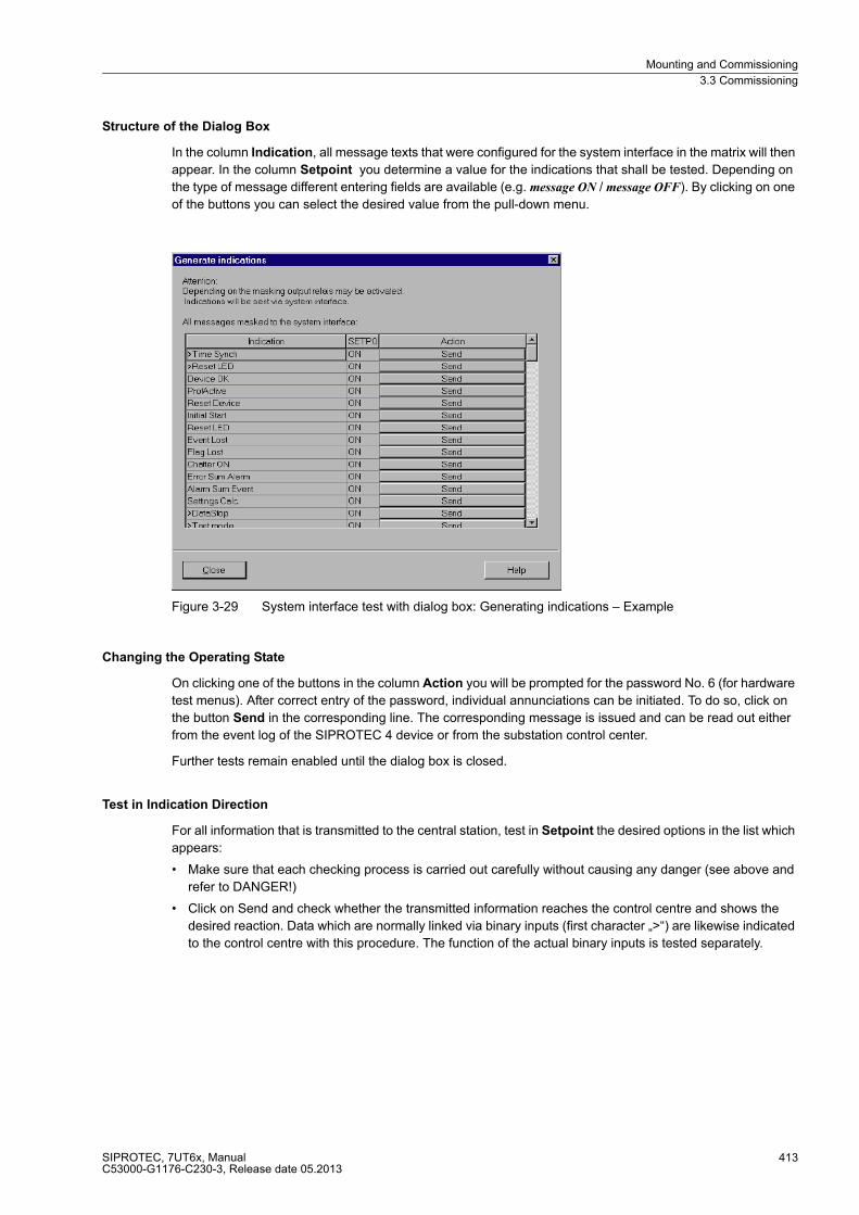
Mounting and Commissioning
3.3 Commissioning
SIPROTEC, 7UT6x, ManualC53000-G1176-C230-3, Release date 05.2013
413
Structure of the Dialog Box
In the column Indication, all message texts that were configured for the system interface in the matrix will then
appear. In the column Setpoint you determine a value for the indications that shall be tested. Depending on
the type of message different entering fields are available (e.g. message ON / message OFF). By clicking on one
of the buttons you can select the desired value from the pull-down menu.
Figure 3-29 System interface test with dialog box: Generating indications – Example
Changing the Operating State
On clicking one of the buttons in the column Action you will be prompted for the password No. 6 (for hardware
test menus). After correct entry of the password, individual annunciations can be initiated. To do so, click on
the button Send in the corresponding line. The corresponding message is issued and can be read out either
from the event log of the SIPROTEC 4 device or from the substation control center.
Further tests remain enabled until the dialog box is closed.
Test in Indication Direction
For all information that is transmitted to the central station, test in Setpoint the desired options in the list which
appears:
� Make sure that each checking process is carried out carefully without causing any danger (see above and
refer to DANGER!)
� Click on Send and check whether the transmitted information reaches the control centre and shows the
desired reaction. Data which are normally linked via binary inputs (first character „>“) are likewise indicated
to the control centre with this procedure. The function of the actual binary inputs is tested separately.
Mounting and Commissioning
3.3 Commissioning
SIPROTEC, 7UT6x, ManualC53000-G1176-C230-3, Release date 05.2013
414
Exiting the Test Mode
To end the System Interface Test, click on Close. The dialog box closes. The processor system is restarted,
then the device is ready for operation.
Test in Command Direction
Data which are normally linked via binary inputs (first character „>“) are likewise checked with this procedure.
The information transmitted in command direction must be indicated by the central station. Check whether the
reaction is correct.
3.3.4 Checking the switching states of the binary Inputs/Outputs
Prefacing Remarks
The binary inputs, outputs, and LEDs of a SIPROTEC 4 device can be individually and precisely controlled in
DIGSI. This feature is used to verify control wiring from the device to plant equipment (operational checks)
during commissioning. This test option should however definitely „not“ be used while the device is in service
on a live system.
DANGER!
A changing of switching states by means of the test function causes a real change of the operating
state at the SIPROTEC 4 device. Connected operating equipment such as circuit breakers or
disconnectors will be switched in this way!
Non-observance of the following measure will result in death, severe personal injury or substantial property
damage.
Equipment used to allow switching such as circuit breakers or disconnectors is to be checked only during com-
missioning. Do not under any circumstances check them by means of the testing mode during „real“ operation
performing transmission and reception of messages via the system interface.
Note
After termination of the hardware test the device will reboot. Thereby, all annunciation buffers are erased. If
required, these buffers should be extracted with DIGSI prior to the test.
The hardware test can be carried out using DIGSI in the Online operating mode:
� Open the Online directory by double-clicking; the operating functions for the device appear.
� Click on Test; the function selection appears in the right half of the window.
� Double-click in the list view on Device inputs and outputs. The dialog box with this name is opened
(see Figure 3-30).
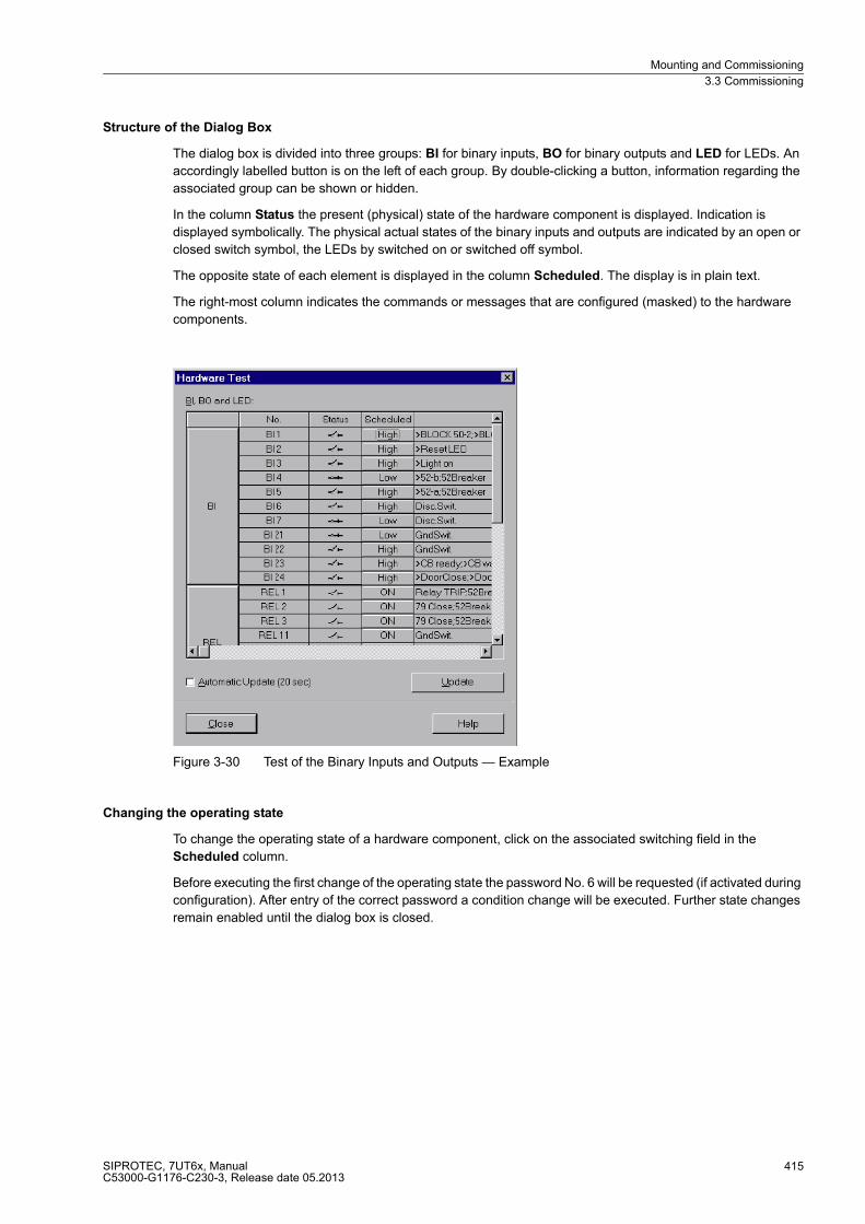
Mounting and Commissioning
3.3 Commissioning
SIPROTEC, 7UT6x, ManualC53000-G1176-C230-3, Release date 05.2013
415
Structure of the Dialog Box
The dialog box is divided into three groups: BI for binary inputs, BO for binary outputs and LED for LEDs. An
accordingly labelled button is on the left of each group. By double-clicking a button, information regarding the
associated group can be shown or hidden.
In the column Status the present (physical) state of the hardware component is displayed. Indication is
displayed symbolically. The physical actual states of the binary inputs and outputs are indicated by an open or
closed switch symbol, the LEDs by switched on or switched off symbol.
The opposite state of each element is displayed in the column Scheduled. The display is in plain text.
The right-most column indicates the commands or messages that are configured (masked) to the hardware
components.
Figure 3-30 Test of the Binary Inputs and Outputs — Example
Changing the operating state
To change the operating state of a hardware component, click on the associated switching field in the
Scheduled column.
Before executing the first change of the operating state the password No. 6 will be requested (if activated during
configuration). After entry of the correct password a condition change will be executed. Further state changes
remain enabled until the dialog box is closed.
Mounting and Commissioning
3.3 Commissioning
SIPROTEC, 7UT6x, ManualC53000-G1176-C230-3, Release date 05.2013
416
Test of the Output Relays
Each individual output relay can be energized allowing a check of the wiring between the output relay of the
7UT6x and the plant, without having to generate the message that is assigned to the relay. As soon as the first
change of state for any of the output relays is initiated, all output relays are separated from the internal device
functions, and can only be operated by the hardware test function. This means, that e.g. a TRIP command
coming from a protection function or a control command from the operator panel to an output relay cannot be
executed.
Proceed as follows in order to check the output relay:
� Make sure that the switching operations caused by the output relays can be executed without any danger
(see above under DANGER!).
� Each output relay must be tested via the corresponding Scheduled field of the dialog box.
� Finish the testing (see margin heading below „Exiting the Procedure“), so that during further testings no
unwanted switchings are initiated.
Test of the Binary Inputs
To test the wiring between the plant and the binary inputs of the 7UT6x the condition in the system which
initiates the binary input must be generated and the response of the device checked.
To do so, open the dialog box Hardware Test again to view the physical position of the binary input. The
password is not yet required.
Proceed as follows in order to check the binary inputs:
� Each state in the system which causes a binary input to pick up must be generated.
� Check the reaction in the Status column of the dialog box. To do this, the dialog box must be updated. The
options may be found below under the margin heading „Updating the Display“.
� Finish the test sequence (see margin heading below „Exiting the Procedure“).
If, however, the effect of a binary input must be checked without carrying out any switching in the system, it is
possible to trigger individual binary inputs with the hardware test function. As soon as the first state change of
any binary input is triggered and the password No. 6 has been entered, all binary inputs are separated from the
system and can only be activated via the hardware test function.
Test of the LEDs
The light-emitting diodes (LEDs) may be tested in a similar manner to the other input/output components. As
soon as the first state change of any LED has been triggered, all LEDs are separated from the internal device
functionality and can only be controlled via the hardware test function. This means e.g. that no LED is
illuminated anymore by a protective function or by pressing the LED reset button.
Updating the Display
When the dialog box Hardware Test is opened, the present conditions of the hardware components at that
moment are read in and displayed.
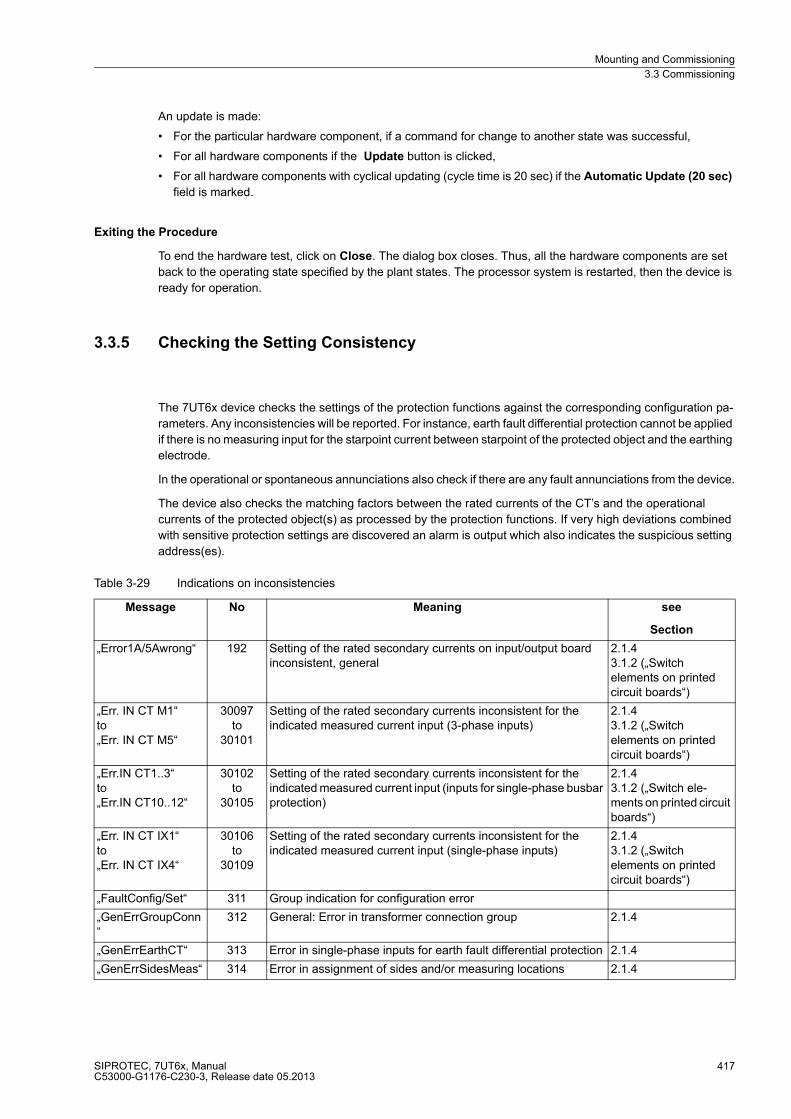
Mounting and Commissioning
3.3 Commissioning
SIPROTEC, 7UT6x, ManualC53000-G1176-C230-3, Release date 05.2013
417
An update is made:
� For the particular hardware component, if a command for change to another state was successful,
� For all hardware components if the Update button is clicked,
� For all hardware components with cyclical updating (cycle time is 20 sec) if the Automatic Update (20 sec)
field is marked.
Exiting the Procedure
To end the hardware test, click on Close. The dialog box closes. Thus, all the hardware components are set
back to the operating state specified by the plant states. The processor system is restarted, then the device is
ready for operation.
3.3.5 Checking the Setting Consistency
The 7UT6x device checks the settings of the protection functions against the corresponding configuration pa-
rameters. Any inconsistencies will be reported. For instance, earth fault differential protection cannot be applied
if there is no measuring input for the starpoint current between starpoint of the protected object and the earthing
electrode.
In the operational or spontaneous annunciations also check if there are any fault annunciations from the device.
The device also checks the matching factors between the rated currents of the CT’s and the operational
currents of the protected object(s) as processed by the protection functions. If very high deviations combined
with sensitive protection settings are discovered an alarm is output which also indicates the suspicious setting
address(es).
Table 3-29 Indications on inconsistencies
Message No Meaning see
Section
„Error1A/5Awrong“ 192 Setting of the rated secondary currents on input/output board inconsistent, general
2.1.43.1.2 („Switch elements on printed circuit boards“)
„Err. IN CT M1“to„Err. IN CT M5“
30097to
30101
Setting of the rated secondary currents inconsistent for the indicated measured current input (3-phase inputs)
2.1.43.1.2 („Switch elements on printed circuit boards“)
„Err.IN CT1..3“to„Err.IN CT10..12“
30102to
30105
Setting of the rated secondary currents inconsistent for the indicated measured current input (inputs for single-phase busbar protection)
2.1.43.1.2 („Switch ele-ments on printed circuit boards“)
„Err. IN CT IX1“to„Err. IN CT IX4“
30106to
30109
Setting of the rated secondary currents inconsistent for the indicated measured current input (single-phase inputs)
2.1.43.1.2 („Switch elements on printed circuit boards“)
„FaultConfig/Set“ 311 Group indication for configuration error
„GenErrGroupConn“
312 General: Error in transformer connection group 2.1.4
„GenErrEarthCT“ 313 Error in single-phase inputs for earth fault differential protection 2.1.4
„GenErrSidesMeas“ 314 Error in assignment of sides and/or measuring locations 2.1.4

Mounting and Commissioning
3.3 Commissioning
SIPROTEC, 7UT6x, ManualC53000-G1176-C230-3, Release date 05.2013
418
„par too low:“ 30067 Parameter setting value too small for the indicated address number
„par too high:“ 30068 Parameter setting value too high for the indicated address number
„settingFault:“ 30069 Parameter setting implausible for the indicated address number
„Diff Adap.fact.“ 5620 The matching factor of the current transformers for the differential protection is too great or too small
2.1.42.2
„Diff err. Set.“ 5623 Differential protection setting not plausible 2.2
REF not avail. 5835 Restricted earth fault protection is not available for the configured protected object
2.1.4
REF Adap.fact. 5836 The matching factor of the current transformers for restricted earth fault protection is too great or too small.
2.1.42.3
REF Err CTstar 5830 There is no single-phase measuring input assigned to the starpoint current for restricted earth fault protection
2.1.42.2
„REF err. Set.“ 199.2493 Earth fault differential protection setting not plausible 2.1.1
„REF2 Not avail.“ 205.2491 Restricted earth fault protection 2 is not available for the configured protected object
2.4.1
„REF2 Adap.fact.“ 205.2494 The matching factor of the current transformers for restricted earth fault protection 2 is too great or too small.
2.4.12.3
„REF2 Err CTstar“ 205.2492 There is no single-phase measuring input assigned to the starpoint current for restricted earth fault protection 2
2.4.12.2
„REF2 err. Set.“ 205.2493 Earth fault differential protection setting not plausible 2.1.1
O/C Ph. not active 1860 Time overcurrent protection for phase currents is not available for the configured protected object
2.1.4
„O/C Para error“ 023.2493 Settings for time overcurrent protection for phase currents not plausible
2.4.2
„O/C Ph2 Not av.“ 207.2491 Time overcurrent protection for phase currents 2 is not available for the configured protected object
2.1.42.1.6
„O/C Ph2 err Set“ 207.2493 Settings for time overcurrent protection for phase currents 2 not plausible
2.4.2
„O/C Ph3 Not av.“ 209.2491 Time overcurrent protection for phase currents 3 is not available for the configured protected object
2.1.42.1.6
„O/C Ph3 err Set“ 209.2493 Settings for time overcurrent protection for phase currents 3 not plausible
2.4.2
O/C 3I0 not av. 1861 Time overcurrent protection for zero current is not available for the configured protected object
2.1.4
„O/C 3I0 error“ 191.2493 Settings for time overcurrent protection for zero sequence current not plausible
2.4.2
„O/C 3I0-2 n/a“ 321.2491 Time overcurrent protection for zero sequence current 2 is not available for the configured protected object
2.1.42.1.6
„O/C3I0-2 errSet“ 321.2493 Settings for time overcurrent protection 2 for zero sequence current not plausible
2.4.2
„O/C 3I0-3 n/a“ 323.2491 Time overcurrent protection for zero sequence current 3 is not available for the configured protected object
2.1.42.1.6
„O/C3I0-3 errSet“ 323.2493 Settings for time overcurrent protection 3 for zero sequence current not plausible
2.4.2
O/C 3I0 Err CT 1862 No assignment possible for time overcurrent protection for earth current
2.1.4
„O/C E error“ 024.2493 Settings for time overcurrent protection for earth current not plausible
2.5
Message No Meaning see
Section

Mounting and Commissioning
3.3 Commissioning
SIPROTEC, 7UT6x, ManualC53000-G1176-C230-3, Release date 05.2013
419
„O/C E2 ErrCT“ 325.2492 No assignment possible for time overcurrent protection for earth current 2
2.1.42.1.6
„O/C E2 err. Set“ 325.2493 Settings for time overcurrent protection for earth current 2 not plausible
2.5
O/C1ph Err CT 5981 No assignment possible for single-phase time overcurrent protection
2.1.4
„O/C 1Ph err Set“ 200.2493 Settings for single-phase time overcurrent protection is not plausible
2.7
„I2 Not avail.“ 5172 Unbalanced load protection is not available for the configured protected object
2.1.4
„I2 Adap.fact.“ 5168 The matching factor of the current transformers for unbalanced load protection is too great or too small
2.8
„I2 error set.“ 5180 Unbalanced load protection setting not plausible 2.8
O/L No Th.meas. 1545 Temperature reception for overload protection is missing (from RTD box)
2.1.32.9.5
O/L not avail. 1549 Overload protection is not available for the configured protected object
2.1.4
O/L Adapt.fact. 1546 The matching factor of the current transformers for overload protection is too great or too small
2.1.42.9
„O/L2 err. Set.“ 204.2493 Settings for overload protection 2 setting not plausible 2.9
„O/L2 No Th.meas“ 204.2609 Temperature reception for overload protection 2 is missing (from RTD box)
2.9
„O/L2 Not avail.“ 204.2491 Overload protection 2 is not available for the configured protective object
2.9
„O/L2 Adap.fact.“ 204.2494 The matching factor of the current transformers for overload protection 2 is too great or too small
2.9
„O/L set wrong“ 044.2493 Overload protection setting not plausible 2.9
„U/f Not avail.“ 5377 Overexcitation protection is not available for the configured protected object
2.1.4
„U/f Err No VT“ 5376 Overexcitation protection is not available without voltage connection
2.1.4
„U/f err. Set.“ 5378 Overexcitation protection setting not plausible 2.11
„U< err. Obj.“ 033.2491 Undervoltage protection is not available for the configured protected object
2.14
„U< err. VT“ 033.2492 Undervoltage protection is not available without voltage connection
2.14
„U< err. Set.“ 033.2493 Undervoltage protection setting not plausible 2.14
„U> err. Obj.“ 034.2491 Overvoltage protection is not available for the configured protected object
2.15
„U> err. VT“ 034.2492 Overvoltage protection is not available without voltage connection
2.15
„U> err. Set.“ 034.2493 Overvoltage protection setting not plausible 2.15
„Freq. err. Obj.“ 5255 Frequency protection is not available for the configured protected object
2.16
„Freq. error VT“ 5254 Frequency protection is not available without voltage connection 2.16
„Freq. err. Set.“ 5256 Frequency protection setting not plausible 2.16
„Pr obj. error“ 5101 Reverse power protection is not available for the configured protected object
2.12
„Pr CT Fact ><“ 5099 The matching factor of the current transformers for reverse power protection is too great or too small.
2.12
Message No Meaning see
Section

Mounting and Commissioning
3.3 Commissioning
SIPROTEC, 7UT6x, ManualC53000-G1176-C230-3, Release date 05.2013
420
Check in the operational or spontaneous annunciations that there is not any information on inconsistencies.
The matching factors of all measured value inputs are indicated in the operational annunciations. It is
recommended to check these factors even if none of the above mentioned alarms is present. The indicated
factors are:
� generally, the ratio of the rated current/voltage of the side referred to the rated current/voltage of the
instrument transformers at the measuring locations;
� for differential protection, the ratio of the rated current of the protected object referred to the rated current of
the current transformers at the measuring locations;
� For restricted earth fault protection, the ratio of the rated current of the assigned side of the protected object
referred to the rated current of the starpoint current transformer.
None of these factors should be greater than 8 or smaller than 0.125. Otherwise, the risk of higher measuring
errors could arise. If a factor is greater than 50 or smaller than 0.02, unexpected reactions of protection function
may occur.
„Pr VT error“ 5100 Reverse power protection is not available without voltage connection
2.12
„Pr set error“ 5102 Reverse power protection setting not plausible 2.12
„Pf> Object err“ 5132 Forward power supervision is not available for the configured protected object
2.13
„Pf> CT fact ><“ 5130 The matching factor of the current transformers for forward power supervision is too great or too small.
2.13
„Pf> VT error“ 5131 Forward power supervision is not available without voltage connection
2.13
„Pf> set error“ 5133 Forward power supervision setting not plausible 2.13
BrkFail not av. 1488 Breaker failure protection is not available for the configured protected object
2.1.4
047.2493 Breaker failure protection setting not plausible 2.1.4
„BkrFail2 Not av“ 206.2491 Breaker failure protection is not available for the configured protected object
2.1.42.1.6
„BkrFail2 errSet“ 206.2493 Breaker failure protection setting not plausible 2.1.4
„TripC ProgFail“ 6864 For trip circuit supervision the number of binary inputs was set incorrectly
3.1 („Connection Variants“)
Message No Meaning see
Section

Mounting and Commissioning
3.3 Commissioning
SIPROTEC, 7UT6x, ManualC53000-G1176-C230-3, Release date 05.2013
421
Table 3-30 Indications on matching factors
Message No. Description see
section
„Gen CT-M1:“to„Gen CT-M5:“
30060to
30064
General: Magnitude matching factor at the indicated measuring location 2.1.4
„Gen VT-U1:“ 30065 General: Magnitude matching factor of 3-phase voltage input 2.1.4
„Diff CT-M1:“to„Diff CT-M5:“
5733to
5737
Differential protection: Magnitude matching factor of the indicated measuring location (3-phase protected objects)
2.1.4
„Diff CT-I1:“to„DiffCT-I12:“
5721to
5732
Differential protection: Magnitude matching factor of the indicated measuring location (1-phase busbar protection)
2.1.4
„Diff CT-IX1:“to„Diff CT-IX4:“
5738to
5741
Differential protection: Magnitude matching factor of the indicated auxiliary 1-phase measuring location
2.1.4
„REF CTstar:“ 199.2639 Earth fault differential protection 1: Magnitude matching factor of the starpoint current
2.1.4
„REF2 CT-M1:“ to „REF2 CT-M5:“
205.2634 to 205.2638
Earth fault differential protection 2: Magnitude matching factor at the indicated measuring location
2.1.4
„REF2 CTstar:“ 205.2639 Earth fault differential protection 2: Magnitude matching factor of the starpoint current
2.1.4
Mounting and Commissioning
3.3 Commissioning
SIPROTEC, 7UT6x, ManualC53000-G1176-C230-3, Release date 05.2013
422
3.3.6 Secondary Tests
Checking the individual protection functions of the characteristic curves or pick-up values is not required since
these are part of the firmware programs which are monitored continuously. Analogue inputs are checked at the
primary commissioning at the protective object (Section 3.3 under „Symmetrical Current Tests on the Protec-
tive Object“). Verification of connections, i.e. coupling with the plant, also takes place there. Measured quanti-
ties deviation between the protective functions and phases can be excluded.
Secondary checks can never replace the primary checks described below, as connection errors cannot be
included. They can however be used as theoretical test of the setting values. Should you want to perform a
secondary test, please observe the following hints.
When performing tests with secondary test equipment, attention must be paid that no other measuring values
are applied and that the trip command to the circuit breakers are interrupted.
The tests should be done with the current setting values of the device. If these are not (yet) available, the test
should be done with the preset values.
Note
The measurement accuracy to be achieved depends on the electrical data of the test sources used. The
accuracies specified in the technical specifications can be expected only if the reference conditions in
accordance with VDE 0435/Part 303 or IEC 60255 are adhered to, and precision measurement instruments
are used. The stated tolerances refer to the preset data of the protective object. If the ( reference current trans-
former rated current) rated current deviates greatly from the protective object, appropriately high pickup
tolerance has to be used.
Differential Protection
Every side of the differential protection can be checked. This is consistent with the simulation of a single source
error. If a side has several measuring locations, the not in a test involved measured inputs remain at zero
current. Checking the pickup value is performed by slowly increasing the test current.
Caution!
Tests with currents that exceed more than 4 times the rated device current cause an overload of the input
circuits and may only be performed for a short time.
See Technical Data
Afterwards the device has to cool off!
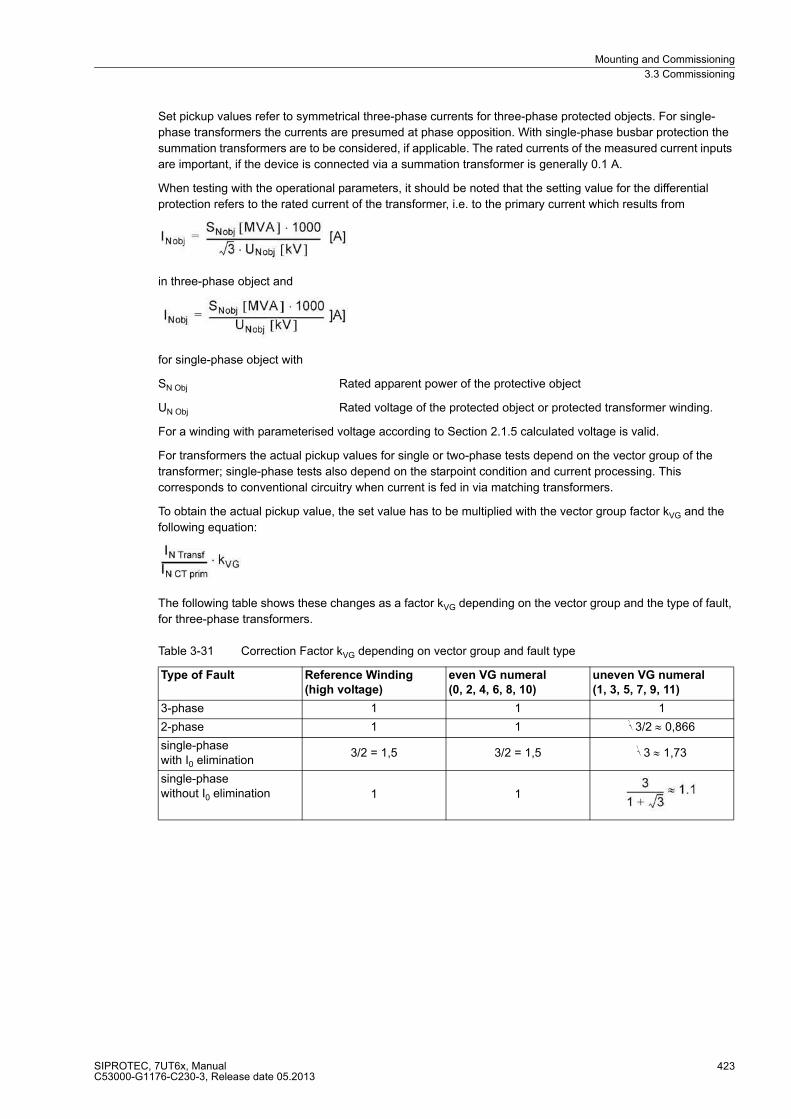
Mounting and Commissioning
3.3 Commissioning
SIPROTEC, 7UT6x, ManualC53000-G1176-C230-3, Release date 05.2013
423
Set pickup values refer to symmetrical three-phase currents for three-phase protected objects. For single-
phase transformers the currents are presumed at phase opposition. With single-phase busbar protection the
summation transformers are to be considered, if applicable. The rated currents of the measured current inputs
are important, if the device is connected via a summation transformer is generally 0.1 A.
When testing with the operational parameters, it should be noted that the setting value for the differential
protection refers to the rated current of the transformer, i.e. to the primary current which results from
in three-phase object and
for single-phase object with
SN Obj Rated apparent power of the protective object
UN Obj Rated voltage of the protected object or protected transformer winding.
For a winding with parameterised voltage according to Section 2.1.5 calculated voltage is valid.
For transformers the actual pickup values for single or two-phase tests depend on the vector group of the
transformer; single-phase tests also depend on the starpoint condition and current processing. This
corresponds to conventional circuitry when current is fed in via matching transformers.
To obtain the actual pickup value, the set value has to be multiplied with the vector group factor kVG and the
following equation:
The following table shows these changes as a factor kVG depending on the vector group and the type of fault,
for three-phase transformers.
Table 3-31 Correction Factor kVG depending on vector group and fault type
Type of Fault Reference Winding
(high voltage)
even VG numeral
(0, 2, 4, 6, 8, 10)
uneven VG numeral
(1, 3, 5, 7, 9, 11)
3-phase 1 1 1
2-phase 1 1 √3/2 ≈ 0,866
single-phasewith I0 elimination
3/2 = 1,5 3/2 = 1,5 √3 ≈ 1,73
single-phasewithout I0 elimination 1 1
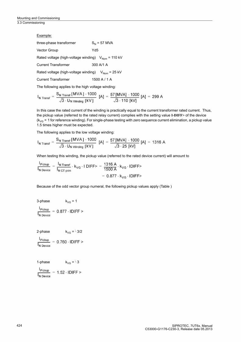
Mounting and Commissioning
3.3 Commissioning
SIPROTEC, 7UT6x, ManualC53000-G1176-C230-3, Release date 05.2013
424
Example:
three-phase transformer SN = 57 MVA
Vector Group Yd5
Rated voltage (high-voltage winding) VNom = 110 kV
Current Transformer 300 A/1 A
Rated voltage (high-voltage winding) VNom = 25 kV
Current Transformer 1500 A / 1 A
The following applies to the high voltage winding:
In this case the rated current of the winding is practically equal to the current transformer rated current. Thus,
the pickup value (referred to the rated relay current) complies with the setting value I-DIFF> of the device
(kVG = 1 for reference winding). For single-phase testing with zero sequence current elimination, a pickup value
1.5 times higher must be expected.
The following applies to the low voltage winding:
When testing this winding, the pickup value (referred to the rated device current) will amount to
Because of the odd vector group numeral, the following pickup values apply (Table )
3-phase kVG = 1
2-phase kVG = √3/2
1-phase kVG = √3

Mounting and Commissioning
3.3 Commissioning
SIPROTEC, 7UT6x, ManualC53000-G1176-C230-3, Release date 05.2013
425
Flexible Functions
While the protection, supervision and measuring functions implemented in the device and part of the device
firmware are "fixed", the flexible functions are individually configured (see Section 2.1.4 under margin heading
„Flexible Functions“). Configuration testing is best performed using secondary testing, as the internal connec-
tions have to be checked. Verification of the system connections is contained in a later primary commissioning
(Section 3.3 under „Circuit Breaker Failure Protection Tests“).
In these secondary testings mainly the correct assignments of flexible function to the analogue measured
inputs are verified, as well as to the binary in/outputs.
Every flexible function is individually checked, as each was individually configured.
Current Functions
For flexible functions with Current Input test currents are fed into the current input, i.e. one after the other, those
that are relevant to the tested flexible functions. For functions working on exceeding currents a slowly increased
test current is applied until the function trips. Value undershooting above a pickup value it is decreased. Keep
in mind that the corresponding message can be delayed if a time delay is set.
Caution!
Tests with currents that exceed more than 4 times the rated device current cause an overload of the input
circuits and may only be performed for a short time.
See Technical Data
Afterwards the device has to cool off!
When checking pickup values keep in mind:
� If the current function is assigned to one side of the main protective object, the pickup values are referred to
the rated current (I/IN S). Magnitude factors are included. The rated current of the side can be determined
analogue to the equations above under :Differential Protection". The test current has to be converted to
secondary value.
� If the current function is assigned to a measured location and the pickup values are set secondary, the
pickup value equals the secondary setting value.
� If the current function is assigned to a measured location and the pickup values are set primary, the setting
value is to be converted to secondary value, so that the pickup value at the secondary test current is main-
tained. For the conversion the transformation of the current transformer (set for this device measuring input)
is important.
� Tests for positive and negative sequence system currents are easiest with three-phase symmetrical testing.
The positive sequence system can be obtained by symmetrical test currents, the negative sequence system
by exchanging two phases. The setting values I1 and I2 correspond to the magnitude of each test current.
For single-phase testing the positive and negative sequence currents are 1/3 of the test current.
� Testing the zero system can be done single-phase at any of the three-phase current inputs. Zero sequence
current is set to 3 · I0, the test current corresponds to the must-pickup value.
Mounting and Commissioning
3.3 Commissioning
SIPROTEC, 7UT6x, ManualC53000-G1176-C230-3, Release date 05.2013
426
Voltage Functions
For flexible functions with Voltage Detection the test voltages are fed to into the single-phase or to the voltage
measuring inputs. This is also valid for the frequency function. A symmetrical three-phase voltage source is
recommended. If testing takes place with a single-phase current source, special considerations are applicable,
which will still be given. For functions working on exceeding voltages slowly increased test voltage is applied
until the function trips. Value undershooting above a pickup value it is decreased. Keep in mind that the corre-
sponding message can be delayed if a time delay is set.
Caution!
Tests with voltages that exceed more than 170 V at the voltage input terminals cause an overload of the input
circuits and may only be performed for a short time.
See Technical Data
Afterwards the device has to cool off!
When checking pickup values keep in mind:
� Valid for all voltages is that the secondary settings are done in volts. If primary values were set, these are to
be converted to secondary values via the voltage transformer data.
� If a single voltage, monitored by the flexible function, is to be tested, check the voltage measuring input in
single-phase.
� If the phase-to-earth voltages important, do the testing at the three-phase voltage measuring inputs; this can
be done three-phase or single-phase (after each other for every phase). When testing for voltage decrease
the not tested voltages have to lie above the pickup value, so that triggering can be prevented.
� If the phase-to-phase voltages are important, three-phase testing is recommended. Otherwise make sure
that the test voltage lies above both measuring inputs for the connected voltage. When testing voltage
decrease the not tested phase must receive a sufficiently high voltage, so that the voltages connected to it
lie above the pickup value.
� Tests for positive and negative sequence system voltages are easiest with three-phase symmetrical testing.
The positive sequence system can be obtained by symmetrical test voltages, the negative sequence system
by exchanging two phases. The setting value U1 and U2 correspond to the magnitude of every test voltage
against starpoint. For single-phase testing the positive and negative sequence voltage are 1/3 of the test volt-
age.
� Testing the zero system can be done single-phase at any of the three-phase voltage inputs. Zero sequence
voltage is set to 3 · I0, the test voltage corresponds to the must-pickup value.
� If a flexible function is configured for frequency monitoring, the pickup value can only be tested with a voltage
source with variable frequency. A special test is not needed, as the device always determines the frequency
from the positive sequence system of the three phase voltages. A possibly wrong allocation of the measuring
quantities for the frequency determination is therefore excluded.
Mounting and Commissioning
3.3 Commissioning
SIPROTEC, 7UT6x, ManualC53000-G1176-C230-3, Release date 05.2013
427
Power Functions
For flexible functions with power functions test voltages and currents are needed. Voltages are applied to the
three voltage measuring inputs and the currents fed into those current measuring inputs, that the voltages are
assigned according to Section 2.1.4 under "Assignment of Voltage Measuring Inputs“.
Important for the load direction and signs:
� the polarity of the test quantities,
� setting of the polarity for the current measuring location/side in the test, according to polarity setting
(e.g. Address 511 STRPNT->OBJ M1 for measuring location 1),
� setting for the sign of power under Address 1107 P,Q sign in system data 2.
For default settings the active power for the three-phase testing with in-phase currents and voltages amounts
to √3 · Utest · Itest (Utest phase-phase). For single-phase testing with in-phase test quantities 1/9 of the three-
phase value as the power is calculated from the positive-sequence systems, which amount to 1/3 each in the
currents as well as in the voltages.
Reactive power can only be tested single-phase if a phase displacement between current and voltage is pos-
sible. With three-phase test quantities, reactive power can be simulated by phase exchange, although a phase
displacement between currents and voltages is not possible. The following table gives examples. Here, the
factors for active and reactive power refer to the power S = √3 · Utest · Itest. The currents are in phase
segregated connection, the voltages have been swapped cyclically. An anti-cyclic exchange (e.g. L2 ↔ L3) is
not permissible as the positive-sequence system would amount to zero in that case.
Table 3-32 Reactive Power Simulation by means of Phase Exchange
Termination of Tests
Secondary feeding of test currents are still required for the tests of the circuit breaker failure protection as set
out below. If no further circuit breaker failure protection needs to be tested, all secondary test connections must
be removed.
Should you have changed setting values for secondary tests, these should now be set to required setpoints.
Test Quantities I Test values U Active Power Reactive power
IL1 at input IL1
IL2 at input IL2
IL3 at input IL3
UL1 at input UL1
UL2 at input UL2
UL3 at input UL3
1 ≈0
IL1 at input IL1
IL2 at input IL2
IL3 at input IL3
UL1 at input UL1
UL2 at input UL2
UL3 at input UL3
–0,5 0,866
IL1 at input IL1
IL2 at input IL2
IL3 at input IL3
UL3 at input UL1
UL1 at input UL2
UL2 at input UL3
–0,5 –0,866

Mounting and Commissioning
3.3 Commissioning
SIPROTEC, 7UT6x, ManualC53000-G1176-C230-3, Release date 05.2013
428
3.3.7 Circuit Breaker Failure Protection Tests
If the device is equipped with the breaker failure protection and this function is used, the integration of this
protection function into the system must be tested under practical conditions.
Before starting the circuit tests it is recommended to isolate the circuit breaker of the feeder to be tested at both
ends, i.e. line disconnectors and busbar disconnectors should be open so that the breaker can be operated
without risk.
Because of the manifold applications and various configuration possibilities of the plant it is not possible to give
a detailed description of the necessary test steps. It is important to consider the local conditions and the
protection and plant drawings.
Caution!
Also for tests on the local circuit breaker of the feeder a trip command to the surrounding circuit breakers can
be issued for the busbar.
Non-observance of the following measure can result in minor personal injury or property damage.
First disable the trip commands to the adjacent (busbar) breakers, e.g. by interrupting the associated control
voltages.
The trip command of other protection functions is made ineffective so that the local breaker can be tripped only
by the breaker failure protection function.
Although the following list does not claim to be complete, it may also contain points which are to be ignored in
the current application.
Circuit Breaker Auxiliary Contacts
The circuit breaker auxiliary contact(s) form an essential part of the breaker failure protection system in case
they have been connected to the device. Make sure that the correct assignment has been checked. Make sure
that the measured currents for breaker failure protection (CTs), the tested circuit breaker, and its auxiliary con-
tact(s) relate to the same measuring location or side of the protected object.
External Initiation Conditions
If the breaker failure protection is intended to be initiated by external protection devices, each of the external
initiation conditions must be checked.
In order for the breaker failure protection to be started, a current must flow at least via the monitored phase.
This may be a secondary injected current.
� Start by trip command of the external protection: binary input >CBF Start (No 1431) in spontaneous or fault
annunciations.
� Following initiation the annunciation CBF Pup. external (No 1457) must appear in the fault annunciations
(trip log) or in the spontaneous annunciations.
� With two-stage breaker failure protection, the trip repetition command to the local circuit breaker is issued
after the delay time T1 (address 7115), and the indication CBF TRIP T1 (No 1492).
� With single- or two-stage failure protection, the trip repetition command to the local circuit breaker is issued
after the delay time T2 (address 7116), and the indication CBF TRIP T2 (No 1494)
Switch off test current.
Mounting and Commissioning
3.3 Commissioning
SIPROTEC, 7UT6x, ManualC53000-G1176-C230-3, Release date 05.2013
429
If start is possible without current flow:
� Close tested circuit breaker while the disconnectors at both sides are open.
� Start by trip command of the external protection:
� Binary input >CBF Start (No 1431) in the spontaneous or fault annunciations.
� Following initiation the annunciation CBF Pup. external (No 1457) must appear in the fault annunciations
(trip log) or in the spontaneous annunciations.
� With two-stage breaker failure protection, the trip repetition command to the local circuit breaker is issued
after the delay time T1 (address 7115), and the indication CBF TRIP T1 (No 1492).
� With single- or two-stage failure protection, the trip repetition command to the local circuit breaker is issued
after the delay time T2 (address 7116), and the indication CBF TRIP T2 (No 1494).
Reopen the local circuit breaker.
Busbar Trip
In particular with multiple busbars the trip distribution logic for the surrounding circuit breakers must be
checked. Here check for every busbar section that all circuit breakers which are connected to the same busbar
section as the feeder circuit breaker under observation are tripped, and no other breakers.
The adjacent circuit breakers are those of all feeders which must be tripped in order to ensure interruption of
the fault current should the local breaker fail. In other words, the adjacent breakers are those of all feeders
which may feed the same busbar or busbar section as the faulty feeder. In case of a power transformer, the
adjacent breakers may include the breaker of the lower-voltage side (or any other side) of the transformer, if
the upper voltage side breaker is to be monitored, and vice versa.
The most important thing is the check of the correct distribution of the trip commands to the adjacent circuit
breakers in case of breaker failure.
A general detailed test guide cannot be specified because the layout of the adjacent circuit breakers largely
depends on the system topology.
Termination of the Checks
All temporary measures taken for testing must be undone. This is to ensure that all switching devices of the
system are in the correct state, that interrupted trigger connections are restored and that control voltages are
activated. Setting values that may have been changed for the tests, must be corrected and protective functions
that were switched, must be set to the intended switching state (ON or OFF).
Mounting and Commissioning
3.3 Commissioning
SIPROTEC, 7UT6x, ManualC53000-G1176-C230-3, Release date 05.2013
430
3.3.8 Symmetrical, Primary Current Tests on the Protected Object
If secondary test equipment is connected to the device, it must be removed; any existing test switches should
be in normal operating position.
Note
It should be expected that tripping occurs if connections were wrong.
The measured quantities of the following tests can be read out from the PC using a web browser via the WEB
monitor. This provides comfortable read-out possibilities for all measured values with visualisation using phasor
diagrams.
If you choose to work with the Web-monitor, please note the Help files referring to the Web-monitor. The IP
address required for the browser depends on the port used for connecting the PC:
� Connection to the front operator interface: IP address192.168.1.1
� Connection to the rear service interface: IP address192.168.2.1
The transmission speed is 115 kBaud.
The following descriptions refer to read-out of measured values with DIGSI. All measured values can be read
out from the device.
Preparation of Symmetrical Current Tests
At first commissioning, current checks must be performed before the protected object is energised for the first
time. This ensures that the differential protection is operative as a short-circuit protection during the first exci-
tation of the protected object with voltage. If current checks are only possible with the protected object under
voltage (e.g. power transformers in networks when no low-voltage test equipment is available), it is imperative
that a backup protection, e.g. time overcurrent protection, be commissioned before, which operates at least at
the feeding side. The trip circuits of other protection devices (e.g. Buchholz protection) must remain operative
as well.
If more than 2 measuring locations are present for the main protected object, the test must be repeated such
that each possible current path through the protected object has been part of a test. It is not necessary to test
every possible current path. Thus, it is advised to start with measuring location M1 of the main protected object
and to check this measuring location against all others. If a side has more than one measuring location, each
location must be included in a test. The other measuring locations remain current-free.
If further three-phase protected objects are present, these are tested individually according to their topology.
The test setup varies dependent of the application
DANGER!
Operations in the primary area must be performed only with plant sections voltage-free and earthed!
Perilous voltages may occur even on voltage-free plant sections due to capacitive influence caused by
other live sections!

Mounting and Commissioning
3.3 Commissioning
SIPROTEC, 7UT6x, ManualC53000-G1176-C230-3, Release date 05.2013
431
On network power transformers and asynchronous machines a low-voltage test is preferably used. A low-
voltage current source is used to energise the protected object, which is completely disconnected from the net-
work. A short-circuit bridge, which is capable of carrying the test current, is installed outside the protected zone
and allows the symmetrical test current to flow. On transformers, the test source is normally connected at the
primary side, and the short-circuit bridges are on the lower voltage side..
Figure 3-31 Test installation with low-voltage source — example for transformer and motor
On power station unit transformers and synchronous machines, the checks are performed during the current
tests, with the generator itself supplying the test current. The current is produced by a short-circuit bridge which
is installed outside the protected zone and is capable of carrying generator rated current for a short time.
Figure 3-32 Test installation at power station with generator as voltage source — example
On busbars and short lines a low-voltage test source can be used or alternatively one can test with load current.
In the latter case the above hints about backup protection must be observed!
With the single-phase differential protection for busbars with more than 2 feeders, symmetrical current test is
not necessary (but permissible, of course). The test can be carried out using a single-phase current source.
However, current tests must be performed for each possible current path (e.g. feeder 1 against feeder 2, feeder
1 against feeder 3, etc.) Please first read the notes contained in the section „Current Testing for Busbar
Protection“.
Mounting and Commissioning
3.3 Commissioning
SIPROTEC, 7UT6x, ManualC53000-G1176-C230-3, Release date 05.2013
432
Implementation of Symmetrical Current Tests
Before beginning with the first current test, check the correct polarity setting for measuring location 1 on the
basis of address 511 STRPNT->OBJ M1and compare it with the actual current connections. Refer to Section
2.1.4 under margin heading „Current Transformer Data for Three-phase Measuring Locations“ for more details.
This check is also important for devices with voltage inputs as all further wrong polarities will not be recognised
because the protection functions may operate even correctly if all polarities are wrong. Only during power check
would the errors be recognised.
For these commissioning tests the test current must be at least 2 % of the rated relay current for each phase.
If deviations occur that cannot be explained by measuring tolerances, either a connection or the test setup is
wrong:
These tests cannot replace visual inspection of the correct current transformer connections. Therefore, a
prerequisite for this test is that the system connections have been completely checked.
The equation symbol for current (I, ϕ) is following by the phase identifier L1 and by a number that identifies the
side (e.g. the transformer winding) or the measuring location, example:
IL1 S1 current in phase L1 on side S1,
IL1 M1 current in phase L1 at the measuring location M1.
The following procedure applies to a three-phase protected object for measuring location M1 against measur-
ing location M2. For transformers it is assumed that measuring location 1 is assigned to side 1, and this is the
high-voltage side of the transformer. The other possible current paths are tested in an analogous way.
� The operational measured values supplied by the 7UT6x allow fast commissioning without external instru-
ments. The following indices are used for the display of measured values:
– At the indication of imbalance there might actually be asymmetries of the primary system. If they are part
of normal operation, the corresponding monitoring function is set less sensitive (see Section 2.19.1,
under margin heading „Measured Value Supervision“).
– In general, the phase rotation is a clockwise phase rotation. If the system has an anti-clockwise phase
rotation, this must have been considered when the power system data was set (address 271 PHASE
SEQ., refer to Subsection 2.1.4 under margin heading „Phase Sequence“). Wrong phase rotation is indi-
cated with the annunciation „Fail Ph. Seq. I“ (No 175). The measuring location with wrong phase rotation
is also stated. The phase allocation of the measured value inputs must be checked and corrected, if re-
quired, after the measuring location has been isolated. The phase rotation check must then be repeated.
� Switch on the test current or start up the generator and bring it to nominal speed and excite it to the required
test current. None of the measurement monitoring functions in the 7UT6x must respond. If there was a fault
annunciation, however, the operational annunciations or spontaneous annunciations could be checked to
investigate the reason for it (refer also to the SIPROTEC 4 System Description /1/ ).
Compare the indicated current magnitudes under measurement → secondary → operational measured
values secondary with the actually flowing values:
This applies for all measuring locations included in the test.
Note: The WEB Monitor provides comfortable read-out possibilities for all measured values with
visualisation using phasor diagrams (Figure ).
Amplitude measurement with switched on test current:
– Switch off the test source and the protected object (shut down the generator) and earth it,
– Re-check the assignment or the tested measuring location (Section 2.1.4 under margin heading
„Assignment of 3-phase measuring locations“).
– Re-check the settings for the magnitude matching (Subsection 2.1.4 under margin heading
„Current Transformer Data for 3-phase Measuring Locations“).
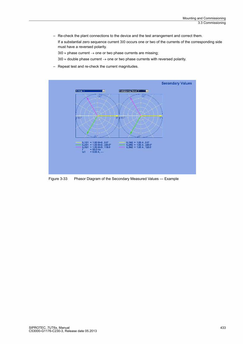
Mounting and Commissioning
3.3 Commissioning
SIPROTEC, 7UT6x, ManualC53000-G1176-C230-3, Release date 05.2013
433
– Re-check the plant connections to the device and the test arrangement and correct them.
If a substantial zero sequence current 3I0 occurs one or two of the currents of the corresponding side
must have a reversed polarity.
3I0 ≈ phase current → one or two phase currents are missing;
3I0 ≈ double phase current → one or two phase currents with reversed polarity.
– Repeat test and re-check the current magnitudes.
Figure 3-33 Phasor Diagram of the Secondary Measured Values — Example
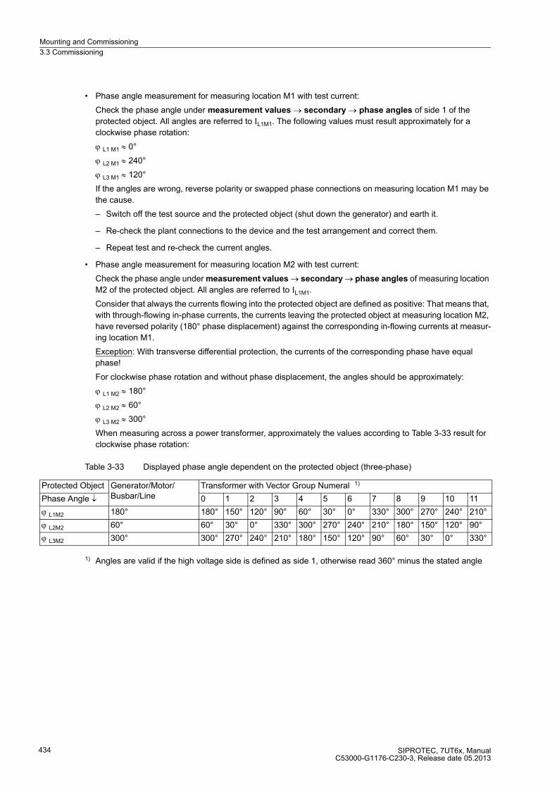
Mounting and Commissioning
3.3 Commissioning
SIPROTEC, 7UT6x, ManualC53000-G1176-C230-3, Release date 05.2013
434
� Phase angle measurement for measuring location M1 with test current:
Check the phase angle under measurement values → secondary → phase angles of side 1 of the
protected object. All angles are referred to IL1M1. The following values must result approximately for a
clockwise phase rotation:
ϕ L1 M1 ≈ 0°
ϕ L2 M1 ≈ 240°
ϕ L3 M1 ≈ 120°
If the angles are wrong, reverse polarity or swapped phase connections on measuring location M1 may be
the cause.
– Switch off the test source and the protected object (shut down the generator) and earth it.
– Re-check the plant connections to the device and the test arrangement and correct them.
– Repeat test and re-check the current angles.
� Phase angle measurement for measuring location M2 with test current:
Check the phase angle under measurement values → secondary → phase angles of measuring location
M2 of the protected object. All angles are referred to IL1M1.
Consider that always the currents flowing into the protected object are defined as positive: That means that,
with through-flowing in-phase currents, the currents leaving the protected object at measuring location M2,
have reversed polarity (180° phase displacement) against the corresponding in-flowing currents at measur-
ing location M1.
Exception: With transverse differential protection, the currents of the corresponding phase have equal
phase!
For clockwise phase rotation and without phase displacement, the angles should be approximately:
ϕ L1 M2 ≈ 180°
ϕ L2 M2 ≈ 60°
ϕ L3 M2 ≈ 300°
When measuring across a power transformer, approximately the values according to Table 3-33 result for
clockwise phase rotation:
Table 3-33 Displayed phase angle dependent on the protected object (three-phase)
1) Angles are valid if the high voltage side is defined as side 1, otherwise read 360° minus the stated angle
Protected Object Generator/Motor/ Busbar/Line
Transformer with Vector Group Numeral 1)
Phase Angle ↓ 0 1 2 3 4 5 6 7 8 9 10 11
ϕ L1M2 180° 180° 150° 120° 90° 60° 30° 0° 330° 300° 270° 240° 210°
ϕ L2M2 60° 60° 30° 0° 330° 300° 270° 240° 210° 180° 150° 120° 90°
ϕ L3M2 300° 300° 270° 240° 210° 180° 150° 120° 90° 60° 30° 0° 330°
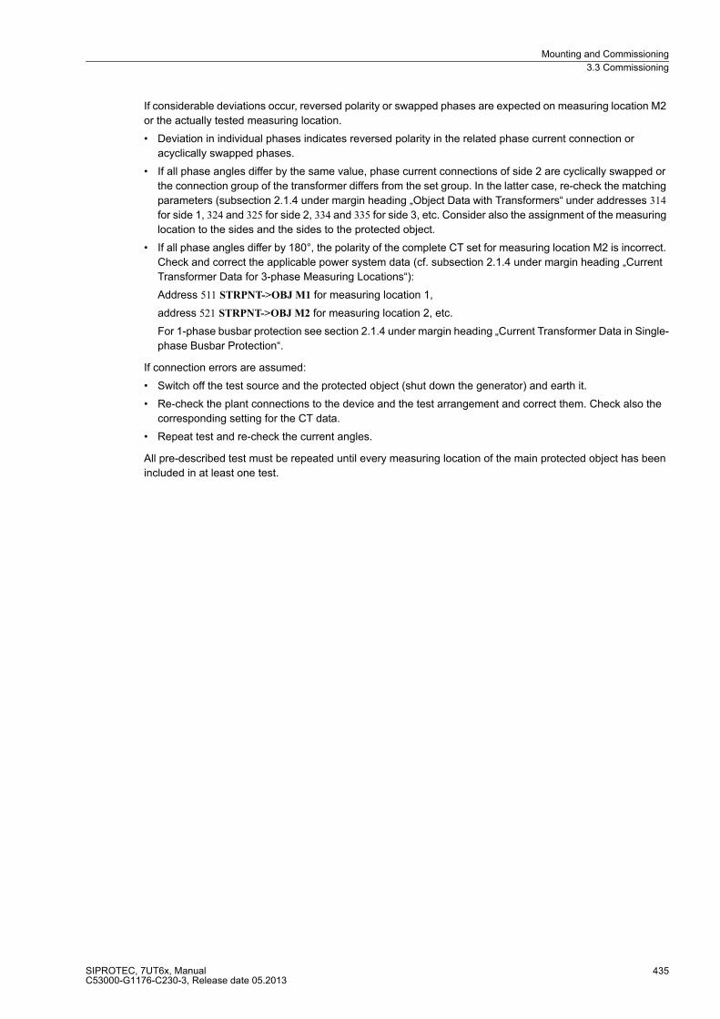
Mounting and Commissioning
3.3 Commissioning
SIPROTEC, 7UT6x, ManualC53000-G1176-C230-3, Release date 05.2013
435
If considerable deviations occur, reversed polarity or swapped phases are expected on measuring location M2
or the actually tested measuring location.
� Deviation in individual phases indicates reversed polarity in the related phase current connection or
acyclically swapped phases.
� If all phase angles differ by the same value, phase current connections of side 2 are cyclically swapped or
the connection group of the transformer differs from the set group. In the latter case, re-check the matching
parameters (subsection 2.1.4 under margin heading „Object Data with Transformers“ under addresses 314
for side 1, 324 and 325 for side 2, 334 and 335 for side 3, etc. Consider also the assignment of the measuring
location to the sides and the sides to the protected object.
� If all phase angles differ by 180°, the polarity of the complete CT set for measuring location M2 is incorrect.
Check and correct the applicable power system data (cf. subsection 2.1.4 under margin heading „Current
Transformer Data for 3-phase Measuring Locations“):
Address 511 STRPNT->OBJ M1 for measuring location 1,
address 521 STRPNT->OBJ M2 for measuring location 2, etc.
For 1-phase busbar protection see section 2.1.4 under margin heading „Current Transformer Data in Single-
phase Busbar Protection“.
If connection errors are assumed:
� Switch off the test source and the protected object (shut down the generator) and earth it.
� Re-check the plant connections to the device and the test arrangement and correct them. Check also the
corresponding setting for the CT data.
� Repeat test and re-check the current angles.
All pre-described test must be repeated until every measuring location of the main protected object has been
included in at least one test.

Mounting and Commissioning
3.3 Commissioning
SIPROTEC, 7UT6x, ManualC53000-G1176-C230-3, Release date 05.2013
436
Measuring Differential and Restraint Currents
Before the tests with symmetrical currents are terminated, the differential and restraint currents are examined.
Even if the above tests with symmetrical current should to a large extent have detected connection errors,
errors concerning current matching and vector group can nevertheless not be completely excluded.
The differential and restraint currents are referred to the rated currents of the protected object. This must be
considered when they are compared with the test currents. With more than 2 sides, the highest rated current
of any side of the protected object is the rated object current.
� Read out the differential and restraint currents under Measured Values → Percentage → Measured
Values I-diff; I-stab.
In the „WEB Monitor“, the differential and restraint currents are displayed as a graph in a characteristics
diagram (Figure ).
– The differential currents „Diff L1:“, „Diff L2:“, „Diff L3:“ must be low, i.e. at least one scale less than the
through-flowing test currents.
– If there are differential currents in the size of the restraint currents (approximately twice the through-
flowing test current), you may assume a polarity reversal of the current transformer(s) at one side. Check
the polarity again and set it right after short-circuiting all six current transformers. If you have modified
these current transformers, repeat the angle test.
– The restraint currents „Res. L1:“, „Res. L2:“, „Res. L3:“ correspond to twice the through-flowing test cur-
rents.
– If there are differential currents which are nearly equal in all three phases, matching of the measured
values may be erroneous. Wrong vector group of a power transformer can be excluded because it should
already have been detected during the phase angle test. Re-check the settings for current matching.
These are mainly the data of the protected object (Power System Data 1, Section 2.1.4):
For all kinds of power transformers, addresses 311 and 312 for side 1 under „Object Data with Transform-
ers“ and accordingly the parameters for the other side(s) under test. Furthermore, addresses 512 and 513
for measuring location M1 under „Current Transformer Data for 3-phase Measuring Locations“, and ac-
cordingly the parameters for the other measuring location(s) under test.
For generators, motors, reactors, addresses 361 and 362 under „Object Data with Generators, Motors or
Reactors“, and addresses 512 and 513 for measuring location 1 under „Current Transformer Data for 3-
phase Measuring Locations“and accordingly the parameters for the other measuring location(s) under
test.
For mini-busbars (3-phase), address 372 under „Object Data with Mini-Busbars or Short Lines" (3-phase)“
for feeder 1 and accordingly the parameters for the other feeder(s) under test, and addresses 512 and
513 for measuring location 1 under „Current Transformer Data for 3-phase Measuring Locations“ and ac-
cordingly the parameters for the other measuring location(s) under test.
For single-phase busbar protection, address 381 under „Object Data with Busbars (1-phase Connection)
with up to 6 or 9 or 12 feeders“ and addresses 562 and 563 under „Current Transformer Data for single-
phase Busbar Protection“ for feeder 1 and accordingly the parameters for the other feeders under test. If
interposed summation transformers are used, matching errors can be caused by wrong connections at
the summation CTs.
� Finally, switch off the test source and the protected object (shut down the generator).
� If parameter settings have been changed for the tests, reset them to the values necessary for operation.
Please keep in mind that the previous tests must be repeated for each current path.
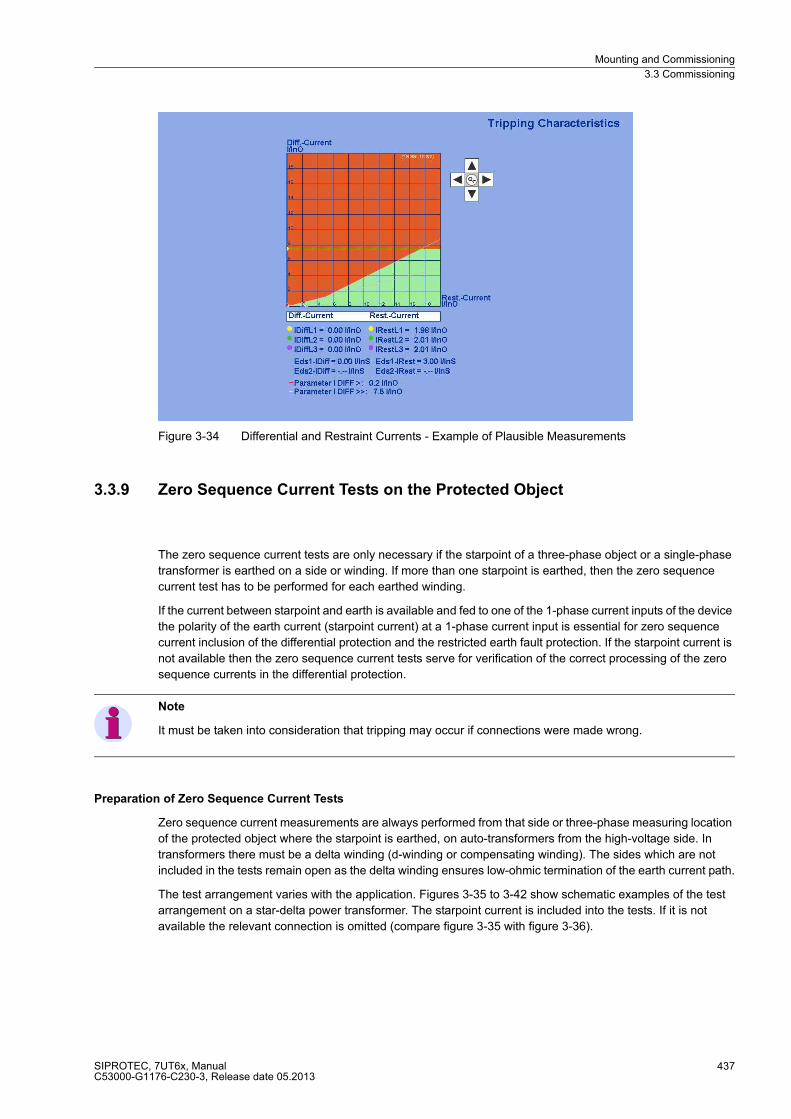
Mounting and Commissioning
3.3 Commissioning
SIPROTEC, 7UT6x, ManualC53000-G1176-C230-3, Release date 05.2013
437
Figure 3-34 Differential and Restraint Currents - Example of Plausible Measurements
3.3.9 Zero Sequence Current Tests on the Protected Object
The zero sequence current tests are only necessary if the starpoint of a three-phase object or a single-phase
transformer is earthed on a side or winding. If more than one starpoint is earthed, then the zero sequence
current test has to be performed for each earthed winding.
If the current between starpoint and earth is available and fed to one of the 1-phase current inputs of the device
the polarity of the earth current (starpoint current) at a 1-phase current input is essential for zero sequence
current inclusion of the differential protection and the restricted earth fault protection. If the starpoint current is
not available then the zero sequence current tests serve for verification of the correct processing of the zero
sequence currents in the differential protection.
Note
It must be taken into consideration that tripping may occur if connections were made wrong.
Preparation of Zero Sequence Current Tests
Zero sequence current measurements are always performed from that side or three-phase measuring location
of the protected object where the starpoint is earthed, on auto-transformers from the high-voltage side. In
transformers there must be a delta winding (d-winding or compensating winding). The sides which are not
included in the tests remain open as the delta winding ensures low-ohmic termination of the earth current path.
The test arrangement varies with the application. Figures 3-35 to 3-42 show schematic examples of the test
arrangement on a star-delta power transformer. The starpoint current is included into the tests. If it is not
available the relevant connection is omitted (compare figure 3-35 with figure 3-36).

Mounting and Commissioning
3.3 Commissioning
SIPROTEC, 7UT6x, ManualC53000-G1176-C230-3, Release date 05.2013
438
DANGER!
Operations in the primary area must be performed only with plant sections voltage-free and earthed!
Perilous voltages may occur even on voltage-free plant sections due to capacitive influence caused by
other live sections!
Figure 3-35 Zero sequence current measurement on a star-delta transformer — without inclusion of the starpoint current
Figure 3-36 Zero sequence current measurement on a star-delta transformer

Mounting and Commissioning
3.3 Commissioning
SIPROTEC, 7UT6x, ManualC53000-G1176-C230-3, Release date 05.2013
439
Figure 3-37 Zero sequence current measurement on a star-star transformer with compensation winding
Figure 3-38 Zero sequence current measurement on an auto-transformer with compensation winding
Figure 3-39 Zero sequence current measurement on a zig-zag-winding
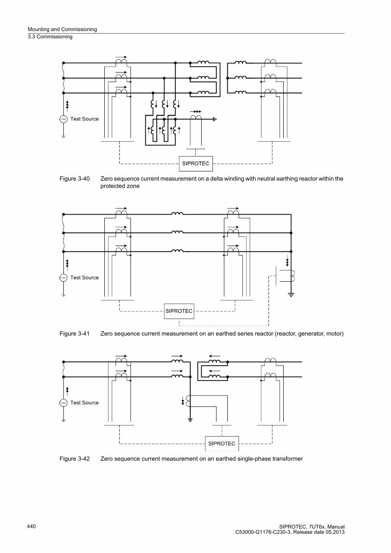
Mounting and Commissioning
3.3 Commissioning
SIPROTEC, 7UT6x, ManualC53000-G1176-C230-3, Release date 05.2013
440
Figure 3-40 Zero sequence current measurement on a delta winding with neutral earthing reactor within the protected zone
Figure 3-41 Zero sequence current measurement on an earthed series reactor (reactor, generator, motor)
Figure 3-42 Zero sequence current measurement on an earthed single-phase transformer
Mounting and Commissioning
3.3 Commissioning
SIPROTEC, 7UT6x, ManualC53000-G1176-C230-3, Release date 05.2013
441
Implementation of Zero Sequence Current Tests
For these commissioning tests, the zero sequence current must be at least 2 % of the rated relay current for
each phase, i.e. the test current at least 6 %.
This test cannot replace visual inspection of the correct current transformer connections. Therefore, the
inspection of these connections is a prerequisite.
� Switch on test current.
� Read out the current magnitudes:
Compare the indicated current magnitudes under measurement → secondary → operational measured
values secondary with the actually flowing values:
– All phase currents of the tested measuring location correspond to approximately 1/3 of the test current
(for 1-phase transformers 1/2),
– 3I0 of the tested measuring location corresponds to the test current.
– Phase currents and zero sequence current of the other measuring location are, on transformers, nearly 0.
– The current at the auxiliary 1-phase current input corresponds to the test current — provided this current
is available and included.
Deviation can practically occur only for the single-phase current (if included) because the connection of the
phase currents had been verified already during the symmetrical tests. In case of deviations:
– Switch off the test source and the protected object (shut down the generator) and earth it.
– Re-check the assignment or the tested 1-phase input (subsection 2.1.4 under margin heading
„Assignment of Auxiliary 1-phase Measuring Locations“).
– Re-check the settings for the magnitude matching (Subsection 2.1.4 under margin heading „Current
Transformer Data for 1-phase Auxiliary Current Inputs“).
– Check the plant connections to the device and the test arrangement and correct them.
– Repeat test and re-check the current magnitudes.

Mounting and Commissioning
3.3 Commissioning
SIPROTEC, 7UT6x, ManualC53000-G1176-C230-3, Release date 05.2013
442
Measuring Differential and Restraint Currents
The differential and restraint currents are referred to the rated currents of the tested side of the main protected
object. If a zero sequence current test does not concern the main protected object but a different earthed object
(e.g. a shunt reactor outside the main object), the base of the referred currents is the rated current of that 3-
phase measuring location to which the 1-phase current input is assigned, i.e. the measuring location under test.
This must be considered when they are compared with the test currents.
� Switch on test current.
� If the starpoint current is available:
Read out the differential and restraint currents I-Diff; I-Rest under Measurement → Percent Values →
Differential and Restraint Currents.
– The differential current of the restricted earth fault protection IDiff REF must be low, at least one scale less
than the test current.
– The stabilisaing current IRest REF corresponds to twice the test current.
– If the differential current is in the size of the restraint current (approximately twice the test current), you
may assume a polarity reversal of the single-phase current transformer. Check the polarity again and
compare it with the setting in address 711 EARTH IX1 AT if the auxiliary single-phase input IX1 is under
test (cf. also subsection 2.1.4 under margin heading „Current Transformer Data for single-phase Auxiliary
Current Inputs“), or accordingly the parameters for the actual input under test.
– If there is a differential current which does not correspond to twice the test current, the matching factor
for the 1-phase input may be incorrect. Check the settings relevant for current matching. These are
mainly the data of the protected object and its current transformers (Subsection 2.1.4):
– for power transformers addresses 313, 323 etc. (dependent on the tested winding), under margin heading
„Object Data with Transformers“ and
– in all cases addresses 712, 713 or 722, 723 etc. (depending on the used 1-phase input), under margin
heading „Current Transformer Data for Single-phase Auxiliary Current Inputs“.
� In all cases (whether or not the starpoint current is available):
Check the differential currents IDiff L1, IDiff L2, IDiff L3.
– The differential currents must be low, at least one scale less than the test current. If considerable
differential currents occur, re-check the settings for the starpoints:
– Starpoint conditioning of a transformer: addresses 313 STARPNT SIDE 1, 323 STARPNT SIDE 2, etc. (de-
pending on the tested winding) (Section 2.1.4, margin heading „Object Data with Transformers“), as well
as
– the assignment of the starpoint current transformer to the 1-phase current input under test: address 251,
252, etc. depending on the input under test, see Subsection 2.1.4 under margin heading „Assignment of
Auxiliary 1-phase Measuring Locations“.
– Countercheck: The restraint currents of the differential protection IRestL1, IRest L2, IRest L3 are equally small.
If all tests have been successful until now, this should be ensured.
� Finally, switch off the test source and the protected object (shut down the generator).
� If parameter settings have been changed for the tests, reset them to the values necessary for operation.
Please keep in mind that the previous tests must be repeated for each earthed side.
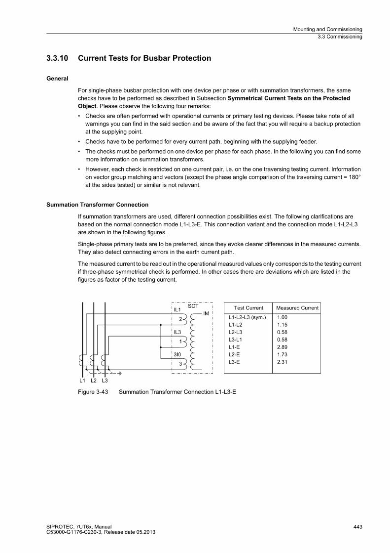
Mounting and Commissioning
3.3 Commissioning
SIPROTEC, 7UT6x, ManualC53000-G1176-C230-3, Release date 05.2013
443
3.3.10 Current Tests for Busbar Protection
General
For single-phase busbar protection with one device per phase or with summation transformers, the same
checks have to be performed as described in Subsection Symmetrical Current Tests on the Protected
Object. Please observe the following four remarks:
� Checks are often performed with operational currents or primary testing devices. Please take note of all
warnings you can find in the said section and be aware of the fact that you will require a backup protection
at the supplying point.
� Checks have to be performed for every current path, beginning with the supplying feeder.
� The checks must be performed on one device per phase for each phase. In the following you can find some
more information on summation transformers.
� However, each check is restricted on one current pair, i.e. on the one traversing testing current. Information
on vector group matching and vectors (except the phase angle comparison of the traversing current = 180°
at the sides tested) or similar is not relevant.
Summation Transformer Connection
If summation transformers are used, different connection possibilities exist. The following clarifications are
based on the normal connection mode L1-L3-E. This connection variant and the connection mode L1-L2-L3
are shown in the following figures.
Single-phase primary tests are to be preferred, since they evoke clearer differences in the measured currents.
They also detect connecting errors in the earth current path.
The measured current to be read out in the operational measured values only corresponds to the testing current
if three-phase symmetrical check is performed. In other cases there are deviations which are listed in the
figures as factor of the testing current.
Figure 3-43 Summation Transformer Connection L1-L3-E

Mounting and Commissioning
3.3 Commissioning
SIPROTEC, 7UT6x, ManualC53000-G1176-C230-3, Release date 05.2013
444
Figure 3-44 Summation transformer connection L1-L2-L3
Deviations which cannot be explained by measuring tolerances may be caused by connection errors or
matching errors of the summation transformers:
� Switch off the test source and the protected object and earth it,
� Check the plant connections to the device and the test arrangement and correct them.
� Repeat test and re-check the current magnitudes.
The phase angles must be 180° in all cases.
Check the differential and restraint currents for each phase.
If single-phase primary checks cannot be carried out but only symmetrical operational currents are available,
polarity or connecting errors in the earth current path with summation transformer connection L1–L3–E will not
be detected with the before-mentioned checks. In this case, asymmetry is to be achieved by secondary manip-
ulation.
Therefore the current transformer of phase L2 is short-circuited as shown in figure 3-45.
DANGER!
Manipulations on the measuring current transformers must be performed with the utmost precaution!
Non-observance of the following measures will result in death, severe personal injury or substantial property
damage.
Short-circuit the current transformers before disconnecting any current supply leads to the device!
Figure 3-45 Asymmetrical test with summation transformer connection L1-L3-E
The measured current is now 2.65 times the current of the symmetrical test.
This test must be carried out for each summation CT.
Mounting and Commissioning
3.3 Commissioning
SIPROTEC, 7UT6x, ManualC53000-G1176-C230-3, Release date 05.2013
445
3.3.11 Testing of the Non-Assigned 1-Phase Current Inputs
As far as single-phase current inputs belong to the main protected object, i.e. they are assigned to a side of the
main protected object, they were already checked with the zero sequence current tests.
Even if they are not assigned to the main protected object but to a 3-phase measuring location of a further pro-
tected object (e.g. restricted earth fault protection for a separate neutral earthing reactor), the same procedure
as for the zero sequence current applies. Perform the zero sequence current tests unless it has already been
done.
Single-phase measured current inputs of the device can also be used for any desired 1-phase protection
function. If this is an actual case and the same input has not yet been checked as a starpoint current input of
the main protected object, an additional check of this 1-phase input must be carried out.
The test methods depend widely on the application of the single-phase input.
By any means, the matching factors for the magnitude have to be checked (address 712, 713 etc. depending
on the input under test; refer also to Subsection 2.1.4 under margin heading „Current Transformer Data for
1-phase Auxiliary Current Inputs“). Consider whether or not the input under test is a high-sensitivity input
(address 255 for IX3 or 256 for IX4, refer to subsection 2.1.4 under margin heading „High-Sensitivity Auxiliary 1-
phase Measuring Locations“). Where applicable, consider the matching factors (addresses 734 and 744
respectively) when reading out the current magnitudes.
Polarity check is not required since only the current magnitude is processed.
With high-impedance protection the assigned 1-phase current corresponds to the fault current in the protected
object. Polarity of all current transformers supplying the resistor whose current is measured must be uniform.
For this purpose, traversing currents are used as for differential protection checks. Each current transformer
must be included into a measurement. The measured current must not exceed, for each through-current test,
half of the pickup value of the single-phase time overcurrent protection.
Mounting and Commissioning
3.3 Commissioning
SIPROTEC, 7UT6x, ManualC53000-G1176-C230-3, Release date 05.2013
446
3.3.12 Checking the Voltage Connections and Polarity Check
Voltage and Phase Sequence Check
If the device is connected to voltage transformers, these connections are checked using primary values. For
devices without voltage transformer connection this section can be bypassed.
The voltage transformer connections are tested for that measuring location or side to which they are assigned
(address 261, refer to Section 2.1.4 under margin heading „Assignment of Voltage Measuring Inputs“).
� Having energised the voltage transformer set, none of the measurement monitoring functions in the device
may respond.
– If there is a fault annunciation, however, the event log or spontaneous annunciation could be checked to
investigate the reason for it.
– At the indication of voltage summation error check also the assignment of the single-phase voltage input
and the matching factors. For further details see Section 2.1.4 under margin heading „Assignment of
Voltage Measuring Inputs“.
– At the indication of symmetry monitoring there might actually be asymmetries of the primary system. If
they are part of normal operation, the corresponding monitoring function is set less sensitive (see Sub-
section 2.19.1.4 under margin heading „Voltage Balance“).
The voltages can be read on the display at the front, or called up in the PC via the operator or service interface,
and compared with the actual measured quantities as primary or secondary values. Besides the magnitudes
of the phase-to-phase and the phase-to-earth voltages, the phase angles can be read out, thus enabling to
verify the correct phase sequence and polarity of individual voltage transformers. The voltages can also be read
out with the „Web Monitor“ (see figure ).
� The voltage magnitudes should be almost equal. All angles must be approximately 120° to each other in a
3-phase system.
– If the measured quantities are not plausible, the connections must be checked and revised after switching
off the measuring location. If the phase difference angle between two voltages is 60° instead of 120°, one
voltage must be polarity-reversed. The same applies if there are phase-to-phase voltages which almost
equal the phase-to-earth voltages instead of having a value that is √3 greater. The measurements are to
be repeated after setting the connections right.
– In general, the phase rotation is a clockwise phase rotation. If the system has an counter-clockwise phase
rotation, this must have been considered when the power system data was set (address 271 PHASE
SEQ., refer to Subsection 2.1.4 under margin heading „Phase Sequence“). Wrong phase rotation is indi-
cated with the annunciation „Fail Ph. Seq. U“ (No 176). The measured value allocation must be checked
and corrected, if required, after the measuring location has been isolated. The phase rotation check must
then be repeated.
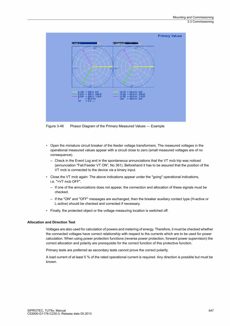
Mounting and Commissioning
3.3 Commissioning
SIPROTEC, 7UT6x, ManualC53000-G1176-C230-3, Release date 05.2013
447
Figure 3-46 Phasor Diagram of the Primary Measured Values — Example
� Open the miniature circuit breaker of the feeder voltage transformers. The measured voltages in the
operational measured values appear with a circuit close to zero (small measured voltages are of no
consequence).
– Check in the Event Log and in the spontaneous annunciations that the VT mcb trip was noticed
(annunciation "Fail:Feeder VT ON", No 361). Beforehand it has to be assured that the position of the
VT mcb is connected to the device via a binary input.
� Close the VT mcb again: The above indications appear under the "going" operational indications,
i.e. ">VT mcb OFF".
– If one of the annunciations does not appear, the connection and allocation of these signals must be
checked.
– If the "ON" and "OFF" messages are exchanged, then the breaker auxiliary contact type (H-active or
L-active) should be checked and corrected if necessary.
� Finally, the protected object or the voltage measuring location is switched off.
Allocation and Direction Test
Voltages are also used for calculation of powers and metering of energy. Therefore, it must be checked whether
the connected voltages have correct relationship with respect to the currents which are to be used for power
calculation. When using power protection functions (reverse power protection, forward power supervision) the
correct allocation and polarity are prerequisite for the correct function of this protective function.
Primary tests are preferred as secondary tests cannot prove the correct polarity.
A load current of at least 5 % of the rated operational current is required. Any direction is possible but must be
known.
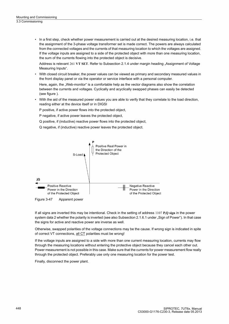
Mounting and Commissioning
3.3 Commissioning
SIPROTEC, 7UT6x, ManualC53000-G1176-C230-3, Release date 05.2013
448
� In a first step, check whether power measurement is carried out at the desired measuring location, i.e. that
the assignment of the 3-phase voltage transformer set is made correct. The powers are always calculated
from the connected voltages and the currents of that measuring location to which the voltages are assigned.
If the voltage inputs are assigned to a side of the protected object with more than one measuring location,
the sum of the currents flowing into the protected object is decisive.
Address is relevant 261 VT SET. Refer to Subsection 2.1.4 under margin heading „Assignment of Voltage
Measuring Inputs“.
� With closed circuit breaker, the power values can be viewed as primary and secondary measured values in
the front display panel or via the operator or service interface with a personal computer.
Here, again, the „Web-monitor“ is a comfortable help as the vector diagrams also show the correlation
between the currents and voltages. Cyclically and acyclically swapped phases can easily be detected
(see figure ).
� With the aid of the measured power values you are able to verify that they correlate to the load direction,
reading either at the device itself or in DIGSI
P positive, if active power flows into the protected object,
P negative, if active power leaves the protected object,
Q positive, if (inductive) reactive power flows into the protected object,
Q negative, if (inductive) reactive power leaves the protected object.
Figure 3-47 Apparent power
If all signs are inverted this may be intentional. Check in the setting of address 1107 P,Q sign in the power
system data 2 whether the polarity is inverted (see also Subsection 2.1.6.1 under „Sign of Power“). In that case
the signs for active and reactive power are inverse as well.
Otherwise, swapped polarities of the voltage connections may be the cause. If wrong sign is indicated in spite
of correct VT connections, all CT polarities must be wrong!
If the voltage inputs are assigned to a side with more than one current measuring location, currents may flow
through the measuring locations without entering the protective object because they cancel each other out.
Power measurement is not possible in this case. Make sure that the currents for power measurement flow really
through the protected object. Preferably use only one measuring location for the power test.
Finally, disconnect the power plant.
Mounting and Commissioning
3.3 Commissioning
SIPROTEC, 7UT6x, ManualC53000-G1176-C230-3, Release date 05.2013
449
Angle Error Correction
During power calculations errors may occur due to angle errors in the current and voltage transformers. In most
cases, these errors are of minor importance, i.e. when referring mainly to the power direction in network
applications, e.g. during network coupling or load shedding.
Errors may not be ignored during the determination of active and reactive power or electrical active and reactive
energy. Especially where reverse power protection with highly accurate active power measurement is used, a
correction of the angle error of the involved current and voltage transformer is inevitable. Here (in case of low
cos ϕ), a very low active power must be calculated from a large apparent power. In case of 7UT6x the angle
errors are corrected in the voltage paths.
In case of generators, a precise determination of the angle errors is carried out during primary commissioning
of the engine by means of the motoring power. Hence, deviations are determined taking three measuring points
into consideration, if possible, from which the correction value ϕcorr is derived. It is not important in which di-
mensions the following measured values are read, as reference or as absolute values, primary or secondary.
All measured values must of course be converted into one dimension. The angle errors caused by the device
internal input transformers have already been compensated in the factory.
� Start up generator and synchronize with network. During exact synchronous working, active and reactive
power are theoretically zero.
� Reduce driving power to zero by closing the regulating valves. The generator now takes motoring energy
from the network.
Caution!
For a turbine set, the intake of reverse power is only permissible for a short time, since operation of the turbine
without a certain throughput of steam (cooling effect) can lead to overheating of the turbine blades!
� Adjust excitation until the reactive power amounts to approximately Q = 0. To check this, read the active and
reactive power including sign (negative) in the operational measured values and note it down as P0 (see
table below). Read the reactive power with sign in the operational measured values and note it down as Q0
(see table below).
� Slowly increase excitation to 30 % of rated apparent power of generator (overexcited).
– Read the motoring power P1 with polarity (negative sign) in the operational measured values under and
write it down (see figure below).
– Read out the reactive power Q1 with polarity (positive sign) and write it down (see table in the figure
below).
� If possible reduce excitation to approximately 0.3 times rated apparent power of generator (underexcited).
Caution!
Under-excitation may cause the generator fall out of step!

Mounting and Commissioning
3.3 Commissioning
SIPROTEC, 7UT6x, ManualC53000-G1176-C230-3, Release date 05.2013
450
� Read the motoring power P2 with polarity (negative sign) in the operational measured values under and write
it down (see table *** 'Motoring and reactive power for angle correction of the transformer error' on page 450
***).
– Read the reactive power Q2 with polarity (negative sign) in the operational measured values and write it
down (see table *** 'Motoring and reactive power for angle correction of the transformer error' on page
450 ***).
� Adjust generator to no-load excitation and shut down if applicable (if not, follow the next margin heading).
Figure 3-48 Determination of the correction angle ϕcorr
Table 3-34 Motoring and reactive power for angle correction of the transformer error
The read-out measured values P1 and P2 are now used to carry out CT angle error correction: First calculate
a correction angle from the measured value pairs according to the following formula:
The power values must be inserted with their correct polarity as read out! Otherwise faulty result!
This angle ϕcorr is entered with reversed sign as the new correction angle under address 803 CORRECT. U Ang:
Setting Value CORRECT. U Ang = – ϕcorr
Reverse Power Protection Setting for Generator
If an exact reverse power protection is used on a generator, you can now calculate the optimum setting value.
If a generator is connected with the network, reverse power can be caused by
� closing of the regulating valves,
� closing of the stop valve.
For the first case, the motoring power has already been determined from the prescribed measurements. As the
pickup value of the reverse power protection corresponds to approximately half the motoring power, set the
pickup value of the reverse power protection P> REVERSE in address 5011 (in Watt) or 5012 (referred to the
nominal current of the generator) to a quarter of the sum of the read-out measured values P1 and P2 – also with
negative sign –.
State Motoring Energy Reactive Power
1 P0 Q0
2 P1 Q1
3 P2 Q2
Mounting and Commissioning
3.3 Commissioning
SIPROTEC, 7UT6x, ManualC53000-G1176-C230-3, Release date 05.2013
451
Because of possible leakages in the valves, the reverse power test should be performed with emergency
tripping.
� Start up generator and synchronise with network, if not yet done.
� Close stop valve.
� From the operational measured value for the active power, the motoring power measured with the protection
device can be derived.
� If that value should be found to be unexpectedly less than the reverse power with the stop valves closed,
50% of that value should be taken as the setting for the reverse power protection.
� Re-open stop valve.
� Shut down the generator.
3.3.13 Testing User-defined Functions
The device has a vast capability for allowing functions to be defined by the user, especially with the CFC logic.
Any special function or logic added to the device must be checked.
A general procedure cannot in the nature of things be specified. Configuration of these functions and the set
value conditions must be actually known beforehand and tested. Especially, possible interlocking conditions of
the switching devices (circuit breakers, isolators, grounding electrodes) must be observed and checked.
3.3.14 Stability Check and Triggering Oscillographic Recordings
In order to verify the reliability of the protection relay even during inrush processes, closing tests can be carried
out to conclude the commissioning process. Oscillograhpic records provide the maximum information about the
behaviour of the protection relay.
Prerequisite
Along with the capability of storing fault recordings via pickup of the protection function, the 7UT6x also has the
capability of capturing the same data when commands are given to the device via the DIGSI software, the serial
interface, or a binary input. For the latter, the information „>Trig.Wave.Cap.“ must be allocated to a binary input.
In this case, a fault record is triggered e.g. via binary input when the protected object is energized.
Such a test fault record triggered externally (i.e. not caused by pickup of a protection function) is processed like
a normal oscillographic record, i.e. a fault log with number is generated which univocally identifies an oscillo-
graphic record. However, these recordings are not displayed in the trip log as they are not fault events.
Start Test Measurement Recording
To trigger test measurement recording with DIGSI, click on Test in the left part of the window. Double click in
the list view the Test Wave Form entry (see Figure 3-49).

Mounting and Commissioning
3.3 Commissioning
SIPROTEC, 7UT6x, ManualC53000-G1176-C230-3, Release date 05.2013
452
Figure 3-49 Triggering oscillographic recording with DIGSI — example
Oscillographic recording is immediately started. During the recording, an annunciation is output in the left area
of the status line. Bar segments additionally indicate the progress of the procedure.
The SIGRA or the Comtrade Viewer program is required to view and analyse the oscillographic data.
Such test records are especially informative on power transformers when they are triggered by the switch-on
command of the transformer. Since the inrush current may have the same effect as a single-ended infeed, but
which may not initiate tripping, the effectiveness of the inrush restraint is checked by energising the power
transformer several times.
The trip circuit should be interrupted or the differential protection should be switched to DIFF. PROT. = Block
relay (address 1201) during these tests in order to avoid tripping.
Conclusions as to the effectiveness of the inrush restraint can be drawn from the recording of the differential
currents and the harmonic contents. If necessary the inrush current restraint effect can be increased (= smaller
value of the 2nd harmonic in address 1271 2. HARMONIC) when trip occurs or when the recorded data show
that the second harmonic content does not safely exceed the restraining threshold (address 1271). A further
method to increase inrush restraint is to set the crossblock function effective or to increase the duration of the
crossblock function (address 1272 CROSSB. 2. HARM) (For further details refer to the setting information for
differential protection under „Harmonic Restraint“).
Note
Do not forget to switch on the differential protection (address 1201) after completion of the test.

Mounting and Commissioning
3.4 Final Preparation of the Device
SIPROTEC, 7UT6x, ManualC53000-G1176-C230-3, Release date 05.2013
453
3.4 Final Preparation of the Device
The used terminal screws must be tightened, including those that are not used. All the plug connectors must
be correctly inserted.
Caution!
Do not use force!
The permissible tightening torque must not be exceeded as the threads and terminal chambers may otherwise
be damaged!
The setting values should be checked again, if they were changed during the tests. Check in particular
whether all protection, control and auxiliary functions to be found with the configuration parameters are set
correctly (Section 2.1.3, Functional Scope) and that all desired elements and functions have been set ON. Keep
a copy of all of the in-service settings on a PC.
The user should check the device-internal clock and set/synchronize it if necessary, provided that it is not
synchronised automatically. For further information refer to SIPROTEC 4 System Description /1/.
The indication buffers are deleted under Main Menu → Annunciation Set/Reset, so that in the future they only
contain information on actual events and states. The numbers in the switching statistics should be reset to the
values that were existing prior to the testing.
The counters of the operational measured values (e.g. operation counter, if available) are reset under Main
Menu → Measurement → Reset.
Press the ESC key, several times if necessary, to return to the default display. The basic window appears in
the display (e.g. display of operation measured values).
Clear the LEDs on the front panel by pressing the LED key, so that they only show real events and states. In
so doing, possibly stored output relays will also be reset. Pressing the LED key also serves as a test for the
LEDs on the front panel because they should all light up when the button is pressed. Any LEDs that are lit after
the clearing attempt are displaying actual conditions.
The green „RUN“ LED must light up, whereas the red „ERROR“ must not light up.
If a test switch is available, it must be in the operating position.
The device is now ready for operation.
■

Mounting and Commissioning
3.4 Final Preparation of the Device
SIPROTEC, 7UT6x, ManualC53000-G1176-C230-3, Release date 05.2013
454
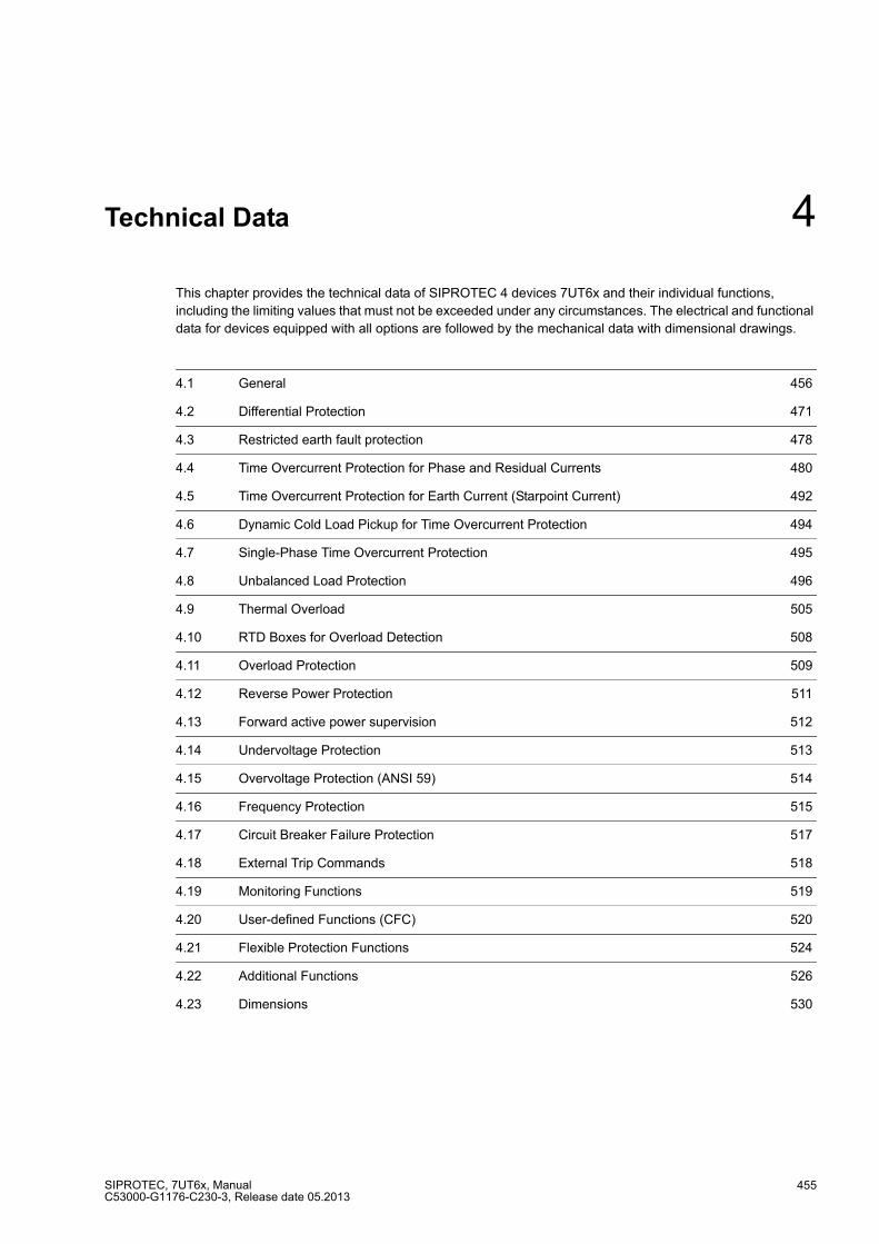
SIPROTEC, 7UT6x, ManualC53000-G1176-C230-3, Release date 05.2013
455
Technical Data 4
This chapter provides the technical data of SIPROTEC 4 devices 7UT6x and their individual functions,
including the limiting values that must not be exceeded under any circumstances. The electrical and functional
data for devices equipped with all options are followed by the mechanical data with dimensional drawings.
4.1 General 456
4.2 Differential Protection 471
4.3 Restricted earth fault protection 478
4.4 Time Overcurrent Protection for Phase and Residual Currents 480
4.5 Time Overcurrent Protection for Earth Current (Starpoint Current) 492
4.6 Dynamic Cold Load Pickup for Time Overcurrent Protection 494
4.7 Single-Phase Time Overcurrent Protection 495
4.8 Unbalanced Load Protection 496
4.9 Thermal Overload 505
4.10 RTD Boxes for Overload Detection 508
4.11 Overload Protection 509
4.12 Reverse Power Protection 511
4.13 Forward active power supervision 512
4.14 Undervoltage Protection 513
4.15 Overvoltage Protection (ANSI 59) 514
4.16 Frequency Protection 515
4.17 Circuit Breaker Failure Protection 517
4.18 External Trip Commands 518
4.19 Monitoring Functions 519
4.20 User-defined Functions (CFC) 520
4.21 Flexible Protection Functions 524
4.22 Additional Functions 526
4.23 Dimensions 530
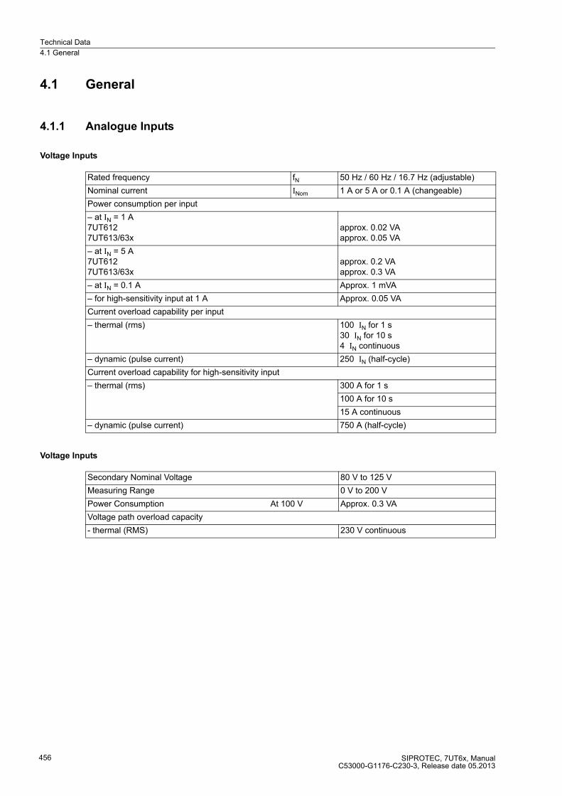
Technical Data
4.1 General
SIPROTEC, 7UT6x, ManualC53000-G1176-C230-3, Release date 05.2013
456
4.1 General
4.1.1 Analogue Inputs
Voltage Inputs
Voltage Inputs
Rated frequency fN 50 Hz / 60 Hz / 16.7 Hz (adjustable)
Nominal current INom 1 A or 5 A or 0.1 A (changeable)
Power consumption per input
– at IN = 1 A7UT6127UT613/63x
approx. 0.02 VAapprox. 0.05 VA
– at IN = 5 A7UT6127UT613/63x
approx. 0.2 VAapprox. 0.3 VA
– at IN = 0.1 A Approx. 1 mVA
– for high-sensitivity input at 1 A Approx. 0.05 VA
Current overload capability per input
– thermal (rms) 100 IN for 1 s30 IN for 10 s4 IN continuous
– dynamic (pulse current) 250 IN (half-cycle)
Current overload capability for high-sensitivity input
– thermal (rms) 300 A for 1 s
100 A for 10 s
15 A continuous
– dynamic (pulse current) 750 A (half-cycle)
Secondary Nominal Voltage 80 V to 125 V
Measuring Range 0 V to 200 V
Power Consumption At 100 V Approx. 0.3 VA
Voltage path overload capacity
- thermal (RMS) 230 V continuous

Technical Data
4.1 General
SIPROTEC, 7UT6x, ManualC53000-G1176-C230-3, Release date 05.2013
457
4.1.2 Auxiliary Voltage
Direct Voltage
Alternating Voltage
Voltage supply through integrated converter
Rated auxiliary direct voltage UH— 24/48 V
Permissible direct voltage range 19 V to 58 V
Rated auxiliary direct voltage UH— 60 /110/ 125 V
Permissible direct voltage range 48 V to 150 V
Rated auxiliary direct voltage UH— 110/125/220/250 V
Permissible direct voltage range 88 V to 300 V
Admissible AC ripple voltage,Peak to peak, IEC 60255-11
≤15 % of the auxiliary voltage
Power consumption, quiescent7UT6127UT613/63x
approx. 5 Wapprox. 6 W
Power consumption, energized7UT6127UT6137UT633/7UT635
approx. 7 Wapprox. 12 WApprox. 20 W
Bridging time for failure/short-circuit of the power supply, IEC 60255-11
≥ 50 ms at UH = 48 V and UH ≥ 110 V
≥ 20 ms at UH = 24 V and UH = 60 V
Voltage supply through integrated converter
Rated auxiliary alternating voltage UH∼ *) 115 / 230 V
Permissible alternating voltage range 92 V to 265 V *) Restriction: AC 230 V operation C-CPU-2 only; 80 MHz; 3.3 V B312–1Max. permissible ambient temperature +55 °C when operated with AC 230 V
Power consumption, quiescent7UT6127UT613/63x
approx. 6.5 VAapprox. 12 VA
Power consumption, energized7UT6127UT6137UT633/7UT635
approx. 8.5 VAapprox. 19 VAApprox. 28 VA
Bridging time for failure/short-circuit of the power supply
≥ 50 ms
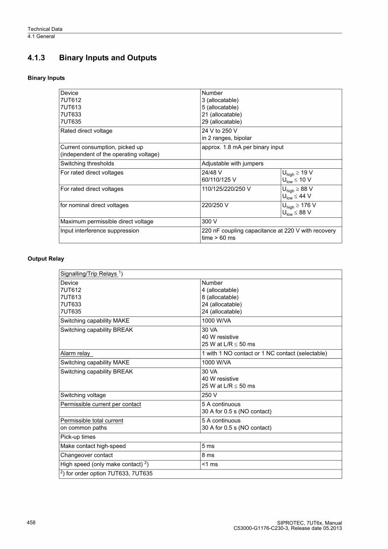
Technical Data
4.1 General
SIPROTEC, 7UT6x, ManualC53000-G1176-C230-3, Release date 05.2013
458
4.1.3 Binary Inputs and Outputs
Binary Inputs
Output Relay
Device7UT6127UT6137UT6337UT635
Number3 (allocatable)5 (allocatable)21 (allocatable)29 (allocatable)
Rated direct voltage 24 V to 250 Vin 2 ranges, bipolar
Current consumption, picked up(independent of the operating voltage)
approx. 1.8 mA per binary input
Switching thresholds Adjustable with jumpers
For rated direct voltages 24/48 V60/110/125 V
Uhigh ≥ 19 VUlow ≤ 10 V
For rated direct voltages 110/125/220/250 V Uhigh ≥ 88 VUlow ≤ 44 V
for nominal direct voltages 220/250 V Uhigh ≥ 176 VUlow ≤ 88 V
Maximum permissible direct voltage 300 V
Input interference suppression 220 nF coupling capacitance at 220 V with recovery time > 60 ms
Signalling/Trip Relays 1)
Device7UT6127UT6137UT6337UT635
Number4 (allocatable)8 (allocatable)24 (allocatable)24 (allocatable)
Switching capability MAKE 1000 W/VA
Switching capability BREAK 30 VA40 W resistive25 W at L/R ≤ 50 ms
Alarm relay 1 with 1 NO contact or 1 NC contact (selectable)
Switching capability MAKE 1000 W/VA
Switching capability BREAK 30 VA40 W resistive25 W at L/R ≤ 50 ms
Switching voltage 250 V
Permissible current per contact 5 A continuous30 A for 0.5 s (NO contact)
Permissible total current on common paths
5 A continuous30 A for 0.5 s (NO contact)
Pick-up times
Make contact high-speed 5 ms
Changeover contact 8 ms
High speed (only make contact) 2) <1 ms2) for order option 7UT633, 7UT635

Technical Data
4.1 General
SIPROTEC, 7UT6x, ManualC53000-G1176-C230-3, Release date 05.2013
459
4.1.4 Frequency Measurement via the Positive Phase-sequence Voltage U1
Frequency Range for Rated Frequency 50/60 Hz
Frequency Range for Rated Frequency 16.7 Hz
1) UL-listed with the following rated data:
AC AC120 V Pilot duty, B300
AC 240 V Pilot duty, B300
AC 240 V 5 A General Purpose
DC 24 V 5 A General Purpose
DC 48 V 0.8 A General Purpose
DC 240 V 0.1 A General Purpose
AC 120 V 1/6 hp (4.4 FLA)
AC 240 V 1/2 hp (4.9 FLA)
Lower frequency limit 9.25 Hz
Upper frequency limit 70 Hz
Lower frequency limit 9.25 Hz
Upper frequency limit 23.33 Hz
Minimum voltage U1 secondary 5 V
The specifications also apply to frequency measuring levels that are realised by the flexible protection functions.

Technical Data
4.1 General
SIPROTEC, 7UT6x, ManualC53000-G1176-C230-3, Release date 05.2013
460
4.1.5 Communications Interfaces
Operator Interface
1) limited selection of baud rates for 7UT612
Connection Front side, non-isolated, RS232, 9-pin D-subminiature female connector for connection of a PCcomputers
Operation With DIGSI
Transmissionspeed
min. 4 800 Bd; max. 115 200 Bd 1);factory setting: 115 200 Bd 1); parity: 8E1
Maximum bridgeable distance 15 m
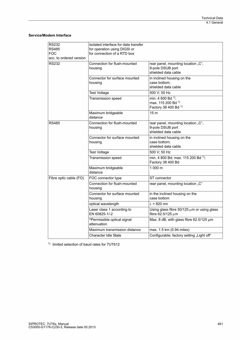
Technical Data
4.1 General
SIPROTEC, 7UT6x, ManualC53000-G1176-C230-3, Release date 05.2013
461
Service/Modem Interface
1) limited selection of baud rates for 7UT612
RS232RS485FOCacc. to ordered version
isolated interface for data transferfor operation using DIGSI or for connection of a RTD box
RS232 Connection for flush-mounted housing
rear panel, mounting location „C“,9-pole DSUB portshielded data cable
Connector for surface mounted housing
in inclined housing on the case bottom;shielded data cable
Test Voltage 500 V; 50 Hz
Transmission speed min. 4 800 Bd 1), max. 115 200 Bd 1)
Factory 38 400 Bd 1)
Maximum bridgeable distance
15 m
RS485 Connection for flush-mounted housing
rear panel, mounting location „C“,9-pole DSUB portshielded data cable
Connector for surface mounted housing
in inclined housing on the case bottom;shielded data cable
Test Voltage 500 V; 50 Hz
Transmission speed min. 4 800 Bd; max. 115 200 Bd 1);Factory 38 400 Bd
Maximum bridgeable distance
1 000 m
Fibre optic cable (FO) FOC connector type ST connector
Connection for flush-mounted housing
rear panel, mounting location „C“
Connector for surface mounted housing
in the inclined housing on the case bottom
optical wavelength λ = 820 nm
Laser class 1 according to EN 60825-1/-2
Using glass fibre 50/125 μm or using glass fibre 62.5/125 μm
^Permissible optical signal attenuation
Max. 8 dB, with glass fibre 62.5/125 µm
Maximum transmission distance max. 1.5 km (0.94 miles)
Character Idle State Configurable; factory setting „Light off“

Technical Data
4.1 General
SIPROTEC, 7UT6x, ManualC53000-G1176-C230-3, Release date 05.2013
462
System Interface (optional)
IEC 60870-5-103RS232RS485FOCProfibus RS485Profibus FOCacc. to ordered version
Isolated interface for data transfer to a master terminal
IEC 60870-5-103different isolated-neutral versions available
RS232rear panel, mounting location „B“, 9-pole DSUB miniature socket
Connection for flush-mounted housing
Connection for surface mounted case
in the inclined housing on the case bottom
Test voltage 500 V; 50 Hz
Transmission speed min. 300 Bd, max. 57 600 Bd 1)
factory setting 9 600 Bd 1)
Maximum bridgeable distance
15 m (50 ft)
RS485rear panel, mounting location „B“, 9-pole DSUB miniature socket
Connection for flush-mounted housing
Connection for surface mounted case
in the inclined housing on the case bottom
Test voltage 500 V; 50 Hz
Transmission speed min.300 Bd, max. 57 600 Bd 1)
factory setting 9 600 Bd 1)
Maximum bridgeable distance
1 km
Optical fibre (FO)ST connector
FOC connector type
Connection for flush mounted case
Rear panel, mounting location „B“
Connection for surface mounted case
in the inclined housing on the case bottom
Optical wavelength λ = 820 nm
Laser class 1 according to EN 60825-1/-2
Using glass fibre 50/12 μm or using glass fibre 62.5/125 μm
Permissible optical signal attenuation
max. 8 dB using glass fibre 62.5/125 µm
Maximum bridgeable distance
1.5 km
Character idle state Selectable: factory setting „Light off“
PROFIBUS RS485 (FMS and DP) rear panel, mounting location „B“, 9-pole DSUB miniature socket
Connection for flush-mounted housing
Connection for surface mounted case
in the inclined housing on the case bottom
Test voltage 500 V; 50 Hz
Transmission speed up to 1.5 MBd 1)
Maximum bridgeable distance
1 000 m (3300 ft) at ≤ 93.75 kBd 1)
500 m (1640 ft) at ≤ 187.5 kBd 1)
200 m (660 ft) at ≤ 1.5 MBd 1)

Technical Data
4.1 General
SIPROTEC, 7UT6x, ManualC53000-G1176-C230-3, Release date 05.2013
463
PROFIBUS FOC (FMS and DP) ST connectorwith FMS: Single or double ring according to order; with DP: only double ring available
FOC connector type
Connection for flush mounted case
only with external OLM;rear panel, mounting location „B“
Connection for surface mounted case
only with external OLM;in the inclined housing on the case bottom
Transmission speed — recommended:
up to 1.5 MBd 1)
> 500 kBd
Optical wavelength λ = 820 nm
Laser class 1 acc. toEN 60825-1/-2
Using glass fibre 50/125 μm or using glass fibre 62.5/125 μm
Permissible optical signal at-tenuation
max. 8 dB, with glass fibre 62.5/125 μm
maximum bridgeable distance between two modules at redun-dant optical ring topology and optical fibre 62.5/125 m
approx. 1.6 km (5 250 ft) at 500 kbit/sapprox. 530 m (1 740 ft) at 1500 kbit/s
DNP3.0 RS485rear panel, mounting location „B“, 9-pole DSUB miniature socket
Connection for flush-mounted housing
Connection for surface mounted case
in the inclined housing on thecase bottom
Test voltage 500 V; 50 Hz
Transmission speed up to 19 200 Bd 1)
Maximum bridgeable distance
1 km
DNP3.0 Fibre Optical LinkST–connector transmitter/receiver
FOC connector type
Connection for flush mounted case
rear panel, mounting location „B“
Connection for surface-mounted case
only with external converter;in the inclined housing on the case bottom
Transmission speed up to 19 200 Bd 1)
Optical wavelength λ = 820 nm
Laser class 1 acc. toEN 60825-1/-2
Using glass fibre 50/125 μm or using glass fibre 62.5/125 μm
Permissible optical signal at-tenuation
max. 8 dB using glass fibre 62.5/125 µm
Maximum bridgeable distance
1.5 km
MODBUS RS485rear panel, mounting location „B“9-pole DSUB miniature socket
Connection for flush-mounted housing
Connector for surface mounted housing
in the inclined housing on thecase bottom
Test Voltage 500 V; 50 Hz
Transmission speed Up to 19 200 Bd 1)
Maximum bridgeable distance
1 km
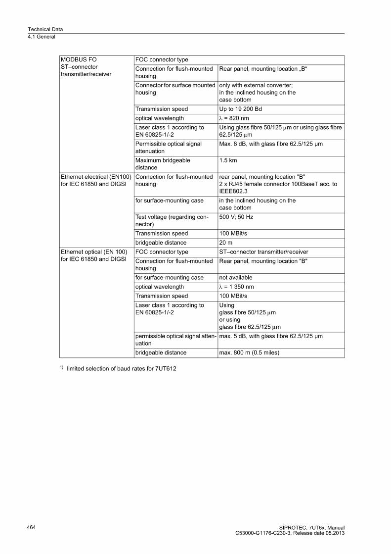
Technical Data
4.1 General
SIPROTEC, 7UT6x, ManualC53000-G1176-C230-3, Release date 05.2013
464
1) limited selection of baud rates for 7UT612
MODBUS FOST–connector transmitter/receiver
FOC connector type
Connection for flush-mounted housing
Rear panel, mounting location „B“
Connector for surface mounted housing
only with external converter;in the inclined housing on the case bottom
Transmission speed Up to 19 200 Bd
optical wavelength λ = 820 nm
Laser class 1 according to EN 60825-1/-2
Using glass fibre 50/125 μm or using glass fibre 62.5/125 μm
Permissible optical signal attenuation
Max. 8 dB, with glass fibre 62.5/125 µm
Maximum bridgeable distance
1.5 km
Ethernet electrical (EN100) for IEC 61850 and DIGSI
Connection for flush-mounted housing
rear panel, mounting location "B"2 x RJ45 female connector 100BaseT acc. to IEEE802.3
for surface-mounting case in the inclined housing on the case bottom
Test voltage (regarding con-nector)
500 V; 50 Hz
Transmission speed 100 MBit/s
bridgeable distance 20 m
Ethernet optical (EN 100) for IEC 61850 and DIGSI
FOC connector type ST–connector transmitter/receiver
Connection for flush-mounted housing
Rear panel, mounting location "B"
for surface-mounting case not available
optical wavelength λ = 1 350 nm
Transmission speed 100 MBit/s
Laser class 1 according to EN 60825-1/-2
Using glass fibre 50/125 μm or using glass fibre 62.5/125 μm
permissible optical signal atten-uation
max. 5 dB, with glass fibre 62.5/125 µm
bridgeable distance max. 800 m (0.5 miles)
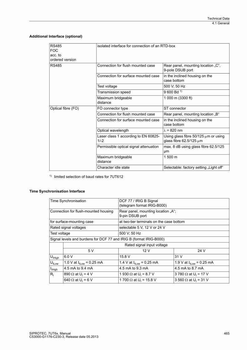
Technical Data
4.1 General
SIPROTEC, 7UT6x, ManualC53000-G1176-C230-3, Release date 05.2013
465
Additional Interface (optional)
1) limited selection of baud rates for 7UT612
Time Synchronisation Interface
RS485FOCacc. toordered version
isolated interface for connection of an RTD-box
RS485 Connection for flush mounted case Rear panel, mounting location „C“, 9-pole DSUB port
Connection for surface mounted case in the inclined housing on thecase bottom
Test voltage 500 V; 50 Hz
Transmission speed 9 600 Bd 1)
Maximum bridgeable distance
1 000 m (3300 ft)
Optical fibre (FO) FO connector type ST connector
Connection for flush mounted case Rear panel, mounting location „B“
Connection for surface mounted case in the inclined housing on thecase bottom
Optical wavelength λ = 820 nm
Laser class 1 according to EN 60825-1/-2
Using glass fibre 50/125 μm or using glass fibre 62.5/125 μm
Permissible optical signal attenuation max. 8 dB using glass fibre 62.5/125 µm
Maximum bridgeable distance
1 500 m
Character idle state Selectable: factory setting „Light off“
Time Synchronisation DCF 77 / IRIG B Signal(telegram format IRIG-B000)
Connection for flush-mounted housing Rear panel, mounting location „A“; 9-pin DSUB port
for surface-mounting case at two-tier terminals on the case bottom
Rated signal voltages selectable 5 V, 12 V or 24 V
Test voltage 500 V; 50 Hz
Signal levels and burdens for DCF 77 and IRIG B (format IRIG-B000)
Rated signal input voltage
5 V 12 V 24 V
UIHigh 6.0 V 15.8 V 31 V
UILow 1.0 V at IILow = 0.25 mA 1.4 V at IILow = 0.25 mA 1.9 V at IILow = 0.25 mA
IIHigh 4.5 mA to 9.4 mA 4.5 mA to 9.3 mA 4.5 mA to 8.7 mA
RI 890 Ω at UI = 4 V 1 930 Ω at UI = 8.7 V 3 780 Ω at UI = 17 V
640 Ω at UI = 6 V 1 700 Ω at UI = 15.8 V 3 560 Ω at UI = 31 V

Technical Data
4.1 General
SIPROTEC, 7UT6x, ManualC53000-G1176-C230-3, Release date 05.2013
466
4.1.6 Electrical Tests
Regulations
Isolation Test
EMC Tests for the Interference Immunity (type test)
Standards: IEC 60255 (product standards) IEEE C37.90.0; C37.90.1UL 508VDE 0435See also standards for individual tests
Standards: IEC 60255-5 and IEC 60870-2-1
High voltage test (routine test)all circuits except power supply, binary inputs, and communication / time sync. interfaces
2.5 kV (rms), 50 Hz
High voltage test (routine test) auxiliary voltage and binary inputs
DC 3.5 kV
High voltage test (routine test)only isolated communication and time synchronisation interfaces and time synchronisation interfaces
500 V (rms), 50 Hz
Impulse voltage test (type test) all circuits except communications / time sync. interfaces, class III
5 kV (peak), 1.2/50 µs, 0.5 J, 3 positive and 3 negative impulses in intervals of 5 s
Standards: IEC 60255-6 and -22 (product standards)EN 61000-6-2 (generic standard)VDE 0435 part 301DIN VDE 0435-110
High frequency testIEC 60255-22-1, Class III and VDE 0435 part 303, Class III
2.5 kV (peak); 1 MHz; τ = 15 µs; 400 surges per s; test duration 2 s; Ri = 200 Ω
Electrostatic dischargeIEC 60255-22-2, Class IV and IEC 61000-4-2, Class IV
8 kV contact discharge; 15 kV air discharge; both polarities; 150 pF; Ri = 330 Ω
Irradiation with HF field, frequency sweepIEC 60255-22-3; Class IIIIEC 61000-4-3, Class III
10 V/m; 80 MHz to 1000 MHz;10 V/m; 800 MHz to 960 MHz;20 V/m; 1.4 GHz to 2.0 GHz;80 % AM; 1 kHz
Irradiation with HF field, single frequenciesIEC 60255-22-3;IEC 61000-4-3 – amplitude modulated – pulse modulated
Class III: 10 V/m 80/160/450/900 MHz; 80 % AM; duty cycle >10 s900 MHz; 50 % PM, repetition frequency 200 Hz
Fast transient disturbance/burstIEC 60255-22-4 and IEC 61000-4-4, Class IV
4 kV; 5/50 ns; 5 kHz; burst length = 15 ms; repetition rate 300 ms; both polarities;Ri = 50 Ω; test duration 1 min

Technical Data
4.1 General
SIPROTEC, 7UT6x, ManualC53000-G1176-C230-3, Release date 05.2013
467
EMC Tests for the Interference Emission (type test)
High energy surge voltages (SURGE),IEC 61000-4-5 Installation Class 3 —auxiliary voltage Measuring inputs, binary inputs and relay outputs
impulse: 1.2/50 µs common mode: 2 kV; 12 Ω; 9 µFDiff. mode:1 kV; 2 Ω; 18 µF common mode: 2 kV; 42Ω; 0. 5 µFdiff. mode: 1 kV; 42Ω; 0. 5 µF
Line conducted HF, amplitude modulatedIEC 61000-4-6, Class III
10 V; 150 kHz to 80 MHz: 80 % AM; 1 kHz
Power system frequency magnetic fieldIEC 61000-4-8, Class IVIEC 60255-6
30 A/m continuous; 300 A/m for 3 s; 50 Hz 0.5 mT; 50 Hz
Oscillatory surge withstand capabilityIEEE Std C37.90.1
2.5 kV (peak value); 1 MHz; τ = 15 µs;400 pulses per s; test duration 2 s; Ri = 200 Ω
Fast transient surge withstand cap.IEEE Std C37.90.1
4 kV; 5/50 ns; 5 kHz; burst length = 15 ms;Repetition rate 300 ms; both polarities;Ri = 50 Ω; test duration 1 min
Damped oscillationsIEC 60694, IEC 61000-4-12
2.5 kV (peak value), polarity alternating 100 kHz, 1 MHz, 10 MHz and 50 MHz; Ri = 200 Ω
Standard: EN 61000-6-4 (basic specification)
Conducted interference, only power supply voltageIEC-CISPR 11
150 kHz to 30 MHzLimit value class A
Radio interference field strengthIEC-CISPR 11
30 MHz to 1 000 MHz Limit value class A

Technical Data
4.1 General
SIPROTEC, 7UT6x, ManualC53000-G1176-C230-3, Release date 05.2013
468
4.1.7 Mechanical Tests
Vibration and shock during operation
Vibration and Shock during Transport
Standards: IEC 60255-21 and IEC 60068
OscillationIEC 60255-21-1 Class 2; IEC 60068-2-6
sinusoidal 10 Hz to 60 Hz: ± 0.075 mm amplitude; 60 Hz to 150 Hz: 1 g acceleration frequency sweep rate 1 octave/min 20 cycles in 3 orthogonal axes
Shock IEC 60255-21-2, Class 1 IEC 60068-2-27
Half-sine shaped Acceleration 5 g, duration 11 ms, 3 shocks in each direction of 3 orthogonal axes
Seismic Vibration IEC 60255-21-3, Class 1 IEC 60068-3-3
sinusoidal 1 Hz to 8 Hz: ± 3.5 mm amplitude (horizontal axis)1 Hz to 8 Hz: ± 1.5 mm amplitude (vertical axis)8 Hz to 35 Hz: 1 g acceleration(horizontal axis) 8 Hz to 35 Hz: 0.5 g acceleration(vertical axis)frequency sweep rate 1 octave/min1 cycle in 3 orthogonal axes
Standards: IEC 60255-21 and IEC 60068
OscillationIEC 60255-21-1, Class 2; IEC 60068-2-6
sinusoidal 5 Hz to 8 Hz: ± 7.5 mm amplitude; 8 Hz to 150 Hz: 2 g acceleration frequency sweep rate 1 octave/min 20 cycles in 3 orthogonal axes
Shock IEC 60255-21-2, Class 1 IEC 60068-2-27
Half-sine shapedAcceleration 15 g, duration 11 ms, 3 shocks in each direction of 3 orthogonal axes
Continuous Shock IEC 60255-21-2, Class 1, IEC 60068-2-29
Half-sine shapedAcceleration 10 g, duration 16 ms, 1000 shocks in each direction of 3 orthogonal axes
Note: All stress test data apply for devices in factory packaging.
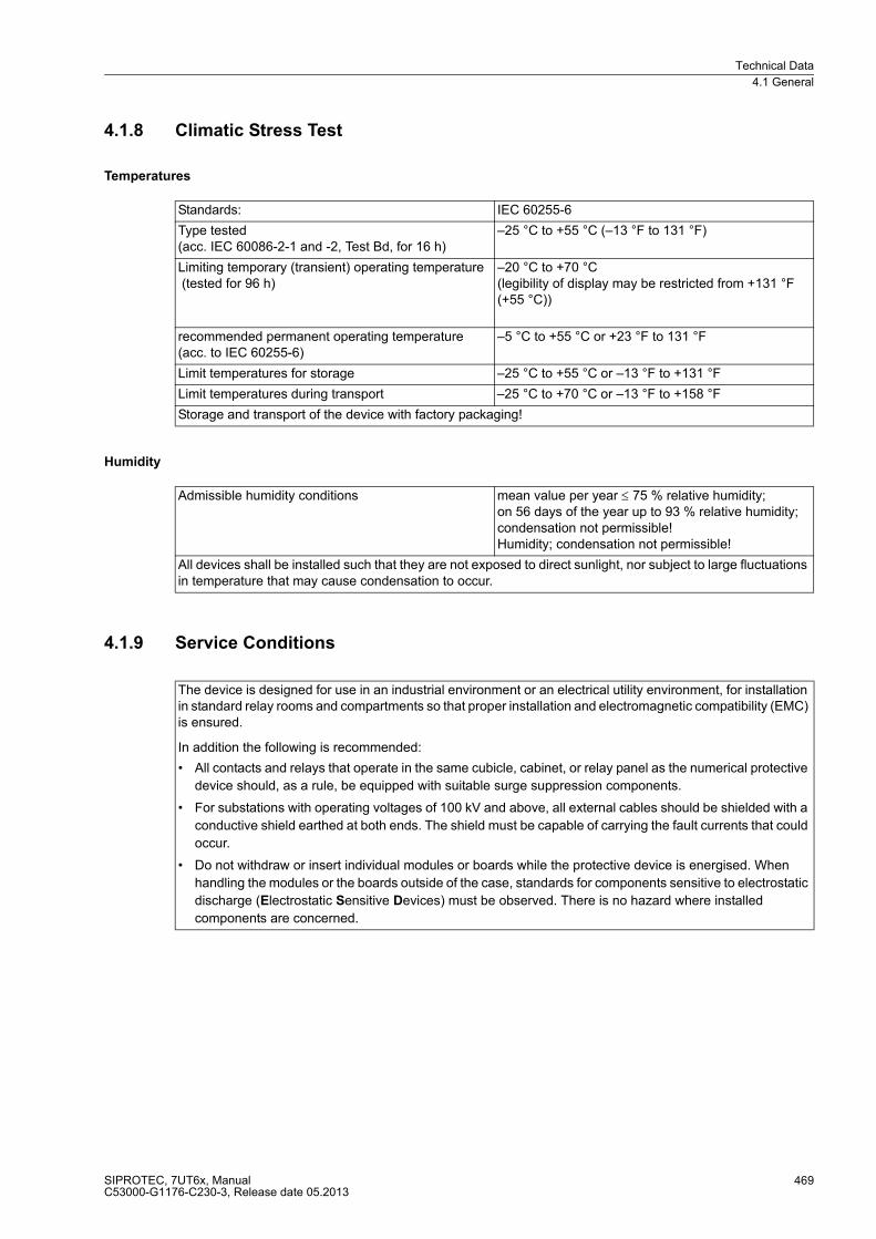
Technical Data
4.1 General
SIPROTEC, 7UT6x, ManualC53000-G1176-C230-3, Release date 05.2013
469
4.1.8 Climatic Stress Test
Temperatures
Humidity
4.1.9 Service Conditions
Standards: IEC 60255-6
Type tested (acc. IEC 60086-2-1 and -2, Test Bd, for 16 h)
–25 °C to +55 °C (–13 °F to 131 °F)
Limiting temporary (transient) operating temperature (tested for 96 h)
–20 °C to +70 °C (legibility of display may be restricted from +131 °F (+55 °C))
recommended permanent operating temperature (acc. to IEC 60255-6)
–5 °C to +55 °C or +23 °F to 131 °F
Limit temperatures for storage –25 °C to +55 °C or –13 °F to +131 °F
Limit temperatures during transport –25 °C to +70 °C or –13 °F to +158 °F
Storage and transport of the device with factory packaging!
Admissible humidity conditions mean value per year ≤ 75 % relative humidity; on 56 days of the year up to 93 % relative humidity; condensation not permissible!Humidity; condensation not permissible!
All devices shall be installed such that they are not exposed to direct sunlight, nor subject to large fluctuations in temperature that may cause condensation to occur.
The device is designed for use in an industrial environment or an electrical utility environment, for installation in standard relay rooms and compartments so that proper installation and electromagnetic compatibility (EMC) is ensured.
In addition the following is recommended:
� All contacts and relays that operate in the same cubicle, cabinet, or relay panel as the numerical protective
device should, as a rule, be equipped with suitable surge suppression components.
� For substations with operating voltages of 100 kV and above, all external cables should be shielded with a
conductive shield earthed at both ends. The shield must be capable of carrying the fault currents that could
occur.
� Do not withdraw or insert individual modules or boards while the protective device is energised. When
handling the modules or the boards outside of the case, standards for components sensitive to electrostatic
discharge (Electrostatic Sensitive Devices) must be observed. There is no hazard where installed
components are concerned.
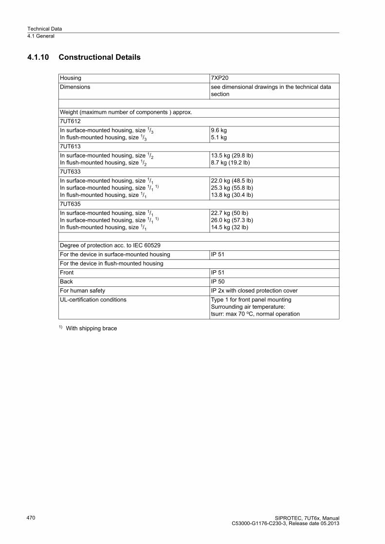
Technical Data
4.1 General
SIPROTEC, 7UT6x, ManualC53000-G1176-C230-3, Release date 05.2013
470
4.1.10 Constructional Details
1) With shipping brace
Housing 7XP20
Dimensions see dimensional drawings in the technical data section
Weight (maximum number of components ) approx.
7UT612
In surface-mounted housing, size 1/3In flush-mounted housing, size 1/3
9.6 kg5.1 kg
7UT613
In surface-mounted housing, size 1/2In flush-mounted housing, size 1/2
13.5 kg (29.8 lb)8.7 kg (19.2 lb)
7UT633
In surface-mounted housing, size 1/1In surface-mounted housing, size 1/1
1)
In flush-mounted housing, size 1/1
22.0 kg (48.5 lb)25.3 kg (55.8 lb)13.8 kg (30.4 lb)
7UT635
In surface-mounted housing, size 1/1In surface-mounted housing, size 1/1
1)
In flush-mounted housing, size 1/1
22.7 kg (50 lb)26.0 kg (57.3 lb)14.5 kg (32 lb)
Degree of protection acc. to IEC 60529
For the device in surface-mounted housing IP 51
For the device in flush-mounted housing
Front IP 51
Back IP 50
For human safety IP 2x with closed protection cover
UL-certification conditions Type 1 for front panel mountingSurrounding air temperature:tsurr: max 70 oC, normal operation
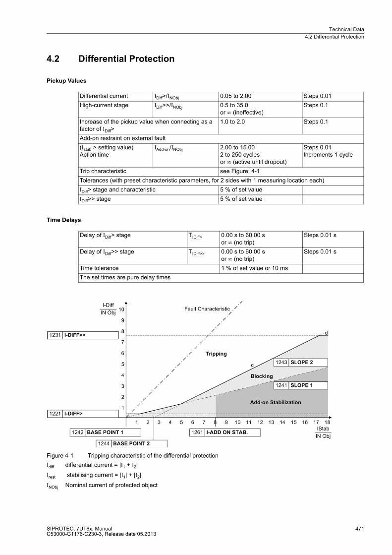
Technical Data
4.2 Differential Protection
SIPROTEC, 7UT6x, ManualC53000-G1176-C230-3, Release date 05.2013
471
4.2 Differential Protection
Pickup Values
Time Delays
Figure 4-1 Tripping characteristic of the differential protection
Idiff differential current = |I1 + I2|
Irest stabilising current = |I1| + |I2|
INObj Nominal current of protected object
Differential current IDiff>/INObj 0.05 to 2.00 Steps 0.01
High-current stage IDiff>>/INObj 0.5 to 35.0or ∞ (ineffective)
Steps 0.1
Increase of the pickup value when connecting as a factor of IDiff>
1.0 to 2.0 Steps 0.1
Add-on restraint on external fault
(Istab > setting value)Action time
IAdd-on/INObj 2.00 to 15.002 to 250 cyclesor ∞ (active until dropout)
Steps 0.01Increments 1 cycle
Trip characteristic see Figure 4-1
Tolerances (with preset characteristic parameters, for 2 sides with 1 measuring location each)
IDiff> stage and characteristic 5 % of set value
IDiff>> stage 5 % of set value
Delay of IDiff> stage TIDiff> 0.00 s to 60.00 sor ∞ (no trip)
Steps 0.01 s
Delay of IDiff>> stage TIDiff>> 0.00 s to 60.00 sor ∞ (no trip)
Steps 0.01 s
Time tolerance 1 % of set value or 10 ms
The set times are pure delay times

Technical Data
4.2 Differential Protection
SIPROTEC, 7UT6x, ManualC53000-G1176-C230-3, Release date 05.2013
472
Harmonic Restraint (Transformers)
Operating Times (Transformers)
Conditioning for Transformers
Inrush restraint ratio(2nd harmonic) I2fN/IfN
10 % to 80 %see also Figure 4-2
Steps 1 %
Restraint ratio further (n-th) harmonic(either 3rd or 5th) InfN/IfN
10 % to 80 %see also Figure 4-3
Steps 1 %
Crossblock function can be activated / deactivated
Max. action time for crossblock 2 to 1000 AC cyclesor 0 (crossblock deactivated)or ∞ (active until dropout)
Steps 1 cycle
7UT612Pickup time / dropout time with single-side infeed
Pickup time at frequency 50 Hz 60 Hz 16.7 Hz
IDiff>IDiff>>
38 ms25 ms
35 ms22 ms
85 ms55 ms
Dropout time, approx. 35 ms 30 ms 80 ms
Drop-off to pickup ratio approx. 0.7
7UT613/63xPickup time / dropout time with single-side infeed
Pickup time at frequency 50 Hz 60 Hz 16.7 Hz
IDiff> minfast relays 30 ms 27 ms 78 ms
high-speed relays 25 ms 22 ms 73 ms
IDiff>> minfast relays 11 ms 11 ms 20 ms
high-speed relays 6 ms 6 ms 15 ms
Dropout time, approx. 54 ms 46 ms 150 ms
Dropout ratio approx. 0.7
Matching of vector group 0 to 11 (x 30°) Steps 1
Starpoint conditioning earthed or non-earthed(for each winding)
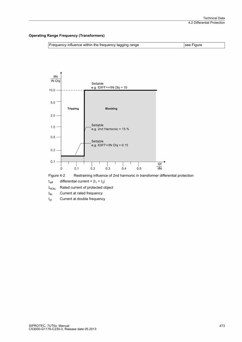
Technical Data
4.2 Differential Protection
SIPROTEC, 7UT6x, ManualC53000-G1176-C230-3, Release date 05.2013
473
Operating Range Frequency (Transformers)
Figure 4-2 Restraining influence of 2nd harmonic in transformer differential protection
Idiff differential current = |I1 + I2|
INObj Rated current of protected object
IfN Current at rated frequency
I2f Current at double frequency
Frequency influence within the frequency tagging range see Figure

Technical Data
4.2 Differential Protection
SIPROTEC, 7UT6x, ManualC53000-G1176-C230-3, Release date 05.2013
474
Figure 4-3 Restraining influence of n-th harmonic in transformer differential protection
Idiff differential current = |I1 + I2|
INObj Nominal current of protected object
IfN Current at nominal frequency
Inf Current at n times the frequency (n = 3 or 4)
Figure 4-4 Frequency influence in transformer differential protection
Idiff Differential current = |I1 + I2|
INObj Nominal current of the protected object
IXf Current at any frequency within specified range
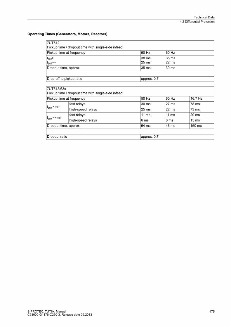
Technical Data
4.2 Differential Protection
SIPROTEC, 7UT6x, ManualC53000-G1176-C230-3, Release date 05.2013
475
Operating Times (Generators, Motors, Reactors)
7UT612Pickup time / dropout time with single-side infeed
Pickup time at frequency 50 Hz 60 Hz
IDiff>IDiff>>
38 ms25 ms
35 ms22 ms
Dropout time, approx. 35 ms 30 ms
Drop-off to pickup ratio approx. 0.7
7UT613/63xPickup time / dropout time with single-side infeed
Pickup time at frequency 50 Hz 60 Hz 16.7 Hz
IDiff> minfast relays 30 ms 27 ms 78 ms
high-speed relays 25 ms 22 ms 73 ms
IDiff>> minfast relays 11 ms 11 ms 20 ms
high-speed relays 6 ms 6 ms 15 ms
Dropout time, approx. 54 ms 46 ms 150 ms
Dropout ratio approx. 0.7
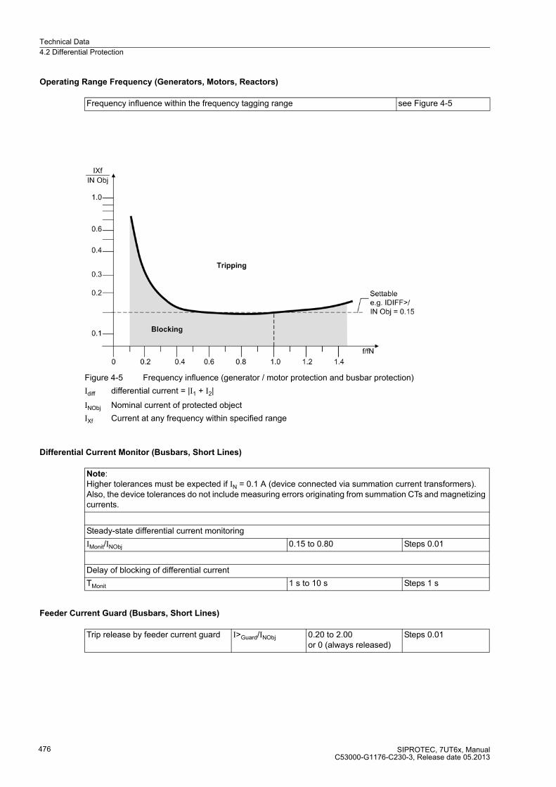
Technical Data
4.2 Differential Protection
SIPROTEC, 7UT6x, ManualC53000-G1176-C230-3, Release date 05.2013
476
Operating Range Frequency (Generators, Motors, Reactors)
Figure 4-5 Frequency influence (generator / motor protection and busbar protection)
Idiff differential current = |I1 + I2|
INObj Nominal current of protected object
IXf Current at any frequency within specified range
Differential Current Monitor (Busbars, Short Lines)
Feeder Current Guard (Busbars, Short Lines)
Frequency influence within the frequency tagging range see Figure 4-5
Note:Higher tolerances must be expected if IN = 0.1 A (device connected via summation current transformers). Also, the device tolerances do not include measuring errors originating from summation CTs and magnetizing currents.
Steady-state differential current monitoring
IMonit/INObj 0.15 to 0.80 Steps 0.01
Delay of blocking of differential current
TMonit 1 s to 10 s Steps 1 s
Trip release by feeder current guard I>Guard/INObj 0.20 to 2.00or 0 (always released)
Steps 0.01

Technical Data
4.2 Differential Protection
SIPROTEC, 7UT6x, ManualC53000-G1176-C230-3, Release date 05.2013
477
Operating Time (Busbars, Short Lines)
Operating Range Frequency (Busbars, Short Lines)
7UT612Pickup time / dropout time with single-side infeed
Pickup time at frequency 50 Hz 60 Hz
IDiff>IDiff>>
25 ms20 ms
25 ms19 ms
Dropout time, approx. 30 ms 30 ms
Drop-off to pickup ratio approx. 0.7
7UT613/63xPickup time / dropout time with single-side infeed
Pickup time at frequency 50 Hz 60 Hz 16.7 Hz
IDiff> minfast relays 11 ms 11 ms 18 ms
high-speed relays 6 ms 6 ms 13 ms
IDiff>> minfast relays 11 ms 11 ms 18 ms
high-speed relays 6 ms 6 ms 13 ms
Dropout time, approx. 54 ms 46 ms 150 ms
Dropout ratio approx. 0.7
Frequency influence within the frequency tagging range see Figure 4-5
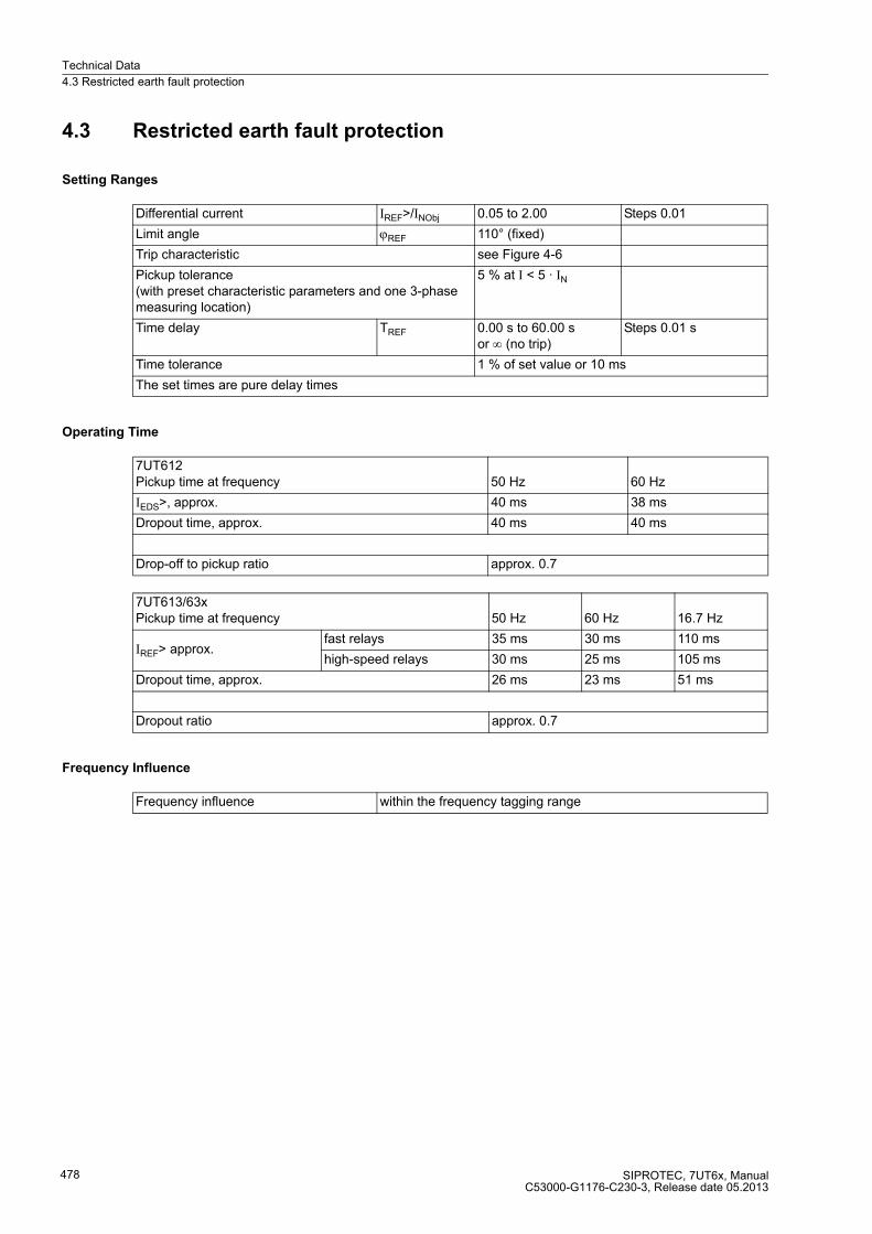
Technical Data
4.3 Restricted earth fault protection
SIPROTEC, 7UT6x, ManualC53000-G1176-C230-3, Release date 05.2013
478
4.3 Restricted earth fault protection
Setting Ranges
Operating Time
Frequency Influence
Differential current IREF>/INObj 0.05 to 2.00 Steps 0.01
Limit angle ϕREF 110° (fixed)
Trip characteristic see Figure 4-6
Pickup tolerance(with preset characteristic parameters and one 3-phase measuring location)
5 % at I < 5 · IN
Time delay TREF 0.00 s to 60.00 sor ∞ (no trip)
Steps 0.01 s
Time tolerance 1 % of set value or 10 ms
The set times are pure delay times
7UT612Pickup time at frequency 50 Hz 60 Hz
IEDS>, approx. 40 ms 38 ms
Dropout time, approx. 40 ms 40 ms
Drop-off to pickup ratio approx. 0.7
7UT613/63xPickup time at frequency 50 Hz 60 Hz 16.7 Hz
IREF> approx.fast relays 35 ms 30 ms 110 ms
high-speed relays 30 ms 25 ms 105 ms
Dropout time, approx. 26 ms 23 ms 51 ms
Dropout ratio approx. 0.7
Frequency influence within the frequency tagging range
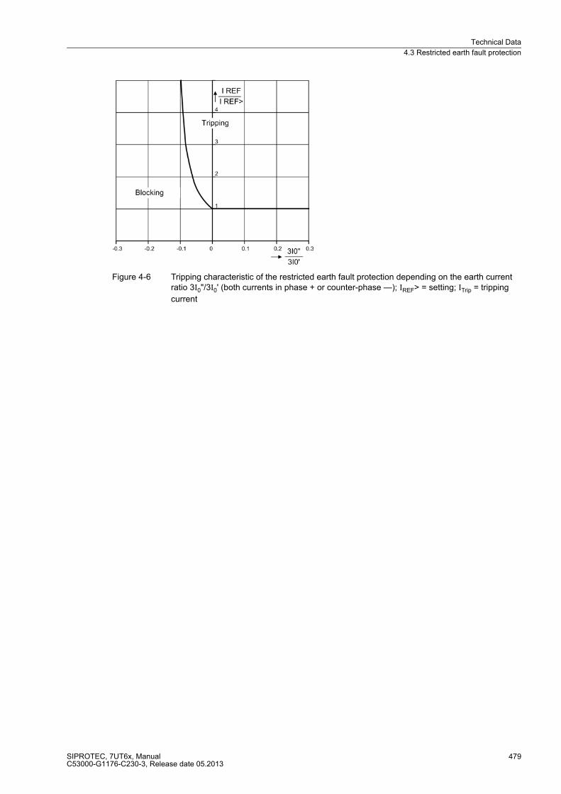
Technical Data
4.3 Restricted earth fault protection
SIPROTEC, 7UT6x, ManualC53000-G1176-C230-3, Release date 05.2013
479
Figure 4-6 Tripping characteristic of the restricted earth fault protection depending on the earth current ratio 3I0"/3I0' (both currents in phase + or counter-phase —); IREF> = setting; ITrip = tripping
current
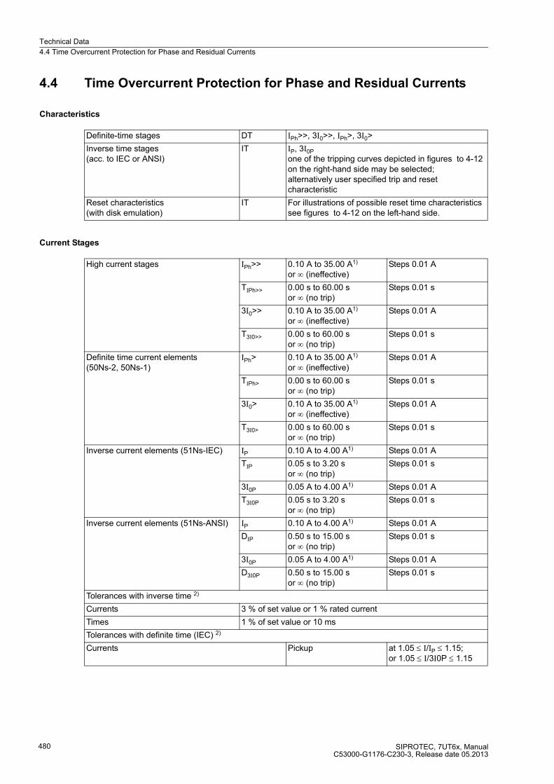
Technical Data
4.4 Time Overcurrent Protection for Phase and Residual Currents
SIPROTEC, 7UT6x, ManualC53000-G1176-C230-3, Release date 05.2013
480
4.4 Time Overcurrent Protection for Phase and Residual Currents
Characteristics
Current Stages
Definite-time stages DT IPh>>, 3I0>>, IPh>, 3I0>
Inverse time stages(acc. to IEC or ANSI)
IT IP, 3I0P
one of the tripping curves depicted in figures to 4-12 on the right-hand side may be selected;alternatively user specified trip and reset characteristic
Reset characteristics(with disk emulation)
IT For illustrations of possible reset time characteristics see figures to 4-12 on the left-hand side.
High current stages IPh>> 0.10 A to 35.00 A1)
or ∞ (ineffective)Steps 0.01 A
TIPh>> 0.00 s to 60.00 sor ∞ (no trip)
Steps 0.01 s
3I0>> 0.10 A to 35.00 A1)
or ∞ (ineffective)Steps 0.01 A
T3I0>> 0.00 s to 60.00 sor ∞ (no trip)
Steps 0.01 s
Definite time current elements (50Ns-2, 50Ns-1)
IPh> 0.10 A to 35.00 A1)
or ∞ (ineffective)Steps 0.01 A
TIPh> 0.00 s to 60.00 sor ∞ (no trip)
Steps 0.01 s
3I0> 0.10 A to 35.00 A1)
or ∞ (ineffective)Steps 0.01 A
T3I0> 0.00 s to 60.00 sor ∞ (no trip)
Steps 0.01 s
Inverse current elements (51Ns-IEC) IP 0.10 A to 4.00 A1) Steps 0.01 A
TIP 0.05 s to 3.20 sor ∞ (no trip)
Steps 0.01 s
3I0P 0.05 A to 4.00 A1) Steps 0.01 A
T3I0P 0.05 s to 3.20 sor ∞ (no trip)
Steps 0.01 s
Inverse current elements (51Ns-ANSI) IP 0.10 A to 4.00 A1) Steps 0.01 A
DIP 0.50 s to 15.00 sor ∞ (no trip)
Steps 0.01 s
3I0P 0.05 A to 4.00 A1) Steps 0.01 A
D3I0P 0.50 s to 15.00 sor ∞ (no trip)
Steps 0.01 s
Tolerances with inverse time 2)
Currents 3 % of set value or 1 % rated current
Times 1 % of set value or 10 ms
Tolerances with definite time (IEC) 2)
Currents Pickup at 1.05 ≤ I/IP ≤ 1.15; or 1.05 ≤ I/3I0P ≤ 1.15

Technical Data
4.4 Time Overcurrent Protection for Phase and Residual Currents
SIPROTEC, 7UT6x, ManualC53000-G1176-C230-3, Release date 05.2013
481
Operating Times of the Definite Time Stages
Times 5 % ± 15 ms5 % ± 45 ms
at fN = 50/60 Hzat fN = 16.7 Hz
for 2 ≤ I/IP≤ 20and TIP/s ≥ 1;or 2 ≤ I/3I0P ≤ 20and T3I0P/s ≥ 1
Tolerances with definite time (ANSI) 2)
Times 5 % ± 15 ms5 % ± 45 ms
at fN = 50/60 Hz for fN = 16.7 Hz
for 2 ≤ I/IP ≤ 20for 2 ≤ I/IP ≤ 20and DIP/s ≥ 1;and D3I0P/s ≥ 1
The set times are pure delay times. 1)Secondary values for IN = 1 A; for IN = 5 A the currents must be multiplied by 5. 2) With one 3-phase measuring location and I/IN = 1 A/5 A
7UT612Pickup time / dropout time phase current stages
Pickup time at frequency 50 Hz 60 Hz
without inrush restraint, min.without inrush restraint, typical
20 ms25 ms
18 ms23 ms
with inrush restraint, min.with inrush restraint, typical
40 ms45 ms
35 ms40 ms
Dropout time, typical 30 ms 30 ms
Pickup time / dropout time residual current stages
Pickup time at frequency 50 Hz 60 Hz
without inrush restraint, min.without inrush restraint, typical
40 ms45 ms
35 ms40 ms
with inrush restraint, min.with inrush restraint, typical
40 ms45 ms
35 ms40 ms
Dropout time, typical 30 ms 30 ms
7UT613/63xPickup time / dropout time phase current stages
Pickup time at frequency 50 Hz 60 Hz 16.7 Hz
without inrush restraint,- 2 x Pickup Valuewithout inrush restraint,- 10 x Pickup Value
26 ms16 ms
22 ms17 ms
47 ms19 ms
with inrush restraint,- 2 x Pickup Valuewith inrush restraint,- 10 x Pickup Value
44 ms36 ms
39 ms31 ms
105 ms77 ms
Dropout time, approx. 33 ms 30 ms 51 ms
Pickup time / dropout time residual current stages
Pickup time at frequency 50 Hz 60 Hz 16.7 Hz
without inrush restraint,- 2 x Pickup Value 1)without inrush restraint,- 10 x Pickup Value 1)
33 ms27 ms
29 ms22 ms
76 ms49 ms
with inrush restraint,- 2 x Pickup Value 1)with inrush restraint,- 10 x Pickup Value 1)
42 ms36 ms
41 ms32 ms
104 ms80 ms
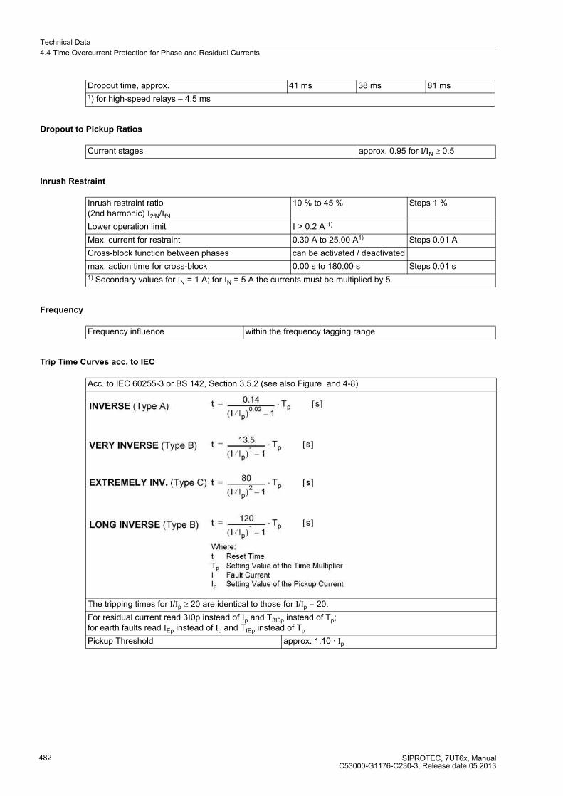
Technical Data
4.4 Time Overcurrent Protection for Phase and Residual Currents
SIPROTEC, 7UT6x, ManualC53000-G1176-C230-3, Release date 05.2013
482
Dropout to Pickup Ratios
Inrush Restraint
Frequency
Trip Time Curves acc. to IEC
Dropout time, approx. 41 ms 38 ms 81 ms1) for high-speed relays – 4.5 ms
Current stages approx. 0.95 for I/IN ≥ 0.5
Inrush restraint ratio(2nd harmonic) I2fN/IfN
10 % to 45 % Steps 1 %
Lower operation limit I > 0.2 A 1)
Max. current for restraint 0.30 A to 25.00 A1) Steps 0.01 A
Cross-block function between phases can be activated / deactivated
max. action time for cross-block 0.00 s to 180.00 s Steps 0.01 s1) Secondary values for IN = 1 A; for IN = 5 A the currents must be multiplied by 5.
Frequency influence within the frequency tagging range
Acc. to IEC 60255-3 or BS 142, Section 3.5.2 (see also Figure and 4-8)
The tripping times for I/Ip ≥ 20 are identical to those for I/Ip = 20.
For residual current read 3I0p instead of Ip and T3I0p instead of Tp;for earth faults read IEp instead of Ip and TIEp instead of Tp
Pickup Threshold approx. 1.10 · Ip

Technical Data
4.4 Time Overcurrent Protection for Phase and Residual Currents
SIPROTEC, 7UT6x, ManualC53000-G1176-C230-3, Release date 05.2013
483
Dropout Time Curves as per IEC
Acc. to IEC 60255-3 or BS 142, Section 3.5.2 (see also Figure and 4-8)
The reset time characteristics apply to (I/Ip) ≤ 0.90
For residual current read 3I0p instead of Ip and T3I0p instead of Tp;for earth faults read IEp instead of Ip and TIEp instead of Tp

Technical Data
4.4 Time Overcurrent Protection for Phase and Residual Currents
SIPROTEC, 7UT6x, ManualC53000-G1176-C230-3, Release date 05.2013
484
Figure 4-7 Dropout time and trip time curves of the inverse time overcurrent protection, as per IEC (phases and ground)

Technical Data
4.4 Time Overcurrent Protection for Phase and Residual Currents
SIPROTEC, 7UT6x, ManualC53000-G1176-C230-3, Release date 05.2013
485
Figure 4-8 Dropout time and trip time curves of the inverse time overcurrent protection, acc. to IEC
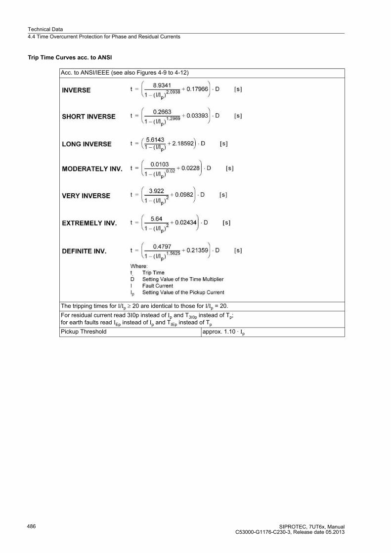
Technical Data
4.4 Time Overcurrent Protection for Phase and Residual Currents
SIPROTEC, 7UT6x, ManualC53000-G1176-C230-3, Release date 05.2013
486
Trip Time Curves acc. to ANSI
Acc. to ANSI/IEEE (see also Figures 4-9 to 4-12)
The tripping times for I/Ip ≥ 20 are identical to those for I/Ip = 20.
For residual current read 3I0p instead of Ip and T3I0p instead of Tp;for earth faults read IEp instead of Ip and TIEp instead of Tp
Pickup Threshold approx. 1.10 · Ip
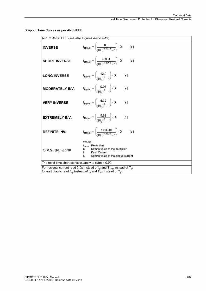
Technical Data
4.4 Time Overcurrent Protection for Phase and Residual Currents
SIPROTEC, 7UT6x, ManualC53000-G1176-C230-3, Release date 05.2013
487
Dropout Time Curves as per ANSI/IEEE
Acc. to ANSI/IEEE (see also Figures 4-9 to 4-12)
The reset time characteristics apply to (I/Ip) ≤ 0.90
For residual current read 3I0p instead of Ip and T3I0p instead of Tp;for earth faults read IEp instead of Ip and TIEp instead of Tp

Technical Data
4.4 Time Overcurrent Protection for Phase and Residual Currents
SIPROTEC, 7UT6x, ManualC53000-G1176-C230-3, Release date 05.2013
488
Figure 4-9 Dropout time and trip time curves of the inverse time overcurrent protection, acc. to ANSI/IEEE
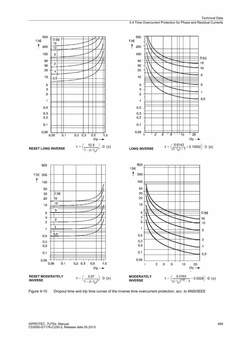
Technical Data
4.4 Time Overcurrent Protection for Phase and Residual Currents
SIPROTEC, 7UT6x, ManualC53000-G1176-C230-3, Release date 05.2013
489
Figure 4-10 Dropout time and trip time curves of the inverse time overcurrent protection, acc. to ANSI/IEEE
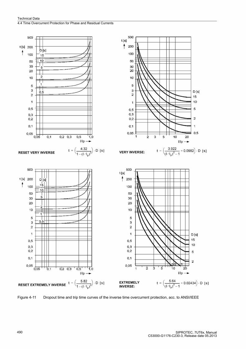
Technical Data
4.4 Time Overcurrent Protection for Phase and Residual Currents
SIPROTEC, 7UT6x, ManualC53000-G1176-C230-3, Release date 05.2013
490
Figure 4-11 Dropout time and trip time curves of the inverse time overcurrent protection, acc. to ANSI/IEEE

Technical Data
4.4 Time Overcurrent Protection for Phase and Residual Currents
SIPROTEC, 7UT6x, ManualC53000-G1176-C230-3, Release date 05.2013
491
Figure 4-12 Dropout time and trip time curve of the inverse time overcurrent protection, acc. to ANSI/IEEE

Technical Data
4.5 Time Overcurrent Protection for Earth Current (Starpoint Current)
SIPROTEC, 7UT6x, ManualC53000-G1176-C230-3, Release date 05.2013
492
4.5 Time Overcurrent Protection for Earth Current (Starpoint Current)
Characteristics
Current Stages
Definite-time stages DT IE>>, IE>
Inverse time stages(acc. to IEC or ANSI)
IT IEP
The same characteristics apply as for time overcurrent protection for phase and residual currents in accordance with the preceding section
Reset characteristics with disk emulation
IT The same reset time characteristics apply as for time overcurrent protection for phase and residual currents in accordance with the preceding section
High current stage IE>> 0.05 A to 35.00 A1)
or ∞ (ineffective)Steps 0.01 A
TIE>> 0.00 s to 60.00 sor ∞ (no trip)
Steps 0.01 s
Definite time current element (50Ns-2, 50Ns-1)
IE> 0.05 A to 35.00 A1)
or ∞ (ineffective)Steps 0.01 A
TIE> 0.00 s to 60.00 sor ∞ (no trip)
Steps 0.01 s
Inverse current element (51Ns-IEC) IEP 0.05 A to 4.00 A1) Steps 0.01 A
TIEP 0.05 s to 3.20 sor ∞ (no trip)
Steps 0.01 s
Inverse current element (51Ns-ANSI) IEP 0.05 A to 4.00 A1) Steps 0.01 A
DIEP 0.50 s to 15.0 sor ∞ (no trip)
Steps 0.01 s
Tolerances with definite time
currents 3 % of setting value or 1 % nominal current
times 1 % of setting value or 10 ms
Tolerances with inverse time (IEC)
currents Pickup with1.05 ≤ I/IEP ≤ 1.15;
times 5 % ± 15 ms5 % ± 45 ms
at fN = 50/60 Hz for fN = 16.7 Hz
for 2 ≤ I/IEP ≤ 20and TIEP/s ≥ 1
Tolerances with inverse time (ANSI)
times 5 % ± 15 ms5 % ± 45 ms
at fN = 50/60 Hz for fN = 16.7 Hz
for 2 ≤ I/IEP ≤ 20and DIEP/s ≥ 1
The set times are pure delay times. 1) Secondary values for IN = 1 A; for IN = 5 A the currents must be multiplied by 5.

Technical Data
4.5 Time Overcurrent Protection for Earth Current (Starpoint Current)
SIPROTEC, 7UT6x, ManualC53000-G1176-C230-3, Release date 05.2013
493
Operating Times of the Definite Time Stages
Dropout to Pickup Ratios
Inrush Restraint
Frequency
7UT612Pickup time / dropout time
Pickup time at frequency 50 Hz 60 Hz
without inrush restraint, min.without inrush restraint, typical
20 ms25 ms
18 ms23 ms
with inrush restraint, min.with inrush restraint, typical
40 ms45 ms
35 ms40 ms
Dropout time, typical 30 ms 30 ms
7UT613/63xPickup time / dropout time
Pickup time at frequency 50 Hz 60 Hz 16.7 Hz
without inrush restraint,- 2 x Pickup Value 1)without inrush restraint,- 10 x Pickup Value 1)
25 ms17 ms
23 ms14 ms
45 ms17 ms
with inrush restraint,- 2 x Pickup Value 1)with inrush restraint,- 10 x Pickup Value 1)
43 ms35 ms
41 ms31 ms
108 ms78 ms
Dropout time, approx. 33 ms 29 ms 53 ms1) for high-speed relays, the pick-up times decrease by 4.5 ms
Current stages approx. 0.95 for I/IN ≥ 0.5
Inrush restraint ratio(2nd harmonic) I2fN/IfN
10 % to 45 % Steps 1 %
Lower operation limit I > 0.2 A 1)
Max. current for restraint 0.30 A to 25.00 A1) Steps 0.01 A1) Secondary values for IN = 1 A; for IN = 5 A the currents must be multiplied by 5.
Frequency influence within the frequency tagging range
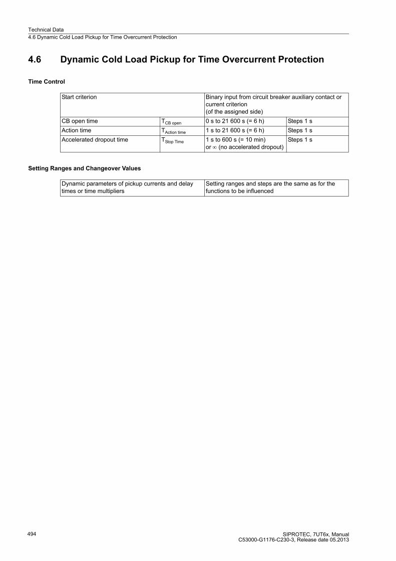
Technical Data
4.6 Dynamic Cold Load Pickup for Time Overcurrent Protection
SIPROTEC, 7UT6x, ManualC53000-G1176-C230-3, Release date 05.2013
494
4.6 Dynamic Cold Load Pickup for Time Overcurrent Protection
Time Control
Setting Ranges and Changeover Values
Start criterion Binary input from circuit breaker auxiliary contact or current criterion (of the assigned side)
CB open time TCB open 0 s to 21 600 s (= 6 h) Steps 1 s
Action time TAction time 1 s to 21 600 s (= 6 h) Steps 1 s
Accelerated dropout time TStop Time 1 s to 600 s (= 10 min)or ∞ (no accelerated dropout)
Steps 1 s
Dynamic parameters of pickup currents and delay times or time multipliers
Setting ranges and steps are the same as for the functions to be influenced
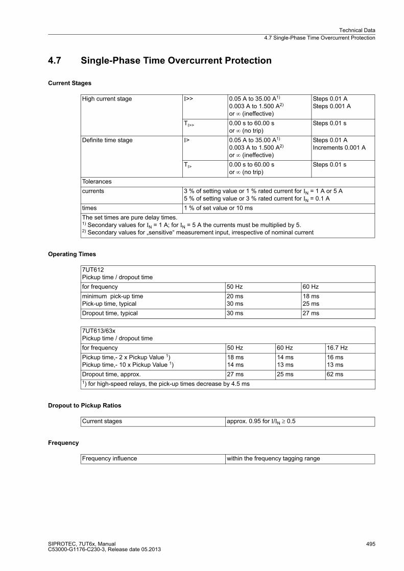
Technical Data
4.7 Single-Phase Time Overcurrent Protection
SIPROTEC, 7UT6x, ManualC53000-G1176-C230-3, Release date 05.2013
495
4.7 Single-Phase Time Overcurrent Protection
Current Stages
Operating Times
Dropout to Pickup Ratios
Frequency
High current stage I>> 0.05 A to 35.00 A1)
0.003 A to 1.500 A2)
or ∞ (ineffective)
Steps 0.01 ASteps 0.001 A
TI>> 0.00 s to 60.00 sor ∞ (no trip)
Steps 0.01 s
Definite time stage I> 0.05 A to 35.00 A1)
0.003 A to 1.500 A2)
or ∞ (ineffective)
Steps 0.01 AIncrements 0.001 A
TI> 0.00 s to 60.00 sor ∞ (no trip)
Steps 0.01 s
Tolerances
currents 3 % of setting value or 1 % rated current for IN = 1 A or 5 A5 % of setting value or 3 % rated current for IN = 0.1 A
times 1 % of set value or 10 ms
The set times are pure delay times. 1) Secondary values for IN = 1 A; for IN = 5 A the currents must be multiplied by 5. 2) Secondary values for „sensitive“ measurement input, irrespective of nominal current
7UT612Pickup time / dropout time
for frequency 50 Hz 60 Hz
minimum pick-up timePick-up time, typical
20 ms30 ms
18 ms25 ms
Dropout time, typical 30 ms 27 ms
7UT613/63xPickup time / dropout time
for frequency 50 Hz 60 Hz 16.7 Hz
Pickup time,- 2 x Pickup Value 1)Pickup time,- 10 x Pickup Value 1)
18 ms14 ms
14 ms13 ms
16 ms13 ms
Dropout time, approx. 27 ms 25 ms 62 ms1) for high-speed relays, the pick-up times decrease by 4.5 ms
Current stages approx. 0.95 for I/IN ≥ 0.5
Frequency influence within the frequency tagging range

Technical Data
4.8 Unbalanced Load Protection
SIPROTEC, 7UT6x, ManualC53000-G1176-C230-3, Release date 05.2013
496
4.8 Unbalanced Load Protection
Characteristics
Current Stages
Definite-time stages DT I2>>, I2>
Inverse time stages(acc. to IEC or ANSI)
IT I2P
One of the characteristics shown in figures 4-14 to 4-17 can be selected
Reset characteristicswith disk emulation
IT For illustrations of possible reset time characteristics see figures 4-14 to 4-17 on the left-hand side.
Operating Range 0.1 to 4 I/InS
High current stage I2>> 0.10 A to 3.00 A1) Steps 0.01 A
TI2>> 0.00 s to 60.00 sor ∞ (no trip)
Steps 0.01 s
Definite time current element (50Ns-2, 50Ns-1)
I2> 0.10 A to 3.00 A1) Steps 0.01 A
TI2> 0.00 s to 60.00 sor ∞ (no trip)
Steps 0.01 s
Inverse current element (51Ns-IEC) I2P 0.10 A to 2.00 A1) Steps 0.01 A
TI2P 0.05 s to 3.20 sor ∞ (no trip)
Steps 0.01 s
Inverse current element (51Ns-ANSI) I2P 0.10 A to 2.00 A1) Steps 0.01 A
DI2P 0.50 s to 15.00 sor ∞ (no trip)
Steps 0.01 s
Tolerances with inverse time 2)
currents 3 % of setting value or 1 % nominal current
times 1 % of setting value or 10 ms
Tolerances with definite time (IEC) 2)
currents Pickup with1.05 ≤ I2/I2P ≤ 1.15
times 5 % ± 15 ms5 % ± 45 ms
at fN = 50/60 Hz for fN = 16.7 Hz
for 2 ≤ I2/I2P ≤ 20and TI2P/s ≥ 1
Tolerances with definite time (ANSI) 2)
times 5 % ± 15 ms5 % ± 45 ms
at fN = 50/60 Hz for fN = 16.7 Hz
for 2 ≤ I2/I2P ≤ 20and DI2P/s ≥ 1
The set times are pure delay times. 1) Secondary values for IN = 1 A; for IN = 5 A the currents must be multiplied by 5. 2) For one 3-phase measuring location
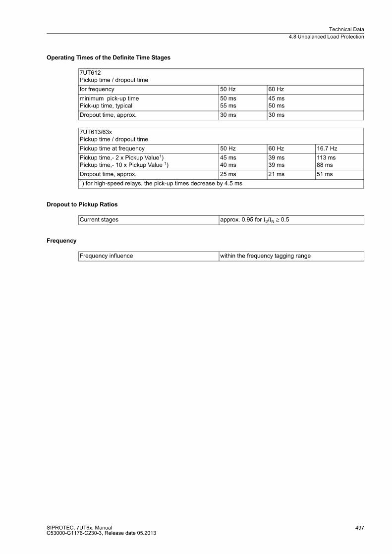
Technical Data
4.8 Unbalanced Load Protection
SIPROTEC, 7UT6x, ManualC53000-G1176-C230-3, Release date 05.2013
497
Operating Times of the Definite Time Stages
Dropout to Pickup Ratios
Frequency
7UT612Pickup time / dropout time
for frequency 50 Hz 60 Hz
minimum pick-up timePick-up time, typical
50 ms55 ms
45 ms50 ms
Dropout time, approx. 30 ms 30 ms
7UT613/63xPickup time / dropout time
Pickup time at frequency 50 Hz 60 Hz 16.7 Hz
Pickup time,- 2 x Pickup Value1)Pickup time,- 10 x Pickup Value 1)
45 ms40 ms
39 ms39 ms
113 ms88 ms
Dropout time, approx. 25 ms 21 ms 51 ms1) for high-speed relays, the pick-up times decrease by 4.5 ms
Current stages approx. 0.95 for I2/IN ≥ 0.5
Frequency influence within the frequency tagging range
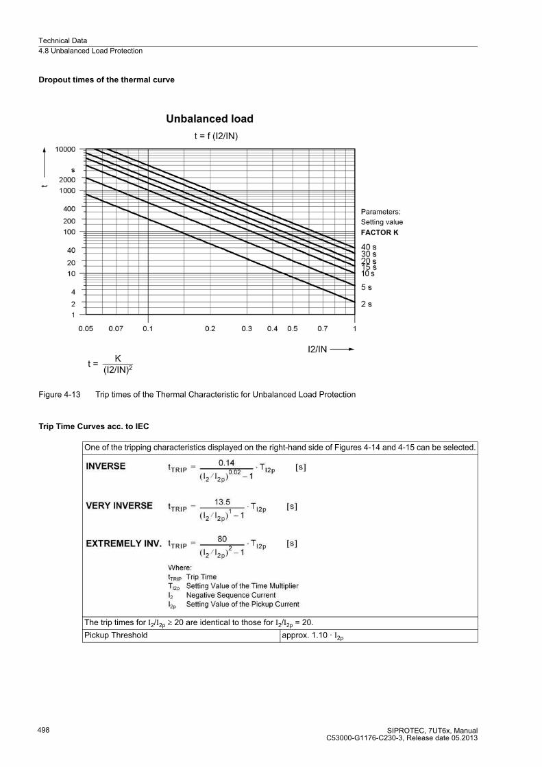
Technical Data
4.8 Unbalanced Load Protection
SIPROTEC, 7UT6x, ManualC53000-G1176-C230-3, Release date 05.2013
498
Dropout times of the thermal curve
Figure 4-13 Trip times of the Thermal Characteristic for Unbalanced Load Protection
Trip Time Curves acc. to IEC
One of the tripping characteristics displayed on the right-hand side of Figures 4-14 and 4-15 can be selected.
The trip times for I2/I2p ≥ 20 are identical to those for I2/I2p = 20.
Pickup Threshold approx. 1.10 · I2p
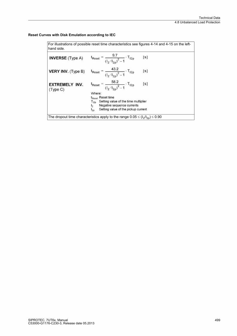
Technical Data
4.8 Unbalanced Load Protection
SIPROTEC, 7UT6x, ManualC53000-G1176-C230-3, Release date 05.2013
499
Reset Curves with Disk Emulation according to IEC
For illustrations of possible reset time characteristics see figures 4-14 and 4-15 on the left-hand side.
The dropout time characteristics apply to the range 0.05 ≤ (I2/I2p) ≤ 0.90

Technical Data
4.8 Unbalanced Load Protection
SIPROTEC, 7UT6x, ManualC53000-G1176-C230-3, Release date 05.2013
500
Figure 4-14 Dropout time and trip time characteristics of the inverse time unbalanced load stage, as per IEC

Technical Data
4.8 Unbalanced Load Protection
SIPROTEC, 7UT6x, ManualC53000-G1176-C230-3, Release date 05.2013
501
Figure 4-15 Dropout time and trip time characteristics of the inverse time unbalanced load stage, as per IEC
Trip Time Curves acc. to ANSI
One of the tripping curves depicted in the figures 4-16 and 4-17 on the right-hand side may be selected.
The tripping times for I2/I2p ≥ 20 are identical to those for I2/I2p = 20.
Pickup Threshold Approx. 1.10· I2p

Technical Data
4.8 Unbalanced Load Protection
SIPROTEC, 7UT6x, ManualC53000-G1176-C230-3, Release date 05.2013
502
Reset Curves with Disk Emulation according to ANSI
For illustrations of possible reset time characteristics see figures 4-16 and 4-17 on the left-hand side.
The dropout times constants apply to (I2/I2p) ≤ 0.90
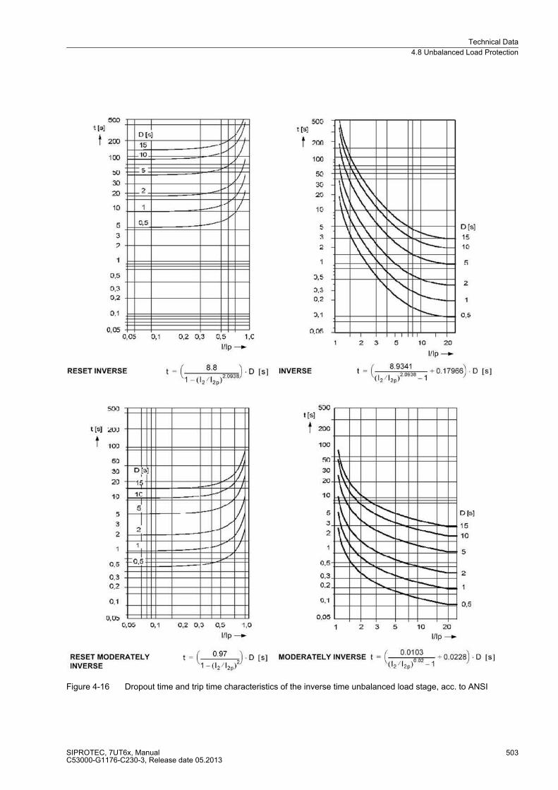
Technical Data
4.8 Unbalanced Load Protection
SIPROTEC, 7UT6x, ManualC53000-G1176-C230-3, Release date 05.2013
503
Figure 4-16 Dropout time and trip time characteristics of the inverse time unbalanced load stage, acc. to ANSI
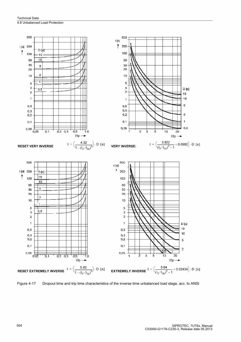
Technical Data
4.8 Unbalanced Load Protection
SIPROTEC, 7UT6x, ManualC53000-G1176-C230-3, Release date 05.2013
504
Figure 4-17 Dropout time and trip time characteristics of the inverse time unbalanced load stage, acc. to ANSI

Technical Data
4.9 Thermal Overload
SIPROTEC, 7UT6x, ManualC53000-G1176-C230-3, Release date 05.2013
505
4.9 Thermal Overload
Setting Ranges
Trip Curve
Dropout to Pickup Ratios
Tolerances
Frequency Influence referring to k · IN
Factor k according to IEC 60255-8 0.10 to 4.00 Steps 0.01
Time constant τ 1.0 min to 999.9 min Increments 0.1 min
Cooling down factor at motor stand-still
Kτ-factor 1.0 to 10.0 Steps 0.1
Thermal alarm stage ΘAlarm/ΘTrip 50 % to 100 % referred to trip temperature rise
Steps 1 %
Current alarm stage IAlarm 0.10 to 4.00 A 1) Steps 0.01 A
Start-up recognition Imotor startup 0.60 to 10.00 A 1) or ∞ (no start-up recognition)
Steps 0.01 A
Emergency start run-on time TRun-on 10 s to 15 000 s Steps 1 s1) Secondary values based on IN = 1 A; for IN = 5 A the currents must be multiplied by 5.
Θ/ΘOFF Dropout with ΘAlarm
Θ/ΘAlarm approx. 0.99
I/IAlarm approx. 0.97
For one 3-phase measuring location
relating to k · IN 3 % or 10 mA 1);class 3% according to IEC 60255-8
Referring to tripping time 3 % or 1.2 s at fN = 50 / 60 Hz5 % or 1.2 s at fN = 16.7 Hzfor I/(k·IN) > 1.25
1) Secondary values based on IN = 1 A; for IN = 5 A the currents must be multiplied by 5.
Frequency in range 0.9 ≤ f/fN ≤ 1.1 1 % at fN = 50 / 60 Hz3 % at fN = 16.7 Hz

Technical Data
4.9 Thermal Overload
SIPROTEC, 7UT6x, ManualC53000-G1176-C230-3, Release date 05.2013
506
Characteristic
Figure 4-18 Trip time characteristic of thermal overload protection
τ Tripping time
τ Thermal time constant
I Load current
Ipre Previous load current
k Setting factor according to IEC 60255-8
INom Rated current of protected object
Technical Data
4.9 Thermal Overload
SIPROTEC, 7UT6x, ManualC53000-G1176-C230-3, Release date 05.2013
507
Temperature Detectors
Cooling
Annunciation Thresholds
Number of measuring points from 1 RTD-box (up to 6 measuring points) orfrom 2 RTD-boxes (up to 12 measuring points)
For hot-spot calculation one temperature detector must be connected.
Cooling method ON (oil natural)OF (oil forced)OD (oil directed)
Oil exponent Y 1.6 to 2.0 Steps 0.1
Hot-spot to top-oil gradient Hgr 22 to 29 Steps 1
Warning temperature hot-spotor
98 °C to 140 °C208 °F to 284 °F
Steps 1 °CIncrements 1 °F
Alarm temperature hot-spotor
98 °C to 140 °C208 °F to 284 °F
Steps 1 °CSteps 1 °F
Warning ageing rate 0.125 to 128.000 Steps 0.001
Alarm ageing rate 0.125 to 128.000 Steps 0.001
Technical Data
4.10 RTD Boxes for Overload Detection
SIPROTEC, 7UT6x, ManualC53000-G1176-C230-3, Release date 05.2013
508
4.10 RTD Boxes for Overload Detection
Temperature Detectors
Operational Measured Values
Annunciation Thresholds
Connectable RTD-boxes 1 or 2
Number of temperature detectors per RTD-box Max. 6
Type of measurement Pt 100 Ω or Ni 100 Ω or Ni 120 ΩSelectable: 2 or 3-wire connection
Mounting identification „Oil“ or „Ambient“ or „Stator“ or „Bearing“ or „Other“
Number of measuring points Max. 12 temperature measuring points
Temperature unit °C or °F (settable)
Measuring range- For Pt 100- For Ni 100- For Ni 120
–199 °C to 800 °C (–326 °F to 1 472 °F)–54 °C to 278 °C (–65 °F to 532 °F)–52 °C to 263 °C (–62 °F to 505 °F)
Resolution 1 °C or 1 °F
Tolerance ± 0.5% of measured value ± 1 digit
For each measuring point:
Stage 1 –58 °F to 482 °F or –50 °C to 250 °Cor ∞ (no indication)or ∞ (no indication)
(in increments of 1 °C)(in increments of 1 °F)
Stage 2 –58 °F to 482 °F or –50 °C to 250 °Cor ∞ (no indication)or ∞ (no indication)
(in increments of 1 °C)(in increments of 1 °F)

Technical Data
4.11 Overexcitation Protection
SIPROTEC, 7UT6x, ManualC53000-G1176-C230-3, Release date 05.2013
509
4.11 Overexcitation Protection
Setting Ranges
Times
Dropout-to-Pickup Ratio
Tripping Time Characteristic
Tolerances
Influencing Variables
Pickup threshold(warning stage)
1.00 to 1.20 Steps 0.01
Pickup threshold(stepped characteristic)
1.00 to 1.40 Steps 0.01
Time delay (warning stage and stepped charact.)
T U/f>, T U/f>> 0.00 to 60.00 sor ∞ (ineffective)
Steps 0.01 s
Pair of values for characteristic of U/f 1.05/1.10/1.15/1.20/1.25/1.30/1.35/1.40
Associated time delays for thermal characteristic
t (U/f) 1 s to 20 000 s Steps 1 s
Time for cool down TCOOL DOWN 1 s to 20 000 s Steps 1 s
Pickup/dropout times of warning stage and stepped characteristic
Pickup time at frequency 50 Hz 60 Hz 16.7 Hz (only 7UT613/63x)
Minimum 36 ms 31 ms 91 ms
Dropout time, approx. 36 ms 23 ms 70 ms
Dropout/Pickup approx. 0.98
Thermal replica and stepped characteristic For default settings see Figure 4-19
U/f pickup 3 % of set value
Time delay (warning stage and stepped charact.) 1 % of setting value, or 10 ms (min. 1.5 cycles)
Thermal replica 5 %, related to U/f ± 600 ms
Power supply direct voltage in range 0.8 ≤ UH/UHN ≤ 1.15
≤ 1 %
Temperature in range –5 °C ≤ δamb ≤ 55 °C ≤ 0.5 %/10 K
Frequency in range 0.95 ≤ f/fN ≤ 1.05 ≤ 1 %
Harmonic currents
up to 10 % 3rd harmonicup to 10 % 5th harmonic
≤ 1 %≤ 1 %
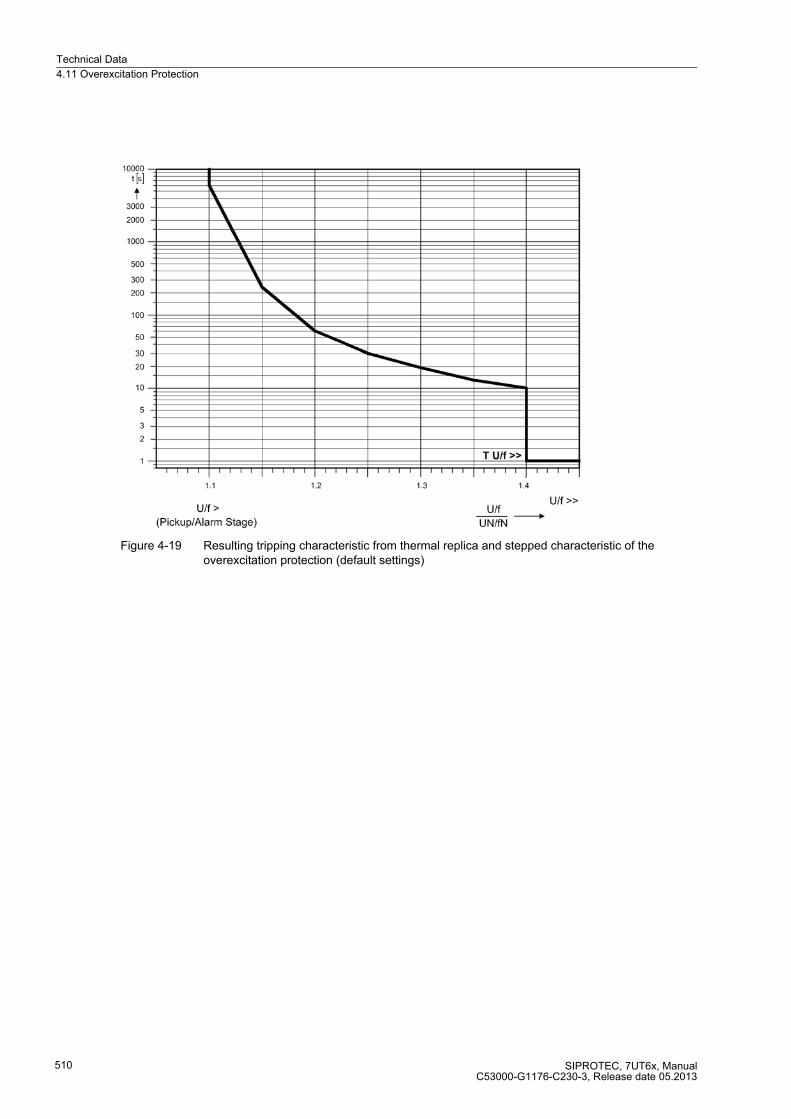
Technical Data
4.11 Overexcitation Protection
SIPROTEC, 7UT6x, ManualC53000-G1176-C230-3, Release date 05.2013
510
Figure 4-19 Resulting tripping characteristic from thermal replica and stepped characteristic of the overexcitation protection (default settings)
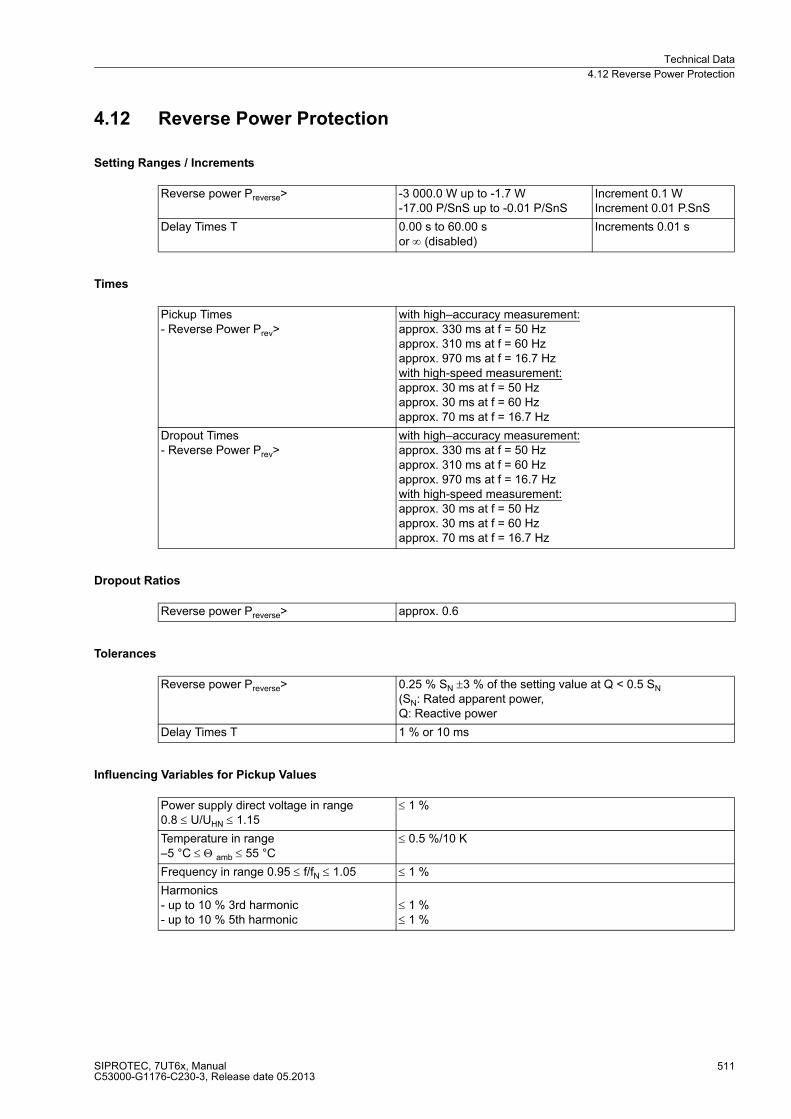
Technical Data
4.12 Reverse Power Protection
SIPROTEC, 7UT6x, ManualC53000-G1176-C230-3, Release date 05.2013
511
4.12 Reverse Power Protection
Setting Ranges / Increments
Times
Dropout Ratios
Tolerances
Influencing Variables for Pickup Values
Reverse power Preverse> -3 000.0 W up to -1.7 W-17.00 P/SnS up to -0.01 P/SnS
Increment 0.1 WIncrement 0.01 P.SnS
Delay Times T 0.00 s to 60.00 sor ∞ (disabled)
Increments 0.01 s
Pickup Times - Reverse Power Prev>
with high–accuracy measurement:approx. 330 ms at f = 50 Hz approx. 310 ms at f = 60 Hzapprox. 970 ms at f = 16.7 Hzwith high-speed measurement:approx. 30 ms at f = 50 Hzapprox. 30 ms at f = 60 Hzapprox. 70 ms at f = 16.7 Hz
Dropout Times - Reverse Power Prev>
with high–accuracy measurement:approx. 330 ms at f = 50 Hz approx. 310 ms at f = 60 Hzapprox. 970 ms at f = 16.7 Hzwith high-speed measurement:approx. 30 ms at f = 50 Hzapprox. 30 ms at f = 60 Hzapprox. 70 ms at f = 16.7 Hz
Reverse power Preverse> approx. 0.6
Reverse power Preverse> 0.25 % SN ±3 % of the setting value at Q < 0.5 SN (SN: Rated apparent power,Q: Reactive power
Delay Times T 1 % or 10 ms
Power supply direct voltage in range 0.8 ≤ U/UHN ≤ 1.15
≤ 1 %
Temperature in range –5 °C ≤ Θ amb ≤ 55 °C
≤ 0.5 %/10 K
Frequency in range 0.95 ≤ f/fN ≤ 1.05 ≤ 1 %
Harmonics - up to 10 % 3rd harmonic - up to 10 % 5th harmonic
≤ 1 %≤ 1 %

Technical Data
4.13 Forward active power supervision
SIPROTEC, 7UT6x, ManualC53000-G1176-C230-3, Release date 05.2013
512
4.13 Forward active power supervision
Setting Ranges / Increments
Times
Dropout Ratios
Tolerances
Influencing Variables for Pickup Values
Forward power Pforward< 1.7 W up to 3 000.0 W0.01 P/SnS up to 17.00 P/SnS
Increment 0.1 WIncrement 0.1 W
Forward power Pforward> 1.7 W up to 3000.0 W0.01 P/SnS up to 17.00 P/SnS
Increment 0.1 WIncrement 0.1 W
Delay Times T 0.00 s to 60.00 sor ∞ (disabled)
Increments 0.01 s
Pickup times- Active power P<, P>
with high–accuracy measurement:approx. 330 ms at f = 50 Hzapprox. 310 ms at f = 60 Hzapprox. 970 ms at f = 16.7 Hzwith high-speed measurement:approx. 30 ms at f = 50 Hzapprox. 30 ms at f = 60 Hzapprox. 70 ms at f = 16.7 Hz
Dropout times- active power P<, P>
with high–accuracy measurement:approx. 330 ms at f = 50 Hzapprox. 310 ms at f = 60 Hzapprox. 970 ms at f = 16.7 Hzwith high-speed measurement:approx. 30 ms at f = 50 Hzapprox. 30 ms at f = 60 Hzapprox. 70 ms at f = 16.7 Hz
Active power PAct< approx. 1.10 or 0.5 % of SN
Active power PAct> approx. 0.90 or 0.5 % of SN
Active power P<, P> 0.25 % SN ±3 % of setting value with high-accuracy measurement0.5 % SN ±3 % of setting value with high-speed measurement(SN: Rated apparent power)
Delay Times T 1 % or 10 ms
Power supply direct voltage in range 0.8 ≤ UH/UHN ≤ 1.15
≤ 1 %
Temperature in range –5 °C ≤ Θ amb ≤ 55 °C ≤ 0.5 %/10 K
Frequency in range 0.95 ≤ f/fN ≤ 1.05 ≤ 1 %
Harmonics - up to 10 % 3rd harmonic - up to 10 % 5th harmonic
≤ 1 %≤ 1 %
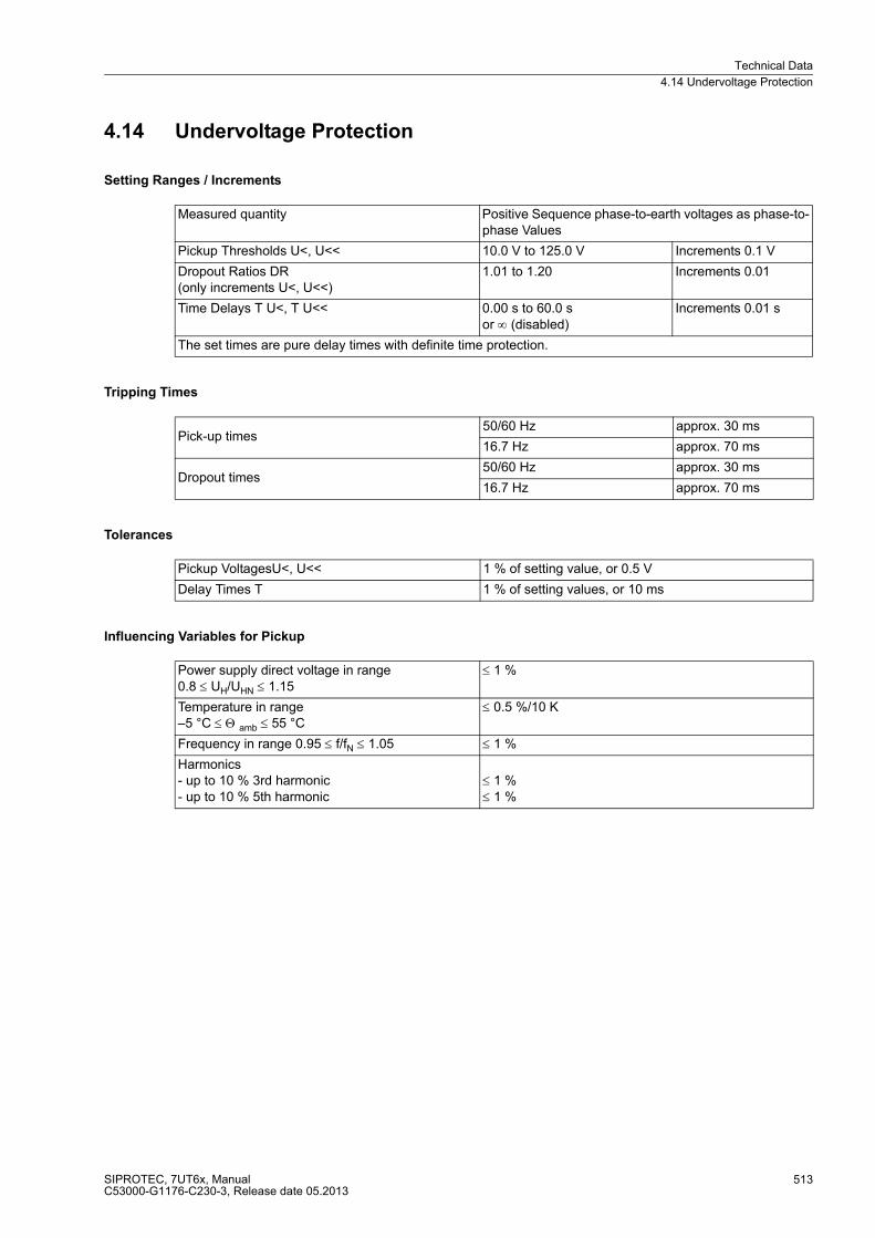
Technical Data
4.14 Undervoltage Protection
SIPROTEC, 7UT6x, ManualC53000-G1176-C230-3, Release date 05.2013
513
4.14 Undervoltage Protection
Setting Ranges / Increments
Tripping Times
Tolerances
Influencing Variables for Pickup
Measured quantity Positive Sequence phase-to-earth voltages as phase-to-phase Values
Pickup Thresholds U<, U<< 10.0 V to 125.0 V Increments 0.1 V
Dropout Ratios DR(only increments U<, U<<)
1.01 to 1.20 Increments 0.01
Time Delays T U<, T U<< 0.00 s to 60.0 sor ∞ (disabled)
Increments 0.01 s
The set times are pure delay times with definite time protection.
Pick-up times50/60 Hz approx. 30 ms
16.7 Hz approx. 70 ms
Dropout times50/60 Hz approx. 30 ms
16.7 Hz approx. 70 ms
Pickup VoltagesU<, U<< 1 % of setting value, or 0.5 V
Delay Times T 1 % of setting values, or 10 ms
Power supply direct voltage in range 0.8 ≤ UH/UHN ≤ 1.15
≤ 1 %
Temperature in range –5 °C ≤ Θ amb ≤ 55 °C
≤ 0.5 %/10 K
Frequency in range 0.95 ≤ f/fN ≤ 1.05 ≤ 1 %
Harmonics- up to 10 % 3rd harmonic - up to 10 % 5th harmonic
≤ 1 %≤ 1 %
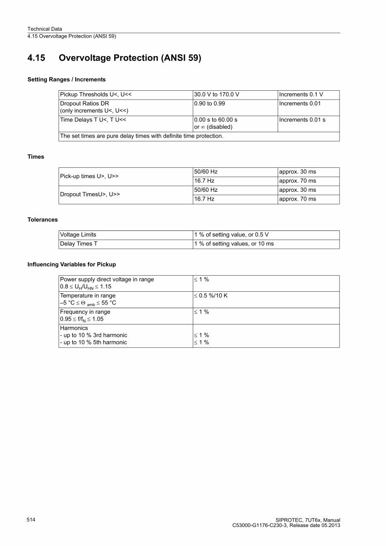
Technical Data
4.15 Overvoltage Protection (ANSI 59)
SIPROTEC, 7UT6x, ManualC53000-G1176-C230-3, Release date 05.2013
514
4.15 Overvoltage Protection (ANSI 59)
Setting Ranges / Increments
Times
Tolerances
Influencing Variables for Pickup
Pickup Thresholds U<, U<< 30.0 V to 170.0 V Increments 0.1 V
Dropout Ratios DR(only increments U<, U<<)
0.90 to 0.99 Increments 0.01
Time Delays T U<, T U<< 0.00 s to 60.00 sor ∞ (disabled)
Increments 0.01 s
The set times are pure delay times with definite time protection.
Pick-up times U>, U>>50/60 Hz approx. 30 ms
16.7 Hz approx. 70 ms
Dropout TimesU>, U>>50/60 Hz approx. 30 ms
16.7 Hz approx. 70 ms
Voltage Limits 1 % of setting value, or 0.5 V
Delay Times T 1 % of setting values, or 10 ms
Power supply direct voltage in range 0.8 ≤ UH/UHN ≤ 1.15
≤ 1 %
Temperature in range –5 °C ≤ Θ amb ≤ 55 °C
≤ 0.5 %/10 K
Frequency in range 0.95 ≤ f/fN ≤ 1.05
≤ 1 %
Harmonics - up to 10 % 3rd harmonic - up to 10 % 5th harmonic
≤ 1 %≤ 1 %

Technical Data
4.16 Frequency Protection
SIPROTEC, 7UT6x, ManualC53000-G1176-C230-3, Release date 05.2013
515
4.16 Frequency Protection
Measuring Range of the Frequency Functions
Setting Ranges / Increments
1) No pickup is effected below the minimum voltage for frequency measurement
Times
Dropout difference
Lower frequency limit Rated frequency 50/60/16.7 Hz approx. 9.25 Hz
Upper frequency limit Rated frequency 50/60 Hz approx. 70 Hz
Nominal frequency 16.7 Hz approx. 23.33 Hz
Minimum positive sequence voltage for frequency measurement (phase-phase voltage)
approx. 8.6 V
Minimum positive sequence voltage for frequency measurement (non-interlinked voltage)
approx. 5 V
Number of frequency elements 4; can be set to f<, f<<, f<<< or f>
Pickup values f<, f<<, f<<<
Nominal frequency 50 Hz 40.00 to 49.99 Hz or 0 (disabled)
Nominal frequency 60 Hz 50.00 to 59.99 Hz or 0 (disabled)
Nominal frequency 16.7 Hz 10.00 to 16.69 Hz or 0 (disabled)
Pickup value f>
Nominal frequency 50 Hz 50.01 to 66.00 Hz or ∞ (disabled)
Nominal frequency 60 Hz 60.01 to 69.99 Hz or ∞ (disabled)
Nominal frequency 16.7 Hz 16.67 to 22.00 Hz or ∞ (disabled)
Delay times T f<< 0.00 s to 600.00 sor ∞ (disabled)
Increments 0.01 s
Delay times T f<, T f<<<,T f> 0.00 s to 100.00 sor ∞ (disabled)
Increments 0.01 s
Undervoltage blocking(positive sequence component U1)
10.0 V to 125.0 V and 0 V 1) (no blocking)
Increments 0.1 V
The set times are pure delay times.
Pickup times f>, f<50/60 Hz approx. 100 ms
16.7 Hz approx. 300 ms
Dropout times f>, f<50/60 Hz approx. 160 ms
16.7 Hz approx. 480 ms
Δf = | Pickup Value – Dropout Value | approx. 20 mHz
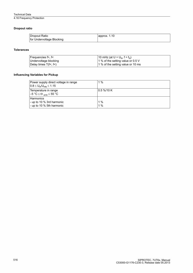
Technical Data
4.16 Frequency Protection
SIPROTEC, 7UT6x, ManualC53000-G1176-C230-3, Release date 05.2013
516
Dropout ratio
Tolerances
Influencing Variables for Pickup
Dropout Ratio for Undervoltage Blocking
approx. 1.10
Frequencies f>, f< Undervoltage blocking Delay times T(f<, f<)
10 mHz (at U = UN, f = fN)1 % of the setting value or 0.5 V 1 % of the setting value or 10 ms
Power supply direct voltage in range 0.8 ≤ UH/UHN ≤ 1.15
1 %
Temperature in range –5 °C ≤ Θ amb ≤ 55 °C
0.5 %/10 K
Harmonics - up to 10 % 3rd harmonic - up to 10 % 5th harmonic
1 %1 %

Technical Data
4.17 Circuit Breaker Failure Protection
SIPROTEC, 7UT6x, ManualC53000-G1176-C230-3, Release date 05.2013
517
4.17 Circuit Breaker Failure Protection
Circuit Breaker Supervision
Starting Conditions
Times
Current flow monitoring 0.04 A to 1.00 A1) for the respective side
Steps 0.01 A
Dropout-to-pickup ratio approx. 0.9 for I ≥ 0.25 A 1)
Tolerance 5 % of set value or 0.01 A 1)
Breaker status monitoring via circuit breaker auxiliary contacts and binary input1) Secondary values based on IN = 1 A; for IN = 5 A the currents must be multiplied by 5.
For breaker failure protection internal trip external trip (via binary input)
Pickup time for fN = 50 / 60 Hz approx. 3 ms with measured quantities,approx. 20 ms after switch-on of measured quantities
Pickup time for fN = 16.7 Hz approx. 60 ms after switch-on of measured quantities
Dropout time for fN = 50/60 Hz approx. 25 ms
Dropout time for fN = 16.7 Hz approx. 75 ms
Times 0.00 s to 60.00 s; ∞ Steps 0.01
Time tolerance 1 % of set value or 10 ms

Technical Data
4.18 External Trip Commands
SIPROTEC, 7UT6x, ManualC53000-G1176-C230-3, Release date 05.2013
518
4.18 External Trip Commands
Binary Inputs for Direct Tripping
Transformer Annunciations
Number 2
Operating Time approx. 12.5 ms min.approx. 25 ms typical
Dropout time approx. 25 ms
Delay time 0.00 s to 60.00 s Steps 0.01 s
Time tolerance 1 % of set value or 10 ms
The set times are pure delay times.
External annunciations Buchholz warning Buchholz tankBuchholz tripping

Technical Data
4.19 Monitoring Functions
SIPROTEC, 7UT6x, ManualC53000-G1176-C230-3, Release date 05.2013
519
4.19 Monitoring Functions
Measured Quantities
Current symmetry(for each side)
|Imin | / | Imax | < BAL. FACT. I M1 provided that Imax/IN > BAL. I LIMIT M1/IN
BAL.FAC. I 0.10 to 0.90 Steps 0.01
BAL. I LIMIT 0.10 A to 1.00 A1) Steps 0.01 A
Voltage balance(if voltages applied)
|Umin | / | Umax | < BAL. FACTOR U provided that |Umax| > BALANCE U-LIMIT
BAL.FACTOR. U 0.58 to 0.90 Increments 0.01
BALANCE I LIMIT 10 V to 100 V Increments 1 V
Voltage sum(if voltages applied)
|UL1+ UL2 + UL3 – kU Uen| > 25 V
Current phase sequence IL1 leads IL2 leads IL3 if clockwiseIL1 leads IL3 leads IL2 if counter-clockwiseif |IL1|, |IL2|, |IL3| > 0.5 IN
Voltage phase sequence(if voltages applied)
UL1 leads UL2 leads UL3 if clockwiseUL1 leads UL3 leads UL2 if counter-clockwiseif |UL1|, |UL2|, |UL3| > 40 V/√ 3
Broken wire unexpected instantaneous current value andcurrent interruption or missing zero crossing
1) Secondary values based on IN = 1 A; for IN = 5 A they must be multiplied with 5.

Technical Data
4.20 User-defined Functions (CFC)
SIPROTEC, 7UT6x, ManualC53000-G1176-C230-3, Release date 05.2013
520
4.20 User-defined Functions (CFC)
Function Blocks and their Possible Allocation to the Priority Classes
Function Module Explanation Task Level
MW_BEARB PLC1_BEARB PLC_BEARB SFS_BEARB
ABSVALUE Magnitude Calculation X – – –
ADD Addition X X X X
ALARM Alarm clock X X X X
AND AND - Gate X X X X
BLINK Flash block X X X X
BOOL_TO_CO Boolean to Control (conversion)
– X X –
BOOL_TO_DI Boolean to Double Point (conversion)
– X X X
BOOL_TO_IC Bool to Internal SI, Conversion
– X X X
BUILD_DI Create Double Point Annunciation
– X X X
CMD_CANCEL Cancel command X X X X
CMD_CHAIN Switching Sequence – X X –
CMD_INF Command Information – – – X
COMPARE Measured value comparison
X X X X
CONNECT Connection – X X X
COUNTER Counter X X X X
CV_GET_STATUS Information status of the metered value, decoder
X X X X
D_FF D- Flipflop – X X X
D_FF_MEMO Status Memory for Restart X X X X
DI_GET_STATUS Information status double point indication, decoder
X X X X
DI_SET_STATUS Double point indication with status, encoder
X X X X
DI_TO_BOOL Double Point to Boolean (conversion)
– X X X
DINT_TO_REAL DoubleInt after real, adapter X X X X
DIST_DECODE Double point indication with status, decoder
X X X X
DIV Division X X X X
DM_DECODE Decode Double Point X X X X
DYN_OR Dynamic OR X X X X
LIVE_ZERO Live zero monitoring, non-linear characteristic
X – – –
LONG_TIMER Timer (max.1193h) X X X X
LOOP Feedback Loop X X X X
LOWER_SETPOINT Lower Limit X – – –
MUL Multiplication X X X X
MV_GET_STATUS Information status measured value, decoder
X X X X
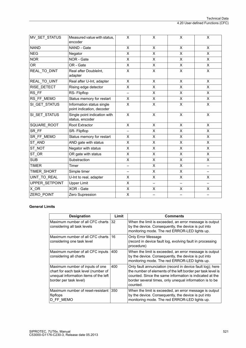
Technical Data
4.20 User-defined Functions (CFC)
SIPROTEC, 7UT6x, ManualC53000-G1176-C230-3, Release date 05.2013
521
General Limits
MV_SET_STATUS Measured value with status, encoder
X X X X
NAND NAND - Gate X X X X
NEG Negator X X X X
NOR NOR - Gate X X X X
OR OR - Gate X X X X
REAL_TO_DINT Real after DoubleInt, adapter
X X X X
REAL_TO_UINT Real after U-Int, adapter X X X X
RISE_DETECT Rising edge detector X X X X
RS_FF RS- Flipflop – X X X
RS_FF_MEMO Status memory for restart X X X X
SI_GET_STATUS Information status single point indication, decoder
X X X X
SI_SET_STATUS Single point indication with status, encoder
X X X X
SQUARE_ROOT Root Extractor X X X X
SR_FF SR- Flipflop – X X X
SR_FF_MEMO Status memory for restart X X X X
ST_AND AND gate with status X X X X
ST_NOT Negator with status X X X X
ST_OR OR gate with status X X X X
SUB Substraction X X X X
TIMER Timer – X X –
TIMER_SHORT Simple timer – X X –
UINT_TO_REAL U-Int to real, adapter X X X X
UPPER_SETPOINT Upper Limit X – – –
X_OR XOR - Gate X X X X
ZERO_POINT Zero Supression X – – –
Designation Limit Comments
Maximum number of all CFC charts considering all task levels
32 When the limit is exceeded, an error message is output by the device. Consequently, the device is put into monitoring mode. The red ERROR-LED lights up.
Maximum number of all CFC charts considering one task level
16 Only Error Message(record in device fault log, evolving fault in processing procedure)
Maximum number of all CFC inputs considering all charts
400 When the limit is exceeded, an error message is output by the device. Consequently, the device is put into monitoring mode. The red ERROR-LED lights up.
Maximum number of inputs of one chart for each task level (number of unequal information items of the left border per task level)
400 Only fault annunciation (record in device fault log); here the number of elements of the left border per task level is counted. Since the same information is indicated at the border several times, only unequal information is to be counted.
Maximum number of reset-resistant flipflopsD_FF_MEMO
350 When the limit is exceeded, an error message is output by the device. Consequently, the device is put into monitoring mode. The red ERROR-LED lights up.
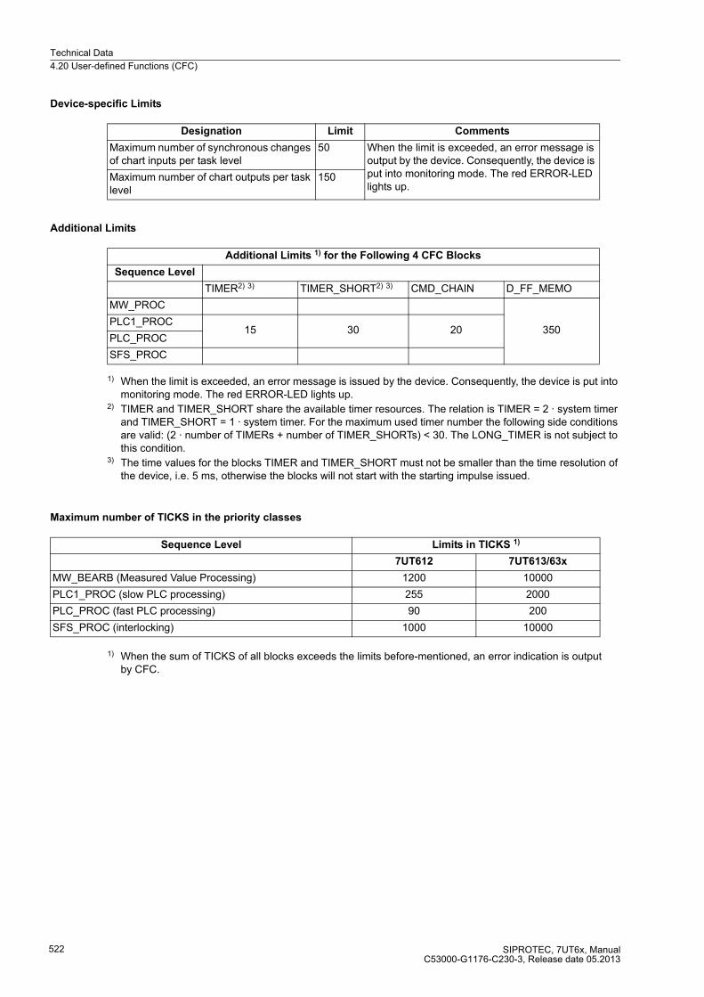
Technical Data
4.20 User-defined Functions (CFC)
SIPROTEC, 7UT6x, ManualC53000-G1176-C230-3, Release date 05.2013
522
Device-specific Limits
Additional Limits
1) When the limit is exceeded, an error message is issued by the device. Consequently, the device is put into monitoring mode. The red ERROR-LED lights up.
2) TIMER and TIMER_SHORT share the available timer resources. The relation is TIMER = 2 · system timer and TIMER_SHORT = 1 · system timer. For the maximum used timer number the following side conditions are valid: (2 · number of TIMERs + number of TIMER_SHORTs) < 30. The LONG_TIMER is not subject to this condition.
3) The time values for the blocks TIMER and TIMER_SHORT must not be smaller than the time resolution of the device, i.e. 5 ms, otherwise the blocks will not start with the starting impulse issued.
Maximum number of TICKS in the priority classes
1) When the sum of TICKS of all blocks exceeds the limits before-mentioned, an error indication is output by CFC.
Designation Limit Comments
Maximum number of synchronous changes of chart inputs per task level
50 When the limit is exceeded, an error message is output by the device. Consequently, the device is put into monitoring mode. The red ERROR-LED lights up.
Maximum number of chart outputs per task level
150
Additional Limits 1) for the Following 4 CFC Blocks
Sequence Level
TIMER2) 3) TIMER_SHORT2) 3) CMD_CHAIN D_FF_MEMO
MW_PROC
350PLC1_PROC
15 30 20PLC_PROC
SFS_PROC
Sequence Level Limits in TICKS 1)
7UT612 7UT613/63x
MW_BEARB (Measured Value Processing) 1200 10000
PLC1_PROC (slow PLC processing) 255 2000
PLC_PROC (fast PLC processing) 90 200
SFS_PROC (interlocking) 1000 10000
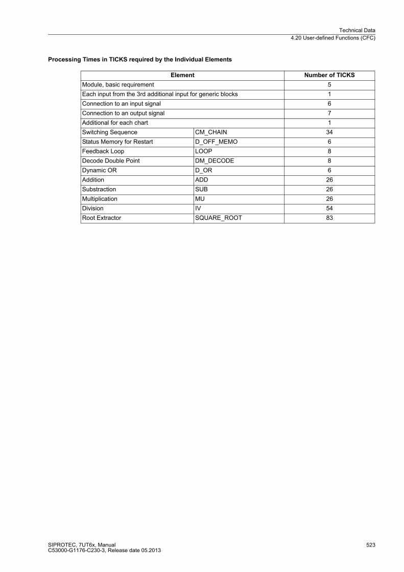
Technical Data
4.20 User-defined Functions (CFC)
SIPROTEC, 7UT6x, ManualC53000-G1176-C230-3, Release date 05.2013
523
Processing Times in TICKS required by the Individual Elements
Element Number of TICKS
Module, basic requirement 5
Each input from the 3rd additional input for generic blocks 1
Connection to an input signal 6
Connection to an output signal 7
Additional for each chart 1
Switching Sequence CM_CHAIN 34
Status Memory for Restart D_OFF_MEMO 6
Feedback Loop LOOP 8
Decode Double Point DM_DECODE 8
Dynamic OR D_OR 6
Addition ADD 26
Substraction SUB 26
Multiplication MU 26
Division IV 54
Root Extractor SQUARE_ROOT 83
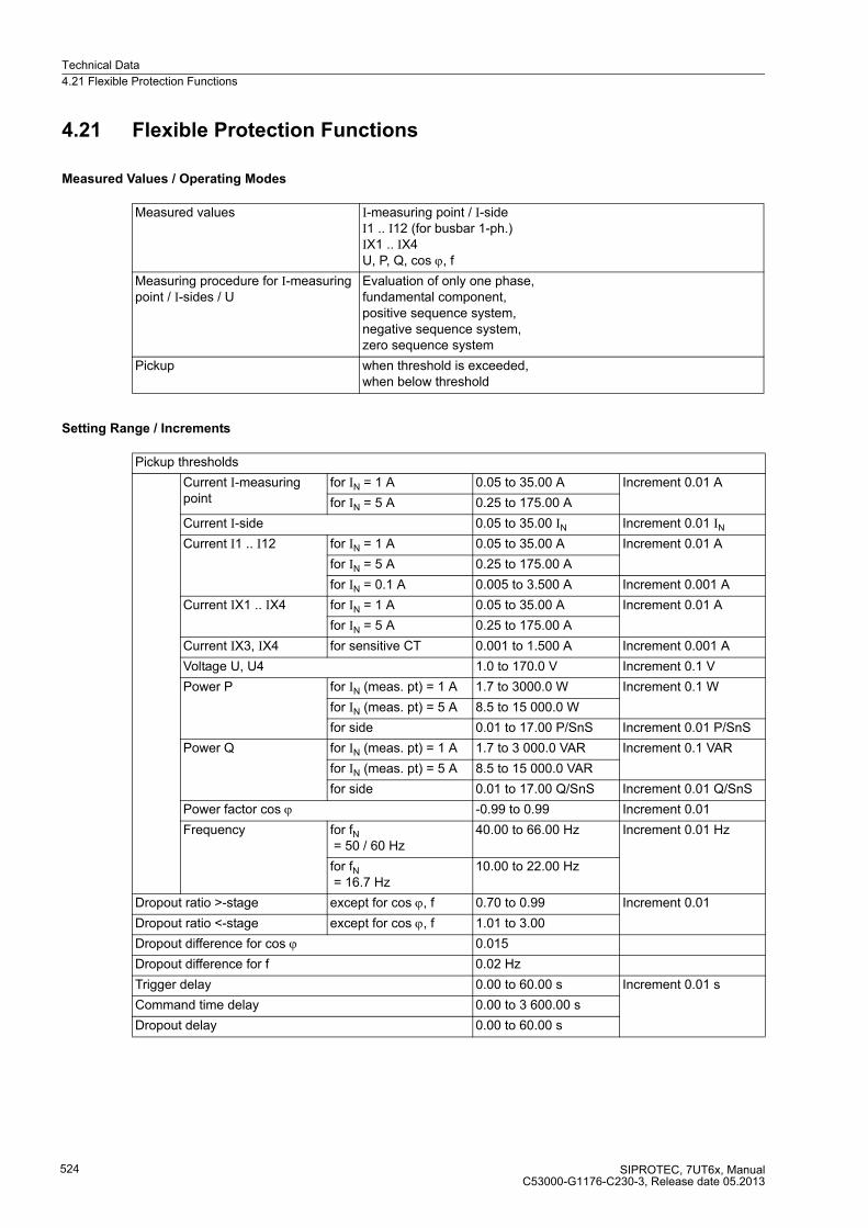
Technical Data
4.21 Flexible Protection Functions
SIPROTEC, 7UT6x, ManualC53000-G1176-C230-3, Release date 05.2013
524
4.21 Flexible Protection Functions
Measured Values / Operating Modes
Setting Range / Increments
Measured values I-measuring point / I-sideI1 .. I12 (for busbar 1-ph.)IX1 .. IX4U, P, Q, cos ϕ, f
Measuring procedure for I-measuring point / I-sides / U
Evaluation of only one phase,fundamental component,positive sequence system,negative sequence system,zero sequence system
Pickup when threshold is exceeded,when below threshold
Pickup thresholds
Current I-measuring point
for IN = 1 A 0.05 to 35.00 A Increment 0.01 A
for IN = 5 A 0.25 to 175.00 A
Current I-side 0.05 to 35.00 IN Increment 0.01 IN
Current I1 .. I12 for IN = 1 A 0.05 to 35.00 A Increment 0.01 A
for IN = 5 A 0.25 to 175.00 A
for IN = 0.1 A 0.005 to 3.500 A Increment 0.001 A
Current IX1 .. IX4 for IN = 1 A 0.05 to 35.00 A Increment 0.01 A
for IN = 5 A 0.25 to 175.00 A
Current IX3, IX4 for sensitive CT 0.001 to 1.500 A Increment 0.001 A
Voltage U, U4 1.0 to 170.0 V Increment 0.1 V
Power P for IN (meas. pt) = 1 A 1.7 to 3000.0 W Increment 0.1 W
for IN (meas. pt) = 5 A 8.5 to 15 000.0 W
for side 0.01 to 17.00 P/SnS Increment 0.01 P/SnS
Power Q for IN (meas. pt) = 1 A 1.7 to 3 000.0 VAR Increment 0.1 VAR
for IN (meas. pt) = 5 A 8.5 to 15 000.0 VAR
for side 0.01 to 17.00 Q/SnS Increment 0.01 Q/SnS
Power factor cos ϕ -0.99 to 0.99 Increment 0.01
Frequency for fN = 50 / 60 Hz
40.00 to 66.00 Hz Increment 0.01 Hz
for fN = 16.7 Hz
10.00 to 22.00 Hz
Dropout ratio >-stage except for cos ϕ, f 0.70 to 0.99 Increment 0.01
Dropout ratio <-stage except for cos ϕ, f 1.01 to 3.00
Dropout difference for cos ϕ 0.015
Dropout difference for f 0.02 Hz
Trigger delay 0.00 to 60.00 s Increment 0.01 s
Command time delay 0.00 to 3 600.00 s
Dropout delay 0.00 to 60.00 s
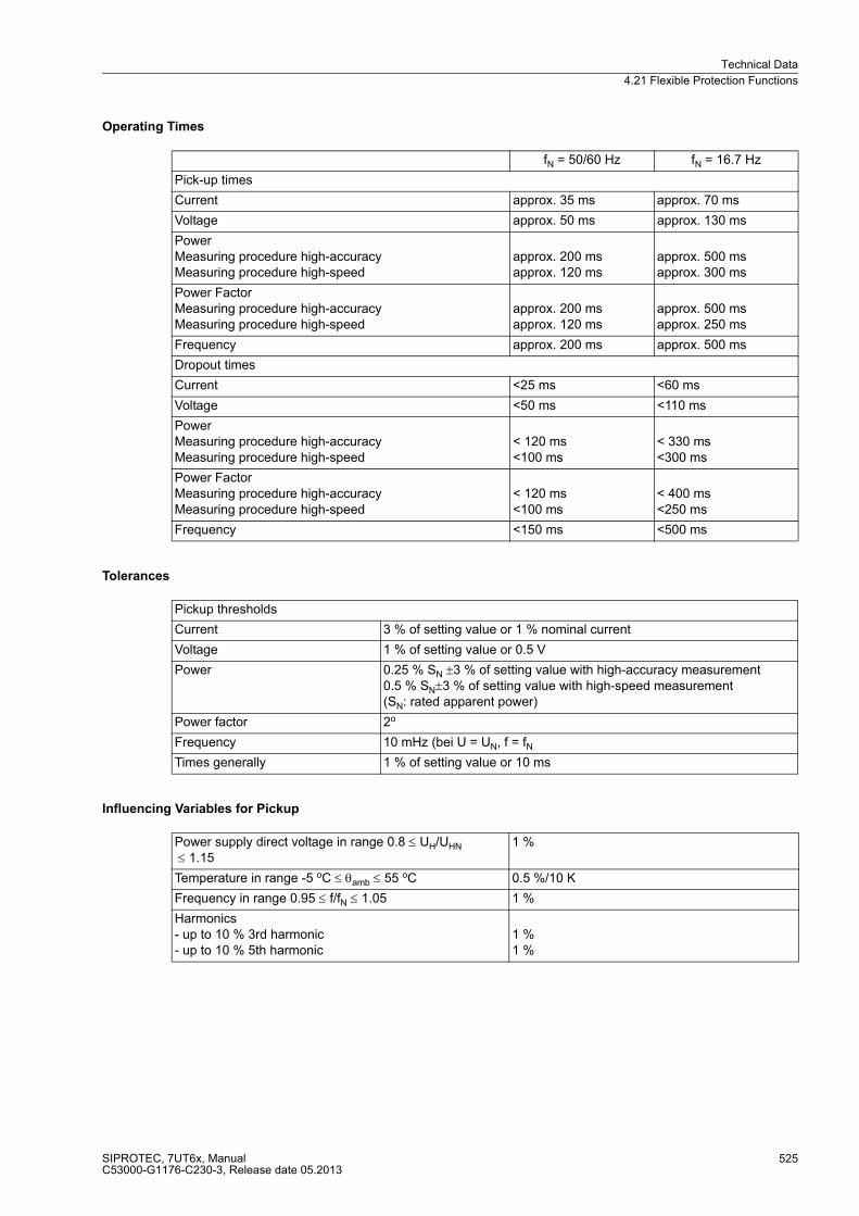
Technical Data
4.21 Flexible Protection Functions
SIPROTEC, 7UT6x, ManualC53000-G1176-C230-3, Release date 05.2013
525
Operating Times
Tolerances
Influencing Variables for Pickup
fN = 50/60 Hz fN = 16.7 Hz
Pick-up times
Current approx. 35 ms approx. 70 ms
Voltage approx. 50 ms approx. 130 ms
PowerMeasuring procedure high-accuracyMeasuring procedure high-speed
approx. 200 msapprox. 120 ms
approx. 500 msapprox. 300 ms
Power FactorMeasuring procedure high-accuracyMeasuring procedure high-speed
approx. 200 msapprox. 120 ms
approx. 500 msapprox. 250 ms
Frequency approx. 200 ms approx. 500 ms
Dropout times
Current <25 ms <60 ms
Voltage <50 ms <110 ms
PowerMeasuring procedure high-accuracyMeasuring procedure high-speed
< 120 ms<100 ms
< 330 ms<300 ms
Power FactorMeasuring procedure high-accuracyMeasuring procedure high-speed
< 120 ms<100 ms
< 400 ms<250 ms
Frequency <150 ms <500 ms
Pickup thresholds
Current 3 % of setting value or 1 % nominal current
Voltage 1 % of setting value or 0.5 V
Power 0.25 % SN ±3 % of setting value with high-accuracy measurement0.5 % SN±3 % of setting value with high-speed measurement(SN: rated apparent power)
Power factor 2o
Frequency 10 mHz (bei U = UN, f = fN
Times generally 1 % of setting value or 10 ms
Power supply direct voltage in range 0.8 ≤ UH/UHN
≤ 1.151 %
Temperature in range -5 oC ≤ θamb ≤ 55 oC 0.5 %/10 K
Frequency in range 0.95 ≤ f/fN ≤ 1.05 1 %
Harmonics- up to 10 % 3rd harmonic- up to 10 % 5th harmonic
1 %1 %
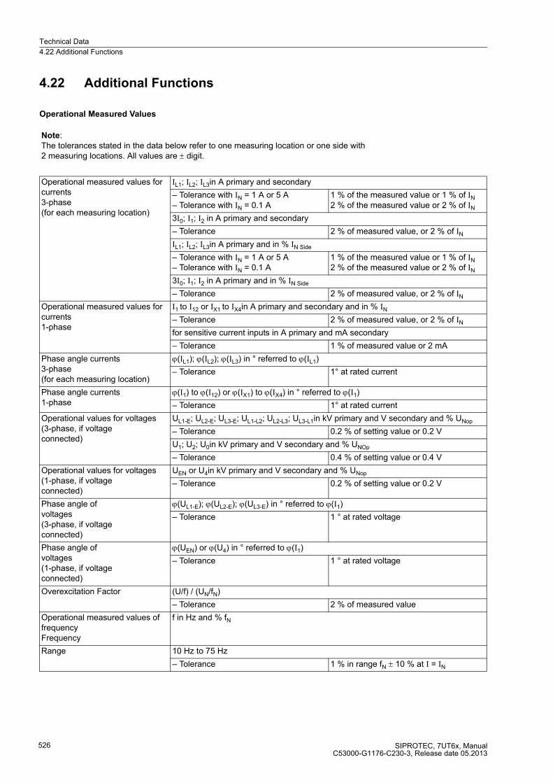
Technical Data
4.22 Additional Functions
SIPROTEC, 7UT6x, ManualC53000-G1176-C230-3, Release date 05.2013
526
4.22 Additional Functions
Operational Measured Values
Note:The tolerances stated in the data below refer to one measuring location or one side with 2 measuring locations. All values are ± digit.
Operational measured values for currents3-phase (for each measuring location)
IL1; IL2; IL3in A primary and secondary
– Tolerance with IN = 1 A or 5 A– Tolerance with IN = 0.1 A
1 % of the measured value or 1 % of IN
2 % of the measured value or 2 % of IN
3I0; I1; I2 in A primary and secondary
– Tolerance 2 % of measured value, or 2 % of IN
IL1; IL2; IL3in A primary and in % IN Side
– Tolerance with IN = 1 A or 5 A– Tolerance with IN = 0.1 A
1 % of the measured value or 1 % of IN
2 % of the measured value or 2 % of IN
3I0; I1; I2 in A primary and in % IN Side
– Tolerance 2 % of measured value, or 2 % of IN
Operational measured values for currents1-phase
I1 to I12 or IX1 to IX4in A primary and secondary and in % IN
– Tolerance 2 % of measured value, or 2 % of IN
for sensitive current inputs in A primary and mA secondary
– Tolerance 1 % of measured value or 2 mA
Phase angle currents3-phase (for each measuring location)
ϕ(IL1); ϕ(IL2); ϕ(IL3) in ° referred to ϕ(IL1)
– Tolerance 1° at rated current
Phase angle currents1-phase
ϕ(I1) to ϕ(I12) or ϕ(IX1) to ϕ(IX4) in ° referred to ϕ(I1)
– Tolerance 1° at rated current
Operational values for voltages(3-phase, if voltage connected)
UL1-E; UL2-E; UL3-E; UL1-L2; UL2-L3; UL3-L1in kV primary and V secondary and % UNop
– Tolerance 0.2 % of setting value or 0.2 V
U1; U2; U0in kV primary and V secondary and % UNOp
– Tolerance 0.4 % of setting value or 0.4 V
Operational values for voltages(1-phase, if voltage connected)
UEN or U4in kV primary and V secondary and % UNop
– Tolerance 0.2 % of setting value or 0.2 V
Phase angle of voltages(3-phase, if voltage connected)
ϕ(UL1-E); ϕ(UL2-E); ϕ(UL3-E) in ° referred to ϕ(I1)
– Tolerance 1 ° at rated voltage
Phase angle of voltages(1-phase, if voltage connected)
ϕ(UEN) or ϕ(U4) in ° referred to ϕ(I1)
– Tolerance 1 ° at rated voltage
Overexcitation Factor (U/f) / (UN/fN)
– Tolerance 2 % of measured value
Operational measured values of frequencyFrequency
f in Hz and % fN
Range 10 Hz to 75 Hz
– Tolerance 1 % in range fN ± 10 % at I = IN

Technical Data
4.22 Additional Functions
SIPROTEC, 7UT6x, ManualC53000-G1176-C230-3, Release date 05.2013
527
Fault Logging
Fault Recording
Operational values for power (3-phase, if voltage connected)
Active power P; reactive power Q; apparent power S in kW; MW; kVA; MVA primary
– Tolerance 1.2 % of measured value, or 0.25 % of SN
Operational measured values for power (1–phase, with measured or rated voltage)
S (apparent power) in kVA; MVA primary
Operational values for power factor (3-phase, if voltage connected)
cos ϕ
Operational measured values for thermal value(overload protection acc. to IEC 60255-8)
ΘL1; ΘL2; ΘL3; Θres referred to tripping temperature rise θtrip
Operational measured values for thermal value(overload protection acc. to IEC 60354)
ΘRTD1 to ΘRTD12 in °C or °F relative ageing rate, load reserve
Tolerances are based on the preset matching parameters. Higher tolerances are to be expected for calculated values dependent on the matching factors for currents and voltages.
Measured values of differential protection
IdiffL1; IdiffL2; IdiffL3; IrestL1; IrestL2; IrestL3;in % of the operational nominal current
– Tolerance (with preset values)(for 2 sides with 1 measuring location each)
2 % of measured value, or 2 % IN (50/60 Hz)3 % of measured value, or. 3 % IN (16.7 Hz)
Measured values of restricted earth fault protection
IdiffREF; IrestREF in % of the operational nominal current
– Tolerance (with preset values)(for 1 side or 1 measuring location)
2 % of measured value, or 2 % IN (50/60 Hz)3 % of measured value, or. 3 % IN (16.7 Hz)
Tolerances are based on the preset matching parameters for a protected object with 2 sides and 1 measuring location on each side. Higher tolerances are to be expected for calculated values dependent on the matching factors for currents and the number of measuring locations.
Storage of the messages of the last 8 faults
with a total of max. 200 messages
Number of stored fault records max. 8
Storage period per fault record Approx. 5 s per fault at 50/60 Hz,approx. 5 s total sumapprox. 18 s per fault at 16.7 Hz,approx. 18 s total sum
Sampling rate at fN = 50 HzSampling rate at fN = 60 HzSampling rate at fN = 16.7 Hz
1.25 ms1.04 ms3.75 ms

Technical Data
4.22 Additional Functions
SIPROTEC, 7UT6x, ManualC53000-G1176-C230-3, Release date 05.2013
528
Statistic Values
Long-Term Average Values
Minimum Values, Maximum Values
Real Time Clock and Buffer Battery
Number of trip events caused by the device
Total of interrupted currents segregated for each pole and each side
Operating hours meter criterion
up to 7 digitsExceeding of settable Current threshold
Time Window 5, 15, 30 or 60 minutes
Frequency of Updates adjustable
Long-Term Averages
currentsactive powerreactive powerapparent power
IL1dmd; IL2dmd; IL3dmd; I1dmd in A (kA)Pdmd in W (kW, MW)Qdmd in VAr (kVAr, MVAr)Sdmd in VAr (kVAr, MVAr)
Storage of Measured Values With date and time
Reset automatic Time of day adjustable (in minutes, 0 to 1 439 min) time frame and starting time adjustable (in days, 1 to 365 days, and ∞)(in days, 1 to 365 and ∞)
Manual Reset Using binary input Using keypad Using communication
Min/Max Values for Currents IL1; IL2; IL3;I1 (positive sequence component)
Min/Max Values for Voltages UL1-E; UL2-E; UL3-E; U1 (positive sequence component);UL1-L2; UL2-L3; UL3-L1
Min/Max Values for Power S, P; Q, cos ϕ; frequency
Min/Max Values for Overload Protection Θ/Θfrom
Min/Max Values for Mean Values IL1dmd; IL2dmd; IL3dmd;I1dmd (positive sequence component);Sdmd; Pdmd; Qdmd
Resolution for operational messages 1 ms
Resolution for fault messages 1 ms
Back-up Battery Lithium battery 3 V/1 Ah, type CR 1/2 AAself-discharging time approx. 10 years

Technical Data
4.22 Additional Functions
SIPROTEC, 7UT6x, ManualC53000-G1176-C230-3, Release date 05.2013
529
Time Synchronisation
Commissioning Aids
Energy Counter
Operating Hours Counter
Trip Circuit Monitoring
Internal Internal using RTC (default)
IEC 60870-5-103 External using system interface
IEC 61850 External synchronisation via the system interface (IEC 61850)
Time signal IRIG B External via IRIG B (telegram format IRIG-B800)
Time signal DCF 77 External via time signal DCF 77
Time signal synchro-box External using time signal SIMEAS Sync. box
Pulse via binary input External with impulse via binary input
Operational measured valuesCircuit breaker test
Four-Quadrant Meter WP+, WP–, WQ+, WQ–
Tolerance 1 %
Display Range up to 6 digits
Criterion Overshoot of an adjustable current threshold (CB I>)
Number of monitorable circuits 1with one or two binary inputs
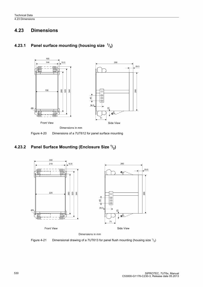
Technical Data
4.23 Dimensions
SIPROTEC, 7UT6x, ManualC53000-G1176-C230-3, Release date 05.2013
530
4.23 Dimensions
4.23.1 Panel surface mounting (housing size 1/3)
Figure 4-20 Dimensions of a 7UT612 for panel surface mounting
4.23.2 Panel Surface Mounting (Enclosure Size 1/2)
Figure 4-21 Dimensional drawing of a 7UT613 for panel flush mounting (housing size 1/2)
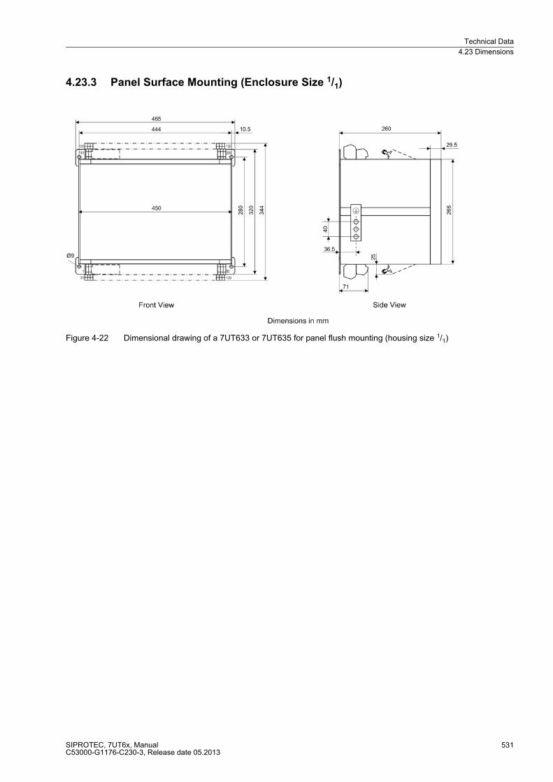
Technical Data
4.23 Dimensions
SIPROTEC, 7UT6x, ManualC53000-G1176-C230-3, Release date 05.2013
531
4.23.3 Panel Surface Mounting (Enclosure Size 1/1)
Figure 4-22 Dimensional drawing of a 7UT633 or 7UT635 for panel flush mounting (housing size 1/1)
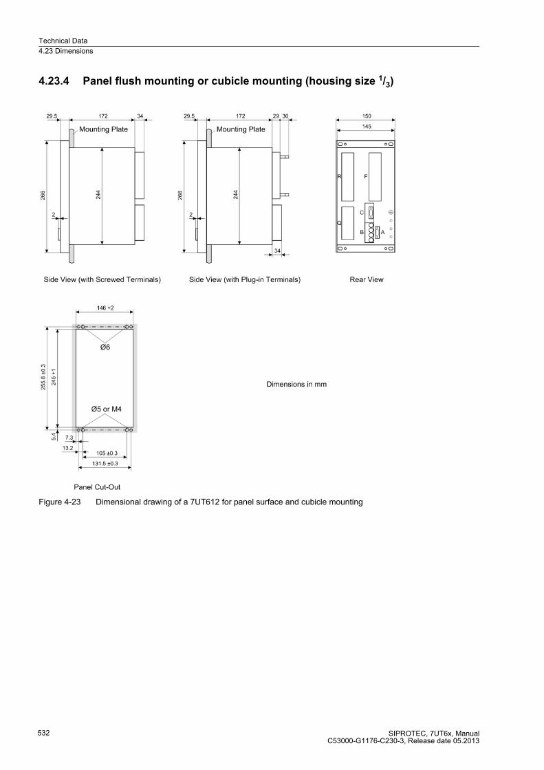
Technical Data
4.23 Dimensions
SIPROTEC, 7UT6x, ManualC53000-G1176-C230-3, Release date 05.2013
532
4.23.4 Panel flush mounting or cubicle mounting (housing size 1/3)
Figure 4-23 Dimensional drawing of a 7UT612 for panel surface and cubicle mounting
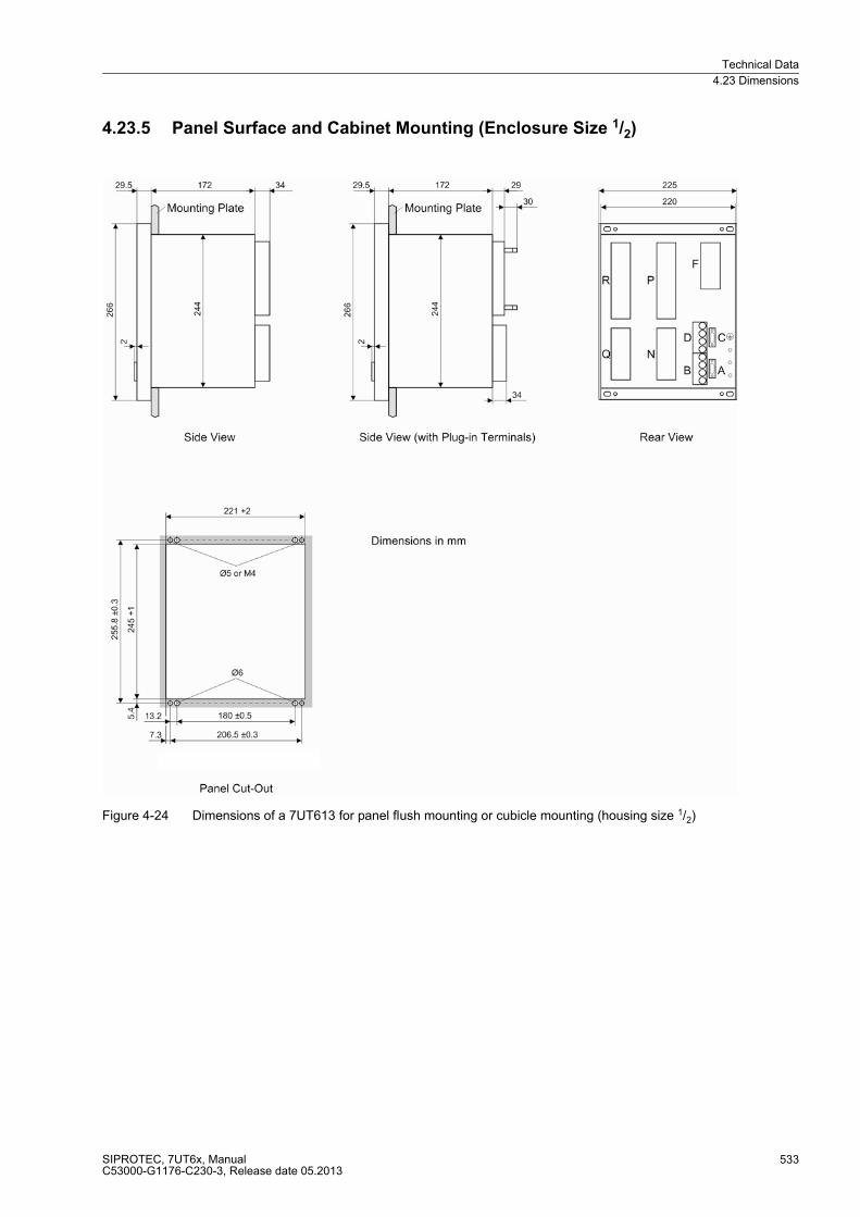
Technical Data
4.23 Dimensions
SIPROTEC, 7UT6x, ManualC53000-G1176-C230-3, Release date 05.2013
533
4.23.5 Panel Surface and Cabinet Mounting (Enclosure Size 1/2)
Figure 4-24 Dimensions of a 7UT613 for panel flush mounting or cubicle mounting (housing size 1/2)
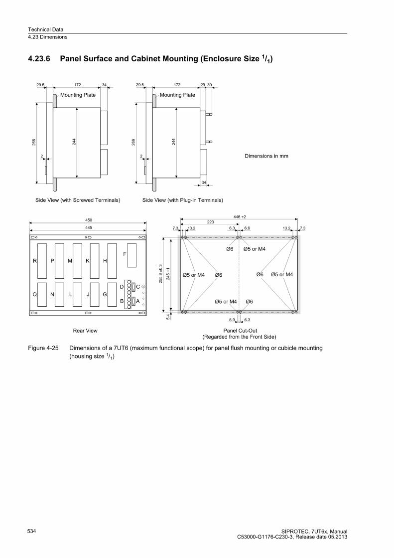
Technical Data
4.23 Dimensions
SIPROTEC, 7UT6x, ManualC53000-G1176-C230-3, Release date 05.2013
534
4.23.6 Panel Surface and Cabinet Mounting (Enclosure Size 1/1)
Figure 4-25 Dimensions of a 7UT6 (maximum functional scope) for panel flush mounting or cubicle mounting
(housing size 1/1)
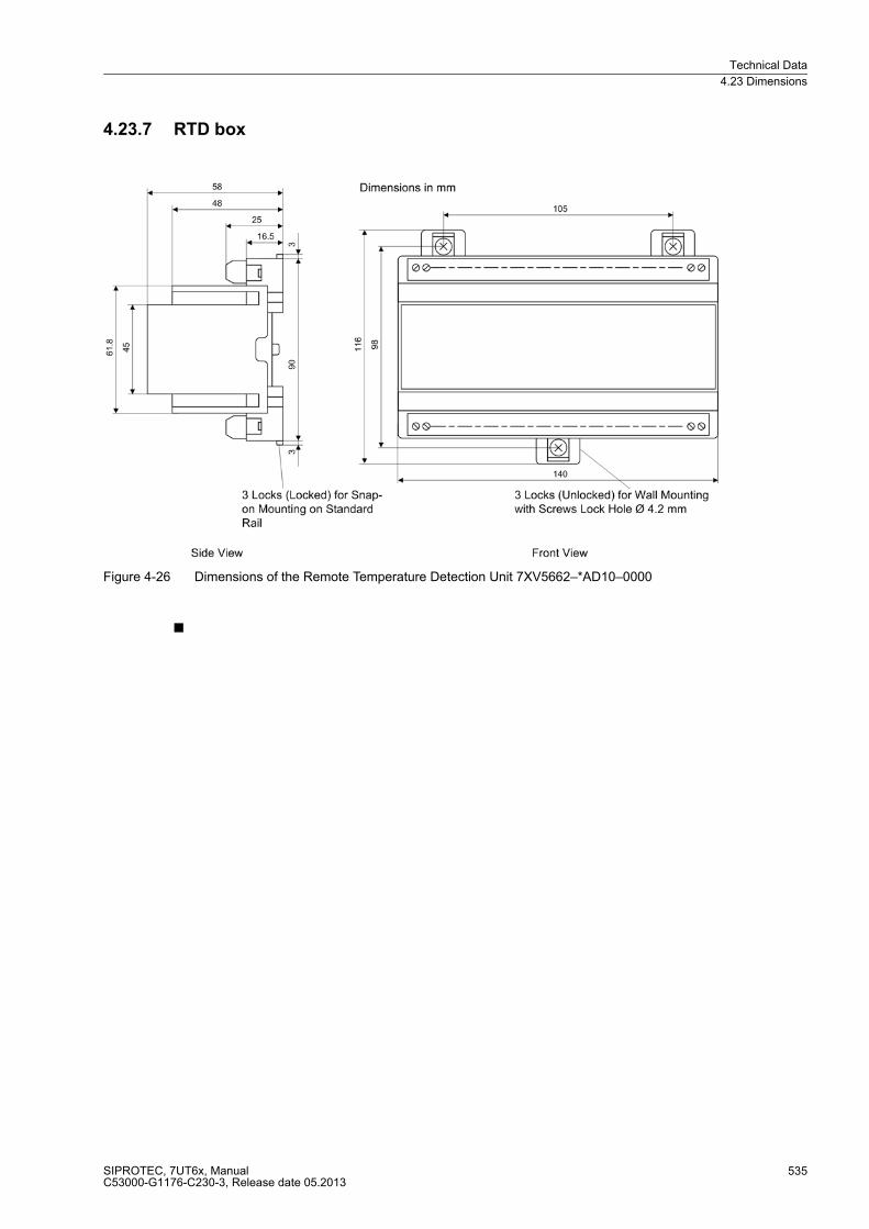
Technical Data
4.23 Dimensions
SIPROTEC, 7UT6x, ManualC53000-G1176-C230-3, Release date 05.2013
535
4.23.7 RTD box
Figure 4-26 Dimensions of the Remote Temperature Detection Unit 7XV5662–*AD10–0000
■

Technical Data
4.23 Dimensions
SIPROTEC, 7UT6x, ManualC53000-G1176-C230-3, Release date 05.2013
536

SIPROTEC, 7UT6x, ManualC53000-G1176-C230-3, Release date 05.2013
537
Appendix A
This appendix is primarily a reference for the experienced user. This section provides ordering information for
the models of this device. Connection diagrams for indicating the terminal connections of the models of this
device are included. Following the general diagrams are diagrams that show the proper connections of the
devices to primary equipment in many typical power system configurations. Tables with all settings and all
information available in this device equipped with all options are provided. Default settings are also given.
A.1 Ordering Information and Accessories 538
A.2 Terminal Assignments 550
A.3 Connection Examples 570
A.4 Current Transformer Requirements 586
A.5 Default Settings 590
A.6 Protocol-dependent Functions 595
A.7 Functional Scope 596
A.8 Settings 599
A.9 Information List 629
A.10 Group Alarms 662
A.11 Measured Values 664
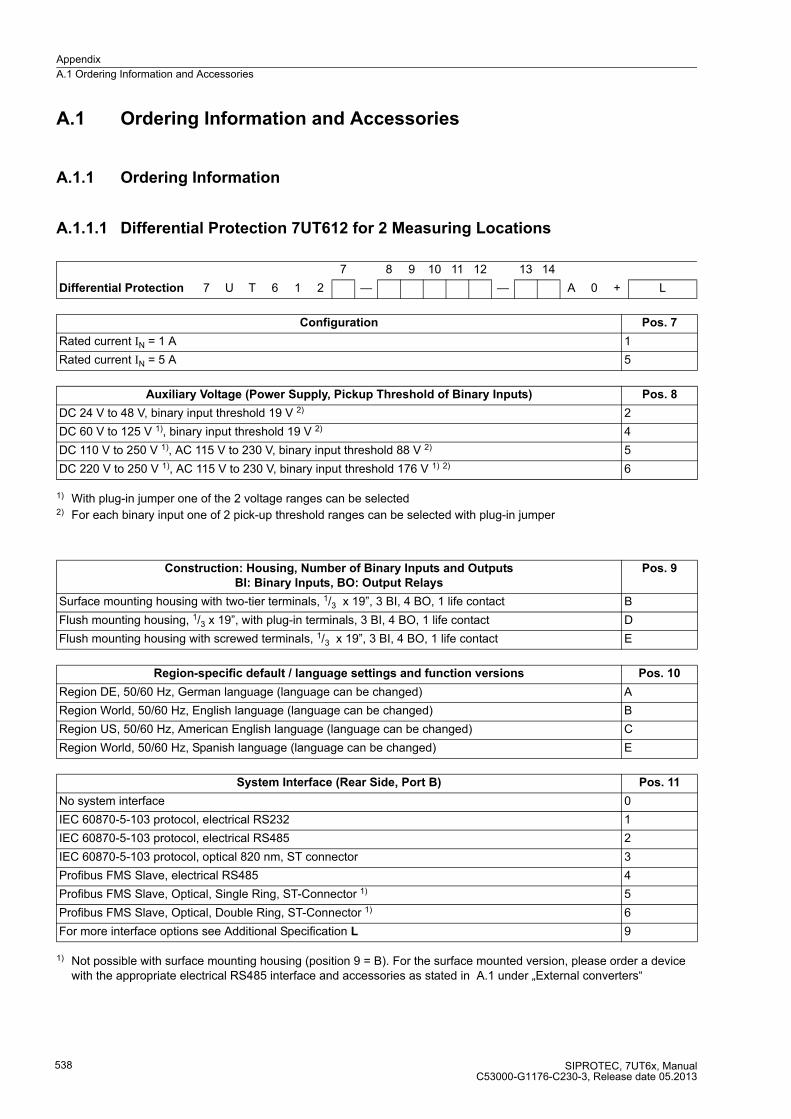
Appendix
A.1 Ordering Information and Accessories
SIPROTEC, 7UT6x, ManualC53000-G1176-C230-3, Release date 05.2013
538
A.1 Ordering Information and Accessories
A.1.1 Ordering Information
A.1.1.1 Differential Protection 7UT612 for 2 Measuring Locations
1) With plug-in jumper one of the 2 voltage ranges can be selected2) For each binary input one of 2 pick-up threshold ranges can be selected with plug-in jumper
1) Not possible with surface mounting housing (position 9 = B). For the surface mounted version, please order a device with the appropriate electrical RS485 interface and accessories as stated in A.1 under „External converters“
7 8 9 10 11 12 13 14
Differential Protection 7 U T 6 1 2 — — A 0 + L
Configuration Pos. 7
Rated current IN = 1 A 1
Rated current IN = 5 A 5
Auxiliary Voltage (Power Supply, Pickup Threshold of Binary Inputs) Pos. 8
DC 24 V to 48 V, binary input threshold 19 V 2) 2
DC 60 V to 125 V 1), binary input threshold 19 V 2) 4
DC 110 V to 250 V 1), AC 115 V to 230 V, binary input threshold 88 V 2) 5
DC 220 V to 250 V 1), AC 115 V to 230 V, binary input threshold 176 V 1) 2) 6
Construction: Housing, Number of Binary Inputs and Outputs
BI: Binary Inputs, BO: Output Relays
Pos. 9
Surface mounting housing with two-tier terminals, 1/3 x 19”, 3 BI, 4 BO, 1 life contact B
Flush mounting housing, 1/3 x 19”, with plug-in terminals, 3 BI, 4 BO, 1 life contact D
Flush mounting housing with screwed terminals, 1/3 x 19”, 3 BI, 4 BO, 1 life contact E
Region-specific default / language settings and function versions Pos. 10
Region DE, 50/60 Hz, German language (language can be changed) A
Region World, 50/60 Hz, English language (language can be changed) B
Region US, 50/60 Hz, American English language (language can be changed) C
Region World, 50/60 Hz, Spanish language (language can be changed) E
System Interface (Rear Side, Port B) Pos. 11
No system interface 0
IEC 60870-5-103 protocol, electrical RS232 1
IEC 60870-5-103 protocol, electrical RS485 2
IEC 60870-5-103 protocol, optical 820 nm, ST connector 3
Profibus FMS Slave, electrical RS485 4
Profibus FMS Slave, Optical, Single Ring, ST-Connector 1) 5
Profibus FMS Slave, Optical, Double Ring, ST-Connector 1) 6
For more interface options see Additional Specification L 9

Appendix
A.1 Ordering Information and Accessories
SIPROTEC, 7UT6x, ManualC53000-G1176-C230-3, Release date 05.2013
539
1) Not possible with surface mounting housing (position 9 = B). For the surface mounted version, please order a device with the appropriate electrical RS485 interface and accessories as stated in A.1under „External converters“
2) Cannot be delivered in connection with 9th digit = B.
1) Only in connection with position 12 = 2 or 3
1) Varistor and resistor are accessory parts2) External RTD-box required3) External resistor and varistor required4) Only in connection with pos. 16 = 1 or 3
Additional Specification L for Further System Interfaces (device rear, port B)
(only if Pos. 11 = 9)
Pos. 21 Pos. 22
Profibus DP Slave, RS485 0 A
Profibus DP Slave, optical, 820 nm, double ring, ST connector 1) 0 B
Modbus, RS485 0 D
Modbus, optical, 820 nm, ST connector 2) 0 E
DNP3.0, RS485 0 G
DNP3.0, optical, 820 nm, ST connector 2) 0 H
IEC 61850, 100 Mbit Ethernet, double electrical, RJ45 connector 0 R
IEC 61850, 100 Mbit Ethernet, optical, ST-connector 2) 0 S
Function Interface (rear side, port C) Pos. 12
without 0
DIGSI / Modem / Browser, electrical RS232 1
DIGSI / Modem / Browser / RTD-box, electrical RS485 2
DIGSI / Modem / Browser / RTD-box, optical, 820 nm, ST connector 3
Measurement Function Pos. 13
Basic measured values 1
Basic measured values; transformer monitoring functions (connection to RTD-box/hot-spot, overload factor) 1) 4
Differential Protection Pos. 14
Differential protection + Basic elements 1)
Differential protection for transformers, generators, motors, busbars Overload protection acc. to IEC 60354 for 1 winding 2)
Lock out Time overcurrent protection, phases: I>, I>>, Ip (inrush restraint)Time overcurrent protection3I0: 3I0>, 3I0>>, 3I0p (inrush restraint)Time overcurrent protection, earth: IE>, IE>>, IEp (inrush restraint)
A
Differential protection + Basic elements + Ancillary functions
Restricted earth fault protectionDefinite-time, single-phase, e.g. high-impedance earth fault protection (87G without resistor nor varistor) 3), or tank leakage protectionNegative squence potection Breaker Failure Protection Trip circuit supervision
B
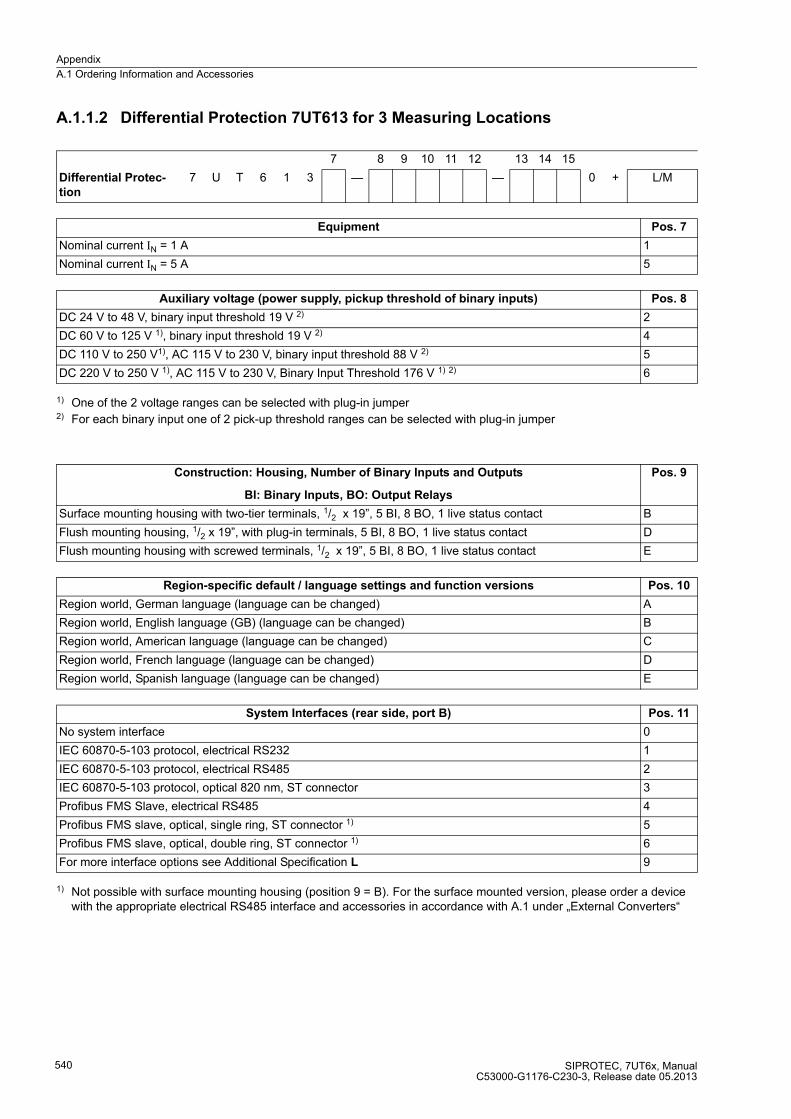
Appendix
A.1 Ordering Information and Accessories
SIPROTEC, 7UT6x, ManualC53000-G1176-C230-3, Release date 05.2013
540
A.1.1.2 Differential Protection 7UT613 for 3 Measuring Locations
1) One of the 2 voltage ranges can be selected with plug-in jumper2) For each binary input one of 2 pick-up threshold ranges can be selected with plug-in jumper
1) Not possible with surface mounting housing (position 9 = B). For the surface mounted version, please order a device with the appropriate electrical RS485 interface and accessories in accordance with A.1 under „External Converters“
7 8 9 10 11 12 13 14 15
Differential Protec-
tion
7 U T 6 1 3 — — 0 + L/M
Equipment Pos. 7
Nominal current IN = 1 A 1
Nominal current IN = 5 A 5
Auxiliary voltage (power supply, pickup threshold of binary inputs) Pos. 8
DC 24 V to 48 V, binary input threshold 19 V 2) 2
DC 60 V to 125 V 1), binary input threshold 19 V 2) 4
DC 110 V to 250 V1), AC 115 V to 230 V, binary input threshold 88 V 2) 5
DC 220 V to 250 V 1), AC 115 V to 230 V, Binary Input Threshold 176 V 1) 2) 6
Construction: Housing, Number of Binary Inputs and Outputs
BI: Binary Inputs, BO: Output Relays
Pos. 9
Surface mounting housing with two-tier terminals, 1/2 x 19”, 5 BI, 8 BO, 1 live status contact B
Flush mounting housing, 1/2 x 19”, with plug-in terminals, 5 BI, 8 BO, 1 live status contact D
Flush mounting housing with screwed terminals, 1/2 x 19”, 5 BI, 8 BO, 1 live status contact E
Region-specific default / language settings and function versions Pos. 10
Region world, German language (language can be changed) A
Region world, English language (GB) (language can be changed) B
Region world, American language (language can be changed) C
Region world, French language (language can be changed) D
Region world, Spanish language (language can be changed) E
System Interfaces (rear side, port B) Pos. 11
No system interface 0
IEC 60870-5-103 protocol, electrical RS232 1
IEC 60870-5-103 protocol, electrical RS485 2
IEC 60870-5-103 protocol, optical 820 nm, ST connector 3
Profibus FMS Slave, electrical RS485 4
Profibus FMS slave, optical, single ring, ST connector 1) 5
Profibus FMS slave, optical, double ring, ST connector 1) 6
For more interface options see Additional Specification L 9
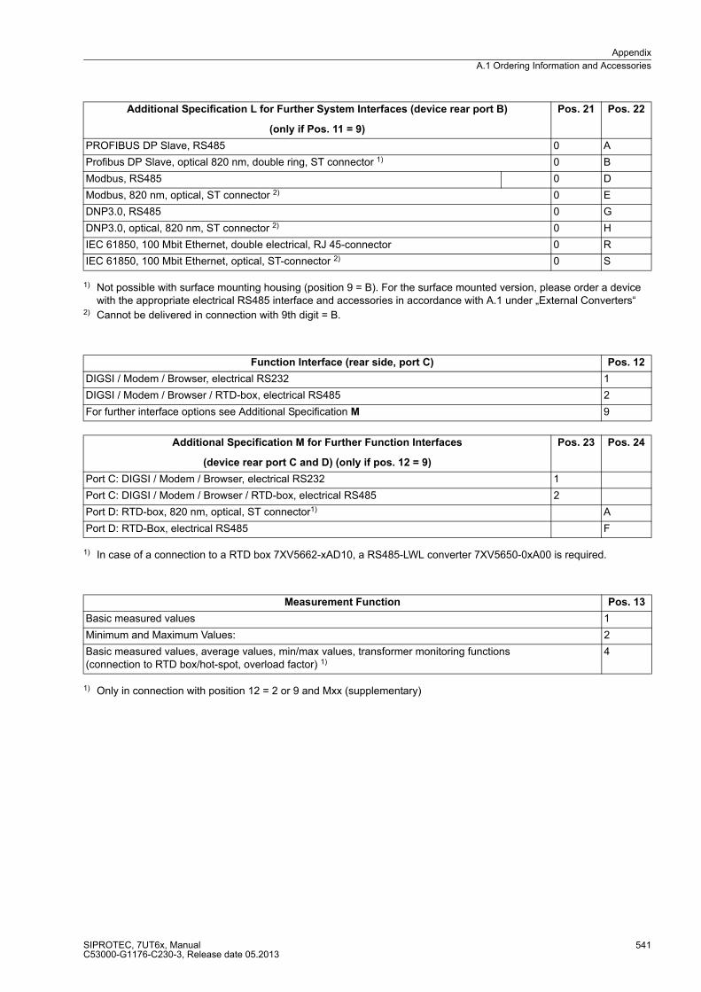
Appendix
A.1 Ordering Information and Accessories
SIPROTEC, 7UT6x, ManualC53000-G1176-C230-3, Release date 05.2013
541
1) Not possible with surface mounting housing (position 9 = B). For the surface mounted version, please order a device with the appropriate electrical RS485 interface and accessories in accordance with A.1 under „External Converters“
2) Cannot be delivered in connection with 9th digit = B.
1) In case of a connection to a RTD box 7XV5662-xAD10, a RS485-LWL converter 7XV5650-0xA00 is required.
1) Only in connection with position 12 = 2 or 9 and Mxx (supplementary)
Additional Specification L for Further System Interfaces (device rear port B)
(only if Pos. 11 = 9)
Pos. 21 Pos. 22
PROFIBUS DP Slave, RS485 0 A
Profibus DP Slave, optical 820 nm, double ring, ST connector 1) 0 B
Modbus, RS485 0 D
Modbus, 820 nm, optical, ST connector 2) 0 E
DNP3.0, RS485 0 G
DNP3.0, optical, 820 nm, ST connector 2) 0 H
IEC 61850, 100 Mbit Ethernet, double electrical, RJ 45-connector 0 R
IEC 61850, 100 Mbit Ethernet, optical, ST-connector 2) 0 S
Function Interface (rear side, port C) Pos. 12
DIGSI / Modem / Browser, electrical RS232 1
DIGSI / Modem / Browser / RTD-box, electrical RS485 2
For further interface options see Additional Specification M 9
Additional Specification M for Further Function Interfaces
(device rear port C and D) (only if pos. 12 = 9)
Pos. 23 Pos. 24
Port C: DIGSI / Modem / Browser, electrical RS232 1
Port C: DIGSI / Modem / Browser / RTD-box, electrical RS485 2
Port D: RTD-box, 820 nm, optical, ST connector1) A
Port D: RTD-Box, electrical RS485 F
Measurement Function Pos. 13
Basic measured values 1
Minimum and Maximum Values: 2
Basic measured values, average values, min/max values, transformer monitoring functions (connection to RTD box/hot-spot, overload factor) 1)
4
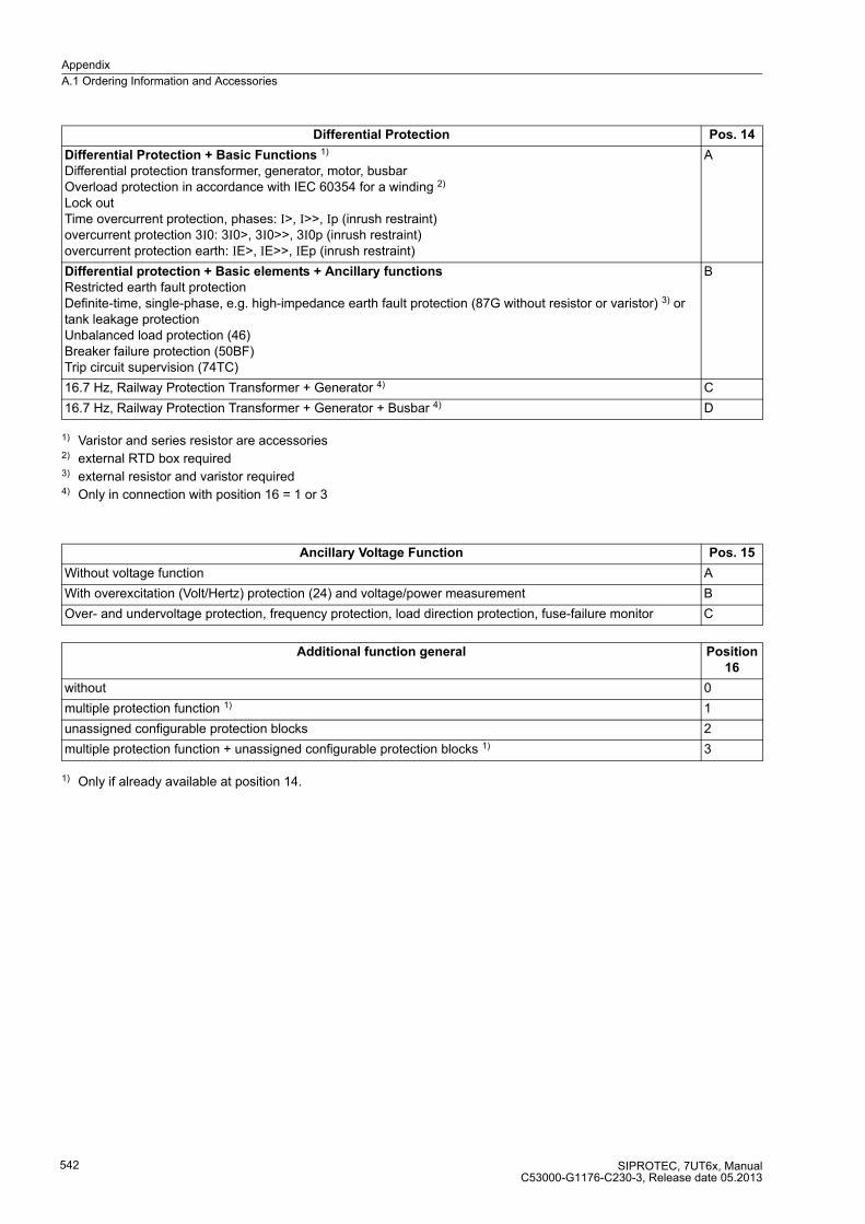
Appendix
A.1 Ordering Information and Accessories
SIPROTEC, 7UT6x, ManualC53000-G1176-C230-3, Release date 05.2013
542
1) Varistor and series resistor are accessories2) external RTD box required3) external resistor and varistor required4) Only in connection with position 16 = 1 or 3
1) Only if already available at position 14.
Differential Protection Pos. 14
Differential Protection + Basic Functions 1)
Differential protection transformer, generator, motor, busbarOverload protection in accordance with IEC 60354 for a winding 2)
Lock outTime overcurrent protection, phases: I>, I>>, Ip (inrush restraint)overcurrent protection 3I0: 3I0>, 3I0>>, 3I0p (inrush restraint)overcurrent protection earth: IE>, IE>>, IEp (inrush restraint)
A
Differential protection + Basic elements + Ancillary functions
Restricted earth fault protectionDefinite-time, single-phase, e.g. high-impedance earth fault protection (87G without resistor or varistor) 3) or tank leakage protection Unbalanced load protection (46)Breaker failure protection (50BF)Trip circuit supervision (74TC)
B
16.7 Hz, Railway Protection Transformer + Generator 4) C
16.7 Hz, Railway Protection Transformer + Generator + Busbar 4) D
Ancillary Voltage Function Pos. 15
Without voltage function A
With overexcitation (Volt/Hertz) protection (24) and voltage/power measurement B
Over- and undervoltage protection, frequency protection, load direction protection, fuse-failure monitor C
Additional function general Position
16
without 0
multiple protection function 1) 1
unassigned configurable protection blocks 2
multiple protection function + unassigned configurable protection blocks 1) 3
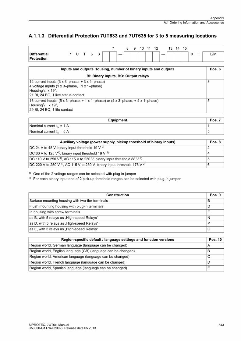
Appendix
A.1 Ordering Information and Accessories
SIPROTEC, 7UT6x, ManualC53000-G1176-C230-3, Release date 05.2013
543
A.1.1.3 Differential Protection 7UT633 and 7UT635 for 3 to 5 measuring locations
1) One of the 2 voltage ranges can be selected with plug-in jumper2) For each binary input one of 2 pick-up threshold ranges can be selected with plug-in jumper
7 8 9 10 11 12 13 14 15
Differential
Protection
7 U T 6 3 — — 0 + L/M
Inputs and outputs Housing, number of binary inputs and outputs
BI: Binary inputs, BO: Output relays
Pos. 6
12 current inputs (3 x 3–phase, + 3 x 1–phase)4 voltage inputs (1 x 3–phase, +1 x 1–phase)Housing1/1 x 19”, 21 BI, 24 BO, 1 live status contact
3
16 current inputs (5 x 3–phase, + 1 x 1–phase) or (4 x 3–phase, + 4 x 1–phase)Housing1/1 x 19”, 29 BI, 24 BO, 1 life contact
5
Equipment Pos. 7
Nominal current IN = 1 A 1
Nominal current IN = 5 A 5
Auxiliary voltage (power supply, pickup threshold of binary inputs) Pos. 8
DC 24 V to 48 V, binary input threshold 19 V 2) 2
DC 60 V to 125 V1), binary input threshold 19 V 2) 4
DC 110 V to 250 V1), AC 115 V to 230 V, binary input threshold 88 V 2) 5
DC 220 V to 250 V 1), AC 115 V to 230 V, binary input threshold 176 V 2) 6
Construction Pos. 9
Surface mounting housing with two-tier terminals B
Flush mounting housing with plug-in terminals D
In housing with screw terminals E
as B, with 5 relays as „High-speed Relays“ N
as D, with 5 relays as „High-speed Relays“ P
as E, with 5 relays as „High-speed Relays“ Q
Region-specific default / language settings and function versions Pos. 10
Region world, German language (language can be changed) A
Region world, English language (GB) (language can be changed) B
Region world, American language (language can be changed) C
Region world, French language (language can be changed) D
Region world, Spanish language (language can be changed) E
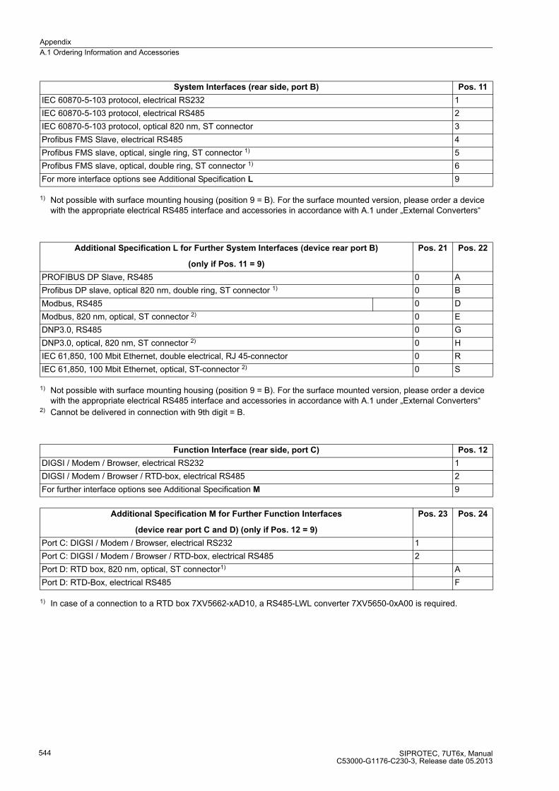
Appendix
A.1 Ordering Information and Accessories
SIPROTEC, 7UT6x, ManualC53000-G1176-C230-3, Release date 05.2013
544
1) Not possible with surface mounting housing (position 9 = B). For the surface mounted version, please order a device with the appropriate electrical RS485 interface and accessories in accordance with A.1 under „External Converters“
1) Not possible with surface mounting housing (position 9 = B). For the surface mounted version, please order a device with the appropriate electrical RS485 interface and accessories in accordance with A.1 under „External Converters“
2) Cannot be delivered in connection with 9th digit = B.
1) In case of a connection to a RTD box 7XV5662-xAD10, a RS485-LWL converter 7XV5650-0xA00 is required.
System Interfaces (rear side, port B) Pos. 11
IEC 60870-5-103 protocol, electrical RS232 1
IEC 60870-5-103 protocol, electrical RS485 2
IEC 60870-5-103 protocol, optical 820 nm, ST connector 3
Profibus FMS Slave, electrical RS485 4
Profibus FMS slave, optical, single ring, ST connector 1) 5
Profibus FMS slave, optical, double ring, ST connector 1) 6
For more interface options see Additional Specification L 9
Additional Specification L for Further System Interfaces (device rear port B)
(only if Pos. 11 = 9)
Pos. 21 Pos. 22
PROFIBUS DP Slave, RS485 0 A
Profibus DP slave, optical 820 nm, double ring, ST connector 1) 0 B
Modbus, RS485 0 D
Modbus, 820 nm, optical, ST connector 2) 0 E
DNP3.0, RS485 0 G
DNP3.0, optical, 820 nm, ST connector 2) 0 H
IEC 61,850, 100 Mbit Ethernet, double electrical, RJ 45-connector 0 R
IEC 61,850, 100 Mbit Ethernet, optical, ST-connector 2) 0 S
Function Interface (rear side, port C) Pos. 12
DIGSI / Modem / Browser, electrical RS232 1
DIGSI / Modem / Browser / RTD-box, electrical RS485 2
For further interface options see Additional Specification M 9
Additional Specification M for Further Function Interfaces
(device rear port C and D) (only if Pos. 12 = 9)
Pos. 23 Pos. 24
Port C: DIGSI / Modem / Browser, electrical RS232 1
Port C: DIGSI / Modem / Browser / RTD-box, electrical RS485 2
Port D: RTD box, 820 nm, optical, ST connector1) A
Port D: RTD-Box, electrical RS485 F

Appendix
A.1 Ordering Information and Accessories
SIPROTEC, 7UT6x, ManualC53000-G1176-C230-3, Release date 05.2013
545
1) Only in connection with position 12 = 2 or 9 and Mxx (supplementary)
1) Varistor and series resistor are accessories2) external RTD box required3) external resistor and varistor required4) Only in connection with position 16 = 1 or 3
1) Only if already available at position 14.
Measurement Function Pos. 13
Basic measured values 1
Minimum and Maximum Values: 2
Basic measured values, average values, min/max values, transformer monitoring functions (connection to RTD box/hot-spot, overload factor) 1)
4
Differential Protection Pos. 14
Differential protection + Basic elements
Differential protection transformer, generator, motor, busbarOverload protection in accordance with IEC 60354 for a winding2)
Lock outTime overcurrent protection, phases: I>, I>>, Ip (inrush restraint)overcurrent protection 3I0: 3I0>, 3I0>>, 3I0p (inrush restraint)overcurrent protection earth: IE>, IE>>, IEp (inrush restraint)
A
Differential Protection + Basic Functions + Additional Functions1)
Restricted earth fault protectionDefinite-time, single-phase, e.g. high-impedance earth fault protection (87G without resistor or varistor) 3), or tank leakage protectionUnbalanced load protection (46)Breaker failure protection (50BF)Trip circuit supervision (74TC)
B
16.7 Hz, Railway Protection Transformer + Generator 4) C
16.7 Hz, Railway Protection Transformer + Generator + Busbar 4) D
Ancillary Voltage Function Pos. 15
Without voltage function A
with overexcitation (Volt/Hertz) protection (24) and voltage/power measurement (only available for 7UT633) B
Over- and undervoltage protection, frequency protection, load direction protection, fuse-failure monitor (only available for 7UT633)
C
Additional function general Position
16
without 0
multiple protection function 1) 1
unassigned configurable protection blocks 2
multiple protection function + unassigned configurable protection blocks 1) 3
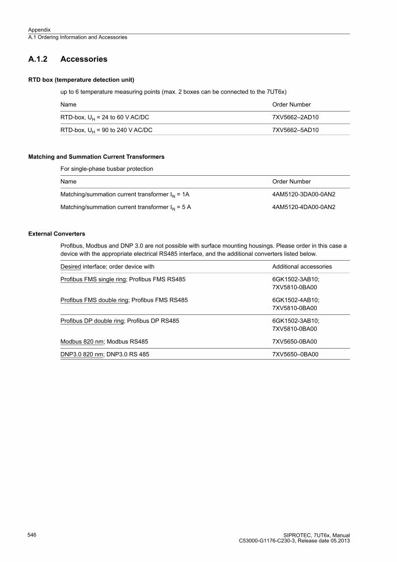
Appendix
A.1 Ordering Information and Accessories
SIPROTEC, 7UT6x, ManualC53000-G1176-C230-3, Release date 05.2013
546
A.1.2 Accessories
RTD box (temperature detection unit)
up to 6 temperature measuring points (max. 2 boxes can be connected to the 7UT6x)
Name Order Number
RTD-box, UH = 24 to 60 V AC/DC 7XV5662–2AD10
RTD-box, UH = 90 to 240 V AC/DC 7XV5662–5AD10
Matching and Summation Current Transformers
For single-phase busbar protection
Name Order Number
Matching/summation current transformer IN = 1A 4AM5120-3DA00-0AN2
Matching/summation current transformer IN = 5 A 4AM5120-4DA00-0AN2
External Converters
Profibus, Modbus and DNP 3.0 are not possible with surface mounting housings. Please order in this case a
device with the appropriate electrical RS485 interface, and the additional converters listed below.
Desired interface; order device with Additional accessories
Profibus FMS single ring; Profibus FMS RS485 6GK1502-3AB10;
7XV5810-0BA00
Profibus FMS double ring; Profibus FMS RS485 6GK1502-4AB10;
7XV5810-0BA00
Profibus DP double ring; Profibus DP RS485 6GK1502-3AB10;
7XV5810-0BA00
Modbus 820 nm; Modbus RS485 7XV5650-0BA00
DNP3.0 820 nm; DNP3.0 RS 485 7XV5650–0BA00
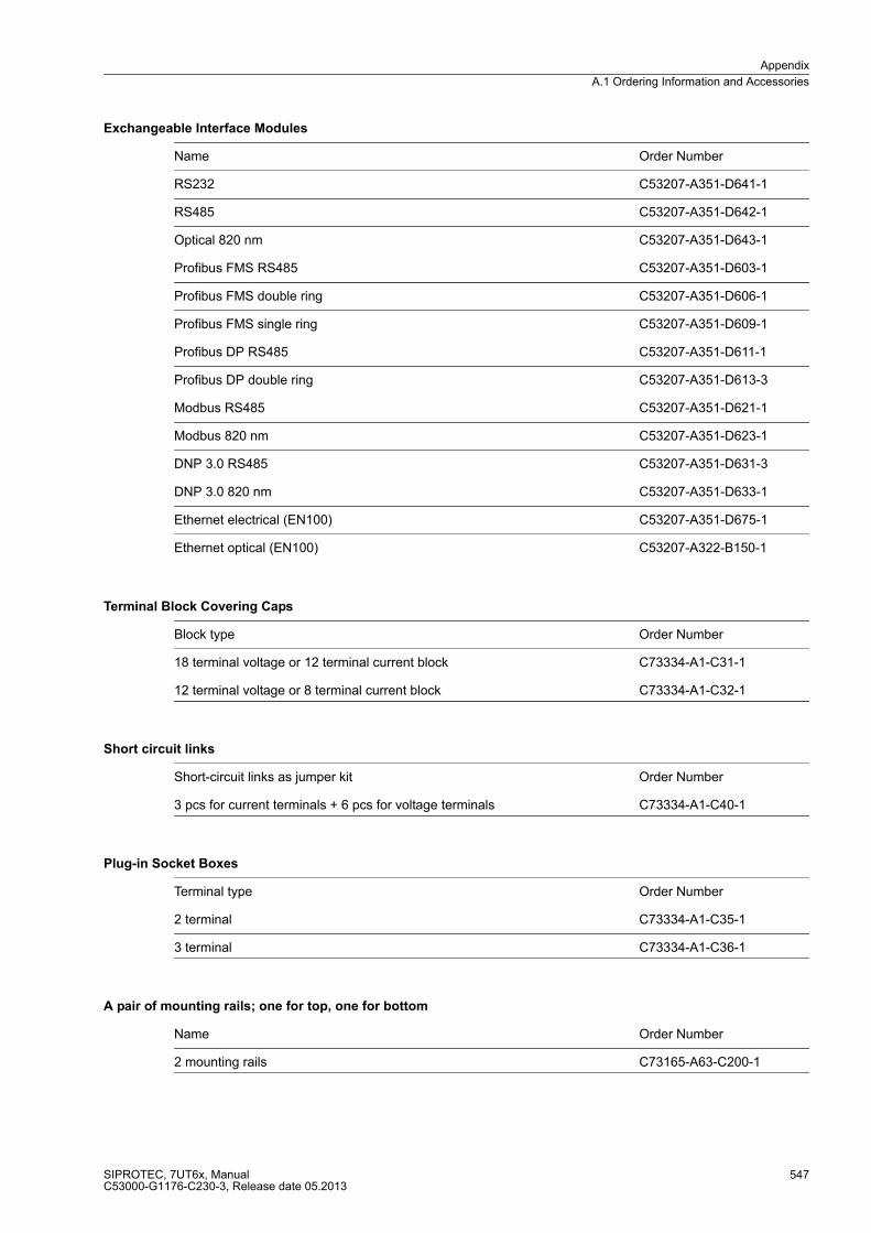
Appendix
A.1 Ordering Information and Accessories
SIPROTEC, 7UT6x, ManualC53000-G1176-C230-3, Release date 05.2013
547
Exchangeable Interface Modules
Name Order Number
RS232 C53207-A351-D641-1
RS485 C53207-A351-D642-1
Optical 820 nm C53207-A351-D643-1
Profibus FMS RS485 C53207-A351-D603-1
Profibus FMS double ring C53207-A351-D606-1
Profibus FMS single ring C53207-A351-D609-1
Profibus DP RS485 C53207-A351-D611-1
Profibus DP double ring C53207-A351-D613-3
Modbus RS485 C53207-A351-D621-1
Modbus 820 nm C53207-A351-D623-1
DNP 3.0 RS485 C53207-A351-D631-3
DNP 3.0 820 nm C53207-A351-D633-1
Ethernet electrical (EN100) C53207-A351-D675-1
Ethernet optical (EN100) C53207-A322-B150-1
Terminal Block Covering Caps
Block type Order Number
18 terminal voltage or 12 terminal current block C73334-A1-C31-1
12 terminal voltage or 8 terminal current block C73334-A1-C32-1
Short circuit links
Short-circuit links as jumper kit Order Number
3 pcs for current terminals + 6 pcs for voltage terminals C73334-A1-C40-1
Plug-in Socket Boxes
Terminal type Order Number
2 terminal C73334-A1-C35-1
3 terminal C73334-A1-C36-1
A pair of mounting rails; one for top, one for bottom
Name Order Number
2 mounting rails C73165-A63-C200-1
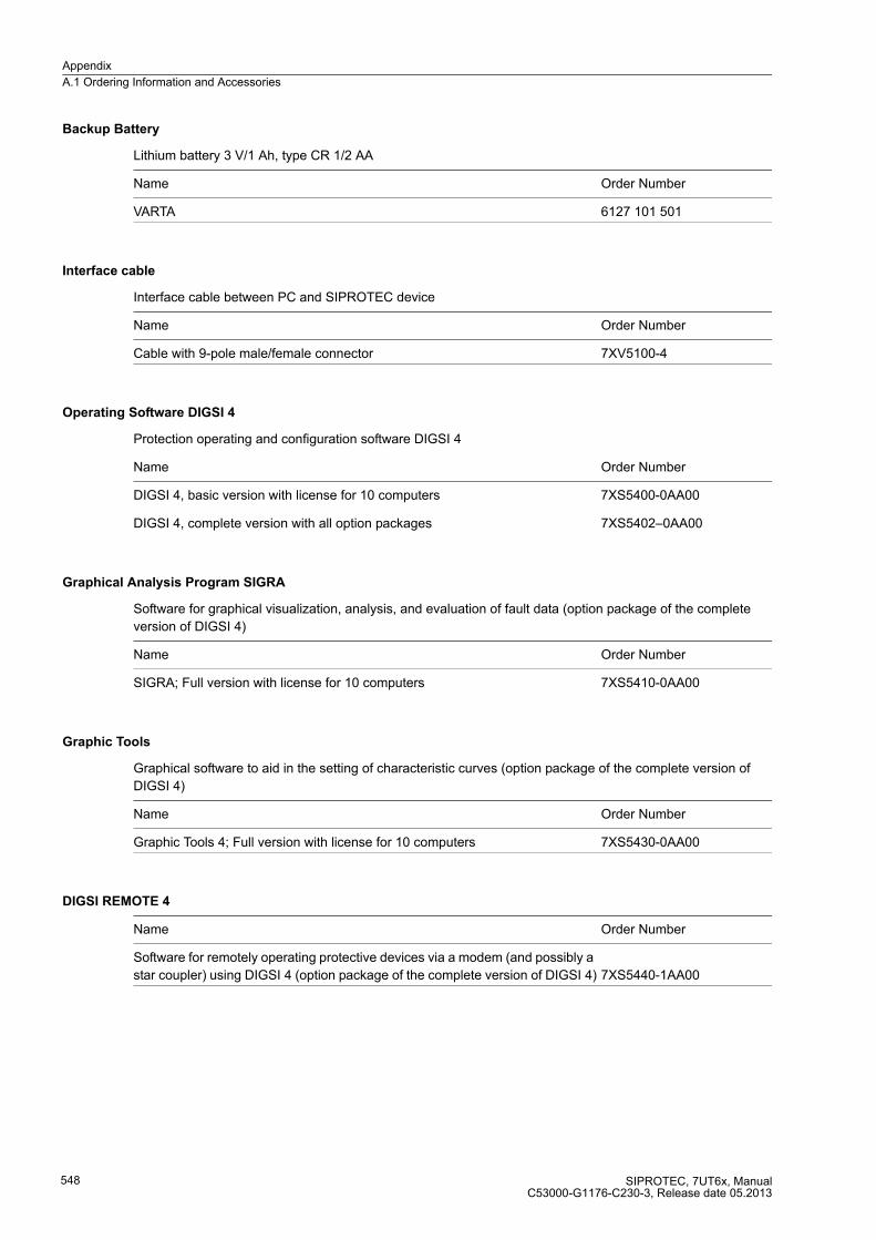
Appendix
A.1 Ordering Information and Accessories
SIPROTEC, 7UT6x, ManualC53000-G1176-C230-3, Release date 05.2013
548
Backup Battery
Lithium battery 3 V/1 Ah, type CR 1/2 AA
Name Order Number
VARTA 6127 101 501
Interface cable
Interface cable between PC and SIPROTEC device
Name Order Number
Cable with 9-pole male/female connector 7XV5100-4
Operating Software DIGSI 4
Protection operating and configuration software DIGSI 4
Name Order Number
DIGSI 4, basic version with license for 10 computers 7XS5400-0AA00
DIGSI 4, complete version with all option packages 7XS5402–0AA00
Graphical Analysis Program SIGRA
Software for graphical visualization, analysis, and evaluation of fault data (option package of the complete
version of DIGSI 4)
Name Order Number
SIGRA; Full version with license for 10 computers 7XS5410-0AA00
Graphic Tools
Graphical software to aid in the setting of characteristic curves (option package of the complete version of
DIGSI 4)
Name Order Number
Graphic Tools 4; Full version with license for 10 computers 7XS5430-0AA00
DIGSI REMOTE 4
Name Order Number
Software for remotely operating protective devices via a modem (and possibly a
star coupler) using DIGSI 4 (option package of the complete version of DIGSI 4) 7XS5440-1AA00
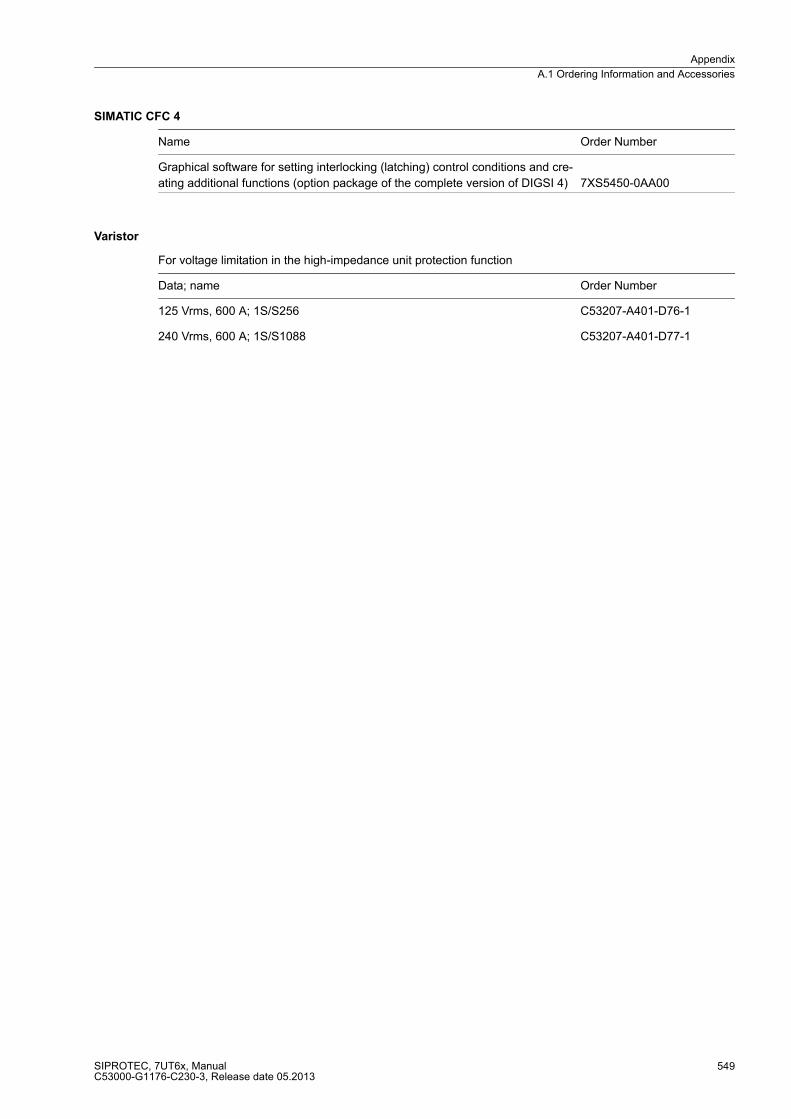
Appendix
A.1 Ordering Information and Accessories
SIPROTEC, 7UT6x, ManualC53000-G1176-C230-3, Release date 05.2013
549
SIMATIC CFC 4
Name Order Number
Graphical software for setting interlocking (latching) control conditions and cre-
ating additional functions (option package of the complete version of DIGSI 4) 7XS5450-0AA00
Varistor
For voltage limitation in the high-impedance unit protection function
Data; name Order Number
125 Vrms, 600 A; 1S/S256 C53207-A401-D76-1
240 Vrms, 600 A; 1S/S1088 C53207-A401-D77-1

Appendix
A.2 Terminal Assignments
SIPROTEC, 7UT6x, ManualC53000-G1176-C230-3, Release date 05.2013
550
A.2 Terminal Assignments
A.2.1 Panel Flush and Cubicle Mounting
7UT612*-*D/E
Figure A-1 General diagram for 7UT612*-*D/E (panel flush mounting or cubicle mounting)
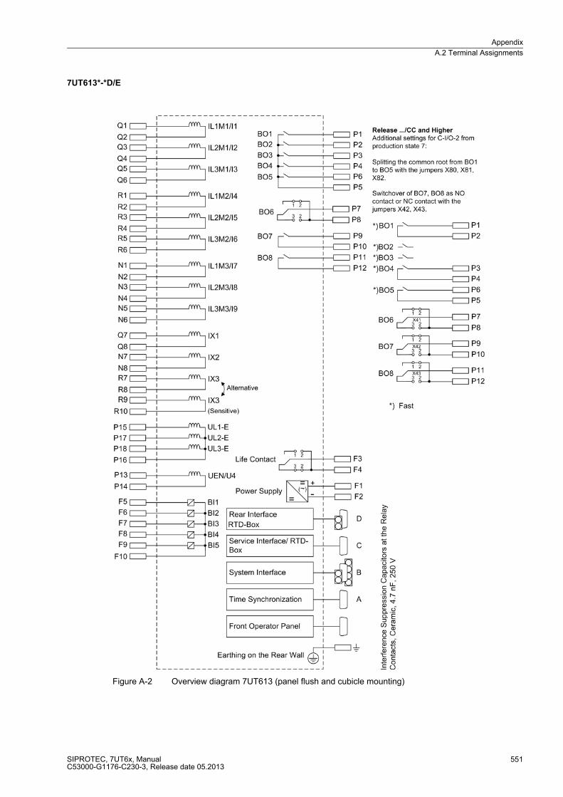
Appendix
A.2 Terminal Assignments
SIPROTEC, 7UT6x, ManualC53000-G1176-C230-3, Release date 05.2013
551
7UT613*-*D/E
Figure A-2 Overview diagram 7UT613 (panel flush and cubicle mounting)
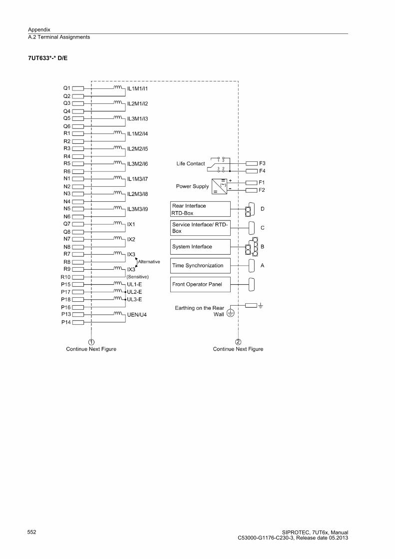
Appendix
A.2 Terminal Assignments
SIPROTEC, 7UT6x, ManualC53000-G1176-C230-3, Release date 05.2013
552
7UT633*-* D/E

Appendix
A.2 Terminal Assignments
SIPROTEC, 7UT6x, ManualC53000-G1176-C230-3, Release date 05.2013
553
7UT633*-* D/E
Figure A-3 General diagram 7UT633 (panel flush and cubicle mounting)

Appendix
A.2 Terminal Assignments
SIPROTEC, 7UT6x, ManualC53000-G1176-C230-3, Release date 05.2013
554
7UT633*-* P/Q
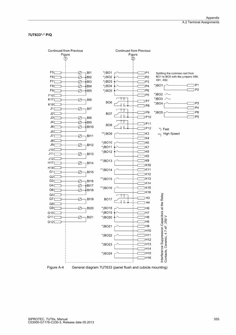
Appendix
A.2 Terminal Assignments
SIPROTEC, 7UT6x, ManualC53000-G1176-C230-3, Release date 05.2013
555
7UT633*-* P/Q
Figure A-4 General diagram 7UT633 (panel flush and cubicle mounting)

Appendix
A.2 Terminal Assignments
SIPROTEC, 7UT6x, ManualC53000-G1176-C230-3, Release date 05.2013
556
7UT635*-* D/E
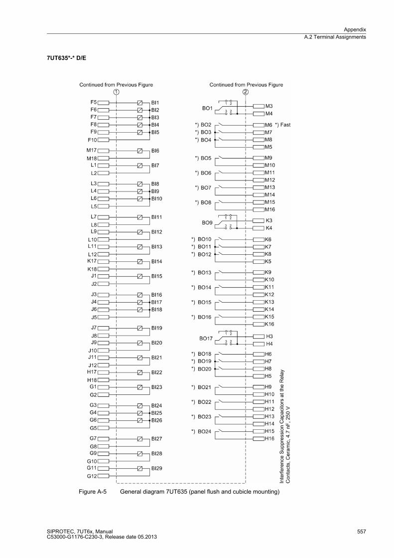
Appendix
A.2 Terminal Assignments
SIPROTEC, 7UT6x, ManualC53000-G1176-C230-3, Release date 05.2013
557
7UT635*-* D/E
Figure A-5 General diagram 7UT635 (panel flush and cubicle mounting)

Appendix
A.2 Terminal Assignments
SIPROTEC, 7UT6x, ManualC53000-G1176-C230-3, Release date 05.2013
558
7UT635*-* P/Q

Appendix
A.2 Terminal Assignments
SIPROTEC, 7UT6x, ManualC53000-G1176-C230-3, Release date 05.2013
559
7UT635*-* P/Q
Figure A-6 General diagram 7UT635 (cubicle mounting)
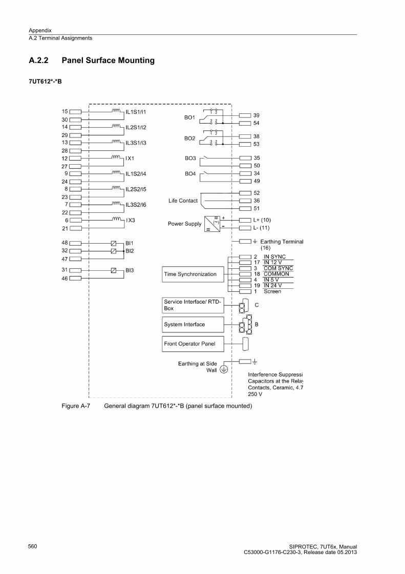
Appendix
A.2 Terminal Assignments
SIPROTEC, 7UT6x, ManualC53000-G1176-C230-3, Release date 05.2013
560
A.2.2 Panel Surface Mounting
7UT612*-*B
Figure A-7 General diagram 7UT612*-*B (panel surface mounted)

Appendix
A.2 Terminal Assignments
SIPROTEC, 7UT6x, ManualC53000-G1176-C230-3, Release date 05.2013
561
7UT613*-* B
Figure A-8 General diagram 7UT613 (panel surface mounting)

Appendix
A.2 Terminal Assignments
SIPROTEC, 7UT6x, ManualC53000-G1176-C230-3, Release date 05.2013
562
7UT633*-* B
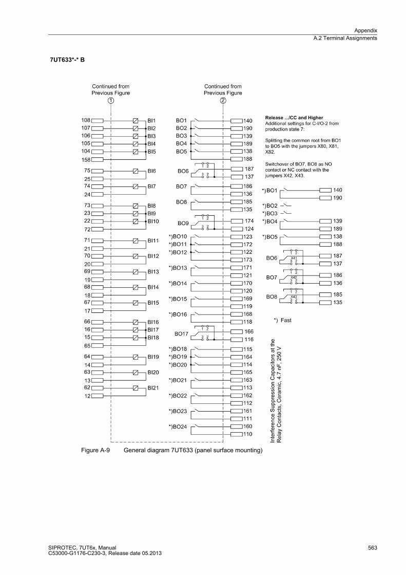
Appendix
A.2 Terminal Assignments
SIPROTEC, 7UT6x, ManualC53000-G1176-C230-3, Release date 05.2013
563
7UT633*-* B
Figure A-9 General diagram 7UT633 (panel surface mounting)
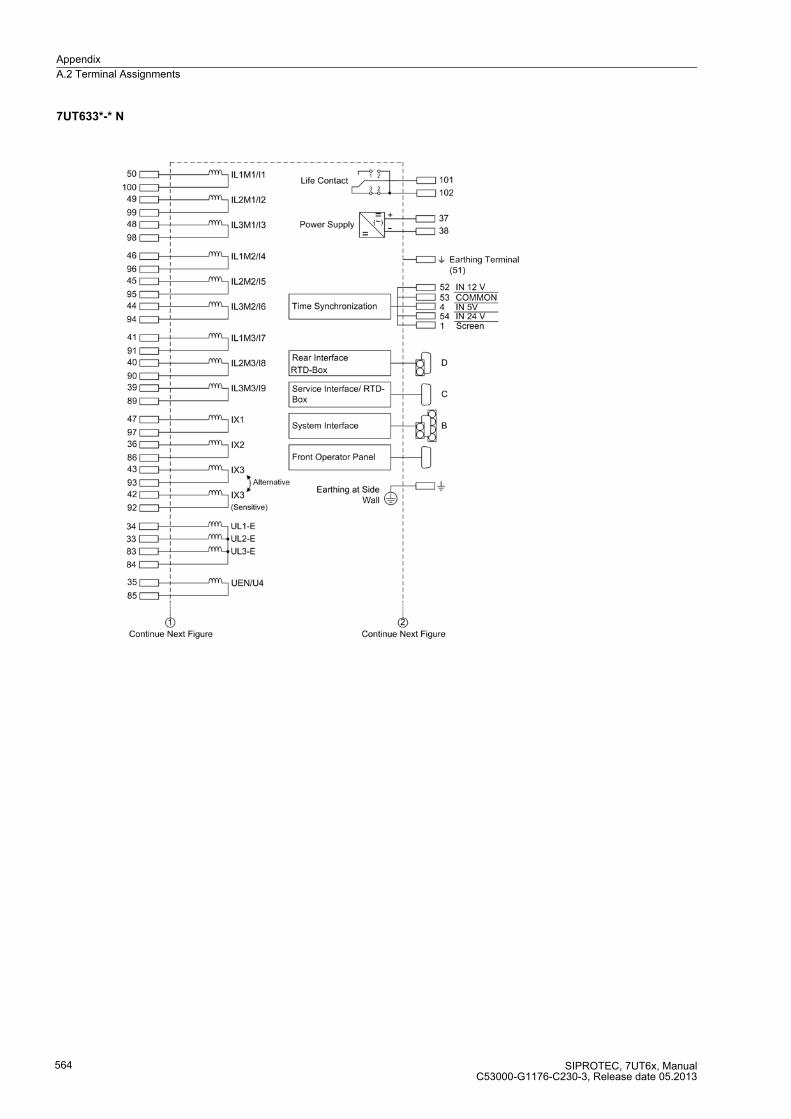
Appendix
A.2 Terminal Assignments
SIPROTEC, 7UT6x, ManualC53000-G1176-C230-3, Release date 05.2013
564
7UT633*-* N

Appendix
A.2 Terminal Assignments
SIPROTEC, 7UT6x, ManualC53000-G1176-C230-3, Release date 05.2013
565
7UT633*-* N
Figure A-10 General diagram 7UT633 (panel surface mounting)
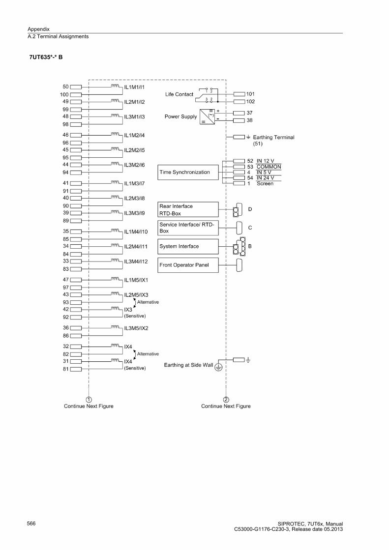
Appendix
A.2 Terminal Assignments
SIPROTEC, 7UT6x, ManualC53000-G1176-C230-3, Release date 05.2013
566
7UT635*-* B

Appendix
A.2 Terminal Assignments
SIPROTEC, 7UT6x, ManualC53000-G1176-C230-3, Release date 05.2013
567
7UT635*-* B
Figure A-11 General diagram 7UT635 (panel surface mounting)

Appendix
A.2 Terminal Assignments
SIPROTEC, 7UT6x, ManualC53000-G1176-C230-3, Release date 05.2013
568
7UT635*-* N

Appendix
A.2 Terminal Assignments
SIPROTEC, 7UT6x, ManualC53000-G1176-C230-3, Release date 05.2013
569
7UT635*-* N
Figure A-12 General diagram 7UT635 (panel surface mounting)

Appendix
A.3 Connection Examples
SIPROTEC, 7UT6x, ManualC53000-G1176-C230-3, Release date 05.2013
570
A.3 Connection Examples
A.3.1 Current Transformer Connection Examples
Figure A-13 Connection example 7UT613 for a three-phase power transformer without earthed starpoint
Figure A-14 Connection example 7UT613 for a three-phase power transformer with earthed starpoint and current transformer between starpoint and earthing point

Appendix
A.3 Connection Examples
SIPROTEC, 7UT6x, ManualC53000-G1176-C230-3, Release date 05.2013
571
Figure A-15 Connection example 7UT613 for a three-phase power transformer with starpoint former and current transformer between starpoint and earthing point
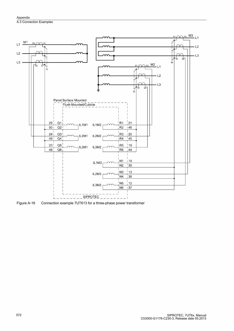
Appendix
A.3 Connection Examples
SIPROTEC, 7UT6x, ManualC53000-G1176-C230-3, Release date 05.2013
572
Figure A-16 Connection example 7UT613 for a three-phase power transformer
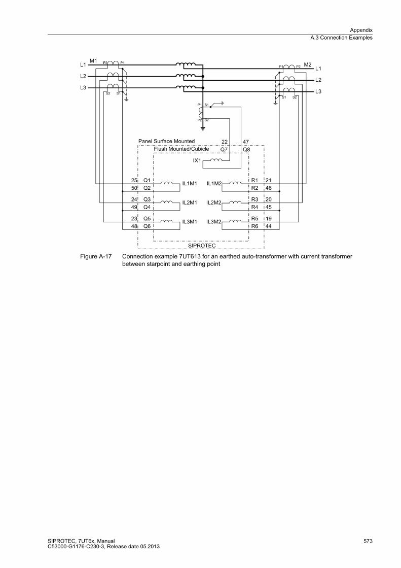
Appendix
A.3 Connection Examples
SIPROTEC, 7UT6x, ManualC53000-G1176-C230-3, Release date 05.2013
573
Figure A-17 Connection example 7UT613 for an earthed auto-transformer with current transformer between starpoint and earthing point

Appendix
A.3 Connection Examples
SIPROTEC, 7UT6x, ManualC53000-G1176-C230-3, Release date 05.2013
574
Figure A-18 Connection example 7UT613 for an earthed auto-transformer with brought-out delta winding capable of carrying load (tertiary winding) and current transformer between starpoint and earthing point

Appendix
A.3 Connection Examples
SIPROTEC, 7UT6x, ManualC53000-G1176-C230-3, Release date 05.2013
575
Figure A-19 Connection example 7UT613 for an auto-transformer bank with protected object auto-transformer branch-points, with individually accessible earthing electrodes equipped with CTs (M3). The CTs on the earthing side constitute a separate side for current comparison for each transformer of the bank. The starpoint of the CTs at M3 is routed via an auxiliary input (IX1), which allows realisation of restricted earth fault protection
and/or earth overcurrent protection.
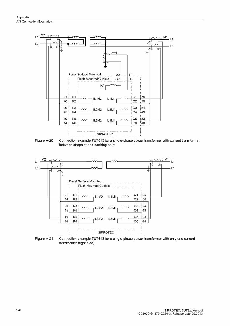
Appendix
A.3 Connection Examples
SIPROTEC, 7UT6x, ManualC53000-G1176-C230-3, Release date 05.2013
576
Figure A-20 Connection example 7UT613 for a single-phase power transformer with current transformer between starpoint and earthing point
Figure A-21 Connection example 7UT613 for a single-phase power transformer with only one current transformer (right side)

Appendix
A.3 Connection Examples
SIPROTEC, 7UT6x, ManualC53000-G1176-C230-3, Release date 05.2013
577
Figure A-22 Connection example 7UT613 for a generator or motor
Figure A-23 Connection example 7UT613 as transversal differential protection for a generator with two windings per phase

Appendix
A.3 Connection Examples
SIPROTEC, 7UT6x, ManualC53000-G1176-C230-3, Release date 05.2013
578
Figure A-24 Connection example 7UT613 for an earthed shunt reactor with current transformer between starpoint and earthing point
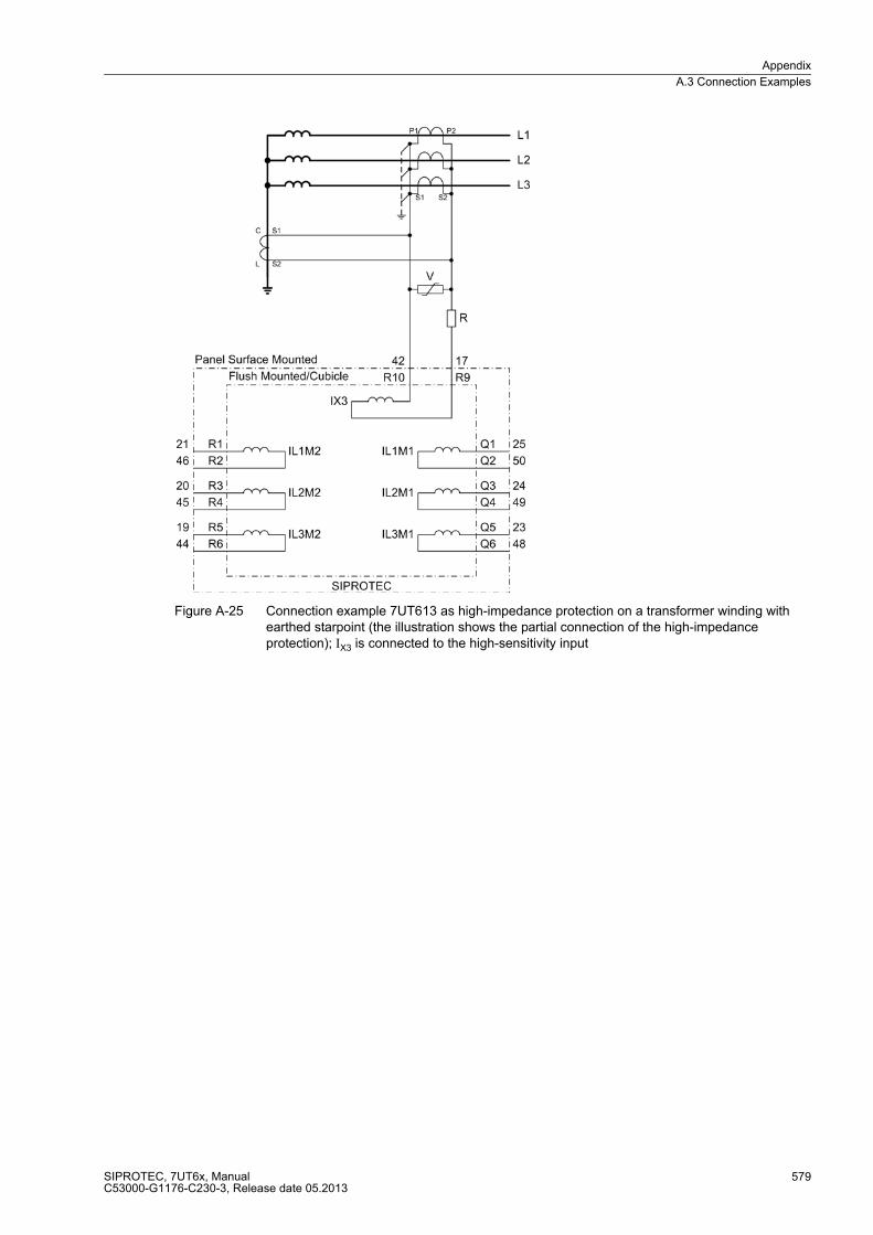
Appendix
A.3 Connection Examples
SIPROTEC, 7UT6x, ManualC53000-G1176-C230-3, Release date 05.2013
579
Figure A-25 Connection example 7UT613 as high-impedance protection on a transformer winding with earthed starpoint (the illustration shows the partial connection of the high-impedance protection); IX3 is connected to the high-sensitivity input
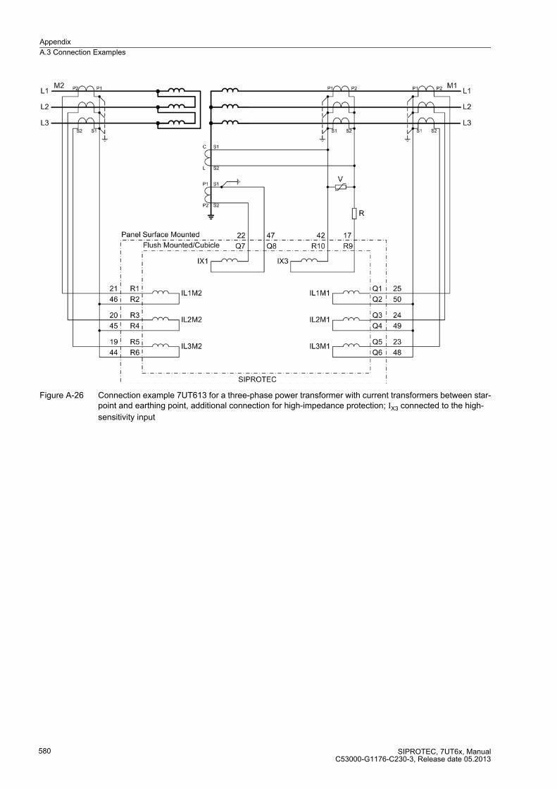
Appendix
A.3 Connection Examples
SIPROTEC, 7UT6x, ManualC53000-G1176-C230-3, Release date 05.2013
580
Figure A-26 Connection example 7UT613 for a three-phase power transformer with current transformers between star-point and earthing point, additional connection for high-impedance protection; IX3 connected to the high-
sensitivity input

Appendix
A.3 Connection Examples
SIPROTEC, 7UT6x, ManualC53000-G1176-C230-3, Release date 05.2013
581
Figure A-27 Connection example 7UT613 as single-phase busbar protection for 7 feeders, illustrated for phase L1

Appendix
A.3 Connection Examples
SIPROTEC, 7UT6x, ManualC53000-G1176-C230-3, Release date 05.2013
582
Figure A-28 Connection example 7UT613 as busbar protection for 6 feeders, connected via external summation transformers (SCT) — partial illustration for feeders 1, 2 and 6
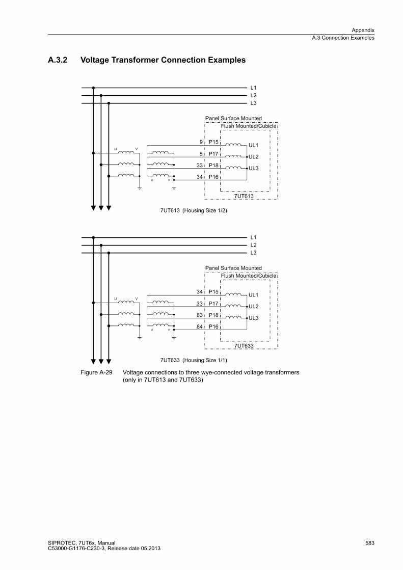
Appendix
A.3 Connection Examples
SIPROTEC, 7UT6x, ManualC53000-G1176-C230-3, Release date 05.2013
583
A.3.2 Voltage Transformer Connection Examples
Figure A-29 Voltage connections to three wye-connected voltage transformers (only in 7UT613 and 7UT633)

Appendix
A.3 Connection Examples
SIPROTEC, 7UT6x, ManualC53000-G1176-C230-3, Release date 05.2013
584
Figure A-30 Voltage connections to three wye-connected voltage transformers with additional open-delta windings (e-n–windings; only in 7UT613 and 7UT633)
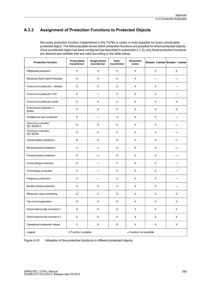
Appendix
A.3 Connection Examples
SIPROTEC, 7UT6x, ManualC53000-G1176-C230-3, Release date 05.2013
585
A.3.3 Assignment of Protection Functions to Protected Objects
Not every protection function implemented in the 7UT6x is useful or even possible for every conceivable protected object. The following table shows which protection functions are possible for which protected objects. Once a protected object has been configured (as described in subsection 2.1.3), only those protection functions are allowed and settable that are valid according to the table below.
Figure A-31 Utilisation of the protective functions in different protected objects
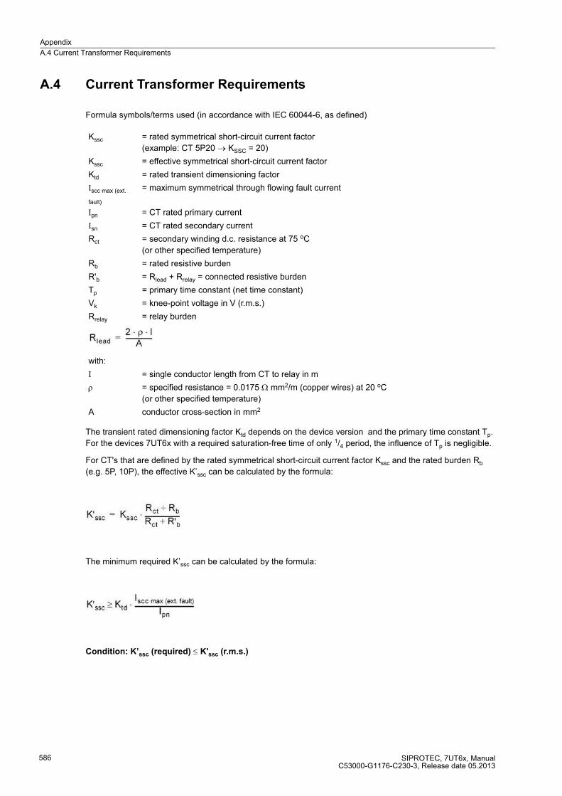
Appendix
A.4 Current Transformer Requirements
SIPROTEC, 7UT6x, ManualC53000-G1176-C230-3, Release date 05.2013
586
A.4 Current Transformer Requirements
Formula symbols/terms used (in accordance with IEC 60044-6, as defined)
The transient rated dimensioning factor Ktd depends on the device version and the primary time constant Tp.
For the devices 7UT6x with a required saturation-free time of only 1/4 period, the influence of Tp is negligible.
For CT's that are defined by the rated symmetrical short-circuit current factor Kssc and the rated burden Rb
(e.g. 5P, 10P), the effective K’ssc can be calculated by the formula:
The minimum required K’ssc can be calculated by the formula:
Condition: K’ssc (required) ≤ K'ssc (r.m.s.)
Kssc = rated symmetrical short-circuit current factor
(example: CT 5P20 → KSSC = 20)
Kssc = effective symmetrical short-circuit current factor
Ktd = rated transient dimensioning factor
Iscc max (ext.
fault)
= maximum symmetrical through flowing fault current
Ipn = CT rated primary current
Isn = CT rated secondary current
Rct = secondary winding d.c. resistance at 75 oC
(or other specified temperature)
Rb = rated resistive burden
R'b = Rlead + Rrelay = connected resistive burden
Tp = primary time constant (net time constant)
Vk = knee-point voltage in V (r.m.s.)
Rrelay = relay burden
with:
I = single conductor length from CT to relay in m
ρ = specified resistance = 0.0175 Ω mm2/m (copper wires) at 20 oC
(or other specified temperature)
A conductor cross-section in mm2
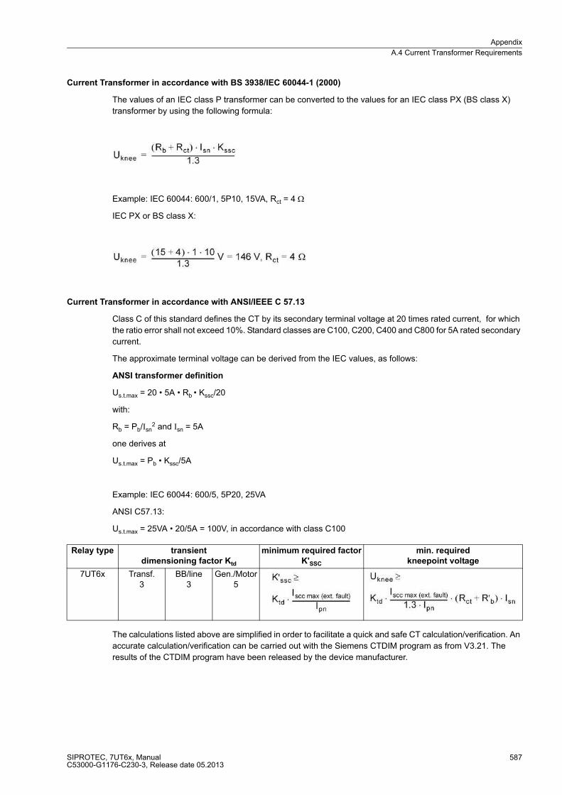
Appendix
A.4 Current Transformer Requirements
SIPROTEC, 7UT6x, ManualC53000-G1176-C230-3, Release date 05.2013
587
Current Transformer in accordance with BS 3938/IEC 60044-1 (2000)
The values of an IEC class P transformer can be converted to the values for an IEC class PX (BS class X)
transformer by using the following formula:
Example: IEC 60044: 600/1, 5P10, 15VA, Rct = 4 ΩIEC PX or BS class X:
Current Transformer in accordance with ANSI/IEEE C 57.13
Class C of this standard defines the CT by its secondary terminal voltage at 20 times rated current, for which
the ratio error shall not exceed 10%. Standard classes are C100, C200, C400 and C800 for 5A rated secondary
current.
The approximate terminal voltage can be derived from the IEC values, as follows:
ANSI transformer definition
Us.t.max = 20 � 5A � Rb � Kssc/20
with:
Rb = Pb/Isn2 and Isn = 5A
one derives at
Us.t.max = Pb � Kssc/5A
Example: IEC 60044: 600/5, 5P20, 25VA
ANSI C57.13:
Us.t.max = 25VA � 20/5A = 100V, in accordance with class C100
The calculations listed above are simplified in order to facilitate a quick and safe CT calculation/verification. An
accurate calculation/verification can be carried out with the Siemens CTDIM program as from V3.21. The
results of the CTDIM program have been released by the device manufacturer.
Relay type transient
dimensioning factor Ktd
minimum required factor
K'SSC
min. required
kneepoint voltage
7UT6x Transf.3
BB/line3
Gen./Motor5
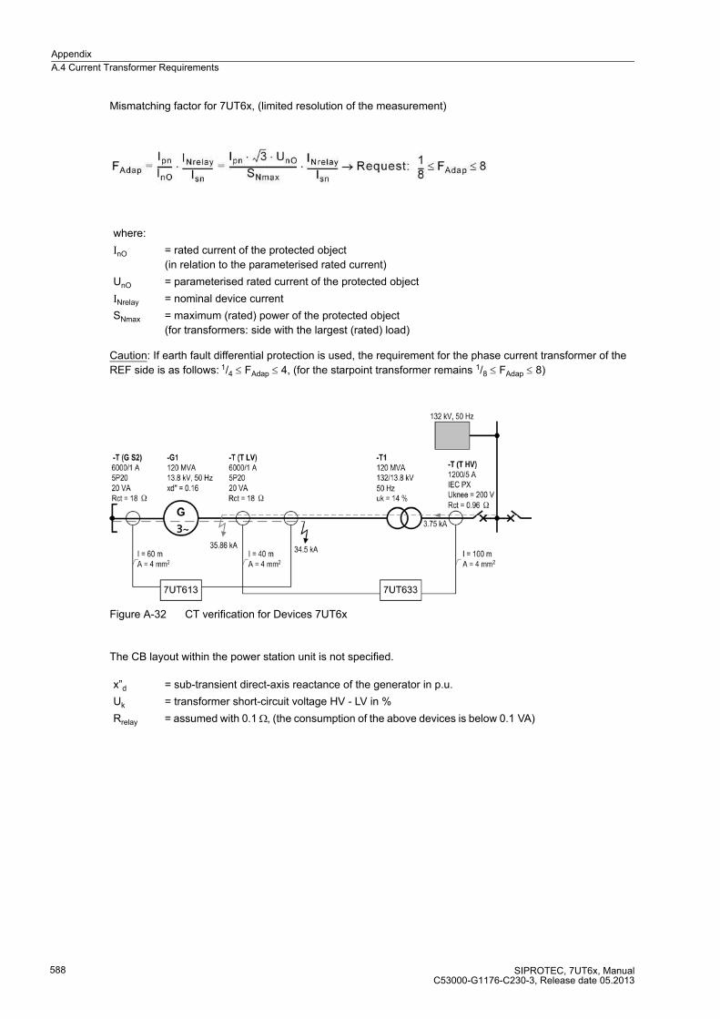
Appendix
A.4 Current Transformer Requirements
SIPROTEC, 7UT6x, ManualC53000-G1176-C230-3, Release date 05.2013
588
Mismatching factor for 7UT6x, (limited resolution of the measurement)
Caution: If earth fault differential protection is used, the requirement for the phase current transformer of the
REF side is as follows: 1/4 ≤ FAdap ≤ 4, (for the starpoint transformer remains 1/8 ≤ FAdap ≤ 8)
Figure A-32 CT verification for Devices 7UT6x
The CB layout within the power station unit is not specified.
where:
InO = rated current of the protected object
(in relation to the parameterised rated current)
UnO = parameterised rated current of the protected object
INrelay = nominal device current
SNmax = maximum (rated) power of the protected object
(for transformers: side with the largest (rated) load)
x”d = sub-transient direct-axis reactance of the generator in p.u.
Uk = transformer short-circuit voltage HV - LV in %
Rrelay = assumed with 0.1 Ω, (the consumption of the above devices is below 0.1 VA)

Appendix
A.4 Current Transformer Requirements
SIPROTEC, 7UT6x, ManualC53000-G1176-C230-3, Release date 05.2013
589
with:
c = voltage factor (for generators: 1,1)
SNOM = nominal power of the transformer in kVA
UNOM = nominal voltage of the transformer in kV
SNG = nominal power of the generator in kVA
UNG = nominal voltage of the generator in kV

Appendix
A.5 Default Settings
SIPROTEC, 7UT6x, ManualC53000-G1176-C230-3, Release date 05.2013
590
A.5 Default Settings
When the device leaves the factory, a large number of LED indicators, binary inputs and outputs as well as
function keys are already preset. They are summarized in the following tables.
A.5.1 LEDs
Table A-1 LED Indication Presettings
A.5.2 Binary Input
Table A-2 Binary input presettings for all devices and ordering variants
LEDs Allocated Function Function No. Description
LED1 Relay TRIP 511 Relay GENERAL TRIP command
LED2 Relay PICKUP 501 Relay PICKUP
LED3 >Buchh. Trip 392 >Tripp. stage from Buchholz protection
LED4 no default setting - -
LED5 no default setting - -
LED6 no default setting - -
LED7 no default setting - -
LED8 no default setting - -
LED9 no default setting - -
LED10 no default setting - -
LED11 no default setting - -
LED12 no default setting - -
LED13 Error Sum Alarm 140 Error with a summary alarm
Alarm Sum Event 160 Alarm Summary Event
LED14 FaultConfig/Set 311 Fault in configuration / setting
Binary Input Allocated Function Function No. Description
BI1 >Reset LED 5 >Reset LED
BI2 >Buchh. Trip 392 >Tripp. stage from Buchholz protection

Appendix
A.5 Default Settings
SIPROTEC, 7UT6x, ManualC53000-G1176-C230-3, Release date 05.2013
591
A.5.3 Binary Output
Table A-3 Output relay presettings for all devices and ordering variants
A.5.4 Function Keys
Table A-4 Applies to all devices and ordered variants
Binary Output Allocated Function Function No. Description
BO1 Relay TRIP 511 Relay GENERAL TRIP command
BO2 Relay PICKUP 501 Relay PICKUP
BO3 >Buchh. Trip 392 >Tripp. stage from Buchholz protection
BO4 Error Sum Alarm 140 Error with a summary alarm
Alarm Sum Event 160 Alarm Summary Event
Function Keys Allocated Function Function No. Description
F1 Display of operational instructions
- -
F2 Display of primary op-erational measured values
- -
F3 An overview of the last 8 network faults
- -
F4 >QuitG-TRP >Quitt Lock Out: General Trip
Resetting the reclosure interlocking
- -

Appendix
A.5 Default Settings
SIPROTEC, 7UT6x, ManualC53000-G1176-C230-3, Release date 05.2013
592
A.5.5 Default Display
For devices with a four-line display, you can scroll among the basic displays shown below. The numerical values shown are examples. The device will display only those values that make sense for the current applica-tion. For instance, voltages will only be shown if the device is provided with voltage inputs and these inputs have been configured; with single-phase transformers there will be no phase L2.
Figure A-33 Default display for 4-line display
*) depending on the phase connected (address 396 PHASE SELECTION)

Appendix
A.5 Default Settings
SIPROTEC, 7UT6x, ManualC53000-G1176-C230-3, Release date 05.2013
593
For devices with a graphic display, the basic displays shown below may appear: The device will display only those values that make sense for the current application. For instance, voltages and powers will only be shown if the device is provided with voltage inputs and these inputs have been configured; with single-phase trans-formers there will be no phase L2.
Figure A-34 Basic graphic displays
*) depending on the phase connected (address 396 PHASE SELECTION)
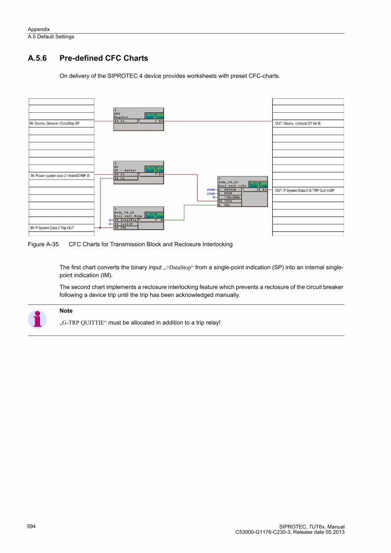
Appendix
A.5 Default Settings
SIPROTEC, 7UT6x, ManualC53000-G1176-C230-3, Release date 05.2013
594
A.5.6 Pre-defined CFC Charts
On delivery of the SIPROTEC 4 device provides worksheets with preset CFC-charts.
Figure A-35 CFC Charts for Transmission Block and Reclosure Interlocking
The first chart converts the binary input „>DataStop“ from a single-point indication (SP) into an internal single-
point indication (IM).
The second chart implements a reclosure interlocking feature which prevents a reclosure of the circuit breaker
following a device trip until the trip has been acknowledged manually.
Note
„G-TRP QUITTIE“ must be allocated in addition to a trip relay!
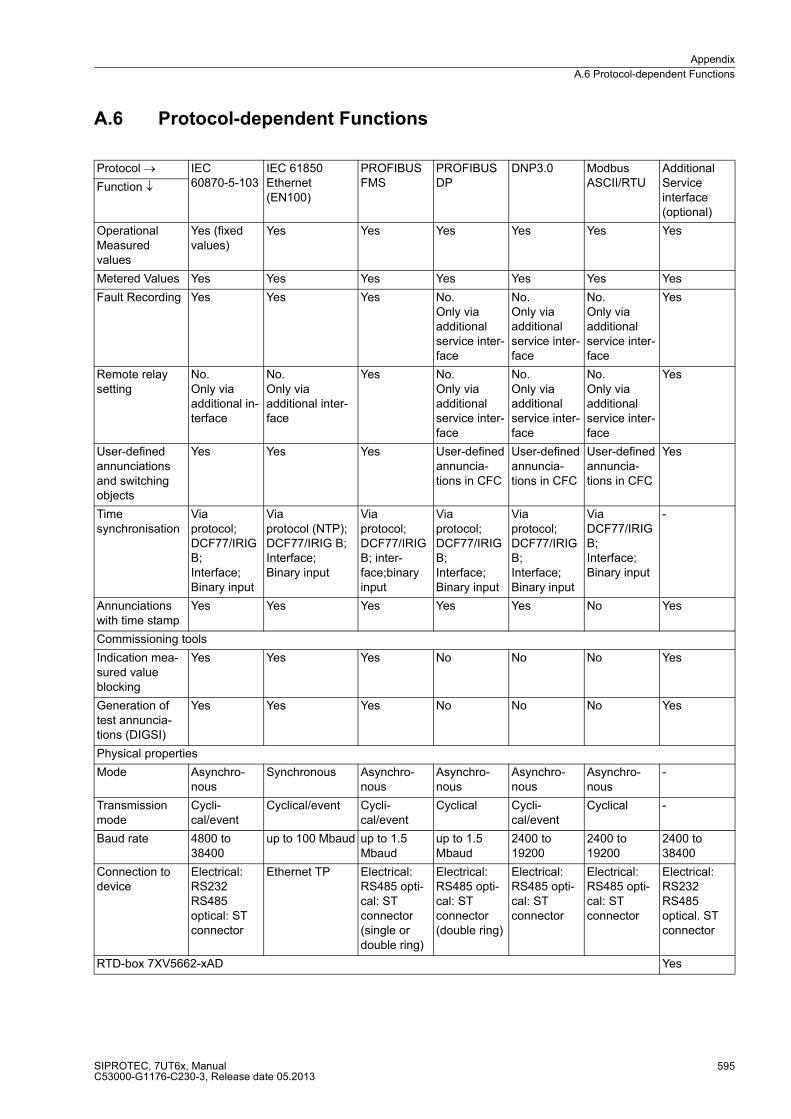
Appendix
A.6 Protocol-dependent Functions
SIPROTEC, 7UT6x, ManualC53000-G1176-C230-3, Release date 05.2013
595
A.6 Protocol-dependent Functions
Protocol → IEC60870-5-103
IEC 61850 Ethernet (EN100)
PROFIBUS FMS
PROFIBUS DP
DNP3.0 Modbus ASCII/RTU
Additional Service interface(optional)
Function ↓
Operational Measured values
Yes (fixed values)
Yes Yes Yes Yes Yes Yes
Metered Values Yes Yes Yes Yes Yes Yes Yes
Fault Recording Yes Yes Yes No. Only via additional service inter-face
No. Only via additional service inter-face
No. Only via additional service inter-face
Yes
Remote relay setting
No. Only via additional in-terface
No. Only via additional inter-face
Yes No. Only via additional service inter-face
No. Only via additional service inter-face
No. Only via additional service inter-face
Yes
User-defined annunciations and switching objects
Yes Yes Yes User-defined annuncia-tions in CFC
User-defined annuncia-tions in CFC
User-defined annuncia-tions in CFC
Yes
Time synchronisation
Via protocol; DCF77/IRIG B; Interface; Binary input
Via protocol (NTP); DCF77/IRIG B; Interface; Binary input
Via protocol; DCF77/IRIG B; inter-face;binary input
Via protocol; DCF77/IRIG B;Interface; Binary input
Via protocol; DCF77/IRIG B; Interface; Binary input
Via DCF77/IRIG B;Interface; Binary input
-
Annunciations with time stamp
Yes Yes Yes Yes Yes No Yes
Commissioning tools
Indication mea-sured value blocking
Yes Yes Yes No No No Yes
Generation of test annuncia-tions (DIGSI)
Yes Yes Yes No No No Yes
Physical properties
Mode Asynchro-nous
Synchronous Asynchro-nous
Asynchro-nous
Asynchro-nous
Asynchro-nous
-
Transmission mode
Cycli-cal/event
Cyclical/event Cycli-cal/event
Cyclical Cycli-cal/event
Cyclical -
Baud rate 4800 to 38400
up to 100 Mbaud up to 1.5 Mbaud
up to 1.5 Mbaud
2400 to 19200
2400 to 19200
2400 to 38400
Connection to device
Electrical: RS232RS485 optical: ST connector
Ethernet TP Electrical: RS485 opti-cal: ST connector (single or double ring)
Electrical: RS485 opti-cal: ST connector (double ring)
Electrical: RS485 opti-cal: ST connector
Electrical: RS485 opti-cal: ST connector
Electrical: RS232RS485 optical. ST connector
RTD-box 7XV5662-xAD Yes
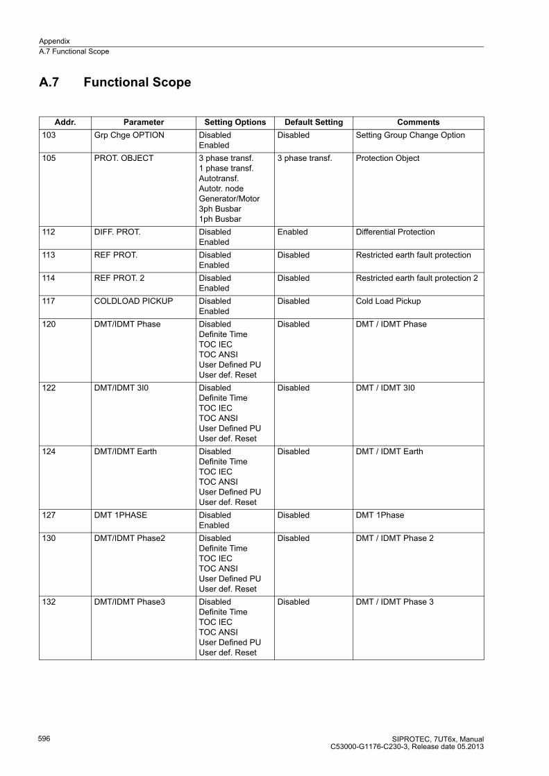
Appendix
A.7 Functional Scope
SIPROTEC, 7UT6x, ManualC53000-G1176-C230-3, Release date 05.2013
596
A.7 Functional Scope
Addr. Parameter Setting Options Default Setting Comments
103 Grp Chge OPTION DisabledEnabled
Disabled Setting Group Change Option
105 PROT. OBJECT 3 phase transf.1 phase transf.Autotransf.Autotr. nodeGenerator/Motor3ph Busbar1ph Busbar
3 phase transf. Protection Object
112 DIFF. PROT. DisabledEnabled
Enabled Differential Protection
113 REF PROT. DisabledEnabled
Disabled Restricted earth fault protection
114 REF PROT. 2 DisabledEnabled
Disabled Restricted earth fault protection 2
117 COLDLOAD PICKUP DisabledEnabled
Disabled Cold Load Pickup
120 DMT/IDMT Phase DisabledDefinite TimeTOC IECTOC ANSIUser Defined PUUser def. Reset
Disabled DMT / IDMT Phase
122 DMT/IDMT 3I0 DisabledDefinite TimeTOC IECTOC ANSIUser Defined PUUser def. Reset
Disabled DMT / IDMT 3I0
124 DMT/IDMT Earth DisabledDefinite TimeTOC IECTOC ANSIUser Defined PUUser def. Reset
Disabled DMT / IDMT Earth
127 DMT 1PHASE DisabledEnabled
Disabled DMT 1Phase
130 DMT/IDMT Phase2 DisabledDefinite TimeTOC IECTOC ANSIUser Defined PUUser def. Reset
Disabled DMT / IDMT Phase 2
132 DMT/IDMT Phase3 DisabledDefinite TimeTOC IECTOC ANSIUser Defined PUUser def. Reset
Disabled DMT / IDMT Phase 3
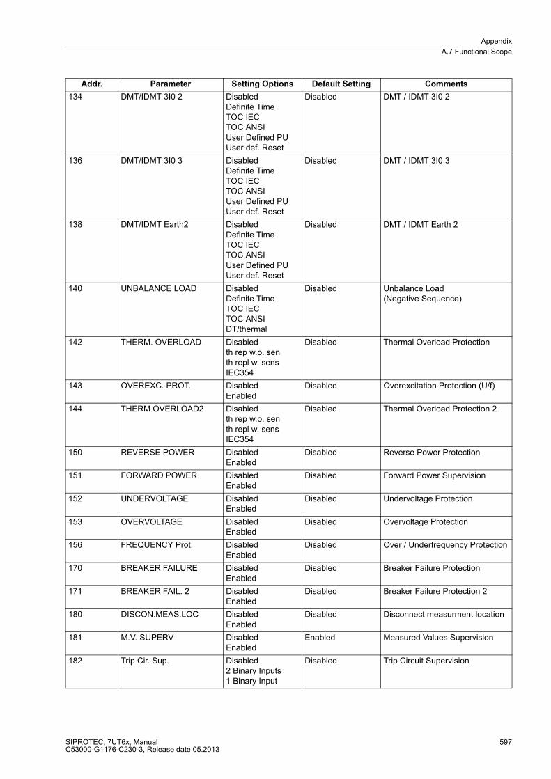
Appendix
A.7 Functional Scope
SIPROTEC, 7UT6x, ManualC53000-G1176-C230-3, Release date 05.2013
597
134 DMT/IDMT 3I0 2 DisabledDefinite TimeTOC IECTOC ANSIUser Defined PUUser def. Reset
Disabled DMT / IDMT 3I0 2
136 DMT/IDMT 3I0 3 DisabledDefinite TimeTOC IECTOC ANSIUser Defined PUUser def. Reset
Disabled DMT / IDMT 3I0 3
138 DMT/IDMT Earth2 DisabledDefinite TimeTOC IECTOC ANSIUser Defined PUUser def. Reset
Disabled DMT / IDMT Earth 2
140 UNBALANCE LOAD DisabledDefinite TimeTOC IECTOC ANSIDT/thermal
Disabled Unbalance Load (Negative Sequence)
142 THERM. OVERLOAD Disabledth rep w.o. senth repl w. sensIEC354
Disabled Thermal Overload Protection
143 OVEREXC. PROT. DisabledEnabled
Disabled Overexcitation Protection (U/f)
144 THERM.OVERLOAD2 Disabledth rep w.o. senth repl w. sensIEC354
Disabled Thermal Overload Protection 2
150 REVERSE POWER DisabledEnabled
Disabled Reverse Power Protection
151 FORWARD POWER DisabledEnabled
Disabled Forward Power Supervision
152 UNDERVOLTAGE DisabledEnabled
Disabled Undervoltage Protection
153 OVERVOLTAGE DisabledEnabled
Disabled Overvoltage Protection
156 FREQUENCY Prot. DisabledEnabled
Disabled Over / Underfrequency Protection
170 BREAKER FAILURE DisabledEnabled
Disabled Breaker Failure Protection
171 BREAKER FAIL. 2 DisabledEnabled
Disabled Breaker Failure Protection 2
180 DISCON.MEAS.LOC DisabledEnabled
Disabled Disconnect measurment location
181 M.V. SUPERV DisabledEnabled
Enabled Measured Values Supervision
182 Trip Cir. Sup. Disabled2 Binary Inputs1 Binary Input
Disabled Trip Circuit Supervision
Addr. Parameter Setting Options Default Setting Comments
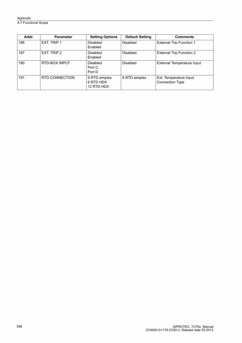
Appendix
A.7 Functional Scope
SIPROTEC, 7UT6x, ManualC53000-G1176-C230-3, Release date 05.2013
598
186 EXT. TRIP 1 DisabledEnabled
Disabled External Trip Function 1
187 EXT. TRIP 2 DisabledEnabled
Disabled External Trip Function 2
190 RTD-BOX INPUT DisabledPort CPort D
Disabled External Temperature Input
191 RTD CONNECTION 6 RTD simplex6 RTD HDX12 RTD HDX
6 RTD simplex Ext. Temperature Input Connection Type
Addr. Parameter Setting Options Default Setting Comments
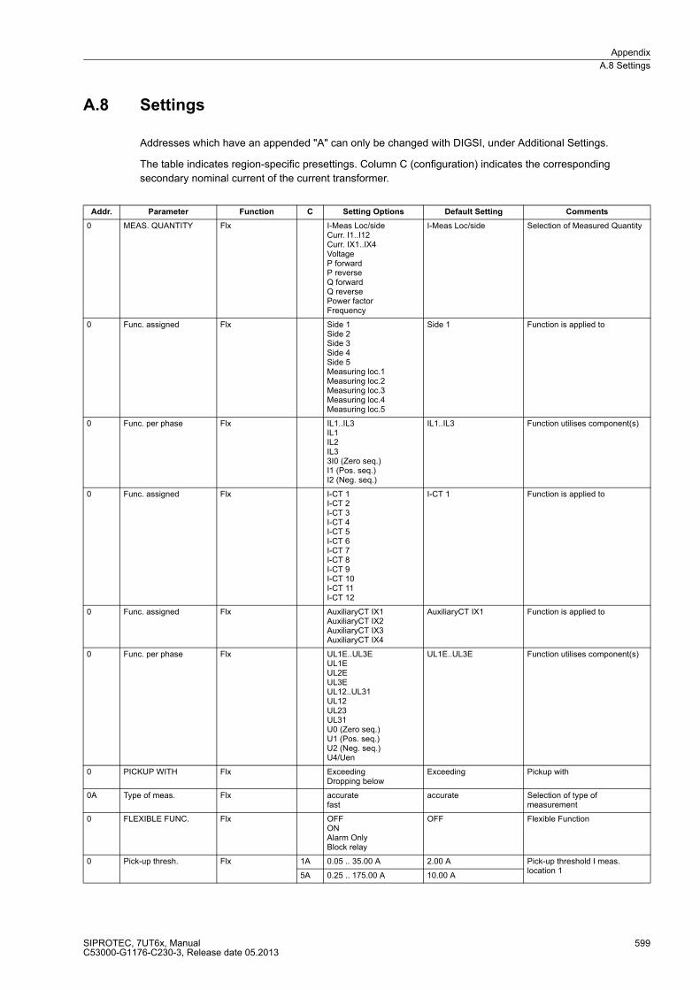
Appendix
A.8 Settings
SIPROTEC, 7UT6x, ManualC53000-G1176-C230-3, Release date 05.2013
599
A.8 Settings
Addresses which have an appended "A" can only be changed with DIGSI, under Additional Settings.
The table indicates region-specific presettings. Column C (configuration) indicates the corresponding
secondary nominal current of the current transformer.
Addr. Parameter Function C Setting Options Default Setting Comments
0 MEAS. QUANTITY Flx I-Meas Loc/sideCurr. I1..I12Curr. IX1..IX4VoltageP forwardP reverseQ forwardQ reversePower factorFrequency
I-Meas Loc/side Selection of Measured Quantity
0 Func. assigned Flx Side 1Side 2Side 3Side 4Side 5Measuring loc.1Measuring loc.2Measuring loc.3Measuring loc.4Measuring loc.5
Side 1 Function is applied to
0 Func. per phase Flx IL1..IL3IL1IL2IL33I0 (Zero seq.)I1 (Pos. seq.)I2 (Neg. seq.)
IL1..IL3 Function utilises component(s)
0 Func. assigned Flx I-CT 1I-CT 2I-CT 3I-CT 4I-CT 5I-CT 6I-CT 7I-CT 8I-CT 9I-CT 10I-CT 11I-CT 12
I-CT 1 Function is applied to
0 Func. assigned Flx AuxiliaryCT IX1AuxiliaryCT IX2AuxiliaryCT IX3AuxiliaryCT IX4
AuxiliaryCT IX1 Function is applied to
0 Func. per phase Flx UL1E..UL3EUL1EUL2EUL3EUL12..UL31UL12UL23UL31U0 (Zero seq.)U1 (Pos. seq.)U2 (Neg. seq.)U4/Uen
UL1E..UL3E Function utilises component(s)
0 PICKUP WITH Flx ExceedingDropping below
Exceeding Pickup with
0A Type of meas. Flx accuratefast
accurate Selection of type of measurement
0 FLEXIBLE FUNC. Flx OFFONAlarm OnlyBlock relay
OFF Flexible Function
0 Pick-up thresh. Flx 1A 0.05 .. 35.00 A 2.00 A Pick-up threshold I meas. location 1
5A 0.25 .. 175.00 A 10.00 A
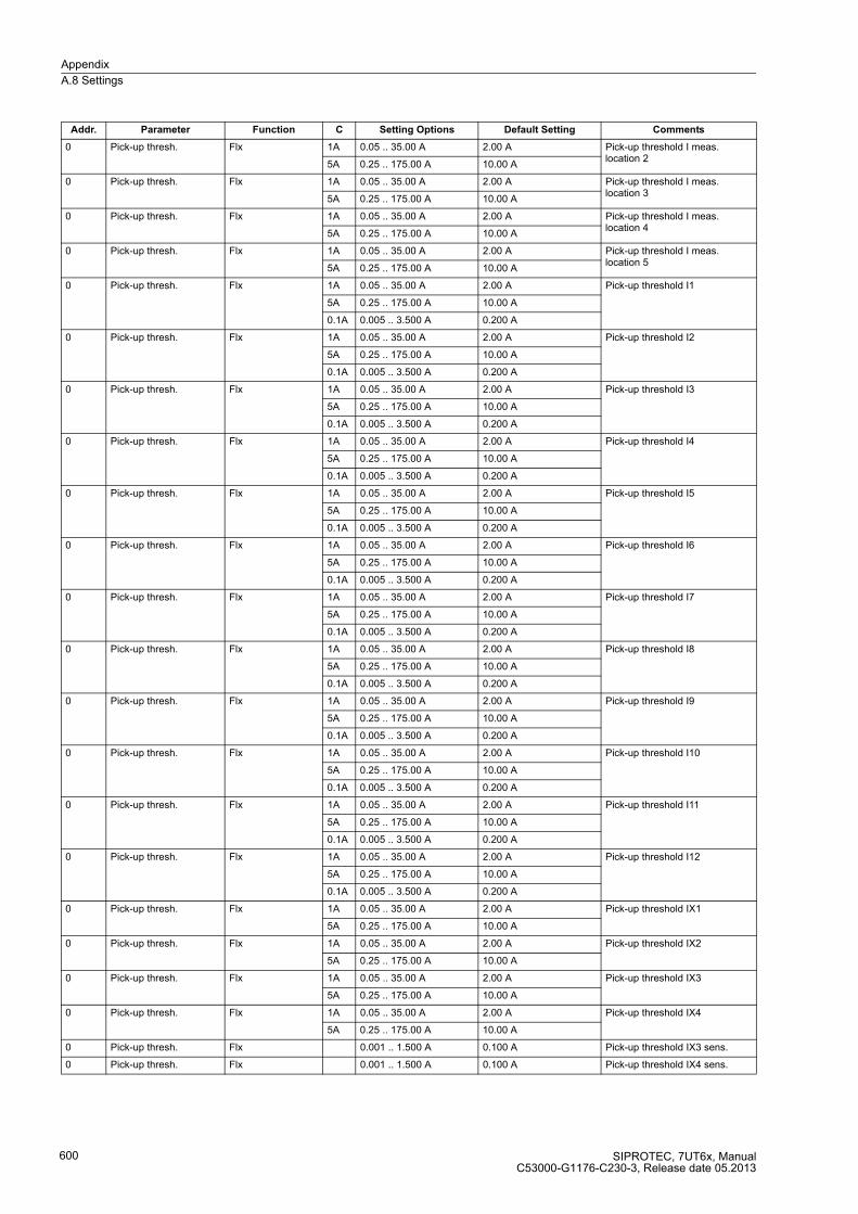
Appendix
A.8 Settings
SIPROTEC, 7UT6x, ManualC53000-G1176-C230-3, Release date 05.2013
600
0 Pick-up thresh. Flx 1A 0.05 .. 35.00 A 2.00 A Pick-up threshold I meas. location 2
5A 0.25 .. 175.00 A 10.00 A
0 Pick-up thresh. Flx 1A 0.05 .. 35.00 A 2.00 A Pick-up threshold I meas. location 3
5A 0.25 .. 175.00 A 10.00 A
0 Pick-up thresh. Flx 1A 0.05 .. 35.00 A 2.00 A Pick-up threshold I meas. location 4
5A 0.25 .. 175.00 A 10.00 A
0 Pick-up thresh. Flx 1A 0.05 .. 35.00 A 2.00 A Pick-up threshold I meas. location 5
5A 0.25 .. 175.00 A 10.00 A
0 Pick-up thresh. Flx 1A 0.05 .. 35.00 A 2.00 A Pick-up threshold I1
5A 0.25 .. 175.00 A 10.00 A
0.1A 0.005 .. 3.500 A 0.200 A
0 Pick-up thresh. Flx 1A 0.05 .. 35.00 A 2.00 A Pick-up threshold I2
5A 0.25 .. 175.00 A 10.00 A
0.1A 0.005 .. 3.500 A 0.200 A
0 Pick-up thresh. Flx 1A 0.05 .. 35.00 A 2.00 A Pick-up threshold I3
5A 0.25 .. 175.00 A 10.00 A
0.1A 0.005 .. 3.500 A 0.200 A
0 Pick-up thresh. Flx 1A 0.05 .. 35.00 A 2.00 A Pick-up threshold I4
5A 0.25 .. 175.00 A 10.00 A
0.1A 0.005 .. 3.500 A 0.200 A
0 Pick-up thresh. Flx 1A 0.05 .. 35.00 A 2.00 A Pick-up threshold I5
5A 0.25 .. 175.00 A 10.00 A
0.1A 0.005 .. 3.500 A 0.200 A
0 Pick-up thresh. Flx 1A 0.05 .. 35.00 A 2.00 A Pick-up threshold I6
5A 0.25 .. 175.00 A 10.00 A
0.1A 0.005 .. 3.500 A 0.200 A
0 Pick-up thresh. Flx 1A 0.05 .. 35.00 A 2.00 A Pick-up threshold I7
5A 0.25 .. 175.00 A 10.00 A
0.1A 0.005 .. 3.500 A 0.200 A
0 Pick-up thresh. Flx 1A 0.05 .. 35.00 A 2.00 A Pick-up threshold I8
5A 0.25 .. 175.00 A 10.00 A
0.1A 0.005 .. 3.500 A 0.200 A
0 Pick-up thresh. Flx 1A 0.05 .. 35.00 A 2.00 A Pick-up threshold I9
5A 0.25 .. 175.00 A 10.00 A
0.1A 0.005 .. 3.500 A 0.200 A
0 Pick-up thresh. Flx 1A 0.05 .. 35.00 A 2.00 A Pick-up threshold I10
5A 0.25 .. 175.00 A 10.00 A
0.1A 0.005 .. 3.500 A 0.200 A
0 Pick-up thresh. Flx 1A 0.05 .. 35.00 A 2.00 A Pick-up threshold I11
5A 0.25 .. 175.00 A 10.00 A
0.1A 0.005 .. 3.500 A 0.200 A
0 Pick-up thresh. Flx 1A 0.05 .. 35.00 A 2.00 A Pick-up threshold I12
5A 0.25 .. 175.00 A 10.00 A
0.1A 0.005 .. 3.500 A 0.200 A
0 Pick-up thresh. Flx 1A 0.05 .. 35.00 A 2.00 A Pick-up threshold IX1
5A 0.25 .. 175.00 A 10.00 A
0 Pick-up thresh. Flx 1A 0.05 .. 35.00 A 2.00 A Pick-up threshold IX2
5A 0.25 .. 175.00 A 10.00 A
0 Pick-up thresh. Flx 1A 0.05 .. 35.00 A 2.00 A Pick-up threshold IX3
5A 0.25 .. 175.00 A 10.00 A
0 Pick-up thresh. Flx 1A 0.05 .. 35.00 A 2.00 A Pick-up threshold IX4
5A 0.25 .. 175.00 A 10.00 A
0 Pick-up thresh. Flx 0.001 .. 1.500 A 0.100 A Pick-up threshold IX3 sens.
0 Pick-up thresh. Flx 0.001 .. 1.500 A 0.100 A Pick-up threshold IX4 sens.
Addr. Parameter Function C Setting Options Default Setting Comments
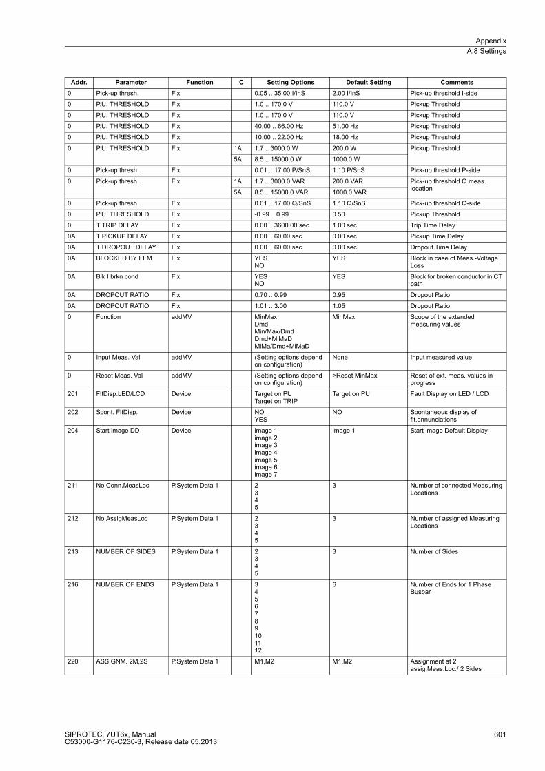
Appendix
A.8 Settings
SIPROTEC, 7UT6x, ManualC53000-G1176-C230-3, Release date 05.2013
601
0 Pick-up thresh. Flx 0.05 .. 35.00 I/InS 2.00 I/InS Pick-up threshold I-side
0 P.U. THRESHOLD Flx 1.0 .. 170.0 V 110.0 V Pickup Threshold
0 P.U. THRESHOLD Flx 1.0 .. 170.0 V 110.0 V Pickup Threshold
0 P.U. THRESHOLD Flx 40.00 .. 66.00 Hz 51.00 Hz Pickup Threshold
0 P.U. THRESHOLD Flx 10.00 .. 22.00 Hz 18.00 Hz Pickup Threshold
0 P.U. THRESHOLD Flx 1A 1.7 .. 3000.0 W 200.0 W Pickup Threshold
5A 8.5 .. 15000.0 W 1000.0 W
0 Pick-up thresh. Flx 0.01 .. 17.00 P/SnS 1.10 P/SnS Pick-up threshold P-side
0 Pick-up thresh. Flx 1A 1.7 .. 3000.0 VAR 200.0 VAR Pick-up threshold Q meas. location
5A 8.5 .. 15000.0 VAR 1000.0 VAR
0 Pick-up thresh. Flx 0.01 .. 17.00 Q/SnS 1.10 Q/SnS Pick-up threshold Q-side
0 P.U. THRESHOLD Flx -0.99 .. 0.99 0.50 Pickup Threshold
0 T TRIP DELAY Flx 0.00 .. 3600.00 sec 1.00 sec Trip Time Delay
0A T PICKUP DELAY Flx 0.00 .. 60.00 sec 0.00 sec Pickup Time Delay
0A T DROPOUT DELAY Flx 0.00 .. 60.00 sec 0.00 sec Dropout Time Delay
0A BLOCKED BY FFM Flx YESNO
YES Block in case of Meas.-Voltage Loss
0A Blk I brkn cond Flx YESNO
YES Block for broken conductor in CT path
0A DROPOUT RATIO Flx 0.70 .. 0.99 0.95 Dropout Ratio
0A DROPOUT RATIO Flx 1.01 .. 3.00 1.05 Dropout Ratio
0 Function addMV MinMaxDmdMin/Max/DmdDmd+MiMaDMiMa/Dmd+MiMaD
MinMax Scope of the extended measuring values
0 Input Meas. Val addMV (Setting options depend on configuration)
None Input measured value
0 Reset Meas. Val addMV (Setting options depend on configuration)
>Reset MinMax Reset of ext. meas. values in progress
201 FltDisp.LED/LCD Device Target on PUTarget on TRIP
Target on PU Fault Display on LED / LCD
202 Spont. FltDisp. Device NOYES
NO Spontaneous display of flt.annunciations
204 Start image DD Device image 1image 2image 3image 4image 5image 6image 7
image 1 Start image Default Display
211 No Conn.MeasLoc P.System Data 1 2345
3 Number of connected Measuring Locations
212 No AssigMeasLoc P.System Data 1 2345
3 Number of assigned Measuring Locations
213 NUMBER OF SIDES P.System Data 1 2345
3 Number of Sides
216 NUMBER OF ENDS P.System Data 1 3456789101112
6 Number of Ends for 1 Phase Busbar
220 ASSIGNM. 2M,2S P.System Data 1 M1,M2 M1,M2 Assignment at 2 assig.Meas.Loc./ 2 Sides
Addr. Parameter Function C Setting Options Default Setting Comments
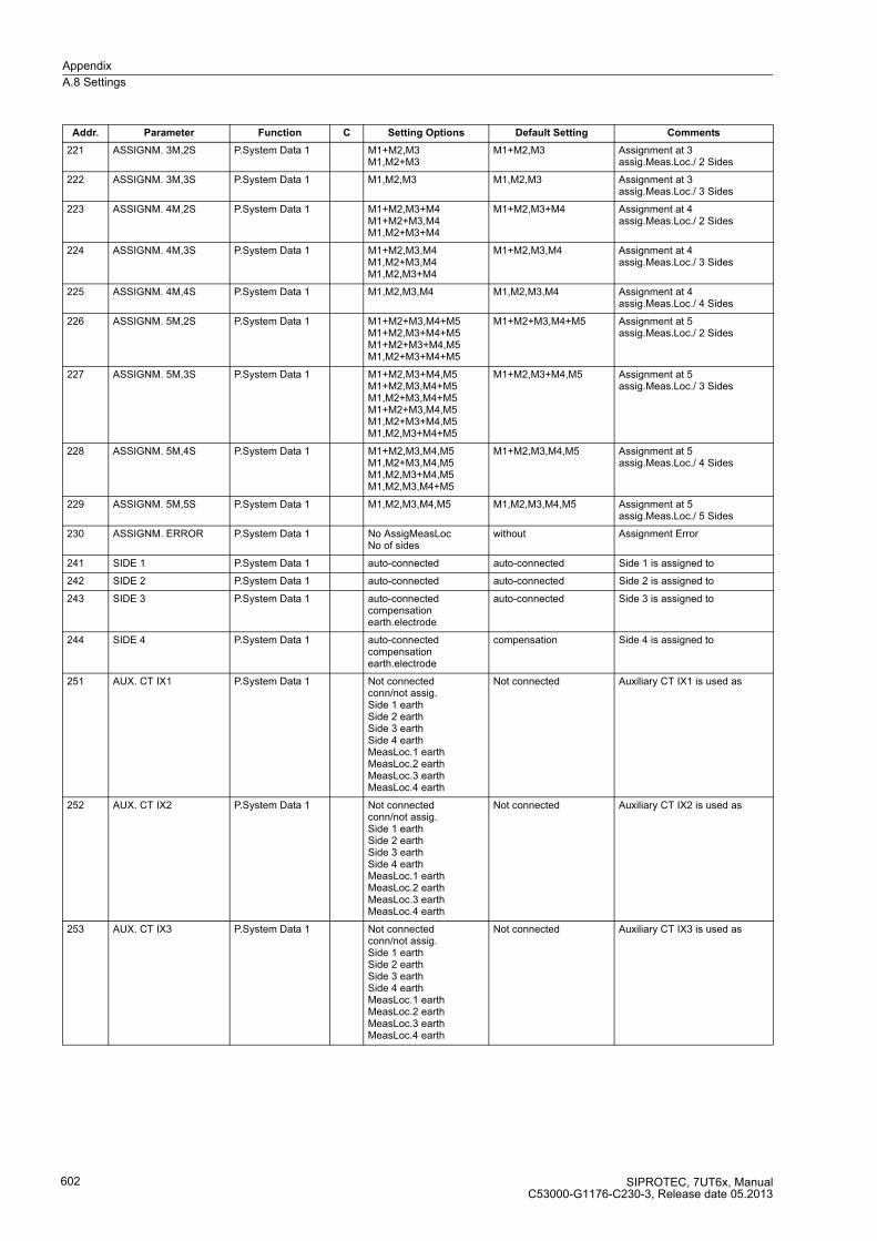
Appendix
A.8 Settings
SIPROTEC, 7UT6x, ManualC53000-G1176-C230-3, Release date 05.2013
602
221 ASSIGNM. 3M,2S P.System Data 1 M1+M2,M3M1,M2+M3
M1+M2,M3 Assignment at 3 assig.Meas.Loc./ 2 Sides
222 ASSIGNM. 3M,3S P.System Data 1 M1,M2,M3 M1,M2,M3 Assignment at 3 assig.Meas.Loc./ 3 Sides
223 ASSIGNM. 4M,2S P.System Data 1 M1+M2,M3+M4M1+M2+M3,M4M1,M2+M3+M4
M1+M2,M3+M4 Assignment at 4 assig.Meas.Loc./ 2 Sides
224 ASSIGNM. 4M,3S P.System Data 1 M1+M2,M3,M4M1,M2+M3,M4M1,M2,M3+M4
M1+M2,M3,M4 Assignment at 4 assig.Meas.Loc./ 3 Sides
225 ASSIGNM. 4M,4S P.System Data 1 M1,M2,M3,M4 M1,M2,M3,M4 Assignment at 4 assig.Meas.Loc./ 4 Sides
226 ASSIGNM. 5M,2S P.System Data 1 M1+M2+M3,M4+M5M1+M2,M3+M4+M5M1+M2+M3+M4,M5M1,M2+M3+M4+M5
M1+M2+M3,M4+M5 Assignment at 5 assig.Meas.Loc./ 2 Sides
227 ASSIGNM. 5M,3S P.System Data 1 M1+M2,M3+M4,M5M1+M2,M3,M4+M5M1,M2+M3,M4+M5M1+M2+M3,M4,M5M1,M2+M3+M4,M5M1,M2,M3+M4+M5
M1+M2,M3+M4,M5 Assignment at 5 assig.Meas.Loc./ 3 Sides
228 ASSIGNM. 5M,4S P.System Data 1 M1+M2,M3,M4,M5M1,M2+M3,M4,M5M1,M2,M3+M4,M5M1,M2,M3,M4+M5
M1+M2,M3,M4,M5 Assignment at 5 assig.Meas.Loc./ 4 Sides
229 ASSIGNM. 5M,5S P.System Data 1 M1,M2,M3,M4,M5 M1,M2,M3,M4,M5 Assignment at 5 assig.Meas.Loc./ 5 Sides
230 ASSIGNM. ERROR P.System Data 1 No AssigMeasLocNo of sides
without Assignment Error
241 SIDE 1 P.System Data 1 auto-connected auto-connected Side 1 is assigned to
242 SIDE 2 P.System Data 1 auto-connected auto-connected Side 2 is assigned to
243 SIDE 3 P.System Data 1 auto-connectedcompensationearth.electrode
auto-connected Side 3 is assigned to
244 SIDE 4 P.System Data 1 auto-connectedcompensationearth.electrode
compensation Side 4 is assigned to
251 AUX. CT IX1 P.System Data 1 Not connectedconn/not assig.Side 1 earthSide 2 earthSide 3 earthSide 4 earthMeasLoc.1 earthMeasLoc.2 earthMeasLoc.3 earthMeasLoc.4 earth
Not connected Auxiliary CT IX1 is used as
252 AUX. CT IX2 P.System Data 1 Not connectedconn/not assig.Side 1 earthSide 2 earthSide 3 earthSide 4 earthMeasLoc.1 earthMeasLoc.2 earthMeasLoc.3 earthMeasLoc.4 earth
Not connected Auxiliary CT IX2 is used as
253 AUX. CT IX3 P.System Data 1 Not connectedconn/not assig.Side 1 earthSide 2 earthSide 3 earthSide 4 earthMeasLoc.1 earthMeasLoc.2 earthMeasLoc.3 earthMeasLoc.4 earth
Not connected Auxiliary CT IX3 is used as
Addr. Parameter Function C Setting Options Default Setting Comments

Appendix
A.8 Settings
SIPROTEC, 7UT6x, ManualC53000-G1176-C230-3, Release date 05.2013
603
254 AUX. CT IX4 P.System Data 1 Not connectedconn/not assig.Side 1 earthSide 2 earthSide 3 earthSide 4 earthSide 5 earthMeasLoc.1 earthMeasLoc.2 earthMeasLoc.3 earthMeasLoc.4 earthMeasLoc.5 earth
Not connected Auxiliary CT IX4 is used as
255 AUX CT IX3 TYPE P.System Data 1 1A/5A inputsensitiv input
1A/5A input Type of auxiliary CT IX3
256 AUX CT IX4 TYPE P.System Data 1 1A/5A inputsensitiv input
1A/5A input Type of auxiliary CT IX4
261 VT SET P.System Data 1 Not connectedSide 1Side 2Side 3Measuring loc.1Measuring loc.2Measuring loc.3Busbar
Measuring loc.1 VT set UL1, UL2, UL3 is assigned
262 VT U4 P.System Data 1 Not connectedconn/not assig.Side 1Side 2Side 3Measuring loc.1Measuring loc.2Measuring loc.3Busbar
Measuring loc.1 VT U4 is assigned
263 VT U4 TYPE P.System Data 1 Udelta transf.UL1E transform.UL2E transform.UL3E transform.UL12 transform.UL23 transform.UL31 transform.Ux transformer
Udelta transf. VT U4 is used as
270 Rated Frequency P.System Data 1 50 Hz60 Hz16,7 Hz
50 Hz Rated Frequency
271 PHASE SEQ. P.System Data 1 L1 L2 L3L1 L3 L2
L1 L2 L3 Phase Sequence
276 TEMP. UNIT P.System Data 1 CelsiusFahrenheit
Celsius Unit of temperature measurement
302 CHANGE Change Group Group AGroup BGroup CGroup DBinary InputProtocol
Group A Change to Another Setting Group
311 UN-PRI SIDE 1 P.System Data 1 0.4 .. 800.0 kV 110.0 kV Rated Primary Voltage Side 1
312 SN SIDE 1 P.System Data 1 0.20 .. 5000.00 MVA 38.10 MVA Rated Apparent Power of Transf. Side 1
313 STARPNT SIDE 1 P.System Data 1 EarthedIsolated
Earthed Starpoint of Side 1 is
314 CONNECTION S1 P.System Data 1 YDZ
Y Transf. Winding Connection Side 1
321 UN-PRI SIDE 2 P.System Data 1 0.4 .. 800.0 kV 11.0 kV Rated Primary Voltage Side 2
322 SN SIDE 2 P.System Data 1 0.20 .. 5000.00 MVA 38.10 MVA Rated Apparent Power of Transf. Side 2
323 STARPNT SIDE 2 P.System Data 1 EarthedIsolated
Earthed Starpoint of Side 2 is
324 CONNECTION S2 P.System Data 1 YDZ
Y Transf. Winding Connection Side 2
Addr. Parameter Function C Setting Options Default Setting Comments

Appendix
A.8 Settings
SIPROTEC, 7UT6x, ManualC53000-G1176-C230-3, Release date 05.2013
604
325 VECTOR GRP S2 P.System Data 1 01234567891011
0 Vector Group Numeral of Side 2
331 UN-PRI SIDE 3 P.System Data 1 0.4 .. 800.0 kV 11.0 kV Rated Primary Voltage Side 3
332 SN SIDE 3 P.System Data 1 0.20 .. 5000.00 MVA 10.00 MVA Rated Apparent Power of Transf. Side 3
333 STARPNT SIDE 3 P.System Data 1 EarthedIsolated
Earthed Starpoint of Side 3 is
334 CONNECTION S3 P.System Data 1 YDZ
Y Transf. Winding Connection Side 3
335 VECTOR GRP S3 P.System Data 1 01234567891011
0 Vector Group Numeral of Side 3
341 UN-PRI SIDE 4 P.System Data 1 0.4 .. 800.0 kV 11.0 kV Rated Primary Voltage Side 4
342 SN SIDE 4 P.System Data 1 0.20 .. 5000.00 MVA 10.00 MVA Rated Apparent Power of Transf. Side 4
343 STARPNT SIDE 4 P.System Data 1 EarthedIsolated
Earthed Starpoint of Side 4 is
344 CONNECTION S4 P.System Data 1 YDZ
Y Transf. Winding Connection Side 4
345 VECTOR GRP S4 P.System Data 1 01234567891011
0 Vector Group Numeral of Side 4
351 UN-PRI SIDE 5 P.System Data 1 0.4 .. 800.0 kV 11.0 kV Rated Primary Voltage Side 5
352 SN SIDE 5 P.System Data 1 0.20 .. 5000.00 MVA 10.00 MVA Rated Apparent Power of Transf. Side 5
353 STARPNT SIDE 5 P.System Data 1 EarthedIsolated
Earthed Starpoint of Side 5 is
354 CONNECTION S5 P.System Data 1 YDZ
Y Transf. Winding Connection Side 5
355 VECTOR GRP S5 P.System Data 1 01234567891011
0 Vector Group Numeral of Side 5
Addr. Parameter Function C Setting Options Default Setting Comments

Appendix
A.8 Settings
SIPROTEC, 7UT6x, ManualC53000-G1176-C230-3, Release date 05.2013
605
361 UN GEN/MOTOR P.System Data 1 0.4 .. 800.0 kV 21.0 kV Rated Primary Voltage Generator/Motor
362 SN GEN/MOTOR P.System Data 1 0.20 .. 5000.00 MVA 70.00 MVA Rated Apparent Power of the Generator
370 UN BUSBAR P.System Data 1 0.4 .. 800.0 kV 110.0 kV Rated Primary Voltage Busbar
371 I PRIMARY OP. P.System Data 1 1 .. 100000 A 200 A Primary Operating Current of Busbar
372 I PRIMARY OP S1 P.System Data 1 1 .. 100000 A 200 A Primary Operating Current Side 1
373 I PRIMARY OP S2 P.System Data 1 1 .. 100000 A 200 A Primary Operating Current Side 2
374 I PRIMARY OP S3 P.System Data 1 1 .. 100000 A 200 A Primary Operating Current Side 3
375 I PRIMARY OP S4 P.System Data 1 1 .. 100000 A 200 A Primary Operating Current Side 4
376 I PRIMARY OP S5 P.System Data 1 1 .. 100000 A 200 A Primary Operating Current Side 5
381 I PRIMARY OP 1 P.System Data 1 1 .. 100000 A 200 A Primary Operating Current End 1
382 I PRIMARY OP 2 P.System Data 1 1 .. 100000 A 200 A Primary Operating Current End 2
383 I PRIMARY OP 3 P.System Data 1 1 .. 100000 A 200 A Primary Operating Current End 3
384 I PRIMARY OP 4 P.System Data 1 1 .. 100000 A 200 A Primary Operating Current End 4
385 I PRIMARY OP 5 P.System Data 1 1 .. 100000 A 200 A Primary Operating Current End 5
386 I PRIMARY OP 6 P.System Data 1 1 .. 100000 A 200 A Primary Operating Current End 6
387 I PRIMARY OP 7 P.System Data 1 1 .. 100000 A 200 A Primary Operating Current End 7
388 I PRIMARY OP 8 P.System Data 1 1 .. 100000 A 200 A Primary Operating Current End 8
389 I PRIMARY OP 9 P.System Data 1 1 .. 100000 A 200 A Primary Operating Current End 9
390 I PRIMARY OP 10 P.System Data 1 1 .. 100000 A 200 A Primary Operating Current End 10
391 I PRIMARY OP 11 P.System Data 1 1 .. 100000 A 200 A Primary Operating Current End 11
392 I PRIMARY OP 12 P.System Data 1 1 .. 100000 A 200 A Primary Operating Current End 12
396 PHASE SELECTION P.System Data 1 Phase 1Phase 2Phase 3
Phase 1 Phase selection
403 I PRIMARY OP M3 P.System Data 1 1 .. 100000 A 200 A Primary Operating Current Meas. Loc. 3
404 I PRIMARY OP M4 P.System Data 1 1 .. 100000 A 200 A Primary Operating Current Meas. Loc. 4
405 I PRIMARY OP M5 P.System Data 1 1 .. 100000 A 200 A Primary Operating Current Meas. Loc. 5
408 UN-PRI M3 P.System Data 1 0.4 .. 800.0 kV 110.0 kV Rated Primary Voltage Measuring Loc. 3
409 UN-PRI U4 P.System Data 1 0.4 .. 800.0 kV 110.0 kV Rated Primary Voltage U4
413 REF PROT. AT P.System Data 1 Side 1Side 2Side 3Side 4Side 5auto-connectedn.assigMeasLoc3n.assigMeasLoc4n.assigMeasLoc5
Side 1 Restricted earth fault prot. assigned to
414 REF PROT. 2 AT P.System Data 1 Side 1Side 2Side 3Side 4Side 5auto-connectedn.assigMeasLoc3n.assigMeasLoc4n.assigMeasLoc5
Side 1 Restricted earth fault prot2 assigned to
Addr. Parameter Function C Setting Options Default Setting Comments

Appendix
A.8 Settings
SIPROTEC, 7UT6x, ManualC53000-G1176-C230-3, Release date 05.2013
606
420 DMT/IDMT Ph AT P.System Data 1 Side 1Side 2Side 3Side 4Side 5Measuring loc.1Measuring loc.2Measuring loc.3Measuring loc.4Measuring loc.5
Side 1 DMT / IDMT Phase assigned to
422 DMT/IDMT 3I0 AT P.System Data 1 Side 1Side 2Side 3Side 4Side 5Measuring loc.1Measuring loc.2Measuring loc.3Measuring loc.4Measuring loc.5
Side 1 DMT / IDMT 3I0 assigned to
424 DMT/IDMT E AT P.System Data 1 no assig. poss.AuxiliaryCT IX1AuxiliaryCT IX2AuxiliaryCT IX3AuxiliaryCT IX4
AuxiliaryCT IX1 DMT / IDMT Earth assigned to
427 DMT 1PHASE AT P.System Data 1 no assig. poss.AuxiliaryCT IX1AuxiliaryCT IX2AuxiliaryCT IX3AuxiliaryCT IX4
AuxiliaryCT IX1 DMT 1Phase assigned to
430 DMT/IDMT Ph2 AT P.System Data 1 Side 1Side 2Side 3Side 4Side 5Measuring loc.1Measuring loc.2Measuring loc.3Measuring loc.4Measuring loc.5
Side 1 DMT / IDMT Phase 2 assigned to
432 DMT/IDMT Ph3 AT P.System Data 1 Side 1Side 2Side 3Side 4Side 5Measuring loc.1Measuring loc.2Measuring loc.3Measuring loc.4Measuring loc.5
Side 1 DMT / IDMT Phase 3 assigned to
434 DMT/IDMT3I0-2AT P.System Data 1 Side 1Side 2Side 3Side 4Side 5Measuring loc.1Measuring loc.2Measuring loc.3Measuring loc.4Measuring loc.5
Side 1 DMT / IDMT 3I0 2 assigned to
436 DMT/IDMT3I0-3AT P.System Data 1 Side 1Side 2Side 3Side 4Side 5Measuring loc.1Measuring loc.2Measuring loc.3Measuring loc.4Measuring loc.5
Side 1 DMT / IDMT 3I0 3 assigned to
438 DMT/IDMT E2 AT P.System Data 1 no assig. poss.AuxiliaryCT IX1AuxiliaryCT IX2AuxiliaryCT IX3AuxiliaryCT IX4
AuxiliaryCT IX1 DMT / IDMT Earth 2 assigned to
Addr. Parameter Function C Setting Options Default Setting Comments

Appendix
A.8 Settings
SIPROTEC, 7UT6x, ManualC53000-G1176-C230-3, Release date 05.2013
607
440 UNBAL. LOAD AT P.System Data 1 Side 1Side 2Side 3Side 4Side 5Measuring loc.1Measuring loc.2Measuring loc.3Measuring loc.4Measuring loc.5
Side 1 Unbalance Load (Neg. Seq.) assigned to
442 THERM. O/L AT P.System Data 1 Side 1Side 2Side 3Side 4Side 5
Side 1 Thermal Overload Protection assigned to
444 THERM. O/L 2 AT P.System Data 1 Side 1Side 2Side 3Side 4Side 5
Side 1 Thermal Overload Protection2 assigned to
470 BREAKER FAIL.AT P.System Data 1 Side 1Side 2Side 3Side 4Side 5Measuring loc.1Measuring loc.2Measuring loc.3Measuring loc.4Measuring loc.5Ext. switchg. 1
Side 1 Breaker Failure Protection assigned to
471 BREAKER FAIL2AT P.System Data 1 Side 1Side 2Side 3Side 4Side 5Measuring loc.1Measuring loc.2Measuring loc.3Measuring loc.4Measuring loc.5Ext. switchg. 1
Side 1 Breaker Failure Protection 2 assigned to
511 STRPNT->OBJ M1 P.System Data 1 YESNO
YES CT-Strpnt. Meas. Loc.1 in Dir. of Object
512 IN-PRI CT M1 P.System Data 1 1 .. 100000 A 200 A CT Rated Primary Current Meas. Loc. 1
513 IN-SEC CT M1 P.System Data 1 1A5A
1A CT Rated Secondary Current Meas. Loc. 1
521 STRPNT->OBJ M2 P.System Data 1 YESNO
YES CT-Strpnt. Meas. Loc.2 in Dir. of Object
522 IN-PRI CT M2 P.System Data 1 1 .. 100000 A 2000 A CT Rated Primary Current Meas. Loc. 2
523 IN-SEC CT M2 P.System Data 1 1A5A
1A CT Rated Secondary Current Meas. Loc. 2
531 STRPNT->OBJ M3 P.System Data 1 YESNO
YES CT-Strpnt. Meas. Loc.3 in Dir. of Object
532 IN-PRI CT M3 P.System Data 1 1 .. 100000 A 2000 A CT Rated Primary Current Meas. Loc. 3
533 IN-SEC CT M3 P.System Data 1 1A5A
1A CT Rated Secondary Current Meas. Loc. 3
541 STRPNT->OBJ M4 P.System Data 1 YESNO
YES CT-Strpnt. Meas. Loc.4 in Dir. of Object
542 IN-PRI CT M4 P.System Data 1 1 .. 100000 A 2000 A CT Rated Primary Current Meas. Loc. 4
543 IN-SEC CT M4 P.System Data 1 1A5A
1A CT Rated Secondary Current Meas. Loc. 4
551 STRPNT->OBJ M5 P.System Data 1 YESNO
YES CT-Strpnt. Meas. Loc.5 in Dir. of Object
552 IN-PRI CT M5 P.System Data 1 1 .. 100000 A 2000 A CT Rated Primary Current Meas. Loc. 5
553 IN-SEC CT M5 P.System Data 1 1A5A
1A CT Rated Secondary Current Meas. Loc. 5
Addr. Parameter Function C Setting Options Default Setting Comments
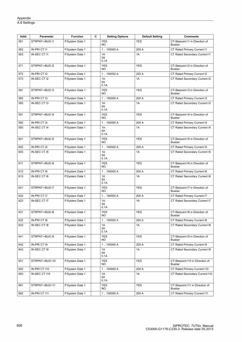
Appendix
A.8 Settings
SIPROTEC, 7UT6x, ManualC53000-G1176-C230-3, Release date 05.2013
608
561 STRPNT->BUS I1 P.System Data 1 YESNO
YES CT-Starpoint I1 in Direction of Busbar
562 IN-PRI CT I1 P.System Data 1 1 .. 100000 A 200 A CT Rated Primary Current I1
563 IN-SEC CT I1 P.System Data 1 1A5A0.1A
1A CT Rated Secondary Current I1
571 STRPNT->BUS I2 P.System Data 1 YESNO
YES CT-Starpoint I2 in Direction of Busbar
572 IN-PRI CT I2 P.System Data 1 1 .. 100000 A 200 A CT Rated Primary Current I2
573 IN-SEC CT I2 P.System Data 1 1A5A0.1A
1A CT Rated Secondary Current I2
581 STRPNT->BUS I3 P.System Data 1 YESNO
YES CT-Starpoint I3 in Direction of Busbar
582 IN-PRI CT I3 P.System Data 1 1 .. 100000 A 200 A CT Rated Primary Current I3
583 IN-SEC CT I3 P.System Data 1 1A5A0.1A
1A CT Rated Secondary Current I3
591 STRPNT->BUS I4 P.System Data 1 YESNO
YES CT-Starpoint I4 in Direction of Busbar
592 IN-PRI CT I4 P.System Data 1 1 .. 100000 A 200 A CT Rated Primary Current I4
593 IN-SEC CT I4 P.System Data 1 1A5A0.1A
1A CT Rated Secondary Current I4
601 STRPNT->BUS I5 P.System Data 1 YESNO
YES CT-Starpoint I5 in Direction of Busbar
602 IN-PRI CT I5 P.System Data 1 1 .. 100000 A 200 A CT Rated Primary Current I5
603 IN-SEC CT I5 P.System Data 1 1A5A0.1A
1A CT Rated Secondary Current I5
611 STRPNT->BUS I6 P.System Data 1 YESNO
YES CT-Starpoint I6 in Direction of Busbar
612 IN-PRI CT I6 P.System Data 1 1 .. 100000 A 200 A CT Rated Primary Current I6
613 IN-SEC CT I6 P.System Data 1 1A5A0.1A
1A CT Rated Secondary Current I6
621 STRPNT->BUS I7 P.System Data 1 YESNO
YES CT-Starpoint I7 in Direction of Busbar
622 IN-PRI CT I7 P.System Data 1 1 .. 100000 A 200 A CT Rated Primary Current I7
623 IN-SEC CT I7 P.System Data 1 1A5A0.1A
1A CT Rated Secondary Current I7
631 STRPNT->BUS I8 P.System Data 1 YESNO
YES CT-Starpoint I8 in Direction of Busbar
632 IN-PRI CT I8 P.System Data 1 1 .. 100000 A 200 A CT Rated Primary Current I8
633 IN-SEC CT I8 P.System Data 1 1A5A0.1A
1A CT Rated Secondary Current I8
641 STRPNT->BUS I9 P.System Data 1 YESNO
YES CT-Starpoint I9 in Direction of Busbar
642 IN-PRI CT I9 P.System Data 1 1 .. 100000 A 200 A CT Rated Primary Current I9
643 IN-SEC CT I9 P.System Data 1 1A5A0.1A
1A CT Rated Secondary Current I9
651 STRPNT->BUS I10 P.System Data 1 YESNO
YES CT-Starpoint I10 in Direction of Busbar
652 IN-PRI CT I10 P.System Data 1 1 .. 100000 A 200 A CT Rated Primary Current I10
653 IN-SEC CT I10 P.System Data 1 1A5A0.1A
1A CT Rated Secondary Current I10
661 STRPNT->BUS I11 P.System Data 1 YESNO
YES CT-Starpoint I11 in Direction of Busbar
662 IN-PRI CT I11 P.System Data 1 1 .. 100000 A 200 A CT Rated Primary Current I11
Addr. Parameter Function C Setting Options Default Setting Comments

Appendix
A.8 Settings
SIPROTEC, 7UT6x, ManualC53000-G1176-C230-3, Release date 05.2013
609
663 IN-SEC CT I11 P.System Data 1 1A5A0.1A
1A CT Rated Secondary Current I11
671 STRPNT->BUS I12 P.System Data 1 YESNO
YES CT-Starpoint I12 in Direction of Busbar
672 IN-PRI CT I12 P.System Data 1 1 .. 100000 A 200 A CT Rated Primary Current I12
673 IN-SEC CT I12 P.System Data 1 1A5A0.1A
1A CT Rated Secondary Current I12
711 EARTH IX1 AT P.System Data 1 Terminal Q7Terminal Q8
Terminal Q7 Earthing electrod IX1 connected to
712 IN-PRI CT IX1 P.System Data 1 1 .. 100000 A 200 A CT rated primary current IX1
713 IN-SEC CT IX1 P.System Data 1 1A5A
1A CT rated secondary current IX1
721 EARTH IX2 AT P.System Data 1 Terminal N7Terminal N8
Terminal N7 Earthing electrod IX2 connected to
722 IN-PRI CT IX2 P.System Data 1 1 .. 100000 A 200 A CT rated primary current IX2
723 IN-SEC CT IX2 P.System Data 1 1A5A
1A CT rated secondary current IX2
731 EARTH IX3 AT P.System Data 1 Terminal R7Terminal R8
Terminal R7 Earthing electrod IX3 connected to
732 IN-PRI CT IX3 P.System Data 1 1 .. 100000 A 200 A CT rated primary current IX3
733 IN-SEC CT IX3 P.System Data 1 1A5A
1A CT rated secondary current IX3
734 FACTOR CT IX3 P.System Data 1 1.0 .. 300.0 60.0 Factor: prim. over sek. current IX3
741 EARTH IX4 AT P.System Data 1 Terminal P7Terminal P8
Terminal P7 Earthing electrod IX4 connected to
742 IN-PRI CT IX4 P.System Data 1 1 .. 100000 A 200 A CT rated primary current IX4
743 IN-SEC CT IX4 P.System Data 1 1A5A
1A CT rated secondary current IX4
744 FACTOR CT IX4 P.System Data 1 1.0 .. 300.0 60.0 Factor: prim. over sek. current IX4
801 UN-PRI VT SET P.System Data 1 0.1 .. 1200.0 kV 110.0 kV VT Rated Prim. Voltage Set UL1, UL2, UL3
802 UN-SEC VT SET P.System Data 1 80 .. 125 V 100 V VT Rated Sec. Voltage Set UL1, UL2, UL3
803 CORRECT. U Ang P.System Data 1 -5.00 .. 5.00 ° 0.00 ° Angle correction UL1, UL2, UL3 - VT
811 UN-PRI VT U4 P.System Data 1 0.1 .. 1200.0 kV 110.0 kV VT Rated Primary Voltage U4
812 UN-SEC VT U4 P.System Data 1 80 .. 125 V 100 V VT Rated Secondary Voltage U4
816 Uph / Udelta P.System Data 1 0.10 .. 9.99 1.73 Matching ratio Phase-VT to Open-Delta-VT
817 Uph(U4)/Udelta P.System Data 1 0.10 .. 9.99 1.73 Matching ratio Ph-VT(U4) to Open-DeltaVT
831 SwitchgCBaux S1 P.System Data 1 (Setting options depend on configuration)
Q0 Switchgear / CBaux at Side 1
832 SwitchgCBaux S2 P.System Data 1 (Setting options depend on configuration)
None Switchgear / CBaux at Side 2
833 SwitchgCBaux S3 P.System Data 1 (Setting options depend on configuration)
None Switchgear / CBaux at Side 3
834 SwitchgCBaux S4 P.System Data 1 (Setting options depend on configuration)
None Switchgear / CBaux at Side 4
835 SwitchgCBaux S5 P.System Data 1 (Setting options depend on configuration)
None Switchgear / CBaux at Side 5
836 SwitchgCBaux M1 P.System Data 1 (Setting options depend on configuration)
None Switchgear / CBaux at Measuring Loc. M1
837 SwitchgCBaux M2 P.System Data 1 (Setting options depend on configuration)
None Switchgear / CBaux at Measuring Loc. M2
838 SwitchgCBaux M3 P.System Data 1 (Setting options depend on configuration)
None Switchgear / CBaux at Measuring Loc. M3
839 SwitchgCBaux M4 P.System Data 1 (Setting options depend on configuration)
None Switchgear / CBaux at Measuring Loc. M4
Addr. Parameter Function C Setting Options Default Setting Comments
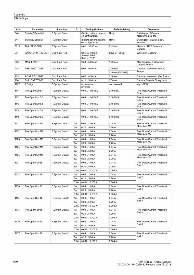
Appendix
A.8 Settings
SIPROTEC, 7UT6x, ManualC53000-G1176-C230-3, Release date 05.2013
610
840 SwitchgCBaux M5 P.System Data 1 (Setting options depend on configuration)
None Switchgear / CBaux at Measuring Loc. M5
841 SwitchgCBaux E1 P.System Data 1 (Setting options depend on configuration)
None Switchgear / CBaux at ext. location 1
851A TMin TRIP CMD P.System Data 1 0.01 .. 32.00 sec 0.15 sec Minimum TRIP Command Duration
901 WAVEFORMTRIGGER Osc. Fault Rec. Save w. PickupSave w. TRIPStart w. TRIP
Save w. Pickup Waveform Capture
903 MAX. LENGTH Osc. Fault Rec. 0.30 .. 5.00 sec 1.00 sec Max. length of a Waveform Capture Record
904 PRE. TRIG. TIME Osc. Fault Rec. 0.05 .. 0.50 sec 0.20 sec Captured Waveform Prior to Trigger
0.10 sec (7UT612)
905 POST REC. TIME Osc. Fault Rec. 0.05 .. 0.50 sec 0.10 sec Captured Waveform after Event
906 BinIn CAPT.TIME Osc. Fault Rec. 0.10 .. 5.00 sec; ∞ 0.50 sec Capture Time via Binary Input
1107 P,Q sign P.System Data 2 not reversedreversed
not reversed sign of P,Q
1111 PoleOpenCurr.S1 P.System Data 2 0.04 .. 1.00 I/InS 0.10 I/InS Pole Open Current Threshold Side 1
1112 PoleOpenCurr.S2 P.System Data 2 0.04 .. 1.00 I/InS 0.10 I/InS Pole Open Current Threshold Side 2
1113 PoleOpenCurr.S3 P.System Data 2 0.04 .. 1.00 I/InS 0.16 I/InS Pole Open Current Threshold Side 3
1114 PoleOpenCurr.S4 P.System Data 2 0.04 .. 1.00 I/InS 0.16 I/InS Pole Open Current Threshold Side 4
1115 PoleOpenCurr.S5 P.System Data 2 0.04 .. 1.00 I/InS 0.16 I/InS Pole Open Current Threshold Side 5
1121 PoleOpenCurr.M1 P.System Data 2 1A 0.04 .. 1.00 A 0.04 A Pole Open Current Threshold Meas.Loc. M1
5A 0.20 .. 5.00 A 0.20 A
1122 PoleOpenCurr.M2 P.System Data 2 1A 0.04 .. 1.00 A 0.04 A Pole Open Current Threshold Meas.Loc. M2
5A 0.20 .. 5.00 A 0.20 A
1123 PoleOpenCurr.M3 P.System Data 2 1A 0.04 .. 1.00 A 0.04 A Pole Open Current Threshold Meas.Loc. M3
5A 0.20 .. 5.00 A 0.20 A
1124 PoleOpenCurr.M4 P.System Data 2 1A 0.04 .. 1.00 A 0.04 A Pole Open Current Threshold Meas.Loc. M4
5A 0.20 .. 5.00 A 0.20 A
1125 PoleOpenCurr.M5 P.System Data 2 1A 0.04 .. 1.00 A 0.04 A Pole Open Current Threshold Meas.Loc. M5
5A 0.20 .. 5.00 A 0.20 A
1131 PoleOpenCurr I1 P.System Data 2 1A 0.04 .. 1.00 A 0.04 A Pole Open Current Threshold End 1
5A 0.20 .. 5.00 A 0.20 A
0.1A 0.004 .. 0.100 A 0.004 A
1132 PoleOpenCurr I2 P.System Data 2 1A 0.04 .. 1.00 A 0.04 A Pole Open Current Threshold End 2
5A 0.20 .. 5.00 A 0.20 A
0.1A 0.004 .. 0.100 A 0.004 A
1133 PoleOpenCurr I3 P.System Data 2 1A 0.04 .. 1.00 A 0.04 A Pole Open Current Threshold End 3
5A 0.20 .. 5.00 A 0.20 A
0.1A 0.004 .. 0.100 A 0.004 A
1134 PoleOpenCurr I4 P.System Data 2 1A 0.04 .. 1.00 A 0.04 A Pole Open Current Threshold End 4
5A 0.20 .. 5.00 A 0.20 A
0.1A 0.004 .. 0.100 A 0.004 A
1135 PoleOpenCurr I5 P.System Data 2 1A 0.04 .. 1.00 A 0.04 A Pole Open Current Threshold End 5
5A 0.20 .. 5.00 A 0.20 A
0.1A 0.004 .. 0.100 A 0.004 A
1136 PoleOpenCurr I6 P.System Data 2 1A 0.04 .. 1.00 A 0.04 A Pole Open Current Threshold End 6
5A 0.20 .. 5.00 A 0.20 A
0.1A 0.004 .. 0.100 A 0.004 A
1137 PoleOpenCurr I7 P.System Data 2 1A 0.04 .. 1.00 A 0.04 A Pole Open Current Threshold End 7
5A 0.20 .. 5.00 A 0.20 A
0.1A 0.004 .. 0.100 A 0.004 A
Addr. Parameter Function C Setting Options Default Setting Comments
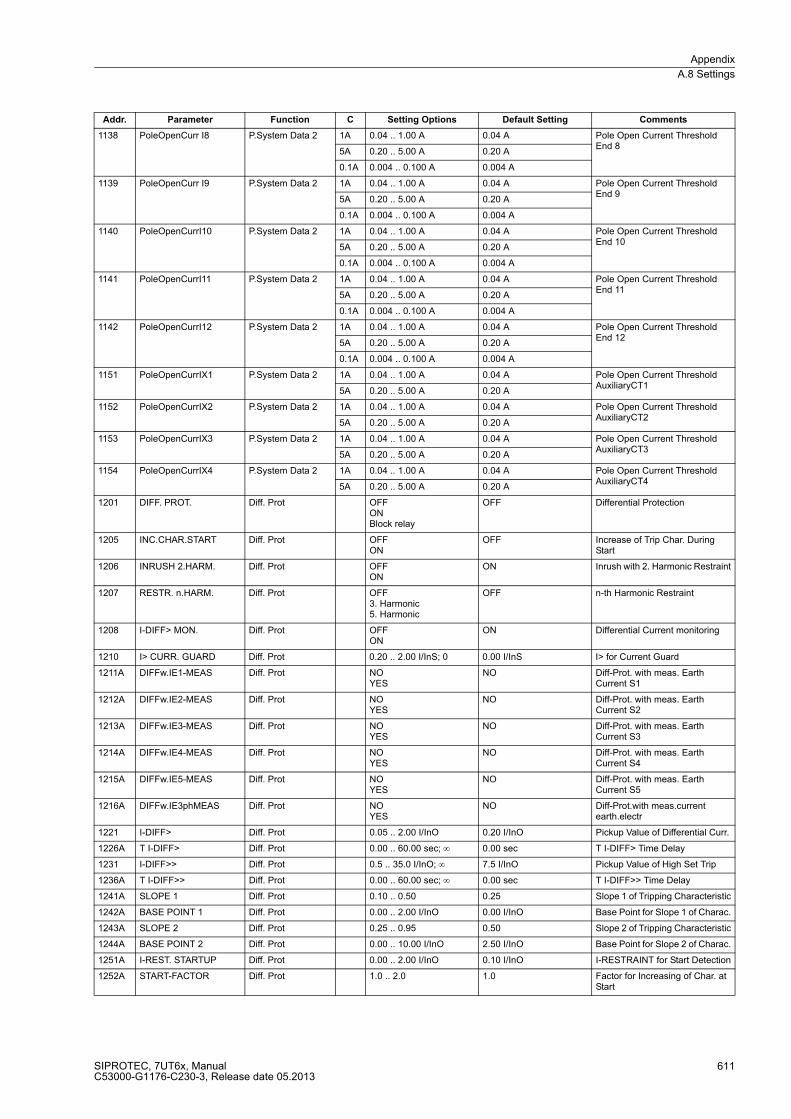
Appendix
A.8 Settings
SIPROTEC, 7UT6x, ManualC53000-G1176-C230-3, Release date 05.2013
611
1138 PoleOpenCurr I8 P.System Data 2 1A 0.04 .. 1.00 A 0.04 A Pole Open Current Threshold End 8
5A 0.20 .. 5.00 A 0.20 A
0.1A 0.004 .. 0.100 A 0.004 A
1139 PoleOpenCurr I9 P.System Data 2 1A 0.04 .. 1.00 A 0.04 A Pole Open Current Threshold End 9
5A 0.20 .. 5.00 A 0.20 A
0.1A 0.004 .. 0.100 A 0.004 A
1140 PoleOpenCurrI10 P.System Data 2 1A 0.04 .. 1.00 A 0.04 A Pole Open Current Threshold End 10
5A 0.20 .. 5.00 A 0.20 A
0.1A 0.004 .. 0.100 A 0.004 A
1141 PoleOpenCurrI11 P.System Data 2 1A 0.04 .. 1.00 A 0.04 A Pole Open Current Threshold End 11
5A 0.20 .. 5.00 A 0.20 A
0.1A 0.004 .. 0.100 A 0.004 A
1142 PoleOpenCurrI12 P.System Data 2 1A 0.04 .. 1.00 A 0.04 A Pole Open Current Threshold End 12
5A 0.20 .. 5.00 A 0.20 A
0.1A 0.004 .. 0.100 A 0.004 A
1151 PoleOpenCurrIX1 P.System Data 2 1A 0.04 .. 1.00 A 0.04 A Pole Open Current Threshold AuxiliaryCT1
5A 0.20 .. 5.00 A 0.20 A
1152 PoleOpenCurrIX2 P.System Data 2 1A 0.04 .. 1.00 A 0.04 A Pole Open Current Threshold AuxiliaryCT2
5A 0.20 .. 5.00 A 0.20 A
1153 PoleOpenCurrIX3 P.System Data 2 1A 0.04 .. 1.00 A 0.04 A Pole Open Current Threshold AuxiliaryCT3
5A 0.20 .. 5.00 A 0.20 A
1154 PoleOpenCurrIX4 P.System Data 2 1A 0.04 .. 1.00 A 0.04 A Pole Open Current Threshold AuxiliaryCT4
5A 0.20 .. 5.00 A 0.20 A
1201 DIFF. PROT. Diff. Prot OFFONBlock relay
OFF Differential Protection
1205 INC.CHAR.START Diff. Prot OFFON
OFF Increase of Trip Char. During Start
1206 INRUSH 2.HARM. Diff. Prot OFFON
ON Inrush with 2. Harmonic Restraint
1207 RESTR. n.HARM. Diff. Prot OFF3. Harmonic5. Harmonic
OFF n-th Harmonic Restraint
1208 I-DIFF> MON. Diff. Prot OFFON
ON Differential Current monitoring
1210 I> CURR. GUARD Diff. Prot 0.20 .. 2.00 I/InS; 0 0.00 I/InS I> for Current Guard
1211A DIFFw.IE1-MEAS Diff. Prot NOYES
NO Diff-Prot. with meas. Earth Current S1
1212A DIFFw.IE2-MEAS Diff. Prot NOYES
NO Diff-Prot. with meas. Earth Current S2
1213A DIFFw.IE3-MEAS Diff. Prot NOYES
NO Diff-Prot. with meas. Earth Current S3
1214A DIFFw.IE4-MEAS Diff. Prot NOYES
NO Diff-Prot. with meas. Earth Current S4
1215A DIFFw.IE5-MEAS Diff. Prot NOYES
NO Diff-Prot. with meas. Earth Current S5
1216A DIFFw.IE3phMEAS Diff. Prot NOYES
NO Diff-Prot.with meas.current earth.electr
1221 I-DIFF> Diff. Prot 0.05 .. 2.00 I/InO 0.20 I/InO Pickup Value of Differential Curr.
1226A T I-DIFF> Diff. Prot 0.00 .. 60.00 sec; ∞ 0.00 sec T I-DIFF> Time Delay
1231 I-DIFF>> Diff. Prot 0.5 .. 35.0 I/InO; ∞ 7.5 I/InO Pickup Value of High Set Trip
1236A T I-DIFF>> Diff. Prot 0.00 .. 60.00 sec; ∞ 0.00 sec T I-DIFF>> Time Delay
1241A SLOPE 1 Diff. Prot 0.10 .. 0.50 0.25 Slope 1 of Tripping Characteristic
1242A BASE POINT 1 Diff. Prot 0.00 .. 2.00 I/InO 0.00 I/InO Base Point for Slope 1 of Charac.
1243A SLOPE 2 Diff. Prot 0.25 .. 0.95 0.50 Slope 2 of Tripping Characteristic
1244A BASE POINT 2 Diff. Prot 0.00 .. 10.00 I/InO 2.50 I/InO Base Point for Slope 2 of Charac.
1251A I-REST. STARTUP Diff. Prot 0.00 .. 2.00 I/InO 0.10 I/InO I-RESTRAINT for Start Detection
1252A START-FACTOR Diff. Prot 1.0 .. 2.0 1.0 Factor for Increasing of Char. at Start
Addr. Parameter Function C Setting Options Default Setting Comments

Appendix
A.8 Settings
SIPROTEC, 7UT6x, ManualC53000-G1176-C230-3, Release date 05.2013
612
1253 T START MAX Diff. Prot 0.0 .. 180.0 sec 5.0 sec Maximum Permissible Starting Time
1261A I-ADD ON STAB. Diff. Prot 2.00 .. 15.00 I/InO 4.00 I/InO Pickup for Add-on Stabilization
1262A T ADD ON-STAB. Diff. Prot 2 .. 250 Cycle; ∞ 15 Cycle Duration of Add-on Stabilization
1263A CROSSB. ADD ON Diff. Prot 2 .. 1000 Cycle; 0; ∞ 15 Cycle Time for Cross-blocking Add-on Stabiliz.
1271 2. HARMONIC Diff. Prot 10 .. 80 % 15 % 2nd Harmonic Content in I-DIFF
1272A CROSSB. 2. HARM Diff. Prot 2 .. 1000 Cycle; 0; ∞ 3 Cycle Time for Cross-blocking 2nd Harm.
1276 n. HARMONIC Diff. Prot 10 .. 80 % 30 % n-th Harmonic Content in I-DIFF
1277A CROSSB. n.HARM Diff. Prot 2 .. 1000 Cycle; 0; ∞ 0 Cycle Time for Cross-blocking n-th Harm.
1278A IDIFFmax n.HM Diff. Prot 0.5 .. 20.0 I/InO 1.5 I/InO Limit IDIFFmax of n-th Harm.Restraint
1281 I-DIFF> MON. Diff. Prot 0.15 .. 0.80 I/InO 0.20 I/InO Pickup Value of diff. Current Monitoring
1282 T I-DIFF> MON. Diff. Prot 1 .. 10 sec 2 sec T I-DIFF> Monitoring Time Delay
1301 REF PROT. REF OFFONBlock relay
OFF Restricted Earth Fault Protection
1311 I-REF> REF 0.05 .. 2.00 I/InS 0.15 I/InS Pick up value I REF>
1312A T I-REF> REF 0.00 .. 60.00 sec; ∞ 0.00 sec T I-REF> Time Delay
1313A SLOPE REF 0.00 .. 0.95 0.00 Slope of Charac. I-REF> = f(I-SUM)
1401 REF PROT. REF 2 OFFONBlock relay
OFF Restricted Earth Fault Protection
1411 I-REF> REF 2 0.05 .. 2.00 I/InS 0.15 I/InS Pick up value I REF>
1412A T I-REF> REF 2 0.00 .. 60.00 sec; ∞ 0.00 sec T I-REF> Time Delay
1413A SLOPE REF 2 0.00 .. 0.95 0.00 Slope of Charac. I-REF> = f(I-SUM)
1701 COLDLOAD PICKUP ColdLoadPickup OFFON
OFF Cold-Load-Pickup Function
1702 Start CLP Phase ColdLoadPickup No CurrentBreaker Contact
No Current Start Condition CLP for O/C Phase
1703 Start CLP 3I0 ColdLoadPickup No CurrentBreaker Contact
No Current Start Condition CLP for O/C 3I0
1704 Start CLP Earth ColdLoadPickup No CurrentBreaker Contact
No Current Start Condition CLP for O/C Earth
1705 Start CLP Ph 2 ColdLoadPickup No CurrentBreaker Contact
No Current Start Condition CLP for O/C Phase 2
1706 Start CLP Ph 3 ColdLoadPickup No CurrentBreaker Contact
No Current Start Condition CLP for O/C Phase 3
1707 Start CLP 3I0 2 ColdLoadPickup No CurrentBreaker Contact
No Current Start Condition CLP for O/C 3I0 2
1708 Start CLP 3I0 3 ColdLoadPickup No CurrentBreaker Contact
No Current Start Condition CLP for O/C 3I0 3
1709 Start CLP E 2 ColdLoadPickup No CurrentBreaker Contact
No Current Start Condition CLP for O/C Earth 2
1711 CB Open Time ColdLoadPickup 0 .. 21600 sec 3600 sec Circuit Breaker OPEN Time
1712 Active Time ColdLoadPickup 1 .. 21600 sec 3600 sec Active Time
1713 Stop Time ColdLoadPickup 1 .. 600 sec; ∞ 600 sec Stop Time
2001 PHASE O/C Phase O/C ONOFFBlock relay
OFF Phase Time Overcurrent
2002 InRushRest. Ph Phase O/C ONOFF
OFF InRush Restrained O/C Phase
2008A MANUAL CLOSE Phase O/C I>> instant.I> instant.Ip instant.Inactive
I>> instant. O/C Manual Close Mode
2011 I>> Phase O/C 1A 0.10 .. 35.00 A; ∞ 4.00 A I>> Pickup
5A 0.50 .. 175.00 A; ∞ 20.00 A
Addr. Parameter Function C Setting Options Default Setting Comments

Appendix
A.8 Settings
SIPROTEC, 7UT6x, ManualC53000-G1176-C230-3, Release date 05.2013
613
2012 I>> Phase O/C 0.10 .. 35.00 I/InS; ∞ 4.00 I/InS I>> Pickup
2013 T I>> Phase O/C 0.00 .. 60.00 sec; ∞ 0.10 sec T I>> Time Delay
2014 I> Phase O/C 1A 0.10 .. 35.00 A; ∞ 2.00 A I> Pickup
5A 0.50 .. 175.00 A; ∞ 10.00 A
2015 I> Phase O/C 0.10 .. 35.00 I/InS; ∞ 2.00 I/InS I> Pickup
2016 T I> Phase O/C 0.00 .. 60.00 sec; ∞ 0.30 sec T I> Time Delay
2021 Ip Phase O/C 1A 0.10 .. 4.00 A 2.00 A Ip Pickup
5A 0.50 .. 20.00 A 10.00 A
2022 Ip Phase O/C 0.10 .. 4.00 I/InS 2.00 I/InS Ip Pickup
2023 T Ip Phase O/C 0.05 .. 3.20 sec; ∞ 0.50 sec T Ip Time Dial
2024 D Ip Phase O/C 0.50 .. 15.00 ; ∞ 5.00 D Ip Time Dial
2025 TOC DROP-OUT Phase O/C InstantaneousDisk Emulation
Disk Emulation TOC Drop-out characteristic
2026 IEC CURVE Phase O/C Normal InverseVery InverseExtremely Inv.Long Inverse
Normal Inverse IEC Curve
2027 ANSI CURVE Phase O/C Very InverseInverseShort InverseLong InverseModerately Inv.Extremely Inv.Definite Inv.
Very Inverse ANSI Curve
2031 I/Ip PU T/Tp Phase O/C 1.00 .. 20.00 I/Ip; ∞0.01 .. 999.00 TD
Pickup Curve I/Ip - TI/TIp
2032 MofPU Res T/Tp Phase O/C 0.05 .. 0.95 I/Ip; ∞0.01 .. 999.00 TD
Multiple of Pickup <-> TI/TIp
2041 2.HARM. Phase Phase O/C 10 .. 45 % 15 % 2nd harmonic O/C Ph. in % of fundamental
2042 I Max InRr. Ph. Phase O/C 1A 0.30 .. 25.00 A 7.50 A Maximum Current for Inr. Rest. O/C Phase
5A 1.50 .. 125.00 A 37.50 A
2043 I Max InRr. Ph. Phase O/C 0.30 .. 25.00 I/InS 7.50 I/InS Maximum Current for Inr. Rest. O/C Phase
2044 CROSS BLK.Phase Phase O/C NOYES
NO CROSS BLOCK O/C Phase
2045 T CROSS BLK.Ph Phase O/C 0.00 .. 180.00 sec 0.00 sec CROSS BLOCK Time O/C Phase
2111 I>> Phase O/C 1A 0.10 .. 35.00 A; ∞ 10.00 A I>> Pickup
5A 0.50 .. 175.00 A; ∞ 50.00 A
2112 I>> Phase O/C 0.10 .. 35.00 I/InS; ∞ 10.00 I/InS I>> Pickup
2113 T I>> Phase O/C 0.00 .. 60.00 sec; ∞ 0.10 sec T I>> Time Delay
2114 I> Phase O/C 1A 0.10 .. 35.00 A; ∞ 4.00 A I> Pickup
5A 0.50 .. 175.00 A; ∞ 20.00 A
2115 I> Phase O/C 0.10 .. 35.00 I/InS; ∞ 4.00 I/InS I> Pickup
2116 T I> Phase O/C 0.00 .. 60.00 sec; ∞ 0.30 sec T I> Time Delay
2121 Ip Phase O/C 1A 0.10 .. 4.00 A 4.00 A Ip Pickup
5A 0.50 .. 20.00 A 20.00 A
2122 Ip Phase O/C 0.10 .. 4.00 I/InS 4.00 I/InS Ip Pickup
2123 T Ip Phase O/C 0.05 .. 3.20 sec; ∞ 0.50 sec T Ip Time Dial
2124 D Ip Phase O/C 0.50 .. 15.00 ; ∞ 5.00 D Ip Time Dial
2201 3I0 O/C 3I0 O/C ONOFFBlock relay
OFF 3I0 Time Overcurrent
2202 InRushRest. 3I0 3I0 O/C ONOFF
OFF InRush Restrained O/C 3I0
2208A 3I0 MAN. CLOSE 3I0 O/C 3I0>> instant.3I0> instant.3I0p instant.Inactive
3I0>> instant. O/C 3I0 Manual Close Mode
2211 3I0>> 3I0 O/C 1A 0.05 .. 35.00 A; ∞ 1.00 A 3I0>> Pickup
5A 0.25 .. 175.00 A; ∞ 5.00 A
Addr. Parameter Function C Setting Options Default Setting Comments
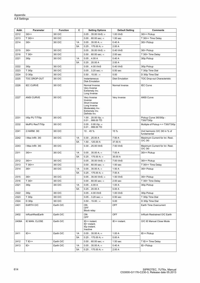
Appendix
A.8 Settings
SIPROTEC, 7UT6x, ManualC53000-G1176-C230-3, Release date 05.2013
614
2212 3I0>> 3I0 O/C 0.05 .. 35.00 I/InS; ∞ 1.00 I/InS 3I0>> Pickup
2213 T 3I0>> 3I0 O/C 0.00 .. 60.00 sec; ∞ 1.50 sec T 3I0>> Time Delay
2214 3I0> 3I0 O/C 1A 0.05 .. 35.00 A; ∞ 0.40 A 3I0> Pickup
5A 0.25 .. 175.00 A; ∞ 2.00 A
2215 3I0> 3I0 O/C 0.05 .. 35.00 I/InS; ∞ 0.40 I/InS 3I0> Pickup
2216 T 3I0> 3I0 O/C 0.00 .. 60.00 sec; ∞ 2.00 sec T 3I0> Time Delay
2221 3I0p 3I0 O/C 1A 0.05 .. 4.00 A 0.40 A 3I0p Pickup
5A 0.25 .. 20.00 A 2.00 A
2222 3I0p 3I0 O/C 0.05 .. 4.00 I/InS 0.40 I/InS 3I0p Pickup
2223 T 3I0p 3I0 O/C 0.05 .. 3.20 sec; ∞ 0.50 sec T 3I0p Time Dial
2224 D 3I0p 3I0 O/C 0.50 .. 15.00 ; ∞ 5.00 D 3I0p Time Dial
2225 TOC DROP-OUT 3I0 O/C InstantaneousDisk Emulation
Disk Emulation TOC Drop-out Characteristic
2226 IEC CURVE 3I0 O/C Normal InverseVery InverseExtremely Inv.Long Inverse
Normal Inverse IEC Curve
2227 ANSI CURVE 3I0 O/C Very InverseInverseShort InverseLong InverseModerately Inv.Extremely Inv.Definite Inv.
Very Inverse ANSI Curve
2231 I/I0p PU T/TI0p 3I0 O/C 1.00 .. 20.00 I/Ip; ∞0.01 .. 999.00 TD
Pickup Curve 3I0/3I0p - T3I0/T3I0p
2232 MofPU ResT/TI0p 3I0 O/C 0.05 .. 0.95 I/Ip; ∞0.01 .. 999.00 TD
Multiple of Pickup <-> T3I0/T3I0p
2241 2.HARM. 3I0 3I0 O/C 10 .. 45 % 15 % 2nd harmonic O/C 3I0 in % of fundamental
2242 I Max InRr. 3I0 3I0 O/C 1A 0.30 .. 25.00 A 7.50 A Maximum Current for Inr. Rest. O/C 3I0
5A 1.50 .. 125.00 A 37.50 A
2243 I Max InRr. 3I0 3I0 O/C 0.30 .. 25.00 I/InS 7.50 I/InS Maximum Current for Inr. Rest. O/C 3I0
2311 3I0>> 3I0 O/C 1A 0.05 .. 35.00 A; ∞ 7.00 A 3I0>> Pickup
5A 0.25 .. 175.00 A; ∞ 35.00 A
2312 3I0>> 3I0 O/C 0.05 .. 35.00 I/InS; ∞ 7.00 I/InS 3I0>> Pickup
2313 T 3I0>> 3I0 O/C 0.00 .. 60.00 sec; ∞ 1.50 sec T 3I0>> Time Delay
2314 3I0> 3I0 O/C 1A 0.05 .. 35.00 A; ∞ 1.50 A 3I0> Pickup
5A 0.25 .. 175.00 A; ∞ 7.50 A
2315 3I0> 3I0 O/C 0.05 .. 35.00 I/InS; ∞ 1.50 I/InS 3I0> Pickup
2316 T 3I0> 3I0 O/C 0.00 .. 60.00 sec; ∞ 2.00 sec T 3I0> Time Delay
2321 3I0p 3I0 O/C 1A 0.05 .. 4.00 A 1.00 A 3I0p Pickup
5A 0.25 .. 20.00 A 5.00 A
2322 3I0p 3I0 O/C 0.05 .. 4.00 I/InS 1.00 I/InS 3I0p Pickup
2323 T 3I0p 3I0 O/C 0.05 .. 3.20 sec; ∞ 0.50 sec T 3I0p Time Dial
2324 D 3I0p 3I0 O/C 0.50 .. 15.00 ; ∞ 5.00 D 3I0p Time Dial
2401 EARTH O/C Earth O/C ONOFFBlock relay
OFF Earth Time Overcurrent
2402 InRushRestEarth Earth O/C ONOFF
OFF InRush Restrained O/C Earth
2408A IE MAN. CLOSE Earth O/C IE>> instant.IE> instant.IEp instant.Inactive
IE>> instant. O/C IE Manual Close Mode
2411 IE>> Earth O/C 1A 0.05 .. 35.00 A; ∞ 1.00 A IE>> Pickup
5A 0.25 .. 175.00 A; ∞ 5.00 A
2412 T IE>> Earth O/C 0.00 .. 60.00 sec; ∞ 1.50 sec T IE>> Time Delay
2413 IE> Earth O/C 1A 0.05 .. 35.00 A; ∞ 0.40 A IE> Pickup
5A 0.25 .. 175.00 A; ∞ 2.00 A
Addr. Parameter Function C Setting Options Default Setting Comments
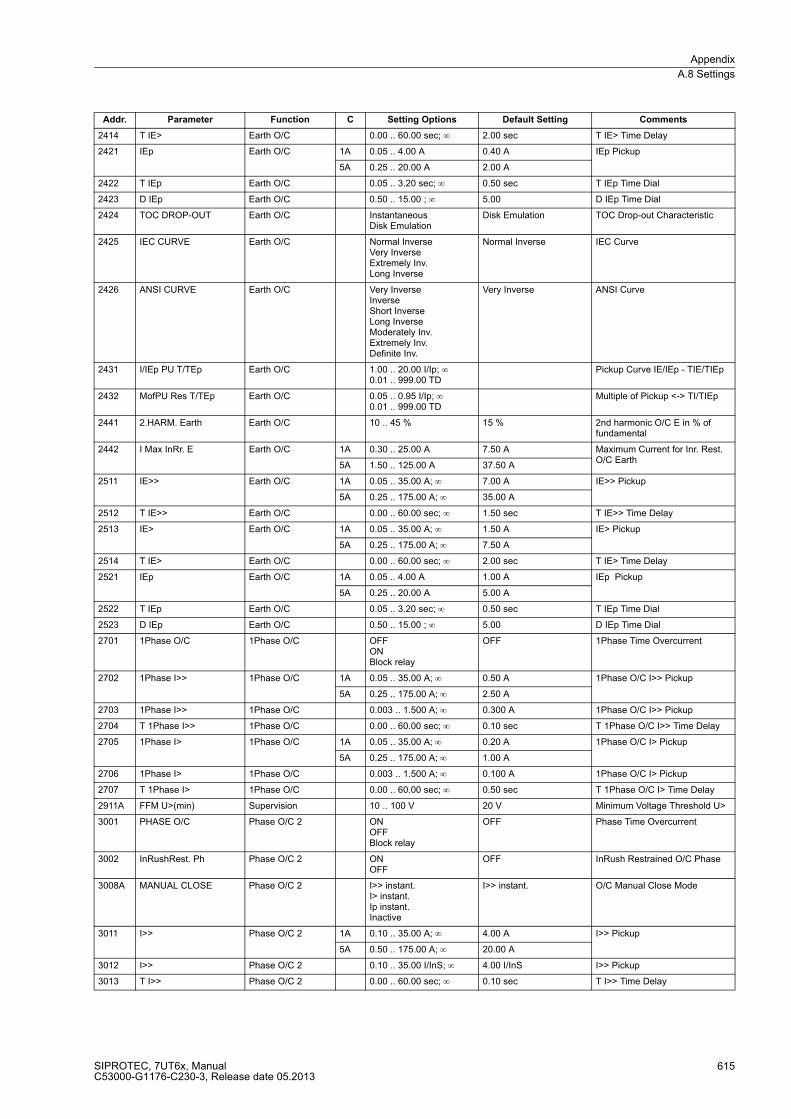
Appendix
A.8 Settings
SIPROTEC, 7UT6x, ManualC53000-G1176-C230-3, Release date 05.2013
615
2414 T IE> Earth O/C 0.00 .. 60.00 sec; ∞ 2.00 sec T IE> Time Delay
2421 IEp Earth O/C 1A 0.05 .. 4.00 A 0.40 A IEp Pickup
5A 0.25 .. 20.00 A 2.00 A
2422 T IEp Earth O/C 0.05 .. 3.20 sec; ∞ 0.50 sec T IEp Time Dial
2423 D IEp Earth O/C 0.50 .. 15.00 ; ∞ 5.00 D IEp Time Dial
2424 TOC DROP-OUT Earth O/C InstantaneousDisk Emulation
Disk Emulation TOC Drop-out Characteristic
2425 IEC CURVE Earth O/C Normal InverseVery InverseExtremely Inv.Long Inverse
Normal Inverse IEC Curve
2426 ANSI CURVE Earth O/C Very InverseInverseShort InverseLong InverseModerately Inv.Extremely Inv.Definite Inv.
Very Inverse ANSI Curve
2431 I/IEp PU T/TEp Earth O/C 1.00 .. 20.00 I/Ip; ∞0.01 .. 999.00 TD
Pickup Curve IE/IEp - TIE/TIEp
2432 MofPU Res T/TEp Earth O/C 0.05 .. 0.95 I/Ip; ∞0.01 .. 999.00 TD
Multiple of Pickup <-> TI/TIEp
2441 2.HARM. Earth Earth O/C 10 .. 45 % 15 % 2nd harmonic O/C E in % of fundamental
2442 I Max InRr. E Earth O/C 1A 0.30 .. 25.00 A 7.50 A Maximum Current for Inr. Rest. O/C Earth
5A 1.50 .. 125.00 A 37.50 A
2511 IE>> Earth O/C 1A 0.05 .. 35.00 A; ∞ 7.00 A IE>> Pickup
5A 0.25 .. 175.00 A; ∞ 35.00 A
2512 T IE>> Earth O/C 0.00 .. 60.00 sec; ∞ 1.50 sec T IE>> Time Delay
2513 IE> Earth O/C 1A 0.05 .. 35.00 A; ∞ 1.50 A IE> Pickup
5A 0.25 .. 175.00 A; ∞ 7.50 A
2514 T IE> Earth O/C 0.00 .. 60.00 sec; ∞ 2.00 sec T IE> Time Delay
2521 IEp Earth O/C 1A 0.05 .. 4.00 A 1.00 A IEp Pickup
5A 0.25 .. 20.00 A 5.00 A
2522 T IEp Earth O/C 0.05 .. 3.20 sec; ∞ 0.50 sec T IEp Time Dial
2523 D IEp Earth O/C 0.50 .. 15.00 ; ∞ 5.00 D IEp Time Dial
2701 1Phase O/C 1Phase O/C OFFONBlock relay
OFF 1Phase Time Overcurrent
2702 1Phase I>> 1Phase O/C 1A 0.05 .. 35.00 A; ∞ 0.50 A 1Phase O/C I>> Pickup
5A 0.25 .. 175.00 A; ∞ 2.50 A
2703 1Phase I>> 1Phase O/C 0.003 .. 1.500 A; ∞ 0.300 A 1Phase O/C I>> Pickup
2704 T 1Phase I>> 1Phase O/C 0.00 .. 60.00 sec; ∞ 0.10 sec T 1Phase O/C I>> Time Delay
2705 1Phase I> 1Phase O/C 1A 0.05 .. 35.00 A; ∞ 0.20 A 1Phase O/C I> Pickup
5A 0.25 .. 175.00 A; ∞ 1.00 A
2706 1Phase I> 1Phase O/C 0.003 .. 1.500 A; ∞ 0.100 A 1Phase O/C I> Pickup
2707 T 1Phase I> 1Phase O/C 0.00 .. 60.00 sec; ∞ 0.50 sec T 1Phase O/C I> Time Delay
2911A FFM U>(min) Supervision 10 .. 100 V 20 V Minimum Voltage Threshold U>
3001 PHASE O/C Phase O/C 2 ONOFFBlock relay
OFF Phase Time Overcurrent
3002 InRushRest. Ph Phase O/C 2 ONOFF
OFF InRush Restrained O/C Phase
3008A MANUAL CLOSE Phase O/C 2 I>> instant.I> instant.Ip instant.Inactive
I>> instant. O/C Manual Close Mode
3011 I>> Phase O/C 2 1A 0.10 .. 35.00 A; ∞ 4.00 A I>> Pickup
5A 0.50 .. 175.00 A; ∞ 20.00 A
3012 I>> Phase O/C 2 0.10 .. 35.00 I/InS; ∞ 4.00 I/InS I>> Pickup
3013 T I>> Phase O/C 2 0.00 .. 60.00 sec; ∞ 0.10 sec T I>> Time Delay
Addr. Parameter Function C Setting Options Default Setting Comments

Appendix
A.8 Settings
SIPROTEC, 7UT6x, ManualC53000-G1176-C230-3, Release date 05.2013
616
3014 I> Phase O/C 2 1A 0.10 .. 35.00 A; ∞ 2.00 A I> Pickup
5A 0.50 .. 175.00 A; ∞ 10.00 A
3015 I> Phase O/C 2 0.10 .. 35.00 I/InS; ∞ 2.00 I/InS I> Pickup
3016 T I> Phase O/C 2 0.00 .. 60.00 sec; ∞ 0.30 sec T I> Time Delay
3021 Ip Phase O/C 2 1A 0.10 .. 4.00 A 2.00 A Ip Pickup
5A 0.50 .. 20.00 A 10.00 A
3022 Ip Phase O/C 2 0.10 .. 4.00 I/InS 2.00 I/InS Ip Pickup
3023 T Ip Phase O/C 2 0.05 .. 3.20 sec; ∞ 0.50 sec T Ip Time Dial
3024 D Ip Phase O/C 2 0.50 .. 15.00 ; ∞ 5.00 D Ip Time Dial
3025 TOC DROP-OUT Phase O/C 2 InstantaneousDisk Emulation
Disk Emulation TOC Drop-out characteristic
3026 IEC CURVE Phase O/C 2 Normal InverseVery InverseExtremely Inv.Long Inverse
Normal Inverse IEC Curve
3027 ANSI CURVE Phase O/C 2 Very InverseInverseShort InverseLong InverseModerately Inv.Extremely Inv.Definite Inv.
Very Inverse ANSI Curve
3031 I/Ip PU T/Tp Phase O/C 2 1.00 .. 20.00 I/Ip; ∞0.01 .. 999.00 TD
Pickup Curve I/Ip - TI/TIp
3032 MofPU Res T/Tp Phase O/C 2 0.05 .. 0.95 I/Ip; ∞0.01 .. 999.00 TD
Multiple of Pickup <-> TI/TIp
3041 2.HARM. Phase Phase O/C 2 10 .. 45 % 15 % 2nd harmonic O/C Ph. in % of fundamental
3042 I Max InRr. Ph. Phase O/C 2 1A 0.30 .. 25.00 A 7.50 A Maximum Current for Inr. Rest. O/C Phase
5A 1.50 .. 125.00 A 37.50 A
3043 I Max InRr. Ph. Phase O/C 2 0.30 .. 25.00 I/InS 7.50 I/InS Maximum Current for Inr. Rest. O/C Phase
3044 CROSS BLK.Phase Phase O/C 2 NOYES
NO CROSS BLOCK O/C Phase
3045 T CROSS BLK.Ph Phase O/C 2 0.00 .. 180.00 sec 0.00 sec CROSS BLOCK Time O/C Phase
3111 I>> Phase O/C 2 1A 0.10 .. 35.00 A; ∞ 10.00 A I>> Pickup
5A 0.50 .. 175.00 A; ∞ 50.00 A
3112 I>> Phase O/C 2 0.10 .. 35.00 I/InS; ∞ 10.00 I/InS I>> Pickup
3113 T I>> Phase O/C 2 0.00 .. 60.00 sec; ∞ 0.10 sec T I>> Time Delay
3114 I> Phase O/C 2 1A 0.10 .. 35.00 A; ∞ 4.00 A I> Pickup
5A 0.50 .. 175.00 A; ∞ 20.00 A
3115 I> Phase O/C 2 0.10 .. 35.00 I/InS; ∞ 4.00 I/InS I> Pickup
3116 T I> Phase O/C 2 0.00 .. 60.00 sec; ∞ 0.30 sec T I> Time Delay
3121 Ip Phase O/C 2 1A 0.10 .. 4.00 A 4.00 A Ip Pickup
5A 0.50 .. 20.00 A 20.00 A
3122 Ip Phase O/C 2 0.10 .. 4.00 I/InS 4.00 I/InS Ip Pickup
3123 T Ip Phase O/C 2 0.05 .. 3.20 sec; ∞ 0.50 sec T Ip Time Dial
3124 D Ip Phase O/C 2 0.50 .. 15.00 ; ∞ 5.00 D Ip Time Dial
3201 PHASE O/C Phase O/C 3 ONOFFBlock relay
OFF Phase Time Overcurrent
3202 InRushRest. Ph Phase O/C 3 ONOFF
OFF InRush Restrained O/C Phase
3208A MANUAL CLOSE Phase O/C 3 I>> instant.I> instant.Ip instant.Inactive
I>> instant. O/C Manual Close Mode
3211 I>> Phase O/C 3 1A 0.10 .. 35.00 A; ∞ 4.00 A I>> Pickup
5A 0.50 .. 175.00 A; ∞ 20.00 A
3212 I>> Phase O/C 3 0.10 .. 35.00 I/InS; ∞ 4.00 I/InS I>> Pickup
3213 T I>> Phase O/C 3 0.00 .. 60.00 sec; ∞ 0.10 sec T I>> Time Delay
Addr. Parameter Function C Setting Options Default Setting Comments
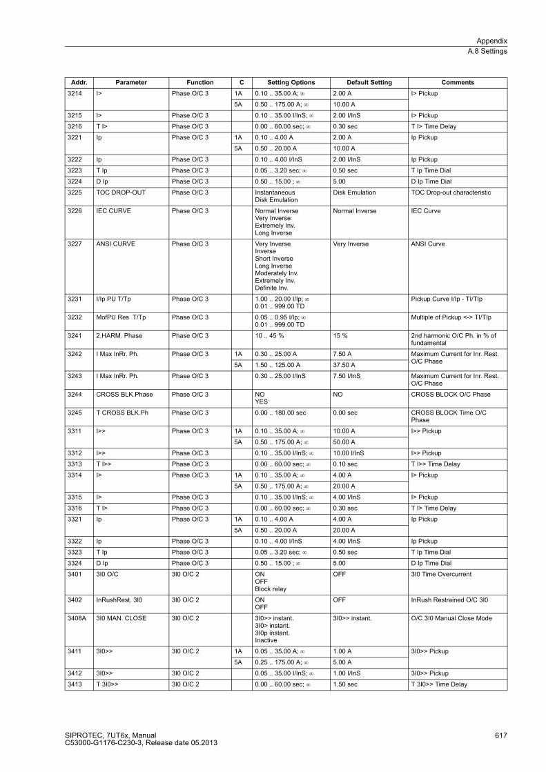
Appendix
A.8 Settings
SIPROTEC, 7UT6x, ManualC53000-G1176-C230-3, Release date 05.2013
617
3214 I> Phase O/C 3 1A 0.10 .. 35.00 A; ∞ 2.00 A I> Pickup
5A 0.50 .. 175.00 A; ∞ 10.00 A
3215 I> Phase O/C 3 0.10 .. 35.00 I/InS; ∞ 2.00 I/InS I> Pickup
3216 T I> Phase O/C 3 0.00 .. 60.00 sec; ∞ 0.30 sec T I> Time Delay
3221 Ip Phase O/C 3 1A 0.10 .. 4.00 A 2.00 A Ip Pickup
5A 0.50 .. 20.00 A 10.00 A
3222 Ip Phase O/C 3 0.10 .. 4.00 I/InS 2.00 I/InS Ip Pickup
3223 T Ip Phase O/C 3 0.05 .. 3.20 sec; ∞ 0.50 sec T Ip Time Dial
3224 D Ip Phase O/C 3 0.50 .. 15.00 ; ∞ 5.00 D Ip Time Dial
3225 TOC DROP-OUT Phase O/C 3 InstantaneousDisk Emulation
Disk Emulation TOC Drop-out characteristic
3226 IEC CURVE Phase O/C 3 Normal InverseVery InverseExtremely Inv.Long Inverse
Normal Inverse IEC Curve
3227 ANSI CURVE Phase O/C 3 Very InverseInverseShort InverseLong InverseModerately Inv.Extremely Inv.Definite Inv.
Very Inverse ANSI Curve
3231 I/Ip PU T/Tp Phase O/C 3 1.00 .. 20.00 I/Ip; ∞0.01 .. 999.00 TD
Pickup Curve I/Ip - TI/TIp
3232 MofPU Res T/Tp Phase O/C 3 0.05 .. 0.95 I/Ip; ∞0.01 .. 999.00 TD
Multiple of Pickup <-> TI/TIp
3241 2.HARM. Phase Phase O/C 3 10 .. 45 % 15 % 2nd harmonic O/C Ph. in % of fundamental
3242 I Max InRr. Ph. Phase O/C 3 1A 0.30 .. 25.00 A 7.50 A Maximum Current for Inr. Rest. O/C Phase
5A 1.50 .. 125.00 A 37.50 A
3243 I Max InRr. Ph. Phase O/C 3 0.30 .. 25.00 I/InS 7.50 I/InS Maximum Current for Inr. Rest. O/C Phase
3244 CROSS BLK.Phase Phase O/C 3 NOYES
NO CROSS BLOCK O/C Phase
3245 T CROSS BLK.Ph Phase O/C 3 0.00 .. 180.00 sec 0.00 sec CROSS BLOCK Time O/C Phase
3311 I>> Phase O/C 3 1A 0.10 .. 35.00 A; ∞ 10.00 A I>> Pickup
5A 0.50 .. 175.00 A; ∞ 50.00 A
3312 I>> Phase O/C 3 0.10 .. 35.00 I/InS; ∞ 10.00 I/InS I>> Pickup
3313 T I>> Phase O/C 3 0.00 .. 60.00 sec; ∞ 0.10 sec T I>> Time Delay
3314 I> Phase O/C 3 1A 0.10 .. 35.00 A; ∞ 4.00 A I> Pickup
5A 0.50 .. 175.00 A; ∞ 20.00 A
3315 I> Phase O/C 3 0.10 .. 35.00 I/InS; ∞ 4.00 I/InS I> Pickup
3316 T I> Phase O/C 3 0.00 .. 60.00 sec; ∞ 0.30 sec T I> Time Delay
3321 Ip Phase O/C 3 1A 0.10 .. 4.00 A 4.00 A Ip Pickup
5A 0.50 .. 20.00 A 20.00 A
3322 Ip Phase O/C 3 0.10 .. 4.00 I/InS 4.00 I/InS Ip Pickup
3323 T Ip Phase O/C 3 0.05 .. 3.20 sec; ∞ 0.50 sec T Ip Time Dial
3324 D Ip Phase O/C 3 0.50 .. 15.00 ; ∞ 5.00 D Ip Time Dial
3401 3I0 O/C 3I0 O/C 2 ONOFFBlock relay
OFF 3I0 Time Overcurrent
3402 InRushRest. 3I0 3I0 O/C 2 ONOFF
OFF InRush Restrained O/C 3I0
3408A 3I0 MAN. CLOSE 3I0 O/C 2 3I0>> instant.3I0> instant.3I0p instant.Inactive
3I0>> instant. O/C 3I0 Manual Close Mode
3411 3I0>> 3I0 O/C 2 1A 0.05 .. 35.00 A; ∞ 1.00 A 3I0>> Pickup
5A 0.25 .. 175.00 A; ∞ 5.00 A
3412 3I0>> 3I0 O/C 2 0.05 .. 35.00 I/InS; ∞ 1.00 I/InS 3I0>> Pickup
3413 T 3I0>> 3I0 O/C 2 0.00 .. 60.00 sec; ∞ 1.50 sec T 3I0>> Time Delay
Addr. Parameter Function C Setting Options Default Setting Comments
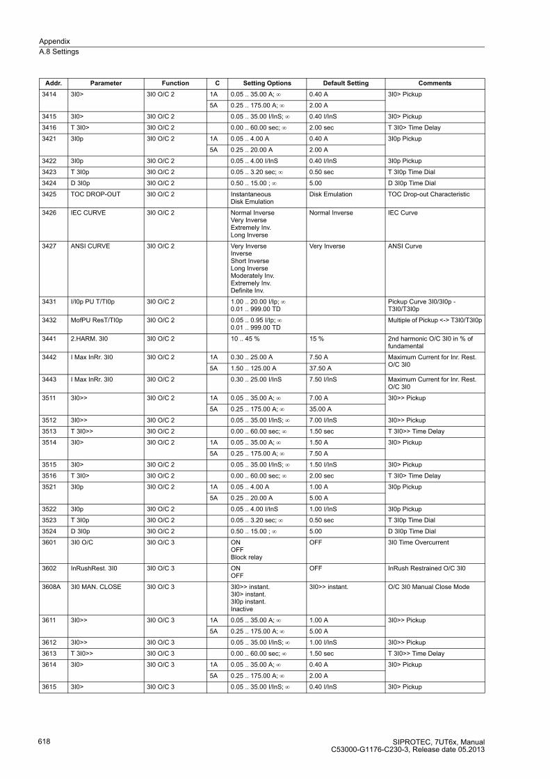
Appendix
A.8 Settings
SIPROTEC, 7UT6x, ManualC53000-G1176-C230-3, Release date 05.2013
618
3414 3I0> 3I0 O/C 2 1A 0.05 .. 35.00 A; ∞ 0.40 A 3I0> Pickup
5A 0.25 .. 175.00 A; ∞ 2.00 A
3415 3I0> 3I0 O/C 2 0.05 .. 35.00 I/InS; ∞ 0.40 I/InS 3I0> Pickup
3416 T 3I0> 3I0 O/C 2 0.00 .. 60.00 sec; ∞ 2.00 sec T 3I0> Time Delay
3421 3I0p 3I0 O/C 2 1A 0.05 .. 4.00 A 0.40 A 3I0p Pickup
5A 0.25 .. 20.00 A 2.00 A
3422 3I0p 3I0 O/C 2 0.05 .. 4.00 I/InS 0.40 I/InS 3I0p Pickup
3423 T 3I0p 3I0 O/C 2 0.05 .. 3.20 sec; ∞ 0.50 sec T 3I0p Time Dial
3424 D 3I0p 3I0 O/C 2 0.50 .. 15.00 ; ∞ 5.00 D 3I0p Time Dial
3425 TOC DROP-OUT 3I0 O/C 2 InstantaneousDisk Emulation
Disk Emulation TOC Drop-out Characteristic
3426 IEC CURVE 3I0 O/C 2 Normal InverseVery InverseExtremely Inv.Long Inverse
Normal Inverse IEC Curve
3427 ANSI CURVE 3I0 O/C 2 Very InverseInverseShort InverseLong InverseModerately Inv.Extremely Inv.Definite Inv.
Very Inverse ANSI Curve
3431 I/I0p PU T/TI0p 3I0 O/C 2 1.00 .. 20.00 I/Ip; ∞0.01 .. 999.00 TD
Pickup Curve 3I0/3I0p - T3I0/T3I0p
3432 MofPU ResT/TI0p 3I0 O/C 2 0.05 .. 0.95 I/Ip; ∞0.01 .. 999.00 TD
Multiple of Pickup <-> T3I0/T3I0p
3441 2.HARM. 3I0 3I0 O/C 2 10 .. 45 % 15 % 2nd harmonic O/C 3I0 in % of fundamental
3442 I Max InRr. 3I0 3I0 O/C 2 1A 0.30 .. 25.00 A 7.50 A Maximum Current for Inr. Rest. O/C 3I0
5A 1.50 .. 125.00 A 37.50 A
3443 I Max InRr. 3I0 3I0 O/C 2 0.30 .. 25.00 I/InS 7.50 I/InS Maximum Current for Inr. Rest. O/C 3I0
3511 3I0>> 3I0 O/C 2 1A 0.05 .. 35.00 A; ∞ 7.00 A 3I0>> Pickup
5A 0.25 .. 175.00 A; ∞ 35.00 A
3512 3I0>> 3I0 O/C 2 0.05 .. 35.00 I/InS; ∞ 7.00 I/InS 3I0>> Pickup
3513 T 3I0>> 3I0 O/C 2 0.00 .. 60.00 sec; ∞ 1.50 sec T 3I0>> Time Delay
3514 3I0> 3I0 O/C 2 1A 0.05 .. 35.00 A; ∞ 1.50 A 3I0> Pickup
5A 0.25 .. 175.00 A; ∞ 7.50 A
3515 3I0> 3I0 O/C 2 0.05 .. 35.00 I/InS; ∞ 1.50 I/InS 3I0> Pickup
3516 T 3I0> 3I0 O/C 2 0.00 .. 60.00 sec; ∞ 2.00 sec T 3I0> Time Delay
3521 3I0p 3I0 O/C 2 1A 0.05 .. 4.00 A 1.00 A 3I0p Pickup
5A 0.25 .. 20.00 A 5.00 A
3522 3I0p 3I0 O/C 2 0.05 .. 4.00 I/InS 1.00 I/InS 3I0p Pickup
3523 T 3I0p 3I0 O/C 2 0.05 .. 3.20 sec; ∞ 0.50 sec T 3I0p Time Dial
3524 D 3I0p 3I0 O/C 2 0.50 .. 15.00 ; ∞ 5.00 D 3I0p Time Dial
3601 3I0 O/C 3I0 O/C 3 ONOFFBlock relay
OFF 3I0 Time Overcurrent
3602 InRushRest. 3I0 3I0 O/C 3 ONOFF
OFF InRush Restrained O/C 3I0
3608A 3I0 MAN. CLOSE 3I0 O/C 3 3I0>> instant.3I0> instant.3I0p instant.Inactive
3I0>> instant. O/C 3I0 Manual Close Mode
3611 3I0>> 3I0 O/C 3 1A 0.05 .. 35.00 A; ∞ 1.00 A 3I0>> Pickup
5A 0.25 .. 175.00 A; ∞ 5.00 A
3612 3I0>> 3I0 O/C 3 0.05 .. 35.00 I/InS; ∞ 1.00 I/InS 3I0>> Pickup
3613 T 3I0>> 3I0 O/C 3 0.00 .. 60.00 sec; ∞ 1.50 sec T 3I0>> Time Delay
3614 3I0> 3I0 O/C 3 1A 0.05 .. 35.00 A; ∞ 0.40 A 3I0> Pickup
5A 0.25 .. 175.00 A; ∞ 2.00 A
3615 3I0> 3I0 O/C 3 0.05 .. 35.00 I/InS; ∞ 0.40 I/InS 3I0> Pickup
Addr. Parameter Function C Setting Options Default Setting Comments
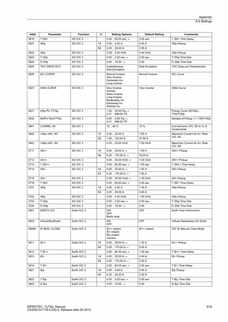
Appendix
A.8 Settings
SIPROTEC, 7UT6x, ManualC53000-G1176-C230-3, Release date 05.2013
619
3616 T 3I0> 3I0 O/C 3 0.00 .. 60.00 sec; ∞ 2.00 sec T 3I0> Time Delay
3621 3I0p 3I0 O/C 3 1A 0.05 .. 4.00 A 0.40 A 3I0p Pickup
5A 0.25 .. 20.00 A 2.00 A
3622 3I0p 3I0 O/C 3 0.05 .. 4.00 I/InS 0.40 I/InS 3I0p Pickup
3623 T 3I0p 3I0 O/C 3 0.05 .. 3.20 sec; ∞ 0.50 sec T 3I0p Time Dial
3624 D 3I0p 3I0 O/C 3 0.50 .. 15.00 ; ∞ 5.00 D 3I0p Time Dial
3625 TOC DROP-OUT 3I0 O/C 3 InstantaneousDisk Emulation
Disk Emulation TOC Drop-out Characteristic
3626 IEC CURVE 3I0 O/C 3 Normal InverseVery InverseExtremely Inv.Long Inverse
Normal Inverse IEC Curve
3627 ANSI CURVE 3I0 O/C 3 Very InverseInverseShort InverseLong InverseModerately Inv.Extremely Inv.Definite Inv.
Very Inverse ANSI Curve
3631 I/I0p PU T/TI0p 3I0 O/C 3 1.00 .. 20.00 I/Ip; ∞0.01 .. 999.00 TD
Pickup Curve 3I0/3I0p - T3I0/T3I0p
3632 MofPU ResT/TI0p 3I0 O/C 3 0.05 .. 0.95 I/Ip; ∞0.01 .. 999.00 TD
Multiple of Pickup <-> T3I0/T3I0p
3641 2.HARM. 3I0 3I0 O/C 3 10 .. 45 % 15 % 2nd harmonic O/C 3I0 in % of fundamental
3642 I Max InRr. 3I0 3I0 O/C 3 1A 0.30 .. 25.00 A 7.50 A Maximum Current for Inr. Rest. O/C 3I0
5A 1.50 .. 125.00 A 37.50 A
3643 I Max InRr. 3I0 3I0 O/C 3 0.30 .. 25.00 I/InS 7.50 I/InS Maximum Current for Inr. Rest. O/C 3I0
3711 3I0>> 3I0 O/C 3 1A 0.05 .. 35.00 A; ∞ 7.00 A 3I0>> Pickup
5A 0.25 .. 175.00 A; ∞ 35.00 A
3712 3I0>> 3I0 O/C 3 0.05 .. 35.00 I/InS; ∞ 7.00 I/InS 3I0>> Pickup
3713 T 3I0>> 3I0 O/C 3 0.00 .. 60.00 sec; ∞ 1.50 sec T 3I0>> Time Delay
3714 3I0> 3I0 O/C 3 1A 0.05 .. 35.00 A; ∞ 1.50 A 3I0> Pickup
5A 0.25 .. 175.00 A; ∞ 7.50 A
3715 3I0> 3I0 O/C 3 0.05 .. 35.00 I/InS; ∞ 1.50 I/InS 3I0> Pickup
3716 T 3I0> 3I0 O/C 3 0.00 .. 60.00 sec; ∞ 2.00 sec T 3I0> Time Delay
3721 3I0p 3I0 O/C 3 1A 0.05 .. 4.00 A 1.00 A 3I0p Pickup
5A 0.25 .. 20.00 A 5.00 A
3722 3I0p 3I0 O/C 3 0.05 .. 4.00 I/InS 1.00 I/InS 3I0p Pickup
3723 T 3I0p 3I0 O/C 3 0.05 .. 3.20 sec; ∞ 0.50 sec T 3I0p Time Dial
3724 D 3I0p 3I0 O/C 3 0.50 .. 15.00 ; ∞ 5.00 D 3I0p Time Dial
3801 EARTH O/C Earth O/C 2 ONOFFBlock relay
OFF Earth Time Overcurrent
3802 InRushRestEarth Earth O/C 2 ONOFF
OFF InRush Restrained O/C Earth
3808A IE MAN. CLOSE Earth O/C 2 IE>> instant.IE> instant.IEp instant.Inactive
IE>> instant. O/C IE Manual Close Mode
3811 IE>> Earth O/C 2 1A 0.05 .. 35.00 A; ∞ 1.00 A IE>> Pickup
5A 0.25 .. 175.00 A; ∞ 5.00 A
3812 T IE>> Earth O/C 2 0.00 .. 60.00 sec; ∞ 1.50 sec T IE>> Time Delay
3813 IE> Earth O/C 2 1A 0.05 .. 35.00 A; ∞ 0.40 A IE> Pickup
5A 0.25 .. 175.00 A; ∞ 2.00 A
3814 T IE> Earth O/C 2 0.00 .. 60.00 sec; ∞ 2.00 sec T IE> Time Delay
3821 IEp Earth O/C 2 1A 0.05 .. 4.00 A 0.40 A IEp Pickup
5A 0.25 .. 20.00 A 2.00 A
3822 T IEp Earth O/C 2 0.05 .. 3.20 sec; ∞ 0.50 sec T IEp Time Dial
3823 D IEp Earth O/C 2 0.50 .. 15.00 ; ∞ 5.00 D IEp Time Dial
Addr. Parameter Function C Setting Options Default Setting Comments
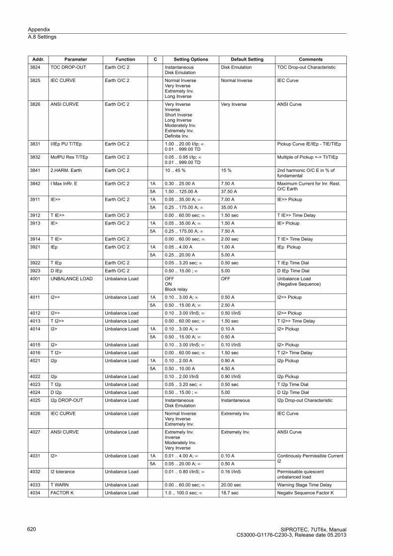
Appendix
A.8 Settings
SIPROTEC, 7UT6x, ManualC53000-G1176-C230-3, Release date 05.2013
620
3824 TOC DROP-OUT Earth O/C 2 InstantaneousDisk Emulation
Disk Emulation TOC Drop-out Characteristic
3825 IEC CURVE Earth O/C 2 Normal InverseVery InverseExtremely Inv.Long Inverse
Normal Inverse IEC Curve
3826 ANSI CURVE Earth O/C 2 Very InverseInverseShort InverseLong InverseModerately Inv.Extremely Inv.Definite Inv.
Very Inverse ANSI Curve
3831 I/IEp PU T/TEp Earth O/C 2 1.00 .. 20.00 I/Ip; ∞0.01 .. 999.00 TD
Pickup Curve IE/IEp - TIE/TIEp
3832 MofPU Res T/TEp Earth O/C 2 0.05 .. 0.95 I/Ip; ∞0.01 .. 999.00 TD
Multiple of Pickup <-> TI/TIEp
3841 2.HARM. Earth Earth O/C 2 10 .. 45 % 15 % 2nd harmonic O/C E in % of fundamental
3842 I Max InRr. E Earth O/C 2 1A 0.30 .. 25.00 A 7.50 A Maximum Current for Inr. Rest. O/C Earth
5A 1.50 .. 125.00 A 37.50 A
3911 IE>> Earth O/C 2 1A 0.05 .. 35.00 A; ∞ 7.00 A IE>> Pickup
5A 0.25 .. 175.00 A; ∞ 35.00 A
3912 T IE>> Earth O/C 2 0.00 .. 60.00 sec; ∞ 1.50 sec T IE>> Time Delay
3913 IE> Earth O/C 2 1A 0.05 .. 35.00 A; ∞ 1.50 A IE> Pickup
5A 0.25 .. 175.00 A; ∞ 7.50 A
3914 T IE> Earth O/C 2 0.00 .. 60.00 sec; ∞ 2.00 sec T IE> Time Delay
3921 IEp Earth O/C 2 1A 0.05 .. 4.00 A 1.00 A IEp Pickup
5A 0.25 .. 20.00 A 5.00 A
3922 T IEp Earth O/C 2 0.05 .. 3.20 sec; ∞ 0.50 sec T IEp Time Dial
3923 D IEp Earth O/C 2 0.50 .. 15.00 ; ∞ 5.00 D IEp Time Dial
4001 UNBALANCE LOAD Unbalance Load OFFONBlock relay
OFF Unbalance Load (Negative Sequence)
4011 I2>> Unbalance Load 1A 0.10 .. 3.00 A; ∞ 0.50 A I2>> Pickup
5A 0.50 .. 15.00 A; ∞ 2.50 A
4012 I2>> Unbalance Load 0.10 .. 3.00 I/InS; ∞ 0.50 I/InS I2>> Pickup
4013 T I2>> Unbalance Load 0.00 .. 60.00 sec; ∞ 1.50 sec T I2>> Time Delay
4014 I2> Unbalance Load 1A 0.10 .. 3.00 A; ∞ 0.10 A I2> Pickup
5A 0.50 .. 15.00 A; ∞ 0.50 A
4015 I2> Unbalance Load 0.10 .. 3.00 I/InS; ∞ 0.10 I/InS I2> Pickup
4016 T I2> Unbalance Load 0.00 .. 60.00 sec; ∞ 1.50 sec T I2> Time Delay
4021 I2p Unbalance Load 1A 0.10 .. 2.00 A 0.90 A I2p Pickup
5A 0.50 .. 10.00 A 4.50 A
4022 I2p Unbalance Load 0.10 .. 2.00 I/InS 0.90 I/InS I2p Pickup
4023 T I2p Unbalance Load 0.05 .. 3.20 sec; ∞ 0.50 sec T I2p Time Dial
4024 D I2p Unbalance Load 0.50 .. 15.00 ; ∞ 5.00 D I2p Time Dial
4025 I2p DROP-OUT Unbalance Load InstantaneousDisk Emulation
Instantaneous I2p Drop-out Characteristic
4026 IEC CURVE Unbalance Load Normal InverseVery InverseExtremely Inv.
Extremely Inv. IEC Curve
4027 ANSI CURVE Unbalance Load Extremely Inv.InverseModerately Inv.Very Inverse
Extremely Inv. ANSI Curve
4031 I2> Unbalance Load 1A 0.01 .. 4.00 A; ∞ 0.10 A Continously Permissible Current I2
5A 0.05 .. 20.00 A; ∞ 0.50 A
4032 I2 tolerance Unbalance Load 0.01 .. 0.80 I/InS; ∞ 0.16 I/InS Permissable quiescent unbalanced load
4033 T WARN Unbalance Load 0.00 .. 60.00 sec; ∞ 20.00 sec Warning Stage Time Delay
4034 FACTOR K Unbalance Load 1.0 .. 100.0 sec; ∞ 18.7 sec Negativ Sequence Factor K
Addr. Parameter Function C Setting Options Default Setting Comments

Appendix
A.8 Settings
SIPROTEC, 7UT6x, ManualC53000-G1176-C230-3, Release date 05.2013
621
4035 T COOL DOWN Unbalance Load 0 .. 50000 sec 1650 sec Time for Cooling Down
4201 THERM. OVERLOAD Therm. Overload OFFONBlock relayAlarm Only
OFF Thermal Overload Protection
4202 K-FACTOR Therm. Overload 0.10 .. 4.00 1.10 K-Factor
4203 TIME CONSTANT Therm. Overload 1.0 .. 999.9 min 100.0 min Thermal Time Constant
4204 Θ ALARM Therm. Overload 50 .. 100 % 90 % Thermal Alarm Stage
4205 I ALARM Therm. Overload 0.10 .. 4.00 I/InS 1.00 I/InS Current Overload Alarm Setpoint
4207A Kτ-FACTOR Therm. Overload 1.0 .. 10.0 1.0 Kt-FACTOR when motor stops
4208A T EMERGENCY Therm. Overload 10 .. 15000 sec 100 sec Emergency Time
4209A I MOTOR START Therm. Overload 0.60 .. 10.00 I/InS; ∞ ∞ I/InS Current Pickup Value of Motor Starting
4210 TEMPSENSOR RTD Therm. Overload 1 .. 6 1 Temperature sensor connected to RTD
4211 TEMPSENSOR RTD Therm. Overload 1 .. 12 1 Temperature sensor connected to RTD
4212 TEMP. RISE I Therm. Overload 40 .. 200 °C 100 °C Temperature Rise at Rated Sec. Curr.
4213 TEMP. RISE I Therm. Overload 104 .. 392 °F 212 °F Temperature Rise at Rated Sec. Curr.
4220 OIL-DET. RTD Therm. Overload 1 .. 6 1 Oil-Detector conected at RTD
4221 OIL Sensor RTD Therm. Overload 1 .. 12 1 Oil sensor connected to RTD
4222 HOT SPOT ST. 1 Therm. Overload 98 .. 140 °C 98 °C Hot Spot Temperature Stage 1 Pickup
4223 HOT SPOT ST. 1 Therm. Overload 208 .. 284 °F 208 °F Hot Spot Temperature Stage 1 Pickup
4224 HOT SPOT ST. 2 Therm. Overload 98 .. 140 °C 108 °C Hot Spot Temperature Stage 2 Pickup
4225 HOT SPOT ST. 2 Therm. Overload 208 .. 284 °F 226 °F Hot Spot Temperature Stage 2 Pickup
4226 AG. RATE ST. 1 Therm. Overload 0.200 .. 128.000 1.000 Aging Rate STAGE 1 Pickup
4227 AG. RATE ST. 2 Therm. Overload 0.200 .. 128.000 2.000 Aging Rate STAGE 2 Pickup
4231 METH. COOLING Therm. Overload ONOFOD
ON Method of Cooling
4232 Y-WIND.EXPONENT Therm. Overload 1.6 .. 2.0 1.6 Y-Winding Exponent
4233 HOT-SPOT GR Therm. Overload 22 .. 29 22 Hot-spot to top-oil gradient
4301 OVEREXC. PROT. Overexcit. OFFONBlock relay
OFF Overexcitation Protection (U/f)
4302 U/f > Overexcit. 1.00 .. 1.20 1.10 U/f > Pickup
4303 T U/f > Overexcit. 0.00 .. 60.00 sec; ∞ 10.00 sec T U/f > Time Delay
4304 U/f >> Overexcit. 1.00 .. 1.40 1.40 U/f >> Pickup
4305 T U/f >> Overexcit. 0.00 .. 60.00 sec; ∞ 1.00 sec T U/f >> Time Delay
4306 t(U/f=1.05) Overexcit. 0 .. 20000 sec 20000 sec U/f = 1.05 Time Delay
4307 t(U/f=1.10) Overexcit. 0 .. 20000 sec 6000 sec U/f = 1.10 Time Delay
4308 t(U/f=1.15) Overexcit. 0 .. 20000 sec 240 sec U/f = 1.15 Time Delay
4309 t(U/f=1.20) Overexcit. 0 .. 20000 sec 60 sec U/f = 1.20 Time Delay
4310 t(U/f=1.25) Overexcit. 0 .. 20000 sec 30 sec U/f = 1.25 Time Delay
4311 t(U/f=1.30) Overexcit. 0 .. 20000 sec 19 sec U/f = 1.30 Time Delay
4312 t(U/f=1.35) Overexcit. 0 .. 20000 sec 13 sec U/f = 1.35 Time Delay
4313 t(U/f=1.40) Overexcit. 0 .. 20000 sec 10 sec U/f = 1.40 Time Delay
4314 T COOL DOWN Overexcit. 0 .. 20000 sec 3600 sec Time for cool down
4401 THERM. OVERLOAD Therm.Overload2 OFFONBlock relayAlarm Only
OFF Thermal Overload Protection
4402 K-FACTOR Therm.Overload2 0.10 .. 4.00 1.10 K-Factor
4403 TIME CONSTANT Therm.Overload2 1.0 .. 999.9 min 100.0 min Thermal Time Constant
4404 Θ ALARM Therm.Overload2 50 .. 100 % 90 % Thermal Alarm Stage
Addr. Parameter Function C Setting Options Default Setting Comments
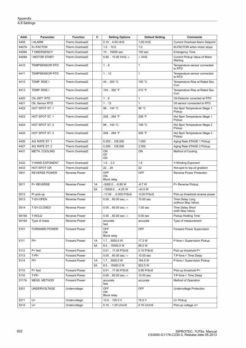
Appendix
A.8 Settings
SIPROTEC, 7UT6x, ManualC53000-G1176-C230-3, Release date 05.2013
622
4405 I ALARM Therm.Overload2 0.10 .. 4.00 I/InS 1.00 I/InS Current Overload Alarm Setpoint
4407A Kτ-FACTOR Therm.Overload2 1.0 .. 10.0 1.0 Kt-FACTOR when motor stops
4408A T EMERGENCY Therm.Overload2 10 .. 15000 sec 100 sec Emergency Time
4409A I MOTOR START Therm.Overload2 0.60 .. 10.00 I/InS; ∞ ∞ I/InS Current Pickup Value of Motor Starting
4410 TEMPSENSOR RTD Therm.Overload2 1 .. 6 1 Temperature sensor connected to RTD
4411 TEMPSENSOR RTD Therm.Overload2 1 .. 12 1 Temperature sensor connected to RTD
4412 TEMP. RISE I Therm.Overload2 40 .. 200 °C 100 °C Temperature Rise at Rated Sec. Curr.
4413 TEMP. RISE I Therm.Overload2 104 .. 392 °F 212 °F Temperature Rise at Rated Sec. Curr.
4420 OIL-DET. RTD Therm.Overload2 1 .. 6 1 Oil-Detector conected at RTD
4421 OIL Sensor RTD Therm.Overload2 1 .. 12 1 Oil sensor connected to RTD
4422 HOT SPOT ST. 1 Therm.Overload2 98 .. 140 °C 98 °C Hot Spot Temperature Stage 1 Pickup
4423 HOT SPOT ST. 1 Therm.Overload2 208 .. 284 °F 208 °F Hot Spot Temperature Stage 1 Pickup
4424 HOT SPOT ST. 2 Therm.Overload2 98 .. 140 °C 108 °C Hot Spot Temperature Stage 2 Pickup
4425 HOT SPOT ST. 2 Therm.Overload2 208 .. 284 °F 226 °F Hot Spot Temperature Stage 2 Pickup
4426 AG. RATE ST. 1 Therm.Overload2 0.200 .. 128.000 1.000 Aging Rate STAGE 1 Pickup
4427 AG. RATE ST. 2 Therm.Overload2 0.200 .. 128.000 2.000 Aging Rate STAGE 2 Pickup
4431 METH. COOLING Therm.Overload2 ONOFOD
ON Method of Cooling
4432 Y-WIND.EXPONENT Therm.Overload2 1.6 .. 2.0 1.6 Y-Winding Exponent
4433 HOT-SPOT GR Therm.Overload2 22 .. 29 22 Hot-spot to top-oil gradient
5001 REVERSE POWER Reverse Power OFFONBlock relay
OFF Reverse Power Protection
5011 P> REVERSE Reverse Power 1A -3000.0 .. -0.85 W -8.7 W P> Reverse Pickup
5A -15000.0 .. -4.25 W -43.5 W
5012 Pr pick-up Reverse Power -17.00 .. -0.005 P/SnS -0.05 P/SnS Pick-up threshold reverse power
5013 T-SV-OPEN Reverse Power 0.00 .. 60.00 sec; ∞ 10.00 sec Time Delay Long (without Stop Valve)
5014 T-SV-CLOSED Reverse Power 0.00 .. 60.00 sec; ∞ 1.00 sec Time Delay Short (with Stop Valve)
5015A T-HOLD Reverse Power 0.00 .. 60.00 sec; ∞ 0.00 sec Pickup Holding Time
5016A Type of meas. Reverse Power accuratefast
accurate Type of measurement
5101 FORWARD POWER Forward Power OFFONBlock relay
OFF Forward Power Supervision
5111 Pf< Forward Power 1A 1.7 .. 3000.0 W 17.3 W P-forw.< Supervision Pickup
5A 8.5 .. 15000.0 W 86.5 W
5112 P< fwd Forward Power 0.01 .. 17.00 P/SnS 0.10 P/SnS Pick-up threshold P<
5113 T-Pf< Forward Power 0.00 .. 60.00 sec; ∞ 10.00 sec T-P-forw.< Time Delay
5114 Pf> Forward Power 1A 1.7 .. 3000.0 W 164.5 W P-forw.> Supervision Pickup
5A 8.5 .. 15000.0 W 822.5 W
5115 P> fwd Forward Power 0.01 .. 17.00 P/SnS 0.95 P/SnS Pick-up threshold P>
5116 T-Pf> Forward Power 0.00 .. 60.00 sec; ∞ 10.00 sec T-P-forw.> Time Delay
5117A MEAS. METHOD Forward Power accuratefast
accurate Method of Operation
5201 UNDERVOLTAGE Undervoltage OFFONBlock relay
OFF Undervoltage Protection
5211 U< Undervoltage 10.0 .. 125.0 V 75.0 V U< Pickup
5212 U< Undervoltage 0.10 .. 1.25 U/UnS 0.75 U/UnS Pick-up voltage U<
Addr. Parameter Function C Setting Options Default Setting Comments

Appendix
A.8 Settings
SIPROTEC, 7UT6x, ManualC53000-G1176-C230-3, Release date 05.2013
623
5213 T U< Undervoltage 0.00 .. 60.00 sec; ∞ 3.00 sec T U< Time Delay
5214 U<< Undervoltage 10.0 .. 125.0 V 65.0 V U<< Pickup
5215 U<< Undervoltage 0.10 .. 1.25 U/UnS 0.65 U/UnS Pick-up voltage U<<
5216 T U<< Undervoltage 0.00 .. 60.00 sec; ∞ 0.50 sec T U<< Time Delay
5217A DOUT RATIO Undervoltage 1.01 .. 1.20 1.05 U<, U<< Drop Out Ratio
5301 OVERVOLTAGE Overvoltage OFFONBlock relay
OFF Overvoltage Protection
5311 U> Overvoltage 30.0 .. 170.0 V 115.0 V U> Pickup
5312 U> Overvoltage 0.30 .. 1.70 U/UnS 1.15 U/UnS Pick-up voltage U>
5313 T U> Overvoltage 0.00 .. 60.00 sec; ∞ 3.00 sec T U> Time Delay
5314 U>> Overvoltage 30.0 .. 170.0 V 130.0 V U>> Pickup
5315 U>> Overvoltage 0.30 .. 1.70 U/UnS 1.30 U/UnS Pick-up voltage U>>
5316 T U>> Overvoltage 0.00 .. 60.00 sec; ∞ 0.50 sec T U>> Time Delay
5317A DOUT RATIO Overvoltage 0.90 .. 0.99 0.98 U>, U>> Drop Out Ratio
0.95 (7UT612)
5318A VALUES Overvoltage U-ph-phU-ph-e
U-ph-ph Measurement Values
5601 O/U FREQUENCY Frequency Prot. OFFONBlock relay
OFF Over / Under Frequency Protection
5611 f< Frequency Prot. 40.00 .. 49.99 Hz; 0 49.50 Hz Pick-up frequency f<
5612 f<< Frequency Prot. 40.00 .. 49.99 Hz; 0 48.00 Hz Pick-up frequency f<<
5613 f<<< Frequency Prot. 40.00 .. 49.99 Hz; 0 47.00 Hz Pick-up frequency f<<<
5614 f> Frequency Prot. 50.01 .. 66.00 Hz; ∞ 52.00 Hz Pick-up frequency f>
5621 f< Frequency Prot. 50.00 .. 59.99 Hz; 0 59.50 Hz Pick-up frequency f<
5622 f<< Frequency Prot. 50.00 .. 59.99 Hz; 0 58.00 Hz Pick-up frequency f<<
5623 f<<< Frequency Prot. 50.00 .. 59.99 Hz; 0 57.00 Hz Pick-up frequency f<<<
5624 f> Frequency Prot. 60.01 .. 66.00 Hz; ∞ 62.00 Hz Pick-up frequency f>
5631 f< Frequency Prot. 10.00 .. 16.69 Hz; 0 16.50 Hz Pick-up frequency f<
5632 f<< Frequency Prot. 10.00 .. 16.69 Hz; 0 16.00 Hz Pick-up frequency f<<
5633 f<<< Frequency Prot. 10.00 .. 16.69 Hz; 0 15.70 Hz Pick-up frequency f<<<
5634 f> Frequency Prot. 16.67 .. 22.00 Hz; ∞ 17.40 Hz Pick-up frequency f>
5641 T f< Frequency Prot. 0.00 .. 100.00 sec; ∞ 20.00 sec Delay time T f<
5642 T f<< Frequency Prot. 0.00 .. 600.00 sec; ∞ 1.00 sec Delay time T f<<
5643 T f<<< Frequency Prot. 0.00 .. 100.00 sec; ∞ 6.00 sec Delay time T f<<<
5644 T f> Frequency Prot. 0.00 .. 100.00 sec; ∞ 10.00 sec Delay time T f>
5651 Umin Frequency Prot. 10.0 .. 125.0 V; 0 65.0 V Minimum Required Voltage for Operation
5652 U MIN Frequency Prot. 0.10 .. 1.25 U/UnS; 0 0.65 U/UnS Minimum voltage
7001 BREAKER FAILURE Breaker Failure OFFONBlock relay
OFF Breaker Failure Protection
7011 START WITH REL. Breaker Failure 0 .. 8 0 Start with Relay (intern)
7012 START WITH REL. Breaker Failure 0 .. 24 0 Start with Relay (intern)
7015 T1 Breaker Failure 0.00 .. 60.00 sec; ∞ 0.15 sec T1, Delay of 1st stage (local trip)
7016 T2 Breaker Failure 0.00 .. 60.00 sec; ∞ 0.30 sec T2, Delay of 2nd stage (busbar trip)
7101 BREAKER FAILURE Breaker Fail. 2 OFFONBlock relay
OFF Breaker Failure Protection
7111 START WITH REL. Breaker Fail. 2 0 .. 8 0 Start with Relay (intern)
7112 START WITH REL. Breaker Fail. 2 0 .. 24 0 Start with Relay (intern)
7115 T1 Breaker Fail. 2 0.00 .. 60.00 sec; ∞ 0.15 sec T1, Delay of 1st stage (local trip)
7116 T2 Breaker Fail. 2 0.00 .. 60.00 sec; ∞ 0.30 sec T2, Delay of 2nd stage (busbar trip)
7601 POWER CALCUL. Measurement with V settingwith V measur.
with V setting Calculation of Power
Addr. Parameter Function C Setting Options Default Setting Comments
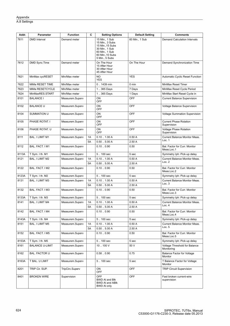
Appendix
A.8 Settings
SIPROTEC, 7UT6x, ManualC53000-G1176-C230-3, Release date 05.2013
624
7611 DMD Interval Demand meter 15 Min., 1 Sub15 Min., 3 Subs15 Min.,15 Subs30 Min., 1 Sub60 Min., 1 Sub60 Min.,10 Subs5 Min., 5 Subs
60 Min., 1 Sub Demand Calculation Intervals
7612 DMD Sync.Time Demand meter On The Hour15 After Hour30 After Hour45 After Hour
On The Hour Demand Synchronization Time
7621 MinMax cycRESET Min/Max meter NOYES
YES Automatic Cyclic Reset Function
7622 MiMa RESET TIME Min/Max meter 0 .. 1439 min 0 min MinMax Reset Timer
7623 MiMa RESETCYCLE Min/Max meter 1 .. 365 Days 7 Days MinMax Reset Cycle Period
7624 MinMaxRES.START Min/Max meter 1 .. 365 Days 1 Days MinMax Start Reset Cycle in
8101 BALANCE I Measurem.Superv ONOFF
OFF Current Balance Supervision
8102 BALANCE U Measurem.Superv ONOFF
OFF Voltage Balance Supervision
8104 SUMMATION U Measurem.Superv ONOFF
OFF Voltage Summation Supervision
8105 PHASE ROTAT. I Measurem.Superv ONOFF
OFF Current Phase Rotation Supervision
8106 PHASE ROTAT. U Measurem.Superv ONOFF
OFF Voltage Phase Rotation Supervision
8111 BAL. I LIMIT M1 Measurem.Superv 1A 0.10 .. 1.00 A 0.50 A Current Balance Monitor Meas. Loc. 1
5A 0.50 .. 5.00 A 2.50 A
8112 BAL. FACT. I M1 Measurem.Superv 0.10 .. 0.90 0.50 Bal. Factor for Curr. Monitor Meas.Loc.1
8113A T Sym. I th. M1 Measurem.Superv 5 .. 100 sec 5 sec Symmetry Iph: Pick-up delay
8121 BAL. I LIMIT M2 Measurem.Superv 1A 0.10 .. 1.00 A 0.50 A Current Balance Monitor Meas. Loc. 2
5A 0.50 .. 5.00 A 2.50 A
8122 BAL. FACT. I M2 Measurem.Superv 0.10 .. 0.90 0.50 Bal. Factor for Curr. Monitor Meas.Loc.2
8123A T Sym. I th. M2 Measurem.Superv 5 .. 100 sec 5 sec Symmetry Iph: Pick-up delay
8131 BAL. I LIMIT M3 Measurem.Superv 1A 0.10 .. 1.00 A 0.50 A Current Balance Monitor Meas. Loc. 3
5A 0.50 .. 5.00 A 2.50 A
8132 BAL. FACT. I M3 Measurem.Superv 0.10 .. 0.90 0.50 Bal. Factor for Curr. Monitor Meas.Loc.3
8133A T Sym. I th. M3 Measurem.Superv 5 .. 100 sec 5 sec Symmetry Iph: Pick-up delay
8141 BAL. I LIMIT M4 Measurem.Superv 1A 0.10 .. 1.00 A 0.50 A Current Balance Monitor Meas. Loc. 4
5A 0.50 .. 5.00 A 2.50 A
8142 BAL. FACT. I M4 Measurem.Superv 0.10 .. 0.90 0.50 Bal. Factor for Curr. Monitor Meas.Loc.4
8143A T Sym. I th. M4 Measurem.Superv 5 .. 100 sec 5 sec Symmetry Iph: Pick-up delay
8151 BAL. I LIMIT M5 Measurem.Superv 1A 0.10 .. 1.00 A 0.50 A Current Balance Monitor Meas. Loc. 5
5A 0.50 .. 5.00 A 2.50 A
8152 BAL. FACT. I M5 Measurem.Superv 0.10 .. 0.90 0.50 Bal. Factor for Curr. Monitor Meas.Loc.5
8153A T Sym. I th. M5 Measurem.Superv 5 .. 100 sec 5 sec Symmetry Iph: Pick-up delay
8161 BALANCE U-LIMIT Measurem.Superv 10 .. 100 V 50 V Voltage Threshold for Balance Monitoring
8162 BAL. FACTOR U Measurem.Superv 0.58 .. 0.90 0.75 Balance Factor for Voltage Monitor
8163A T BAL. U LIMIT Measurem.Superv 5 .. 100 sec 5 sec T Balance Factor for Voltage Monitor
8201 TRIP Cir. SUP. TripCirc.Superv ONOFF
OFF TRIP Circuit Supervision
8401 BROKEN WIRE Supervision OFFBWD Al and BlkBWD Al and ABlkBWD Al only
OFF Fast broken current-wire supervision
Addr. Parameter Function C Setting Options Default Setting Comments

Appendix
A.8 Settings
SIPROTEC, 7UT6x, ManualC53000-G1176-C230-3, Release date 05.2013
625
8403 FUSE FAIL MON. Supervision OFFON
OFF Fuse Failure Monitor
8414 T BWD delay Supervision 0.0 .. 180.0 sec 0.0 sec Delay time for BWd supervision
8415 ΔI< BWD Supervision 0.005 .. 0.500 I/In 0.040 I/In min differential current for BWD
8422A FFM I< M1 Supervision 1A 0.04 .. 2.00 A 0.10 A I< for FFM detection M1
5A 0.20 .. 10.00 A 0.50 A
8423A FFM I< M2 Supervision 1A 0.04 .. 2.00 A 0.10 A I< for FFM detection M2
5A 0.20 .. 10.00 A 0.50 A
8424A FFM I< M3 Supervision 1A 0.04 .. 2.00 A 0.10 A I< for FFM detection M3
5A 0.20 .. 10.00 A 0.50 A
8426A FFM U<max (3ph) Supervision 2 .. 100 V 5 V Maximum Voltage Threshold U< (3phase)
8601 EXTERN TRIP 1 External Trips OFFONBlock relay
OFF External Trip Function 1
8602 T DELAY External Trips 0.00 .. 60.00 sec; ∞ 1.00 sec Ext. Trip 1 Time Delay
8701 EXTERN TRIP 2 External Trips OFFONBlock relay
OFF External Trip Function 2
8702 T DELAY External Trips 0.00 .. 60.00 sec; ∞ 1.00 sec Ext. Trip 2 Time Delay
9011A RTD 1 TYPE RTD-Box Not connectedPt 100 ΩNi 120 ΩNi 100 Ω
Pt 100 Ω RTD 1: Type
9012A RTD 1 LOCATION RTD-Box OilAmbientWindingBearingOther
Oil RTD 1: Location
9013 RTD 1 STAGE 1 RTD-Box -50 .. 250 °C; ∞ 100 °C RTD 1: Temperature Stage 1 Pickup
9014 RTD 1 STAGE 1 RTD-Box -58 .. 482 °F; ∞ 212 °F RTD 1: Temperature Stage 1 Pickup
9015 RTD 1 STAGE 2 RTD-Box -50 .. 250 °C; ∞ 120 °C RTD 1: Temperature Stage 2 Pickup
9016 RTD 1 STAGE 2 RTD-Box -58 .. 482 °F; ∞ 248 °F RTD 1: Temperature Stage 2 Pickup
9021A RTD 2 TYPE RTD-Box Not connectedPt 100 ΩNi 120 ΩNi 100 Ω
Not connected RTD 2: Type
9022A RTD 2 LOCATION RTD-Box OilAmbientWindingBearingOther
Other RTD 2: Location
9023 RTD 2 STAGE 1 RTD-Box -50 .. 250 °C; ∞ 100 °C RTD 2: Temperature Stage 1 Pickup
9024 RTD 2 STAGE 1 RTD-Box -58 .. 482 °F; ∞ 212 °F RTD 2: Temperature Stage 1 Pickup
9025 RTD 2 STAGE 2 RTD-Box -50 .. 250 °C; ∞ 120 °C RTD 2: Temperature Stage 2 Pickup
9026 RTD 2 STAGE 2 RTD-Box -58 .. 482 °F; ∞ 248 °F RTD 2: Temperature Stage 2 Pickup
9031A RTD 3 TYPE RTD-Box Not connectedPt 100 ΩNi 120 ΩNi 100 Ω
Not connected RTD 3: Type
9032A RTD 3 LOCATION RTD-Box OilAmbientWindingBearingOther
Other RTD 3: Location
9033 RTD 3 STAGE 1 RTD-Box -50 .. 250 °C; ∞ 100 °C RTD 3: Temperature Stage 1 Pickup
9034 RTD 3 STAGE 1 RTD-Box -58 .. 482 °F; ∞ 212 °F RTD 3: Temperature Stage 1 Pickup
Addr. Parameter Function C Setting Options Default Setting Comments
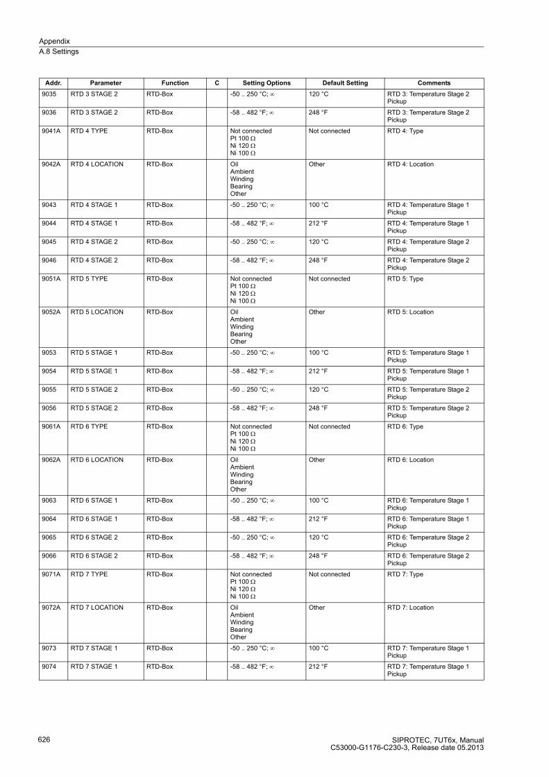
Appendix
A.8 Settings
SIPROTEC, 7UT6x, ManualC53000-G1176-C230-3, Release date 05.2013
626
9035 RTD 3 STAGE 2 RTD-Box -50 .. 250 °C; ∞ 120 °C RTD 3: Temperature Stage 2 Pickup
9036 RTD 3 STAGE 2 RTD-Box -58 .. 482 °F; ∞ 248 °F RTD 3: Temperature Stage 2 Pickup
9041A RTD 4 TYPE RTD-Box Not connectedPt 100 ΩNi 120 ΩNi 100 Ω
Not connected RTD 4: Type
9042A RTD 4 LOCATION RTD-Box OilAmbientWindingBearingOther
Other RTD 4: Location
9043 RTD 4 STAGE 1 RTD-Box -50 .. 250 °C; ∞ 100 °C RTD 4: Temperature Stage 1 Pickup
9044 RTD 4 STAGE 1 RTD-Box -58 .. 482 °F; ∞ 212 °F RTD 4: Temperature Stage 1 Pickup
9045 RTD 4 STAGE 2 RTD-Box -50 .. 250 °C; ∞ 120 °C RTD 4: Temperature Stage 2 Pickup
9046 RTD 4 STAGE 2 RTD-Box -58 .. 482 °F; ∞ 248 °F RTD 4: Temperature Stage 2 Pickup
9051A RTD 5 TYPE RTD-Box Not connectedPt 100 ΩNi 120 ΩNi 100 Ω
Not connected RTD 5: Type
9052A RTD 5 LOCATION RTD-Box OilAmbientWindingBearingOther
Other RTD 5: Location
9053 RTD 5 STAGE 1 RTD-Box -50 .. 250 °C; ∞ 100 °C RTD 5: Temperature Stage 1 Pickup
9054 RTD 5 STAGE 1 RTD-Box -58 .. 482 °F; ∞ 212 °F RTD 5: Temperature Stage 1 Pickup
9055 RTD 5 STAGE 2 RTD-Box -50 .. 250 °C; ∞ 120 °C RTD 5: Temperature Stage 2 Pickup
9056 RTD 5 STAGE 2 RTD-Box -58 .. 482 °F; ∞ 248 °F RTD 5: Temperature Stage 2 Pickup
9061A RTD 6 TYPE RTD-Box Not connectedPt 100 ΩNi 120 ΩNi 100 Ω
Not connected RTD 6: Type
9062A RTD 6 LOCATION RTD-Box OilAmbientWindingBearingOther
Other RTD 6: Location
9063 RTD 6 STAGE 1 RTD-Box -50 .. 250 °C; ∞ 100 °C RTD 6: Temperature Stage 1 Pickup
9064 RTD 6 STAGE 1 RTD-Box -58 .. 482 °F; ∞ 212 °F RTD 6: Temperature Stage 1 Pickup
9065 RTD 6 STAGE 2 RTD-Box -50 .. 250 °C; ∞ 120 °C RTD 6: Temperature Stage 2 Pickup
9066 RTD 6 STAGE 2 RTD-Box -58 .. 482 °F; ∞ 248 °F RTD 6: Temperature Stage 2 Pickup
9071A RTD 7 TYPE RTD-Box Not connectedPt 100 ΩNi 120 ΩNi 100 Ω
Not connected RTD 7: Type
9072A RTD 7 LOCATION RTD-Box OilAmbientWindingBearingOther
Other RTD 7: Location
9073 RTD 7 STAGE 1 RTD-Box -50 .. 250 °C; ∞ 100 °C RTD 7: Temperature Stage 1 Pickup
9074 RTD 7 STAGE 1 RTD-Box -58 .. 482 °F; ∞ 212 °F RTD 7: Temperature Stage 1 Pickup
Addr. Parameter Function C Setting Options Default Setting Comments

Appendix
A.8 Settings
SIPROTEC, 7UT6x, ManualC53000-G1176-C230-3, Release date 05.2013
627
9075 RTD 7 STAGE 2 RTD-Box -50 .. 250 °C; ∞ 120 °C RTD 7: Temperature Stage 2 Pickup
9076 RTD 7 STAGE 2 RTD-Box -58 .. 482 °F; ∞ 248 °F RTD 7: Temperature Stage 2 Pickup
9081A RTD 8 TYPE RTD-Box Not connectedPt 100 ΩNi 120 ΩNi 100 Ω
Not connected RTD 8: Type
9082A RTD 8 LOCATION RTD-Box OilAmbientWindingBearingOther
Other RTD 8: Location
9083 RTD 8 STAGE 1 RTD-Box -50 .. 250 °C; ∞ 100 °C RTD 8: Temperature Stage 1 Pickup
9084 RTD 8 STAGE 1 RTD-Box -58 .. 482 °F; ∞ 212 °F RTD 8: Temperature Stage 1 Pickup
9085 RTD 8 STAGE 2 RTD-Box -50 .. 250 °C; ∞ 120 °C RTD 8: Temperature Stage 2 Pickup
9086 RTD 8 STAGE 2 RTD-Box -58 .. 482 °F; ∞ 248 °F RTD 8: Temperature Stage 2 Pickup
9091A RTD 9 TYPE RTD-Box Not connectedPt 100 ΩNi 120 ΩNi 100 Ω
Not connected RTD 9: Type
9092A RTD 9 LOCATION RTD-Box OilAmbientWindingBearingOther
Other RTD 9: Location
9093 RTD 9 STAGE 1 RTD-Box -50 .. 250 °C; ∞ 100 °C RTD 9: Temperature Stage 1 Pickup
9094 RTD 9 STAGE 1 RTD-Box -58 .. 482 °F; ∞ 212 °F RTD 9: Temperature Stage 1 Pickup
9095 RTD 9 STAGE 2 RTD-Box -50 .. 250 °C; ∞ 120 °C RTD 9: Temperature Stage 2 Pickup
9096 RTD 9 STAGE 2 RTD-Box -58 .. 482 °F; ∞ 248 °F RTD 9: Temperature Stage 2 Pickup
9101A RTD10 TYPE RTD-Box Not connectedPt 100 ΩNi 120 ΩNi 100 Ω
Not connected RTD10: Type
9102A RTD10 LOCATION RTD-Box OilAmbientWindingBearingOther
Other RTD10: Location
9103 RTD10 STAGE 1 RTD-Box -50 .. 250 °C; ∞ 100 °C RTD10: Temperature Stage 1 Pickup
9104 RTD10 STAGE 1 RTD-Box -58 .. 482 °F; ∞ 212 °F RTD10: Temperature Stage 1 Pickup
9105 RTD10 STAGE 2 RTD-Box -50 .. 250 °C; ∞ 120 °C RTD10: Temperature Stage 2 Pickup
9106 RTD10 STAGE 2 RTD-Box -58 .. 482 °F; ∞ 248 °F RTD10: Temperature Stage 2 Pickup
9111A RTD11 TYPE RTD-Box Not connectedPt 100 ΩNi 120 ΩNi 100 Ω
Not connected RTD11: Type
9112A RTD11 LOCATION RTD-Box OilAmbientWindingBearingOther
Other RTD11: Location
9113 RTD11 STAGE 1 RTD-Box -50 .. 250 °C; ∞ 100 °C RTD11: Temperature Stage 1 Pickup
9114 RTD11 STAGE 1 RTD-Box -58 .. 482 °F; ∞ 212 °F RTD11: Temperature Stage 1 Pickup
Addr. Parameter Function C Setting Options Default Setting Comments
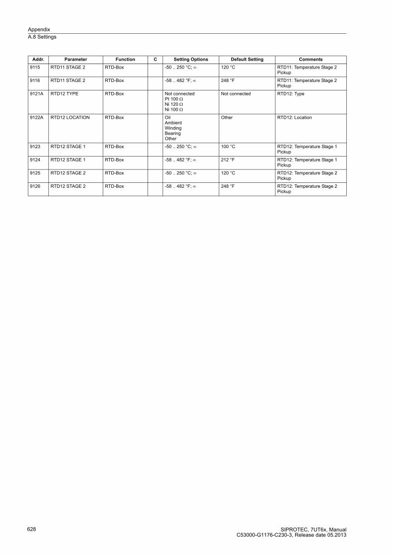
Appendix
A.8 Settings
SIPROTEC, 7UT6x, ManualC53000-G1176-C230-3, Release date 05.2013
628
9115 RTD11 STAGE 2 RTD-Box -50 .. 250 °C; ∞ 120 °C RTD11: Temperature Stage 2 Pickup
9116 RTD11 STAGE 2 RTD-Box -58 .. 482 °F; ∞ 248 °F RTD11: Temperature Stage 2 Pickup
9121A RTD12 TYPE RTD-Box Not connectedPt 100 ΩNi 120 ΩNi 100 Ω
Not connected RTD12: Type
9122A RTD12 LOCATION RTD-Box OilAmbientWindingBearingOther
Other RTD12: Location
9123 RTD12 STAGE 1 RTD-Box -50 .. 250 °C; ∞ 100 °C RTD12: Temperature Stage 1 Pickup
9124 RTD12 STAGE 1 RTD-Box -58 .. 482 °F; ∞ 212 °F RTD12: Temperature Stage 1 Pickup
9125 RTD12 STAGE 2 RTD-Box -50 .. 250 °C; ∞ 120 °C RTD12: Temperature Stage 2 Pickup
9126 RTD12 STAGE 2 RTD-Box -58 .. 482 °F; ∞ 248 °F RTD12: Temperature Stage 2 Pickup
Addr. Parameter Function C Setting Options Default Setting Comments
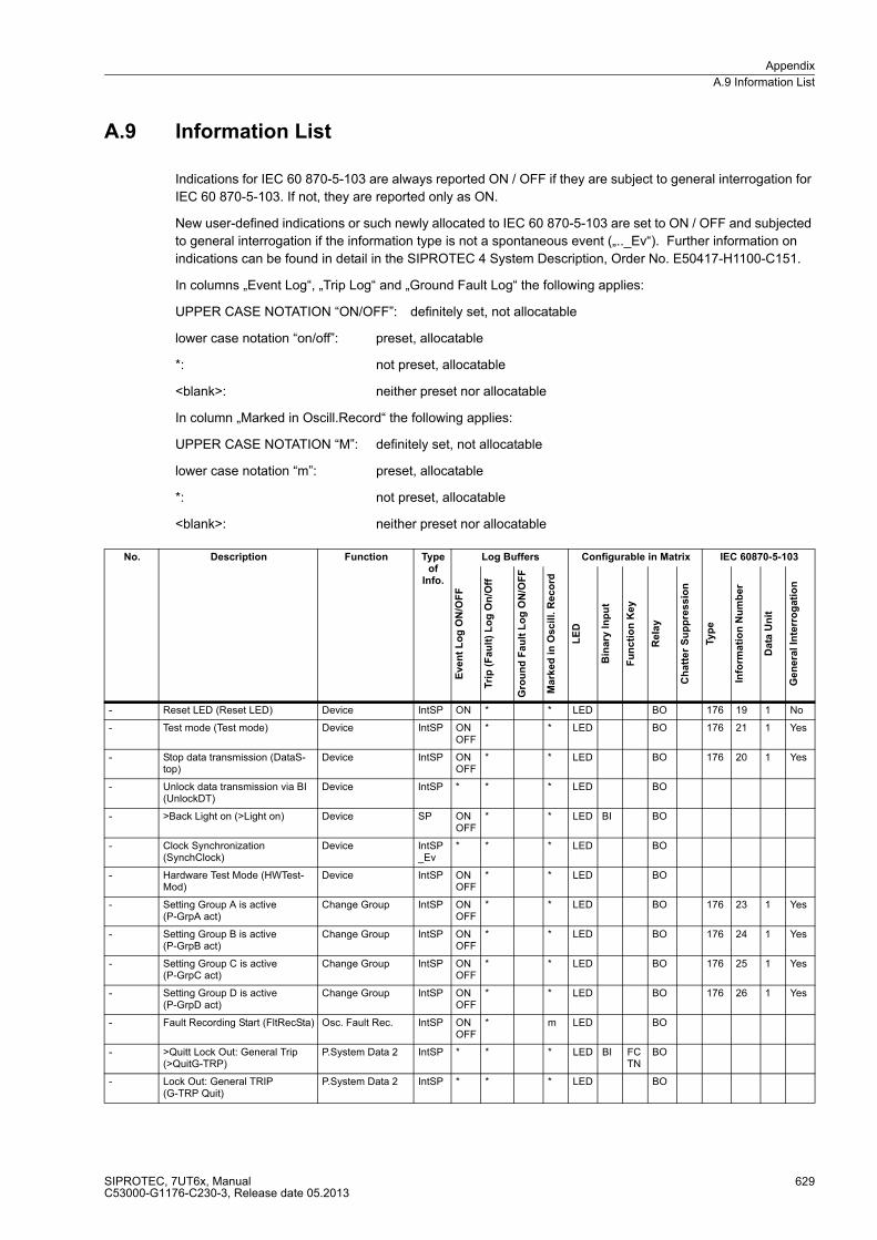
Appendix
A.9 Information List
SIPROTEC, 7UT6x, ManualC53000-G1176-C230-3, Release date 05.2013
629
A.9 Information List
Indications for IEC 60 870-5-103 are always reported ON / OFF if they are subject to general interrogation for
IEC 60 870-5-103. If not, they are reported only as ON.
New user-defined indications or such newly allocated to IEC 60 870-5-103 are set to ON / OFF and subjected
to general interrogation if the information type is not a spontaneous event („.._Ev“). Further information on
indications can be found in detail in the SIPROTEC 4 System Description, Order No. E50417-H1100-C151.
In columns „Event Log“, „Trip Log“ and „Ground Fault Log“ the following applies:
UPPER CASE NOTATION “ON/OFF”: definitely set, not allocatable
lower case notation “on/off”: preset, allocatable
*: not preset, allocatable
<blank>: neither preset nor allocatable
In column „Marked in Oscill.Record“ the following applies:
UPPER CASE NOTATION “M”: definitely set, not allocatable
lower case notation “m”: preset, allocatable
*: not preset, allocatable
<blank>: neither preset nor allocatable
No. Description Function Type of
Info.
Log Buffers Configurable in Matrix IEC 60870-5-103
Eve
nt
Lo
g O
N/O
FF
Tri
p (
Fa
ult
) L
og
On
/Off
Gro
un
d F
au
lt L
og
ON
/OF
F
Ma
rked
in
Osc
ill.
Re
co
rd
LE
D
Bin
ary
In
pu
t
Fu
nc
tio
n K
ey
Re
lay
Ch
att
er
Su
pp
res
sio
n
Typ
e
Info
rma
tio
n N
um
be
r
Data
Un
it
Ge
ne
ral In
terr
og
ati
on
- Reset LED (Reset LED) Device IntSP ON * * LED BO 176 19 1 No
- Test mode (Test mode) Device IntSP ON OFF
* * LED BO 176 21 1 Yes
- Stop data transmission (DataS-top)
Device IntSP ON OFF
* * LED BO 176 20 1 Yes
- Unlock data transmission via BI (UnlockDT)
Device IntSP * * * LED BO
- >Back Light on (>Light on) Device SP ON OFF
* * LED BI BO
- Clock Synchronization (SynchClock)
Device IntSP_Ev
* * * LED BO
- Hardware Test Mode (HWTest-Mod)
Device IntSP ON OFF
* * LED BO
- Setting Group A is active(P-GrpA act)
Change Group IntSP ON OFF
* * LED BO 176 23 1 Yes
- Setting Group B is active (P-GrpB act)
Change Group IntSP ON OFF
* * LED BO 176 24 1 Yes
- Setting Group C is active (P-GrpC act)
Change Group IntSP ON OFF
* * LED BO 176 25 1 Yes
- Setting Group D is active (P-GrpD act)
Change Group IntSP ON OFF
* * LED BO 176 26 1 Yes
- Fault Recording Start (FltRecSta) Osc. Fault Rec. IntSP ON OFF
* m LED BO
- >Quitt Lock Out: General Trip (>QuitG-TRP)
P.System Data 2 IntSP * * * LED BI FCTN
BO
- Lock Out: General TRIP (G-TRP Quit)
P.System Data 2 IntSP * * * LED BO
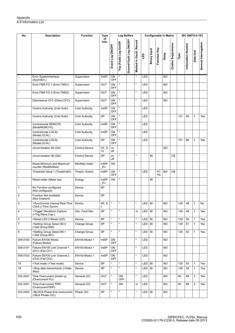
Appendix
A.9 Information List
SIPROTEC, 7UT6x, ManualC53000-G1176-C230-3, Release date 05.2013
630
- Error Systeminterface (SysIntErr.)
Supervision IntSP ON OFF
* * LED BO
- Error FMS FO 1 (Error FMS1) Supervision OUT ON OFF
* * LED BO
- Error FMS FO 2 (Error FMS2) Supervision OUT ON OFF
* * LED BO
- Disturbance CFC (Distur.CFC) Supervision OUT ON OFF
* * LED BO
- Control Authority (Cntrl Auth) Cntrl Authority IntSP ON OFF
* LED
- Control Authority (Cntrl Auth) Cntrl Authority DP ON OFF
* LED 101 85 1 Yes
- Controlmode REMOTE (ModeREMOTE)
Cntrl Authority IntSP ON OFF
* LED
- Controlmode LOCAL(ModeLOCAL)
Cntrl Authority IntSP ON OFF
* LED
- Controlmode LOCAL(ModeLOCAL)
Cntrl Authority DP ON OFF
* LED 101 86 1 Yes
- circuit breaker Q0 (Q0) Control Device CF_D12
on off
BO
- circuit breaker Q0 (Q0) Control Device DP on off
* * BI CB
- Reset Minimum and Maximum counter (ResMinMax)
Min/Max meter IntSP_Ev
ON
- Threshold Value 1 (ThreshVal1) Thresh.-Switch IntSP ON OFF
* * LED FCTN
BO CB
- Reset meter (Meter res) Energy IntSP_Ev
ON * BI
1 No Function configured (Not configured)
Device SP
2 Function Not Available (Non Existent)
Device SP
3 >Synchronize Internal Real Time Clock (>Time Synch)
Device SP_Ev
* * * LED BI BO 135 48 1 No
4 >Trigger Waveform Capture (>Trig.Wave.Cap.)
Osc. Fault Rec. SP * * m LED BI BO 135 49 1 Yes
5 >Reset LED (>Reset LED) Device SP * * * LED BI BO 135 50 1 Yes
7 >Setting Group Select Bit 0(>Set Group Bit0)
Change Group SP * * * LED BI BO 135 51 1 Yes
8 >Setting Group Select Bit 1(>Set Group Bit1)
Change Group SP * * * LED BI BO 135 52 1 Yes
009.0100 Failure EN100 Modul (Failure Modul)
EN100-Modul 1 IntSP ON OFF
* LED BO
009.0101 Failure EN100 Link Channel 1 (Ch1) (Fail Ch1)
EN100-Modul 1 IntSP ON OFF
* LED BO
009.0102 Failure EN100 Link Channel 2 (Ch2) (Fail Ch2)
EN100-Modul 1 IntSP ON OFF
* LED BO
15 >Test mode (>Test mode) Device SP * * * LED BI BO 135 53 1 Yes
16 >Stop data transmission (>Data-Stop)
Device SP * * * LED BI BO 135 54 1 Yes
022.2421 Time Overcurrent picked up (Overcurrent PU)
General O/C OUT * ON OFF
* LED BO 60 69 2 Yes
022.2451 Time Overcurrent TRIP (OvercurrentTRIP)
General O/C OUT * ON m LED BO 60 68 2 Yes
023.2404 >BLOCK Phase time overcurrent (>BLK Phase O/C)
Phase O/C SP * * * LED BI BO
No. Description Function Type of
Info.
Log Buffers Configurable in Matrix IEC 60870-5-103
Eve
nt
Lo
g O
N/O
FF
Tri
p (
Fa
ult
) L
og
On
/Off
Gro
un
d F
au
lt L
og
ON
/OF
F
Ma
rke
d i
n O
scil
l. R
ec
ord
LE
D
Bin
ary
In
pu
t
Fu
nc
tio
n K
ey
Re
lay
Ch
att
er
Su
pp
res
sio
n
Typ
e
Info
rma
tio
n N
um
be
r
Da
ta U
nit
Ge
ne
ral
Inte
rro
ga
tio
n
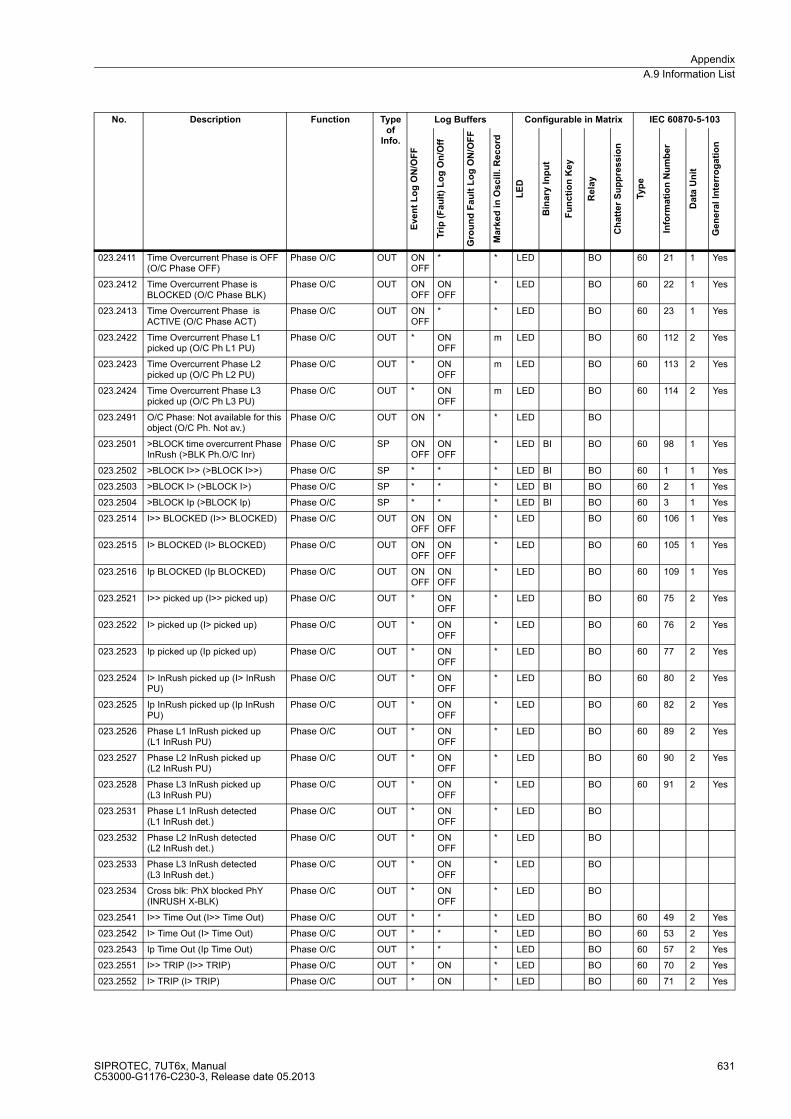
Appendix
A.9 Information List
SIPROTEC, 7UT6x, ManualC53000-G1176-C230-3, Release date 05.2013
631
023.2411 Time Overcurrent Phase is OFF (O/C Phase OFF)
Phase O/C OUT ON OFF
* * LED BO 60 21 1 Yes
023.2412 Time Overcurrent Phase is BLOCKED (O/C Phase BLK)
Phase O/C OUT ON OFF
ON OFF
* LED BO 60 22 1 Yes
023.2413 Time Overcurrent Phase is ACTIVE (O/C Phase ACT)
Phase O/C OUT ON OFF
* * LED BO 60 23 1 Yes
023.2422 Time Overcurrent Phase L1 picked up (O/C Ph L1 PU)
Phase O/C OUT * ON OFF
m LED BO 60 112 2 Yes
023.2423 Time Overcurrent Phase L2 picked up (O/C Ph L2 PU)
Phase O/C OUT * ON OFF
m LED BO 60 113 2 Yes
023.2424 Time Overcurrent Phase L3 picked up (O/C Ph L3 PU)
Phase O/C OUT * ON OFF
m LED BO 60 114 2 Yes
023.2491 O/C Phase: Not available for this object (O/C Ph. Not av.)
Phase O/C OUT ON * * LED BO
023.2501 >BLOCK time overcurrent Phase InRush (>BLK Ph.O/C Inr)
Phase O/C SP ON OFF
ON OFF
* LED BI BO 60 98 1 Yes
023.2502 >BLOCK I>> (>BLOCK I>>) Phase O/C SP * * * LED BI BO 60 1 1 Yes
023.2503 >BLOCK I> (>BLOCK I>) Phase O/C SP * * * LED BI BO 60 2 1 Yes
023.2504 >BLOCK Ip (>BLOCK Ip) Phase O/C SP * * * LED BI BO 60 3 1 Yes
023.2514 I>> BLOCKED (I>> BLOCKED) Phase O/C OUT ON OFF
ON OFF
* LED BO 60 106 1 Yes
023.2515 I> BLOCKED (I> BLOCKED) Phase O/C OUT ON OFF
ON OFF
* LED BO 60 105 1 Yes
023.2516 Ip BLOCKED (Ip BLOCKED) Phase O/C OUT ON OFF
ON OFF
* LED BO 60 109 1 Yes
023.2521 I>> picked up (I>> picked up) Phase O/C OUT * ON OFF
* LED BO 60 75 2 Yes
023.2522 I> picked up (I> picked up) Phase O/C OUT * ON OFF
* LED BO 60 76 2 Yes
023.2523 Ip picked up (Ip picked up) Phase O/C OUT * ON OFF
* LED BO 60 77 2 Yes
023.2524 I> InRush picked up (I> InRush PU)
Phase O/C OUT * ON OFF
* LED BO 60 80 2 Yes
023.2525 Ip InRush picked up (Ip InRush PU)
Phase O/C OUT * ON OFF
* LED BO 60 82 2 Yes
023.2526 Phase L1 InRush picked up (L1 InRush PU)
Phase O/C OUT * ON OFF
* LED BO 60 89 2 Yes
023.2527 Phase L2 InRush picked up (L2 InRush PU)
Phase O/C OUT * ON OFF
* LED BO 60 90 2 Yes
023.2528 Phase L3 InRush picked up (L3 InRush PU)
Phase O/C OUT * ON OFF
* LED BO 60 91 2 Yes
023.2531 Phase L1 InRush detected (L1 InRush det.)
Phase O/C OUT * ON OFF
* LED BO
023.2532 Phase L2 InRush detected (L2 InRush det.)
Phase O/C OUT * ON OFF
* LED BO
023.2533 Phase L3 InRush detected (L3 InRush det.)
Phase O/C OUT * ON OFF
* LED BO
023.2534 Cross blk: PhX blocked PhY (INRUSH X-BLK)
Phase O/C OUT * ON OFF
* LED BO
023.2541 I>> Time Out (I>> Time Out) Phase O/C OUT * * * LED BO 60 49 2 Yes
023.2542 I> Time Out (I> Time Out) Phase O/C OUT * * * LED BO 60 53 2 Yes
023.2543 Ip Time Out (Ip Time Out) Phase O/C OUT * * * LED BO 60 57 2 Yes
023.2551 I>> TRIP (I>> TRIP) Phase O/C OUT * ON * LED BO 60 70 2 Yes
023.2552 I> TRIP (I> TRIP) Phase O/C OUT * ON * LED BO 60 71 2 Yes
No. Description Function Type of
Info.
Log Buffers Configurable in Matrix IEC 60870-5-103
Eve
nt
Lo
g O
N/O
FF
Tri
p (
Fa
ult
) L
og
On
/Off
Gro
un
d F
au
lt L
og
ON
/OF
F
Ma
rke
d i
n O
scil
l. R
ec
ord
LE
D
Bin
ary
In
pu
t
Fu
nc
tio
n K
ey
Re
lay
Ch
att
er
Su
pp
res
sio
n
Typ
e
Info
rma
tio
n N
um
be
r
Da
ta U
nit
Ge
ne
ral
Inte
rro
ga
tio
n
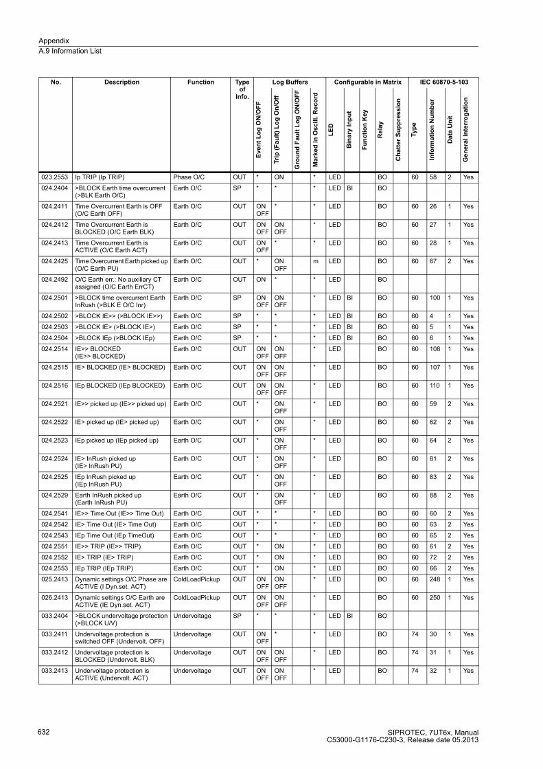
Appendix
A.9 Information List
SIPROTEC, 7UT6x, ManualC53000-G1176-C230-3, Release date 05.2013
632
023.2553 Ip TRIP (Ip TRIP) Phase O/C OUT * ON * LED BO 60 58 2 Yes
024.2404 >BLOCK Earth time overcurrent (>BLK Earth O/C)
Earth O/C SP * * * LED BI BO
024.2411 Time Overcurrent Earth is OFF (O/C Earth OFF)
Earth O/C OUT ON OFF
* * LED BO 60 26 1 Yes
024.2412 Time Overcurrent Earth is BLOCKED (O/C Earth BLK)
Earth O/C OUT ON OFF
ON OFF
* LED BO 60 27 1 Yes
024.2413 Time Overcurrent Earth is ACTIVE (O/C Earth ACT)
Earth O/C OUT ON OFF
* * LED BO 60 28 1 Yes
024.2425 Time Overcurrent Earth picked up (O/C Earth PU)
Earth O/C OUT * ON OFF
m LED BO 60 67 2 Yes
024.2492 O/C Earth err.: No auxiliary CT assigned (O/C Earth ErrCT)
Earth O/C OUT ON * * LED BO
024.2501 >BLOCK time overcurrent Earth InRush (>BLK E O/C Inr)
Earth O/C SP ON OFF
ON OFF
* LED BI BO 60 100 1 Yes
024.2502 >BLOCK IE>> (>BLOCK IE>>) Earth O/C SP * * * LED BI BO 60 4 1 Yes
024.2503 >BLOCK IE> (>BLOCK IE>) Earth O/C SP * * * LED BI BO 60 5 1 Yes
024.2504 >BLOCK IEp (>BLOCK IEp) Earth O/C SP * * * LED BI BO 60 6 1 Yes
024.2514 IE>> BLOCKED (IE>> BLOCKED)
Earth O/C OUT ON OFF
ON OFF
* LED BO 60 108 1 Yes
024.2515 IE> BLOCKED (IE> BLOCKED) Earth O/C OUT ON OFF
ON OFF
* LED BO 60 107 1 Yes
024.2516 IEp BLOCKED (IEp BLOCKED) Earth O/C OUT ON OFF
ON OFF
* LED BO 60 110 1 Yes
024.2521 IE>> picked up (IE>> picked up) Earth O/C OUT * ON OFF
* LED BO 60 59 2 Yes
024.2522 IE> picked up (IE> picked up) Earth O/C OUT * ON OFF
* LED BO 60 62 2 Yes
024.2523 IEp picked up (IEp picked up) Earth O/C OUT * ON OFF
* LED BO 60 64 2 Yes
024.2524 IE> InRush picked up (IE> InRush PU)
Earth O/C OUT * ON OFF
* LED BO 60 81 2 Yes
024.2525 IEp InRush picked up (IEp InRush PU)
Earth O/C OUT * ON OFF
* LED BO 60 83 2 Yes
024.2529 Earth InRush picked up (Earth InRush PU)
Earth O/C OUT * ON OFF
* LED BO 60 88 2 Yes
024.2541 IE>> Time Out (IE>> Time Out) Earth O/C OUT * * * LED BO 60 60 2 Yes
024.2542 IE> Time Out (IE> Time Out) Earth O/C OUT * * * LED BO 60 63 2 Yes
024.2543 IEp Time Out (IEp TimeOut) Earth O/C OUT * * * LED BO 60 65 2 Yes
024.2551 IE>> TRIP (IE>> TRIP) Earth O/C OUT * ON * LED BO 60 61 2 Yes
024.2552 IE> TRIP (IE> TRIP) Earth O/C OUT * ON * LED BO 60 72 2 Yes
024.2553 IEp TRIP (IEp TRIP) Earth O/C OUT * ON * LED BO 60 66 2 Yes
025.2413 Dynamic settings O/C Phase are ACTIVE (I Dyn.set. ACT)
ColdLoadPickup OUT ON OFF
ON OFF
* LED BO 60 248 1 Yes
026.2413 Dynamic settings O/C Earth are ACTIVE (IE Dyn.set. ACT)
ColdLoadPickup OUT ON OFF
ON OFF
* LED BO 60 250 1 Yes
033.2404 >BLOCK undervoltage protection (>BLOCK U/V)
Undervoltage SP * * * LED BI BO
033.2411 Undervoltage protection is switched OFF (Undervolt. OFF)
Undervoltage OUT ON OFF
* * LED BO 74 30 1 Yes
033.2412 Undervoltage protection is BLOCKED (Undervolt. BLK)
Undervoltage OUT ON OFF
ON OFF
* LED BO 74 31 1 Yes
033.2413 Undervoltage protection is ACTIVE (Undervolt. ACT)
Undervoltage OUT ON OFF
ON OFF
* LED BO 74 32 1 Yes
No. Description Function Type of
Info.
Log Buffers Configurable in Matrix IEC 60870-5-103
Eve
nt
Lo
g O
N/O
FF
Tri
p (
Fa
ult
) L
og
On
/Off
Gro
un
d F
au
lt L
og
ON
/OF
F
Ma
rke
d i
n O
scil
l. R
ec
ord
LE
D
Bin
ary
In
pu
t
Fu
nc
tio
n K
ey
Re
lay
Ch
att
er
Su
pp
res
sio
n
Typ
e
Info
rma
tio
n N
um
be
r
Da
ta U
nit
Ge
ne
ral
Inte
rro
ga
tio
n
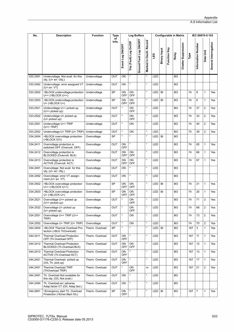
Appendix
A.9 Information List
SIPROTEC, 7UT6x, ManualC53000-G1176-C230-3, Release date 05.2013
633
033.2491 Undervoltage: Not avail. for this obj. (U< err. Obj.)
Undervoltage OUT ON * * LED BO
033.2492 Undervoltage: error assigned VT (U< err. VT)
Undervoltage OUT ON * * LED BO
033.2502 >BLOCK undervoltage protection U<< (>BLOCK U<<)
Undervoltage SP ON OFF
ON OFF
* LED BI BO 74 8 1 Yes
033.2503 >BLOCK undervoltage protection U< (>BLOCK U<)
Undervoltage SP ON OFF
ON OFF
* LED BI BO 74 6 1 Yes
033.2521 Undervoltage U<< picked up (U<< picked up)
Undervoltage OUT * ON OFF
* LED BO 74 37 2 Yes
033.2522 Undervoltage U< picked up (U< picked up)
Undervoltage OUT * ON OFF
* LED BO 74 33 2 Yes
033.2551 Undervoltage U<< TRIP (U<< TRIP)
Undervoltage OUT * ON * LED BO 74 40 2 Yes
033.2552 Undervoltage U< TRIP (U< TRIP) Undervoltage OUT * ON * LED BO 74 39 2 Yes
034.2404 >BLOCK overvoltage protection (>BLOCK O/V)
Overvoltage SP * * * LED BI BO
034.2411 Overvoltage protection is switched OFF (Overvolt. OFF)
Overvoltage OUT ON OFF
* * LED BO 74 65 1 Yes
034.2412 Overvoltage protection is BLOCKED (Overvolt. BLK)
Overvoltage OUT ON OFF
ON OFF
* LED BO 74 66 1 Yes
034.2413 Overvoltage protection is ACTIVE (Overvolt. ACT)
Overvoltage OUT ON OFF
ON OFF
* LED BO 74 67 1 Yes
034.2491 Overvoltage: Not avail. for this obj. (U> err. Obj.)
Overvoltage OUT ON * * LED BO
034.2492 Overvoltage: error VT assign-ment (U> err. VT)
Overvoltage OUT ON * * LED BO
034.2502 >BLOCK overvoltage protection U>> (>BLOCK U>>)
Overvoltage SP ON OFF
ON OFF
* LED BI BO 74 21 1 Yes
034.2503 >BLOCK overvoltage protection U> (>BLOCK U>)
Overvoltage SP ON OFF
ON OFF
* LED BI BO 74 20 1 Yes
034.2521 Overvoltage U>> picked up (U>> picked up)
Overvoltage OUT * ON OFF
* LED BO 74 71 2 Yes
034.2522 Overvoltage U> picked up (U> picked up)
Overvoltage OUT * ON OFF
* LED BO 74 68 2 Yes
034.2551 Overvoltage U>> TRIP (U>> TRIP)
Overvoltage OUT * ON * LED BO 74 73 2 Yes
034.2552 Overvoltage U> TRIP (U> TRIP) Overvoltage OUT * ON * LED BO 74 70 2 Yes
044.2404 >BLOCK Thermal Overload Pro-tection (>BLK ThOverload)
Therm. Overload SP * * * LED BI BO 167 3 1 Yes
044.2411 Thermal Overload Protection OFF (Th.Overload OFF)
Therm. Overload OUT ON OFF
* * LED BO 167 11 1 Yes
044.2412 Thermal Overload Protection BLOCKED (Th.Overload BLK)
Therm. Overload OUT ON OFF
ON OFF
* LED BO 167 12 1 Yes
044.2413 Thermal Overload Protection ACTIVE (Th.Overload ACT)
Therm. Overload OUT ON OFF
* * LED BO 167 13 1 Yes
044.2421 Thermal Overload picked up (O/L Th. pick.up)
Therm. Overload OUT ON OFF
* * LED BO 167 17 1 Yes
044.2451 Thermal Overload TRIP (ThOverload TRIP)
Therm. Overload OUT * ON OFF
m LED BO 167 21 2 Yes
044.2491 Th. Overload Not available for this obj. (O/L Not avail.)
Therm. Overload OUT ON * * LED BO
044.2494 Th. Overload err.:adverse Adap.factor CT (O/L Adap.fact.)
Therm. Overload OUT ON * * LED BO
044.2601 >Emergency start Th. Overload Protection (>Emer.Start O/L)
Therm. Overload SP ON OFF
* * LED BI BO 167 7 1 Yes
No. Description Function Type of
Info.
Log Buffers Configurable in Matrix IEC 60870-5-103
Eve
nt
Lo
g O
N/O
FF
Tri
p (
Fa
ult
) L
og
On
/Off
Gro
un
d F
au
lt L
og
ON
/OF
F
Ma
rke
d i
n O
scil
l. R
ec
ord
LE
D
Bin
ary
In
pu
t
Fu
nc
tio
n K
ey
Re
lay
Ch
att
er
Su
pp
res
sio
n
Typ
e
Info
rma
tio
n N
um
be
r
Da
ta U
nit
Ge
ne
ral
Inte
rro
ga
tio
n
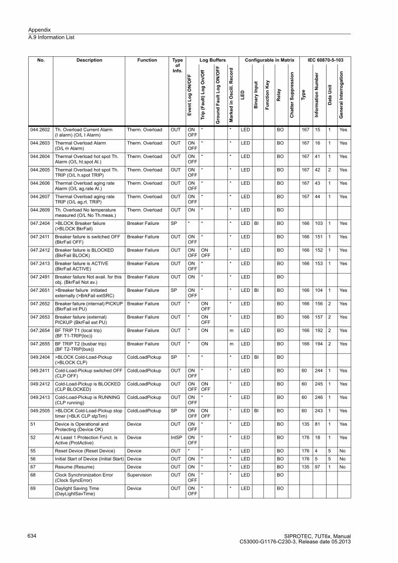
Appendix
A.9 Information List
SIPROTEC, 7UT6x, ManualC53000-G1176-C230-3, Release date 05.2013
634
044.2602 Th. Overload Current Alarm (I alarm) (O/L I Alarm)
Therm. Overload OUT ON OFF
* * LED BO 167 15 1 Yes
044.2603 Thermal Overload Alarm (O/L Θ Alarm)
Therm. Overload OUT ON OFF
* * LED BO 167 16 1 Yes
044.2604 Thermal Overload hot spot Th. Alarm (O/L ht.spot Al.)
Therm. Overload OUT ON OFF
* * LED BO 167 41 1 Yes
044.2605 Thermal Overload hot spot Th. TRIP (O/L h.spot TRIP)
Therm. Overload OUT ON OFF
* * LED BO 167 42 2 Yes
044.2606 Thermal Overload aging rate Alarm (O/L ag.rate Al.)
Therm. Overload OUT ON OFF
* * LED BO 167 43 1 Yes
044.2607 Thermal Overload aging rate TRIP (O/L ag.rt. TRIP)
Therm. Overload OUT ON OFF
* * LED BO 167 44 1 Yes
044.2609 Th. Overload No temperature measured (O/L No Th.meas.)
Therm. Overload OUT ON * * LED BO
047.2404 >BLOCK Breaker failure (>BLOCK BkrFail)
Breaker Failure SP * * * LED BI BO 166 103 1 Yes
047.2411 Breaker failure is switched OFF (BkrFail OFF)
Breaker Failure OUT ON OFF
* * LED BO 166 151 1 Yes
047.2412 Breaker failure is BLOCKED (BkrFail BLOCK)
Breaker Failure OUT ON OFF
ON OFF
* LED BO 166 152 1 Yes
047.2413 Breaker failure is ACTIVE (BkrFail ACTIVE)
Breaker Failure OUT ON OFF
* * LED BO 166 153 1 Yes
047.2491 Breaker failure Not avail. for this obj. (BkrFail Not av.)
Breaker Failure OUT ON * * LED BO
047.2651 >Breaker failure initiated externally (>BrkFail extSRC)
Breaker Failure SP ON OFF
* * LED BI BO 166 104 1 Yes
047.2652 Breaker failure (internal) PICKUP (BkrFail int PU)
Breaker Failure OUT * ON OFF
* LED BO 166 156 2 Yes
047.2653 Breaker failure (external) PICKUP (BkrFail ext PU)
Breaker Failure OUT * ON OFF
* LED BO 166 157 2 Yes
047.2654 BF TRIP T1 (local trip) (BF T1-TRIP(loc))
Breaker Failure OUT * ON m LED BO 166 192 2 Yes
047.2655 BF TRIP T2 (busbar trip) (BF T2-TRIP(bus))
Breaker Failure OUT * ON m LED BO 166 194 2 Yes
049.2404 >BLOCK Cold-Load-Pickup (>BLOCK CLP)
ColdLoadPickup SP * * * LED BI BO
049.2411 Cold-Load-Pickup switched OFF (CLP OFF)
ColdLoadPickup OUT ON OFF
* * LED BO 60 244 1 Yes
049.2412 Cold-Load-Pickup is BLOCKED (CLP BLOCKED)
ColdLoadPickup OUT ON OFF
ON OFF
* LED BO 60 245 1 Yes
049.2413 Cold-Load-Pickup is RUNNING (CLP running)
ColdLoadPickup OUT ON OFF
* * LED BO 60 246 1 Yes
049.2505 >BLOCK Cold-Load-Pickup stop timer (>BLK CLP stpTim)
ColdLoadPickup SP ON OFF
ON OFF
* LED BI BO 60 243 1 Yes
51 Device is Operational and Protecting (Device OK)
Device OUT ON OFF
* * LED BO 135 81 1 Yes
52 At Least 1 Protection Funct. is Active (ProtActive)
Device IntSP ON OFF
* * LED BO 176 18 1 Yes
55 Reset Device (Reset Device) Device OUT * * * LED BO 176 4 5 No
56 Initial Start of Device (Initial Start) Device OUT ON * * LED BO 176 5 5 No
67 Resume (Resume) Device OUT ON * * LED BO 135 97 1 No
68 Clock Synchronization Error (Clock SyncError)
Supervision OUT ON OFF
* * LED BO
69 Daylight Saving Time (DayLightSavTime)
Device OUT ON OFF
* * LED BO
No. Description Function Type of
Info.
Log Buffers Configurable in Matrix IEC 60870-5-103
Eve
nt
Lo
g O
N/O
FF
Tri
p (
Fa
ult
) L
og
On
/Off
Gro
un
d F
au
lt L
og
ON
/OF
F
Ma
rke
d i
n O
scil
l. R
ec
ord
LE
D
Bin
ary
In
pu
t
Fu
nc
tio
n K
ey
Re
lay
Ch
att
er
Su
pp
res
sio
n
Typ
e
Info
rma
tio
n N
um
be
r
Da
ta U
nit
Ge
ne
ral
Inte
rro
ga
tio
n

Appendix
A.9 Information List
SIPROTEC, 7UT6x, ManualC53000-G1176-C230-3, Release date 05.2013
635
70 Setting calculation is running (Settings Calc.)
Device OUT ON OFF
* * LED BO 176 22 1 Yes
71 Settings Check (Settings Check) Device OUT * * * LED BO
72 Level-2 change (Level-2 change) Device OUT ON OFF
* * LED BO
73 Local setting change (Local change)
Device OUT * * * LED BO
109 Frequency out of range (Frequ. o.o.r.)
Device OUT ON OFF
* * LED BO
110 Event lost (Event Lost) Supervision OUT_Ev
ON * * LED BO 135 130 1 No
113 Flag Lost (Flag Lost) Supervision OUT ON * M LED BO 135 136 1 Yes
125 Chatter ON (Chatter ON) Device OUT ON OFF
* * LED BO 135 145 1 Yes
126 Protection ON/OFF (via system port) (ProtON/OFF)
P.System Data 2 IntSP ON OFF
* * LED BO
140 Error with a summary alarm (Error Sum Alarm)
Supervision OUT * * * LED BO 176 47 1 Yes
160 Alarm Summary Event (Alarm Sum Event)
Supervision OUT * * * LED BO 176 46 1 Yes
161 Failure: General Current Supervi-sion (Fail I Superv.)
Measurem.Superv OUT ON OFF
* * LED BO
163 Failure: Current Balance (Fail I balance)
Measurem.Superv OUT ON OFF
* * LED BO 135 183 1 Yes
164 Failure: General Voltage Supervision (Fail U Superv.)
Measurem.Superv OUT ON OFF
* * LED BO
165 Failure: Voltage Summation Phase-Earth (Fail Σ U Ph-E)
Measurem.Superv OUT ON OFF
* * LED BO 135 184 1 Yes
167 Failure: Voltage Balance (Fail U balance)
Measurem.Superv OUT ON OFF
* * LED BO 135 186 1 Yes
169 VT Fuse Failure (alarm >10s)(VT FuseFail>10s)
Supervision OUT ON OFF
* * LED BO 135 188 1 Yes
170 VT Fuse Failure (alarm instantaneous) (VT FuseFail)
Supervision OUT ON OFF
* * LED BO
171 Failure: Phase Sequence (Fail Ph. Seq.)
Measurem.Superv OUT ON OFF
* * LED BO
175 Failure: Phase Sequence Current (Fail Ph. Seq. I)
Measurem.Superv OUT ON OFF
* * LED BO 135 191 1 Yes
176 Failure: Phase Sequence Voltage (Fail Ph. Seq. U)
Measurem.Superv OUT ON OFF
* * LED BO 135 192 1 Yes
177 Failure: Battery empty(Fail Battery)
Supervision OUT ON OFF
* * LED BO 135 193 1 Yes
181 Error: Measurement system (Error MeasurSys)
Supervision OUT ON OFF
* * LED BO 135 178 1 Yes
183 Error Board 1 (Error Board 1) Supervision OUT ON OFF
* * LED BO 135 171 1 Yes
184 Error Board 2 (Error Board 2) Supervision OUT ON OFF
* * LED BO 135 172 1 Yes
185 Error Board 3 (Error Board 3) Supervision OUT ON OFF
* * LED BO 135 173 1 Yes
186 Error Board 4 (Error Board 4) Supervision OUT ON OFF
* * LED BO 135 174 1 Yes
187 Error Board 5 (Error Board 5) Supervision OUT ON OFF
* * LED BO 135 175 1 Yes
188 Error Board 6 (Error Board 6) Supervision OUT ON OFF
* * LED BO 135 176 1 Yes
No. Description Function Type of
Info.
Log Buffers Configurable in Matrix IEC 60870-5-103
Eve
nt
Lo
g O
N/O
FF
Tri
p (
Fa
ult
) L
og
On
/Off
Gro
un
d F
au
lt L
og
ON
/OF
F
Ma
rke
d i
n O
scil
l. R
ec
ord
LE
D
Bin
ary
In
pu
t
Fu
nc
tio
n K
ey
Re
lay
Ch
att
er
Su
pp
res
sio
n
Typ
e
Info
rma
tio
n N
um
be
r
Da
ta U
nit
Ge
ne
ral
Inte
rro
ga
tio
n
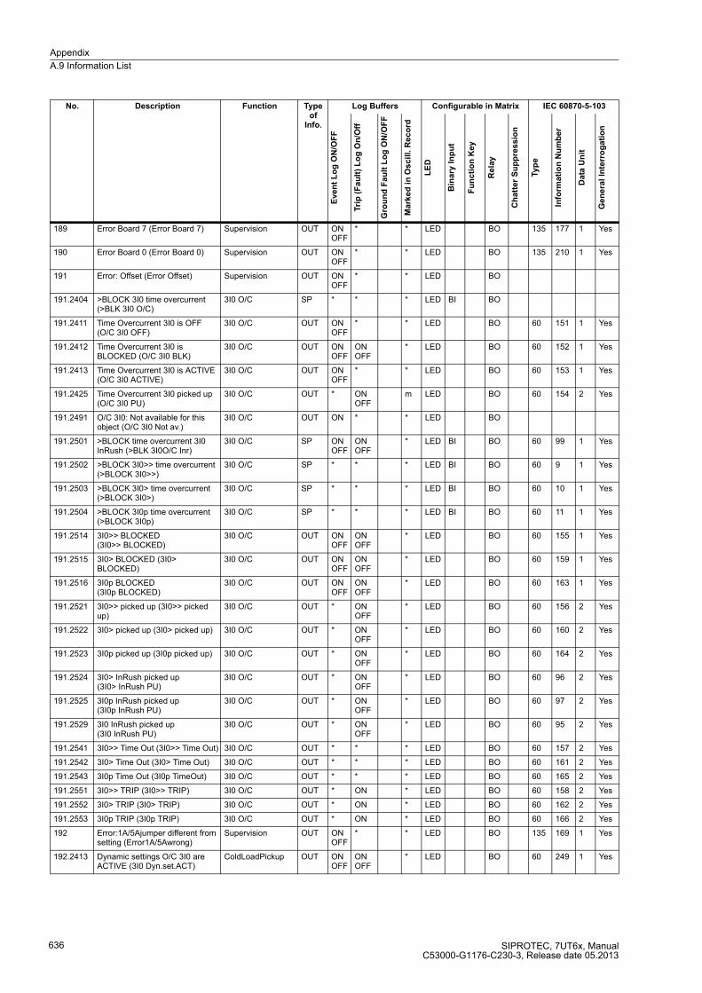
Appendix
A.9 Information List
SIPROTEC, 7UT6x, ManualC53000-G1176-C230-3, Release date 05.2013
636
189 Error Board 7 (Error Board 7) Supervision OUT ON OFF
* * LED BO 135 177 1 Yes
190 Error Board 0 (Error Board 0) Supervision OUT ON OFF
* * LED BO 135 210 1 Yes
191 Error: Offset (Error Offset) Supervision OUT ON OFF
* * LED BO
191.2404 >BLOCK 3I0 time overcurrent (>BLK 3I0 O/C)
3I0 O/C SP * * * LED BI BO
191.2411 Time Overcurrent 3I0 is OFF (O/C 3I0 OFF)
3I0 O/C OUT ON OFF
* * LED BO 60 151 1 Yes
191.2412 Time Overcurrent 3I0 is BLOCKED (O/C 3I0 BLK)
3I0 O/C OUT ON OFF
ON OFF
* LED BO 60 152 1 Yes
191.2413 Time Overcurrent 3I0 is ACTIVE (O/C 3I0 ACTIVE)
3I0 O/C OUT ON OFF
* * LED BO 60 153 1 Yes
191.2425 Time Overcurrent 3I0 picked up (O/C 3I0 PU)
3I0 O/C OUT * ON OFF
m LED BO 60 154 2 Yes
191.2491 O/C 3I0: Not available for this object (O/C 3I0 Not av.)
3I0 O/C OUT ON * * LED BO
191.2501 >BLOCK time overcurrent 3I0 InRush (>BLK 3I0O/C Inr)
3I0 O/C SP ON OFF
ON OFF
* LED BI BO 60 99 1 Yes
191.2502 >BLOCK 3I0>> time overcurrent (>BLOCK 3I0>>)
3I0 O/C SP * * * LED BI BO 60 9 1 Yes
191.2503 >BLOCK 3I0> time overcurrent (>BLOCK 3I0>)
3I0 O/C SP * * * LED BI BO 60 10 1 Yes
191.2504 >BLOCK 3I0p time overcurrent (>BLOCK 3I0p)
3I0 O/C SP * * * LED BI BO 60 11 1 Yes
191.2514 3I0>> BLOCKED (3I0>> BLOCKED)
3I0 O/C OUT ON OFF
ON OFF
* LED BO 60 155 1 Yes
191.2515 3I0> BLOCKED (3I0> BLOCKED)
3I0 O/C OUT ON OFF
ON OFF
* LED BO 60 159 1 Yes
191.2516 3I0p BLOCKED (3I0p BLOCKED)
3I0 O/C OUT ON OFF
ON OFF
* LED BO 60 163 1 Yes
191.2521 3I0>> picked up (3I0>> picked up)
3I0 O/C OUT * ON OFF
* LED BO 60 156 2 Yes
191.2522 3I0> picked up (3I0> picked up) 3I0 O/C OUT * ON OFF
* LED BO 60 160 2 Yes
191.2523 3I0p picked up (3I0p picked up) 3I0 O/C OUT * ON OFF
* LED BO 60 164 2 Yes
191.2524 3I0> InRush picked up (3I0> InRush PU)
3I0 O/C OUT * ON OFF
* LED BO 60 96 2 Yes
191.2525 3I0p InRush picked up (3I0p InRush PU)
3I0 O/C OUT * ON OFF
* LED BO 60 97 2 Yes
191.2529 3I0 InRush picked up (3I0 InRush PU)
3I0 O/C OUT * ON OFF
* LED BO 60 95 2 Yes
191.2541 3I0>> Time Out (3I0>> Time Out) 3I0 O/C OUT * * * LED BO 60 157 2 Yes
191.2542 3I0> Time Out (3I0> Time Out) 3I0 O/C OUT * * * LED BO 60 161 2 Yes
191.2543 3I0p Time Out (3I0p TimeOut) 3I0 O/C OUT * * * LED BO 60 165 2 Yes
191.2551 3I0>> TRIP (3I0>> TRIP) 3I0 O/C OUT * ON * LED BO 60 158 2 Yes
191.2552 3I0> TRIP (3I0> TRIP) 3I0 O/C OUT * ON * LED BO 60 162 2 Yes
191.2553 3I0p TRIP (3I0p TRIP) 3I0 O/C OUT * ON * LED BO 60 166 2 Yes
192 Error:1A/5Ajumper different from setting (Error1A/5Awrong)
Supervision OUT ON OFF
* * LED BO 135 169 1 Yes
192.2413 Dynamic settings O/C 3I0 are ACTIVE (3I0 Dyn.set.ACT)
ColdLoadPickup OUT ON OFF
ON OFF
* LED BO 60 249 1 Yes
No. Description Function Type of
Info.
Log Buffers Configurable in Matrix IEC 60870-5-103
Eve
nt
Lo
g O
N/O
FF
Tri
p (
Fa
ult
) L
og
On
/Off
Gro
un
d F
au
lt L
og
ON
/OF
F
Ma
rke
d i
n O
scil
l. R
ec
ord
LE
D
Bin
ary
In
pu
t
Fu
nc
tio
n K
ey
Re
lay
Ch
att
er
Su
pp
res
sio
n
Typ
e
Info
rma
tio
n N
um
be
r
Da
ta U
nit
Ge
ne
ral
Inte
rro
ga
tio
n
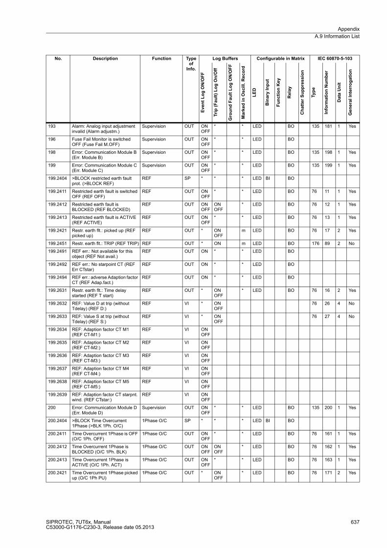
Appendix
A.9 Information List
SIPROTEC, 7UT6x, ManualC53000-G1176-C230-3, Release date 05.2013
637
193 Alarm: Analog input adjustment invalid (Alarm adjustm.)
Supervision OUT ON OFF
* * LED BO 135 181 1 Yes
196 Fuse Fail Monitor is switched OFF (Fuse Fail M.OFF)
Supervision OUT ON OFF
* * LED BO
198 Error: Communication Module B (Err. Module B)
Supervision OUT ON OFF
* * LED BO 135 198 1 Yes
199 Error: Communication Module C (Err. Module C)
Supervision OUT ON OFF
* * LED BO 135 199 1 Yes
199.2404 >BLOCK restricted earth fault prot. (>BLOCK REF)
REF SP * * * LED BI BO
199.2411 Restricted earth fault is switched OFF (REF OFF)
REF OUT ON OFF
* * LED BO 76 11 1 Yes
199.2412 Restricted earth fault is BLOCKED (REF BLOCKED)
REF OUT ON OFF
ON OFF
* LED BO 76 12 1 Yes
199.2413 Restricted earth fault is ACTIVE (REF ACTIVE)
REF OUT ON OFF
* * LED BO 76 13 1 Yes
199.2421 Restr. earth flt.: picked up (REF picked up)
REF OUT * ON OFF
m LED BO 76 17 2 Yes
199.2451 Restr. earth flt.: TRIP (REF TRIP) REF OUT * ON m LED BO 176 89 2 No
199.2491 REF err.: Not available for this object (REF Not avail.)
REF OUT ON * * LED BO
199.2492 REF err.: No starpoint CT (REF Err CTstar)
REF OUT ON * * LED BO
199.2494 REF err.: adverse Adaption factor CT (REF Adap.fact.)
REF OUT ON * * LED BO
199.2631 Restr. earth flt.: Time delay started (REF T start)
REF OUT * ON OFF
* LED BO 76 16 2 Yes
199.2632 REF: Value D at trip (without Tdelay) (REF D:)
REF VI * ON OFF
76 26 4 No
199.2633 REF: Value S at trip (without Tdelay) (REF S:)
REF VI * ON OFF
76 27 4 No
199.2634 REF: Adaption factor CT M1 (REF CT-M1:)
REF VI ON OFF
199.2635 REF: Adaption factor CT M2 (REF CT-M2:)
REF VI ON OFF
199.2636 REF: Adaption factor CT M3 (REF CT-M3:)
REF VI ON OFF
199.2637 REF: Adaption factor CT M4 (REF CT-M4:)
REF VI ON OFF
199.2638 REF: Adaption factor CT M5 (REF CT-M5:)
REF VI ON OFF
199.2639 REF: Adaption factor CT starpnt. wind. (REF CTstar:)
REF VI ON OFF
200 Error: Communication Module D (Err. Module D)
Supervision OUT ON OFF
* * LED BO 135 200 1 Yes
200.2404 >BLOCK Time Overcurrent 1Phase (>BLK 1Ph. O/C)
1Phase O/C SP * * * LED BI BO
200.2411 Time Overcurrent 1Phase is OFF (O/C 1Ph. OFF)
1Phase O/C OUT ON OFF
* * LED BO 76 161 1 Yes
200.2412 Time Overcurrent 1Phase is BLOCKED (O/C 1Ph. BLK)
1Phase O/C OUT ON OFF
ON OFF
* LED BO 76 162 1 Yes
200.2413 Time Overcurrent 1Phase is ACTIVE (O/C 1Ph. ACT)
1Phase O/C OUT ON OFF
* * LED BO 76 163 1 Yes
200.2421 Time Overcurrent 1Phase picked up (O/C 1Ph PU)
1Phase O/C OUT * ON OFF
* LED BO 76 171 2 Yes
No. Description Function Type of
Info.
Log Buffers Configurable in Matrix IEC 60870-5-103
Eve
nt
Lo
g O
N/O
FF
Tri
p (
Fa
ult
) L
og
On
/Off
Gro
un
d F
au
lt L
og
ON
/OF
F
Ma
rke
d i
n O
scil
l. R
ec
ord
LE
D
Bin
ary
In
pu
t
Fu
nc
tio
n K
ey
Re
lay
Ch
att
er
Su
pp
res
sio
n
Typ
e
Info
rma
tio
n N
um
be
r
Da
ta U
nit
Ge
ne
ral
Inte
rro
ga
tio
n
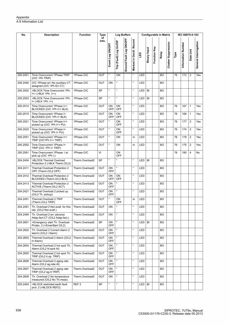
Appendix
A.9 Information List
SIPROTEC, 7UT6x, ManualC53000-G1176-C230-3, Release date 05.2013
638
200.2451 Time Overcurrent 1Phase TRIP (O/C 1Ph TRIP)
1Phase O/C OUT * ON * LED BO 76 172 2 Yes
200.2492 O/C 1Phase err.:No auxiliary CT assigned (O/C 1Ph Err CT)
1Phase O/C OUT ON * * LED BO
200.2502 >BLOCK Time Overcurrent 1Ph. I>> (>BLK 1Ph. I>>)
1Phase O/C SP * * * LED BI BO
200.2503 >BLOCK Time Overcurrent 1Ph. I> (>BLK 1Ph. I>)
1Phase O/C SP * * * LED BI BO
200.2514 Time Overcurrent 1Phase I>> BLOCKED (O/C 1Ph I>> BLK)
1Phase O/C OUT ON OFF
ON OFF
* LED BO 76 167 1 Yes
200.2515 Time Overcurrent 1Phase I> BLOCKED (O/C 1Ph I> BLK)
1Phase O/C OUT ON OFF
ON OFF
* LED BO 76 166 1 Yes
200.2521 Time Overcurrent 1Phase I>> picked up (O/C 1Ph I>> PU)
1Phase O/C OUT * ON OFF
* LED BO 76 177 2 Yes
200.2522 Time Overcurrent 1Phase I> picked up (O/C 1Ph I> PU)
1Phase O/C OUT * ON OFF
* LED BO 76 174 2 Yes
200.2551 Time Overcurrent 1Phase I>> TRIP (O/C1Ph I>> TRIP)
1Phase O/C OUT * ON m LED BO 76 179 2 Yes
200.2552 Time Overcurrent 1Phase I> TRIP (O/C 1Ph I> TRIP)
1Phase O/C OUT * ON m LED BO 76 175 2 Yes
200.2561 Time Overcurrent 1Phase: I at pick up (O/C 1Ph I:)
1Phase O/C VI ON OFF
76 180 4 No
204.2404 >BLOCK Thermal Overload Protection 2 (>BLK Therm.O/L2)
Therm.Overload2 SP * * * LED BI BO
204.2411 Thermal Overload Protection 2 OFF (Therm.O/L2 OFF)
Therm.Overload2 OUT ON OFF
* * LED BO
204.2412 Thermal Overload Protection 2 BLOCKED (Therm.O/L2 BLK)
Therm.Overload2 OUT ON OFF
ON OFF
* LED BO
204.2413 Thermal Overload Protection 2 ACTIVE (Therm.O/L2 ACT)
Therm.Overload2 OUT ON OFF
* * LED BO
204.2421 Thermal Overload 2 picked up (O/L2 Th. pickup)
Therm.Overload2 OUT ON OFF
* * LED BO
204.2451 Thermal Overload 2 TRIP (Therm.O/L2 TRIP)
Therm.Overload2 OUT * ON OFF
m LED BO
204.2491 Th. Overload 2 Not avail. for this obj. (O/L2 Not avail.)
Therm.Overload2 OUT ON * * LED BO
204.2494 Th. Overload 2 err.:adverse Adap.fact.CT (O/L2 Adap.fact.)
Therm.Overload2 OUT ON * * LED BO
204.2601 >Emergency start Th. Overload Protec. 2 (>EmerStart O/L2)
Therm.Overload2 SP ON OFF
* * LED BI BO
204.2602 Th. Overload 2 Current Alarm (I alarm) (O/L2 I Alarm)
Therm.Overload2 OUT ON OFF
* * LED BO
204.2603 Thermal Overload 2 Alarm (O/L2 Θ Alarm)Therm.Overload2 OUT ON
OFF* * LED BO
204.2604 Thermal Overload 2 hot spot Th. Alarm (O/L2 ht.spot Al)
Therm.Overload2 OUT ON OFF
* * LED BO
204.2605 Thermal Overload 2 hot spot Th. TRIP (O/L2 h.sp. TRIP)
Therm.Overload2 OUT ON OFF
* * LED BO
204.2606 Thermal Overload 2 aging rate Alarm (O/L2 ag.rate Al)
Therm.Overload2 OUT ON OFF
* * LED BO
204.2607 Thermal Overload 2 aging rate TRIP (O/L2 ag.rt.TRIP)
Therm.Overload2 OUT ON OFF
* * LED BO
204.2609 Th. Overload 2 No temperature measured (O/L2 No Th.meas)
Therm.Overload2 OUT ON * * LED BO
205.2404 >BLOCK restricted earth fault prot. 2 (>BLOCK REF2)
REF 2 SP * * * LED BI BO
No. Description Function Type of
Info.
Log Buffers Configurable in Matrix IEC 60870-5-103
Eve
nt
Lo
g O
N/O
FF
Tri
p (
Fa
ult
) L
og
On
/Off
Gro
un
d F
au
lt L
og
ON
/OF
F
Ma
rke
d i
n O
scil
l. R
ec
ord
LE
D
Bin
ary
In
pu
t
Fu
nc
tio
n K
ey
Re
lay
Ch
att
er
Su
pp
res
sio
n
Typ
e
Info
rma
tio
n N
um
be
r
Da
ta U
nit
Ge
ne
ral
Inte
rro
ga
tio
n

Appendix
A.9 Information List
SIPROTEC, 7UT6x, ManualC53000-G1176-C230-3, Release date 05.2013
639
205.2411 Restricted earth fault 2 is switched OFF (REF2 OFF)
REF 2 OUT ON OFF
* * LED BO
205.2412 Restricted earth fault 2 is BLOCKED (REF2 BLOCKED)
REF 2 OUT ON OFF
ON OFF
* LED BO
205.2413 Restricted earth fault 2 is ACTIVE (REF2 ACTIVE)
REF 2 OUT ON OFF
* * LED BO
205.2421 Restr. earth flt. 2: Time delay started (REF2 T start)
REF 2 OUT * ON OFF
m LED BO
205.2451 Restr. earth flt. 2: TRIP (REF2 TRIP)
REF 2 OUT * ON m LED BO
205.2491 REF2 err.: Not available for this object (REF2 Not avail.)
REF 2 OUT ON * * LED BO
205.2492 REF2 err.: No starpoint CT (REF2 Err CTstar)
REF 2 OUT ON * * LED BO
205.2494 REF2 err.: adverse Adaption factor CT (REF2 Adap.fact.)
REF 2 OUT ON * * LED BO
205.2631 Restr. earth flt. 2: picked up (REF2 picked up)
REF 2 OUT * ON OFF
* LED BO
205.2632 REF2: Value D at trip (without Tdelay) (REF2 D:)
REF 2 VI * ON OFF
205.2633 REF2: Value S at trip (without Tdelay) (REF2 S:)
REF 2 VI * ON OFF
205.2634 REF2: Adaption factor CT M1 (REF2 CT-M1:)
REF 2 VI ON OFF
205.2635 REF2: Adaption factor CT M2 (REF2 CT-M2:)
REF 2 VI ON OFF
205.2636 REF2: Adaption factor CT M3 (REF2 CT-M3:)
REF 2 VI ON OFF
205.2637 REF2: Adaption factor CT M4 (REF2 CT-M4:)
REF 2 VI ON OFF
205.2638 REF2: Adaption factor CT M5 (REF2 CT-M5:)
REF 2 VI ON OFF
205.2639 REF2: Adaption factor CT starpnt. wind. (REF2 CTstar:)
REF 2 VI ON OFF
206.2404 >BLOCK Breaker failure 2 (>BLOCK BkrFail2)
Breaker Fail. 2 SP * * * LED BI BO
206.2411 Breaker failure 2 is switched OFF (BkrFail2 OFF)
Breaker Fail. 2 OUT ON OFF
* * LED BO
206.2412 Breaker failure 2 is BLOCKED (BkrFail2 BLOCK)
Breaker Fail. 2 OUT ON OFF
ON OFF
* LED BO
206.2413 Breaker failure 2 is ACTIVE (BkrFail2 ACTIVE)
Breaker Fail. 2 OUT ON OFF
* * LED BO
206.2491 Breaker failure 2 Not avail.for this obj (BkrFail2 Not av)
Breaker Fail. 2 OUT ON * * LED BO
206.2651 >Breaker failure 2 initiated externally (>BrkFail2extSRC)
Breaker Fail. 2 SP ON OFF
* * LED BI BO
206.2652 Breaker failure 2 (internal) PICKUP (BkrFail2 int PU)
Breaker Fail. 2 OUT * ON OFF
* LED BO
206.2653 Breaker failure 2 (external) PICKUP (BkrFail2 ext PU)
Breaker Fail. 2 OUT * ON OFF
* LED BO
206.2654 BF 2 TRIP T1 (local trip) (BF2 T1TRIP(loc))
Breaker Fail. 2 OUT * ON m LED BO
206.2655 BF 2 TRIP T2 (busbar trip) (BF2 T2TRIP(bus))
Breaker Fail. 2 OUT * ON m LED BO
207.2404 >BLOCK Phase time overcurrent 2 (>BLK Phase O/C2)
Phase O/C 2 SP * * * LED BI BO
No. Description Function Type of
Info.
Log Buffers Configurable in Matrix IEC 60870-5-103
Eve
nt
Lo
g O
N/O
FF
Tri
p (
Fa
ult
) L
og
On
/Off
Gro
un
d F
au
lt L
og
ON
/OF
F
Ma
rke
d i
n O
scil
l. R
ec
ord
LE
D
Bin
ary
In
pu
t
Fu
nc
tio
n K
ey
Re
lay
Ch
att
er
Su
pp
res
sio
n
Typ
e
Info
rma
tio
n N
um
be
r
Da
ta U
nit
Ge
ne
ral
Inte
rro
ga
tio
n
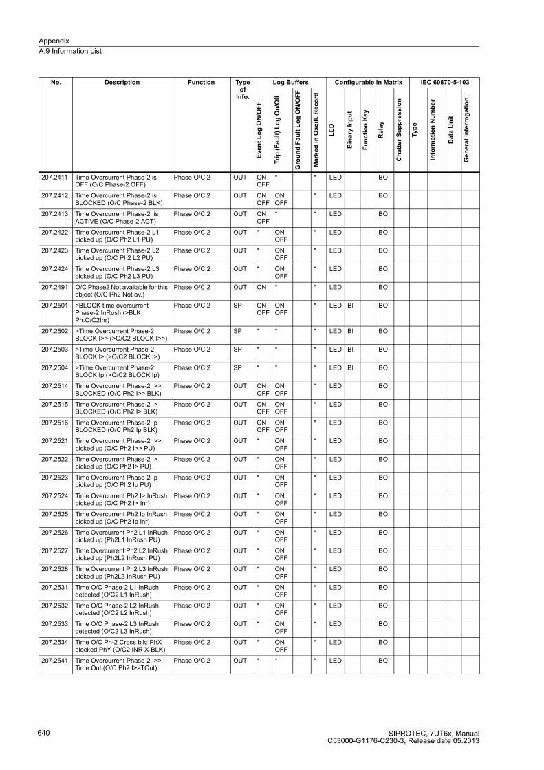
Appendix
A.9 Information List
SIPROTEC, 7UT6x, ManualC53000-G1176-C230-3, Release date 05.2013
640
207.2411 Time Overcurrent Phase-2 is OFF (O/C Phase-2 OFF)
Phase O/C 2 OUT ON OFF
* * LED BO
207.2412 Time Overcurrent Phase-2 is BLOCKED (O/C Phase-2 BLK)
Phase O/C 2 OUT ON OFF
ON OFF
* LED BO
207.2413 Time Overcurrent Phase-2 is ACTIVE (O/C Phase-2 ACT)
Phase O/C 2 OUT ON OFF
* * LED BO
207.2422 Time Overcurrent Phase-2 L1 picked up (O/C Ph2 L1 PU)
Phase O/C 2 OUT * ON OFF
* LED BO
207.2423 Time Overcurrent Phase-2 L2 picked up (O/C Ph2 L2 PU)
Phase O/C 2 OUT * ON OFF
* LED BO
207.2424 Time Overcurrent Phase-2 L3 picked up (O/C Ph2 L3 PU)
Phase O/C 2 OUT * ON OFF
* LED BO
207.2491 O/C Phase2 Not available for this object (O/C Ph2 Not av.)
Phase O/C 2 OUT ON * * LED BO
207.2501 >BLOCK time overcurrent Phase-2 InRush (>BLK Ph.O/C2Inr)
Phase O/C 2 SP ON OFF
ON OFF
* LED BI BO
207.2502 >Time Overcurrent Phase-2 BLOCK I>> (>O/C2 BLOCK I>>)
Phase O/C 2 SP * * * LED BI BO
207.2503 >Time Overcurrent Phase-2 BLOCK I> (>O/C2 BLOCK I>)
Phase O/C 2 SP * * * LED BI BO
207.2504 >Time Overcurrent Phase-2 BLOCK Ip (>O/C2 BLOCK Ip)
Phase O/C 2 SP * * * LED BI BO
207.2514 Time Overcurrent Phase-2 I>> BLOCKED (O/C Ph2 I>> BLK)
Phase O/C 2 OUT ON OFF
ON OFF
* LED BO
207.2515 Time Overcurrent Phase-2 I> BLOCKED (O/C Ph2 I> BLK)
Phase O/C 2 OUT ON OFF
ON OFF
* LED BO
207.2516 Time Overcurrent Phase-2 Ip BLOCKED (O/C Ph2 Ip BLK)
Phase O/C 2 OUT ON OFF
ON OFF
* LED BO
207.2521 Time Overcurrent Phase-2 I>> picked up (O/C Ph2 I>> PU)
Phase O/C 2 OUT * ON OFF
* LED BO
207.2522 Time Overcurrent Phase-2 I> picked up (O/C Ph2 I> PU)
Phase O/C 2 OUT * ON OFF
* LED BO
207.2523 Time Overcurrent Phase-2 Ip picked up (O/C Ph2 Ip PU)
Phase O/C 2 OUT * ON OFF
* LED BO
207.2524 Time Overcurrent Ph2 I> InRush picked up (O/C Ph2 I> Inr)
Phase O/C 2 OUT * ON OFF
* LED BO
207.2525 Time Overcurrent Ph2 Ip InRush picked up (O/C Ph2 Ip Inr)
Phase O/C 2 OUT * ON OFF
* LED BO
207.2526 Time Overcurrent Ph2 L1 InRush picked up (Ph2L1 InRush PU)
Phase O/C 2 OUT * ON OFF
* LED BO
207.2527 Time Overcurrent Ph2 L2 InRush picked up (Ph2L2 InRush PU)
Phase O/C 2 OUT * ON OFF
* LED BO
207.2528 Time Overcurrent Ph2 L3 InRush picked up (Ph2L3 InRush PU)
Phase O/C 2 OUT * ON OFF
* LED BO
207.2531 Time O/C Phase-2 L1 InRush detected (O/C2 L1 InRush)
Phase O/C 2 OUT * ON OFF
* LED BO
207.2532 Time O/C Phase-2 L2 InRush detected (O/C2 L2 InRush)
Phase O/C 2 OUT * ON OFF
* LED BO
207.2533 Time O/C Phase-2 L3 InRush detected (O/C2 L3 InRush)
Phase O/C 2 OUT * ON OFF
* LED BO
207.2534 Time O/C Ph-2 Cross blk: PhX blocked PhY (O/C2 INR X-BLK)
Phase O/C 2 OUT * ON OFF
* LED BO
207.2541 Time Overcurrent Phase-2 I>> Time Out (O/C Ph2 I>>TOut)
Phase O/C 2 OUT * * * LED BO
No. Description Function Type of
Info.
Log Buffers Configurable in Matrix IEC 60870-5-103
Eve
nt
Lo
g O
N/O
FF
Tri
p (
Fa
ult
) L
og
On
/Off
Gro
un
d F
au
lt L
og
ON
/OF
F
Ma
rke
d i
n O
scil
l. R
ec
ord
LE
D
Bin
ary
In
pu
t
Fu
nc
tio
n K
ey
Re
lay
Ch
att
er
Su
pp
res
sio
n
Typ
e
Info
rma
tio
n N
um
be
r
Da
ta U
nit
Ge
ne
ral
Inte
rro
ga
tio
n

Appendix
A.9 Information List
SIPROTEC, 7UT6x, ManualC53000-G1176-C230-3, Release date 05.2013
641
207.2542 Time Overcurrent Phase-2 I> Time Out (O/C Ph2 I> TOut)
Phase O/C 2 OUT * * * LED BO
207.2543 Time Overcurrent Phase-2 Ip Time Out (O/C Ph2 Ip TOut)
Phase O/C 2 OUT * * * LED BO
207.2551 Time Overcurrent Phase-2 I>> TRIP (O/C Ph2 I>>TRIP)
Phase O/C 2 OUT * ON * LED BO
207.2552 Time Overcurrent Phase-2 I> TRIP (O/C Ph2 I> TRIP)
Phase O/C 2 OUT * ON * LED BO
207.2553 Time Overcurrent Phase-2 Ip TRIP (O/C Ph2 Ip TRIP)
Phase O/C 2 OUT * ON * LED BO
208.2413 Dynamic settings O/C Phase-2 are ACTIVE (I-2 Dyn.set.ACT)
ColdLoadPickup OUT ON OFF
ON OFF
* LED BO
209.2404 >BLOCK Phase time overcurrent 3 (>BLK Phase O/C3)
Phase O/C 3 SP * * * LED BI BO
209.2411 Time Overcurrent Phase-3 is OFF (O/C Phase-3 OFF)
Phase O/C 3 OUT ON OFF
* * LED BO
209.2412 Time Overcurrent Phase-3 is BLOCKED (O/C Phase-3 BLK)
Phase O/C 3 OUT ON OFF
ON OFF
* LED BO
209.2413 Time Overcurrent Phase-3 is ACTIVE (O/C Phase-3 ACT)
Phase O/C 3 OUT ON OFF
* * LED BO
209.2422 Time Overcurrent Phase-3 L1 picked up (O/C Ph3 L1 PU)
Phase O/C 3 OUT * ON OFF
* LED BO
209.2423 Time Overcurrent Phase-3 L2 picked up (O/C Ph3 L2 PU)
Phase O/C 3 OUT * ON OFF
* LED BO
209.2424 Time Overcurrent Phase-3 L2 picked up (O/C Ph3 L3 PU)
Phase O/C 3 OUT * ON OFF
* LED BO
209.2491 O/C Phase3 Not available for this object (O/C Ph3 Not av.)
Phase O/C 3 OUT ON * * LED BO
209.2501 >BLOCK time overcurrent Phase-3 InRush (>BLK Ph.O/C3Inr)
Phase O/C 3 SP ON OFF
ON OFF
* LED BI BO
209.2502 >Time Overcurrent Phase-3 BLOCK I>> (>O/C3 BLOCK I>>)
Phase O/C 3 SP * * * LED BI BO
209.2503 >Time Overcurrent Phase-3 BLOCK I> (>O/C3 BLOCK I>)
Phase O/C 3 SP * * * LED BI BO
209.2504 >Time Overcurrent Phase-3 BLOCK Ip (>O/C3 BLOCK Ip)
Phase O/C 3 SP * * * LED BI BO
209.2514 Time Overcurrent Phase-3 I>> BLOCKED (O/C Ph3 I>> BLK)
Phase O/C 3 OUT ON OFF
ON OFF
* LED BO
209.2515 Time Overcurrent Phase-3 I> BLOCKED (O/C Ph3 I> BLK)
Phase O/C 3 OUT ON OFF
ON OFF
* LED BO
209.2516 Time Overcurrent Phase-2 Ip BLOCKED (O/C Ph3 Ip BLK)
Phase O/C 3 OUT ON OFF
ON OFF
* LED BO
209.2521 Time Overcurrent Phase-3 I>> picked up (O/C Ph3 I>> PU)
Phase O/C 3 OUT * ON OFF
* LED BO
209.2522 Time Overcurrent Phase-3 I> picked up (O/C Ph3 I> PU)
Phase O/C 3 OUT * ON OFF
* LED BO
209.2523 Time Overcurrent Phase-3 Ip picked up (O/C Ph3 Ip PU)
Phase O/C 3 OUT * ON OFF
* LED BO
209.2524 Time Overcurrent Ph3 I> InRush picked up (O/C Ph3 I> Inr)
Phase O/C 3 OUT * ON OFF
* LED BO
209.2525 Time Overcurrent Ph3 Ip InRush picked up (O/C Ph3 Ip Inr)
Phase O/C 3 OUT * ON OFF
* LED BO
209.2526 Time Overcurrent Ph3 L1 InRush picked up (Ph3L1 InRush PU)
Phase O/C 3 OUT * ON OFF
* LED BO
No. Description Function Type of
Info.
Log Buffers Configurable in Matrix IEC 60870-5-103
Eve
nt
Lo
g O
N/O
FF
Tri
p (
Fa
ult
) L
og
On
/Off
Gro
un
d F
au
lt L
og
ON
/OF
F
Ma
rke
d i
n O
scil
l. R
ec
ord
LE
D
Bin
ary
In
pu
t
Fu
nc
tio
n K
ey
Re
lay
Ch
att
er
Su
pp
res
sio
n
Typ
e
Info
rma
tio
n N
um
be
r
Da
ta U
nit
Ge
ne
ral
Inte
rro
ga
tio
n
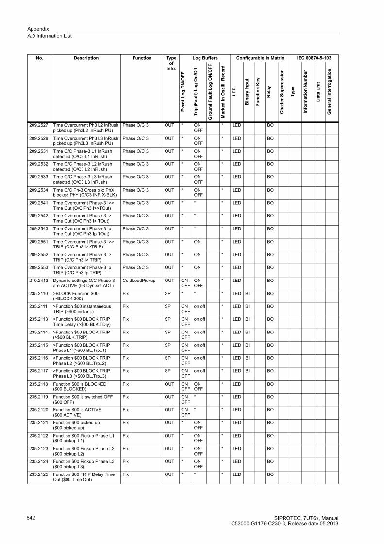
Appendix
A.9 Information List
SIPROTEC, 7UT6x, ManualC53000-G1176-C230-3, Release date 05.2013
642
209.2527 Time Overcurrent Ph3 L2 InRush picked up (Ph3L2 InRush PU)
Phase O/C 3 OUT * ON OFF
* LED BO
209.2528 Time Overcurrent Ph3 L3 InRush picked up (Ph3L3 InRush PU)
Phase O/C 3 OUT * ON OFF
* LED BO
209.2531 Time O/C Phase-3 L1 InRush detected (O/C3 L1 InRush)
Phase O/C 3 OUT * ON OFF
* LED BO
209.2532 Time O/C Phase-3 L2 InRush detected (O/C3 L2 InRush)
Phase O/C 3 OUT * ON OFF
* LED BO
209.2533 Time O/C Phase-3 L3 InRush detected (O/C3 L3 InRush)
Phase O/C 3 OUT * ON OFF
* LED BO
209.2534 Time O/C Ph-3 Cross blk: PhX blocked PhY (O/C3 INR X-BLK)
Phase O/C 3 OUT * ON OFF
* LED BO
209.2541 Time Overcurrent Phase-3 I>> Time Out (O/C Ph3 I>>TOut)
Phase O/C 3 OUT * * * LED BO
209.2542 Time Overcurrent Phase-3 I> Time Out (O/C Ph3 I> TOut)
Phase O/C 3 OUT * * * LED BO
209.2543 Time Overcurrent Phase-3 Ip Time Out (O/C Ph3 Ip TOut)
Phase O/C 3 OUT * * * LED BO
209.2551 Time Overcurrent Phase-3 I>> TRIP (O/C Ph3 I>>TRIP)
Phase O/C 3 OUT * ON * LED BO
209.2552 Time Overcurrent Phase-3 I> TRIP (O/C Ph3 I> TRIP)
Phase O/C 3 OUT * ON * LED BO
209.2553 Time Overcurrent Phase-3 Ip TRIP (O/C Ph3 Ip TRIP)
Phase O/C 3 OUT * ON * LED BO
210.2413 Dynamic settings O/C Phase-3 are ACTIVE (I-3 Dyn.set.ACT)
ColdLoadPickup OUT ON OFF
ON OFF
* LED BO
235.2110 >BLOCK Function $00(>BLOCK $00)
Flx SP * * * LED BI BO
235.2111 >Function $00 instantaneous TRIP (>$00 instant.)
Flx SP ON OFF
on off * LED BI BO
235.2113 >Function $00 BLOCK TRIP Time Delay (>$00 BLK.TDly)
Flx SP ON OFF
on off * LED BI BO
235.2114 >Function $00 BLOCK TRIP (>$00 BLK.TRIP)
Flx SP ON OFF
on off * LED BI BO
235.2115 >Function $00 BLOCK TRIP Phase L1 (>$00 BL.TrpL1)
Flx SP ON OFF
on off * LED BI BO
235.2116 >Function $00 BLOCK TRIP Phase L2 (>$00 BL.TrpL2)
Flx SP ON OFF
on off * LED BI BO
235.2117 >Function $00 BLOCK TRIP Phase L3 (>$00 BL.TrpL3)
Flx SP ON OFF
on off * LED BI BO
235.2118 Function $00 is BLOCKED ($00 BLOCKED)
Flx OUT ON OFF
ON OFF
* LED BO
235.2119 Function $00 is switched OFF ($00 OFF)
Flx OUT ON OFF
* * LED BO
235.2120 Function $00 is ACTIVE ($00 ACTIVE)
Flx OUT ON OFF
* * LED BO
235.2121 Function $00 picked up ($00 picked up)
Flx OUT * ON OFF
* LED BO
235.2122 Function $00 Pickup Phase L1 ($00 pickup L1)
Flx OUT * ON OFF
* LED BO
235.2123 Function $00 Pickup Phase L2 ($00 pickup L2)
Flx OUT * ON OFF
* LED BO
235.2124 Function $00 Pickup Phase L3 ($00 pickup L3)
Flx OUT * ON OFF
* LED BO
235.2125 Function $00 TRIP Delay Time Out ($00 Time Out)
Flx OUT * * * LED BO
No. Description Function Type of
Info.
Log Buffers Configurable in Matrix IEC 60870-5-103
Eve
nt
Lo
g O
N/O
FF
Tri
p (
Fa
ult
) L
og
On
/Off
Gro
un
d F
au
lt L
og
ON
/OF
F
Ma
rke
d i
n O
scil
l. R
ec
ord
LE
D
Bin
ary
In
pu
t
Fu
nc
tio
n K
ey
Re
lay
Ch
att
er
Su
pp
res
sio
n
Typ
e
Info
rma
tio
n N
um
be
r
Da
ta U
nit
Ge
ne
ral
Inte
rro
ga
tio
n

Appendix
A.9 Information List
SIPROTEC, 7UT6x, ManualC53000-G1176-C230-3, Release date 05.2013
643
235.2126 Function $00 TRIP ($00 TRIP) Flx OUT * ON * LED BO
235.2128 Function $00 has invalid settings ($00 inval.set)
Flx OUT ON OFF
* * LED BO
235.2701 >Function $00 block TRIP L12 (>$00 Blk Trip12)
Flx SP ON OFF
on off * LED BI BO
235.2702 >Function $00 block TRIP L23 (>$00 Blk Trip23)
Flx SP ON OFF
on off * LED BI BO
235.2703 >Function $00 block TRIP L31 (>$00 Blk Trip31)
Flx SP ON OFF
on off * LED BI BO
235.2704 Function $00 Pick-up L12 ($00 Pick-up L12)
Flx OUT * ON OFF
* LED BO
235.2705 Function $00 Pick-up L23 ($00 Pick-up L23)
Flx OUT * ON OFF
* LED BO
235.2706 Function $00 Pick-up L31 ($00 Pick-up L31)
Flx OUT * ON OFF
* LED BO
236.2127 BLOCK Flexible Function (BLK. Flex.Fct.)
P.System Data 2 IntSP on off
* * LED BO
251 Broken wire detected (Broken wire)
Supervision OUT ON OFF
* * LED BO
264 Failure: RTD-Box 1 (Fail: RTD-Box 1)
Supervision OUT ON OFF
* * LED BO 135 208 1 Yes
267 Failure: RTD-Box 2 (Fail: RTD-Box 2)
Supervision OUT ON OFF
* * LED BO 135 209 1 Yes
272 Set Point Operating Hours (SP. Op Hours>)
SetPoint(Stat) OUT ON OFF
* * LED BO 135 229 1 Yes
301 Power System fault (Pow.Sys.Flt.)
P.System Data 2 OUT ON OFF
ON * 135 231 2 Yes
302 Fault Event (Fault Event) P.System Data 2 OUT * ON * 135 232 2 Yes
311 Fault in configuration / setting (FaultConfig/Set)
P.System Data 2 OUT ON OFF
* * LED BO
312 Gen.err.: Inconsistency group/connection(GenErrGroupConn)
P.System Data 2 OUT ON * * LED BO
313 Gen.err.: Sev. earth-CTs with equal typ (GenErrEarthCT)
P.System Data 2 OUT ON * * LED BO
314 Gen.err.: Number of sides / mea-surements (GenErrSidesMeas)
P.System Data 2 OUT ON * * LED BO
320 Warn: Limit of Memory Data ex-ceeded (Warn Mem. Data)
Device OUT ON OFF
* * LED BO
321 Warn: Limit of Memory Parameter exceeded (Warn Mem. Para.)
Device OUT ON OFF
* * LED BO
321.2404 >BLOCK 3I0 time overcurrent 2 (>BLK 3I0 O/C 2)
3I0 O/C 2 SP * * * LED BI BO
321.2411 Time Overcurrent 3I0-2 is OFF (O/C 3I0-2 OFF)
3I0 O/C 2 OUT ON OFF
* * LED BO
321.2412 Time Overcurrent 3I0-2 is BLOCKED (O/C 3I0-2 BLK)
3I0 O/C 2 OUT ON OFF
ON OFF
* LED BO
321.2413 Time Overcurrent 3I0-2 is ACTIVE (O/C 3I0-2 ACT)
3I0 O/C 2 OUT ON OFF
* * LED BO
321.2425 Time Overcurrent 3I0-2 picked up (O/C 3I0-2 PU)
3I0 O/C 2 OUT * ON OFF
* LED BO
321.2491 O/C 3I0-2: Not available for this object (O/C 3I0-2 n/a)
3I0 O/C 2 OUT ON * * LED BO
321.2501 >BLOCK time overcurrent 3I0-2 InRush (>BLK 3I0O/C2Inr)
3I0 O/C 2 SP ON OFF
ON OFF
* LED BI BO
No. Description Function Type of
Info.
Log Buffers Configurable in Matrix IEC 60870-5-103
Eve
nt
Lo
g O
N/O
FF
Tri
p (
Fa
ult
) L
og
On
/Off
Gro
un
d F
au
lt L
og
ON
/OF
F
Ma
rke
d i
n O
scil
l. R
ec
ord
LE
D
Bin
ary
In
pu
t
Fu
nc
tio
n K
ey
Re
lay
Ch
att
er
Su
pp
res
sio
n
Typ
e
Info
rma
tio
n N
um
be
r
Da
ta U
nit
Ge
ne
ral
Inte
rro
ga
tio
n
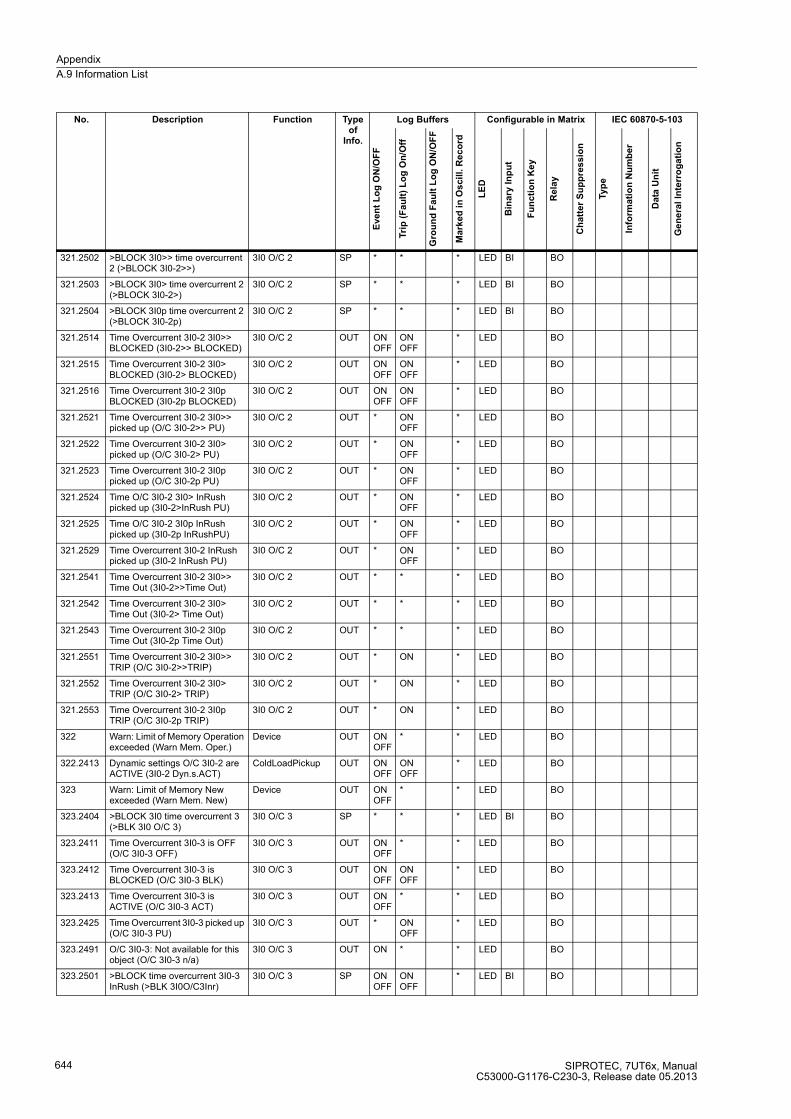
Appendix
A.9 Information List
SIPROTEC, 7UT6x, ManualC53000-G1176-C230-3, Release date 05.2013
644
321.2502 >BLOCK 3I0>> time overcurrent 2 (>BLOCK 3I0-2>>)
3I0 O/C 2 SP * * * LED BI BO
321.2503 >BLOCK 3I0> time overcurrent 2 (>BLOCK 3I0-2>)
3I0 O/C 2 SP * * * LED BI BO
321.2504 >BLOCK 3I0p time overcurrent 2 (>BLOCK 3I0-2p)
3I0 O/C 2 SP * * * LED BI BO
321.2514 Time Overcurrent 3I0-2 3I0>> BLOCKED (3I0-2>> BLOCKED)
3I0 O/C 2 OUT ON OFF
ON OFF
* LED BO
321.2515 Time Overcurrent 3I0-2 3I0> BLOCKED (3I0-2> BLOCKED)
3I0 O/C 2 OUT ON OFF
ON OFF
* LED BO
321.2516 Time Overcurrent 3I0-2 3I0p BLOCKED (3I0-2p BLOCKED)
3I0 O/C 2 OUT ON OFF
ON OFF
* LED BO
321.2521 Time Overcurrent 3I0-2 3I0>> picked up (O/C 3I0-2>> PU)
3I0 O/C 2 OUT * ON OFF
* LED BO
321.2522 Time Overcurrent 3I0-2 3I0> picked up (O/C 3I0-2> PU)
3I0 O/C 2 OUT * ON OFF
* LED BO
321.2523 Time Overcurrent 3I0-2 3I0p picked up (O/C 3I0-2p PU)
3I0 O/C 2 OUT * ON OFF
* LED BO
321.2524 Time O/C 3I0-2 3I0> InRush picked up (3I0-2>InRush PU)
3I0 O/C 2 OUT * ON OFF
* LED BO
321.2525 Time O/C 3I0-2 3I0p InRush picked up (3I0-2p InRushPU)
3I0 O/C 2 OUT * ON OFF
* LED BO
321.2529 Time Overcurrent 3I0-2 InRush picked up (3I0-2 InRush PU)
3I0 O/C 2 OUT * ON OFF
* LED BO
321.2541 Time Overcurrent 3I0-2 3I0>> Time Out (3I0-2>>Time Out)
3I0 O/C 2 OUT * * * LED BO
321.2542 Time Overcurrent 3I0-2 3I0> Time Out (3I0-2> Time Out)
3I0 O/C 2 OUT * * * LED BO
321.2543 Time Overcurrent 3I0-2 3I0p Time Out (3I0-2p Time Out)
3I0 O/C 2 OUT * * * LED BO
321.2551 Time Overcurrent 3I0-2 3I0>> TRIP (O/C 3I0-2>>TRIP)
3I0 O/C 2 OUT * ON * LED BO
321.2552 Time Overcurrent 3I0-2 3I0> TRIP (O/C 3I0-2> TRIP)
3I0 O/C 2 OUT * ON * LED BO
321.2553 Time Overcurrent 3I0-2 3I0p TRIP (O/C 3I0-2p TRIP)
3I0 O/C 2 OUT * ON * LED BO
322 Warn: Limit of Memory Operation exceeded (Warn Mem. Oper.)
Device OUT ON OFF
* * LED BO
322.2413 Dynamic settings O/C 3I0-2 are ACTIVE (3I0-2 Dyn.s.ACT)
ColdLoadPickup OUT ON OFF
ON OFF
* LED BO
323 Warn: Limit of Memory New exceeded (Warn Mem. New)
Device OUT ON OFF
* * LED BO
323.2404 >BLOCK 3I0 time overcurrent 3 (>BLK 3I0 O/C 3)
3I0 O/C 3 SP * * * LED BI BO
323.2411 Time Overcurrent 3I0-3 is OFF (O/C 3I0-3 OFF)
3I0 O/C 3 OUT ON OFF
* * LED BO
323.2412 Time Overcurrent 3I0-3 is BLOCKED (O/C 3I0-3 BLK)
3I0 O/C 3 OUT ON OFF
ON OFF
* LED BO
323.2413 Time Overcurrent 3I0-3 is ACTIVE (O/C 3I0-3 ACT)
3I0 O/C 3 OUT ON OFF
* * LED BO
323.2425 Time Overcurrent 3I0-3 picked up (O/C 3I0-3 PU)
3I0 O/C 3 OUT * ON OFF
* LED BO
323.2491 O/C 3I0-3: Not available for this object (O/C 3I0-3 n/a)
3I0 O/C 3 OUT ON * * LED BO
323.2501 >BLOCK time overcurrent 3I0-3 InRush (>BLK 3I0O/C3Inr)
3I0 O/C 3 SP ON OFF
ON OFF
* LED BI BO
No. Description Function Type of
Info.
Log Buffers Configurable in Matrix IEC 60870-5-103
Eve
nt
Lo
g O
N/O
FF
Tri
p (
Fa
ult
) L
og
On
/Off
Gro
un
d F
au
lt L
og
ON
/OF
F
Ma
rke
d i
n O
scil
l. R
ec
ord
LE
D
Bin
ary
In
pu
t
Fu
nc
tio
n K
ey
Re
lay
Ch
att
er
Su
pp
res
sio
n
Typ
e
Info
rma
tio
n N
um
be
r
Da
ta U
nit
Ge
ne
ral
Inte
rro
ga
tio
n
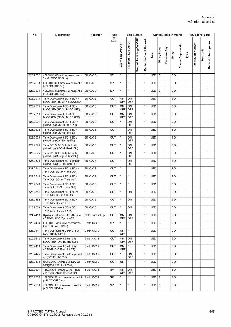
Appendix
A.9 Information List
SIPROTEC, 7UT6x, ManualC53000-G1176-C230-3, Release date 05.2013
645
323.2502 >BLOCK 3I0>> time overcurrent 3 (>BLOCK 3I0-3>>)
3I0 O/C 3 SP * * * LED BI BO
323.2503 >BLOCK 3I0> time overcurrent 3 (>BLOCK 3I0-3>)
3I0 O/C 3 SP * * * LED BI BO
323.2504 >BLOCK 3I0p time overcurrent 3 (>BLOCK 3I0-3p)
3I0 O/C 3 SP * * * LED BI BO
323.2514 Time Overcurrent 3I0-3 3I0>> BLOCKED (3I0-3>> BLOCKED)
3I0 O/C 3 OUT ON OFF
ON OFF
* LED BO
323.2515 Time Overcurrent 3I0-3 3I0> BLOCKED (3I0-3> BLOCKED)
3I0 O/C 3 OUT ON OFF
ON OFF
* LED BO
323.2516 Time Overcurrent 3I0-3 3I0p BLOCKED (3I0-3p BLOCKED)
3I0 O/C 3 OUT ON OFF
ON OFF
* LED BO
323.2521 Time Overcurrent 3I0-3 3I0>> picked up (O/C 3I0-3>> PU)
3I0 O/C 3 OUT * ON OFF
* LED BO
323.2522 Time Overcurrent 3I0-3 3I0> picked up (O/C 3I0-3> PU)
3I0 O/C 3 OUT * ON OFF
* LED BO
323.2523 Time Overcurrent 3I0-3 3I0p picked up (O/C 3I0-3p PU)
3I0 O/C 3 OUT * ON OFF
* LED BO
323.2524 Time O/C 3I0-3 3I0> InRush picked up (3I0-3>InRush PU)
3I0 O/C 3 OUT * ON OFF
* LED BO
323.2525 Time O/C 3I0-3 3I0p InRush picked up (3I0-3p InRushPU)
3I0 O/C 3 OUT * ON OFF
* LED BO
323.2529 Time Overcurrent 3I0-3 InRush picked up (3I0-3 InRush PU)
3I0 O/C 3 OUT * ON OFF
* LED BO
323.2541 Time Overcurrent 3I0-3 3I0>> Time Out (3I0-3>>Time Out)
3I0 O/C 3 OUT * * * LED BO
323.2542 Time Overcurrent 3I0-3 3I0> Time Out (3I0-3> Time Out)
3I0 O/C 3 OUT * * * LED BO
323.2543 Time Overcurrent 3I0-3 3I0p Time Out (3I0-3p Time Out)
3I0 O/C 3 OUT * * * LED BO
323.2551 Time Overcurrent 3I0-3 3I0>> TRIP (O/C 3I0-3>>TRIP)
3I0 O/C 3 OUT * ON * LED BO
323.2552 Time Overcurrent 3I0-3 3I0> TRIP (O/C 3I0-3> TRIP)
3I0 O/C 3 OUT * ON * LED BO
323.2553 Time Overcurrent 3I0-3 3I0p TRIP (O/C 3I0-3p TRIP)
3I0 O/C 3 OUT * ON * LED BO
324.2413 Dynamic settings O/C 3I0-3 are ACTIVE (3I0-3 Dyn.s.ACT)
ColdLoadPickup OUT ON OFF
ON OFF
* LED BO
325.2404 >BLOCK Earth time overcurrent 2 (>BLK Earth O/C2)
Earth O/C 2 SP * * * LED BI BO
325.2411 Time Overcurrent Earth 2 is OFF (O/C Earth2 OFF)
Earth O/C 2 OUT ON OFF
* * LED BO
325.2412 Time Overcurrent Earth 2 is BLOCKED (O/C Earth2 BLK)
Earth O/C 2 OUT ON OFF
ON OFF
* LED BO
325.2413 Time Overcurrent Earth 2 is ACTIVE (O/C Earth2 ACT)
Earth O/C 2 OUT ON OFF
* * LED BO
325.2425 Time Overcurrent Earth 2 picked up (O/C Earth2 PU)
Earth O/C 2 OUT * ON OFF
* LED BO
325.2492 O/C Earth2 err.:No auxiliary CT assigned (O/C E2 ErrCT)
Earth O/C 2 OUT ON * * LED BO
325.2501 >BLOCK time overcurrent Earth 2 InRush (>BLK E O/C2 Inr)
Earth O/C 2 SP ON OFF
ON OFF
* LED BI BO
325.2502 >BLOCK IE>> time overcurrent 2 (>BLOCK IE-2>>)
Earth O/C 2 SP * * * LED BI BO
325.2503 >BLOCK IE> time overcurrent 2 (>BLOCK IE-2>)
Earth O/C 2 SP * * * LED BI BO
No. Description Function Type of
Info.
Log Buffers Configurable in Matrix IEC 60870-5-103
Eve
nt
Lo
g O
N/O
FF
Tri
p (
Fa
ult
) L
og
On
/Off
Gro
un
d F
au
lt L
og
ON
/OF
F
Ma
rke
d i
n O
scil
l. R
ec
ord
LE
D
Bin
ary
In
pu
t
Fu
nc
tio
n K
ey
Re
lay
Ch
att
er
Su
pp
res
sio
n
Typ
e
Info
rma
tio
n N
um
be
r
Da
ta U
nit
Ge
ne
ral
Inte
rro
ga
tio
n

Appendix
A.9 Information List
SIPROTEC, 7UT6x, ManualC53000-G1176-C230-3, Release date 05.2013
646
325.2504 >BLOCK IEp time overcurrent 2 (>BLOCK IE-2p)
Earth O/C 2 SP * * * LED BI BO
325.2514 Time Overcurrent Earth 2 IE>> BLOCKED (IE-2>> BLOCKED)
Earth O/C 2 OUT ON OFF
ON OFF
* LED BO
325.2515 Time Overcurrent Earth 2 IE> BLOCKED (IE-2> BLOCKED)
Earth O/C 2 OUT ON OFF
ON OFF
* LED BO
325.2516 Time Overcurrent Earth 2 IEp BLOCKED (IE-2p BLOCKED)
Earth O/C 2 OUT ON OFF
ON OFF
* LED BO
325.2521 Time Overcurrent Earth 2 IE>> picked up (O/C E2 IE>> PU)
Earth O/C 2 OUT * ON OFF
* LED BO
325.2522 Time Overcurrent Earth 2 IE> picked up (O/C E2 IE> PU)
Earth O/C 2 OUT * ON OFF
* LED BO
325.2523 Time Overcurrent Earth 2 IEp picked up (O/C E2 IEp PU)
Earth O/C 2 OUT * ON OFF
* LED BO
325.2524 Time O/C Earth 2 IE> InRush picked up (IE-2> InRushPU)
Earth O/C 2 OUT * ON OFF
* LED BO
325.2525 Time O/C Earth 2 IEp InRush picked up (IE-2p InRushPU)
Earth O/C 2 OUT * ON OFF
* LED BO
325.2529 Earth 2 InRush picked up (Earth2 InRushPU)
Earth O/C 2 OUT * ON OFF
* LED BO
325.2541 Time Overcurrent Earth 2 IE>> Time Out (IE-2>> Time Out)
Earth O/C 2 OUT * * * LED BO
325.2542 Time Overcurrent Earth 2 IE> Time Out (IE-2> Time Out)
Earth O/C 2 OUT * * * LED BO
325.2543 Time Overcurrent Earth 2 IEp Time Out (IE-2p Time Out)
Earth O/C 2 OUT * * * LED BO
325.2551 Time Overcurrent Earth 2 IE>> TRIP (O/C E2 IE>>TRIP)
Earth O/C 2 OUT * ON * LED BO
325.2552 Time Overcurrent Earth 2 IE> TRIP (O/C E2 IE> TRIP)
Earth O/C 2 OUT * ON * LED BO
325.2553 Time Overcurrent Earth 2 IEp TRIP (O/C E2 IEp TRIP)
Earth O/C 2 OUT * ON * LED BO
326.2413 Dynamic settings O/C Earth-2 are ACTIVE (IE-2 Dyn.s. ACT)
ColdLoadPickup OUT ON OFF
ON OFF
* LED BO
361 >Failure: Feeder VT (MCB tripped) (>FAIL:Feeder VT)
Supervision SP ON OFF
ON OFF
* LED BI BO 150 38 1 Yes
390 >Warning stage from gas in oil detector (>Gas in oil)
Ext. Tansf.Ann. SP ON OFF
* * LED BI BO
391 >Warning stage from Buchholz protection (>Buchh. Warn)
Ext. Tansf.Ann. SP ON OFF
* * LED BI BO 150 41 1 Yes
392 >Tripp. stage from Buchholz protection (>Buchh. Trip)
Ext. Tansf.Ann. SP ON OFF
* * LED BI BO 150 42 1 Yes
393 >Tank supervision from Buchh. protect. (>Buchh. Tank)
Ext. Tansf.Ann. SP ON OFF
* * LED BI BO 150 43 1 Yes
409 >BLOCK Op Counter (>BLOCK Op Count)
Statistics SP ON OFF
* * LED BI BO
501 Relay PICKUP (Relay PICKUP) P.System Data 2 OUT * ON M LED BO 150 151 2 Yes
511 Relay GENERAL TRIP command (Relay TRIP)
P.System Data 2 OUT * ON M LED BO 150 161 2 Yes
545 Time from Pickup to drop out (PU Time)
P.System Data 2 VI
546 Time from Pickup to TRIP (TRIP Time)
P.System Data 2 VI
576 Primary fault current IL1 side1 (IL1S1:)
P.System Data 2 VI * *
No. Description Function Type of
Info.
Log Buffers Configurable in Matrix IEC 60870-5-103
Eve
nt
Lo
g O
N/O
FF
Tri
p (
Fa
ult
) L
og
On
/Off
Gro
un
d F
au
lt L
og
ON
/OF
F
Ma
rke
d i
n O
scil
l. R
ec
ord
LE
D
Bin
ary
In
pu
t
Fu
nc
tio
n K
ey
Re
lay
Ch
att
er
Su
pp
res
sio
n
Typ
e
Info
rma
tio
n N
um
be
r
Da
ta U
nit
Ge
ne
ral
Inte
rro
ga
tio
n
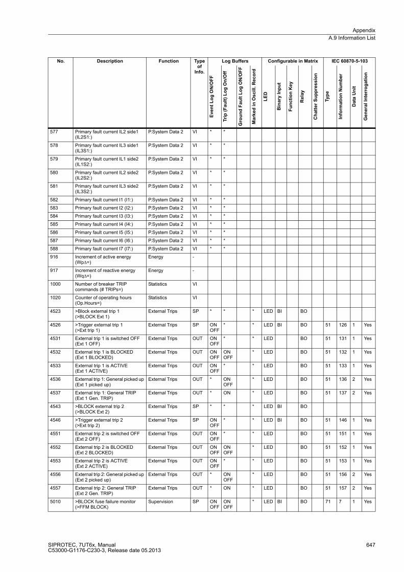
Appendix
A.9 Information List
SIPROTEC, 7UT6x, ManualC53000-G1176-C230-3, Release date 05.2013
647
577 Primary fault current IL2 side1 (IL2S1:)
P.System Data 2 VI * *
578 Primary fault current IL3 side1 (IL3S1:)
P.System Data 2 VI * *
579 Primary fault current IL1 side2 (IL1S2:)
P.System Data 2 VI * *
580 Primary fault current IL2 side2 (IL2S2:)
P.System Data 2 VI * *
581 Primary fault current IL3 side2 (IL3S2:)
P.System Data 2 VI * *
582 Primary fault current I1 (I1:) P.System Data 2 VI * *
583 Primary fault current I2 (I2:) P.System Data 2 VI * *
584 Primary fault current I3 (I3:) P.System Data 2 VI * *
585 Primary fault current I4 (I4:) P.System Data 2 VI * *
586 Primary fault current I5 (I5:) P.System Data 2 VI * *
587 Primary fault current I6 (I6:) P.System Data 2 VI * *
588 Primary fault current I7 (I7:) P.System Data 2 VI * *
916 Increment of active energy (WpΔ=)
Energy -
917 Increment of reactive energy (WqΔ=)
Energy -
1000 Number of breaker TRIP commands (# TRIPs=)
Statistics VI
1020 Counter of operating hours (Op.Hours=)
Statistics VI
4523 >Block external trip 1 (>BLOCK Ext 1)
External Trips SP * * * LED BI BO
4526 >Trigger external trip 1 (>Ext trip 1)
External Trips SP ON OFF
* * LED BI BO 51 126 1 Yes
4531 External trip 1 is switched OFF (Ext 1 OFF)
External Trips OUT ON OFF
* * LED BO 51 131 1 Yes
4532 External trip 1 is BLOCKED(Ext 1 BLOCKED)
External Trips OUT ON OFF
ON OFF
* LED BO 51 132 1 Yes
4533 External trip 1 is ACTIVE (Ext 1 ACTIVE)
External Trips OUT ON OFF
* * LED BO 51 133 1 Yes
4536 External trip 1: General picked up (Ext 1 picked up)
External Trips OUT * ON OFF
* LED BO 51 136 2 Yes
4537 External trip 1: General TRIP (Ext 1 Gen. TRIP)
External Trips OUT * ON * LED BO 51 137 2 Yes
4543 >BLOCK external trip 2 (>BLOCK Ext 2)
External Trips SP * * * LED BI BO
4546 >Trigger external trip 2 (>Ext trip 2)
External Trips SP ON OFF
* * LED BI BO 51 146 1 Yes
4551 External trip 2 is switched OFF (Ext 2 OFF)
External Trips OUT ON OFF
* * LED BO 51 151 1 Yes
4552 External trip 2 is BLOCKED (Ext 2 BLOCKED)
External Trips OUT ON OFF
ON OFF
* LED BO 51 152 1 Yes
4553 External trip 2 is ACTIVE (Ext 2 ACTIVE)
External Trips OUT ON OFF
* * LED BO 51 153 1 Yes
4556 External trip 2: General picked up (Ext 2 picked up)
External Trips OUT * ON OFF
* LED BO 51 156 2 Yes
4557 External trip 2: General TRIP (Ext 2 Gen. TRIP)
External Trips OUT * ON * LED BO 51 157 2 Yes
5010 >BLOCK fuse failure monitor(>FFM BLOCK)
Supervision SP ON OFF
ON OFF
* LED BI BO 71 7 1 Yes
No. Description Function Type of
Info.
Log Buffers Configurable in Matrix IEC 60870-5-103
Eve
nt
Lo
g O
N/O
FF
Tri
p (
Fa
ult
) L
og
On
/Off
Gro
un
d F
au
lt L
og
ON
/OF
F
Ma
rke
d i
n O
scil
l. R
ec
ord
LE
D
Bin
ary
In
pu
t
Fu
nc
tio
n K
ey
Re
lay
Ch
att
er
Su
pp
res
sio
n
Typ
e
Info
rma
tio
n N
um
be
r
Da
ta U
nit
Ge
ne
ral
Inte
rro
ga
tio
n
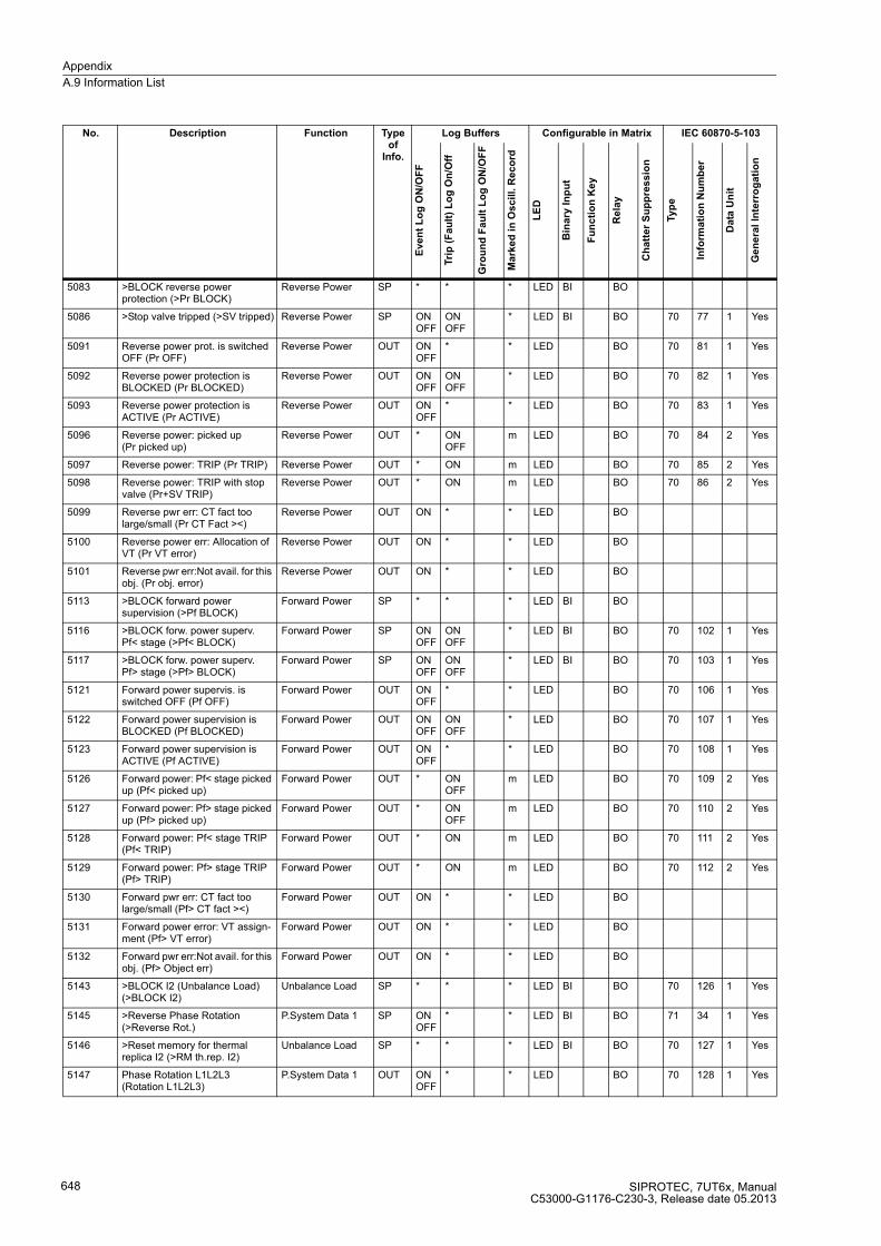
Appendix
A.9 Information List
SIPROTEC, 7UT6x, ManualC53000-G1176-C230-3, Release date 05.2013
648
5083 >BLOCK reverse power protection (>Pr BLOCK)
Reverse Power SP * * * LED BI BO
5086 >Stop valve tripped (>SV tripped) Reverse Power SP ON OFF
ON OFF
* LED BI BO 70 77 1 Yes
5091 Reverse power prot. is switched OFF (Pr OFF)
Reverse Power OUT ON OFF
* * LED BO 70 81 1 Yes
5092 Reverse power protection is BLOCKED (Pr BLOCKED)
Reverse Power OUT ON OFF
ON OFF
* LED BO 70 82 1 Yes
5093 Reverse power protection is ACTIVE (Pr ACTIVE)
Reverse Power OUT ON OFF
* * LED BO 70 83 1 Yes
5096 Reverse power: picked up (Pr picked up)
Reverse Power OUT * ON OFF
m LED BO 70 84 2 Yes
5097 Reverse power: TRIP (Pr TRIP) Reverse Power OUT * ON m LED BO 70 85 2 Yes
5098 Reverse power: TRIP with stop valve (Pr+SV TRIP)
Reverse Power OUT * ON m LED BO 70 86 2 Yes
5099 Reverse pwr err: CT fact too large/small (Pr CT Fact ><)
Reverse Power OUT ON * * LED BO
5100 Reverse power err: Allocation of VT (Pr VT error)
Reverse Power OUT ON * * LED BO
5101 Reverse pwr err:Not avail. for this obj. (Pr obj. error)
Reverse Power OUT ON * * LED BO
5113 >BLOCK forward power supervision (>Pf BLOCK)
Forward Power SP * * * LED BI BO
5116 >BLOCK forw. power superv.Pf< stage (>Pf< BLOCK)
Forward Power SP ON OFF
ON OFF
* LED BI BO 70 102 1 Yes
5117 >BLOCK forw. power superv. Pf> stage (>Pf> BLOCK)
Forward Power SP ON OFF
ON OFF
* LED BI BO 70 103 1 Yes
5121 Forward power supervis. is switched OFF (Pf OFF)
Forward Power OUT ON OFF
* * LED BO 70 106 1 Yes
5122 Forward power supervision is BLOCKED (Pf BLOCKED)
Forward Power OUT ON OFF
ON OFF
* LED BO 70 107 1 Yes
5123 Forward power supervision is ACTIVE (Pf ACTIVE)
Forward Power OUT ON OFF
* * LED BO 70 108 1 Yes
5126 Forward power: Pf< stage picked up (Pf< picked up)
Forward Power OUT * ON OFF
m LED BO 70 109 2 Yes
5127 Forward power: Pf> stage picked up (Pf> picked up)
Forward Power OUT * ON OFF
m LED BO 70 110 2 Yes
5128 Forward power: Pf< stage TRIP (Pf< TRIP)
Forward Power OUT * ON m LED BO 70 111 2 Yes
5129 Forward power: Pf> stage TRIP (Pf> TRIP)
Forward Power OUT * ON m LED BO 70 112 2 Yes
5130 Forward pwr err: CT fact too large/small (Pf> CT fact ><)
Forward Power OUT ON * * LED BO
5131 Forward power error: VT assign-ment (Pf> VT error)
Forward Power OUT ON * * LED BO
5132 Forward pwr err:Not avail. for this obj. (Pf> Object err)
Forward Power OUT ON * * LED BO
5143 >BLOCK I2 (Unbalance Load) (>BLOCK I2)
Unbalance Load SP * * * LED BI BO 70 126 1 Yes
5145 >Reverse Phase Rotation(>Reverse Rot.)
P.System Data 1 SP ON OFF
* * LED BI BO 71 34 1 Yes
5146 >Reset memory for thermal replica I2 (>RM th.rep. I2)
Unbalance Load SP * * * LED BI BO 70 127 1 Yes
5147 Phase Rotation L1L2L3(Rotation L1L2L3)
P.System Data 1 OUT ON OFF
* * LED BO 70 128 1 Yes
No. Description Function Type of
Info.
Log Buffers Configurable in Matrix IEC 60870-5-103
Eve
nt
Lo
g O
N/O
FF
Tri
p (
Fa
ult
) L
og
On
/Off
Gro
un
d F
au
lt L
og
ON
/OF
F
Ma
rke
d i
n O
scil
l. R
ec
ord
LE
D
Bin
ary
In
pu
t
Fu
nc
tio
n K
ey
Re
lay
Ch
att
er
Su
pp
res
sio
n
Typ
e
Info
rma
tio
n N
um
be
r
Da
ta U
nit
Ge
ne
ral
Inte
rro
ga
tio
n

Appendix
A.9 Information List
SIPROTEC, 7UT6x, ManualC53000-G1176-C230-3, Release date 05.2013
649
5148 Phase Rotation L1L3L2 (Rotation L1L3L2)
P.System Data 1 OUT ON OFF
* * LED BO 70 129 1 Yes
5151 I2 switched OFF (I2 OFF) Unbalance Load OUT ON OFF
* * LED BO 70 131 1 Yes
5152 I2 is BLOCKED (I2 BLOCKED) Unbalance Load OUT ON OFF
ON OFF
* LED BO 70 132 1 Yes
5153 I2 is ACTIVE (I2 ACTIVE) Unbalance Load OUT ON OFF
* * LED BO 70 133 1 Yes
5157 Unbalanced load: Thermal warning stage (I2 th. Warn)
Unbalance Load OUT ON OFF
* * LED BO 70 135 2 Yes
5158 Reset memory of thermal replica I2 (RM th.rep. I2)
Unbalance Load OUT ON OFF
ON OFF
* LED BO 70 137 1 Yes
5159 I2>> picked up (I2>> picked up) Unbalance Load OUT * ON OFF
* LED BO 70 138 2 Yes
5160 Unbalanced load: TRIP of current stage (I2>> TRIP)
Unbalance Load OUT * ON * LED BO
5161 Unbalanced load: TRIP of thermal stage (I2 Θ TRIP)
Unbalance Load OUT * ON * LED BO
5165 I2> picked up (I2> picked up) Unbalance Load OUT * ON OFF
* LED BO 70 150 2 Yes
5166 I2p picked up (I2p picked up) Unbalance Load OUT * ON OFF
* LED BO 70 141 2 Yes
5167 Unbalanced load: Pick-up I2 thermal (I2th Pick-up)
Unbalance Load OUT * ON OFF
* LED BO 70 142 2 Yes
5168 I2 err.: adverse Adaption factor CT (I2 Adap.fact.)
Unbalance Load OUT ON * * LED BO
5170 I2 TRIP (I2 TRIP) Unbalance Load OUT * ON m LED BO 70 149 2 Yes
5172 I2 err.: Not available for this object (I2 Not avail.)
Unbalance Load OUT ON * * LED BO
5178 I2> TRIP (I2> TRIP) Unbalance Load OUT * ON * LED BO
5179 I2p TRIP (I2p TRIP) Unbalance Load OUT * ON * LED BO
5203 >BLOCK frequency protection (>BLOCK Freq.)
Frequency Prot. SP * * * LED BI BO 70 176 1 Yes
5211 Frequency protection is switched OFF (Freq. OFF)
Frequency Prot. OUT ON OFF
* * LED BO 70 181 1 Yes
5212 Frequency protection is BLOCKED (Freq. BLOCKED)
Frequency Prot. OUT ON OFF
ON OFF
* LED BO 70 182 1 Yes
5213 Frequency protection is ACTIVE (Freq. ACTIVE)
Frequency Prot. OUT ON OFF
* * LED BO 70 183 1 Yes
5214 Frequency protection undervolt-age Blk (Freq UnderV Blk)
Frequency Prot. OUT ON OFF
ON OFF
* LED BO 70 184 1 Yes
5254 Frequency protection: error VT assign. (Freq. error VT)
Frequency Prot. OUT ON * * LED BO
5255 Frequency prot.:Not avail. for this obj. (Freq. err. Obj.)
Frequency Prot. OUT ON * * LED BO
5353 >BLOCK overexcitation protection (>U/f BLOCK)
Overexcit. SP * * * LED BI BO
5357 >Reset memory of thermal replica U/f (>RM th.rep. U/f)
Overexcit. SP * * * LED BI BO
5361 Overexcitation protection is swiched OFF (U/f> OFF)
Overexcit. OUT ON OFF
* * LED BO 71 83 1 Yes
5362 Overexcitation protection is BLOCKED (U/f> BLOCKED)
Overexcit. OUT ON OFF
ON OFF
* LED BO 71 84 1 Yes
5363 Overexcitation protection is ACTIVE (U/f> ACTIVE)
Overexcit. OUT ON OFF
* * LED BO 71 85 1 Yes
No. Description Function Type of
Info.
Log Buffers Configurable in Matrix IEC 60870-5-103
Eve
nt
Lo
g O
N/O
FF
Tri
p (
Fa
ult
) L
og
On
/Off
Gro
un
d F
au
lt L
og
ON
/OF
F
Ma
rke
d i
n O
scil
l. R
ec
ord
LE
D
Bin
ary
In
pu
t
Fu
nc
tio
n K
ey
Re
lay
Ch
att
er
Su
pp
res
sio
n
Typ
e
Info
rma
tio
n N
um
be
r
Da
ta U
nit
Ge
ne
ral
Inte
rro
ga
tio
n

Appendix
A.9 Information List
SIPROTEC, 7UT6x, ManualC53000-G1176-C230-3, Release date 05.2013
650
5367 Overexc. prot.: U/f warning stage (U/f> warn)
Overexcit. OUT ON OFF
* * LED BO 71 86 1 Yes
5369 Reset memory of thermal replica U/f (RM th.rep. U/f)
Overexcit. OUT ON OFF
* * LED BO 71 88 1 Yes
5370 Overexc. prot.: U/f> picked up (U/f> picked up)
Overexcit. OUT * ON OFF
* LED BO 71 89 2 Yes
5371 Overexc. prot.: TRIP of U/f>> stage (U/f>> TRIP)
Overexcit. OUT * ON m LED BO 71 90 2 Yes
5372 Overexc. prot.: TRIP of th. stage (U/f> th.TRIP)
Overexcit. OUT * ON * LED BO 71 91 2 Yes
5373 Overexc. prot.: U/f>> picked up (U/f>> pick.up)
Overexcit. OUT * ON OFF
* LED BO 71 92 2 Yes
5376 Overexc. err: No VT assigned (U/f Err No VT)
Overexcit. OUT ON * * LED BO
5377 Overexc. err: Not avail. for this object (U/f Not avail.)
Overexcit. OUT ON * * LED BO
5603 >BLOCK differential protection (>Diff BLOCK)
Diff. Prot SP * * * LED BI BO
5615 Differential protection is switched OFF (Diff OFF)
Diff. Prot OUT ON OFF
* * LED BO 75 15 1 Yes
5616 Differential protection is BLOCKED (Diff BLOCKED)
Diff. Prot OUT ON OFF
ON OFF
* LED BO 75 16 1 Yes
5617 Differential protection is ACTIVE (Diff ACTIVE)
Diff. Prot OUT ON OFF
* * LED BO 75 17 1 Yes
5620 Diff err.: adverse Adaption factor CT (Diff Adap.fact.)
Diff. Prot OUT ON * * LED BO
5631 Differential protection picked up (Diff picked up)
Diff. Prot OUT * ON OFF
m LED BO 75 31 2 Yes
5644 Diff: Blocked by 2.Harmon. L1 (Diff 2.Harm L1)
Diff. Prot OUT * ON OFF
* LED BO 75 44 2 Yes
5645 Diff: Blocked by 2.Harmon. L2 (Diff 2.Harm L2)
Diff. Prot OUT * ON OFF
* LED BO 75 45 2 Yes
5646 Diff: Blocked by 2.Harmon. L3 (Diff 2.Harm L3)
Diff. Prot OUT * ON OFF
* LED BO 75 46 2 Yes
5647 Diff: Blocked by n.Harmon. L1 (Diff n.Harm L1)
Diff. Prot OUT * ON OFF
* LED BO 75 47 2 Yes
5648 Diff: Blocked by n.Harmon. L2 (Diff n.Harm L2)
Diff. Prot OUT * ON OFF
* LED BO 75 48 2 Yes
5649 Diff: Blocked by n.Harmon. L3 (Diff n.Harm L3)
Diff. Prot OUT * ON OFF
* LED BO 75 49 2 Yes
5651 Diff. prot.: Blocked by ext. fault L1 (Diff Bl. exF.L1)
Diff. Prot OUT * ON OFF
* LED BO 75 51 2 Yes
5652 Diff. prot.: Blocked by ext. fault L2 (Diff Bl. exF.L2)
Diff. Prot OUT * ON OFF
* LED BO 75 52 2 Yes
5653 Diff. prot.: Blocked by ext. fault.L3 (Diff Bl. exF.L3)
Diff. Prot OUT * ON OFF
* LED BO 75 53 2 Yes
5657 Diff: Crossblock by 2.Harmonic (DiffCrosBlk 2HM)
Diff. Prot OUT * ON OFF
* LED BO
5658 Diff: Crossblock by n.Harmonic (DiffCrosBlk nHM)
Diff. Prot OUT * ON OFF
* LED BO
5660 Diff: Crossblock by ext. fault (DiffCrosBlk exF)
Diff. Prot OUT * ON OFF
* LED BO
5662 Diff. prot.: Blocked by CT fault L1 (Block Iflt.L1)
Diff. Prot OUT ON OFF
ON OFF
* LED BO 75 62 2 Yes
5663 Diff. prot.: Blocked by CT fault L2 (Block Iflt.L2)
Diff. Prot OUT ON OFF
ON OFF
* LED BO 75 63 2 Yes
No. Description Function Type of
Info.
Log Buffers Configurable in Matrix IEC 60870-5-103
Eve
nt
Lo
g O
N/O
FF
Tri
p (
Fa
ult
) L
og
On
/Off
Gro
un
d F
au
lt L
og
ON
/OF
F
Ma
rke
d i
n O
scil
l. R
ec
ord
LE
D
Bin
ary
In
pu
t
Fu
nc
tio
n K
ey
Re
lay
Ch
att
er
Su
pp
res
sio
n
Typ
e
Info
rma
tio
n N
um
be
r
Da
ta U
nit
Ge
ne
ral
Inte
rro
ga
tio
n

Appendix
A.9 Information List
SIPROTEC, 7UT6x, ManualC53000-G1176-C230-3, Release date 05.2013
651
5664 Diff. prot.: Blocked by CT fault L3 (Block Iflt.L3)
Diff. Prot OUT ON OFF
ON OFF
* LED BO 75 64 2 Yes
5666 Diff: Increase of char. phase (start) L1 (DiffStrtInChaL1)
Diff. Prot OUT ON OFF
ON OFF
* LED BO
5667 Diff: Increase of char. phase (start) L2 (DiffStrtInChaL2)
Diff. Prot OUT ON OFF
ON OFF
* LED BO
5668 Diff: Increase of char. phase (start) L3 (DiffStrtInChaL3)
Diff. Prot OUT ON OFF
ON OFF
* LED BO
5670 Diff: Curr-Release for Trip (Diff I-Release)
Diff. Prot OUT * ON OFF
* LED BO
5671 Differential protection TRIP (Diff TRIP)
Diff. Prot OUT * * * LED BO 176 68 2 No
5672 Differential protection: TRIP L1 (Diff TRIP L1)
Diff. Prot OUT * * * LED BO 176 86 2 No
5673 Differential protection: TRIP L2 (Diff TRIP L2)
Diff. Prot OUT * * * LED BO 176 87 2 No
5674 Differential protection: TRIP L3 (Diff TRIP L3)
Diff. Prot OUT * * * LED BO 176 88 2 No
5681 Diff. prot.: IDIFF> L1(without Tdelay) (Diff> L1)
Diff. Prot OUT * ON OFF
* LED BO 75 81 2 Yes
5682 Diff. prot.: IDIFF> L2 (without Tdelay) (Diff> L2)
Diff. Prot OUT * ON OFF
* LED BO 75 82 2 Yes
5683 Diff. prot.: IDIFF> L3(without Tdelay) (Diff> L3)
Diff. Prot OUT * ON OFF
* LED BO 75 83 2 Yes
5684 Diff. prot: IDIFF>> L1 (without Tdelay) (Diff>> L1)
Diff. Prot OUT * ON OFF
* LED BO 75 84 2 Yes
5685 Diff. prot: IDIFF>> L2 (without Tdelay) (Diff>> L2)
Diff. Prot OUT * ON OFF
* LED BO 75 85 2 Yes
5686 Diff. prot: IDIFF>> L3 (without Tdelay) (Diff>> L3)
Diff. Prot OUT * ON OFF
* LED BO 75 86 2 Yes
5691 Differential prot.: TRIP by IDIFF> (Diff> TRIP)
Diff. Prot OUT * ON m LED BO 75 91 2 Yes
5692 Differential prot.: TRIP by IDIFF>> (Diff>> TRIP)
Diff. Prot OUT * ON m LED BO 75 92 2 Yes
5701 Diff. curr. in L1 at trip without Tdelay (Diff L1:)
Diff. Prot VI * ON OFF
75 101 4 No
5702 Diff. curr. in L2 at trip without Tdelay (Diff L2:)
Diff. Prot VI * ON OFF
75 102 4 No
5703 Diff. curr. in L3 at trip without Tdelay (Diff L3:)
Diff. Prot VI * ON OFF
75 103 4 No
5704 Restr.curr. in L1 at trip without Tdelay (Res. L1:)
Diff. Prot VI * ON OFF
75 104 4 No
5705 Restr.curr. in L2 at trip without Tdelay (Res. L2:)
Diff. Prot VI * ON OFF
75 105 4 No
5706 Restr.curr. in L3 at trip without Tdelay (Res. L3:)
Diff. Prot VI * ON OFF
75 106 4 No
5721 Diff. prot: Adaption factor CT I1 (Diff CT-I1:)
Diff. Prot VI ON OFF
5722 Diff. prot: Adaption factor CT I2 (Diff CT-I2:)
Diff. Prot VI ON OFF
5723 Diff. prot: Adaption factor CT I3 (Diff CT-I3:)
Diff. Prot VI ON OFF
5724 Diff. prot: Adaption factor CT I4 (Diff CT-I4:)
Diff. Prot VI ON OFF
5725 Diff. prot: Adaption factor CT I5 (Diff CT-I5:)
Diff. Prot VI ON OFF
No. Description Function Type of
Info.
Log Buffers Configurable in Matrix IEC 60870-5-103
Eve
nt
Lo
g O
N/O
FF
Tri
p (
Fa
ult
) L
og
On
/Off
Gro
un
d F
au
lt L
og
ON
/OF
F
Ma
rke
d i
n O
scil
l. R
ec
ord
LE
D
Bin
ary
In
pu
t
Fu
nc
tio
n K
ey
Re
lay
Ch
att
er
Su
pp
res
sio
n
Typ
e
Info
rma
tio
n N
um
be
r
Da
ta U
nit
Ge
ne
ral
Inte
rro
ga
tio
n

Appendix
A.9 Information List
SIPROTEC, 7UT6x, ManualC53000-G1176-C230-3, Release date 05.2013
652
5726 Diff. prot: Adaption factor CT I6 (Diff CT-I6:)
Diff. Prot VI ON OFF
5727 Diff. prot: Adaption factor CT I7 (Diff CT-I7:)
Diff. Prot VI ON OFF
5728 Diff. prot: Adaption factor CT I8 (Diff CT-I8:)
Diff. Prot VI ON OFF
5729 Diff. prot: Adaption factor CT I9 (Diff CT-I9:)
Diff. Prot VI ON OFF
5730 Diff. prot: Adaption factor CT I10 (DiffCT-I10:)
Diff. Prot VI ON OFF
5731 Diff. prot: Adaption factor CT I11 (DiffCT-I11:)
Diff. Prot VI ON OFF
5732 Diff. prot: Adaption factor CT I12 (DiffCT-I12:)
Diff. Prot VI ON OFF
5733 Diff. prot: Adaption factor CT M1 (Diff CT-M1:)
Diff. Prot VI ON OFF
5734 Diff. prot: Adaption factor CT M2 (Diff CT-M2:)
Diff. Prot VI ON OFF
5735 Diff. prot: Adaption factor CT M3 (Diff CT-M3:)
Diff. Prot VI ON OFF
5736 Diff. prot: Adaption factor CT M4 (Diff CT-M4:)
Diff. Prot VI ON OFF
5737 Diff. prot: Adaption factor CT M5 (Diff CT-M5:)
Diff. Prot VI ON OFF
5738 Diff. prot: Adaption factor aux. CT IX1 (Diff CT-IX1:)
Diff. Prot VI ON OFF
5739 Diff. prot: Adaption factor aux. CT IX2 (Diff CT-IX2:)
Diff. Prot VI ON OFF
5740 Diff. prot: Adaption factor aux. CT IX3 (Diff CT-IX3:)
Diff. Prot VI ON OFF
5741 Diff. prot: Adaption factor aux. CT IX4 (Diff CT-IX4:)
Diff. Prot VI ON OFF
5742 Diff: DC L1 (Diff DC L1) Diff. Prot OUT * ON OFF
* LED BO
5743 Diff: DC L2 (Diff DC L2) Diff. Prot OUT * ON OFF
* LED BO
5744 Diff: DC L3 (Diff DC L3) Diff. Prot OUT * ON OFF
* LED BO
5745 Diff: Increase of char. phase (DC) (Diff DC InCha)
Diff. Prot OUT * ON OFF
* LED BO
6851 >BLOCK Trip circuit supervision (>BLOCK TripC)
TripCirc.Superv SP * * * LED BI BO
6852 >Trip circuit supervision: trip relay (>TripC trip rel)
TripCirc.Superv SP ON OFF
* * LED BI BO 170 51 1 Yes
6853 >Trip circuit supervision: breaker relay (>TripC brk rel.)
TripCirc.Superv SP ON OFF
* * LED BI BO 170 52 1 Yes
6861 Trip circuit supervision OFF (TripC OFF)
TripCirc.Superv OUT ON OFF
* * LED BO 170 53 1 Yes
6862 Trip circuit supervision is BLOCKED (TripC BLOCKED)
TripCirc.Superv OUT ON OFF
ON OFF
* LED BO 153 16 1 Yes
6863 Trip circuit supervision is ACTIVE (TripC ACTIVE)
TripCirc.Superv OUT ON OFF
* * LED BO 153 17 1 Yes
6864 Trip Circuit blk. Bin. input is not set (TripC ProgFail)
TripCirc.Superv OUT ON OFF
* * LED BO 170 54 1 Yes
6865 Failure Trip Circuit (FAIL: Trip cir.) TripCirc.Superv OUT ON OFF
* * LED BO 170 55 1 Yes
No. Description Function Type of
Info.
Log Buffers Configurable in Matrix IEC 60870-5-103
Eve
nt
Lo
g O
N/O
FF
Tri
p (
Fa
ult
) L
og
On
/Off
Gro
un
d F
au
lt L
og
ON
/OF
F
Ma
rke
d i
n O
scil
l. R
ec
ord
LE
D
Bin
ary
In
pu
t
Fu
nc
tio
n K
ey
Re
lay
Ch
att
er
Su
pp
res
sio
n
Typ
e
Info
rma
tio
n N
um
be
r
Da
ta U
nit
Ge
ne
ral
Inte
rro
ga
tio
n

Appendix
A.9 Information List
SIPROTEC, 7UT6x, ManualC53000-G1176-C230-3, Release date 05.2013
653
11001 >Reset MinMaxValues (>Reset MinMax)
Min/Max meter SP ON OFF
* * LED BI BO
12006 >Frequency prot.: Block Stage f< (>Freq. f< blk)
Frequency Prot. SP ON OFF
ON OFF
* LED BI BO 170 239 1 Yes
12007 >Frequency prot.: Block Stage f<< (>Freq. f<< blk)
Frequency Prot. SP ON OFF
ON OFF
* LED BI BO 170 240 1 Yes
12008 >Frequency prot.: Block Stage f<<< (>Freq. f<<< blk)
Frequency Prot. SP ON OFF
ON OFF
* LED BI BO 70 241 1 Yes
12009 >Frequency prot.: Block Stage f> (>Freq. f> blk)
Frequency Prot. SP ON OFF
ON OFF
* LED BI BO 70 242 1 Yes
12032 Frequency prot.: Pick-up Stage f< (Freq. f< P-up)
Frequency Prot. OUT * ON OFF
* LED BO 70 243 2 Yes
12033 Frequency prot.: Pick-up Stage f<< (Freq. f<< P-up)
Frequency Prot. OUT * ON OFF
* LED BO 70 244 2 Yes
12034 Frequency prot.: Pick-up Stage f<<< (Freq. f<<< P-up)
Frequency Prot. OUT * ON OFF
* LED BO 70 245 2 Yes
12035 Frequency prot.: Pick-up Stage f> (Freq. f> P-up)
Frequency Prot. OUT * ON OFF
* LED BO 70 246 2 Yes
12036 Frequency prot.: Trip Stage f< (Freq. f< TRIP)
Frequency Prot. OUT * ON m LED BO 70 247 2 Yes
12037 Frequency prot.: Trip Stage f<< (Freq. f<< TRIP)
Frequency Prot. OUT * ON m LED BO 70 248 2 Yes
12038 Frequency prot.: Trip Stage f<<< (Freq. f<<< TRIP)
Frequency Prot. OUT * ON m LED BO 70 249 2 Yes
12039 Frequency prot.: Trip Stage f> (Freq. f> TRIP)
Frequency Prot. OUT * ON m LED BO 70 250 2 Yes
14101 Fail: RTD (broken wire/shorted) (Fail: RTD)
RTD-Box OUT ON OFF
* * LED BO
14111 Fail: RTD 1 (broken wire/shorted) (Fail: RTD 1)
RTD-Box OUT ON OFF
* * LED BO
14112 RTD 1 Temperature stage 1 picked up (RTD 1 St.1 p.up)
RTD-Box OUT ON OFF
* * LED BO
14113 RTD 1 Temperature stage 2 picked up (RTD 1 St.2 p.up)
RTD-Box OUT ON OFF
* * LED BO
14121 Fail: RTD 2 (broken wire/shorted) (Fail: RTD 2)
RTD-Box OUT ON OFF
* * LED BO
14122 RTD 2 Temperature stage 1 picked up (RTD 2 St.1 p.up)
RTD-Box OUT ON OFF
* * LED BO
14123 RTD 2 Temperature stage 2 picked up (RTD 2 St.2 p.up)
RTD-Box OUT ON OFF
* * LED BO
14131 Fail: RTD 3 (broken wire/shorted) (Fail: RTD 3)
RTD-Box OUT ON OFF
* * LED BO
14132 RTD 3 Temperature stage 1 picked up (RTD 3 St.1 p.up)
RTD-Box OUT ON OFF
* * LED BO
14133 RTD 3 Temperature stage 2 picked up (RTD 3 St.2 p.up)
RTD-Box OUT ON OFF
* * LED BO
14141 Fail: RTD 4 (broken wire/shorted) (Fail: RTD 4)
RTD-Box OUT ON OFF
* * LED BO
14142 RTD 4 Temperature stage 1 picked up (RTD 4 St.1 p.up)
RTD-Box OUT ON OFF
* * LED BO
14143 RTD 4 Temperature stage 2 picked up (RTD 4 St.2 p.up)
RTD-Box OUT ON OFF
* * LED BO
14151 Fail: RTD 5 (broken wire/shorted) (Fail: RTD 5)
RTD-Box OUT ON OFF
* * LED BO
14152 RTD 5 Temperature stage 1 picked up (RTD 5 St.1 p.up)
RTD-Box OUT ON OFF
* * LED BO
No. Description Function Type of
Info.
Log Buffers Configurable in Matrix IEC 60870-5-103
Eve
nt
Lo
g O
N/O
FF
Tri
p (
Fa
ult
) L
og
On
/Off
Gro
un
d F
au
lt L
og
ON
/OF
F
Ma
rke
d i
n O
scil
l. R
ec
ord
LE
D
Bin
ary
In
pu
t
Fu
nc
tio
n K
ey
Re
lay
Ch
att
er
Su
pp
res
sio
n
Typ
e
Info
rma
tio
n N
um
be
r
Da
ta U
nit
Ge
ne
ral
Inte
rro
ga
tio
n
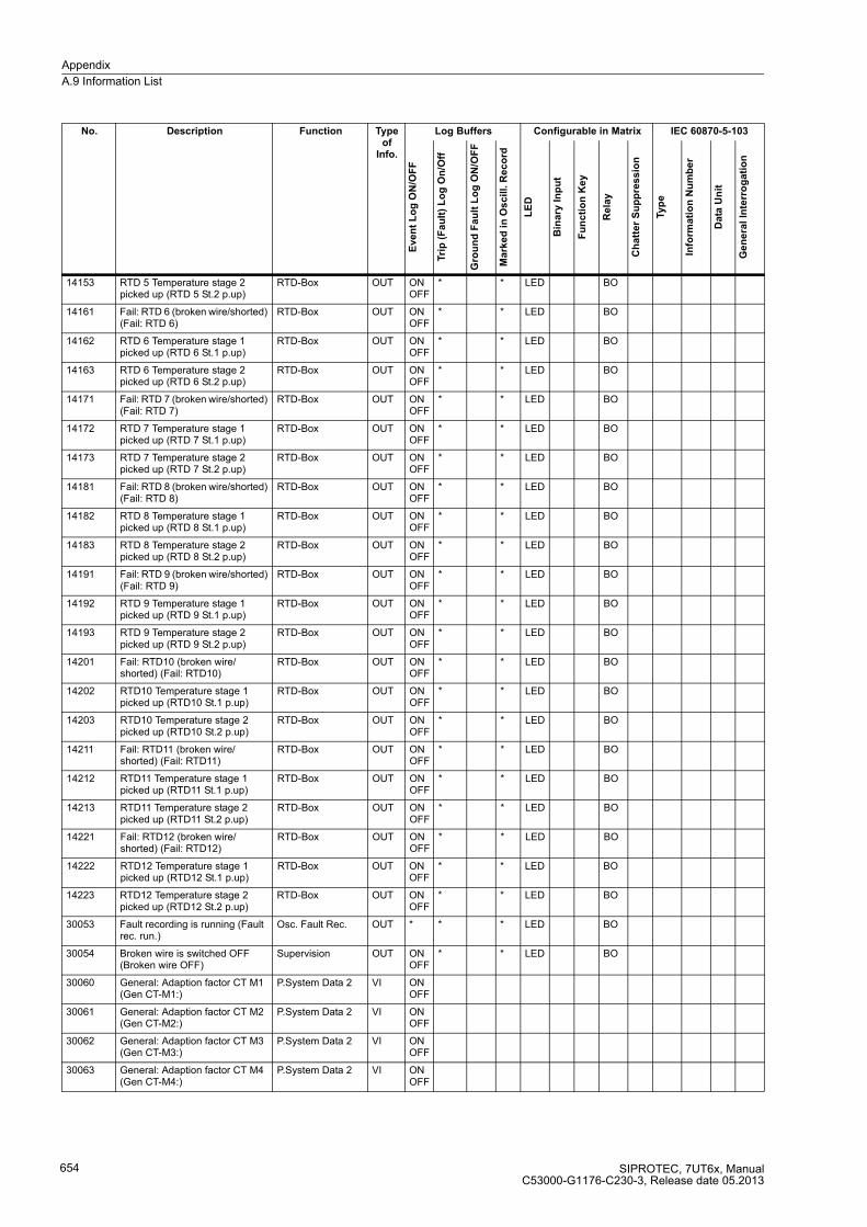
Appendix
A.9 Information List
SIPROTEC, 7UT6x, ManualC53000-G1176-C230-3, Release date 05.2013
654
14153 RTD 5 Temperature stage 2 picked up (RTD 5 St.2 p.up)
RTD-Box OUT ON OFF
* * LED BO
14161 Fail: RTD 6 (broken wire/shorted) (Fail: RTD 6)
RTD-Box OUT ON OFF
* * LED BO
14162 RTD 6 Temperature stage 1 picked up (RTD 6 St.1 p.up)
RTD-Box OUT ON OFF
* * LED BO
14163 RTD 6 Temperature stage 2 picked up (RTD 6 St.2 p.up)
RTD-Box OUT ON OFF
* * LED BO
14171 Fail: RTD 7 (broken wire/shorted) (Fail: RTD 7)
RTD-Box OUT ON OFF
* * LED BO
14172 RTD 7 Temperature stage 1 picked up (RTD 7 St.1 p.up)
RTD-Box OUT ON OFF
* * LED BO
14173 RTD 7 Temperature stage 2 picked up (RTD 7 St.2 p.up)
RTD-Box OUT ON OFF
* * LED BO
14181 Fail: RTD 8 (broken wire/shorted) (Fail: RTD 8)
RTD-Box OUT ON OFF
* * LED BO
14182 RTD 8 Temperature stage 1 picked up (RTD 8 St.1 p.up)
RTD-Box OUT ON OFF
* * LED BO
14183 RTD 8 Temperature stage 2 picked up (RTD 8 St.2 p.up)
RTD-Box OUT ON OFF
* * LED BO
14191 Fail: RTD 9 (broken wire/shorted) (Fail: RTD 9)
RTD-Box OUT ON OFF
* * LED BO
14192 RTD 9 Temperature stage 1 picked up (RTD 9 St.1 p.up)
RTD-Box OUT ON OFF
* * LED BO
14193 RTD 9 Temperature stage 2 picked up (RTD 9 St.2 p.up)
RTD-Box OUT ON OFF
* * LED BO
14201 Fail: RTD10 (broken wire/ shorted) (Fail: RTD10)
RTD-Box OUT ON OFF
* * LED BO
14202 RTD10 Temperature stage 1 picked up (RTD10 St.1 p.up)
RTD-Box OUT ON OFF
* * LED BO
14203 RTD10 Temperature stage 2 picked up (RTD10 St.2 p.up)
RTD-Box OUT ON OFF
* * LED BO
14211 Fail: RTD11 (broken wire/ shorted) (Fail: RTD11)
RTD-Box OUT ON OFF
* * LED BO
14212 RTD11 Temperature stage 1 picked up (RTD11 St.1 p.up)
RTD-Box OUT ON OFF
* * LED BO
14213 RTD11 Temperature stage 2 picked up (RTD11 St.2 p.up)
RTD-Box OUT ON OFF
* * LED BO
14221 Fail: RTD12 (broken wire/ shorted) (Fail: RTD12)
RTD-Box OUT ON OFF
* * LED BO
14222 RTD12 Temperature stage 1 picked up (RTD12 St.1 p.up)
RTD-Box OUT ON OFF
* * LED BO
14223 RTD12 Temperature stage 2 picked up (RTD12 St.2 p.up)
RTD-Box OUT ON OFF
* * LED BO
30053 Fault recording is running (Fault rec. run.)
Osc. Fault Rec. OUT * * * LED BO
30054 Broken wire is switched OFF (Broken wire OFF)
Supervision OUT ON OFF
* * LED BO
30060 General: Adaption factor CT M1 (Gen CT-M1:)
P.System Data 2 VI ON OFF
30061 General: Adaption factor CT M2 (Gen CT-M2:)
P.System Data 2 VI ON OFF
30062 General: Adaption factor CT M3 (Gen CT-M3:)
P.System Data 2 VI ON OFF
30063 General: Adaption factor CT M4 (Gen CT-M4:)
P.System Data 2 VI ON OFF
No. Description Function Type of
Info.
Log Buffers Configurable in Matrix IEC 60870-5-103
Eve
nt
Lo
g O
N/O
FF
Tri
p (
Fa
ult
) L
og
On
/Off
Gro
un
d F
au
lt L
og
ON
/OF
F
Ma
rke
d i
n O
scil
l. R
ec
ord
LE
D
Bin
ary
In
pu
t
Fu
nc
tio
n K
ey
Re
lay
Ch
att
er
Su
pp
res
sio
n
Typ
e
Info
rma
tio
n N
um
be
r
Da
ta U
nit
Ge
ne
ral
Inte
rro
ga
tio
n

Appendix
A.9 Information List
SIPROTEC, 7UT6x, ManualC53000-G1176-C230-3, Release date 05.2013
655
30064 General: Adaption factor CT M5 (Gen CT-M5:)
P.System Data 2 VI ON OFF
30065 General: Adaption factor VT UL123 (Gen VT-U1:)
P.System Data 2 VI ON OFF
30067 parameter too low: (par too low:) P.System Data 2 VI ON OFF
30068 parameter too high: (par too high:)
P.System Data 2 VI ON OFF
30069 setting fault: (settingFault:) P.System Data 2 VI ON OFF
30070 Manual close signal meas.loc. 1 detected (Man.Clos.Det.M1)
P.System Data 2 OUT ON * * LED BO
30071 Manual close signal meas.loc. 2 detected (Man.Clos.Det.M2)
P.System Data 2 OUT ON * * LED BO
30072 Manual close signal meas.loc. 3 detected (Man.Clos.Det.M3)
P.System Data 2 OUT ON * * LED BO
30073 Manual close signal meas.loc. 4 detected (Man.Clos.Det.M4)
P.System Data 2 OUT ON * * LED BO
30074 Manual close signal meas.loc. 5 detected (Man.Clos.Det.M5)
P.System Data 2 OUT ON * * LED BO
30075 Manual close signal side 1 is detected (Man.Clos.Det.S1)
P.System Data 2 OUT ON * * LED BO
30076 Manual close signal side 2 is detected (Man.Clos.Det.S2)
P.System Data 2 OUT ON * * LED BO
30077 Manual close signal side 3 is detected (Man.Clos.Det.S3)
P.System Data 2 OUT ON * * LED BO
30078 Manual close signal side 4 is detected (Man.Clos.Det.S4)
P.System Data 2 OUT ON * * LED BO
30079 Manual close signal side 5 is detected (Man.Clos.Det.S5)
P.System Data 2 OUT ON * * LED BO
30080 Measurment location 1 is disconnected (M1 disconnected)
Discon.MeasLoc OUT ON OFF
* * LED BO
30081 Measurment location 2 is disconnected (M2 disconnected)
Discon.MeasLoc OUT ON OFF
* * LED BO
30082 Measurment location 3 is disconnected (M3 disconnected)
Discon.MeasLoc OUT ON OFF
* * LED BO
30083 Measurment location 4 is disconnected (M4 disconnected)
Discon.MeasLoc OUT ON OFF
* * LED BO
30084 Measurment location 5 is discon-nected (M5 disconnected)
Discon.MeasLoc OUT ON OFF
* * LED BO
30085 End 1 is disconnected (I1 disconnected)
Discon.MeasLoc OUT ON OFF
* * LED BO
30086 End 2 is disconnected(I2 disconnected)
Discon.MeasLoc OUT ON OFF
* * LED BO
30087 End 3 is disconnected (I3 disconnected)
Discon.MeasLoc OUT ON OFF
* * LED BO
30088 End 4 is disconnected (I4 disconnected)
Discon.MeasLoc OUT ON OFF
* * LED BO
30089 End 5 is disconnected (I5 disconnected)
Discon.MeasLoc OUT ON OFF
* * LED BO
30090 End 6 is disconnected (I6 disconnected)
Discon.MeasLoc OUT ON OFF
* * LED BO
30091 End 7 is disconnected (I7 disconnected)
Discon.MeasLoc OUT ON OFF
* * LED BO
30092 End 8 is disconnected (I8 disconnected)
Discon.MeasLoc OUT ON OFF
* * LED BO
No. Description Function Type of
Info.
Log Buffers Configurable in Matrix IEC 60870-5-103
Eve
nt
Lo
g O
N/O
FF
Tri
p (
Fa
ult
) L
og
On
/Off
Gro
un
d F
au
lt L
og
ON
/OF
F
Ma
rke
d i
n O
scil
l. R
ec
ord
LE
D
Bin
ary
In
pu
t
Fu
nc
tio
n K
ey
Re
lay
Ch
att
er
Su
pp
res
sio
n
Typ
e
Info
rma
tio
n N
um
be
r
Da
ta U
nit
Ge
ne
ral
Inte
rro
ga
tio
n

Appendix
A.9 Information List
SIPROTEC, 7UT6x, ManualC53000-G1176-C230-3, Release date 05.2013
656
30093 End 9 is disconnected (I9 disconnected)
Discon.MeasLoc OUT ON OFF
* * LED BO
30094 End 10 is disconnected (I10disconnected)
Discon.MeasLoc OUT ON OFF
* * LED BO
30095 End 11 is disconnected (I11disconnected)
Discon.MeasLoc OUT ON OFF
* * LED BO
30096 End 12 is disconnected (I12disconnected)
Discon.MeasLoc OUT ON OFF
* * LED BO
30097 Err: inconsist. jumper/setting CT M1 (Err. IN CT M1)
Supervision OUT ON OFF
* * LED BO
30098 Err: inconsist. jumper/setting CT M2 (Err. IN CT M2)
Supervision OUT ON OFF
* * LED BO
30099 Err: inconsist. jumper/setting CT M3 (Err. IN CT M3)
Supervision OUT ON OFF
* * LED BO
30100 Err: inconsist. jumper/setting CT M4 (Err. IN CT M4)
Supervision OUT ON OFF
* * LED BO
30101 Err: inconsist. jumper/setting CT M5 (Err. IN CT M5)
Supervision OUT ON OFF
* * LED BO
30102 Err: inconsist. jumper/setting CT I1..3 (Err.IN CT1..3)
Supervision OUT ON OFF
* * LED BO
30103 Err: inconsist. jumper/setting CT I4..6 (Err.IN CT4..6)
Supervision OUT ON OFF
* * LED BO
30104 Err: inconsist. jumper/setting CT I7..9 (Err.IN CT7..9)
Supervision OUT ON OFF
* * LED BO
30105 Err:inconsist. jumper/setting CT I10..12 (Err.IN CT10..12)
Supervision OUT ON OFF
* * LED BO
30106 Err: inconsist. jumper/setting CT IX1 (Err. IN CT IX1)
Supervision OUT ON OFF
* * LED BO
30107 Err: inconsist. jumper/setting CT IX2 (Err. IN CT IX2)
Supervision OUT ON OFF
* * LED BO
30108 Err: inconsist. jumper/setting CT IX3 (Err. IN CT IX3)
Supervision OUT ON OFF
* * LED BO
30109 Err: inconsist. jumper/setting CT IX4 (Err. IN CT IX4)
Supervision OUT ON OFF
* * LED BO
30110 Fail.: Current Balance meas. location 1 (Fail balan. IM1)
Measurem.Superv OUT ON OFF
* * LED BO
30111 Fail.: Current Balance meas. location 2 (Fail balan. IM2)
Measurem.Superv OUT ON OFF
* * LED BO
30112 Fail.: Current Balance meas. location 3 (Fail balan. IM3)
Measurem.Superv OUT ON OFF
* * LED BO
30113 Fail.: Current Balance meas. location 4 (Fail balan. IM4)
Measurem.Superv OUT ON OFF
* * LED BO
30114 Fail.: Current Balance meas. location 5 (Fail balan. IM5)
Measurem.Superv OUT ON OFF
* * LED BO
30115 Failure: Phase Sequence I meas. loc. 1 (FailPh.Seq IM1)
Measurem.Superv OUT ON OFF
* * LED BO
30116 Failure: Phase Sequence I meas. loc. 2 (FailPh.Seq IM2)
Measurem.Superv OUT ON OFF
* * LED BO
30117 Failure: Phase Sequence I meas. loc. 3 (FailPh.Seq IM3)
Measurem.Superv OUT ON OFF
* * LED BO
30118 Failure: Phase Sequence I meas. loc. 4 (FailPh.Seq IM4)
Measurem.Superv OUT ON OFF
* * LED BO
30119 Failure: Phase Sequence I meas. loc. 5 (FailPh.Seq IM5)
Measurem.Superv OUT ON OFF
* * LED BO
30120 Broken wire IL1 measurement location 1 (brk. wire IL1M1)
Supervision OUT ON OFF
* * LED BO
No. Description Function Type of
Info.
Log Buffers Configurable in Matrix IEC 60870-5-103
Eve
nt
Lo
g O
N/O
FF
Tri
p (
Fa
ult
) L
og
On
/Off
Gro
un
d F
au
lt L
og
ON
/OF
F
Ma
rke
d i
n O
scil
l. R
ec
ord
LE
D
Bin
ary
In
pu
t
Fu
nc
tio
n K
ey
Re
lay
Ch
att
er
Su
pp
res
sio
n
Typ
e
Info
rma
tio
n N
um
be
r
Da
ta U
nit
Ge
ne
ral
Inte
rro
ga
tio
n
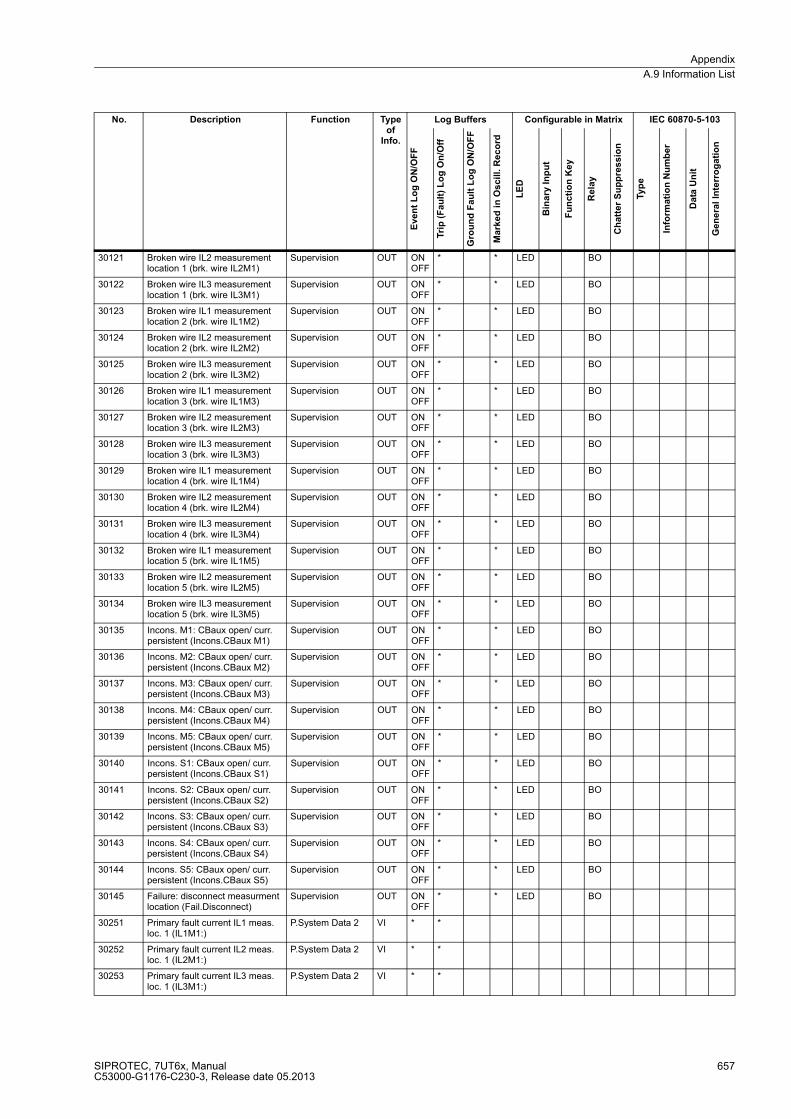
Appendix
A.9 Information List
SIPROTEC, 7UT6x, ManualC53000-G1176-C230-3, Release date 05.2013
657
30121 Broken wire IL2 measurement location 1 (brk. wire IL2M1)
Supervision OUT ON OFF
* * LED BO
30122 Broken wire IL3 measurement location 1 (brk. wire IL3M1)
Supervision OUT ON OFF
* * LED BO
30123 Broken wire IL1 measurement location 2 (brk. wire IL1M2)
Supervision OUT ON OFF
* * LED BO
30124 Broken wire IL2 measurement location 2 (brk. wire IL2M2)
Supervision OUT ON OFF
* * LED BO
30125 Broken wire IL3 measurement location 2 (brk. wire IL3M2)
Supervision OUT ON OFF
* * LED BO
30126 Broken wire IL1 measurement location 3 (brk. wire IL1M3)
Supervision OUT ON OFF
* * LED BO
30127 Broken wire IL2 measurement location 3 (brk. wire IL2M3)
Supervision OUT ON OFF
* * LED BO
30128 Broken wire IL3 measurement location 3 (brk. wire IL3M3)
Supervision OUT ON OFF
* * LED BO
30129 Broken wire IL1 measurement location 4 (brk. wire IL1M4)
Supervision OUT ON OFF
* * LED BO
30130 Broken wire IL2 measurement location 4 (brk. wire IL2M4)
Supervision OUT ON OFF
* * LED BO
30131 Broken wire IL3 measurement location 4 (brk. wire IL3M4)
Supervision OUT ON OFF
* * LED BO
30132 Broken wire IL1 measurement location 5 (brk. wire IL1M5)
Supervision OUT ON OFF
* * LED BO
30133 Broken wire IL2 measurement location 5 (brk. wire IL2M5)
Supervision OUT ON OFF
* * LED BO
30134 Broken wire IL3 measurement location 5 (brk. wire IL3M5)
Supervision OUT ON OFF
* * LED BO
30135 Incons. M1: CBaux open/ curr. persistent (Incons.CBaux M1)
Supervision OUT ON OFF
* * LED BO
30136 Incons. M2: CBaux open/ curr. persistent (Incons.CBaux M2)
Supervision OUT ON OFF
* * LED BO
30137 Incons. M3: CBaux open/ curr. persistent (Incons.CBaux M3)
Supervision OUT ON OFF
* * LED BO
30138 Incons. M4: CBaux open/ curr. persistent (Incons.CBaux M4)
Supervision OUT ON OFF
* * LED BO
30139 Incons. M5: CBaux open/ curr. persistent (Incons.CBaux M5)
Supervision OUT ON OFF
* * LED BO
30140 Incons. S1: CBaux open/ curr. persistent (Incons.CBaux S1)
Supervision OUT ON OFF
* * LED BO
30141 Incons. S2: CBaux open/ curr. persistent (Incons.CBaux S2)
Supervision OUT ON OFF
* * LED BO
30142 Incons. S3: CBaux open/ curr. persistent (Incons.CBaux S3)
Supervision OUT ON OFF
* * LED BO
30143 Incons. S4: CBaux open/ curr. persistent (Incons.CBaux S4)
Supervision OUT ON OFF
* * LED BO
30144 Incons. S5: CBaux open/ curr. persistent (Incons.CBaux S5)
Supervision OUT ON OFF
* * LED BO
30145 Failure: disconnect measurment location (Fail.Disconnect)
Supervision OUT ON OFF
* * LED BO
30251 Primary fault current IL1 meas. loc. 1 (IL1M1:)
P.System Data 2 VI * *
30252 Primary fault current IL2 meas. loc. 1 (IL2M1:)
P.System Data 2 VI * *
30253 Primary fault current IL3 meas. loc. 1 (IL3M1:)
P.System Data 2 VI * *
No. Description Function Type of
Info.
Log Buffers Configurable in Matrix IEC 60870-5-103
Eve
nt
Lo
g O
N/O
FF
Tri
p (
Fa
ult
) L
og
On
/Off
Gro
un
d F
au
lt L
og
ON
/OF
F
Ma
rke
d i
n O
scil
l. R
ec
ord
LE
D
Bin
ary
In
pu
t
Fu
nc
tio
n K
ey
Re
lay
Ch
att
er
Su
pp
res
sio
n
Typ
e
Info
rma
tio
n N
um
be
r
Da
ta U
nit
Ge
ne
ral
Inte
rro
ga
tio
n

Appendix
A.9 Information List
SIPROTEC, 7UT6x, ManualC53000-G1176-C230-3, Release date 05.2013
658
30254 Primary fault current IL1 meas. loc. 2 (IL1M2:)
P.System Data 2 VI * *
30255 Primary fault current IL2 meas. loc. 2 (IL2M2:)
P.System Data 2 VI * *
30256 Primary fault current IL3 meas. loc. 2 (IL3M2:)
P.System Data 2 VI * *
30257 Primary fault current IL1 meas. loc. 3 (IL1M3:)
P.System Data 2 VI * *
30258 Primary fault current IL2 meas. loc. 3 (IL2M3:)
P.System Data 2 VI * *
30259 Primary fault current IL3 meas. loc. 3 (IL3M3:)
P.System Data 2 VI * *
30260 Primary fault current IL1 meas. loc. 4 (IL1M4:)
P.System Data 2 VI * *
30261 Primary fault current IL2 meas. loc. 4 (IL2M4:)
P.System Data 2 VI * *
30262 Primary fault current IL3 meas. loc. 4 (IL3M4:)
P.System Data 2 VI * *
30263 Primary fault current IL1 meas. loc. 5 (IL1M5:)
P.System Data 2 VI * *
30264 Primary fault current IL2 meas. loc. 5 (IL2M5:)
P.System Data 2 VI * *
30265 Primary fault current IL3 meas. loc. 5 (IL3M5:)
P.System Data 2 VI * *
30266 Primary fault current IL1 side3 (IL1S3:)
P.System Data 2 VI * *
30267 Primary fault current IL2 side3 (IL2S3:)
P.System Data 2 VI * *
30268 Primary fault current IL3 side3 (IL3S3:)
P.System Data 2 VI * *
30269 Primary fault current IL1 side4 (IL1S4:)
P.System Data 2 VI * *
30270 Primary fault current IL2 side4 (IL2S4:)
P.System Data 2 VI * *
30271 Primary fault current IL3 side4 (IL3S4:)
P.System Data 2 VI * *
30272 Primary fault current IL1 side5 (IL1S5:)
P.System Data 2 VI * *
30273 Primary fault current IL2 side5 (IL2S5:)
P.System Data 2 VI * *
30274 Primary fault current IL3 side5 (IL3S5:)
P.System Data 2 VI * *
30275 Primary fault current I8 (I8:) P.System Data 2 VI * *
30276 Primary fault current I9 (I9:) P.System Data 2 VI * *
30277 Primary fault current I10 (I10:) P.System Data 2 VI * *
30278 Primary fault current I11 (I11:) P.System Data 2 VI * *
30279 Primary fault current I12 (I12:) P.System Data 2 VI * *
30351 >Manual close signal measure-ment loc. 1 (>ManualClose M1)
P.System Data 2 SP * * * LED BI BO
30352 >Manual close signal measure-ment loc. 2 (>ManualClose M2)
P.System Data 2 SP * * * LED BI BO
30353 >Manual close signal measure-ment loc. 3 (>ManualClose M3)
P.System Data 2 SP * * * LED BI BO
30354 >Manual close signal measure-ment loc. 4 (>ManualClose M4)
P.System Data 2 SP * * * LED BI BO
No. Description Function Type of
Info.
Log Buffers Configurable in Matrix IEC 60870-5-103
Eve
nt
Lo
g O
N/O
FF
Tri
p (
Fa
ult
) L
og
On
/Off
Gro
un
d F
au
lt L
og
ON
/OF
F
Ma
rke
d i
n O
scil
l. R
ec
ord
LE
D
Bin
ary
In
pu
t
Fu
nc
tio
n K
ey
Re
lay
Ch
att
er
Su
pp
res
sio
n
Typ
e
Info
rma
tio
n N
um
be
r
Da
ta U
nit
Ge
ne
ral
Inte
rro
ga
tio
n
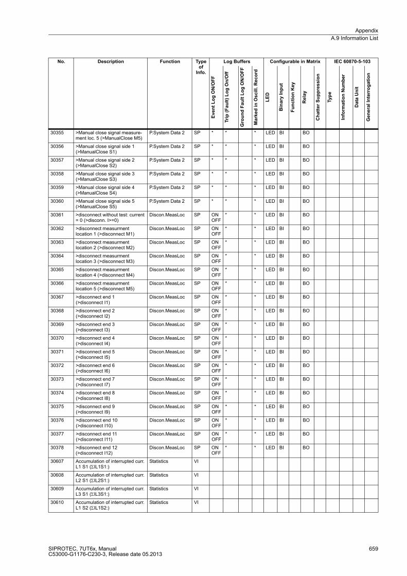
Appendix
A.9 Information List
SIPROTEC, 7UT6x, ManualC53000-G1176-C230-3, Release date 05.2013
659
30355 >Manual close signal measure-ment loc. 5 (>ManualClose M5)
P.System Data 2 SP * * * LED BI BO
30356 >Manual close signal side 1 (>ManualClose S1)
P.System Data 2 SP * * * LED BI BO
30357 >Manual close signal side 2 (>ManualClose S2)
P.System Data 2 SP * * * LED BI BO
30358 >Manual close signal side 3 (>ManualClose S3)
P.System Data 2 SP * * * LED BI BO
30359 >Manual close signal side 4 (>ManualClose S4)
P.System Data 2 SP * * * LED BI BO
30360 >Manual close signal side 5 (>ManualClose S5)
P.System Data 2 SP * * * LED BI BO
30361 >disconnect without test: current = 0 (>disconn. I>=0)
Discon.MeasLoc SP ON OFF
* * LED BI BO
30362 >disconnect measurment location 1 (>disconnect M1)
Discon.MeasLoc SP ON OFF
* * LED BI BO
30363 >disconnect measurment location 2 (>disconnect M2)
Discon.MeasLoc SP ON OFF
* * LED BI BO
30364 >disconnect measurment location 3 (>disconnect M3)
Discon.MeasLoc SP ON OFF
* * LED BI BO
30365 >disconnect measurment location 4 (>disconnect M4)
Discon.MeasLoc SP ON OFF
* * LED BI BO
30366 >disconnect measurment location 5 (>disconnect M5)
Discon.MeasLoc SP ON OFF
* * LED BI BO
30367 >disconnect end 1 (>disconnect I1)
Discon.MeasLoc SP ON OFF
* * LED BI BO
30368 >disconnect end 2 (>disconnect I2)
Discon.MeasLoc SP ON OFF
* * LED BI BO
30369 >disconnect end 3 (>disconnect I3)
Discon.MeasLoc SP ON OFF
* * LED BI BO
30370 >disconnect end 4 (>disconnect I4)
Discon.MeasLoc SP ON OFF
* * LED BI BO
30371 >disconnect end 5 (>disconnect I5)
Discon.MeasLoc SP ON OFF
* * LED BI BO
30372 >disconnect end 6 (>disconnect I6)
Discon.MeasLoc SP ON OFF
* * LED BI BO
30373 >disconnect end 7 (>disconnect I7)
Discon.MeasLoc SP ON OFF
* * LED BI BO
30374 >disconnect end 8 (>disconnect I8)
Discon.MeasLoc SP ON OFF
* * LED BI BO
30375 >disconnect end 9 (>disconnect I9)
Discon.MeasLoc SP ON OFF
* * LED BI BO
30376 >disconnect end 10 (>disconnect I10)
Discon.MeasLoc SP ON OFF
* * LED BI BO
30377 >disconnect end 11 (>disconnect I11)
Discon.MeasLoc SP ON OFF
* * LED BI BO
30378 >disconnect end 12 (>disconnect I12)
Discon.MeasLoc SP ON OFF
* * LED BI BO
30607 Accumulation of interrupted curr. L1 S1 (ΣIL1S1:)
Statistics VI
30608 Accumulation of interrupted curr. L2 S1 (ΣIL2S1:)
Statistics VI
30609 Accumulation of interrupted curr. L3 S1 (ΣIL3S1:)
Statistics VI
30610 Accumulation of interrupted curr. L1 S2 (ΣIL1S2:)
Statistics VI
No. Description Function Type of
Info.
Log Buffers Configurable in Matrix IEC 60870-5-103
Eve
nt
Lo
g O
N/O
FF
Tri
p (
Fa
ult
) L
og
On
/Off
Gro
un
d F
au
lt L
og
ON
/OF
F
Ma
rke
d i
n O
scil
l. R
ec
ord
LE
D
Bin
ary
In
pu
t
Fu
nc
tio
n K
ey
Re
lay
Ch
att
er
Su
pp
res
sio
n
Typ
e
Info
rma
tio
n N
um
be
r
Da
ta U
nit
Ge
ne
ral
Inte
rro
ga
tio
n
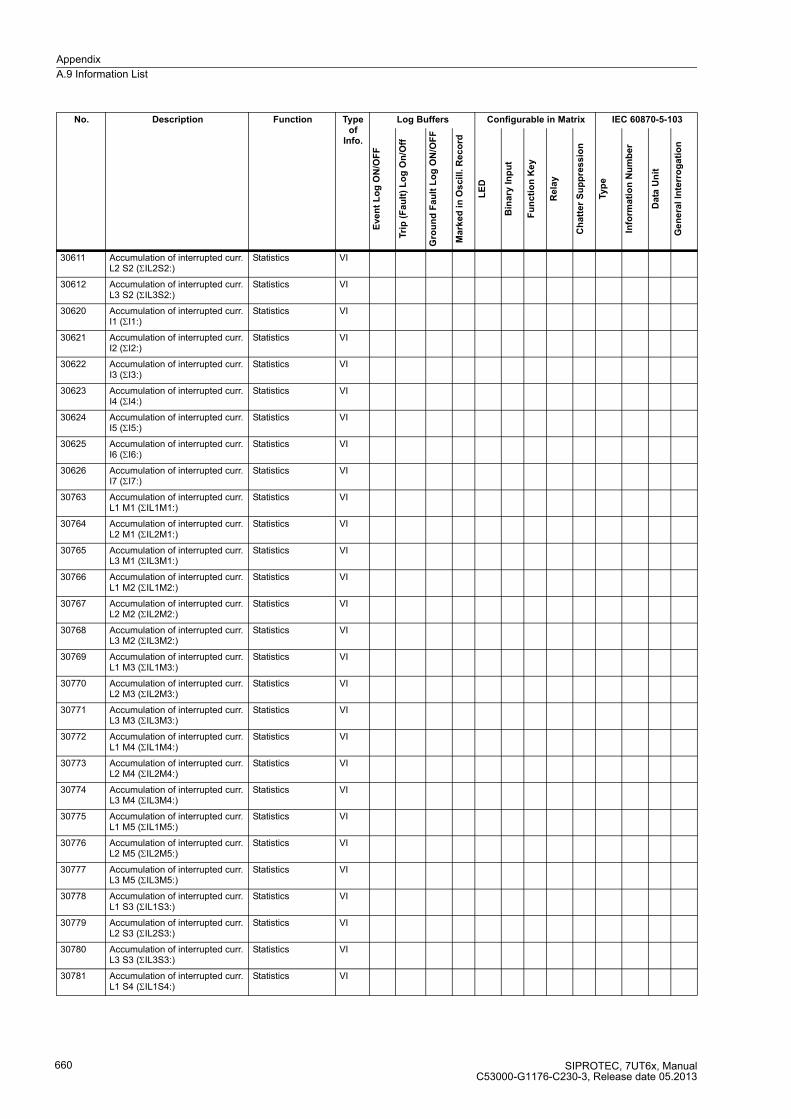
Appendix
A.9 Information List
SIPROTEC, 7UT6x, ManualC53000-G1176-C230-3, Release date 05.2013
660
30611 Accumulation of interrupted curr. L2 S2 (ΣIL2S2:)
Statistics VI
30612 Accumulation of interrupted curr. L3 S2 (ΣIL3S2:)
Statistics VI
30620 Accumulation of interrupted curr. I1 (ΣI1:)
Statistics VI
30621 Accumulation of interrupted curr. I2 (ΣI2:)
Statistics VI
30622 Accumulation of interrupted curr. I3 (ΣI3:)
Statistics VI
30623 Accumulation of interrupted curr. I4 (ΣI4:)
Statistics VI
30624 Accumulation of interrupted curr. I5 (ΣI5:)
Statistics VI
30625 Accumulation of interrupted curr. I6 (ΣI6:)
Statistics VI
30626 Accumulation of interrupted curr. I7 (ΣI7:)
Statistics VI
30763 Accumulation of interrupted curr. L1 M1 (ΣIL1M1:)
Statistics VI
30764 Accumulation of interrupted curr. L2 M1 (ΣIL2M1:)
Statistics VI
30765 Accumulation of interrupted curr. L3 M1 (ΣIL3M1:)
Statistics VI
30766 Accumulation of interrupted curr. L1 M2 (ΣIL1M2:)
Statistics VI
30767 Accumulation of interrupted curr. L2 M2 (ΣIL2M2:)
Statistics VI
30768 Accumulation of interrupted curr. L3 M2 (ΣIL3M2:)
Statistics VI
30769 Accumulation of interrupted curr. L1 M3 (ΣIL1M3:)
Statistics VI
30770 Accumulation of interrupted curr. L2 M3 (ΣIL2M3:)
Statistics VI
30771 Accumulation of interrupted curr. L3 M3 (ΣIL3M3:)
Statistics VI
30772 Accumulation of interrupted curr. L1 M4 (ΣIL1M4:)
Statistics VI
30773 Accumulation of interrupted curr. L2 M4 (ΣIL2M4:)
Statistics VI
30774 Accumulation of interrupted curr. L3 M4 (ΣIL3M4:)
Statistics VI
30775 Accumulation of interrupted curr. L1 M5 (ΣIL1M5:)
Statistics VI
30776 Accumulation of interrupted curr. L2 M5 (ΣIL2M5:)
Statistics VI
30777 Accumulation of interrupted curr. L3 M5 (ΣIL3M5:)
Statistics VI
30778 Accumulation of interrupted curr. L1 S3 (ΣIL1S3:)
Statistics VI
30779 Accumulation of interrupted curr. L2 S3 (ΣIL2S3:)
Statistics VI
30780 Accumulation of interrupted curr. L3 S3 (ΣIL3S3:)
Statistics VI
30781 Accumulation of interrupted curr. L1 S4 (ΣIL1S4:)
Statistics VI
No. Description Function Type of
Info.
Log Buffers Configurable in Matrix IEC 60870-5-103
Eve
nt
Lo
g O
N/O
FF
Tri
p (
Fa
ult
) L
og
On
/Off
Gro
un
d F
au
lt L
og
ON
/OF
F
Ma
rke
d i
n O
scil
l. R
ec
ord
LE
D
Bin
ary
In
pu
t
Fu
nc
tio
n K
ey
Re
lay
Ch
att
er
Su
pp
res
sio
n
Typ
e
Info
rma
tio
n N
um
be
r
Da
ta U
nit
Ge
ne
ral
Inte
rro
ga
tio
n
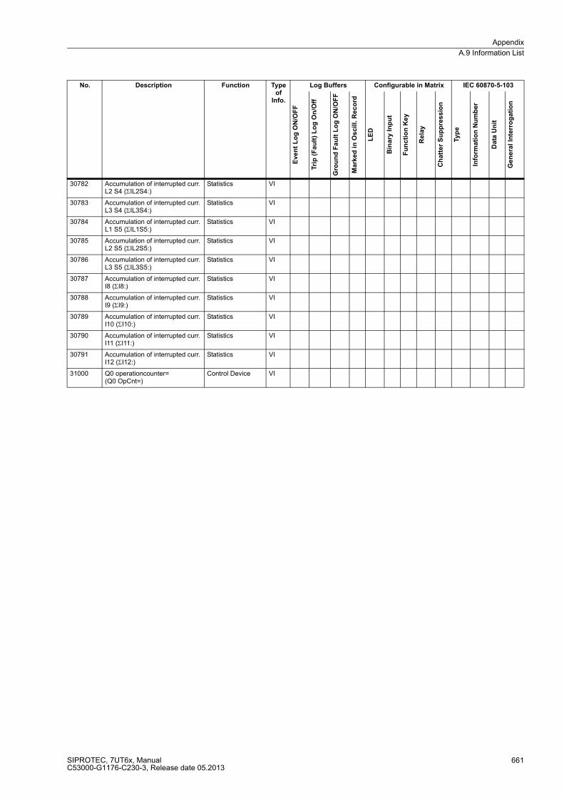
Appendix
A.9 Information List
SIPROTEC, 7UT6x, ManualC53000-G1176-C230-3, Release date 05.2013
661
30782 Accumulation of interrupted curr. L2 S4 (ΣIL2S4:)
Statistics VI
30783 Accumulation of interrupted curr. L3 S4 (ΣIL3S4:)
Statistics VI
30784 Accumulation of interrupted curr. L1 S5 (ΣIL1S5:)
Statistics VI
30785 Accumulation of interrupted curr. L2 S5 (ΣIL2S5:)
Statistics VI
30786 Accumulation of interrupted curr. L3 S5 (ΣIL3S5:)
Statistics VI
30787 Accumulation of interrupted curr. I8 (ΣI8:)
Statistics VI
30788 Accumulation of interrupted curr. I9 (ΣI9:)
Statistics VI
30789 Accumulation of interrupted curr. I10 (ΣI10:)
Statistics VI
30790 Accumulation of interrupted curr. I11 (ΣI11:)
Statistics VI
30791 Accumulation of interrupted curr. I12 (ΣI12:)
Statistics VI
31000 Q0 operationcounter= (Q0 OpCnt=)
Control Device VI
No. Description Function Type of
Info.
Log Buffers Configurable in Matrix IEC 60870-5-103
Eve
nt
Lo
g O
N/O
FF
Tri
p (
Fa
ult
) L
og
On
/Off
Gro
un
d F
au
lt L
og
ON
/OF
F
Ma
rke
d i
n O
scil
l. R
ec
ord
LE
D
Bin
ary
In
pu
t
Fu
nc
tio
n K
ey
Re
lay
Ch
att
er
Su
pp
res
sio
n
Typ
e
Info
rma
tio
n N
um
be
r
Da
ta U
nit
Ge
ne
ral
Inte
rro
ga
tio
n
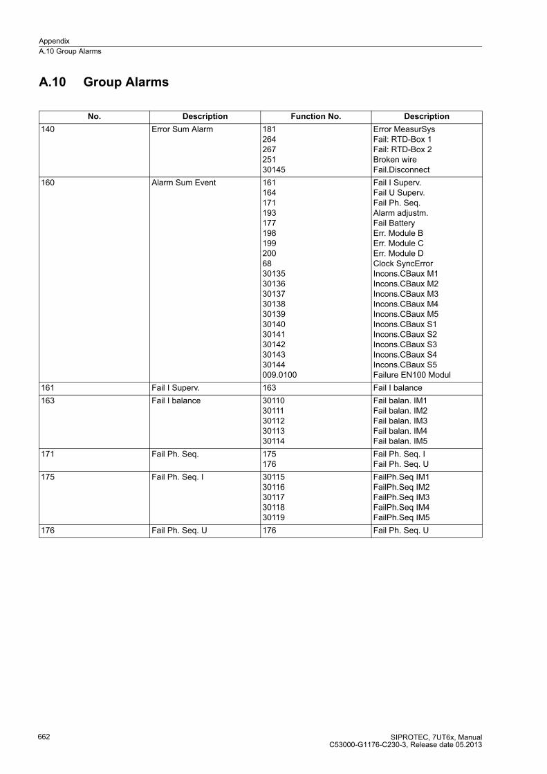
Appendix
A.10 Group Alarms
SIPROTEC, 7UT6x, ManualC53000-G1176-C230-3, Release date 05.2013
662
A.10 Group Alarms
No. Description Function No. Description
140 Error Sum Alarm 18126426725130145
Error MeasurSysFail: RTD-Box 1Fail: RTD-Box 2Broken wireFail.Disconnect
160 Alarm Sum Event 1611641711931771981992006830135301363013730138301393014030141301423014330144009.0100
Fail I Superv.Fail U Superv.Fail Ph. Seq.Alarm adjustm.Fail BatteryErr. Module BErr. Module CErr. Module DClock SyncErrorIncons.CBaux M1Incons.CBaux M2Incons.CBaux M3Incons.CBaux M4Incons.CBaux M5Incons.CBaux S1Incons.CBaux S2Incons.CBaux S3Incons.CBaux S4Incons.CBaux S5Failure EN100 Modul
161 Fail I Superv. 163 Fail I balance
163 Fail I balance 3011030111301123011330114
Fail balan. IM1Fail balan. IM2Fail balan. IM3Fail balan. IM4Fail balan. IM5
171 Fail Ph. Seq. 175176
Fail Ph. Seq. IFail Ph. Seq. U
175 Fail Ph. Seq. I 3011530116301173011830119
FailPh.Seq IM1FailPh.Seq IM2FailPh.Seq IM3FailPh.Seq IM4FailPh.Seq IM5
176 Fail Ph. Seq. U 176 Fail Ph. Seq. U

Appendix
A.10 Group Alarms
SIPROTEC, 7UT6x, ManualC53000-G1176-C230-3, Release date 05.2013
663
181 Error MeasurSys 190183184185186187188189192191
Error Board 0Error Board 1Error Board 2Error Board 3Error Board 4Error Board 5Error Board 6Error Board 7Error1A/5AwrongError Offset
192 Error1A/5Awrong 30097300983009930100301013010230103301043010530106301073010830109
Err. IN CT M1Err. IN CT M2Err. IN CT M3Err. IN CT M4Err. IN CT M5Err.IN CT1..3Err.IN CT4..6Err.IN CT7..9Err.IN CT10..12Err. IN CT IX1Err. IN CT IX2Err. IN CT IX3Err. IN CT IX4
No. Description Function No. Description
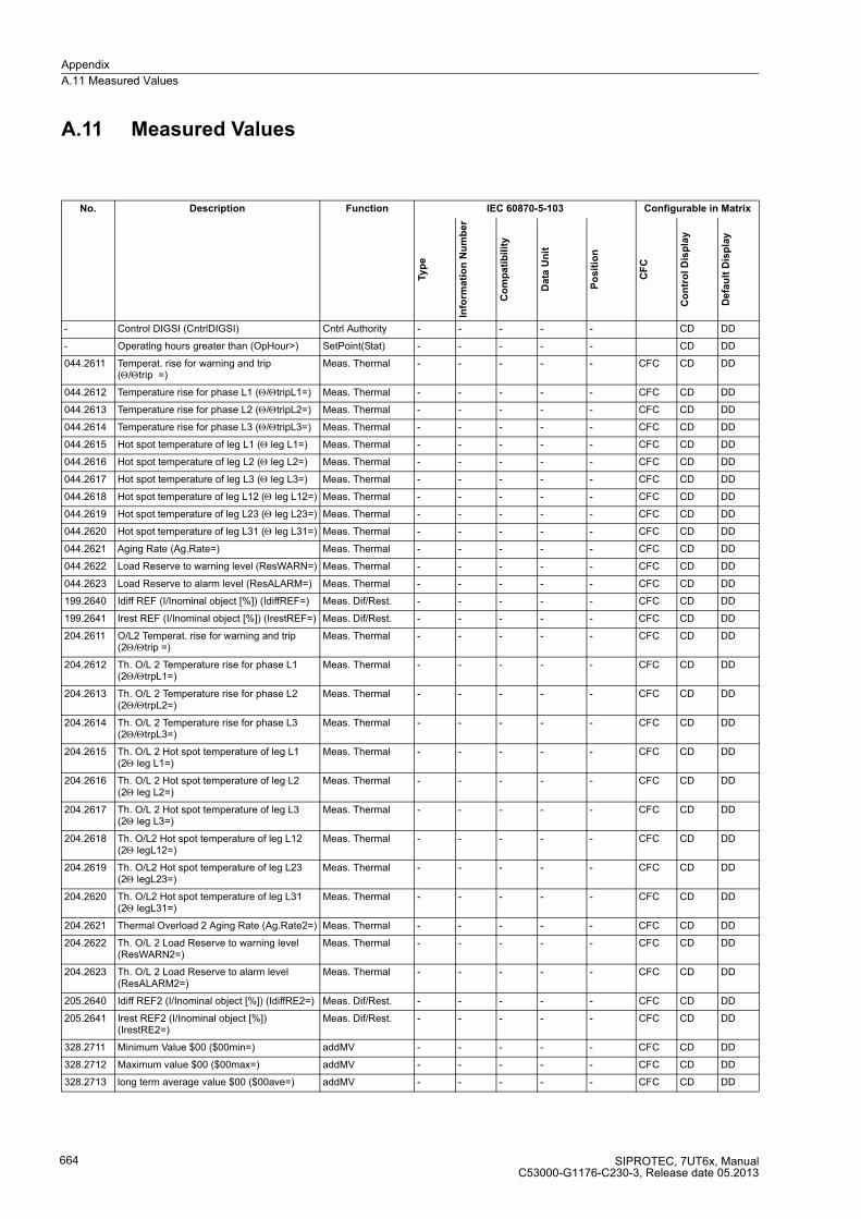
Appendix
A.11 Measured Values
SIPROTEC, 7UT6x, ManualC53000-G1176-C230-3, Release date 05.2013
664
A.11 Measured Values
No. Description Function IEC 60870-5-103 Configurable in Matrix
Ty
pe
Info
rma
tio
n N
um
be
r
Co
mp
ati
bil
ity
Data
Un
it
Po
sit
ion
CF
C
Co
ntr
ol D
isp
lay
De
fau
lt D
isp
lay
- Control DIGSI (CntrlDIGSI) Cntrl Authority - - - - - CD DD
- Operating hours greater than (OpHour>) SetPoint(Stat) - - - - - CD DD
044.2611 Temperat. rise for warning and trip (Θ/Θtrip =)
Meas. Thermal - - - - - CFC CD DD
044.2612 Temperature rise for phase L1 (Θ/ΘtripL1=) Meas. Thermal - - - - - CFC CD DD
044.2613 Temperature rise for phase L2 (Θ/ΘtripL2=) Meas. Thermal - - - - - CFC CD DD
044.2614 Temperature rise for phase L3 (Θ/ΘtripL3=) Meas. Thermal - - - - - CFC CD DD
044.2615 Hot spot temperature of leg L1 (Θ leg L1=) Meas. Thermal - - - - - CFC CD DD
044.2616 Hot spot temperature of leg L2 (Θ leg L2=) Meas. Thermal - - - - - CFC CD DD
044.2617 Hot spot temperature of leg L3 (Θ leg L3=) Meas. Thermal - - - - - CFC CD DD
044.2618 Hot spot temperature of leg L12 (Θ leg L12=) Meas. Thermal - - - - - CFC CD DD
044.2619 Hot spot temperature of leg L23 (Θ leg L23=) Meas. Thermal - - - - - CFC CD DD
044.2620 Hot spot temperature of leg L31 (Θ leg L31=) Meas. Thermal - - - - - CFC CD DD
044.2621 Aging Rate (Ag.Rate=) Meas. Thermal - - - - - CFC CD DD
044.2622 Load Reserve to warning level (ResWARN=) Meas. Thermal - - - - - CFC CD DD
044.2623 Load Reserve to alarm level (ResALARM=) Meas. Thermal - - - - - CFC CD DD
199.2640 Idiff REF (I/Inominal object [%]) (IdiffREF=) Meas. Dif/Rest. - - - - - CFC CD DD
199.2641 Irest REF (I/Inominal object [%]) (IrestREF=) Meas. Dif/Rest. - - - - - CFC CD DD
204.2611 O/L2 Temperat. rise for warning and trip (2Θ/Θtrip =)
Meas. Thermal - - - - - CFC CD DD
204.2612 Th. O/L 2 Temperature rise for phase L1 (2Θ/ΘtrpL1=)
Meas. Thermal - - - - - CFC CD DD
204.2613 Th. O/L 2 Temperature rise for phase L2 (2Θ/ΘtrpL2=)
Meas. Thermal - - - - - CFC CD DD
204.2614 Th. O/L 2 Temperature rise for phase L3 (2Θ/ΘtrpL3=)
Meas. Thermal - - - - - CFC CD DD
204.2615 Th. O/L 2 Hot spot temperature of leg L1 (2Θ leg L1=)
Meas. Thermal - - - - - CFC CD DD
204.2616 Th. O/L 2 Hot spot temperature of leg L2 (2Θ leg L2=)
Meas. Thermal - - - - - CFC CD DD
204.2617 Th. O/L 2 Hot spot temperature of leg L3 (2Θ leg L3=)
Meas. Thermal - - - - - CFC CD DD
204.2618 Th. O/L2 Hot spot temperature of leg L12 (2Θ legL12=)
Meas. Thermal - - - - - CFC CD DD
204.2619 Th. O/L2 Hot spot temperature of leg L23 (2Θ legL23=)
Meas. Thermal - - - - - CFC CD DD
204.2620 Th. O/L2 Hot spot temperature of leg L31 (2Θ legL31=)
Meas. Thermal - - - - - CFC CD DD
204.2621 Thermal Overload 2 Aging Rate (Ag.Rate2=) Meas. Thermal - - - - - CFC CD DD
204.2622 Th. O/L 2 Load Reserve to warning level (ResWARN2=)
Meas. Thermal - - - - - CFC CD DD
204.2623 Th. O/L 2 Load Reserve to alarm level (ResALARM2=)
Meas. Thermal - - - - - CFC CD DD
205.2640 Idiff REF2 (I/Inominal object [%]) (IdiffRE2=) Meas. Dif/Rest. - - - - - CFC CD DD
205.2641 Irest REF2 (I/Inominal object [%]) (IrestRE2=)
Meas. Dif/Rest. - - - - - CFC CD DD
328.2711 Minimum Value $00 ($00min=) addMV - - - - - CFC CD DD
328.2712 Maximum value $00 ($00max=) addMV - - - - - CFC CD DD
328.2713 long term average value $00 ($00ave=) addMV - - - - - CFC CD DD
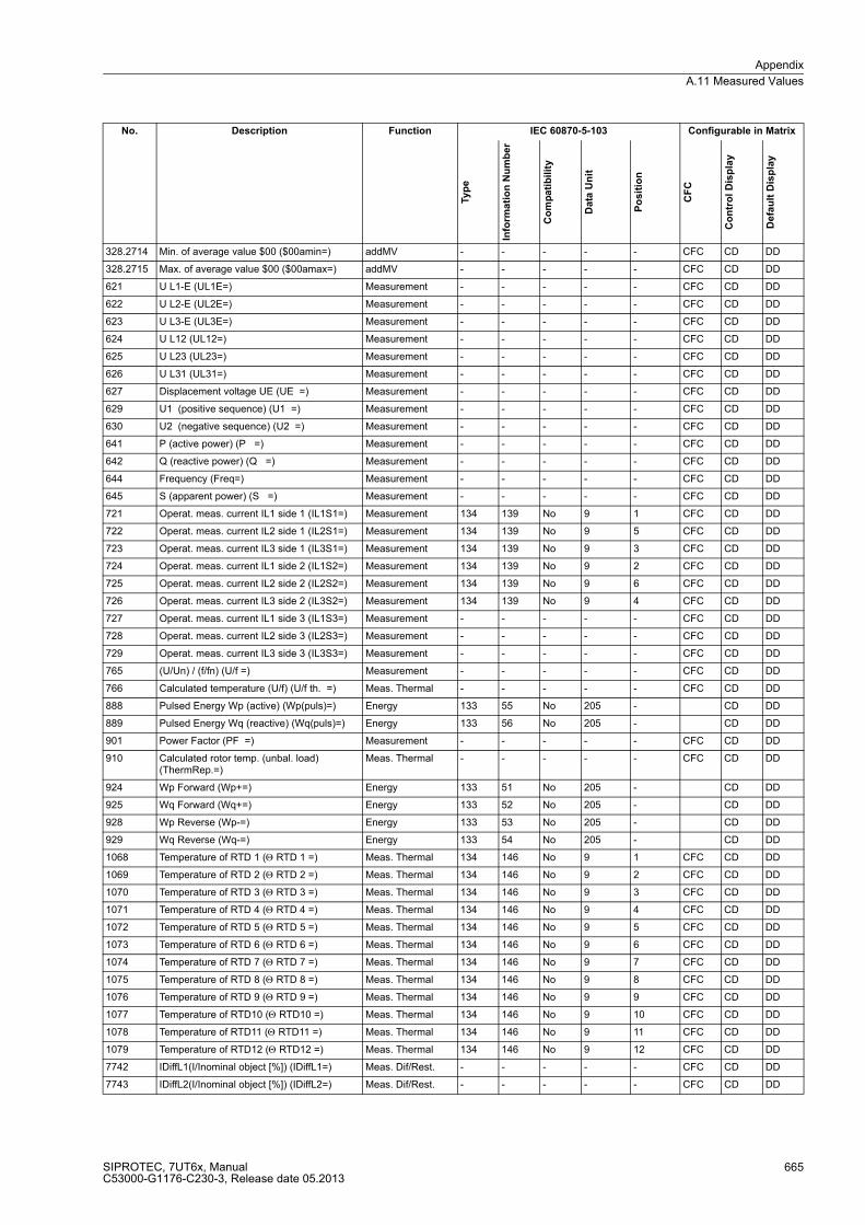
Appendix
A.11 Measured Values
SIPROTEC, 7UT6x, ManualC53000-G1176-C230-3, Release date 05.2013
665
328.2714 Min. of average value $00 ($00amin=) addMV - - - - - CFC CD DD
328.2715 Max. of average value $00 ($00amax=) addMV - - - - - CFC CD DD
621 U L1-E (UL1E=) Measurement - - - - - CFC CD DD
622 U L2-E (UL2E=) Measurement - - - - - CFC CD DD
623 U L3-E (UL3E=) Measurement - - - - - CFC CD DD
624 U L12 (UL12=) Measurement - - - - - CFC CD DD
625 U L23 (UL23=) Measurement - - - - - CFC CD DD
626 U L31 (UL31=) Measurement - - - - - CFC CD DD
627 Displacement voltage UE (UE =) Measurement - - - - - CFC CD DD
629 U1 (positive sequence) (U1 =) Measurement - - - - - CFC CD DD
630 U2 (negative sequence) (U2 =) Measurement - - - - - CFC CD DD
641 P (active power) (P =) Measurement - - - - - CFC CD DD
642 Q (reactive power) (Q =) Measurement - - - - - CFC CD DD
644 Frequency (Freq=) Measurement - - - - - CFC CD DD
645 S (apparent power) (S =) Measurement - - - - - CFC CD DD
721 Operat. meas. current IL1 side 1 (IL1S1=) Measurement 134 139 No 9 1 CFC CD DD
722 Operat. meas. current IL2 side 1 (IL2S1=) Measurement 134 139 No 9 5 CFC CD DD
723 Operat. meas. current IL3 side 1 (IL3S1=) Measurement 134 139 No 9 3 CFC CD DD
724 Operat. meas. current IL1 side 2 (IL1S2=) Measurement 134 139 No 9 2 CFC CD DD
725 Operat. meas. current IL2 side 2 (IL2S2=) Measurement 134 139 No 9 6 CFC CD DD
726 Operat. meas. current IL3 side 2 (IL3S2=) Measurement 134 139 No 9 4 CFC CD DD
727 Operat. meas. current IL1 side 3 (IL1S3=) Measurement - - - - - CFC CD DD
728 Operat. meas. current IL2 side 3 (IL2S3=) Measurement - - - - - CFC CD DD
729 Operat. meas. current IL3 side 3 (IL3S3=) Measurement - - - - - CFC CD DD
765 (U/Un) / (f/fn) (U/f =) Measurement - - - - - CFC CD DD
766 Calculated temperature (U/f) (U/f th. =) Meas. Thermal - - - - - CFC CD DD
888 Pulsed Energy Wp (active) (Wp(puls)=) Energy 133 55 No 205 - CD DD
889 Pulsed Energy Wq (reactive) (Wq(puls)=) Energy 133 56 No 205 - CD DD
901 Power Factor (PF =) Measurement - - - - - CFC CD DD
910 Calculated rotor temp. (unbal. load) (ThermRep.=)
Meas. Thermal - - - - - CFC CD DD
924 Wp Forward (Wp+=) Energy 133 51 No 205 - CD DD
925 Wq Forward (Wq+=) Energy 133 52 No 205 - CD DD
928 Wp Reverse (Wp-=) Energy 133 53 No 205 - CD DD
929 Wq Reverse (Wq-=) Energy 133 54 No 205 - CD DD
1068 Temperature of RTD 1 (Θ RTD 1 =) Meas. Thermal 134 146 No 9 1 CFC CD DD
1069 Temperature of RTD 2 (Θ RTD 2 =) Meas. Thermal 134 146 No 9 2 CFC CD DD
1070 Temperature of RTD 3 (Θ RTD 3 =) Meas. Thermal 134 146 No 9 3 CFC CD DD
1071 Temperature of RTD 4 (Θ RTD 4 =) Meas. Thermal 134 146 No 9 4 CFC CD DD
1072 Temperature of RTD 5 (Θ RTD 5 =) Meas. Thermal 134 146 No 9 5 CFC CD DD
1073 Temperature of RTD 6 (Θ RTD 6 =) Meas. Thermal 134 146 No 9 6 CFC CD DD
1074 Temperature of RTD 7 (Θ RTD 7 =) Meas. Thermal 134 146 No 9 7 CFC CD DD
1075 Temperature of RTD 8 (Θ RTD 8 =) Meas. Thermal 134 146 No 9 8 CFC CD DD
1076 Temperature of RTD 9 (Θ RTD 9 =) Meas. Thermal 134 146 No 9 9 CFC CD DD
1077 Temperature of RTD10 (Θ RTD10 =) Meas. Thermal 134 146 No 9 10 CFC CD DD
1078 Temperature of RTD11 (Θ RTD11 =) Meas. Thermal 134 146 No 9 11 CFC CD DD
1079 Temperature of RTD12 (Θ RTD12 =) Meas. Thermal 134 146 No 9 12 CFC CD DD
7742 IDiffL1(I/Inominal object [%]) (IDiffL1=) Meas. Dif/Rest. - - - - - CFC CD DD
7743 IDiffL2(I/Inominal object [%]) (IDiffL2=) Meas. Dif/Rest. - - - - - CFC CD DD
No. Description Function IEC 60870-5-103 Configurable in Matrix
Ty
pe
Info
rma
tio
n N
um
be
r
Co
mp
ati
bil
ity
Data
Un
it
Po
sit
ion
CF
C
Co
ntr
ol
Dis
pla
y
De
fau
lt D
isp
lay

Appendix
A.11 Measured Values
SIPROTEC, 7UT6x, ManualC53000-G1176-C230-3, Release date 05.2013
666
7744 IDiffL3(I/Inominal object [%]) (IDiffL3=) Meas. Dif/Rest. - - - - - CFC CD DD
7745 IRestL1(I/Inominal object [%]) (IRestL1=) Meas. Dif/Rest. - - - - - CFC CD DD
7746 IRestL2(I/Inominal object [%]) (IRestL2=) Meas. Dif/Rest. - - - - - CFC CD DD
7747 IRestL3(I/Inominal object [%]) (IRestL3=) Meas. Dif/Rest. - - - - - CFC CD DD
30633 Phase angle of current I1 (ϕI1=) Measurement - - - - - CFC CD DD
30634 Phase angle of current I2 (ϕI2=) Measurement - - - - - CFC CD DD
30635 Phase angle of current I3 (ϕI3=) Measurement - - - - - CFC CD DD
30636 Phase angle of current I4 (ϕI4=) Measurement - - - - - CFC CD DD
30637 Phase angle of current I5 (ϕI5=) Measurement - - - - - CFC CD DD
30638 Phase angle of current I6 (ϕI6=) Measurement - - - - - CFC CD DD
30639 Phase angle of current I7 (ϕI7=) Measurement - - - - - CFC CD DD
30640 3I0 (zero sequence) of side 1 (3I0S1=) Measurement - - - - - CFC CD DD
30641 I1 (positive sequence) of side 1 (I1S1=) Measurement - - - - - CFC CD DD
30642 I2 (negative sequence) of side 1 (I2S1=) Measurement - - - - - CFC CD DD
30643 3I0 (zero sequence) of side 2 (3I0S2=) Measurement - - - - - CFC CD DD
30644 I1 (positive sequence) of side 2 (I1S2=) Measurement - - - - - CFC CD DD
30645 I2 (negative sequence) of side 2 (I2S2=) Measurement - - - - - CFC CD DD
30646 Operat. meas. current I1 (I1=) Measurement - - - - - CFC CD DD
30647 Operat. meas. current I2 (I2=) Measurement - - - - - CFC CD DD
30648 Operat. meas. current I3 (I3=) Measurement - - - - - CFC CD DD
30649 Operat. meas. current I4 (I4=) Measurement - - - - - CFC CD DD
30650 Operat. meas. current I5 (I5=) Measurement - - - - - CFC CD DD
30651 Operat. meas. current I6 (I6=) Measurement - - - - - CFC CD DD
30652 Operat. meas. current I7 (I7=) Measurement - - - - - CFC CD DD
30653 Operat. meas. current I8 (I8=) Measurement - - - - - CFC CD DD
30656 Operat. meas. voltage Umeas. (Umeas.=) Measurement - - - - - CFC CD DD
30661 Operat. meas. current IL1 meas. loc. 1 (IL1M1=)
Measurement 134 149 No 9 2 CFC CD DD
30662 Operat. meas. current IL2 meas. loc. 1 (IL2M1=)
Measurement 134 149 No 9 1 CFC CD DD
30663 Operat. meas. current IL3 meas. loc. 1 (IL3M1=)
Measurement 134 149 No 9 3 CFC CD DD
30664 3I0 (zero sequence) of meas. loc. 1 (3I0M1=) Measurement - - - - - CFC CD DD
30665 I1 (positive sequence) of meas. loc. 1 (I1M1=)
Measurement - - - - - CFC CD DD
30666 I2 (negative sequence) of meas. loc. 1 (I2M1=)
Measurement - - - - - CFC CD DD
30667 Operat. meas. current IL1 meas. loc. 2 (IL1M2=)
Measurement 134 149 No 9 5 CFC CD DD
30668 Operat. meas. current IL2 meas. loc. 2 (IL2M2=)
Measurement 134 149 No 9 4 CFC CD DD
30669 Operat. meas. current IL3 meas. loc. 2 (IL3M2=)
Measurement 134 149 No 9 6 CFC CD DD
30670 3I0 (zero sequence) of meas. loc. 2 (3I0M2=) Measurement - - - - - CFC CD DD
30671 I1 (positive sequence) of meas. loc. 2 (I1M2=)
Measurement - - - - - CFC CD DD
30672 I2 (negative sequence) of meas. loc. 2 (I2M2=)
Measurement - - - - - CFC CD DD
30673 Operat. meas. current IL1 meas. loc. 3 (IL1M3=)
Measurement 134 149 No 9 8 CFC CD DD
30674 Operat. meas. current IL2 meas. loc. 3 (IL2M3=)
Measurement 134 149 No 9 7 CFC CD DD
No. Description Function IEC 60870-5-103 Configurable in Matrix
Ty
pe
Info
rma
tio
n N
um
be
r
Co
mp
ati
bil
ity
Data
Un
it
Po
sit
ion
CF
C
Co
ntr
ol
Dis
pla
y
De
fau
lt D
isp
lay
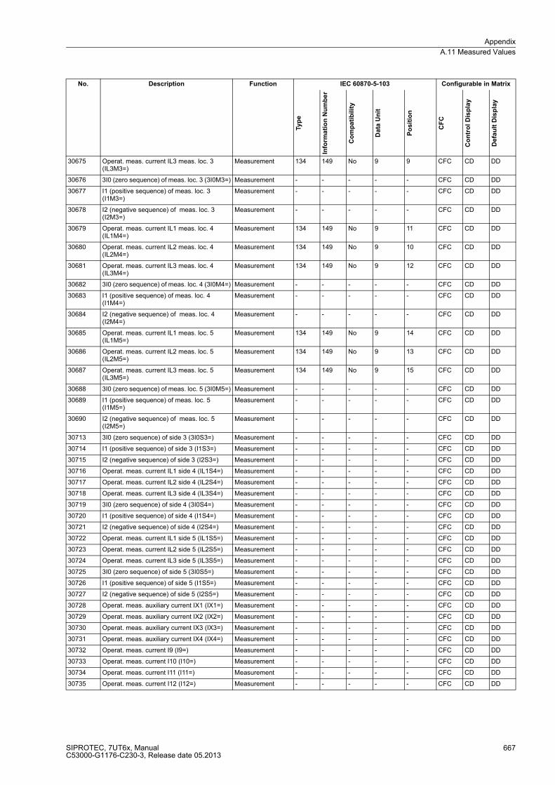
Appendix
A.11 Measured Values
SIPROTEC, 7UT6x, ManualC53000-G1176-C230-3, Release date 05.2013
667
30675 Operat. meas. current IL3 meas. loc. 3 (IL3M3=)
Measurement 134 149 No 9 9 CFC CD DD
30676 3I0 (zero sequence) of meas. loc. 3 (3I0M3=) Measurement - - - - - CFC CD DD
30677 I1 (positive sequence) of meas. loc. 3 (I1M3=)
Measurement - - - - - CFC CD DD
30678 I2 (negative sequence) of meas. loc. 3 (I2M3=)
Measurement - - - - - CFC CD DD
30679 Operat. meas. current IL1 meas. loc. 4 (IL1M4=)
Measurement 134 149 No 9 11 CFC CD DD
30680 Operat. meas. current IL2 meas. loc. 4 (IL2M4=)
Measurement 134 149 No 9 10 CFC CD DD
30681 Operat. meas. current IL3 meas. loc. 4 (IL3M4=)
Measurement 134 149 No 9 12 CFC CD DD
30682 3I0 (zero sequence) of meas. loc. 4 (3I0M4=) Measurement - - - - - CFC CD DD
30683 I1 (positive sequence) of meas. loc. 4 (I1M4=)
Measurement - - - - - CFC CD DD
30684 I2 (negative sequence) of meas. loc. 4 (I2M4=)
Measurement - - - - - CFC CD DD
30685 Operat. meas. current IL1 meas. loc. 5 (IL1M5=)
Measurement 134 149 No 9 14 CFC CD DD
30686 Operat. meas. current IL2 meas. loc. 5 (IL2M5=)
Measurement 134 149 No 9 13 CFC CD DD
30687 Operat. meas. current IL3 meas. loc. 5 (IL3M5=)
Measurement 134 149 No 9 15 CFC CD DD
30688 3I0 (zero sequence) of meas. loc. 5 (3I0M5=) Measurement - - - - - CFC CD DD
30689 I1 (positive sequence) of meas. loc. 5 (I1M5=)
Measurement - - - - - CFC CD DD
30690 I2 (negative sequence) of meas. loc. 5 (I2M5=)
Measurement - - - - - CFC CD DD
30713 3I0 (zero sequence) of side 3 (3I0S3=) Measurement - - - - - CFC CD DD
30714 I1 (positive sequence) of side 3 (I1S3=) Measurement - - - - - CFC CD DD
30715 I2 (negative sequence) of side 3 (I2S3=) Measurement - - - - - CFC CD DD
30716 Operat. meas. current IL1 side 4 (IL1S4=) Measurement - - - - - CFC CD DD
30717 Operat. meas. current IL2 side 4 (IL2S4=) Measurement - - - - - CFC CD DD
30718 Operat. meas. current IL3 side 4 (IL3S4=) Measurement - - - - - CFC CD DD
30719 3I0 (zero sequence) of side 4 (3I0S4=) Measurement - - - - - CFC CD DD
30720 I1 (positive sequence) of side 4 (I1S4=) Measurement - - - - - CFC CD DD
30721 I2 (negative sequence) of side 4 (I2S4=) Measurement - - - - - CFC CD DD
30722 Operat. meas. current IL1 side 5 (IL1S5=) Measurement - - - - - CFC CD DD
30723 Operat. meas. current IL2 side 5 (IL2S5=) Measurement - - - - - CFC CD DD
30724 Operat. meas. current IL3 side 5 (IL3S5=) Measurement - - - - - CFC CD DD
30725 3I0 (zero sequence) of side 5 (3I0S5=) Measurement - - - - - CFC CD DD
30726 I1 (positive sequence) of side 5 (I1S5=) Measurement - - - - - CFC CD DD
30727 I2 (negative sequence) of side 5 (I2S5=) Measurement - - - - - CFC CD DD
30728 Operat. meas. auxiliary current IX1 (IX1=) Measurement - - - - - CFC CD DD
30729 Operat. meas. auxiliary current IX2 (IX2=) Measurement - - - - - CFC CD DD
30730 Operat. meas. auxiliary current IX3 (IX3=) Measurement - - - - - CFC CD DD
30731 Operat. meas. auxiliary current IX4 (IX4=) Measurement - - - - - CFC CD DD
30732 Operat. meas. current I9 (I9=) Measurement - - - - - CFC CD DD
30733 Operat. meas. current I10 (I10=) Measurement - - - - - CFC CD DD
30734 Operat. meas. current I11 (I11=) Measurement - - - - - CFC CD DD
30735 Operat. meas. current I12 (I12=) Measurement - - - - - CFC CD DD
No. Description Function IEC 60870-5-103 Configurable in Matrix
Ty
pe
Info
rma
tio
n N
um
be
r
Co
mp
ati
bil
ity
Data
Un
it
Po
sit
ion
CF
C
Co
ntr
ol
Dis
pla
y
De
fau
lt D
isp
lay

Appendix
A.11 Measured Values
SIPROTEC, 7UT6x, ManualC53000-G1176-C230-3, Release date 05.2013
668
■
30736 Phase angle in phase IL1 meas. loc. 1 (ϕIL1M1=)
Measurement - - - - - CFC CD DD
30737 Phase angle in phase IL2 meas. loc. 1 (ϕIL2M1=)
Measurement - - - - - CFC CD DD
30738 Phase angle in phase IL3 meas. loc. 1 (ϕIL3M1=)
Measurement - - - - - CFC CD DD
30739 Phase angle in phase IL1 meas. loc. 2 (ϕIL1M2=)
Measurement - - - - - CFC CD DD
30740 Phase angle in phase IL2 meas. loc. 2 (ϕIL2M2=)
Measurement - - - - - CFC CD DD
30741 Phase angle in phase IL3 meas. loc. 2 (ϕIL3M2=)
Measurement - - - - - CFC CD DD
30742 Phase angle in phase IL1 meas. loc. 3 (ϕIL1M3=)
Measurement - - - - - CFC CD DD
30743 Phase angle in phase IL2 meas. loc. 3 (ϕIL2M3=)
Measurement - - - - - CFC CD DD
30744 Phase angle in phase IL3 meas. loc. 3 (ϕIL3M3=)
Measurement - - - - - CFC CD DD
30745 Phase angle in phase IL1 meas. loc. 4 (ϕIL1M4=)
Measurement - - - - - CFC CD DD
30746 Phase angle in phase IL2 meas. loc. 4 (ϕIL2M4=)
Measurement - - - - - CFC CD DD
30747 Phase angle in phase IL3 meas. loc. 4 (ϕIL3M4=)
Measurement - - - - - CFC CD DD
30748 Phase angle in phase IL1 meas. loc. 5 (ϕIL1M5=)
Measurement - - - - - CFC CD DD
30749 Phase angle in phase IL2 meas. loc. 5 (ϕIL2M5=)
Measurement - - - - - CFC CD DD
30750 Phase angle in phase IL3 meas. loc. 5 (ϕIL3M5=)
Measurement - - - - - CFC CD DD
30751 Phase angle in auxiliary current IX1 (ϕIX1=) Measurement - - - - - CFC CD DD
30752 Phase angle in auxiliary current IX2 (ϕIX2=) Measurement - - - - - CFC CD DD
30753 Phase angle in auxiliary current IX3 (ϕIX3=) Measurement - - - - - CFC CD DD
30754 Phase angle in auxiliary current IX4 (ϕIX4=) Measurement - - - - - CFC CD DD
30755 Phase angle of current I8 (ϕI8=) Measurement - - - - - CFC CD DD
30756 Phase angle of current I9 (ϕI9=) Measurement - - - - - CFC CD DD
30757 Phase angle of current I10 (ϕI10=) Measurement - - - - - CFC CD DD
30758 Phase angle of current I11 (ϕI11=) Measurement - - - - - CFC CD DD
30759 Phase angle of current I12 (ϕI12=) Measurement - - - - - CFC CD DD
30760 Operat. meas. voltage U4 (U4 =) Measurement - - - - - CFC CD DD
30761 Operat. meas. voltage U0 measured (U0meas.=)
Measurement - - - - - CFC CD DD
30762 Operat. meas. voltage U0 calculated (U0calc.=)
Measurement - - - - - CFC CD DD
30792 Phase angle of voltage UL1E (ϕUL1E=) Measurement - - - - - CFC CD DD
30793 Phase angle of voltage UL2E (ϕUL2E=) Measurement - - - - - CFC CD DD
30794 Phase angle of voltage UL3E (ϕUL3E=) Measurement - - - - - CFC CD DD
30795 Phase angle of voltage U4 (ϕU4=) Measurement - - - - - CFC CD DD
30796 Phase angle of voltage UE (ϕUE=) Measurement - - - - - CFC CD DD
No. Description Function IEC 60870-5-103 Configurable in Matrix
Ty
pe
Info
rma
tio
n N
um
be
r
Co
mp
ati
bil
ity
Data
Un
it
Po
sit
ion
CF
C
Co
ntr
ol
Dis
pla
y
De
fau
lt D
isp
lay
SIPROTEC, 7UT6x, ManualC53000-G1176-C230-3, Release date 05.2013
669
Literature
/1/ SIPROTEC 4 System Manual; E50417-H1176-C151-A9
/2/ SIPROTEC DIGSI, Start UP; E50417-G1176-C152-A5
/3/ DIGSI CFC, Manual; E50417-H1176-C098-A9
/4/ SIPROTEC SIGRA 4, Manual; E50417-H1176-C070-A4

Literature
SIPROTEC, 7UT6x, ManualC53000-G1176-C230-3, Release date 05.2013
670
SIPROTEC, 7UT6x, ManualC53000-G1176-C230-3, Release date 05.2013
671
Glossary
Battery
The buffer battery ensures that specified data areas, flags, timers and counters are retained retentively.
Bay controllers
Bay controllers are devices with control and monitoring functions without protective functions.
Bit pattern indication
Bit pattern indication is a processing function by means of which items of digital process information applying
across several inputs can be detected together in parallel and processed further. The bit pattern length can be
specified as 1, 2, 3 or 4 bytes.
BP_xx
→ Bit pattern indication (Bitstring Of x Bit), x designates the length in bits (8, 16, 24 or 32 bits).
C_xx
Command without feedback
CF_xx
Command with feedback
CFC
Continuous Function Chart. CFC is a graphical editor with which a program can be created and configured by
using ready-made blocks.
CFC blocks
Blocks are parts of the user program delimited by their function, their structure or their purpose.
Chatter blocking
A rapidly intermittent input (for example, due to a relay contact fault) is switched off after a configurable
monitoring time and can thus not generate any further signal changes. The function prevents overloading of
the system when a fault arises.
Combination devices
Combination devices are bay devices with protection functions and a control display.

Glossary
SIPROTEC, 7UT6x, ManualC53000-G1176-C230-3, Release date 05.2013
672
Combination matrix
From DIGSI V4.6 onward, up to 32 compatible SIPROTEC 4 devices can communicate with one another in an
Inter Relay Communication combination (IRC combination). Which device exchanges which information is
defined with the help of the combination matrix.
Communication branch
A communications branch corresponds to the configuration of 1 to n users that communicate by means of a
common bus.
Communication reference CR
The communication reference describes the type and version of a station in communication by PROFIBUS.
Component view
In addition to a topological view, SIMATIC Manager offers you a component view. The component view does
not offer any overview of the hierarchy of a project. It does, however, provide an overview of all the
SIPROTEC 4 devices within a project.
COMTRADE
Common Format for Transient Data Exchange, format for fault records.
Container
If an object can contain other objects, it is called a container. The object Folder is an example of such a
container.
Control display
The display which is displayed on devices with a large (graphic) display after you have pressed the control key
is called the control display. It contains the switchgear that can be controlled in the feeder with status display.
It is used to perform switching operations. Defining this display is part of the configuration.
Data pane
→ The right-hand area of the project window displays the contents of the area selected in the → navigation
window, for example indications, measured values, etc. of the information lists or the function selection for the
device configuration.
DCF77
The extremely precise official time is determined in Germany by the "Physikalisch-Technische-Bundesanstalt
PTB" in Braunschweig. The atomic clock station of the PTB transmits this time via the long-wave time-signal
transmitter in Mainflingen near Frankfurt/Main. The emitted time signal can be received within a radius of
approx. 1,500 km from Frankfurt/Main.
Device container
In the Component View, all SIPROTEC 4 devices are assigned to an object of type Device container. This
object is a special object of DIGSI Manager. However, since there is no component view in DIGSI Manager,
this object only becomes visible in conjunction with STEP 7.
Glossary
SIPROTEC, 7UT6x, ManualC53000-G1176-C230-3, Release date 05.2013
673
Double command
Double commands are process outputs which indicate 4 process states at 2 outputs: 2 defined (for example
ON/OFF) and 2 undefined states (for example intermediate positions)
Double-point indication
Double-point indications are items of process information which indicate 4 process states at 2 inputs: 2 defined
(for example ON/OFF) and 2 undefined states (for example intermediate positions).
DP
→ Double-point indication
DP_I
→ Double point indication, intermediate position 00
Drag and drop
Copying, moving and linking function, used at graphics user interfaces. Objects are selected with the mouse,
held and moved from one data area to another.
Earth
The conductive earth whose electric potential can be set equal to zero at every point. In the area of earth
electrodes the earth can have a potential deviating from zero. The term "Earth reference plane" is often used
for this state.
Earth (verb)
This term means that a conductive part is connected via an earthing system to the → earth.
Earthing
Earthing is the total of all means and measures used for earthing.
Electromagnetic compatibility
Electromagnetic compatibility (EMC) is the ability of an electrical apparatus to function fault-free in a specified
environment without influencing the environment unduly.
EMC
→ Electromagnetic compatibility
ESD protection
ESD protection is the total of all the means and measures used to protect electrostatic sensitive devices.
ExBPxx
External bit pattern indication via an ETHERNET connection, device-specific → Bit pattern indication

Glossary
SIPROTEC, 7UT6x, ManualC53000-G1176-C230-3, Release date 05.2013
674
ExC
External command without feedback via an ETHERNET connection, device-specific
ExCF
External command with feedback via an ETHERNET connection, device-specific
ExDP
External double point indication via an ETHERNET connection, device-specific → Double point indication
ExDP_I
External double point indication via an ETHERNET connection, intermediate position 00, device-specific →
Double point indication
ExMV
External metered value via an ETHERNET connection, device-specific
ExSI
External single point indication via an ETHERNET connection, device-specific → Single point indication
ExSI_F
External single point indication via an ETHERNET connection, device-specific → Transient information, →
Single point indication
Field devices
Generic term for all devices assigned to the field level: Protection devices, combination devices, bay
controllers.
Floating
→ Without electrical connection to the → Earth.
FMS communication branch
Within an FMS communication branch, the users communicate on the basis of the PROFIBUS FMS protocol
via a PROFIBUS FMS network.
Folder
This object type is used to create the hierarchical structure of a project.
General interrogation (GI)
During the system start-up the state of all the process inputs, of the status and of the fault image is sampled.
This information is used to update the system-end process image. The current process state can also be
sampled after a data loss by means of a GI.
Glossary
SIPROTEC, 7UT6x, ManualC53000-G1176-C230-3, Release date 05.2013
675
GOOSE message
GOOSE messages (Generic Object Oriented Substation Event) are data packets which are transferred event-
controlled via the Ethernet communication system. They serve for direct information exchange among the
relays. This mechanism implements cross-communication between bay units.
GPS
Global Positioning System. Satellites with atomic clocks on board orbit the earth twice a day on different paths
in approx. 20,000 km. They transmit signals which also contain the GPS universal time. The GPS receiver
determines its own position from the signals received. From its position it can derive the delay time of a satellite
signal and thus correct the transmitted GPS universal time.
Hierarchy level
Within a structure with higher-level and lower-level objects a hierarchy level is a container of equivalent objects.
HV field description
The HV project description file contains details of fields which exist in a ModPara-project. The actual field
information of each field is stored in a HV field description file. Within the HV project description file, each field
is allocated such a HV field description file by a reference to the file name.
HV project description
All the data is exported once the configuration and parameterization of PCUs and sub-modules using ModPara
has been completed. This data is split up into several files. One file contains details about the fundamental
project structure. This also includes, for example, information detailing which fields exist in this project. This file
is called a HV project description file.
ID
Internal double point indication → Double point indication
ID_S
Internal double point indication, intermediate position 00 → Double point indication
IEC
International Electrotechnical Commission, international standardisation body
IEC address
Within an IEC bus a unique IEC address has to be assigned to each SIPROTEC 4 device. A total of 254 IEC
addresses are available for each IEC bus.
IEC communication branch
Within an IEC communication branch the users communicate on the basis of the IEC60-870-5-103 protocol via
an IEC bus.
Glossary
SIPROTEC, 7UT6x, ManualC53000-G1176-C230-3, Release date 05.2013
676
IEC61850
International communication standard for communication in substations. The objective of this standard is the
interoperability of devices from different manufacturers on the station bus. An Ethernet network is used for data
transfer.
Initialization string
An initialization string comprises a range of modem-specific commands. These are transmitted to the modem
within the framework of modem initialization. The commands can, for example, force specific settings for the
modem.
Inter relay communication
→ IRC combination
IRC combination
Inter Relay Communication, IRC, is used for directly exchanging process information between SIPROTEC 4
devices. You require an object of type IRC combination to configure an inter relay communication. Each user
of the combination and all the necessary communication parameters are defined in this object. The type and
scope of the information exchanged between the users is also stored in this object.
IRIG-B
Time signal code of the Inter-Range Instrumentation Group
IS
Internal single point indication → Single point indication
IS_F
Internal indication transient → Transient information, → Single point indication
ISO 9001
The ISO 9000 ff range of standards defines measures used to assure the quality of a product from the
development stage to the manufacturing stage.
Link address
The link address gives the address of a V3/V2 device.
List view
The right window section of the project window displays the names and icons of objects which represent the
contents of a container selected in the tree view. Because they are displayed in the form of a list, this area is
called the list view.
LV
Limit value

Glossary
SIPROTEC, 7UT6x, ManualC53000-G1176-C230-3, Release date 05.2013
677
LVU
Limit value, user-defined
Master
Masters may send data to other users and request data from other users. DIGSI operates as a master.
Metered value
Metered values are a processing function with which the total number of discrete similar events (counting
pulses) is determined for a period, usually as an integrated value. In power supply companies the electrical
work is usually recorded as a metered value (energy purchase/supply, energy transportation).
MLFB
MLFB is the abbreviation for "MaschinenLesbare FabrikateBezeichnung" (machine-readable product
designation). This is the equivalent of an order number. The type and version of a SIPROTEC 4 device are
coded in the order number.
Modem connection
This object type contains information on both partners of a modem connection, the local modem and the remote
modem.
Modem profile
A modem profile consists of the name of the profile, a modem driver and may also comprise several initialization
commands and a user address. You can create several modem profiles for one physical modem. To do so you
need to link various initialization commands or user addresses to a modem driver and its properties and save
them under different names.
Modems
Modem profiles for a modem connection are stored in this object type.
MV
Measured value
MVMV
Metered value which is formed from the measured value
MVT
Measured value with time
MVU
Measured value, user-defined
Navigation pane
The left pane of the project window displays the names and symbols of all containers of a project in the form
of a folder tree.
Glossary
SIPROTEC, 7UT6x, ManualC53000-G1176-C230-3, Release date 05.2013
678
Object
Each element of a project structure is called an object in DIGSI.
Object properties
Each object has properties. These might be general properties that are common to several objects. An object
can also have specific properties.
Off-line
In offline mode a connection to a SIPROTEC 4 device is not required. You work with data which are stored in
files.
OI_F
Output Indication Transient → Transient information
On-line
When working in online mode, there is a physical connection to a SIPROTEC 4 device. This connection can
be implemented as a direct connection, as a modem connection or as a PROFIBUS FMS connection.
OUT
Output indication
Parameter set
The parameter set is the set of all parameters that can be set for a SIPROTEC 4 device.
Phone book
User addresses for a modem connection are saved in this object type.
PMV
Pulse metered value
Process bus
Devices with a process bus interface allow direct communication with SICAM HV modules. The process bus
interface is equipped with an Ethernet module.
PROFIBUS
PROcess FIeld BUS, the German process and field bus standard, as specified in the standard EN 50170,
Volume 2, PROFIBUS. It defines the functional, electrical, and mechanical properties for a bit-serial field bus.
PROFIBUS address
Within a PROFIBUS network a unique PROFIBUS address has to be assigned to each SIPROTEC 4 device.
A total of 254 PROFIBUS addresses are available for each PROFIBUS network.

Glossary
SIPROTEC, 7UT6x, ManualC53000-G1176-C230-3, Release date 05.2013
679
Project
Content-wise, a project is the image of a real power supply system. Graphically, a project is represented as a
number of objects which are integrated in a hierarchical structure. Physically, a project consists of a number of
directories and files containing project data.
Protection devices
All devices with a protective function and no control display.
Reorganizing
Frequent addition and deletion of objects results in memory areas that can no longer be used. By reorganizing
projects, you can release these memory areas again. However, a cleanup also reassigns the VD addresses.
The consequence is that all SIPROTEC 4 devices have to be reinitialized.
RIO file
Relay data Interchange format by Omicron.
RSxxx-interface
Serial interfaces RS232, RS422/485
SCADA Interface
Rear serial interface on the devices for connecting to a control system via IEC or PROFIBUS.
Service port
Rear serial interface on the devices for connecting DIGSI (for example, via modem).
Setting parameters
General term for all adjustments made to the device. Parameterization jobs are executed by means of DIGSI
or, in some cases, directly on the device.
SI
→ Single point indication
SI_F
→ Single point indication transient → Transient information, → Single point indication
SICAM SAS
Modularly structured station control system, based on the substation controller → SICAM SC and the SICAM
WinCC operator control and monitoring system.
SICAM SC
Substation Controller. Modularly structured substation control system, based on the SIMATIC M7 automation
system.

Glossary
SIPROTEC, 7UT6x, ManualC53000-G1176-C230-3, Release date 05.2013
680
SICAM WinCC
The SICAM WinCC operator control and monitoring system displays the state of your network graphically,
visualizes alarms, interrupts and indications, archives the network data, offers the possibility of intervening
manually in the process and manages the system rights of the individual employee.
Single command
Single commands are process outputs which indicate 2 process states (for example, ON/OFF) at one output.
Single point indication
Single indications are items of process information which indicate 2 process states (for example, ON/OFF) at
one output.
SIPROTEC
The registered trademark SIPROTEC is used for devices implemented on system base V4.
SIPROTEC 4 device
This object type represents a real SIPROTEC 4 device with all the setting values and process data it contains.
SIPROTEC 4 variant
This object type represents a variant of an object of type SIPROTEC 4 device. The device data of this variant
may well differ from the device data of the original object. However, all variants derived from the original object
have the same VD address as the original object. For this reason they always correspond to the same real SI-
PROTEC 4 device as the original object. Objects of type SIPROTEC 4 variant have a variety of uses, such as
documenting different operating states when entering parameter settings of a SIPROTEC 4 device.
Slave
A slave may only exchange data with a master after being prompted to do so by the master. SIPROTEC 4
devices operate as slaves.
Time stamp
Time stamp is the assignment of the real time to a process event.
Topological view
DIGSI Manager always displays a project in the topological view. This shows the hierarchical structure of a
project with all available objects.
Transformer Tap Indication
Transformer tap indication is a processing function on the DI by means of which the tap of the transformer tap
changer can be detected together in parallel and processed further.
Transient information
A transient information is a brief transient → single-point indication at which only the coming of the process
signal is detected and processed immediately.
Glossary
SIPROTEC, 7UT6x, ManualC53000-G1176-C230-3, Release date 05.2013
681
Tree view
The left pane of the project window displays the names and symbols of all containers of a project in the form
of a folder tree. This area is called the tree view.
TxTap
→ Transformer Tap Indication
User address
A user address comprises the name of the user, the national code, the area code and the user-specific phone
number.
Users
From DIGSI V4.6 onward , up to 32 compatible SIPROTEC 4 devices can communicate with one another in an
Inter Relay Communication combination. The individual participating devices are called users.
VD
A VD (Virtual Device) includes all communication objects and their properties and states that are used by a
communication user through services. A VD can be a physical device, a module of a device or a software
module.
VD address
The VD address is assigned automatically by DIGSI Manager. It exists only once in the entire project and thus
serves to identify unambiguously a real SIPROTEC 4 device. The VD address assigned by DIGSI Manager
must be transferred to the SIPROTEC 4 device in order to allow communication with DIGSI Device Editor.
VFD
A VFD (Virtual Field Device) includes all communication objects and their properties and states that are used
by a communication user through services.
VI
VI stands for Value Indication.

Glossary
SIPROTEC, 7UT6x, ManualC53000-G1176-C230-3, Release date 05.2013
682

SIPROTEC, 7UT6x, ManualC53000-G1176-C230-3, Release date 05.2013
683
Index
A
Acknowledgement of commands 358
Add-on Restraint 112
Add-on Stabilisation 108
Additional Functions 318, 526
Additional Interface 465
Ageing Rate 232, 237
Alternating Voltage 457
Analogue Inputs 19
Analogue Inputs and Outputs 456
Assembling of the Device 396
Assigned Measuring Points 46
Assignments of the D-SUB Socket 405
Asymmetrical Load Protection
Asymmetric Faults 219
Characteristics 221
Definite-time Stages 219
Dropout Time Multiplier 221
Generator 220
Motor 220
Pickup 214
Pickup Time Multiplier 222
Thermal Tripping Characteristic 222
Trip Time 214
Tripping Characteristic 221
Auto-transformers 52, 58
Auxiliary Inputs 47
Auxiliary Transformers 47
Auxiliary Voltage 457
Auxiliary Voltages 290
Average Values 349
B
Back-up Battery 290, 528
Battery 528
Binary Inputs 361
Binary Outputs 318, 361
Board Arrangement 369
Branch Point 125
Broken Wire 302
Buchholz Protection 287
Busbar data 68
Busbar Protection 24, 127, 204, 209
Busbars 38, 68
Frequency 477
Operating Time 477
C
CFC 520
Change of Operating Stage 415
Changing Setting Groups 36, 361
Check: Operator interface 404
Check: Service Interface 404
Check: System interface 405
Check: Time Synchronisation Interface 406
Circuit Breaker Data 82
Circuit Breaker Failure Protection 27, 517
Circuit Breaker Status 82
Climatic Stress Test 469
Clock Time Synchronisation 529
Cold Load Pickup
Cold Load Criteria 195, 198
Command Duration 83
Command Execution 354
Command output 359
Command Path 353
Command Task 353
Commissioning 28
Commissioning Aids 529
Constructional Daily 470
Control Logic 358
Cool-down Time 252
Coolant 231
Cooling Method 231
Cooling Methods 238
Couplings
Blocking Signal 288
Command Duration 287
CPU 405
Jumper settings 372
Crossblock Function 110, 136, 136, 162
Cubicle Mounting 399
Current Direction 144
Current Grading 175
Current input 127
Current Measuring Input 182, 184, 185, 200
Index
SIPROTEC, 7UT6x, ManualC53000-G1176-C230-3, Release date 05.2013
684
Current measuring input 204
Current Release 126
Current Restraint 106
Current Symmetry 292
Current Symmetry Supervision 292
Current Transformer
Knee-point Voltage 202, 208
Current Transformer Data 70
Current Transformer Fault 190
Current Transformer Saturation 109, 110, 111
Current Transformers
Saturation Voltage 203
Secondary Circuit 131
Currents 360
D
Delay Times 177
Dialog Box 415
Differential Current 131
Monitoring 133
Differential Current Monitor 476
Differential Currents 109
Differential Protection
Additional Stabilisation 135
Characteristic 133
Delay Times 134
Dropout 112
Earth Fault 24
Generators 23
High Impedance 24
Increase of Pickup Value 135
Lines 24
Measuring Tolerances 133
Motors 23
Pickup 112
Pickup Values 471
Restraint Current 135
Short Stubs 24
Stabilisation 134
Startup 135
Transformers 23
Tripping 133
Tripping Characteristic 111, 134
Differential Values 331
Dimensional Drawings 533, 534
Dimensional drawings 532
Dimensions: Cubicle Mounting 534
Dimensions: Cubicle mounting 532, 533
Dimensions: Panel Flush Mounting 533, 534
Dimensions: Panel flush mounting 532
Dimensions: Panel Surface Mounting 530
Dimensions: Panel surface mounting 530
Dimensions:Panel Surface Mounting 531
Direct Impedance 110
Direct Voltage 457
Disassembly of the Device 367
Disconnection 315
Disk Emulation 186
Double Earth Fault 129, 175
Dropout Characteristic: user-defined 39
Dynamic Cold Load Pickup
Dropout of Pickup 195
Dropout Time 195
Overcurrent Protection Function 195
Pickup Values 198
Time Stages 198
Timers 195
E
Earth Fault 130, 144, 175, 203, 209
CT Saturation 147
Restraint 146
Sensitivity 146
Starpoint Current 146
Through-Fault Current 146
Tripping Characteristics 147
Earth fault 202
Earth Fault Differential Protection
Delay Times 150
Measuring Principle 144
Sensitivity 150
Earth-fault Sensitivity 130
Electrical Tests 466
EMC Tests for the Interference Emission (type test) 467
EMC Tests for the Interference Immunity (type test) 466
Emergency Start 229, 237
EN100-module
Interface Selection 35
Energy Counter 529
Event Buffer 319
External Direct Trip 28
External Information 28
External Trip Commands 518
Delay Times 288
Transformer Messages 287
F
Fault Characteristic 108
Fault Current 105, 107, 129, 185
Fault current 123, 124
Fault Currents 126
Fault Logging 527
Fault Logs 112
Fault Recording 29, 345, 527
Recording Duration 346
Fault Recordings 112

Index
SIPROTEC, 7UT6x, ManualC53000-G1176-C230-3, Release date 05.2013
685
Fault Value Storage
Storage Criterion 346
Storage Period 346
Feedback monitoring 358
Feeder Current Guard 476
Ferraris Disk 186
Fibre-optic cables 406
Final Preparation of the Device 453
Flexible Functions
Blocking 335
Configuration Settings 336
Function Settings 338
Measured Values 334
Processing 335
Flexible functions 28
Forward Power Monitoring 512
Forward Power Protection
Delay Times 262
Measuring Procedure 262
Pickup Values 261
Forward power supervision 27
Fourier Analysis 109
Frequency Increase 272
Frequency Protection 515
Minimum Voltage 275
Pickup Values, Times 274
Frequency protection 27
Function Blocks 520
Functional Scope 36
Fuse-Failure-Monitor 302
G
General 32
General Pickup 312
Generator 38
Generators
Frequency 476
Operating Time 475
Ground Fault 190
H
Harmonic Analysis 112
Harmonic Restraint 136
High-current Trip Stage 110
High-impedance Differential Protection 205
Sensitivity 208
Stability Conditions 206
High-impedance differential protection 124
High-impedance Principle 202
High-set Stage 183
High-set Stages 153, 165, 175, 189
High-Speed Busbar Protection 162
Hot Spot 231
Hot-spot Temperature 231, 237, 238
Hot-spot Temperature Calculation 231
Humidity 469
I
Increase of Characteristic 110
Increase of Pickup Value 110
Indications 319, 319
Information to a Control Centre 319
Input/Output Board
C-I/O-2 381
C-I/O-9 387
Input/Output Boards
C-I/O-1 378
C-I/O-9 384
input/output boards
Jumper positions 377
Input/Output Module
C-I/O-1 378
Inrush Current 109, 161, 184, 192
Inrush Currents 109
Inrush Restraint 110, 164, 165, 174, 178, 189, 189, 189
Instantaneous Tripping 110, 112
Integrated Display (LCD) 319
Interface Board 405
Interfaces 29
Interlocking 354
Isolation Test 466
K
K-factor 228
K-factor 234
L
Leakage Protection 24
Life Contact 373
Limits 332
Limits for CFC Blocks 521
Limits for User-defined Functions 521
Lines 38
Lines; Short Lines 67
Live Contact 291
Load Circuit 126
Log Buffers 29
Logic Diagram
Phase Currents 155
Logic Diagrams
Index
SIPROTEC, 7UT6x, ManualC53000-G1176-C230-3, Release date 05.2013
686
Zero Sequence Current 155
Long-Term Average Values 528
M
Main Protected Object 46
Main Protected Object; Protected Object 37
Manual Close 164, 187
Manual Close Pulse 160
Manual Closing 189
Measured Quantities 519
Measured Values Monitoring 295
Measuring Input 203
Measuring Input for High-impedance Differential
Protection 202
Measuring Locations 46
Measuring Voltage Failure 304
Mechanical Tests 468
Memory Components 290
Microcomputer system 19
Mini-busbar 125
Mini-busbars 38
Mini-busbars; Busbars 67
Minimum Command Duration 114
Minimum Trip Command Duration 313
Minimum Values 528, 528
Minimum, Maximum Values 349
Monitoring Functions 29, 519
Motors 38
O
Object data
Busbars 68
Operating Current 167, 167
Operating Hours Counter 529
Operating Measured Value Temperatures 508
Operation Diagram 108
Operational Measured Values 526
Operator Interface 460
Order Data
7UT613 540
7UT633 and 7UT635 543
Ordering information
7UT612 538
Output Relay Binary Outputs 458
Output Relays 318
Overcurrent Protection
1-phase 25
Characteristic 200
Characteristics 157, 166, 176, 190, 480
Cold Load Pickup 494
Crossblock Function 170
Current Stages 480
Current Transformer Data 205
Delay Time 183
Delay Times 152, 175, 175
Disk Emulation 159, 167
Dropout Characteristic 170
Dropout to Pickup Ratios 482
Frequency 482
Inrush Current 178
Inrush Restraint 154, 157, 170, 174, 188, 192, 482
Operating Times 481
Pick-up Threshold 175
Pickup 152, 157, 185
Pickup Threshold 189, 189
Pickup Value 156, 160, 209
Pickup Value Changeover 168, 187
Short Circuit 166
Single-phase 200
Single-phase 205
Single-Phase 495
Startup Current 166
Time Delay 166, 189, 205, 209
Time Multiplier 167, 167, 190, 191
Trip Characteristic 166, 167, 169, 176
Tripping 152, 157
Tripping Characteristic 160, 190, 190
Tripping Time 189
User Characteristics 168
User-defined Characteristics 191
User-specific Characteristic 187
Overcurrent Protection Earth Current
Current Stages 492
Dropout to Pickup Ratios 493
Frequency 493, 495, 497
Inrush Restraint 493
Operating Times 493
Overcurrent Stage 184
Overcurrent Stages 166, 175, 189
Overcurrent stages 152
Overcurrent Time Protection 189
Overexcitation Protection
Dropout-to-Pickup Ratio 509
Influencing Variables 509
Setting Ranges 509
Tolerances 509
Tripping Time Characteristic 509
Overexcitation protection 26
Setting Ranges 509
Overload Protection 233, 509
Thermal 505
thermal 26
Overvoltage Protection
Dropout Ratio 270
Pickup Values, Times 270
Overvoltage protection 27
Overvoltage Protection (ANSI 59) 514
Index
SIPROTEC, 7UT6x, ManualC53000-G1176-C230-3, Release date 05.2013
687
P
Parameter Group Changeover 36, 97
Password 36
Phase Assignment 69
Phase Currents 127, 145
Phase Evaluation 109
Phase Rotation 294
Phase Sequence 64, 294
Phase Sequence Monitoring 294
Power Supply 457, 457
Power System Data 1 82
Protected Object 46, 360
Protected Objects 105
Protection Functions 524
Publication Thresholds 508
R
Rack Mounting 399
Rated Frequency 64
Reactor 124
Reclosure Interlocking 313
Reference Voltages 290
Regulations 466
Restraining Values 331
Restraint Current 107, 110, 112
Restraint in case of Overexcitation 136
Restricted Earth Fault Protection 124, 478
Frequency Influence 478
Operating Time 478
Pickup Threshold 150
Setting Ranges 478
Restricted earth fault protection 124
Restricted earth fault protection
Restraint quantity 147
Reverse Interlocking 166
Reverse Power Protection 511
Delay Time 257
Pickup Seal-in Time 257
Pickup Value 256
Reverse power protection 26
RTD 41, 241
RTD Box 329, 407
RTD box 535
RTD Boxes for Overload Detection 508
RTD-box 41, 41, 241
Hot-spot Temperature 64
Temperature Unit 64
S
Sampling Frequency 291
Saturation Indicator 108, 112
Service Conditions 469
Service/Modem Interface 461
Setting Consistency 417
Setting Groups 96
Changeover Possibility 96
Short-circuit 108, 109
Sides 46
Single-phase Breaker Failure Protection 285
Single-phase Overcurrent Protection
Current Stages 495
Dropout to Pickup Ratios 495
Frequency 495
Single-phase Transformer 49
Standard Interlocking 357
Standstill Time Constant 228
Starpoint
Treatment 132
Starpoint Conditioning 65, 75
Starpoint CT 146
Starpoint Current 144, 191
Starpoint Earthing Transformer 37
Starpoint Former 124
Start Test Measurement Recording 451
Startup 110
Statistic Values 528
Summation CT 127
Summation Transformer
Connection 128
Symmetrical Fault 129
Winding Arrangement 131
Winding Factors 130
Switching (interlocked/non-interlocked) 354
Switching Statistics 29, 321
System Frequency Decrease 272
System Interface 462
T
Tank Leakage Protection 204, 209
Delay Time 209
Sensitivity 209
Temperature Detector 237, 241
Temperature Detectors 241, 329, 508
Temperature Meter 407
Temperature Rise 229
Temperature Sensor 241
Temperatures 469
Terminating Resistors 405
Termination 392, 405
Test in Command Direction 414
Test Mode 411
Test:
Binary Inputs 416
Indication Direction 413
LEDs 416
Index
SIPROTEC, 7UT6x, ManualC53000-G1176-C230-3, Release date 05.2013
688
Output Relays 416
Switching States of the Binary Inputs/Outputs 414
System Interface 412
Testing:
Time Synchronisation Interface 411
User-defined Functions 451
Thermal Load 130
Thermal Measured Values 329
Thermal Overload Protection 26
Annunciation Thresholds 507
Cooling 507
Dropout to Pickup Ratios 505
Fault Indication 312
Frequency Influence 505
Setting Ranges 505
Temperature Detectors 507
Tolerances 505
Thermal Replica 233
Thermal Time Constant 234
Through-flowing Current 107
Time Allocation 528
Time Delays 471
Time Grading Schedule of the Network 167
Time Overcurrent Protection
Characteristics 176
Cold Load Pickup 160, 177, 191
Earth Current 25, 492
Inrush Restraint 161
Phase Currents 25, 480
Pickup 186
Residual Currents 480
Reverse Interlocking 162
Time Multiplier 176
User-specific Characteristics 177
Zero Sequence Current 25
Time overcurrent protection
Inrush current 161
Time Overcurrent Protection Earth Current
Characteristics 492
Time Synchronisation Interface 406, 465
Topology of the Protected Object 46
Transformer
Current Matching 114
Rated Data 123
Saturation 144
Starpoint 116
Transformer Differential Protection 125
Transformer Protection 135
Transformers 37
Conditioning 472
Frequency 473
Operating Time 472
Restraint 472
Transmission Block 411
Transmission of Measured Values 322
Transport Protection 402
Transverse Differential Protection 123, 123
Trip Circuit Monitoring 529
Trip Circuit Supervision 298, 301
Fault Indication 301
Minimum Voltage Drop 300
Supervision Criterion 299
Trip Command 112, 126
Indications 314
Trip Signal 131
Tripping Characteristic 348
Tripping Current 107
Tripping Logic
Minimum Trip Command Duration 313
Tripping Zone 108
Two-stage Breaker Failure Protection 283
Type of Commands 352
U
Unbalanced Load Protection 26, 496
Characteristics 213, 496
Current Stages 496
Delay Times 219
Dropout to Pickup Ratios 497
Operating Times 497
Transformer 220
Two-pole Fault 219
Undervoltage Protection 513
Dropout Ratio 266
Pickup Values, Times 265
Undervoltage protection 27
V
Vibration and Shock during Operation 468
Vibration and Shock during Transport 468
Voltage Inputs 456, 456
Voltage Limitation 204
Voltage Measurement 322
Voltage Phase Sequence 294
Voltage Sum Monitoring 293
Voltage Symmetry Monitoring 293
W
Warning Stage 228
Warning Stages 237
Watchdog 291, 291
Web Monitor 347, 347

Index
SIPROTEC, 7UT6x, ManualC53000-G1176-C230-3, Release date 05.2013
689
Z
Zero Current 124
Zero Sequence Current 124
Zero Sequence Current 145

Index
SIPROTEC, 7UT6x, ManualC53000-G1176-C230-3, Release date 05.2013
690