Shielding Against Debris and Radiation in Orbit
16
NEAmines Group: Shielding Against Debris and Radiation in Orbit. Milestone November 2008 Page 1 Shielding Against Debris and Radiation in Orbit An exploration into shielding strategies for large structures in LEO NEAmines Group November 2008 With contributions from Jan Kaliciak (EOS Mars Program, Graphic Design), Ueli Scheuermeier, Debi-Lee Wilkinson, James Brown, Shaun Strong. This paper is a ‘milestone’ in the work of the NEAmines group 01 Why shielding? What shielding? Shielding in space generally is against cosmic radiation. This is small atomic particles hurtling in from deep space at nearly the speed of light. Cosmic radiation is steady and without thorough protections would gradually kill us by steadily breaking apart the atoms in the living cells of our bodies. Anywhere near a star we need to also protect against the solar wind. These are other slower but bigger particles that are spewed out by the Sun. We need protection particularly when this wind becomes a storm from outbursts on the Sun. Caught in a spacecraft without protection from a solar storm kills almost immediately. Then we need to protect against hard stuff flying around. This is most pronounced in the vicinity of large bodies such as planets, and in dusty regions of the asteroid belt. Hard stuff must not puncture our pressurized craft. Vacuum kills almost immediately too. Of immediate importance for us is protection against debris (’space junk’) in Earth’s orbit. This stuff will hit us at between 6 and 14 km/sec. This makes it similar or worse than bullets. So in the inner Solar System where we intend to operate our NEA mining, we need good shielding against radiation and hard projectiles. Our shielding must allow for sustained presence of humans for months and years on end. 02 Focus for this milestone • LEOstation shielding In this milestone we only look at shielding for the LEOstation, our staging base in Low Earth Orbit (500 km circular orbit on the equatorial plane), see the milestone for this at: http://www.asteroidmines.net/documents/LEOstation/LEOstation.html • Shielding the ‘garage’ More specifically we concentrate on shielding the garage bay, not the rotating habitat with its one gee. See the central cylinder in the following Illustration 01:
-
Upload
independent -
Category
Documents
-
view
1 -
download
0
Transcript of Shielding Against Debris and Radiation in Orbit

NEAmines Group: Shielding Against Debris and Radiation in Orbit. Milestone November 2008 Page 1
Shielding Against Debris and Radiation in Orbit
An exploration into shielding strategies for large structures in LEO
NEAmines Group November 2008
With contributions from Jan Kaliciak (EOS Mars Program, Graphic Design),Ueli Scheuermeier, Debi-Lee Wilkinson, James Brown, Shaun Strong.
This paper is a ‘milestone’ in the work of the NEAmines group
01 Why shielding? What shielding?
Shielding in space generally is against cosmic radiation. This is small atomic particles hurtling in from deep space at
nearly the speed of light. Cosmic radiation is steady and without thorough protections would gradually kill us by
steadily breaking apart the atoms in the living cells of our bodies.
Anywhere near a star we need to also protect against the solar wind. These are other slower but bigger particles
that are spewed out by the Sun. We need protection particularly when this wind becomes a storm from outbursts
on the Sun. Caught in a spacecraft without protection from a solar storm kills almost immediately.
Then we need to protect against hard stuff flying around. This is most pronounced in the vicinity of large bodies such
as planets, and in dusty regions of the asteroid belt. Hard stuff must not puncture our pressurized craft. Vacuum kills
almost immediately too.
Of immediate importance for us is protection against debris (’space junk’) in Earth’s orbit. This stuff will hit us at
between 6 and 14 km/sec. This makes it similar or worse than bullets.
So in the inner Solar System where we intend to operate our NEA mining, we need good shielding against radiation
and hard projectiles. Our shielding must allow for sustained presence of humans for months and years on end.
02 Focus for this milestone
• LEOstation shielding
In this milestone we only look at shielding for the LEOstation, our staging base in Low Earth Orbit (500 km circular
orbit on the equatorial plane), see the milestone for this at:
http://www.asteroidmines.net/documents/LEOstation/LEOstation.html
• Shielding the ‘garage’
More specifically we concentrate on shielding the garage bay, not the rotating habitat with its one gee. See the
central cylinder in the following Illustration 01:

NEAmines Group: Shielding Against Debris and Radiation in Orbit. Milestone November 2008 Page 2
01: DRAFT SPECIFICATIONS LEOstation 3.0 Concept © Jan Kaliciak EOS Mars Program 10 December 2007
Habitat
Solar Array
Radiators
Rotor
Solar Array
Garage Bay
LEO Shuttle
Conveyor Way
LEO Shuttle
Vestibule
Dock
Comms Array
Fuel (H20) and Gas Stores

Garage
Garage Access
Structural Frame anchors external gear:Solar Panels, Comms, Toolkits, EVA Support
Garage Door
Static Garage
Static Structural Shell
Exchange Hub
Dual Airlock
Rotating Bearing ShellTubeway
Synchromesh Airlock
Rotating Wheel Frame
Static Structural Frame
Counter-rotating Wheel Frame
Habitat or Workshop Unit
NEAmines Group: Shielding Against Debris and Radiation in Orbit. Milestone November 2008 Page 3
• First Phase
And we concentrate on the shielding we need to establish before any material will be coming from the asteroids.
This means all the material for shielding must be sent up from Earth, unless it becomes feasible to use collected
debris for some of the shielding. This means we need to achieve the best shielding with the least mass.
03 Specifics for LEOstation Alpha (’Clarke’)
We are concentrating on shielding for the static garage of the first LEOstation. This means the shield is not rotating.
Specifications for the shielding:
3.1 Where the crew work inside the garage in their coveralls, radiation levels shall be held equivalent to altitude
4000m on Earth.
3.2 Keep a hit by a piece of junk or meteorite up to the size of a tennisball from breaching the pressure shell.
Tennisball, because this is the minimum size that can reasonably be expected to be tracked by ground-based
radar. Anything bigger than this is not what the shield must manage, as collisions can be predicted and taken
care of with evasive manoeuvres of the station, or through hunting the piece with a tug and hauling it in.
Anything smaller must not breach the pressure shell.
3.3 Must not result in a spray of smaller pieces flying off from an impact and contributing to the junk in orbit.
This means the shield must ‘swallow and hold’ the incoming debris.
3.4 Progressive improvement of the shield possible through modular elements added to it.
04 Basic principles of shielding in orbit
4.1 Serial impact: The Whipple Shield
Named after the astronomer Fred Whipple who invented this shield for deep space probes to comets, etc. Instead
of putting a thick metal plate in the path of a whizzing projectile to stop it, the trick is to put several much thinner
metal sheets separated by space in its path. The projectile then slams through the outermost layer, thereby melts
or breaks up resulting in a spreading spray of stuff hitting the next layer, and so on. This dissipates the energy of
the impact much better. The result is that the projectile is stopped with less mass. Of course the big disadvantage
for launches from Earth is that Whipple Shields use more space, which is rare inside the payload bays on the tips
of rockets. But in orbit we won’t have that restraint. The farther apart the layers are, the better as it allows a spray
to spread more and then hit a bigger area on the next layer, thereby dissipating the impact energy over a wider area.
So:
Arrange for serial impacts through multiple layers of thin metal.
Also see http://en.wikipedia.org/wiki/Whipple_Shield
4.2 Refraction: Many surfaces at many angles
Re-fractio means ‘repeated breaking’ in Latin.
When projectiles hit consecutive layers at different angles, their impact energy is better spread around. Imagine an
initial spray of particles from the first breakthrough to travel into a ‘jungle’ of diversely angled metal surfaces. The
particles will be bounced in all directions, some punching through to the next layer, some diverted slightly just making
a dent and thereby further losing speed, etc. Each bent piece of metal further brakes a projectile or its pieces.

Refraction for waves such as light or radiation is different. These waves travel at diverse speeds through various
materials. When they pass from one material to the next, their direction is diverted ‘down’ when the next material
slows down the wave, and ‘up’ when the next material lets the wave through faster (that’s why when light from
an object in water passes through the surface into air and then on into our eyes, that object appears to be higher
up than it actually is). Same thing here with our shielding: Radiation will slow down when going through many density
variations and bouncing off all these variously angled surfaces.
Hard cosmic radiation, on the other hand, again is different: that’s almost like hard little balls of matter whizzing in
at almost the speed of light. They almost go through the same transitions as solid projectiles. However, their impacts
are with single atoms in the materials we put there, punching off their electrons and themselves being split and
recombining with other free flying atoms in the metal. This results in slower ‘secondary radiation’ that can be even
more dangerous to us than the cosmic radiation itself. But it’s slower, and it is whizzing around in all directions
because of the various angles. And whatever is headed inward is slow enough it can then be swallowed and held
by plastics (see below).
So:
Put many diverse densities of surfaces at many angles in the path of incoming projectiles and radiation.
Ten stacked sheets of very thin metal foil of 0.2mm each and angled in corrugations, or crumpled, achieve
much better shielding than a flat metal sheet of 2mm thickness.
See also:
http://en.wikipedia.org/wiki/Refraction
http://de.wikipedia.org/wiki/Brechung (sorry this one is in German, the link on ‘Brechung’ (Physik) I find is a better
explanation).
4.3 Outer skin to hold in debris
The shield must ‘swallow’ the debris that impacts it. Usually when there is an impact in space the result is either a
breakup of the two colliding pieces if they are roughly of comparable size, or there is an eruption forming a crater.
This means there must be a kind of outer skin that holds in any spalls erupting from an impact.
A projectile should fly through the skin without tearing a big hole, then slams into a jungle of variously angled layers
of metal foil where it may result in a spray of slower moving ejecta that may want to travel out again. Those ejecta
are then caught by the skin and contained.
So:
An outer skin that easily punctures without tearing, but holds in larger and slower pieces trying to erupt
from an impact.
Garage Access
Garage Door
Exchange Hub
Rotating Bearing Shell
Tubeway
Synchromesh Airlock
Rotating Wheel Frame
Static Structural Frame
Habitat or Workshop Unit
Static Structural Frame
NEAmines Group: Shielding Against Debris and Radiation in Orbit. Milestone November 2008 Page 4
NEAmines Group: Shielding Against Debris and Radiation in Orbit. Milestone November 2008 Page 5
4.3 Hydrogen shielding
Hydrogen is the best shield against radiation because it is the smallest atom and therefore cannot be split up into
dangerous secondary radiation even by cosmic rays. Pure hydrogen however is extremely difficult to pack densely,
and it is so small it seeps through any material. Plain simple plastics, however, densely pack a lot of hydrogen in long-
chain molecules, and can be used in radiation shielding. With intelligent doping of the plastics, for instance with
Boron, the shielding can be further enhanced.
So:
Let the metal foils take care of braking and deflection, then towards the inner parts let plastics take care of
stopping remaining radiation heading inwards down to acceptable levels.
4.4 Crush zone
We must reckon with navigational mishaps, as happened for instance with that aborted docking of a Russian ‘Progress’
vehicle with ‘Mir’. So when a large heavy tank or tug, or even a misguided manipulator arm, push into the garage,
this shall not result in a major jolt, but be braked through crumpling and crushing of material in the shield.
So:
The shield must be able to crush and crumple and thereby dissipate the energy of a slow encounter with
a massive piece of equipment
4.5 In-orbit production from densely packed materials launched from Earth
Many layers, many surfaces, angled in all directions, and lots of space between layers and surfaces – this all leads
to the counterintuitive realization that shields in space will be more effective when they are not compact like those
we know on Earth, but rather ‘fluffy’.
This means we need to manufacture these shields in orbit from densely packed materials coming up from Earth on
‘cheap’ launchers, ie. rolls of metal foils and wires, rolls of plastics, or cans of liquids that can be foamed, etc.
So:
Orbital manufacturing from Earth-launched materials.
The metric is: achievable protection times mass per m2 of pressure skin.
4.6 Progressive addition
The shield will not be in place all in one go. We will need a system whereby a minimal shield is available to begin
with, then gradually and modularly, the shield can be augmented and improved by adding further layers on the outside
and the inside.
So:
Modular build up
NEAmines Group: Shielding Against Debris and Radiation in Orbit. Milestone November 2008 Page 6
4.7 Exoskeleton to be easily attached
We need to stack tanks, bags full of collected junk, redundant materials and components on the outside of the garage.
Furthermore we will need a strong doorframe where the manipulator arms can be anchored, etc.
So:
There needs to be a good connection between the outermost parts of the shield and an exoskeleton, or
alternatively it must be easy to take away shielding, stack a piece of equipment, and then put the
shielding back on top again.
05 Basic layering
The shield must have the following four layers with diverse functions:
5.1 Outer skin
The outer skin must allow incoming projectiles to go right through it in a clear and contained puncture, and then hold
in any pieces and debris resulting from the impact. Sizes of projectiles are expected to be from less than 1 mm to
50 mm (tennisball). The pieces that will need to be held will range in size from small chips (1mm) to large chunks
from the shielding material getting displaced or cut loose by an impact.
5.2 Impact layer
This is the main zone where serial impacts through multiple layers of metal foil and refraction from variously dense
material with angled surfaces stops the projectiles and brakes down or dissipates the radiation. Furthermore this
layer is also the crush-zone for slow collisions. This layer should therefore be as ‘fluffy’ as possible, and thereby may
be as wide as possible.
The structure of this layer is open for a lot of fantasy. Apart from materials specifically designed and manufactured
for this layer, other materials can also be integrated, such as collected space-junk, waste from operations and
processing, tanks of various liquids, stores, semi-processed materials waiting for further processing, equipment
‘parked’ for later use, etc….
5.3 Pressure skin
This holds in the atmosphere when the ‘garage’ of LEOstation is under pressure. Again, many solutions can be
thought of, ranging from inflatables pressing against ‘chainmail’, foamed structures for stiffening, several skins one
within the other with progressively lower pressure towards the outside, metal sheeting, etc…
5.4 Radiation layer
These are plastics in various forms finally stopping any cosmic or secondary radiation that makes it through to this
level.
NEAmines Group: Shielding Against Debris and Radiation in Orbit. Milestone November 2008 Page 7
06 Various detailed ideas
6.1 ‘Skin’
The skin will need to be a combination of a thin metal sheet, backed by Kevlar and reinforced with a strong metal
mesh. The thin metal sheet will protect the Kevlar from UV light, while the Kevlar fabric supplies the greater part of
the strength. However, there should not be too much strength at this level as one is aiming to sequestrate projectiles
within the shield, rather than projectiles bouncing off and creating a local particle cloud. The skin has to be weak
enough to be easily punctured by small debris down to the size of about 1 mm, but the Kevlar fabric must be strong
enough to hold in the small chips spalling outward from the impact layer, whereas the strong metal mesh will hold
in the large chunks. For an example see outermost layer of Illustration 06 on Page 11 (with puncture holes shown
in outermost layer). Although the Kevlar would be protected from UV, it remains to be seen how such polymer
material holds up to sustained cosmic radiation.
6.2 ‘Cocoon’
For the impact layer, how about loosely spinning a metal wire around the garage, like a cocoon. Lots of angles, lots
of surface, lots of open space between wires for dissipating energy…..wire can be shot up on cheap launchers in
densely coiled rolls.
6.3 ‘Chicken wire’
With the cocoon an impact would cut a wire and probably let it reel off…. Additional strength when woven to chicken
wire, but complicated to manufacture in the garage from rolls of wire.
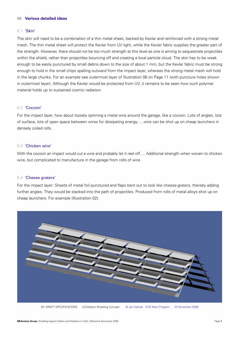
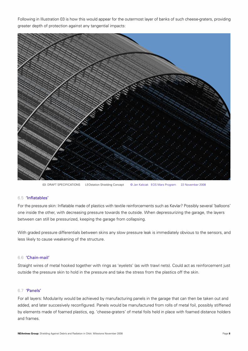
6.4 ‘Cheese graters’
For the impact layer: Sheets of metal foil punctured and flaps bent out to look like cheese-graters, thereby adding
further angles. They would be stacked into the path of projectiles. Produced from rolls of metal alloys shot up on
cheap launchers. For example (Illustration 02):
02: DRAFT SPECIFICATIONS LEOstation Shielding Concept © Jan Kaliciak EOS Mars Program 22 November 2008
NEAmines Group: Shielding Against Debris and Radiation in Orbit. Milestone November 2008 Page 8
Following in Illustration 03 is how this would appear for the outermost layer of banks of such cheese-graters, providing
greater depth of protection against any tangential impacts:
6.5 ‘Inflatables’
For the pressure skin: Inflatable made of plastics with textile reinforcements such as Kevlar? Possibly several ‘balloons’
one inside the other, with decreasing pressure towards the outside. When depressurizing the garage, the layers
between can still be pressurized, keeping the garage from collapsing.
With graded pressure differentials between skins any slow pressure leak is immediately obvious to the sensors, and
less likely to cause weakening of the structure.
6.6 ‘Chain-mail’
Straight wires of metal hooked together with rings as ‘eyelets’ (as with trawl nets). Could act as reinforcement just
outside the pressure skin to hold in the pressure and take the stress from the plastics off the skin.
6.7 ‘Panels’
For all layers: Modularity would be achieved by manufacturing panels in the garage that can then be taken out and
added, and later succesively reconfigured. Panels would be manufactured from rolls of metal foil, possibly stiffened
by elements made of foamed plastics, eg. ‘cheese-graters’ of metal foils held in place with foamed distance holders
and frames.
03: DRAFT SPECIFICATIONS LEOstation Shielding Concept © Jan Kaliciak EOS Mars Program 22 November 2008

NEAmines Group: Shielding Against Debris and Radiation in Orbit. Milestone November 2008 Page 9
6.8 Plastic spheres of various sizes
For radiation shielding: Plastic spheres of different diameters (eg. 2-10mm) provide innumerable changes of surface
angles of incidence to incoming radiation between them, and if the doping constituents also are varied between sizes
or layers, different ‘refraction indices’ within the spheres themselves will contribute to the refraction as well.
The plastic (polyethylene) spheres can be manufactured either in orbit from granules, or come up as filler around
payloads in the payload bays of cheap launches. Or structural elements of the stack achieving orbit on the cheap
launchers are made of plastics to be salvaged and reused for adding to the radiation shield.
Bags full of such small plastic spheres can be placed on the inside of the pressure skin, allowing easy access to the
skin for repairs and maintenance (’sandbagging the inside’).
Another option is to blow plastic balls into cavities, eg. between two multi-skins.
For integration in panels banks of pressed together polyballs should be ideal.
All radiatian screening balls should be made of plastic that quickly disintegrates on exposure to UV, so as to make
them degrade in sunlight in case they get spilt in orbit.
6.9 Plastic beads to chickenwire
In case of a cocoon or chickenwire, plastic beads could be clipped onto the wire. Such protection interwoven in wire
would dampen secondary radiation and add to ‘soft resistance’ by withstanding somewhat any wires being bent into
them from an impact.
6.10 Foams
Plastics can also be foamed in orbit, either into cavities (eg. between two multi-skins) or in the interstices of ‘cheese-
graters’ and such, thereby keeping metal foils in place but also adding to the ‘internal soft resistance’ to incoming
projectiles by somewhat withstanding the bending of a metal foil when it is hit. Defined shapes foamed in orbit may
also contribute structural elements to the shield.
6.11 Corrugated sheets of metal foil with sandwiched mesh
Metal foils could be corrugated like a tin roof to produce panels, corrugated either down their length, or laterally for
more deflective surfaces, and increased rigidity. Longitudinal corrugations would aid rigidity during assembly.
Sandwiched in symmetric opposition over a mesh insert would create a fluted panpipe appearance. The mesh would
also help in holding in displaced material from hits.
Next page:
A sectional example – Illustration 04:
This could be manufactured to be a modular panel – lllustration 05:

NEAmines Group: Shielding Against Debris and Radiation in Orbit. Milestone November 2008 Page 10
04: DRAFT SPECIFICATIONS LEOstation Shielding Concept © Jan Kaliciak EOS Mars Program 22 November 2008
05: DRAFT SPECIFICATIONS LEOstation Shielding Concept © Jan Kaliciak EOS Mars Program 22 November 2008
NEAmines Group: Shielding Against Debris and Radiation in Orbit. Milestone November 2008 Page 11
6.12 ….. with Kevlar backing
When manufacturing in orbit from rolled alloy, polyethylene film could be sandwiched between Kevlar as the backing
sheet to the alloy metal foil.
6.13 ‘Mini Robonauts’
With a fluffed out impact layer, interstices can be so great as to allow mini robonauts to travel along them for inspection
and repairs after a hit.
6.14 ‘Diamondate structure’
To give the impact layer some structure, ‘vertical’ stands can extend from the true hull (eg. the pressure skin) radially
outwards to the outer skin. They would be attached first and foremost in one piece before any panelling is added.
The lateral ties can be also added at this stage to hold the relationships between rays steady. There are no curved
parts in any part of the structure, so the total profile is that of a many faceted polygon.
So what is needed are simple guides on the diamond struts into which the panels slide continuously at their angle,
so in fact the structure gains rigidity from just the clipping-in effect. No precision, low tolerance assembly. This would
also allow attachment of the exo-skeleton on top of the vertical struts and progressively add panelling from the
outside in towards the pressure skin. So the outer skin can be pop-riveted to an extension of the exoskeleton, and
then progressively infilled from within. This gives progressive protection to crew or robonauts undertaking the
construction.
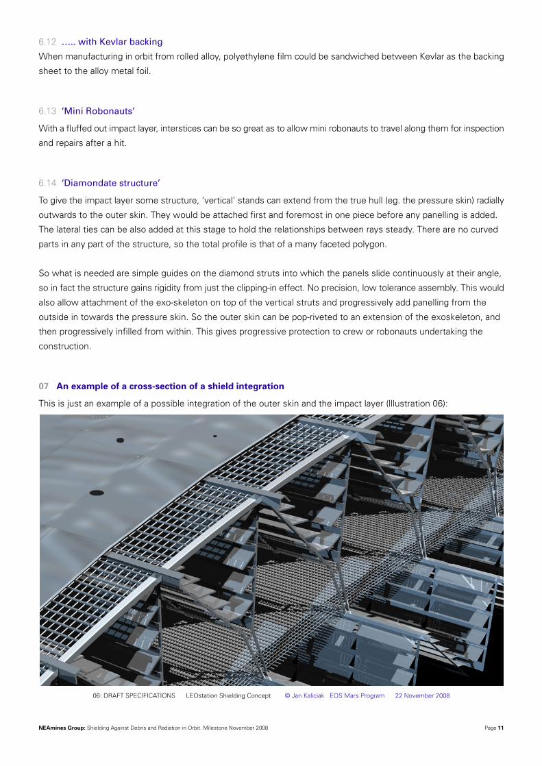
07 An example of a cross-section of a shield integration
This is just an example of a possible integration of the outer skin and the impact layer (lllustration 06):
06: DRAFT SPECIFICATIONS LEOstation Shielding Concept © Jan Kaliciak EOS Mars Program 22 November 2008

NEAmines Group: Shielding Against Debris and Radiation in Orbit. Milestone November 2008 Page 12
The outer skin is a thin metal sheet, backed with Kevlar and reinforced by a metal mesh (see three puncture holes
in the skin).
Beneath that ‘cheese-graters’ are held in place by diamondate structures, although in this graph does not show
vertical radial struts going all the way from the pressure skin to the outer skin. Of course these cheese-graters could
be panels of layered much finer cheesegraters embedded in plastics foam, even back-laminated with polythene. Or
mesh-reinforced fluted panels (see above), or any combination of the above.
Further horizontal meshes help to further brake the velocity of both incoming projectiles and erupting outbound
debris.
The interstices are intentionally hollow and wide apart to allow more spread of debris from an impact and therefore
further dissipation of energy. This also allows stowage of other materials and allows for movement of mini-robonauts
along the corridors.
Keep in mind that all materials are kept as thinly as possible in order to increase the number of surfaces and density
differences through which a projectile will travel. The impact layer is made as wide as possible.
This is shown in the following illustration. It is an example of a full-view of the complex layering:
The outermost skin is followed by three layers of ‘cheese-graters’, beneath which an exoskeleton extends inwards
to hold the pressure skin. Various materials, mainly plastics, are loosely distributed between the struts of the
exoskeleton (shown notionally as white balls floating in between the struts). The pressure skin then follows, held
07: DRAFT SPECIFICATIONS LEOstation Shielding Concept © Jan Kaliciak EOS Mars Program 22 November 2008
NEAmines Group: Shielding Against Debris and Radiation in Orbit. Milestone November 2008 Page 13
in place by pads extending inwards from the exoskeleton. Inside the pressure skin a further level of bags filled with
plastic balls may be envisaged (not shown here). In the pressurized ‘garage’ a person can be seen in coveralls working
on a shuttle. This overall view shows how ‘fluffy’ the shield may be.
08 Open issues, new questions, hypotheses to be checked out....
8.1 Testing
How to test and compare various shield configurations?:
8.1.1 Measure kg per m2 of protected pressure skin
8.1.2 Fire gamma rays at it and see how much of it gets through to the other side and in which form
(scattering secondary radiation, etc).
8.1.3 Fire projectiles at it of a fixed diameter and speed of impact, and see how deep they can penetrate the
shield without erupting any fly-off pieces. Do this at various angles of impact.
This would give a standard for comparisions.
8.1.4 Fire projectiles of various scales and of various materials and energy particles from multiple angles.
It would also be useful to try the tests with variously shaped projectiles.
A set of standard tests need to be defined for analysis of future shield materials and structures.
8.2 Exoskeleton spalls in a hit…
When the exoskeleton is hit, it may also break up and pieces would be flying off, adding junk to the orbit.
How do we deal with this?
8.3 Skin on top of everything?
Think of dismantling part of the skin, stuffing junk or stores or bags full of plastics into there, and then hitching the
skin pack on. Or are we going to have ‘doors’ of outer skin, ie. hinged elements that can be lifted and then our
grappler or robonaut walking along on the outside can put something in or take something out of storage?
Panels of skin that can be temporarily added over any attachments on the outside? Blankets?
8.3 Spilling grit
We expect mixed asteroid material to arrive as metal and rocky grit mixed with volatiles packed in metal containers.
The explosive destruction of such a container by an orbital hit would add a tremendous amount of debris into orbit.
Therefore shielding also around depots? How do we deal with containers parked at LEOstation?
8.4 The door
The most vulnerable area for shielding is going to be the garage door to space. It would seem that this is going to
be a much larger structure than is at first obvious, due to its own screening buffer, but when one thinks about it,
collision resistance at this point is going to be tested for real sooner or later.
NEAmines Group: Shielding Against Debris and Radiation in Orbit. Milestone November 2008 Page 14
8.5 Ceramics as elements of refractionary shields
Whatever we depict here as ‘shield’ is temporary until materials from asteroids become available. Once asteroid
materials become available, shields will mostly be made of rocky materials, eg. ceramics from baking hydrated
minerals for their water, or leftovers from extraction processes, etc. Shields at asteroids themselves (ie. for stations
at asteroids) will mainly simply be raw asteroid material, either added on the outside of prefabricated structures, or
prefabricated structures burrowing into asteroids.
Ceramics may also double up as heat shields for payloads to Earth. Rocky material is generally expected to be in
abundant supply after the mass transport from asteroids becomes regular.
8.6 Catchers
Is there any way to detect an incoming projectile in the path of LEOstation down to the size of 1cm, and have a
‘catcher arm’ react fast enough to put a screen in its path before it hits the shield proper?
09 Appendix: Links
9.1 http://www.msnbc.msn.com/id/4285550/
Describes debris coming off ISS and the concerns that raises.
9.2 http://www.msnbc.msn.com/id/19070465/
Describes the installation of 2.5cm thick aluminium shields on ISS.
9.3 http://www.space.com/missionlaunches/070606_exp15_eva2.html
Describes the installation of 2.5cm thick aluminium shields on ISS.
9.4 http://www.freshpatents.com/Orbital-debris-shield-dt20070329ptan20070069082.php
Patent application: An orbital debris shield for protecting the hull of a spacecraft is claimed. The shield is comprised
of a number of flexible and releasably attached gores that substantially cover the hull. Interleafed between layers
of the gores are layers of a spacing material. As debris collides with the gores, the material is shocked and breaks
up to some degree. As the shocked debris disperses through a layer of the gore, the spacing material interacts with
the debris. After dispersing through a number of layers of the gores and the spacing material, the debris transfers
a significant portion of kinetic energy and the probability of the remaining particles piercing the hull is significantly
decreased (end of abstract).
9.5 http://www.daedalusal4.utvinternet.co.uk/3%20-%20Construction.htm
The Daedalus project (large habitable sphere) thinks of ice as a radiation shield.
9.6 http://www.daedalusal4.utvinternet.co.uk/Contents.htm
Points out the radiation shielding challenges at Lagrange 4.
9.7 http://www.daedalusal4.utvinternet.co.uk/Contents.htm
A patent: An improved blade containment structure including a projectile shield having a braided ballistic fabric is
disclosed. The braided fabric includes ballistic strands arranged in a preferred orientation and is effective for increasing
NEAmines Group: Shielding Against Debris and Radiation in Orbit. Milestone November 2008 Page 15
the ability of the fabric to contain projectiles and absorb energy therefrom. The braided ballistic fabric provides
substantial improvement in performance over conventional woven ballistic fabrics.
9.8 http://www.daedalusal4.utvinternet.co.uk/Contents.htm
‘Hybrid Inflatable’, ie. rigid inner structure with expansions that can be inflated. Projectile shielding with 3 layers of
Open-cell foam between Nomex’.
9.9 http://www.sciencedirect.com/science?_ob=ArticleURL&_udi=B6V3S-4CHRCVW-
2&_user=10&_rdoc=1&_fmt=&_orig=search&_sort=d&view=c&_acct=C000050221&_version=1&_urlVersion=0&_
userid=10&md5=c3d74a29be8d85455321b96f5ad3d4d5
High strength fiber is a potential material for shielding from a viewpoint of strength, lightweight and flexibility. We
developed a single bumper shield based on Vectran fibers, that stopped a polycarbonate projectile with 14 mm in
diameter, 1 g in weight and 6.45 km/s in velocity. The thickness of this shield was 7 mm. As compared with the
mesh stuffed Whipple bumper shield installed on the Japanese Experiment Module, the areal density was half and
the thickness was approximately one sixteenth. The aim of our hypervelocity impact experiments was to develop a
thin bumper material consisting of only Vectran fibers and to research a deployable shielding system for debris
protection using the fiber material. The results indicated that the new thin shield with 7 mm in thickness has a good
protection capability. The new single bumper shield may provide the basic technology for reinforcing the protection
capability and reducing the weight of the shield drastically.
9.10 http://www.osti.gov/bridge/servlets/purl/10116086-DIQ7aK/webviewable/10116086.pdf
Protecting space-based structures against the impact of orbital debris is an important problem of current interest.
This paper presents scaling results based on simulations with the CALE computer program of aluminum projectile
impacting typical aluminum Whipple shields at speeds of 6 to 14 km/s. The objective was to determine the extent
of projectile and shield material melting.
9.11 http://en.wikipedia.org/wiki/Whipple_shield
Whipple Shield: as opposed to monolithic shielding of early spacecraft, Whipple shields place spacings between
several layers of shielding. This improves the shielding to mass ratio, critical for spaceflight components, but also
increases the thickness of the spacecraft walls, which is not ideal for fitting spacecraft into launch vehicle fairings.
The advantage of spacing out thinner shields over a single thick shield is that the initial wall shock can melt the
incoming particle (depending on its speed) and molten bits of the particle strike a wider area of the subsequent walls
reducing the pressure. Some Whipple shields have a filling in between the layers of a lower density material, such
as a high-strength fabric and plastics. There are many different configurations of thickness of walls, number of walls,
materials, and filling on the International Space Station alone. Higher risk areas are given better shielding.
9.12 http://www.swri.org/4org/d18/engdyn/armor/
http://www.swri.org/4org/d18/engdyn/impact/default.htm
Company studying armor
9.13 http://www.esa.int/TEC/Structures/SEM1TQLJC0F_0.html
ESA’s work on protecting Giotto probes and others. Good photos and graphics on dynamics of impacts into Whipple
shields.
9.14 http://www.freepatentsonline.com/5723201.html
A protective armor construction includes a plurality of layers of penetration resistant material. These layers comprise
NEAmines Group: Shielding Against Debris and Radiation in Orbit. Milestone November 2008 Page 16
one or more expandable stress layers of flexible penetration resistant material having a plurality of folds therein. The
folds are arranged so as to unfold and expand in response to a penetration force exerted on the armor construction,
e.g., by a bullet, such as to impede the penetration force and to thereby limit penetration of the armor construction.
To provide superior protection, two or more of such expandable stress layers are provided along with multiple unfolded
layers disposed in front and behind these layers. The folds of the two expandable layers extend orthogonally to one
another while the folds of the individual expandable layers over lap. The folds of the outermost expandable layer face
outwardly while the folds of the innermost expandable layer face inwardly.
9.15 http://klabs.org/DEI/References/design_guidelines/environment_series/1107.pdf
NASA paper on micrometeorite protection. No suggested construction ideas, except a vague pointer to MLI (Mulit
Layered Insulation) blankets (probably the stuff they coat ISS with).
9.16 http://ammtiac.alionscience.com/pdf/2002MaterialEase20.pdf
Good paper on modern composite armors and how they work.
9.17 http://iss.jaxa.jp/iss/kibo/develop_status_09_e.html
Shielding of Japanese moduel Kibo with a ‘stuffed Whipple shield’.
9.18 http://www.orbitaldebris.jsc.nasa.gov/newsletter/pdfs/ODQNv12i3.pdf
This is the ‘Orbital Debris, Quarterly News’ of NASA. A most detailed account of publicly available information on
various fragmentation events in orbit. Plus some quite scary photos of impacts on the space station.......’seeing is
believing’ that we do have a problem with debris out there!
9.19 http://www.aerolite.org/meteorite-photography.htm
An interesting site with very detailed photographs of actual meteorites retrieved from sites on Earth. Note that since
atmospheric thermal ablation has smoothed the features of those susceptible to melt-flow, they would otherwise
be much sharper and penetrating in a LEO strike upon unprotected orbiting equipment.
Estimates of 100,000 meteorites per year over 1Kg mass reach Earth’s surface, and of these a hundred can exceed
100 kg. Annual capture of space-borne debris in this way, varies between 100,000 and 200,000 tons. Of this, much
falls into the size range of 10 to 50m in diameter, but most will break up into smaller fragments on atmospheric entry.
About 100 tons per day, or 40,000 tons a year is contributed by particles sized between 0.05 and 0.5mm. These all
pass somewhere through our proposed working environment unattenuated by atmospheric drag.
The net mass gain from these sources over the Earth's history is estimated to contribute the equivalent of a 40cm
layer over the entire surface of the globe. Although very few create Tunguska type events, over 200 aerial explosions
have been observed by orbiting satellites since 1972. [Source of data: ‘METEORITES - Their Impact on Science and History’ edited
by Zanda & Rotaru, Cambridge University Press 2001]
The NEAmines group welcomes feedback on these preliminary designs.
We also welcome people who may want to join the effort.
Please surf to http://www.asteroidmines.net
All illustrations are copyrighted. Permission for their use in any other publication or format
must first be sought by contacting Jan Kaliciak at [email protected]