EMW shielding considerations in building design - University ...
161
University of Calgary PRISM: University of Calgary's Digital Repository Graduate Studies The Vault: Electronic Theses and Dissertations 2018-03-06 EMW shielding considerations in building design Hakgudener, Serhan Hakgudener, S. (2018). EMW Shielding Considerations in Building Design (Unpublished doctoral thesis). University of Calgary, Calgary, AB. doi:10.11575/PRISM/30879 http://hdl.handle.net/1880/106436 doctoral thesis University of Calgary graduate students retain copyright ownership and moral rights for their thesis. You may use this material in any way that is permitted by the Copyright Act or through licensing that has been assigned to the document. For uses that are not allowable under copyright legislation or licensing, you are required to seek permission. Downloaded from PRISM: https://prism.ucalgary.ca
-
Upload
khangminh22 -
Category
Documents
-
view
0 -
download
0
Transcript of EMW shielding considerations in building design - University ...

University of Calgary
PRISM: University of Calgary's Digital Repository
Graduate Studies The Vault: Electronic Theses and Dissertations
2018-03-06
EMW shielding considerations in building design
Hakgudener, Serhan
Hakgudener, S. (2018). EMW Shielding Considerations in Building Design (Unpublished doctoral
thesis). University of Calgary, Calgary, AB. doi:10.11575/PRISM/30879
http://hdl.handle.net/1880/106436
doctoral thesis
University of Calgary graduate students retain copyright ownership and moral rights for their
thesis. You may use this material in any way that is permitted by the Copyright Act or through
licensing that has been assigned to the document. For uses that are not allowable under
copyright legislation or licensing, you are required to seek permission.
Downloaded from PRISM: https://prism.ucalgary.ca

UNIVERSITY OF CALGARY
EMW SHIELDING CONSIDERATIONS IN BUILDING DESIGN
by
Serhan Hakgudener
A THESIS
SUBMITTED TO THE FACULTY OF GRADUATE STUDIES IN
PARTIAL FULFILMENT OF THE REQUIREMENTS FOR THE
DEGREE OF DOCTOR OF PHILOSOPHY
GRADUATE PROGRAM IN ENVIRONMENTAL DESIGN
CALGARY, ALBERTA
MARCH, 2018
© SERHAN HAKGUDENER 2018

ii
Abstract
Providing healthy and effective wireless communication in the building environment is a
challenge among architects and wireless network designers, due to physical indoor environmental
factors. Wireless communication systems emit high-frequency waves both inside buildings and in
the free space around us. There are a variety of EMW sources covering a wide range of the
electromagnetic spectrum, spanning the frequency range from Hz to several hundred GHz. In
building design, there are diverse approaches to provisions of wireless communication and
constant innovation; however, the construction materials and EMW propagation relationship
remain a secondary consideration. This research evaluates current power intensity levels range
from 5 Hz to 10 GHz in building environments and develops guidelines for design professionals
based upon an understanding of conventional building material properties.
The research site survey that I conducted in the Calgary area, suggested in some cases, power
spectral densities in building environments rose to levels that could possibly a problem.
Incorporation of newly developed guidelines and security controls such as shielding, provided
in this study, may prevent data confidentiality compromise in transit (e.g. eavesdropping) and
prevent data integrity compromise in transit (e.g. hacking) for wireless communication systems in
building environments.
In this research, I develop the concept that effective EMW shielding can be achieved using
conventional construction materials.
The results of this study have significant implications for architectural design. The design
method would reduce high power spectral densities by improving EMW shielding. Ultimately, I
would like to see the developed shielding method in building codes and used in building projects
all over the world.

iii
Preface
This dissertation includes previously published materials such as figures, texts, and tables.
These contents appear in one peer-reviewed journal paper and a master’s thesis as follows:
1. Hakgudener, Serhan. 2015. “Spatial Design for Healthy and Effective Electromagnetic
Wave Propagation.” Procedia Engineering 118: 109–119.
doi:10.1016/j.proeng.2015.08.409.
http://linkinghub.elsevier.com/retrieve/pii/S1877705815020640.
2. Hakgudener, Serhan. 2007. “FUTURE OF WLAN AND THE INFLUENCES TO THE
ARCHITECTURAL FORMS AND DESIGN.” Yeditepe University.
https://tez.yok.gov.tr/UlusalTezMerkezi/TezGoster?key=7d53ed97e31a8bd3aa6864b0e7
704416eae44e48141d7a55b82c08696ffae08b44f75cea77711c76
The above publishing was produced by the author and use of these materials allowed by
journal/proceedings publishers and the Council of Higher Education of Turkey.
The research investigates the gap between architecture and engineering regarding wireless
communication issues in building environments. Researching Electromagnetic Wave propagation
provides an understanding of the relationship between the use of building materials and wireless
communication performance. For instance, the problem can be solved through the use of a different
building or furniture materials. Even different space-planning options and the use of innovative
materials can improve wireless performance, as shown in the scenarios in Chapter Four. In terms
of electromagnetic power intensity levels in living environments, each country adopts different RF
exposure limits for its wireless communication. Therefore, this research provides a case study to
show the current electromagnetic power density levels within our living environments. Moreover,
this research proposes basic building design solutions for effective EMW shielding methods.

iv
Overall, the ultimate goal of the research is to determine how architecture can leverage engineering
knowledge to improve human well-being in building environments.
Serhan Hakgudener March 2018
v
Acknowledgements
I would like to express my gratitude to all those people who have supported me and contributed
to making this study possible.
I have the pleasure of thanking Dr. Thomas Patrick Keenan, my supervisor, for his constant
guidance, support and motivation and belief in my research potential. His constructive suggestions
allowed me to achieve a high quality of research.
I would like to thank AITF (Alberta Innovates- Technology Futures) Grant Management team
for their efforts. AITF’S grant allowed me access to sophisticated frequency analyzers. This
research would have been difficult to accomplish without their support.
I would like to express my sincere gratitude to the contractors, whom I worked with. They
showed me the practical ways of construction execution. The methods they practiced over years
inspired me to develop architectural details for healthy and effective EMW propagation in building
environments.
I would also like to thank my supervisory committee members, Dr. Branko Kolarevic, Prof.
Tang Lee and Dr. Leonid Belostotski for their careful reading and suggestions to improve the
manuscript. This thesis would not be possible without their remarkable patience and prompt
guidance. Moreover, I am honored to see that EMW propagation in buildings topic has been added
to Health in the Built Environment curriculum by Prof. Tang Lee. Thank you again, Prof. Lee.
You answered my calls.
I would like to thank Dr. Vincent Chiew for his invaluable comments that helped me to align
research with data confidentiality and data integrity.
I would like to thank Dr. Sean Victor Hum and Dr. Caroline Hachem-Vermette for their
suggestions. Their comments also helped me to develop finalized structure of this theses.

vi
Finally, I am grateful to my family, my wife, for bearing with me during this journey and my
son Kael, for the times I spent on my theses instead of playing with him. I owe him a lot. He is my
inspiration.

vii
Dedication
To my Parents
With all my Love

viii
Table of Contents
Abstract .......................................................................................................................... ii Preface ........................................................................................................................... iii Acknowledgements ......................................................................................................... v Dedication ..................................................................................................................... vii Table of Contents ......................................................................................................... viii List of Tables ................................................................................................................. xi List of Figures and Illustrations ..................................................................................... xii List of Plates ................................................................................................................ xiv List of Symbols, Abbreviations, and Nomenclature ....................................................... xv Epigraph ..................................................................................................................... xvii
CHAPTER ONE: INTRODUCTION .............................................................................. 1 Context .................................................................................................................. 1 History .................................................................................................................. 2 Literature Review .................................................................................................. 3 1.3.1 EMW and Frequency ..................................................................................... 3 1.3.2 EMW Phenomena and Harmonious Environments for Electronic Devices ..... 4
1.3.2.1 The importance of Electromagnetic Compatibility (EMC) .................. 12 1.3.3 Wireless Communication Systems and Networking ..................................... 14 1.3.4 Data Security for Wireless Devices ............................................................. 19
1.3.4.1 Electromagnetic Warfare .................................................................... 24 1.3.5 The Power Density Levels and Potential Health Impact on Humans ............ 26 Discussion ........................................................................................................... 30 Research Overview.............................................................................................. 31 1.5.1 Research Problem ........................................................................................ 32 1.5.2 Hypothesis .................................................................................................. 33 1.5.3 Objectives, Purpose and Contributions ........................................................ 34 1.5.4 Thesis Outline ............................................................................................. 35 1.5.5 Methods ...................................................................................................... 36 1.5.6 Conclusion .................................................................................................. 36
CHAPTER TWO: BUILDING MATERIALS AND WIRELESS COMMUNICATION PERFORMANCE ................................................................................................ 37 Brick ................................................................................................................... 40 Brick faced concrete wall .................................................................................... 43 Brick faced masonry block .................................................................................. 44 Plain concrete ...................................................................................................... 44 Drywall ............................................................................................................... 45 Glass ................................................................................................................... 45 Lumber (Dry/Wet) ............................................................................................... 46 Plywood (Dry/Wet) ............................................................................................. 46 Reinforced Concrete ............................................................................................ 47 Rebar Grid ......................................................................................................... 47 The need for new building materials .................................................................. 50 EMW Shielding Alternatives and Effects in Building Environments .................. 51

ix
Conclusion ........................................................................................................ 54
CHAPTER THREE: POWER DENSITY LEVELS IN DIFFERENT BUILDING ENVIRONMENTS: CASE STUDY ..................................................................... 55 Method ................................................................................................................ 56 Residential Indoor Environment .......................................................................... 56 3.2.1 Study Description ........................................................................................ 56 3.2.2 Data Analyses ............................................................................................. 58 Typical Office Environment ................................................................................ 61 3.3.1 Study Description ........................................................................................ 61 3.3.2 Data Analyses ............................................................................................. 62 Typical Class Environment .................................................................................. 66 3.4.1 Study Description ........................................................................................ 66 3.4.2 Data Analyses ............................................................................................. 67
3.5 Results ................................................................................................................ 71 Limitations .......................................................................................................... 74
CHAPTER FOUR: BASIC SHIELDING GUIDELINES FOR DESIGN PROFESSIONALS ............................................................................................................................. 75
4.1 The design guideline............................................................................................ 75 4.1.1 EMW Shielding Principles in building environments ................................... 75
4.1.1.1 RF Absorbers ..................................................................................... 79 4.1.1.2 RF Shielding Foil ............................................................................... 80 4.1.1.3 RF Shielding Film .............................................................................. 81 4.1.1.4 RF Shielding Mesh............................................................................. 81 4.1.1.5 RF Shielding Fabric ........................................................................... 81
4.2 Conclusion .......................................................................................................... 89
CHAPTER FIVE: ARCHITECTURAL SPATIAL DESIGN EFFECT ON EMW PROPAGATION IN BUILDING ENVIRONMENTS .......................................... 92 EMW Propagation in Residential Spaces ............................................................. 92 5.1.1 Spatial Design for Residential Spaces .......................................................... 99 EMW Propagation in Commercial Spaces ........................................................... 99 5.2.1 Spatial Design for Commercial Spaces ...................................................... 100 EMW Propagation in Educational Spaces .......................................................... 103 5.3.1 Spatial Design for Educational Spaces ....................................................... 104 EMW Propagation in Military and Government Spaces ..................................... 105 5.4.1 Spatial Design for Military and Government Spaces .................................. 106
CHAPTER SIX: DISCUSSION .................................................................................. 107 Conclusions ....................................................................................................... 112 Future Research ................................................................................................. 117
APPENDIX A ............................................................................................................. 121
APPENDIX B ............................................................................................................. 126

x
REFERENCES ........................................................................................................... 130
xi
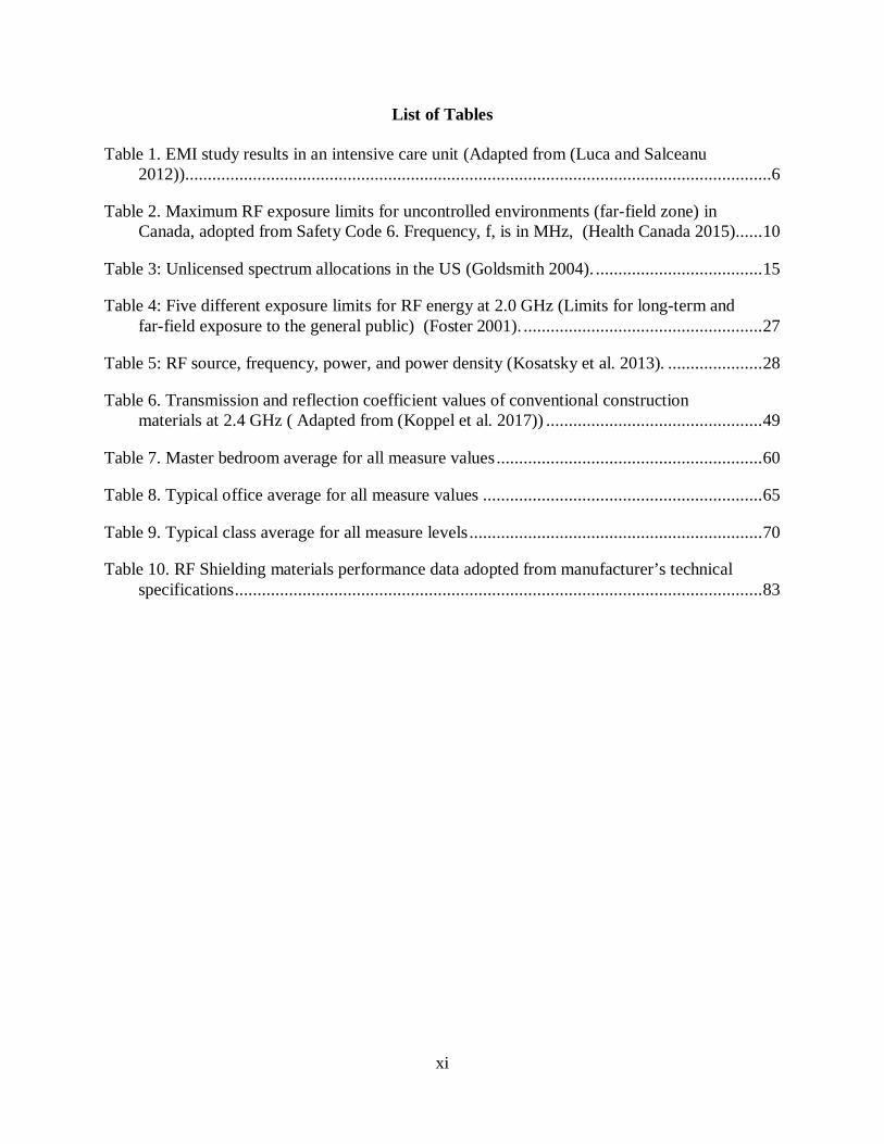
List of Tables
Table 1. EMI study results in an intensive care unit (Adapted from (Luca and Salceanu 2012)) ..................................................................................................................................6
Table 2. Maximum RF exposure limits for uncontrolled environments (far-field zone) in Canada, adopted from Safety Code 6. Frequency, f, is in MHz, (Health Canada 2015). ..... 10
Table 3: Unlicensed spectrum allocations in the US (Goldsmith 2004). ..................................... 15
Table 4: Five different exposure limits for RF energy at 2.0 GHz (Limits for long-term and far-field exposure to the general public) (Foster 2001). ..................................................... 27
Table 5: RF source, frequency, power, and power density (Kosatsky et al. 2013). ..................... 28
Table 6. Transmission and reflection coefficient values of conventional construction materials at 2.4 GHz ( Adapted from (Koppel et al. 2017)) ................................................ 49
Table 7. Master bedroom average for all measure values ........................................................... 60
Table 8. Typical office average for all measure values .............................................................. 65
Table 9. Typical class average for all measure levels ................................................................. 70
Table 10. RF Shielding materials performance data adopted from manufacturer’s technical specifications ..................................................................................................................... 83

xii
List of Figures and Illustrations
Figure 1. Sample Office Room Experiment (Hakgudener 2007) ................................................ 38
Figure 2. EMW Propagation Contour Graphs for an empty and an occupied room at the 2.4 GHz frequency (Hakgudener 2007) ................................................................................... 39
Figure 3. Transmission coefficients for brick wall specimens (0.5-2.0 GHz) (Stone 1997). ........ 41
Figure 4. Transmission coefficients for brick specimens (3.0-8 GHz) (Stone 1997). .................. 42
Figure 5. Residential indoor environment, master bedroom, measurement location shop drawing. Drawn by author. (Not in scale, units are cm.) ..................................................... 57
Figure 6. Residential indoor environment 3D (x, y, z) AC magnetic flux density data (units are time/ hour for X, and nT for Y axis) ............................................................................. 58
Figure 7. Residential Indoor Environment High-Frequency range data (units are time/ hour, for X, and μW/m² for Y axis) ............................................................................................. 59
Figure 8. Residential Indoor Environment High-Frequency range data (units are, time/ hour, for X, and μW/m² Y axis) .................................................................................................. 60
Figure 9. Typical office measurement location (Not in scale) (University of Calgary 2016)....... 62
Figure 10. AC 3D Magnetic flux densities (5 Hz- 1000 KHz), X axis unit is time/hour and nT is for Y axis. ...................................................................................................................... 63
Figure 11. HF range (27 MHz- 3300 MHz), the measurement was taken at the same period (1 p.m-3:30 p.m.) ................................................................................................................... 64
Figure 12. HF range (2.4 GHz- 10 GHz), X axis unit is time/hour and μW/m² is for Y axis. ...... 65
Figure 13. Typical classroom measurement location (Not in scale) (University of Calgary 2016). ................................................................................................................................ 67
Figure 14. Typical Class environment 3D (x, y, z) AC magnetic flux density data (units are time/ hour for X axis, and nT for Y) .................................................................................. 68
Figure 15. HF range (27 MHz- 3300 MHz), X axis unit is time/hour and μW/m² is for Y axis. .. 69
Figure 16. Typical Class Environment High-Frequency range data (units are time/ hour for X, and μW/m² for Y) ......................................................................................................... 70
Figure 17. Average for all measured values 3D (x, y, z) AC magnetic flux density data (frequency rage, 5 Hz-1 MHz for X axis, and nT for Y) ..................................................... 71
Figure 18. Average for all measured values High-Frequency range (27 MHz- 3300 MHz) data (units MHz for X, and μW/cm² for Y) ........................................................................ 72
xiii
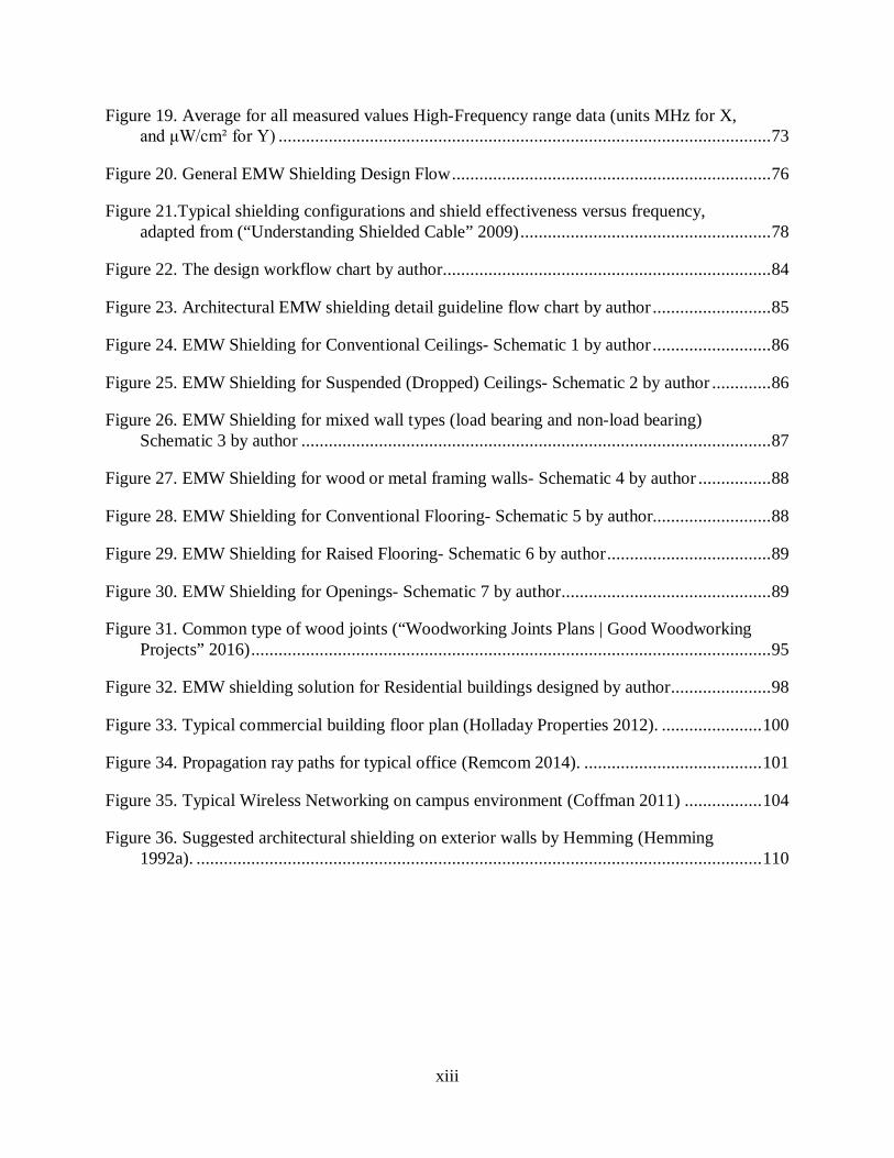
Figure 19. Average for all measured values High-Frequency range data (units MHz for X, and μW/cm² for Y) ............................................................................................................ 73
Figure 20. General EMW Shielding Design Flow ...................................................................... 76
Figure 21.Typical shielding configurations and shield effectiveness versus frequency, adapted from (“Understanding Shielded Cable” 2009) ....................................................... 78
Figure 22. The design workflow chart by author........................................................................ 84
Figure 23. Architectural EMW shielding detail guideline flow chart by author .......................... 85
Figure 24. EMW Shielding for Conventional Ceilings- Schematic 1 by author .......................... 86
Figure 25. EMW Shielding for Suspended (Dropped) Ceilings- Schematic 2 by author ............. 86
Figure 26. EMW Shielding for mixed wall types (load bearing and non-load bearing) Schematic 3 by author ....................................................................................................... 87
Figure 27. EMW Shielding for wood or metal framing walls- Schematic 4 by author ................ 88
Figure 28. EMW Shielding for Conventional Flooring- Schematic 5 by author.......................... 88
Figure 29. EMW Shielding for Raised Flooring- Schematic 6 by author .................................... 89
Figure 30. EMW Shielding for Openings- Schematic 7 by author .............................................. 89
Figure 31. Common type of wood joints (“Woodworking Joints Plans | Good Woodworking Projects” 2016) .................................................................................................................. 95
Figure 32. EMW shielding solution for Residential buildings designed by author ...................... 98
Figure 33. Typical commercial building floor plan (Holladay Properties 2012). ...................... 100
Figure 34. Propagation ray paths for typical office (Remcom 2014). ....................................... 101
Figure 35. Typical Wireless Networking on campus environment (Coffman 2011) ................. 104
Figure 36. Suggested architectural shielding on exterior walls by Hemming (Hemming 1992a). ............................................................................................................................ 110
xiv
List of Plates

xv
List of Symbols, Abbreviations, and Nomenclature
Symbol Definition µT Microtesla nT Nanotesla µW Microwatt ANSI American National Standards Institute AP Access Point ATM Asynchronous Transfer Mode AWS Advanced Wireless Services BAS Building Automation System BRS Broadband Radio Services BSI British Standards Institute CEN European Committee for Standardization CENELEC European Committee for Electrotechnical Standardization cm Centimeter cm² Square centimeter CRT Cathode Ray Tube DECT Digital Enhanced Cordless Telecommunications DSSS Direct Sequence Spread Spectrum E Electric field EESS Earth Exploration Satellite Service ELF Extreme Low Frequency EMC Electromagnetic Compability EMI Electromagnetic Interference EMW Electromagnetic Wave ETSI European Telecommunications Standards Institute EU European Union f Frequency (Hertz) FCC Federal Communications Commission FHSS Frequency Hopping Spread Spectrum G Gauss GHz Giga Hertz (a billion of Hertz) H Magnetic field HiperLAN High performance radio Local Area Networking HSP Henoch-Schonlein Purpura HVAC Heating, Ventilating, and Air Conditioning ICNIRP International Commission on Non-Ionizing Radiation Protection IEC International Electrotechnical Commission IEE 802.11 xx US-based WLAN standard IEEE Institute of Electrical and Electronic Engineers IPF Induction Power Feeder ISB Inter-state Bus ISO International Organization for Standardization kA Kiloampere (a thousand Amperes)

xvi
kHz Kilohertz LAN Local Area Networking m Meter (SI unit of length) M Mass (kg) SI units MAN Metropolitan Area Network MBS Mobile Broadband Services MetAids Meteorological Aids Service MetSat Meteorological Satellite Service MHz Mega Hertz (million Hertz) MMAC Multimedia Mobile Access Communication System NCRP National Council on Radiation Protection and Measurements Ni Nickel PCS Personal Communications Services RAS Radio Astronomy Service RF Radio Frequency RFI Radio Frequency Interference RFID Radio Frequency Identification RFR Radio Frequency Radiation SCC Standards Council of Canada SOS Space Operation Service SRS Space Research Service t Time (second) SI units USB Universal Serial Bus UWB Ultra-Wideband V Volt Wi-Fi Local Area Wireless technology WiMAX Worldwide Interoperability for Microwave Access WLAN Wireless Local Area Networking ZigBee IEEE 802.15.4-based specification for a suite of high-level communication
protocols used to create small personal area networks

xvii
Epigraph
Experimental science is continually revealing to our new features of natural processes and we are thus compelled to search for new forms of thought appropriate to these features.
J.C. Maxwell (1831-1879)

1
Chapter One: Introduction
Context
WLAN (Wireless Local Area Networking) has become a significant technology that delivers
Internet service to both residential and commercial buildings. The Internet fosters low-cost
wireless technologies that provide global access anytime (Kwok, Y.; Lau 2007). The widespread
accessibility of Internet has led to the need to address issues of functionality, sustainability, and
usability in the building environment. While many researchers are focusing on surveying the
energy efficiency of buildings, little attention has been paid to EMW (Electromagnetic Wave)
propagation, its relationship to building design before construction, and in particular the
exploration of EMW propagation issues during design phases (Hens 2008).
Conventional WLAN allows for accessibility according to technical specifications and
interface design; however, it remains to be seen how far building materials are integrated into
conventional WLAN design, and where the conflicts might arise between electromagnetic power
spectral densities and the functionality of WLAN in a specific space.
EMW propagation (radiation) needs to be included in the definition of “green building”
because this invisible effect causes an impact on the quality of the indoor environment. To define
the meaning of green buildings; Cynamon argues, "They are created to provide healthy and
productive indoor environments for their occupants," as well as be energy efficient and have good
indoor air quality (Cynamon 1996). Moreover, he suggests that the goals should be defined in the
design phase before executing the construction. Bioelectromagnetics is a field of study that
considers the health impacts of electromagnetic radiation on humans (Kato 2006). Environmental
sensitivities such as fatigue, pain, and headaches are a concern in the building environment and
need to be accounted for in EMW propagation (Margaret 2007).

2
History
EMW spectrum conceptualizes the link between light, electricity, and magnetism. Infrared
light, the first "invisible" form of electromagnetic radiation, was discovered by British scientist
and astronomer Sir William Herschel (Barr 1961), and ultraviolet radiation, the end of the visible
light spectrum, was discovered by Wilhelm Ritter. Ritter was investigating the energy relation of
visible light that has various colors when he discovered another invisible form of light that is
beyond the blue end of the spectrum (Frercks, Weber, and Wiesenfeldt 2009). Moreover, in 1820,
Danish physicist Hans Christian Ørsted linked electricity and magnetism. Ørsted discovered that
electrical current flowing through a wire could deflect a compass needle (Wilson 2008). In
addition, French scientist André-Marie Ampère’s demonstration that electrical currents passing
through two wires could attract or repel each other showed strong evidence that electricity and
magnetism are closely related (Dibner 1984). Consequently, in 1865, Scottish scientist James
Clerk Maxwell managed to explain, mathematically, his unification of a single theory that clarifies
the relationship between electricity and magnetism. They act together as electromagnetism that
demonstrates their bond. Maxwell discovered that alternating current produces waves and radiates
out into space at the speed of light. These observations concluded that visible light is a form of
electromagnetic radiation (Reid, Wang, and Thompson 2008). The basic definition of the EMW
can be explained as oscillating field vectors, both electric (E) and magnetic (H), that are oriented
at right angles to each other; a wave propagates or, in other words, continues its journey in the
same way. It also transports energy from the radiation source to an unspecified final destination
(Hakgudener 2007).

3
Literature Review
This general literature review provides some key concepts (EMW and frequency relation,
Electromagnetic Compatibility (EMC), Electromagnetic Interference (EMI)) for the study and
detailed information about conventional building materials and the wireless communication
performance correlation by previously executed lab experiments. Portions of Chapter one has been
published in:
1. Procedia Engineering 118: 109–119 “Spatial Design for Healthy and Effective
Electromagnetic Wave Propagation.”1
2. Council of Higher Education Theses Center of Turkey “Future of WLAN and the
Influences to the Architectural Forms and Design.”2
1.3.1 EMW and Frequency
EMWs pass through buildings, depending on the frequency. The intended function of a
building, such as hospitals, apartments, schools, and military facilities, become significant in terms
of their requirements for propagation. Each building has different propagation demands. For
instance, high secure military buildings require total security, which entails a full exterior sealing.
Thus, hospitals, residential buildings, and schools need a variety of different design solutions to
have efficient EMW shielding and healthy indoor environments. In architecture, healthy indoor
environments can be created by reducing energy consumption, minimizing environmental impact
1 (Hakgudener 2015), http://linkinghub.elsevier.com/retrieve/pii/S1877705815020640. 2 (Hakgudener 2007), https://tez.yok.gov.tr/UlusalTezMerkezi/TezGoster?key=7d53ed97e31a8bd3aa6864b0e7704416eae44e48141d7a55b82c08696ffae08b44f75cea77711c76

4
by promoting the use of recyclable building materials (Fairs 2009). In addition, a healthy EMW
propagation concept should be considered in architecture because of public health concerns and
security.
1.3.2 EMW Phenomena and Harmonious Environments for Electronic Devices
All electric devices can emit electromagnetic wave radiation and many environments have high
levels of electromagnetic radiation due to a concentration of transmitting devices. During their
operation, even if their function is not to radiate, these devices generate leakage of electromagnetic
radiation. Unwanted radiation from sources such as these can interfere with the operation of many
electrical equipment. Source, transmission path, and receiver are the combination factors of an
EMI problem. Hussein (1996) classifies EMI into two classes; an intrasystem problem, for which
the EMI may come from within the system. The second class of EMI is the intersystem problem,
which may come from outside causes and applications such as radio transmitters, microwave relay,
air craft, radar transmitters, power lines and generators, and lightning strokes. (Hussein and Sebak
1996).
An example of EMI affecting certain equipment occurs in hospitals. In a hospital environment,
potential EMI emitting sources might be walkie-talkies, cellular phones, Bluetooth devices,
wireless local area networking, medical telemetry, radiology equipment, electrocautery
equipment, fluorescent lights, fire alarms, computers, printers and radio frequency identification
devices. The earliest EMI problems in hospitals reported in the 90s, caused by cell phones, which
were the main concern because of the high output levels in early models. Close range interactions,
less than two meters, interfered with infusion pumps, infant incubator heaters, electric wheelchairs,
and ventilators (Lapinsky and Easty 2006). According to an extensive study carried out in 2004,

5
at Massachusetts General Hospital, cellular phones caused malfunctioning in operational
mechanical ventilators (C. I. Shaw et al. 2004). Another example from the Healthcare Industry is
RFID (Radio Frequency Identification), which caused potentially hazardous incidents in critical
care medical equipment tubes (Togt and Lieshout 2008). Even if we do not pay attention to RFID
technology, it is all around us, such as security access cards, electronic toll collection, and antitheft
clips in retail clothing. RFID technology has also become an important element in healthcare, used
to ensure patient safety, and to track medical equipment and devices. The potential of RFID
applications in the Healthcare Industry is undeniable. For instance, intelligently designed drug
packs could prevent drug counterfeiting or RFID could help monitor the quality of blood products.
Moreover, specially designed RFID microchips could be incorporated into surgical sponges,
endoscopic capsules, and endotracheal. Visualizing this variety of RFID and other electronic
equipment in a hospital space suggests potential unintended EMW disturbances. Heavily equipped
healthcare environments could create potential EMI in the hospital but also create high power
intensity levels. According to Togt and Lieshout’s study, RFID caused 34 EMI incidents; 22 were
classified as hazardous, two as significant, and 10 as light. To prevent EMI in RFID applications,
EMI filters can be used in problematic environments (“Electromagnetic Interference (Emi) Filter
and Process for Providing Electromagnetic Compatibility of an Electronic Device While in the
Presence of an Electromagnetic Emitter Operating at the Same Frequency” 2002).
Recent studies also address that EMI is still a potential problem in hospital environments.
Luca and Salceanu (2012) conduct a study in an intensive care unit. Their first phase of study was
to map power intensity levels in the room. Their measurements were subject to Infusion Pump B/
Braun, Acutronic Fabian conventional ventilation type, Dash 2500 Vital Care Monitor, Neonatal
Isolette Incubator Type C-2000 and EEG brain monitor type BRAINTZ 3. There was also

6
additional equipment such as; a ventilation system, a video camera, electric photocell of the sink,
a console with electrical outlets and sources of oxygen, medical air and vacuum. Their
measurements showed the flux density reached up 100 V/m, which is higher than Canadas`
threshold (Table 2.), when the medical devices were turned on. They also assessed the overall flux
density in the patients` head location. Thus, the flowing Table shows the test results.
Type of Medical Device Results The infusion pumps type B/Braun Series: 83033, 83040, 83018, 83044
There were changes in the rate of infusion, three of four devices at a maximum volume administrated, variations ranging from 0.41 ml and 1.2 ml.
Ventilator- Fabian Plus Serial Number: 02-0404
There were changes in Tidal Air Volume with a variation between 35 ml and 54 ml per distance from the source.
Cardio monitor (Vital Functions Parameters Monitor) Dash 2500, which was attached an oxygen saturation sensor SpO2 and ECG electrodes
No major changes were observed in ECG signal.
Neonatal Isolette Incubator C-2000 Serial Number: TW12218 and QT17756
Small deviations (2% - 5%) were observed in humidity and air temperature inside the incubator. However, for a newborn, 0.5-degree variation of humidity and temperature might be significant.
EEG brain monitor BRAINTZ type 3 Significant changes in EEG in both hemispheres of the brain, at a short distance from the source.
Table 1. EMI study results in an intensive care unit (Adapted from (Luca and Salceanu 2012))
Therefore, intensive care unit environment shows a potential EMI and health impact. To
minimize the risk, keeping a safe distance from the EMF sources is suggested. However, the
patients are located close by to the equipment. The initial suggestion would be regular monitoring
of flux densities in these spaces, developing local policies per medical devices in use and careful
interior design planning.
In some cases, wireless local area network causes EMI problems in hospital environment. For
instance, a patient, who had experienced a prior myocardial infarction, participated in the cardiac
rehabilitation program in the sports medicine center at Sungkyunkwan University (Chung, Yi, and

7
Park 2013). After the installation of wireless networking, ECG monitoring system failed to show
a proper ECG signal. Therefore, ECG signal was distorted when WLAN was turned on, but it was
normalized after turning off the WLAN. Therefore, the initial suggestion may be the adjustment
of wireless frequency bands and medical apparatus should be carefully monitored.
Most new commercial buildings have a building automation system (BAS). The purposes of
BAS are to control mechanical and lighting systems in a building. This control provides energy
efficiency, low maintenance costs, and a healthier environment for its occupants. To create
wireless communication inside the building, IEEE 802.15.4 and ZigBee 3 standards have been
implemented. IEEE 802.15.4 standard uses both the 900 MHz ISM band and the 2.4 GHz ISM
band. Considering many other devices, such as Wi-Fi, Bluetooth, ZigBee, and wireless USB, use
this frequency range, the building environment has a potential EMI issue. Moreover, a microwave
oven also operates in the 2.4 GHz frequency range. To determine the results of BAS and the
interactions of other electronic components in a building environment, Guo et al. (2010) developed
a set of measurements to understand the EMI effect of Wi-Fi, Bluetooth, and microwave ovens.
These researchers deployed interference sources in the same office environment and observed the
negligible effect of Bluetooth. However, Wi-Fi and ZigBee channels overlapped. Therefore, they
recommend a non-overlapping channel and four-meter distance between Wi-Fi and ZigBee
receivers and a two-metre distance from a microwave oven, which had the most significant impact
on the system (Guo, Healy, and Zhou 2012). There is rigorous study to reduce EMI in BAS
systems. For instance, in their study, Kumar and Hancke (2014) designed an energy-efficient smart
comfort sensing system based on the IEEE 1451 standard for Green Buildings. The system has
been designed to monitor and control the thermal comfort and indoor air comfort parameters such
as humidity, temperature, CO and CO₂ in real time. Their electrochemical sensor provides better
8
performance in compared to semiconductor sensor and EMI and RFI noises in electrochemical
sensor were improved (Kumar and Hancke 2014).
Natural EMI sources such as lightning also have a big impact on electronic devices in building
environments. Lightning can strike the structure’s protection system and produce radiated
electromagnetic disturbances. The influence of the electromagnetic field might be direct or
indirect. Indirect fields affect power supply lines and signal lines, which are directly connected to
the devices. During a natural strike, the lightning current can reach several hundred kA. The current
may flow in different directions through conducting elements in the building, such as rebar grids
and aluminum window frames (Sowa 1991).
So, the question is “How can we decrease EMI?” There are two methods that can be applied
in such cases: shielding of a space and grounding the shield material. The shielding technique uses
a conductor to surround sensitive portions of equipment or system. If there is any gap between
shielding materials, it might cause leakage and a low shielding performance in the space. This
method is a good alternative solution especially in building environments. Furthermore, an
effective building envelope can be developed and applied to prevent external disturbances in
indoor spaces.
Therefore, building codes can be developed and executed either during the construction or
during the renovation process to minimize EMI problems.
In addition to these suggestions, Hanada’s investigation of EMI in hospital environments made
several recommendations that can be implemented in the other types of buildings. Hanada and his
colleagues summarize the causes of EMI. The first point is the high radiation exposure from
external sources, such as microwave relay telephone systems, radio/TV broadcasting, and a radar
that was assumed to be at far-field zone to the hospital. However, the study does not provide any

9
specific data regarding the distance of radiation sources. The maximum electric field strength level
was 200 V/m. According to Safety Code 6 (Canada), far-field zone is defined as “The space beyond
an imaginary boundary around an antenna, where the angular field distribution begins to be
essentially independent of the distance from the antenna. In the far-field zone of an electromagnetic
source, electric field strength, magnetic field strength and power density are interrelated by simple
mathematical expressions, where any one of these parameters defines the remaining two. In the
near-field zone, both the unperturbed electric- and magnetic-field strengths shall be measured.”
The following table shows reference levels for electric field strength (V/m), reference period
(minutes) for uncontrolled environments (far-field zone) in Canada. In Safety Code 6, controlled
environment is defined as “An area where the RF field intensities have been adequately
characterized by means of measurement or calculation and exposure is incurred by persons who
are: aware of the potential for RF field exposure, cognizant of the intensity of the RF fields in their
environment, aware of the potential health risks associated with RF field exposure and able to
control their risk using mitigation strategies.” And uncontrolled environment defined as “An area
where any of the criteria defining the controlled environment are not met.” To assess Hanada’s
investigation, 200 V/m electric field strength can be compared with uncontrolled environment RF
exposure limits. The following table illustrates uncontrolled RF exposure limits (far-field zone) in
Canada.

10
Frequency (MHz) Uncontrolled Environment Electric Field Strength (E),
(V/m, RMS (root mean square))
Reference Period (minutes)
10-20 27.46 6
20-48 58.07 / 𝑓𝑓0.25 6
48-300 22.06 6
300-6000 3.142 x 𝑓𝑓0.3417 6
6000-15000 61.4 6
15000-150000 61.4 616000 / 𝑓𝑓1.2
150000-300000 0.158 x 𝑓𝑓0.5 616000 / 𝑓𝑓1.2
Table 2. Maximum RF exposure limits for uncontrolled environments (far-field zone) in Canada, adopted from Safety Code 6. Frequency, f, is in MHz, (Health Canada 2015).
Regarding Hanada’s investigation, the measured value is not just a concern for EMI but is
also a significant risk to human health (Kosatsky et al. 2013). Their second point is the building’s
structure analysis. The researchers conceptualize the potential magnetic flux density at welding
points in the hospital and speculated about the effect of magnetization on these points. According
to their measurements, the maximum density was 200 μT (2 G). The result was caused by the
electromagnetic interference with the CRT of electronic medical equipment. The third point is the
investigation of the induction power feeder (IPF). The measured intensity within one meter was
high enough to interfere with medical equipment. The fourth point is the electromagnetic shielding
capacity of the hospital walls. They emphasized that reinforced concrete walls have a higher
shielding capacity than hollow brick partition walls. Their fifth point is related to commercial
electromagnetic shielding materials. They implemented shielding fabrics, mesh, and metal spray
on plywood boards. Above 1 GHz frequency, the mesh failed to perform as a shield. It needs to be

11
noted that there are different types and sizes of shielding meshes, which are covered in Chapter 4.
Moreover, Hanada does not specify the mesh size in his study, which makes it hard to assess the
performance of the mesh against the EMW propagation. On the other hand, the shielding cloth and
metal sprayed plywood performed well, preventing EMI. Their sixth point is anechoic chamber
observations and they found that the medical equipment with metal casing showed higher
performance if the power cord is not connected to the device. As it is expected, medical devices
with plastic casing showed low immunity to EMI; syringe pumps and infusion pumps were also
vulnerable to EMI. The seventh point in the Hanada`s study was to evaluate Bluetooth cellular
phone headsets in surgical operation rooms, which was shown to have no significant effect. The
last investigation studied a cordless phone system. There was also no impact in the surgical room
when the personal phone system was in the space.
Consequently, the researchers made the following suggestions to prevent EMI in hospital
environments:
• If the site survey in a building shows high power intensity levels, shielding materials need
to be applied to the walls.
• To reduce magnetic flux in the building, welding points need to be shielded.
• If a higher electric field is observed around electric motor systems, medical equipment
needs to be placed in a different location where levels are lower.
• To provide immunity to EMI, some medical equipment needs to be covered by a protective
wire mesh.
• Screening devices can be located at entrance gates to prevent cellular phone access to
hospital buildings (Hanada, Takano, and Antoku 2002).

12
Hanada’s research stresses that the EMI problem is not just restricted to hospital buildings but
also the other structures, such as residential and commercial buildings. Regarding architectural
practice, it is suggested that covering welding points in a structure is impractical for constructed
building environments. For instance, rebar grids act like a skeleton in concrete buildings with the
main purpose of providing structural integrity. When a floor or a column is constructed on site, the
first step is to build rebar grids and then concrete is poured into this frame. To maintain structural
integrity, these rebar grid intersections are welded or are stabilized by wires. In a building, the
amount of these rebar intersections can reach hundreds of thousands (ARC National Office 2008).
The surface area of reinforced concrete slabs, floors, columns, and beams can reach thousands of
square meters. Assuming all grid intersections are welded, the solution to prevent high power
spectral densities might be to access the most available points and create a ground connection.
However, it does not shield a variety of EM waves because EM waves have different frequencies
and different wavelengths. The other suggestions from Hanada’s study is to use shielding
materials, control the cell phone access, and apply protective nets to medical equipment in hospital
environments.
1.3.2.1 The importance of Electromagnetic Compatibility (EMC)
Kodali defines Electromagnetic Compatibility as “The ability of a receptor (a device, or an
equipment, or a system) to function satisfactorily in its electromagnetic environment without at
the same time introducing intolerable electromagnetic disturbances to any other device/
equipment/system in that environment is called electromagnetic compatibility (EMC)” (Kodali
2001). Thus, the diversity of electronic circuits to use for communication, automation,
computation, and other purposes creates complex EMW propagation environments. Moreover, the

13
developments of the circuit technology and the size of the electronic equipment would allow a
several gadgets to fit in a small space, which also creates a challenge to maintain EMC. It seems
like the development of our technology would make this challenge even more complicated in the
near future. Moreover, the demand for faster and smaller personal computers over 1 GHz clock
speeds could also foster EMI issues.
Taking a circuit out from the lab to a real-time environment creates a challenge for the
engineers. In other words, engineers need to design their equipment to be compatible with other
circuits because, in the real world, they operate close to each other. Therefore, the equipment
should not be a source of electromagnetic noise and, at the same time, it should not be affected by
other equipment nearby. So, EMC is a major design objective for engineers (Ott 2009). According
to Ott, good EMC design requires collaboration and communication between the systems engineer,
the electrical engineer, the mechanical engineer, the EMC engineer, the software/ firmware
designer, and the printed circuit board designer. In our case, to provide healthy and effective
electromagnetic wave propagation in building environments, this collaboration also needs to be
fostered between engineers and building design professionals.
The importance of EMC has been taken into account in many countries, and standardization
has been made by the SCC (Standards Council of Canada) (“Standards Council of Canada -
Conseil Canadien Des Normes” 2014); the FCC (Federal Communications Commission) for the
United States (“Home | FCC.gov” 2014); the CEN (European Committee for Standardization)
(“European Committee for Standardization” 2014); the CENELEC (European Committee for
Electrotechnical Standardization) (“European Committee for Electrotechnical Standardization”
2014) and ETSI (European Telecommunications Standards Institute) (“ETSI - European
Telecommunications Standards Institute” 2014); and, for Britain, the BSI (“British Standards

14
Institution - BSI | IHS” 2014). Moreover, the most important international organization for EMC
regulation, the International Electrotechnical Commission (IEC), has several committees working
full-time on EMC issues (“IEC - International Electrotechnical Commission” 2014).
1.3.3 Wireless Communication Systems and Networking
Current wireless communication systems include cellular telephone systems, cordless phones,
wireless LANs, wide-area wireless data services, fixed wireless access, paging systems, satellite
networks, Bluetooth, HomeRF and remote sensor networks. These many systems require well-
designed spectrum allocation. In most countries, governments allocate and control the use of the
radio spectrum. For instance, in the US, the Federal Communications Commission decides the
spectrum allocation between civil and military use. In Canada, Innovation, Science and Economic
Development Canada carries out that function (Government of Canada 2017b).
Most wireless applications operate in frequency ranges of 30 MHz to 30 GHz. This frequency
range brings performance advantages to wireless systems. For instance, signals are not affected by
the earth’s curvature and they can penetrate the ionosphere (Vagner 2004). The distributions of the
frequency band spectrum are divided into two parts, such as licensed and unlicensed bands.
For instance, in Canada, AM radio broadcasting uses the band from 525 to 1705 kHz and FM
radio services use those from 88 to 108 MHz. Moreover, television bands reside in the 54 to 72
MHz, 76 to 88 MHz, 174 to 216 MHz, and 470 to 806 MHz ranges and amateur operators use 52
MHz to 38 GHz for land mobile systems. Fixed systems (backhaul and fixed wireless access) in
Canada use some frequency bands such as 1800-1830 MHz, 3475-3650 MHz, 3650-3700 MHz
and 2305-2320 MHz. Finally, cellular services reside in the following band ranges:

15
• cellular: 824-849 MHz/869-894 MHz
• personal communications services (PCS): 1850-1915 MHz/1930-1995 MHz
• advanced wireless services (AWS): 1710-1755 MHz/2110-2155 MHz, broadband radio
services (BRS): 2500-2690 MHz
• mobile broadband service (MBS): 698-764 MHz/776-794 MHz
• 1670-1675 MHz
Moreover, satellite systems use licensed frequencies in the Ku-Band (11-15 GHz), C-Band (3-
7 GHz) and Ka-Band (18-31 GHz). The other applications such as Space Sciences Services (EESS,
SRS, MetSat, SOS, MetAids, RAS), Aeronautical Services and Applications, Maritime Mobile
ServiceMaritime, and Radiodetermination reside between 52 MHz to 38 GHz (Canada 2010). The
remaining free space in the spectrum is dedicated to unlicensed spectrum users. For instance, the
following table shows unlicensed spectrum allocations in the US.
ISM Band I (Cordless phones, 1G WLANs) 902-928 MHz
ISM Band II (Bluetooth, 802.11b WLANs) 2.4-2.4835 GHz
ISM Band III (Wireless PBX) 5.725-5.85 GHz
NII Band I (Indoor systems, 802.11a WLANs) 5.15-5.25 GHz
NII Band II (short outdoor and campus applications) 5.25-5.35 GHz
NII Band III (long outdoor and point-to-point links) 5.725-5.825 GHz
Table 3: Unlicensed spectrum allocations in the US (Goldsmith 2004).
Canada also uses same unlicensed spectrum allocations for cordless phones, Bluetooth,
wireless PBX, Indoor systems, 802.11a WLANs, short outdoor and campus applications, long
outdoor and point-to-point links (Government of Canada 2018a).

16
Wireless networking developments started in the early 1990s. The use of wireless systems and
the integration of the Internet have fostered market growth for WLAN during the last decade
(Cooklev 2004), (LaMaire et al. 1996), resulting in low-cost 802.11b and 802.11g standards
stability, and 2.4 GHz frequency for higher data transfer rates. The data transfer between two or
more digital devices, such as computers, set up the structure of WLAN. This type of networking
system has been employed for the purposes of education, private use, national use, or public use.
In addition, WLAN has all the features of LAN (Local Area Networking) that uses a cable to
connect between devices. WLAN also provides broadband Internet access, which means users
have a gateway for e-mails or shared folders options (Rodriguez and Campolargo 2011). The other
benefit of WLAN is its efficiency in open spaces such as parks and streets. There are two standard
WLAN technologies: US-based IEE 802.11 xx and European based HiperLAN (Doufexi et al.,
2002). The Japanese-based MMAC (Multimedia Mobile Access Communication System) is
another alternative to WLAN. Unfortunately, MMAC systems use between 3-60 GHz frequency
band and are not compatible with European standards (Ohmori, Yamao, and Nakajima 2000).
IEEE (Institute of Electrical and Electronic Engineers) defines the most common standards
worldwide. IEEE 802.11 works with a 2.4 GHz frequency. Its max capable data-transfer limit is 2
Mbps by using FHSS (Frequency Hopping Spread Spectrum) and DSSS (Direct Sequence Spread
Spectrum). The purpose of this protocol is to keep the current LAN systems well organized and
make adaptations to WLAN. After the successful achievements of these studies, IEEE published
new WLAN protocols, such as 802.11 xs. These protocol developments still continue to provide
better service. IEEE 802.11b works with 2.4 GHz frequency and is commonly used worldwide and
is capable of transferring data up to 11 Mbps. Currently, the 802.11g protocol works with the same
frequency mentioned above. Its limitation is up to 54 Mbps data rate but it is still very popular in

17
the market (Carcelle, Dang, and Devic 2006). Another protocol is HiperLAN (High-Performance
Radio LAN), which was developed in Europe and is a different standard of WLAN. There are two
types of HiperLAN that work with a 5 GHz frequency: HiperLAN1 and HiperLAN2. They have
some similarities with 802.11 in terms of speed and capacity. Moreover, HiperLAN uses ATM
technology, which provides better service quality (Pahlavad, Zahedi, and Krishnamurthy 1997).
Thus, HiperLAN might be considered a better alternative to WLAN. Unfortunately, it is not as
common as WLAN. To be able to transfer data, WLAN provides users some options, such as RF
(Radio Frequency) and infrared. They both have advantages and disadvantages; making the right
choice affects the efficiency of the system. Coverage and speed are two main factors for a network.
In application, RF is more common because of high-speed data transfer and passes through
physical barriers. Another new approach is WiMAX (Worldwide Interoperability for Microwave
Access). It has been approved as IEEE 802.16 wireless metropolitan area network (MAN) standard
for broadband wireless access. WiMAX has a real wireless fidelity with connectivity up to several
kilometers as opposed to a couple hundred meters for 802.11a/b/g. IEEE 802.11g looks at even
faster standards, such as 802.11n (Ghosh and Wolter 2005). As mentioned above, 802.11g runs at
rates up to 54Mbps, which is more than adequate for most Wi-Fi users. Even if these users do not
notice the difference between 50Mbps and 320Mbps, many applications run better at higher
speeds. Ultra-wideband (UWB) is another alternative to Bluetooth technology, but it is 100 times
faster than Bluetooth. UWB transmits data at high speeds over short distances. Thus, UWB is an
appropriate choice for the home market. The UWB standard works across a wide range of
frequencies as opposed to most others. However, the main concern with UWB is interference
problems with other networking and consumer electronic technologies, which are assigned a
narrow band of spectrum. Despite these concerns, UWB product development is moving forward
18
in the home networking market due to its fast transmission rates (Chong, Watanabe, and Inamura
2006).
Another alternative for Wi-Fi networks is power line communications, which carry data using
a conductor used for electric power transmission. Consumers can create their own networking
using two sets of adapters. These adaptors plug into wall outlets and they are connected to a router
by cabling. Additional adapters could be plugged and connected to different equipment such as
Blue-ray player, game console, laptop and so on (“What Is Powerline – Simple to Set Up, Faster-
than-Wi-Fi Home Network - Feature - PC Advisor” 2016). Powerline adapters seem like a good
solution to overcome wireless performance issues in building environments; however, there are
some disadvantages. For instance, adaptors need to be connected to the same circuit. In this case,
powerline technology would not work through the whole house. European wiring design requires
a junction box for each room. The box provides the power through the outlets in the same room.
This wiring strategy is critical for addressing malfunction in both outlets and switches. In North
America, instead of using junction boxes for each space, a wire is connected directly to a breaker.
Current wiring design in residential houses do not allow power line adapters to be connected in
different floors. Thus, powerline adapters do not provide effective solution of existing dwellings.
Another problem is interference between household devices and the adapters. Other electrical
equipment creates noise into the wires resulting low performance for plug-in wireless adaptors
nearby. Therefore, power line plug in adaptors are not the ideal solution to create effective wireless
communications. Ethernet cabling and Wi-Fi repeaters for each space is the most consumer-
oriented solution so far to maintain effective wireless communication.
Li-Fi (Light Fidelity) is high speed bi-directional networked and mobile communication of
data using light. To create a wireless network, Li-Fi uses multiple light bulbs and provides better

19
performance than Wi-Fi using the light spectrum. It modulates the intensity of light. A photo
sensitive detector demodulates the light signal into electronic form and this modulation is not
perceptible to the human eye (“Home - pureLiFi” 2018).
It can be assumed that Li-Fi, WiMAX (Worldwide Interoperability for Microwave Access)
and Ultra-wideband (UWB) will compete with each other in the near future over control of the
WLAN market.
1.3.4 Data Security for Wireless Devices
The integrated existence of wireless devices in our lives today, and global mobile devices and
connections in 2016 grew to 8.0 billion, up from 7.6 billion in 2015 (Cisco 2017) and raise
questions and concerns regarding security issues in wireless networks such as 802.11x, 802.16x,
and CDMA2000. Even though specially designed military and corporate structures exist that can
effectively shield against wireless network attacks, there is currently no motivation in the
construction industry to develop comparable EMW shielding strategies. This is surprising given
that almost all buildings are vulnerable to wireless networking attacks. Once the security network
is breached, the attacker can have access to the network of government, corporate, commercial and
residential wireless infrastructures. These types of attacks are generally associated with
BLACKHAT communities, otherwise known as hackers (“Black Hat: Top 20 Hack-Attack Tools
| Network World” 2015); these attacks create enormous recovery cost for asset owners. For
instance;
• The biggest loss of credit-card data in history was compromised by a Wireless local area
networking (LAN) attack. Hackers stole 45 million customer records from the parent
company of TJ Maxx in the second half of 2005 and through 2006. Hackers compromised
WEP encryption protocol used to transmit data between price checking devices, cash
20
registers, and computers at a store in Minnesota and analysts have estimated the breach
will cost the company approximately $1billion (Espiner 2007).
• Brian Salcedo, a young hacker, connected to Lowe’s Wi-Fi network from the parking lot
of the Southfield store. Brain Salcedo and his roommate Adam Botbyl used the wireless
network to route through the company's corporate data center in North Carolina and
connect to the local networks at stores in Kansas, North Carolina, Kentucky, South Dakota,
Florida, and two stores in California. Botbyl and Salcedo modified a proprietary piece of
software called "tcpcredit" that Lowe's uses to process credit card transactions, building in
a virtual wiretap that would store customer's credit card numbers where the hackers could
retrieve them later (Poulsen 2004).
These numbers above indicate the level of threat and loss. Adding a physical layer of security
in terms of EMW shielding would solve this type of attacks. According to International Standards
Organization (ISO), Open System Interconnection (OSI) model defines a networking framework
to implement protocols in seven layers (ISO 1996). The physical layer, OSI layer one, is the first
line of defense against wireless attacks (Beal 2017). Regardless of the attackers’ sophisticated
software tools, a physical shielding barrier would not allow leakage and keep control of EMW
propagation within the structure.
According to a study conducted by the Wireless System Research Laboratory, 62% (1,426) of
2300 residential wireless networks in the state of Massachusetts had no security measures at all.
Similarly, 47% of business networks – including high-tech companies, financial institutions, and
banks – used no security whatsoever to protect their infrastructure. These numbers show the

21
potential for wireless networking attacks given how easily attackers can access these networks
(Osorio 2008).
To protect their internal resources, many organizations purchase and install a hardware
firewall, believing this method of security to be sufficient to prevent unauthorized access and use
of wireless infrastructure. According to Rbaugh, the 802.11 standard provides only limited support
for confidentially through the Wired Equivalent Privacy (WEP) protocol due to its significant
implementation design flaws. For instance, key management and authentication mechanisms
create poor encryption. Therefore, many organizations have tried to solve this issue by using fixed
cryptographic variables or keys, or by avoiding encryption altogether (Rbaugh et al. 2002). WEP
and RC4 have been tried to fortify the cryptography but they have weak encryption algorithms and
therefore make little difference to the overall security of these networks. Indeed, Fluhrer, Mantin
and Shamir (2001) validated that WEP and RC4 are completely insecure in a common mode of
operation (Fluhrer, Mantin, and Shamir 2001). It is likely that organizations choose RC4 (designed
by Ron Rivest in 1987) because it is the most widely used stream cipher in software applications.
Another network security weakness was proven by Bellardo and Savage (2003) when they
examined the 802.11 MAC layer and found a few vulnerabilities. They found that MAC layers do
not include any mechanism for verifying the correctness of the self-reported MAC address, which
leads to several distinct vulnerabilities (Bellardo and Savage 2003). Moreover, similar
vulnerabilities have been identified in newer protocols such as WPA, 802.16, and CDMA2000
(Borisov, Goldberg, and Wagner 2001).
WEP (Wired Equivalent Privacy) is the most basic form of encryption and is the easiest to
crack. Even if it has major vulnerability issues, people still widely use this encryption (Tews,
Weinmann, and Pyshkin 2007). Wigle.net is a website where individuals submit both the location

22
and properties of wireless networks from around the world (“WiGLE: Wireless Network
Mapping” 2015). According to WIGLE, at the end of October 2015, there are 214.5 million Wi-
Fi networks in the world. Regarding the number of people who use the encryption:
• 19,000,747 (8.76%) do not use any type of encryption
• 27,505,905 (12.68%) use WEP
• 20,449,385 (9.43%) use WPA
• 109,631,508 (50.54%) use WPA2
• 40,732,117 (18.78%) is unknown
It is clear that WEP encryption is still widely used in the world. In Canada, among 5,198,488
people:
• 617,695 do not use any type of encryption,
• 1,168,887 (22.5%) use WEP
• 2,721,611 use WPA and WPA2
• 690,295 is unknown
34% of total, WEP and no type of encryption rate, also assert the potential security vulnerability
of these networks.
Drones are a new approach to hacking wireless networks, and this innovative method of cyber
hacking could change the game between hackers and cyber security professionals. These drones
could easily hover over your roof any time and could easily collect sensitive data. To test this
method, a drone called "Snoopy” was used in the skies of London, and collected wireless
networking data (“SensePost | Snoopy: A Distributed Tracking and Profiling Framework” 2015).
The project was first introduced at 2012, 44Con IT security conference in London (“44CON”

23
2015) and findings were also shared at the Black Hat Asia cybersecurity conference in March 2014
(“Black Hat Asia 2014” 2015). During the conference, developer Glenn Wilkinson used Snoopy
and collected smartphone information from hundreds of Black Hat attendees (“Data-Stealing
Snoopy Drone Unveiled at Black Hat - BBC News” 2015). After collecting information, Glenn
Wilkinson presented his data, which includes all personal information of the attendees, and he
underlined that how effective the drone was. Snoopy works by gathering smartphone data using
unsecured Wi-Fi networks. Many of the smartphone users leave Wi-Fi on most of the time and the
phone send constant signals searching for the network. During this stage, Snoopy intercepts these
signals and uses as an entry point to gather valuable information from the user (“Snoopy Drone
Can Hack Your Smartphone When You’re on Street - Hacking News” 2015). During the
interception process, the user does not recognize anything. In just a couple of minutes, the drone
could collect all passwords, bank account information, and other personal details. This is a very
effective process for hackers to gather all the necessary information to steal the identity of the user.
When developers were testing the drone in London, in an hour the drone-collected data from 150
devices. They collected Amazon, PayPal and Yahoo user information (“Tech Times” 2015). The
threat could be on an even larger scale. Quite a large number of drones could be deployed at the
same time and could cover a large area. They could work simultaneously, and each drone could
upload its data to a central server. When the server obtains the data, the data might be used
anywhere and for any purpose. If the target is a specific individual, the drone can build a profile
of the user. With the support of geolocation services, the drone can also map the target’s Wi-Fi
networks. The potential of these type of attacks is limitless. So, security experts suggest turning
off the Wi-Fi connection when the user does not need it. It can temporarily prevent data leakage.

24
Van Eck, the first person, demonstrated electromagnetic eavesdropping of computer displays
in 1985. According to Kuhn (2004), modern flat-panel displays can be at least as vulnerable as
cathode-ray tubes. Nearby eavesdroppers can pick up such compromising emanations with
directional antennas and wideband receivers (Kuhn 2004).
We cannot totally avoid the technology we have developed so far. An effective solution can
be shielding spaces to prevent wireless attacks by maintaining data confidentiality (prevent
sensitive information from reaching the wrong people) and data integrity (maintaining the
consistency, accuracy, and trustworthiness of data) in our building environments (Rouse, Haughn,
and Gibilisco 2014).
1.3.4.1 Electromagnetic Warfare
The first recorded electromagnetic warfare actions date back to 1916. Sir Henry Jackson, the
admiral of the British fleet, used coastal radio direction finders to locate and observe the German
fleet. The use of such actions became widespread during World War II. Non-military applications
point to an even earlier decade. In 1901, Marconi and DeForest were contracted by the Associated
Press and the Publishers Press Association. They used wireless communication to report
international yacht races. Unfortunately, their race reports were intercepted and jammed by
Pickard of the American Wireless Telephone and Telegraph Company. This action was
accomplished by a simple continuous series of interfering dashes that also transmitted Pickard’s
coded reports (Golden, August 1987).
The basic principles of Electromagnetic Warfare could be divided into following sections as:

25
EM Compatibility (EMC); Emission Control (EMCON); spectrum management; EM deception,
hardening, pulse, interference, intrusion, and jamming; and electronic masking, probing,
reconnaissance, intelligence, security, and reprograming.
Some of these concepts, such as EM Compatibility, interference, and jamming, have been
covered in Section 1.3.2. EM deception involves radiation intended to provide misleading
information to the enemy or to electromagnetic dependent systems. EM hardening is the activities
to protect personnel, facilities, and systems by filtering, attenuating, and grounding against the
unintentional impact of EM radiation. EM intrusion is an intentional act to create confusion by
placing EM energy to transmission paths. The EM pulse is a strong EMW burst to disable electric
and electronic devices. Electronic masking is applied to protect the friendly radiation against
hostile actions. In other words, it is controlled radiation of EM energy with respect to the friendly
frequency ranges. Electronic probing is the deliberate radiation to gather information about hostile
devices and systems. Electronic reconnaissance is the act to detect, identified, locate, and evaluate
existing EM radiation. Electronic intelligence (ELINT) is the act to collect data from foreign
communication EM propagations. The intelligence act can gather information of a technical
nature, geolocation or both. Electronics security is intended to protect and deny unauthorized
access to sensitive data against interception or communications EM propagation. Electronic
reprogramming is an action intended to alter or modify target sensitive systems. These changes
could be done according to whether the activities are friendly or hostile. The goal of this action is
to sustain and promote the effectiveness of the devices, which includes defensive and offensive
weapons and intelligence data collection systems. Emission Control (EMCON) measures mutual
interference among friendly systems and intends to prohibit the detection of these systems by
enemy sensors. Spectrum Management is a planning, coordinating and managing act to create

26
harmonious EM environment among friendly systems (Kucukozyigit 2006). Creating safe and
healthy buildings in the urban environment could be implemented utilizing electromagnetic
warfare basic principles used to overcome challenges such as data security risks and adverse health
impacts related to high power spectral densities. For instance, Cuprotect Shielding systems are
used in a NATO military airbase in Italy and large scale industrial projects such as the nuclear
plant in Olkiluoto, Finland, Munich airport. The shielding system also surpasses the US
government military standard: MIL-STD 188-125 part 1 & 2 (Kessel 2013). These basic shielding
principles are implemented in many dwellings in Germany. Flux density (532.7 μW/cm²) from
Stuttgart airport radar has been reduced to 0.073 μW/cm² (-38.6 dB) in a residential house based
on a shielding concept with different shielding components such as copper wire mesh and
shielding film (Kessel 2017).
1.3.5 The Power Density Levels and Potential Health Impact on Humans
Achieving a healthy indoor environment for occupants has always been a challenge among
designers due to physical indoor environmental parameters. The public concern now is how radio
frequency and microwave radiation impact human health, given that the body is continually
exposed to radio and television transmitters, mobile base stations, wireless networks and so on.
Several investigations of non-ionizing radiation, such as RFR (Radio Frequency Radiation) levels,
are investigated all over the world to resolve the safe levels of exposure on humans. Specific
guidelines and standards have been issued by the ANSI (American National Standards Institute),
the IEEE (Institute of Electrical and Electronics Engineers), the ICNIRP (International
Commission on Non-Ionizing Radiation Protection), the NCRP (National Council on Radiation
protection and Measurements) and other organizations. These standards are expressed in terms of

27
power flux density as mW/cm². For instance, the 1992 ANSI/IEEE exposure standard for the
general public was set at 1200 µW/cm² with the antennas operating in the 1800-2000 MHz range
(IEEE Standards Coordinating Committee 28 1999).
There have been large discrepancies in EMF exposure standards that are in effect throughout
the world (Foster 2001). These differences are apparent between Russia, North America and West
Europe. Moreover, recent adoption of precautionary limits of Switzerland, Italy and other EU
countries creates a complicated issue regarding the evaluation of EMF measurements. According
to Foster, these differences are large differences in perception of science and health protection.
The following table compares five different power density exposure limits at 2.0 GHz (similar
frequency range used by many cellular phones through the world).
Standard
Limit for public exposure to RF fields (2.0 GHz) for extended periods of exposure, µW/cm2 (power density applies to far-field exposure, extended duration)
ICNIRP (adopted in numerous countries worldwide) 1,000 U.S. Federal Communications Commission (FCC) Bulletin 65, “Evaluating Compliance with FCC Guidelines for Human Exposure to Radiofrequency Electromagnetic Fields”, Washington DC 1997. Generally, follows IEEE C95.1- 1999 with some modifications.
1,000
China UDC 614.898.5 GB 9175 –88 10
Russia Sanitary Norms and Regulations 2.2.4/2.1.8.055-96
10
Switzerland Ordinance on Protection from Non-ionising Radiation (NISV) of 23 December 1999
10
Table 4: Five different exposure limits for RF energy at 2.0 GHz (Limits for long-term and far-field exposure to the general public) (Foster 2001).
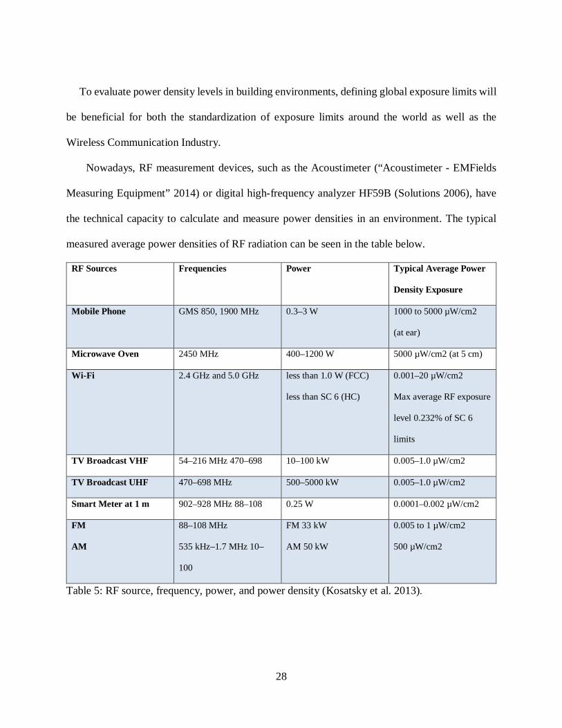
28
To evaluate power density levels in building environments, defining global exposure limits will
be beneficial for both the standardization of exposure limits around the world as well as the
Wireless Communication Industry.
Nowadays, RF measurement devices, such as the Acoustimeter (“Acoustimeter - EMFields
Measuring Equipment” 2014) or digital high-frequency analyzer HF59B (Solutions 2006), have
the technical capacity to calculate and measure power densities in an environment. The typical
measured average power densities of RF radiation can be seen in the table below.
RF Sources Frequencies Power Typical Average Power
Density Exposure
Mobile Phone GMS 850, 1900 MHz 0.3–3 W 1000 to 5000 µW/cm2
(at ear)
Microwave Oven 2450 MHz 400–1200 W 5000 µW/cm2 (at 5 cm)
Wi-Fi 2.4 GHz and 5.0 GHz less than 1.0 W (FCC)
less than SC 6 (HC)
0.001–20 µW/cm2
Max average RF exposure
level 0.232% of SC 6
limits
TV Broadcast VHF 54–216 MHz 470–698 10–100 kW 0.005–1.0 µW/cm2
TV Broadcast UHF 470–698 MHz 500–5000 kW 0.005–1.0 µW/cm2
Smart Meter at 1 m 902–928 MHz 88–108 0.25 W 0.0001–0.002 µW/cm2
FM
AM
88–108 MHz
535 kHz–1.7 MHz 10–
100
FM 33 kW
AM 50 kW
0.005 to 1 µW/cm2
500 µW/cm2
Table 5: RF source, frequency, power, and power density (Kosatsky et al. 2013).

29
1.3.5.1.1 WLAN vs Other EMW Exposure
The first step to investigate the significance and potential health impact of WLAN, as
compared to other signals, requires focusing on WLAN architecture. Traditional wireless local
area networking is an infrastructure of Access Points (APs) that provide networking capabilities
in a specific area. Each AP serves independently to provide association, authentication, IP address
acquisition, and data exchange operations with the user. Dealing with hundreds of APs in a
university or commercial building network brings new challenges, such as configuration and
management (Jardosh et al. 2008). For instance, regarding Wi-Fi transmissions exposure to RF
electromagnetic fields in UK schools, personal exposure in the classroom could reach 1.66
µW/cm², when compared to the ICNIRP international guideline reference level of 1000 µW/cm²
(Khalid et al. 2011).
Obviously, this is only a fragment of the whole picture of EMW exposure. EMW exposure
sources such as mobile base stations, and radio transmitters (for instance, spot measurements of
10 randomly selected base stations) illustrate 0.0045 µW/cm² (rural) and 0.0002 µW/cm² (urban)
mean total electric field strength in Austria (Hutter et al. 2006). By comparison, in Switzerland,
AM radio transmitter field strength is measured as 0.083 µW/cm² (Altpeter et al. 2006). These
values are below the maximum allowed field strength limits such as 1000 µW/cm² (61.4 V/m) in
North America and 10 µW/cm² (6.14 V/m) in most EU countries. Khalid et al. (2011) surveys
indicate that personal exposure of WLAN could reach 1.66 µW/cm² (2.5 V/m). So, potential health
impact of WLAN is higher when compared to other RF radiation sources, such as cell phone masts
or radio transmitters, in Europe. On the other hand, it can be assumed that outdoor field strengths
reach higher values in North America when compared to Europe. Wi-Fi typical average power
density range is lower than Microwave Ovens and mobile phone exposure (Table 4). However,

30
Wi-Fi has higher levels than TV and FM/AM broadcasting (Kosatsky et al. 2013). These values
represent a single source. My research assumes that varieties of these RF sources develop higher
power intensity levels in a building environment (IEEE Standards Coordinating Committee 28
1999).
Total understanding of the potential and significant health impacts requires the consideration
of multiple EMW signals and frequencies because we are exposed to the variety of EMW radiation
sources. Therefore, when a human being is exposed to multiple EMW signals, the sum value of
these signals creates a potential health impact because the value may exceed recommended country
health standard (Peatross and Ware 2014).
Discussion
The future of electronic devices, such as a new generation of mobile systems, is expected to
provide a wide variety of services. High voice quality, high video definition, and superior data
transmission rates will be demanded by users worldwide. To have sufficient broadband, high-
frequency bands are expected to be used. These bands include microwave, Ka-band, and
millimeter wave bands. The new generation of devices is not only cellular phones but also include
many types of communication systems such as broadband wireless access systems, millimeter-
wave LANs, intelligent transport systems, and high-altitude stratospheric platform station systems.
The expected transmission rate will reach Terabits per second in the near future. Therefore, the
development of new technology and the interaction between the old and new generation of
electronic devices will only further expand the use of EMI and EMC in building environments
(Moldovan et al. 2017).

31
Most countries have legal codes to discourage EMI on electrical hardware and these countries
continue to fix this issue (Kaur, Kakar, and Mandal 2011). Thus, building codes can be developed
and executed during either the construction or renovation process of the buildings to minimize
EMI problems. Another challenge is data security for wireless networks. All encryption can be
breached. WEP is the easiest protocol to be hacked in any wireless networking and it is widely
used all around the world. So, how could we protect our data in wireless networks? To minimize
this problem, the balanced approach would work on encryption, physical layer security, wireline
technologies in building environments. These solutions can reduce the possibility of the data from
being captured. If hackers could not get the data, they would not have something to work on.
Today’s government and military buildings require cutting edge technology and radical
solutions against sophisticated attacks, which includes Electromagnetic Warfare. In this case, these
buildings need to be sealed against EM radiation. The outcome is not just to reduce EMI issues
inside the structure but also to provide a healthy environment for the personnel.
Research Overview
There are a variety of challenges of pursuing this interdisciplinary study. For example, they
span distinct disciplines such as electronics engineering and architecture can be problematic
because architectural studies or approaches considered interesting or worthwhile may be
considered quite differently in engineering. Furthermore, criteria for acceptance appear to vary
between different disciplinary cultures (Turner and Carpenter 1999). Split ways to solve EMW
propagation problem in buildings that appear strongly driven by cross-disciplinary difference.
Development of wireless communication technologies and the integration into buildings drive the
need for healthy and effective electromagnetic wave propagation in building environments. This

32
interdisciplinary research assumes a much more prominent role that would be recognized as key
to developing innovative questions and overcoming limitations to intellectual progress in
architectural science.
Additionally, a limited amount of research has sought to conceptualize architectural design
option of EMW propagation in buildings and the topic has not propagated well through the
architectural community. Providing design guidelines would foster further research in this
interdisciplinary design approach.
1.5.1 Research Problem
EMW propagation issues require a different approach to engineering in building
environments. For instance, instead of adding more Access Points (APs) to improve WLAN
coverage and better performance, the answer could be found in changing building materials or
design geometry of the space. In other words, using appropriate design knowledge, architects and
engineers could make EMW propagation more efficient in the building environment. Currently,
the architecture profession is not greatly concerned with this issue. In fact, Internet and building
design have evolved simultaneously in the last decade; the relationship between EMW propagation
and construction remains a question, and an opportunity, for the Architecture profession.
Furthermore, to improve the thermal performance, some metallic coated materials such as; foil-
backed plasterboard (Saint-Gobain 2017), Low emissivity (Low E) (Hartig, Larson, and Lingle
1996) glazing are widely used in construction. However, their use can also affect the transmission
of wireless signals into and within buildings. Despite an engineer’s rigorous effort on designing
EMW devices, the growing use of metallic coated building materials would undermine wireless
performance in buildings. The increasing expectation of consumers is seamless coverage, both

33
indoors and outdoors. To meet this expectation, higher powers, more dense networks or both would
be implied by wireless network providers. In all cases, interference within and between networks
tend to increase. Spectrum planners are interested not only in the degree of penetration of EMW
into the buildings, but also in understanding the leakage from indoor devices that may cause
interference to neighbouring systems (Chandra, Kumar, and Chandra 1999). For instance, Wi-Fi
systems operating at 2.4 GHz could cause congestion in ‘smart metering’ of domestic electricity
and gas supplies (Ayoub et al. 2016). These problems can be minimized by intelligent radio
systems such as multiple-input multiple-output (MIMO) (Larsson et al. 2014), beam forming (Gan
Quan and Li 2016), or “data-offload” (Vasudevan et al. 2013) to other networks (e.g. from cellular
to Wi-Fi). However, the type of building materials used in construction have an impact on current
and future wireless communication system performance (Kurner et al. 2007).
1.5.2 Hypothesis
Conventional construction methods neither improves wireless communication performance
nor prevent data confidentiality, and data integrity in building environments. The main hypotheses
of this research is that evaluating current power densities in building environments per legal limits
and analysis of transmission and reflection coefficients of building materials can provide
guidelines for design professionals. Furthermore, the design guidelines may better secure data
confidentiality from being compromised in transit (e.g. eavesdropping) and data integrity from
being compromised in transit (e.g. hacking) for wireless communication systems in building
environments. The design method also would prevent high power spectral densities that can harm
its occupant.

34
1.5.3 Objectives, Purpose and Contributions
The study has been divided into six chapters to answer the following research questions:
1. Why do we need harmonious EMW environments for electronic devices?
2. How do building materials affect EMW propagation?
3. What does the impact of building materials have on health and EMW shielding?
4. How can building materials be used to control EMW to protect data confidentiality and
integrity in building environments?
5. What are the current power intensity levels in building environments and how do these
levels impact human health? (Case study in residential and the various locations in
Calgary.)
6. How does the EMW study of this theses can benefit architecture profession with regards
to better shielded, more secure and healthier buildings in the future?
The purpose of this study is to evaluate EMW propagation in the building environment, develop
basic guidelines for design professionals by understanding building material properties and
provide initial architectural design options to create healthy and effective electromagnetic power
spectral densities.
The major contributions of this dissertation can be summarized as follows:
1. Underlining the EMW shielding and conventional building materials relationship.
2. Characterizing the other options to improve data confidentiality and, data integrity for
wireless communication security.
35
3. Exposing current electromagnetic power spectral densities in building environments and
addressing the potential adverse health impact for occupants.
4. Providing initial design guidelines to the architecture profession. These guidelines would
allow creating healthy, secure, and shielded effective electromagnetic wave in building
environments.
5. Assessing the role of emerging building materials and methods in addressed EMW
shielding.
1.5.4 Thesis Outline
This dissertation contains six chapters and the remaining chapters are as follows:
The second chapter provides information regarding building materials and wireless
communication performance.
The third chapter is a case study that investigates the power intensity levels and potential health
impact on humans in a building environment.
The fourth chapter provides basic guidelines for design professionals regarding how
construction materials can have an impact on wireless communication.
The fifth chapter analyzes how architectural spatial designs effect EMW propagation in
building environments.
The sixth chapter summarizes the presented work, answers the research questions posed above,
and describes the major contributions of this work. It summarizes conclusions based on the
empirical research and literature review. Moreover, the future goals and recommendations are
characterized.

36
1.5.5 Methods
Two research methods were employed in this research, one in each study. The first study
explores current power density levels by conducting site surveys in building environments
(different locations in Calgary area). A data analyses approach has been taken to examine whether
power density levels are above or below the legal limits in Canada. The power density levels data
was also used for a comparison with the other countries thresholds. Furthermore, the data analyses
results were used to support a theoretical framework to study EMW shielding necessity of each
space in a building.
The second study examines the literature review data of building material responses against
EMW propagation. A condition-based analyses was employed to provide building design
guidelines for each specific building type. The results provide a new perspective for building
design from the point-of-view of EMW shielding in building environments.
1.5.6 Conclusion
This dissertation presents two distinct chapters address these gaps in the architecture literature,
and each includes a review of relevant literature as well as presentations of the study methods,
analyses, results, and potential directions for future study. Collectively, these two chapters
illustrate the overall power density levels in building environments and provide initial design
guidelines, supplement engineering solutions to create healthy and effective EMW propagation.
The current introductory chapter provides a literature review of the general concepts used in the
two studies. In addition, a research overview is presented of the chapter to outline the general
objective, purpose of pursuing this research, as well as highlighting the methods, and possible
outcomes.

37
Chapter Two: Building Materials and Wireless Communication Performance
While propagating, EMW experience reflection, diffraction, scattering, and dispersion. Each
causes distortion in radio signals (Vagner 2004). For instance, reflection can be seen in metallic
surfaces such as aluminum facade, curtain walls, window frames, and furniture in building
environments. These surfaces act as an almost perfect reflector for electromagnetic waves.
However, signal strength can be reduced according to the thickness of the building material. For
instance, the signal from a cell phone mast often travels a variety of paths until it reaches its
destination. When these signals encounter an obstacle, scattering and diffraction occur; naturally,
the signal travels around the object. When a signal hits a surface, scattering occurs and remits in
different directions. All dielectric materials have some loss, which causes dispersion (Schmitt
2015). Lossy dielectric materials such as cement and pure water are good examples on which to
observe dispersion (Eccosorb, n.d.). So, in buildings, reflection, diffraction, scattering, and
dispersion are the common effects, which are not seen in free spaces where EM waves do not
interact with any material. On the other hand, propagation intensity decreases through walls, roofs,
and floors. In addition, corners foster multipath propagation and diffraction. These EM
propagation effects are almost unavoidable in today’s modern structures because of the use of
aluminum, steel columns, rebar grids, metal pipes, HVAC systems, and so on.
As an illustration, a room, PF 3165 in the Professional Faculties Building on the University
of Calgary campus, contains aluminum power/data line poles, metal bookshelves/lockers, and
aluminum window frames. Microwave antennas around the building, interior EMW sources, and
electronic devices create unintended high-power intensity levels. These unintended higher-power
intensity levels do not provide efficient wireless communication because these levels can cause
distortion. This type of distortion is caused by too much reflection, diffraction, scattering, and

38
dispersion of the radiation. In our case, aluminum and steel, as building materials, have a diverse
performance effect on wireless communication because of their high reflective electromagnetic
properties (Li and Li 2012). The common satellite dish, which could be made of aluminum or light
steel, is a good example to show how electromagnetic waves reflect from metallic surfaces. The
curved shape of the dish reflects and focuses the electromagnetic waves towards the satellite’s
Low Noise Block (LNB) device to capture the reflected and concentrated signals.
Another example regarding the relation between EMW propagation and building material can
be demonstrated by a lab experiment. The sample office room modeling experiment indicates how
the building material and the room occupancy (furniture, living organisms, human, electronic
devices and so on.) interact with EMW propagation under controlled conditions. The experiment
occurred in the microwave and antennas laboratory at Yeditepe University Department of
Electrical & Electronics Engineering. To simulate a real-life environment, 1/5 scaled sample office
room (Fig.1) and furniture models were made. Using this scaled model required a 12 GHz (2.4x5)
frequency in the experiment to maintain the same wavelength of WLAN simulation.
Figure 1. Sample Office Room Experiment (Hakgudener 2007)

39
Two different scenarios were applied: one involving a control (empty) room and one involving
an occupied room. EMW propagation behavior results for these scenarios can be seen in the
contour graphs below (Fig.2). In this experiment, the difference of potential is 6 V/m. The
following two graphs also indicate the hot spots (around 10 V/m) in the occupied room. When the
source (transmitter antenna) generates and transmits the radio wave to the object (furniture) via
transmission line (air), there are two possibilities of the object response. Firstly, the wave is
absorbed and or secondly, the wave is reflected (Aswoyo et al. 2003).
The higher values would be formed by two or more different reflected and scattered waves. In
physics, this phenomenon can be explained by the formation of standing waves (“Formation of
Standing Waves” 2014).
Figure 2. EMW Propagation Contour Graphs for an empty and an occupied room at the 2.4 GHz frequency (Hakgudener 2007)
The occupied room contains some metal furniture components, an aluminum-framed window,
and a coffee table. This accounts for the unexpected propagation (reflected and scattered waves)
in the EMW activity. Exterior/interior wireless communication sources, building envelope, wall
partitions, occupancy, and furniture all have an impact on EMW propagation behavior in the
building environment. In our case, these variables could cause distorted wireless signals and low

40
WLAN performance. Therefore, design professionals (interior designers/ architects) can
manipulate EMW propagation behaviour just changing the layout of the space. In our case, the
ultimate goal would correlate architectural space design options and EMW behaviour.
To understand the other conventional building materials’ response to certain frequency ranges,
the following sections, discuss transmission coefficients of materials from 0.5 - 8.0 GHz (60 to 4
cm wavelength). These transmission values represent an impact on wireless communication
system performance by these materials. Regarding the reliability, quality, and usability in wireless
communication, each building type has a different performance requirement. For instance, in
residential spaces, power intensity levels for sleeping areas and a baby’s room need to be at lower
levels than the other part of the house. Brick, brick-faced concrete walls, and brick-faced masonry
blocks demonstrate good sealing performance to maintain safe levels in these spaces. Detailed
information regarding architectural spatial design effects on EMW propagation in building
environments can be found in Chapter 5.
The following sections focus on each of the conventional building materials and provide
detailed information regarding their material properties and effects on EMW propagation.
Brick
Brick is a commonly used building material in residential and commercial construction. It is
one of the oldest and traditional exterior cladding materials (“Technical Notes,” n.d.). Besides its
benefits of low maintenance, sound insulation, thermal mass, fire protection, and penetration, brick
has electromagnetic shielding properties. To determine the various construction material responses

41
to EMW propagation, the National Institute of Standards of Technology (NIST) conducted a series
of experiments. Two frequency bands from 0.5 to 2.0 GHz and from 3.0 to 8.0 GHz were chosen.
The first experiment covered three different nominal target thickness regarding B1L=89 mm,
B2L=178 mm, and B3L= 267 mm. The 1 m height of the wall was not considered as an impact
factor regarding EMW propagation because separate transmit and receive horn antennas were
spaced 2 meters apart with a metal RF isolation barrier located midway between the antennas to
eliminate multipath signals. This setup allowed the collection of one-way transmission data.
Therefore, accurate transmission coefficients were measured for each different layout; the
following figures show transmission coefficients for three different brick wall specimens.
Appendix A provides detailed information regarding the NIST experiment.
Figure 3. Transmission coefficients for brick wall specimens (0.5-2.0 GHz) (Stone 1997).
The frequency response determination from 0.5 GHz to 2.0 GHz underlines similar
characteristics for brick walls. The thickness of the wall and higher frequencies foster lower

42
transmission in this type of configuration. However, from 3.0 GHz to 8.0 GHz, brick performs
differently according to the thickness. For instance, in Fig 4., B1L, which is 89 mm, stays between
the 0.15 and 0.2 transmission efficiency level. The higher frequency input does not provide a
significant impact on EMW transmission. The second specimen, B2L, which is 178 mm, shows
less monotonic performance within the frequency range. From 3.0 GHz to 5 GHz, B2L reduces
the transmission coefficient from 0.15 to 0.04. This dramatic decrease stops at 5 GHz and the slow
increase continues between 5 GHz and 7 GHz. Above this frequency, the transmission coefficient
dramatically increases. Moreover, B3L, which has 267 mm thickness, shows a consistent reduction
in EMW propagation until 6.5 GHz. Above this frequency, the transmission slightly increases until
the 8 GHz frequency.
Figure 4. Transmission coefficients for brick specimens (3.0-8 GHz) (Stone 1997).

43
Therefore, it could be determined that B3L has the best shielding performance among three
specimens from 0.5 GHz to 8.0 GHz. If the design purpose is to shield the structure against high
power spectral densities, the ideal brick wall shielding thickness would be 267 mm if only the
options are available. As mentioned in Section 1.3.4, most wireless applications, such as cell phone
and Wi-Fi communication, stay in this frequency range. So, BL3 would be the first line of defense
against high power spectral densities.
Brick faced concrete wall
Brick faced concrete wall is another alternative for retaining walls, ramps, buildings, screens,
foundations, dumpster enclosures and truck dock walls. This type of solution is commonly used to
separate residential from commercial zones (“Brick Faced Concrete Walls, Inc. - Novi, Michigan”
2016). Methods for embedding thin brick into concrete walls provide the better appearance of laid-
up brick, timing, and costs inherent in brick and mortar construction. For architects, this way of
wall construction fosters greater design options such as integrated arches with a variety of field
patterns, attractive transitions to non-brick surfaces and other design elements (“Thin Brick
Construction | Tilt Up Concrete Walls | Embeded Brick Construction” 2016).
The transmission coefficients of the brick-faced concrete wall, 90 mm brick backed by 102 mm
of plain concrete, vary from 0.28 to 0.14 in low range frequencies (0.5 to 2.0 GHz). Another
specimen, which has 203 mm thickness of concrete, reduces the EMW transmission to 0.02.
Therefore, in low range frequencies, brick-faced concrete performs better than plain brick.
From 3.0 GHz to 8.0 GHz, two specimens show good shielding performance against higher
power spectral densities. For instance, 90 mm brick backed by 102 mm of concrete reduces the

44
EMW propagation down to transmission coefficient of 0.005, while 90 mm brick backed by 203
mm plain concrete transmission drops down to 0.001 (Stone 1997).
Overall, it can be assumed that brick-faced concrete specimens provide better shielding
performance compared to the other conventional building materials.
Brick faced masonry block
Masonry wall systems have been used in construction for thousands of years. The variations of
this wall system, such as brick veneer, provide cladding and structural backup and resist transfer
wind load. Brick is a good choice with respect to the cladding resistance (“Building Envelope
Design Guide - Masonry Wall Systems | Whole Building Design Guide” 2016). Regarding the
shielding performance of brick faced masonry wall, 90 mm brick by 194 mm block, the
transmission coefficient stays under 0.32 from 0.8 GHz to 8.0 GHz. This behavior promotes the
wall as an alternative shielding option against high power spectral densities. Transmission
coefficients of this specimen can be found in Appendix A/Fig. A.5.
Plain concrete
In both the low 0.5 GHz-2.0 GHz and the high 3.0 GHz-8.0 GHz frequency bandwidths, plain
concrete performs well against high spectral densities. For instance, 305 mm thick concrete
(approximate water cement ratio of 0.4, a slump of 57 mm (“low”), a nominal maximum crushed
aggregate size of 12.7 mm (“small”), a cement content by weight of 22% and an average density
of 2.31 g/cc) shows a value below a 0.03 transmission rate in these frequency bandwidths. In higher
frequencies, close to 8.0 GHz, this rate drops to 0. This behavior is especially advantageous for
45
the government, military buildings, and power plants when faced with electronic warfare.
Transmission coefficients of this specimen can be found in Appendix A/Fig. A.6.
Drywall
Drywall, which is also known as plasterboard, wallboard or gypsum board, is a panel made of
gypsum plaster sandwiched between two thick layers of paper. It is used for to build interior walls
and ceilings. This durable construction material is used for building many types of structures, such
as residential, commercial, hospitality, government and so on. It also has fire resistance and
soundproofing features (“How Did We End up with Drywall? : TreeHugger” 2016).
Regarding transmission coefficients in “low” (0.5 to 2.0 GHz) and “high” (3.0 to 8.0 GHz)
frequency band- widths, drywall stays between 0.9 and 1.0 (90% to 100% EMW transmission).
This response could be helpful for design professionals when the effective wireless transmission
is required in a structure.
Glass
Glass is one of the most versatile building materials available to designers (Hoar 1999). Glass
also has a good transmission coefficient. For instance, a 12.5 mm thickness glass pane transmits
between 86% and 87% in “low” (0.5 to 2.0 GHz) and “high” (3.0 to 8.0 GHz) frequency band-
widths. According to spectral power densities, this response is useful for interior and exterior
applications. In addition to that, reflective coatings and film applications add shielding properties
to glass (Hakgudener 2015). Therefore, whether the purpose is EMW shielding or transmission,
glass provides flexibility to designers to solve EMW propagation-related issues.

46
Lumber (Dry/Wet)
Wood-based products have been used for building construction since the beginnings of the
urban revolution. Their proper applications would be framing, insulating and finishing
(“Material Choices for Wood Frame Construction | Green Home Guide | Ecohome” 2016).
According to the data, the dryness of the spruce specimen does not have a big impact on
transmission behavior. The 113-mm thickness lumber panel transmits between 32.5% and 76%
in “low” (0.5 to 2.0 GHz) and “high” (3.0 to 8.0 GHz) frequency bands. Higher frequency and
specimen thickness are the main factors affecting transmission coefficients for the spruce
specimen.
Plywood (Dry/Wet)
Plywood is an engineered wood made from sheets of thin hard and softwood specimens.
These sheets are glued together to create thick, ridged flat sheet. The end product, which is
called Plywood, has a wide range of use in the construction industry due to its high strength,
flexibility, and moisture, and its economic, insulation, chemical, impact, and fire-resistance
properties. Some of its uses in construction are making a partition or external walls, formwork,
furniture, flooring systems, packaging, cupboards, kitchen cabinets, office tables, light doors
and shutters (“Plywood as a Building Material - Understand Building Construction” 2016).
In high moisture areas, conventional plywood could change its response against EMW
propagation. Dry plywood of 11.8 mm thickness has a high EMW transmission rate of 97%-
98% in “low” (0.5 to 2.0 GHz) and “high” (3.0 to 8.0 GHz) frequency bandwidths. This feature
can be used when a high EMW transmission is required. For instance, to create healthy indoor
WLAN in office, corporate or government facilities, high transmission coefficient rates are
needed to prevent wireless networking performance issues.

47
Wet plywood of 11.8 mm thickness has a relatively high EMW transmission rate of 86%-
76% in “low” (0.5 to 2.0 GHz) and “high” (3.0 to 8.0 GHz) frequency bandwidths. However,
in the high-frequency range, the specimen transmission rate declines to 76%. So, to solve wet
plywood problem, marine graded plywood can be a good choice to maintain transmission
stability of the material.
Reinforced Concrete
After its invention in the 19th century, reinforced concrete revolutionized the construction
industry. Reinforced concrete is made of embedded steel rebar meshes in concrete (“Reinforced
Concrete Introduction” 2016). For this reason, reinforced concrete can withstand the wind,
vibrations, and other forces in structures.
The transmission percentage for reinforced concrete begins with 52% in (0.5 to 2.0 GHz)
bandwidths and declines to 0.3% in (3.0 to 8.0 GHz) frequency bandwidths. This type of response
promotes reinforced concrete as a good insulator against high power spectral densities.
Rebar Grid
Rebar grid or reinforcing steel is a mesh of steel to support reinforced concrete and reinforced
masonry structures. 19 mm thickness (70mm x 70 mm) rebar grid transmits 64% in “low” (0.5 to
2.0 GHz) and 88% in “high” (3.0 to 8.0 GHz) frequency bands. So, the mesh grid of rebar grid can
be customized according to spectral densities of the environment.
In their experiment, Stone et al. (1997) do not provide information regarding reflection
coefficients of conventional construction materials (Section 2.1, 2.2, 2.3, 2.4, 2.5, 2.6, 2.7, 2.8, 2.9,
2.10). Moreover, building materials also reflect EMW to varying degrees and this is related to

48
transmission coefficient. In building design process, transmission coefficients and reflection
coefficients of the building materials would need to be known and material selections could be
done accordingly.
The flowing table shows transmission and reflection coefficient values of conventional building
materials at 2.4 GHz. In the Table, Minus (-) reflection coefficient refers a resonant effect with a
destructive wave to incident wave. According to Koppel et al., the measured values represent a
resultant field from all possible (destructive and constructive) wave interactions. If the thickness
of the material would be increased, the resonant effect would no longer occur as the wavelength
ratio dependency is lost.

49
Material Transmission coefficient
Reflection coefficient
Thickness (mm) Density (g/cm³)
EPS (Foamed polystyrene thermal insulation board)
0.87 0.02 50 0.013
Neo EPS (Graphitized foamed polystyrene thermal insulation board)
0.69 0.00 50 0.016
Steico Flex (Flexible insulation board made from natural wood fibres)
0.79 0.08 100 0.049
Marine graded Plywood
1.03 0.26 18 0.353
Composite peat-wood plate
1.1 0.1 35 0.603
Knauf Heraklith C50 (Natural fiber concrete pressed plate)
1.3 -0.03 50 0.353
Gypsum Panel (Custom made)
1.25 0.13 50 1.043
Aeroc (Aerated concrete)
0.92 -0.11 100 0.461
LECA (Lightweight expanded clay aggregate concrete block
1.06 -0.11 85 0.858
Gypsum Board (Knauf)
0.45 0.17 16 0.762
OSB (Oriented strand board)
0.48 0.17 14 0.580
Particleboard with veneer
0.69 0.25 14 0.672
High performance concrete plate (circular shape)
0.71 0.38 13 1.975
High performance concrete plate
0.34 0.35 13 2.093
MDF (Fibreboard) 0.87 0.12 4 0.808 Table 6. Transmission and reflection coefficient values of conventional construction materials at 2.4 GHz ( Adapted from (Koppel et al. 2017))
50
The need for new building materials
Regarding wireless communication in building environments, each conventional construction
material has its transmission and reflection coefficients and the other elements such as furniture,
electrical, plumbing, HVAC, other electronic equipment, and occupants have an impact on EMW
propagation in the space. Creating effective and healthy EMW propagation in a built environment
is a challenge and requires rigorous EMW simulations. There has been a great effort by engineers
to develop next generation of advanced, low cost and intelligent antennas such as diversity/ MIMO
to create effective EMW propagation (Malik, Patnaik, and Kartikeyan 2013). It is expected that,
in a high flux density environment, to protect the occupants in a building, the construction material
needs to provide good absorption and when effective EMW propagation when required. The
previous sections show that there is no ideal conventional building material has been produced by
the construction industry to achieve reliable and usable wireless communication. This is because
conventional building materials are considered for structural integrity, building envelope,
aesthetic, and functionality. However, there has been a great deal of scientific development for
new generation RF radiation shielding and absorption materials. Examples include geopolymer
cement (Rangan 2008) and nano-Ni coated cenosphere composites to limit EMI. Nano-Ni coated
cenospheres are the processed products of fly ash cenospheres. Fly-ash is the by-product of power
generation plants and is an environmental concern regarding its disposal. However, cenospheres
are non-toxic, lightweight, and have good insulation properties. Coating metal film on their
surfaces makes this material ideal for the use of EMW absorption and shielding purposes (Meng
et al. 2010). According to European building regulations, to reduce EMI in work environments,
new materials are encouraged for use in building design (Migliaccio et al. 2013). Thus, creating a
new generation of building materials might supplement the engineering studies to achieve healthy,

51
reliable, and usable wireless communication systems in the building environment. Advanced
materials such as conductive composites can provide efficient conductivity and shielding
performance, while preserving the basic weight, cost, structural, environmental, and
manufacturing performance advantages of composites and plastics such as, nickel coated carbon
fibers, nickel coated aramid fibers (Composites 2016). There are a variety of application potential
of advanced materials in architectural practice such as shielding paints, wall coverings, furniture,
office partition panels, wall dividers, flooring, ceiling, door and window material coatings and so
on. A Utah firm has revealed conductive composite wallpaper to block signals against
cybershopping and cyberwarfare. Using the wallpaper would also protect inhabitants against
higher power spectral densities in building environments (Prigg 2015).
The new generation building envelopes can create RF radiation-controlled building
environments. The combination of an insulation material and RF shielding window film would
minimize the unintended RF radiation leakage into the building. The potential use of the new
insulation material might not just be for shielding, but also harvesting the energy from the space
around. In addition, this free source of electrical energy can be combined with solar panels to
maximize the energy efficiency in building environments.
EMW Shielding Alternatives and Effects in Building Environments
According to the amount of EMW sources in an environment, conventional building materials
could fail to provide safe power spectral densities. In this case, EMW shielding materials needs to
be applied to structures. For instance, shielding mesh provides basic interior and exterior frequency
shielding and keeps rooms at safe levels, thereby protecting its occupants; also, the mesh can be
applied directly to the facade or interior walls. However, the mesh needs to enclose the whole

52
volume (Pirkkalainen, Elovaara, and Korpinen 2016). This solution is only suggested when there
is no WLAN intended to be used in the space. In other case, RF shielding would increase reflection
and cause unintended EMW propagation.
RF shielding firms prefer to use both copper and aluminum mesh. The only concern with
using copper in RF radiation shielding applications might be the initial cost and oxidation of the
material (“Architecture Design Handbook: Fundamentals: Radio Frequency Shielding” 2014). On
the other hand, aluminum is a low-cost, effective EMW shielding option in comparison to copper.
For instance, the base wholesale price of copper foil is 10,000 US $ per metric ton (“Copper Foil-
Copper Foil Manufacturers, Suppliers, and Exporters on Alibaba.comCopper Strips” 2014),
whereas aluminum foil ranges between 2,000-2,900 US$ per ton (“Aluminium Foils-Aluminium
Foils Manufacturers, Suppliers, and Exporters on Alibaba.comAluminum Foil” 2014). In this
specific type of application, aluminum and copper have the advantage of being recyclable
materials. Therefore, because aluminum is five-times less costly, it is considered to be the right
choice for EMI shielding in most applications.
Another alternative is RF shielding paint that contains carbon-based and corrosion-resistant
materials. This paint can be applied to both exterior and interior surfaces. In North America,
residential buildings are constructed with wood-based materials such as plywood, lumber, and
drywall. This paint seals and reduces higher-power intensity levels. For the windows or curtain
walls in residential or commercial buildings, RF shielding window film can be applied to over-
exposure cases. RF shielding window film performs by reflecting the EMW. Instead of using wire
mesh in windows, RF shielding window film provides an alternative aesthetical solution for
buildings (“EMF Products + RF Products by Safe Living Technologies Inc.” 2014). Moreover, in
this type of application, wired networking is suggested in the required space.

53
Residential buildings in North America seem structurally ideal for efficient wireless
communications because of the wide-range and use of wood-based materials, such as lumber and
composites. However, wood-framed construction is vulnerable to unintended exterior RF radiation
sources because wood does not have strong electromagnetic shielding properties (Section 2.7, 2.8).
On the other hand, commercial building construction relies on reinforced concrete, steel beams
and columns, aluminum curtain walls, and so on. However, as discussed above, commercial
building materials do not have the ideal properties for efficient wireless communication. Drywall,
glass, and plywood are some of the choices currently available in the construction industry. The
ultimate goal is to find the right materials to provide efficient and safe wireless communication in
the building environment.
Wireless communication coverage is affected by electromagnetic compatibility, interference,
and construction materials. Examples of an environment might be an office or a school laboratory,
with many electronic devices (such as computers, cell phones, TVs, lighting fixtures, and wireless
gadgets) that cause electromagnetic phenomena in their operation. The goal of EMC
(Electromagnetic Compatibility) is to reduce the conflicts between these devices. To fix this
problem, EMC deals with emission issues related to the reduction of the unintentional generation
of electromagnetic energy. Therefore, Electromagnetic Compatibility aims to sustain a harmonious
environment for electronic devices for optimal functionality and safety. To address the
electromagnetic interference issue, electrical circuits emit electromagnetic signals according to
their application, and these signals might come in the form of Radio Frequency Interference (RFI)
for the other systems. These devices produce rapidly changing signals. These unwanted signals are
called interference, or noise, in other circuits. EMI (Electromagnetic Interference) interrupts or
limits the effective performance of other circuits (Kaur, Kakar, and Mandal 2011). Sometimes,

54
this action is intended as a form of electronic warfare, which is a concern for the spatial design of
military buildings. Brick, brick-faced concrete walls, brick-faced masonry blocks and reinforced
concrete reduce the unwanted external power intensities. Using the right conventional building
material is an initial step towards reducing electromagnetic disturbances that are due to the
incorrect operation of electrical equipment. Making the right choice of building materials
supplements the efficiency of the wireless communication system. In Europe, the buildings are
typically constructed of concrete, and historical buildings are structured with load-bearing stone
walls. Stone, as a construction material, creates attenuation loss like concrete against EMW
(EuropeanCommision 1999). In this case, the concrete and stone walls help to reduce unintended
EMW penetration into the building. However, interior concrete partition walls cause performance
issues in wireless communication (Shamir 2002). In this case, the solution is to provide plywood
and drywall interior partitions to support effective communication. If the building is designed for
an office environment, open workspaces and glass walls might be applied to prevent propagation
loss.
Conclusion
Achieving the optimum wireless communication performance output in a building is
complicated by building material, EMW device, and locational power density interrelated
variables. The holistic approach taken by most engineering solutions based on gadget design and
rigorous testing can coupled with best practice architecture design to achieve optimum solution.

55
Chapter Three: Power Density Levels in Different Building Environments: Case Study
A case study was executed at a residential building and different locations in Calgary to
support the theoretical framework. Measuring power density levels between 5 Hz and 10 GHz RF
(Radio Frequency) helped to evaluate typical suburb residential community, typical office and
class environments exposure levels. The frequency range is suitable for detecting radiation from
the following sources: AC power lines, cell towers (masts), cordless DECT phones, smart meters,
Wi-Fi router/modems, WiMAX networks, cellular phones (mobiles), radar, Nintendo Wii, Sony
PlayStation and other video games, digital baby monitors, digital TV, audio/video sender
receivers, tetra emissions, and wireless burglar alarms. Gigahertz Solutions Radio Frequency (RF)
and ELF analyzers were used to measure power densities (Gigahertz Solutions 2017).
Measurement accuracy was related to device calibration per manufacturers’ certificate of
calibration. Measuring alternating fields are calibrated during the manufacturing process for the
instruments. The laboratory instrumentation is used to prove the instrument’s quality and
calibration, which is directly traceable to the German “Physikalish-Tecnische Bundesanstalt”, the
National Institute of Standards, or natural physical constants at planned intervals. Moreover, the
manufacturer’s “Total Quality” System is monitored by VDE, the German Association for
Electrical, Electronic & Information Technologies to assure the compliance of the manufactured
products to published specifications (“Benchmark Tests | Measurement | Gigahertz Solutions”
2015). Regarding RF-Analyzer HFW59D (2.4 – 10 GHz), basic accuracy (CW) including linearity
tolerance is +/- 4.5 dB zero offset and rollover +/- 5 digits. For the RF-Analyzer HF59B (27 MHz-
3.3 GHz), basic accuracy (CW) of linearity tolerance is +/- 3 dB zero offset and a rollover of +/- 5
digits. For the 3D-LF-Analyzer with data logger NFA1000 (5 Hz- 1000 KHz), basic accuracy for

56
50-60 Hz is +/- 5, 16 Hz - 30 kHz is +/- 1 dB, 5 Hz - 1000 kHz is +/- 2 dB and the isotropic
deviation is +/- 1.5 dB with an offset +/- 5 digits.
Method
Quantitative research method was conducted to collect empirical data (site survey
measurements). The data allows to evaluate current power density levels in building environments.
Five different exposure limits for long-term exposure to the general public (Canada, ICNIRP,
China, Russia and Switzerland) were used to compare power density levels in residential, typical
office and typical class environments. Moreover, other measurement values around the world also
compared with the case study data.
Residential Indoor Environment
According to Leech et al. (2002) time activity patterns study, Canadians (67.21 %) and
Americans (67.19 %) spent most of their times indoor (Leech et al. 2002). Under these
circumstances, power densities need to be analyzed to determine if the measurement data above
or below legal Canada`s threshold. Moreover, initial EMW shielding properties of these of these
dwellings are addressed. The measurements were taken in day and night time periods.
3.2.1 Study Description
Isotropic (3D) AC magnetic low- and high-frequency range measurements are taken over 24
hours at a townhouse community (51.1623038 latitude, -114.0966560 longitude), 1131.84 m
(elevation)) (MyGeoPosition.com 2017). The townhouse community has a total of 213 units,
which are in several rows of houses connected by a drywall. The layout also provides a large
number AP’s in a close environment that allows to receive Wi-Fi signals from multiple modems

57
in one location. Moreover, these houses do not have any shielding and conventional construction
materials such as plywood, glass, drywall and lumber favor to transmit stronger signal values in
and out.
Measurement have been taken at the second-floor master bedroom. Two measurement devices
have been used simultaneously to measure these densities and the devices are located on the bed,
which is 45 cm above the floor level. During this process, the data is recorded to an SD card,
transferred, and then analyzed by NFA software (“NFAsoft | NFA-Series | Low Frequency |
Measurement | Gigahertz Solutions” 2015). The following shop drawing shows the location of the
measurement setting.
Figure 5. Residential indoor environment, master bedroom, measurement location shop drawing. Drawn by author. (Not in scale, units are cm.)

58
3.2.2 Data Analyses
Isotropic (3D) AC magnetic field measurement capability is an advanced measurement feature
to define different band segments such as 16.7 Hz, 50/60 Hz, 100/120 Hz, 150 /180 Hz, both below
and above 2 KHz.
The following plots (Fig. 6, Fig. 7 and Fig. 8) show the statistical data analyses of power density
levels in the master bedroom. From 5 Hz to 1000 KHz frequency range, 36.15 (nT) average AC
magnetic flux density is measured. In Figure 6, X axis unit is time/hour and nT (nano Tesla) is for
Y axis.
Figure 6. Residential indoor environment 3D (x, y, z) AC magnetic flux density data (units are time/ hour for X, and nT for Y axis)
For RF range, average 0.0055 (μW/cm²) power density is measured between 27 MHz- 3300
MHz (Fig.7). Units are time/hour, for X, and μW/m² power density for Y axis.
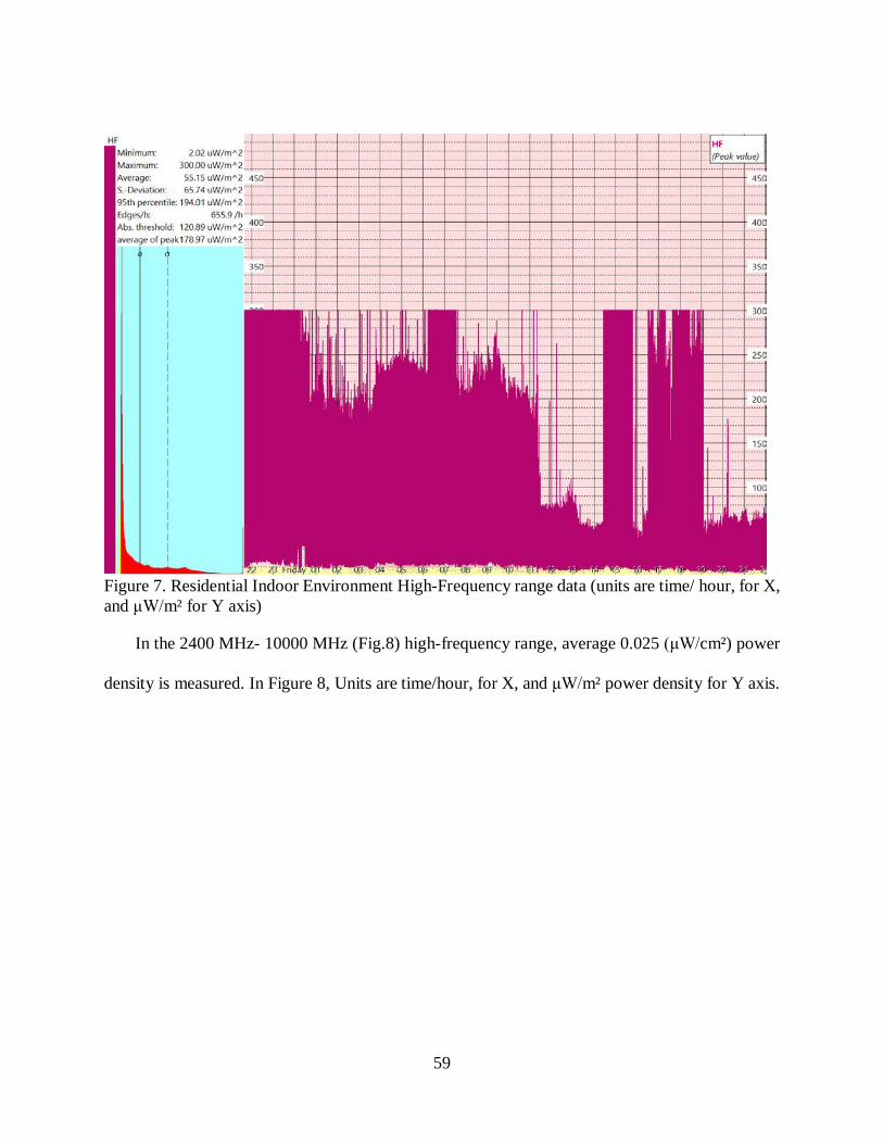
59
Figure 7. Residential Indoor Environment High-Frequency range data (units are time/ hour, for X, and μW/m² for Y axis)
In the 2400 MHz- 10000 MHz (Fig.8) high-frequency range, average 0.025 (μW/cm²) power
density is measured. In Figure 8, Units are time/hour, for X, and μW/m² power density for Y axis.

60
Figure 8. Residential Indoor Environment High-Frequency range data (units are, time/ hour, for X, and μW/m² Y axis)
The following table shows measured values in the master bedroom per three different frequency
range.
Measurement Period Frequency Range Average for all measure values
9 p.m. – 9 p.m. (24 hr) 5 Hz-1 MHz 36.15 nT (magnetic flux density)
9 p.m. – 9 p.m. (24 hr) 27 MHz- 3300 MHz 0.0055 μW/cm² (power density)
9 p.m. – 9 a.m. (12 hr) 2400 MHz- 10000 MHz 0.025 μW/cm² (power density)
Table 7. Master bedroom average for all measure values
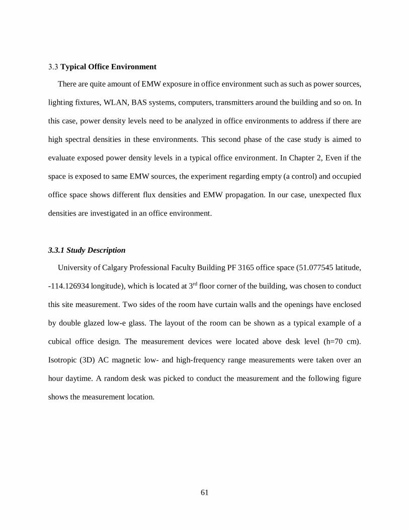
61
Typical Office Environment
There are quite amount of EMW exposure in office environment such as such as power sources,
lighting fixtures, WLAN, BAS systems, computers, transmitters around the building and so on. In
this case, power density levels need to be analyzed in office environments to address if there are
high spectral densities in these environments. This second phase of the case study is aimed to
evaluate exposed power density levels in a typical office environment. In Chapter 2, Even if the
space is exposed to same EMW sources, the experiment regarding empty (a control) and occupied
office space shows different flux densities and EMW propagation. In our case, unexpected flux
densities are investigated in an office environment.
3.3.1 Study Description
University of Calgary Professional Faculty Building PF 3165 office space (51.077545 latitude,
-114.126934 longitude), which is located at 3rd floor corner of the building, was chosen to conduct
this site measurement. Two sides of the room have curtain walls and the openings have enclosed
by double glazed low-e glass. The layout of the room can be shown as a typical example of a
cubical office design. The measurement devices were located above desk level (h=70 cm).
Isotropic (3D) AC magnetic low- and high-frequency range measurements were taken over an
hour daytime. A random desk was picked to conduct the measurement and the following figure
shows the measurement location.
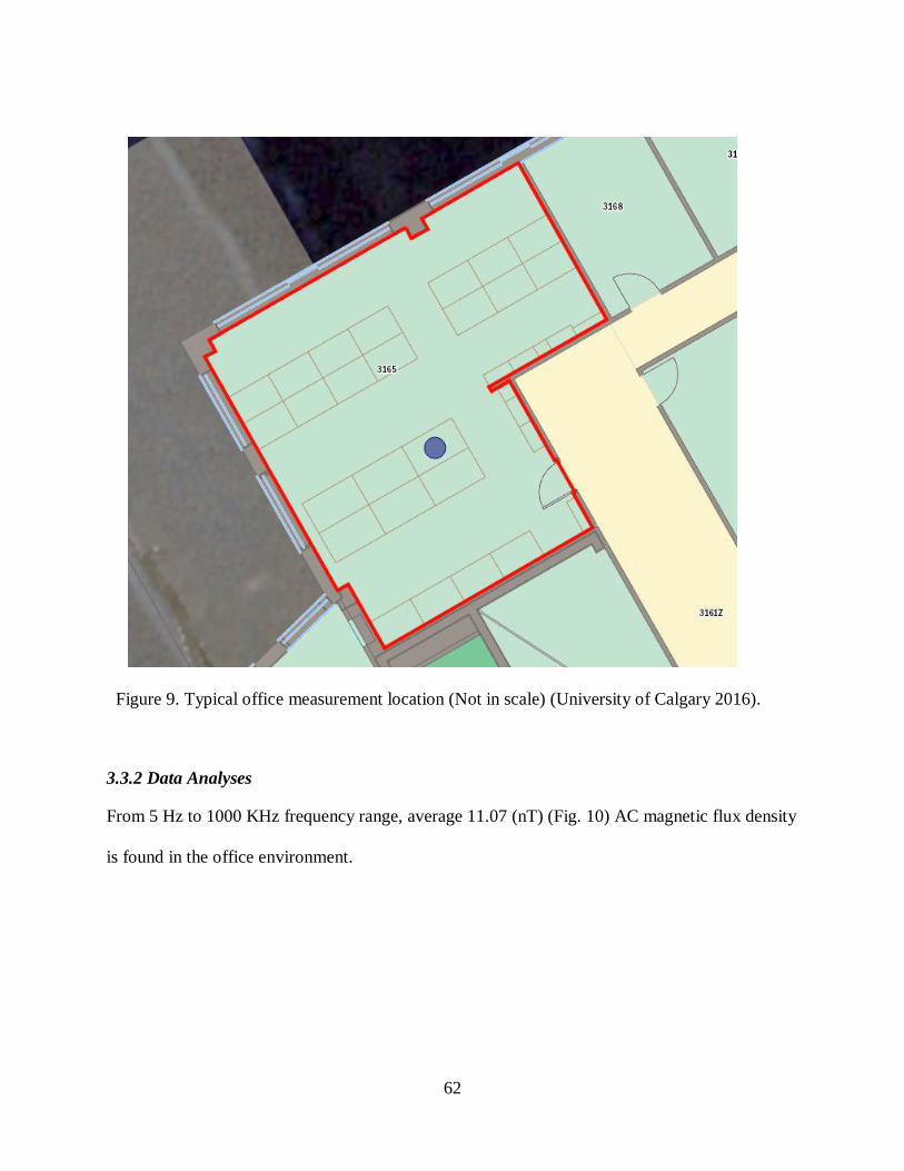
62
Figure 9. Typical office measurement location (Not in scale) (University of Calgary 2016).
3.3.2 Data Analyses
From 5 Hz to 1000 KHz frequency range, average 11.07 (nT) (Fig. 10) AC magnetic flux density
is found in the office environment.

63
Figure 10. AC 3D Magnetic flux densities (5 Hz- 1000 KHz), X axis unit is time/hour and nT is for Y axis.
For RF range, average 0.03 (μW/cm²) power density is measured between 27 MHz- 3300
MHz (Fig.11). Units are time/hour, for X, and μW/m² power density for Y axis.

64
Figure 11. HF range (27 MHz- 3300 MHz), the measurement was taken at the same period (1 p.m-3:30 p.m.)
For the high-frequency range between 27MHz- 10GHz (Fig.12), average 0.1758 (μW/cm²)
power density level is found. In Figure 12, X axis unit is time/hour and μW/m² power density is
for Y axis.
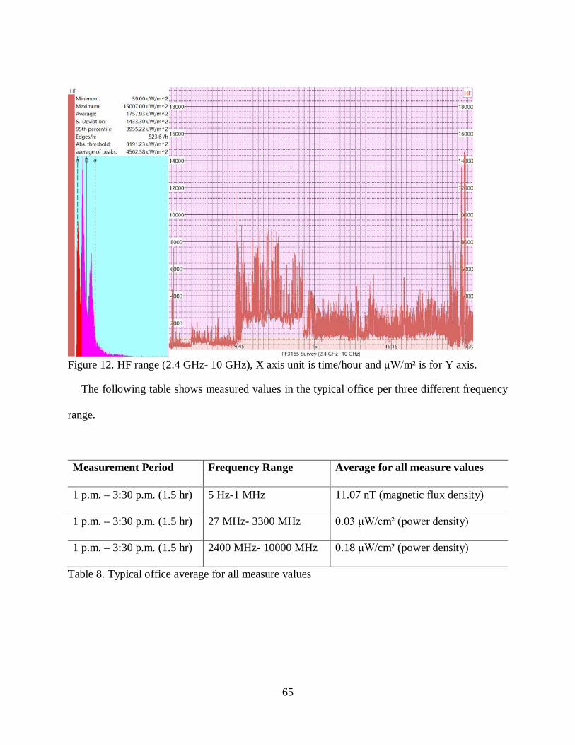
65
Figure 12. HF range (2.4 GHz- 10 GHz), X axis unit is time/hour and μW/m² is for Y axis.
The following table shows measured values in the typical office per three different frequency
range.
Measurement Period Frequency Range Average for all measure values
1 p.m. – 3:30 p.m. (1.5 hr) 5 Hz-1 MHz 11.07 nT (magnetic flux density)
1 p.m. – 3:30 p.m. (1.5 hr) 27 MHz- 3300 MHz 0.03 μW/cm² (power density)
1 p.m. – 3:30 p.m. (1.5 hr) 2400 MHz- 10000 MHz 0.18 μW/cm² (power density)
Table 8. Typical office average for all measure values

66
Typical Class Environment
Typical full time college student spends 15 (3 credit hours/one course) hours in class per week
(University of Michigan 2017). Class environments have different furniture layouts than office
spaces. However, Occupancy levels are higher in most cases. In this case, there is a possibility to
measure close spectral densities at WLAN frequency bands. This part of the study aimed to
investigate how occupancy might affect on power spectral densities in this specific space.
3.4.1 Study Description
To assess typical class power densities, the University of Calgary’s PF 2140 (51.077371
latitude, -114.126689 longitude) room was selected (University of Calgary 2016). The room has
no windows besides an interior glass panel and the door that provides visual display and physical
pass. The measurements were taken while 12 occupants were inside the room during class hours
to determine the real-life situation and the measurement height was 70 cm. Desks were oriented in
rectangular configuration. The room also had one projector and a podium, which had a built-in
computer and a monitor, and the following figure shows the measurement location.

67
Figure 13. Typical classroom measurement location (Not in scale) (University of Calgary 2016).
3.4.2 Data Analyses
Fig. 14 shows the average AC 3D Magnetic flux density between 5 Hz and 1000 kHz as 22.96
(nT). Units are time/ hour for X axis, and nT for Y.

68
Figure 14. Typical Class environment 3D (x, y, z) AC magnetic flux density data (units are time/ hour for X axis, and nT for Y)
In Figure 15, between 27 MHz- 3300 MHz range HF average power density is 0.15 (μW/cm²).

69
Figure 15. HF range (27 MHz- 3300 MHz), X axis unit is time/hour and μW/m² is for Y axis.
In the 2400 MHz- 10000 MHz (Fig.16) high-frequency range, average 0.14 (μW/cm²) power
density is measured.

70
Figure 16. Typical Class Environment High-Frequency range data (units are time/ hour for X, and μW/m² for Y)
The following table shows measured values in the typical office per three different frequency
range.
Frequency Range Average for all measure values
5 Hz-1 MHz 22.96 nT (magnetic flux density)
27 MHz- 3300 MHz 0.015 μW/cm² (power density)
2400 MHz- 10000 MHz 0.14 μW/cm² (power density)
Table 9. Typical class average for all measure levels

71
3.5 Results
The following histograms represent a graphical presentation of measured power density levels
in residential, office and class environments.
5 Hz-1 MHz
Figure 17. Average for all measured values 3D (x, y, z) AC magnetic flux density data (frequency rage, 5 Hz-1 MHz for X axis, and nT for Y)
For 0.003-10 MHz frequency range, instantaneous magnetic flux exposure threshold is 112,860
nT, root mean square (RMS), which is the square root of the average of the square of the data
values, in Canada (Health Canada 2015).
36.15
11.07
22.96
0
5
10
15
20
25
30
35
40
Residentail Indoor Environment Office Environment Class Environment
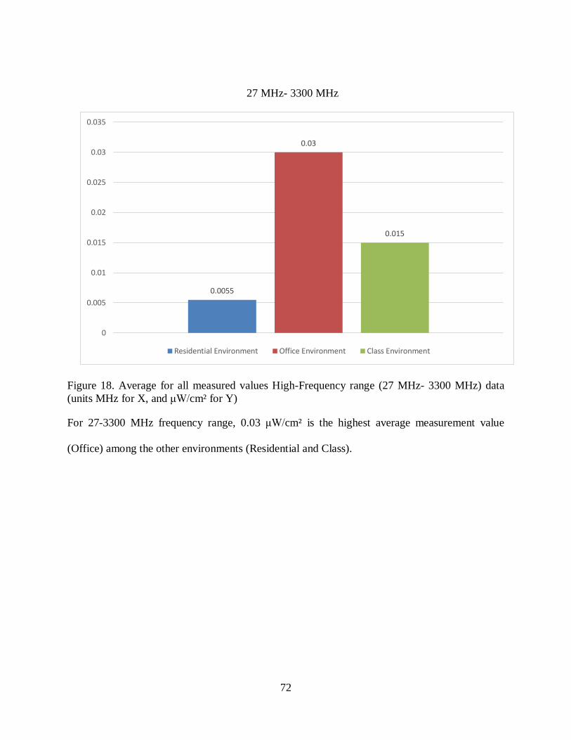
72
27 MHz- 3300 MHz
Figure 18. Average for all measured values High-Frequency range (27 MHz- 3300 MHz) data (units MHz for X, and μW/cm² for Y)
For 27-3300 MHz frequency range, 0.03 μW/cm² is the highest average measurement value
(Office) among the other environments (Residential and Class).
0.0055
0.03
0.015
0
0.005
0.01
0.015
0.02
0.025
0.03
0.035
Residential Environment Office Environment Class Environment

73
2400 MHz- 10000MHz
Figure 19. Average for all measured values High-Frequency range data (units MHz for X, and μW/cm² for Y)
For 2400 MHz, maximum exposure limit (6 minutes) is 535 μW/cm² in Canada. Office and class
environments have close measurement data. It can be assumed that higher occupancy of the class
environment (more cell phones and laptops) in a specific area have an impact on this result.
According to general public long term exposure limits in Canada (Health Canada 2015), The
United States, China, Russia and Switzerland (Table 3), measured average power density levels
for residential, office and class environments stay in the safe zone. However, there are some cases,
200 V/m (Hanada, Takano, and Antoku 2002) and 100 V/m (Luca and Salceanu 2012) in hospital
environments around the world. These values are above the exposure limits in Canada. Further
research needs to be conducted to identify these spaces.
0.25
0.18
0.14
0
0.05
0.1
0.15
0.2
0.25
0.3
Residential Environment Office Environment Class Environment

74
Limitations
The results of this research are subject to several limitations. The general limitations on site
survey studies are related to the number of measurement locations. Although the commonality
uses of the holistic approach of evaluating power density levels in these environments, a
comparison approach has been taken in this research using different case study data around the
world to reduce the effect of possible biases that may come from other professionals. More time
and a larger budget would help to expand the site survey area such as measuring many dwellings
and whole campus buildings. A second limitation of this study is that only two building were
included in the study. Additional research involving other types of buildings such as commercial,
government, hospitality is required to extend the generalizability of the results.
75
Chapter Four: Basic shielding guidelines for design professionals
Previous chapters provided literature review, experiment and results. Chapter 4 derive basic
guidelines based on information obtained from these chapters. Understanding building material
responses and EMW shielding behavior in building environments can help to build a design
strategy for specific spaces. According to the functionality of the space, these variables will
determine the proposed guidelines for design professionals.
4.1 The design guideline
The initial design guideline provides an overview for design professionals that outlines the
necessary steps to create safe wireless communication based on the results derived from this theses
experiment. This new result and derived guideline with wireless communication security
incorporation will also be explained.
4.1.1 EMW Shielding Principles in building environments
EMW propagation shielding in the building environment means to protect its occupants from
external radiation by partially or completely enclosing the space. There are a variety of materials
that need to be used to achieve the purpose, and each of these components has their own role to
promote the overall performance of the system. The process begins with the purpose to reduce
high power spectral densities. Moreover, the design guidelines need to be incorporated with
shielding principles to achieve the best performance.
The reducing would be a preferred choice to provide increased data security for military
applications, corporate boardrooms, VIP rooms, academic, research and other government
facilities. Moreover, this is also preferred when adverse health effects are concerned, and it would
be the choice of residential, commercial, hospitality, schools and any other spaces to reduce high

76
power spectral densities. EMW shielding begins with creating a conductive barrier around the
space. Michael Faraday introduced this concept to the world in 1821 (Tong 2015b). He created a
conductive housing with zero electrical fields inside the housing. His principle known as Faraday
cage and it could be used effectively in building environments. This method also helps undesired
conducted or radiated electrical disturbances (EMI) from the surrounding of the structure. This
type of disturbances would occur at any frequency in the electromagnetic wave spectrum, and
conductive shield provides protection from radiating energy. Moreover, an EMW shielding design
needs to meet both emission and immunity requirements of the space. This would be achieved via
reducing the high power spectral densities and isolation. These procedures could be incorporated
into the entire electrical and construction system design.
The following proposed general EMW shielding design flow model (Figure 20.) illustrates
these procedures.
Figure 20. General EMW Shielding Design Flow
Electrical design stage covers electrical panel allocation/installation, cable shielding, and
filtering steps. Conventional electric power (50-60 Hz) network circuit breakers only work in the
Design Specification (The Purpose)
Site Survey (Measurements)
Electrical Design Architectural Design
• Electrical Panel Allocation/Installation • Filtering • Cable Shielding
• Material Selection • Shielding at all levels • Seaming

77
on and off position (Shibata, Sakai, and Okabe 2011). When the breakers are on, the power travels
through cables and reaches to the spaces in a building. This is the current practical solution
regarding the power demand in building environments. In this case, even if the power is not used,
the power networking creates EMW propagation in the environment. Another power related issue
is dirty electricity, which could be produced by different sources such as; computers, variable
speed motors, television sets, entertainment units, dimmer switches, power tools, arching on hydro
wires, cell phone masts, broadcast antennas, energy efficient lighting, and appliances. Dirty
electricity propagation is at the low end of RF spectrum (kHz) and radiates from the wires and
creates a significant impact on the environment. Therefore, the result could be referred as low
power quality in the system (Havas 2006). Using demand switches incorporated with filtering and
cable shielding could be a good choice to prevent dirty electricity in buildings. More simply, when
there is no energy demand, demand switches automatically turn off the power supply (“Demand
Switches - Green Evolution USA” 2015). In this way, dirty electricity could not travel through
power network. To protect equipment from power surges, large capacitors are used by industry. In
this way, high-frequency voltage transients (HFVT) could be reduced or removed from the
network. Graham and Stetzer developed a filter for residential and commercial spaces to remove
HFVT. G/S filters reduce the amount of HFVT in 4 kHz and 100 kHz frequency range (de Vocht
2010).
Cable shielding is accomplished by insulating the surrounding structure. The medium voltage
standard cable insulation has two components, which are a semiconducting or stress relief layer
and metallic layer of tapes. Both must function as a unit (Lawrence and Landinger 1999). Foil and
braid type of shielding are the choice of industry to shield the wires. Foil shielding uses a thin layer
of aluminum and it provides good performance. Braid is made of exposed or tinned copper wire
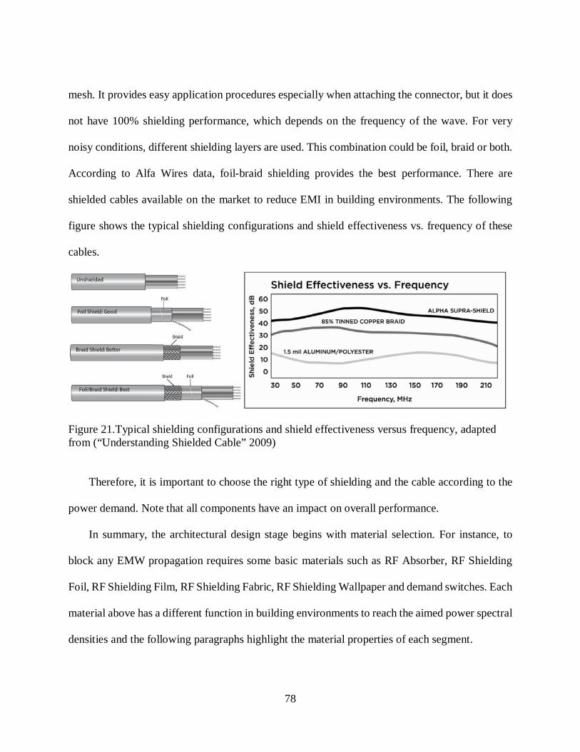
78
mesh. It provides easy application procedures especially when attaching the connector, but it does
not have 100% shielding performance, which depends on the frequency of the wave. For very
noisy conditions, different shielding layers are used. This combination could be foil, braid or both.
According to Alfa Wires data, foil-braid shielding provides the best performance. There are
shielded cables available on the market to reduce EMI in building environments. The following
figure shows the typical shielding configurations and shield effectiveness vs. frequency of these
cables.
Figure 21.Typical shielding configurations and shield effectiveness versus frequency, adapted from (“Understanding Shielded Cable” 2009)
Therefore, it is important to choose the right type of shielding and the cable according to the
power demand. Note that all components have an impact on overall performance.
In summary, the architectural design stage begins with material selection. For instance, to
block any EMW propagation requires some basic materials such as RF Absorber, RF Shielding
Foil, RF Shielding Film, RF Shielding Fabric, RF Shielding Wallpaper and demand switches. Each
material above has a different function in building environments to reach the aimed power spectral
densities and the following paragraphs highlight the material properties of each segment.

79
4.1.1.1 RF Absorbers
The increasing variety of electronic devices and high power spectral densities requires
absorbing materials to address EMI issues. Instead of harnessing and transferring the energy to
the ground as do conductive materials, absorber materials attenuate and absorb the energy, and
reradiates it as heat. As it is discussed in Chapter 1, this feature could be embraced with a smart
architectural detail. For instance, according to building location, this feature help to promote
efficient building design. Typical absorbers could be categorized as microwave absorber
materials, dielectric absorbing materials, and electromagnetic absorbers. The microwave
absorber materials promote reflectivity minimization through shape, structure, permittivity (Ɛ)
and permeability (µ) allowing for absorbtion of EMI and broadband frequencies. In dielectric
absorbers, molecular forces of the atoms are not free to dislocate because the dominant charges
of the atoms are positive and negative. This structural order causes the storage of electric
energy, which turns into heat by the Joule effect.
The main feature of dielectric absorbers is to change the dielectric characteristics of the
material from transmitter or reflector, to absorber. To do this, a combination of semiconductive
or conductive fillers is used in the polymeric matrix. Silicon, graphite, carbon black, aluminum,
copper, stainless steel, and various metal-coated powders are components of these fillers.
Moreover, different polymeric matrices are rigid or flexible such as epoxy, phenolic, bis-
maleimide, polyurethane, polyimide and silicone resins. When the absorber is close to the near
field, the magnetic field will be large, and this causes a large absorption value. This feature has
an impact on absorption material design. Magnetic absorbers are made of carbonyl iron and
hexaferrites. These materials have a wide frequency range from Megahertz to Gigahertz and
can be tuned according to particle size (Tong 2015a).
80
4.1.1.2 RF Shielding Foil
A foil is a thin metal sheet made with malleable metals such as aluminum, copper, gold, and
silver. Aluminum foil contains 92 to 99 percent aluminum and produced in 0.043 to 1.5 mm
thickness. The foil has the variety of widths and strengths to promote different applications such
as: thermal insulation for the construction industry, fin stock for air conditioners, electrical coils
for transformers, capacitors for radios and televisions, insulation for storage tanks, decorative
products, and containers and packaging. The availability of the raw material fosters the popularity
of aluminum foil. Therefore, aluminum foil is inexpensive, durable, non-toxic, and greaseproof.
In addition, it resists chemical attack and provides excellent electrical and non-magnetic shielding
(“How Aluminum Foil Is Made - Material, Manufacture, Making, Used, Processing, Dimensions,
Aluminium, Procedure” 2015).
Copper sheets/foils alloy 99% Cu and sheet thickness vary 1 mil (0.25 mm) to 22 mils (5.5
mm). 1, 1.4, and 3 mil copper foils are very thin, and they are used for scrapbooking, paper crafts,
electrical and R&D applications. 5 mil copper foil is approximately 7-8 times thicker than typical
household aluminum foil. It is often used for various home improvement/interior design such as
tabletops, backsplashes, bar tops, countertops and crafts projects as well as electrical,
manufacturing and other applications. 8, 10, 16 and 22 mil copper sheets are more durable. For
instance, 10 mils are often used in outdoor projects to protect wood from the elements, such as for
flashing, or capping poles or exposed beams in a structure, 16 mils for backsplashes, bar tops,
countertops, and range hoods as well as roofing projects. 22 mil copper sheeting is a heavy weight
copper often used for roofing and flashing (“Copper Sheets and Rolls” 2015). Regarding RF
shielding purposes 8 mil copper shield could be used for flooring or if required space has very high
power spectral densities.
81
4.1.1.3 RF Shielding Film
RF shielding film is a laminate, optically clear polyester and has metallized coatings bonded
by adhesives. The coating metals are applied onto a clear, polyester film as an even layer. To meet
the shielding performance, different metals are used. Typical window film structure has a release
liner with silicone coating, adhesive layer with UV inhibitor, clear or tinted polyester film, an
adhesive layer, metallized layer for heat and EMW rejection on clear polyester film, and scratch-
resistant coating. There are two basic types of window films, which are non-reflective or dyed,
and reflective or metalized. In our case, reflective or metalized type will promote radiation
rejection. Moreover, shielding film would also prevent infrared (IR) and UV rays in building
environments (“How Window Films Works” 2015).
4.1.1.4 RF Shielding Mesh
There are various types of mesh available on the market which include woven wire mesh,
welded wire mesh, and weave mesh. Wire diameter (noted in millimeters or inches) and mesh
count (the number of holes per linear inch or cm), are a performance factor regarding RF shielding.
For instance, higher frequencies require higher mesh counts. Both aluminum and copper wire mesh
could be used for shielding purposes (“Aluminum Mesh - Ferrier Wire Goods Company Limited”
2015).
4.1.1.5 RF Shielding Fabric
A variety of shielding fabrics provide a varying degree of shielding. The base materials for
fabrics are cotton, artificial fibers such as polyester, polyamide, and aramids. These materials are
processed with conductive elements, which are called monofilament. It could be made from
copper, bronze, silver, gold, aluminum, inox, and so on. The surface of the fabric could be either
conductive or insulated. The result is up to 99.98% effective shielding performance at 1 GHz

82
(“NATURELL: Swiss Shield” 2015). In building environments, one vulnerable element against
high power spectral densities is openings, such as windows and doors. The first defense is window
film and the leakage of the frames could be prevented by shielding fabrics used for draperies.
These types of fabrics have potential use for clothing, which could include uniforms.
To verify the effectiveness of the model, different type of RF shielding material’s (such as
shielding fabrics, aluminum foil, absorber, shielding film, aluminum, copper wire mesh and
wallpaper) data were provided in 0.01 MHz to 10.0 GHz frequency range to fulfill the aimed RF
shielding performance in building environments. The table below provides the necessary material
properties and shielding effectiveness, which is calculated by taking the ratio of the RF energy on
one side of the shield to the RF energy on the other side of the shield, and expressed the results in
decibels (dB) as a function of the logarithm of the ratio of incident and exit power densities (Bursky
2013). In Table 10, negative values represent small but positive numbers, on a logarithmic scale.
Therefore, higher dB (shielding effectiveness) value of the material represent lower shielding
performance.

83
RF Shielding Material Dimension/ Properties
Tested frequency band
Shielding Effectiveness
dB
Reference
Shielding Fabric Type I (Swiss Shield Natural)
Over 100 Nm yarn count
1.0 KHz to 2.0 GHz 62-31 (Frei 1999)
Shielding Fabric Type II (Swiss Shield Evolution)
Over 100 Nm yarn count
200 MHz to 2.5 GHz
30-33 (Klaus 2000)
Shielding Fabric Type III (Swiss Shield New Daylight)
Over 100 Nm yarn count
30 MHz to 10.0 GHz
17-42 (Pauli 2006)
Aluminum Shielding Foil (5 mil, 0.127 mm thickness)
Dimension 100X100 cm
1.0 KHz to 10.0 GHz
12-60 (Ramayes 2017)
Wire mesh (Aluminum) (wire diameter 0.28 mm)
Dimension 100X100 cm
100 MHz to 10.0 GHz
18-71 (Metzinger 2014b)
Wire mesh (Copper) Type I
16X16 mesh count per 25.4 mm, 2.8 mm
wire diameter
1.0 KHz to 10.0 GHz
20-108 (Reed 2003)
Wire mesh (Copper) Type II
22X22 mesh count per 25.4 mm, 3.8 mm
wire diameter
1.0 KHz to 10.0 GHz
28-108 (Reed 2003)
Wire mesh (Copper) Type III
100X100 mesh count per 25.4 mm, 1.1 mm
wire diameter
1.0 KHz to 10.0 GHz
30-108 (Reed 2003)
RF Shielding Film Dimension 100X100 cm
1.0 GHz to 10.0 GHz
(-36) to (-29) (Metzinger 2014a)
RF Absorber Dimension 61X61X (0.64-23) cm
400 MHz to 18.0 GHz
> -20 (“Absorbers | MVG”
2015)
Table 10. RF Shielding materials performance data adopted from manufacturer’s technical specifications
Based on conventional building and shielding material properties, the following design work
flow chart and Architectural EMW Shielding Design Guideline is developed. The first step of the
workflow is to evaluate power density levels in the building. If the measured level is above legal
limits, options such as further investigation to address the EMW sources in the area, and legal
proceedings need to be followed. The occupants of the high-power density areas advised to leave
these spaces until power spectral densities are lowered below the legal limits. If legal procedure
provides immediate results and power densities are lowered, the occupants would proceed EMW
shielding as an option to prevent further consideration regarding long term adverse health impact.

84
Another potential issue would be the performance issues of devices in the space. If these problems
occur, EMW shielding is advised.
Figure 22. The design workflow chart by author
Motives for EMW shielding can be data confidentiality, data integrity (Section 1.3.4), EMI,
EMC (Section 1.3.2), and adverse health impact on humans. To execute EMW shielding projects,
architectural details needs to be developed by incorporating construction and shielding materials
(Table 10). Thus, the following architectural EMW shielding detail guideline flow chart provides
a method that design professionals can adapt this basic design detail method to apply any type of
required space. The guideline has been developed per conventional construction methods for each

85
detail type and the purpose of the guideline is to direct design professionals to a specific schematic,
which provides initial detail layering and used shielding materials.
Figure 23. Architectural EMW shielding detail guideline flow chart by author
Ceilings and walls are one of the most important structural elements of a building and it also
requires creativity in architectural design process. Ceilings can be divided into two types according
to their construction methods such as conventional and suspended (dropped) ceilings. Flat ceilings
demonstrate basic structure of a ceilings which can be concrete or wood. Concrete ceilings can
take a variety of forms and they can be found in modern structures. Frame ceilings such as vaulted,
tray and cove ceilings are traditional but still widely used. Framework of these type of ceilings
provide support for the floor above, and the surface for the finished attachment below. A wide
range of materials can be used in finishing for ceilings. Drywall is the most common, which can
vary in thickness and density and can be chosen per safety regulations of the building. To achieve
higher thermal performance in buildings, insulation is incorporated in ceilings. Thus, EMW

86
shielding can also be incorporated with insulation in building design. The following figure shows
this type of detail in schematic form.
TOP Ceiling Material (Concrete, wood or steel)
Wire mesh (Copper or aluminum)
EMW Absorber
Insulation (Batt, rigid, hemp, or other sustainable alternatives)
Framing (Wood or light steel)
Finish Layer (Drywall, wood plank or other available materials)
BOTTOM Figure 24. EMW Shielding for Conventional Ceilings- Schematic 1 by author
Schematic 1 can allow designers to develop conventional ceiling details for a EMW shielding
project.
Suspended or dropped ceilings are the secondary ceilings suspended from the structural floor
slab above. The purpose of the ceiling is to create a void between the underside of the floor slab
and the top of the suspended ceiling. This void can provide useful space for the distribution of
heating, ventilation and air conditioning (HVAC) services, plumbing and wiring, as well as
providing a platform to install speakers, light fittings, wireless antennas, CCTV, fire, smoke
detectors, motion detectors, sprinklers and EMW shielding materials.
TOP Ceiling Material (Concrete, wood or steel)
Insulation (Batt, rigid, or other sustainable alternatives) if it is required
Heating, ventilation and air conditioning (HVAC), plumbing and wiring service space
Wire mesh (Copper or aluminum) if required to elevate shielding (by reflecting the external sources)
EMW Absorber
Suspended (Dropped) Ceiling
BOTTOM Figure 25. EMW Shielding for Suspended (Dropped) Ceilings- Schematic 2 by author
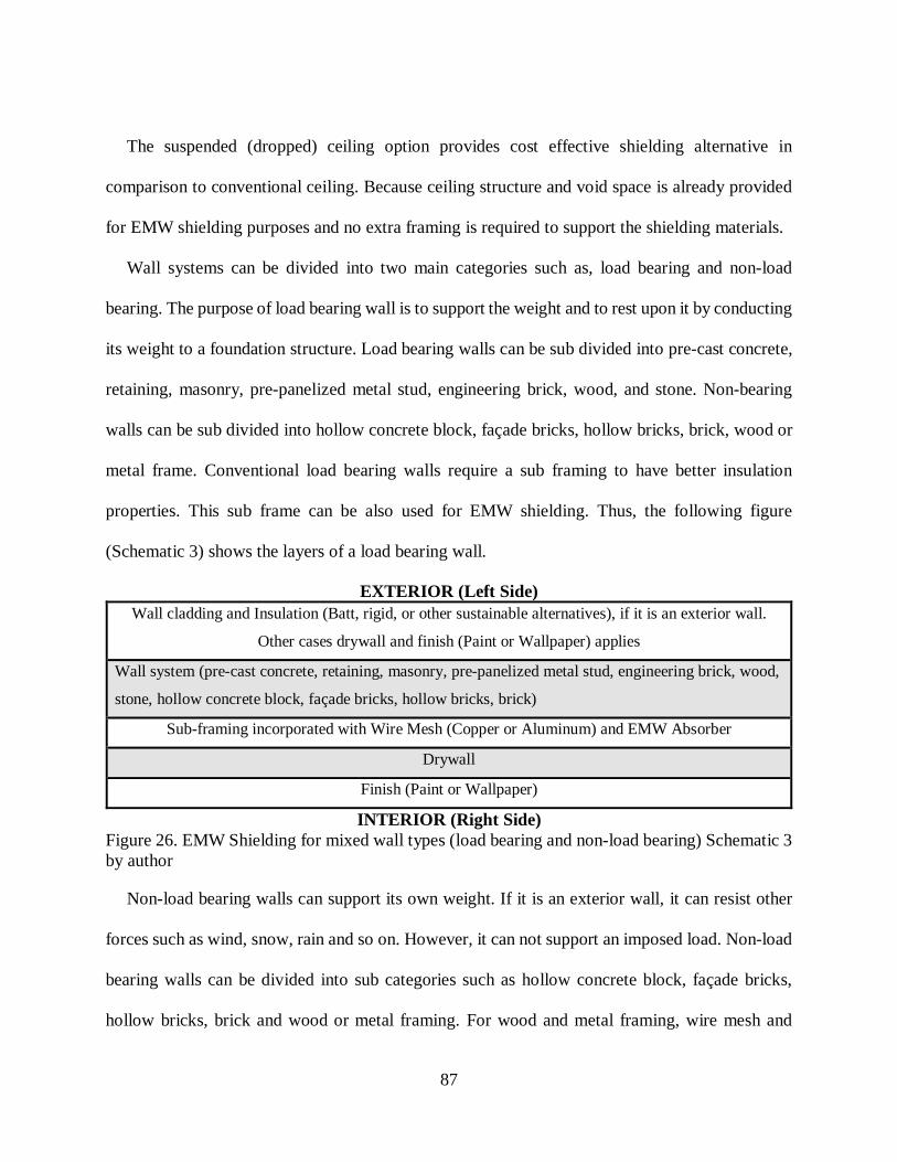
87
The suspended (dropped) ceiling option provides cost effective shielding alternative in
comparison to conventional ceiling. Because ceiling structure and void space is already provided
for EMW shielding purposes and no extra framing is required to support the shielding materials.
Wall systems can be divided into two main categories such as, load bearing and non-load
bearing. The purpose of load bearing wall is to support the weight and to rest upon it by conducting
its weight to a foundation structure. Load bearing walls can be sub divided into pre-cast concrete,
retaining, masonry, pre-panelized metal stud, engineering brick, wood, and stone. Non-bearing
walls can be sub divided into hollow concrete block, façade bricks, hollow bricks, brick, wood or
metal frame. Conventional load bearing walls require a sub framing to have better insulation
properties. This sub frame can be also used for EMW shielding. Thus, the following figure
(Schematic 3) shows the layers of a load bearing wall.
EXTERIOR (Left Side) Wall cladding and Insulation (Batt, rigid, or other sustainable alternatives), if it is an exterior wall.
Other cases drywall and finish (Paint or Wallpaper) applies
Wall system (pre-cast concrete, retaining, masonry, pre-panelized metal stud, engineering brick, wood,
stone, hollow concrete block, façade bricks, hollow bricks, brick)
Sub-framing incorporated with Wire Mesh (Copper or Aluminum) and EMW Absorber
Drywall
Finish (Paint or Wallpaper)
INTERIOR (Right Side) Figure 26. EMW Shielding for mixed wall types (load bearing and non-load bearing) Schematic 3 by author
Non-load bearing walls can support its own weight. If it is an exterior wall, it can resist other
forces such as wind, snow, rain and so on. However, it can not support an imposed load. Non-load
bearing walls can be divided into sub categories such as hollow concrete block, façade bricks,
hollow bricks, brick and wood or metal framing. For wood and metal framing, wire mesh and

88
EMW Absorber can be incorporated with insulation material. This method does not require extra
framing and can reduce the cost. The following Figure (Schematic 4) shows EMW shielding for
wood or metal framing wall.
EXTERIOR (Left Side) Wall cladding and Insulation (Batt, rigid, or other sustainable alternatives) if it is an exterior wall.
Other cases Drywall and finish (Paint or Wallpaper) applies
Wall system (wood or metal framed)
Framing incorporated with Wire Mesh (Copper or Aluminum) and EMW Absorber
Drywall
Finish (Paint or Wallpaper)
INTERIOR (Right Side) Figure 27. EMW Shielding for wood or metal framing walls- Schematic 4 by author
The purpose of the flooring is to provide a walking surface for occupants of a structure. Flooring
can be divided into two main categories such as conventional and raised. The common construction
methods for conventional floors are platform framing (Steel, Wood) and solid (Concrete). These
two sub flooring types requires a sub framing for EMW Shielding. Thus, the following Figure
(Schematic 5) shows the shielding method.
ABOVE Flooring system (Hardwood, engineered flooring, laminate, ceramic tile, marble, granite and so on)
Plywood
Sub framing incorporated with wire mesh and EMW Absorber
Plywood for sub flooring (If the surface is concrete it is not required)
Platform framing (Steel, wood) or Concrete
BELOW Figure 28. EMW Shielding for Conventional Flooring- Schematic 5 by author
The purpose of a raised flooring (raised floor, access floor) is to create an elevated structural
floor above a solid substrate (often a concrete slab). This hidden void provides a passage of

89
mechanical, electrical services and EMW shielding materials. Thus, the following Figure
(Schematic 6) provides the shielding method for raised flooring.
ABOVE Flooring system (Hardwood, engineered flooring, laminate, ceramic tile, marble, granite and so on)
Plywood
Raised flooring framing integrated with Wire mesh and EMW Absorber
BELOW Figure 29. EMW Shielding for Raised Flooring- Schematic 6 by author
Openings can be categorized into standard windows, interior/ exterior doors, curtain walls in a
building. EMW shielding for an opening can be hard to achieve. However, there are EMW
shielding materials such as EM shielding window film, window/door shielding gaskets are
available on the market. The following Figure (Schematic 6) show an initial shielding method for
the openings in a built environment.
EXTERIOR Shielding film (works by reflecting the EMW) for curtain walls, windows
Shielding gaskets to seal the doors and windows
EMW Absorber incorporated into the interior/exterior door frame and casing
INTERIOR Figure 30. EMW Shielding for Openings- Schematic 7 by author
Therefore, this initial Schematic guideline can provide conventional shielding components to
develop a specific detail in building environments. It is also suggested that the transition details
such as, floor to wall and wall to ceiling need to be develop by design professionals to improve
the shielding effectiveness.
4.2 Conclusion
Regarding the use of common building materials for EMW propagation, there is usually better
material selection in the design aspect. The question is how practical and cost effective these

90
materials are. Each building material has its unique response to EMW propagation. According to
the power intensity requirements, these materials have their own places in buildings. Designing
healthy and propagation friendly buildings requires a conceptual planning. This planning needs to
be supported with right building materials and other components of a space such as the form of
furniture, lighting fixtures, interior partitions, and so on. Using this strategy, design professionals
will not just solve this design requirement addressed by their customers but also will achieve the
design principle of unity in architecture. Moreover, incorporation of the EMW shielding design
flow with the guidelines provide an initial RF shielding strategy to design professionals. This
incorporation creates an effective model that will foster a new way of thinking in the field of
architecture. Moreover, the method would reduce health impacts, and security threats in building
environments.
The success of a construction project relies on a good planning, execution, and control. To
become a master in construction trade requires years of practice in job sites and the broad
knowledge of the trade, passed from experienced journeyperson to apprentice. The theory could
be read; however, the practice could only be developed in a work setting. Workers trained in both
design and execution could see the elements of physics, chemistry, and mathematics. For instance,
mixing cement with water to create the right amount of consistency, estimating the square meter
of hardwood, how to build a header for a window, how to build and install a roof beam, and so on.
New technological developments push the envelope for the construction industry. Overcoming
these challenges can be done by the integration of the architectural practice and the theory.
Incorporation of wireless communication systems into the architectural design is one of the
aspects, which needs to be a standard practice in building design. Engineering shielding methods
needs to be incorporated into interior design practice, to achieve safe and healthy EMW
91
Propagation in building environments. The suggestions may be simple in theoretical form;
however, in terms of practice there would be obstacles at job sites. Initial suggestions for effective
solutions for each type of building are provided in the following chapter.

92
Chapter Five: Architectural Spatial Design Effect on EMW Propagation in Building Environments
Structural building types require different architectural layouts and construction materials to
create of a functional space. Chapter Five systematically investigates the architectural spatial
design effect on electromagnetic wave propagation for structures including: residential,
commercial, educational, government, industrial, military, religious, transport, power
station/plant. The initial suggestions can help a better understanding of how to shield
electromagnetic wave propagation in these spaces. In some cases, EMW manipulation is necessary
to prevent standing waves and high power spectral densities in such environments. Moreover, in
this Chapter, new shielding construction and interior design methods are provided by analyzing
different types of architectural space and material configurations for design professionals. These
initial suggestions would be beneficial to reduce potential problems such as EMI, EMC, electronic
warfare, data and security and long-term health concerns on building occupants.
EMW Propagation in Residential Spaces
EMW propagation in residential buildings relies on its construction method, building materials,
space planning, and exterior and interior EMW sources. In North America, the most popular
residential construction is wood-framed, and the typical construction process for a single-family
or small multi-family house begins with development of floor plans, which is also the first stage
of our EMW shielding planning strategy. Wood does not have good shielding properties (Section
2.7). However, wood provides sub-framing for EMW shielding materials. For instance, the
existing power spectral densities of the area would help to develop exterior wall details of the
house in the planning stage. If the project deals with an existing house, the survey needs to be done

93
both outside and inside to determine to build envelope response against EMW propagation. In the
case of higher power spectral densities in the environment, renovation might be necessary for
walls, ceilings, roof, frost walls, new electrical wiring and installation of demand switches and so
on.
Most North America dwellings have basements and building one begins with pouring concrete
into a foundation, and footers that reinforce the concrete base. Above it, construction materials
such as wood or metal I-beams are needed to build a load bearing structure. In this stage, the
material choice would affect EMW propagation. For instance, metal I-beams promotes reflection
and standing waves. To create less reflective propagation, Plywood I-beams (APA 1992) would
be a better choice because of transmission properties against EMWs and the manufacturing process
of these beams, which are based on layered and glued plywood sheets. Hundreds of thousands of
installed nails, bolts, screws in wood framing, frost walls, roofing, interior partitions and dry walls,
would create significant interaction with the existing EM field in an environment. Minimizing the
usage of steel nails, bolts, and screws would promote less reflective propagation. Using engineered
I-beam would be the first suggestion to achieve it. Therefore, further research is needed to address
the impact of metal usage regarding EMW propagation in built environment. There are also other
benefits using less metal in building environments. For instance, this choice would also reduce the
labor and material cost. Other options to reduce the use of metal nails, bolts and screws can be
found in ancient Japanese construction techniques. These methods constructed wooden structures
without using a nail, bolt or screw for centuries. The ancient technique uses joinery, an interlocking
of the pieces that creates an extremely stable structure, that can withstand earthquakes and
typhoons (“Japanese Craftsman Builds Amazing Wooden Structures Without Nail, Bolt, or Screw
- The Vision TimesThe Vision Times” 2016). Horyu-ji Temple is the oldest wooden building in

94
the world, which was built the year of 607 A.D. (“Japan National Tourism Organization | Japan
In-Depth | Scenic Beauty | World Heritage Sites in Japan” 2016). Therefore, no nails, screws or
bolts had been used to create the monument, and it has been standing for over a millennium.
This construction technique is still being used and adapted to build such as exterior walls,
interior partitions, frost walls, rafters and so on. For instance, Catharhome has developed an
ecological and economical wooden brick. Wooden bricks can be built like a Lego, without glue
neither nails nor screws. The principle of these bricks is to produce timber frame walls for any
type of architecture. This type of structure can be built by anyone without any trade experience.
The required tools are a rubber mallet and a drill to build the structure. The mallet is used to mount
the bricks and the drill is used to secure the sill plate on the slab. The choice of insulation material
is woodchips (Brikawood 2017). In France, a square meter turnkey, which include foundation,
exterior roof membrane, flooring, kitchen, bathrooms, electrical, plumbing, flooring and finishes
cost between $1,375 to $1,500 (CAD) against $2,400 (CAD) conventional timber frame structure
(Mohabuth 2016). In Canada, a typical conventional timber frame home square meter turn key
cost starts at $2,500 (Hamill Creek Timber Homes 2017). Using this method would promote better
EMW propagation, structural stability, sustainability in residential buildings. This type of timber
frame housing cost is lower than conventional wooden house and the structure can also withstand
earthquakes of 8.5 on the Richter scale. Therefore overall structural quality is higher than the
conventional wooden house (“A House With No Nails: Building a Timber-Frame Home” 2016).
Moreover, analyzing furniture design principles would also promote to create structural details
(Smardzewski 2015). Common wood joints such as dado, rabbet, dowelled butt, mortise and
tendon could be used to create structural integrity. In this case, the type of joints needs to be

95
selected according to structural load. For instance, rabbet for corners and dado joint for studs would
be a good choice to build frost walls. The following figure shows the common type of wood joints.
Figure 31. Common type of wood joints (“Woodworking Joints Plans | Good Woodworking Projects” 2016)
In conventional residential construction, outer walls, floors, roofs are covered with plywood.
OSB (Oriented strand board) is used for exterior walls in some cases, but plywood shows better
performance regarding resistance to moisture. Marine grade plywood would be the better choice
in high moist or nautical environments (“Marine Grade Fir Plywood | Windsor Plywood” 2016).
Plywood has also high transmission coefficient (Section 2.8) against EMW. This feature is useful
when EMW transmission is required. For other cases, plywood could be utilized to support
shielding outer walls by stone, stucco, copper and aluminum panels.
Old plumbing materials such as cast-iron piping have been used since 1623 and it is still
functional in the fountains of Versailles in France. Virtually, most of the residential homes have
some type of iron cast prior to 1960s. Currently, residential drainage uses ABS and PVC piping
instead of cast iron as a material. PVC pipes have no rusting problems and are lighter than cast
iron (“PVC Pipe vs. Cast Iron Pipe | Ask the Builder” 2016). Moreover, PVC pipes are friendlier
regarding to reduce EMW reflection. The other substitute pipe material is copper. Currently, the
96
usage of copper tubing is limited in residential construction because of high material cost, and is
mostly used in bathrooms to connect hot and cold water supply (“The Basics of Working with
Copper Pipe” 2016). If a large amount of copper is used in a house, these lines might cause
unintended EMW reflection. Further research needs to be done to see the copper piping reflection
effect in built environments.
Regarding HVAC systems, sheet metal ducts promote unintended reflections, which may cause
EMI, EMC, shielding and standing wave issues in the building environment.
As mentioned in Section 2.9, concrete has good sealing properties against EMW. However, this
performance could not be reached in a standard wall thickness. In residential construction, stucco
is widely used to cover exterior walls (“Building a Stucco Wall | QUIKRETE®” 2016). Adding
𝑀𝑀𝑀𝑀𝑀𝑀 (Magnesium Oxide)-doped 𝐵𝐵𝐵𝐵𝐹𝐹𝐹𝐹12𝑀𝑀19 (barium hexaferrites), low toxic antibacterial
(Stankic et al. 2016), to the stucco mortar would create a good absorber in a range of 0.5- 6 GHz
(Chang et al. 2016). This powder could also be used in any type of sub-flooring for shielding
purposes. This way of execution would also solve the leveling problems on floors. Unfortunately,
most of the builders ignore this stage and deliver the house without proper floor leveling, which
causes damage on finished materials such as hardwood, laminate flooring joints, ceramic tile. To
fix this structural and aesthetical problem, demolition of the whole floor and reinstallation costs
more than just applying self leveling underlayment, which creates levelled floor surfaces by
applying self levelling cement compound (“Self-Compacting Cement ‘Sikacrete’ - 25 Kg | RONA”
2016). To shield the floors, 𝑀𝑀𝑀𝑀𝑀𝑀 (Magnesium Oxide)-doped 𝐵𝐵𝐵𝐵𝐹𝐹𝐹𝐹12𝑀𝑀19 (barium hexaferrites)
powder could be added to self levelling compound. Moreover, embedding copper or aluminum
wire mesh would also provide reinforcement and better EMW shielding.

97
Openings such as windows and doors allow easy EMW access into dwellings. Regarding
windows, the first line of defense is to use shielding film or conductive shielding glass. The glass
needs to be electrically connected to conducting gasket and aluminum or metal window frame to
prevent further EMW leakage. These types of windows are commercially available and the
shielding method can be used for residential and commercial buildings (Pilkington 2017). For
instance, to protect computerized records from nearby radar system, architect Frankfurt Short
Bruza choose conductive shielding glass for the registry building at the FAA Mike Monroney
Aeronautical Centre, Oklahoma City, USA. To resolve EMW transmission for doors, copper or
aluminum plates could be incorporated into the door section with conductive gaskets (“Welcome
to Pentair | Hoffman” 2016). Therefore, the following graphical illustration shows suggested
shielding components against high power spectral densities in residential construction. The other
design options could be developed according to existed building conditions.
In the suggested shielding strategy, rigid foam (R-value 4-6.5) insulation would be a better material
choice in comparison to fiberglass, which has the lower R-value (2.2-2.7) per inch among the other
insulation materials such as Cellulose, Stone Wool, Cotton, Cementitious, Polyicynene, Phenolic,
Polyisocyanurate and Polyurethane foam (U.S Department of Energy 2016). Moreover,
polyurethane foam is also a suitable material to develop microwave absorbers (He and Gong 2009).

98
Figure 32. EMW shielding solution for Residential buildings designed by author
Therefore, using suggested shielding strategy above would prevent the penetration of high
power spectral densities into residential structures. Moreover, shielding residential structures
would reduce the possibility of eavesdropping. The design would also allow Wi-Fi networking
Attic
Steel window well: Galvanized and grounded
Ground
Basement
Main Floor
Ridged foam insulation Gravel
Reinforced concrete slab
Drain
Exterior Cladding: 1. Tyvek (air and water
barrier) 2. Steel wire mesh 3. Stucco (mixed with
EM absorbent powder)
Or: Stone façade (mortar needs to be mixed by EM absorbent powder
Aluminum window: 1. Conductive gaskets 2. RF shielding film applied
Wood framed exterior wall: 1. 3/8” marine graded plywood outer shell 2. Ridged foam insulation 3. Poly film
Wood framed frost wall: 1. Ridged Foam Insulation 2. Aluminum Foil 3. Copper wire mesh (grounded) 4. Drywall
Basement Floor: 1. Moisture barrier (Poly Film) 2. Ridged foam insulation 3. Copper wire mesh and underfloor heating system are embedded in cement and self leveling is applied 5. Finish floor (ceramic tile, hardwood etc.)
Shielded exterior door (grounded)
Wood Framed Roof: 1. Spray foam insulation 2. Aluminum foil 3. Copper wire mesh 4. Absorber
Reinforced Concrete Wall
Void Wall: 1. Aluminum Foil 2. Copper wire mesh 3. Absorber
Basement Ceiling: 1. Drywall 2. Copper wire mesh 3. Aluminum foil
Wood framed floor: 1. Copper wire mesh and underfloor heating system are embedded in cement and self levelling is applied 2. Finish floor (ceramic tile, hardwood etc.)

99
customization. For instance, users could allow Wi-Fi networking just for living rooms, bedrooms
and basements could be shielded.
5.1.1 Spatial Design for Residential Spaces
Creating healthy EMW propagation in residential spaces requires a minimum amount of
reflection. To do this, interior elements such as furniture, partition walls, stairs, flooring need to
build using low reflection, absorbent materials. According to the function of the space, flooring
could be constructed using hardwood, ceramic tile, and granite. For countertops, marble or granite
could be used to create serene and inviting interior environments. Moreover, to foster easy EMW
flow for wireless networking in residential spaces, wooden doors and furniture would be a good
choice.
EMW Propagation in Commercial Spaces
Commercial space, also called commercial facility, is designed for retail/ wholesale trade such
as hotel, restaurant, offices, shopping malls, warehouses, clinics, and so on. The function of these
spaces would require many EM sources to propagate such as Wi-Fi networking, Bluetooth,
wireless security cameras, printers, computers, complex lighting systems and electrical wiring,
sensor tags, magnetic removers, hard security tags, checkpoint post slave pillars (Sensor Tags Inc.
2016). In addition to that occupants and visitors would also bring their electronic gadgets to the
building environment and create complex and high power spectral densities. The current design
solution of commercial spaces challenges to solve data confidentiality and data integrity (Section
1.3.5), EMC, EMI (Section 1.3.2.1) and potential health issues. Moreover, reinforced concrete as
the main building material in commercial spaces creates problems for cell phone coverage because
of its EMW absorbent properties (Section 2.2). Low reflective building materials such as wood,
plywood, ceramic, granite and glass would allow harmonized EMW propagation inside the
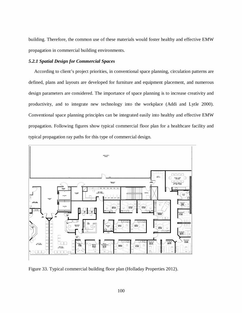
100
building. Therefore, the common use of these materials would foster healthy and effective EMW
propagation in commercial building environments.
5.2.1 Spatial Design for Commercial Spaces
According to client’s project priorities, in conventional space planning, circulation patterns are
defined, plans and layouts are developed for furniture and equipment placement, and numerous
design parameters are considered. The importance of space planning is to increase creativity and
productivity, and to integrate new technology into the workplace (Addi and Lytle 2000).
Conventional space planning principles can be integrated easily into healthy and effective EMW
propagation. Following figures show typical commercial floor plan for a healthcare facility and
typical propagation ray paths for this type of commercial design.
Figure 33. Typical commercial building floor plan (Holladay Properties 2012).
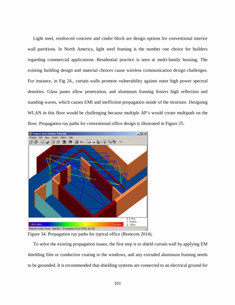
101
Light steel, reinforced concrete and cinder block are design options for conventional interior
wall partitions. In North America, light steel framing is the number one choice for builders
regarding commercial applications. Residential practice is seen at multi-family housing. The
existing building design and material choices cause wireless communication design challenges.
For instance, in Fig 24., curtain walls promote vulnerability against outer high power spectral
densities. Glass panes allow penetration, and aluminum framing fosters high reflection and
standing waves, which causes EMI and inefficient propagation inside of the structure. Designing
WLAN in this floor would be challenging because multiple AP’s would create multipath on the
floor. Propagation ray paths for conventional office design is illustrated in Figure 25.
Figure 34. Propagation ray paths for typical office (Remcom 2014).
To solve the existing propagation issues, the first step is to shield curtain wall by applying EM
shielding film or conductive coating to the windows, and any extruded aluminum framing needs
to be grounded. It is recommended that shielding systems are connected to an electrical ground for

102
personal safety and to prevent the generation of low frequency electromagnetic fields through field
coupling with the building’s electrical wiring system. According to Radiansa (2017), shielding
does not require an electrical ground to function as a shield against high-frequency electromagnetic
radiation. Ground connections are easily made using a ground connection kit, generally consisting
of a steel plate which screws into the shielding wall with a conductive fleece on the rear side to
ensure a good connection to the paint, or mesh surface (Radiansa 2017). Moreover, during curtain
wall insulation, absorbers needs to be placed behind insulation batts, foam or rigid foam. Façade
shielding allows controlling interior propagation; therefore, interior partition walls needs to be
built using wood, glass, and paper-based products that would minimize the reflection and
interference. If the steel framing is chosen, the frame needs to be grounded and absorbers need to
be applied to minimize the reflection. Conductive aluminum or copper foil shielding tapes can be
used to provide effective seaming (3M 2017). There is growing demand around the world to lower
power density levels in commercial buildings. For instance, elevated ELF magnetic fields were
presented in a sizeable portion of the ground level floor of a commercial building in mid-town
Manhattan. The project was executed by FMS (Field Management Services). Before the shielding,
the peak level was 21,500 nT and an average of 4,000 nT was present throughout the mail room.
FMS developed a plan to prevent extreme computer monitor interference in the space. Their goal
was to reach 1,000 nT magnetic power density in the room. After the shielding, the average value
was reduced from 4,000 nT to 500 nT. Therefore, EMI concern was eliminated by the shielding
approach (FMS 2017b). Another example can be Letterman Digital Arts Center, a division of
Lucas Films Limited, which is located at the Presidio of San Francisco. The 79,000 m² (square
meter) campus-like setting has several complex houses, which contain advanced computer, digital
motion picture, television, audio and wireless network facilities. The concern was EMI emissions

103
from electrical and other sources internal and external to the site that might present serious
interference threats to sensitive equipment. An extensive broadband (DC through 8 GHZ) survey
was conducted by FMS at the site to identify potential EMI threat sources external to the site (FMS
2017b). After the survey, multiple areas in several of the buildings electrical substations and high
current distribution equipment were to be located beneath occupied areas containing sensitive
equipment, including an extensive Computer Center. Therefore, the shielding project was executed
to lower EMF levels to acceptable levels (average 500 nT).
Therefore, these shielding projects would lead to improve data security and health concerns.
Commercial spaces require effective wireless communication and it is a need for the occupants. If
there are high flux densities in the environment, in this case, EMW shielding is suggested. The
balance approach such as next generation of antennas, better encryption methods, and shielding
needs to be incorporated to solve these issues in commercial spaces.
EMW Propagation in Educational Spaces
Educational and commercial structures have high occupancy that creates complex EMW
propagation inside these buildings. Currently, each university student has a laptop and a
smartphone which have become an inseparable part of student life. Thousands of students in such
environments foster complex EMW propagation. Additionally, transformer vaults in buildings and
wireless networking systems in campus environments create complex and problematic power
spectral densities in some cases. In fact, typical campus wireless networking is much more than a
mesh. The infrastructure provides to support indoor and outdoor Wi-Fi, inter-building
connectivity, LAN extension, video surveillance, access control and so on. The following figure
illustrates the infrastructure, and the complexity of creating effective and safe propagation in a
campus environment.

104
Figure 35. Typical Wireless Networking on campus environment (Coffman 2011)
The nature of this type of wireless network design creates potential security breaches. Outdoor
access points are integrated with Wi-Fi hotspots, surveillance cameras, and critical servers. The
sensitive data can be easily accessed by an attacker. Currently, universities all over the world lose
sensitive data and money because of campus hacking activities. As mentioned on Section 1.3.4,
wireless hacking is easier than many people think, and the attacker can easily reach a target using
this type of intrusion.
5.3.1 Spatial Design for Educational Spaces
Commercial and educational spaces have similar characteristics in terms of construction
methods and building material selection. Currently, wireless networking infrastructure of campus
environments fosters highly complex EMW propagation. External transmitters for Wi-Fi hotspots
and other sources would create high power spectral densities in campus buildings. Besides,
wireless communication systems, High ELF flux densities are also a concern in educational spaces.

105
For instance, high magnetic field levels sufficient to cause excessive monitor distortion and
concern about potential health effect caused a high school in the Midwest of the USA to abandon
use of a large classroom and attached offices located above the school’s transformer vault and
switch panels. Exposed copper bus bars mounted to the ceiling of the transformer vault (beneath
the classroom) were identified as the main source of magnetic fields. According to site survey,
peak fields of 11,200 nT and an average of 2,600 nT were present throughout the classroom and
offices. After the project shielding installation, peak conditions were reduced to less than 1,000 nT
and the average throughout the classroom and offices was below 500 nT (FMS 2017a). These
issues are common on educational buildings. To resolve high power density problem, power
spectral densities of each classroom, laboratory, and office need to be analyzed, and EMW
mitigation methods (Section 4.1) need to be implemented. Regarding data security in these
buildings, shielding would reduce the possibility of hacking. These include building envelope
shielding, non-reflective interior partitions, furniture upholstery, shielded electrical wiring with
demand switches. The results can be significant for educational spaces, these solutions could be
expanded to educational buildings worldwide.
EMW Propagation in Military and Government Spaces
Military and government buildings require a high level of security in terms of wireless
communication. For instance, US government uses MIL-STD-285, NSA 65-6, and NSA 73-2A
building performance standards to test of shielding enclosures (Hemming 1992b). Any mistake in
building design and execution can lead to the potential loss of lives, such as one the battle field.
Reinforced concrete is the main choice in this type of building design because of its resistance
against attacks and eavesdropping. However, reinforced concrete as a material is not the only
106
solution to create safe EMW propagation in such buildings. EMW shielding principles (Section
4.1.1) for residential buildings can also be used for military infrastructure.
5.4.1 Spatial Design for Military and Government Spaces
In addition to bunkers and fortified buildings, military and government buildings follow
commercial spatial design principles. The purpose of these standards is to stay current with trends
and best practices in space management, and provide functional work environments for
government employees (“Office Space Standards and Guidelines” 2003). Creating healthy and
effective EMW propagation can be associated with tenant improvements including partitions,
screens, finishes, signs and modifications to telephone, lighting, electrical, heating and ventilation
as necessary to service the office layout. Incorporation of commercial shielding techniques can be
used for military and government spaces per required security measures. Therefore, the shielding
level can be justified.

107
Chapter Six: Discussion
Current wireless communication systems include cellular telephone systems, cordless phones,
wireless LANs, wide-area wireless data services, fixed wireless access, paging systems, satellite
networks, Bluetooth, HomeRF and remote sensor networks (Agarwal 2015). The performance of
these systems relies on EMW propagation, which underlines the relationship between
electromagnetic wave and frequency. Engineers are looking for other capabilities to improve
previous wireless generations, such as 3G and 4G. The demand for new capabilities include very
high data transfer rates, high reliability, energy efficiency, and the combination of new radio-
access technologies. This demand would require higher frequency bands, device-to-device
communication, flexible spectrum usage, multi-antenna transmission, and so on. Higher traffic
growth of electronic devices requires higher bandwidth connectivity. Thus, 5G could provide
solutions to accelerate the development of the Internet of Things. 5G networking will be able to
connect bands below 6 GHz and bands within the range of 6 GHz to 100 GHz (“5G Radio Access”
2016). However, effective EMW penetration throughout building materials is reduced. It is
anticipated that mobile phone companies need to push the power spectral density thresholds to
provide better coverage in existing buildings.
The diversity of electronic circuits, which can be used for communication, automation,
computation and other purposes, promotes complex EMW propagation environments. Moreover,
the developments of circuit technology and the size of the electronic equipment would allow for
increased device density and create a challenge to maintain EMC.
The effects of EMW propagation can be seen in metallic surfaces such as aluminum facade,
curtain walls, window frames, and furniture in building environments. Due to material properties,
108
EMW behavior could be a reflection, diffraction, scattering, and dispersion, which cause distortion
in transferred data.
Regarding wireless communication in building environments, there is no ideal conventional
building material. Each construction material has different transmission and reflection coefficient.
Conventional building materials are considered for structural integrity, building envelope,
aesthetics, and functionality. Creating a new generation of building materials might supplement
engineering studies to achieve healthy, reliable and usable wireless communication systems in the
building environment. For instance, Aerogel products have different application fields such as:
electronics (insulator, sensor material, impedance adjustment, low Ɛ material, Çerenkov detectors,
pigment carrier), kinetic energy absorbers (tank buffers, star dust impact, shock absorption),
chemistry (absorbents, catalyst support, extracting agents, nano vessels), thermal insulation
(cryogenic, ambient conditions, high temperature, translucent), acoustic insulation
(building/construction, transportation, machinery), filler applications (paints, varnishes, films,
elastomers), pharmacy/agriculture-carrier material applications (active substances, fungicides,
herbicides, pesticides) (Schmidt and Schwertfeger 1998) and the different form of aerogels such
as: Graphene oxide/cellulose aerogel nanocomposite shows a good EMI shielding performance
(Wan and Li 2016). Thus, aerogel can be used as a hybrid thermal insulation and EM shielding
product.
To improve data confidentiality and data integrity for wireless devices, a physical layer of
security (OSI layer one), such as EMW shielding, needs to be applied. It would reduce the
possibility of wireless attacks. A physical shielding barrier would reduce the leakage and would
keep the propagation in control inside of the structure. Cyber attacks are very real, hence
109
implementing shielding and design options in building environments would promote data
confidentiality and data integrity.
Information and communications technology (ICT) systems are the catalyst of today’s
innovative and knowledge-based society. The growth of these technologies demand high energy
consumption (Fettweis and Zimmermann 2008). According to Gartner’s research in 2007, ICT
technologies are responsible for the 2 percent of global CO₂ emissions (Stamford 2007). The
solution relies on advanced microelectronics circuits, which consume less energy.
A rapidly expanding source of EMW is mobile phone base stations. Developing and executing
new building codes that incorporate healthy building environments for occupants is a meaningful
goal. Alternatively, next generation antennas may be developed to improve directivity. Moreover,
specifying a minimum required distance between inhabited structures, antennas, and their
mountings is critical to protecting public health.
Designing healthy and propagation friendly buildings requires a conceptual form. This form
needs to be supported with right building materials and other components of a space, such as the
form of furniture, lighting fixtures, interior partitions, and so on. Using this strategy, design
professionals could decrease high power densities, in turn decreasing associated health risks, and
increasing effective EMW propagation. This will achieve the design principle of unity in
architecture.
EMW manipulation is necessary to prevent standing waves and high power spectral densities
in building environments. Provided new shielding construction and interior design methods, by
analyzing different types of architectural space and material configurations, would be beneficial
to solving problems such as EMI, EMC, electronic warfare, and long-term adverse health impact
on humans.
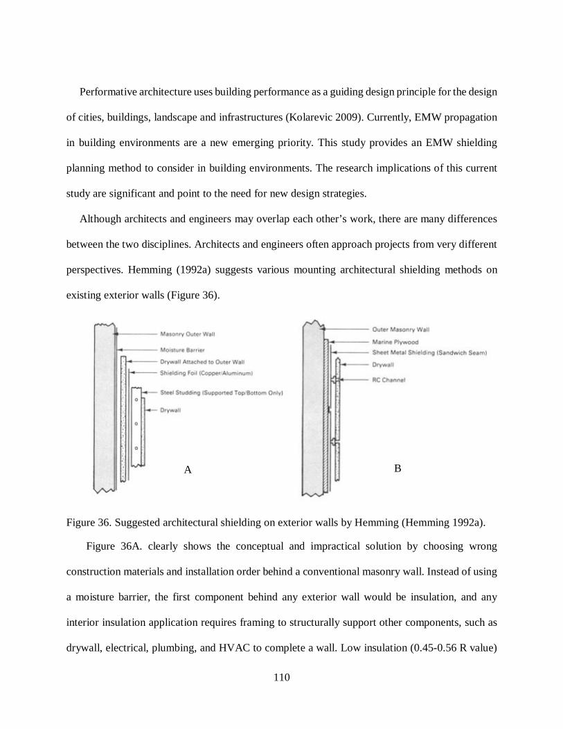
110
Performative architecture uses building performance as a guiding design principle for the design
of cities, buildings, landscape and infrastructures (Kolarevic 2009). Currently, EMW propagation
in building environments are a new emerging priority. This study provides an EMW shielding
planning method to consider in building environments. The research implications of this current
study are significant and point to the need for new design strategies.
Although architects and engineers may overlap each other’s work, there are many differences
between the two disciplines. Architects and engineers often approach projects from very different
perspectives. Hemming (1992a) suggests various mounting architectural shielding methods on
existing exterior walls (Figure 36).
Figure 36. Suggested architectural shielding on exterior walls by Hemming (Hemming 1992a).
Figure 36A. clearly shows the conceptual and impractical solution by choosing wrong
construction materials and installation order behind a conventional masonry wall. Instead of using
a moisture barrier, the first component behind any exterior wall would be insulation, and any
interior insulation application requires framing to structurally support other components, such as
drywall, electrical, plumbing, and HVAC to complete a wall. Low insulation (0.45-0.56 R value)
A B

111
(Randy L. Martin of R. L. Martin & Associates 2014) and moisture resistance properties of drywall
would not help to solve the issue. In this detail, another problem is how to secure drywall to the
masonry wall. To do this, pivot holes need to be drilled, and either mechanical bolts with washers
or wall plug-screw-washer combination need to be applied. Moreover, the suggestion would not
provide thermal and structural efficiency. The last problematic element is steel studding, which
creates unintended reflection and possible standing waves. The practical order behind the masonry
wall would begin with a one-inch air gap and then 2x4” wood framing would structurally support
the insulation, electrical and plumbing. Shielding foil (aluminum/copper) could be mounted to
wood framing. Therefore, the finishing element would be drywall cover on the framing.
In Figure 36B., there is no insulation. Plywood sheathing could not provide efficient insulation
and RC channeling is not necessary to use in this detail. Thus, the practical order would begin with
a one-inch air gap, 2x4” wood framing, insulation, sheet metal shielding, and drywall application.
Therefore, to avoid any impractical detail solutions in building design, EMW shielding
considerations concept needs to be utilized in architecture/interior design curriculum. This method
would also foster a better understanding of architectural practice and execution. When both
architect and engineer work together following this theses guidelines and workflow, future
structure built can be healthy and secure.
Technological innovation reshapes the future of construction industry. Emerging economies of
Asia, the Middle East, Latin America, Africa and India foster this growth. To take a full advantage
of this opportunity, construction companies have been looking for new methods to build cost-
effective and cheaper structures. One of the reasons of this motive is rapid urbanization. Thus,
traditional construction methods would be too slow to meet this demand. Moreover, governments

112
and communities require better use of resources of energy, warmer, safer, affordable, and healthier
buildings. Therefore, Hempcrete construction method looks promising in terms of non-
combustibility, pest resistance, dimensional stability, sustainability, and energy efficiency that can
lower construction and home ownership costs (JustBioFiber 2014). The design guidelines of this
study can be implemented to Hempcrete structures to support this need.
Conclusions
The power spectral density values found in the case study for a typical office, residential
indoor environments are below legal limits in Canada, however, high power density levels cause
potential negative health impact on all living things. For instance, in Ontario farms, livestock
exposed to uncontrolled electricity exhibited odd behavior, had lower productivity, stopped eating
or drinking, and in other cases even died (Royce 2015). There are some high-power flux density
cases around the world and further research needs to be done to address these cases in Canada.
The following research questions has been answered in previous Chapters.
1. Why do we need harmonious environments for electronic devices?
All electric devices can emit electromagnetic wave radiation and many environments have
high levels of electromagnetic radiation due to a concentration of transmitting devices. During
their operation, even if their function is not to radiate, these devices generate leakage of
electromagnetic radiation. Unwanted radiation from sources such as these can interfere with
the operation of many electrical equipment. Source, transmission path, and receiver are the
combination factors of an EMI problem.
An example of EMI affecting certain equipment occurs in hospitals. In a hospital
environment, potential EMI emitting sources might be walkie-talkies, cellular phones,

113
Bluetooth devices, wireless local area networking, medical telemetry, radiology equipment,
electrocautery equipment, fluorescent lights, fire alarms, computers, printers and radio
frequency identification devices.
The diversity of electronic circuits to use for communication, automation, computation, and
other purposes promotes complex EMW propagation environments. Therefore, these complex
environments may have an adverse impact on health and security.
2. How do building materials affect EMW propagation?
While propagating, EMW experience reflection, diffraction, scattering, and dispersion. Each
causes distortion in radio signals. For instance, reflection can be seen in metallic surfaces such
as aluminum facade, curtain walls, window frames, and furniture in building environments.
These surfaces act as an almost perfect reflector for electromagnetic waves. However, signal
strength can be reduced according to the thickness of the building material. For instance, the
signal from a cell phone mast often travels a variety of paths until it reaches its destination.
When these signals encounter an obstacle, scattering and diffraction occur; naturally, the signal
travels around the object. When a signal hits a surface, scattering occurs and remits in different
directions. All dielectric materials have some loss, which causes dispersion. Lossy dielectric
materials such as cement and pure water are good examples on which to observe dispersion
So, in buildings, reflection, diffraction, scattering, and dispersion are the common effects,
which are not seen in free spaces where EM waves do not interact with any material. On the
other hand, propagation intensity decreases through walls, roofs, and floors. In addition,
corners foster multipath propagation and diffraction. These EM propagation effects are almost
unavoidable in today’s modern structures because of the use of aluminum, steel columns, rebar
grids, metal pipes, HVAC systems, and so on.

114
3. Do we need new building materials for healthy and effective EMW propagation?
Regarding wireless communication in building environments, each conventional
construction material has its transmission and reflection coefficients and the other elements
such as furniture, electrical, plumbing, HVAC, other electronic equipment, and occupants have
an impact on EMW propagation in the space. Creating effective and healthy EMW propagation
in a built environment is a challenge and requires rigorous EMW simulations. This is because
conventional building materials are also considered for structural integrity, building envelope,
aesthetic, and functionality. This requires development of new building materials, and research
into how they can be used effectively. There are a variety of application potential of advanced
materials in architectural practice such as shielding paints, wall coverings, furniture, office
partition panels, wall dividers, flooring, ceiling, door and window material coatings and so on.
In addition, the new generation building envelopes can create RF radiation-controlled building
environments. The combination of an insulation material and RF shielding window film would
minimize the unintended RF radiation leakage into the building. The potential use of the new
insulation material might not just be for shielding, but also harvesting the energy from the
space around. In addition, this free source of electrical energy can be combined with solar
panels to maximize the energy efficiency in building environments.
4. What are the other options to improve data confidentiality and data integrity for Wireless
Networking?
An effective solution can be shielding spaces to prevent wireless attacks by maintaining data
confidentiality (prevent sensitive information from reaching the wrong people) and data
integrity (maintaining the consistency, accuracy, and trustworthiness of data) in our building
environments.

115
5. What are the current power intensity levels in building environments and how do these
levels impact human health? (Case study in residential and the different locations in
Calgary.)
According to general public long-term exposure limits in Canada (Health Canada 2015), The
United States, China, Russia and Switzerland (Table 3), measured average power density levels
for residential, office and class environments stay in the safe zone. However, there are some
cases, 200 V/m (Hanada, Takano, and Antoku 2002) and 100 V/m (Luca and Salceanu 2012)
in hospital environments around the world. These values are above the exposure limits in
Canada. Further research needs to be conducted to identify these spaces.
6. How can design options for buildings be developed considering the wireless
communication technologies currently available?
Designing healthy and propagation friendly buildings requires a conceptual form. This form
needs to be supported with right building materials and other components of a space, such as the
form of furniture, lighting fixtures, interior partitions, and so on.
7. How does spatial design (by architects) affect EMW propagation?
Creating healthy EMW propagation in residential spaces requires a minimum amount of
reflection. To do this, interior elements such as furniture, partition walls, stairs, flooring need to
build using low reflection, absorbent materials. According to the function of the space, flooring
could be constructed using hardwood, ceramic tile, and granite. For countertops, marble or granite
could be used to create serene and inviting interior environments. Moreover, to foster easy EMW

116
flow for wireless networking in residential spaces, wooden doors and furniture would be a good
choice.
In conventional space planning, circulation patterns are defined, plans and layouts are
developed for furniture and equipment placement, and numerous design parameters are
considered. The importance of space planning is to increase creativity and productivity, and to
integrate new technology into the workplace (Addi and Lytle 2000). Conventional space planning
principles can be integrated easily into healthy and effective EMW propagation. For instance,
shielding projects would lead to improve data security and health concerns. Commercial spaces
require effective wireless communication and it is a need for the occupants. If there are high flux
densities in the environment, in this case, EMW shielding is suggested. The balance approach such
as next generation of antennas, better encryption methods, and shielding needs to be incorporated
to solve these issues in commercial spaces.
Commercial and educational spaces have similar characteristics in terms of construction
methods and building material selection. Currently, wireless networking infrastructure of campus
environments fosters highly complex EMW propagation. External transmitters for Wi-Fi hotspots
and other sources would create high power spectral densities in campus buildings. Besides,
wireless communication systems, High ELF flux densities are also a concern in educational spaces.
To resolve high power density problem, power spectral densities of each classroom, laboratory,
and office need to be analyzed, and EMW mitigation methods (Section 4.1) need to be
implemented. Regarding data security in these buildings, shielding would reduce the possibility of
hacking. These include building envelope shielding, non-reflective interior partitions, furniture
upholstery, shielded electrical wiring with demand switches. The results can be significant for
educational spaces, these solutions could be expanded to educational buildings worldwide.

117
Moreover, incorporation of commercial shielding techniques can be used for military and
government spaces per required security measures. Therefore, the shielding level can be justified.
Future Research
Further research will ideally consider the development of new EMW propagation software
based on these design guidelines. Prior to executing construction, this software could provide an
easy design solution that incorporates healthy and effective wireless communication into the
building environment. There are a variety of EMW propagation software in the market. HFSS
(High-frequency structural simulator) is an example; however, this software does not provide built-
in options, such as built-in antennas and a real-life environment, which is critical for propagation
modeling. The user needs to create a full-model, which is time-consuming and complicated for
design professionals. HFSS’s focus is to the design antennas, complex RF electronic circuit
elements including filters, and transmission lines (“ANSYS HFSS” 2015). Another example is
Wireless InSite (“Wireless EM Propagation Software - Wireless InSite - Remcom” 2015), which
could solve urban scaled propagation problems. This feature provides an advantage to solve
propagation issues. However, the software has two drawbacks. The first, Wireless InSite has the
limited drawing capabilities. There is only a line drawing option on the interface, which creates a
hurdle to working with curvilinear geometry. It should be noted that only rectangular geometry
does not represent architectural forms as the software developer’s vision in architectural design.
The developer expects users to integrate import options from the other software such as AutoCAD
or Sketch up to solve this problem. Moreover, there is no limit in architecture regarding creativity
and problem solving. The second drawback is the cost of the software. The retail price is 25,000

118
US$ for the commercial and 35,000 US$ for the advanced version. Academic licensing is available
for researchers but 1000 US$ annual licensing option creates another financial hurdle.
Technology has an impact on how the buildings and infrastructures are designed, constructed
and used. Building Information Modelling (BIM) is an efficient tool to implement different
technologies into architectural design, engineering (electrical and mechanical) and construction.
BIM is based on a 3D modelling tool that provides more informed design decisions, builds more
efficiently and cost-effectively, and manages and maintains buildings with greater ease (“What Is
BIM | Building Information Modeling | Autodesk” 2016). However, Autodesk BIM tools for
building design, construction and civil infrastructure do not provide EMW propagation simulation
software. The software can be integrated into Autodesk BIM tools such as AutoCAD and Revit.
Detailed 3D modelling production problems of HFSS and Wireless InSite can be solved by the
Autodesk platform, and EMW propagation simulation software can be developed utilizing the
design guidelines and EMW shielding methods that are provided in this study. Autodesk cloud
rendering A360, which provides infinite computer power, can be used to create EMW propagation
simulations in 3D. It allows design professionals to visualize, analyze and develop healthy and
effective propagation in building environments. Another solution is to adopt V-Ray, which is a
professional rendering plug-in for 3D Modelling tools such as: Studio Max/Design, Maya, Render
Node, MODO, NUKE, KATANA, SketchUp, Rhino, Revit and Blender (“V-Ray for 3ds Max –
Top Rendering Plugin for Autodesk 3ds Max | Chaos Group” 2016). V-Ray uses global
illumination algorithms to render a 3D model. EMW propagation models can be used in V-Ray to
create realistic 3D EMW propagation renderings. These two solutions provide realistic 3D EMW
simulations and lower the cost of EMW propagation software. This platform also fosters the

119
exploration of new architectural forms, spatial design options, and building material choices for
different EMW propagation scenarios.
All building propagation simulations need to be verified by experimental data. To achieve this
goal, the first step would be to collect necessary data. The second step would be 1/1 scaled
experiments, which could allow developing details of different architectural forms. Working on
different building materials or building components, such as window frame, door, and insulation
materials, requires sophisticated equipment in a laboratory environment. Establishment of new
building science laboratories in higher education institutions will provide solutions but will also
lower associated health care costs and increased system security.
Electromagnetic propagation issues have been addressed by engineers in building environments
thus far. To improve wired and wireless local area networking (WLAN) efficiency, engineering
society uses troubleshooting tolls, such as OneTouch AT Network Assistant, which provides
copper, fiber and Wi-Fi troubleshooting, Wi-Fi and wired client devices connectivity testing,
network services testing, network application testing, local-intranet and internet performance,
cloud based results management, remote visibility, control and file access, wired network
discovery and analyses, Wi-Fi network discovery and analyses, end-to-end performance
measurement, VoIP analyses and package capture (Netscout 2016). The tool can address 2.4 GHz
and 5 GHz Wi-Fi electromagnetic interference (EMI) issues. These identified issues could be
solved by network engineers/technicians. Their solution is to try different channels to overcome
Wi-Fi performance problems or to increase power spectral densities. However, adding more
Access Points (APs) or trying different channels can not fundamentally solve higher power spectral
densities and data breach in building environments. Wireless efficiency and security can be

120
improved by EMW shielding. This one-time investment can lower the high cost of wireless
troubleshooting for corporates, government facilities, commercial and residential buildings.
Once, Nikola Tesla said: “There is a difference between progress and technology, progress
benefits mankind. Technology does not necessarily do that” (ancient-code.com 2016). Tesla
referred to the Industrial Revolution as technology. In that period, environment and human well-
being were not considered. Tesla imagined the world with wireless energy transmission. He
thought, that using electricity provided better sustainability than coal-powered steam engines.
Time proved him right; however, he had not anticipated the adverse impact of high power spectral
densities on all living things. In some cases, technology does not benefit mankind, thus, research
provides solutions in different areas, such as engineering, architecture, and medicine. The ultimate
goal is to disseminate this knowledge and to employ it when designing building projects.

121
Appendix A
NIST Experiment Description
Included in this Appendix are RF transmission system characteristics, antenna specifications,
test fixtures and transmission coefficients of tested materials.
A.1 RF transmission system characteristics
A modification of an ultra-wideband synthetic aperture radar was used to create the NSL
measurement system. Bistatic mode use of the radar allowed collecting one-way transmission data.
Separate transmit and receive antennas were used and directed each other at 2 m. In this research,
RF transmission system characteristics are based on frequencies (0.5-2.0 GHz and 2.0-8 GHz),
bandwidth (antenna limited), waveform (gated CW), pulse width (10 ns to 500 ns), PRF (50 kHz
to 5 MHz), polarization (fully polarimetric), output power (20 dBm), dynamic range (80 dBm),
noise floor (-100 dBm). Overall, the following figure shows the schematic of the spread spectrum
transmission system used for NIST research.

122
Fig A1. Schematic of the spread spectrum transmission system (Stone 1997).
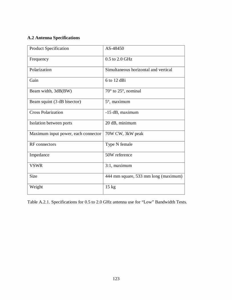
123
A.2 Antenna Specifications
Product Specification AS-48450
Frequency 0.5 to 2.0 GHz
Polarization Simultaneous horizontal and vertical
Gain 6 to 12 dBi
Beam width, 3dB(BW) 70° to 25°, nominal
Beam squint (3 dB bisector) 5°, maximum
Cross Polarization -15 dB, maximum
Isolation between ports 20 dB, minimum
Maximum input power, each connector 70W CW, 3kW peak
RF connectors Type N female
Impedance 50W reference
VSWR 3:1, maximum
Size 444 mm square, 533 mm long (maximum)
Weight 15 kg
Table A.2.1. Specifications for 0.5 to 2.0 GHz antenna use for “Low” Bandwidth Tests.

124
Model Specification FR-6415
Frequency (GHz) 3.0 to 8.0
Gain 1.7 dBi (nominal)
Beam width level 17 degrees’ nominal
Side lobe -30 dB nominal
VSWR 2:1 maximum
Isolation 60 dB minimum
Aperture width 261 mm
Overall length 627 mm
Weight 4.77 kg
Input SMA Female
Table A.2.2. Specifications for 3.0 to 8.0 GHz antenna use for “High” Bandwidth tests.
A.3 Test Fixtures
Fig A.3. Isometric view of a test stand used in NIST test.
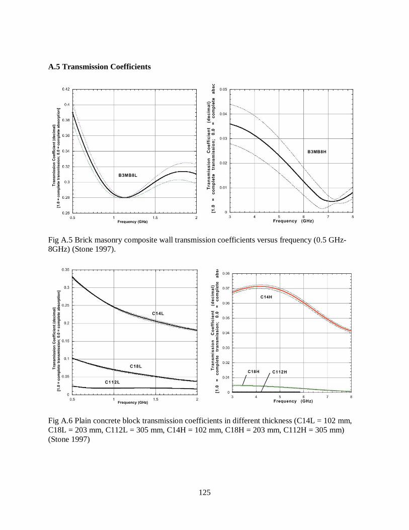
125
A.5 Transmission Coefficients
Fig A.5 Brick masonry composite wall transmission coefficients versus frequency (0.5 GHz- 8GHz) (Stone 1997).
Fig A.6 Plain concrete block transmission coefficients in different thickness (C14L = 102 mm, C18L = 203 mm, C112L = 305 mm, C14H = 102 mm, C18H = 203 mm, C112H = 305 mm) (Stone 1997)

126
Appendix B
Included in this Appendix is wireless attack hacking tools list and sample methods of wireless
network cracking.
Wireless Attacks:
1. Aircrack-ng, (“Aircrack-Ng” 2015).
2. Asleap, (“Asleap | Penetration Testing Tools” 2016).
3. Bluelog, (“DigiFAIL.com - Bluelog” 2016).
4. BlueMaho, (“BlueMaho | Penetration Testing Tools” 2016).
5. Bluepot, (“Bluepot | Penetration Testing Tools” 2016).
6. BlueRanger, (“BlueRanger | Penetration Testing Tools” 2016).
7. Bluesnarfer, (“Bluesnarfer | Penetration Testing Tools” 2016).
8. Bully, (“Bully | Penetration Testing Tools” 2016)
9. coWPAtty, (“coWPAtty | Penetration Testing Tools” 2016).
10. Crackle, (“Crackle | Penetration Testing Tools” 2016).
11. eapmd5pass, (“eapmd5pass | Penetration Testing Tools” 2016).
12. Fern Wi-Fi Cracker, (“Fern Wifi Cracker | Penetration Testing Tools” 2016).
13. Ghost Phisher, (“Ghost Phisher | Penetration Testing Tools” 2016).
14. GISKismet, (“GISKismet | Penetration Testing Tools” 2016).
15. Gqrx, (“Gqrx SDR – A Software Defined Radio Powered by GNU-Radio and Qt” 2016).
16. gr-scan, (“GNU Radio Signal Scanner” 2016).
17. kalibrate-rtl, (“Kalibrate-Rtl | Penetration Testing Tools” 2016).
18. KillerBee, (“Google Code Archive - Long-Term Storage for Google Code Project
Hosting.” 2016a).
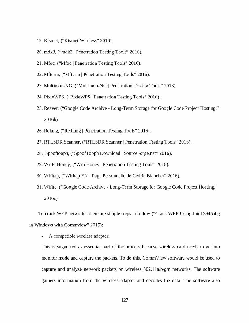
127
19. Kismet, (“Kismet Wireless” 2016).
20. mdk3, (“mdk3 | Penetration Testing Tools” 2016).
21. Mfoc, (“Mfoc | Penetration Testing Tools” 2016).
22. Mfterm, (“Mfterm | Penetration Testing Tools” 2016).
23. Multimon-NG, (“Multimon-NG | Penetration Testing Tools” 2016).
24. PixieWPS, (“PixieWPS | Penetration Testing Tools” 2016).
25. Reaver, (“Google Code Archive - Long-Term Storage for Google Code Project Hosting.”
2016b).
26. Refang, (“Redfang | Penetration Testing Tools” 2016).
27. RTLSDR Scanner, (“RTLSDR Scanner | Penetration Testing Tools” 2016).
28. Spooftooph, (“SpoofTooph Download | SourceForge.net” 2016).
29. Wi-Fi Honey, (“Wifi Honey | Penetration Testing Tools” 2016).
30. Wifitap, (“Wifitap EN - Page Personnelle de Cédric Blancher” 2016).
31. Wifite, (“Google Code Archive - Long-Term Storage for Google Code Project Hosting.”
2016c).
To crack WEP networks, there are simple steps to follow (“Crack WEP Using Intel 3945abg
in Windows with Commview” 2015):
• A compatible wireless adapter:
This is suggested as essential part of the process because wireless card needs to go into
monitor mode and capture the packets. To do this, CommView software would be used to
capture and analyze network packets on wireless 802.11a/b/g/n networks. The software
gathers information from the wireless adapter and decodes the data. The software also

128
provides the list of network connections. User-defined WEP or WPA keys would allow
decoding packets for a full analysis of the most widespread protocols. Captured packets can
be saved to log files for future analysis. This feature promotes the cracking of network
password. Overall, CommView is designed to picture WLAN traffic for administrators,
security professionals, and network programmers. However, anyone could use the software
for WLAN hijacking purposes (“CommView for WiFi Download” 2015). Another
alternative is Wireshark, which is a free open-source packet analyzer. It is compatible with
Linux, OS X, BSB, Solaris, other Unix-like operating systems and Windows (“Wireshark ·
Go Deep.” 2015). The software has the capability to capture wired or wireless networking
packets, which is needed to crack data for the next step.
• Aircrack-ng GUI:
Aircrack-ng GUI software cracks the network after capturing the packets by CommView
(“Aircrack-Ng” 2015) or Wireshark. Aircrack-ng GUI software has the capability to crack
both WEP and WPA encryptions. To start the process:
• Firstly, scan the wireless networks around and select the target network according to
encryption type.
• Secondly, capture the packets from desired channels; the minimum number is 100,000
for a strong signal.
The rest of the process is done by Aircrack-ng software, which provides the WLAN network
password (“Simple_wep_crack [Aircrack-Ng]” 2015). The solution to stop cracking of WEP
networks is the physical shielding of the required space because the signal quality is a significant
factor to be successful in Wi-Fi networking cracking process. In meantime, if the goal is to keep

129
Wi-Fi networking in the space, the type of shielding method would be provided by shielding
wallpaper and the other products, which is covered in Section 3.1.1.1
WPA Wi-Fi password cracking requires different tools such as Reaver or wpscrack software.
Depending on the program, the cracking process takes about 2 -10 hours. The defeating process of
WPS is done by intelligent brute force attack to the static WPS PIN. The requirement for the
process is to have Linux-OS, a router with WPS and the following programs such as aircrack-ng,
python-pycryptopp, python-scapy, and libpcap-dev (“Cracking_wpa [Aircrack-Ng]” 2015).
Therefore, it could be assumed that all wireless networking encryption protocols such as WEP,
WPA, and WPA 2 have security bridges and they could be breached. The security improvements
of these vulnerabilities would follow anti-action by the hacker community. Currently, the
immediate response to solve this problem is to create a physical barrier in building environments.
EMW shielding is currently considered the first layer of defense (OSI layer one).
Hacking android smartphones are even easier and are possible to do remotely. A Hacker can
get the complete access to text messages, videos, images, files. Moreover, victim’s cell phone
could be used for a variety of purposes such as a microphone, a camera, or to send SMS, and all
files could be downloaded by a hacker. To complete this process, all that is needed is an internet
connection and the victim’s phone number (“How to Hack an Android Smartphone Remotely! |
Hacks and Glitches Portal” 2015). Another general approach to hacking any cell phone is to send
a message that includes a picture of your choice. When the victim opens the picture, his or her
phone is infected. With this type of attack, hacker could see and send text messages, make calls,
see send calls, see received calls, listen to voicemails, record his own voice message, watch a live
feed through victim’s camera, take pictures, record video from the camera, view all files, and so
on (“Download” 2015).

130
REFERENCES
3M. 2017. “3MTM EMI Copper Foil Shielding Tape 1181 : Electrical OEM Materials: 3M US.” Electrical OEM Materials. http://solutions.3m.com/wps/portal/3M/en_US/ElectricalOEM/Home/Products/ProductCatalog/~/3M-EMI-Copper-Foil-Shielding-Tape-1181?N=5561499+3293719476&rt=rud.
“44CON.” 2015. Accessed October 18. http://44con.com/. “5G Radio Access.” 2016. 284 23-3204. White Paper. Rev C.
http://www.ericsson.com/res/docs/whitepapers/wp-5g.pdf. “A House With No Nails: Building a Timber-Frame Home.” 2016. Accessed May 14.
http://www.popularmechanics.com/home/outdoor-projects/how-to/a1506/4213580/. “Absorbers | MVG.” 2015. Accessed September 12. http://www.mvg-
world.com/products/field_product_family/absorber-6. “Acoustimeter - EMFields Measuring Equipment.” 2014. Accessed July 29.
http://www.emfields-solutions.com/detectors/acoustimeter.asp. Addi, Gretchen, and Jacqueline Lytle. 2000. “Space Planning.” In The Architect`s Handbook of
Proffesional Practice, 13th ed., 1–7. AIA. http://www.aia.org/aiaucmp/groups/aia/documents/pdf/aiab089276.pdf.
Agarwal, Tarun. 2015. “Types of Wireless Communication and Its Applications.” El-Pro-Cus. https://www.elprocus.com/types-of-wireless-communication-applications/.
“Aircrack-Ng.” 2015. Accessed October 8. http://www.aircrack-ng.org/. Altpeter, Ekkehardt-Siegfried, Martin Röösli, Markus Battaglia, Dominik Pfluger, Christoph E
Minder, and Theodor Abelin. 2006. “Effect of Short-Wave (6-22 MHz) Magnetic Fields on Sleep Quality and Melatonin Cycle in Humans: The Schwarzenburg Shut-down Study.” Bioelectromagnetics 27 (2): 142–50. doi:10.1002/bem.20183.
“Aluminium Foils-Aluminium Foils Manufacturers, Suppliers and Exporters on Alibaba.comAluminum Foil.” 2014. Accessed July 25. http://www.alibaba.com/trade/search?fsb=y&IndexArea=product_en&CatId=&SearchText=aluminium+foils&isPremium=y.
“Aluminum Mesh - Ferrier Wire Goods Company Limited.” 2015. Accessed October 15. http://www.ferrierwire.com/aluminum-mesh/aluminum-brass-and-copper-mesh/products.html.
ancient-code.com. 2016. “Nikola Tesla- The Secrets Behind The Genius.” Accessed June 29. http://www.ancient-code.com/nikola-tesla-secrets-behind-genius/.
“ANSYS HFSS.” 2015. Accessed September 13. http://www.ansys.com/Products/Simulation+Technology/Electronics/Signal+Integrity/ANSYS+HFSS.
APA. 1992. “Design And Fabrication Of Glued Plywood-Lumber Beams. Supplement 2. July 1992.” The Engineered Wood Association. https://law.resource.org/pub/us/code/bsc.ca.gov/sibr/org.apawood.S812.pdf.
ARC National Office. 2008. REINFORCEMENT HANDBOOK YOUR GUIDE TO STEEL REINFORCEMENT. Fifth. Sunshine.
“Architecture Design Handbook: Fundamentals: Radio Frequency Shielding.” 2014. Accessed July 25. http://www.copper.org/applications/architecture/arch_dhb/technical-discussion/fundamentals/radio_shielding.html.

131
“Asleap | Penetration Testing Tools.” 2016. Accessed April 16. http://tools.kali.org/wireless-attacks/asleap.
Aswoyo, B., O. Makino, Y. Shimoshio, and M. Tokuda. 2003. “A Measurement Method for Reflection Coefficient of Anechoic Chamber Using Standing Wave Techniques.” In Asia-Pacific Conference on Circuits and Systems, 1:115–19. IEEE. doi:10.1109/APCCAS.2002.1114919.
Ayoub, Omran, Stefano Bregni, Najme Monajemi, Francesco Musumeci, and Massimo Tornatore. 2016. “Strategies for Effective Converged Control of LTE and Wi-Fi Networks.” In 2016 8th IEEE Latin-American Conference on Communications (LATINCOM), 1–6. IEEE. doi:10.1109/LATINCOM.2016.7811582.
Barr, E Scott. 1961. “THE INFRARED PIONEERS-I. SIR WILLIAM HERSCHEL.” Infrared Physics 1: 1–4. http://www.sciencedirect.com.ezproxy.lib.ucalgary.ca/science/article/pii/0020089161900379.
Beal, Vangie. 2017. “The 7 Layers of the OSI Model - Webopedia Study Guide.” Webopedia. http://www.webopedia.com/quick_ref/OSI_Layers.asp.
Bellardo, John, and Stefan Savage. 2003. “12th USENIX Security Symposium — Technical Paper.” In 802.11 Denial-of-Service Attacks: Real Vulnerabilities and Practical Solutions, 15–28. http://static.usenix.org/legacy/events/sec03/tech/full_papers/bellardo/bellardo_html/.
“Benchmark Tests | Measurement | Gigahertz Solutions.” 2015. Accessed September 27. https://www.gigahertz-solutions.de/en/cat/index/sCategory/201.
“Black Hat: Top 20 Hack-Attack Tools | Network World.” 2015. Accessed October 7. http://www.networkworld.com/article/2168329/malware-cybercrime/black-hat--top-20-hack-attack-tools.html.
“Black Hat Asia 2014.” 2015. Accessed October 18. https://www.blackhat.com/asia-14/. “BlueMaho | Penetration Testing Tools.” 2016. Accessed April 16. http://tools.kali.org/wireless-
attacks/bluemaho. “Bluepot | Penetration Testing Tools.” 2016. Accessed April 16. http://tools.kali.org/wireless-
attacks/bluepot. “BlueRanger | Penetration Testing Tools.” 2016. Accessed April 16.
http://tools.kali.org/wireless-attacks/blueranger. “Bluesnarfer | Penetration Testing Tools.” 2016. Accessed April 16.
http://tools.kali.org/wireless-attacks/bluesnarfer. Borisov, Nikita, Ian Goldberg, and David Wagner. 2001. “Intercepting Mobile Communications:
The Insecurity of 802.11.” Proceedings of the 7th Annual International Conference on Mobile Computing and Networking, 180–89. doi:10.1145/381677.381695.
“Brick Faced Concrete Walls, Inc. - Novi, Michigan.” 2016. Accessed February 16. http://www.brickfaced.com/.
Brikawood. 2017. “Brikawood - Wooden Brick That Can Be Assembled without Nails, Screws or Glue.” Brikawood International. http://www.brikawood-ecologie.fr/.
“British Standards Institution - BSI | IHS.” 2014. Accessed February 27. http://www.ihs.com/products/industry-standards/organizations/bsi/index.aspx.
“Building a Stucco Wall | QUIKRETE®.” 2016. Accessed June 4. https://www.quikrete.com/athome/video-building-a-stucco-wall.asp.
“Building Envelope Design Guide - Masonry Wall Systems | Whole Building Design Guide.”

132
2016. Accessed February 17. https://www.wbdg.org/design/env_wall_masonry.php. “Bully | Penetration Testing Tools.” 2016. Accessed April 16. http://tools.kali.org/wireless-
attacks/bully. Bursky, Dave. 2013. “RF Shielding: The Art and Science of Eliminating Interference.” Digi-Key.
https://www.digikey.ca/en/articles/techzone/2013/jan/rf-shielding-the-art-and-science-of-eliminating-interference.
Canada, Industry. 2010. “Radio Spectrum Inventory.” https://www.ic.gc.ca/eic/site/smt-gst.nsf/vwapj/inventory-e.pdf/$file/inventory-e.pdf.
Carcelle, Xavier, Tuan Dang, and Catherine Devic. 2006. “AD-HOC Networking.” In IFIP 19th World Computer Congress, TC-6, IFIP Interactive Conference on Ad-Hoc Networking, edited by Al Agha Kaldoun, 142–57. Santiago: Springer. http://medcontent.metapress.com/index/A65RM03P4874243N.pdf.
Chandra, A., A. Kumar, and P. Chandra. 1999. “Comparative Study of Path Losses from Propagation Measurements at 450 MHz, 900 MHz, 1.35 GHz and 1.89 GHz in the Corridors of a Multifloor Laboratory-Cum-Office Building.” Gateway to 21st Century Communications Village. VTC 1999-Fall. IEEE VTS 50th Vehicular Technology Conference (Cat. No.99CH36324) 4: 2272–76. doi:10.1109/VETECF.1999.797343.
Chang, Sun, Sun Kangning, Pang Laixue, and Liu Jian. 2016. “Preparation and Electromagnetic Properties of an Electromagnetic Wave Absorber.” Journal of Magnetics 21 (1): 61–64. http://komag.org/journal/home/sub.php?menu_no=1210&gubun=1&volume=&number=&startpage=&page=2&pid=1184&redir=%2Fjournal%2Fhome%2Fsub.php%3Fmenu_no%3D1210%26gubun%3D1%26volume%3D%26number%3D%26startpage%3D%26page%3D2.
Chong, CC, Fujio Watanabe, and Hiroshi Inamura. 2006. “Potential of UWB Technology for the next Generation Wireless Communications.” 2006 IEEE Ninth International Symposium on Spread Spectrum Techniques and Applications, 422–29. http://ieeexplore.ieee.org/xpls/abs_all.jsp?arnumber=4100596.
Chung, Seungmin, Joohee Yi, and Seung Woo Park. 2013. “Electromagnetic Interference of Wireless Local Area Network on Electrocardiogram Monitoring System : A Case Report.” Korean Circulaton Journal, 187–88. doi:10.4070/kcj.2013.43.3.187.
Cisco. 2017. “Cisco Visual Networking Index (VNI) Update Global Mobile Data Traffic Forecast.” C11-738429–00. VNI Mobile Forecast. VNI. San Jose. http://www.cisco.com/c/en/us/solutions/collateral/service-provider/visual-networking-index-vni/complete-white-paper-c11-481360.html.
Coffman, Ksenia. 2011. “Mesh Without Wires.” https://kseniacoffman.wordpress.com/category/wireless/wireless-lan/.
“CommView for WiFi Download.” 2015. Accessed October 8. http://www.tamos.com/download/main/ca.php.
Composites, Conductive. 2016. “Advanced Materials.” Heber City: CONDUCTIVE COMPOSITES. http://www.conductivecomposites.com/pdf/CC_AdvancedMat.pdf.
Cooklev, T. 2004. The IEEE Standard for WLAN : John Wiley & Sons, Inc. “Copper Foil-Copper Foil Manufacturers, Suppliers and Exporters on Alibaba.comCopper
Strips.” 2014. Accessed July 25. http://www.alibaba.com/trade/search?fsb=y&IndexArea=product_en&CatId=&SearchText=copper+foil&isPremium=y.
“Copper Sheets and Rolls.” 2015. Accessed October 15. http://basiccopper.com/copper-sheet--

133
rolls.html. “coWPAtty | Penetration Testing Tools.” 2016. Accessed April 16. http://tools.kali.org/wireless-
attacks/cowpatty. “Crack WEP Using Intel 3945abg in Windows with Commview.” 2015. Accessed October 8.
https://www.youtube.com/watch?t=10&v=knMUDo5a_Xw. “Cracking_wpa [Aircrack-Ng].” 2015. Accessed October 10. http://www.aircrack-
ng.org/doku.php?id=cracking_wpa. “Crackle | Penetration Testing Tools.” 2016. Accessed April 16. http://tools.kali.org/wireless-
attacks/crackle. Cynamon, J. 1996. “Industry Corner.” Simulation 66 (2): 91–92.
doi:10.1177/003754979606600204. “Data-Stealing Snoopy Drone Unveiled at Black Hat - BBC News.” 2015. Accessed October 18.
http://www.bbc.com/news/technology-26762198. de Vocht, Frank. 2010. “‘Dirty Electricity’: What, Where, and Should We Care?” Journal of
Exposure Science & Environmental Epidemiology 20 (5): 399–405. doi:10.1038/jes.2010.8. “Demand Switches - Green Evolution USA.” 2015. Accessed September 24.
https://sites.google.com/site/greenevolutionusa/help-is-on-the-way/demand-switches. Dibner, Bern. 1984. “History of Electrical Engineering.” IEEE Power Engineering Review PER-
4 (February): 15–16. doi:10.1109/MPER.1984.5525468. “DigiFAIL.com - Bluelog.” 2016. Accessed April 16.
http://www.digifail.com/software/bluelog.shtml. “Download.” 2015. Accessed October 11. http://howtohackacellphone.com/download/. “eapmd5pass | Penetration Testing Tools.” 2016. Accessed April 16.
http://tools.kali.org/wireless-attacks/eapmd5pass. Eccosorb. n.d. “Dielectric Materials Chart — Eccostock.” Technical Reports AFML-TR-72-39
and 74-250. Randolp. http://www.eccosorb.com/Collateral/Documents/English-US/dielectric-chart.pdf.
“Electromagnetic Interference (Emi) Filter and Process for Providing Electromagnetic Compatibility of an Electronic Device While in the Presence of an Electromagnetic Emitter Operating at the Same Frequency.” 2002. http://www.google.com.ezproxy.lib.ucalgary.ca/patents/US6424234.
“EMF Products + RF Products by Safe Living Technologies Inc.” 2014. Accessed May 8. http://www.slt.co/Products/.
Espiner, Tom. 2007. “Wi-Fi Hack Caused TK Maxx Security Breach | ZDNet.” ZDNet. http://www.zdnet.com/article/wi-fi-hack-caused-tk-maxx-security-breach/.
“ETSI - European Telecommunications Standards Institute.” 2014. Accessed February 27. http://www.etsi.org/.
“European Committee for Electrotechnical Standardization.” 2014. Accessed February 27. http://www.cenelec.eu/.
“European Committee for Standardization.” 2014. Accessed February 27. https://www.cen.eu/Pages/default.aspx.
EuropeanCommision. 1999. COST Action 231 : Digital Mobile Radio towards Future Generation Systems - Final Report. Edited by Eraldo Damosso. Final Repo. Brussels: European Commission.
Fairs, Marcus. 2009. “Architecture.” In Green Design, 202–3. Berkeley: North Atlantic Books.

134
“Fern Wifi Cracker | Penetration Testing Tools.” 2016. Accessed April 16. http://tools.kali.org/wireless-attacks/fern-wifi-cracker.
Fettweis, Gerhard, and E Zimmermann. 2008. “ICT Energy Consumption-Trends and Challenges.” International Symposium on Wireless Personal Multimedia Communications (WPMC), no. Wpmc 2008: 2006–9. doi:10.1.1.139.4150.
Fluhrer, Scott, Itsik Mantin, and Adi Shamir. 2001. “Weaknesses in the Key Scheduling Algorithm of RC4.” Selected Areas in Cryptography 2259: 1–24. doi:10.1007/3-540-45537-X_1.
FMS. 2017a. “High School : EMF Shielding Project : EMI Consultant : FMS-Corp.com.” FMS Project. http://fms-corp.com/projects/high-school/.
———. 2017b. “Office Building : EMF Shielding Project : Magnetic Field Shielding : EMF Survey : FMS-Corp.com.” FMS Experienece. http://fms-corp.com/projects/office-building/.
“Formation of Standing Waves.” 2014. Accessed August 27. http://www.physicsclassroom.com/class/waves/Lesson-4/Formation-of-Standing-Waves.
Foster, Kenneth R. 2001. “Exposure Limits for Radiofrequency Energy: Three Models.” In Criteria for EMF Standards Harmonization. Varna: WHO. http://www.who.int/peh-emf/meetings/day2Varna_Foster.pdf.
Frei, Armin. 1999. “Swiss Shield ® Naturell EMC I EMI TEST REPORT.” Swiss Shield EMC/ EMI Test Report. Zurich. http://www.swiss-shield.ch/NATURELL.54.0.html?&L=1.
Frercks, Jan, Heiko Weber, and Gerhard Wiesenfeldt. 2009. “Reception and Discovery: The Nature of Johann Wilhelm Ritter’s Invisible Rays.” Studies in History and Philosophy of Science Part A 40 (2). Elsevier Ltd: 143–56. doi:10.1016/j.shpsa.2009.03.014.
Gan Quan, and Gun Li. 2016. “A High Performance Beam Forming Method Based on the Secondary Combination Array.” In 2016 IEEE Advanced Information Management, Communicates, Electronic and Automation Control Conference (IMCEC), 1058–61. IEEE. doi:10.1109/IMCEC.2016.7867373.
Ghosh, A, and DR Wolter. 2005. “Broadband Wireless Access with WiMax/802.16: Current Performance Benchmarks and Future Potential.” IEEE Communications Magazine, no. February: 129–36. http://ieeexplore.ieee.org/xpls/abs_all.jsp?arnumber=1391513.
“Ghost Phisher | Penetration Testing Tools.” 2016. Accessed April 6. http://tools.kali.org/information-gathering/ghost-phisher.
Gigahertz Solutions. 2017. “Measure EMR EMF RF | Gigahertz Solutions.” https://www.gigahertz-solutions.de/en/rf-and-emf-meters/.
“GISKismet | Penetration Testing Tools.” 2016. Accessed April 16. http://tools.kali.org/wireless-attacks/giskismet.
“GNU Radio Signal Scanner.” 2016. Accessed April 16. http://www.techmeology.co.uk/gr-scan/.
Golden, August, Jr. 1987. Introduction to Electronic Warfare. Radar Electronic Warfare. American Institute of Aeronautics and Astronautics.
Goldsmith, Andrea. 2004. Wireless Communications. Cambridge: Cambridge University Press. doi:10.1017/CBO9780511841224.
“Google Code Archive - Long-Term Storage for Google Code Project Hosting.” 2016a. Accessed April 16. https://code.google.com/archive/p/killerbee/.
———. 2016b. Accessed April 16. https://code.google.com/archive/p/reaver-wps/. ———. 2016c. Accessed April 16. https://code.google.com/archive/p/wifite/.
135
Government of Canada. 2018a. “Canadian Table of Frequency Allocations - Spectrum Management and Telecommunications.” Spectrum Management and Telecommunications. Accessed January 4. http://www.ic.gc.ca/eic/site/smt-gst.nsf/eng/h_sf01678.html.
———. 2017b. “Home - Spectrum Management and Telecommunications.” Accessed May 1. http://www.ic.gc.ca/eic/site/smt-gst.nsf/eng/home?OpenDocument.
“Gqrx SDR – A Software Defined Radio Powered by GNU-Radio and Qt.” 2016. Accessed April 16. http://gqrx.dk/.
Guo, Wenqi, William M. Healy, and Mengchu Zhou. 2012. “Impacts of 2.4-GHz ISM Band Interference on IEEE 802.15.4 Wireless Sensor Network Reliability in Buildings.” IEEE Transactions on Instrumentation and Measurement 61 (9): 2533–44. doi:10.1109/TIM.2012.2188349.
Hakgudener, Serhan. 2007. “FUTURE OF WLAN AND THE INFLUENCES TO THE ARCHITECTURAL FORMS AND DESIGN.” Yeditepe University. https://tez.yok.gov.tr/UlusalTezMerkezi/TezGoster?key=7d53ed97e31a8bd3aa6864b0e7704416eae44e48141d7a55b82c08696ffae08b44f75cea77711c76.
———. 2015. “Spatial Design for Healthy and Effective Electromagnetic Wave Propagation.” Procedia Engineering 118. Elsevier B.V.: 109–19. doi:10.1016/j.proeng.2015.08.409.
Hamill Creek Timber Homes. 2017. “Timber Frame Homes Prices | Timber Frame Cost | Hamill Creek.” https://www.hamillcreek.com/process/timber-frame-cost/.
Hanada, Eisuke, Kyoko Takano, and Yasuaki Antoku. 2002. “A Practical Procedure to Prevent Electromagnetic Interference with Electronic Medical Equipment.” Journal of Medical … 26 (1): 61–65. http://link.springer.com/article/10.1023/A:1013094904976.
Hartig, KW, SL Larson, and PJ Lingle. 1996. Dual silver layer Low-E glass coating system and insulating glass units made therefrom. US Patent 5,557,462, issued 1996. http://www.google.com/patents?hl=en&lr=&vid=USPAT5557462&id=mzAfAAAAEBAJ&oi=fnd&dq=Dual+silver+layer+low-e+glass+coating+system+and+insulating+glass+units+made+therefrom&printsec=abstract%5Cnhttp://www.google.com/patents?hl=en&lr=&vid=USPAT5557462&id=mzAf.
Havas, Magda. 2006. “Electromagnetic Hypersensitivity: Biological Effects of Dirty Electricity with Emphasis on Diabetes and Multiple Sclerosis.” Electromagnetic Biology and Medicine 25 (4): 259–68. doi:10.1080/15368370601044192.
He, Yanfei, and Rongzhou Gong. 2009. “Preparation and Microwave Absorption Properties of Foam-Based Honeycomb Sandwich Structures.” Europhysics Letters 58003 (5): 1–6. doi:10.1209/0295-5075/85/58003.
Health Canada. 2015. “Limits of Human Exposure to Radiofrequency Electromagnetic Energy in the Frequency Range from 3 kHz to 300 GHz” 6. doi:10.1109/EMBC.2012.6347343.
Hemming, Leland H. 1992a. “Architectural Shielding.” In Architectural Electromagnetic Shielding Handbook, edited by Leonard Shaw and William C. Guyker, 1sted., 75–97. New York: IEEE Press.
———. 1992b. “Introduction.” In Architectural Electromagnetic Shielding Handbook, edited by Leonard Shaw and William C. Guyker, 1sted., 1–5. New York: IEEE Press.
Hens, Hugo S. L. C. 2008. “Performance Based Building Design 2.” In Performance Based Building Design 2, 19–24. Wiley. http://site.ebrary.com/id/10657681?ppg=19.
Hoar, Chris. 1999. “An Overview of Advanced Glazing Technologies.pdf.” Coventry: Saint-Gobain Solaglas. http://www.bath.ac.uk/cwct/cladding_org/gib99/paper23.pdf.
136
Holladay Properties. 2012. “St. Margaret Mercy Medical Pavilion South Dyer, Indiana.” Medical Pavilion South. http://www.dyermob.com/floorplans.htm.
“Home - pureLiFi.” 2018. Accessed January 4. https://purelifi.com/. “Home | FCC.gov.” 2014. Accessed February 27. http://www.fcc.gov/. “How Aluminum Foil Is Made - Material, Manufacture, Making, Used, Processing, Dimensions,
Aluminium, Procedure.” 2015. Accessed October 13. http://www.madehow.com/Volume-1/Aluminum-Foil.html.
“How Did We End up with Drywall? : TreeHugger.” 2016. Accessed March 28. http://www.treehugger.com/green-architecture/how-did-we-end-drywall.html.
“How to Hack an Android Smartphone Remotely! | Hacks and Glitches Portal.” 2015. Accessed October 11. http://hackolo.com/how-to-hack-an-android-smartphone-remotely/.
“How Window Films Works.” 2015. Accessed October 15. http://www.solargard.com/window-films/resources/how-window-films-works.
Hussein, M., and A. Sebak. 1996. “EMI Sources and Modeling Techniques.” In 1996 Symposium on Antenna Technology and Applied Electromagnetics, 285–89. IEEE.
Hutter, H-P, H Moshammer, P Wallner, and M Kundi. 2006. “Subjective Symptoms, Sleeping Problems, and Cognitive Performance in Subjects Living near Mobile Phone Base Stations.” Occupational and Environmental Medicine 63 (5): 307–13. doi:10.1136/oem.2005.020784.
“IEC - International Electrotechnical Commission.” 2014. Accessed February 27. http://www.iec.ch/.
IEEE Standards Coordinating Committee 28. 1999. “IEEE C95. 1-1992: IEEE Standard for Safety Levels with Respect to Human Exposure to Radio Frequency Electromagnetic Fields, 3 kHz to 300 GHz, The.” In IEEE Standard for Safety Levels with Respect to Human Exposure to Radio Frequency Electromagnetic Fields, 3 kHz to 300 GHz, 1–83. New York: Institute of Electrical and Electronics Engineers, Inc. http://scholar.google.com/scholar?hl=en&btnG=Search&q=intitle:IEEE+Standard+for+Safety+Levels+with+Respect+to+Human+Exposure+to+Radio+Frequency+Electromagnetic+Fields+,+3+kHz+to+300+GHz#1.
ISO. 1996. “- Open Systems Interconnection in General.” Standards Catalogue. https://www.iso.org/ics/35.100.01/x/.
“Japan National Tourism Organization | Japan In-Depth | Scenic Beauty | World Heritage Sites in Japan.” 2016. Accessed May 14. http://www.jnto.go.jp/eng/indepth/scenic/worldheritage/c_6_horyu-ji.html.
“Japanese Craftsman Builds Amazing Wooden Structures Without Nail, Bolt, or Screw - The Vision TimesThe Vision Times.” 2016. Accessed May 14. http://www.visiontimes.com/2015/01/12/japanese-craftsman-builds-amazing-wooden-structures-without-nail-bolt-or-screw.html.
Jardosh, Amit P., Konstantina Papagiannaki, Elizabeth M. Belding, Kevin C. Almeroth, Gianluca Iannaccone, and Bapi Vinnakota. 2008. “Green WLANs: On-Demand WLAN Infrastructures.” Mobile Networks and Applications 14 (6): 798–814. doi:10.1007/s11036-008-0123-8.
JustBioFiber. 2014. “Just Bio Fiber | Sustainable Building System Featuring Carbon Capture.” JustBioFiber. http://justbiofiber.ca/.
“Kalibrate-Rtl | Penetration Testing Tools.” 2016. Accessed April 16.

137
http://tools.kali.org/wireless-attacks/kalibrate-rtl. Kato, Masamichi. 2006. Electromagnetics in Biology. Hicom: Springer. Kaur, Mandeep, Shikha Kakar, and Danvir Mandal. 2011. “Electromagnetic Interference.” 2011
3rd International Conference on Electronics Computer Technology, April. Ieee, 1–5. doi:10.1109/ICECTECH.2011.5941844.
Kessel, Wolfgang. 2017. “Shielding Examples.” Cuprotect. Accessed January 1. http://www.cuprotect.eu/7_shielding-projects.htm.
———. 2013. “A Comprehensive System in Protecting Large and Small Scale Electronic Infrastructure.” Irvine. http://www.cuprotect.eu/.
Khalid, M, T Mee, a Peyman, D Addison, C Calderon, M Maslanyj, and S Mann. 2011. “Exposure to Radio Frequency Electromagnetic Fields from Wireless Computer Networks: Duty Factors of Wi-Fi Devices Operating in Schools.” Progress in Biophysics and Molecular Biology 107 (3). Elsevier Ltd: 412–20. doi:10.1016/j.pbiomolbio.2011.08.004.
“Kismet Wireless.” 2016. Accessed April 16. http://www.kismetwireless.net/. Klaus, Georg. 2000. “Swiss Shield Evolution Test Report.” http://www.swiss-
shield.ch/EVOLUTION.67.0.html?&L=1. Kodali, W. 2001. “Introduction.” In Engineering Electromagnetic Compatibility:Principles,
Measurements, Technologies, and Computer Models, 1–24. Wiley-IEEE Press. Kolarevic, Branko. 2009. “Digital Morphogenesis.” In Architecture in the Digital Age: Design
and Manufacturing, edited by Branko Kolarevic. London: Taylor&Francis. Koppel, Tarmo, Andrei Shishkin, Heldur Haldre, Nikolajs Toropovs, Inese Vilcane, and Piia
Tint. 2017. “Reflection and Transmission Properties of Common Construction Materials at 2.4 GHz Frequency.” Energy Procedia 113: 158–65. doi:10.1016/j.egypro.2017.04.045.
Kosatsky, Tom, Abderrachid Zitouni, Mona Shum, Helen D. Ward, Richard P. Gallagher, Francine Anselmo, Randy Ross, et al. 2013. Radiofrequency Toolkit for Environmental Health Practitioners. Vancouver: British Columbia Centre for Disease Control (BCCDC) Environmental Health Services, National Collaborating Centre for Environmental Health (NCCEH). http://www.bccdc.ca/NR/rdonlyres/9AE4404B-67FF-411E-81B1-4DB75846BF2F/0/RadiofrequencyToolkit_v5_26032014.pdf.
Kucukozyigit, Ali Can. 2006. “Electronic Warfare (EW) Historical Perspectives and Its Relationship to Information Operations (IO)-Considerations for Turkey.” Naval Postgraduate School. www.handle.dtic.mil/100.2/ada457350.
Kuhn, Markus G. 2004. “Electromagnetic Eavesdropping Risks of Flat-Panel Displays.” 4th Workshop on Privacy Enhancing Technologies 3424 (May): 88–107. doi:10.1007/b136164.
Kumar, Anuj, and Gerhard P. Hancke. 2014. “An Energy-Efficient Smart Comfort Sensing System Based on the IEEE 1451 Standard for Green Buildings.” IEEE Sensors Journal 14 (12): 4245–52. doi:10.1109/JSEN.2014.2356651.
Kurner, Thomas, Radoslaw Piesiewicz, Martin Koch, and Joerg Schoebel. 2007. “Propagation Models, Measurements and Simulations for Wireless Communication Systems beyond 100 GHz.” In 2007 International Conference on Electromagnetics in Advanced Applications, 108–11. IEEE. doi:10.1109/ICEAA.2007.4387249.
Kwok, Y.; Lau, V. 2007. “SHORT-RANGE WIRELESS TECHNOLOGIES.” In SHORT-RANGE WIRELESS TECHNOLOGIES, 257–84. John Wiley & Sons, Inc. doi:10.1002/9780470167960.ch9.
LaMaire, Richard, Arvind Krishna, Pravin Bhagwat, and Panian James. 1996. “Wireless LANs

138
and Mobile Networking: Standards and Future Directions.” IEEE Communications Magazine, August. http://medcontent.metapress.com/index/A65RM03P4874243N.pdf.
Lapinsky, Stephen E, and Anthony C Easty. 2006. “Electromagnetic Interference in Critical Care.” Journal of Critical Care 21 (3): 267–70. doi:10.1016/j.jcrc.2006.03.010.
Larsson, Erik, Ove Edfors, Fredrik Tufvesson, and Thomas Marzetta. 2014. “Massive MIMO for next Generation Wireless Systems.” IEEE Communications Magazine 52 (2): 186–95. doi:10.1109/MCOM.2014.6736761.
Lawrence, J. Kelly, and Carl C. Landinger. 1999. “Shielding Power Cables.” In Electrical Power Cable Engineering, edited by William A. Thue, 101–6. New York: Marcel Dekker Inc.
Leech, Judith A., William C. Nelson, Richard T. Burnett, Shawn Aaron, and Mark E. Raizenne. 2002. “It’s about Time: A Comparison of Canadian and American Time-Activity Patterns.” Journal of Exposure Analysis and Environmental Epidemiology 12 (6): 427–32. doi:10.1038/sj.jea.7500244.
Li, Cunhua, and Jingjing Li. 2012. “On The Electromagnetic Reflectivity Properties of Selected Materials.” In Computing and Convergence Technology (ICCCT), 2012 7th International Conference on, 1215–21. Seoul.
Luca, Catalina, and Alexandru Salceanu. 2012. “Study upon Electromagnetic Interferences inside an Intensive Care Unit.” EPE 2012 - Proceedings of the 2012 International Conference and Exposition on Electrical and Power Engineering, no. Epe: 535–40. doi:10.1109/ICEPE.2012.6463878.
Malik, Jagannath, Amalendu Patnaik, and M V Kartikeyan. 2013. “Novel Compact MIMO Antenna for WLAN Application,” 3–4.
Margaret, E Sears. 2007. “The Medical Perspective on Environmental Sensitivities The Medical Perspective on Environmental Sensitivities.”
“Marine Grade Fir Plywood | Windsor Plywood.” 2016. Accessed May 29. http://www.windsorplywood.com/Marine_Grade_Fir_Plywood.aspx.
“Material Choices for Wood Frame Constrution | Green Home Guide | Ecohome.” 2016. Accessed April 3. http://www.ecohome.net/guide/material-choices-wood-frame-construction.
“mdk3 | Penetration Testing Tools.” 2016. Accessed April 16. http://tools.kali.org/wireless-attacks/mdk3.
Meng, Xian-feng, Dong-hong Li, Xiang-qian Shen, and Wei Liu. 2010. “Preparation and Magnetic Properties of Nano-Ni Coated Cenosphere Composites.” Applied Surface Science 256 (12): 3753–56. doi:10.1016/j.apsusc.2010.01.019.
Metzinger, Rob. 2014a. “RF Window Film: Signal Protect - Clear: Transparent Window Shielding.” Signal Protect- Clear Film. http://www.slt.co/Products/RFShieldingWindowFilm/RFWindowFilm-SignalProtect-Clear.aspx#ManualAnchor.
———. 2014b. “Signal Protect AM1 Aluminum Mesh.” Signal Protect AM1 Aluminum Mesh. http://www.slt.co/Products/RFShieldingMesh/SignalProtectAM1.aspx#DetailAnchor.
“Mfoc | Penetration Testing Tools.” 2016. Accessed April 16. http://tools.kali.org/wireless-attacks/mfoc.
“Mfterm | Penetration Testing Tools.” 2016. Accessed April 16. http://tools.kali.org/wireless-attacks/mfterm.
Migliaccio, Maurizio, Giuseppe Ferrara, Angelo Gifuni, Antonio Sorrentino, Francesco

139
Colangelo, Claudio Ferone, Raffaele Cioffi, Francesco Messina, and Dipartimento Ingegneria. 2013. “SHIELDING EFFECTIVENESS TESTS OF LOW-COST CIVIL ENGINEERING MATERIALS.” Progress In Electromagnetics Research B 54 (August): 227–43. http://www.jpier.org/PIERB/pierb54/12.13071703.pdf.
Mohabuth, Yasine. 2016. “Brikawood: An Ecological House Built with Wooden Bricks – INSPIR’ACTION.” Inspiraction News. http://www.inspiraction.news/en/2016/10/28/brikawood-an-ecological-house-built-with-wooden-bricks/.
Moldovan, Anamaria, Prasanth Karunakaran, Ian F. Akyildiz, and Wolfgang H. Gerstacker. 2017. “Coverage and Achievable Rate Analysis for Indoor Terahertz Wireless Networks.” Proceedings of IEEE International Conference on Communications (IEEE ICC’17).
“Multimon-NG | Penetration Testing Tools.” 2016. Accessed April 16. http://tools.kali.org/wireless-attacks/multimon-ng.
MyGeoPosition.com. 2017. “MyGeoPosition.com - Free Address Geocoding (Latitude, Longitude, Elevation) / Geo-Metatags / Geotags / Kml Files!” http://en.mygeoposition.com/.
“NATURELL: Swiss Shield.” 2015. Accessed October 15. http://www.swiss-shield.ch/NATURELL.54.0.html?&L=1.
Netscout. 2016. “OneTouchTM AT G2 Network Assistant - Network Troubleshooting Fiber, Copper and Wi-Fi | NETSCOUT.” OneTouch AT Network Assistant. http://enterprise.netscout.com/enterprise-network/network-testing/OneTouch-AT-Network-Assistant.
“NFAsoft | NFA-Series | Low Frequency | Measurement | Gigahertz Solutions.” 2015. Accessed October 3. https://www.gigahertz-solutions.de/en/measurement/low-frequency/nfa-series/334/nfasoft.
“Office Space Standards and Guidelines.” 2003. GNWT Office Space Standards and Guidelines. http://www.pws.gov.nt.ca/pdf/publications/officest.pdf.
Ohmori, Shingo, Yasushi Yamao, and Nobuo Nakajima. 2000. “The Future Generations of Mobile Communications Based on Broadband Access Technologies.” IEEE Communications Magazine, no. December: 134–42. http://ieeexplore.ieee.org/xpls/abs_all.jsp?arnumber=888267.
Osorio, Fernando C Colon. 2008. “State of Wireless Security Implementations in the United States and Europe - Empirical Data.” 2008 3rd International Conference on Malicious and Unwanted Software (MALWARE), 92–97. doi:10.1109/MALWARE.2008.4690863.
Ott, Henry W. 2009. Electromagnetic Compatibility Engineering. Hoboken: Wiley. http://s1.downloadmienphi.net/file/downloadfile5/192/1388769.pdf.
Pahlavad, Kaveh, Ali Zahedi, and Parashant Krishnamurthy. 1997. “Wideband Local Access: Wireless LAN and Wireless ATM.” IEEE Communications Magazine, no. November: 34–40. http://medcontent.metapress.com/index/A65RM03P4874243N.pdf.
Pauli, P. 2006. “Swiss Shield New Daylite EMC / EMI Test Report Shielding Effectiveness EMC-Textile.” Munich. http://www.swiss-shield.ch/NEW-DAYLITE.69.0.html?&L=1.
Peatross, Justin, and M Ware. 2014. Physics of Light and Optics. 2013thed. Bringham Young University. http://optics.byu.edu/PrevText/BYUOpticsContents.pdf.
Pilkington. 2017. “Data Stop.” Troy: Tempest Security Systems Inc. http://www.ramayes.com/RF_Shielded_Glass.htm.

140
Pirkkalainen, Herkko, Jarmo Elovaara, and Leena Korpinen. 2016. “Decreasing the Extremely Low-Frequency Electric Field Exposure with a Faraday Cage during Work Tasks from a Man Hoist at a 400 kV Substation.” Progress In Electromagnetics Research 48 (April): 55–66. http://www.jpier.org/PIERM/pierm48/06.16021501.pdf.
“PixieWPS | Penetration Testing Tools.” 2016. Accessed April 16. http://tools.kali.org/wireless-attacks/pixiewps.
“Plywood as a Building Material - Understand Building Construction.” 2016. Accessed April 3. http://www.understandconstruction.com/plywood.html.
Poulsen, Kevin. 2004. “Wardriving Guilty Plea in Lowe’s Wi-Fi Case.” SecurityFocus. http://www.securityfocus.com/news/9281.
Prigg, Mark. 2015. “NSA-Proof Wallpaper Could Keep Snoopers and Electromagnetic Weapons at Bay | Daily Mail Online.” Daily Mail. http://www.dailymail.co.uk/sciencetech/article-3286629/Forget-tin-foil-hat-NSA-proof-wallpaper-snoopers-doomsday-electromagnetic-weapons-bay.html.
“PVC Pipe vs. Cast Iron Pipe | Ask the Builder.” 2016. Accessed May 14. http://www.askthebuilder.com/pvc-pipe-vs-cast-iron-pipe/.
Radiansa. 2017. “Shielding Materials for High-Frequency Electromagnetic Radiation.” Architectural Shielding for Protection against High Frequency Electromagnetic Radiation. Accessed April 6. http://www.radiansa.com/electromagnetic/microwave-radiofrequency/hf-radiation-shielding.htm.
Ramayes. 2017. “Emi-Shield al5.” Franktown: RaMayes. http://www.ramayes.com/aluminum_foil_emi_rfi_shielding.htm.
Randy L. Martin of R. L. Martin & Associates, Inc. 2014. “R-Value Table.” ColoradoEnergy.org. http://coloradoenergy.org/procorner/stuff/r-values.htm.
Rangan, BV. 2008. “Fly Ash-Based Geopolymer Concrete.” In Your Building Administrator, 2010:68–106. Mumbai. http://www.researchgate.net/publication/230717147_Fly_Ash-Based_Geopolymer_Concrete/file/d912f5035b0abd9fc7.pdf.
Rbaugh, W Illiam a a, N Arendar S Hankar, Y C J Ustin W An, K a N Z Hang, and H Ewlett Ackard L Aboratories. 2002. “W I R E L E S S Lan S Y Our 802 . 11 W Ireless N Etwork H As N O C Lothes U Niversity of M Aryland,” no. December: 44–51.
“Redfang | Penetration Testing Tools.” 2016. Accessed April 16. http://tools.kali.org/wireless-attacks/redfang.
Reed, George. 2003. “Shielding Effectiveness of Copper Wire Meshes to Plane Waves.” Berkeley. https://www.twpinc.com/wire-mesh-material/copper/rfi-shielding-mesh.
Reid, John S, Charles H-T Wang, and J Michael T Thompson. 2008. “James Clerk Maxwell 150 Years On.” Philosophical Transactions. Series A, Mathematical, Physical, and Engineering Sciences 366 (1871): 1651–59. doi:10.1098/rsta.2007.2196.
“Reinforced Concrete Introduction.” 2016. Accessed April 3. http://www.world-housing.net/major-construction-types/reinforced-concrete-introduction.
Remcom. 2014. “Wireless Insite User`s Guide.” REMCOM, Inc. www.remcom.com. Rodriguez, Luis, and Roesllo Mario Campolargo. 2011. The Future Internet Assembly 2011:
Achievements and Technological Promises. Edited by John Domingue, Alex Galis, Anastasius Gavras, Theodore Zahariadis, Dave Lambert, and Frances Cleary. Future Internet. Heidelberg, Dordrecht, London, New York: Springer. doi:10.1007/978-3-642-20898-0.

141
Rouse, Margaret, Matthew Haughn, and Stan Gibilisco. 2014. “What Is Confidentiality, Integrity, and Availability (CIA Triad)? - Definition from WhatIs.com.” WhatIs.com. http://whatis.techtarget.com/definition/Confidentiality-integrity-and-availability-CIA.
Royce, Brent. 2015. “Building Better Plans to Deal with Uncontrolled Electricity.” Ontario Federation of Agriculture, December 10. http://www.ofa.on.ca/media/news/building-better-plans-to-deal-with-uncontrolled-electricity.
“RTLSDR Scanner | Penetration Testing Tools.” 2016. Accessed April 16. http://tools.kali.org/wireless-attacks/rtlsdr-scanner.
Saint-Gobain. 2017. “Gyproc Foil Back Plasterboard – Saint-Gobain Gyproc.” Accessed March 16. http://www.gyproc.in/gyproc-foil-back-plasterboard.
Schmidt, M, and F Schwertfeger. 1998. “Applications for Silica Aerogel Products.” Journal of Non-Crystalline Solids 225: 364–68. doi:10.1016/S0022-3093(98)00054-4.
Schmitt, Ron. 2015. “Schmitt, Ron. EDN Series for Design Engineers : Electromagnetics Explained : A Handbook for Wireless/ RF, EMC, and High-Speed Electronics. Burlington, MA, USA: Newnes, 2002. ProQuest Ebrary. Web. 10 September 2015. Copyright © 2002. Newnes. All Rights Res.” In Electromagnetics Explained : A Handbook for Wireless/ RF, EMC, and High-Speed Electronics, 286–87. Burlington: ProQuest ebrary.
“Self-Compacting Cement ‘Sikacrete’ - 25 Kg | RONA.” 2016. Accessed June 4. http://www.rona.ca/en/self-leveler-cement.
“SensePost | Snoopy: A Distributed Tracking and Profiling Framework.” 2015. Accessed October 18. https://www.sensepost.com/blog/2012/snoopy-a-distributed-tracking-and-profiling-framework/.
Sensor Tags Inc. 2016. “Retail Security Systems.” https://www.sensortags.com/. Shamir, By Adi. 2002. “An Introduction to Radio Waves Propagation : Generic Terms , Indoor
Propagation and Practical Approaches to Path Loss Calculations , Including Examples 1 Introduction 2 Free-Space Propagation,” 1–21. http://www.angelfire.com/planet/adi_shamir/Radio_Propagation_Rev_-_1_0.pdf.
Shaw, Cheryl I., Robert M. Kacmarek, Rickey L. Hampton, Vincent Riggi, Ashraf El Masry, Jeffrey B. Cooper, and William E. Hurford. 2004. “Cellular Phone Interference with the Operation of Mechanical Ventilators*.” Critical Care Medicine 32 (4): 928–31. doi:10.1097/01.CCM.0000120061.01431.DB.
Shibata, Tomoki, Kazumi Sakai, and Yasuo Okabe. 2011. “Power Routing Switches toward Energy-on-Demand Home Networking.” In 2011 IEEE Consumer Communications and Networking Conference, CCNC’2011, 844–45. doi:10.1109/CCNC.2011.5766623.
“Simple_wep_crack [Aircrack-Ng].” 2015. Accessed October 10. http://www.aircrack-ng.org/doku.php?id=simple_wep_crack.
Smardzewski, Jerzy. 2015. Furniture Design. Furniture Design. doi:10.1007/978-3-319-19533-9.
“Snoopy Drone Can Hack Your Smartphone When You’re on Street - Hacking News.” 2015. Accessed October 18. http://www.hackingnews.com/vulnerability/snoopy-drone-can-hack-smartphone/.
Solutions, Gigahertz. 2006. “Instruction Manual.” Langenzenn: Gigahertz Solutions GmbH. Sowa, Andrzej. 1991. “Lightning Overvoltages in Wires within the Buildings.” … Compatibility,
1991. Symposium Record., IEEE 1991 … 1: 99–102. http://ieeexplore.ieee.org/xpls/abs_all.jsp?arnumber=148192.

142
“SpoofTooph Download | SourceForge.net.” 2016. Accessed April 16. https://sourceforge.net/projects/spooftooph/.
Stamford, Conn. 2007. “Gartner Estimates ICT Industry Accounts for 2 Percent of Global CO2 Emissions.” Gartner. http://www.gartner.com/newsroom/id/503867.
“Standards Council of Canada - Conseil Canadien Des Normes.” 2014. Accessed February 27. http://www.scc.ca/.
Stankic, Slavica, Sneha Suman, Francia Haque, and Jasmina Vidic. 2016. “Pure and Multi Metal Oxide Nanoparticles: Synthesis, Antibacterial and Cytotoxic Properties.” Journal of Nanobiotechnology 14 (1). BioMed Central: 73. doi:10.1186/s12951-016-0225-6.
Stone, William C. 1997. “NISTIR 6055 NIST Construction Automation Program Report No . 3 Electromagnetic Signal Attenuation in Construction Materials.” Gaithersburg. http://fire.nist.gov/bfrlpubs/build97/PDF/b97123.pdf.
“Tech Times.” 2015. Accessed October 18. http://www.techtimes.com/articles/4676/20140324/attack-of-the-drones-snoopy-drone-can-steal-your-smartphone-data.htm.
“Technical Notes.” n.d. Clay Brick Associaton of Canada. http://www.claybrick.ca/site/clay_brick_assn__of_canada/assets/pdf/cbac_tech_notes_canada.pdf.
Tews, Erik, Ralph-Philipp Weinmann, and Andrei Pyshkin. 2007. “Breaking 104 Bit WEP in Less than 60 Seconds.” Proceedings of the 8th International Conference on Information Security Applications, 188–202. doi:10.1007/978-3-540-77535-5_14.
“The Basics of Working with Copper Pipe.” 2016. Accessed May 29. http://www.doityourself.com/stry/basicscopperpipe#b.
“Thin Brick Construction | Tilt Up Concrete Walls | Embeded Brick Construction.” 2016. Accessed February 16. http://www.mbrick.com/brickfaced.html.
Togt, Remko Van Der, and EJ van Lieshout. 2008. “Electromagnetic Interference from Radio Frequency Identification Inducing Potentially Hazardous Incidents in Critical Care Medical Equipment.” Jama 299 (24): 2884–90. http://archpedi.jamanetwork.com/article.aspx?articleid=182113.
Tong, Colin. 2015a. “Absorber Materials.” In Advanced Materials and Design for Electromagnetic Interference Shielding, 237–54. Boca Raton: ProQuest ebrary.
———. 2015b. “Electromagnetic Interference Shielding Fundamentals and Design Guide.” In Advanced Materials and Design for Electromagnetic Interference Shielding, 1–36. ProQuest ebrary.
Turner, Monica G., and Stephen R. Carpenter. 1999. “Tips and Traps in Interdisciplinary Research.” Ecosystems 2 (4): 275–76. doi:10.1007/PL00010895.
U.S Department of Energy. 2016. “Types of Insulation.” http://energy.gov/energysaver/types-insulation.
“Understanding Shielded Cable.” 2009. Alpha Wire. http://www.newark.com/pdfs/techarticles/alphaWire/Understanding_Shielded_Cable.pdf.
University of Calgary. 2016. “Interactive Room Finder.” University of Calgary. http://ucmapspro.ucalgary.ca/RoomFinder/#.
University of Michigan. 2017. “Surviving College | University of Michigan-Flint.” Surviving College. https://www.umflint.edu/advising/surviving_college.htm.
“V-Ray for 3ds Max – Top Rendering Plugin for Autodesk 3ds Max | Chaos Group.” 2016.

143
Chaos Group. https://www.chaosgroup.com/vray/3ds-max#new. Vagner, I. D. 2004. “Electromagnetic Waves.” In , 135:82–151. doi:10.1007/978-3-662-06941-
7_4. Vasudevan, Subramanian, Kathiravetpillai Sivanesan, Satish Kanugovi, and Jialin Zou. 2013.
“Enabling Data Offload and Proximity Services Using Device to Device Communication over Licensed Cellular Spectrum with Infrastructure Control.” IEEE Vehicular Technology Conference, no. Figure 1. doi:10.1109/VTCFall.2013.6692180.
Wan, Caichao, and Jian Li. 2016. “Graphene Oxide/cellulose Aerogels Nanocomposite: Preparation, Pyrolysis, and Application for Electromagnetic Interference Shielding.” Carbohydrate Polymers 150. Elsevier Ltd.: 172–79. doi:10.1016/j.carbpol.2016.05.051.
“Welcome to Pentair | Hoffman.” 2016. Accessed June 4. http://www.pentairprotect.com/hoffman.
“What Is BIM | Building Information Modeling | Autodesk.” 2016. Autodesk. http://www.autodesk.com/solutions/bim/overview.
“What Is Powerline – Simple to Set Up, Faster-than-Wi-Fi Home Network - Feature - PC Advisor.” 2016. Accessed May 26. http://www.pcadvisor.co.uk/feature/network-wifi/what-is-powerline-3491484/.
“Wifi Honey | Penetration Testing Tools.” 2016. Accessed April 16. http://tools.kali.org/wireless-attacks/wifi-honey.
“Wifitap EN - Page Personnelle de Cédric Blancher.” 2016. Accessed April 16. http://sid.rstack.org/static/articles/w/i/f/Wifitap_EN_9613.html.
“WiGLE: Wireless Network Mapping.” 2015. Accessed October 10. https://wigle.net/. Wilson, Andrew D. 2008. “The Unity of Physics and Poetry: H. C. Ørsted and the Aesthetics of
Force.” History of Ideas 69 (October): 627–46. http://www.ncbi.nlm.nih.gov/pubmed/4137539.
“Wireless EM Propagation Software - Wireless InSite - Remcom.” 2015. Accessed September 13. http://www.remcom.com/wireless-insite.
“Wireshark · Go Deep.” 2015. Accessed October 11. https://www.wireshark.org/. “Woodworking Joints Plans | Good Woodworking Projects.” 2016. Accessed May 29.
http://goddessarianna.com/woodworking-joints-plans/.