AK-285T Shielding Effectiveness Antenna Kit Operation Manual

Cent. Eur. J. Eng. • 1-13Author version
Central European Journal of Engineering
Monte Carlo simulations for optimization of neutron
shielding concrete
Research Article
Tomasz Piotrowski1∗, Dariusz B. Tefelski2, Aleksander Polanski3, Janusz Skubalski4
1 Warsaw University of Technology, Faculty of Civil Engineering,Al.Armii Ludowej 16, PL 00637 Warsaw, Poland
2 Warsaw University of Technology, Faculty of Physics,Koszykowa 75, PL 00662 Warsaw, Poland
3 The Andrzej Sotan Institute for Nuclear Studies, Department of Interdisciplinary Applications of PhysicsPL 05400 Swierk/Otwock, Poland
3 University of Lodz, Faculty of Physics and Applied InformaticsPomorska 149/153 PL 90236 Lodz, Poland
Abstract: Concrete is one of the main materials used for gamma and neutron shielding. While in case of gamma rays an
increase in density is usually efficient enough, protection against neutrons is more complex. The aim of thispaper is to show the possibility of using the Monte Carlo codes for evaluation and optimization of concrete mix
to reach better neutron shielding. Two codes (MCNPX and SPOT - written by authors) were used to simulate
neutron transport through a wall made of different concretes. It is showed that concrete of higher compressivestrength attenuates neutrons more effectively. The advantage of heavyweight concrete (with barite aggregate),
usually used for gamma shielding, over the ordinary concrete was not so clear. Neutron shielding depends on
many factors e.g. neutron energy, barrier thickness and atomic composition. All this makes a proper designof concrete as a very important issue for nuclear power plant safety assurance.
Keywords: radiation protection • concrete design and optimization • Monte Carlo
© Versita Sp. z o.o.
1. Introduction
One of the main radiation shielding materials used in nuclear power plants is a cement concrete. It attenuates
both gamma and neutron radiations. One of the main advantages of concrete, in comparison to the others, is that
it is a composite-type material and there is a possibility to optimize its constituents and mix proportions for better
properties. Optimization has already been widely used in concrete mix design for better mechanical properties but
in radiation protection the geometry of barriers is designed not due to the static conditions but due to efficiency
of shielding properties of an element. In general, it leads to massive structures which cost are not negligible. Most
∗ E-mail: [email protected]
1
Monte Carlo simulations for optimization of neutron shielding concrete
of all, facilities space and weight reduction is desirable.Ordinary concrete of a density % = 2000 ÷ 2600 kg/m3,
is a mixture of cement, coarse and fine aggregate, water and eventually additives and admixtures that are set
by cement hydratation. Usually for shielding barrier a heavyweight concrete (% > 2600 kg/m3) is used. It is
obtained by addition of heavy components (mainly aggregate and fillers) like basalt, magnetite, barite, limonite,
iron and metal ash and slag. The report [1] presents the analysis of concrete components for The MARIA nuclear
reactor and for The Zarnowiec nuclear power plant with domestic polish sand, gravel and cement. The goal is
to achieve better radiation shielding properties with no increase in weight as well as improvement or no loss in
other properties e.g. compressive strength and durability. The aim of this paper is to show the possibility of
using the Monte Carlo (MC) simulation codes for evaluation and optimization of concrete mix to reach better
neutron shielding. The performance of neutron shielding concrete has already been simulated and investigated
experimentally by Okuno et al [2]. Gallego et al [3] compared experimental results using 241Am-Be neutron soures
to MCNP5 calculation resutls (MCNP5 is the same package as MCNPX [4] for low energy neutrons: less than 20
MeV) and they found some differences with regard to the experiments. In this paper, only theoretical study was
presented. Authors are planning an experimental verification of the SPOT results on real samples of concrete of
different compositions in a real neutron fluxes. This work is than an entry point for further experimental data
validation.
2. Monte Carlo simulations
In Poland SAMSY [5] numerical programs as well as ANISN [6], DOT [7], MORSE [8] and MCNP/MCNPX [9]
have been the most commonly used to design the shield against the radiation of nuclear facilities, such as the
MARIA nuclear reactor in Swierk and The Zarnowiec nuclear power plant [1], the accelerator in the SINS and
sub-critical assembly SAD [10]. These programs allow for the solution of Boltzmann transport equation using
remove-diffusion method (SAMSY), discrete ordinates method (ANISN, DOT) or the Monte Carlo (MC) method
(MORSE, MCNP). However, the solution of complex shielding problems in a nuclear reactor uses a combination
of programs based on the method of discrete ordinates and schemes based on the MC method. In this case,
DOT programs are used for calculation of two-dimensional distribution of neutron radiation and gamma rays in
a reactor core, while programs based on the MC method in the other parts of the object. It should be mentioned,
that simultaneously to the development of computational methods and numerical programs, work on nuclear
cross sections is beeing conducted. In this paper, the core of nuclear reactor was calculated with APOLLO 2
[11] and shielding using MC software with ENDF/B nuclear data as the cover for calculations. MC simulation
method is one of the most reliable methods for determining the ability of materials to shield against the radiation.
Calzada et al [12] already used MC simulations to optimize the composition of new shielding material composed
of steel resin, paraffin/polyethylene and a boron compound that radiation attenuation is higher compared to
heavy weight concrete. This method is a statistical method based on the pseudo-random number generator, the
2
Tomasz Piotrowski, Dariusz B. Tefelski, Aleksander Polanski, Janusz Skubalski
a)
80 85 90 95
100 105
0.1 1 10
Ra
tio
S/M
, %
Incident neutron energy [MeV]
0.3
0.4
0.5
0.6
0.7
N/N
0
Material: OCEM1 thickness: 10cm
SPOTMCNPX
b)
0
2e-06
4e-06
6e-06
8e-06
1e-05
1.2e-05
1.4e-05
1.6e-05
10 20 30 40 50 60
Ne
utr
on
flu
x [
cm
-2*s
-1]
Shield thickness [cm]
Neutron flux. E=1MeV. Material: OCEM1
SPOTMCNPX
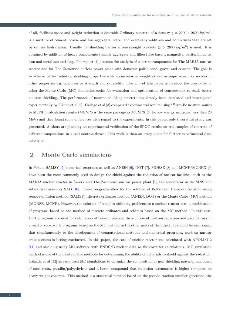
Figure 1. SPOT and MCNPX comparison: a) neutron transmittance vs. incident neutron energy for 10 cm concretethickness, b) neutron flux for 1.0 MeV incident neutron energy transmittance vs. concrete thickness
cross sections for reactions in material already known and the assumed model of particle motion. A complete
set of simulation must also include a geometry of the shielding material, an atomic composition of material,
parameters of radioactive source and a type and a placement of radiation detectors. The MC simulation method
has one important drawback - the real time of simulation significantly increases when more accurate data has to
be calculated, especially when high complexity test system is considered. The most advanced MC computational
package is MCNPX [4] from Los Alamos National Laboratory. It is very flexible package, which can be used in
many applications [13] including shielding analysis [14]. In this paper, data from simulation of neutron transport
in concrete shields using MCNPX and also authors’ simulation software called SPOT are presented. SPOT, a
quite simple software for engineering calculations, was prepared using the assumptions of MCNPX software, but
including only the elastic neutron scattering and absorption in the model. The advantage of SPOT is a wide
range of possible modifications. A semi-quantitative agreement between data obtained from SPOT and MCNPX
was obtained up to 2.0 MeV of neutron initial energy (Fig.1a). It is consistent with the model used, because in
this energy range, the elastic scattering process is dominating in neutron collisions with atoms. The comparison
of 1.0 MeV neutron flux depending on thickness of concrete shield for SPOT and MCNPX shows that obtained
results are in good agreement (Fig.1b).
Calculations in MCNPX were performed for 107 neutron histories, whereas in SPOT were performed for 10
batches of 105 histories. In MCNPX nuclear data was included from ENDF/B-VI.0, ENDF/B-VI.8, ENDF/B-
VII.0 databases. In SPOT, the ENDF/B-VI.8 databases were used (JANIS [15] software was used to extract cross
sections). No variance-reduction techniques were applied. The basic steps of MC neutron transport simulation
consists of a particle generation (initial energy, position and direction in the domain of θ, φ angles tossed from
pseudo–random number generator – RNG). Next step is a transport code. For non–charged particle like neutron
it is a straight line with a distance acquired from RNG with use of exponential distribution. Distance is easily
calculated from equation 1.
d = − 1
Σtln(x) (1)
where x is a number from RNG (linear distribution), Σt is macroscopic total cross-section of medium.
3

Monte Carlo simulations for optimization of neutron shielding concrete
Then particle interactions are considered in a manner of RNG with use of correct cross-sections. In case of
SPOT only absorption and elastic scattering was considered whereas in MCNPX a lot of interactions are possible,
like production of neutrons (n, 2n), (n, 3n), (n, xn), gamma rays, electrons, particles (d, t, α, ...), ions and heavy-
ions. In such cases another particle tracks are generated. Also photons and other particles like light ions may
be generated. For example, if elastic scattering is chosen, a nuclide should be tossed with use of macroscopic
cross-sections. MCNPX uses many advanced modelling techniques like thermal treatment based on the free gas
aproximation, chemical binding, crystal structure influcence, and cross-section data are corrected accordingly
to the simulation conditions. In case of elastic scattering the particle energy loss is generally obtained from
momentum and energy conservation principles in a center of mass frame. Then a new ”motion” is started with
angle generated by RNG using differential angular cross-sections. Theses steps are repeated until an absorption
is chosen or particle leaves the material. In this case particle counter is increased, flux is updated and for SPOT
equivalent dose is updated. In case of MCNPX histogram of selected energy bins is created and on this basis
equivalent dose is calculated in external program. In MCNPX there are many physics models codes like inner
nucleus cascades which helps obtaining correct solution within high energy ranges. For inelastic scattering, there
are many laws incorporated. There are photo effect, pair production, Compton effect, electron interactions like
Bremstrahlung, Auger transitions and so on. MCNPX can be used in wide areas of nuclear physics simulation.
The SPOT program is a very thin subset of this, but quite useful for our simulation conditions (energy up to 2.0
MeV, only neutron transport). SPOT is also not suited for complex medium geometry but suited for calculation
of neutron transport in inhomogeneous medium. The proper improvement is under preparation stage.
3. Shielding concrete optimization
Lately a big progress in concrete evolution has been made. It is mostly due to use of polymer additives (e.g.
superplasticizers) together with reactive additions (e.g. silica fume), that allows for decrease of w/c ratio, increase
of tightness and mechanical properties without loss in workability of fresh concrete mix. Also an intensive
development of Polymer-Cement Concrete (PCC) in the last decade has been observed [16]. This progress allows
for a new look at the concrete optimization for better radiation shielding properties. Already some calculations and
investigations on shielding (mainly against gamma rays) has been made. Akkurt et al. [17] proved that the type
of the aggregate is more important than the amount of aggregate for gamma ray shielding and the barite-loaded
concretes would be preferred for this purpose. Sato et al. [18] proposed for a radioactive waste management a
multilayered concrete structures with boron-doped low activation concrete wall. Here a flexible neutron shielding
resin, recently developed by Sukegawa et al. [19], could be used. This solution could be problematic in a reactor
building construction due to the particularity of concrete works technology and problems that can arise at the
interface like it happens in multilayer repair systems [20]. Bashter [21], apart from gamma shielding analyses,
showed that calculated effective macroscopic neutron removal cross-sections for six different concretes can be
4

Tomasz Piotrowski, Dariusz B. Tefelski, Aleksander Polanski, Janusz Skubalski
increased up to 50% with relation to ordinary one by a change of an aggregate type. Measured values differs from
the calculated ones within the range 13.5 ÷ 33.7%. It shows that while in case of gamma radiation an increase
in density by a change of aggregate is usually efficient enough, protection against neutrons is more complex. It
is due to the differences in interactions of free neutrons with the matter, depending on their kinetic energy and
cross-sections for different reactions of the component atoms of the cement paste and the aggregate. Some general
recommendations can be presented here e.g. increase of hydrogen content in concrete (more chemically bounded
water) or addition of neutron absorbers (boron). It is worth to mention that shielding process and its intensity
against different radiation depends not only on the chemical composition but the structure of the barrier (e.g.
heterogeneites) [22] and local defects (e.g. cracks) as well [23].
4. Dose calculation
In radiation protection doses refer mostly to absorbed dose and relate to the X-rays and gamma rays. Formally,
absorbed dose D, is defined by equation (2) as a measure of the energy deposited in a medium by ionizing
radiation:
D =∆E
∆m
[J
kg= Gy (gray)
](2)
where: ∆E – the mean energy imparted by ionizing radiation to matter in a volume element, ∆m – the mass of
matter in the volume element.
However, the biological effects do not depend only on the absorbed dose but on the sensitivity of particular organs
or tissues and the radiation type as well. Radiation type is described by the ionization density (numbers of ions
produced in the individual path of radiation). Therefore the two doses are defined, which take into consideration
all these aspects. The equivalent dose HT takes into consideration the radiation type (by multiplication factor
wR) and the effective dose DE takes into consideration the sensitivity of individual organs or tissues to radiation
(by multiplication factor wT ). The equivalent dose is defined by equation (3):
HT = wR ·DT (3)
where: DT - the absorbed dose delivered by radiation type R averaged over a tissue or organ T , wR - the radiation
weighting factor for radiation type R.
The effective dose (4) is a summation of tissue equivalent doses multiplied by the appropriate tissue weighting
factor:
DE =∑
wT ·HT (4)
where: HT - the equivalent dose in tissue T , wT - the tissue weighting factor for tissue T .
In the Polish legal system, the binding values of radiation weighting factors (Tab.1) and tissue weighting factors
(Tab.2) are given in the Regulation of the Council of Ministers [24] in accordance with the recommendations of
5

Monte Carlo simulations for optimization of neutron shielding concrete
Table 1. Radiation weighting factors wR [24]
Radiation type and energy Radiation weighting factor, wR
Photons, all energies 1
Electrons, myons, all energies 1
Neutrons below 10 keV 5
from 10 keV to 100 keV 10
from 100 keV to 2 MeV 20
from 2 MeV to 20 MeV 10
over 20 MeV 5
Protons over 2 MeV 5
Alpha particles, fission fragments, heavy nuclei 20
Table 2. Tissue weighting factor wT [24]
Tissue (organ), T Tissue (organ) weighting factor,wT
Gonads 0.20
Bone marrow (red) 0.12
Colon 0.12
Lung 0.12
Stomach 0.12
Bladder 0.05
Chest 0.05
Liver 0.05
Oesophagus 0.05
Thyroid gland 0.05
Skin 0.01
Bone surface 0.01
Adrenals, brain, small intestine, kidney 0.05
muscle, pancreas,spleen, thymus, uterus
(the weighting factor 0.05 is applied to
the average dose of these organs)
Figure 2. The model of effective dose calculation used in this paper. N - number of neutron energy groups, DE - effective dose,E - neutron energy
6
Tomasz Piotrowski, Dariusz B. Tefelski, Aleksander Polanski, Janusz Skubalski
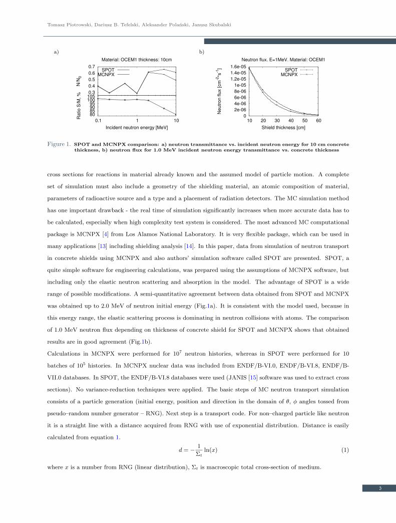
Table 3. The conversion coefficients CCn as the effective dose per unit fluence
Energy CCn Energy CCn Energy CCn
[MeV ] [pSv · cm2] [MeV ] [pSv · cm2] [MeV ] [pSv · cm2]
1.0E-09 2.40 1.0E-03 6.04 1.2 130
1.0E-08 2.89 2.0E-03 6.05 2.0 178
2.5E-08 3.30 5.0E-03 6.52 3.0 222
1.0E-07 4.13 0.01 7.70 4.0 250
2.0E-07 4.59 0.02 10.2 5.0 272
5.0E-07 5.20 0.03 12.7 6.0 282
1.0E-06 5.63 0.05 17.3 7.0 290
2.0E-06 5.96 0.07 21.5 8.0 297
5.0E-06 6.28 0.10 27.2 9.0 303
1.0E-05 6.44 0.15 35.2 10 309
2.0E-05 6.51 0.20 42.4 12 322
5.0E-05 6.51 0.30 54.7 14 333
1.0E-04 6.45 0.50 75.0 15 338
2.0E-04 6.32 0.70 92.8 16 342
5.0E-04 6.14 0.90 108 18 345
1.00 116 20 343
ICRP [25]. When effective dose for all body is calculated, it corresponds to the equivalent dose because a sum of
all tissue weighting factors is equal to 1 (∑wT = 1). In this paper the effective doses were determined using the
neutron flux and the conversion coefficients CCn as the effective dose per unit fluence (Fig.2). The conversion
coefficients (Tab.3) depend on neutron energy and were taken from the ICRU Report [26].
5. Simulation results
Simulations presented in this paper assumed no cracks and the homogeneity of concrete (no structural heterogene-
ity due to aggregates arrangement) - the atoms were homogeneously spread in the atomic structure. Obviously
it is not always true, for example in case of poor quality of concrete works. Next assumption concerns water
demand of 25% of mass of cement used for hydratation. A preliminary study was a SPOT simulation performed
for two separate groups of concretes of different class of compressive strength; from C30/37 to C45/55 (Group A)
and from C25/30 to C50/60 (Group B). Change in compressive strength class was a result of different concrete
composition (Tab.4) that leads to differences in atomic compositions (Tab.5). Calculations has been made for a
25 cm thick wall.
SPOT simulations source was based on a neutron flux from a Light Water Reactor (LWR) core calculated using
APOLLO 2. Calculation has been made for 105 histories. Results present a clear decrease in effective dose
behind barrier with an increase in compressive strength of concrete both for group A and B: 31% and 44%
respectively (Fig.3). The next investigation was made for two types of concrete: ordinary concrete and the
heavyweight concrete with barite, that is commonly used for gamma shielding (Tab.6). In these concretes, two
different cement classes (CEM I 42.5 R and CEM II/B-V 32.5R) were considered. Differences in mix lead to
7

Monte Carlo simulations for optimization of neutron shielding concrete
Table 4. Concrete compositions of different compressive strength class for SPOT simulations
GROUP A samples C30A C40A C45A GROUP B samples C25B C35B C50B
Compressive strength Compressive strength
class of concrete C30/37 C40/50 C45/55 class of concrete C25/30 C35/45 C50/60
CEM I 52.5 N [kg/m3] 275 325 375 CEM I 32.5 R [kg/m3] 350 407 488
Crushed Sand 0/2 [kg/m3] 765 729 676 Sand 0/2 [kg/m3] 610 611 604
Crushed limestone 2/8 [kg/m3] 255 230 206 River Gravel 2/8 [kg/m3] 666 667 658
Crushed limestone 8/14 [kg/m3] 569 576 601 River Gravel 8/16 [kg/m3] 574 575 567
Crushed limestone 14/20 [kg/m3] 390 401 412 Aggregate total [kg/m3] 1850 1853 1829
Aggregate total [kg/m3] 1979 1936 1895 Super-plasticizer [l/m3] - 1.63 7.32
Water [l/m3] 197 192 188 Water [l/m3] 189 170 152
Hydrated water [l/m3] 68.75 81,25 93.75 Hydrated water [l/m3] 87.50 101.75 122.00
w/c ratio 0.72 0.59 0.50 w/c ratio 0.54 0.42 0.31
fck,cyl,28days [MPa] 34.96 41.34 48.77 fck,cube,28days [MPa] 31.47 45.67 62.10
Table 5. Concrete atomic compositions of different compressive strength class for SPOT simulations
Sample C30A C40A C45A C25B C35B C50B
Compressive strength
class of concrete C30/37 C40/50 C45/55 C25/30 C35/45 C50/60
Ato
mic
com
posi
tion
H 0.33% 0.39% 0.44% 0.43% 0.48% 0.56%
O 52.28% 52.10% 51.93% 51.98% 51.81% 51.56%
Na 0.02% 0.02% 0.02% 0.02% 0.03% 0.03%
Mg 0.10% 0.12% 0.13% 0.13% 0.14% 0.17%
Al 0.33% 0.39% 0.44% 0.43% 0.48% 0.56%
Si 40.85% 39.85% 38.88% 39.15% 38.20% 36.84%
S 0.16% 0.19% 0.21% 0.21% 0.23% 0.27%
Cl 0.01% 0.01% 0.01% 0.01% 0.01% 0.01%
K 0.06% 0.07% 0.08% 0.08% 0.09% 0.11%
Ca 5.59% 6.55% 7.49% 7.22% 8.13% 9.44%
Fe 0.27% 0.32% 0.36% 0.35% 0.40% 0.46%
Figure 3. Effective dose behind 25 cm thick concrete of different compressive strength (SPOT simulation)
8
Tomasz Piotrowski, Dariusz B. Tefelski, Aleksander Polanski, Janusz Skubalski
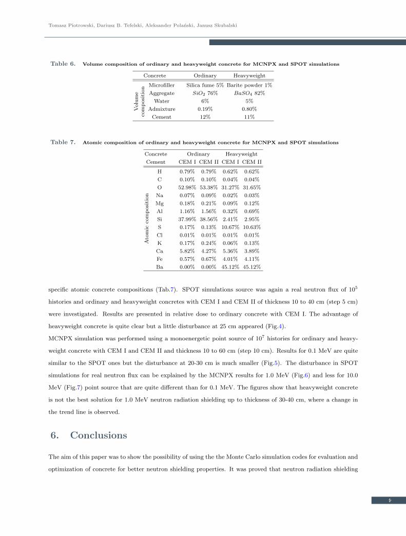
Table 6. Volume composition of ordinary and heavyweight concrete for MCNPX and SPOT simulations
Concrete Ordinary Heavyweight
Volu
me
com
posi
tion Microfiller Silica fume 5% Barite powder 1%
Aggregate SiO2 76% BaSO4 82%
Water 6% 5%
Admixture 0.19% 0.80%
Cement 12% 11%
Table 7. Atomic composition of ordinary and heavyweight concrete for MCNPX and SPOT simulations
Concrete Ordinary Heavyweight
Cement CEM I CEM II CEM I CEM II
Ato
mic
com
posi
tion
H 0.79% 0.79% 0.62% 0.62%
C 0.10% 0.10% 0.04% 0.04%
O 52.98% 53.38% 31.27% 31.65%
Na 0.07% 0.09% 0.02% 0.03%
Mg 0.18% 0.21% 0.09% 0.12%
Al 1.16% 1.56% 0.32% 0.69%
Si 37.99% 38.56% 2.41% 2.95%
S 0.17% 0.13% 10.67% 10.63%
Cl 0.01% 0.01% 0.01% 0.01%
K 0.17% 0.24% 0.06% 0.13%
Ca 5.82% 4.27% 5.36% 3.89%
Fe 0.57% 0.67% 4.01% 4.11%
Ba 0.00% 0.00% 45.12% 45.12%
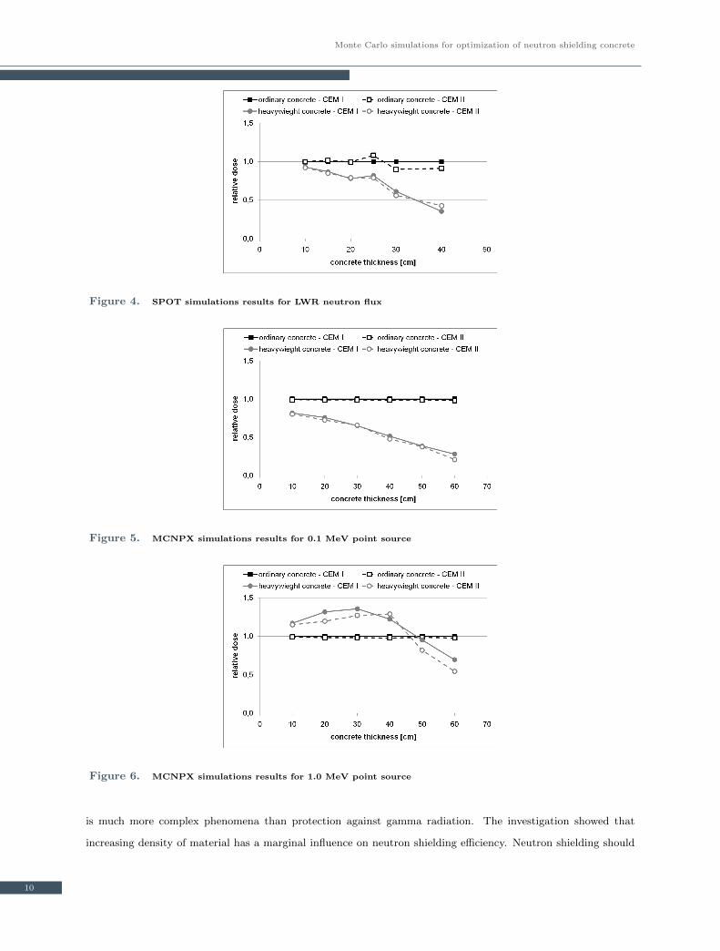
specific atomic concrete compositions (Tab.7). SPOT simulations source was again a real neutron flux of 105
histories and ordinary and heavyweight concretes with CEM I and CEM II of thickness 10 to 40 cm (step 5 cm)
were investigated. Results are presented in relative dose to ordinary concrete with CEM I. The advantage of
heavyweight concrete is quite clear but a little disturbance at 25 cm appeared (Fig.4).
MCNPX simulation was performed using a monoenergetic point source of 107 histories for ordinary and heavy-
weight concrete with CEM I and CEM II and thickness 10 to 60 cm (step 10 cm). Results for 0.1 MeV are quite
similar to the SPOT ones but the disturbance at 20-30 cm is much smaller (Fig.5). The disturbance in SPOT
simulations for real neutron flux can be explained by the MCNPX results for 1.0 MeV (Fig.6) and less for 10.0
MeV (Fig.7) point source that are quite different than for 0.1 MeV. The figures show that heavyweight concrete
is not the best solution for 1.0 MeV neutron radiation shielding up to thickness of 30-40 cm, where a change in
the trend line is observed.
6. Conclusions
The aim of this paper was to show the possibility of using the the Monte Carlo simulation codes for evaluation and
optimization of concrete for better neutron shielding properties. It was proved that neutron radiation shielding
9
Monte Carlo simulations for optimization of neutron shielding concrete
Figure 4. SPOT simulations results for LWR neutron flux
Figure 5. MCNPX simulations results for 0.1 MeV point source
Figure 6. MCNPX simulations results for 1.0 MeV point source
is much more complex phenomena than protection against gamma radiation. The investigation showed that
increasing density of material has a marginal influence on neutron shielding efficiency. Neutron shielding should
10

Tomasz Piotrowski, Dariusz B. Tefelski, Aleksander Polanski, Janusz Skubalski
Figure 7. MCNPX simulations results for 10.0 MeV point source
be solved taking in mind two aspects slowing down neutrons, which is best done with light nuclides (hydrogen)
and neutron absorption with nuclides with high cross section for neutron absorption like boron and gadolinium.
In fact, neutron shielding for the given barrier depends on many factors e.g. neutron energy, barrier thickness
and atomic composition. All this makes a very important issue for nuclear power plant and other facility (eg.
accelerator) safety assurance to design concrete properly for protection against radiation not only from photons
(gamma) but neutrons as well.
Acknowledgments
The authors are thankful to: P. Olbratowski for his activity in SPOT development, B. S lowinski for possibility of
simulation with MCNPX code and Lafarge Poland for the real data of concrete composition used in simulations.
This paper was presented at the 1st International Nuclear Energy Congress [27], Warsaw, May 23-24, 2011.
References
[1] Szymendera L., Water-Concrete Shielding Systems for PWR, Rep. INR 1528/IX/PR/B, Warsaw, 1974
[2] Okuno K., Kawai M., Yamada H., Development of Novel Neutron Shielding Concrete, Nucl Technol, 168 (2)
2009, pp. 545-552
[3] Gallego E., Lorente A., Vega-Carrillo H.R., Testing of a High-Density Concrete as Neutron Shielding Material,
Nucl Technol, 168 (2) 2009, pp. 399-404
[4] X-5 Monte Carlo Team, MCNP-A General Monte Carlo N-Particle Transport Code, Version 5, Los Alamos
National Laboratory (2003)
[5] Szymendera L., Wincel K., Sobolewska L. et al, SAMSY: A One-Dimensional Improved Shielding Code,
User’s Manual, INR 1691, 1971
11

Monte Carlo simulations for optimization of neutron shielding concrete
[6] Computer Code Collection, CCC-225, ANISN W. ORNL, USA
[7] Computer Code Collection, CCC-226, DOT. ORNL, USA
[8] The MORSE code - A Multigroup Neutron and Gamma-Ray Monte Carlo Transport Code, ORNL - 4585
USA
[9] Waters L.S., MCNPXTM Users Manual Version 2.1.5, Los Alamos National Laboratory, November 14, (1999)
[10] Seltborg P., Polanski A., Petrochenkov S., Lopatkin A., Gudowski W., Shvetsov V., Radiation shield-
ing of high-energy neutrons in SAD, Nucl Instr and Meth Phys Res, A550 2005, pp. 313-328,
doi:10.1016/j.nima.2005.04.071
[11] Sanchez R., Zmijarevic I., Coste-Delclaux M., Masiello E., Santandrea S., Martinolli E., Villate L., Schwartz
N., Guler N., Apollo2 year 2010, Nucl Eng and Technol, 42 (5) 2010, pp. 474-499
[12] Calzada E., Grnauer F., Schillinger B., Turck H., Reusable shielding material for neutron- and gamma-
radiation, Nucl Instr and Meth Phys Res, 2011 in press, doi:10.1016/j.nima.2010.12.239
[13] Polanski A., S lowinski B., Wojciechowski A., Spallation neutron production in extended targets initiated by
electronuclear reactions, XX Intern Baldin Seminar on High Energy Physics Problems, Dubna, October 4-10,
2010, p.92
[14] Torres D.A., Mosteller R.D., Sweezy J.E., Comparison of MCNP5 and Experimental Results on Neutron
Shielding Effects for Materials, 2004 Annual Meeting of the American Nuclear Society, June 13-17 2004,
Pittsburgh, PA, LA UR-04-0122
[15] http://www.oecd-nea.org/janis/
[16] Czarnecki L., Lukowski P., Polymer-cement concretes, Cem Lime Concr 5 2010, pp. 243-258
[17] Akkurt I., Basyigit C., Kilincarslan S., Mavi B., Akkurt A., Radiation shielding of concretes containing
different aggregates, Cem Concr Comp 28 2006, pp. 153-157, doi:10.1016/jcemconcomp.2005.09.006
[18] Sato S., Maegawa T., Yoshimatsu K., Sato K., Nonaka A., Takakura K., Ochiaia K., Konno Ch., Development
of a low activation concrete shielding wall by multi-layered structure for a fusion reactor, J Nucl Mater, 2011
in press, doi:10.1016/j.jnucmat.2010.12.302
[19] Sukegawa A.M., Anayama A., Okuno K., Sakurai S., Kaminaga A., Flexible heat resistant neutron shielding
resin, J Nucl Mater, 2011 in press, doi:10.1016/j.jnucmat.2010.12.291
[20] Courard L., Michel F., Schwall D., Van der Wielen A., Piotrowski T., Garbacz A., Perez F., Bissonette B.,
Surfology: concrete surface evaluation prior to repair, Materials Characterisation IV, Comput Meth and Exp,
WIT Press 2009 (Ed. A.A. Mammoli, C.A. Brebbia), pp. 407-416
[21] Bashter I.I., Calculation of radiation attenuation coefficients for shielding concretes, Ann Nucl Energy, 24
(17) 1997, pp. 1389-1401
[22] Murata I., Yoshida S., Takahashi A., Effect of Heterogeneities in Heavy Concrete on Shielding of Fusion
Neutrons, Fusion Sci and Technol, 36 (2) 1999, pp. 181-193
[23] Lee C.-M., Lee Y.H., Lee K.J., Cracking effect on gamma-ray shielding performance in concrete structure,
12

Tomasz Piotrowski, Dariusz B. Tefelski, Aleksander Polanski, Janusz Skubalski
Prog in Nucl Energy, 49 (4) 2007, pp. 303-312, doi:10.1016/j.pnucene.2007.01.006
[24] Regulation Prime Minister of Republic of Poland, The Radiation Dose Limits, J of Law 2005, No 20, pos.
168 (in Polish)
[25] ICRP Publication 60: 1990 Recommendations of the International Commission on Radiological Protection,
Ann of the ICRP Vol 21/1-3
[26] International Commission on Radiation Units and Measurements, Conversion coefficients for use in radiolog-
ical protection against external radiation, ICRU Report 57, Bethesda, Maryland (1998)
[27] http://nuclear.itc.pw.edu.pl (accessed: June 28 2011)
13
Copyright © 2022 FDOKUMEN