AK-285T Shielding Effectiveness Antenna Kit Operation Manual
16
A.H. Systems AK-285T Shielding Effectiveness Antenna Kit © A.H. Systems inc. – May 2014 REV A 1 AK-285T Shielding Effectiveness Antenna Kit Operation Manual
-
Upload
khangminh22 -
Category
Documents
-
view
0 -
download
0
Transcript of AK-285T Shielding Effectiveness Antenna Kit Operation Manual

A.H. Systems AK-285T Shielding Effectiveness Antenna Kit
© A.H. Systems inc. – May 2014 REV A
1
AK-285T
Shielding Effectiveness Antenna Kit
Operation Manual

A.H. Systems AK-285T Shielding Effectiveness Antenna Kit
© A.H. Systems inc. – May 2014 REV A
2
TABLE OF CONTENTS
WARRANTY 3
INTRODUCTION 4
GENERAL INFORMATION 5
EQUIPMENT AND OPERATION 6
DYNAMIC RANGE 12
ANTENNA FORMULAS 14
CONVERSION FORMULAS 15
MAINTENANCE 16

A.H. Systems AK-285T Shielding Effectiveness Antenna Kit
© A.H. Systems inc. – May 2014 REV A
3
WARRANTY INFORMATION
A.H. Systems Inc., warrants that our Antennas, Sensors and Probes will be free from defects in materials and workmanship for a period of three (3) years. All other products delivered under contract will be warranted for a period of two (2) years. Damage caused by excessive signals at the product's input is not covered under the warranty. A.H. Systems' obligation under this warranty shall be limited to repairing or replacing, F.O.B. Chatsworth, California, each part of the product which is defective, provided that the buyer gives A.H. Systems notice of such defect within the warranty period commencing with the delivery of the product by A.H. Systems. The remedy set forth herein shall be the only remedy available to the buyer, and in no event shall A.H. Systems be liable for direct, indirect, incidental or consequential damages. This warranty shall not apply to any part of the product which, without fault of A.H. Systems has been subject to alteration, failure caused by a part not supplied by A.H. Systems, accident, fire or other casualty, negligence, misuse or normal wear of materials. Except for the warranty set forth above, there are no other warranties, expressed or implied, with respect to the condition of the product or it's suitability for the use intended for them by the buyer. For prompt service, please contact our service department for a Return Material Authorization Number before shipping equipment back to us.

A.H. Systems AK-285T Shielding Effectiveness Antenna Kit
© A.H. Systems inc. – May 2014 REV A
4
INTRODUCTION
Shown with optional preamplifiers
ANTENNA KIT CONTENTS
Model Number Frequency
Range Description
SAS-510-2 290 MHz – 2000 MHz Log Periodic
SAS-544F 20 MHz – 330 MHz Biconical, Folding
SAS-551 9 KHz – 40 MHz Passive Monopole
SAS-563P 1 KHz – 30 MHz 12” Passive Loop
SAS-571 700 MHz – 18 GHz Double ridge guide horn
SAC-18G-3 Up to 18 GHz 3 Meter Low-Loss Cable
TSC-285R Transit Storage Case
ADP-202 N(f) to BNC(m) Adapter
ATU-510 Wood Tripod
AEH-510 Azimuth and Elevation Head
TCC-511 Tripod Carrying Case
Tripod Case Antenna Case
Dimensions: 46” x 8” Dia. 28” x 23” x 10”
Weight: 18.6 lbs. 38 lbs.

A.H. Systems AK-285T Shielding Effectiveness Antenna Kit
© A.H. Systems inc. – May 2014 REV A
5
GENERAL INFORMATION
INTENDED PURPOSES
This equipment is intended for general laboratory use in a wide variety of industrial
and scientific applications, and designed to be used in the process of generating
and measuring high levels of electromagnetic Radio Frequency (RF) energy. It is
the responsibility of the user to assure that the device is operated in a location
which will generate the radiated energy such that it will not cause injury and will
not violate regulatory levels of electromagnetic interference.
GENERAL DESCRIPTION
The A.H. Systems AK-285R and AK-285T antenna kits includes all of the required antennas needed to perform shielding effectiveness. Each component has a specific storage compartment in the carrying case therefore, loss and breakage are virtually eliminated. Cables, a tripod with azimuth and elevation head, and a tripod carrying case accompany each antenna kit. Each of the antennas, and cables, are provided with calibrations when connected to a 50-ohm input receiver or spectrum analyzer. Each of the E-field antennas mounts directly to the tripod azimuth and elevation head. The azimuth and elevation head allows the operator to vary the antenna azimuth (direction) and tilt the antenna up and down. The antenna polarity can also be rotated (horizontal or vertical). Cables and an adapter are provided to connect each antenna and probe to either a BNC or N type connector on the receiver. To obtain the field strength of the signal being measured, the operator must add the receiver reading in dBuV, the antenna factor in dB, and the cable attenuation in dB. This yields the field strength in dBuV/m. Calibrations for the E-field antennas are supplied at appropriate distances (1, 3, and 10 meter) to comply with various specification requirements.

A.H. Systems AK-285T Shielding Effectiveness Antenna Kit
© A.H. Systems inc. – May 2014 REV A
6
SAS-510-2
Log Periodic Antenna 290 MHz – 2 GHz
This directional Log Periodic Antenna is an ideal solution for radiated emissions and normalized
site attenuation.
Frequency Range: 290 MHz - 2000 MHz
Antenna Factor: 14 - 32 dB/m
Gain: 6.5 dBi
Maximum Continuous Power: 1000 Watts
Maximum Radiated Field: 200 V/m
Pattern Type: directional
3dB Beamwidth (E-Field): 45°
3dB Beamwidth (H-Field): 100°
Impedance: 50
VSWR: 1.45:1 typ. (2.2:1 max)
Connector: N-Type, Female
Mounting Base: ¼ x 20 Thread, Female
Features • Frequency Range of 290 MHz to 2000 MHz
• Receive and Transmit
• Individually Calibrated (1, 3 and 10 Meter calibration included, horizontal
polarization)
• Rugged Construction
• Three Year Warranty
The SAS-510-2 Log Periodic Antenna (also known as a log periodic dipole array) is a
compact, lightweight antenna that has been designed to ensure maximum gain, low VSWR
and high-power handling capabilities. This compact design is an ideal solution for EMC
testing where the reduced size of the antenna is preferred to minimize chamber wall
coupling and increasing the half power beamwidth to a more acceptable angle that will cover
the whole device under test. Constructed of lightweight aluminum, the SAS-510-2 Log
Periodic Antenna has been manufactured to operate over a very wide bandwidth. Weighing
in at just 1.5 pounds this Log Periodic Antenna is one of the lightest antennas commercially
available.
Assembly: The log periodic antenna comes assembled and ready to use. Operation: Attach the antenna to the tripod azimuth and elevation head through the screw
hole in the antenna base. Connect a cable between the antenna connector and the receiver.
The log periodic beamwidth is 45 degrees and it should be pointed or aimed in the direction
that the horizontal received signal is coming from.

A.H. Systems AK-285T Shielding Effectiveness Antenna Kit
© A.H. Systems inc. – May 2014 REV A
7
SAS-544F
High Field Biconical Antenna, Folding 20 MHz – 300 MHz
This Biconical antenna has a coaxial wound
balun that can handle High fields of RF energy.
Frequency Range: 20 MHz - 300 MHz
Antenna Factor: 6 to 21 dB/m
Gain: -23 to 2.8 dBi
Maximum Continuous Power: 300 Watts
Max Radiated Field: 20 V/m
Pattern Type: omni-directional
Impedance: 50
Connector: N-Type, female
Mounting Base: ¼ - 20 Thread, female
Features • Frequency Range of 20 MHz to 300 MHz
• Receive and Transmit
• Individually Calibrated (1, 3 and 10 Meter horizontal calibration included, horizontal
polarization)
• Rugged Construction
• Three Year Warranty
The SAS-544F Folding Biconical Antenna was the first EMC antenna designed for portable
compliance testing applications. This Biconical Antenna is designed with a coaxial wound
balun for increased power capability and intended for both transmitting and receiving high
electromagnetic RF fields. For rapid deployment, along with the mobility of a small package,
the Folding Biconical elements can be closed similar to an umbrella allowing the antenna
to be contained in an optional transit storage case. Whether testing in a shielded enclosure,
or outdoors, the rugged construction of the A.H. Systems Biconical antenna will ensure long
life, and reliable performance.
Assembly: The biconical antenna consists of the SAS-544F balun assembly, balun clamp assembly and two folding biconical elements. Operation: Attach the balun assembly to the tripod azimuth and elevation head with the
balun clamp. Screw the two biconical elements into the 'tee' end of the balun assembly.
Open the antenna elements completely and secure in open position by tightening the
knurled knobs in the element caps. Connect a cable between the antenna connector and
the receiver. The biconical beam pattern is similar to a dipole response.
A.H. Systems AK-285T Shielding Effectiveness Antenna Kit
© A.H. Systems inc. – May 2014 REV A
8
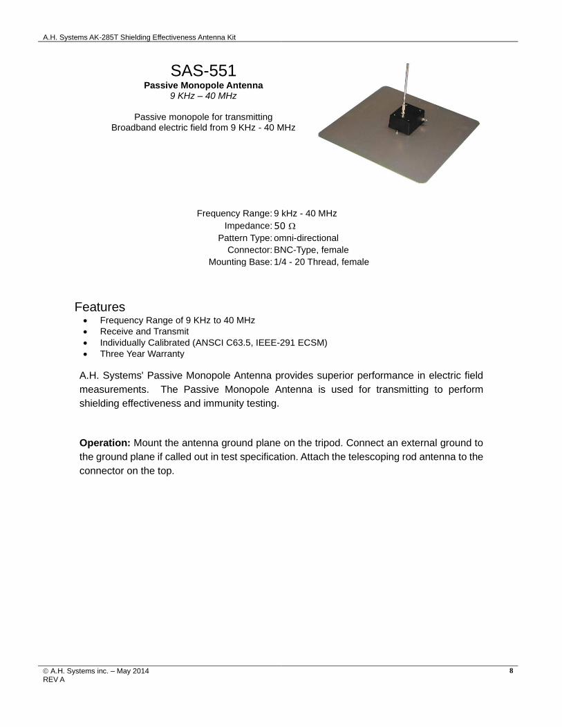
SAS-551
Passive Monopole Antenna 9 KHz – 40 MHz
Passive monopole for transmitting
Broadband electric field from 9 KHz - 40 MHz
Frequency Range: 9 kHz - 40 MHz
Impedance: 50
Pattern Type: omni-directional
Connector: BNC-Type, female
Mounting Base: 1/4 - 20 Thread, female
Features • Frequency Range of 9 KHz to 40 MHz
• Receive and Transmit
• Individually Calibrated (ANSCI C63.5, IEEE-291 ECSM)
• Three Year Warranty
A.H. Systems' Passive Monopole Antenna provides superior performance in electric field
measurements. The Passive Monopole Antenna is used for transmitting to perform
shielding effectiveness and immunity testing.
Operation: Mount the antenna ground plane on the tripod. Connect an external ground to
the ground plane if called out in test specification. Attach the telescoping rod antenna to the
connector on the top.

A.H. Systems AK-285T Shielding Effectiveness Antenna Kit
© A.H. Systems inc. – May 2014 REV A
9
SAS-563P
Passive Shielded Loop Antenna 1 KHz – 30 MHz
This 12" (30 cm) Passive Shielded Loop Antenna is an excellent solution for
shielding effectiveness testing.
Frequency Range: 1 kHz - 30 MHz
Impedance: 50 (Nominal)
Maximum Input: 500 Watts
Connector: N, Female
Mounting Base: ¼ x 20 Thread, Female
Features Broad Frequency Range of 1 KHz to 30 MHz
• Individually Calibrated (Calibration included per IEEE-291)
• Rugged Construction
• Three Year Warranty
The SAS-563P electrostatic shielded loop antenna is typically used for shielding
effectiveness testing per IEEE 299, MIL-STD 285 and NSA 65-6 as well as many other
test standards. This passive 12" (30cm) diameter loop antenna is shielded against the
electric component by enclosing the conducting loop within an all-metal shield. This
balanced faraday shield ensures that it is producing (or measuring) just the magnetic
component of the radiated energy. Due to the relatively long wavelengths in this band, and
the typical test distance from the source, the 377 Ohm relationship to the E-field will not
hold true and you may have to measure (or produce) the "E" field separately with a high
impedance monopole antenna.
Operation: Mount the antenna base on the tripod and connect the N connector to an
amplifier or signal generator.

A.H. Systems AK-285T Shielding Effectiveness Antenna Kit
© A.H. Systems inc. – May 2014 REV A
10
SAS-571
Double Ridge Guide Horn Antenna 700 MHz – 18 GHz
High gain, low VSWR, input handling capability up to 300 watts CW, and rugged design make this horn antenna excellent for both immunity
and emissions testing.
Frequency Range: 700 MHz - 18 GHz Antenna Factor: 22 to 44 dB/m
Gain (dBi): 1.4 to 15 dBi Maximum Continuous Power: 300 Watts
Max Radiated Field: 200 V/m Pattern Type: directional
3dB Beamwidth (E-Field): 48° 3dB Beamwidth (H-Field): 30°
Impedance: 50 VSWR: 1.6:1 (3.5:1 max)
Connector: N-Type, female Mounting Base: ¼ - 20 Thread, female
Features • Broad Frequency Range of 700 MHz to 18 GHz
• Linearly Polarized High Gain, Low VSWR
• Individually Calibrated
• Three-year Warranty
The SAS-571 Double Ridge Guide Horn Antenna is lightweight, compact and has been
manufactured for maximum gain, low VSWR and broadband response. The double ridge
guide horn antenna was initially designed for surveillance where a high gain broadband
response was required.
Assembly: The horn antenna comes assembled and ready to use. The antenna mounting
bracket is attached to the antenna backwards in order to fit in the carrying case. The bracket
must be removed from the antenna, rotated (so that the bracket leg faces away from the
antenna), and re-attached to the antenna. (The bracket is not needed for mounting if the
tripod being used has an Azimuth/Elevation Head.)
Operation: Attach the antenna to the tripod azimuth and elevation head through the
threaded hole on the antenna bottom or the threaded hole in the mounting bracket. The
ridge guides determine the antenna polarity: for horizontal polarity they should be parallel
to the ground and for vertical polarity they should be perpendicular to the ground. Connect
a cable between the antenna connector and the receiver.
A.H. Systems AK-285T Shielding Effectiveness Antenna Kit
© A.H. Systems inc. – May 2014 REV A
11
TRIPOD AND MOUNTING ADPTERS
ATU-510 Tripod AEH-510 Azimuth and Elevation Head
The azimuth and elevation head (AEH-510) mounts to the tripod (ATU-510) top and allows the antennas to be rotated 360 degrees, titled up and down and between horizontal and vertical polarization. The tripod and azimuth and elevation head come in their own carrying case. Each tripod leg is independently adjustable in angle and length to facilitate antenna height setting. The tripod legs have a rubber tip on one end for indoor or hard surface use, and a metal spike on the other end for outdoor soft surface (such as dirt) use.
TRANSIT STORAGE CASES
TCC-510 Tripod Carrying Case TSC-542 Transit Storage Case
The antenna carrying case (TSC-542) prevents damage and loss of antennas when storing or transporting the antenna kit. The case is constructed of lightweight and durable polyethylene. Two case keys are provided with the case.

A.H. Systems AK-285T Shielding Effectiveness Antenna Kit
© A.H. Systems inc. – May 2014 REV A
12
AK-285R and AK-285T Dynamic Range Calculations
Here is a sample calculation of the required dynamic range at a 1 meter separation. Both the monopole and loop antennas have one passive and one active antenna. The use of preamplifiers with the active antennas is not recommended.
Noise Level (10 Hz RB) Vt-Vr
S + N
N
Xmtr Amp
Margin
0 dB Sig Gen
Dynamic Range
Preamp Gain
Dynamic Range
with Preamp
1 Watt Power Amp
Dynamic Range with 1W Power
Amp
Monopoles
1 MHz -130 18 6 6 100 30 130
5 MHz -130 19 6 6 99 30 129
10 MHz -130 17.5 6 6 100.5 30 130.5
20 MHz -134 9 6 6 113 30 143
40 MHz -134 8 6 6 114 30 144
50 MHz -134 3 6 6 119 30 149
Loops
1 MHz -130 52 6 6 66 30 96
5 MHz -130 39 6 6 79 30 109
10 MHz -130 31 6 6 87 30 117
20 MHz -134 38 6 6 84 30 114
40 MHz -134 51.5 6 6 70.5 30 100.5
50 MHz -134 53.5 6 6 68.5 30 98.5
Biconicals
20 MHz -134 33.5 6 6 88.5 40 128.5
50 MHz -134 23.6 6 6 98.4 40 138.4
100 MHz -134 12.8 6 6 109.2 40 149.2
200 MHz -134 17.9 6 6 104.1 40 144.1
300 MHz -134 26.6 6 6 95.4 40 135.4
Log Periodics
300 MHz -134 13.4 6 6 108.6 40 148.6
500 MHz -134 13.8 6 6 108.2 40 148.2
1 GHz -134 19.4 6 6 102.6 40 142.6
1.5 GHz -134 24.1 6 6 97.9 40 137.9
2 GHz -134 26.3 6 6 95.7 40 135.7
A.H. Systems AK-285T Shielding Effectiveness Antenna Kit
© A.H. Systems inc. – May 2014 REV A
13
Noise Level (10 Hz RB) Vt-Vr
S + N
N
Xmtr Amp
Margin
0 dB Sig Gen
Dynamic Range
Preamp Gain
Dynamic Range
with Preamp
1 Watt Power Amp
Dynamic Range with 1W Power
Amp
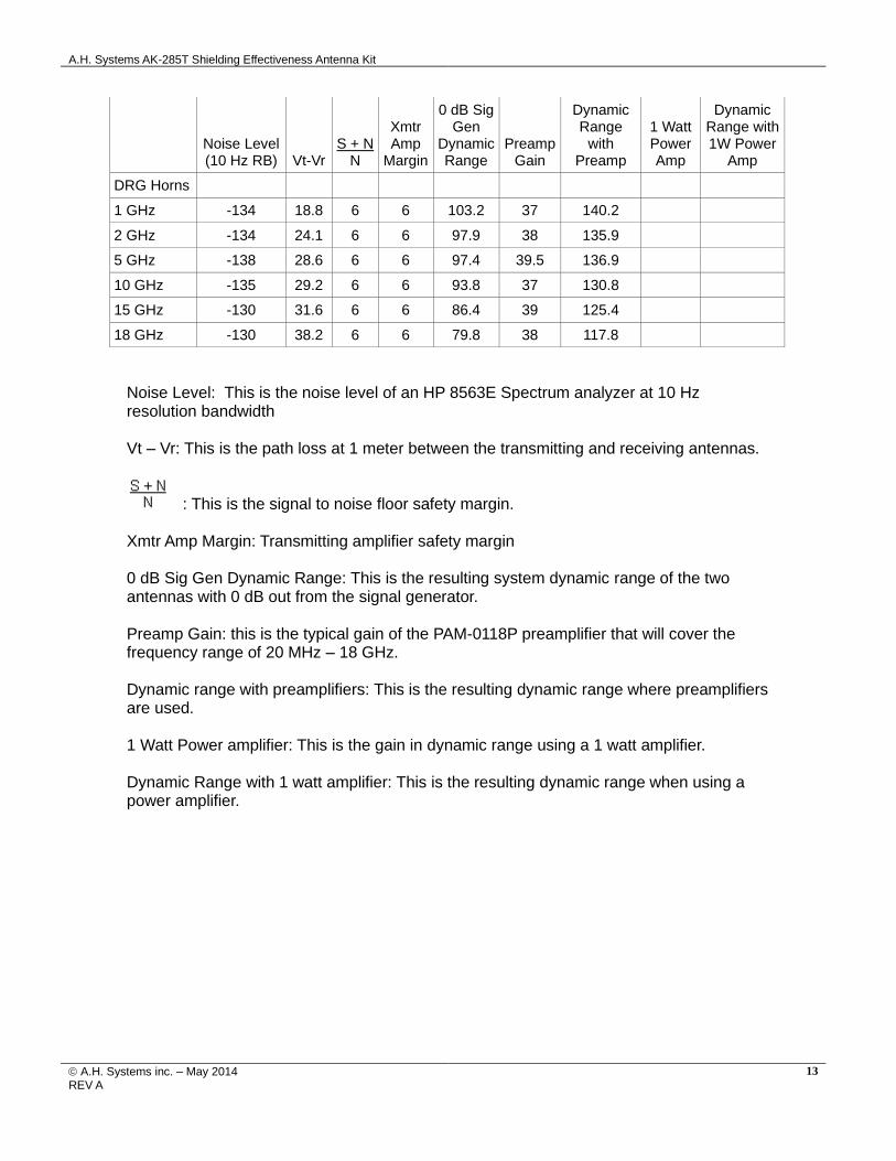
DRG Horns
1 GHz -134 18.8 6 6 103.2 37 140.2
2 GHz -134 24.1 6 6 97.9 38 135.9
5 GHz -138 28.6 6 6 97.4 39.5 136.9
10 GHz -135 29.2 6 6 93.8 37 130.8
15 GHz -130 31.6 6 6 86.4 39 125.4
18 GHz -130 38.2 6 6 79.8 38 117.8
Noise Level: This is the noise level of an HP 8563E Spectrum analyzer at 10 Hz resolution bandwidth Vt – Vr: This is the path loss at 1 meter between the transmitting and receiving antennas.
: This is the signal to noise floor safety margin.
Xmtr Amp Margin: Transmitting amplifier safety margin 0 dB Sig Gen Dynamic Range: This is the resulting system dynamic range of the two antennas with 0 dB out from the signal generator. Preamp Gain: this is the typical gain of the PAM-0118P preamplifier that will cover the frequency range of 20 MHz – 18 GHz. Dynamic range with preamplifiers: This is the resulting dynamic range where preamplifiers are used. 1 Watt Power amplifier: This is the gain in dynamic range using a 1 watt amplifier. Dynamic Range with 1 watt amplifier: This is the resulting dynamic range when using a power amplifier.

A.H. Systems AK-285T Shielding Effectiveness Antenna Kit
© A.H. Systems inc. – May 2014 REV A
14
ANTENNA FORMULAS AND CALCULATIONS
E-FIELD ANTENNAS Add antenna factor plus cable loss to receiver reading in dBuV to convert to field strength in dBuV/meter. Field Strength(dBuV/m) = SA(dBuV) + AF(dB/m) + cable loss (dB)
LOOP ANTENNA Add the magnetic antenna factor plus cable loss to receiver reading in dBuV to convert to field strength in dBuA/meter. dBuA/m = dBuV + Magnetic AF(dB/m) + Cable Loss dBuV/m = dBuA/m + 51.5 dB

A.H. Systems AK-285T Shielding Effectiveness Antenna Kit
© A.H. Systems inc. – May 2014 REV A
15
TYPICAL CONVERSION FORMULAS
LOG -> LINEAR VOLTAGE FIELD STRENGTH & POWER DENSITY
dBV to Volts V = 10 ((dBV – 120) / 20) dBV/m to V/m V/m = 10 (((dBV/m) -120) / 20)
Volts to dBV dBV = 20 log(V) + 120 V/m to dBV/m dBV/m = 20 log(V/m) + 120
dBV to Volts V = 10 (dBV / 20) dBV/m to dBmW/m2 dBmW/m2 = dBV/m – 115.8
Volts to dBV dBV = 20log(V) dBmW/m2 to dBV/m dBV/m = dBmW/m2 + 115.8
dBV to dBV dBV = dBV +120 dBV/m to dBA/m dBA/m = dBV/m – 51.5
dBV to dBV dBV = dBV - 120 dBA/m to dBV/m dBV/m = dBA + 51.5
LOG -> LINEAR CURRENT dBA/m to dBpT DBpT = dBA/m + 2
dBA to uA A = 10 (dBA / 20) dBpT to dBA/m dBA/m = dBpT – 2
A to dBA dBA = 20 log(A) W/m2 to V/m V/m = SQRT(W/m2 * 377)
dBA to A A = 10 (dBA / 20) V/m to W/m2 W/m2 = (V/m)2 / 377
A to dBA dBA = 20log(A) T to A/m A/m = T / 1.25
dBA to dBA dBA = dBA + 120 A/m to T T = 1.25 * A/m
dBA to dBA dBA = dBA -120 E-FIELD ANTENNAS
LOG -> LINEAR POWER Correction Factor dBV/m = dBV + AF
dBm to Watts W = 10((dBm – 30)/10) Field Strength V/m = 30 * watts * Gain numeric
meters Watts to dBm dBm = 10log(W) + 30 Required Power Watts = (V/m * meters)2
30 * Gain numeric
dBW to Watts W = 10(dBW / 10) LOOP ANTENNAS
Watts to dBW dBW = 10log(W) Correction Factors dBA/m = dBV + AF
dBW to dBm dBm = dBW + 30 Assumed E-field for shielded loops
dBV/m = dBA/m + 51.5
dBm to dBW dBW = dBm - 30 dBpT = dBV + dBpT/V
TERM CONVERSIONS
dBm to dBV dBV = dBm + 107 (50)
dBV = dBm + 10log(Z) + 90
CURRENT PROBES
dBV to dBm dBm = dBV – 107 (50)
dBm = dBV – 10log(Z) – 90
Correction Factor dBA = dBV – dB(ohm)
dBm to dBA dBA = dBm – 73 (50)
dBA = dBm – 10log(Z) + 90
Power needed for injection probe given voltage(V) into
50 load and Probe Insertion Loss (IL)
dBA to dBm dBm = dBA + 73 (50)
dBm = dBA + 10log(Z) – 90
Watts = 10 ((IL + 10log(V2/50))/10)
dBA to dBV dBV = dBA + 34 (50)
dBV = dBA + 20log(Z)
dBV to dBA dBA = dBV – 34 (50)
dBA = dBV – 20log(Z)

A.H. Systems AK-285T Shielding Effectiveness Antenna Kit
© A.H. Systems inc. – May 2014 REV A
16
MAINTENANCE
MAINTENANCE PROCEDURES
Proper antenna maintenance should include:
• Visual inspection of RF connectors
• Check for loose or missing hardware
• Check for corrosion near the joints
At least once a month it is a good idea to wipe down the antenna with a damp
rag.
ANNUAL CALIBRATION
To ensure reliable and repeatable long-term performance, annual re-calibration of your antennas, preamplifiers and current probes by A.H. Systems experienced technicians is recommended. Our staff can calibrate almost any type or brand of antenna.
It is always up to the user to determine the appropriate interval for calibration certification based on the requirements of the end user’s specific test/application. The calibration of EMC antennas is important for those conforming to compatibility standard. Radiated emissions testing for electromagnetic compatibility (EMC) requires the measurement of electric field (E-field) strength, which is compared with a limit level. The output voltage of an antenna is converted to E-field strength via its antenna factor, the measurement of which must include the uncertainty components related to that particular antenna, taking into consideration the environment in which the antenna is to be used for the testing. Most standards will specify the appropriate interval for re-calibration of your EMC antenna.
In some cases, these antennas are used for a manufacturer’s pre-compliance testing, field monitoring, surveillance and/or other applications where the exact field intensity of the received signal is not of importance. For those customers a yearly re-calibration is not necessary, however it is recommended that an interval for maintenance be performed.
For more information about our calibration services or to place an order for antenna calibration visit our website at http://www.AHSystems.com or cal l 1(818) 998-0223.
![Patch Antenna[1]](https://static.fdokumen.com/doc/165x107/63158e4cc32ab5e46f0d5c89/patch-antenna1.jpg)