Active Vibration Isolation Using an Electrical Damper or an ...
Upload
khangminh22Category
view
6download
0
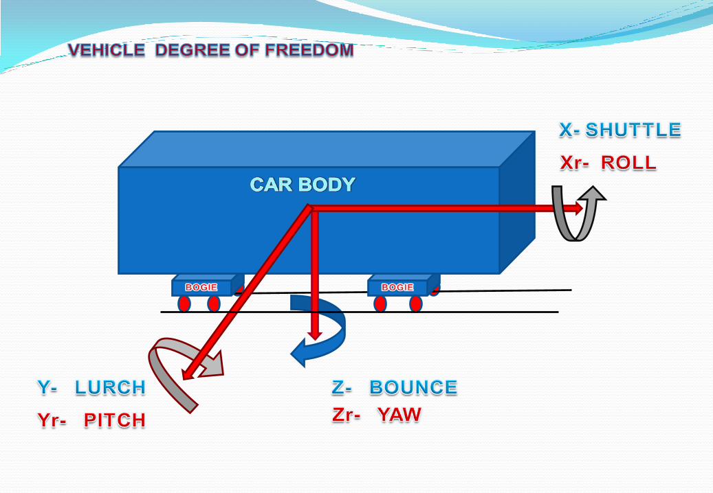

MODEL WITH 2 DEGREE OF FREEDOM
SHELL
DAMPER
BOGIE
SEC. SPRING
PRI. SPRING
WHEEL SET
TRACK
EQUATION OF MOTION

VEHICLE DYNAMIC SIMULATIONS HELPS TO PRE INVESTIGATE THE
STATIC, QUASISTATIC AND DYNAMIC BEHAVIOR OF RUNNING
VEHICLE SYSTEM IN DIFFERENT DYNAMICS CONDITIONS, VARING
LOAD WITH SPECIFIED GEOMETRY CONDITIONS OF TRACK AND
WHEEL-RAIL INETRACTION. TO OPTIMIZE THE SUSPENSION
CHARACTERISTICS FOR DESIGNED CRITICAL SPEED OF VEHICLE
WITH SAFE & IMPROVED RIDING .
QUASISTATIC : WHEN VEHICLE RUNS WITH CONSTANT SPEED ON IDEAL TRACK
WITH CONSTANT CURVE RADIUS, CANT AND WHEEL RAIL FRICTION.
QUASISTATIC LIMIT FOR LATERAL FORCES IN CURVES = 60 KN
( V=5.4 KMPH) AS PER UIC-518.
$------------------------------------------------------
---------------MDI_HEADER
[MDI_HEADER]
FILE_TYPE = 'dpr'
FILE_VERSION = 4.0
FILE_FORMAT = 'ASCII'
$------------------------------------------------------
--------------------UNITS
[UNITS]
LENGTH = 'meter‘
ANGLE = 'degrees‘
FORCE = 'newton‘
MASS = 'kg‘
TIME = 'second'
$------------------------------------------------------
--------------------CURVE
[CURVE]
{ vel force}
-1.0 -1000.0
-0.28 -400.0
-0.16 -300.0
-0.09 -200.0
-0.04 -100.0
0.0 0.0
0.04 100.0
0.09 200.0
0.16 300.0
0.28 400.0
1.0 1000.0
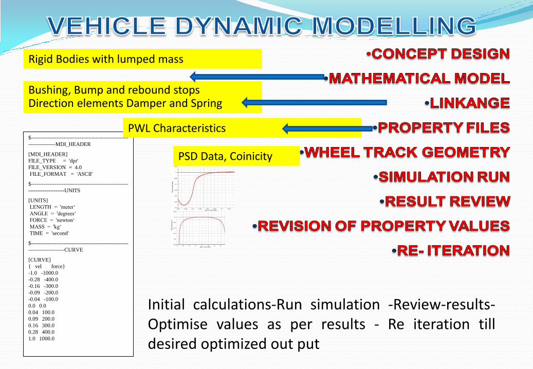
Bushing, Bump and rebound stops Direction elements Damper and Spring
Rigid Bodies with lumped mass
PWL Characteristics
PSD Data, Coinicity
Initial calculations-Run simulation -Review-results- Optimise values as per results - Re iteration till desired optimized out put
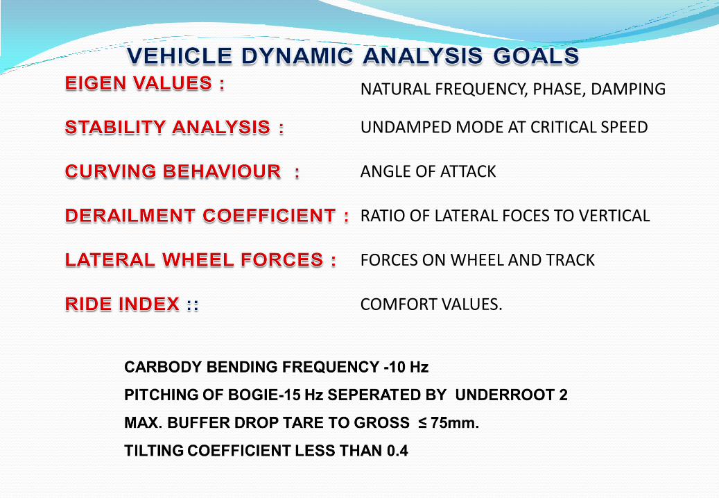
NATURAL FREQUENCY, PHASE, DAMPING
UNDAMPED MODE AT CRITICAL SPEED
ANGLE OF ATTACK
RATIO OF LATERAL FOCES TO VERTICAL
FORCES ON WHEEL AND TRACK
COMFORT VALUES.
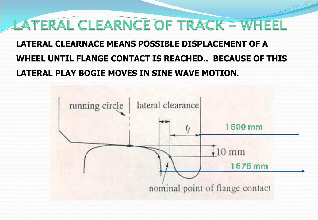
LATERAL CLEARNACE MEANS POSSIBLE DISPLACEMENT OF A
WHEEL UNTIL FLANGE CONTACT IS REACHED.. BECAUSE OF THIS
LATERAL PLAY BOGIE MOVES IN SINE WAVE MOTION.

Sinusoidal motion of wheel set
A cylindrical wheel with minor disturbance will take an extreme
position and will never return back towards center line on its
own.
Taper on tread of 1:20 gives self centering effect and changed
rolling radius works as differential on curves.
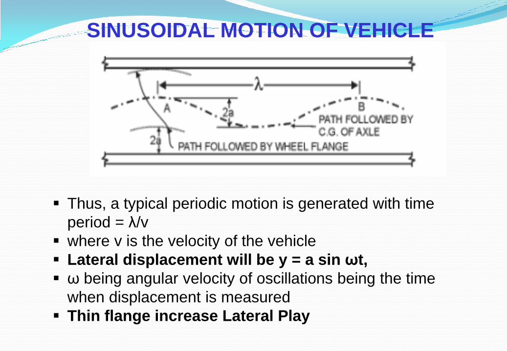
SINUSOIDAL MOTION OF VEHICLE
Thus, a typical periodic motion is generated with time
period = λ/v
where v is the velocity of the vehicle
Lateral displacement will be y = a sin ωt,
ω being angular velocity of oscillations being the time
when displacement is measured
Thin flange increase Lateral Play

KLINGEL’S FORMULA Wave Length 0 of a Single wheel
0 =
G = Dynamic Gauge
r = Dynamic Wheel Radius
= Conicity
0 ; Frequency
22
rG
1
Hollow tyre increase conicity of wheel LARGER CONICITY REAULTS IN LOWER WAVE LENGTH AND HIGH FREQUENCY RESLUTING IN STABILITY --- LOWER CRITICAL SPEED IN BOGIE HUNTING---
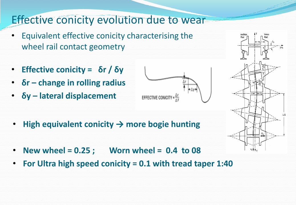
Effective conicity evolution due to wear • Equivalent effective conicity characterising the
wheel rail contact geometry
• High equivalent conicity → more bogie hunting
• New wheel = 0.25 ; Worn wheel = 0.4 to 08
• For Ultra high speed conicity = 0.1 with tread taper 1:40
• Effective conicity = δr / δy
• δr – change in rolling radius
• δy – lateral displacement

SECTIONAL PLAN OF WHEEL FLANGE AT LEVEL OF FLANGE TO RAIL CONTACT
Sectional plan of wheel flange at level of flange to Rail contact
Due to lateral clearance between wheel & track, Axle may assume intermediate angular position.
On curves wheel obliquity is accentuated in proportion to ratio of wheel base and radius of curvature.
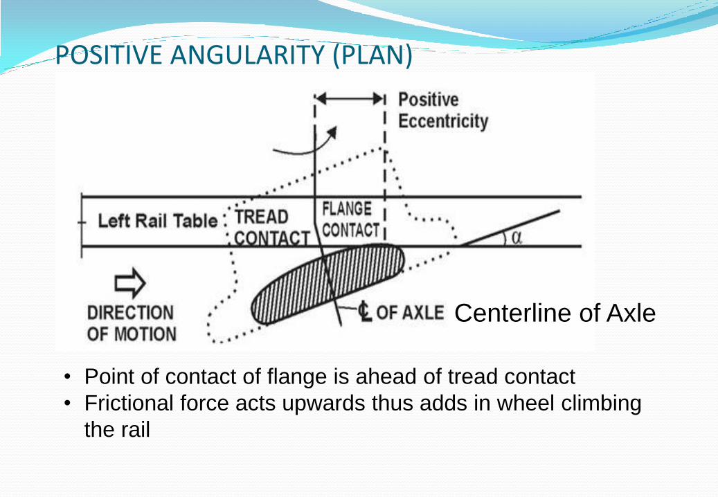
POSITIVE ANGULARITY (PLAN)
Centerline of Axle
• Point of contact of flange is ahead of tread contact
• Frictional force acts upwards thus adds in wheel climbing
the rail
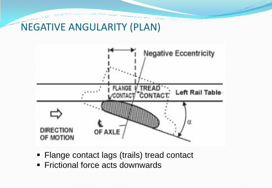
NEGATIVE ANGULARITY (PLAN)
Flange contact lags (trails) tread contact
Frictional force acts downwards
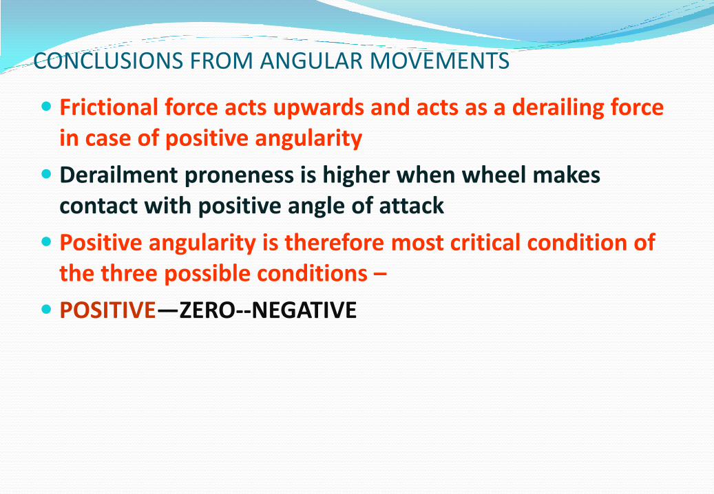
CONCLUSIONS FROM ANGULAR MOVEMENTS
Frictional force acts upwards and acts as a derailing force in case of positive angularity
Derailment proneness is higher when wheel makes contact with positive angle of attack
Positive angularity is therefore most critical condition of the three possible conditions –
POSITIVE—ZERO--NEGATIVE
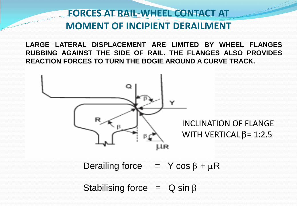
FORCES AT RAIL-WHEEL CONTACT AT MOMENT OF INCIPIENT DERAILMENT
Derailing force = Y cos + R
Stabilising force = Q sin
INCLINATION OF FLANGE WITH VERTICAL = 1:2.5
LARGE LATERAL DISPLACEMENT ARE LIMITED BY WHEEL FLANGES
RUBBING AGAINST THE SIDE OF RAIL. THE FLANGES ALSO PROVIDES
REACTION FORCES TO TURN THE BOGIE AROUND A CURVE TRACK.
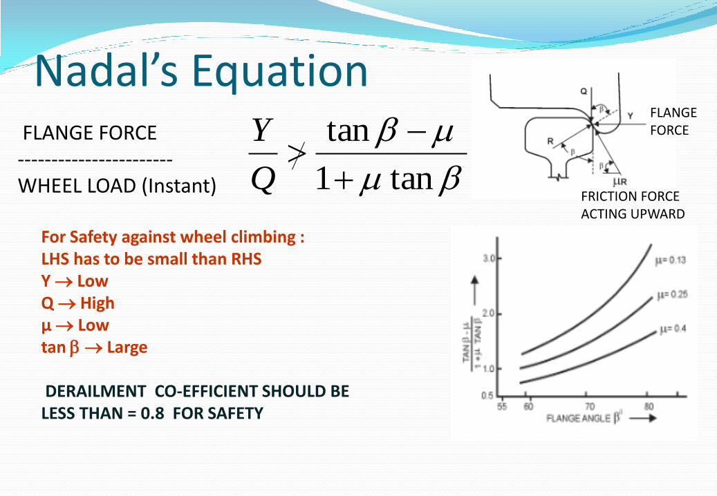
Nadal’s Equation
For Safety against wheel climbing : LHS has to be small than RHS Y Low Q High µ Low tan Large DERAILMENT CO-EFFICIENT SHOULD BE LESS THAN = 0.8 FOR SAFETY
tan1
tan
Q
Y FLANGE FORCE ----------------------- WHEEL LOAD (Instant)
FRICTION FORCE ACTING UPWARD
FLANGE FORCE
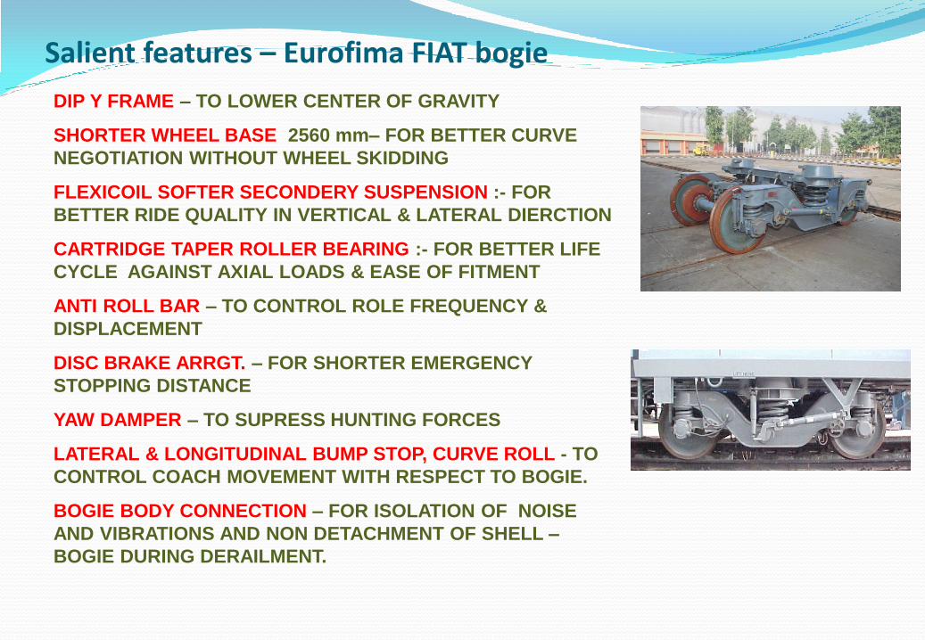
Salient features – Eurofima FIAT bogie
DIP Y FRAME – TO LOWER CENTER OF GRAVITY
SHORTER WHEEL BASE 2560 mm– FOR BETTER CURVE
NEGOTIATION WITHOUT WHEEL SKIDDING
FLEXICOIL SOFTER SECONDERY SUSPENSION :- FOR
BETTER RIDE QUALITY IN VERTICAL & LATERAL DIERCTION
CARTRIDGE TAPER ROLLER BEARING :- FOR BETTER LIFE
CYCLE AGAINST AXIAL LOADS & EASE OF FITMENT
ANTI ROLL BAR – TO CONTROL ROLE FREQUENCY &
DISPLACEMENT
DISC BRAKE ARRGT. – FOR SHORTER EMERGENCY
STOPPING DISTANCE
YAW DAMPER – TO SUPRESS HUNTING FORCES
LATERAL & LONGITUDINAL BUMP STOP, CURVE ROLL - TO
CONTROL COACH MOVEMENT WITH RESPECT TO BOGIE.
BOGIE BODY CONNECTION – FOR ISOLATION OF NOISE
AND VIBRATIONS AND NON DETACHMENT OF SHELL –
BOGIE DURING DERAILMENT.
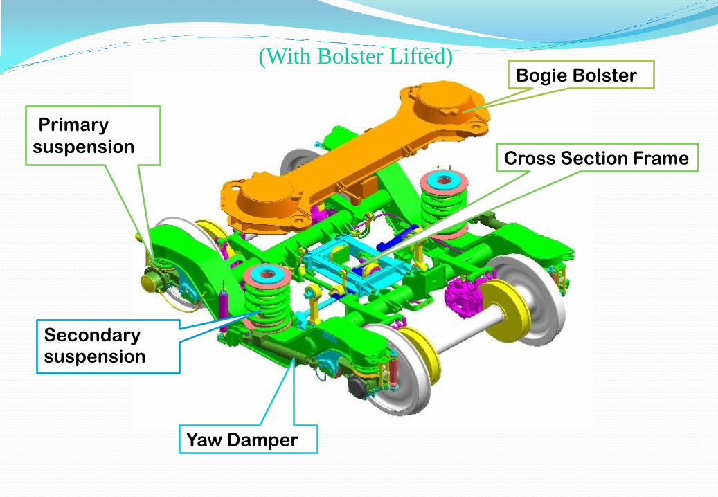
(With Bolster Lifted) Bogie Bolster
Secondary suspension
Yaw Damper
Primary
suspension Cross Section Frame
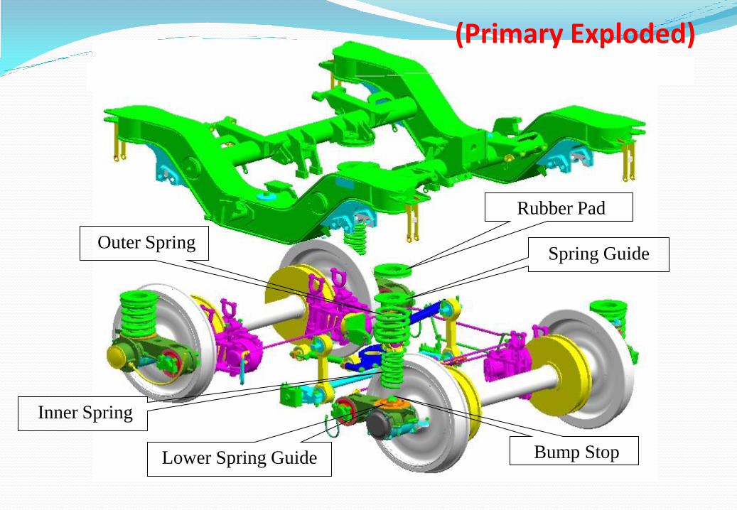
Rubber Pad
Spring Guide Outer Spring
Inner Spring
Bump Stop Lower Spring Guide
(Primary Exploded)

Wheelset --- Why condemening limit = 845 mm
Brake disks dia. = 640 mm.
Wheel discs Dia = 915 (New), 845 (worn).
New wheel radius = 915/2 = 457.5 mm
Brake disc radius = 640/2 = 320 mm
Ground clearance mandatory = 102 mm
m=Margin = 457 – (320+102) = 35 mm
Condemning limit =915 – (35x2) = 845mm
Variation allowed in size of wheel discs
Wheel disc one axle = 0.5 mm
Wheel disc one bogie = 5mm
Wheel disc one coach = 13 mm
W.I. as RCF MDTS 168
Dynamic balance at 320 rpm
Unbalance moment should be
</= 50 gm.
3M self adhesive strip or
Glue weights
Chisel Gasket Remover-Loctite 79040
Activator- Loctite 7075
Adhesive Loctite 324
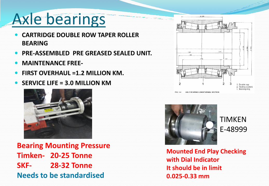
Axle bearings CARTRIDGE DOUBLE ROW TAPER ROLLER
BEARING
PRE-ASSEMBLED PRE GREASED SEALED UNIT.
MAINTENANCE FREE-
FIRST OVERHAUL =1.2 MILLION KM.
SERVICE LIFE = 3.0 MILLION KM
Bearing Mounting Pressure Timken- 20-25 Tonne SKF- 28-32 Tonne Needs to be standardised
Mounted End Play Checking with Dial Indicator It should be in limit 0.025-0.33 mm
TIMKEN E-48999

Self align double row spherical roller bearings
Induction Heating 130 -140 DEG. CEN
22326 C3 CK SELF ALIGNMENT UPTO 2.5 DEG.
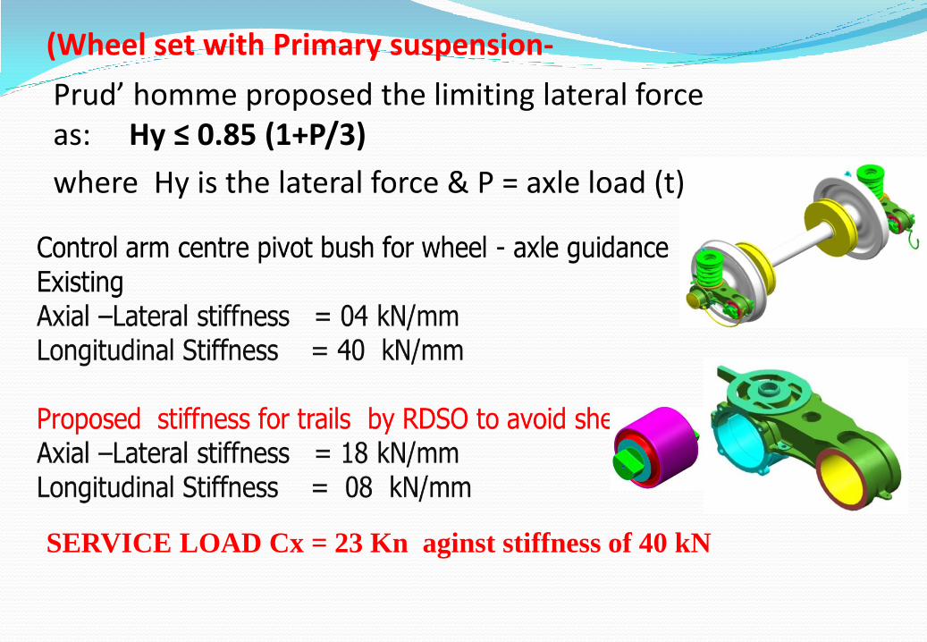
(Wheel set with Primary suspension-
Prud’ homme proposed the limiting lateral force as: Hy ≤ 0.85 (1+P/3)
where Hy is the lateral force & P = axle load (t)
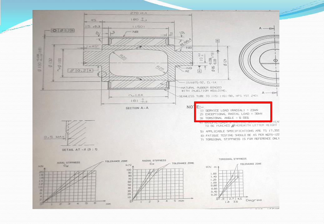
SERVICE LOAD Cx = 23 Kn aginst stiffness of 40 kN
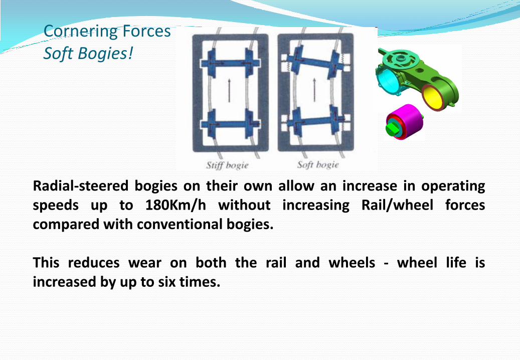
Cornering Forces Soft Bogies!
Radial-steered bogies on their own allow an increase in operating speeds up to 180Km/h without increasing Rail/wheel forces compared with conventional bogies. This reduces wear on both the rail and wheels - wheel life is increased by up to six times.
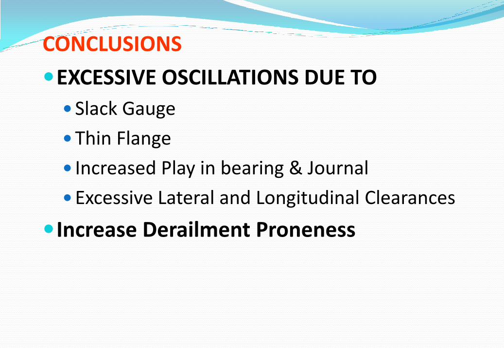
CONCLUSIONS
EXCESSIVE OSCILLATIONS DUE TO
Slack Gauge
Thin Flange
Increased Play in bearing & Journal
Excessive Lateral and Longitudinal Clearances
Increase Derailment Proneness
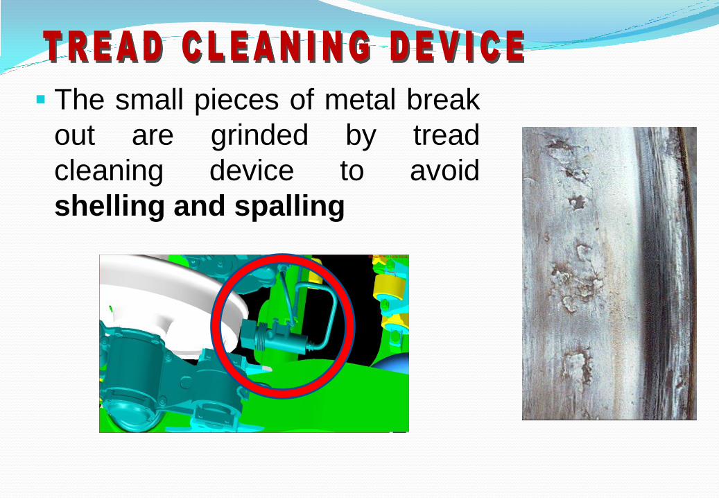
The small pieces of metal break
out are grinded by tread
cleaning device to avoid
shelling and spalling

04 nos Nested coil springs with top rubber pad, primary vertical
dampers, control arm, elastic joints - connecting the cartridge bearing
on wheel set to bogie frame.
Articulated Flexible guidance.
Vertical Stiffness outer = 475 N/mm Vertical Stiffness inner = 280 N/mm Combined Stiffness of nest = 755 N/mm PRI. VERTICAL DAMPERS -04 NOS. 4250 +/- 640 N @ 0.3 M/sec.
LATERAL STIFFNESS 5 TIMES THE VERTICAL STIFFNESS AND
LONGITUDINAL STIFFNESS. 16 TIMES OF VERTICAL STIFFNESS.
Primary suspension High stiffness- Low deflection springs nest
PRI BUMP STOP
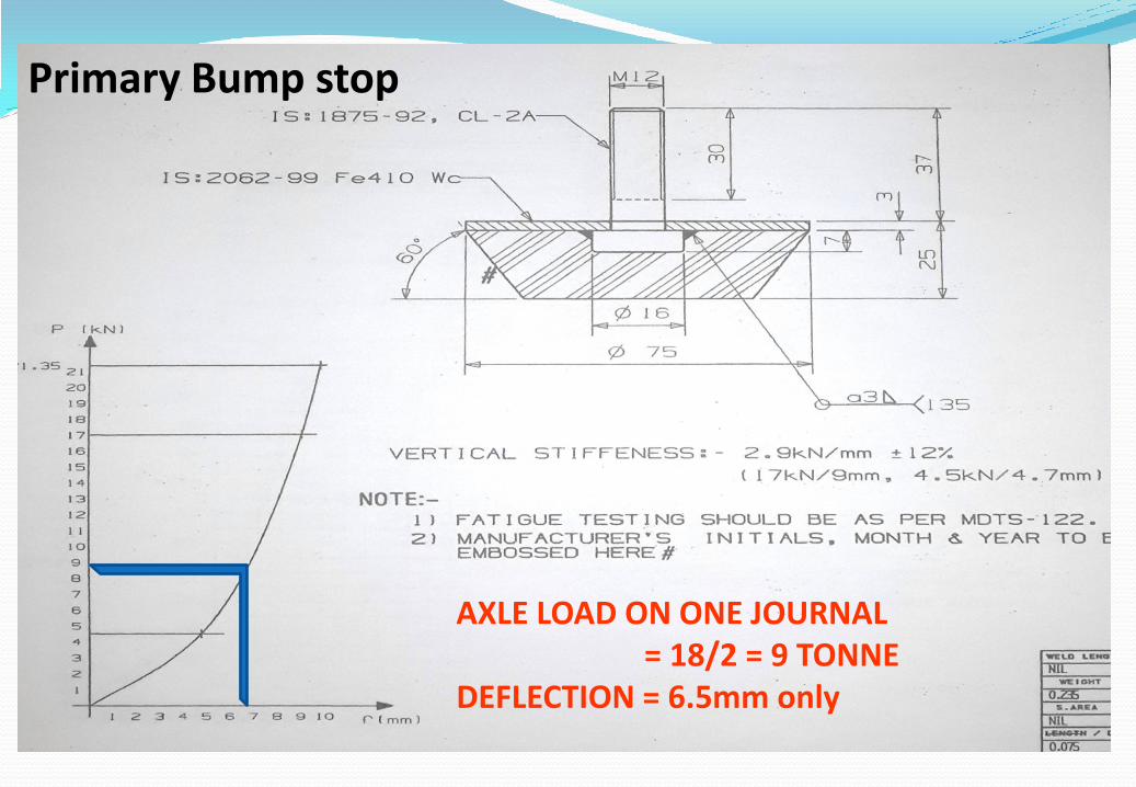
AXLE LOAD ON ONE JOURNAL = 18/2 = 9 TONNE DEFLECTION = 6.5mm only
Primary Bump stop

Spring Design
Stress= G * d^4 / 8 * Dm^3 * n -- N/mm.
G = MODULUS OF RIGIDITY
D = Bar Dia.
Dm = Mean Dia.
N = No. of active turns
RDSO SPEC WD-01-HLS-94 REV-3
MATERAIL – IS:3195-92
d<30 -60 - Si 7 ,
30<d<60 - 52Cr4Mo2v
Primary suspension---

Orientation of Outer & Inner Primary springs to avoid biting of coils and for balanced distribution of load on centering disc
1 - 4 3 - 2
Bottom side of primary springs

(With Secondary Spring System Exploded)
Bogie
Bolster
Miner Pad
Spring Guide
Outer Spring
Inner Spring
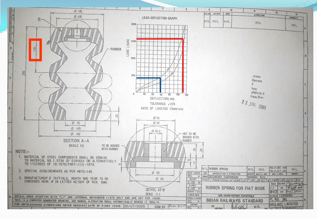
Rubber Spring

RESONANCE
Natural Frequency =
k = Spring Stiffness
m = Mass If frequency caused by external excitation is equal to
natural frequency, resonance occurs. If there is no
damping in the system, the amplitude becomes infinite
with time.
High stiffness >>>> High frequency >>> Poor Ride
m
k
2
1
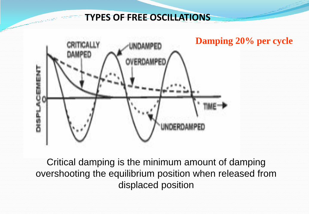
TYPES OF FREE OSCILLATIONS
Critical damping is the minimum amount of damping
overshooting the equilibrium position when released from
displaced position
Damping 20% per cycle

SECONDARY SUSPENSION NEST OF FLEXI-COIL SPRINGS INNER AND OUTER, RUBBER SPRING WITH (MINER )PAD &, PRI. VERTICAL, SEC. VERTICAL & LATERAL AND YAW DAMPERS AND ANTI ROLL BAR ETC.
SEC. VERTICAL DAMPERS -02 NOS.
3500 +/- 520 N @ 0.2 M/sec.
LATERAL DAMPERS -01 NOS.
8000 +/- 1200 N @ 0.3 M/sec.
YAW DAMPERS -02 NOS.
11000 +/- 1650 @ 0.1 M/sec.
Combined Vt. Stiffness Sec. Spg. =370.6 N/mm
Combined Lat.. Stiffness Sec. Spg. =195.6 N/mm
Lateral flexibility provide better lateral ride.
RATIO PRI AND SEC STIFFNESS 755 N/mm : 370 N/mm 67 % : 33 %
SEC. VT.-D
YAW-D
SEC. LAT-D

Velocity = 𝜋 ∗ 𝑓 ∗ 𝑐 = 𝜋 * rpm *stroke 60 Act.disp./Force delivered by damper u/F = (1 /k) – (1/wd) k = series stiffness w = 2𝜋f
d = Damping Cofficient By Fourier Analysis

Secondary Suspension
Conventional Bogie
Flexi-coil suspension
Helical coil suspension
Fiat Bogie
Vt . Stiff. =471 N/mm d=42 mm ; Dm=242mm N= 6.25 ; F.H.=400 mm
Vt .Stiff.=241-O, 129 -I N/mm (370 N/mm) d= outer 34 -- -Inner 26 Dm= outer 246, Inner 138 n= outer 8.3, inner=6.6 F.H. =outer707 inner 663 mm

• Each flexicoil spring is provided with the
following markings:
• The positive directions of the alignment
deviations is indicated with an Aluminium
band (secured tightly and wound twice
around the spring)
• The length of the spring under test load
and the value of the alignment deviation
(in mm) are printed on a nonferrous
metal band.
ALIGNMENT DEVIATION
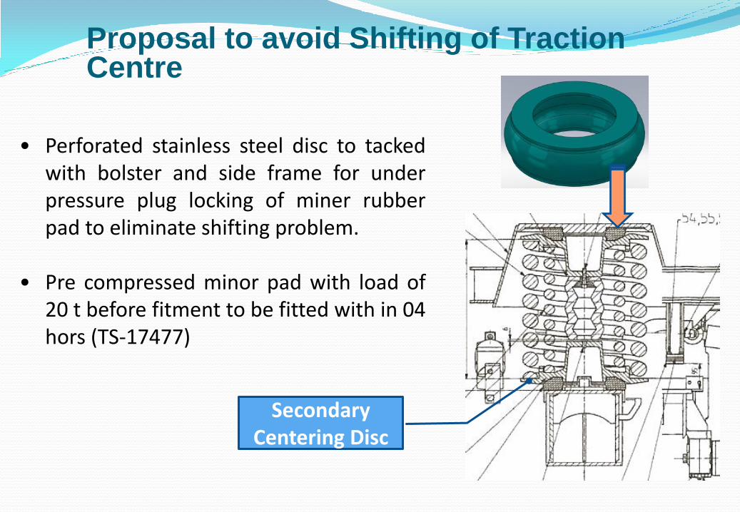
Proposal to avoid Shifting of Traction Centre
• Perforated stainless steel disc to tacked with bolster and side frame for under pressure plug locking of miner rubber pad to eliminate shifting problem.
• Pre compressed minor pad with load of 20 t before fitment to be fitted with in 04 hors (TS-17477)
Secondary
Centering Disc

ALIGNMENT DEVIATION (COUPLING INSTRUCTIONS) The difference between the alignment deviations of the
two outer springs not to exceed 4 mm and that of the inner springs 8 mm.
The outer and inner springs with the greater alignment deviations must be situated in the same spring assembly, that is:
If A greater than B, C should be greater than D
A - B = 4 mm max, C - D = 8 mm max
C A B D OUTER SPG. BAND OUTSIDE
INNER SPG BAND INSIDE
OUTER SPG. BAND OUTSIDE
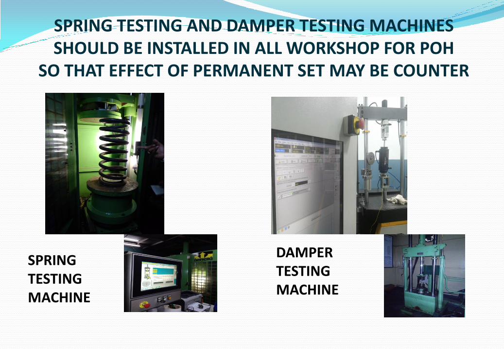
SPRING TESTING AND DAMPER TESTING MACHINES SHOULD BE INSTALLED IN ALL WORKSHOP FOR POH
SO THAT EFFECT OF PERMANENT SET MAY BE COUNTER
DAMPER TESTING MACHINE
SPRING TESTING MACHINE
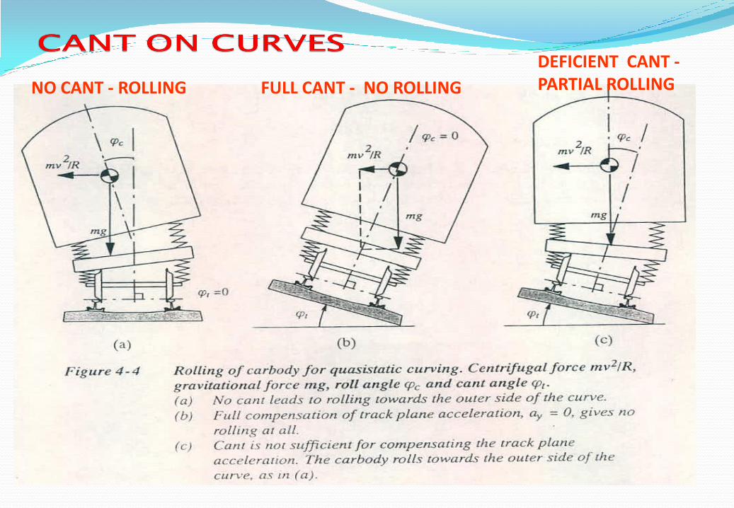
NO CANT - ROLLING FULL CANT - NO ROLLING
DEFICIENT CANT - PARTIAL ROLLING
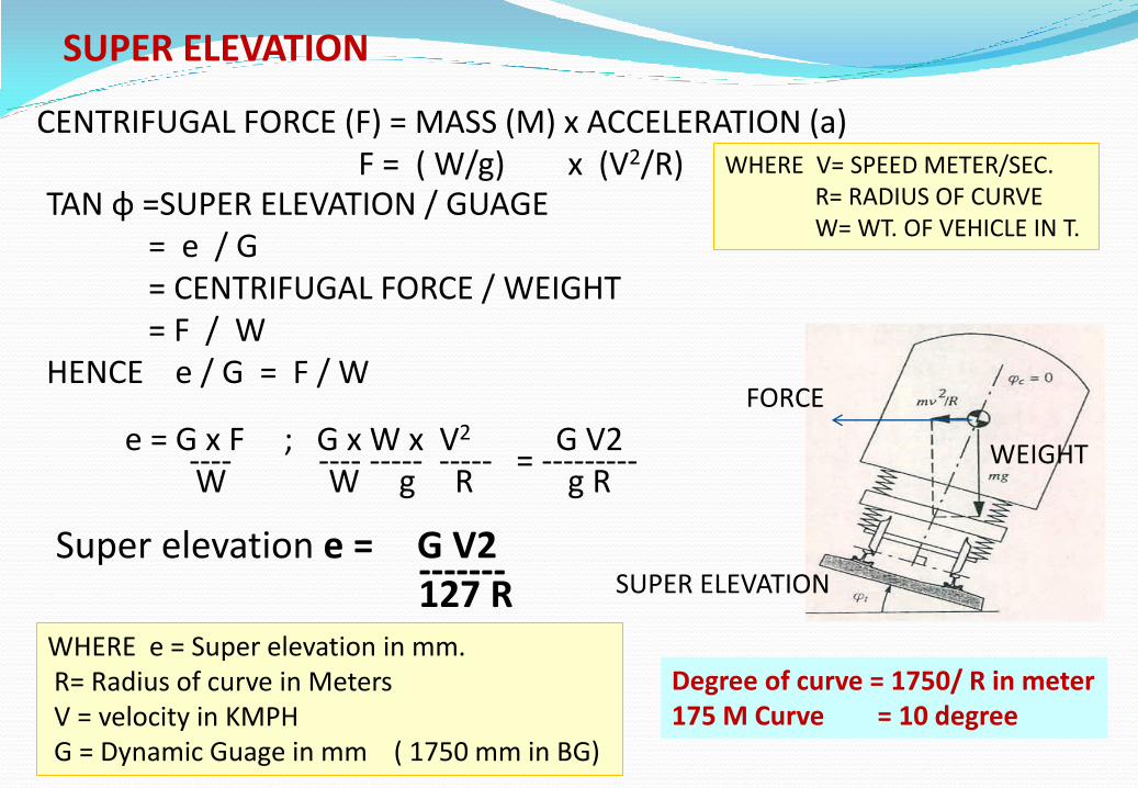
CENTRIFUGAL FORCE (F) = MASS (M) x ACCELERATION (a) F = ( W/g) x (V2/R) WHERE V= SPEED METER/SEC.
R= RADIUS OF CURVE W= WT. OF VEHICLE IN T.
TAN φ =SUPER ELEVATION / GUAGE = e / G = CENTRIFUGAL FORCE / WEIGHT = F / W HENCE e / G = F / W e = G x F ; G x W x V2 G V2 ---- ---- ----- ----- = --------- W W g R g R Super elevation e = G V2 ------- 127 R
FORCE
WEIGHT
SUPER ELEVATION
WHERE e = Super elevation in mm. R= Radius of curve in Meters V = velocity in KMPH G = Dynamic Guage in mm ( 1750 mm in BG)
Degree of curve = 1750/ R in meter 175 M Curve = 10 degree
SUPER ELEVATION

ANTI-ROLL BAR :
ANTI ROLL BAR USED TO CONTROL EXCESSIVE ROLLING MOTION AND TO CONTROL ROLL FREQUENCY. LOW ROLL FREQ. CAN LEAD TO NAUSEA ASSOCIATED WITH SEA SICKNESS.
TILTING CO-EFFICIENT AS PER UIC-515-1 & 4 SHOULD BE LESS THAN 0.4 AT HIGH SPEED ON THE SHARPEST CURVE WITH MAX. PERMITTED CANT DEFICIENCY FOR KEEPING THE VEHICLE WITHIN DYNAMIC MOVING GUAGE AND FOR PASSENGER COMFORT.
UIC-515-4 , Wind pr. 600 n/m^2 , Lateral force=43.2 kN , Tilting Momentum=108 kN

BOGIE FRAME
Y-DIP SIDE FRAMES OF MATERIAL S355J2W+N EN10025 Part-5 in
place of ST5 2.3
TWO SIDE FRAMES CONNECTED BY TWO BRAKE BEAM ASSEMBLY
( CROSS TUBES- DIN.1630-ST52.4 OD=168.3 THK=14.2 MM )
WHICH SUPPORTS :
CONTROL ARM BRACKETS
SUPPORT BRAKE SUPPORT ,
PRIMARY SPRING POTS
ANCHOR LINK BRACKETS
CROSS SECTION FRAME FOR LATERAL
AND LOGITUDINAL BUMP STOPS ETC.
Surface protection Garnet Ballast Sa 2.5DIN 8501
Adhesion promoting Etch primer if ballsating not possible.
Epoxy zinc phosphate primer RDSO spec M&C/PCN/100/2013
Visco elastic aqueous synthetic resin Anti Stone Chipping Paint RCF MDTS 22283. for corrosion preention.
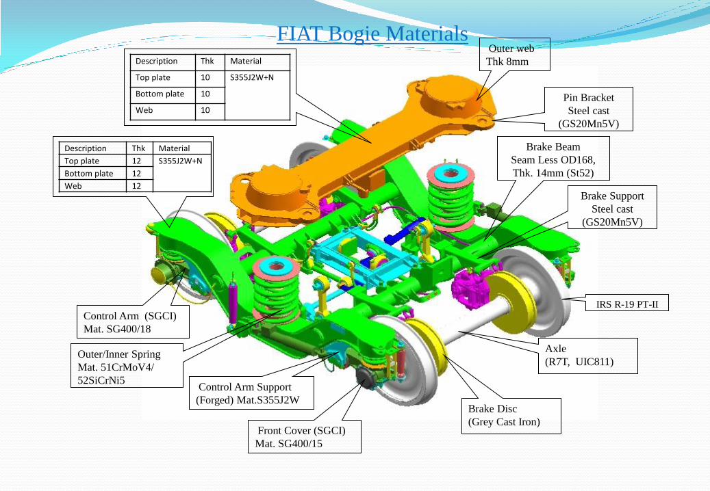
FIAT Bogie Materials Outer web
Thk 8mm
IRS R-19 PT-II
Description Thk Material
Top plate 10 S355J2W+N
Bottom plate 10
Web 10
Description Thk Material
Top plate 12 S355J2W+N
Bottom plate 12
Web 12 Brake Support
Steel cast
(GS20Mn5V)
Pin Bracket
Steel cast
(GS20Mn5V)
Control Arm Support
(Forged) Mat.S355J2W
Front Cover (SGCI)
Mat. SG400/15
Axle
(R7T, UIC811)
Brake Disc
(Grey Cast Iron)
Brake Beam
Seam Less OD168,
Thk. 14mm (St52)
Control Arm (SGCI)
Mat. SG400/18
Outer/Inner Spring
Mat. 51CrMoV4/
52SiCrNi5
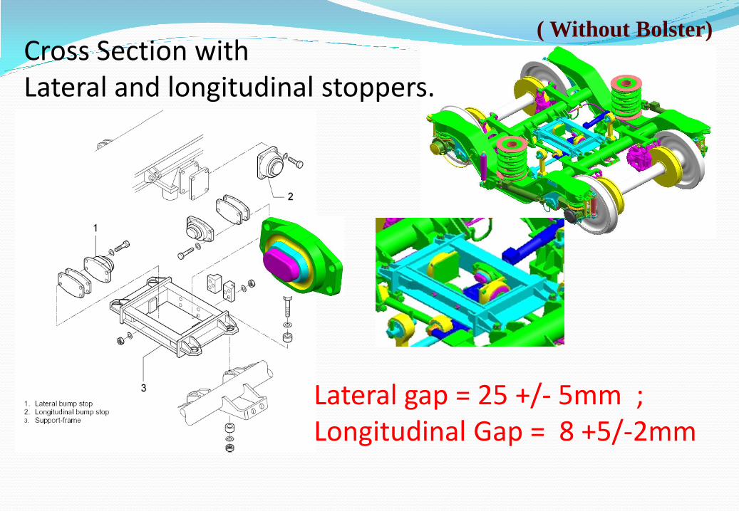
( Without Bolster) Cross Section with Lateral and longitudinal stoppers.
Lateral gap = 25 +/- 5mm ; Longitudinal Gap = 8 +5/-2mm

Anti Roll Assly
Traction Lever Traction Center
Curve Roll
Traction center with traction levers

Traction and braking forces:
BODY-BOGIE BOLSTER CENTER POST -TRACTION CENTRE-TRACTION LEVER/LONGITUDINAL BUMP STOP-BOGIE FRAME-CONTROL ARM-AXLES.

CURVE ROLL ON COACH END SIDE TO RESTRICT EXCESS ROTATION OF BOGIE WITH RESPECT TO COACH
STOPPER BRACKET NEAR FOOT STEP ARRGT. ON UNDER FRAME FOR RESTRICTED MOVEMENT OF CURVE ROLL

Important clearances in dynamic situation
55
With
shim
Without
shim
Vertical stopper
gap
Gap between
bolster and
mounting frame

Bogie Body Connection

Bogie Body Connection Provides rigid connection between body and bogie Capable to transmit 0.25g acceleration in lateral
and longitudinal in normal operation and 5g in emergency condition
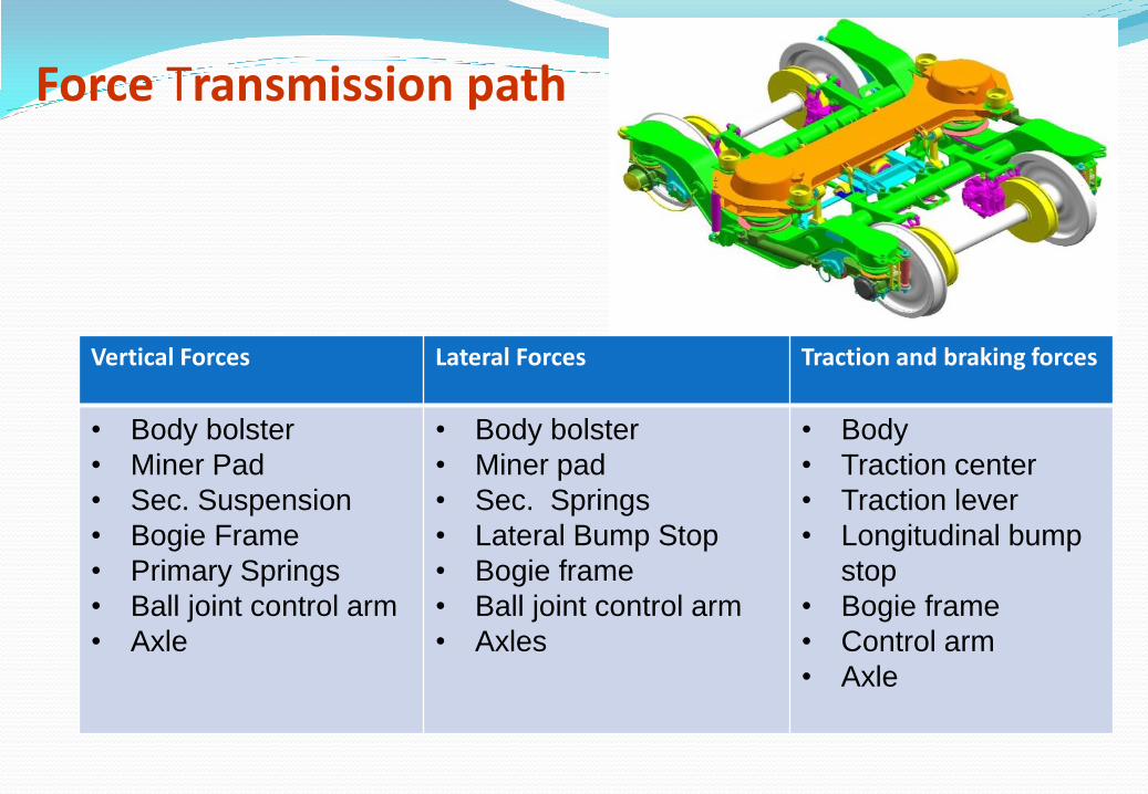
Force Transmission path
Vertical Forces Lateral Forces Traction and braking forces
• Body bolster
• Miner Pad
• Sec. Suspension
• Bogie Frame
• Primary Springs
• Ball joint control arm
• Axle
• Body bolster
• Miner pad
• Sec. Springs
• Lateral Bump Stop
• Bogie frame
• Ball joint control arm
• Axles
• Body
• Traction center
• Traction lever
• Longitudinal bump
stop
• Bogie frame
• Control arm
• Axle
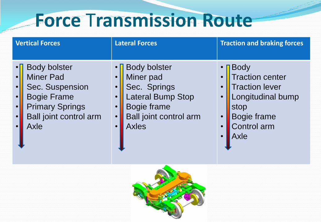
Force Transmission Route Vertical Forces Lateral Forces Traction and braking forces
• Body bolster
• Miner Pad
• Sec. Suspension
• Bogie Frame
• Primary Springs
• Ball joint control arm
• Axle
• Body bolster
• Miner pad
• Sec. Springs
• Lateral Bump Stop
• Bogie frame
• Ball joint control arm
• Axles
• Body
• Traction center
• Traction lever
• Longitudinal bump
stop
• Bogie frame
• Control arm
• Axle
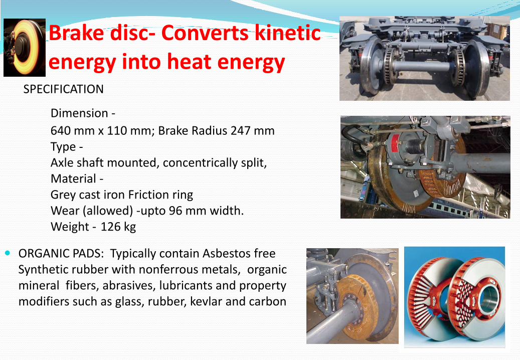
Brake disc- Converts kinetic energy into heat energy
SPECIFICATION
Dimension -
640 mm x 110 mm; Brake Radius 247 mm Type - Axle shaft mounted, concentrically split, Material - Grey cast iron Friction ring Wear (allowed) - upto 96 mm width. Weight - 126 kg
ORGANIC PADS: Typically contain Asbestos free Synthetic rubber with nonferrous metals, organic mineral fibers, abrasives, lubricants and property modifiers such as glass, rubber, kevlar and carbon
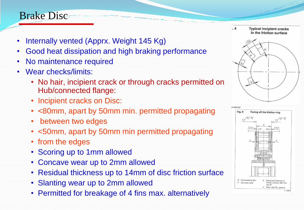
Brake Disc
• Internally vented (Apprx. Weight 145 Kg)
• Good heat dissipation and high braking performance
• No maintenance required
• Wear checks/limits:
• No hair, incipient crack or through cracks permitted on Hub/connected flange:
• Incipient cracks on Disc:
• <80mm, apart by 50mm min. permitted propagating
• between two edges
• <50mm, apart by 50mm min permitted propagating
• from the edges
• Scoring up to 1mm allowed
• Concave wear up to 2mm allowed
• Residual thickness up to 14mm of disc friction surface
• Slanting wear up to 2mm allowed
• Permitted for breakage of 4 fins max. alternatively
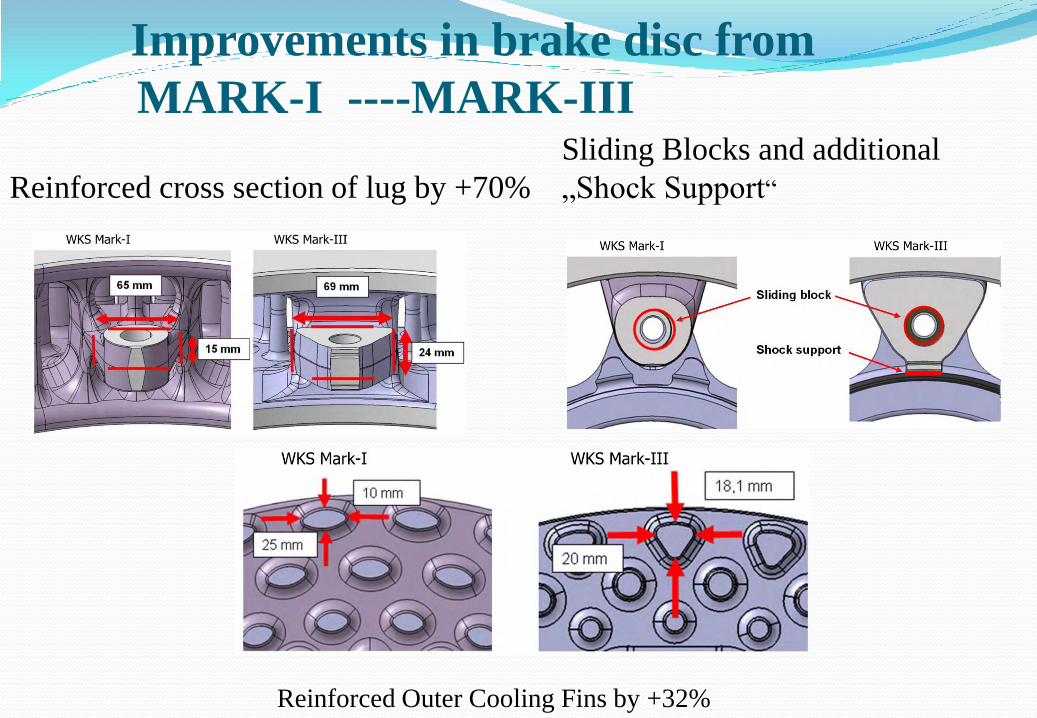
Reinforced cross section of lug by +70%
Improvements in brake disc from
MARK-I ----MARK-III Sliding Blocks and additional
„Shock Support“
Reinforced Outer Cooling Fins by +32%

Brake caliper & Brake pad
• Suitable for UIC type 200 x 2 brake pads,
thickness 35mm
• Caliper ratio -2.17 (2.48 for special coaches-
power car and DD)
•Brake radius - 247 mm
•Weight -67 kg (with brake pad)
•Wear limit - 28mm max.
• Approved 35 mm Non asbestos pads for LHB
JURID 877 of M/s Federl Mogul ( Honeywell) germany BECORIT 984 of M/s Becorit, Germany BK 7000 of M/s Bremskerl, Germany Friction co-eff.-0.35; Conforms to requirements in UIC 541-3 OR RDSO specification : CG/2013/CG-01

DISC BRAKE SYSTEM FOR 200 KMPH. Electro Pneumatic assist –Control panel
with elctro Magnet valve advantage in achieving uniform braking & EBD
Steel discs (instead of grey cast iron) per axle to keep the temperature of the brake discs and the pads under control
Flexible sintered pads - provides iso-pressure even in case of wear of pads and brake energy upto 40 MJ / disc
Life cost cycle of CS Disc + sintered 185 % in comparison to than GCI disc +organic pads

AMDBS –Schematic
Layout
Speed Sensor
Dump Valve
Pneumatic
Electric
WSP-Electronic
Vehicle-Bus UBatt.
Phonic
Wheel
Brake Pad
Brake Disc

DETAILED VIEW OF EARTHING ARRGT.
66
Shell body to bogie
frame earthing cable
Bogie frame to axle
earthing cable
Resistor earthing
cable
Copper bush earthing arrangement on
axle end.
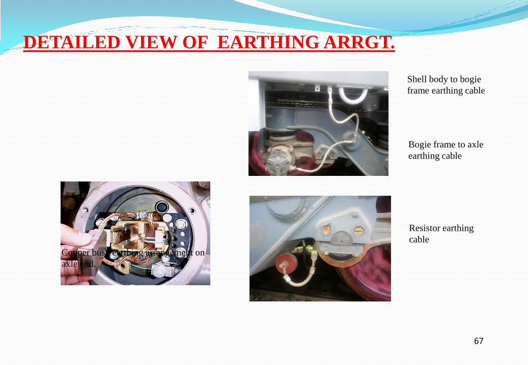
DETAILED VIEW OF EARTHING ARRGT.
67
Shell body to bogie
frame earthing cable
Bogie frame to axle
earthing cable
Resistor earthing
cable
Copper bush earthing arrangement on
axle end.

68
LS1- With 100 seater, chair car spring, SBC underslung
LS2- Chair car springs with 32 mm shim, Suitable for 16 T pay load
Under-slung water tanks 2x685 ltrs removed
Transverse luggage rack shifted upward
LS-3 variant LHB GS/EOG coach
Shalimar springs with 32 mm shim
Suitable for 18 T pay load
LS-4 variant LHB GS/EOG coach
Shalimar springs with stiffer secondary inner springs
with 32 mm shim Suitable for 22.6 T pay load
LS-5 WITH AIR SPRING IN SECONDARY 140 KN CAPCITY.


Maintain constant height at varying load Fewer variants required to be
stocked for various coaches Buffer height adjustments easy Helps in maintaining level of coach
under non-uniform loading Less failures as compared to helical
springs
Air spring as per rdso Spec cK-509 for Conv. and cK-508 for FIAT bogies
Secondary Air Suspension

Advantage of Air Spring over Helical Springs.
-Constant Buffer Height at varying pay loads.

construction The spring consists of an air bellow fitted
between two plates Air pressure creates an air gap between the plates
which provides cushioning
There is an inner emergency rubber spring also Comes in operation upon deflation of bellow or
during overload

FIAT-SG with 30 kW permanent magnet alternator
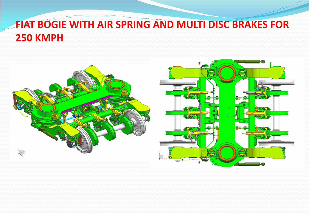
FIAT BOGIE WITH AIR SPRING AND MULTI DISC BRAKES FOR 250 KMPH

Wheel spalling :- spalling occurs as a result of fine thermal cracks joining to produce the loss of small
piece of tread material.
Wheel shelling :- shelling is due to result of stress generated by rolling contact fatigue and leading to
material flow and damage at wheel surface.
Rolling contact stresses are major factor controlling both shelling and spalling.
Fatigue process : dependent on magnitude and range of multi axial alternating stress component at or near
the tread surface. The presence of compressive normal stress on plane having greatest range of shear
stress would tend to inhibit crack nucleation and propagation. -----require information on the full
thermodynamic cycle of complex multiaxial stress experienced by tread surface and sub surface elements
during both wheel rotation and major breaking cycles.
Stress in rolling contact : Elastic contact pressure between wheel and rail has magnitude proportional the
cube root of the wheel loads. The associated half width of contact patch would be about 6.5mm.
Orthogonal sub surface shear stress cycle changes with addition of traction as would occur in a braked
wheel. Retarding force and traction at the contact increase, the max. Range of shear stress move towards
the surface, and tensile stresses begin to develop at the trailing edge of the wheel contact until friction ratio
exceed at least 0.25.
Impact effect : it can effect both crack initiation and crack propagation modes. It can arise from rail joints.
Wheel flats serves as sites for formation of additional flats and resulting shelling. Dipped joints or
corrugation impose repeated defects on wheel as it traverses and contact pressure can be increased by
factor of 3 or 4.
Martensite formation: Thermally induced metallurgical transformation of region in the tread surface can
contribute to cracking. Eventually spalls are formed by un tempered martensitic, which is very brittle --
cracks
Copyright © 2022 FDOKUMEN