Surface modifications of cellulose nanocrystals for biobased ...
Upload
khangminh22Category
view
2download
0
nanomaterials
Article
Shear-Coated Linear Birefringent and Chiral CelluloseNanocrystal Films Prepared from Non-Sonicated Suspensionswith Different Storage Time
Olga Rubi Juárez-Rivera 1 , Reina Araceli Mauricio-Sánchez 1, Kenneth Järrendahl 2 , Hans Arwin 2 andArturo Mendoza-Galván 1,*
�����������������
Citation: Juárez-Rivera, O.R.;
Mauricio-Sánchez, R.A.; Järrendahl,
K.; Arwin, H.; Mendoza-Galván, A.
Shear-Coated Linear Birefringent and
Chiral Cellulose Nanocrystal Films
Prepared from Non-Sonicated
Suspensions with Different Storage
Time. Nanomaterials 2021, 11, 2239.
https://doi.org/10.3390/
nano11092239
Academic Editors: Nae-Man Park and
Elena Vismara
Received: 17 July 2021
Accepted: 26 August 2021
Published: 30 August 2021
Publisher’s Note: MDPI stays neutral
with regard to jurisdictional claims in
published maps and institutional affil-
iations.
Copyright: © 2021 by the authors.
Licensee MDPI, Basel, Switzerland.
This article is an open access article
distributed under the terms and
conditions of the Creative Commons
Attribution (CC BY) license (https://
creativecommons.org/licenses/by/
4.0/).
1 Cinvestav-Unidad Querétaro, Libramiento Norponiente 2000, Querétaro 76230, Mexico;[email protected] (O.R.J.-R.); [email protected] (R.A.M.-S.)
2 Materials Optics, Department of Physics, Chemistry and Biology, Linköping University, SE-581 83 Linköping,Sweden; [email protected] (K.J.); [email protected] (H.A.)
* Correspondence: [email protected]; Tel.: +52-442-211-9922
Abstract: Nanocelluloses are very attractive materials for creating structured films with uniqueoptical properties using different preparation techniques. Evaporation-induced self-assembly ofcellulose nanocrystals (CNC) aqueous suspensions produces iridescent films with selective circularBragg reflection. Blade coating of sonicated CNC suspensions leads to birefringent CNC films. In thiswork, fabrication of both birefringent and chiral films from non-sonicated CNC suspensions using ashear-coating method is studied. Polarization optical microscopy and steady-state viscosity profilesshow that non-sonicated CNC suspensions (concentration of 6.5 wt%) evolve with storage time froma gel-like shear-thinning fluid to a mixture of isotropic and chiral nematic liquid crystalline phases.Shear-coated films prepared from non-sonicated fresh CNC suspensions are birefringent, whereasfilms prepared from suspensions stored several weeks show reflection of left-handed polarized light.Quantification of linear and circular birefringence as well circular dichroism in the films is achievedby using a Mueller matrix formalism.
Keywords: cellulose nanocrystals; structural color; linear birefringence; circular dichroism;Mueller matrix
1. Introduction
Cellulose is the most abundant biopolymer on earth. Polymer chains of celluloseconformed by β-1,4 glucopyranose units interact thorough hydrogen bonds leading toformation of semicrystalline fibrils [1]. Nanocellulose materials (nanofibrils and nanocrys-tals) can be assembled in structured materials and composites (organic or hybrid), withphysicochemical properties suitable for biomimicking, sensing, medical, and environ-mental applications among other fields [2–4]. Cellulose nanocrystals (CNC) have beenisolated for decades by acid hydrolysis of cellulose fibrils [5–7]. With the use of sulfuricacid and by varying CNC concentration, the aqueous suspensions become isotropic, bipha-sic, or anisotropic; the latter corresponding to a chiral nematic liquid crystal phase [8].Evaporation-induced self-assembly of CNC suspensions is often used to cast free-standingfilms [6,9]. In this type of CNC film, the chiral nematic order is retained with a microstruc-tural organization, the so-called Bouligand structure, which is optically expressed as aselective reflection of left-handed circular polarization [10,11]. Among methods to controlthe spectral position of selective reflection, ultrasound treatment (sonication) of the CNCsuspension has proved to produce an increase in pitch and thereby a redshift [12]. Amechanism for sonication-induced increase in pitch was proposed as result of changes inthe interactions between CNC and the electrical double layer.
To understand the structural arrangement of CNC in aqueous suspensions, studies ofrheological properties have been very valuable. Indeed, effects of concentration, sonication,
Nanomaterials 2021, 11, 2239. https://doi.org/10.3390/nano11092239 https://www.mdpi.com/journal/nanomaterials

Nanomaterials 2021, 11, 2239 2 of 13
sulfation degree, and ionic strength on the rheological properties of CNC suspensions havebeen reported [13–16]. It has been found that the steady-state viscosity increases with CNCconcentration and changes from Newtonian to gel-like (shear-thinning fluid) as the phasechanges from isotropic to anisotropic. In contradistinction, the application of ultrasonicpower decreases the steady-state viscosity [13]. Recent reviews of the rheology of cellulosenanomaterials account for the importance to process these materials [17,18]. However,to the knowledge of the authors, evidence of changes of viscosity of non-sonicated CNCsuspensions over time have not been reported yet. Effects of storage conditions on sulfurcontent, pH, conductivity, and critical concentration of acidic and neutralized CNC suspen-sions have been studied before [19,20]. Auto-catalyzed acidic desulfation at 23 ◦C produceda blue-shift of the wavelength for selective reflection with storage time in free-standingcast CNC films [20]. As is known, this type of film is irregular and other methods shouldbe tested to fabricate flat films for applications in planar configurations.
Since the shear-thinning property of CNC suspensions promotes preferential align-ment of nanocrystals, shear-applying methods such as blade coating have been used toproduce birefringent films [21,22]. Permanent birefringence in the films was achieved fromsonicated CNC suspensions in the anisotropic phase. However, at concentrations of thebiphasic regime, the birefringent effect was only temporary because the high mobility ofCNC destroyed the alignment [22]. Sheared CNC hydrogels with a large monodomainnematic organization and responsive to pressure and ionic strength suitable as sensorshave recently been developed [23]. In addition, methylcellulose/CNC birefringent hydro-gels with inverse thermoreversible mechanical stiffening have been reported [24]. Thealignment of CNC in dip-coated films from sonicated suspensions of chemically modifiedCNC has been studied [25]. Additionally, dip-coated mixtures of CNC and carbon-basednanomaterials (nanoparticles, nanotubes, and graphene) for anti-counterfeiting have beenreported [26]. Dip coating of non-sonicated CNC suspensions produced birefringent filmsas reported by our group [27].
Thus, the optical characteristics of nanostructured CNC films, ranging from birefrin-gent to chiral, make them very attractive for applications. As a prerequisite for applications,accurate characterization of the optical response of CNC films must be performed. For thispurpose, a Mueller matrix formalism is well suited because it enables methods to evaluateelementary polarization properties of linear and circular birefringence as well as linearand circular dichroism. In nanostructured CNC films, the latter property is related to thestructural chirality of CNC in a helicoidal arrangement. In previous studies carried out inour group, the elementary polarization properties of dip-coated [27] and free-standing [28]CNC films were addressed by a Mueller-matrix approach. Additionally, other authors usedMueller-matrix measurements to study the circular dichroism of chiral nematic films ofCNC loaded with metallic nanoparticles [29].
In this work, the effect of storage at room conditions of non-sonicated CNC suspen-sions is studied using polarization optical microscopy (POM) and steady shear viscositymeasurements. The use of CNC suspensions without ultrasonic treatment was motivatedbecause an increase in fluidity with storage time was noticed. This indicated a tendency forequilibrium and the change of viscosity in addition to desulfation with time are expected tohave an impact on the properties of shear-coated films in a planar configuration fabricatedfrom non-sonicated suspensions. The optical properties of the films are qualitatively evalu-ated from images recorded by cross-polarizers techniques. The objective is to quantitativelyassess the polarization properties of the films, which is performed using Mueller matricesmeasured by spectroscopic ellipsometry in transmission mode.
2. Materials and Methods2.1. Preparation of CNC Suspensions
The preparation of the suspensions followed the procedure previously reported in theliterature [7,27]. Ashless filter paper (Whatman 40) was chosen as the source of cellulose.An amount of 8 g was ground using a coffee mill to increase the surface area (3 cycles,
Nanomaterials 2021, 11, 2239 3 of 13
30 s each). The ground filter paper was hydrolyzed with 70 mL of 64 wt% sulfuric acid(J. T. Baker) at 60 ◦C for 60 min under mechanical stirring. To stop the reaction, 700 mLof distilled water at 5 ◦C was added and the solution was left to rest for 24 h. The topclear layer was decanted, and the bottom part was centrifuged three times for 10 min eachat 9000 rpm to eliminate the hydrolyzed amorphous parts of cellulose. The CNC slurrywas dialyzed against distilled water with a dialysis tubing cellulose membrane (SigmaAldrich) changing the water every 24 h until a neutral pH was reached, which took oneweek. The concentration of CNC in the dialyzed paste was determined gravimetrically andthen diluted in deionized water to a concentration 6.5 wt% and stored at room temperatureuntil used. This concentration was selected because suspensions in the biphasic regime aresuitable for fabrication of photonic films with uniform color in larger areas than isotropicor anisotropic phases [30].
2.2. Shear-Coating of CNC Films
The films were shear-coated according to the procedure reported by Hoeguer et al. [31],as schematically shown in Figure 1. Glass slides with size 25 × 75 mm2 (Corning 2947),washed with water and detergent, were used as substrates and as coater plates. Thesubstrate was placed on a horizontal surface, and a volume of 0.2 mL of CNC suspensionwas deposited at one end of the glass slide (Figure 1a). The coater plate was then placedat an angle of approximately 35◦ with respect to the substrate and put in contact withthe suspension, which adheres through capillary forces (Figure 1b). Then, the suspensionwas distributed along the substrate by moving the coater plate as indicated with the redarrow (y axis) in Figure 1c at a speed of 5 mm/s. The substrate remained fixed duringdeposition. The coated substrate was placed inside a Petri dish (90 mm diameter) on ahorizontal surface. To promote slow evaporation, water droplets were added around theglass slide and the Petri dish was covered. This procedure for drying has been reported asan effective method to increase the homogeneity of films [30]. The evaporation took placeat room temperature for three days.
Nanomaterials 2021, 11, x FOR PEER REVIEW 3 of 13
2. Materials and Methods 2.1. Preparation of CNC Suspensions
The preparation of the suspensions followed the procedure previously reported in the literature [7,27]. Ashless filter paper (Whatman 40) was chosen as the source of cellu-lose. An amount of 8 g was ground using a coffee mill to increase the surface area (3 cycles, 30 s each). The ground filter paper was hydrolyzed with 70 mL of 64 wt% sulfuric acid (J. T. Baker) at 60 °C for 60 min under mechanical stirring. To stop the reaction, 700 mL of distilled water at 5 °C was added and the solution was left to rest for 24 h. The top clear layer was decanted, and the bottom part was centrifuged three times for 10 min each at 9000 rpm to eliminate the hydrolyzed amorphous parts of cellulose. The CNC slurry was dialyzed against distilled water with a dialysis tubing cellulose membrane (Sigma Al-drich) changing the water every 24 h until a neutral pH was reached, which took one week. The concentration of CNC in the dialyzed paste was determined gravimetrically and then diluted in deionized water to a concentration 6.5 wt% and stored at room tem-perature until used. This concentration was selected because suspensions in the biphasic regime are suitable for fabrication of photonic films with uniform color in larger areas than isotropic or anisotropic phases [30].
2.2. Shear-Coating of CNC Films The films were shear-coated according to the procedure reported by Hoeguer et al.
[31], as schematically shown in Figure 1. Glass slides with size 25 × 75 mm2 (Corning 2947), washed with water and detergent, were used as substrates and as coater plates. The sub-strate was placed on a horizontal surface, and a volume of 0.2 mL of CNC suspension was deposited at one end of the glass slide (Figure 1a). The coater plate was then placed at an angle of approximately 35° with respect to the substrate and put in contact with the sus-pension, which adheres through capillary forces (Figure 1b). Then, the suspension was distributed along the substrate by moving the coater plate as indicated with the red arrow (y axis) in Figure 1c at a speed of 5 mm/s. The substrate remained fixed during deposition. The coated substrate was placed inside a Petri dish (90 mm diameter) on a horizontal sur-face. To promote slow evaporation, water droplets were added around the glass slide and the Petri dish was covered. This procedure for drying has been reported as an effective method to increase the homogeneity of films [30]. The evaporation took place at room temperature for three days.
Figure 1. Images of the shear-coating method: (a) a drop of CNC suspension is placed on a glass substrate; (b) another slide, the coater plate, is placed so that the suspension adheres to it; (c) the coater plate is moved to the opposite side of the substrate to distribute the suspension; (d) the sample is left inside a Petri dish so that the suspension slowly evaporates in a humid environment. (e) Schematics of the deposition of CNC during film deposition.
2.3. Characterization Techniques An Olympus BX60 optical microscope with a Hitachi KP-D50 color digital camera
was used to image the samples through crossed polarizers in transmission mode. To ob-serve the fresh suspension, a drop was placed between a glass slide and a cover slip using a 100 μm thick separator. The slides with shear-coated films were placed directly on the microscope stage. Viscosity measurements were performed in a steady-rate sweep test, Couette geometry (cup diameter 16.6 mm, bob diameter 16.2 mm, bob length 14 mm), gap
Figure 1. Images of the shear-coating method: (a) a drop of CNC suspension is placed on a glass substrate; (b) anotherslide, the coater plate, is placed so that the suspension adheres to it; (c) the coater plate is moved to the opposite side of thesubstrate to distribute the suspension; (d) the sample is left inside a Petri dish so that the suspension slowly evaporates in ahumid environment. (e) Schematics of the deposition of CNC during film deposition.
2.3. Characterization Techniques
An Olympus BX60 optical microscope with a Hitachi KP-D50 color digital camera wasused to image the samples through crossed polarizers in transmission mode. To observethe fresh suspension, a drop was placed between a glass slide and a cover slip using a100 µm thick separator. The slides with shear-coated films were placed directly on themicroscope stage. Viscosity measurements were performed in a steady-rate sweep test,Couette geometry (cup diameter 16.6 mm, bob diameter 16.2 mm, bob length 14 mm),gap of 10 mm, and shear rates in the range 0.1–100 s−1 using an ARES Rheometer (TAInstruments, Inc., New Castle, DE, USA). A dual rotating compensator ellipsometer (RC2, J.A. Woollam Co., Inc., Lincoln, NE, USA) was used to perform Mueller matrix measurementsin transmission mode at normal incidence in the wavelength range 210–1690 nm. Thediameter of the collimated probe beam was about 3 mm. Film thicknesses were determinedfrom scanning electron microscopy (SEM) images using a JEOL 7610F instrument. To avoid

Nanomaterials 2021, 11, 2239 4 of 13
overcharging, a thin layer of Au-Pd was deposited on samples using a Denton VacuumDesk V with argon as the carrier gas.
3. Results and Discussion
Non-sonicated suspensions of CNC prepared under the same hydrolysis conditionsand concentration (6.5 wt%) were stored in sealed vials and left at rest under ambientconditions for different periods of time. Evolution of the suspensions properties wasobserved in a polarization optical microscope and by the viscosity profiles, but also throughthe optical characteristics of CNC dry films.
3.1. Changes with Time in Properties of Non-Sonicated CNC Suspensions3.1.1. From Birefringent Liquid to Formation of Fingerprint Texture
The evolution of non-sonicated CNC suspensions was imaged by POM at differenttimes after preparation, as shown in Figure 2. Figure 2a corresponds to the day the suspen-sion was prepared. Dark and bright areas show linear birefringence generated by the radialorientation that the CNC adopt when the drop is deposited. This texture, characteristicof an anisotropic gel, was observed during approximately two weeks. However, for theCNC concentration used (6.5 wt%) a suspension in the biphasic regime is expected [8],i.e., a coexistence of isotropic and anisotropic phases. The latter phase corresponds to achiral nematic liquid crystal phase where the director n, which defines the preferentialorientation of CNC in pseudo-planes, describes a helix. The formation of this type ofhelicoidal arrangement can be evidenced by the presence of tactoids in POM images, asshown in Figure 2b for a non-sonicated suspension stored for 90 days. In the tactoids,the helical axis is perpendicular to the alternate dark (n out-of-plane) and bright (n inplane) stripes. The helix pitch determined from the distance between bright stripes for thetactoids observed in Figure 2b was 24.8 ± 1.6 µm. The tactoids in the sample grow withtime and finally they form the fingerprint texture characteristic of a chiral nematic liquidcrystal phase, as can be seen in Figure 2c. The latter image was taken eleven days afterthat in Figure 2b. These results indicate that the formation of tactoids in non-sonicatedCNC suspensions with a concentration above the critical value requires a certain time todevelop. This time can be several weeks as in our case and must be considered during thepreparation of chiral films, as will be discussed in Section 3.3.
Nanomaterials 2021, 11, x FOR PEER REVIEW 4 of 13
of 10 mm, and shear rates in the range 0.1–100 s−1 using an ARES Rheometer (TA Instru-ments, Inc., New Castle, DE, USA). A dual rotating compensator ellipsometer (RC2, J. A. Woollam Co., Inc., Lincoln, NE, USA) was used to perform Mueller matrix measurements in transmission mode at normal incidence in the wavelength range 210–1690 nm. The di-ameter of the collimated probe beam was about 3 mm. Film thicknesses were determined from scanning electron microscopy (SEM) images using a JEOL 7610F instrument. To avoid overcharging, a thin layer of Au-Pd was deposited on samples using a Denton Vac-uum Desk V with argon as the carrier gas.
3. Results and Discussion Non-sonicated suspensions of CNC prepared under the same hydrolysis conditions
and concentration (6.5 wt%) were stored in sealed vials and left at rest under ambient conditions for different periods of time. Evolution of the suspensions properties was ob-served in a polarization optical microscope and by the viscosity profiles, but also through the optical characteristics of CNC dry films.
3.1. Changes with Time in Properties of Non-Sonicated CNC Suspensions 3.1.1. From Birefringent Liquid to Formation of Fingerprint Texture
The evolution of non-sonicated CNC suspensions was imaged by POM at different times after preparation, as shown in Figure 2. Figure 2a corresponds to the day the sus-pension was prepared. Dark and bright areas show linear birefringence generated by the radial orientation that the CNC adopt when the drop is deposited. This texture, character-istic of an anisotropic gel, was observed during approximately two weeks. However, for the CNC concentration used (6.5 wt%) a suspension in the biphasic regime is expected [8], i.e., a coexistence of isotropic and anisotropic phases. The latter phase corresponds to a chiral nematic liquid crystal phase where the director n, which defines the preferential orientation of CNC in pseudo-planes, describes a helix. The formation of this type of hel-icoidal arrangement can be evidenced by the presence of tactoids in POM images, as shown in Figure 2b for a non-sonicated suspension stored for 90 days. In the tactoids, the helical axis is perpendicular to the alternate dark (n out-of-plane) and bright (n in plane) stripes. The helix pitch determined from the distance between bright stripes for the tac-toids observed in Figure 2b was 24.8 ± 1.6 μm. The tactoids in the sample grow with time and finally they form the fingerprint texture characteristic of a chiral nematic liquid crystal phase, as can be seen in Figure 2c. The latter image was taken eleven days after that in Figure 2b. These results indicate that the formation of tactoids in non-sonicated CNC sus-pensions with a concentration above the critical value requires a certain time to develop. This time can be several weeks as in our case and must be considered during the prepa-ration of chiral films, as will be discussed in Section 3.3.
Figure 2. Optical microscopy images of CNC suspensions seen through crossed linear polarizers with a storage time of: (a) no storage, (b) 90 days, and (c) the same sample as in (b) but 11 days later. The scale bars are 400, 100, and 20 μm, respectively.
Figure 2. Optical microscopy images of CNC suspensions seen through crossed linear polarizers with a storage timeof: (a) no storage, (b) 90 days, and (c) the same sample as in (b) but 11 days later. The scale bars are 400, 100, and20 µm, respectively.
3.1.2. Changes in Viscosity of Non-Sonicated CNC Suspensions with Storage Time
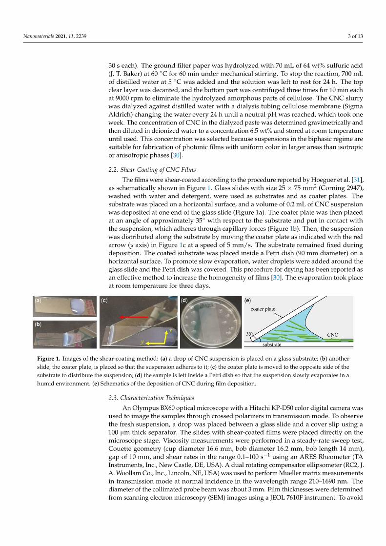
A key observation during experimentation with non-sonicated CNC suspensions wasthe increasing fluidity with time. Therefore, the profiles of steady shear viscosity of CNCsuspensions were measured at different times after their preparation. Figure 3 shows thedependence of viscosity on shear rate on a logarithmic scale for three measurements madeon CNC suspensions with a storage time of 1 day, 10 days, and 120 days. The suspension
Nanomaterials 2021, 11, 2239 5 of 13
stored only one day exhibits the typical shear thinning behavior of a gel, which is attributedto the alignment of the CNC in the direction of the applied shear stress [13,16,22]. Thegel-like behavior of this non-sonicated CNC suspension agrees with the texture observed inthe POM image in Figure 2a. Indeed, other authors have reported that non-sonicated CNCsuspensions in the biphasic regime show gel-like viscosity profiles [13]. In Figure 3, it canbe noticed that the viscosity profile of the suspension after 10 days of storage also showsthe shear-thinning behavior, but with a lower viscosity, which can be noticed at low shearrates. On the other hand, the viscosity profile of the non-sonicated CNC suspension storedfor 120 days exhibits a plateau at shear rates below 1 s−1 and a shear thinning behaviorat higher shear rates. These features in the viscosity profile are characteristic of a chiralnematic liquid crystal phase [17,18].
Nanomaterials 2021, 11, x FOR PEER REVIEW 5 of 13
3.1.2. Changes in Viscosity of Non-Sonicated CNC Suspensions with Storage Time A key observation during experimentation with non-sonicated CNC suspensions
was the increasing fluidity with time. Therefore, the profiles of steady shear viscosity of CNC suspensions were measured at different times after their preparation. Figure 3 shows the dependence of viscosity on shear rate on a logarithmic scale for three measurements made on CNC suspensions with a storage time of 1 day, 10 days, and 120 days. The sus-pension stored only one day exhibits the typical shear thinning behavior of a gel, which is attributed to the alignment of the CNC in the direction of the applied shear stress [13,16,22]. The gel-like behavior of this non-sonicated CNC suspension agrees with the texture observed in the POM image in Figure 2a. Indeed, other authors have reported that non-sonicated CNC suspensions in the biphasic regime show gel-like viscosity profiles [13]. In Figure 3, it can be noticed that the viscosity profile of the suspension after 10 days of storage also shows the shear-thinning behavior, but with a lower viscosity, which can be noticed at low shear rates. On the other hand, the viscosity profile of the non-sonicated CNC suspension stored for 120 days exhibits a plateau at shear rates below 1 s−1 and a shear thinning behavior at higher shear rates. These features in the viscosity profile are characteristic of a chiral nematic liquid crystal phase [17,18].
The steady-shear viscosity profile of a chiral nematic liquid crystalline phase exhibits a three-region profile. Region I at low shear rates is characterized by a shear-thinning be-havior attributed to alignment of tactoids in the shear direction. Region II is found at in-termediate shear rates where a plateau in viscosity is ascribed to disruption of tactoids into smaller units and release of CNC to some extent. Region III is located at higher shear rates where another shear-thinning zone reflects the breakdown of tactoids and the align-ment of the individual CNC in the direction of the applied shear [17,32]. In Figure 3, the viscosity profile of the sample with 120 days of storage shows characteristics of the liquid crystalline phase identified by the plateau below shear rate 1 s−1 (region II) and the shear-thinning behavior at higher shear rates (region III). Region I might be located at lower shear rates than the capability of the equipment used. Furthermore, region I has been re-ported to be elusive and is not always detected [17,33].
According to previous reports [19,20], desulfation of CNC progressively occurs in stored non-sonicated acidic suspensions. The released sulfate groups react with H+ coun-terions to form sulfuric acid which decreases the pH of the suspensions and increase the conductivity [19,20]. Hence, in non-sonicated suspensions, the screening charge distribu-tion around the twisted-rod CNC might result in a cylindrical effective particle shape and a highly repulsive suspension shows the gel-like behavior [34]. The progressive desul-fation over time increases the ionic strength, which decreases the repulsion, and the effec-tive shape changes to a twisted rod, promoting the formation of a chiral nematic liquid crystalline phase [34].
Figure 3. Steady shear viscosity profile of non-sonicated CNC suspensions stored for 1 day (red triangles), 10 days (magenta circles), and 120 days (blue squares).
0.1 1 10 1000.1
1
10
100
day 120
day 1
Visc
osity
(Pas
)
Shear rate (s-1)
day 10
Figure 3. Steady shear viscosity profile of non-sonicated CNC suspensions stored for 1 day (redtriangles), 10 days (magenta circles), and 120 days (blue squares).
The steady-shear viscosity profile of a chiral nematic liquid crystalline phase exhibitsa three-region profile. Region I at low shear rates is characterized by a shear-thinningbehavior attributed to alignment of tactoids in the shear direction. Region II is found atintermediate shear rates where a plateau in viscosity is ascribed to disruption of tactoidsinto smaller units and release of CNC to some extent. Region III is located at highershear rates where another shear-thinning zone reflects the breakdown of tactoids and thealignment of the individual CNC in the direction of the applied shear [17,32]. In Figure 3,the viscosity profile of the sample with 120 days of storage shows characteristics of theliquid crystalline phase identified by the plateau below shear rate 1 s−1 (region II) andthe shear-thinning behavior at higher shear rates (region III). Region I might be locatedat lower shear rates than the capability of the equipment used. Furthermore, region I hasbeen reported to be elusive and is not always detected [17,33].
According to previous reports [19,20], desulfation of CNC progressively occurs instored non-sonicated acidic suspensions. The released sulfate groups react with H+ coun-terions to form sulfuric acid which decreases the pH of the suspensions and increase theconductivity [19,20]. Hence, in non-sonicated suspensions, the screening charge distri-bution around the twisted-rod CNC might result in a cylindrical effective particle shapeand a highly repulsive suspension shows the gel-like behavior [34]. The progressivedesulfation over time increases the ionic strength, which decreases the repulsion, and theeffective shape changes to a twisted rod, promoting the formation of a chiral nematic liquidcrystalline phase [34].
3.2. Microstructure of CNC Films Deposited after Different Storage Times
As the non-sonicated CNC suspensions show detectable changes with storage time,shear-coating films were prepared after different times of storage to investigate the effecton microstructure and optical properties of the films. The thicknesses of films prepared at

Nanomaterials 2021, 11, 2239 6 of 13
days 1, 18, and 38 of storage determined from SEM images are 7.08 ± 0.08, 8.77 ± 0.05, and4.79 ± 0.10 µm, respectively (see Figure A1 in Appendix A).
Figure 4a shows a SEM image of the surface of a shear-coated film obtained the sameday the non-sonicated suspension was prepared. As was shown in Figure 3, the viscosityof non-sonicated fresh suspensions shows a shear thinning profile (red triangles). Thedecrease in viscosity with shear rate is ascribed to a preferential alignment of CNC in thedirection of the applied shear. In films prepared from this type of suspension, the shearapplied during the coating process preferentially aligns CNC, as indicated by the red arrowin Figure 4a.
Nanomaterials 2021, 11, x FOR PEER REVIEW 6 of 13
3.2. Microstructure of CNC Films Deposited after Different Storage Times As the non-sonicated CNC suspensions show detectable changes with storage time,
shear-coating films were prepared after different times of storage to investigate the effect on microstructure and optical properties of the films. The thicknesses of films prepared at days 1, 18, and 38 of storage determined from SEM images are 7.08 ± 0.08, 8.77 ± 0.05, and 4.79 ± 0.10 μm, respectively (see Figure A1 in Appendix A).
Figure 4a shows a SEM image of the surface of a shear-coated film obtained the same day the non-sonicated suspension was prepared. As was shown in Figure 3, the viscosity of non-sonicated fresh suspensions shows a shear thinning profile (red triangles). The de-crease in viscosity with shear rate is ascribed to a preferential alignment of CNC in the direction of the applied shear. In films prepared from this type of suspension, the shear applied during the coating process preferentially aligns CNC, as indicated by the red ar-row in Figure 4a.
Figure 4b shows a SEM image of the cross section of a film deposited from a suspen-sion stored for 38 days. The imaged cross section is perpendicular to the shear applied (x direction in Figure 1c). The microstructure seen in Figure 4b looks like that often reported for free-standing chiral CNC films [35]. Since CNC films are brittle, a fracture does not always produce a clean cut. The fact that the shear-coated films investigated here are sup-ported on glass (a hard material) introduces another factor that further complicates the possibility to obtain a clean cut. The description of the cross-sectional SEM images is given according to a previous report from other authors [9]. The presence of holes in the struc-ture is explained by the removal of CNC in the opposite section of the fractured film. However, an apparent layered structure of alternate dark and light gray stripes can be noticed, as is shown in Figure 4c, which is a magnification of the highlighted region in Figure 4b. As is known, dried films retain the chiral nematic liquid crystalline phase formed in the suspensions [6]. The dark gray stripes are formed by CNC nearly parallel to the surface of the fracture (x-z plane), favoring a clean cut. On the other hand, the frac-ture of the film produces an irregular cut for CNC perpendicular to the cut plane [11]. The latter case is imaged as light gray stripes because the CNC protruding from the fracture surface. The helical axis is parallel to the z-axis in Figure 4b.
Figure 4. SEM images of shear-coated CNC films: (a) the surface of a film prepared on day 1; the arrow indicates the direction of the applied shear. (b) Cross section of a film prepared from a suspension stored for 38 days. (c) Magnification of the highlighted area in (b).
3.3. Optical Characteristics of CNC Films Deposited at Different Storage Times 3.3.1. Birefringent Films from Fresh Suspensions
The film deposited the same day as the CNC suspension was prepared became trans-parent. However, when viewed through crossed linear polarizers, birefringence was re-vealed. Figure 5a shows a photograph taken by placing the sample between a liquid crys-tal display monitor as a source of linearly polarized light at 45° with respect to the hori-zontal (S direction) and a linear polarizer placed in the extinction configuration (P direc-tion). As can be noticed, the logo of Cinvestav on the screen’s white background is clearly seen. Thicker regions in the film produce the dark yellow color observed in small areas of
Figure 4. SEM images of shear-coated CNC films: (a) the surface of a film prepared on day 1; the arrow indicates thedirection of the applied shear. (b) Cross section of a film prepared from a suspension stored for 38 days. (c) Magnification ofthe highlighted area in (b).
Figure 4b shows a SEM image of the cross section of a film deposited from a suspensionstored for 38 days. The imaged cross section is perpendicular to the shear applied (xdirection in Figure 1c). The microstructure seen in Figure 4b looks like that often reportedfor free-standing chiral CNC films [35]. Since CNC films are brittle, a fracture does notalways produce a clean cut. The fact that the shear-coated films investigated here aresupported on glass (a hard material) introduces another factor that further complicatesthe possibility to obtain a clean cut. The description of the cross-sectional SEM imagesis given according to a previous report from other authors [9]. The presence of holes inthe structure is explained by the removal of CNC in the opposite section of the fracturedfilm. However, an apparent layered structure of alternate dark and light gray stripes canbe noticed, as is shown in Figure 4c, which is a magnification of the highlighted regionin Figure 4b. As is known, dried films retain the chiral nematic liquid crystalline phaseformed in the suspensions [6]. The dark gray stripes are formed by CNC nearly parallel tothe surface of the fracture (x-z plane), favoring a clean cut. On the other hand, the fractureof the film produces an irregular cut for CNC perpendicular to the cut plane [11]. The lattercase is imaged as light gray stripes because the CNC protruding from the fracture surface.The helical axis is parallel to the z-axis in Figure 4b.
3.3. Optical Characteristics of CNC Films Deposited at Different Storage Times3.3.1. Birefringent Films from Fresh Suspensions
The film deposited the same day as the CNC suspension was prepared becametransparent. However, when viewed through crossed linear polarizers, birefringence wasrevealed. Figure 5a shows a photograph taken by placing the sample between a liquidcrystal display monitor as a source of linearly polarized light at 45◦ with respect to thehorizontal (S direction) and a linear polarizer placed in the extinction configuration (Pdirection). As can be noticed, the logo of Cinvestav on the screen’s white background isclearly seen. Thicker regions in the film produce the dark yellow color observed in smallareas of the sample. In contradistinction to the birefringent shear-coated films of this work,free-standing cast films showed a peak reflection wavelength of 390 nm from non-sonicatedsuspensions, as reported elsewhere [20].
Nanomaterials 2021, 11, 2239 7 of 13
Nanomaterials 2021, 11, x FOR PEER REVIEW 7 of 13
the sample. In contradistinction to the birefringent shear-coated films of this work, free-standing cast films showed a peak reflection wavelength of 390 nm from non-sonicated suspensions, as reported elsewhere [20].
Other authors have reported preparation of blade-coated CNC birefringent films from sonicated suspensions with CNC concentrations in the anisotropic phase [21,22]. In-deed, in sonicated biphasic CNC suspensions [22], the alignment of CNC was lost after a few minutes of stopping the applied shear because the low viscosity of sonicated suspen-sions allows the rearrangement of the cholesteric phase. In contradistinction, the larger viscosity of the non-sonicated suspensions in the biphasic regime investigated here locks the alignment of CNC. Microphase transitions in flow towards the nematic order of CNC suspensions showing shear thinning behavior have been reported [36]. However, shear-thinning behavior of CNC suspensions does not ensure alignment of nanocrystals, but a breakup of CNC aggregates might appear [37]. Physicochemical properties of CNC sus-pensions are largely depending on many factors such as the source of cellulose and hy-drolysis conditions, among others [17,18].
3.3.2. Chiral Films from Stored Suspensions Films deposited from non-sonicated CNC suspensions stored for at least two weeks
showed a blue color with only a small linear birefringent effect, as observed when placed between crossed polarizers. Figure 5b shows a photograph of a film obtained from a sus-pension stored for 18 days as seen through a left-handed circular polarizer. Rotation of the film did not result in any detectable change in the color, which is indicative of a struc-tural origin. Furthermore, selective reflection of left-handed circularly polarized light was confirmed by observation that the film becomes dark when seen through a right-handed circular polarizer. As expected, films deposited for a longer storage time also exhibited selective circular Bragg reflection through tactoid annealing [38]. Figure 5c shows an im-age of a film obtained from a 38-day-old non-sonicated CNC suspension, also seen through a left-handed circular polarizer. Compared to Figure 5b, a more intense blue color is perceived.
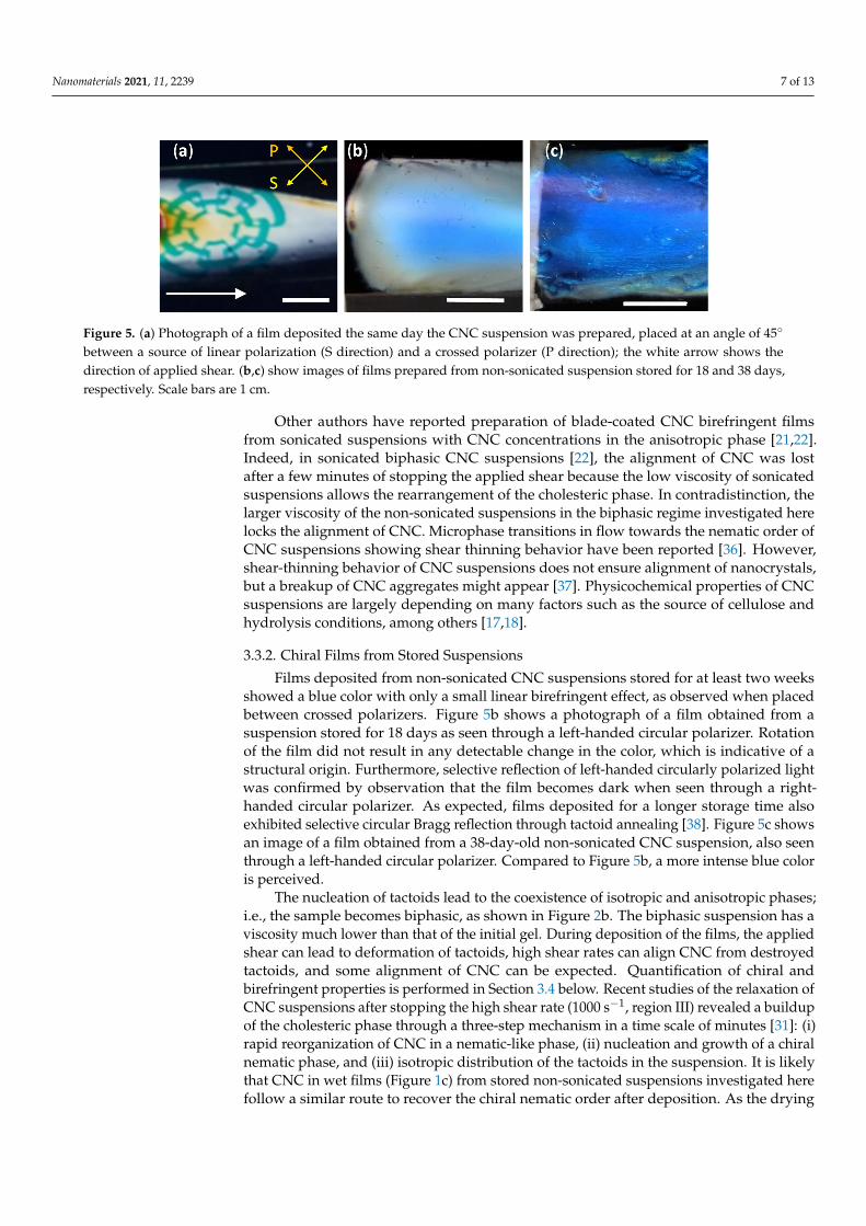
Figure 5. (a) Photograph of a film deposited the same day the CNC suspension was prepared, placed at an angle of 45° between a source of linear polarization (S direction) and a crossed polar-izer (P direction); the white arrow shows the direction of applied shear. (b,c) show images of films prepared from non-sonicated suspension stored for 18 and 38 days, respectively. Scale bars are 1 cm.
The nucleation of tactoids lead to the coexistence of isotropic and anisotropic phases; i.e., the sample becomes biphasic, as shown in Figure 2b. The biphasic suspension has a viscosity much lower than that of the initial gel. During deposition of the films, the applied shear can lead to deformation of tactoids, high shear rates can align CNC from destroyed tactoids, and some alignment of CNC can be expected. Quantification of chiral and bire-fringent properties is performed in Section 3.4 below. Recent studies of the relaxation of CNC suspensions after stopping the high shear rate (1000 s−1, region III) revealed a buildup of the cholesteric phase through a three-step mechanism in a time scale of minutes
Figure 5. (a) Photograph of a film deposited the same day the CNC suspension was prepared, placed at an angle of 45◦
between a source of linear polarization (S direction) and a crossed polarizer (P direction); the white arrow shows thedirection of applied shear. (b,c) show images of films prepared from non-sonicated suspension stored for 18 and 38 days,respectively. Scale bars are 1 cm.
Other authors have reported preparation of blade-coated CNC birefringent filmsfrom sonicated suspensions with CNC concentrations in the anisotropic phase [21,22].Indeed, in sonicated biphasic CNC suspensions [22], the alignment of CNC was lostafter a few minutes of stopping the applied shear because the low viscosity of sonicatedsuspensions allows the rearrangement of the cholesteric phase. In contradistinction, thelarger viscosity of the non-sonicated suspensions in the biphasic regime investigated herelocks the alignment of CNC. Microphase transitions in flow towards the nematic order ofCNC suspensions showing shear thinning behavior have been reported [36]. However,shear-thinning behavior of CNC suspensions does not ensure alignment of nanocrystals,but a breakup of CNC aggregates might appear [37]. Physicochemical properties of CNCsuspensions are largely depending on many factors such as the source of cellulose andhydrolysis conditions, among others [17,18].
3.3.2. Chiral Films from Stored Suspensions
Films deposited from non-sonicated CNC suspensions stored for at least two weeksshowed a blue color with only a small linear birefringent effect, as observed when placedbetween crossed polarizers. Figure 5b shows a photograph of a film obtained from asuspension stored for 18 days as seen through a left-handed circular polarizer. Rotationof the film did not result in any detectable change in the color, which is indicative of astructural origin. Furthermore, selective reflection of left-handed circularly polarized lightwas confirmed by observation that the film becomes dark when seen through a right-handed circular polarizer. As expected, films deposited for a longer storage time alsoexhibited selective circular Bragg reflection through tactoid annealing [38]. Figure 5c showsan image of a film obtained from a 38-day-old non-sonicated CNC suspension, also seenthrough a left-handed circular polarizer. Compared to Figure 5b, a more intense blue coloris perceived.
The nucleation of tactoids lead to the coexistence of isotropic and anisotropic phases;i.e., the sample becomes biphasic, as shown in Figure 2b. The biphasic suspension has aviscosity much lower than that of the initial gel. During deposition of the films, the appliedshear can lead to deformation of tactoids, high shear rates can align CNC from destroyedtactoids, and some alignment of CNC can be expected. Quantification of chiral andbirefringent properties is performed in Section 3.4 below. Recent studies of the relaxation ofCNC suspensions after stopping the high shear rate (1000 s−1, region III) revealed a buildupof the cholesteric phase through a three-step mechanism in a time scale of minutes [31]: (i)rapid reorganization of CNC in a nematic-like phase, (ii) nucleation and growth of a chiralnematic phase, and (iii) isotropic distribution of the tactoids in the suspension. It is likelythat CNC in wet films (Figure 1c) from stored non-sonicated suspensions investigated herefollow a similar route to recover the chiral nematic order after deposition. As the drying

Nanomaterials 2021, 11, 2239 8 of 13
time is of the order of days, there is enough time for reorganization of CNC to produce thestructural color observed in the films.
3.4. Quantification of Polarization Properties of CNC Films
The results discussed in previous sections make it very plausible that shear-coatedfilms from non-sonicated CNC suspensions are birefringent or chiral depending on storagetime. To quantify the polarization properties of a sample, a Mueller matrix formalism iswell suited, and is employed in this section. Normal incidence transmission measurementsof Mueller matrices were performed; thus, propagation of light is along the z-axis, asdefined in Figure 4b.
3.4.1. Mueller Matrices of CNC Films Measured in Transmission
A complete description of the polarization and depolarization properties of a linearoptical system is given by the Stokes–Mueller approach [39]. In this approach, light beamsare represented by column vectors S = [I,Q,U,V]T (T means transpose) where I representsthe total irradiance; Q > 0 (<0) accounts for the tendency for linear polarization along thex-axis (y-axis); U > 0 (< 0) for the tendency for linear polarization along direction +45◦
(−45◦) in the xy-plane; and V > 0 (<0) for the right (left) circular character of polarization.After interacting with a system, the Stokes vector of the resulting beam is given by S’ = MSwhere M = {Mij} is the 4 × 4 Mueller matrix of the system. In this work, normalized Muellermatrices (mij =Mij/M11) and Stokes vectors (I = 1) are used.
Figure 6 shows Mueller matrices measured on samples fabricated from non-sonicatedCNC suspensions stored at different times. Data for the film fabricated with the fresh (day1) suspension have most of the elements close to zero with the exemption of m22 (≈1) andthe 2 × 2 lower-right block. This is indicative of a sample with linear birefringence withthe slow and fast axes aligned with the laboratory frame (x − y) [39].
Nanomaterials 2021, 11, x FOR PEER REVIEW 9 of 13
Figure 6. Evolution of Mueller matrices in transmission mode of films deposited from CNC sus-pensions with different times of storage. Scales are shown in the lower-left panel.
From a Mueller matrix, the linear optical response to any incident beam can be de-termined, regardless of its polarization state. This means that the degree of polarization, ellipticity, and azimuth of the polarization ellipse of the emerging beam can be quantified [39]. However, of high interest are properties of the sample related to its micro- and nanostructure and intrinsic properties of the constituent materials. In the present case, there is preferential alignment of CNC in birefringent films and a helicoidal arrangement of CNC in structurally colored films. To determine sample properties, the capability of the system to depolarize incident polarized light should be evaluated first. A measure of this capability is given by the polarization index PΔ of a normalized Mueller matrix M [40],
Ttr 13
PΔ−= M M , (1)
where tr stands for trace. A value of PΔ = 0 corresponds to an ideal depolarizer and PΔ = 1 to a non-depolarizing system. Figure 7 shows PΔ for films prepared from non-sonicated suspensions stored for 1, 18, and 38 days, where the average values of PΔ are 0.993 ± 0.008, 0.999 ± 0.002, and 0.999 ± 0.001, respectively. In conclusion, for measurements in transmis-sion mode, the CNC films practically do not depolarize incident polarized light.
day 1 day 18 day 38
m12
m13
m14
m21
m22
m23
m24
m31
m32
m33
m34
400 600 800 1000-1
0
1
λ (nm)
m41
m42
m43
m44
Figure 6. Evolution of Mueller matrices in transmission mode of films deposited from CNC suspensions with differenttimes of storage. Scales are shown in the lower-left panel.
A drastic change in the Mueller matrices of films prepared from stored non-sonicatedsuspensions is noticed: the 2 × 2 lower-right block becomes nearly a unity block, whereas

Nanomaterials 2021, 11, 2239 9 of 13
the elements in the secondary diagonal show structure below wavelength 600 nm; otherelements are close to zero. In data of the film prepared from the 18-day-old suspension,m41 exhibits a band centered at wavelength 455 nm, whereas in the film prepared with a38-day-old suspension, the band is at 423 nm. The presence of these bands is consistentwith the blue color of the films and the blue-shift with storage time agrees with the result incast films [20]. For unpolarized light, which is described with a Stokes vector S = [1,0,0,0]T,the transmitted beam is given by S’ = [1,m21, m31, m41]T. Since m21 and m31 are nearly zeroand m41 > 0, films obtained from stored suspensions transmit right-handed polarized light;thus, left-handed polarized light is reflected.
From a Mueller matrix, the linear optical response to any incident beam can be de-termined, regardless of its polarization state. This means that the degree of polarization,ellipticity, and azimuth of the polarization ellipse of the emerging beam can be quanti-fied [39]. However, of high interest are properties of the sample related to its micro- andnanostructure and intrinsic properties of the constituent materials. In the present case,there is preferential alignment of CNC in birefringent films and a helicoidal arrangementof CNC in structurally colored films. To determine sample properties, the capability of thesystem to depolarize incident polarized light should be evaluated first. A measure of thiscapability is given by the polarization index P∆ of a normalized Mueller matrix M [40],
P∆ =
√trMTM − 1
3, (1)
where tr stands for trace. A value of P∆ = 0 corresponds to an ideal depolarizer and P∆ = 1to a non-depolarizing system. Figure 7 shows P∆ for films prepared from non-sonicatedsuspensions stored for 1, 18, and 38 days, where the average values of P∆ are 0.993 ± 0.008,0.999 ± 0.002, and 0.999 ± 0.001, respectively. In conclusion, for measurements in transmis-sion mode, the CNC films practically do not depolarize incident polarized light.
Nanomaterials 2021, 11, x FOR PEER REVIEW 10 of 13
Figure 7. Depolarization index of the Mueller matrices shown in Figure 6.
3.4.2. Polarization Properties of CNC Films With polarization properties, we refer to linear birefringence (linear diattenuation)
referred to the x − y LB (LD) and ±45° LB’ (LD’) frames as well as circular dichroism CD and circular birefringence CB. LB and LB’ are related to the difference in refractive indices for electric field parallel and perpendicular to the direction of the applied shear during deposition. As the optical principal axes of the sample in general are not aligned with the laboratory frame, but deviate by an angle φ, it is convenient to use LB = δcosφ and LB’ = δsinφ, where δ is the retardation introduced by the sample. Differences in absorption in x-y and ±45° directions account for LD and LD’, respectively. Similarly, LD = pcosφ and LD’ = psinφ where p is the diattenuation. The difference in speed of propagation of left- and right-handed circular polarization states in the sample is contained in CB. CD is related to sample selectivity for transmission of left- and right-handed circular polarization. There exist several methods for an accurate determination of these polarization properties of a sample from its experimental Mueller matrix. Since the films investigated in this work correspond to non-depolarizing samples (PΔ ≈ 1 in Figure 7), analytical inversion is suita-ble [41], whereby LB, LD, LB’, LD’, CD, and CB are obtained explicitly in terms of the Mueller matrix elements mij. To eliminate the orientational dependence (φ), the retardation δ = (LB2 + LB’2)1/2 and diattenuation p = (LD2 + LD’2)1/2 are then calculated.
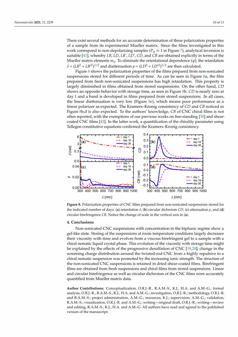
Figure 8 shows the polarization properties of the films prepared from non-sonicated suspensions stored for different periods of time. As can be seen in Figure 8a, the film pre-pared from fresh non-sonicated suspensions has high retardation. This property is largely diminished in films obtained from stored suspensions. On the other hand, CD shows an opposite behavior with storage time, as seen in Figure 8b. CD is nearly zero at day 1 and a band is developed in films prepared from stored suspensions. In all cases, the linear diattenuation is very low (Figure 8c), which means poor performance as a linear polarizer as expected. The Kramers–Kronig consistency of CD and CB noticed in Figure 8b,d is also expected. To the authors’ knowledge, CB of CNC chiral films is not often reported, with the exemptions of our previous works on free-standing [30] and shear-coated CNC films [42]. In the latter work, a quantification of the chirality parameter using Tellegen consti-tutive equations confirmed the Kramers–Kronig consistency.
400 600 800 10000.85
0.90
0.95
1.00
day 1 day 18 day 38P
Δ
λ (nm)
Figure 7. Depolarization index of the Mueller matrices shown in Figure 6.
3.4.2. Polarization Properties of CNC Films
With polarization properties, we refer to linear birefringence (linear diattenuation)referred to the x − y LB (LD) and ±45◦ LB’ (LD’) frames as well as circular dichroism CDand circular birefringence CB. LB and LB’ are related to the difference in refractive indicesfor electric field parallel and perpendicular to the direction of the applied shear duringdeposition. As the optical principal axes of the sample in general are not aligned withthe laboratory frame, but deviate by an angle ϕ, it is convenient to use LB = δcosϕ andLB’ = δsinϕ, where δ is the retardation introduced by the sample. Differences in absorptionin x-y and ±45◦ directions account for LD and LD’, respectively. Similarly, LD = pcosϕand LD’ = psinϕ where p is the diattenuation. The difference in speed of propagation ofleft- and right-handed circular polarization states in the sample is contained in CB. CD isrelated to sample selectivity for transmission of left- and right-handed circular polarization.
Nanomaterials 2021, 11, 2239 10 of 13
There exist several methods for an accurate determination of these polarization propertiesof a sample from its experimental Mueller matrix. Since the films investigated in thiswork correspond to non-depolarizing samples (P∆ ≈ 1 in Figure 7), analytical inversion issuitable [41], whereby LB, LD, LB’, LD’, CD, and CB are obtained explicitly in terms of theMueller matrix elements mij. To eliminate the orientational dependence (ϕ), the retardationδ = (LB2 + LB’2)1/2 and diattenuation p = (LD2 + LD’2)1/2 are then calculated.
Figure 8 shows the polarization properties of the films prepared from non-sonicatedsuspensions stored for different periods of time. As can be seen in Figure 8a, the filmprepared from fresh non-sonicated suspensions has high retardation. This property islargely diminished in films obtained from stored suspensions. On the other hand, CDshows an opposite behavior with storage time, as seen in Figure 8b. CD is nearly zero atday 1 and a band is developed in films prepared from stored suspensions. In all cases,the linear diattenuation is very low (Figure 8c), which means poor performance as alinear polarizer as expected. The Kramers–Kronig consistency of CD and CB noticed inFigure 8b,d is also expected. To the authors’ knowledge, CB of CNC chiral films is notoften reported, with the exemptions of our previous works on free-standing [30] and shear-coated CNC films [42]. In the latter work, a quantification of the chirality parameter usingTellegen constitutive equations confirmed the Kramers–Kronig consistency.
Nanomaterials 2021, 11, x FOR PEER REVIEW 11 of 13
Figure 8. Polarization properties of CNC films prepared from non-sonicated suspensions stored for the indicated number of days: (a) retardation δ, (b) circular dichroism CD, (c) attenuation p, and (d) circular birefringence CB. Notice the change of scale in the vertical axis in (a).
4. Conclusions Non-sonicated CNC suspensions with concentration in the biphasic regime show a
gel-like state. Storing of the suspensions at room temperature conditions largely decreases their viscosity with time and evolves from a viscous birefringent gel to a sample with a chiral nematic liquid crystal phase. This evolution of the viscosity with storage time might be explained by the effects of the progressive desulfation of CNC [19,20]; change in the screening charge distribution around the twisted-rod CNC from a highly repulsive to a chiral nematic suspension was promoted by the increasing ionic strength. The structure of the non-sonicated CNC suspensions is retained in dried shear-coated films. Birefringent films are obtained from fresh suspensions and chiral films from stored suspensions. Lin-ear and circular birefringence as well as circular dichroism of the CNC films were accu-rately quantified from Mueller matrix data.
Author Contributions: Conceptualization, O.R.J.-R., R.A.M.-S., K.J., H.A.,and A.M.-G.; formal anal-ysis, O.R.J.-R., R.A.M.-S., K.J., H.A. and A.M.-G.; investigation, O.R.J.-R.; methodology, O.R.J.-R. and R.A.M.-S.; project administration, A.M.-G.; resources, K.J.; supervision, A.M.-G.; validation, R.A.M.-S.; visualization, O.R.J.-R. and A.M.-G.; writing—original draft, O.R.J.-R.; writing—review and editing, R.A.M.-S., K.J., H.A. and A.M.-G. All authors have read and agreed to the published version of the manuscript.
Funding: This research received no external funding.
Institutional Review Board Statement: Not applicable.
Informed Consent Statement: Not applicable.
Data Availability Statement: The data presented in the study are available in the article (figures).
Acknowledgments: O.R.J.-R. acknowledges the scholarship (782810) from Conacyt-Mexico for doc-toral studies. V. Flores-Casamayor and J. E. Urbina-Álvarez are acknowledged for assistance in vis-cosity and SEM measurements, respectively. Facilities of LIDTRA (Conacyt grants N-295261 and LN-254119) for SEM studies are acknowledged. K.J. acknowledges the Swedish Government Stra-tegic Research Area in Materials Science on Advanced Functional Materials at Linköping University (Faculty Grant SFO-Mat-Liu No. 2009-000971).
Conflicts of Interest: The authors declare no conflict of interest.
0.0
0.1
0.2
0.3
0.4 day 1 day 18 day 38
CD
(b)
0.0
0.3
3
6(a)
day 1 day 18 day 38
δ (ra
d)
300 400 500 600 700 800 900 1000-0.3-0.2-0.10.00.1 (d)
λ (nm)
day 1 day 18 day 38C
B (r
ad)
300 400 500 600 700 800 900 10000.00
0.02
0.04 (c)
λ (nm)
day 1 day 18 day 38
p
Figure 8. Polarization properties of CNC films prepared from non-sonicated suspensions stored forthe indicated number of days: (a) retardation δ, (b) circular dichroism CD, (c) attenuation p, and (d)circular birefringence CB. Notice the change of scale in the vertical axis in (a).
4. Conclusions
Non-sonicated CNC suspensions with concentration in the biphasic regime show agel-like state. Storing of the suspensions at room temperature conditions largely decreasestheir viscosity with time and evolves from a viscous birefringent gel to a sample with achiral nematic liquid crystal phase. This evolution of the viscosity with storage time mightbe explained by the effects of the progressive desulfation of CNC [19,20]; change in thescreening charge distribution around the twisted-rod CNC from a highly repulsive to achiral nematic suspension was promoted by the increasing ionic strength. The structure ofthe non-sonicated CNC suspensions is retained in dried shear-coated films. Birefringentfilms are obtained from fresh suspensions and chiral films from stored suspensions. Linearand circular birefringence as well as circular dichroism of the CNC films were accuratelyquantified from Mueller matrix data.
Author Contributions: Conceptualization, O.R.J.-R., R.A.M.-S., K.J., H.A. and A.M.-G.; formalanalysis, O.R.J.-R., R.A.M.-S., K.J., H.A. and A.M.-G.; investigation, O.R.J.-R.; methodology, O.R.J.-R.and R.A.M.-S.; project administration, A.M.-G.; resources, K.J.; supervision, A.M.-G.; validation,R.A.M.-S.; visualization, O.R.J.-R. and A.M.-G.; writing—original draft, O.R.J.-R.; writing—reviewand editing, R.A.M.-S., K.J., H.A. and A.M.-G. All authors have read and agreed to the publishedversion of the manuscript.

Nanomaterials 2021, 11, 2239 11 of 13
Funding: This research received no external funding.
Institutional Review Board Statement: Not applicable.
Informed Consent Statement: Not applicable.
Data Availability Statement: The data presented in the study are available in the article (figures).
Acknowledgments: O.R.J.-R. acknowledges the scholarship (782810) from Conacyt-Mexico for doc-toral studies. V. Flores-Casamayor and J. E. Urbina-Álvarez are acknowledged for assistance inviscosity and SEM measurements, respectively. Facilities of LIDTRA (Conacyt grants N-295261 andLN-254119) for SEM studies are acknowledged. K.J. acknowledges the Swedish Government Strate-gic Research Area in Materials Science on Advanced Functional Materials at Linköping University(Faculty Grant SFO-Mat-Liu No. 2009-000971).
Conflicts of Interest: The authors declare no conflict of interest.
Appendix A
Nanomaterials 2021, 11, x FOR PEER REVIEW 12 of 13
Appendix A
Figure A1. SEM cross-sectional images of films deposited (a) on day 1, (b) day 18, and (c) day 38.
References 1. Wertz, J.-L.; Bédué, O.; Mercier, J.-P. Cellulose Science and Technology; EPFL: Lausanne, Switzerland, 2010. 2. Kontturi, E.; Laaksonen, P.; Linder, M. B.; Nonappa; Gröschel, A. H.; Rojas, O. J.; Ikkala, O. Advanced materials through assem-
bly of nanocelluloses. Adv. Mater. 2018, 30, 1703779. https://doi.org/10.1002/adma.201703779 3. Heise, K.; Kontturi, E.; Allahverdiyeva, Y.; Tammelin, T.; Linder, M. B.; Nonappa; Ikkala, O. Nanocellulose: Recent fundamental
advances and emerging biological and biomimicking applications. Adv. Mater. 2020, 33, 2004349. https://doi.org/10.1002/adma.202004349
4. Tardy, B. L.; Mattos, B. D.; Greca, L. G.; Kämäräinen, T.; Klockars, K. W.; Rojas, O. J. Tessellation of chiral-nematic cellulose nanocrystal films by microtemplating. Adv. Funct. Mater. 2019, 29, 1808518. https://doi.org/10.1002/adfm.201808518
5. Rånby, B. G. Fibrous macromolecular systems. Cellulose and muscle. The colloidal properties of cellulose micelles. Discuss. Faraday Soc. 1951, 11, 158–164. https://doi.org/10.1039/DF9511100158
6. Revol, J. F.; Bradford, H.; Giasson, J.; Marchessault, R. H.; Gray, D. G. Helicoidal self-ordering of cellulose microfibrils in aque-ous suspension. Int. J. Biol. Macromol. 1992, 14, 170–172. https://doi.org/10.1016/s0141-8130(05)80008-x
7. Dong, X. M.; Revol, J. F.; Gray, D. G. Effect of microcrystallite preparation conditions on the formation of colloid crystals of cellulose. Cellulose 1998, 5, 19–32. https://doi.org/10.1023/A:1009260511939
8. Dong, X. M.; Kimura, T.; Revol, J.-F.; Gray, D. G. Effects of ionic strength on the isotropic−chiral nematic phase transition of suspensions of cellulose crystallites. Langmuir 1996, 12, 2076–2082. https://doi.org/10.1021/la950133b
9. Majoinen, J.; Kontturi, E.; Ikkala, O.; Gray, D. G. SEM imaging of chiral nematic films cast from cellulose nanocrystal suspen-sions. Cellulose 2012, 19, 1599–1605. https://doi.org/10.1007/s10570-012-9733-1
10. Parker, R. M.; Guidetti, G.; Williams, C. A.; Zhao, T.; Narkevicius, A.; Vignolini, S.; Frka-Petesic, B. The self-assembly of cellulose nanocrystals: hierarchical design of visual appearance. Adv. Mater. 2018, 30, 1704477. https://doi.org/10.1002/adma.201704477
11. Schütz, C.; Bruckner, J. R.; Honorato-Rios, C.; Tosheva, Z.; Anyfantakis, M.; Lagerwall, J. P. F. From equilibrium liquid crystal formation and kinetic arrest to photonic bandgap films using suspensions of cellulose nanocrystals. Crystals 2020, 10, 199. https://doi.org/10.3390/cryst10030199
12. Beck, S.; Bouchard, J.; Berry, R. Controlling the reflection wavelength of iridescent solid films of nanocrystalline cellulose. Bi-omacromolecules 2011, 12, 167–172. https://doi.org/10.1021/bm1010905
13. Shafiei-Sabet, S.; Hamad, W. Y.; Hatzikiriakos, S. G. Rheology of nanocrystalline cellulose aqueous suspensions. Langmuir 2012, 28, 17124–17133. https://doi.org/10.1021/la303380v
14. Shafeiei-Sabet, S.; Hamad, W. Y.; Hatzikiriakos, S. G. Influence of degree of sulfation on the rheology of cellulose nanocrystal suspensions. Rheol. Acta 2013, 52, 741–751. https://doi.org/10.1007/s00397-013-0722-6
15. Shafiei-Sabet, S.; Hamad, W. Y.; Hatzikiriakos, S. G. Ionic strength effects on the microstructure and shear rheology of cellulose nanocrystal suspensions. Cellulose 2014, 21, 3347–3359. https://doi.org/10.1007/s10570-014-0407-z
16. Gicquel, E.; Bras, J.; Rey, C.; Putaux, J.-L.; Pignon, F.; Jean, B.; Martin, C. Impact of sonication on the rheological and colloidal properties of highly concentrated cellulose nanocrystal suspensions. Cellulose 2019, 26, 7619–7634. https://doi.org/10.1007/s10570-019-02622-7
17. Xu, Y.; Atrens, A.; Stokes, J. R. A review of nanocrystalline cellulose suspensions: rheology, liquid crystal ordering and colloidal phase behaviour. Adv. Colloid Interface Sci. 2020, 275, 102076. https://doi.org/10.1016/j.cis.2019.102076
Figure A1. SEM cross-sectional images of films deposited (a) on day 1, (b) day 18, and (c) day 38.
References1. Wertz, J.-L.; Bédué, O.; Mercier, J.-P. Cellulose Science and Technology; EPFL: Lausanne, Switzerland, 2010.2. Kontturi, E.; Laaksonen, P.; Linder, M.B.; Nonappa; Gröschel, A.H.; Rojas, O.J.; Ikkala, O. Advanced materials through assembly
of nanocelluloses. Adv. Mater. 2018, 30, 1703779. [CrossRef]3. Heise, K.; Kontturi, E.; Allahverdiyeva, Y.; Tammelin, T.; Linder, M.B.; Nonappa; Ikkala, O. Nanocellulose: Recent fundamental
advances and emerging biological and biomimicking applications. Adv. Mater. 2020, 33, 2004349. [CrossRef]4. Tardy, B.L.; Mattos, B.D.; Greca, L.G.; Kämäräinen, T.; Klockars, K.W.; Rojas, O.J. Tessellation of chiral-nematic cellulose
nanocrystal films by microtemplating. Adv. Funct. Mater. 2019, 29, 1808518. [CrossRef]5. Rånby, B.G. Fibrous macromolecular systems. Cellulose and muscle. The colloidal properties of cellulose micelles. Discuss.
Faraday Soc. 1951, 11, 158–164. [CrossRef]6. Revol, J.F.; Bradford, H.; Giasson, J.; Marchessault, R.H.; Gray, D.G. Helicoidal self-ordering of cellulose microfibrils in aqueous
suspension. Int. J. Biol. Macromol. 1992, 14, 170–172. [CrossRef]7. Dong, X.M.; Revol, J.F.; Gray, D.G. Effect of microcrystallite preparation conditions on the formation of colloid crystals of cellulose.
Cellulose 1998, 5, 19–32. [CrossRef]8. Dong, X.M.; Kimura, T.; Revol, J.-F.; Gray, D.G. Effects of ionic strength on the isotropic−chiral nematic phase transition of
suspensions of cellulose crystallites. Langmuir 1996, 12, 2076–2082. [CrossRef]9. Majoinen, J.; Kontturi, E.; Ikkala, O.; Gray, D.G. SEM imaging of chiral nematic films cast from cellulose nanocrystal suspensions.
Cellulose 2012, 19, 1599–1605. [CrossRef]10. Parker, R.M.; Guidetti, G.; Williams, C.A.; Zhao, T.; Narkevicius, A.; Vignolini, S.; Frka-Petesic, B. The self-assembly of cellulose
nanocrystals: Hierarchical design of visual appearance. Adv. Mater. 2018, 30, 1704477. [CrossRef]11. Schütz, C.; Bruckner, J.R.; Honorato-Rios, C.; Tosheva, Z.; Anyfantakis, M.; Lagerwall, J.P.F. From equilibrium liquid crystal
formation and kinetic arrest to photonic bandgap films using suspensions of cellulose nanocrystals. Crystals 2020, 10, 199.[CrossRef]

Nanomaterials 2021, 11, 2239 12 of 13
12. Beck, S.; Bouchard, J.; Berry, R. Controlling the reflection wavelength of iridescent solid films of nanocrystalline cellulose.Biomacromolecules 2011, 12, 167–172. [CrossRef]
13. Shafiei-Sabet, S.; Hamad, W.Y.; Hatzikiriakos, S.G. Rheology of nanocrystalline cellulose aqueous suspensions. Langmuir 2012, 28,17124–17133. [CrossRef]
14. Shafeiei-Sabet, S.; Hamad, W.Y.; Hatzikiriakos, S.G. Influence of degree of sulfation on the rheology of cellulose nanocrystalsuspensions. Rheol. Acta 2013, 52, 741–751. [CrossRef]
15. Shafiei-Sabet, S.; Hamad, W.Y.; Hatzikiriakos, S.G. Ionic strength effects on the microstructure and shear rheology of cellulosenanocrystal suspensions. Cellulose 2014, 21, 3347–3359. [CrossRef]
16. Gicquel, E.; Bras, J.; Rey, C.; Putaux, J.-L.; Pignon, F.; Jean, B.; Martin, C. Impact of sonication on the rheological and colloidalproperties of highly concentrated cellulose nanocrystal suspensions. Cellulose 2019, 26, 7619–7634. [CrossRef]
17. Xu, Y.; Atrens, A.; Stokes, J.R. A review of nanocrystalline cellulose suspensions: Rheology, liquid crystal ordering and colloidalphase behaviour. Adv. Colloid Interface Sci. 2020, 275, 102076. [CrossRef] [PubMed]
18. Li, M.; Wu, Q.; Moon, R.J.; Hubbe, M.A.; Bortner, M.J. Rheological aspects of cellulose nanomaterials: Governing factors andemerging applications. Adv. Mater. 2021, 2006052. [CrossRef] [PubMed]
19. Beck, S.; Bouchard, J. Auto-catalyzed acidic desulfation of cellulose nanocrystals. NPPRJ 2014, 29, 6–14. [CrossRef]20. Beck, S.; Bouchard, J. Effect of storage conditions on cellulose nanocrystal stability. Tappi J. 2014, 13, 53–61. [CrossRef]21. Chowdhury, R.A.; Peng, S.X.; Youngblood, J. Improved order parameter (alignment) determination in cellulose nanocrystal
(CNC) films by a simple optical birefringence method. Cellulose 2017, 24, 1957–1970. [CrossRef]22. Haywood, A.D.; Davis, V.A. Effects of liquid crystalline and shear alignment on the optical properties of cellulose nanocrystal
films. Cellulose 2017, 24, 705–716. [CrossRef]23. Hiratani, T.; Kose, O.; Hamad, W.Y.; MacLachlan, M.J. Stable and sensitive stimuli-responsive anisotropic hydrogels for sensing
ionic strength and pressure. Mater. Horiz. 2018, 5, 1076–1081. [CrossRef]24. Hynninen, V.; Hietala, S.; McKee, J.R.; Murtomäki, L.; Rojas, O.J.; Ikkala, O.; Nonappa. Inverse thermoreversible mechanical
stiffening and birefringence in a methylcellulose/cellulose nanocrystal hydrogel. Biomacromolecules 2018, 19, 2795–2804. [CrossRef][PubMed]
25. Gan, L.; Feng, N.; Liu, S.; Zheng, S.; Li, Z.; Huang, J. Assembly-induced emission of cellulose nanocrystals for hiding information.Part. Part. Syst. Charact. 2019, 36, 1800412. [CrossRef]
26. Liu, S.-Y.; Gong, Y.-B.; Ma, S.; Wang, Y.-H.; Gan, L.; Huang, J. Antistatic structural color and photoluminescent membranes fromco-assembling cellulose nanocrystals and carbon nanomaterials for anti-counterfeiting. Chin. J. Polym. Sci. 2020, 38, 1061–1071.[CrossRef]
27. Mendoza-Galván, A.; Tejeda-Galán, T.; Domínguez-Gómez, A.; Mauricio-Sánchez, R.; Järrendahl, K.; Arwin, H. Linear birefringentfilms of cellulose nanocrystals produced by dip-coating. Nanomaterials 2018, 9, 45. [CrossRef]
28. Mendoza-Galván, A.; Muñoz-Pineda, E.; Ribeiro, S.J.L.; Santos, M.V.; Järrendahl, K.; Arwin, H. Mueller matrix spectroscopicellipsometry study of chiral nanocrystalline cellulose films. J. Opt. 2018, 20, 024001. [CrossRef]
29. Querejeta-Fernández, A.; Kopera, B.; Prado, K.S.; Klinkova, A.; Methot, M.; Chauve, G.; Bouchard, J.; Helmy, A.S.; Kumacheva,E. Circular dichroism of chiral nematic films of cellulose nanocrystals loaded with plasmonic nanoparticles. ACS Nano 2015, 9,10377–10385. [CrossRef]
30. Saha, P.; Davis, V.A. Photonic properties and applications of cellulose nanocrystal films with planar anchoring. ACS Appl. NanoMater. 2018, 1, 2175–2183. [CrossRef]
31. Hoeger, I.; Rojas, O.J.; Efimenko, K.; Velev, O.D.; Kelley, S.S. Ultrathin film coatings of aligned cellulose nanocrystals from aconvective-shear assembly system and their surface mechanical properties. Soft Matter 2011, 7, 1957–1967. [CrossRef]
32. Pignon, F.; Challamel, M.; De Geyer, A.; Elchamaa, M.; Semeraro, E.F.; Hengl, N.; Jean, B.; Putaux, J.-L.; Gicquel, E.; Bras, J.; et al.Breakdown and buildup mechanisms of cellulose nanocrystal suspensions under shear and upon relaxation probed by SAXS andSALS. Carbohydr. Polym. 2021, 260, 117751. [CrossRef] [PubMed]
33. Haywood, A.D.; Weigandt, K.M.; Saha, P.; Noor, M.; Green, M.J.; Davis, V.A. New insights into the flow and microstructuralrelaxation behavior of biphasic cellulose nanocrystal dispersions from RheoSANS. Soft Matter 2017, 13, 8451–8462. [CrossRef]
34. Araki, J.; Kuga, S. Effect of trace electrolyte on liquid crystal type of cellulose microcrystals. Langmuir 2001, 17, 4493–4496.[CrossRef]
35. Park, J.H.; Noh, J.; Schütz, C.; Salazar-Alvarez, G.; Scalia, G.; Bergström, L.; Lagerwall, J.P.F. Macroscopic control of helixorientation in films dried from cholesteric liquid-crystalline cellulose nanocrystal suspensions. Chem. Phys. Chem. 2014, 15,1477–1484. [CrossRef] [PubMed]
36. Kádár, R.; Fazilati, M.; Nypelö, T. Unexpected microphase transitions in flow towards nematic order of cellulose nanocrystals.Cellulose 2019, 27, 2003–2014. [CrossRef]
37. Xu, H.-N.; Tang, Y.-Y.; Ouyang, X.-K. Shear-induced breakup of cellulose nanocrystal aggregates. Langmuir 2017, 33, 235–242.[CrossRef]
38. Tran, A.; Hamad, W.Y.; MacLachlan, M.J. Tactoid annealing improves order in self-assembled cellulose nanocrystal films withchiral nematic structures. Langmuir 2018, 34, 646–652. [CrossRef]
39. Goldstein, D.H. Polarized Light, 3rd ed.; CRC Press: Boca Raton, FL, USA, 2011.

Nanomaterials 2021, 11, 2239 13 of 13
40. Gil, J.J.; Bernabeu, E. Depolarization and polarization indices of an optical system. Optica Acta Int. J. Opt. 1986, 33, 185–189.[CrossRef]
41. Arteaga, O.; Canillas, A. Analytic inversion of the Mueller-Jones polarization matrices for homogeneous media. Opt. Lett. 2010,35, 559–561. [CrossRef]
42. Juárez-Rivera, O.R.; Mauricio-Sánchez, R.A.; Järrendahl, K.; Arwin, H.; Mendoza-Galván, A. Quantification of optical chirality incellulose nanocrystal films prepared by shear-coating. Appl. Sci. 2021, 11, 6191. [CrossRef]
Copyright © 2022 FDOKUMEN