TRANSIENT SEEPAGE AND SLOPE STABILITY ANALYSIS FOR RAINFALL-INDUCED LANDSLIDE: A CASE STUDY
Upload
khangminh22Category
view
0download
0
Engineering, Technology & Applied Science Research Vol. 10, No. 2, 2020, 5477-5482 5477
www.etasr.com Zebar & Madani: Power System Transient Stability Enhancement using SFCL and SMES
SFCL-SMES Control for Power System Transient
Stability Enhancement including SCIG-based Wind
Generators
Abdelkrim Zebar
Electrical Engineering Department
University Ferhat Abbas Setif 1 Setif, Algeria
Lakhdar Madani
Electrical Engineering Department
University Ferhat Abbas Setif 1 Setif, Algeria
Abstract—The resolution of the environment pollution depends
on renewable energy sources, such as wind energy systems. These
systems face transient and voltage stability issues with wind
energy employing fixed-speed induction generators to be
augmented with resistive type Superconducting Fault Current
Limiter (SFCL) and Superconducting Magnetic Energy Storage
(SMES) devices. The use of a combined model based on SFCL and SMES for promoting transient and voltage stability of a
multi-machine power system considering the fixed-speed
induction generators is the primary focus of this study. Our
contribution is the development of a new model that combines the
advantages of SFCL and SMES. The proposed model functions
assure flexible control of reactive power using SMES controller
while reducing fault current using superconducting technology-based SFCL. The effectiveness of the proposed combined model
is tested on the IEEE11-bus test system applied to the case of a three-phase short circuit fault in one transmission line.
Keywords-distributed wind generation(DWG); superconducting
fault current limiter (SFCL); superconducting magnetic energy
storage (SMES); transient stability
I. INTRODUCTION
With the increased penetration of the distributed generations (DGs), the mostly used induction machines are wind generators. Induction machines face stability problems, similar to the transient stability of synchronous machines [1-2]. So, it is important to analyze the transient stability of power systems including wind power stations. In power system stability studies, the term transient stability usually refers to the ability of the synchronous machines to remain in synchronism during brief periods that follow large disturbances, such as severe lightning strikes, loss of heavily loaded transmission lines, loss of generation stations, or short circuits on buses [3-4]. On the other hand, the braking resistor (BR) has been recognized and used as a cost-effective measure for transient stability control of synchronous generators for a long time. According to some recent reports, BRs can be used for wind generator stabilization as well [5-6]. The selection of a suitable device for the stabilization of fixed-speed wind generators is a matter of interest. The Static Synchronous Compensator (STATCOM) and Static Var Compensator (SVC) are reported of being able to stabilize the fixed speed wind generator [7-8].
The research on the application of superconducting devices in power systems, such as the SMES as a tool for the stabilization of grid-connected wind generator systems [9-11], is recently developed. An SMES is a large superconducting coil capable of storing electric energy in the magnetic field generated by the direct current (DC) current flowing through it, and the real and reactive power can be absorbed (charging) by or released (discharging) from the coil according to the system power requirements.
SFCLs can suppress short-circuit currents using the unique quench characteristics of superconductors. In the event of a fault, the superconductor undergoes a transition into its normal state (quenching). After quenching, the current is commutated to a shunt resistance and is then limited rapidly [12–14]. In this paper, the potential influence of the combined application of SFCLs and shunt controller SMES is proposed and investigated for improving both transient stability and voltage regulation of the power system containing a distributed wind generation based on conventional fixed speed induction generator. Moreover, the optimal location of the proposed coordinated controller (SFCL–SMES) is also analyzed. The effectiveness of the proposed combined model is tested on the IEEE 11-bus test system applied to the case of three-phase short circuit fault in one transmission line. Simulation results for the system under study are presented and discussed. They show that the optimal location selected by the proposed method improves the transient stability of the power system when a fault occurs.
II. MATHEMATICAL MODEL
This section gives a mathematical model for the power system network which includes modelling of synchronous generator, DWG, SFCL, and SMES.
A. Synchronous Generator
For transient stability analysis, a synchronous machine model is considered as a classic fourth-degree model (Figure 1) and is simulated in MATLAB/Simulink [15]. The systems basic elements are: is the power angle of the generator, is the rotor speed with respect to synchronous reference, is the inertia constant of the generator, is the mechanical input torque to the generator which is assumed to be constant, is
Corresponding author: Abdelkrim Zebar

Engineering, Technology & Applied Science Research Vol. 10, No. 2, 2020, 5477-5482 5478
www.etasr.com Zebar & Madani: Power System Transient Stability Enhancement using SFCL and SMES
the electromagnetic torque to the generator, D is the damping
constant of the generator, ′ is the quadrature-axis transient
voltage, is the reference voltage, ′ is the direct-axis
open-circuit transient time constant of the generator,′ is the
quadrature axis open-circuit transient time constant of the
generator, is the direct-axis synchronous reactance, ′ is
the direct axis transient reactance, ′ is the quadrature axis
transient reactance, is the terminal voltage of the generator, and and I are the direct and quadrature axis currents of the generator respectively.
Fig. 1. The synchronous generator model
B. DWG
DWGs contain many wind turbines and their detailed modeling may be unaffordable due to computational burden. In order to reduce dimensionality, aggregation techniques are used to obtain equivalent models. A proper equivalent model can be easily obtained for fixed-speed wind turbines where a one-to-one correspondence between wind speed and active power output exists. In this case, aggregation is performed by adding the mechanical power of each wind turbine and by using an equivalent squirrel cage induction generator (SCIG) which receives the total mechanical power [16-18]. A simplified transient model of a SCIG is given in [19]. The DWG penetration level in the system is defined as [20]:
) CGP DWGP (100 DWGP DWG % +∗= (1)
where PDWG and PCG are the amount of total active power generated by DWG and centralized generation respectively.
C. SMES
Figure 2 shows the basic configuration of a thyristor-based SMES unit which consists of a Y-Delta transformer, an AC/DC thyristor controlled bridge converter, and a superconducting coil or inductor [21]. The converter impresses positive or negative voltage on the superconducting coil. Charge and discharge are easily controlled by simply changing the delay angle that controls the sequential firing of the thyristors.
• If α is less than 90, the converter operates in the rectifier mode (charging).
• If α is greater than 90, the converter operates in the inverter mode (discharging).
As a result power can be absorbed from or released to the power system according to the requirements. At the steady state
SMES should not consume any real or reactive power. The voltage of the DC side of the converter is expressed by:
cos (2)
where is the ideal no-load maximum DC voltage of the bridge.
Fig. 2. Typical schematic diagram of an SMES unit
The current and voltage of superconducting inductor are related as:
!
" (3)
where is the initial current of the inductor. The real power # absorbed or delivered by the SMES is given by:
# (4)
The energy stored in the superconducting inductor is:
$ $ ! #
" (5)
where $ 1 2'(⁄ is the initial energy in the
inductor. This is applicable for the twelve pulse converter also [21]. Since the bridge current is not reversible, the bridge output power # can be positive or negative depending on . If is positive, power is transferred from the power system to the SMES, while if it is negative, power is released from the SMES unit. The thyristor-based SMES using a six pulse converter is simulated in MATLAB/Simulink as shown in Figure 3.
Fig. 3. Circuit of SMES

Engineering, Technology & Applied Science Research Vol. 10, No. 2, 2020, 5477-5482 5479
www.etasr.com Zebar & Madani: Power System Transient Stability Enhancement using SFCL and SMES
D. SFCL
Depending on the superconducting materials and operation principles, the superconducting fault current limiters can be classified into different types [22]. In the resistive type the superconductor is directly connected in series to the line to be protected while in the inductive concept the superconductor is magnetically coupled into the line [23].
Fig. 4. Modified transmission line with SFCL
The SFCL is a device that limits the fault current by generating impedance when a fault occurs. In addition, the limiting impedance generated to limit fault currents is helpful in increasing the generator output degraded by a fault, thus providing stabilization. SFCLs installed in series with transmission lines can be operated during the period from the fault occurrence to fault clearing [24]. The equivalent circuit of the transmission line with SFCL is illustrated in Figure 4. The associated equation for RSFCL can be described by:
( ) (1 exp( ))SFCL m scR t R t T= − − (6)
where Rm is the expected maximum value of SFCL resistance in the normal state (Rm≈20Ω) and TSC is the time constant of transition from the superconducting state to the normal state, which is assumed to be 1ms. The three phase of the resistance SFCL model is simulated in MATLAB/Simulink as shown in Figure 5.
Fig. 5. The three phase resistance SFCL model
III. SIMULATION RESULTS
To investigate the efficiency and the robustness of the proposed SFCL and SMES based controller on the power system transient stability in the presence of distributed wind generation, the model is integrated in the IEEE benchmark four-machine two-area test system in the case of a three phase short circuit fault in the transmission line. The test system consists of eleven buses, four synchronous generators
connected to buses 1, 2, 3, and 4 respectively through transformers which contribute to the supply of two loads through transmission lines, and two fully symmetrical areas linked together by two 230kV lines of 220km length [25, 26]. DWG is connected to each of the load buses. The configuration is shown in Figure 6.
Fig. 6. On-line diagram of the electrical test system considering the
combined controller SFCL and SMES
Technical data such as voltage regulator, governor turbine, buses and branches information are given in [23]. The transient stability is assessed by the criterion of relative rotor angles, using the time domain simulation method. The Sim Power Systems toolbox of MATLAB/SIMULINK was used to carry out simulations.
IV. OPTIMAL LOCATION OF SFCL-SMES
For secure operation of power systems, it is required to maintain an adequate voltage stability margin, not only under normal conditions, but also in contingency cases. In this study, the voltage stability index using continuation power flow is proposed for the optimal location of SMES and SFCL. From the Continuation Power Flow (CPF) results shown in Figure 7 [18], the buses 5, 6, 7, 8, 9, 10, and 11 are the critical buses. Among these buses, bus 8 has the weakest voltage profile. Figure 8 shows the PV curves for the IEEE four-machine two-area test system without considering SFCL and SMES.
Fig. 7. Curves for the IEEE four-machine two-area test system
At first, the buses are classified according to three procedures:

Engineering, Technology & Applied Science Research Vol. 10, No. 2, 2020, 5477-5482 5480
www.etasr.com Zebar & Madani: Power System Transient Stability Enhancement using SFCL and SMES
Procedure1: all buses are classified according to voltage stability index. In this study, bus 8 is considered as a candidate bus, the main role of the STATOM is to control voltage at this bus by exchanging reactive (capacitive or inductive) power with the network.
Procedure 2: Buses are classified according to the value of fault currents (three phase fault).
Procedure 3: Buses are classified according to the reactive power compensation consumed by the DWG. The DWG will generate an active power, equal to the amount of power consumed by the load. However, in order to generate this necessary active power, the DWG needs to consume reactive power from the network. Bus 9 is considered as the Point of Common Coupling (PCC) where the WG is connected and the main role of the SMES is to compensate for this reactive power.
Fig. 8. Critical buses based on continuation power flow
V. IMPACT OF THE SFCL-SMES CONTROLLER ON POWER SYSTEM TRANSIENT STABILITY ENHANCEMENT
Three logic cases are considered: In the base case, which indicates the original system, there is no SFCL and SMES, in the system. In the second case, with SMES at the weak bus (low voltage stability index) and SFCL at a bus which has high fault current. In the third case, with SMES at the PCC and SFCL at another bus with a high fault current.
A. Case 1
A 3-phase fault occurs at t=1s on line 7–8 near bus 8 and it is cleared by opening the line at both ends. A WG at bus 9 is considered with a penetration level of 20%. Generator 2 is the nearest generator to the fault location and therefore it has the most rotor speed deviation for this fault. The Fault Clearing Time is FCT=0.266s at first and then FCT=0.300s. Simulation results on the rotor angle differences and rotor speed deviation of the four generators without considering SFCL and SMES controller are shown in Figures 9–10 respectively. It can be seen that the relative rotor angles are damped and consequently the system maintains its stability, but when the FTC increased to 0.300s, the relative angles (δ14, δ24 and δ34) increase indefinitely, so at this critical situation the system loses its stability.
Fig. 9. Relative rotor angles without SFCL–SMES
Fig. 10. Rotor speed deviation without SFCL–SMES
B. Case 2
In order to maximize voltage stability index and to improve power system transient stability, SMES is located at the weak bus (low voltage stability index) and the SFCL is placed in line 7–8 which has a high fault current. The SMES will try to support the voltage by injecting reactive power on the line when the voltage is lower than the reference voltage. The first mentioned fault in the previous sub-section is applied again. Time domain simulation was performed at cleared time 0.333s.
Fig. 11. Relative rotor angles considering SFCL–SMES
1 2 3 4 5 6 7 8 9 10 110
0.2
0.4
0.6
0.8
1
1.2
1.4
Voltage magnitude (p.u)
Bus
Engineering, Technology & Applied Science Research Vol. 10, No. 2, 2020, 5477-5482 5481
www.etasr.com Zebar & Madani: Power System Transient Stability Enhancement using SFCL and SMES
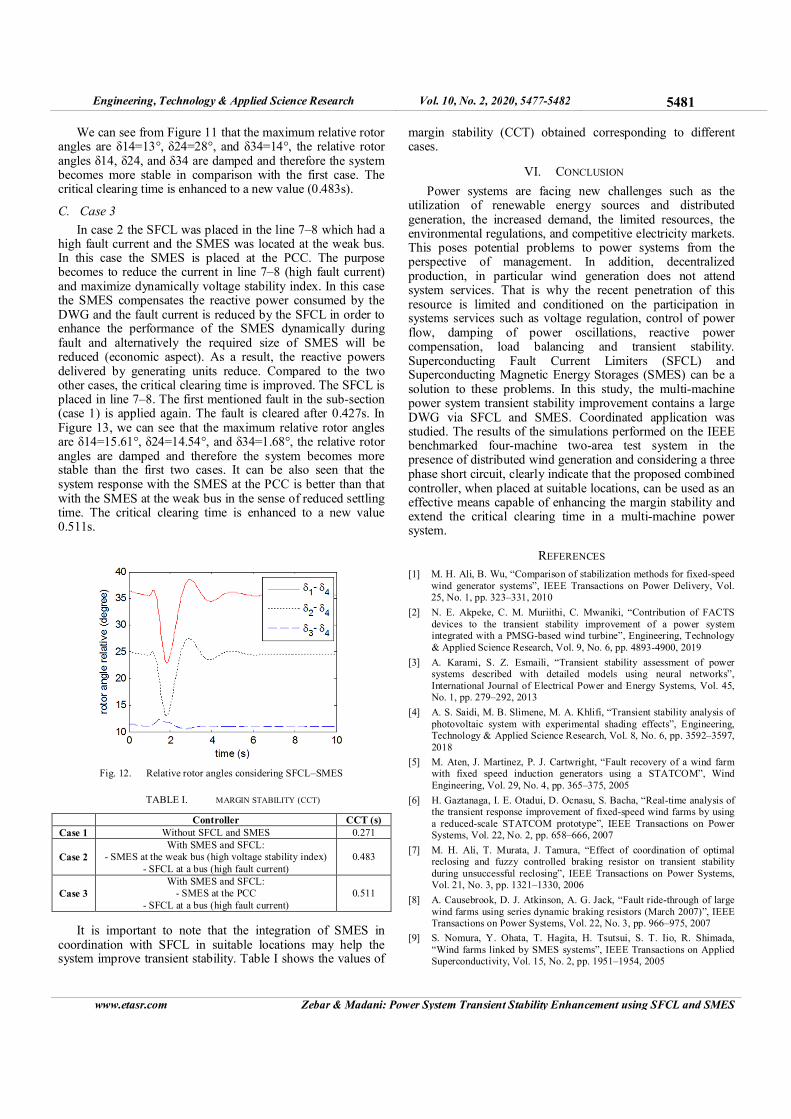
We can see from Figure 11 that the maximum relative rotor angles are δ14=13°, δ24=28°, and δ34=14°, the relative rotor angles δ14, δ24, and δ34 are damped and therefore the system becomes more stable in comparison with the first case. The critical clearing time is enhanced to a new value (0.483s).
C. Case 3
In case 2 the SFCL was placed in the line 7–8 which had a high fault current and the SMES was located at the weak bus. In this case the SMES is placed at the PCC. The purpose becomes to reduce the current in line 7–8 (high fault current) and maximize dynamically voltage stability index. In this case the SMES compensates the reactive power consumed by the DWG and the fault current is reduced by the SFCL in order to enhance the performance of the SMES dynamically during fault and alternatively the required size of SMES will be reduced (economic aspect). As a result, the reactive powers delivered by generating units reduce. Compared to the two other cases, the critical clearing time is improved. The SFCL is placed in line 7–8. The first mentioned fault in the sub-section (case 1) is applied again. The fault is cleared after 0.427s. In Figure 13, we can see that the maximum relative rotor angles are δ14=15.61°, δ24=14.54°, and δ34=1.68°, the relative rotor angles are damped and therefore the system becomes more stable than the first two cases. It can be also seen that the system response with the SMES at the PCC is better than that with the SMES at the weak bus in the sense of reduced settling time. The critical clearing time is enhanced to a new value 0.511s.
Fig. 12. Relative rotor angles considering SFCL–SMES
TABLE I. MARGIN STABILITY (CCT)
Controller CCT (s)
Case 1 Without SFCL and SMES 0.271
Case 2
With SMES and SFCL:
- SMES at the weak bus (high voltage stability index)
- SFCL at a bus (high fault current)
0.483
Case 3
With SMES and SFCL:
- SMES at the PCC
- SFCL at a bus (high fault current)
0.511
It is important to note that the integration of SMES in coordination with SFCL in suitable locations may help the system improve transient stability. Table I shows the values of
margin stability (CCT) obtained corresponding to different cases.
VI. CONCLUSION
Power systems are facing new challenges such as the utilization of renewable energy sources and distributed generation, the increased demand, the limited resources, the environmental regulations, and competitive electricity markets. This poses potential problems to power systems from the perspective of management. In addition, decentralized production, in particular wind generation does not attend system services. That is why the recent penetration of this resource is limited and conditioned on the participation in systems services such as voltage regulation, control of power flow, damping of power oscillations, reactive power compensation, load balancing and transient stability. Superconducting Fault Current Limiters (SFCL) and Superconducting Magnetic Energy Storages (SMES) can be a solution to these problems. In this study, the multi-machine power system transient stability improvement contains a large DWG via SFCL and SMES. Coordinated application was studied. The results of the simulations performed on the IEEE benchmarked four-machine two-area test system in the presence of distributed wind generation and considering a three phase short circuit, clearly indicate that the proposed combined controller, when placed at suitable locations, can be used as an effective means capable of enhancing the margin stability and extend the critical clearing time in a multi-machine power system.
REFERENCES
[1] M. H. Ali, B. Wu, “Comparison of stabilization methods for fixed-speed wind generator systems”, IEEE Transactions on Power Delivery, Vol. 25, No. 1, pp. 323–331, 2010
[2] N. E. Akpeke, C. M. Muriithi, C. Mwaniki, “Contribution of FACTS devices to the transient stability improvement of a power system integrated with a PMSG-based wind turbine”, Engineering, Technology
& Applied Science Research, Vol. 9, No. 6, pp. 4893-4900, 2019
[3] A. Karami, S. Z. Esmaili, “Transient stability assessment of power systems described with detailed models using neural networks”,
International Journal of Electrical Power and Energy Systems, Vol. 45, No. 1, pp. 279–292, 2013
[4] A. S. Saidi, M. B. Slimene, M. A. Khlifi, “Transient stability analysis of photovoltaic system with experimental shading effects”, Engineering, Technology & Applied Science Research, Vol. 8, No. 6, pp. 3592–3597,
2018
[5] M. Aten, J. Martinez, P. J. Cartwright, “Fault recovery of a wind farm with fixed speed induction generators using a STATCOM”, Wind
Engineering, Vol. 29, No. 4, pp. 365–375, 2005
[6] H. Gaztanaga, I. E. Otadui, D. Ocnasu, S. Bacha, “Real-time analysis of the transient response improvement of fixed-speed wind farms by using
a reduced-scale STATCOM prototype”, IEEE Transactions on Power Systems, Vol. 22, No. 2, pp. 658–666, 2007
[7] M. H. Ali, T. Murata, J. Tamura, “Effect of coordination of optimal reclosing and fuzzy controlled braking resistor on transient stability
during unsuccessful reclosing”, IEEE Transactions on Power Systems, Vol. 21, No. 3, pp. 1321–1330, 2006
[8] A. Causebrook, D. J. Atkinson, A. G. Jack, “Fault ride-through of large wind farms using series dynamic braking resistors (March 2007)”, IEEE Transactions on Power Systems, Vol. 22, No. 3, pp. 966–975, 2007
[9] S. Nomura, Y. Ohata, T. Hagita, H. Tsutsui, S. T. Iio, R. Shimada, “Wind farms linked by SMES systems”, IEEE Transactions on Applied Superconductivity, Vol. 15, No. 2, pp. 1951–1954, 2005

Engineering, Technology & Applied Science Research Vol. 10, No. 2, 2020, 5477-5482 5482
www.etasr.com Zebar & Madani: Power System Transient Stability Enhancement using SFCL and SMES
[10] M. H. Ali, T. Murata, J. Tamura, “Minimization of fluctuations of line power and terminal voltage of wind generator by fuzzy logic-controlled
SMES”, International Review of Electrical Engineering, Vol. 1, No. 4, pp. 559–566, 2006
[11] M. H. Ali, T. Murata, J. Tamura, “Wind generator stabilization by PWM voltage source converter and chopper controlled SMES”, Record of ICEM (International Conference on Electrical Machines) 2006, 2006
[12] B. W. Lee, J. Sim, K. B. Park, I. S. Oh, “Practical application issues of superconducting fault current limiters for electric power systems”, IEEE Transactions on Applied Superconductivity, Vol. 18, No. 2, pp. 620–
623, 2008
[13] B. C. Sung, D. K. Park, J. W. Park, T. K. Ko, “Study on optimal location of a resistive SFCL applied to an electric power grid”, IEEE Transactions on Applied Superconductivity, Vol. 19, No. 3, pp. 2048–
2052, 2009
[14] B. C. Sung, D. K. Park, J. W. Park, T. K. Ko, “Study on a series resistive SFCL to improve power system transient stability: Modeling,
simulation, and experimental verification”, IEEE Transactions on Industrial Electronics, Vol. 56, No. 7, pp. 2412–2419, 2009
[15] N. A. Tabak, Stabilite dynamique des systemes electriques multimachines: Modelisation, commande, observation et simulation, PhD Thesis, University of Lyon, 2008 (in French)
[16] H. A. P. Painemal, Wind farm model for power system stability analysis, PhD Thesis, University of Illinois at Urbana-Champaign, 2010
[17] A. Zebar, A. Hamouda, K. Zehar, “Impact of the location of fuzzy controlled static VAR compensator on the power system transient
stability improvement in presence of distributed wind generation”, Revue Roumaine des Sciences Techniques-Serie Electrotechnique et
Energetique, Vol. 60, No. 4, pp. 426–436, 2015
[18] S. H. E. Osman, G. K. Irungu, D. K. Murage, “Application of FVSI, Lmn and CPF techniques for proper positioning of FACTS devices and
SCIG wind turbine integrated to a distributed network for voltage stability enhancement”, Engineering, Technology & Applied Science
Research, Vol. 9, No. 5, pp. 4824-4829, 2019
[19] N. K. Roy, M. J. Hossain, H. R. Pota, “Voltage profile improvement for distributed wind generation using D-STATCOM”, IEEE Power and Energy Society General Meeting, Detroit, USA, July 24-28, 2011
[20] M. Reza, P. H. Schavemaker, J. G. Slootweg, W. L. Kling, L. V. D. Sluis, “Impacts of distributed generation penetration levels on power systems transient stability”, IEEE Power Engineering Society General
Meeting, Denver, USA, June 6-10, 2004
[21] M. H. Ali, B. Wu, R. A. Dougal, “An overview of SMES applications in power and energy systems”, IEEE Transactions on Sustainable Energy,
Vol. 1, No. 1, pp. 38-47, 2010
[22] M. Noe, M. Steurer, “High-temperature superconductor fault current limiters: Concepts, applications, and development status”,
Superconductor Science and Technology, Vol. 20, No. 3, pp. R15-R29, 2007
[23] S. Nemdili, S. Belkhiat, “Electrothermal modeling of coated conductor for a resistive superconducting fault-current limiter”, Journal of Superconductivity and Novel Magnetism, Vol. 26, pp. 2713-2720, 2013
[24] M. Sjostrom, R. Cherkaoui, B. Dutoit, “Enhancement of power system transient stability using superconducting fault current limiters”, IEEE Transactions on Applied Superconductivity, Vol. 9, No. 2, pp. 1328-
1330, 1999
[25] M. Klein, G. J. Rogers, S. Moorty, P. Kundur, “Analytical investigation of factors influencing power system stabilizers performance”, IEEE Transactions on Energy Conversion, Vol. 7, No. 3, pp. 382-390, 1992
[26] P. Kundur, Power System Stability and Control, McGraw-Hill, 1994
Copyright © 2022 FDOKUMEN