Service Manual PEFY-P-NMHU-E-OA
48
-
Upload
khangminh22 -
Category
Documents
-
view
3 -
download
0
Transcript of Service Manual PEFY-P-NMHU-E-OA


ii
HWE1804A GB
Safety PrecautionsRead before installation and performing electrical work
Symbol explanations
Ask your dealer or a qualified technician to install the unit.- Improper installation by the user may result in water leakage, electric shock, or fire.Properly install the unit on a surface that can withstand its weight.- Unit installed on an unstable surface may fall and cause injury.Only use specified cables. Securely connect each cable so that the ter-minals do not carry the weight of the cable.- Improperly connected cables may produce heat and start a fire.Take appropriate safety measures against wind gusts and earthquakes to prevent the unit from toppling over.- Improper installation may cause the unit to topple over and cause injury or damage to the unit.Only use accessories (i.e., air cleaners, humidifiers, electric heaters) recommended by Mitsubishi Electric.Do not make any modifications or alterations to the unit.Consult your dealer for repair.- Improper repair may result in water leakage, electric shock, or fire.Do not touch the heat exchanger fins with bare hands.- The fins are sharp and pose a risk of cuts.In the event of a refrigerant leak, thoroughly ventilate the room.- If gaseous refrigerant leaks out and comes in contact with an open flame, toxic gases will be generated.Properly install the unit according to the instructions in the Installation Manual.- Improper installation may result in water leakage, electric shock, or fire.Have all electrical work performed by an authorized electrician accord-ing to the local regulations and the instructions in this manual. Use a dedicated circuit.- Insufficient power supply capacity or improper installation of the unit may re-sult in malfunctions of the unit, electric shock, or fire.Disconnect all electric power supplies before accessing of electric parts (inner of control box, fan motor, drain pump etc.)- Touching electric parts result in electric shock.Keep electrical parts away from water.- Wet electrical parts pose a risk of electric shock, smoke, or fire.
Securely attach the control box cover.- If the cover is not installed properly, dust or water may infiltrate and pose a risk of electric shock, smoke, or fire.Only use the type of refrigerant that is indicated on the unit when install-ing or relocating the unit.- Infiltration of any other types of refrigerant or air into the unit may adversely affect the refrigerant cycle and may cause the pipes to burst or explode.When installing the unit in a small space, take appropriate precautions to prevent leaked refrigerant from reaching the limiting concentration.- Leaked refrigerant gas will displace oxygen and may cause oxygen starva-tion. Consult your dealer before installing the unit.Consult your dealer or a qualified technician when moving or reinstall-ing the unit.- Improper installation may result in water leakage, electric shock, or fire.After completing the service work, check for a refrigerant leak.- If leaked refrigerant is exposed to a heat source, such as a fan heater, stove, or electric grill, toxic gases will be generated.Do not try to defeat the safety features of the unit.- Forced operation of the pressure switch or the temperature switch by defeat-ing the safety features for these devices, or the use of accessories other than the ones that are recommended by Mitsubishi Electric may result in smoke, fire, or explosion.Consult your dealer for proper disposal method.Do not use a leak detection additive.
Precautions for handling units for use with R410A
Do not use the existing refrigerant piping.- A large amount of chlorine that may be contained in the residual refrigerant and refrigerator oil in the existing piping may cause the refrigerator oil in the new unit to deteriorate.Use refrigerant piping materials made of phosphorus deoxidized cop-per. Keep the inner and outer surfaces of the pipes clean and free of such contaminants as sulfur, oxides, dust, dirt, shaving particles, oil, and moisture.- Contaminants in the refrigerant piping may cause the refrigerator oil to de-teriorate.Store the piping materials indoors, and keep both ends of the pipes sealed until immediately before brazing. (Keep elbows and other joints wrapped in plastic.)- Infiltration of dust, dirt, or water into the refrigerant system may cause the refrigerator oil to deteriorate or cause the compressor to malfunction.Use a small amount of ester oil, ether oil, or alkyl benzene to coat flares and flanges.- Infiltration of a large amount of mineral oil may cause the refrigerator oil to deteriorate.Charge the system with refrigerant in the liquid phase.- If gaseous refrigerant is drawn out of the cylinder first, the composition of the remaining refrigerant in the cylinder will change and become unsuitable for use.Only use R410A.- The use of other types of refrigerant that contain chloride may cause the re-frigerator oil to deteriorate.Use a vacuum pump with a check valve.- If a vacuum pump that is not equipped with a check valve is used, the vac-uum pump oil may flow into the refrigerant cycle and cause the refrigerator oil to deteriorate.Prepare tools for exclusive use with R410A. Do not use the following tools if they have been used with the conventional refrigerant: gauge manifold, charging hose, gas leak detector, check valve, refrigerant charge base, vacuum gauge, and refrigerant recovery equipment.- If the refrigerant or the refrigerator oil that may be left on these tools are mixed in with R410A, it may cause the refrigerator oil in the new system to deteriorate. Infiltration of water may cause the refrigerator oil to deteriorate.Leak detectors for conventional refrigerants will not detect an R410A leak because R410A is free of chlorine.
Thoroughly read the following safety precautions prior to installation.Observe these safety precautions for your safety.This equipment may have adverse effects on the equipment on the same power supply system.Contact the local power authority before connecting to the system.
WARNINGThis symbol indicates that failure to follow the instructions exactly as stated poses the risk of serious injury or death.
CAUTIONThis symbol indicates that failure to follow the instructions exactly as stated poses the risk of serious injury or damage to the unit.
Indicates an action that must be avoided.
Indicates important instructions.
Indicates a parts that requires grounding.
Indicates that caution must be taken with rotating parts. (This symbol is on the main unit label.) <Color: Yellow>
Indicates that the parts that are marked with this symbol pose a risk of electric shock. (This symbol is on the main unit label.) <Color: Yellow>
WARNINGCarefully read the labels affixed to the main unit.
WARNING
CAUTION

iiHWE1804A GB
Do not use a charging cylinder.- If a charging cylinder is used, the composition of the refrigerant in the cylin-der will change and become unsuitable for use.Exercise special care when handling tools for use with R410A.- Infiltration of dust, dirt, or water into the refrigerant system may cause the refrigerator oil to deteriorate.

CONTENTS
HWE1804A GB
I Features[1] Features.................................................................................................................................... 1
II Part Names and Functions[1] Part Names and Functions ....................................................................................................... 2
1.Indoor (main) unit.................................................................................................................... 22.Remote controller ................................................................................................................... 3
III Specification[1] Specification ............................................................................................................................. 5
1.Specification ........................................................................................................................... 52.Electrical parts specifications.................................................................................................. 6
IV Outlines and Dimensions[1] Outlines and Dimensions.......................................................................................................... 7
V Wiring Diagram[1] Wiring Diagram ....................................................................................................................... 11
VI Refrigerant System Diagram[1] Refrigerant System Diagram .................................................................................................. 13
VII Troubleshooting[1] Troubleshooting ...................................................................................................................... 14
1.Check methods..................................................................................................................... 142.DC fan motor (fan motor/indoor control board)..................................................................... 183.Setting of address switch...................................................................................................... 194.Voltage test points on the control board ............................................................................... 205.Setting of dip-switch (at delivery).......................................................................................... 216.Function setting .................................................................................................................... 217.Selecting external static pressure......................................................................................... 228.Enabling the function to prevent cold draft (during heating operation) ................................. 229.Setting addresses ................................................................................................................. 2310.Function the LED of the indoor unit service board.............................................................. 23
VIII Disassembly Procedure[1] Disassembly Procedure (PEFY-P36, 48NMHU-E-OA)........................................................... 24
1.Control box ........................................................................................................................... 242.Fan and fan motor ................................................................................................................ 253.LEV, thermistor (Liquid/Gas piping temperature detection).................................................. 264.Drain pump ........................................................................................................................... 275.Heat exchanger .................................................................................................................... 286.Control box inside layout ...................................................................................................... 307.Thermistor position ............................................................................................................... 31
[2] Disassembly Procedure (PEFY-P72, 96NMHU-E-OA)........................................................... 321.Control box ........................................................................................................................... 322.Fan and fan motor ................................................................................................................ 333.LEV, thermistor (Liquid/Gas piping temperature detection).................................................. 354.Drain pump ........................................................................................................................... 365.Heat exchanger .................................................................................................................... 386.Control box inside layout ...................................................................................................... 407.Thermistor position ............................................................................................................... 41

HWE1804A GB

[ I Features ]
- 1 -HWE1804A GB
I Features
[1] Features
Model Cooling capacity/Heating capacity
kW
PEFY-P36NMHU-E-OA 10.5/6.2
PEFY-P48NMHU-E-OA 14.1/8.2
PEFY-P72NMHU-E-OA 21.1/12.6
PEFY-P96NMHU-E-OA 28.1/16.7
Ceiling ConcealedSeries PEFY
Indoor unit

[ II Part Names and Functions ]
- 2 -HWE1804A GB
II Part Names and Functions
[1] Part Names and Functions
1. Indoor (main) unit
Air inlet
Air outlet

[ II Part Names and Functions ]
- 3 -HWE1804A GB
2. Remote controller[PAR-30MAOA]Once the operation mode is selected, the unit will remain in the selected mode until changed.
(1) Remote Controller Buttons
Function buttons
9 107 8
5
6
1234
Main display:
Fri
Set temp.
Mode Temp. Fan
Cool
Main
Cursor Page
Main menuVane·Louver·Vent. (Lossnay)High powerTimerWeekly timerOU silent mode
ON/OFF buttonPress to turn ON/OFF the indoor unit.
SELECT buttonPress to save the setting.
RETURN buttonPress to return to the previous screen.
MENU buttonPress to bring up the Main menu.
Backlit LCDOperation settings will appear. When the backlight is off, pressing any button turns the backlight on andit will stay lit for a certain period of time depending on the screen.
ON/OFF lampThis lamp lights up in green while the unit is in operation. It blinks while theremote controller is starting up or when there is an error.
The functions of the function buttons change depending on the screen.Refer to the button function guide that appears at the bottom of the LCD forthe functions they serve on a given screen. When the system is centrally controlled, the button function guide thatcorresponds to the locked button will not appear.
Main display Main menu
Function button F1Main display: Press to change the operation mode.Main menu: Press to move the cursor down.
Function button F2Main display: Press to decrease temperature.Main menu: Press to move the cursor up.
Function button F3Main display: Press to increase temperature.Main menu: Press to go to the previous page.
Function button F4Main display: Press to change the fan speed.Main menu: Press to go to the next page.
Function guide
5
6
9
10
7
8
1
2
3
4
9 107 8 9 107 8
• When the backlight is off, pressing any button turns the backlight on and doesnot perform its function. (except for the ON/OFF button)
• Most settings (except ON/OFF, mode, fan speed, temperature) can be made from the Menu screen.

- 4 -
[ II Part Names and Functions ]
GBHWE1804A
(2) Remote Controller Display
Fri
Mode Temp. Fan
Cool Set temp.
Fri
Cool
Mode Temp. Fan
Set temp.910
11
12 13 14 15 16 17 18
19
20
21
21
1
1
2
2
3 3
44
5
5
67
8
The main display can be displayed in two different modes: "Full" and "Basic."The factory setting is "Full." To switch to the "Basic" mode, change the setting on the "Main display" setting screen (Main menu > Initial setting > Main display).
Operation mode
Preset temperature
Clock
Fan speed
Button function guideFunctions of the corresponding buttons appear here.
Appears when the ON/OFF operation is centrally controlled.
Appears when the operation mode is centrally controlled.
Appears when the preset temperature is centrally controlled.
Appears when the filter reset function is centrally controlled.
TemperatureCurrent outlet air temperature appears here.
Appears when the buttons are locked.
Appears when the On/Off timer, Night setback, or Auto-off timer function isenabled.
appears when the timer is disabled by the centralized control system.
Appears when the Weekly timer is enabled.
Appears while the units are operated in the energy-save mode.
Appears while the outdoor units are operated in the silent mode.
Appears when the thermistor on the indoor unit is activated to monitor theoutlet air temperature ( ).* This icon appears when the remote controller is connected to the Fresh
Air Intake model. If the icon does not appear, refer to the indoor unitInstruction Book.
appears when the built-in thermistor on the remote controller isactivated to monitor the room temperature.
Indicates the vane setting.This function cannot be used on the Fresh Air Intake model units.
Indicates the louver setting.This function cannot be used on the Fresh Air Intake model units.
Indicates the ventilation setting.This function cannot be used on the Fresh Air Intake model units.
Appears when the preset temperature range is restricted.
9
10
11
12
13
14
15
16
17
11
18
19
20
21
Appears when an energy-saving operation is performed using a "3D i-Seesensor" function.
22
1
2
3
4
5
6
7
8
Indicates when filter needs maintenance.
* All icons are displayed for explanation.
Full mode Basic mode

[ III Specification ]
- 5 -HWE1804A GB
III Specification
[1] Specification
1. Specification
Model PEFY-P36NMHU-E-OA PEFY-P48NMHU-E-OA PEFY-P72NMHU-E-OA PEFY-P96NMHU-E-OA
Power source 1-phase 208/230 V 60 Hz 1-phase 208/230 V 60 Hz 1-phase 208/230 V 60 Hz 1-phase 208/230 V 60 Hz
Cooling capacity *1 BTU/h 36,000 48,000 72,000 96,000
*1 kW 10.5 14.1 21.1 28.1
*2 Power input kW 0.130 0.180 0.220 0.320
(208 V) *2 Current input A 1.25 1.59 1.86 2.56
Temp. range of 17.2°CD.B. ~ 47.7°CD.B.
cooling 63°FD.B. ~ 118°FD.B.
Thermo-off (FAN-mode) automatically starts if the outdoor temperature is lower than 63°F (17.2°C)D.B.
The fan speed automatically runs at a very low speed if the outdoor temperature is higher than 109°F (42.8°C)D.B.
Heating capacity *3 BTU/h 21,000 28,000 43,000 57,000
*3 kW 6.2 8.2 12.6 16.7
*2 Power input kW 0.140 0.200 0.240 0.330
(208 V) *2 Current input A 1.09 1.46 1.70 2.42
Temp. range of -10°CD.B. ~ 15°CD.B.
heating 14°FD.B. ~ 59°FD.B.
Thermo-off (FAN-mode) automatically starts if the outdoor temperature is higher than 59°F (15.0°C)D.B.
External finish Galvanized Galvanized Galvanized Galvanized
External dimension H x W x D inch 15 x 47-1/16 x 35-7/16 15 x 47-1/16 x 35-7/16 18-9/16 x 49-1/4 x 44-1/8 18-9/16 x 49-1/4 x 44-1/8
mm 380 x 1,195 x 900 380 x 1,195 x 900 470 x 1,250 x 1,120 470 x 1,250 x 1,120
Net weight lbs (kg) 109 (49) 109 (49) 177 (80) 183 (83)
Heat exchanger Cross fin (Aluminium fin and copper tube)
Cross fin (Aluminium fin and copper tube)
Cross fin (Aluminium fin and copper tube)
Cross fin (Aluminium fin and copper tube)
FAN Type x Quantity Sirocco fan x 1 Sirocco fan x 1 Sirocco fan x 2 Sirocco fan x 2
External in.WG <0.60> - 0.80 - <1.00> <0.60> - 0.80 - <1.00> <0.60> - 0.80 - <1.00> <0.60> - 0.80 - <1.00>
*4, 5 static press. Pa <150> - 200 - <250> <150> - 200 - <250> <150> - 200 - <250> <150> - 200 - <250>
Motor Type DC motor DC motor DC motor DC motor
Motor output kW 0.244 0.244 0.375 0.375
Driving mechanism Direct-driven by motor Direct-driven by motor Direct-driven by motor Direct-driven by motor
*5 Air flow rate (Low-Mid-High) (Low-Mid-High) (Low-Mid-High) (Low-Mid-High)
cfm 350 - 400 - 450 500 - 550 - 600 700 - 800 - 900 1,000 - 1,100 - 1,200
m3/min 9.9 - 11.3 - 12.7 14.2 - 15.6 - 17.0 19.8 - 22.7 - 25.5 28.3 - 31.1 - 34.0
L/s 165 - 188 - 212 237 - 260 - 283 330 - 378 - 425 472 - 518 - 567
*6 Air flow rate cfm 320 420 700 790
(Very low) m3/min 9.1 11.9 19.8 22.4
L/s 152 198 330 373
Sound pressure level (measured in anechoic room) (Low-Mid-High) (Low-Mid-High) (Low-Mid-High) (Low-Mid-High)
dB <A> 35-38-40 38-40-41 34-38-42 39-41-44
Air filter Field supply Field supply Field supply Field supply
Diameter of Liquid (R410A) inch (mm) 3/8 (9.52)Brazed 3/8 (9.52)Brazed 3/8 (9.52)Brazed 3/8 (9.52)Brazed
refrigerant pipe Gas (R410A) inch (mm) 5/8 (15.88)Brazed 5/8 (15.88)Brazed 3/4 (19.05)Brazed 7/8 (22.22)Brazed
Field drain pipe size inch (mm) O.D.1-1/4 (32) x2 O.D.1-1/4 (32) x2 O.D.1-1/4 (32) x2 O.D.1-1/4 (32) x2
Remarks Details on foundation work, duct work, insulation work, electrical wiring, power source switch, and other items shall be referred to the Installation Manual.Systems with considerably long pipe runs, in heating mode, may be subject to slightly louder than normal noise from the outdoor unit/s.
Notes: Unit converter
1.Cooling capacity indicates the maximum value at operation under the following condition. Cooling: Indoor 91°F (32.7°C)DB/82°F (27.8°C)WB, Outdoor 91°F (32.7°C)DB. The set temperature of the remote controller is 63°F (17.2°C). 2.The values are measured at the factory setting of external static pressure. 3.Heating capacity indicates the maximum value at operation under the following condition. Heating: Indoor 32°F (0°C)DB/27°F (-2.9°C)WB, Outdoor 32°F (0°C)DB/27°F (-2.9°C)WB. The set temperature of the remote controller is 77°F (25°C). 4.The factory setting of external static pressure is shown without < >. Refer to "Fan characteristics curves", according to the external static pressure, in DATA BOOK for the usable range of air flow rate. 5.If the airflow rate is over the usable range, dew drop can be caused from the air outlet and the air flow rate is changed automatically because of the output down by the fan motor control. If the air flow rate is less than the usable range, condensation from the unit surface can be caused. 6.The very low mode is not selectable from the remote controller. The unit will automatically operate in the very low mode when the outside temperature exceeds 109°F (42.8°C) in the Cooling mode or drops below 14°F (-10°C) in the Heating mode. The combination of fresh air intake type indoor units with other types of indoor units that handle internal thermal load may cause the conflict of operation mode. It is not recommended when fresh air intake type indoor unit is connected to the Y or WY series. Depending on the air conditioning load, outside temperature, and due to the activation of protection functions, the desired preset temperature may not always be achieved and the discharge temperature may swing. Note that untreated outside air may be delivered directly into the room upon the activation of protection functions. Fresh air intake type indoor units cannot be connected to PUMY and cannot be connected to an outdoor unit together with PWFY series. The maximum connectable indoor units to 1 outdoor unit are 110% (100% in case of heating below 23°F (-5°C)). When fresh air intake type indoor units connect to an outdoor unit together with other types of indoor unit, the total capacity of fresh air intake type indoor units needs to be 30% or less of the connected outdoor unit capacity. The AUTO mode on the local remote controller is available only when fresh air intake type indoor unit is connected to the R2 or WR2 series of outdoor unit. The system changeover function is available only when all the connected indoor units are fresh air intake type indoor units. The fan temporary stops during defrost. The cooling and heating capacities are the maximum capacities that were obtained by operating in the above air conditions and with a refrigerant pipe of about 25 ft (7.5 m) and a level difference of 0 m. The actual capacity characteristics vary with the combination of indoor and outdoor units. See the technical information in DATA BOOK for the details. Thermo off (Fan) operation automatically starts either when temperature is lower than 63°F (17.2°C)DB in cooling mode or when the temperature exceeds 59°F (15.0°C)DB in heating mode. Dry mode is not available. Un-conditioned outdoor air such as humid air or cold air blows to the indoor during thermo off operation. Please be careful when positioning indoor unit air outlet grilles, ie take the necessary precautions for cold air, and also insulate rooms for dew condensation prevention as required. Air filter must be installed in the air intake side. The filter should be attached where easy maintenance is possible in case of usage of field supply filters. Before switching ducts by using a damper, be sure to bring the indoor unit to a stop to prevent malfunction. Make sure to set the static pressure in all ducts within the range specified in the P-Q line diagram in the DATA BOOK. This indoor unit does not interlock with an electric heater. Regarding P96NMHU-E-OA, the low notch air flow rate is different from the spec value when the external static pressure setting is set to 150Pa. See Fan characterics curves in DATA BOOK for the details.
kcal =kW x 860
BTU/h =kW x 3,412
cfm =m3/min x 35.31
lbs =kg/0.4536
*Above specification data is subject to rounding variation.

[ III Specification ]
- 6 -HWE1804A GB
2. Electrical parts specifications
modelSymbol PEFY-P36, 48NMHU-E-OA PEFY-P72NMHU-E-OA PEFY-P96NMHU-E-OA
Parts name
Outlet air temperaturethermistor
TH21 Resistance 0°C/15kΩ, 10°C/9.6kΩ, 20°C/6.3kΩ, 25°C/5.4kΩ, 30°C/4.3kΩ, 40°C/3.0kΩ
Liquid pipe thermistor TH22 Resistance 0°C/15kΩ, 10°C/9.6kΩ, 20°C/6.3kΩ, 25°C/5.4kΩ, 30°C/4.3kΩ, 40°C/3.0kΩ
Gas pipe thermistor TH23 Resistance 0°C/15kΩ, 10°C/9.6kΩ, 20°C/6.3kΩ, 25°C/5.4kΩ, 30°C/4.3kΩ, 40°C/3.0kΩ
Inlet air temperature thermistor TH24 Resistance 0°C/15kΩ, 10°C/9.6kΩ, 20°C/6.3kΩ, 25°C/5.4kΩ, 30°C/4.3kΩ, 40°C/3.0kΩ
Fuse FUSE 250 VAC 6.3A
Fan motor(with inner thermostat) MF1, 2 8-pole, output 244W
SIC-101CW-D8244-410-pole, output 375W
KMUC4E2MW or KMUC4E3MW
Linear expansion valve LEV 12 VDC Stepping motor drive
Power supply terminal bed TB2 (L, N, ) 250V 20A
Transmission terminal bed
TB5TB15
(M1, M2, S) 250V 20A(1, 2) 250V 15A

[ IV Outlines and Dimensions ]
- 7 -HWE1804A GB
IV Outlines and Dimensions
[1] Outlines and Dimensions
1. PEFY-P36, 48NMHU-E-OAUnit: mm (in.)
2×5-
ø3(1
/8) h
oles
15(5
/8)
50
50(2)
50×18=900(2×18=35-7/16)
23(15/16)1204(47-7/16)(Suspension bolt pitch)1250(49-1/4)
814(
32-1
/16)
904(
35-5
/8)
900(
35-7
/16)
847(
33-3
/8)
10(7
/16)
41
1000(39-3/8)(Duct)
94(3
-3/4
)25
0(9-
7/8)
2×19
-ø3(
1/8)
hol
es
143
25(1)50×4=200
45(1-13/16)50×5=250
380(15)
25
50(2)
40(1-5/8)
65(2-9/16)1130(44-1/2)
50×20=1000(2×20=39-3/8)
10(7
/16)
(Duc
t)
Sus
pens
ion
bolt
hole
(Sus
pens
ion
bolt
pitc
h)
80(3-3/16)
4-14
×30(
9/16
×1-3
/16)
Slo
t2×
21-ø
3(1/
8) h
oles
Term
inal
blo
ck(P
ower
sou
rce)
Con
trol b
ox1
Ref
riger
ant p
ipin
g (g
as)
2×6-
ø3(1
/8) h
oles
2 R
efrig
eran
t pip
ing
(liqu
id)
115(4-9/16)(T
rans
mis
sion
)
29
60(2
-3/8
)
24(1
)29
(1-3
/16)
15(5
/8)
50(2)
187
69
164.
5
58
50
16(1
1/16
)34
0(13
-7/1
6)
1050(41-3/8)(Duct)
(Duc
t)
180
326.5(12-7/8)
432(
17-1
/16)
Dra
in p
ipe
(1)
Air
inle
tA
ir ou
tlet
(2) braz
ing
conn
ectio
n
braz
ing
conn
ectio
n (In
tegra
l lift p
ump o
utlet)
(2×5=9-7/8)
Term
inal
blo
ckD
rain
pip
e(E
mer
genc
y dr
ain)
Dra
in p
ipe
(Gra
vity
dra
in)
(7-3
/8)
34
(2-3
/4) (6
-1/2
)(7
-1/8
)
(1-3/16)
(1-3/8)
(MA
rem
ocon
)Te
rmin
al b
lock
(1-5/8)
(5-11/16)(2-5/16)
(2)
(2×4=7-7/8)
700(27-9/16) Max
300(
11-1
3/16
) or l
ess
3 D
rain
hos
e
(Act
ual l
engt
h)65
0 -10(2
-9/1
6
)0 -7
/16
Inle
t air
Top
Out
let a
ir
Top
Botto
m
side
vie
wsi
de v
iew
view
Pip
ing
side
vie
w
Not
e 1.
Use
an
M10
scr
ew fo
r the
sus
pens
ion
bolt
(fiel
d su
pply
).2.
Mak
e su
re to
inst
all t
he a
ir fil
ter (
field
sup
ply)
on
the
air
inta
ke s
ide.
In c
ase
field
sup
plie
d ai
r filt
er is
use
d, a
ttach
itw
here
the
filte
r ser
vice
is e
asily
don
e.
Mode
lPE
FY-P3
6NMH
U-E-OA
ø15.
88(5
/8)
ø9.5
2(3
/8)
Drain
hos
e32
mm
(1-1
/4inc
h)<a
cces
sory
>PE
FY-P4
8NMH
U-E-OA
Gas p
ipe1
Liquid
pipe
2Dr
ain ho
se3

[ IV Outlines and Dimensions ]
- 8 -HWE1804A GB
Unit: mm (in.),S
ecur
e en
ough
acc
ess
spac
e to
allo
w fo
r the
mai
nten
ance
,insp
ectio
n,an
d re
plac
emen
t of t
he m
otor
,fan,
heat
exc
hang
er,
drai
n pa
n an
d co
ntro
l box
in o
ne o
f the
follo
win
g w
ays.
Sel
ect a
n in
stal
latio
n si
te fo
r the
indo
or u
nit s
o th
at it
's m
aint
enan
ce a
cces
s sp
ace
will
not
be
obst
ruct
ed b
ybe
am o
r oth
er o
bjec
ts.
Cre
ate
acce
ss d
oor 1
(450
×450
mm
)(17
-3/4
×17-
3/4i
nch)
for t
he m
aint
enan
ce fr
om th
e un
it si
de w
hen
the
ther
mis
tor,L
EV
and
cont
rol b
ox is
exc
hang
ed.(F
ig.2
,4)
(1) W
hen
a sp
ace
of 3
00m
m(1
1-13
/16i
nch)
or m
ore
is a
vaila
ble
belo
w th
e un
it be
twee
n th
e un
it an
d th
e ce
iling
.C
reat
e ac
cess
doo
r 2(6
00×6
00m
m)(
23-5
/8×2
3-5/
8inc
h) fo
r the
mai
nten
ance
from
the
botto
m w
hen
the
mot
or,fa
n,he
at e
xcha
nger
and
dra
in p
an is
clea
ned(
exch
ange
d).(F
ig.2
)(2
) Whe
n a
spac
e of
less
than
300
mm
(11-
13/1
6inc
h) is
ava
ilabl
e be
low
the
unit
betw
een
the
unit
and
the
ceili
ng.
(At l
east
20m
m(1
3/16
inch
) of s
pace
sho
uld
be le
ft be
low
the
unit
as s
how
n in
Fig
.3.)
Cre
ate
acce
ss d
oor 3
for t
he m
aint
enan
ce fr
om th
e bo
ttom
whe
n th
e m
otor
,fan,
heat
exc
hang
er a
nd d
rain
pan
iscl
eane
d(ex
chan
ged)
.(Fig
.4)
Sup
ply
air
Inta
ke a
ir
Con
trol b
ox
Acc
ess
door
1C
eilin
gC
eilin
g be
am
Min. 20mm
Min. 20mm
Con
trol b
ox
Acc
ess
door
3
Acc
ess
door
1(4
50×4
50)(
17-3
/4×1
7-3/
4)
5090
0
450
100~
200
1000
1230
501130(44-1/2)
150~200
450
Bot
tom
of
indo
or u
nit
(Vie
wed
from
the
dire
ctio
n of
the
arro
w Y
)
Mai
nten
ance
acce
ss s
pace
Fig.
4
Supp
lyai
rIn
take
air
Y
Fig.
3
Sup
ply
air
Inta
ke a
ir
Con
trol b
ox
Acc
ess
door
1C
eilin
gCe
iling
beam
Min. 20mm
Min. 300mm
Con
trol b
oxA
cces
s do
or 2
(600
×600
)
Acc
ess
door
1(4
50×4
50)(
17-3
/4×1
7-3/
4)45
010
0~20
0
1130(44-1/2)
150~200
450
Botto
m o
f ind
oor u
nit
(Vie
wed
from
the
dire
ctio
n of
the
arro
w Z
)M
aint
enan
ceac
cess
spa
ceFi
g.2
Supp
lyai
rIn
take
air
Z
Fig.
1
600
600
900
150~
200
200~250
50
(13/16)
(11-13/16) (13/16)
(13/16)
(3-1
5/16
~7-7
/8)
(17-
3/4)
(23-
5/8×
23-5
/8)
(5-1
5/16
~7-7
/8)
(23-
5/8)
(35-
7/16
)
(5-15/16~7-7/8)
(23-5/8) (7-7/8~9-7/8)
(2)
(2)
(35-
7/16
)
(17-
3/4)
(3-1
5/16
~7-7
/8)
(17-3/4) (17-3/4) (5-15/16~7-7/8)
(48-7/16)
(2)
(39-
3/8)
[Mai
nten
ance
acc
ess
spac
e]

[ IV Outlines and Dimensions ]
- 9 -HWE1804A GB
2. PEFY-P72, 96NMHU-E-OAUnit: mm (in.),
Air in
letAi
r outl
et
(Pow
er s
ourc
e)
(MA
rem
ocon
)
(ø22
(7/8
) Tra
nsm
issi
on w
iring
)
(ø22
(7/8
) Pow
er s
ouse
wiri
ng)
(Tra
nsm
issi
on)
1100(43-5/16)(Duct) 100
1372(54-1/16)1326(52-1/4)(Suspension bolt pitch) 23(15/16)
100×10=1000(3-15/16×10=39-3/8) 50(2)
100(3-15/16)
340(
13-7
/16)
105(
4-3/
16)
15
2×11
-ø3(
1/8)
hol
es2×
11-ø
3(1/
8) h
oles
100×10=1000(3-15/16×10=39-3/8)100(3-15/16)
50(2)1250(49-1/4)
10
60(2
-3/8
)11
24(4
4-5/
16)
1034
(40-
3/4)
(Sus
pens
ion
bolt
pitc
h)
100(3-15/16)60(2-3/8)100×3=300
9515
(5/8
)
29(1
-3/1
6)10
67(4
2-1/
16)
24(1
)10
(7/1
6)
1120
(44-
1/8) 48
9(19
-5/1
6)
Kno
ckou
t hol
e
Kno
ckou
t hol
e
Term
inal
blo
ck
Dra
in p
ipe30(1-3/16)
1 R
efrig
eran
t pip
ing(
gas)
2 R
efrig
eran
t pip
ing(
liqui
d)D
rain
pip
e
Con
trol b
ox2×
4-ø3
(1/8
) hol
esTe
rmin
al b
lock
Term
inal
blo
ck
2×4-
ø3(1
/8) h
oles
470(18-9/16)
100×3=300 20(13/16)100(3-15/16)
327(12-7/8)
164(6-1/2)44
41(1-5/8)
1021100(43-5/16)(Duct)
20(1
3/16
)42
0(16
-9/1
6)
249(
9-13
/16)
342(
13-1
/2)
80
(Gra
vity
dra
in)
(Duc
t)
(4-1/16)
(Duc
t)
(3-15/16)
100(3-15/16)
(7/1
6)(5
/8)
Sus
pens
ion
bolt
hole
4-14
×30(
9/16
×1-3
/16)
Slo
t
(3-3
/4)
(Inte
gral
lift
pum
p ou
tlet)
(3-15/16×3=11-13/16)
(3-3
/16)
Dra
in p
ipe
(Em
erge
ncy
drai
n)
(1-3/4)
(3-15/16×3=11-13/16)braz
ing
conn
ectio
n
braz
ing
conn
ectio
n
700(27-9/16) Max
300(
11-1
3/16
) or l
ess
3 D
rain
hos
e
(Act
ual l
engt
h)65
0 -10(
2-9/
16
)
0 -7/1
6
Inle
t air
Top
Out
let a
ir
Top
Botto
m
side
vie
wsi
de v
iew
view
Pip
ing
side
vie
w
Note
1.U
se a
n M
10 s
crew
for t
he s
uspe
nsio
n bo
lt (fi
eld
supp
ly).
2.M
ake
sure
to in
stal
l the
air
filter
(fie
ld s
uppl
y) o
n th
e ai
rin
take
sid
e.In
cas
e fie
ld s
uppl
ied
air f
ilter i
s us
ed, a
ttach
itwh
ere
the
filter
ser
vice
is ea
sily
done
.
Mod
el1
Gas p
ipe2
Liquid
pipe
3Dr
ain ho
sePE
FY-P7
2NMH
U-E-OA
ø19.
05(3
/4)
ø9.5
2(3
/8)
Drain
hos
e32
mm
(1-1
/4inc
h)<a
cces
sory
>PE
FY-P9
6NMH
U-E-OA
ø22.
2(7/
8)

[ IV Outlines and Dimensions ]
- 10 -HWE1804A GB
Unit: mm (in.),S
ecur
e en
ough
acc
ess
spac
e to
allo
w fo
r the
mai
nten
ance
,insp
ectio
n,an
d re
plac
emen
t of t
he m
otor
,fan,
heat
exc
hang
er,
drai
n pa
n an
d co
ntro
l box
in o
ne o
f the
follo
win
g w
ays.
Sel
ect a
n in
stal
latio
n si
te fo
r the
indo
or u
nit s
o th
at it
's m
aint
enan
ce a
cces
s sp
ace
will
not
be
obst
ruct
ed b
ybe
am o
r oth
er o
bjec
ts.
Cre
ate
acce
ss d
oor 1
(450
×450
mm
)(17
-3/4
×17-
3/4i
nch)
for t
he m
aint
enan
ce fr
om th
e un
it si
de w
hen
the
ther
mis
tor,L
EV
and
cont
rol b
ox is
exc
hang
ed.(F
ig.2
,4)
(1) W
hen
a sp
ace
of 5
00m
m(1
9-11
/16i
nch)
or m
ore
is a
vaila
ble
belo
w th
e un
it be
twee
n th
e un
it an
d th
e ce
iling
.C
reat
e ac
cess
doo
r 2(6
00×6
00m
m)(
23-5
/8×2
3-5/
8inc
h) fo
r the
mai
nten
ance
from
the
botto
m w
hen
the
mot
or,fa
n,he
at e
xcha
nger
and
dra
in p
an is
clea
ned(
exch
ange
d).(F
ig.2
)(2
) Whe
n a
spac
e of
less
than
500
mm
(19-
11/1
6inc
h) is
ava
ilabl
e be
low
the
unit
betw
een
the
unit
and
the
ceili
ng.
(At l
east
20m
m(1
3/16
inch
) of s
pace
sho
uld
be le
ft be
low
the
unit
as s
how
n in
Fig
.3.)
Cre
ate
acce
ss d
oor 3
for t
he m
aint
enan
ce fr
om th
e bo
ttom
whe
n th
e m
otor
,fan,
heat
exc
hang
er a
nd d
rain
pan
iscl
eane
d(ex
chan
ged)
.(Fig
.4)
Con
trol b
ox
Acce
ss d
oor 1
Cei
ling
Cei
ling
beam
Min. 20mm
Min. 20mm
1250(49-1/4)450
1120
5050
450
200~
300
Supp
lyai
r
1220
1350
50
Acc
ess
door
1(4
50×4
50)(
17-3
/4×1
7-3/
4)
150~200
Acc
ess
door
3
Con
trol b
ox
Bot
tom
of
indo
or u
nit
Inta
keai
r
Mai
nten
ance
acce
ss s
pace Fig.
4(V
iew
ed fr
om th
e di
rect
ion
of th
e ar
row
Y)
Supp
ly a
irIn
take
air
Y
Fig.
3
Botto
m o
f ind
oor u
nit
450
200~
300
1250(49-1/4)
150~200
450
Supp
lyai
r
Con
trol b
ox
Acc
ess
door
2(6
00×6
00)
Acc
ess
door
1(4
50×4
50)(
17-3
/4×1
7-3/
4)
Mai
nten
ance
acce
ss s
pace
Inta
keai
r
Fig.
2(V
iew
ed fr
om th
e di
rect
ion
of th
e ar
row
Z)
Sup
ply
air
Inta
ke a
ir
Con
trol b
ox
Acc
ess
door
1C
eilin
gC
eilin
g be
am
Min. 20mm
Min. 500mm
Z
Fig.
160
011
2025
0~30
0
600 200~300
(17-
3/4)
(7-7
/8~1
1-13
/16)
(13/16)
(19-11/16)
(17-3/4) (5-15/16~7-7/8)(2
3-5/
8)
(44-
1/8)
(9-7
/8~1
1-13
/16)
(23-
5/8~
23-5
/8)
(23-5/8) (7-7/8~11-13/16)
(2)
(2)
(44-
1/8)
(17-
3/4)
(7-7
/8~1
1-13
/16)
(5-15/16~7-7/8)(17-3/4) (2)
(53-3/16)
(48-
1/16
)
(13/16)
(13/16)
[Mai
nten
ance
acc
ess
spac
e]

[ V Wiring Diagram ]
- 11 -HWE1804A GB
V Wiring Diagram
[1] Wiring Diagram
1. PEFY-P36, 48NMHU-E-OA
ON
CN
D(R
ed)
INSIDE
SECT
ION O
F CON
TROL
BOX
SW
E
TB2
13C
NP
LED
1
PO
WE
R S
UP
PLY
~208
,230
V60
Hz
53
11
CN
2M(B
lue)
2
1C
N3A
(Blu
e)
3
5678
90 1 2
3
4
SW12
(10t
hs d
igit)
SW
1
SW
2
SW
3
SW
4
SW
21
SW
22
2 CN
20(R
ed)1
2
CN
44
14
3
1CN60
23456
LEV
S(SH
EILD
)
TH21
TH22
TH23
TO N
EXT I
NDOO
R UN
ITBR
EAKE
R(16
A)FU
SE(16
A)
PU
LL B
OX
TO M
A RE
MOT
ECO
NTRO
LLER
TO O
UTDO
OR U
NIT
BC C
ONTR
OLLE
RRE
MOT
E CO
NTRO
LLER
CN
AC
L(B
lack
)
SA
UZN
R00
2
CN
41
CN
51
CN
52(G
reen
)
CN
32
CN
105
(Red
)
09
87 6 5
4
321
SW11
(1s
digi
t)
0
876
54321
SW14
(BR
ANC
H N
o.)
FE
DC B A 9
21
21
3C
NE
(Whi
te)
3
2 CN
22(G
reen
)
1
TH24
LED
2
CN
90
2
CN
4F
14
3FS
L1L2
GTB
5M1
M2TB
151
2
CN
27(R
ed)
7 CNMF
1
41
MF
31
65
7
CNDB
53
1
1
2 34
DB
I.B.
OFF
MS 3~
M
MS 3~ DP
AC
L
UZN
R00
1F1
PAR
TS L
OC
ATIO
N
AC
LS
YM
BO
LS
YM
BO
L E
XP
LAN
ATIO
N NA
ME
NOTE
)1.S
ince
the
outd
oor s
ide
elec
tric
wirin
g m
ay c
hang
e be
sur
eto
che
ck th
e ou
tdoo
r uni
t ele
ctric
wiri
ng fo
r ser
vicin
g.2.
Sym
bols
used
in w
iring
dia
gram
are
:Con
nect
or,
:T
erm
inal
,(H
eavy
dot
ted
line)
:Fie
ld w
iring
,3.
Have
all e
lect
ric w
ork
done
by
a lic
ense
d el
ectri
cian
acco
rdin
g to
the
loca
l reg
ulat
ions
.4.
Earth
leak
age
circu
it br
eake
r sho
uld
be s
et u
p on
the
wirin
gof
the
powe
r sup
ply.
5.To
per
form
a d
rain
age
test
for t
he d
rain
pum
p tu
rn o
n th
e SW
Eon
the
cont
rol b
oard
whi
le th
e in
door
uni
t is
bein
g po
were
d.*B
e su
re to
turn
off
the
SWE
afte
r com
plet
ing
a dr
aina
ge te
st o
r tes
t run
.6.
Use
copp
er s
uppl
y wi
res.
AC re
actor
(Pow
er fa
ctor im
prov
emen
t)Di
ode B
ridge
Drain
Pum
pFlo
at sw
itch
Fan M
otor
Powe
r sou
rce te
rmina
l bloc
kTr
ansm
ission
term
inal b
lock
Tran
smiss
ion te
rmina
l bloc
kTh
ermi
stor (
outle
t air t
emp.
detec
tion)
Ther
misto
r (pip
ing te
mp.de
tectio
n/liqu
id)Th
ermi
stor (
piping
temp
.detec
tion/g
as)
DB
DP
FS MF
TB2
TB5
TB15
TH21
TH22
TH23
CN32
Conn
ecto
r (Re
mot
e sw
itch)
CN41
Conn
ecto
r (HA
term
inal
-A)
CN51
Conn
ecto
r (Ce
ntra
lly c
ontro
l)CN
52Co
nnec
tor (
Rem
ote
indi
catio
n)CN
90Co
nnec
tor (
Wire
less
)CN
105
Conn
ecto
r (IT
term
inal
)
SW
2Sw
itch
(for c
apac
ity co
de)
SW
3Sw
itch
(for m
ode
selec
tion)
SW
14Sw
itch
(BRA
NCH
No.)
SW
21Sw
itch
(for s
tatic
pre
ssur
e se
lectio
n)S
W22
Switc
h (W
ireles
s pair
No.
)S
WE
Conn
ecto
r (em
erge
ncy o
pera
tion)
LED
1LE
D(Po
wer s
upply
)LE
D2
LED(
Rem
ote
cont
rolle
r sup
ply)
SY
MB
OL
NA
ME
SY
MB
OL
NA
ME
SAAr
rest
erF1
Fuse
AC2
50V
6.3A
ZNR00
1,002
Varis
tor
SW
4Sw
itch
(for m
odel
selec
tion)
SW
11Sw
itch
(1s d
igit a
ddre
ss se
t)S
W12
Switc
h (1
0ths
digi
t add
ress
set)
I.B.
Indo
or c
ontro
ller b
oard
I.B.
Indo
or co
ntro
ller b
oard
Elec
trical
linea
r exp
ansio
n valv
eLE
V
Ther
misto
r (inl
et air
temp
. dete
ction
)TH
24
CN27
Conn
ecto
r (Da
mpe
r out
put)
SW1
Switc
h (fo
r mod
e se
lect
ion)
I.B.
TB2
CO
NTR
OL
BO
XTB
5
DB
AC
L
TB15
t°t°
t°t°
-+

[ V Wiring Diagram ]
- 12 -HWE1804A GB
2. PEFY-P72, 96NMHU-E-OA
The
grou
ndin
g w
ire o
f the
mot
or w
ire is
foun
d on
ly o
n th
e K
MU
C4E
3MW
. The
mod
el o
f the
mot
or is
not
ed in
th
e na
mep
late
on
the
fan
mot
or c
asin
g.t°
t°t°
t°
-+
ONOF
F
7
CN
D(R
ed)
I.B.
CNM
F1
INSIDE
SECT
ION O
F CON
TROL
BOX
SW
E
13C
NP
LED
1
PO
WE
R S
UP
PLY
~208
,230
V60
Hz
53
1
46
51
1C
N2M
(Blu
e)2
1CN
3A(B
lue)
3
5678
90 1 2
3
4
SW12
(10t
hs d
igit)
SW
1
SW
2
SW
3
SW
4
SW
21
SW
22
2 CN
20(R
ed)1
1CN60
2346
DP
LEV
1TH
21
TO N
EXT I
NDOO
R UN
ITBR
EAKE
R(16A
)FU
SE(16
A)TO
MA
REM
OTE
CONT
ROLL
ERTO
OUT
DOOR
UNI
TBC
CON
TROL
LER
REM
OTE
CONT
ROLL
ER
MF
31
CN
AC
L(B
lack
)
LED
2
SA
UZN
R00
2
CN41
CN51
CN52
(Gre
en)
CN
32
CN
105
(Red
)
09
87 6 5
4
321
SW11
(1s
digi
t)
0
876
54321
SW14
(BR
ANC
H N
o.)
FE
DC B A 9
21
21
3C
NE
(Whi
te)
3
2 CN
22(G
reen
)
1
TH24
1
CN6V 2346
LEV
2
CN
90
2
CN
4F
14
3FS
TB2
S(SH
EILD
)L1
L2G
TB5
M1M2
TB15
12
CN
27(R
ed)2
CN
44
14
3
TH22
TH23
7
CNDB
53
1
1
2 34
AC
L
DB
MS 3~
MS 3~
MM
UZN
R00
1F1
PU
LL B
OX
PART
S LO
CATI
ON
NOTE
)1.S
ince
the
outd
oor s
ide
elec
tric
wirin
g m
ay c
hang
e be
sur
eto
che
ck th
e ou
tdoo
r uni
t ele
ctric
wiri
ng fo
r ser
vicin
g.2.
Sym
bols
used
in w
iring
dia
gram
are
Conn
ecto
r,
:Te
rmin
al,
(Hea
vy d
otte
d lin
e):F
ield
wiri
ng,
3.Ha
ve a
ll ele
ctric
wor
k do
ne b
y a
licen
sed
elec
tricia
nac
cord
ing
to th
e lo
cal r
egul
atio
ns.
4.Ea
rth le
akag
e cir
cuit
brea
ker s
houl
d be
set
up
on th
e wi
ring
of th
e po
wer s
uppl
y.5.
To p
erfo
rm a
dra
inag
e te
st fo
r the
dra
in p
ump
turn
on
the
SWE
on th
e co
ntro
l boa
rd w
hile
the
indo
or u
nit i
s be
ing
powe
red.
*Be
sure
to tu
rn o
ff th
e SW
E af
ter c
ompl
etin
g a
drai
nage
test
or t
est r
un.
6.Us
e co
pper
sup
ply
wire
s.
AC
LS
YM
BO
LS
YM
BO
L E
XP
LAN
ATIO
N NA
ME
AC re
actor
(Pow
er fa
ctor im
prov
emen
t)Di
ode B
ridge
Drain
Pum
pFlo
at sw
itch
Fan M
otor
Powe
r sou
rce te
rmina
l bloc
kTr
ansm
ission
term
inal b
lock
Tran
smiss
ion te
rmina
l bloc
kTh
ermi
stor (
outle
t air t
emp.
detec
tion)
Ther
misto
r (pip
ing te
mp.de
tectio
n/liqu
id)Th
ermi
stor (
piping
temp
.detec
tion/g
as)
DB
DP
FS MF
TB2
TB5
TB15
TH21
TH22
TH23
CN32
Con
nect
or (R
emot
e sw
itch)
CN41
Con
nect
or (H
A te
rmin
al-A
)CN
51C
onne
ctor
(Cen
trally
con
trol)
CN52
Con
nect
or (R
emot
e in
dica
tion)
CN90
Con
nect
or (W
irele
ss)
CN10
5C
onne
ctor
(IT
term
inal
)
SW
2Sw
itch
(for c
apac
ity co
de)
SW
3Sw
itch
(for m
ode
selec
tion)
SW
14Sw
itch
(BRA
NCH
No.)
SW
21Sw
itch
(for s
tatic
pre
ssur
e se
lectio
n)S
W22
Switc
h (W
ireles
s pair
No.
)S
WE
Conn
ecto
r (em
erge
ncy o
pera
tion)
LED
1LE
D(Po
wer s
upply
)LE
D2
LED(
Rem
ote
cont
rolle
r sup
ply)
SY
MB
OL
NA
ME
SY
MB
OL
NA
ME
SAA
rres
ter
F1Fu
se A
C25
0V 6
.3A
ZNR0
01,002
Varis
tor
SW
4Sw
itch
(for m
odel
selec
tion)
SW
11Sw
itch
(1s d
igit a
ddre
ss se
t)S
W12
Switc
h (1
0ths
digi
t add
ress
set)
I.B.
Indo
or c
ontro
ller b
oard
I.B.
Indo
or co
ntro
ller b
oard
Elec
trical
linea
r exp
ansio
n valv
e
Ther
misto
r (inl
et air
temp
. dete
ction
)TH
24
LEV1
,LEV
2CN
27C
onne
ctor
(Dam
per o
utpu
t)
SW1
Sw
itch
(for m
ode
sele
ctio
n)
I.B.
TB2
CONT
ROL
BOX
TB5
DB ACL
TB15

[ VI Refrigerant System Diagram ]
- 13 -HWE1804A GB
VI Refrigerant System Diagram
[1] Refrigerant System Diagram
Capacity PEFY-P36, 48NMHU-E-OA PEFY-P72NMHU-E-OA PEFY-P96NMHU-E-OA
Gas pipe ø15.88 [5/8] ø19.05 [3/4] ø22.2 [7/8]
Liquid pipe ø9.52 [3/8] ø9.52 [3/8] ø9.52 [3/8]
Strainer (#100mesh)
Strainer (#100mesh)
Heat exchanger
Inlet air temperature thermistor TH24
Outlet air temperature thermistor TH21
Gas pipe thermistor TH23
Liquid pipe thermistor TH22
Linear expansion valve
Gas pipe
Brazed joints

[ VII Troubleshooting ]
- 14 -HWE1804A GB
VII Troubleshooting
[1] Troubleshooting
1. Check methods1. Component and check points(1) Thermistor
Inlet air temperature thermistor (TH21)Liquid pipe thermistor (TH22)Gas pipe thermistor (TH23)Outdoor air temperature thermistor (TH24)Disconnect the connector and measure the resistance between terminals with a tester.(Ambient temperature 10°C - 30°C)
1) Thermistor characteristic graph
(2) Fan motor (CNMF)
Refer to the page on "DC fan motor (fan motor/indoor control board)."
(3) Linear expansion valve
Disconnect the connector, and measure the resistance between terminals with a tester.Refer to the next page for details.
Normal Abnormal
4.3kΩ - 9.6kΩ Open or short
(Refer to the thermistor characteristic graph below.)
Thermistor R0 = 15 kΩ 3%Multiplier of B = 3480 kΩ 2%
0°C 15kΩ10°C 9.6kΩ20°C 6.3kΩ25°C 5.2kΩ30°C 4.3kΩ40°C 3.0kΩ
Normal Abnormal
1-6 2-6 3-6 4-6 Open or shortWhite-Red Yellow-Red Orange-Red Blue-Red
(150Ω) 10%
(A) Red (E) Yellow
(C) Blue (F) White
(D) Orange
Rt = 15 exp 3480( ) 1
273+t1
273
0
10
20
30
40
50
-20 -10 0 10 20 30 40 50
Temperature(°C)
Res
ista
nce(
kΩ)
1 2 3 4
6 LEV
M
(A)
(C)
(D)
(E)
(F) CN60

[ VII Troubleshooting ]
- 15 -HWE1804A GB
1) Summary of linear expansion valve (LEV) operation
The LEV is operated by a stepping motor, which operates by receiving a pulse signal from the indoor control board.The LEV position changes in response to the pulse signal.
Indoor control board and LEV connection
Pulse signal output and valve operation
The output pulse changes in the following order:When the valve closes 1 -> 2 -> 3 -> 4 -> 1When the valve opens 4 -> 3 -> 2 -> 1 -> 4When the valve position remains the same, all output signals will be OFF.If any output signal is missing or if the signal remains ON, the motor vibrates and makes clicking noise.
(A) Red (G) Control board
(C) Blue (H) Connection (CN60)
(D) Orange (I) Drive circuit
(E) Yellow (J) Linear expansion valve
(F) White
Phase number
Output pulse
1 2 3 4
ø1 ON OFF OFF ON
ø2 ON ON OFF OFF
ø3 OFF ON ON OFF
ø4 OFF OFF ON ON
4
3
6
5
2
1
(G)
(H)
(I)
(J) (A)
(A)
(B)
(C)
(C)
(D)
(D) (E)
(E)
(F) (F)
12VDC
M
4
6
2
3
5 1

[ VII Troubleshooting ]
- 16 -HWE1804A GB
2) LEV operation
When the power is turned on, a pulse signal of fully open pulse + 10% pulse is output (valve closure signal), to bring the valve to position A.When the valve is operating normally, it is free of vibration noise. If the valve locks or when it goes from point E to A in the figure, it makes louder noise than would be heard when there is an open phase. Check for abnormal sound/vibration by placing the metal tip of a screwdriver against the valve and the handle side against your ear.
3) Troubleshooting
(a) Close
(b) Open
(c) Fully open valve (2000 pulses)
(d) No. of pulses
(e) Extra tightening (41 pulses)
(f) Valve opening degree(f)
(a)
(b)
(e)
(d)
(c)
Symptom Checking Criteria Remedy
Circuit failure on the microcomputer
Disconnect the connectors on the control board, and connect LEDs to test the cir-cuit as shown below.
Pulse signals are output for 10 seconds when the main power is turned on. If there are LEDs that do not light up at all or remain lit after the pulses are turned off, there is a problem with the driving circuit.
Replace the in-door control board if driving circuit failure is detected.
Locked LEV The motor will idle and make small clicking noise if it is run while the LEV is locked. If this clicking noise is heard both when the valve is fully closed and while it is being opened, it indicates a problem.
Replace the LEV.
Disconnected or shorted LEV motor coils
Measure the resistance between the coils with a tester (red-white, red-orange, Red-yellow, Red-blue). The normal range of resistance is 150 10%
Replace the LEV.
6
5
4
3
2
11 k LED

[ VII Troubleshooting ]
- 17 -HWE1804A GB
(4) Drain pump
(5) Drain float switch (CN4F)
Disconnect the connector, and measure the resistance between terminals with a tester.
Valve closure fail-ure (leaky valve)
To check the LEV on the indoor unit, check the indoor unit liquid pipe temperature that appears on the operation monitor on the outdoor unit's multi control board while operating the indoor unit in question in the FAN mode and the other indoor units in the cooling mode.
Replace the LEV if the amount of leakage is great.
(A) Termistor (TH22)
Normally, the LEV is fully closed while the unit is in the FAN mode. If the valve is leaky, liquid pipe thermistor reading will be lower than normal. If it is significantly lower than the inlet temperature on the remote controller, valve closure failure is suspected. If the amount of leakage is insignificant, replacement of LEV is unnec-essary unless it is causing a problem.
Misconnections of connectors or con-tact failure
Perform a visual check for disconnected connectors.Perform a visual check of lead wire color.
Disconnect the connectors on the control board and perform a continuity test.
(A)
LEV
1. Check if the drain float switch works properly.2. Check if the drain pump works and drains water properly in cooling operation.3. If no water drains, confirm that the check code 2502 will not be displayed 10 minutes after the
operation starts.Note: The drain pump for this model is driven by the internal DC motor of controller board, so it is not
possible to measure the resistance between the terminals.
NormalRed–Black: Input 13V DC The fan starts to rotate.Purple–Black: Abnormal (check code 2502) if it outputs 0–13 V square wave (5 pulses/rotation), and
the number of rotaion is not normal.
(A) Moving part
(B) Switch
(C) Magnet
Position of the moving part Normal Abnormal
Up Short (any position but short)
Down Open (any position but open)
RedPurpleBlack
123
1234
(A)
(A)
(B)(C)

[ VII Troubleshooting ]
- 18 -HWE1804A GB
2. DC fan motor (fan motor/indoor control board)1. CAUTION A high voltage is applied to the connector for connection to the fan motor (CNMF1).Do not unplug the connector CNMF1 with the unit energized to avoid damage to the indoor control board and fan motor.Electric shock hazard. Do not touch the motor when energized.
2. TroubleshootingSymptom: Indoor unit fan does not run.
Check fan motor connector contact (CNMF1).
Fix the connection.
Yes
NoIs the fan motor connector (CNMF1) fully inserted?
Replace the indoor control board.
Yes
NoIs the voltage within the normal range?
Check the power supply.Measure the voltage at the indoor control board.
15VDC (same with the voltage between fan connector 5 (+) and 4(-)) 1 - 6.5VDC (same with the voltage between fan connector 6 (+) and 4(-))
[Values for Vsp are the values that are measured with the fan motor in operation. Vsp is 0V when the fan motor is stopped.]
Power supply voltage310 - 340VDC (same with the voltage between fan connector 1 (+) and 4(-))
VDC
Check the fan motor position thermistor signal.Get the motor to make a full rotation or more, and measure the voltage at the test point VFG.(same with the voltage between fan connector 7 (+) and 4(-))
Replace the indoor control board.
Yes
No Replace the motor.Are 0VDC and 15VDC displayed alternately?

[ VII Troubleshooting ]
- 19 -HWE1804A GB
3. Setting of address switchMake sure that power source is turning off.
1) Incase using network remote controller, address is set by rotary switches. (SW11,SW12)
It is not necessary setting address in case of using unit remote controller.
2) Indoor unit address setting rule is different by each field work.Refer to install manual of outdoor unit, operate the address setting.
3) Setting the address is combination of SW11 (1st digit address setting) and SW12 (2nd digit address setting).
Address " 3 " setting is composed SW11 " 3 " and SW12 " 0 ".Address " 25 " setting is composed SW11 " 5 " and SW12 " 2 ".
SW
22012345678
9A
B C D EF 0
12345
6 7 8 9
01234
56 7 8 9
Indoor unit control board
SW
2S
W1
SW
4S
W3
SW
21S
W12
SW
14S
W11
Indoor unit do not run without address setting in field.

[ VII Troubleshooting ]
- 20 -HWE1804A GB
4. Voltage test points on the control board
CND Power supply voltage (208 - 230VAC)
CN2M For M-NET transmission cable connection (24 - 30VDC)
CN3A For MA remote controller cable connection (10 - 13 VDC (Between 1 and 3.))
CNP Drain-up mechanism output (13VDC)
CNMF1 Fan motor output1 - 4: 294 - 340 VDC5 - 4: 15 VDC6 - 4: 0 - 6.5 VDC7 - 4: Stop 0 or 15 VDC
Run 7.5 VDC(0 - 15 pulse)
VFG Voltage on 3 of PC352 and the (-) side of C351(Same with the voltage between 7 (+) and 4 (-) of CNMF)
VCC Voltage between the C084 pins 15 VDC(Same with the voltage between 5 (+) and 4 (-) of CNMF)
Vsp Voltage between the C351 pins0VDC (with the fan stopped)1 - 6.5VDC (with the fan in opera-tion)(Same with the voltage between 6 (+) and 4 (-) of CNMF)
CN2M
CND
CN3A
CNMF1
CNP

[ VII Troubleshooting ]
- 21 -HWE1804A GB
5. Setting of dip-switch (at delivery)
6. Function setting(1) SW1
(2) SW3
Models SW1 SW2 SW3 SW4 SW21 SW22 SWE
PEFY-P36NMHU-E-OA
PEFY-P48NMHU-E-OA
PEFY-P72NMHU-E-OA
PEFY-P96NMHU-E-OA
ON
1 2 3 4 5 6 7 8 9 10
ON
1 2 3 4 5 6
ON
1 2 3 4 5 6 7 8 9 10
ON
1 2 3 4 5 6
ON
1 2 3 4 5 6 7 8
ON
1 2 3 4
ON
ON
1 2 3 4 5 6 7 8 9 10
ON
1 2 3 4 5 6
ON
1 2 3 4 5 6 7 8 9 10
ON
1 2 3 4 5 6
ON
1 2 3 4 5 6 7 8
ON
1 2 3 4
ON
ON
1 2 3 4 5 6 7 8 9 10
ON
1 2 3 4 5 6
ON
1 2 3 4 5 6 7 8 9 10
ON
1 2 3 4 5 6
ON
1 2 3 4 5 6 7 8
ON
1 2 3 4
ON
ON
1 2 3 4 5 6 7 8 9 10
ON
1 2 3 4 5 6
ON
1 2 3 4 5 6 7 8 9 10
ON
1 2 3 4 5 6
ON
1 2 3 4 5 6 7 8
ON
1 2 3 4
ON
ON
1 2 3 4 5 6 7 8 9 10
The figure at left shows that the switches 1 through 5 are set to ON and 6 through 10 are set to OFF.
Switch position Function Switch setting
ON OFF
1 Active Thermistor - Indoor unit
2 Filter clogging detection Available Unavailable
3 Filter life 2500 hr 100 hr
4 - - -
5 Remote display Thermo-ON signal Fan output
6 - - -
7 - - -
8 - - -
9 Auto restart after power failure Enabled Disabled
10 Power start/stop Enabled Disabled
Switch position Function Switch setting
ON OFF
1 Unit type Cooling only Heat pump
2 - - -
3 - - -
4 - - -
5 - - -
6 - - -
7 - - -
8 - - -
9 - - -
10 Thermo-OFF temperature for cooling
63°F(17.2°C)
57.2°F(14°C)

[ VII Troubleshooting ]
- 22 -HWE1804A GB
7. Selecting external static pressureThis indoor unit supports three external static pressure settings.
Notes: When the static pressure setting were set from the remote controller, the actual setting and the switch setting on the control board may not match because the latest setting from the remote controller overrides the previous setting. To check the latest static pressure setting, check them on the remote controller, not on the switch.If the static pressure setting for the duct is lower than that for the unit, the fan of the unit may repeat start/stop, and the outdoor unit may remain in a stopped state. Match the static pressure settings for the unit to that for the duct.
To set the static pressure setting with the switches on the control board
To set the static pressure setting from the function selection screen on the remote controller (Some remote control-lers do not support the function selection function. Refer to the Instruction Book of a given remote controller.)
Follow the instructions below and the instructions detailed in the remote controller manual for how to set the switches.1. Set the function setting No. 32 (Switch setting/Function selection) to “2”.2. Set the function setting No. 8 to appropriate values, according to the airflow mode and the static pressure setting.
8. Enabling the function to prevent cold draft (during heating operation)This indoor unit features a function that automatically changes the fan speed to Very Low when the outside temperature reach-es at or below the preset temperature to reduce the undesired effect of cold outside air to the supply air. This function can be enabled or disabled and the trigger threshold temperature can also be selected by setting the function No. 117 to the desired setting. Refer to the table below for details.
External static pressure SW21-1 SW21-2 Set the switches on the control board (SW21-1, and SW21-2) as shown in the table at left.
0.6 in.WG (150 Pa) OFF ON
0.8 in.WG (200 Pa) OFF OFF
1.0 in.WG (250 Pa) ON OFF
Selection
Function setting No. Initial
SettingCurrent setting
No. 32
Switch setting 1
Function selection 2
External staticpressure setting
Function setting No. Initial setting
Current setting
[Important]Be sure to write down the settings for all func-tions in the “Current setting” row if any of the initial settings has been changed.
No. 8
0.6 in.WG (150 Pa) 1
0.8 in.WG (200 Pa) 2
1.0 in.WG (250 Pa) 3
Function setting No.Setting Initial
settingCurrent setting
[Important]Be sure to write down the settings for all func-tions in the “Current setting” row if any of the initial settings has been changed.
No. 117
1 Disabled
2 Triggered at outside temperature of 23°F (-5°C) or below
3 Triggered at outside temperature of 21.2°F (-6°C) or below
4 Triggered at outside temperature of 19.4°F (-7°C) or below
5 Triggered at outside temperature of 17.6°F (-8°C) or below
6 Triggered at outside temperature of 15.8°F (-9°C) or below
7 Triggered at outside temperature of 14°F (-10°C) or below
15 Initialize the setting

[ VII Troubleshooting ]
- 23 -HWE1804A GB
9. Setting addresses(Be sure to operate with the main power turned OFF.)There are two types of rotary switch setting available: setting addresses 1 to 9 and over 10, and setting branch numbers.
1) How to set addressesExample: If Address is “3”, remain SW12 (for over 10) at “0”, and match SW11 (for 1 to 9) with “3”.
2) How to set branch numbers SW14 (Series R2 only)The branch number assigned to each indoor unit is the port number of the BC controller to which the indoor unit is con-nected.Leave it to “0” on the non-R2 series of units.
The rotary switches are all set to “0” when shipped from the factory. These switches can be used to set unit addresses and branch numbers at will.The determination of indoor unit addresses varies with the system at site. Set them referring to the Data Book.
10.Function the LED of the indoor unit service board
Factory setting
Factory setting
Symbol Silk display LED operation under normal state
LED1 Main power source At applying main power source (indoor unit 200V) → Lighting
LED2 Transmission power source At receiving M-NET transmission power source → Lighting

[ VIII Disassembly Procedure ]
- 24 -HWE1804A GB
VIII Disassembly Procedure
[1] Disassembly Procedure (PEFY-P36, 48NMHU-E-OA)
1. Control boxBe careful on removing heavy parts.
1. Removing the control box cover(1) Remove the fixing screws (two) of the control box (A), and
remove the cover. (Fig.1)
*At this stage, the following servicing is possible. (Fig.2)
1) Operation and check of the switches (listed below) which are on the control board.Dip switch SW1 . . . . . . . . . . . . Function changeDip switch SW2 . . . . . . . . . . . . Capacity code settingDip switch SW3 . . . . . . . . . . . . Function changeDip switch SW4 . . . . . . . . . . . . Model code settingDip switch SW21 . . . . . . . . . . . Static pressure settingDip switch SW22 . . . . . . . . . . . Function settingRotary switches SW11, 12 . . . . Address settingRotary switch SW14 . . . . . . . . . Branch port setting
2) Connection check of the lead wires (listed below) which are connected to the controller board.Power supply lead wire.Transmission lead wire x 2Fan motor lead wire.LEV lead wireInlet air temperature thermistor lead wireOutlet air temperature thermistorLiquid piping temperature thermistor lead wireGas piping temperature thermistor lead wireDrain pump lead wireFloat switch lead wire
3) Control board exchange4) Reactor exchange5) Thermistor (inlet air, outlet air, liquid piping, gas piping)
exchange6) Power supply terminal bed exchange7) Transmission terminal bed exchange x 2
Fig.1
Fig.2
Fixing screws(A)

[ VIII Disassembly Procedure ]
- 25 -HWE1804A GB
2. Fan and fan motorBe careful on removing heavy parts.Electric shock hazard. Before performing any work, shut off the power supply.
1. Remove the control box cover according to the procedure in section [1]-1. Control box.
2. Removing the fan motor cable(1) Disconnect the connector (CNMF1) from the control
board.
(2) Remove the cable through the rubber bush.
3. Removing the bottom plate (Fig.1)(1) Remove the fifteen fixing screws on the bottom plate to
remove it.
Fig.1
4. Removing the fan case (Fig.2)(1) Remove the four fixing screws on the fan case to remove
it.
Fig.2
5. Removing the fan and fan motor (Fig.3)(1) Remove the two fixing screws and attachment on the fan
motor.
(2) Pull out the fan motor in the direction of the arrow.
Exercise caution when removing heavy parts.
Fig.3
6. Precautions for reinstalling the removed motor in its orig-inal position
(1) As shown in Fig. 4, reinstall the motor cable in its original position and reset it on the control board.
(2) Fix the motor in place so that the heat radiating fins on the motor and the stopper of the motor leg are positioned as shown in Fig. 5.
Fig.4
Fig.5
Connector CNMF1
Heat radiating finsViewed from left
Stopper

[ VIII Disassembly Procedure ]
- 26 -HWE1804A GB
3. LEV, thermistor (Liquid/Gas piping temperature detection)Be careful on removing heavy parts.
1. Removing the LEV.(1) Remove the control box cover with procedure [1]-1.
(2) Remove the fixing screws (five) of the heat exchanger cover (A), and remove the cover (A). (Fig.1)
(3) Remove the LEV driving motor. (Fig.2)
2. Removing the liquid pipe and gas pipe thermistor.(1) Remove the thermistors from the thermistor holders
which are installed on the piping. (Fig.3)
3. Removing the outlet air temperature thermistor.(1) Remove control box cover with procedure [1]-1.
(2) Remove the fixing screws (five) of the heat exchanger cover (A), and remove the cover (A). (Fig.1)
(3) Remove the fixing screws (four) of maintenance cover (B), and remove the cover (B). (Fig.1)
(4) Remove the cable bush from the panel, and pull the outlet air temperature thermistor through the hole. (Fig.4)
Fig.1
Fig.2
Fig.3
Fig.4
(A)
(B)
LEV
Thermistor
Cable bush

[ VIII Disassembly Procedure ]
- 27 -HWE1804A GB
4. Drain pump
1. Remove the fixing screws shown in Fig. 1, and remove the control box cover.
Fig.1
2. Remove the connector from CN4F and CNP on the con-trol board, shown in Fig. 2.
Fig.2
3. Remove the fixing screws shown in Fig. 3, and remove the maintenance cover.
Fig.3
4. Remove the fixing screws holding the drain hose and the drain pump assy shown in Fig. 4.
Fig.4
5. Remove the fixing screws and cut the band shown in Fig. 5, by doing so, the drain pump and the float switch can be disassembled.
Fig.5
Control box cover
Fixing screw
Fixing screw
Fixing screw
Float switch wire(clear wire)
Wire saddle
Wire saddle
IndoorP.C. board
CNP White
CN4F WhiteSW1
Band
Drain pump wire(Black wire)
Maintenancecover
Band
Fixing screws

[ VIII Disassembly Procedure ]
- 28 -HWE1804A GB
5. Heat exchangerBe careful on removing heavy parts.
1. Removing the heat exchanger.(1) Remove the heat exchanger cover (A) with procedure
[1]-3-1.
(2) Remove the bottom plate which is air outlet side. (fixing screws: twelve) (Fig.1)
(3) Remove the drainpan. (Fig.2)
(4) Remove the cover (A), (B). (fixing screws: two x 2) (Fig.3)
Fig.1
Fig.2
Fig.3
Bottom plate
Drainpan
Fixing screws
Fixing screws
Cover(A) Cover(B)

[ VIII Disassembly Procedure ]
- 29 -HWE1804A GB
(5) Remove the maintenance cover. (fixing screws: four) (Fig.4)
(6) Remove the heat exchanger. (fixing screws: two) (Fig.5,6)
*Removed heat exchanger is as shown in Fig.7
Fig.4
Fig.5
Fig.6
Fig.7
Fixing screws
Maintenance cover
Fixing screws
Fixing screws

[ VIII Disassembly Procedure ]
- 30 -HWE1804A GB
6. Control box inside layout
Power source terminal bed
Transmission terminal bed
AC reactor
Diode bridge
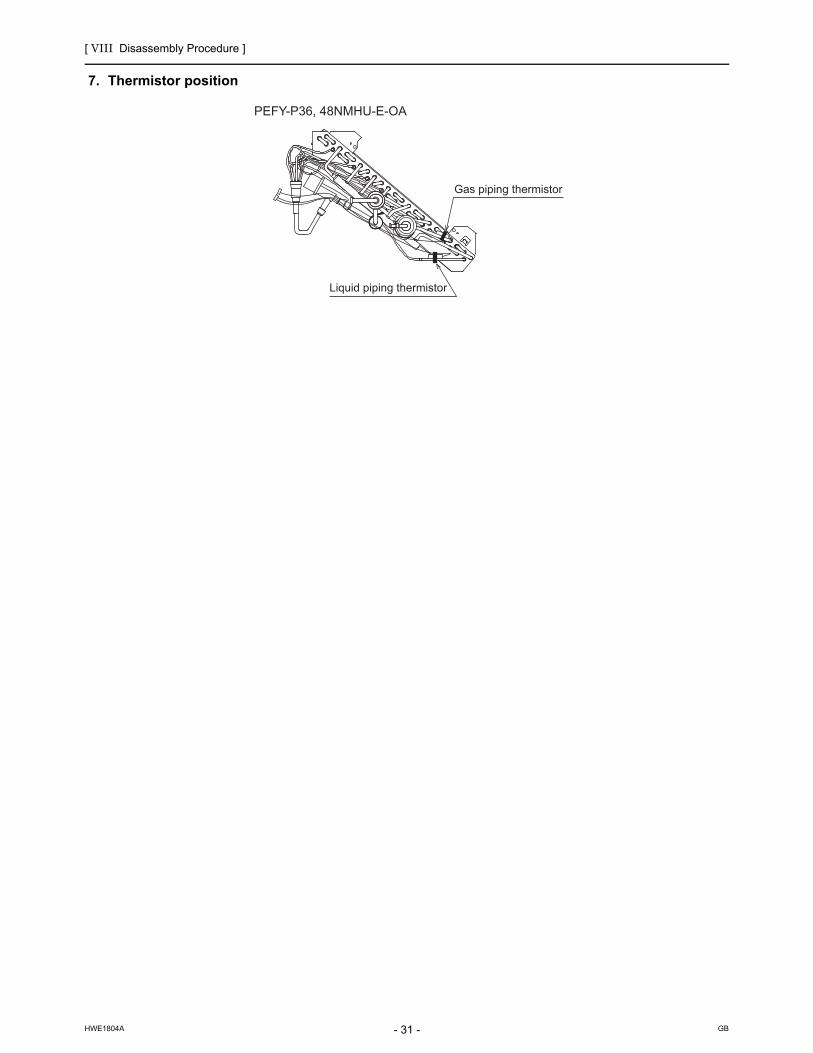
[ VIII Disassembly Procedure ]
- 31 -HWE1804A GB
7. Thermistor position
Liquid piping thermistor
PEFY-P36, 48NMHU-E-OA
Gas piping thermistor

[ VIII Disassembly Procedure ]
- 32 -HWE1804A GB
[2] Disassembly Procedure (PEFY-P72, 96NMHU-E-OA)
1. Control boxBe careful on removing heavy parts.
1. Removing the control box cover(1) Remove the fixing screws (two) of the control box (A), and
remove the cover. (Fig.1)
*At this stage, the following servicing is possible. (Fig.2)
1) Operation and check of the switches (listed below) which are on the control board.Dip switch SW1 . . . . . . . . . . . . Function changeDip switch SW2 . . . . . . . . . . . . Capacity code settingDip switch SW3 . . . . . . . . . . . . Function changeDip switch SW4 . . . . . . . . . . . . Model code settingDip switch SW21 . . . . . . . . . . . Static pressure settingDip switch SW22 . . . . . . . . . . . Function settingRotary switches SW11, 12 . . . . Address settingRotary switch SW14 . . . . . . . . . Branch port setting
2) Connection check of the lead wires (listed below) which are connected to the controller board.Power supply lead wire.Transmission lead wire x 2Fan motor lead wire.LEV lead wireInlet air temperature thermistor lead wireOutlet air temperature thermistorLiquid piping temperature thermistor lead wireGas piping temperature thermistor lead wireDrain pump lead wireFloat switch lead wire
3) Control board exchange4) Reactor exchange5) Thermistor (inlet air, outlet air, liquid piping, gas piping)
exchange6) Power supply terminal bed exchange7) Transmission terminal bed exchange x 28) Ferrite core exchange
A ferrite core is attached to the wire only when the model of fan motor is KMUC4E3MW. The model of the motor is noted in the nameplate on the fan motor casing.
Fig.1
Fig.2
Fixing screws(A)

[ VIII Disassembly Procedure ]
- 33 -HWE1804A GB
2. Fan and fan motorBe careful on removing heavy parts.Electric shock hazard. Before performing any work, shut off the power supply.
1. Remove the control box cover according to the procedure in section [2]-1. Control box.
2. Removing the fan motor cable(1) Disconnect the connector (CNMF1) from the control
board and remove the ferrite core from the cable (Fig. 2).A ferrite core is attached to the wire only when the model of fan motor is KMUC4E3MW. The model of the motor is noted in the nameplate on the fan motor casing.
(2) Remove the cable through the rubber bush.
3. Removing the bottom plate(1) Remove the thirteen fixing screws on the bottom plate to
remove it. Fig.1
Fig.2
4. Removing the fan case(1) Remove the eight fixing screws on the fan case to re-
move it (Fig. 3).
Fig.3
CNMF1
CNMF1Ferrite core

[ VIII Disassembly Procedure ]
- 34 -HWE1804A GB
5. Removing the fan and fan motor(1) Remove the grounding wire of the motor wire from the
motor base (Fig. 4).The grounding wire of the motor wire is found only on the KMUC4E3MW. The model of the motor is noted in the nameplate on the fan motor casing.
(2) Remove the two fixing screws and attachment on the fan motor (Fig. 5).
(3) Pull out the fan motor in the direction of the arrow (Fig. 5). Fig.4
Exercise caution when removing heavy parts.
Fig.5
6. Precautions for reinstalling the removed motor in its orig-inal position
(1) As shown in Fig. 6, reinstall the motor cable in its original position and reset it on the control board.
(2) Fix the motor in place so that the heat radiating fins on the motor and the stopper of the motor leg are positioned as shown in Fig. 7.
Fig.6
Fig.7
Protruding portion
Stopper
Viewed from left

[ VIII Disassembly Procedure ]
- 35 -HWE1804A GB
3. LEV, thermistor (Liquid/Gas piping temperature detection)Be careful on removing heavy parts.
1. Removing the LEV.(1) Remove the control box cover with procedure [2]-1.
(2) Remove the fixing screws (three) of the heat exchanger cover (A), and remove the cover (A). (Fig.1)
(3) Remove the LEV driving motor. (Fig.2)
2. Removing the liquid pipe and gas pipe thermistor.(1) Remove the thermistors from the thermistor holders
which are installed on the piping. (Fig.3)
3. Removing the outlet air temperature thermistor.(1) Remove control box cover with procedure [2]-1.
(2) Remove the fixing screws (three) of the heat exchanger cover (A), and remove the cover (A). (Fig.1)
(3) Remove the fixing screws (four) of maintenance cover (B), and remove the cover (B). (Fig.1)
(4) Remove the cable bush from the panel, and pull the outlet air temperature thermistor through the hole. (Fig.4)
Fig.1
Fig.2
Fig.3
Fig.4
(A)(B)
LEV
Thermistor
P96P72 Thermistor
Cable bush

[ VIII Disassembly Procedure ]
- 36 -HWE1804A GB
4. Drain pump
1. Remove the fixing screws shown in Fig. 1, and remove the control box cover.
Fig.1
2. Remove the connector into CN4F and CNP on the control board shown in Fig. 2.
Fig.2
3. Remove the fixing screws shown in Fig. 3, and remove the wire cover.
Fig.3
4. Remove the fixing screws shown in Fig. 4, and remove the maintenance cover.
Fig.4
Fixing screwControl box cover
Fixing screw
Wire saddleFloat switch wire (clear tube)
Indoor P.C. board
Drain pump wire(Black tube)
CNP White
CN4F WhiteSW1
Wire saddle
Clamp Hole
Wire cover
Fixing screws
Fixing screw
Maintenance cover

[ VIII Disassembly Procedure ]
- 37 -HWE1804A GB
5. Remove the fixing screws holding the drain hose and the drain pump assy shown in Fig. 5.
Fig.5
6. Remove the fixing screws and cut the band shown in Fig. 6, by doing so, the drain pump and the float switch can be disassembled.
Fig.6
Band

[ VIII Disassembly Procedure ]
- 38 -HWE1804A GB
5. Heat exchangerBe careful on removing heavy parts.
1. Removing the heat exchanger.(1) Remove the heat exchanger cover (A) with procedure
[2]-3-1.
(2) Remove the bottom plate which is air outlet side. (fixing screws: twelve) (Fig.1)
(3) Remove the drainpan. (Fig.2)
(4) Remove the two fixing screws. (Fig.3)
Fig.1
Fig.2
Fig.3
Bottom plate
Drainpan
Fixing screws

[ VIII Disassembly Procedure ]
- 39 -HWE1804A GB
(5) Remove the maintenance cover. (fixing screws: four) (Fig.4)
(6) Remove the heat exchanger. (fixing screws: two) (Fig.5)
*Removed heat exchanger is as shown in Fig.6
Fig.4
Fig.5
Fig.6
Maintenance cover
Fixing screws

[ VIII Disassembly Procedure ]
- 40 -HWE1804A GB
6. Control box inside layout
A ferrite core is attached to the wire only when the model of fan motor is KMUC4E3MW. The model of the motor is noted in the nameplate on the fan motor casing.
Power source terminal bed Transmission terminal bed
AC reactor
Diode bridge
*Ferrite core

[ VIII Disassembly Procedure ]
- 41 -HWE1804A GB
7. Thermistor position
Liquid piping thermistor
Liquid piping thermistor
Gas piping thermistorGas piping thermistor
PEFY-P96NMHU-E-OAPEFY-P72NMHU-E-OA

- 42 -
[ VIII Disassembly Procedure ]
GBHWE1804A

![lwpuk ,oa yksd lEidZ foHkkx] mÙkjk[kM](https://static.fdokumen.com/doc/165x107/633777c0a5ba10dda70195a7/lwpuk-oa-yksd-leidz-fohkkx-mukjkkm.jpg)