Service/ P arts Manual - HubSpot
121
1 Service/ Parts Manual Floating Air Pro-Premiere Single Zone 96261401_01 Model Indoor Unit Outdoor Unit Voltage BTU FPHW091 FPHSW09A1A FPHSR09A1A 115 9k FPHW091A FPHSW09A1B FPHSR09A1A 115 9k WiFi FPHW093 FPHFW09A3A FPHSR09A3A 208/230 9k FPHW093A FPHFW09A3B FPHSR09A3A 208/230 9k WiFi FRHW093 FRHSW09A3A FRHSR09A3A 208/230 9k FRHW093A FRHSW09A3B FRHSR09A3A 208/230 9k WiFi FPHW121 FPHSW12A1A FPHSR12A1A 115 12k FPHW121A FPHSW12A1B FPHSR12A1A 115 12k WiFi FPHW123 FPHFW12A3A FPHSR12A3A 208/230 12k FPHW123A FPHFW12A3B FPHSR12A3A 208/230 12k WiFi FRHW123 FRHSW12A3A FRHSR12A3A 208/230 12k FRHW123A FRHSW12A3B FRHSR12A3A 208/230 12k WiFi FPHW183 FPHFW18A3A FPHSR18A3A 208/230 18k FPHW183A FPHFW18A3B FPHSR18A3A 208/230 18k WiFi FPHW243 FPHFW24A3A FPHSR24A3A 208/230 24k FPHW243A FPHFW24A3B FPHSR24A3A 208/230 24k WiFi FPHW363 FPHSW36A3A FPHSR36A3A 208/230 36k FPHW363A FPHSW36A3B FPHSR36A3A 208/230 36k WiFi FPHW363B FPHSW36A3C FPHSR36A3B 208/230 36k WiFi
-
Upload
khangminh22 -
Category
Documents
-
view
0 -
download
0
Transcript of Service/ P arts Manual - HubSpot
1 PB
Serv
ice/
Par
ts M
anua
l
Floating Air Pro-PremiereSingle Zone
96261401_01
Model Indoor Unit Outdoor Unit Voltage BTU
FPHW091 FPHSW09A1A FPHSR09A1A 115 9k
FPHW091A FPHSW09A1B FPHSR09A1A 115 9k WiFi
FPHW093 FPHFW09A3A FPHSR09A3A 208/230 9k
FPHW093A FPHFW09A3B FPHSR09A3A 208/230 9k WiFi
FRHW093 FRHSW09A3A FRHSR09A3A 208/230 9k
FRHW093A FRHSW09A3B FRHSR09A3A 208/230 9k WiFi
FPHW121 FPHSW12A1A FPHSR12A1A 115 12k
FPHW121A FPHSW12A1B FPHSR12A1A 115 12k WiFi
FPHW123 FPHFW12A3A FPHSR12A3A 208/230 12k
FPHW123A FPHFW12A3B FPHSR12A3A 208/230 12k WiFi
FRHW123 FRHSW12A3A FRHSR12A3A 208/230 12k
FRHW123A FRHSW12A3B FRHSR12A3A 208/230 12k WiFi
FPHW183 FPHFW18A3A FPHSR18A3A 208/230 18k
FPHW183A FPHFW18A3B FPHSR18A3A 208/230 18k WiFi
FPHW243 FPHFW24A3A FPHSR24A3A 208/230 24k
FPHW243A FPHFW24A3B FPHSR24A3A 208/230 24k WiFi
FPHW363 FPHSW36A3A FPHSR36A3A 208/230 36k
FPHW363A FPHSW36A3B FPHSR36A3A 208/230 36k WiFi
FPHW363B FPHSW36A3C FPHSR36A3B 208/230 36k WiFi

2 PB
TABLE OF CONTENTSINTRODUCTION‑ 4 Important Safety Information‑ 4 Personal Injury Or Death Hazards‑ 6 Model Identification Guide‑ 7SPECIFICATIONS‑ 8 Product Specifications 9k and 12k‑ 8 Product Specifications 18k, 24k and 36k‑ 9 Product Dimensions: Indoor Units‑ 10 Capacities and Selection Data‑ 11 Capacities and Selection Data‑ 12 Remote Control‑ 18 Using Sleep during Off‑Timer Function‑ 20INSTALLATION‑ 24 Installation Dimension Diagram‑ 24 Main Tools For Installation and Maintenance‑ 25 Install Indoor Unit‑ 27 Power and Wiring‑ 35 Leak Check, Evacuation, and Charging (Triple Evacuation)‑ 36 Checklist and Operation Test‑ 38MAINTENANCE‑ 39R‑410A SEALED SYSTEM REPAIR‑ 42 Service Valves Appearance‑ 42 Pumping Down‑ 43 Gas Charging (After Repair)‑ 44COMPONENTS TESTING ‑ 45 Resistance Table Of Indoor Coil And Indoor Room Sensor‑ 45 Resistance Table Of Outdoor Compressor Temperature Sensor‑ 46 Compressor‑ 47 Fan Motor‑ 48 Printed Circuit Board Diagram Lookup Chart‑ 50 Printed Circuit Board (Indoor)‑ 51 Printed Circuit Board (Outdoor)‑ 53TROUBLESHOOTING‑ 56 Diagnostic Codes‑ 56 Outdoor Unit‑ 56 Outdoor Unit When The Compressor Is In Operation‑ 58 Indoor Unit‑ 59 Led Display‑ 62 Test the jumper terminals‑ 65 Protection Circuit Fault Isolation‑ 66 Compressor Fault Isolation‑ 67 Electric FIlter Board Fault Isolation‑ 67 Electrical Communication Fault ISOLATION‑ 67 Unit does not run‑ 68 Error Code 39‑DC FAN‑ 69 Error Code 39‑PG Fan‑ 70 Error Code 9‑ 71 Error Code 13‑ 72 Error Code 8‑ 72 Error Code 15‑ 73 Error Code 16 Cooling Mode‑ 74 Error Code 16 Heating Mode‑ 74 Error Code 21 Cooling Mode‑ 74 Error Code 11 EEPROM Fault‑ 74
3 PB
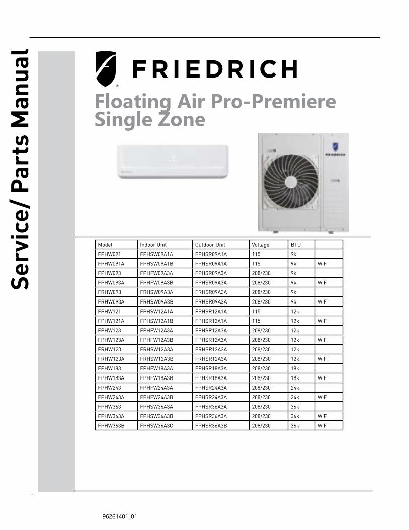
TABLE OF CONTENTS Error Code 20‑ 75 Error Code 33‑ 76 Error Code 19‑ 77 Error Code 36 ‑ 80WIRING DIAGRAMS‑ 81 Wiring Diagram Lookup Table‑ 81 Indoor Units‑ 82 Outdoor Units‑ 84 Introduction‑ 85PARTS CATALOG‑ 86 115V Indoor Unit 9‑12K‑ 86 230V Indoor Unit 9‑12K‑ 88 230V Indoor Unit High Seer 9K‑ 90 230V Indoor Unit High Seer12K‑ 92 230V Indoor Unit 18K‑ 94 230V Indoor Unit 24K‑ 96 230V Indoor Unit 36k‑ 98 230V Outdoor Unit 9k‑ 100 230V Outdoor Unit 12k‑ 102 230V Outdoor Unit 18k‑ 104 230V Outdoor Unit 18k‑ 105 230V Outdoor Unit 24k‑ 106 Outdoor Unit 36k‑ 108 115V Outdoor Unit 9K‑ 110 115V Outdoor Unit 12K‑ 112 230v Outdoor Unit 9K HIGH SEER‑ 114 230V Outdoor Unit 12K HIGH SEER‑ 116APPENDIX‑ 118 Appendix 1: Reference Sheet of Celsius and Farenheit‑ 118 Appendix 2: Pipe Expanding Method‑ 119LIMITED WARRANTY‑ 120CUSTOMER SATISFACTION and QUALITY ASSURANCE‑ 121FRIEDRICH AUTHORIZED PARTS DEPOTS‑ 121
4 PB
INTRODUCTION
The information in this manual is intended for use by a qualified technician who is familiar with the safety procedures required for installation and repair, and who is equipped with the proper tools and test instruments required to service this product.
Installation or repairs made by unqualified persons can result in subjecting the unqualified person making such repairs as well as the persons being served by the equipment to hazards resulting in injury or electrical shock which can be serious or even fatal.
Safety warnings have been placed throughout this manual to alert you to potential hazards that may be encountered. If you install or perform service on equipment, it is your responsibility to read and obey these warnings to guard against any bodily injury or property damage which may result to you or others.
Important Safety Information
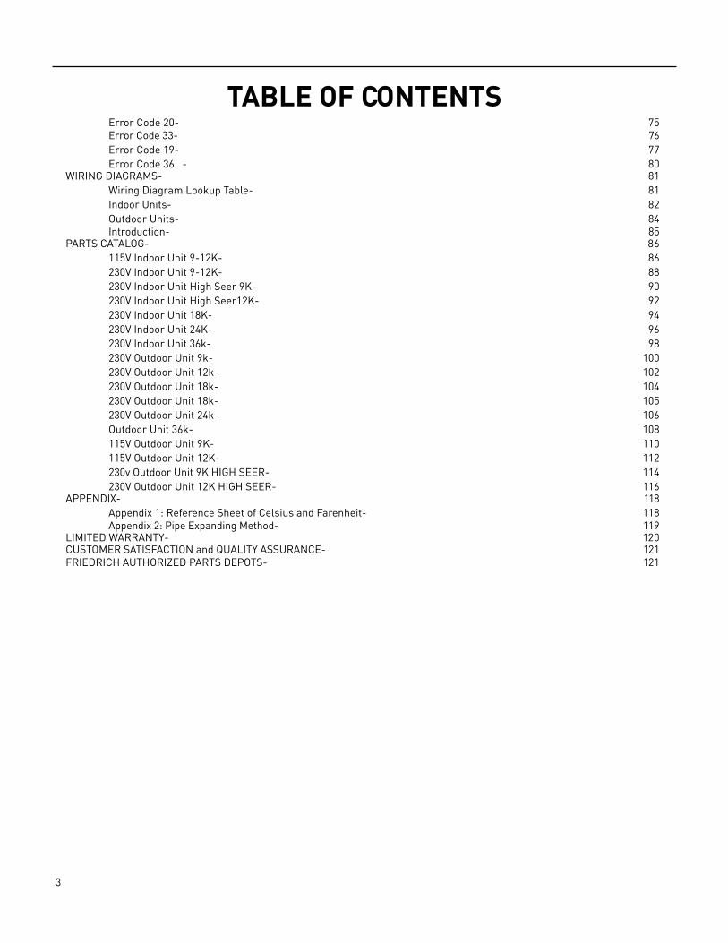
Your safety and the safety of others is very important.
We have provided many important safety messages in this manual and on your appliance. Always read and obey all safety messages.
This is a safety Alert symbol.This symbol alerts you to potential hazards that can kill or hurt you and others.
All safety messages will follow the safety alert symbol with the word “WARNING”or “CAUTION”. These words mean:
Indicates a hazard which, if not avoided, can result in severe personal injury or death and damage to product or other property.
Indicates a hazard which, if not avoided, can result in personal injury and damage to product or other property.
All safety messages will tell you what the potential hazard is, tell you how to reduce the chance of injury, and tell you what will happen if the instructions are not followed.
Indicates property damage can occur if instructions are not followed.
WARNING
NOTICE
CAUTION
WARNINGRefrigeration systemunder high pressure
Do not puncture, heat, expose to flame or incinerate.
Only certified refrigeration technicians should service this equipment.
R410A systems operate at higher pressures than R22 equipment. Appropriate safe service and handling practices must be used.
Only use gauge sets designed for use with R410A. Do not use standard R22 gauge sets.
5 PB
Important Safety InformationINTRODUCTION
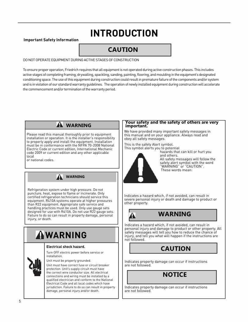
WARNINGPlease read this manual thoroughly prior to equipmentinstallation or operation. It is the installer’s responsibilityto properly apply and install the equipment. Installationmust be in conformance with the NFPA 70‑2008 NationalElectric Code or current edition, International Mechanic code 2009 or current edition and any other applicable localor national codes.
WARNING
Refrigeration system under high pressure. Do not puncture, heat, expose to flame or incinerate. Only certified refrigeration technicians should service this equipment. R410A systems operate at higher pressures than R22 equipment. Appropriate safe service and handling practices must be used. Only use gauge sets designed for use with R410A. Do not use R22 gauge sets. Failure to do so can result in property damage, personal injury, or death.
WARNINGElectrical shock hazard.
Turn OFF electric power before service or installation. Unit must be properly grounded.Unit must have correct fuse or circuit breaker protection. Unit’s supply circuit must have the correct wire conductor size. All electrical connections and wiring must be installed by a qualified electrician and conform to the National Electrical Code and all local codes which have jurisdiction. Failure to do so can result in property damage, personal injury and/or death.
Your safety and the safety of others are very important.
We have provided many important safety messages in this manual and on your appliance. Always read and obey all safety messages.
This is the safety Alert symbol.This symbol alerts you to potential
hazards that can kill or hurt you and others. All safety messages will follow the safety alert symbol with the word “WARNING” or “CAUTION”. These words mean:
Indicates a hazard which, if not avoided, can result in severe personal injury or death and damage to product or other property.
Indicates a hazard which, if not avoided, can result inpersonal injury and damage to product or other property. All safety messages will tell you how to reduce the chance of injury, and tell you what will happen if the instructions are not followed.
Indicates property damage can occur if instructionsare not followed.
Indicates property damage can occur if instructionsare not followed.
WARNING
CAUTION
NOTICE
DO NOT OPERATE EQUIPMENT DURING ACTIVE STAGES OF CONSTRUCTION
To ensure proper operation, Friedrich requires that all equipment is not operated during active construction phases. This includes active stages of completing framing, drywalling, spackling, sanding, painting, flooring, and moulding in the equipment’s designated conditioning space. The use of this equipment during construction could result in premature failure of the components and/or system and is in violation of our standard warranty guidelines. The operation of newly installed equipment during construction will accelerate the commencement and/or termination of the warranty period.
CAUTION
6 PB
INTRODUCTIONPersonal Injury Or Death Hazards
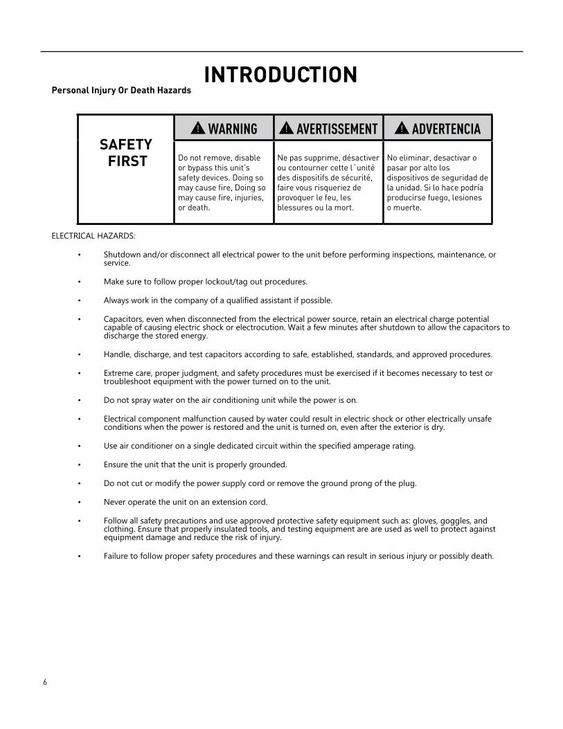
ELECTRICAL HAZARDS:
• Shutdown and/or disconnect all electrical power to the unit before performing inspections, maintenance, or service.
• Make sure to follow proper lockout/tag out procedures.
• Always work in the company of a qualified assistant if possible.
• Capacitors, even when disconnected from the electrical power source, retain an electrical charge potential capable of causing electric shock or electrocution. Wait a few minutes after shutdown to allow the capacitors to discharge the stored energy.
• Handle, discharge, and test capacitors according to safe, established, standards, and approved procedures.
• Extreme care, proper judgment, and safety procedures must be exercised if it becomes necessary to test or troubleshoot equipment with the power turned on to the unit.
• Do not spray water on the air conditioning unit while the power is on.
• Electrical component malfunction caused by water could result in electric shock or other electrically unsafe conditions when the power is restored and the unit is turned on, even after the exterior is dry.
• Use air conditioner on a single dedicated circuit within the specified amperage rating.
• Ensure the unit that the unit is properly grounded.
• Do not cut or modify the power supply cord or remove the ground prong of the plug.
• Never operate the unit on an extension cord.
• Follow all safety precautions and use approved protective safety equipment such as: gloves, goggles, and clothing. Ensure that properly insulated tools, and testing equipment are are used as well to protect against equipment damage and reduce the risk of injury.
• Failure to follow proper safety procedures and these warnings can result in serious injury or possibly death.
SAFETY FIRST
WARNING AVERTISSEMENT ADVERTENCIA Do not remove, disable or bypass this unit’s safety devices. Doing so may cause fire, Doing so may cause fire, injuries, or death.
Ne pas supprime, désactiver ou contourner cette l´unité des dispositifs de sécurité, faire vous risqueriez de provoquer le feu, les blessures ou la mort.
No eliminar, desactivar o pasar por alto los dispositivos de seguridad de la unidad. Si lo hace podría producirse fuego, lesiones o muerte.
7 PB
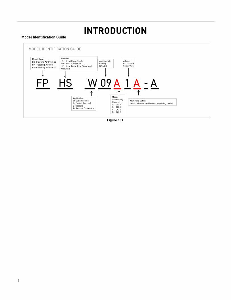
INTRODUCTIONModel Identification Guide
Figure 101
FP HS W 09 A 1 A - A
Model Type:FR- Floating Air PremierFP - Floating Air ProFS- F loating Air Sele ct
Application :W- Wa llmountedD- Ducted (Insider)C- CassetteR- Remo te Condense r
Function :HS – H ea t Pump SingleHM – Heat Pump MultiHF – H eat Pump Flex Single and Multizon e
Coolin gBTU/HR
Model
Approximate
IntroductoryChara cter:
Voltag e
A- 201 9B- 202 0C- 202 1D- 202 2
1- 115 Volts3- 230 Volts
MODEL IDENTIFICATION GUIDE
Marketing Suffix :Letter indicates modification to existing mode l
8 PB
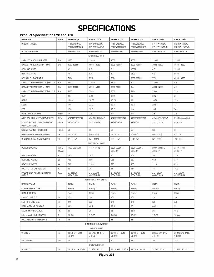
SPECIFICATIONSProduct Specifications 9k and 12k
Model No. Units FPHW091/A FPHW121/A FPHW093/A FRHW093/A FPHW123/A FRHW123/A
INDOOR MODEL FPHSW09A1A, FPHSW09A1B/B
FPHSW12A1A, FPHSW12A1B/B
FPHFW09A3A, FPHFW09A3B/B
FRHSW09A3A, FRHSW09A3B/B
FPHFW12A3A, FPHFW12A3B/B
FRHSW12A3A, FRHSW12A3B/B
OUTDOOR MODEL FPHSR09A1A FPHSR12A1A FPHSR09A3A FRHSR09A3A FPHSR12A3A FRHSR12A3A
SPECIFICATIONS
CAPACITY COOLING (RATED) Btu 9000 12000 9000 9000 12000 12000
CAPACITY COOLING MIN ‑ MAX Btu 3600‑10000 4000‑13500 3600‑10000 3600‑10000 4000‑13500 4000‑13500
COOLING AMPS 6.3 8.3 2.9 10500 4.3 13000
HEATING AMPS 7.0 9.7 3.1 6500 5.0 8000
SENSIBLE HEAT RATIO 76% 77% 76% 3600‑10500 77% 4000‑14000
CAPACITY HEATING (RATED) @ 47°F Btu 9500 13000 9500 2.3 13000 4.6
CAPACITY HEATING MIN ‑ MAX Btu 3600‑10500 4000‑14000 3600‑10500 3.4 4000‑14000 4.8
CAPACITY HEATING (RATED) @ 17°F Btu 5000 7500 5000 76% 7500 77%
COP 3.56 3.46 3.88 28 3.42 25
HSPF 10.00 10.50 10.70 16.1 10.50 15.4
SEER 19.5 22.0 22.5 12.5 22.0 12
EER 12.8 13.0 13.7 Yes 13.0 Yes
MOISTURE REMOVAL Pts/h 1.9 2.5 1.9 1.9 2.5 2.5
AIRFLOW (HIGH/MED/LOW/QUIET) CFM 424/382/323/247 424/382/323/247 424/382/323/247 416/384/355/279 424/382/323/247 598/536/446/345
SOUND RATING ‑ INDOOR (HIGH/MED/LOW/QUIET)
dB‑A 39/32/29/26 39/32/29/26 39/32/29/26 39/34/31 39/32/29/26 45/41/39
SOUND RATING ‑ OUTDOOR dB‑A 53 53 53 55 53 55
OPERATING RANGE (HEATING) °F (‑4° – 75°) (‑4° – 75°) (‑4° – 75°) 0˚‑115˚ (‑4° – 75°) 0˚‑115˚
OPERATING RANGE (COOLING) °F (5° – 115°) (5° – 115°) (5° – 115°) ‑13˚‑75˚ (5° – 115°) ‑13˚‑75˚
ELECTRICAL DATA
POWER SOURCE V/Hz/Phase
115V~,60Hz,1P 115V~,60Hz,1P 230V~,208V~, 60Hz,1P
230V~,208V~, 60Hz,1P
230V~,208V~, 60Hz,1P
230V~,208V~, 60Hz,1P
MIN. AMPACITY A 13.5 16.5 10 10A 10 12A
COOLING WATTS W 700 950 655 559 960 779
HEATING WATTS W 780 1100 720 905 1110 856
MAX. TD FUSE/ BREAKER A 20 25 15 15A 15 15A
POWER AND COMMUNICATION CABLE
Type 4 x 14AWG600V THHN
4 x 14AWG600V THHN
4 x 14AWG600V THHN
4 x 14AWG600V THHN
4 x 14AWG600V THHN
4 x 14AWG600V THHN
REFRIGERATION SYSTEM
REFRIGERANT R410a R410a R410a R410a R410a R410a
COMPRESSOR TYPE Rotary Rotary Rotary Rotary Rotary Rotary
CONNECTIONS Flare Flare Flare Flare Flare Flare
LIQUID LINE O.D. in 1/4 1/4 1/4 1/4 1/4 1/4
SUCTION LINE O.D. in 3/8 3/8 3/8 3/8 3/8 3/8
REFRIGERANT CHARGE oz 33.5 40.9 33.5 25 40.9 25
FACTORY PRECHARGE ft. 25 25 25 38.8 25 45.9
MIN. / MAX. LINE LENGTH ft 9.8‑50 9.8‑50 9.8‑50 10‑66 9.8‑50 10‑66
MAX. HEIGHT DIFFERENCE ft 33 33 33 33 33 33
DIMENSIONS & WEIGHT
INDOOR UNIT
W x H x D in 33 7/8 x 11 3/16 x 8 1/2
33 7/8 x 11 3/16 x 8 1/2
33 7/8 x 11 3/16 x 8 1/2
33 7/8 x 11 3/16 x 8 1/2
33 7/8 x 11 3/16 x 8 1/2
38 1/8 X 13 1/8 X 9 15/16
NET WEIGHT lbs 20 20 20 22 20 28.5
OUTDOOR UNIT
W x H x D in 28 1/8 x 19 x 9 7/16 31 7/8 x 23 x 11 28 1/8 x19 x 9 7/16 31 7/8 x 23 x 11 31 7/8 x 23 x 11 31 7/8 x 23 x 11
Figure 201
9 PB
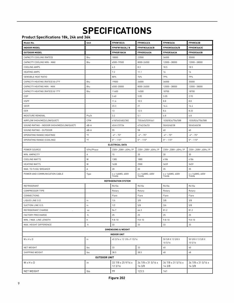
SPECIFICATIONSProduct Specifications 18k, 24k and 36k
Model No. Unit FPHW183/A FPHW243/A FPHW363A FPHW363B
INDOOR MODEL FPHFW18A3A,/ B FPHFW24A3A/B FPHSW36A3A/B FPHSW36A3C
OUTDOOR MODEL FPHSR18A3A FPHSR24A3A FPHSR36A3A FPHSR36A3B
CAPACITY COOLING (RATED) Btu 18000 23500 36000 35000
CAPACITY COOLING MIN ‑ MAX Btu 6500‑19500 8000‑26500 12000‑‑38000 12000‑‑38000
COOLING AMPS 6.3 8.3 18.5 18.5
HEATING AMPS 7.2 11.1 16 16
SENSIBLE HEAT RATIO 80% 76% 79% 79%
CAPACITY HEATING (RATED) @ 47°F Btu 19000 26000 36000 35000
CAPACITY HEATING MIN ‑ MAX Btu 6500‑20000 8000‑26500 12000‑‑38000 12000‑‑38000
CAPACITY HEATING (RATED) @ 17°F Btu 11600 14500 18700 18700
COP 3.40 3.05 3.05 2.93
HSPF 11.6 10.5 8.8 8.8
SEER 23.3 21 16.4 16.4
EER 13 12.5 8.6 8.33
MOISTURE REMOVAL Pts/h 3.2 5.1 6.8 6.8
AIRFLOW (HIGH/MED/LOW/QUIET) CFM 618/565/482/382 735/665/559/441 1030/824/706/588 1030/824/706/588
SOUND RATING ‑ INDOOR (HIGH/MED/LOW/QUIET) dB‑A 45/41/37/34 47/42/36/33 50/45/40/38 50/45/40/38
SOUND RATING ‑ OUTDOOR dB‑A 55 58 60 60
OPERATING RANGE (HEATING) °F ‑4° – 75° ‑4° – 75° ‑4° – 75° ‑4° – 75°
OPERATING RANGE (COOLING) °F 5° – 115° 5° – 115° 5° – 115° 5° – 115°
ELECTRICAL DATA
POWER SOURCE V/Hz/Phase 230V~,208V~,60Hz,1P 230V~,208V~,60Hz,1P 230V~,208V~,60Hz,1P 230V~,208V~,60Hz,1P
MIN. AMPACITY A 15 20 30 30
COOLING WATTS W 1385 1880 4186 4186
HEATING WATTS W 1638 2500 3459 3459
MAX. TD FUSE/ BREAKER A 20 30 35 35
POWER AND COMMUNICATION CABLE Type 4 x 14AWG, 600V THHN
4 x 14AWG, 600V THHN
4 x 14AWG, 600V THHN
4 x 14AWG, 600V THHN
REFRIGERATION SYSTEM
REFRIGERANT R410a R410a R410a R410a
COMPRESSOR TYPE Rotary Rotary Rotary Rotary
CONNECTIONS Flare Flare Flare Flare
LIQUID LINE O.D. in 1/4 3/8 3/8 3/8
SUCTION LINE O.D. in 1/2 5/8 3/4 5/8
REFRIGERANT CHARGE . oz 54.7 66.3 81.2 81.2
FACTORY PRECHARGE ft. 25 25 25 25
MIN. / MAX. LINE LENGTH ft 9.8‑10 9.8‑10 9.8‑10 9.8‑10
MAX. HEIGHT DIFFERENCE ft 33 33 33 33
DIMENSIONS & WEIGHT
INDOOR UNIT
W x H x D in 45 3/16 x 13 1/8 x 9 15/16 50 5/8 X 13 5/8 X 10 5/16
50 5/8 X 13 5/8 X 10 5/16
NET WEIGHT lbs 33 33 40 40
SHIPPING WEIGHT lbs 38.5 38.5 48 48
OUTDOOR UNIT
W x H x D in 33 7/8 x 25 9/16 x 12 3/16
34 7/8 x 31 5/16 x 14 3/8
34 7/8 x 31 5/16 x 14 3/8
34 7/8 x 31 5/16 x 14 3/8
NET WEIGHT lbs 99 123.5 141
Figure 202
10 PB
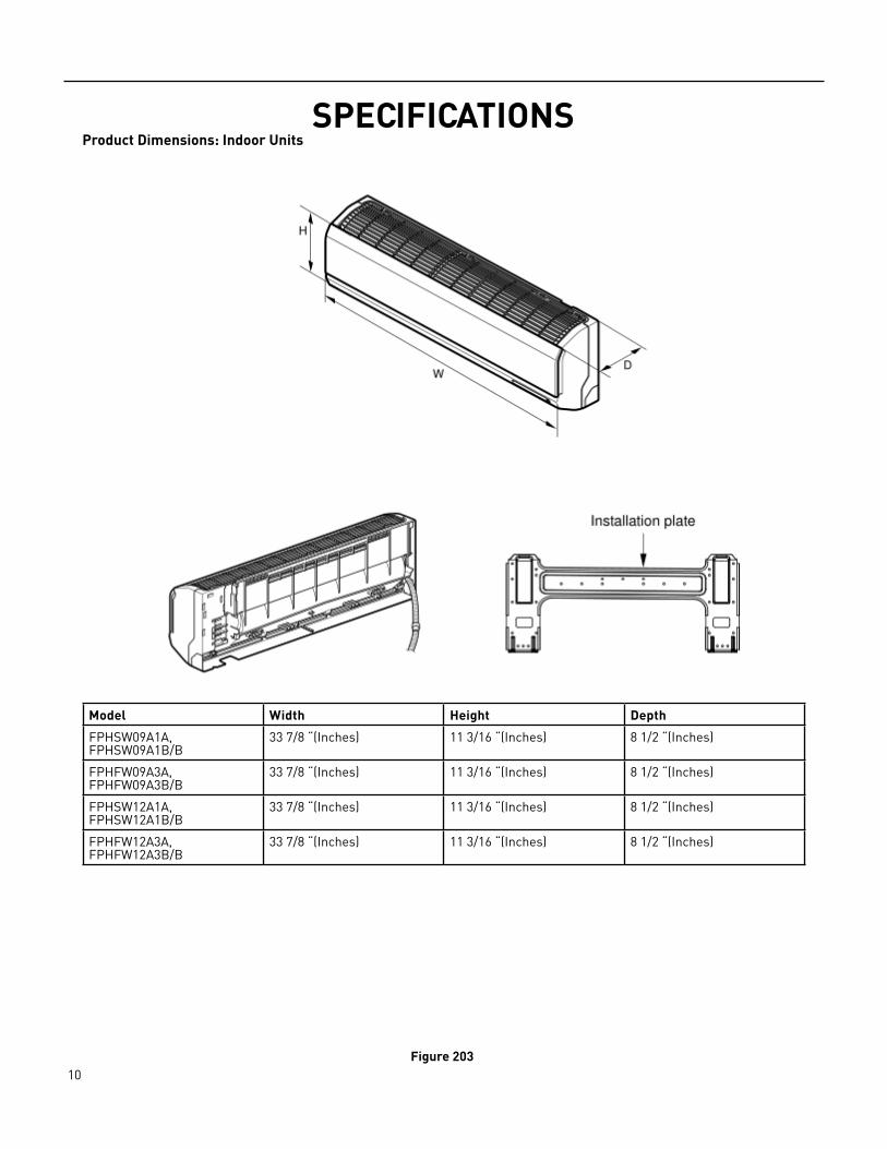
SPECIFICATIONSProduct Dimensions: Indoor Units
Model Width Height Depth
FPHSW09A1A, FPHSW09A1B/B
33 7/8 “(Inches) 11 3/16 “(Inches) 8 1/2 “(Inches)
FPHFW09A3A, FPHFW09A3B/B
33 7/8 “(Inches) 11 3/16 “(Inches) 8 1/2 “(Inches)
FPHSW12A1A, FPHSW12A1B/B
33 7/8 “(Inches) 11 3/16 “(Inches) 8 1/2 “(Inches)
FPHFW12A3A, FPHFW12A3B/B
33 7/8 “(Inches) 11 3/16 “(Inches) 8 1/2 “(Inches)
Figure 203
11 PB
SPECIFICATIONSCapacities and Selection Data
Capacity characteristic charts
The following charts show the characteristics of outdoor unit capacity, which corresponds with the operating ambient temperature of outdoor unit. This data is obtained with Free‑Spin of the Condenser and not in a testing mode Conditions:
1‑ Pipe length / height difference : 25 ft. (7.6m) / 0 ft. (0m)2‑ Compressor at rated inverter frequenc y3‑ Indoor fan speed at high fan speed4‑ Capacity loss due to frost accumulation and defrost operation is not included.

12 PB
SPECIFICATIONSCapacities and Selection Data
Floating Air Pro / Premier Cooling Extended Capacity (By System Model)
System Model Outdoor Air Temp. (°F DB)
Indoor Air Temp. °F DB / °F WB
80 /67
TC SHC PI
kBtu/h kW
FPHW091/A
32 9.56 6.69 0.26
41 10.09 7.06 0.36
50 10.35 7.24 0.47
59 10.96 7.67 0.50
67 11.18 7.83 0.59
77 11.57 8.10 0.70
82 11.90 8.33 0.81
87 11.78 8.25 1.00
95 11.63 8.14 1.02
104 11.08 7.76 1.02
115 9.94 6.96 1.00
FPHW121/A
32 10.76 7.53 0.27
41 11.29 7.90 0.36
50 11.93 8.35 0.42
59 12.17 8.52 0.59
67 12.44 8.71 0.78
77 12.68 8.88 1.01
82 13.25 9.28 1.07
87 12.98 9.08 1.16
95 12.55 8.79 1.25
104 11.90 8.33 1.24
115 10.53 7.37 1.18
FPHW093/A
32 8.54 5.97 0.26
41 8.72 6.10 0.36
50 9.15 6.41 0.47
59 9.53 6.67 0.60
67 9.89 6.92 0.69
77 10.21 7.14 0.80
82 10.37 7.25 0.90
87 10.28 7.19 0.91
95 10.11 7.08 0.92
104 9.85 6.89 0.89
115 9.26 6.48 0.88

13 PB
SPECIFICATIONSCapacities and Selection Data
Floating Air Pro / Premier Cooling Extended Capacity (By System Model)
System Model Outdoor Air Temp. (°F DB)
Indoor Air Temp. °F DB / °F WB
80 /67
TC SHC PI
kBtu/h kW
FPHW123/A
32 10.66 7.46 0.35
41 11.39 7.97 0.54
50 12.09 8.46 0.65
59 12.73 8.91 0.76
67 13.13 9.19 0.86
77 13.62 9.54 0.95
82 14.07 9.85 1.09
87 13.85 9.69 1.15
95 13.25 9.27 1.22
104 12.15 8.50 1.19
115 9.81 6.87 1.10
FPHW183/A
32 16.78 11.75 0.97
41 17.75 12.43 1.09
50 18.40 12.88 1.22
59 18.62 13.03 1.30
67 19.03 13.32 1.35
77 19.31 13.52 1.41
82 19.55 13.69 1.60
87 19.26 13.48 1.91
95 18.57 13.00 1.91
104 17.27 12.09 2.11
115 15.80 11.06 2.11
FPHW243/A
32 22.14 15.50 1.09
41 25.05 17.54 1.47
50 26.49 18.55 1.72
59 27.28 19.10 1.93
67 27.51 19.26 2.13
77 27.72 19.40 2.35
82 28.08 19.66 2.52
87 27.35 19.15 2.72
95 26.47 18.53 3.02
104 22.76 15.93 2.89
115 18.34 12.84 2.60
14 PB
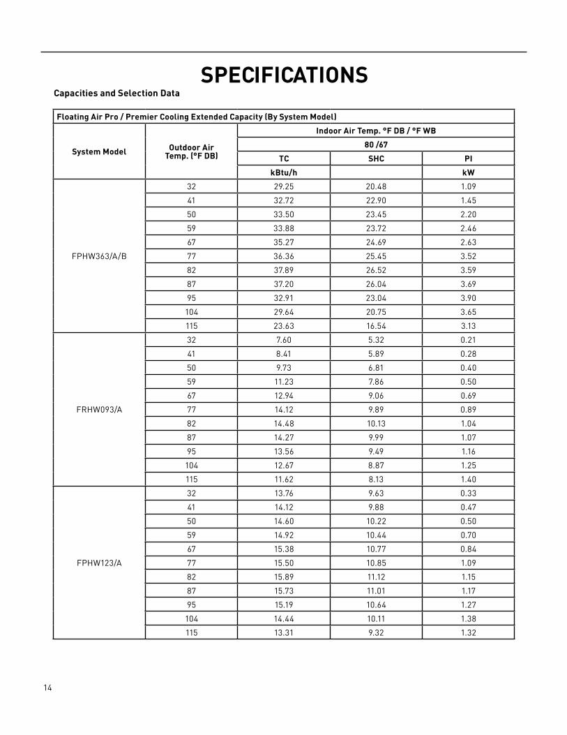
SPECIFICATIONSCapacities and Selection Data
Floating Air Pro / Premier Cooling Extended Capacity (By System Model)
System Model Outdoor Air Temp. (°F DB)
Indoor Air Temp. °F DB / °F WB
80 /67
TC SHC PI
kBtu/h kW
FPHW363/A/B
32 29.25 20.48 1.09
41 32.72 22.90 1.45
50 33.50 23.45 2.20
59 33.88 23.72 2.46
67 35.27 24.69 2.63
77 36.36 25.45 3.52
82 37.89 26.52 3.59
87 37.20 26.04 3.69
95 32.91 23.04 3.90
104 29.64 20.75 3.65
115 23.63 16.54 3.13
FRHW093/A
32 7.60 5.32 0.21
41 8.41 5.89 0.28
50 9.73 6.81 0.40
59 11.23 7.86 0.50
67 12.94 9.06 0.69
77 14.12 9.89 0.89
82 14.48 10.13 1.04
87 14.27 9.99 1.07
95 13.56 9.49 1.16
104 12.67 8.87 1.25
115 11.62 8.13 1.40
FPHW123/A
32 13.76 9.63 0.33
41 14.12 9.88 0.47
50 14.60 10.22 0.50
59 14.92 10.44 0.70
67 15.38 10.77 0.84
77 15.50 10.85 1.09
82 15.89 11.12 1.15
87 15.73 11.01 1.17
95 15.19 10.64 1.27
104 14.44 10.11 1.38
115 13.31 9.32 1.32

15 PB
SPECIFICATIONSCapacities and Selection Data
Floating Air Pro / Premier Cooling Extended Capacity (By System Model)
System Model Outdoor Air Temp. (°F DB)
Indoor Air Temp. °F DB / °F WB
80 /67
TC SHC PI
kBtu/h kW
FPHW091/A
‑5 ‑7 4.95 1.14
5 3 5.45 1.07
14 12 7.08 1.17
17 15 8.93 1.30
23 19 9.67 1.30
32 28 9.65 1.19
35 33 9.89 1.03
47 43 10.54 0.94
59 50 9.86 0.82
FPHW121/A
‑5 ‑7 6.40 1.22
5 3 8.12 1.30
14 12 9.76 1.49
17 15 12.13 1.63
23 19 12.95 1.68
32 28 13.07 1.48
35 33 14.00 1.43
47 43 15.50 1.45
59 50 12.73 0.91
FPHW093/A
‑5 ‑7 4.95 1.14
5 3 6.20 1.20
14 12 7.29 1.27
17 15 8.59 1.34
23 19 9.33 1.38
32 28 9.85 1.34
35 33 10.23 1.19
47 43 11.65 1.11
59 50 10.78 0.80
FPHW123/A
‑5 ‑7 8.67 1.29
5 3 10.18 1.34
14 12 11.40 1.44
17 15 12.10 1.48
23 19 12.72 1.54
32 28 13.46 1.56
35 33 13.94 1.51
47 43 14.19 1.31
59 50 14.01 1.10
16 PB
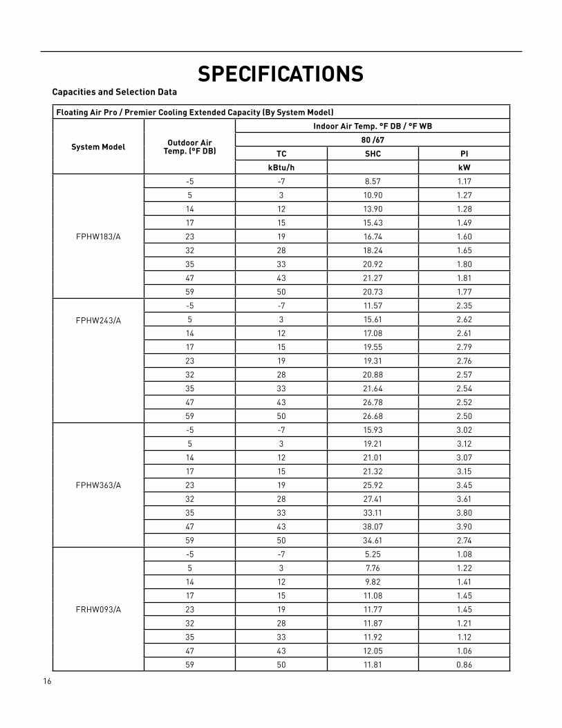
SPECIFICATIONSCapacities and Selection Data
Floating Air Pro / Premier Cooling Extended Capacity (By System Model)
System Model Outdoor Air Temp. (°F DB)
Indoor Air Temp. °F DB / °F WB
80 /67
TC SHC PI
kBtu/h kW
FPHW183/A
‑5 ‑7 8.57 1.17
5 3 10.90 1.27
14 12 13.90 1.28
17 15 15.43 1.49
23 19 16.74 1.60
32 28 18.24 1.65
35 33 20.92 1.80
47 43 21.27 1.81
59 50 20.73 1.77
FPHW243/A
‑5 ‑7 11.57 2.35
5 3 15.61 2.62
14 12 17.08 2.61
17 15 19.55 2.79
23 19 19.31 2.76
32 28 20.88 2.57
35 33 21.64 2.54
47 43 26.78 2.52
59 50 26.68 2.50
FPHW363/A
‑5 ‑7 15.93 3.02
5 3 19.21 3.12
14 12 21.01 3.07
17 15 21.32 3.15
23 19 25.92 3.45
32 28 27.41 3.61
35 33 33.11 3.80
47 43 38.07 3.90
59 50 34.61 2.74
FRHW093/A
‑5 ‑7 5.25 1.08
5 3 7.76 1.22
14 12 9.82 1.41
17 15 11.08 1.45
23 19 11.77 1.45
32 28 11.87 1.21
35 33 11.92 1.12
47 43 12.05 1.06
59 50 11.81 0.86
17 PB
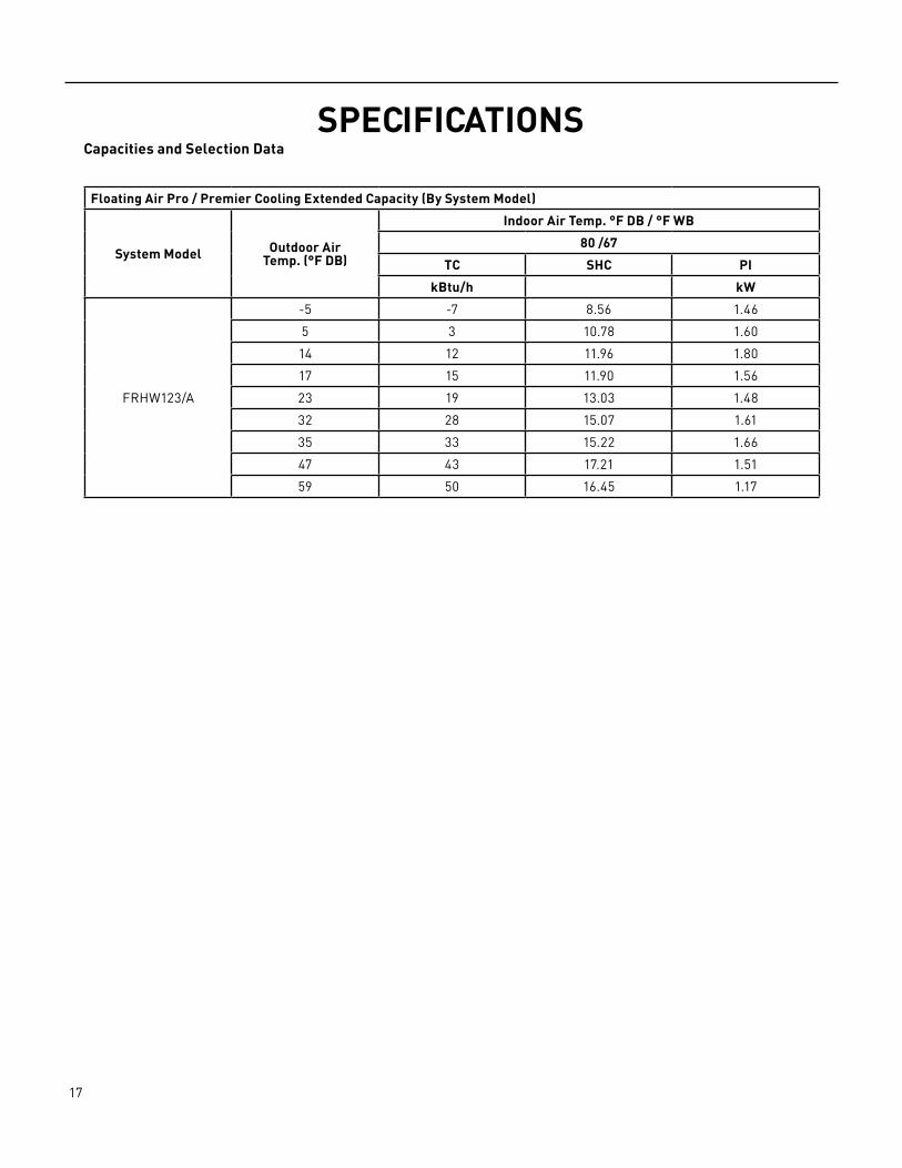
SPECIFICATIONSCapacities and Selection Data
Floating Air Pro / Premier Cooling Extended Capacity (By System Model)
System Model Outdoor Air Temp. (°F DB)
Indoor Air Temp. °F DB / °F WB
80 /67
TC SHC PI
kBtu/h kW
FRHW123/A
‑5 ‑7 8.56 1.46
5 3 10.78 1.60
14 12 11.96 1.80
17 15 11.90 1.56
23 19 13.03 1.48
32 28 15.07 1.61
35 33 15.22 1.66
47 43 17.21 1.51
59 50 16.45 1.17

18 PB
OPERATIONRemote Control
Figure 301Remote Control Operation and Function
Remote controller 1 Remote controller The remote controller transmits signals to the system.
SMART(invalid for multi system) Used to enter fuzzy logic operation directly, regardless of the unit is on or off.
POWER The appliance will be started when it is energized or will be stopped when it is in operation, if you press this button.
SUPER Used to start or stop the fast cooling/heating. {Fast cooling operates at high fan speed with 61'F(16'C) set temp automatically; Fast heating operates at auto fan speed with 30'C (86'F) set temp automatically)
!FEELUsed to set IFEEL mode operation. Pressit once, the IFEEL function will be started.Press it again, the IFEEL function will beshut off.
TEMP+ Used to adjust the room temperature and the timer, also real time.
MODE Press this button to select the operation mode.
FAN Used to select fan speed in sequence auto, higher, high, medium, low and lower.
SLEEP Used to set or cancel Sleep Mode operation.
� SWING Used to stop or start Horizontal adjustment louver swinging and set the desired left/right airflow direction.
TIMER ON/CLOCK
(;:: SWING Used to stop or start vertical adjustment louver swinging and set the desired up/ down airfow direction. it
Used to set or cancel the timer operation and used to set the current time.
TIMER OFF Used to set or cancel the timer operation.
ECONOMY
8 HEAT(optional) Used to set 8 HEAT Mode.
QUIET Used to set or cancel Quiet Mode operation.
Indication symbols on LCD:
$ Cooling indicator cf) Dry indicator
(i Auto fan speed (¢," .� Higher fan speed
y Lower fan speed \:, Sleep 1 indicator
• Smart indicator , Quiet indicator
Used to set o r cancel Economy Mode operation.
DIMMER When you press this button, all the display of indoor unit will be closed. Press any button to resume display.
� Fan only indicator ;i,8'"
a· Heating indicator ;*; Heating indicator
� High fan speed * Medium fan speed :0: Low fan speed
C: Sleep 2 indicator \;; Sleep 3 indicator � Sleep 4 indicator
� Economy indicator ,a : 88:88 Display set timerSuper indicator
Display current time -A-• Signal transmit ((l)) lfeel a Lock indicator BB }: Display temperature @i!I Battery power indicator
Note: Each mode and relevant function will be further specified in following pages.
-1-
19 PB
OPERATIONRemote Technical Parameters
Remote receiver distance (front of the air conditioner): 26ft.Remote receiver angle: Less than 60 degrees. Temperature control accuracy: ±2.4°F. Time Response: Less than 1 second.
Display Functions
RemoteCurrent control functions on the remote controller (See unit’s “Installation and Operating Manual”) Display of the indoor unit displays set temperature or indoor temperature.
Indoor unit
Running LED lit during operation, flashing when in defrost.Timer LED lit when the timer mode is active.Sleep LED lit when the sleep mode is activated and turns off after 10 seconds.Compressor LED lit when compressor is running.Remote control receiver receives signals from the remote control.Displays error codes if present. An error code is displayed according to the signal from the indoor CPU. The error code will flash for 5 seconds while displayed. Indoor Unit Operation
Manual Operation “ON/OFF” Button:When pressing the manual operation “ON/OFF” button after system is idle or in stand‑by mode, the previous settings will be restored from last operation: Mode, Temperature, and Fan Speed. The air flow directional setting does not restore. When first powered, pressing the manual operation “ON/OFF” button will force the system would operate in “auto” mode and will enter stand‑by mode by pressing the button again. Pressing and holding the manual operation “ON/OFF” button for 5 seconds will engage Test Mode and will beep 1 time. It will operate in cooling mode with the indoor fan speed set to high‑speed and will ignore indoor temperature for 5 minutes. If the manual operation “ON/OFF” button is pressed again or a signal is received from the remote control, test mode will exit. If exited from the remote control the system will operate with the corresponding mode selected on the remote control. I-Feel Function
The I‑Feel function is set by the remote control. The room temperature value interpreted by the system will use the temperature on the remote control instead of the temperature reported by the ambient air sensor in the indoor unit. The remote control will automatically transmits a temperature signal every 10 minutes. The remote control will transmits a signal every 2 minutes if the temperature setpoint selected exceeds 2°F. If the indoor unit does not received a signal from the remote in 30 minutes, the selected temperature setpoint will depend on the ambient air sensor of the indoor unit.
Timer Function
Max Timer range is 24 hours.Timer ON/OFF can be cycled anytime.Timer accuracy is ±1 minute.
The Timer can be adjusted by 1 min increments.Timer On‑OFF operational times can overlap.
Sleep Function
Sleep mode can only be used in Cooling, Heating and Dry mode.If Sleep mode is selected in Cooling mode, the room temperature setting will increase 2.5°F every hour for 8 hours. Room temperature will not rise more than 2.5°F per hour. Temperature rise will cease at 79°F. Room temperature will not rise above 79°F.If Sleep mode is selected in Heating mode, room temperature will be decreased by 2.5°F per hour for 3 hours but will not decrease more than 2.5°F per hour or 8°F for the duration of the mode.In either mode, the indoor fan run in the LOW speed. Last user settings (air direction and temperature) can be used, or adjusted by user. The Running indicator will flash, then the unit will turn off all the light indicators except the Sleep. After 5 minutes, the Sleep indicator will turn off. All indicators will be standby unless the temperature or Time setting is adjusted. After setting these, the indicators will turn off after 10 seconds.
20 PB
OPERATIONSleep mode will cease after 8 hours of operation. Using Sleep during Off-Timer FunctionWhen using Sleep mode, if the next OFF‑Timer setting less than 8 hours, Sleep mode will remain active until the OFF‑Timer setting. If the next OFF‑Timer setting more than 8 hours, it will override the OFF‑Timer setting and will turn the system off 8 hours after engaging Sleep mode.
Auto Mode (SMART)
In Auto Mode (SMART) the system will automatically switch to Cooling, Heating, Dry or Fan Only modes based on the current room temperature. Air flow direction can be adjusted in any mode.The auto set point is determined by the user.When the room temperature is 79°F or above, Cooling mode will activate.When the room temperature is between 73°F and 79°F, Dry mode will activate. Fan Speed will drop to LOW after 3 minutes.When the room temperature is between 70°F and 73°F, Fan only mode will activate. Fan Speed is automatically set to LOW, but can be adjusted when between these room temperatures.When the room temperature is below 70°F, Heating mode will activate. The room temperature is set to 72°F.Auto Mode ceases when another specific operation mode is selected. If changing between Cooling and Heating modes, the compressor ceased for operation for 5 minutes.Cooling only appliancea. When the room temperature exceeds 79°F, it will be ran in Cool mode, and the temperature is set to 79°F.b. When the room temperature exceeds 73°F, but not more than 79°F, it will be operated in the Dry mode.c. When the room temperature is not more than 73°F, it will be operated in the Fan only, the air volume is set to LOW and the fan speed can be adjusted
Cooling Mode
Outdoor Fan
The outdoor fan’s speeds (except in single speed‑selection motors) is changed automatically according to outdoor ambient temperatures demands. When operating at a fixed frequency, the outdoor fan is forced to operate at the highest speed. Indoor Fan
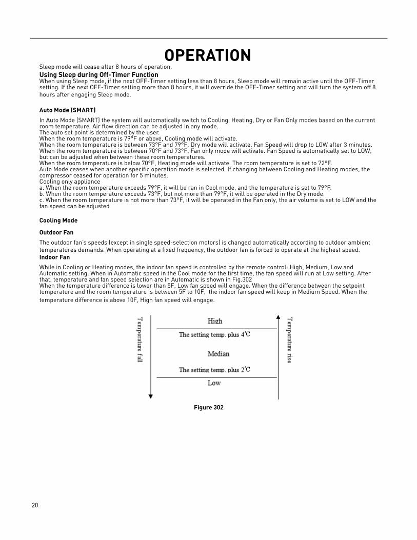
While in Cooling or Heating modes, the indoor fan speed is controlled by the remote control: High, Medium, Low and Automatic setting. When in Automatic speed in the Cool mode for the first time, the fan speed will run at Low setting. After that, temperature and fan speed selection are in Automatic is shown in Fig.302When the temperature difference is lower than 5F, Low fan speed will engage. When the difference between the setpoint temperature and the room temperature is between 5F to 10F, the indoor fan speed will keep in Medium Speed. When the temperature difference is above 10F, High fan speed will engage.
Figure 302
21 PB
OPERATIONAir flow direction (Louvers) control
The louver is operated by a stepper motor and operates the horizontal swing of the louver automatically. Press the SWING button to start or stop the louver swing.During the louver swing in normal operation, the current position will be stored. When the appliance turns off and the louvers swing automatically to the default position, it will position at the close position plus 5º.
4-way valve
State: It is interrupted in cooling.Switchover: When initially powered on for cooling, the 4‑way valve is interrupted immediately.When the heating is changed to the cooling, it needs an interval of 50 seconds for the 4‑way valve to change over from being activated to being interrupted.
Heating-run mode
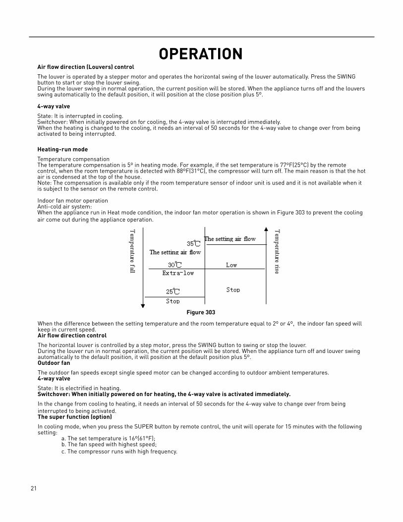
Temperature compensationThe temperature compensation is 5º in heating mode. For example, if the set temperature is 77ºF(25°C) by the remote control, when the room temperature is detected with 88ºF(31°C), the compressor will turn off. The main reason is that the hot air is condensed at the top of the house.Note: The compensation is available only if the room temperature sensor of indoor unit is used and it is not available when it is subject to the sensor on the remote control. Indoor fan motor operationAnti‑cold air system:When the appliance run in Heat mode condition, the indoor fan motor operation is shown in Figure 303 to prevent the cooling air come out during the appliance operation.
When the difference between the setting temperature and the room temperature equal to 2º or 4º, the indoor fan speed will keep in current speed.Air flow direction control
The horizontal louver is controlled by a step motor, press the SWING button to swing or stop the louver.During the louver run in normal operation, the current position will be stored. When the appliance turn off and louver swing automatically to the default position, it will position at the default position plus 5º.Outdoor fan
The outdoor fan speeds except single speed motor can be changed according to outdoor ambient temperatures.4-way valve
State: It is electrified in heating.Switchover: When initially powered on for heating, the 4-way valve is activated immediately.
In the change from cooling to heating, it needs an interval of 50 seconds for the 4‑way valve to change over from being interrupted to being activated. The super function (option)
In cooling mode, when you press the SUPER button by remote control, the unit will operate for 15 minutes with the following setting: a. The set temperature is 16º(61°F); b. The fan speed with highest speed; c. The compressor runs with high frequency.
Figure 303

22 PB
OPERATIONDehumidifying mode
Dehumidifying area I: Operation at the frequency in the range (30–60Hz) according to Dt (Tindoor ambient‑Tset).Dehumidifying area II: The compressor stops for 5 minutes and operators for 5 minutes at the lowest frequency.Dehumidifying area III: The compressor stops.
Dt(°F) f(Hz)
32 30
33 30
34 40
35 50
36 60
Figure 304
Figure 305
23 PB
OPERATIONFan Only Mode OperationDuring the appliance run in this mode; the compressor and outdoor fan stop and the indoor fan operates under the pre‑setting of air volume. The louver swing and the indoor fan speed is the same as the Heating Mode.
Defrost
Conditions for Defrost Activation:
The following three conditions must be met to activate Defrost.• Condition 1: Outdoor ambient sensor is below 28.4F• Condition 2: When the heating compressor consecutively runs for 40 minutes .• Condition 3: The difference between the condenser coil pipe sensor outdoor ambient temperature sensor ≥10F.
Defrosting actions:
• The compressor stops, and the outdoor fan stops after delay of 30 seconds; in 50 seconds the four‑way valve is powered off; and in 10 seconds the compressor starts and runs at “defrosting frequency”.
Conditions for ending defrosting:
Defrosting is over if either of the conditions below are met.• Condition 1: The accumulated time of defrosting is longer than 12 minutes (EEPROM setting value in the current
operating mode).• Condition 2: If the temperature of coiled pipe is equal to or higher than 57°F (EEPROM setting value in the current
operating mode).
Actions of exiting the defrosting state:
• The compressor stops. 50 seconds later the four‑way valve opens, and another 10 seconds later the compressor and outdoor fan restart and begin normal operation.
Conditions of anti-freezing prohibition of frequency rising:
• Condition 1: in the case of anti‑freezing frequency decreasing, the temperature of indoor heat exchanger rises to “anti‑freezing frequency decreasing temperature”.
• Condition 2: in normal operation, the temperature of indoor heat exchanger reaches “anti‑freezing prohibition of frequency rising temperature”.
• If either of the above two conditions is met, the product will enter anti‑freezing prohibition of frequency rising state.• Anti‑freezing prohibition of frequency rising operation: the compressor is kept at the current frequency, which may
decrease according to situations while cannot rise. The outdoor fan runs.
Condition for the end of anti-freezing prohibition of frequency rising state:
• When the temperature of indoor heat exchanger rises to “anti‑freezing releasing temperature”, the state of anti‑freezing prohibition of frequency rising is released.

24 PB
INSTALLATIONInstallation Dimension Diagram
Figure 401

25 PB
INSTALLATIONMain Tools For Installation and Maintenance
Figure 402
26 PB
INSTALLATION
Capacity(Btu/h)
Pipe Size StandardLength (ft)
Max. ElevationB (ft)
Max. LengthA (ft)
AdditionalRefrigerant(oz/ft)
LIQUID GAS
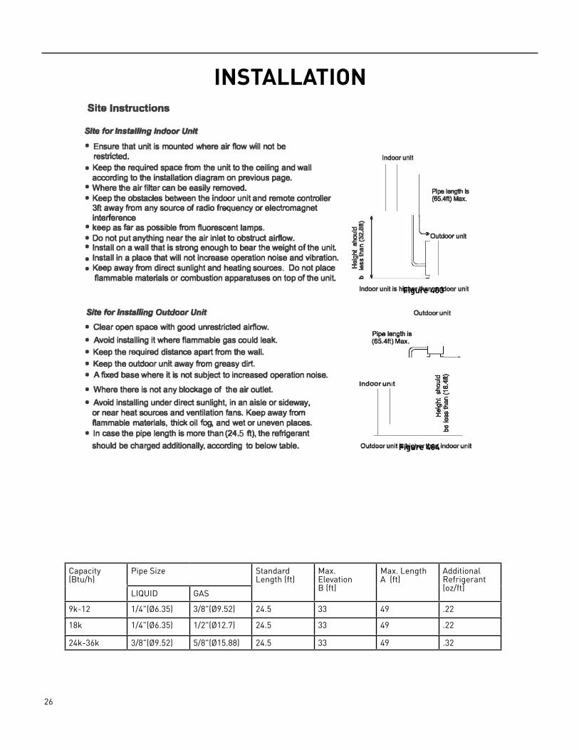
9k‑12 1/4"(Ø6.35) 3/8"(Ø9.52) 24.5 33 49 .22
18k 1/4"(Ø6.35) 1/2"(Ø12.7) 24.5 33 49 .22
24k‑36k 3/8"(Ø9.52) 5/8"(Ø15.88) 24.5 33 49 .32
Site Instructions
Site for Installing Indoor Unit • Ensure that unit is mounted where air flow will not be
restricted.• Keep the required space from the unit to the ceiling and wall
according to the installation diagram on previous page.• Where the air filter can be easily removed.• Keep the obstacles between the indoor unit and remote controller
3ft away from any source of radio frequency or electromagnetinterference
• keep as far as possible from fluorescent lamps.• Do not put anything near the air inlet to obstruct airflow.• Install on a wall that is strong enough to bear the weight of the unit• Install in a place that will not increase operation noise and vibration.• Keep away from direct sunlight and heating sources. Do not place
flammable materials or combustion apparatuses on top of the unit
Site for Installing Outdoor Unit • Clear open space with good unrestricted airflow.
• Avoid installing it where flammable gas could leak.• Keep the required distance apart from the wall.• Keep the outdoor unit away from greasy dirt.• A fixed base where it is not subject to increased operation noise.
• Where there is not any blockage of the air outlet.• Avoid installing under direct sunlight, in an aisle or sideway,
or near heat sources and ventilation fans. Keep away from flammable materials, thick oil fog. and wet or uneven places.
• In case the pipe length is more than (24.5 ft), the refrigerant should be charged additionally, according to below table.
Indoor unit
Pipe lenglhls (65.4ft) Max.
Outdoor unit
Indoor unit is higher than outdoor unit
Pipe length is (65.4ft) Max.
Indoor unit
Outdoor unit
Outdoor unit is higher than indoor unit
24K 1.0
30K-36K 1.5
If the height or pipe length is out of the scope of the table, please consult your installer or Friedrich /!ur Conditioning.
Figure 403
Figure 404

27 PB
INSTALLATIONInstall Indoor Unit
Mounting plate Horizontal ruler position
Holder (for some models)
.... -·····
: . .... .
/
(@),i ,i@
First fixed center position
@ . . .
screws Tapping
Fig. 405
.. ..
. . •· · ·
1. the Mounting Plate1)
2)
3)
4)
5)
Decide an installing location for the mounting plate according to the indoor unit location and piping direction.Find the center of the mounting plate according to the mark on it. Then Install a screw to fix it preliminary. Keep the mounting plate horizontally with a horizontal ruler or dropping line.Drill holes of 1 1/4" (inches) in depth on the wall for fixing the plate.Fix the mounting plate with as least 7 self-tapping screws. For some mounting plates with a holder in the middle , at least 8 screws are required. (Fig. 405)
6) Inspect if the mounting plate is well fixed. Then drill ahole for piping.
2in or more ! to wall
• MOUNTING DIAGRAMS AND DIMENSIONS
d.
Pipe hole
7 .9in or more to ceiling
For 9K/12K Series Models, WIDTH: 26.6in
Indoor unit outline
Pipe hole
Note: It to for sheet concrete block, brick and such of Note: The left of the mounting bracket may be not the center of the indoor unit. Note: The design of your mounting plate may be the one above, but method
Figure 406
wall hole sleeve
2. Drill a Hole for Piping1) Decide the position of hole for piping according to the
location of mounting plate.2) Drill a hole on the wall. The hole should tilt a little
downward toward outside.3) Install a sleeve through the wall hole to keep the wall
tidy and clean. (Fig. 406)
( hard polythene tube prepared by user)
1/4" (inch) (tilt downward)
Flg.406 3. Piping Provision1) Put the piping (liquid and gas pipe) and cables through the wall hole from outside or put them through
from inside after indoor piping and cables connection is complete to connect to the outdoor unil2) Decide whether to cut the unloading piece off in accordance with the piping direction. (Fig. 407)
Piping direction
Trough Unloading piece
Saw the unloading piece off along the trough 2
Fig. 407
�=n � DrainageJ---:::,stt----' � structura
Rubber plug �
Note: Wflen Installing Ille pipe at flle dlt&C1lons 1,2 or 4, cut the conaspondlng unlaadlng piece oll the Indoor unit base.
28 PB
INSTALLATIONInstall Indoor Unit
Note: Both sides drainage structure is standanl. For both sides drainage stroctul'8, it can be chosen for right. left or both Ilk/es drainage connection. If choosing both aides drainage connection, another proper drain hose Is needed as there Is only one drain hose offered by facto,y. If choosing one side drainage connection, ma/ce suf8 the drain hole on the other side Is well plugged.
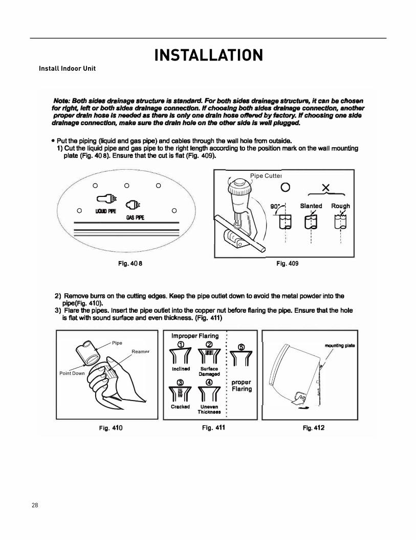
• Put the piping (liquid and gas pipe) and cables through the wall hole from outside.1) Cut the liquid pipe and gas pipe to the right length according to the position mark on the wall mounting
plate (Fig. 408). Ensure that the cut is flat (Fig. 409).
0 0 0 0 X cJlt 0
�·� Slanted Rough
0 LIIIIJ Pl'E 0 rn rn GMPFE
I I I ' I '
I : '
Flg.408 Fig. 409
2) Remove buns on the cutting edges. Keep the pipe outlet down to avoid the metal powder into thepipe(Fig. 410).
3) Flare the pipes. Insert the pipe ouUet into the copper nut before flaring the pipe. Ensure that the holeis flat with sound surface and even thickness. (Fig. 411)
Improper Flaring G) (2) : ®TT ff !TT
lnclln911 Surface Damaged
(3) @ proper w TT Flaring
Cracked Unavan Thicknaaa
Fig. 410 Fig. 411
mounting plata
-Flg.412

29 PB
INSTALLATIONInstall Indoor Unit
4. Indoor Unit Piping Installation1 ) Hang the unit onto mounting plate (Fig. 412).
30 PB
INSTALLATIONInstall Indoor Unit
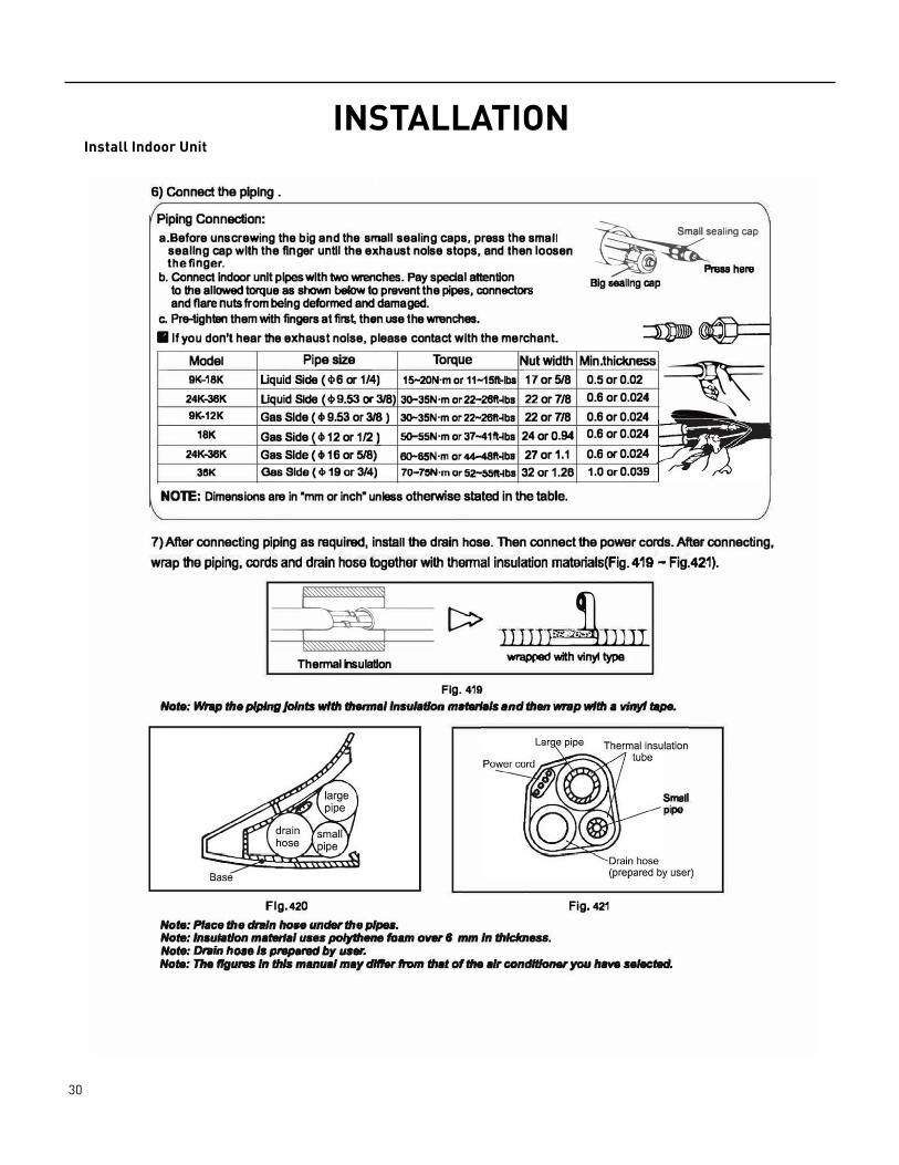
6) Connect the piping .
Piping Connection: a.Before unscrewing the b ig and the small sealing caps, press the small
seallng cap with the finger until the exhaust noise stops, and then loosen the finger.
b. Connect Indoor unit pipes with two wrenches. Pay special attentionto the allowed torque as shown below to prevent the pipes, conneclonland flare nuts from being deformed and damaged.
�sealing cap
�Presahere Big Haling cap
c. Pre-tighllln them with fingers at first then use the wrenches.■ If you don't hear the exhaust noise, please contact with the merchant.
24K--36K Liquid Side ( <t,9.53 or 318) 30-35N·m or22-26ft-lbs 22 or 7/8 0.6 or 0.024
Model Pipe size Torque Nut width Min.thickness
� 9K-18K Liquid Side ( <ti 6 or 1/4) 1S-20N·m or 11-15ft-lbs 17 or 5/8 0.5 or 0.02
9K-12K Gas Side ( ell 9.53 or 318 ) 30-35N·m or 22-26ft-lbs 22 or 7/8 0.6 or 0.024 18K Gas Side ( cll 12 or 1/2) 50--55N·m or37-41ft-lbs 24 or 0.94 0.6 or 0.024
24K--36K Gas Side ( • 16 or 5/8) 00--65N·m or 44-48ft-lbs 27 or 1.1 0.6 or 0.024 38K Gas Side ( 4> 19 or 3/4) 7D-711N·m or 52-55ft-lbs 32 or 1.26 1.0 or 0.039
NOTE: Dimensions are in "mm or inch• unless otherwise stated in the table.
7) After connecting piping as required, install the drain hose. Then connect the power cords. After connecting, wrap the piping, cords and drain hose together with thermal insulation matarials(Fig. 419 - Fig.421).
Thermal lnsuletlon
[::::> jj))l)"'"L wrapped with vinyl type
Fig. 419 Note: Wrap ffle piping Jolnm with thennal Insulation mttterlals and than wrap wUII a vinyl tape.
Flg.420 Note: Place the dntln hon under the pipes. Note: lm1ulatlon matedal usu polythene foam over I mm In thlclcneu. Not.: Drain hose Is prepared by unr.
Fig. 421
Smell pipe
Note: The flg1118S In this manual may differ hm that of the air conditioner you hva n/ectad.
31 PB
INSTALLATIONInstall Indoor Unit
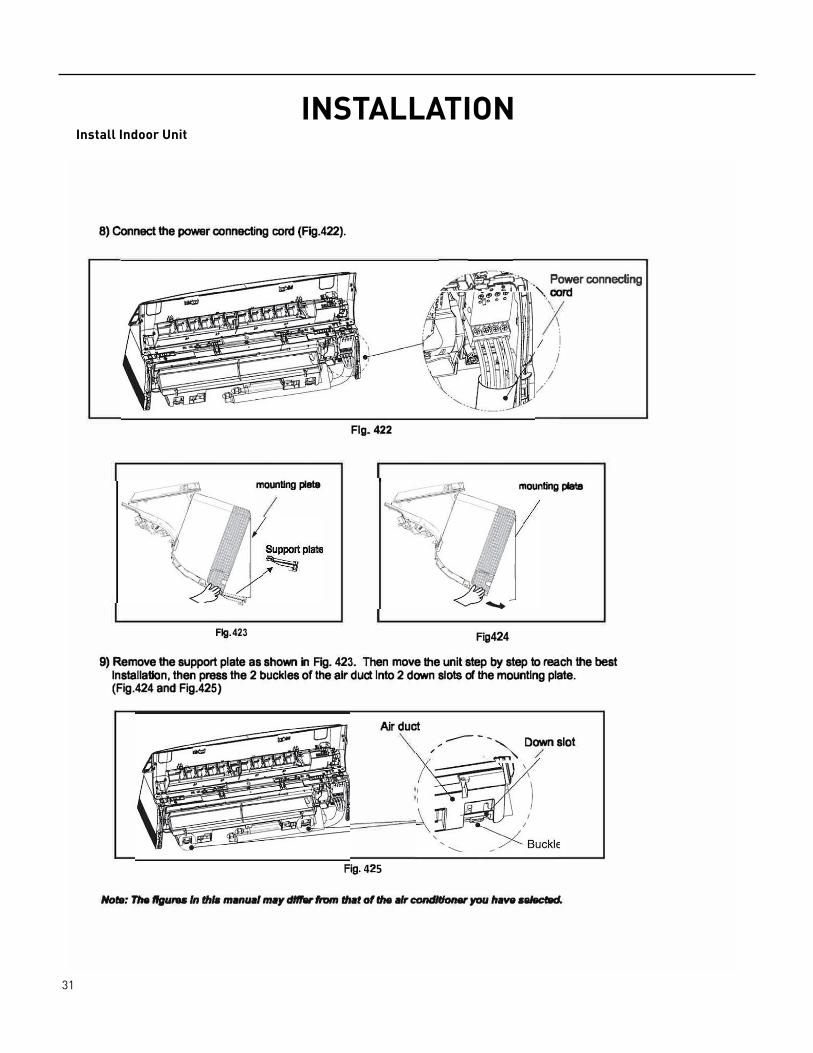
8) Connect the power connecting cord (Fig.422).
Fig. 422
mounUng plate
Flg.423
�u'it!=;:;��� . Power connecting'-. cord
Fig424
\ \ i
/ /
/
mounting plate
9) Remove the support plate as shown in Fig. 423. Then move the unit step by step to reach the bestInstallation, then press the 2 buckles of the air duct Into 2 down slots of the mounting plate. (Fig.424 and Fig.425)
Air duct
/ / ...--- -_ -
� Down slot
Fig. 425
No,.: Tire ffguru In thlB manual may d"'8r fn,,n that of file air conditioner you have a"'8cfad.
32 PB
INSTALLATIONInstall Indoor Unit
Installation instructions/Indoor unit installation
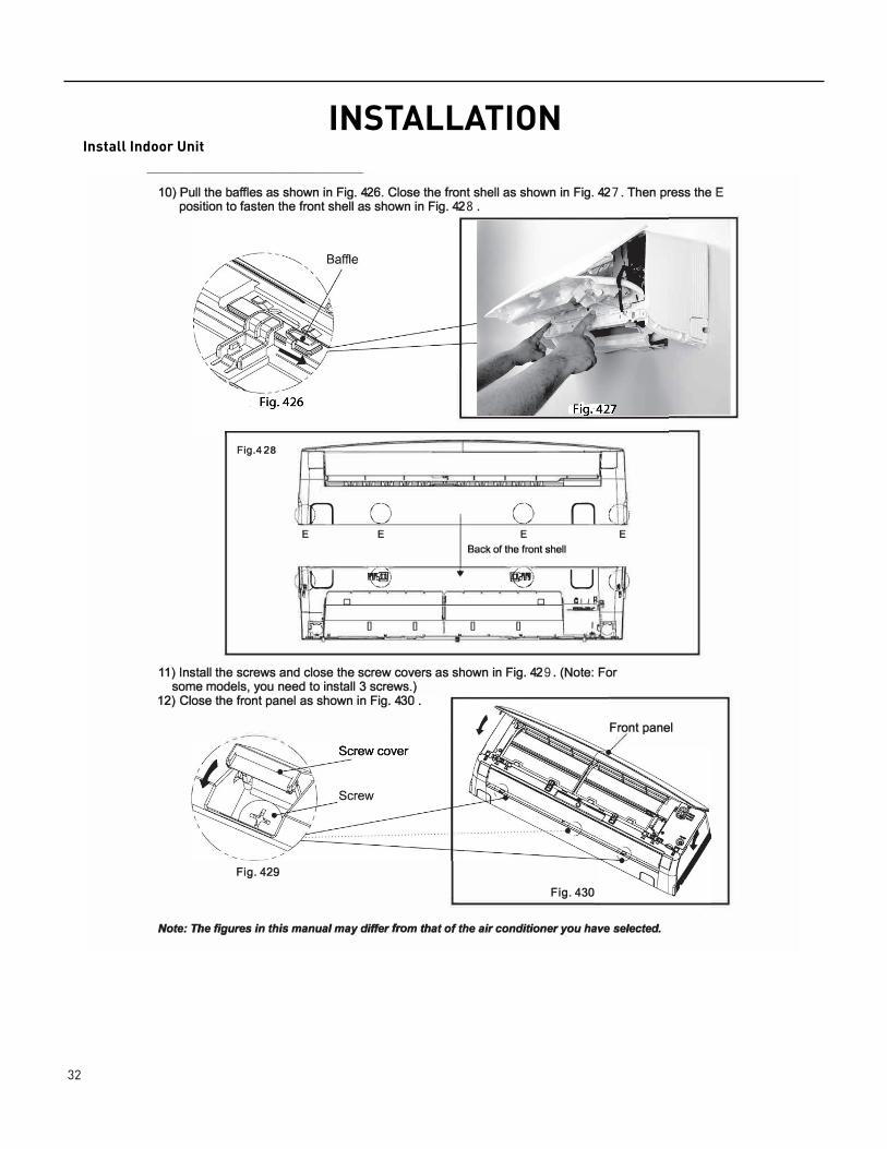
10) Pull the baffles as shown in Fig. 426. Close the front shell as shown in Fig. 427. Then press the Eposition to fasten the front shell as shown in Fig. 428 .
Fig.428
�
( fl /--
·, .. <)
E E
! LJ Ml ... \ . • . .__,./
n � - u � a a i .
(�-) \. ___ /'
E Back of the front shell
�'1
_../ n
a a
n u a 1 -
J-I
) \ E
r ' , ... } ca
IA.•
11) Install the screws and close the screw covers as shown in Fig. 429. (Note: Forsome models, you need to install 3 screws.)
12) Close the front panel as shown in Fig. 430.
Front panel
Fig. 429
Fig. 430
Note: The figures in this manual may differ from that of the air conditioner you have selected.
-15-
33 PB
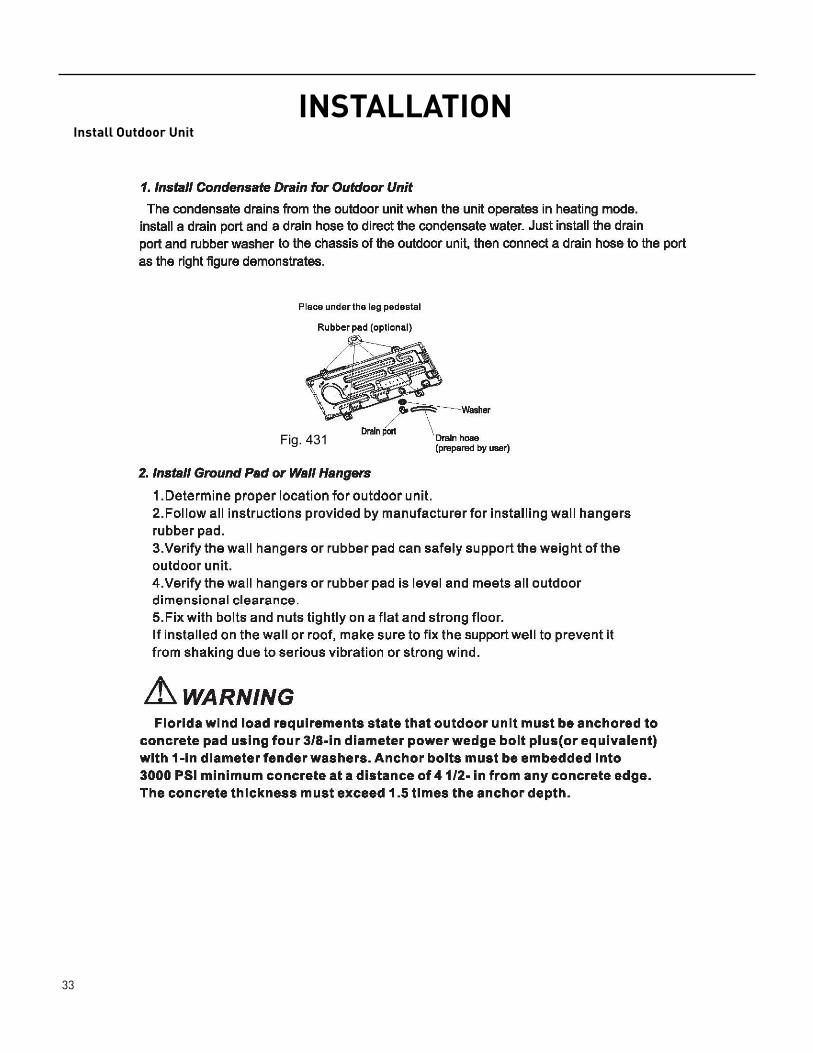
INSTALLATIONInstall Outdoor Unit
Fig. 431

34 PB
INSTALLATIONOutdoor Units
35 PB
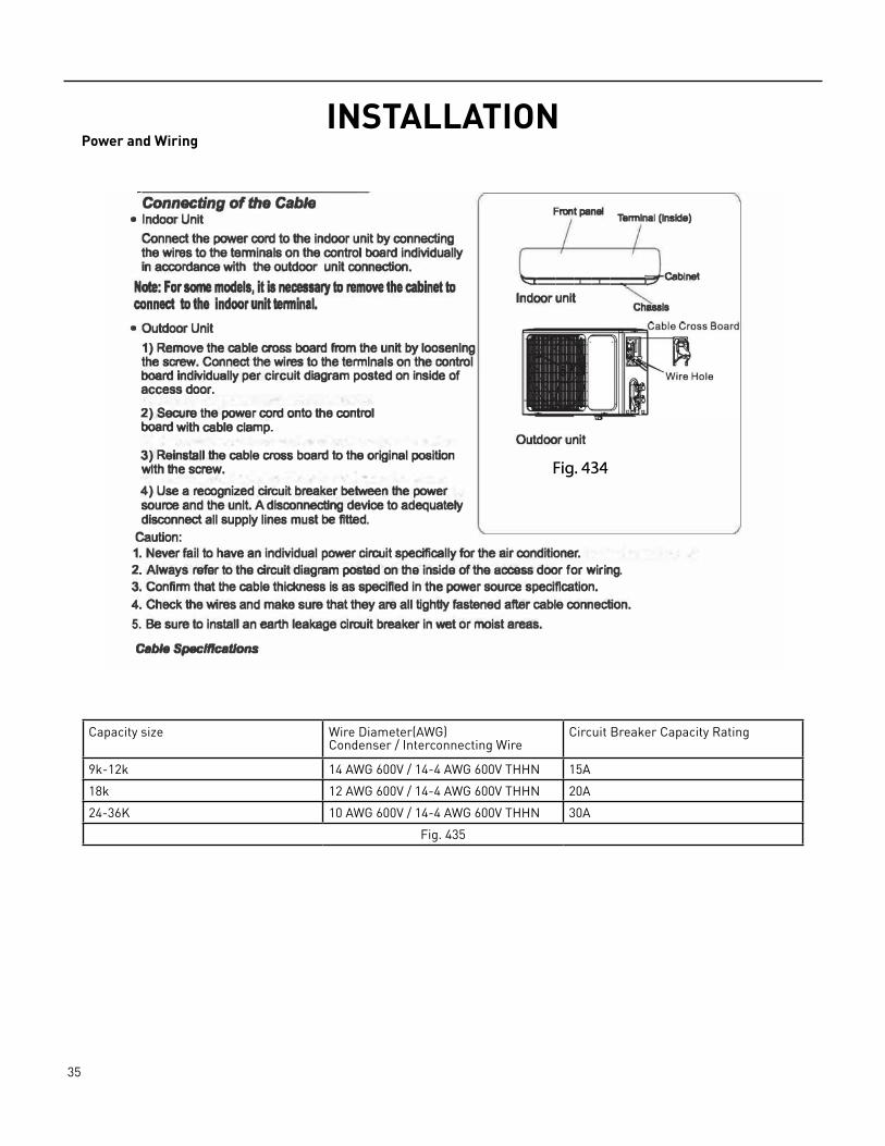
INSTALLATIONPower and Wiring
Capacity size Wire Diameter(AWG)Condenser / Interconnecting Wire
Circuit Breaker Capacity Rating
9k‑12k 14 AWG 600V / 14‑4 AWG 600V THHN 15A
18k 12 AWG 600V / 14‑4 AWG 600V THHN 20A
24‑36K 10 AWG 600V / 14‑4 AWG 600V THHN 30A
Fig. 435
Installation Instructions, l Power and WiringConnecting of the Cable
• Indoor Unit Front panel Terminal (Inside)
Connect the power cord to the indoor unit by connectingthe wires to the terminals on the control board individuallyin accordance with the outdoor unit connection.
Note: For some models, it is necessary to remove the cabinet to connect to the indoor unit terminal.
��������Cablnet
• Outdoor Unit1) Remove the cable cross board from the unit by loosenlngthe screw. Connect the wires to the termlnals on the controlboard individually per circuit diagram posted on inside ofaccess door.
2) Secure the power cord onto the controlboard with cable clamp.
3) Reinstall the cable cross board to the original positionwith the screw.4) Use a recognized circuit breaker between the powersource and the unit. A dlsconnecUng device to adequatelydisconnect all supply lines must be fitted.
Caution:
Indoor unit Chassis
Outdoor unit
Fig. 434
1. Never fail to have an individual power circuit specifically for the air conditioner. 2. Always refer to the circuit diagram posted on Iha inside of the access door for wiring.3. Confirm that the cable thickness is as specified in the power source specification.4. Check the wires and make sure that they are all tightly fastened after cable connection.5. Be sure to install an earth leakage circuit breaker in wet or moist areas.
Cable Specifications

36 PB
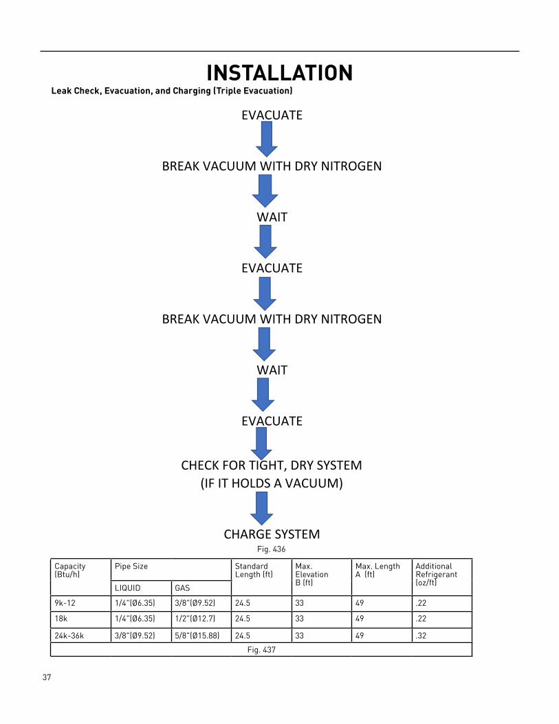
INSTALLATIONLeak Check, Evacuation, and Charging (Triple Evacuation)
Friedrich requires all installations are Leak Checked and Evacuated in accordance to the “triple evacuation” process. This process promotes a dry tight refrigeration system before opening the service valves. It recommended that a single port refrigeration manifold and hoses rated over 31.5psi be used. Refrigeration hose valves, along with a vacuum pump and micron gauge, must be used to ensure the system can be vacuumed and held under 500 microns. Check all equipment and hoses for proper usage and leaks before beginning.
1. 1st Nitrogen Pressure Test: Ensure all refrigeration connections are properly flared, secured, and torqued to their respective settings. Pressurize the system with nitrogen to 550psi. Soap all connections with an approved refrigerant leak detection solution. The pressure in the system must hold for one hour respective to the environmental conditions and should not vary less than 540psi. If pressure can not be adequate held, check integrity of flares and torque specifications. Once pressure is held adequately, purge the nitrogen charge to system pressure of 5‑10psi. DO NOT RETURN TO ATMOSPHERIC PRESSURE.
2. 1st Vacuum Micron Test: Connect hoses and vacuum pump to the outdoor unit as shown in Fig. 436. Start the vacuum pump and vacuum to 1000 microns. Close the valve to the vacuum pump and check for micron rise for 15 minutes. If microns rise to near atmospheric pressure, there is a potential leak; repeat step 1. If microns rise over 5000, the system is very wet and will require further nitrogen purges.
3. 2nd Nitrogen Break: Once the system holds below 5000 microns, reconnect the nitrogen tank break the system vacuum with 30‑50psi of nitrogen. Wait 5 minutes, then purge to 5‑10psi. DO NOT RETURN TO ATMOSPHERIC PRESSURE.
4. 2nd Vacuum Micron Test: Reconnect vacuum pump and gauge and begin evacuation. Vacuum system to 500 microns. Close vacuum valve and check for micron rise. Vacuum should hold under 1000 microns. Repeat steps 3 and 4 until achieved.
5. 3rd Nitrogen Break: Once the system holds below 1000 microns, reconnect the nitrogen tank break the system vacuum with 30‑50psi of nitrogen. Wait 5 minutes, then purge to 5‑10psi. DO NOT RETURN TO ATMOSPHERIC PRESSURE.
6. 3rd Final Vacuum Micron Test: Reconnect vacuum pump and gauge and begin evacuation. Vacuum system to 300 microns. Close vacuum valve and check for micron rise. Vacuum should hold under 500 microns. Repeat steps 3 and 4 until achieved. Once held under 500 microns, the system is considered dry and tight.
7. Charging the system: Unscrew Service Valve Caps to expose the inner hexagon head. Use an allen‑head spanner or service wrench with appropriate adapter to release the refrigerant into the system. If the calculated line set length is over 24.5 ft, weight in the additional charge with an approved refrigerant scale as needed. Refer to fig. 437.
37 PB
INSTALLATIONLeak Check, Evacuation, and Charging (Triple Evacuation)
WAIT
EVACUATE
BREAK VACUUM WITH DRY NITROGEN
CHARGE SYSTEM
EVACUATE
WAIT
EVACUATE
CHECK FOR TIGHT, DRY SYSTEM(IF IT HOLDS A VACUUM)
BREAK VACUUM WITH DRY NITROGEN
Capacity(Btu/h)
Pipe Size StandardLength (ft)
Max. ElevationB (ft)
Max. LengthA (ft)
AdditionalRefrigerant(oz/ft)
LIQUID GAS
9k‑12 1/4"(Ø6.35) 3/8"(Ø9.52) 24.5 33 49 .22
18k 1/4"(Ø6.35) 1/2"(Ø12.7) 24.5 33 49 .22
24k‑36k 3/8"(Ø9.52) 5/8"(Ø15.88) 24.5 33 49 .32
Fig. 437
Fig. 436

38 PB
INSTALLATIONChecklist and Operation Test
Check Unit following Installation
Test Operation
System Checks
1. Conceal refrigerant pipes where possible. 2. Make sure drain hose slopes downward along entire length at a slope of 1/4”(inch) per ‘(foot). 3. Ensure all refrigerant pipes and connections are properly insulated. 4. Fasten pipes to outside wall, when possible. 5. Seal and weatherproof wall hole which the interconnecting wires and refrigerant pipes pass through.Perform test operation after completing gas leak and electrical safety check.
1. Turn on electrical disconnect to outdoor unit. 2. Push the “ON/OFF” button on Remote Controller to begin testing or press and hold Emergency ON/OFF button for 5 seconds to force test mode. 3. Push MODE button, select COOLING, HEATING, FAN mode to confirm all functions.
Indoor Unit
1. Do all Remote controller’s buttons function properly? 2. Do the display panel lights work properly? 3. Does the swing louver function properly? 4. Does the drain work?Outdoor Unit
1. Push the mode button to COOL and adjust the room setting to 61 °F(16°C) deg. wait up to 3 minutes from compressor time guard. Does compressor and outdoor fan turn on in cooling mode? 2. Push the mode button to HEAT and adjust the room setting to 85 °F(30°C) deg. wait up to 3 minutes for compressor time guard. Does compressor and outdoor fan turn on in heat mode?
Fig. 438

39 PB
MAINTENANCE
Fig. 501
40 PB
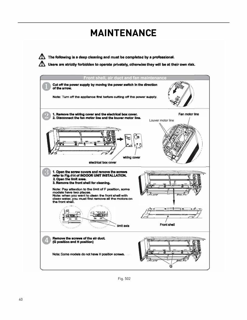
MAINTENANCE
Fig. 502
Lh The following is a deep cleaning and must be completed by a professional.
Lh Usera are strictly forbidden to operate privately, otherwise they will be at their own risk.
0 Cut off the power supply by moving the power switch In the dlnictlon of the arrow.
Note: Tum off the appllanoe first before cutting off the power supply .
• 1. Ramova the wiring COV&r and the elactrlc■I box cover.2. Disconnect tha fan motor line and the louver motor line.
wiring COYer electrical box cover
• 1. Open the screw covers and remove the screwsrafltr to Flg.414 of INDOOR UNrr INSTALLATION.2. Open tha Hmlt axn.3. Remove the front shall for clean Ing.
Note: Pay attention to the llmlt of F position, some models have two places. Note: when you want to dean the front shell with clean water, you must first remove all the motors on the front shell.
Fan motor llne
s 7 I :· ZP
ft Remove the screws of tha air ductV (G position and H position)
limit axis
Note: Some models do not have H position screws.
Front shell
G
41 PB
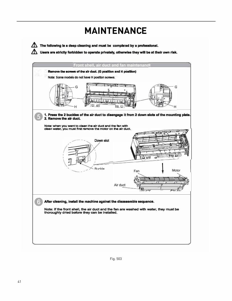
MAINTENANCE
Fig. 503
L'.h The followlng 18 a deep cleanlng and must be completed by a professlonal.
L'.h Users ara strlctly forbidden to operate prlvately, otherwise they wlll be at their own risk.
Remove the acrews of the air duct. (G poaltlon and H poaltlon) Note: Some models do not have H position screws.
A 1. Press the 2 buckles of the air duct to disengage it from 2 down slots of the mounting plate . .:,' 2. Remove the air duct.
Note: when you want to cl-n the air duct and the fan with clean water, you must first remove the motor on the air duct.
-----
e After cleaning, install the machine against the disanemble sequence.
Motor
Note: If the front shell, the air duct and the fan are washed with water, they must be thoroughly dried before they can be Installed.
42 PB
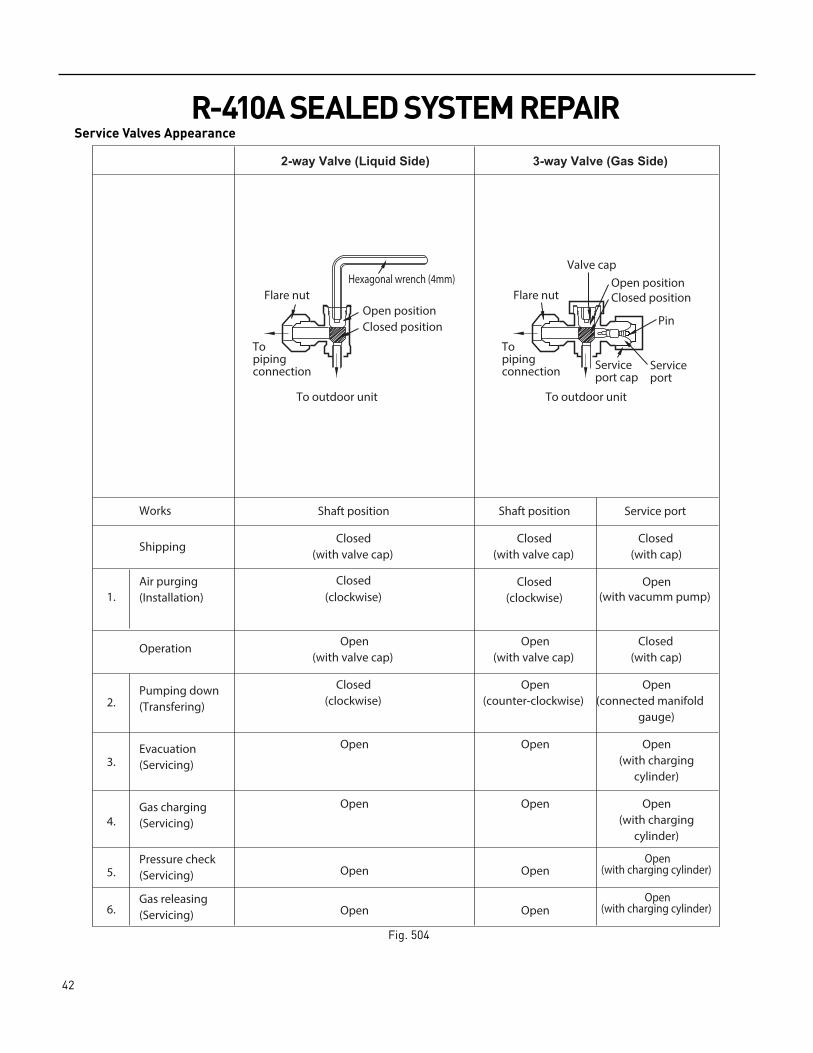
R-410A SEALED SYSTEM REPAIRService Valves Appearance
2-way Valve (Liquid Side)
Shaft position
3-way Valve (Gas Side)
Shaft position Service port
Closed
Closed
(with cap) Closed
(with valve cap)Closed
(with valve cap)
Closed(clockwise)
Closed(with cap)
Open(with valve cap)
Open(with valve cap)
Closed(clockwise)
gauge)
Open
Open Open(counter-clockwise) (connected manifold
Open Open(with charging
cylinder)
OpenOpen
Open
Open(with charging
cylinder)
Open
OpenOpen
Works
Shipping
Air purging(Installation)
Operation
Evacuation
Pumping down(Transfering)
(Servicing)
Gas charging(Servicing)
Pressure check(Servicing)
Gas releasing(Servicing)
1.
2.
3.
4.
5.
6.
Valve capOpen positionClosed position
Pin
Serviceport
Serviceport cap
To outdoor unit
Flare nut
Topipingconnection
To outdoor unit
Hexagonal wrench (4mm)
Open positionClosed position
Topipingconnection
Flare nut
Open(with charging cylinder)
Open(with charging cylinder)
(clockwise)Open
(with vacumm pump)
Fig. 504
43 PB
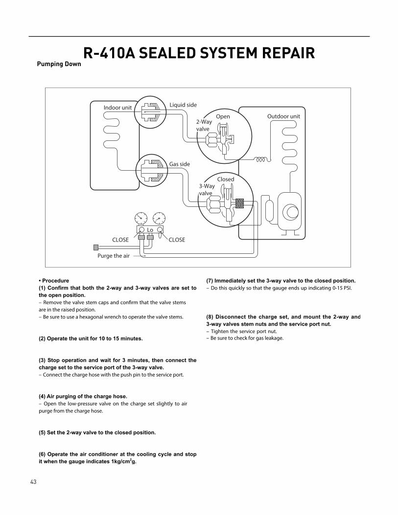
R-410A SEALED SYSTEM REPAIRPumping Down
Lo
Closed
Purge the air
Outdoor unitIndoor unit Liquid side
Gas side
CLOSE
Open2-Wayvalve
CLOSE
3-Wayvalve
– Remove the valve stem caps and confirm that the valve stemsare in the raised position.– Be sure to use a hexagonal wrench to operate the valve stems.
– Connect the charge hose with the push pin to the service port.
– Open the low-pressure valve on the charge set slightly to airpurge from the charge hose.
– Do this quickly so that the gauge ends up indicating 0-15 PSI.
– Tighten the service port nut.– Be sure to check for gas leakage.

44 PB
R-410A SEALED SYSTEM REPAIRGas Charging (After Repair)
45 PB
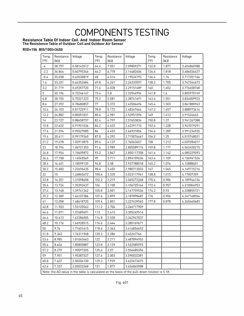
COMPONENTS TESTING Resistance Table Of Indoor Coil And Indoor Room SensorThe Resistence Table of Outdoor Coil and Outdoor Air Sensor
R(0)=15k B(0/100)=3450
Temp.(°F)
Resistance(kΩ)
Voltage Temp.(°F)
Resistance(kΩ)
Voltage Temp.(°F)
Resistance(kΩ)
Voltage
‑4 38.757 0.58143512 64.4 7.051 2.09859271 132.8 1.877 3.654865988
‑2.2 36.844 0.60795346 66.2 6.778 2.14682606 134.6 1.818 3.686036427
‑0.4 35.038 0.63530819 68 6.516 2.19524793 136.4 1.76 3.717201166
1.4 33.331 0.66352684 69.8 6.267 2.24333597 138.2 1.705 3.747244673
3.2 31.719 0.69257720 71.6 6.028 2.29151689 140 1.652 3.776658768
5 30.196 0.72246147 73.4 5.8 2.33944954 141.8 1.6 3.805970149
6.8 28.755 0.75321223 75.2 5.581 2.38741691 143.6 1.551 3.834009923
8.6 27.392 0.78480857 77 5.372 2.43506494 145.4 1.503 3.861880963
10.4 26.103 0.81722911 78.8 5.172 2.48247664 147.2 1.457 3.888973616
12.2 24.882 0.85051031 80.6 4.981 2.52951096 149 1.413 3.91524643
14 23.727 0.88458737 82.4 4.797 2.57653834 150.8 1.37 3.941267388
15.8 22.632 0.91951536 84.2 4.622 2.62291710 152.6 1.328 3.967019291
17.6 21.594 0.95527085 86 4.453 2.66931854 154.4 1.289 3.991234935
19.4 20.611 0.99179340 87.8 4.292 2.715076661 156.2 1.25 4.015748031
21.2 19.678 1.02913875 89.6 4.137 2.76063657 158 1.213 4.039284017
23 18.794 1.06721353 91.4 3.989 2.805589174 159.8 1.177 4.062450215
24.8 17.954 1.10609872 93.2 3.847 2.850117358 161.6 1.142 4.085229093
26.6 17.158 1.14565549 95 3.711 2.894109636 163.4 1.109 4.106941536
28.4 16.401 1.18599135 96.8 3.58 2.937788018 165.2 1.076 4.12888601
30.2 15.683 1.22696435 98.6 3.455 2.980713033 167 1.045 4.149715216
32 15 1.26865672 100.4 3.335 3.023117961 168.8 1.015 4.17007359
33.8 14.351 1.31098658 102.2 3.219 3.065272268 170.6 0.986 4.189944134
35.6 13.734 1.35393437 104 3.108 3.106725146 172.4 0.957 4.210004953
37.4 13.148 1.39741342 105.8 3.001 3.147759536 174.2 0.93 4.228855721
39.2 12.589 1.44157386 107.6 2.899 3.187898487 176 0.904 4.247168554
41 12.058 1.48618720 109.4 2.801 3.227439565 177.8 0.878 4.265640683
42.8 11.553 1.53125563 111.2 2.706 3.266717909
44.6 11.071 1.57689691 113 2.615 3.305249514
46.4 10.613 1.62286005 114.8 2.528 3.342947037
48.2 10.176 1.66928515 116.6 2.444 3.380169671
50 9.76 1.71601615 118.4 2.363 3.416856492
51.8 9.363 1.76311968 120.2 2.286 3.45247766
53.6 8.985 1.81043663 122 2.211 3.487894953
55.4 8.624 1.85805887 123.8 2.139 3.522585993
57.2 8.279 1.90597205 125.6 2.07 3.556485356
59 7.951 1.95387327 127.4 2.003 3.590032381
60.8 7.637 2.00204130 129.2 1.939 3.622673675
62.6 7.337 2.05033368 131 1.877 3.654865988
Note: the AD value in the table is calculated on the basis of the pull‑down resistor is 5.1K
Fig. 601
46 PB
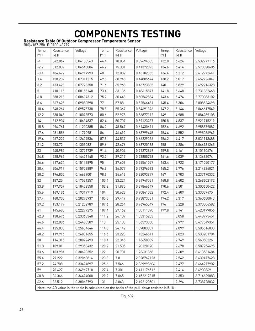
COMPONENTS TESTING Resistance Table Of Outdoor Compressor Temperature SensorR(0)=187.25k B(0100)=3979
Temp.(°F)
Resistance(kΩ)
Voltage Temp.(°F)
Resistance(kΩ)
Voltage Temp.(°F)
Resistance(kΩ)
Voltage
‑4 542.867 0.06185563 64.4 78.854 0.39694585 132.8 6.624 2.532777116
‑2.2 512.839 0.06543004 66.2 75.381 0.41372093 134.6 6.414 2.573028606
‑0.4 484.672 0.06917993 68 72.082 0.43102355 136.4 6.212 2.612972641
1.4 458.239 0.07311215 69.8 68.948 0.44885674 138.2 6.017 2.652726847
3.2 433.423 0.07723358 71.6 65.968 0.46723835 140 5.829 2.692216328
5 410.115 0.08155140 73.4 63.136 0.48615877 141.8 5.648 2.731362468
6.8 388.213 0.08607312 75.2 60.443 0.50562884 143.6 5.474 2.770083102
8.6 367.625 0.09080590 77 57.88 0.52566481 145.4 5.306 2.808524698
10.4 348.264 0.09575738 78.8 55.367 0.54691396 147.2 5.144 2.846617549
12.2 330.048 0.10093573 80.6 52.978 0.56877112 149 4.988 2.884289108
14 312.904 0.10634837 82.4 50.707 0.59123237 150.8 4.837 2.921715219
15.8 296.761 0.11200385 84.2 48.547 0.61430611 152.6 4.692 2.958579882
17.6 281.556 0.11790981 86 46.492 0.63799445 154.4 4.552 2.995066949
19.4 267.227 0.12407536 87.8 44.537 0.66229036 156.2 4.417 3.031113488
21.2 253.72 0.13050821 89.6 42.676 0.68720188 158 4.286 3.066931265
23 240.982 0.13721739 91.4 40.904 0.71272849 159.8 4.161 3.10190676
24.8 228.965 0.14421140 93.2 39.217 0.73885738 161.6 4.039 3.13682074
26.6 217.624 0.15149895 95 37.609 0.76561057 163.4 3.922 3.171050177
28.4 206.917 0.15908889 96.8 36.077 0.79296593 165.2 3.776 3.214826021
30.2 196.805 0.16699001 98.6 34.616 0.82093877 167 3.703 3.237170332
32 187.25 0.17521257 100.4 33.224 0.84949031 168.8 3.602 3.268602192
33.8 177.957 0.18402550 102.2 31.895 0.87866649 170.6 3.501 3.300650422
35.6 169.186 0.19319719 104 30.628 0.90841082 172.4 3.409 3.33039475
37.4 160.903 0.20273937 105.8 29.419 0.93873381 174.2 3.317 3.360680043
39.2 153.179 0.21252789 107.6 28.264 0.96965549 176 3.228 3.390506582
41 145.685 0.22297275 109.4 27.162 1.00111890 177.8 3.141 3.420179056
42.8 138.696 0.23368340 111.2 26.109 1.03315203 3.058 3.448975451
44.6 132.086 0.24480509 113 25.103 1.06573050 2.977 3.477549351
46.4 125.833 0.25634646 114.8 24.142 1.09883007 2.899 3.505516033
48.2 119.916 0.26831655 116.6 23.223 1.13246511 2.823 3.533201704
50 114.315 0.28072493 118.4 22.345 1.16658089 2.749 3.56058226
51.8 109.01 0.29358432 120.2 21.505 1.20120120 2.678 3.587254695
53.6 103.984 0.30690352 122 20.701 1.23631868 2.609 3.613561484
55.4 99.222 0.32068816 123.8 7.8 2.328767123 2.542 3.639477628
57.2 94.708 0.33494897 125.6 7.546 2.369998606 2.477 3.664977902
59 90.427 0.34969710 127.4 7.301 2.411176512 2.414 3.6900369
60.8 86.366 0.36494000 129.2 7.065 2.452217815 2.353 3.714629083
62.6 82.512 0.38068793 131 6.843 2.492120501 2.294 3.738728832
Note: the AD value in the table is calculated on the basis of the pull‑down resistor is 5.1K
Fig. 602

47 PB
COMPONENTS TESTING Compressor
DCINVERTER&
R U( )
S V( )CONTROLLER
T W( )
POWER
OVERLOAD PROT ECTION
Resistance Test.
The compressor is at fault if the resistance of winding is 0(short circuit)or∞ open circuit.Common signs compressor is faulty:• Compressor motor lock. • Discharge pressure value approaches static pressure value .• Compressor motor winding abnormality.Note:• Don’t put a compressor on its side or turn over.• Assemble the compressor quickly after removing the plugs. Prolonged exposure will damage the internal components
of the compressor• Ensure wiring is correct before operating. Reverse operation will permanently damage the compressor.• Electric ReactorCommon Problems:• Sound abnormality• Runs in a sporadic rhythm.
48 PB
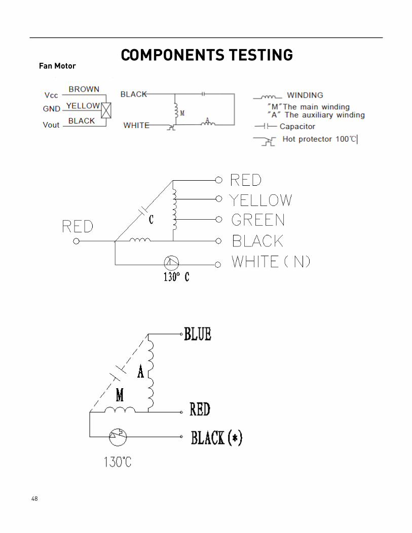
COMPONENTS TESTING Fan Motor

49 PB
COMPONENTS TESTING Fan MotorResistance Test.
Test the resistance of the main winding. The indoor fan motor is faulted if the resistance ofmain winding 0 (short circuit)or ∞ open circuit.DC Voltage test
Manually rotate indoor fan motor slowly for several revolutions, and measure voltage “YELLOW” and “GND” on motor. The voltage repeats 0V DC and 5V DC.Notes:• Do not hold motor by lead wires.• Do not connect or disconnect the molex connecter while power ON.• Do not drop motor against hard material. Malfunction may not be observed at early stage after such shock. But it may be
found later, this type of mishandling voids our warranty.
Indoor DC Fan Motor
Outdoor DC Fan Motor
Outdoor DC Fan Motor
50 PB
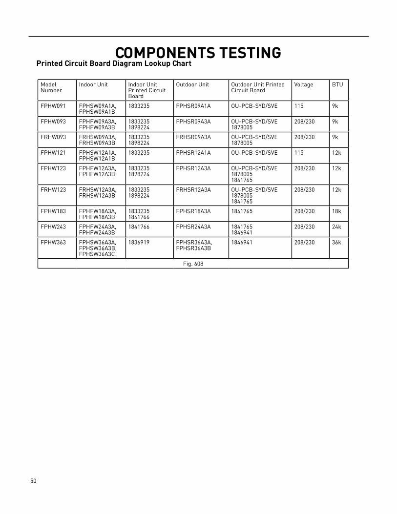
COMPONENTS TESTING Printed Circuit Board Diagram Lookup Chart
Model Number
Indoor Unit Indoor Unit Printed Circuit Board
Outdoor Unit Outdoor Unit Printed Circuit Board
Voltage BTU
FPHW091 FPHSW09A1A, FPHSW09A1B
1833235 FPHSR09A1A OU‑PCB‑SYD/SVE 115 9k
FPHW093 FPHFW09A3A, FPHFW09A3B
18332351898224
FPHSR09A3A OU‑PCB‑SYD/SVE1878005
208/230 9k
FRHW093 FRHSW09A3A, FRHSW09A3B
18332351898224
FRHSR09A3A OU‑PCB‑SYD/SVE1878005
208/230 9k
FPHW121 FPHSW12A1A, FPHSW12A1B
1833235 FPHSR12A1A OU‑PCB‑SYD/SVE 115 12k
FPHW123 FPHFW12A3A, FPHFW12A3B
18332351898224
FPHSR12A3A OU‑PCB‑SYD/SVE18780051841765
208/230 12k
FRHW123 FRHSW12A3A, FRHSW12A3B
18332351898224
FRHSR12A3A OU‑PCB‑SYD/SVE18780051841765
208/230 12k
FPHW183 FPHFW18A3A, FPHFW18A3B
18332351841766
FPHSR18A3A 1841765 208/230 18k
FPHW243 FPHFW24A3A, FPHFW24A3B
1841766 FPHSR24A3A 18417651846941
208/230 24k
FPHW363 FPHSW36A3A, FPHSW36A3B, FPHSW36A3C
1836919 FPHSR36A3A, FPHSR36A3B
1846941 208/230 36k
Fig. 608
51 PB
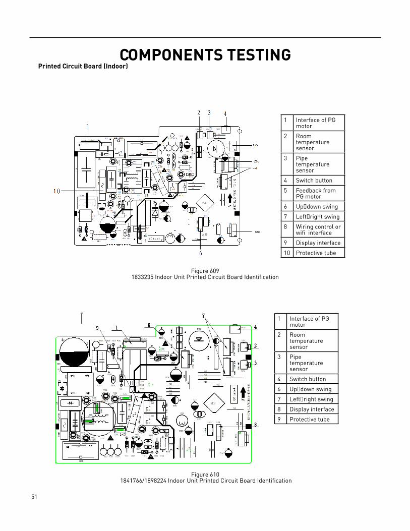
COMPONENTS TESTING Printed Circuit Board (Indoor)
Figure 6091833235 Indoor Unit Printed Circuit Board Identification
Figure 610 1841766/1898224 Indoor Unit Printed Circuit Board Identification
1 Interface of PG motor
2 Room temperature sensor
3 Pipe temperature sensor
4 Switch button
5 Feedback from PG motor
6 Up&down swing
7 Left&right swing
8 Wiring control or wifi interface
9 Display interface
10 Protective tube
1 Interface of PG motor
2 Room temperature sensor
3 Pipe temperature sensor
4 Switch button
6 Up&down swing
7 Left&right swing
8 Display interface
9 Protective tube
52 PB
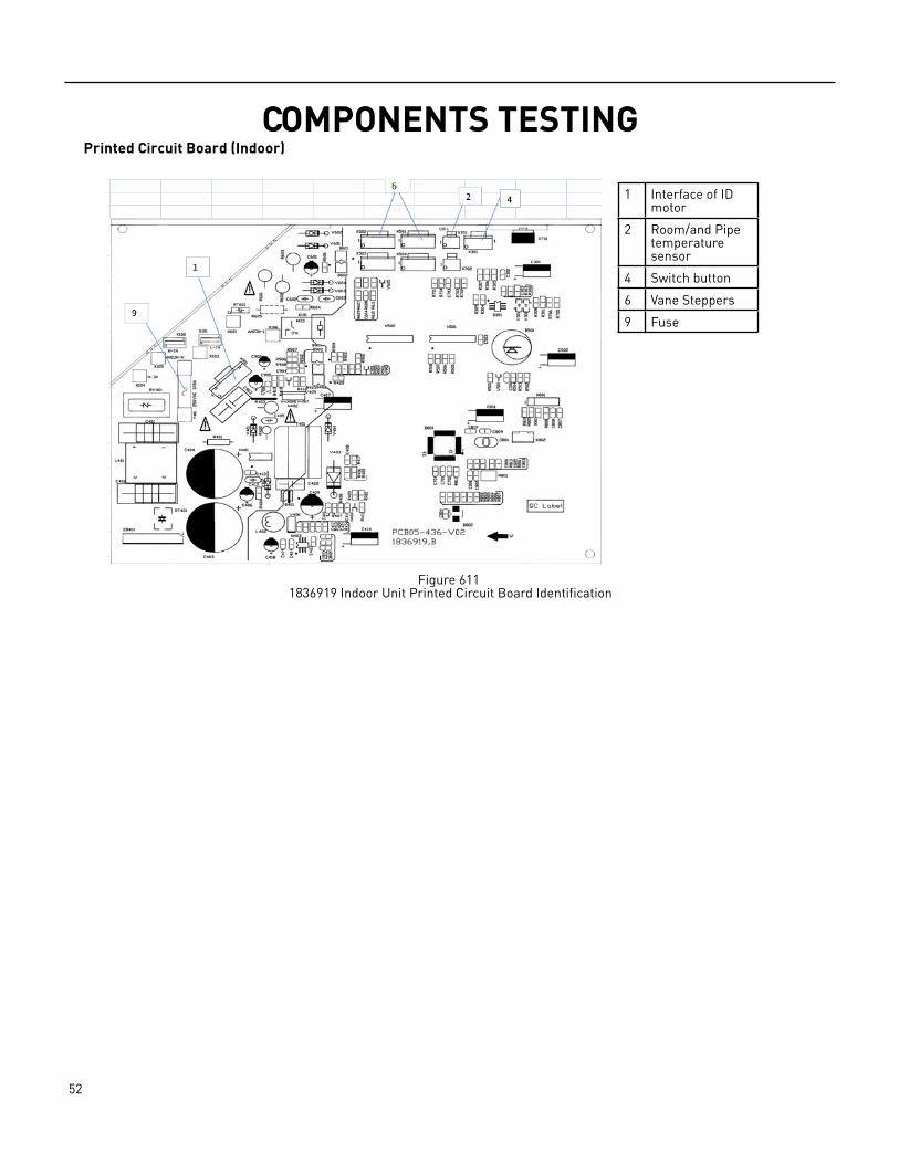
COMPONENTS TESTING Printed Circuit Board (Indoor)
Figure 611 1836919 Indoor Unit Printed Circuit Board Identification
1 Interface of ID motor
2 Room/and Pipe temperature sensor
4 Switch button
6 Vane Steppers
9 Fuse
53 PB
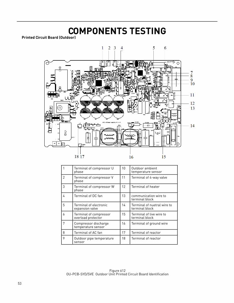
COMPONENTS TESTING Printed Circuit Board (Outdoor)
Figure 612OU‑PCB‑SYD/SVE Outdoor Unit Printed Circuit Board Identification
1 Terminal of compressor U phase
10 Outdoor ambient temperature sensor
2 Terminal of compressor V phase
11 Terminal of 4‑way valve
3 Terminal of compressor W phase
12 Terminal of heater
4 Terminal of DC fan 13 communication wire to terminal block
5 Terminal of electronic expansion valve
14 Terminal of nuetral wire to terminal block
6 Terminal of compressor overload protector
15 Terminal of live wire to terminal block
7 Compressor discharge temperature sensor
16 Terminal of ground wire
8 Terminal of AC fan 17 Terminal of reactor
9 Outdoor pipe temperature sensor
18 Terminal of reactor
54 PB
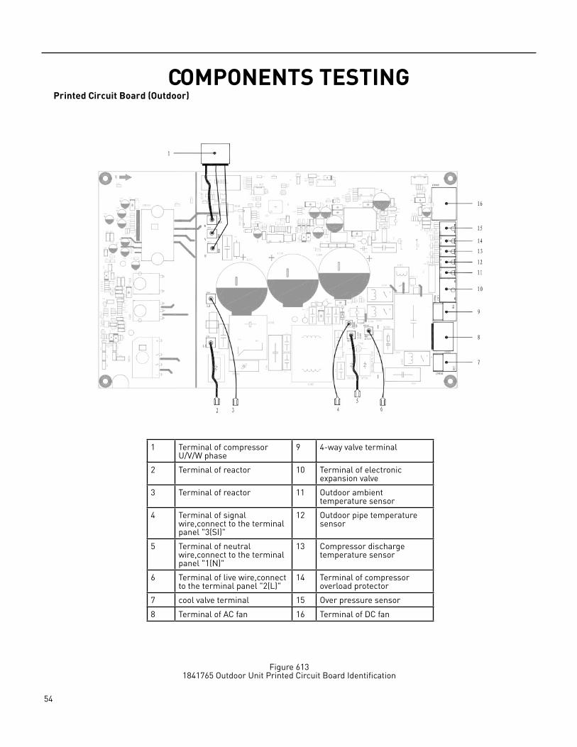
COMPONENTS TESTING Printed Circuit Board (Outdoor)
Figure 6131841765 Outdoor Unit Printed Circuit Board Identification
1 Terminal of compressor U/V/W phase
9 4‑way valve terminal
2 Terminal of reactor 10 Terminal of electronic expansion valve
3 Terminal of reactor 11 Outdoor ambient temperature sensor
4 Terminal of signal wire,connect to the terminal panel "3(SI)"
12 Outdoor pipe temperature sensor
5 Terminal of neutral wire,connect to the terminal panel "1(N)"
13 Compressor discharge temperature sensor
6 Terminal of live wire,connect to the terminal panel "2(L)"
14 Terminal of compressor overload protector
7 cool valve terminal 15 Over pressure sensor
8 Terminal of AC fan 16 Terminal of DC fan

55 PB
COMPONENTS TESTINGPrinted Circuit Board (Outdoor)
Figure 6141846941 Outdoor Unit Printed Circuit Board Identification
1 Terminal of reactor 10 Terminal of electronic expansion valve
2 Terminal of compressor 11 DRED Function
3 Terminal of DC fan 12 Terminal of AC fan
4 Heat Sink temperature sensor
13 Cool Valve terminal
5 PressureProtector 14 Heater terminal
6 Compressor discharge temperature sensor
15 4‑way valve terminal
7 Outdoor ambient temperature sensor
16 Terminal of communication wire
8 Outdoor pipe temperature sensor
17 Terminal of live wire
56 PB
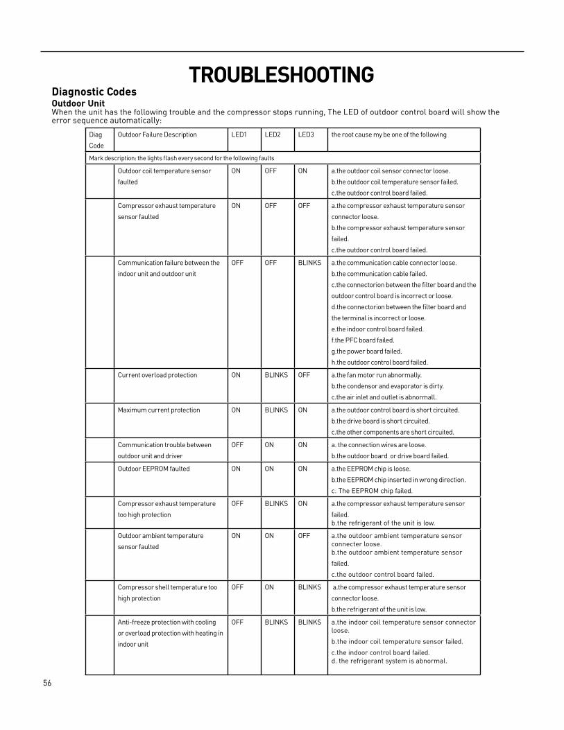
TROUBLESHOOTINGDiagnostic CodesOutdoor UnitWhen the unit has the following trouble and the compressor stops running, The LED of outdoor control board will show the error sequence automatically:
Diag
Code
Outdoor Failure Description LED1 LED2 LED3 the root cause my be one of the following
Mark description: the lights flash every second for the following faults
Outdoor coil temperature sensor
faulted
ON OFF ON a.the outdoor coil sensor connector loose.
b.the outdoor coil temperature sensor failed.
c.the outdoor control board failed.
Compressor exhaust temperature
sensor faulted
ON OFF OFF a.the compressor exhaust temperature sensor
connector loose.
b.the compressor exhaust temperature sensor
failed.
c.the outdoor control board failed.
Communication failure between the
indoor unit and outdoor unit
OFF OFF BLINKS a.the communication cable connector loose.
b.the communication cable failed.
c.the connectorion between the filter board and the
outdoor control board is incorrect or loose.
d.the connectorion between the filter board and
the terminal is incorrect or loose.
e.the indoor control board failed.
f.the PFC board failed.
g.the power board failed.
h.the outdoor control board failed.
Current overload protection ON BLINKS OFF a.the fan motor run abnormally.
b.the condensor and evaporator is dirty.
c.the air inlet and outlet is abnormall.
Maximum current protection ON BLINKS ON a.the outdoor control board is short circuited.
b.the drive board is short circuited.
c.the other components are short circuited.
Communication trouble between
outdoor unit and driver
OFF ON ON a. the connection wires are loose.
b.the outdoor board or drive board failed.
Outdoor EEPROM faulted ON ON ON a.the EEPROM chip is loose.
b.the EEPROM chip inserted in wrong direction.
c. The EEPROM chip failed.
Compressor exhaust temperature
too high protection
OFF BLINKS ON a.the compressor exhaust temperature sensor
failed.b.the refrigerant of the unit is low.
Outdoor ambient temperature
sensor faulted
ON ON OFF a.the outdoor ambient temperature sensor connecter loose. b.the outdoor ambient temperature sensor
failed.
c.the outdoor control board failed.
Compressor shell temperature too
high protection
OFF ON BLINKS a.the compressor exhaust temperature sensor
connector loose.
b.the refrigerant of the unit is low.
Anti‑freeze protection with cooling
or overload protection with heating in
indoor unit
OFF BLINKS BLINKS a.the indoor coil temperature sensor connector loose.
b.the indoor coil temperature sensor failed.
c.the indoor control board failed.d. the refrigerant system is abnormal.
57 PB
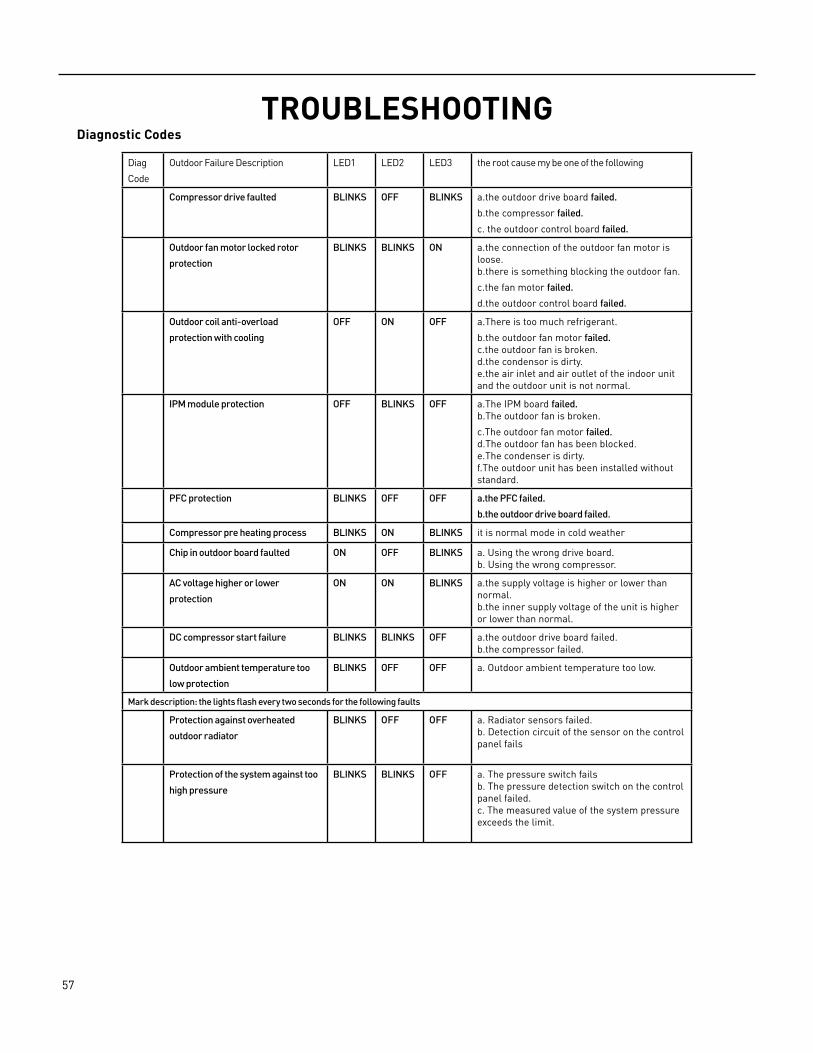
TROUBLESHOOTINGDiagnostic Codes
Diag
Code
Outdoor Failure Description LED1 LED2 LED3 the root cause my be one of the following
Compressor drive faulted BLINKS OFF BLINKS a.the outdoor drive board failed.
b.the compressor failed.
c. the outdoor control board failed.
Outdoor fan motor locked rotor
protection
BLINKS BLINKS ON a.the connection of the outdoor fan motor is loose. b.there is something blocking the outdoor fan.
c.the fan motor failed.
d.the outdoor control board failed.
Outdoor coil anti-overload
protection with cooling
OFF ON OFF a.There is too much refrigerant.
b.the outdoor fan motor failed. c.the outdoor fan is broken. d.the condensor is dirty. e.the air inlet and air outlet of the indoor unit and the outdoor unit is not normal.
IPM module protection OFF BLINKS OFF a.The IPM board failed.b.The outdoor fan is broken.
c.The outdoor fan motor failed.d.The outdoor fan has been blocked.e.The condenser is dirty.f.The outdoor unit has been installed without standard.
PFC protection BLINKS OFF OFF a.the PFC failed.
b.the outdoor drive board failed.
Compressor pre heating process BLINKS ON BLINKS it is normal mode in cold weather
Chip in outdoor board faulted ON OFF BLINKS a. Using the wrong drive board.b. Using the wrong compressor.
AC voltage higher or lower
protection
ON ON BLINKS a.the supply voltage is higher or lower than normal. b.the inner supply voltage of the unit is higher or lower than normal.
DC compressor start failure BLINKS BLINKS OFF a.the outdoor drive board failed. b.the compressor failed.
Outdoor ambient temperature too
low protection
BLINKS OFF OFF a. Outdoor ambient temperature too low.
Mark description: the lights flash every two seconds for the following faults
Protection against overheated
outdoor radiator
BLINKS OFF OFF a. Radiator sensors failed.b. Detection circuit of the sensor on the control panel fails
Protection of the system against too
high pressure
BLINKS BLINKS OFF a. The pressure switch failsb. The pressure detection switch on the control panel failed.c. The measured value of the system pressure exceeds the limit.
58 PB
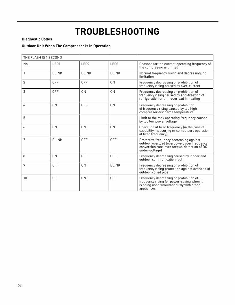
TROUBLESHOOTINGDiagnostic Codes
Outdoor Unit When The Compressor Is In Operation
THE FLASH IS 1 SECOND
No. LED1 LED2 LED3 Reasons for the current operating frequency of the compressor is limited
1 BLINK BLINK BLINK Normal frequency rising and decreasing, no limitation
2 OFF OFF ON Frequency decreasing or prohibition of frequency rising caused by over‑current
3 OFF ON ON Frequency decreasing or prohibition of frequency rising caused by anti‑freezing of refrigeration or anti‑overload in heating
4 ON OFF ON Frequency decreasing or prohibition of frequency rising caused by too high compressor discharge temperature
5 Limit to the max operating frequency caused by too low power voltage
6 ON ON ON Operation at fixed frequency (in the case of capability measuring or compulsory operation at fixed frequency)
7 BLINK OFF OFF Protective frequency decreasing against outdoor overload (overpower, over frequency conversion rate, over torque, detection of DC under‑voltage)
8 ON OFF OFF Frequency decreasing caused by indoor and outdoor communication fault
9 OFF ON BLINK Frequency decreasing or prohibition of frequency rising protection against overload of outdoor coiled pipe
10 OFF ON OFF Frequency decreasing or prohibition of frequency rising for power‑saving when it is being used simultaneously with other appliances
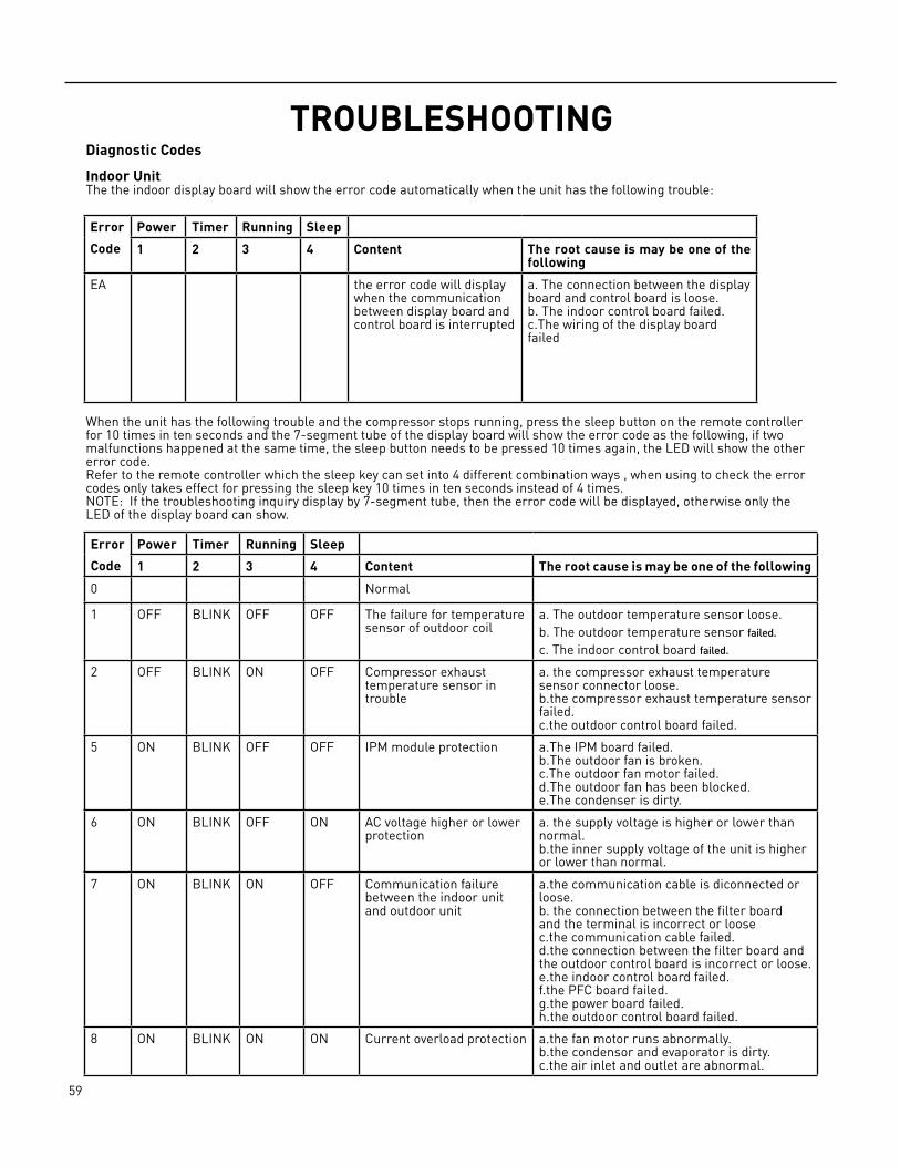
59 PB
TROUBLESHOOTINGDiagnostic Codes
Indoor UnitThe the indoor display board will show the error code automatically when the unit has the following trouble:
Error
Code
Power Timer Running Sleep
1 2 3 4 Content The root cause is may be one of the following
EA the error code will display when the communication between display board and control board is interrupted
a. The connection between the display board and control board is loose. b. The indoor control board failed.c.The wiring of the display board failed
When the unit has the following trouble and the compressor stops running, press the sleep button on the remote controller for 10 times in ten seconds and the 7‑segment tube of the display board will show the error code as the following, if two malfunctions happened at the same time, the sleep button needs to be pressed 10 times again, the LED will show the other error code.Refer to the remote controller which the sleep key can set into 4 different combination ways , when using to check the error codes only takes effect for pressing the sleep key 10 times in ten seconds instead of 4 times.NOTE: If the troubleshooting inquiry display by 7‑segment tube, then the error code will be displayed, otherwise only the LED of the display board can show.
Error
Code
Power Timer Running Sleep
1 2 3 4 Content The root cause is may be one of the following
0 Normal
1 OFF BLINK OFF OFF The failure for temperature sensor of outdoor coil
a. The outdoor temperature sensor loose.b. The outdoor temperature sensor failed.
c. The indoor control board failed.
2 OFF BLINK ON OFF Compressor exhaust temperature sensor in trouble
a. the compressor exhaust temperature sensor connector loose. b.the compressor exhaust temperature sensor failed.c.the outdoor control board failed.
5 ON BLINK OFF OFF IPM module protection a.The IPM board failed.b.The outdoor fan is broken.c.The outdoor fan motor failed.d.The outdoor fan has been blocked.e.The condenser is dirty.
6 ON BLINK OFF ON AC voltage higher or lower protection
a. the supply voltage is higher or lower than normal.b.the inner supply voltage of the unit is higher or lower than normal.
7 ON BLINK ON OFF Communication failure between the indoor unit and outdoor unit
a.the communication cable is diconnected or loose. b. the connection between the filter board and the terminal is incorrect or loose c.the communication cable failed.d.the connection between the filter board and the outdoor control board is incorrect or loose.e.the indoor control board failed.f.the PFC board failed.g.the power board failed. h.the outdoor control board failed.
8 ON BLINK ON ON Current overload protection a.the fan motor runs abnormally. b.the condensor and evaporator is dirty. c.the air inlet and outlet are abnormal.
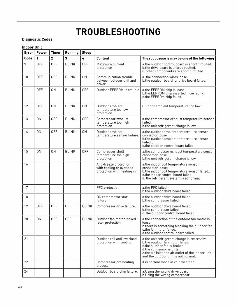
60 PB
TROUBLESHOOTINGDiagnostic Codes
Indoor UnitError
Code
Power Timer Running Sleep
1 2 3 4 Content The root cause is may be one of the following
9 OFF OFF BLINK OFF Maximum current protection
a.the outdoor control board is short circuited.b.the drive board is short circuited.c. other components are short circuited.
10 OFF OFF BLINK ON Communication trouble between outdoor unit and driver
a. the connection wires loose. b.the outdoor board or drive board failed.
11 OFF ON BLINK OFF Outdoor EEPROM in trouble a.the EEPROM chip is loose.b.the EEPROM chip inserted incorrectly.c.the EEPROM chip failed.
12 OFF ON BLINK ON Outdoor ambient temperature too low protection
Outdoor ambient temperature too low.
13 ON OFF BLINK OFF Compressor exhaust temperature too high protection
a.the compressor exhaust temperature sensor failed. b.the unit refrigerant charge is low
14 ON OFF BLINK ON Outdoor ambient temperature sensor failure.
a.the outdoor ambient temperature sensor connector looseb.the outdoor ambient temperature sensor failed.; c.the outdoor control board failed.
15 ON ON BLINK OFF Compressor shell temperature too high protection
a.the compressor exhaust temperature sensor connector loose.b.the unit refrigerant charge is low.
16 Anti‑freeze protection with cooling or overload protection with heating in
a.the indoor coil temperature sensor connector loose; b.the indoor coil temperature sensor failed.. c.the indoor control board failed..d. the refrigerant system is abnormal
17 PFC protection a.the PFC failed.; b.the outdoor drive board failed.
18 DC compressor start failure
a.the outdoor drive board failed.; b.the compressor failed.
19 OFF OFF OFF BLINK Compressor drive failure. a.the outdoor drive board failed.; b.the compressor failed. c. the outdoor control board failed.
20 ON OFF OFF BLINK Outdoor fan motor locked rotor protection.
a.the connection of the outdoor fan motor is loose.b.there is something blocking the outdoor fan. c.the fan motor failed. d.the outdoor control board failed.
21 Outdoor coil anti‑overload protection with cooling.
a.the unit refrigerant charge is exccessive. b.the outdoor fan motor failed. c.the outdoor fan is broken. d.the condensor is dirty. e.the air inlet and air outlet of the indoor unit and the outdoor unit is not normal.
22 Compressor pre heating process
it is normal mode in cold weather.
24 Outdoor board chip failure. a.Using the wrong drive board;b.Using the wrong compressor
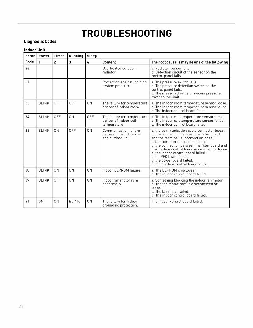
61 PB
TROUBLESHOOTINGDiagnostic Codes
Indoor UnitError
Code
Power Timer Running Sleep
1 2 3 4 Content The root cause is may be one of the following
26 Overheated outdoor radiator
a. Radiator sensor fails.b. Detection circuit of the sensor on the control panel fails.
27 Protection against too high system pressure
a. The pressure switch fails.b. The pressure detection switch on the control panel fails.c. The measured value of system pressure exceeds the limit.
33 BLINK OFF OFF ON The failure for temperature sensor of indoor room
a. The indoor room temperature sensor loose.b. The indoor room temperature sensor failed.c. The indoor control board failed.
34 BLINK OFF ON OFF The failure for temperature sensor of indoor coil temperature
a. The indoor coil temperature sensor loose.b. The indoor coil temperature sensor failed.c. The indoor control board failed.
36 BLINK ON OFF ON Communication failure between the indoor unit and outdoor unit
a. the communication cable connector loose.b. the connection between the filter board and the terminal is incorrect or loose. c. the communication cable failed. d. the connection between the filter board and the outdoor control board is incorrect or loose.e. the indoor control board failed.f. the PFC board failed.g. the power board failed. h. the outdoor control board failed.
38 BLINK ON ON ON Indoor EEPROM failure a. The EEPROM chip loose;b. The indoor control board failed.
39 BLINK OFF ON ON Indoor fan motor runs abnormally.
a. Something blocking the indoor fan motor.b. The fan motor cord is disconnected or loose.c. The fan motor failed. d. The indoor control board failed.
41 ON ON BLINK ON The failure for Indoor grounding protection.
The indoor control board failed.
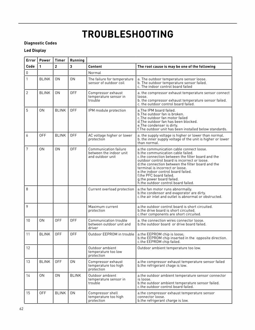
62 PB
TROUBLESHOOTINGDiagnostic Codes
Led Display
Error
Code
Power Timer Running
1 2 3 Content The root cause is may be one of the following
0 Normal
1 BLINK ON ON The failure for temperature sensor of outdoor coil
a. The outdoor temperature sensor loose.b. The outdoor temperature sensor failed.c. The indoor control board failed
2 BLINK ON OFF Compressor exhaust temperature sensor in trouble
a. the compressor exhaust temperature sensor connect loose. b. the compressor exhaust temperature sensor failed. c. the outdoor control board failed.
5 ON BLINK OFF IPM module protection a.The IPM board failed.b.The outdoor fan is broken.c.The outdoor fan motor failedd.The outdoor fan has been blocked.e.The condenser is dirty.f.The outdoor unit has been installed below standards.
6 OFF BLINK OFF AC voltage higher or lower protection
a. the supply voltage is higher or lower than normal.b. the inner supply voltage of the unit is higher or lower than normal.
7 ON ON OFF Communication failure between the indoor unit and outdoor unit
a.the communication cable connect loose. b.the communication cable failed. c.the connection between the filter board and the outdoor control board is incorrect or loose.d.the connection between the filter board and the terminal is incorrect or loose.e.the indoor control board failed.f.the PFC board failed.g.the power board failed.h.the outdoor control board failed.
8 Current overload protection a.the fan motor runs abnormally. b.the condensor and evaporator are dirty. c.the air inlet and outlet is abnormal or obstructed.
9 Maximum current protection
a.the outdoor control board is short circuited.b.the drive board is short circuited.c.ther components are short circuited.
10 ON OFF OFF Communication trouble between outdoor unit and driver
a. the connection wires connector loose.b.the outdoor board or drive board failed.
11 BLINK OFF OFF Outdoor EEPROM in trouble a.the EEPROM chip is loose;b.the EEPROM chip inserted in the opposite direction.c.the EEPROM chip failed.
12 Outdoor ambient temperature too low protection
Outdoor ambient temperature too low.
13 BLINK OFF ON Compressor exhaust temperature too high protection
a.the compressor exhaust temperature sensor failed b.the refrigerant chage is low.
14 ON ON BLINK Outdoor ambient temperature sensor in trouble
a.the outdoor ambient temperature sensor connector is loose.b.the outdoor ambient temperature sensor failed. c.the outdoor control board failed.
15 OFF BLINK ON Compressor shell temperature too high protection
a.the compressor exhaust temperature sensor connector loose.b.the refrigerant charge is low.

63 PB
TROUBLESHOOTINGDiagnostic Codes
LED Display
Error
Code
Power Timer Running
1 2 3 Content The root cause is may be one of the following
16 ON OFF ON Anti‑freeze protection with cooling or overload protection with heating in
a.the indoor coil temperature sensor connector loose. b.the indoor coil temperature sensor failed. c.the indoor control board failed.d. the refrigerant system is abnormal.
17 OFF ON OFF PFC protection a.the PFC failed.b.the outdoor drive board failed.
18 OFF ON ON DC compressor start failure
a.the outdoor drive board failed. b.the compressor failed.
19 OFF ON BLINK Compressor drive in trouble
a.the outdoor drive board failed.b.the compressor failed.c. the outdoor control board failed.
20 ON OFF BLINK Outdoor fan motor locked rotor protection
a.the connection of the outdoor fan motor is loose. b.there are something blocking the outdoor fan. c.the fan motor failed.d.the outdoor control board failed.
21 OFF OFF BLINK Outdoor coil anti‑overload protection with cooling
a.the refrigerant charge is exxcessive. b.the outdoor fan motor failed. c.the outdoor fan is broken. d.the condensor is dirty.e.the air inlet and air outlet of the indoor unit and the outdoor unit are abnormal.
22 Compressor pre heating process
it is normal mode in cold weather
24 Outdoor board chip failure. a.Using the wrong drive board;b.Using the wrong compressor.
26 Overheated outdoor radiator
a. Radiator sensor fails.b. Detection circuit of the sensor on the control panel fails.
27 Protection against too high system pressure
a. The pressure switch fails.b. The pressure detection switch on the control panel fails.c. The measured value of system pressure exceeds the limit.
33 ON BLINK BLINK Indoor room temperature sensor failure.
a. The indoor room temperature sensor loose;b. The indoor room temperature sensor is failure;c. The indoor control board is failure.
34 OFF BLINK BLINK Indoor coil temperature sensor failure.
d. The indoor coil temperature sensor loose.e. The indoor coil temperature sensor failed.f. The indoor control board failed.
36 BLINK ON BLINK Communication failure between the indoor unit and outdoor unit
a.the communication cable connector loose.b.the communication cable failed.c.the connection between the filter board and the outdoor control board is incorrect or loose.d.the connection between the filter board and the terminal is incorrect or loose.e.the indoor control board failed.f.the PFC board failed.g.the power board failed.h.the outdoor control board failed.
38 BLINK BLINK OFF Indoor EEPROM failure a. The EEPROM chip loose;b. The indoor control board failed.

64 PB
TROUBLESHOOTINGDiagnostic Codes
LED Display
Error
Code
Power Timer Running
1 2 3 Content The root cause is may be one of the following
39 BLINK BLINK ON Indoor fan motor run abnormally
a. There is something blocking the indoor fan motor. b. The fan motor cord connector loose.c. The fan motor has failed. d. The indoor control board failed.
41 OFF OFF ON The failure for Indoor grounding protective
The indoor control board failed.
The failure is detected when the room temperature sensor broken or shorted over 5 sec. The failure is detected when the temperature sensor of heater exchange broken or shorted over 5 sec.The failure is detected when each setting data is not match after the EEPPOM self‑check two times.The failure is occur when the grounding signal is not detected after the appliance power ON.

65 PB
TROUBLESHOOTINGTest the jumper terminalsOutdoor Unit Verification of Operation and Testing:
When powered on, if there is a probability that the outdoor unit is malfunctioning, or to rule out field wiring, the terminals below can be jumped to engage the outdoor unit in normal cooling operation.
Application: Jump these terminals to engage cooling for the outdoor unit. This is to determine that the field wiring is correct.
Fig. 701
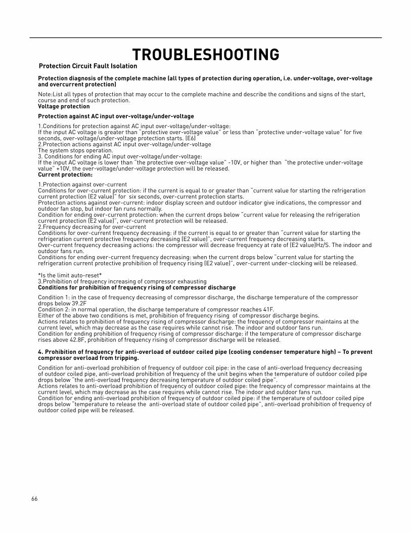
66 PB
TROUBLESHOOTINGProtection Circuit Fault Isolation
Protection diagnosis of the complete machine (all types of protection during operation, i.e. under-voltage, over-voltage and overcurrent protection)
Note:List all types of protection that may occur to the complete machine and describe the conditions and signs of the start, course and end of such protection.Voltage protection
Protection against AC input over-voltage/under-voltage
1.Conditions for protection against AC input over‑voltage/under‑voltage:If the input AC voltage is greater than “protective over‑voltage value” or less than “protective under‑voltage value” for five seconds, over‑voltage/under‑voltage protection starts. (E6)2.Protection actions against AC input over‑voltage/under‑voltageThe system stops operation.3. Conditions for ending AC input over‑voltage/under‑voltage:If the input AC voltage is lower than “the protective over‑voltage value” ‑10V, or higher than “the protective under‑voltage value” +10V, the over‑voltage/under‑voltage protection will be released.Current protection:
1.Protection against over‑currentConditions for over‑current protection: if the current is equal to or greater than “current value for starting the refrigeration current protection (E2 value)” for six seconds, over‑current protection starts.Protection actions against over‑current: indoor display screen and outdoor indicator give indications, the compressor and outdoor fan stop, but indoor fan runs normally. Condition for ending over‑current protection: when the current drops below “current value for releasing the refrigeration current protection (E2 value)”, over‑current protection will be released.2.Frequency decreasing for over‑currentConditions for over‑current frequency decreasing: if the current is equal to or greater than “current value for starting the refrigeration current protective frequency decreasing (E2 value)”, over‑current frequency decreasing starts.Over‑current frequency decreasing actions: the compressor will decrease frequency at rate of (E2 value)Hz/S. The indoor and outdoor fans run.Conditions for ending over‑current frequency decreasing: when the current drops below “current value for starting the refrigeration current protective prohibition of frequency rising (E2 value)”, over‑current under‑clocking will be released.
*Is the limit auto‑reset*3.Prohibition of frequency increasing of compressor exhaustingConditions for prohibition of frequency rising of compressor discharge
Condition 1: in the case of frequency decreasing of compressor discharge, the discharge temperature of the compressor drops below 39.2F Condition 2: in normal operation, the discharge temperature of compressor reaches 41F.Either of the above two conditions is met, prohibition of frequency rising of compressor discharge begins.Actions relates to prohibition of frequency rising of compressor discharge: the frequency of compressor maintains at the current level, which may decrease as the case requires while cannot rise. The indoor and outdoor fans run.Condition for ending prohibition of frequency rising of compressor discharge: if the temperature of compressor discharge rises above 42.8F, prohibition of frequency rising of compressor discharge will be released.
4. Prohibition of frequency for anti-overload of outdoor coiled pipe (cooling condenser temperature high) – To prevent compressor overload from tripping.
Condition for anti‑overload prohibition of frequency of outdoor coil pipe: in the case of anti‑overload frequency decreasing of outdoor coiled pipe, anti‑overload prohibition of frequency of the unit begins when the temperature of outdoor coiled pipe drops below “the anti‑overload frequency decreasing temperature of outdoor coiled pipe”.Actions relates to anti‑overload prohibition of frequency of outdoor coiled pipe: the frequency of compressor maintains at the current level, which may decrease as the case requires while cannot rise. The indoor and outdoor fans run.Condition for ending anti‑overload prohibition of frequency of outdoor coiled pipe: if the temperature of outdoor coiled pipe drops below “temperature to release the anti‑overload state of outdoor coiled pipe”, anti‑overload prohibition of frequency of outdoor coiled pipe will be released.
67 PB
TROUBLESHOOTINGCompressor Fault Isolation
Judging the connecting terminals of inverter compressor:
It is impossible to identify terminals U, V and W of inverter compressor with multi‑meter. Just connect the terminals in the same way as the original unit when replacing the compressor. A wrong connection will lead to reverse and loud noise of the compressor.Resistance of compressor coil:
Measure the resistance between any two terminals, which are about a few Ohms, three phases having the same resistance
Electric FIlter Board Fault IsolationVisual examination: as the circuit is simple, the connection may be checked visually to see whether any loose or poor connection.Voltage test: the voltage at the input end shall be the same as the voltage at the output end.
Electrical Communication Fault ISOLATIONStep one: to determine whether the connecting cables and tether cables of indoor/outdoor units are correctly wired. If not, change wiring order and test connection.Step two: to determine whether there is loose connection. Fasten the connection in the case of loose connection and then conduct verification.Step three: measure the voltage between SI and N with multi‑meter and see whether the voltage fluctuates between 0V and 24V. Please directly replace indoor and outdoor control boards if there are no voltage fluctuations.
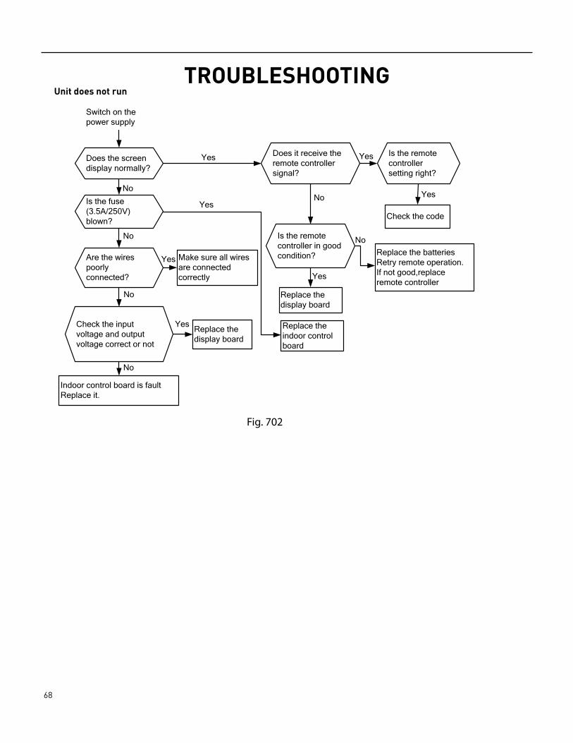
68 PB
TROUBLESHOOTINGUnit does not run
Does the screen display normally?
Switch on the power supply
Is the fuse
blown?(3.5A/250V)
Are the wires poorly connected?
Check the input voltage and output voltage correct or not
Indoor control board is fault Replace it.
No
No
No
No
Does it receive the remote controller signal?
Is the remote controller setting right?
Check the code
Replace the batteriesRetry remote operation.
If not good,replaceremote controller
Is the remote controller in good condition?
Make sure all wires are connectedcorrectly
display boardReplace the
display boardReplace the
Replace the
boardindoor control
Yes
Yes
No
Yes
Yes
No
Yes
Yes
Yes
Fig. 702
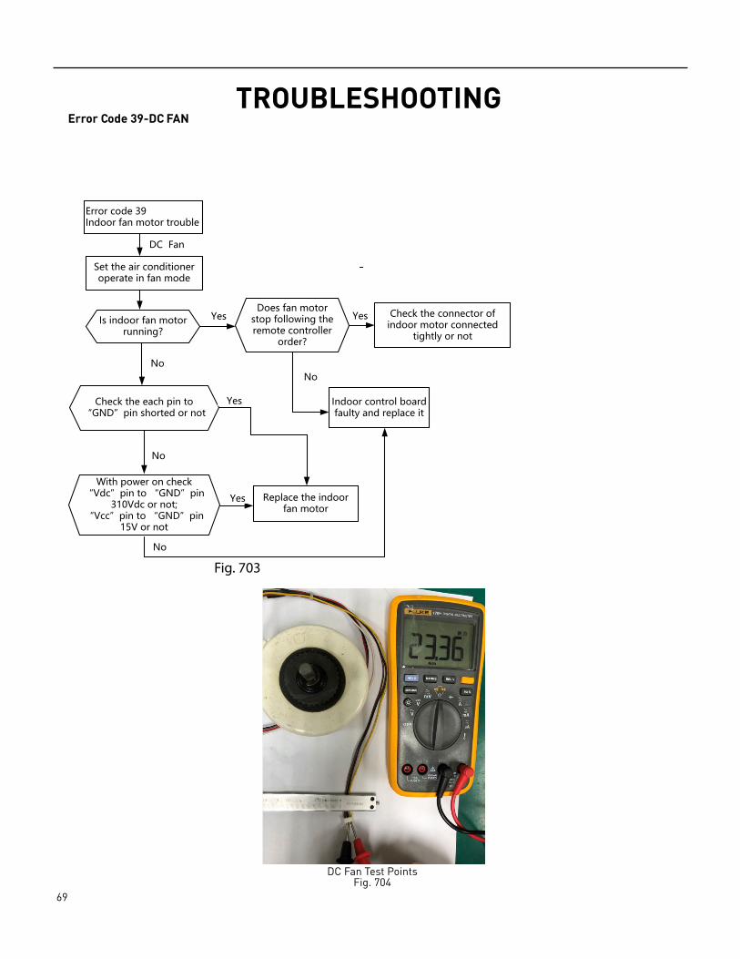
69 PB
TROUBLESHOOTINGError Code 39-DC FAN
Error code 39Indoor fan motor trouble
Set the air conditioner operate in fan mode
Is indoor fan motor running?
Does fan motor stop following the remote controller
order?
Check the connector of indoor motor connected
tightly or not
Check the each pin to “GND”pin shorted or not
Indoor control board faulty and replace it
DC Fan
Replace the indoor fan motor
With power on check “Vdc”pin to “GND”pin
310Vdc or not;“Vcc”pin to “GND”pin
15V or not
Yes Yes
No
No
No
No
Yes
Yes
Fig. 703
DC Fan Test PointsFig. 704
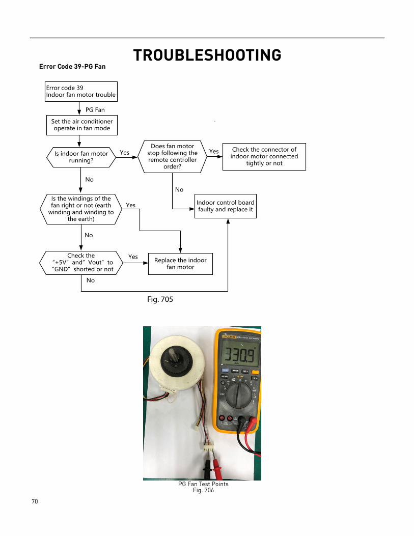
70 PB
TROUBLESHOOTINGError Code 39-PG Fan
Error code 39Indoor fan motor trouble
Set the air conditioner operate in fan mode
Is indoor fan motor running?
Does fan motor stop following the remote controller
order?
Check the connector of indoor motor connected
tightly or not
Is the windings of the fan right or not (earth
winding and winding to the earth)
Indoor control board faulty and replace it
PG Fan
Replace the indoor fan motor
Check the “+5V”and”Vout”to “GND”shorted or not
Yes Yes
No
No
No
No
Yes
Yes
Fig. 705
PG Fan Test PointsFig. 706
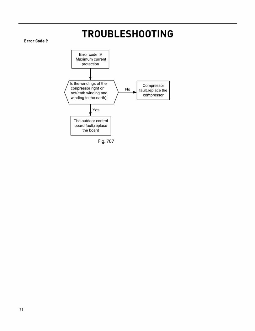
71 PB
TROUBLESHOOTINGError Code 9
Error code 9 Maximum current
protection
The outdoor control board fault,replace
the board
Yes
NoCompressor
fault,replace the compressor
Is the windings of the conpressor right or not(eath winding and winding to the earth)
Fig. 707

72 PB
TROUBLESHOOTINGError Code 13
Fig. 708
Error Code 8
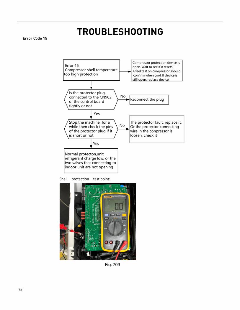
73 PB
TROUBLESHOOTINGError Code 15
Error 15 Compressor shell temperature too high protection
Stop the machine for a while then check the pins of the protector plug if it is short or not
Reconnect the plug
Normal protecton,unit refrigerant charge low, or the two valves that connecting to indoor unit are not opening
Yes
Yes
The protector fault, replace it. Or the protector connecting wire in the conpressor is loosen, check it
No
No
Is the protector plug connected to the CN902 of the control board tightly or not
Shell protec�on test point:
Fig. 709
Compressor protection device isopen. Wait to see if it resets. A feel test on compressor should con�rm when cool. If device is still open, replace device.
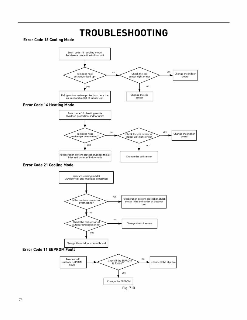
74 PB
TROUBLESHOOTINGError Code 16 Cooling Mode
Error code 16 cooling modeAnti-freeze protection indoor unit
Is indoor heat exchanger iced up?
Refrigeration system protection,check the air inlet and outlet of indoor unit
Check the coil sensor right or not
Change the coil sensor
Change the indoor board
no yes
yes no
Error code 16 heating modeOverload protection indoor unite
Is indoor heat exchanger overheating?
Refrigeration system protection,check the air inlet and outlet of indoor unit
Check the coil sensor of indoor unit right or not
Change the indoor board
Change the coil sensor
no
yes
yes
no
Error 21 (cooling mode)Outdoor coil anti-overload protection
Is the outdoor condensor overheating?
Check the coil sensor of outdoor unit right or not
Change the outdoor control board
Change the coil sensor
Refrigeration system protection,check the air inlet and outlet of outdoor
unit
yes
no
yes
no
Error code11Outdoor EEPROM
Faultreconnect the EEprom
Change the EEPROM
Check if the EEPROMno
yes
is loose?
Fig. 710
Error Code 16 Heating Mode
Error Code 21 Cooling Mode
Error Code 11 EEPROM Fault
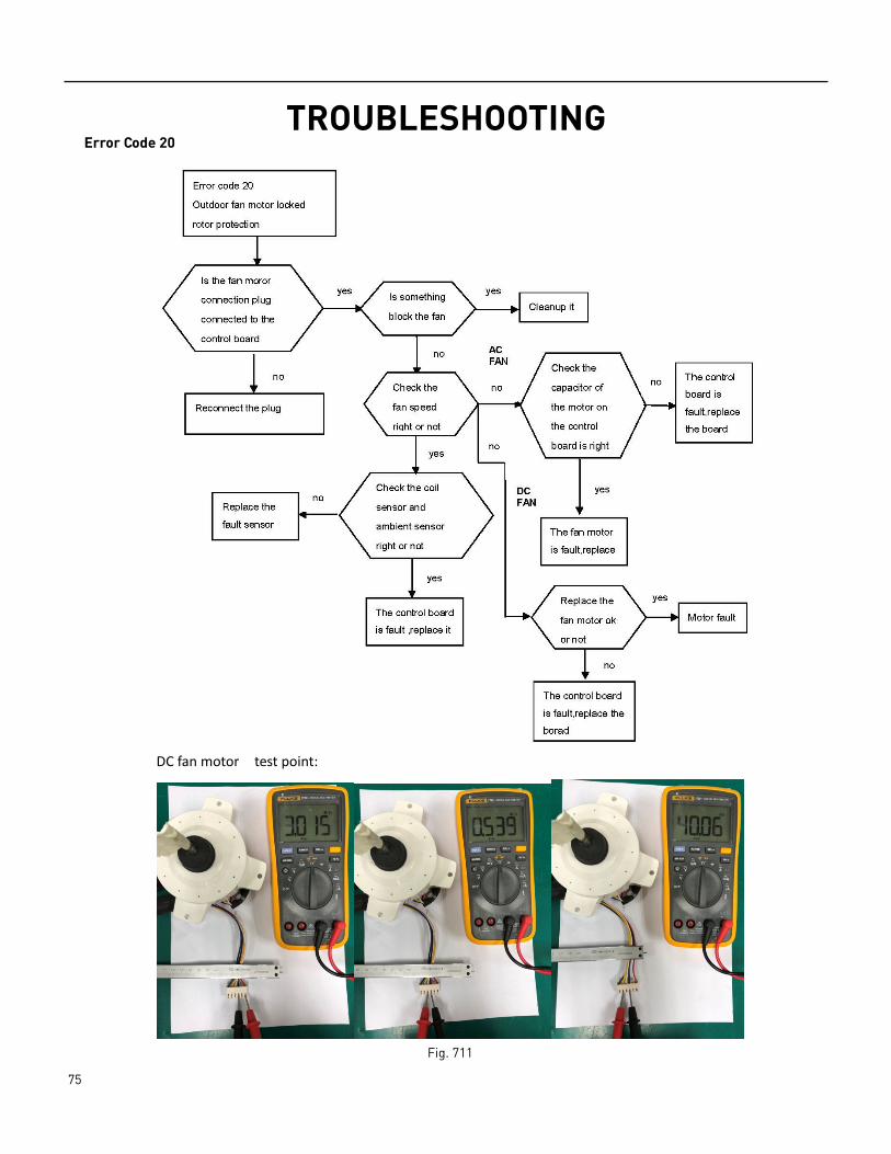
75 PB
TROUBLESHOOTINGError Code 20
DC fan motor test point:
Fig. 711
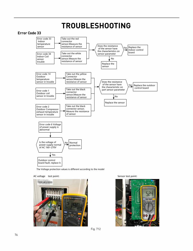
76 PB
TROUBLESHOOTINGError Code 33
Error code 33 Indoor
sensortemperature
Error code 34 Indoor Coil sensortrouble
Take out the red connector sensor.Measure the resistance of sensor Replace the
indoor control boardTake out the white
connector sensor.Meaure the resistance of sensor
Replace the sensor
Error code 14Outdoor temperature sensor in trouble
Error code 1Outdoor coil sensor in trouble
Error code 2Outdoor Compressor exhaust temperature sensor in trouble
Take out the yellowConnector sensor,Meaure the resistance of sensor
Take out the black connector sensor,Meaure the resistance of sensor
Replace the sensor
Replace the outdoor
Take out the black connector sensor, Meaure the resistance of sensor
control board
No
Yes
Does the resistance of the sensor have the characteristics on sensor parameter
Does the resistance of the sensor have the characteristic on part sensor parameter
Error code 6 Voltage of power supply is abnormal
Is the voltage of power supply normal of AC 160~270V
Normal
Outdoor control board fault, replace it.
protectionNo
Yes
No
Yes
The Voltage protection values is different according to the model
AC voltage test point: Sensor test point:
Fig. 712
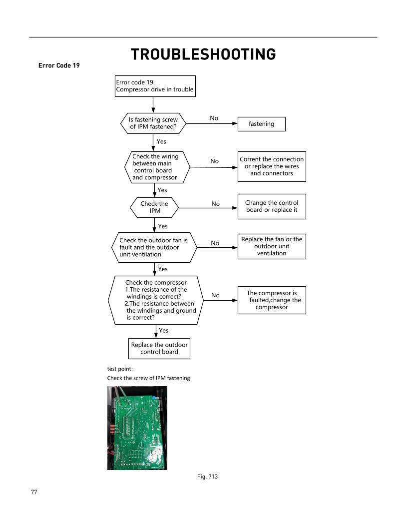
77 PB
TROUBLESHOOTINGError Code 19
Error code 19 Compressor drive in trouble
Check the IPM
Check the wiring between main control board and compressor
Check the compressor
Check the outdoor fan is fault and the outdoor unit ventilation
Replace the outdoor control board
1.The resistance of thewindings is correct?
2.The resistance betweenthe windings and groundis correct?
Corrent the connection or replace the wires
and connectors
Change the control board or replace it
Replace the fan or the outdoor unit ventilation
The compressor is faulted,change the
compressor
No
No
No
No
Yes
Yes
Yes
Yes
Is fastening screw of IPM fastened? fastening
No
Yes
test point: Check the screw of IPM fastening
Fig. 713
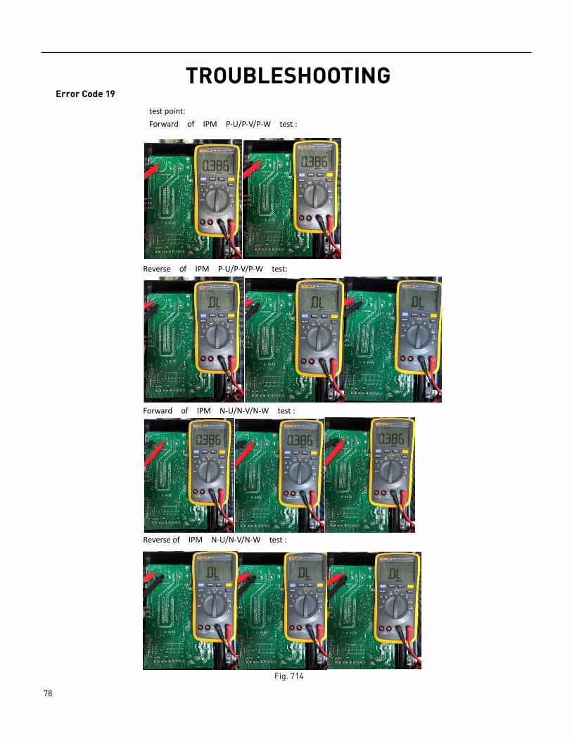
78 PB
TROUBLESHOOTINGError Code 19
Reverse of IPM P-U/P-V/P-W test:
Forward of IPM N-U/N-V/N-W test :
Reverse of IPM N-U/N-V/N-W test :
test point: Forward of IPM P-U/P-V/P-W test :
Fig. 714
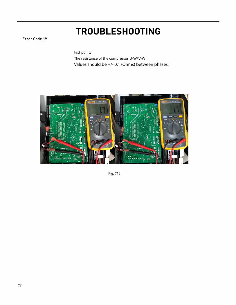
79 PB
TROUBLESHOOTINGError Code 19
test point: The resistance of the compressor U-W\V-W Values should be +/- 0.1 (Ohms) between phases.
Fig. 715
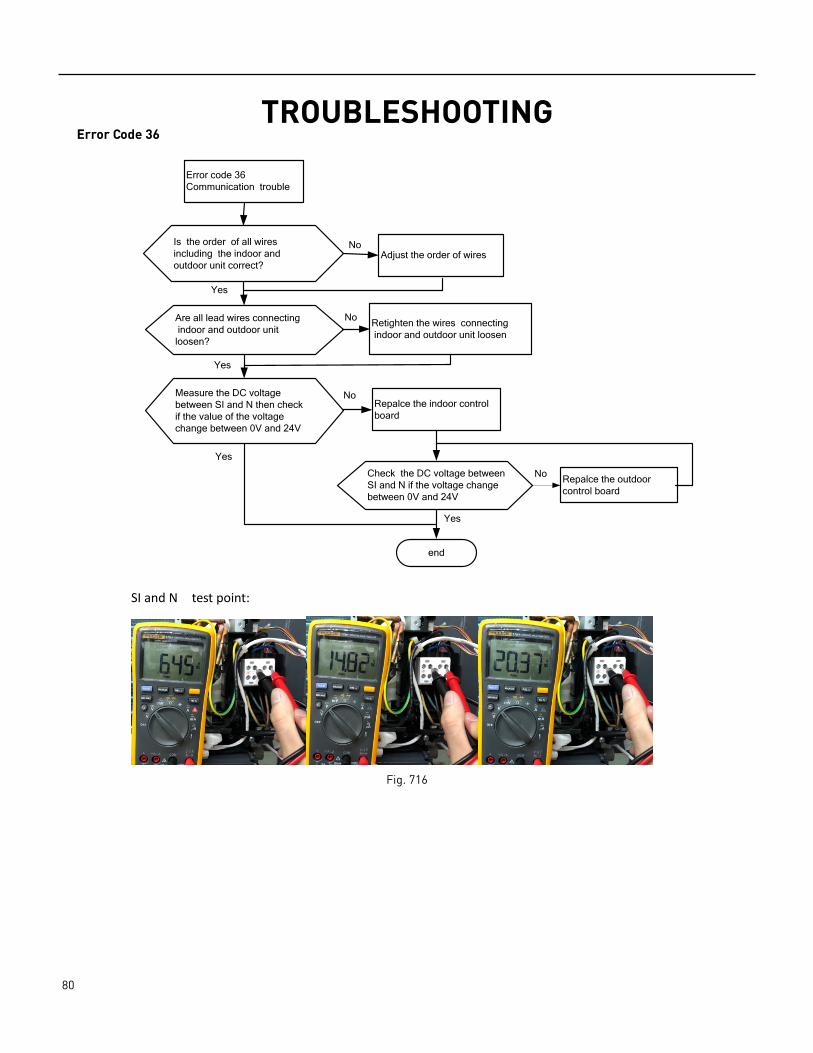
80 PB
TROUBLESHOOTINGError Code 36
Error code 36Communication trouble
Is the order of all wires including the indoor and outdoor unit correct?
Are all lead wires connecting indoor and outdoor unit loosen?
Adjust the order of wires
Retighten the wires connecting indoor and outdoor unit loosen
Repalce the indoor control board
Measure the DC voltage between SI and N then check if the value of the voltage change between 0V and 24V
end
Repalce the outdoor control board
Check the DC voltage between SI and N if the voltage change between 0V and 24V
No
Yes
Yes
No
No
Yes
No
Yes
SI and N test point:
Fig. 716

81 PB
WIRING DIAGRAMSWiring Diagram Lookup Table
Model Number Indoor Unit Indoor Unit Wiring Diagram
Outdoor Unit Outdoor Unit Wiring Diagram
Voltage BTU
FPHW091/A FPHSW09A1A, FPHSW09A1B/B
1912241 FPHSR09A1A 1912204 115 9k
FPHW093/A FPHFW09A3A, FPHFW09A3B/B
185460519122411907790
FPHSR09A3A 1854707 208/230 9k
FRHW093/A FRHSW09A3A, FRHSW09A3B/B
185460519122411907790
FRHSR09A3A 1854707 208/230 9k
FPHW121/A FPHSW12A1A, FPHSW12A1B/B
1912241 FPHSR12A1A 1912204 115 12k
FPHW123/A FPHFW12A3A, FPHFW12A3B/B
1854605 FPHSR12A3A 1854707 208/230 12k
FRHW123/A FRHSW12A3A, FRHSW12A3B/B
1854605 FRHSR12A3A 1854707 208/230 12k
FPHW183/A FPHFW18A3A, FPHFW18A3B/B
18546051854698
FPHSR18A3A 1854707 208/230 18k
FPHW243/A FPHFW24A3A, FPHFW24A3B
1854698 FPHSR24A3A 1854707 208/230 24k
FPHW363/A FPHSW36A3A, FPHSW36A3B, FPHSW36A3C/B/C
1852066 FPHSR36A3A, FPHSR36A3B/B
1854707 208/230 36k
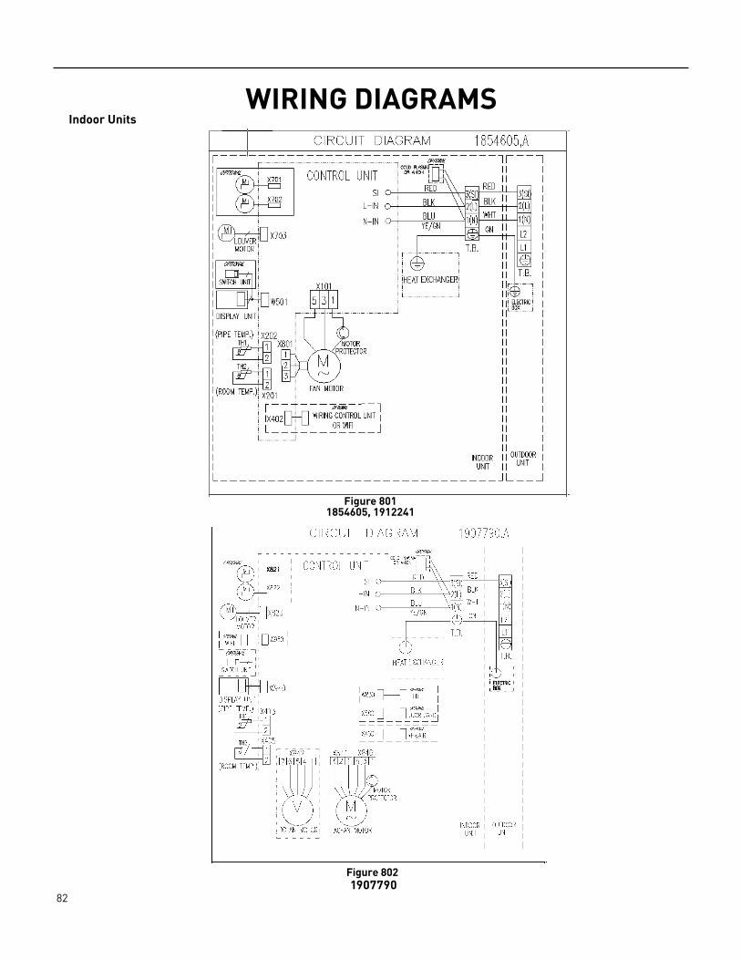
82 PB
WIRING DIAGRAMSIndoor Units
Figure 802 1907790
Figure 8011854605, 1912241

83 PB
WIRING DIAGRAMSIndoor Units
Figure 8041852066
Figure 803
1854698
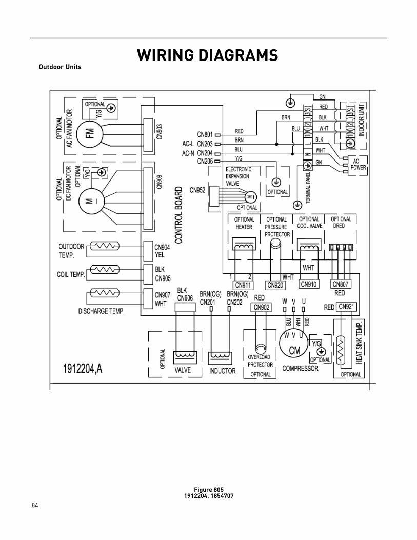
84 PB
WIRING DIAGRAMSOutdoor Units
Figure 8051912204, 1854707
85 PB
PARTS CATALOGIntroduction
This illustrated part catalog has been written to help assist the technician to quickly locate the parts that he or she needs to make a repair.
The catalog is broken down into different figures which represent different modules of the air conditioning unit. For example; the chassis, refrigeration system, blower system, or electrical controls. Each figure contains an illustration(s) containing item numbers and a corresponding item list.
The item list contains the item number, part number, part description, the model it is used on, and the quantity used per figure. The models will end with a letter indicating the major revision of the model. for example; WCT12A30A. Choose the part that corresponds with the USED ON MODEL annotation that corresponds to your nameplate.
In some cases there will be an additional “-” letter indicating there has been a minor revision to that model which may have caused a part number change. For example; WCT12A30A-B. If there are minor revisions listed for a part, and the minor revision that is listed on your equipment’s nameplate is not listed in the manual please check our online parts viewer for the latest update. If you still require
asistance, call Friedrich customer service(1-800-541-6645) for an explanation.
Items with a - in front of the item number (for example -10), are non illustrated items.
Items with an * in front of the number (for example *10) are non-stocked items. If you require these items contact Friedrich customer service at (1-800-541-6645) to check for availability and lead time.
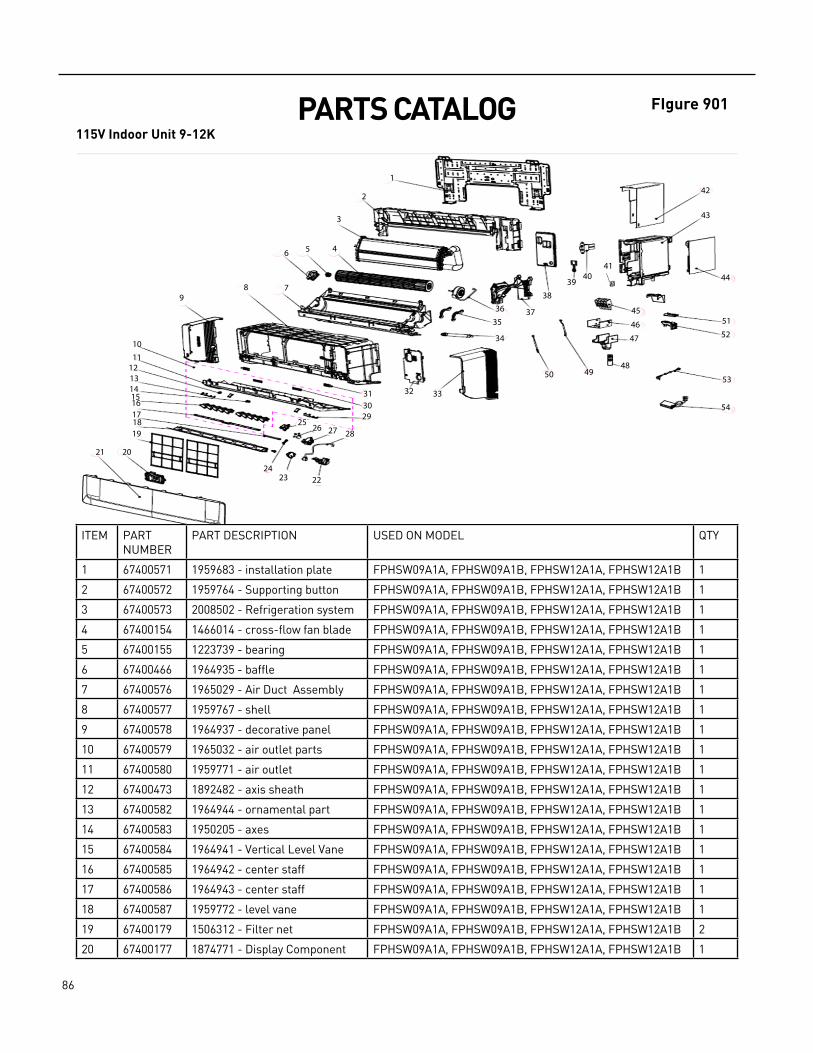
86 PB
FIgure 901 PARTS CATALOG115V Indoor Unit 9-12K
ITEM PART NUMBER
PART DESCRIPTION USED ON MODEL QTY
1 67400571 1959683 ‑ installation plate FPHSW09A1A, FPHSW09A1B, FPHSW12A1A, FPHSW12A1B 1
2 67400572 1959764 ‑ Supporting button FPHSW09A1A, FPHSW09A1B, FPHSW12A1A, FPHSW12A1B 1
3 67400573 2008502 ‑ Refrigeration system FPHSW09A1A, FPHSW09A1B, FPHSW12A1A, FPHSW12A1B 1
4 67400154 1466014 ‑ cross‑flow fan blade FPHSW09A1A, FPHSW09A1B, FPHSW12A1A, FPHSW12A1B 1
5 67400155 1223739 ‑ bearing FPHSW09A1A, FPHSW09A1B, FPHSW12A1A, FPHSW12A1B 1
6 67400466 1964935 ‑ baffle FPHSW09A1A, FPHSW09A1B, FPHSW12A1A, FPHSW12A1B 1
7 67400576 1965029 ‑ Air Duct Assembly FPHSW09A1A, FPHSW09A1B, FPHSW12A1A, FPHSW12A1B 1
8 67400577 1959767 ‑ shell FPHSW09A1A, FPHSW09A1B, FPHSW12A1A, FPHSW12A1B 1
9 67400578 1964937 ‑ decorative panel FPHSW09A1A, FPHSW09A1B, FPHSW12A1A, FPHSW12A1B 1
10 67400579 1965032 ‑ air outlet parts FPHSW09A1A, FPHSW09A1B, FPHSW12A1A, FPHSW12A1B 1
11 67400580 1959771 ‑ air outlet FPHSW09A1A, FPHSW09A1B, FPHSW12A1A, FPHSW12A1B 1
12 67400473 1892482 ‑ axis sheath FPHSW09A1A, FPHSW09A1B, FPHSW12A1A, FPHSW12A1B 1
13 67400582 1964944 ‑ ornamental part FPHSW09A1A, FPHSW09A1B, FPHSW12A1A, FPHSW12A1B 1
14 67400583 1950205 ‑ axes FPHSW09A1A, FPHSW09A1B, FPHSW12A1A, FPHSW12A1B 1
15 67400584 1964941 ‑ Vertical Level Vane FPHSW09A1A, FPHSW09A1B, FPHSW12A1A, FPHSW12A1B 1
16 67400585 1964942 ‑ center staff FPHSW09A1A, FPHSW09A1B, FPHSW12A1A, FPHSW12A1B 1
17 67400586 1964943 ‑ center staff FPHSW09A1A, FPHSW09A1B, FPHSW12A1A, FPHSW12A1B 1
18 67400587 1959772 ‑ level vane FPHSW09A1A, FPHSW09A1B, FPHSW12A1A, FPHSW12A1B 1
19 67400179 1506312 ‑ Filter net FPHSW09A1A, FPHSW09A1B, FPHSW12A1A, FPHSW12A1B 2
20 67400177 1874771 ‑ Display Component FPHSW09A1A, FPHSW09A1B, FPHSW12A1A, FPHSW12A1B 1
1
1
2
3
456
789
1011
1213141516171819
2021
222324
2526 27 28
293031 32 33
34
35
36 37
38
3940
41
42
43
44
45
46
47
484950
51
52
53
54

87 PB
ITEM PART NUMBER
PART DESCRIPTION USED ON MODEL QTY
21 67400588 4113865 ‑ panel FPHSW09A1A, FPHSW09A1B, FPHSW12A1A, FPHSW12A1B 1
22 67400589 1964953 ‑ Motor bracket FPHSW09A1A, FPHSW09A1B, FPHSW12A1A, FPHSW12A1B 1
23 67400590 1964954 ‑ motor cover FPHSW09A1A, FPHSW09A1B, FPHSW12A1A, FPHSW12A1B 1
24 67400591 1964950 ‑ center staff FPHSW09A1A, FPHSW09A1B, FPHSW12A1A, FPHSW12A1B 1
25 67400592 1964956 ‑ motor cover FPHSW09A1A, FPHSW09A1B, FPHSW12A1A, FPHSW12A1B 1
26 67400174 1260259 ‑ Step motor FPHSW09A1A, FPHSW09A1B, FPHSW12A1A, FPHSW12A1B 1
27 67400550 1964955 ‑ Motor bracket FPHSW09A1A, FPHSW09A1B, FPHSW12A1A, FPHSW12A1B 1
28 67400595 1467336 ‑ Step motor FPHSW09A1A, FPHSW09A1B, FPHSW12A1A, FPHSW12A1B 1
29 67400596 1964945 ‑ ornamental part FPHSW09A1A, FPHSW09A1B, FPHSW12A1A, FPHSW12A1B 1
30 67400485 1964949 ‑ baffle FPHSW09A1A, FPHSW09A1B, FPHSW12A1A, FPHSW12A1B 2
31 67400598 1964939 ‑ axes FPHSW09A1A, FPHSW09A1B, FPHSW12A1A, FPHSW12A1B 2
32 67400599 1964940 ‑ wiring distribution cover assy
FPHSW09A1A, FPHSW09A1B, FPHSW12A1A, FPHSW12A1B 1
33 67400600 1964938 ‑ decorative panel FPHSW09A1A, FPHSW09A1B, FPHSW12A1A, FPHSW12A1B 1
34 67400487 1978713 ‑ Water pipe parts FPHSW09A1A, FPHSW09A1B, FPHSW12A1A, FPHSW12A1B 1
35 67400602 1964936 ‑ Motor hoop FPHSW09A1A, FPHSW09A1B, FPHSW12A1A, FPHSW12A1B 2
36 67400326 2006737 ‑ AC motor FPHSW09A1A, FPHSW09A1B, FPHSW12A1A, FPHSW12A1B 1
37 67400603 1964934 ‑ motor guard FPHSW09A1A, FPHSW09A1B, FPHSW12A1A, FPHSW12A1B 1
38 67400604 1961612 ‑ electric box cover FPHSW09A1A, FPHSW09A1B, FPHSW12A1A, FPHSW12A1B 1
39 67400489 1961613 ‑ button FPHSW09A1A, FPHSW09A1B, FPHSW12A1A, FPHSW12A1B 1
40 67400490 1988669 ‑ Power Switch FPHSW09A1A, FPHSW09A1B, FPHSW12A1A, FPHSW12A1B 1
41 67400559 1988777 ‑ Jiggle switch FPHSW09A1A, FPHSW09A1B, FPHSW12A1A, FPHSW12A1B 1
42 67400786 1959674 ‑ electric box FPHSW09A1A, FPHSW09A1B, FPHSW12A1A, FPHSW12A1B 1
43 67400609 1961611 ‑ electric box FPHSW09A1A, FPHSW09A1B, FPHSW12A1A, FPHSW12A1B 1
44 67400313 2009266 ‑ 9K Indoor Main Control Board Component
FPHSW09A1A, FPHSW09A1B 1
44 67400317 2010485 ‑ 12K Indoor Main Control Board Component
FPHSW12A1A, FPHSW12A1B 1
45 67400166 1852126 ‑ Wire terminal board FPHSW09A1A, FPHSW09A1B, FPHSW12A1A, FPHSW12A1B 1
46 67400611 1959675 ‑ guard cover FPHSW09A1A, FPHSW09A1B, FPHSW12A1A, FPHSW12A1B 1
47 67400612 2010238 ‑ guard cover FPHSW09A1A, FPHSW09A1B, FPHSW12A1A, FPHSW12A1B 1
48 67400161 4084109 ‑ Remote Controller FPHSW09A1A, FPHSW09A1B, FPHSW12A1A, FPHSW12A1B 1
49 67400494 1831400 ‑ Temperature sensor FPHSW09A1A, FPHSW09A1B, FPHSW12A1A, FPHSW12A1B 1
50 67400495 1965628 ‑ Temperature sensor FPHSW09A1A, FPHSW09A1B, FPHSW12A1A, FPHSW12A1B 1
‑51 67401169 WIFI module FPHSW09A1B, FPHSW12A1B 1
‑ITEMS ARE NON‑ ILLUSTRATED*ITEMS ARE NON‑STOCKED, WILL NORMALLY REQUIRE EXTENDED LEAD TIME
PARTS CATALOG115V Indoor Unit 9-12K
FIgure 901

88 PB
PARTS CATALOG230V Indoor Unit 9-12K
ITEM PART NUMBER
PART DESCRIPTION USED ON MODEL QTY
1 67400571 1959683 ‑ installation plate FPHFW09A3A, FPHFW09A3B, FPHFW12A3A, FPHFW12A3B 1
2 67400572 1959764 ‑ Supporting button FPHFW09A3A, FPHFW09A3B, FPHFW12A3A, FPHFW12A3B 1
3 67400573 2008502 ‑ Refrigeration system FPHFW09A3A, FPHFW09A3B, FPHFW12A3A, FPHFW12A3B 1
4 67400154 1466014 ‑ cross‑flow fan blade FPHFW09A3A, FPHFW09A3B, FPHFW12A3A, FPHFW12A3B 1
5 67400155 1223739 ‑ bearing FPHFW09A3A, FPHFW09A3B, FPHFW12A3A, FPHFW12A3B 1
6 67400466 1964935 ‑ baffle FPHFW09A3A, FPHFW09A3B, FPHFW12A3A, FPHFW12A3B 1
7 67400576 1965029 ‑ Air Duct Assembly FPHFW09A3A, FPHFW09A3B, FPHFW12A3A, FPHFW12A3B 1
8 67400577 1959767 ‑ shell FPHFW09A3A, FPHFW09A3B, FPHFW12A3A, FPHFW12A3B 1
9 67400578 1964937 ‑ decorative panel FPHFW09A3A, FPHFW09A3B, FPHFW12A3A, FPHFW12A3B 1
10 67400579 1965032 ‑ air outlet parts FPHFW09A3A, FPHFW09A3B, FPHFW12A3A, FPHFW12A3B 1
11 67400580 1959771 ‑ air outlet FPHFW09A3A, FPHFW09A3B, FPHFW12A3A, FPHFW12A3B 1
12 67400473 1892482 ‑ axis sheath FPHFW09A3A, FPHFW09A3B, FPHFW12A3A, FPHFW12A3B 1
13 67400582 1964944 ‑ ornamental part FPHFW09A3A, FPHFW09A3B, FPHFW12A3A, FPHFW12A3B 1
14 67400583 1950205 ‑ axes FPHFW09A3A, FPHFW09A3B, FPHFW12A3A, FPHFW12A3B 1
15 67400584 1964941 ‑ Vertical Level Vane FPHFW09A3A, FPHFW09A3B, FPHFW12A3A, FPHFW12A3B 2
16 67400585 1964942 ‑ center staff FPHFW09A3A, FPHFW09A3B, FPHFW12A3A, FPHFW12A3B 1
17 67400586 1964943 ‑ center staff FPHFW09A3A, FPHFW09A3B, FPHFW12A3A, FPHFW12A3B 1
18 67400587 1959772 ‑ level vane FPHFW09A3A, FPHFW09A3B, FPHFW12A3A, FPHFW12A3B 1
19 67400179 1506312 ‑ Filter net FPHFW09A3A, FPHFW09A3B, FPHFW12A3A, FPHFW12A3B 2
20 67400177 1874771 ‑ Display Component FPHFW09A3A, FPHFW09A3B, FPHFW12A3A, FPHFW12A3B 1
Figure 902
1
1
2
3
456
789
1011
1213141516171819
2021
222324
2526 27 28
293031 32 33
34
35
36 37
38
3940
41
42
43
44
45
46
47
484950
51
52
53
54

89 PB
PARTS CATALOG230V Indoor Unit 9-12K
ITEM PART NUMBER
PART DESCRIPTION USED ON MODEL QTY
21 67400588 4113865 ‑ panel FPHFW09A3A, FPHFW09A3B, FPHFW12A3A, FPHFW12A3B 1
22 67400589 1964953 ‑ Motor bracket FPHFW09A3A, FPHFW09A3B, FPHFW12A3A, FPHFW12A3B 1
23 67400590 1964954 ‑ motor cover FPHFW09A3A, FPHFW09A3B, FPHFW12A3A, FPHFW12A3B 1
24 67400591 1964950 ‑ center staff FPHFW09A3A, FPHFW09A3B, FPHFW12A3A, FPHFW12A3B 1
25 67400592 1964956 ‑ motor cover FPHFW09A3A, FPHFW09A3B, FPHFW12A3A, FPHFW12A3B 1
26 67400174 1260259 ‑ Step motor FPHFW09A3A, FPHFW09A3B, FPHFW12A3A, FPHFW12A3B 1
27 67400550 1964955 ‑ Motor bracket FPHFW09A3A, FPHFW09A3B, FPHFW12A3A, FPHFW12A3B 1
28 67400595 1467336 ‑ Step motor FPHFW09A3A, FPHFW09A3B, FPHFW12A3A, FPHFW12A3B 1
29 67400596 1964945 ‑ ornamental part FPHFW09A3A, FPHFW09A3B, FPHFW12A3A, FPHFW12A3B 1
30 67400485 1964949 ‑ baffle FPHFW09A3A, FPHFW09A3B, FPHFW12A3A, FPHFW12A3B 1
31 67400598 1964939 ‑ axes FPHFW09A3A, FPHFW09A3B, FPHFW12A3A, FPHFW12A3B 1
32 67400599 1964940 ‑ wiring distribution cover assy
FPHFW09A3A, FPHFW09A3B, FPHFW12A3A, FPHFW12A3B 1
33 67400600 1964938 ‑ decorative panel FPHFW09A3A, FPHFW09A3B, FPHFW12A3A, FPHFW12A3B 1
34 67400487 1978713 ‑ Water pipe parts FPHFW09A3A, FPHFW09A3B, FPHFW12A3A, FPHFW12A3B 1
35 67400602 1964936 ‑ Motor hoop FPHFW09A3A, FPHFW09A3B, FPHFW12A3A, FPHFW12A3B 1
36 67400331 1838324 ‑ DC motor FPHFW09A3A, FPHFW09A3B, FPHFW12A3A, FPHFW12A3B 1
37 67400603 1964934 ‑ motor guard FPHFW09A3A, FPHFW09A3B, FPHFW12A3A, FPHFW12A3B 1
38 67400604 1961612 ‑ electric box cover FPHFW09A3A, FPHFW09A3B, FPHFW12A3A, FPHFW12A3B 1
39 67400489 1961613 ‑ button FPHFW09A3A, FPHFW09A3B, FPHFW12A3A, FPHFW12A3B 1
40 67400490 1988669 ‑ Power Switch FPHFW09A3A, FPHFW09A3B, FPHFW12A3A, FPHFW12A3B 1
41 67400559 1988777 ‑ Jiggle switch FPHFW09A3A, FPHFW09A3B, FPHFW12A3A, FPHFW12A3B 1
42 67400786 1959674 ‑ electric box FPHFW09A3A, FPHFW09A3B, FPHFW12A3A, FPHFW12A3B 1
43 67400609 1961611 ‑ electric box FPHFW09A3A, FPHFW09A3B, FPHFW12A3A, FPHFW12A3B 1
44 67400330 2010509 ‑ Indoor Main Control Board Component
FPHFW09A3A, FPHFW09A3B, FPHFW12A3A, FPHFW12A3B 1
45 67400166 1852126 ‑ Wire terminal board FPHFW09A3A, FPHFW09A3B, FPHFW12A3A, FPHFW12A3B 1
46 67400611 1959675 ‑ guard cover FPHFW09A3A, FPHFW09A3B, FPHFW12A3A, FPHFW12A3B 1
47 67400612 2010238 ‑ guard cover FPHFW09A3A, FPHFW09A3B, FPHFW12A3A, FPHFW12A3B 1
48 67400161 4084109 ‑ Remote Controller FPHFW09A3A, FPHFW09A3B, FPHFW12A3A, FPHFW12A3B 1
49 67400494 1831400 ‑ Temperature sensor FPHFW09A3A, FPHFW09A3B, FPHFW12A3A, FPHFW12A3B 1
50 67400495 1965628 ‑ Temperature sensor FPHFW09A3A, FPHFW09A3B, FPHFW12A3A, FPHFW12A3B 1
‑51 67401169 WIFI module FPHFW09A3B, FPHFW12A3B 1
‑ITEMS ARE NON‑ ILLUSTRATED*ITEMS ARE NON‑STOCKED, WILL NORMALLY REQUIRE EXTENDED LEAD TIME
Figure 902

90 PB
PARTS CATALOG230V Indoor Unit High Seer 9K
ITEM PART NUMBER
PART DESCRIPTION USED ON MODEL QTY
1 67400571 1959683 ‑ installation plate FRHSW09A3A, FRHSW09A3B 1
2 67400572 1959764 ‑ Supporting button FRHSW09A3A, FRHSW09A3B 1
3 67400573 2008502 ‑ Refrigeration system FRHSW09A3A, FRHSW09A3B 1
4 67400154 1466014 ‑ cross‑flow fan blade FRHSW09A3A, FRHSW09A3B 1
5 67400155 1223739 ‑ bearing FRHSW09A3A, FRHSW09A3B 1
6 67400466 1964935 ‑ baffle FRHSW09A3A, FRHSW09A3B 1
7 67400576 1965029 ‑ Air Duct Assembly FRHSW09A3A, FRHSW09A3B 1
8 67400577 1959767 ‑ shell FRHSW09A3A, FRHSW09A3B 1
9 67400578 1964937 ‑ decorative panel FRHSW09A3A, FRHSW09A3B 1
10 67401185 2026072 ‑ air outlet parts FRHSW09A3A, FRHSW09A3B 1
11 67400580 1959771 ‑ air outlet FRHSW09A3A, FRHSW09A3B 1
12 67400473 1892482 ‑ axis sheath FRHSW09A3A, FRHSW09A3B 1
13 67400582 1964944 ‑ ornamental part FRHSW09A3A, FRHSW09A3B 1
14 67400583 1950205 ‑ axes FRHSW09A3A, FRHSW09A3B 1
15 67401186 2015956 ‑ Vertical Level Vane FRHSW09A3A, FRHSW09A3B 1
16 67400585 1964942 ‑ center staff FRHSW09A3A, FRHSW09A3B 1
17 67400586 1964943 ‑ center staff FRHSW09A3A, FRHSW09A3B 1
18 67400587 1959772 ‑ level vane FRHSW09A3A, FRHSW09A3B 1
19 67400179 1506312 ‑ Filter net FRHSW09A3A, FRHSW09A3B 1
20 67401187 1898704 ‑ Display Component FRHSW09A3A, FRHSW09A3B 1
21 67400588 4113865 ‑ panel FRHSW09A3A, FRHSW09A3B 1
Figure 903
1
1
2
3
456
789
1011
1213141517
1819
2021
222324
2526 27 28
293031 32 33
34
35
36 37
38
3940
41
42
43
44
45
46
47
484950
51
52
53
5416
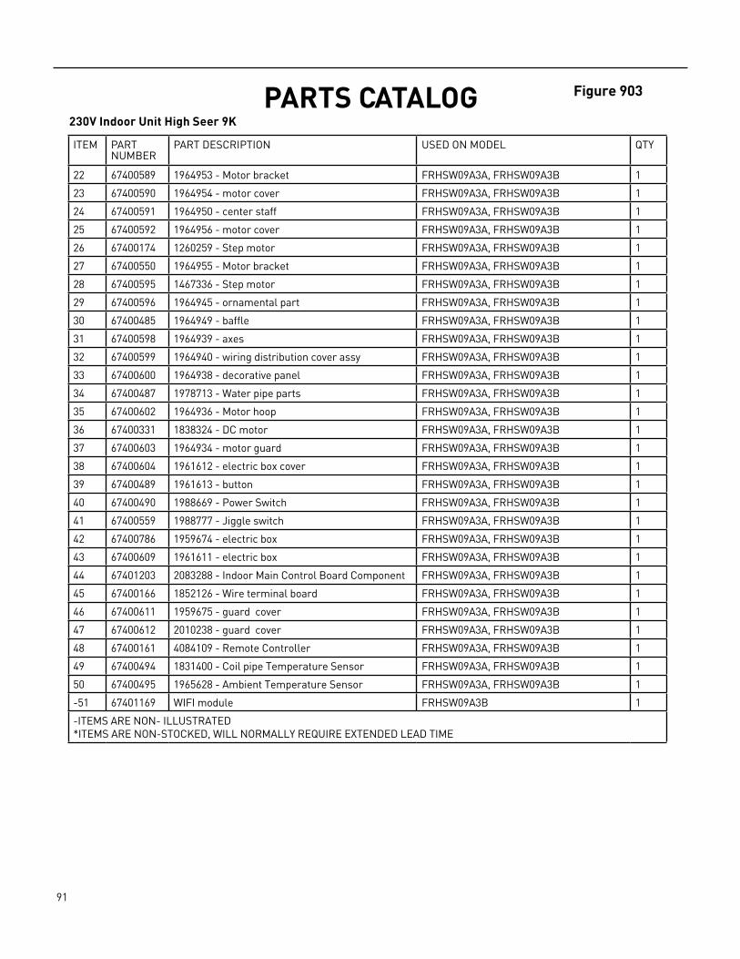
91 PB
PARTS CATALOG230V Indoor Unit High Seer 9K
Figure 903
ITEM PART NUMBER
PART DESCRIPTION USED ON MODEL QTY
22 67400589 1964953 ‑ Motor bracket FRHSW09A3A, FRHSW09A3B 1
23 67400590 1964954 ‑ motor cover FRHSW09A3A, FRHSW09A3B 1
24 67400591 1964950 ‑ center staff FRHSW09A3A, FRHSW09A3B 1
25 67400592 1964956 ‑ motor cover FRHSW09A3A, FRHSW09A3B 1
26 67400174 1260259 ‑ Step motor FRHSW09A3A, FRHSW09A3B 1
27 67400550 1964955 ‑ Motor bracket FRHSW09A3A, FRHSW09A3B 1
28 67400595 1467336 ‑ Step motor FRHSW09A3A, FRHSW09A3B 1
29 67400596 1964945 ‑ ornamental part FRHSW09A3A, FRHSW09A3B 1
30 67400485 1964949 ‑ baffle FRHSW09A3A, FRHSW09A3B 1
31 67400598 1964939 ‑ axes FRHSW09A3A, FRHSW09A3B 1
32 67400599 1964940 ‑ wiring distribution cover assy FRHSW09A3A, FRHSW09A3B 1
33 67400600 1964938 ‑ decorative panel FRHSW09A3A, FRHSW09A3B 1
34 67400487 1978713 ‑ Water pipe parts FRHSW09A3A, FRHSW09A3B 1
35 67400602 1964936 ‑ Motor hoop FRHSW09A3A, FRHSW09A3B 1
36 67400331 1838324 ‑ DC motor FRHSW09A3A, FRHSW09A3B 1
37 67400603 1964934 ‑ motor guard FRHSW09A3A, FRHSW09A3B 1
38 67400604 1961612 ‑ electric box cover FRHSW09A3A, FRHSW09A3B 1
39 67400489 1961613 ‑ button FRHSW09A3A, FRHSW09A3B 1
40 67400490 1988669 ‑ Power Switch FRHSW09A3A, FRHSW09A3B 1
41 67400559 1988777 ‑ Jiggle switch FRHSW09A3A, FRHSW09A3B 1
42 67400786 1959674 ‑ electric box FRHSW09A3A, FRHSW09A3B 1
43 67400609 1961611 ‑ electric box FRHSW09A3A, FRHSW09A3B 1
44 67401203 2083288 ‑ Indoor Main Control Board Component FRHSW09A3A, FRHSW09A3B 1
45 67400166 1852126 ‑ Wire terminal board FRHSW09A3A, FRHSW09A3B 1
46 67400611 1959675 ‑ guard cover FRHSW09A3A, FRHSW09A3B 1
47 67400612 2010238 ‑ guard cover FRHSW09A3A, FRHSW09A3B 1
48 67400161 4084109 ‑ Remote Controller FRHSW09A3A, FRHSW09A3B 1
49 67400494 1831400 ‑ Coil pipe Temperature Sensor FRHSW09A3A, FRHSW09A3B 1
50 67400495 1965628 ‑ Ambient Temperature Sensor FRHSW09A3A, FRHSW09A3B 1
‑51 67401169 WIFI module FRHSW09A3B 1
‑ITEMS ARE NON‑ ILLUSTRATED*ITEMS ARE NON‑STOCKED, WILL NORMALLY REQUIRE EXTENDED LEAD TIME

92 PB
PARTS CATALOG230V Indoor Unit High Seer12K
FIgure 904
ITEM PART NUMBER
PART DESCRIPTION USED ON MODEL QTY
1 67401204 1969822 ‑ installation plate FRHSW12A3A, FRHSW12A3B 1
2 67401205 1964337 ‑ Supporting button FRHSW12A3A, FRHSW12A3B 1
3 67401206 2008448 ‑ Refrigeration system FRHSW12A3A, FRHSW12A3B 1
4 67400231 1541622 ‑ cross‑flow fan blade FRHSW12A3A, FRHSW12A3B 1
5 67400230 1223738 ‑ bearing FRHSW12A3A, FRHSW12A3B 1
6 67400466 1964935 ‑ baffle FRHSW12A3A, FRHSW12A3B 1
7 67401207 1984618 ‑ Air Duct Assembly FRHSW12A3A, FRHSW12A3B 1
8 67401208 1961597 ‑ shell FRHSW12A3A, FRHSW12A3B 1
9 67401209 1961600 ‑ decorative panel FRHSW12A3A, FRHSW12A3B 1
10 67401210 2018966 ‑ air outlet parts FRHSW12A3A, FRHSW12A3B 1
11 67401211 1961599 ‑ air outlet FRHSW12A3A, FRHSW12A3B 1
12 67400473 1892482 ‑ axis sheath FRHSW12A3A, FRHSW12A3B 2
12
3
456
789
1011
1220151614171819
21
22
242526
272829 30
313233 34 35
363738 39
4041
4243
23 13 52
5150494847
46
44
45
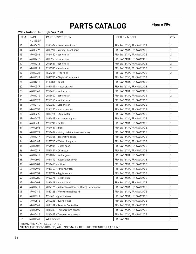
93 PB
ITEM PART NUMBER
PART DESCRIPTION USED ON MODEL QTY
13 67400474 1961606 ‑ ornamental part FRHSW12A3A, FRHSW12A3B 1
14 67400476 2015970 ‑ Vertical Level Vane FRHSW12A3A, FRHSW12A3B 1
15 67400591 1964950 ‑ center staff FRHSW12A3A, FRHSW12A3B 2
16 67401212 2015958 ‑ center staff FRHSW12A3A, FRHSW12A3B 1
17 67401213 2015959 ‑ center staff FRHSW12A3A, FRHSW12A3B 2
18 67401214 1961598 ‑ level vane FRHSW12A3A, FRHSW12A3B 2
19 67400238 1541386 ‑ Filter net FRHSW12A3A, FRHSW12A3B 2
20 67401193 1898705 ‑ Display Component FRHSW12A3A, FRHSW12A3B 1
21 67401215 4113866 ‑ panel FRHSW12A3A, FRHSW12A3B
22 67400547 1961607 ‑ Motor bracket FRHSW12A3A, FRHSW12A3B 1
23 67400548 1961610 ‑ motor cover FRHSW12A3A, FRHSW12A3B 1
24 67401216 2015960 ‑ center staff FRHSW12A3A, FRHSW12A3B 2
25 67400592 1964956 ‑ motor cover FRHSW12A3A, FRHSW12A3B 1
26 67400174 1260259 ‑ Step motor FRHSW12A3A, FRHSW12A3B 1
27 67400550 1964955 ‑ Motor bracket FRHSW12A3A, FRHSW12A3B 1
28 67400222 1819726 ‑ Step motor FRHSW12A3A, FRHSW12A3B 1
29 67400475 1961608 ‑ ornamental part FRHSW12A3A, FRHSW12A3B 1
30 67400485 1964949 ‑ baffle FRHSW12A3A, FRHSW12A3B 1
31 67400598 1964939 ‑ axes FRHSW12A3A, FRHSW12A3B 1
32 67401194 1961602 ‑ wiring distribution cover assy FRHSW12A3A, FRHSW12A3B 1
33 67401217 1961601 ‑ decorative panel FRHSW12A3A, FRHSW12A3B 1
34 67400487 1978713 ‑ Water pipe parts FRHSW12A3A, FRHSW12A3B 1
35 67400602 1964936 ‑ Motor hoop FRHSW12A3A, FRHSW12A3B 1
36 67400219 1561454 ‑ DC motor FRHSW12A3A, FRHSW12A3B 1
37 67401218 1964339 ‑ motor guard FRHSW12A3A, FRHSW12A3B 1
38 67400604 1961612 ‑ electric box cover FRHSW12A3A, FRHSW12A3B 1
39 67400489 1961613 ‑ button FRHSW12A3A, FRHSW12A3B 1
40 67400490 1988669 ‑ Power Switch FRHSW12A3A, FRHSW12A3B 1
41 67400559 1988777 ‑ Jiggle switch FRHSW12A3A, FRHSW12A3B 1
42 67400786 1959674 ‑ electric box FRHSW12A3A, FRHSW12A3B 1
43 67400609 1961611 ‑ electric box FRHSW12A3A, FRHSW12A3B 1
44 67401219 2087176 ‑ Indoor Main Control Board Component FRHSW12A3A, FRHSW12A3B 1
45 67400166 1852126 ‑ Wire terminal board FRHSW12A3A, FRHSW12A3B 1
46 67400611 1959675 ‑ guard cover FRHSW12A3A, FRHSW12A3B 1
47 67400612 2010238 ‑ guard cover FRHSW12A3A, FRHSW12A3B 1
48 67400161 4084109 ‑ Remote Controller FRHSW12A3A, FRHSW12A3B 1
49 67400494 1831400 ‑ Temperature sensor FRHSW12A3A, FRHSW12A3B 1
50 67400495 1965628 ‑ Temperature sensor FRHSW12A3A, FRHSW12A3B 1
‑51 67401169 WIFI module FRHSW12A3B 1
‑ITEMS ARE NON‑ ILLUSTRATED*ITEMS ARE NON‑STOCKED, WILL NORMALLY REQUIRE EXTENDED LEAD TIME
PARTS CATALOG230V Indoor Unit High Seer12K
FIgure 904
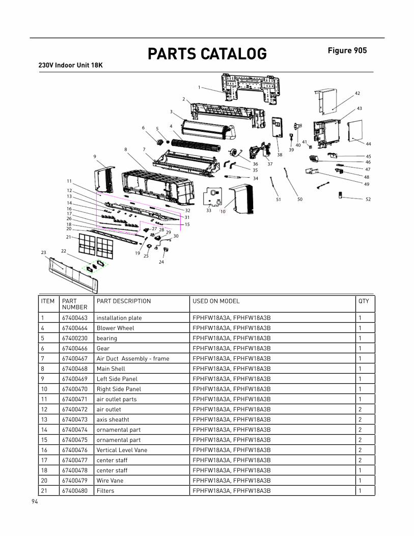
94 PB
PARTS CATALOG230V Indoor Unit 18K
Figure 905
ITEM PART NUMBER
PART DESCRIPTION USED ON MODEL QTY
1 67400463 installation plate FPHFW18A3A, FPHFW18A3B 1
4 67400464 Blower Wheel FPHFW18A3A, FPHFW18A3B 1
5 67400230 bearing FPHFW18A3A, FPHFW18A3B 1
6 67400466 Gear FPHFW18A3A, FPHFW18A3B 1
7 67400467 Air Duct Assembly ‑ frame FPHFW18A3A, FPHFW18A3B 1
8 67400468 Main Shell FPHFW18A3A, FPHFW18A3B 1
9 67400469 Left Side Panel FPHFW18A3A, FPHFW18A3B 1
10 67400470 Right Side Panel FPHFW18A3A, FPHFW18A3B 1
11 67400471 air outlet parts FPHFW18A3A, FPHFW18A3B 1
12 67400472 air outlet FPHFW18A3A, FPHFW18A3B 2
13 67400473 axis sheatht FPHFW18A3A, FPHFW18A3B 2
14 67400474 ornamental part FPHFW18A3A, FPHFW18A3B 2
15 67400475 ornamental part FPHFW18A3A, FPHFW18A3B 2
16 67400476 Vertical Level Vane FPHFW18A3A, FPHFW18A3B 2
17 67400477 center staff FPHFW18A3A, FPHFW18A3B 2
18 67400478 center staff FPHFW18A3A, FPHFW18A3B 1
20 67400479 Wire Vane FPHFW18A3A, FPHFW18A3B 1
21 67400480 Filters FPHFW18A3A, FPHFW18A3B 1
1
2
3
45 46
789
11
12131416
23 22 19 2524
27 28 2930
153132 33 10
34
3536 37
3839
4041
42
43
44
4546
47
4849
525051
20
21
172618

95 PB
PARTS CATALOG230V Indoor Unit 18K
ITEM PART NUMBER
PART DESCRIPTION USED ON MODEL QTY
22 67400481 Display kit FPHFW18A3A, FPHFW18A3B 1
23 67400482 Front Panel FPHFW18A3A, FPHFW18A3B 1
28 67400174 Stepper Motor FPHFW18A3A, FPHFW18A3B 1
30 67400222 Stepper motor harness FPHFW18A3A, FPHFW18A3B 1
31 67400485 baffle FPHFW18A3A, FPHFW18A3B 1
32 67400598 Louver Pins FPHFW18A3A, FPHFW18A3B 1
34 67400487 Drain Pipe FPHFW18A3A, FPHFW18A3B 2
36 67400488 Blower Motor FPHFW18A3A, FPHFW18A3B 1
39 67400489 ELEC Panel Switch FPHFW18A3A, FPHFW18A3B 1
40 67400490 Front Cover Switch FPHFW18A3A, FPHFW18A3B 1
44 67400491 Indoor Main Control Board FPHFW18A3A, FPHFW18A3B 1
46 67400492 Terminal Block FPHFW18A3A, FPHFW18A3B 1
49 67400611 guard cover FPHFW18A3A, FPHFW18A3B 1
50 67400494 Upper Thermistor FPHFW18A3A, FPHFW18A3B 1
51 67400495 Lower Thermistor FPHFW18A3A, FPHFW18A3B 1
52 67400496 Remote Control FPHFW18A3A, FPHFW18A3B 1
‑53 67401169 WIFI module FPHFW18A3B 1
‑ITEMS ARE NON‑ ILLUSTRATED*ITEMS ARE NON‑STOCKED, WILL NORMALLY REQUIRE EXTENDED LEAD TIME
Figure 905

96 PB
PARTS CATALOG230V Indoor Unit 24K
Figure 906
ITEM PART NUMBER
PART DESCRIPTION USED ON MODEL QTY
1 67400463 1981622 ‑ installation plate FPHFW24A3A, FPHFW24A3B 1
2 67400534 1964593 ‑ Main Air Frame FPHFW24A3A, FPHFW24A3B 1
3 67400535 2012367 ‑ EVAP COIL FPHFW24A3A, FPHFW24A3B 1
4 67400464 1541633 ‑ Blower Wheel FPHFW24A3A, FPHFW24A3B 1
5 67400230 1223738 ‑ bearing FPHFW24A3A, FPHFW24A3B 1
6 #N/A FPHFW24A3A, FPHFW24A3B 1
7 67400467 1990852 ‑ Lower Air Duct FPHFW24A3A, FPHFW24A3B 1
8 67400468 1961593 ‑ Main Shell FPHFW24A3A, FPHFW24A3B 1
9 67400469 1977016 ‑ Left Panel FPHFW24A3A, FPHFW24A3B 1
10 67400470 1977018 ‑ Right Panel FPHFW24A3A, FPHFW24A3B 1
11 67400471 2025744 ‑ Louver Kit FPHFW24A3A, FPHFW24A3B 1
*12 67400472 air outlet FPHFW24A3A, FPHFW24A3B 1
*13 67400473 axis sheath FPHFW24A3A, FPHFW24A3B 1
*14 67400474 ornamental part FPHFW24A3A, FPHFW24A3B 1
*15 67400475 ornamental part FPHFW24A3A, FPHFW24A3B 1
*16 67400476 Vertical Level Vane FPHFW24A3A, FPHFW24A3B 1
*17 67400477 center staff FPHFW24A3A, FPHFW24A3B
18 #N/A
1
2
3
45 46
789
11
12131416
23 22 19 2524
27 28 2930
153132 33 10
34
3536 37
3839
4041
42
43
44
4546
47
4849
525051
20
21
172618
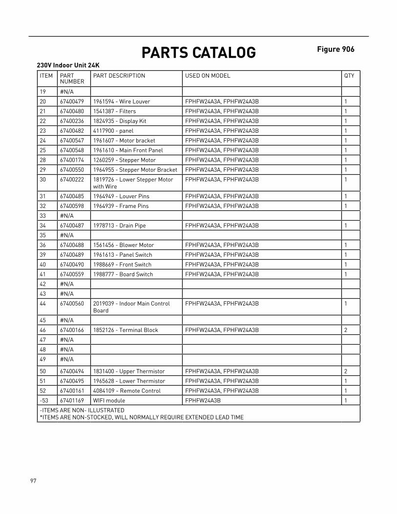
97 PB
PARTS CATALOG230V Indoor Unit 24K
ITEM PART NUMBER
PART DESCRIPTION USED ON MODEL QTY
19 #N/A
20 67400479 1961594 ‑ Wire Louver FPHFW24A3A, FPHFW24A3B 1
21 67400480 1541387 ‑ Filters FPHFW24A3A, FPHFW24A3B 1
22 67400236 1824935 ‑ Display Kit FPHFW24A3A, FPHFW24A3B 1
23 67400482 4117900 ‑ panel FPHFW24A3A, FPHFW24A3B 1
24 67400547 1961607 ‑ Motor bracket FPHFW24A3A, FPHFW24A3B 1
25 67400548 1961610 ‑ Main Front Panel FPHFW24A3A, FPHFW24A3B 1
28 67400174 1260259 ‑ Stepper Motor FPHFW24A3A, FPHFW24A3B 1
29 67400550 1964955 ‑ Stepper Motor Bracket FPHFW24A3A, FPHFW24A3B 1
30 67400222 1819726 ‑ Lower Stepper Motor with Wire
FPHFW24A3A, FPHFW24A3B 1
31 67400485 1964949 ‑ Louver Pins FPHFW24A3A, FPHFW24A3B 1
32 67400598 1964939 ‑ Frame Pins FPHFW24A3A, FPHFW24A3B 1
33 #N/A
34 67400487 1978713 ‑ Drain Pipe FPHFW24A3A, FPHFW24A3B 1
35 #N/A
36 67400488 1561456 ‑ Blower Motor FPHFW24A3A, FPHFW24A3B 1
39 67400489 1961613 ‑ Panel Switch FPHFW24A3A, FPHFW24A3B 1
40 67400490 1988669 ‑ Front Switch FPHFW24A3A, FPHFW24A3B 1
41 67400559 1988777 ‑ Board Switch FPHFW24A3A, FPHFW24A3B 1
42 #N/A
43 #N/A
44 67400560 2019039 ‑ Indoor Main Control Board
FPHFW24A3A, FPHFW24A3B 1
45 #N/A
46 67400166 1852126 ‑ Terminal Block FPHFW24A3A, FPHFW24A3B 2
47 #N/A
48 #N/A
49 #N/A
50 67400494 1831400 ‑ Upper Thermistor FPHFW24A3A, FPHFW24A3B 2
51 67400495 1965628 ‑ Lower Thermistor FPHFW24A3A, FPHFW24A3B 1
52 67400161 4084109 ‑ Remote Control FPHFW24A3A, FPHFW24A3B 1
‑53 67401169 WIFI module FPHFW24A3B 1
‑ITEMS ARE NON‑ ILLUSTRATED*ITEMS ARE NON‑STOCKED, WILL NORMALLY REQUIRE EXTENDED LEAD TIME
Figure 906
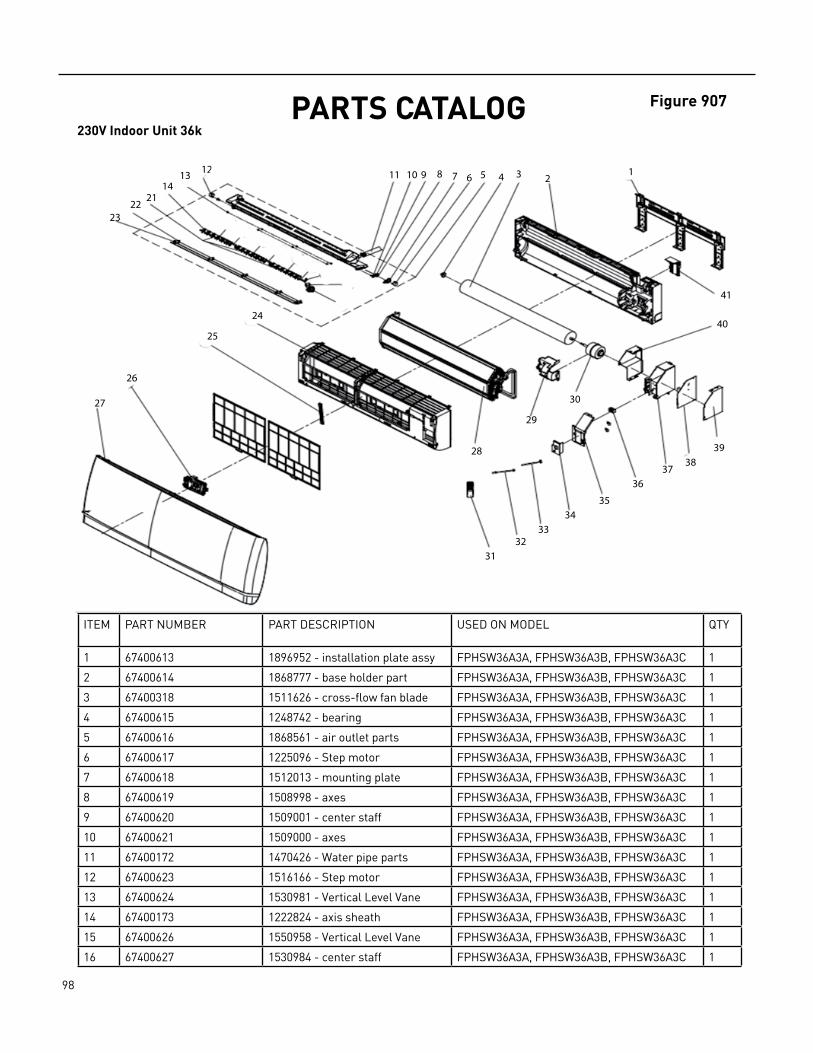
98 PB
PARTS CATALOG230V Indoor Unit 36k
Figure 907
ITEM PART NUMBER PART DESCRIPTION USED ON MODEL QTY
1 67400613 1896952 ‑ installation plate assy FPHSW36A3A, FPHSW36A3B, FPHSW36A3C 1
2 67400614 1868777 ‑ base holder part FPHSW36A3A, FPHSW36A3B, FPHSW36A3C 1
3 67400318 1511626 ‑ cross‑flow fan blade FPHSW36A3A, FPHSW36A3B, FPHSW36A3C 1
4 67400615 1248742 ‑ bearing FPHSW36A3A, FPHSW36A3B, FPHSW36A3C 1
5 67400616 1868561 ‑ air outlet parts FPHSW36A3A, FPHSW36A3B, FPHSW36A3C 1
6 67400617 1225096 ‑ Step motor FPHSW36A3A, FPHSW36A3B, FPHSW36A3C 1
7 67400618 1512013 ‑ mounting plate FPHSW36A3A, FPHSW36A3B, FPHSW36A3C 1
8 67400619 1508998 ‑ axes FPHSW36A3A, FPHSW36A3B, FPHSW36A3C 1
9 67400620 1509001 ‑ center staff FPHSW36A3A, FPHSW36A3B, FPHSW36A3C 1
10 67400621 1509000 ‑ axes FPHSW36A3A, FPHSW36A3B, FPHSW36A3C 1
11 67400172 1470426 ‑ Water pipe parts FPHSW36A3A, FPHSW36A3B, FPHSW36A3C 1
12 67400623 1516166 ‑ Step motor FPHSW36A3A, FPHSW36A3B, FPHSW36A3C 1
13 67400624 1530981 ‑ Vertical Level Vane FPHSW36A3A, FPHSW36A3B, FPHSW36A3C 1
14 67400173 1222824 ‑ axis sheath FPHSW36A3A, FPHSW36A3B, FPHSW36A3C 1
15 67400626 1550958 ‑ Vertical Level Vane FPHSW36A3A, FPHSW36A3B, FPHSW36A3C 1
16 67400627 1530984 ‑ center staff FPHSW36A3A, FPHSW36A3B, FPHSW36A3C 1
12345678910111213
1421
2223
24
25
26
27
28
29
30
3132
3334
35
3637
3839
40
41
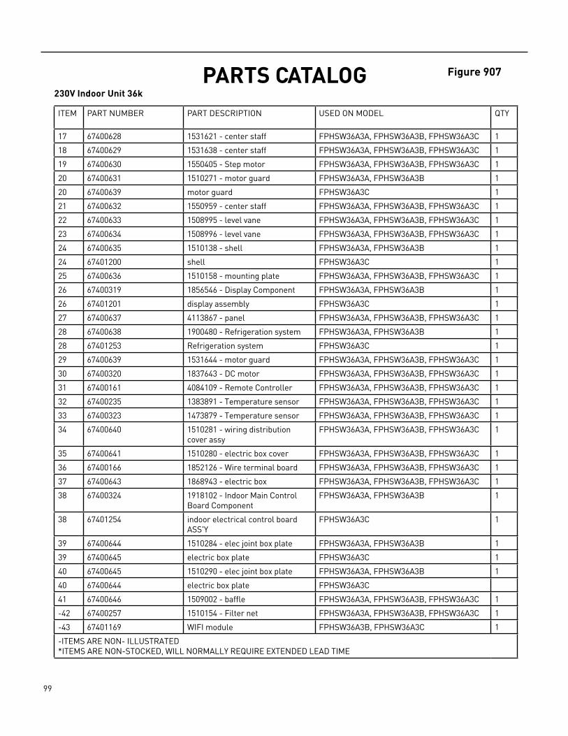
99 PB
PARTS CATALOG230V Indoor Unit 36k
ITEM PART NUMBER PART DESCRIPTION USED ON MODEL QTY
17 67400628 1531621 ‑ center staff FPHSW36A3A, FPHSW36A3B, FPHSW36A3C 1
18 67400629 1531638 ‑ center staff FPHSW36A3A, FPHSW36A3B, FPHSW36A3C 1
19 67400630 1550405 ‑ Step motor FPHSW36A3A, FPHSW36A3B, FPHSW36A3C 1
20 67400631 1510271 ‑ motor guard FPHSW36A3A, FPHSW36A3B 1
20 67400639 motor guard FPHSW36A3C 1
21 67400632 1550959 ‑ center staff FPHSW36A3A, FPHSW36A3B, FPHSW36A3C 1
22 67400633 1508995 ‑ level vane FPHSW36A3A, FPHSW36A3B, FPHSW36A3C 1
23 67400634 1508996 ‑ level vane FPHSW36A3A, FPHSW36A3B, FPHSW36A3C 1
24 67400635 1510138 ‑ shell FPHSW36A3A, FPHSW36A3B 1
24 67401200 shell FPHSW36A3C 1
25 67400636 1510158 ‑ mounting plate FPHSW36A3A, FPHSW36A3B, FPHSW36A3C 1
26 67400319 1856546 ‑ Display Component FPHSW36A3A, FPHSW36A3B 1
26 67401201 display assembly FPHSW36A3C 1
27 67400637 4113867 ‑ panel FPHSW36A3A, FPHSW36A3B, FPHSW36A3C 1
28 67400638 1900480 ‑ Refrigeration system FPHSW36A3A, FPHSW36A3B 1
28 67401253 Refrigeration system FPHSW36A3C 1
29 67400639 1531644 ‑ motor guard FPHSW36A3A, FPHSW36A3B, FPHSW36A3C 1
30 67400320 1837643 ‑ DC motor FPHSW36A3A, FPHSW36A3B, FPHSW36A3C 1
31 67400161 4084109 ‑ Remote Controller FPHSW36A3A, FPHSW36A3B, FPHSW36A3C 1
32 67400235 1383891 ‑ Temperature sensor FPHSW36A3A, FPHSW36A3B, FPHSW36A3C 1
33 67400323 1473879 ‑ Temperature sensor FPHSW36A3A, FPHSW36A3B, FPHSW36A3C 1
34 67400640 1510281 ‑ wiring distribution cover assy
FPHSW36A3A, FPHSW36A3B, FPHSW36A3C 1
35 67400641 1510280 ‑ electric box cover FPHSW36A3A, FPHSW36A3B, FPHSW36A3C 1
36 67400166 1852126 ‑ Wire terminal board FPHSW36A3A, FPHSW36A3B, FPHSW36A3C 1
37 67400643 1868943 ‑ electric box FPHSW36A3A, FPHSW36A3B, FPHSW36A3C 1
38 67400324 1918102 ‑ Indoor Main Control Board Component
FPHSW36A3A, FPHSW36A3B 1
38 67401254 indoor electrical control board ASS'Y
FPHSW36A3C 1
39 67400644 1510284 ‑ elec joint box plate FPHSW36A3A, FPHSW36A3B 1
39 67400645 electric box plate FPHSW36A3C 1
40 67400645 1510290 ‑ elec joint box plate FPHSW36A3A, FPHSW36A3B 1
40 67400644 electric box plate FPHSW36A3C
41 67400646 1509002 ‑ baffle FPHSW36A3A, FPHSW36A3B, FPHSW36A3C 1
‑42 67400257 1510154 ‑ Filter net FPHSW36A3A, FPHSW36A3B, FPHSW36A3C 1
‑43 67401169 WIFI module FPHSW36A3B, FPHSW36A3C 1
‑ITEMS ARE NON‑ ILLUSTRATED*ITEMS ARE NON‑STOCKED, WILL NORMALLY REQUIRE EXTENDED LEAD TIME
Figure 907
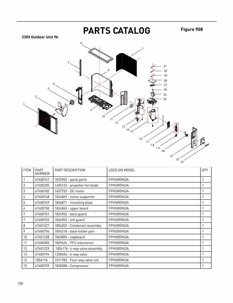
100 PB
PARTS CATALOG230V Outdoor Unit 9k
ITEM PART NUMBER
PART DESCRIPTION USED ON MODEL QTY
1 67400747 1832902 ‑ panel parts FPHSR09A3A 1
2 67400335 1405123 ‑ propeller fan blade FPHSR09A3A 1
3 67400182 1457759 ‑ DC motor FPHSR09A3A 1
4 67400748 1824869 ‑ motor supporter FPHSR09A3A 1
5 67400749 1824871 ‑ mounting plate FPHSR09A3A 1
6 67400750 1824865 ‑ upper board FPHSR09A3A 1
7 67400751 1824902 ‑ back guard FPHSR09A3A 1
7 67400752 1824903 ‑ left guard FPHSR09A3A 1
8 67401227 1854202 ‑ Condenser assembly FPHSR09A3A 1
9 67400754 1854218 ‑ base holder part FPHSR09A3A 1
10 67401228 1843005 ‑ clapboard FPHSR09A3A 1
11 67400283 1829624 ‑ PFC inductance FPHSR09A3A 1
12 67401229 1854176‑ 4‑way valve assembly FPHSR09A3A 1
13 67400194 1258654 ‑ 4‑way valve FPHSR09A3A 1
14 1854176 1511783 ‑ Four‑way valve coil FPHSR09A3A 1
15 67400759 1838380 ‑ Compressor FPHSR09A3A 1
Figure 908
1
2
3
4
5
6
7
8
9
1011
1213
1415
1617
1 81 9
20
2122
23
24
25
26
27
28
29
30
31
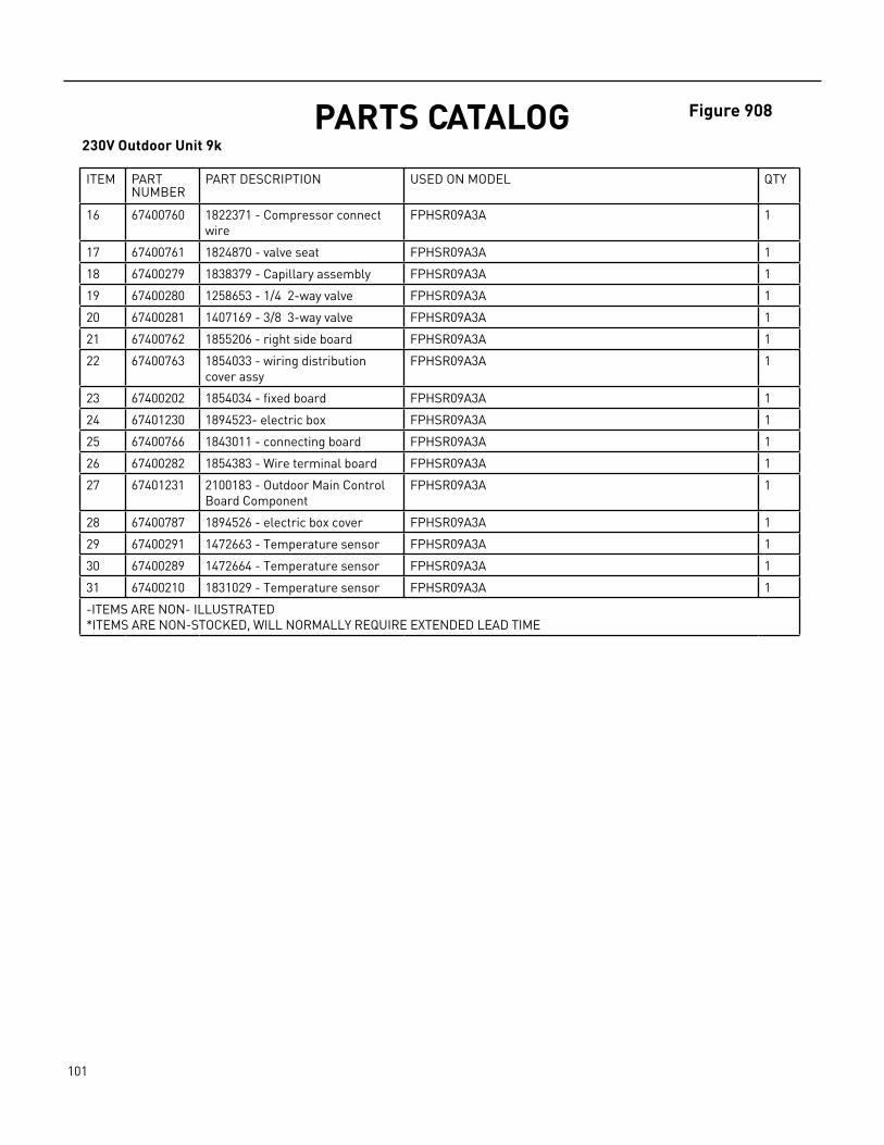
101 PB
PARTS CATALOG230V Outdoor Unit 9k
Figure 908
ITEM PART NUMBER
PART DESCRIPTION USED ON MODEL QTY
16 67400760 1822371 ‑ Compressor connect wire
FPHSR09A3A 1
17 67400761 1824870 ‑ valve seat FPHSR09A3A 1
18 67400279 1838379 ‑ Capillary assembly FPHSR09A3A 1
19 67400280 1258653 ‑ 1/4 2‑way valve FPHSR09A3A 1
20 67400281 1407169 ‑ 3/8 3‑way valve FPHSR09A3A 1
21 67400762 1855206 ‑ right side board FPHSR09A3A 1
22 67400763 1854033 ‑ wiring distribution cover assy
FPHSR09A3A 1
23 67400202 1854034 ‑ fixed board FPHSR09A3A 1
24 67401230 1894523‑ electric box FPHSR09A3A 1
25 67400766 1843011 ‑ connecting board FPHSR09A3A 1
26 67400282 1854383 ‑ Wire terminal board FPHSR09A3A 1
27 67401231 2100183 ‑ Outdoor Main Control Board Component
FPHSR09A3A 1
28 67400787 1894526 ‑ electric box cover FPHSR09A3A 1
29 67400291 1472663 ‑ Temperature sensor FPHSR09A3A 1
30 67400289 1472664 ‑ Temperature sensor FPHSR09A3A 1
31 67400210 1831029 ‑ Temperature sensor FPHSR09A3A 1
‑ITEMS ARE NON‑ ILLUSTRATED*ITEMS ARE NON‑STOCKED, WILL NORMALLY REQUIRE EXTENDED LEAD TIME

102 PB
PARTS CATALOG230V Outdoor Unit 12k
ITEM PART NUMBER
PART DESCRIPTION USED ON MODEL QTY
1 67400180 1847919 ‑ panel parts FPHSR12A3A 1
2 67400181 1556766 ‑ propeller fan blade FPHSR12A3A 1
3 67400182 1457759 ‑ DC motor FPHSR12A3A 1
4 67400183 1849292 ‑ motor supporter assy FPHSR12A3A 1
5 67400184 1846086 ‑ mounting plate FPHSR12A3A 1
6 67400185 1846082 ‑ upper board FPHSR12A3A 1
7 67400187 1854579 ‑ back guard FPHSR12A3A 1
7 67400186 1854580 ‑ back guard FPHSR12A3A 1
8 67400188 1909061 ‑ Condenser assembly FPHSR12A3A 1
9 67400189 1851356 ‑ base holder part FPHSR12A3A 1
10 67400776 2008778 ‑ clapboard part FPHSR12A3A 1
11 67400283 1829624 ‑ PFC inductance FPHSR12A3A 1
12 67400777 2007913 ‑ 4‑way reversing valve assembly
FPHSR12A3A 1
13 67400193 1511783 ‑ Four‑way valve coil FPHSR12A3A 1
14 67400194 1258654 ‑ 4‑way valve FPHSR12A3A 1
15 67400779 1821191 ‑ Compressor FPHSR12A3A 1
16 67400760 1822371 ‑ Compressor connect wire
FPHSR12A3A 1
Figure 909
1
2
3
4
5
6
78
910
1112
1314
15
16
1718
1920
2122
23
24
25
26
27
28
29
30
31

103 PB
PARTS CATALOG230V Outdoor Unit 12k
Figure 909
ITEM PART NUMBER
PART DESCRIPTION USED ON MODEL QTY
17 67400271 1854557 ‑ Capillary assembly FPHSR12A3A 1
18 67400272 1844583 ‑ 1/4 2‑way valve FPHSR12A3A 1
19 67400199 1335015 ‑ 3/8 3‑way valve FPHSR12A3A 1
20 67400200 1846084 ‑ right side board FPHSR12A3A 1
21 67400201 1854040 ‑ wiring distribution cover assy
FPHSR12A3A 1
22 67400202 1854034 ‑ fixed board FPHSR12A3A 1
23 67400784 1937153 ‑ connecting board FPHSR12A3A 1
24 67400785 1852125 ‑ Wire terminal board FPHSR12A3A 1
25 67400781 1951957 ‑ electric box FPHSR12A3A 1
26 67400294 1985663 ‑ Outdoor Main Control Board Component
FPHSR12A3A 1
27 67400787 1894526 ‑ electric box cover FPHSR12A3A 1
28 67400291 1472663 ‑ Temperature sensor FPHSR12A3A 1
29 67400301 1511780 ‑ Temperature sensor FPHSR12A3A 1
30 67400210 1831029 ‑ Temperature sensor FPHSR12A3A 1
31 67400211 1546721 ‑ sensor mounting plate FPHSR12A3A 1
‑32 67400789 2008361 ‑ Tube type electric heater
FPHSR12A3A 1
‑ITEMS ARE NON‑ ILLUSTRATED*ITEMS ARE NON‑STOCKED, WILL NORMALLY REQUIRE EXTENDED LEAD TIME
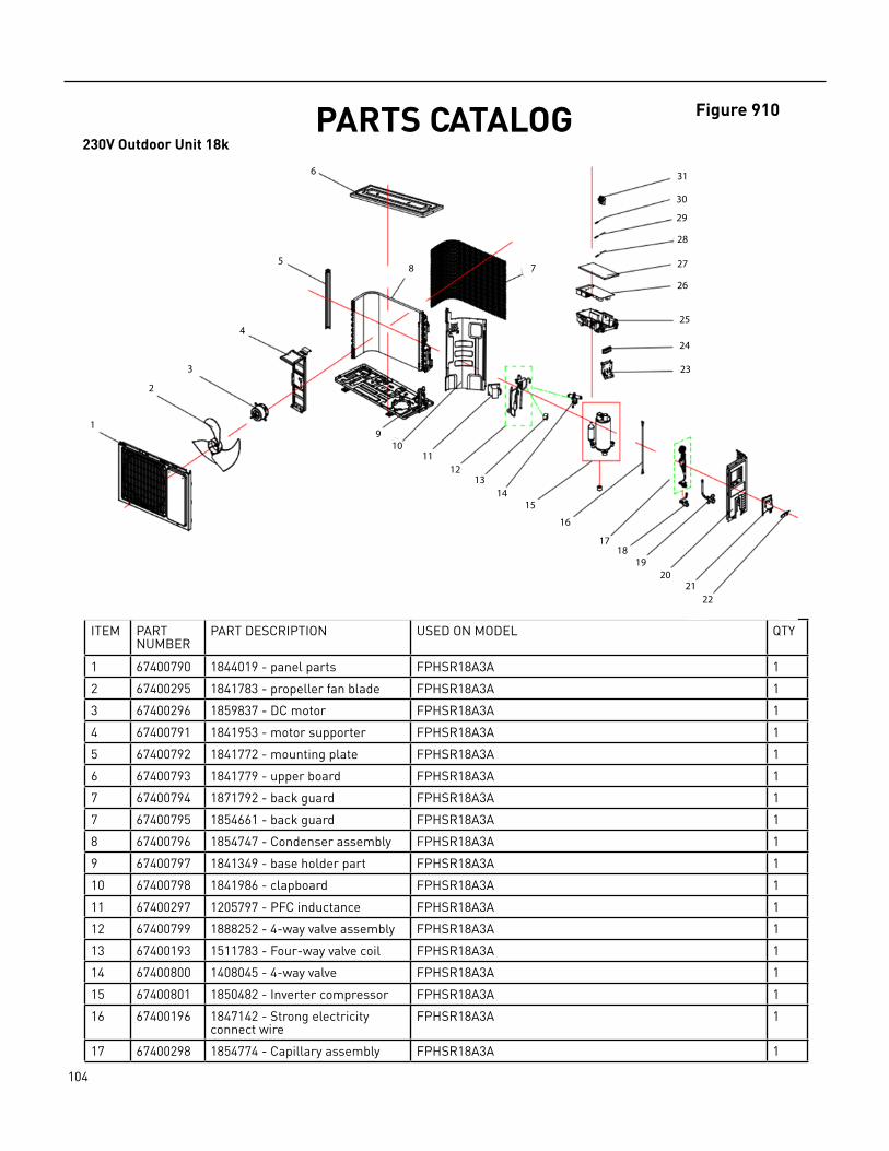
104 PB
PARTS CATALOG230V Outdoor Unit 18k
ITEM PART NUMBER
PART DESCRIPTION USED ON MODEL QTY
1 67400790 1844019 ‑ panel parts FPHSR18A3A 1
2 67400295 1841783 ‑ propeller fan blade FPHSR18A3A 1
3 67400296 1859837 ‑ DC motor FPHSR18A3A 1
4 67400791 1841953 ‑ motor supporter FPHSR18A3A 1
5 67400792 1841772 ‑ mounting plate FPHSR18A3A 1
6 67400793 1841779 ‑ upper board FPHSR18A3A 1
7 67400794 1871792 ‑ back guard FPHSR18A3A 1
7 67400795 1854661 ‑ back guard FPHSR18A3A 1
8 67400796 1854747 ‑ Condenser assembly FPHSR18A3A 1
9 67400797 1841349 ‑ base holder part FPHSR18A3A 1
10 67400798 1841986 ‑ clapboard FPHSR18A3A 1
11 67400297 1205797 ‑ PFC inductance FPHSR18A3A 1
12 67400799 1888252 ‑ 4‑way valve assembly FPHSR18A3A 1
13 67400193 1511783 ‑ Four‑way valve coil FPHSR18A3A 1
14 67400800 1408045 ‑ 4‑way valve FPHSR18A3A 1
15 67400801 1850482 ‑ Inverter compressor FPHSR18A3A 1
16 67400196 1847142 ‑ Strong electricity connect wire
FPHSR18A3A 1
17 67400298 1854774 ‑ Capillary assembly FPHSR18A3A 1
Figure 910
1
2
3
4
5
6
78
910
1112
1314
15
16
1718
1920
2122
23
24
25
26
27
28
29
30
31

105 PB
PARTS CATALOG230V Outdoor Unit 18k
Figure 910
ITEM PART NUMBER
PART DESCRIPTION USED ON MODEL QTY
18 67400272 1844583 ‑ 1/4 2‑way valve FPHSR18A3A 1
19 67400299 1844499 ‑ 1/2 3‑way valve FPHSR18A3A 1
20 67400803 1841776 ‑ right side board FPHSR18A3A 1
21 67400201 1854040 ‑ wiring distribution cover assy
FPHSR18A3A 1
22 67400202 1854034 ‑ fixed board FPHSR18A3A 1
23 67400203 1842392 ‑ connecting board FPHSR18A3A 1
24 67400204 1852124 ‑ Wire terminal board FPHSR18A3A 1
25 67400205 1841985 ‑ electric box FPHSR18A3A 1
26 67400300 1854367 ‑ Controller Component FPHSR18A3A 1
27 67400207 1546706 ‑ electric box cover FPHSR18A3A 1
28 67400301 1511780 ‑ Temperature sensor FPHSR18A3A 1
29 67400302 1511782 ‑ Temperature sensor FPHSR18A3A 1
30 67400210 1831029 ‑ Temperature sensor FPHSR18A3A 1
31 67400809 1982183 ‑ sensor mounting plate FPHSR18A3A 1
‑ITEMS ARE NON‑ ILLUSTRATED*ITEMS ARE NON‑STOCKED, WILL NORMALLY REQUIRE EXTENDED LEAD TIME

106 PB
PARTS CATALOG230V Outdoor Unit 24k
ITEM PART NUMBER
PART DESCRIPTION USED ON MODEL QTY
1 67400810 1542623 ‑ panel parts FPHSR24A3A 1
2 67400307 1542217 ‑ propeller fan blade FPHSR24A3A 1
3 67400303 1561964 ‑ DC motor FPHSR24A3A 1
4 67400811 1561919 ‑ motor supporter FPHSR24A3A 1
5 #N/A FPHSR24A3A 1
6 67400813 1878885 ‑ top plate part FPHSR24A3A 1
7 67400814 1819106 ‑ back guard FPHSR24A3A 1
8 67400815 1854549 ‑ Condenser assembly FPHSR24A3A 1
9 67400816 1814292 ‑ base holder part FPHSR24A3A 1
10 67400817 1534867 ‑ valve seat FPHSR24A3A 1
11 67400297 1205797 ‑ PFC inductance FPHSR24A3A 1
12 67400818 2017922 ‑ 4‑way reversing valve assembly
FPHSR24A3A 1
13 67400819 1830018 ‑ Compressor FPHSR24A3A 1
14 67400196 1847142 ‑ Strong electricity connect wire
FPHSR24A3A 1
15 67400304 1867906 ‑ Electronic expansion valve assembly
FPHSR24A3A 1
16 67400310 1536052 ‑ 3/8 2‑way valve FPHSR24A3A 1
17 67400305 1456114 ‑ 5/8 3‑way valve FPHSR24A3A 1
Figure 911
1
2
3
4
5
6
78
910
1112
1314
15
16
1718
1920
2122
23
24
25
26
27
28
29
30
31

107 PB
Figure 911PARTS CATALOG230V Outdoor Unit 24k
ITEM PART NUMBER
PART DESCRIPTION USED ON MODEL QTY
18 67400821 1542621 ‑ right side board part FPHSR24A3A 1
19 67400306 2006156 ‑ Controller Component FPHSR24A3A 1
20 67400204 1852124 ‑ Wire terminal board FPHSR24A3A 1
21 67400208 1822633 ‑ Temperature sensor FPHSR24A3A 1
22 67400209 1822634 ‑ Temperature sensor FPHSR24A3A 1
23 67400288 1852304 ‑ Temperature sensor FPHSR24A3A 1
‑ITEMS ARE NON‑ ILLUSTRATED*ITEMS ARE NON‑STOCKED, WILL NORMALLY REQUIRE EXTENDED LEAD TIME
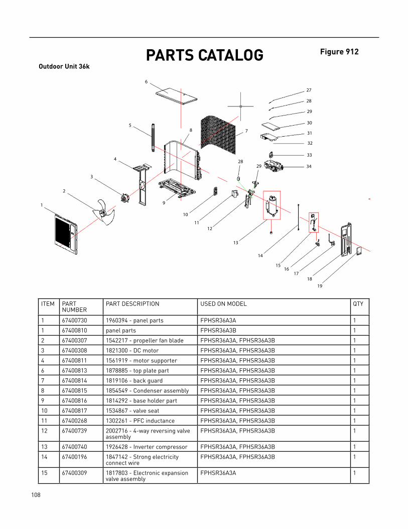
108 PB
PARTS CATALOGOutdoor Unit 36k
ITEM PART NUMBER
PART DESCRIPTION USED ON MODEL QTY
1 67400730 1960394 ‑ panel parts FPHSR36A3A 1
1 67400810 panel parts FPHSR36A3B 1
2 67400307 1542217 ‑ propeller fan blade FPHSR36A3A, FPHSR36A3B 1
3 67400308 1821300 ‑ DC motor FPHSR36A3A, FPHSR36A3B 1
4 67400811 1561919 ‑ motor supporter FPHSR36A3A, FPHSR36A3B 1
6 67400813 1878885 ‑ top plate part FPHSR36A3A, FPHSR36A3B 1
7 67400814 1819106 ‑ back guard FPHSR36A3A, FPHSR36A3B 1
8 67400815 1854549 ‑ Condenser assembly FPHSR36A3A, FPHSR36A3B 1
9 67400816 1814292 ‑ base holder part FPHSR36A3A, FPHSR36A3B 1
10 67400817 1534867 ‑ valve seat FPHSR36A3A, FPHSR36A3B 1
11 67400268 1302261 ‑ PFC inductance FPHSR36A3A, FPHSR36A3B 1
12 67400739 2002716 ‑ 4‑way reversing valve assembly
FPHSR36A3A, FPHSR36A3B 1
13 67400740 1926428 ‑ Inverter compressor FPHSR36A3A, FPHSR36A3B 1
14 67400196 1847142 ‑ Strong electricity connect wire
FPHSR36A3A, FPHSR36A3B 1
15 67400309 1817803 ‑ Electronic expansion valve assembly
FPHSR36A3A 1
Figure 912
1
2
3
4
5
6
78
9
10
1112
13
14
1516
1718
19
27
28
29
30
31
32
33
3428
29

109 PB
Figure 912
ITEM PART NUMBER
PART DESCRIPTION USED ON MODEL QTY
15 67401251 Electronic expansion valve assembly
FPHSR36A3B 1
16 67400310 1536052 ‑ 3/8 2‑way valve FPHSR36A3A, FPHSR36A3B 1
17 67400311 1856169 ‑ 3/4 3‑way valve FPHSR36A3A 1
17 67400305 5/8 3‑way valve FPHSR36A3B 1
18 67400742 1866429 ‑ right side board part FPHSR36A3A, FPHSR36A3B 1
19 67400743 1865713 ‑ wiring distribution cover assy
FPHSR36A3A, FPHSR36A3B 1
20 67400744 1986886 ‑ electric box FPHSR36A3A, FPHSR36A3B 1
21 67400292 1846888 ‑ connecting board FPHSR36A3A, FPHSR36A3B 1
22 67400204 1852124 ‑ Wire terminal board FPHSR36A3A, FPHSR36A3B 1
23 67400286 2002924 ‑ Controller Component FPHSR36A3A 1
23 67401252 Controller Component FPHSR36A3B 1
24 67400746 1986887 ‑ electric box cover FPHSR36A3A, FPHSR36A3B 1
25 67400208 1822633 ‑ Temperature sensor FPHSR36A3A, FPHSR36A3B 1
26 67400209 1822634 ‑ Temperature sensor FPHSR36A3A, FPHSR36A3B 1
27 67400288 1852304 ‑ Temperature sensor FPHSR36A3A, FPHSR36A3B 1
28 67400193 1511783 ‑ Four‑way valve coil FPHSR36A3A, 1
‑29 67400457 4‑way valve FPHSR36A3B 1
‑ITEMS ARE NON‑ ILLUSTRATED*ITEMS ARE NON‑STOCKED, WILL NORMALLY REQUIRE EXTENDED LEAD TIME
PARTS CATALOGOutdoor Unit 36k
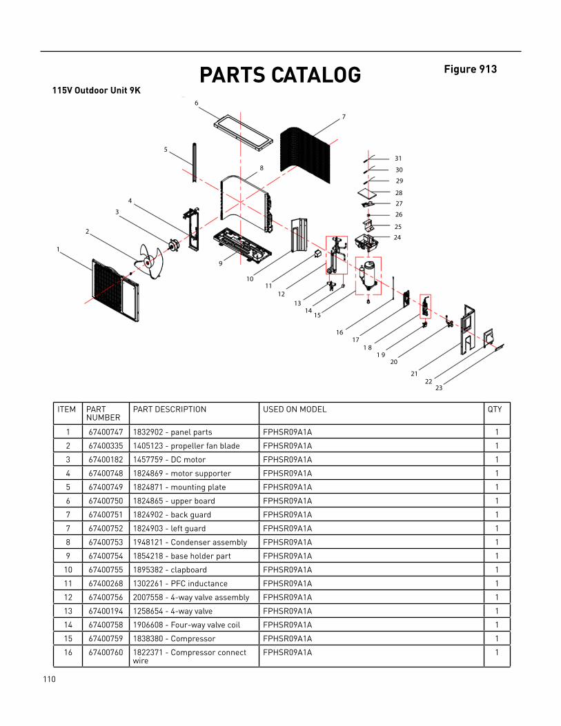
110 PB
PARTS CATALOG115V Outdoor Unit 9K
ITEM PART NUMBER
PART DESCRIPTION USED ON MODEL QTY
1 67400747 1832902 ‑ panel parts FPHSR09A1A 1
2 67400335 1405123 ‑ propeller fan blade FPHSR09A1A 1
3 67400182 1457759 ‑ DC motor FPHSR09A1A 1
4 67400748 1824869 ‑ motor supporter FPHSR09A1A 1
5 67400749 1824871 ‑ mounting plate FPHSR09A1A 1
6 67400750 1824865 ‑ upper board FPHSR09A1A 1
7 67400751 1824902 ‑ back guard FPHSR09A1A 1
7 67400752 1824903 ‑ left guard FPHSR09A1A 1
8 67400753 1948121 ‑ Condenser assembly FPHSR09A1A 1
9 67400754 1854218 ‑ base holder part FPHSR09A1A 1
10 67400755 1895382 ‑ clapboard FPHSR09A1A 1
11 67400268 1302261 ‑ PFC inductance FPHSR09A1A 1
12 67400756 2007558 ‑ 4‑way valve assembly FPHSR09A1A 1
13 67400194 1258654 ‑ 4‑way valve FPHSR09A1A 1
14 67400758 1906608 ‑ Four‑way valve coil FPHSR09A1A 1
15 67400759 1838380 ‑ Compressor FPHSR09A1A 1
16 67400760 1822371 ‑ Compressor connect wire
FPHSR09A1A 1
Figure 913
1
2
3
4
5
6
7
8
9
1011
1213
1415
1617
1 81 9
20
2122
23
24
25
26
27
28
29
30
31

111 PB
Figure 913PARTS CATALOG115V Outdoor Unit 9K
ITEM PART NUMBER
PART DESCRIPTION USED ON MODEL QTY
17 67400761 1824870 ‑ valve seat FPHSR09A1A 1
18 67400279 1838379 ‑ Capillary assembly FPHSR09A1A 1
19 67400280 1258653 ‑ 1/4 2‑way valve FPHSR09A1A 1
20 67400281 1407169 ‑ 3/8 3‑way valve FPHSR09A1A 1
21 67400762 1855206 ‑ right side board FPHSR09A1A 1
22 67400763 1854033 ‑ wiring distribution cover assy
FPHSR09A1A 1
23 67400202 1854034 ‑ fixed board FPHSR09A1A 1
24 67400765 1916000 ‑ electric box FPHSR09A1A 1
25 67400766 1843011 ‑ connecting board FPHSR09A1A 1
26 67400275 1912060 ‑ Wire terminal board FPHSR09A1A 1
27 67401226 2099703 ‑ Outdoor Main Control Board Component
FPHSR09A1A 1
28 67400767 1916001 ‑ electric box cover FPHSR09A1A 1
29 67400277 1822632 ‑ Temperature sensor FPHSR09A1A 1
30 67400209 1822634 ‑ Temperature sensor FPHSR09A1A 1
31 67400210 1831029 ‑ Temperature sensor FPHSR09A1A 1
‑ITEMS ARE NON‑ ILLUSTRATED*ITEMS ARE NON‑STOCKED, WILL NORMALLY REQUIRE EXTENDED LEAD TIME
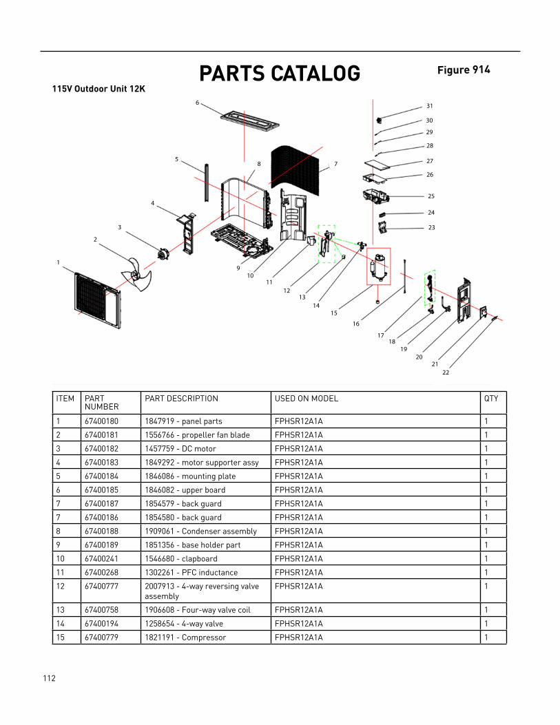
112 PB
PARTS CATALOG115V Outdoor Unit 12K
ITEM PART NUMBER
PART DESCRIPTION USED ON MODEL QTY
1 67400180 1847919 ‑ panel parts FPHSR12A1A 1
2 67400181 1556766 ‑ propeller fan blade FPHSR12A1A 1
3 67400182 1457759 ‑ DC motor FPHSR12A1A 1
4 67400183 1849292 ‑ motor supporter assy FPHSR12A1A 1
5 67400184 1846086 ‑ mounting plate FPHSR12A1A 1
6 67400185 1846082 ‑ upper board FPHSR12A1A 1
7 67400187 1854579 ‑ back guard FPHSR12A1A 1
7 67400186 1854580 ‑ back guard FPHSR12A1A 1
8 67400188 1909061 ‑ Condenser assembly FPHSR12A1A 1
9 67400189 1851356 ‑ base holder part FPHSR12A1A 1
10 67400241 1546680 ‑ clapboard FPHSR12A1A 1
11 67400268 1302261 ‑ PFC inductance FPHSR12A1A 1
12 67400777 2007913 ‑ 4‑way reversing valve assembly
FPHSR12A1A 1
13 67400758 1906608 ‑ Four‑way valve coil FPHSR12A1A 1
14 67400194 1258654 ‑ 4‑way valve FPHSR12A1A 1
15 67400779 1821191 ‑ Compressor FPHSR12A1A 1
Figure 914
1
2
3
4
5
6
78
910
1112
1314
15
16
1718
1920
2122
23
24
25
26
27
28
29
30
31
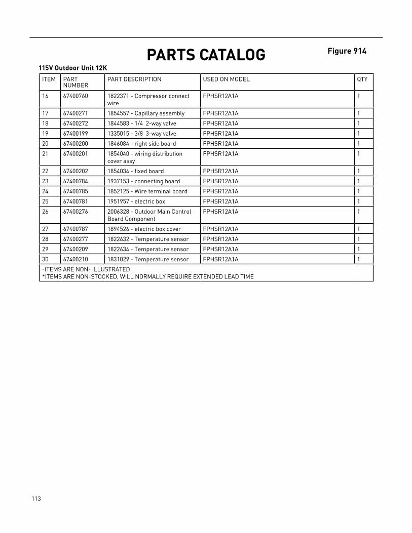
113 PB
PARTS CATALOG115V Outdoor Unit 12K
ITEM PART NUMBER
PART DESCRIPTION USED ON MODEL QTY
16 67400760 1822371 ‑ Compressor connect wire
FPHSR12A1A 1
17 67400271 1854557 ‑ Capillary assembly FPHSR12A1A 1
18 67400272 1844583 ‑ 1/4 2‑way valve FPHSR12A1A 1
19 67400199 1335015 ‑ 3/8 3‑way valve FPHSR12A1A 1
20 67400200 1846084 ‑ right side board FPHSR12A1A 1
21 67400201 1854040 ‑ wiring distribution cover assy
FPHSR12A1A 1
22 67400202 1854034 ‑ fixed board FPHSR12A1A 1
23 67400784 1937153 ‑ connecting board FPHSR12A1A 1
24 67400785 1852125 ‑ Wire terminal board FPHSR12A1A 1
25 67400781 1951957 ‑ electric box FPHSR12A1A 1
26 67400276 2006328 ‑ Outdoor Main Control Board Component
FPHSR12A1A 1
27 67400787 1894526 ‑ electric box cover FPHSR12A1A 1
28 67400277 1822632 ‑ Temperature sensor FPHSR12A1A 1
29 67400209 1822634 ‑ Temperature sensor FPHSR12A1A 1
30 67400210 1831029 ‑ Temperature sensor FPHSR12A1A 1
‑ITEMS ARE NON‑ ILLUSTRATED*ITEMS ARE NON‑STOCKED, WILL NORMALLY REQUIRE EXTENDED LEAD TIME
Figure 914

114 PB
ITEM PART NUMBER
PART DESCRIPTION USED ON MODEL QTY
1 67400180 1847919 PANEL PARTS FRHSR09A3A 1
2 67400181 1556766 PROPELLER FAN BLADE
FRHSR09A3A 1
3 67400182 1457759 FAN MOTOR FRHSR09A3A 1
4 67400183 1849292 MOTOR SUPPORTER ASSY
FRHSR09A3A 1
5 67400184 1846086 MOUNTING PLATE FRHSR09A3A 1
6 67400185 1846082 UPPER BOARD FRHSR09A3A 1
7 67400186 1854580 BACK GUARD FRHSR09A3A 1
‑7a 67400187 1854579 BACK GUARD FRHSR09A3A 1
8 67400188 1909061 CONDENSER ASSEMBLY FRHSR09A3A 1
9 67400189 1851356 BASE HOLDER PART FRHSR09A3A 1
10 67400190 1847982 CLAPBOARD FRHSR09A3A 1
11 67400283 1829624 PFC INDUCTANCE FRHSR09A3A 1
12 67400192 1907925 4‑WAY VALVE ASSEMBLY
FRHSR09A3A 1
13 67400193 1511783 FOUR‑WAY VALVE COIL FRHSR09A3A 1
14 67400194 1258654 FOUR‑WAY VALVE FRHSR09A3A 1
PARTS CATALOG230v Outdoor Unit 9K HIGH SEER
Figure 915
1
2
3
4
5
6
78
910
1112
1314
15
16
1718
1920
2122
23
24
25
26
27
28
29
30
31
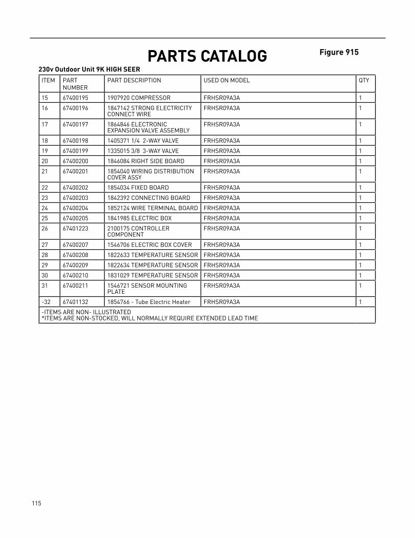
115 PB
Figure 915PARTS CATALOG230v Outdoor Unit 9K HIGH SEER
ITEM PART NUMBER
PART DESCRIPTION USED ON MODEL QTY
15 67400195 1907920 COMPRESSOR FRHSR09A3A 1
16 67400196 1847142 STRONG ELECTRICITY CONNECT WIRE
FRHSR09A3A 1
17 67400197 1864846 ELECTRONIC EXPANSION VALVE ASSEMBLY
FRHSR09A3A 1
18 67400198 1405371 1/4 2‑WAY VALVE FRHSR09A3A 1
19 67400199 1335015 3/8 3‑WAY VALVE FRHSR09A3A 1
20 67400200 1846084 RIGHT SIDE BOARD FRHSR09A3A 1
21 67400201 1854040 WIRING DISTRIBUTION COVER ASSY
FRHSR09A3A 1
22 67400202 1854034 FIXED BOARD FRHSR09A3A 1
23 67400203 1842392 CONNECTING BOARD FRHSR09A3A 1
24 67400204 1852124 WIRE TERMINAL BOARD FRHSR09A3A 1
25 67400205 1841985 ELECTRIC BOX FRHSR09A3A 1
26 67401223 2100175 CONTROLLER COMPONENT
FRHSR09A3A 1
27 67400207 1546706 ELECTRIC BOX COVER FRHSR09A3A 1
28 67400208 1822633 TEMPERATURE SENSOR FRHSR09A3A 1
29 67400209 1822634 TEMPERATURE SENSOR FRHSR09A3A 1
30 67400210 1831029 TEMPERATURE SENSOR FRHSR09A3A 1
31 67400211 1546721 SENSOR MOUNTING PLATE
FRHSR09A3A 1
‑32 67401132 1854766 ‑ Tube Electric Heater FRHSR09A3A 1
‑ITEMS ARE NON‑ ILLUSTRATED*ITEMS ARE NON‑STOCKED, WILL NORMALLY REQUIRE EXTENDED LEAD TIME
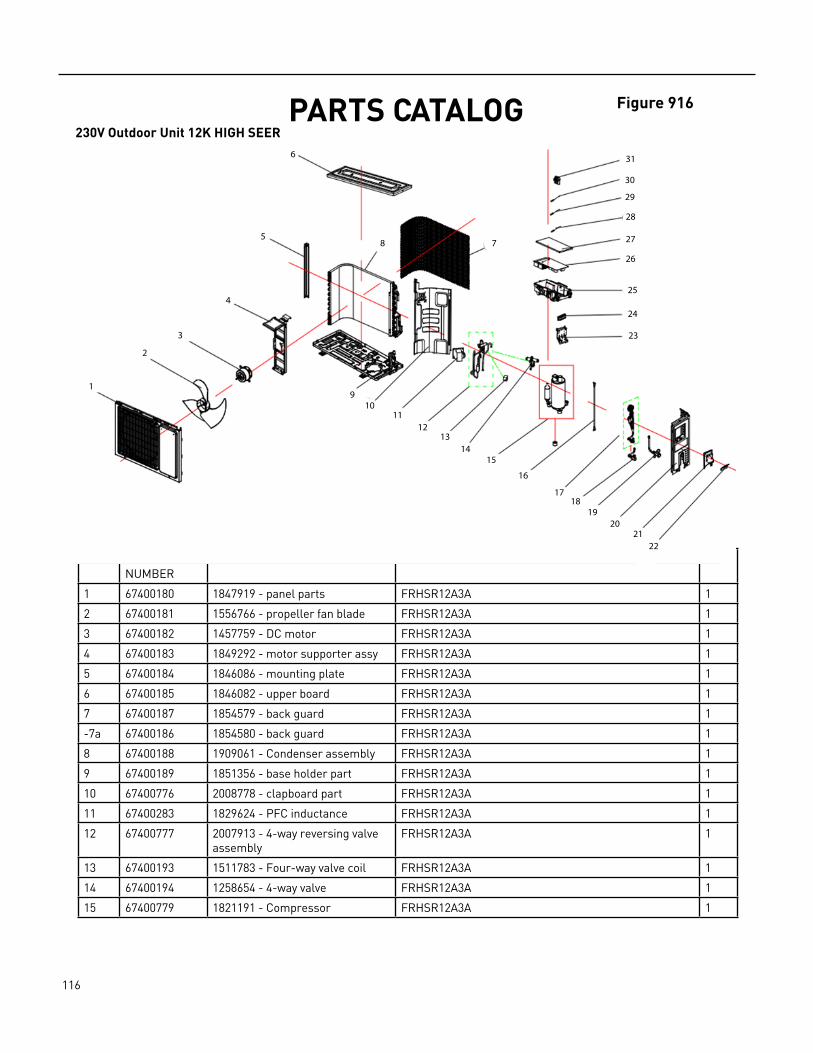
116 PB
PARTS CATALOG230V Outdoor Unit 12K HIGH SEER
ITEM PART NUMBER
PART DESCRIPTION USED ON MODEL QTY
1 67400180 1847919 ‑ panel parts FRHSR12A3A 1
2 67400181 1556766 ‑ propeller fan blade FRHSR12A3A 1
3 67400182 1457759 ‑ DC motor FRHSR12A3A 1
4 67400183 1849292 ‑ motor supporter assy FRHSR12A3A 1
5 67400184 1846086 ‑ mounting plate FRHSR12A3A 1
6 67400185 1846082 ‑ upper board FRHSR12A3A 1
7 67400187 1854579 ‑ back guard FRHSR12A3A 1
‑7a 67400186 1854580 ‑ back guard FRHSR12A3A 1
8 67400188 1909061 ‑ Condenser assembly FRHSR12A3A 1
9 67400189 1851356 ‑ base holder part FRHSR12A3A 1
10 67400776 2008778 ‑ clapboard part FRHSR12A3A 1
11 67400283 1829624 ‑ PFC inductance FRHSR12A3A 1
12 67400777 2007913 ‑ 4‑way reversing valve assembly
FRHSR12A3A 1
13 67400193 1511783 ‑ Four‑way valve coil FRHSR12A3A 1
14 67400194 1258654 ‑ 4‑way valve FRHSR12A3A 1
15 67400779 1821191 ‑ Compressor FRHSR12A3A 1
Figure 916
1
2
3
4
5
6
78
910
1112
1314
15
16
1718
1920
2122
23
24
25
26
27
28
29
30
31
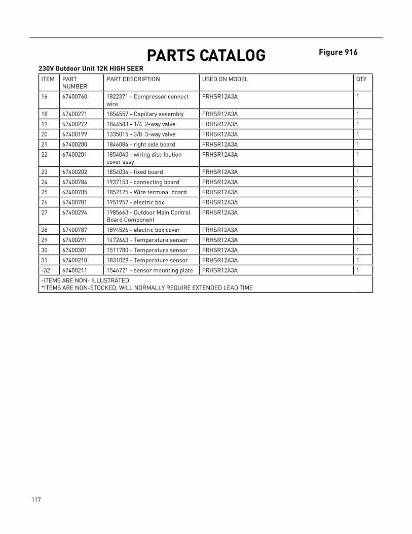
117 PB
Figure 916PARTS CATALOG230V Outdoor Unit 12K HIGH SEER
ITEM PART NUMBER
PART DESCRIPTION USED ON MODEL QTY
16 67400760 1822371 ‑ Compressor connect wire
FRHSR12A3A 1
18 67400271 1854557 ‑ Capillary assembly FRHSR12A3A 1
19 67400272 1844583 ‑ 1/4 2‑way valve FRHSR12A3A 1
20 67400199 1335015 ‑ 3/8 3‑way valve FRHSR12A3A 1
21 67400200 1846084 ‑ right side board FRHSR12A3A 1
22 67400201 1854040 ‑ wiring distribution cover assy
FRHSR12A3A 1
23 67400202 1854034 ‑ fixed board FRHSR12A3A 1
24 67400784 1937153 ‑ connecting board FRHSR12A3A 1
25 67400785 1852125 ‑ Wire terminal board FRHSR12A3A 1
26 67400781 1951957 ‑ electric box FRHSR12A3A 1
27 67400294 1985663 ‑ Outdoor Main Control Board Component
FRHSR12A3A 1
28 67400787 1894526 ‑ electric box cover FRHSR12A3A 1
29 67400291 1472663 ‑ Temperature sensor FRHSR12A3A 1
30 67400301 1511780 ‑ Temperature sensor FRHSR12A3A 1
31 67400210 1831029 ‑ Temperature sensor FRHSR12A3A 1
‑32 67400211 1546721 ‑ sensor mounting plate FRHSR12A3A 1
‑ITEMS ARE NON‑ ILLUSTRATED*ITEMS ARE NON‑STOCKED, WILL NORMALLY REQUIRE EXTENDED LEAD TIME
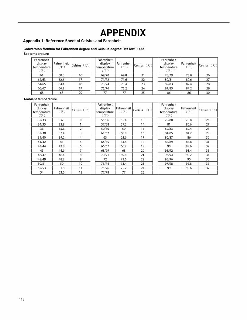
118 PB
APPENDIXAppendix 1: Reference Sheet of Celsius and Farenheit
.
temperaturedisplay
Fahrenheit Fahrenheit Celsius temperature
display Fahrenheit
Fahrenheit Celsius display temperature
Fahrenheit Fahrenheit
32/33
Celsius
32 0 55/56 55.4 13 79/80 78.8 2634/35 33.8 1 57/58 57.2 14 81 80.6 27
36 35.6 2 59/60 59 15 82/83 82.4 2837/38 37.4 3 61/62 60.8 16 84/85 84.2 2939/40 39.2 4 63 62.6 17 86/87 86 3041/42 41 5 64/65 64.4 18 88/89 87.8 3143/44 42.8 6 66/67 66.2 19 90 89.6 32
45 44.6 7 68/69 68 20 91/92 91.4 3346/47 46.4 8 70/71 69.8 21 93/94 93.2 3448/49 48.2 9 72 71.6 22 95/96 95 3550/51 50 10 73/74 73.4 23 97/98 96.8 3652/53 51.8 11 75/76 75.2 24 99 98.6 37
54 53.6 12 77/78 77 25
temperature
Fahrenheit display Fahrenheit Celsius display
Fahrenheit
temperatureFahrenheit Celsius display
Fahrenheit
temperatureFahrenheit
61
Celsius
60.8 16 69/70 69.8 21 78/79 78.8 2662/63 62.6 17 71/72 71.6 22 80/81 80.6 2764/65 64.4 18 73/74 73.4 23 82/83 82.4 2866/67 66.2 19 75/76 75.2 24 84/85 84.2 29
68 68 20 77 77 25 86 86 30

119 PB
APPENDIXAppendix 2: Pipe Expanding Method
F:Inspection
Improper expanding
The length is equalsurface
leaning damaged
� Check the quality of expanding port. If there is any blemish, expand theport again according to the steps above.
crack uneventhickness
Smooth surface
Downwards
Pipe
Shaper
Union pipe
Pipe
Expander
Hardmold
Pipe
Pipe
Pipe cutter
Leaning Uneven Burr
B:Remove the burrs
C:Put on suitable insulating pipe
� Confirm the pipe length according to the distance of indoor unit and outdoor unit.� Cut the required pipe with pipe cutter.
D:Put on the union nut
� Remove the burrs with shaper and prevent the burrs from getting into the pipe.
A:Cut the pip
E:Expand the port
� Remove the union nut on the indoor connection pipe and outdoor valve; install
the union nut on the pipe.
Outer diameter(inch)A(inch)
Max MinФ1/4
� Expand the port with expander.
� "A" is di�erent according to the diameter, please refer to the sheet below:
2/39 1/36Ф3/8 1/16 1/51Ф1/2 1/14 1/51Ф5/8 5/53 2/23

120 PB
Friedrich Air Conditioning Company10001 Reunion Place, Suite 500
San Antonio, TX 788.531.5‑541‑6645
www.friedrich.com
FLOATING AIR DUCTLESS SPLIT SYSTEMS
LIMITED WARRANTY1. A) FIVE YEAR WARRANTY ‑ FRIEDRICH AIR CONDITIONING CO. (FRIEDRICH) warrants to the original end‑user of this product that should it prove defective due to improper workmanship and/or material under normal use for a period of five years from the date of installation, FRIEDRICH will repair or replace, at its option, any defective part without charge for the part. Replacement parts are warranted for the remainder of the original warranty period.B) THIS WARRANTY DOES NOT INCLUDE LABOR or other cost incurred for servicing, repairing, removing, installing, shipping, or handling of either defective or replacement parts, or complete unit. Such cost may be covered by a separate warranty provided by the installing contractor. C) Seven YEAR COMPRESSOR WARRANTY‑ During the seven year warranty period from the date of installation, should the compressor prove defective due to improper workmanship and/or material, FRIEDRICH will furnish a replacement compressor, at no charge, which is warranted for the remainder of the original warranty period. LABOR IS NOT INCLUDED FOR INSTALLING REPLACEMENT COMPRESSOR. These warranties apply only while the unit remains at the original site and only to units installed inside the continental United States, Alaska, Hawaii, Puerto Rico, Mexico and Canada. The warranty applies only if the unit is installed and operated in accordance with the printed instructions and in compliance with applicable local installation and building codes and good trade practices. For international warranty information, contact the Friedrich Air Conditioning Company ‑ International Division. D) NOTICE: To obtain service and/or warranty parts replacement, you must notify an authorized FRIEDRICH Air Conditioning Co. distributor, dealer, or contractor of any defect within the applicable warranty period.2. Any defective part to be replaced must be made available to FRIEDRICH in exchange for the replacement part. You must present proof of the original date of installation of the product in order to establish the effective date of the warranty. Otherwise, the effective date will be deemed to be the date of manufacture plus thirty days. The return of the owner registration card is not a condition of warranty coverage. However, please detach and return it so that we can contact you should a question of safety arise which could affect you.3. TO OBTAIN WARRANTY SERVICE, please contact your authorized FRIEDRICH distributor, dealer, or the contractor who installed the equipment. If your dealer or contractor needs assistance, the authorized FRIEDRICH distributor is available for consultation, and FRIEDRICH supports the efforts of the distributor.4. This limited warranty applies only to units remaining at the site of the original installation (except for mobile home installations) and only to units installed within the continental United States, Alaska, Hawaii, and Canada. This limited warranty applies only if the unit is installed and operated in accordance with FRIEDRICH instructions and in compliance with applicable local installation and building codes and good trade practices.5. THIS WARRANTY DOES NOT COVER damages caused by: (a) accident, abuse, negligence, or misuse; (b) operating the product in a corrosive atmosphere containing chlorine, fluorine or any other damaging chemicals; (c) modification, alteration, poor service practices; (d) improper matching or application of the product or components; (e) failure to provide proper maintenance and service to the product according to manufacture’s instructions; (f) installation or operating of the product in a manner contrary to the instructions of the manufacturer; (g) lightning, fluctuations in electrical power or other Acts of God. This LIMITED WARRANTY also excludes all cost of installation, disconnection or dismantling the product, parts used in connection with normal maintenance such as air filters or belts and owner‑required maintenance. Consult the instructions enclosed with the product for information regarding recommended maintenance.6. No one is authorized to change this LIMITED WARRANTY in any respect, or to create any other obligation or liability in connection with this product.7. YOUR ONLY REMEDIES ARE PROVIDED IN THIS LIMITED WARRANTY. ANY EXPRESS WARRANTY NOT PROVIDED HEREIN, AND ANY REMEDY WHICH, BUT FOR THIS PROVISION, MIGHT ARISE BY IMPLICATION OR OPERATION OF LAW, IS HEREBY EXCLUDED AND DISCLAIMED. THE IMPLIED WARRANTIES OF MERCHANTABILITY AND OF FITNESS FOR ANY PARTICULAR PURPOSE ARE EXPRESSLY LIMITED TO A TERM OF ONE YEAR FROM THE DATE OF ORIGINAL INSTALLATION. UNDER NO CIRCUMSTANCES SHALL FRIEDRICH BE LIABLE TO THE OWNER OR ANY OTHER PERSON FOR ANY INCIDENTAL, SPECIAL OR CONSEQUENTIAL DAMAGES IN CONNECTION WITH THIS PRODUCT, WHETHER ARISING OUT OF BREACH OF WARRANTY, BREACH OF CONTRACT OR OTHERWISE.8. Some states do not allow limitations on how long an implied warranty lasts and/or do not allow the exclusion or limitation of incidental, special or consequential damages, so the above limitations or exclusions may not apply to you.9. This warranty gives you specific legal rights, and you may have other rights which vary from state to state and province to province.

121 PB
Friedrich Air Conditioning Co.10001 Reunion Place, Suite 500 • San Antonio, Texas 782161-877-599-5665www.friedrich.com
TECHNICAL SUPPORT CONTACT INFORMATION
CUSTOMER SATISFACTION and QUALITY ASSURANCEFriedrich is a conscientious manufacturer, concerned about customer satisfaction, product quality, and controlling warranty costs. As an Authorized Service Provider you play a vital role in these areas. By adhering to the policies and procedures you provide us with vital information on each warranty repair you complete. This information is used to identify product failure trends, initiate corrective action, and improve product quality, thereby further reducing warranty expenses while increasing customer satisfaction levels.
FRIEDRICH AUTHORIZED PARTS DEPOTSAAA Refrigeration Service 1322 24th Street, Suite B Kenner, Louisiana 70062 504‑464‑7444 877‑813‑7444
Alamo Service Company 1450 North Flores Street San Antonio, Texas 78281210‑227‑2450 315‑328‑2450
The Gabbert Company 6868 Ardmore Houston, Texas 77054713‑747‑4110 315‑458‑4110
Johnstone Supply of Woodside27‑01 Brooklyn Queens Expway Woodside, New York 11377718‑545‑5464 315‑431‑1143
Reeve Air Conditioning, Inc. 2501 South Park Road Hallandale, Florida 33009954‑962‑0252 315‑962‑1333