2014 PRL Xu Infinite SHPo -OA - eScholarship
21
UCLA UCLA Previously Published Works Title Infinite lifetime of underwater superhydrophobic states Permalink https://escholarship.org/uc/item/8hm781p6 Journal Physical Review Letters, 113(3) ISSN 0031-9007 Authors Xu, M Sun, G Kim, CJ Publication Date 2014-09-25 DOI 10.1103/PhysRevLett.113.136103 Supplemental Material https://escholarship.org/uc/item/8hm781p6#supplemental Peer reviewed eScholarship.org Powered by the California Digital Library University of California
-
Upload
khangminh22 -
Category
Documents
-
view
5 -
download
0
Transcript of 2014 PRL Xu Infinite SHPo -OA - eScholarship

UCLAUCLA Previously Published Works
TitleInfinite lifetime of underwater superhydrophobic states
Permalinkhttps://escholarship.org/uc/item/8hm781p6
JournalPhysical Review Letters, 113(3)
ISSN0031-9007
AuthorsXu, MSun, GKim, CJ
Publication Date2014-09-25
DOI10.1103/PhysRevLett.113.136103
Supplemental Materialhttps://escholarship.org/uc/item/8hm781p6#supplemental Peer reviewed
eScholarship.org Powered by the California Digital LibraryUniversity of California

1
Manuscript for Physical Review Letters, Vol. 113, Issue 13, Sept. 2014, 136103(5). (doi: 10.1103/PhysRevLett.113.136103);
Infinite Lifetime of Underwater Superhydrophobic State
Muchen Xu, Guangyi Sun, and Chang-Jin “CJ” Kim*
Mechanical and Aerospace Engineering Department
University of California at Los Angeles (UCLA), Los Angeles, CA 90095, USA
Abstract
Submerged superhydrophobic (SHPo) surfaces are well known to transition from the dewetted to
wetted state over time. Here, a theoretical model is applied to describe the depletion of trapped
air in a simple trench and re-arranged to prescribe the conditions for infinite lifetime. By
fabricating a microscale trench in a transparent hydrophobic material, we directly observe the air
depletion process and verify the model. The study leads to the demonstration of infinite lifetime
(> 50 days) of air pockets on engineered microstructured surfaces under water for the first time.
Environmental fluctuations are identified as the main factor behind the lack of a long-term
underwater SHPo state to date.
The stability of the air layer on superhydrophobic (SHPo [1]) surfaces fully submerged in water
is of critical importance because their key anticipated applications, such as drag reduction [2-5]
and anti-biofouling [6], are under water. Unfortunately, the air film on the underwater SHPo
surface, often called a plastron, is fragile [2,7]. Over time, the air initially trapped on the SHPo
surface diffuses away into the surrounding water, collapsing the air-water interface and causing a
transition from the dewetted to wetted state [8]. Recent experimental studies showed that the
lifetime of the underwater SHPo state is influenced by various environmental parameters [7,9-
11]. However, most of the studies only reported statistical information, such as average wetting
time; more direct knowledge such as air-depletion dynamics or the effect of roughness
geometries is needed to design the SHPo surface to be more robust against wetting. While some
underwater insects boast a long-term or even indefinite (tested up to 120 days [12]) plastron, all
artificial SHPo surfaces retained their plastron for much shorter length of time (mostly less than

2
an hour; rarely for days [7,9,13-15]). To date, no artificial SHPo surface has been demonstrated
to retain an air layer indefinitely unless assisted [16].
This paper aims to understand the air depletion process on submerged SHPo surfaces and to
determine if an indefinite plastron is achievable. In order to systematically study the effect of
geometric parameters of the surface structures for an intended goal, SHPo surfaces made of
regular structures would be far more informative than those of random structures that produce
only statistical data. Furthermore, for drag-reduction application in particular, SHPo surfaces
with parallel trenches [3,4,17,18] have been found to outperform those with random structures
[19,20], making SHPo surfaces with trenches a good candidate to study. Since multiple trenches
are in parallel and isolated from each other, a single trench can represent the whole SHPo surface
as far as the stability of the trapped air is concerned. The potential over-estimation of the
depletion speed on single trench compared with the parallel trenches due to the edge effect
[21,22] is considered minor to our goal. Importantly for our purpose instead, a sample with
single trench would allow clear images of one air-water meniscus; in comparison, multiple
menisci in multiple trenches would overlap and blur the images. The transparent sample with a
single trench was fabricated by hot embossing Teflon® FEP into a deep-reactive-ion-etch
(DRIE)-processed silicon mold by improving the process from [23], as described in
Supplemental Material (SM). The whole Teflon® FEP sample is semi-clear and intrinsically
hydrophobic with advancing contact angle ~115o [24]. Figure 1(a) shows scanning electron
microscopy (SEM) images of the single-trench sample. The sidewall of the trench has
nanometer-scale roughness, as it was replicated from the “scalloped” surface [25] on the DRIE
silicon mold.

3
FIG. 1. The sample and testing setup. (a) SEM images of a single-trench sample with the microscale trench characterized by length l, width w, and depth h. (b) Schematic illustration of the experimental setup to visualize the air-water meniscus inside the trench throughout the depletion process. One sample was immersed in water of heightH in a clear tube and observed from the side, as indicated by the arrow A in (a).
Let us first analyze how the trapped air is depleted from a hydrophobic trench after being
submerged based on previous works [15,26,27]. Consider a simple trench with width w, length l,
and depth h, as defined in Fig. 1(a), and the radius of curvature of the air-water interface R, as
defined in Fig. 1(b). Since the trench length is much larger (~10 times) than its width, the
meniscus was straight along the length of the trench in the middle section over a significant
period of time before reaching the bottom, as shown in Fig. 2(a), supporting the 2D diffusion
model as a crude but useful approximation. According to Henry`s law, the partial pressure of a
gas equilibrated in water is: Hp k c= , where kH is Henry`s constant and c is the dissolved gas
concentration in water. Right after submerging the sample from atmosphere (patm) to immersion
depth H at hydrostatic pressure pH, the air in the trench is compressed to ptr,0 and the meniscus
forms the radius of curvature R0, as detailed in SM. If tr,0 Hp k c> , air in the trench will start to
diffuse out through the meniscus. The volume rate of dissolution (i.e., the dissolution rate) of the
trapped air into the water is limited by the diffusion of dissolved air in the water, which is related
to the temporal and spatial evolvement of concentration field by Fick`s law approximated [27] as:
( ) ( )[ ( ) ]p tr H
dV t k A t p t k cdt
= − − (1)

4
where V is the air volume, kp is the mass transfer coefficient of air across the air-water interface,
ptr is the air pressure in the trench, and A is the meniscus area or Eq. (S4). The influence of
meniscus curvature on kp was discussed in SM based on diffusion-limited drop evaporation
theory [28]. To estimate the value of kp, diffusion length was eventually applied for simplicity
[15] as explained in SM. Combining Eq. (1) with the Laplace equation across the meniscus
patm + pH − ptr =σ / R , where σ is the air-water interfacial tension, we get:
( ) ( )[ ]( )p H atm H
dV t k A t p p k cdt R t
σ= − − + − (2)
Here, we consider only depinning impalement (not sagging [29,30]) because the trench is much
deeper than it is wide. The wetting process goes through two stages: (i) Stage I involves the
contact line pinned to the top edge of the trench, and (ii) Stage II involves the contact line sliding
on the sidewall of the trench. For the pinned stage of Stage I, R can be numerically calculated
with initial condition R0 and boundary condition Rc, as detailed in SM. Since the depinning
occurs when the angle of the meniscus on the sidewall reaches the advancing contact angle advθ
[29], / 2cosc advR w θ= . For the sliding stage of Stage II, since constantcR R= = for the simple
trench, the meniscus slides down the vertical sidewall at constant speed (u d V / A) / dt= , which
can also be obtained from Eq. (2). The meniscus movement was estimated from video recordings,
such as Video S1, assuming a smooth sidewall. The scallops on the sidewalls were too small (~
500 nm apart) to appear in the optical images (e.g., Fig. 2(a)) used for the measurement. If
diffusion rate dV(t) / dt can decrease to zero during the pinned stage (Stage I), the meniscus will
reach a stable state and the air loss will cease. However, once the meniscus depins and proceeds
to the sliding stage (Stage II), the meniscus curvature and pressure ptr will not change further.
Defined as the maximum immersion depth beyond which the air-water meniscus has no stable
state, the critical immersion depth Hc is the depth where air diffusion rate decreases to zero at the
end of Stage I. By substituting dV(t) / dt = 0 and / 2cosc advR R w θ= = into Eq. (2), we obtain:
2 cos adv H atmc
k c PHw g g
σ θρ ρ
−= + (3)
where ρ is the density of water and g is the gravitational acceleration. Note that H atmk c p− is
the difference between the pressures of the dissolved air at the immersion depth and the

5
atmospheric air just above the water. If the dissolved air is in full equilibrium with the
atmosphere so that 0H atmk c p− = , Eq. (3) reduces to the well-known relation below [31]:
2 cos advcH w g
σ θρ
= (4)
Assuming equilibrium, Eq. (4) simply states that the critical immersion depth is when the
hydrostatic pressure at the depth equals the Laplace pressure sustainable by the interface at the
trench. In contrast, Eq. (3) further specifies how the critical immersion depth is affected when the
condition diverges from the equilibrium. Because the environmental parameters (e.g.,
temperature, atmospheric pressure) keep changing in reality, the dissolved air at the immersion
depth is always in the process of equilibrating through diffusion, so 0H atmk c p− ≠ in reality.
The above analysis is based on a single component gas but still applies to multiple component
gases (e.g., air), because partial volumes and partial pressures can be added up in Eq. (1).

6
FIG. 2. Observed air depletion and trench wetting. (a) Air-water meniscus visualized by the setup shown in Fig. 1(b) with the viewing direction A shown in Fig. 1(a). Images from top to bottom show the meniscus starting to bend, depinning, sliding down, touching the trench bottom

7
and fully wetting the trench. Shown on the right are the corresponding cross-sectional schematics with viewing direction B. For a complete movie, see Video S1. (b) Experimental and theoretical data of the meniscus position over time reveal two distinctive stability conditions, determined by the immersion depth H. The meniscus position is defined as the distance from the top edge of the trench to the lowest position of meniscus. Experimental data were obtained from continuous microscopy images of the air-water meniscus, as shown in Fig. 2(a), using samples with w = 147 µm, h = 85 µm, and l = 1 mm. Uncertainty of the position measurement (~ 3 µm) is shown in the figure. Calculated for the same trench geometry and immersion depth, the solid line fit the data best with kp = 2.5×10⁻¹² cm/(sec•Pa), while the dotted lines show the influence of kp with 2×10-12 m/(sec•Pa) and 3×10-12 m/(sec•Pa), respectively. The dot-dash line denotes the maximum deflection of the meniscus while the meniscus remained pinned at the top edge.
In order to elucidate the dynamic process of air depletion and trench wetting, a setup was
developed to directly visualize the meniscus, as schematically illustrated in Fig. 1(b). Unlike the
confocal microscopy based [7,15,29] studies, a cool LED (NuGreen Flexible Neck LED Desk
Lamp, Newer Technology) was used as the light source to allow long-term observation without
heating. As shown in Fig. 2(a), curved across the width of the trench, the meniscus appears as a
dark strip, whose upper border is the two contact lines on the two sidewalls and whose lower
border is the lowest position between the two sidewalls. When the sample was just immersed in
water, the meniscus was almost flat and pinned at the top edges of the trench, as shown in the
image at t = 0 hr. At t = 0.5 hr, the meniscus bent down as some of the trapped air diffused out,
but the meniscus was still pinned to the top edges. As more air diffused out, the meniscus
continued to bend down until finally depinning from the top edges and moving down the
sidewall, as shown in the image at t = 4 hr. When the meniscus touched the bottom of the trench,
the meniscus split into two and spread rapidly towards the ends to satisfy the local contact angle
(~120°) on the bottom surface, turning the contact line along the trench length convex and in
compensation making the contact line along the trench width concave. The spreading slowed
down as the spreading menisci started to compress the air trapped at the corners, as suggested by
the curvature change of the contact line. The trapped air continued to diffuse into the water and
disappeared eventually, as shown in Video S1 in SM. In this study, we define the “lifetime” of
the trapped air in the trench as the time between the moment of immersion and the moment of
the meniscus touching the trench bottom. However, this definition should not be considered
universal. For SHPo drag reduction, as an example, the time to the meniscus depinning, after
which the designed reduction is compromised, may define the lifetime better.

8
In Fig. 2(b), the meniscus movement shown in Fig. 2(a) was quantified for a sample immersed at
two different depths. For small immersion depth (i.e., H = 50 mm), the meniscus bent down and
stayed relatively stable, remaining in Stage I for many hours. However, for large immersion
depth (i.e., H = 165 mm), the meniscus bent down, depinned, moved down, and touched the
bottom. The meniscus position decreased faster at the beginning during Stage I but slowed down
to a constant speed (i.e., linear trend) during Stage II. The lines are drawn from Eq. (2) with
0H atmk c P− = , which are consistent with [27], using R0 and kp derived and using advθ measured
in SM. In addition to helping us define the lifetime, the results in Fig. 2 confirm the theoretical
model based on two stages of wetting and suggest the existence of stable menisci, i.e., infinite
lifetime.
If only lifetime data of the air pocket are needed without the depletion dynamics above, the setup
can be simplified by placing the sample sideways and observing the trench from above its
opening with a low magnification camera, as schematically illustrated in Fig. S2 in SM. Three
exemplary images captured from a video clip are shown in Fig. 3(a). The total reflection of the
light from behind the sample made the meniscus in the trench appear darker to the camera,
compared with the rest of the sample. These observations were confirmed consistent with the
detailed dynamics of Fig. 2, validating the simplified setup, which allowed us to monitor
multiples samples simultaneously and continuously in a controlled environment, as detailed in
SM.

9
FIG. 3. Observed lifetime of trapped air. (a) Air-water meniscus seen from above the sample with low-magnification camera. The meniscus appears black. The black strip at t = 0 hr, the broken strip at t = 8.5 hr, and the disappearance of the strip at t = 16 hr indicate the beginning, touching bottom, and full wetting, respectively, corroborating the observation in Fig. 2(a). (b) Lifetime of trapped air as a function of immersion depth with trench width of 147 µm ( ), 96 µm ( ), and 46 µm ( ) as the parameter. The measurement errors of immersion depth (i.e., ± 2.5 mm due to evaporation, as explained in SM) and lifetime (i.e., the interval between snapshots) are too small to appear in the given scales. The symbols with an arrow indicate at least 1200 hours, considered infinite in this study. Each of the three colored shades indicates the uncertainty range of critical depth Hc for a given trench width. (c) Critical immersion depth Hc as a function of trench width w. The experimental results are from the uncertainty ranges (i.e., the colored shades) in (b). The solid line is the theoretical prediction of Eq. (4) with 130o as the advancing contact angle measured on the trench sidewall (obtained in SM).
Figure 3(b) shows the lifetime of the trapped air of multiple samples tested at varying immersion
depths. All samples (10 mm x 5 mm x 0.5 mm Teflon® FEP piece) have one trench with the
same length (l = 1 mm) and depth (h ~ 85 µm) but three different widths. For all three trench
widths the lifetime increased as the immersion depth decreased, which is consistent with Eq. (3)

10
and previous experimental results [7,13,15]. However, when the immersion depth was smaller
than a certain value, the trench retained the air pocket for a very long time. We declared the
lifetime “infinite” after 1200 hours (50 days) and terminated the recording, but some tests were
left to continue with no sign of wetting. For each trench width, the critical immersion depth Hc
should be between the last data (i.e., the smallest depth) among those that became wet and the
first data (i.e., largest depth) that showed an indefinite lifetime, indicating the uncertainty of
measuring instability data. As shown in Fig. 3(c), the experimentally obtained ranges of Hc
matched the theoretical reciprocal curve based on Eq. (4). As expected, trenches with a smaller
width can be submerged deeper without losing the air pocket. Since the environmental
fluctuation cannot be completely eliminated, the experimental data are slightly smaller (i.e.,
shallower) than the theoretically predicted depth in Fig. 3(c).
To the best of our knowledge, this is the first experimental verification of infinite lifetime of
entrapped gas on microstructured surfaces fully submerged in water. Compared with previous
tests, we note several aspects critical to our success. (1) The surface should be tested at a smaller
depth than the critical immersion depth. However, this basic requirement was not always met
before (e.g., [15]). (2) The samples in this Letter had a simple and distinctive geometry and were
carefully examined to avoid any defect. Assuming a similar dimensional scale, an ordered
structure is favored over random structures [7,13,14], because the latter get wetted more easily as
discussed in SM. (3) Made entirely of Teflon FEP, the samples in this Letter did not need any
hydrophobic coating, which is a typical source of defects for SHPo surfaces. Many used self-
assembled monolayer (SAM) [14,15,31], which was found to degrade under water over time [32].
(4) The experimental procedure was carefully controlled and environmental fluctuations
minimized, as detailed in SM. This extreme care was especially important when the testing depth
was close to the theoretical limit.
In summary, we applied a theoretical model to describe the depletion dynamics and re-arranged
it to prescribe the stable state of the air trapped in a simple hydrophobic trench under water. Then
we verified the model through direct observation of air-water meniscus and experimentally
obtained a stable air pocket in the trench. The lifetime of the air pocket was obtained as function
of immersion depth with the trench width as a parameter. The infinite lifetime (> 1200 hours)

11
was obtained by minimizing the environmental fluctuations in the experiments. The critical
immersion depth, within which the indefinite plastron is possible, was confirmed to depend
reciprocally on the trench width. While verifying that the indefinite plastron can exist as
predicted by the theoretical model, this study conversely attests to the delicate fragility of the
plastron on SHPo surfaces. To keep a plastron stable under realistic conditions, where
environmental parameters would fluctuate significantly, one should use the SHPo surface at a
much shallower depth than the theoretical critical immersion depth. Although performed under a
near thermodynamic equilibrium environment far from realistic conditions, this study
nevertheless teaches us (1) that the indefinite SHPo state does exist, (2) how to design SHPo
surfaces to retain the air better, and (3) that the indefinite SHPo state would not be possible for
many applications unless energetically assisted [16]. In particular for drag reduction, which
requires a trench width larger than ~20 µm [18], the results indicate long-term (e.g., > days)
operations are not possible in field conditions unless the immersion is very shallow (e.g., mere
centimeters) or the gas is replenished [16].
Acknowledgments: This work has been supported by the ONR Grant (No. N000141110503) and
NSF Grant (No. 1336966). The authors thank Ryan Freeman for help with the manuscript.
*Correspondence to: [email protected]
[1] We abbreviate superhydrophobic to SHPo in order to differentiate it from
superhydrophilic (SHPi) as well as the likes of superlyophobic and superoleophobic. [2] L. Bocquet and E. Lauga, Nature Materials 10, 334 (2011). [3] C. Lee, C.-H. Choi, and C.-J. Kim, Phys Rev Lett 101, 64501 (2008). [4] R. J. Daniello, N. E. Waterhouse, and J. P. Rothstein, Physics of Fluids 21, 085103
(2009). [5] E. Karatay, A. S. Haase, C. W. Visser, C. Sun, D. Lohse, P. A. Tsai, and R. G. H.
Lammertink, P Natl Acad Sci USA 110, 8422 (2013). [6] K. Koch and W. Barthlott, Philos T R Soc A 367, 1487 (2009). [7] R. Poetes, K. Holtzmann, K. Franze, and U. Steiner, Phys Rev Lett 105, 166104 (2010). [8] Y. H. Xue, S. G. Chu, P. Y. Lv, and H. L. Duan, Langmuir 28, 9440 (2012). [9] W.-Y. Sun and C.-J. Kim, in Proc. IEEE Conf. MEMS (IEEE, Taipei, Taiwan, 2013), pp.
397. [10] M. A. Samaha, H. V. Tafreshi, and M. Gad-el-Hak, Langmuir 28, 9759 (2012). [11] F. O. Ochanda, M. A. Samaha, H. V. Tafreshi, G. C. Tepper, and M. Gad-el-Hak, Journal
of Applied Polymer Science 124, 5021 (2012).

12
[12] A. Balmert, H. Florian Bohn, P. Ditsche-‐Kuru, and W. Barthlott, Journal of Morphology 272, 442 (2011).
[13] M. A. Samaha, H. V. Tafreshi, and M. Gad-el-Hak, Physics of Fluids 24, 112103 (2012). [14] M. S. Bobji, S. V. Kumar, A. Asthana, and R. N. Govardhan, Langmuir 25, 12120
(2009). [15] P. Lv, Y. Xue, Y. Shi, H. Lin, and H. Duan, Phys Rev Lett 112, 196101 (2014). [16] C. Lee and C.-J. Kim, Phys Rev Lett 106, 14502 (2011). [17] B. Woolford, J. Prince, D. Maynes, and B. W. Webb, Physics of Fluids 21, 085106
(2009). [18] H. Park, G. Sun, and C.-J. Kim, Journal of Fluid Mechanics 747, 722 (2014). [19] E. Aljallis, M. A. Sarshar, R. Datla, V. Sikka, A. Jones, and C. H. Choi, Physics of Fluids
25, 025103 (2013). [20] C.-H. Choi and C.-J. Kim, Phys Rev Lett 96, 066001 (2006). [21] F. Scholz, Electroanalytical methods: guide to experiments and applications (Springer,
2009). [22] R. D. Deegan, O. Bakajin, T. F. Dupont, G. Huber, S. R. Nagel, and T. A. Witten, Nature
389, 827 (1997). [23] K. N. Ren, W. Dai, J. H. Zhou, J. Su, and H. K. Wu, P Natl Acad Sci USA 108, 8162
(2011). [24] W. Feast, H. Munro, and R. W. Richards, Polymer surfaces and interfaces II (Wiley,
1993), Vol. 2. [25] M. J. Madou, Fundamentals of microfabrication: the science of miniaturization (CRC
press, 2002). [26] M. Flynn and J. W. Bush, Journal of Fluid Mechanics 608, 275 (2008). [27] B. Emami, A. Hemeda, M. Amrei, A. Luzar, M. Gad-el-Hak, and H. V. Tafreshi, Physics
of Fluids 25, 062108 (2013). [28] R. Picknett and R. Bexon, Journal of Colloid and Interface Science 61, 336 (1977). [29] P. Papadopoulos, L. Mammen, X. Deng, D. Vollmer, and H.-J. Butt, Proceedings of the
National Academy of Sciences 110, 3254 (2013). [30] M. Reyssat, J. M. Yeomans, and D. Quere, Europhys. Lett. 81, 26606 (2008). [31] H. Rathgen and F. Mugele, Faraday Discuss 146, 49 (2010). [32] B. Kobrin, J. Chin, and W. Ashurst, in World Tribology Congress III (American Society
of Mechanical Engineers, Washington, D.C., USA, 2005), pp. 533. [33] See Supplemental Material [url], which includes Refs. [34-36]. [34] E. L. Cussler, Diffusion: mass transfer in fluid systems (Cambridge university press,
2009). [35] P. B. Duncan and D. Needham, Langmuir 20, 2567 (2004). [36] T. Enns, P. F. Scholander, and E. D. Bradstreet, The Journal of Physical Chemistry 69,
389 (1965).

1
Supplemental Materials for
Infinite Lifetime of Underwater Superhydrophobic State
Muchen Xu, Guangyi Sun, and Chang-Jin “CJ” Kim *
Mechanical and Aerospace Engineering Department University of California at Los Angeles, (UCLA), Los Angeles, CA 90095, USA
*Correspondence to: [email protected]
Contents:
Material and Methods Theory of Air Depletion in Trench
Figure S1. Molding process to form an optically clear Teflon® FEP single-trench sample Figure S2. Schematic illustration of the experimental setup to monitor the lifetime
Figure S3. Measurement of advancing contact angle on trench sidewall Video S1: Wetting dynamics corresponding to Fig. 2(a)
MATERIALS AND METHODS
Fabrication of Teflon® FEP single-trench sample
The single-trench sample was fabricated from Teflon® FEP by hot embossing with a silicon mold,
as illustrated in Fig. S1. The mold was fabricated by deep reactive ion etching (DRIE) on a 500
µm-thick silicon wafer using photoresist as etching mask. A thin Teflon® FEP sheet (McMaster-
Carr Supply Co., Inc.) was pressed into the silicon mold at temperature higher than its glass
transition temperature (265 ℃ [S1]). After transferring the silicon-FEP-glass onto a cold plate
and allowing a cooldown, the Teflon® FEP sample was manually demolded from the silicon
mold. The resulting sample is semi-transparent and intrinsically hydrophobic with advancing
contact angle on smooth surface ~ 115° [S2].

2
FIG. S1. Molding process to form an optically clear Teflon® FEP single-trench sample. Silicon mold is ~500 µm thick; glass plate is ~1 mm thick; and Teflon® FEP sample is around 10 mm x 5 mm x 0.5 mm.
Simplified visualization setup to monitor the lifetime of air pocket
In order to obtain the lifetime data under uniform conditions efficiently, all the samples were
tested simultaneously in 19 tubes of varying water levels, using multiple low-cost cameras
(Dino-Lite®) as shown in Fig. S2. Two identical samples, i.e., of an identical trench geometry,
were placed in a tube to produce two data points for each of all test conditions. Although this
setup does not provide the vertical position or shape information of the meniscus shown in Fig. 2,
it can still conclusively determine whether the meniscus touched the bottom of the trench, i.e.,
reached the lifetime, as confirmed in the detailed study of the meniscus described in the main
text. Since the samples were placed vertically in the tube for the lifetime tests for convenience
(e.g., to fit in the narrow bottom of the tube, make the sample handling easier, and ease the
adjustment of lighting, etc.), the immersion depth varied along the channel length. However, the
channel length (l = 1 mm) was much smaller than the immersion depth (H > 50 mm) so that the
length effect was negligible in the lifetime data.
Minimizing environmental fluctuation
The meniscus stability in the trench was found to be very sensitive to environment fluctuations,
especially if the surrounding water was of a large amount. When various parameters (e.g.,
pressure, temperature) of the environment change, the corresponding parameters in the water
(e.g., the dissolved gas concentration, temperature) change slowly with a time lag. The lagging
responses make the states of water at a given moment somewhat different from the states of
water in full equilibrium with the surrounding, leading to a deviation from the theoretical model,

3
which was based on full equilibrium. In order to emulate the equilibrium states as close as
possible, the experiment was carried out with small-diameter (~1.5 cm) tubes in an enclosed lab
bench with no air flow, no agitations, and minimal temperature variations. Deionized water was
left in the bench for a minimum of 2 days before using so that the water is fully saturated with
surrounding air [S3]. The temperature (21.3 ± 0.5 ℃) and relative humidity (53 ± 3 %) in the lab
bench were monitored throughout the experiment (> 1200 hours) using a barometer (Wireless
Weather Forecaster, SpringField Precision, Inc.). In order to compensate for the water loss by
evaporation, which decreases the immersion depth, the tubes were refilled once a day using a
water bottle kept in the same bench with the tubes. The variation of the water level in the tube
was less than ~ 5 mm throughout the experiment.
FIG. S2. Schematic illustration of the experimental setup to monitor the lifetime. Each tube has two identical samples (although only one is drawn for clarity) at the bottom and is filled with water to an assigned height H. By employing multiple cameras, 38 samples were monitored simultaneously for the entire testing period (> 1200 hours). Water loss by evaporation was compensated once a day using the reserve water in a bottle kept in the same bench throughout the experiment.

4
THEORY OF AIR DEPLETION IN TRENCH
Initial curvature of the air-water interface
When the above-prepared Teflon FEP sample is immersed in water, the air at atmospheric
pressure is entrapped in the microscopic trench. Assuming the sample surface crosses the free
surface of water very slowly so that the trench is closed off with a flat air-water meniscus, we
can say at the crossing the trapped air has the pressure of atmosphere patm and the volume of
trench Vtr determined by the trench width w, depth h, and length l. As the sample is lowered to
depth H, the trapped air is compressed by the hydrostatic pressure pH to a volume of V0 at ptr,0 at
time t = 0. If the meniscus is pinned at the top edge of the trench, the compression makes the
meniscus bend down into the trench, and the capillary pressure by the air-water interfacial
tension σ helps counter the hydrostatic pressure. Assuming the air is ideal gas and compressed
isothermally [S4], Laplace equation and the ideal gas law lead to:
,0atm H tr 0p + p - p = / Rσ (S1)
patmVtr = ptr,0V0 (S2)
By combining Eqs. (S1) and (S2), the initial radius of curvature R0 after submerging the sample
to a depth H can be calculated as:
R0 =s
patm(1-Vtr /V0 )+ pH (S3)
where V0 can be expressed in terms of Vtr and R0. Since V0 ≤ Vtr and R0 ≥σ / pH with the equality
for an infinitely deep trench (i.e., h→∞ ), this equation indicates that at fresh immersion (i.e.,
before diffusion starts) the meniscus bends down less on a shallow trench than on a deep trench.
Calculation of the meniscus area and position
Based on the 2D schematics in the right column named “B (midsection view from end)” of Fig.
2(a), i.e., assuming an infinitely long trench, the area of the meniscus A and the volume of the
trapped air V can be obtained from the trench dimensions and the radius of curvature of the
meniscus R as:
5
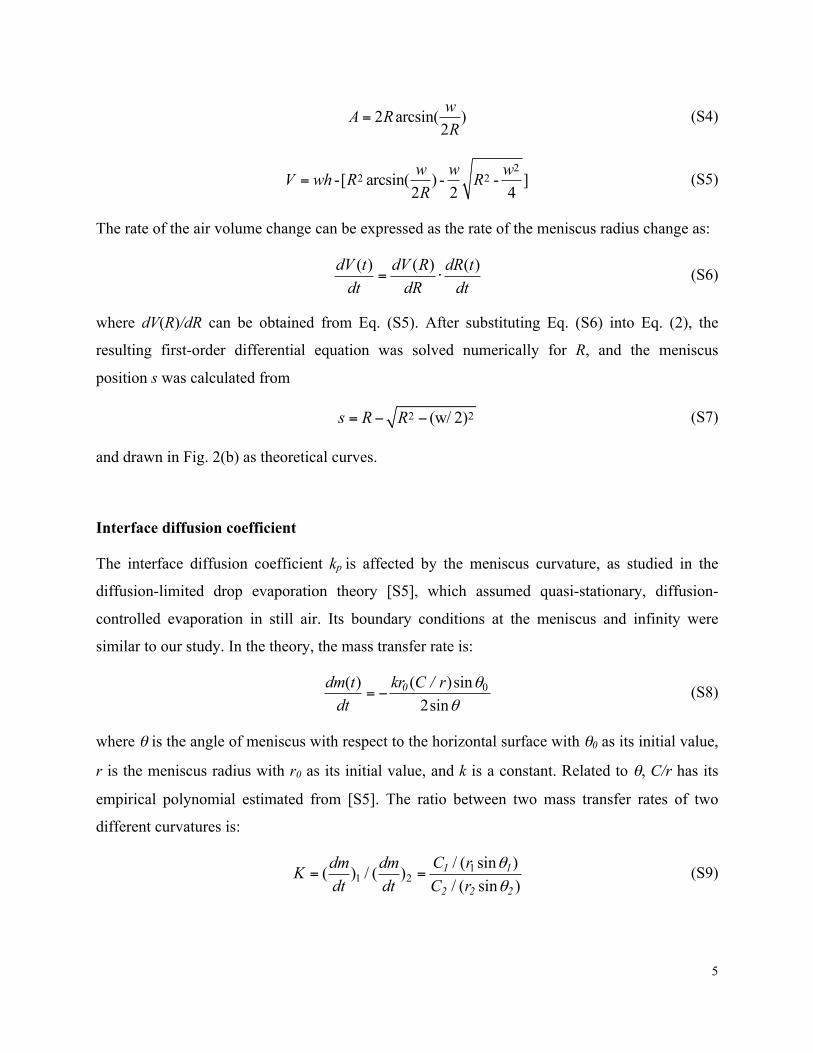
2 arcsin( )2wA RR
= (S4)
2
2 2-[ arcsin( ) - - ]2 2 4w w wV wh R RR
= (S5)
The rate of the air volume change can be expressed as the rate of the meniscus radius change as:
( ) ( ) ( )dV t dV R dR tdt dR dt
= ⋅ (S6)
where dV(R)/dR can be obtained from Eq. (S5). After substituting Eq. (S6) into Eq. (2), the
resulting first-order differential equation was solved numerically for R, and the meniscus
position s was calculated from
2 2(w/ 2)s R R= − − (S7)
and drawn in Fig. 2(b) as theoretical curves.
Interface diffusion coefficient
The interface diffusion coefficient kp is affected by the meniscus curvature, as studied in the
diffusion-limited drop evaporation theory [S5], which assumed quasi-stationary, diffusion-
controlled evaporation in still air. Its boundary conditions at the meniscus and infinity were
similar to our study. In the theory, the mass transfer rate is:
0( ) ( )sin2sin
0dm t kr C / rdt
θθ
= − (S8)
where θ is the angle of meniscus with respect to the horizontal surface with θ0 as its initial value,
r is the meniscus radius with r0 as its initial value, and k is a constant. Related to θ, C/r has its
empirical polynomial estimated from [S5]. The ratio between two mass transfer rates of two
different curvatures is:
11 2
/ ( sin )( ) / ( )/ ( sin )1 1
2 2 2
dm dm C rKdt dt C r
θθ
= = (S9)

6
When the meniscus is flat so that 1θ is 0°, C1 / (r1 sinθ1) = 2 / π 0.63 [S5]. When the meniscus
forms the advancing contact angle on the trench sidewall (θadv = 130° in this study) so that θ2 is
40°, C2 / (r2 sinθ2 ) 0.73 , and the ratio K is about 0.86. However, this result is for a spherical
droplet. Having about half the value, the curvature of the meniscus on the long trench of this
Letter is expected to affect the mass diffusion rate less than the above discussion. To calculate
the interface diffusion coefficient kp, we eventually used the diffusion length, which assumes a
constant mass transfer rate and was used in recent work [S6]. The interface diffusion coefficient
kp can be estimated using “film theory” for mass transfer across interfaces [S7]:
pH air
D Mkkδ ρ
= ⋅ (S10)
Here, δ is the “diffusion length”, typically around 0.1 mm for short diffusion time (i.e., ~ 103 s)
[S6,7]. Other values are obtained from reference [S8] measured at 22 ºC: M is the molecular
weight of air (i.e., 29 g/mol); ρair is the density of air (i.e., 0.0012 g/cm3); D is the diffusion
constant of air in water (i.e., 1.75–2.00×10⁻⁵ cm2/s); and kH is Henry`s constant (i.e., 1.21–1.34
atm/mM). Henry`s constant is invariant of hydrostatic pressure, unless the immersion depth is
very large (e.g., Hr only increases by 14% at ~1000 m of water depth [S9]). By substituting these
values in Eq. (4), kp is calculated to be around 3×10-12 m/(sec•Pa), which is around the extracted
value from Fig. 2(b) or 2.5×10⁻¹² m/(sec•Pa).
Advancing contact angle on sidewall
The advancing contact angle θadv on the trench sidewall was determined by observing an air
bubble shrinking inside the trench. Figure S3 shows an image right before the bubble depinned
from the top edge of the trench. The advancing contact angle was measured to be ~130o, larger
than that on a smooth Teflon® FEP surface (~115o [S2]) because of the rough sidewall shown in
Fig. 1(a).

7
FIG. S3. Measurement of advancing contact angle on trench sidewall. The advancing contact angle was read using the bubbles shrinking at the two ends of the trench after the meniscus touched the bottom. The picture is the frame when the left bubble’s triple contact line at the top edge of the trench was about to depin. The advancing contact angle is estimated to be ~130°. The right bubble had already depinned.
Surface topography and plastron robustness
It would be informative to relate the current results with different surfaces reported in the
literature, e.g., schematically drawn for random protrusions of lotus-leaves-like surfaces [S10] in
Fig. S4(a) and parallel microtrichia of underwater insect skins [S11,12] in Fig. S4(c). Assuming
same material (i.e., same contact angle) and similar structure spacing, their morphologies would
determine the critical radii of curvature Rc and thus the critical immersion depth Hc. For the
random structures of Fig. S4(a), the sloped sidewalls and non-uniform heights make Rc larger
and Hc smaller. On the other hand, for the parallel structures of Fig. S4(c), the re-entrance of the
structures makes Rc smaller and Hc larger, explaining the observation for indefinite plastron.
Importantly, the habitat of these underwater insects is much shallower (e.g., H ~ 15 cm [S11])
than the Hc value calculated from their surface structures (e.g., Hc > 15 m for ~0.5 µm
microtrichia [S11], assuming local advancing contact angle of 120o). We speculate that the large
safety factor (~100×) helps their plastron resist the large environmental fluctuations present in
nature.

8
FIG. S4. Schematic representations of three different SHPo surfaces of same material with different surface topography and corresponding air-water meniscus shape. (a) SHPo surface with random protrusions (e.g., [S10]) with slightly convex meniscus can hardly support any hydrostatic pressure unless the spacing is in nanometer scale. (b) Trench structure with reasonable convex meniscus (e.g., this study) can support some hydrostatic pressures with spacing in micrometer scale. (c) Parallel setae with highly convex meniscus (e.g., [S11,12]) and micrometer scale spacing can support more hydrostatic pressure due to their re-entrant shape. In reality, the environmental fluctuations make the air depleted much easier than the theory based on the equilibrium state. As result, the indefinite retention of the air was observed only when the environmental fluctuation was minimized for (b) (this study) or when the spacing was in nanometer scale for (c) [S11,12].
References [S1] K. N. Ren, W. Dai, J. H. Zhou, J. Su, and H. K. Wu, P Natl Acad Sci USA 108, 8162
(2011). [S2] W. Feast, H. Munro, and R. W. Richards, Polymer surfaces and interfaces II (Wiley,
1993), Vol. 2. [S3] M. S. Bobji, S. V. Kumar, A. Asthana, and R. N. Govardhan, Langmuir 25, 12120
(2009). [S4] B. Emami, A. Hemeda, M. Amrei, A. Luzar, M. Gad-el-Hak, and H. V. Tafreshi, Physics
of Fluids 25, 062108 (2013). [S5] R. Picknett and R. Bexon, Journal of Colloid and Interface Science 61, 336 (1977).
[S6] P. Lv, Y. Xue, Y. Shi, H. Lin, and H. Duan, Phys Rev Lett 112, 196101 (2014). [S7] E. L. Cussler, Diffusion: mass transfer in fluid systems (Cambridge Univ. Press, 2009).
[S8] P. B. Duncan and D. Needham, Langmuir 20, 2567 (2004). [S9] T. Enns, P. F. Scholander, and E. D. Bradstreet, The Journal of Physical Chemistry 69,
389 (1965). [S10] R. Poetes, K. Holtzmann, K. Franze, and U. Steiner, Phys Rev Lett 105, 166104 (2010).
[S11] A. Balmert, H. Florian Bohn, P. Ditsche-‐Kuru, and W. Barthlott, Journal of Morphology 272, 442 (2011).
[S12] M. Flynn and J. W. Bush, Journal of Fluid Mechanics 608, 275 (2008).


![lwpuk ,oa yksd lEidZ foHkkx] mÙkjk[kM](https://static.fdokumen.com/doc/165x107/633777c0a5ba10dda70195a7/lwpuk-oa-yksd-leidz-fohkkx-mukjkkm.jpg)